applied thermal engineering
TRANSCRIPT

102013 Basic Mechanical Engineering A J Bhosale
AISSMS College of Engineering, Pune
Unit 6:
Applied Thermal Engineering
Presented by,
Arvind J Bhosale
Asst. Prof.
Mechanical Engineering
AISSMS CoE, Pune
102013 Basic Mechanical Engineering A J Bhosale
AISSMS College of Engineering, Pune
Syllabus:
Power Plant Engineering: Conventional and non-conventional
energy sources, Hydro-electric, Thermal, Nuclear, Wind,
Solar (with block diagram)
Power Producing Devices: Boiler- Water tube and Fire tube,
Internal Combustion Engines – Two stroke and four stroke
(spark ignition and compression ignition), Turbines – Impulse
& Reaction
Power Absorbing Devices: Pump – Reciprocating &
Centrifugal, Compressors – Single acting, Single stage
reciprocating air compressor, Refrigerator – Vapor
compression refrigeration process, House hold refrigerator,
Window air conditioner (working with block diagram)

102013 Basic Mechanical Engineering A J Bhosale
AISSMS College of Engineering, Pune
POWER PRODUCING DEVICES:- Turbines (Impulse & Reaction)
Internal Combustion Engines (Two stroke & Four stroke (CI & SI))
Boiler- Water Tube Boiler & Fire Tube Boiler
POWER ABSORBING DEVICES:- Pump (Centrifugal & Reciprocating)
Compressor(Reciprocating – single stage, single acting)
Refrigerator (House hold)
Window Air Conditioner
POWER PLANT ENGINEERING:- Thermal Power Plant
Hydro- Electric Power Plant
Nuclear Power Plant
Wind Power Plant
Solar Power Plant

102013 Basic Mechanical Engineering A J Bhosale
AISSMS College of Engineering, Pune
Boiler
A boiler is a closed vessel in which steam is produced from
water by combustion of fuel.
Purposes of Steam:
For generating power in steam engines or steam turbines.
In Sugar Mill, Chemical & many more.
For heating the buildings in cold weather and for producing hot water for
hot water supply.
Primary requirement of Steam:
The water must be contained safely.
The steam must be safely delivered in desired conditions (as regards its
pressure, temperature , quality and required rates).

102013 Basic Mechanical Engineering A J Bhosale
AISSMS College of Engineering, Pune
Simple Boiler
102013 Basic Mechanical Engineering A J Bhosale
AISSMS College of Engineering, Pune
Steam:
• Steam is vapourized water. It is a transparent gas. At
standard temperature and pressure, pure steam (unmixed
with air, but in equilibrium with liquid water) occupies about
1,600 times the volume of an equal mass of liquid water.
• Saturated steam is steam at equilibrium with liquid water at
the same pressure and temperature.
• Superheated steam is steam at a temperature higher than
its boiling point at a given pressure

102013 Basic Mechanical Engineering A J Bhosale
AISSMS College of Engineering, Pune
Boiler Requirements:
• Safety
– The boiler should be safe under operating conditions.
• Accessibility
– The various parts of the boiler should be accessible for repair andmaintenance.
• Capacity
– Should be capable of supplying steam according to the requirements.
• Efficiency
– Should be able to absorb a maximum amount of heat produced due toburning of fuel in the furnace.
• Construction
– simple in construction .
• Cost
– Its initial cost and maintenance cost should below.

102013 Basic Mechanical Engineering A J Bhosale
AISSMS College of Engineering, Pune
Classification of Boilers:
1. Depending upon the relative position of Water and Flue gases:
Water Tube Boiler
Smoke or Fire Tube Boiler
2. Depending upon the Position Furnace:
Internally Fired Boiler
Externally Fired Boiler
3. Depending upon the Position of Axis of the Boiler:
Vertical Boiler
Horizontal Boiler
4. Depending upon the Service:
Stationary Boiler
Portable Boiler

102013 Basic Mechanical Engineering A J Bhosale
AISSMS College of Engineering, Pune
5. According to the Method of Circulation of Water and Steam:
Natural Circulation
Forced Circulation
6. According to the Pressure of Steam Generated:
Low Pressure (pressure of steam below 20 bar)
Medium Pressure( pressure of steam in range of 20-80 bar)
High Pressure (80 bar &above pressure of steam )
7. According to Nature of Draught Employed
Natural or Chimney Draught
Artificial Draught

102013 Basic Mechanical Engineering A J Bhosale
AISSMS College of Engineering, Pune
Water Tube Boiler :
• In these, the water flows in the
tube and hot gases are passed
over the tubes.
• These type of boilers are useful
for large amount of steam
generation at high pressures due
to low water to high flue gases
ratio.
• Used for high steam demand
and pressure requirements
• Capacity range of 4,500 –
120,000 kg/hour
• Combustion efficiency enhanced
by induced draft provisions
• Lower tolerance for water quality
and needs water treatment plant

102013 Basic Mechanical Engineering A J Bhosale
AISSMS College of Engineering, Pune
Babcock and Wilcox Boiler:
• D- Drum
• DTH- Down take header
• WT- Water Tubes
• BP- Baffle Plates
• D- Doors
• G- Grate
• FD-Fire Door
• MC- Mud Collector
• WLI- Water Level Indicator
• PG- Pressure Gauge
• ST- Super heater Tubes
• SV- Safety Valve
• MSV- Main Stop Valve
• APP- Anti priming Pipe
• L- Lower Junction Box
• FV- Feed Valve

102013 Basic Mechanical Engineering A J Bhosale
AISSMS College of Engineering, Pune
• This is the one of the most important type of water tube boiler as shownin above figure.
• It consists of number of inclined water tubes connected between uptakeheader and downtake header.
• Whole combustion chamber is divided into number of parts with the helpof baffles so that hot gases first move from the furnace upwardsbetween the water tubes and then move downward and upward betweenthe baffles over the tubes and finally these are exhausted to the chimneythrough the damper.
• The water near the uptake header are in contact with the hotter flue gasescompared to portion near the downtake header due to which the water inthe uptake header rises due to decreased density and enters the drumwhich is replaced by the cold water from the downtake header.
• Wet steam from the boiler drum enters in the outer tube, then passes intothe superheated tubes and during its passage it gets further heated up.Superheated steam now enters into the inner tubes and from here it iswithdrawn through a stop valve.

102013 Basic Mechanical Engineering A J Bhosale
AISSMS College of Engineering, Pune
Lamont Boiler :

102013 Basic Mechanical Engineering A J Bhosale
AISSMS College of Engineering, Pune
Fire Tube Boiler :
• In these boilers, the flue
gases pass through the
tubes which are
surrounded by water in
boiler shell.
• Relatively small steam
capacities (12,000
kg/hour)
• Low to medium steam
pressures (18 kg/cm2)
• Operates with oil, gas or
solid fuels

102013 Basic Mechanical Engineering A J Bhosale
AISSMS College of Engineering, Pune
Cochran Boiler:
Salient features• The dome shape of the furnacecauses the hot gases to deflectback and pass through the fluepipe. The un‐burnt fuel if any willalso be deflected back.• Spherical shape of the top of theshell and the fire box gives higherarea by volume ratio.• It occupies comparatively lessfloor area and is very compact.• It is well suited for small capacityrequirements.

102013 Basic Mechanical Engineering A J Bhosale
AISSMS College of Engineering, Pune
Cochran Boiler
• Very compact and requires
minimum floor area
• Any type of fuel can be
used with this boiler
• Well suited for small
capacity requirements
• Gives about 70% thermal
efficiency with coal firing and
about 75% with oil firing

102013 Basic Mechanical Engineering A J Bhosale
AISSMS College of Engineering, Pune
Lancashire Boiler

102013 Basic Mechanical Engineering A J Bhosale
AISSMS College of Engineering, Pune
• It is stationary, fire tube, internally fired, horizontal,
natural circulation boiler.
• This is a widely used boiler because of its good steaming
quality and its ability to burn coal of inferior quality.
• These boilers have a cylindrical shell 2 m in diameters
and its length varies from 8 m to 10 m.
• It has two large internal flue tubes having diameter
between 80 cm to 100 cm in which the grate is situated.
• This boiler is set in brickwork forming external flue so
that the external part of the shell forms part of the
heating surface.

102013 Basic Mechanical Engineering A J Bhosale
AISSMS College of Engineering, Pune
Boiler Mountings:- Stop valve
Safety Valve
Water Level Indicators
Pressure Gauge
Fusible Plug
Blow Off Cock, etc.
Boiler Accessories:- Economizers
Super heaters
Air -Preheater
Feed Pumps, etc.

102013 Basic Mechanical Engineering A J Bhosale
AISSMS College of Engineering, Pune
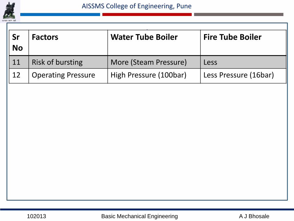
Difference between Water Tube And Fire Tube Boiler:
SrNo
Factors Water Tube Boiler Fire Tube Boiler
1 Position of waterand flue gases
Water flows inside tubesand flue gases arecirculated around thetubes
Flue gases are insidethe tubes and water iscirculated around thetubes
2 Floor area for thesame power
It occupies less floor area It occupies more floorarea
3 Rate of steamgeneration
Higher Lesser
4 Construction Simple Difficult
5 Transportation Simpler Difficult

102013 Basic Mechanical Engineering A J Bhosale
AISSMS College of Engineering, Pune
.SrNo
Factors Water Tube Boiler Fire Tube Boiler
6 Shell diameter for thegiven power
Less required Large
7 Treatment of water Not so much necessary More necessary
8 Requirement of skill It requires more skill aswell as careful attention
It requires less skill forefficient and economicworking
9 Accessibility ofvarious parts forcleaning, repair andinspection
It has more accessibility The parts are not soeasily accessible
10 Suitability Suitable Not suitable for largepower generation.
102013 Basic Mechanical Engineering A J Bhosale
AISSMS College of Engineering, Pune
.
SrNo
Factors Water Tube Boiler Fire Tube Boiler
11 Risk of bursting More (Steam Pressure) Less
12 Operating Pressure High Pressure (100bar) Less Pressure (16bar)

102013 Basic Mechanical Engineering A J Bhosale
AISSMS College of Engineering, Pune
Steam Turbines:
A steam turbine is a thermo-mechanical device that extracts
thermal energy from pressurized steam, and converts it
into rotary motion.

102013 Basic Mechanical Engineering A J Bhosale
AISSMS College of Engineering, Pune
Classification of Turbines
Turbines
Steam Turbines
Impulse Turbines
Reaction Turbines
Hydraulic Turbines
Impulse-Pelton Turbines
Reaction-Kaplan Turbines
Reaction-Francis Turbines
Gas Turbines
Open Cycle Gas Turbines
Closed Cycle Gas Turbines

102013 Basic Mechanical Engineering A J Bhosale
AISSMS College of Engineering, Pune
Impulse Turbines:• An impulse turbine has fixednozzles that orient the steam flowinto high speed jets.
• These jets contain significantkinetic energy, which the rotorblades, shaped like buckets,convert into shaft rotation as thesteam jet changes direction.
• A pressure drop occurs acrossonly the stationary blades, with anet increase
Disadvantages:1. velocity of the wheel is too, high
(25000 to 30000 r p m.) for practical
purposes.
2. loss of kinetic energy. In an actual
turbine this loss is 10% to 12%.

102013 Basic Mechanical Engineering A J Bhosale
AISSMS College of Engineering, Pune
Reaction Turbine:
• In the reaction turbine, the rotor blades themselves are arranged toform convergent nozzles.
• This type of turbine also makes use of the reaction force producedas the steam accelerates through the nozzles formed by the rotor.
• Steam is directed onto the rotor by the fixed vanes of the stator. Itleaves the stator as a jet that fills the entire circumference of therotor.
• The steam then changes direction and increases its speed relativeto the speed of the blades.
• A pressure drop occurs across both the stator and the rotor, withsteam accelerating through the stator and decelerating through therotor, with no net change in steam velocity across the stage butwith a decrease in both pressure and temperature, reflecting thework performed in the driving of the rotor.

102013 Basic Mechanical Engineering A J Bhosale
AISSMS College of Engineering, Pune
In Reaction Turbines, the rotation is mainly achieved by the reaction
forces created by the acceleration of the fluid in the runner (rotating
blade). The basic principle is the same as a rotating lawn sprinkler in
which water enters the arms of the sprinkler at low velocity and leaves
through the jets at high velocity.
Newton's third law describes the transfer of energy for reactionturbines.
A Simple Reaction Turbine Actual Reaction Turbine

102013 Basic Mechanical Engineering A J Bhosale
AISSMS College of Engineering, Pune
Animation

102013 Basic Mechanical Engineering A J Bhosale
AISSMS College of Engineering, Pune
Hydraulic Turbines:
Hydraulic turbine – A rotary engine that converts hydraulic
energy into mechanical energy.
Mechanical energy is used in running an electric generator
which is coupled to turbine shaft.

102013 Basic Mechanical Engineering A J Bhosale
AISSMS College of Engineering, Pune
Impulse Turbine:
• Energy available at the inlet of the turbine is only kinetic
energy.
• Pressure is atmospheric from inlet to outlet.
• Works on the basis of impulse momentum principle
• Eg: Pelton Wheel
102013 Basic Mechanical Engineering A J Bhosale
AISSMS College of Engineering, Pune
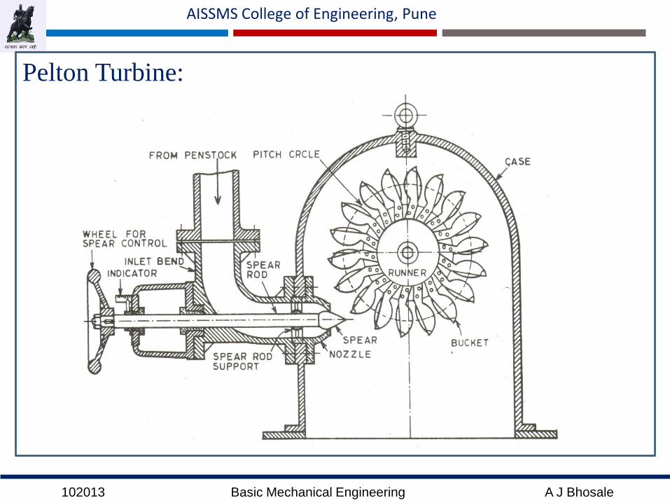
Pelton Turbine:

102013 Basic Mechanical Engineering A J Bhosale
AISSMS College of Engineering, Pune
Pelton Wheel:
102013 Basic Mechanical Engineering A J Bhosale
AISSMS College of Engineering, Pune
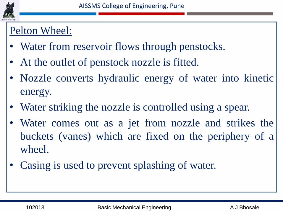
Pelton Wheel:
• Water from reservoir flows through penstocks.
• At the outlet of penstock nozzle is fitted.
• Nozzle converts hydraulic energy of water into kinetic
energy.
• Water striking the nozzle is controlled using a spear.
• Water comes out as a jet from nozzle and strikes the
buckets (vanes) which are fixed on the periphery of a
wheel.
• Casing is used to prevent splashing of water.

102013 Basic Mechanical Engineering A J Bhosale
AISSMS College of Engineering, Pune

102013 Basic Mechanical Engineering A J Bhosale
AISSMS College of Engineering, Pune
Reaction Turbine:
• Energy of fluid partly transferred into kinetic energybefore it enters the runner
• It enters the runner with excess pressure.
• Pressure energy is converted into kinetic energy as waterpasses through runner.
• The difference in pressure between inlet and outlet ofrunner (reaction pressure) is responsible for motion ofrunner.
• Eg: Francis turbine, Kaplan Turbine

102013 Basic Mechanical Engineering A J Bhosale
AISSMS College of Engineering, Pune
Francis Turbine:
• Named after American Engineer J.B.Francis
• It is a mixed flow reaction turbine with medium head and
medium specific speed

102013 Basic Mechanical Engineering A J Bhosale
AISSMS College of Engineering, Pune
Francis Turbine Components:
• Penstock
• Scroll/Spiral casing
• Speed ring/Stay ring
• Stay vanes
• Guide vanes/Wicket vanes
• Runner blades
• Draft tube

102013 Basic Mechanical Engineering A J Bhosale
AISSMS College of Engineering, Pune
Francis Turbine Working:
• Water from the penstock enters the scroll casing which
completely surrounds the runner.
• Involute casing provides an even distribution of
water(constant velocity) around the circumference of the
runner.
• Stay rings directs water from scroll casing to guide
vanes.

102013 Basic Mechanical Engineering A J Bhosale
AISSMS College of Engineering, Pune
Francis Turbine Working:
• The guide vanes
-regulate the quantity of water supplied to the runner(totake care of the load variations)
-direct water to the runner at an appropriate angle.
• The runner consists of a series of curved vanes evenlyarranged around the circumference.
• At the entrance to the runner only a part of energy ofwater is converted into kinetic energy and substantialpart remains in the form of pressure energy.
• As water flows through the runner the change frompressure to kinetic energy takes place gradually.

102013 Basic Mechanical Engineering A J Bhosale
AISSMS College of Engineering, Pune
Francis Turbine:
• The difference in pressure between the inlet and outlet of the
runner is called reaction pressure.
• Water enters the runner from the guide vanes towards the
centre radially and discharges out axially- Mixed flow
turbine.
• After doing work water is discharged to the tail race through
a closed tube of gradually enlarging section called draft tube.

102013 Basic Mechanical Engineering A J Bhosale
AISSMS College of Engineering, Pune
Kaplan Turbine:
• Developed by Austrian Engineer V. Kaplan.
• Suitable for relatively low heads and requires large
volume of water to develop large power.
• Kaplan turbine is a reaction turbine in which water enters
and leaves the runner blades axially-Axial flow turbine

102013 Basic Mechanical Engineering A J Bhosale
AISSMS College of Engineering, Pune

102013 Basic Mechanical Engineering A J Bhosale
AISSMS College of Engineering, Pune
Kaplan Turbine Components:
Scroll casing
Guide Vanes
Runner Vanes
Draft tube

102013 Basic Mechanical Engineering A J Bhosale
AISSMS College of Engineering, Pune
Kaplan Turbine Working:
• Kaplan turbine works on the reaction principle as Francis
turbine.
• Only difference is that water enters and leaves the turbine
axially –Axial flow turbine.
• Both the guide vane(wicket gate) angle and runner vane
angle can be adjusted which gives rise to high efficiency.

102013 Basic Mechanical Engineering A J Bhosale
AISSMS College of Engineering, Pune

102013 Basic Mechanical Engineering A J Bhosale
AISSMS College of Engineering, Pune
Selection of Turbine:
Type of turbine Range of head
Pelton 200-2000
Francis 15-300
Kaplan 5-30

102013 Basic Mechanical Engineering A J Bhosale
AISSMS College of Engineering, Pune
Heat Engines
Any type of engine or machine which derives Heat Energy from the combustion of the
fuel or any other source and converts this energy into Mechanical Work is known as a
Heat Engine.
Classification :
1. External Combustion Engine (E. C. Engine) :
Combustion of fuel takes place outside the cylinder.
e.g. Steam Turbine, Gas Turbine Steam Engine, etc.

102013 Basic Mechanical Engineering A J Bhosale
AISSMS College of Engineering, Pune
Heat EnginesAdvantages of External Combustion Engines over Internal Combustion Engines :
1. Starting Torque is generally high.
2. Due to external combustion, cheaper fuels can be used (even solid fuels !).
3. Due to external combustion, flexibility in arrangement is possible .
4. Self – Starting units.
Internal Combustion Engines require additional unit for starting the engine !
Advantages of Internal Combustion Engines over External Combustion Engines :
1. Overall efficiency is high.
2. Greater mechanical simplicity.
3. Weight – to – Power ratio is low.
4. Easy Starting in cold conditions.
5. Compact and require less space.

102013 Basic Mechanical Engineering A J Bhosale
AISSMS College of Engineering, Pune
Classification of I. C. Engines
A. Cycle of Operation :
B. Cycle of Combustion :
2. Four – Stroke Engine1. Two – Stroke Engine.
1. Otto Cycle (Combustion at Constant Volume).
2. Diesel Cycle (Combustion at Constant Pressure).
3. Dual Cycle (Combustion partly at Constant Volume + Constant Pressure).

102013 Basic Mechanical Engineering A J Bhosale
AISSMS College of Engineering, Pune
Classification of I. C. Engines
C. Arrangement of Cylinder :
1. Horizontal Engine. 2. Vertical Engine
3. V – type Engine 4. Radial Engine

102013 Basic Mechanical Engineering A J Bhosale
AISSMS College of Engineering, Pune
Classification of I. C. Engines
D. Uses :
1. Automobile Engine. 2. Marine Engine
3. Stationary Engine 4. Portable Engine

102013 Basic Mechanical Engineering A J Bhosale
AISSMS College of Engineering, Pune
Classification of I. C. Engines
E. Fuel used :
1. Oil Engine. 2. Petrol Engine
3. Gas Engine 4. Kerosene Engine
F. Speed of Engine :
1. High Speed 2. Low Speed
G. Method of Cooling :
1. Air – Cooled Engine. 2. Water – Cooled Engine

102013 Basic Mechanical Engineering A J Bhosale
AISSMS College of Engineering, Pune
Classification of I. C. Engines
G. Method of Ignition :
2. Compression – Ignition (C.I.) Engine1. Spark – Ignition (S.I.) Engine.

102013 Basic Mechanical Engineering A J Bhosale
AISSMS College of Engineering, Pune
Classification of I. C. Engines
I. No. of cylinders :
1. Single Cylinder Engine. 2. Multi - Cylinder Engine
102013 Basic Mechanical Engineering A J Bhosale
AISSMS College of Engineering, Pune
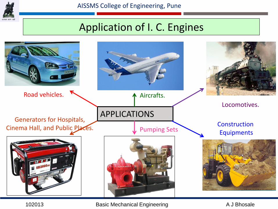
Application of I. C. Engines
APPLICATIONS
Road vehicles. Aircrafts.
Locomotives.
Construction EquipmentsPumping Sets
Generators for Hospitals, Cinema Hall, and Public Places.

102013 Basic Mechanical Engineering A J Bhosale
AISSMS College of Engineering, Pune
Air – Standard Cycles
OPERATING Cycle of an I. C. Engine ≡ Sequence of separate Processes.
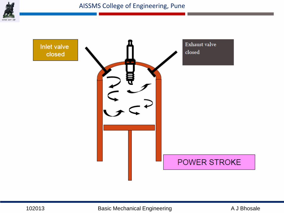
1. Intake
2. Compression
3. Combustion
4. Expansion
5. Exhaust
I.C. Engine DOES NOT operate on a Thermodynamic Cycle, as it is an Open System.
i.e. Working Fluid enters the System at 1 set of conditions (State 1) and leaves at another
(State 2).
Compression ratio:

102013 Basic Mechanical Engineering A J Bhosale
AISSMS College of Engineering, Pune
Otto Cycle
Basis of Spark – Ignition Engines.
0 -1 : Suction
1 -2 : Isentropic Compression
2 -3 : Constant Vol. Heat Addition
3 -4 : Isentropic Expansion
1 -0 : Exhaust
0 1
Pre
ssu
re, P
Volume, V
Isentropic
2
Qs
3
4
QR
Qs
1
2
Tem
per
atu
re, T
Entropy, s
3Isochoric
4
QR
4 -1 : Constant Vol.Heat Rejection

102013 Basic Mechanical Engineering A J Bhosale
AISSMS College of Engineering, Pune
Diesel Cycle
Basis of Compression – Ignition Engines.
0 -1 : Suction
1 -2 : Isentropic Compression
2 -3 : Constant Pr. Heat Addition
3 -4 : Isentropic Expansion
1 -0 : Exhaust
Qs
1
2
Tem
per
atu
re, T
Entropy, s
3
Isobaric
4
QR
4 -1 : Constant Vol.Heat Rejection
0 1
Pre
ssu
re, P
Volume, V
Isentropic2
Qs 3
4
QR
Isochoric
102013 Basic Mechanical Engineering A J Bhosale
AISSMS College of Engineering, Pune
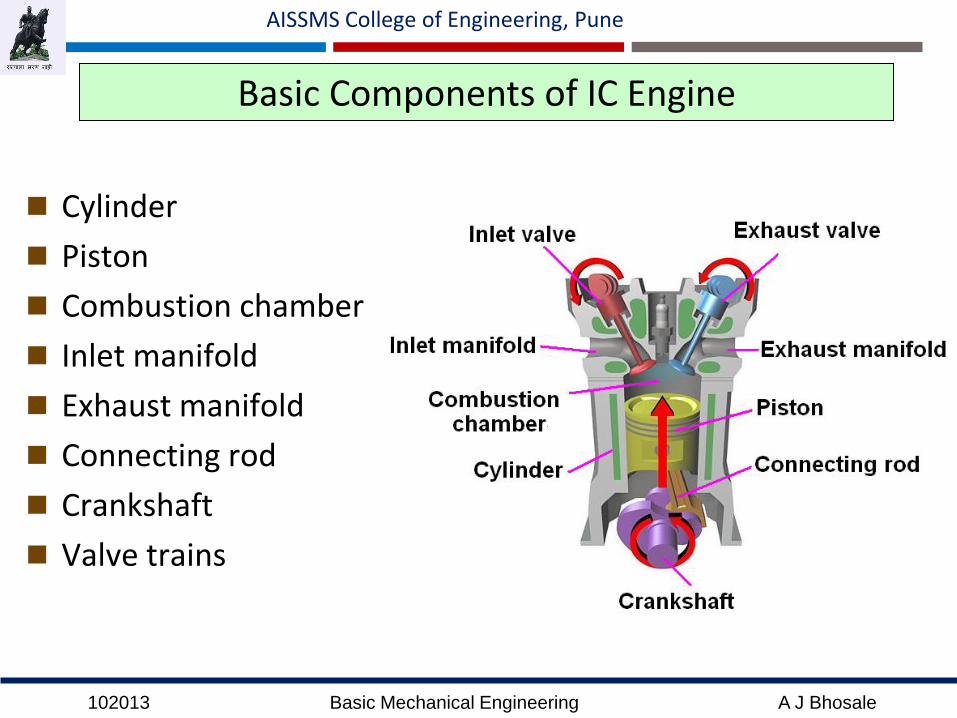
Cylinder
Piston
Combustion chamber
Inlet manifold
Exhaust manifold
Connecting rod
Crankshaft
Valve trains
Basic Components of IC Engine

102013 Basic Mechanical Engineering A J Bhosale
AISSMS College of Engineering, Pune
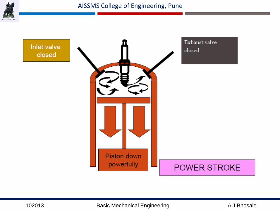
Four Stroke S.I. Engine

102013 Basic Mechanical Engineering A J Bhosale
AISSMS College of Engineering, Pune

102013 Basic Mechanical Engineering A J Bhosale
AISSMS College of Engineering, Pune

102013 Basic Mechanical Engineering A J Bhosale
AISSMS College of Engineering, Pune

102013 Basic Mechanical Engineering A J Bhosale
AISSMS College of Engineering, Pune

102013 Basic Mechanical Engineering A J Bhosale
AISSMS College of Engineering, Pune

102013 Basic Mechanical Engineering A J Bhosale
AISSMS College of Engineering, Pune

102013 Basic Mechanical Engineering A J Bhosale
AISSMS College of Engineering, Pune
102013 Basic Mechanical Engineering A J Bhosale
AISSMS College of Engineering, Pune

102013 Basic Mechanical Engineering A J Bhosale
AISSMS College of Engineering, Pune
102013 Basic Mechanical Engineering A J Bhosale
AISSMS College of Engineering, Pune

102013 Basic Mechanical Engineering A J Bhosale
AISSMS College of Engineering, Pune

102013 Basic Mechanical Engineering A J Bhosale
AISSMS College of Engineering, Pune

102013 Basic Mechanical Engineering A J Bhosale
AISSMS College of Engineering, Pune

102013 Basic Mechanical Engineering A J Bhosale
AISSMS College of Engineering, Pune

102013 Basic Mechanical Engineering A J Bhosale
AISSMS College of Engineering, Pune

102013 Basic Mechanical Engineering A J Bhosale
AISSMS College of Engineering, Pune
Four – Stroke / Compression Ignition (C.I.) Engine

102013 Basic Mechanical Engineering A J Bhosale
AISSMS College of Engineering, Pune
Four – Stroke / Compression Ignition (C.I.) Engine

102013 Basic Mechanical Engineering A J Bhosale
AISSMS College of Engineering, Pune
Two Stroke I C Engine

102013 Basic Mechanical Engineering A J Bhosale
AISSMS College of Engineering, Pune
Two – Stroke / Spark Ignition (S.I.) Engine

102013 Basic Mechanical Engineering A J Bhosale
AISSMS College of Engineering, Pune
Two – Stroke / Spark Ignition (S.I.) Engine

102013 Basic Mechanical Engineering A J Bhosale
AISSMS College of Engineering, Pune
Comparison : Two – Stroke Vs. Four Stroke
Sr.
No.
Description Four Stroke Engines Two Stoke Engines
1 Completion of
cycle
Cycle is completed in four
strokes of the piston or in two
revolutions of the crankshaft.
Cycle is completed in two
strokes of the piston or one
revolution of the
crankshaft.
2 Power produced
for same cylinder
dimensions and
speed
Less High
3 Size of flywheel Heavier flywheel is needed Lighter flywheel is needed
4 Initial cost and
space requirement
for same size of
engine
Occupies more space and
costly.
Occupies less space and
cheaper.

102013 Basic Mechanical Engineering A J Bhosale
AISSMS College of Engineering, Pune
5 Thermal
efficiency
High Low
6 Volumetric
efficiency
High due to more time
for induction
Low due to less time of
induction.
7 Starting Complicated Easy
8 Noise Less High
9 Application Used where efficiency is
important, viz., in Cars,
Buses Trucks, Tractors,
Aero planes Industrial
engines, Generators etc.
Used where low cost,
compactness and light weight
are important viz., in
mopeds, scooters,
motorcycles, etc.
Comparison : Two – Stroke Vs. Four Stroke

102013 Basic Mechanical Engineering A J Bhosale
AISSMS College of Engineering, Pune
Comparison : S.I. Vs. C.I. Engines
Sr.
No.
Description SI Engines CI Engines
1 Basic cycle Based on Otto cycle Based on Diesel cycle
2 Fuel used Gasoline (Petrol) having high
self ignition temperature
Diesel having lower self ignition
temperature compared to
gasoline
3 Induction A carburetor is used to prepare
the required strength of
mixture of fuel and air
No carburetor is needed. Fuel is
injected with the help of fuel
pump under high pressure
directly into combustion
chamber
4 Compression
ratio (CR)
Varies from 6-10 Varies from 16-20
5 Ignition Spark is used to ignite the
mixture
The self ignition of fuel occurs
due to high temperature of air
because of high compression of
air

102013 Basic Mechanical Engineering A J Bhosale
AISSMS College of Engineering, Pune
Comparison : S.I. Vs. C.I. Engines
6 Speed High speed engines due to
light weight
Low speed engine due to
heavy weight
7 Thermal
Efficiency
Low efficiency due to low
CR
High efficiency because
of higher CR
8 Starting Easy due to low CR Difficult due to high CR
9 Running cost More as they use costly
fuel
Low as they use cheap
fuel
10 Initial cost Low High

102013 Basic Mechanical Engineering A J Bhosale
AISSMS College of Engineering, Pune
Comparison : Petrol Vs. Diesel Engines
Sr. No. Petrol Engine Diesel Engine
1. Working : Otto Cycle Working : Diesel Cycle
2. Suction Stroke :Air / Fuel mixture is taken in
Suction Stroke :only Air is taken in
3. Spark Plug Fuel Injector
4. Spark Ignition generates Power Compression Ignition generates Power
5. Thermal Efficiency – 35 % Thermal Efficiency – 40 %
6. Compact Bulky
7. Running Cost – High Running Cost – Low
8. Light – Weight Heavy – Weight
9. Fuel : Costly Fuel : Cheaper
10. Gasoline : Volatile and Danger Diesel : Non-volatile and Safe.
11. Less Dependable More Dependable

102013 Basic Mechanical Engineering A J Bhosale
AISSMS College of Engineering, Pune
Power Absorbing Devices:-
Compressor
Pumps
Refrigerator
Air Conditioner

102013 Basic Mechanical Engineering A J Bhosale
AISSMS College of Engineering, Pune
Compressor:-
COMPRESSOR – A device which takes a definite
quantity of fluid ( usually gas, and most often air ) and
deliver it at a required pressure.
Air Compressor- are used to compress the atmospheric
air to high pressure.
Air Compressor –1) Takes in atmospheric air,
2) Compresses it, and
3) Delivers it to a storage vessel ( i.e. Reservoir ).

102013 Basic Mechanical Engineering A J Bhosale
AISSMS College of Engineering, Pune
Uses of Compressed Air:
Inflating tyres /tubes
In spray Paintings
For cleaning purposes in garages along with water for washing
cars etc.
Gas turbines
Diesel Engines
Air Brakes

102013 Basic Mechanical Engineering A J Bhosale
AISSMS College of Engineering, Pune
Uses of Compressed Air
Compressed Air
Powering portable small Engines
Drills and Hammers in road building
Excavating
Tunneling and MiningStarting the
Diesel engines
Operating Brakes for buses, trucks and trains
102013 Basic Mechanical Engineering A J Bhosale
AISSMS College of Engineering, Pune
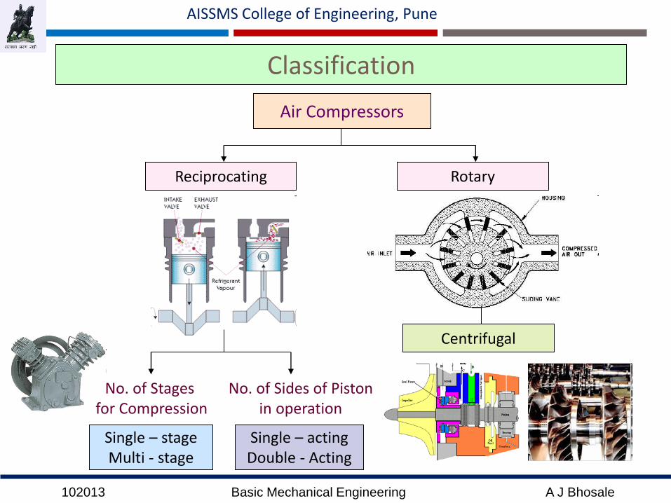
Classification
Air Compressors
Reciprocating Rotary
Single – actingDouble - Acting
No. of Sides of Piston in operation
No. of Stages for Compression
Centrifugal
Single – stageMulti - stage

102013 Basic Mechanical Engineering A J Bhosale
AISSMS College of Engineering, Pune
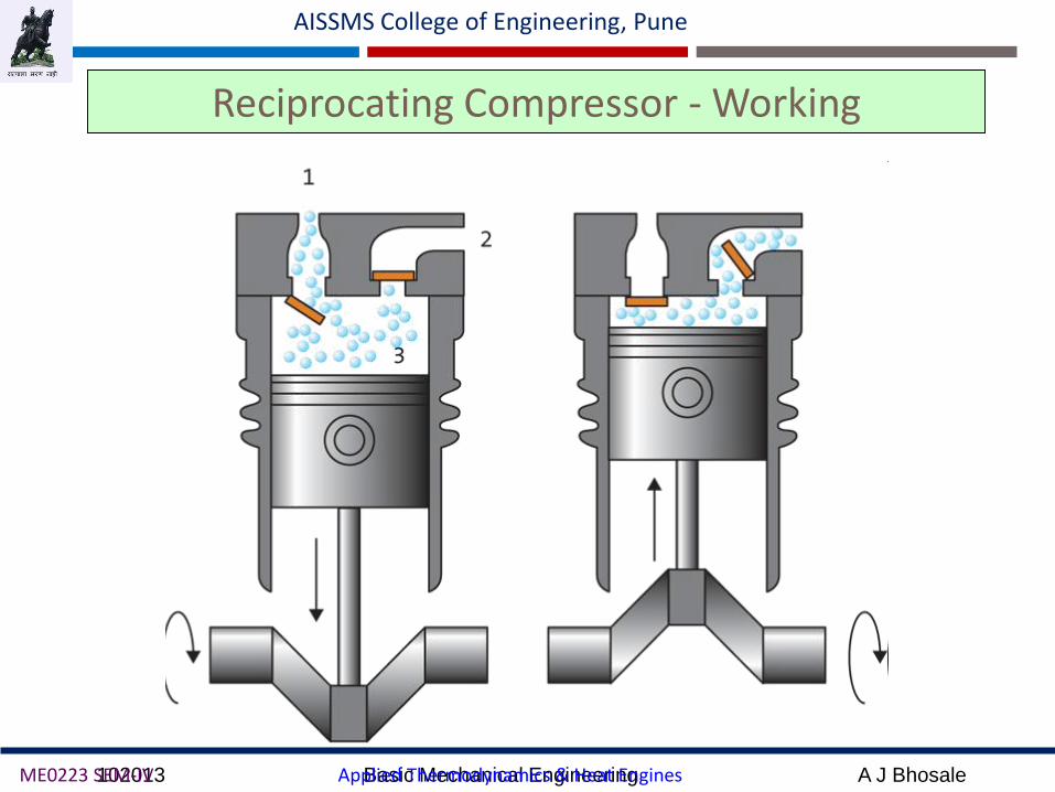
Reciprocating Compressor - Working
102013 Basic Mechanical Engineering A J Bhosale
AISSMS College of Engineering, Pune
Reciprocating Compressor - Working
ME0223 SEM-IV Applied Thermodynamics & Heat Engines

102013 Basic Mechanical Engineering A J Bhosale
AISSMS College of Engineering, Pune
• Single acting Single stage Reciprocating Compressor
Working Principle:
Block diagram of Single acting Single stage Reciprocating Compressor

102013 Basic Mechanical Engineering A J Bhosale
AISSMS College of Engineering, Pune
Refrigeration
REFRIGERATION – Science of producing and maintaining temperature below that of
surrounding / atmosphere.
REFRIGERATION – Cooling of or removal of heat from a system.
Refrigerating System – Equipment employed to maintain the system at a low temperature.
Refrigerated System – System which is kept at lower temperature.
Refrigeration – 1) By melting of a solid,
2) By sublimation of a solid,
3) By evaporation of a liquid.
Most of the commercial refrigeration production : Evaporation of liquid.
This liquid is known as Refrigerant.

102013 Basic Mechanical Engineering A J Bhosale
AISSMS College of Engineering, Pune
Refrigeration Circuit
Refrigeration Circuit
EvaporatorCompressor
CondenserExpansion Valve

102013 Basic Mechanical Engineering A J Bhosale
AISSMS College of Engineering, Pune
Refrigeration - Elements
Compressor
Condenser
Evaporator
Expansion Valve
Wnet, in
Surrounding Air
Refrigerated Space
QH
QL
High Temp Source
Low TempSink
QH
QL
Wnet, in

102013 Basic Mechanical Engineering A J Bhosale
AISSMS College of Engineering, Pune
Vapor Compression Cycle:-

102013 Basic Mechanical Engineering A J Bhosale
AISSMS College of Engineering, Pune
Refrigeration - Applications1. Ice making.
2. Transportation of food items above and below freezing.
2. Industrial Air – Conditioning.
4. Comfort Air – Conditioning.
5. Chemical and related industries.
6. Medical and Surgical instruments.
7. Processing food products and beverages.
8. Oil Refining.
9. Synthetic Rubber Manufacturing.
10. Manufacture and treatment of metals.
11. Freezing food products.
12. Manufacturing Solid Carbon Dioxide.
13. Production of extremely low temperatures (Cryogenics)
14. Plumbing.
15. Building Construction.
Applications :

102013 Basic Mechanical Engineering A J Bhosale
AISSMS College of Engineering, Pune
Window Air Conditioner:
Air conditioning is the simultaneous control of temperature,humidity, motion, and purity of atmosphere of confinedspace.
Application of Air conditioning:-
Industrial applications Food Industry
Photographic Industry
Printing Industry
Hospital Air conditioning
Transport Air conditioning Automobile Air conditioning
Train Air conditioning
Air craft Air conditioning
Ship Air conditioning
Air conditioning of Computer centers
Air conditioning of television centers

102013 Basic Mechanical Engineering A J Bhosale
AISSMS College of Engineering, Pune
Block diagram of Window Air conditioner

102013 Basic Mechanical Engineering A J Bhosale
AISSMS College of Engineering, Pune

102013 Basic Mechanical Engineering A J Bhosale
AISSMS College of Engineering, Pune
Sources of Energy:
Conventional Energy
Sources
Coal
Water
Nuclear Energy
Petroleum Products
Natural gas
Non-Conventional
Energy Sources
Solar
Wind
Ocean
Tidal
Geo-Thermal, etc

102013 Basic Mechanical Engineering A J Bhosale
AISSMS College of Engineering, Pune
Non-Conventional Energy Sources:
ADVANTAGES
Easily available in nature.
Available in large quantity.
Not pollutant.
Less maintenance cost.
Sources
Solar
Wind
Ocean
Tidal
Geo-Thermal, etc DIS-ADVANTAGES
Available in Low intensity.
Available in particular period only.
Less efficiency of power plant.
High initial cost.

102013 Basic Mechanical Engineering A J Bhosale
AISSMS College of Engineering, Pune
Conventional Energy Sources
ADVANTAGES
Thermal Efficiency is more
Initial cost is less.
Intensities are high.
Sources
Coal
Water
Nuclear Energy
Petroleum Products
Natural gasDIS-ADVANTAGES
Running and maintenance cost is high
Pollution in atmosphere.

102013 Basic Mechanical Engineering A J Bhosale
AISSMS College of Engineering, Pune
102013 Basic Mechanical Engineering A J Bhosale
AISSMS College of Engineering, Pune
Power Plants:
• Thermal/ Steam Power plants
• Hydroelectric Power Plant
• Solar Power System
• Wind Power Plant

102013 Basic Mechanical Engineering A J Bhosale
AISSMS College of Engineering, Pune
Thermal Power Plant:
Thermal power is the largest source of power in India. About 75% of electricity
consumed in India are generated by Thermal power plants. There are different
types of Thermal power plants based on the fuel used to generate the steam such
as coal, gas, diesel etc.
Coal-fired plants account for 56% of India's installed electricity capacity.
The thermal energy available in the steam is converted into mechanical energy
and is used for driving steam turbines. Steam turbines is coupled to generator
and hence power is produced whenever turbine is rotated.

102013 Basic Mechanical Engineering A J Bhosale
AISSMS College of Engineering, Pune
Prime factors for starting a steam power plant
– Availability of fuel, Coal
– Availability of water
– Availability of strong foil foundation
– Availability of transport facility
– Availability of labors and engineers
– Availability of sufficient space for power plant equipments,
space for disposing ash, space for storing coal etc.

102013 Basic Mechanical Engineering A J Bhosale
AISSMS College of Engineering, Pune
Working Principle:

102013 Basic Mechanical Engineering A J Bhosale
AISSMS College of Engineering, Pune
• Advantages-
Fuel is cheaper
Less space is required as compared with Hydro-electric power
plant
Cheaper in production cost and initial cost compared with
diesel power plant
Transmission Costs are reduced as these plants can be set up
near the industry.

102013 Basic Mechanical Engineering A J Bhosale
AISSMS College of Engineering, Pune
• Disadvantages:-
The Cost of plant is increases with the increase in temperature
and pressure.
Maintenance and operating cost is high.
Long Time is required for erecting and put in action.
Large quantity of water is required.
Coal and ash handling poses a serious problem.
Pollution causes health problem to workers and habitants near
the thermal power plant

102013 Basic Mechanical Engineering A J Bhosale
AISSMS College of Engineering, Pune
Hydro-Electric Power Plant:
In Hydro Power Plant the water is utilized to move theturbines which in turn run the electric generator’s.
The Potential energy of the water stored in the damgets converted into the Kinetic Energy of the movingwater in the penstock. And this Kinetic Energy getsconverted into the Electrical Energy with the help ofTurbine & Generator (T-G) combination.
Hydro Power Plant was invented by H.F. Rogers
Hydro Power Plant fulfills the 30% of the total energyneeds of the world.
Total hydro potential of the world = 5000 GW

102013 Basic Mechanical Engineering A J Bhosale
AISSMS College of Engineering, Pune
First Hydro Power Plant was constructed at Darjeeling in 1898
named as “SIDRAPONG” of capacity 130 KW.
Second Hydro Power Plant was constructed at Mysore in1902 named as “ SIVARAMUDRAM ” having capacity 4.5MW.

102013 Basic Mechanical Engineering A J Bhosale
AISSMS College of Engineering, Pune
Essential Elements of Hydro-Electric Power Plant.
PRIMARY ELEMENT’S
CATCHMENTS AREA
RESERVOIR
DAM
PRIME MOVERS
DRAFT TUBES
POWER HOUSE & EQUIPMENT
SAFETY DEVICE’S
SPILL WAY’S
SURGE TANK
TRASH RACK

102013 Basic Mechanical Engineering A J Bhosale
AISSMS College of Engineering, Pune
Hydro-electric power station
transformer
generator
lock gate
turbine

102013 Basic Mechanical Engineering A J Bhosale
AISSMS College of Engineering, Pune
1.Catchment Area:
The whole area behind the clam training into a stream asriver across which the dam has been built at suitable placeis called catchments area
2.Reservoir:
A reservoir is employed to store water which is furtherutilized to generate power by running the hydroelectricturbines.
3.Dam:
- A dam is a barrier which confines or raise water for storageor diversion to create a hydraulic head.
- Dam’s are generally made of concrete, Stone masory,Rockfill or Timber.

102013 Basic Mechanical Engineering A J Bhosale
AISSMS College of Engineering, Pune
4. Turbine and Generator:
Turbine & Generator is the most important part of any
power plant
This combination is known as THE HEART OF THE
POWER PLANT.
TURBINE :- Turbine is a very light fan like structure
having many number’s of blades . It has an ability to
rotate on its axis when water passes through it.
GENERATOR :- Generator is a device in which when
there is rotation of coil between the strong Magnetic
Field then it produces an Alternating Current.

102013 Basic Mechanical Engineering A J Bhosale
AISSMS College of Engineering, Pune

102013 Basic Mechanical Engineering A J Bhosale
AISSMS College of Engineering, Pune
5. Penstock:
Penstock is the connecting pipe between the dam & the turbine house.
It helps to increase the kinetic energy of the water coming from the dam.
Penstock is made up of a very strong material which can sustain thehigh pressure of water.
6.Draft Tube:
- Draft Tube is an empty structure made beneath the Turbine. It serves infollowing 2 purpose’s :
It allows the turbine to be set above tail water level without loss of head,to facilitate inspection and maintenance.
It regains by diffuser action, the major portion of the kinetic energydelivered to it from the runner.
It increases the output power.
It increases the efficiency of Hydro Power Plant
102013 Basic Mechanical Engineering A J Bhosale
AISSMS College of Engineering, Pune
7.Power House & Equipment
- Some more components are required for the proper, user friendly &
smooth functioning of the power plant. These components are as follow:
VALVE :- This the instrument which is used to control the pressure of
flow of water .
PUMPS :- This device is used to send water or any fluid from lower
potential to higher potential.
8. Spillway:
Spill Way’s is a kind of canal provided besides the dam.
Spill Way’s is used to arrange the excess of accumulation of water on
the dam because excess accumulation of water may damage the dam
structure

102013 Basic Mechanical Engineering A J Bhosale
AISSMS College of Engineering, Pune
9. Surge Tank:
When there is a sudden close or decrease in pressure due to control
valve then there is a back flow of water. This creates a high pressure
zone in the penstock due to which it may burst . This effect is known as
WATER HAMMERING EFFECT .
To avoid this a tank is attached to the penstock which stores water in it .
This tank is called as Surge Tank.

102013 Basic Mechanical Engineering A J Bhosale
AISSMS College of Engineering, Pune
Working Principle:
Initially the water of the river is in Catchments Area.
From catchments area the water flows to the dam.
At the dam the water gets accumulated . Thus the potential energy ofthe water increases due to the height of the dam .
When the gates of the dam are opened then the water moves with highKinetic Energy into the penstock.
Through the penstock water goes to the turbine house.
Since the penstock makes water to flow from high altitude to low altitude,Thus the Kinetic Energy of the water is again raised.
In the turbine house the pressure of the water is controlled by thecontrolling valves as per the requirements.
The controlled pressurized water is fed to the turbine.
Due to the pressure of the water the light weight turbine rotates.

102013 Basic Mechanical Engineering A J Bhosale
AISSMS College of Engineering, Pune
Due to the high speed rotation of the turbine the
shaft connected between the turbine and the
generator rotates .
Due to the rotation of generator the ac current is
produced.
This current is supplied to the powerhouse .
From powerhouse it is supplied for the commercial
purposes.

102013 Basic Mechanical Engineering A J Bhosale
AISSMS College of Engineering, Pune
Advantages:-
No fuel charges.
Less supervising staff is required.
Maintenance & operation charges are very low.
Running cost of the plant is low.
The plant efficiency does not changes with age.
It takes few minutes to run & synchronize the plant.
No fuel transportation is required.
No ash & flue gas problem & does not pollute the atmosphere.
These plants are used for flood control & irrigation purpose.
Long life in comparison with the Thermal & Nuclear Power Plant.

102013 Basic Mechanical Engineering A J Bhosale
AISSMS College of Engineering, Pune
Disadvantages:
The initial cost of the power plant is very high.
Takes long time for construction of the dam.
Generally, Such plant’s are located in hilly area’s far awayfrom load center & thus they require long transmission lines& losses in them will be more.
Power generation by hydro power plant is only dependanton natural phenomenon of rain .Therefore at the time ofdrought or summer session the Hydro Power Plant will not
work.

102013 Basic Mechanical Engineering A J Bhosale
AISSMS College of Engineering, Pune

102013 Basic Mechanical Engineering A J Bhosale
AISSMS College of Engineering, Pune
• Installed Capacity: 22,500 MW ,
• Total cost of $26 Billion = Approx. Rs 1,30, 000 Crore
• 32 turbines (Francis Turbines) of capacity: 700 MW and
• 2 turbines of 50 MW capacity.

102013 Basic Mechanical Engineering A J Bhosale
AISSMS College of Engineering, Pune
A groundbreaking man made structure

102013 Basic Mechanical Engineering A J Bhosale
AISSMS College of Engineering, Pune

102013 Basic Mechanical Engineering A J Bhosale
AISSMS College of Engineering, Pune
• The Tehri Dam is the highest dam in India, 5th highest in Asia and
10th highest in world on the Bhagirathi river near Tehri in
Uttarakhand, India. It is the primary dam of the THDC India Ltd.
The Tehri Dam withholds a reservoir for irrigation, municipal
water supply and the generation of 2,400 MW of hydroelectricity.
102013 Basic Mechanical Engineering A J Bhosale
AISSMS College of Engineering, Pune
Solar Power Plant:
The intensity of solar radiation are weather dependent.
On cloudy days , the intensity is very low.
Average power available is only 1 kW/m2 in hottest
regions. Thus large collection area is required.
It is intermittent source of energy since it is not available
in night.

102013 Basic Mechanical Engineering A J Bhosale
AISSMS College of Engineering, Pune
Working Principle:

102013 Basic Mechanical Engineering A J Bhosale
AISSMS College of Engineering, Pune
Gujarat Solar Park the largest
solar park in the India. It's the
biggest solar farm in the world,
covering 2,000 hectare (4900
acres) of northern Gujarat, India,
and it has the capacity to
generate 600 MW of power.
600 MW of solar panels will save
around 8 million tonnes of carbon
dioxide from being released into
the atmosphere and save around
900,000 tonnes of coal &
Natural gas per year.

102013 Basic Mechanical Engineering A J Bhosale
AISSMS College of Engineering, Pune
Wind Power:
The wind power can be generated where
the wind velocities are more than 8 kmph.
Such winds are available along the sea
coast and at high altitudes in hilly region.
The wind power is clean and non-
polluting
It has low maintenance cost and low
power generation cost of about Rs.
2.25/kWh.
It needs high capital cost of about
3.5crores/MW.

102013 Basic Mechanical Engineering A J Bhosale
AISSMS College of Engineering, Pune
Working Principle: Generator Brake Gear Box

102013 Basic Mechanical Engineering A J Bhosale
AISSMS College of Engineering, Pune
• Advantages:-
– Non polluting.
– No fuel is required.
– The cost of generation is low.
Disadvantages:-
- More noisy.
- Weight of system is high.
- Does not provide constant output due to velocity fluctuations.