apprenticeship curriculum standard steamfitter level 3 … · s0933.25 introduction to high...
TRANSCRIPT
Apprenticeship Curriculum Standard
Steamfitter
Level 3
307A
2009


STEAMFITTER - LEVEL 3
© Ontario College of Trades
Please Note: Apprenticeship Training and Curriculum Standards were developed by the Ministry of Training, Colleges and Universities (MTCU). As of April 8th, 2013, the Ontario College of Trades (College) has become responsible for the development and maintenance of these standards. The College is carrying over existing standards without any changes.
However, because the Apprenticeship Training and Curriculum Standards documents were developed under either the Trades Qualification and Apprenticeship Act (TQAA) or the Apprenticeship and Certification Act, 1998 (ACA), the definitions contained in these documents may no longer be accurate and may not be reflective of the Ontario College of Trades and Apprenticeship Act, 2009 (OCTAA) as the new trades legislation in the province. The College will update these definitions in the future.
Meanwhile, please refer to the College’s website (http://www.collegeoftrades.ca) for the most accurate and up-to-date information about the College. For information on OCTAA and its regulations, please visit: http://www.collegeoftrades.ca/about/legislation-and-regulations
STEAMFITTER - LEVEL 3
TABLE OF CONTENTS Introduction ................................................................................................................... 1 Program Summary of Reportable Subjects ................................................................ 2 Pneumatic Systems S0932 Fluid Power Systems III ........................................................................... 3 S0932.1 Pneumatic System Safety .......................................................................... 4 S0932.2 Pneumatic System Types .......................................................................... 6 S0932.3 Pneumatic System Components................................................................ 7 S0932.4 Pneumatic System Drawings ..................................................................... 9 S0932.5 Pneumatic System Controls .................................................................... 11 S0932.6 Pneumatic System Commissioning ......................................................... 12 Hydraulic Systems S0932.7 Hydraulic System Principles .................................................................... 13 S0932.8 Hydraulic Oils .......................................................................................... 14 S0932.9 Hydraulic Reservoirs ................................................................................ 15 S0932.10 Hydraulic Oil Filters .................................................................................. 16 S0932.11 Hydraulic Cylinders .................................................................................. 18 S0932.12 Hydraulic Pumps...................................................................................... 20 S0932.13 Hydraulic Valves and Controls ................................................................. 22 S0932.14 Hydraulic Piping Brackets and Supports .................................................. 24 S0932.15 Hydraulic System Drawings .................................................................... 25 S0932.16 Hydraulic System Commissioning ........................................................... 27 Robotics S0932.17 Programmable Logic Controllers ............................................................. 28 S0933 Steamfitting Systems III ........................................................................ 29 S0933.1 Process Piping Systems .......................................................................... 31 S0933.2 Medical Gas Systems .............................................................................. 33 S0933.3 Sprinkler and Standpipe Installations....................................................... 35 Fuel Gas Systems S0933.4 Fuel Gas Properties and Codes .............................................................. 43 S0933.5 Fuel Gas Meters and Regulators ............................................................. 46 S0933.6 Fuel Gas Piping Practices ....................................................................... 49 S0933.7 Fuel Gas Pipe Sizing ............................................................................... 53 S0933.8 Fuel Gas Combustion .............................................................................. 54 S0933.9 Fuel Gas Venting ..................................................................................... 57 S0933.10 Fuel Gas Burners and Controls ............................................................... 58 S0933.11 Fuel Gas System Commissioning ............................................................ 62
STEAMFITTER - LEVEL 3
Hydronic Heating Systems S0933.12 Building Heat Loss Calculations .............................................................. 64 S0933.13 Hydronic Heating System Design ............................................................ 66 Refrigeration Systems S0933.14 Principles of Refrigeration ........................................................................ 68 S0933.15 Basic Refrigeration Cycle ........................................................................ 70 S0933.16 Refrigeration System Components .......................................................... 72 S0933.17 Refrigeration System Commissioning ...................................................... 80 Air Conditioning Systems S0933.18 Principles of Air Conditioning ................................................................... 82 S0933.19 Psychometrics ......................................................................................... 83 S0933.20 Air Conditioning Applications ................................................................... 85 S0933.21 Air Conditioning System Components ..................................................... 88 S0933.22 Air Conditioning System Commissioning ................................................. 89 Heat Pump Systems S0933.23 Heat Pump Principles and Applications ................................................... 91 S0933.24 Solar Heat ................................................................................................ 95 High Temperature Hot Water Systems S0933.25 Introduction to High Temperature Hot Water Systems ............................ 96 S0933.26 Direct Return High Temperature Hot Water Systems .............................. 98 S0933.27 Pressurization of High Temperature Hot Water Systems ...................... 100 S0933.28 High Temperature Hot Water System Components............................... 102 S0933.29 Commissioning High Temperature Hot Water Systems ......................... 106 Cross Connection Prevention S0933.30 Cross Connection and Backflow Prevention .......................................... 107 S0934 Trade Documentation III ...................................................................... 110 S0934.1 Computer Aided Design ......................................................................... 112 S0934.2 Process Flow Diagrams ......................................................................... 113 S0934.3 Spool Sheets ......................................................................................... 114 S0934.4 Plan Drawings ....................................................................................... 115 S0934.5 Manufacturers Diagrams ....................................................................... 117 S0934.6 Job Specifications .................................................................................. 118 S0934.7 Labour and Material Estimates .............................................................. 119 S0934.8 Job Schedules and Critical Path Planning ............................................. 120 S0934.9 Memorandums, Reports and Forms ...................................................... 121 S0934.10 Meeting Organization ............................................................................. 122 S0934.11 Job Resumes ......................................................................................... 123

STEAMFITTER - LEVEL 3
S0935 Welding III ............................................................................................. 124 S0935.1 Welding Codes and Standards .............................................................. 126 S0935.2 Welding Metallurgy and Quality Control ................................................. 127 S0935.3 Shielded Metal Arc Welding ................................................................... 129 S0935.4 Metal Inert Gas Welding ........................................................................ 130 S0935.5 Tungsten Inert Gas Welding .................................................................. 133

STEAMFITTER - LEVEL 3
-1-
Introduction This new curriculum standard for the Steamfitter trade is based upon the on-the-job performance objectives, located in the industry-approved training standard. The curriculum is organized into 3 levels of training. The Program Summary of Reportable Subjects chart summarizes the training hours for each reportable subject. The curriculum identifies only the learning that takes place off-the-job. The in-school program focuses primarily on the theoretical knowledge and the essential skills required to support the performance objectives of the Apprenticeship Training Standards. Employers/Sponsors are expected to extend the apprentice’s knowledge and skills through practical training on the work site. Regular evaluations of the apprentice’s knowledge and skills are conducted throughout training to ensure that all apprentices have achieved the learning outcomes identified in the curriculum standard. It is not the intent of the in-school curriculum to perfect on-the-job skills. The practical portion of the in-school program is used to reinforce theoretical knowledge. Skill training is provided on the job.
STEAMFITTER - LEVEL 3
-2-
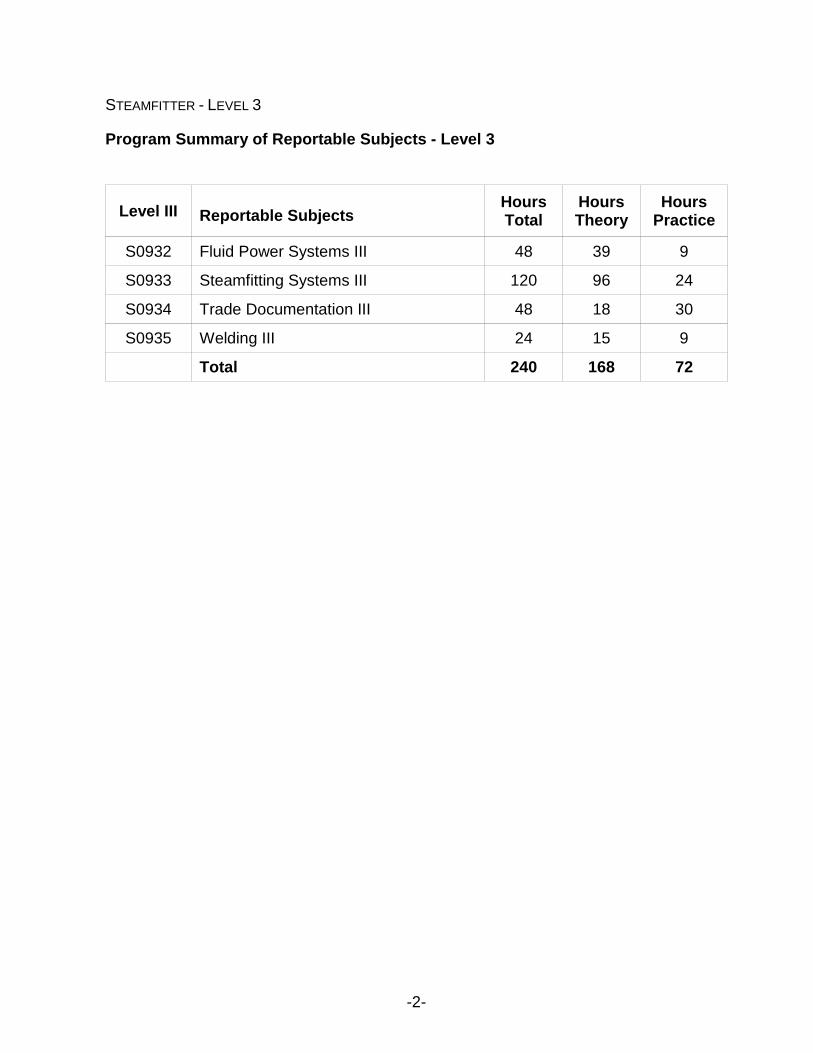
Program Summary of Reportable Subjects - Level 3
Level III Reportable Subjects Hours Total
Hours Theory
Hours Practice
S0932 Fluid Power Systems III 48 39 9
S0933 Steamfitting Systems III 120 96 24
S0934 Trade Documentation III 48 18 30
S0935 Welding III 24 15 9
Total 240 168 72

STEAMFITTER - LEVEL 3
-3-
Number: S0932 Reportable Subject: FLUID POWER SYSTEMS Duration: Total 48 hours Theory 39 hours Practical 9 hours Prerequisites: Level II Content: Pneumatic Systems
S0932.1 Pneumatic System Safety S0932.2 Pneumatic System Types S0932.3 Pneumatic System Components S0932.4 Pneumatic System Drawings S0932.5 Pneumatic System Controls S0932.6 Pneumatic System Commissioning
Hydraulic Systems S0932.7 Hydraulic System Principles S0932.8 Hydraulic Oils S0932.9 Hydraulic Reservoirs S0932.10 Hydraulic Oil Filters S0932.11 Hydraulic Cylinders S0932.12 Hydraulic Pumps S0932.13 Hydraulic Valves and Controls S0932.14 Hydraulic Piping Supports S0932.14 Hydraulic System Drawings S0932.16 Hydraulic System Commissioning
Robotics S0932.17 Programmable Logic Controllers
Evaluation & Testing: Assignments related to theory and appropriate application
skills. Minimum of one mid-term test during the 8-week term. Final exam at end of term. Periodic quizzes.
Mark Distribution:
Theory Testing
Practical Application Testing
Final Assessment
60% 10% 30%
STEAMFITTER - LEVEL 3
-4-
Instructional and Delivery Strategies: Use of material samples and manufacturers’ specifications (CDs, manuals, internet, computers, satellite)
Reference Materials: IPT Pipe trades Handbook
IPT Industrial Hydraulics Handbook Alberta steamfitting modules
Recommended Equipment List: air compressor
pump reservoirs cylinders actuator hoses relief valves gauges stauff clamps tubing wrenches allen keys (imperial/metric) pneumatic valves hydraulic valves pneumatically controlled valves for heating and cooling dryer regulator set filter oiler sets intensifiers pneumatic tools pneumatic controller (heating and cooling boards)
STEAMFITTER - LEVEL 3
-5-
S0932.1 Pneumatic System Safety Duration: Total 0.5 hour Theory 0.5 hours Practical 0 hours Cross-Reference to Training Standard: 5470.0, 5472.0, 5473.0, 5474.0, 5476.0, 5477.0, 5478.0, 5479.0, 5480.0, 5481.0, 5483.0 5484.0 GENERAL LEARNING OUTCOMES Upon successful completion the apprentice is able to identify and state the safety precautions used when working with or in the vicinity of compressed air. LEARNING OUTCOMES AND CONTENT 1.1 Identify the correct behaviour when working with compressed air in order to avoid
hazards 1.2 Determine and apply the correct methods of practising compressed air safety

STEAMFITTER - LEVEL 3
-6-
S0932.2 Pneumatic System Types Duration: Total 1.5 hours Theory 1.5 hours Practical 0 hours Cross-Reference to Training Standard: 5470.0, 5472.0, 5473.0, 5474.0, 5476.0, 5477.0, 5478.0, 5479.0, 5480.0, 5481.0, 5483.0 5484.0 GENERAL LEARNING OUTCOMES Upon successful completion the apprentice is able to identify types of pneumatic systems. LEARNING OUTCOMES AND CONTENT 2.1 Identify the following air systems:
• instrument air • control air • building automation • ultra-pure air – lab air • plant air • robotics • air driven tools • conveyors • paint shop air

STEAMFITTER - LEVEL 3
-7-
S0932.3 Pneumatic System Components Duration: Total 6 hours Theory 6 hours Practical 0 hours Cross-Reference to Training Standard: 5470.0, 5472.0, 5473.0, 5474.0, 5476.0, 5477.0, 5478.0, 5479.0, 5480.0, 5481.0, 5483.0 5484.0 GENERAL LEARNING OUTCOMES Upon successful completion the apprentice is able to identify types, use and applications of pneumatic system components. LEARNING OUTCOMES AND CONTENT 3.1 Identify types of the following pneumatic system components:
• compressors • motors • mounting requirements • pipes and fittings • filters • dryers • oilers • receivers • valves • cylinders • pressure regulators • gauges • circuits • intensifiers • controllers and recorders • sensors

STEAMFITTER - LEVEL 3
-8-
3.2 Describe the function, applications and construction features of the following pneumatic components: • compressors • motors • mounting requirements • pipes and fittings • filters • dryers • valves • cylinders • oilers • pressure regulators • manifold blocks • gauges • circuits • controllers and recorders • intensifiers • sensors
3.3 Describe the installation procedures for pneumatic gauges 3.4 Determine the function and correct layout of pneumatic circuits 3.5 Identify the purpose and methods of adjusting controllers and recorders 3.6 Identify the purpose and use of pneumatic tools
STEAMFITTER - LEVEL 3
-9-
S0932.4 Pneumatic System Drawings Duration: Total 6 hours Theory 3 hours Practical 3 hours
Cross-Reference to Training Standard: 5470.0, 5472.0, 5473.0, 5474.0, 5476.0, 5477.0, 5478.0, 5479.0, 5480.0, 5481.0, 5483.0 5484.0 GENERAL LEARNING OUTCOMES Upon successful completion the apprentice is able to read and draw pneumatic system drawings and sketches. LEARNING OUTCOMES AND CONTENT 4.1 Identify pneumatic systems
4.2 Draw the following pneumatic system component symbols: • air intake filters • compressors • receivers • regulators • lubricators • valves • cylinders • motors • oscillators • blowers • transmission lines
4.3 Read and interpret pneumatic system drawings and sketches
STEAMFITTER - LEVEL 3
-10-
4.4 Sketch and label an isometric drawing of a five-station plant air circuit with: • a reciprocating multi-cylinder air compressor • filter • dryer • valves • oilers • pressure regulator • pressure relief valve • manifold block • gauges • pipes and fittings including a start-up bypass

STEAMFITTER - LEVEL 3
-11-
S0932.5 Pneumatic System Controls Duration: Total 6 hours Theory 3 hours Practical 3 hours Cross-Reference to Training Standard: 5470.0, 5472.0, 5473.0, 5474.0, 5476.0, 5477.0, 5478.0, 5479.0, 5480.0, 5481.0, 5483.0 5484.0 GENERAL LEARNING OUTCOMES Upon successful completion the apprentice is able to read and sketch pneumatic control systems. LEARNING OUTCOMES AND CONTENT 5.1 Define the abbreviation “LOC”
5.2 Sketch steam control valves
5.3 Identify the sequencing of pneumatic controls
5.4 Describe humidity control features
5.5 Describe zone control features
5.6 Describe indoor and outdoor control features
5.7 Describe digital controls for electronic and computer systems
5.8 Build and test a number of projects using various pneumatic valves and tubing

STEAMFITTER - LEVEL 3
-12-
S0932.6 Pneumatic System Commissioning Duration: Total 0.5 hours Theory 0.5 hours Practical 0 hours Cross-Reference to Training Standard: 5470.0, 5472.0, 5473.0, 5474.0, 5476.0, 5477.0, 5478.0, 5479.0, 5480.0, 5481.0, 5483.0 5484.0 GENERAL LEARNING OUTCOMES Upon successful completion the apprentice is able to describe pneumatic system commissioning procedures. LEARNING OUTCOMES AND CONTENT 6.1 Define the following commissioning procedures:
• testing • start-up • balance, set up and adjust equipment
STEAMFITTER - LEVEL 3
-13-
S0932.7 Hydraulic Systems Principles Duration: Total 3 hours Theory 3 hours Practical 0 hours Cross-Reference to Training Standard: 5470.0, 5472.0, 5473.0, 5474.0, 5476.0, 5477.0, 5478.0, 5479.0, 5480.0, 5481.0, 5483.0 5484.0 GENERAL LEARNING OUTCOMES Upon successful completion the apprentice is able to describe hydraulic systems principles. LEARNING OUTCOMES AND CONTENT 7.1 Define the fundamentals of hydraulic systems principles: 7.2 Define the properties of hydraulic fluids:
• viscosity • fire resistance • lubricity • contamination from foreign particles, air and water
7.3 Define basic principles for force, work and power
• weight and specific gravity • pressure and force • static pressure • gauge pressures in English and Metric units • Pascal’s Law • conversion of energy and hydraulic power • pressure losses
7.4 Identify hydraulic system types
• open system • closed system

STEAMFITTER - LEVEL 3
-14-
S0932.8 Hydraulic Oils Duration: Total 1 hour Theory 1 hour Practical 0 hours Cross-Reference to Training Standard: 5470.0, 5472.0, 5473.0, 5474.0, 5476.0, 5477.0, 5478.0, 5479.0, 5480.0, 5481.0, 5483.0 5484.0 GENERAL LEARNING OUTCOMES Upon successful completion the apprentice is able to identify the different types, purpose and characteristics of hydraulic oils. LEARNING OUTCOMES AND CONTENT 8.1 Identify types of hydraulic oils
8.2 State the requirements of hydraulic oils
8.3 Identify the types, purpose and interrelation of standard tests
8.4 Identify the types and application of fire-resistant fluids

STEAMFITTER - LEVEL 3
-15-
S0932.9 Hydraulic Reservoirs Duration: Total 1 hour Theory 1 hour Practical 0 hours Cross-Reference to Training Standard: 5470.0, 5472.0, 5473.0, 5474.0, 5476.0, 5477.0, 5478.0, 5479.0, 5480.0, 5481.0, 5483.0 5484.0 GENERAL LEARNING OUTCOMES Upon successful completion the apprentice is able to identify and state the function of fluid reservoirs. LEARNING OUTCOMES AND CONTENT 9.1 Identify types, state purpose and function of fluid reservoirs:
• filling system with fluid • heat dissipation • sump for settling foreign matter • breather for vapours • surge and make up for system • level indication
STEAMFITTER - LEVEL 3
-16-
S0932.10 Hydraulic Oil Filters Duration: Total 2 hours Theory 2 hours Practical 0 hours Cross-Reference to Training Standard: 5470.0, 5472.0, 5473.0, 5474.0, 5476.0, 5477.0, 5478.0, 5479.0, 5480.0, 5481.0, 5483.0 5484.0 GENERAL LEARNING OUTCOMES Upon successful completion the apprentice is able to identify the types, purpose and application of filters, metal screens, magnets and absorbents. LEARNING OUTCOMES AND CONTENT 10.1 Identify the types, purpose and application of filters:
• metal screen filters • adsorbent filters • bypass filters • full flow filters • dual filters
10.2 Describe the construction features of filters:
• describe filter materials used in adsorbent filters • describe filter housing and passages
10.3 Explain the operation of filters:
• determine full flow and proportional flow application • filter restrictions • define “micron” • by-pass or dual filter for continuous operation • determine correct direction of flow
10.4 Determine location and mounting of filters
10.5 Determine accessibility of equipment for servicing
10.6 State filter maintenance requirements

STEAMFITTER - LEVEL 3
-17-
10.7 State importance of routine inspection
10.8 Describe method of inspection
STEAMFITTER - LEVEL 3
-18-
S0935.11 Hydraulic Cylinders Duration: Total 3 hours Theory 3 hours Practical 0 hours Cross-Reference to Training Standard: 5470.0, 5472.0, 5473.0, 5474.0, 5476.0, 5477.0, 5478.0, 5479.0, 5480.0, 5481.0, 5483.0 5484.0 GENERAL LEARNING OUTCOMES Upon successful completion the apprentice is able to identify hydraulic cylinders and related components. LEARNING OUTCOMES AND CONTENT 11.1 Identify types, purpose, and applications of:
• packing and seals • air bleeds • cushions • rotary actuators • cushions • motors • pumps • boosters • accumulators
11.2 Describe method of installing actuators 11.3 Describe procedure for connecting to load 11.4 Determine installing and mounting procedures 11.5 State importance of regular charging

STEAMFITTER - LEVEL 3
-19-
11.6 State importance of relieving gas and liquid 11.7 Identify method of checking seal in piston accumulators using gas pressure and
gauge 11.8 State importance of checking level of liquid in air bottle type accumulators 11.9 Indicate techniques of replacing accumulator parts 11.10 State importance of using nitrogen above 1000 PSI with non-fire resistance fluids
STEAMFITTER - LEVEL 3
-20-
S0932.12 Hydraulic Pumps Duration: Total 2 hours Theory 2 hours Practical 0 hours Cross-Reference to Training Standard: 5470.0, 5472.0, 5473.0, 5474.0, 5476.0, 5477.0, 5478.0, 5479.0, 5480.0, 5481.0, 5483.0 5484.0 GENERAL LEARNING OUTCOMES Upon successful completion the apprentice is able to describe the construction and operation of hydraulic system pumps. LEARNING OUTCOMES AND CONTENT 12.1 Define the classification and function of hydraulic system pumps:
• identify the class of service • single stage • multi stage
12.2 Identify types of pumps and impellers:
gear vane screw centrifugal
12.3 Identify pump drives:
shaft position electric motors couplings
12.4 Describe the construction features of hydraulic system pumps:
construction materials mountings
STEAMFITTER - LEVEL 3
-21-
12.5 Explain the operating procedures of hydraulic system pumps: starting procedures low and high pressure areas
12.6 Describe the techniques to analyze abnormal conditions:
low pressures high pressures low flow rates overheating rapid wear

STEAMFITTER - LEVEL 3
-22-
S0932.13 Hydraulic Valves and Controls Duration: Total 3 hours Theory 3 hours Practical 0 hours Cross-Reference to Training Standard: 5470.0, 5472.0, 5473.0, 5474.0, 5476.0, 5477.0, 5478.0, 5479.0, 5480.0, 5481.0, 5483.0 5484.0 GENERAL LEARNING OUTCOMES Upon successful completion the apprentice is able to identify the types and purposes of hydraulic valves and controls. LEARNING OUTCOMES AND CONTENT 13.1 Identify the types, purposes and applications of the following:
• directional control valves • pressure control valves • flow control valves • servo-valves • pressure switches • gauges
13.2 Describe the construction features of the following:
directional control valves pressure control valves flow control valves servo-valves pressure switches gauges
13.3 Explain the operating procedures of following:
directional control valves pressure control valves flow control valves servo-valves pressure switches gauges methods of actuating valves

STEAMFITTER - LEVEL 3
-23-
13.4 Identify methods of installing valves and controls 13.5 Identify the effects of using panel or flange mounting on removal of valves

STEAMFITTER - LEVEL 3
-24-
S0932.14 Hydraulic Piping Supports Duration: Total 3 hours Theory 3 hours Practical 0 hours Cross-Reference to Training Standard: 5470.0, 5472.0, 5473.0, 5474.0, 5476.0, 5477.0, 5478.0, 5479.0, 5480.0, 5481.0, 5483.0 5484.0 GENERAL LEARNING OUTCOMES Upon successful completion the apprentice is able to identify the types, purpose and application of hydraulic piping brackets and supports. LEARNING OUTCOMES AND CONTENT 14.1 Identify the types and purpose of piping:
brackets supports anchors
14.2 Identify the application of piping:
brackets supports anchors
14.3 Describe hydraulic brackets, supports and anchor installations

STEAMFITTER - LEVEL 3
-25-
S0932.15 Hydraulic System Drawings Duration: Total 6 hours Theory 3 hours Practical 3 hours Cross-Reference to Training Standard: 5470.0, 5472.0, 5473.0, 5474.0, 5476.0, 5477.0, 5478.0, 5479.0, 5480.0, 5481.0, 5483.0 5484.0 GENERAL LEARNING OUTCOMES Upon successful completion the apprentice is able to read and sketch hydraulic system drawings. LEARNING OUTCOMES AND CONTENT 15.1 Identify the specified types of hydraulic system diagrams and their contents, as
applicable, with respect to: • flow lines • abbreviations • specifications • terminology • standards • capacities • pressures • system classifications • sequence of component installation • operating principles of components • circuit function • applications and limitations
15.2 Determine and apply the correct methods of reading and interpreting hydraulic
system diagrams and sketches

STEAMFITTER - LEVEL 3
-26-
15.3 Identify and interpret the specified hydraulic system component symbols in terms of: • symbol characteristics • types of lines • functions of components • joining procedures with the system • direction of flow • operating sequence • types of controls
15.4 State the value of freehand sketching hydraulic circuits 15.5 State principles behind sketching hydraulic system component symbols 15.6 Sketch and label a hydraulic circuit consisting of the following components:
• hoses • connections • reservoirs • strainers • pumps • filters • valves • actuators • cylinders • accumulators • heat exchangers • intensifiers • motors

STEAMFITTER - LEVEL 3
-27-
S0932.16 Hydraulic System Commissioning Duration: Total 0.5 hours Theory 0.5 hours Practical 0 hours Cross-Reference to Training Standard: 5470.0, 5472.0, 5473.0, 5474.0, 5476.0, 5477.0, 5478.0, 5479.0, 5480.0, 5481.0, 5483.0 5484.0 GENERAL LEARNING OUTCOMES Upon successful completion the apprentice is able to describe hydraulic system commissioning procedures. LEARNING OUTCOMES AND CONTENT 16.1 Describe hydraulic system testing procedures 16.2 Describe hydraulic system flushing procedures 16.3 Describe hydraulic system commissioning procedures
STEAMFITTER - LEVEL 3
-28-
S0932.17 Programmable Logic Controllers Duration: Total 3 hours Theory 3 hours Practical 0 hours Cross-Reference to Training Standard: 5470.0, 5472.0, 5473.0, 5474.0, 5476.0, 5477.0, 5478.0, 5479.0, 5480.0, 5481.0, 5483.0 5484.0 GENERAL LEARNING OUTCOMES Upon successful completion the apprentice is able to describe the function of Programmable Logic Controllers. LEARNING OUTCOMES AND CONTENT 17.1 Describe the operation of Programmable Logic Controllers (PLC) 17.2 Describe the methods of PLC communication:
• parallel • serial • protocol establishment
17.3 Name PLC applications 17.4 Describe system requirements of PLC devices 17.5 Describe the advantages of using PLC devices 17.6 Describe the disadvantages of using PLC devices 17.7 Describe methods of troubleshooting PLC devices:
• controller • input modules • output modules

STEAMFITTER - LEVEL 3
-29-
Number: S0933 Title: STEAMFITTING SYSTEMS III Duration: Total 120 hours Theory 96 hours Practical 24 hours Prerequisities: Level II Content: S0933.1 Process Piping Systems
S0933.2 Medical Gas Systems S0933.3 Sprinkler and Standpipe Installations
Fuel Gas Systems S0933.4 Fuel Gas Properties and Codes
S0933.5 Fuel Gas Meters and Regulators S0933.6 Fuel Gas Piping Practices S0933.7 Fuel Gas Pipe Sizing S0933.8 Fuel Gas Combustion S0933.9 Fuel Gas Venting S0933.10 Fuel Gas Burners and Controls S0933.11 Fuel Gas System Commissioning
Hydronic Heating Systems
S0933.12 Building Heat Loss Calculations S0933.13 Hydronic Heating System Design
Refrigeration Systems
S0933.14 Principles of Refrigeration S0933.15 Basic Refrigeration Cycle S0933.16 Refrigeration System Components S0933.17 Refrigeration System Commissioning
Air Conditioning Systems
S0933.18 Principles of Air Conditioning S0933.19 Psychometrics S0933.20 Air Conditioning Applications S0933.21 Air Conditioning System Components S0933.22 Air Conditioning System Commissioning
Heat Pump Systems
S0933.23 Heat Pump Principles and Applications S0933.24 Solar Heat

STEAMFITTER - LEVEL 3
-30-
Evaluation & Testing: Assignments related to theory and appropriate application skills. Minimum of one mid-term test during the 8-week term. Final exam at end of term. Periodic quizzes.
Mark Distribution:
Theory Testing
Practical Application Testing
Final Assessment
60% 10% 30%
Instructional and Delivery Strategies: Use of material samples and manufacturers’
specifications (CDs, manuals, internet) Reference Materials: Refrigeration & Air Conditioning Technology
(Whifman/Johnson/Tomczyk) Gas Code B149 Med Gas Code Book BPV Act IPT Pipetrades Handbook CSA B149 Handbook
Recommended Equipment List: display panels
testing equipment purge burner regulators manometers meter bunsen burner conversion burner fire hose cabinets and valve display valves siamese connection (fabricate in shop) cutting torch and welding machine oxyacetylene torch and turbo-torch, b tank grinders medical gas display c/w outlets, zone valve box, alarm gas supply boiler gas fired unit heater gas fired radiant heater gas fired bvent venting system test pump hydrostatic

STEAMFITTER - LEVEL 3
-31-
S0933.1 Process Piping Systems Duration: Total 3 hours Theory 2 hours Practical 1 hour Cross-Reference to Training Standard: 5470.0, 5472.O, 5473.0, 5475.0, 5476.0, 5477.0, 5478.0, 5479.0, 5480.0, 5484.0 GENERAL LEARNING OUTCOMES Upon successful completion the apprentice is able to identify and explain a variety of process piping systems. LEARNING OUTCOMES AND CONTENT 1.1 Define a “process piping system” and state its purpose 1.2 Describe the difference between a process piping system and a plumbing system 1.3 Identify industries where process-piping systems are installed 1.4 Identify some common process piping systems including:
• compressed air • chemical supply piping • high purity water supply piping • food process piping • irrigation piping • brewery piping • oil refineries
1.5 Identify different acts, regulations and specifications used to estimate, plan,
install, inspect and commission a variety of process piping systems

STEAMFITTER - LEVEL 3
-32-
1.6 Identify the authorities having jurisdiction for process piping systems including: • owners • owner representatives • engineers • health inspectors • municipal inspectors
1.7 Research and report on at least five process piping systems including details
such as: • type • purpose • enforcing authority • any special training, certificates or licenses required for installation • types of pipe, valves, fittings and joining methods that may be used to
install • support, testing and commissioning requirements • specification, code or act used

STEAMFITTER - LEVEL 3
-33-
S0933.2 Medical Gas Systems Duration: Total 3 hours Theory 2 hours Practical 1 hour Cross-Reference to Training Standard: 5470.0, 5472.O, 5473.0, 5475.0, 5476.0, 5477.0, 5478.0, 5479.0, 5480.0, 5484.0 GENERAL LEARNING OUTCOMES Upon successful completion the apprentice is able to identify and describe the types of medical gas systems, standards and acceptable materials, installation, identification, commissioning and reporting procedures in accordance with government safety regulations, manufacturers’ recommendations and approved industry standards. LEARNING OUTCOMES AND CONTENT 2.1 Define the purpose of medical gas systems 2.2 Identify the standards governing the design and installation of medical gas
systems 2.3 List gases covered by the standards 2.4 List the type and grade of piping acceptable for medical gas systems 2.5 Specify the minimum size of acceptable piping 2.6 Describe how medical gas piping must be identified 2.7 Describe the installation procedures for medical gas systems 2.8 State where valves are required in medical gas systems
STEAMFITTER - LEVEL 3
-34-
2.9 Identify the acceptable methods of joining pipe and fittings 2.10 Specify the welding, brazing or silver soldering qualification requirements 2.11 Identify typical applications for silver soldering 2.12 Identify the TSSA standards for silver soldering 2.13 Specify the spacing of hangers or supports for various sizes of pipe for medical
gas systems 2.14 Describe the testing procedures required by standards 2.15 Fill out the report forms required by standards 2.16 Draw a schematic for each of the following systems:
• oxygen • medical air • vacuum
STEAMFITTER - LEVEL 3
-35-
S0933.3 Sprinkler and Standpipe Installations Duration: Total 12 hours Theory 10 hours Practical 2 hours Cross-Reference to Training Standard: 5470.0, 5472.O, 5473.0, 5475.0, 5476.0, 5477.0, 5478.0, 5479.0, 5480.0, 5484.0 GENERAL LEARNING OUTCOMES Upon successful completion the apprentice is able to identify and explain sprinkler and standpipe installation requirements to comply with the NFPA standards LEARNING OUTCOMES AND CONTENT 3.1 List the three general classes of service for standpipe and hose systems for the
extinguishing of fire and the intended use for each 3.2 Describe the design features of the four basic types of standpipe and hose
systems 3.3 Explain the relative efficiency of the standpipe and hose system when compared
to other types of fire protection 3.4 Describe a “combined” system 3.5 State the purpose of a sprinkler system 3.6 Name and describe the two main types of sprinkler systems 3.7 State the purpose of a dry pipe valve 3.8 State the purpose of a wet pipe valve
STEAMFITTER - LEVEL 3
-36-
3.9 Explain what “UL approved” or “UL Certified” means 3.10 Identify the “NFPA” standard which covers installation of sprinkler systems 3.11 State the regulations pertaining to zone heights exceeding the normal maximum 3.12 Specify the minimum size for standpipes not exceeding 100 feet in height 3.13 Specify the minimum size for standpipes over 100 feet in height 3.14 Specify the normal maximum height for a standpipe 3.15 Specify the required size and capacity of standpipes for a class II service 3.16 List all factors governing the number and arrangement of standpipe equipment 3.17 List all factors governing the number class I, II and III services in a building 3.18 State all the requirements pertaining to the location of standpipes being built
within 60 feet of exposed buildings 3.19 Name two common types of alarms used on sprinkler systems 3.20 Describe the construction features and application of sprinkler and standpipe
installations 3.21 Specify the minimum standpipe size where 2½-inch hose outlets are provided on
a combined system 3.22 Draw and label an elevation view of a typical single-zone system

STEAMFITTER - LEVEL 3
-37-
3.23 Draw and label an elevation view of a typical two-zone system where pumps are on the same level, and indicate minimum sizes for the supply piping
3.24 Identify the pump requirements per zone 3.25 Draw and label an elevation drawing of a two-zone system 3.26 State all requirements pertaining to the protection and concealment of standpipes 3.27 List all requirements pertaining to each hose valve for linen hose used on a wet
system 3.28 Specify the threads for the hose connections at each hose valve 3.29 List all the requirements pertaining to shut-off nozzles 3.30 List all factors governing the water supply requirements for standpipe systems 3.31 Describe the purpose of indicator post valves 3.32 Specify the types of pipe that may be installed in standpipe and hose systems 3.33 Specify the type of fittings that may be used on standpipe and hose systems 3.34 Specify the type of pressure gauge to be used on standpipe and hose systems 3.35 Draw and label the complete trim piping for a wet pipe valve 3.36 Draw and label the complete trim piping for a dry pipe valve

STEAMFITTER - LEVEL 3
-38-
3.37 State where an antifreeze system is required to be installed 3.38 Describe how to hook an antifreeze system into an existing system 3.39 Specify the type of valves to be installed on the connections to each water supply 3.40 Specify the type of valves to be installed on risers that utilize a common water
supply 3.41 Explain the operating principles of sprinkler and standpipe installations 3.42 Describe the operation of the four basic types of standpipe and hose systems 3.43 Explain the operation of a dry pipe valve 3.44 Explain the operation of a wet pipe valve 3.45 Specify the recommended pressure at a small hose outlet 3.46 Specify the minimum supply rates and pressures for class I, II and III services
Describe a fire department connection 3.47 List ten requirements pertaining to fire department connections 3.48 State all the requirements pertaining to the connection of gravity or pressure
tanks on the top floor or roof of a building to a standpipe system 3.49 Specify the minimum flow for a standpipe for a class I or II service 3.50 Specify the minimum flow where there is more than one standpipe

STEAMFITTER - LEVEL 3
-39-
3.51 Explain why an excess pressure pump is used 3.52 Describe the difference between a pendant and upright sprinkler head 3.53 Explain what is meant by a sidewall sprinkler head 3.54 Explain what is meant by a deluge system 3.55 Explain what is meant by a fusible link in a sprinkler head 3.56 List the temperature and colour coding for sprinkler heads 3.57 Describe a frangible bulb sprinkler head 3.58 State the usual standard minimum water pressure required at the highest
sprinkler on the system 3.59 Describe the function of a flow indicator in a sprinkler system 3.60 Describe the operation of a water gong 3.61 Describe a pre-action system 3.62 Describe the operation of a foam system 3.63 State where a foam system would be used 3.64 State where a carbon dioxide system would be used 3.65 Describe the testing procedures for sprinkler and standpipe installations 3.66 Specify all the hydrostatic test requirements for standpipe and hose systems
STEAMFITTER - LEVEL 3
-40-
3.67 State the recommended maximum interval between tests for dry pipe systems 3.68 Describe the suggested pressure test for systems that have been out of service
for a number of years 3.69 State the normal hydrostatic pressure used for testing new sprinkler systems 3.70 Describe the recommended location and installation requirements of sprinkler
and standpipe installations 3.71 Identify the location of the following components:
• standpipes in buildings with numerous partitions • standpipes in buildings having large open areas • indicator valves • hose valves • hose outlets for class I, II and III services • indicator post valves • pressure gauges in standpipe and hose systems
3.72 Identify the location of pressure gauges in standpipe and hose systems 3.73 State all the installation requirements pertaining to water flow alarms 3.74 Identify the location of hose valves in buildings under construction 3.75 Specify the maximum height for hose outlets identify the location of hose stations 3.76 Specify the clearance of the hose valve within a fire hose cabinet 3.77 Specify the number of 2 ½-inch hose outlets allowed where a standpipe system
is supplied by a fire pump
STEAMFITTER - LEVEL 3
-41-
3.78 Specify the maximum length of 1½-inch fire hose for class II and III services 3.79 Specify the minimum water supply for a combined system for a light-hazard high-
rise building that is fully protected by sprinklers 3.80 State all the requirements pertaining to hose racks for 1 ½-inch hose 3.81 State all the factors governing the size of a standpipe for a given installation 3.82 State all the requirements pertaining to the connection of gravity or pressure
tanks to a common riser 3.83 State all the requirements pertaining to the installation of two or more standpipes
in the same building or section of a building 3.84 State all the installation requirements pertaining to water flow alarms 3.85 Describe the recommended procedure when a system is to be out of service 3.86 State all the requirements pertaining to standpipe installations in buildings under
construction that are over 100 feet in height 3.87 State all the requirements pertaining to the vertical support of standpipes in
buildings under construction 3.88 State all the requirements pertaining to the installation of fire department
connections in buildings under construction 3.89 Identify the location of the uppermost hose connection during construction and
the requirements pertaining to this connection

STEAMFITTER - LEVEL 3
-42-
3.90 State the length of time for which a temporary standpipe must remain in service Identify the location of signs indicating fire department connections
3.91 Explain the circumstances in which a telephone system should be installed in
conjunction with the standpipe system 3.92 State the pipe size commonly used on most standard sprinkler heads 3.93 List how many sprinkler heads can be installed in one area on extra hazard
occupancy on a given number of pipe sizes 3.94 State how many sprinkler heads can be installed in one area of ordinary hazard
occupancy on a given number of pipe sizes 3.95 Specify the smallest permissible size of flushing connection 3.96 Draw, label and size a dry pipe sprinkler system for three types of hazard areas
given relevant information for sprinkler and standpipe installation 3.97 Draw, label and size a wet pipe sprinkler system for three types of hazard areas
given relevant information for sprinkler and standpipe installation 3.98 Draw, label and size an antifreeze sprinkler system for three types of hazard
areas given relevant information for sprinkler and standpipe installation
STEAMFITTER - LEVEL 3
-43-
S0933.4 Fuel Gas Properties and Codes Duration: Total 3 hours Theory 3 hours Practical 0 hours Cross-Reference to Training Standard: 5470.0, 5472.O, 5473.0, 5475.0, 5476.0, 5477.0, 5478.0, 5479.0, 5480.0, 5484.0 GENERAL LEARNING OUTCOME Upon successful completion the apprentice is able to identify and describe the properties of natural gas and the code requirements for fuel gas. LEARNING OUTCOMES AND CONTENT 4.1 Define the types of natural fuel gasses 4.2 State the origin of natural gas 4.3 Name the family of chemicals to which natural gas belongs 4.4 Explain why the properties of natural gas can be regarded as those of methane
gas 4.5 List four constituents of natural gas 4.6 State the two reasons for removing sulphur compounds from natural gas 4.7 State the ignition temperature for natural gas 4.8 Identify the flame temperature for natural gas 4.9 Explain the heat value of natural gas during complete combustion
STEAMFITTER - LEVEL 3
-44-
4.10 State the upper and lower percentage limits of inflammability for natural gas in the gas/air mixture necessary to support combustion
4.11 Name the result and products of complete combustion of a natural gas flame 4.12 Name the product used to give natural gas a distinct odour 4.13 State the specific gravity of natural gas when air is given a specific gravity of 1 4.14 State if natural gas is heavier or lighter than air per the same volume 4.15 Define the following terms as they apply to fuel gas systems:
• absolute pressure • gauge pressure • static pressure • working pressure • flow pressure • high pressure
4.16 Explain the algebraic equation of the Charles and Boyles Combined Gas Law 4.17 Calculate the different pressure and volumes of natural gas 4.18 Identify the Imperial and metric units of measurement used for the flow rate of
natural gas 4.19 List factors that affect the pressure drop or measurement of the resistance to flow
when gas flows through piping 4.20 Convert water column to equivalent PSI 4.21 Calculate the pressure in ounces per square inch equivalent PSI
STEAMFITTER - LEVEL 3
-45-
4.22 Describe the testing information for fuel gas systems 4.23 Name the two basic instruments used by the gas industry to measure pressure 4.24 Describe how pressure is measured by a water-filled manometer 4.25 Measure pressure with a water filled manometer 4.26 List approved testing agencies whose certification marks and ratings are
nationally recognized 4.27 Explain the role of the TSSA in Ontario 4.28 Define the code regulations for fuel gas installations 4.29 State the regulation by which all gas installations are governed

STEAMFITTER - LEVEL 3
-46-
S0933.5 Fuel Gas Meters and Regulators Duration: Total 3 hours Theory 2 hours Practical 1 hour Cross-Reference to Training Standard: 5470.0, 5472.O, 5473.0, 5475.0, 5476.0, 5477.0, 5478.0, 5479.0, 5480.0, 5484.0 GENERAL LEARNING OUTCOMES Upon successful completion the apprentice is able to identify types and functions of fuel gas meters and regulators. LEARNING OUTCOMES AND CONTENT 5.1 State the main purpose of a gas meter 5.2 Describe the two main types of gas meters 5.3 State the main purpose for which rotary type gas meters are used 5.4 State the three types of dials found on the bellows-type gas meter 5.5 State the purpose of consumption dials in bellows-type gas meters 5.6 State the main purpose of a gas pressure regulator 5.7 State the purpose of the vent in the regulator body above the diaphragm 5.8 Identify the two basic types of regulators used in gas fittings 5.9 Describe the construction features and function of gas meters and regulators

STEAMFITTER - LEVEL 3
-47-
5.10 State the number of consumption dials to be found on residential (domestic) bellows type meters
5.11 State the number of cubic feet recorded by each consumption dial of a residential
(domestic) bellows-type gas meter 5.12 State the number of cubic feet indicated by one revolution of the indicating dial 5.13 State the three different cubic measurements that can be recorded by one
revolution of the test dial for residential (domestic) meters 5.14 State the number of divisions in one revolution of a consumption dial 5.15 Describe how the small rotary gas meter is supported 5.16 Identify in which direction the impellers of a rotary gas meter rotate 5.17 Describe how allowances may be made for variations in temperature and volume
of gas flowing through the meter 5.18 State the three main components of a gas pressure regulator 5.19 Identify in which direction the spring adjusting screw must be turned to increase
pressure downstream from the regulator 5.20 State the terminating point of the vent piping from the regulator 5.21 Name the three factors to be considered when selecting gas pressure regulators 5.22 Identify the consumption reading from a given illustration of metering dials

STEAMFITTER - LEVEL 3
-48-
5.23 Draw and label a single-line illustration of the service line connected to a bellows-type meter, correctly locating a shut-off valve and a pressure regulator
5.24 Draw and label an illustration of a regulator, indicating the loading element,
measuring and restricting element

STEAMFITTER - LEVEL 3
-49-
S0933.6 Fuel Gas Piping Practices Duration: Total 5 hours Theory 4 hours Practical 1 hour Cross-Reference to Training Standard: 5470.0, 5472.O, 5473.0, 5475.0, 5476.0, 5477.0, 5478.0, 5479.0, 5480.0, 5484.0 GENERAL LEARNING OUTCOMES Upon successful completion the apprentice is able to identify and explain the application for gas pipe practices. LEARNING OUTCOMES AND CONTENT 6.1 List the pressure categories for gas mains 6.2 Define the term “gas service line” 6.3 Define the term “branch line” 6.4 Name who is responsible for gas piping upstream from the gas meter 6.5 State the reason for reaming gas piping 6.6 State the recommendations for gas piping installed in a location where
condensation is likely to occur 6.7 Describe the application and installation practices of gas piping and fittings 6.8 State the minimum requirements for the installation of a pipe drip or dirt pocket 6.9 Identify the piping materials that are permitted in gas fitting
STEAMFITTER - LEVEL 3
-50-
6.10 Identify the size of gas piping that must be welded 6.11 State the requirement for the use of fabricated welded branch connections 6.12 State the requirement for the use of pipe dope or equivalent material 6.13 Name the material used for gaskets in natural gas piping 6.14 Describe piping practices that are not recommended for gas systems 6.15 State the prohibited areas for the location of gas piping in a building 6.16 State the requirements for a piping outlet that is not connected to an appliance or
piece of equipment when the pressure is at or below 14 inches of water column 6.17 State the requirements for a piping outlet that is not connected to an appliance or
piece of equipment when the pressure is in excess of 14 inches of water column 6.18 State the minimum measurement for an un-threaded portion of steel pipe
extended through a finished ceiling 6.19 State the minimum measurement for an un-threaded portion of steel pipe
extended through the floor 6.20 State the requirements of gas piping that runs from one building to another 6.21 State the types of materials that shall not be used as gasket material 6.22 State the size of opening required at the top of vertical pipe chases

STEAMFITTER - LEVEL 3
-51-
6.23 State the requirement pertaining to screwed joints underground 6.24 State the identification requirements for gas piping 6.25 State the type of copper pipe or tube that can be used to convey natural gas
above ground 6.26 Describe how copper tube can be joined below ground 6.27 Describe where plastic pipe can be used to convey natural gas 6.28 Describe how piping joints can be made in plastic pipe used for natural gas 6.29 State the length requirement for hose connecting permanent installations 6.30 State the valve used as a shut-off valve 6.31 State the requirement for connecting an appliance by a flexible metal hose where
the appliance is in a concealed location 6.32 State the maximum allowable pressure drop in the piping from the meter to the
appliance where pressure is less than ½ PSIG. 6.33 Calculate the minimum pipe size required (to the riser or drop) to supply a central
appliance requiring 80,000 BTU/hr. 6.34 State the minimum pipe size that can be used indoors 6.35 Calculate the correct pipe sizes for a given piping layout
STEAMFITTER - LEVEL 3
-52-
6.36 Draw and label an illustration of three branch lines taken off a supply line; one taken off the side, one taken off the top and the other taken off the bottom
6.37 Draw and label an illustration of a typical pipe drip

STEAMFITTER - LEVEL 3
-53-
S0933.7 Fuel Gas Pipe Sizing Duration: Total 2 hours Theory 2 hours Practical 0 hours Cross-Reference to Training Standard: 5470.0, 5472.O, 5473.0, 5475.0, 5476.0, 5477.0, 5478.0, 5479.0, 5480.0, 5484.0 GENERAL LEARNING OUTCOMES Upon successful completion the apprentice is able to size gas piping for multiple piping connections to gas fired equipment and appliances. LEARNING OUTCOMES AND CONTENT 7.1 Define the following terms:
• low pressure • intermediate pressure • pressure loss (differential) • manifold • water column “WC”
7.2 Convert water column to ounces per square inch “WC to ozs/sq” 7.3 Explain how a water manometer is used to measure gas pressures 7.4 State the pressure loss allowable in gas piping 7.5 Convert BTU/hr to cubic feet/hr of gas 7.6 List the factors required to determine pipe sizing for multiple gas piping
connections 7.7 Size the piping required for given piping drawings of multiple gas connections
STEAMFITTER - LEVEL 3
-54-
S0933.8 Fuel Gas Combustion Duration: Total 3 hours Theory 3 hours Practical 0 hours Cross-Reference to Training Standard: 5470.0, 5472.O, 5473.0, 5475.0, 5476.0, 5477.0, 5478.0, 5479.0, 5480.0, 5484.0 GENERAL LEARNING OUTCOMES Upon successful completion the apprentice is able to describe the fundamentals, types, and function of combustion and venting systems. LEARNING OUTCOMES AND CONTENT 8.1 State the scientific definition of combustion 8.2 State the products of the complete combustion of natural gas 8.3 Identify the chemical formula involved in the complete combustion of natural gas 8.4 State the percentage of natural gas required at the burner for peak efficiency 8.5 Calculate the approximate amount of condensed water vapour resulting from the
complete combustion of 1000 cubic feet of natural gas 8.6 Calculate the approximate amount of heat produced by the complete combustion
of 1 cubic foot of natural gas 8.7 Name the two types of air used in the process of complete combustion 8.8 Calculate air required for a 100,000 BTU burner
STEAMFITTER - LEVEL 3
-55-
8.9 Name the main product of incomplete combustion 8.10 List agencies that test new designs of appliances to ensure that carbon
monoxide levels are kept extremely low 8.11 Identify the chemical that is also a product of incomplete combustion and has a
sharp, distinct odour 8.12 State the purpose of venting a gas appliance 8.13 Describe the function of combustion and venting 8.14 Identify draft hoods or diverters 8.15 Identify gas flow resistance relating to pipe size and number of elbows 8.16 State the effect of introducing air to flue gases at the draft diverter 8.17 State the problems that may occur in a venting system 8.18 State the cause of condensation of water vapour within the venting system 8.19 List causes of condensation 8.20 State the requirements for combustion air 8.21 State the requirements for make up air

STEAMFITTER - LEVEL 3
-56-
8.22 State the type of appliances that use draft diverters (hoods) 8.23 State the draft control size required for a 6-inch flue pipe 8.24 State the appliance types in relation to the venting

STEAMFITTER - LEVEL 3
-57-
S0933.9 Fuel Gas Venting Duration: Total 3 hours Theory 3 hours Practical 0 hours Cross-Reference to Training Standard: 5470.0, 5472.O, 5473.0, 5475.0, 5476.0, 5477.0, 5478.0, 5479.0, 5480.0, 5484.0 GENERAL LEARNING OUTCOMES Upon successful completion the apprentice is able to identify and specify venting requirements for fuel gas fired appliances and equipment. LEARNING OUTCOMES AND CONTENT 9.1 List three types of vents used on gas appliances and describe the applications
and limitations of each. 9.2 Explain the meaning of the following terms:
• vent • chimney • flue • vent connector
9.3 Specify materials, clearances and code requirements for:
• vents • chimneys • vent connectors • vent and chimney terminations
9.4 Size vents, vent connectors and chimneys from a given drawing, using the gas
code
STEAMFITTER - LEVEL 3
-58-
S0933.10 Fuel Gas Burners and Controls Duration: Total 5 hours Theory 4 hours Practical 1 hour Cross-Reference to Training Standard: 5470.0, 5472.O, 5473.0, 5475.0, 5476.0, 5477.0, 5478.0, 5479.0, 5480.0, 5484.0 GENERAL LEARNING OUTCOMES Upon successful completion the apprentice is able to describe the fundamentals, types, applications, operation and recommended installation procedures of burners and controls. LEARNING OUTCOMES AND CONTENT 10.1 Describe the fundamentals, types and application of fuel burner controls 10.2 Define the term “atmospheric burner” 10.3 Define a “bunsen flame” 10.4 Define a “luminous flame” 10.5 Name the two main types of burner ports 10.6 Name the two types of design for mono-port burners 10.7 Name the device usually used to distribute the heat evenly from the burner over
the heating surface of the boiler 10.8 List the types of gas burner mixing systems 10.9 List the types of atmospheric gas burner port construction
STEAMFITTER - LEVEL 3
-59-
10.10 State the type of flame safeguard feature usually used on domestic gas
equipment 10.11 State the operating principle of the thermocouple 10.12 Identify the design of conversion burner used for a boiler previously fired by coal 10.13 Identify the types of pilot burners used on gas equipment 10.14 Define the term “millivolts” 10.15 State how millivolts are produced 10.16 Measure millivoltage on thermocouples and thermopiles 10.17 Describe the operating principles of burners and controls 10.18 State how the primary air to the burner can be regulated 10.19 State where secondary air is added to the burner 10.20 State the percentage of primary air that is premixed with gas in the atmospheric
burner 10.21 State the method used to determine the size of the gas orifice 10.22 State how the rated BTU/hr. output for a burner can be obtained 10.23 State how a downdraft oil-burning furnace can be converted to a gas-fired
furnace
STEAMFITTER - LEVEL 3
-60-
10.24 State the length of thermocouple or thermopile that should be encompassed by the pilot flame to generate the required voltage
10.25 State the approximate number of volts produced by a single thermocouple 10.26 State the range of volts usually produced by a thermopile 10.27 State why the pilotstat will not initially open when the thermocouple is energized 10.28 State which flame is protected by a non-100%-protected automatic pilot system 10.29 State the protection given by a 100%-protected automatic pilot system 10.30 State the functions performed by the pilot burner assembly 10.31 Describe the recommended installation procedures for burners and controls 10.32 Draw and label an illustration of a typical atmospheric burner 10.33 Draw and label an illustration of a single thermocouple connected to a sensitive
millivolt meter
10.34 Draw and label an illustration of a simple thermopile 10.35 Sketch a wiring diagram that uses a self-energizing system connecting the
following: • pilotstat • main gas valve • thermostat • high limit control
10.36 Describe the diagnostic procedures for burner flames
STEAMFITTER - LEVEL 3
-61-
10.37 State the causes of a lazy yellow pilot flame
10.38 State the causes of a waving blue pilot flame
10.39 State the causes of a small blue pilot flame

STEAMFITTER - LEVEL 3
-62-
S0933.11 Fuel Gas System Commissioning Duration: Total 1 hour Theory 1 hour Practical 0 hours Cross-Reference to Training Standard: 5470.0, 5472.O, 5473.0, 5475.0, 5476.0, 5477.0, 5478.0, 5479.0, 5480.0, 5484.0 GENERAL LEARNING OUTCOMES Upon successful completion the apprentice is able to state and apply the procedures for commissioning a fuel gas system. LEARNING OUTCOMES AND CONTENT 11.1 State the testing pressure and the duration of the test for a given fuel gas piping
system 11.2 State the tests required for newly installed gas piping before and after the
appliances have been installed 11.3 Identify two substances that should not be used to pressure test gas piping
systems 11.4 Identify the gases commonly used to pressure test gas piping systems 11.5 Describe the final testing procedure before the gas system becomes operational 11.6 List methods of purging a gas piping system to the outdoors 11.7 Describe the procedure to be followed when gas piping of 4-inch N.P.S. or larger
has been pressure tested with air 11.8 State the safety precautions that must be taken when purging gas piping

STEAMFITTER - LEVEL 3
-63-
11.9 State the maximum increments used in calibrating pressure testing devices on gas piping before appliances are connected
11.10 State the maximum increment used in calibrating pressure testing devices on gas
piping after appliances are connected

STEAMFITTER - LEVEL 3
-64-
S0933.12 Building Heat Loss Calculations Duration: Total 8 hours Theory 5 hours Practical 3 hours Cross-Reference to Training Standard: 5470.0, 5472.O, 5473.0, 5475.0, 5476.0, 5477.0, 5478.0, 5479.0, 5480.0, 5484.0 GENERAL LEARNING OUTCOMES Upon successful completion the apprentice is able to perform building heat loss calculations. LEARNING OUTCOMES AND CONTENT 12.1 Name the units of measurement used in calculations to measure the quantity of
heat 12.2 Name the units of measurement used in calculations to measure the intensity of
heat 12.3 State the main method of heat transfer or heat loss from a building 12.4 Identify the type of material primarily used to retard heat flow from a building 12.5 Name two terms used in calculations to represent the coefficient of heat transfer
for a particular construction material 12.6 Define the term “U factor” 12.7 Define the term “inside design temperature” for residential buildings 12.8 Define the term “multiplier”
STEAMFITTER - LEVEL 3
-65-
12.9 State the coefficient of heat transfer (“U factor”) for single-glazed windows 12.10 State the methods used in the calculation of heat loss by infiltration 12.11 State the method used in the calculation of heat loss for residential buildings 12.12 State the number of air changes for a given room 12.13 Calculate the heat loss for each room or area of a building, given pertinent
information

STEAMFITTER - LEVEL 3
-66-
S0933.13 Hydronic Heating System Design Duration: Total 6 hours Theory 4 hours Practical 2 hours Cross-Reference to Training Standard: 5470.0, 5472.O, 5473.0, 5475.0, 5476.0, 5477.0, 5478.0, 5479.0, 5480.0, 5484.0 GENERAL LEARNING OUTCOMES Upon successful completion the apprentice is able to design hot water heating systems. LEARNING OUTCOMES AND CONTENT 13.1 State the normally recommended temperature drop for hot water heating
systems in residential buildings 13.2 State the temperature drop used for small residential buildings and for large
commercial and industrial installations 13.3 State why the gpm measurement is used in calculating the flow rate 13.4 Name the factors involved in calculating the flow rate for a particular hot water
heating system 13.5 State the formula for calculating the flow rate 13.6 Calculate the gpm flow rate for a given installation 13.7 State what would happen to the gpm flow for a circulating pump if the head were
decreased
STEAMFITTER - LEVEL 3
-67-
13.8 Define the term “measured length” 13.9 State the recommended method of allowing for friction loss in valves and fittings
for residential buildings 13.10 State the established design practices used for calculating the various
requirements for a hot water heating system 13.11 Select a hot water heating boiler using the manufacturer’s literature and
established industry practices 13.12 Select a cushion tank using the manufacturer’s literature and established industry
practices 13.13 Select a circulating pump using the manufacturer’s literature and established
industry practices 13.14 Design, draw, label, and size the following diagrams from given plans:
• a series-loop, split-circuit hot water heating system • a one-pipe, monoflow hot water heating system • a two-pipe, reverse return hot water heating system • solar and ground source radiant heating system

STEAMFITTER - LEVEL 3
-68-
S0933.14 Principles of Refrigeration Duration: Total 2 hours Theory 2 hours Practical 0 hours Cross-Reference to Training Standard: 5470.0, 5472.O, 5473.0, 5475.0, 5476.0, 5477.0, 5478.0, 5479.0, 5480.0, 5484.0 GENERAL LEARNING OUTCOMES Upon successful completion the apprentice is able to state the principles of refrigeration. LEARNING OUTCOMES AND CONTENT 14.1 Define the term refrigeration
14.2 Describe the process of mechanical refrigeration
14.3 State the physical laws which govern the mechanical refrigeration process
14.4 State the function of a refrigerant
14.5 State the properties of an ideal refrigerant
14.6 State the “Second Law of Thermodynamics”
14.7 State the methods of heat transfer involved in refrigeration

STEAMFITTER - LEVEL 3
-69-
14.8 Define the following terms and their application in the mechanical refrigeration process: • heat • temperature • pressure • pressure - temperature relationship • sensible heat • specific heat • latent heat • latent heat of fusion • latent heat of vaporization • change of state • saturation temperature • superheated vapour • ton of refrigeration

STEAMFITTER - LEVEL 3
-70-
S0933.15 Basic Refrigeration Cycle Duration: Total 3 hours Theory 2 hours Practical 1 hour Cross-Reference to Training Standard: 5470.0, 5472.O, 5473.0, 5475.0, 5476.0, 5477.0, 5478.0, 5479.0, 5480.0, 5484.0 GENERAL LEARNING OUTCOMES Upon successful completion the apprentice is able to state the basic refrigeration cycle. LEARNING OUTCOMES AND CONTENT 15.1 Name the most frequently used closed refrigeration systems 15.2 Identify and list the components of the basic compression refrigeration system 15.3 Identify and list the components of the area known as the high-pressure side of a
compression refrigeration system 15.4 State the definition of the low-pressure side of a compression refrigeration
system 15.5 State the four different processes that occur in the main components of the basic
compression refrigeration system 15.6 Define a “direct” refrigeration system 15.7 Define an “indirect” refrigeration system

STEAMFITTER - LEVEL 3
-71-
15.8 State the type of system usually used for skating rinks or large air conditioning systems
15.9 State how the compression and absorption refrigeration systems differ 15.10 List the components used by the absorption system in place of the compressor
used in the compression system 15.11 List the refrigerant used in an absorption system if water is used as the
absorbent 15.12 List the absorbent used in an absorption system if water is used as the
refrigerant 15.13 State where small ammonia absorption refrigeration systems are usually used 15.14 State where large ammonia absorption refrigeration systems are usually used 15.15 Draw and label an illustration of a basic compression refrigeration system
showing the main components, direction of flow, and indicating the high and low- pressure sides of the system
15.16 Draw and label an illustration of a basic ammonia absorption refrigeration system
showing the main components, direction of flow, and indicating the high and low-pressure sides of the system
STEAMFITTER - LEVEL 3
-72-
S0933.16 Refrigeration System Components Duration: Total 12 hours Theory 8 hours Practical 4 hours Cross-Reference to Training Standard: 5470.0, 5472.O, 5473.0, 5475.0, 5476.0, 5477.0, 5478.0, 5479.0, 5480.0, 5484.0 GENERAL LEARNING OUTCOMES Upon successful completion the apprentice is able to describe the operational features of refrigeration system components. LEARNING OUTCOMES AND CONTENT 16.1 State the purpose of a refrigerant 16.2 State the requirements of a refrigerant 16.3 State the qualities of a good refrigerant 16.4 Describe the classification system for refrigerants 16.5 Name the organization that was mainly responsible for introducing the “R”
designation and numbering refrigerants 16.6 State the purpose of oil in a refrigeration system 16.7 Describe the construction features of compressors 16.8 State the purpose of a refrigeration compressor
STEAMFITTER - LEVEL 3
-73-
16.9 List the classifications of compressors 16.10 Explain the cycles of a reciprocating compressor 16.11 List the ways to classify reciprocating compressors 16.12 List the types of reciprocating compressors whose classification is based on the
arrangement of cylinders 16.13 State the purpose of the seal around the protruding shaft of the open-type
compressor 16.14 State how the open-type compressor is connected to an electric motor 16.15 State how the hermetic compressor unit differs from the open-type compressor 16.16 State the type of service for which the hermetic compressor unit is used 16.17 Describe how serviceable hermetic compressor units differ from the sealed type 16.18 State the designs of rotary compressors 16.19 State the purpose of the single stationary blade in the stationary blade
compressor 16.20 Describe how the blades or vanes of the rotary blade or vane compressor are
forced against the walls of the cylinder 16.21 Describe how the refrigerant is forced from intake to discharge in the helical gear
compressor

STEAMFITTER - LEVEL 3
-74-
16.22 State the direction of movement of the rotor in the stationary blade compressor State where helical gear compressors are usually used
16.23 State the type of displacement created by centrifugal compressors 16.24 State why centrifugal compressors are usually limited to large capacity machines
(above 50 tons) 16.25 State the name given to centrifugal compressors that have more than one
impeller 16.26 Draw and label a cross-sectional illustration of the arrangement of the rotor,
vanes and cylinder of the rotary vane compressor 16.27 Draw and label a cross-sectional illustration of the rotor and cylinder of a single
stationary blade compressor 16.28 Draw and label an illustration of a refrigeration system showing the main
components and indicating the high and low pressure sides of the system 16.29 Describe the construction features of evaporators 16.30 List the types of evaporators 16.31 List the classifications of evaporators 16.32 Identify the component that controls the flow of liquid refrigerant to the evaporator 16.33 Describe the state of matter in which the refrigerant leaves the evaporator
STEAMFITTER - LEVEL 3
-75-
16.34 State the amount of liquid refrigerant that is metered to the flooded-type evaporator
16.35 List the disadvantages of using flooded type evaporators 16.36 State where bare-pipe coil evaporators coils are best suited 16.37 State the use for which plate-type evaporator coils are best suited 16.38 State the temperature limitations for finned tube coils using air flow by natural
convection currents 16.39 State what happens to the amount of heat transferred when a fan forces air
through the finned tub evaporator in place of the natural convection currents 16.40 State another name given to the shell and tube evaporator 16.41 Identify the location of the primary and secondary refrigerants used in the direct
expansion chiller 16.42 Draw and label an illustration of a bare-pipe coil evaporator indicating the
metering device and the direction of flow of the refrigerant 16.43 Draw and label an illustration of a plate-type coil 16.44 Draw and label an illustration of a flooded-type chiller indicating the connections 16.45 Describe the construction features of condensers 16.46 State the purpose of the condenser in the refrigeration system
STEAMFITTER - LEVEL 3
-76-
16.47 List the types of condensers 16.48 State the cooling medium (s) used in the evaporative condenser unit 16.49 Identify the type of condenser recommended for large-tonnage refrigeration
systems 16.50 State why natural circulation air-cooled condensers are not suitable for large-
sized refrigeration units 16.51 Name the equipment used to force air across the condenser coil of a forced-air-
cooled condenser 16.52 State the three basic types of water-cooled condensers 16.53 Identify in which tube the cooling water flows in a double-tube condenser 16.54 Identify which part of the shell and coil condenser contains the refrigerant 16.55 Identify which part of the shell and tube condenser determines the number of
passes of cooling water through the condenser 16.56 List the methods of heat transfer used by evaporative condensers 16.57 State how the water level in the pan of an evaporative condenser is maintained 16.58 Draw and label a diagrammatic illustration of an evaporative condenser 16.59 Draw and label a diagrammatic illustration of a double tube condenser 16.60 Describe the construction features of metering devices
STEAMFITTER - LEVEL 3
-77-
16.61 State what happens to the refrigerant as it passes through the metering device 16.62 Name the type of refrigeration machine that can use manually operated metering
valves 16.63 Name the type of evaporator coil that uses a float-operated valve as a metering
device 16.64 Describe the main difference between the operation of a manually operated
metering valve and the of a constant pressure expansion valve 16.65 Name the type of evaporator coil that uses a constant pressure expansion valve 16.66 Name the type of system that cannot use a constant pressure expansion valve 16.67 Name the type of metering device that is most frequently used in refrigeration
and air conditioning systems 16.68 Name the type of liquid usually used in the sensing bulb and tubing of the
thermostatic expansion valve 16.69 Describe what happens to the thermostatic expansion valve when the
temperature of the refrigerant leaving the evaporator rises 16.70 Describe what happens to the thermostatic expansion valve when the
compressor starts 16.71 State the size and length of the capillary tubing when used as a metering device
in a refrigeration system 16.72 State what happens to the pressure throughout a refrigeration system using a
capillary tube as a metering device when the compressor stops

STEAMFITTER - LEVEL 3
-78-
16.73 Draw and label a diagrammatic illustration of a constant pressure expansion valve
16.74 Draw and label a diagrammatic illustration of a thermostatic expansion valve
correctly located on the piping to the evaporator and include the sensing bulb 16.75 Draw and label a diagrammatic illustration of a capillary tube connected to the
inlet of the evaporator coil 16.76 Describe the construction features of cooling towers 16.77 Name the component in the refrigeration system that is connected to the cooling
tower 16.78 State two reasons for using a cooling tower 16.79 Identify the type of heat that is extracted from the un-evaporated portion of the
sprayed condenser water thereby reducing its temperature 16.80 State what happens to the water in the bottom of the cooling tower 16.81 State how water lost in the evaporation process is replenished 16.82 Name the two basic types of cooling towers 16.83 State where natural draft cooling towers should be placed 16.84 State why mechanical draft cooling towers are so named 16.85 Indicate the path of air flow in an induced draft cooling tower

STEAMFITTER - LEVEL 3
-79-
16.86 List three deposits that could be left on the inside surfaces of the cooling tower if the water is not treated
16.87 Draw and label a diagrammatic illustration of the piping connections between a
cooling tower and a water-cooled condenser 16.88 Draw and label an illustration of a typical induced draft-cooling tower indicating
water and air inlets and outlets

STEAMFITTER - LEVEL 3
-80-
S0933.17 Refrigeration System Commissioning Duration: Total 1 hour Theory 1 hour Practical 0 hours Cross-Reference to Training Standard: 5470.0, 5472.O, 5473.0, 5475.0, 5476.0, 5477.0, 5478.0, 5479.0, 5480.0, 5484.0 GENERAL LEARNING OUTCOMES Upon successful completion the apprentice is able to describe the commissioning procedures for a refrigeration system. LEARNING OUTCOMES AND CONTENT 17.1 Describe recommended system testing procedures 17.2 Perform tests according to manufacturers’ and government regulations 17.3 Test a refrigeration system for low and high pressures using a manifold gauge
set 17.4 Test system-operating pressures and control functions 17.5 Test for refrigerant leaks 17.6 Identify leak-testing methods:
• dyes • electronic leak detectors • bubble producing solutions • nitrogen testing • trace gas testing

STEAMFITTER - LEVEL 3
-81-
17.7 Identify potential location of leaks: • fittings • lines • seals • compressor • evaporator • condenser
STEAMFITTER - LEVEL 3
-82-
S0933.18 Principles of Air Conditioning Duration: Total 1 hour Theory 1 hour Practical 0 hours Cross-Reference to Training Standard: 5470.0, 5472.O, 5473.0, 5475.0, 5476.0, 5477.0, 5478.0, 5479.0, 5480.0, 5484.0 GENERAL LEARNING OUTCOMES Upon successful completion the apprentice is able to describe the principles of air conditioning. LEARNING OUTCOMES AND CONTENT 18.1 Define the term “air conditioning”
18.2 Describe the process of mechanical air conditioning
18.3 State the physical laws which govern the air conditioning process
18.4 State the function of an air conditioning system
18.5 State the methods of heat transfer involved in air conditioning

STEAMFITTER - LEVEL 3
-83-
S0933.19 Psychometrics Duration: Total 3 hours Theory 1 hour Practical 2 hours Cross-Reference to Training Standard: 5470.0, 5472.O, 5473.0, 5475.0, 5476.0, 5477.0, 5478.0, 5479.0, 5480.0, 5484.0 GENERAL LEARNING OUTCOMES Upon successful completion the apprentice is able to interpret and use a psychometric chart. LEARNING OUTCOMES AND CONTENT 19.1 Define the term “psychometrics” 19.2 List seven interrelated properties of air 19.3 State how the wet bulb thermometer differs from the dry thermometer 19.4 Define the term “dewpoint temperature” 19.5 Define the term “relative humidity” 19.6 State the number of grains of water vapour contained in 1 pound of air 19.7 State in which unit the specific volume of air is measured 19.8 State the name given to the instrument containing the wet and dry bulb
thermometers

STEAMFITTER - LEVEL 3
-84-
19.9 State how the instrument containing the wet and dry bulb thermometers should be used
19.10 State what percentage of relative humidity exists when both the wet and dry bulb
thermometers read the same 19.11 Calculate the following, given the relative humidity, dry bulb temperature, and a
psychometric chart: • wet bulb temperature • dewpoint temperature • grains of moisture/lb. of dry air • specific volume • enthalpy
STEAMFITTER - LEVEL 3
-85-
S0933.20 Air Conditioning Applications Duration: Total 4 hours Theory 3 hours Practical 1 hour Cross-Reference to Training Standard: 5470.0, 5472.O, 5473.0, 5475.0, 5476.0, 5477.0, 5478.0, 5479.0, 5480.0, 5484.0 GENERAL LEARNING OUTCOMES Upon successful completion the apprentice is able to state the application and operation of an air conditioning system. LEARNING OUTCOMES AND CONTENT 20.1 Describe the types of air conditioning systems 20.2 Identify the name given to the two heating coils located in the plenum of large air
conditioning plants 20.3 State the two mediums commonly used in the heat coils 20.4 Identify the type of steam trap used on heating coils 20.5 State when a vacuum breaker must be installed on a heating coil 20.6 State whether warm or cold air can hold more moisture 20.7 Identify the most controllable method of humidification 20.8 State the reason why banks of steam heating coils are used in large air
conditioning systems

STEAMFITTER - LEVEL 3
-86-
20.9 Identify the correct method of piping a water-cooling coil (direction of flow) 20.10 Identify the type of ducting normally used for low velocity air conditioning systems 20.11 Name the two main classifications of air conditioning systems 20.12 Define a unitary air conditioning system 20.13 List the three general classifications of filters used in air conditioning systems 20.14 State the main function of eliminator plates 20.15 State the direction of discharge for spray installed in air washers 20.16 State how the water level is maintained in the tank or pan of the air washer 20.17 State when it is usually necessary to humidify conditioned air 20.18 Describe the application and operation of air conditioning systems 20.19 State the basic operating principle of electronic filters 20.20 State the location for control valves on a cooling coil 20.21 Identify the location of a possible third heating coil in large air conditioning
systems 20.22 State how the air washer can serve as a humidifier

STEAMFITTER - LEVEL 3
-87-
20.23 State how a steam humidifier operates 20.24 State how the temperature of the cooling water can be controlled 20.25 Identify the sequence of components through which air passes in a central plant
during the heating cycle 20.26 Identify the sequence of components through which air passes in a central plant
during the cooling cycle 20.27 Draw and label a single-line illustration of a two-row heating coil complete with
piping connections for hot water 20.28 Draw and label a single-line illustration of a bank of three steam heating coils
with piping connections to and from the units and mains 20.29 Draw and label an illustration of a single-bank air washer correctly locating the
spray nozzles, eliminator plates, pan or tank, heat exchanger, pump and connecting piping
20.30 Draw and label a single-line illustration of the components of a central air
conditioning plant to completely condition the air
STEAMFITTER - LEVEL 3
-88-
S0933.21 Air Conditioning System Components Duration: Total 2 hours Theory 2 hours Practical 0 hours Cross-Reference to Training Standard: 5470.0, 5472.O, 5473.0, 5475.0, 5476.0, 5477.0, 5478.0, 5479.0, 5480.0, 5484.0 GENERAL LEARNING OUTCOMES Upon successful completion the apprentice is able to describe the construction features and operation of air conditioning system components. LEARNING OUTCOMES AND CONTENT 21.1 Describe the construction features and operation of the following air conditioning
system components: • condenser • receiver dehydration • accumulator-dryer • evaporator • compressor • hoses, lines and fittings • low and high pressure cutout • low charge protection • evaporator temperature control • cycling clutch control • orifice tubes • expansion valves

STEAMFITTER - LEVEL 3
-89-
S0933.22 Air Conditioning System Commissioning Duration: Total 1 hour Theory 1 hour Practical 0 hours Cross-Reference to Training Standard: 5470.0, 5472.O, 5473.0, 5475.0, 5476.0, 5477.0, 5478.0, 5479.0, 5480.0, 5484.0 GENERAL LEARNING OUTCOMES Upon successful completion the apprentice is able to describe the testing procedures of an air conditioning/refrigeration system. LEARNING OUTCOMES AND CONTENT 22.1 Describe recommended system testing procedures 22.2 Perform tests according to manufacturers’ and government regulations 22.3 Test an air conditioning system for low and high pressures using a manifold
gauge set 22.4 Test system-operating pressures and control functions 22.5 Test for refrigerant leaks 22.6 Identify leak-testing methods:
• dyes • electronic leak detectors • bubble producing solutions • nitrogen testing • trace gas testing

STEAMFITTER - LEVEL 3
-90-
22.7 Identify potential location of leaks: • fittings • lines • seals • compressor • evaporator • condenser

STEAMFITTER - LEVEL 3
-91-
S0933.23 Heat Pump Principles and Applications Duration: Total 8 hours Theory 7 hours Practical 1 hour Cross-Reference to Training Standard: 5470.0, 5472.O, 5473.0, 5475.0, 5476.0, 5477.0, 5478.0, 5479.0, 5480.0, 5484.0 GENERAL LEARNING OUTCOMES Upon successful completion the apprentice is able to describe the fundamentals, types, principles and applications of heat pumps. LEARNING OUTCOMES AND CONTENT 23.1 Describe heat pump fundamentals 23.2 List three advantages of using a heat pump system to condition a building 23.3 State the number of BTUs produced by an electric resistance heater using 1
kilowatt 23.4 State why a kilowatt of electrical energy used by a heat pump will produce
approximately three to four times more BTUs than the same kilowatt used in a resistance heater
23.5 Define the meaning of the abbreviation “cop” 23.6 State the general cop for conventional heating systems using natural gas, coal,
or other fossil fuels 23.7 State the cop for electric resistance heaters 23.8 List five heat sources which can be utilized by the heat pump

STEAMFITTER - LEVEL 3
-92-
23.9 State another name for a heat source 23.10 Describe the fundamentals of a deep lake cooling system 23.11 Describe the fundamentals of a ground source heating system 23.12 State why water source heat pumps are considered the most dependable 23.13 State the two sources for a water source heat pump 23.14 State the best water source to use if it is available 23.15 State why ground coils are not predominantly used 23.16 Name the two types of solar systems used for heat pumps 23.17 Name the source of heat for internal heat source heat pumps 23.18 List four common types of heat pump cycles 23.19 List the three methods by which heat pumps are classified 23.20 Describe the construction features of a ground source heating system 23.21 Describe heat pump principles and applications 23.22 State what happens to the operation of the heat pump as the outside air
temperature drops 23.23 State the most commonly used heat source
STEAMFITTER - LEVEL 3
-93-
23.24 State the recommended depth for ground coils 23.25 State why an air source heat pump should be selected according to its cooling
load and not its heating load 23.26 Name the two methods used to change the heat pump cycle from heating to
cooling and vice versa 23.27 Name the two metering devices commonly used by heat pump systems 23.28 Identify where the metering device is located in the heat pump system 23.29 Name the valve that reverses the flow of refrigerant in the heat pump system 23.30 State why the lines from the compressor to the evaporator and condenser are the
same size 23.31 State type of connections used for jointing copper piping of heat pump systems 23.32 State the type of compressor usually used for large heat pump systems 23.33 State the type of unit used for small heat pump systems 23.34 State the main reason for using a liquid receiver in the heat pump system 23.35 State the most common method of providing supplementary heating for heat
pump systems 23.36 State why frosting occurs on the outdoor air coil of a heat pump

STEAMFITTER - LEVEL 3
-94-
23.37 List the three basic functions automatically performed by the heat pump to solve the problem of frosting
23.38 Explain the operation of a ground source heating system 23.39 Name the two different methods used to detect frost buildup on the outdoor coil 23.40 State the common substance used for heat storage by a heat pump system 23.41 List the three main groups or classification of heat pumps available 23.42 State the usual range of sizes for unitary heat pumps 23.43 State the maximum size of heat pumps 23.44 Draw and label diagrammatic illustrations of two typical four-way valve patterns 23.45 Draw and label diagrammatic illustrations of thermostatic expansion valves
correctly located in the heat pump system, indicating the direction of flow for both the heating and cooling cycles
23.46 Draw and label a diagrammatic illustration of an air heat pump on a cooling cycle 23.47 Draw and label a diagrammatic illustration of a water to air heat pump on a
heating cycle 23.48 State the installation requirements for a ground source heat pump 23.49 State the installation requirements for a deep lake cooling system

STEAMFITTER - LEVEL 3
-95-
S0933.24 Solar Heat Duration: Total 3 hours Theory 3 hours Practical 0 hours Cross-Reference to Training Standard: 5470.0, 5472.O, 5473.0, 5475.0, 5476.0, 5477.0, 5478.0, 5479.0, 5480.0, 5484.0 GENERAL LEARNING OUTCOMES Upon successful completion the apprentice is able to describe the fundamentals, construction features and operation of a solar heating system. LEARNING OUTCOMES AND CONTENT 24.1 Describe the fundamental types of solar heating systems:
• direct systems • indirect systems • thermo siphons • drain down systems • swimming pool systems
24.2 Describe the various construction features of different solar collectors”
• flat plate collectors • evacuated tube collectors • concentrating collectors • transpired collectors • batch collectors
24.3 Explain the applications of a solar heating system:
• solar process heat • active solar cooling
STEAMFITTER - LEVEL 3
-96-
S0933.25 Introduction to High Temperature Hot Water Systems Duration: Total 3 hours Theory 3 hours Practical 0 hours Cross-Reference to Training Standard: 5470.0, 5472.O, 5473.0, 5475.0, 5476.0, 5477.0, 5478.0, 5479.0, 5480.0, 5484.0 GENERAL LEARNING OUTCOMES Upon successful completion the apprentice is able to describe the fundamentals of high temperature hot water systems. LEARNING OUTCOMES AND CONTENT 25.1 Describe the fundamentals of a high temperature hot water (HTHW) system 25.2 State the type of indirect heat transfer unit usually used by HTHW systems 25.3 State the reason for operating circulating pumps continuously 25.4 State the principal difference between high temperature and low temperature hot
water systems 25.5 Define the term “saturation temperature” 25.6 State what happens to the heat content of water as the water temperature
increases 25.7 State what happens to water in the HTHW system if the pressure is suddenly
reduced to atmospheric conditions 25.8 State what happens to the water volume as the temperature is increased

STEAMFITTER - LEVEL 3
-97-
25.9 State the specific heat of water 25.10 State the comparison between the heat-carrying capacities of equal weights of
air and water 25.11 State the type of heat used by steam for heating purposes 25.12 State the type of heat used by water in transporting heat from one place to
another 25.13 State the number of BTUs released in cooling a given amount of water a given
temperature 25.14 List the advantages of installing a HTHW system as compared to a high pressure
steam system 25.15 Explain the thermal flywheel effect experienced in the operation of a HTHW
system 25.16 List the disadvantages experienced with the installation of a HTHW system 25.17 State the temperature and pressure ranges associated with low temperature hot
water systems 25.18 State the temperature and pressure ranges associated with medium temperature
hot water systems 25.19 State the temperature and pressure ranges associated with HTHW systems 25.20 State the residential applications for HTHW systems used in district heating

STEAMFITTER - LEVEL 3
-98-
S0933.26 Direct Return High Temperature Hot Water Systems Duration: Total 3 hours Theory 2 hours Practical 1 hour Cross-Reference to Training Standard: 5470.0, 5472.O, 5473.0, 5475.0, 5476.0, 5477.0, 5478.0, 5479.0, 5480.0, 5484.0 GENERAL LEARNING OUTCOMES Upon successful completion the apprentice is able to illustrate a direct return high temperature hot water system: LEARNING OUTCOMES AND CONTENT 26.1 Explain why very little make-up water is required in a HTHW system 26.2 Explain why provision must be made for drainage at any low points in the system 26.3 State the range of temperature drop normally used in the design of the HTHW
system 26.4 Explain why the pressure on the system must be kept above the pressure
corresponding to the saturation temperature of water in the system 26.5 Explain why the high heat content of the water in a HTHW system acts as a
“thermal flywheel” by evening out load fluctuations 26.6 List the components of a HTHW system 26.7 State the principal difference between high and low temperature hot water
systems
STEAMFITTER - LEVEL 3
-99-
26.8 State the purpose of converters in a HTHW system 26.9 State the uses of heat exchangers in a HTHW system 26.30 State which type of piping arrangement would be more suitable for district
heating or institutional buildings 26.31 Draw and label a typical illustration of a heat exchanger located in a HTHW
system supplying heat to a lower-temperature hot water system (using a two-way valve)
26.32 Draw and label a single line illustration of a direct return HTHW system
STEAMFITTER - LEVEL 3
-100-
S0933.27 Pressurization of High Temperature Hot Water Systems Duration: Total 4 hours Theory 3 hours Practical 1 hour Cross-Reference to Training Standard: 5470.0, 5472.O, 5473.0, 5475.0, 5476.0, 5477.0, 5478.0, 5479.0, 5480.0, 5484.0 GENERAL LEARNING OUTCOMES Upon successful completion the apprentice is able to state the pressurization of a high temperature hot water system. LEARNING OUTCOMES AND CONTENT 27.1 State the reason for pressurizing a HTHW system 27.2 Explain why low temperature water systems usually require smaller compression
tanks than high temperature systems 27.3 Identify the methods of pressurizing HTHW systems 27.4 State the problem when pressurizing large HTHW systems with steam 27.5 State another name given to the compression tank 27.6 State what happens to the pressure of the inert gas in the top of the compression
tank when the volume of water in the system increases 27.7 State how the compression tank is connected to piping in the system 27.8 State what happens to excess water after a predetermined pressure has been
reached in systems using a compression tank
STEAMFITTER - LEVEL 3
-101-
27.9 Explain why air is not recommended for pressurizing HTHW systems 27.30 State why nitrogen is used to pressurize HTHW systems 27.31 Draw and label a single-line illustration of a steam boiler and compression tank
complete with connecting piping
STEAMFITTER - LEVEL 3
-102-
S0933.28 High Temperature Hot Water System Components Duration: Total 6 hours Theory 5 hours Practical 1 hour Cross-Reference to Training Standard: 5470.0, 5472.O, 5473.0, 5475.0, 5476.0, 5477.0, 5478.0, 5479.0, 5480.0, 5484.0 GENERAL LEARNING OUTCOMES Upon successful completion the apprentice is able to describe the function of components of high temperature hot water systems. LEARNING OUTCOMES AND CONTENT 28.1 Identify the types of boilers and generators used in HTHW systems 28.2 Describe how the boiler or generator is selected 28.3 State how the load is usually determined 28.4 Describe the basic function of the boiler or generator 28.5 State how the hot water is heated in the heat exchanger type expansion drum 28.6 State to where the system water is returned when a steam boiler is used for the
HTHW system 28.7 Describe how return water is returned to the expansion drum 28.8 State the water source for boiler feedwater pumps

STEAMFITTER - LEVEL 3
-103-
28.9 Describe the type of steam boiler used for HTHW installations 28.10 Explain how a hot water generator differs from a steam boiler 28.11 State what causes circulation in a HTHW generator 28.12 State the location on the generator where water from the system is returned 28.13 Explain how equal pressures and water levels are maintained in multiple-boiler
installations 28.14 Explain why boiler or generator accessories used on high-pressure steam
systems are not necessarily suitable for HTHW 28.15 Describe the function of circulation pumps used on HTHW systems 28.16 State the difference between pumps used for low temperature and HTHW
systems 28.17 State why stand-by circulating pumps are used for HTHW systems 28.18 State the purpose of the mixing connection 28.19 State the ideal location for the circulating pump in a HTHW system 28.20 Explain what could happen if the circulating pump were located on the return line 28.21 State where the pump should be installed in relation to the boiler or generator
outlet
STEAMFITTER - LEVEL 3
-104-
28.22 Define the term “cavitation” 28.23 State another name for “cavitation” 28.24 Describe the results of cavitation 28.25 List the factors to be considered in the installation of a circulation pump 28.26 Explain the initial operations performed on the circulating pump in the starting
procedure for a HTHW system 28.27 State the final operating condition of the circulating pump in the starting
procedure before the discharge valve to the system is opened 28.28 Draw and label a single-line illustration of a steam boiler, pump, and connecting
piping for a HTHW system 28.29 List the pipe and components used on HTHW systems 28.30 List the combination of pressures that determines the total operating pressure on
which the selection of pipe, valves and fittings is based 28.31 List the factors that determine the piping arrangement for the HTHW system 28.32 State where most distribution mains are run 28.33 State the methods used when installing mains underground 28.34 State the pressure rating of pipe, valves and fittings used for systems operating
for given ranges

STEAMFITTER - LEVEL 3
-105-
28.35 State the type of joints used on medium or HTHW systems 28.36 State the type of expansion devices used to alleviate the thermal expansion of
pipe 28.37 State the type of valves used in HTHW mains 28.38 List the materials of which valves used in HTHW systems are made 28.39 Describe the type of valves used to connect individual heat transfer equipment 28.40 Describe where control valves for heat transfer equipment should be located 28.41 Draw and label an illustration of the piping arrangement for venting air and
blowing down sludge as used in HTHW systems 28.42 Draw and label an illustration of two expansion bends used on HTHW systems
STEAMFITTER - LEVEL 3
-106-
S0933.29 Commissioning High Temperature Hot Water Systems Duration: Total 1 hour Theory 1 hour Practical 0 hours Cross-Reference to Training Standard: 5470.0, 5472.O, 5473.0, 5475.0, 5476.0, 5477.0, 5478.0, 5479.0, 5480.0, 5484.0 GENERAL LEARNING OUTCOMES Upon successful completion the apprentice is able to describe the commissioning procedures of a high temperature hot water system. LEARNING OUTCOMES AND CONTENT 29.1 Describe the recommended system testing procedures for HTHW Systems 29.2 Explain how to set HTHW system operating pressures 29.3 Explain how to test HTHW system control functions 29.4 Explain how to test HTHW systems for leaks

STEAMFITTER - LEVEL 3
-107-
S0933.30 Cross Connection and Backflow Prevention Duration: Total 6 hours Theory 6 hours Practical 0 hours Cross-Reference to Training Standard: 5470.0, 5472.O, 5473.0, 5475.0, 5476.0, 5477.0, 5478.0, 5479.0, 5480.0, 5484.0 GENERAL LEARNING OUTCOMES Upon successful completion the apprentice is able to recognize and explain cross connections and backflow prevention. LEARNING OUTCOMES AND CONTENT 30.1 Define the following terms:
• backflow preventer • cross connection • backflow • back siphonage backflow • back-pressure backflow • pollutant • critical level • contaminant • minor hazard • moderate hazard • severe hazard • individual isolation • area or zone isolation • premise isolation
30.2 Identify the ten different ways to control backflow conditions including:
• barometric loops • air gaps • hose connection vacuum breakers • laboratory faucet vacuum breakers • atmospheric vacuum breakers • pressure vacuum breakers • dual check with intermediate port (vending machine backflow preventer) • dual check with atmospheric port • double check valve assembly • reduced pressure assembly
STEAMFITTER - LEVEL 3
-108-
30.3 Explain how to select a backflow prevention device 30.4 Identify the type of building that requires premise isolation 30.5 List five cross connections that constitute minor hazards 30.6 List five cross connections that constitute moderate hazards 30.7 List five cross connections that constitute severe hazards 30.8 Identify the minimum height of an air gap 30.9 Explain the concern in the installation of air gaps in areas with toxic or hazardous
atmospheres 30.10 Describe the installation requirements for atmospheric vacuum breakers
including the height above the critical level at which the device must be installed 30.11 Describe the installation requirements for pressure vacuum breakers including
the height above the critical level at which the device must be installed 30.12 Explain why shut off valves must be supplied with all testable backflow
prevention devices 30.13 Identify the backflow preventer that cannot be operated under continuous
pressure 30.14 Identify the backflow prevention devices that may be used to isolate minor
hazards only 30.15 Identify the backflow prevention devices that may be used to isolate minor and
moderate hazards
STEAMFITTER - LEVEL 3
-109-
30.16 Identify the backflow prevention devices that may be used to isolate minor, moderate and severe hazards
30.17 Identify the backflow prevention devices that may be used to protect against
back-siphonage backflow conditions only 30.18 Identify the backflow prevention devices that may be used to protect against both
back-siphonage and backpressure backflow conditions 30.19 Explain the installation recommendations for backflow prevention devices 30.20 Identify when backflow prevention devices must be tested 30.21 Identify who may test backflow prevention devices in Ontario
STEAMFITTER - LEVEL 3
-110-
Number: S0934 Reportable Subject: TRADE DOCUMENTATION III Duration: Total 48 hours Theory 18 hours Practical 30 hours Prerequisites: Level II Content: S0934.1 Computer Aided Design
S0934.2 Process Flow Diagrams S0934.3 Spool Sheets S0934.4 Plan Drawings S0934.5 Manufacturers’ Diagrams S0934.6 Job Specifications S0934.7 Labour and Material Estimates S0934.8 Job Schedules and Critical Path Planning S0934.9 Memorandums, Reports, Estimates and Forms S0934.10 Meeting Organization S0934.11 Job Resumes
Evaluation & Testing: Assignments related to theory and appropriate application
skills. Minimum of one mid-term test during the 8-week term. Final exam at end of term. Periodic quizzes.
Mark Distribution:
Theory Testing
Practical Application Testing
Final Assessment
35% 35% 30%
Instructional and Delivery Strategies: The use of a computer-aided design program
is encouraged throughout this reportable subject
Reference Materials: IPT Pipe Trades Handbook Alberta steamfitting modules

STEAMFITTER - LEVEL 3
-111-
Recommended Equipment List: drafting tables job specification books set of blueprints for architectural and mechanical applications scale rules “T” squares compass 30°, 60° and 45° set squares protractor computer with CAD program

STEAMFITTER - LEVEL 3
-112-
S0934.1 Computer-Aided Design Duration: Total 6 hours Theory 2 hours Practical 4 hours Cross-Reference to Training Standard: 5472.0, 5473.0, 5474.0, 5475.0, 5476.0, 5480.0 GENERAL LEARNING OUTCOMES Upon successful completion the apprentice is able to navigate a computer-aided design program to read construction drawings. LEARNING OUTCOMES AND CONTENT 1.1 Turn on a computer
1.2 Load an operating system
1.3 Load a computer-aided design (CAD) program
1.4 Navigate CAD software
1.5 Read CAD generated drawings

STEAMFITTER - LEVEL 3
-113-
S0934.2 Process Flow Diagrams Duration: Total 3 hours Theory 2 hours Practical 1 hour Cross-Reference to Training Standard: 5472.0, 5473.0, 5474.0, 5475.0, 5476.0, 5480.0 GENERAL LEARNING OUTCOMES Upon successful completion the apprentice is able to read of process flow diagrams. LEARNING OUTCOMES AND CONTENT 2.1 Identify the types of process flow diagrams
2.2 Define the term “P&ID”
2.3 Read P&ID drawings to understand equipment and piping functions
2.4 Identify the major equipment piping and valves
2.5 Identify the process lines and pipe sizes for each pipeline
2.6 Identify line numbers
2.7 Identify flow direction
2.8 Identify instrumentation and control devices
2.9 Develop a drawing in a P&ID format given relevant information
STEAMFITTER - LEVEL 3
-114-
S0934.3 Spool Sheets Duration: Total 3 hours Theory 1 hour Practical 2 hours Cross-Reference to Training Standard: 5472.0, 5473.0, 5474.0, 5475.0, 5476.0, 5480.0 GENERAL LEARNING OUTCOMES Upon successful completion the apprentice is able to read spool sheets. LEARNING OUTCOMES AND CONTENT 3.1 Identify a double line orthographic spool drawing
3.2 Identify a single line orthographic spool drawing
3.3 Identify a single line isometric spool drawing
3.4 Describe the spool numbering process
3.5 Create a spool drawing in isometric
3.6 Create a bill of materials from a spool drawing

STEAMFITTER - LEVEL 3
-115-
S0934.4 Plan Drawings Duration: Total 12 hours Theory 3 hours Practical 9 hours Cross-Reference to Training Standard: 5472.0, 5473.0, 5474.0, 5475.0, 5476.0, 5480.0 GENERAL LEARNING OUTCOMES Upon successful completion the apprentice is able to read architectural and mechanical plan drawings. LEARNING OUTCOMES AND CONTENT 4.1 Identify a site plan 4.2 Locate dimensions on architectural drawings that relate to pipe drawings and
installation 4.3 Find schedules for ceiling height and wall construction
4.4 Locate the building orientation and elevation
4.5 Locate structural steel drawings to determine hanger points
4.6 Identify the site serving drawing
4.7 Identify mechanical drawings by their trade grouping
4.8 Identify electrical light fixture locations
4.9 Locate electrical rooms
STEAMFITTER - LEVEL 3
-116-
4.10 Locate sprinkler standpipe
4.11 Find the building water main entry points
4.12 Locate sheet metal routes and sizes
4.13 Locate piping schematic drawings
4.14 Locate mechanical rooms
4.15 Locate the radiator schedule
4.16 Identify the drawings required to check for piping system interferences
STEAMFITTER - LEVEL 3
-117-
S0934.5 Manufacturers’ Diagrams Duration: Total 3 hours Theory 1 hour Practical 2 hours Cross-Reference to Training Standard: 5472.0, 5473.0, 5474.0, 5475.0, 5476.0, 5480.0 GENERAL LEARNING OUTCOMES Upon successful completion the apprentice is able to locate and read manufacturers’ diagrams. LEARNING OUTCOMES AND CONTENT 5.1 Describe the features of manufacturers’ diagrams
5.2 Identify a shop drawing
5.3 Locate pertinent dimensions on a shop drawing
5.4 Identify connecting sizes on a shop drawing
5.5 Search the internet for specified manufacturers’ drawings and report findings
STEAMFITTER - LEVEL 3
-118-
S0934.6 Job Specifications Duration: Total 6 hours Theory 3 hours Practical 3 hours Cross-Reference to Training Standard: 5472.0, 5473.0, 5474.0, 5475.0, 5476.0, 5480.0 GENERAL LEARNING OUTCOMES Upon successful completion the apprentice is able to read job specifications. LEARNING OUTCOMES AND CONTENT 6.1 Interpret job specifications 6.2 State the number of sections to a job specification, and how they relate to the
steamfitting trade 6.3 Answer a number of detailed questions, given a set of job specifications

STEAMFITTER - LEVEL 3
-119-
S09347 Labour and Material Estimates Duration: Total 9 hours Theory 3 hours Practical 6 hours Cross-Reference to Training Standard: 5472.0, 5473.0, 5474.0, 5475.0, 5476.0, 5480.0 GENERAL LEARNING OUTCOMES Upon successful completion the apprentice is able to read material take-offs from mechanical drawings and estimate installation labour costs. LEARNING OUTCOMES AND CONTENT 7.1 Describe the various rules of thumb for labour and material estimates 7.2 Use a CAD program to view a material take-off list for a specified drawing 7.3 Produce a detailed labour and material estimate from a given set of mechanical
drawings

STEAMFITTER - LEVEL 3
-120-
S0934.8 Job Schedules and Critical Path Planning Duration: Total 3 hours Theory 1.5 hours Practical 1.5 hours Cross-Reference to Training Standard: 5472.0, 5473.0, 5474.0, 5475.0, 5476.0, 5480.0 GENERAL LEARNING OUTCOMES Upon successful completion the apprentice is able to prepare steamfitter related piping job schedules LEARNING OUTCOMES AND CONTENT 8.1 State the principles of critical path planning
8.2 Illustrate the functions of a critical path chart
8.3 List the requirements for dealing with inspectors and other trades on-site
8.4 List the information required to produce a job schedule
8.5 Prepare a job schedule based on given related information

STEAMFITTER - LEVEL 3
-121-
S0934.9 Memorandums, Reports, Estimates and Forms Duration: Total 1 hour Theory 0.5 hours Practical 0.5 hours Cross-Reference to Training Standard: 5472.0, 5473.0, 5474.0, 5475.0, 5476.0, 5480.0 GENERAL LEARNING OUTCOMES Upon successful completion the apprentice is able to prepare trade related memos, reports, estimates and forms. LEARNING OUTCOMES AND CONTENT 9.1 Identify memorandums, reports and forms
9.2 Prepare a memorandum
9.3 Prepare a job progress report
9.4 Prepare a customer job cost estimate

STEAMFITTER - LEVEL 3
-122-
S0934.10 Meeting Organization Duration: Total 1 hour Theory 0.5 hours Practical 0.5 hours Cross-Reference to Training Standard: 5472.0, 5473.0, 5474.0, 5475.0, 5476.0, 5480.0 GENERAL LEARNING OUTCOMES Upon successful completion the apprentice is able to plan and prepare for a job meeting. LEARNING OUTCOMES AND CONTENT 10.1 Define “job meeting”
10.2 Define “agenda”
10.3 List the commonly used rules of order for a meeting
10.4 Prepare for a simulated job meeting
10.5 Prepare a motion for the meeting
10.6 Participate in a simulated job meeting in the classroom
10.7 Take notes on main points

STEAMFITTER - LEVEL 3
-123-
S0934.11 Job Resumes Duration: Total 1 hour Theory 0.5 hours Practical 0.5 hours Cross-Reference to Training Standard: 5472.0, 5473.0, 5474.0, 5475.0, 5476.0, 5480.0 GENERAL LEARNING OUTCOMES Upon successful completion the apprentice is able to prepare a job resume. LEARNING OUTCOMES AND CONTENT 11.1 Prepare a job resume in a specified format
STEAMFITTER - LEVEL 3
-124-
Number: S0935 Reportable Subject: WELDING III Duration: Total 24 hours Theory 15 hours Practical 9 hours Prerequisites: Welding Level II Content: S0934.1 Welding Codes and Standards
S0934.2 Welding Metallurgy and Quality Control S0934.3 Shielded Metal Arc Welding S0934.4 Metal Inert Gas Welding S0934.5 Tungsten Inert Gas Welding
Evaluation & Testing: Assignments related to theory and appropriate application
skills. Minimum of one mid-term test during the 8-week term. Final exam at end of term. Periodic quizzes.
Mark Distribution:
Theory Testing
Practical Application Testing
Final Assessment
55% 15% 30%
Instructional and Delivery Strategies: Welding theory will be emphasized to help the
apprentice learning the metallurgy, codes, standards, quality control and to work well with a welder-partner on the job.
Reference Materials: IPT Pipe Trades Handbook
IPT Metal Trades Handbook Alberta steamfitting modules

STEAMFITTER - LEVEL 3
-125-
Recommended Equipment List: prescribed welding safety equipment shielded metal arc welding (SMAW) equipment metal inert gas welding (MIG) equipment tungsten inert gas welding (TIG) equipment protective safety equipment including goggles, hearing and breathing protection approved ventilated welding area welding booths grinders files wire brushes

STEAMFITTER - LEVEL 3
-126-
S0935.1 Welding Codes and Standards Duration: Total 3 hours Theory 3 hours Practical 0 hours Cross-Reference to Training Standard: 5472.0, 5473.0, 5474.0, 5475.0, 5476.0, 5478.0, 5479.0, 5480.0, 5484.0 GENERAL LEARNING OUTCOMES Upon successful completion the apprentice is able to state the various code requirements LEARNING OUTCOMES AND CONTENT 1.1 Identify the applicable section of the Ontario Boilers and Pressure Vessels Act
which contains requirements for steamfitting-related welding operations 1.2 Identify applicable sections of the ASME and CWB codes from a given welding
procedure qualification form 1.3 Describe the requirements of welding codes and standards for:
• pressure welding applications to the ASME Boiler and Pressure Vessel Code
• base and filler metal requirements to Section II • product design and manufacture requirements to Section III or VIII • welding procedure and performance qualification requirements to Section
IX • structural welding applications to the CSA Structural Welding Standards • filler metal requirements to CSA W48 • company and personnel requirements to CSA W47.1 • product design and manufacture requirements to CSA W59 • material test reports • other codes and standards

STEAMFITTER - LEVEL 3
-127-
S0935.2 Welding Metallurgy and Quality Control Duration: Total 3 hours Theory 3 hours Practical 0 hours Cross-Reference to Training Standard: 5472.0, 5473.0, 5474.0, 5475.0, 5476.0, 5478.0, 5479.0, 5480.0, 5484.0 GENERAL LEARNING OUTCOMES Upon successful completion the apprentice is able to explain welding metallurgy and quality control. LEARNING OUTCOMES AND CONTENT 2.1 Identify the fundamentals of metallurgy required for the production of quality
welds including: • mechanical properties
• tensile strength • impact strength • hardness • ductility
• chemical properties • corrosion resistance
2.2 Describe the following procedures:
• preheating • post heating • stress relief
2.3 Define the fundamentals of distortion control
• selection of preventative method • distortion allowances • preheating • back step • weld progression • vertical up vs. vertical down • continuous vs. intermittent welding • pre-setting joints • jigs and fixtures • effects of travel speed

STEAMFITTER - LEVEL 3
-128-
• effects of weld size • effects of bead size • effects of over welding • multiple pass vs. single pass
2.4 Describe the recommended quality controls measures for welds 2.5 Explain inspection and testing methods for the following:
• hardness testing • rockwell method • brinell method • vickers method
• metallography • weld joint cross-sections • polishing • etching • analyzing • macro-examination • micro-examination • hydrostatic testing • leak testing • vacuum testing • fracture testing • chemical analysis

STEAMFITTER - LEVEL 3
-129-
S0935.3 Shielded Metal Arc Welding Duration: Total 12 hours Theory 3 hours Practical 9 hours Cross-Reference to Training Standard: 5472.0, 5473.0, 5474.0, 5475.0, 5476.0, 5478.0, 5479.0, 5480.0, 5484.0 GENERAL LEARNING OUTCOMES Upon successful completion the apprentice is able to perform Shielded Metal Arc Welding (SMAW) butt welds on mild steel. LEARNING OUTCOMES AND CONTENT 3.1 Describe the Shielded Metal Arc Welding procedure variables and their effect on
quality and productivity: • pre-selected variables
• joint design and fit-up • consumables
• primary variables (conducted prior to welding) • current type and polarity • amperage • pre-heat • electrode size
• secondary variables (conducted during welding) • travel speed • arc length • work angle • electrode angle • technique • whipping • weaving • stringer • multiple passes • drag
3.2 Perform Shielded Metal Arc Welding procedures to produce butt welds in pipe

STEAMFITTER - LEVEL 3
-130-
S0935.4 Metal Inert Gas Welding Duration: Total 3 hours Theory 3 hours Practical 0 hours Cross-Reference to Training Standard: 5472.0, 5473.0, 5474.0, 5475.0, 5476.0, 5478.0, 5479.0, 5480.0, 5484.0 GENERAL LEARNING OUTCOMES Upon successful completion the apprentice is able to explain Metal Inert Gas (M.I.G.) welding. LEARNING OUTCOMES AND CONTENT 4.1 Define the fundamentals of the Metal Inert Gas Welding process:
• modes of metal transfer • short-circuiting transfer
• spray arc transfer • globular • pulsed
• gas shielding • purpose • types
• Argon / Helium • CO2 • mixed gases • triple mix gas
4.2 Explain safety concerns applicable to the Metal Inert Gas Welding process:
• UV radiation • appropriate helmet and filter plate • spatter and proper safety clothing • storage and handling of high pressure cylinders • flow meters • fumes and gases • oxygen depletion

STEAMFITTER - LEVEL 3
-131-
4.3 Explain the function of the components of the Metal Inert Gas Welding process: • fundamentals and characteristics of the constant voltage power source
self-correcting arc gap • application of constant current power sources • wire feeders • spool guns
• push type • push pull type
• drive rolls • liners • metallic • non-metallic • gas diffusers • contact tips / contact tubes • nozzles • water cooled guns
4.4 Explain the selection and characteristics of consumables necessary for Metal
Inert Gas Welding for: • short-circuit transfer • spray-arc transfer • optimal wire type and size (diameter) • filler metal classification system • low alloy • steels • stainless steels • aluminum • types and sizes • purpose of copper plating • shielding gas • types • flow rate
4.5 Describe the procedure variables for Metal Inert Gas Welding and their effect on
quality and productivity: • pre-selected variables • joint design and fit-up • consumables • wire • shielding gas • primary variables
• current type and polarity • amperage • wire feed speed • wire diameter

STEAMFITTER - LEVEL 3
-132-
• voltage • preheat
• secondary variables (conducted during welding) • travel speed • nozzle to work distance • work angle • gun angle to work • technique • stringer • multi-passes • weaving • forehand • backhand
4.6 Explain the use of the term Gas Metal Arc Welding (GMAW) 4.7 View a demonstration of Metal Inert Gas Welding in various positions:
• horizontal • vertical • overhead
STEAMFITTER - LEVEL 3
-133-
S0935.5 Tungsten Inert Gas Welding Duration: Total 3 hours Theory 3 hours Practical 0 hours Cross-Reference to Training Standard: 5472.0, 5473.0, 5474.0, 5475.0, 5476.0, 5478.0, 5479.0, 5480.0, 5484.0 GENERAL LEARNING OUTCOMES Upon successful completion the apprentice is able to explain Tungsten Inert Gas (TIG) Welding. LEARNING OUTCOMES AND CONTENT 5.1 Define the fundamentals of the Tungsten Inert Gas Welding process:
• non-consumable tungsten electrode • gas shielding of weld • advantages of the Tungsten Inert Gas Welding process
• no spatter • all position capable • precision • weld light gauge materials • high quality welds • concentrated high-temperature arc • wide variety of applications and alloys
• limitations of the Tungsten Inert Gas Welding process • deposition rates • pre-cleaning required
5.2 Explain the safety concerns applicable to the Tungsten Inert Gas Welding
process: • arc radiation • heat • air quality • fumes • gases • oxygen depletion • electrical • high frequency • thorium • high pressure cylinders

STEAMFITTER - LEVEL 3
-134-
5.3 Explain the required equipment and components for the Tungsten Inert Gas Welding process including: • power source
• fundamentals and characteristics of the constant current power source
• equipment controls • welding currents
• AC • DC electrode negative • DC electrode positive • high frequency (HF) circuit
• contractor and current control methods • manual control • remote controls • foot control • torch thumbwheel
• shielding gas supply system • cylinders or bulk systems • regulator • flow meter • hoses • torches • air and water cooled • amperage rating • coolant circulators • collet and body • nozzle • gas lens
5.4 Explain the characteristics and selection considerations for consumables used
for Tungsten Inert Gas Welding on steel: • shielding gas • type • flow rate (Imperial and metric) • filler material • type (alloy) and classification • size • tungsten electrode • type and grade • size • conditioning and contamination control

STEAMFITTER - LEVEL 3
-135-
5.5 Explain the set-up and control of the process variables for the Tungsten Inert Gas Welding process: • electrical
• current type and polarity • amperage adjustment
• shielding gas • flow rate • backing gas and purging
• filler rod selection • diameter
• arc initiation methods • scratch start • lift start • high frequency start
• technique • torch and filler rod angles • arc length • travel speed • filler rod addition method
5.6 Explain the use of the term Gas Tungsten Arc Welding (GTAW) 5.7 View a demonstration of Tungsten Inert Gas Welding to produce butt welds in the
following positions: • horizontal • vertical • overhead


collegeoftrades.ca
earnwhileyoulearn.ca
Steamfitter Level 3
@collegeoftrades