approval sheet title : payload specification … payload spec1.pdfpayload specification doc no....
TRANSCRIPT

Payload Specification
Doc No. SALT-1520AS0001 Draft Page 1 of 86
APPROVAL SHEET
TITLE : PAYLOAD SPECIFICATION
DOCUMENT NUMBER : 1520AS0001 ISSUE : Draft
SYNOPSIS : This document describes the technical requirementsof the Payload subsystem of the Southern AfricanLarge Telescope (SALT).
KEYWORDS : Payload, Guidance, Acquisition, Fiber Feed, PayloadAlignment, PFIS, Closed Loop Tracking,Open Loop Tracking
PREPARED BY : Leon Nel Manager: Tracker, Payload and TCS
APPROVED : Gerhard Swart SALT System Engineer
: Kobus Meiring SALT Project Manager
DATE : March 2001
This issue is only valid when the above signatures are present.

Payload Specification
Doc No. SALT-1520AS0001 Draft Page 2 of 86
ACRONYMS AND ABBREVIATIONS
mm micronarcsec Seconds of arcCCAS Centre-of-Curvature Alignment SensorCCD Charge-coupled Device (Camera)COTS Commercial off the shelfEE(50) Enclosed Energy is 50% of total energyFoV Filed-of-ViewFWHM Full Width Half MaximumHET Hobby-Eberly TelescopeHRS High-resolution SpectrographI/O Input/Output (Device)ICD Interface Control DossierIR InfraredLRS Low-resolution SpectrographMMI Man-Machine InterfaceMTBF Mean Time Between FailuresMTTR Mean Time to Repairnm nano-metreOEM Original Equipment ManufacturerPC Personal ComputerPFIS Prime Focus Imaging SpectrographPFP Prime Focus PlatformPI Principal Investigator (Astronomer)RA, DEC Right Ascension and DeclinationRMS Root Mean SquareSA SALT AstronomerSAC Spherical Aberration CorrectorSALT Southern African Large TelescopeSO SALT OperatorSW SoftwareTAC Time Assignment CommitteeTBC To Be ConfirmedTBD To Be DeterminedTCS Telescope Control SystemUPS Uninterruptible Power SupplyUV Ultraviolet (light)XL Lower X-driveXU Upper X-drive

Payload Specification
Doc No. SALT-1520AS0001 Draft Page 3 of 86
DEFINITIONS
Acquisition time This is the length of time required to put the target at adesired position (a bore-sight), within the offsetpointing requirement, from end-of-slew, until start ofthe integration
Offset accuracy This is the ability to place a given point in the sky onthe bore-sight once the telescope has acquired anobject in the FoV.
Target This is a point in the sky. If the target is not visible tothe acquisition imager, then the target is defined asan offset from a visible star that is within the focalplane field of view.
Technical Baseline This is the design baseline that is required to fulfil therequirements of the SALT Observatory ScienceRequirements, Issue 7.1, and is the topic of thisSpecification.

Payload Specification
Doc No. SALT-1520AS0001 Draft Page 4 of 86
TABLE OF CONTENTS
1 Scope.................................................................................................. 101.1 Identification........................................................................................................................101.2 System overview ...............................................................................................................10
2 Referenced documents..................................................................... 123 Customer Furnished Equipment and Responsibilities.................. 144 Functional Requirements ................................................................. 174.1 Main functions ....................................................................................................................174.2 Functional definition ..........................................................................................................194.3 Major Control Functions ...................................................................................................204.3.1 Subsystem modes, States and Events............................................................................204.3.2 Functional Flow Diagram(see also overall system diagram in Appendix E) ....................254.3.3 Function descriptions.......................................................................................................26
4.3.3.1 TCS Communication......................................................................................................264.3.3.2 Tracker Computer Communication................................................................................264.3.3.3 Axes Controllers Communication (ADC, Moving Baffle, Fold Mirrors, Calibration Source)
264.3.3.4 Acquisition Communication...........................................................................................274.3.3.5 Thermal Control Communication ...................................................................................274.3.3.6 Power Switches Communication .................................................................................274.3.3.7 Time Synchronization Input ..........................................................................................274.3.3.8 Payload Algorithms.......................................................................................................27
4.3.3.8.1 Power Up..............................................................................................................284.3.3.8.2 Shut Down............................................................................................................284.3.3.8.3 Time Synchronization............................................................................................284.3.3.8.4 Payload Mount Model ............................................................................................284.3.3.8.5 Guidance Corrections...........................................................................................284.3.3.8.6 Acquisition ............................................................................................................284.3.3.8.7 Axes Command Generator ...................................................................................284.3.3.8.8 Thermal loop..........................................................................................................284.3.3.8.9 Mode and State Control.........................................................................................284.3.3.8.10 Diagnostics & Safety............................................................................................284.3.3.8.11 Software Set up & Maintenance..........................................................................28
4.3.3.9 Payload Man-Machine-Interface (MMI).........................................................................294.3.3.10 Axes Control.............................................................................................................294.3.3.11 Acquisition................................................................................................................294.3.3.12 Thermal Control.........................................................................................................294.3.3.13 Power Switches.......................................................................................................294.3.3.14 Guidance ..................................................................................................................294.3.3.15 Structural and Interface Support..............................................................................29
4.3.4 Operational Concept ........................................................................................................29
5 Payload Technical Requirements .................................................... 335.1 Schematic diagram ............................................................................................................335.2 SALT Payload Interfaces...................................................................................................33

Payload Specification
Doc No. SALT-1520AS0001 Draft Page 5 of 86
5.2.1 SALT Payload External Interfaces...................................................................................335.2.2 SALT Payload Internal Interfaces ....................................................................................375.3 SALT Payload Characteristics..........................................................................................385.3.1 Performance Characteristics...........................................................................................38
5.3.1.1 SAC..............................................................................................................................395.3.1.2 ADC..............................................................................................................................395.3.1.3 Guidance System.........................................................................................................405.3.1.4 Moving Baffle ...............................................................................................................425.3.1.5 Fold Mirrors ..................................................................................................................425.3.1.6 Calibration Source........................................................................................................435.3.1.7 Thermal Control ............................................................................................................445.3.1.8 Payload Structure.........................................................................................................445.3.1.9 Payload Computer ........................................................................................................445.3.1.10 Control loop Requirements........................................................................................445.3.1.11 Safety.......................................................................................................................445.3.1.12 Structural Frequencies (TBC10)..............................................................................455.3.1.13 Static Structural Deflections (TBC11) ......................................................................455.3.1.14 Dynamic Structural Deflections ................................................................................455.3.1.15 Mounting Points on Payload Structure : (TBC13) ...................................................465.3.1.16 Travel limits...............................................................................................................465.3.1.17 Payload MMI..............................................................................................................47
5.3.2 Physical Characteristics ..................................................................................................475.3.2.1 Obscuration..................................................................................................................475.3.2.2 Mass.............................................................................................................................475.3.2.3 Total Power Requirements...........................................................................................475.3.2.4 Total Cooling Requirements..........................................................................................485.3.2.5 Total Dry Pressurised Air Requirements......................................................................495.3.2.6 Maximum surface temperatures...................................................................................49
5.3.2.6.1 Objects in the optical path.....................................................................................505.3.2.6.2 Objects outside the optical path............................................................................50
5.3.2.7 Minimum surface temperatures....................................................................................505.3.2.7.1 Objects in the optical path.....................................................................................515.3.2.7.2 Objects outside the optical path............................................................................51
5.3.2.8 Component/module replacement ..................................................................................515.3.2.9 Payload and Subsystem Clearance and Envelope.......................................................51
5.3.3 Environmental Requirements............................................................................................515.3.3.1 Normal Operational Environment ..................................................................................515.3.3.2 Marginal Operational Environment................................................................................525.3.3.3 Survival Environment....................................................................................................52
5.4 Operation and Maintenance Requirements..................................................................535.4.1 Packaging, handling, storage...........................................................................................535.4.2 Product Documentation....................................................................................................535.4.3 Personnel and Training ....................................................................................................53
5.4.3.1 Operation......................................................................................................................535.4.3.2 Maintenance.................................................................................................................54
5.4.4 Availability........................................................................................................................54

Payload Specification
Doc No. SALT-1520AS0001 Draft Page 6 of 86
5.4.4.1 Science Efficiency .......................................................................................................545.4.4.1.1 Reliability ...............................................................................................................555.4.4.1.2 Payload Maintainability ..........................................................................................55
5.4.4.2 Measures to achieve efficiency...................................................................................555.5 Design and Construction constraints............................................................................565.5.1 General design guidelines and constraints......................................................................565.5.2 Materials, Processes and Parts.......................................................................................575.5.3 Electromagnetic Radiation................................................................................................575.5.4 Workmanship ...................................................................................................................575.5.5 Interchangeability.............................................................................................................575.5.6 Safety ..............................................................................................................................57
5.5.6.1 Safety-critical failures..................................................................................................585.5.6.2 Software safety...........................................................................................................585.5.6.3 Safe initialisation...........................................................................................................585.5.6.4 Local electric operation................................................................................................58
5.5.7 Ergonomics ......................................................................................................................585.5.8 Special commissioning requirements...............................................................................58
5.5.8.1 Subsystem MMI’s..........................................................................................................585.5.8.2 Test Points....................................................................................................................585.5.8.3 Test Data......................................................................................................................595.5.8.4 Spotter Telescope........................................................................................................59
5.5.9 Software..........................................................................................................................595.5.10 Computer Hardware ........................................................................................................595.5.11 Electrical Design...............................................................................................................59
5.5.11.1 UPS...........................................................................................................................595.5.11.1.1 Installed Capacity .................................................................................................595.5.11.1.2 Use of UPS power ...............................................................................................605.5.11.1.3 General UPS Requirements..................................................................................60
5.5.11.2 Standby Power generators......................................................................................605.5.11.2.1 Use of Emergency Power....................................................................................605.5.11.2.2 General Emergency Power Requirements...........................................................60
5.5.11.3 Cable sizing ..............................................................................................................605.5.11.4 General Electrical Requirements...............................................................................60
5.5.12 Future growth..................................................................................................................605.5.12.1 Remote Observing....................................................................................................61
6 Subsystem technical requirements ................................................. 626.1 Major Component List ......................................................................................................626.2 Major Component Characteristics .................................................................................636.2.1 Payload Computer System...............................................................................................64
6.2.1.1 Computer Hardware:...................................................................................................646.2.1.2 Software Suite.............................................................................................................646.2.1.3 Power Switches ..........................................................................................................64
6.2.2 Structure..........................................................................................................................646.2.3 SAC..................................................................................................................................656.2.4 ADC..................................................................................................................................656.2.5 Moving Baffle...................................................................................................................66

Payload Specification
Doc No. SALT-1520AS0001 Draft Page 7 of 86
6.2.6 Fixed Baffle......................................................................................................................686.2.7 Fold Mirrors......................................................................................................................686.2.8 Thermal Control System...................................................................................................736.2.9 Cable & Tube Handlers and Enclosures ..........................................................................74
7 Test Requirements ............................................................................ 747.1 Verification cross-reference Matrix...............................................................................747.2 Detailed Test Methods......................................................................................................75
8 Notes................................................................................................... 75APPENDIX A: TIMELINESAPPENDIX B: LIST OF TBC’S AND TBD’SAPPENDIX C: System Functional Flow Diagram

Payload Specification
Doc No. SALT-1520AS0001 Draft Page 8 of 86
TABLE OF FIGURES
Figure 1. SALT Subsystems................................................................................................... 10Figure 2. SALT Pier, structure, primary mirror and tracker ............................................... 11Figure 3. Facility and Dome.................................................................................................... 12Figure 4. PFIS Position............................................................................................................ 14Figure 5. PFIS Responsibilities............................................................................................. 14Figure 6. Fibre Fed Instruments Responsibilities............................................................. 15Figure 7. Fibre Fed Instruments Responsibilities............................................................. 15Figure 8. Calibration Source Responsibilities ................................................................... 16Figure 9. Payload & Hexapod................................................................................................. 19Figure 10. System modes..................................................................................................... 22Figure 11. Payload Functional Flow Diagram ................................................................... 25Figure 12. Major Components of Payload Subsystem and Communication interfaces33Figure 13. Schematic showing SALT Payload External Interfaces................................ 34Figure 14. Interfaces............................................................................................................... 38Figure 15. Tracker and Payload : Layout & Dimension ................................................... 63Figure 16. Detail of structure................................................................................................. 64Figure 17. Conceptual illustration of the SALT Payload & SAC..................................... 65Figure 18. Conceptual illustration of the ADC ................................................................... 66Figure 19. Conceptual illustration of the Moving Baffle.................................................... 68Figure 20. Conceptual illustration of the Commissioning Instrument ......................... 73Figure 21. Cable and Tube Handlers ................................................................................. 74

Payload Specification
Doc No. SALT-1520AS0001 Draft Page 9 of 86
LIST OF TABLES
Table 1 Description of System Modes................................................................................... 22Table 2 Description of Mode Transition Events................................................................... 24Table 3 Closed loop tracking .................................................................................................. 30Table 4 Open Loop Tracking................................................................................................... 30Table 5 Positioning. .................................................................................................................. 31Table 6 Tracker & Payload external interfaces..................................................................... 34Table 7 Payload external interfaces to Tracker (refer Figure 9)........................................ 35Table 8 Internal Interfaces ....................................................................................................... 38Table 9 Structural deflections: static...................................................................................... 45Table 10 Structural deflections: dynamic............................................................................. 46Table 11 Payload Mass Budget............................................................................................. 47Table 12 Payload Power Budget........................................................................................... 47Table 13 Payload Cooling Budget ........................................................................................ 49Table 14 Payload Pressurised Air Budget .......................................................................... 49Table 15 Normal Operational Environment ........................................................................ 51Table 16 Marginal Operational Environment ...................................................................... 52Table 17 SALT Survival Operating Environment................................................................. 52Table 18 : SALT Efficiency....................................................................................................... 55Table 19 Part identification..................................................................................................... 57Table 20 Payload major components.................................................................................. 62Table 21 Verification cross-reference Matrix (TBD21)....................................................... 74

Payload Specification
Doc No. SALT-1520AS0001 Draft Page 10 of 86
1 Scope
1.1 Identification
This document specifies the requirements for the Payload system of the Southern African LargeTelescope. Where applicable, the possible growth paths for later upgrades have been identified.
In general, the word “shall” is used to indicate mandatory requirements while descriptive statementsare used to provide non-mandatory information
1.2 System overview
The purpose of SALT is to collect light from astronomical objects, accurately focus it onto thetelescope focal plane from where it will proceed into an optical instrument while tracking the relativemovement of the target across the sky to maximise exposure time. The SALT system comprises ofthe subsystems as depicted in Figure 1 below:
Figure 1. SALT Subsystems
This specification will focus on the Payload as numbered 1520 in the breakdown of Figure 1.
Figure 2 and Figure 3 below are schematic representations of the internal layout of the telescope, the facility and dome
1000TelescopeSystem
1100Facility
1200TelescopeStructure
1300Dome
1400Primary Mirror
1500Tracker &Payload
1600Commissioning Instrument
1700TCS
1510Tracker
1520Payload

Payload Specification
Doc No. SALT-1520AS0001 Draft Page 11 of 86
Figure 2. SALT Pier, structure, primary mirror and tracker
Tracker & Payload
Structure
Fibre Bundle
Primary Mirror & Truss
Air bearingsAzimuth Pier
Main Instrument room

Payload Specification
Doc No. SALT-1520AS0001 Draft Page 12 of 86
Figure 3. Facility and Dome
2 Referenced documents
SALT DB000531 SALT Observatory Science Requirements, Issue 7.1, D.A.H. Buckley,dd. 31 May 2000
LWR95055 Hobby-Eberly Telescope Operations Requirements Document, L.W.Ramsey, dd. 27/11/95, edited by D Buckley
HET Tech Report #67 Statement of Work – HET Tracker, October 1994HET Tech Report #44 HET Error Budget, April 94
Keck Visit ReportScience with SALT, DAH Buckley, March 1998SPIE proceedings (various)
SALT-1000AS0028 Specification for the SALT Fibre-Feed System (TBC1)SALT-1000AS0029 Specification for the SALT Prime Focus Instrument (TBC1)SALT-1000AS0027 SALT External Interface Control Dossier (TBC1)SALT-1000AS0013 SALT Electrical Interface Control Dossier (TBC1)SALT-1000AS0014 SALT Physical Interface Control Dossier (TBC1)SALT-1000AA0030 SALT Safety Analysis (TBC1)SALT-1000AS0031 SALT Axes and Calibration definition (TBC1)SALT-1000AA0017 SALT Error Budget (TBC1)SALT-1000BS0021 SALT Requirements for Built-in Testing (TBC1)SALT-1000BS0010 SALT Software Standard (TBC1)SALT-1000BS0011 SALT Computer Standard (TBC1)

Payload Specification
Doc No. SALT-1520AS0001 Draft Page 13 of 86
SALT-1000AS0032 SALT Electrical Requirements (TBC1)SALT Report of Interim Project Team, April 1999
SALT-1000AS0033 SALT Support Requirements (TBC1)SALT-1000AS0040 SALT Operational Requirements (TBC1)
Applicable South African Building and Construction StandardsApplicable South African Legal Requirements (TBC1)Safety, Health and Environment Act
SALT-1523AS0001 SAC Specification

Payload Specification
Doc No. SALT-1520AS0001 Draft Page 14 of 86
3 Customer Furnished Equipment and Responsibilities
The following equipment shall be customer furnished:a) PFIS – Prime Focus Imaging Spectrographb) Fibre Fed Instrument/sc) Fibre Instrument Feed Systemd) Calibration Source (for Flat fielding)
3.1 PFISFigure 4 below shows the position of PFIS on the Payload.
Figure 4. PFIS Position
Figure 5 shows the division of responsibilities for procuring PFIS between the Customer and the SALTProject Team:
Figure 5. PFIS Responsibilities
The detailed interfaces are described in document SALT-1520AS0002, “ PFIS Interface ControlDossier”NOTE! The PFIS computer will be located in the computer room.
3.2 Fibre Fed Instruments
The fibre fed instruments shall be located in the spectrometer room, under the floor of the telescopechamber, see figure 3.
Figure 6 shows the division of responsibilities between the Customer and the SALT Project Team forprocuring the fibre fed instruments:
SALT Project Team
TCS
Power 220V
Payload Structure
Coolant for Detectors
Instrument Grade Air
Actuator Air
Interface
SALT ProjectTeam
Customer
PFIS Computer
PFIS
TCS
Instrument Grade Air
Interface
HRS & LRSComputer/s

Payload Specification
Doc No. SALT-1520AS0001 Draft Page 15 of 86
Figure 6. Fibre Fed Instruments Responsibilities
The detailed interfaces are described in document SALT-1000AS0027, “ SALT External InterfaceControl Dossier”NOTES!
• The HRS & LRS computer/s will be located in the computer room.• The fibre bundle forms part of the fibre instrument feed system.
3.3 Fibre Instrument Feed System
The fibre instrument feed system shall be located on the payload, the fibre bundle piping the light tothe spectrometer room shall be supported by the payload, tracker and telescope structures.Figure 7 shows the division of responsibilities between the Customer and the SALT Project Team forprocuring the fibre instrument feed system:
Figure 7. Fibre Fed Instruments Responsibilities
The detailed interfaces are described in document SALT-1000AS0027, “ SALT External Interface
SALT Project Team
TCS
Power 220V
Payload Structure
Interface
SALT ProjectTeam
Customer
FIF Computer
Fibre InstrumentFeedFibre Bundle
HRS & LRSFibre Bundle

Payload Specification
Doc No. SALT-1520AS0001 Draft Page 16 of 86
Control Dossier”NOTES!
• The FIF computer will be located in the computer room.• The fibre bundle forms part of the fibre instrument feed system.
3.4 Calibration Source
The Calibration Source shall be located in the computer room, the fibre bundle piping the light to thecalibration screen shall be supported by the payload, tracker and telescope structures.Figure 8 shows the division of responsibilities between the Customer and the SALT Project Team forprocuring the Calibration Source:
Figure 8. Calibration Source Responsibilities
The detailed interfaces are described in document SALT-1000AS0027, “ SALT External InterfaceControl Dossier”NOTES!
• The CAL computer will be located in the computer room.• The fibre bundle forms part of the Calibration Source.
SALT Project Team
TCS
Power 220V
Telescope, Tracker &Payload Structure
Interface
SALT ProjectTeam
Customer
CAL Computer
Calibration SourceFibre Bundle
Calibration screenPayload Structure

Payload Specification
Doc No. SALT-1520AS0001 Draft Page 17 of 86
4 Functional Requirements
4.1 Main functions
The main functions of the Payload System in SALT are to:
a) Receive light from Primary Mirror and correct its optical aberrations (SAC)b) Distribute the light to the various science instruments or ports:
1) Acquisition System2) Guidance System3) Fibre Instrument Feed System4) Prime Focus Imaging Spectrograph5) Auxiliary Port
c) Provide the telescope with an acquisition capabilityd) Provide closed loop guidance correctionse) Correct atmospheric dispersionf) Baffle all stray light, especially light emanating from outside the Primary Mirrorg) Act as supporting interface for all power, data, cooling and compressed air to all science
instrumentsh) Provide structural supporti) Provide communication with the TCSj) Provide the science instruments with a calibration facility (for flat fielding)k) Provide the Guidance and Acquisition MMI (Man Machine Interface)
The Payload will be supported and positioned by the Tracker near the paraxial focus of the PrimaryMirror. The Tracker will support all the interfaces of the Payload with the rest of the SALT System,except the optical fibres to the Spectrometer Room.
Figure 9 illustrates the components of the Payload and their relationship to the Hexapod system ofthe Tracker.

Payload Specification
Doc No. SALT-1520AS0001 Draft Page 18 of 86
Z

Payload Specification
Doc No. SALT-1520AS0001 Draft Page 19 of 86
Figure 9. Payload & Hexapod
The coordinate system, in which the location of the Payload subsystems is described, is called thePayload Mechanical Frame (PMF). A detailed description of all coordinate systems is given in SALT-1000AS0031: SALT Axes and Calibration definition, listed in Section 2.
In operation on SALT, the Payload will perform the following actions when commanded to aparticular target in the sky:
a) The Payload Computer shall receive its position information, and the relevant instrumentconfiguration from the TCS
b) The Payload Computer shall generate the position commands to all relevant subsystemsc) The Fold Mirrors shall be positioned such as to direct the light to the Acquisition Systemd) The following Subsystems shall be slewed to respective X,Y,Z positions corresponding to
the instantaneous celestial position of the target :a. ADCb. Moving Baffle
e) The payload will be positioned in q,f to align with the normal of the primary mirror at thatpoint, ensuring the correct focus distance at the same time(Tracker function)
f) The value of r rotation on the sky will be chosen depending on whether the target is anextended or point source (tracker function)
g) The Payload Computer shall be notified by the relevant instruments whether the requestedtarget is in the correct position, which in turn shall notify the TCS. The TCS will initiatecorrective action if necessary.
h) During Acquisition and Closed loop guidance the science and guidance images shall be sentto the TCS, the selection of the target and a guide star on the TCS shall be fed back to thePayload computer, which will calculate offsets and feed it back to the TCS.
i) During tracking the TCS shall send the Tracker Trajectory commands(time,x,y) to the PayloadComputer, which in turn will then generate the trajectory commands for the ADC and MovingBaffle. The TCS shall update these commands with the feedback from the Tracker regardingits actual position.
j) During closed loop tracking the Payload Computer shall compute the guidance correctionsand feed it back to the TCS
k) When trajectory is complete, the Payload shall stop all motion unless a new preloadedtrajectory or other commands are available.
The Payload subsystem will be under command from the TCS. The user interface on the PayloadComputer must be duplicated at TCS level. The user interface on both systems must at all timespresent the same information and system status.
4.2 Functional definition
The main functional objectives of the Payload subsystem are:
a) Configuring of Payload: For each target the SA will specify the configuration of theinstruments. The Payload Computer shall ensure that light is directed to the selected instrument,after acquisition.

Payload Specification
Doc No. SALT-1520AS0001 Draft Page 20 of 86
b) Target Acquisition: During the target acquisition phase the light shall be directed to theAcquisition system, the acquisition image shall be sent to the TCS, upon target selection by SAon TCS, the target offsets shall be computed by the Payload computer and fed back to theTCS. During acquisition the Payload Computer shall position the guide probes on the selectedguide star.
c) Closed loop guidance corrections: The Payload computer will compute these correctionsfrom the guidance images and feed it back to the TCS.
d) Calibration: The Payload system shall perform all calibrations which are not instrumentspecific.
e) Positioning: The Payload computer shall position the Moving Baffle and ADC according to TCScommands during open and closed loop tracking, as well as controlling any motion or switchingrelating to the calibration system.
The following major functions have to be performed as a minimum by the Payload system to achievethe main functional objectives as stated above:
_ Communication_ with other SALT subsystems (TCS)_ with other Payload subsystems (ADC, Moving Baffle, Acquisition System, Guidance
System)_ Algorithm Execution
_ Mount Model (Coordinate Transformations)_ Image Processing_ Mode and State Control_ Diagnostics & Safety etc
_ Man Machine Interface (MMI)_ Axes Control : Tracking of commands to all axes_ Thermal Control : Ensure that all surface temperatures and heat generation in light path are within
specification_ Structural and interface support
A detailed functional flow diagram is presented in Figure 11.
The following predefined focus positions shall be selectable from Manual and Automatic Modes(seesection 4.3.1 for details):
ACQUISITION - at Acquisition SystemFIF – at Fibre Instrument FeedPFIS – at Prime Focus Imaging SpectrographAUX - at Auxiliary port
4.3 Major Control Functions
4.3.1 Subsystem modes, States and Events
The operation of the Payload system has been divided into distinct modes. Each Mode issubdivided into a number of States. Transitions between Modes and States are triggered byEvents. The details of these modes,states & events will be finalised in the design phase, so

Payload Specification
Doc No. SALT-1520AS0001 Draft Page 21 of 86
the descriptions in figure 6 and table 1 are typical.

Payload Specification
Doc No. SALT-1520AS0001 Draft Page 22 of 86
Figure 10. System modes
Table 1 Description of System Modes
Mode Description StatesOff Power to Payload Computer and all
other subsystems is switched offStandby Power to all subsystems switched off,
except Payload Computer. The Payloadcomputer switches power to all thesubsystems except itself .
Initialise Payload Computer powers up allsubsystems of Payload and homes allsensors :
• Zero all commands to actuators• Check system Health (sensor
readings)• Do Homing• Command all actuators to
predefined positions
Initialisation
Health Check
Manual Homing
Automatic Homing
Ready The Payload is waiting for commandsfrom TCS, whilst performing thefollowing tasks:
1
2
3
5
6
4
7
89
10Standby
InitialiseShutDown
Error
Ready
ManualAutomatic
11
12
13
14
OFF15

Payload Specification
Doc No. SALT-1520AS0001 Draft Page 23 of 86
from TCS, whilst performing thefollowing tasks:
• Perform Position Control (lowaccuracy) on all actuators
• Report commanded & feedbackvalues (positions, velocities,motor currents, temperatures)
• Report System HealthManual Manual commands to Payload via
Payload computer terminal/keyboard orTCS & Feedback to terminal and TCS
Position SubsystemsAcquisitionGuidanceCalibration
Automatic 1. Receives Instrument selectioncommands from TCS2.Payload subsystems move and starttracking automatically under TCScommand with preconditions:
• Configuration status confirmed• Target position received• Structure position confirmed
(origin of coordinate system)• Safety – green status
3. Receives Tracker actual positionfrom TCS.4. Perform Acquisition Task3. Perform guidance4. Reports commands, feedback &health to terminal and TCS
Position SubsystemsAcquisitionGuidance
Error Any errors, which prevent payloadfunctions being executed, will put thepayload system in this mode. Sensorreadings and status reporting willcontinue in this mode. Depending onthe error, commands to actuators mightbe zero and closed loop positioncontrol ceased. In this mode errorreporting must be sufficient to guidethe telescope operator to the source ofthe problem.
StandbyInitialiseReadyManualAutomatic
Shutdown This mode is the opposite of power upand the following actions will beperformed:
• Move subsystems topredefined positions
• Zero all commands to actuators
Payload Specification
Doc No. SALT-1520AS0001 Draft Page 24 of 86
• Check system Health• Switch power off
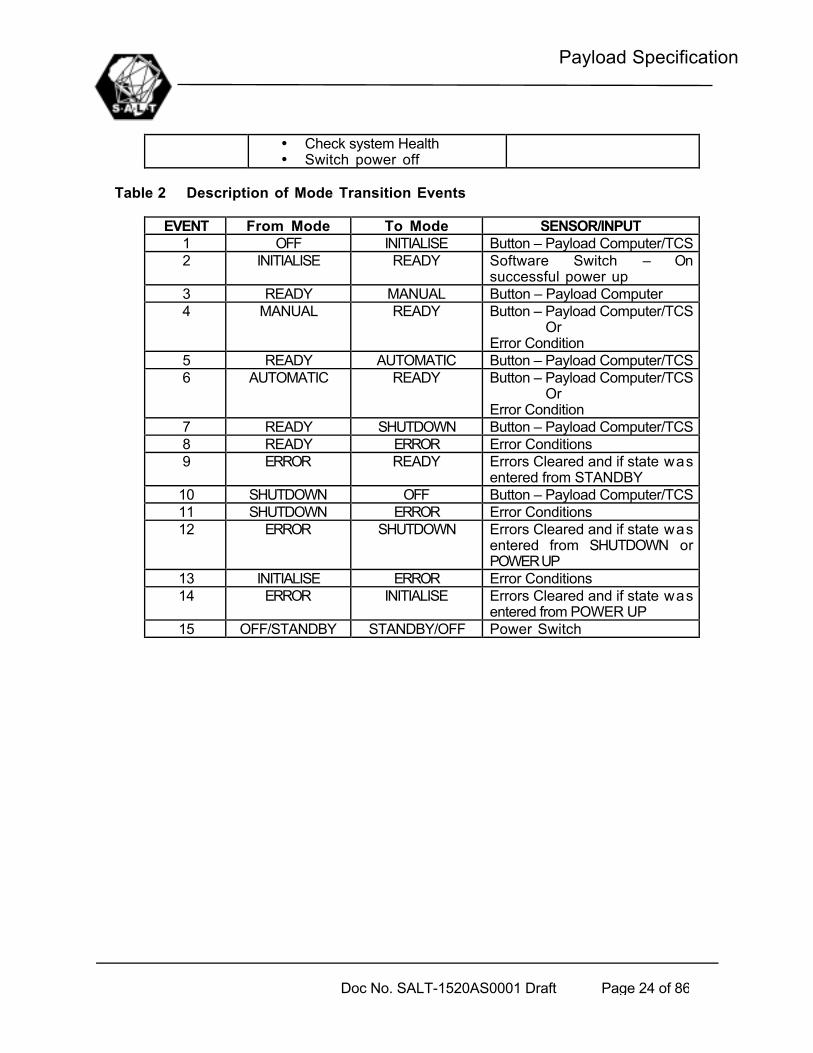
Table 2 Description of Mode Transition Events
EVENT From Mode To Mode SENSOR/INPUT1 OFF INITIALISE Button – Payload Computer/TCS2 INITIALISE READY Software Switch – On
successful power up3 READY MANUAL Button – Payload Computer4 MANUAL READY Button – Payload Computer/TCS
OrError Condition
5 READY AUTOMATIC Button – Payload Computer/TCS6 AUTOMATIC READY Button – Payload Computer/TCS
OrError Condition
7 READY SHUTDOWN Button – Payload Computer/TCS8 READY ERROR Error Conditions9 ERROR READY Errors Cleared and if state was
entered from STANDBY10 SHUTDOWN OFF Button – Payload Computer/TCS11 SHUTDOWN ERROR Error Conditions12 ERROR SHUTDOWN Errors Cleared and if state was
entered from SHUTDOWN orPOWER UP
13 INITIALISE ERROR Error Conditions14 ERROR INITIALISE Errors Cleared and if state was
entered from POWER UP15 OFF/STANDBY STANDBY/OFF Power Switch

Payload Specification
Doc No. SALT-1520AS0001 Draft Page 25 of 86
4.3.2 Functional Flow Diagram(see also overall system diagram in Appendix E)
Figure 11. Payload Functional Flow Diagram
InstrumentComputersTCS
4. AXES CONTROL(ADC, Moving Baffle, Fold Mirrors,Calibration Source)
PAYLOAD COMPUTER
6. THERMAL CONTROL
5. Acquisition
1. COMMS
1.1 Ethernet
1.1.1 TCS Comms
1.1.2 Acquisition System Comms
Time Sync Input
1.3 Other
1.1.3 Axes Controllers Comms
1.2 RS485
1.2.2Thermal Control Comms
1.2.3Power Switches Comms
4.1 Axes Controllers 4.3 Sensors
4.2 Servo Amps 4.4 Motors Load
6.1Analog Output
6.2 Analog Input
6.4 Valves
6.3 Temp Sensors
7. POWER SWITCHES
7.1 Digital Output 7.2 Relays
2.PAYLOAD ALGORITHMS
3. PAYLOAD MMI
2.1Power Up
2.2Shutdown
2.3Time Synchronization
2.4Payload Mount Model
2.5 Guidance
2.6Axes Command Generator
2.8Thermal Loop
2.9Mode & State Control
2.10Diagnostics & Safety
2.11Software Setup & maint
PayloadPosition andAttitude
Precision Time Sync
Payload Temp SetpointDetermination
Payload Computer Comms
TRACKER COMPUTER
Payload Computer Comms(Payload Actual Position)
8. Guidance
10. Structural & Interface Support
PAYLOAD
1.1.2 Guidance System Comms
2.7 Acquisition
9. Spherical Aberration Corrector(SAC)
Fibre Feed
Instruments
PFIS & VisitInstr

Payload Specification
Doc No. SALT-1520AS0001 Draft Page 26 of 86
4.3.3 Function descriptions
4.3.3.1 TCS COMMUNICATION
The TCS shall send the following commands to the payload computer:• Request Payload Computer MMI and Data (full control at TCS level – Operating
System Function)• Mode & State Commands• Tracker trajectory commands and actual positions (t,x,y) every 1 to 30
seconds with 100ms time-steps (TBC2). These commands are in the IDEALTRACKER FRAME(ITF)
• Time synchronisation signals• Payload configuration commands• Target and Guide star selections• Safety Commands (Emergency Stop etc) at 10 Hz (TBC3)
The Payload Computer shall send the following information back to TCS:• MMI Screens (TCS will have access to Payload computer MMI with full
functionality of MMI – Operating System Function)• Current Mode & State at 10Hz• Subsystem positions (t,x,y,z) in PMF at 10Hz• Temperature measurements at 1Hz• Acquisition Image at < 2Hz• Acquisition Offset• Guidance Image at < 10Hz• Guidance Corrections at 0.03 to 10 Hz (TBC4-compensation for structural
vibrations)• Diagnostics and Safety Status (TBD3)• ADC, Moving Baffle, Guide probe and fold mirror positions @ 1Hz
4.3.3.2 TRACKER COMPUTER COMMUNICATION
The Tracker Computer (TBD4) shall send the payload position to the payload computer via theTCS as indicated in Figure 11, see section 4.3.3.1
The Payload Computer shall send the following information to the Tracker Computer via theTCS:
• Guidance Errors (t,dx,dy), see section 4.3.3.1 .
4.3.3.3 AXES CONTROLLERS COMMUNICATION (ADC, MOVING BAFFLE, FOLD MIRRORS, CALIBRATIONSOURCE)
The Payload Computer shall send the following information to the Axes Controllers:• Axes Commands at frequency of 10Hz TBC5 .

Payload Specification
Doc No. SALT-1520AS0001 Draft Page 27 of 86
• Mode Commands (Slew / track /emergency stop) at 10 Hz• Predefined Positions and Commands whenever required
The Axes Controllers shall send the following information to the Payload Computer:• Sensor Measurements at 10Hz• Current Modes at 10Hz• Measured Motor Currents at 10Hz
4.3.3.4 ACQUISITION COMMUNICATION
The Payload Computer shall send the following information to the Acquisition system_ Commands for set up / calibration (Fixed set of commands as
available)
The Acquisition system shall send the following information to the Payload Computer:_ Acquisition Image at 0.2 to 2Hz (TBC6)_ Acquisition system state
4.3.3.5 THERMAL CONTROL COMMUNICATION
The thermal control system will be a passive one. All heat generating equipment shall beinsulated and the heat removed by chilled glycol. However temperature measurements will befed back to the TCS, therefore :
The Thermal Control Analogue Output shall send the following information to the PayloadComputer:
• Temperature Measurements (xm) at 0.1Hz (TBD2)
4.3.3.6 POWER SWITCHES COMMUNICATION
The Payload subsystems shall be powered up in an orderly and selectable fashion. Thedetails shall be agreed upon in the design phase.
Typically the Payload Computer shall send the following information to the Power SwitchesDigital Output
_ On/Off Commands for Switches [Axes Controllers, Acquisition System,Guidance System, Fibre Instrument Feed, PFIS, Thermal Control] (TBC7)
4.3.3.7 TIME SYNCHRONIZATION INPUT
The TCS and Payload Computer shall be time synchronized to an accuracy of 1ms (TBC8)or better.
4.3.3.8 PAYLOAD ALGORITHMS
The execution of all Payload Computer functions should be sufficiently fast so as to ensurea cycle time of 100ms or less.

Payload Specification
Doc No. SALT-1520AS0001 Draft Page 28 of 86
4.3.3.8.1 Power Up
The Payload System shall be powered up and sensors homed in a controlled fashion
4.3.3.8.2 Shut Down
The Payload System shall be parked and shut down in a controlled fashion
4.3.3.8.3 Time Synchronization
The Payload Computer local time shall be synchronised with the TCS computer as specifiedin 4.3.3.7.
4.3.3.8.4 Payload Mount Model
This model typically defines:• a conversion from TCS commands to a Payload equivalent set both in
PMF.• Conversions to Payload subsystem Frames• Calibration factors and coefficients
4.3.3.8.5 Guidance Corrections
A set of guidance errors (t,dx,dy), in PMF, is calculated from the guidance image
4.3.3.8.6 Acquisition
A set of Acquisition offset errors(t,x,y), in PMF, is calculated from the Acquisition image.
4.3.3.8.7 Axes Command Generator
Using the Payload position, as reported by TCS, to calculate all subsystem positioncommands. The feedback from the axes controllers is used to calculate the measuredposition in PMF.
4.3.3.8.8 Thermal loop
Extract and display temperature measurements (TBD2)
4.3.3.8.9 Mode and State Control
Control the modes and states of the Payload system.
4.3.3.8.10 Diagnostics & Safety
Performs all diagnostics and safety functions. (TBD3)
4.3.3.8.11 Software Set up & Maintenance

Payload Specification
Doc No. SALT-1520AS0001 Draft Page 29 of 86
Performs all set up and maintenance functions:• Log real time data to disk for analysis• Save/retrieve/edit Calibration Data• Save/retrieve/edit software set up• Must be available via TCS (remote operation)
4.3.3.9 PAYLOAD MAN-MACHINE-INTERFACE (MMI)
Implements the MMI (TBD5).The standards as per reference documents shall apply, details shall be approved in designphase.
4.3.3.10 AXES CONTROL
Implements the mode commands and tracks the position commands. Axes control shallsatisfy the requirements in paragraph 5.3.1.
4.3.3.11 ACQUISITION
The observation target shall be identified and pointing offsets be calculated with sufficientaccuracy and speed to satisfy the requirements in paragraph 5.3.1.
4.3.3.12 THERMAL CONTROL
This function reads and displays the temperature sensor measurements.
4.3.3.13 POWER SWITCHES
The purpose of this function is to power up all subsystems in an orderly and selectablefashion. This function implements the commands from the Payload computer. This functionshall satisfy the performance requirement in paragraph 5.3.1.
4.3.3.14 GUIDANCE
The guide probes shall be positioned with sufficient accuracy to ensure that the selectedguide star will be within its field of view at the end of target acquisition. Guidance imagesshall be collected and sent to the Payload Computer for image processing. The guidanceimages shall be collected with sufficient accuracy and speed to satisfy the requirements inparagraph 5.3.1.
4.3.3.15 STRUCTURAL AND INTERFACE SUPPORT
The Payload subsystem shall provide sufficient structural and interface support toaccommodate all the relevant payload subsystems. This structure will be supported by therotation stage of the Tracker. This support (payload structure) shall satisfy theperformance requirements in paragraph 5.3.1.
4.3.4 Operational Concept

Payload Specification
Doc No. SALT-1520AS0001 Draft Page 30 of 86
Is detailed in ‘SALT 1000AS0040’, see section 2, but closed and open loop tracking, and positioning,will typically be executed as follows:
Table 3 Closed loop trackingNo Action Start Time Frequency Remarks1. Star position input by SA, SO
single position or scheduledpositions – on TCS terminal
Acquisition time– 3 minutesminimum
Once per target Star position:RA,DEC,EpochTime, ephemeris
2. Exposure start time andObservation Duration for eachtarget – input by SA on TCSterminal or predetermined inschedule file
Acquisition time– 3 minutesminimum
Once per target Time availablebetweenAcquisition andTrack must bevariable by RA
3. TCS sends Acquisition,tracking start times, payloadposition and configuration toPayload computer
Acquisition time– 2.5 minutesminimum
Once per target
4. Payload subsystemspositioned and configuredaccording to 3
Immediately after3.
5. Payload computer reports toTCS when subsystems inposition and configured
Acquisition Time– 30 seconds
Once per target
6. TCS send tracker trajectory(t,x,y) to Payload Computer
Immediately after5.
Once every 30sec
Open loopcommands
7. Payload position subsystemsaccording to 6, sendingAcquisition image to TCS
According totime stamp ofcommands
Continuously (atsamplingfrequency of axes controllers)
Controllersshouldinterpolatecommandsbetweentrajectory points
8. Target and Guide Starsselected by SA – on TCSterminal, TCS feed thisinformation to Payloadcomputer
Any timebetweenAcquisition andtrack start time
Once per target
9 Payload Computer sendsAcquisition offsets andguidance correction signals toTCS computer (t,x,y)
When locked onguide star/s
1Hz
Table 4 Open Loop Tracking.
No Action Start Time Frequency Remarks1. Star position input by SA,SO
single position or scheduledpositions – on TCS terminal
Acquisition time– 3 minutesminimum
Once per target Star position:RA,DEC,EpochTime

Payload Specification
Doc No. SALT-1520AS0001 Draft Page 31 of 86
2. Sidereal Rate selected bySA,SO
Acquisition time– 3 minutesminimum
Any time RA can adjusttracking rate(non sidereal)
3. Acquisition and Tracking starttimes and ObservationDuration for each target –input by SA on TCS terminal
Acquisition time– 3 minutesminimum
Once per target Time availablebetweenAcquisition andTrack must bevariable by RA
4. TCS send Acquisition, trackingstart times, payload positionand configuration to Payloadcomputer
Acquisition time– 2.5 minutesminimum
Once per target
5. Payload subsystemspositioned and configuredaccording to 4
Immediately after1.
6. Payload computer reports toTCS when in position andconfigured
Acquisition Time– 30 seconds
Once per target
7. TCS sends tracker trajectory(t,x,y) to Payload Computer
Immediately after5.
Once every 30sec
Open loopcommands
8. Payload position subsystemsaccording to 6, sendingAcquisition images to TCS
According totime stamp ofcommands
Continuously (atsamplingfrequency of axes controllers)
Controllersshouldinterpolatecommandsbetweentrajectory points
9 Target or offset Star selectedby SA – on TCS terminal, TCSfeed this information toPayload computer
Any timebetweenAcquisition andtrack start time
Once per target
10 Payload Computer sendsAcquisition offsets to TCScomputer (t,x,y)
Any timebetweenAcquisition andtrack start time
Until AcquisitionCompleted
11 Payload Computer positions allrelevant subsystemsaccording to Tracker positionas received from TCS
After Track StartTime
Until Trackcompleted
Table 5 Positioning.
No Action Start Time Frequency Remarks1. Tracker Position and or
Payload configuration inputby SA,SO – on TCS orPayload Computer terminal
Any time Continuously Position in ITF

Payload Specification
Doc No. SALT-1520AS0001 Draft Page 32 of 86
Payload Computer terminal2. Payload Computer positions
and configures subsystemsaccording to 3
Immediately after1.
3. Payload computer reports toTCS when subsystems inposition and configured
When positionreached andconfigured
Once percommand

Payload Specification
Doc No. SALT-1520AS0001 Draft Page 33 of 86
5 Payload Technical Requirements
5.1 Schematic diagram
The figure below shows the major components of the payload subsystem and the communicationinterfaces. The numbers inside each block identifies the functions, in Figure 11, implemented by eachhardware item
Figure 12. Major Components of Payload Subsystem and Communication interfaces
All the internal interfaces between the Payload subsystem components and external interfacesbetween Payload subsystem and other subsystems of SALT are shown and numbered in the figurebelow.
5.2 SALT Payload Interfaces
5.2.1 SALT Payload External Interfaces
Telescope ControlSystem
Payload ComputerSystem (1,2,3)
AcquisitionSystem(5){CommisioningInstrument)
GuidanceSystem(8)
Key : Not Part ofPAYLOAD
ThermalControl (6)
SAC(9)
Payload Structure (10)
TrackerComputer
Cable & TubeHandlers, Enclosures(10)
Tracker Rotation Stage
ADC(4)
MovingBaffle(4)
CalibrationSource(4)
VisitingInstruments
PFIS
InstrumentComputer/s
Fold Mirrors(4)
FiberFeed
Instrument(HRS)

Payload Specification
Doc No. SALT-1520AS0001 Draft Page 34 of 86
Figure 13 shows the major External interfaces for SALT.
Facility
Structure
Tracker & Payload
CommissioningInstrument
ScienceInstruments
TCS
Primary Mirror
Dome
Cooling (C)Physical (P)Data (D)Optical (O)Air (A)Electrical (E)Ventilation (V)
Key to interfaces:
1 2
10
9
4
5
7
6
8
3
11
14
12
13
15
16
17
18
External Services
19
Figure 13. Schematic showing SALT Payload External Interfaces
The system interfaces shall comply with the Physical, Electrical and External Interface ControlDossiers referred to in Section 2
Table 6 Tracker & Payload external interfaces (Refer to Figure 13)
No. Subsystem1
Subsystem 2 Type Direction Interface Description
8 TCS Payload D Both Communication cables, TrajectoryCommands, Mode Commands,Measurement Feedback,Diagnostics and Safety Feedback,Payload MMI, see Table 7(e4)below
2 Structure Payload P Attachment of all cables, coolinglines, fibre optic cables runningbetween Tracker & Payload andother sub systems
Payload Specification
Doc No. SALT-1520AS0001 Draft Page 35 of 86
lines, fibre optic cables runningbetween Tracker & Payload andother sub systems
P ->Payload
Provide Access to Payload
E Electrical power to various partsof payload, as per Power Budget.Both 220V and 110V AC
A Dry, Instrument Quality Air toPayload subsystems
3 Facility Payload
C Liquid cooling capacity :
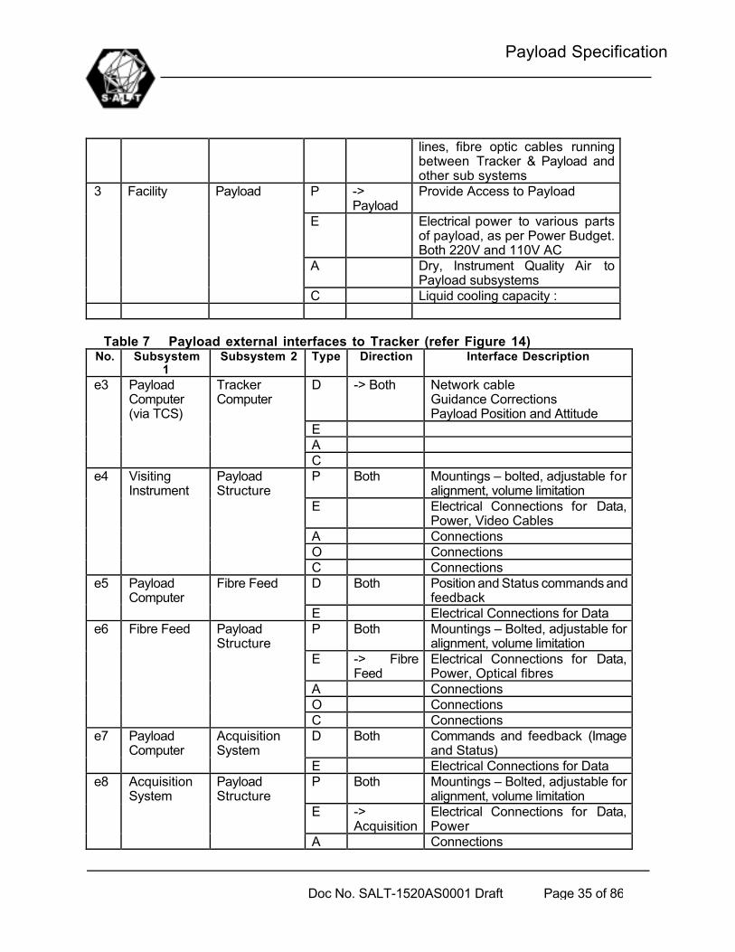
Table 7 Payload external interfaces to Tracker (refer Figure 14)No. Subsystem
1Subsystem 2 Type Direction Interface Description
D -> Both Network cableGuidance CorrectionsPayload Position and Attitude
EA
e3 PayloadComputer(via TCS)
Tracker Computer
CP Both Mountings – bolted, adjustable for
alignment, volume limitationE Electrical Connections for Data,
Power, Video CablesA ConnectionsO Connections
e4 VisitingInstrument
PayloadStructure
C ConnectionsD Both Position and Status commands and
feedbacke5 Payload
ComputerFibre Feed
E Electrical Connections for DataP Both Mountings – Bolted, adjustable for
alignment, volume limitationE -> Fibre
FeedElectrical Connections for Data,Power, Optical fibres
A ConnectionsO Connections
e6 Fibre Feed PayloadStructure
C ConnectionsD Both Commands and feedback (Image
and Status)e7 Payload
ComputerAcquisitionSystem
E Electrical Connections for DataP Both Mountings – Bolted, adjustable for
alignment, volume limitationE ->
AcquisitionElectrical Connections for Data,Power
e8 AcquisitionSystem
PayloadStructure
A Connections

Payload Specification
Doc No. SALT-1520AS0001 Draft Page 36 of 86
O ConnectionsC ConnectionsP Both Mountings – Bolted, adjustable for
alignment, volume limitationE -> PFIS Electrical Connections for Data,
PowerA -> PFIS ConnectionsO -> PFIS Connections
e9 PFIS Rotation Stage
C -> PFIS ConnectionsP Both Mountings – Bolted, adjustable for
alignment, diameter limitationE -> Payload
StructureElectrical Connections for Data,Power, Video
A ConnectionsO Connections
e10 RotationStage
PayloadStructure
C ConnectionsP Both Mountings – Bolted, adjustable for
alignment, diameter limitationE ->
AlignmentSystem
Electrical Connections for Data,Power
A ConnectionsO Connections
e11 PayloadAlignmentSystem
SAC
C Connections

Payload Specification
Doc No. SALT-1520AS0001 Draft Page 37 of 86
5.2.2 SALT Payload Internal Interfaces
Telescope ControlSystem (TCS)
Pa
ylo
ad
Co
mp
ute
rNot Part of PAYLOAD
AcquisitionSystem (CommInstr)
Moving Baffle
Guidance System
Rho-Drive System
T
ub
e &
Cab
le H
and
lers
& E
ncl
osu
res
14
F
AC
ILIT
Y
Pay
load
ST
RU
CT
UR
E
INTERFACES e** : external ** : internal
Thermal Control
ADC
All payloadsubsystems
e10Tra
cker
CO
MP
UT
ER
e1
e2
e3 via TCS
SAC
Fold Mirrors
CalibrationSource
Fibre Feed
PFIS
Visit Instr
e8
e6
e4
e919
13
12
10
8
6
4
2 1
3
5
7
9
11
e5
e7
PayloadAlignment e11
1511

Payload Specification
Doc No. SALT-1520AS0001 Draft Page 38 of 86
Figure 14. Interfaces
For a complete description of all the interfaces, refer to the interface control dossier, listedin section 2
Table 8 Internal InterfacesNo. Subsystem
1Subsystem 2 Type Direction Interface Description
1,3,5,7,9,11
See FigFigure 14
PayloadComputer
D Both Electrical Connections for Data,PowerCommandsFeedback
P Mounting, ConnectorsD Thermal
ControlTemperature Feedback
C Subsystems Coolant Supply, drain
2 ThermalControl
All PayloadSubsystems
E Subsystems PowerP Both Mountings4,6
8,1012,13
PayloadStructure
See Fig Figure14 E,A,D,
O,CSubsystems Connectors
P Handler Bolted to Rotation StageE ConnectorsA ConnectorsD ConnectorsO Connectors
14 Cable & TubeHandlers (forr stage,forms part oftracker)
PayloadStructure
C Connectors
5.3 SALT Payload Characteristics
5.3.1 Performance Characteristics
The payload consist of the following subsystems:• SAC (Spherical Aberration Corrector)• ADC (Atmospheric Dispersion Compensator)• Guidance System• Moving Baffle• Fold Mirrors• Fixed Baffle• Calibration Screen• Thermal control system• Payload structure• Payload computer• Cable & Tube Handling

Payload Specification
Doc No. SALT-1520AS0001 Draft Page 39 of 86
The Payload subsystem performance characteristics that are required to perform the functionsabove are described below:
5.3.1.1 SACFor details of the requirements, refer to Section 2,” SAC Specification”.
a) Image Quality
The contribution of the SAC towards image quality shall be less than 0.2 arc seconds(EE50) and less than 0.336 arc seconds (EE80) in its operational environment. The nominaloptical axis of the SAC will be 37 degrees from vertical (when positioned at the PrimaryMirror Vertex). Due to tracking this angle can vary with +- 8 .5 degrees in two directions.The SAC not rotate with the rest of the payload during tracking.(TBC9)
b) Field of View(FOV)
The FOV shall not be less than 10 arc minutes.
c) Entrance Pupil
The SAC shall have an entrance pupil within the range 10.5 to 11m. The final selection willbe made after cost/performance tradeoffs at the supplier.
d) Delivered F-ratio
The final F-ratio shall be 4.2 +- 0.05.
e) Stray Light
A fixed baffle ( not part of SAC) shall be provided at the optical entrance to the SAC toprevent stray light from entering it. Absorbent baffles shall be provided inside the SAC toprevent vignetted stray light from striking the focal plane. The surface finish shall be suchthat 98% of all impacting light will be absorbed for wavelengths between (TBD5).
f) SAC mirror coatings
As specified in doc.: SALT-1523AS0002, ”SAC Optical Specification”.
5.3.1.2 ADC
a) Image Quality
The ADC shall not degrade the image at 500nm by more than 5%.
b) Wavelength Coverage
The ADC shall correct dispersion for wavelengths from 320 to 850nm, with a design goalof 1800nm. At least 95% of the light in these wavelengths shall be transmitted.

Payload Specification
Doc No. SALT-1520AS0001 Draft Page 40 of 86
c) Secondary Dispersion
As introduced by the ADC shall not exceed 0.15 arc seconds.
d) Insertion
The ADC will be installed in a fixed position on the payload structure.
5.3.1.3 GUIDANCE SYSTEM
a) Guidance Concept
b) Position of Guide Stars
All guide stars will be located in a 1 arc minute annulus, from 4 to 5 arc minutes in radiusfrom the centre of the field. Provision shall be made for guidance using the science field atthe Acquisition system by means of a beam splitter where a (TBD6)% of the light will be
Guidance Probe position
Science Field
Science & Guidance Field
Probe Position commands & feedback
Sc
Sc
PFIS
AuxiliaryPort
FIF
Light path
Acquisition
Sc
Sc
Guidancecamera &Optics
Payload Computer
TCS
Fibre Bundle
Guidance Corrections
Guidance Corrections
Guidance Images

Payload Specification
Doc No. SALT-1520AS0001 Draft Page 41 of 86
used for guidance and the rest for science at any of the science instruments.
c) Number of Guidance Positions
Provision shall be made for guidance pickups at the following positions:- Acquisition System (in 4-5” field and in science field using beam splitter)- Fibre Feed- PFIS
NOTE: The instrument at the auxiliary port shall provide guidance corrections to the TCS.
d) Brightness of Guidance Objects
Shall be brighter than 21st magnitude.
e) Guidance correction and image update rates
The guidance errors and image shall be fed back to the TCS at rates between 10 Hz to 1/30Hz (TBC4).
f) Guidance Field of view
The pointing accuracy of the telescope will be 15 arc seconds. It shall be ensured that oncethe telescope is pointed towards a target, the guide star will be on the guidance pickup.
g) Guidance Error
The guidance system shall introduce a guidance error of less than 0.05 arc seconds for allguidance positions and object brightness.

Payload Specification
Doc No. SALT-1520AS0001 Draft Page 42 of 86
5.3.1.4 MOVING BAFFLE
The moving Baffle shall ensure that no light from outside the Primary Mirror enters the focal plane.
a) Degrees of Freedom
The Moving Baffle shall have 4 degrees of freedom (TBC10), x, y, z and rotation.
b) Range of Motion
The Moving Baffle shall have a sufficient range in each degree of freedom to compensatefor the payload motions and the curvature of the exit pupil, which are:
- 17 degrees rotation in tip and tilt- 230 degrees in rotation (TBC9)- 210mm radius of curvature in exit pupil
c) Accuracy of Motion
The Moving Baffle Aperture shall be aligned within 0.5 arc minutes from the edge of thePrimary Mirror.
d) Speed of Motion
The Moving Baffle Aperture shall maintain accuracy at tracking speeds, 0 to 20 arcseconds per second and at flat fielding speeds, 5 degrees per second.
e) Aperture Stop
An aperture stop shall be mounted on the fixed part of the moving baffle to ensure no lightoutside the entrance pupil propagate to the focal plane.
5.3.1.5 FIXED BAFFLE
a) Stray light
The surface finish shall be such that 98% of all impacting light will be absorbed forwavelengths between (TBD6). The drivers for the design has still to be determined(TBD7)
b) Structure
The structure shall not interfere in any way with the SAC structure. The deflections underwind loading and or varying gravity components shall not cause it to touch the SACstructure at any point.
5.3.1.6 FOLD MIRRORS

Payload Specification
Doc No. SALT-1520AS0001 Draft Page 43 of 86
The Fold Mirrors shall ensure that light is channelled to the selected instrument/s.
a) Reflectivity
The same as SACmirrors
b) Degrees of Freedom
Each Fold Mirrors shall have 1 linear degree of freedom for insertion.
c) Range of Motion
The Fold mirrors shall have sufficient range in each degree of freedom for insertion
- Insertion Range (TBD8) and depend on design
d) Accuracy of Motion
The Fold Mirrors shall be positioned with such accuracy that the image position in the focalplane is repeatable to within 0.05 arc seconds.
e) Speed of Motion
The insertion time of any mirror should be less than 5 seconds.
f) Number of Mirrors
Light shall be directed to the following instruments, which will be at different locations:
- Acquisition System (x2 … make provision for beam splitter)- PFIS- Fibre Feed- Auxiliary Port
g) Optical Quality
The mirrors shall be flat to 1/20l rms
5.3.1.7 CALIBRATION SOURCE AND SCREEN
The Calibration Source shall illuminate the selected instrument with equal intensity anywhere in thetelescope pupil. Note that the Calibration Source is CFE equipment as described under section 3.
a) Intensity variations in the FOV
TBD9.

Payload Specification
Doc No. SALT-1520AS0001 Draft Page 44 of 86
b) Light Sources
• Flat Field lamp (Halogen)• Blue diode Lamp• Arc lamps: Cu-Ar, Cu-Ne,He,Fe-Ar,Th-Ar,Th-Ne
c) Degrees of freedom
Shall have a linear degree of freedom for sliding in and out of the light path.
d) Other functions
TBD9.
5.3.1.8 THERMAL CONTROL
(a) Measurement accuracy shall be better than 0.5 deg C.(b) All surface temperatures that can rise more than 2 degrees C above ambient shall
be passively controlled (by insulation and glycol cooling). Glycol source /drainpoints will be supplied at the Tracker rotation stage.
5.3.1.9 PAYLOAD STRUCTURE
The Payload structure shall support all the Payload subsystems and relevant Client FurnishedEquipment (PFIS, Fibre Feed, Commissioning Instrument), under the operating conditions,operational envelope, ensuring that structural deflections due to external forces and massdistribution of the various subsystems as well as temperature effects shall not affect the imagequality by more than:
- 0.1 arc seconds (EE50)- 0.2 arc seconds (EE80)
5.3.1.10 PAYLOAD COMPUTER
The Payload Computer shall execute all software reliably within a cycle time sufficiently short notto compromise the performance of the various payload subsystems and other telescopesubsystems.
5.3.1.11 CONTROL LOOP REQUIREMENTS
All Control loops shall satisfy the following stability and bandwidth requirements under allloading conditions:
• Phase margin: > 50 degrees• Gain Margin: > 8dB• Maximum Overshoot: < 2%
5.3.1.12 SAFETY

Payload Specification
Doc No. SALT-1520AS0001 Draft Page 45 of 86
The following should be read in conjunction with the SALT Safety Analysis, SALT-1000AA0030, listed in section 2.
a) All single point failures that can lead to loss of life, serious injury to personnel ordamage to equipment shall be identified and the design modified to prevent suchfailures.
b) In no case shall it be possible for a component or control system failure to cause anysubsystem or piece to detach and drop from the Payload Assembly.
c) Motor overload protection, fusing and sensing shall be implemented and monitored bythe control system to ensure that failure mode criteria are met.
d) Where tools must be used on-telescope for servicing and maintenance, they shall besecured by lanyards to the servicer’s tool belt or man lift.
e) All fasteners, cover panels and other components which can be accessed while thepayload is on telescope shall be captivated by the use of _ turn captured fasteners,wire loop, bails, threads or some other like means to prevent accidental injury topersonnel below as well as damage to primary mirror.
f) No lock washers shall be used for on-telescope accessible fasteners, chemicallocking compounds or aircraft-type locking nuts shall be used instead.
g) A safety analysis and design shall be presented and implemented to satisfy all safetyrequirements.
5.3.1.13 STRUCTURAL FREQUENCIES
The stiffness of the payload structure is dictated by its effect on the image quality see 5.3.1.9.The stiffness design shall ensure that these requirements are met under all operatingconditions.
5.3.1.14 STATIC STRUCTURAL DEFLECTIONS
The following maximum deflections of the Payload structure under its own weight, asteady state wind force of **** and for all possible orientations, shall be allowed. Theaction point of the wind force is *********** (TBC121).
Table 9 Structural deflections: staticDegree of Freedom(ITF)
Units MaximumDisplacement
Rotation about X arcsec 100Rotation about Y arcsec 100Rotation about Z arcsec 100
5.3.1.15 DYNAMIC STRUCTURAL DEFLECTIONS
The following maximum deflections of the Payload and SAC structures under dynamic forcessuch as wind and control system induced, shall be allowed. The frequency of disturbance

Payload Specification
Doc No. SALT-1520AS0001 Draft Page 46 of 86
forces is 2.5 Hz or less. The specs in table 10 are only guidelines, image quality specificationsshould be met irrespective. It is important to note that these requirements apply to eachinstrument position.
Table 10 Structural deflections: dynamicDegree of Freedom(ITF)
Units MaximumDisplacement
Rotation about X arcsec 1Rotation about Y arcsec 1Rotation about Z arcsec 3
5.3.1.16 MOUNTING POINTS ON PAYLOAD STRUCTURE : (TBC13)
The mounting points on the Payload Structure for the various instruments/subsystems shall besuch that adjustments of no more than +- 0.1 degree in tip and tilt and 5mm in decentre, will beneeded to align with the optical axis.
5.3.1.17 TRAVEL LIMITS
The control system hardware and software shall provide for three levels of travel limits forall axes of motion:
(a) Software limitsUpon reaching the software limits, all motions shall be stopped smoothly within 1second, feeding back to TCS the affected subsystem and axis, the programmedlimit and current position. The initiation of a software limit shutdown shall occur intime to stop the affected axes prior to activating a hardware limit.
(b) Hardware limits using limit switchesEach motion axis shall be equipped with a normally closed limit switch at eitherend of its travel range, outside the software limit range defined above. Uponreceiving limit switch data all motions shall be stopped smoothly within 1 second,feeding back to TCS the affected subsystem and axis, the tripped limit switch andcurrent position.
(c) Mechanical hard stops with motor overload protectionCushioned hard stops shall be provided at each end of each motion axis. Eachdrive motor / actuator shall be equipped with software and limit switchindependent overload sensing and shutdown protection, which shall also informthe TCS of its activation and motor current. The Payload computer shall initiateshutdown procedure, as discussed above, when overload protection activationis sensed. Additional servo commanded motion, in either direction shall not bepossible once a hard stop is struck. Provision shall be made to manually reversethe motion axis to within normal limits after the drive problem has been found andfixed. Provision shall be made in the software to reinitialise the system after ahard stop event has occurred.

Payload Specification
Doc No. SALT-1520AS0001 Draft Page 47 of 86
5.3.1.18 PAYLOAD MMI
Control over all Payload subsystem functions and access to all sensor measurements shallbe available through the MMI. The MMI shall be accessible through the TCS as well. Therequirements of relevant document in Section 2 must be satisfied. Details to be approved indesign phase.
5.3.2 Physical Characteristics
5.3.2.1 OBSCURATION
Payload Shadow on Primary mirror:• On – Axis: within a central circle of 3.0m diameter or inside the central
obstruction of the SAC whichever is the least.
5.3.2.2 MASS
The payload mass, inclusive of all subsystems, shall be less than 750kgThe mass budget for the Payload is as follows:
Table 11 Payload Mass BudgetSubsystem Mass[kg] % of
TotalPayload Structure 65 8.67SAC 150 20.00Guidance System 20 2.67Acquisition System 25 3.33Prime focus instrument 375 50.00Moving Baffle 20 2.67Fold Mirrors 15 2.00Fibre Feed System 30 4.00ADC System 35 4.67Thermal Control Syst 15 2.00Total 750 100
5.3.2.3 TOTAL POWER REQUIREMENTS
The payload power consumption is allocated per subsystem in Table 12 below.This table also indicate from which source the power will be supplied. If there is disagreementbetween these figures and those in the power budget (SALT-1000AA0034,”SALT ElectricalPower and Cooling Budget”), the latter shall take precedence.
Table 12 Payload Power BudgetSubsystem Total
Power[kW]
UPS [kW] Notes
Payload Computer 0.75 0.75

Payload Specification
Doc No. SALT-1520AS0001 Draft Page 48 of 86
Guidance System 0.4 0CommissioningInstrument
1.42 0
ADC 0.1 0Moving Baffle 0.2 0Fold Mirrors 0.2 0Fibre Feed System 0.3 0PFIS 1.82 0.5 Only Computer
on UPSCalibration Source 0.3 0Thermal Control System 0.1 0Additional Instrument 2.0 0TOTAL 7.59 1.25
5.3.2.4 TOTAL COOLING REQUIREMENTS
The payload required cooling capacity is allocated per subsystem in Table 13 below. Thiscooling shall be provided by the glycol system and is relevant only to subsystems generatingheat in the light path. . If there is disagreement between these figures and those in the powerbudget (SALT-1000AA0034,”SALT Electrical Power and Cooling Budget”), the latter shall takeprecedence.

Payload Specification
Doc No. SALT-1520AS0001 Draft Page 49 of 86
Table 13 Payload Cooling BudgetSubsystem Total Cooling
Requirements[kW]
Notes
Payload Computer 0.0Guidance System 0.3CommissioningInstrument
1.30 Cryotiger heat isremoved as well
ADC 0.15Moving Baffle 0.05Fold Mirrors 0.05Fibre Feed System 0.15PFIS 1.30 Cryotiger heat is
removed as wellCalibration Source 0.15Thermal Control System 0.02Additional Instrument 2.00TOTAL 5.47
5.3.2.5 TOTAL DRY PRESSURISED AIR REQUIREMENTS
This air is needed for:• Maintaining a slight positive pressure inside the payload to keep dust out.
Overpressure value TBD10• Flushing air for science instruments• Actuation of pneumatic systems• Over pressurization of bellows around bearings
The quality of the air shall be instrument grade (TBD11)
Table 14 Payload Pressurised Air BudgetSubsystem Pressure
[Bar]Flow rate[litres/minute]
Notes
Flushing Air 6 8.0 Keeping payload underpositive pressure – dust
eliminationPFIS 6 6.0 Motion & InstrumentationFold Mirrors 6 3.0 MotionCalibration Source 6 3.0 MotionTOTAL 20
5.3.2.6 MAXIMUM SURFACE TEMPERATURES
Any gradient in the air temperature within the optical path will have a negative influence on

Payload Specification
Doc No. SALT-1520AS0001 Draft Page 50 of 86
the image quality produced by SALT. In order to minimise this effect, the followingconstraints are imposed. Relaxation of these constraints may be allowed on a case-by-case basis, subject to meeting the overall seeing objectives. These constraints shall bemet for the 99th percentile of operation ambient conditions (see 5.3.3.1).
Section 5.5 provides further guidance in this regard.
5.3.2.6.1 Objects in the optical path
All items of equipment that are within 1m of the telescope optical path or within a verticalcylinder defined as a vertical extension of the pier to the highest point of the top hex,shall comply with the following:
a. No item exposed to the ambient air, regardless of its size, shall have a surfacetemperature of more than 8ºC above ambient.
b. No item having forced-air cooling shall blow the exhausted air into the ambient air.c. Items with a surface temperature of more than 2ºC above ambient shall have a
Thermal Factor (TF) of less than 0.6 m2C, where TF is defined as follows:
TF = A__T
Where A = Exposed surface area of the item in m2
_T = Temperature difference between the items exposed surface and the ambient airtemperature in ºC
NOTE: In practice, these constraints mean that many items may require cooling jacketsor cooled enclosures. As an example, an item measuring 0.4x0.4x0.4m emitting morethan about 4W of heat continuously, will need to be insulated and cooled otherwise itssurface temperature will go above the allowed limit.
5.3.2.6.2 Objects outside the optical path
All items of equipment that are within 1 m of the telescope optical path, but not includedin 5.3.2.6.1 shall comply with the following:
a. No item exposed to the ambient air, regardless of its size, shall have a surfacetemperature of more than 8ºC above ambient.
b. No item having forced-air cooling shall blow the exhausted air into the ambient air.c. Items with a surface temperature of more than 3ºC above ambient shall have a
Thermal Factor (TF) of less than 2 m2C (with TF defined in 5.3.2.6.1).
NOTE: In practice, these constraints mean that many items may require cooling jacketsor cooled enclosures. As an example, an item measuring 0.4x0.4x0.4m emitting morethan about 6.5W of heat continuously, will need to be insulated and cooled otherwise it’ssurface temperature will go above the allowed limit.
5.3.2.7 MINIMUM SURFACE TEMPERATURES
Any gradient in the air temperature within the optical path will have a negative influence on

Payload Specification
Doc No. SALT-1520AS0001 Draft Page 51 of 86
the image quality produced by SALT. In order to minimise this effect, the followingconstraints are imposed. Relaxation of these constraints may be allowed on a case-by-case basis, subject to meeting the overall seeing objectives. These constraints shall be metfor the 98th percentile of operation ambient conditions (see 5.3.3.1).
Section 5.5 provides further guidance in this regard.
5.3.2.7.1 Objects in the optical path
All items of equipment that are within 1 meter of the telescope optical path or directlyabove the primary mirror, shall comply with the following:
a. No item exposed to the ambient air, regardless of its size, shall have a surfacetemperature cooler than 2ºC below ambient to prevent condensation on surfaces.
b. No item shall blow exhausted cool air into the ambient air.
5.3.2.7.2 Objects outside the optical path
All items of equipment that are within the telescope “chamber” but not included in5.3.2.7.1 shall comply with the following:
a. No item exposed to the ambient air, regardless of its size, shall have a surfacetemperature cooler than 3ºC below ambient.
b. No item shall blow exhausted cool air into the ambient air
5.3.2.8 COMPONENT/MODULE REPLACEMENT
All major components that might need removal, must provide for interfaces suitable forusing the dome crane as lifting device (capacity 1ton).Any special lifting or handling fixtures for modules by their nature or orientation requiresuch fixtures for safe lifting and positioning. The SAC shall be fitted on telescope byusing the dome crane - from top only????
5.3.2.9 PAYLOAD AND SUBSYSTEM CLEARANCE AND ENVELOPE
The payload envelope as illustrated on the supplied drawings (see section 6.2) can beused as guideline. This will be finalised in the design phase.Sufficient clearances should exist between potentially interfering subsystems after hardstop limits of actuators have been reached.
5.3.3 Environmental Requirements
5.3.3.1 NORMAL OPERATIONAL ENVIRONMENT
SALT shall meet all the requirements specified in this document when operated in the night-time outside ambient condition defined in Table 15 below:
Table 15 Normal Operational Environment

Payload Specification
Doc No. SALT-1520AS0001 Draft Page 52 of 86
Parameter Value NotesMinimum Temperature 0ºCMaximum Temperature 20ºCMaximum nightly temperature range 8ºCMaximum rate environment cooling -1.5ºC/hMaximum rate of environment warming +0.5ºC/h Estimated valueMinimum Humidity 5%Maximum Humidity 97% Non-condensingMaximum wind velocity (outside) 16.8 m/s Gusts up to 22 m/sMaximum wind velocity (inside) 4m/sSite altitude 1798mSolar radiation 0 W/m2 Twilight to dawn
5.3.3.2 MARGINAL OPERATIONAL ENVIRONMENT
The degradation of system performance as a result of the ambient environment specified inTable 16 below, shall not exceed 10% (Error! Reference source not found.) of the nominalvalues in paragraph 5.3.1
Table 16 Marginal Operational EnvironmentParameter Value NotesMinimum Temperature -10ºCMaximum Temperature 25ºCMaximum rate environment cooling -2.0ºC/hMaximum rate of environment warming +1ºC/h Estimated valueMinimum Humidity 5%Maximum Humidity 97% Non-condensingMaximum wind velocity (outside) 21 m/s Gusts up to 25 m/sMaximum wind velocity (inside) 5.5m/sSolar radiation 0 W/m2 Twilight to dawn
5.3.3.3 SURVIVAL ENVIRONMENT
SALT shall survive when exposed to the day or night ambient environment specified inTable 17 below. Note that the dome and louvers will be closed under these conditions andtherefore the tracker does not have to be designed for this wind loading, but all trackersubsystems must be able to survive the temperature profile.
Table 17 SALT Survival Operating Environment

Payload Specification
Doc No. SALT-1520AS0001 Draft Page 53 of 86
Parameter Value NotesMinimum Temperature -20ºC**Maximum Temperature 45ºC**Maximum Humidity 100% Occasional exposure to condensing
conditionsMaximum wind velocity 61 m/s**Rain Note 1Snow Note 1Hail Note 1Icing Present Low temperatures after
condensation or rain are common.Solar Radiation Note 1Other Note 1NOTES:
1. Environmental conditions not specified shall be obtained from the appropriatebuilding/civil standards suitable for Sutherland.
2. **: Use the worst case of these figures and those specified in the appropriatebuilding/civil standards.
5.4 Operation and Maintenance Requirements
5.4.1 Packaging, handling, storage
Packaging, handling and storage requirements will be determined for each individual type ofcomponent, taking into account the specific requirements of the component, the method ofshipping and interim storage locations. Storage at SALT will be in the SALT Store Room, indry, air-conditioned conditions. Containers shall be sufficient for one return shipping only,unless otherwise specified.
5.4.2 Product Documentation
a) The SALT Payload shall include operating manuals, training manuals, maintenance manualsand calibration and alignment procedures at Payload and subsystem level. Component leveldocumentation will be specified on individual basis, within the following guideline: ForCOTS equipment, the standard manufacturers documentation will be supplied, and nospecial documentation will be developed. For custom made equipment, a set ofdocumentation will be specified and will form part of the deliverable.
b) Full size copies of as built component specifications, drawings and CAD files.
All documentation shall be in English.
5.4.3 Personnel and Training
5.4.3.1 OPERATION
SALT will be operated from the control room at the telescope. A SALT operator (SO) and a

Payload Specification
Doc No. SALT-1520AS0001 Draft Page 54 of 86
SALT Astronomer (SA) will be on duty during the whole night, for every operational night. Any ad hoc repair work will be performed by the SAAO standby maintenance staff, to becalled by the SO when required. The SO will have a National Diploma (N6/S3) or equivalentqualification in electronic or mechanical engineering or have adequate experience. The SAwill be a PhD astronomer.
5.4.3.2 MAINTENANCE
SALT will be maintained by the SAAO staff at Sutherland and Cape Town. Personnel willbe trained in the maintenance of SALT, and be granted a “SALT – license” upon completionof training. All maintenance work carried out on SALT will be supervised/signed off by aSALT licensed person. It is anticipated that the following people will be required to maintainSALT:
At Sutherland:Mechanical Technician: 2Electronic Technician: 1Electrical Technician: 1In Cape Town:Mechanical Engineer: 1Electronic Engineer: 1Software Engineer: 1
These positions should not be SALT only, i.e. these personnel must be part of the SAAOtechnical staff, who will also work on the other SAAO telescopes. Thus, two Electronictechnicians, each working 50% on SALT, can constitute the one full time ElectronicTechnician listed above.
One mechanical and one of the electrical/electronic technician will also be required to be onstandby during every night of operations. These standby personnel will form part of thenormal SAAO standby team.
In the above requirements, “Technicians” require a N6, T3 or equivalent qualification, and“Engineer” means an S6 or Bachelors degree in Engineering and/or Computer Science.
The Payload system shall be designed such that maintenance requirements shall becompliant with the mentioned personnel resources, keeping in mind that only part of thehuman resources can be allocated to the Payload.
5.4.4 Availability
5.4.4.1 SCIENCE EFFICIENCY
Table 18 below specifies the required SALT efficiency for various operational aspects.• The values are percentages of the total time allocated to science, and exclude bad
weather, engineering time and instrument commissioning.• A Problem Reporting and Corrective Action System (PRACAS) shall be implemented
from system testing onwards, to monitor the growth in efficiency to achieve thesevalues after ten years of operation.
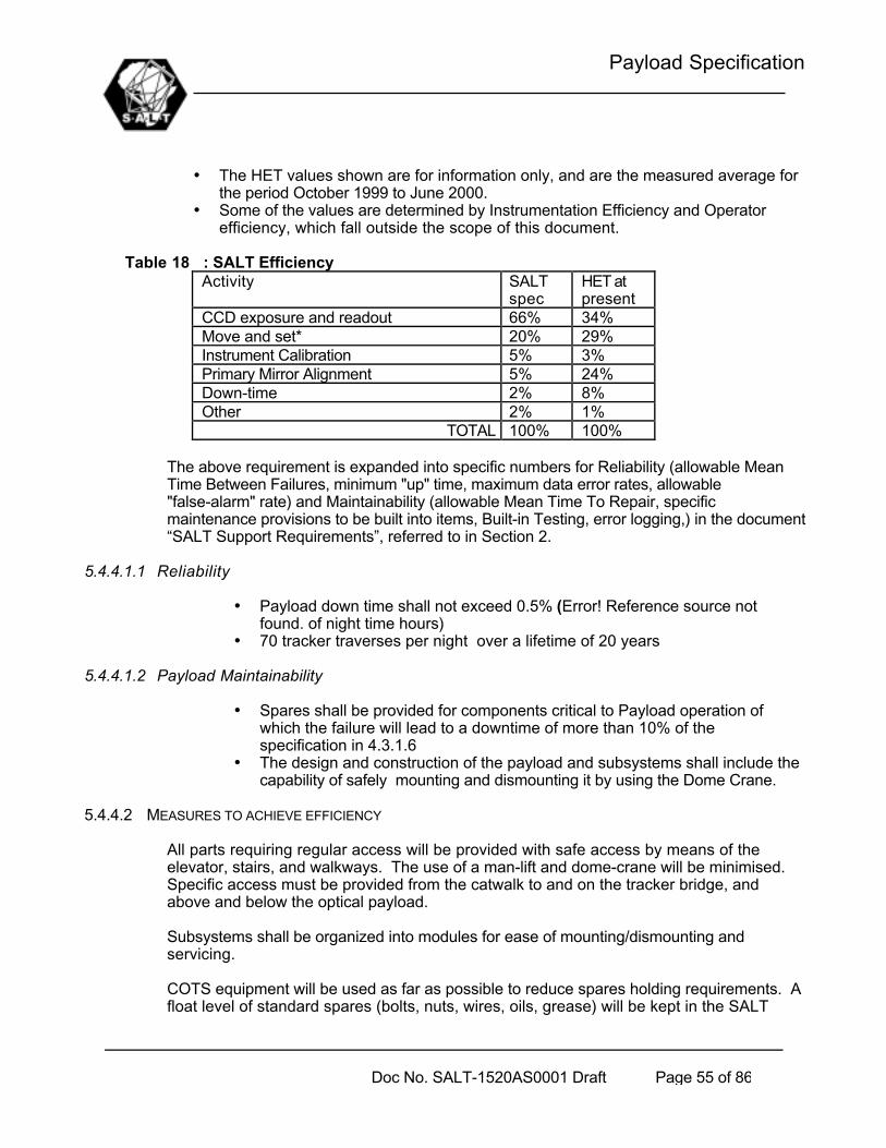
Payload Specification
Doc No. SALT-1520AS0001 Draft Page 55 of 86
• The HET values shown are for information only, and are the measured average forthe period October 1999 to June 2000.
• Some of the values are determined by Instrumentation Efficiency and Operatorefficiency, which fall outside the scope of this document.
Table 18 : SALT EfficiencyActivity SALT
specHET atpresent
CCD exposure and readout 66% 34%Move and set* 20% 29%Instrument Calibration 5% 3%Primary Mirror Alignment 5% 24%Down-time 2% 8%Other 2% 1%
TOTAL 100% 100%
The above requirement is expanded into specific numbers for Reliability (allowable MeanTime Between Failures, minimum "up" time, maximum data error rates, allowable"false-alarm" rate) and Maintainability (allowable Mean Time To Repair, specificmaintenance provisions to be built into items, Built-in Testing, error logging,) in the document“SALT Support Requirements”, referred to in Section 2.
5.4.4.1.1 Reliability
• Payload down time shall not exceed 0.5% (Error! Reference source notfound. of night time hours)
• 70 tracker traverses per night over a lifetime of 20 years
5.4.4.1.2 Payload Maintainability
• Spares shall be provided for components critical to Payload operation ofwhich the failure will lead to a downtime of more than 10% of thespecification in 4.3.1.6
• The design and construction of the payload and subsystems shall include thecapability of safely mounting and dismounting it by using the Dome Crane.
5.4.4.2 MEASURES TO ACHIEVE EFFICIENCY
All parts requiring regular access will be provided with safe access by means of theelevator, stairs, and walkways. The use of a man-lift and dome-crane will be minimised. Specific access must be provided from the catwalk to and on the tracker bridge, andabove and below the optical payload.
Subsystems shall be organized into modules for ease of mounting/dismounting andservicing.
COTS equipment will be used as far as possible to reduce spares holding requirements. Afloat level of standard spares (bolts, nuts, wires, oils, grease) will be kept in the SALT

Payload Specification
Doc No. SALT-1520AS0001 Draft Page 56 of 86
Store.
As far as possible local support for all subsystems/components is required
Special tools and equipment required for system operation and maintenance shall be kept toa minimum, and will be provided with each subsystem.
All normal maintenance actions will be able to be completed within one working day, unlessotherwise specified. Where maintenance actions take more than a day and happenregularly (e.g. primary mirror coating), enough spares will be held to ensure that theoperation of the telescope system is not affected.
Two standard (metric) tool sets will be available, one in the SALT workshop and one in thetelescope chamber. Special tools will be kept to a minimum, and be limited to mirror handlingand coating.
5.5 Design and Construction constraints
5.5.1 General design guidelines and constraints
The following guidelines and constraints apply to SALT (where these general guidelinescontradict specific requirements in other parts of this document, the other requirements shallhave precedence):
a. Every part of SALT that is exposed to direct sunlight will be shielded, have a double wall,and/or be made from a material which has a low thermal inertia.
b. The area around the circular telescope building will be disturbed as little as possible (e.g.minimum buildings, paving, levelling), and the natural vegetation will be preserved.
c. Preference will be given to material with low thermal inertia and open section (e.g. I-beamrather than tube) for anything above the telescope chamber floor.
d. The telescope chamber shall not be heated by adjacent rooms, i.e. any rooms underneathor next door which are heated, shall be thermally isolated from the telescope chamber.
e. The telescope chamber shall have the same temperature as the ambient air during observing,i.e. it shall be cooled during the day, to match ambient temperature at the start of observing
f. No warm air will be exhausted directly from the building.g. Commercial, off the shelf (COTS) equipment will be used unless specifically stated
otherwise.h. All computer hardware will be COTS equipment, using “mainstream” equipment and vendors.i. Computer operating system and application software will be COTS, using “mainstream”
packages and vendorsj. Optical fibres will be used for any digital communications travelling more than 30mk. No artificial light will intrude into the telescope chamber, or outside the building during
observation.l. The layout of the building and services, (e.g. fire escapes, light switches, toilets) must be
logical and intuitive.m. The Metric measurement system will be used.n. All surfaces inside the telescope chamber should follow the ambient temperature as closely
as possible, the effect of a positive delta being air turbulence, causing bad seeing, and anegative delta being the risk of condensation, damaging mirrors and equipment.

Payload Specification
Doc No. SALT-1520AS0001 Draft Page 57 of 86
o. Stray (star/moon) light should be baffled
5.5.2 Materials, Processes and Parts
a. All components will be protected against corrosion by proper surface treatment (e.g.anodising), painting, etc.
b. Wherever a component is mounted in an optically sensitive area, it shall be painted with a non-fluorescing, non-radioactive paint.
c. All components mounted in the optical path will be non-reflective, non radiating in thespectrum 320 to 1500nm
d. All custom components will be marked as follows:
Table 19 Part identificationSALT
Supplier nameProduct name
Product numberSerial number (where applicable, e.g. mirror
segments, mirror mounts)Version number (where applicable, e.g.controllers/computers with embedded
software)Hazard/danger/poison warning (where
applicable)
e. No special markings are required on COTS equipment.f. The normal operation of any component/subsystem shall have no negative impact on the
environment, and shall comply with the Montreal Protocol.
5.5.3 Electromagnetic Radiation
The normal operation of any component or system will not affect the normal operation of anyother system or component, or any other equipment at the Observatory at Sutherland., andhas to comply with the FCC standards as per Section 2.
5.5.4 Workmanship
Workmanship specifications will be specified per type of component, but will not be higherthan required to fulfil the overall SALT performance specification.
5.5.5 Interchangeability
a. Interchangeability will be maximised by using COTS equipment wherever possible, andexceptions will be specified.
b. All primary mirror segments and supports will be interchangeable i.t.o. position on themirror truss, but mirrors and mirror mounts will be matched.
5.5.6 Safety

Payload Specification
Doc No. SALT-1520AS0001 Draft Page 58 of 86
5.5.6.1 SAFETY-CRITICAL FAILURES
All single-point failures that can lead to loss of life, serious injury to personnel or damage toequipment shall be identified and the design modified to prevent such failures.
A preliminary safety analysis to identify such potential failures is contained in the SALTSafety Analysis referred to in section 2.
5.5.6.2 SOFTWARE SAFETY
Where the malfunction of software alone could cause a safety-critical failure, alternatemeans shall be provided to prevent the occurrence of such a failure. This would typicallytake the form of electrical interlocks designed in a fail-safe manner.
5.5.6.3 SAFE INITIALISATION
All systems, when initialising from power-up or when reset, shall be in a safe, non-activestate (e.g. equipment stationary, drives off). It shall take a specific command from the TCS(by exception) or the operator via the TCS, to proceed with potentially unsafe actions(such as rotating the structure or dome, moving the tracker or opening/closing the shutter).
5.5.6.4 LOCAL ELECTRIC OPERATION
A means shall be provided at the relevant electrical panel, to control critical equipment manually,even in the event of a Controller failure. A selection switch on the panel shall select either“Automatic” or “Manual” control. The status of this switch shall enable/disable the manual controlfunctions on the panel and shall be reported to the TCS.
“Critical Equipment” is equipment identified in the Safety Analysis document as requiring thisfunction to achieve safe operation (e.g. dome shutter).
5.5.7 Ergonomics
Comfortable working positions and conditions will be provided at all stations where operatorswill spend long times regularly during normal operation.
5.5.8 Special commissioning requirements
5.5.8.1 SUBSYSTEM MMI’S
There shall be monitors/keyboards plus good human interface SW at the subsystemcomputers, for use during system commissioning. These controls must include facilities foroverriding automatic functions and monitoring of information communicated to/from the TCS.
5.5.8.2 TEST POINTS
Means shall be provided to measure electrical signals and interpret data transferredbetween subsystems and major electronic items within each subsystem.

Payload Specification
Doc No. SALT-1520AS0001 Draft Page 59 of 86
5.5.8.3 TEST DATA
Each subsystem shall send to the TCS the values of all internal variables that may need tobe interrogated during commissioning and testing, but would not normally be needed fortelescope control by the TCS. A list of typical variables required is provided below, butdetails will be provided in the SALT Electrical Interface Control Dossier:
5.5.8.4 SPOTTER TELESCOPE
A small telescope pointing at the sky and aligned parallel to the SAC axis, shall bepermanently mounted on the payload. It shall be fitted with a removable video camera at theeyepiece linked to a monitor in the Control Room. The FOV of this telescope shall bedetermined prior to commissioning, once its role has been fully defined.
5.5.9 Software
Each subsystem shall comply to the requirements defined in SALT Computer SoftwareStandard referred to in Section 2.
This document addresses the following:• Software must separate H/W interfaces with functional software, so that I/O devices can be
replaced later without having to modify all the software• The acceptable languages and operating systems will be specified per computer plus general
interfacing requirements• Specific practices and documentation/design requirements for the software will be defined• Protocols for interfacing between computers will be defined (detail will be in ICD)• Format for PLC software• Each computer shall report the health status of itself and all it’s input/output devices to a
higher level computer, such that the TCS will be notified all major failures.• TCS shall monitor communication health to all systems (ping test?)
5.5.10 Computer Hardware
Each subsystem shall comply to the requirements defined in SALT Computer HardwareStandard referred to in Section 2.
This document addresses the following:• Hardware must be selected such that it is possible to upgrade the PC’s at a later stage• Acceptable types of PLC’s servo drives, axis controllers and amplifiers will also be specified
5.5.11 Electrical Design
5.5.11.1 UPS
5.5.11.1.1 Installed Capacity
The total installed UPS capacity shall be at least the value indicated in the Power Budgetplus 20%.

Payload Specification
Doc No. SALT-1520AS0001 Draft Page 60 of 86
5.5.11.1.2 Use of UPS power
The following items will be placed on UPS power:• All computer systems and PLC’s• Safety monitoring equipment (e.g. dome open-close indication)• Sensitive instrumentation
5.5.11.1.3 General UPS Requirements
The UPS shall have the following features:• It’s battery charge level and overall health shall be monitored by the TCS, with
operator warnings as appropriate.• A “power-fail” signal shall be passed to the TCS from the UPS to indicate the loss of
normal power so that contingency software can be activated• The UPS shall not increase electrical noise on the normal power line but rather
provide a filter to protect its load from the Sutherland electrical supplycharacteristics.
5.5.11.2 STANDBY POWER GENERATORS
5.5.11.2.1 Use of Emergency Power
All essential power uses shall be provided with Emergency Power during a normalpower failure
5.5.11.2.2 General Emergency Power Requirements
The emergency power source shall have the following features:• It shall become active within 30s of a general power failure and will remain on until
manually turned off• The quality of power (voltage, frequency drift, harmonics) shall be no worse than
the normal electrical supply5.5.11.3 CABLE SIZING
All electrical power cables shall be sized such that their outside surface temperature doesnot rise above ambient by more than 0.5ºC under worst-case operating loads.
5.5.11.4 GENERAL ELECTRICAL REQUIREMENTS
All subsystems shall comply with the SALT Electrical Requirements. This document willaddress the following:• Earthing and bonding of electrical equipment• Measures to minimise electrical interference• General principle to follow for electrical parts of each subsystem
5.5.12 Future growth
The following potential growth areas shall be borne in mind during the design process andaccommodated where this does not have an impact on the achievement of the immediate

Payload Specification
Doc No. SALT-1520AS0001 Draft Page 61 of 86
performance, schedule and cost requirements.
5.5.12.1 REMOTE OBSERVING
The control room of SALT may be required to be duplicated at the SAAO in Cape Town, toallow remote operating of SALT.

Payload Specification
Doc No. SALT-1520AS0001 Draft Page 62 of 86
6 Subsystem technical requirements
6.1 Major Component List
The major suggested components and subcomponents with their respective functional allocationsare detailed in the following table. The selection and design of these components will be finalisedin the design phase. The contractor is encouraged to motivate any cost/risk/performance enhancingchanges that are to be accepted by the subcontractor.
Table 20 Payload major componentsNo Major Component Sub Components Function
1 Payload ComputerSystem
1.1 Computer Hardware1.2 Software Suite1.3 Power Switches
1. Communication2. Payload Algorithms3. Payload MMI
2 Payload Structure 9. Structural Support
3 SAC4 Guidance System 4.1 CCD
4.2 Optics4.3 Electronics4.4 Fibre Bundles4.5 Motion System4.6 Enclosure
4. Guidance
5 ADC 5.1 Optics5.2 Mechanics5.3 Motion System
4. Atmospheric dispersioncorrection
6 Mechanics 6.1 Moving Baffle6.2 Fixed Baffle6.3 Fold Mirrors
7 Thermal ControlSystem
7.1 Analogue Input7.2 Temperature Sensors7.3 Insulation
6. Thermal Control2.8 Thermal Loop
8 Calibration Screen 7.1 Screen7.2 Actuators7.3 Light emitters
9 Cable & TubeHandlers , Enclosures
8.1 Fibre Bundle Cable Tray8.2 Electric enclosuresTBD13

Payload Specification
Doc No. SALT-1520AS0001 Draft Page 63 of 86
6.2 Major Component CharacteristicsAll systems & subsystems shall comply with the requirements of Section 2 documents.The figure below shows the major dimensions of the Tracker, Payload and interfaces with the TopHex.
Figure 15. Tracker and Payload : Layout & Dimension

Payload Specification
Doc No. SALT-1520AS0001 Draft Page 64 of 86
6.2.1 Payload Computer System
The computer system shall be located in the computer room in the Facility. The maximum wirelength between the Computer Room and the top of the Telescope Structure will be less than80m.This room will be maintained at temperatures between 5 to 25 degrees C and relative humidity5% to 95%.
The Payload Computer System shall perform all functions reliably in this environment.
6.2.1.1 COMPUTER HARDWARE:
At least a Pentium III class machine.
The selection of hardware should not limit future upgrading with advances in technology.
6.2.1.2 SOFTWARE SUITE
Operating system : Real Time LinuxCommunication Software shall include TCP/IP ProtocolPayload software development environment : Labview PreferablePayload Software : Comply with standard as in section 2 (SALT Software Standard )Payload Subsystems shall be fully commanded from either the TCS or Payload Computer withthe Payload MMI fully available at TCS level
6.2.1.3 POWER SWITCHES
Functionality must be provided to power up the Payload subsystems in an orderly fashioneither fully or selectively. The details will be finalised in the design phase.
6.2.2 Structure
a) The Structure shall support the following subsystems within the performance requirementsof section 5.3.1:
- ADC- Moving Baffle- Fold Mirrors- Fibre Feed System- Commissioning Instrument- Guidance System- Auxiliary Port
b) The Structure shall be enclosed to enable positive pressurization to 50Pa.
The other payload subsystems shall be supported by the hexapod system of the tracker.
Figure 16. Detail of structure

Payload Specification
Doc No. SALT-1520AS0001 Draft Page 65 of 86
6.2.3 SAC(a) For the optical requirements of the SAC refer to the relevant document in Section 2:(b) The SAC shall be non-rotating and will therefore be supported by the hexapod system of
the Tracker.(c) Volume Envelope
Figure 17. Conceptual illustration of the SALT Payload & SAC
6.2.4 ADC
(a) Shall mount onto the SAC Structure(b) Volume Envelope

Payload Specification
Doc No. SALT-1520AS0001 Draft Page 66 of 86
Figure 18. Conceptual illustration of the ADC
6.2.5 Moving Baffle
(a) Shall mount onto the SAC Structure(b) Volume Envelope

Payload Specification
Doc No. SALT-1520AS0001 Draft Page 67 of 86

Payload Specification
Doc No. SALT-1520AS0001 Draft Page 68 of 86
Figure 19. Conceptual illustration of the Moving Baffle
6.2.6 Fixed Baffle
(a) Shall mount onto the Hexapod System of the Tracker.(b) Shall not interfere with the SAC structure(c) Volume Envelope
6.2.7 Fold Mirrors
(a) Shall mount onto the Payload Structure

Payload Specification
Doc No. SALT-1520AS0001 Draft Page 69 of 86
(b) Volume Envelope
6.2.8 Commissioning Instrument
(c) Shall mount onto the Payload Structure(d) Volume Envelope

Payload Specification
Doc No. SALT-1520AS0001 Draft Page 70 of 86
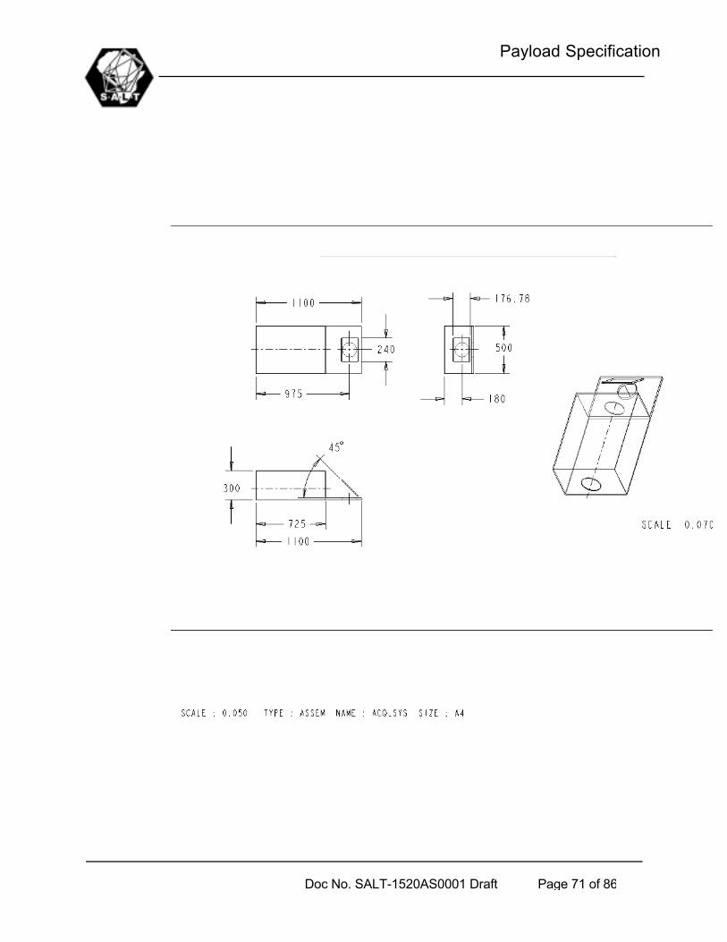
Payload Specification
Doc No. SALT-1520AS0001 Draft Page 71 of 86

Payload Specification
Doc No. SALT-1520AS0001 Draft Page 72 of 86

Payload Specification
Doc No. SALT-1520AS0001 Draft Page 73 of 86
Figure 20. Conceptual illustration of the Commissioning Instrument
6.2.9 Thermal Control System
The thermal control system will be a passive system as far as the payload is concerned, heatgenerating equipment will be insulated and heat removed by chilled glycol. A glycol source

Payload Specification
Doc No. SALT-1520AS0001 Draft Page 74 of 86
and drain will be supplied at the Tracker. Temperature measurements at these subsystemswill be fed back to the TCS via the Payload computer.
6.2.10 Cable & Tube Handlers and Enclosures
(a) Cable and Tube Handlers shall be located at the Rho stage or at any of the subsystems toaccommodate all motions as required.
Figure 21. Cable and Tube Handlers
7 Test Requirements
7.1 Verification cross-reference Matrix
Per paragraph in sections 3,4,5 and 6, identification of how the product’s compliance of therequirement will be measured to test compliance is indicated in the table below.
Note that compliance to a requirement may be proven at the “system” (S), “subsystem” (SS) orcomponent (C) level, depending on the particular requirement (e.g. the mass of the total product canbe proven by weighing all the components, it needn't be in the assembled state).
The "Test Method" may be any one of the following:_ Review (R) - the design is reviewed and it is obvious to all whether or not the item complies
(e.g. whether or not the system has a particular mode)._ Inspection (I) - the completed item is inspected and compliance can be easily observed. This
is normally used for physical characteristics such as colour, dimensions and mass._ Testing (T) - this entails a technical effort whereby the system is stimulated in a certain
fashion and its response compared to the required response._ Analysis (A) – compliance of the design to the requirement is proved by mathematical
analysis.Where it is considered important, reference to the detail of the test method should be provided in the"Details" column of the table.
Table 21 Verification cross-reference Matrix (Error! Reference source not found.)Para. Requirement Test
MethodTestLevel
Test DetailRef.
4.3.14.3.24.3.34.3.3.84.3.3.94.3.3.104.3.3.124.3.3.134.3.3.15
Functional RequirementsModes and StatesFunctional Flow DiagramFunction Details (4.3.3.1 – 4.3.3.7)Payload AlgorithmsPayload MMIAxes ControlThermal ControlPower SwitchesStructural SupportTechnical Requirements
R,TRR, TR, TR, TR, TT, IT, IA, I
SSS, SSSSSS, SSSSS, SSS, SS
7.2

Payload Specification
Doc No. SALT-1520AS0001 Draft Page 75 of 86
5.2 SALT Payload Interfaces R, I S, SS
7.2 Detailed Test Methods
(Error! Reference source not found.)
8 Notes
NA

Payload Specification
Doc No. SALT-1520AS0001 Draft Page 76 of 86
APPENDIX A: FUNCTIONAL DEFINITION TABLES
Timeline Diagrams
This table illustrates Closed Loop Guidance.
No Action Start Time Frequency Remarks1. Star position input by RA,
single position or scheduledpositions – on TCS terminal
Acquisition time– 3 minutesminimum
Once per target Star position:RA,DEC,EpochTime
2. Acquisition and Tracking starttimes and ObservationDuration for each target –input by RA on TCS terminal
Acquisition time– 3 minutesminimum
Once per target Time availablebetweenAcquisition andTrack must bevariable by RA
3. TCS send Acquisition andtracking start times andposition to Tracker computer
Acquisition time– 2.5 minutesminimum
Once per target
4. Tracker and Payload slewedto position in 3
Immediately after3.
5. Tracker computer reports toTCS when in position
Acquisition Time– 30 seconds
Once per target
6. TCS send trajectorycommands(x,y,z,q,f,r) toTracker Computer
Immediately after5.
Once every 30sec
Open loopcommands
7. Tracker executes commandsin 6.
According totime stamp ofcommands
Continuously (atsamplingfrequency of axes controllers)
Controllersshouldinterpolatecommandsbetweentrajectory points
8. Target and Guid Starsselected by RA – on TCSterminal
Any timebetweenAcquisition andtrack start time
Once per target
9 Payload Computer sendscorrection signals to Trackercomputer (x,y corrections)
When locked onguid star/s
1Hz
10. Beyond track start time –closed loop tracking, if nocorrection signals frompayload – open loop tracking
Start of Track Continuously (atsamplingfrequency of axes controllers)
Controllersshouldinterpolatecommands
Tabel 3.1.1.1a : Tracker & Payload Timeline for Closed Loop Guidance
This table illustrates Open Loop Guidance.
No Action Start Time Frequency Remarks

Payload Specification
Doc No. SALT-1520AS0001 Draft Page 77 of 86
1. Star position input by RA,single position or scheduledpositions – on TCS terminal
Acquisition time– 3 minutesminimum
Once per target Star position:RA,DEC,EpochTime
2. Sidereal Rate selected by RA Acquisition time– 3 minutesminimum
Any time RA can adjustsidereal rate
3. Acquisition and Tracking starttimes and ObservationDuration for each target –input by RA on TCS terminal
Acquisition time– 3 minutesminimum
Once per target Time availablebetweenAcquisition andTrack must bevariable by RA
4. TCS send Acquisition andtracking start times andposition to Tracker computer
Acquisition time– 2.5 minutesminimum
Once per target
5. Tracker and Payload slewedto position in 3
Immediately after3.
6. Tracker computer reports toTCS when in position
Acquisition Time– 30 seconds
Once per target
7. TCS send trajectorycommands(x,y,z,q,f,r) toTracker Computer
Immediately after5.
Once every 30sec
Open loopcommands
8. Tracker executes commandsin 6.
According totime stamp ofcommands
Continuously (atsamplingfrequency of axes controllers)
Controllersshouldinterpolatecommandsbetweentrajectory points
Tabel 3.1.1.1b : Tracker & Payload Timeline for Open Loop Guidance
The next table illustrates Positioning.
No Action Start Time Frequency Remarks1. Star position or Tracker
Position input by RA – onTCS or Tracker Computerterminal
Any time Continuously
2. Tracker and Payload slewedto position in 3
Immediately after1.
6. Tracker computer reports toTCS when in position
When positionreached
Once per target
Tabel 3.1.1.1c : Tracker & Payload Timeline for Positioning
The following timeline tables are for the detailed functions in Figure 11 the first of which is the TrackerComputer functions.
No Action Start Time Frequency
Remarks
1 COMMUNICATION

Payload Specification
Doc No. SALT-1520AS0001 Draft Page 78 of 86
1.1 ETHERNET1.1.1 TCS Comms1.1.1.1 TCS -> Tracker Computer :
Command message to Tracker ,thermal control set points,Acquisition offset
When switched on 10Hz The userinterface onTrackercomputer andTCS identical
1.1.1.2 Tracker Computer -> TCS :Reporting Tracker Modes, States,Health status of subsystems,Safety
When switched on 10Hz Status Message
1.1.1.3 Tracker Computer -> TCS :Reporting tracker position, errors,(x,y,z,q,f,r), hexapod positions,collimator errors and thermalcontrol variables
When switched on 10Hz Data Message
1.1.2 Payload Computer Comms1.1.2.1 Payload Computer -> Tracker
ComputerWhen switched on 1Hz Guidance Errors
1.1.3 Axes Controllers Comms1.1.3.1 Axes Control -> Tracker Computer When switched on 10Hz All sensor
readings1.1.3.2 Tracker Computer -> Axes
Controllers : Control loop and modecommands
From when PowerUp Mode entered
1 to10Hz
Variable(toadjust ifaccuracyrequires)
1.2 RS4851.2.1 Payload Alignment Comms1.2.1.1 Payload Alignment Sensors ->
Tracker ComputerWhen switched on 10Hz
1.2.1.2 Tracker Computer -> PayloadAlignment Sensors
When switched on Asrequired
For Setup,calibration
1.2.2 Thermal Control Comms1.2.2.1 Thermal Control -> Tracker
Computer CommsWhen switched on 1Hz Read
Temperaturesensors & ValvePosition
1.2.2.2 Tracker Computer -> ThermalControl Comms
When switched on 1Hz Valve Commands
1.2.3 Power Switches Comms1.2.3.1 Tracker Computer ->Power
Switches CommsDuring Powerup/Shut Down
1.2.4 Gravity Compensation Comms1.2.4.1 Gravity Compensation -> Tracker
Computer Comms : Valve Position &Pressure
When switched on 1Hz ReadTemperaturesensors & ValvePosition

Payload Specification
Doc No. SALT-1520AS0001 Draft Page 79 of 86
Position1.2.4.2 Tracker Computer -> Gravity
Compensation: Valve CommandWhen switched on 1Hz Valve Commands
1.3 OTHER1.3.1 Time Sync Input1.3.1.1 Time sync -> Tracker Computer When switched on 1Hz Time sync is part
of TCS
2 TRACKER ALGORITHMS2.1 Power Up MMI Activated NA2.2 Shutdown MMI Activated NA2.3 Time Synchronisation When switched on 1Hz2.4 Tracker Mount Model Entering Power UP
Mode10Hz
2.5 Guidance Corrections MMI Enabled 1Hz Part of Softwareset up
2.6 Axes Command Generator Entering Power UPMode
10Hz
2.7 Orthogonality Corrections Entering StandbyMode
10Hz
2.8 Thermal loop MMI Activated 1Hz2.9 Mode & State Control Switched on 10Hz2.10 Diagnostics & Safety Switched on 10Hz2.11 Software Setup & Maintenance MMI Activated (In
Power up/Shutdown)
NA Save andretrieveconfigurationsetup & data
3 TRACKER MMI3.1 Update MMI When switched on 10Hz
Tabel 3.1.1.1d : Timeline for functions in Tracker Computer
The next table illustrates Axes Control.
No Action Start Time Frequency
Remarks
4 AXES CONTROL4.1 Axes Controllers4.1.1 Receive commands from Tracker
ComputerFrom when PowerUp Mode entered
1to10Hz
Variable – toadjust if required
4.1.2 Read sensor inputs When switched on 100Hz4.1.3 Calculate and Output Servo Amp
CommandsFrom when PowerUp Mode entered
100Hz
4.1.4 Send time stamped sensorreadings to Tracker computer
When switched on 10Hz

Payload Specification
Doc No. SALT-1520AS0001 Draft Page 80 of 86
4.1.5 Activate Brakes on X and Y Drives As required AsRequired
Tabel 3.1.1.1e : Timeline for functions in Axes Control
The next table illustrates Payload Alignment.No Action Start Time Frequ
encyRemarks
5 Payload ALIGNMENT SENSORS5.1 Payload Alignment Sensors ->
Tracker Computer Comms : Status& measurements
Switched on 10Hz
5.2 Tracker Computer -> PayloadAlignment Sensors Comms :Commands
From when PowerUp Mode entered
1Hz
Tabel 3.1.1.1f : Timeline for functions in Payload Alignment Sensors
The next table illustrates Thermal Control. TBD
No Action Start Time Frequency
Remarks
6 THERMAL CONTROL6.1 Analogue Output TBC6.1.1 Tracker Computer -> Analogue
Output Comms : Valve PositionCommands
Prompted byTracker Comp
1Hz
6.1.2 Output Commands to Valves Prompted byTracker Comp
1Hz
6.2 Analogue Input TBC6.2.1 Analogue input -> Tracker
Computer Comms : TemperatureMeasurements & Valve Positions
Prompted byTracker Comp
1Hz
6.2.2 Read Temperature Sensors &Valve Positions
Prompted byTracker Comp
1Hz
Tabel 3.1.1.1g : Timeline for functions in Thermal Control
The next table illustrates Power Switching.TBD
No Action Start Time Frequency
Remarks

Payload Specification
Doc No. SALT-1520AS0001 Draft Page 81 of 86
ency7 POWER SWITCHES7.1 Digital Output7.1.1 Tracker Computer -> Digital Output
Comms : Switch CommandsPrompted byTracker Comp
NA
7.1.2 Output Commands to Relays Prompted byTracker Comp
NA
Tabel 3.1.1.1h : Timeline for functions in Power Switches
The next table illustrates Gravity Compensation.TBD
No Action Start Time Frequency
Remarks
8 GRAVITY COMPENSATION8.1 Analogue Output TBD8.1.1 Tracker Computer -> Analogue
Output Comms : Valve PositionCommands
Prompted byTracker Comp
10Hz
8.1.2 Output Commands to Valves Prompted byTracker Comp
10Hz
8.2 Analogue Input TBD6.2.1 Analogue input -> Tracker
Computer Comms : PressureMeasurements & Valve Positions
Prompted byTracker Comp
10Hz
6.2.2 Read Pressure Sensors & ValvePositions
Prompted byTracker Comp
10Hz
Tabel 3.1.1.1i: Timeline for functions in Gravity Compensation

Payload Specification
Doc No. SALT-1520AS0001 Draft Page 82 of 86
APPENDIX B : LIST OF TBD’S AND TBC’S
TBC PARA DESCRIPTION/DATETBC1 2 All reference documents to be finalisedTBC2 4.3.3.1 Trajectory command time steps are to be determinedTBC3 4.3.3.1 Safety CommandsTBC4 4.3.3.2 Guidance Update rate selected -TBC5 4.3.3.3 Axes command time steps are to be determinedTBC6 4.3.3.4 Payload Alignment update Rate is to be determinedTBC7 4.3.3.6 Power Switch AllocationTBC8 4.3.3.7 Time Synch Accuracy: Tracker Computer and TCSTBC9 Error! Reference source not found. SAC Rotating/non-rotatingTBC10 5.3.1.13 Moving Baffle degrees of FreedomTBC11 5.3.1.14 Wind Force magnitude and frequencyTBC12 5.3.1.14 Mounting accuracies of subsystemsTBC13 5.3.1.16 Degradation under marginal operating conditionsTBC14 Error! Reference source not found. Reliability figures

Payload Specification
Doc No. SALT-1520AS0001 Draft Page 83 of 86
TBD PARA DESCRIPTION/DATETBD1 Table 1 Safety and diagnostics definitionTBD2 4.3.3.8.8 Thermal Control DetailsTBD3 4.3.3.1 Comms with tracker via TCS?TBD4 4.3.3.2 MMI DefinitionTBD5 4.3.3.9 Stray light DefinitionTBD6 Table 6 Beam SplitterTBD7 5.3.1.11 Drivers for Fixed baffle designTBD8 Error! Reference source not found. Insertion Range of Fold mirrorsTBD9 Error! Reference source not found. Calibration Screen definitionsTBD10 5.3.1.17 Over pressurization of PayloadTBD11 Error! Reference source not found. Instrument air quality definitionTBD12 5.3.2.9 Test verification matrixTBD13 6.1 Detailed test methods

Payload Specification
Doc No. SALT-1520AS0001 Draft Page 84 of 86
APPENDIX C: System Functional Flow Diagram

Payload Specification
Doc No. SALT-1520AS0001 Draft Page 85 of 86
Facility
TCS
StructureDomeSALT Functional Flow Diagram
Doc No. SALT-1000AD0022
Author: GP Swart Issue: 1.1 Date: 21/08/00
ActuatorDrivers
Edge-senseElectronics
ActuatorDrivers
Edge-senseElectronics
AxisController
AxisController
AxisController
AxisController
AxisController
AxisController
AxisController
AxisController
AxisController
CameraElectronics
Soft-startdrive
Soft-startdrive
AxisController
AxisController
FireSystem
PressureController
Temp.Controller
Temp.Controller
Actuators
Z1
Z273
Edge Sensors
E1
E480
T1
T4 Tilt Sensors
OpticalAlignmentSensor
H1
H6 Hexapodservos
Autocollimator
Rangefinder
M
M
M
M
M
M
M
Rho servo
Y-fast servo
Y-slow servo
X1-fast servo
X1-slow servo
X2-fast servo
X2-slow servo
Limit switchesand discretes
Guidance opticsdiscretes
PFIP & calibrationdiscretes
Guidance camera
M
Load balance
Dome Rotation
Az Sensor(s)
M
Soft-startdrive
Shutter open/close
M M
Anti-backlash
Az Sensor(s)
Variable-spd. drive
Variable-spd. drive
Structure rotation
S
Air bearings x 4
S
P
HSLimit switches
ActuatorMirror Model
Edge-sensorMirror Model
PrimaryMirror ControlZ1.....Z273
*E1...*E480
Status
Configure
Error(",$,z)1...91
Error(",$,z)1...91
Reset, Status
Status
AlignmentSensor MirrorModelError(",$,z)1...91
Shutter, Status
PFIP Tip,Tilt, Pistoncontrol
ImmediateGuidance
TrackerMode Control
Tilt(",$)1...4
H1...H6
Configure
H1...H6
",$
Z
Trackerdigital model
Slow/Fast control
Digitalstatus/control
Modeset/reset
Digital I/O signals
X
Y
Rho
Command(!,$,z)
Error(",$,z), H1...H6
Trajectorycalibration &hex axistransform
PFIP andoptics control
Fibre(x,y,z)1...10
Videodigitiser
Guidance &Aquisitionsetup/control
Video data
Selection /status
Spot tracker
Aquisitioncamerafunctions
Convert totracker errors
Selectguidance/scienceobjects
Camera control
Guidanceconfig.
Digitalvideo
(*X,*Y)1..2
Error(x,y,Rho)
P(t)
Error(t)
Trajectorydetermination& adjustment
Digitalvideo
P(t)Error(t)
Dome az.control
Dome digitalcontrol
Structure az.control
Structuredigital control
h1...h4
Systempointingmodel
Displayguidanceobjects
Axesconversion
Image, co- ord’s
Displayscienceobjects
Az angle Az angle
System modecontrol &monitoring
Open/Close
Az Cmd
Actual Az
Az Cmd
Actual Az
Status
Interlocks, mode
Interlocks, mode
Status, mode cmnd
Status, mode cmnd
Status, mode cmnd
Status, mode cmnd
Lock/Adjust
Time Source
t
EventLogging
OperatorReport
SelectScienceObject
Precisiontime synch
System status info
Failure status
RequiredRA, Dec
RA, Dec
t
Object information
AstronomerReport
Interface toScienceInstruments
Observation information
ElectricityMonitor
Fire AlarmSystem
Transformers and switchgear
UPS status, control
Power status, consumption
Emergency power status
Alarm status
M
M
Ventilationcontroller
Open/Close, status
Open/Close, status
CCASshutter
VentilationShutters
UPS
Emergencygenerators
T
T
Air Conditioning
T EnvironmentcontrollerTsetpoint ,T1...TN
T1...TM
Temp monitors
HHumidity
Wind Speed
T
P
P
Aircompressorcontroller
P1...PN
Psetpoint ,Pactual
Pressuremonitors
AirCompressor
TTemp.Controller
Temp.Controller
Temp.Controller
GlycolChillercontroller
GlycolChiller
ControlNode 1
ControlNode N
T
T
TN setpoint ,TN actual
T1 setpoint ,T1 actual
Tsetpoint ,Tactual
PPout ,Pin
Dataconcentrator
Enironmental and facility info, setpoints
OutsideWeathersource
ForcastWeather
VentilationStatus
Display local& forcastweatherLocal
Weather
Setpoint, status
Status
Status
Status
Status
Status
Schedule/filter scienceobjects
Storeobservationdata
PI internetforms,database
ObservationTools
Science data
Configure,status
Short termschedule
What-if info
Long term schedule
Science data
SensorElectronics
What-if info
PI access todata
Science data
Key:
Hardware function and data flow
Discrete function and control/status flow
Analogue function and data flow
Notes:1. Not all control/status data flow is shown.2. TCS and PFIP functions require further definition.
Audio &Telephonesystems
Primary Mirror System
Tracker and Payload
M
Setpoint
Systemcalibration/metrology
Calibration data
RRaindetector
Systemvisualisation
SensorElectronics
Video, & status dataVideo
Status data
CameraElectronics
Aquisition/Science camera
Comm. Instr.
AxisController
Fibre Feedcontrol (XYZ)
Provided byothers

Payload Specification
Doc No. SALT-1520AS0001 Draft Page 86 of 86