approved manual and installation guide for biofilters on...
TRANSCRIPT

Approved Manual and Installation Guide for Sub-Surface Ecoflo® Biofilters
On-Site Sewage Disposal Systems Manufactured by
Premier Tech Aqua
Prepared for Nova Scotia Environment
by Premier Tech Aqua
October, 2010
This installation guide includes technical information relative to the design and the installation of the different Ecoflo® Biofilter models. The first section includes a Technical Data Sheet presenting for all the Ecoflo® Biofilter models, their components, dimensions, etc. The second section is specific to the design of the different Ecoflo® models and provides examples of typical installations; the third section provides the installation instruction for the different Ecoflo® models.
This document has been developed by Premier Tech Aqua (PTA) to include specific references and pertinent information for the design and installation of Ecoflo® Biofilters in the Province of Nova Scotia. Systems must be designed and installed in accordance with the Nova Scotia Environment “On-site Sewage Disposal Systems, Technical Guidelines” dated 1 April 2009, and any future amendments. Where this document does not indicate information on a specific point, the designer and installer shall use the Technical Guidelines standard on the point as the minimum requirement. However, if different standards are stated on any point in this document, compared to the Technical Guidelines (such as effluent filters being required on the outlet of the septic tank), the requirements in this document shall govern. General literature published by PTA frequently refers to these units being certified under an “NQ 3680-910”standard for an advanced secondary treatment system. Such references are not applicable in Nova Scotia where this Approved Manual and Installation Guide, together with the Nova Scotia Technical Guidelines and the On-Site Sewage Systems Regulations made under the Nova Scotia Environment Act and Health Act, are the only official documents related to the design and installation of Ecoflo® Biofilters in Nova Scotia. Reference to PTA septic tanks, pumping stations, and accessories in this document signify approval for use in Nova Scotia only as integral components involved in installation of Ecoflo® Biofilters in Nova Scotia. Such units may be used in other applications where regular Approval of such component(s) has been given and the item(s) registered as Approved Product in Appendix L of the Technical Guidelines.

Premier Tech Aqua Page 2 of 51 Installation Guide - Sub-Surface Ecoflo® Biofilters - NS Edition: 2011-05-06
Table of Content
Technical Introduction ............................................................................................................................... 3 PART I – Ecoflo® Biofilter Technical Data Sheet .................................................................................... 4 PART II – Ecoflo® Biofilter Design Guidelines ........................................................................................ 7
A) Installation procedure for the Ecoflo® Biofilter with OPEN BOTTOM – ST Series Models ......... 7
B) Installation procedure for the Ecoflo® Biofilter with COLLECTING BOTTOM – STB Series Models ........................................................................................................................ 16 PART III – Ecoflo® Biofilter Assembly and Installation Guide ........................................................... 22
A) Ecoflo® Biofilter with Open Bottom – ST Series Models ............................................................. 22
B) Ecoflo® Biofilter with Collecting Bottom – Fiberglass Shell ........................................................ 29
C) Ecoflo® Biofilter with Collecting Bottom – Concrete Shell .......................................................... 38

Premier Tech Aqua Page 3 of 51 Installation Guide - Sub-Surface Ecoflo® Biofilters - NS Edition: 2011-05-06
Technical Introduction IMPORTANT! THIS INTRODUCITON PROVIDES CRITICAL INFORMATION AND CLARIFCATION OF TERMS THAT NEED TO BE READ AND UNDERSTOOD IN ORDER TO ENSURE PROPER USE OF THIS MANUAL CLARIFICATION Ecoflo Biofilter shell can be made of various materials such as, but not limited to: fibreglass, concrete, polyethylene, etc. Ecoflo® Biofilter models are designed for a maximum hydraulic loading rate of 290 L/m3 per day of organic filter medium. All Ecoflo® Biofilters with open bottom (See PART II A of this Manual) are designed as Sub-Surface Discharge Systems. An Ecoflo® Biofilter with collecting bottom (See PART II B of this Manual) can discharge to an absorptive bed where soil conditions (e.g. allowable vertical Hydraulic Loading Rate) allow for total acceptance of the complete flow by the in-situ sub-soils and thus are considered Sub-Surface Discharge Systems. Sizing of the absorptive bed for these systems is based on the design principles and criteria (e.g. Hydraulic Loading Rates for various soil types) provided in PART II of this manual. Sub-Surface Discharge This term applies to disposal methods for an effluent where the design allows for total acceptance of the complete flow by the in-situ sub-soils. In Sub-Surface Discharge design calculations the absorptive area bed is sized based on the design flow (L/day) and the (allowable) vertical Hydraulic Loading Rate (L/m2/day) of the on-site sub-soils accepting the flow. Surface Discharge This term applies to disposal methods for an effluent where the design does not allow for total acceptance of the complete flow by the in-situ sub-soils. In Surface Discharge Design some or all of the design flow is presented as a surface flow. Examples of surface discharge include: • pipe discharge to a receiving water; • pipe discharge to a ditch; • a perforated pipe installed in a gravel trench or French Drain where part of flow is accepted into the sub-soils
along length of the gravel area but the total flow is not directly accepted into the sub-soils; • discharge through a toe drain.
** THIS MANUAL DOES NOT ADDRESS SURFACE DISCHARGE **

Premier Tech Aqua Page 4 of 51 Installation Guide - Sub-Surface Ecoflo® Biofilters - NS Edition: 2011-05-06
PART I – Ecoflo® Biofilter Technical Data Sheet
Ecoflo® models
Ecoflo® components material Fiberglass Shell Concrete Shell
Shell Fiberglass/polyester resin composite Reinforced concrete 5000 psi
Top tile NA Reinforced concrete 5000 psi
Main access and ventilation system Polyethylene plastic Fiberglass/polyester resin composite
Lids Polyethylene plastic Polyethylene plastic Sampling device Polyethylene plastic N/A Secondary access and access funnel N/A Polyethylene plastic Support rails N/A PVC Tipping bucket, central support & distribution plates
ABS plastic or Polyethylene plastic
ABS plastic or Polyethylene plastic
Filtering media Natural organic fibres Natural organic fibres
Volume of filtering media Models 500: 3.9 m³ (138 ft³) – 23 bags Models 650: 5,2 m3 (183 ft3) – 30 bags
Connections
Flexible, watertight and adapter to 100 mm Ø (4”) SDR-35 and SCH-40 PVC pipes.
Flexible, watertight and adapter to 100 mm Ø (4”) SDR-35 and SCH-40 PVC pipes. Outlet of the STB-650BR adapter to 25 mm (1”) Ø flexible pipes.
Dimensions – FIBERGLASS MODELS
ST-500 STB-500 ST-650 STB-650
Total length (L) 3345 mm (132”) 4175 mm (164") Total width (W) 2360 mm (7’9”) Total height (H) 1320 mm (4’4”) 1700 mm (5’7”) 1320 mm (4’4”) 1700 mm (5’7”) Height to the inlet (Hi) 970 mm (3’2”) 1345 mm (4’5”) 970 mm (3’2”) 1345 mm (4’5”) Bottom height N/A 380 mm (15”) N/A 380 mm (15”) Maximum groundwater level N/A 1245 mm (49”) N/A 1245 mm (49”) Shell weight 105 kg (230 lbs) 210 kg (460 lbs) 125 kg ( 275 lbs) 250 kg (550 lbs)
Fiberglass Shell Concrete Shell
Open bottom ST-500 ST-650 N/A
Closed bottom STB-500 STB-650
STB-500B STB-650B
Closed bottom with integrated pump vault NA STB-500BR STB-650BR

Pr
D
WWLWTCHS
*a(1
HFi
2 (2
remier Tech Aqua
Dimensions –
Weight of the tWeight of the sLength (L) Width (W) Total height (HConcrete tank Height to the inStorage capaci
approximate weigh) Ecoflo Biofilter m
Handling iberglass Shel
or 4 lifting rin2 rings minimu
– CONCRE
top tile* shell*
Ht) height (Hc) nlet (Hi) ity
ht: may vary. models housed in
ll
gs are located um are required
ETE MODE
concrete shell whi
on top of the sd to lift the shel
P
ELS
STB-5STB-50
1 180 kg (24 000 kg (82 920 mm1 960 mm1 870 mm1 570 mm1 300 mm362 L (95
ich model number
hell ll)
Page 5 of 51
00B 00BR
2 600 lb) 8 810 lb)
m (115") m (77") m (74") m (62") m (51") 5 USg)
rs terminate by BR
Concret
2 hoistinproper hbe moveand 4 mo
Install
R include an integr
te Shell
ng grooves alhoisting equipmed separately wore rings inside
ation Guide - Sub-
STB-STB-65
1 610 kg 4 750 kg (
3 800 mm1 960 m1 820 m1 520 m1 250 m
492.4 L (
ated pump vault.
low handling ment. The shellwith the 4 hoise the shell (on
-Surface Ecoflo® BEditio
-650B 50BR(1)
(3 550 lb) (10 470 lb) m (150")
mm (77") mm (72") mm (60") mm (49")
130 USg)
of the systeml and the top tisting rings on tthe bottom).
Biofilters - NS on: 2011-05-06
m with the ile can also the top tile

Premier Tech Aqua Page 6 of 51 Installation Guide - Sub-Surface Ecoflo® Biofilters - NS Edition: 2011-05-06
Treatment Efficiency – Ecoflo Effluent Quality (source: NSF bench test) NSF cert. Average Std. Dev. Min. Max. Median BOD5 2 0.3 < 2 4 < 2 TSS 2 0.7 < 2 8 < 2 Fecals 185 * 2 053 4 10 600 174 * Geometric mean

Pr
P
Thinana
A
1.2.3.4. 1
1.SeGrelif If 1.
2.
1.ThEefgoalsecl
remier Tech Aqua
PART II
his document cn the Province n on-site sewaglist of currently
A) InstallaEcoflo®
. System co
. Compone
. Effluent d
. Typical in
1. System
.1 Septic teptic tanks mu
Guidelines (herequired tank sizfe of the treatm
f a repair install
. Replacing this also possibeasy access polyethylene
. Upgrading tfilter must beto facilitate a
.2 Effluenhe use of an efFT-080 from Pffluent filter stoood functioninlso be installedeptic tank and blearance distan
I – Ecofl
contains the infof Nova Scotiage system instaly certified and
ation proc® Biofilter
omponents ents locationdisposal menstallations
m compo
tank ust conform to eafter referredze according to
ment system, w
lation is propo
he septic tankble to supply iinside the sepe septic tanks
the existing see installed in a access inside th
nt filter EFTffluent filter isPTA and the Pops suspended
ng of operationd, in accordancbefore the pum
nces prescribed
flo® BiofAppro
nformation requa. The design maller who is cerd accepted insta
cedure for with OPE
descriptionn and speciaethod determs
onents de
Section 3.1 of d to as ‘Techno the Technica
we recommend
sed, two option
k: the new tank it with a TAD
ptic tank and tfrom PTA.
eptic tank: theseparate filter
he tank and to t
T-080 by PTs mandatory wPolylok PL-12d solids from rns. The effluence with existin
mping station (ifor septic tank
P
filter Deoved Desig
uired to plan amust be made brtified in Novaallers by conta
the EN BOTTO
n al instructiomination
escription
the Nova Scotnical Guidelineal Guidelines.
d using a larger
ns are possible
must be equipD-240 septic tan
o the effluent
e tank must ber container outsthe effluent filt
TA or Polylowith an Ecoflo22. It is therefeaching the fil
nt filter is usuang standards, inif applicable). Tks.
Page 7 of 51
esign Gugn Manualand design theby a Qualified a Scotia and whacting our custo
OM - ST S
ons
n
tia Environmenes’) or be a PTo optimize t
r septic tank tha
e:
pped with an Enk adapter, PSfilter. You ca
e inspected to side the tank. Ater.
ok pl-122 o® Biofilter. Thfore strictly prltering media aally installed inn the TLF-240The effluent fi
Install
uidelinesl and Instae installation ofPerson Level 1ho has been traomer service a
Series Mo
nt (NSE) On-SPTA unit descthe efficiency oan that prescrib
ffluent filter ESR-060 or PSRan also use the
make sure thatA TAD-240 se
he effluent filtrohibited to uand the effluenn the second co0 filter contaiilter container m
ation Guide - Sub-
s allation Gf the Ecoflo® 1. The installatained and acce
at 1 800 6-ECO
dels
Site Sewage Diribed in this dof any septic inbed.
EFT-080 by PR-140 risers ane PST 420/50
t it is in good ptic tank adap
er models that use another tynt pump, solidsompartment ofiner by PTA, must be install
-Surface Ecoflo® BEditio
uide- NovBiofilters – Option must be peepted by PTA. OFLO (1 800 6
isposal Systemdocument. Detnstallation and
TA or Polyloknd LID-240 li0/660 high pe
condition andpter may also
meet this criteype of effluents that could inf the septic tanwhich is plac
led in complian
Biofilters - NS on: 2011-05-06
va Scotia pen Bottom erformed by You can get
632-6356).
ms Technical termine the
d extend the
k PL-122. It ds allowing erformance
an effluent be installed
erion are the t filter. The terfere with nk, but may ed after the nce with the

Premier Tech Aqua Page 8 of 51 Installation Guide - Sub-Surface Ecoflo® Biofilters - NS Edition: 2011-05-06
1.3 Ecoflo® Biofilter The Ecoflo® Biofilter is a biofiltration system approved for use in Nova Scotia for the treatment of wastewater. It is always installed following a septic tank equipped with an effluent filter. The model and number of Biofilter units required is determined according to the design flow. According to Nova Scotia regulation, the all Ecoflo models can handle up to 290 L/m³ of filtering media per day or 230 L/m² per day. As such, select the type and number of Ecoflo units necessary to provide for at least the daily design flow. 1.4 General function of the system
The Ecoflo® Biofilter is designed to treat domestic wastewater after a primary treatment. This function is performed as the wastewater percolates through the peat based filtering media. It is absorbed briefly where beneficial aerobic microorganisms and fungis degrade the waste constituents and produce highly treated effluent. To be treated, the wastewater goes first into the septic tank where it is submitted to a primary treatment and then it flows to the Ecoflo® Biofilter. The water is directed into an internal tipping bucket where effluent is dosed equally in one gallon increments onto the peat medium by specially designed distribution plates. The distribution plates are located on both sides of the central support. These plates include channels and orifices to distribute the effluent evenly on top of the filtering media. After, wastewater trickles down into the filtering media where its organic content is consumed by fixed bacteria before entering the absorption bed located underneath the Biofilter.
Water flow diagram
Air flow diagram
from the septic tank
Towards the home vent via the septic tank or an independent vent

Premier Tech Aqua Page 9 of 51 Installation Guide - Sub-Surface Ecoflo® Biofilters - NS Edition: 2011-05-06
To be efficient, the system requires enough oxygen transfer for the bacteria to do their work. The aeration of the system is based on a gravity air flow as illustrated on the diagram above. The air intake is located on the lid of the biofilter and an independent vent assures the air flow through the system. Air comes into the system by the intake located on the lid. Then, it goes to the extremities of the filter bed via the shell's airflow ducts and circulates at the top of the filtering media underneath the distribution plates. It penetrates then into the filtering media via water infiltration. Also, a gas exchange occurs at the top and at the base of the filtering media promoting its oxygenation. The air coming out of the filtering media is evacuated by passing through the opening located at the top of the central support. Finally, it is conducted by convection to the home air vent via the septic tank. 1.5 Pumping Station (if applicable) The Ecoflo® typically does not require a pump, but receives gravity-fed effluent from the septic tank. If the system requires a pumping station, a PSA-240L Pumping Station (or an approved product - in either case the standard requirements of the Technical Guidelines for pump chamber capacity shall be met) should be installed downstream of the septic tank and/or the effluent filter container, unless site conditions do not permit this configuration (see PSA-240L Installation Guide for information on its function and installation as example). Where it is necessary to pump to the septic tank, the additional standard requirements of the Technical Guidelines concerning septic tank type and size, discharge per pump cycle, discharge rate, and flow control must be observed. Like the septic tank, the pumping station must also be watertight to prevent groundwater infiltration. The amount of water released to each Ecoflo® Biofilter must be within 30 to 40 L (6.6 to 8.8 imp. gal.) per dosing.
2. Components location and special instructions
Components of a residential gravity-flow septic installation 2.1 Minimum clearance Distances prescribed by regulation See Table 2.5 (A) of the Technical Guidelines for horizontal clearance distances applicable to all on-site sewage disposal systems in Nova Scotia, including PTA units. In addition, no trees are to be located within 2 m (6.5 ft) of the absorption bed, and, no motorized traffic or heavy loading is to be located within 3 m of the lid of the unit. The use of the term “absorption bed” in this document has the same meaning as “disposal field” in the Technical Guidelines for the purpose of determining minimum clearance distances. 2.2 Installation conditions Contact the septic tank manufacturer to see if they recommend a maximum installation depth. The septic tank must be watertight and receive only household wastewater in accordance with the Technical Guidelines. Depending on the situation, an interceptor trench may be installed up slope/around the septic tank to prevent groundwater infiltration.
Septic tank Ecoflo® Biofilter

Premier Tech Aqua Page 10 of 51 Installation Guide - Sub-Surface Ecoflo® Biofilters - NS Edition: 2011-05-06
The Ecoflo® Biofilter must be installed in a place: • Where soil conditions affecting the absorption bed are acceptable, as specified in Part II A Section 3.1.2; • Where the area around the unit (and around the absorption bed if it is remotely located), has positive surface water
drainage away from the unit and the bed; • That is not subject to flooding or groundwater rise; • Where it is accessible for pumping and maintenance. The lid of the Ecoflo® Biofilter must be 50 mm (2") aboveground after the final landscaping has been completed. It is important that all interested parties (installer, landscaper, owner, snow removal company) be advised of the following: • Never cover or bury the lid; • Never overload the ground within 3 m (10') of the lid (e.g. vehicle, blown snow, embankment); • Ensure rapid revegetation to prevent soil erosion.
3. Effluent disposal method determination
Important! THIS IS A CRUCIAL STEP IN ANY SEPTIC INSTALLATION 3.1 Subsurface disposal 3.1.1 Natural soil and site characterization The Ecoflo® Biofilter system requires a design by a QP1 certified in Nova Scotia. The design process includes, among others, consideration of the site topography, the gradient of the receiving ground, the soil permeability as well as the rock and groundwater level. Soil permeability assessment is essential to size the absorption bed for the Ecoflo® Biofilter.
3.1.2 Absorption area bed Once the soil and site characteristics have been established, determine the required size of the absorption area bed beneath the Ecoflo® Biofilter, using the definitions of soil types in Section 2.5.2 in the Technical Guidelines. The table below provides the minimum area per soil type based on the specified design flows. If the design flow differs from those listed (up to 2200 L/day), the minimum area is the flow rate divided by the hydraulic loading rate permissible by soil type. Example: Minimum bed area for design flow of 1500 L/day in medium to coarse sand would be:
1500 L/day = 33 m2 45 L/m2/day
The absorption bed consists of a minimum depth of 200 mm (8") of clean crushed stone 15-60 mm Ø (½"-2") in diameter, with a high fraction being 20 mm (¾") in diameter, under the Ecoflo® Biofilter (see next paragraph concerning remote location). As shown in figures 1 and 2 below, the absorption bed width and length are proportional to Ecoflo® Biofilter dimensions. The shape of the absorption bed and position of the Ecoflo® Biofilter on the crushed stone may vary depending on site constraints. If the absorption bed is located elsewhere than directly beneath the units, an Ecoflo Biofilter with collecting bottom (the STB series models) and solid piping (and pumping if needed) shall be used to convey the effluent to the bed. Table 3.1 provides sizing criteria for absorption bed.

Premier Tech Aqua Page 11 of 51 Installation Guide - Sub-Surface Ecoflo® Biofilters - NS Edition: 2011-05-06
Table 3.1 – Sizing of Absorption Bed
Minimum Area of Absorption Bed, by Soil Type
Example Design Flow (L/day)
Number of Ecoflo® Biofilter required
Medium to Coarse Sand
Fine Sandy Gravel
Silty Sand Sandy Silt Clayey Silt Silty Clay
ST-500 ST-650 Hydraulic Loading Rate used (L/ m2/day)
45 40 32 27 22 15
m² m² m² m² m² m²
500 1 - 1000 1 - 22 25 31 37 45 67 1200 - 1 27 30 38 44 55 80 1350 - 1 30 34 42 50 61 90 1500 - 1 33 38 47 56 68 100 1700 2 - 38 43 53 63 77 113 2050 2 - 46 51 64 76 93 137
Design notes:
For larger flows, non-residential sources, and system clustering please consult Appendix F in the NS Technical Guidelines. In any case where an absorption bed exceeds 150 m2 an engineering review of potential local water table mounding should be completed. The mounded water table for these
systems must be at least 300 mm below the absorption bed.
If disposal under the unit is not possible effluent can be directed to a disposal field as described in the Technical Guidelines. If the slope on the lot is less than 3% and an area bed or mound are proposed, the loading rates in Table 3.1 are used to determine the size of the field. If the field is a contour (C1, C2, or C3) the required length is calculated following the design procedure found in Chapter 5 of the Technical Guidelines. The length of contour is the same as for septic tank effluent but it is possible to reduce the width of the trench using the loading rates in Table 3.1 to calculate the required bottom area of the trench.
3.1.3 Soil depth required under the absorption bed There must be at least 600 mm (24") of soil between the base of the absorption bed and the seasonal high water table, bedrock, highly impermeable soil (clay, silty clay, or clayey silt), or highly permeable soil (rock or clean gravel).

Premier Tech Aqua Page 12 of 51 Installation Guide - Sub-Surface Ecoflo® Biofilters - NS Edition: 2011-05-06
3.1.4 Final cover Shall meet Nova Scotia guidelines 3.1.5 Mounding analysis When mounding may be a concern the designers should make themselves aware of the theories involved and include consideration for mounding in the calculations of system size and shape. The best way to limit or avoid mounding concerns is to keep the disposal field long and narrow with the long dimension following the site contour.

Premier Tech Aqua Page 13 of 51 Installation Guide - Sub-Surface Ecoflo® Biofilters - NS Edition: 2011-05-06
4. Typical installations Type of installation varies according to site conditions. Here are different types of installations: In all cases, the area and depth of the absorption bed and soil depth under the absorption bed, must comply with Part II A Section 3.1 of this document. Type 1 Installation on flat ground with gravity flow
Type 2 Aboveground installation on a flat site • For installations with a pumping station, the amount of water released to each Ecoflo® Biofilter should not exceed 30 to
40 L (6.6 to 8.8 imp. gal.) per dosing. See Part II A Section 1.5 of this document concerning pumping configuration. • To ensure air circulation, the pumping station must be linked to the Ecoflo® Biofilter by an airflow duct. • The pumping station must be watertight. • The pumping station must be accessible at all times.
Ecoflo® Biofilter
Ecoflo® Biofilter
Limiting layer
Limiting layer

Premier Tech Aqua Page 14 of 51 Installation Guide - Sub-Surface Ecoflo® Biofilters - NS Edition: 2011-05-06
Type 3 Surface installation on a sloped site • On sloped sites, the shell should be placed at right angle to the slope. • The profile of the lot should be such that surface runoff flows away from the Ecoflo® Biofilter and absorption bed. If
necessary, the profile should be modified. • To account for water released into the soil by the Ecoflo® Biofilter, the base of the retaining wall must be well drained to
ensure that the soil and septic system remain stable. • If there is no retaining wall, the backfill material and method used must ensure that the backfill remains stable and does not
slide and displace the Ecoflo® Biofilter. • Final cover shall meet Nova Scotia guidelines
Type 4 Installation with two Ecoflo® Biofilters fed by gravity Installation comprising two Ecoflo® Biofilters fed by gravity requires a flow divider. Premier Tech Aqua offers two gravity flow divider models: the GFD-200 gravity flow divider and the GFD-200A adjustable gravity flow divider.
Limiting layer
Limiting layer

Premier Tech Aqua Page 15 of 51 Installation Guide - Sub-Surface Ecoflo® Biofilters - NS Edition: 2011-05-06
Type 5 Installation with two or three Ecoflo® Biofilters fed by a pumping station Installation with two or three Ecoflo® Biofilters that can not be fed by gravity requires a PSA-240L Pumping Station and PFS-200/300 pressurized flow dividers. PTA offers several pressurized flow divider models. The schematic diagrams below show an installation using the PFS-200 Pressurized Flow Divider. Flow dividers are also available for onsite installations with multiple systems of up to ten Ecoflo® Biofilters. Important: the amount of water released to each Ecoflo® Biofilter must not exceed 30 to 40 L (6.6 to 8.8 imp. gal.) per dosing. See Part II A Section 1.5 of this document concerning pumping configuration.
Limiting layer

Pr
P
Thinange63
B 1.2.3.4.5.
1
1.Th 1.Th 1.ThIt is
remier Tech Aqua
PART II
his document cn the Province n on-site sewaget a list of cur356).
B) InstallaEcoflo®
. System co
. Compone
. Determin
. Function
. Typical in
1. System
.1 Septic the requirement
.2 Premiehe requirement
.3 Ecoflo®
he Ecoflo® Biois always instadetermined as
I B - Eco
contains the infof Nova Scotiage system insta
rrently certified
ation proc® Biofilter
omponents ents locationnation of thes of the Econstallations
m compo
tank ts for septic tan
r Tech Aquts for an efflue
® Biofilter Sofilter STB-50alled followings stated in Part
oflo® BioApprov
formation requa. The design maller who is ced and accepted
cedure for with COL
descriptionn and speciae effluent dioflo® Biofiltes
onents de
nks are as state
ua’s Effluentent filter is as s
TB-500/65000/650 is a biog a septic tank II A Table 3.1
Pa
ofilters wved Design
uired to plan amust be made bertified in Novd installers by
the LLECTIN
n al instructioisposal mether
escription
ed in Part II A
t filter EFTtated in Part II
0 with submofiltration syste
equipped with of this docum
age 16 of 51
with coln Manual a
and design the by a Qualified a Scotia AND contacting ou
NG BOTTO
ons hod
n
in this docume
T-080 or PolI A in this docu
mersible colleem approved foh an effluent fil
ment.
Install
llecting band Instal
installation ofPerson Level1who has been
ur customer se
OM - STB
ent.
ylok PL-122ument.
ecting bottoor use in Novalter. The mode
ation Guide - Sub-
bottom llation Gu
f the Ecoflo® B1. The installatn trained and arvice at 1 800
B Series M
2
om a Scotia for theel and number o
-Surface Ecoflo® BEditio
uide – Nov
Biofilters – Cltion must be peaccepted by PT0 6-ECOFLO
Models
treatment of wof Biofilter uni
Biofilters - NS on: 2011-05-06
a Scotia
lose Bottom erformed by TA. You can (1 800 632-
wastewater. its required

Premier Tech Aqua Page 17 of 51 Installation Guide - Sub-Surface Ecoflo® Biofilters - NS Edition: 2011-05-06
1.4 General function of the system
The Ecoflo® Biofilter is designed to treat domestic wastewater after a primary treatment. This function is performed as the wastewater percolates through the peat based filtering media. It is absorbed briefly where beneficial aerobic microorganisms and fungis degrade the waste constituents and produce highly treated effluent. To be treated, the wastewater goes first into the septic tank where it is submitted to a primary treatment and then it flows to the Ecoflo® Biofilter. The water is directed into an internal tipping bucket where effluent is dosed equally in one gallon increments onto the peat medium by specially designed distribution plates. The distribution plates are located on both sides of the central support. These plates include channels and orifices to distribute the effluent evenly on top of the filtering media. After, wastewater trickles down into the filtering media where its organic content is consumed by fixed bacteria before entering the absorption bed located underneath the Biofilter. To be efficient, the system requires enough oxygen transfer for the bacteria to do their work. The aeration of the system is based on a gravity air flow as illustrated on the diagram above. The air intake is located on the lid of the biofilter and an independent vent assures the air flow through the system. Air comes into the system by the intake located on the lid. Then, it goes to the extremities of the filter bed via the shell's airflow ducts and circulates at the top of the filtering media underneath the distribution plates. It penetrates then into the filtering media via water infiltration. Also, a gas exchange occurs at the top and at the base of the filtering media promoting its oxygenation. The air coming out of the filtering media is evacuated by passing through the opening located at the top of the central support. Finally, it is conducted by convection to the home air vent via the septic tank.
Water flow diagram
from the septic tank
treated water
towards the home air vent via the septic tank or an independent vent.
Air flow diagram

Premier Tech Aqua Page 18 of 51 Installation Guide - Sub-Surface Ecoflo® Biofilters - NS Edition: 2011-05-06
1.5 Pumping station (when Applicable) The Ecoflo® typically does not require a pump, but receives gravity-fed effluent from the septic tank. If the system requires a pumping station, a PSA-240L Pumping Station (or an approved product - in either case the standard requirements of the Technical Guidelines for pump chamber capacity shall be met) should be installed downstream of the septic tank and/or the effluent filter container, unless site conditions do not permit this configuration (see PSA-240L Installation Guide for information on its function and installation). Where it is necessary to pump to the septic tank, the additional standard requirements of the Technical Guidelines concerning septic tank type and size, discharge per pump cycle, discharge rate, and flow control must be observed. Like the septic tank, the pumping station must also be watertight to prevent groundwater infiltration. The amount of water released to each Ecoflo® Biofilter must be within 30 to 40 L (6.6 to 8.8 imp. gal.) per dosing.
2. Components location and special instructions
Components of a residential gravity flow septic installation 2.1 Minimum Clearance Distances Prescribed by Regulation See Table 2.5 (A) of the Technical Guidelines for horizontal clearance distances applicable to all on-site sewage disposal systems in Nova Scotia, including PTA units. In addition, no trees are to be located within 2 m (6.5 ft) of the absorption bed (if applicable), and, no motorized traffic or heavy loading is to be located within 3 m of the lid of the unit. The use of the term “absorption bed” in this document has the same meaning as “disposal field” in the Technical Guidelines for the purpose of determining minimum clearance distances. 2.2 Installation conditions Contact the septic tank manufacturer to see if they recommend a maximum installation depth. The septic tank must be watertight and receive only household wastewater in accordance with the Technical Guidelines. Depending on the situation, an interceptor trench may be installed up slope/around the septic tank to prevent groundwater infiltration. The Ecoflo® Biofilter must be installed in a place: • where the area around the unit (and around the absorption bed, if any), has positive surface water drainage away from the
unit and the bed; • that is not subject to flooding or groundwater rise, such that maximum level of the groundwater table rises over the
shoulder of the Ecoflo® Biofilter, which means 1245 mm (49") from the base of the shell. If there is a possibility that the groundwater may rise higher than that, drainage by means of ditching or subdrains is required around the Biofilter to prevent it;
• where it is accessible for pumping and maintenance.
Septic tank Ecoflo® Biofilter

Premier Tech Aqua Page 19 of 51 Installation Guide - Sub-Surface Ecoflo® Biofilters - NS Edition: 2011-05-06
3. Determination of the effluent disposal method
IMPORTANT! THIS STEP IS A CRUCIAL ELEMENT FOR ANY SEPTIC INSTALLATION Disposal methods
The effluent of the Ecoflo® Biofilter with collecting bottom can be discharged by gravity flow or via a pumping station (if needed) that brings the effluent to an absorption bed. If a pump is used, the pumping station PSA-240L that has been specially designed for this application can be used in conjunction with the Ecoflo models with a fibreglass shell. Note that the Ecoflo models with a concrete shell have an integrated pump vault thus the use of an external pumping station is not required.
3.1 Discharge to an absorption bed (WHEN applicable) The requirements for absorption beds are as stated in Part II A section 3 of this document. The absorption bed is to be entirely covered on top by geotextile. All piping within the absorption bed shall be installed in accordance with the Nova Scotia Technical Guidelines.
4. Typical installations The type of installation depends on site conditions and the Technical Guidelines. Below are some examples. The Ecoflo shell could be either in fibreglass or in concrete. Note that the Ecoflo models with a concrete shell have an integrated pump vault thus the use of an external pumping station is not required.
Type 1 Gravity flow installation with effluent release to absorption bed
Ecoflo® Biofilter
Effluent released to absorption bed as per Part II A section 3.1.2
Septic tank w/
Effluent filter
Premier Tech Aqua Page 20 of 51 Installation Guide - Sub-Surface Ecoflo® Biofilters - NS Edition: 2011-05-06
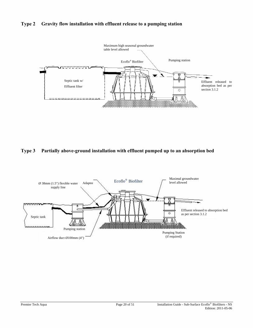
Type 2 Gravity flow installation with effluent release to a pumping station
Type 3 Partially above-ground installation with effluent pumped up to an absorption bed
Septic tank
Pumping Station (if required) Airflow duct Ø100mm (4")
Ecoflo® BiofilterAdapterØ 38mm (1.5") flexible water supply line
Pumping station
Effluent released to absorption bed as per section 3.1.2
Maximal groundwater level allowed
Ecoflo® Biofilter Pumping station
Effluent released to absorption bed as per section 3.1.2
Septic tank w/
Effluent filter
Maximum high seasonal groundwater table level allowed

Premier Tech Aqua Page 21 of 51 Installation Guide - Sub-Surface Ecoflo® Biofilters - NS Edition: 2011-05-06
Type 4 Gravity flow installation with two Ecoflo® Biofilters
Onsite systems comprising two Ecoflo® Biofilters require a flow divider. Premier Tech Aqua offers two gravity flow divider models: • the GFD-200 gravity flow divider and • the GFD-200A adjustable gravity flow divider.

Premier Tech Aqua Page 22 of 51 Installation Guide - Sub-Surface Ecoflo® Biofilters - NS Edition: 2011-05-06
Part III - Ecoflo® Biofilter Assembly and Installation Guide Approved Design Manual and Installation Guide – Nova Scotia
A) Ecoflo® Biofilter with Open Bottom – ST Series Models 1. Ecoflo® Biofilter functions
1.1 System components functions Lid: • Gives access inside the shell; • Feeds with air the filtering media (via its intake); • Securely fastened with bolted assemblies. Insulating board: • Give a thermal insulation to the system; • Helps guiding airflow into the shell’s air ducts; • Seals the system (with Premier Tech ty-raps); • Constitute an added security against frost. Shell (including optional riser, if any): • Encloses the system components; • Holds air and water pipes connections to the
system; • Circulates air via its air ducts to the ends of the
filtering media. Central support: • Support the tipping bucket and one end of the
distribution plates; • Allow air exchange between bottom and top of the
filtering media; • Its access allows inspection of the absorption bed. Tipping bucket: • Allows even distribution of the influent on both sides of the filtering media; • Creates hydraulic events required to obtain a good water distribution on the distribution plates and contribute to their self-
cleaning.
Distribution plates: • Allow even distribution of the influent over the filtering media.
Filtering media: • Acts as a support for bacteria that consume the wastewater organic content; • Does a physical filtration of the influent solids content; • Keeps an adequate humidity level required for biomass viability when there is no incoming water. Sampling device: • Allows taking representative samples of the effluent treated by the system.

Pr
2
2.
N
2. Pr • •
Aw
remier Tech Aqua
2. Instal
.1 Make s
A. 1 shell • 1 b• 4 b• 1 in
B. 1 lid
NOTE: The insta
.2 Absorp
repare the abso
Clean crushMinimum th
After that, placewe look at the ab
B A
1
llation se
ure that you
including : bag with the owblack plastic tynsulating board
installer isallation step
ption bed, sa
orption bed in a
hed stone 15-60hickness of the
e the samplingbsorption bed f
G
equence
u have all th
wner’s documey-raps, 2 ty-rapd
For acontact o
s responsibls, including
ampling dev
accordance wit
0 mm Ø (½-2")e bed is 200 mm
g device on thefrom the septic
C
2
Pa
he following
entation s marked Prem
any problemour custome
le to take tg wearing a
vice and cen
th the sizes pre
), with a high fm (8") (3).
e crushed stonc tank) (4).
D
age 23 of 51
g componen
mier Tech
m, faulty or er service at
the precauthard hat, g
ntral suppor
escribed in Par
fraction of a di
ne bed with its
3
Install
nts or article
C. 1 tippingD. 4 distribuE. 1 sampleF. 1 centralG. 1 pallet o
missing part 1 800 632-
tionary meagloves, boots
rt
rt II section 3.1
iameter of 20 m
s flat part on
E
ation Guide - Sub-
es
g-bucket ution plates er l support of filtering med
rt, 6356.
asures of sas, glasses, m
1.2 of this docu
mm (¾") (2);
the right side
-Surface Ecoflo® BEditio
dia
afety applyimask, etc.
ument (1).
of the supply
F
4
Biofilters - NS on: 2011-05-06
ing to all
y line (when

Pr
2. 2.
2.
remier Tech Aqua
.3 Setting
.4 Geotext
.5 Supply
The samplmust be locaand under theLevel the cenmake sure tcontact with tcrushed stone
5
8
9
the shell in
tile installat
line connec
ler’s receptaated in the cene central suppontral support athat it is in fthe surface of e.
and levellin
tion and Ec
Place crusheobstru Thereshouldmattershell. Warncarefu After,backfirecom
ction All pisupplytoward It is im
acle nter ort. and full the
10
Pa
ng
oflo® Biofilt
a geotextile ed stone arounuction from obj
e should be nd be clean fill r, impervious
ning! When bully backfilling
backfill the till material be
mmended.
ipe connectiony line to the Ed the Biofilter
mportant that th
6
Place the ssupport. Taksupport musshell. Thefunnel mustthe water in
age 24 of 51
ter backfill
(polymeric mend the shell ojects or particle
no geotextile ranging in parsoil, stones, r
ackfilling the g the four corne
two long sidese deposited, n
ns to a treatmeEcoflo® Biofilte
.
he soil underne
shell on the ke note that thest be embeddee central st be located o
nlet.
Install
embrane permonly so as to pes.
under the Erticle size fromrocks, debris o
Ecoflo® Biofers.
s, followed bynot dumped. U
ent unit must ber, ensuring a
eath the pipe be
central e central d in the support opposite
ation Guide - Sub-
meable to air aprotect the ston
coflo® Biofiltem 0.2 – 2.0 mmor other object
filter, start by
y the two endsUsing a bulldo
be watertight asteady downw
e well compact
Doublethe sheare botcontactclean c
-Surface Ecoflo® BEditio
and water) on ne from contam
er. The backfm and containts that could d
y stabilizing th
s. It is importaozer for this
and flexible. Cward slope of a
ted.
e check to mell and centrath levelled ant with the surfarushed stone.
Biofilters - NS on: 2011-05-06
top of the mination or
fill material n no organic damage the
he shell by
ant that the step is not
Connect the at least 2 %
make sure al support nd in full ace of the

Premier Tech Aqua Page 25 of 51 Installation Guide - Sub-Surface Ecoflo® Biofilters - NS Edition: 2011-05-06
2.6 Supply line connection to the flexible adapter* Assembly steps
1. Loosen the clamp without removing it from the adapter; 2. Clean the supply pipe end and apply a PVC primer; 3. Apply PVC cement inside the adapter and on the supply pipe end; 4. Insert the pipe covered with cement all the way inside the adapter; 5. Tighten back the clamp on the adapter and the supply pipe. * The same procedure is applicable to the vent pipe connection when a pumping station is
used.
Pipe installation details when a pumping station is required to feed the Ecoflo® Biofilter ST Series Models When the use of a pumping station is required upstream of an Ecoflo® Biofilter ST-500/650, the following instructions must be taken into account: • The pumping station must be accessible at all times. • For installations with a pumping station, the amount of water released to each Ecoflo® Biofilter must be within 30 to 40 L
(6.6 to 8.8 imp. gal.) per dosing. See Part I Section 1.5 of this document concerning pumping configuration. • The pumping station must be watertight to infiltration and exfiltration. • The supply line (flexible pipe of 38 mm Ø (1.5")) uses an adapter to allow connection to the Ecoflo® Biofilter inlet which
has a diameter of 100mm Ø (4"). Take note that the use of the adapter is mandatory to break the jet stream coming from the pumping station.
• An airflow duct must link the pumping station and the Ecoflo® Biofilter to ensure air circulation. The airflow duct is connected to the adapter located at the Biofilter's inlet, as illustrated below.
To facilitate the understanding of these instructions, refer to the diagram below, or to the pumping station PSA-240L Installation Guide, as example.
Pipe installation diagram when using a pumping stationEcoflo® Biofilter ST Series Models
Airflow duct 100 mm (4") Ø
Pumping station
Flexible supply line38 mm (1½") Ø
Septic tank
Airflow duct connection
Pipe installation in systems with a pumping station
Hook-upAdapter
Premier Tech Aqua Page 26 of 51 Installation Guide - Sub-Surface Ecoflo® Biofilters - NS Edition: 2011-05-06
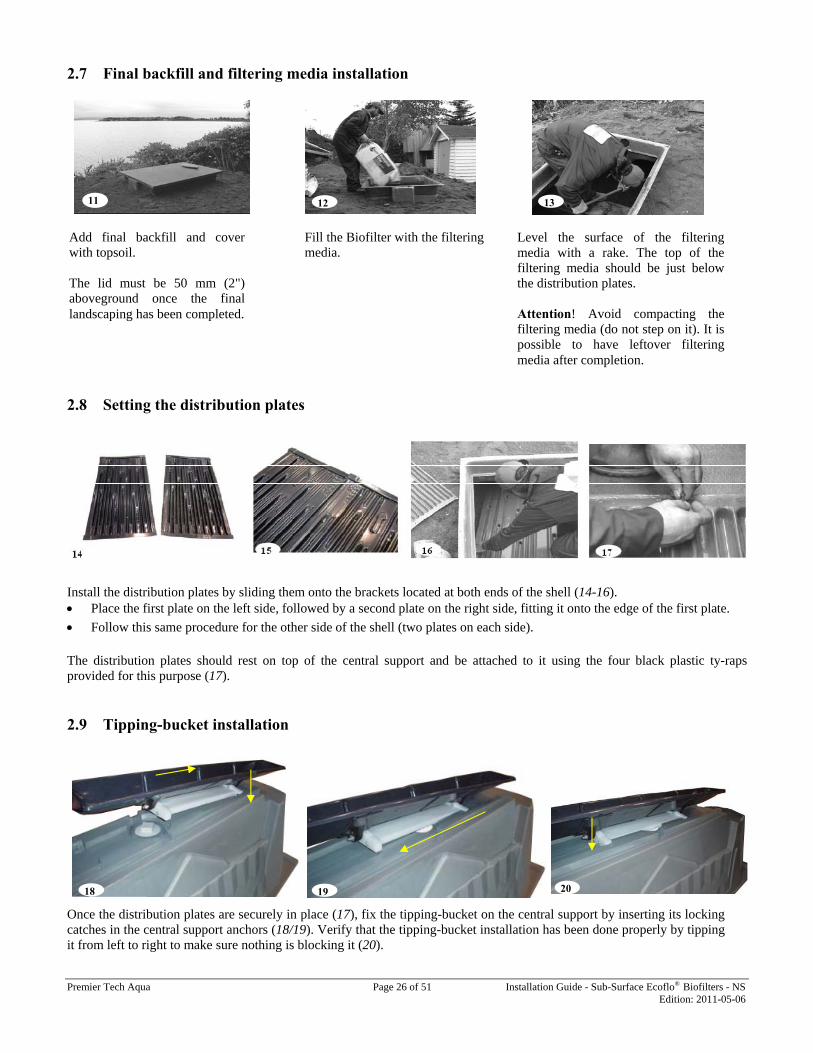
2.7 Final backfill and filtering media installation
2.8 Setting the distribution plates
Install the distribution plates by sliding them onto the brackets located at both ends of the shell (14-16). • Place the first plate on the left side, followed by a second plate on the right side, fitting it onto the edge of the first plate. • Follow this same procedure for the other side of the shell (two plates on each side).
The distribution plates should rest on top of the central support and be attached to it using the four black plastic ty-raps provided for this purpose (17). 2.9 Tipping-bucket installation Once the distribution plates are securely in place (17), fix the tipping-bucket on the central support by inserting its locking catches in the central support anchors (18/19). Verify that the tipping-bucket installation has been done properly by tipping it from left to right to make sure nothing is blocking it (20).
Add final backfill and cover with topsoil. The lid must be 50 mm (2") aboveground once the final landscaping has been completed.
Fill the Biofilter with the filtering media.
Level the surface of the filtering media with a rake. The top of the filtering media should be just below the distribution plates. Attention! Avoid compacting the filtering media (do not step on it). It is possible to have leftover filtering media after completion.
18 19 20
11 12 13

Premier Tech Aqua Page 27 of 51 Installation Guide - Sub-Surface Ecoflo® Biofilters - NS Edition: 2011-05-06
2.10 System operation verification and warranty seals
After making sure the distribution system operates properly, close the Ecoflo® Biofilter by installing first the insulating board and then the lid (21). Seal it shut by attaching the handle of the insulating board to the access of the Ecoflo® Biofilter using the two plastic ty-raps marked "Premier Tech Aqua" (22). Check points following installation:
Never cover or bury the lid; Never install the absorption bed of an Ecoflo® Biofilter within 2 m (6.5’) of a tree; Never enter the biofilter after installation without prior written authorization; Never drive vehicles or place objects weighing over 225 kg (500 lbs) within 3 m (10') of the lid, and make sure you
advise those involved so they don’t damage your septic system (landscaper, snow blower); Do not shovel or blow snow so it accumulates on top of the septic system. The overload could cause damage; For an installation with a pumping station located upstream of the Ecoflo® Biofilter, the airflow duct must be
connected from the pumping station to the Ecoflo® Biofilter.
Homes must be equipped with an air vent that is in proper working order and complies with the applicable standards; PTA recommends the use of a 100 mm (4") Ø pipe;
Give the owner the plastic bag containing the Owner’s Manual and the Maintenance Agreement; Tell the customer to fill out and sign the Maintenance Agreement. He must keep the white copy, send the yellow copy
to the authorized distributor and the pink copy to Premier Tech Aqua.
FOR ANY PROBLEM, QUESTION OR COMMENT, DO NOT HESITATE TO CONTACT OUR CUSTOMER SERVICE AT
1 800 632-6356
Don’t forget the inspections required by the Nova Scotia Regulations.

Premier Tech Aqua Page 28 of 51 Installation Guide - Sub-Surface Ecoflo® Biofilters - NS Edition: 2011-05-06
3. Shipping and handling instructions
3.1 Shipping from the dealer to the installation site • Use a vehicle with loading space large enough for the Ecoflo® Biofilter to fit in completely. • Secure the Biofilter to the vehicle with appropriate straps. • The carrier is responsible for any damages and for observance of traffic regulations. • As much as possible, use the anchor rings to load the Biofilter onto the vehicle. 3.2 Handling • Handle with care to avoid damages. • Use the anchor rings to unload the Biofilter (especially for assembled Biofilter). Make sure that the forks used are long
enough to reach completely across the Biofilter. • The material handler is responsible for any damages that may occur. 3.3 Loading configuration • The loading configuration depends on the type of vehicle used to transport the Biofilter(s) to the installation site. • The loading area must be at least 4.2 m x 2.4 m for the Ecoflo® Biofilter to fit inside completely. • The carrier must keep enough space to carry the filtering media bags (bags can be taken off the pallet). A pallet of filtering
media measures about 1.4 m x 1.1 m.

Pr
B 1
1.
L• • •
In• • •
•
Sh• • •
T•
•
D•
C•
•
•
Fi• • •
C• •
E•
C•
remier Tech Aqua
B) Ecoflo
1 Funct
.1 Compo
id: Gives accesFeeds with Secures acc
nsulating boarGives a therHelps guidiSeals the sywraps); Constitutes
hell (includingEncloses thAllows connCirculates avia its ducts
ipping-bucketAllows evensides of the Creates hydgood water and contribu
Distribution plaAllows evenfiltering me
entral supporSupports thdistributionAllows air filtering meIts access al
iltering mediaActs as a suDoes a physKeeps an ad
rushed stone Supports thWeighs dow
ffluent collectStrainer typ
ollecting bottoSeals bottom
® Biofilte
tions of t
nent functio
ss inside the shair the filtering
cess with bolted
rd: rmal insulationing airflow intoystem (with Pr
an added secu
g optional risee system compnection of air a
air to the filteris.
t: n distribution ofiltering media
draulic events rdistribution onute to their self
ate: n distribution o
edia.
rt: he tipping-bu
n plates; exchange betw
edia; llows inspectio
a (FM): upport for bactesical filtration dequate humid
at the bottom e filtering med
wn the system t
ting pipe: pe tube used to
om gasket: m and top of th
er with C
he Ecoflo
ons
hell; g media (via itsd assembly.
n to the systemo the shell air demier Tech A
urity against fro
er, if any): ponents; and water pipeng media’s ext
of the influent a; required to obtan the distributiof-cleaning.
of the influent
ucket and one
ween bottom a
on of the absorp
eria that consuof the influent ity level requir
of the biofiltedia; to resist to the
evacuate the tr
he shell.
Pa
Collecting
o® Biofilt
s air intake);
m; ducts;
Aqua tie
ost.
s; tremities
on both
ain a on plates
over the
e end of the
and top of the
ption bed.
me the wastewsolids content
red for biomass
er:
hydrostatic up
reated effluent
age 29 of 51
g Bottom
ter STB S
e
e
water organic cot; s viability whe
plift (for a level
t out of the shel
Install
m – Fiberg
Series M
ontent;
en there is no in
l of groundwat
ll.
ation Guide - Sub-
glass She
Models
ncoming water
ter up to 50 cm
-Surface Ecoflo® BEditio
ell
r.
m below ground
Biofilters - NS on: 2011-05-06
d surface).

Pr
C• • •
2
2.
N
remier Tech Aqua
ollecting bottoHolds the trAllows connMakes the s
2. Instal
.1 Make s
A. 1 sh
• • 4• •
B. 1 shC. 1 tipD. 4 diE. 1 pa
NOTE: The incl
om: reated effluent;nection of the shell watertigh
llation se
ure you hav
hell with subme1 packet contai4 black plastic 1 insulating bo1 optional riserhell lid pping-bucket istribution plateallet of filtering
installer isuding the u
B
; effluent dischat and resistant
equence
ve all the fol
ersible collectiining the Owntie wraps, 2 tie
oard r
es g media
For ancontact o
s responsibluse of hard h
B A
Pa
arge pipes; to groundwate
llowing com
ing bottom, cener’s documentse wraps marke
ny problemour custome
le for all sahat, gloves,
age 30 of 51
er pressure.
mponents:
ntral support ans
ed "Premier Tec
m, broken orer service at
afety measuboots, glass
C
Install
nd integrated e
ch"
r missing pat 1 800 632-
ures applicses, mask, et
ation Guide - Sub-
effluent collecti
art, 6356.
able to all tc.
D
-Surface Ecoflo® BEditio
ing pipe:
steps of in
Biofilters - NS on: 2011-05-06
nstallation
E

Premier Tech Aqua Page 31 of 51 Installation Guide - Sub-Surface Ecoflo® Biofilters - NS Edition: 2011-05-06
2.2 Excavate and put shell in Excavate an area approximately 4 m x 4.5 m (13' x 15'). Lay a 150 mm (6") bed of gravel 20 mm Ø (¾"), free of organic matter and of similar diameter.
Level and compact the gravel surface.
Install the Ecoflo® Biofilter in the excavated area. Make sure it is levelled and in full contact with the foundation. FOR INFORMATION REGARDING INSTALATION OF THE ABSORPTION BED SEE SECTION 3 IN PART II A OF THIS MANUAL.
2.3 Connect the effluent discharge pipe
Connect the Biofilter effluent discharge pipe (5). It can be connected to a pumping station, or lead directly to an absorption system.
Pumping Station
1
2 3 4
5
PSA-240L
BIOFILTER
Compacted soil underneath the pipe and Biofilter
Effluent discharge pipe

Pr
2.
IM Wda(2
2.
remier Tech Aqua
.4 Put cru
MPORTAN
We recommendamage by lean26" x 96") on e
.5 Backfil
8
ushed stone
NT: This ste
d protecting thning two woodeach side.
l and conne
into the she
p must be d
he central suppd panels 0.66 m
ect the supp
Wheeachsuccnot d The rock
Connat leunde
Pa
ell
done on the
port against m x 2.44 m
Place a 38bottom of must be drentire surfAt the endbottom’s j
ly line
en backfilling th of the four cocessive layers odumped, which
backfill mateks, debris or oth
nect the supplyeast 2 percenter the pipes.
age 32 of 51
same day th
81 mm (15") the Ecoflo® Bi
ropped on bothface of the bottd, the top of thoint.
the Ecoflo® Biorners. Backfillof 30 cm (12"h is why we do
erial should coher objects that
y line to the Ectoward the Bi
Central support
Install
hat the shel
layer of 20 miofilter, on both sides alternattom and undere crushed ston
ofilter, first stal the two long ). It is importa
o not recommen
ontain no orgat could damage
coflo® Biofilteiofilter intake.
ation Guide - Sub-
ll is put in.
mm Ø (¾") clth sides of the tively. Spread tr the central supne bed should b
abilize the shelsides next, follant that the band using a bull
anic matter, ime the shell.
er, ensuring a sMake sure th
Wood panelscentral suppo
-Surface Ecoflo® BEditio
lean crushed scentral supporthe crushed stopport after eacbe even with th
ll by carefully lowed by the tw
ackfill materialldozer for this
mpervious soil,
steady downwahe soil is well
s to protect the ort against damage
Biofilters - NS on: 2011-05-06
stone in the rt. The stone one over the ch dumping. he shell and
backfilling wo ends, in be placed, step.
, stones,
ard slope of compacted

Premier Tech Aqua Page 33 of 51 Installation Guide - Sub-Surface Ecoflo® Biofilters - NS Edition: 2011-05-06
2.6 Connect the supply line to the flexible adapter * Assembly steps 1. Loosen the clamp and push it back. Don’t remove it from the adapter; 2. Clean the pipe and apply a PVC primer; 3. Apply PVC cement inside the adapter and on the pipe end; 4. Insert the pipe (covered with cement) all the way inside the adapter; 5. Bring the clamp forward and tighten it on the adapter and the
4" (100 mm) Ø pipe. * The same procedure is applicable for vent pipe connection when there is a pumping station Pipe installation details when a pumping station is required to feed the Ecoflo® Biofilter STB Series Models When the use of a pumping station is required upstream of an Ecoflo® Biofilter STB-500/650, the following instructions must be taken into account: • The pumping station must be accessible at all times • For installations with a pumping station, the amount of water released to each Ecoflo® Biofilter should not exceed 30 to
40 L (6.6 to 8.8 imp. gal.) per dosing. The Ecoflo® typically does not require a pump, as it generally receives gravity-fed effluent from the septic tank. If the system requires a pumping station, the PSA-240L Pumping Station (or approved product – see Part I section 1.4) should be installed downstream of the septic tank and/or the effluent filter container, unless site conditions do not permit this configuration (see PSA-240L Installation Guide for information on its function and installation as example). Where it is necessary to pump to the septic tank, the additional standard requirements of the Technical Guidelines concerning septic tank type and size, discharge per pump cycle, discharge rate, and flow control must be observed. Like the septic tank, the pumping station must also be watertight to prevent groundwater infiltration.
• The pumping station must be watertight to infiltration and exfiltration. • The supply line (flexible pipe of 38 mm Ø (1.5")) uses an adapter to allow connection to the Ecoflo® Biofilter inlet which
has a diameter of 100 mm Ø (4"). Take note that the use of the adapter is mandatory to break the jet stream coming from the pumping station.
• An airflow duct must link the pumping station and the Ecoflo® Biofilter to ensure air circulation. The airflow duct is connected to the adapter located at the Biofilter's inlet, as illustrated below.
To facilitate the understanding of these instructions, refer to the diagram below and to the pumping station PSA-240L Installation Guide.
Pipe installation in systems with a pumping station
Airflow duct Ø 100mm (4")
Pumping station
Hook-up adapter
Flexible water supply line
Airflow duct connection
Septic tank

Pr
2.
2.
• •
• •
1
1
remier Tech Aqua
9
.7 Add fin
.8 Install d
Install the dPlace the fir(14). Follow this The distribuprovided fo
10
11
12
nal layer of b
distribution
distribution plarst plate on the
same proceduution plates shoor this purpose
backfill and
Add a final la The access lid Fill the Biofil Level the filtunderneath th Attention! A
n plates
tes by sliding te left side, follo
re for the otherould rest on top(15).
13
Pa
d install filte
ayer of backfill
d must be 50 m
lter with the fil
ering media suhe distribution
Avoid compact
them onto the bowed by a seco
r side of the shp of the central
age 34 of 51
ering media
l and cover wit
mm (2") aboveg
ltering media.
urface with a rplates.
ting the filterin
brackets locateond plate on the
hell (two platesl support and b
14
Install
a
th topsoil.
ground once th
rake. The surfa
ng media (do
ed at both endse right side, fit
on each side) be attached to i
ation Guide - Sub-
he final landsca
ace of the filter
not lean on it)
of the shell (1tting it onto the
(14). t using the fou
1
-Surface Ecoflo® BEditio
aping has been
ring media sho
).
2, 13, & 14). e edge of the fir
ur black plastic
15
Biofilters - NS on: 2011-05-06
completed.
ould be just
rst plate
ty-raps

Premier Tech Aqua Page 35 of 51 Installation Guide - Sub-Surface Ecoflo® Biofilters - NS Edition: 2011-05-06
2.9 Install tipping-bucket
Once the distribution plates are securely in place (15), fix the tipping-bucket on the central support by inserting its locking catches in the central support anchor slots and set the other end down in position (16/17). Verify that the tipping-bucket installation has been done properly by tipping it from left to right to make sure nothing is blocking it (18). 2.10 Make sure the system operates properly and put the warranty seals
After making sure the distribution system operates properly, close the Ecoflo® Biofilter by installing first the insulating board and then the lid (19). Seal it shut by attaching the handle of the insulating board to the access of the Ecoflo® Biofilter using the two plastic ty-raps marked “Premier Tech" (20).
Don’t forget the inspections required by the Nova Scotia Regulations.
17 16
18
19 20

Premier Tech Aqua Page 36 of 51 Installation Guide - Sub-Surface Ecoflo® Biofilters - NS Edition: 2011-05-06
Checkpoints following installation:
Never cover or bury the access lid.
If a riser is required, only add a Premier Tech Aqua riser STR-080 to the Ecoflo® Biofilter.
Install only one riser per Biofilter.
Never locate an absorption bed within 2 m (6.5') from a tree.
Never enter the shell after installation without prior written authorization.
Never drive vehicles or place objects weighing over 225 kg (500 lb) within 3 m (10') of the lid, and if you plan to do any landscaping, make sure you advise those involved so they don’t damage your septic system.
Do not let anything accumulates on top of the septic system. The overload could cause damage.
For an installation with a pumping station located upstream of the Ecoflo® Biofilter, the airflow duct must be connected from the pumping station to the Ecoflo® Biofilter.
Mark the appropriate classification box on the identification sticker located inside the access of the Ecoflo® Biofilter
The home must be equipped with an air vent that is in proper working order and complies with the applicable standards. Premier Tech Aqua strongly recommends using a 100 mm (4") Ø pipe.
Give the owner the plastic packet containing the Owner’s Manual and the Maintenance Agreement.
Mention to the customer to fill out and sign the Maintenance Agreement. They must keep the white copy, send the yellow copy to the authorized distributor and the pink copy to Premier Tech Aqua.
FOR ANY PROBLEM, QUESTION OR COMMENT, DO NOT HESITATE TO CONTACT OUR CUSTOMER SERVICE AT
1 800 632-6356

Premier Tech Aqua Page 37 of 51 Installation Guide - Sub-Surface Ecoflo® Biofilters - NS Edition: 2011-05-06
3. Shipping & Handling Instructions
3.1 Shipping from the dealer to the installation site • Use a vehicle with loading space wide enough for the Ecoflo® Biofilter to fit in completely. • Secure the Biofilter to the vehicle with appropriate straps. • The carrier is responsible for any damage and for the observance of traffic regulations. • As much as possible, use the anchor rings to load the Biofilter onto the vehicle. 3.2 Handling • Handle with care to avoid damages. • Use the anchor rings to unload the Biofilter. If forks are used, make sure that the forks are long enough to reach across the
whole Biofilter. • Material handler is responsible for any damages that may occur. 3.3 Loading configuration • The loading configuration depends on the type of vehicle used to transport the Biofilters to the installation site. • The loading area must be at least 4.2 m x 2.4 m (14' x 8') for the Ecoflo® Biofilter to fit in completely. • The carrier must keep enough space to transport the filtering media bags (bags can be taken off the pallet). A pallet of
filtering media bags measures about 1.4 m x 1.1 m (4.6' x 3.6').
Premier Tech Aqua Page 38 of 51 Installation Guide - Sub-Surface Ecoflo® Biofilters - NS Edition: 2011-05-06
C) Ecoflo® Biofilter with Collecting Bottom – Concrete Shell 1. Operation of the Ecoflo® Biofilter STB Series Models B and BR
1.1 Operation of the components (see exploded view of the system on the following page) Lids: • Provide access to the inside the system (main and secondary accesses); • Provide air to the filtering media (via air intake on main access); • Secure access with bolted assembly.
Insulating boards: • Provide thermal insulation for the system; • Help guide airflow into the shell's air ducts (main access only); • Seal the system (main access only) (with Premier Tech ty-raps).
Shell (tank and top tile): • Contains the system components; • Allows connection of air, inlet and outlet pipes; • Circulates air to the ends of the filtering media via its air ducts; • Holds the treated effluent.
Central support plate: • Supports the tipping bucket and one end of the distribution plates.
Support rails: • Support the other end of the distribution plates.
Tipping bucket: • Allows even distribution of the influent on both sides of the filtering media; • Creates hydraulic events required to obtain proper distribution of the water on the distribution plates and promotes self-
cleaning.
Distribution plates: Allow even distribution of the influent on the filtering media.
Filtering media: • Consists a layer of filtering media; • Acts as a support for the bacteria that consume the organic content in the wastewater while trickling down through it; • Physically filters the solids content of the effluent; • Keeps an adequate level of humidity required for biomass viability when there is no incoming water.
Treated effluent collection area: • Layer of clean crushed stone 20 mm ø (¾"); • Supports the filtering media; • Ensures drainage of the treated effluent; • Allows air to circulate under the filtering media.
Access well: • Contains the pumping equipment (models STB-500 and STB-650BR only); • Allows air circulation between the top and the bottom of the filtering media; • Allows access to the bottom of the system to collect samples of the treated effluent.
Aeration and drainage system: • Takes the effluent from the gravel bed and directs it towards the discharge pipe; • Allows air to circulate under the filtering media.
Pumping unit (STB-500BR and STB-650BR models only): • Includes a pump, a float tree, an ON/OFF float, an alarm float and an alarm box; • Pumps the treated effluent towards an absorption area, or a tertiary treatment system.

Premier Tech Aqua Page 39 of 51 Installation Guide - Sub-Surface Ecoflo® Biofilters - NS Edition: 2011-05-06
Note: Float tree is used in all STB concrete series models terminating by the BR suffix.
Exploded view of the system

Premier Tech Aqua Page 40 of 51 Installation Guide - Sub-Surface Ecoflo® Biofilters - NS Edition: 2011-05-06
1.2 Overall operation of the system The overall operation of the Ecoflo® Biofilter is to treat domestic wastewater following a primary treatment. This is done via a water and air (oxygen) management inside the system. Wastewater is treated aerobically by bacteria attached to the filtering media.
To be treated, the wastewater first goes into the septic tank where it is submitted to a primary treatment and then it enters the Ecoflo® Biofilter. Once inside the Ecoflo®, the water is directed to the tipping bucket to be distributed evenly over the distribution plates located on both sides of the central support plate. These plates include channels with orifices (openings) to distribute the influent evenly on top of the filtering media. Afterwards, wastewater trickles down into the filtering media where its organic content is consumed by bacteria. The treated effluent is collected in the gravel bed and evacuated by gravity (STB-500B, STB-650B) or using an integrated pump (STB-500BR, STB-650BR).
To be effective, the system requires enough oxygen for the bacteria on the filtering media to do their work. To achieve this, the filtering media is fed oxygen by the air that flows at the top and at the bottom of the filtering media. The air comes into the system through the intake located on the main access lid. Then, it is directed to both ends of the filter bed via the air ducts in the shell. Air flows over the surface of the filtering media underneath the distribution plates, and penetrates the filtering media partly through the infiltration of water that takes it from the surface to the bottom of the filtering media. As well, there is an exchange of gases both at the top and at the bottom of the filtering media, which promotes its oxygenation. The opening located in the access well of the central support allows air to circulate between the top and the bottom of the filtering media. Finally, air circulates throughout the system by means of convection, from the home air vent (or independent vent) to the inlet pipe and the septic tank.
Water flow diagram
Airflow diagram
Water flow diagram (STB-650B discharged by gravity)

Pr
2
2.
N
A.
B.
C.
remier Tech Aqua
2. Instal
.1 Make s
NOTE: Theincl
. 1 concrete shi 1 ac
ii 1 aeiii 1 iniv 1 ou
show
v 1 bdocumar
. 1 top tile incl
i 1 minclwith
ii 1 seinclwith
iii 2 air
. 1 pallet of fillayer" bags)
llation se
ure you hav
cont
installer iuding the u
hell including :ccess well eration and dranlet adapter 100utlet adapter cawn)
25 mm Ø (1100 mm Ø (4
bag (not showuments, 4 blacrked Premier T
luding : main access emb
uding an insulah 4 lag screws econdary accesuding an insulah 4 lag screws r ducts
ltering media ()
equence
ve all the fol
For antact our Cu
is responsibuse of a hard
inage system 0 mm Ø (4") ast in the concr
") (STB-500/64") (STB-500/6wn) containinck plastic ty-rapTech (Ty-Rap®)
bedded in concating board and
s embedded inating board and
("top layer" ba
Pa
llowing com
ny problemstomer Serv
ble for all d hat, gloves
rete shell (not
50BR) 650B) ng the ownerps and 2 ty-rap)
crete and d a lid attached
n concrete and d a lid attached
ags and "bottom
age 41 of 51
mponents:
m, broken orvice Depart
safety meas, boots, saf
r's ps
d
d
m
D. 1 cE. 2 PF. 4 dG. 1 tH. 2 sI. Bu Additio(see sec J. 1 c
pipK. 1 c
disL. 1 p
weM. 1 aN. 1 jO. Se
Install
r missing pament at 1 8
asures applifety glasses,
central support PVC support radistribution platipping bucketsections of nettutyl seal
onal items forctions 2.7 and
crenate outlet cpes coupling 25mmscharge pipe topumping unit well alarm box unction box al connectors (
ation Guide - Sub-
art, 00 632-6356
icable to aface mask,
plate ails ates
ting
r model STB-5 2.10 for the f
coupling 25 mm
m Ø (1") to cono the polishing with float tree i
(for the electric
-Surface Ecoflo® BEditio
6
all installatietc.
500BR, STB-6following item
m ø (1") for fl
nnect the effluefield
installed inside
c wires)
Biofilters - NS on: 2011-05-06
ion steps,
650BR only ms):
lexible
ent
e the access

Pr
2.
Fodidoco 2.Tthat
BWbadeussa(2 A 2.O(wcr FrlanetosuRgrfilenra A•
• • •
remier Tech Aqua
.2 Excava
or the Ecoflo® ischarge pipe uownward positompacted.
.3 Initial bhe height of t
hat the maximt least 75 mm
ackfill the sheWhen backfillin
ackfill the two eposited, not dsing a bulldozeandy, with litt2”) in diamete
ATTENTION:
.4 PuttingOnce inside the with no fine parushed stone la
rom the outsidayer on the lowetting to separaop layer up to upport rails ar
Remove any parooves and theltering media und, the surfaceails of the distri
ATTENTION! When moviit. Make sure nCarefully levMake sure nofilled.
ation, founda
Biofilter STB-using the flextion all along
backfill of thhe inlet invert
mum seasonal (3") below the
ell up to 200
ng the shell, staends. It is imp
dumped, whicer for this step.tle or no rockr.
When backfill
g the gravel tank, evenly s
articles or orgaayer to put, use
de of the tank, wer part of theate the two laythe lowest lev
re located and articles from the central suppoup to the top o
e of the filterinibution plates.
ng inside the
not to compacvel the surface o filtering med
ation and in
-500B, STB-65ible and water its length an
he shell t is 1255 mm level of the gre lid joint.
mm (8") undart by the two lportant that thech is why we . The backfill ks or stones l
ling, make sure
and the filtspread a 200 manic debris). Tthe upper leve
pour the bagse tank. Level tyers of filteringvel of the groo
level the surfhe grooves andort plate in theof the support ng media must
tank, make s
t the filtering of the filtering
dia falls into the
Pa
nstallation o
50B only (discrtight couplingnd down to th
(49⅜"). Makeroundwater ta
der the inlet iateral sides and
e backfill materdo not recommaterial shou
larger than 50
e that no backf
ering mediamm (8") layer oTo determine tel of the drainin
s of filtering mthe surface andg media. Then oves in the conface (see illusd place the supe center groovrails and levelbe at the uppe
sure no backfi
media (do nog media. e access well w
age 42 of 51
of the system
Excavate aDepending 150 mm (6contain any20 mm Ø (making surewith the folevelled.
charge by gravig. Connect thehe disposal are
e sure able is
invert. d then rial be
mmend uld be 0 mm
fill material get
a down of clean crushethe upper levelng chamber.
media marked d add two sectpour the bags
ncrete walls whstration on thepport rails in t
ve. Finish pourl it with a rakeer level of the
fill material ge
t lean on it).
while the tank i
Install
m
an area approxon the soil co
6") layer of gray vegetable ma0-¾") surroune that it is leveoundation that
ity), before goe pipe to the Eea. Make sure
ts into the shel
ed stone l of the
bottom tions of marked
here the e right). the end ring the e. In the support
ets into
is being
Effluen
ation Guide - Sub-
ximately 3.0 ondition, it migavel 0-20 mmatter, or a laye
nded by a geotelled and that itt has previou
ing to the nextEcoflo® Biofilte the soil und
l.
nt pipe (STB-500
-Surface Ecoflo® BEditio
m x 4.5 m (ght be necessa
m Ø (0-3/4") ther of clean cruextile. Set the ts entire floor isly been com
t step, connect ter making surderneath the p
0/650B)
Biofilters - NS on: 2011-05-06
(10' x 15'). ary to add a hat does not ushed stone shell down
is in contact mpacted and
the effluent re it is in a
pipe is well

Premier Tech Aqua Page 43 of 51 Installation Guide - Sub-Surface Ecoflo® Biofilters - NS Edition: 2011-05-06
2.5 Installing the distribution plates
• Install the distribution plates by placing them on their support rails at both ends. • The arrow on the distribution plates must be oriented toward the end of the tank. • Place the first plate on the left side and place the second plate against the edge of the first one. • Repeat on the right side of the shell (2 plates on each side of the shell). The distribution plates sit on top of the central support plate and must be attached to it with four black plastic ty-raps. 2.6 Installing the tipping bucket and the inlet pipe
Once the distribution plates are in place, install the tipping bucket by inserting its locking catches in the anchor slots of the central support plate and push down the other end to make sure the tipping bucket stays in place. Check that the installation of the tipping bucket by tipping it from left to right to make sure nothing is blocking it. Then, glue the interior part of the inlet pipe in the tank’s water inlet. Be sure that the end of the inlet pipe is lower than the water inlet in order to have a good water flow coming inside the system. 2.7 Connecting the pipes (inlet and discharge pipes) Connect the inlet pipe from the septic tank to the Ecoflo® Biofilter water inlet, making sure that the pipe runs downward along its length to the Ecoflo® Biofilter’s water inlet. The soil underneath the pipe must be well compacted. The Ecoflo® Biofilter is equipped with a standard flexible inlet adapter and is connected with a regular pipe clamp. As well, the STB-500BR, STB-650BR effluent must be connected to the means of disposal (absorption area, or tertiary treatment system) of the treated effluent by a 25 mm Ø (1") flexible pipe that can support at least 700 kPa (100 PSI) of pressure and is compatible with the underground applications. A 25 mm Ø (1") crenated outlet coupling (item J) connects this flexible pipe to the Biofilter outlet. The other end of the pipe is connected to the polishing field using the supplied coupling (Item K).
Anchor slots Locking catch Inlet pipe (interior part)
K
J

Premier Tech Aqua Page 44 of 51 Installation Guide - Sub-Surface Ecoflo® Biofilters - NS Edition: 2011-05-06
What you must know: • Maximum length of pressurized pipe (flexible pipe) at the pump's outlet: 20 m (65') with 25 mm ∅ (1") pipe. • When the length of the pressurized pipe required is more than 20 m (65 ft) and less than 40 m (130 ft), it is possible to use
a pumping station PSA-240L as shown on next figure. A 14" riser must be use on the PSA-240L. The diameter of the pressurized pipe is 1 ½". No floats adjustment is required.
• The head (the difference in elevation between the base of the tank and the end of the pressurized pipe) must be no more
than 6 m (20'). The pipes must be positioned such that they can drain by gravity. ATTENTION! The inlet pipe invert must be always higher than the level of the groundwater table. If the terrain layout it is such that surface run-off accumulation is possible, an interceptor ditching up slope the system or absorption area, may need to be installed to prevent any risk of infiltration. 2.8 Opening of the access well In model STB-500B, STB-650B, the main function of the access well is to allow air to flow between the top and the bottom of the system. In model STB-500BR, STB-650BR, the access well is also used as a vault for the pumping unit. The cover of the access well is there to prevent gravel or particles of filtering media to fall into the access well during installation. Therefore, once the filtering media has been put down, remove the cover (taking care not to let the ty-raps fall inside the well and do NOT put it back on.
2.9 Installing the top tile and doing the final backfilling of the system ATTENTION! The top tile must be installed before finishing to backfill. Before laying the butyl seal, carefully clean the rim of the tank. To ensure the seal is watertight, it must be put down in one continuous section without overlapping where the two ends meet, as shown below. Proper cleaning of the bottom of the top tile is required to ensure the seal is watertight and that no backfill material gets into the filtering media. Butyl seal
Remove the ty-raps Access well
without its cover
Model STB-500/650B illustrated
Incorrect junction
Correct junction Incorrect junction
Effluent released to absorption bed
(max. distance: 40m (130 feet))

Premier Tech Aqua Page 45 of 51 Installation Guide - Sub-Surface Ecoflo® Biofilters - NS Edition: 2011-05-06
Once the butyl seal is installed, place the top tile on the tank being careful to align the secondary access with the access well. To properly position the access, make sure the indicator marks on the top tile align with those on the tank. Finish backfilling. It is important that the backfill material be deposited, not dumped, which is why we do not recommend using a bulldozer for this step. The backfill material should be sandy with little or no rocks or stones larger than 50 mm (2") in diameter. Allow space for plant cover and make sure that the lids are 50 mm (2") above the finished landscaping. The usual burial depth is 300 mm (12 "). If necessary, you may ADD ONLY ONE (1) 20 cm (8") riser on the main access (STR-080) and secondary (STR-080SP) access. The maximal burial depth is 500 mm (20") over the top tile. 2.10 Checking the pump and the electrical wiring (For series model with BR suffix) Step 1 Checking the pump
Visually inspect the components inside the access well (pump, float tree, floats) to make sure they are properly installed and will work as they should. Step 2 Electrical wiring
All electrical connections must be done by a certified electrician. To provide power to the system (from the dwelling (home) to the system), 2 double-strand power-supply wires are needed. These wires will be buried underground. Use a pipe to protect the buried wires. The wire calibre must also be chosen by a certified electrician. One of the wires will be used as the power supply and the other will connect the alarm float current to the alarm box or the control panel (when required). Seal connectors must be used to pass through the secondary access. In fact, the wires must go into the secondary access under the access’s structural rib. In order to fix the connector through the secondary access wall, drilled two 13/16" holes. Use the reference point provided for this purpose (see secondary access figure below).
Effluent pipe (STB-500/650B only)
Effluent pipe STB-500/650BR only
50 mm (2") 500 mm (20") maximum
Maximum groundwater table level
L

Premier Tech Aqua Page 46 of 51 Installation Guide - Sub-Surface Ecoflo® Biofilters - NS Edition: 2011-05-06
Make the appropriate electrical connections using the parts provided (junction box and seal connectors). First, remove the plug connectors from the float and pump wires by cutting the wires 5 cm (2") from the end. The junction box is located on the insulating board of the secondary access. Identify each wire and insert it into the junction box according to the electrical diagram provided. Use seal connectors for the electrical connections to ensure the water does not affect the electrical circuit. Respect the diagram’s colour code. As well, since the white wire of the ON/OFF float is connected to the pump’s black wire (live wire), covering the white wire with black electrical tape is recommended. Then, close the junction box. Pass the wires from the pump through the slot in the insulating board. Place the insulating board into the access, with the electrical box on top of it, and put the secondary access cover on. Notes: The electrical connections for the pump and the alarm box must be on two separate
electric circuits.
The pumping unit uses 0.075 kW.h of power per day.
M
N
O
Secondary access
Insulatingboard
Junction box
Effluent pipe Seal connector
White
Cover the white wire on theON/OFF float with blackelectrical tape.

Premier Tech Aqua Page 47 of 51 Installation Guide - Sub-Surface Ecoflo® Biofilters - NS Edition: 2011-05-06
THE PUMP’S PERFORMANCE CURVE The figure on the right shows the performance curve of the pump supplied with the Ecoflo® Biofilter STB-500/650BR Note that this curve was obtained in clear water. In wastewater, the pump’s performance may not be as good. If you have questions as to the interpretation of this curve, please do not hesitate to contact Premier Tech Aqua. Pump characteristics: • 0.4 HP • 9.1 Amperes • 1 Ø, 60 Hz, 115 V 2.11 Starting up the system and affixing the warranty seals
Then, put the insulating board in place using the seals marked Premier Tech®. Once in place, these seals link the main access of the Ecoflo® Biofilter to the handle on the insulating board. Finally, secure the lid using the plastic Tinnerman-type fasteners and the lag screws. Note that the owner has nothing to do to start up the system.
Performance curve
0123456789
101112
0 40 80 120 160 200 240
Flow rate (L/min)(gpm)
Tota
l hea
d (m
)
0
5
10
15
20
25
30
35
(0) (10.6) (21.1) (31.7) (52.8) (63.4)
Tota
l hea
d (f
t)
(42.3)
Don’t forget the inspections required by the Nova Scotia Regulations.

Premier Tech Aqua Page 48 of 51 Installation Guide - Sub-Surface Ecoflo® Biofilters - NS Edition: 2011-05-06
Checkpoints following installation:
Never cover or bury the access lid.
Never put the absorption bed of the Ecoflo® Biofilter within 2 m (6.5’) of a tree.
Never open or go inside the Ecoflo® Biofilter once the installation is completed without prior authorization.
Never connect a drain pipe, roof gutter, sump pump or air conditioning drain to the septic installation.
Never operate a vehicle or place any object weighing over 225 kg (500 lb) within 5 m (16.4') of the lid and make sure everyone involved in landscaping knows this.
If there is a certain period of time between the initial installation and final landscaping, identification and protective barriers should identify the unit, keep traffic off the unit, and indicate the final level of the installation.
A riser can be added to the system's accesses. The maximum thickness of the layer of soil on top of the top tile is 500 mm (20”). Use ONLY ONE (1) PTA riser per access (the STR-080/ STR-080SP extension kit)
Do not let anything accumulate on top of the septic system (for example, blown snow).
The dwelling (home) must be equipped with an air vent that is in proper working order and complies with applicable standards; Premier Tech Aqua strongly recommends using a 100 mm Ø (4") pipe.
Give the owner the plastic bag containing the Owner’s Manual and the Maintenance Agreement.
Make sure the customer fills out and signs the Maintenance Agreement, keeps the white copy, sends the yellow copy to the municipality (when required) and the pink copy to the Premier Tech Aqua.
FOR ANY PROBLEM, QUESTION OR COMMENT, DO NOT HESITATE TO CONTACT OUR CUSTOMER SERVICE DEPARTMENT
AT 1 800 632-6356.

Premier Tech Aqua Page 49 of 51 Installation Guide - Sub-Surface Ecoflo® Biofilters - NS Edition: 2011-05-06
3. Typical installations The type of installation depends on the site constraints. Here are some examples. Type 1: Installation on flat grounds with effluent discharged by gravity (STB-500B or STB-650B)
Type 2: Installation on flat ground with an integrated pump (STB-500BR or STB-650BR)
Note: The maximum groundwater table must never be higher than 75 mm (3”) below the lid joint of the Biofilter.
level allowedMaximal groundwater150mm (6'') min.
Septic tank bed or a tertiary treatment unitDischarge to an absorptionEcoflo® Biofilter Effluent released to absorption bed
Maximum groundwater table 150 mm (6”) min.
Septic tank
or a tertiary treatment unitDischarge to an absorption bed
Maximal groudwater level allowed
Effluent released to absorption bed
Ecoflo® Biofilter Maximum groundwater table

Premier Tech Aqua Page 50 of 51 Installation Guide - Sub-Surface Ecoflo® Biofilters - NS Edition: 2011-05-06
Type 3: Installation with effluent discharge pumped (STB-500B + STB-500BR)
Flow divider
Communicating pipe
Pressurized effluent
Ecoflo® BiofilterSTB-500B
Ecoflo® Biofilter STB-500BR

Premier Tech Aqua Page 51 of 51 Installation Guide - Sub-Surface Ecoflo® Biofilters - NS Edition: 2011-05-06
4. Transportation and handling instructions
4.1 Transportation of the Ecoflo® Biofilter from the dealer to the installation site • Use a vehicle with loading space wide enough for the Ecoflo® Biofilter to fit in completely. • The vehicle must also be capable of unload the Ecoflo® Biofilter to an appropriate location on the installation site. • Secure the Ecoflo® Biofilter to the vehicle with appropriate straps. • The transporter is responsible for any damages and for the observance of traffic regulations. 4.2 Handling • The tank and the top tile can be handled (moved) together or separately. • Make sure no one is inside the Ecoflo® Biofilter during handling. • To handle the tank and the top tile together, use the lifting grooves and chains on both ends of the tank. • To handle the tank and the top tile separately, use the anchor rings or the lifting grooves. • When using the anchor rings, make sure to use all 4 rings and chain sections of equal length. • The material handler is responsible for any damages he causes.
Handling diagrams for the Ecoflo® Biofilter 4.3 Loading configuration • The loading configuration depends on the type of vehicle used to transport the Ecoflo® Biofilter to the installation site. • The loading area must be at least 3.8 m x 2.0 m for the Ecoflo® Biofilter to fit in completely. • The transporter must keep enough space to transport the filtering media bags (bags can be taken off the pallet). A pallet of
filtering media bags measures about 1.5 m x 1.2 m (4’10” x 3’10”).