approved proofs krs asme ch25 p253-322 3-13-09
TRANSCRIPT

CHAPTER
25
25.1 INTRODUCTION
This chapter is intended primarily for engineers and designerswhose experience with vessels is primarily with metal equip-ment. Those having experience with fiberglass equipment but notwith Section X [1] or RTP-1 [2] will also find this chapter useful,but they may want to skim over the following sections on FRP1
technology. Section X is part of the ASME Boiler and Pressure Vessel
(B&PV) Code and has been enacted into law in 37 jurisdictions inthe United States and Canada. Although the authors of RTP-1wrote it so that it could be used as a Code, RTP-1 has not beenenacted into law anywhere; therefore, it is at present a voluntarystandard. Both standards govern vessels constructed of thermoset-ting resin reinforced with glass fibers. In addition to glass fibers,Section X also provides for vessels reinforced with carbon oraramid fibers. The pressure scope of Section X is 15 psig internalpressure and above, of which the upper limit depends on the sizeand construction of the vessel. RTP-1 covers tanks and vesselswith design pressures 0–15 psig. Both standards have provisionsfor vessels with external pressure from 0–15 psig.
Neither RTP-1 nor Section X makes a good handbook or text-book on FRP vessel design. This chapter is intended to serve as amanual on the use of the documents. An engineer who specifies anFRP vessel does not need to have the under-standing of FRP thatthe vessel designer possesses. However, in specifying the vessel,the engineer necessarily makes many design choices, for whichreason he or she should understand the rudiments of FRP technol-ogy. Section 25.2 discusses the basics of FRP technology, particu-larly aspects that might be foreign to metal-vessel engineers.
25.2 FRP TECHNOLOGY
The purpose of this section is to discuss technology used inSection X and RTP-1 that may not be familiar to engineers anddesigners of metal vessels. This section describes the resins andreinforcing fibers included in RTP-1 and Section X. The docu-ments govern vessels built of epoxy, vinyl ester, polyester, furanand phenolic resins reinforced with glass, and carbon and aramidfibers. It also describes the following processes used to manufac-ture RTP-1 and Section X vessels: contact molding, bag molding,centrifugal casting, and filament winding. The joining of vesselparts made by these methods is also discussed.
Stress analysis of FRP equipment involves lamination theoryand plate-and-shell theory. Plate-and-shell theory is widely usedby metal-vessel designers and is therefore not discussed exceptwhere it forms part of the bases for design examples. Laminationtheory is a branch of mechanics concerned with plates and shellsmade of layered material, where the layers are bonded together,but have different elastic properties. Lamination theory is essen-tial to the engineering of FRP tanks and vessels but is not neededto design and analyze metal equipment. Engineers familiar withmetal-vessel design are usually unacquainted with lamination the-ory; therefore its rudiments are discussed. This chapter presentsthe physical, intuitive basis for lamination theory and examples ofits application, but not its mathematical development. Laminationtheory is used in both RTP-1 and Section X.
Acoustic-emission (AE) examination is another technologywidely applied to both new and in-service FRP tanks and vessels,although not as widely to metal equipment. It is required for someSection X vessels and is optional for RTP-1.
FIBER-REINFORCED PLASTIC
PRESSURE VESSELS AND
ASME RTP-1–REINFORCED
THERMOSET PLASTIC
CORROSION-RESISTANCE EQUIPMENT
Peter Conlisk
1 FRP is an acronym that stands for fiber-reinforced plastic; RTP is an acronym that stands for reinforced -thermoset resin. Herein, FRP, RTP, and fiberglass are all used as synonyms.
ASME_Ch25_p253-322.qxd 3/10/09 11:12 AM Page 253

254 • Chapter 25
25.2.1 FRP-Composite Materials FRP-composite materials governed by Section X and RTP-1
consist of thermosetting plastic that is reinforced by glass, aramid,or carbon fibers. The vast majority of FRP-composite tanks andvessels use glass fibers. Thermosetting resins are viscous liquidsthat can be cured to form rigid solids. The curing process is initi-ated by the addition of a hardening agent, the use of catalysts andinitiators, the use of heat, or the use of a combination of chemicalagents and heat. Once cured, the now-rigid plastic cannot be melt-ed and rehardened, for which reason the vessel parts built of com-posites made with thermosetting resins cannot be welded togetherbut must instead be assembled by adhesive joints. Vessel parts arebuilt up layer by layer with glass fibers bound together with thethermosetting resin. The layers are applied to molds or mandrelsby many processes that are described in this chapter.
The fiber reinforcement contributes structural performancerequired of the vessel or tank. The fibers are the primary contribu-tor of strength and stiffness of the vessel parts. Section X coversFRP reinforced by E-glass, S-glass, or aramid and carbon fibers,whereas RTP-1 covers FRP reinforced by either E-glass or S-glass. The average diameter of a glass fiber is approximately0.0005 in.; the diameter varies from 0.00025 in. to 0.00075 in.Table 25.1 summarizes fiber properties.
Section X provides for five kinds of resin, each described asfollows:
Isophthalic Polyester This is the lowest cost system governedby the ASME standards. Isophthalic polyester has good strengthand corrosion resistance and is therefore widely used for FRPchemical-process equipment. It is cured at room temperature.
Vinyl Ester These resins combine both epoxy and polyestertechnology. They have excellent corrosion resistance, strength, andtoughness, but they are more expensive than isophthalic poly-esters. They can be cured at room temperature.
Chlorendic Bisphenol-A Fumerate These resins are used formore exotic systems to improve corrosion resistance and high-temperature service and are therefore more expensive than vinylester. They are cured at room temperature.
Phenolic These resins have better flammability properties (e.g.,higher flame retardance and lower smoke emissivity) than theother four families of resin. Phenolic composites are more brittlethan composites built with the other resins, and phenolic resins areharder to process than the others. Phenolics are cured at room tem-perature.
Epoxy There is wide range of epoxy resins available. Epoxycomposites typically are stronger than composites made with theother resins and have good chemical resistance. They are usuallycured with heat.
RTP-1 governs FRP made with isophthalic polyester, vinylester, and chlorendic Bisphenol-A Fumerate resins; it does notcover phenolic or epoxy laminates.
The resin and glass are combined and applied to the vessel-partmold in thin layers called laminae. Many laminae combine to formthe full-part thickness, and this “stack-up” or sequence of laminae iscalled a laminate. Laminae can be classified by the form of reinforc-ing glass they contain. The common lamina types are as follows:
Mat Lamina Figure 25.1 shows a magnified view of this prod-uct form. The mat commonly used in tanks and vessels weighseither 0.75 oz/ft2 or 1.5 oz/ft2 and is supplied in rolls of variouswidths. When it is combined with resin, applied to a mold, andcured, a 1.5 oz/ft2 mat ply is typically 0.43 in. thick and is byweight about 35% glass fiber.
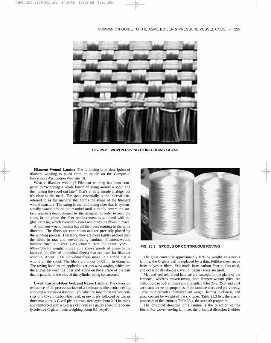
Woven-Roving Lamina Figure 25.2 shows woven-roving rein-forcing glass. There are five fiber bundles per inch in the verticaldirection and four in the horizontal direction. The woven-rovinglamina weighs 24 oz/yd2 (2.7 oz/ft2).2 A typical specimen is 0.33 in.thick and is by weight 50%–60% glass fiber.
2 For reasons unknown to the author, it is an industry practice to quote mat weight in oz/ft2 and woven-roving weight in oz/yd2.
FIG. 25.1 FIBERGLASS-REINFORCING MAT
ASME_Ch25_p253-322.qxd 3/10/09 11:12 AM Page 254
COMPANION GUIDE TO THE ASME BOILER & PRESSURE VESSEL CODE • 255
Filament-Wound Lamina The following brief description offilament winding is taken from an article on the CompositeFabricators Association Web site [3].
What is filament winding? Filament winding has been com-pared to “wrapping a whole bunch of string around a spool andthen taking the spool out late.” That’s a fairly simple analogy, butit’s close to the mark. The spool essentially is the internal part,referred to as the mandrel that forms the shape of the filamentwound structure. The string is the reinforcing fiber that is system-atically wound around the mandrel until it totally covers the sur-face area to a depth desired by the designer. In order to keep thestring in the place, the fiber reinforcement is saturated with theglue, or resin, which eventually cures and binds the fibers in place.
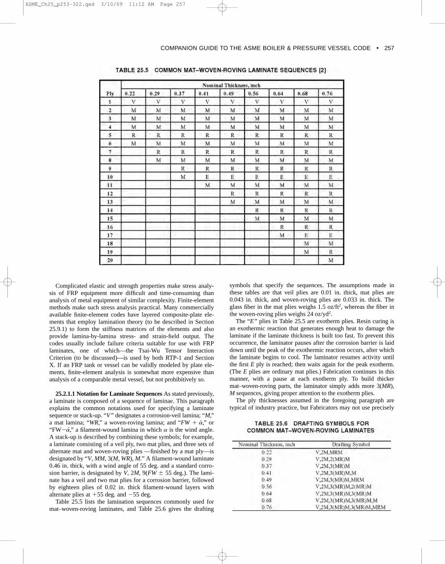
A filament-wound lamina has all the fibers running in the samedirection. The fibers are continuous and are precisely placed bythe winding process. Therefore, they are more tightly packed thanthe fibers in mat and woven-roving laminae. Filament-woundlaminae have a higher glass content than the other types—60%–70% by weight. Figure 25.3 shows spools of glass-rovinglaminae (bundles of individual fibers) that are used for filamentwinding. About 5,000 individual fibers make up a strand that iswound on the spool. The fibers are about 0.005 in. in diameter.The roving bundles are applied at various wind angles, which arethe angles between the fiber and a line on the surface of the partthat is parallel to the axis of the cylinder being constructed.
C-veil, Carbon-Fiber Veil, and Nexus Lamina The corrosionresistance of the process surface of a laminate is often enhanced byapplying a corrosion barrier. Typically, the innermost surface con-sists of a C-veil, carbon-fiber veil, or nexus ply followed by two orthree mat plies. A C-veil ply is a resin-rich layer about 0.01 in. thickand reinforced with a C-glass veil. Veil is a gauzy sheet of random-ly oriented C-glass fibers weighing about 0.1 oz/yd3.
The glass content is approximately 10% by weight. In a nexuslamina, the C-glass veil is replaced by a thin, feltlike sheet madefrom polyester fibers. Veil made from carbon fiber is also used,and occasionally double C-veil or nexus layers are used.
Mat and veil-reinforced laminae are isotropic in the plane of thelaminate, whereas woven-roving and filament-wound piles areorthotropic in both stiffness and strength. Tables 25.2, 25.3, and 25.4each summarize the properties of the laminae discussed pre-viously.Table 25.2 provides reinforcement weight, lamina thick-ness, andglass content by weight of the six types. Table 25.3 lists the elasticproperties of the laminae; Table 25.4, the strength properties.
The principal direction of a lamina is the direction of thefibers. For woven-roving laminae, the principal direction is either
FIG. 25.2 WOVEN-ROVING REINFORCING GLASS
FIG. 25.3 SPOOLS OF CONTINUOUS ROVING
ASME_Ch25_p253-322.qxd 3/10/09 11:12 AM Page 255

256 • Chapter 25
fiber direction; in isotropic laminae, the principal direction isarbitrary. In Tables 25.3 and 25.4, X refers to the principal direc-tion and Y refers to the direction in the plane of the lamina per-pendicular to X. Tables 25.3 and 25.4 provide room-temperatureproperties for laminae made with Derakane 470 resin and withthe glass contents listed. Properties of laminae made with otherresins or glass content vary somewhat from those listed. At firstglance, it would seem that the woven-roving lamina is onlyslightly anisotropic, as the moduli in the X and Y directions arenot too different. However, in isotropic material the shear modu-lus G is related to Young’s modulus E and Poisson’s ratio v bythe following equation:
(25.1)
Suppose for simplicity that we wished to treat the woven-roving lamina as an isotropic material and decided to set E as theaverage of the two Young’s moduli in the table and use the listedvalue of Poisson’s ratio. Then,
psi (25.2)
This value for G is 3.06 times the actual value. The actualwoven-roving lamina is much more compliant for tensile strain at
G =
2.71 * 106
2(1 + 0.15)= 1.18 * 106
G =
E
2(1 + v)
45 deg. to the principal direction than the assumed isotropicmodel. Some woven-roving laminae have the same Young’s modu-lus in the principal directions; however, because of their low shearmodulus, they should be treated as orthotropic materials in thestress analysis. A common example of this kind of behavior is acloth handkerchief. It is much stiffer in the thread directions thanin the bias direction. Even though the tensile moduli in the threaddirections are roughly equal, the cloth is highly anisotropic.
The values in Table 25.4 are for the same laminae as in Table25.3; laminae made with other resins and glass contents havesomewhat different strength properties. However, most other fea-tures of Table 25.4, including mat lamina having higher tensile-strength than compressive-strength properties, are common to allthe laminae allowed by Section X and RTP-1. Nonetheless, thestrength behavior is very different and more complicated than thatof ductile metals used in tanks and vessels. Strengths may or maynot be different in different directions. For example, the tensilestrength of mat laminae is the same in both directions, whereasthe tensile strength of filament-wound laminae is 32 times greaterin the fiber direction than it is in the cross-fiber direction. In somelaminae (such as mat or woven-roving), the compressive strengthin a given direction is less than the tensile strength. In filament-wound plies, the compressive strength is less than the tensilestrength in the fiber direction, but it is greater than the tensilestrength in the cross-fiber direction. There is no obvious generalrelationship between shear strength and the other strength values.
ASME_Ch25_p253-322.qxd 3/10/09 11:12 AM Page 256
COMPANION GUIDE TO THE ASME BOILER & PRESSURE VESSEL CODE • 257
Complicated elastic and strength properties make stress analy-sis of FRP equipment more difficult and time-consuming thananalysis of metal equipment of similar complexity. Finite-elementmethods make such stress analysis practical. Many commerciallyavailable finite-element codes have layered composite-plate ele-ments that employ lamination theory (to be described in Section25.9.1) to form the stiffness matrices of the elements and alsoprovide lamina-by-lamina stress- and strain-field output. Thecodes usually include failure criteria suitable for use with FRPlaminates, one of which—the Tsai-Wu Tensor InteractionCriterion (to be discussed)—is used by both RTP-1 and SectionX. If an FRP tank or vessel can be validly modeled by plate ele-ments, finite-element analysis is somewhat more expensive thananalysis of a comparable metal vessel, but not prohibitively so.
25.2.1.1 Notation for Laminate Sequences As stated previously,a laminate is composed of a sequence of laminae. This paragraphexplains the common notations used for specifying a laminatesequence or stack-up. “V ” designates a corrosion-veil lamina; “M,”a mat lamina; “WR,” a woven-roving lamina; and “FW � a,” or“FW�a,” a filament-wound lamina in which is the wind angle.A stack-up is described by combining these symbols; for example,a laminate consisting of a veil ply, two mat plies, and three sets ofalternate mat and woven-roving plies —finished by a mat ply—isdesignated by “V, MM, 3(M, WR), M.” A filament-wound laminate0.46 in. thick, with a wind angle of 55 deg. and a standard corro-sion barrier, is designated by V, 2M, 9(FW � 55 deg.). The lami-nate has a veil and two mat plies for a corrosion barrier, followedby eighteen plies of 0.02 in. thick filament-wound layers withalternate plies at �55 deg. and �55 deg.
Table 25.5 lists the lamination sequences commonly used format–woven-roving laminates, and Table 25.6 gives the drafting
a
symbols that specify the sequences. The assumptions made inthese tables are that veil plies are 0.01 in. thick, mat plies are0.043 in. thick, and woven-roving plies are 0.033 in. thick. Theglass fiber in the mat plies weighs 1.5 oz/ft2, whereas the fiber inthe woven-roving plies weighs 24 oz/yd2.
The “E” plies in Table 25.5 are exotherm plies. Resin curing isan exothermic reaction that generates enough heat to damage thelaminate if the laminate thickness is built too fast. To prevent thisoccurrence, the laminator pauses after the corrosion barrier is laiddown until the peak of the exothermic reaction occurs, after whichthe laminate begins to cool. The laminator resumes activity untilthe first E ply is reached; then waits again for the peak exotherm.(The E plies are ordinary mat plies.) Fabrication continues in thismanner, with a pause at each exotherm ply. To build thickermat–woven-roving parts, the laminator simply adds more 3(MR),M sequences, giving proper attention to the exotherm plies.
The ply thicknesses assumed in the foregoing paragraph aretypical of industry practice, but Fabricators may not use precisely
ASME_Ch25_p253-322.qxd 3/10/09 11:12 AM Page 257
258 • Chapter 25
these values. Instead, they may use the values that their shopsactually produce. Because of these minor variations amongFabricators, it is better to specify the laminate in a vessel part bydrafting symbols such as those in Table 25.6 rather than simplygiving the thickness and type of laminate. For example, an engi-neer who wants to specify a mat–woven-roving laminate in.thick would specify a V, 2M, 3(MR)M stack-up in addition tospecifying the reinforcing glass weights.
25.3 FABRICATION METHODS3
Pressure-containing parts for RTP-1 and Section X, Class IIvessels are made by contact molding and filament winding. Partsfor Section X, Class I vessels are made by those two processes aswell, but also by bag molding and centrifugal casting. Each ofthese methods is discussed in the following paragraphs.
25.3.1 Contact Molding The following definition is from the glossary of Section X [1]:
Contact molding—a process for molding reinforced plastic inwhich reinforcement and resin are placed on a mold—cure iseither at room temperature using a catalyst–promoter systemor by heat in an oven, and no additional pressure is used.
Contact molding includes two processes: the hand lay-up and thespray-up. In the hand lay-up method, the mold is first prepared witha parting agent so that the resin does not adhere to the mold as itcures. On head molds, wax-parting agents or a liquid such aspolyvinyl alcohol is used; on cylindrical mold, Mylar film is usuallyused. A sheet of reinforcing material, such as a C-glass veil, is thenplaced on the mold and wetted with catalyzed and promoted resin.(Catalyst and promoter are added to all resins except epoxy so thatthey will cure and become solids. A hardener may be added to the
38
epoxy, or it may be heat-cured.) The resin-wetted reinforcing mate-rial is compacted and pressed to the mold by hand with a roller tosqueeze out excess resin and to remove air bubbles. Rollers resem-ble paint rollers, except that the type used in this application ismetal with deep grooves about in. wide and in. deep, with a in.pitch. Rollers vary from 2 or 3 in. to in. in diameter and from 3 in.to 12 in. in width. After the first lamina is applied, the second andsubsequent plies are added the same way. Veil, mat, and woven-roving plies are all applied by the hand lay-up method.
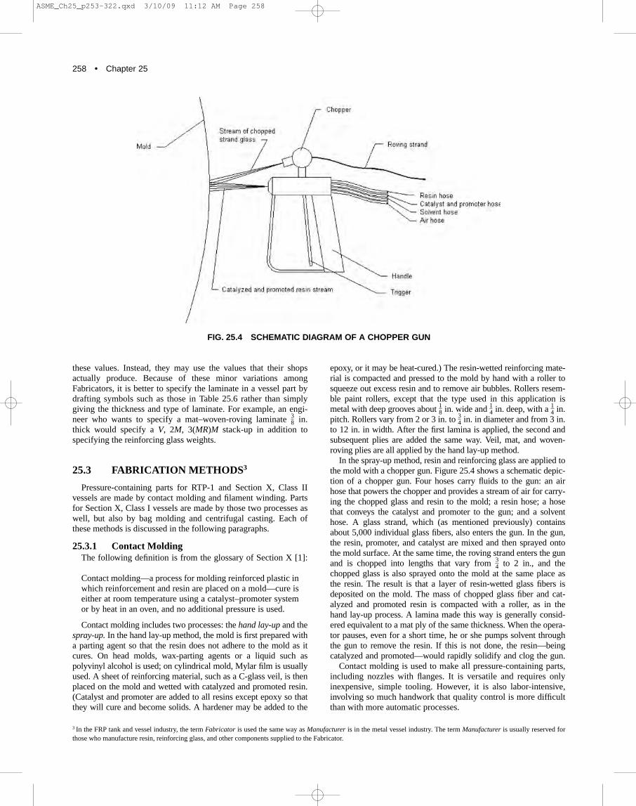
In the spray-up method, resin and reinforcing glass are applied tothe mold with a chopper gun. Figure 25.4 shows a schematic depic-tion of a chopper gun. Four hoses carry fluids to the gun: an airhose that powers the chopper and provides a stream of air for carry-ing the chopped glass and resin to the mold; a resin hose; a hosethat conveys the catalyst and promoter to the gun; and a solventhose. A glass strand, which (as mentioned previously) containsabout 5,000 individual glass fibers, also enters the gun. In the gun,the resin, promoter, and catalyst are mixed and then sprayed ontothe mold surface. At the same time, the roving strand enters the gunand is chopped into lengths that vary from to 2 in., and thechopped glass is also sprayed onto the mold at the same place asthe resin. The result is that a layer of resin-wetted glass fibers isdeposited on the mold. The mass of chopped glass fiber and cat-alyzed and promoted resin is compacted with a roller, as in thehand lay-up process. A lamina made this way is generally consid-ered equivalent to a mat ply of the same thickness. When the opera-tor pauses, even for a short time, he or she pumps solvent throughthe gun to remove the resin. If this is not done, the resin—beingcatalyzed and promoted—would rapidly solidify and clog the gun.
Contact molding is used to make all pressure-containing parts,including nozzles with flanges. It is versatile and requires onlyinexpensive, simple tooling. However, it is also labor-intensive,involving so much handwork that quality control is more difficultthan with more automatic processes.
34
34
14
14
18
3 In the FRP tank and vessel industry, the term Fabricator is used the same way as Manufacturer is in the metal vessel industry. The term Manufacturer is usually reserved forthose who manufacture resin, reinforcing glass, and other components supplied to the Fabricator.
FIG. 25.4 SCHEMATIC DIAGRAM OF A CHOPPER GUN
ASME_Ch25_p253-322.qxd 3/10/09 11:12 AM Page 258

COMPANION GUIDE TO THE ASME BOILER & PRESSURE VESSEL CODE • 259
25.3.2 Filament Winding Figure 25.5 is a schematic diagram of filament winding. A band
of glass or other fiber roving is pulled from the creel through a resinbath and wound onto the mandrel. For winding a cylindrical shell,Mylar film is ordinarily used as the parting agent. The roving bandis 2–6 in. or more wide, depending on the diameter of the part beingwound. Consider winding an 8 ft diameter vessel shell with a 55 deg. wind angle. The roving band would be about 5 in. wide andconsist of 45 strands. (Nine strands per in. of width is typical.) Eachstrand has about 5,000 individual fibers; thus the 5 in. band consistsof 225,000 fibers. The creel would hold 45 spools of roving. Thecarriage feeding the band onto the mandrel moves axially along themandrel to maintain the proper wind angle. When the carriagereaches the end of the mandrel, it reverses direction, laying down aband with the opposite slope of the band put down on the first pass.With a 55 deg. wind angle, the bands would form a helix on theshell, with a pitch of 211.2 in.; therefore, the bands are widelyspaced. The carriage is carefully controlled so that on the third pass(the second pass in the original direction), the band is next to theband made on the first pass. Eventually this process results in thecovering of the mandrel with two plies of material: one with a windangle of �55 deg.; the other, �55 deg. The process continues untilthe desired thickness is built up. Laminate thickness increases quicklyenough during winding so that the process must be paused to let thepeak exotherm occur, just as in contact molding. After the exothermbut before the winding is resumed, the laminator usually applies a matbedding ply, either by using the hand lay-up method or by using achopper gun. The laminate laid down at the ends while the carriage isreversing has a variable wind angle (from 55 deg. to 0 deg.) as well asvariable thickness, for which reason the laminate is called the turn-around zone. This portion is usually cut off and scrapped.
Filament-wound laminates have of a 60%–70% glass contentby weight, considerably higher than mat or mat–woven-rovinglaminates. Consequently, filament-wound laminates are strongerand stiffer than the others. Because the process is more automatedthan contact molding, the quality is more predictable. Once awinding setup is working properly, the quality is more repeatableand the quality control is easier than with contact molding.
Cylinders as small as 1 in. and as large as 80 ft are filament-wound. Mandrels with either horizontal or vertical axes are used,
as are winders on which the mandrel is mounted so that it can berotated about more than one axis. These winders can produce ves-sels complete with heads.
25.3.3 Bag Molding Only Section X, Class I provides for bag molding. Qualification
of a Class I design is by destructive testing of a prototype. If theprototype satisfies Section X requirements, vessels identical to theprototype may be built and receive an ASME RP Stamp. Designqualification of Class II vessels is by mandatory design rules andnondestructive acceptance testing. Class I rules are suitable formass-produced vessels, whereas Class II rules are used for one-of-a-kind or limited-production equipment. The two classes are dis-cussed more thoroughly later in this chapter.
Figure 25.6 sketches the bag-molding concept. The catalyzedresin–glass mixture is applied to the inside of the mold, the bag isinserted and pressurized, and the resin is cured either at room
FIG. 25.5 FILAMENT WINDING
FIG. 25.6 BAG-MOLDING CONCEPT
ASME_Ch25_p253-322.qxd 3/10/09 11:12 AM Page 259

260 • Chapter 25
temperature or by the application of heat. The resin–glass mixturemay be applied by contact molding; otherwise, the reinforcingfibers may be a preform, a reinforcement that is preshaped to thegeneral geometry of the intended molded part, usually by lightpressing or by distribution of chopped fibers of a perforated for-mer. It is used on more complex or deep-draw moldings to opti-mize the distribution and orientation of the fibers [4]. TheFabricator may also apply the resin and glass onto the bag andthen insert the bag into the mold. Bag molding can produce partswith a higher glass content than contact molding, as the reinforce-ment–resin mass is compacted more during bag molding than dur-ing the rolling step of contact molding. Thus bag-molded parts arestronger and stiffer than contact-molded parts. In addition, bagmolding can produce vessels with integral heads.
25.3.4 CENTRIFUGAL CASTING
Figure 25.7 is a schematic depiction of centrifugal casting.Resin, resin catalyst and promoter, and glass fiber are all con-veyed to a device that chops the glass and blends the ingredients;sprays them onto the inside of the mold. The mold rotates at ahigh enough speed for the centrifugal force to press theresin–glass mass against the mold. Either room- or elevated-temperature curing may be used. Centrifugal casting produceshollow cylindrical parts, such as vessel shells.
25.3.5 Joining Vessel Parts The aforementioned processes produce vessel parts: shells,
heads, nozzles, and so on. Because the resins governed by theASME documents are all thermosets, once cured they will not meltand solidify into good material. Thus vessel parts cannot be joinedby welding. The industry has developed adhesive-joint techniquesfor assembling parts; these are discussed in this section.
Figure 25.8 shows the steps for making the type of butt jointrequired by RTP-1 for making head-to-shell or shell-to-shell
girth joints. Bonders apply the structural overlay—also called strap-ping—to the outside of the vessel, which is usually coveredwith a film of wax. Air inhibits the cure of most resins used forvessels, so the common practice is to coat the outside surface of apart with resin that contains a small fraction of wax. The waxfloats to the surface, preventing the contact of air with the curingresin and producing a wax film on the outside of the vessel. Thisfilm would interfere with bonding to the surface, so it is thereforeremoved before a structural joint is applied. The bonder first sandsthe surface to which the joint is to be applied with a coarse abra-sive until the wax is removed and the glass fiber is exposed. Thejoint plies are then applied by the use of hand lay-up methods.
FIG. 25.7 CENTRIFUGAL CASTING
FIG. 25.8 RTP-1–STYLE BUTT JOINT
ASME_Ch25_p253-322.qxd 3/10/09 11:13 AM Page 260
COMPANION GUIDE TO THE ASME BOILER & PRESSURE VESSEL CODE • 261
The joint may be of all-mat-ply construction or of alternate pliesof mat and woven-roving. If the joint is all mat, each ply overlapsthe preceding ply by in. If the joint is alternating mat and woven-roving, the woven-roving plies are of the same width as the mat plyunderneath them, and each mat ply extends in. beyond the plybeneath it. Steps (2) and (3) in Fig. 25.8 illustrate the application ofthe structural strapping. Peak exotherms are accommodated thesame way as in making laminates, as discussed previously. Thedesign rules in RTP-1 govern the thickness of the joint overlay;their intention is for the joint laminate to be at least as strong as thestronger of the laminates in the parts being joined and for the over-lay to be wide enough to provide adequate shear strength to carrythe load from the part to the joint overlay to the second part.
The final step (4) of Fig. 25.8 is to make a corrosion seal for thejoint. This seal is made on the inner (process) surface, as shown inFig. 25.8, and the seal is a minimum of two plies of 1 mat with anadditional C-veil or nexus veil on the inside. The innermost mat playis at least 3 in. wide, the next ply extends at least in. beyond thefirst, and the veil ply extends at least in. beyond the mat plies.
The joint is applied to cured FRP parts. Therefore, the bondbetween the joint and the parts is adhesive; it is not the molecularbond that forms when the parts are cured. Adhesive bonds are notas strong as molecular bonds, but they are strong enough to pro-vide safe joints as long as the requirements of the applicableASME Standard are satisfied.
Figure 25.9 illustrates the bell-and-spigot joint, another designdetail provided by RTP-1. This joint is used to assemble shell seg-ments or to join the head and shell. The first step in making thejoint is to fit and hold the parts, which is ordinarily done with fix-tures. The next step is to apply the resin putty as shown in Fig.25.9. The resin putty is made of the same resin as the parts beingjoined and is thickened with particulate-mineral filler. Recall thatthe strapping is put in place and then compacted with a roller. Theresin putty serves as a foundation for the application of the struc-tural strapping—that is, something to press the roller against.Finally, the corrosion seal is installed.
12
12
12
12
516
Figure 25.10 illustrates a Section X, Class II butt joint—a vari-ation on the RTP-1 butt joint shown in Fig. 25.8 —that constitutesa head-to-shell joint, although the detail also applies to shell-girthjoints. The difference between the RTP-1 joint and the Section Xjoint is that the parts to be joined are scarfed first, as in steel weld-ing, and then the structural overlay is applied. Rules for dimen-sions of the joint are given in Section X, Article RD-1175 [1].
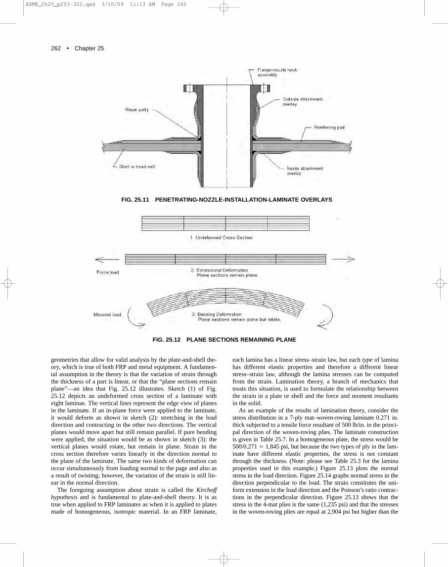
Both RTP-1 and Section X use the same styles of joints forattaching nozzles to shells or heads. Figure 25.11 shows one typeof joint —a penetrating nozzle —in which the nozzle neck pro-trudes inside the shell or head to which it is attached. The nozzleneck–flange assembly is first attached to the head or shell withfixtures or with a few dabs of hot-melt adhesive to hold the nozzlein place while the attachment laminate is applied. Next, the resinputty is placed as shown in Fig. 25.11 to provide a base for thestructural attachment layers. Finally, the structural overlay isinstalled. Either RTP-1 or Section X, whichever applies, governsthe dimensions of the overlay. Flanges are attached to nozzlenecks by similar joints, and the reinforcing pad is added to mini-mize stress intensification caused by cutting the hole in the shellor head on which the nozzle in installed. Reinforcing-pad dimen-sions are given in Section X or RTP-1, as applicable.
25.4 STRESS ANALYSIS OF FRP VESSELS
Simpler RTP-1 or Section X, Class II vessels can be designedby using design rules found in the ASME Standards, althoughmany configurations are not governed by these rules. BothSection X and RTP-1 provide for design-by-stress analysis, whichcovers such configurations. Two factors complicate the stressanalysis of FRP vessels compared to metal vessels:
(1) Vessel parts are made of layered composites, in which thelayers have different elastic and strength properties, causingeach layer to have its own stress distribution.
(2) Each type of layer has five distinct strength properties,which complicates the failure criterion.
This section discusses how these complications are treated. Lamination analysis provides a way of dealing with the first
complication of the preceding list. Most tanks and vessels haveFIG. 25.9 BELL-AND-SPIGOT JOINT
FIG. 25.10 SECTION X–STYLE BUTT JOINT
ASME_Ch25_p253-322.qxd 3/10/09 11:13 AM Page 261
262 • Chapter 25
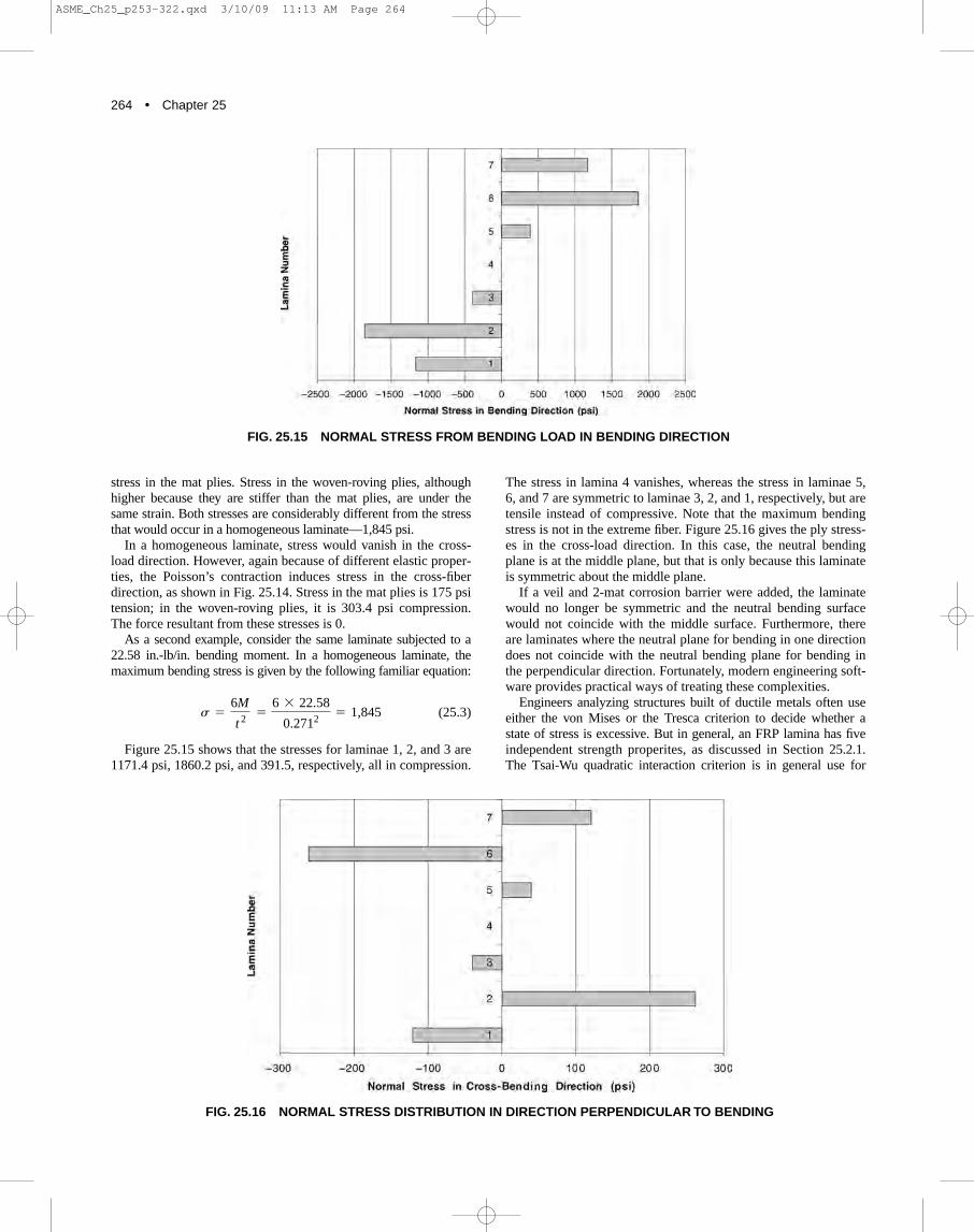
geometries that allow for valid analysis by the plate-and-shell the-ory, which is true of both FRP and metal equipment. A fundamen-tal assumption in the theory is that the variation of strain throughthe thickness of a part is linear, or that the “plane sections remainplane”—an idea that Fig. 25.12 illustrates. Sketch (1) of Fig.25.12 depicts an undeformed cross section of a laminate witheight laminae. The vertical lines represent the edge view of planesin the laminate. If an in-plane force were applied to the laminate,it would deform as shown in sketch (2): stretching in the loaddirection and contracting in the other two directions. The verticalplanes would move apart but still remain parallel. If pure bendingwere applied, the situation would be as shown in sketch (3): thevertical planes would rotate, but remain in plane. Strain in thecross section therefore varies linearly in the direction normal tothe plane of the laminate. The same two kinds of deformation canoccur simultaneously from loading normal to the page and also asa result of twisting; however, the variation of the strain is still lin-ear in the normal direction.
The foregoing assumption about strain is called the Kirchoffhypothesis and is fundamental to plate-and-shell theory. It is astrue when applied to FRP laminates as when it is applied to platesmade of homogeneous, isotropic material. In an FRP laminate,
each lamina has a linear stress–strain law, but each type of laminahas different elastic properties and therefore a different linearstress–strain law, although the lamina stresses can be computedfrom the strain. Lamination theory, a branch of mechanics thattreats this situation, is used to formulate the relationship betweenthe strain in a plate or shell and the force and moment resultantsin the solid.
As an example of the results of lamination theory, consider thestress distribution in a 7-ply mat–woven-roving laminate 0.271 in.thick subjected to a tensile force resultant of 500 lb/in. in the princi-pal direction of the woven-roving plies. The laminate constructionis given in Table 25.7. In a homogeneous plate, the stress would be500/0.271 � 1,845 psi, but because the two types of ply in the lam-inate have different elastic properties, the stress is not constantthrough the thickness. (Note: please see Table 25.3 for the laminaproperties used in this example.) Figure 25.13 plots the normalstress in the load direction. Figure 25.14 graphs normal stress in thedirection perpendicular to the load. The strain constitutes the uni-form extension in the load direction and the Poisson’s ratio contrac-tions in the perpendicular direction. Figure 25.13 shows that thestress in the 4-mat plies is the same (1,235 psi) and that the stressesin the woven-roving plies are equal at 2,904 psi but higher than the
FIG. 25.11 PENETRATING-NOZZLE-INSTALLATION-LAMINATE OVERLAYS
FIG. 25.12 PLANE SECTIONS REMAINING PLANE
ASME_Ch25_p253-322.qxd 3/10/09 11:13 AM Page 262

COMPANION GUIDE TO THE ASME BOILER & PRESSURE VESSEL CODE • 263
FIG. 25.13 NORMAL STRESS IN LOAD DIRECTION FOR EXTENSIONAL STRAIN
FIG. 25.14 NORMAL STRESS PERPENDICULAR TO LOAD DIRECTION FOR EXTENSIONAL STRAIN
ASME_Ch25_p253-322.qxd 3/10/09 11:13 AM Page 263
264 • Chapter 25
stress in the mat plies. Stress in the woven-roving plies, althoughhigher because they are stiffer than the mat plies, are under thesame strain. Both stresses are considerably different from the stressthat would occur in a homogeneous laminate—1,845 psi.
In a homogeneous laminate, stress would vanish in the cross-load direction. However, again because of different elastic proper-ties, the Poisson’s contraction induces stress in the cross-fiberdirection, as shown in Fig. 25.14. Stress in the mat plies is 175 psitension; in the woven-roving plies, it is 303.4 psi compression.The force resultant from these stresses is 0.
As a second example, consider the same laminate subjected to a22.58 in.-lb/in. bending moment. In a homogeneous laminate, themaximum bending stress is given by the following familiar equation:
(25.3)
Figure 25.15 shows that the stresses for laminae 1, 2, and 3 are1171.4 psi, 1860.2 psi, and 391.5, respectively, all in compression.
s =
6M
t 2=
6 * 22.58
0.2712= 1,845
The stress in lamina 4 vanishes, whereas the stress in laminae 5,6, and 7 are symmetric to laminae 3, 2, and 1, respectively, but aretensile instead of compressive. Note that the maximum bendingstress is not in the extreme fiber. Figure 25.16 gives the ply stress-es in the cross-load direction. In this case, the neutral bendingplane is at the middle plane, but that is only because this laminateis symmetric about the middle plane.
If a veil and 2-mat corrosion barrier were added, the laminatewould no longer be symmetric and the neutral bending surfacewould not coincide with the middle surface. Furthermore, thereare laminates where the neutral plane for bending in one directiondoes not coincide with the neutral bending plane for bending inthe perpendicular direction. Fortunately, modern engineering soft-ware provides practical ways of treating these complexities.
Engineers analyzing structures built of ductile metals often useeither the von Mises or the Tresca criterion to decide whether astate of stress is excessive. But in general, an FRP lamina has fiveindependent strength properites, as discussed in Section 25.2.1.The Tsai-Wu quadratic interaction criterion is in general use for
FIG. 25.15 NORMAL STRESS FROM BENDING LOAD IN BENDING DIRECTION
FIG. 25.16 NORMAL STRESS DISTRIBUTION IN DIRECTION PERPENDICULAR TO BENDING
ASME_Ch25_p253-322.qxd 3/10/09 11:13 AM Page 264

COMPANION GUIDE TO THE ASME BOILER & PRESSURE VESSEL CODE • 265
layered-composite materials; it represents a generalization of thevon Mises criterion [5] and provides a strength criterion for FRP.
Both RTP-1 (in paragraph M5-530) and Section X (in para-graph RD-188.5) use the same form of the Tsai-Wu quadraticinteraction criterion. The purpose of the criterion is to distinguishbetween stress states that overload any lamina and stress statesthat are acceptable. Both standards employ strength ratios for thispurpose. The equations that state the quadratic interaction criteri-on in terms of a strength ratio may be written as follows:
(25.4)
where Sxx � the normal stress in a principal direction of the lamina in
questionSyy � the normal stress in the other principal directionSxy � the shear stress in the plane of the lamina R � the strength ratio
The other parameters are defined in terms of the five laminaultimate strengths, as follows:
(25.5)
where X and Xc � the tensile and compressive strengths in the x
direction, respectivelyY, Yc � the tensile and compressive strengths in the y direc-
tion, respectively Su � the shear strength
Given the five strength values and a stress state, that is, a set ofvalues for Sx, Sy, and Sxy, equation (25.4) can be solved for R.This equation is quadratic in R and therefore has two roots for R:one positive, the other negative. If the positive root is greater thana value stipulated in Section X or RTP-1 for the layer in question,the stress state in the layer is acceptable; however, if the positiveroot is less than the stipulated value, the stress state is excessiveand not allowed.
The physical meaning of R is that if all three stresses are multi-plied by R, the ply is just at the point of failure. Thus R is like asafety factor; the greater R, the farther from failure the lamina is.Because the five lamina strength values are different for differentlamina types, and also because the stress varies from lamina tolamina, the criterion is applied to each layer separately.
Finite-element stress analysis of FRP tanks and vessels takemore time than analysis of metal equipment of comparable con-figuration. Instead of inputting one or two sets of isotropic materi-al property values for the entire vessel, the analyst must input aset of orthotropic values for each type of laminate in the vessel.Furthermore, instead of simply inputting a plate thickness foreach vessel part of different thickness, the analyst must input anentire lamination sequence for each part and must also sift
Fy =
1
Y-
1
Yc
Fxy = -
1
22FxxFyy Fx =
1
X-
1
Xc
Fxx =
1
XXc Fyy =
1
YYc Fss =
1
Su2
+ R(FxSxx + FySyy) - 1 = 0
R2(FxxSxx2
+ 2FxySxxSyy + FyySyy2
+ FssSxy2 )
through the stress distribution in each lamina. For example, if avessel shell consists of twelve plies of material, the analyst mustcheck the stress distribution in every ply instead of one bendingand one membrane stress distribution for the entire part.
Modern finite-element software makes stress-distributionchecking a practical task. The analyst can set up a set of materialconstants for each lamina type in the vessel and then refer to theproperty set when he or she inputs data that defines the laminationsequence. Many software systems that have a capability forlayered-composite plate elements provide efficient ways for speci-fying stack-ups and also provide ways of finding the most highlystressed lamina without the analyst having to view the stress dis-tribution in every lamina. The Algor post-processor, for example,produces a “worst-ply” plot. The program makes color-contourplots of the reciprocal of the strength ratio, where the value plot-ted is the worst 1/R for any lamina at that point on the vessel.Using this plot, the analyst can quickly isolate areas (if there areany) where the strength criterion is violated; then, he or she looksat individual ply plots in those areas to isolate the locations andplies where stress is excessive. Other software systems have otherways of filtering the voluminous stress output produced bycomposite-element calculations.
A simpler strength criterion is being introduced into the currentedition of RTP-1, ASME RTP-1-2007. The criterion is intendedfor details of design and construction for which no rule is provid-ed in Subpart 3A, but for which other recognized engineering for-mulas exist. They may be accepted by comparing calculatedstress with ultimate laminate strength to establish a minimumdesign factor. Other recognized formulas include stress calcula-tions presented in various sections of the ASME pressure vesselcodes, formulas included in the non-mandatory appendices ofRTP-1, and well documented formulas presented elsewhere.
Combined flexural and membrane stress must comply with thefollowing inequalities:
(25.6)
and
(25.7)
Where� calculated maximum sustained membrane stress
� calculated maximum sustained flexural stress� calculated maximum combined intermittent
and sustained membrane stress� calculated maximum combined intermittent and
sustained flexural stressSt � ultimate tensile strengthSf � ultimate flexural strength
F10 � design factor for sustained loads � 10F5 � design factor for sustained loads � 5
Examples of sustained stress are hydrostatic stress and designpressure stress. Examples of loads that induce intermittent stressare wind, earthquake and loads from personnel standing on a ves-sel. In the two inequalities, maximum stress means the stresswith the largest absolute value. Absolute values of stress are usedin the inequalities.
sfi
smi
sfc
smc
smi
St
+
sfi
Sf
…
1
F5
smc
St
+
sfc
Sf
…
1
F10
ASME_Ch25_p253-322.qxd 3/10/09 11:13 AM Page 265

266 • Chapter 25
Quadratic Interaction Damage Criterion Section X, in thecurrent edition, I introduced a new strength criterion based onacoustic emission measurements of FRP samples which define thelowest stress at which significant damage occurs. The requiredtests are defined by Article RT-8 in Section X. For contact mold-ed laminates, flexural and shear tests are required. For filamentwound laminates, a sample filament wound cylinder must be test-ed. The values upon which the criterion is based are:
Rd � damage criterion stress ratio � 1.25Sd � damaged based design value with respect to shear stress in
the plane of the laminate.Xd � tensile and compressive damage based design value in the
x (strong) directionYd � tensile and compressive damaged based design value in
the y (weak) direction� damage criterion design factor � 0.75
� stress in the lamina material direction x at the point andlamina under investigation
� stress in the lamina material direction y at the point andlamina under investigation
� in-plane shear stress at the point and lamina under inves-tigation
The Quadratic Interaction Design Criterion is:
(25.8)
This criterion is scientifically better than the others in the twostandards, but it is just now being introduced into use.
25.5 SCOPES OF SECTION X AND RTP-1
This section discusses the scope of both Section X and RTP-1.The scope of Section X is discussed first, followed by that ofRTP-1.
25.5.1 Scope of Section X Section X has two classes of vessels: I and II, both of which
differ in scope. In brief, the classes are distinguished as follows:
(1) Class I vessel designs are qualified through possiblydestructive fatigue and pressure testing of a prototype.Vessels similar to the prototype may then be built and theASME Code Symbol RP applied, but the prototype itself,however, may not receive the Code Symbol RP.
(2) Class II vessel design is qualified through mandatory designrules and nondestructive acceptance testing, which includesan acoustic-emission (AE) examination.
Rd2
°2 c asx
Xdb 2
-
sxsy
XdYd+ asy
Ydb 2
+ ass
Sdb 2 d … 1
ss
sy
sx
°
Table 25.8 gives the pressure scope for Class I vessels. Vessels with only polar-boss openings must satisfy the follow-
ing requirements to be eligible for the higher pressure scope:
(1) openings shall be centered on the axis of rotation; (2) openings shall be of the polar-boss type wound in place on
the axis of revolution; (3) the boss diameter shall not exceed half the vessel inside
diameter; and (4) the filaments shall not be cut.
The pressure scope for Class II vessels is more complicated,depending on the size of the vessel. As is discussed below,Section X vessels must be between 6 in. and 192 in. in diameter.There are two methods for design calculations: Method A thatuses design rules like Section VIII, Division 1, and Method B thatprovides for design by stress analysis. Vessels designed byMethod A are limited to 100 psi internal design pressure and 144 in.diameter.
Vessels designed by Method B rules shall have pressure anddiameter restrictions as follows:
1. The algebraic product of the internal pressure in psig and thediameter in inches shall not exceed 14,400 lb/in (Equation25.9)
2. The maximum internal pressure shall not exceed 250 psig. 3. The maximum inside diameter shall not exceed 192 in.
Vessels may be designed using a combination of Methods Aand B. For such vessels the maximum design pressure is limitedto 100 psig with a maximum inside diameter of 144 in. Vesselsdesigned by either Methods A or B are limited to a maximumexternal pressure of 15 psig.
(25.9)
where P � is the design pressure in psi and D � is the diameter in in. These rules are expressed by Figure
25.17
The maximum external design pressure for Class II vessels is 15psig.
The design temperature of Section X vessels must not exceed250ºF or 35ºF less than the maximum-use temperature of theresin, whichever is less. The maximum-use temperature of a resinis either the glass-transition temperature (TG) or the heat-deflection (also called heat-distortion) temperature, whichever theFabricator and resin supplier prefer. When a polymer is coolerthan its TG, it is rigid and hard; when it is hotter than TG, it is
P =
14400D
ASME_Ch25_p253-322.qxd 3/10/09 11:13 AM Page 266

COMPANION GUIDE TO THE ASME BOILER & PRESSURE VESSEL CODE • 267
rubbery. The Section X resins are used below the TG, whereasother resins (such as tire rubber) are used above it. The elasticmodulus of Section X resins drops orders of magnitude at andabove the TG [6]. The heat-deflection temperature is the tempera-ture at which a specified bar specimen deflects 0.01 in. whenloaded as a simple beam to a constant 264 psi (see ASTM D 648,Test Method for Deflection Temperature of Plastics underFlexural Load, for details). It is usually measured for resin cast-ings, not laminates [7]. For the resin used in Section X, the TGand heat-deflection temperatures are approximately equal. Thetemperature scope applies to both Class I and Class II vessels.
Vessels fabricated under Section X intended for Section IVpotable-water use are limited to applications permitted herein.The vessels are limited to internal pressure only with a maximumallowable working pressure (MAWP) of 160 psig. The maximumallowable temperature used shall be 210ºF [8].
The following classes of vessels are exempted from the scopeof Section X [9].
(1) Pressure containers, which are integral parts of rotating orreciprocating mechanical devices (e.g., pumps, compres-sors, turbines, generators, engines, and hydraulic or pneu-matic cylinders) where the primary design considerationsandor the stresses are derived from the functional require-ments of the device.
(2) Piping systems in which the primary function is to transportfluids from one location to another within a system of whichit is an integral part.
(3) Piping components, such as pipe, flanges, bolting, gaskets,valves, expansion joints, fittings, and pressure-containingparts of other components (e.g., strainers) and devices thatare used for mixing, separating, snubbing, distributing andmetering, or controlling the flow, provided the pressure-containing parts are generally recognized as piping compo-nents or accessories.
(4) Vessels that have any part of their shells, heads, nozzles, fit-tings, or support laminates heated above the aforementionedmaximum temperature allowable.
(5) Vessels having an inside diameter or maximum internalcross-sectional dimension not exceeding 6 in. without anylimitation of the length of the vessel or pressure.
(6) Pressure vessels for human occupancy. (7) Vessels intended to store, handle, transport, or process
lethal fluids.
The jurisdiction of Section X vessels includes only the vesseland integral communication chambers; it terminates where
(1) the external piping is connected to the vessel at the thread-ed first joint, the first circumferential adhesive-bonded joint,and the face of the first flange in bolted flanged connections;or where
(2) the lugs, skirts, and other supporting structures are joineddirectly to a vessel at the first joint or connection beyond thevessel, but the attachment of the supporting structure to thevessel is included in the scope.
Section X vessels are limited to those constructed of thermoset-ting epoxy, polyester–vinyl ester, furan or phenolic resins rein-forced by glass, or carbon or aramid fibers.
25.5.2 Scope of RTP-1 The pressure scope of RTP-1 is simpler than that of Section X
and applies to stationary vessels used for the storage, accumula-tion, or processing of corrosive and other substances at pressuresnot exceeding 15 psig external and/or 15 psig internal above anyhydrostatic head. The maximum temperature within the scope ofRTP-1 is not defined. RTP-1, Article 1-130 states only that
applications above 180F require that the designer recognizesand accounts for possible reduced mechanical properties at
FIG. 25.17 INTERNAL PRESSURE SCOPE FOR SECTION X VESSELS
ASME_Ch25_p253-322.qxd 3/10/09 11:13 AM Page 267

268 • Chapter 25
the elevated temperature and possibly decreasing mechanicalproperties with time as a consequence of thermal and chemi-cal exposure. Such elevated temperature applications requirespecial design attention, and consultation with the ResinManufacturer is essential.
In this connection, it should be noted that RTP-1 requires aRegistered Professional Engineer experienced in the design of RTP-1 vessels to certify the design, including the design temperature(s).
Certain types of FRP equipment are excluded from the scope ofRTP-1. They are as follows:
(1) vessels with an internal design pressure in excess of 15 psig; (2) hoods, ducts, and stacks; (3) fans and blowers; (4) vessel internals, such as entrainment separators and
packing-support plates; (5) pumps; (6) piping; and (7) underground, fully buried closed vessels
The geometric jurisdiction is similar to Section X. RTP-1includes the following:
(1) Where external piping is to be connected to the vessel, (a) the first threaded joint for screwed connections; (b) the face of the first flange for bolted connections; and (c) the vessel side sealing surface for proprietary connections
or fittings. (2) The vessel attachment joint when an attachment is made to
either the external or the internal surface of the vessel. (3) Covers for vessel openings such as manholes and hand-
holes. (4) The vessel side sealing surface for proprietary fittings
attached to the vessels for which rules are not provided byRTP-1, such as gages and instruments.
RTP-1 vessels are limited to those constructed of thermosettingpolyester or vinyl ester, each reinforced by glass fibers.
25.6 DESIGN QUALIFICATIONS OFSECTION X AND RTP-1 VESSELS
This section discusses design qualification of Section X andRTP-1 vessels. Design qualification of Section X, Class I vesselsis by destructive testing. Qualification for Class II vessels requiresdesign calculations and a successful AE examination. RTP-1 ves-sel designs are qualified by design computations and, in somecases, by proof testing.
25.6.1 Section X, Class I Design Qualifications No design calculations are required for Section X, Class I ves-
sels. Section X does contain Nonmandatory Appendix AA(Suggested Methods of Preliminary Design for Class I Vessels), butthe Fabricator is not obligated to use it. The Fabricator must build aprototype of a new design and subject it to a cyclic and a qualifica-tion pressure test. Table 25.9 summarizes these requirements.
The pressure qualification test is a type of hydrostatic pressuretest. Filament-wound vessels and pipes tend to “weep” at pres-sures considerably less than their burst pressures, that is, test liq-uid oozes through the laminate and beads on its surface, possiblyat pressures well below bursting. When this occurs, it is some-times difficult to pump the liquid into the test piece quicklyenough to attain the desired test pressure, for which reasonSection X permits the use of a flexible bladder inside the vesselsduring the pressure qualification test to attain the qualificationpressure. No leakage may occur during cyclic testing, nor may aliner or bladder be used that is not part of the vessel design.
When a prototype vessel satisfies these requirements, a vesselidentical to it may be built and marked with the ASME RP Code
ASME_Ch25_p253-322.qxd 3/10/09 11:13 AM Page 268

COMPANION GUIDE TO THE ASME BOILER & PRESSURE VESSEL CODE • 269
Symbol. It may not, however, receive a Code Stamp. Section Xprovides a thorough set of quality assurance requirements toensure that production vessels are essentially identical to the suc-cessful prototype vessel. These requirements are discussed in theforthcoming paragraphs.
25.6.2 Section X, Class II Design Qualifications Class II requirements are more similar to those of other sections
of the Code. Section X, Class II requires design computations anda hydrostatic test, the latter part of an AE examination that isrequired for all Class II vessels. Unlike other Code sections, theFabricator is required to develop materials’ data for his or herdesign calculations. A Registered Professional Engineer must cer-tify that the design calculations satisfy Section X.
Manufacturers of metal vessels build them of plate and othermetal-product forms that are made of standardized alloys.Therefore, it is possible to make a compilation of materials’ data,such as from Section II, Part D of the Code, and use it as input fordesign calculations. However, that approach is not useful for FRPvessels. Fabricators combine resin and fiber reinforcement to pro-duce vessel components, with results that differ among them.Neither the Resin Manufacturer nor the Fiber Manufacturer hascontrol of these differences and therefore cannot certify any par-ticular set of properties for a cured laminate. Section X requiresFabricators to measure mechanical properties of the laminatesthat they produce for use in design computations.
Section X provides two kinds of design calculation: method Aand method B. Method A is design-by-rule analysis, in which thethicknesses of the pressure-containing parts are given by simplemathematical expressions in terms of design pressure, dimensionsof the part, and elastic constants of the laminate of which the part ismade. The properties used in method A are effective elastic con-stants of the laminate taken as a unit, not the elastic properties ofthe individual laminae comprising the laminate. To provide materialdata for a particular design, the Fabricator must measure the elasticproperties of each type of lamina he or she intends to use in the ves-sel. The design-basis lamina must be composed of the same resinand reinforcing fiber that will be used as well as the same catalyst,promoter, and other additives. Based on the lamina properties, thedesign engineer uses lamination theory to calculate the elastic con-stants of the laminate. Section X, Article RD-12 contains the lami-nation theory equations that are used, which are usually volumi-nous and possible to perform with a pencil, some paper, and a sliderule, although ordinarily commercial software is used. It is theresponsibility of the Registered Professional Engineer who certifiesthe design to establish that the software used in the design givesidentical results to the equations in Section X. Figure 25.18 showsthe components for which method A rules exist and indicates thearticle giving the rule for a particular component.
Method B governs design-by-stress analysis. A set of thick-nesses for vessel parts is chosen and the stress fields are calculat-ed throughout the vessel for that choice as well as for all relevantload combinations. The strength criterion specified by Section Xis applied to determine whether the computed stresses satisfy thecriterion. Section X, Article RD-1188 uses a form of the Tsai-Wucriterion. Given the strain fields in a vessel for a particular loadcombination, Section X lays out a procedure for calculating thestrength ratios, but it does not specify how the analysis to deter-mine the strain fields should be implemented.
Section X, Nonmandatory Appendix AC (DiscontinuityStresses for Class II Method B Vessels) discusses discontinuitystress analysis, although very few engineers today use discontinu-ity analysis, for it has been largely supplanted by finite-elementanalysis—the way most method B calculations are done. TheCode does not provide rules for deciding whether a given analysisis valid; that is the responsibility of the Registered ProfessionalEngineer.
No vessel can be designed entirely by method A; every vesselcontains supports, for which method A lacks rules. (The samecomment is true of Section VIII, Division 1.) Article RD-1150requires that design calculations be provided for internal andexternal attachments such as supports. Using a combination ofmethods A and B is allowed. There is a very important paragraphin the preface that states,
The Code contains mandatory requirements, specific prohibi-tions, and nonmandatory guidance for construction4 activi-ties. For the Code does not address all aspects of these activ-ities and those aspects which are not specifically addressedshould not be considered prohibited. The Code is not a hand-book and cannot replace education, experience, and engineer-ing judgment. The phrase engineering judgment refers totechnical judgments made by knowledgeable designers expe-rienced in the application of the Code. Engineeringjudgments must be consistent with Code philosophy and suchjudgments must never be used to overrule mandatory require-ments or specific prohibitions of the Code.
In the spirit of this paragraph, Article RD-1186 on attachmentsstates that the effect of local structural discontinuities from smallattachments need not be included in the stress analysis of the ves-sel if, in the opinion of the registered Professional Engineer, theyare insignificant. Thus the engineer may design as many compo-nents as possible with the simple rules of method A and supple-ment these calculations with method B stress analysis, as needed.He or she may use this experience and informed judgment toaccept some design details without analysis. Section X, Class IIprovides a practical, reliable way to design FRP vessels. The AEexamination demonstrates the structural integrity of the vessel.Section 25.7 presents a design example that has all the compo-nents shown in Fig. 25.18.
4 The term construction, as used in this Foreword, is an all-inclusive term that comprises materials, design, fabrication, examination, inspection, testing, certification, and pres-sure relief.
FIG. 25.18 SECTION X, CLASS II, METHODB COMPONENTS
ASME_Ch25_p253-322.qxd 3/10/09 11:13 AM Page 269

270 • Chapter 25
25.6.3 Design Qualifications of RTP-1 Vessels Design qualifications of RTP-1 vessels resemble those for
Section X, Class II. The RTP nomenclature is slightly different:Subpart 3A design is analogous to the method A design in SectionX and Subpart 3B is analogous to the method B design. Part 3 ofRTP pertains to design; Subparts 3A and 3B are subsets of Part 3,the former covering design-by-rule analysis, the latter coveringdesign-by-stress analysis.
Figures 25.19 and 25.20 sketch the components for whichSubpart 3A rules are available. The notes on the drawings refer tothe articles in RTP-1 that cover the indicated detail. The “NM”notes—for example, the note indicating the footprint load on thetop of the vessel in Fig. 25.20—refer to nonmandatory provisions.
That means that RTP-1 may be satisfied by using the componentdesign in the NM article, although the provision is not compulsory.
RTP-1 introduced a new pressure containing component: flatsandwich plates with balsa cores. Non-mandatory Appendix NM-15 “Flat Cored Plate Design”. Mandatory Appendix M-13 “BalsaWood Receiving and Inspection Procedures” provide qualityassurance requirements for the balsa.
RTP-1 defines the footprint load as a 250 lb vertically down-ward load that is distributed uniformly over a 16 in.2 compactarea, an area with an aspect ratio close to 1.0 (e.g., a circle orsquare). The footprint-load requirement is intended to preventdamage to the vessel if someone stands on it, such as the timewhen the piping is connected to a nozzle on the top head. BecauseRTP-1 vessels may have very low design pressures, the footprint-load requirement may dictate the thickness of a top head.Although the collection of components covered by Subpart 3A ismore complete than the method A collection in Section X, neitherhas the variety available in Section VIII, Division 1.
Material properties for design are treated differently in Subpart3A than they are in Section X. RTP-1 requires the results ofmechanical properties tests on samples cut from complete lami-nates, as opposed to tests on individual laminae. The propertytests must be run on all types of laminates used.
The strength criterion required by Subpart 3B rules, likemethod B in Section X, is based on the Tsai-Wu quadraticinteraction criterion. However, there are differences in the waythe criterion is applied.
Sections 25.7–25.10 provide a series of design examples illus-trating design calculation and specification of all the componentsshown in Figs. 25.19 and 25.20.
25.6.4 Design Qualification Overview Design qualification in Section X Class I is empirical, based on
a thorough prototype testing. Class II design is based partly oncalculation, partly on testing. Material testing provides materialproperties, calculation establishes the part dimensions and thick-nesses, and an AE examination gives an experimental verificationof the design. RTP-1 design is based either entirely or largely onmeasured material properties and calculation, and it does notrequire hydrostatic testing of vessels with design pressures lessthan 0.5 psig and diameters not exceeding 12 ft For larger vesselsor those with design pressures greater than 0.5 psig, a hydrostatictest is required. All three methods are based on long experienceand produce safe, reliable vessels.
25.7 SECTION X EXAMPLE: DESIGNSPECIFICATION
Section X, Article RG-310 states the requirement for a DesignSpecification as follows in a single paragraph:
The User, or an agent acting in his behalf, requiring that a ves-sel be designed, fabricated, tested and certified to be a vesselcomplying with this Section, shall provide or cause to be providedfor such a vessel information as to operating conditions, includingintended use and material compatibility with the contents, in suchdetail as will provide the basis for design, material selection, fab-rication, and inspection in accordance with this Section. Thisinformation will be designated hereinafter as the DesignSpecification.
Figure 25.21 is a sketch of a Section X vessel suitable foruse in a Design Specification. The vessel is a reactor with
FIG. 25.19 AVAILABLE DESIGN BY SUBPART 3ACOMPONENTS (CHART 1 OF 2)
FIG. 25.20 AVAILABLE DESIGN BY SUBPART3A COMPONENTS (CHART 2 OF 2)
ASME_Ch25_p253-322.qxd 3/10/09 11:13 AM Page 270

COMPANION GUIDE TO THE ASME BOILER & PRESSURE VESSEL CODE • 271
internal design pressure of 40 psig that will be filled with 1.2specific gravity liquid coincident with the internal design pres-sure. The empty reactor will also be subjected to 10 psig exter-nal pressure. The design temperature is 150�F for both internaland external design pressures. Acme 105 vinyl ester resin,reinforced by glass fibers, is determined to be suitable for theliquids the User intends to process in the reactor. The Userdesires the Fabricator to choose the brand of reinforcing glassfiber. The contents are corrosive, so the User requires a con-ventional-veil-ply and 2-mat-ply corrosion barrier. In addition,the User requires a visual inspection level 2. (Visual inspectionand other quality control provisions are discussed later in thissection.)
Many FRP vessels require corrosion barriers, but Section Xdoes not provide rules for their construction (although it doesallow their use). Section VIII treats liners the same way. Forexample, many steel vessels have rubber liners that arerequired to prevent excessive corrosion. Without the properdesign and installation of the liners, these vessels would not besafe and reliable. Section VIII leaves the task of design andinstallation to the Manufacturer, and similarly, Section Xleaves the task of design and installation of corrosion barriersto the Fabricator. The nontreatment of liners and corrosion bar-riers is a good example of the following statement from thepreface of Section X:
The Code does not address all aspects of these activities andthose aspects which are specifically addressed should not be con-sidered prohibited.
Table 25.10 is an example of a Design Specification for aSection X vessel. The first set of entries gives the vessel designa-tion in addition to the names, addresses, telephone numbers, ande-mail addresses of the User, the User’s Agent, and the individualwho prepared the Design Specification.
The final version of the Design Specification is often a collabo-ration between the User and the Fabricator. However, the Design
Specification is a key part of the User’s request for quotation.Thus, so that the Fabricator’s bids are comparable, it is wise forthe User to develop a complete, thorough Design Specification.
In this example, the User has chosen the resin and thereforeaccepts responsibility for compatibility of the resin with vesselcontents. If the User had wished the Fabricator to select the resin,the User would have needed to make a complete disclosure of thevessel contents, including any changes in the contents’ composi-tion during the chemical reactions occurring in the vessel. It isobvious that the person who selects the resin must understandwhat the vessel will contain, but sometimes ChemicalManufacturers regard such information as proprietary. If theywant to keep the composition of the contents secret, they mustchoose the resin themselves.
Because the reactor will be installed indoors, there are no snow,rain, or wind loads. Unprotected FRP is subject to damage fromthe ultraviolet radiation of the Sun. Therefore, if the vessel will bestored outdoors for a long period before it is installed, the Userwould need to inform the Fabricator. The Fabricator would thenrecommend an ultraviolet inhibitor for the final coat of resin or apigmented-gel coat on the outside of the vessel.
The User’s Design Specification should contain any informa-tion necessary to the Fabricator but not governed by Section X.For example, the corrosion barrier should be specified, andalthough tolerances on nozzle locations are important as well,they are not provided in Section X and should thus be included inthe Design Specification. Scheduling, shipping, delivery, pay-ment, and other commercial arrangements must be worked outand possibly documented in the Design Specification.
Nozzle elevations are measured from the bottom of the skirt. Itis tempting to reference them from the bottom tangent line, butthat location is not easily located in a finished FRP vessel.Consider Fig. 25.10, which shows a head-to-shell joint. Thethick, bulging joint overlay conceals the exact location of the tan-gent line.
Section X, Class II vessels are required to satisfy visual inspec-tion criteria, but they apply only to the structural part of the lami-nate. A visual inspection of defects, such as pits and bubbles, areat least as important in the corrosion barrier; however, Section Xdoes not cover them, for which reason the User’s DesignSpecification should provide criteria for such an inspection.Article 6-940 and Table 6-1 of RTP-1, however, do contain suchcriteria that are suitable for use with Section X equipment. TheUser could reference the RTP-1 provisions in the DesignSpecification.
All too often, a User’s Design Specification lists several nation-al standards on FRP equipment, such as RTP-1, Section X, ASTMpipe-and-tank standards, and the now-obsolete National Bureau ofStandards’ PS15-69 document. The User’s standard imposes all ofthem on the same vessel and states something to the effect of “incase of conflicts among these standards, the most stringent shallapply”—practice that invites chaos. In the author’s experience,RTP-1 for tanks and low-pressure vessels and Section X forhigher-pressure vessels, together with a good User’s DesignSpecification, shall suffice.
25.8 SECTION X: EXAMPLE DESIGNCALCULATIONS
Design calculations for the vessel in the Design Specification ofTable 25.10 are presented in the following paragraphs. Table 25.11
FIG. 25.21 SECTION X DESIGN EXAMPLE
ASME_Ch25_p253-322.qxd 3/10/09 11:13 AM Page 271

272 • Chapter 25
lists the design calculations and the section numbers of this chap-ter where they are presented.
The vessel will be constructed of mat–woven-roving laminate.Section X requires the use of lamina properties coupled with
lamination analysis to determine the laminate properties for use inmethod A design. (See Table 25.3 earlier in the chapter for a list ofmat- and woven-roving lamina properties.) They were used togeth-er with the lamination theory equations in Section X, Article
ASME_Ch25_p253-322.qxd 3/10/09 11:13 AM Page 272

COMPANION GUIDE TO THE ASME BOILER & PRESSURE VESSEL CODE • 273
RD-12 to obtain the mechanical properties of the mat–woven-roving laminate listed in Table 25.12. In that table and in thedesign formulas that follow, the following symbols are used:
E1 � the axial tensile modulusE2 � the hoop tensile modulus
E1f � the axial flexural modulusE2f � the hoop flexural modulusv1 � Poisson’s ratio for stress in x direction and contraction in
y directionv2 � Poisson’s ratio for stress in y direction and contraction in
x directionv1f � Poisson’s ratio for bending stress in x direction and con-
traction/expansion in y directionv2f � Poisson’s ratio for bending stress in y direction and con-
traction/expansion in x direction
Section X, Class II does not allow the thickness of the corro-sion barrier to be considered as contributing to structural strength.Therefore, even though the vessel would have a corrosion barrier,it is not included in the forthcoming calculations.
25.8.1 Component Pressures The internal pressure used in design computations for each
component is the sum of the design pressure and the hydrostaticpressure at the component. This pressure is given by the following
P � Pd � �h (25.10)
where Pd � the design pressure y � the weight density h � the vertical distance of the component to the surface of the
liquid contents
The distance of h is measured to the centerline of nozzles in theshell, to the deepest point on nozzles in the heads, to the bottom
tangent line of the shell, to the location where the heads and shellabut for the joints, and to the deepest points in the heads. Theweight density, �, is the product of the specific gravity and theweight density of water, which is 0.0361 lb/in.3; thus � � 0.0433lb/in.3. The external pressure is the same for all components —10psig. Table 25.13 lists the internal pressures.
25.8.2 Top and Bottom Heads To safely resist internal pressure, Section X requires that the
thickness of a 2:1 ellipsoidal head be at least equal to t as givenby (RD-1173.1):
(25.11)
where E � the lesser of E1 and E2 from Table 25.12 � 1.666 � 106 psi P � the component pressure given in Table 25.13 � 41.34 psig
(top head)D � the inside diameter of the head � 96 in.
When these values are inserted in the equation (25.11), theresult is t � 1.209 in., which is similar to an equation in SectionVIII, Division 1. In this case, however, the allowable stress hasbeen replaced by 0.001E, which is 1,666 psi. The head must alsoresist an external pressure of 10 psig. Article RD-1173.2 gives thefollowing equation for the maximum allowable external pressure,PA, for an elliptical head of thickness, t.
(25.12)
WhereK0 � a numerical factor from Table 1173.2 in Section X that
is a function of the ratio of major to minor axes of thehead (for the ratio � 2, K0 0.9)
F � the design factor � 10 D0 � D � 2t � 98.412 in., using the thickness required for
internal pressure �1,�2 � Poisson’s ratio given in Table 25.12
When inserted into equation (25.12), these values yield PA �7.739 psig, which is less than design external pressure of 10 psig.
PA =
0.41aE
Fb t 2
33(1 - v1v2)(K0D0)2
t1 =
PD
2(0.001E - 0.6P)
TABLE 25.12 LAMINATE PROPERTIES FOR EXAMPLE 1DESIGN CALCULATIONS
E1 1.666 � 106 psiE2 1.785 � 106 psiE1f 1.778 � 106 psiE2f 1.681 � 106 psiv1 0.24v2 0.22v1f 0.239v2f 0.226
ASME_Ch25_p253-322.qxd 3/10/09 11:13 AM Page 273

274 • Chapter 25
Equation (25.12) cannot readily be solved for t, because D0
depends implicitly on t. D0 � D � t could be substituted into theequation, which could then be solved for t. The result would be arather messy quadratic equation for t. It is easier to have a pro-gram such as Mathcad solve the equation, or else to use a cut-and-try method. A Mathcad solution for t with PA � 10 psig gives t �1.377 in. Thus the minimum thickness for the top head, governedby external pressure, is 1.377 in.
Equation (25.11) also applies to the bottom head, but in thiscase P � 48.61 psig. All the other values that go into equation(25.11) are the same. The result is t � 1.425 in. As far as externalpressure is concerned, the top and bottom heads have the sameload, geometry, and material properties, so the required thicknessis the same at 1.377 in. However, because this is less than thethickness required for internal pressure, it is the internal pressurethat governs the thickness of the bottom head.
Thicknesses given by design formulas can usually not be builtexactly, because they do not correspond to a real laminatesequence. A real laminate must have an integral number of plies.In the notation of Table 25.6, the next practical laminate closest to,but not thinner than, 1.377 in. is the one with a sequence of fivesets of 3(MR) followed by one M, which comes out to 1.40 in. ifmat plies are assumed to be 0.043 in. thick and woven roving pliesare assumed to be 0.033 in. thick. Similarly, the actual laminate forthe bottom head-calculated thickness of 1.425 in. is 1.474 in.,which has a laminate sequence of five sets of 3(MR), M followedby MRM. This could also be written 5[3(MR), M], MRM.
25.8.3 Shell-Design Computations Article RD-1171.1 gives the following rule for the minimum
thickness of a cylindrical shell subjected to internal pressure: Theminimum shell thickness shall be the greater of t1 or t2, where
(25.13)
(25.14)
Equation (25.13) is based on the membrane stress in the axialdirection; equation (25.14), on the hoop membrane stress. Theallowable stress is 0.001 times the relevant modulus, discounted by0.6P. The symbols are as defined previously, except for R, which isthe inside radius of the shell. The numerical values are as follows:
P � 47.58 psig from Table 25.13 E1 � 1.666 � 106 psi (from Table 25.12) E2 � 1.785 � 106 (also from Table 25.12) R � 48 in
For this choice of values:
t1 � 0.689 in.t2 � 1.300 in.
Thus the internal-pressure hoop stress governs, and the mini-mum allowed is t � 1.3 in.
Both Section X and RTP-1 have adopted new and more compli-cated rules for computing the allowable external pressure on acylindrical part, and both standards adopted the same rules. Thenew treatment is simplified version of the rigorous NASA SP-8007 solution for lateral and longitudinal external pressure. The
t1 =
PR
2(0.001E1 - 0.6P)
t2 =
PR
0.001E2 - 0.6P
equations use more material properties. Previously, hoop andaxial tensile modulii and hoop and axial Poisson’s ratios wereneeded. Now, the equations use all the properties in Table 25.12except hoop tensile modulus, E2. The four elastic modulii may beobtained by testing or by lamination theory calculations. The fourPoisson’s ratios are ordinarily calculated.
In addition to the dimensions used in the example above, thedesign length for external pressure design and the shell thicknessare required. The design length is defined the same way by RD-1172.1 of Section X and 3A-310 of RTP-1, and it is taken as thegreatest of the following:
1. The distance between head tangent lines plus one-third thedepth of each formed head, if there are no stiffening rings(excluding conical heads and sections).
2. The distance between cone-to-cylinder junctions for vesselswith cone or conical heads if there are no stiffening rings.
3. The greatest center-to-center distance between any two adja-cent stiffening rings.
4. The distance from the center of the first stiffening ring to theformed head tangent line plus one-third the depth of theformed head (excluding conical heads and sections), all mea-sured parallel to the axis of the vessel.
5. The distance from the first stiffening in the cylinder to thecone-cylinder junction.
To continue the example, let L � 144 in. The above calculationgives a thickness of 1.3 in. Then the OD of the cylinder is 96 �2(1.3) � 98.6 in. The equations in RD-1172.1 for calculating theallowable external pressure, PA, are:
(25.15)
where:D0 � the outside diameter of the shell
KD � 0.84, a knockdown factorF � design factor � 5
and the other symbols are defined above. The parameter � isdefined by:
(25.16)
Zp is given by:
(25.17)
When inserted in (25.17) the values above give Zp � 353.4,which is greater than 100 and thus � � 0.9. Then the value of PA
from (25.15) is 9.3 psi, which is less than the required 10 psi(Table 25.10). Using ply thicknesses from Table 25.2, the thinnestlaminate with an integral number of plies that is at least 1.3 inthick is 5[3(MR),M], or 1.355 in thick. With t � 1.355 in, Zp �338.9, � � 0.9 and PA � 10.3 psi, which satisfies the requirement.
The internal pressure requires t � 1.3 in. But the closest practi-cal stack-up is 5[3(MR),M] which has nominal thickness 1.355 in,and which satisfies the external pressure requirement.
Zp =
E322f
E121
E21f
(1 - v1fv2f)12
L2
aD0
2tb
g = 1 - 0.001 Zp if Zp … 100
g = 0.9 if Zp 7 100
PA =
KD 0.8531 g E342f
E141t
52
(1 - v1fv2f)34LaD0
2b
32
F
ASME_Ch25_p253-322.qxd 3/10/09 11:13 AM Page 274

COMPANION GUIDE TO THE ASME BOILER & PRESSURE VESSEL CODE • 275
Section X included a new Non-mandatory Appendix AI “RigorousNASA SP-8007 Solution for Lateral and Longitudinal Pressure”which gives an example of the use of the rigorous solution. RTP-1introduced Non-mandatory Appendix NM-16, “External PressureDesign Example for Cylindrical Shells”. It has the same example asthe Section X appendix.
25.8.4 Shell-to-Head Joints Figure 25.22 indicates the two dimensions of the joint: t0 is the
overlay thickness and Lo is the length of overlay on each side ofthe joint. RD-1175.2 provides the following simple formulas fort0 and L 0:
(25.18)
(25.19)
whereP � the pressure at the center of the joint t � the shell thickness
F � the design factor � 10 E2 � the tensile hoop modulus Ss � the secondary bond strength in shear � 1,000 psi maxi-
mum
At the bottom joint, P � 47.58 psi, R � 48in., E2 � 1.786 �106 psi, and t � 1.3 in.; we will take Ss � 1,000 psi. Given thesevalues, L0 � 11.42 in. and t0 � 1.314 in. The same practical lami-nate schedules used for the shell can be used here, so the actualoverlay thickness is 1.355 in. with a stack-up of 5[3(MR), M].
The top-joint overlay dimensions are calculated the same wayand with the same numbers except that P � 41.34 psi. The result-ing dimensions are L0 � 9.92 in. and t0 � 1.138 in. The practicallaminate has a stack-up of 4[3(MR), M], MM and is 1.17 in. thick.After laying down each 3(MR), M, the laminator must wait for thepeak exotherm and then resume with an M ply. Therefore, finish-ing the overlay with three M plies was a good choice for the mosteconomical acceptable overlay.
L0 =
PR
2(Ss>F)
t0 =
P(R + t)
0.001E2
25.8.5 Nozzle, Nozzle Attachment, and ReinforcingPad Design
Table 25.14 is a reproduction of Table RD-620.1 from SectionX; it gives the dimensions of nozzles and their flanges constructedof contact-molded and pressure-molded FRP. Nozzles and flangesof these dimensions satisfy the design requirements of Section X.Flanges or nozzle designs not listed in this table can be designedby using Article RD-1176, a method that represents an adaptationof Mandatory Appendix 2 of Section VIII, Division 1 (Rules forBolted Flange Connections with Ring-Type Gaskets) to full-facedgasket flanges. In the Section X version of the method, many ofthe method’s stress factors are given by graphs; in the Section VIIIversion, the same factors are used, but they are provided here inboth graphical and equational forms. For anybody consideringcomputerizing the method, the equational forms of the stress fac-tors are much more convenient to use than the graphical forms.
Table 25.15 lists the nozzle and flange dimensions for theexample vessel, which are taken from Table 25.14 and are for 50 psig. Table 25.16 lists practical and minimum allowable thick-nesses for the nozzles. The columns labeled “minimum” representthe minimum allowable dimensions for 50 psig; those labeled“actual” represent the dimensions corresponding to laminateswith practical stack-ups.
Each nozzle has attachment overlays and a reinforcing pad.Figure 25.23 shows these dimensions. The dimensions to be cal-culated are Lb, the length of the secondary overlay on the nozzleneck; tb, the thickness of the secondary overlay; Lp, the length the padwill extend from the nozzle neck; and tp, the thickness of the rein-forcing pad. RD-1174.2 has an algorithm for obtaining thesedimensions. The calculated attachment laminate length, Lbc, isgiven by
(25.20)
where F � the design factor � 10 P � the internal pressure at the nozzle r � the inside radius of the nozzle
Ss � the secondary shear bond strength in shear (1,000 psimaximum)
If Lbc < 3 in., then Lb � 3 in.; otherwise, Lb � Lbc. The calculated overlay thickness, tbc, is given by the following
equation:
(25.21)
If tbc < 0.25 in., then tb � 0.25 in.; otherwise, tb � tbc, As anexample, consider the manway opening. Here, P � 46.02 psigand r � 12 in.; let Ss � 1,000 psi. In this case, Lbc � 2.761 in.;thus, Lb � 3 in. The tbc � 0.333 in., which is greater than 0.25 in.;therefore, tb � 0.333 in.
The thickness of the reinforcing pad shall be the greater of thefollowing:
(1) A thickness of secondary overlay with strength equivalentto the tensile strength in the circumferential direction of theshell thickness removed, tp1.
(2) A thickness of secondary overlay, tp2, that when added tothe shell thickness reduces the bending stress at the openingto an allowable level. The allowable bending stress is
tbc =
Pr
Ss - 0.6P
Lbc =
FPr
2Ss
FIG. 25.22 HEAD-TO-SHELL JOINT DIMENSIONS
ASME_Ch25_p253-322.qxd 3/10/09 11:13 AM Page 275

276 • Chapter 25
ASME_Ch25_p253-322.qxd 3/10/09 11:13 AM Page 276
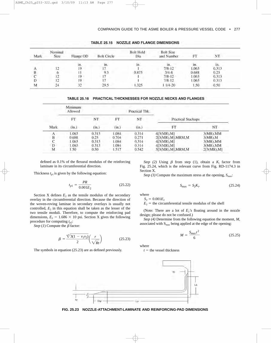
COMPANION GUIDE TO THE ASME BOILER & PRESSURE VESSEL CODE • 277
defined as 0.1% of the flexural modulus of the reinforcinglaminate in its circumferential direction.
Thickness tp1 is given by the following equation:
(25.22)
Section X defines E2 as the tensile modulus of the secondaryoverlay in the circumferential direction. Because the direction ofthe woven-roving laminae in secondary overlays is usually notcontrolled, E2 in this equation shall be taken as the lesser of thetwo tensile moduli. Therefore, to compute the reinforcing paddimensions, E2 � 1.686 � 10 psi. Section X gives the followingprocedure for computing tp2:
Step (1) Compute the factor:
(25.23)
The symbols in equation (25.23) are as defined previously.
b = 423(1 - v1v2)
2a r
2Rtb
tp1 =
PR
0.001E2
Step (2) Using from step (1), obtain a Kt factor from Fig. 25.24, which is the relevant curve from Fig. RD-1174.3 inSection X.
Step (3) Compute the maximum stress at the opening, Smax:
(25.24)
where S2 � 0.001E2
E2 � the circumferential tensile modulus of the shell
(Note: There are a lot of E2’s floating around in the nozzledesign; please do not be confused.)
Step (4) Determine from the following equation the moment, M,associated with Smax being applied at the edge of the opening:
(25.25)
where t � the vessel thickness
M =
Smax t 2
6
Smax = S2Kt.
FIG. 25.23 NOZZLE-ATTACHMENT-LAMINATE AND REINFORCING-PAD DIMENSIONS
ASME_Ch25_p253-322.qxd 3/10/09 11:13 AM Page 277
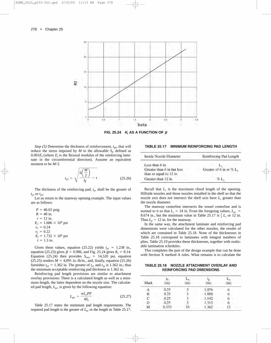
278 • Chapter 25
Recall that Lc is the maximum chord length of the opening.Hillside nozzles and those nozzles installed in the shell so that thenozzle axis does not intersect the shell axis have Lc greater thanthe nozzle diameter.
The manway centerline intersects the vessel centerline and isnormal to it so that Lc � 24 in. From the foregoing values, Lpc �8.674 in., but the minimum value in Table 25.17 is Lc or 12 in.Thus Lp � 12 in. for the manway.
In the same way, the attachment laminate and reinforcing paddimensions were calculated for the other nozzles, the results ofwhich are contained in Table 25.18. None of the thicknesses inTable 25.18 correspond to laminates with integral numbers ofplies. Table 25.19 provides these thicknesses, together with realiz-able lamination schedules.
This completes the part of the design example that can be donewith Section X method A rules. What remains is to calculate the
12
Step (5) Determine the thickness of reinforcement, tpb, that willreduce the stress imposed by M to the allowable Sf, defined as0.001Ef (where Ef is the flexural modulus of the reinforcing lami-nate in the circumferential direction). Assume an equivalentmoment to be M/2.
(25.26)
The thickness of the reinforcing pad, tp, shall be the greater oftp1 or tp2.
Let us return to the manway opening example. The input valuesare as follows:
P � 46.02 psig R � 48 in. r � 12 in.
E2 � 1.686 � 106 psi v1 � 0.24 v2 � 0.22 Ef � 1.732 � 106 psi
t � 1.3 in.
Given these values, equation (25.22) yields tp1 � 1.238 in.,equation (25.23) gives � 0.986, and Fig. 25.24 gives Kt � 8.14.Equation (25.24) then provides Smax � 14,520 psi, equation(25.25) renders M � 4,091 in.-lb/in., and, finally, equation (25.26)furnishes tp2 � 1.362 in. The greater of tp1 and t2p is 1.362 in.; thusthe minimum acceptable reinforcing pad thickness is 1.362 in.
Reinforcing pad length provisions are similar to attachmentoverlay provisions: There is a calculated length as well as a mini-mum length, the latter dependent on the nozzle size. The calculat-ed pad length, Lpc, is given by the following equation:
(25.27)
Table 25.17 states the minimum pad length requirements. Therequired pad length is the greater of Lpc or the length in Table 25.17.
Lpc =
pLcPF
4Ss
tt2 =
Q
6aM
2b
Sf- t
FIG. 25.24 Kt AS A FUNCTION OF B
ASME_Ch25_p253-322.qxd 3/10/09 11:13 AM Page 278

COMPANION GUIDE TO THE ASME BOILER & PRESSURE VESSEL CODE • 279
required skirt thickness, which is done in the next section byusing methods available to engineers familiar with the design ofFRP structural components.
25.8.6 Support Skirt Design Because the vessel will be installed indoors, and also because
there are no earthquake loads, the only structural requirement onthe skirt is that it supports the weight of the vessel and its con-tents. It must withstand direct stress and it must not buckle. Inaccordance with the design of the shell, the allowable stress is setat 0.001E, where E is the axial modulus. The critical bucklingstress, scr , is given by the following equation:
(25.28)
whereE � the axial modulus of the skirt t � the thickness of the skirt
R � the radius of the skirt
The allowable buckling stress is . Equation (25.28) is usedin Nonmandatory Appendix 3 of RTP-1, Article NM3-321, and isvalid when the length of the skirt is more than several times Lc �1.72(Rt)0.5, the critical length. The stress in the skirt, , is simplythe supported weight divided by the cross-sectional area. The sup-ported weight W � 56,500 lb, which was computed by ordinarymethods; the axial modulus E � 1.666 � 106 psi; and R � 48 in.Let us take t � 0.317 as a trial value for the thickness, correspond-ing to the lamination schedule 3(MR), MM. In addition, Lc � 6.71in., the length of the skirt—60 in.—is 8.9 times Lc, and equation(25.22) applies. The applied stress is computed as follows:
(25.29)
For this case, equation (25.29) gives 589 psi. The criticalbuckling stress from equation (25.28) is 3,301 psi; when dividedby Fb � 5, the stress equals 660 psi. The allowable stress from amaterial strength standpoint is 0.001E � 1,666 psi. The appliedstress is less than either allowable stress, so therefore the skirtthickness is acceptable.
25.9 RTP-1: EXAMPLE 1 DESIGNSPECIFICATION
Figure 25.25 is a sketch of the first RTP-1 design example: aflat-bottomed storage tank with nozzles that can be designed with
s =
s =
W
p[(R + t)2- R2]
15scr
scr =
0.3Et
R
Subpart 3A rules. Typical tanks have more nozzles, but the noz-zles presented in Fig. 25.25 illustrate Subpart 3A design rules aswell as many would.
The tank is intended for outdoor service in an area with SeismicZone 0, so therefore the tank must withstand wind but not seismicloads. In addition, it is located in an area where building codesrequire outdoor structures to support a 35 lb/ft2 snow load. Thetank will contain liquid with a specific gravity of 1.2. RTP-1requires the purchaser, or his or her agent, to complete a User’sBasic Requirements Specification (UBRS), which is RTP-1’sDesign Specification. (The completed UBRS for the tank is foundin Appendix 25.A.) Most entries in the UBRS are self-explanatory,but some are not, particularly to those unfamiliar with FRP. SuchUBRS entries are discussed in the following paragraphs.
Parts 6.00 and 7.00 in the UBRS concern the choice of construc-tion materials. There is a set of entries appropriate for the User whoselects the resin and another for the User who wants the Fabricatorto select the resin. In the present example, the User selectsDerakane 470, basing the decision on personal experience. Items7.10, 7.20, 7.50, and 7.60 therefore need not be filled in. Items 7.30and 7.40 are required for design of the tank, and if the User requiresthe Fabricator to choose the resin, these items must be completedbecause they give the Fabricator a basis for selection.
The User’s standard cited in 8.00 would contain technical andpossibly commercial matters not covered by RTP-1. For example,RTP-1 does not give tolerances on nozzle location, for which rea-son a User’s Design Specification should state them.
In 11.00, there is an entry for “man load,” which provides for aperson standing on the top head, but Articles 3A-340 and 3B-300state the same requirement. A reason for including a provision forthe man load in the UBRS is to remind the User that there may bea different, more demanding man-load requirement.
Section 19.00 deals with the recording of the Inspector’s desig-nation. Three individuals named in RTP-1, Article 1-400 are con-cerned with various aspects of inspection: a Certified Individual,an Inspector, and an inspector. RTP-1, Article 1-400 delineatestheir roles as follows:
This Standard requires that specific inspections be carried outby Inspection Personnel experienced in the fabrication of RTPvessels. In addition, other inspections may be carried out as a partof the Fabricator’s Quality Control Program. Throughout thisStandard, Inspection Personnel are referred to as either inspec-tor(s) (lowercase “i”), Inspectors (uppercase “I”), or CertifiedIndividual(s) (uppercase “CI”).
A Certified Individual is an employee of the Fabricator authorizedby ASME to use its marks. The Certified Individual’s principalresponsibility is to protect the ASME mark by carrying out the dutiesdescribed in this Standard (RTP-1). He can also be the Inspector.
ASME_Ch25_p253-322.qxd 3/10/09 11:13 AM Page 279

280 • Chapter 25
An Inspector is an individual who shall be mutually acceptableto the User and Fabricator and shall carry out his duties in accordwith this Standard. An Inspector’s reporting relationship to man-agement must be independent of the Fabricator’s production andmarketing groups. He can also be the Certified Individual or theinspector, but not both.
An inspector is an individual engaged in inspection activitiesduring the course of fabrication, usually as a function of qualitycontrol. He can be the Inspector, but he cannot be the CertifiedIndividual.
The following paragraphs demonstrate the application ofSubpart 3A rules to the tank. Material properties are consideredfirst, followed by the design of the top head, the design of theshell and flat bottom, the design of the nozzles, nozzle reinforce-ments, and attachment overlays, and finally the design of hold-down lugs to resist wind forces. Table 25.20 lists the section num-bers of this chapter where component calculations are given.
25.9.1 Laminate Properties The tank will be built of mat–oven-roving laminates as in the
previous example, but the laminates will be thinner and willinclude the corrosion barrier in the calculation of the vessel’sstrength RTP-1 permits. For these reasons, the laminates will have
a higher proportion of mat than in the previous example.Consequently, the modulus and strength will be somewhat lessand the Poisson’s ratio will be higher. RTP-1 Fabricators arerequired to obtain laminate properties for design by testing lami-nates of the same construction, resin, and glass that they intend touse in the vessel. Table 25.21 lists a typical set of properties,which will be used in the example.
25.9.2 Top Head Design Because the tank is vented, there is no internal pressure in the
top head. It must, however, withstand two loads: the snow load of35 psf (0.243 psi) and the man load of 250 lb on a 16 in.2 area.
As it is possible that someone would want to clear snow fromthe top of the tank, the loads will be treated as acting simultane-ously. Nonmandatory Appendix 11 of RTP-1 provides a methodfor calculating the stress in the center of an F&D head under thefootprint load. The stress would be less if the load were appliedelsewhere on the head, so the calculation suffices. The stress onthe top surface is given by Gt /t2, where t is the thickness of thecrown of the head and Gt is a value from a graph inNonmandatory Appendix 11. Similarly, the stress on the under-surface is Gb/t2 . Figure 25.26 is the graph that gives Gt and Gb asa function of (Rct)1/2. Here, Rc is the crown radius of the head.
FIG. 25.25 RTP-1, EXAMPLE 1 DESIGN AND SPECIFICATION
ASME_Ch25_p253-322.qxd 3/10/09 11:13 AM Page 280

COMPANION GUIDE TO THE ASME BOILER & PRESSURE VESSEL CODE • 281
In an F&D head, the crown radius equals the shell diameter;thus Rc � 144 in. The minimum pressure-containing part thick-ness allowed by RTP-1 is 0.22 in. Using this thickness, (Rct)1/2
5.63 in.; from the graph, Gt � �193.2 lb. and Gb � 103.9 lb.Therefore, the stress on the upper surface of the head is�193.2/0.222 � 3,992 psi; on the lower surface, it is 103.9/0.222 �2,146 psi. The membrane stress, s, from the pressure exerted bythe snow load is given as follows:
(25.30)
which, for the current values, yields s � �79.5 psi because thesnow load is �35 lb/ft2 � �0.243 psi. Thus the stress under thefootprint load on the top surface � �3,299 � 79.5 � �3,378 psi.The snow load may act for many days, but the footprint load actsonly for a short time, for which reason the design factor for tempo-rary loads, F � 5, may be applied to find the allowable for the com-bined stress: 16,000/5 � 3,200 psi, which is less than the absolutevalue of the applied stress. Therefore, the head must be thicker. Thenext thickest practical mat–wovenroving laminate is 0.29 in. thickwith a stack-up of V, 2M, 2(MR)M. In this case, Gt � �213.7 lb and Gb � 121.8 lb, and the footprint stresses on the upper and lowersurfaces are �2,541 psi and 1,448 psi, respectively. The membranestress from the snow load becomes �60.3 psi; therefore, the stressunder the footprint becomes �2,601 psi, which satisfies the allow-able stress criterion. (Note: Neither the graph in this book nor thegraph in RTP-1 can be read to four figures, as the text seems toimply. Appendix 11 was derived from an article by Eric Reissnerthat gives a solution to the problem in terms of Coulomb functions[10]. The author of this chapter wrote a Mathcad worksheet basedon the paper from which the values of Gt and Gb were obtained.)
Because the snow load applies an external pressure, the headmust be checked for elastic stability. Article 3A-320 of RTP-1gives the following formula for the minimum allowed thicknessfor an F&D head subjected to external pressure, Pd:
(25.31)
where Ef � the flexural modulus
t = Rca FPd
0.36Efb0.5
ss =
PRc
2t
RTP-1 requires F � for elastic stability, Ef � 1.25 � 106 psi,and Pd � 0.243 psi. The minimum required thickness is 0.236 in.,which is less than 0.29 in.; thus the head satisfies the bucklingrequirements.
25.9.3 Shell Design Hydrostatic pressures for heights in the shell needed for design
were computed in the usual way. These are listed in Table 25.22. RTP-1, Article 3A-210 gives the following algorithm for deter-
mining the minimum required thickness for a contact-molded,cylindrical shell. Compute thicknesses th and ta as follows:
(25.32)
(25.33)
whereP � the combined hydrostatic and design pressure at the
height at which the thickness is computed D � the shell diameter F � 10, the design factor on internal pressure
Nax � the axial force per unit circumferential length Sh � the ultimate hoop tensile strength Sa � the ultimate axial tensile strength
The greater of th or ta is the required minimum thickness. Forsimplicity, the shell will be of uniform thickness. Thus P � 7.8 psi,the hydrostatic pressure at the bottom of the shell (because thetank is vented, the design pressure is 0). Given the values of D �144 in. and Sh � 16,000 psi, th � 0.351 in. The weight of the headwas calculated by ordinary methods as 286 lb. The projected areaof the head in ft2 is as follows:
(25.34)
Thus the total snow load is 113.1 � 35 � 3,939 lb. The circum-ference of the tank is �D � 452.4 in.; therefore, Nax � (3,939 �286)/452.4 � 9.34 lb/in. The axial and hoop strengths are thesame, so Sa � 16,000 psi and
(25.35)
Thus the hoop stress governs and the required minimum thick-ness is 0.351 in. The next thickest realizable laminate is 0.37 in.thick with a stack-up of V, 2M, 3(MR)M.
ta =
9.34 * 10
16,000= 0.00584
A =
pD2
2= 113.1
ta =
NaxF
Sa
th =
2Sh
FIG. 25.26 STRESS FUNCTIONS FOR FOOTPRINTLOADING
ASME_Ch25_p253-322.qxd 3/10/09 11:13 AM Page 281
282 • Chapter 25
The bending moment at the base of the shell from wind is givenby the following equation:
(25.36)
From the UBRS, Pw � 20 psf. For computing the windmoment, the height is taken as the shell height plus the headheight of 17.16 ft The diameter is 12 ft; therefore, the base windmoment Mw � 35,336 ft lb. The moment produces a stress swthat can be calculated as follows from the ordinary beam formula:
(25.37)
whereI � the moment of inertia of the shell cross section c � D/2
The moment of inertia can be obtained from the followingequation:
(25.38)
With these values, sw � 71.5 psi. The axial stress from theweight is given as follows:
(25.39)
The stresses add weight on the leeward side of the tank, wherethe total axial stress is �82.8 psi. This is far less than the allow-able stress. To be complete, the compressive stress on the leewardside must be checked for buckling. The critical buckling stress forbending under wind moment is as follows:
(25.40)
where R � the radius of the tank
For the values given in equation (25.40), cr � 2,776 psi,which is much greater than the applied stress. The method used inequation (25.40) for wind loading is the same as that illustrated inNonmandatory Appendix 3, Article NM3-321 of RTP-1.
25.9.4 Design of Bottom and Bottom Knuckle Given the shell thickness and tank diameter, RTP-1 has rules
for the thickness of the bottom and design of the knuckle thatrequire no calculation. Article 3A-250 states the minimum flat-bottom thicknesses given in Table 25.23.
Subpart 3A rules currently apply to tanks and vessels up to 16 ftin diameter, a limit that may be increased soon by the RTP-1Committee. For tanks 12 ft–16 ft in diameter, RTP-1 requires adesign analysis. There are gaps in the diameter ranges because therule is for commonly available tooling.
The rules for the knuckle are somewhat more complicated.Article 3A-350 states the following:
The radius of the bottom knuckle of a flat bottom vessel shallnot be less than 1 in. if the diameter is 4 ft or less, and 1.5 in. for
scr =
0.39Et
R
swt =
W
p(D - t)t= 11.3
I = paD - t
2b2
t = 4.272 * 105 in.4
sw =
Mwc
I
Mw = Pw D H2
2
diameters exceeding 4 ft The minimum thickness of the radiussection shall be equal to the combined thickness of the shell walland the bottom. The reinforcement of the knuckle radius areashall taper so that it is tangent to the flat bottom, and shall notextend beyond the tangent line onto the tank bottom. Theknuckle reinforced area shall extend for a minimum distance of8 in. from the inside tank bottom up the vertical wall for tanksup to and including 4 ft in diameter, and 12 in. for tanks over 4 ftin diameter. The reinforcement shall then taper into the side wallfor an additional 4 in. The perimeter of the tank bottom shall bein a flat plane, and the bottom shall have no projections whichexceed 41 in. and which will prevent uniform contact with a flatsupport surface when the tank is filled with liquid.
Figure 25.27 shows the knuckle construction for this example.By coincidence, the shell and bottom have the same thickness, butthis is not always true. The bottom has a straight flange, for whichreason the knuckle radius does not contain a joint (the joint is afew in. up the side). This is not clearly stated as a requirement,although it is treated as such and is certainly good practice. Onthe inside of the joint, a seal overlay is applied to prevent processliquid from getting into the joint. The seal overlay has the samestack-up as the corrosion barrier—namely, V, MM. On the outsideof the joint, a butt-joint overlay is installed. Article 4-320 pro-vides the rules for butt joints between the heads and the shell andbetween the shell courses, and also for joints in the flat portion ofa fully supported (as by a slab) flat bottom. In this case, the rulesrequire the joint to be constructed of mat–woven-roving laminate(the same as the parts being joined) of at least the same thicknessas the thicker of the parts being joined. The first ply of the jointoverlay must be a mat ply at least 3 in. wide; the next, a woven-roving ply of the same width as the mat ply; the last, a mat plyextending beyond the woven-roving ply beneath it by at least
in. on each side. The sequence continues, with alternating pliesof mat and woven-roving and with each mat ply extending at leastin. on either side of the ply beneath it until the required thickness
is attained. The knuckle-reinforcement overlay is then added. Itwould also be of a mat–woven-roving laminate and would extendat least 12 in. up the shell, as measured from the inside surface ofthe tank bottom. The reinforcement overlay would be at leastequal to the bottom thickness and would taper into the shell to awidth of at least 4 in., which is in addition to the 12 in. full-thickness part of the overlay.
25.9.5 Hold-Down Lug Design Because the tank will be subjected to wind loading, it must be
equipped with hold-down lugs. Although no mandatory rules gov-ern these lugs, Nonmandatory Appendix NM-4 gives a methodfor designing them. The forthcoming analysis of the lugs uses this
12
12
ASME_Ch25_p253-322.qxd 3/10/09 11:13 AM Page 282
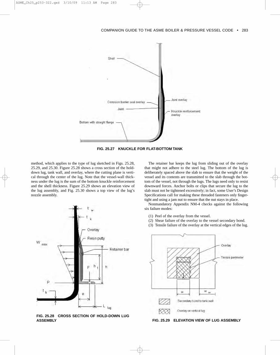
COMPANION GUIDE TO THE ASME BOILER & PRESSURE VESSEL CODE • 283
method, which applies to the type of lug sketched in Figs. 25.28,25.29, and 25.30. Figure 25.28 shows a cross section of the hold-down lug, tank wall, and overlay, where the cutting plane is verti-cal through the center of the lug. Note that the vessel-wall thick-ness under the lug is the sum of the bottom knuckle reinforcementand the shell thickness. Figure 25.29 shows an elevation view ofthe lug assembly, and Fig. 25.30 shows a top view of the lug’snozzle assembly.
The retainer bar keeps the lug from sliding out of the overlaythat might not adhere to the steel lug. The bottom of the lug isdeliberately spaced above the slab to ensure that the weight of thevessel and its contents are transmitted to the slab through the bot-tom of the vessel, not through the lugs. The lugs need only to resistdownward forces. Anchor bolts or clips that secure the lug to theslab must not be tightened excessively; in fact, some User’s DesignSpecifications call for making these threaded fasteners only finger-tight and using a jam nut to ensure that the nut stays in place.
Nonmandatory Appendix NM-4 checks against the followingsix failure modes:
(1) Peel of the overlay from the vessel. (2) Shear failure of the overlay to the vessel secondary bond. (3) Tensile failure of the overlay at the vertical edges of the lug.
FIG. 25.27 KNUCKLE FOR FLAT-BOTTOM TANK
FIG. 25.28 CROSS SECTION OF HOLD-DOWN LUGASSEMBLY FIG. 25.29 ELEVATION VIEW OF LUG ASSEMBLY
ASME_Ch25_p253-322.qxd 3/10/09 11:13 AM Page 283

284 • Chapter 25
(4) Yield in bending at the base of the lug. (5) Shear failure of the vessel wall. (6) Bending failure of the vessel wall.
Table 25.24 lists the quantities that are input to the lug compu-tations as well as the symbols used to represent the quantities inthe forthcoming equations. We are attempting to determine thelug dimensions, but because the calculation is of the cut-and-trymethod, the dimensions are input.
The allowable peel load and the allowable bond shear stress arevalues suggested in Nonmandatory Appendix NM-4. The lugyield strength is for A-36 structural steel. Lugs are often cut fromsteel structural shapes; thus the yield strength is realistic.
The first series of computations determines the force on themost heavily loaded lug. The lugs need to resist uplift only, for adownward force in the vicinity of a lug is resisted by the knucklepressing into the support lab. In the present example, a wind-
overturning moment, the uplift on the dished top head from thewind, and the weight of the vessel less the bottom weight, allinfluence the lug force. The wind uplift force on the top head, Uw,is given by the following equation:
(25.41)
Inserting the values in the table results in the following equations:
(25.42)
(25.43)Uw =
p
4(144.74)2 c 20
144d (0.8) = 1,828
Uq =
4Mq
D0
=
4(35,340)
144.74= 11,720 lb
Uw =
p
4D2
0PwPg
FIG. 25.30 TOP VIEW OF NOZZLE ASSEMBLY
ASME_Ch25_p253-322.qxd 3/10/09 11:13 AM Page 284

COMPANION GUIDE TO THE ASME BOILER & PRESSURE VESSEL CODE • 285
The wind pressure is divided by 144 to convert it from psf topsi to be consistent with the other values in the equation. (Theinside diameter of the tank shell is 144 in.; therefore, the outsidediameter is the inside diameter plus twice the thickness or 144.74in.) The effective uplift force from the wind moment, Uq, isobtained as follows:
The net uplift force is then
(25.44)
The force on a single lug, Flug, is then
(25.45)
The next step is to check resistance to peel. The maximum unitradial load on the overwrap, wmax, is given as follows:
(25.46)
The total radial load, P, is obtained from the following equation:
(25.47)
The length of the tensile perimeter, Ltp, is as follows
(25.48)
The peel load (lb/in.) is then
(25.49)
which is less than the allowable peel of 50 lb/in.The next mode to check is failure of the overlay to vessel sec-
ondary bond in shear. The shear stress is as follows:
(25.50)
The allowable bond shear stress is 200 psi; therefore, the bondshear is acceptable.
Next, the tensile stress in the overlay adjacent to the verticaledges of the lug is checked. The tension, T, is obtained from thefollowing equation:
(25.51)
The tensile hoop stress in the overlay, sov, is then
(25.52)sov =
T
h1tov=
8,037
(10.5)(0.27)= 2,835 psi
T =
PD0
2w=
(662.95)(145.48)
2(6)= 8,037 lb
tov =
Flug
2h1wov=
1,945
2(10.5)(3)= 30.87 psi
Spl =
P
Ltp=
662.95
27.25= 24.33
lb
in.
Ltp = 2(h - tb) + wlug = 2(11 - 0.375) + 6 = 27.25 in.
P =
wmaxh
2=
(120.54)(2.5)
2= 662.95 lb
wmax =
3Fluge
h2=
3(1,945)(2.5)
112= 120.54
lb
in.
Flug =
U
N=
11,670
6= 1,945 lb
U = Uw + Uq - Wv = 1,828 + 11,720 - 1,879 = 11,670 lb
The allowable stress is the tensile strength of the laminate—that is, 3,200 psi, for the stress results from wind, which is atemporary load. Because the overlay hoop stress is less thanthat, it is therefore acceptable. Peel, overlay bond shear stress,and hoop stress in the overlay are all less than their allowables,and the lug attachment overlay is acceptable. What remains isto check the lug itself and the stresses in the vessel wall underthe lug.
The bending stress at the base of the lug can be computed fromthe following equation:
(25.53)
The allowable stress in the lug, which is assumed to be cutfrom a structural A-36–steel angle, is of its yield stress or24,000 psi, which is greater than the bending stress in the lug.Thus the lug stress is acceptable. The shear stress in the tank wallunder the lug, Tw, is approximately given as follows:
(25.54)
which is a low value. Normal stress under the lugs is a combi-nation of bending from the lugs and the membrane from pressure.The computation of these stresses begins by computing the bend-ing parameter, b:
(25.55)
The axial bending moment in the shell under the lug, Max, isthen obtained from the following equation:
(25.56)
and the hoop moment, Mh, is as follows:
(25.57)
The axial normal stress in the wall under the lug results fromthe superposition of the axial membrane stress and the bendingstress from Max, as follows:
(25.58) = 1,752 psi
sax =
U
pDktk+
6Max
t 2k
=
11,670
p(145.48)(0.74)+
6(156.7)
0.742
Mh = vMax = (0.26)(156.7) = 40.74 in.-lb
in.
Max = a P
wlugb 1
4b= a662.95
6b =
1
4(0.1763)= 156.7
in.-lb
in.
b = ≥ 3(1 - v2)
aDk
2b2
t 2k
¥1/4
= ≥ 3(1 - 0.262)
a145.48
2b2
0.742
¥1/4
= 0.1763 in..-1
tw =
P
tkwk=
662.95
(0.74)(6)= 149.3 psi
23
sb =
3Flugwlug
Llugt 2b
=
3(1,945)(6)
4(4)(0.375)2= 15,560 psi
15
ASME_Ch25_p253-322.qxd 3/10/09 11:13 AM Page 285
286 • Chapter 25
Similarly, the hoop stress is the sum of the hoop membrane andthe hoop bending stresses, as follows:
(25.59)
As in the case of the overlay hoop stress, the allowable is 3,200 psi,which is comfortably more than the greater of the hoop and axialstresses.
The lug design is adequate to resist wind loads. Table 25.25lists the six failure modes, the allowable stress, the imposedstress, and the ratio of allowable to imposed stress. It shows thatthe lug and attachment overlay are well designed.
The allowable stress for the vessel-wall shear is only a roughvalue; it is rarely measured. It is the shear stress in a plane normalto the laminate and containing the axis of the vessel. Except forgross impact (which is always the result of an accident), this kindof failure is rare; therefore, the industry has not tried to define it.The lug design method is only approximate and is based as muchon experience as science. However, the method does result in reli-able lugs. Although finite-element or some other exacting stressanalysis might result in smaller lugs and overlays, the engineeringcost would be greater than the material and labor savings unless theFabricator plans to build many lugs of the same design.
25.9.6 Nozzle Reinforcement and Attachment Design Only nozzle A on the top head and the manway will be consid-
ered because in both cases it illustrates the design process as wellas many more examples would. External pressure from the snowload governs the design of the reinforcing pad for nozzle A.
Paragraph 3A-700 of RTP-1 contains rules for the openingreinforcement. The rules apply to openings for nozzles or man-ways with cylindrical necks. Other restrictions are the following:
(1) Only openings for circular nozzles in which the diameterdoes not exceed half the vessel diameter are covered bythese rules.
(2) Only openings in which the largest dimension along oneaxis is no longer than two times the largest diameter alongthe axis at 90 deg. to the first axis are covered by these rules.These dimensions shall be measured from one cut edge tothe opposite cut edge.
(3) These rules cover only the reinforcement of cylinders anddished, elliptical, and conical heads using RTP-1 design-by-rule thicknesses.
= 1,213 psi
s =
PhydDk
2tk+
6Mh
t 2k
=
(7.8)(145.48)
2(0.74)+
6(40.74)
0.742
The outside diameter of the reinforcing pad, dr, shall be thegreater of twice the opening’s largest dimension of the opening’slargest dimension plus 6 in. The taper at the outer periphery of thereinforcement laminate shall not be included in dr. Reinforcingpads shall not overlap. The thickness of the reinforcing pad, tr, isgiven by the following equation:
(25.60)
where V 1 for internal pressure, for external pressure M 1 for vessel parts of contact-molded laminates
M /15,000 for other laminates, such as those thatare filament-wound
a the hoop design strength, psi K 1 for nozzles of greater than 6 in. diameter K d/6 for 6 6 d the nozzle’s largest hole dimension
Tc the nominal wall thickness for construction Tt the minimum wall thickness that satisfies the design
conditions
If tr � 0.129 in., no reinforcing is required
Now, let us consider nozzle A. The head is governed by externalpressure so that . The head is contact-molded; therefore, M 1. The diameter is 12 in., which is greater than 6 in., and K 1.
From these values, Tc 0.29 in. and T1 0.236 in. Then,
(25.61)
Thus tr 0.129 in., and no reinforcing is required.The attachment laminate is specified in RTP-1 by Figs. 4.8 and
4.9 as well as Table 4.1 on pages 38, 39, and 42, respectively.Table 4.1 is reproduced in this chapter as Table 25.26.
The shear-bond width is the width of the attachment not only onthe vessel part or reinforcing pad, but up the nozzle neck as well.
Nozzle attachment laminates are shown in Fig. 25.11. Theattachment thickness is the greatest of 0.4 in.—twice the nozzleneck thickness, or tr Assume a nozzle neck thickness of 0.29 in, inwhich case the attachment laminate total thickness must be atleast 0.58 in. Some of it may be on the inside of the installation,may be some on the outside; this is acceptable as long as the sumof the two is at least 0.58 in. Table 25.26 gives the width of the
6
tr =
1
2* 1 * 1 * 0.236 - 1 * (0.29 - 0.236) = 0.064 in.
==
=
=V =12
=
=
=
=
=
=
=
=
12=
tr = VMKTt - M(Tc - Tt)
ASME_Ch25_p253-322.qxd 3/10/09 11:13 AM Page 286
COMPANION GUIDE TO THE ASME BOILER & PRESSURE VESSEL CODE • 287
attachment to be at least 5 in. on the shell or head to which thenozzle is attached and 5 more in. up the nozzle neck.
Assume that the manway neck is 0.37 in. thick. The shell is gov-erned by internal pressure and is contact-molded; therefore, V � 1and M � 1. The manway diameter is 24 in., so K � 1 and dr �48 in. In addition, Tc � 0.37 in. and Tt � 0.351 in. Thus the rein-forcing pad thickness is as follows:
(25.62)
From Fig. 4.8 of RTP-1, the attachment laminate thickness istwice the neck thickness, 0.74 in.; from Table 4.1 of RTP-1, thewidth is 6 in.
The dimensions of the reinforcing pad and attachment arefound the same way for nozzle B.
Table 25.27 lists the dimensions of the nozzle reinforcing padsand attachments. The thicknesses have been rounded up from thecalculated values to correspond to practical laminate sequences.
25.10 RTP-1: DESIGN EXAMPLE 2
25.10.1 RTP-1 Example 2 Design Specification Figure 25.31 sketches Example 2 of RTP-1 design. The vessel
has F&D top and bottom heads and is supported by a steel ring,
tr = 1 * 1 * 1 * 0.351 - 1 * (0.37 - 0.351) = 0.332 in.
which is a rolled-structural channel. The vessel will be supportedby building steel in an octagonal factory-floor opening andframed by steel beams. The support ring will be connected to thebuilding steel by lugs welded to the ring. The vessel may be filledwith a liquid with a specific gravity of 1.4, but it must have adesign internal pressure of 5 psig and a design external pressureof 10 psig.
The vessel will require vacuum-stiffening rings, even thoughthey are not shown in Fig. 25.31. The figure is meant to illus-trate a sketch that would be part of the Design Specification,which would not usually show vacuum rings. The Fabricatorwould determine whether rings are needed and would alsodesign them.
Appendix 25.B provides the UBRS for the vessel. As in theprevious example, many of the entries may be left blank. Table25.28 provides a list of the sections of this chapter where thecalculations for the vessel components can be found. However,manway and nozzle reinforcement and attachment designs arenot included because they are the same as in the previousexample.
The vessel will be built of the same resin as that used inExample 1, but the Fabricator intends to build this vessel ofmat–woven-roving laminate as well. For this reason, the samelaminate properties of Example 1 apply. For convenience, they arelisted in Table 25.29.
Hydrostatic pressures at various levels in the vessel arerequired during the design process. The hydrostatic pressure isgiven by the following equation:
(25.63)
where Ph � the hydrostatic pressureg � the specific weight of the contents H � the depth of the liquid at the level in question
Because the design condition is with the full vessel, H is mea-sured from the top of the top head. Table 25.30 lists the hydrostat-ic pressures used in design computations.
25.10.2 Design of the Top Head The top head will be subjected to an internal pressure of
5 psig, an external pressure of 10 psig, and the footprint load.
Ph = gH
ASME_Ch25_p253-322.qxd 3/10/09 11:13 AM Page 287

288 • Chapter 25
The hydrostatic pressure at the bottom of the head is 1.027 psig;therefore, the head must withstand a total of 6.027 psig.Paragraph 3A-220 requires the head to have a thickness of atleast tr, as follows:
(25.64)
where P � 6.027 psi, the total pressure
Rc � 120 in., the crown radius of the headSu � 16,000 psi, the ultimate tensile strength of the laminate F � 10, the design factor
Inserting the preceding values into equation (25.64) gives tr �0.40 in., which is the minimum thickness required to resist inter-nal pressure. The maximum allowed external pressure to thick-ness t is specified in paragraph 3A-320:
(25.65)
In this equation, Ef is the flexural modulus, Fv � 5, the designfactor on elastic stability, and Ro � R � t, the outside crown radius.
Pext = 0.36a Ef
Fvb a t
Rob2
tr =
0.885PRcF
Su
Using the thickness required for internal pressure and the flexuralmodulus from Table 25.29:
(25.66)
This is less than the required value Pext � 10 psi. By trial anderror it can be established that t � 1.299 in leads to Pext � 10.32 psi.
Pext = 0.36a1.25 * 106
5b a 0.40
120 + 0.4b2
= 0.9930 psi
FIG. 25.31 RTP-1,SECOND DESIGN EXAMPLE
ASME_Ch25_p253-322.qxd 3/10/09 11:13 AM Page 288
COMPANION GUIDE TO THE ASME BOILER & PRESSURE VESSEL CODE • 289
That thickness corresponds to a practical lamination sequence:V,MM,4[3(MR),M],MRM. Equation 25.64 above for thicknessrequired to resist internal pressure can be solved for the P thatresults from thickness of 1.299 in.:
(25.67)
The MAWP for the top head is then this value of P less thehydrostatic pressure which gives 18.5 psi.
It remains to verify that the head will resist the combination offootprint load and external pressure. The footprint load is consid-ered a temporary load, and therefore by Paragraph NM11-300, adesign factor of F � 5 may be used while considering the combi-nation of footprint load and stress from external pressure.
Nonmandatory Appendix 11 of RTP-1 provides a method forcalculating the stress in the center of an F & D head under thefootprint load. The stress would be less if the load were appliedelsewhere on the head, so the calculation suffices. The stress onthe top surface is given by Gt /t2 where t is the thickness of thecrown of the head, and Gt is a value from a graph inNonmandatory Appendix 11. Similarly the stress on the undersurface is Gb /t2. Figure 25.26 in Section 25.9.2 above is a copy ofthe graph that gives Gt and Gb as functions of (Rct)1/2. Here, Rc isthe crown radius of the head. In this case (Rct)1/2 � (120 �1.299)1/2 � 12.49 in. Then, from the graph, Gt � �323 lb and Gb �224 lb. Thus the footprint stress on the top surface is t ��323/1.2992 � �191 psi and the footprint stress on the lowersurface is b � 224/1.292 � 133 psi. The membrane stress at thetop of the crown from external pressure is obtained from:
(25.68)
The superposition of this stress and the footprint stress on thetop surface gives �191 � 461.9 � �653 psi. The allowable stressis 16000/5 � 3200 psi, which is much greater than the imposedstress. Since the internal design pressure is less than the externaldesign pressure, and since the positive footprint stress on theunderside of the head is less in absolute value than the footprintstress on the top, the combination of internal pressure and footprintload is also acceptable.
A top head laminate with stackup V,MM,4[3(MR),M]MRM,which is 1.299 in. thick, satisfies RTP-1.
25.10.3 Design of the Shell and Vacuum Rings The shell must withstand two independent loads: external pres-
sure and combined design pressure–hydrostatic load. The usualstrategy is to first compute the shell thickness required for internalpressure and then to determine if this is sufficient for externalpressure. If it is not, the design must be rechecked with one ormore vacuum-stiffening rings added to the shell. If the externalpressure condition can be satisfied with a satisfactory number ofrings, the design is accepted; if not, the shell thickness isincreased and the design is checked again. Eventually, by trial anderror, a satisfactory design is reached. There is a trade-offbetween the number of rings required and shell thickness. Thedesign engineer uses his or her judgment to determine whether aparticular choice is satisfactory.
Because the support ring will serve as a vacuum stiffener, theshell design will be done in two stages. The first will be to design
sm =
PextRc
2t=
-10 * 120
2 * 1.299= - 461.9 psi
P =
Sut
0.885FRc=
16000 * 1.299
0.885 * 10 * 120= 19.57 psi
the part of the shell above the stiffening ring (to be taken as thepart of the shell above the upper surface of the support ring); thesecond will be to design the part of the shell below the upper sur-face of the ring.
At the top of the support ring, the hydrostatic pressure is 6.99psig; the design pressure, 5 psig. The shell must therefore with-stand a combined pressure of P � 11.99 psig. Paragraph 3A-210supplies a rule for the required shell thickness—that it must be thegreater of t1 or t2, where
(25.69)
and
(25.70)
where P � combined design pressure-hydrostatic load
Nax � the axial stress resultant Su � the tensile strength F � 10, the design factor
The axial stress resultant from the design pressure is Nax PdR/2 �5 � 60/2 � 150 lb/in.
For t1:
(25.71)
For t2:
(25.72)
Thus the required minimum thickness for resisting internalpressure is 0.312 in. In reality, the axial stress resultant would bereduced because the weight of the upper part of the vessel wouldpartially counteract the pressure, but hoop stress governs, forwhich reason this conservatism has no effect on the design.
Paragraph 3A-310 gives an equation for computing the allowedmaximum external pressure on a given shell. It is:
(25.73)
where:F � design factor � 5
KD � knockdown factor � 0.84� � 1 � 0.001Zp if Zp 100 Zp � 0.9 otherwise
and
Zp =
E322f E
121
E21f
11 - v1f v2f212
L2
aD0
2 tb
…
PA =
KD 0.8531 g E342f
E141 t
52
11 - v1fv2f234 LaD0
2b
32
F
t2 =
(8.31)(60)
16,000
12
= 0.312 in.
t1 =
15016,000
10
= 0.094 in.
t2 =
PRSu
F
t1 =
Nax
Su
F
ASME_Ch25_p253-322.qxd 3/10/09 11:13 AM Page 289

290 • Chapter 25
In Equation (25.73), D0 represents the outside diameter, t the shellthickness, E1 the axial tensile modulus, E2f the hoop flexural modulus,E1f the axial flexural modulus, v1f Poisson’s ratio for bending stress inx direction and contraction/expansion in y direction, v2f Poisson’s ratiofor bending stress in y direction and contraction/expansion in x direc-tion and PA the allowable external pressure. The design length, L isdefined as the greatest of the following:
1. The distance between head tangent lines plus one-third thedepth of each formed head, if there are no stiffening rings(excluding conical heads and sections).
2. The distance between cone-to-cylinder junctions for vesselswith cone or conical heads if there are no stiffening rings.
3. The greatest center-to-center distance between any two adja-cent stiffening rings.
4. The distance from the center of the first stiffening ring to theformed head tangent line plus one-third the depth of theformed head (excluding conical heads and sections), all mea-sured parallel to the axis of the vessel.
5. The distance from the first stiffening in the cylinder to thecone-cylinder junction.
In the current example, one-third the depth of a head is 7.27 in.,the distance from the bottom tangent line to the top of the supportring is 27.5 in. and the tangent line to tangent line length of theshell is 144 in. Then the design length for the upper part of theshell is 144 � 7.27 � 27.5 � 123.77 in. Taking the shell thick-ness as the minimum required for internal pressure, D0 � 120�2(0.312) � 120.624 in. For this design, Equation (25.73) yieldsPA � 0.22 psi, far too low.
If two evenly spaced vacuum rings are added to the shell abovethe support ring, then the design length is 123.77/3 � 41.26 in.With the thickness unchanged, Equation (25.73) gives PA � 0.67psi, still too low. By using various values of t in the equation, onefinds that t � 0.9 in results in PA � 10.05 psi. The laminationschedule of the thinnest laminate with thickness at least 0.9 inthick is 3[3(MR)M]MRM which is 0.932 in thick. That thicknessresults in PA � 10.97 psi, which satisfies the design requirement.
The required moment of inertia of the vacuum rings is obtainedfrom paragraph 3A-330:
(25.74)I =
PvLsD30Fv
24Eh
whereI � the moment of inertia
Pv � the design vacuum pressure Ls � half the distance from the centerline of the stiffening
ring to the next line of support on one side, plus half ofthe centerline distance to the next line of support on theother side of the stiffening ring (both measured parallelto the axis of the cylinder)
Fv � 5, the design factor for elastic stability Eh � the hoop modulus of the sitffening ring laminate
A line of support, Ls, is defined as follows:
(1) a stiffening ring that meets the requirements of this paragraph; (2) a circumferential line on a head at one-third the depth of the
head from the tangent line; or (3) a cone-to-cylinder junction.
The ring will be made of the same laminate, except for thick-ness, as the shell. Thus E2 � 1.785 � 106 psi. With t � 0.932 in.,D0 � 120 � 2(0.932) � 121.846 in. The design length for use inEquation (25.73), Ls � 41.26 in., the same as the shell designlength.
No particular ring section is required by RTP-1. Perhaps themost common section is a trapezoid, an example of which issketched in Fig. 25.32. The dimensions shown result in a momentof inertia of 108.7 in.4 about an axis parallel to the vessel axis andthrough the centroid of the section. It was computed by ordinarymethods. The moment of inertia includes the attachment, the shellwall under the trapezoid, and the attachment laminate. The wallthickness of the ring is 0.28 in., with a lamination sequence ofMM,2(MR), M.
A common way of building the ring is from a core of low-density rigid foam, which is attached to the vessel with an adhe-sive. Then, the ring is laid up over the core. The core is usually solight that it does not contribute to strength or stiffness, but it is leftin the ring nevertheless.
The maximum allowable design pressure for the upper part ofthe shell is obtained by solving the t 2 equation, which governs the
I =
10 * 41.26 * (121.846)3* 5
24 * 1.785 * 106= 87.113 in4
FIG. 25.32 VACUUM-STIFFENING RING SECTION
ASME_Ch25_p253-322.qxd 3/10/09 11:13 AM Page 290

COMPANION GUIDE TO THE ASME BOILER & PRESSURE VESSEL CODE • 291
internal pressure, for P and inserting the values for this exampleas follows:
(25.75)
In the portion of the shell below the upper surface of the sup-port ring, the axial load is the sum of the weight of the vessel con-tents, the weight of the vessel below the support, and the forcefrom the internal design pressure. (Table 25.31 lists the sum ofthese weights.) At the bottom of the shell, the total pressure is thehydrostatic pressure of 8.31 psig (from Table 25.30) plus thedesign pressure of 5 psig, which sums to 13.31 psig. At the upperpart of the shell, the required thickness for internal pressure andcontents weight is the greater of t1 and t2, where
(25.76)
and
(25.77)
Nax is the axial membrane stress resultant and is given by thefollowing equation:
(25.78)
wherePd � the design pressureR � the inside shell radius
Wt � the total weight given in Table 25.31
Thus:
(25.79)
Inserting this value in equation (25.76) gives
(25.80)
Hoop stress therefore governs, requiring a thickness of 0.499 in.For simplicity, the entire shell will have the same thickness of
t1 =
411.8816,000
10
= 0.257 in.
Nax =
5 * 60
2+
98,725
2p * 60= 411.88
lb
in.
Nax =
PdR
2+
Wt
2pR
t2 =
PRSu
F
=
13.31 * 6016,000
10
= 0.499 in.
t1 =
Nax
Su
F
MAWP =
Sut
RF- Phyd =
16,000 * 0.932
60 * 10- 6.99 = 24.9 psi
0.909 in. The external pressure design length of the lower shell is27.5 in., which is less than 41.26 in. (the design length of theupper shell). Thus, if the shell segments are of the same thickness,the lower shell would be adequate for the design external pres-sure. The MAWP of the lower shell segment is calculated asbefore:
(25.81)
Thus a shell that has a lamination sequence of V, 2M, 3[3(MR),M (0.909 in. thick), as well as two vacuum rings as shown in Fig.25.32, satisfies the RTP-1 requirements.
25.10.4 Design of the Bottom Head The top head will be subjected to a hydrostatic pressure of
9.33 psig (from Table 25.30) combined with the design pressureof 5 psig to give a total pressure of P � 14.33 psig. The externaldesign pressure is 10 psig. It will have the same geometry as thetop head: torispherical, with a 120 in. crown radius, a 6% knuckleradius, and a 120 in. head diameter. The required thickness forinternal pressure is as follows:
(25.82)
The required thickness for external pressure is the same as forthe top head—that is, 1.223 in.—and has a lamination sequenceof V, MM, 4[3(MR), M], M. From Section 25.7, the pressurecapacity of the head is 18.43 psi. Thus the MAWP is 18.43 �9.33 � 9.10 psig.
25.10.5 Support Ring Design The weight of the entire vessel and its contents are computed
by ordinary methods. The total weight of 103,327 lb must be sup-ported by the ring. The ring, in turn, is supported by eight evenlyspaced lugs that mate with building steel, forming the edge of theoctagonal opening that the vessel occupies. Figure 25.33 is asketch of a cross section of the ring. In this example, theFabricator rolls the ring from a structural channel. (The ring isusually made in two halves connected with bolted splices.) Thevessel is built; then, the FRP-support and -retainer bands areinstalled on the vessel. The ring is assembled onto the vesseleither on the site or in the Fabricator’s shop.
RTP-1, paragraph NM5-400 provides a method for designingthe ring in Nonmandatory Appendix NM-5 (Ring Support ofVessels). The bending moment, Mb, and the twisting moment, Mv,at Section A in Fig. 25.34 are given by the following equations:
(25.83)
(25.84)Mt = -
WR
2pcf sin a
sin f- a +
fe
R cos (f - a) d
Mb = -
WR
2pcf cos a
sin f- 1 -
fe
R sin (f - a) d
tr =
0.885 PRcF
Su=
0.885 * 14.33 * 120 * 10
16,000= 0.919 in.
= 15.93 psi
MAWP =
Sut
RF= Phyd =
16,000 * 0.909
60 * 10- 8.31
ASME_Ch25_p253-322.qxd 3/10/09 11:13 AM Page 291

292 • Chapter 25
whereW � the total supported weightR � the geometric quantities defined by Fig, 25.34
Note that the angle 2 is the angular separation between lugsand that a locates a section of the ring. Given that there are Nlugs, � 180/N deg. The quantity e, the eccentricity of the lugforces, is the radial distance from the line of action of the supportforce to the shear center of the ring section, as shown in Fig.25.35. The bending stress, j/b, and the torsional shear stress, ,are then given as follows:
(25.85)sb =
Mb
Zb
t
f
f
a, f =
and
(25.86)
where Zb � the bending section modulus of the ring about a radial
centroidal axis Zt � the torsional section modulus
For relatively thin-walled open sections, such as a rolled chan-nel, Zt is well approximated by the torsional stiffness constant Jdivided by the thickest part of the section wall. A good indicatorof yield in a steel channel is the von Mises stress, obtainedfrom the bending and shear stresses by the following equation:
(25.87)
Thus, for a given ring, the von Mises stress is given as a func-tion of a by equation (25.87). To verify the design of the ring, it isnecessary to find the section at which svm is greatest.
For the present example, W � 103,327 lb, R � 62 in., and N �8. Then � 180/8 � 22.5 deg. A candidate section is a C15 �50 structural channel [11]. This channel has a moment of inertiaof 404 in. 4 and is 15 in. high. Then Zb � 404/7.5 � 53.87 in.3,the torsional constant J � 2.67 in.4, and the thickness for com-puting Zt is 0.65 in. Thus Zt � 2.67/0.65 � 4.108 in.3, and theshear center is 0.583 in. radially inward from the back of thechannel. Setting e � 6 in. gives a reasonable allowance for the lugdesign and clearance between the ring and building steel. Figure25.35 is a plot of as a function of a for this set of values.
The value of a for which is greatest is 14.28 deg.,where 17,840 psi. The channel would be composed ofA36 steel, which has a yield strength of 36,000 psi. A normalallowable stress is of the yield or 24,000 psi, of which the actualstress is 74.3%. Thus the ring section is acceptable.
Computations for the maximum von Mises stress were done byusing Mathcad. Figures NM5-8, NM5-9, and NM5-10 in RTP-1
23
svm =
a =svm
svm
f
svm = 2s2b + 3t2
svm,
t =
Mt
Zt
FIG. 25.33 SUPPORT-RING CROSS SECTION
FIG. 25.34 GEOMETRIC QUANTITIES IN THE STRESSANALYSIS OF THE RING
ASME_Ch25_p253-322.qxd 3/10/09 11:13 AM Page 292

COMPANION GUIDE TO THE ASME BOILER & PRESSURE VESSEL CODE • 293
are design charts for streamlining this process. They plot a stressfunction, as a function of Zb / Zt for various e/R, and there is aseparate chart for each number of lugs. The stress is then given bythe following equation:
(25.88)
In the present case, Zb/Zt � 13.113 and e/R � 0.968. FigureNM5-10 is the chart for eight lugs; it yields � 0.15 for thischoice of Zb/Zt and e/R. The maximum von Mises stress is thus:
(25.88)
25.10.6 Vessel MAWP The MAWP is listed in Table 25.32 for each pressure-containing
component. The MAWP for the entire vessel is 9.10 psig, the leastof those listed, and the maximum allowable external pressure is 10 psig, governed by the stiffening rings. The reason why theMAWP is so much higher than the design pressure is that externalpressure governs the design of all the components, requiringgreater component thicknesses than the internal pressure.
svm =
103,327 * 62 * 0.15
53.87= 17,840 psi
Æ
svm =
WRÆ
Zb
Æ,25.11 QUALITY ASSURANCE OF SECTION
X AND RTP-1 VESSELS
25.11.1 Introduction Manufacturers of both RTP-1 and Section X vessels are gov-
erned by stringent quality assurance systems that are certified bythe ASME. The shops themselves must have written quality con-trol procedures and be accredited by the ASME. All vessel con-struction must be done in accordance with a detailed procedurespecification; moreover, each vessel design must be qualifiedeither by testing (in the case of Section X, Class I) or by designcalculations backed by measured laminate properties (in the casesof RTP-1 and Section X, Class II). Design calculations for RTP-1and Section X, Class II vessels must be certified by a RegisteredProfessional Engineer. Completed vessels must be inspected by anindividual certified by the ASME.
Although both RTP-1 and Section X necessarily use similarquality assurance methods, ASME requirements from the twodocuments are not identical; although they accomplish the samepurpose by very similar means, they differ in detail. In the follow-ing paragraphs, Section X requirements are considered first, fol-lowed by those of RTP-1.
25.11.2 Section X Quality Assurance Section X contains requirements for the Fabricator’s quality
control system, vessel manufacturing procedure specification, andinspection and testing. These three aspects of quality control areeach discussed in turn below.
25.11.2.1 Fabricator’s Quality Control System The Fabriator’sQuality Control System must be maintained to ensure that the ves-sels he or she builds satisfy all Section X requirements. TheFabricator must also maintain a quality control manual thatdescribes his or her system. The manual is reviewed by the ASMEteam that originally accredits the Fabricator’s shop and must beavailable for review by the Authorized Inspector as a part of his or
FIG. 25.35 VON MISES STRESS IN THE SUPPORT RING
ASME_Ch25_p253-322.qxd 3/10/09 11:13 AM Page 293

294 • Chapter 25
her vessel inspections. The manual, which may contain proprietaryinformation, is not required to be distributed. As Section X states,
It is intended that information learned about the system (TheFabricator’s Quality Control System) in connection with theevaluation will be treated as confidential and that all loaneddescriptions will be returned to the Fabricator upon comple-tion of the evaluation.
Thus the ASME team that accredits the shop may borrow themanual, but must return it and not reveal the contents. TheAuthorized Inspector5 has access to the manual during the visitsto the Fabricator’s facility, but does not retain a copy. Section Xdoes not require that the manual be available to Purchasers; there-fore, if a Purchaser wishes to review the manual, the Fabricatormust agree to let the Purchaser read it.
The complexity of the Quality Control System and manualdepend greatly on the size and complexity of the Fabricator’soperations and the kind of equipment that the Fabricator builds. Itshould be appropriate to the Fabricator’s circumstances. Althoughthe Code does not have a long, detailed set of requirements forFabricators’ Quality Control Systems, it does have an outline offeatures to be included in the manual. These are as follows:
(a) Authority and Responsibility This section defines theauthority and responsibility of those in charge of the QualityControl System. These individuals must have well-definedresponsibilities as well as the authority and freedom to identifyand remedy quality control problems.
(b) Organization The manual contains an organization chartthat shows the relationship among engineering, quality control,purchasing, production, testing, inspection, and management per-sonnel. A small shop may have combined functions, such as qual-ity control, testing, and inspection vested in one person, andtherefore may have a very simple organization chart.
(c) Drawings, Design Calculations, and Specifications For bothClass I and II vessels, the Quality Control System has procedures toensure that the latest revisions of drawings, procedures and specifi-cations required by Section X are used for fabrication, inspection,and testing. For Class II vessels, the system also includes referenceto the design documents certified by a Regis tered ProfessionalEngineer and the need for any changes to such documents to beapproved by the Registered Professional Engineer. The Fabricator’sQuality Control System also provides those individuals building thevessel with other information not governed by the Code. TheForeword to Section X (and all other Codebook sections) states that“the Code does not address all aspects of these activities.”
(d) Production Flow and In-Plant Inspection and Checkoff Thesystem includes a basic production-flow procedure, including in-plant inspection procedures and checkoff points as well as ameans of documenting them. The purpose of this aspect of thesystem is to guarantee that the Procedure Specification on thedrawing is actually implemented. An example of a ProcedureSpecification is given below.
(e) Material Receiving Control and Identity Before and duringfabrication, a system of material control ensures that the materialused complies with the applicable specifications and procedures.The system provides documentation that the proper material isused in fabrication.
(f) Nonconforming Materials, Components, and Repairs Allnonconformities, including materials, components, and fabricationerrors, are identified and documented. Components that fail tomeet the required standards may be repaired if the proposed repair
is approved by the design engineer and by the Inspector before therepair is begun. If the repair is not approved, the component isrejected. Some repairs may be required to satisfy Purchaser’srequirements that are not governed by the Code. For example,excessive air bubbles in an FRP corrosion barrier would violate thePurchaser’s specification, not Section X. Because repairing thebarrier would not affect the pressure containment, the RegisteredProfessional Engineer and the Inspector would not be required toapprove the repair. Another example is a misplaced nozzle, forwhich the Code does not require a repair to be made. However, therepair would affect the pressure containment, so in this case boththe Registered Professional Engineer and the Inspector would needto approve the repair. If there is doubt, the prudent Fabricatorwould consult the Inspector to determine whether a given repairneeds his or her approval in addition to the Registered ProfessionalEngineer’s approval. After all, it is the Inspector who decideswhether a particular vessel may be stamped.
(g) Resin Control Good resin control is essential to vessel qual-ity. The Quality Control System contains resin specification andmixing procedures; procedures for the storage, handling, and dis-posal of resins, catalysts, fillers, pigments, and promoters; and aprocedure for identifying resin during fabrication.
(h) Assembly, Fit-Up, and Dimensions Control Documentationof methods for assembly, fit-up, dimensional checks, and adhesivebonding of vessel components are included in the Quality ControlSystem. The system may also contain procedures for dimensionalcontrol not required by the Code, such as tolerances on nozzleplacement.
(i) Calibration of Measurement and Test Equipment TheFabricator maintains a system, including documentation, for thecalibration of all examination, measuring, and test equipmentused to show compliance with Code requirements. A descriptionof the system is included in the Quality Control System manual.
(j) Forms The Quality Control System manual contains sampleforms for documenting all system procedures that must befollowed. Pages 211–249 of Section X display many of theseforms. The Fabricator must, however, compose his or her ownforms as well, such as those for documenting resin receipt, stor-age, and use.
(k) Authorized Inspector As stated previously, the Inspector hasaccess to the Quality Control System manual. In addition, he orshe has access to the design documents and records governed bythe Code that are relevant to the vessels to be inspected.
25.11.2.2 Accreditation of a Fabricator The ASME authorizesa Fabricator’s shop to place the RP Section X) Symbol Stamp onvessels. The authorizing of shops is governed by the ASME Boardon Conformity Assessment, not by the B&PV Code itself. TheBoard sends a team to a candidate Fabricator to deter minewhether his or her shop can produce vessels in conformity withSection X. The team examines the Quality Control System, theProcedure Specifications, and the fabrication work in progress;then recommends to the Board whether to authorize the shop.Authorizations must be renewed every three years.
25.11.2.3 Example of a Procedure Specification The ProcedureSpecification for Class II vessels is defined by completing Form Q-120, found on pages 225-234 of Section X. Form Q-120 has the fol-lowing three parts:
• Part I (Fabrication): This part must be completed for eachseparately fabricated vessel part, including nozzle necks and
ASME_Ch25_p253-322.qxd 3/10/09 11:13 AM Page 294

COMPANION GUIDE TO THE ASME BOILER & PRESSURE VESSEL CODE • 295
nozzle flanges. It specifies the materials, ply sequence, plyorientation, and procedures used to fabricate the vessel part.Part I must be accompanied by Parts II and III.
• Part II (Assembly) This part must be completed for every sec-ondary lay-up process required to join vessel parts. It lists thematerials, dimensions, and ply sequences of each secondaryoverlay, including not only head-to-shell joints between separate shell courses, but also overlays used to install nozzles,flange-nozzle neck connections, and opening-reinforcingpads. Part II must be accompanied by Parts I and III.
• Part III (Summary) This part compiles a list of procedures usedto fabricate individual vessel parts and join them into a com-pleted vessel. Part III must be accompanied by Parts I and II.
Appendix 25.C shows a Form Q-120 Procedure Specificationfor the Section X design example presented in Section 25.7.
Item I in Part I identifies the vessel, the vessel part for whichthe procedure is to be done, and the Fabricator, User, andRegistered Professional Engineer who certify the design. It alsogives the procedure number, the procedure date, and the date thepart was fabricated.
Item II defines the essential design variables: the reinforcingfiber types; the resin, catalyst, and promoter; the laminatesequence; and the method of resin cure. In the top head, there arethree types of reinforcement—a C-glass veil on the inner surface,a 1.5 oz/ft randomly oriented mat, and a 24 oz/yd woven roving—after which the ply sequence is stated. The orientation defines thedirection of the weave of the woven-roving relative to the vesselaxis. The woven-roving in the example has four fiber bundles perin. in one direction and five per in. in the perpendicular direction.The direction of the four-per-in. bundle coincides with the E1modulus direction. An orientation of 0 deg. aligns this directionwith the vessel axis.
Item II(B)(3) states that the resin will be cured at room tempera-ture, without a post-cure; (B)(4) gives the design Barcol hardnessas 40 � 5; (B)(5) is not applicable; and (B)(6) lists the design-reinforcing fiber content as 41.1% � 1% by weight.
Item III documents the test report that establishes the engineer-ing constants used in design calculation for the vessel.
Item IV documents the design qualification for the top head.The date the vessel was tested, the design and acceptance testnumbers, and the version of Section X are all given. Item IV(A)lists the type and batch numbers of the reinforcing fiber forms, aswell as the resin and its catalyst and promoter. With this data, allmaterials could be traced through the Fabricator’s receivingreports and back to the Material Manufacturer’s certifications andquality control data. The catalyst and promoter are chemicalsmixed with the resin just before it is used that initiate the cross-linking reaction that transforms the resin from a thick liquid to asolid. In this case, the catalyst is benzoyl peroxide; the promoter,dimethylaniline. Other catalysts and promoters are used to curevinyl ester resin. Item IV(B) gives the resin data that theFabricator collects for each different batch of resin. The values inthe example are typical of vinyl ester resins. Item IV(C), (D), and(E) each record the results of quality checks and inspections, and(F) shows the certification by a representative of the Fabricatorand Inspector that the vessel part satisfies Section X.
Part II of Form Q-120 is a similar compilation for the overlaythat joins the top head to the shell. There are, however, twoimportant differences. The first is that Part II(B) specifies the sur-face preparation for the joint by referencing a procedure in theFabricator’s Quality Control Manual. The second is that there are
two lamination sequences, for part of the overlay could be (but isnot required to be) on the inside of the vessel while the rest is onthe outside. Vessels with FRP corrosion barriers will always haveat least the corrosion-barrier overlay part on the inside.
Part III of Form Q-120 provides a list of all ProcedureSpecifications for the parts and joint overlays in the vessel. It alsocontains the certification by the Authorized Inspector that the ves-sel satisfies Section X and may receive the Section X RP SymbolStamp.
An actual Form Q-120 would be much longer than the one pre-sented in Appendix 25.C. In addition to having eighteen overlays,the example vessel has fourteen parts for which Q-120, Part IForms would be required. Each part is four pages long, so thecomplete form would be 4 � (14 � 18) � 1 � 129 pages long.Besides the Form Q-120, there are material-receiving reports,mechanical-property test reports, resin test records, inspectionrecords, the acoustic-emission (AE) test report, and the designreport. Documentation for a Section X vessel is voluminous.
Procedure Specifications for the various types of Class I vesselsare similar to one another.
25.11.3 RTP-1 Quality Assurance Quality assurance and shop-accreditation requirements for
RTP-1 are very similar to those for Section X, especially SectionX, Class II. The similarity is not surprising because both RTP-1and Section X use the same materials and manufacturing methodsand both also require accreditation by an ASME survey teambefore vessels are stamped. In addition, both require a QualityControl System with a written manual, as well as thorough docu-mentation of the design, fabrication, testing, and inspection ofevery vessel that receives the ASME mark. RTP-1 and Section Xboth result in about the same amount of documentation for ves-sels of similar complexity.
There are, however, a few significant differences, four of whichare as follows:
• As part of the accreditation process, the Fabricator must builda demonstration vessel to show that his or her shop can buildequipment that satisfies RTP-1. Though small, the vessel haschallenging design details, including a tangential nozzle and abody flange. The vessel must be available to the ASME teamthat surveys the shop.
• The Fabricator must produce demonstration laminates ofevery type of all laminates that he or she needs to produce andmust conduct tests to determine their mechanical proper ties.The test values must meet the values set by RTP-1.
• Inspection personnel are different, as exemplified by the RTP-1, Article 1-400 passage reproduced in Section 25.9.
• Bonders and laminators are tested and certified. Bonders arecraftspeople who join FRP parts by means of secondary bondedoverlays, whereas laminators are craftspeople who build the lam-inates. To be certified, both must produce sample work accord-ing to written procedures. The sample work is then tested; if it isfound satisfactory, the bonder or laminator may, by using thewritten procedures, produce parts for a stamped vessel.
24.11.4 Summary The quality assurance provisions of both Section X and RTP-1
standards ensure that vessels that receiving the ASME mark—RPfor Section X, RTP for RTP-1—are built according to either ofthese standards. Such vessels have high-quality design and fabri-cation and provide long, reliable service.
ASME_Ch25_p253-322.qxd 3/10/09 11:13 AM Page 295

296 • Chapter 25
25.12 REFERENCES
1. ASME Boiler and Pressure Vessel Code Section X, Riber-ReinforcedPlastic Pressure Vessels; The American Society of MechanicalEngineers.
2. ASME RTP-1, Reinforced Thermoset Plastic Corrosion-ResistantEquipment; The American Society of Mechanical Engineers.
3. Beckwith, S. W., Filament Winding—The String and the Glue,Composite Fabricators Association Web site: http://www.cfahq.org/documents/StringandGlue.doc.
4. Murphy, J., The Reinforced Plastics Handbook, Elsevier SciencePublishers, 1994, p. 356.
5. Tsai, S. W., and Hahn, H. T., Introduction to Composite Materials,Technomic Publishing Co., Westport, CT, 1980, p. 280f.
6. Nielsen, L. E., Mechanical Properties of Polymers, ReinholdPublishing Co., New York, 1962, p. 11.
7. RTP-1, Mandatory Appendix M-11; The American Society ofMechanical Engineers.
8. ASME Section X, Article RG-113; The American Society ofMechanical Engineers.
9. ASME Section X, Article RG-121; The American Society ofMechanical Engineers.
10. Reissner, E., “Stresses and Small Displacements of Shallow SphericalShells, II,” Journal of Mathematical Physics, Vol. 25, No. 4, 1947, pp. 279–300.
11. American Institute of Steel Construction (AISC), Manual of SteelConstruction, Allowable Sress Design, 9th ed., pp. 1–40.
ASME_Ch25_p253-322.qxd 3/10/09 11:13 AM Page 296

COMPANION GUIDE TO THE ASME BOILER & PRESSURE VESSEL CODE • 297
APPENDIX 25.A
UBRS FOR RTP-1 EXAMPLE 1
ASME_Ch25_p253-322.qxd 3/10/09 11:13 AM Page 297

298 • Chapter 25
ASME_Ch25_p253-322.qxd 3/10/09 11:13 AM Page 298

COMPANION GUIDE TO THE ASME BOILER & PRESSURE VESSEL CODE • 299
ASME_Ch25_p253-322.qxd 3/10/09 11:13 AM Page 299

300 • Chapter 25
ASME_Ch25_p253-322.qxd 3/10/09 11:13 AM Page 300

COMPANION GUIDE TO THE ASME BOILER & PRESSURE VESSEL CODE • 301
ASME_Ch25_p253-322.qxd 3/10/09 11:13 AM Page 301

302 • Chapter 25
ASME_Ch25_p253-322.qxd 3/10/09 11:13 AM Page 302

COMPANION GUIDE TO THE ASME BOILER & PRESSURE VESSEL CODE • 303
ASME_Ch25_p253-322.qxd 3/10/09 11:13 AM Page 303

304 • Chapter 25
ASME_Ch25_p253-322.qxd 3/10/09 11:13 AM Page 304

COMPANION GUIDE TO THE ASME BOILER & PRESSURE VESSEL CODE • 305
ASME_Ch25_p253-322.qxd 3/10/09 11:13 AM Page 305

306 • Chapter 25
APPENDIX 25.B
UBRS FOR RTP-1 EXAMPLE 2
ASME_Ch25_p253-322.qxd 3/10/09 11:13 AM Page 306

COMPANION GUIDE TO THE ASME BOILER & PRESSURE VESSEL CODE • 307
ASME_Ch25_p253-322.qxd 3/10/09 11:13 AM Page 307

308 • Chapter 25
ASME_Ch25_p253-322.qxd 3/10/09 11:13 AM Page 308

COMPANION GUIDE TO THE ASME BOILER & PRESSURE VESSEL CODE • 309
ASME_Ch25_p253-322.qxd 3/10/09 11:13 AM Page 309
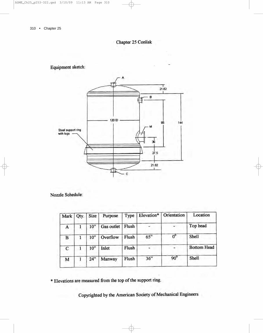
310 • Chapter 25
ASME_Ch25_p253-322.qxd 3/10/09 11:13 AM Page 310

COMPANION GUIDE TO THE ASME BOILER & PRESSURE VESSEL CODE • 311
ASME_Ch25_p253-322.qxd 3/10/09 11:13 AM Page 311

312 • Chapter 25
APPENDIX 25.C
EXAMPLE PROCEDURE SPECIFICATION FOR A SECTION X VESSEL
ASME_Ch25_p253-322.qxd 3/10/09 11:13 AM Page 312

COMPANION GUIDE TO THE ASME BOILER & PRESSURE VESSEL CODE • 313
ASME_Ch25_p253-322.qxd 3/10/09 11:13 AM Page 313

314 • Chapter 25
ASME_Ch25_p253-322.qxd 3/10/09 11:13 AM Page 314

COMPANION GUIDE TO THE ASME BOILER & PRESSURE VESSEL CODE • 315
ASME_Ch25_p253-322.qxd 3/10/09 11:13 AM Page 315

316 • Chapter 25
ASME_Ch25_p253-322.qxd 3/10/09 11:13 AM Page 316

COMPANION GUIDE TO THE ASME BOILER & PRESSURE VESSEL CODE • 317
ASME_Ch25_p253-322.qxd 3/10/09 11:13 AM Page 317

318 • Chapter 25
ASME_Ch25_p253-322.qxd 3/10/09 11:14 AM Page 318

COMPANION GUIDE TO THE ASME BOILER & PRESSURE VESSEL CODE • 319
ASME_Ch25_p253-322.qxd 3/10/09 11:14 AM Page 319

320 • Chapter 25
ASME_Ch25_p253-322.qxd 3/10/09 11:14 AM Page 320

COMPANION GUIDE TO THE ASME BOILER & PRESSURE VESSEL CODE • 321
ASME_Ch25_p253-322.qxd 3/10/09 11:14 AM Page 321

ASME_Ch25_p253-322.qxd 3/10/09 11:14 AM Page 322