apricus australia
TRANSCRIPT

Owner’s Guide and Installation Manual for Heavy Duty Electric Water Heaters|1
Apricus Australia Heavy Duty Glass-Lined Electric Water Heaters
Owner’s Guide and Installation Manual For End Users and Installers
Models: AP315GL336 AP315GL348
Scope:
This document outlines the owner’s instructions and installation manual. By using this manual, you will be able to understand the product better and for the installer, make sound decisions regarding installation.
Last Update Date: 12/10/2015

Owner’s Guide and Installation Manual for Heavy Duty Electric Water Heaters|2
This manual outlines the installation procedures for correct assembly, installation and safe operation of the heavy duty electric water heaters. This water heater must be installed and serviced by a qualified person in accordance with relevant standards and local authority and OH&S regulations. On completion, sign and leave this guide with the responsible officer.
Responsible Officer(s)
It is recommended that you read through Chapters 1, 7 and 8, the rest of the manual is intended for the installer however it may be of interest.
Instal ler(s) Please take the time to read and understand the complete installation requirements as this will ensure a
successful and trouble free installation. If you have any questions regarding the installation process, please contact your Apricus Relationship Manager.
For Repairs and Service, Cal l : 1300 APRICUS (1300 277 428)
Notes Specifications and materials are subject to change without notice. Images are for illustrative purposes only. This manual is effective for heavy-duty electric water heaters manufactured and sold after 1 November 2015. Every care has been taken to ensure accuracy in preparation of this publication. No liability can be accepted for any consequences, which may arise as a result of its application.

Owner’s Guide and Installation Manual for Heavy Duty Electric Water Heaters|3
Contents 1. Warnings and Precautions ........................................................................................................... 4
2. Installation and Site Inspection .................................................................................................... 6
3. Plumbing Connections ................................................................................................................ 8
4. Electrical Connections ............................................................................................................... 10
5. Commissioning ......................................................................................................................... 12
6. Post Installation ........................................................................................................................ 13
7. Maintenance ............................................................................................................................ 14
8. Troubleshooting ....................................................................................................................... 14
9. Warranty ................................................................................................................................. 17

Owner’s Guide and Installation Manual for Heavy Duty Electric Water Heaters|4
1. Warnings and Precautions
Instal ler Requirements
Installation of a system must be completed by a
licensed plumber and in accordance with the
requirements listed below, as well as any relevant
local standards and regulations.
AS/NZS 3500 - National Plumbing and Drainage
Code
AS/NZS 3000 Electrical Installations/ Wiring Rules
IMPORTANT Use only qualified trades people or Apricus Australia nominated service technicians for installation and repairs. Installations must have electrical and plumbing compliance certificates.
Occupational Health and Safety
The installer must adhere to occupational health
and safety guidelines and other relevant industry
associations. Under no circumstances should any
installer attempt to install a water heater without
reading and understanding this installation
manual. For any queries Apricus staff may be
contacted on 1300 277 428.
Over Pressure and Temperature Protection
Pressure Temperature Relief Valve (PTRV)
Any system design must allow a means of pressure
release at no more than 850kPa, using a PTRV. The
PTRV must be mounted in the marked socket and
its outlet vented to atmosphere, copper-piped
continuously downward in a frost free
environment. This ensures that any expelled hot
water or air is directed to a safe, frost free and appropriate drainage location.
From time to time the PTRV may discharge small
amounts of water under normal operations, this
can be up to 10% of tank capacity. If the tank is
installed indoors, a safe-tray must be installed
beneath the hot water tank to safely collect any
water expelled from the PTRV. The safe operation
of this valve prevents the water heater exploding if there is a serious fault.
Mains Pressure Control
The water heater is designed to operate at mains
pressure by connecting directly to the mains water
supply. Where the mains pressure supply can
exceed or fluctuate beyond the pressure of
500kPa, a pressure-limiting valve must be fitted to
the cold mains line. The device is installed after the
duo valve (isolation valve and check valve) and
should have a pressure limit of 500kPa. Refer to
Table 1 for the maximum mains water supply pressures.
Table 1 – Maximum mains water supply pressures
Models Units AP315GL336 AP315GL348
PTRV Setting kPa 850
ECV Setting* kPa 700
Max Mains Supply Pressure (with ECV)
kPa 580
Max Mains Supply Pressure (without ECV)
kPa 680
Pressure Limiting Valve
kPa 500
*ECV is not supplied with water heater.
In some states it is a mandatory requirement that
an expansion control valve be fitted on the cold
mains line to provide a form of pressure relief. A
separate drain line must be run for this relief valve
(as per AS/NZS 3500). If unsure please check with
the local authority.
Water Quality
Water quality is an important aspect of system
lifetime. For the system to be warranted, the water
used in the system must meet the water quality
requirements as per Table 2.

Owner’s Guide and Installation Manual for Heavy Duty Electric Water Heaters|5
Table 2 – Water Quality Thresholds
Water Quality Maximum Allowable Levels Total hardness <= 200 mg/litre or ppm
Total dissolved solids
<= 600 mg/litre or ppm
Electrical conductivity
<= 850 μS/cm
Chloride <= 250 mg/litre or ppm
Magnesium <= 10 mg/litre or ppm Sodium <= 150 mg/litre or ppm
pH Min 6.5 to Max 8.5
If in doubt contact your local water authority or
have a water test completed. In areas of poor
water quality all major components will have a reduced life due to the hardness of the water.
In areas with "hard water" (>200mg/L or ppm), it is
advised to install a water softening device to
ensure the long term efficient operation of the
system is met. It is also advisable that a glass-lined
tank is used as opposed to a stainless steel tank,
since the glass-lined tank has a sacrificial anode to protect from corrosion.
Stagnation and No-Load Conditions
Hydrogen Build Up
Glass lined (vitreous enamel) tanks are fitted with a
Magnesium anode to provide corrosion protection
for the tank from the storage water. Small
quantities of hydrogen gas can be released by the
anode, which generally remains dissolved in the
water and flushed away as hot water is used from
the tank. Depending on the water quality there
may be a degree of hydrogen build-up in the tank
if the water heater hasn't been used for two or more weeks.
To resolve the build-up of hydrogen within the
tank "purge" the tank for approximately 30 seconds from the lever on the PTRV.
WARNING Ensure there are no open flames or ignition sources close to the tank.
WARNING This appliance is not intended for use by young children or infirm persons unless they have been adequately supervised by a responsible person to ensure that they can use the appliance safely. Young children should be supervised to ensure that they do not play with the appliance.
WARNING This unit can produce water hot enough to burn skin. Delivery temperatures must be controlled as per AS/NZS3500.4

Owner’s Guide and Installation Manual for Heavy Duty Electric Water Heaters|6
2. Installation and Site
Inspection
Instal lation Standards This water heater shall be installed with the following requirements:
In accordance with the Apricus Heavy Duty Electric Water Heaters Installation Manual
In compliance with the relevant standards AS/NZS 3500.4, AS/NZS 3000 and all local mandatory, regulatory requirements.
Installation carried out by qualified person(s).
The water heater must be installed only after completing site inspection, refer to the sections below in this Chapter for details.
Water Heater Appl ication
Use with Potable Water The heavy duty electric water heaters are designed for use with potable water, using alternative fluids may reduce the lifetime of the water heater.
Continuous hot water load Should the site require a continuous flow of hot water, the system design must incorporate redundancy to allow for the scenario where a water heater may cease to perform as it normally should for any reason and requires servicing or maintenance. A back-up water heater can ensure the continuous supply of hot water in such cases.
Using the Water Heater in Circulated Flow and Return Setup Should the water heater(s) need to be set up to circulate through the ring main of the building/site with flow and return, it must be verified that the water heater thermostat is set to a minimum of 60oC.
Using the Water Heater as an in - line booster In such a setup, hot water from a hot water circuit is fed to the heavy duty electric water heater that activates to boost the water to a higher desired temperature. Ensure that
isolation valves are used on the water heater’s inlet and outlet lines.
This water heater is not suitable for use with pool heating applications.
Storage Tank Location
Position the Water Heater near Draw Off Points
The storage tank should be located as close as
possible to the most frequent draw off points
in the building such as the bathroom or
kitchen. If the storage tank is located a long
way from hot water draw points, a hot water
circulation loop on a timer may be considered
to reduce the time-lag for water to heat up
and resultant water wastage.
Avoid Obstructions
The tank should not obstruct any windows,
doors or exits and should cause minimal
intrusion to the existing site (minimum
clearances between the rear of the water
heater and wall is 100mm). The water heater
must also be easy to access for servicing and
maintenance purposes (minimum of 900mm
from the front of water heater), with the labels
clearly visible. Should the water heater be
installed outdoors, ensure that the rear side is
against a solid wall with the relevant clearance.
Anodes
For glass-lined tanks, consider the requirement
of anode removal and replacement
maintenance.
Safe Trays
The storage tank may be installed in a safe tray
that complies with AS/NZS 3500.4 and all local
codes and regulatory authority requirements
with regards to its construction, installation
and draining. Tanks installed outside must be
installed on a suitable, level concrete slab, away from pooling water.
Transportation of Components
When transporting boxes, note the orientation
of the "THIS WAY UP" arrows.

Owner’s Guide and Installation Manual for Heavy Duty Electric Water Heaters|7
Ensure all boxes are strapped and secured to
prevent movement during transit.
All tanks must be transported upright. Stacking
is not recommended for any tanks.
Products should always be handled with care.
Damage incurred during the transportation is not covered under product warranty.
Unpacking of Components
When unpacking, take care to ensure that the
components are not damaged in the process.
Avoid using sharp blades or knives as this can
scratch the surfaces of the products
particularly the tanks.
Carefully remove all packaging and transit
protection from the heater before installation.
Dispose of the packaging responsibly using
recycling facilities where they exist.
Total Dissolved Sol ids (TDS) and Anodes Heavy Duty Electric water heaters that are glass-
lined are not covered by Apricus warranty if the
anode used in the water heater does not match
the allowable TDS. Using incorrect anodes can
damage and reduce the lifetime of the water
heater.
Refer to Chapter 1 in Water Quality section for further information on water quality thresholds.

Owner’s Guide and Installation Manual for Heavy Duty Electric Water Heaters|8
3. Plumbing Connections
Pipe Size
For commercial installations, the recommended
pipe size is 1 ¼”.
Two factors affect the choice of pipe sizing, the
flow rate and pressure drop. These two factors are
closely related; a higher pressure drop will reduce
the flow rate. Pressure drop increases with
decreased pipe diameters as well as the presence
of bends, elbows and other components that
restrict flow.
It may be necessary for some installations with
numerous pipe bends and significant pipe runs to
increase the pipe diameter to reduce the pressure
drop. All pipe work must be installed in accordance with AS/NZS 3500.4
IMPORTANT It is necessary that all valves and fittings used are solar rated due to high temperatures that can be experienced.
Pipe Insulation
Insulate all pipes running to and from the manifold
with insulation of at least 15mm thickness, or
25mm in cold climates. Also, ensure the insulation
is tight against the all ports (minimizing the loss of heat from any exposed areas).
IMPORTANT All insulation needs to be solar-rated. Any insulation exposed to sunlight must be UV-stabilized.
Storage Tank
The Apricus Heavy Duty Electric tanks contain three ports.
1. Inlet (Mains): Inlet line from mains water
supply
2. Outlet: Outlet line to load
3. PTRV: Pressure temperature relief valve location.
Figure 1 Apricus Heavy Duty Electric Storage Tank
All ports on an Apricus Australia Heavy Duty Glass-
Lined Electric storage tank are of 32mm (1 ¼”)BSP,
with the exception of PTRV port which is 20mm (3/4”) BSP.
All fittings must be sealed using thread sealing tape
such as Teflon tape or any approved thread
sealant. Copper olives must be used with all compression fittings.
IMPORTANT Apricus tanks must be installed in accordance to AS/NZS 3500.4 as well as any other relevant local/government standards.

Owner’s Guide and Installation Manual for Heavy Duty Electric Water Heaters|9
Inlet (Mains)
The mains line should consist of the following brass components when installing:
Duo valve
Cold Water Expansion control valve (Required
by some local authorities)
Pressure Reducing Valve
Four-Way Cross (Required if tempering valve is
used)
Tempering Valve (Required depending on the application type)
Figure 2 Mains Line Valves
The set of mains line valves can be purchased as a
kit from Apricus and provides the above
components with insulating jackets to streamline the installation process.
Note that the inlet pressure or maximum mains
supply pressure without an ECV should not exceed
680kPa. A pressure reducing valve must be fitted to maintain the correct inlet pressure.
It is recommended that a cold water expansion
relief valve is fitted to reduce pressure buildup
during the heating cycle and save heating energy.
All attached valves and pipes should be lagged to save energy.
IMPORTANT The valve or drain valve outlet pipe must not be sealed or blocked.
In order to limit the hot water to outlets for
bathrooms, amenities, etc. it is recommended that
a tempering valve is installed between the water
heater and the fixture in accordance with
AS/NZS3500.4. Refer to the figure above for the location of the valve.
Outlet
The outlet is where the hot water from the tank is extracted to be supplied to the load.
PTRV Port
The PTRV port is where the tank ‘pressure and
temperature relief valve’ is to be installed. All
PTRV’s must be fitted with a copper drain pipe to
carry any discharge to an appropriate drain. The
water heater must have a PTRV installed before it is operated.
IMPORTANT
All storage tanks include a PTRV, which is located
under a plastic cover near base of the tank
packaging support.

Owner’s Guide and Installation Manual for Heavy Duty Electric Water Heaters|10
4. Electrical Connections
Boosting Explained
If the water inside the tank is not at the desired
temperature, the electric elements switch on and raise the water to a suitable temperature.
Legionella Bacteria - Importance of Boosting
It is a legal requirement that water be heated on a
regular basis to kill Legionella bacteria that can
lead to Legionnaires disease. The frequency that
this temperature must be reached varies, and is explained in the table below.
Table 3 Minimum Heat Requirements
Type of Apricus System Installed
Minimum Heat
Requirements
Bottom elements electric boosted system
Once per week to 60°C for 32 minutes
Thermostat Setting
The water heater has an adjustable thermostat
that controls the electricity supply to the electric
elements automatically such that a constant water
temperature is achieved in the tank. The over
temperature cut out and thermostats are located
on the front side of the water heater underneath a cover.
The thermostat should be set to 60°C or above as per AS/NZS 3498.
The temperature setting on thermostat can be
adjusted by a licensed tradesperson only. It is
recommended by Apricus that the thermostat is
set to the lowest temperature setting that can meet the hot water needs at the site.
When the electric element is activated it will heat
up all the water above the element to the lowest
thermostat temperature setting that meets the
site’s hot water needs. This heating can take as
long as 2-3 hours if the tank is cold.
Note: Apricus recommends that the electric water
heater is left on, or controlled by a suitable timer.
The water heater should not be switched off when
it is not in use as the thermostats are fully
automatic and power is only drawn when heating is required.
This unit is fitted with over temperature electrical
cutout, thermostat and a pressure and
temperature relief valve (see Pressure
Temperature Relief Valve section). Apricus advises
that this water heater is not to be operated unless
these features are present and in working condition.
WARNING The water heater uses 240V/415V AC power for the electrically operated components. Removing the front cover exposes the wiring. The equipment must not be interfered with and must only be serviced by a suitably qualified technician.
Instal lation of Electr ical Connections
The unit must be installed by a licensed tradesman
in accordance with AS/NZS3000. Means for
disconnection from the supply mains having a
contact separation in all poles that provide full
disconnection under over-voltage category III
conditions must be incorporated in the fixed wiring
in accordance with the wiring rules.
IMPORTANT
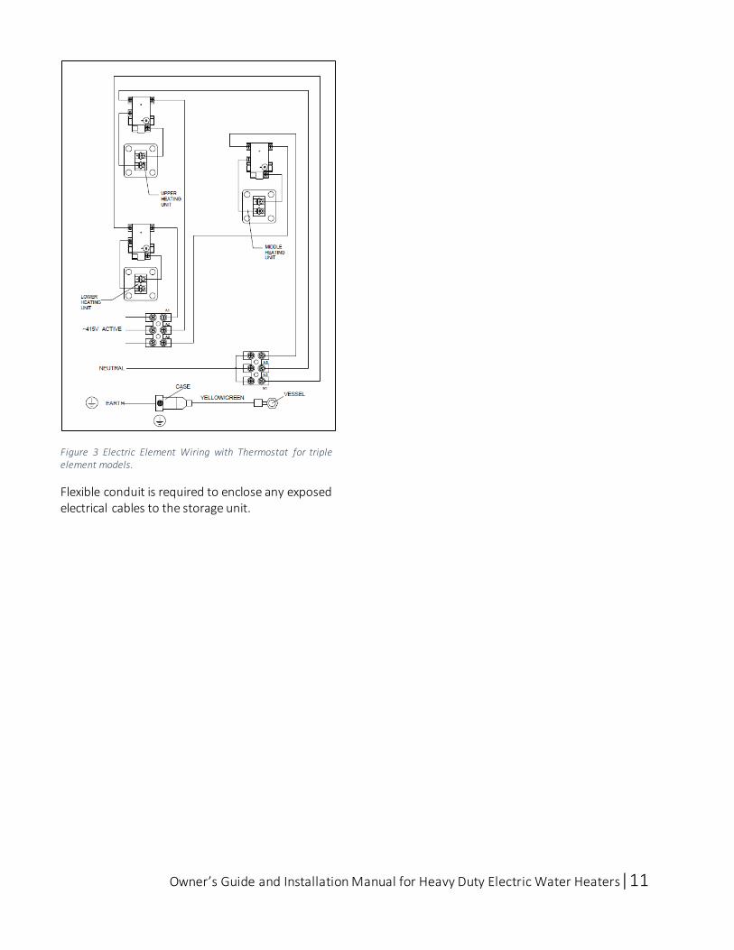
All electrical connections must be completed by an authorized and licensed person. The electrical elements will be required to be directly connected to a 240V AC 50Hz mains power supply or three phase 415V AC star supply with one element per phase for the triple element heavy duty water heaters. See wiring diagram below.
Owner’s Guide and Installation Manual for Heavy Duty Electric Water Heaters|11
Figure 3 Electric Element Wiring with Thermostat for triple element models.
Flexible conduit is required to enclose any exposed electrical cables to the storage unit.

Owner’s Guide and Installation Manual for Heavy Duty Electric Water Heaters|12
5. Commissioning
Fi l l ing and Air Purging
IMPORTANT
Power Supply to the electric water heater must be off until the water heater is filled with water and a satisfactory megger reading is obtained.
To fill the water heater:
1. Open the cold mains line and fill up the
tank, then open the hot water outlet or
hot water taps in the building (including
any showers, supply cocks and valves in
the system).
2. This includes opening the isolation valves
fully on the cold and hot water lines to the
water heater(s) installed in a bank and
opening the cold water isolation valve on
the cold water line to the water heater(s).
3. Filling is completed once there is a
constant stream of water exiting from the
taps as air is forced out.
4. Close all hot water taps in the building.
5. Inspect the piping to ensure there are no
leakages.
6. Electricity supply to the water heater(s)
isolating switch should be switched on at
this point.
7. Once the system reaches its working
temperature, the pipework needs to be
inspected again for leakages.
8. The operation and functions of the water
heater must be explained to the end user
or responsible officer.
9. Once the system is installed and
commissioned completely, the end user or
responsible officer must have a copy of
this guide left with them.
Turning off the Water Heater Following the completion of installation and
commissioning it may be necessary to turn off the
water heater in cases where the building premises
are vacant.
To turn off the water heater:
1. Electricity supply to the water heater(s)
isolating switch should be switched off.
2. The cold water isolation valve on the cold
water line to the water heater(s) must be
closed in order to stop the system.
Otherwise; closing the isolation valves on
the cold and hot water branches to shut
down an individual water heater(s) in a bank.

Owner’s Guide and Installation Manual for Heavy Duty Electric Water Heaters|13
6. Post Installation To ensure optimal operation and to maintain the
integrity of Apricus solar hot water systems, the
post installation checklist involves important tasks
that must be completed. Ensure that each of the
following processes is carried out prior to leaving the site.
Checklist Prior to Leaving Instal lation Site
System check: Check all connections for leaks
and that all components are installed as per
this manual.
Take photos of all system components for
warranty purposes. This should include photos
of the plumbing lines to and from the tank.
Note down the Tank Serial Number
Fill out the installation record form supplied
for heavy duty electric water heater warranty
and service issues. This is located in the back of
this manual following the warranty policy.
Submit your Installation Record Form via
Email: [email protected]
In the subject heading, please enter ‘Heavy
Duty Electric Tank – Installation Record Form’

Owner’s Guide and Installation Manual for Heavy Duty Electric Water Heaters|14
7. Maintenance Please refer to the manufacturer’s documentation for any non-Apricus components for maintenance guidelines. Maintenance and servicing should only be completed by a certified plumber, with experience in heavy duty electric water heaters. The following regular care is recommended to maintain the tank. The responsible officer is recommended to carry out the following minor maintenances every six months.
Draining the Water Heater The unit should be isolated at the stop cock and also electrically. Depressurize the unit with the pressure and temperature relief valve by gently lifting and hold the valve lever open while draining the unit. Remove inlet pipe fitting to drain water, again gently lifting the lever to break the vacuum. Failure to hold the pressure and temperature relief valve open during draining may result in a vacuum implosion, which will void the warranty. To drain the water heater:
1. Follow the instructions in the section
‘Turning off the water heater”.
2. Close all hot water taps in the building.
3. Gently lift the PTRV lever to release the
pressure in the water heater.
IMPORTANT
Water released through the PTRV may be of a very high temperature, care must be exercised to gently lift and lower the lever.
4. The cold water inlet union must be
undone, and a hose attached in its place at
the water heater cold inlet. The opposite
end of the hose must be placed near a
drain.
5. Release the PTRV lever again to allow air to
enter the tank and water to drain through the hose.
Over Pressure Protection Maintenance The lever on the PTRV should be carefully lifted and placed down once every 6 months to remove any debris of scale build up and verify the valve is not blocked. It is important to slowly and gently lift and release the lever to avoid damaging the valve. Water should flow out. If the valve is always leaking water, or does not flow when the lever is pulled, it must be repaired by a licensed tradesman. The valve should be replaced every 5 years or sooner in hard water areas.
WARNING Exercise caution and stand clear of the valve to avoid hot water relieved from the PTRV from splashing.
This should be similarly done for the expansion
control valve on the cold mains line (if there is one
installed). Ensure that the lever is lifted and
lowered gently.
Safe Tray Drain Line Check that the drain line from the safe tray (if
there is one installed) is not blocked.
Magnesium Anode Replacement
Glass lined storage tanks have a magnesium anode
inserted into the tank. The anode prevents internal
corrosion that will otherwise drastically shorten
storage tank life. Apricus recommends the anode
be inspected at least every three (3) years, and
serviced as required.
A qualified person must be used to change the
anode.
8. Troubleshooting The points below must be confirmed prior to
contacting Apricus regarding a service call. Unless
the fault is related to manufacture or failure of a component, you will be charged.

Owner’s Guide and Installation Manual for Heavy Duty Electric Water Heaters|15
Therefore Apricus urges you to run through the
following points.
Not enough or No Hot Water
Is your Electricity Supply switched on? Check that the electricity supply is switched on by verifying that both isolating switches, at the switchboard (marked ‘HOT WATER’ or ‘WATER HEATER’) and near the water heater (if it is present) are at the ‘ON’ position. It is important to note that in the case where an off-peak or timer is used with the electricity supply it dictates the hours in the day that the electricity supply is switched ‘ON’ for. Inspect the fuse at the switchboard marked ‘HOT WATER’ or ‘WATER HEATER’.
Are you using more hot water than you think?
It may be possible that at the points of hot
water use (particularly at fixtures such as
showers), more hot water than what is
assumed to be used may be used.
You may reduce water usage by having a
plumber install flow control valves to each shower rose to minimize the hot water usage.
Is the PTRV discharging too much hot water? Refer to the chapter 1 in the PTRV section.
How can I minimize the amount of hot water being discharged at the PTRV?
Installing a cold water expansion valve can
significantly reduce the amount of hot water
being discharged at the PTRV. Read more
about it in Chapter 3 in the plumbing connections on the cold mains line section.
Is the Thermostat setting correct?
Ensure that the appropriate setting is used for
the thermostat. Refer to Chapter 4 in
Thermostat Settings section for further
information.
A qualified person may increase the setting on
the thermostat if the end user requires a
greater hot water capacity than the minimum
required.
No water from the hot outlet taps
If no hot water is available from hot water
outlets, it may be an indication that the cold
water supply to the water heater has failed or
been restricted.
Observe the water flow at other taps at the
site and that the cold water isolation valve is fully open.
Is your water not hot enough? Heavy hot water usage can lead to lower than normally expected hot water. Your water heater may not be appropriately sized to meet your hot water requirements in such a scenario. Apricus has a sizing guide to suggest average sizes that may be required for different hot water applications. The Apricus sales literature and guide can be found on the website (www.apricus.com.au).
Pressure Temperature Rel ief Valve The PTRV is expected to release hot water. The levels of hot water discharged can be observed as fitting within the following categories:
Normal Operation Small quantities (less than 2% of hot water used) released by the valve during the heating cycle is considered normal operation. Any more than this much hot water being released can be considered excessive and may be an indicator of another problem.
Continuous Dribble
WARNING Exercise caution as higher temperature water can cause a greater risk of scald injuries.

Owner’s Guide and Installation Manual for Heavy Duty Electric Water Heaters|16
Continuously dribbling hot water at the PTRV may be caused by foreign matter being lodged within the valve. Refer to Chapter 8 in Over Pressure Protection Maintenance section for instruction on how to remove any debris.
Steady Flows for Prolonged Periods (often at night) It is likely that the mains water pressure is being exceeded at times above the pressure that the water heater is designed for. A pressure limiting valve can be fitted on the cold-mains line to reduce the pressure of the system.
WARNING
Never replace a PTRV with a higher pressure rated PTRV.
Heavy flows of hot water until water heater is cold, then stops until water reheats. The water heater must be switched off at the isolating switch or switchboard. Contact Apricus or their nearest Accredited Service Agent to arrange for an inspection.
Expansion Control Valve (ECV) Running
Why is the ECV running and discharging cold water instead of the PTRV? The ECV is functioning under normal operation, where it relieves the increase in pressure caused by water expansion during the normal heating cycle. The ECV will relieve cold water, not hot water, so that there is some energy saving and the PTRV's lifetime is increased. Refer to Chapter 3 in Inlet Mains section for the location of the ECV on the cold mains line.
Higher than Expected Electr icity Bi l ls
What could be the reason behind higher than expected electricity bills? Should you find that you feel as though your electricity bills are much higher than you might expect, it is important to run through the following points:
o Is the PTRV running excessively?
Refer to Chapter 8 in PTRV section. o Are the hot water outlets using more
hot water than you might think? Refer to Chapter 8 in Not Enough or No Hot Water section.
o Is there a leaking hot water pipe, dripping hot water tap or anything, etc.? Inspect all pipework to ensure there are no leaks as even a small leak can lead to significant wastage of hot water and electricity. Have your plumber fix any leakages and replace any faulty outlet fixtures at the site.
o Has hot water usage increased at the site? If hot water usage increased at the site, then the water heater operation also increases.
o Has your electricity retailer increased the electricity tariff since your previous account? The electricity tariff to which your water heater is connected to will determine the overall operating cost of the system. Ensure that you are aware of the tariff being used, whether it continuous or is a time controlled supply. Contact your electricity retailer/supplier for more information relating to your water heater tariff rate.
If you have checked the above points and still believe that you may need assistance, contact Apricus or their nearest Accredited Service Agent.

Owner’s Guide and Installation Manual for Heavy Duty Electric Water Heaters|17
9. Warranty The Heavy Duty Glass Lined Electric Water Heaters
have a 7 year warranty period, conditional upon
the maintenance requirements as per the Apricus Australia commercial warranty policy.
For the range of Heavy Duty Electric Glass-lined
water heaters, the warranty periods are
conditional upon the type of component and perceived issue of that component.
i. Inner Cylinder leakage warranty period is 7
years for parts only, 1 year for parts and
labour;
ii. Water heater casing undergoing corrosion
and/or paint peeling warranty period is 3
years for parts only, 1 year for parts and
labour.
iii. Heating element failure warranty period is
1 year for parts only and parts and labour.
iv. PTRV failure and leaking warranty period is
1 year for parts only and parts and labour.
v. Thermostat failure warranty period if 1 year for parts only and parts and labour.
Note that the warranty period shall begin from the
date of installation, where there is no record of
this, the warranty period shall begin 60 days from the date of manufacture.
Refer to the Apricus commercial warranty policy document for full terms and conditions.
www.apricus.com.au
1300 APRICUS (1300 277 428)