apta-pr-e-rp-018-99 - american public transportation association
TRANSCRIPT

APTA PR-E-RP-018-99 Edited 3-22-04
Volume III - Electrical 17.0
17. APTA PR-E-RP-018-99 Recommended Practice for 480 VAC
Head End Power Jumper and Receptacle Hardware
Approved March 4, 1999 APTA PRESS Task Force
Authorized January 11, 2000 APTA Commuter Rail Executive Committee
Abstract: This document defines the recommended practices for Head End Power (HEP) jumper/ receptacle hardware.
Keywords: head end power system, trainline, 480 VAC hardware
Copyright © 1999 by The American Public Transportation Association
1666 K Street, N. W. Washington, DC, 20006, USA
No part of this publication may be reproduced in any form, in an electronic retrieval
system or otherwise, without the prior written permission of The American Public Transportation Association.
APTA PR-E-RP-018-99 Edited 3-22-04
Volume III - Electrical 17.1
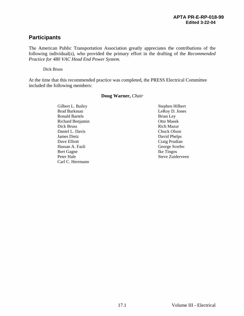
Participants
The American Public Transportation Association greatly appreciates the contributions of the following individual(s), who provided the primary effort in the drafting of the Recommended Practice for 480 VAC Head End Power System.
Dick Bruss At the time that this recommended practice was completed, the PRESS Electrical Committee included the following members:
Doug Warner, Chair
Gilbert L. Bailey Brad Barkman Ronald Bartels Richard Benjamin Dick Bruss Daniel L. Davis James Dietz Dave Elliott Hassan A. Fazli Bert Gagne Peter Hale Carl C. Herrmann
Stephen Hilbert LeRoy D. Jones Brian Ley Otto Masek Rich Mazur Chuck Olson David Phelps Craig Prudian George Scerbo Ike Tingos Steve Zuiderveen
APTA PR-E-RP-018-99 Edited 3-22-04
Volume III - Electrical 17.2
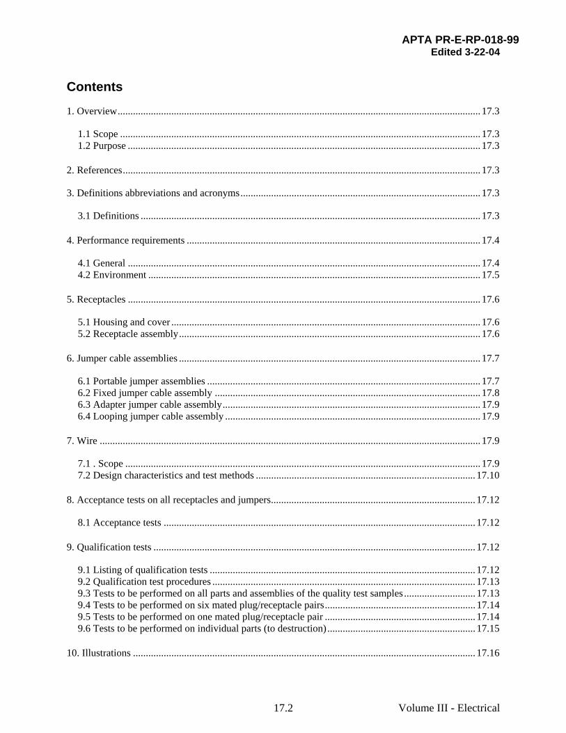
Contents
1. Overview.............................................................................................................................................. 17.3
1.1 Scope ............................................................................................................................................. 17.3 1.2 Purpose .......................................................................................................................................... 17.3
2. References............................................................................................................................................ 17.3
3. Definitions abbreviations and acronyms.............................................................................................. 17.3
3.1 Definitions ..................................................................................................................................... 17.3 4. Performance requirements ................................................................................................................... 17.4
4.1 General .......................................................................................................................................... 17.4 4.2 Environment .................................................................................................................................. 17.5
5. Receptacles .......................................................................................................................................... 17.6
5.1 Housing and cover ......................................................................................................................... 17.6 5.2 Receptacle assembly...................................................................................................................... 17.6
6. Jumper cable assemblies ...................................................................................................................... 17.7
6.1 Portable jumper assemblies ........................................................................................................... 17.7 6.2 Fixed jumper cable assembly ........................................................................................................ 17.8 6.3 Adapter jumper cable assembly..................................................................................................... 17.9 6.4 Looping jumper cable assembly .................................................................................................... 17.9
7. Wire ..................................................................................................................................................... 17.9
7.1 . Scope ........................................................................................................................................... 17.9 7.2 Design characteristics and test methods ...................................................................................... 17.10
8. Acceptance tests on all receptacles and jumpers................................................................................ 17.12
8.1 Acceptance tests .......................................................................................................................... 17.12 9. Qualification tests .............................................................................................................................. 17.12
9.1 Listing of qualification tests ........................................................................................................ 17.12 9.2 Qualification test procedures ....................................................................................................... 17.13 9.3 Tests to be performed on all parts and assemblies of the quality test samples ............................ 17.13 9.4 Tests to be performed on six mated plug/receptacle pairs........................................................... 17.14 9.5 Tests to be performed on one mated plug/receptacle pair ........................................................... 17.14 9.6 Tests to be performed on individual parts (to destruction).......................................................... 17.15
10. Illustrations ...................................................................................................................................... 17.16

APTA PR-E-RP-018-99 Edited 3-22-04
Volume III - Electrical 17.3
APTA PR-E-RP-018-99 Recommended Practice for 480 VAC Head End Power Jumper and Receptacle Hardware
1. Overview
1.1 Scope
This document defines the recommended practices for 480-volt jumper cable and receptacle hardware for new and existing equipment. System requirements for the use of the components defined in this document are described in APTA-PR-E-RP-016-99.
1.2 Purpose
The purpose is to define recommended practices for 480-volt jumper cable and associated receptacle hardware, both for construction standards and to ensure mutual mechanical compatibility among products manufactured by different vendors.
2. References
APTA PR-E-RP-016-99, Recommended Practice for 480 VAC Head End Power System
APTA PR-E-S-001-98, Standard for Insulation Integrity
ASTM B-3 Soft or Annealed Copper Wire
ASTM B-33 Tinned Soft or Annealed Copper Wire
ASTM B-172 Rope-Lay-Stranded Copper conductors Having Bunch-Stranded Members, For Electrical Conductors
IPCEA S-19-81 Rubber Insulated Wire and Cable
UL Subject 62 Thermoplastic Wire and Cable
3. Definitions abbreviations and acronyms
3.1 Definitions
For the purpose of this recommended practice the following definitions apply.
3.1.1 fixed jumper: A variation of a HEP jumper cable in which only one end is provided with a plug, while the remaining end is provided with a flange for mounting on a vehicle. This approach is taken to permanently affix the jumper to the vehicle and reduce the number of contacts, since they are only present on one end rather than two.

APTA PR-E-RP-018-99 Edited 3-22-04
Volume III - Electrical 17.4
3.1.2 head end power (HEP): A system by which 480 VAC 3-phase electrical power, to operate auxiliaries, is provided to railroad vehicles from a central source via a trainline system. The power source can be locomotive (hence "Head End"), power car, or a wayside source.
3.1.3 HEP jumper cable: A cable assembly, having the necessary power and control conductors and equipped with a plug on one or both ends, which is used to provide a flexible electrical connection between two cars and/ or locomotives or a wayside equipment.
3.1.4 HEP receptacles: The receptacles mounted on the ends of rail vehicles and wayside equipment into which the HEP jumper cables mate.
3.1.5 HEP trainline: An electrical cable system which allows HEP to be transmitted over the entire length of a train. It includes both power and control conductors. It includes both power and control conductors. The trainline may provide power to equipment in each vehicle, or may simply pass straight through, providing a power path between vehicles on opposite ends of that vehicle.
3.1.6 looping: The process of connecting a jumper cable between two adjacent receptacles (or a fixed jumper and adjacent receptacle) on the same vehicle. This is normally done on the exposed end of the first and last vehicles of a train and establishes the trainline complete circuit. Locomotives having the F-end HEP receptacles disconnected through the use of an isolation switch use an internal loop circuit and do not require an F-end loop.
When wayside power is applied via the end of the consist, the far end of the train is looped in the normal fashion. At the near end, a loop is put between left and right sides of the train and the wayside power is connected with one jumper to the right and one jumper to the left side of the train.
3.1.7 portable jumper: A form of a HEP jumper cable in which both ends are provided with plugs. This approach is taken to allow the jumper cable to be easily removed from the vehicle and moved elsewhere.
4. Performance requirements
4.1 General
4.1.1 Rating
The rating of the mated jumper and receptacle contacts should be 600 volts A.C., 400 amperes for power contacts and 600 VAC, 40 amperes for control contacts, minimum continuous over the full operating temperature range of -40°C to +60°C.
4.1.2 Keying
Plugs and receptacles should be keyed through the use of a polarized power pin, having a larger diameter than the other contacts.

APTA PR-E-RP-018-99 Edited 3-22-04
Volume III - Electrical 17.5
4.1.3 Mating force
The force required to manually mate a jumper cable with the receptacle should be 50 +/- 20 pounds.
4.1.4 Jumper head retention in the receptacle
When applied to a vehicle or wayside power outlet, the jumper should be the weakest link of the jumper/receptacle marriage. The connection should separate without damage to plug or receptacle should the vehicles be uncoupled or moved before the jumper(s) is disconnected.
4.1.5 Protection by control pin design
The jumper receptacle/plug used should be designed so that control pins are the first to break connection and the last to make connection relative to the power pins. The conductor connected to the control pins should be used to establish a train line complete signal. The absence of a trainline-complete signal should prevent connection of the HEP source to the HEP trainline.
4.1.6 Watertightness and weatherproofness
The mating of cable assemblies should provide a connection which is weatherproof when exposed to the conditions described in APTA PR-E-RP-016-99 Section 4.5. With a jumper fully seated in an outlet/receptacle, a watertight seal should be provided between the mated parts. The sealing bosses at the base of each contact pin, in conjunction with the sealing lip in the contact entry of the mating plug, should form the primary seal between contacts. The secondary seal should be between the circumference of the plug body and bore of the receptacle body.
4.2 Environment
The receptacles and jumper cables should be designed and manufactured to operate reliably and without degradation under the following environmental conditions and/or as specified by the authority:
– Exposure to weather typically experienced throughout the United States
– Direct sunlight
– Temperature range: -40°C to +60°C
– 5% to 100% relative humidity, including condensing
– Blown and flying sand, dust, ballast, water, ice and other debris at velocities up to 125 mph.
– Combined vertical and horizontal movement incident to motion between vehicles
– Diesel fuel, car washing solvents and other fluids commonly experienced in the railroad environment

APTA PR-E-RP-018-99 Edited 3-22-04
Volume III - Electrical 17.6
– Being dropped onto the ground or other hard surfaces occasionally, as might occur when apply or removing jumpers from a vehicle.
5. Receptacles
5.1 Housing and cover
5.1.1 Construction materials
The receptacle housing and its cover (Figure 2) should be made from a lightweight, corrosion-resistant material, aluminum alloy or approved equal. The cover spring and hinge pin should be corrosion resistant, stainless steel or approved equal.
5.1.2 Mechanical lock with connected plug
The hinged cover should be provided with a latching boss to hold a mated plug in a retained position.
5.1.3 Cover gasket
A neoprene gasket, secured with compatible adhesive, should be provided on the inside face of the cover to provide a weatherproof seal when the cover is closed.
5.1.4 Assembly color
The assembly should be painted red, preferably with Polyester powder paint, in OSHA colors.
5.1.5 Warning label
The receptacle cover should be labeled as required in APTA PR-E-RP-016-99, Section 5.31 unless otherwise required by the railroad.
5.2 Receptacle assembly
5.2.1 Assembly with conductors
The receptacle assembly (Figures 1 and 4) should consist of a receptacle body and contacts crimped to three 4/0 cables and each conductor of a three #10 conductor cord.
5.2.2 Body material
The receptacle body should be made from a resilient material with mechanical properties equivalent to chlorosulfonated polyethylene rubber ("Hypalon"), red in color, capable of meeting the performance specified over a component operating temperature range or -40°C to +60°C.
1 For references in Italics, see Section 2.

APTA PR-E-RP-018-99 Edited 3-22-04
Volume III - Electrical 17.7
5.2.3 Cable seal
Cable and cord entry into the body should be sealed to prevent entrance of water that may otherwise wick into the body from extended and repeated exposure to moisture: rain, ice or car wash chemicals.
5.2.4 Engaging reinforcement
The engaging end of the receptacle should be reinforced to resist buckling during engagement of plugs.
5.2.5 Manufacturer’s mark and date
The body should be permanently marked with the manufacturer’s name and date code (month and year, i.e. 1/99)
5.2.6 Contacts
Contacts should be copper alloy, 90% conductivity minimum, silver plated. Care should be taken during the molding process to provide the maximum possible clearance among the six circuits. Each contact should have a circumferential seal boot to achieve an interfacial seal between the receptacle contact and plug contact cavity while in the mated condition.
5.2.7 Contact retaining force
The 4/0 contacts should each be retained within the plug body while withstanding a pullout or push in force of 400 lbs. minimum, and the # 10 contacts should each be retained within the plug body while withstanding a pullout or push in force of 40 lbs. minimum, relative to the plug body.
6. Jumper cable assemblies
6.1 Portable jumper assemblies
6.1.1 Description of assembly
The portable jumper cable assembly (Figures 1 and 5) should consist of 2 plug bodies and sets of contacts crimped to three 4/0 cables and each conductor of a three #10 conductor cord.
6.1.2 Plug body material
The plug body should be made from a resilient material with mechanical properties equivalent to chlorosulfonated polyethylene rubber ("Hypalon"), yellow in color, capable of meeting the performance specified, over a component operating temperature range of -40°C to +120°C.
6.1.3 Contact float
Contacts should "float" within the jumper head to accommodate any pin/socket misalignment and thus maintain reasonable mating forces.

APTA PR-E-RP-018-99 Edited 3-22-04
Volume III - Electrical 17.8
6.1.4 Contact springs
A spring arrangement should be provided on each of the six female contacts to ensure reliable gripping action for the life of the jumper.
6.1.5 Contact material
Contacts should be copper alloy 90% conductivity minimum, silver-plated.
6.1.6 Contact insulation
Rigid insulation should be provided between the forward end of the socket contacts and the plug face to preclude any possible contact between any plug contact and any receptacle contact unless plugs and receptacles are property aligned, i.e., such as might occur in standby wayside service operations.
6.1.7 Contact retaining force
The 4/0 contacts should each be retained within the plug body while withstanding a pullout or push in force of 400 lbs. minimum, and the # 10 contacts should each be retained within the plug body while withstanding a pullout or push in force of 40 lbs. minimum, relative to the plug body
6.1.8 Seals
The plug mating end should effect a circumferential seal in addition to the interfacial seal when mated with a receptacle.
Cable and cord entry into body should be sealed to prevent entrance of water that may otherwise wick into body from extended and repeated exposure to moisture: rain snow, ice or carwash chemicals.
6.1.9 . Cable lengths
The 3/10 cord (see Figure 7) should be 1” to 1.5” longer than the 4/0 cables, to prevent strain on the cord.
6.1.10 Manufacturer’s mark and date
The body should be permanently marked with the manufacturers name and date code (month and year i.e. 1/99) and the jumper should be color banded (See Figure 7).
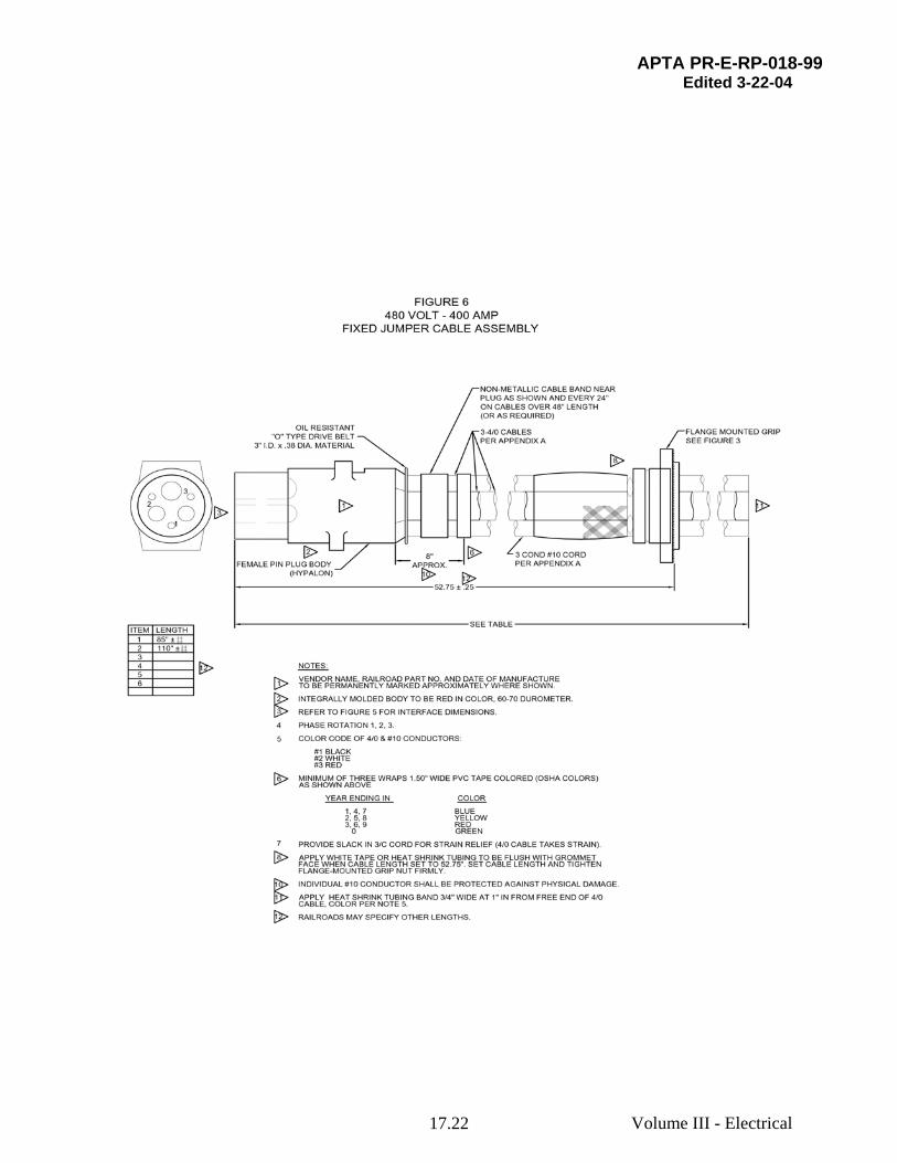
6.2 Fixed jumper cable assembly
6.2.1 Description of assembly
The fixed jumper cable assembly (Figures 1, 3 and 6) should consist of a plug body and contacts crimped to three 4/0 cables and each conductor of three #10 conductor cord. The plug body and contacts, attached to one end, should be the same as supplied for portable jumpers described in Section 6.1.2 through 6.1.8, above.

APTA PR-E-RP-018-99 Edited 3-22-04
Volume III - Electrical 17.9
6.2.2 Fixed end cable attachment
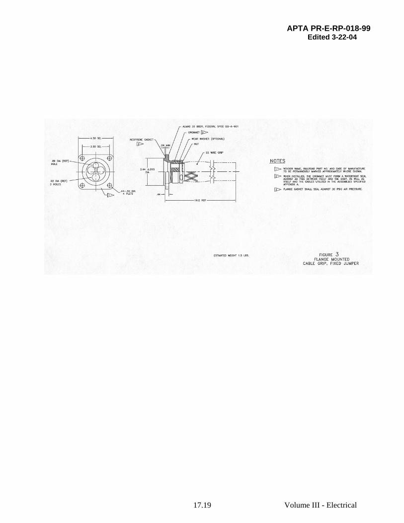
The cables should be secured to the vehicle through the Flange Mounted Cable Grip (Figure 3). It should consist of a flange with threaded body to accept a 4-hole cable sealing grommet, grommet compression nut and stainless steel cable grip. The flange portion should be provided with a sealing gasket. The compression nut should be secured against unintentional loosening through the use of a locking setscrew or other approved means.
6.2.3 Cable lengths
The 3/10 cord (see Figure 7) should be 1” to 1.5” longer than the 4/0 cables, to prevent strain on the cord.
6.2.4 Manufacturer’s mark and date
The fixed jumper connector body should be marked with the manufacturer's name and date code (month and year, i.e., 11/99).
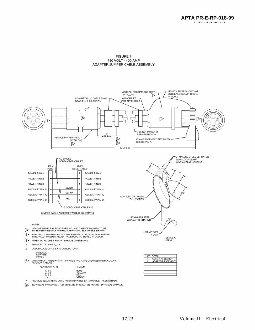
6.3 Adapter jumper cable assembly
6.3.1 Description of assembly
The adapter jumper cable assembly (Figures 1 and 7) should consist of a plug body with contacts and receptacle body with contacts crimped to three 4/0 cables and each conductor of a three #10 conductor cord.
6.3.2 Plug body and contacts
The plug body and contacts should be the same as supplied for portable jumpers described in Section 6.1, above.
6.3.3 Receptacle
The receptacle should be the same as supplied under Section 5.2, above, except the reinforcement at the mating end is replaced with a clamp assembly to hold mated connectors in the secured position.
6.4 Looping jumper cable assembly
6.4.1 Description of assembly
The looping jumper cable (Figure 8) should consist of a double-ended receptacle.
7. Wire
7.1 . Scope
This section defines the design and performance recommended practices for single conductor #4/0 AWG and three conductor #10 AWG for head-end power cables rated 600 volts, designed

APTA PR-E-RP-018-99 Edited 3-22-04
Volume III - Electrical 17.10
for heavy duty service where severe flexing is encountered. The design operating temperature range for this material is –55 C to +90 C.
7.2 Design characteristics and test methods
7.2.1 Conductor:
The conductor should be bare or tinned annealed copper conforming to the requirements of ASTM B-3 or ASTM B-33, respectively. Stranding should be in accordance with ASTM-B-172 for Class M Rope-Lay conductor2. Conductor should meet the dimensions and DC resistance specified in Table I.
TABLE I
CONDUCTOR DATA
Conductor Size AWG
Coating Area, CMills No & Size Each Wire In Strand
Strand Construction
Conductor Diameter (Max.)
D.C. Resistance @ 20 C (Ohms/M ft)
4/0 Bare 211,600 5320/34 19 x 7 x 40/34 .645” .0524
10 Tinned 10,380 259/34 7 x 37/34 .132” 1.04
7.2.2 Primary insulation:
The primary insulation should be an approved single extrusion of thermoplastic elastomer (TFE) (or other material with equal or superior properties), specially compounded to have good electrical properties, flame resistance, excellent low temperature properties and extreme flexibility. The insulation should be tight fitting over the stranded conductors, but should strip freely using manual mechanical stripping tools.
Thickness: The average insulation wall thickness and minimum insulation thickness should be as specified in Table II.
Physical Properties-Unaged: When tested according to UL Subject 62, Paragraph 86.1-89.19, the minimum acceptable values should be as follows:
Tensile Strength, Min. psi – 800
Elongation, Min. Percent - 300
Physical Properties-Aged: When tested according to UL Subject 62, Paragraphs 82.1-89.19, insulation samples which have been aged in a circulating air oven for 168 hours at 120 C±1 C
2 For references in Italics, see Section 2.

APTA PR-E-RP-018-99 Edited 3-22-04
Volume III - Electrical 17.11
should retain the following minimum physical property values:
Tensile Strength - 80% of unaged value
Elongation - 80% of unaged value
Reinforcement: reinforcing seine twine or other approved material should be applied in the form of a cross wrap over the primary insulation on the 4/0 cable.
Jacket: The jacket should be an approved black polychloroprene (Neoprene), or other material with equal or superior properties, specially compounded for heavy-duty applications. The material should be compounded to exhibit excellent resistance to: moisture, oils and fluids, abrasion, tearing, compression, flexing, ozone, sunlight, flame, and heat, as described in Section 4.2. The jacket should be extruded tightly over the primary insulation (and reinforcing twine) but adhesion between the two layers is not a requirement.
TABLE II
DIMENSIONS
For a Single Conductor #4/0 AWG.
Conductor Diameter (Nominal)
Average Insulation Thickness
Minimum Insulation Thickness
Average Jacket Thickness
Minimum Jacket Thickness
Cable Diameter
.605” .060” .054” .085” .068” .895” ± .025
For Three Conductors #10 AWG
ConductoDiameter (Nominal)
Average Insulation Thickness
Minimum Insulation Thickness
Single Insulated Compound(Nominal)
Fillers Binders Jacket Thickness
Cable Diameter
Color Code
.132 .045” .042” .229” Nylon filament as required to maintain circular cable cross- section
Mylar tape spirally applied .001” thick 25% min overlap
.083” Min.
.685” ±
.015 Black White Red

APTA PR-E-RP-018-99 Edited 3-22-04
Volume III - Electrical 17.12
8. Acceptance tests on all receptacles and jumpers
8.1 Acceptance tests
Acceptance tests should-be conducted by the manufacturer on all receptacles and jumper cables as follows:
Tests should be conducted in accordance with the requirements of APTA PR-E-S-001-98, Standard for Insulation Integrity, as well as the following, on each jumper and receptacle to ascertain:
– Continuity
– Freedom from unintended cross connections
– HiPot at 1500 VAC
– To housing
– Among conductors
– Plug/receptacle mating (to ensure proper alignment and operation of each contact)
– Plug/receptacle mating force measurement (periodic sample only)
– Gauging of each male contact O.D.
– Check of “grip” of each female contact on male pin
9. Qualification tests
9.1 Listing of qualification tests
Qualification tests should be conducted on a minimum of six (6) mated pairs of jumper/receptacles that should, as a minimum, demonstrate the following, in order:
– Mechanical Inspection (See 9.3.1)
– Mating & Unmating Forces. (See 9.3.2)
– Insulation Resistance (See 9.4.1)
– Dielectric Withstand Voltage (Dry) (See 9.4.2)
– Physical Shock Tolerance (See 9.4.3)
– Watertightness (See 9.4.4)
– Dielectric Withstand Voltage (Wet) (See 9.4.5)

APTA PR-E-RP-018-99 Edited 3-22-04
Volume III - Electrical 17.13
– Current Rating/Temperature Rise (See 9.5.1)
– Contact Resistance (See 9.5.2)
– Contact Retention Force (See 9.6.1)
– Crimp Tensile Strength (See 9.6.2)
9.2 Qualification test procedures
Prior to the first shipment, the railroad should be furnished with a minimum of six production quality test samples of each type for inspection and testing as described below.
There are three groups of tests:
– Mated pair durability/performance tests, conducted on six mated plug/receptacle pair
– Contact rating and resistance tests, conducted on one mated plug/receptacle pair (may be conducted on one of the above six mated pair, or a separate mated pair)
– Contact retention and crimp tensile tests:
a) Retention test is destructive test conducted on one plug and receptacle
b) Crimp tensile test is destructive test conducted on one of each type of contact
9.3 Tests to be performed on all parts and assemblies of the quality test samples
9.3.1 Mechanical inspection
A mechanical inspection should be made to determine compliance with approved drawings including a check of all dimensions and proper level of workmanship. This would include the use of metal go/no-go gauges to check plug sealing boss diameter (3.106 in. [78.89 mm]) and inside diameter of receptacle body.
9.3.2 Mating/unmating force
A check should be made to determine that the force necessary to mate and unmate plugs and receptacles is as stated in this recommended practice. Receptacles should be secured to the bench and plugs mated by hand, employing a slight rocking motion. A suitable force-measuring instrument connected to the receptacle should be used. Each of the plug/receptacle pair should be mated three times each by three people (total of nine matings and readings.) The test should be conducted at 70°F (21°C) on all six samples. In addition, the test should be conducted on one sample at 70°F (21°C) ambient, immediately after removing the sample from a freezer where it has undergone an eight-hour minimum cold soak at -20°F (-29°C).

APTA PR-E-RP-018-99 Edited 3-22-04
Volume III - Electrical 17.14
9.4 Tests to be performed on six mated plug/receptacle pairs
9.4.1 Insulation resistance
Using a 1000V megger or similar instrument, insulation resistance of the mated pair should be measured. Measurements should be taken between each contact and all other contacts and also between contacts and the housing. At 77°F (25°C), readings should be a minimum of 100 megohms.
9.4.2 Dielectric withstand voltage (Dry)
Each mated pair should be high potential tested at 1960 VAC for one minute. There should be no evidence of flashover or breakdown. Leakage current between any pair of contacts or between contacts and housing should not exceed 1 mA.
9.4.3 Physical shock tolerance
Six mated assemblies (less housings) should be subjected to a physical shock test by dropping the mated assembly onto a concrete surface from an elevation of six feet (1.8 meters). Mated assemblies should be dropped in a horizontal position a total of eight times. Mating force measurements should again be taken per Section 9.3.2. There should be no change in the insertion and withdrawal force.
9.4.4 Watertightness
After the drop test is complete, the six mated assemblies should be immersed horizontally in six inches (150 mm) of tap water for 30 minutes to verify sealing between cable and connector body as well as primary and secondary sealing of the mated pair of connectors.
9.4.5 Dielectric withstand voltage (Wet)
Following successful completion of the Physical Shock Tolerance (9.4.3) and Watertightness (9.4.4) tests, the assemblies should again be subjected to an insulation resistance test in accordance with Section 9.4.1 with the mated assemblies still immersed in water from test 9.4.4. Readings to the housing are not required.
9.5 Tests to be performed on one mated plug/receptacle pair
The following groups of tests should be conducted on a single mated plug/receptacle pair. All tests defined in Section 9.3 should be completed prior to performing the following tests.
9.5.1 Current rating/temperature rise
A continuous DC current of 400 amperes should be applied simultaneously through each of the three power conductors. The mated assemblies (with the housing) should be supported in still air, two feet above floor level in a 110°F (43°C) ambient. Temperatures should be monitored by means of thermocouples as shown in Figure 9.
APTA PR-E-RP-018-99 Edited 3-22-04
Volume III - Electrical 17.15
Temperatures should be continuously monitored and recorded at thirty-minute intervals. Upon stabilization of all temperatures to within 1°F (0.5°C) over a one-hour period, temperatures should be recorded at three-minute intervals for 30 minutes. The cable assemblies would be considered acceptable if the temperature rises recorded in this test satisfactorily demonstrate to the railroad that continuous operation at 400 amperes in an ambient of 110°F (43°C) would not produce temperatures in excess of the insulation material’s capability.
9.5.2 Contact resistance
The millivolt drop across mated male and female contacts including the cable crimps should be measured at rated current (400 A and 40 A respectively) to check that the voltage drop across the contact pair does not exceed 75 millivolts and 33 millivolts respectively for the 4/0 and #10 AWG cables. The test should be conducted at an ambient temperature in the range of 70-80°F. (21-27°C) Refer to Figure 10 for locations of the test probes. This test should be performed before and after the physical shock test described in Section 9.4.3. There should be no increase in the voltage drop as a result of the drop test.
9.6 Tests to be performed on individual parts (to destruction)
The following two tests should be conducted to destruction of the parts. Parts used for 9.6.1, Contact Retention Test, should first have passed the tests defined in 9.3.1 and 9.3.2. Parts used for 9.6.2, Crimp Tensile Strength Test should be mechanically inspected and mated to determine that mating forces are reasonable (no instrumentation required).
9.6.1 Contact retention force
The contact pullout and push in forces should be measured for each contact type on the plug and receptacle body. Forces should meet or exceed those required in this recommended practice, applied at a rate of 1 +/- ¼ inch (25 +/- 6 mm) per minute.
The test should be continued until the part fails, or until the test machine capability is reached, whichever occurs first.
9.6.2 Crimp tensile strength
The minimum axial load to separate the wire from the contacts either by pulling the wire out of the wire barrel or breaking the wire within the wire barrel should be not less than shown in the table below:
Contact Size Axial Load
4/0 450 lbs. (2000 newtons)
10 80 lbs. (355 newtons)
Representative contacts crimped to cable should be tested. The cable length should be sufficient for adapting to a Tinius Olsen or similar test device. The rate of applying the load should be 1 ± ¼ inch (25 +/- 6 mm) per minute.
APTA PR-E-RP-018-99 Edited 3-22-04
Volume III - Electrical 17.16
The test is to be continued until the part fails, or the test machine capability is reached, whichever occurs first.
10. Illustrations
Figure Subject
1. Plug/receptacle interface
2. Receptacle housing
3. Flange-mounted cable grip
4. Receptacle
5. Portable jumper
6 Fixed jumper
7. Adapter jumper
8. Looping jumper
9. Temperature rise test measurement locations
10. Contact resistance test measurement locations

APTA PR-E-RP-018-99 Edited 3-22-04
Volume III - Electrical 17.17

APTA PR-E-RP-018-99 Edited 3-22-04
Volume III - Electrical 17.18
APTA PR-E-RP-018-99 Edited 3-22-04
Volume III - Electrical 17.19

APTA PR-E-RP-018-99 Edited 3-22-04
Volume III - Electrical 17.20

APTA PR-E-RP-018-99 Edited 3-22-04
Volume III - Electrical 17.21
APTA PR-E-RP-018-99 Edited 3-22-04
Volume III - Electrical 17.22
APTA PR-E-RP-018-99 Edited 3-22-04
Volume III - Electrical 17.23

APTA RP-E-018-99 Edited 3-22-04
Volume III - Electrical 17.24

APTA PR-E-RP-018-99 Edited 3-22-04
Volume III - Electrical 17.25

APTA PR-E-RP-018-99 Edited 3-22-04
Volume III - Electrical 17.26