aqua curtain
TRANSCRIPT

8/13/2019 Aqua Curtain
http://slidepdf.com/reader/full/aqua-curtain 1/10
The Wet Curing System of Concrete “AQUA CURTAIN”
1. Background
In the fabrication of concrete structures, role of curing in optimizing the performance
of the concrete is crucial. The desired concrete performance and durability, as measured
by strength and mass-transfer resistance for example, will be obtained only if the
cement is properly hydrated during curing. That is, it is crucial to maintain the
appropriate temperature and moisture level for hydration over the necessary period.
Suitable curing conditions are set in various published standards.
According to Committee 308 of the American Concrete Institute (ACI), specific levelsof moisture and temperature—crucial factors for hydration—are specified for concrete
curing. In Japan, the period for wet curing is specified in the standard specifications
published by the Japan Society of Civil Engineers (JSCE), as shown in Table 1.
However, while it is easy to supply moisture to a horizontal surface, where ponding or
a curing mat soaked with water can be used, it is extremely difficult to attain
appropriate curing conditions on a vertical surface. As a result, at actual construction
sites, curing is likely to cease before the end of the curing period considered necessary
for full hydration.
To remedy this, the authors have developed a novel wet curing system named AQUACURTAIN (AC). This system makes it possible to supply curing water to vertical
concrete surfaces and to the interior of tunnel linings after the formwork has been
removed.
Table 1 Curing periods JSCE)
Daily mean
temperature
Ordinary
portlan d cement
Blendedcements
(Blast-furnace slag
cement[typeB])
High-early-strength
portlan d cement
15 5days 7days 3days
10 7days 9days 4days
5 9days 12days 5days
8/13/2019 Aqua Curtain
http://slidepdf.com/reader/full/aqua-curtain 2/10
2. Overview of the AQUA CURTAIN curing system
2.1 Background
A. M. Neville has discussed the principles of the major curing methods [1],
categorizing as “wet curing” and “membrane curing,” respectively, those curing methods
that actively supply water to the concrete and those that simply prevent water loss.
Wet curing, which not only prevents moisture dissipation but also actively supplies
water to the concrete being cured, has a significant effect on concrete performance. As
already noted, however, at actual construction sites it is difficult to wet cure under
perfect conditions, particularly in the case of vertical and inclined surfaces after the
formwork has been removed. In the AC system described here, a water film is createdon any concrete surface, including the vertical walls of structures and the interior
surface of tunnel linings, ensuring that appropriate wetness conditions are maintained.
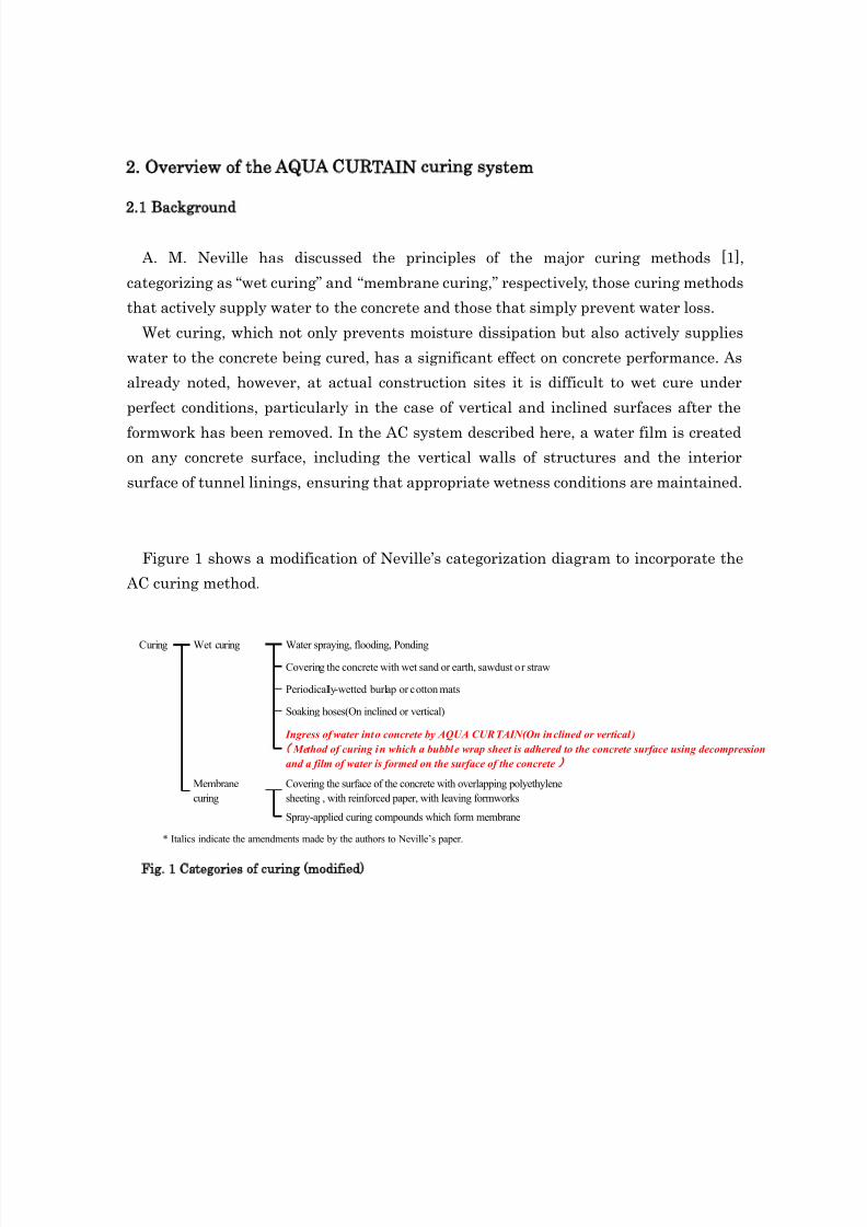
Figure 1 shows a modification of Neville’s categorization diagram to incorporate the
AC curing method.
Fig. 1 Categories of curing modified)
Curing Wet curing
Membrane
curing
Water spraying, flooding, Ponding
Covering the concrete with wet sand or earth, sawdust or straw
Periodically-wetted burlap or cotton mats
Soaking hoses(On inclined or vertical)
Covering the surface of the concrete with overlapping polyethylene
sheeting , with reinforced paper, with leaving formworks
Spray-applied curing compounds which form membrane
Ingress of water into concrete by AQUA CURTAIN(On inclined or vertical)
Method of curing in which a bubble wrap sheet is adhered to the concrete surface using decompression
and a film of water is formed on the surface of the concrete
* Italics indicate the amendments made by the authors to Neville’s paper.
8/13/2019 Aqua Curtain
http://slidepdf.com/reader/full/aqua-curtain 3/10
2.2 Work technique for AC curing
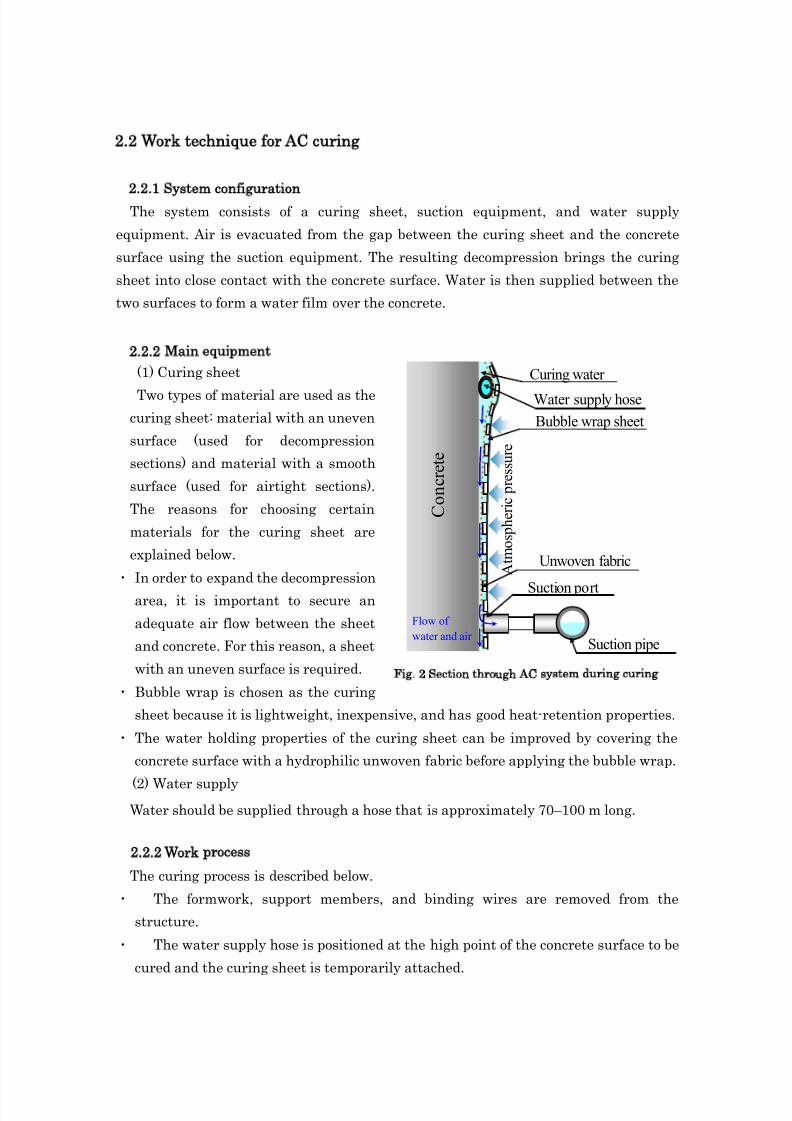
2.2.1 System configuration
The system consists of a curing sheet, suction equipment, and water supply
equipment. Air is evacuated from the gap between the curing sheet and the concrete
surface using the suction equipment. The resulting decompression brings the curing
sheet into close contact with the concrete surface. Water is then supplied between the
two surfaces to form a water film over the concrete.
2.2.2 Main equipment
(1) Curing sheet
Two types of material are used as thecuring sheet: material with an uneven
surface (used for decompression
sections) and material with a smooth
surface (used for airtight sections).
The reasons for choosing certain
materials for the curing sheet are
explained below.
・ In order to expand the decompression
area, it is important to secure an
adequate air flow between the sheet
and concrete. For this reason, a sheet
with an uneven surface is required.
・ Bubble wrap is chosen as the curing
sheet because it is lightweight, inexpensive, and has good heat-retention properties.
・ The water holding properties of the curing sheet can be improved by covering the
concrete surface with a hydrophilic unwoven fabric before applying the bubble wrap.
(2) Water supplyWater should be supplied through a hose that is approximately 70–100 m long.
2.2.2 Work process
The curing process is described below.
・ The formwork, support members, and binding wires are removed from the
structure.
・ The water supply hose is positioned at the high point of the concrete surface to be
cured and the curing sheet is temporarily attached.
C o n c r e t e
A t m o s p h e r i c p r e s s u r e
Bubble wrap sheet
Suction pipe
Suction port
Water supply hose
Flow of
water and air
Unwoven fabric
Curing water
Fig. 2 Section through AC system during curing
8/13/2019 Aqua Curtain
http://slidepdf.com/reader/full/aqua-curtain 4/10
・ Suction ports are positioned at the lower edge of the curing sheet at intervals of
approximately 4 m.
・ The suction equipment and suction pipes are connected.
・ After ensuring that the edges of the curing sheet are airtight, the suction pumps
are switched on.
・ The water supply pump is switched on to supply curing water through the water
supply hose, thereby starting the wet curing process.
・ The water supply is regulated on an intermittent basis so that water is supplied
at a specified rate throughout the curing process in accordance with the water
absorption rate of the concrete.

8/13/2019 Aqua Curtain
http://slidepdf.com/reader/full/aqua-curtain 5/10
3. Effects of AC wet curing
3.1 Purpose and overview of tests
To ascertain the effects of wet curing using the AC system, the authors have
previously investigated the development of compression strength in normal Portland
cement. It was found that wet curing improved compression strength over an extended
period. However, strength is not the only important measure of expected performance;
mass-transfer resistance is also important to attaining durability.
In this study, in order to investigate the effect of wet curing on durability, freeze-thaw
resistance, pore size distribution tests, and carbonation resistance tests were conducted
so as to evaluate quantitatively the mass-transfer resistance.
The mix proportions for the concrete used in the investigation are shown in Table 2.
The cements used were normal Portland cement (N) and Portland blast furnace slag
cement (BB). In addition to simulations run for general structures, a simulated case
(BT) using for tunnel lining concrete that had the formwork removed at an earlier stage
than usual and on which it is difficult to apply wet curing was conducted. The targetvalues for slump and air volume at the time of pouring the concrete were 8±2.5 cm and
4.5±1.5%, respectively.
Details of the curing conditions are shown in Table 3. With AC curing, the concrete
surface is always in a water-wet condition. Therefore, in the case of freeze-thaw
resistance and pore size distribution tests using small specimens, AC curing in table-3
assumed itself standard water curing.

8/13/2019 Aqua Curtain
http://slidepdf.com/reader/full/aqua-curtain 6/10

8/13/2019 Aqua Curtain
http://slidepdf.com/reader/full/aqua-curtain 7/10
8/13/2019 Aqua Curtain
http://slidepdf.com/reader/full/aqua-curtain 8/10
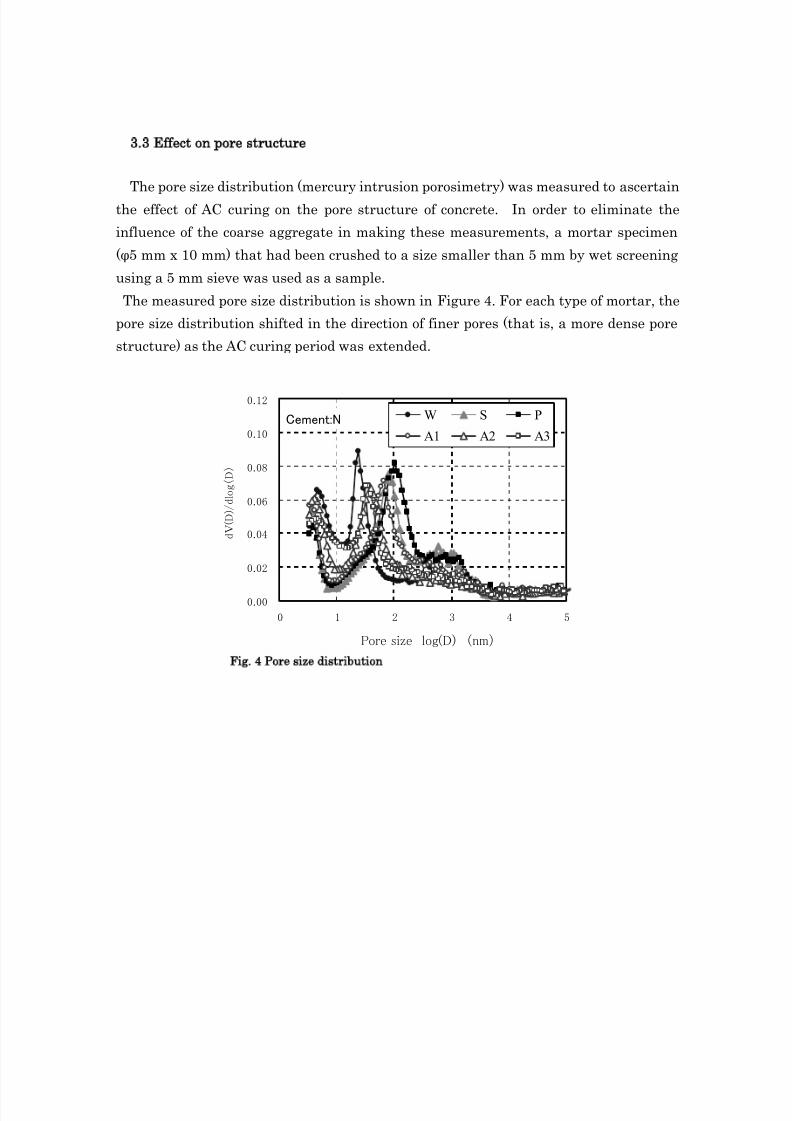
3.3 Effect on pore structure
The pore size distribution (mercury intrusion porosimetry) was measured to ascertain
the effect of AC curing on the pore structure of concrete. In order to eliminate the
influence of the coarse aggregate in making these measurements, a mortar specimen
(φ5 mm x 10 mm) that had been crushed to a size smaller than 5 mm by wet screening
using a 5 mm sieve was used as a sample.
The measured pore size distribution is shown in Figure 4. For each type of mortar, the
pore size distribution shifted in the direction of finer pores (that is, a more dense pore
structure) as the AC curing period was extended.
Cement:N
0.00
0.02
0.04
0.06
0.08
0.10
0.12
0 1 2 3 4 5
Pore size log(D) (nm)
d V ( D ) / d l o g ( D )
W S P
A1 A2 A3
Fig. 4 Pore size distribution
8/13/2019 Aqua Curtain
http://slidepdf.com/reader/full/aqua-curtain 9/10
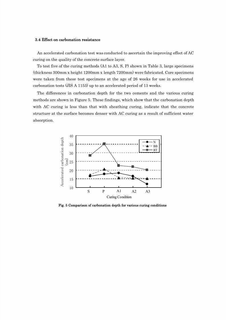
3.4 Effect on carbonation resistance
An accelerated carbonation test was conducted to ascertain the improving effect of AC
curing on the quality of the concrete surface layer.
To test five of the curing methods (A1 to A3, S, P) shown in Table 3, large specimens
(thickness 300mm x height 1200mm x length 7200mm) were fabricated. Core specimens
were taken from these test specimens at the age of 26 weeks for use in accelerated
carbonation tests (JIS A 1153) up to an accelerated period of 13 weeks.
The differences in carbonation depth for the two cements and the various curing
methods are shown in Figure 5. These findings, which show that the carbonation depth
with AC curing is less than that with sheathing curing, indicate that the concrete
structure at the surface becomes denser with AC curing as a result of sufficient water
absorption.
Fig. 5 Comparison of carbonation depth for various curing conditions
10
15
20
25
30
35
40
Curing Condition
A c c e l e r a t e d
c a r b o n a t i o n d e p t h
( n m )
N
BB
BT
S P A1 A2 A3
8/13/2019 Aqua Curtain
http://slidepdf.com/reader/full/aqua-curtain 10/10
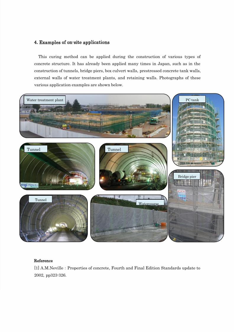
4. Examples of on-site applications
This curing method can be applied during the construction of various types ofconcrete structure. It has already been applied many times in Japan, such as in the
construction of tunnels, bridge piers, box culvert walls, prestressed concrete tank walls,
external walls of water treatment plants, and retaining walls. Photographs of these
various application examples are shown below.
Reference
[1] A.M.Neville:Properties of concrete, Fourth and Final Edition Standards update to
2002, pp323-326.
Tunnel Tunnel
PC tank
Bridge pier
TunnelWatercourse
Water treatment plant