aquafixseparators - hauraton · the operating principle of the oil and light liquid separator is...
TRANSCRIPT
AQUA SPORTCIVILS LANDSCAPING
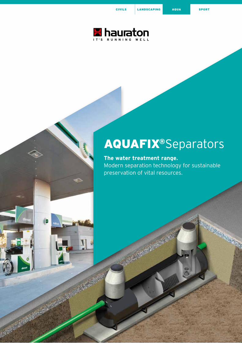
AQUAFIX®SeparatorsThe water treatment range.Modern separation technology for sustainable preservation of vital resources.

2
AQUA SPORTCIVILS LANDSCAPING
The water treatment range.Modern separation technology for sustainable preservation of vital resources.
Living rivers and lakes, intact groundwater resources, a secure and reliable water supply and efficient
wastewater disposal are fundamental requirements for environmentally sound economic development.
To avoid harming nature, contaminated water must be treated before it is allowed to flow directly or
indirectly back into the natural water cycle.
The mechanical separation process is designed to separate mixtures of substances. The aim is to remove
one or more components of the mixture.
The operating principle of the oil and light liquid separator is based on the difference in density between
the water and the components being separated from it. The lighter liquid rises to the top, collects on
the surface of the water and can then be removed and disposed of. Coalescence separators are an
enhancement of standard petroleum separators. These systems work on the coalescence principle,
i.e. encouraging the merging of small oil particles into larger ones. Even the smallest drops of oil will
then float to the surface as a result of gravity, where they can be separated off.
AQUAFIX separators form part of a controlled disposal concept and will deliver many years of reliable
performance. The range consists of high quality systems made of polyethylene, polypropylene, steel
or concrete. Each system is individually measured and customised to suit the construction project, thus
guaranteeing many years of efficient water treatment. AQUAFIX separators are always state of the art
and comply with all relevant standards and regulations.

3
AQUA SPORTCIVILS LANDSCAPING
AQUAFIX®SeparatorsSeries „G“ made of steel 6
AQUAFIX®Separators Series „k“ made of steel 16
AQUAFIX®Separators Series made of concrete (H/P) 30
AQUAFIX®Separators Series „10 PE“ made of polyethylene 56
AQUAFIX®Separators Series „PP“ made of polypropylene 86
AQUAFIX®Separators Installation Instructions & Examples 98

4
AQUA SPORTCIVILS LANDSCAPING
AQUAFIX®SeparatorsThe water treatment range.Modern separation technology for sustainable preservation of vital resources.
RequirementsWater is one of the most valuable resources on Earth.
Germany has one of the best developed sewage systems
in the world. If both are to be protected and kept in good
condition for our descendants, efficient cleansing
systems are required.
In fuel stations, industrial and commercial areas where
surface water or effluents are polluted with hydrocarbon
compounds, light liquid separators are needed that satisfy
the rigorous requirements of the norms and regulations
governing groundwater protection.
Effluents polluted with grease and fatty acids can cause
enormous damage to drain systems and sewage plants.
This is where AQUAFIX-Grease and Starch Separators
make a valuable contribution to protecting the environ-
ment.
Application areasFuel stations, car washes, car repair workshops, car
showrooms, oil depots, car scrap yards, transformer
stations, industrial plants where lubricating oil is used,
road haulage depots, police, fire brigade, army, main-
tenance/servicing areas, parking areas, car customisers
and importers, canteen kitchens, student refectories,
cafés and restaurants, hotels, cafeterias, producers of
ready-made meals, producers of tinned foods, sweet
factories, potato processing plants, producers of frozen
foods, commercial bakeries, abattoirs, butchers, animal
product processing plants, soap and stearin factories,
cosmetics industry, cat and dog food producers, fair-
ground operators and many more.

5
AQUA SPORTCIVILS LANDSCAPING
AQUAFIX®SeparatorsAlarm devices.Security for the environment.
Warning systems Warning system type 1
The W1 LAL-SRW-PF-01 warning system is an alarming
device for light liquid separators (petrol, oil and coale-
scence separators) that is licensed for operation in
potentially explosive areas (Zone 0). It is used to detect
the oil layer thickness in a light liquid separator. The
warning system consists of a signalling unit with LED‘s
for „Power“, „System OK“, „Layer thickness alarm“
and „Sensor error“ and an acoustic alarm. The acoustic
alarm can be manually disabled. The „Sensor error“
diode cannot be acknowledged until the cause of the
alarm has actually been rectified.
A sensor that creates an electrical field is suspended
in the separator. When the light liquid layer in a separator
becomes thicker and the separating layer between the
water and the light liquid is relocated downwards, the tip
of the sensor is suspended in the light liquid. This affects
the electrical field and an alarm is triggered.
Item no.: 134100
Warning system type 2
The W2 LAL-SRW-PF-08 warning system is an alarming
device for light liquid separators. It has the same signal-
ling unit, but has negative switching. In warning system
2 an alarm is signalled when current is flowing. As soon
as the liquid level increases and the probe tips reach the
surface of the water, an alarm is triggered. In this case
the cause of the backup in the separator is irrelevant.
For example, if the coalescence material is soiled and
preventing an adequate water flow, an alarm is signalled.
An alarm is also triggered if the pipeline behind the
separator is blocked or the entire system is hydraulically
overloaded because of heavy rainfall.
Item no.: 134200
Warning system type 3
Has a signalling unit with two plug-in units and two probes.
It is a combination of warning systems 1 and 2.
Item no.: 134300

6
AQUA SPORTCIVILS LANDSCAPING
AQUAFIX®SeparatorsSeries „G“ made of steelHighest volume for biggest flow.

7
AQUA SPORTCIVILS LANDSCAPING
At a glance: Compact design
Separator tank, continuously chargeable
up to class D 400
Galvanised inside and outside or coated
with several layers of epoxy resin on
pretreated surface
8
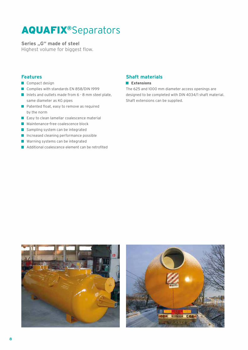
AQUAFIX®SeparatorsSeries „G“ made of steelHighest volume for biggest flow.
Features Compact design
Complies with standards EN 858/DIN 1999
Inlets and outlets made from 6 - 8 mm steel plate,
same diameter as KG pipes
Patented float, easy to remove as required
by the norm
Easy to clean lamellar coalescence material
Maintenance-free coalescence block
Sampling system can be integrated
Increased cleaning performance possible
Warning systems can be integrated
Additional coalescence element can be retrofited
Shaft materials Extensions
The 625 and 1000 mm diameter access openings are
designed to be completed with DIN 4034/1 shaft material.
Shaft extensions can be supplied.
9
AQ
UA
FIX
® S
tee
l „G
“A
QU
AF
IX®
Ste
el „
k“A
QU
AF
IX®
co
ncr
ete
AQ
UA
FIX
® „
10 P
E“
AQ
UA
FIX
® „
PP
“In
sta
lla
tio
n I
nstr
uc
tio
ns
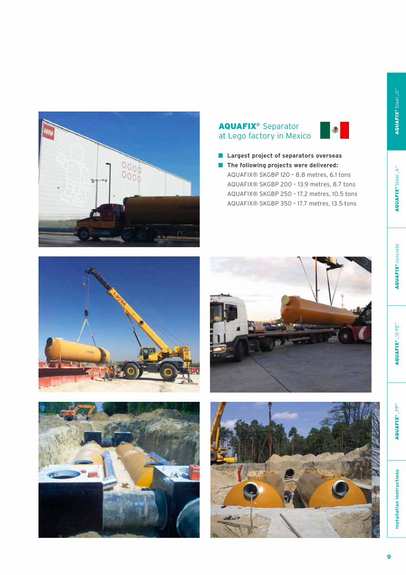
AQUAFIX® Separator at Lego factory in Mexico
Largest project of separators overseas
The following projects were delivered:
AQUAFIX® SKGBP 120 – 8.8 metres, 6.1 tons
AQUAFIX® SKGBP 200 – 13.9 metres, 8.7 tons
AQUAFIX® SKGBP 250 – 17.2 metres, 10.5 tons
AQUAFIX® SKGBP 350 – 17.7 metres, 13.5 tons

10
AQUA SPORTCIVILS LANDSCAPING
AQUAFIX®Separator made of steel, series G
AQUAFIX® – SKG Coalescence separator with sludge trap
SKG 015
Length mm
Width mm
Height mm
External diameter
mm
Flow performance
l/s
Sludge trap capacity
l
Separator capacity
l
DN/OD in-/outlet
mm
HE H inlet mm
HA H outlet
mm
DNE Manhole
1 mm
DNE Manhole
2 mm
Weight kg
Item No.
SKG 015 3860 1250 1400 1250 15 1580 1400 200 1000 950 625 625 952,00 181015
SKG 020 4960 1250 1400 1250 20 1890 2200 200 1000 950 625 625 1178,00 181020
SKG 025 4550 1600 1750 1600 25 2900 3380 200 1350 1300 1000 1000 1437,00 181025
SKG 030 5200 1600 1750 1600 30 3620 3820 200 1350 1300 1000 1000 1580,00 181030
SKG 035 5600 1600 1750 1600 35 3800 4340 200 1350 1300 1000 1000 1657,00 181035
SKG 040 6020 1600 1750 1600 40 4710 4200 200 1350 1300 1000 1000 1758,00 181040
SKG 045 5150 2000 2150 2000 45 4850 6090 315 1650 1600 1000 1000 2356,00 181045
SKG 050 5450 2000 2150 2000 50 6100 5930 315 1650 1600 1000 1000 2467,00 181050
SKG 060 6040 2000 2150 2000 60 6930 6470 315 1650 1600 1000 1000 2641,00 181060
SKG 065 6350 2000 2150 2000 65 7380 6870 315 1650 1600 1000 1000 2766,00 181065
SKG 070 6750 2000 2150 2000 70 8040 7280 315 1650 1600 1000 1000 2885,00 181070
SKG 075 7200 2000 2150 2000 75 8320 8250 315 1650 1600 1000 1000 3017,00 181075
SKG 080 7660 2000 2150 2000 80 9150 8680 315 1650 1600 1000 1000 3113,00 181080
SKG 090 8240 2000 2150 2000 90 10260 9160 315 1650 1600 1000 1000 3358,00 181090
SKG 100 9100 2000 2150 2000 100 11370 10400 315 1650 1600 1000 1000 3646,00 181100
SKG 120 8100 2500 2650 2500 120 13520 16000 400 2050 2000 1000 1000 4431,00 181120
SKG 130 8100 2500 2650 2500 130 13520 16000 400 2050 2000 1000 1000 4431,00 181130
SKG 140 8440 2500 2650 2500 140 14220 16840 400 2050 2000 1000 1000 4584,00 181140
SKG 150 8440 2500 2650 2500 150 14220 16840 400 2050 2000 1000 1000 4584,00 181150
SKG 160 9740 2500 2650 2500 160 18100 18530 400 2050 2000 1000 1000 5165,00 181160
SKG 170 9740 2500 2650 2500 170 18100 18530 400 2050 2000 1000 1000 5165,00 181170
SKG 180 10540 2500 2650 2500 180 19820 20210 400 2050 2000 1000 1000 5515,00 181180
SKG 200 11300 2500 2650 2500 200 21540 21730 400 2050 2000 1000 1000 5661,00 181200
SKG 250 14100 2500 2650 2500 250 28270 26950 400 2050 2000 1000 1000 6694,00 181250

11
AQUA SPORTCIVILS LANDSCAPING
Length mm
Width mm
Height mm
External diameter
mm
Flow performance
l/s
Sludge trap capacity
l
Separator capacity
l
DN/OD in-/outlet
mm
HE H inlet mm
HA H outlet
mm
DNE Manhole
1 mm
DNE Manhole
2 mm
Weight kg
Item No.
SKG 015 3860 1250 1400 1250 15 1580 1400 200 1000 950 625 625 952,00 181015
SKG 020 4960 1250 1400 1250 20 1890 2200 200 1000 950 625 625 1178,00 181020
SKG 025 4550 1600 1750 1600 25 2900 3380 200 1350 1300 1000 1000 1437,00 181025
SKG 030 5200 1600 1750 1600 30 3620 3820 200 1350 1300 1000 1000 1580,00 181030
SKG 035 5600 1600 1750 1600 35 3800 4340 200 1350 1300 1000 1000 1657,00 181035
SKG 040 6020 1600 1750 1600 40 4710 4200 200 1350 1300 1000 1000 1758,00 181040
SKG 045 5150 2000 2150 2000 45 4850 6090 315 1650 1600 1000 1000 2356,00 181045
SKG 050 5450 2000 2150 2000 50 6100 5930 315 1650 1600 1000 1000 2467,00 181050
SKG 060 6040 2000 2150 2000 60 6930 6470 315 1650 1600 1000 1000 2641,00 181060
SKG 065 6350 2000 2150 2000 65 7380 6870 315 1650 1600 1000 1000 2766,00 181065
SKG 070 6750 2000 2150 2000 70 8040 7280 315 1650 1600 1000 1000 2885,00 181070
SKG 075 7200 2000 2150 2000 75 8320 8250 315 1650 1600 1000 1000 3017,00 181075
SKG 080 7660 2000 2150 2000 80 9150 8680 315 1650 1600 1000 1000 3113,00 181080
SKG 090 8240 2000 2150 2000 90 10260 9160 315 1650 1600 1000 1000 3358,00 181090
SKG 100 9100 2000 2150 2000 100 11370 10400 315 1650 1600 1000 1000 3646,00 181100
SKG 120 8100 2500 2650 2500 120 13520 16000 400 2050 2000 1000 1000 4431,00 181120
SKG 130 8100 2500 2650 2500 130 13520 16000 400 2050 2000 1000 1000 4431,00 181130
SKG 140 8440 2500 2650 2500 140 14220 16840 400 2050 2000 1000 1000 4584,00 181140
SKG 150 8440 2500 2650 2500 150 14220 16840 400 2050 2000 1000 1000 4584,00 181150
SKG 160 9740 2500 2650 2500 160 18100 18530 400 2050 2000 1000 1000 5165,00 181160
SKG 170 9740 2500 2650 2500 170 18100 18530 400 2050 2000 1000 1000 5165,00 181170
SKG 180 10540 2500 2650 2500 180 19820 20210 400 2050 2000 1000 1000 5515,00 181180
SKG 200 11300 2500 2650 2500 200 21540 21730 400 2050 2000 1000 1000 5661,00 181200
SKG 250 14100 2500 2650 2500 250 28270 26950 400 2050 2000 1000 1000 6694,00 181250
AQ
UA
FIX
® S
tee
l „G
“A
QU
AF
IX®
Ste
el „
k“A
QU
AF
IX®
co
ncr
ete
AQ
UA
FIX
® „
10 P
E“
AQ
UA
FIX
® „
PP
“In
sta
lla
tio
n I
nstr
uc
tio
ns

12
AQUA SPORTCIVILS LANDSCAPING
AQUAFIX® – SKGBP Coalescence separator with sludge trap and bypass
SKGBP 015
Length mm
Width mm
Height mm
External diameter
mm
Flow performance
l/s
Sludge trap capacity l
Separator capacity l
DN/OD in-/outlet
mm
HE H inlet mm
HA H outlet
mm
DNE Manhole
1 mm
DNE Manhole
2 mm
Weight kg
Item No.
SKGBP 015 4700 1500 1400 1250 75 1500 1770 315 920 820 625 625 1700,00 182015
SKGBP 020 5825 1500 1400 1250 100 2300 2080 315 920 820 625 625 1900,00 182020
SKGBP 025 5235 1900 1750 1600 125 2990 2940 400 1150 1000 1000 1000 2350,00 182025
SKGBP 030 6300 1900 1750 1600 150 3960 4020 400 1150 1000 1000 1000 2700,00 182030
SKGBP 035 6300 1900 1750 1600 175 3960 4020 400 1150 1000 1000 1000 2750,00 182035
SKGBP 040 7200 1900 1750 1600 200 4850 4330 400 1150 1000 1000 1000 3050,00 182040
SKGBP 045 5400 2200 2150 2000 225 5120 5750 400 1550 1450 1000 1000 3100,00 182045
SKGBP 050 6000 2200 2150 2000 250 5690 5490 500 1450 1300 1000 1000 3300,00 182050
SKGBP 055 6300 2200 2150 2000 275 5920 6220 500 1450 1300 1000 1000 3500,00 182055
SKGBP 060 6300 2200 2150 2000 300 5920 6220 500 1450 1300 1000 1000 3600,00 182060
SKGBP 065 7200 2200 2150 2000 325 7460 6950 500 1450 1300 1000 1000 4050,00 182065
SKGBP 070 8000 2200 2150 2000 350 8390 7810 500 1450 1300 1000 1000 4250,00 182070
SKGBP 075 8000 2200 2150 2000 375 8390 7810 500 1450 1300 1000 1000 4300,00 182075
SKGBP 080 8500 2200 2150 2000 400 8600 9030 500 1450 1300 1000 1000 4500,00 182080
SKGBP 090 7300 2800 2650 2500 450 10010 12510 630 1850 1650 1000 1000 5450,00 182090
SKGBP 100 7300 2800 2650 2500 500 10010 12510 630 1850 1650 1000 1000 5600,00 182100
SKGBP 120 8800 2800 2650 2500 600 14010 14610 630 1850 1700 1000 1000 6150,00 182120
SKGBP 130 9600 2800 2650 2500 650 14580 13400 800 1650 1400 1000 1000 6300,00 182130
SKGBP 140 10300 2900 2650 2500 700 15640 14900 800 1650 1400 1000 1000 6700,00 182140
SKGBP 150 11000 2900 2650 2500 750 16710 15120 800 1650 1400 1000 1000 6900,00 182150
SKGBP 160 11500 2900 2650 2500 800 17780 16150 800 1650 1400 1000 1000 7450,00 182160
SKGBP 170 12000 2900 2650 2500 850 19020 17010 800 1650 1400 1000 1000 7650,00 182170
SKGBP 180 12700 2900 2650 2500 900 20090 18040 800 1650 1400 1000 1000 7950,00 182180
SKGBP 200 13900 2900 2650 2500 1000 22220 20110 800 1650 1400 1000 1000 8650,00 182200
SKGBP 250 17200 2900 2650 2500 1250 28440 25430 800 1650 1400 1000 1000 10400,00 182250
AQUAFIX®Separator made of steel, series G

13
AQUA SPORTCIVILS LANDSCAPING
Length mm
Width mm
Height mm
External diameter
mm
Flow performance
l/s
Sludge trap capacity l
Separator capacity l
DN/OD in-/outlet
mm
HE H inlet mm
HA H outlet
mm
DNE Manhole
1 mm
DNE Manhole
2 mm
Weight kg
Item No.
SKGBP 015 4700 1500 1400 1250 75 1500 1770 315 920 820 625 625 1700,00 182015
SKGBP 020 5825 1500 1400 1250 100 2300 2080 315 920 820 625 625 1900,00 182020
SKGBP 025 5235 1900 1750 1600 125 2990 2940 400 1150 1000 1000 1000 2350,00 182025
SKGBP 030 6300 1900 1750 1600 150 3960 4020 400 1150 1000 1000 1000 2700,00 182030
SKGBP 035 6300 1900 1750 1600 175 3960 4020 400 1150 1000 1000 1000 2750,00 182035
SKGBP 040 7200 1900 1750 1600 200 4850 4330 400 1150 1000 1000 1000 3050,00 182040
SKGBP 045 5400 2200 2150 2000 225 5120 5750 400 1550 1450 1000 1000 3100,00 182045
SKGBP 050 6000 2200 2150 2000 250 5690 5490 500 1450 1300 1000 1000 3300,00 182050
SKGBP 055 6300 2200 2150 2000 275 5920 6220 500 1450 1300 1000 1000 3500,00 182055
SKGBP 060 6300 2200 2150 2000 300 5920 6220 500 1450 1300 1000 1000 3600,00 182060
SKGBP 065 7200 2200 2150 2000 325 7460 6950 500 1450 1300 1000 1000 4050,00 182065
SKGBP 070 8000 2200 2150 2000 350 8390 7810 500 1450 1300 1000 1000 4250,00 182070
SKGBP 075 8000 2200 2150 2000 375 8390 7810 500 1450 1300 1000 1000 4300,00 182075
SKGBP 080 8500 2200 2150 2000 400 8600 9030 500 1450 1300 1000 1000 4500,00 182080
SKGBP 090 7300 2800 2650 2500 450 10010 12510 630 1850 1650 1000 1000 5450,00 182090
SKGBP 100 7300 2800 2650 2500 500 10010 12510 630 1850 1650 1000 1000 5600,00 182100
SKGBP 120 8800 2800 2650 2500 600 14010 14610 630 1850 1700 1000 1000 6150,00 182120
SKGBP 130 9600 2800 2650 2500 650 14580 13400 800 1650 1400 1000 1000 6300,00 182130
SKGBP 140 10300 2900 2650 2500 700 15640 14900 800 1650 1400 1000 1000 6700,00 182140
SKGBP 150 11000 2900 2650 2500 750 16710 15120 800 1650 1400 1000 1000 6900,00 182150
SKGBP 160 11500 2900 2650 2500 800 17780 16150 800 1650 1400 1000 1000 7450,00 182160
SKGBP 170 12000 2900 2650 2500 850 19020 17010 800 1650 1400 1000 1000 7650,00 182170
SKGBP 180 12700 2900 2650 2500 900 20090 18040 800 1650 1400 1000 1000 7950,00 182180
SKGBP 200 13900 2900 2650 2500 1000 22220 20110 800 1650 1400 1000 1000 8650,00 182200
SKGBP 250 17200 2900 2650 2500 1250 28440 25430 800 1650 1400 1000 1000 10400,00 182250
AQ
UA
FIX
® S
tee
l „G
“A
QU
AF
IX®
Ste
el „
k“A
QU
AF
IX®
co
ncr
ete
AQ
UA
FIX
® „
10 P
E“
AQ
UA
FIX
® „
PP
“In
sta
lla
tio
n I
nstr
uc
tio
ns
14
AQUA SPORTCIVILS LANDSCAPING
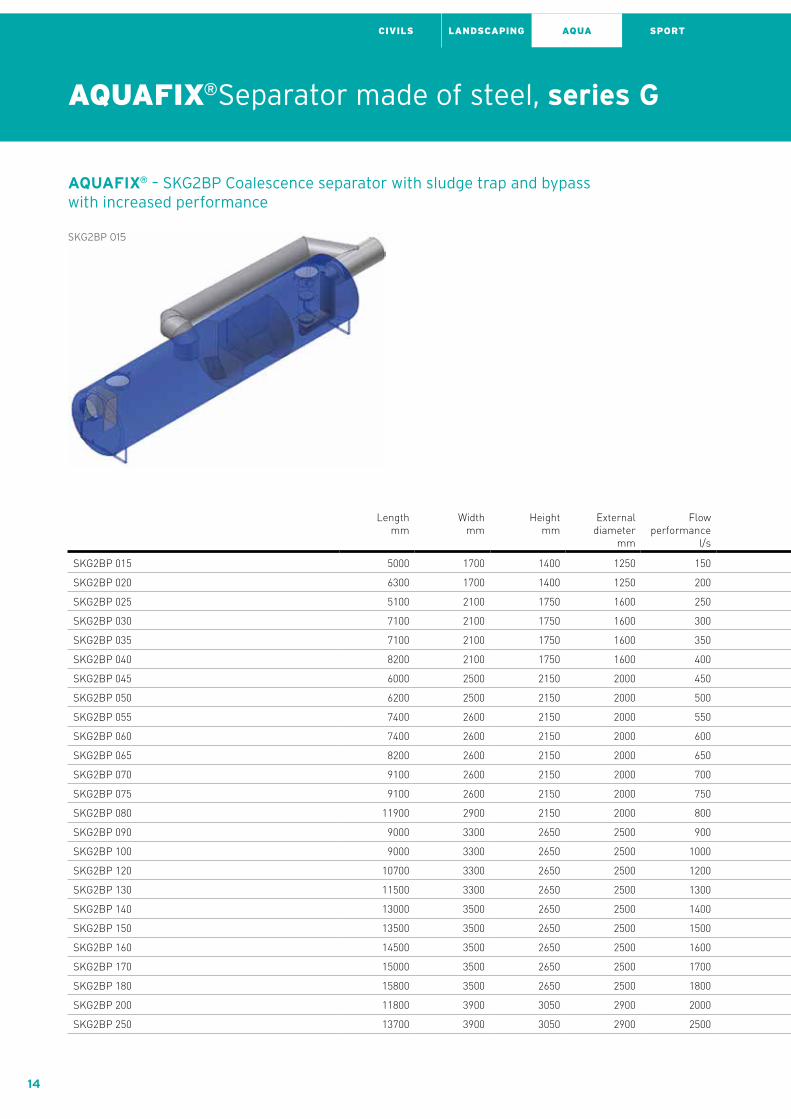
AQUAFIX® – SKG2BP Coalescence separator with sludge trap and bypass with increased performance
SKG2BP 015
Length mm
Width mm
Height mm
External diameter
mm
Flow performance
l/s
Sludge trap capacity l
Separator capacity l
DN/OD in-/outlet
mm
HE H inlet mm
HA H outlet
mm
DNE Manhole
1 mm
DNE Manhole
2 mm
Weight kg
Item No.
SKG2BP 015 5000 1700 1400 1250 150 1510 1740 400 820 670 625 625 2300,00 184015
SKG2BP 020 6300 1700 1400 1250 200 2310 2070 400 820 670 625 625 2700,00 184020
SKG2BP 025 5100 2100 1750 1600 250 2990 2940 400 1150 1000 1000 1000 2800,00 184025
SKG2BP 030 7100 2100 1750 1600 300 4050 4060 500 1050 850 1000 1000 3250,00 184030
SKG2BP 035 7100 2100 1750 1600 350 4050 4060 500 1050 850 1000 1000 3300,00 184035
SKG2BP 040 8200 2100 1750 1600 400 4860 4760 500 1050 850 1000 1000 3750,00 184040
SKG2BP 045 6000 2500 2150 2000 450 5310 5370 500 1450 1300 1000 1000 3800,00 184045
SKG2BP 050 6200 2500 2150 2000 500 5690 5490 500 1450 1300 1000 1000 3900,00 184050
SKG2BP 055 7400 2600 2150 2000 550 6110 6320 630 1350 1150 1000 1000 4500,00 184055
SKG2BP 060 7400 2600 2150 2000 600 6110 6320 630 1350 1150 1000 1000 4600,00 184060
SKG2BP 065 8200 2600 2150 2000 650 7520 6990 630 1350 1150 1000 1000 4650,00 184065
SKG2BP 070 9100 2600 2150 2000 700 8460 7900 630 1350 1150 1000 1000 5050,00 184070
SKG2BP 075 9100 2600 2150 2000 750 8460 7900 630 1350 1150 1000 1000 5100,00 184075
SKG2BP 080 11900 2900 2150 2000 800 8850 9330 800 1150 850 1000 1000 6400,00 184080
SKG2BP 090 9000 3300 2650 2500 900 9950 12720 800 1650 1400 1000 1000 6700,00 184090
SKG2BP 100 9000 3300 2650 2500 1000 9950 12720 800 1650 1400 1000 1000 6800,00 184100
SKG2BP 120 10700 3300 2650 2500 1200 13860 15120 800 1650 1400 1000 1000 7500,00 184120
SKG2BP 130 11500 3300 2650 2500 1300 14580 16840 800 1650 1400 1000 1000 7900,00 184130
SKG2BP 140 13000 3500 2650 2500 1400 15970 14440 1000 1450 1100 1000 1000 8000,00 184140
SKG2BP 150 13500 3500 2650 2500 1500 16890 15320 1000 1450 1100 1000 1000 8200,00 184150
SKG2BP 160 14500 3500 2650 2500 1600 18120 16500 1000 1450 1100 1000 1000 8900,00 184160
SKG2BP 170 15000 3500 2650 2500 1700 19350 17090 1000 1450 1100 1000 1000 9500,00 184170
SKG2BP 180 15800 3500 2650 2500 1800 20270 18270 1000 1450 1100 1000 1000 10350,00 184180
SKG2BP 200 11800 3900 3050 2900 2000 20640 19120 1000 1850 1500 1000 1000 10800,00 184200
SKG2BP 250 13700 3900 3050 2900 2500 25220 22820 1000 1850 1450 1000 1000 11200,00 184250
AQUAFIX®Separator made of steel, series G

15
AQUA SPORTCIVILS LANDSCAPING
Length mm
Width mm
Height mm
External diameter
mm
Flow performance
l/s
Sludge trap capacity l
Separator capacity l
DN/OD in-/outlet
mm
HE H inlet mm
HA H outlet
mm
DNE Manhole
1 mm
DNE Manhole
2 mm
Weight kg
Item No.
SKG2BP 015 5000 1700 1400 1250 150 1510 1740 400 820 670 625 625 2300,00 184015
SKG2BP 020 6300 1700 1400 1250 200 2310 2070 400 820 670 625 625 2700,00 184020
SKG2BP 025 5100 2100 1750 1600 250 2990 2940 400 1150 1000 1000 1000 2800,00 184025
SKG2BP 030 7100 2100 1750 1600 300 4050 4060 500 1050 850 1000 1000 3250,00 184030
SKG2BP 035 7100 2100 1750 1600 350 4050 4060 500 1050 850 1000 1000 3300,00 184035
SKG2BP 040 8200 2100 1750 1600 400 4860 4760 500 1050 850 1000 1000 3750,00 184040
SKG2BP 045 6000 2500 2150 2000 450 5310 5370 500 1450 1300 1000 1000 3800,00 184045
SKG2BP 050 6200 2500 2150 2000 500 5690 5490 500 1450 1300 1000 1000 3900,00 184050
SKG2BP 055 7400 2600 2150 2000 550 6110 6320 630 1350 1150 1000 1000 4500,00 184055
SKG2BP 060 7400 2600 2150 2000 600 6110 6320 630 1350 1150 1000 1000 4600,00 184060
SKG2BP 065 8200 2600 2150 2000 650 7520 6990 630 1350 1150 1000 1000 4650,00 184065
SKG2BP 070 9100 2600 2150 2000 700 8460 7900 630 1350 1150 1000 1000 5050,00 184070
SKG2BP 075 9100 2600 2150 2000 750 8460 7900 630 1350 1150 1000 1000 5100,00 184075
SKG2BP 080 11900 2900 2150 2000 800 8850 9330 800 1150 850 1000 1000 6400,00 184080
SKG2BP 090 9000 3300 2650 2500 900 9950 12720 800 1650 1400 1000 1000 6700,00 184090
SKG2BP 100 9000 3300 2650 2500 1000 9950 12720 800 1650 1400 1000 1000 6800,00 184100
SKG2BP 120 10700 3300 2650 2500 1200 13860 15120 800 1650 1400 1000 1000 7500,00 184120
SKG2BP 130 11500 3300 2650 2500 1300 14580 16840 800 1650 1400 1000 1000 7900,00 184130
SKG2BP 140 13000 3500 2650 2500 1400 15970 14440 1000 1450 1100 1000 1000 8000,00 184140
SKG2BP 150 13500 3500 2650 2500 1500 16890 15320 1000 1450 1100 1000 1000 8200,00 184150
SKG2BP 160 14500 3500 2650 2500 1600 18120 16500 1000 1450 1100 1000 1000 8900,00 184160
SKG2BP 170 15000 3500 2650 2500 1700 19350 17090 1000 1450 1100 1000 1000 9500,00 184170
SKG2BP 180 15800 3500 2650 2500 1800 20270 18270 1000 1450 1100 1000 1000 10350,00 184180
SKG2BP 200 11800 3900 3050 2900 2000 20640 19120 1000 1850 1500 1000 1000 10800,00 184200
SKG2BP 250 13700 3900 3050 2900 2500 25220 22820 1000 1850 1450 1000 1000 11200,00 184250
AQ
UA
FIX
® S
tee
l „G
“A
QU
AF
IX®
Ste
el „
k“A
QU
AF
IX®
co
ncr
ete
AQ
UA
FIX
® „
10 P
E“
AQ
UA
FIX
® „
PP
“In
sta
lla
tio
n I
nstr
uc
tio
ns

16
AQUA SPORTCIVILS LANDSCAPING
AQUAFIX®SeparatorsSeries „k“ small made of steelStrong solutions for small fl ows.
17
AQUA SPORTCIVILS LANDSCAPING
At a glance: At least 5 - 6 mm solid steel plates
Separator tank, continuously chargeable
up to class D 400
Galvanised inside and outside or coated
with several layers of epoxy resin on
pretreated sur face

18
AQUA SPORTCIVILS LANDSCAPING
Features At least 5-6 mm solid steel plates
Entry and maintenance openings
Size 1: 500 x 630 mm or 500 x 500 mm;
Size 2: 1000 x 630 mm or 1000 x 500 mm
(Measurements depending on the place of delivery/
country)
Class B 125 or C 250 extension covers with adjustable
height (Loading class depending on the place of
delivery/country)
Stop rings to handle the systems
Separator tank, continuously chargeable
up to class D 400
Galvanised inside and outside or coated with several
layers of epoxy resin on pretreated surface (Coating
depending on the place of delivery/country)
Compact design
Complies with standards EN 858 and EN 1825
Inlets and outlets made from 5 - 6 mm steel plate,
same diameter as KG pipes
For light liquid separation systems:
Easy to remove as required by the norm
Easy to clean lamellar coalescence material
Maintenance-free coalescence block
Sampling system can be integrated
ExtensionsAll models are equipped with 500 x 630 mm and 1000 x
630 mm, or with 500 x 500 mm and 1000 x 500 mm
covers. They are 200 mm or 100 mm high and are conti-
nuously adjustable by up to 40 mm. They have been
designed for class B 125 or C 250. Several units can be
stacked on top of each other.
AQUAFIX®SeparatorsSeries „k“ small made of steelStrong solutions for small flows.

19
AQUA SPORTCIVILS LANDSCAPING
AQ
UA
FIX
® S
tee
l „G
“A
QU
AF
IX®
Ste
el „
k“A
QU
AF
IX®
co
ncr
ete
AQ
UA
FIX
® „
10 P
E“
AQ
UA
FIX
® „
PP
“In
sta
lla
tio
n I
nstr
uc
tio
ns

20
AQUA SPORTCIVILS LANDSCAPING
AQUAFIX®Separator made of steel, series k
AQUAFIX® – Sk Sludge trap
Sk 0100
Length mm
Width mm
Height mm
Exter-nal
dia-meter
mm
Flow perfor-mance
l/s
Sludge trap
capa-city
l
Sepa-rator
capa-city
l
DN/OD in-/
outlet mm
HE H inlet mm
HA H outlet
mm
DNE Man-hole
1 mm
DNE Man-hole
2 mm
Weight kg
Item No.
Sk 0100 800 500 600 - - 100 - 110 350 320 1 - 94,00 87000
Sk 0150 800 600 600 - - 150 - 110 350 320 1 - 104,00 87001
Sk 0200 800 600 700 - - 200 - 110 450 420 1 - 117,00 87002
Sk 0300 1000 600 800 - - 300 - 110 550 520 1 - 151,00 87003
Sk 0400 1000 600 950 - - 400 - 110 700 670 1 - 174,00 87004
Sk 0500 1000 600 1150 - - 500 - 110 900 870 1 - 204,00 87005
Sk 0600 1200 600 1150 - - 600 - 110 900 870 1 - 232,00 87006
Sk 0800 1200 800 1150 - - 800 - 110 900 870 1 - 266,00 87008
Sk 1000 1200 800 1400 - - 1000 - 160 1100 1070 1 - 316,00 87010
Sk 1500 1750 800 1450 - - 1500 - 200 1100 1070 1 - 425,00 87015
Sk 2000 2000 1000 1450 - - 2000 - 200 1100 1070 1 - 517,00 87020
Sk 2500 2500 1000 1450 - - 2500 - 200 1100 1070 1 - 612,00 87025
Sk 3000 2500 1000 1650 - - 3000 - 200 1300 1270 1 - 677,00 87030
Sk 4000 2500 1200 1750 - - 4000 - 200 1400 1370 1 - 770,00 87040
Sk 5000 2750 1200 1950 - - 5000 - 200 1600 1570 1 - 901,00 87050

21
AQUA SPORTCIVILS LANDSCAPING
AQUAFIX® – Kk Coalescence separator
Kk 01,5
Length mm
Width mm
Height mm
Exter-nal
dia-meter
mm
Flow perfor-mance
l/s
Sludge trap
capa-city
l
Sepa-rator
capa-city
l
DN/OD in-/
outlet mm
HE H inlet mm
HA H outlet
mm
DNE Man-hole
1 mm
DNE Man-hole
2 mm
Weight kg
Item No.
Kk 01,5 1000 600 800 - 1 - 261 110 600 580 1 - 265,00 87501
Kk 03 1000 600 1000 - 3 - 351 110 800 780 1 - 339,00 87503
Kk 04 1000 800 1000 - 4 - 468 110 800 780 1 - 419,00 87504
Kk 06 1200 800 1200 - 6 - 699 160 940 920 2 - 554,00 87506
Kk 08 1500 800 1200 - 8 - 920 160 940 920 2 - 664,00 87508
Kk 10 1500 800 1200 - 10 - 920 160 940 920 2 - 664,00 87510
Kk 15 1500 1000 1500 - 15 - 1475 200 1200 1180 2 - 1010,00 87515
Kk 20 1800 1000 1500 - 20 - 1829 200 1200 1180 2 - 1029,00 87520A
QU
AF
IX®
Ste
el „
G“
AQ
UA
FIX
® S
tee
l „k“
AQ
UA
FIX
® c
on
cret
eA
QU
AF
IX®
„10
PE
“A
QU
AF
IX®
„P
P“
Insta
lla
tio
n I
nstr
uc
tio
ns

22
AQUA SPORTCIVILS LANDSCAPING
AQUAFIX®Separator made of steel, series k
AQUAFIX® – SKk Coalescence separator with sludge trap
SKk 01,5/0150
Length mm
Width mm
Height mm
Exter-nal
dia-meter
mm
Flow perfor-mance
l/s
Sludge trap
capa-city
l
Sepa-rator
capa-city
l
DN/OD in-/
outlet mm
HE H inlet mm
HA H outlet
mm
DNE Man-hole
1 mm
DNE Man-hole
2 mm
Weight kg
Item No.
SKk 01,5/0150 1200 600 800 - 1 157 261 110 600 560 1 - 291,00 87601
SKk 03/0300 1400 600 1000 - 3 328 328 110 800 750 2 - 363,00 87603
SKk 04/0400 1400 800 1000 - 4 406 468 110 800 750 - 1 427,00 87604
SKk 06/0600 1800 800 1200 - 6 626 699 160 950 900 1 1 623,00 87606
SKk 08/0800 2100 800 1200 - 8 810 662 160 950 900 1 1 699,00 87608
SKk 10/1000 2300 800 1300 - 10 1061 734 160 1050 1000 1 1 809,00 87610
SKk 15/1500 2300 1100 1600 - 15 1690 1408 200 1300 1250 - 3 1275,00 87615
SKk 20/2000 2900 1100 1600 - 20 2253 1830 200 1300 1250 - 3 1371,00 87620

23
AQUA SPORTCIVILS LANDSCAPING
AQUAFIX® – SKBPk Coalescence separator with sludge trap and bypass
SKBPk 03/0300
Length mm
Width mm
Height mm
Exter-nal
dia-meter
mm
Flow perfor-mance
l/s
Sludge trap
capa-city
l
Sepa-rator
capa-city
l
DN/OD in-/
outlet mm
HE H inlet mm
HA H outlet
mm
DNE Man-hole
1 mm
DNE Man-hole
2 mm
Weight kg
Item No.
SKBPk 03/0300 1200 800 1200 - 15 384 426 160 980 760 2 - 498,00 87803
SKBPk 04/0400 1500 800 1200 - 20 473 483 200 930 710 2 - 563,00 87804
SKBPk 06/0600 1900 1000 1300 - 30 859 851 200 1030 810 - 2 804,00 87806
SKBPk 08/0800 2300 1100 1200 - 40 891 872 315 830 610 - 2 916,00 87808
SKBPk 10/1000 2300 1100 1400 - 50 1333 980 315 1030 810 - 2 1073,00 87810
SKBPk 15/1500 2500 1200 1800 - 75 1886 1732 400 1330 1110 - 2 1560,00 87815
SKBPk 20/2000 2900 1200 1800 - 100 2201 1998 400 1330 1110 - 3 1657,00 87820A
QU
AF
IX®
Ste
el „
G“
AQ
UA
FIX
® S
tee
l „k“
AQ
UA
FIX
® c
on
cret
eA
QU
AF
IX®
„10
PE
“A
QU
AF
IX®
„P
P“
Insta
lla
tio
n I
nstr
uc
tio
ns

24
AQUA SPORTCIVILS LANDSCAPING AQUA SPORTCIVILS LANDSCAPING
AQUAFIX®Separator made of steel, series k
AQUAFIX® – SKmPk Coalescence separator with sludge trap and pump chamber
SKmPk 01,5/0150
Length mm
Width mm
Height mm
Exter-nal
dia-meter
mm
Flow perfor-mance
l/s
Sludge trap
capa-city
l
Sepa-rator
capa-city
l
DN/OD in-/
outlet mm
HE H inlet mm
HA H outlet
mm
DNE Man-hole
1 mm
DNE Man-hole
2 mm
Weight kg
Item No.
SKmPk 01,5/0150 2200 600 800 - 1.5 157 296 110 600 570 3 - 396,00 87701
SKmPk 03/0300 1800 800 1000 - 3 312 437 110 800 770 3 - 492,00 87703
SKmPk 04/0400 2400 800 1000 - 4 406 562 110 800 770 3 - 574,00 87704
SKmPk 06/0600 2200 1100 1200 - 6 607 1012 160 950 920 - 2 950,00 87706
SKmPk 08/0800 2700 1200 1100 - 8 836 984 160 850 820 - 3 1111,00 87708
SKmPk 10/1000 2700 1200 1300 - 10 1040 1224 160 1050 1020 - 3 1220,00 87710
SKmPk 15/1500 3100 1200 1600 - 15 1690 1690 200 1300 1270 - 3 1633,00 87715
SKmPk 20/2000 3100 1400 1600 - 20 2253 1971 200 1300 1270 - 3 1766,00 87720

25
AQ
UA
FIX
® S
tee
l „G
“A
QU
AF
IX®
Ste
el „
k“A
QU
AF
IX®
co
ncr
ete
AQ
UA
FIX
® „
10 P
E“
AQ
UA
FIX
® „
PP
“In
sta
lla
tio
n I
nstr
uc
tio
ns

26
AQUA SPORTCIVILS LANDSCAPING
Grease Separator
AQUAFIX®Separator made of steel, series k
27
AQUA SPORTCIVILS LANDSCAPING
AQ
UA
FIX
® S
tee
l „G
“A
QU
AF
IX®
Ste
el „
k“A
QU
AF
IX®
co
ncr
ete
AQ
UA
FIX
® „
10 P
E“
AQ
UA
FIX
® „
PP
“In
sta
lla
tio
n I
nstr
uc
tio
ns
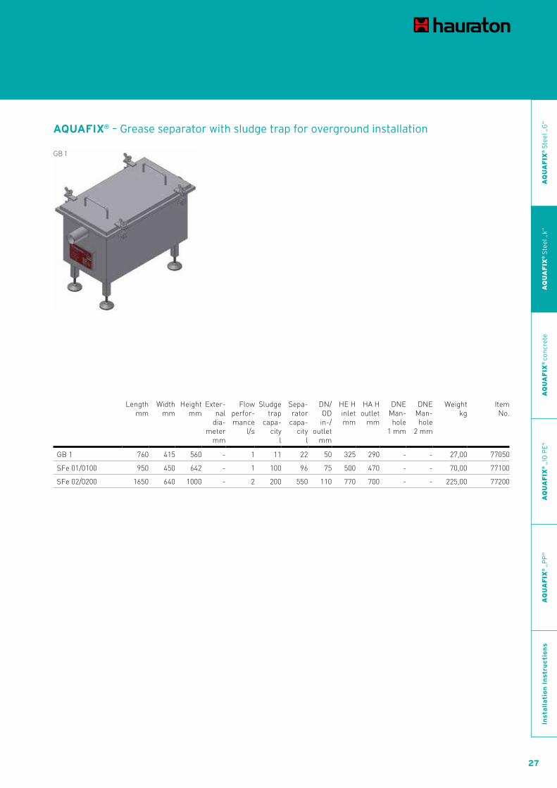
AQUAFIX® – Grease separator with sludge trap for overground installation
GB 1
Length mm
Width mm
Height mm
Exter-nal
dia-meter
mm
Flow perfor-mance
l/s
Sludge trap
capa-city
l
Sepa-rator
capa-city
l
DN/OD in-/
outlet mm
HE H inlet mm
HA H outlet
mm
DNE Man-hole
1 mm
DNE Man-hole
2 mm
Weight kg
Item No.
GB 1 760 415 560 - 1 11 22 50 325 290 - - 27,00 77050
SFe 01/0100 950 450 642 - 1 100 96 75 500 470 - - 70,00 77100
SFe 02/0200 1650 640 1000 - 2 200 550 110 770 700 - - 225,00 77200

28
AQUA SPORTCIVILS LANDSCAPING
AQUAFIX®Separator made of steel, series k
AQUAFIX® – Fk Grease separator
Fk 01
Length mm
Width mm
Height mm
Exter-nal
dia-meter
mm
Flow perfor-mance
l/s
Sludge trap
capa-city
l
Sepa-rator
capa-city
l
DN/OD in-/
outlet mm
HE H inlet mm
HA H outlet
mm
DNE Man-hole
1 mm
DNE Man-hole
2 mm
Weight kg
Item No.
Fk 01 1000 500 1000 - 1 - 390 110 800 780 1 - 171,00 87101
Fk 02 1200 800 1000 - 2 - 749 110 800 780 1 - 242,00 87102
Fk 04 1500 800 1200 - 4 - 1176 110 1000 980 - 1 324,00 87104
Fk 07 1800 1000 1200 - 7 - 1674 160 950 930 - 1 416,00 87107
Fk 10 2500 1000 1400 - 10 - 2825 160 1150 1130 1 1 597,00 87110
Fk 15 3200 1200 1400 - 15 - 4147 200 1100 1080 - 2 609,00 87115
Fk 20 3200 1600 1500 - 20 - 6042 200 1200 1180 - 2 953,00 87120
Fk 25 4000 1600 1500 - 25 - 7552 200 1200 1180 - 2 1133,00 87125

29
AQUA SPORTCIVILS LANDSCAPING
AQ
UA
FIX
® S
tee
l „G
“A
QU
AF
IX®
Ste
el „
k“A
QU
AF
IX®
co
ncr
ete
AQ
UA
FIX
® „
10 P
E“
AQ
UA
FIX
® „
PP
“In
sta
lla
tio
n I
nstr
uc
tio
ns
AQUAFIX® – SFk Grease separator with sludge trap
SFk 01/0100
Length mm
Width mm
Height mm
Exter-nal
dia-meter
mm
Flow perfor-mance
l/s
Sludge trap
capa-city
l
Sepa-rator
capa-city
l
DN/OD in-/
outlet mm
HE H inlet mm
HA H outlet
mm
DNE Man-hole
1 mm
DNE Man-hole
2 mm
Weight kg
Item No.
SFk 01/0100 1000 500 1000 - 1 113 256 110 800 730 1 - 194,00 87201
SFk 02/0200 1200 800 1000 - 2 240 467 110 800 730 - 1 277,00 87202
SFk 04/0400 1500 1000 1200 - 4 475 930 110 1000 930 - 1 418,00 87204
SFk 07/0700 2400 1000 1400 - 7 715 1890 160 1150 1080 1 1 644,00 87207
SFk 10/1000 2500 1400 1400 - 10 1001 2797 160 1150 1080 - 2 793,00 87210
SFk 15/1500 3200 1600 1500 - 15 1564 4249 200 1100 1030 - 2 1063,00 87215
SFk 20/2000 4000 1800 1500 - 20 2277 5899 200 1200 1130 - 2 1325,00 87220
SFk 25/2500 5000 1800 1500 - 25 2588 7628 200 1200 1130 - 2 1567,00 87225

30
AQUA SPORTCIVILS LANDSCAPING
AQUAFIX®SeparatorsSeries made of concreteSolid constructions for heavy duty.
31
AQUA SPORTCIVILS LANDSCAPING
At a glance: High quality concrete
Strong wall thickness
Conforms to standards – even down
to the details

32
AQUA SPORTCIVILS LANDSCAPING
AQUAFIX®SeparatorsSeries made of concreteSolid constructions for heavy duty.
Features high grade reinforced concrete C35/45 in accordance
with Eurocode EC 206, DIN 1045 and 4281, wall thick-
ness at least 120 mm
coating consisting of three layers of epoxy resin
resistant to light liquids and fatty acids
conform to European standards EN 858 and 1825

33
AQUA SPORTCIVILS LANDSCAPING
AQ
UA
FIX
® S
tee
l „G
“A
QU
AF
IX®
Ste
el „
k“A
QU
AF
IX®
co
ncr
ete
AQ
UA
FIX
® „
10 P
E“
AQ
UA
FIX
® „
PP
“In
sta
lla
tio
n I
nstr
uc
tio
ns

34
AQUA SPORTCIVILS LANDSCAPING
AQUAFIX®Separator made of concrete, series P
The following are products from Poland - series P

35
AQUA SPORTCIVILS LANDSCAPING
AQ
UA
FIX
® S
tee
l „G
“A
QU
AF
IX®
Ste
el „
k“A
QU
AF
IX®
co
ncr
ete
AQ
UA
FIX
® „
10 P
E“
AQ
UA
FIX
® „
PP
“In
sta
lla
tio
n I
nstr
uc
tio
ns
AQUAFIX® – S Sludge trap
S 02000/0150
Length mm
Width mm
Height mm
Ex-ternal
dia-meter
mm
Flow perfor-mance
l/s
Sludge trap
capa-city
l
Sepa-rator
capa-city
l
DN/OD in-/
outlet mm
HE H inlet mm
HA H outlet
mm
DNE Man-hole
1 mm
DNE Man-hole
2 mm
Weight kg
Item No.
S 00300/0100 1300 1300 1300 1300 - 300 - 110 720 695 625 - 2490,00 3101031P
S 00600/0150 1300 1300 1620 1300 - 600 - 160 990 965 625 - 2680,00 3101061P
S 01000/0150 P 1300 1300 2080 1300 - 1000 - 160 1450 1425 625 - 3280,00 3101101P
S 01500/0200 P 1500 1500 2180 1500 - 1500 - 200 1510 1485 625 - 4180,00 3101152P
S 02000/0150 1800 1800 1940 1800 - 2000 - 160 1310 1285 625 - 5060,00 3101103P
S 02000/0200 1800 1800 1980 1800 - 2000 - 200 1310 1285 625 - 5150,00 3101203P
S 01000 / 0400 P 1800 1800 2530 1800 - 3000 - 160 1900 1875 625 - 7100,00 3101104P
S 02500 / 0200 P 2300 2300 1770 2300 - 3000 - 200 1100 1075 625 - 7370,00 3101205P
S 03500 / 0150 P 2300 2300 1910 2300 - 3000 - 315 1125 1100 625 - 7460,00 3101305P
S 04000/0200 2300 2300 2120 2300 - 4000 - 200 1450 1425 625 - 8090,00 3101206P
S 08000 / 0200 P 2300 2300 2770 2300 - 6000 - 200 2095 2070 625 - 10100,00 3101208P
S 07500 / 0250 P 2300 2300 2880 2300 - 6000 - 315 2095 2070 625 - 11030,00 3101308P
S 07500 / 0250 P 2740 2740 2800 2740 - 9000 - 315 2015 1990 625 - 11820,00 3101319P

36
AQUA SPORTCIVILS LANDSCAPING
AQUAFIX® – S Sludge trap, rectangular version
S 10000/0500 rectangular P
Length mm
Width mm
Height mm
Ex-ternal
dia-meter
mm
Flow perfor-mance
l/s
Sludge trap
capa- city
l
Sepa-rator
capa- city
l
DN/OD in-/
outlet mm
HE H inlet mm
HA H outlet
mm
DNE Man-hole
1 mm
DNE Man-hole
2 mm
Weight kg
Item No.
S 10000/0500 rectangular P 5660 2360 2090 - - 10000 - 500 1150 1100 625 - 22430,00 3101005P
S 10000/0600 rectangular P 5660 2360 2220 - - 10000 - 630 1150 1100 625 - 23110,00 3101006P
S 10000/0800 rectangular P 5660 2360 2390 - - 10000 - 800 1150 1100 625 - 23910,00 3101008P
S 10000/1000 rectangular P 5660 2360 2590 - - 10000 - 1000 1150 1100 625 - 24840,00 3101010P
S 12000/0600 angular P 5660 2360 2410 - - 12000 - 630 1340 1290 625 - 24190,00 3101210P
S 12000/1000 angular P 5660 2360 2780 - - 12000 - 1000 1340 1290 625 - 25920,00 3101126P
S 15000/0500 rectangular P 5660 2360 2550 - - 15000 - 500 1610 1560 625 - 25040,00 3101505P
S 20000/0500 rectangular P 5660 2360 3000 - - 20000 - 500 2060 2010 625 - 27600,00 3102005P
S 20000/0600 rectangular P 5660 2360 3130 - - 20000 - 630 2060 2010 625 - 28270,00 3102006P
S 20000/0800 rectangular P 5660 2360 3300 - - 20000 - 800 2060 2010 625 - 29080,00 3102008P
AQUAFIX®Separator made of concrete, series P
37
AQUA SPORTCIVILS LANDSCAPING
AQ
UA
FIX
® S
tee
l „G
“A
QU
AF
IX®
Ste
el „
k“A
QU
AF
IX®
co
ncr
ete
AQ
UA
FIX
® „
10 P
E“
AQ
UA
FIX
® „
PP
“In
sta
lla
tio
n I
nstr
uc
tio
ns
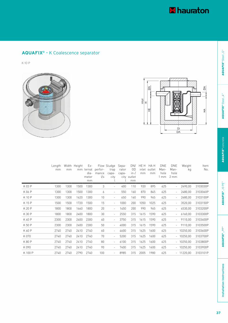
AQUAFIX® – K Coalescence separator
K 10 P
Length mm
Width mm
Height mm
Ex-ternal
dia-meter
mm
Flow perfor-mance
l/s
Sludge trap
capa- city
l
Sepa-rator
capa- city
l
DN/OD in-/
outlet mm
HE H inlet mm
HA H outlet
mm
DNE Man-hole
1 mm
DNE Man-hole
2 mm
Weight kg
Item No.
K 03 P 1300 1300 1500 1300 3 - 400 110 920 895 625 - 2490,00 3103030P
K 06 P 1300 1300 1500 1300 6 - 550 160 870 845 625 - 2480,00 3103060P
K 10 P 1300 1300 1620 1300 10 - 650 160 990 965 625 - 2680,00 3103100P
K 15 P 1500 1500 1720 1500 15 - 1000 200 1050 1025 625 - 3520,00 3103150P
K 20 P 1800 1800 1660 1800 20 - 1450 200 990 965 625 - 4530,00 3103200P
K 30 P 1800 1800 2400 1800 30 - 2550 315 1615 1590 625 - 6160,00 3103300P
K 40 P 2300 2300 2400 2300 40 - 3750 315 1615 1590 625 - 9110,00 3103400P
K 50 P 2300 2300 2400 2300 50 - 4000 315 1615 1590 625 - 9110,00 3103500P
K 60 P 2740 2740 2410 2740 60 - 4600 315 1625 1600 625 - 10250,00 3103600P
K 070 2740 2740 2410 2740 70 - 5200 315 1625 1600 625 - 10250,00 3103700P
K 80 P 2740 2740 2410 2740 80 - 6100 315 1625 1600 625 - 10250,00 3103800P
K 090 2740 2740 2410 2740 90 - 7400 315 1625 1600 625 - 10250,00 3103900P
K 100 P 2740 2740 2790 2740 100 - 8985 315 2005 1980 625 - 11220,00 3103101P

38
AQUA SPORTCIVILS LANDSCAPING
AQUAFIX® – K Coalescence separator - rectangular shape
K 150 rectangular P
Length mm
Width mm
Height mm
Ex-ternal
dia-meter
mm
Flow perfor-mance
l/s
Sludge trap
capa-city
l
Sepa-rator
capa-city
l
DN/OD in-/
outlet mm
HE H inlet mm
HA H outlet
mm
DNE Man-hole
1 mm
DNE Man-hole
2 mm
Weight kg
Item No.
K 150 rectangular P 5660 2360 3100 - 150 - 17700 500 1900 1800 800 800 28220,00 3178150P
K 200 rectangular P 5660 2360 3300 - 200 - 19900 500 2200 2000 800 800 39360,00 3178200P
AQUAFIX®Separator made of concrete, series P

39
AQUA SPORTCIVILS LANDSCAPING
AQ
UA
FIX
® S
tee
l „G
“A
QU
AF
IX®
Ste
el „
k“A
QU
AF
IX®
co
ncr
ete
AQ
UA
FIX
® „
10 P
E“
AQ
UA
FIX
® „
PP
“In
sta
lla
tio
n I
nstr
uc
tio
ns
AQUAFIX® – K2BP Coalescence separator with double bypass
K2BP 10 P
Length mm
Width mm
Height mm
Ex-ternal
dia-meter
mm
Flow perfor-mance
l/s
Sludge trap
capa-city
l
Sepa-rator
capa-city
l
DN/OD in-/
outlet mm
HE H inlet mm
HA H outlet
mm
DNE Man-hole
1 mm
DNE Man-hole
2 mm
Weight kg
Item No.
K2BP 10 P 1500 1500 2650 1500 100 - 1610 400 1650 1575 625 - 4860,00 3174010P
K2BP 15 P 1800 1800 2650 1800 150 - 2520 400 1695 1575 625 - 6520,00 3174015P
K2BP 20 P 2300 2300 2500 2300 200 - 3530 500 1430 1275 625 - 9070,00 3174020P
K2BP 30 P 2300 2300 2900 2300 300 - 4480 630 1675 1575 625 - 10290,00 3174030P
K2BP 40 P 2740 2740 2900 2300 400 - 6185 630 1600 1425 625 - 11290,00 3174040P
K2BP 60 P 2740 2740 3050 2300 600 - 6920 800 1750 1575 625 - 11530,00 3174060P
K2BP 80 P 3300 3300 3050 3300 800 - 9360 800 1675 1475 625 - 18840,00 3174080P
K2BP 90 P 3300 3300 3300 3300 900 - 10600 1000 1750 1550 800 - 19540,00 3174090P

40
AQUA SPORTCIVILS LANDSCAPING
AQUAFIX® – SK Coalescence separator with sludge trap
SK 10/1000
Length mm
Width mm
Height mm
Exter-nal dia-
meter mm
Flow perfor-mance
l/s
Sludge trap
capa- city
l
Sepa-rator
capa- city
l
DN/OD in-/
outlet mm
HE H inlet mm
HA H outlet
mm
DNE Man-hole
1 mm
DNE Man-hole
2 mm
Weight kg
Item No.
SK 03/0650 P 1300 1300 2260 1300 3 600 400 110 1680 1655 625 - 3550,00 3176043P
SK 06/0600 1300 1300 2310 1300 6 600 550 160 1680 1655 625 - 3540,00 3176061P
SK 10/1000 1500 1500 2380 1500 10 1000 650 160 1750 1725 625 - 4510,00 3176101P
SK 10/2000 1800 1800 2620 1800 10 2000 650 160 1990 1965 625 - 6500,00 3176104P
SK 10/2500 P 1800 1800 2910 1800 10 2500 650 160 2280 2255 625 - 7100,00 3176105P
SK 10/3000 1800 1800 3070 1800 10 3000 650 160 2440 2415 625 - 7300,00 3176106P
SK 10/5000 P 2300 2300 3070 2300 10 5000 650 160 2440 2415 625 - 11070,00 3176107P
SK 15/1500 1800 1800 2320 1800 15 1500 1000 200 1650 1625 625 - 5890,00 3176152P
SK 15/3000 P 1800 1800 3070 1800 15 3000 1000 200 2390 2365 625 - 7290,00 3176155P
SK 15/5000 P 2300 2300 3070 2300 15 5000 1000 200 2400 2375 625 - 11060,00 3176157P
SK 20/4000 P 1800 1800 2790 1800 20 2000 1450 200 2120 2095 625 - 6760,00 3176203P
SK 20/4000 P 2300 2300 2750 2300 20 4000 1450 200 2080 2055 625 - 10100,00 3176204P
SK 30/3000 P 2300 2300 3070 2300 30 3000 2550 315 2285 2260 625 - 11030,00 3176305P
SK 40/4000 P 2740 2740 3070 2740 40 4000 3750 315 2325 2300 625 - 11820,00 3176406P
SK 50/5000 P 2740 2740 3070 2740 50 5000 5554 315 2325 2300 625 - 11820,00 3176505P
AQUAFIX®Separator made of concrete, series P

41
AQUA SPORTCIVILS LANDSCAPING
AQ
UA
FIX
® S
tee
l „G
“A
QU
AF
IX®
Ste
el „
k“A
QU
AF
IX®
co
ncr
ete
AQ
UA
FIX
® „
10 P
E“
AQ
UA
FIX
® „
PP
“In
sta
lla
tio
n I
nstr
uc
tio
ns
AQUAFIX® – K2BP Coalescence separator with double bypass, rectangular version
Length mm
Width mm
Height mm
Ex-ternal
dia-meter
mm
Flow perfor-mance
l/s
Sludge trap
capa-city
l
Sepa-rator
capa-city
l
DN/OD in-/
outlet mm
HE H inlet mm
HA H outlet
mm
DNE Man-hole
1 mm
DNE Man-hole
2 mm
Weight kg
Item No.
K2BP100 5660 2360 3100 - 1000 - 11600 1000 1450 1250 800 - 27840,00 3179100P
K2BP120 5660 2360 3300 - 1200 - 13800 1000 1700 1450 800 - 28980,00 3179120P
AQUAFIX® – SK2BP Coalescence separator with sludge trap and double bypass
SK2BP 15/1500
K2BP100 oder K2BP120
Length mm
Width mm
Height mm
Ex-ternal
dia-meter
mm
Flow perfor-mance
l/s
Sludge trap ca-
pa-city l
Sepa-rator
ca-pa-city
l
DN/OD in-/
outlet mm
HE H inlet mm
HA H outlet
mm
DNE Man-hole
1 mm
DNE Man-hole
2 mm
Weight kg
Item No.
SK2BPl 10/1000 light 1500 1500 2535 1500 100 1000 688 315 1693 1643 1000 - 4720,00 3100101P
SK2BP 15/1500 2300 2300 2860 2300 150 2510 2520 400 1870 1750 625 - 10300,00 3175015P
SK2BP 20/2000 2740 2740 3000 2740 200 3310 4540 500 1905 1750 625 - 11580,00 3175020P

42
AQUA SPORTCIVILS LANDSCAPING
Grease Separator
AQUAFIX®Separator made of concrete, series P

43
AQUA SPORTCIVILS LANDSCAPING
AQ
UA
FIX
® S
tee
l „G
“A
QU
AF
IX®
Ste
el „
k“A
QU
AF
IX®
co
ncr
ete
AQ
UA
FIX
® „
10 P
E“
AQ
UA
FIX
® „
PP
“In
sta
lla
tio
n I
nstr
uc
tio
ns
AQUAFIX® – Sf Sludge trap for grease
Sf 0700/07 P
Length mm
Width mm
Height mm
Ex-ternal
dia-meter
mm
Flow perfor-mance
l/s
Sludge trap
capa- city
l
Sepa-rator
capa- city
l
DN/OD in-/
outlet mm
HE H inlet mm
HA H outlet
mm
DNE Man-hole
1 mm
DNE Man-hole
2 mm
Weight kg
Item No.
Sf 0700/07 P 1300 1300 1470 1300 - 400 - 160 840 815 625 - 2680,00 3107404P
Sf 0700/07 P 1300 1300 1720 1300 - 700 - 160 1090 1065 625 - 2950,00 3107073P
Sf 0800/04 P 1300 1300 1820 1300 - 800 - 160 1190 1165 625 - 2950,00 3107043P

44
AQUA SPORTCIVILS LANDSCAPING
AQUAFIX® – F Grease separator
F 04 P
Length mm
Width mm
Height mm
Ex-ternal
dia-meter
mm
Flow perfor-mance
l/s
Sludge trap
capa- city
l
Sepa-rator
capa- city
l
DN/OD in-/
outlet mm
HE H inlet mm
HA H outlet
mm
DNE Man-hole
1 mm
DNE Man-hole
2 mm
Weight kg
Item No.
F 02 P 1300 1300 1500 1300 2 - 550 160 870 845 625 - 2480,00 3108020P
F 04 P 1500 1500 1670 1500 4 - 1000 160 1040 1015 625 - 3470,00 3108040P
F 07 P 1800 1800 1670 1800 7 - 1550 160 1040 1015 625 - 4540,00 3108070P
F 10 P 2300 2300 1710 2300 10 - 2900 160 1080 1055 625 - 7270,00 3108100P
F 15 P 2740 2740 1990 2740 20 - 5700 200 1320 1295 625 - 9250,00 3108150P
AQUAFIX®Separator made of concrete, series P

45
AQUA SPORTCIVILS LANDSCAPING
AQ
UA
FIX
® S
tee
l „G
“A
QU
AF
IX®
Ste
el „
k“A
QU
AF
IX®
co
ncr
ete
AQ
UA
FIX
® „
10 P
E“
AQ
UA
FIX
® „
PP
“In
sta
lla
tio
n I
nstr
uc
tio
ns
AQUAFIX® – SF Grease separator with sludge trap
SF 04/0400 P
Length mm
Width mm
Height mm
Ex-ternal
dia-meter
mm
Flow perfor-mance
l/s
Sludge trap
capa- city
l
Sepa-rator
capa-city
l
DN/OD in-/
outlet mm
HE H inlet mm
HA H outlet
mm
DNE Man-hole
1 mm
DNE Man-hole
2 mm
Weight kg
Item No.
SF 02/0200 P 1300 1300 1810 1300 2 200 600 160 1180 1155 625 - 2950,00 3178021P
SF 02/0400 P 1300 1300 2070 1300 2 400 600 160 1440 1415 625 - 3280,00 3178022P
SF 04/0400 P 1500 1500 2120 1500 4 400 1100 160 1490 1465 625 - 4040,00 3178042P
SF 04/0800 P 1500 1500 2380 1500 4 800 994 160 1750 1725 625 - 4510,00 3178043P
SF 04/0700 P 1800 1800 2320 1800 7 700 2000 160 1690 1665 625 - 5900,00 3178073P
SF 07/1400 P 1800 1800 2770 1800 7 1400 2050 160 2140 2115 625 - 6770,00 3178074P
SF 10/1000 P 2300 2300 2000 2300 10 1000 2800 160 1370 1345 625 - 7800,00 3178104P
SF 10/2000 P 2300 2300 2320 2300 10 2000 2800 160 1690 1665 625 - 8700,00 3178105P
SF 20/2000 P 2740 2740 2380 2740 20 2000 5600 200 1710 1685 625 - 10280,00 3178205P

46
AQUA SPORTCIVILS LANDSCAPING
Starch Separator
AQUAFIX®Separator made of concrete, series P
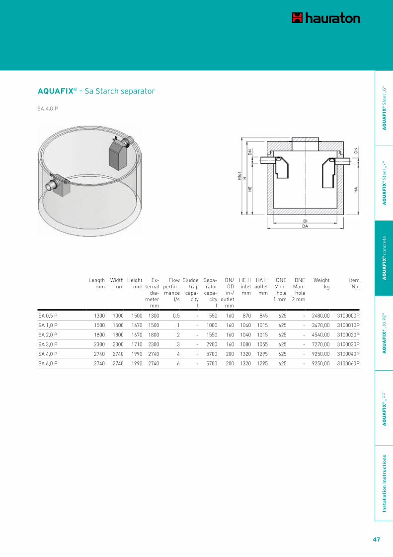
47
AQUA SPORTCIVILS LANDSCAPING
AQUAFIX® – Sa Starch separator
SA 4,0 P
Length mm
Width mm
Height mm
Ex-ternal
dia-meter
mm
Flow perfor-mance
l/s
Sludge trap
capa- city
l
Sepa-rator
capa-city
l
DN/OD in-/
outlet mm
HE H inlet mm
HA H outlet
mm
DNE Man-hole
1 mm
DNE Man-hole
2 mm
Weight kg
Item No.
SA 0,5 P 1300 1300 1500 1300 0.5 - 550 160 870 845 625 - 2480,00 3100000P
SA 1,0 P 1500 1500 1670 1500 1 - 1000 160 1040 1015 625 - 3470,00 3100010P
SA 2,0 P 1800 1800 1670 1800 2 - 1550 160 1040 1015 625 - 4540,00 3100020P
SA 3,0 P 2300 2300 1710 2300 3 - 2900 160 1080 1055 625 - 7270,00 3100030P
SA 4,0 P 2740 2740 1990 2740 4 - 5700 200 1320 1295 625 - 9250,00 3100040P
SA 6,0 P 2740 2740 1990 2740 6 - 5700 200 1320 1295 625 - 9250,00 3100060P
AQ
UA
FIX
® S
tee
l „G
“A
QU
AF
IX®
Ste
el „
k“A
QU
AF
IX®
co
ncr
ete
AQ
UA
FIX
® „
10 P
E“
AQ
UA
FIX
® „
PP
“In
sta
lla
tio
n I
nstr
uc
tio
ns

48
AQUA SPORTCIVILS LANDSCAPING
AQUAFIX®Separator made of concrete, series H
The following are products from Hungary - series H

49
AQUA SPORTCIVILS LANDSCAPING
AQ
UA
FIX
® S
tee
l „G
“A
QU
AF
IX®
Ste
el „
k“A
QU
AF
IX®
co
ncr
ete
AQ
UA
FIX
® „
10 P
E“
AQ
UA
FIX
® „
PP
“In
sta
lla
tio
n I
nstr
uc
tio
ns
AQUAFIX® – S Sludge trap
S 10/02500 H
Length mm
Width mm
Height mm
Ex-ternal
dia-meter
mm
Flow perfor-mance
l/s
Sludge trap
capa-city
l
Sepa-rator
capa-city
l
DN/OD in-/
outlet mm
HE H inlet mm
HA H outlet
mm
DNE Man-hole
1 mm
DNE Man-hole
2 mm
Weight kg
Item No.
S 10/02500 H 1740 1740 1920 1740 - 2500 - 160 1650 1625 800 - 3607,00 101105H
S 20/02500 H 1740 1740 1920 1740 - 2500 - 200 1600 1575 800 - 3596,00 101205H
S 30/4000 H 2240 2240 2230 2240 - 4000 - 250 1675 1650 800 - 4767,00 101306H
S 40/4000 H 2240 2240 2230 2240 - 4000 - 250 1650 1625 800 - 4767,00 101406H
S 40/8000H 2240 2240 2980 2240 - 8000 - 250 2430 2405 800 - 6163,00 101409H
S 50/06500 H 2800 2800 2250 2800 - 6500 - 315 1565 1515 1000 - 10200,00 101508H

50
AQUA SPORTCIVILS LANDSCAPING
AQUAFIX® – K Coalescence separator
K 10 H
Length mm
Width mm
Height mm
Ex-ternal
dia-meter
mm
Flow perfor-mance
l/s
Sludge trap
capa-city
l
Sepa-rator
capa-city
l
DN/OD in-/
outlet mm
HE H inlet mm
HA H outlet
mm
DNE Man-hole
1 mm
DNE Man-hole
2 mm
Weight kg
Item No.
K 10 H 1240 1240 1120 1240 10 - 518 160 900 875 800 - 1515,00 103100H
K 20 H 1740 1740 1320 1740 20 - 1439 200 1000 975 800 - 2726,00 103200H
K 040 H 2240 2240 2975 2240 40 - 7160 250 2430 2405 800 - 8560,00 103400H
K 050 H 2800 2800 2250 2800 50 - 6730 315 1565 1515 1000 - 10626,00 103500H
K 060 H 2800 2800 2750 2800 60 - 9190 315 2065 2015 1000 - 12091,00 103600H
AQUAFIX®Separator made of concrete, series H

51
AQUA SPORTCIVILS LANDSCAPING
AQ
UA
FIX
® S
tee
l „G
“A
QU
AF
IX®
Ste
el „
k“A
QU
AF
IX®
co
ncr
ete
AQ
UA
FIX
® „
10 P
E“
AQ
UA
FIX
® „
PP
“In
sta
lla
tio
n I
nstr
uc
tio
ns
AQUAFIX® – SK Coalescence separator with sludge trap
SK 04/0650 H
Length mm
Width mm
Height mm
Ex-ternal
dia-meter
mm
Flow perfor-mance
l/s
Sludge trap
capa-city
l
Sepa-rator
capa-city
l
DN/OD in-/
outlet mm
HE H inlet mm
HA H outlet
mm
DNE Man-hole
1 mm
DNE Man-hole
2 mm
Weight kg
Item No.
SK 04/0650 H 1240 1240 1970 1300 4 650 575 110 1750 1725 800 - 2410,00 176043H
SK 10/2500 H 1740 1740 2470 1740 10 2385 1166 160 2200 2175 800 - 4479,00 176105H
SK 06/0600 H 1740 1740 1795 1740 6 786 1237 160 1400 1375 800 - 3860,00 176063H
SK 15/1500 H 1740 1740 2295 1740 15 1677 1237 200 1925 1900 800 - 4582,00 176154H
SK 20/2000 H 2240 2240 2425 2240 20 2000 3219 200 1875 1850 800 - 6900,00 176203H
SK 20/4000 H 2240 2240 2975 2240 20 4000 3219 200 2425 2400 800 - 8020,00 176204H
SK 25/2500 H 2240 2240 2975 2240 25 3000 4219 200 2425 2400 800 - 8020,00 176253H
SK 30/3000 H 2240 2240 2975 2240 30 3000 4160 250 2430 2405 800 800 8020,00 176305H
SK 40/4000 H 2800 2800 2750 2800 40 4000 5890 250 2150 2100 1000 - 12100,00 176405H
SK 050/03000 H 2800 2800 2750 2800 50 3000 6150 315 2065 2015 1000 - 12812,00 176504H

52
AQUA SPORTCIVILS LANDSCAPING
AQUAFIX® – SK Coalescence separator with sludge trap (more tanks S-K) H
SK 150/15000 H
Length mm
Width mm
Height mm
Ex-ternal
dia-meter
mm
Flow perfor-mance
l/s
Sludge trap
capa-city
l
Sepa-rator
capa-city
l
DN/OD in-/
outlet mm
HE H inlet mm
HA H outlet
mm
DNE Man-hole
1 mm
DNE Man-hole
2 mm
Weight kg
Item No.
SK 040/04000 H 8500 5100 2425 2240 40 4000 6438 200 1875 1850 800 800 17500,00 176406H
SK 040/08000 H 8500 5100 2975 2240 40 8000 6438 200 2425 2400 800 800 19600,00 176408H
SK 050/05000 H 8500 5100 2975 2240 50 5000 8438 200 2425 2400 800 800 19600,00 176507H
SK 060/06000 H 8500 5100 2975 2000 60 6000 8320 250 2430 2405 800 800 19600,00 176608H
SK 075/07500 H 11000 7200 2425 2000 75 7500 12657 200 1875 1850 800 800 26800,00 176758H
SK 080/08000 H 12000 5100 2975 2000 80 8000 14320 250 1650 2405 800 800 32700,00 176809H
SK 090/09000 H 11000 7200 2975 2000 90 9000 12480 250 2430 2405 800 800 27600,00 176908H
SK 100/10000 H 14000 6400 2250 2800 100 13000 13460 315 1650 1515 1000 1000 28826,00 176111H
SK 120/12000 H 14000 7200 2975 2240 120 12000 21480 250 1650 2405 800 800 47300,00 176121H
SK 120/13000 H 14000 6400 2750 2800 120 13000 18380 315 1650 2015 1000 1000 22291,00 176122H
SK 150/15000 H 14000 6400 2250 2800 150 19500 20190 315 1650 1515 1000 1000 62478,00 176161H
SK 180/18000 H 14000 10000 2750 2800 180 19500 27570 315 1650 2015 1000 1000 66873,00 176181H
AQUAFIX®Separator made of concrete, series H

53
AQUA SPORTCIVILS LANDSCAPING
AQ
UA
FIX
® S
tee
l „G
“A
QU
AF
IX®
Ste
el „
k“A
QU
AF
IX®
co
ncr
ete
AQ
UA
FIX
® „
10 P
E“
AQ
UA
FIX
® „
PP
“In
sta
lla
tio
n I
nstr
uc
tio
ns
AQUAFIX® – SK2BP Coalescence separator with sludge trap and double bypass
SK2BP 10/3000
Length mm
Width mm
Height mm
Ex-ternal
dia-meter
mm
Flow perfor-mance
l/s
Sludge trap
capa-city
l
Sepa-rator
capa-city
l
DN/OD in-/
outlet mm
HE H inlet mm
HA H outlet
mm
DNE Man-hole
1 mm
DNE Man-hole
2 mm
Weight kg
Item No.
SK2BP 10/3000 2240 2240 2750 2240 100 3000 2570 400 1973 1923 1000 - 7733,00 175010H
SK2BP 15/3000 2800 2800 2750 2800 150 3000 5210 500 1873 1823 1000 - 12015,00 175015H
SK2BP 20/2000 2800 2800 2750 2800 200 2000 6210 500 1873 1823 1000 - 12015,00 175020H

54
AQUA SPORTCIVILS LANDSCAPING
Grease Separator
AQUAFIX®Separator made of concrete, series H

55
AQUA SPORTCIVILS LANDSCAPING
AQUAFIX® – SF Grease separator with sludge trap
SF 04/0400 H
Length mm
Width mm
Height mm
Ex-ternal
dia-meter
mm
Flow perfor-mance
l/s
Sludge trap
capa-city
l
Sepa-rator
capa-city
l
DN/OD in-/
outlet mm
HE H inlet mm
HA H outlet
mm
DNE Man-hole
1 mm
DNE Man-hole
2 mm
Weight kg
Item No.
SF 04/0400 H 1240 1240 1570 1240 4 400 418 160 1220 1170 800 - 1968,00 178042H
SF 10/1000 H 1740 1740 1770 1740 10 1000 1766 160 1420 1370 800 - 3388,00 178104H
AQ
UA
FIX
® S
tee
l „G
“A
QU
AF
IX®
Ste
el „
k“A
QU
AF
IX®
co
ncr
ete
AQ
UA
FIX
® „
10 P
E“
AQ
UA
FIX
® „
PP
“In
sta
lla
tio
n I
nstr
uc
tio
ns

56
AQUA SPORTCIVILS LANDSCAPING
AQUAFIX®SeparatorsSeries „10 PE” made of polyethyleneLight solutions for strong requirements.
57
AQUA SPORTCIVILS LANDSCAPING
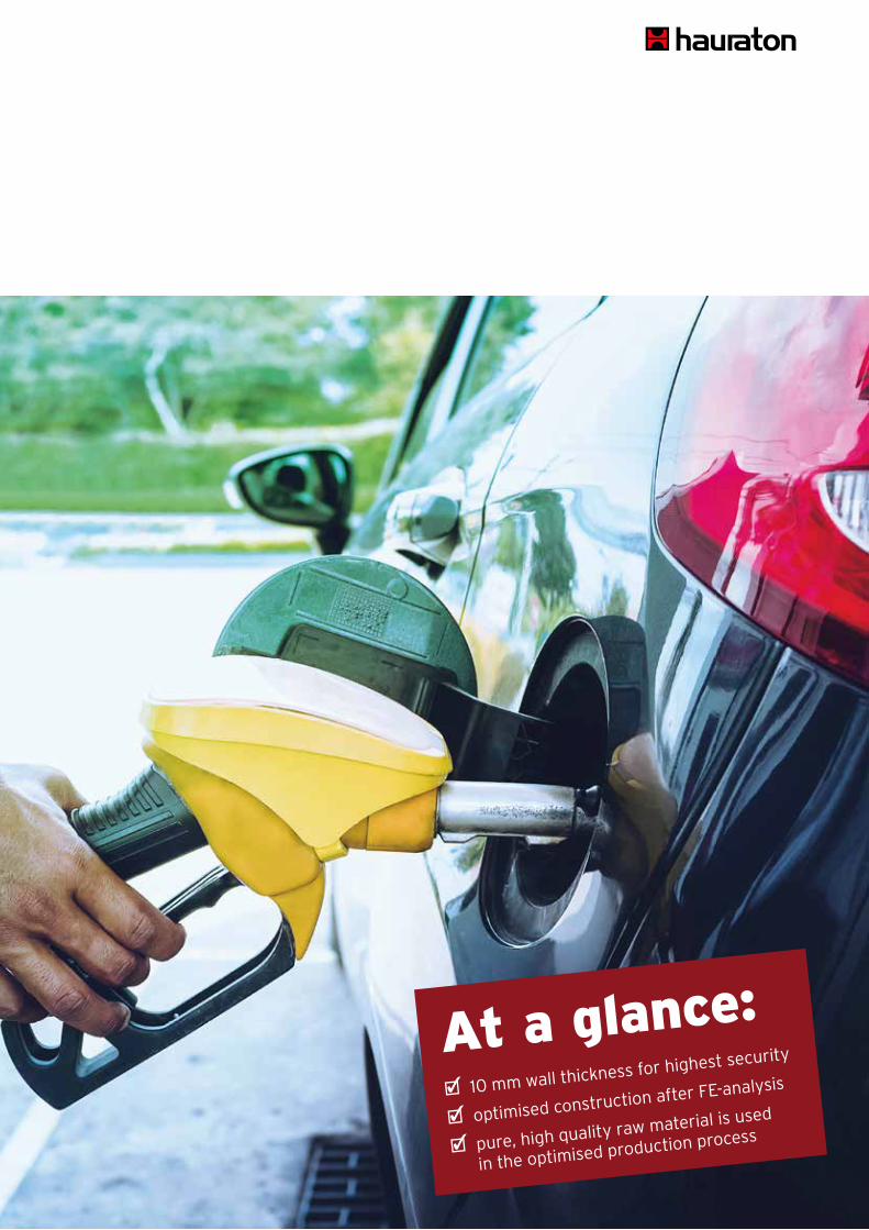
At a glance: 10 mm wall thickness for highest security
optimised construction after FE-analysis
pure, high quality raw material is used
in the optimised production process

58
AQUA SPORTCIVILS LANDSCAPING
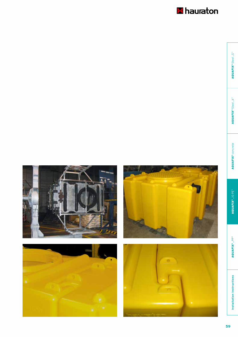
Features 10 mm wall thickness
stop rings to handle
computer aided design
according to standards EN 858 or EN 1825
wide openings
for light liquid separators:
automatic closing device easy to remove
colescence cell easy to remove
sample taking device can be integrated
ExtensionsExtension pipes in every length can be supplied.
Covers in class A or D available.
The construction of AQUAFIX 10 PE separators was done
according to detailed FE analysis. The combination of high
AQUAFIX®SeparatorsSeries „10 PE” made of polyethyleneLight solutions for strong requirements.
quality material, optimised production process and at
least 10 mm wall thickness quarantuees highest stability.
59
AQUA SPORTCIVILS LANDSCAPING
AQ
UA
FIX
® S
tee
l „G
“A
QU
AF
IX®
Ste
el „
k“A
QU
AF
IX®
co
ncr
ete
AQ
UA
FIX
® „
10 P
E“
AQ
UA
FIX
® „
PP
“In
sta
lla
tio
n I
nstr
uc
tio
ns
60
AQUA SPORTCIVILS LANDSCAPING
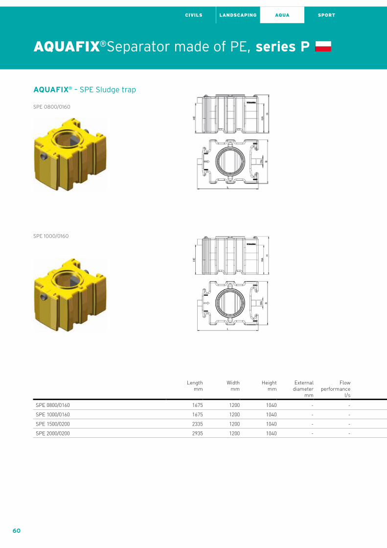
AQUAFIX®Separator made of PE, series P
AQUAFIX® – SPE Sludge trap
SPE 0800/0160
SPE 1000/0160
Length mm
Width mm
Height mm
External diameter
mm
Flow performance
l/s
Sludge trap capacity
l
Separator capacity
l
DN/OD in-/outlet
mm
HE H inlet mm
HA H outlet
mm
DNE Manhole
1 mm
DNE Manhole
2 mm
Weight kg
Item No.
SPE 0800/0160 1675 1200 1040 - - 1224 - 160 810 800 700 - 92,00 384308
SPE 1000/0160 1675 1200 1040 - - 1224 - 160 810 800 700 - 92,00 384310
SPE 1500/0200 2335 1200 1040 - - 1717 - 200 780 760 700 - 122,00 384315
SPE 2000/0200 2935 1200 1040 - - 2250 - 200 760 740 700 700 145,00 384320

61
AQUA SPORTCIVILS LANDSCAPING
SPE 1500/0200
SPE 2000/0200
Length mm
Width mm
Height mm
External diameter
mm
Flow performance
l/s
Sludge trap capacity
l
Separator capacity
l
DN/OD in-/outlet
mm
HE H inlet mm
HA H outlet
mm
DNE Manhole
1 mm
DNE Manhole
2 mm
Weight kg
Item No.
SPE 0800/0160 1675 1200 1040 - - 1224 - 160 810 800 700 - 92,00 384308
SPE 1000/0160 1675 1200 1040 - - 1224 - 160 810 800 700 - 92,00 384310
SPE 1500/0200 2335 1200 1040 - - 1717 - 200 780 760 700 - 122,00 384315
SPE 2000/0200 2935 1200 1040 - - 2250 - 200 760 740 700 700 145,00 384320
AQ
UA
FIX
® S
tee
l „G
“A
QU
AF
IX®
Ste
el „
k“A
QU
AF
IX®
co
ncr
ete
AQ
UA
FIX
® „
10 P
E“
AQ
UA
FIX
® „
PP
“In
sta
lla
tio
n I
nstr
uc
tio
ns

62
AQUA SPORTCIVILS LANDSCAPING
AQUAFIX®Separator made of PE, series P
AQUAFIX® – KPE Coalescence separator
KPE 03
KPE 06
KPE 08
Length mm
Width mm
Height mm
External diameter
mm
Flow performance
l/s
Sludge trap capacity
l
Separator capacity
l
DN/OD in-/outlet
mm
HE H inlet mm
HA H outlet
mm
DNE Manhole
1 mm
DNE Manhole
2 mm
Weight kg
Item No.
KPE 03 1635 1200 1040 - 3 - 1270 110 850 830 700 - 107,00 383503
KPE 06 1810 1200 1040 - 6 - 1435 160 800 780 700 - 149,00 383506
KPE 08 2310 1200 1040 - 8 - 1810 160 800 780 700 - 167,00 383508
KPE 10 2910 1200 1040 - 10 - 2371 160 800 780 700 700 182,00 383510
KPE 15 3515 1200 1040 - 15 - 2650 200 740 720 700 700 241,00 383515

63
AQUA SPORTCIVILS LANDSCAPING
KPE 15
KPE 10
Length mm
Width mm
Height mm
External diameter
mm
Flow performance
l/s
Sludge trap capacity
l
Separator capacity
l
DN/OD in-/outlet
mm
HE H inlet mm
HA H outlet
mm
DNE Manhole
1 mm
DNE Manhole
2 mm
Weight kg
Item No.
KPE 03 1635 1200 1040 - 3 - 1270 110 850 830 700 - 107,00 383503
KPE 06 1810 1200 1040 - 6 - 1435 160 800 780 700 - 149,00 383506
KPE 08 2310 1200 1040 - 8 - 1810 160 800 780 700 - 167,00 383508
KPE 10 2910 1200 1040 - 10 - 2371 160 800 780 700 700 182,00 383510
KPE 15 3515 1200 1040 - 15 - 2650 200 740 720 700 700 241,00 383515
AQ
UA
FIX
® S
tee
l „G
“A
QU
AF
IX®
Ste
el „
k“A
QU
AF
IX®
co
ncr
ete
AQ
UA
FIX
® „
10 P
E“
AQ
UA
FIX
® „
PP
“In
sta
lla
tio
n I
nstr
uc
tio
ns

64
AQUA SPORTCIVILS LANDSCAPING
AQUAFIX®Separator made of PE, series P
AQUAFIX® – SKPE Coalescence separator with sludge trap
SKPE 01,5/0150
SKPE 03/0300
SKPE 06/0600
Length mm
Width mm
Height mm
External diameter
mm
Flow performance
l/s
Sludge trap capacity
l
Separator capacity
l
DN/OD in-/outlet
mm
HE H inlet mm
HA H outlet
mm
DNE Manhole
1 mm
DNE Manhole
2 mm
Weight kg
Item No.
SKPE 01,5/0150 1635 1200 1040 - 1 150 1120 110 850 830 700 - 116,00 384001
SKPE 03/0300 1895 1200 1040 - 3 300 1227 110 850 830 700 - 128,00 384003
SKPE 06/0600 2310 1200 1040 - 6 600 1210 160 800 780 700 - 176,00 384006
SKPE 08/0800 2910 1200 1040 - 8 800 1571 160 800 780 700 700 188,00 384008
SKPE 10/1000 4255 1200 1040 - 10 1000 2565 160 810 780 700 700 280,00 384010
SKPE 15/1500 4915 1200 1040 - 15 1500 2359 200 780 760 700 700 301,00 384015

65
AQUA SPORTCIVILS LANDSCAPING
SKPE 15/1500
SKPE 08/0800
SKPE 10/1000
Length mm
Width mm
Height mm
External diameter
mm
Flow performance
l/s
Sludge trap capacity
l
Separator capacity
l
DN/OD in-/outlet
mm
HE H inlet mm
HA H outlet
mm
DNE Manhole
1 mm
DNE Manhole
2 mm
Weight kg
Item No.
SKPE 01,5/0150 1635 1200 1040 - 1 150 1120 110 850 830 700 - 116,00 384001
SKPE 03/0300 1895 1200 1040 - 3 300 1227 110 850 830 700 - 128,00 384003
SKPE 06/0600 2310 1200 1040 - 6 600 1210 160 800 780 700 - 176,00 384006
SKPE 08/0800 2910 1200 1040 - 8 800 1571 160 800 780 700 700 188,00 384008
SKPE 10/1000 4255 1200 1040 - 10 1000 2565 160 810 780 700 700 280,00 384010
SKPE 15/1500 4915 1200 1040 - 15 1500 2359 200 780 760 700 700 301,00 384015
AQ
UA
FIX
® S
tee
l „G
“A
QU
AF
IX®
Ste
el „
k“A
QU
AF
IX®
co
ncr
ete
AQ
UA
FIX
® „
10 P
E“
AQ
UA
FIX
® „
PP
“In
sta
lla
tio
n I
nstr
uc
tio
ns

66
AQUA SPORTCIVILS LANDSCAPING
AQUAFIX® – SKBPPE Coalescence separator with sludge trap and bypass
SKBPPE 06/0600
SKBPPE 08/0800
Length mm
Width mm
Height mm
External diameter
mm
Flow performance
l/s
Sludge trap capacity
l
Separator capacity
l
DN/OD in-/outlet
mm
HE H inlet mm
HA H outlet
mm
DNE Manhole
1 mm
DNE Manhole
2 mm
Weight kg
Item No.
SKBPPE 06/0600 2910 1200 1040 - 30 600 1315 315 640 630 700 700 203,00 383606
SKBPPE 08/0800 4255 1200 1040 - 40 800 2079 315 650 630 700 700 285,00 383608
SKBPPE 10/1000 4505 1200 1040 - 50 1000 2074 315 650 630 700 700 297,00 383610
AQUAFIX®Separator made of PE, series P

67
AQUA SPORTCIVILS LANDSCAPING
SKBPPE 10/1000
Length mm
Width mm
Height mm
External diameter
mm
Flow performance
l/s
Sludge trap capacity
l
Separator capacity
l
DN/OD in-/outlet
mm
HE H inlet mm
HA H outlet
mm
DNE Manhole
1 mm
DNE Manhole
2 mm
Weight kg
Item No.
SKBPPE 06/0600 2910 1200 1040 - 30 600 1315 315 640 630 700 700 203,00 383606
SKBPPE 08/0800 4255 1200 1040 - 40 800 2079 315 650 630 700 700 285,00 383608
SKBPPE 10/1000 4505 1200 1040 - 50 1000 2074 315 650 630 700 700 297,00 383610
AQ
UA
FIX
® S
tee
l „G
“A
QU
AF
IX®
Ste
el „
k“A
QU
AF
IX®
co
ncr
ete
AQ
UA
FIX
® „
10 P
E“
AQ
UA
FIX
® „
PP
“In
sta
lla
tio
n I
nstr
uc
tio
ns

68
AQUA SPORTCIVILS LANDSCAPING
AQUAFIX® – SKmPPE Coalescence separator with sludge trap and pump chamber
SKmPPE 01,5/0150
SKmPPE 03/0300
SKmPPE 06/0600
Length mm
Width mm
Height mm
External diameter
mm
Flow performance
l/s
Sludge trap capacity
l
Separator capacity
l
DN/OD in-/outlet
mm
HE H inlet mm
HA H outlet
mm
DNE Manhole
1 mm
DNE Manhole
2 mm
Weight kg
Item No.
SKmPPE 01,5/0150 2980 1200 1040 - 1 150 1120 110 850 830 700 700 205,00 384401
SKmPPE 03/0300 3240 1200 1040 - 3 300 1227 110 850 830 700 700 217,00 384403
SKmPPE 06/0600 3655 1200 1040 - 6 600 1210 160 800 780 700 700 265,00 384406
SKmPPE 08/0800 4255 1200 1040 - 8 800 1571 160 800 780 700 700 287,00 384408
SKmPPE 10/1000 5600 1200 1040 - 10 1000 2565 160 810 780 700 700 369,00 384410
SKmPPE 15/1500 6260 1200 1040 - 15 1500 2359 200 780 750 700 700 390,00 384415
AQUAFIX®Separator made of PE, series P

69
AQUA SPORTCIVILS LANDSCAPING
SKmPPE 08/0800
SKmPPE 10/1000
SKmPPE 15/1500
Length mm
Width mm
Height mm
External diameter
mm
Flow performance
l/s
Sludge trap capacity
l
Separator capacity
l
DN/OD in-/outlet
mm
HE H inlet mm
HA H outlet
mm
DNE Manhole
1 mm
DNE Manhole
2 mm
Weight kg
Item No.
SKmPPE 01,5/0150 2980 1200 1040 - 1 150 1120 110 850 830 700 700 205,00 384401
SKmPPE 03/0300 3240 1200 1040 - 3 300 1227 110 850 830 700 700 217,00 384403
SKmPPE 06/0600 3655 1200 1040 - 6 600 1210 160 800 780 700 700 265,00 384406
SKmPPE 08/0800 4255 1200 1040 - 8 800 1571 160 800 780 700 700 287,00 384408
SKmPPE 10/1000 5600 1200 1040 - 10 1000 2565 160 810 780 700 700 369,00 384410
SKmPPE 15/1500 6260 1200 1040 - 15 1500 2359 200 780 750 700 700 390,00 384415
AQ
UA
FIX
® S
tee
l „G
“A
QU
AF
IX®
Ste
el „
k“A
QU
AF
IX®
co
ncr
ete
AQ
UA
FIX
® „
10 P
E“
AQ
UA
FIX
® „
PP
“In
sta
lla
tio
n I
nstr
uc
tio
ns

70
AQUA SPORTCIVILS LANDSCAPING
AQUAFIX®Separator made of PE, series P

71
AQUA SPORTCIVILS LANDSCAPING
Grease Separator
AQ
UA
FIX
® S
tee
l „G
“A
QU
AF
IX®
Ste
el „
k“A
QU
AF
IX®
co
ncr
ete
AQ
UA
FIX
® „
10 P
E“
AQ
UA
FIX
® „
PP
“In
sta
lla
tio
n I
nstr
uc
tio
ns

72
AQUA SPORTCIVILS LANDSCAPING
AQUAFIX® – FPE Grease separator
FPE 02
FPE 07
FPE 04
Length mm
Width mm
Height mm
External diameter
mm
Flow performance
l/s
Sludge trap capacity
l
Separator capacity
l
DN/OD in-/outlet
mm
HE H inlet mm
HA H outlet
mm
DNE Manhole
1 mm
DNE Manhole
2 mm
Weight kg
Item No.
FPE 02 1675 1200 1040 - 2 - 1178 160 790 770 700 - 95,00 385002
FPE 04 1925 1200 1040 - 4 - 1435 160 800 780 700 - 107,00 385004
FPE 07 2324 1200 1040 - 7 - 1810 160 800 780 700 700 124,00 385007
FPE 10 2935 1200 1040 - 10 - 2371 160 800 780 700 700 141,00 385010
FPE 15 4280 1200 1040 - 15 - 3382 200 760 740 700 700 238,00 385015
AQUAFIX®Separator made of PE, series P
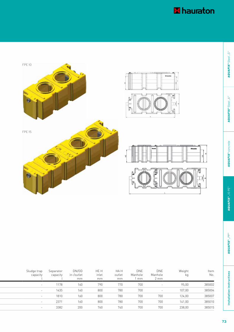
73
AQUA SPORTCIVILS LANDSCAPING
FPE 15
FPE 10
Length mm
Width mm
Height mm
External diameter
mm
Flow performance
l/s
Sludge trap capacity
l
Separator capacity
l
DN/OD in-/outlet
mm
HE H inlet mm
HA H outlet
mm
DNE Manhole
1 mm
DNE Manhole
2 mm
Weight kg
Item No.
FPE 02 1675 1200 1040 - 2 - 1178 160 790 770 700 - 95,00 385002
FPE 04 1925 1200 1040 - 4 - 1435 160 800 780 700 - 107,00 385004
FPE 07 2324 1200 1040 - 7 - 1810 160 800 780 700 700 124,00 385007
FPE 10 2935 1200 1040 - 10 - 2371 160 800 780 700 700 141,00 385010
FPE 15 4280 1200 1040 - 15 - 3382 200 760 740 700 700 238,00 385015
AQ
UA
FIX
® S
tee
l „G
“A
QU
AF
IX®
Ste
el „
k“A
QU
AF
IX®
co
ncr
ete
AQ
UA
FIX
® „
10 P
E“
AQ
UA
FIX
® „
PP
“In
sta
lla
tio
n I
nstr
uc
tio
ns

74
AQUA SPORTCIVILS LANDSCAPING
AQUAFIX®Separator made of PE, series P
AQUAFIX® – SFPE Grease separator with sludge trap
SFPE 02/0200
SFPE 04/0400
Length mm
Width mm
Height mm
External diameter
mm
Flow performance
l/s
Sludge trap capacity
l
Separator capacity
l
DN/OD in-/outlet
mm
HE H inlet mm
HA H outlet
mm
DNE Manhole
1 mm
DNE Manhole
2 mm
Weight kg
Item No.
SFPE 02/0200 1675 1200 1040 - 2 200 993 160 800 780 700 - 103,00 385302
SFPE 04/0400 2335 1200 1040 - 4 400 1210 160 800 780 700 700 134,00 385304
SFPE 07/0700 2935 1200 1040 - 7 700 1671 160 800 780 700 700 156,00 385307
SFPE 10/1000 4280 1200 1040 - 10 1000 2565 160 810 780 700 700 238,00 385310

75
AQUA SPORTCIVILS LANDSCAPING
SFPE 07/0700
SFPE 10/1000
Length mm
Width mm
Height mm
External diameter
mm
Flow performance
l/s
Sludge trap capacity
l
Separator capacity
l
DN/OD in-/outlet
mm
HE H inlet mm
HA H outlet
mm
DNE Manhole
1 mm
DNE Manhole
2 mm
Weight kg
Item No.
SFPE 02/0200 1675 1200 1040 - 2 200 993 160 800 780 700 - 103,00 385302
SFPE 04/0400 2335 1200 1040 - 4 400 1210 160 800 780 700 700 134,00 385304
SFPE 07/0700 2935 1200 1040 - 7 700 1671 160 800 780 700 700 156,00 385307
SFPE 10/1000 4280 1200 1040 - 10 1000 2565 160 810 780 700 700 238,00 385310
AQ
UA
FIX
® S
tee
l „G
“A
QU
AF
IX®
Ste
el „
k“A
QU
AF
IX®
co
ncr
ete
AQ
UA
FIX
® „
10 P
E“
AQ
UA
FIX
® „
PP
“In
sta
lla
tio
n I
nstr
uc
tio
ns

76
AQUA SPORTCIVILS LANDSCAPING
AQUAFIX®Separator made of PE, series P

77
AQUA SPORTCIVILS LANDSCAPING
Starch Separator
AQ
UA
FIX
® S
tee
l „G
“A
QU
AF
IX®
Ste
el „
k“A
QU
AF
IX®
co
ncr
ete
AQ
UA
FIX
® „
10 P
E“
AQ
UA
FIX
® „
PP
“In
sta
lla
tio
n I
nstr
uc
tio
ns

78
AQUA SPORTCIVILS LANDSCAPING AQUA SPORTCIVILS LANDSCAPING
AQUAFIX®Separator made of PE, series P
AQUAFIX® – SaPE Starch separator
SaPE 01
SaPE 02
Length mm
Width mm
Height mm
External diameter
mm
Flow performance
l/s
Sludge trap capacity
l
Separator capacity
l
DN/OD in-/outlet
mm
HE H inlet mm
HA H outlet
mm
DNE Manhole
1 mm
DNE Manhole
2 mm
Weight kg
Item No.
SaPE 01 1675 1200 1040 - 1 - 1178 160 790 770 700 - 93,00 386201
SaPE 02 1935 1200 1040 - 2 - 1435 160 800 780 700 - 102,00 386202
SaPE 03 2335 1200 1040 - 3 - 1810 160 800 780 700 - 124,00 386203
SaPE 04 2935 1200 1040 - 4 - 2371 160 800 780 700 700 145,00 386204
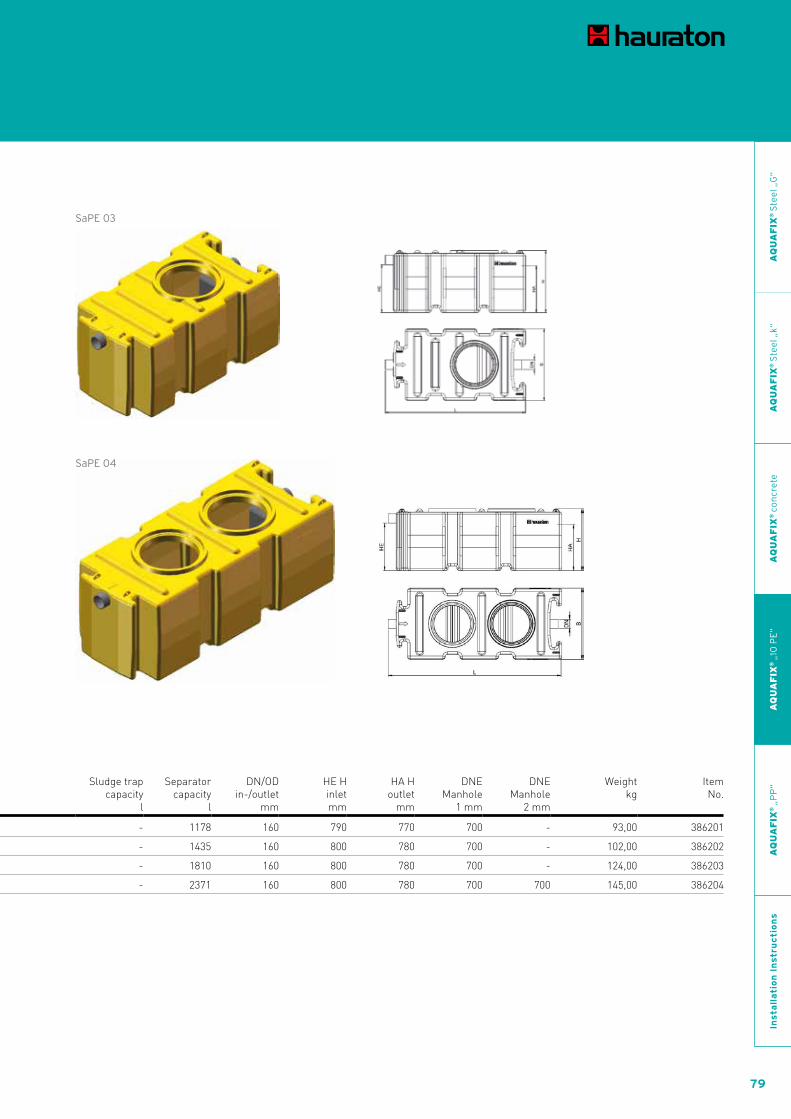
79
SaPE 03
SaPE 04
Length mm
Width mm
Height mm
External diameter
mm
Flow performance
l/s
Sludge trap capacity
l
Separator capacity
l
DN/OD in-/outlet
mm
HE H inlet mm
HA H outlet
mm
DNE Manhole
1 mm
DNE Manhole
2 mm
Weight kg
Item No.
SaPE 01 1675 1200 1040 - 1 - 1178 160 790 770 700 - 93,00 386201
SaPE 02 1935 1200 1040 - 2 - 1435 160 800 780 700 - 102,00 386202
SaPE 03 2335 1200 1040 - 3 - 1810 160 800 780 700 - 124,00 386203
SaPE 04 2935 1200 1040 - 4 - 2371 160 800 780 700 700 145,00 386204
AQ
UA
FIX
® S
tee
l „G
“A
QU
AF
IX®
Ste
el „
k“A
QU
AF
IX®
co
ncr
ete
AQ
UA
FIX
® „
10 P
E“
AQ
UA
FIX
® „
PP
“In
sta
lla
tio
n I
nstr
uc
tio
ns

80
AQUA SPORTCIVILS LANDSCAPING
AQUAFIX®Separator made of PE, series P
81
AQUA SPORTCIVILS LANDSCAPING
Battery acid neutraliser
AQ
UA
FIX
® S
tee
l „G
“A
QU
AF
IX®
Ste
el „
k“A
QU
AF
IX®
co
ncr
ete
AQ
UA
FIX
® „
10 P
E“
AQ
UA
FIX
® „
PP
“In
sta
lla
tio
n I
nstr
uc
tio
ns

82
AQUA SPORTCIVILS LANDSCAPING
AQUAFIX® – NPE Battery acid neutraliser
NPE 03
NPE 04
Length mm
Width mm
Height mm
External diameter
mm
Flow performance
l/s
Sludge trap capacity
l
Separator capacity
l
DN/OD in-/outlet
mm
HE H inlet mm
HA H outlet
mm
DNE Manhole
1 mm
DNE Manhole
2 mm
Weight kg
Item No.
NPE 03 1675 1200 1040 - 3 - 1193 160 790 770 700 - 457,00 386903
NPE 04 1935 1200 1040 - 4 - 1435 160 800 780 700 - 539,00 386904
NPE 05 2325 1200 1040 - 5 - 1810 160 800 780 700 - 697,00 386905
NPE 06 2925 1200 1040 - 6 - 2371 160 800 780 700 700 790,00 386906
AQUAFIX®Separator made of PE, series P

83
AQUA SPORTCIVILS LANDSCAPING
NPE 05
NPE 06
Length mm
Width mm
Height mm
External diameter
mm
Flow performance
l/s
Sludge trap capacity
l
Separator capacity
l
DN/OD in-/outlet
mm
HE H inlet mm
HA H outlet
mm
DNE Manhole
1 mm
DNE Manhole
2 mm
Weight kg
Item No.
NPE 03 1675 1200 1040 - 3 - 1193 160 790 770 700 - 457,00 386903
NPE 04 1935 1200 1040 - 4 - 1435 160 800 780 700 - 539,00 386904
NPE 05 2325 1200 1040 - 5 - 1810 160 800 780 700 - 697,00 386905
NPE 06 2925 1200 1040 - 6 - 2371 160 800 780 700 700 790,00 386906
AQ
UA
FIX
® S
tee
l „G
“A
QU
AF
IX®
Ste
el „
k“A
QU
AF
IX®
co
ncr
ete
AQ
UA
FIX
® „
10 P
E“
AQ
UA
FIX
® „
PP
“In
sta
lla
tio
n I
nstr
uc
tio
ns

84
AQUA SPORTCIVILS LANDSCAPING
AQUAFIX® – Covers
Cover for multi-functional shaft, PE, cl. B 125
Length mm
Width mm
Height mm
Weight kg
Item No.
Cover for multi-functional shaft, PE, cl. B 125 800 800 35 13,00 386006
Accessories for separators made of PE, series P

85
AQUA SPORTCIVILS LANDSCAPING
AQUAFIX® – Extension parts
Shaft extension PE, max. height 1000 mm
Length mm
Width mm
Height mm
Weight kg
Item No.
Frame for shaft cover PE, height 110 mm 840 840 152 10,00 386012
Shaft extension PE, max. height 1000 mm 840 840 1030 24,00 386011
Accessories for separators made of PE, series P
AQ
UA
FIX
® S
tee
l „G
“A
QU
AF
IX®
Ste
el „
k“A
QU
AF
IX®
co
ncr
ete
AQ
UA
FIX
® „
10 P
E“
AQ
UA
FIX
® „
PP
“In
sta
lla
tio
n I
nstr
uc
tio
ns

86
AQUA SPORTCIVILS LANDSCAPING
AQUAFIX®SeparatorsSeries „PP” made of polypropyleneOne system for all cases.

87
AQUA SPORTCIVILS LANDSCAPING
At a glance: 6 to 12 mm wall thickness
light ¬ installation on site is possible
without crane
high stability (self standing construction)

88
AQUA SPORTCIVILS LANDSCAPING
AQUAFIX®SeparatorsSeries „PP” made of polypropyleneOne system for all cases.
Features 6 to 12 mm wall thickness
stop rings to handle in horizontal and vertical position
buoyancy protection
according to standards EN 858 or EN 1825
wide openings
for light liquid separators:
automatic closing device easy to remove
colescence cell easy to remove
sample taking device can be integrated
ExtensionsExtension 500 mm included, adjustment rings 500 mm
can be supplied. Covers in class A or D available.

89
AQUA SPORTCIVILS LANDSCAPING
AQ
UA
FIX
® S
tee
l „G
“A
QU
AF
IX®
Ste
el „
k“A
QU
AF
IX®
co
ncr
ete
AQ
UA
FIX
® „
10 P
E“
AQ
UA
FIX
® „
PP
“In
sta
lla
tio
n I
nstr
uc
tio
ns

90
AQUA SPORTCIVILS LANDSCAPING
AQUAFIX®Separator made of PP, series H
AQUAFIX® – SPP Sludge trap
SPP 0600/06
Length mm
Width mm
Height mm
Ex-ternal
dia-meter
mm
Flow perfor-mance
l/s
Sludge trap
capa- city
l
Sepa-rator
capa- city
l
DN/OD in-/
outlet mm
HE H inlet mm
HA H outlet
mm
DNE Man-hole
1 mm
DNE Man-hole
2 mm
Weight kg
Item No.
SPP 0600/06 1000 1000 1675 950 - 607 - 160 881 856 800 - 54,00 284306
SPP 1000/10 1240 1240 1727 1190 - 1008 - 160 935 910 800 - 78,00 284310
SPP 2500/10 1500 1500 2449 1430 - 2615 - 160 1655 1630 800 - 160,00 284325
SPP 1500/15 1500 1500 1804 1430 - 1545 - 200 990 965 800 - 128,00 284315
SPP 2000/20 1500 1500 2097 1430 - 2016 - 200 1283 1258 800 - 140,00 284320
SPP 2500/20 1500 1500 2097 1430 - 2581 - 200 1283 1258 800 - 160,00 284326

91
AQUA SPORTCIVILS LANDSCAPING
AQUAFIX® – KPP Coalescence separator
KPP 04
Length mm
Width mm
Height mm
Ex-ternal
dia-meter
mm
Flow perfor-mance
l/s
Sludge trap
capa- city
l
Sepa-rator
capa- city
l
DN/OD in-/
outlet mm
HE H inlet mm
HA H outlet
mm
DNE Man-hole
1 mm
DNE Man-hole
2 mm
Weight kg
Item No.
KPP 04 700 700 1044 600 4 - 191 110 706 681 600 - 30,00 283504
KPP 06 850 850 1500 800 6 - 339 160 706 681 800 - 57,00 283506
KPP 10 1000 1000 1496 950 10 - 478 160 702 677 800 - 67,00 283510
KPP 15 1240 1240 1749 1190 15 - 1140 200 853 828 800 - 144,00 283515
KPP 20 1500 1500 1749 1430 20 - 1325 200 853 828 800 - 161,00 283520
AQ
UA
FIX
® S
tee
l „G
“A
QU
AF
IX®
Ste
el „
k“A
QU
AF
IX®
co
ncr
ete
AQ
UA
FIX
® „
10 P
E“
AQ
UA
FIX
® „
PP
“In
sta
lla
tio
n I
nstr
uc
tio
ns

92
AQUA SPORTCIVILS LANDSCAPING
AQUAFIX®Separator made of PP, series H
AQUAFIX® – SKPP Coalescence separator with sludge trap
SKPP 04/0400
Length mm
Width mm
Height mm
Ex-ternal
dia-meter
mm
Flow perfor-mance
l/s
Sludge trap
capa- city
l
Sepa-rator
capa- city
l
DN/OD in-/
outlet mm
HE H inlet mm
HA H outlet
mm
DNE Man-hole
1 mm
DNE Man-hole
2 mm
Weight kg
Item No.
SKPP 04/0400 1000 1000 1840 950 4 424 478 110 1071 1046 800 - 67,00 284004
SKPP 06/0600 1000 1000 2345 950 6 603 478 160 1551 1526 800 - 82,00 284006
SKPP 06/1200 1240 1240 2480 1190 6 1211 551 160 1604 1579 800 - 120,00 284106
SKPP 10/1000 1240 1240 2480 1190 10 1011 751 160 1604 1579 800 - 120,00 284010
SKPP 10/2500 1500 1500 3074 1430 10 2500 1084 160 2198 2173 800 - 160,00 284110
SKPP 15/1500 1500 1500 2704 1430 15 1547 1325 200 1808 1783 800 - 230,00 284015
SKPP 15/3000 2000 2000 2804 1910 15 3023 2364 200 1908 1883 800 - 280,00 284115
SKPP 20/2000 2000 2000 2446 1910 20 2020 2364 200 1550 1525 800 - 256,00 284020
SKPP 20/4000 2500 2500 2654 2380 20 4026 3670 200 1758 1733 800 - 340,00 284120

93
AQUA SPORTCIVILS LANDSCAPING
AQUAFIX® – SKBPPP Coalescence separator with sludge trap and bypass
SKBPPP 10/1000
Length mm
Width mm
Height mm
Ex-ternal
dia-meter
mm
Flow perfor-mance
l/s
Sludge trap
capa- city
l
Sepa-rator
capa- city
l
DN/OD in-/
outlet mm
HE H inlet mm
HA H outlet
mm
DNE Man-hole
1 mm
DNE Man-hole
2 mm
Weight kg
Item No.
SKBPPP 10/1000 2500 2500 2374 2380 50 1001 3621 315 1110 1060 800 - 320,00 283610
SKBPPP 15/1500 2500 2500 2674 2380 75 1501 4023 400 1317 1267 800 - 350,00 283615
AQ
UA
FIX
® S
tee
l „G
“A
QU
AF
IX®
Ste
el „
k“A
QU
AF
IX®
co
ncr
ete
AQ
UA
FIX
® „
10 P
E“
AQ
UA
FIX
® „
PP
“In
sta
lla
tio
n I
nstr
uc
tio
ns

94
AQUA SPORTCIVILS LANDSCAPING
AQUAFIX®Separator made of PP, series H
AQUAFIX® – SK2BPPP Coalescence separator with sludge trap and double bypass
SK2BPPP 10/1000
Length mm
Width mm
Height mm
Ex-ternal
dia-meter
mm
Flow perfor-mance
l/s
Sludge trap
capa- city
l
Sepa-rator
capa-city
l
DN/OD in-/
outlet mm
HE H inlet mm
HA H outlet
mm
DNE Man-hole
1 mm
DNE Man-hole
2 mm
Weight kg
Item No.
SK2BPPP 10/1000 2500 2500 2474 2380 100 1001 3869 400 1167 1117 800 - 335,00 283010
SK2BPPP 15/1500 2500 2500 2774 2380 150 1501 4241 500 1367 1317 800 - 360,00 283015

95
AQUA SPORTCIVILS LANDSCAPING
AQ
UA
FIX
® S
tee
l „G
“A
QU
AF
IX®
Ste
el „
k“A
QU
AF
IX®
co
ncr
ete
AQ
UA
FIX
® „
10 P
E“
AQ
UA
FIX
® „
PP
“In
sta
lla
tio
n I
nstr
uc
tio
ns
Grease Separator

96
AQUA SPORTCIVILS LANDSCAPING
AQUAFIX® – FPP Grease separator
FPP 02
Length mm
Width mm
Height mm
Ex-ternal
dia-meter
mm
Flow perfor-mance
l/s
Sludge trap
capa-city
l
Sepa-rator
capa-city
l
DN/OD in-/
outlet mm
HE H inlet mm
HA H outlet
mm
DNE Man-hole
1 mm
DNE Man-hole
2 mm
Weight kg
Item No.
FPP 02 1000 1000 1694 950 2 - 567 160 825 800 800 - 60,00 285002
FPP 04 1240 1240 1998 1190 4 - 1223 160 1127 1102 800 - 83,00 285004
FPP 07 1500 1500 2224 1430 7 - 2008 200 1278 1251 800 - 160,00 285007
FPP 10 2000 2000 2011 1910 10 - 3008 200 1078 1053 800 - 196,00 285010
FPP 15/20 2500 2500 2219 2380 20 - 5561 200 1278 1253 800 - 270,00 285020
AQUAFIX®Separator made of PP, series H

97
AQUA SPORTCIVILS LANDSCAPING
AQUAFIX® – SFPP Grease separator with sludge trap
SFPP 02/0200
Length mm
Width mm
Height mm
Ex-ternal
dia-meter
mm
Flow perfor-mance
l/s
Sludge trap
capa- city
l
Sepa-rator
capa- city
l
DN/OD in-/
outlet mm
HE H inlet mm
HA H outlet
mm
DNE Man-hole
1 mm
DNE Man-hole
2 mm
Weight kg
Item No.
SFPP 02/0200 1000 1000 2035 950 2 213 592 160 1166 1141 800 - 66,00 285302
SFPP 02/0400 1000 1000 2305 950 2 411 585 160 1436 1411 800 - 71,00 285303
SFPP 04/0400 1200 1200 2307 1190 4 423 1140 160 1436 1411 800 - 90,00 285304
SFPP 04/0800 1240 1240 2654 1190 4 806 1140 160 1803 1778 800 - 98,00 285305
SFPP 07/0700 1500 1500 2654 1430 7 715 1983 200 1708 1683 800 - 180,00 285307
SFPP 07/1400 1500 1500 3104 1430 7 1429 1983 200 2158 2133 800 - 200,00 285308
SFPP 10/1000 2000 2000 2116 1910 10 1003 2292 200 1183 1158 800 - 203,00 285310
SFPP 10/2000 2000 2000 2466 1910 10 2006 2292 200 1533 1508 800 - 227,00 285311A
QU
AF
IX®
Ste
el „
G“
AQ
UA
FIX
® S
tee
l „k“
AQ
UA
FIX
® c
on
cret
eA
QU
AF
IX®
„10
PE
“A
QU
AF
IX®
„P
P“
Insta
lla
tio
n I
nstr
uc
tio
ns
98
AQUA SPORTCIVILS LANDSCAPING
AQUAFIX®SeparatorsInstallation Instructions & Examples

99
AQUA SPORTCIVILS LANDSCAPING

100
AQUA SPORTCIVILS LANDSCAPING
Installation advice for AQUAFIX®Separators series „G“ made of steel1. Please check completeness of delivery and immediately
note any parts that are missing or were damaged in
transit on the delivery note. Complaints received at a
later date will not be accepted. Otherwise our general
business terms and conditions apply.
2. The separator must be installed outside the washing
areas where it will not overfill or back up. It must also
be as close as possible to the source of the sewage,
in the open but protected from the frost and easy to
access with cleaning vehicles. The outlets and pipes
must be able to drain off.
3. The excavation base must be level. If no suitable soil
is available a 10 mm thick compressed bed of sand or
small pebbles can be used. A foundation plate would be
even better. If the foundation soil is non-supporting,
make a statically dimensioned foundation plate.
4. Take thickness of base and correction layer into
consideration in height calculations. Pay attention to
height information in installation drawing.
5. Tank must be installed in a level position.
6. The material must be level as it flows through the
separator. Inlets and outlets must be correctly aligned.
The inlet and outlet must not be the wrong way around!
Use the correct gradient! Recommended total gradient
of system must be 2 - 5 %!
7. Install system with top edge higher than last inlet point.
8. Pipelines must be connected without leaks.
9. After all tanks, tops, covers and connecting pipes have
been correctly aligned, clean the system!
10. Before filling up the system, fill all tanks with fresh
water and check for leaks. The leak test is mandatory!
11. Do not modify tank or pipes again after filling with sand
and compressing. Please refer to provided installation
drawing.
12. Attach concrete plate to provide buoyancy protection
if necessary.
13. When fitting the dome shafts, ensure that the seals
are correctly placed! Please use an adequate quantity
of lubricant. We recommend laying the shaft elements
beneath each other in mortar.
14. With liquid separation systems: When filling with fresh
water, hold float in raised position by hand until it is
able to float independently. Report start-up to relevant
authority. Always follow accident prevention regulati-
ons during installation!
AQUAFIX®SeparatorsInstallation Instructions Separators series „G“ made of steel

101
AQUA SPORTCIVILS LANDSCAPING
AQ
UA
FIX
® S
tee
l „G
“A
QU
AF
IX®
Ste
el „
k“A
QU
AF
IX®
co
ncr
ete
AQ
UA
FIX
® „
10 P
E“
AQ
UA
FIX
® „
PP
“In
sta
lla
tio
n I
nstr
uc
tio
ns
Installation Drawing

102
AQUA SPORTCIVILS LANDSCAPING
Installation Drawing
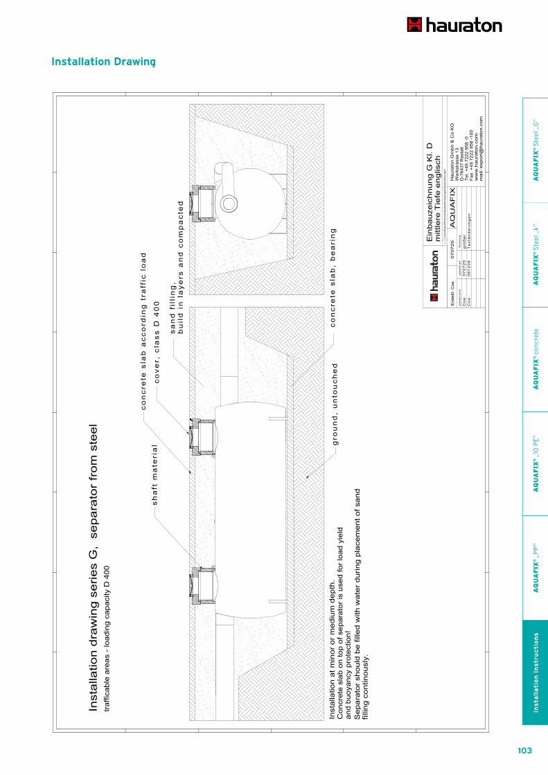
103
AQUA SPORTCIVILS LANDSCAPING
4 Abbildungen folgen
Installation Drawing
AQ
UA
FIX
® S
tee
l „G
“A
QU
AF
IX®
Ste
el „
k“A
QU
AF
IX®
co
ncr
ete
AQ
UA
FIX
® „
10 P
E“
AQ
UA
FIX
® „
PP
“In
sta
lla
tio
n I
nstr
uc
tio
ns

104
AQUA SPORTCIVILS LANDSCAPING
Installation Drawing
105
AQUA SPORTCIVILS LANDSCAPING
AQ
UA
FIX
® S
tee
l „G
“A
QU
AF
IX®
Ste
el „
k“A
QU
AF
IX®
co
ncr
ete
AQ
UA
FIX
® „
10 P
E“
AQ
UA
FIX
® „
PP
“In
sta
lla
tio
n I
nstr
uc
tio
ns

106
AQUA SPORTCIVILS LANDSCAPING
AQUAFIX®SeparatorsInstallation Instructions Separators series „G“ made of steel
Operation and maintenance of AQUAFIX® light liquid separators series „G“ made of steel
Before start-up
1. Clean entire system and remove residual mortar, soil etc.
2. Fill sludge trap and separator with fresh water.*
Attention! Always hold float of seal in hand when
filling until it can float by itself. Please ensure that
water level is same in all chambers of tank, and fill
in sequence!
3. Re-check joints of system for leaks.
* Sludge trap in this type of system must be filled
with fresh water.
Operation
As well as following the maintenance guide, the entire
system must comply with the following regulations:
DIN 1986 (estate drainage systems)
EN 858 (light liquid separators)
Local drainage regulations and other instructions
Only sewage that does not have a detrimental effect on
the intended operation of the separator must be led into
the system. Emulsions and solvents (cold cleaners, drilling
and cutting oil, water-soluble hydrocarbons etc.) must not
be allowed to enter the separator. Dispose of these mate-
rials together with the special waste. Rainwater from
surfaces for which the separator was not intended and
domestic sewage must not be led into the separator.
With coalescence separators: Do not remove coalescence
insert during operation!
The use of alarm systems with big steel AQUAFIX® SKG,
SKBP, SKGBP2 and SKGBPL separators is strongly
recommended because of the large quantity of light
liquid that is stored!
Disposal
Separator systems must be drained at least every six
months, but should not be allowed to fill to more than
85% of their storage capacity. Cleaning must occur more
often if the storage capacity of the separator or sludge
trap is exceeded. Operation must not be interrupted.
All separated material must be drained, cleaned and taken
away for disposal by an approved disposal company.
Please empty the separator and the sludge trap of this
type of system at the same time if possible.
First extract the oil layer from the system and then the
layer of water beneath it, into separate tanks if possible.
Clean float and seal every time the system is emptied and
check operation thereof.
With coalescence separators: If the coalescence material
is soiled, remove coalescence material, clean above sludge
trap, give damaged coalescence material to disposal com-
pany and replace with new material. Replace coalescence
material. The sludge trap has a coalescence chamber access
flap for removing the coalescence material. Refill system
with fresh water whenever it is emptied and cleaned.
Attention! Always hold float of seal by hand until it
is floating when filling the system. Use mobile ladder
when entering the system. Extract air/vapour mixture
beforehand. Take the relevant safety precautions!
Follow the accident prevention regulations!
In the event of torrential rainfall, a sudden influx into the
separator can occur with large separators. When entering
the system, prevent influx and pay attention to personal
safety.
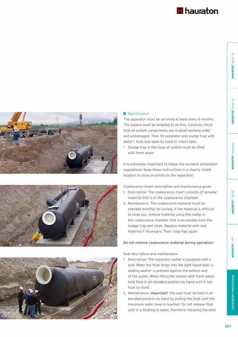
107
AQUA SPORTCIVILS LANDSCAPING
Maintenance
The separator must be serviced at least every 6 months.
The system must be emptied to do this. Carefully check
that all system components are in good working order
and undamaged. Then fill separator and sludge trap with
water*, hold seal open by hand or insert later.
* Sludge trap in this type of system must be filled
with fresh water.
It is extremely important to follow the accident prevention
regulations! Keep these instructions in a clearly visible
location in close proximity to the separator!
Coalescence insert description and maintenance guide
1. Description: The coalescence insert consists of lamellar
material that is in the coalescence chamber.
2. Maintenance: The coalescence material must be
checked monthly for soiling. If the material is difficult
to rinse out, remove material using the clamp in
the coalescence chamber that is accessible from the
sludge trap and clean. Replace material with new
material if necessary. Then close flap again.
Do not remove coalescence material during operation!
Seal description and maintenance
1. Description: The separator outlet is equipped with a
seal. When the float drops into the light liquid layer a
sealing washer is pressed against the bottom end
of the outlet. When filling the system with fresh water,
hold float in an elevated position by hand until it can
float by itself.
2. Maintenance: Important! The seal must be held in an
elevated position by hand by pulling the float until the
maximum water level is reached. Do not release float
until it is floating in water, therefore releasing the seal!
AQ
UA
FIX
® S
tee
l „G
“A
QU
AF
IX®
Ste
el „
k“A
QU
AF
IX®
co
ncr
ete
AQ
UA
FIX
® „
10 P
E“
AQ
UA
FIX
® „
PP
“In
sta
lla
tio
n I
nstr
uc
tio
ns

108
AQUA SPORTCIVILS LANDSCAPING
AQUAFIX®SeparatorsInstallation Instructions Separators series „k“ made of steel
Installation advice for AQUAFIX®Separators series „k“ made of steel
1. Please check completeness of delivery and immediately
note any parts that are missing or were damaged in
transit on the delivery note. Complaints received at a
later date will not be accepted. Otherwise our general
business terms and conditions apply.
2. The separator should be installed outside the washing
areas where it will not overfill or back up. It must
also be as close as possible to the source of the
sewage, in the open but protected from the frost and
easy to access with cleaning vehicles.
3. The excavation base must be level. If no suitable soil
is available a 10 mm thick compressed bed of sand or
small pebbles can be used. A foundation plate would
be even better. If the foundation soil is non-supporting,
make a statically dimensioned foundation plate.
4. Take thickness of base and correction layer into
consideration in height calculations. Pay attention
to height information in installation drawing.
5. Tank must be installed in a level position.
6. The material must be level as it flows through the
separator. The inlet and outlet must be correctly
aligned.
The inlet and outlet must not be the wrong way around!
Use the correct gradient! Recommended total gradient
of system must be 2 - 5 %!
7. Install system with top edge higher than last inlet point.
8. Attach buoyancy protector if necessary and anchor
it in the foundation plate.
9. Pipelines must be connected without leaks.
10. After correctly aligning all tanks, tops, covers and
connecting pipes, clean the system!
11. Before filling up the system, fill all tanks with fresh
water and check for leaks. The leak test is mandatory!
12. Do not modify tank or pipes again after filling with
sand and compressing. Please refer to provided
installation drawing.
13. Attach concrete plate to provide buoyancy protection
if necessary.
14. With liquid separation systems: When filling with fresh
water, hold float in raised position by hand until it is
able to float independently. Report start-up to relevant
authority.
Always follow accident prevention regulations during
installation!

109
AQUA SPORTCIVILS LANDSCAPING
AQ
UA
FIX
® S
tee
l „G
“A
QU
AF
IX®
Ste
el „
k“A
QU
AF
IX®
co
ncr
ete
AQ
UA
FIX
® „
10 P
E“
AQ
UA
FIX
® „
PP
“In
sta
lla
tio
n I
nstr
uc
tio
ns
Installation Drawing

110
AQUA SPORTCIVILS LANDSCAPING
Installation Drawing

111
AQUA SPORTCIVILS LANDSCAPING
Installation Drawing
AQ
UA
FIX
® S
tee
l „G
“A
QU
AF
IX®
Ste
el „
k“A
QU
AF
IX®
co
ncr
ete
AQ
UA
FIX
® „
10 P
E“
AQ
UA
FIX
® „
PP
“In
sta
lla
tio
n I
nstr
uc
tio
ns

112
AQUA SPORTCIVILS LANDSCAPING
AQUAFIX®SeparatorsInstallation Instructions Separators series „k“ made of steel
Operation and maintenance of AQUAFIX® light liquid separators series „k“ made of steel
Before start-up
1. Clean entire system and remove residual mortar,
soil etc.
2. Fill sludge trap and separator with fresh water.*
Attention! Always hold float of seal in hand when filling
until it can float by itself. Please ensure that water level
is same in all chambers of tank, and fill in sequence!
3. Re-check joints of system for leaks.
* Sludge trap in this type of system must be filled with
fresh water.
Operation
As well as following the maintenance guide, the entire
system must comply with the following regulations
DIN 1986 (estate drainage systems)
EN 858 (light liquid separators)
Local drainage regulations and other instructions
Only sewage that does not have a detrimental effect on
the intended operation of the separator must be led into
the system. Emulsions and solvents (cold cleaners, drilling
and cutting oil, water-soluble hydrocarbons etc.) must
not be allowed to enter the separator. Dispose of these
materials together with the special waste. Rainwater from
surfaces for which the separator was not intended and
domestic sewage must not be led into the separator. With
coalescence separators: Do not remove coalescence insert
during operation!
Seal description and maintenance
1. Description: The separator outlet is equipped with a
seal. When the float drops into the light liquid layer a
sealing washer is pressed against the bottom end of
the outlet. When filling the system with fresh water,
hold float in an elevated position by hand until it can
float by itself.
2. Maintenance: Important! The seal must be held in an
elevated position by hand by pulling the float until the
maximum water level is reached. Do not release float
until it is floating in water, therefore releasing the seal!
Keep these instructions in close proximity to the
separator!
Disposal
Separator must be drained at least every six months,
but should not be allowed to fill to more than 85% of its
storage capacity. Cleaning must occur more often if the
storage capacity of the separator or sludge trap is ex-
ceeded. Operation must not be interrupted. All separated
material must be drained, cleaned and taken away for
disposal by an approved disposal company.
Please empty the separator and the sludge trap of this
type of system at the same time if possible.
First extract the oil layer from the system and then the
layer of water beneath it, into separate tanks if possible.
Clean float and seal every time the system is emptied
and check operation thereof.
With coalescence separators: If the coalescence material
is soiled, remove coalescence material, clean above sludge
trap, give damaged coalescence material to disposal
company and replace with new material. Replace coale-
scence material. Refill system with fresh water whenever
it is emptied and cleaned.
Attention! Always hold float of seal by hand until it is
floating when filling the system. Use mobile ladder when
entering the system. Extract air/vapour mixture before-
hand. Take the relevant safety precautions! Follow the
accident prevention regulations!

113
AQUA SPORTCIVILS LANDSCAPING
Maintenance
Separator must be serviced at least every 6 months.
System must be emptied to do this. Carefully check that
all system components are in good working order and
undamaged. Then fill separator and sludge trap with
water*, hold seal open by hand or insert later.
* Sludge trap of this type of system must be filled
with fresh water.
It is extremely important to follow the accident
prevention regulations! Keep these instructions in
close proximity to the separator!
Coalescence insert description and maintenance guide
1. Description: The coalescence insert consists of lamellar
material that is in the coalescence chamber.
2. Maintenance: The coalescence material must be
checked monthly for soiling. If it cannot be rinsed
out easily it must be removed and cleaned. Replace
material with new material if necessary. Do not
remove coalescence material during operation!
Operation and maintenance of AQUAFIX® grease separators series „k“ made of steel
Before start-up
Clean entire system and remove any residual mortar, soil
etc. if necessary. Fill entire system with fresh water. Check
joints of system for leaks.
Operation
As well as the maintenance guide, the following instructions
must be followed for the entire system:
DIN 4040 (grease separation systems)
DIN 1986 (estate drainage systems)
Local water removal regulations and other instructions
Only sewage that does not have a detrimental effect on
the intended operation of the separator must be led to the
separator. It is particularly important to prevent domestic
sewage and light mineral liquids from entering the separator.
Do not allow rainwater to enter the system.
Keep these instructions in close proximity to the
separator!
Disposal
1. Grease separators must be cleaned at least once per
month, possibly more frequently. Cleaning must take
place more frequently if the separator or sludge trap
storage capacity is exceeded. The operation of the
separator must not be affected.
2. Have all separated material drained, cleaned and taken
away by an approved disposal company.
3. Fill entire system with fresh water after it has been
emptied and drained.
4. Use mobile ladders when entering the system.
Extract vapour/air mixture beforehand. Pay attention
to accident prevention regulations!
Maintenance
The separator must be serviced at least once per month.
The system must be drained and cleaned in order to
do this. Carefully check that all system components are
in good working order and undamaged. Then refill system
with fresh water. It is extremely important to observe the
accident prevention regulations!
AQ
UA
FIX
® S
tee
l „G
“A
QU
AF
IX®
Ste
el „
k“A
QU
AF
IX®
co
ncr
ete
AQ
UA
FIX
® „
10 P
E“
AQ
UA
FIX
® „
PP
“In
sta
lla
tio
n I
nstr
uc
tio
ns
114
AQUA SPORTCIVILS LANDSCAPING
AQUAFIX®SeparatorsInstallation Instructions Separators series made of concrete (H/P)
Installation advice for AQUAFIX®Separators series made of concrete (H/P)
1. Please check completeness of delivery. Note any
missing parts or transit damage that has occurred on
the delivery note immediately. Complaints that are
received later will not be accepted. Otherwise our
general terms and conditions apply.
2. The separator system must be installed in a location
outside the washing areas where it will not overflow or
back up, as close as possible to the location where the
waste water occurs. It must also be in the open, frost-
free and easily accessible for cleaning vehicles. The
drains and pipes must be able to drain until empty.
3. The base of the excavation must be level. If no suitable
soil is available, create a 10 cm thick bed of sand and
fine gravel and compress. If the ground is non-load
bearing, make a statically measured foundation slab.
Put a 10 cm compensation layer of sand onto the foun-
dation slab.
4. Take thickness of foundation and compensation layer
into consideration during height measurements. Pay
attention to height information in installation drawing.
5. The tanks must be installed in a level position.
Do not confuse the inlet with the outlet! Adhere to order
of tanks! Maintain slope! Recommended total incline of
system 2 - 5%!
6. Install system so that top edge is higher than final
admission point.
7. Manual transport on side can be done easily with steel
bars which can be put through the holes of the outer
stop rings.
8. Arrange maintenance shaft at outlet side such that all
separator areas are accessible and the floats and the
coalescence insert can be removed if necessary.
9. Ensure that the seals are correctly placed! Please use
an adequate quantity of antiseize agent. It is advisable
to offset the relative positions of the shaft elements in
mortar or using hose bearings.
10. The distance between the individual elements should
be 60 - 100 cm.
11. Ensure that pipelines are connected without leaks.
12. Fill all tanks with fresh water before filling and check
for leaks. This leak test is mandatory!
13. Do not alter positions of tanks and lines when filling
and compressing with sand. Please pay attention to
the provided drawing.
14. When all tanks, covering plates, tops and covers
and connecting pipes have been correctly located,
the system must be cleaned.
15. When filling light liquid separators with fresh water,
hold float in raised position until it can float indepen-
dently.
Report start-up to the responsible authority. Pay attention
to accident prevention regulations during installation!
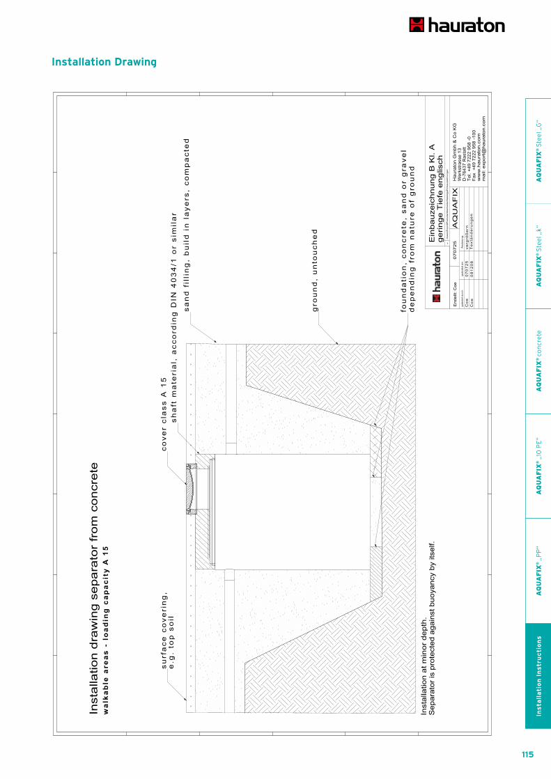
115
AQUA SPORTCIVILS LANDSCAPING
AQ
UA
FIX
® S
tee
l „G
“A
QU
AF
IX®
Ste
el „
k“A
QU
AF
IX®
co
ncr
ete
AQ
UA
FIX
® „
10 P
E“
AQ
UA
FIX
® „
PP
“In
sta
lla
tio
n I
nstr
uc
tio
ns
Installation Drawing
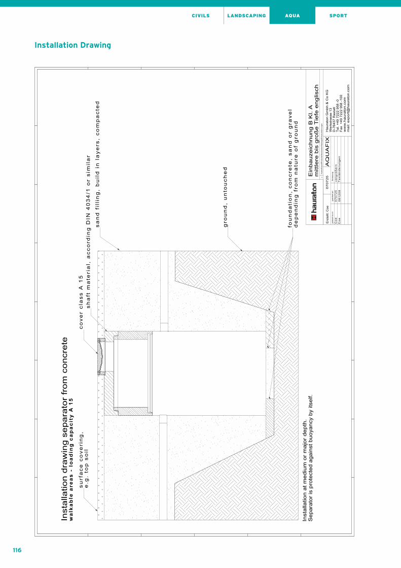
116
AQUA SPORTCIVILS LANDSCAPING
Installation Drawing

117
AQUA SPORTCIVILS LANDSCAPING
Installation Drawing
AQ
UA
FIX
® S
tee
l „G
“A
QU
AF
IX®
Ste
el „
k“A
QU
AF
IX®
co
ncr
ete
AQ
UA
FIX
® „
10 P
E“
AQ
UA
FIX
® „
PP
“In
sta
lla
tio
n I
nstr
uc
tio
ns

118
AQUA SPORTCIVILS LANDSCAPING
Installation Drawing

119
AQUA SPORTCIVILS LANDSCAPING
AQ
UA
FIX
® S
tee
l „G
“A
QU
AF
IX®
Ste
el „
k“A
QU
AF
IX®
co
ncr
ete
AQ
UA
FIX
® „
10 P
E“
AQ
UA
FIX
® „
PP
“In
sta
lla
tio
n I
nstr
uc
tio
ns

120
AQUA SPORTCIVILS LANDSCAPING
Operation and maintenance of AQUAFIX® light liquid separators series made of CONCRETE (H/P)
Before start-up
1. Clean the entire system and remove mortar residue,
soil etc. Remove lock during this operation and
(if separator is a coalescence separator) remove the
coalescence insert and replace them again afterwards.
2. Fill sludge trap and separator with fresh water.
Attention! Always hold lock in raised position when
filling, or replace when filling is complete.
3. Re-check tightness of joints in the system.
Operation
As well as the maintenance guide, the following regulations
must be observed for the entire system:
DIN 1986 (Land drainage systems)
DIN 1999 (Light liquid separating systems)
EN 858 (Light liquid separating systems)
Local drainage statutes and other regulations
Only waste water that does not affect the intended
operation of the separator must be led to the separating
system. Emulsions and solvents (cold cleaners, drilling
and cutting oils, water-soluble hydrocarbons etc.) must
be kept away from the separating system and disposed
of as special waste. Rainwater from surfaces for which
the separating system is not intended and domestic waste
water must not be led to the separating system. Do not
remove coalescence insert during operation!
Disposal
Separating systems must be emptied at least every six
months unless otherwise stipulated by the monitoring
authority, but no later than when 85% of the storage
capacity has been reached. The cleaning intervals must
be shorter if the storage capacity of the separator or the
sludge trap is exceeded. The operation of the equipment
must not be interrupted.
The separated material must only be emptied, cleaned
and taken away by authorised disposal companies.
The oil layer and water beneath it must be extracted first,
preferably into separate tanks. The float and the lock must
be cleaned and the operation thereof checked every time
the equipment is emptied. Remove coalescence insert,
clean the sludge trap, give damaged coalescence material
to the disposal company and replace with new material.
Re-insert the coalescence insert.
Every time that the equipment is emptied and cleaned,
refill system with fresh water. Hold lock open by hand
when doing this or insert it again afterwards. Use mobile
ladders when climbing into the system. Extract vapour/
air mixture beforehand.
Servicing
The separator system must be serviced at least every
6 months. The system may need to be emptied to do this.
Carefully check operation of all parts of the system and
inspect for damage. Then fill separator and sludge trap with
fresh water, hold lock open by hand or insert afterwards.
Pay attention to accident prevention regulations!
AQUAFIX®SeparatorsInstallation Instructions Separators series made of concrete (H/P)
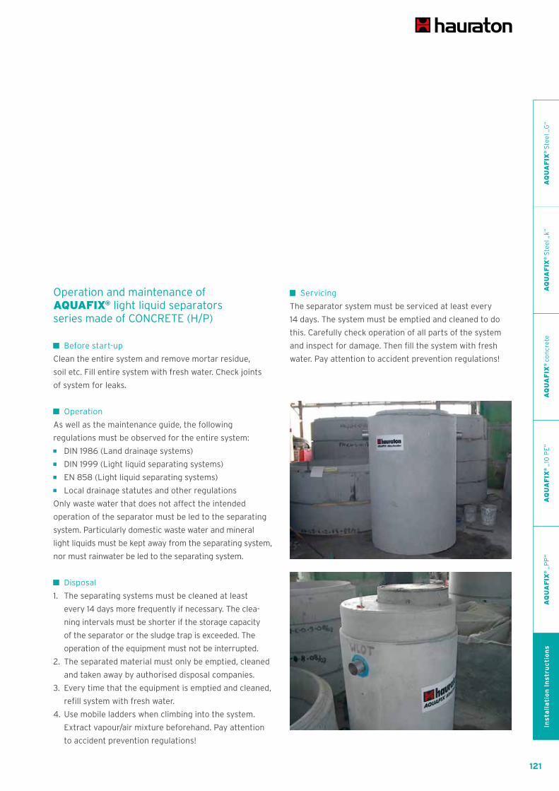
121
AQUA SPORTCIVILS LANDSCAPING
Operation and maintenance of AQUAFIX® light liquid separators series made of CONCRETE (H/P)
Before start-up
Clean the entire system and remove mortar residue,
soil etc. Fill entire system with fresh water. Check joints
of system for leaks.
Operation
As well as the maintenance guide, the following
regulations must be observed for the entire system:
DIN 1986 (Land drainage systems)
DIN 1999 (Light liquid separating systems)
EN 858 (Light liquid separating systems)
Local drainage statutes and other regulations
Only waste water that does not affect the intended
operation of the separator must be led to the separating
system. Particularly domestic waste water and mineral
light liquids must be kept away from the separating system,
nor must rainwater be led to the separating system.
Disposal
1. The separating systems must be cleaned at least
every 14 days more frequently if necessary. The clea-
ning intervals must be shorter if the storage capacity
of the separator or the sludge trap is exceeded. The
operation of the equipment must not be interrupted.
2. The separated material must only be emptied, cleaned
and taken away by authorised disposal companies.
3. Every time that the equipment is emptied and cleaned,
refill system with fresh water.
4. Use mobile ladders when climbing into the system.
Extract vapour/air mixture beforehand. Pay attention
to accident prevention regulations!
Servicing
The separator system must be serviced at least every
14 days. The system must be emptied and cleaned to do
this. Carefully check operation of all parts of the system
and inspect for damage. Then fill the system with fresh
water. Pay attention to accident prevention regulations!
AQ
UA
FIX
® S
tee
l „G
“A
QU
AF
IX®
Ste
el „
k“A
QU
AF
IX®
co
ncr
ete
AQ
UA
FIX
® „
10 P
E“
AQ
UA
FIX
® „
PP
“In
sta
lla
tio
n I
nstr
uc
tio
ns

122
AQUA SPORTCIVILS LANDSCAPING
Installation advice for AQUAFIX®Separators series „10 PE“ made of polypropylene
Installation in frequented areas.
1. The system must be installed below ground.
2. Place the system on a stable base (concrete) in a
horizontal position.
3. Connect the inlet and the outlet to the sewage system.
4. Connect the height adaptation equipment if necessary,
and adjust the height thereof depending on the nature
of the terrain.
5. Fill the system with clean water, packing layers of sand
around the equipment.
6. If the system is being installed in a frequented area a
400 kN cast iron cover must be provided. The cast iron
lid is attached to the self-supporting concrete base and
sealed, whereby the edge of the floor (height and
reinforcement must be calculated) serves as a base.
7. Manual transport on side can be done easily with steel
bars which can be put through the holes of the outer
stop rings.
Installation outside frequented areas.
1. The system must be installed below ground.
2. Place the system on a compressed earth or concrete
base in a horizontal position.
3. Connect the inlet and the outlet to the sewage system.
4. If necessary, attach the height adapter and adjust the
height thereof depending on the nature of the top edge
of the ground.
5. Fill the system with clean water, packing layers of sand
down around the system.
6. If several height adapters are required, a self-supporting
concrete base must be made (base height and reinforce-
ment must be calculated).
7. Manual transport on side can be done easily with steel
bars which can be put through the holes of the outer
stop rings.
AQUAFIX®SeparatorsInstallation Instructions Separators series „10 PE“ made of polypropylene

123
AQUA SPORTCIVILS LANDSCAPING
AQ
UA
FIX
® S
tee
l „G
“A
QU
AF
IX®
Ste
el „
k“A
QU
AF
IX®
co
ncr
ete
AQ
UA
FIX
® „
10 P
E“
AQ
UA
FIX
® „
PP
“In
sta
lla
tio
n I
nstr
uc
tio
ns
Installation Drawing

124
AQUA SPORTCIVILS LANDSCAPING
Installation Drawing

125
AQUA SPORTCIVILS LANDSCAPING
Installation Drawing
AQ
UA
FIX
® S
tee
l „G
“A
QU
AF
IX®
Ste
el „
k“A
QU
AF
IX®
co
ncr
ete
AQ
UA
FIX
® „
10 P
E“
AQ
UA
FIX
® „
PP
“In
sta
lla
tio
n I
nstr
uc
tio
ns
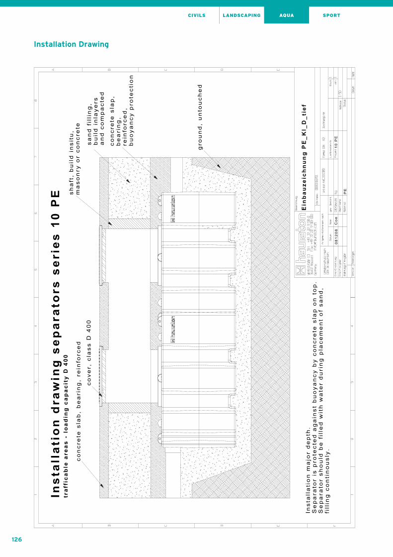
126
AQUA SPORTCIVILS LANDSCAPING
Installation Drawing

127
AQUA SPORTCIVILS LANDSCAPING
Installation Drawing
AQ
UA
FIX
® S
tee
l „G
“A
QU
AF
IX®
Ste
el „
k“A
QU
AF
IX®
co
ncr
ete
AQ
UA
FIX
® „
10 P
E“
AQ
UA
FIX
® „
PP
“In
sta
lla
tio
n I
nstr
uc
tio
ns

128
AQUA SPORTCIVILS LANDSCAPING
Operation and maintenance of AQUAFIX® grease separatorseries „10 PE“ made of polypropylene
Before start-up
Clean entire system and remove any residual mortar, soil
etc. if necessary. Fill entire system with fresh water. Check
joints of system for leaks.
Operation
As well as the maintenance guide, the following
instructions must be followed for the entire system:
EN 1825 Grease separating systems
Local water removal regulations and other instructions
Only sewage that does not have a detrimental effect on
the intended operation of the separator must be led to
the separator. It is particularly important to prevent
domestic sewage and light mineral liquids from entering
the separator. Do not allow rainwater to enter the system.
Disposal
1. Grease separators must be cleaned at least once per
month, possibly more frequently. Cleaning must take
place more frequently if the separator or sludge trap
storage capacity is exceeded. The operation of the
separator must not be affected.
2. Have all separated material drained, cleaned and taken
away by an approved disposal company.
3. Fill entire system with fresh water after it has been
emptied and drained.
4. Use mobile ladders when entering the system.
Extract vapour/air mixture beforehand. Pay attention
to accident prevention regulations!
Maintenance
The separator must be serviced at least once per month.
The system must be drained and cleaned in order to do
this. Carefully check that all system components are in
good working order and undamaged. Then refill system
with fresh water. It is extremely important to observe
the accident prevention regulations!
Operation and maintenance of AQUAFIX® light liquid separators series „10 PE“ made of polypropylene
Before start-up
1. Clean entire system and remove residual mortar,
soil etc.
2. Fill sludge trap and separator with fresh water.
Please ensure that water level is same in all chambers
of tank, and fill in sequence!
3. Re-check joints of system for leaks.
Operation
Separator must be drained at least every six months,
but should not be allowed to fill to more than 85% of
its storage capacity. Cleaning must occur more often
if the storage capacity of the separator or sludge trap
is exceded. Operation must not be interrupted.
All separated material must be drained, cleaned and
taken away for disposal by an approved disposal company.
Please empty the separator and the sludge trap of this
type of system at the same time if possible. First extract
the oil layer from the system and then the layer of water
beneath it, into separate tanks if possible. Clean float and
seal every time the system is emptied and check operati-
on thereof.
With coalescence separators: If the coalescence material
is soiled, remove coalescence material, clean above sludge
trap, give damaged coalescence material to disposal
company and replace with new material. Replace coale-
scence material. Refill system with fresh water whenever
it is emptied and cleaned.
AQUAFIX®SeparatorsInstallation Instructions Separators series „10 PE“ made of polypropylene

129
AQUA SPORTCIVILS LANDSCAPING
AQ
UA
FIX
® S
tee
l „G
“A
QU
AF
IX®
Ste
el „
k“A
QU
AF
IX®
co
ncr
ete
AQ
UA
FIX
® „
10 P
E“
AQ
UA
FIX
® „
PP
“In
sta
lla
tio
n I
nstr
uc
tio
ns

130
AQUA SPORTCIVILS LANDSCAPING
AQUAFIX®SeparatorsInstallation Instructions Separators series „PP“ made of polypropylene
Installation advice for AQUAFIX® light liquid separators series „PP“ made of polypropylene
Installation in a frequented area
1. The system must be installed below ground.
2. Place the system on a stable base (concrete) in a
horizontal position.
3. Connect the inlet and the outlet to the sewage system.
4. Connect the height adaptation equipment if necessary,
and adjust the height thereof depending on the nature
of the terrain.
5. Fill the system with clean water, packing layers of sand
around the equipment.
6. If the system is being installed in a frequented area a
400 kN cast iron cover must be provided. The cast iron
lid is attached to the selfsupporting concrete base and
sealed, whereby the edge of the floor (height and
reinforcement must be calculated) serves as a base.
Installation outside frequented areas.
1. The system must be installed below ground.
2. Place the system on a compressed earth or concrete
base in a horizontal position.
3. Connect the inlet and the outlet to the sewage system.
4. Connect the ventilation (diam. 50 mm).
5. If necessary, attach the height adapter and adjust the
height thereof depending on the nature of the top edge
of the ground.
6. Fill the system with clean water, packing layers of sand
down around the system.
7. If several height adapters are required, a self-
supporting concrete base must be made (base height
and reinforcement must be calculated).

131
AQUA SPORTCIVILS LANDSCAPING
AQ
UA
FIX
® S
tee
l „G
“A
QU
AF
IX®
Ste
el „
k“A
QU
AF
IX®
co
ncr
ete
AQ
UA
FIX
® „
10 P
E“
AQ
UA
FIX
® „
PP
“In
sta
lla
tio
n I
nstr
uc
tio
ns
Installation Drawing

132
AQUA SPORTCIVILS LANDSCAPING
Installation Drawing

133
AQUA SPORTCIVILS LANDSCAPING
Installation Drawing
AQ
UA
FIX
® S
tee
l „G
“A
QU
AF
IX®
Ste
el „
k“A
QU
AF
IX®
co
ncr
ete
AQ
UA
FIX
® „
10 P
E“
AQ
UA
FIX
® „
PP
“In
sta
lla
tio
n I
nstr
uc
tio
ns
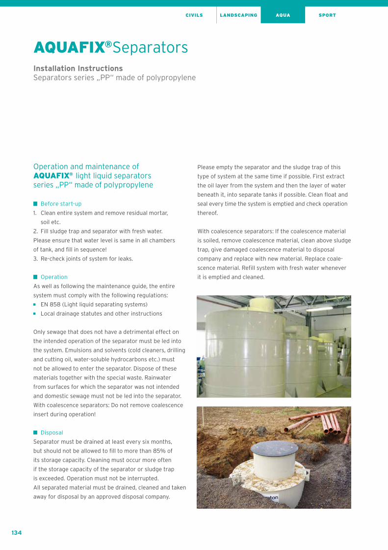
134
AQUA SPORTCIVILS LANDSCAPING
AQUAFIX®SeparatorsInstallation Instructions Separators series „PP“ made of polypropylene
Operation and maintenance of AQUAFIX® light liquid separators series „PP“ made of polypropylene
Before start-up
1. Clean entire system and remove residual mortar,
soil etc.
2. Fill sludge trap and separator with fresh water.
Please ensure that water level is same in all chambers
of tank, and fill in sequence!
3. Re-check joints of system for leaks.
Operation
As well as following the maintenance guide, the entire
system must comply with the following regulations:
EN 858 (Light liquid separating systems)
Local drainage statutes and other instructions
Only sewage that does not have a detrimental effect on
the intended operation of the separator must be led into
the system. Emulsions and solvents (cold cleaners, drilling
and cutting oil, water-soluble hydrocarbons etc.) must
not be allowed to enter the separator. Dispose of these
materials together with the special waste. Rainwater
from surfaces for which the separator was not intended
and domestic sewage must not be led into the separator.
With coalescence separators: Do not remove coalescence
insert during operation!
Disposal
Separator must be drained at least every six months,
but should not be allowed to fill to more than 85% of
its storage capacity. Cleaning must occur more often
if the storage capacity of the separator or sludge trap
is exceeded. Operation must not be interrupted.
All separated material must be drained, cleaned and taken
away for disposal by an approved disposal company.
Please empty the separator and the sludge trap of this
type of system at the same time if possible. First extract
the oil layer from the system and then the layer of water
beneath it, into separate tanks if possible. Clean float and
seal every time the system is emptied and check operation
thereof.
With coalescence separators: If the coalescence material
is soiled, remove coalescence material, clean above sludge
trap, give damaged coalescence material to disposal
company and replace with new material. Replace coale-
scence material. Refill system with fresh water whenever
it is emptied and cleaned.

135
AQUA SPORTCIVILS LANDSCAPING
Operation and maintenance of AQUAFIX®Separators series „PP“ made of polypropylene
Before start-up
Clean entire system and remove any residual mortar,
soil etc. if necessary. Fill entire system with fresh water.
Check joints of system for leaks.
Operation
As well as the maintenance guide, the following
instructions must be followed for the entire system:
EN 1825 Grease separating systems
Local water removal regulations and other instructions
Only sewage that does not have a detrimental effect on
the intended operation of the separator must be led to
the separator. It is particularly important to prevent
domestic sewage and light mineral liquids from entering
the separator. Do not allow rainwater to enter the system.
Disposal
1. Grease separators must be cleaned at least once per
month, possibly more frequently. Cleaning must take
place more frequently if the separator or sludge trap
storage capacity is exceeded. The operation of the
separator must not be affected.
2. Have all separated material drained, cleaned and taken
away by an approved disposal company.
3. Fill entire system with fresh water after it has been
emptied and drained.
4. Use mobile ladders when entering the system.
Extract vapour/air mixture beforehand. Pay attention
to accident prevention regulations!
Maintenance
The separator must be serviced at least once per month.
The system must be drained and cleaned in order to do
this. Carefully check that all system components are in
good working order and undamaged. Then refill system
with fresh water. It is extremely important to observe
the accident prevention regulations!
AQ
UA
FIX
® S
tee
l „G
“A
QU
AF
IX®
Ste
el „
k“A
QU
AF
IX®
co
ncr
ete
AQ
UA
FIX
® „
10 P
E“
AQ
UA
FIX
® „
PP
“In
sta
lla
tio
n I
nstr
uc
tio
ns

Hauraton GmbH & Co. KG
Werkstraße 13
76437 Rastatt
Germany
Tel. +49 7222 958 0
Fax +49 7222 958 100
www.hauraton.com
Hauraton GmbH & Co. KGHauraton GmbH & Co. KGHauraton GmbH & Co. KG
Werkstraße 13Werkstraße 13Werkstraße 13
76437 Rastatt76437 Rastatt76437 Rastatt
Germany
Tel. +49 7222 958 0Tel. +49 7222 958 0Tel. +49 7222 958 0
Fax +49 7222 958 100Fax +49 7222 958 100Fax +49 7222 958 100
[email protected]@[email protected]
www.hauraton.comwww.hauraton.comwww.hauraton.com
HAURATON GmbH & Co. KGWerkstraße 1376437 RastattGermanyTel. +49 7222 958 222Fax +49 7222 958 [email protected]
07/
20
17 |
Pri
nte
d in
Ger
man
y
All
dra
win
gs,
Me
asu
rem
en
ts a
nd
we
igh
ts
are
no
nco
mm
itta
l! W
e r
ese
rve
th
e r
igh
t to
do
te
chn
ica
l ch
an
ge
s fo
r im
pro
vem
en
t
EN
00
1-0
5-0
717
HAURATON partner