ar2700 operating manual - aor, u.s.a · full microprocessor reset: later in this manual reference...
TRANSCRIPT

AR2700 operating manual
1
(1) Introduction & accessories
Thank you for purchasing the new AOR AR2700 wide band receiver.
This operating manual is divided into many sections and presented in a logicalorder assuming that it will be read section by section following the examples.However, if you are familiar with the operations of modern multi-functionreceivers you may proceed directly to section 6 . Many phrases arerepeated through the manual, while this may make the text a little repetitious, itshould provide clear instructions if you refer directly to a specific section.
Every effort has been made to make this manual correct and up to date. Dueto continuous development of the receiver and by error or omissions,anomalies may be found and this is acknowledged.
Most apparent faults are usually due to accidental misoperation of the receiver,carefully read all of the manual before deciding to return the receiver for repair.
Although carefully designed, this receiver (like all receivers) suffers from adegree of internal noises known as spurii. They are a product of the receiver’scircuitry and do not represent a fault.
This manual is protected by copyright AOR LTD 1995. No informationcontained in this manual may be copied or transferred by any means withoutthe prior written consent of AOR LTD. AOR and the [AOR] logo are trademarks of AOR, LTD. All other trade marks and names acknowledged. E&OE.
© 1995 AOR LTD.
Operating manual Conventions and special notes
Where text appears in [SQUARE BRACKETS] the keys are to be pressedexactly as shown.
For example: [1] [4] [5] [ENT]
Means press the 1 key followed by the 4 key followed by the 5 keyfollowed by the ENTER key.
The arrow keys to the lower left of the keypad are referred to as UP / DOWN or[UP] [DOWN] keys.
Words contained in speech marks “BANK” refer to indications displayed on theLiquid Crystal Display.
Where memory banks etc are empty the indication “- - -” is often displayed.
[2ndF] function key : The function key [2ndF] provides access to additionalfacilities via the numeric keypad. The function key should be momentarilypressed only (so that the legend “2ndF” appears in the top left corner of theLCD) before another numeric key is pressed... do not hold the function keyin while pressing other keys .
AR2700 operating manual
2
[PWR] power switch : The power switch is not of the traditional “click”operation but microprocessor controlled, this is to facilitate the sleep timer.To switch the receiver On, press and hold the [PWR] key for more than1.5 seconds . Similarly to switch the receiver Off, press and hold the [PWR]key for more than 1.5 seconds.
Full microprocessor reset : Later in this manual reference is made to FULLmicroprocessor reset. The AR2700 takes about 30 seconds to recoverfollowing a FULL reset as all memory and search data has to be deleted...be patient as 30 seconds feels like a very long time when you are waiting.Remember also, when there is no memory or search data, the AR2700 will notscan or search until you have input new data.
1-1 Accessories supplied
4 x AA internal high capacity rechargeable NiCad batteriesMains chargerDC power lead with cigar lighter plugTelescopic whip aerialBelt clip with two screwsHand strapOperating manual
(2) Table of contents
1 Introduction and accessories ............................. 11-1 Accessories supplied ............................................ 2
2 Table of contents ................................................ 23 Major features ..................................................... 44 Precautions ......................................................... 6
4-1 Location ............................................................... 64-2 Looking after your receiver .................................... 64-3 Power requirements .............................................. 64-4 NiCads and charging ............................................ 74-5 Aerial (antenna) connection .................................. 8
5 Controls and functions ....................................... 9TOP PANEL ......................................................... 9
5-1 Aerial (antenna) input ........................................... 105-2 Earphone connection / speaker connection ........... 105-3 [DIAL] - tuning control / selector ............................ 105-4 Squelch control ..................................................... 105-5 Volume control ...................................................... 11
FRONT PANEL .................................................... 115-6 Liquid Crystal Display LCD ................................... 115-7 Keypad (extensive information) ............................. 115-8 Internal loudspeaker ............................................. 22
LEFT HAND SIDE ................................................ 225-9 [2ndF] function key ............................................... 225-10 [MONI] monitor key .............................................. 235-11 [K.LOCK] keypad lock key .................................... 23
AR2700 operating manual
3
5-12 [RESET] microprocessor reset switch .................... 23RIGHT HAND SIDE ............................................... 24
5-13 DC 12V - charging and DC input socket ................. 24REAR CABINET .................................................... 24
5-14 RS232 REMOTE connector .................................... 255-15 Battery compartment ..............................................25
6 Basic manual operation of the receiver ............. 266-1 Before starting ...................................................... 266-2 Switching On ......................................................... 266-3 Entering frequencies (using the keypad) ................ 276-4 Correcting frequency input ..................................... 286-5 Changing frequency - UP / DOWN keys & [DIAL] ... 296-6 Changing frequency step (PROGRAM) .................. 296-7 Changing receive mode (PROGRAM) ................... 316-8 Attenuator ............................................................. 32
7 Memory banks & channels ................................. 337-1 Storing receive data into memory .......................... 337-2 Automatic memory incrementation ........................ 347-3 Memory recall ....................................................... 357-4 Transfer of memory channels to VFO .................... 367-5 Memory over-write ................................................. 367-6 Deleting memory channels and banks .................... 37
8 Priority operation ................................................. 388-1 Entering data into the priority channel .................... 388-2 Activating & deactivating priority ............................ 398-3 Programming priority sampling interval ................. 39
9 SCAN - scanning memory channels & banks ..... 409-1 Starting to scan, considerations ............................. 409-2 Scanning a memory bank ...................................... 409-3 Memory transfer to VFO ........................................ 419-4 Scanning a single memory bank to scan ................ 429-5 Memory bank linking .............................................. 429-6 Scanning a memory bank which is not linked ......... 439-7 Scan channel PASS ............................................... 439-8 Memory scan channel pass while scanning ............ 439-9 Memory channel pass - review ............................... 43
10 Delay and Pause facilities - scan & search ......... 4410-1 Delay time ............................................................. 4410-2 Pause time .............................................................45
11 SEARCH ................................................................4611-1 Manual search ....................................................... 4611-2 Frequency pass in search mode ............................... 4811-3 Program search banks ........................................... 4911-4 Reviewing program search parameters ...................5011-5 Programming and reprogramming search banks .... 5111-6 Program search bank linking .................................. 5311-7 Searching a search bank which is not linked ........... 54
12 Sleep timer - automatic power off ....................... 5412-1 Enabling sleep time ................................................. 5512-2 Defining the sleep time period ................................ 55
13 Optional VOICE recording facility ....................... 5513-1 Initialising the voice record option ...........................5513-2 Recording ............................................................. 56
AR2700 operating manual
4
13-3 Record - Play back ............................................... 5614 Remote control using a computer (RS232) ....... 56
14-1 Setting RS232 parameters .................................... 5715 Clone (copy) data between two AR2700 .............. 57
15-1 Transferring data by clone .................................... 5716 Trouble shooting ................................................. 58
16-1 Microprocessor reset ............................................. 5816-2 Other possible operating problems ........................ 5916-3 Other LCD indications & error messages ............... 6016-4 Special functions ................................................... 61
17 Optional accessories ........................................... 6218 Specification ........................................................ 63
(3) Major features
General
The AR2700 is a new generation of receiver combining a wide frequencycoverage with advanced features and facilities.
Internal construction is of a high quality modular surface mount design. Thisensures the highest levels of performance and reliability.
Frequency coverage and modes
The AR2700 boasts a wide frequency coverage of 500kHz to 1300MHz withoutgaps in the range (actual acceptable frequency input from 100kHz). Step sizeis programmable: AM/NFM 5kHz, 6.25kHz, 9kHz, 10kHz, 12.5kHz, 20kHz,25kHz, 30kHz, 50kHz, 100kHz and WFM: 50kHz & 100kHz. Modes ofreception are: AM, NFM and WFM and may be selected on any frequencywithin the receiver’s range.
Auto-Mode tuning
Comprehensive band plan information specific to the target market area hasbeen programmed into the AR2700 receiver. This inclusion will greatly simplifyfrequency entry and search programming, the receiver will “automatically”select the appropriate mode and channel step. Of course, should you wishthen both the mode and channel step may be manually changed whenrequired.
Wide variety of search & scan facilities
Great flexibility is offered by the microprocessor. Search & scan may beselected using various parameters such as PROGRAM SEARCH, MANUALSEARCH, BANK LINK, DELAY, PAUSE, PASS etc. plus PRIORITY.

AR2700 operating manual
5
Memories and search banks
A total of 500 memory channels are provided which are divided into 10 banks,each having 50 channels. The AR2700 will search and scan at a veryrespectable (and fast) maximum speed of approximately 30 increments persecond.
In addition there are 10 programmable search banks, all of which may beprogrammed by the operator for different start / end frequencies, mode andchannel step.
The data contents of memory and search banks are held in an EEPROM sothat no backup battery or capacitor is required for memory retention.
Copy (CLONE) between two AR2700 receivers
The stored memory and search data may be transferred from one set toanother using an optional adaptor and interface (IF-ADP & CU8232).
Full computer control
The computer control port may be connected via an optional adaptor andinterface (IF-ADP & CU8232) to a computer for remote control of the receiver(control software will be required).
On screen battery indication
The AR27000 permanently displays the battery level status when switched On,this is achieved by a special indication on the LCD.
Sleep timer
The AR27000 has an auto power off sleep timer programmable between 1 and120 minutes. A special indication on the LCD shows when the facility hasbeen activated.
Optional VOICE recording
An optional VOICE recoding chip (RU2700) may be internally fitted to permit20 second digital recording and play back of transmissions.
Other facilities
The AR2700 is truly full featured, among other facilities are keypad beepOn/Off, plus keypad lock and microprocessor reset.
AR2700 operating manual
6
(4) Precautions
4-1 Location
Do not use or leave the receiver in direct sunlight (especially the LCD). It isbest to avoid locations where excessive heat, humidity, dust and vibration areexpected. Always treat the receiver with care.
Take care to avoid spillage or leakage of liquids into the receiver and ACcharger. Special care should be taken to avoid liquid entering via the powerjack and earphone sockets. Always remove batteries if the receiver is notgoing to be used for a while.
Avoid static discharge from discones or long wire aerials, earth to a centralheating radiator or similar earthing point in order to discharge the wire aerialbefore connection to the receiver. Always disconnect and earth any externalaerial system if an electrical storm is expected.
Avoid connecting / disconnecting the power connection or batteries with the setswitched On. Avoid a rapid switch On/Off sequence. If switched Off, leave atleast two seconds before switching On again. Ensure the mains plugconnections are tight and other DC connections (such as cigar lighter plugs)secure.
Avoid strong RF fields from nearby transmitters. If in doubt, disconnect theAR2700 from the aerial and switch the set Off.
4-2 Looking after your receiver
Always keep the receiver free from dust and water. Use a soft dry cloth togently wipe the set clean. Never use chemicals such as benzine or thinnerswhich will damage certain parts.
4-3 Power requirements
The AR2700 is designed for operation from internal NiCad batteries, internaldry batteries or an external DC supply of 11 - 16V DC at approximately 300mAminimum.
Always use the mains charger provided or a regulated DC power supply of13.8V @ 300mA or more using the provided DC connecting lead. NEVERCONNECT THE AR2700 DIRECTLY TO THE MAINS SUPPLY . Alwaysswitch the receiver Off when connecting or disconnecting the receiver.
Note: The DC input socket uses a standard dual concentric 1.3mm connector.The connector is CENTRE POSITIVE (which is the RED terminal of most DCpower supplies). The outer connector is NEGATIVE - ground.
Should you be using the AR2700 at home with an external aerial, a separateearth connection may be made between the outer earth connector of the BNC

AR2700 operating manual
7
plug and water pipe, central heating system radiator or external earth rod. Iffitting a separate external earth rod, consider the implications carefully if yourmains supply uses a Protective Multiple Earth (PME) system. If in doubtconsult an experienced electrician. Never earth to a gas pipe!
Always disconnect the charger from the AC mains supply when not in use.
If using dry batteries (Alkaline or Manganese), always remove the batterieswhen exhausted or if the AR2700 is not going to be used for a while. This willavoid leakage which could seriously damage the receiver.
There is a special on screen battery indicator with three segmentsindicating state of charge / drain. The indicator is useful inproviding a short period of warning of low battery power.
Three segments indicates that there is plenty of charge in thebatteries, two segments indicate that the batteries are beginning toloose their charge and one segment indicates that the batteries areabout to expire.
Background noise may still be heard from the loudspeaker eventhough the batteries are exhausted, usually the Liquid Crystal Display orreceiver fails to operate in this condition.
Access to the battery compartment is via aremovable sub-panel on the rearof the unit using a downward motion. Alwaysswitch the receiver Off when inserting or removingbatteries. If fitting new batteries always select aquality brand, 4 x AA size 1.2 or 1.5V cells arerequired.
When replacing batteries the receiver mayautomatically switch On, this is quite normal.
4-4 NiCads and charging
Before operating, charge the internal NiCadbatteries using the supplied charger forapproximately 16 hours.
NiCads are prone to “memory effect ”, as a resultthey may have to be cycled (fully charged thenused until flat) 3 or 4 times before they provide atruly full period of operation. Once charged, youshould never again leave the NiCads in a flat condition. Although you maycharge the NiCads in order to “top up” their capacity if you have only used theset for an hour or two, the NiCads should be cycled at least once per month toensure continued long term reliability.

AR2700 operating manual
8
Important!Do not overcharge the NiCad pack, 16 hours issufficient from flat. In severe cases of overcharginghigh temperatures may be generated, this can resultin damage to the NiCads and to the receiver. If thispoint is ignored, there is a small but potential dangerof personal injury due to explosion. Never shortcircuit NiCad batteries, the effect is similar toovercharging but happens very quickly. Neverattempt to charge dry batteries.
4-5 Aerial (antenna) connection summary
The aerial input is via a high quality BNC 50 OHMsocket. The standard supplied telescopic whipshould provide good result across most of thereceiver’s frequency coverage with the exception of short wave & medium/longwave.
The BNC socket should also permit straight forward connection to almost anytype of receive aerial setup.
It is not possible to further increase sensitivity on medium wave, firstly due tothe up-conversion receive circuit employed (which is required for high qualityVHF-UHF reception) and secondly due to the potential noise from themicroprocessor (being a compact hand-held design).
Aerial attenuator
An aerial attenuator system allows selection of 0dB or 10dB. This is especiallyuseful in reducing the potential for breakthrough when using external aerialsystems.
Do remember, if considering the use of an external aerial, there will be agreater chance of signal overload and breakthrough. While this will notdamage the receiver in average use, it may degrade the receive performancedue to the effects of “signal mixing”. Liberal use of the attenuator may berequired.
VHF - UHF discone aerials
Ideally, separate aerials should be employed for each frequency or band ofinterest. Of course, except for government listening stations this is totallyimpractical. For this reason most people choose an externally mounteddiscone aerial such as the AOR DA3000 aerial. The DA3000 has a usablefrequency coverage of 25 to 2000 MHz.

AR2700 operating manual
9
Shortwave long wire aerials
For the shortwave bands a different type of aerial will be required. The mostcommon form is the random long wire connected to the centre terminal of theBNC plug or wrapped around the retracted telescopic whip aerial.
Aerial Tuning Units (ATU)
An ATU can improve the selectivity of any shortwave receiver when connectedto long wire aerials. This valuable extra selectivity is achieved by the ATUrejecting out of band signals enabling the receiver to “single out” one band offrequencies while rejecting potentially strong unwanted transmissions.
Active desktop loop aerials
Usually designed for the shortwave bands (such as the AOR LA320). Loopaerials have the advantage of small size when compared to long wire aerialsand being within easy reach of the operator they may be rotated to providedirectivity. The circuitry offers a small level of gain with the advantage ofselectivity similar to an ATU.
(5) Controls and functions
The AR2700 receiver is housed in an attractive and modern looking greyplastic cabinet. Controls for operation are located on the top, front and lefthand side of the cabinet.
Top Panel

AR2700 operating manual
10
5-1 Aerial (antenna) input
The aerial input is via a high quality BNC 50 OHM socket. The standardsupplied telescopic whip should be connected to this point and provide goodresult across most of the receiver’s frequency coverage.
5-2 EAR - Earphone / speaker connection
This 3.5mm mono socket permits connection to an external earphone, headsetor speaker of 8 OHM impedance or greater. When this earphone socket isused, the internal speaker will be automatically disconnected.
5-3 DIAL - tuning control / selector
The DIAL control is prominently located on the top of the cabinet forease of use. This control changes the received frequency up and downin whatever step increment is selected and operates as a “selector”when entering certain data though menus. This type of rotary control isoften referred to as the “VFO”.
Being a mechanical device, it is not uncommon for operations to beoccasionally missed and this does not constitute a fault (unless excessive).
5-4 SQ - squelch control
The squelch control is used to eliminate unwanted background noisewhen monitoring a normally inactive frequency and is used by theAR2700 microprocessor to determine when a channel is “active”(busy). The receiver cannot scan or search when the background noise ispresent.
The squelch control requires careful setting to achieve optimum operatingperformance. Rotate the control clockwise until the background noise justdisappears (threshold), this is the most sensitive setting of the control. Inpractice the control is usually rotated a little further clockwise beyond thethreshold point to prevent the receiver from stopping on noise or very weak andunreadable signals.
If the control is rotated too far clockwise then weaker signals will be totally lostand only local strong signals will be heard.
When the squelch control is rotated anti-clockwise so that background noise isaudible, the squelch is referred to as being “OPEN”. In a similar manner, whenthe squelch control is rotated clockwise so that the background noise is muted,the squelch is referred to as being “CLOSED”.
The squelch is not usually used when listening to short wave transmissionsdue to the relatively high short wave background noise levels nor in WFMmode. The usual setting for the control when listening to short wave or WFMis fully anti-clockwise (squelch open).
AR2700 operating manual
11
Note: Even when the squelch is fully CLOSED a low level backgroundnoise may still be audible . This is because the receiver’s audio amplifiercircuit is permanently operational in order to provide fast search/scan rates andan efficient squelch opening characteristic. This phenomenon is common withother hand-held receivers on the market today.
5-5 VOL - volume control
The volume control is located on the top face of the cabinet. Thiscontrol is used to set the required audio output from the receiver.When rotated fully clockwise the volume is at maximum, when rotatedfully anti-clockwise the volume is reduced to minimum.
Front panel
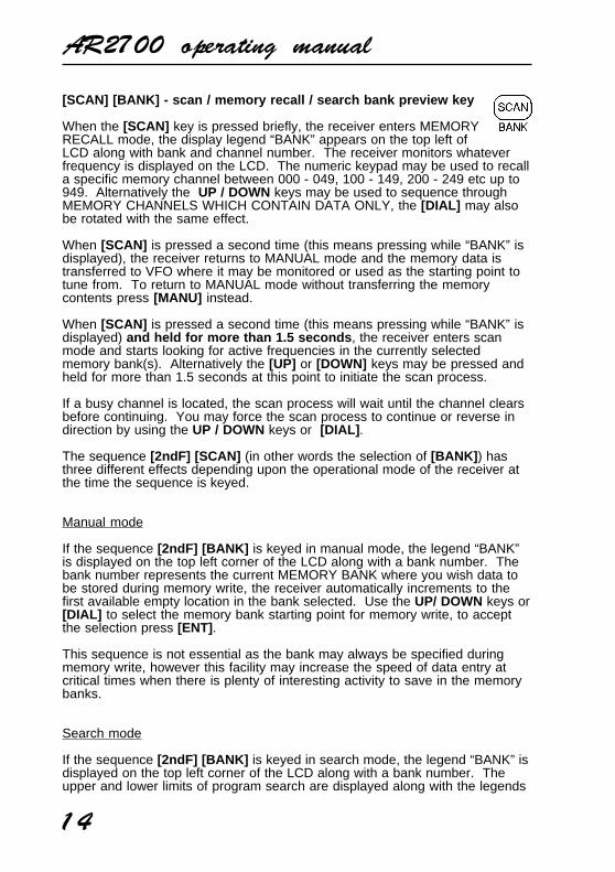
5-6 Liquid Crystal Display (LCD)
The AR2700 uses a high contrast LiquidCrystal Display. Due to its mechanicalconstruction the LCD is best viewed fromdirectly in front of the receiver, a fairlywide viewing angle is still maintained.
The LCD is custom manufactured and haslegends for mode, channel step, banknumber, frequency etc.
A full test pattern may be displayed by holding the [1] key while switching thereceiver On until the set fully powers up. Not all legends are used by theAR2700. To remove the test pattern, briefly press the [PWR] key again.
Attractive green rear illumination of the LCD (and keypad) is switchable for usein locations of low level lighting.
The LCD will provide frequency readout to tens of Hertz (the last digit on theright is used when using 6.25 kHz steps otherwise it will always read “0”).
The lower left corner of the LCD displays a legend “BUSY” to indicate that thesquelch is open. To the right is the signal strength presented as a bar graph.The stronger the signal then the larger the graph, if there is no signal presentthis area of LCD will be blank. It is quite common for a few of the signalmeter segments to appear due to background band noise even when nosignal is present.
5-7 Keypad
The front keypad comprises of twenty press keys laid in a grid four horizontaland five vertical. The keys are multi-function and are used to input frequency

AR2700 operating manual
12
and other operational data in conjunction with the left side panel [2ndF]function key and top panel [DIAL] .
If a key is not pressed within about 30 seconds during data entry, the entry willbe aborted and the receiver will return to the previous display.
Attractive green rear illumination of the front keypad and LCD is switchable foruse in locations of low level lighting.
The basic operational description of each key is as follows:
[PWR] - power On/Off key
When the [PWR] key is pressed and held for more than 1.5 seconds themicroprocessor will switch the receiver On. The requirement of PRESSAND HOLD prevents accidental switch On and Off.

AR2700 operating manual
13
When correctly activated and BEEP enabled, a high pitch bleep will confirmoperation.
To switch the receiver Off simply press and hold the key again for more than1.5 seconds. If the BEEP is enabled and you press the key for too short aperiod, a low pitch beep advises of the error.
The [PWR] switch is not of a common volume control combined arrangementas a SLEEP timer can also switch the receiver Off when programmed andactivated. Resetting the microprocessor from the external reset switch will alsocause the receiver to power On.
The K.LOCK (key lock) switch located on the left side panel preventsaccidental switch On and Off of the receiver. This is an extremely usefulfeature when carrying the set in a coat pocket or bag.
Note: It is quite normal for a click to be heard as the receiver is powered Onand often the lamp will momentarily illuminate. A low level hiss may also beheard from the speaker when in quiet surroundings, this is because the audioamplifier is permanently powered in order to provide fast scan & search ratesand to facilitate a good squelch characteristic. The set may switch On whenchanging batteries or when connecting external power to the receiver, this isnormal and you should be aware of and check for this condition.
[SRCH] [S.PROG] - search & search program key
When the [SRCH] key is first pressed the receiver initiates a thesearch process for one of the programmed search banks. The bankcurrently being searched is indicated by the legends “BANK 1” for example inthe top left hand corner of the LCD and the word “SEARCH” in the centre ofthe top row of the LCD.
If no data is stored in the program search banks, the set will not be able tosearch.
When [SRCH] is pressed a second time during search , the SEARCH processis cancelled and the current search frequency is transferred to the VFOreturning the receiver to MANUAL mode where the frequency may bemonitored or used as the starting point for tuning. As the search process isterminated you may also decide to write the frequency into a memory channelor resume searching again. To return from SEARCH to MANUAL mode andreceive the original frequency without transferring the search frequency press[MANU] .
The key sequence [2ndF] [SRCH] (short press of the [SRCH] key) initiates theprocess for programming the search banks to your own specification offrequency range, step size, attenuator and mode... this is referred to asPROGRAM SEARCH input.
The key sequence [2ndF] [SRCH] (long press of the [SRCH] key for more than1.5 seconds) initiates the process for linking search banks together.
AR2700 operating manual
14
[SCAN] [BANK] - scan / memory recall / search bank preview key
When the [SCAN] key is pressed briefly, the receiver enters MEMORYRECALL mode, the display legend “BANK” appears on the top left ofLCD along with bank and channel number. The receiver monitors whateverfrequency is displayed on the LCD. The numeric keypad may be used to recalla specific memory channel between 000 - 049, 100 - 149, 200 - 249 etc up to949. Alternatively the UP / DOWN keys may be used to sequence throughMEMORY CHANNELS WHICH CONTAIN DATA ONLY, the [DIAL] may alsobe rotated with the same effect.
When [SCAN] is pressed a second time (this means pressing while “BANK” isdisplayed), the receiver returns to MANUAL mode and the memory data istransferred to VFO where it may be monitored or used as the starting point totune from. To return to MANUAL mode without transferring the memorycontents press [MANU] instead.
When [SCAN] is pressed a second time (this means pressing while “BANK” isdisplayed) and held for more than 1.5 seconds , the receiver enters scanmode and starts looking for active frequencies in the currently selectedmemory bank(s). Alternatively the [UP] or [DOWN] keys may be pressed andheld for more than 1.5 seconds at this point to initiate the scan process.
If a busy channel is located, the scan process will wait until the channel clearsbefore continuing. You may force the scan process to continue or reverse indirection by using the UP / DOWN keys or [DIAL] .
The sequence [2ndF] [SCAN] (in other words the selection of [BANK] ) hasthree different effects depending upon the operational mode of the receiver atthe time the sequence is keyed.
Manual mode
If the sequence [2ndF] [BANK] is keyed in manual mode, the legend “BANK”is displayed on the top left corner of the LCD along with a bank number. Thebank number represents the current MEMORY BANK where you wish data tobe stored during memory write, the receiver automatically increments to thefirst available empty location in the bank selected. Use the UP/ DOWN keys or[DIAL] to select the memory bank starting point for memory write, to acceptthe selection press [ENT] .
This sequence is not essential as the bank may always be specified duringmemory write, however this facility may increase the speed of data entry atcritical times when there is plenty of interesting activity to save in the memorybanks.
Search mode
If the sequence [2ndF] [BANK] is keyed in search mode, the legend “BANK” isdisplayed on the top left corner of the LCD along with a bank number. Theupper and lower limits of program search are displayed along with the legends

AR2700 operating manual
15
“HI” and “Lo”. Use the UP / DOWN keys or [DIAL] to select the desiredprogram search bank, pressing [ENT] or [CLR] will cause the receiver tosearch the selected program search bank.
Scan mode
If the sequence [2ndF] [BANK] is keyed in scan mode, the legends “BANK”and “CH” are displayed in the top left corner of the LCD. The receiver willpause on the currently displayed channel for about 30 seconds beforeresuming the scan process again. The UP / DOWN keys, [ENT] key or [DIAL]may be used to force the scan process to resume.
The sequence [2ndF] [SCAN] with the [SCAN] key held for more than 1.5seconds, causes the receiver to enter the SCAN BANK LINK menu regardlessof whether the receiver is in SEARCH, SCAN or MANUAL operational modes.
[MANU] - manual mode
The AR2700 receiver has a manual operational mode often referred toas VFO MODE. The term VFO historically means “Variable FrequencyOscillator” and today refers to a tunable data store which contains frequency,mode, channel step, and attenuator information.
Pressing the [MANU] key places the receiver into a known operationalcondition ready for data entry. The display legend “MANUAL” appears towardthe top right of the LCD. If you are ever unsure what operational mode thereceiver is in, press the [MANU] key.
Manual mode is used for frequency entry, change of mode, general listeningand memory write (data entry - into memory channels and program searchbanks).
The key sequence [2ndF] [MANU] (with the [MANU] key held for more than1.5 seconds) places the receiver into MANUAL SEARCH MODE with thelegend “SEARCH MANUAL” appearing on the top line of the LCD. Thereceiver will search upward or downward from the currently displayedfrequency in whatever mode and channel step selected. The UP / DOWN keysor [DIAL] may be used to reverse the direction of manual search.
The receiver will stop on active channels and the UP / DOWN keys or [DIAL]may be used to force the process to continue passed the busy frequency. Tocancel manual search and monitor the currently displayed frequency press the[MANU] key. (Holding the UP or DOWN keys for more than 1.5 seconds alsoplaces the receiver into manual search mode.
[UP] / MHz / SER - key
The [UP] key is used as a DECIMAL —> • <— during the entry offrequencies during frequency input through the numeric keypad.
AR2700 operating manual
16
For example 133.7 MHz [1] [3] [3] [MHz] [7] [ENT] there is no need to addtrailing zeros. Frequencies below 1 MHz may be preceded by [0] [MHz]frequency then [ENT] .
The [UP] key may be used to force the receiver to continue search / scan froma busy channel and to reverse the direction of search / scan should thereceiver be tracking downward. The key will also act as an upward tuningcontrol just like DIAL.
The key is also used to select menu options under certain circumstances.
The key may be used to place the receiver in manual search mode by pressingand holding the [UP] key for more than 1.5 seconds while in manual mode.
The key sequence [2ndF] [UP] places the receiver in ready condition toCLONE data to another AR2700 connected to an optional CU8232 via theoptional IF-ADP. This facility enables an exact data copy of one receiver to bemade with another possibly belonging to a friend etc. The display “COPySEnd” and a flashing legend “SERIAL” indicates operation.
Use the UP / DOWN keys or [DIAL] to toggle between SEND and RECEIVEmodes, press [ENT] to accept the selection, always select the receive unit first.The first segment of the signal bar graph will appear to confirm operation,as the data transfer progresses so the bar graph will grow to indicate thatthe process is functioning correctly. It will take a few minutes to transferall the data.
The sequence [2ndF] [UP] with the UP key being held for more than 1.5seconds places the receiver into the menu to select the RS232 parameters forconnection to a computer via the optional IF-ADP and CU8232 adaptor andinterface units.
The [DIAL] is used to select the baud rate between 9600, 4800 and 2400 bpsand the UP / DOWN keys select the addition of LF (line feed).
[DOWN] / kHz / SS - key
The [DOWN] key is used as a kHz key during frequency entry andprovides an alternative method of frequency entry to the MHz (decimal)key method.
For example, a frequency of 945 kHz may be entered as [0] [MHz] [9] [4] [5][ENT] or [9] [4] [5] [kHz] [ENT] the later taking one less key press.
This kHz method of entry makes entry from short wave frequency listingsparticularly easy. A listing of 6045 kHz (6.045 MHz) may be entered as[6] [0] [4] [5] [kHz] [ENT]
The [DOWN] key may be used to force the receiver to continue search / scanfrom a busy channel and to reverse the direction of search / scan should thereceiver be tracking upward. The key will also act as an downward tuningcontrol just like DIAL.

AR2700 operating manual
17
The key is also used to select menu options under certain circumstances.
The key may be used to place the receiver in manual search mode by pressingand holding the [DOWN] key for more than 1.5 seconds while in manual mode.
The sequence [2ndF] [DOWN] places the receiver into “SS” descramble mode,refer to the information supplied with the optional printed circuit board, notavailable within the UK.
The sequence [2ndF] [DOWN] with the DOWN key being held for morethan 1.5 seconds places the receiver into “SS” descramble select mode, referto the information supplied with the optional printed circuit board, not availablewithin the UK.
[1] [ATT] Numeric 1 / ATTENUATOR key
This key acts as a numeric 1 when entering frequencies via the keypad.
In search, scan and memory modes this key is used to identify bank 1.
If the sequence [2ndF] [1] is keyed, the attenuator is toggled On/Off. TheATTENUATOR is a useful feature to aid with the reduction of interferencecaused by the presence of strong signals.
[2] [STEP] Numeric 2 / STEP key
This key acts as a numeric 2 when entering frequencies via the keypad.
In search, scan and memory modes this key is used to identify bank 2.
If the sequence [2ndF] [2] is keyed, the tuning STEP size may be selected.
[3] [MODE] Numeric 3 / MODE key
This key acts as a numeric 3 when entering frequencies via the keypad.
In search, scan and memory modes this key is used to identify bank 3.
If the sequence [2ndF] [3] is keyed, the receive MODE may be selected.
[4] [REC/PLAY] Numeric 4 / Record / Play (optional) key
This key acts as a numeric 4 when entering frequencies via thekeypad.
In search, scan and memory modes this key is used to identify bank 4.
AR2700 operating manual
18
If the sequence [2ndF] [4] is keyed, the legend “PLAY” will be displayed on theLCD and a previous 20 second digital recording may be replayed (presumingthat the optional record chip has been fitted). If the optional chip has not beenfitted then white noise will be heard.
The signal meter acts as a “progress meter” to illustrate how much record andplay back time has elapsed.
If the sequence [2ndF] [4] is keyed with the [4] key held for more than 1.5seconds , the legend “REC” will be displayed on the LCD and the currentdisplayed frequency will be recorded for 20 seconds (presuming that theoptional record chip has been fitted).
[5] [SLEEP] Numeric 5 / Sleep key
This key acts as a numeric 5 when entering frequencies via the keypad.
In search, scan and memory modes this key is used to identify bank 5.
If the sequence [2ndF] [5] is keyed, the sleep timer is enabled. A clocklegend will be displayed on the lower right of the LCD and the receiver willautomatically switch Off after the programmed sleep time has elapsed. Tode-activate the sleep timer, key the sequence [2ndF] [5] a second time, theclock legend will be removed from the LCD.
To program the sleep timer between 1 and 120 minutes in one minuteincrements key the sequence [2ndF] [5] with the [5] key held for more than1.5 seconds . The new value may be keyed through the numeric keypad or theUP / DOWN keys may be used or the [DIAL] . To accept the new value press[ENT] .
[6] [DELAY] Numeric 6 / DELAY key
This key acts as a numeric 6 when entering frequencies via the keypad.
In search, scan and memory modes this key is used to identify bank 6.
If the sequence [2ndF] [6] is keyed, the global DELAY (used in search andscan modes) may be programmed by the operator. The delay is the timebetween the frequency becoming clear (squelch closing) and the automaticcontinuation of the search or scan process. The default is 2.0 seconds and theaccepted range is between 0.0 and 9.9 seconds.
The value may be changed by keying in a two digit number via the numerickeypad (the decimal is automatically entered by the microprocessor) or theUP / DOWN keys or [DIAL] may be used to change the value in 0.1 secondincrements. Press [ENT] to accept the new value.
[7] [M.DEL] Numeric 7 / Memory delete key
This key acts as a numeric 7 when entering frequencies via the keypad.
AR2700 operating manual
19
In search, scan and memory modes this key is used to identify bank 7.
If the sequence [2ndF] [7] is keyed while in memory recall mode or whenstopped on a channel during scan, the displayed frequency will be deletedfrom the memory bank and the set will move on to the next memory channelcontaining data (upward or downward depending upon howprogrammed).
Memory channels are usually deleted one at a time. It is possible however todelete a selected bank or all banks, this will be further described later in themanual.
[8] [CH.PASS] Numeric 8 / channel pass key
This key acts as a numeric 8 when entering frequencies via thekeypad.
In search, scan and memory modes this key is used to identify bank 8.
If the sequence [2ndF] [8] is keyed during memory recall mode, the legend“CH PASS” will appear on the LCD to indicate that the channel has beenLOCKED OUT (passed) so that it will not be automatically scanned but will beskipped over.
This is useful for temporarily passing busy channels such as amateur bandrepeaters or broadcast transmissions. The locked out channel may still berecalled and monitored in memory recall mode.
To reinstate the locked out channel repeat the key sequence [2ndF] [8] whilethe desired channel is being displayed. The legend “CH PASS” will beremoved from the LCD.
[9] [PAUSE] Numeric 9 / Pause key
This key acts as a numeric 9 when entering frequencies via the keypad.
In search, scan and memory modes this key is used to identify bank 9.
If the sequence [2ndF] [9] is keyed the global PAUSE facility will be engagedand the legend “PAUSE” will be displayed on the LCD. The pause facility isused in search and scan modes and causes the receiver to wait for aprogrammable period before resuming the search or scan process even if thetransmission continues (when the squelch is still open). This can be veryuseful should unwanted continually active frequencies be encountered or ifanalysing activity.
To program the PAUSE time, key the sequence [2ndF] [9] and hold the [9]key for more than 1.5 seconds . The pause default is 05 seconds and theaccepted range is between 01 and 99 seconds. The value may be changed bykeying in a two digit number via the numeric keypad, or the UP / DOWN keysor [DIAL] may be used to change the value in one second increments. Press[ENT] to accept the new value.

AR2700 operating manual
20
[0] [LAMP] Numeric 0 / Lamp key
This key acts as a numeric 0 when entering frequencies via the keypad.
In search, scan and memory modes this key is used to identify bank 0.
If the sequence [2ndF] [0] is keyed, the LAMP will be switched on for a periodof about five seconds. If you are using the keypad, the five second timer startsfrom the last key press so that you are not inconvenienced in areas of low levellighting by the lamp switching Off while you are keying in data.
It is possible to switch the lamp On permanently using the key sequence[2ndF] [0] with the [0] key help for more than 1.5 seconds . This is usefulfor base station or mobile operation but uses more power so will reduce theoperational time if running from batteries. To switch the lamp Off (if it hasbeen switched permanently On) use the sequence [2ndF] [0] .
[PASS] [BEEP] Frequency pass / beep key
The [PASS] key is used during search to skip unwanted frequencies,these may be permanently active control channel transmissions,broadcast stations, spurii etc. Up to 50 frequencies may be passed inthis way and are held in a list numbered from 00 to 49.
When the search process stops on an active channel press [PASS] . Thefrequency will automatically be assigned to a pass channel and the set willmove on to the next frequency in search mode. If the set fails to respond tothe [PASS] key then all 50 PASS channels have probably been used up andyou will need to delete some in order to make more channels available.
To review the pass list press and hold the [PASS] key for more than 1.5seconds while in MANUAL or SEARCH mode . The legends “CH” and“PASS” will be flashing on the LCD to indicate that the pass list has beenaccessed and the first frequency in the list will be displayed along with its passchannel number “00”.
The list may be reviewed using the UP / DOWN keys or by using the [DIAL] .A pass frequency may be deleted by first displaying the selected frequency inthe pass list then keying [0] [ENT] . The frequency will disappear and the listwill “shuffle down” to fill the gap which has been made. It is also possible todelete the entire list in one go, this will be described later in the manual.
Frequencies may be manually added to the pass list by first displaying thechosen pass channel then keying in a frequency followed by [ENT] , thepass list will increment to the next channel. To escape from the pass listpress [CLR] .
The key sequence [2ndF] [PASS] toggles On and Off the keypad “beep” and“boop” confirmation tones. The beep tones can speed up entry of data via thekeypad as you need to look at the LCD less often. If you have the keylock Onand attempt to access the keypad, the beep low tone “boop” draws attention tothe fact that the keypad is locked.

AR2700 operating manual
21
Should you prefer, it is possible to switch “musical notes” to most of thekeypad keys when the keylock is On. This may be accomplished by holdingdown the [4] key while switching On the receiver by the [PWR] key .
The musical notes are arranged as follows:
[1] FA F3[2] SO G3[3] LA A3[4] TI B3[5] DO C4[6] RE D4[7] MI E4[8] FA F4[9] SO G4[0] LA A4[PASS] TI B4[PRIO] DO C5[DOWN] RE D5[CLR] MI E5[ENT] FA F5
While this may be fun, remember that although very hard wearing, thereis always a degree of aging with mechanical devices such as keypads.It is not too difficult to make up tunes as a party piece... try Twinkle TwinkleLittle Star !!!
[9] [9] [DOWN] [DOWN] [CLR] [CLR] [DOWN][PRIO] [PRIO] [PASS] [PASS] [0] [0] [9][DOWN] [DOWN] [PRIO] [PRIO] [PASS] [PASS] [0][DOWN] [DOWN] [PRIO] [PRIO] [PASS] [PASS] [0][9] [9] [DOWN] [DOWN] [CLR] [CLR] [DOWN][PRIO] [PRIO] [PASS] [PASS] [0] [0] [9]
[PRIO] [PRIO/SET] Priority key
The [PRIO] key is used to select the priority frequency, select thesampling interval and toggle the priority watch On and Off.
To toggle the priority watch On and Off press [PRIO] , a “PRIO” legend appearson the LCD to confirm operation and the priority frequency will be periodicallychecked for activity.
The priority frequency is selected in manual mode using the key sequence[2ndF] [PRIO] , this is referred to as PRIORITY SET.
The priority sampling interval is programmed with the key sequence [2ndF][PRIO] with the [PRIO] key held for more than 1.5 seconds . The range is01 to 19 seconds with the default being 05 seconds. The value may bechanged in one second increments by using the UP / DOWN keys or [DIAL] orby keying in a two digit number via the numeric keypad. The new value isaccepted by pressing [ENT] .

AR2700 operating manual
22
[CLR] - Clear entry key
This key will cause data entry to be cancelled should a mistake beaccidentally typed and forces an escape “back to search, scan or manualmode” whichever had been previously selected. The [CLR] key is also used toescape from the frequency pass menu.
There is no second function for this key.
Should you experience a programming / operational problem with the AR2700,you may “soft” reset the microprocessor by holding the [CLR] key whilepowering up the receiver. Your memory bank and search bank data willremain intact but any linked bank settings etc will be lost. This has the sameeffect as the external soft reset switch on the left hand cabinet... use only as alast resort.
A FULL MICROPROCESSOR reset is accomplished by holding both the[CLR] and [ENT] keys while switching On the unit using the [PWR] key .All memory channels, search banks, pass channels etc will be lost and blank.As a result the search and scan facilities will not operate until new data hasbeen entered. Note: It is quite normal for the set to take about 30 secondsto recover from a FULL reset as all data is being deleted !!!
[ENT] - Enter key
The enter key is used to finalise the entry of frequency and other data inputs.
While in manual mode, press and hold the [ENT] key for more than 1.5seconds to add the currently displayed frequency into memory.
While in SEARCH mode and stopped on a busy channel, press the [ENT] keyto write the current displayed frequency into memory.
The [ENT] key is also used during a FULL microprocessor reset.
5-8 Loudspeaker (internal)
The AR2700 is fitted with an internal front facing loudspeaker toward thelower front cabinet. When an external earphone, headphone or speaker isconnected, the internal speaker is automatically disconnected.
Side panel - left hand side
5-9 [2ndF] Function key
The AR2700 uses a multi-function keyboard. The second function[2ndF] (shift) key is used to access the second key functions as listedunderneath the keypad keys. Other functions may also be accessedusing the function key.

AR2700 operating manual
23
When the function keyis operated, a legend“2ndF” appears in theupper left of the LCD.
The function key shouldbe momentarilypressed only (so thatthe legend “2ndF”appears in the top leftcorner of the LCD)before another numerickey is pressed... do nothold the function keyin while pressingother keys .
5-10 [MONI] monitor(squelch defeat) key
This key isused to defeatthe squelch(open it) toallow the monitoring ofvery weak or flutteringsignals.
5-11 [K.LOCK]keypad lock key
The [K.LOCK]slide switchhas twopositions andis designed to preventaccidental operation ofthe keypad whencarrying the receiver ina pocket or bag.
When the switch is in the down position the keylock is Off. When the switch isslid upward position the keylock is On and the keypad and [DIAL] is disabled(except for the [MONI] key). A special “KEY” graphical legend on the LCDindicates when keylock is On.
5-12 RESET switch
Should you experience a programming / operational problem with theAR2700, you may “soft” reset the microprocessor by momentarilypressing the reset switch located on the left hand cabinet using a pointed
AR2700 operating manual
24
utensil such as a pin, small screwdriver, sharp pencil etc. It does not matterwhether the receiver is switched On or Off at the time. This has the sameeffect as switching the receiver On by the [PWR] key while holding the[CLR] key.
Your memory bank and search bank data will remain intact but any linkedbank settings, etc will be lost. This has the same effect as the external softreset switch on the left hand cabinet... use only as a last resort.
Side panel - right hand side
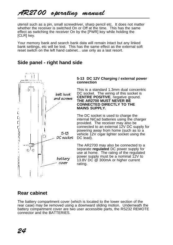
5-13 DC 12V Charging / external powerconnection
This is a standard 1.3mm dual concentricDC socket. The wiring of this socket isCENTRE POSITIVE, negative ground.THE AR2700 MUST NEVER BECONNECTED DIRECTLY TO THEMAINS SUPPLY.
The DC socket is used to charge theinternal NiCad batteries using the chargerprovided. The receiver may also beconnected to an external 12V DC supply forpowering away from home (such as to avehicle 12V cigar lighter socket using theDC lead).
The AR2700 may also be connected to aseparate regulated DC power supply foruse at home. The rating of the regulatedpower supply must be a nominal 12V to13.8V DC @ 300mA or higher currentrating.
Rear cabinet
The battery compartment cover (which is located to the lower section of therear case) may be removed using a downward sliding motion. Underneath thebattery compartment cover are two user accessible parts, the RS232 REMOTEconnector and the BATTERIES.

AR2700 operating manual
25
5-14 RS232C REMOTE connector
This is a very small connector located in thebattery housing, the batteries need to beremoved to permit access. For this reason theuse of the REMOTE CONNECTOR demandsthe use of an external regulated power supply.
The connector is partially hidden from view bythe lower battery near the serial plate and by theangle of the cabinet. An optional adaptor(IF-ADP) and interface (CU8232) is available forcloning (copying) of data between two AR2700receivers and an RS232 lead plus software isrequired for computer control.
5-15 BATTERY compartment
Inside the battery compartment isa cradle designed to accept 4 xUM-3 (AA size) batteries.Carefully note the polarity of thecells (which way around they fit).Either the supplied rechargeableNiCad batteries or high qualitydry batteries may be used.However, never attempt tocharge the receiver or connect toan external power source whendry batteries are fitted.
Always remove dry batterieswhen they have expired (rundown). Should you plan not touse the receiver for a period oftime and have dry batteries fitted,remove the batteries to avoidleakage.
Note: The memory channeldata is held by an internalEEPROM which does notrequire batteries or connection

AR2700 operating manual
26
to external supply. However, always switch the receiver Off whenchanging batteries or connecting / disconnecting external power. Thereceiver may switch On by itself when fitting batteries, this is quitenormal.
(6) Basic manual operation of the receiver
Operating manual conventions
Where text appears in [SQUARE BRACKETS] the keys are to be pressedexactly as shown.
For example: [1] [4] [5] [ENT]
Means press the 1 key followed by the 4 key followed by the 5 key followed bythe ENTER key.
Words contained in speech marks “BANK” refer to indications displayed on theLiquid Crystal Display.
6-1 Before starting
Before operating, charge the internal NiCad batteries using the suppliedcharger for approximately 16 hours. Connect the supplied telescopicwhip aerial to the BNC connector.
Note: When the receiver is switched OFF, all VFO data will be automaticallystored into EEPROM memory storage. No battery or capacitor is required formemory backup.
6-2 Switching On
Set the squelch control to the 12 o’clock position and rotate the volume controlto the 12 o’clock position. Press and hold the [PWR] key for more than 1.5seconds , this will switch the receiver On. It is never a good idea to switch Onthe receiver with an earphone connected, there may be an audible click whenthe unit is switched On or the volume may be accidentally set uncomfortablyhigh.
In normal use, the squelch control should be rotated clockwise until thebackground noise is just cancelled. This is known as “threshold” and is themost sensitive setting for the squelch control. Do not rotate the control too farclockwise or only the stronger local signals will be heard. If you find setting thesquelch control difficult, try removing the aerial from the receiver.
Should you encounter problems in setting the volume level, press the [MONI]key on the left hand panel to momentarily defeat (open) the squelch so that acomfortable volume level may be set.
AR2700 operating manual
27
It is best to press the [MANU] key at thistime to place the receiver in a known stateof operation... MANUAL MODE.
Note: If the keypad or [DIAL] is notoperated for approximately 30 secondswhile inputting data through a selectioninput option, the operation will time outand the receiver will return to its previoustask just as if the [CLR] key had beenpressed.
6-3 Entering a frequency through the keypad - VFO (MANUAL) MODE
When the [MANU] key is pressed, the receiver enters manual mode ready forinput of a frequency or other data. The receiver may also be tuned using the[DIAL] just like a VFO. The term VFO historically means “Variable FrequencyOscillator” and today refers to a tunable data store which contains frequency,mode, step and attenuator information.
Press the [MANU] key to first select “MANUAL” - VFO mode (should thereceiver be scanning or searching etc).
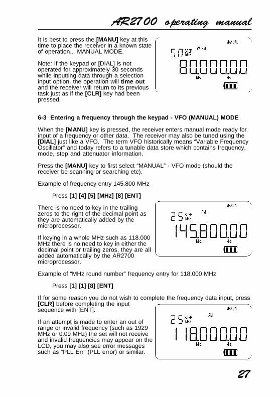
Example of frequency entry 145.800 MHz
Press [1] [4] [5] [MHz] [8] [ENT]
There is no need to key in the trailingzeros to the right of the decimal point asthey are automatically added by themicroprocessor.
If keying in a whole MHz such as 118.000MHz there is no need to key in either thedecimal point or trailing zeros, they are alladded automatically by the AR2700microprocessor.
Example of “MHz round number” frequency entry for 118.000 MHz
Press [1] [1] [8] [ENT]
If for some reason you do not wish to complete the frequency data input, press[CLR] before completing the inputsequence with [ENT].
If an attempt is made to enter an out ofrange or invalid frequency (such as 1929MHz or 0.09 MHz) the set will not receiveand invalid frequencies may appear on theLCD, you may also see error messagessuch as “PLL Err” (PLL error) or similar.

AR2700 operating manual
28
Remember, the frequency coverage is 500 kHz to 1300 MHz with frequenciesaccepted by the microprocessor from 0.1 MHz (100 kHz).
Note: If the keypad or [DIAL] is not operated for approximately 30 secondswhile inputting data, the operation will time out and the receiver will return toits previous task just as if the [CLR] key had been pressed.
Frequencies may also be entered as kHz which is convenient when inputtingdata from a short wave frequency listing.
Example of frequency entry 945 kHz (0.945 MHz)
Press [0] [MHz] [9] [4] [5] [ENT] MHz input
Press [9] [4] [5] [kHz] [ENT] kHz input
The frequency of 945 kHz is equivalent to0.945 MHz and data may be entered ineither format.
You will note that frequencies below 1.6MHz (1600 kHz) will not have a decimalpoint displayed to the right of the “MHz”position, this is to ensure easy recognitionof frequencies which are often listed as“kHz” in frequency guides. Instead, thedecimal point is positioned to the right of the kHz position
Another example of frequency entry 1215 kHz (1.215 MHz)
Press [1] [2] [1] [5] [kHz] [ENT]
The frequency of 1215 kHz is equivalent to1.215 MHz.
PROG: If the frequency displaychanges when the [ENT] key ispressed, then an inappropriate stepsize has been selected. The AR2700has an automatic bandplan lookuptable so that an appropriate step size and mode should be selected.It is possible to override this PROGRAM data by simply selecting adifferent step size or mode. As a rule of thumb, the displayed frequencymust be exactly divisible by the step size.
6-4 Correcting frequency input
Should an error be made while entering frequency data (by pressing the wrongnumeric key), you may abort the entry by using the [CLR] key and typing thefrequency again followed by [ENT] .

AR2700 operating manual
29
6-5 Changing frequency using the [UP] [DOWN] keys and [DIAL]
The UP / DOWN keys provide a convenient method of frequency change,alternatively the [DIAL] may be rotated.
The speed at which the receiver steps up or down depends upon the STEPSIZE which is default to PROG (automatically set from the lookup table). It ispossible to override the PROGRAM default using the [STEP] key. Availablestep sizes are:
NFM & AM : 5kHz, 6.25kHz, 9kHz, 10kHz, 12.5kHz, 20kHz, 25kHz,30kHz, 50kHz & 100kHz.
WFM: 50kHz & 100kHz.
If the STEP SIZE / MODE is set to PROGRAM, the mode and channel step willautomatically change as you tune through the various amateur, broadcast andutility bands.
The [DIAL] method of frequency selection is the most traditional approach tolocating signals particularly on the short wave and medium wave bands. Itprovides an easy method to locate new or previously unknown frequencies orto check activity within certain frequency bands such as amateur or shortwavebroadcast. The rotary tuning [DIAL] provides the very best “user interface”with the AR2700.
Rotating the [DIAL] clockwise increases frequency while rotationanti-clockwise decreases receive frequency. Being a mechanical device, it isnot unusual for the [DIAL] to missoccasional tuning increments whenrotating.
Should you press and hold either the[UP] or [DOWN] key for more than 1.5seconds while the squelch is closed, thereceiver will begin to MANUALLYSEARCH from the displayed frequencylooking for active frequencies. Press[MANU] to cancel the process.
6-6 Changing frequency STEP size (PROGRAM)
The specification for channel occupancy, step (separation) and mode aredecided by and allocated by departments of Government followingInternational discussions.
Not surprisingly the allocation of frequency bands are not the same all over theworld and channel separation (step) varies from band to band. As an examplethe channel separation (step) for the medium wave band in Europe is 9 kHzwhile in the U.S.A. it is 10 kHz.
For the above reasons it is necessary to alter the STEP size according to local

AR2700 operating manual
30
bandplan conventions. The AR2700 has been pre-programmed at the factorywith all the bandplan data (specific to each market area) so that the AR2700will automatically select the appropriate step size and mode for the frequencychosen. This greatly simplifies operation of the receiver while you arefamiliarising yourself with all the facilities.
The pre-programming of step size may be manually overridden so you maychoose alternative settings at will or when bandplans are updated.
Should you wish to change the default step size press [2ndF] [2] . The legend“STEP kHz” will flash on the LCD to indicate that the receiver is expecting achange of step size. If the legend “PROG” is displayed on the top row of theLCD then the step size is currently set to the automatic PROGRAM default. Itis possible to override the PROGRAM default. Available step sizes are:
NFM & AM : 5kHz, 6.25kHz, 9kHz, 10kHz, 12.5kHz, 20kHz, 25kHz,30kHz, 50kHz & 100kHz.
WFM: 50kHz & 100kHz.
Use the UP / DOWN keys or [DIAL] to change the step size selection which isdisplayed to the left of the flashing “STEP kHz” legend. When you have madethe new selection press [ENT] . Should you choose not to change the setting,press [CLR] .
Once you have changed the step settingfrom PROGRAM it may only be reinstatedby selecting “PROG” in the mode inputusing the sequence [2ndF] [3] (mode).
There is just one small point to remember,the active frequency must be divisible bythe step size... in 99% of cases theywill be. However, should you startexperimenting with different step sizes youmay notice the active frequency change automatically to the nearest multiple ofstep size as the AR2700 calculates automatically for you, there is no need tocarry a calculator!
For example, select 118.000 MHz [1] [1] [8] [ENT] then select a 9 kHz stepsize [2ndF] [2] choose “9.00” by rotating the [DIAL] and accept the selectionby pressing [ENT] .
You will note the frequency has been corrected to 117.99900 or 118.00800MHz (depending upon the previousdirection of tuning / searching) both ofwhich are the closest multiple of 9 kHz to118 MHz.
Note: PROGRAM-STEP andPROGRAM-MODE are linked to thepre-programmed bandplan data. Whenone of the parameters is changed from thedefault “PROG” the bandplan will be
AR2700 operating manual
31
ignored. This is useful for tuning through bands with unusual modes andchannel steps.
To reinstate PROGRAM step size, the receive MODE must be returned to“PROG” using the “MODE SET” input sequence which is accessed bypressing [2ndF] [3] .
6-7 Changing receive mode (PROGRAM)
As mentioned earlier (section 6-6 of this manual), the specification for step andmode are allocated by departments of Government following Internationaldiscussions. Like step size, the receive mode has been pre-programmed atthe factory to simplify operation of the receiver while you familiarise yourselfwith all the facilities.
The defaults may be manually overridden at any time should you wish to selectan alternative receive mode on any frequency.
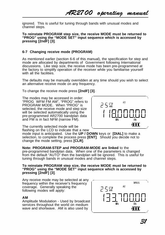
To change the receive mode press [2ndF] [3] .
The modes may be accessed in order:“PROG WFM FM AM”, “PROG” refers toPROGRAM MODE. When “PROG” isselected, the receive mode and step sizewill be selected automatically using thepre-programmed AR2700 bandplan dataand FM is in fact NFM (narrow FM).
The currently selected mode will beflashing on the LCD to indicate that a newmode input is anticipated. Use the UP / DOWN keys or [DIAL] to make aselection, to complete the process press [ENT] . Should you decide not tochange the mode setting, press [CLR] .
Note: PROGRAM-STEP and PROGRAM-MODE are linked to thepre-programmed bandplan data. When one of the parameters is changedfrom the default “AUTO” then the bandplan will be ignored. This is useful fortuning through bands in unusual modes and channel steps.
To reinstate PROGRAM step size, the receive MODE must be returned to“PROG” using the “MODE SET” input sequence which is accessed bypressing [2ndF] [3] .
Any receive mode may be selected at anyfrequency within the receiver’s frequencycoverage. Generally speaking thefollowing modes will apply:
AMAmplitude Modulation - Used by broadcastservices throughout the world on mediumwave and shortwave. AM is also used by

AR2700 operating manual
32
VHF Civil airband, UHF Military airband and some PMR (Private Mobile Radio)and utility services.
FM (NFM)Narrow Band Frequency Modulation - this provides high quality communicationfor relatively short distance operation. NFM is the most common mode usedabove 30 MHz with the exception of the airbands. NFM is widely used on theVHF bands: VHF Marine band, 2m amateur Band (145MHz), 70cm amateurband (433 MHz), PMR (Private Mobile Radio) and utilities.
In the absence of a signal, the backgroundwhite noise may appear quite loud. Forease of listening the squelch controlshould be rotated clockwise until thebackground noise just disappears, thisshould be carried out when no signal ispresent. The point where the backgroundnoise is cancelled is known as “thresholdpoint”. Do not advance the squelchcontrol more than necessary or thereceiver will appear to be desensitised andweaker signals will be missed.
WFMWide band Frequency Modulation - usedby VHF and UHF broadcast stations asexcellent audio quality is available due tothe relatively wide frequency bandwidthemployed. Used only for local servicessuch as VHF band-2 stereo (received asmono on the AR2700) and UHF TV soundchannels.
When listening in VERY strong signal locations especially when using anexternal aerial, the WFM I.F. amplifier may be overloaded. This will notdamage the AR2700 but may result in “apparent signal loss”. Should this beencountered, use the attenuator to reduce signal strength or swap to thestandard telescopic whip aerial.
6-8 [ATT] Attenuator ON/OFF
The attenuator adds 10dB of signal reduction to the RF input stages ofthe AR2700 to reduce the possible effects of signal overloading due toconnection to an external aerial or when the receiver is used in closeproximity to strong transmissions.
The AR2700 has two settings for ATT (attenuator), On and Off. When theattenuator is On, the legend “ATT” appears on the top left line of the LCD.
To toggle the attenuator On/Off while in MANUAL mode press [2ndF] [1] thelegend “ATT” confirms selection and incoming signals will be reduced instrength. To toggle On/Off again just repeat the sequence [2ndF] [1] , the

AR2700 operating manual
33
legend “ATT” is extinguished when the attenuator is Off.
The selection of attenuator may also be programmed into memory channelsand when defining program search.
(7) Memory banks & channels
It is very convenient to store commonly used frequencies into a memory bankalong with mode and attenuator status, this saves having to key the data inover and over again. Memory recall is very straight forward and quick whencompared to retyping all data.
Think of memory channels as pages in a notebook each of which is numberedto identify it. Data may be written to each new page (memory channel) andeach page may be overwritten with new data, they can be used over and overagain.
Each memory channel may hold one frequency, mode, attenuator setting,and step data. A total of 500 memory channels are provided which aredivided into 10 banks, each having 50 channels. The memory banks areidentified by the numbers 0, 1, 2, 3, 4, 5, 6, 7, 8, & 9.
Examples are “000” for the first channellocation in memory bank “0” and “049” forthe last memory channel in memory bank“0”.
“415” is the location of memory bank “4”channel “15”.
The data contents of memory and searchbanks are held in an EEPROM so that nobackup battery or capacitor is required formemory retention.
The stored data may be quickly and easily recalled, changed or deleted byre-entry, memory recall, and memory delete.
During the manufacture and testing of the receiver, various test frequencies areentered into the receiver’s memory banks so the memory locations are unlikelyto be completely blank.
Note: Where memory banks etc are empty the indication “- - -” is oftendisplayed.
7-1 Storing receive data into memory - memory input in MANUAL mode
For example, to store the frequency of 88.3 MHz with the attenuator Off intomemory bank “0” location “00” (000) while in MANUAL mode.

AR2700 operating manual
34
Start by selecting MANUAL mode (the [MANU] key) then key in the frequencyof 88.3 MHz, “mode and step size” are set to the default of PROGRAM.
[MANU] to place the receiver into MANUAL mode
[8] [8] [MHz] [3] [ENT] to select the desired frequency, themode and step size will be automatically set by the AR2700microprocessor.
Press and hold the [ENT] key for more than 1.5 seconds to entermemory input mode .
The legend “BANK” and “CH” will appearon the LCD and start to flash to indicatethat memory write is in progress. The firstavailable empty memory bank andchannel number will be displayed alongwith an alternating “- - - -” legend andfrequency to show that no data is currentlystored in the memory location.
To select "BANK 0" "CHANNEL 00" type[0] [0] [0] alternatively the UP / DOWN keys will allow selection of BANK andthe [DIAL] will allow selection of channel number. If data is already stored inlocation “000”, the existing frequency will be alternatively displayed along withthe new frequency to be stored... this is a warning just in case you are about tooverwrite important memory data.
There is no need to first delete thecontents of the memory channel, they maybe simply over-written. Press [ENT] towrite the new data to memory location“000”. The frequency, mode, channel stepand attenuator status will be stored.
Remember, if you take too longentering data (approximately 30seconds) the display will revert to itsoriginal condition (MANUAL mode) .
At any time you may abort the memory input by pressing the [CLR] key, thedisplay will return to MANUAL mode.
7-2 Automatic memory incrementation
Once you have written data to a memory channel, the next entry will beautomatically incremented by one channel. If for example you last stored datato memory location “000” then the next time you press and hold the [ENT] keythe set will move to memory location “001” unless it already holds data inwhich case it will move upward sequentially to the first available emptymemory location.

AR2700 operating manual
35
If you had previously written memorydata to location “315”, then themicroprocessor will automaticallyincrement to location “316” or the firstavailable empty memory channel. Themicroprocessor will always select thebank number last used unless otherwisespecified.
Should you wish, you may instruct themicroprocessor to “offer” an alternative bank or review the current setting.While in MANUAL mode use the sequence [2ndF] [SCAN] (the secondfunction being labelled as BANK. Use the UP / DOWN keys, [DIAL] ornumeric keypad to select an alternative bank then press [ENT] .
As you may force a bank / channel location during memory write, the abovefacility is not essential but provides a better understanding as to how thememory system operates.
7-3 Memory recall - Recalling receive data from memory
Once receive frequency and mode data has been stored into a memorylocation, its retrieval is quick and simple.
For example to retrieve the frequency of 88.3 MHz which has been pro-grammed into to memory location “000” during the example in the precedingsection of this manual...
Press [SCAN] to place the receiver into memory recall mode . The legend“BANK” and “CH” appears on the top left of the LCD to confirm operation.
The receiver will display a memory channel, mode and frequency. If thedesired memory channel is not immediately displayed it may be RECALLED bykeying in the required location.
To recall memory channel “000” while inmemory recall mode, type [0] [0] [0] thereis no need to press [ENT] .
The receiver will monitor whatevermemory channel first appeared when youentered memory recall mode or your newselection.
Memory channel review / hunt
The UP / DOWN keys and [DIAL] may be used to review, hunt for and selectmemory channels.
From MANUAL mode press [SCAN] to enter memory recall mode then use theUP / DOWN keys or rotate the [DIAL] to select the required memory channel.
AR2700 operating manual
36
This is a useful tool for reviewing memory contents and hunting for a specificchannel when you forget where you stored it! Should you know the number ofthe required memory channel, the keypad method of memory recall will bemuch faster.
7-4 Transfer of memory channel to VFO
Should you wish to tune away from the memory channel and benefit from nothaving to re-enter the frequency, mode, attenuator setting, channel and step,the data may be quickly transferred from memory to VFO for tuning inMANUAL mode.
To transfer the currently displayed memory channel to VFO simply press[SCAN] . The transferred frequency may be tuned using the UP / DOWN keysor [DIAL] , the tuning step will have also been transferred from memory alongwith mode.
If you wish to return to the previous MANUAL VFO frequency rather thantransfer memory to VFO press [MANU] instead of [SCAN].
7-5 Memory over-write
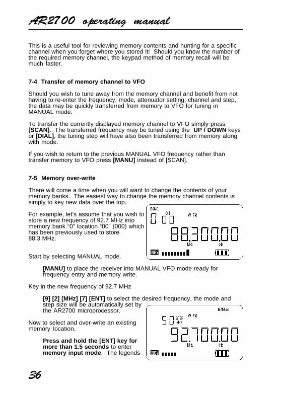
There will come a time when you will want to change the contents of yourmemory banks. The easiest way to change the memory channel contents issimply to key new data over the top.
For example, let’s assume that you wish tostore a new frequency of 92.7 MHz intomemory bank “0” location “00” (000) whichhas been previously used to store88.3 MHz.
Start by selecting MANUAL mode.
[MANU] to place the receiver into MANUAL VFO mode ready forfrequency entry and memory write.
Key in the new frequency of 92.7 MHz
[9] [2] [MHz] [7] [ENT] to select the desired frequency, the mode andstep size will be automatically set bythe AR2700 microprocessor.
Now to select and over-write an existingmemory location.
Press and hold the [ENT] key formore than 1.5 seconds to entermemory input mode . The legends

AR2700 operating manual
37
“BANK” and “CH” will flash to indicate that memory input is in progress.
Press [0] [0] [0] to select the memory location you wish to over-write(000), the stored frequency and new frequency data will alternately flashon the LCD.
Press [ENT] to over-write memorylocation “000”. The data will bestored and the display will return toMANUAL mode.
At any time you may abort the memoryinput by pressing the [CLR] key, thedisplay will return to MANUAL mode.
7-6 [M.DEL] - deleting individual memory channels and banks
The deletion of memory data presumes that you have previously programmedmemory channels which you now wish to delete! Once you have deletedmemory channel and memory bank data it cannot be restored so follow the keysequence carefully.
If the sequence [2ndF] [7] is keyed while in memory recall mode or whenstopped on a channel during scan mode, the displayed frequency will bedeleted from the memory bank and the set will move on to the next memorychannel containing data (upward or downward depending upon howprogrammed).
For example, to delete memory channel “000” (Bank 0, CHANNEL 00).Press [SCAN] to enter MEMORY RECALL MODE. Key in the desiredmemory channel which is to be deleted [0] [0] [0] . Key the sequence[2ndF] [7] to delete memory channel “000”.
The set will remain in memory recall mode and increment to the next channelwhich contains data. To delete the current channel just key [2ndF] [7] . Toreturn to MANUAL mode press [MANU] .
It is only possible DELETE ALL THE MEMORY DATA FROM A SPECIFICBANK by first selecting the memory bank (using [2ndF] [SCAN] [DIAL] [ENT])while in manual mode, switching the receiver Off, then switching the receiverOn again while holding the [7] key.
For example, press [MANU] to place thereceiver in memory recall mode. Press[2ndF] [SCAN] then select the desiredmemory bank to be deleted using the UP /DOWN keys, [DIAL] or numeric keypad.To accept the selection press [ENT] . Nowpower the set Off by pressing andholding the [PWR] key for more than1.5 seconds . Switch the receiver backOn by pressing and holding the [PWR]
AR2700 operating manual
38
key for more than 1.5 seconds and at the same time holding the [7] key .Release both keys and the display will remain blank for about 2 or 3 seconds.The receiver will power up and the selected memory bank data will have beendeleted. It is also possible to delete ALL programmed data by fully resettingthe microprocessor, this will delete all memory, search, pass data etc.
A FULL MICROPROCESSOR reset is accomplished by holding both the[CLR] and [ENT] keys while switching On the unit using the [PWR] key .All memory channels, search banks, pass channels etc will be lost and blank.As a result the search and scan facilities will not operate until new data hasbeen entered. Note: It is quite normal for the set to take about 30 secondsto recover from a FULL reset as all data has to be deleted !!!
(8) Priority operation
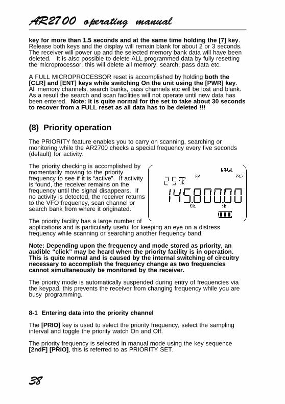
The PRIORITY feature enables you to carry on scanning, searching ormonitoring while the AR2700 checks a special frequency every five seconds(default) for activity.
The priority checking is accomplished bymomentarily moving to the priorityfrequency to see if it is “active”. If activityis found, the receiver remains on thefrequency until the signal disappears. Ifno activity is detected, the receiver returnsto the VFO frequency, scan channel orsearch bank from where it originated.
The priority facility has a large number ofapplications and is particularly useful for keeping an eye on a distressfrequency while scanning or searching another frequency band.
Note: Depending upon the frequency and mode stored as priority, anaudible “click” may be heard when the priority facility is in operation.This is quite normal and is caused by the internal switching of circuitrynecessary to accomplish the frequency change as two frequenciescannot simultaneously be monitored by the receiver.
The priority mode is automatically suspended during entry of frequencies viathe keypad, this prevents the receiver from changing frequency while you arebusy programming.
8-1 Entering data into the priority channel
The [PRIO] key is used to select the priority frequency, select the samplinginterval and toggle the priority watch On and Off.
The priority frequency is selected in manual mode using the key sequence[2ndF] [PRIO] , this is referred to as PRIORITY SET.

AR2700 operating manual
39
For example, to set the frequency 145.500 MHz as the priority channel:
First ensure that the receiver is in manualmode by checking that the legend“MANUAL” is displayed on the LCD or bypressing [MANU] .
Enter the required frequency [1] [4] [5][MHz] [5] [ENT] .
Transfer the displayed data to the prioritychannel using the key sequence [2ndF][PRIO] .
8-2 Activating & deactivating priority
To toggle the priority watch On and Offpress [PRIO] , a “PRIO” legend appears onthe LCD to confirm that priority is activeand the priority frequency will beperiodically checked for activity regardlessof whether the receiver is in MANUAL,SCAN or SEARCH mode. The prioritychannel will be checked for activity even ifthe current frequency being monitored isactive.
The receiver will return to its previous operation only when the activity on thepriority channel has cleared and the squelch closed.
8-3 Programming priority sampling interval
The priority sampling interval is defaulted to five seconds. The programmablerange is 01 to 19 seconds.
The interval time is programmed with thekey sequence [2ndF] [PRIO] with the[PRIO] key held for more than 1.5seconds . The value may be changed inone second increments by using theUP / DOWN keys or [DIAL] or by keyingin a two digit number via the numerickeypad. The new value is accepted bypressing [ENT] .
AR2700 operating manual
40
(9) SCAN - scanning memory channels & banks
The AR2700 has a SCAN mode whereby the contents stored in the MEMORYCHANNELS ARE AUTOMATICALLY RECALLED AND MONITORED veryquickly for activity - scanned.
* It is important that you do not confuse SCAN and SEARCH modes. *SEARCH mode (covered later in this manual) automatically TUNES THERECEIVER THROUGH ALL FREQUENCIES between two specified frequencylimits looking for active frequencies.
9-1 Starting to SCAN, considerations...
It is presumed that you have already stored your favourite and commonly usedfrequencies into the memory banks (as per section 7 of this manual).
A total of 500 memory channels are provided which are divided into 10 banks,each having 50 channels. The memory banks are identified by the numbers0,1,2,3,4,5,6,7,8 & 9 and channels numbered from 00 to 49.
Keep your memory banks tidy - for best scan speed
In order to achieve the maximum scanning speed, it is advisable to keep allsimilar frequencies and modes grouped together within the memory banks.
The greater the frequency change between memory channels, then the furtherthe receiver’s VCO (Voltage Controlled Oscillator) has to travel and the slowerthe scan rates. Similarly, when many changes of mode are called for the moreswitching has to be accomplished and the scan speed may be reduced.Memory channel data may be entered in duplicate into several channels.This will ensure the channel data is scanned more frequently to increasethe chances of activity being detected.
Should a number of different modes and wide range of frequencies be used,then the SCAN process may be affected by noise or differences in squelchcharacteristic on some frequencies and modes.
9-2 SCANNING a memory bank...
For example, to SCAN the contents of memory bank “0” (channels 00-49)which have been previously stored with memory data.
There are two ways to start scanning:
Firstly
From “MANUAL” or “SEARCH” modes:
Press [SCAN] to enter “MEMORY RECALL” mode then press [SCAN]again and hold the key for more than 1.5 seconds to initiate the scan

AR2700 operating manual
41
process. Alternatively, the UP /DOWN key may take the place of thesecond [SCAN] key press.
Secondly
From “MEMORY RECALL” mode:
Press [SCAN] once holding the key for more than 1.5 seconds toinitiate the scan process. Alternatively, the UP / DOWN key may take theplace of the [SCAN] key press.
To reverse the direction of SCAN press either the [UP] or [DOWN] key orrotate the [DIAL] .
The legend “SCAN” is displayed on the top row of the LCD to indicate that theSCAN process has been initiated.
When SCAN has been selected, ALL MEMORY CHANNELS WHICHCONTAIN DATA in the memory will be SCANNED irrespective of mode andfrequency. ANY BLANK (empty) MEMORY CHANNELS which contain no datawill be ignored (skipped).
The memory bank identifier (such as “0”) will be displayed on the left of theLCD with channel numbers changing.
When an “active” channel has beenlocated (busy so the squelch opens) thescan process will temporarily pause on theactive channel and the memory location(such as “123”) will be displayed on theLCD.
Finally when the channel becomes clearagain (the signal disappears) and squelchcloses, the receiver will wait for anadditional two seconds (default delay) toallow for a reply on the channel before resuming the scanning process.
To force the receiver to pause on a memory channel for about 30 seconds,press [2ndF] [SCAN] .
To cancel the SCAN process and return to the VFO’s previous frequencywithout transferring the contents of the memory channel press [MANU] .
9-3 Memory transfer to VFO
When stopped on an active channel or when using memory recall, press[SCAN] to transfer the memory data (frequency, mode, step & attenuator) tothe VFO and the receiver will change to MANUAL MODE where you may tune
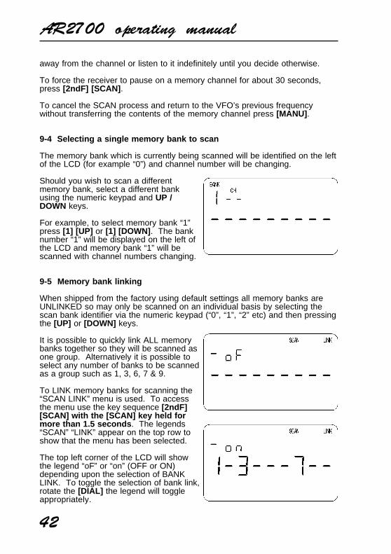
AR2700 operating manual
42
away from the channel or listen to it indefinitely until you decide otherwise.
To force the receiver to pause on a memory channel for about 30 seconds,press [2ndF] [SCAN] .
To cancel the SCAN process and return to the VFO’s previous frequencywithout transferring the contents of the memory channel press [MANU] .
9-4 Selecting a single memory bank to scan
The memory bank which is currently being scanned will be identified on the leftof the LCD (for example “0”) and channel number will be changing.
Should you wish to scan a differentmemory bank, select a different bankusing the numeric keypad and UP /DOWN keys.
For example, to select memory bank “1”press [1] [UP] or [1] [DOWN] . The banknumber “1” will be displayed on the left ofthe LCD and memory bank “1” will bescanned with channel numbers changing.
9-5 Memory bank linking
When shipped from the factory using default settings all memory banks areUNLINKED so may only be scanned on an individual basis by selecting thescan bank identifier via the numeric keypad (“0”, “1”, “2” etc) and then pressingthe [UP] or [DOWN] keys.
It is possible to quickly link ALL memorybanks together so they will be scanned asone group. Alternatively it is possible toselect any number of banks to be scannedas a group such as 1, 3, 6, 7 & 9.
To LINK memory banks for scanning the“SCAN LINK” menu is used. To accessthe menu use the key sequence [2ndF][SCAN] with the [SCAN] key held formore than 1.5 seconds . The legends“SCAN” “LINK” appear on the top row toshow that the menu has been selected.
The top left corner of the LCD will showthe legend “oF” or “on” (OFF or ON)depending upon the selection of BANKLINK. To toggle the selection of bank link,rotate the [DIAL] the legend will toggleappropriately.

AR2700 operating manual
43
The left of the “oF / on” legend and lower row of the LCD provide places for allten scan banks. To add more banks to the bank link list simply press theappropriate identifying scan bank number using the numeric keypad, thenumber legends will toggle On and Off... the legend “ - “ depicting Off(unselected).
To accept the new list and setting press [ENT] .
The next time the receiver enters SCAN MODE with bank link specified as On,the legend “SCAN” “LINK” will be displayed and a group of scan banks will bescanned together as one large group.
9-6 Scanning a memory bank which is not selected in BANK LINK
It is still possible to SCAN a single deselected bank by manually bypassing theBANK LINK programming. To SCAN any deselected bank simply key thedesired identifying bank number through the keypad and press either the [UP]or [DOWN] key.
Only the scan bank manually selected will be scanned.
9-7 SCAN channel PASS - CH PASS (lockout), general outline
Should the AR2700 stop on an active channel while scanning and for somereason you do not wish to monitor it any longer, simply press the UP / DOWNkeys or rotate the [DIAL] to force the SCAN process to resume in the directionselected.
However, should the receiver continually stop on the same channel you maywish to PASS (lockout) the channel so that it will be skipped over when thebank is next scanned.
Memory scan channels may be PASSED (locket out) either when the receiverstops in scan mode (when they are active and the receiver has stoppedscanning) or by recalling them in memory recall mode.
9-8 Memory scan PASS while scanning
To PASS a channel when scanning, wait for the channel to become active thenpress [2ndF] [8] . The legend “CH PASS” will be added above and to the left ofthe LCD to indicate that the channel has been locked out and the scan processwill move on to the next channel. This process will happen so quickly thatyou will not see the “CH PASS” legend being added. However, shouldthe memory channel subsequently be recalled using memory recall, the“CH PASS” legend will be displayed to signify CHANNEL PASS.
9-9 Memory CHANNEL PASS & review using Memory Recall mode
Memory scan channels may be “tagged” for “PASS”, un-tagged or reviewedusing memory recall mode.
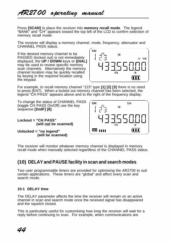
AR2700 operating manual
44
Press [SCAN] to place the receiver into memory recall mode . The legend“BANK” and “CH” appears toward the top left of the LCD to confirm selection ofmemory recall mode.
The receiver will display a memory channel, mode, frequency, attenuator andCHANNEL PASS status.
If the desired memory channel to bePASSED (locked out) is not immediatelydisplayed, the UP / DOWN keys or [DIAL]may be used to review specific memoryscan channels. Alternatively the memorychannel location may be quickly recalledby keying in the required location usingthe keypad.
For example, to recall memory channel “123” type [1] [2] [3] there is no needto press [ENT]. When a locked out memory channel has been selected, thelegend “CH PASS” appears above and to the right of the frequency display.
To change the status of CHANNEL PASS(toggle CH PASS On/Off) use the keysequence [2ndF] [8] .
Lockout = “CH PASS” (will not be scanned)
Unlocked = “no legend” (will be scanned)
The receiver will monitor whatever memory channel is displayed in memoryrecall mode when manually selected regardless of the CHANNEL PASS status.
(10) DELAY and PAUSE facility in scan and search modes
Two user programmable timers are provided for optimising the AR2700 to suitcertain applications. These timers are “global” and affect every scan andsearch mode.
10-1 DELAY time
The DELAY parameter affects the time the receiver will remain on an activechannel in scan and search mode once the received signal has disappearedand the squelch closed.
This is particularly useful for customising how long the receiver will wait for areply before continuing to scan. For example, when communications are

AR2700 operating manual
45
passed back-and-fore between a control tower / aircraft which may take a fewseconds. If you are scanning duplex channels then a small delay or no delayat all may be preferable.
The limits are 0.0 to 9.9 seconds with 0.0 being interpreted as DELAY OFF.The default is 2.0 seconds.
To access the menu to change the delaytime press [2ndF] [6] . The legend“SEARCH SCAN” appears on the top lineof the LCD with the flashing legend“DELAY” centrally positioned to the left ofa two digit number, at default this numberwill be 2.0
The value may be changed by keying in atwo digit number via the numeric keypad(the decimal is automatically entered by the microprocessor) or the UP /DOWN keys or [DIAL] may be used to change the value in 0.1 secondincrements. Press [ENT] to accept the new value.
Note: Setting DELAY to 0.0 turns the delay OFF. Under this condition,the receiver may start to scan before the transmission has finished dueto signal level changes such as mobile flutter or signal fading.
10-2 PAUSE time
The PAUSE parameter determines how long the receiver will remain on an“active” channel before resuming scanning channels or searching.
This is useful if you wish to gain a picture of what is happening without thereceiver being tied to a busy frequency for long periods of time (such as whenmonitoring active amateur band repeaters etc). PAUSE saves you having tomanually intervene to force the scan or search process to continue or usePASS channels.
The limits are 01 to 99 seconds with the default being 05 . It is also possibleto switch PAUSE Off.
If the sequence [2ndF] [9] is keyed the global PAUSE facility will be engagedand the legend “PAUSE” will be displayed on the LCD. To toggle the pausefacility to Off simply repeat the key sequence [2ndF] [9] .
To program the pause delay time, key thesequence [2ndF] [9] and hold the [9] keyfor more than 1.5 seconds . The valuemay be changed by keying in a two digitnumber via the numeric keypad or theUP / DOWN keys or [DIAL] may be usedto change the value in one secondincrements. Press [ENT] to accept thenew value.

AR2700 operating manual
46
(11) SEARCH - manual & program search banks and PASS
The AR2700 has a SEARCH mode whereby an upper and lower frequencylimit may be defined and the receiver instructed to look for activity on allfrequencies in selected step size and mode in an upward or downwarddirection.
The mode and channel step will change automatically when set to the defaultof PROGRAM “PROG” but data may be specified specifically if preferred.
* It is important that you do not confuse SEARCH and SCAN modes. *
SEARCH mode automatically TUNES THE RECEIVER THROUGH ALLFREQUENCIES between two specified frequency limits looking for activefrequencies. SCAN mode automatically recalls and monitors SPECIFIC SPOTFREQUENCIES which have been stored into memory.
The great advantage of SEARCH over manual tuning is that it is so fast! Thereare many different options available for SEARCH mode which will be explainedin this section.
The search instructions may be programmed into banks. There are a total of10 programmable search banks so that data entry and recall is simple andefficient.
Continuously active or busy frequencies such as amateur band repeaters maybe PASSED (skipped) and active frequencies stored to memory.
When the receiver stops on a genuine active frequency during search, the[SRCH] key may be pressed to transfer the frequency to VFO where it may bemonitored for long periods of time or tuned. Pressing [ENT] for more than1.5 seconds will initiate the process of storing the frequency into a memorychannel.
Limitations of SEARCH mode
SEARCH mode is extremely effective for AM & NFM use in the VHF and UHFbands. Searching the shortwave bands is usually ineffective due to therelatively high background and in-band noise especially when propagationconditions are good and bands open.
11-1 Manual SEARCH
The simplest form of SEARCH is achieved by programming a frequency whilein MANUAL MODE then press and hold the [UP] or [DOWN] key for morethan 1.5 seconds . The legend “SEARCH” and “MANUAL” will be displayed onthe LCD to indicate that a MANUAL SEARCH is in progress and the set willstart to tune upwards or downward depending upon which key had been used.

AR2700 operating manual
47
The search process takes place from thedisplayed frequency using the receivemode and step size displayed.If the default mode of PROGRAM “PROG”has been selected, then the receivemode and channel step will changeautomatically depending upon theautomatic bandplan data programmedinto the AR2700 during manufacture.
Example of manual searchFor example, to search manually from145.000 MHz key [1] [4] [5] [ENT] inMANUAL mode then press and hold the[UP] key for more than 1.5 seconds .
Changing the direction of manual searchDepending upon the key used to initiatethe MANUAL SEARCH, the receiver maybe automatically searching upward or downward. The direction of search maybe reversed by rotating the [DIAL] or using the UP / DOWN keys.
Moving on from active frequenciesShould the receiver stop on an active frequency during manual search, youmay force the manual search process to continue by pressing the UP / DOWNkeys or rotating the [DIAL] .
To cancel manual search and transfer to manual modeTo cancel manual search press [MANU] , the current displayed frequency willbe transferred to the VFO frequency in manual mode where it may bemonitored or tuned.
Writing active frequencies to memory and continuing manual searchIf an interesting active frequency is found while in manual search mode, it maybe written to a memory channel.
Press and hold the [ENT] key for more than 1.5 seconds to enter memorywrite mode.
The legend “BANK” and “CH” will bedisplayed in the upper left corner of theLCD to confirm that memory write is inprogress.
The first available empty memory locationwill automatically be offered. To write thefrequency into this memory locationsimply press [ENT] .
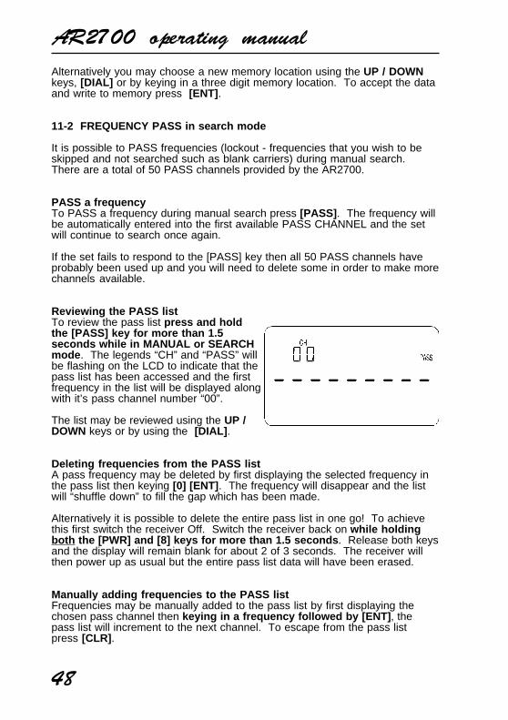
AR2700 operating manual
48
Alternatively you may choose a new memory location using the UP / DOWNkeys, [DIAL] or by keying in a three digit memory location. To accept the dataand write to memory press [ENT] .
11-2 FREQUENCY PASS in search mode
It is possible to PASS frequencies (lockout - frequencies that you wish to beskipped and not searched such as blank carriers) during manual search.There are a total of 50 PASS channels provided by the AR2700.
PASS a frequencyTo PASS a frequency during manual search press [PASS] . The frequency willbe automatically entered into the first available PASS CHANNEL and the setwill continue to search once again.
If the set fails to respond to the [PASS] key then all 50 PASS channels haveprobably been used up and you will need to delete some in order to make morechannels available.
Reviewing the PASS listTo review the pass list press and holdthe [PASS] key for more than 1.5seconds while in MANUAL or SEARCHmode . The legends “CH” and “PASS” willbe flashing on the LCD to indicate that thepass list has been accessed and the firstfrequency in the list will be displayed alongwith it’s pass channel number “00”.
The list may be reviewed using the UP /DOWN keys or by using the [DIAL] .
Deleting frequencies from the PASS listA pass frequency may be deleted by first displaying the selected frequency inthe pass list then keying [0] [ENT] . The frequency will disappear and the listwill “shuffle down” to fill the gap which has been made.
Alternatively it is possible to delete the entire pass list in one go! To achievethis first switch the receiver Off. Switch the receiver back on while holdingboth the [PWR] and [8] keys for more than 1.5 seconds . Release both keysand the display will remain blank for about 2 of 3 seconds. The receiver willthen power up as usual but the entire pass list data will have been erased.
Manually adding frequencies to the PASS listFrequencies may be manually added to the pass list by first displaying thechosen pass channel then keying in a frequency followed by [ENT] , thepass list will increment to the next channel. To escape from the pass listpress [CLR] .
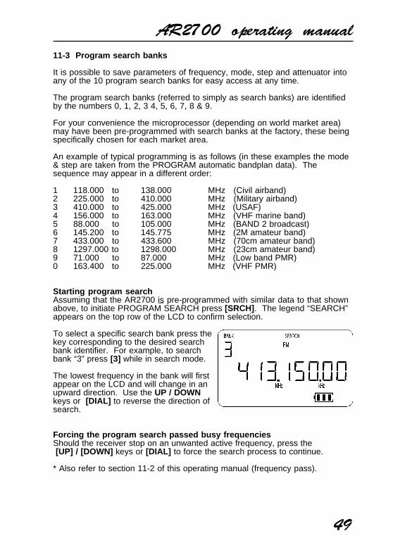
AR2700 operating manual
49
11-3 Program search banks
It is possible to save parameters of frequency, mode, step and attenuator intoany of the 10 program search banks for easy access at any time.
The program search banks (referred to simply as search banks) are identifiedby the numbers 0, 1, 2, 3 4, 5, 6, 7, 8 & 9.
For your convenience the microprocessor (depending on world market area)may have been pre-programmed with search banks at the factory, these beingspecifically chosen for each market area.
An example of typical programming is as follows (in these examples the mode& step are taken from the PROGRAM automatic bandplan data). Thesequence may appear in a different order:
1 118.000 to 138.000 MHz (Civil airband)2 225.000 to 410.000 MHz (Military airband)3 410.000 to 425.000 MHz (USAF)4 156.000 to 163.000 MHz (VHF marine band)5 88.000 to 105.000 MHz (BAND 2 broadcast)6 145.200 to 145.775 MHz (2M amateur band)7 433.000 to 433.600 MHz (70cm amateur band)8 1297.000 to 1298.000 MHz (23cm amateur band)9 71.000 to 87.000 MHz (Low band PMR)0 163.400 to 225.000 MHz (VHF PMR)
Starting program searchAssuming that the AR2700 is pre-programmed with similar data to that shownabove, to initiate PROGRAM SEARCH press [SRCH] . The legend “SEARCH”appears on the top row of the LCD to confirm selection.
To select a specific search bank press thekey corresponding to the desired searchbank identifier. For example, to searchbank “3” press [3] while in search mode.
The lowest frequency in the bank will firstappear on the LCD and will change in anupward direction. Use the UP / DOWNkeys or [DIAL] to reverse the direction ofsearch.
Forcing the program search passed busy frequenciesShould the receiver stop on an unwanted active frequency, press the [UP] / [DOWN] keys or [DIAL] to force the search process to continue.
* Also refer to section 11-2 of this operating manual (frequency pass).
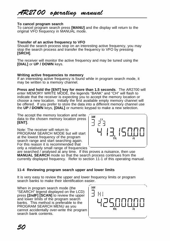
AR2700 operating manual
50
To cancel program searchTo cancel program search press [MANU] and the display will return to theoriginal VFO frequency in MANUAL mode.
Transfer of an active frequency to VFOShould the search process stop on an interesting active frequency, you maystop the search process and transfer the frequency to VFO by pressing[SRCH] .
The receiver will monitor the active frequency and may be tuned using the[DIAL] or UP / DOWN keys.
Writing active frequencies to memoryIf an interesting active frequency is found while in program search mode, itmay be written to a memory channel.
Press and hold the [ENT] key for more than 1.5 seconds . The AR2700 willenter MEMORY WRITE MODE, the legends “BANK” and “CH” will flash toindicate that the receiver is expecting you to accept the memory location orchoose a new location. Initially the first available empty memory channel willbe offered. If you prefer to store the data into a different memory channel usethe UP / DOWN keys, [DIAL] or numeric keypad to make a new selection.
The accept the memory location and writedata to the chosen memory location press[ENT] .
Note: The receiver will return toPROGRAM SEARCH MODE but will startat the lowest frequency of the programsearch range and start searching again.For this reason it is recommended thatonly a relatively small range of frequenciesare searched / analysed at any time. If this proves a nuisance, then useMANUAL SEARCH mode so that the search process continues from thecurrently displayed frequency. Refer to section 11-1 of this operating manual.
11-4 Reviewing program search upper and lower limits
It is very easy to review the upper and lower frequency limits or programsearch banks to make their identification easier.
When in program search mode (the“SEARCH” legend displayed on the LCD)press [2ndF] [SCAN] to review the upperand lower limits of the program searchbanks. This method is preferable to thePROGRAM SEARCH MENU as youcannot accidentally over-write the programsearch bank contents.
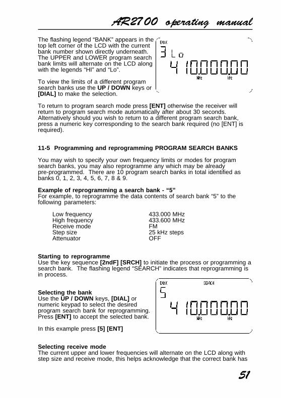
AR2700 operating manual
51
The flashing legend “BANK” appears in thetop left corner of the LCD with the currentbank number shown directly underneath.The UPPER and LOWER program searchbank limits will alternate on the LCD alongwith the legends “HI” and “Lo”.
To view the limits of a different programsearch banks use the UP / DOWN keys or[DIAL] to make the selection.
To return to program search mode press [ENT] otherwise the receiver willreturn to program search mode automatically after about 30 seconds.Alternatively should you wish to return to a different program search bank,press a numeric key corresponding to the search bank required (no [ENT] isrequired).
11-5 Programming and reprogramming PROGRAM SEARCH BANKS
You may wish to specify your own frequency limits or modes for programsearch banks, you may also reprogramme any which may be alreadypre-programmed. There are 10 program search banks in total identified asbanks 0, 1, 2, 3, 4, 5, 6, 7, 8 & 9.
Example of reprogramming a search bank - “5”For example, to reprogramme the data contents of search bank “5” to thefollowing parameters:
Low frequency 433.000 MHzHigh frequency 433.600 MHzReceive mode FMStep size 25 kHz stepsAttenuator OFF
Starting to reprogrammeUse the key sequence [2ndF] [SRCH] to initiate the process or programming asearch bank. The flashing legend “SEARCH” indicates that reprogramming isin process.
Selecting the bankUse the UP / DOWN keys, [DIAL] ornumeric keypad to select the desiredprogram search bank for reprogramming.Press [ENT] to accept the selected bank.
In this example press [5] [ENT]
Selecting receive modeThe current upper and lower frequencies will alternate on the LCD along withstep size and receive mode, this helps acknowledge that the correct bank has

AR2700 operating manual
52
been selected. If no frequency data is currently stored the legend “- - -” will bedisplayed.
Use the UP / DOWN keys or [DIAL] to select the required receive mode. If thealternating frequency is distracting, press one of the numeric keys so that thedisplay “- - -” is presented.
If “PROG” is selected then the receivemode and step will be taken from theautomatic bandplan data, in this case theselection of step will be skipped.
To accept the choice of receive modepress [ENT] .
In this example select “FM” thenpress [ENT]
Selecting step sizeIf the mode selection has previously been made as “PROG” then the receivemode and step will be taken from the automatic bandplan data and this itemwill be skipped.
To select the step size use the UP / DOWN keys or [DIAL] . The choices are asfollows:
NFM & AM : 5kHz, 6.25kHz, 9kHz,10kHz, 12.5kHz, 20kHz, 25kHz,30kHz, 50kHz & 100kHz.
WFM: 50kHz & 100kHz.
To accept the choice press [ENT] .
In this example select “25kHz” thenpress [ENT]
Selecting attenuator On / OffUse the UP / DOWN keys or [DIAL] to select the appropriate setting for theattenuator. On is when the receiver is least sensitive, Off is when the receiveris most sensitive. The legends are “on” or “oFF”, the usual setting is Off.
Other legends at this time will be aflashing “ATT”, steady “PROG” andflashing “SEARCH”.
To accept the choice of attenuator press[ENT] .
In this example select “oFF” thenpress [ENT]

AR2700 operating manual
53
Setting the LOWER frequency limitThe legends at this time are a steady“PROG” and flashing “SEARCH”. To theleft of the frequency readout is the legend“Lo” to indicate that the lower frequencylimit is required.
Enter the lower frequency then press[ENT] .
In this example type [4] [3] [3] [MHz] [ENT]
Setting the UPPER frequency limitThe legends at this time are a steady“PROG” and flashing “SEARCH”. To theleft of the frequency readout is the legend“HI” to indicate that the upper frequencylimit is required.
Enter the upper frequency then press[ENT] .
In this example type [4] [3] [3] [MHz] [6] [ENT]
THE REPROGRAMMING IS NOW COMPLETE AND THE RECEIVER WILLENTER PROGRAM SEARCH MODE AND WILL START SEARCHING.
Notes on program search bank programmingThere is no need to delete program search bank data before programming.If data is already present, it may simply be over-written.
Should you initiate program search bank programming while in search mode,the receiver will return to search mode, similarly with scan and manual mode...within reason, the receiver will return to where it left off.
Aborting program search programmingTo ABORT the the process of programming a search bank at any timepress [CLR] .
11-6 Program search bank linking
When shipped from the factory using default settings all search banks areUNLINKED so may only be searched on an individual basis by selecting thesearch bank identifier via the numeric keypad (“0”, “1”, “2” etc).
It is possible to quickly link search banks together so they will be searched asone group (handy for breaking down a large frequency range into smaller moremanageable ranges). It is possible to select any number of banks to bescanned as a group such as 2, 4, 5, 6 & 9.

AR2700 operating manual
54
To LINK ALL search banks the “SEARCHLINK” menu is used. To access the menuuse the key sequence [2ndF] [SRCH] withthe [SRCH] key held for more than 1.5seconds . The legends “SEARCH” “LINK”will appear on the top row to show that themenu has been selected.
The top left corner of the LCD will showthe legend “oF” or “on” (OFF or ON)depending upon the selection of BANKLINK. To toggle the selection of bank link,rotate the [DIAL] and the legend willtoggle appropriately.
The left of the “oF / on” legend and lowerrow of the LCD provide places for all tensearch banks. To add more banks to thebank link list simply press the appropriateidentifying search bank number using thenumeric keypad, the number legends willtoggle On and Off... the legend “ - “depicting Off (unselected).
To accept the new list and setting press [ENT] .
The next time the receiver enters PROGRAM SEARCH MODE with bank linkspecified as On, the legend “SEARCH” “LINK” will be displayed and a largegroup of search banks will be sequentially searched together as one largegroup.
11-7 Searching a search bank which is not selected in BANK LINK
It is still possible to SEARCH a single deselected bank by manually bypassingthe BANK LINK programming. To SEARCH any deselected bank simply keythe desired identifying bank number through the keypad while in search mode.
Only the search bank manually selected will be searched.
(12) Sleep timer - automatic power Off
The AR2700 is fitted with a SLEEP timer which is capable ofautomatically switching the receiver Off after a prescribed time period.
This can be useful if you use the receiver at bedtime, listening to local radioamateur repeaters etc as you slip off into sleep. Alternatively if you leave thehouse while the receiver is still monitoring, you can be confident that thereceiver will soon switch Off so saving you having to immediately recharge theNiCad batteries upon your return to home.
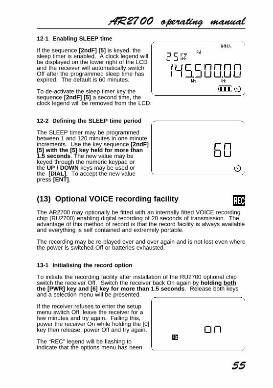
AR2700 operating manual
55
12-1 Enabling SLEEP time
If the sequence [2ndF] [5] is keyed, thesleep timer is enabled. A clock legend willbe displayed on the lower right of the LCDand the receiver will automatically switchOff after the programmed sleep time hasexpired. The default is 60 minutes.
To de-activate the sleep timer key thesequence [2ndF] [5] a second time, theclock legend will be removed from the LCD.
12-2 Defining the SLEEP time period
The SLEEP timer may be programmedbetween 1 and 120 minutes in one minuteincrements. Use the key sequence [2ndF][5] with the [5] key held for more than1.5 seconds . The new value may bekeyed through the numeric keypad orthe UP / DOWN keys may be used orthe [DIAL] . To accept the new valuepress [ENT] .
(13) Optional VOICE recording facility
The AR2700 may optionally be fitted with an internally fitted VOICE recordingchip (RU2700) enabling digital recording of 20 seconds of transmission. Theadvantage of this method of record is that the record facility is always availableand everything is self contained and extremely portable.
The recording may be re-played over and over again and is not lost even wherethe power is switched Off or batteries exhausted.
13-1 Initialising the record option
To initiate the recording facility after installation of the RU2700 optional chipswitch the receiver Off. Switch the receiver back On again by holding boththe [PWR] key and [6] key for more than 1.5 seconds . Release both keysand a selection menu will be presented.
If the receiver refuses to enter the setupmenu switch Off, leave the receiver for afew minutes and try again. Failing this,power the receiver On while holding the [0]key then release, power Off and try again.
The “REC” legend will be flashing toindicate that the options menu has been

AR2700 operating manual
56
selected. The selection of RECORD On and Off is made using the [DIAL] withlegends “oFF” and “on” confirming selection. To accept the displayed selectionpress [ENT] . The set will quickly display all LCD segments then power On asnormal. The option will now have been added or removed from the keypadoperation as appropriate.
Note: When in the setup menu, the UP / DOWN keys toggle between theRECORD and DESCRAMBLE option setup routines.
13-2 Recording
To make a recording, tune the receiver toan active frequency and key the sequence[2ndF] [4] with the [4] key held for morethan 1.5 seconds , the legend “REC” willbe displayed on the LCD and the currentdisplayed frequency will be recorded for20 seconds (presuming that the optionalrecord chip has been fitted).
The signal meter acts as a “progress meter” to illustrate how much record andplay back time has elapsed.
The record facility may be used in MANUAL mode, or even when scanning orsearching.
13-3 Play back
To replay a previously recordedtransmission, key the sequence [2ndF][4] . The legend “PLAY” will be displayedon the LCD and the 20 second digitalrecording will be replayed (presuming thatthe optional record chip has been fitted).If the optional chip has not been fitted thenwhite noise will be heard.
The signal meter acts as a “progress meter” to illustrate how much record andplay back time has elapsed.
(14) Remote control using a computer (RS232C)
The AR2700 is capable of remote control using a computer such asan IBM compatible and control software. An adaptor (IF-ADP) andsmall external interface (CU8232) and lead are required andavailable as options.
Further information will be provided with the optionalCU8232 interface unit.
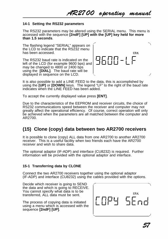
AR2700 operating manual
57
14-1 Setting the RS232 parameters
The RS232 parameters may be altered using the SERIAL menu. This menu isaccessed with the sequence [2ndF] [UP] with the [UP] key held for morethan 1.5 seconds .
The flashing legend “SERIAL” appears onthe LCD to indicate that the RS232 menuhas been accessed.
The RS232 baud rate is indicated on theleft of the LCD (for example 9600 bps) andmay be changed to 4800 or 2400 bpsusing the [DIAL] . The baud rate will bedisplayed in sequence on the LCD.
It is also possible to add a LINE FEED to the data, this is accomplished byusing the [UP] or [DOWN] keys. The legend “LF” to the right of the baud rateindicates when the LINE FEED has been added.
To accept the currently displayed value press [ENT] .
Due to the characteristics of the EEPROM and receiver circuits, the choice ofRS232 communications speed between the receiver and computer may notgreatly affect the operational efficiency. Of course, correct operation will onlybe achieved when the parameters are all matched between the computer andAR2700.
(15) Clone (copy) data between two AR2700 receivers
It is possible to clone (copy) ALL data from one AR2700 to another AR2700receiver. This is a useful facility when two friends each have the AR2700receiver and wish to share data.
The optional adaptor (IF-ADP) and interface (CU8232) is required. Furtherinformation will be provided with the optional adaptor and interface.
15-1 Transferring data by CLONE
Connect the two AR2700 receivers together using the optional adaptor(IF-ADP) and interface (CU8232) using the cables provided with the options.
Decide which receiver is going to SENDthe data and which is going to RECEIVE.You cannot specify what data is to betransferred, ALL data must be sent.
The process of copying data is initiatedusing a menu which is accessed with thesequence [2ndF] [UP] .
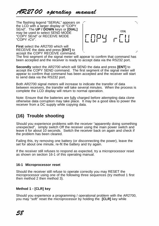
AR2700 operating manual
58
The flashing legend “SERIAL” appears onthe LCD with a larger display of “COPYSEnd”. The UP / DOWN keys or [DIAL]may be used to select SEND MODE“COPY SEnd” or RECEIVE MODE“COPY rCV”.
First select the AR2700 which willRECEIVE the data and press [ENT] toaccept the COPY RECEIVE command.The first segment of the signal meter will appear to confirm that command hasbeen accepted and the receiver is ready to accept data via the RS232 port.
Secondly select the AR2700 which will SEND the data and press [ENT] toaccept the COPY SEND command. The first segment of the signal meter willappear to confirm that command has been accepted and the receiver will startto send data via the RS232 port.
Both AR2700 signal meters will increase to indicate the transfer of databetween receivers, the transfer will take several minutes. When the process iscomplete the LCD display will return to normal operation.
Note: Ensure that the batteries are fully charged before attempting data cloneotherwise data corruption may take place. It may be a good idea to power thereceiver from a DC supply while copying data.
(16) Trouble shooting
Should you experience problems with the receiver “apparently doing somethingunexpected”, simply switch Off the receiver using the main power switch andleave it for about 10 seconds. Switch the receiver back on again and check ifthe problem has been cleared.
Failing this, try removing one battery (or disconnecting the power), leave theset for about one minute, re-fit the battery and try again.
If the receiver still refuses to respond as expected, try a microprocessor resetas shown on section 16-1 of this operating manual.
16-1 Microprocessor reset
Should the receiver still refuse to operate correctly you may RESET themicroprocessor using one of the following three sequences (try method 1 firstthen method 2 then method 3).
Method 1 - [CLR] key
Should you experience a programming / operational problem with the AR2700,you may “soft” reset the microprocessor by holding the [CLR] key while
AR2700 operating manual
59
powering up the receiver. Your memory bank and search bank data willremain intact but any linked banks, frequency pass data etc will be lost.
Method 2 - RESET switch, left side panel
A “soft” microprocessor reset may also be accomplished by momentarilypressing the reset switch located on the left hand cabinet using a pointedutensil such as a pin, small screwdriver, sharp pencil etc. It does not matter ifthe receiver is switched On or Off at the time.
Your memory bank and search bank data will remain intact but any linkedbank data etc will be lost.
Method 3 - FULL reset [CLR] + [ENT] keys
DO NOT USE THIS KEY SEQUENCE UNLESS ABSOLUTELY NECESSARY .
A FULL MICROPROCESSOR reset is accomplished by holding both the[CLR] and [ENT] keys while switching On the unit using the [PWR] key .All memory channels, search banks, pass channels etc will be lost and blank.
As a result the search and scan facilities will not operate until new data hasbeen entered. Note: It is quite normal for the set to take about 30 secondsto recover from a FULL reset as all data is being deleted !!! Often there isno external indication that a reset is in progress so be patient, following a FULLreset the receiver will power On and the display will show 80 MHz.
16-2 Other possible operational problems
Signals are weakCheck that the attenuator is not switched On (the legend “ATT” is not displayedon the top line of the LCD).
Ensure the correct receive mode is being used (AM for airband, NFM for pointto point communications - not WFM etc).
Frequency jumps a few kHzIf you have altered the tuning step size for VFO or SEARCH mode, rememberthat the receiver frequency must be divisible by the step size. If it is not, theAR2700 will correct the displayed frequency to the nearest kHz which isdivisible.
Frequencies and memory channels are skippedEnsure that the frequencies are not in the PASS list and memory channels notlocked out “CH PASS” by reviewing memory contents in memory recall.
AR2700 operating manual
60
The receiver stops on blank carriersThe receiver may stop on blank carriers. It may be that these are truetransmissions (you can usually remove the aerial to determine this).
Alternatively the AR2700 (like all receivers) will produce spurii in certain placessuch as 129.600 MHz, 144.000 MHz and 158.400 MHz as examples. You mayuse the PASS facility to reduce their annoyance to a minimum.
The display blinks and changesEnsure that the PRIORITY facility is not engaged. If it is, the legend “PRIO”will be displayed on the second line of the LCD toward the upper right handcorner.
Receiver does not switch onIn using NiCad batteries, charge them using the charger provided or connectthe receiver to a vehicle cigar lighter socket using the DC lead provided. If youare using dry batteries, replace them with a fresh set.
If this does not helpIf the above does not help, please contact your supplier for assistance.
16-3 Other LCD indications and error messages
“BEEP” & “BOOP”The keypad usually produces a high pitch “beep” when the correct key orsequence is followed. Should an inappropriate key be pressed, a lower pitch“BOOP” will be produced. It is possible to switch the beep & boop On/Offusing the key sequence [2ndF] [PASS] .
A “boop” will be emitted if you attempt to scan or search when no data hasbeen programmed.. following a FULL microprocessor reset for example.
BATTERY LOW special indicatorThe special on-screen battery indicator provides a constant indication ofbattery level. Once the unit indicator drops to “one block” then it is time torecharge or replace the batteries as the unit may stop functioning at any time.
“PLL Err” - PLL ERRORThis indicates that the PLL (Phase Lock Loop) has unlocked. This is thesystem used by the receiver to select and change frequency. Ensure that thefrequency is within the receiver's specified frequency coverage of 500 kHz(0.5 MHz) to 1300 MHz.
A PLL ERROR message may also be displayed if the batteries are near toexhaustion.

AR2700 operating manual
61
16-4 Special functions
The AR2700 has a number of “special functions”, it is highly recommendedthat these are left where set during manufacturer. However, the defaults arelisted here for information.
First power the receiver while holding both the [PWR] key and [0] key formore than 1.5 seconds , release the keys and switch the receiver Off againusing the [PWR] key.
Squelch detect
Switch the receiver On again while holding both the [PWR] key and the [2]key for more than 1.5 seconds . This is the menu for setting the SQUELCHDETECT TIME. The default is 15 and the acceptable range is 0 - 30. TheUP / DOWN keys, [DIAL] or numeric keypad may be used to change thesetting. The [ENT] key is used to accept the changes or [CLR] to abort.
PLL lock detect time
Switch the receiver On again while holding both the [PWR] key and the [3]key for more than 1.5 seconds . This is the menu for setting the PLL LOCKDETECT TIME. The default is 04 and the acceptable range is 0 - 30. TheUP / DOWN keys, [DIAL] or numeric keypad may be used to change thesetting. The [ENT] key is used to accept the changes or [CLR] to abort.
Intermediate frequency selection
Switch the receiver On again while holding both the [PWR] key and the [5]key for more than 1.5 seconds . This is the menu for setting theINTERMEDIATE FREQUENCIES - DO NOT ADJUST THIS !! !The values are keyed in via the numeric keypad.
The defaults are:
600 70.000.00601 108.000.00602 147.000.00603 470.000.00604 1013.000.00605 1300.000.00605 - - - - - -
AR2700 operating manual
62
(17) Optional accessories
RU2700An optional VOICE RECORDING chip is available. When internally fitted, it ispossible to record and play back 20 seconds of activity.
SC2700An optional soft leatherette case is available to add protection to the plasticcabinet when used on the move.
IF-ADP & CU8232RS232 adaptor and interface unit is required for computer control and clone(copy) data between two AR2700 receivers. For computer control a standardserial lead is also required.
DA900 whip aerialFlexible whip aerial for VHF/UHF approximately 25cm in length, ideal forportable use especially when the receiver is to be carried in a pocket.
MA500 mobile aerialCompact mobile whip aerial for VHF/UHF on a magnetic base with a fewmetres of coaxial cable and ready terminated with a BNC plug.
LA320 loop aerialDesktop active loop aerial for portable operation away from a base aerial suchas when while travelling on business or holiday. Frequency coverage is 1.6 to15 MHz with optional elements to cover 0.2 to 0.54 MHz and 0.54 to 1.6 MHz.
WA7000 wide band active whip aerialCompact aerial designed for installation where space is a problem. TheWA7000 is active on the lower frequency band 30kHz to 30MHz and passiveon the higher band between 30MHz to 2000MHz.
DA3000 VHF-UHF discone aerial16 element VHF - UHF discone aerial with usable coverage of 25 MHz to 2000MHz. Supplied with cable and connectors etc.
ABF125VHF civil airband filter to reduce the chances of breakthrough especially frompowerful VHF band-2 transmitters.

AR2700 operating manual
63
(18) Specification
Frequency coverage: 500 kHz - 1300 MHz no gaps(input accepted from 100 kHz)
Receive modes: NFM, WFM, AM
Sensitivity: 10 - 400 MHz NFM = 12dB SINADNFM 0.5 uV AM = 10dB S/NAM 0.8 uV WFM = 30dB S/NWFM 6.0 uV400 - 1000 MHzNFM 0.7 uVWFM 6.0 uV1000 1500 MHzNFM 1.5 uV
Selectable tuning steps: AM & NFM5kHz, 6.25kHz, 9kHz, 10kHz,12.5kHz, 20kHz, 25kHz, 30kHz,50kHz & 100kHz
WFM 50kHz & 100kHz
Memory capacity: 500 ch total, 10 banks x 50 ch
Search banks: 10
Pass channels: 50 ch
VFO: One
Priority channel: One
Scan & search rate: 30ch/sec approx
Aerial input: 50 OHM BNC
Audio output: 110mW (6V 10%THD 8 OHM)
Power requirements: 4.8V from 4 x AA internal NiCads6.0V manganese / alkaline9.0 - 16V external
Current consumption: 95mA squelched - stand by140mW (receive 50mW audio)
E&OE Rev 1.1 © 1995 AOR, LTD.

AR2700 operating manual
64
Notes