ar3030 operating manual - textfiles.compdf.textfiles.com/manuals/scanners-a-e/aor_ar3030 hf comms...
TRANSCRIPT
AR3030 operating manual
1
(1) Introduction & accessories
Thank you for purchasing the AOR AR3030 General Coverage Receiver. TheAR3030 uses the very latest DDS (Direct Digital Synthesizer) technology toensure the highest levels of design, performance and reliability. A TCXO(Temperature Compensated Crystal Oscillator) is provided for high stabilityand the legendary Collins 6kHz AM filter for the ultimate in AM selectivity.
It is recommended that you carefully read this handbook and familiariseyourself with the receiver before placing it into operation.
Every effort has been made to make this manual correct and up to date. Dueto continuous development of the receiver and by error or omissions anomaliesmay be found and this is acknowledged.
Most apparent faults are usually due to accidental misoperation of the receiver,carefully read all of the manual before deciding to return the receiver for repair.
Although carefully designed, the receiver (like all receivers) suffers from adegree of internal noises known as spurii. They are a product of the receiver’scircuitry and do not represent a fault.
This manual is protected by copyright AOR Ltd 1993. No informationcontained in this manual may be copied or transferred by any means withoutthe prior written consent of AOR Ltd. AOR and the [AOR] logo are trademarks of AOR, Ltd. * Collins is a trade name of Rockwell International. Theuse of Collins and “Collins inside” has been authorised by Rockwell Interna-tional.All other trade marks and names acknowledged. E&OE.
© 1993 AOR Ltd.
Operating manual Conventions
Where text appears in [BOLD UPPERCASE] the keys are to be pressedexactly as shown.
For example: [4] [9] [mtr]
Means press the 4 key followed by the 9 key followed by the mtr key.
Words contained in speech marks “PASS” refer to indications displayed on theLiquid Crystal Display.
Where the mode of FM is referred to, this indicates NFM (Narrow FM).For clarity, the LCD diagrams for key sequences often have highlights ""above digits to signify they are flashing. These highlights do not actuallyappear on the LCD.
1-1 Accessories supplied
Mains power supplyOperating manual
AR3030 operating manual
2
(2) Table of contents
1 Introduction... 11-1 Accessories supplied... 1
2 Table of contents... 2
3 Major features... 4
4 Precautions... 84-1 Location... 84-2 Looking after your receiver... 84-3 Power requirements.. 84-4 Aerial (antenna) connection... 9
5 Controls and functions... 10Front panel 11
5-1 On/Off power switch... 105-2 Headphone socket... 125-3 Mode keys and indicators... 125-4 Liquid Crystal Display (LCD)... 125-5 VFO key... 125-6 SCAN key... 135-7 MEMO key... 135-8 BW - Bandwidth key... 135-9 TONE key... 145-10 PASS key... 145-11 AGC - Automatic Gain Control key... 145-12 ATT - Attenuator key... 155-13 M.in - Memory input key... 155-14 Numeric keypad 0 - 9... 155-15 [.] decimal and separator key... 155-16 [MHz] MHz key... 165-17 [kHz] kHz key... 165-18 [mtr] metre key... 165-19 ENT/BS - Enter and Backspace key... 165-20 Volume control... 175-21 BFO pitch control... 175-22 SQL - Squelch control.. 175-23 RF gain control... 185-24 Rotary tuning control... 185-25 S-meter - (signal strength meter)... 185-26 Loudspeaker (internal)... 18
Rear panel 195-27 EX power - external power connection... 205-28 AUX socket... 205-29 SP - Speaker output socket... 205-30 FAX - FAX audio output socket... 215-31 RS232C - Computer control port... 215-32 GND - Ground connection... 215-33 Wire ANT - (aerial) connector... 215-34 ANT selection - Selection switch... 225-35 WHIP ANT / 50 OHM / LW-HF ANT socket... 22
AR3030 operating manual
3
5-36 VHF ANT - VHF socket... 225-37 LIGHT switch... 225-38 BATT compartment... 22
6 Basic manual operation on the receiver... 236-1 Tuning the receiver using the rotary control... 246-2 Changing receive mode... 246-3 Changing VFO A/B... 266-4 Tone - Audio tailoring... 276-5 Bandwidth and filters... 276-6 AGC - Automatic Gain Control... 286-7 ATT - Attenuator operation... 286-8 RF gain control... 296-9 Squelch control... 296-10 BFO pitch control... 296-11 VFO and keypad lock... 306-12 Entering a frequency via the keypad... 316-13 Memory mode... 326-14 Memory write... 336-15 Deleting memory contents... 346-16 Memory channel scan... 366-17 Program memory channel scan... 376-18 Pass channel operation... 386-19 Pause time programming in scan mode... 386-20 Delay time programming in scan mode (VHF only)... 39
7 Computer control (RS232C)... 407-1 Connection... 407-2 Communication parameters... 417-3 Start up and end... 417-4 Command transmission in terminal mode... 417-5 Monitoring the contents of received serial data... 427-6 FORMAT 1 - Contents of the received signal... 427-7 FORMAT 2 - Reading the receiver’s signal strength... 437-8 FORMAT 3 - Transmitting the memory contents... 437-9 Change the receive modes or Make new entries... 43
8 Optional accessories... 45
9 Trouble shooting - (microprocessor reset)... 46
10 Aerials (antennas) and earth systems... 47
11 Propagation - shortwave bands... 51
12 Specification... 54
AR3030 operating manual
4
(3) Major features
General
The AR3030 offers the very latest technology through use of its’ DDS (DirectDigital Synthesizer). The legendary Collins 6kHz AM filter is fitted as standardto provide the highest levels of AM selectivity. High stability is accomplishedby the standard fitting of a TCXO (Temperature Compensated CrystalOscillator).
As the model name would suggest, the tunable coverage is 30kHz - 30 MHz(with 29.999995 MHz being the actual upper limit of tuning) using silky-smooth5Hz steps. The AR3030 offers all mode operation as standard: AM, S.AM(double side band synchronous), USB, LSB, CW, FAX & FM. All necessaryinformation relating to frequency, filter setting etc is presented via a highlyvisible switchable backlit custom LCD. Mode selection is displayed via a seriesof LEDs.
Although 5Hz tuning steps are available in all modes coupled to true automaticcarrier insertion in USB, LSB, FAX & CW, a separate BFO control isselectable in USB, LSB, FAX & CW to provide even greater flexibilityproducing a manual form of pass band tuning.
While in any receive mode it is possible to increase the tuning steps from fiveHz (display resolution 10Hz) to hundreds of Hz and kHz by pressing the kHzkey while in VFO mode. Selection of MHz tuning may also be accomplished inVFO mode by pressing the MHz key. The position of the underscore character“_” indicates selected tuning rate.
A smooth action rotary tuning control with a finger-tip-hollow is provided toensure a high level of operating pleasure, convenience and versatility.
Frequencies may be entered directly via the numeric keypad, great versatilityis provided by careful attention to firmware programming. Frequencies may beentered as kHz i.e. [6] [0] [9] [0] [kHz], MHz i.e. [6] [.] [0] [9] [0] [MHz] or the“band” may be selected i.e. [4] [9] [mtr] returns to the last frequency used onthat band, probably no other receiver offers such convenience. All broadcastbands are recognised as well as region 1,2 & 3 Amateur bands... i.e. 80, 75,49m etc.
Twin VFOs retain all necessary information such as frequency, mode, I.F.bandwidth, audio filter, attenuator setting and tuning step size and BFO statusOn/Off. 100 memories also hold the full range of settings making transfer toand from memory straight forward and very convenient.
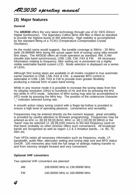
Optional VHF converters
Two optional VHF converters are planned:
AM 108.00000 MHz to 139.99999 MHz
FM 140.00000 MHz to 169.99999 MHz
AR3030 operating manual
5
One converter may be internally fitted to further extend the receive coverage ofthe receiver. A separate 50 OHM BNC aerial socket is fitted to the rear case ofthe AR3030 in order to simplify connection to a dedicated VHF aerial.
SSB (Single Side-Band) - who uses it?
SSB is a general term given to two additional modes of operation USB forupper-side-band and LSB for lower-side-band. Generally speaking, SSB isused by long range services such as oceanic airband, ship to shore andAmateur band to increase the operational coverage of the radio transceivers.
Most point-to-point services use USB including Amateur band. By convention,Radio Amateurs use LSB below 10MHz.
True carrier insertion is used for USB, LSB and CW with a separate SSB highlyselective filter being used for these modes. A BFO control (which operates inCW, USB, LSB & FAX modes) has also been provided so that the CW notemay be optimised to suit individual preferences and to form a simple manualform of passband tuning, particularly helpful on a crowded frequency.
The inclusion of SSB on the AR3030 adds a new dimension to the listeningpotential of the receiver when compared to AM broadcast-only shortwavereceivers.
All Mode
As well as SSB, the AR3030 can receive all other popular modes: AM(Amplitude Modulation) used mainly by broadcast stations and some otherservices (such as VHF commercial airband with the optional VHF converterfitted). Synchronous AM (double side band) used to combat fading on theshortwave bands. NFM (Narrow band Frequency Modulation) little used onthe shortwave bands but found on the UK CB radio and 10m Amateur Bands.
Bandwidth and filters
The AR3030 is fitted with several standard IF bandwidths including a cascade8kHz/-6dB ceramic filter (CFU455G2) for AM/SSB/FAX/CW plus two audiobandwidths:
AM/S.AM6kHz/-3dB in the normal position using the legendary Collins eight resonatormechanical filter (526 8636 010) and a 2.4kHz/-6dB Murata ceramic filter(CFJ455K6) in the narrow position. Should the narrow CW optional PCBposition not be used, it is possible to fit an additional wider filter for AM suchas Collins 8.5kHz/-3dB 526 8561 020. Due to the I.F. cascade filter, thewidest possible filter is 8.5kHz.
USB/LSB/FAX2.4kHz Murata ceramic filter (CFJ455K6). An optional 2.5kHz/-3dB Collinseight resonator mechanical filter (526 8635 010) of higher specification may be
AR3030 operating manual
6
optionally fitted (workshop fitting) to replace the 2.4kHz filter. Should thenarrow CW optional PCB position not be used, it is possible to fit the optionalCollins 2.5kHz filter as an addition which will be selected in the narrowposition.
CW2.4kHz Murata ceramic filter in the Normal position. An optional 500Hz/-3dBCollins seven resonator mechanical filter (526 8634 010) may be optionallyfitted (workshop fitting)in the Narrow position.
FM15kHz Murata ceramic filter (CFU455E2) fixed. Selection of Normal/Narrow isdisabled.
Attenuator, whip amplifier and aerial input & AGC
The AR3030 does not contain RF amplification prior to the band-pass filters,all gain is applied in the more selective IF stages. This ensures the highestimmunity to intermodulation effects often caused by the high number of strongsignals encountered on the shortwave bands.
There are two aerial inputs. The first is of the standard BNC type allowingstraight forward connection to almost any low impedance shortwave dipole ormultiband aerial system. The second is a “jaw” designed for a high impedancelong wire. An earth connection is also provided on the rear panel.
A rear panel three position slide switch selects the 50 OHM BNC connector orhigh impedance wire input. The third position applies a preamplifier andimpedance matching network to the BNC aerial socket which may be used inconjunction with a telescopic whip aerial to enable a fair level of operationaway from a long wire aerial or more elaborate system.
An aerial attenuator system allows selection of 0db, 10dB or 20dB from thefront panel. RF gain is also available via a front panel rotary control, this isespecially useful in providing optimum audio quality for SSB operation. AGCattack / decay may also be selected from the front panel either fast or slow butcannot be switched off.
Memories & SCAN
There are 100 memory channels which can store frequency, mode, AGC,attenuator, bandwidth, AF filter (tone), BFO and lockout status. The memoriesmay be used to store shortwave or VHF frequencies if the VHF converteroption has been fitted.
Program scan allows only a selected block of channels to be scanned whilelockout permits certain channels to be skipped. Pause and delay scan add toflexibility.
Data may be easily entered into memory and back to VFO where it may betuned.
AR3030 operating manual
7
There is a massive EEPROM store for all memory channels and VFO dataso that no memory backup battery is required. The memories may be over-written time and time again.
RS232 computer port
A 9 pin D type socket is fitted to the rear case, this will permitcontrol of manyreceiver facilities via a computer.
Loudspeaker and audio output
The AR3030 has a built-in 66mm 3 WATT loudspeaker. A 3.5mm jack socketis located on the rear panel of the receiver for external speaker connection.Connection to this socket automatically cancels audio from the internalspeaker.
Audio output is also available through a quarter inch headphone jack pluglocated on the front panel of the receiver. Use of this headphone socketautomatically cancels output from both the internal and external loudspeakerif used.
A low level audio output suitable for tape recording is available through via theAUX socket located on the rear panel. Switching to control a tape motor is alsoavailable via the AUX socket. A second constant level slightly higher output isavailable via a second rear panel 3.5mm socket suitable for connection to afacsimile decoder.
AGC and IF outputs are also available via an 8 pin DIN socket located on therear panel.
Versatility & power connection
The AR3030 can meet a number of requirements to satisfy Broadcast,Amateur band, Airband or Marine enthusiasts, Professional off air monitoringand of course casual listening too. The World’s shortwave and Amateur bandscan be monitored, even the longer range Oceanic Airband and ship to shore.
The receiver is designed to operate from either an external DC supply (such asthat provided) of a nominal 13.8V DC or from internally fitted batteries (8 x AAdry cells which may not have been provided). Although rechargeable batteriesmay be used with the receiver, they must be externally recharged.
The receiver must never be connected directly to the mains supply.
(4) Precautions
AR3030 operating manual
8
4-1 Location
Do not use or leave the receiver in direct sunlight. It is best to avoid locationswhere excessive heat, humidity, dust and vibration are expected. Alwaystreat the receiver with care.
Take care to avoid spillage or leakage of liquids into the receiver and ACpower supply. Special care should be taken to avoid liquid entering via thepower jack. Always remove batteries if the receiver is not going to be usedfor a while.
Avoid static discharge from wire aerials, earth to a central heating radiator orsimilar in order to discharge the wire before connection to the AR3030. Alwaysdisconnect and earth an aerial system if an electrical storm is expected.
Avoid connecting / disconnecting the power connection or batteries with theset switched on. Avoid a rapid switch On/Off sequence. If switched off, leaveat least ten seconds before switching on again. Ensure the mains plugconnections are tight and DC connections such as cigar lighters secure.
Avoid strong RF fields from near by transmitters. If in doubt, disconnect theAR3030 from the aerial and switch the set off.
4-2 Looking after your receiver
Always keep the receiver free from dust and water. Use a soft dry cloth togently wipe the set clean. Never use chemicals such as benzine or thinnerswhich will damage certain parts.
4-3 Power requirements
The AR3030 is designed for operation from an external DC supply of 11 - 16VDC at approximately 0.7A minimum or from internal fitted dry batteries.
Always use the mains power supply provided, or from a regulated DC powersupply of 13.8V @ 0.7A or more using the optional DC3000 connecting lead.Always switch the receiver off when connecting or disconnecting the receiver.
Note: The DC input socket uses a special type of connector. This plug/socketis of a moulded type and pre-wired, positive is the RED wire. The chassis ofthe receiver is negative ground .
The UK power supply has two cables attached. One is terminated in theappropriate power jack plug to fit the DC input socket of the AR3030. Thesecond has two bared wires ready for connection to a standard 3-pin mainsplug. A 3 Ampere fuse should be used in the plug and the cable is colourcoded as follows:
Brown: LiveBlue: Neutral
AR3030 operating manual
9
The AR3030 power supply has no connection to the EARTH pin of the mainsplug. However a separate earth point is provided on the rear panel of theAR3030 for connection to a water pipe, central heating system radiator orexternal earth rod. If fitting a separate external earth rod, consider theimplications carefully is your mains supply uses Protective Multiple Earth(PME) system. If in doubt consult an expert electrician. Never earth to agas pipe!
Always disconnect the power supply from the AC mains supply when not inuse.
Always remove dry batteries when exhausted or if the AR3030 is not going tobe used for a while. This will avoid leakage which could seriously damage thereceiver.
Access to the battery compartment is via a removable sub-panel on the rearpanel. Always switch the receiver off when inserting or removing batteries. Iffitting batteries always select a quality brand, 8 x AA size 1.2 or 1.5V cells arerequired.
4-4 Aerial (antenna) connection
The low impedance aerial input is of a high quality BNC type as preferred bycommercial users rather than the cheaper SO239 type. Adaptors are readilyavailable to convert from a BNC to almost any other plug or socket as requiredallowing straight forward connection to almost any shortwave aerial.
The second input is a “jaw” designed for a high impedance long wire. An earthconnection is also provided on the rear panel.
A rear panel three position slide switch selects the 50 OHM BNC connector orhigh impedance wire input. The third position applies a preamplifier andimpedance matching network to the BNC aerial socket which may be used inconjunction with a telescopic whip aerial to enable a level of operation awayfrom a long wire aerial or more elaborate system.
The AR3030 does not contain RF amplification prior to the band-pass filters,all gain is applied in the more selective IF stages. This ensures the highestimmunity to intermodulation effects often caused by the high number of strongsignals encountered on the shortwave bands.
An aerial attenuator system allows selection of 0db, 10dB or 20dB from thefront panel. RF gain is also available via a front panel rotary control, this isespecially useful in providing optimum audio quality for SSB operation. AGCattack / decay may also be selected from the front panel either fast or slow butcannot be switched off.
Aerial Tuning Units (ATU)
AR3030 operating manual
10
An ATU can improve the selectivity of any shortwave receiver when connectedto long wire aerial other than a short wire of a few metres. This valuable extraselectivity is created provided by the ATU rejecting out of band signalsenabling the receiver to “single out” one band of frequencies while rejectingpotentially strong unwanted transmissions.
An ATU is usually constructed in a small box with about two or three controlson the front panel. One disadvantage however is the need to constantly retunethe ATU when changing frequency. An ATU of this type has no active circuitryso is known as a passive device.
Active desk-top loop aerials
Usually designed for the shortwave bands (such as the AOR LA320. Loopaerials have the advantage of small size when compared to long wire aerialsand being within easy reach of the operator it can be rotated to providedirectivity. The circuitry offers a small level of gain with the advantage ofselectivity similar to an ATU.
* For further information please refer to section 10 of this manual regardingaerial and earth systems.
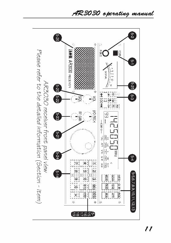
(5) Controls and functions
The AR3030 receiver is housed in a strong metal cabinet. Controls foroperation are located on the top and front of the cabinet with connections tothe rear.
Front panel
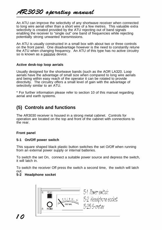
5-1 On/Off power switch
This square shaped black plastic button switches the set O/Off when runningfrom an external power supply or internal batteries.
To switch the set On, connect a suitable power source and depress the switch,it will latch in.
To switch the receiver Off press the switch a second time, the switch will latchout.5-2 Headphone socket
AR3030 operating manual
11
AR3030 operating manual
12
This quarter inch socket is located on the top left hand side of the front cabinetdirectly underneath the power switch. A pair of headphones or earphone maybe connected with an impedance of 8 OHMS or greater. When this headphonesocket is used, the internal speaker and any external speaker will beautomatically disconnected.
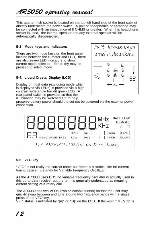
5-3 Mode keys and indicators
There are two mode keys on the front panellocated between the S-meter and LCD, thereare also seven LED indicators to showcurrent mode selected. Either key may bepressed to select mode.
5-4. Liquid Crystal Display (LCD)
Display of most data (excluding mode whichis displayed via LEDs) is provided via a highcontrast wide angle backlit green LCD. Arear panel switch is provided so that theillumination may be switched Off to helppreserve battery power should the set not be powered via the external powerconnection.
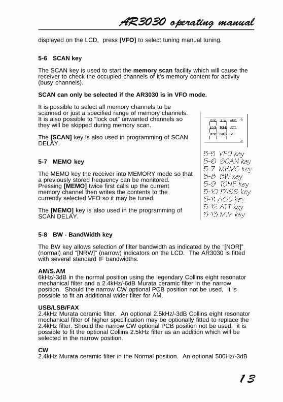
5-5 VFO key
“VFO” is not really the correct name but rather a historical title for currenttuning device, it stands for Variable Frequency Oscillator.
As the AR3030 uses DDS no variable frequency oscillator is actually used inthis up-to-date receiver but the term is generally understood as meaningcurrent setting of a rotary dial.
The AR3030 has two VFOs’ (two selectable tuners) so that the user mayquickly swap between and tune around two frequency bands with a singlepress of the VFO key.VFO status is indicated by “[A]” or “[B]” on the LCD. If the word “[MEMO]” is
AR3030 operating manual
13
displayed on the LCD, press [VFO] to select tuning manual tuning.
5-6 SCAN key
The SCAN key is used to start the memory scan facility which will cause thereceiver to check the occupied channels of it’s memory content for activity(busy channels).
SCAN can only be selected if the AR3030 is in VFO mode.
It is possible to select all memory channels to bescanned or just a specified range of memory channels.It is also possible to “lock out” unwanted channels sothey will be skipped during memory scan.
The [SCAN] key is also used in programming of SCANDELAY.
5-7 MEMO key
The MEMO key the receiver into MEMORY mode so thata previously stored frequency can be monitored.Pressing [MEMO] twice first calls up the currentmemory channel then writes the contents to thecurrently selected VFO so it may be tuned.
The [MEMO] key is also used in the programming ofSCAN DELAY.
5-8 BW - BandWidth key
The BW key allows selection of filter bandwidth as indicated by the “[NOR]”(normal) and “[NRW]” (narrow) indicators on the LCD. The AR3030 is fittedwith several standard IF bandwidths.
AM/S.AM6kHz/-3dB in the normal position using the legendary Collins eight resonatormechanical filter and a 2.4kHz/-6dB Murata ceramic filter in the narrowposition. Should the narrow CW optional PCB position not be used, it ispossible to fit an additional wider filter for AM.
USB/LSB/FAX2.4kHz Murata ceramic filter. An optional 2.5kHz/-3dB Collins eight resonatormechanical filter of higher specification may be optionally fitted to replace the2.4kHz filter. Should the narrow CW optional PCB position not be used, it ispossible to fit the optional Collins 2.5kHz filter as an addition which will beselected in the narrow position.
CW2.4kHz Murata ceramic filter in the Normal position. An optional 500Hz/-3dB
AR3030 operating manual
14
Collins seven resonator mechanical filter may be optionally fitted in the Narrowposition.
FM15kHz Murata ceramic filter fixed. Selection of Normal/Narrow is disabled.
5-9 TONE key
Audio quality may be tailored to suite the type of listening. When a transmis-sion is noisy or suffering from interference, it may be useful to change theaudio tailoring to improve readability by making reception more or less “toppy”.
Status of TONE setting is displayed by “[HIGH]” and “[LOW]” indications onthe LCD.
USB/LSB/AM/S.AM/FMHIGH position cut off frequency 3000 HzLOW position cut off frequency 1800 Hz
CWTONE key inoperative. Frequency set to 800 Hz.
FAXTONE key inoperative.
5-10 PASS key
The PASS key is used in MEMORY mode to lockout (PASS) unwantedchannels during memory scan. Pressing the [PASS] key a second time willreinstate a locked out channel.
Status of memory channel pass is indicated by “PASS” on the LCD.
This key is also used in the programming of MEMORY DELETE.
5-11 AGC - Automatic Gain Control key
The AGC key is used to select the Automatic Gain Control setting on all modesexcept FM. The status of AGC is indicated on the LCD by “[FAST]” and“[SLOW]” on the LCD. It is not possible to switch the AGC off.
Generally speaking “[FAST]” is used for CW and some data communicationsreception and “[SLOW]” is used for USB & LSB. A slow setting in SSB modescan reduce the background noise during pauses in speech.
For AM and S.AM reception the setting will depend on reception conditions forbest setting.
5-12 ATT - attenuator key
AR3030 operating manual
15
The attenuator facility can be useful for reducing the level of unwanted strongsignals or “overload”. The AR3030 has three settings of attenuator (ATT),these being 0dB (no indication on the LCD - normal setting), -10dB “[10dB]”indicated and -20dB “[20dB]” indicated.
The AR3030 does not contain RF amplification prior to the band-pass filters,all gain is applied in the more selective IF stages. This ensures the highestimmunity to intermodulation effects sometimes caused by a large number ofstrong signals encountered on the shortwave bands.
The [ATT] key is also used in the programming of PROGRAM MEMORYCHANNEL SCAN.
5-13 M.in - Memory input key
The [M.in] key is used to enter frequencies from the currently selected VFO intomemory. When [M.in] is pressed a flashing two digit memory channel numberindicates memory input selection in progress. To abort memory input withoutexecuting simply press [M.in] a second time or press [MEMO] or [SCAN] .
The [M.in] key is also used in the programming of MEMORY DELETE.
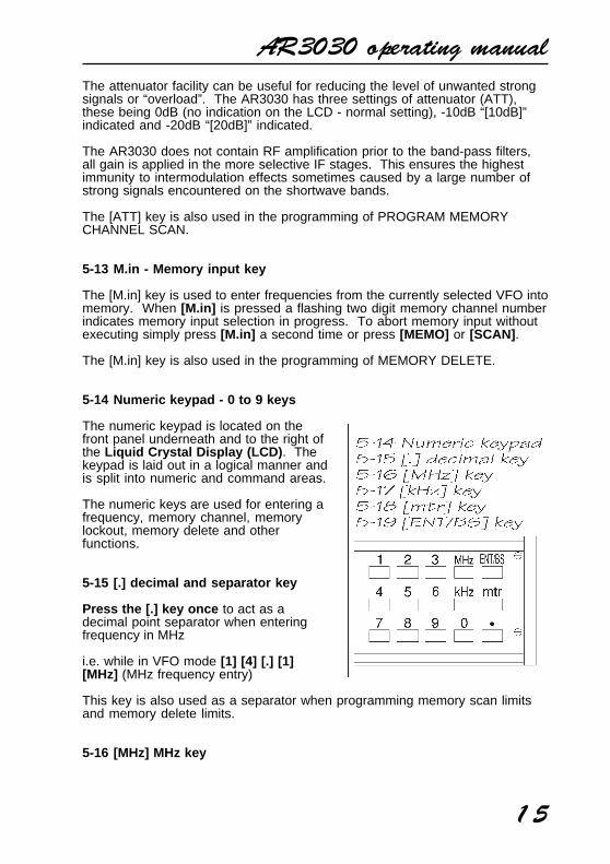
5-14 Numeric keypad - 0 to 9 keys
The numeric keypad is located on thefront panel underneath and to the right ofthe Liquid Crystal Display (LCD) . Thekeypad is laid out in a logical manner andis split into numeric and command areas.
The numeric keys are used for entering afrequency, memory channel, memorylockout, memory delete and otherfunctions.
5-15 [.] decimal and separator key
Press the [.] key once to act as adecimal point separator when enteringfrequency in MHz
i.e. while in VFO mode [1] [4] [.] [1][MHz] (MHz frequency entry)
This key is also used as a separator when programming memory scan limitsand memory delete limits.
5-16 [MHz] MHz key
AR3030 operating manual
16
The [MHz] key is used to complete frequency entry when MHz selection isrequired
i.e. while in VFO mode [4] [.] [7] [2] [2] [MHz]
While in VFO mode, this key alters selection of tuning rate to MHz. Anunderscore “[ _ ]” indicates the selection of MHz tuning speed on the LCD.
Note: Frequencies below 1.8 MHz are treated as kHz. For this reason1 MHz cannot be selected using the [MHz] key in conjunction with
the rotary tuning control.
5-17 [kHz] kHz key
The [kHz] key is used to complete frequency entry when kHz selection isrequired
1.e. while in VFO mode [4] [7] [2] [2] [kHz]
While in VFO mode, this key alters selection of tuning rate from 5Hz (10Hzindication) to hundreds of Hz and kHz. An underscore “[ _ ]” indicates thecurrent tuning speed on the LCD.
While using the VHF converter , frequency step size range is 5Hz, 10Hz,100Hz, 1kHz, 100kHz. When tuning in 5Hz steps, a square box appears to theright hand side of the LCD.
5-18 [mtr] metre key
The [mtr] key is used to complete frequency band entry.
i.e. while in VFO mode, to call the 49m broadcast band type [4] [9] [mtr]
Pressing [0] [mtr] while in VFO mode selects manual BFO tuning for CW andSSB modes. An “[o]” indicator appears on the LCD to confirm selection. Thesame sequence de-selects manual BFO.
5-19 ENT/BS - ENTer and BackSpace key
This key is not used for frequency entry but to complete sequences ofvarious data such as memory scan and delete. During keypad frequencyentry this key may be used to backspace delete incorrect entries.
If you wish to abort the completed keypad frequency entry press [MEMO] toreturn to VFO mode.
While in VFO mode, pressing the [ENT/BS] key activates keypad androtary tuning lock. A row of five underscores “[_ _ _ _ _]” indicateskeypad / VFO lock. Press the key a second time to deactivate keypadlock.
AR3030 operating manual
17
The receiver will always deactivate keypad/VFO lock when switched Off/On.
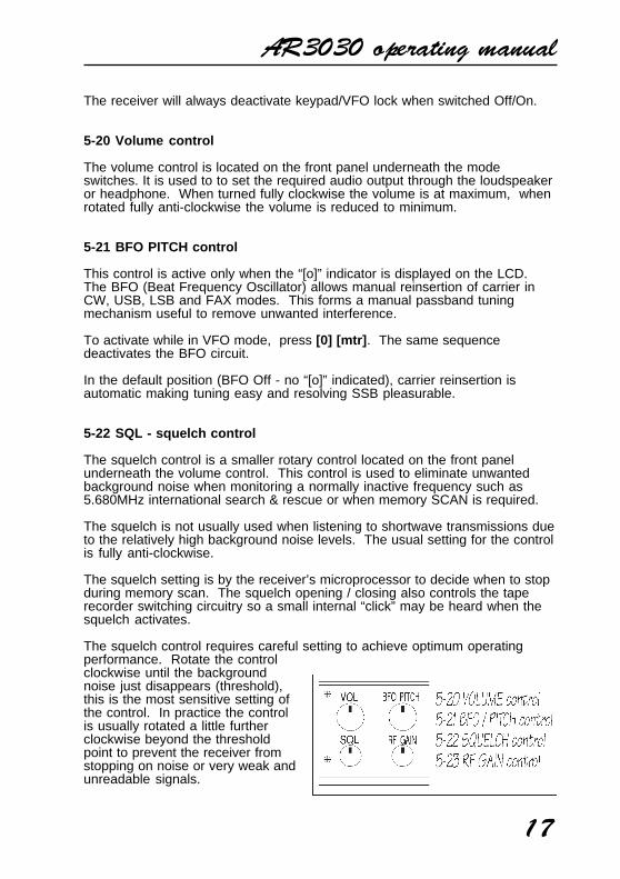
5-20 Volume control
The volume control is located on the front panel underneath the modeswitches. It is used to to set the required audio output through the loudspeakeror headphone. When turned fully clockwise the volume is at maximum, whenrotated fully anti-clockwise the volume is reduced to minimum.
5-21 BFO PITCH control
This control is active only when the “[o]” indicator is displayed on the LCD.The BFO (Beat Frequency Oscillator) allows manual reinsertion of carrier inCW, USB, LSB and FAX modes. This forms a manual passband tuningmechanism useful to remove unwanted interference.
To activate while in VFO mode, press [0] [mtr] . The same sequencedeactivates the BFO circuit.
In the default position (BFO Off - no “[o]” indicated), carrier reinsertion isautomatic making tuning easy and resolving SSB pleasurable.
5-22 SQL - squelch control
The squelch control is a smaller rotary control located on the front panelunderneath the volume control. This control is used to eliminate unwantedbackground noise when monitoring a normally inactive frequency such as5.680MHz international search & rescue or when memory SCAN is required.
The squelch is not usually used when listening to shortwave transmissions dueto the relatively high background noise levels. The usual setting for the controlis fully anti-clockwise.
The squelch setting is by the receiver’s microprocessor to decide when to stopduring memory scan. The squelch opening / closing also controls the taperecorder switching circuitry so a small internal “click” may be heard when thesquelch activates.
The squelch control requires careful setting to achieve optimum operatingperformance. Rotate the controlclockwise until the backgroundnoise just disappears (threshold),this is the most sensitive setting ofthe control. In practice the controlis usually rotated a little furtherclockwise beyond the thresholdpoint to prevent the receiver fromstopping on noise or very weak andunreadable signals.
AR3030 operating manual
18
If the control is rotated too far clockwise then weaker signals will be totally lostand only local strong signals will be heard.
5-23 RF GAIN control
This small rotary tuning control is located on the front panel underneath theBFO PITCH control.
The RF GAIN control reduces the level of amplification applied to the receiver’sI.F. circuits. This has the effect of reducing the sensitivity of the receiver inmuch the same way as the attenuator but is more controllable.
The usual position for the RF GAIN control is fully clockwise when the set is atits most sensitive. As the control is rotated anti-clockwise the S-meter willadvance to indicate what strength signal is required to produce solid andreadable results.
The control is most useful on SSB where the RF GAIN should be adjusted sothat the “peaks” of SSB signals just deflect the S-meter. This will greatlyreduce the level of background noise especially during pauses in speech orinactivity.
5-24 Rotary tuning control
The large rotary tuning control is prominently located on the front of thecabinet. This control changes the received frequency up and down in whateverstep increment is selected by the [kHz] and [MHz] keys. The minimum tuningrate is 5 Hz. This control is often referred to as the “VFO”.
5-25 S-meter (signal strength meter)
The rear illuminated analogue SIGNAL METER is located to the left hand sideof the front panel. Relative strength of incoming signal is indicated in standard“S” points where S1 is weak and S9 is strong. Calibration above S9 is in dB.As with other receivers, the calibration may not be reliable on FM mode.
5-26 Loudspeaker (internal)
The AR3030 is fitted with a large 66mm 3 WATT internal loudspeaker. Due toclever design, sound is projected through a small front mounted speaker grille.
When an external speaker or headphone is connected, the internal speaker isautomatically disconnected.
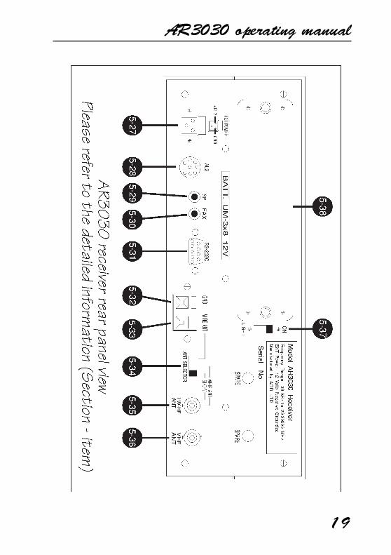
Rear panel5-27 EX POWER - external power connection
AR3030 operating manual
19
AR3030 operating manual
20
This is a special switching three pin socket designed to accept external DCinput of a nominal 13.8V DC @ 0.7A negative ground. You may either connectthe power supply provided or another suitable supply such as a 12V car batteryusing the optional DC3000 DC lead and observing the correct polarity:
RED = positiveWHITE = negative
At no time must AC mains power be connected directly to this socketor serious damage may occur and a risk of personal injury.
When the power plug is removed from the EX POWER socket, supply isautomatically switched to internal batteries should they be fitted.
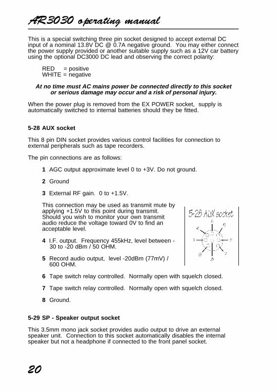
5-28 AUX socket
This 8 pin DIN socket provides various control facilities for connection toexternal peripherals such as tape recorders.
The pin connections are as follows:
1 AGC output approximate level 0 to +3V. Do not ground.
2 Ground
3 External RF gain. 0 to +1.5V.
This connection may be used as transmit mute byapplying +1.5V to this point during transmit.Should you wish to monitor your own transmitaudio reduce the voltage toward 0V to find anacceptable level.
4 I.F. output. Frequency 455kHz, level between - 30 to -20 dBm / 50 OHM.
5 Record audio output, level -20dBm (77mV) / 600 OHM.
6 Tape switch relay controlled. Normally open with squelch closed.
7 Tape switch relay controlled. Normally open with squelch closed.
8 Ground.
5-29 SP - Speaker output socket
This 3.5mm mono jack socket provides audio output to drive an externalspeaker unit. Connection to this socket automatically disables the internalspeaker but not a headphone if connected to the front panel socket.
AR3030 operating manual
21
An external speaker should have a nominal 8 OHM impedance and powerhandling of 2 WATTS or greater.
5-30 FAX - FAX audio output socket
This 3.5mm mono jack socket is designed to provide a suitable audiocharacteristic and constant level output to feed data facsimile decoders.Output is 600 OHM 0dBm constant.
5-31 RS232C - Computer control port
The 9 pin female D type RS232C control socket and associated internalcircuitry is fitted as standard. This permits the receiver to be connecteddirectly to a computer for “hands off” remote control.
Please refer to the COMPUTER CONTROL section (7) for a full list of facilities,protocols and connection details.
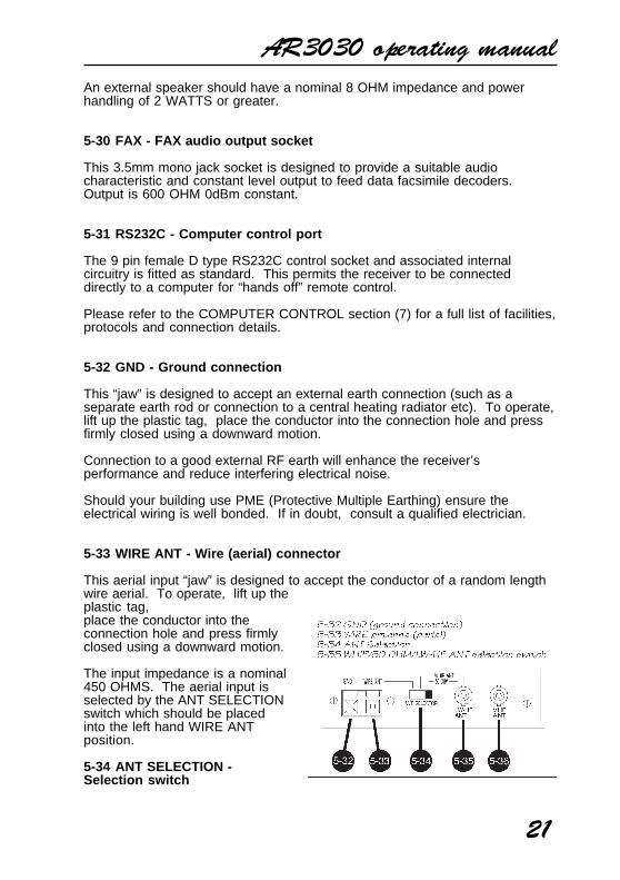
5-32 GND - Ground connection
This “jaw” is designed to accept an external earth connection (such as aseparate earth rod or connection to a central heating radiator etc). To operate,lift up the plastic tag, place the conductor into the connection hole and pressfirmly closed using a downward motion.
Connection to a good external RF earth will enhance the receiver’sperformance and reduce interfering electrical noise.
Should your building use PME (Protective Multiple Earthing) ensure theelectrical wiring is well bonded. If in doubt, consult a qualified electrician.
5-33 WIRE ANT - Wire (aerial) connector
This aerial input “jaw” is designed to accept the conductor of a random lengthwire aerial. To operate, lift up theplastic tag,place the conductor into theconnection hole and press firmlyclosed using a downward motion.
The input impedance is a nominal450 OHMS. The aerial input isselected by the ANT SELECTIONswitch which should be placedinto the left hand WIRE ANTposition.
5-34 ANT SELECTION -Selection switch
AR3030 operating manual
22
This three position slide switch allows selection of aerial input.
In the left position the high impedance wire input is selected.
In the centre position a small level of amplification along with impedancematching is applied to the BNC aerial input to permit operation from a smallhigh impedance telescopic whip aerial.
In the right position the 50 OHM BNC aerial socket is selected allowingconnection to low impedance coaxial aerials such as dipoles, magnetic baluns,loop aerials (AOR LA320), coaxial fed systems (like the AOR WA7000 activeaerial) or an aerial tuning unit.
5-35 WHIP ANT / 50 OHM / LW-HF ANT socket
This is a high quality 50 OHM BNC aerial input socket. BNC is the commercialstandard and offers superior performance to the cheaper SO239 socket. Ofcourse inter-series adaptors are widely available so connection to almost anyaerial system should not present a problem.
5-36 VHF ANT - VHF socket
This is a 50 OHM BNC aerial input socket for use when an optional VHFconverter is fitted. Suitable aerials include telescopic whips, VHF dipoles,groundplanes and discones.
5-37 LIGHT switch
The LCD and S-meter illumination is selectable On/Off via this switch. Thisfacility is particularly useful if the receiver is being operated from batteries inorder to reduce the current taken by the receiver and lengthen the operationaltime.
5-38 BATT compartment
This is the battery compartment. Access is achieved by removing (andcarefully storing) the two knurled nuts. Inside the battery compartment is acradle designed to accept 8 x UM-3 (AA size) batteries.
The receiver has not been designed to operate for a long timefrom batteries. However, depending upon the type of batteryused operation is typically 30 minutes using Manganese and
45+ minutes when using Alkaline cells.
Always remove the batteries when they have expired (run down). Should youplan not to use the receiver for a period of time, remove the batteries to avoidpotential leakage.
Note: The memory channel data is held by an internal EEPROMwhich does not require batteries or connection to external supply.
AR3030 operating manual
23
(6) Basic manual operation of the receiver
Connect and select an appropriate aerial (antenna) to the input on the rear ofthe receiver. The selection of aerial depends upon your location and specificrequirements but may include a dipole or long wire. There is further aerialinformation in this manual (section 10). If in doubt please consult your dealer.
Connect the AR3030 to an appropriate DC power source using either thesupplied AC adaptor or optional DC3000 DC lead. Never connect thereceiver directly to the mains.
Before turning on the power switch, set the volume to the 10 o’clock positionand squelch control to the 8 o’clock position (fully anti-clockwise).
Press the power switch until it latches in (depressed) which is the “Onposition”.
Ensure the label “MEMO” is not displayed on the LCD, if it is then press the[VFO] key once until the label “MEMO” is cancelled.
When the above procedure is complete the receiver is ready to acceptfrequency input, change of mode etc. As with all modern microprocessorcontrolled equipment, the AR3030 has enormous potential and capabilities.
Note: The AR3030 uses an EEPROM (Electronically ErasableProgrammable Read Only Memory) for storage of memories, metreband information and other parameters. A permanent storage EEPROMhas the advantage of not requiring a back-up battery to maintain dataeven when the receiver is disconnected from a power supply. TheEEPROM may be over-written many thousands of times.
In order to provide the maximum EEPROM life span a “fuzzy logic” hasbeen applied to the storage system which attempts to intuitivelydetermine when to store new data.
For this reason, the last frequency used in VFO mode via the tuningcontrol or keypad will not be recalled upon switch-On unless you hadlistened to it for more than about 15 seconds (the actual time dependsupon many factors but typically ranges from 6 to 13 seconds).
Similarly when using the metre key, if you haven’t “listened” to a newfrequency for more than 15 seconds or so, it will not have updated themetre band data. This can be used as a positive asset under certaincircumstances when tuning through amateur radio bands etc and youwish to return to the starting point... simply re-enter the metre band.
To achieve the maximum use of the receiver’s performance and features, it isimportant to fully familiarise yourself with it’s operation through the use of thishandbook.6-1 Tuning the receiver using the rotary control
AR3030 operating manual
24
The receiver may be immediately tuned via the rotary tuning control. The freerunning tuning knob is used to select receiving frequency and in memory modefor selection of memory channel.
The tuning knob is by far the most “traditional” approach to tuning onshortwave providing a smooth feel and the best method of user interfaceespecially when listening on the SSB, FAX and CW modes.
It is possible to tune the receiver through it’s entire range from 30kHz to29.99999MHz. Rotating the tuning control clockwise increases the displayedfrequency (and tunes the receiver upward), rotating the tuning control anti-clockwise decreases the displayed frequency (and tunes the receiverdownward).
At some point you may wish to increase the speed of tuning, this isaccomplished using the [kHz] and [MHz] keys.
You will note a small underscore “_” underneath one of the frequency readoutdigits. It is possible to move the underscore by pressing the [kHz] key. Theunderscore will move from the underneath of the right digit (tens of Hz),second from right (hundreds of Hz) and third from right (kHz). Pressing the[kHz] key again returns the underscore to the right.
The position of the underscore determines the rate of tuning. On shortwave,the receiver will tune in either 5Hz steps (10Hz resolution), 100Hz steps of1kHz steps.
In a similar way, you may decide to change the MHz readout using the rotarytuning control. To accomplish this, simply press the [MHz] key. An under-score “_” will appear on the LCD underneath the MHz digit to confirm selection.To return to fine tuning press the [kHz] key.
6-2 Changing receive mode
There are two mode keys on the front panel located between the S-meter andLCD, there are also seven LED indicators to show the current mode selected.Either key may be pressed to change mode.
Any receive mode may be selected at any frequency within the receiver’sshortwave coverage.
Generally speaking the following modes will apply:
AMAmplitude Modulation - Used by broadcast services throughout the World onlongwave, medium wave and shortwave. AM is also used by commercialairband 108 - 137MHz (should you have the VHF converter option fitted).
For best results, you will have to experiment with the setting of AGC betweenfast and slow.S.AMSynchronous AM - (the AR3030 uses double side band synchronous
AR3030 operating manual
25
detection). This is a special form of AM reception capable of reducing fadingon longwave, mediumwave and shortwave signals especially at night.
The receiver must first be accurately tuned in standard AM mode then switchedto S.AM. A short whistle may be heard as the set “locks” onto the receivedstation. If a sustained whistle is encountered then you probably do not havethe receiver quite centred on the station, try tuning up and down by a coupleof kHz and try again.
For best results, you will have to experiment with the setting of AGC betweenfast and slow.
FMNarrow Band Frequency Modulation - this provides high quality communicationfor relatively short distance operation. FM uses a greater frequency bandwidththan other modes such as SSB so is less efficient.
Typically on shortwave, FM is used by UK Citizen Band radio and 10mAmateur Band operation centred around 29.6 MHz. FM is widely used on theVHF bands: Marine band, 2m Amateur Band (145MHz) and PMR (PrivateMobile Radio) but not commercial airband which still uses AM. If the optionalVHF converter fitted, FM will be quite active in most areas.
In the absence of a signal, the background white noise may appear quite loud.For ease of listening the squelch control should be rotated clockwise until thebackground noise just disappears, this should be carried out when no signal ispresent. The point where the background noise is cancelled is known as“threshold point”. Do not advance the squelch control more than necessary orthe receiver will appear to be desensitised and weaker signals will be missed.
LSBLower Side Band - is a form or Single Side Band (SSB). LSB tends not to beused commercially but is extensively used by Radio Amateurs on frequenciesbelow 10 MHz. This assists the separation of Commercial and Amateur userson traditionally shared bands and prevents them from speaking to each other.
SSB is a very efficient method of transmission as the unwanted secondsideband and carrier have been removed. This allows the full transmitterpower to be employed in carrying useful information within the wantedsideband. As a result greater distances are possible on SSB and a smallerfrequency bandwidth is required than most other modes.
The AR3030 uses true carrier re-insertion so that voice becomes intelligible.However due to the complexities of SSB, audio never sounds 100% naturaland often listeners comment on it sounding a little like “Donald Duck” or “MickyMouse” but this is normal and with practice you soon become used to thischaracteristic.
The setting of AGC is important for SSB reception. Usually a SLOW settingprovides the best results when background noise will usually be reduced.
Rotate the RF gain control anti-clockwise so that the S-meter needle just “lifts”with voice peaks, this can reduce the background noise especially during
AR3030 operating manual
26
pauses in speech.
Do remember that reducing the RF GAIN control (which increases deflection ofthe S-meter) reduces the sensitivity of the receiver, the normal position is fullyclockwise.
USBUpper Side Band - The same comments apply as for LSB. By convention,Radio Amateurs also use USB above 10MHz.
An optional Collins 2.5kHz 8 resonator mechanical filter of high specificationmay be fitted in place of the standard 2.4kHz Murata ceramic filter forimproved selectivity.
CWContinuous Wave - Often referred to a Carrier Wave or Morse code. Selectionof CW changes the audio tailoring to best suite reception of “dots and dashes”.A 500Hz Collins 7 resonator mechanical filter may be optionally fitted in theNARROW filter position and will greatly aid rejection of unwanted signals onthis mode.
FAXFacsimile - Selection of [FAX] optimises the receiver for reception of weatherand news facsimile. The 2.4kHz standard SSB filter is employed but audiotailoring is optimised for facsimile reception. A constant level 0dBm 600 OHMaudio output is available through a rear panel 3.5mm FAX OUTPUT socketready to feed an external facsimile decoder / printer such as the AORWX-2000.
6-3 Changing VFO A/B
In the true sense of the word, “VFO” stands for Variable FrequencyOscillator . Of course as technology improved so modern receivers do notstrictly use a VFO, in the case of the AR3030 a Direct Digital Synthesizer(DDS) is employed.
However, the term “VFO” has generally come to mean “current tuningparameters” and refers to the tunable frequency currently displayed alongwith mode and other settings such as attenuator, filters etc.
In this sense, the AR3030 has two VFOs’ available A and B.
Two VFOs’ can be useful for listening to split frequency communications suchas a DX pile up on the Amateur bands where a much sort after station istransmitting on one frequency but listening on another. Another examplewould be coastal marine communications where split frequencies areemployed.
Should the optional VHF converter be fitted then split frequency operation(known as DUPLEX) is common place. (Single frequency operation is knownas SIMPLEX).The currently selected VFO is indicated on the LCD by [A] or [B]. To changefrom one to another simply press the [VFO] key. To return to the original VFO
AR3030 operating manual
27
press the [VFO] key again.
Note: The rotary tuning control is also often historicallyreferred to as the VFO.
6-4 TONE - Audio tailoring
The audio characteristic is adjustable on most modes via the [TONE] key onthe front panel.
Selecting a high tone setting may improve the listening quality of strongbroadcast services such as longwave but where adjacent interference isexperienced selecting the low setting may reduce the levels of annoyingheterodynes.
The current setting of tone is indicated on the LCD as [HIGH] or [LOW].
The actual audio tailoring characteristics are:
USB/LSB/AM/S.AM/FMTONE High position cut off frequency 3000 HzTONE Low position cut off frequency 1800 Hz
CWTONE key inoperative. Frequency set to 800 Hz
FAXTONE key inoperative
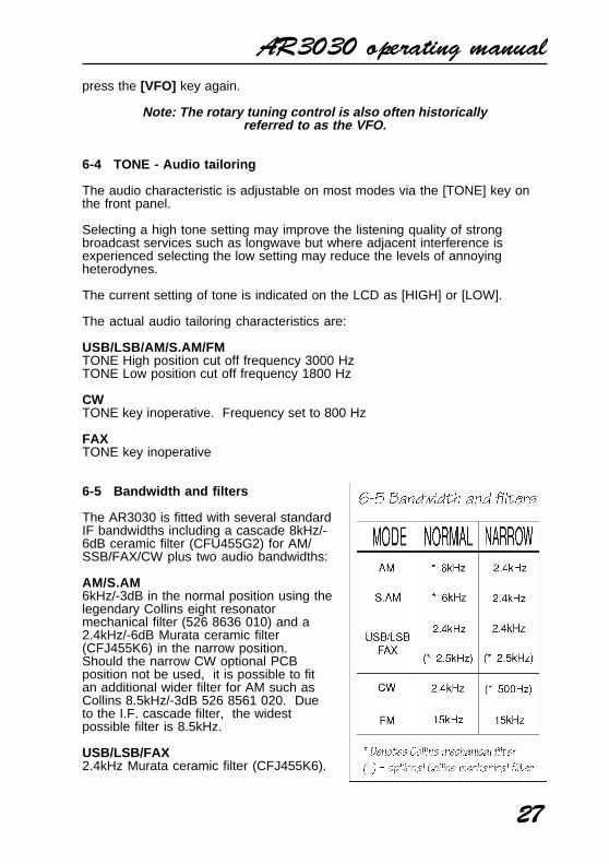
6-5 Bandwidth and filters
The AR3030 is fitted with several standardIF bandwidths including a cascade 8kHz/-6dB ceramic filter (CFU455G2) for AM/SSB/FAX/CW plus two audio bandwidths:
AM/S.AM6kHz/-3dB in the normal position using thelegendary Collins eight resonatormechanical filter (526 8636 010) and a2.4kHz/-6dB Murata ceramic filter(CFJ455K6) in the narrow position.Should the narrow CW optional PCBposition not be used, it is possible to fitan additional wider filter for AM such asCollins 8.5kHz/-3dB 526 8561 020. Dueto the I.F. cascade filter, the widestpossible filter is 8.5kHz.
USB/LSB/FAX2.4kHz Murata ceramic filter (CFJ455K6).
AR3030 operating manual
28
An optional 2.5kHz/-3dB Collins eight resonator mechanical filter (526 8635010) of higher specification may be optionally fitted (workshop fitting) toreplace the 2.4kHz filter. Should the narrow CW optional PCB position not beused, it is possible to fit the optional Collins 2.5kHz filter as an addition whichwill be selected in the narrow position.
CW2.4kHz Murata ceramic filter in the Normal position. An optional 500Hz/-3dBCollins seven resonator mechanical filter (526 8634 010) may be optionallyfitted (workshop fitting)in the Narrow position.
FM15kHz Murata ceramic filter (CFU455E2) fixed. Selection of Normal/Narrow isdisabled.
The AR3030 is fitted with several standard I.F. bandwidths:
Selecting a narrow filter setting can improve intelligibility under somecircumstances when listening to AM and S.AM. The fitting of a narrow500Hz CW filter greatly improves the rejection of unwanted adjacentsignals. Indication of current setting is provide on the LCD as [NOR] or[NRW].
6-6 AGC - Automatic Gain Control
This key is used to select the Automatic Gain Control setting on all modesexcept FM. The status of AGC is indicated on the LCD as [FAST] or [SLOW].It is not possible to switch the AGC off.
Generally speaking [FAST] is used for CW and some data communicationsreception and [SLOW] is used for USB & LSB. A slow setting on SSB canreduce the background noise during pauses in speech.
For AM and S.AM reception the setting will depend on receiving conditions.
6-7 ATT - Attenuator operation
The attenuator can be useful for reducing the level of unwanted strong signalsor overload. The AR3030 has three settings for ATT, these being 0dB (noindication on the LCD - normal setting), -10dB [10dB] indicated and -20dB[20dB] indicated.
The AR3030 does not contain RF amplification prior to the band-pass filters,all gain is applied in the more selective I.F. stages. This ensures the highestimmunity to intermodulation effects sometimes caused by a large number ofstrong signals on the shortwave bands.
6-8 RF GAIN control
AR3030 operating manual
29
The usual position for this control is fully clockwise.
The setting of RF GAIN is particularly important for SSB reception to preventan unpleasant rise in background noise especially during pauses in speech.
When listening to SSB transmissions, rotate the RF gain control anti-clockwise so that the S-meter needle just “lifts” with speech peaks. This willgreatly reduce background noise levels.
Do remember that reducing the RF GAIN control (which increasesdeflection of the S-meter) reduces the sensitivity of the receiver, thenormal position is fully clockwise.
6-9 SQUELCH control
In the absence of a signal, background white noise may appear quite loudespecially in FM mode. For ease of listening the AR3030 is fitted with an “allmode” squelch circuit. The squelch control should be rotated clockwise untilthe background noise just disappears and be carried out when no signal ispresent.
The point where the background noise is cancelled is known as “thresholdpoint”. Do not advance the squelch control more than necessary or thereceiver will appear desensitised and weaker signals will be missed.
It is important for the squelch control to close when using an optional VHFconverter as it’s status is used by the microprocessor to determine when afrequency is clear and when it is busy.
The usual position for the squelch control is fully anti-clockwise.
6-10 BFO PITCH control
Due to the complexities of SSB, audio never sounds 100% natural and oftenlisteners comment on it sounding a little like “Donald Duck” or “Micky Mouse”,this is normal and with practice you soon become used to this characteristic.
The AR3030 uses automatic carrier re-insertion to make tuning of SSB/FAX/CW as easy as possible. However should you wish to change the beat note onCW reception or alter the tonal characteristics of SSB/FAX it is possible toengage a manual BFO. “BFO” stands for Beat Frequency Oscillator andtakes the place of automatic carrier re-insertion.
One benefit of the manual BFO setting is to form a simple manual type ofpassband tuning to reduce the potential interfering effects of adjacent strongsignals.
The normal position for the BFO PITCH control is 12 o’clock.
To activate the BFO in VFO mode press the [0] key followed by [mtr] . TheLCD will display a “o” to indicate that manual BFO mode has been selected. If
AR3030 operating manual
30
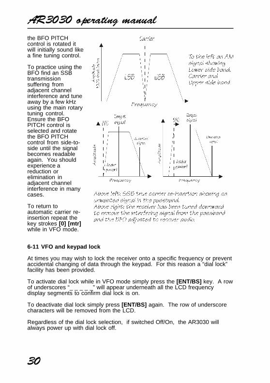
the BFO PITCHcontrol is rotated itwill initially sound likea fine tuning control.
To practice using theBFO find an SSBtransmissionsuffering fromadjacent channelinterference and tuneaway by a few kHzusing the main rotarytuning control.Ensure the BFOPITCH control isselected and rotatethe BFO PITCHcontrol from side-to-side until the signalbecomes readableagain. You shouldexperience areduction orelimination inadjacent channelinterference in manycases.
To return toautomatic carrier re-insertion repeat thekey strokes [0] [mtr]while in VFO mode.
6-11 VFO and keypad lock
At times you may wish to lock the receiver onto a specific frequency or preventaccidental changing of data through the keypad. For this reason a “dial lock”facility has been provided.
To activate dial lock while in VFO mode simply press the [ENT/BS] key. A rowof underscores “_ _ _ _ _” will appear underneath all the LCD frequencydisplay segments to confirm dial lock is on.
To deactivate dial lock simply press [ENT/BS] again. The row of underscorecharacters will be removed from the LCD.
Regardless of the dial lock selection, if switched Off/On, the AR3030 willalways power up with dial lock off.
AR3030 operating manual
31
6-12 Entering a frequency via the keypad
Where exact frequencies are known, you may wish to enter a frequencydirectly through the keypad. The numeric keypad is located on the front panelunderneath and to the right of the LCD. The keypad is laid out in a logicalmanner and is split into numeric and command areas.
The numeric keys are used for entering a frequency with the decimal key [.]acting as a separator. It is possible to enter frequencies as MHz, kHz or bymetre band.
Entry as MHz:
For example, to select 14.10000 MHz follow the key sequence:
[1] [4] [.] [1] [MHz] (MHz frequency entry)
You will note that the trailing zeros are not required as the AR3030 completesthe entry at the time the [MHz] key is pressed.
Entry as kHz:
For example, to select 4722 kHz (4.722 MHz) follow the key sequence:
[4] [7] [2] [2] [kHz] (kHz frequency entry)
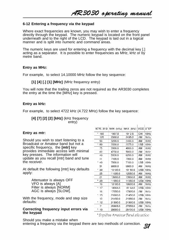
Entry as mtr:
Should you wish to start listening to aBroadcast or Amateur band but not aspecific frequency, the [mtr] keyprovides immediate access with minimalkey presses. The information willupdate as you recall [mtr] band and tunethe receiver.
At default the following [mtr] key defaultsapply:
Attenuator is always OFFVFO is always [A]Filter is always [NORM]AGC is always [SLOW].
With the frequency, mode and step sizedefaults:
Correcting frequency input errors viathe keypad
Should you make a mistake whenentering a frequency via the keypad there are two methods of correction.
AR3030 operating manual
32
Back Space delete
The [ENT/BS] key acts as a “BS” Back Space just like a computer keyboarddeleting data input from the right hand side.
For example, if you wish to enter 3.750 MHz but had keyed [3] [.] [7] [5] [8]the last digit being “8” in place of “0”, before pressing [MHz] press the [ENT/BS] key. The last digit on the right hand side will be deleted. You can thenpress the correct key [0] and complete the sequence with [MHz] .
Should you press [ENT/BS] twice during the sequence, then the first two digitson the right hand side would be deleted and so on.
[MEMO] - abort frequency input
Should you decide to abort the frequency input during programming, press the[MEMO] key once to abort. The display will return to the frequency prior toinput and the sequence aborted.
6-13 Memory mode - [MEMO] - [M.in] - [PASS] - [ENT/BS]
There are 100 memory channels (00 to 99) which can store frequency, mode,AGC, attenuator, bandwidth, AF filter (tone), BFO status and lockout status.The memories can be used to store shortwave or VHF frequencies if the VHFconverter option has been fitted.
Program scan allows only a selected block of channels to be scanned whilelockout causes certain channels to be skipped. Pause and delay scan add toflexibility.
Data may be easily entered into memory or from memory to VFO for tuning.
There is a massive EEPROM store for all memory channels and VFO dataso that no memory backup battery is required. The memories may beover-written time and time again.
Note: Memory channels 1 to 9 must be entered using a zero prefix.i.e. memory channel 2 is “02” and channel 3 is “03” etc.
Memory select - [MEMO] key
In VFO mode the LCD display will not show any legend relating to the memoryoperations such as memory channel number, SCAN and PASS.
To select memory mode press the [MEMO] key. The legend “MEMO” willappear on the LCD to confirm selection.
AR3030 operating manual
33
Presuming data has been stored, in memory mode press [0][1] to selectmemory channel 1, [0][2] for memory channel 2, etc.
Alternatively you may rotate the main rotary tuning control to select memorychannel. If no data has been stored then “empty” channels will be “skipped”when turning the main rotary tuning control or when selected via the keypad.
While the legend “MEMO” is displayed along with a channel number, theAR3030 will be actually receive the displayed frequency.
Return to VFO:
To return to VFO mode simply press the [VFO] key.
Transfer memory to VFO:
To transfer the current memory data to VFO press [MEMO] while the “MEMO”legend is displayed on the LCD.
6-14 Memory write - [M.in] key
While tuning in VFO mode , you may wish to store an interesting or regularlyused frequency into memory so that it may be called upon quickly andconveniently.
To store the current VFO data into memory (which includes frequency, mode,AGC, ATT, TONE, BW, BFO status, tuning step) the [M.in] and [ENT/BS]keys are used.
Automatic:
Press the [M.in] key and the AR3030 will automatically select the first lowestnumber empty memory channel (unless they are all in use in which casechannel [00] is always selected). The memory channel number will appear onthe lower left hand side of the LCD and will flash to indicate memory writemode.
Press the [ENT/BS] key to complete the sequence.
As the AR3030 automatically increments to the next available memorychannel, it is easy to keep the memory channel allocation sequential and tidywithout having to remember which channels have already been used.
Manual:
It is possible to store VFO data into any of the 100 memory channels and over-write current data if required.
AR3030 operating manual
34
Let’s assume that you have 14.25000 MHz USB displayed in VFO mode andyou wish to write into memory channel number 25 which has not beenpreviously used.
Press [M.in] followed by the channel number desired memory channel number[2] [5] , ignore any automatically displayed channel number before 25 waskeyed. The chosen channel number will flash to indicate memory write mode.To complete the sequence press the [ENT/BS] key, a beep sounds to confirmcorrect entry.
Note: If the memory channel already had data present then the previouslystored data would “cause the whole LCD to flash twice” and a low-levelbeep sounded to draw your attention that you will over-write data.
You must wait for the two flashes to execute before completing thesequence with the [ENT/BS] key. A high pitched beep confirms correct entryand completion of the memory input sequence.
Of course if you decide not to over-write the data which has been displayedsimply select another memory channel using the keypad.To abort memory input press [MEMO] .
6-15 Deleting memory contents
Although you may over-write memory channels time and time again, there willbe occasions when you may wish to delete a particular memory channel orwhole bank of channels. This is especially true if you are reorganising thememory contents or planning to use the program scan facility.
Deleting a single memory channel
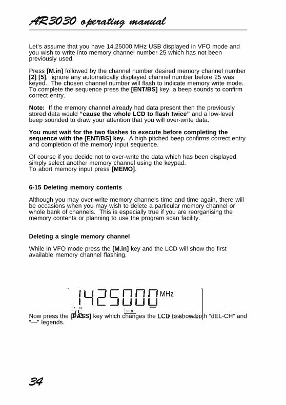
While in VFO mode press the [M.in] key and the LCD will show the firstavailable memory channel flashing.
Now press the [PASS] key which changes the LCD to show both “dEL-CH” and“—” legends.
AR3030 operating manual
35
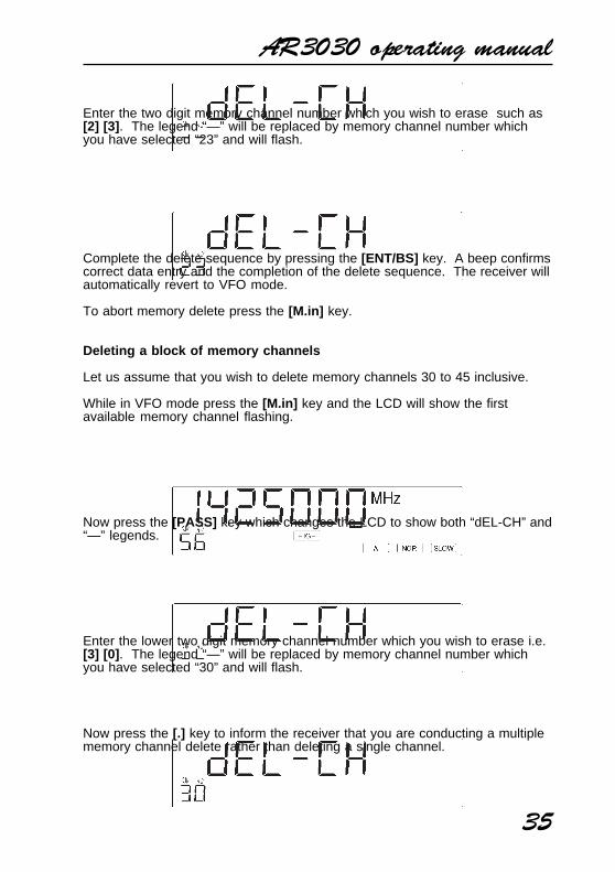
Enter the two digit memory channel number which you wish to erase such as[2] [3] . The legend “—” will be replaced by memory channel number whichyou have selected “23” and will flash.
Complete the delete sequence by pressing the [ENT/BS] key. A beep confirmscorrect data entry and the completion of the delete sequence. The receiver willautomatically revert to VFO mode.
To abort memory delete press the [M.in] key.
Deleting a block of memory channels
Let us assume that you wish to delete memory channels 30 to 45 inclusive.
While in VFO mode press the [M.in] key and the LCD will show the firstavailable memory channel flashing.
Now press the [PASS] key which changes the LCD to show both “dEL-CH” and“—” legends.
Enter the lower two digit memory channel number which you wish to erase i.e.[3] [0] . The legend “—” will be replaced by memory channel number whichyou have selected “30” and will flash.
Now press the [.] key to inform the receiver that you are conducting a multiplememory channel delete rather than deleting a single channel.
AR3030 operating manual
36
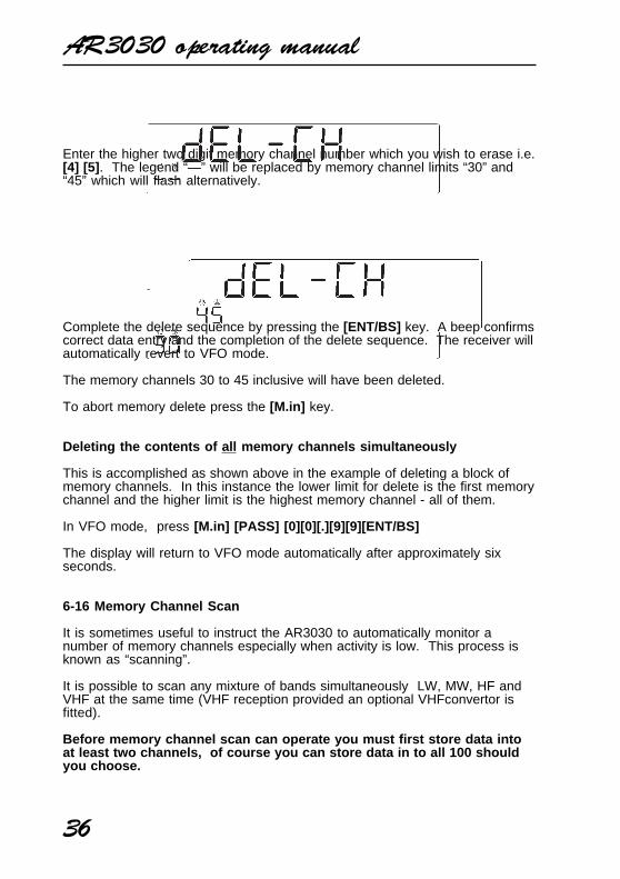
Enter the higher two digit memory channel number which you wish to erase i.e.[4] [5] . The legend “—” will be replaced by memory channel limits “30” and“45” which will flash alternatively.
Complete the delete sequence by pressing the [ENT/BS] key. A beep confirmscorrect data entry and the completion of the delete sequence. The receiver willautomatically revert to VFO mode.
The memory channels 30 to 45 inclusive will have been deleted.
To abort memory delete press the [M.in] key.
Deleting the contents of all memory channels simultaneously
This is accomplished as shown above in the example of deleting a block ofmemory channels. In this instance the lower limit for delete is the first memorychannel and the higher limit is the highest memory channel - all of them.
In VFO mode, press [M.in] [PASS] [0][0][.][9][9][ENT/BS]
The display will return to VFO mode automatically after approximately sixseconds.
6-16 Memory Channel Scan
It is sometimes useful to instruct the AR3030 to automatically monitor anumber of memory channels especially when activity is low. This process isknown as “scanning”.
It is possible to scan any mixture of bands simultaneously LW, MW, HF andVHF at the same time (VHF reception provided an optional VHFconvertor isfitted).
Before memory channel scan can operate you must first store data intoat least two channels, of course you can store data in to all 100 shouldyou choose.
AR3030 operating manual
37
The receiver must first be placed into VFO mode . If in doubt press the[VFO] key and check that the “MEMO” legend is not shown on the LCD.
Press [SCAN] to start memory channel scan from the memory channel lastused. Both the “MEMO” and “SCAN” legends will appear on the LCD toconfirm operation. All memory channels containing data will be scanned butempty channels will be skipped.
To stop the scanning process press [SCAN] again. The receiver will continueto receive on the channel where scan has been stopped but will return to VFOmode copying the data automatically.
To resume scanning once again simply press [SCAN] .
6-17 Program Memory Channel Scan
It is possible to instruct the AR3030 to scan a group of memory channelsrather than all channels which contain data. This is a convenient method ofscanning a few memory channels without needing to delete temporarilyunwanted memory channels.
The following example assumes data is stored in about the first twenty memorychannels, you wish to scan only channels 5 to 12 inclusive.
Ensure the receiver is in VFO mode , if in doubt press the [VFO] key andensure that “MEMO” is not displayed.
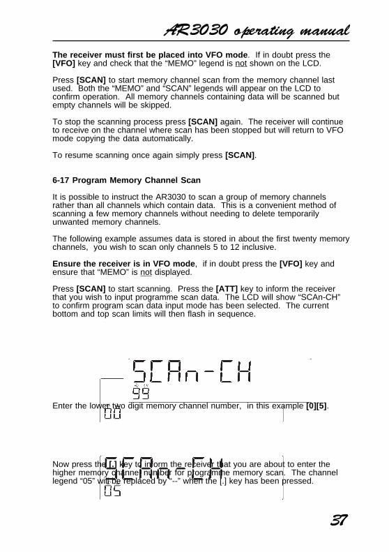
Press [SCAN] to start scanning. Press the [ATT] key to inform the receiverthat you wish to input programme scan data. The LCD will show “SCAn-CH”to confirm program scan data input mode has been selected. The currentbottom and top scan limits will then flash in sequence.
Enter the lower two digit memory channel number, in this example [0][5] .
Now press the [.] key to inform the receiver that you are about to enter thehigher memory channel number for programme memory scan. The channellegend “05” will be replaced by “--” when the [.] key has been pressed.
AR3030 operating manual
38
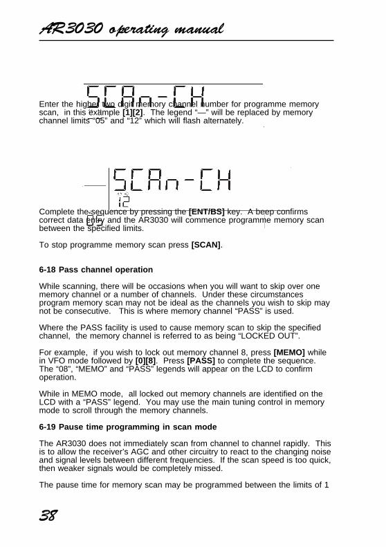
Enter the higher two digit memory channel number for programme memoryscan, in this example [1][2] . The legend “—” will be replaced by memorychannel limits “05” and “12” which will flash alternately.
Complete the sequence by pressing the [ENT/BS] key. A beep confirmscorrect data entry and the AR3030 will commence programme memory scanbetween the specified limits.
To stop programme memory scan press [SCAN] .
6-18 Pass channel operation
While scanning, there will be occasions when you will want to skip over onememory channel or a number of channels. Under these circumstancesprogram memory scan may not be ideal as the channels you wish to skip maynot be consecutive. This is where memory channel “PASS” is used.
Where the PASS facility is used to cause memory scan to skip the specifiedchannel, the memory channel is referred to as being “LOCKED OUT”.
For example, if you wish to lock out memory channel 8, press [MEMO] whilein VFO mode followed by [0][8] . Press [PASS] to complete the sequence.The “08”, “MEMO” and “PASS” legends will appear on the LCD to confirmoperation.
While in MEMO mode, all locked out memory channels are identified on theLCD with a “PASS” legend. You may use the main tuning control in memorymode to scroll through the memory channels.
6-19 Pause time programming in scan mode
The AR3030 does not immediately scan from channel to channel rapidly. Thisis to allow the receiver’s AGC and other circuitry to react to the changing noiseand signal levels between different frequencies. If the scan speed is too quick,then weaker signals would be completely missed.
The pause time for memory scan may be programmed between the limits of 1
AR3030 operating manual
39
and 10 seconds. The factory default is 5 seconds.
For example, should you wish to program pause time to 3 seconds carry outthe following sequence.
While in VFO mode press [SCAN] to start memory channel scan.
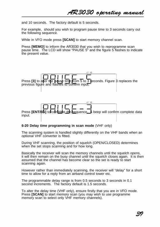
Press [MEMO] to inform the AR3030 that you wish to reprogramme scanpause time. The LCD will show “PAUSE 5” and the figure 5 flashes to indicatethe present value.
Press [3] to alter the pause time from 5 to 3 seconds. Figure 3 replaces theprevious figure and flashes to confirm input.
Press [ENT/BS] to complete the sequence, a beep will confirm complete datainput.
6-20 Delay time programming in scan mode (VHF only)
The scanning system is handled slightly differently on the VHF bands when anoptional VHF converter is fitted.
During VHF scanning, the position of squelch (OPEN/CLOSED) determineswhen the set stops scanning and for how long.
Basically the receiver will scan the memory channels until the squelch opens,it will then remain on the busy channel until the squelch closes again. It is thenassumed that the channel has become clear so the set is ready to startscanning again.
However rather than immediately scanning, the receiver will “delay” for a shorttime to allow for a reply from an airband control tower etc.
The programmable delay range is from 0.5 seconds to 3 seconds in 0.1second increments. The factory default is 1.5 seconds.
To alter the delay time (VHF only), ensure firstly that you are in VFO mode.Press [SCAN] to start memory scan (you may wish to use programmememory scan to select only VHF memory channels).
AR3030 operating manual
40
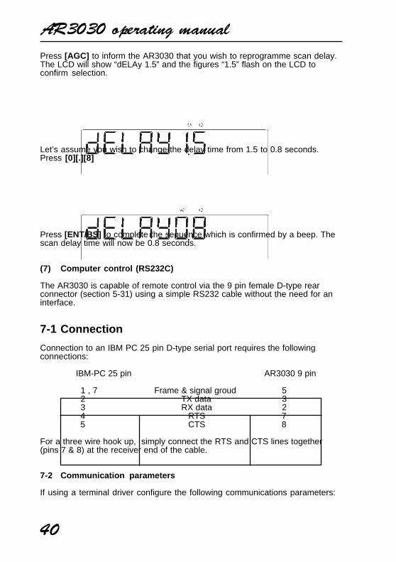
Press [AGC] to inform the AR3030 that you wish to reprogramme scan delay.The LCD will show “dELAy 1.5” and the figures “1.5” flash on the LCD toconfirm selection.
Let’s assume you wish to change the delay time from 1.5 to 0.8 seconds.Press [0][.][8]
Press [ENT/BS] to complete the sequence which is confirmed by a beep. Thescan delay time will now be 0.8 seconds.
(7) Computer control (RS232C)
The AR3030 is capable of remote control via the 9 pin female D-type rearconnector (section 5-31) using a simple RS232 cable without the need for aninterface.
7-1 Connection
Connection to an IBM PC 25 pin D-type serial port requires the followingconnections:
IBM-PC 25 pin AR3030 9 pin
1 , 7 Frame & signal groud 5 2 TX data 3 3 RX data 2 4 RTS 7 5 CTS 8
For a three wire hook up, simply connect the RTS and CTS lines together(pins 7 & 8) at the receiver end of the cable.
7-2 Communication parameters
If using a terminal driver configure the following communications parameters:
AR3030 operating manual
41
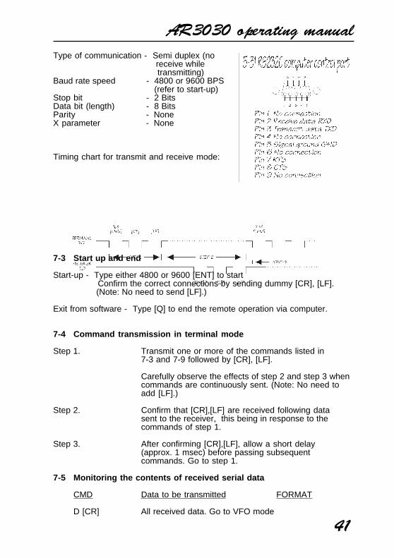
Type of communication - Semi duplex (no receive while transmitting)
Baud rate speed - 4800 or 9600 BPS (refer to start-up)
Stop bit - 2 BitsData bit (length) - 8 BitsParity - NoneX parameter - None
Timing chart for transmit and receive mode:
7-3 Start up and end
Start-up - Type either 4800 or 9600 [ENT] to start Confirm the correct connections by sending dummy [CR], [LF]. (Note: No need to send [LF].)
Exit from software - Type [Q] to end the remote operation via computer.
7-4 Command transmission in terminal mode
Step 1. Transmit one or more of the commands listed in7-3 and 7-9 followed by [CR], [LF].
Carefully observe the effects of step 2 and step 3 whencommands are continuously sent. (Note: No need toadd [LF].)
Step 2. Confirm that [CR],[LF] are received following datasent to the receiver, this being in response to thecommands of step 1.
Step 3. After confirming [CR],[LF], allow a short delay(approx. 1 msec) before passing subsequentcommands. Go to step 1.
7-5 Monitoring the contents of received serial data
CMD Data to be transmitted FORMAT
D [CR] All received data. Go to VFO mode
AR3030 operating manual
42
from Memory mode. 1
Y [CR] Send signal level (64 div 00 - 3F) 2
nn M [CR] Go to Memory mode after sendingdata of selected memory channel. 3
- nn = 00 ~ 99 Data of the selected memory channel
- nn = BLANK Data of the present memory channel
7-6 FORMAT 1 - Contents of the received signal
Contents of serial data ==> D Rn Gn Bn Tn Fnnnnnnnn C [CR] [LF]
Contents of each TX Details
D - HEADER D(DIAL)
Rn - ATT positionn = 0 OFFn = 1 10dBn = 2 20dB
Gn - AGC positionn = 0 Slown = 1 Fast
Bn - Filter positionn = 0 Normaln = 1 Narrow
Tn - Tone positionn = 0 Lown = 1 High
Fnnnnnnnn - Receive Frequency Present frequency
(LSD = 10Hz)- Other than VHF band 0nnnnnnn- VHF band nnnnnn00
C or - Present mode C C W U or U USB L or L LSB A or A A M S or S S.AM N or N F M X X FAX
AR3030 operating manual
43
7-7 FORMAT 2 - Reading the receiver’s signal strength
Contents of transmission === nn [CR] [LF]
Contents of TX Details
n - Send the S-Meter Readings in64 steps 00 ~ 3F00 MIN0102 :3E3F MAX
7-8 FORMAT 3 - Transmitting the memory contents
Contents of transmission =Mnn Pn Rn Gn Bn Tn Fnnnnnnnn C [CR] [LF]
Note: Mnn represents HEADER and Memory channel number.Pn indicates Memory channel Pass position:n == 0 ... PASS-OFF == 1 ... PASS-O N
Details of each TX is same as FORMAT 1When the selected channel is blank:. M— [CR] [LF] ... CHANNEL # == “—”
7-9 Change the receiving modes or Make new entries
CMD Function
nn W [CR] - Write the present contents into a selectedchannel and go to the memory mode.
W [CR] - Search for a blank channel and write the presentmemory contents (If no blank channel is found go to thedial mode followed by [M—]).
0 R [CR] - Selection of ATT OFF1 R [CR] 10 dB2 R [CR] 20 dB
0 G [CR] - Selection of AGC SLOW1 G [CR] FAST0 B [CR] - Selection of FILTER NORMAL1 B [CR] NARROW
0 T [CR] - Selection of TONE LOW1 T [CR] HIGH
AR3030 operating manual
44
nnn.nnnn [CR] - Enter the frequency (MHz) and go to the dial (VFO) mode.
Frequency entry for MHz band must be correct withinthe range of receiver. Over-flow digits will be ignoredfrom higher to lower in order.
C [CR] - Selection of mode C WU [CR] USBL [CR] LSBA [CR] A MS [CR] S.AMN [CR] F MX [CR] FAX
nn % [CR] - Removal of memory contents from the selected memory channel.
% [CR] - Removal of memory contents from all memory channels ( nn === BLANK )
0 P [CR] - Selection of PASS status in memory mode PASS OFF
1 P [CR] PASS O N
Q [CR] - Quit the remote control mode of RS232C
Remarks:
The above functions can be set up simultaneously by either one or morecommands. Frequency entry and mode selection must come at the end ofwhole command.
However removal of memory contents or memory channel pass entry can onlybe carried out individually.
The last command must be followed by either [CR] or [CR], [LF].
(8) Optional accessories
VHF converters
Two separate optional VHF internal converters are planned for the AR3030 but
AR3030 operating manual
45
only one may be fitted at a time. It’s fitting is recommended in a workshop.
The frequency limits of the VHF converters are:
108.00000 MHz to 139.99999 MHzor
140.00000 MHz to 169.99999 MHz
Optional SSB filter
USB/LSB/FAX modes use a 2.4kHz Murata ceramic filter. An optionalCollins 2.5kHz eight resonator mechanical filter ((526-8635-010) of higherspecification may be fitted into the normal position replacing the 2.4kHz filter(workshop fitting).
Optional CW filter
CW mode uses the 2.4kHz Murata ceramic filter in the Normal position. Anadditional optional 500Hz Collins seven resonator mechanical filter (526-8634-010) may be optionally fitted (workshop fitting) in the narrow position.
Service information
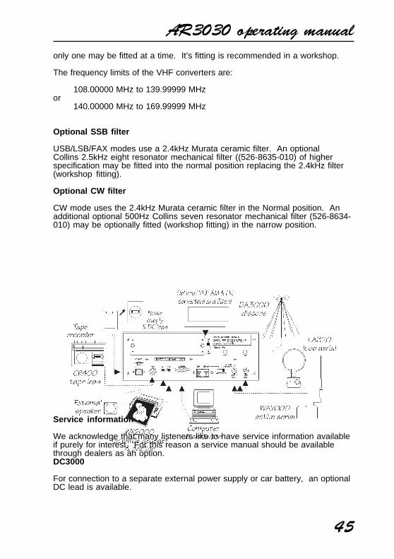
We acknowledge that many listeners like to have service information availableif purely for interest. For this reason a service manual should be availablethrough dealers as an option.DC3000
For connection to a separate external power supply or car battery, an optionalDC lead is available.
AR3030 operating manual
46
Computer control software
A hands off IBM-PC computer program is planned to control the AR3030 viathe RS232C port. A separate serial connecting lead will also be required.
LA320 loop aerial
Desktop active loop aerial for portable operation away from a base aerial suchas when while travelling on business or holiday. Frequency coverage is 1.6 to15MHz with optional elements to cover 0.2 to 0.54MHz and 0.54 to 1.6MHz.
WA7000 wide band active whip aerial
Compact aerial designed for installation where space is a problem. TheWA7000 is active on the lower frequency band 30kHz to 30MHz and passiveon the higher band between 30MHz to 2000MHz.
DA3000 VHF-UHF discone aerial
Ideal for use when an optional VHF converter has been fitted. Frequencycoverage is nominally 25 to 2000MHz.
CR400 tape record lead
This lead comprises an 8 pin DIN plug on one end for connection to theAR3030 with a 3.5mm audio plug on the other for connection to a taperecorder with a 2.5mm plug for control On/Off of the tape motor.
WX2000 weather facsimile decoder / printer
Purpose designed and built to decode and print high quality facsimile pictures.For use on both shortwave and UHF Meteorsat with a suitable receiver.
(9) Trouble shooting - Microprocessor reset
Should you experience problems with the receiver “apparently doing somethingunexpected”, simply switch Off the receiver using the main power switch andleave it for about 10 seconds. Switch the receiver back on again and check ifthe problem has been cleared.
If this does not appear to solve the problem disconnect all connections andperipherals such as tape recorders, weather facsimile printers, aerials and thepower supply. Switch the receiver off and leave for one minute. Reconnect thepower supply and test again.
Should the receiver still refuse to operate correctly, turn the set up-side-down
AR3030 operating manual
47
and locate a small hole in the bottom cabinet close to the main rotary tuningcontrol. This hole provides access to the microprocessor reset switch.
With the AR3030 connected to it’s power supply and switched On,momentarily press this switch and release using preferably a non conductivethin probe such as a cocktail stick or cotton bud. This action will reset themicroprocessor.
Should the receiver fail to power up, check the power supply and mains fuse.The AR3030 does contain an internal DC power fuse but should it blow wesuggest you contact your dealer for advise and service... there must be areason for the fuse to blow!
If the above does not help, please contact your dealer for assistance.
We acknowledge that many listeners like to have service informationavailable if purely for interest. For this reason a service manual shouldbe available through dealers as an option.
(10) Aerials (Antennas) and earth systems
The subject of aerial choice and earth can be quite complex. There are manyadvantages and disadvantages to consider before connecting an external aerialto your receiver.
Theory and practice
One interesting phenomena is that aerial theory and practice can besurprisingly different. Keeping common sense in mind it is one of thefew remaining areas for listeners to easily experiment and often achievefantastic results.
Mounting location
It is important to mount any aerial as high as possible and in clear spacealthough this is more important at VHF frequencies than for shortwave. Ifpossible the aerial should have a clear path to the horizon. Results are usuallydisappointing when an installation is in a loft space.
Telescopic whip aerials
Whip aerials may be connected to the 50 OHM BNC aerial input of the AR3030and the whip aerial switch position selected. The selection of “WHIP” adds asmall preamplification to the receiver’s input stages and matches the very highimpedance of the whip to the receiver’s circuitry.
Although whip aerials allow you to start listening without delay they should onlybe considered as a temporary aerial or for portability.
Of course a whip aerial may be connected directly to the VHF BNC 50 OHM
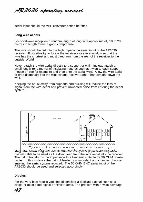
AR3030 operating manual
48
aerial input should the VHF converter option be fitted.
Long wire aerials
For shortwave reception a random length of long wire approximately 10 to 20metres in length forms a good compromise.
The wire should be fed into the high impedance aerial input of the AR3030receiver. If possible try to locate the receiver close to a window so that thewire has the shortest and most direct run from the rear of the receiver to theoutside World.
Never attach the wire aerial directly to a support or wall. Instead attach asmall length (one metre) of insulating material such as nylon to each support(house or tree for example) and then onto the aerial wire. Allow the wire aerialto drop diagonally into the window and receiver rather than straight down thewall.
Keeping the aerial away from supports and building will reduce the loss ofsignal from the wire aerial and prevent unwanted noise from entering the aerialsystem.
Magnetic balun long wire aerials are becoming very popular as they allowcoaxial cable to be used as the down-lead from the wire aerial into the receiver.The balun transforms the impedance to a low level suitable for 50 OHM coaxialcable. In this instance the path of feeder is unimportant and chances of noiseentering the aerial system reduced. The 50 OHM BNC aerial input of theAR3030 should be used and selected accordingly.
Dipoles
For the very best results you should consider a dedicated aerial such as asingle or multi-band dipole or similar aerial. The problem with a wide coverage
AR3030 operating manual
49
receiver like the AR3030 is that for the ultimate results many dedicated aerialsare required to cover the whole spectrum. This may involve complex aerialswitching and reduces the ability to quickly monitor many bands.
As a compromise it may be worth making up a dipole aerial for a band ofparticular interest and have a second random wire for general listening.
It is quite easy to make a dipole for shortwave, for that matter one can beeasily made up for VHF should you have the optional VHF converter fitted.
It is worth noting that dipoles are also quite effective on two and three timestheir design frequency so you can cover a few bands at once. Reception usinga half wave dipole is best at 90 degrees to the direction the aerial is laying,however if used at two or three times it’s fundamental design frequency,reception is best closer to the direction the aerial is lying.
A dipole has two legs running in opposite directions and can be mountedvertically or horizontally (most VHF activity is vertical). One leg is connected tothe centre conductor the coaxial feeder cable while the other leg is connectedto the outer screen of the coaxial feeder cable. If mounted vertically the centreof the coaxial feeder should be connected to the leg facing upward.
A simple formulae can be used to calculate the required length of each leg fora half wave dipole:
75———————— = Length of each
leg in metres Frequency in MHz
i.e. For 14.2 MHz
75——————— = 5.28 metres (i.e. the total length of 14.2 the aerial is twice 5.28m.)
Coaxial cables
When constructing dipole aerials or connecting VHF aerials 50 OHM coaxialcable should be used. For shortwave or short runs of VHF URM43, URM76 orRG58U is ideal, for longer runs of VHF feeder it may be worth considering aheavier URM67 or RG213.
ATU
Aerial tuning units (ATU) may improve the shortwave section of a wide rangereceiver by rejecting unwanted signals and only allowing a specific band offrequencies through. These ATUs are normally constructed in small boxeswith about 3 controls on the front. The disadvantage is the need to constantlyre-tune the ATU when changing frequency. An ATU of this nature is “passive”,this means that no power is required to operate the ATU and no extra circuit-
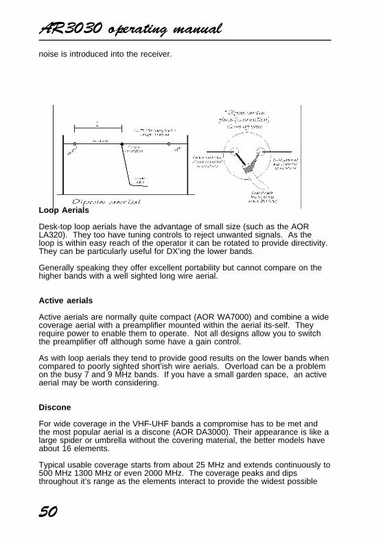
AR3030 operating manual
50
noise is introduced into the receiver.
Loop Aerials
Desk-top loop aerials have the advantage of small size (such as the AORLA320). They too have tuning controls to reject unwanted signals. As theloop is within easy reach of the operator it can be rotated to provide directivity.They can be particularly useful for DX’ing the lower bands.
Generally speaking they offer excellent portability but cannot compare on thehigher bands with a well sighted long wire aerial.
Active aerials
Active aerials are normally quite compact (AOR WA7000) and combine a widecoverage aerial with a preamplifier mounted within the aerial its-self. Theyrequire power to enable them to operate. Not all designs allow you to switchthe preamplifier off although some have a gain control.
As with loop aerials they tend to provide good results on the lower bands whencompared to poorly sighted short’ish wire aerials. Overload can be a problemon the busy 7 and 9 MHz bands. If you have a small garden space, an activeaerial may be worth considering.
Discone
For wide coverage in the VHF-UHF bands a compromise has to be met andthe most popular aerial is a discone (AOR DA3000). Their appearance is like alarge spider or umbrella without the covering material, the better models haveabout 16 elements.
Typical usable coverage starts from about 25 MHz and extends continuously to500 MHz 1300 MHz or even 2000 MHz. The coverage peaks and dipsthroughout it’s range as the elements interact to provide the widest possible
AR3030 operating manual
51
coverage. Due to their necessary construction discone aerials are a little proneto “wind noise” due to vibration and possible damage in severe gales.
Earth systems
The AR3030 power supply has no EARTH connection to the mains plug.However a separate earth point is provided on the rear panel of the AR3030 forconnection to a water pipe, central heating radiator or external earth rod. Iffitting a separate external earth rod, consider the implications carefully if yourmains supply uses Protective Multiple Earth (PME) system. If in doubt consultan experienced electrician.
Connecting an external earth wire may greatly reduce the local noiseencountered when listening on the shortwave bands. It is very important toprovide a good earth should you use an aerial tuning unit.
A short length of thick gauge earth wire may be connected to a nearby centralheating radiator or water pipe but never use a gas pipe for earthing. Ideally aseparate earth rod should be used but the length between the receiver and rodbecomes restrictive, if too long the earth system may well “pick up” noiserather than remove it.
If a long run of earth wire is necessary, it may be worth considering a“screened earth system”. This simply comprises a coaxial cable (such asURM43, URM76 for short runs or URM67 or RG213 for longer runs) shortedinner to outer at the earth rod end with only the centre core connected to theAR3030 earth point, the outer braid being cut back and insulated.
This provides a screen for potential incoming interference and passes anynoise down the cable away from the receiver and toward the earth rod.
(11) Propagation - shortwave bands
Unlike VHF and UHF transmissions which generally propagate only on alocalised basis (to the horizon plus a small amount), shortwave transmissionsmay travel for many thousands of kilometres. Depending upon the frequencyin use, time of day, season of the year and sun spot activity, transmissionsmay propagate completely around the World.
Radio signals are electromagnetic waves very similar to light beams. As suchthey do not readily follow the curvature of the Earth but attempt to travel outinto space.
The ionosphere
Luckily the frequency spectrum of shortwave is often reflected back down toEarth by the upper layer of the Earth’s atmosphere called the ionosphere.When the reflected signals reach the Earth again they may either bereceived or reflected back up into space. If lucky, they will be reflected by theionosphere yet again down toward the Earth providing reception into another
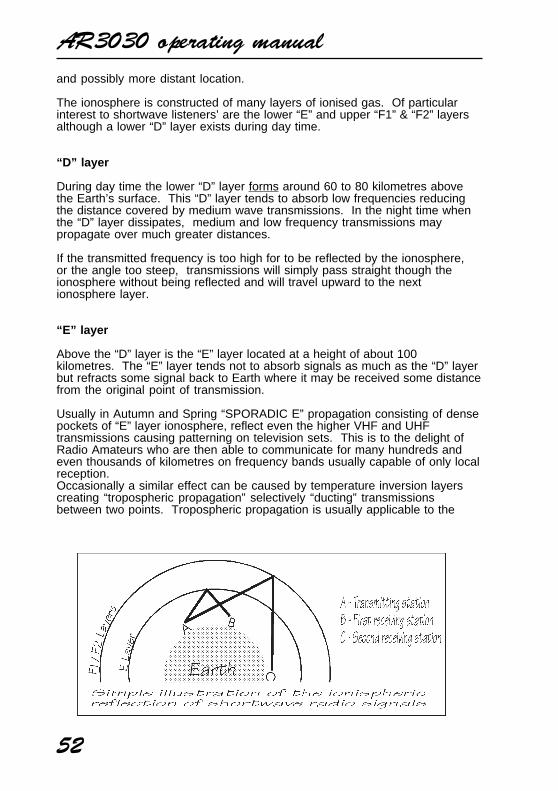
AR3030 operating manual
52
and possibly more distant location.
The ionosphere is constructed of many layers of ionised gas. Of particularinterest to shortwave listeners’ are the lower “E” and upper “F1” & “F2” layersalthough a lower “D” layer exists during day time.
“D” layer
During day time the lower “D” layer forms around 60 to 80 kilometres abovethe Earth’s surface. This “D” layer tends to absorb low frequencies reducingthe distance covered by medium wave transmissions. In the night time whenthe “D” layer dissipates, medium and low frequency transmissions maypropagate over much greater distances.
If the transmitted frequency is too high for to be reflected by the ionosphere,or the angle too steep, transmissions will simply pass straight though theionosphere without being reflected and will travel upward to the nextionosphere layer.
“E” layer
Above the “D” layer is the “E” layer located at a height of about 100kilometres. The “E” layer tends not to absorb signals as much as the “D” layerbut refracts some signal back to Earth where it may be received some distancefrom the original point of transmission.
Usually in Autumn and Spring “SPORADIC E” propagation consisting of densepockets of “E” layer ionosphere, reflect even the higher VHF and UHFtransmissions causing patterning on television sets. This is to the delight ofRadio Amateurs who are then able to communicate for many hundreds andeven thousands of kilometres on frequency bands usually capable of only localreception.Occasionally a similar effect can be caused by temperature inversion layerscreating “tropospheric propagation” selectively “ducting” transmissionsbetween two points. Tropospheric propagation is usually applicable to the
AR3030 operating manual
53
higher VHF and UHF bands.
“F1” & “F2” layers
During the day time there are two upper layers of the ionosphere, these beingthe “F1” layer at about 200 kilometres and the “F2” layer at about 400kilometres. As evening falls, these layers combine to form a single “F” layer.It is “F” layer propagation that is largely responsible for shortwave propagationover great distances.
The density of the ionosphere layers varies depending upon season, time ofday and sunspot activity which is believed to follow an eleven year cycle ofgood and bad propagation conditions.
You will note that large areas of the Earth’s surface lays between the point oftransmission and reflection, in this area there will be little or no reception. Forthis reason “F” layer propagation is often referred to a “SKIP” and the reflectedsignal as “SKY WAVE”.
Generally speaking only frequencies below 30MHz are reflected by theionosphere. Higher frequencies pass straight through even the “F” layers andwill continue outward into space for ever.
Choice of frequency
Depending upon the time of day and desired skip distance, differentfrequencies will be selected by Radio Amateurs and commercial users suchas Oceanic Air Traffic.
For instance the “MUF” (Maximum Usable Frequency) is often stated for a pathbetween two locations. Choosing a frequency above the “MUF” will notproduce results as transmissions will pass straight into space.
Many propagation predictions and statistics are published and usuallyavailable from most country’s National Amateur Radio and ShortwaveListeners representatives.
Various publications are produced giving transmission and contact details forWorld wide reception. These titles include:
World Radio TV Handbook (WRTH), BPI Communications, 1515 Broadway,New York 10036, NY USA.
Passport To World Band Radio, IBS North America, Box 300, Penn’s Park PA18943, USA.
Listings for utility services are also widely published and available.
For a list of Shortwave and Amateur Band allocations refer to the table insection 6-12 of this manual.(12) Specification
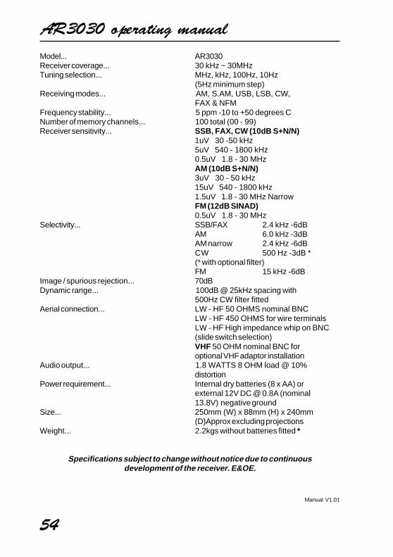
AR3030 operating manual
54
Model... AR3030Receiver coverage... 30 kHz ~ 30MHzTuning selection... MHz, kHz, 100Hz, 10Hz
(5Hz minimum step)Receiving modes... AM, S.AM, USB, LSB, CW,
FAX & NFMFrequency stability... 5 ppm -10 to +50 degrees CNumber of memory channels... 100 total (00 - 99)Receiver sensitivity... SSB, FAX, CW (10dB S+N/N)
1uV 30 -50 kHz5uV 540 - 1800 kHz0.5uV 1.8 - 30 MHzAM (10dB S+N/N)3uV 30 - 50 kHz15uV 540 - 1800 kHz1.5uV 1.8 - 30 MHz NarrowFM (12dB SINAD)0.5uV 1.8 - 30 MHz
Selectivity... SSB/FAX 2.4 kHz -6dBAM 6.0 kHz -3dBAM narrow 2.4 kHz -6dBCW 500 Hz -3dB *(* with optional filter)FM 15 kHz -6dB
Image / spurious rejection... 70dBDynamic range... 100dB @ 25kHz spacing with
500Hz CW filter fittedAerial connection... LW - HF 50 OHMS nominal BNC
LW - HF 450 OHMS for wire terminalsLW - HF High impedance whip on BNC(slide switch selection)VHF 50 OHM nominal BNC foroptional VHF adaptor installation
Audio output... 1.8 WATTS 8 OHM load @ 10%distortion
Power requirement... Internal dry batteries (8 x AA) orexternal 12V DC @ 0.8A (nominal13.8V) negative ground
Size... 250mm (W) x 88mm (H) x 240mm(D)Approx excluding projections
Weight... 2.2kgs without batteries fitted *
Specifications subject to change without notice due to continuousdevelopment of the receiver. E&OE.
Manual V1.01