ar6400t manual - micron radio control
TRANSCRIPT

AR6400T User GuideBedienungsanleitung AR6400TGuide de l’utilisateur AR6400TAR6400T Guida per l’utente

EN
WARNING: Read the ENTIRE instruction manual to become familiar with the features of
the product before operating. Failure to operate the product correctly can result in damage to the product, personal property and cause serious injury.
This is a sophisticated hobby product. It must be operated with caution and common sense and requires some basic mechanical ability. Failure to operate this Product in a safe and responsible manner could result in injury or damage to the product or other property. This product is not intended for use by children without direct adult supervision. Do not attempt disassembly, use with incompatible components or augment product in any way without the approval of Horizon Hobby, Inc. This manual contains instructions for safety, operation and maintenance. It is essential to read and follow all the instructions and warnings in the manual, prior to assembly, setup or use, in order to operate correctly and avoid damage or serious injury.
NOTICEAll instructions, warranties and other collateral documents are subject to change at the sole discretion of Horizon Hobby, Inc. For up-to-date product literature, visit www.horizonhobby.com and click on the support tab for this product.
Meaning of Special Language: The following terms are used throughout the product literature to indicate various levels of potential harm when operating this product: NOTICE: Procedures, which if not properly followed, create a possibility of physical property damage AND little or no possibility of injury. CAUTION: Procedures, which if not properly followed, create the probability of physical property damage AND a possibility of serious injury. WARNING: Procedures, which if not properly followed, create the probability of property damage, collateral damage, and serious injury OR create a high probability of superficial injury.
WARNING AGAINST COUNTERFEIT PRODUCTS Thank you for purchasing a genuine Spektrum product. Always purchase from a Horizon Hobby, Inc. authorized dealer to ensure authentic high-quality Spektrum product. Horizon Hobby, Inc. disclaims all support and warranty with regards, but not limited to, compatibility and performance of counterfeit products or products claiming compatibility with DSM2 or Spektrum.
EN
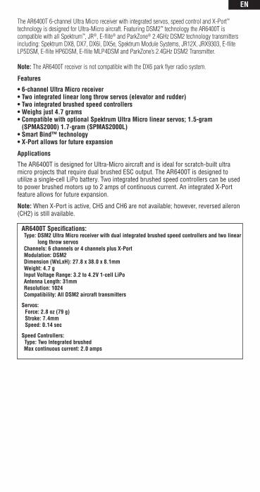
The AR6400T 6-channel Ultra Micro receiver with integrated servos, speed control and X-Port™ technology is designed for Ultra-Micro aircraft. Featuring DSM2™ technology the AR6400T is compatible with all Spektrum™, JR®, E-flite® and ParkZone® 2.4GHz DSM2 technology transmitters including: Spektrum DX8, DX7, DX6i, DX5e, Spektrum Module Systems, JR12X, JRX9303, E-flite LP5DSM, E-flite HP6DSM, E-flite MLP4DSM and ParkZone’s 2.4GHz DSM2 Transmitter.
Note: The AR6400T receiver is not compatible with the DX6 park flyer radio system.
Features
• 6-channel Ultra Micro receiver• Two integrated linear long throw servos (elevator and rudder)• Two integrated brushed speed controllers• Weighs just 4.7 grams• Compatible with optional Spektrum Ultra Micro linear servos; 1.5-gram
(SPMAS2000) 1.7-gram (SPMAS2000L)• Smart Bind™ technology• X-Port allows for future expansion
Applications
The AR6400T is designed for Ultra-Micro aircraft and is ideal for scratch-built ultra micro projects that require dual brushed ESC output. The AR6400T is designed to utilize a single-cell LiPo battery. Two integrated brushed speed controllers can be used to power brushed motors up to 2 amps of continuous current. An integrated X-Port feature allows for future expansion.
Note: When X-Port is active, CH5 and CH6 are not available; however, reversed aileron (CH2) is still available.
AR6400T Specifications: Type: DSM2 Ultra Micro receiver with dual integrated brushed speed controllers and two linear
long throw servos Channels: 6 channels or 4 channels plus X-Port Modulation: DSM2 Dimension (WxLxH): 27.8 x 38.0 x 8.1mm Weight: 4.7 g Input Voltage Range: 3.2 to 4.2V 1-cell LiPo Antenna Length: 31mm Resolution: 1024 Compatibility: All DSM2 aircraft transmitters
Servos: Force: 2.8 oz (79 g) Stroke: 7.4mm Speed: 0.14 sec
Speed Controllers: Type: Two Integrated brushed Max continuous current: 2.0 amps

EN
US Patent D578,146. PRC patent ZL 200720069025.2. Other Patents Pending.
AR6400T Features and Ports
Receiver Installation
It is recommended to use double-sided foam tape strips and/or minimal hot glue in the corners to install your receiver in the fuselage. Note that the servos need to be in the appropriate position to attach to and drive the elevator and rudder pushrods. Note: Installation will vary depending upon application.
Dual Brushed Motor output
Antenna
Rudder (CH4) servo
X-Port (all 4 pins)OR
Gear (CH5) (lower 3 pins)
Aileron (CH2)
Battery input
Reversed Aileron (CH2) or Aux1 (CH6)
Elevator (CH3)servo
+ - + -
ESC Brushed
+ -
EN
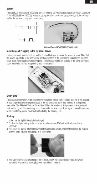
Servos
The AR6400T incorporates integrated servos; optional servos are also available through Spektrum (SPMAS2000/SPMAS2000L). Note that using any other servo may cause damage to the receiver and/or the servo and may void the warranty.
Optional Servo (SPMAS2000/SPMAS2000L)
Installing and Plugging in the Optional Servos
Use double-sided foam tape strips and/or minimal hot glue to mount the servos in place. Note that the servos need to be in the appropriate position to attach to the corresponding pushrods. Plug the servo leads into the appropriate servo ports in the receiver noting the polarity of the servo connector. Note: Installation will vary depending upon application.
Smart Bind™
The AR6400T receiver must be bound to the transmitter before it will operate. Binding is the process of teaching the receiver the specific code of the transmitter so it will only connect to that specific transmitter. The AR6400T features Smart Bind. When the receiver is first powered, the receiver will look for the signal of its previously bound transmitter for 5 seconds. If no signal is found the receiver will automatically go into bind mode indicated by the flashing LED.
Binding
1. Make sure the flight battery is fully charged.2. Confirm the flight battery is disconnected from the receiver/ESC unit and the transmitter is
turned off.3. Plug the flight battery into the receiver’s battery connector. After 5 seconds the LED on the receiver
unit will begin flashing indicating it is in bind mode.
4. After verifying the LED is flashing on the receiver, follow the steps necessary that allow your transmitter to enter bind mode. (See your transmitter’s manual)
EN
LED
5. If you entered bind mode correctly, you will see a solid LED within about 10 seconds. You should now be bound to the transmitter and have full control and function.
NOTICE: After Binding
Once the system is bound, the transmitter should always be turned on first and then the receiver to prevent the receiver from re-entering bind mode. If your receiver inadvertently enters bind mode, simply unplug the battery from the receiver and reinstall with the transmitter remaining on.
Advanced Programming Features The following programming features are only recommended for advanced radio users. To safely accomplish advanced programming feature changes, please enlist the use of a helper. One to hold the aircraft to prevent unintended flyaways, and one to make the changes on the transmitter. The photos in this section show the E-flite MLP4DSM transmitter, however, the procedures apply to all compatible transmitters. Prior to making any advanced programming feature changes it is necessary to:
Computer Radios like the DX6i, DX7 amd DX8 1. Choose an empty model location 2. Select model type ACRO3. Perform a model reset 4. Set all channels to normal reversing5. Ensure a successful bind has been established
CAUTION: Please secure the aircraft safely to a work bench or enlist the use of a helper while accessing the advanced programming features. Mistakes in programming could cause the motor to run unexpectedly.
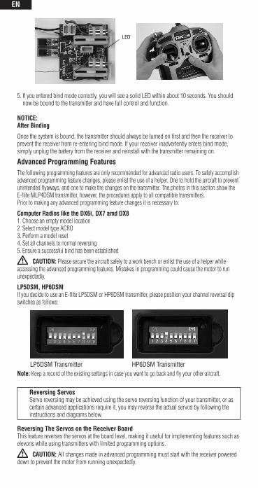
LP5DSM, HP6DSMIf you decide to use an E-flite LP5DSM or HP6DSM transmitter, please position your channel reversal dip switches as follows:
LP5DSM Transmitter HP6DSM Transmitter
Note: Keep a record of the existing settings in case you want to go back and fly your other aircraft.
Reversing Servos Servo reversing may be achieved using the servo reversing function of your transmitter, or as certain advanced applications require it, you may reverse the actual servos by following the instructions and diagrams below.
Reversing The Servos on the Receiver BoardThis feature reverses the servos at the board level, making it useful for implementing features such as elevons while using transmitters with limited programming options.
CAUTION: All changes made in advanced programming must start with the receiver powered down to prevent the motor from running unexpectedly.
EN
To safely accomplish advanced programming feature changes, please enlist the use of a helper. One to hold the aircraft to prevent unintended flyaways, and one to make the changes on the transmitter.
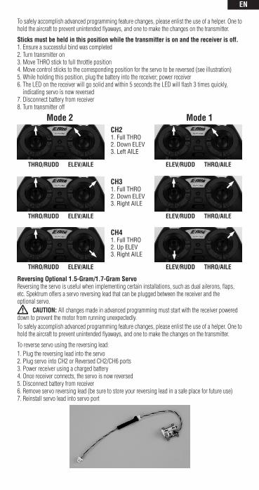
Sticks must be held in this position while the transmitter is on and the receiver is off.1. Ensure a successful bind was completed2. Turn transmitter on 3. Move THRO stick to full throttle position 4. Move control sticks to the corresponding position for the servo to be reversed (see illustration) 5. While holding this position, plug the battery into the receiver; power receiver6. The LED on the receiver will go solid and within 5 seconds the LED will flash 3 times quickly,
indicating servo is now reversed7. Disconnect battery from receiver 8. Turn transmitter off
THRO/RUDD ELEV/AILE ELEV/RUDD THRO/AILE
CH41. Full THRO2. Up ELEV3. Right AILE
Mode 1CH21. Full THRO2. Down ELEV3. Left AILE
THRO/RUDD ELEV/AILE
THRO/RUDD ELEV/AILE
ELEV/RUDD THRO/AILE
ELEV/RUDD THRO/AILE
CH31. Full THRO2. Down ELEV3. Right AILE
Mode 2
Reversing Optional 1.5-Gram/1.7-Gram ServoReversing the servo is useful when implementing certain installations, such as dual ailerons, flaps, etc. Spektrum offers a servo reversing lead that can be plugged between the receiver and the optional servo.
CAUTION: All changes made in advanced programming must start with the receiver powered down to prevent the motor from running unexpectedly.To safely accomplish advanced programming feature changes, please enlist the use of a helper. One to hold the aircraft to prevent unintended flyaways, and one to make the changes on the transmitter.
To reverse servo using the reversing lead:1. Plug the reversing lead into the servo 2. Plug servo into CH2 or Reversed CH2/CH6 ports3. Power receiver using a charged battery 4. Once receiver connects, the servo is now reversed5. Disconnect battery from receiver6. Remove servo reversing lead (be sure to store your reversing lead in a safe place for future use) 7. Reinstall servo lead into servo port

EN
To Change Channel 6 to a Reversed Channel 2 for Dual Ailerons or Reversed Channel 2 to Channel 6
CAUTION: All changes made in advanced programming must start with the receiver powered down to prevent the motor from running unexpectedly.
To safely accomplish advanced programming feature changes, please enlist the use of a helper. One to hold the aircraft to prevent unintended flyaways, and one to make the changes on the transmitter.
Sticks must be held in this position while the transmitter is on and the receiver is off.1. Ensure a successful bind was completed2. Turn transmitter on 3. Move THRO stick to full throttle position 4. Move Control sticks to the corresponding position to change between the available options (see
illustration)5. While holding this position, plug the battery into the receiver; power receiver6. The LED on the receiver will go solid and within 5 seconds the LED will flash 3 times quickly,
indicating the option is now changed7. Disconnect flight pack from receiver 8. Turn transmitter off
Mode 1
THRO/RUDD ELEV/AILE ELEV/RUDD THRO/AILE
Rev. CH2/CH61. Full THRO2. Up ELEV3. Left AILE
Mode 2
To Change Channel 5 to X-port or X-port to Channel 5
Note: When X-Port is active, CH5 and CH6 are not available; however, reversed aileron (CH2) is still available.
CAUTION: All changes made in advanced programming must start with the receiver powered down to prevent the motor from running unexpectedly.
To safely accomplish advanced programming feature changes, please enlist the use of a helper. One to hold the aircraft to prevent unintended flyaways, and one to make the changes on the transmitter.
Sticks must be held in this position while the transmitter is on and the receiver is off.1. Ensure a successful bind was completed 2. Plug the X-Port accessory or the optional servo into the X-Port/CH5 3. Turn the transmitter on 4. Move the THRO stick to the full throttle position5. Move Control sticks to the corresponding position to change between the available options. (see
illustration)6. While holding this position, plug the battery into the receiver; power receiver 7. The LED on the receiver will go solid and within 5 seconds the LED will flash 3 times quickly,
indicating the option is now changed8. Disconnect battery from receiver 9. Turn transmitter off
Mode 1
THRO/RUDD ELEV/AILE ELEV/RUDD THRO/AILE
1. Full THRO2. Right RUDD
Mode 2
CH5/X-port
EN
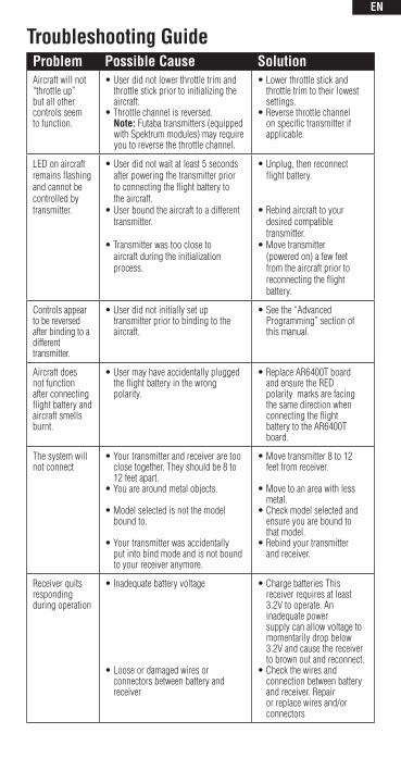
Troubleshooting GuideProblem Possible Cause SolutionAircraft will not “throttle up”but all other controls seem to function.
• User did not lower throttle trim and throttle stick prior to initializing the aircraft.• Throttle channel is reversed. Note: Futaba transmitters (equipped with Spektrum modules) may require you to reverse the throttle channel.
• Lower throttle stick and throttle trim to their lowest settings.• Reverse throttle channel on specific transmitter if applicable.
LED on aircraft remains flashing and cannot be controlled by transmitter.
• User did not wait at least 5 seconds after powering the transmitter prior to connecting the flight battery to the aircraft.• User bound the aircraft to a different transmitter.
• Transmitter was too close to aircraft during the initialization process.
• Unplug, then reconnect flight battery.
• Rebind aircraft to your desired compatible transmitter.• Move transmitter (powered on) a few feet from the aircraft prior to reconnecting the flight battery.
Controls appear to be reversed after binding to a different transmitter.
• User did not initially set up transmitter prior to binding to the aircraft.
• See the “Advanced Programming” section of this manual.
Aircraft does not function after connecting flight battery and aircraft smells burnt.
• User may have accidentally plugged the flight battery in the wrong polarity.
• Replace AR6400T board and ensure the RED polarity marks are facing the same direction when connecting the flight battery to the AR6400T board.
The system will not connect
• Your transmitter and receiver are too close together. They should be 8 to 12 feet apart.• You are around metal objects.
• Model selected is not the model bound to.
• Your transmitter was accidentally put into bind mode and is not bound to your receiver anymore.
• Move transmitter 8 to 12 feet from receiver.
• Move to an area with less metal.• Check model selected and ensure you are bound to that model.• Rebind your transmitter and receiver.
Receiver quits responding during operation
• Inadequate battery voltage
• Loose or damaged wires or connectors between battery and receiver
• Charge batteries This receiver requires at least 3.2V to operate. An inadequate power supply can allow voltage to momentarily drop below 3.2V and cause the receiver to brown out and reconnect.• Check the wires and connection between battery and receiver. Repair or replace wires and/or connectors
EN
Warranty PeriodExclusive Warranty- Horizon Hobby, Inc., (Horizon) warranties that the Products purchased (the “Product”) will be free from defects in materials and workmanship for a period of 1 year from the date of purchase by the Purchaser.
1 Year Limited Warranty(a) This warranty is limited to the original Purchaser (“Purchaser”) and is not transferable. REPAIR OR REPLACEMENT AS PROVIDED UNDER THIS WARRANTY IS THE EXCLUSIVE REMEDY OF THE PURCHASER. This warranty covers only those Products purchased from an authorized Horizon dealer. Third party transactions are not covered by this warranty. Proof of purchase is required for all warranty claims.
(b) Limitations- HORIZON MAKES NO WARRANTY OR REPRESENTATION, EXPRESS OR IMPLIED, ABOUT NON-INFRINGEMENT, MERCHANTABILITY OR FITNESS FOR A PARTICULAR PURPOSE OF THE PRODUCT. THE PURCHASER ACKNOWLEDGES THAT THEY ALONE HAVE DETERMINED THAT THE PRODUCT WILL SUITABLY MEET THE REQUIREMENTS OF THE PURCHASER’S NTENDED USE.
(c) Purchaser Remedy- Horizon’s sole obligation hereunder shall be that Horizon will, at its option, (i) repair or (ii) replace, any Product determined by Horizon to be defective. In the event of a defect, these are the Purchaser’s exclusive remedies. Horizon reserves the right to inspect any and all equipment involved in a warranty claim. Repair or replacement decisions are at the sole discretion of Horizon. This warranty does not cover cosmetic damage or damage due to acts of God, accident, misuse, abuse, negligence, commercial use, or modifi cation of or to any part of the Product.
This warranty does not cover damage due to improper installation, operation, maintenance, or attempted repair by anyone other than Horizon. Return of any Product by Purchaser must be approved in writing by Horizon before shipment.
Damage LimitsHORIZON SHALL NOT BE LIABLE FOR SPECIAL, INDIRECT OR CONSEQUENTIAL DAMAGES, LOSS OF PROFITS OR PRODUCTION OR COMMERCIAL LOSS IN ANY WAY CONNECTED WITH THE PRODUCT, WHETHER SUCH CLAIM IS BASED IN CONTRACT, WARRANTY, NEGLIGENCE, OR STRICT LIABILITY. Further, in no event shall the liability of Horizon exceed the individual price of the Product on which liability is asserted. As Horizon has no control over use, setup, fi nal assembly, modifi cation or misuse, no liability shall be assumed nor accepted for any resulting damage or injury. By the act of use, setup or assembly, the user accepts all resulting liability.
If you as the Purchaser or user are not prepared to accept the liability associated with the use of this Product, you are advised to return this Product immediately in new and unused condition to the place of purchase.
Law: These Terms are governed by Illinois law (without regard to confl ict of law principals).
Warranty ServicesQuestions, Assistance, and Repairs
Your local hobby store and/or place of purchase cannot provide warranty support or repair. Once assembly, setup or use of the Product has been started, you must contact Horizon directly. This will enable Horizon to better answer your questions and service you in the event that you may need any assistance. For questions or assistance, please direct your email to productsupport@ horizonhobby.com, or call 877.504.0233 toll free to speak to a Product Support representative. You may also find information on our website at www.horizonhobby.com.
Inspection or RepairsIf this Product needs to be inspected or repaired, please use the Horizon Online Repair Request submission process found on our website or call Horizon to obtain a Return Merchandise Authorization (RMA) number. Pack the Product securely using a shipping carton. Please note that original boxes may be included, but are not designed to withstand the rigors of shipping without additional protection. Ship via a carrier that provides tracking and insurance for lost or damaged parcels, as Horizon is not responsible for merchandise until it arrives and is accepted at our facility. An Online Repair Request is available at www.horizonhobby.com http://www.horizonhobby. com under the Repairs tab. If you do not have internet access, please contact Horizon Product Support to obtain a RMA number along with instructions for submitting your product for repair. When calling Horizon, you will be asked to provide your complete name, street address, email address and phone number where you can be reached during business hours. When sending product into Horizon, please include your RMA number, a list of the included items, and a brief summary of the problem. A copy of your original sales receipt must be included for warranty

EN
consideration. Be sure your name, address, and RMA number are clearly written on the outside of the shipping carton.
Notice: Do not ship batteries to Horizon. If you have any issue with a battery, please contact the appropriate Horizon Product Support office.
Warranty Inspection and RepairsTo receive warranty service, you must include your original sales receipt verifying the proof-of-purchase date. Provided warranty conditions have been met, your Product will be repaired or replaced free of charge. Repair or replacement decisions are at the sole discretion of Horizon Hobby.
Non-Warranty RepairsShould your repair not be covered by warranty the repair will be completed and payment will be required without notification or estimate of the expense unless the expense exceeds 50% of the retail purchase cost. By submitting the item for repair you are agreeing to payment of the repair without notification. Repair estimates are available upon request. You must include this request with your repair. Non-warranty repair estimates will be billed a minimum of ½ hour of labor. In addition you will be billed for return freight. Horizon accepts money orders and cashiers checks, as well as Visa, MasterCard, American Express, and Discover cards. By submitting any item to Horizon for inspection or repair, you are agreeing to Horizon’s Terms and Conditions found on our website under the Repairs tab.
Contact InformationCountry of Purchase Horizon Hobby Address Phone Number /
Email Address
Horizon Service Center(Electronics and engines)
4105 Fieldstone RdChampaign, Illinois61822 USA
877-504-0233Online Repair Request visit:www.horizon hobby.com/repairs
Horizon Product Support (All other products)
4105 Fieldstone RdChampaign, Illinois61822 USA
United Kingdom
Horizon Hobby Limited
Units 1-4 Ployters RdStaple TyeHarlow, EssexCM18 7NSUnited Kingdom
+44 (0) 1279 641 097sales@horizon hobby.co.uk
GermanyHorizon Technischer Service
Hamburger Str. 1025335 ElmshornGermany
+49 4121 46199 [email protected]
France Horizon Hobby SAS
14 Rue Gustave EiffelZone d’Activité du Réveil Matin91230 Montgeron
+33 (0) 1 60 47 44 [email protected]
United States of America
EN
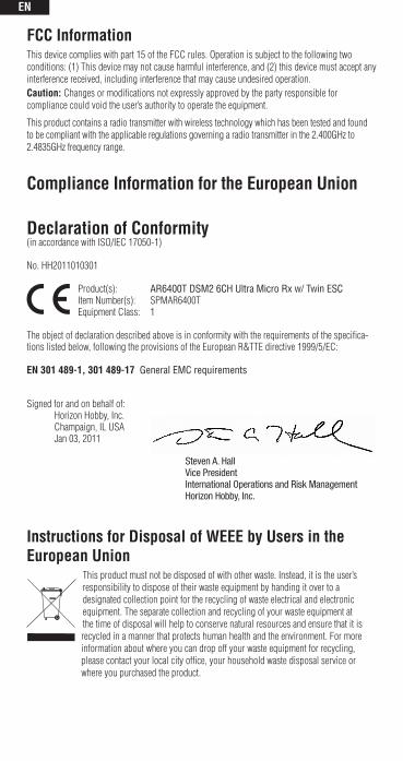
FCC InformationThis device complies with part 15 of the FCC rules. Operation is subject to the following two conditions: (1) This device may not cause harmful interference, and (2) this device must accept any interference received, including interference that may cause undesired operation.Caution: Changes or modifications not expressly approved by the party responsible for compliance could void the user’s authority to operate the equipment.
This product contains a radio transmitter with wireless technology which has been tested and found to be compliant with the applicable regulations governing a radio transmitter in the 2.400GHz to 2.4835GHz frequency range.
Compliance Information for the European Union
Declaration of Conformity(in accordance with ISO/IEC 17050-1)
No. HH2011010301
Product(s): AR6400T DSM2 6CH Ultra Micro Rx w/ Twin ESCItem Number(s): SPMAR6400TEquipment Class: 1
The object of declaration described above is in conformity with the requirements of the specifica-tions listed below, following the provisions of the European R&TTE directive 1999/5/EC:
EN 301 489-1, 301 489-17 General EMC requirements
Signed for and on behalf of: Horizon Hobby, Inc. Champaign, IL USA Jan 03, 2011
Instructions for Disposal of WEEE by Users in the European Union
This product must not be disposed of with other waste. Instead, it is the user’s responsibility to dispose of their waste equipment by handing it over to a designated collection point for the recycling of waste electrical and electronic equipment. The separate collection and recycling of your waste equipment at the time of disposal will help to conserve natural resources and ensure that it is recycled in a manner that protects human health and the environment. For more information about where you can drop off your waste equipment for recycling, please contact your local city office, your household waste disposal service or where you purchased the product.
Steven A. Hall Vice PresidentInternational Operations and Risk ManagementHorizon Hobby, Inc.

© 2010 Horizon Hobby, Inc. 4105 Fieldstone Road, Champaign, Illinois 61822, USA (877) 504-0233 • www.horizonhobby.com • www.spektrumrc.com
Horizon Hobby LTD. Units 1-4 Ployters Rd., Staple Tye, Harlow, Essex CM18 7NS, United Kingdom +44 (0)1279 641 097 • www.horizonhobby.co.uk
Horizon Hobby GmbH Hamburger Str. 10, 25335 Elmshorn, Germany +49 4121 46199 60 • www.horizonhobby.de
The Spektrum trademark is used with permission of Bachmann Industries, Inc.
All other marks are trademarks or registered trademarks of Horizon Hobby, Inc.
Revised 11/10 30835.I