architectural photogrammetry: basic theory, … · reference: grussenmeyer, p., hanke, k .,...
TRANSCRIPT
Reference: GRUSSENMEYER, P., HANKE, K ., STREILEIN, A. Architectural photogrammetry.
Chapter in « Digital Photogrammetry », edited by M. KASSER and Y. EGELS, Taylor & Francis (2002), pp. 300-339.
1
ARCHITECTURAL PHOTOGRAMMETRY: Basic theory, Procedures, Tools
Klaus HANKE & Pierre GRUSSENMEYER
Corfu, September 2002 ISPRS Commission 5 tutorial
CONTENT: 1. Introduction ..................................................................................................................................................... 1 2. Strategies for image processing....................................................................................................................... 2
2.1 Single images ................................................................................................................................................ 2 2.1.1. With known camera parameters and exterior orientation ................................................................ 2 2.1.2. Without knowledge of camera parameters ...................................................................................... 2
2.2. Stereographic processing......................................................................................................................... 3 2.3. Bundle restitution .................................................................................................................................... 5
3. Image Acquisition systems.............................................................................................................................. 7 3.1. General remarks....................................................................................................................................... 7 3.2. Photographic cameras.............................................................................................................................. 8 3.3. Scanners................................................................................................................................................... 9 3.4. CCD cameras......................................................................................................................................... 10 3.5. Which camera to use?............................................................................................................................ 10
4. Overview of existing methods and systems for architectural photogrammetry............................................. 11 4.1. General remarks..................................................................................................................................... 11 4.2. Recommendation for simple photogrammetric architectural survey ..................................................... 12 4.3. Digital image rectification ..................................................................................................................... 12 4.4. Monoscopic multi-image measurement systems ................................................................................... 14 4.5. Stereoscopic image measurement systems ............................................................................................ 16
4.5.1. From analytical to digital............................................................................................................... 16 4.5.2. Stereoscopy.................................................................................................................................... 16 4.5.3. Automation and correlation ........................................................................................................... 16 4.5.4. Model orientation .......................................................................................................................... 16 4.5.5. Stereo-digitising and data collection.............................................................................................. 17
5. 3D object structures....................................................................................................................................... 18 5.1. General remarks.......................................................................................................................................... 18 5.2. Classification of 3D models ....................................................................................................................... 19
6. Visual reality ................................................................................................................................................. 20 7. International Committee for Architectural Photogrammetry (CIPA) ............................................................ 22 8. References ..................................................................................................................................................... 23
1. Introduction Compared with aerial photogrammetry, close range photogrammetry and particularly architectural photogrammetry isn’t limited to vertical photographs with special cameras. The methodology of terrestrial photogrammetry has changed significantly and various photographic acquisitions are widely in use. New technologies and techniques for data acquisition (CCD cameras, Photo-CD, photoscanners), data processing (computer vision), structuring and representation (CAD, simulation, animation, visualisation) and archiving, retrieval and analysis (spatial information systems) are leading to novel systems, processing methods and results. The improvement of methods for surveying historical monuments and sites, is an important contribution to recording and perceptual monitoring of cultural heritage, to preservation and restoration of any valuable architectural or other cultural monument, object or site, as a support to architectural, archaeological and other art-historical research.
Reference: GRUSSENMEYER, P., HANKE, K ., STREILEIN, A. Architectural photogrammetry.
Chapter in « Digital Photogrammetry », edited by M. KASSER and Y. EGELS, Taylor & Francis (2002), pp. 300-339.
2
2. Strategies for image processing Close range photogrammetry is a technique for obtaining geometric information, e.g. position, size and shape of any object, that was imaged on photos before. To achieve a restitution of a 3D point you need the intersection between at least two rays (from photo to object point) in space or between one ray and the surface that includes this point. If more than two rays are available (the objects shows on three or more photos) a bundle solution is possible including all available measurements (on photos or even others) at the same time. These cases lead to different approaches for the photogrammetric restitution of an object.
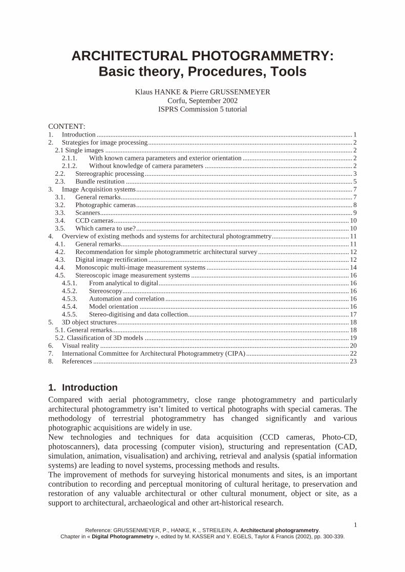
2.1 Single images A very common problem is that we know the shape and attitude of an object's surface in space (digital surface model) but we are interested in the details on this surface (patterns, texture, additional points, etc.). In this case a single image restitution can be appropriate.
Figure 1.
2.1.1. With known camera parameters and exterior orientation In this case the interior orientation of the camera and camera's position and orientation are needed. So the points can be calculated by intersection of rays from camera to surface with the surface known for its shape and attitude. Interior orientation does not mean only the calibrated focal length and the position of the principal point but also the coefficients of a polynomial to describe lens distortion (if the photo does not originate from a metric camera). If the camera position and orientation is unknown at least 3 control points on the object (points with known co-ordinates) are necessary to compute the exterior orientation (spatial resection of camera position).
2.1.2. Without knowledge of camera parameters This is a very frequent problem in architectural photogrammetry. The shape of the surface is restricted to planes only and a minimum number of four control points in two dimensions have to be available. The relation of the object plane to the image plane is described by the projective equation of two planes:
Reference: GRUSSENMEYER, P., HANKE, K ., STREILEIN, A. Architectural photogrammetry.
Chapter in « Digital Photogrammetry », edited by M. KASSER and Y. EGELS, Taylor & Francis (2002), pp. 300-339.
3
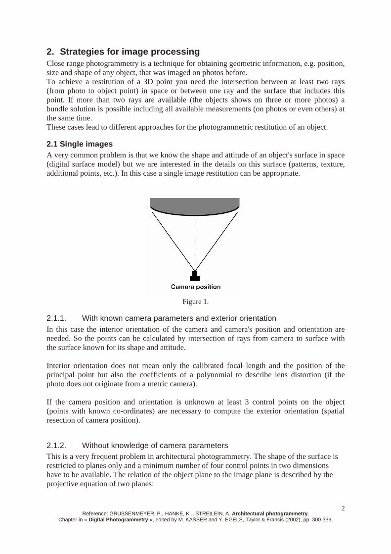
Where X and Y are the co-ordinates on the object's plane, x and y the measured co-ordinates on the image and ai ,bi, ci the 8 parameters describing this projective relation The measurement of a minimum of 4 control points in the single photo leads to the evaluation of these 8 unknowns (a1, a2, a3, ... , c2). As a result the 2D co-ordinates of arbitrary points on this surface can be calculated using those equations. This is also true for digital images of facades. Digital image processing techniques can apply these equations for every single pixel and thus produce an orthographic view of the object's plane, a so-called orthophoto or orthoimage.
original photo rectified orthophoto (in scale) Figure 2.
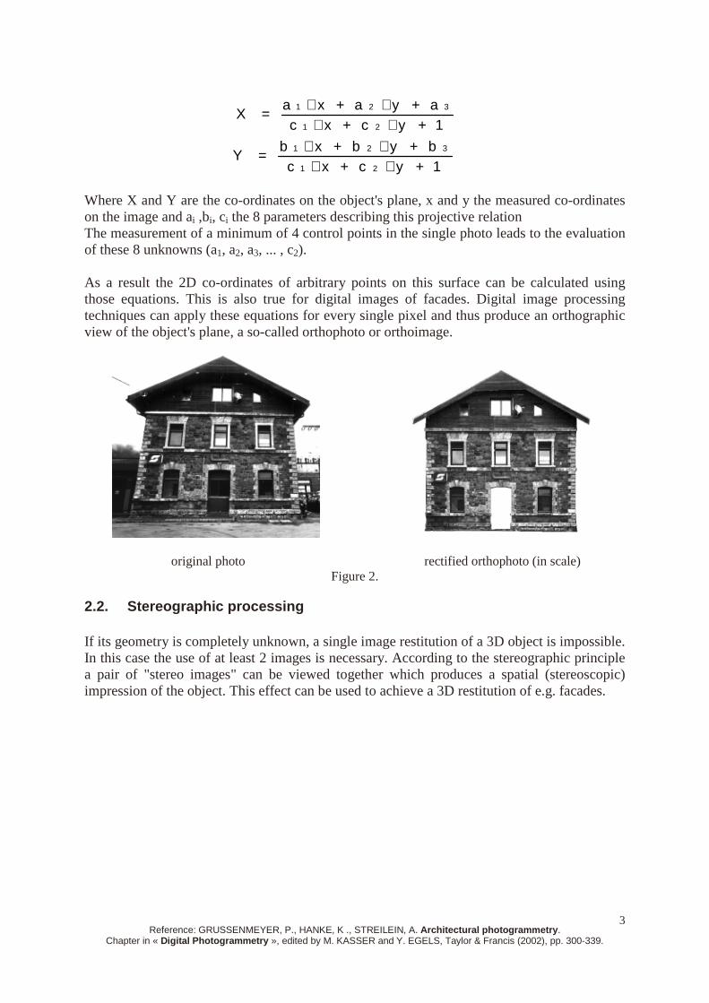
2.2. Stereographic processing If its geometry is completely unknown, a single image restitution of a 3D object is impossible. In this case the use of at least 2 images is necessary. According to the stereographic principle a pair of "stereo images" can be viewed together which produces a spatial (stereoscopic) impression of the object. This effect can be used to achieve a 3D restitution of e.g. facades.
1
1
21
321
21
321
+⋅+⋅+⋅+⋅=
+⋅+⋅+⋅+⋅=
ycxcbybxb
Y
ycxcayaxa
X
Reference: GRUSSENMEYER, P., HANKE, K ., STREILEIN, A. Architectural photogrammetry.
Chapter in « Digital Photogrammetry », edited by M. KASSER and Y. EGELS, Taylor & Francis (2002), pp. 300-339.
4
Figure 3.
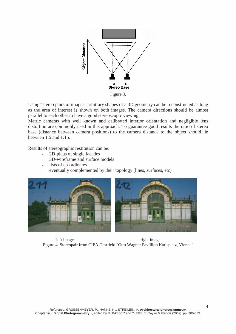
Using "stereo pairs of images" arbitrary shapes of a 3D geometry can be reconstructed as long as the area of interest is shown on both images. The camera directions should be almost parallel to each other to have a good stereoscopic viewing. Metric cameras with well known and calibrated interior orientation and negligible lens distortion are commonly used in this approach. To guarantee good results the ratio of stereo base (distance between camera positions) to the camera distance to the object should lie between 1:5 and 1:15. Results of stereographic restitution can be:
- 2D-plans of single facades - 3D-wireframe and surface models - lists of co-ordinates - eventually complemented by their topology (lines, surfaces, etc)
left image right image Figure 4. Stereopair from CIPA-Testfield "Otto Wagner Pavillion Karlsplatz, Vienna"
Reference: GRUSSENMEYER, P., HANKE, K ., STREILEIN, A. Architectural photogrammetry.
Chapter in « Digital Photogrammetry », edited by M. KASSER and Y. EGELS, Taylor & Francis (2002), pp. 300-339.
5
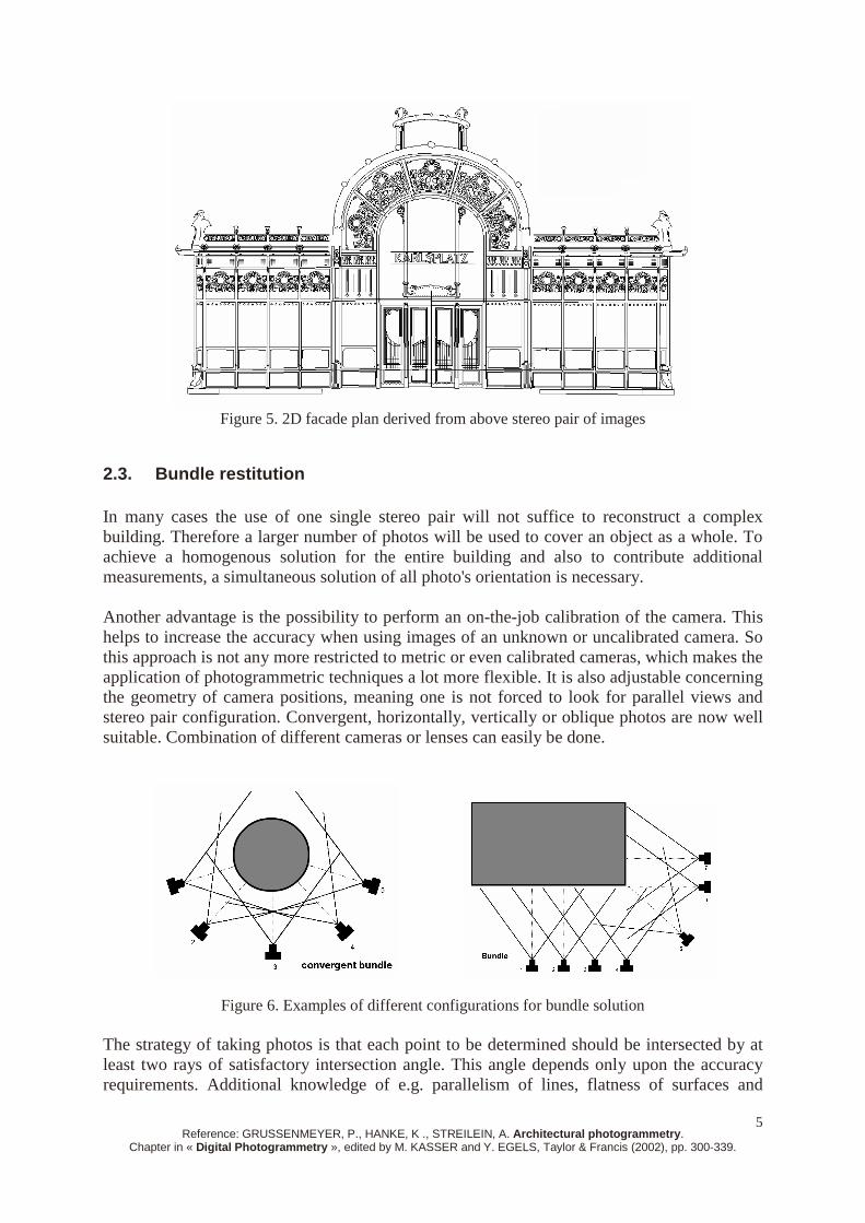
Figure 5. 2D facade plan derived from above stereo pair of images
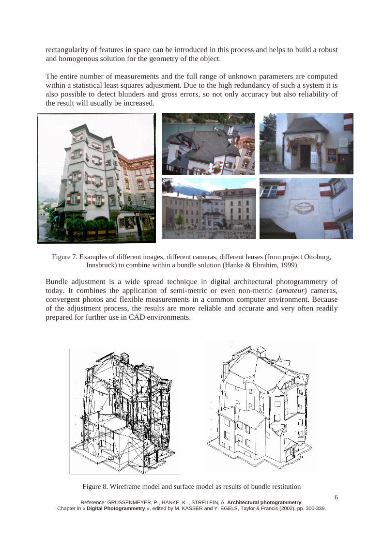
2.3. Bundle restitution In many cases the use of one single stereo pair will not suffice to reconstruct a complex building. Therefore a larger number of photos will be used to cover an object as a whole. To achieve a homogenous solution for the entire building and also to contribute additional measurements, a simultaneous solution of all photo's orientation is necessary. Another advantage is the possibility to perform an on-the-job calibration of the camera. This helps to increase the accuracy when using images of an unknown or uncalibrated camera. So this approach is not any more restricted to metric or even calibrated cameras, which makes the application of photogrammetric techniques a lot more flexible. It is also adjustable concerning the geometry of camera positions, meaning one is not forced to look for parallel views and stereo pair configuration. Convergent, horizontally, vertically or oblique photos are now well suitable. Combination of different cameras or lenses can easily be done.
Figure 6. Examples of different configurations for bundle solution The strategy of taking photos is that each point to be determined should be intersected by at least two rays of satisfactory intersection angle. This angle depends only upon the accuracy requirements. Additional knowledge of e.g. parallelism of lines, flatness of surfaces and
Reference: GRUSSENMEYER, P., HANKE, K ., STREILEIN, A. Architectural photogrammetry.
Chapter in « Digital Photogrammetry », edited by M. KASSER and Y. EGELS, Taylor & Francis (2002), pp. 300-339.
6
rectangularity of features in space can be introduced in this process and helps to build a robust and homogenous solution for the geometry of the object. The entire number of measurements and the full range of unknown parameters are computed within a statistical least squares adjustment. Due to the high redundancy of such a system it is also possible to detect blunders and gross errors, so not only accuracy but also reliability of the result will usually be increased.
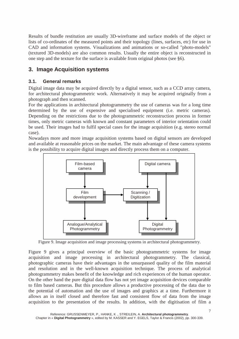
Figure 7. Examples of different images, different cameras, different lenses (from project Ottoburg,
Innsbruck) to combine within a bundle solution (Hanke & Ebrahim, 1999) Bundle adjustment is a wide spread technique in digital architectural photogrammetry of today. It combines the application of semi-metric or even non-metric (amateur) cameras, convergent photos and flexible measurements in a common computer environment. Because of the adjustment process, the results are more reliable and accurate and very often readily prepared for further use in CAD environments.
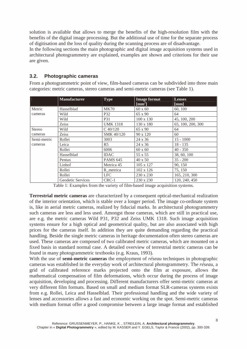
Figure 8. Wireframe model and surface model as results of bundle restitution
Reference: GRUSSENMEYER, P., HANKE, K ., STREILEIN, A. Architectural photogrammetry.
Chapter in « Digital Photogrammetry », edited by M. KASSER and Y. EGELS, Taylor & Francis (2002), pp. 300-339.
7
Results of bundle restitution are usually 3D-wireframe and surface models of the object or lists of co-ordinates of the measured points and their topology (lines, surfaces, etc) for use in CAD and information systems. Visualizations and animations or so-called "photo-models" (textured 3D-models) are also common results. Usually the entire object is reconstructed in one step and the texture for the surface is available from original photos (see §6).
3. Image Acquisition systems
3.1. General remarks Digital image data may be acquired directly by a digital sensor, such as a CCD array camera, for architectural photogrammetric work. Alternatively it may be acquired originally from a photograph and then scanned. For the applications in architectural photogrammetry the use of cameras was for a long time determined by the use of expensive and specialised equipment (i.e. metric cameras). Depending on the restrictions due to the photogrammetric reconstruction process in former times, only metric cameras with known and constant parameters of interior orientation could be used. Their images had to fulfil special cases for the image acquisition (e.g. stereo normal case). Nowadays more and more image acquisition systems based on digital sensors are developed and available at reasonable prices on the market. The main advantage of these camera systems is the possibility to acquire digital images and directly process them on a computer.
Figure 9. Image acquisition and image processing systems in architectural photogrammetry. Figure 9 gives a principal overview of the basic photogrammetric systems for image acquisition and image processing in architectural photogrammetry. The classical, photographic cameras have their advantages in the unsurpassed quality of the film material and resolution and in the well-known acquisition technique. The process of analytical photogrammetry makes benefit of the knowledge and rich experiences of the human operator. On the other hand the pure digital data flow has not yet image acquisition devices comparable to film based cameras. But this procedure allows a productive processing of the data due to the potential of automation and the use of images and graphics at a time. Furthermore it allows an in itself closed and therefore fast and consistent flow of data from the image acquisition to the presentation of the results. In addition, with the digitisation of film a
Film-based camera
Digital camera
Film development
Scanning / Digitization
Analogue/Analytical Photogrammetry
Digital Photogrammetry
Reference: GRUSSENMEYER, P., HANKE, K ., STREILEIN, A. Architectural photogrammetry.
Chapter in « Digital Photogrammetry », edited by M. KASSER and Y. EGELS, Taylor & Francis (2002), pp. 300-339.
8
solution is available that allows to merge the benefits of the high-resolution film with the benefits of the digital image processing. But the additional use of time for the separate process of digitisation and the loss of quality during the scanning process are of disadvantage. In the following sections the main photographic and digital image acquisition systems used in architectural photogrammetry are explained, examples are shown and criterions for their use are given.
3.2. Photographic cameras From a photogrammetric point of view, film-based cameras can be subdivided into three main categories: metric cameras, stereo cameras and semi-metric cameras (see Table 1).
Manufacturer Type Image format [mm2]
Lenses [mm]
Hasselblad MK70 60 x 60 60, 100 Wild P32 65 x 90 64 Wild P31 100 x 130 45, 100, 200
Metric cameras
Zeiss UMK 1318 130 x 180 65, 100, 200, 300 Wild C 40/120 65 x 90 64 Stereo
cameras Zeiss SMK 40/120 90 x 120 60 Rollei 3003 24 x 36 15 - 1000 Leica R5 24 x 36 18 - 135 Rollei 6006 60 x 60 40 - 350 Hasselblad IDAC 55 x 55 38, 60, 100 Pentax PAMS 645 40 x 50 35 - 200 Linhof Metrica 45 105 x 127 90, 150 Rollei R_metrica 102 x 126 75, 150 Rollei LFC 230 x 230 165, 210, 300
Semi-metric cameras
Geodetic Services CRC-1 230 x 230 120, 240, 450 Table 1: Examples from the variety of film-based image acquisition systems.
Terrestrial metric cameras are characterized by a consequent optical-mechanical realization of the interior orientation, which is stable over a longer period. The image co-ordinate system is, like in aerial metric cameras, realized by fiducial marks. In architectural photogrammetry such cameras are less and less used. Amongst those cameras, which are still in practical use, are e.g. the metric cameras Wild P31, P32 and Zeiss UMK 1318. Such image acquisition systems ensure for a high optical and geometrical quality, but are also associated with high prices for the cameras itself. In addition they are quite demanding regarding the practical handling. Beside the single metric cameras in heritage documentation often stereo cameras are used. These cameras are composed of two calibrated metric cameras, which are mounted on a fixed basis in standard normal case. A detailed overview of terrestrial metric cameras can be found in many photogrammetric textbooks (e.g. Kraus, 1993). With the use of semi-metric cameras the employment of réseau techniques in photographic cameras was established in the everyday work of architectural photogrammetry. The réseau, a grid of calibrated reference marks projected onto the film at exposure, allows the mathematical compensation of film deformations, which occur during the process of image acquisition, developing and processing. Different manufacturers offer semi-metric cameras at very different film formats. Based on small and medium format SLR-cameras systems exists from e.g. Rollei, Leica and Hasselblad. Their professional handling and the wide variety of lenses and accessories allows a fast and economic working on the spot. Semi-metric cameras with medium format offer a good compromise between a large image format and established
Reference: GRUSSENMEYER, P., HANKE, K ., STREILEIN, A. Architectural photogrammetry.
Chapter in « Digital Photogrammetry », edited by M. KASSER and Y. EGELS, Taylor & Francis (2002), pp. 300-339.
9
camera technique. An overview on semi-metric cameras is given in (Wester-Ebbinghaus, 1989). Often in architectural applications so called amateur cameras are often used. This often not in a dedicated photogrammetric project, but in emergency cases, where no other recording medium was available or in case of destroyed or damaged buildings only such imagery is available. Examples are given in, amongst others, (Grün, 1976), (Dallas et al., 1995) and (Ioannidis et al., 1996). Due to the ongoing destroying of the world cultural heritage it will be necessary also in the future to reconstruct objects taken with amateur cameras (Waldhäusl and Brunner, 1988).
3.3. Scanners The digitisation of photographic images offers to combine the advantages of film-based image acquisition (large image format, geometric and radiometric quality, established camera technique) with the advantages of digital image processing (archiving, semi-automatic and automatic measurement techniques, combination of raster and vector data). Scanner for the digitisation of film material can be distinguished regarding different criteria. For example regarding the type of sensor, either point, line or area sensor, or regarding the arrangement with respect to the scanned object as flatbed or drum scanner. For the practical use of scanners in architectural photogrammetric applications the problem of necessary and adequate scan resolution has to be faced. On the one side the recognition of details has to be ensured and on the other side the storage medium is not unlimited. This holds especially for larger projects. To scan a photographic film with a resolution equivalent to the film a scan resolution of about 12 µm (2100 dpi) is required. Thus, a scanned image from a medium format film (6x6 cm2) has about 5’000x5’000 pixel. To hold this data on disk requires approximately 25 Mbytes for a black-and-white scan and 75 Mbytes for a coloured image. For a scanned colour aerial image one would get a digital image of 20’000x20’000 pixel or 1.2 Gbytes. Even with the constant increasing size and decreasing costs for computer storage medium, this is a not to underestimate factor in the planning of a project. For the use in architectural photogrammetry typically two different types of scanners are used, high-resolution photogrammetric scanners and desktop publishing scanners. The photogrammetric scanners are typically flatbed scanners, which have a high geometric resolution (5-12.5 µm) and a high geometric accuracy (2-5 µm). Currently there are just a few systems commercially available, which are offered mainly by photogrammetric companies. The desktop publishing scanners (DTP) are not developed for the photogrammetric use, but they are widely available on the market at low cost and they are developed and improved in a short time interval. DTP scanners have typically a scan size of DIN A4 or A3 with a scan resolution of 300-1200 dpi. The geometric resolution of these systems is about 50 µm. Despite this technical reduction compared to photogrammetric scanners, this scanners, which are low cost and easy to handle, can be used for photogrammetric purposes. This holds especially for calibrated systems, where geometric accuracy in the order of 5-10 µm is feasible (Baltsavias and Waegli, 1996). Another possibility for the digitisation and storage of film material offers the Photo-CD system. Small and medium format film can be digitised in a special laboratory and stored on CD-ROM. The advantage of such a system is the inexpensive and easy digitisation and convenient data archiving. On the other side the scanning process can not be controlled of influenced and the image corners are usually not scanned. Thus the interior orientation of an image is nearly impossible to reconstruct. Investigations about the practical use of the Photo-CD system for digital photogrammetry are performed by (Hanke, 1994) and (Thomas et al., 1995).
Reference: GRUSSENMEYER, P., HANKE, K ., STREILEIN, A. Architectural photogrammetry.
Chapter in « Digital Photogrammetry », edited by M. KASSER and Y. EGELS, Taylor & Francis (2002), pp. 300-339.
10
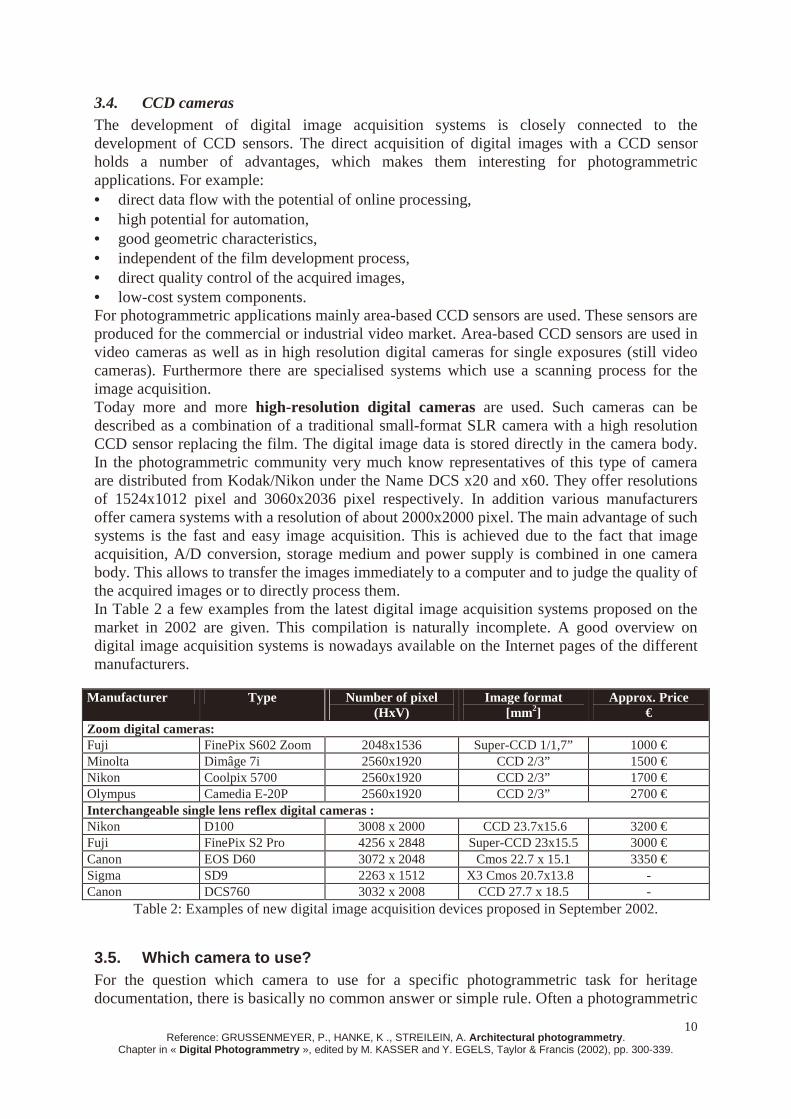
3.4. CCD cameras The development of digital image acquisition systems is closely connected to the development of CCD sensors. The direct acquisition of digital images with a CCD sensor holds a number of advantages, which makes them interesting for photogrammetric applications. For example: • direct data flow with the potential of online processing, • high potential for automation, • good geometric characteristics, • independent of the film development process, • direct quality control of the acquired images, • low-cost system components. For photogrammetric applications mainly area-based CCD sensors are used. These sensors are produced for the commercial or industrial video market. Area-based CCD sensors are used in video cameras as well as in high resolution digital cameras for single exposures (still video cameras). Furthermore there are specialised systems which use a scanning process for the image acquisition. Today more and more high-resolution digital cameras are used. Such cameras can be described as a combination of a traditional small-format SLR camera with a high resolution CCD sensor replacing the film. The digital image data is stored directly in the camera body. In the photogrammetric community very much know representatives of this type of camera are distributed from Kodak/Nikon under the Name DCS x20 and x60. They offer resolutions of 1524x1012 pixel and 3060x2036 pixel respectively. In addition various manufacturers offer camera systems with a resolution of about 2000x2000 pixel. The main advantage of such systems is the fast and easy image acquisition. This is achieved due to the fact that image acquisition, A/D conversion, storage medium and power supply is combined in one camera body. This allows to transfer the images immediately to a computer and to judge the quality of the acquired images or to directly process them. In Table 2 a few examples from the latest digital image acquisition systems proposed on the market in 2002 are given. This compilation is naturally incomplete. A good overview on digital image acquisition systems is nowadays available on the Internet pages of the different manufacturers.
Manufacturer Type Number of pixel (HxV)
Image format [mm2]
Approx. Price €
Zoom digital cameras: Fuji FinePix S602 Zoom 2048x1536 Super-CCD 1/1,7” 1000 € Minolta Dimâge 7i 2560x1920 CCD 2/3” 1500 € Nikon Coolpix 5700 2560x1920 CCD 2/3” 1700 € Olympus Camedia E-20P 2560x1920 CCD 2/3” 2700 € Interchangeable single lens reflex digital cameras : Nikon D100 3008 x 2000 CCD 23.7x15.6 3200 € Fuji FinePix S2 Pro 4256 x 2848 Super-CCD 23x15.5 3000 € Canon EOS D60 3072 x 2048 Cmos 22.7 x 15.1 3350 € Sigma SD9 2263 x 1512 X3 Cmos 20.7x13.8 - Canon DCS760 3032 x 2008 CCD 27.7 x 18.5 -
Table 2: Examples of new digital image acquisition devices proposed in September 2002.
3.5. Which camera to use? For the question which camera to use for a specific photogrammetric task for heritage documentation, there is basically no common answer or simple rule. Often a photogrammetric
Reference: GRUSSENMEYER, P., HANKE, K ., STREILEIN, A. Architectural photogrammetry.
Chapter in « Digital Photogrammetry », edited by M. KASSER and Y. EGELS, Taylor & Francis (2002), pp. 300-339.
11
project is so complex as the object itself and more often the use of an image acquisition device is determined by the budget of the project (read: use a camera system that is already available at no cost). However, for a successful photogrammetric project several aspects have to be taken into account. For example the maximum time limit for the image acquisition on the spot and for the (photogrammetric) processing of the data afterwards. Further criterions can be: the need for colour images or black-and-white images, the requested accuracy of the final model, the smallest object detail which can be modelled, the minimum and maximum of images for the project, the mobility and flexibility of the image acquisition system or the integration into the entire production process. But after all the price of the image acquisition system and the possibilities for further processing of the image data remain as the major factors for selecting a specific image acquisition system for a specific project.
4. Overview of existing methods and systems for architectural photogrammetry
4.1. General remarks Architectural photogrammetry and aerial photogrammetry don’t have the same applications and requirements. Most of the commercial Digital Photogrammetric Workstations (DPWs) are mainly dedicated to stereoscopic image measurement, aerial triangulation, Digital Terrain Model (DTM) and orthoimages production from aerial and vertical stereopair images. In this paragraph, we consider systems and methods which are rather low cost comparing to those well known products developed mainly for digital mapping. Software packages for architectural photogrammetry may use different image types, obtained directly by CCD cameras or by scanning small and medium format metric or non metric slides (see §3). The quality of digital images influences directly the final result: the use of low resolution digital cameras or low-priced scanners may be sufficient for digital 3D visual models but not for a metric documentation. The systems may be used by photogrammetrists as well as by architects or other specialists in historic monument conservation, and run on simple PC-systems which suffice for special tasks in architectural photogrammetry. According to the specific needs in architectural documentation, the different kinds of systems are based either on digital image rectification, or on monoscopic multi-image measurement or on stereoscopic image measurement (Fellbaum, 1992). Software of such systems is advanced in such a way that mass restitution and modelling is possible, if digital images is provided in a well arranged way. We give the reader notice that only some software packages are mentioned in this paragraph and that the aim is not to make a survey of existing systems. To compare different systems, following topics can be considered (CIPA, 1999):
- the handling of a system, - the flow of data, - the management of the project, - the import and export of data (image formats, parameter of interior and exterior
orientation, control information, CAD information), - the interior orientation, - the exterior orientation (one step or two steps), - the reconstruction of the object, - the derived results in terms of topology, consistency, accuracy and reliability, - the amount of photogrammetric knowledge necessary to handle the system.
Reference: GRUSSENMEYER, P., HANKE, K ., STREILEIN, A. Architectural photogrammetry.
Chapter in « Digital Photogrammetry », edited by M. KASSER and Y. EGELS, Taylor & Francis (2002), pp. 300-339.
12
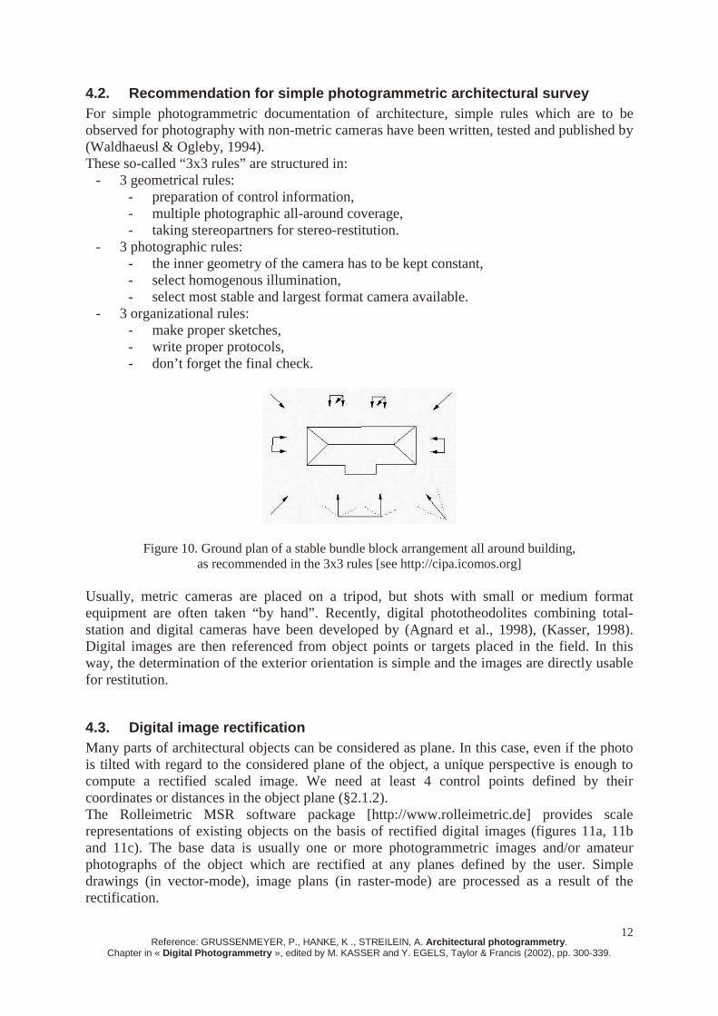
4.2. Recommendation for simple photogrammetric architectural survey For simple photogrammetric documentation of architecture, simple rules which are to be observed for photography with non-metric cameras have been written, tested and published by (Waldhaeusl & Ogleby, 1994). These so-called “3x3 rules” are structured in:
- 3 geometrical rules: - preparation of control information, - multiple photographic all-around coverage, - taking stereopartners for stereo-restitution.
- 3 photographic rules: - the inner geometry of the camera has to be kept constant, - select homogenous illumination, - select most stable and largest format camera available.
- 3 organizational rules: - make proper sketches, - write proper protocols, - don’t forget the final check.
Figure 10. Ground plan of a stable bundle block arrangement all around building, as recommended in the 3x3 rules [see http://cipa.icomos.org]
Usually, metric cameras are placed on a tripod, but shots with small or medium format equipment are often taken “by hand”. Recently, digital phototheodolites combining total-station and digital cameras have been developed by (Agnard et al., 1998), (Kasser, 1998). Digital images are then referenced from object points or targets placed in the field. In this way, the determination of the exterior orientation is simple and the images are directly usable for restitution.
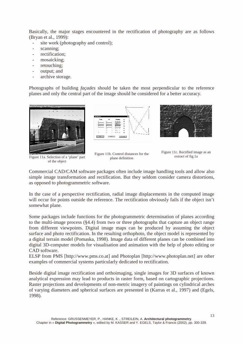
4.3. Digital image rectification Many parts of architectural objects can be considered as plane. In this case, even if the photo is tilted with regard to the considered plane of the object, a unique perspective is enough to compute a rectified scaled image. We need at least 4 control points defined by their coordinates or distances in the object plane (§2.1.2). The Rolleimetric MSR software package [http://www.rolleimetric.de] provides scale representations of existing objects on the basis of rectified digital images (figures 11a, 11b and 11c). The base data is usually one or more photogrammetric images and/or amateur photographs of the object which are rectified at any planes defined by the user. Simple drawings (in vector-mode), image plans (in raster-mode) are processed as a result of the rectification.
Reference: GRUSSENMEYER, P., HANKE, K ., STREILEIN, A. Architectural photogrammetry.
Chapter in « Digital Photogrammetry », edited by M. KASSER and Y. EGELS, Taylor & Francis (2002), pp. 300-339.
13
Basically, the major stages encountered in the rectification of photography are as follows (Bryan et al., 1999):
- site work (photography and control); - scanning; - rectification; - mosaicking; - retouching; - output; and - archive storage.
Photographs of building façades should be taken the most perpendicular to the reference planes and only the central part of the image should be considered for a better accuracy.
Figure 11a. Selection of a ‘plane’ part of the object
Figure 11b. Control distances for the plane definition
Figure 11c. Rectified image as an extract of fig.1a
Commercial CAD/CAM software packages often include image handling tools and allow also simple image transformation and rectification. But they seldom consider camera distortions, as opposed to photogrammetric software. In the case of a perspective rectification, radial image displacements in the computed image will occur for points outside the reference. The rectification obviously fails if the object isn’t somewhat plane. Some packages include functions for the photogrammetric determination of planes according to the multi-image process (§4.4) from two or three photographs that capture an object range from different viewpoints. Digital image maps can be produced by assuming the object surface and photo rectification. In the resulting orthophoto, the object model is represented by a digital terrain model (Pomaska, 1998). Image data of different planes can be combined into digital 3D-computer models for visualisation and animation with the help of photo editing or CAD software. ELSP from PMS [http://www.pms.co.at] and Photoplan [http://www.photoplan.net] are other examples of commercial systems particularly dedicated to rectification. Beside digital image rectification and orthoimaging, single images for 3D surfaces of known analytical expression may lead to products in raster form, based on cartographic projections. Raster projections and developments of non-metric imagery of paintings on cylindrical arches of varying diameters and spherical surfaces are presented in (Karras et al., 1997) and (Egels, 1998).
Reference: GRUSSENMEYER, P., HANKE, K ., STREILEIN, A. Architectural photogrammetry.
Chapter in « Digital Photogrammetry », edited by M. KASSER and Y. EGELS, Taylor & Francis (2002), pp. 300-339.
14
4.4. Monoscopic multi-image measurement systems Photogrammetric multi-image systems are designed to handle with two or more overlapping photographs taken from different angles of an object (see §2.3). In the past, these systems were used with analogue images enlarged and placed on digitizing tablets. Presently, the software usually processes image data from digital and analogue imaging sources (réseau, semi-metric or non-metric cameras). Scanners are used to digitize the analogue pictures. Film and lens distorsions are required to perform metric documentation. Monoscopic measurements are achieved separately on each image. These systems don’t give the opportunity of conventional stereo-photogrammetry. For the point measurements and acquisition of the object geometry, systems can propose support :
- for the automatic réseau cross measurement, - for the measurement of homologous points through the representation of line
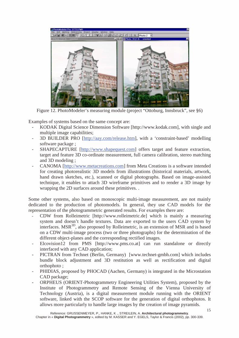
information in the photogrammetric images and epipolar geometry. The acquisition of linear objects can be directly evaluated due to superimposition in the current photogrammetric image. Theses systems are designed for multi-image bundle triangulation (including generally simultaneous bundle adjustment with self calibration of the used cameras, see §2.3). Main differences between the systems consist in the capabilities of the calculation module to combine additional parameters and knowledge like directions, distances and surfaces. The main contribution of digital images in architectural photogrammetry is the handle of textures. The raster files are transformed into object surfaces and digital image data is projected onto a three-dimensional object model. Some systems are combined with a module of digital orthorectification. The Canadian PhotoModeler Software Package developed by Eos Systems is well known as a low cost 3D-measurement tool for architectural and archeological applications [http://www.photomodeler.com]. PhotoModeler (figure 12) is a Windows based software that allows measurements and transforms photographs into 3D models. The basic steps in a project performed with PhotoModeler are:
- shoot two or more overlapping photographs from different angles of an object; - scan the images into digital form and load them into PhotoModeler; - using the point and line tools, mark on the photographs the features you want in the
final 3D model; - reference the points by indicating which points on different photographs represent the
same location on the object; - process referenced data (and possibly the camera) to produce 3D model; - view the resulting 3D model in the 3D viewer; - extract co-ordinates, distances and areas measurements within PhotoModeler; - export the 3D model to rendering, animation or CAD program.
Fast camera calibration based on a printable plane pattern can be set up separately to compute the camera’s focal length, principal point, digitising aspect ratio and lens distortion. Images from standard 35mm film cameras digitised with Kodak PhotoCD, negative scanner or flat-bed scanner as well as from digital and video cameras can be used in PhotoModeler. The achieved accuracy obtained by (Hanke & Ebrahim, 1997) for distances between points lies in the range of 1:1700 (for a 35mm small format “amateur” camera, without lens distortion compensation) to 1:8000 (for a Wild P32 metric camera) and shows promising results.
Reference: GRUSSENMEYER, P., HANKE, K ., STREILEIN, A. Architectural photogrammetry.
Chapter in « Digital Photogrammetry », edited by M. KASSER and Y. EGELS, Taylor & Francis (2002), pp. 300-339.
15
Figure 12. PhotoModeler’s measuring module (project “Ottoburg, Innsbruck”, see §6)
Examples of systems based on the same concept are:
- KODAK Digital Science Dimension Software [http://www.kodak.com], with single and multiple image capabilities;
- 3D BUILDER PRO [http://aay.com/release.htm], with a ‘constraint-based’ modelling software package ;
- SHAPECAPTURE [http://www.shapequest.com] offers target and feature extraction, target and feature 3D co-ordinate measurement, full camera calibration, stereo matching and 3D modeling ;
- CANOMA [http://www.metacreations.com] from Meta Creations is a software intended for creating photorealistic 3D models from illustrations (historical materials, artwork, hand drawn sketches, etc.), scanned or digital photographs. Based on image-assisted technique, it enables to attach 3D wireframe primitives and to render a 3D image by wrapping the 2D surfaces around these primitives. .
Some other systems, also based on monoscopic multi-image measurement, are not mainly dedicated to the production of photomodels. In general, they use CAD models for the representation of the photogrammetric generated results. For examples there are:
- CDW from Rolleimetric [http://www.rolleimetric.de] which is mainly a measuring system and doesn’t handle textures. Data are exported to the users CAD system by interfaces. MSR3D, also proposed by Rolleimetric, is an extension of MSR and is based on a CDW multi-image process (two or three photographs) for the determination of the different object-planes and the corresponding rectified images.
- Elcovision12 from PMS [http://www.pms.co.at] can run standalone or directly interfaced with any CAD application;
- PICTRAN from Technet (Berlin, Germany) [www.technet-gmbh.com] which includes bundle block adjustment and 3D restitution as well as rectification and digital orthophoto ;
- PHIDIAS, proposed by PHOCAD (Aachen, Germany) is integrated in the Microstation CAD package;
- ORPHEUS (ORIENT-Photogrammetry Engineering Utilities System), proposed by the Institute of Photogrammetry and Remote Sensing of the Vienna University of Technology (Austria), is a digital measurement module running with the ORIENT software, linked with the SCOP software for the generation of digital orthophotos. It allows more particularly to handle large images by the creation of image pyramids.
Reference: GRUSSENMEYER, P., HANKE, K ., STREILEIN, A. Architectural photogrammetry.
Chapter in « Digital Photogrammetry », edited by M. KASSER and Y. EGELS, Taylor & Francis (2002), pp. 300-339.
16
4.5. Stereoscopic image measurement systems
4.5.1. From analytical to digital Digital stereoscopic measuring systems follow analytical stereoplotters well known as the more expensive systems. Many plottings are still done on analytical stereoplotters for metric documentation but as the performance and handle of digital systems increase and allow mass restitution. As textures are more and more required for 3D models, digital photographs and systems are getting more and more importance.
4.5.2. Stereoscopy Systems presented in the former paragraph allow more than two images but homologous points are measured in monoscopic mode. Problems may occur for objects with less texture when no target is used to identify homologous points. Only stereo-viewing allow in this case a precise 3D measurement. Therefore stereopairs of images (close to the normal case) are required. Systems can then be assimilated to 3D plotters for the measuring of spatial object co-ordinates. 3D measurements are required for the definition of digital surface models which are the base of the orthophotos. Usually, proposed solutions for stereo-viewing devices are:
- the split screen configuration using a mirror stereoscope placed in front of the screen; - the anaglyph process; - the alterning of the two images on the full screen (which requires active glasses); - the alterning generation of the two synchronised images on a polarised screen (which
requires polarised spectacles)
4.5.3. Automation and correlation In digital photogrammetry, most of the measurements can be done automatically by correlation. The task is then to find the position of a geometric figure (called reference matrix) in a digital image. If the approximate position of the measured point is known in the image, then we can define a so-called search matrix. Correlation computations are used to determine the required position in the digital image. By correlation in the subpixel range the accuracy of positioning is roughly one order of magnitude better than the pixel size. Usually, the correlation process is very efficient on architectural objects, due to textured objects. Correlation functions can be implemented in the different steps of the orientation :
- fiducial marks or réseau crosses can be measured automatically in the inner orientation; - measurement of homologous points can be automated by the use of the correlation
process both in the exterior orientation, and in the digital surface model and stereoplotting modules.
The correlation function is a real progress compared to manual measurements applied in analytical photogrammetry. The quality of the measurement is usually given by a correlation factor.
4.5.4. Model orientation Systems currently used for aerial photogrammetry run with stereopair of images but their use isn’t always possible in architectural photogrammetry. In many cases, systems cannot handle different type and scale of images. The orientation module may fail either because photographs and control points are defined in a terrestrial case, or due to the non-respect of the approximate normal case. For the exterior orientation, some systems propose solutions based on typical two steps orientation (relative an absolute), as known in analytical photogrammetry. But bundle adjustment are more and more proposed and allow an
Reference: GRUSSENMEYER, P., HANKE, K ., STREILEIN, A. Architectural photogrammetry.
Chapter in « Digital Photogrammetry », edited by M. KASSER and Y. EGELS, Taylor & Francis (2002), pp. 300-339.
17
orientation in only one step. A Direct Linear Transformation is sometimes used to compute approximate parameters of the orientation. Some systems propose automatic triangulation. But due to the configuration of the set of photographs in architectural photogrammetry, their use requires a lot of manual measurements. After the relative orientation, often normalised images can be computed. Either original or normalised images can be used for further processes.
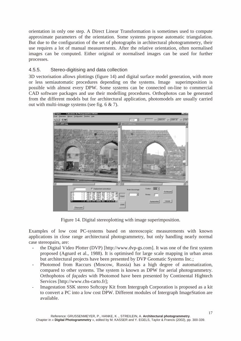
4.5.5. Stereo-digitising and data collection 3D vectorisation allows plottings (figure 14) and digital surface model generation, with more or less semiautomatic procedures depending on the systems. Image superimposition is possible with almost every DPW. Some systems can be connected on-line to commercial CAD software packages and use their modelling procedures. Orthophotos can be generated from the different models but for architectural application, photomodels are usually carried out with multi-image systems (see fig. 6 & 7).
Figure 14. Digital stereoplotting with image superimposition. Examples of low cost PC-systems based on stereoscopic measurements with known applications in close range architectural photogrammetry, but only handling nearly normal case stereopairs, are:
- the Digital Video Plotter (DVP) [http://www.dvp-gs.com]. It was one of the first system proposed (Agnard et al., 1988). It is optimised for large scale mapping in urban areas but architectural projects have been presented by DVP Geomatic Systems Inc.;
- Photomod from Raccurs (Moscow, Russia) has a high degree of automatization, compared to other systems. The system is known as DPW for aerial photogrammetry. Orthophotos of façades with Photomod have been presented by Continental Hightech Services [http://www.chs-carto.fr];
- Imagestation SSK stereo Softcopy Kit from Intergraph Corporation is proposed as a kit to convert a PC into a low cost DPW. Different modules of Intergraph ImageStation are available.
Reference: GRUSSENMEYER, P., HANKE, K ., STREILEIN, A. Architectural photogrammetry.
Chapter in « Digital Photogrammetry », edited by M. KASSER and Y. EGELS, Taylor & Francis (2002), pp. 300-339.
18
Several systems have been developed by Universities during the last years. Some of them are: - VSD as Video Stereo Digitizer (Jachimski, 1995) is well known for architectural
applications. VSD is a digital autograph built on the basis of a PC. It is suitable for plotting vector maps on the basis of pairs of monochrome or colour digital images as well as for vectorization of orthophotographs. The stereoscopic observation is based on a simple mirror stereoscope;
- POIVILLIERS ‘E’ developed by Yves Egels (IGN-ENSG, Paris, France) is running under DOS. Stereo-viewing is possible by active glasses connected to the parallel port of the PC or by anaglyphs. The system is very efficient for large images and high pointing accuracy is available due to sub-pixel measuring module. Color superimposition of plottings is also proposed. The system runs on aerial images as well as on terrestrial ones;
- Mapping from stereopairs within Autocad R14 is proposed by Greek Universities (Glykos et al., 1999);
- TIPHON is a Windows application developed at ENSAIS (Polytechnicum of Strasbourg, France) for two-image based photogrammetry (stereopair or convergent bundle) with different kinds of cameras (Grussenmeyer & Koehl, 1998). The measurements on the images are manual or semiautomatic by correlation. A stereoscope is used if stereoscopic observations are required.
ARPENTEUR as ‘ARchitectural PhotogrammEtry Network Tool for EdUcation and Research’ is a platform-independent system available on the web by a simple internet browser (Drap & Grussenmeyer, 2000). The system is an adaptation of TIPHON to the Internet World and is particularly dedicated to architectural applications. ARPENTEUR is a web based software package utilizing HTTP and FTP protocols. The photogrammetric adjustment and image processing routines are written in JAVA™. Different solutions are available for the orientation of the digital stereopairs. The concept of running photogrammetric software on the Internet is extended by a new approach of architectural photogrammetry 3D modeling. The architectural survey is monitored by underlying geometrical models stemming from architectural knowledge. Image correlation, geometrical functions and photogrammetry data are combined to optimize the modeling process. The data of the stereoplotting are directly superimposed on the images and exported towards CAD software packages and VRML file format. ARPENTEUR is usable via the Internet at [http://www.arpenteur.net].
5. 3D object structures
5.1. General remarks If a person is asked to describe an object, he/she solves the problem typically by describing all the single components of the object with all their attributes and properties and the relations they have with respect to each other and to the object. In principle computer representations and models are nothing else than the analogue description of the object, only the human language is replaced by mathematical methods. All kinds of representations describe only a restricted amount of attributes and each finite mathematical description of an object is incomplete. Data models are necessary in order to process and manipulate real world objects with the computer. The data models are abstractions of real world objects or phenomenon’s. Abstractions are used in order to grasp or manipulate the complex and extensive reality. Each attempt to represent reality is already an abstraction. The only complete representation of a real world object is the object itself. Models are structures, which combine abstractions and
Reference: GRUSSENMEYER, P., HANKE, K ., STREILEIN, A. Architectural photogrammetry.
Chapter in « Digital Photogrammetry », edited by M. KASSER and Y. EGELS, Taylor & Francis (2002), pp. 300-339.
19
operands to a unit useful for analysis and manipulation. Using models the behaviour, appearance and various functions of an object or building can be easily represented and manipulated. Prerequisite for the origin of a model is the existence of an abstraction. Each model needs to fulfil a number of conventions to work with it effective. The higher the degree of abstraction the more conventions have to be fulfilled. CAD models represent in an ideal way the building in form, behaviour and function as a logical and manipulable organism. The data of the computer internal representation, which is sorted according to a specific order (“data structure”), forms the basis for software applications. The data basis is not directly accessed, but via available model algorithms, which allow the performance of complex functions by transforming them into simple basic functions according to a defined algorithm. The representation of a real world object in a computer oriented model is a synthesis of data structure and algorithms. Depending on extend and amount of information of the data an object can be represented as a data intensive or an algorithm intensive model (Grätz, 1989). The most important role in the definition of models plays a proper balance between correctness and easy handling.
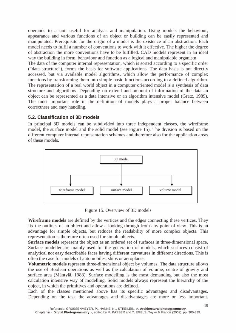
5.2. Classification of 3D models In principal 3D models can be subdivided into three independent classes, the wireframe model, the surface model and the solid model (see Figure 15). The division is based on the different computer internal representation schemes and therefore also for the application areas of these models.
Figure 15. Overview of 3D models
Wireframe models are defined by the vertices and the edges connecting these vertices. They fix the outlines of an object and allow a looking through from any point of view. This is an advantage for simple objects, but reduces the readability of more complex objects. This representation is therefore often used for simple objects. Surface models represent the object as an ordered set of surfaces in three-dimensional space. Surface modeller are mainly used for the generation of models, which surfaces consist of analytical not easy describable faces having different curvatures in different directions. This is often the case for models of automobiles, ships or aeroplanes. Volumetric models represent three-dimensional object by volumes. The data structure allows the use of Boolean operations as well as the calculation of volume, centre of gravity and surface area (Mäntylä, 1988). Surface modelling is the most demanding but also the most calculation intensive way of modelling. Solid models always represent the hierarchy of the object, in which the primitives and operations are defined. Each of the classes mentioned above has its specific advantages and disadvantages. Depending on the task the advantages and disadvantages are more or less important.
3D model
wireframe model surface model volume model
Reference: GRUSSENMEYER, P., HANKE, K ., STREILEIN, A. Architectural photogrammetry.
Chapter in « Digital Photogrammetry », edited by M. KASSER and Y. EGELS, Taylor & Francis (2002), pp. 300-339.
20
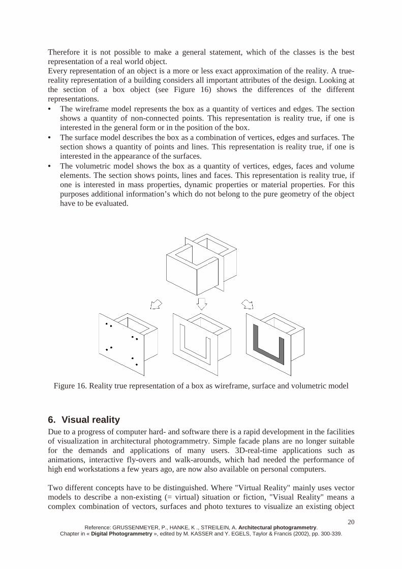
Therefore it is not possible to make a general statement, which of the classes is the best representation of a real world object. Every representation of an object is a more or less exact approximation of the reality. A true-reality representation of a building considers all important attributes of the design. Looking at the section of a box object (see Figure 16) shows the differences of the different representations. • The wireframe model represents the box as a quantity of vertices and edges. The section
shows a quantity of non-connected points. This representation is reality true, if one is interested in the general form or in the position of the box.
• The surface model describes the box as a combination of vertices, edges and surfaces. The section shows a quantity of points and lines. This representation is reality true, if one is interested in the appearance of the surfaces.
• The volumetric model shows the box as a quantity of vertices, edges, faces and volume elements. The section shows points, lines and faces. This representation is reality true, if one is interested in mass properties, dynamic properties or material properties. For this purposes additional information’s which do not belong to the pure geometry of the object have to be evaluated.
Figure 16. Reality true representation of a box as wireframe, surface and volumetric model
6. Visual reality Due to a progress of computer hard- and software there is a rapid development in the facilities of visualization in architectural photogrammetry. Simple facade plans are no longer suitable for the demands and applications of many users. 3D-real-time applications such as animations, interactive fly-overs and walk-arounds, which had needed the performance of high end workstations a few years ago, are now also available on personal computers. Two different concepts have to be distinguished. Where "Virtual Reality" mainly uses vector models to describe a non-existing (= virtual) situation or fiction, "Visual Reality" means a complex combination of vectors, surfaces and photo textures to visualize an existing object
Reference: GRUSSENMEYER, P., HANKE, K ., STREILEIN, A. Architectural photogrammetry.
Chapter in « Digital Photogrammetry », edited by M. KASSER and Y. EGELS, Taylor & Francis (2002), pp. 300-339.
21
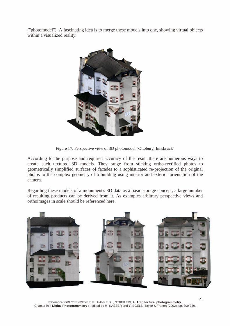
("photomodel"). A fascinating idea is to merge these models into one, showing virtual objects within a visualized reality.
Figure 17. Perspective view of 3D photomodel "Ottoburg, Innsbruck"
According to the purpose and required accuracy of the result there are numerous ways to create such textured 3D models. They range from sticking ortho-rectified photos to geometrically simplified surfaces of facades to a sophisticated re-projection of the original photos to the complex geometry of a building using interior and exterior orientation of the camera. Regarding these models of a monument's 3D data as a basic storage concept, a large number of resulting products can be derived from it. As examples arbitrary perspective views and orthoimages in scale should be referenced here.
Reference: GRUSSENMEYER, P., HANKE, K ., STREILEIN, A. Architectural photogrammetry.
Chapter in « Digital Photogrammetry », edited by M. KASSER and Y. EGELS, Taylor & Francis (2002), pp. 300-339.
22
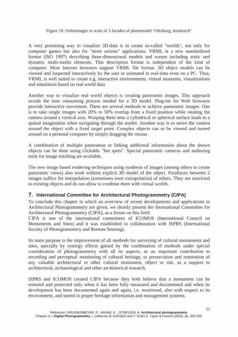
Figure 18. Orthoimages in scale of 3 facades of photomodel "Ottoburg, Innsbruck"
A very promising way to visualize 3D-data is to create so-called "worlds", not only for computer games but also for "more serious" applications. VRML is a new standardized format (ISO 1997) describing three-dimensional models and scenes including static and dynamic multi-media elements. This description format is independent of the kind of computer. Most Internet browsers support VRML file format. 3D object models can be viewed and inspected interactively by the user or animated in real-time even on a PC. Thus, VRML is well suited to create e.g. interactive environments, virtual museums, visualizations and simulation based on real world data. Another way to visualize real world objects is creating panoramic images. This approach avoids the time consuming process needed for a 3D model. Plug-ins for Web browsers provide interactive movement. There are several methods to achieve panoramic images. One is to take single images with 20% to 50% overlap from a fixed position while rotating the camera around a vertical axis. Warping them onto a cylindrical or spherical surface leads to a spatial imagination when navigating through the model. Another way is to move the camera around the object with a fixed target point. Complex objects can so be viewed and turned around on a personal computer by simply dragging the mouse. A combination of multiple panoramas or linking additional information about the shown objects can be done using clickable "hot spots". Special panoramic cameras and authoring tools for image stitching are available. The new image based rendering techniques using synthesis of images (among others to create panoramic views) also work without explicit 3D model of the object. Parallaxes between 2 images suffice for interpolation (sometimes even extrapolation) of others. They are restricted to existing objects and do not allow to combine them with virtual worlds.
7. International Committee for Architectural Photogrammetry (CIPA) To conclude this chapter in which an overview of recent developments and applications in Architectural Photogrammetry are given, we shortly present the International Committee for Architectural Photogrammetry (CIPA), as a forum on this field. CIPA is one of the international committees of ICOMOS (International Council on Monuments and Sites) and it was established in collaboration with ISPRS (International Society of Photogrammetry and Remote Sensing). Its main purpose is the improvement of all methods for surveying of cultural monuments and sites, specially by synergy effects gained by the combination of methods under special consideration of photogrammetry with all its aspects, as an important contribution to recording and perceptual monitoring of cultural heritage, to preservation and restoration of any valuable architectural or other cultural monument, object or site, as a support to architectural, archaeological and other art-historical research. ISPRS and ICOMOS created CIPA because they both believe that a monument can be restored and protected only when it has been fully measured and documented and when its development has been documented again and again, i.e. monitored, also with respect to its environment, and stored in proper heritage information and management systems.

Reference: GRUSSENMEYER, P., HANKE, K ., STREILEIN, A. Architectural photogrammetry.
Chapter in « Digital Photogrammetry », edited by M. KASSER and Y. EGELS, Taylor & Francis (2002), pp. 300-339.
23
In order to accomplish this mission, CIPA [see http://cipa.icomos.org] will: • establish links between architects, historians, archaeologists, conservationists,
inventory experts and specialists in photogrammetry and remote sensing, spatial information systems, CAAD, computer graphics and other related fields;
• organise and encourage the dissemination and exchange of ideas, knowledge, experience and the results of research and development (CIPA Expert Groups and CIPA Mailing List);
• establish contacts with and between the relevant institutions and companies which specialise in the execution of photogrammetric surveys or in the manufacture of appropriate systems and instruments (Board of Sustaining Members);
• initiate and organise conferences, symposia, specialised colloquia, workshops, tutorials, practical sessions and specialised courses (CIPA Events);
• initiate and co-ordinate applied research and development activities (CIPA Working Groups);
• undertake the role of scientific and technical expert for specific projects (CIPA Expert Advisory Board);
• organise a network of National and Committee Delegates; • submit an annual report on its activities to the ICOMOS Bureau (Secretary General)
and the ISPRS Council (Secretary General) and publish it in the Internet (Annual Reports);
• publish also its Structure, its Statutes and Guidelines in the Internet. CIPA has a well established structure of Working Groups (WG) and Task Groups (TG): Most of the references from papers given in the next paragraph are published in CIPA and ISPRS Commission V archives.
8. References References from Books: 1. ATKINSON, K.B., 1996. Close Range Photogrammetry and Machine Vision.
Whittles Publishing, London. 2. BATIC J. et al., 1996. Photogrammetry as a Method of Documenting the Cultural Heritage, (in English
and Slovenian). Minist. of Culture, Ljubljana, Slovenia. 1996. 3. DALLAS, R.W.A., 1996. Architectural and archaeological photogrammetry. Chapter in Close Range
Photogrammetry and Machine Vision, Edited by K.B. Atkinson, Wittles Publishing, Caithness, U.K., 1996, pp. 283-302.
4. FONDELLI, M., 1992. Trattato di fotogrammetria urbana e architettonica, (in Italian). Editori Gius.
Laterza & Figli Spa, Roma-Bari, Italia 1992. 5. GRÄTZ, J.F., 1989. Handbuch der 3D-CAD-Technik. Modellierung mit 3D-Volumensystemen. Siemens-
Aktiengesellschaft, Berlin, 1989, (in German). 6. KRAUS, K. with contributions by P. WALDHÄUSL. 1993. Photogrammetry, Vol. 1, Fundamentals and
Standard Processes , 4th edition, Dümmler/Bonn, ISBN 3-427-78684-6.
7. KRAUS K. with contributions by JANSA J. and KAGER H., 1997. Photogrammetry - Advanced Methods and Applications. Volume 2, , 4th edition, Dümmler/Bonn.
Reference: GRUSSENMEYER, P., HANKE, K ., STREILEIN, A. Architectural photogrammetry.
Chapter in « Digital Photogrammetry », edited by M. KASSER and Y. EGELS, Taylor & Francis (2002), pp. 300-339.
24
8. LUHMANN, Th., 2000. Nahbereichsphotogrammetrie - Grundlagen, Methoden und Anwendungen". Wichmann-Verlag, Heidelberg, (in German).
9. PATIAS, P. & KARRAS, G.E., 1995. Contemporary Photogrammetric Applications in Architecture
and Archaeology. Thessaloniki, Greece, 1995, (in Greek). 10. SAINT-AUBIN, J.-P., 1992. Le relevé et la représentation de l’architecture. Inventaire Général des
Monuments et des Richesses Artistiques de la France, Paris, 232pp. (in French). 11. WEIMANN, G., 1988. Architektur-Photogrammetrie,. Wichmann Verlag, Karlsruhe, Germany 1988, (in
German). References from Journals and other Literatures : 12. AGNARD, J.-P., GAGNON, P.-A., NOLETTE, C., 1988. Microcomputers and Photogrammetry. A New
Tool: The Videoplotter. PE&RS, 54 (8), pp.1165-1167.
13. AGNARD, J.P., GRAVEL, C., GAGNON, P.-A., 1998. Realization of a Digital Phototheodolite. ISPRS International archives of Photogrammetry and Remote Sensing Vol. XXXII, part 5, Hakodate, 1998, pp. 498-501.
14. ALMAGRO, A., 1999. Photogrammetry for Everybody. International Archives of Photogrammetry and Remote Sensing Vol. XXXII, CIPA Symposium 1999, Olinda, Brazil.
15. BALTSAVIAS, E., WAEGLI, B., 1996. Quality analysis and calibration of DTP scanners. International Archives of Photogrammetry and Remote Sensing, Vol. 31, Part B1, pp. 13-19.
16. BRYAN, P.G., CORNER, I., STEVENS, D., 1999. Digital rectification techniques for architectural and archeological presentation. Photogrammetric Record, 16(93): 399-415 (April 1999).
17. CHENGSHUANG, L., RODEHORST, V. WIEDEMANN, A., 1997. Digital Image Processing for
Automation in Architectural Photogrammetry In: O. Altan & L. Gründig (eds.) Second Turkish-German Joint Geodetic Days. Berlin, Germany, May 28-30, 1997. Istanbul Technical University, 1997, pp. 541-548.
18. CIPA, 1999. Questionnaire on the processing of the data set “Zurich city hall”. Edited by CIPA Working Group 3 & 4 (A. Streilein, P. Grussenmeyer and K. Hanke) 1999. 8 pages.
19. DALLAS, R.W.A., KERR, J.B., LUNNON, S., BRYAN, P.G., 1995. Windsor Castle: photogrammetric
and archaelogical recording after the fire. Photogrammetric Record, 15 (86). pp. 225-240. 20. DRAP, P., GRUSSENMEYER, P., 2000. A digital photogrammetric workstation on the WEB. ISPRS
Journal of Photogrammetry and Remote Sensing 55 (1), pp.48-58. 21. EGELS, Y., 1998. Monuments historiques et levers photogrammétriques. Revue Géomètre, (3) 1998,
pp. 41-43, in French.
22. EL-HAKIM, S., 2000. A practical approach to creating precise and detailed 3D models from single and multiple views. International Archives of Photogrammetry and Remote Sensing, 33(5): 203-210.
23. FELLBAUM, M., 1992. Low Cost Systems in Architectural Photogrammetry. International Archives of Photogrammetry and Remote Sensing, Vol. XXIX, Part B5, Washinton DC, 1992, pp. 771-777.
24. GLYKOS, T., KARRAS, G.E., VOULGARIDIS, G., 1999. Close-Range Photogrammetry within a
Commercial CAD Package. International Archives of Photogrammetry and Remote Sensing, Vol. XXXII, Part 5W11. Thessaloniki , 1999. pp. 103-106.
25. GRUEN, A., 2000. Semi-automated approaches to site recording and modeling. International Archives
of Photogrammetry and Remote Sensing, 33(5): 309-318.
Reference: GRUSSENMEYER, P., HANKE, K ., STREILEIN, A. Architectural photogrammetry.
Chapter in « Digital Photogrammetry », edited by M. KASSER and Y. EGELS, Taylor & Francis (2002), pp. 300-339.
25
26. GRUEN, A., 1976. Photogrammetrische Rekonstruktion aus Amateuraufnahmen. Architektur-Photogrammetrie II, Arbeitsheft 17, Landeskonservator Rheinland. Rheinland-Verlag, Köln, 1976. pp. 85-92.
27. GRUSSENMEYER, P., HANKE, K ., STREILEIN, A., 2002.Architectural photogrammetry. Chapter in
« Digital Photogrammetry ». Edited by M. KASSER and Y. EGELS, Taylor & Francis, pp. 300-339. 28. GRUSSENMEYER, P., KOEHL, M., 1998. Architectural photogrammetry with the TIPHON software,
towards digital documentation in the field. International archives of Photogrammetry and Remote Sensing Vol. XXXII, part 5, Hakodate, 1998, pp. 549-556.
29. GRUSSENMEYER P. – ABDALLAH T., 1997. The cooperation in architectural photogrammetry
between ENSAIS (France) and ECAE (Egypt) : practical experiences on historic monuments in CAIRO. International archives of Photogrammetry and Remote Sensing, Vol. XXXII, Part 5C1B, Göteborg, 1997, pp. 215-221.
30. GRUSSENMEYER, P., GUNTZ, C., 1997. Photogrammétrie architecturale et réalité virtuelle :
modélisation de l’aqueduc El-Ghuri (Le Caire, Egypte). Revue de l’Association Française de Topographie, XYZ 4e trim. 97 N°73, pp. 75-81, in french.
31. HANKE K, EBRAHIM M.A-B., 1999. The „Digital Projector“ – Raytracing as a tool for digital close-
range photogrammetry. ISPRS Journal of Photogrammetry and Remote Sensing, 1999. Vol. 54 / 1. Elsevier Science B.V., Amsterdam, NL
32. HANKE K., 1998. Digital Close Range Photogrammetry using CAD and Raytracing Techniques. International Archives of Photogrammetry and Remote Sensing Vol. XXXII Part 5, Hakodate 1998, pp. 221-225.
33. HANKE K, EBRAHIM M.A-B., 1997. A low cost 3D-Measurement Tool for Architectural and Archaeological Applications. International Archives of Photogrammetry and Remote Sensing Vol. XXXI Part 5C1B, CIPA Symposium, Göteborg 1997, pp. 113-120.
34. HANKE K., 1994. The Photo-CD - A Source and Digital Memory for Photogrammetric Images. International Archives of Photogrammetry and Remote Sensing. Vol. XXX Part 5, Melbourne, 1994, pp. 144-149
35. HEMMLEB, M., WIEDEMANN A., 1997. Digital Rectification and Generation of Orthoimages in Architectural Photogrammetry. International Archives of Photogrammetry and Remote Sensing Vol. XXXI Part 5C1B, CIPA Symposium, Göteborg 1997, pp. 261-267
36. IOANNIDIS, C., POTSIOU, C., BADEKAS, J., 1996. 3D detailed reconstruction of a demolished building by using old photographs. International Archives of Photogrammetry and Remote Sensing, Vol. XXXI, Part B5, Vienna 1996. pp. 16-21
37. JACHIMSKI, J., 1995. Video Stereo Digitizer. A Small Digital Stereophotogrammetric Working Station for the Needs of SIT and other Application. Polish Academy Of Sciences. The Krakow Section. Proceedings of the Geodesy and Environmental Engineering Commission, Geodesy 38, 1995, pp. 71-91.
38. KARRAS, G., PATIAS, P., PETSA, E., KETIPIS, K., 1997. Raster projection and development of curved surfaces. International Archives of Photogrammetry & Remote Sensing, Vol. XXXII, Part 5C1B, Göteborg, pp. 179-185.
39. KASSER, M., 1998. Développement d’un photothéodolite pour les levés archéologiques. Revue
Géomètre, (3) 1998, pp. 44-45, (in French).
40. MÄNTÄLA, M., 1988. Introduction to Solid Modeling. Computer Science Press. 1988.
41. PATIAS, P., STREILEIN, A., 1996. Contribution of Videogrammetry to the architectural restitution - Results of the CIPA "O. Wagner Pavillon" test. International Archives of Photogrammetry and Remote Sensing, Vol. XXI, Part B5, Vienna 1996, pp. 457-462.
Reference: GRUSSENMEYER, P., HANKE, K ., STREILEIN, A. Architectural photogrammetry.
Chapter in « Digital Photogrammetry », edited by M. KASSER and Y. EGELS, Taylor & Francis (2002), pp. 300-339.
26
42. PATIAS, P., PEIPE, J., 2000. Photogrammetry and CAD/CAM in culture and industry, an ever changing paradigm. International Archives of Photogrammetry and Remote Sensing, 33(5): 599-603.
43. POMASKA, G., 1998. Automated processing of digital image data in architectural surveying. International Archives of Photogrammetry and Remote Sensing, Vol. XXII, Part 5, Hakodate 1998, pp. 637-642.
44. SCHNEIDER, C-T., 1996. DPA-WIN – A PC based Digital Photogrammetric Station for Fast and Flexible On-Site Measurement. International Archives of Photogrammetry and Remote Sensing, Vol. XXI, Part B5, Vienna, 1996, pp. 530-533.
45. STREILEIN, A, HANKE, K., GRUSSENMEYER, P., 2000. First experiences with the “Zurich City Hall” data set for architectural photogrammetry. International Archives of Photogrammetry and Remote Sensing, 33(5): 772-779.
46. STREILEIN, A., NIEDERÖST, M., 1998. Reconstruction of the Disentis monastery from high resolution still video imagery with object oriented measurement routines. International Archives of Photogrammetry and Remote Sensing, Vol. XXII, Part 5, Hakodate, 1998, pp. 271-277.
47. STREILEIN, A., 1996. Utilization of CAD models for the object oriented measurement of industrial and architectural objects. International Archives of Photogrammetry and Remote Sensing, Vol. XXI, Part B5, Vienna, 1996, pp. 548-553.
48. STREILEIN, A., 1995. Videogrammetry and CAAD for architectural restitution of the Otto-Wagner-Pavillion in Vienna. In “Optical 3-D Measurement Techniques III”, Gruen/Kahmen (Eds), Wichmann Verlag, Heidelberg, 1995. pp. 305-314.
49. STREILEIN, A., GASCHEN, S., 1994. Comparison of a S-VHS camcorder and a high-resolution CCD-camera for use in architectural photogrammetry. International Archives of Photogrammetry and Remote Sensing Volume XXX, Part 5, Melbourne, 1994, pp. 382-389.
50. STREILEIN, A., BEYER, H. and KERSTEN, T., 1992. Digital photogrammetric techniques for architectural design. International Archives of Photogrammetry and Remote Sensing, Vol. XXIX, Part B5, Washinton DC, 1992, pp.825-831.
51. THOMAS, P.R., MILLER, J.P., NEWTON, I., 1995. An Investigation into the use of Kodak Photo CD
for Digital Photogrammetry. Photogrammetric Record 15 (86), pp. 301-314. 52. VAN DEN HEUVEL, F.A., 1999. Estimation of interior orientation parameters from constraints on
line measurements in a single image. International Archives of Photogrammetry and Remote Sensing, Vol. 32, Part 5W11, Thessaloniki 1999, pp. 81-88.
53. VAN DEN HEUVEL, F.A., 1998, 3D Reconstruction from a Single Image using Geometric Constraints ISPRS Journal of Photogrammetry and Remote Sensing, Vol.53, No.6, pp.354-368
54. VARHOSAZ, M., D0WMAN, I., CHAPMAN, D., 2000. Towards automatic reconstruction of visually realistic models of buildings. International Archives of Photogrammetry and Remote Sensing, 33(5): 180-186.
55. WALDHAEUSL, P.,1999. Tasks for ISPRS Working Groups to Serve ICOMOS. International Archives of Photogrammetry and Remote Sensing, Volume XXXII, Part 5W11, Thessaloniki 1999, pp. 1-7.
56. WALDHAEUSL, P.,OGLEBY, C., 1994. 3x3-Rules for Simple Photogrammetric Documentation of Architecture. International Archives of Photogrammetry and Remote Sensing, Volume XXX, Part 5, Melbourne, 1994, pp. 426-429.
57. WALDHAEUSL, P., 1992. Defining the Future of Architectural Photogrammetry. International Archives of Photogrammetry and Remote Sensing, Volume XXX, Part B5, Washington DC, 1992, pp. 767-770.
Reference: GRUSSENMEYER, P., HANKE, K ., STREILEIN, A. Architectural photogrammetry.
Chapter in « Digital Photogrammetry », edited by M. KASSER and Y. EGELS, Taylor & Francis (2002), pp. 300-339.
27
58. WALDHAEUSL, P., BRUNNER, M., 1988. Architectural Photogrammetry world-wide and by anybody with non-metric cameras? Proceedings des XI. Internationalen CIPA Symposiums, October 1988, Sofia, pp. 35-49.
59. WESTER-EBBINGHAUS, W., 1989. Das Réseau im photogrammetrischen Bildraum. Bildmessung und Luftbildwesen 3/89. pp. 64-71.
60. WIEDEMANN, A, HEMMLEB, M., ALBERTZ, J., 2000. Recontruction of historical buildings based on images from the Meydenbauer archives. International Archives of Photogrammetry and Remote Sensing, 33(5): 887-893.
61. WIEDEMANN, A., RODEHORST, V., 1997. Towards Automation in Architectural Photogrammetry using Digital Image Processing. International Archives of Photogrammetry and Remote Sensing Vol. XXXI Part 5C1B, CIPA Symposium, Göteborg 1997, pp. 209-214.
62. WIEDEMANN, A., 1996. Digital Orthoimages in Architectural Photogrammetry Using Digital Surface Models. International Archives of Photogrammetry and Remote Sensing, Vol. XXXI, Part B5, Vienna 1996, pp. 605-609.
63. ZISCHINSKY, T., DORFFNER, L., ROTTENSTEINER.F., 2000. Application of a new model helicopter system in architectural photogrammetry. International Archives of Photogrammetry and Remote Sensing, 33(5): 959-968.