architecture and implementation of database systems...
TRANSCRIPT

Architecture and Implementation
of Database Systems (Winter 2014/15)
Jens Teubner, DBIS Group
Winter 2014/15
© Jens Teubner · Architecture & Implementation of DBMS · Winter 2014/15 1

Part VI
Query Optimization
© Jens Teubner · Architecture & Implementation of DBMS · Winter 2014/15 203

Finding the “Best” Query Plan
SELECT · · ·FROM · · ·WHERE · · ·
π
1NL
1hash
R σ
S
T?
We already saw that there may be more than one way to answer a
given query.
Which one of the join operators should we pick? With which
parameters (block size, buffer allocation, . . . )?
The task of finding the best execution plan is, in fact, the holy grail
of any database implementation.
© Jens Teubner · Architecture & Implementation of DBMS · Winter 2014/15 204
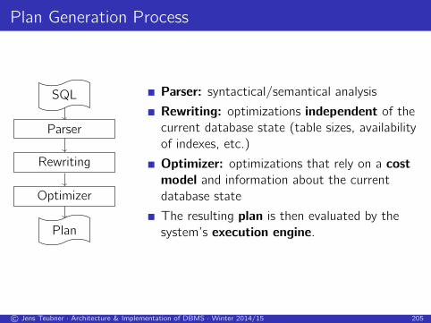
Plan Generation Process
SQL
Parser
Rewriting
Optimizer
Plan
Parser: syntactical/semantical analysis
Rewriting: optimizations independent of the
current database state (table sizes, availability
of indexes, etc.)
Optimizer: optimizations that rely on a cost
model and information about the current
database state
The resulting plan is then evaluated by the
system’s execution engine.
© Jens Teubner · Architecture & Implementation of DBMS · Winter 2014/15 205
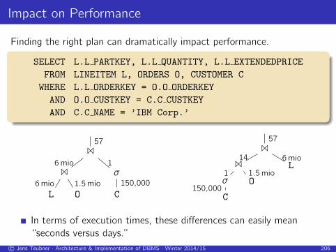
Impact on Performance
Finding the right plan can dramatically impact performance.
SELECT L.L PARTKEY, L.L QUANTITY, L.L EXTENDEDPRICE
FROM LINEITEM L, ORDERS O, CUSTOMER C
WHERE L.L ORDERKEY = O.O ORDERKEY
AND O.O CUSTKEY = C.C CUSTKEY
AND C.C NAME = ’IBM Corp.’
1
1
L6mio
O1.5mio
6mioσ
C150,000
1
571
1
σ
C150,000
1O1.5mio
14L6mio
57
In terms of execution times, these differences can easily mean
“seconds versus days.”
© Jens Teubner · Architecture & Implementation of DBMS · Winter 2014/15 206
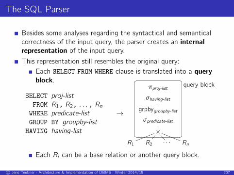
The SQL Parser
Besides some analyses regarding the syntactical and semantical
correctness of the input query, the parser creates an internal
representation of the input query.
This representation still resembles the original query:
Each SELECT-FROM-WHERE clause is translated into a query
block.
SELECT proj-list
FROM R1, R2, . . . , RnWHERE predicate-list
GROUP BY groupby-list
HAVING having-list
→
πproj-list
σhaving-list
grpbygroupby-list
σpredicate-list
×
R1 R2 · · · Rn
query block
Each Ri can be a base relation or another query block.
© Jens Teubner · Architecture & Implementation of DBMS · Winter 2014/15 207

Finding the “Best” Execution Plan
SQL
Parser
Rewriting
Optimizer
Plan
The parser output is fed into a rewrite engine which,
again, yields a tree of query blocks.
It is then the optimizer’s task to come up with the
optimal execution plan for the given query.
Essentially, the optimizer
1 enumerates all possible execution plans,
2 determines the quality (cost) of each plan, then
3 chooses the best one as the final execution plan.
Before we can do so, we need to answer the question
What is a “good” execution plan at all?
© Jens Teubner · Architecture & Implementation of DBMS · Winter 2014/15 208
Cost Metrics
Database systems judge the quality of an execution plan based on a
number of cost factors, e.g.,
the number of disk I/Os required to evaluate the plan,
the plan’s CPU cost,
the overall response time observable by the user as well as the total
execution time.
A cost-based optimizer tries to anticipate these costs and find the
cheapest plan before actually running it.
All of the above factors depend on one critical piece of information:
the size of (intermediate) query results.
Database systems, therefore, spend considerable effort into accurate
result size estimates.
© Jens Teubner · Architecture & Implementation of DBMS · Winter 2014/15 209

Result Size Estimation
Consider a query block corresponding to a simple SFW query Q.
πproj-list
σpredicate-list
×
R1 R2 · · · Rn
We can estimate the result size of Q based on
the size of the input tables, |R1|, . . . , |Rn|, and
the selectivity sel(p) of the predicate predicate-list:
|Q| ≈ |R1| · |R2| · · · |Rn| · sel(predicate-list) .
© Jens Teubner · Architecture & Implementation of DBMS · Winter 2014/15 210
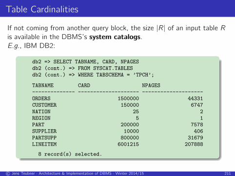
Table Cardinalities
If not coming from another query block, the size |R| of an input table R
is available in the DBMS’s system catalogs.
E.g., IBM DB2:
db2 => SELECT TABNAME, CARD, NPAGESdb2 (cont.) => FROM SYSCAT.TABLESdb2 (cont.) => WHERE TABSCHEMA = ’TPCH’;
TABNAME CARD NPAGES-------------- -------------------- --------------------ORDERS 1500000 44331CUSTOMER 150000 6747NATION 25 2REGION 5 1PART 200000 7578SUPPLIER 10000 406PARTSUPP 800000 31679LINEITEM 6001215 207888
8 record(s) selected.
© Jens Teubner · Architecture & Implementation of DBMS · Winter 2014/15 211

Estimating Selectivities
To estimate the selectivity of a predicate, we look at its structure.
column = value
sel(·) ={1/|I | if there is an index I on column1/10 otherwise
column1 = column2
sel(·) =
1
max{|I1|,|I2|} if there are indexes on both cols.1|Ik | if there is an index only on col. k
1/10 otherwise
p1 AND p2sel(·) = sel(p1) · sel(p2)
p1 OR p2sel(·) = sel(p1) + sel(p2)− sel(p1) · sel(p2)
© Jens Teubner · Architecture & Implementation of DBMS · Winter 2014/15 212

Improving Selectivity Estimation
The selectivity rules we saw make a fair amount of assumptions:
uniform distribution of data values within a column,
independence between individual predicates.
Since these assumptions aren’t generally met, systems try to improve
selectivity estimation by gathering data statistics.
These statistics are collected offline and stored in the system
catalog.
I IBM DB2: RUNSTATS ON TABLE ...
The most popular type of statistics are histograms.
© Jens Teubner · Architecture & Implementation of DBMS · Winter 2014/15 213

I Example: Histograms in IBM DB2
SELECT SEQNO, COLVALUE, VALCOUNTFROM SYSCAT.COLDIST
WHERE TABNAME = ’LINEITEM’AND COLNAME = ’L_EXTENDEDPRICE’AND TYPE = ’Q’;
SEQNO COLVALUE VALCOUNT----- ----------------- --------
1 +0000000000996.01 30012 +0000000004513.26 3150643 +0000000007367.60 6331284 +0000000011861.82 9481925 +0000000015921.28 12632566 +0000000019922.76 15783207 +0000000024103.20 18963848 +0000000027733.58 22114489 +0000000031961.80 2526512
10 +0000000035584.72 284157611 +0000000039772.92 315964012 +0000000043395.75 347470413 +0000000047013.98 3789768
.
.
.
SYSCAT.COLDIST also contains
information like
the n most frequent values
(and their frequency),
the number of distinct
values in each histogram
bucket.
Histograms may even be
manipulated manually to tweak
the query optimizer.
© Jens Teubner · Architecture & Implementation of DBMS · Winter 2014/15 214

Join Optimization
We’ve now translated the query into a graph of query blocks.
Query blocks essentially are a multi-way Cartesian product
with a number of selection predicates on top.
We can estimate the cost of a given execution plan.
Use result size estimates in combination with the cost for
individual join algorithms in the previous chapter.
We are now ready to enumerate all possible execution plans, e.g., all
possible 3-way join combinations for a query block.
11
R S
T
11
S R
T
11
R T
S
11
S T
R
11
T R
S
11
T S
R
1
R 1
S T
1
S 1
R T
1
R 1
T S
1
S 1
T R
1
T 1
R S
1
T 1
S R
© Jens Teubner · Architecture & Implementation of DBMS · Winter 2014/15 215

How Many Such Combinations Are There?
A join over n + 1 relations R1, . . . ,Rn+1 requires n binary joins.
Its root-level operator joins sub-plans of k and n − k − 1 join
operators (0 ≤ k ≤ n − 1):
1
k joins
R1, . . . ,Rk
n− k − 1 joinsRk+1, . . . ,Rn+1
Let Ci be the number of possibilities to construct a binary tree of i
inner nodes (join operators):
Cn =
n−1∑k=0
Ck · Cn−k−1 .
© Jens Teubner · Architecture & Implementation of DBMS · Winter 2014/15 216

Catalan Numbers
This recurrence relation is satisfied by Catalan numbers:
Cn =
n−1∑k=0
Ck · Cn−k−1 =(2n)!
(n + 1)!n!,
describing the number of ordered binary trees with n + 1 leaves.
For each of these trees, we can permute the input relations
R1, . . . ,Rn+1, leading to
(2n)!
(n + 1)!n!· (n + 1)! =
(2n)!
n!
possibilities to evaluate an (n + 1)-way join.
© Jens Teubner · Architecture & Implementation of DBMS · Winter 2014/15 217

Search Space
The resulting search space is enormous:
number of relations n Cn−1 join trees
2 1 2
3 2 12
4 5 120
5 14 1,680
6 42 30,240
7 132 665,280
8 429 17,297,280
10 4,862 17,643,225,600
And we haven’t yet even considered the use of k different join
algorithms (yielding another factor of k(n−1))!
© Jens Teubner · Architecture & Implementation of DBMS · Winter 2014/15 218

Dynamic Programming
The traditional approach to master this search space is the use of
dynamic programming.
Idea:
Find the cheapest plan for an n-way join in n passes.
In each pass k , find the best plans for all k-relation sub-queries.
Construct the plans in pass k from best i-relation and
(k − i)-relation sub-plans found in earlier passes (1 ≤ i < k).
Assumption:
To find the optimal global plan, it is sufficient to only consider the
optimal plans of its sub-queries.
© Jens Teubner · Architecture & Implementation of DBMS · Winter 2014/15 219
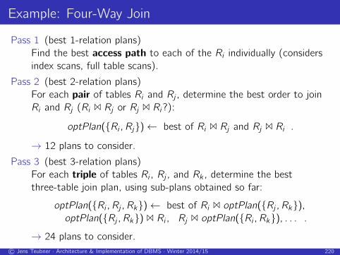
Example: Four-Way Join
Pass 1 (best 1-relation plans)
Find the best access path to each of the Ri individually (considers
index scans, full table scans).
Pass 2 (best 2-relation plans)
For each pair of tables Ri and Rj , determine the best order to join
Ri and Rj (Ri 1 Rj or Rj 1 Ri?):
optPlan({Ri ,Rj})← best of Ri 1 Rj and Rj 1 Ri .
→ 12 plans to consider.
Pass 3 (best 3-relation plans)
For each triple of tables Ri , Rj , and Rk , determine the best
three-table join plan, using sub-plans obtained so far:
optPlan({Ri ,Rj ,Rk})← best of Ri 1 optPlan({Rj ,Rk}),optPlan({Rj ,Rk}) 1 Ri , Rj 1 optPlan({Ri ,Rk}), . . . .
→ 24 plans to consider.
© Jens Teubner · Architecture & Implementation of DBMS · Winter 2014/15 220

Example (cont.)
Pass 4 (best 4-relation plan)
For each set of four tables Ri , Rj , Rk , and Rl , determine the best
four-table join plan, using sub-plans obtained so far:
optPlan({Ri ,Rj ,Rk ,Rl})← best of Ri 1 optPlan({Rj ,Rk ,Rl}),optPlan({Rj ,Rk ,Rl}) 1 Ri , Rj 1 optPlan({Ri ,Rk ,Rl}), . . . ,optPlan({Ri ,Rj}) 1 optPlan({Rk ,Rl}), . . . .
→ 14 plans to consider.
Overall, we looked at only 50 (sub-)plans (instead of the possible
120 four-way join plans; ↗ slide 218).
All decisions required the evaluation of simple sub-plans only (no
need to re-evaluate the interior of optPlan(·)).
© Jens Teubner · Architecture & Implementation of DBMS · Winter 2014/15 221

Dynamic Programming Algorithm
1 Function: find join tree dp (q(R1, . . . ,Rn))
2 for i = 1 to n do
3 optPlan({Ri})← access plans (Ri) ;
4 prune plans (optPlan({Ri})) ;
5 for i = 2 to n do
6 foreach S ⊆ {R1, . . . ,Rn} such that |S | = i do
7 optPlan(S)← ∅ ;
8 foreach O ⊂ S do
9 optPlan(S)← optPlan(S)∪10 possible joins (optPlan(O), optPlan(S \O));
11 prune plans (optPlan(S)) ;
12 return optPlan({R1, . . . ,Rn}) ;
possible joins (R, S) enumerates the possible joins between R
and S (nested loops join, merge join, etc.).
prune plans (set) discards all but the best plan from set.
© Jens Teubner · Architecture & Implementation of DBMS · Winter 2014/15 222
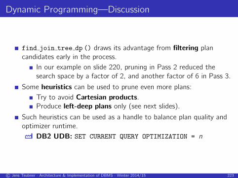
Dynamic Programming—Discussion
find join tree dp () draws its advantage from filtering plan
candidates early in the process.
In our example on slide 220, pruning in Pass 2 reduced the
search space by a factor of 2, and another factor of 6 in Pass 3.
Some heuristics can be used to prune even more plans:
Try to avoid Cartesian products.
Produce left-deep plans only (see next slides).
Such heuristics can be used as a handle to balance plan quality and
optimizer runtime.
I DB2 UDB: SET CURRENT QUERY OPTIMIZATION = n
© Jens Teubner · Architecture & Implementation of DBMS · Winter 2014/15 223
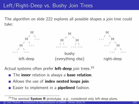
Left/Right-Deep vs. Bushy Join Trees
The algorithm on slide 222 explores all possible shapes a join tree could
take:
1
1
1
· · · · · ·· · ·· · ·
left-deep
1
1
· · · · · ·1
· · · · · ·bushy
(everything else)
1
· · · 1
· · · 1
· · · · · ·right-deep
Actual systems often prefer left-deep join trees.15
The inner relation is always a base relation.
Allows the use of index nested loops join.
Easier to implement in a pipelined fashion.
15The seminal System R prototype, e.g., considered only left-deep plans.© Jens Teubner · Architecture & Implementation of DBMS · Winter 2014/15 224

Join Order Makes a Difference
XPath evaluation over relationally encoded XML data16
n-way self-join with a range predicate.
1 2 3 4 5 6 7 8 9 10 11 120 0
50 50
100 100
150 150
200 200
250 250
exec
.ti
me
[s]
path length
35MBXML·IBMDB29SQL
16↗ Grust et al. Accelerating XPath Evaluation in Any RDBMS. TODS 2004.http://www.pathfinder-xquery.org/
© Jens Teubner · Architecture & Implementation of DBMS · Winter 2014/15 225

Join Order Makes a Difference
Contrast the execution plans for a 8- and a 9-step path.
left-deep join tree bushy join tree
DB2’s optimizer essentially gave up in the face of 9+ joins.
© Jens Teubner · Architecture & Implementation of DBMS · Winter 2014/15 226

Joining Many Relations
Dynamic programming still has exponential resource requirements:
time complexity: O(3n)space complexity: O(2n)
This may still be to expensive
for joins involving many relations (∼ 10–20 and more),
for simple queries over well-indexed data (where the right plan
choice should be easy to make).
The greedy join enumeration algorithm jumps into this gap.
© Jens Teubner · Architecture & Implementation of DBMS · Winter 2014/15 227

Greedy Join Enumeration
1 Function: find join tree greedy (q(R1, . . . ,Rn))
2 worklist ← ∅ ;
3 for i = 1 to n do
4 worklist ← worklist ∪ best access plan (Ri) ;
5 for i = n downto 2 do
// worklist = {P1, . . . ,Pi}6 find Pj ,Pk ∈ worklist and 1... such that cost(Pj 1... Pk) is minimal ;
7 worklist ← worklist \ {Pj ,Pk} ∪ {(Pj 1... Pk)} ;
// worklist = {P1}8 return single plan left in worklist ;
In each iteration, choose the cheapest join that can be made over
the remaining sub-plans.
Observe that find join tree greedy () operates similar to finding
the optimum binary tree for Huffman coding.
© Jens Teubner · Architecture & Implementation of DBMS · Winter 2014/15 228

Discussion
Greedy join enumeration:
The greedy algorithm has O(n3) time complexity.
The loop has O(n) iterations.
Each iteration looks at all remaining pairs of plans in worklist.
An O(n2) task.
Other join enumeration techniques:
Randomized algorithms: randomly rewrite the join tree one rewrite
at a time; use hill-climbing or simulated annealing strategy to find
optimal plan.
Genetic algorithms: explore plan space by combining plans
(“creating offspring”) and altering some plans randomly
(“mutations”).
© Jens Teubner · Architecture & Implementation of DBMS · Winter 2014/15 229

Physical Plan Properties
Consider the query
SELECT O.O ORDERKEY, L.L EXTENDEDPRICE
FROM ORDERS O, LINEITEM L
WHERE O.O ORDERKEY = L.L ORDERKEY
where table ORDERS is indexed with a clustered index OK IDX on column
O ORDERKEY.
Possible table access plans are:
ORDERS full table scan: estimated I/Os: NORDERSindex scan: estimated I/Os: NOK IDX + NORDERS.
LINEITEM full table scan: estimated I/Os: NLINEITEM.
© Jens Teubner · Architecture & Implementation of DBMS · Winter 2014/15 230

Since the full table scan is the cheapest access method for both tables,
our join algorithms will select them as the best 1-relation plans in
Pass 1.17
To join the two scan outputs, we now have the choices
nested loops join,
hash join, or
sort both inputs, then use merge join.
Hash join or sort-merge join are probably the preferable candidates here,
incurring a cost of ≈ 2(NORDERS + NLINEITEM).
→ overall cost: NORDERS + NLINEITEM + 2(NORDERS + NLINEITEM).
17Dynamic programming and the greedy algorithm happen to do the same in this
example.© Jens Teubner · Architecture & Implementation of DBMS · Winter 2014/15 231

A Better Plan
It is easy to see, however, that there is a better way to evaluate the
query:
1 Use an index scan to access ORDERS. This guarantees that the scan
output is already in O ORDERKEY order.
2 Then only sort LINEITEM and
3 join using merge join.
→ overall cost: (NOK IDX + NORDERS)︸ ︷︷ ︸1.
+ 2 · NLINEITEM︸ ︷︷ ︸2./3.
.
Although more expensive as a standalone table access plan, the use of
the index pays off in the overall plan.
© Jens Teubner · Architecture & Implementation of DBMS · Winter 2014/15 232

Interesting Orders
The advantage of the index-based access to ORDERS is that it
provides beneficial physical properties.
Optimizers, therefore, keep track of such properties by annotating
candidate plans.
System R introduced the concept of interesting orders, determined
by
ORDER BY or GROUP BY clauses in the input query, or
join attributes of subsequent joins (; merge join).
In prune plans (), retain
the cheapest “unordered” plan and
the cheapest plan for each interesting order.
© Jens Teubner · Architecture & Implementation of DBMS · Winter 2014/15 233

Query Rewriting
Join optimization essentially takes a set of relations and a set of join
predicates to find the best join order.
By rewriting query graphs beforehand, we can improve the effectiveness
of this procedure.
The query rewriter applies (heuristic) rules, without looking into the
actual database state (no information about cardinalities, indexes, etc.).
In particular, it
rewrites predicates and
unnests queries.
© Jens Teubner · Architecture & Implementation of DBMS · Winter 2014/15 234

Predicate Simplification
Example: rewrite
SELECT *
FROM LINEITEM L
WHERE L.L TAX * 100 < 5
into
SELECT *
FROM LINEITEM L
WHERE L.L TAX < 0.05
Predicate simplification may enable the use of indexes and simplify
the detection of opportunities for join algorithms.
© Jens Teubner · Architecture & Implementation of DBMS · Winter 2014/15 235

Additional Join Predicates
Implicit join predicates as in
SELECT *
FROM A, B, C
WHERE A.a = B.b AND B.b = C.c
can be turned into explicit ones:
SELECT *
FROM A, B, C
WHERE A.a = B.b AND B.b = C.c
AND:::A.a
:::=
::::C.c
This enables plans like(A 1 C) 1 B .
((A 1 C) would have been a Cartesian product before.)
© Jens Teubner · Architecture & Implementation of DBMS · Winter 2014/15 236

Nested Queries
SQL provides a number of ways to write nested queries.
Uncorrelated sub-query:
SELECT *
FROM ORDERS O
WHERE O_CUSTKEY IN (SELECT C_CUSTKEY
FROM CUSTOMER
WHERE C_NAME = ’IBM Corp.’)
Correlated sub-query:
SELECT *
FROM ORDERS O
WHERE O.O_CUSTKEY IN
(SELECT C.C_CUSTKEY
FROM CUSTOMER C
WHERE C.C_ACCTBAL < O.O_TOTALPRICE)
© Jens Teubner · Architecture & Implementation of DBMS · Winter 2014/15 237

Query Unnesting
Taking query nesting literally might be expensive.
An uncorrelated query, e.g., need not be re-evaluated for every
tuple in the outer query.
Oftentimes, sub-queries are only used as a syntactical way to
express a join (or a semi-join).
The query rewriter tries to detect such situations and make the
join explicit.
This way, the sub-query can become part of the regular join order
optimization.
↗ Won Kim. On Optimizing an SQL-like Nested Query. ACM TODS, vol. 7,
no. 3, September 1982.
© Jens Teubner · Architecture & Implementation of DBMS · Winter 2014/15 238

Summary
Query Parser
Translates input query into (SFW-like) query blocks.
Rewriter
Logical (database state-independent) optimizations; predicate
simplification; query unnesting.
(Join) Optimization
Find “best” query execution plan based on a cost model
(considering I/O cost, CPU cost, . . . ); data statistics (histograms);
dynamic programming, greedy join enumeration; physical plan
properties (interesting orders).
Database optimizers still are true pieces of art. . .
© Jens Teubner · Architecture & Implementation of DBMS · Winter 2014/15 239

“Picasso” Plan Diagrams
(a) Plan Diagram (b) Cost Diagram
Figure 1:Smooth Plan and Cost Diagram (Query 7)
The Picasso Tool
As part of our ongoing project on developing value-addition software for query optimization [24], we have cre-ated a tool, calledPicasso, that given a query and a rela-tional engine, automatically generates the associated planand cost diagrams. In this paper, we report on the fea-tures of the plan/cost diagrams output by Picasso on a suiteof three popular commercial query optimizers for queriesbased on the TPC-H benchmark. [Due to legal restrictions,these optimizers are anonymously identified as OptA, OptBand OptC, in the sequel.]
Our evaluation shows that a few queries in the bench-mark do produce “well-behaved” or “smooth” plan dia-grams, like that shown in Figure 1(a). A substantial remain-der, however, result in extremely complex and intricate plandiagrams that appear similar tocubist paintings3, providingrich material for investigation. A particularly compellingexample is shown in Figure 2(a) for Query 8 of the bench-mark with optimizer OptA4, where no less than 68 planscover the space in a highly convoluted manner! Further,even this cardinality is aconservativeestimate since it wasobtained with a query grid of 100 x 100 – a finer grid sizeof 300 x 300 resulted in the plan cardinality going up to 80plans!
Before we go on, we hasten to clarify that our goal inthis paper is to provide a broad overview of the intrigu-ing behavior of modern optimizers, butnot to make judge-ments on specific optimizers, nor to draw conclusions aboutthe relative qualities of their execution plans. Further, notbeing privy to optimizer internals, some of the remarks
3Hence, the name of our tool – Pablo Picasso is considered to beafounder of the cubist painting genre [23].
4Operating at its highest optimization level.
made here are perforce speculative in nature and shouldtherefore be treated as such. Our intention is primarily toalert database system designers and developers to the phe-nomena that we have encountered during the course of ourstudy, with the hope that they may prove useful in buildingthe next generation of optimizers.
Features of Plan and Cost Diagrams
Analyzing the TPC-H-based query plan and cost diagramsprovides a variety of interesting insights, including the fol-lowing:
Fine-grained Choices: Modern query optimizers oftenmake extremelyfine-grainedplan choices, exhibitinga marked skew in the space coverage of the individualplans. For example, 80 percent of the space is usu-ally covered by less than 20 percent of the plans, withmany of the smaller plans occupying less thanonepercentof the selectivity space. Using the well-knownGini index [22], which ranges over [0,1], to quantifythe skew, we find that all the optimizers,across theboard, exhibit a marked skew in excess of 0.5 for mostqueries, on occasion going even higher than 0.8.
Further, and more importantly, we show that thesmall-sized plans may often be supplanted by largersiblings without substantively affecting the quality.For example, the plan diagram of Figure 2(a) whichhas 68 plans can be “reduced” to that shown in Fig-ure 2(b) featuring as few assevenplans, without in-creasing the estimated cost of any individual querypoint by more than 10 percent.
Overall, this leads us to the hypothesis that currentoptimizers may perhaps be over-sophisticated in that
(a) Complex Plan Diagram (b) Reduced Plan Diagram
Figure 2:Complex Plan and Reduced Plan Diagram (Query 8, OptA)
they are “doing too good a job”, not merited by thecoarseness of the underlying cost space. Moreover,if it were possible to simplify the optimizer to pro-duce only reduced plan diagrams, it is plausible thatthe considerable processing overheads typically asso-ciated with query optimization could be significantlylowered.
Complex Patterns: The plan diagrams exhibit a varietyof intricate tessellated patterns, includingspeckles,stripes, blinds, mosaicsandbands, among others. Forexample, witness the rapidly alternating choices be-tween plans P12 (dark green) and P16 (light gray)in the bottom left quadrant of Figure 2(a). Further,the boundaries of the plan optimality regions can behighly irregular – a case in point is plan P8 (darkpink) in the top right quadrant of Figure 2(a). Thesecomplex patterns appear to indicate the presence ofstrongly non-linear and discretized cost models, againperhaps an over-kill in light of Figure 2(b).
Non-Monotonic Cost Behavior: We have found quite afew instances where, although the base relation selec-tivities and the result cardinalities are monotonicallyincreasing, the cost diagram doesnot show a corre-sponding monotonic behavior.5 Sometimes, the non-monotonic behavior arises due to a change in plan,perhaps understandable given the restricted searchspace evaluated by the optimizer. But, more surpris-ingly, we have also encountered situations where aplan shows such behavior eveninternal to its optimal-ity region.
5Our query setup is such that in addition to the result cardinality mono-tonically increasing as we travel outwards along the selectivity axes, theresult tuples are alsosupersetsof the previous results.
Validity of PQO: A rich body of literature exists onpara-metric query optimization(PQO) [1, 2, 7, 8, 3, 4, 10,11, 12]. The goal here is to apriori identify the optimalset of plans for the entire relational selectivity spaceat compile time, and subsequently to use at run timethe actual selectivity parameter settings to identify thebest plan – the expectation is that this would be muchfaster than optimizing the query from scratch. Muchof this work is based on a set of assumptions, that wedo not find to hold true,even approximately, in theplan diagrams produced by the commercial optimiz-ers.
For example, one of the assumptions is that a plan isoptimal within theentire regionenclosed by its planboundaries. But, in Figure 2(a), this is violated by thesmall (brown) rectangle of plan P14, close to coordi-nates (60,30), in the (light-pink) optimality region ofplan P3, and there are several other such instances.
On the positive side, however, we show that someof the important PQO assumptions do hold approxi-mately forreducedplan diagrams.
1.1 Organization
The above effects are described in more detail in the re-mainder of this paper, which is organized as follows: InSection 2, we present the Picasso tool and the testbed en-vironment. Then, in Section 3, the skew in the plan spacedistribution, as well as techniques for reducing the plan setcardinalities, are discussed. The relationship to PQO is ex-plored in Section 4. Interesting plan diagram motifs arepresented in Section 5. An overview of related work is pro-vided in Section 6. Finally, in Section 7, we summarize
↗ Naveen Reddy and Jayant Haritsa. Analyzing Plan Diagrams of Database
Query Optimizers. VLDB 2005.
© Jens Teubner · Architecture & Implementation of DBMS · Winter 2014/15 240

“Picasso” Plan DiagramsFigure 6:Duplicates and Islands (Query 5, OptC)
Databases # Duplicates # IslandsOriginal Reduced Original Reduced
OptA 136 14 38 3OptB 80 15 1 0OptC 55 7 8 3
Table 3: Duplicates and Islands
PQO, which, as mentioned in the previous section, appearsill-suited to directly capture the complexities of modern op-timizers, may turn out to be a more viable proposition in thespace of reduced plan diagrams.
5.2 Plan Switch Points
In several plan diagrams, we find lines parallel to the axesthat run through theentire selectivity space, with a planshift occurring forall plans bordering the line, when wemove across the line. We will hereafter refer to such linesas “plan switch-points”.
In the plan diagram of Figure 7, obtained with Q9 onOptA, an example switch-point appears at approximately30% selectivity of theSUPPLIERrelation. Here, we foundacommon changein all plans across the switch-point – thehash-join sequencePARTSUPP./ SUPPLIER./ PART is al-tered toPARTSUPP./ PART ./ SUPPLIER, suggesting an in-tersection of the cost function of the two sequences at thisswitch-point.
For the same Q9 query, an even more interesting switch-point example is obtained with OptB, shown in Figure 8.Here we observe, between 10% and 35% on theSUPPLIER
axis,six planssimultaneously changing with rapid alterna-tions to produce a “Venetian blinds” effect. Specifically,the optimizer changes from P6 to P1, P16 to P4, P25 toP23, P7 to P18, P8 to P9, and P42 to P47, from one verticalstrip to the next.
The reason for this behavior is that the optimizer alter-nates between aleft-deephash join and aright-deephash
Figure 7:Plan Switch-Point (Query 9, OptA)
Figure 8:Venetian Blinds Pattern (Query 9, OptB)
join across theNATION , SUPPLIER and LINEITEM rela-tions. Both variations have almost equal estimated cost,and their cost-models are perhaps discretized in a step-function manner, resulting in the observed blinds.
5.3 Footprint Pattern
A curious pattern, similar to footprints on the beach, showsup in Figure 9, obtained with Q7 on the OptA optimizer,where we see plan P7 exhibiting a thin (cadet-blue) bro-ken curved pattern in the middle of plan P2’s (orange) re-gion. The reason for this behavior is that both plans are ofroughly equal cost, with the difference being that in planP2, theSUPPLIER relation participates in asort-merge-join at the top of the plan tree, whereas in P7, thehash-joinoperator is used instead at the same location. This is con-firmed in the corresponding reduced plan diagram wherethe footprints disappear.
Figure 9:Footprint Pattern (Query 7, OptA)
Figure 10:Speckle Pattern (Query 17, OptA)
5.4 Speckle Pattern
Operating Picasso with Q17 on OptA (at its highest opti-mization level) results in Figure 10. We see here that theentire plan diagram is divided into just two plans, P1 andP2, occupying nearly equal areas, but that plan P1 (brightgreen) also appears as speckles sprinkled in P2’s (red) area.
The only difference between the two plans is that an ad-ditional SORT operation is present in P2 on thePART rela-tion. However, the cost of this sort is very low, and there-fore we find intermixing of plans due to the close and per-haps discretized cost models.
5.5 Non-Monotonic Cost Behavior
The example switch-points shown earlier, were allcost-basedswitch-points, where plans were switched to de-rive lower execution costs. Yet another example of sucha switch-point is seen in Figure 11(a), obtained with queryQ2 on OptA, at 97% selectivity of thePART relation. Here,
the common change in all plans across the switch-point isthat thehash-join between relationsPART andPARTSUPP
is replaced by asort-merge-join.But, in the same picture, there are switch-points occur-
ring at 26% and 50% in thePARTSUPPselectivity range,that result in a counter-intuitivenon-monotoniccost behav-ior, as shown in the corresponding cost diagram of Fig-ure 11(b). Here, we see that although the result cardi-nalities are monotonically increasing, the estimated costsfor producing these results show a marked non-monotonicstep-down behavior in the middle section. Specifically,at the 26% switch-point, an additional‘sort’ operator(on ps supplycost) is added, which substantially de-creases the overall cost – for example, in moving from planP2 to P3 at 50%PART selectivity, the estimated cost de-creases by a factor of 50! Conversely, in moving from P3to P1 at the 50% switch-point, the cost of the optimal planjumps up by a factor of 70 at 50%PART selectivity.
Step-function upward jumps in the cost with increas-ing input cardinalities are known to occur – for example,when one of the relations in a join ceases to fit completelywithin the available memory – however, what is surprisingin the above is the step-function costdecreaseat the 26%switch-point. We conjecture that such disruptive cost be-havior may arise either due to the presence of rules in theoptimizer, or due to parameterized changes in the searchspace evaluated by the optimizer.
The above example showed non-monotonic behaviorarising out of a plan-switch. However, more surprisingly,we have also encountered situations where a plan showsnon-monotonic behaviorinternal to its optimality region.A specific example is shown in Figure 12 obtained for Q21with OptA. Here, the plans P1, P3, P4 and P6, show a re-duction in their estimated costs with increasing input andresult cardinalities. An investigation of these plans showedthat all of them feature anested-loops join, whose esti-mated costdecreaseswith increasing cardinalities of its in-put relations – this may perhaps indicate an inconsistencyin the associated cost model. Further, such instances ofnon-monotonic behavior were observed with all three opti-mizers.
6 Related Work
To the best of our knowledge, there has been no prior workon the analysis of plan diagrams with regard toreal-worldindustrial-strengthquery optimizers. However, similar is-sues have been studied in the parametric query optimization(PQO) literature in the context of simplified self-crafted op-timizers. Specifically, in [1, 11, 12], an optimizer modeledalong the lines of the original System R optimizer [16] isused, with the search space restricted to left-deep join trees,and the workload comprised of pure SPJ queries with “star”or “linear” join-graphs. The metrics considered includethe cardinality and spatial distribution of the set of optimalplans – while [1] considered only single-relation selectivi-ties, [11, 12] evaluated two-dimensional relational selectiv-ity spaces, similar to those considered in this paper. Their
Download Picasso at
http://dsl.serc.iisc.ernet.in/projects/PICASSO/index.html.
© Jens Teubner · Architecture & Implementation of DBMS · Winter 2014/15 241