architecture portfolio
DESCRIPTION
Week 4 PCC WINTER 2012 Architecture Portfolio Class 100TRANSCRIPT
Architecture PortfolioChi Hung Leung
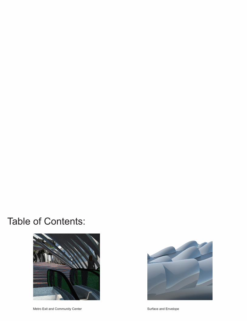
Table of Contents:
Surface and EnvelopeMetro Exit and Community Center
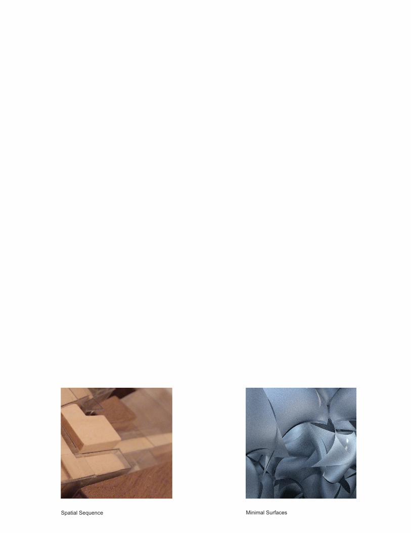
Minimal SurfacesSpatial Sequence

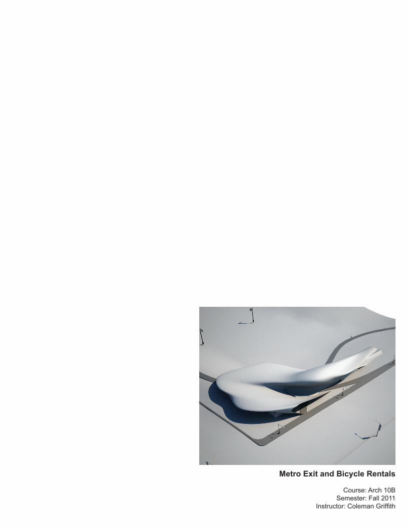
Metro Exit and Bicycle Rentals
Course: Arch 10BSemester: Fall 2011
Instructor: Coleman Griffith
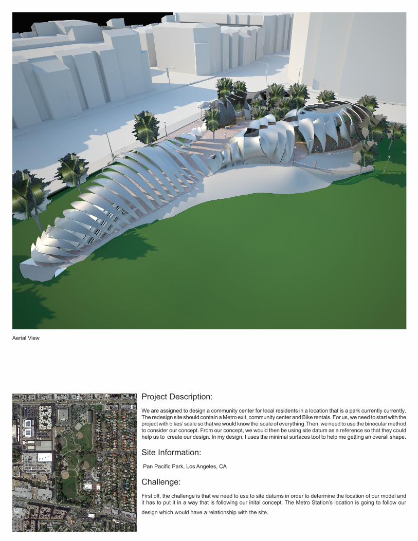
Project Description:We are assigned to design a community center for local residents in a location that is a park currently currently. The redesign site should contain a Metro exit, community center and Bike rentals. For us, we need to start with the project with bikes’ scale so that we would know the scale of everything.Then, we need to use the binocular method to consider our concept. From our concept, we would then be using site datum as a reference so that they could help us to create our design. In my design, I uses the minimal surfaces tool to help me getting an overall shape.
Site Information: Pan Pacific Park, Los Angeles, CA
Challenge:First off, the challenge is that we need to use to site datums in order to determine the location of our model and it has to put it in a way that is following our inital concept. The Metro Station’s location is going to follow our
design which would have a relationship with the site.
Aerial View
Vertical Datum
Tree Street LightCar FenceB icycle Bench person riding a bike People
Tree
Street Light
Car
Fence
Bicycle
Bench
person riding a bikePeople
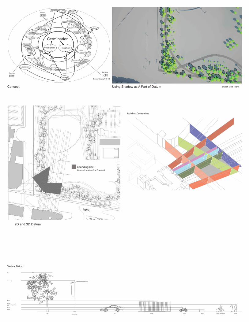
Building Constraints
Bounding Box(Potential Location of the Programs)
2D and 3D Datum
Transition
Reunion
Exchange
轉變 交換
團聚
轉
Rotation
Di�erent
變
團
Corporation
Transform
Round Mass
Group
Regiment
Together
聚To Assemble
To Gather
To combine
交
換
To Hand Over
To Join
To associate with
To Connect
To Link
To Unite
To Joint
Deliver
Render
To turn In
To Consociate
Tie In
Colligate
Relate
Change
To A�liate
AssortConsort
SumSum
TackCollect
Forgather
CompoundContribute
Aggregate
Merge
To UniteMix
Con�ate
Give
Accumulation
Collection
Body
Organization
Legion
Division
Associations
BusinessFamily
Alter
Revision
Transmute
Transubstantiate
Metamorphose
Translate
Modify
Various
Diversifed
Alternative
Miscellaneous
Contrary
DeviantDisparate
RevolutionCircumvolution
FlowLocus Ambit
Brandon Leung Arch 10B
Germination
Prolongment Inception
March 21st 10amConcept Using Shadow as A Part of Datum
A
B
C
D E
F
G
A
B
CD
E
F
G
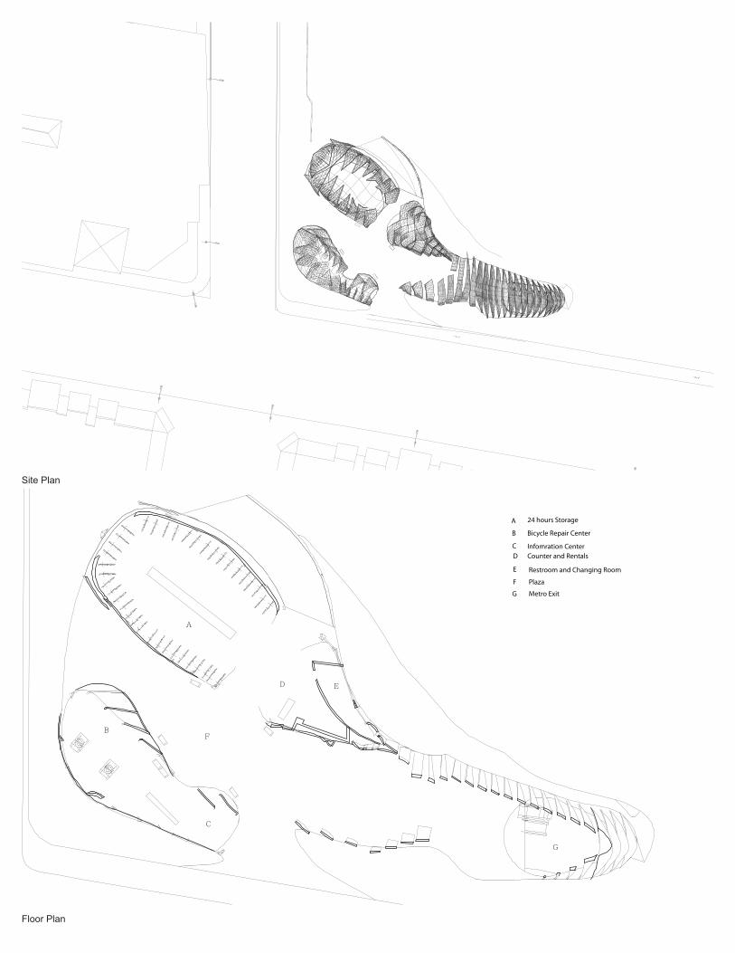
24 hours Storage
Bicycle Repair Center
Infomration CenterCounter and Rentals
Restroom and Changing Room
Plaza
Metro Exit
Site Plan
Floor Plan
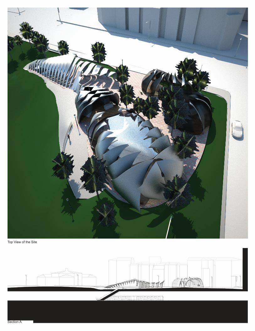
SCALE : 1’-0”= 1/ 16”SECTION A
Section A
Top View of the Site


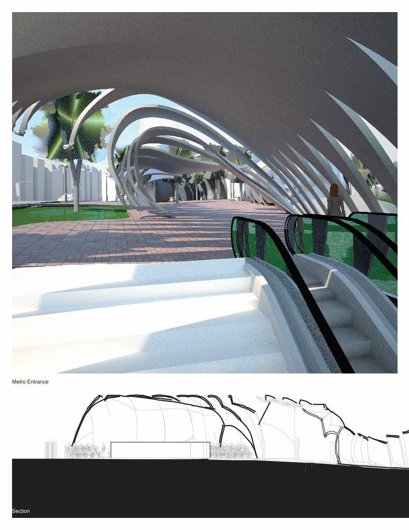
Metro Entrance
Section
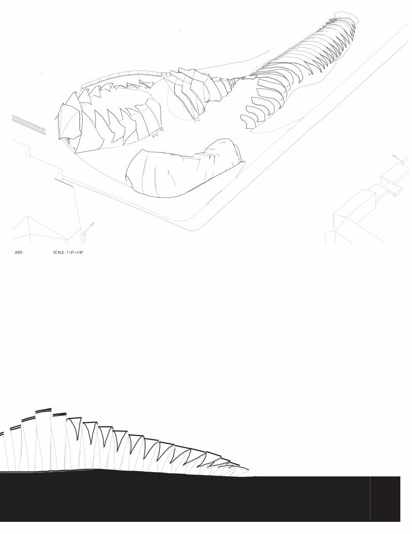
AXO SCALE : 1’-0”=1/8”
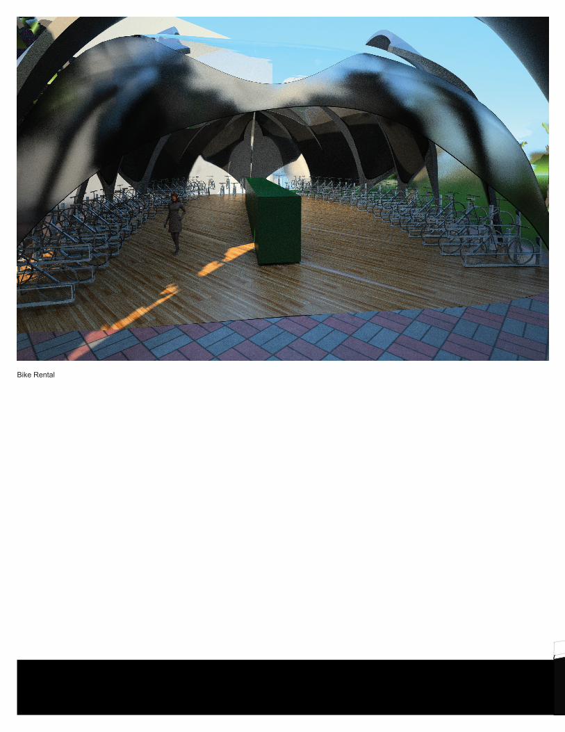
Bike Rental
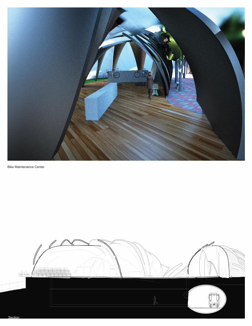
Section
Bike Maintenance Center

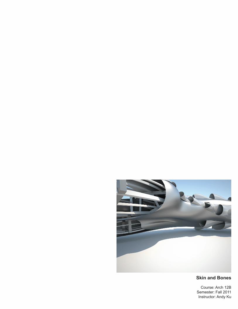
Skin and Bones
Course: Arch 12BSemester: Fall 2011Instructor: Andy Ku
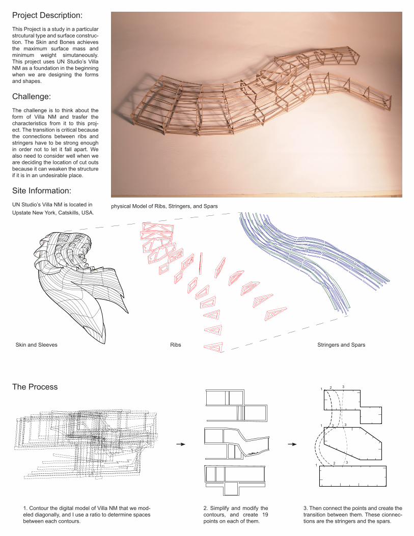
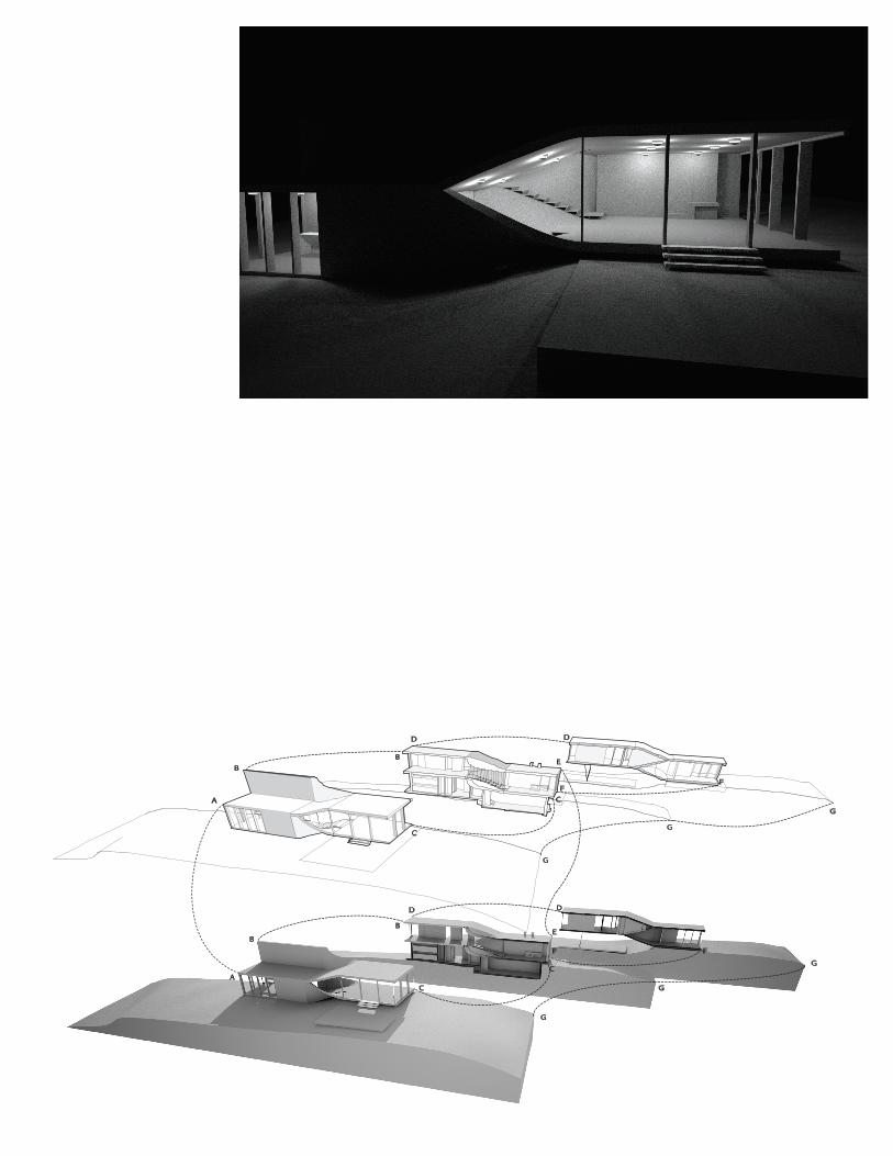
Project Description: This Project is a study in a particular strcutural type and surface construc-tion. The Skin and Bones achieves the maximum surface mass and minimum weight simutaneously. This project uses UN Studio’s Villa NM as a foundation in the beginning when we are designing the forms and shapes.
Challenge:The challenge is to think about the form of Villa NM and trasfer the characteristics from it to this proj-ect. The transition is critical because the connections between ribs and stringers have to be strong enough in order not to let it fall apart. We also need to consider well when we are deciding the location of cut outs because it can weaken the structure if it is in an undesirable place.
Site Information:UN Studio’s Villa NM is located in Upstate New York, Catskills, USA.
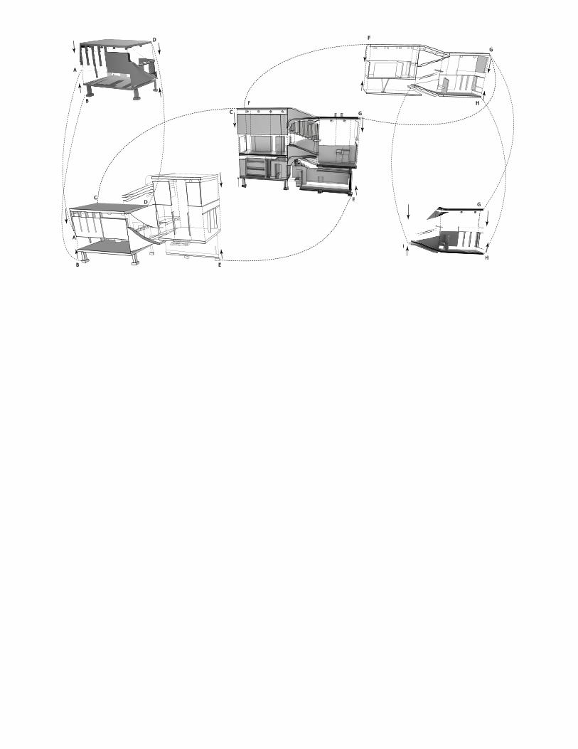
physical Model of Ribs, Stringers, and Spars
The Process
1. Contour the digital model of Villa NM that we mod-eled diagonally, and I use a ratio to determine spaces between each contours.
2. Simplify and modify the contours, and create 19 points on each of them.
3. Then connect the points and create the transition between them. These cionnec-tions are the stringers and the spars.
1
1
1 2
2
2
3
3
3
Skin and Sleeves Ribs Stringers and Spars
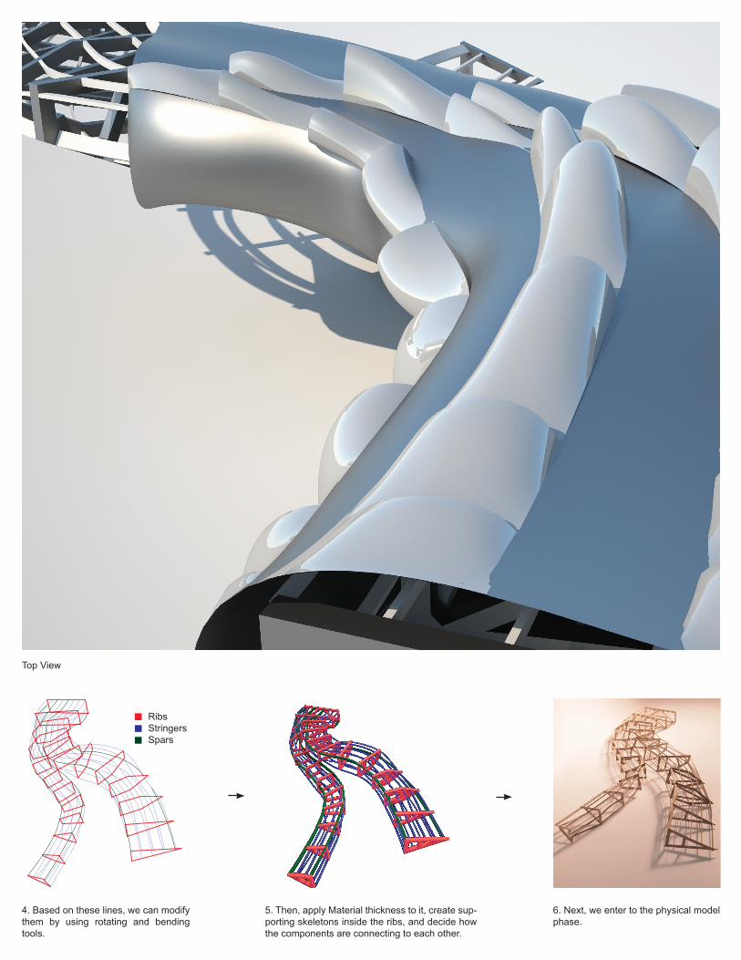
Top View
4. Based on these lines, we can modify them by using rotating and bending tools.
5. Then, apply Material thickness to it, create sup-porting skeletons inside the ribs, and decide how the components are connecting to each other.
6. Next, we enter to the physical model phase.
RibsStringersSpars
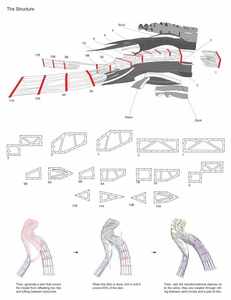
The Structure
1
1
2
2
3
3
4
4
5
5
6
6
7A
7A
7B
7B
8B
8B
9B
9B
10B
10B
11B
11B
8A
8A
9A
9A
10A
10A
11A
11A
StairsDeck
Roof
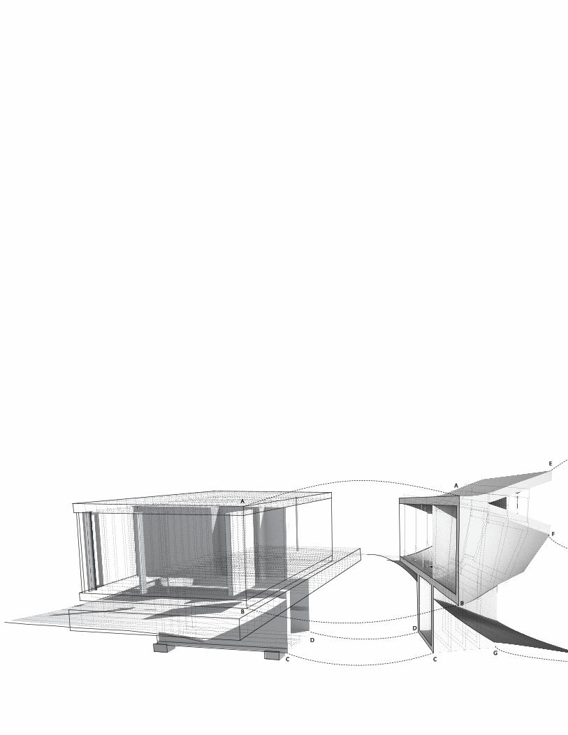
Then, generate a skin that covers the model from offsetting the ribs and lofting between isocurves.
When the Skin is done, trim it until it covers 60% of the skin.
Then, add the transformational sleeves on to the skins. they are created through loft-ing between semi-circles and a part of ribs.
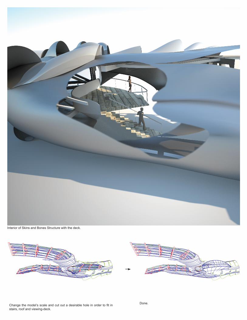
Interior of Skins and Bones Structure with the deck.
Change the model’s scale and cut out a desirable hole in order to fit in stairs, roof and viewing-deck.
Done.

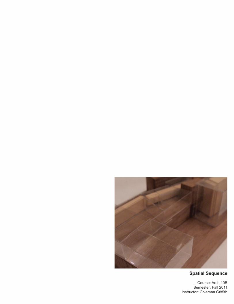
Spatial Sequence
Course: Arch 10BSemester: Fall 2011
Instructor: Coleman Griffith
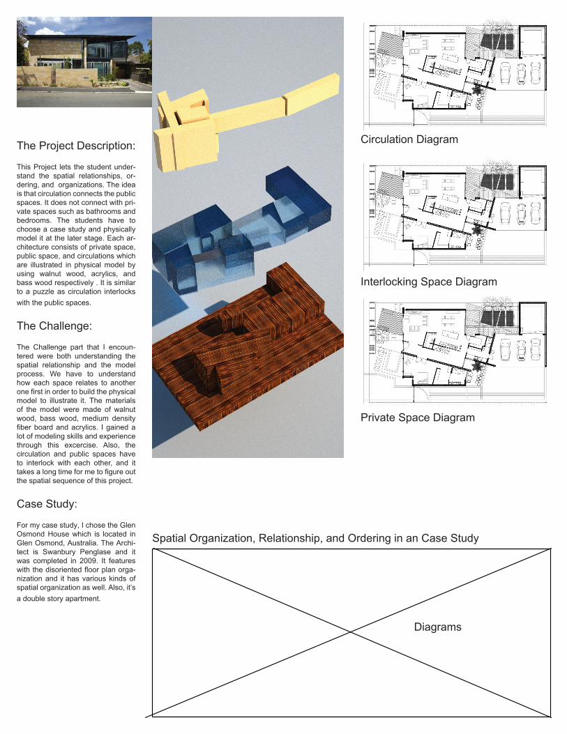
The Project Description:
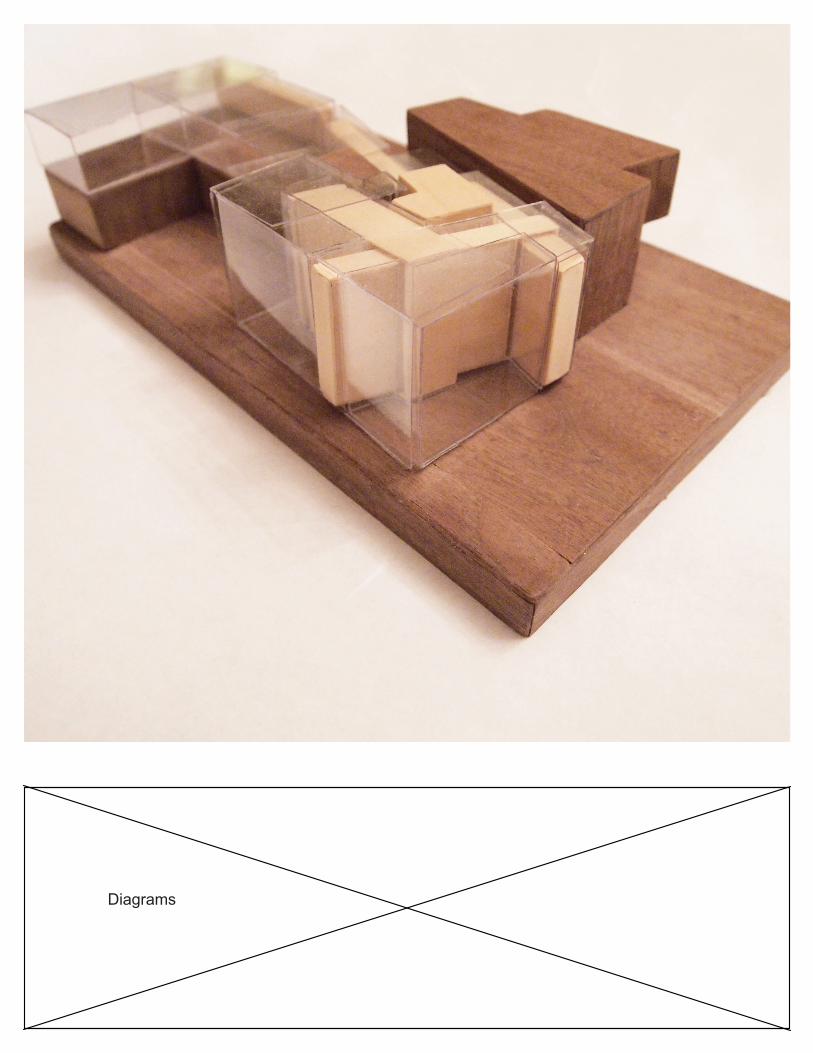
This Project lets the student under-stand the spatial relationships, or-dering, and organizations. The idea is that circulation connects the public spaces. It does not connect with pri-vate spaces such as bathrooms and bedrooms. The students have to choose a case study and physically model it at the later stage. Each ar-chitecture consists of private space, public space, and circulations which are illustrated in physical model by using walnut wood, acrylics, and bass wood respectively . It is similar to a puzzle as circulation interlocks with the public spaces.
The Challenge:
The Challenge part that I encoun-tered were both understanding the spatial relationship and the model process. We have to understand how each space relates to another one first in order to build the physical model to illustrate it. The materials of the model were made of walnut wood, bass wood, medium density fiber board and acrylics. I gained a lot of modeling skills and experience through this excercise. Also, the circulation and public spaces have to interlock with each other, and it takes a long time for me to figure out the spatial sequence of this project.
Case Study:
For my case study, I chose the Glen Osmond House which is located in Glen Osmond, Australia. The Archi-tect is Swanbury Penglase and it was completed in 2009. It features with the disoriented floor plan orga-nization and it has various kinds of spatial organization as well. Also, it’s a double story apartment.
Spatial Organization, Relationship, and Ordering in an Case Study
First Floor Plan
Diagrams
Private Space Diagram
Circulation Diagram
Interlocking Space Diagram
Second Floor Plan
Diagrams


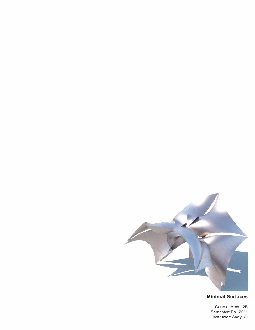
Minimal Surfaces
Course: Arch 12BSemester: Fall 2011Instructor: Andy Ku
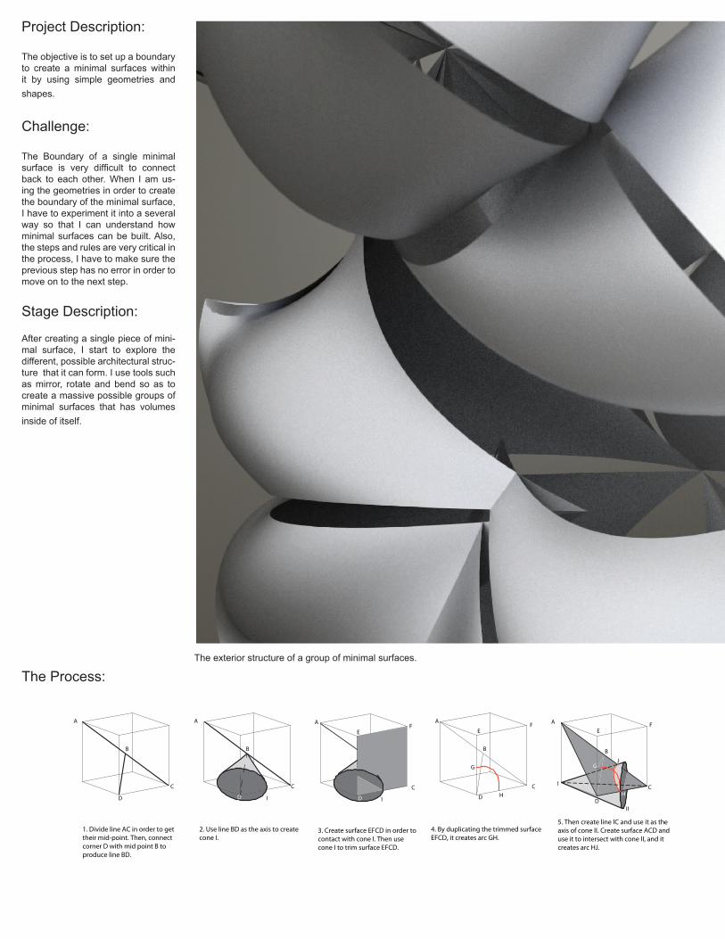
1. Divide line AC in order to gettheir mid-point. Then, connectcorner D with mid point B toproduce line BD.
A
B
D
C
2. Use line BD as the axis to createcone I.
A
B
D
C
I
3. Create surface EFCD in order tocontact with cone I. Then usecone I to trim surface EFCD.
I
A
D
C
EF
4. By duplicating the trimmed surfaceEFCD, it creates arc GH.
A
D
C
B
EF
G
H
5. Then create line IC and use it as theaxis of cone II. Create surface ACD anduse it to intersect with cone II, and itcreates arc HJ.
A
D
C
B
EF
G
H
I
II
J
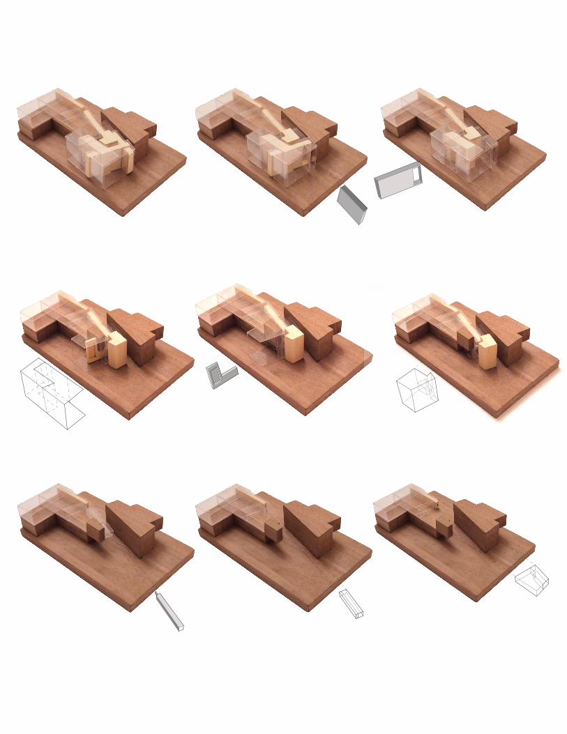
Project Description:
The objective is to set up a boundary to create a minimal surfaces within it by using simple geometries and shapes.
Challenge:
The Boundary of a single minimal surface is very difficult to connect back to each other. When I am us-ing the geometries in order to create the boundary of the minimal surface, I have to experiment it into a several way so that I can understand how minimal surfaces can be built. Also, the steps and rules are very critical in the process, I have to make sure the previous step has no error in order to move on to the next step.
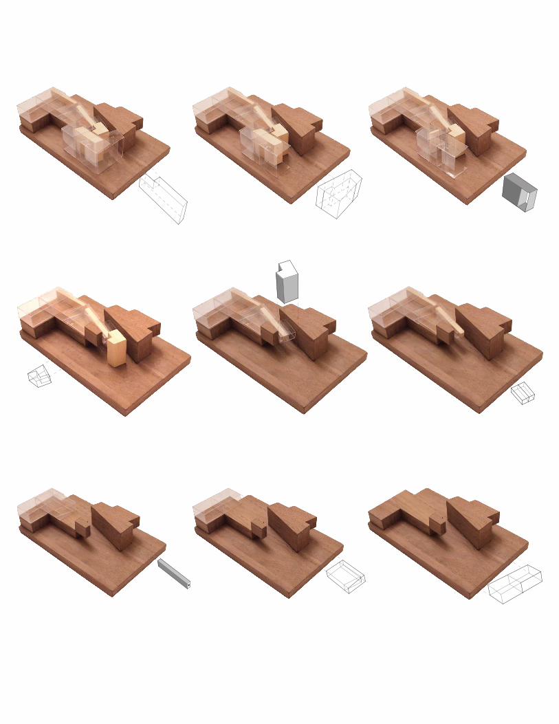
Stage Description:
After creating a single piece of mini-mal surface, I start to explore the different, possible architectural struc-ture that it can form. I use tools such as mirror, rotate and bend so as to create a massive possible groups of minimal surfaces that has volumes inside of itself.
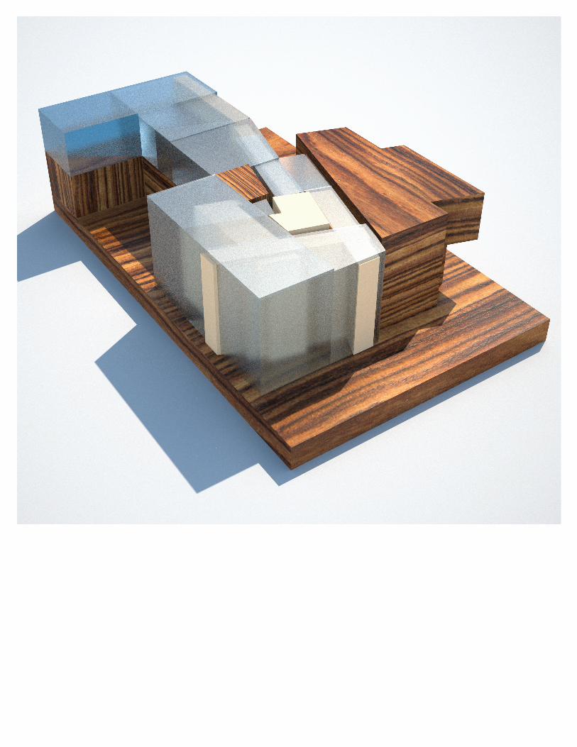
The Process:The exterior structure of a group of minimal surfaces.
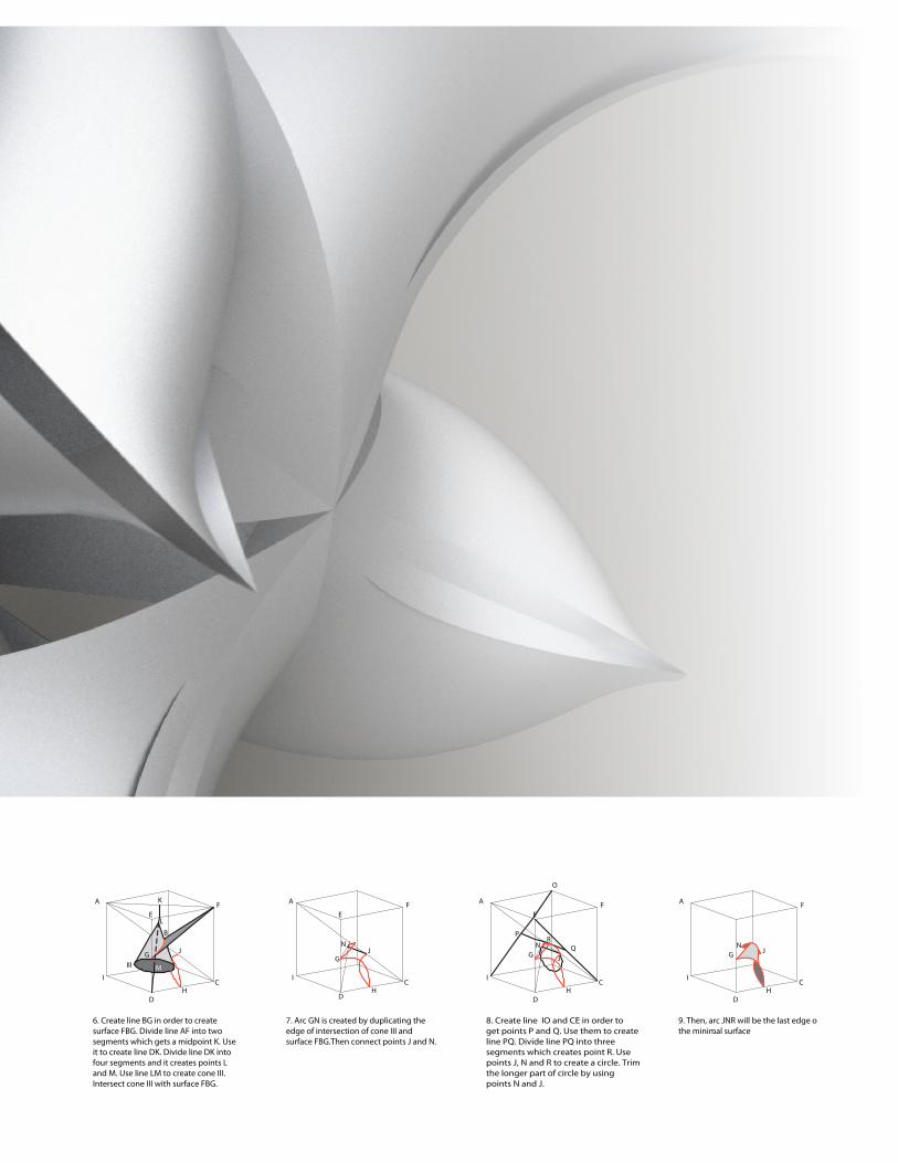
6. Create line BG in order to createsurface FBG. Divide line AF into twosegments which gets a midpoint K. Useit to create line DK. Divide line DK intofour segments and it creates points Land M. Use line LM to create cone III.Intersect cone III with surface FBG.
A
D
C
B
EF
G
H
I
J
K
L
MIII
7. Arc GN is created by duplicating theedge of intersection of cone III andsurface FBG.Then connect points J and N.
A
D
C
EF
G
H
I
JN
8. Create line IO and CE in order toget points P and Q. Use them to createline PQ. Divide line PQ into threesegments which creates point R. Usepoints J, N and R to create a circle. Trimthe longer part of circle by usingpoints N and J.
A
D
C
EF
G
H
I
J
N
O
P
QR
9. Then, arc JNR will be the last edge othe minimal surface.
A
D
C
F
G
H
I
JN
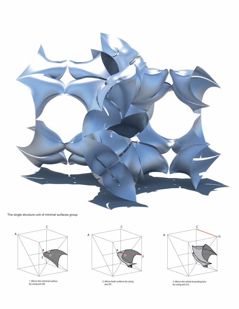
The single structure unit of minimal surfaces group.
1. Mirror the minimal surfaceby using axis DE.
A
DE
B
C
2. Mirror both surfaces by using axis DF.
A
D F
B
C
3. Mirror the whole bounding boxby using axis CG.
A G
C
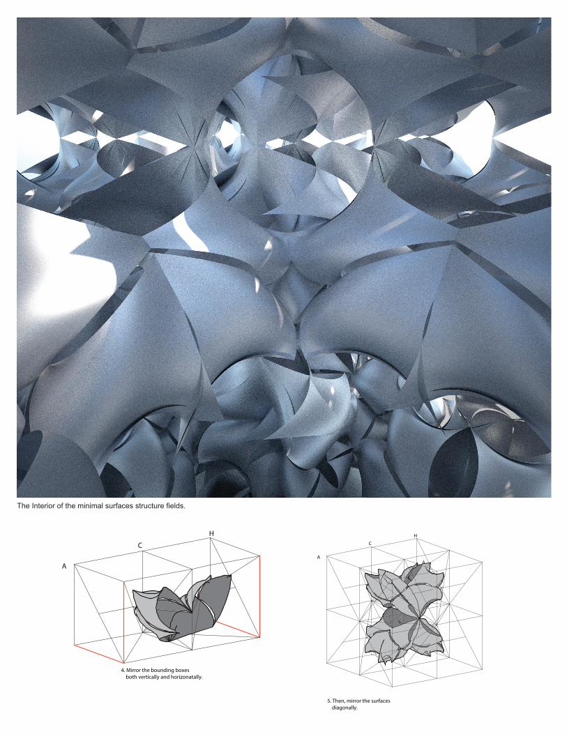
5. Then, mirror the surfaces diagonally.
A
C
H
4. Mirror the bounding boxes both vertically and horizonatally.
A
C
H
The Interior of the minimal surfaces structure fields.


Beach Shelter
Course: Arch 10ASemester: Spring 2011
Instructor: Sandy Lee


Tea House
Course: Arch 10ASemester: Spring 2011
Instructor: Sandy Lee


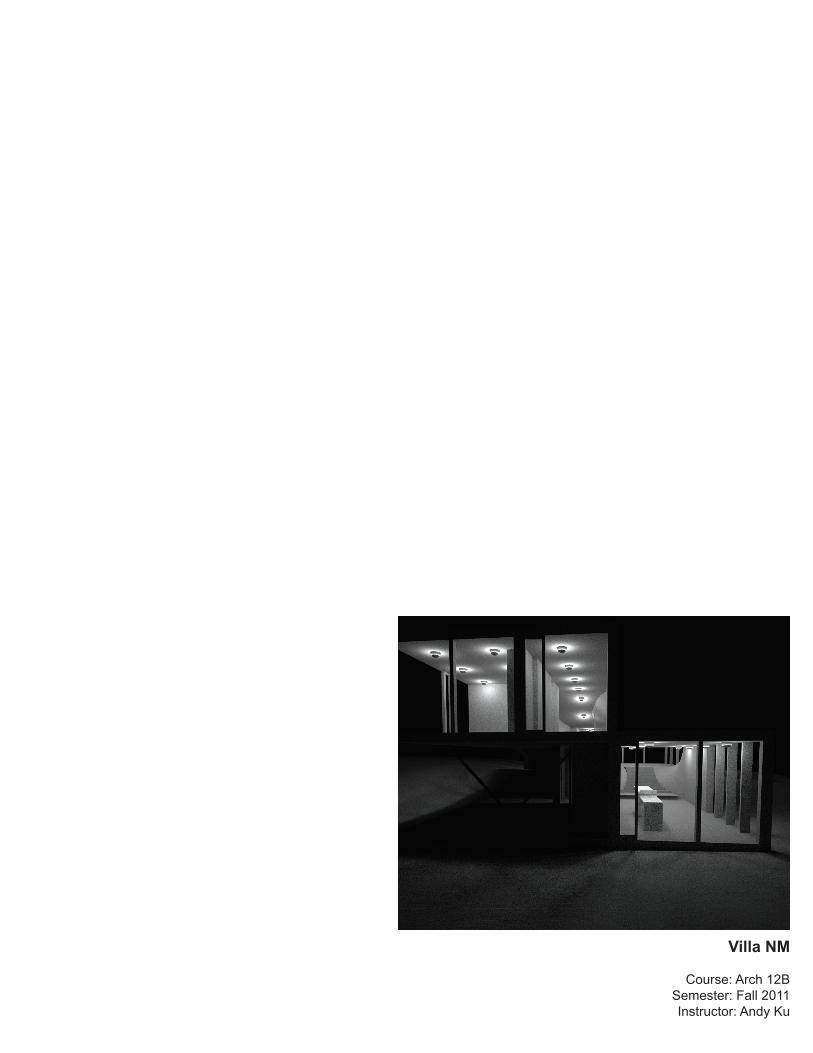
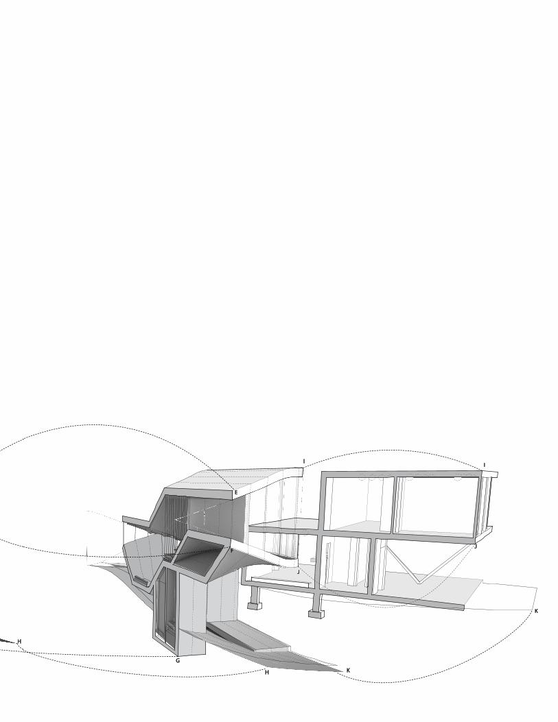
Villa NM
Course: Arch 12BSemester: Fall 2011Instructor: Andy Ku
B
D D
E
F
B
D D
C
E
F
A
B
C
F
G
G
G
G
G
G
A
B
C
F
C
A
A
B
B
C
C
D
E
E
F
F
G
H
H
G
D
G
I
A
A
BB
C C
D
D
E
F
G H
A
A
BB
C C
D
D
E
F
G H
G
H
I
J
I
J
K
K
E
F
