arcview how to do it manual no. 1: georeferencing for beginners
TRANSCRIPT

ArcView How to do it Manual No. 1: Georeferencing for Beginners
Jeremy Green
Report—Department of Maritime ArchaeologyWestern Australian Museum, No. 219

�
What is georeferencing?A Geographical Information Systems (GIS) is a system for creating, storing, analysing and managing spatial data and associated attributes. In a GIS variety of graphical information can be displayed in form that allows the geographical coordinates of a particular point to be determined. In GIS, georeferencing is the process of scaling, rotating, translating and deskewing graphical information, particularly raster images, to match the geographical coordinate system.
An ordinary raster image is made up of pixels that have no particular size. By georeferencing, each individual pixel is give a particular coordinate corresponding to the point on the ground that it represents. Georeferenced images can be placed in layers on a GIS and used to locate positions on the ground.
What can you georeference?Any map, plan, aerial photograph, satellite image that has know features that can be identified and their coordinates determined. You can even georeference semi-oblique photographs. Georeferencing can only be used for raster images. All image files used here are available on a CD for you to play with.
How do you do it?Firstly, you will get with this document a CD with the following files which will be the working examples. All you need to do is copy the files into your MyDocuments folder (or any other directotory/folder) on your hard drive and crank up Esri ArcMap 9.1. The file names you will be using are: Freo1887xx.tif; Rectifymetro.tif; Ning.tif; NMoleAdm,tif.
To georeference a raster image you need a way of determining the coordinates of a number of reference points on the image. So, if you can identify a point on your original and then work out its coordinates, you are in business. There are a number of ways of determining coordinates. In some cases the image may have the coordinates on it already, like an Admiralty chart. If there is no position information on the image you will have to find a way of getting position from other sources. In this situation you will have to be able to identify prominent features on your image and then determine their coordinates from some other source. Some of the alternatives are:1. Using a map or chart and manually locate points and determine their coordinates. 2. Use an already georeferenced aerial photograph or map and locate matching points between the
two, or 3. Use Department of Land Information (DLI) SkyView to obtain coordinates.
In general you will need at least 5 or more points, unless you are dealing with a map or chart (which is going to be rectangular).
What format do I use for the original?If not already scanned, you will need scan your original at a good resolution (general rule of thumb 300 to 600 dpi on original) save as a Tif using LZW compression. If your original is in any other format, you will need to change it to Tif. If the original is a colour image, you should save the scan of it as Indexed colour. Sometimes when you are adding a new data image, a dialogue box comes up asking if you want to create pyramids. There is nothing Egyptian about this, it is a system that helps improve display speed. However, I have found that in the georeferencing process, pyramids sometimes cause problems and is best not used it while you are georeferencing. Once you have done the georeference, and start to use the image, you can then use pyramids and it will improve performance.

�
Version 1. Georeferencing an image using a second georeferenced imageIn this example I am going to georeference an historical map of Fremantle using a DLI Georeferenced aerial photograph of North West Metropolitan Perth.
The historical map Freo_1887xx.tif we will call FREO (for the sake of simplicity) and Georeferenced aerial Rectifymetro.tif which is georeferenced in Geographical (Lat/Long GDA94) we will call MOSAIC.
In a new ArcView page, you will need to set the coordinate system to Geographical and the datum GDA94 (or WGS84, avoid all other datum). To do this Right Click on page. Choose Properties. Select the Coordinate System tab. In the Select a Coordinate System box, select Predefined/Australia and New Zealand/Australia Geocentric Datum of Australia 1994 (GDA94). OK that.
Use the Add Data button , select the image Rectifymetro.tif from directory and Add the image (this will look like figure below).

�
Next, add Freo_1887xx.tif, this will not appear in the same place because it is not georeferenced and, therefore, will be located in a different geographical position. Because you have added it after the MOSAIC, FREO will sit on a layer above MOSAIC. To find FREO, Right Click the File Name in the Table of Contents (ToC, the left hand column) and select Zoom to Layer. This will bring you to FREO as below. The local coordinates (Lat/Long) for the cursor are shown on box at the lower right, note they not correct for FREO, but in MOSAIC they are correct. This is because MOSAIC is georeferenced and as yet FREO is not.
You will now need to go back to the MOSAIC. In some cases where the georeference image is
much bigger you will have to zoom to approximately the same area, using the +Zoom tool (on the top left). To do this Clic/Drag a square around area you want to zoom into. You can, if you want, Bookmark that view so you can quickly get back to it at any time. To Bookmark, use the menu View/Bookmarks/Create and name the view (View1) in the drop-down menu. Next time you want to go to that view, select View/Bookmark/View1. In this example, the two images are about the same so it is not necessary.
To navigate around different images you can also use the Back button . To go back to successive last views you can use this, or you can select the image in the ToC and Right Click Zoom to Image, or you can use a Bookmark.
If Georeferencing Tool Bar is not active, then select it in the View/Tool Bars/Georeferencing drop down and activate it. The Tool Bar looks like this:

�
Select Freo_1887xx.tif the layer to georeference. It is important to remember if you are working with lots of different layers and images to be sure you remember to select the correct that image you want to georeference.
Select a point on FREO (I am going to use the Round House, I have put an arrow showing where it is, but you could select any feature, road intersections work really well) and zoom onto it. Activate the Add Control Points, the icon with red and blue cross.
Place the Control Point tool precisely on the centre of the Round House and click.
Go back to MOSAIC zoom to the Round House and place the second control point. Notice there will be line following the cursor with the control point tool. This line is joined to the first control point on FREO. If you do some other action between clicking on the first Control Point, so that the Add Control Point Button become deactivated, simply click on Control Point button and the tool will become active again.

�
After clicking the MOSAIC may disappear from the frame because FREO is now sitting over the top of it (remember the image in Top layer on ToC will sit over anything below it). In our case (see below) it is not too bad, but sometimes the screen goes completely black or obscured because the top layer is much bigger and covers everything.
Because you can see both images there is no need to use the zoom tool, bookmarks, etc., to zoom back to FREO, but in other examples you may have to do this for the second point. Select a second point on FREO. In this case I am going to use the Monument (Obelisk)
�
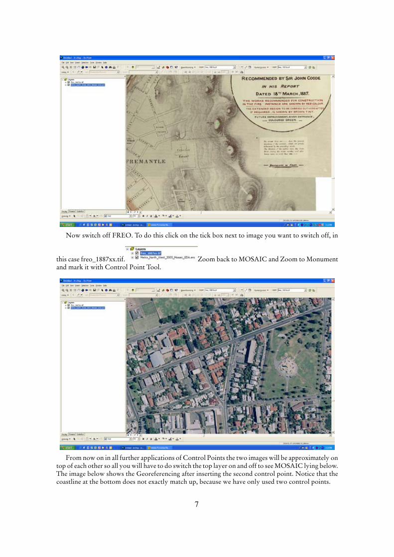
Now switch off FREO. To do this click on the tick box next to image you want to switch off, in
this case freo_1887xx.tif. Zoom back to MOSAIC and Zoom to Monument and mark it with Control Point Tool.
From now on in all further applications of Control Points the two images will be approximately on top of each other so all you will have to do switch the top layer on and off to see MOSAIC lying below. The image below shows the Georeferencing after inserting the second control point. Notice that the coastline at the bottom does not exactly match up, because we have only used two control points.
�
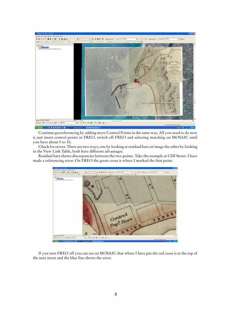
Continue georeferencing by adding more Control Points in the same way. All you need to do now is just insert control points in FREO, switch off FREO and selecting matching on MOSAIC until you have about 5 to 10.
Check for errors. There are two ways, one by looking at residual bars on image the other by looking in the View Link Table, both have different advantages.
Residual bars shows discrepancies between the two points. Take the example at Cliff Street. I have made a referencing error. On FREO the green cross is where I marked the first point.
If you turn FREO off you can see on MOSAIC that where I have put the red cross is at the top of the next street and the blue line shows the error.

�
Now open the View Link Table which is right hand icon on Georeferencing Tool Bar.
If we compare this same problem in View Link Table we can identify links with large residuals. I click on Link 4 which has largest residual (17.226) and it highlights the link line in yellow, which is same problem discussed above.

10
We can delete that link by highlighting Link 4 in the table and using the X button in the screen (the one below the red close window X) and then insert a new Control Point link.
Once you have got rid of the obvious problems, by editing or deleting large residuals, you can then georeference FREO. Click on the Georeferencing DropDown menu and select Rectify. You will only need a 1st Order Polynomial in Transformation because we are really just scaling and moving image, so make sure that is selected. Rectify and save. It is best to keep the default georeference file name (ArcView uses the prefix Rectify so it will be RectifyFreo_1887xx.tif). Always keep the prefix Rectify so you know which images have been rectified and which images are un-rectified.
Delete original IMAGE and add the new file RectifyFreo_1887xx.tif. It will look like the iamge below.
If you are using an Indexed colour image then, because the original rectangular image will almost certainly be rotated somewhat, there will be some white boarders in the square enclosing the rectified image (as above). In this case the white surround is only a minor problem, but it will be a big problem if original image is, say, rotated 45°. You can get rid of the surround by making the border colour transparent (this can only be done with Indexed Colour, it does not work with RGB or grey scale images). Expand the rectified image in the ToC by clicking on the square box next to Image in the ToC (as below, it shows a + when closed and a – when expanded) and it will show a list of all 255 colours.
The white is usually the last colour in the Table (No. 255), but in this case it is No. 1 (you may have to fiddle around with this to find the right white). Right click the white box (No. 1) and select No Colour (see below). In our example there are still some black lines left outside the georeferenced

11
image. By fiddling with colours, in this case make No. 255 (a black icon) No Colour, removes that problem.
The final result is now a fully georeferenced map of Fremantle.
Notice that the coastline at the top of the modern aerial does not match the historical map. This is not a mistake, the shoreline has changed. You can see this because the Swan River matches exactly at the top right.

1�
Version 2 Georeferencing a map that has coordinatesIn this example we take a part of an Admiralty chart that has been scanned and georeference it manually. Here the map must have four coordinates that can be determined. In this example there are two latitude lines and two longitude lines. If there are several lines, always use the outermost.
Add Data and it will appear as below. In this example we will use NMoleAdm.tif where you will notice there are two Latitude lines (32° 02’ 30”S and 32° 03’ 00”S) and two Longitude lines (115° 43’ 30”E and 115° 44’ 00”E). These coordinates need to be converted to decimal degrees as ArcView operates in this system and remember South latitude is Negative. So, for example 32° 03’ 00”S would be -32.05°. Just use a calculator for this.
Make sure you have created the correct coordinate system as described in the last example. Also, make absolutely sure the ArcView coordinate system matches that Datum of the map. If the map datum is different from what you want then you will have to convert the coordinates. Say you are working in GDA94 and the map is in AUS88, then AUS88 coordinates will have to be converted to GDA94 using GeoCalc (see next example).
Activate the Georeferencing Tool Bar, select Layer and select Add Control Point. Zoom to the intersection of 115° 44’E and 32° 03’S. Click on intersection and then Right Click. This will give you an option box with Input X and Y or Cancel Point. Select former. Enter values as shown below.
On clicking OK the image will disappear (because it has moved in geographical space) and you will have to use Zoom to Layer to relocate the image. Repeat for the three other points. You can check the points in the Link Table to ensure everything is correct.

1�
Click on Rectify in Georeferencing drop down and save rectified map. Delete original and replace with Rectified map RectifyNMoleAdm.tif in layer.

1�
Version 3. Using SkyView to georeference an imageSkyView is a web site set up by the DLI that gives access to aerial photographic mosaics of WA. It does not cover all of WA , but a lot. There are several different levels of resolution, ranging from about 1 m per pixel to about 2 m per pixel. The advantage of this system is, if you can identify a point in SkyView that you can see on your image, then you can determine the coordinates of the point. Unfortunately, for marine people, the SykView coordinate system is UTM, so, if you are working in Lat/Long, you will have to use GeoCalc to convert the units. The example I am going to use here is a bit of the Ningaloo Marine Park aerial photograph, it is grey scale and called Ning.tif.
I know pretty well where this is in the Ningaloo Marine Park so in SkyView I can find the corresponding area.
Go to the web site <http://www.landonline.com.au> select Aerial Photography and then SkyView (SkyView does not work on a Mac). If it is the first time your computer has accessed SkyView will not work until the ECW plug in installed. This is done automatically by the system, you just need to OK the process and follow the prompts. Once you have the SkyView WA page operational, click on GO button. This gives you the DLI License Agreement, click on Proceed button at bottom of page. This will bring you to HOW TO USE PanARama-SKYVIEW. Read this page, as it tells you how the tools for SkyView system work. When you have done that click on Proceed button.
The net page is the start of SkyView. It has a map of WA on left. Below there are a series of buttons with: New Mosaics, High Resolution, Low Resolution, Townsites, Suburbs, Special Projects, Archived, Historic and Satellite. I have selected the Low Resolution screen as an example. It shows the coverage of low resolution mosaics and in right hand column a list of the individual mosaics. This is a bit of a problem in finding the area you want, as the locations are a bit obscure and have with post codes. You may have a lot of fiddling to do here to try and find your mosaic.

1�
I know Ningaloo is only covered under low resolution in Special Projects—Coral Bay to Exmouth mosaic. Select Special Projects and click on Coral Bay-Exmouth and you see the area of coverage (see below). If it is what you need click on the folder icon on the right of purple highlighted area.

1�
You will now see a map of the area.
Now click on the Image button, second from left bottom and this will bring you to the aerial photograph. Use the Zoom tool to zoom to the approximate area your photograph is in (see the two images below). The first I have zoomed to the approximate area.
1�
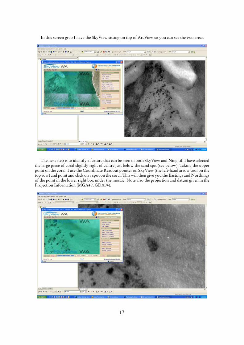
In this screen grab I have the SkyView sitting on top of ArcView so you can see the two areas.
The next step is to identify a feature that can be seen in both SkyView and Ning.tif. I have selected the large piece of coral slightly right of centre just below the sand spit (see below). Taking the upper point on the coral, I use the Coordinate Readout pointer on SkyView (the left-hand arrow tool on the top row) and point and click on a spot on the coral. This will then give you the Eastings and Northings of the point in the lower right box under the mosaic. Note also the projection and datum given in the Projection Information (MGA49, GDA94).

1�
The great thing is you can now Cut and Paste the values of Easting and Northings from this box to the GeoCalc program in order to convert the UTM to Lat Long.
GeoCalc can be used to Convert Lat/Longs to UTM or vice versa (and a lot of other things too). In GeoCalc select Interactive Conversions on top left (see below).
On the left hand side is one set of coordinates (usually the Input coordinates) and on the right hand side is the output. In the Coordinate System box choose Universal Transverse Mercator for the Group, enter the correct UTM Zone in System drop down. Select GD94 for the Datum and Metres for the Linear Unit (see below).
In the Define Coordinate System always remember to choose correct UTM Zone, 49S, 50S, etc., which will depend on your Longitude. In the right-hand box, where the Lat Long results will appear, select Define Coordinate System button, select Geodetic Lat/Long (the top one on list), System Lat/Long and Datum GDA94. Click on the DEG button and select DEGREES (this will give you Decimal Degrees as an output). You should see the letters DEG next to Lat and Long boxes (above).
Cut and Paste the Northings and Eastings from SkyView into the Coordinate Point Definition box on left. Click on the Convert button with the right-facing arrow and you should get the following result (Lat -22.79641912° Long 113.74046182°) as shown above (two up).

1�
With this information we can start georeferencing the aerial photograph using the same technique as in Version 2. Activate Georeferencing, click the Add Control Point tool on the corresponding point (the lump of coral that was used in SkyView) and then Right Click and select Input X and Y. Cut and paste the X (or Longitude) and Y (or latitude) values from GeoCalc (remembering to keep minus sign as Latitude is negative in the Southern Hemisphere) to Arc View. Repeat for a scatter of points across the image. Be careful, after you have copied the first coordinate from SkyView to GeoCalc, when you click back to SkyView, to make sure you do not click into the active area of the aerial photograph. If you do, it will change your pointer position and give you a new set of coordinates.
The process, in simple terms, is as follows:1. Locate a position in SkyView, 2. Copy the Easting from SkyView to GeoCalc3. Copy the Northing from SkyView to GeoCalc4. In GeoCalc convert Northing and Eastings to Latitude and Longitude5. Locate corresponding position in ArcView6. Copy Latitude from GeoCalc to ArcView Position7. Copy Longitude from GeoCalc to ArcView Position8. Continue process until you have between 5 and 10 reference points.It might sound complicated, but once you have got the hang of it, it works fine. Below is the rectified
aerial overlaid with the georeferenced aerial of Ningaloo Reef. You cannot get rid of the white boarders on Rectifying.tif because it is a grey scale, but if the scan was colour you could use the Indexed colour as we used in Version 1. Remember too, you can make the aerial layer semi-transparent so you can see through the aerial to the things below to see changes.