arduino development cookbook - · pdf filetable of contents arduino development cookbook...
TRANSCRIPT


ArduinoDevelopmentCookbook

TableofContents
ArduinoDevelopmentCookbook
Credits
AbouttheAuthor
AbouttheReviewers
www.PacktPub.com
Supportfiles,eBooks,discountoffers,andmore
WhySubscribe?
FreeAccessforPacktaccountholders
Preface
Whatthisbookcovers
Whatyouneedforthisbook
Whothisbookisfor
Sections
Gettingready
Howtodoit…
Howitworks…
There’smore…
Seealso
Conventions
Readerfeedback
Customersupport
Downloadingtheexamplecode
Downloadingthecolorimagesofthisbook
Errata
Piracy
Questions
1.Poweron–ArduinoBasics
Introduction
DownloadingtheArduinosoftware

Gettingready
Howtodoit…
There’smore
Seealso
ConnectingArduino
Gettingready
Howtodoit…
MacOSX
Windows
Seealso
UploadingcodetoArduino
Gettingready
Howtodoit…
Howitworks…
LearningArduinocodebasics
Gettingready
Howtodoit…
Howitworks…
Seealso
Codebasics–ArduinoC
Gettingready
Howtodoit…
Howitworks…
Seealso
Codebasics–Arduinopins
Gettingready
Howtodoit…
Howitworks…
2.BlinkingLEDs
Introduction
BlinkingLEDwithoutdelay()

Gettingready
Howtodoit…
Howitworks…
Breakingdownthecode
Seealso
ConnectinganexternalLED
Gettingready
Howtodoit…
Schematic
Code
Howitworks…
Codebreakdown
There’smore…
LEDresistor
MultipleLEDs
Seealso
FadingtheexternalLED
Gettingready
Howtodoit…
Schematic
Code
Howitworks…
Codebreakdown
There’smore…
Seealso
RGBLED
Gettingready
Howtodoit…
Schematic
Code
Howitworks…

Codebreakdown
There’smore…
Commonanode(+)orcommoncathode(-)
WithoutPWM
LEDbargraph
Gettingready
Howtodoit…
Schematic
Code
Howitworks…
Codebreakdown
There’smore…
Commonanode(+)andcommoncathode(-)
Bargraphvariations
Seealso
The7-segmentdisplay
Gettingready
Howtodoit…
Schematic
Code
Howitworks…
Codebreakdown
There’smore…
Commonanode(+)andcommoncathode(-)
Thedot
Variations
3.WorkingwithButtons
Introduction
Connectingabutton
Gettingready
Howtodoit…

Schematic
Code
Howitworks…
Codebreakdown
There’smore…
Pull-upconfiguration
Multiplebuttons
Seealso
Buttonwithnoresistor
Gettingready
Howtodoit…
Schematic
Code
Howitworks…
Codebreakdown
There’smore…
Multiplebuttons
Seealso
Thetoggleswitch
Gettingready
Howtodoit…
Schematic
Code
Howitworks…
Codebreakdown
There’smore…
Seealso
Buttontoserial
Gettingready
Howtodoit…
Code

Howitworks…
Codebreakdown
There’smore…
Buttondebouncing
Gettingready
Howtodoit…
Code
Howitworks…
Codebreakdown
Seealso
1,000buttonsto1pin
Gettingready
Howtodoit…
Schematic
Code
Howitworks…
Codebreakdown
There’smore…
Morebuttons
Findingeachbutton
Pressingmultiplebuttons
Seealso
Buttonmultiplexing
Gettingready
Howtodoit…
Schematic
Code
Howitworks…
Codebreakdown
There’smore…
Morebuttons

Seealso
4.Sensors
Introduction
Simplesensor–potentiometer
Gettingready
Howtodoit…
Schematic
Code
Howitworks…
Codebreakdown
There’smore…
ArduinoDue
Analogreference(AREF)
Seealso
Temperaturesensor
Gettingready
Howtodoit…
Schematic
Code
Howitworks…
Codebreakdown
There’smore…
Detectingmotion–PIRsensor
Gettingready
Howtodoit…
Schematic
Code
Howitworks…
Codebreakdown
Measuringdistance–infraredandultrasonic
Gettingready

Howtodoit…
Schematic
Code
Howitworks…
Codebreakdown
There’smore…
Seealso
Noisereduction
Gettingready
Howtodoit…
Code
Howitworks…
Meanfilter
Medianfilter
Mainloop()
Seealso
Accelerometer
Gettingready
Howtodoit…
Schematic
Code
Howitworks…
Codebreakdown
There’smore…
Seealso
Localization–GPS
Gettingready
Howtodoit…
Schematic
Code
Howitworks…

Codebreakdown
There’smore…
Seealso
5.MotorControl
Introduction
Controllingsmallmotors
Gettingready
Howtodoit…
Schematic
Code
Howitworks…
There’smore…
Multiplemotors
Electricalspikes
Seealso
Controllingmotorswithtransistors
Gettingready
Howtodoit…
Schematic
Code
Howitworks…
There’smore…
Pull-downresistor
PNPtransistors
MOSFETs
Differentloads
Seealso
ControllingspeedwithPWM
Gettingready
Howtodoit…
Schematic

Code
Howitworks…
Codebreakdown
There’smore…
Spinningmotorsbothways
Gettingready
Howtodoit…
Code
Howitworks…
Codebreakdown
There’smore…
Controlusingthedirectionpin,PWMpin,andbrakepin
ControlusingInputA,InputB,andPWM
Custom-madeL293Ddriver
Seealso
Servomotor
Gettingready
Howtodoit…
Code
Howitworks…
Codebreakdown
There’smore…
Controllingtheexactpulsetime
Moreservos
Continuousrotationservos
Seealso
Steppermotor
Gettingready
Howtodoit…
Schematic
Code

Howitworks…
Codebreakdown
There’smore…
Transistorunipolarstepperdriver
Identifyingthesteppermotortype
Seealso
Bipolarsteppermotors
Gettingready
Howtodoit…
Code
Howitworks…
Codebreakdown
There’smore…
Brushlessmotors
Gettingready
Howtodoit…
Code
Howitworks…
Codebreakdown
Seealso
6.MoreOutputDevices
Introduction
Creatingsound
Gettingready
Howtodoit…
Schematic
Code
Howitworks…
Codebreakdown
There’smore…
Tonewithnoduration

Toneonmultiplepins
Seealso
Transistordriver
Gettingready
Howtodoit…
Schematic
Code
Howitworks…
Seealso
Relaydriver
Gettingready
Howtodoit…
Schematic
Code
Howitworks…
Optocouplers/Optoisolators
Gettingready
Howtodoit…
Schematic
Code
Howitworks…
Moreoutputs–shiftregisters
Gettingready
Howtodoit…
Schematic
Code
Howitworks…
Codebreakdown
7.DigitalCommunicationwithArduino
Introduction
Serialoutput

Gettingready
Howtodoit…
Howitworks…
Codebreakdown
Seealso
ControllingtheArduinooverserial
Gettingready
Howtodoit…
Howitworks…
There’smore…
ArduinoMega
TransmittingvaluestoArduino
Seealso
SoftwareserialandUARTbetweenArduinos
Gettingready
Howtodoit…
Schematic
Code
Howitworks…
Codebreakdown
There’smore…
Usablepins
Moresoftwareserialconnections
Interference
Generalconnectiontips
Seealso
Wirelessserial
Gettingready
Howtodoit…
Schematic
Howitworks…

There’smore…
Seealso
I2CbetweenArduinos
Gettingready
Howtodoit…
Schematic
Code
Howitworks…
Codebreakdown
There’smore…
ComparingdifferentArduinocategories
MoreaboutI2C
Connectingmoredevices
Seealso
SDcards
Gettingready
Howtodoit…
Code
Howitworks…
Codebreakdown
There’smore…
LCDcharacterdisplays
Gettingready
Howtodoit…
Code
Howitworks…
Codebreakdown
There’smore…
Ethernet
Gettingready
Howtodoit…

Code
Howtotest
Howitworks…
Codebreakdown
There’smore…
Seealso
8.Hacking
Introduction
Moredigitalpins
Gettingready
Howtodoit…
Howitworks…
FasterPWM
Gettingready
Howtodoit…
Howitworks…
Timer0
Timer1
Timer2
There’smore…
Interference
OtherArduinos
Seealso
Storingdatainternally–EEPROM
Gettingready
Howtodoit…
Howitworks…
Codebreakdown
TimingArduinocode
Gettingready
Howtodoit…

Howitworks…
Externalinterrupts
Gettingready
Howtodoit…
Schematic
Code
Howitworks…
Codebreakdown
There’smore…
InterruptsonvariousArduinos
Aboutinterrupt-attachedfunctions
Differenttriggeringmodes
Detachinganinterrupt
A.Electronics–theBasics
Workingofelectriccurrent
Ohm’slaw
Resistorconfigurations
DiodesandLEDs
Diodes
LEDs
Workingwithbreadboards
Index


ArduinoDevelopmentCookbook


ArduinoDevelopmentCookbookCopyright©2015PacktPublishing
Allrightsreserved.Nopartofthisbookmaybereproduced,storedinaretrievalsystem,ortransmittedinanyformorbyanymeans,withoutthepriorwrittenpermissionofthepublisher,exceptinthecaseofbriefquotationsembeddedincriticalarticlesorreviews.
Everyefforthasbeenmadeinthepreparationofthisbooktoensuretheaccuracyoftheinformationpresented.However,theinformationcontainedinthisbookissoldwithoutwarranty,eitherexpressorimplied.Neithertheauthor,norPacktPublishing,anditsdealersanddistributorswillbeheldliableforanydamagescausedorallegedtobecauseddirectlyorindirectlybythisbook.
PacktPublishinghasendeavoredtoprovidetrademarkinformationaboutallofthecompaniesandproductsmentionedinthisbookbytheappropriateuseofcapitals.However,PacktPublishingcannotguaranteetheaccuracyofthisinformation.
Firstpublished:April2015
Productionreference:1170415
PublishedbyPacktPublishingLtd.
LiveryPlace
35LiveryStreet
BirminghamB32PB,UK.
ISBN978-1-78398-294-3
www.packtpub.com
CoverImagebyCornelAmariei(<[email protected]>)


CreditsAuthor
CornelAmariei
Reviewers
SimoneBianchi
WilsondaRochaFrança
VincentGijsen
FrancisPerea
CommissioningEditor
EdwardGordon
AcquisitionEditor
SamWood
ContentDevelopmentEditor
RitikaSingh
TechnicalEditor
VivekArora
CopyEditors
CharlotteCarneiro
PujaLalwani
ProjectCoordinator
JudieJose
Proofreaders
SimranBhogal
StephenCopestake
Indexer
RekhaNair
Graphics
LaurentiuMihailescu
AbhinashSahu
ProductionCoordinator
KomalRamchandani

CoverWork
KomalRamchandani


AbouttheAuthorCornelAmarieiisaRomanianinventorandentrepreneurinthefieldsofRoboticsand3Dprinting.HehasbeenworkingwiththeArduinoplatformsinceitsearlydaysin2007.Hispastexperienceinvolveslargecargogammarayscanningrobotics,ATMsecuritysystems,andblindassistingdevices.Inhissparetime,heisaperformingmusicianplayingmultipleinstruments—predominatelytheguitar.Heisalsoaswimmer,waterpoloplayer,andphotographer.
Overtheyears,hehasbuilthundredsofArduinoprojects,rangingfromflyingQuadcopterstolevitatingmagnetsandunderwaterrobots.Currently,hesplitshistimebetweendoinghisundergraduatestudiesinelectricengineeringandcomputerscienceatJacobsUniversityinBremen,Germany,andhisstart-upsandresearchanddevelopmentjob.
Iwouldliketothankmyparents:mymother,Cristina,andmyfather,Eugen,forbuyingmemyfirsttechnologybook18yearsago.Idon’tknowwhetherthiswastheintendedpaththeyhadinmindforme,butconsideringtheamountofsupporttheyofferedduringthewritingofthisbook,Ibelievenowitis.
Iwouldalsoliketothankmyfriends,colleagues,andbusinesspartnersforacceptingmynewprojectandprovidingmewiththetimerequiredtocompleteit,evenifthismeantmoreworkforthem.
Finally,IwouldliketothankPacktPublishingforofferingmethechancetowritethisbookandforhandlingallthedelaysIbroughttotheproject,asmostofthisbookwaswrittenintransit,shortbreaks,latenights,andearlymornings.
Thankyou.


AbouttheReviewersSimoneBianchilivesinItaly,wherehegotadegreeinelectronicengineering.
NowheworksfulltimeforasoftwarehouseasaJavadeveloper.Inhissparetime,helikestofeedhiscurioussidebyexploringothertopicssothathecandevelopcomponentsfortheTalendplatform,anappfortheAndroidsystem,delighthimselfbybuildingIoTprojectsusingdifferentmicrocontrollers(suchastheArduinoandSparkCore)withthehelpofhis6-year-oldnephew,Leonardo,orsimplylearnnewthingssuchasAngularJSor3Dgraphics.
I’dliketothankPacktPublishingforgivingmetheopportunitytoreviewtheirbookagainafterTalendforBigDataandArduinoAndroidBlueprints,andIhopeIhavecontributedtomakingthisyourfavoritebookcompanionduringyourArduinoprojects.
Leo,hereisyourprojectbook.
WilsondaRochaFrançaisasystemarchitectinaleadingonlineretailcompanyinLatinAmerica.HeisanITprofessional,computersciencepassionate,andanopensourceenthusiast;hegraduatedwithauniversitydegreefromCentroFederaldeEducaçãoTecnológicaCelsoSuckowdaFonseca,RiodeJaneiro,Brazil,in2005andalsoholdsamasterofbusinessadministrationdegreefromUniversidadeFederaldoRiodeJaneiroin2010.
Heispassionateaboute-commerceandtheWeb;hehadtheopportunitytoworknotonlyinonlineretail,butalsoinothermarkets,suchascomparisonshoppingandonlineclassifieds.HehasdedicatedmostofhistimetobeingaJavawebdeveloper.
HeiscurrentlyworkingonaMongoDBbookandhadalsoworkedasarevieweronInstantVarnishCacheHow-to,PacktPublishing.
Firstandforemost,Iwouldliketothankmywife,Christiane,forstandingbyme.IwouldalsoliketoexpressmyspecialgratitudetoPacktPublishingforgivingmesuchattentionandtime.Mythanksandappreciationalsogotomyfamilyandpeoplewhohavehelpedmeoutwiththeirabilities.
VincentGijsenisanall-rounder.Withabachelor’sinembeddedsystemsandamaster’sininformationscience,hehasalsoworkedinabigdatastart-upandiscurrentlyworkingasasecurityofficerandcybersecurityconsultantregardingvitalinfrastructure.HehasbeenarevieweronStormBlueprints:PatternsforDistributedReal-timeComputation,PacktPublishing.
Hehasabroadrangeofinterests.Inhissparetime,helikestofiddlewithlasers,microcontrollers,andotherrelatedelectronics,hencethisreview.Hehopesyoulikethisbookasmuchasheenjoyedreviewingit.
FrancisPereaisaprofessionaleducationprofessoratConsejeríadeEducacióndelaJuntadeAndalucíainSpainwithmorethan14yearsofexperience.
Hespecializesinsystemadministration,webdevelopment,andcontentmanagement

systems.Inhissparetime,heworksasafreelancerandcollaborates,amongothers,withñmultimedia,alittledesignstudioinCórdobaworkingasasystemadministratorandmainwebdeveloper.
HehasalsocollaboratedasatechnicalreviewerforSketchUp2013forArchitecturalVisualization,ArduinoHomeAutomation,andInternetofThingswiththeArduinoYún,byPacktPublishing.
Whennotsittinginfrontofacomputerortinkeringinhisworkshop,hecanbefoundmountainbikingorkitesurfingorasabeekeepertakingcareofhishivesinAxarquíaCounty,wherehelives.
Iwouldliketothankmywife,Salomé,andourthreekids,Paula,Álvaro,andJavi,forallthesupporttheygivemeevenwhenweallarebusy.Therearenowordstoexpressmygratitude.
Iwouldalsoliketothankmycolleaguesinñmultimediaandmystudentsforbeingpatient.Theneedtobeatthelevelyoudemandiswhatkeepsmegoingforward.


www.PacktPub.com

Supportfiles,eBooks,discountoffers,andmoreForsupportfilesanddownloadsrelatedtoyourbook,pleasevisitwww.PacktPub.com.
DidyouknowthatPacktofferseBookversionsofeverybookpublished,withPDFandePubfilesavailable?YoucanupgradetotheeBookversionatwww.PacktPub.comandasaprintbookcustomer,youareentitledtoadiscountontheeBookcopy.Getintouchwithusat<[email protected]>formoredetails.
Atwww.PacktPub.com,youcanalsoreadacollectionoffreetechnicalarticles,signupforarangeoffreenewslettersandreceiveexclusivediscountsandoffersonPacktbooksandeBooks.
https://www2.packtpub.com/books/subscription/packtlib
DoyouneedinstantsolutionstoyourITquestions?PacktLibisPackt’sonlinedigitalbooklibrary.Here,youcansearch,access,andreadPackt’sentirelibraryofbooks.

WhySubscribe?FullysearchableacrosseverybookpublishedbyPacktCopyandpaste,print,andbookmarkcontentOndemandandaccessibleviaawebbrowser

FreeAccessforPacktaccountholdersIfyouhaveanaccountwithPacktatwww.PacktPub.com,youcanusethistoaccessPacktLibtodayandview9entirelyfreebooks.Simplyuseyourlogincredentialsforimmediateaccess.


PrefaceTheyearwas2005whenafewguysfromtheInteractionDesignInstituteIvrea,Italywantedtocreateasimplemicrocontrollerboardfortheirstudents—aboardthatwasmoremodern,cheaper,andeasiertousethanthedesignsavailableatthatmoment.AndtheynameditArduino,afterthelocalbar,whichwasnamedafterKingArduino.
Theinitialversionwasbulky,complicatedtoconnect,andlackedUSB,andotherfeaturescommonlyfoundthesedays,buttheboardhadpotential.Now,Arduinoisrenownedforitssimplicityandeaseofuse.ChildrenarebuildingprojectsusingArduinothatonly10yearsagowouldhaverequiredengineers.
Thewholedesignisopensourcedandclonesoftheboardcanbefoundeverywhereintheworld.ThereisnoknownnumberofArduinoboardsbutitisintherangeofhundredsofthousandsorevenmore.Everybodycandesigntheirowncustomimplementationofthestandardinventedin2005.
Today,Arduinohasbeentoeverycorneroftheplanetandevenaboveit.Ithasfueledotherrevolutionssuchasthemaker,theopensourceand3Dprintingmovements.Itiscontinuouslyupgradedtobefasterandhandlemore.ButwhatisArduino?
Arduinoisamicrocontrollerboard,designedtoconnecttoelectronicsandcontrolthem.WecanwritecodefortheArduinothatwillgetdatafromtheenvironment,andmakedecisionsandtakeactionsbasedonthedata.Robots,3Dprinters,toys,eventoastersmayhaveanArduinoinside,poweringupalltheinteraction.
ThisbookcontainsrecipesthatshowhowtoimplementkeytopicsoftheArduino,startingfrombasicinteractionwithbuttonsandLEDs,goinguptointeractionwiththeGlobalPositioningSystem(GPS),makingmusic,orcommunicatingwiththeInternet.Itisintendedforprogrammingorelectronicsenthusiastswhowanttocombinethebestofbothworldstobuildinteractiveprojects.

WhatthisbookcoversChapter1,Poweron–ArduinoBasics,willteachyoutoconnect,install,andtransferthefirstprogramtotheArduinoboard.ThischaptercoversthebasicsofhowtousetheArduinoboard,thetypesofboards,andhowtousetheArduinoIDE.
Chapter2,BlinkingLEDs,coversoneofthebasicusesofArduino,controllingLEDs.Varioustypesandimplementationshavebeencovered,RGBLEDs,blinkingandfadingLEDs,7-segmentdisplays,ormoreadvancedcontroltechniques.
Chapter3,WorkingwithButtons,willshowyouhowtodetectandusebuttonsasakeyinputmethod.Severaltypesofbuttonshavebeencoveredalongwithsolutionstothemostcommonbuttonimplementationissues.Also,waysofconnectingmorebuttonsthanavailabledigitalpinshavebeenshown.
Chapter4,Sensors,coversthemostimportantsensorsthatcanbeconnectedtotheArduino.ProbablythemostimportantthingforArduinoistobeabletoreadasmanyparametersfromtheenvironmentaspossible.Usingsensors,itcanreaddistance,temperature,lightintensity,orevengloballocalization.
Chapter5,MotorControl,willshowyouhowtoconnectandcontrolmultipletypesofmotors.MakingthingsmoveisincrediblyeasyusingmotorsandArduino.Smallandlarge,brushlessandservosmotoralongwithspeedanddirectioncontrol,haveallbeencoveredhere.
Chapter6,MoreOutputDevices,talksaboutgettingmoreoutofArduino.Thischaptercovershowtocontroldifferentloads,howtomakesound,howtoisolateandprotecttheboard,andhowtocommandmoreoutputs.
Chapter7,DigitalCommunicationwithArduino,coversseveralcommunicationprotocolssuchasUART,I2C,Serial,andEthernet,togetthemostoutofthecommunicationinterfacesavailableonArduino.Arduinocancommunicatewithotherboards,computers,andeventheInternet.
Chapter8,Hacking,talksaboutthesmallhacksthatcanhelpanArduinodesigngofurther.ItincludesspeedingupthePWM,reactingtoexternalinterrupts,orevenstoringdatainsidetheArduinoforever.
Appendix,Electronics–theBasics,coversthebasicsofelectronics,suchasbreadboards,Ohm’slaw,andsoon.


WhatyouneedforthisbookIngeneral,fortherecipesinthisbookyouwillneedthefollowingitems:
AnArduinoboardAUSBcabletoconnecttheArduinotothecomputerAbreadboardwithajumperwirekitAgeneralsetofresistorswithvaluesbetween100ohmand10,000ohmAnassortmentofgeneralLEDsAfewpushbuttonsandswitches1N4148and1N4001/1N4007diodes
Someofthemorefocusedrecipesrequirespecifichardwarecomponentsinordertoimplementthem.Thisisalistofspecificcomponentsrequiredperchapter:
Chapter2,BlinkingLEDs:
RGBLED7-segmentdisplaywithatleastonedigitStandardmulti-segmentbargraph
Chapter3,WorkingwithButtons:
4051orequivalentmultiplexerIntegratedCircuit(IC)
Chapter4,Sensors:
10KorotherpotentiometerLM35orTMP36temperaturesensorIntegratedCircuit(IC)PIRmotionsensorGassensorssuchastheMQ-3,MQ-4,MQ-5,andothersintheseriesSharpIRsensorsuchastheGP2Y0A21YKUltrasonicsensorsuchastheMaxSonarEZseriesorsimilarSimpleaccelerometerbreakoutsuchastheADXL335StandardI2CStandardGPSreceiverwithUARTcommunication4051orequivalentmultiplexerIntegratedCircuit(IC)
Chapter5,MotorControl:
SmallvibratingmotorStandardNPNtransistorssuchastheBC547,2N3905,ortheTIP120StandardLogicLevelNChannelMOSFETssuchastheIRF510orIRF520ArduinomotorshieldStandardRCservomotorULN2003orULN2004DarlingtonArrayICSmallbipolarsteppermotorBrushlessmotorwithsuitedESC
Chapter6,MoreOutputDevices:

8-ohmsmallspeakerStandardNPNtransistorssuchastheBC547,2N3905,ortheTIP120General5Vrelay1.5–3.0VbatterywithwireterminalsGeneraloptocoupler/optoisolatorsuchastheTLP621,4N35,orLTV-816A74HC595shiftregister
Chapter7,DigitalCommunicationwithArduino:
AnotherArduinoboardRFLinkTransmitterandReceiver(434/315Mhz)orequivalentArduinocompatbileEthernetShieldLCDcharacterDisplayArduinocompatibleSDshield
Chapter8,Hacking:
ADCmotorAresistorbetween220ohmand4,700ohmAstandardNPNtransistor(BC547,2N3904,N2222A,TIP120)oralogiclevel-compatibleMOSFET(IRF510,IRF520)Astandarddiode(1N4148,1N4001,1N4007)


WhothisbookisforIfyouwanttobuildprogrammingandelectronicsprojectsthatinteractwiththeenvironment,thisbookwillofferyoudozensofrecipestoguideyouthroughallthemajorapplicationsoftheArduinoplatform.Itisintendedforprogrammingorelectronicsenthusiastswhowanttocombinethebestofbothworldstobuildinteractiveprojects.


SectionsThisbookcontainsthefollowingsections:

GettingreadyThissectiontellsuswhattoexpectintherecipe,anddescribeshowtosetupanysoftwareoranypreliminarysettingsneededfortherecipe.

Howtodoit…Thissectioncharacterizesthestepstobefollowedfor“cooking”therecipe.

Howitworks…Thissectionusuallyconsistsofabriefanddetailedexplanationofwhathappenedintheprevioussection.

There’smore…Itconsistsofadditionalinformationabouttherecipeinordertomakethereadermoreanxiousabouttherecipe.

SeealsoThissectionmaycontainreferencestotherecipe.


ConventionsInthisbook,youwillfindanumberofstylesoftextthatdistinguishbetweendifferentkindsofinformation.Herearesomeexamplesofthesestyles,andanexplanationoftheirmeaning.
Codewordsintext,databasetablenames,foldernames,filenames,fileextensions,pathnames,dummyURLs,userinput,andTwitterhandlesareshownasfollows:“Intheloop()function,wefirstprintthehalfChristmastree.”
Ablockofcodeissetasfollows:
if(logFile)
logFile.print(val1);//Writefirstvalue
logFile.print("");//Writeaspace
logFile.println(val2);//Writesecondvalue
logFile.close();//closethefile
Newtermsandimportantwordsareshowninbold.Wordsthatyouseeonthescreen,inmenusordialogboxesforexample,appearinthetextlikethis:”Toeasilyfindinformationaboutacard,runtheArduinoIDEbuilt-inexamplefoundunderFile|Examples|SD|CardInfo.”
NoteWarningsorimportantnotesappearinaboxlikethis.
TipTipsandtricksappearlikethis.


ReaderfeedbackFeedbackfromourreadersisalwayswelcome.Letusknowwhatyouthinkaboutthisbook—whatyoulikedormayhavedisliked.Readerfeedbackisimportantforustodeveloptitlesthatyoureallygetthemostoutof.
Tosendusgeneralfeedback,simplysendane-mailto<[email protected]>,andmentionthebooktitleviathesubjectofyourmessage.
Ifthereisatopicthatyouhaveexpertiseinandyouareinterestedineitherwritingorcontributingtoabook,seeourauthorguideonwww.packtpub.com/authors.


CustomersupportNowthatyouaretheproudownerofaPacktbook,wehaveanumberofthingstohelpyoutogetthemostfromyourpurchase.

DownloadingtheexamplecodeYoucandownloadtheexamplecodefilesfromyouraccountathttp://www.packtpub.comforallthePacktPublishingbooksyouhavepurchased.Ifyoupurchasedthisbookelsewhere,youcanvisithttp://www.packtpub.com/supportandregistertohavethefilese-maileddirectlytoyou.

DownloadingthecolorimagesofthisbookWealsoprovideyouwithaPDFfilethathascolorimagesofthescreenshots/diagramsusedinthisbook.Thecolorimageswillhelpyoubetterunderstandthechangesintheoutput.Youcandownloadthisfilefromhttps://www.packtpub.com/sites/default/files/downloads/2943OS_ColoredImages.pdf.

ErrataAlthoughwehavetakeneverycaretoensuretheaccuracyofourcontent,mistakesdohappen.Ifyoufindamistakeinoneofourbooks—maybeamistakeinthetextorthecode—wewouldbegratefulifyoucouldreportthistous.Bydoingso,youcansaveotherreadersfromfrustrationandhelpusimprovesubsequentversionsofthisbook.Ifyoufindanyerrata,pleasereportthembyvisitinghttp://www.packtpub.com/submit-errata,selectingyourbook,clickingontheErrataSubmissionFormlink,andenteringthedetailsofyourerrata.Onceyourerrataareverified,yoursubmissionwillbeacceptedandtheerratawillbeuploadedtoourwebsiteoraddedtoanylistofexistingerrataundertheErratasectionofthattitle.
Toviewthepreviouslysubmittederrata,gotohttps://www.packtpub.com/books/content/supportandenterthenameofthebookinthesearchfield.TherequiredinformationwillappearundertheErratasection.

PiracyPiracyofcopyrightedmaterialontheInternetisanongoingproblemacrossallmedia.AtPackt,wetaketheprotectionofourcopyrightandlicensesveryseriously.IfyoucomeacrossanyillegalcopiesofourworksinanyformontheInternet,pleaseprovideuswiththelocationaddressorwebsitenameimmediatelysothatwecanpursuearemedy.
Pleasecontactusat<[email protected]>withalinktothesuspectedpiratedmaterial.
Weappreciateyourhelpinprotectingourauthorsandourabilitytobringyouvaluablecontent.

QuestionsIfyouhaveaproblemwithanyaspectofthisbook,youcancontactusat<[email protected]>,andwewilldoourbesttoaddresstheproblem.


Chapter1.Poweron–ArduinoBasicsInthischapter,wewillcoverthefollowingrecipes:
DownloadingtheArduinosoftwareConnectingArduinoUploadingcodetoArduinoLearningArduinocodebasicsCodebasics:ArduinoCCodebasics:ArduinoPins

IntroductionWhenwehaveanidea,wetakeapenandwesketchitdownonapieceofpaper.Imagineifwecouldbuildthingsthatinteractwiththeenvironmentjustaseasily.ThisiswheretheArduinoplatformcomesintoplay.
Arduinoisanopensourcefamilyofelectronicmicroprocessorboardsthatwecaneasilyprogramtounderstandandinteractwiththeenvironment.Overtheyears,Arduinohasbecomethestandardforbuildingelectronicsprojects.Arduinohasbeensentintospacetorunmicrosatellites;ithasbeensenttothebottomoftheoceantocontrolsmallroboticsubmersibles;andnow,Arduinohasarrivedforyou.Let’sexplorethelimitlessworldofArduino.
Ifyouwanttogothroughthebasicsofelectronicsbeforestartingwiththebook,youcanrefertotheAppendix,Electronics–theBasics.


DownloadingtheArduinosoftwareThefirstthingweneedistheArduinoIntegratedDevelopmentEnvironment(IDE).OneofthebestpartsaboutArduinoisthatthesoftwareinwhichweneedtoprogramtheboardsisfreeandopensource.TheArduinoIDEiscompatiblewithWindows,MacOSX,andLinux.

GettingreadyWeonlyneedonethingtocompletethisrecipe—acomputerconnectedtotheInternet.

Howtodoit…Followthesesimplesteps:
1. VisittheArduinowebsiteathttp://arduino.cc/.2. Inthemainmenu,gototheDownloadsection.3. SelectyouroperatingsystemanddownloadthelateststablereleaseoftheArduino
software.Atthetimeofwriting,thelateststableversioncompatiblewithallstandardboardswasversion1.0.5.
4. Afteritdownloads,installtheArduinosoftware.

There’smoreNowthatwehavetheArduinoIDEinstalled,let’sfamiliarizeourselveswiththeuserinterface.
HereisascreenshotoftheArduinosoftwarerunningonWindows.ItlooksthesameonMacandLinux,sinceit’sallwritteninJava.
First,wewilldiscusstheToolBar.IntheToolBar,wecanfindthemostusedbuttons:
Button Description
TheVerifybuttoncompilesthecodeandchecksitforerrors.
TheUploadbuttoncompilesthecodeand,ifthereisnoerrorinthecode,uploadsittotheArduinoboard.
TheNewbuttonstartsanewprogram.IntheArduinoworld,programsarecalledsketches.

TheOpenbuttonsimplyallowsustoopenasavedsketch.
TheSavebuttonsavesthecurrentsketch.
ThisbuttonopenstheSerialMonitorwindowthatallowsustocommunicatewiththeArduinoboard.Itisextremelyhelpfulwhenwedebugaprogram.MoreinformationcanbefoundintheSerialoutputrecipeinChapter7,DigitalCommunicationwithArduino
IntheSketchtab,wecanseealltheopenedArduinoSketches.Thiscomeshandywhenwewanttoworkonmultipleprogramsatthesametime.
TheCodeSpaceareaiswhereallthemagichappens.That’swherewewritethecodethatpowerssatellitesandcatfooddispensers.It’sacodeeditorwithautomaticsyntaxhighlightingandautoarranging.
TheStatusDisplayareaindicatesallthebadstuff.Wheneverthereareerrorsinthecode,theywillbedisplayedthere.Italsodisplayserrorsintheconnectionwiththeboard.TheonlygoodthingitcandisplayisthatthecodehasbeensuccessfullyuploadedtotheArduinoboard.
Additionalfunctionalitycanbefoundinthemainmenubar.Here,wehavetheclassicFilemenuwherewehaveSave,Open,Close,andalsosomeexamples.Inthefollowingrecipes,morewillbediscussedaboutthemenubarcomponents.AnicetrickworthsharingisintheToolsmenu—theAutoFormattoolwillformatthecodetolookprofessionalandclean.

SeealsoConsiderthefollowingrecipestobetterunderstandhowtousetheArduinosoftwareenvironment:
TheConnectingArduinorecipeTheUploadingcodetoArduinorecipe


ConnectingArduinoBeforewecanstartwritingcodeandmakingthingsmove,wefirstneedtoconnecttheArduinoboardtoourcomputer.TheArduinoboardiscompatiblewithMac,Windows,andLinux.Herewewilldiscusshowtoconnectandinstallthedrivers.

GettingreadyThefollowingaretheingredientsrequiredforthisrecipe:
AnArduinoboardconnectedtothecomputerviaUSBTheArduinoIDEdownloadedandinstalled

Howtodoit…Thisrecipeissplitintwo,asthestepsforMacandWindowsareslightlydifferent.
MacOSXFollowthesestepstoconnectArduinotoMacOSX:
1. ConnecttheArduinotothecomputerusingaUSBcable.Ifeverythingisproperlyconnected,thegreenlightwillturnandstayon.
2. IfyouhaveanArduinoUno,Leonardo,Due,orMega2560,nodriversareneededandtheboardisreadytogo.
3. Ifyou’reusinganolderArduinoboardsuchastheDuemilanove,Diecimila,orProMini,youwillrequireFTDIdrivers.Toobtainthem,youcanvisithttp://www.ftdichip.com/Drivers/VCP.htmanddownloadthelatest.Afterdownloadingthem,clickontheinstallerandfollowtheinstructions.Finally,rebootthecomputerandtheArduinoboardwillbeinstalled.
WindowsThefollowingstepsarerequiredfortheUno,Mega2560,Leonardo,andDueboardswhenconnectingArduinotoWindows:
1. ConnecttheArduinotothecomputerusingaUSBcable.Ifeverythingisproperlyconnected,thegreenlightwillturnonandstayon.
2. Windowswillbeginitsdriverinstallationprocessandfail.ClicktheStartbuttonandopentheControlPanel.There,navigatetoSystemandthenDeviceManager.
3. IntheDeviceManagerwindow,searchforPorts(COM&LPT)andlookforaportwithanamesimilartoyourboard.FortheArduinoUno,theportshouldbenamedArduinoUNO….IfthereisnosuchtitleunderPorts,lookinOtherDevicesforanUnknownDevice.ThatwillbeyourArduinoboard.
4. Right-clickontheArduinoBoardinDeviceManagerandchooseUpdateDriverSoftware.Next,selectBrowsemycomputerfordriversoftware.
5. ThiswillrequirethepathtotheArduinodriver.ThiscanbefoundintheArduinoinstallationfolderinProgramFiles,inthedriversfolder.ItisnamedArduino.inf.SelectthefileandWindowswillfinishinstallingthedriver.
ThesearethestepsfortheolderFTDI-basedDuemilanove,Diecimila,Nano,andMegaboards:
1. ConnecttheArduinotothecomputerusingaUSBcable.Thegreenlightwillturnonifeverythingisconnectedproperly.
2. InWindowsVistaandhigher,thedriverswillinstallautomaticallyandtheboardwillbereadyforuse.
3. Ifthedriverinstallationfails,navigatetoDeviceManagerinasimilarfashionasforthenewerboardsand,underPorts(COM&LPT),searchforaUSBSerialConverterorsimilar.ChooseUpdateDriverSoftware,selectBrowsemy

computerfordriversoftware,andthenselecttheFTDIdriverfolderfromtheArduinoinstallationfolder,inthedriversfolder.Afterselection,clickonNextandWindowswillfinishinstallingtheArduinoboard.

SeealsoTheprocedureforanUbuntuLinuxcomputerisathttp://playground.arduino.cc/Linux/Ubuntu.


UploadingcodetoArduinoIt’stimetopowerontheArduinoboardandmakeitdosomething.Inthisrecipe,wewillconnecttheArduinotothecomputeranduploadanexamplesketchfromtheArduinoIDE.

GettingreadyToexecutethisrecipe,thefollowingarethecomponentsrequired:
AcomputerwiththeArduinoIDEinstalledAnArduinoboardconnectedtothecomputerviaUSB

Howtodoit…Followthesesteps:
1. ConnecttheArduinotothecomputerusingaUSBcable.Ifeverythingisproperlyconnected,thegreenLEDlightwillturnon.
2. IfthisisthefirsttimetheArduinohasbeenconnectedtothecomputer,driverinstallationmightberequired.PleasefollowtheConnectingArduinorecipetoproperlysetuptheArduinoboard.
3. StarttheArduinoIDEand,intheMenuBar,gotoFile|Examples|01.BasicsandclickontheBlinkexample.ThiswillloadtheBlinksketch.
4. MakesureyourArduinoboardisselectedintheBoardmenu.ThemenucanbefoundintheMenubarinTools|Board.
5. Weneedtocheckwhetherthecorrectserialportisselected.UnderTools|SerialPort,wecanseeallavailableserialportdevicesconnectedtothecomputer.OnWindows,eachportwillbelabeledasCOMfollowedbyanumber.Usually,ArduinoinstallsonCOM3,butnotalways.AfastwaytocheckwhichserialporttheArduinoisconnectedtoistounplugthecableandseewhichCOMportdisappearsinthemenu.ThatwillbeourArduinoboard.IntheMac,theportshouldbecalledsomethingbeginningwith/dev/tty.usbmodemor/dev/tty.usbserial.
6. ClickontheUploadbuttonontheToolBar.Ifeverythingrunsproperly,theTXRXLEDsontheArduinoboardwillbeginblinkingforashorttimeuntiltheuploadisdone.Afterthis,oneLEDlightontheArduinoBoardshouldslowlyblink.

Howitworks…Whenweuploadasketchtotheboard,theArduinosoftwarefirstcompilesthecode.Ifthereisanerrorinthecode,itwillwriteitintheStatusDisplayareaandwillstoptheupload.Ifnoerrorsarefound,itwillbeginwritingthecompiledcodetotheboard.Errorswillappeariftheboardorserialportisnotproperlyselected.Wheneverythingiscorrectlysetup,theTXRXLEDswillblink,meaningdataisbeingtransferredbetweenthecomputerandtheArduinoboard.Whenthetransferisdone,theboardwillresetandthecodewillimmediatelybeginexecuting.
ThecodeisstoredintheArduinoboarduntilitiserasedorreplacedbyanothercode.Wecantaketheboardandplugitintoabatteryortoanothercomputer,anditwillstillexecutethisblinking.


LearningArduinocodebasicsHerewebeginwiththebasicsofcodingforArduino.WritingcodeforArduinoandotherembeddedplatformsisalittledifferentfromwritingcodeforacomputer.Butdon’tfear—thedifferencesaresmall.

GettingreadyToexecutethisrecipe,weneedjustoneingredient:theArduinoIDErunningonacomputer.

Howtodoit…ThesearethetwomandatoryfunctionsintheArduinocodingenvironment:
voidsetup()
//OnlyexecuteoncewhentheArduinoboots
voidloop()
//Codeexecutestop-downandrepeatscontinuously

Howitworks…EachArduinosketchhastwomandatoryfunctions:thesetup()functionandtheloop()function.Thesetup()functiononlyexecutesonce:eitherwhenweapplypowertotheArduinoorwhenitresets.Usually,weusethisfunctiontoconfigurethepinsoftheArduino,tostartcommunicationprotocols,suchasserialcommunication,ortoperformactionsweonlywanttoperformoncewhentheArduinoboots.
Theloop()functionexecutescontinuously.Codeinthisfunctionisexecutedtop-down;whenitreachestheendofthefunction,itjumpsbacktothestartandrunsagain.ThishappensforeveruntiltheArduinoisswitchedoff.Inhere,wewritethecodewewanttoruncontinuously.

SeealsoContinuetheArduinocodebasicswiththefollowingrecipe,Codebasics:ArduinoC.


Codebasics–ArduinoCTheArduinousesaslightlyreducedC/C++programminglanguage.Inthisrecipe,wewillrememberafewbasicsofC/C++.

GettingreadyEnsurethatyouhavetheArduinoIDErunningonacomputer.

Howtodoit…HereisasimpleexampleofbasicArduinoC/C++manipulatingtwovariables:
//GlobalVariables
intvar1=10;
intvar2=20;
voidsetup()
//OnlyexecuteoncewhentheArduinoboots
var2=5;//var2becomes5oncetheArduinoboots
voidloop()
//Codeexecutestop-downandrepeatscontinuously
if(var1>var2)//Ifvar1isgreaterthanvar2
var2++;//Incrementvar2by1
else//Ifvar1isNOTgreaterthanvar2
var2=0;//var2becomes0

Howitworks…Thecodeplayswithtwointegervariables.Herewehaveacodebreakdowntobetterexplaineachstep.
First,wedeclaredtwoglobalvariables—var1andvar2—andwesetthemtothevaluesof10and20respectively.
//GlobalVariables
intvar1=10;
intvar2=20;
WhentheArduinoboots,itfirstallocatestheglobalvariablesintomemory.Inthesetup()function,wechangethevalueofvar2to5:
voidsetup()
//OnlyexecuteoncewhentheArduinoboots
var2=5;//var2becomes5oncetheArduinoboots
AftertheArduinoallocatestheglobalvariables,itexecutesthecodeinsidethesetup()functiononce.Followingthis,theloop()functionwillexecuterepeatedly.Inside,wehaveanifconditionthatwillplaywiththevaluesofvar2.Ifvar1isgreaterthanvar2,weincreasevar2byone.Eventually,var1willnotbegreaterthanvar2,andthenwesetvar2to0.Thiswillresultinaninfiniteaddingandequalingofvar2.
ThisisoneexampleonhowtheArduinoexecutesthecodeinitstwomainfunctions.

SeealsoContinuetheArduinocodebasicswiththefollowingrecipe,Codebasics–Arduinopins.


Codebasics–ArduinopinsThemostimportantfeatureoftheArduinoisitscontroloverdigitalinput/output(I/O)pins.Oneachpin,wecansetavoltagevalueof5V,representinglogicHIGH,or0V,representinglogicLOW.Also,wecanreadwhetheravalueof5Vor0Visappliedexternally.Herewewilllearnhow.

GettingreadyForthisrecipe,ensurethatyouhavetheArduinoIDErunningonacomputer.

Howtodoit…ThefollowingcodeturnsapinHIGHandLOWrepeatedlywhilereadingtheexternalvoltageappliedtoanother:
voidsetup()
//Setpin2asadigitalOutput
pinMode(2,OUTPUT);
//Setpin3asadigitalInput
pinMode(3,INPUT);
voidloop()
//Setpin2HIGH
digitalWrite(2,HIGH);
//Wait100milliseconds
delay(100);
//Setpin2LOW
digitalWrite(2,LOW);
//Wait100milliseconds
delay(100);
//Readthevalueofpin3andstoreitinavariable
intpinValue=digitalRead(3);

Howitworks…Thecodesetstwopinsinoutputandinputmodeandthenwritesandreadsfromthem.Hereisthecodebreakdown:
Insetup(),weusethepinMode()functiontosetpinnumber2asanoutput.Whenwesetapinasanoutput,wecansetthatpinaseitherHIGH(5V)orLOW(0V).Also,wesetpinnumber3asaninput.Apinconfiguredasinputcanreadexternalvoltagesappliedtoit.ItcanreadHIGHifthevoltageisaround5VandLOWifthevoltageiscloseorequalto0V:
voidsetup()
//Setpin2asadigitalOutput
pinMode(2,OUTPUT);
//Setpin3asadigitalInput
pinMode(3,INPUT);
Intheloop()function,weusethedigitalWrite()functiontosetpinnumber2toHIGH.Then,wewaitfor100millisecondsusingthedelay()function.Thisfunctionstopstheexecutionofthecodeforthespecifiedtime,inmilliseconds.Thereafter,wesetthepintoLOWandwaitanother100milliseconds.Intheend,wereadthevalueofpin3inavariable:
voidloop()
//Setpin2HIGH
digitalWrite(2,HIGH);
//Wait100milliseconds
delay(100);
//Setpin2LOW
digitalWrite(2,LOW);
//Wait100milliseconds
delay(100);
//Readthevalueofpin3andstoreitinavariable
intpinValue=digitalRead(3);
TipDownloadingtheexamplecode
Youcandownloadtheexamplecodefilesfromyouraccountathttp://www.packtpub.comforallthePacktPublishingbooksyouhavepurchased.Ifyoupurchasedthisbookelsewhere,youcanvisithttp://www.packtpub.com/supportandregistertohavethefilese-maileddirectlytoyou.


Chapter2.BlinkingLEDsInthischapter,wewillcoverthefollowingrecipes:
BlinkingLEDwithoutdelay()ConnectinganexternalLEDFadingtheexternalLEDRGBLEDLEDbargraphThe7-segmentdisplay

IntroductionInthischapter,wewillexploreLEDswiththeArduino.ThefastestwaytogetsomefeedbackfromasystemorfromtheArduinoisviaanLED.Theyaresimpledeviceswhichareeitheronoroff.However,theyformthebasisforadvancedtechnologiessuchasLEDTVs,projectors,orlasers.Inthischapter,wewillalsoseehowtousethemefficientlyandexploresomeinterestingapplicationsforthem.
LEDstandsforLightEmittingDiodeand,initscore,it’sjustadiodethatemitslight.LEDsareincrediblycommonthesedaysandcanbefoundatanycommonelectronicsshop.Radioshack,Digikey,Farnell,Sparkfun,Adafruit,orPololuarejustafewplaceswecanbuyLEDsfrom,online.


BlinkingLEDwithoutdelay()ItiseasytomaketheLEDblinkonanArduino.Weturniton,wait,turnitoff,waitagain,andthenwerepeatthecycle.However,thiswaitstatewillcompletelyhalttheArduinoexecution.WewanttomaketheLEDblinkwhiletheArduinoisperformingotheractions.

GettingreadyForthisrecipeallyouneedisanArduinoboardconnectedtothecomputerviaUSB.

Howtodoit…ThefollowingcodewillmaketheinternalLEDblinkontheArduinowithouteverusingthedelay()function:
//VariableforkeepingthepreviousLEDstate
intpreviousLEDstate=LOW;
unsignedlonglastTime=0;//LasttimetheLEDchangedstate
intinterval=200;//intervalbetweentheblinksinmilliseconds
voidsetup()
//DeclarethepinfortheLEDasOutput
pinMode(LED_BUILTIN,OUTPUT);
voidloop()
//Herewecanwriteanycodewewanttoexecutecontinuously
//Readthecurrenttime
unsignedlongcurrentTime=millis();
//Comparethecurrenttimewiththelasttime
if(currentTime-lastTime>=interval)
//Firstwesettheprevioustimetothecurrenttime
lastTime=currentTime;
//ThenweinversethestateoftheLED
if(previousLEDstate==HIGH)
digitalWrite(LED_BUILTIN,LOW);
previousLEDstate=LOW;
else
digitalWrite(LED_BUILTIN,HIGH);
previousLEDstate=HIGH;
NoteWhilemostArduinoshavetheLEDonpin13,somedon’t.TomakesureweareaddressingthecorrectLEDpin,wecanusetheLED_BUILTINconstant.ThisisalreadydefinedintheArduinolanguageandwillalwaysequaltheLEDpinnumberoftheArduinoboardthathasbeenused.

Howitworks…ThebigdifferencebetweenanormalLEDblinkingprogramandthisoneisthatwedon’tusethedelay()function.Thedelay()functionsimplystopsthecodeexecutionuntilthespecifiedamountoftimepasses.Here,wetracktheinternaltimeoftheArduino;whenenoughtimepasses,wechangestate.TheinternaltimesincethestartoftheArduinoisaccessibleusingthemillis()function,whichwillreturnthetime—inmilliseconds—sincetheprogramstartedworking.
Thisapproachiscallednon-blocking,sinceitdoesn’tblocktheexecutionofourcode.Thedelay()functionisconsideredtobeablockingfunction,asitblockscodeexecution.
BreakingdownthecodeThecodetrackstheamountoftimepassedandchangesthestateoftheLEDifenoughtimehaspassed.
Weneedafewvariables.ThepreviousLEDstatevariablewillstorethelaststateoftheLED.ThelastTimevariablerememberswhentheLEDstatechangedfromHIGHtoLOWorfromLOWtoHIGH.WhenwesetapinasHIGH,itwilloutput5V.WhenwesetitasLOW,itwilljustgoto0V.
TheintervalvariableistheintervalinmillisecondsatwhichwewanttheLEDtochangestate.
//VariableforkeepingthepreviousLEDstate
intpreviousLEDstate=LOW;
unsignedlonglastTime=0;//LasttimetheLEDchangedstate
intinterval=200;//intervalbetweentheblinksinmilliseconds
Inthesetup()function,wesettheLEDpinasanoutput:
voidsetup()
//DeclarethepinfortheLEDasOutput
pinMode(LED_BUILTIN,OUTPUT);
Theimportantpartcomesintheloop()function.ThefirststepistorecordthetimesincetheArduinobeganrunningtheprogram.Themillis()functionreturnsverybignumbers;variablesgettingdatafromthisfunctionshouldalwaysbedeclaredaslongorunsignedlong.Unsignedvariablescanonlytakepositivevalues,from0tothemaximumallocatedspace.Forexample,anormallongvariablecantakevaluesfrom-2,147,483,648upto2,147,483,648,whileanunsignedlongcangofrom0upto4,294,967,295.
unsignedlongcurrentTime=millis();
Now,weneedtoseeifenoughtimehaspassedsincethelasttimewechangedthestateoftheLED.Forthis,wecomparewiththeprevioustime.Ifthedifferencebetweenthecurrenttimeandthelastisbiggerthantheintervalwedeclared,wecanproceedtochangethestateoftheLED:

if(currentTime-lastTime>=interval)
Whentheintervalhaspassed,wefirstrecordthenewtimeasbeingtheprevioustime.Bydoingthis,weresetthetimetowhichwewillcomparethenexttime.Then,wecheckwhatthepreviousLEDstatewasandwesettheLEDtotheoppositestate.IfitwasLOWwesetittoHIGHandifitwasHIGH,wesetittoLOW.ThepreviousLEDstatevariableisalsosettothenewLEDstate:
lastTime=currentTime;
//ThenweinversethestateoftheLED
if(previousLEDstate==HIGH)
digitalWrite(LED,LOW);
previousLEDstate=LOW;
else
digitalWrite(LED,HIGH);
previousLEDstate=HIGH;

SeealsoTheButtondebouncingrecipeinChapter3,WorkingwithButtons,forothertopicswhichavoidthedelay()function


ConnectinganexternalLEDLuckily,theArduinoboardscomewithaninternalLEDconnectedtopin13.Itissimpletouseandalwaysthere.ButmosttimeswewantourownLEDsindifferentplacesofoursystem.WemightconnectsomethingontopoftheArduinoboardandcannolongerseetheinternalLED.Here,wewillexplorehowtoconnectanexternalLED.

GettingreadyForthisrecipe,weneedthefollowingingredients:
AnArduinoboardconnectedtothecomputerviaUSBAbreadboardandjumperwiresAregularLED(thetypicalLEDsizeis3mm)Aresistorbetween220–1,000ohm

Howtodoit…FollowthesestepstoconnectanexternalLEDtoanArduinoboard:
1. Mounttheresistoronthebreadboard.ConnectoneendoftheresistortoadigitalpinontheArduinoboardusingajumperwire.
2. MounttheLEDonthebreadboard.Connecttheanode(+)pinoftheLEDtotheavailablepinontheresistor.WecandeterminetheanodeontheLEDintwoways.Usually,thelongerpinistheanode.AnotherwayistolookfortheflatedgeontheoutercasingoftheLED.Thepinnexttotheflatedgeisthecathode(-).
3. ConnecttheLEDcathode(-)totheArduinoGNDusingjumperwires.
SchematicThisisonepossibleimplementationontheseconddigitalpin.Otherdigitalpinscanalsobeused.

HereisasimplewayofwiringtheLED:
CodeThefollowingcodewillmaketheexternalLEDblink:
//DeclaretheLEDpin
intLED=2;
voidsetup()
//DeclarethepinfortheLEDasOutput
pinMode(LED,OUTPUT);
voidloop()
//HerewewillturntheLEDONandwait200milliseconds
digitalWrite(LED,HIGH);
delay(200);
//HerewewillturntheLEDOFFandwait200milliseconds
digitalWrite(LED,LOW);
delay(200);
TipIftheLEDisconnectedtoadifferentpin,simplychangetheLEDvaluetothevalueofthepinthathasbeenused.

Howitworks…Thisisallsemiconductormagic.WhentheseconddigitalpinissettoHIGH,theArduinoprovides5Vofelectricity,whichtravelsthroughtheresistortotheLEDandGND.Whenenoughvoltageandcurrentispresent,theLEDwilllightup.TheresistorlimitstheamountofcurrentpassingthroughtheLED.Withoutit,itispossiblethattheLED(orworse,theArduinopin)willburn.TrytoavoidusingLEDswithoutresistors;thiscaneasilydestroytheLEDorevenyourArduino.
CodebreakdownThecodesimplyturnstheLEDon,waits,andthenturnsitoffagain.Comparedtothepreviousrecipe,inthisonewewilluseablockingapproachbyusingthedelay()function.HerewedeclaretheLEDpinondigitalpin2:
intLED=2;
Inthesetup()functionwesettheLEDpinasanoutput:
voidsetup()
pinMode(LED,OUTPUT);
Intheloop()function,wecontinuouslyturntheLEDon,wait200milliseconds,andthenweturnitoff.Afterturningitoffweneedtowaitanother200milliseconds,otherwiseitwillinstantaneouslyturnonagainandwewillonlyseeapermanentlyonLED.
voidloop()
//HerewewillturntheLEDONandwait200miliseconds
digitalWrite(LED,HIGH);
delay(200);
//HerewewillturntheLEDOFFandwait200miliseconds
digitalWrite(LED,LOW);
delay(200);

There’smore…Thereareafewmorethingswecando.Forexample,whatifwewantmoreLEDs?DowereallyneedtomounttheresistorfirstandthentheLED?
LEDresistorWedoneedtheresistorconnectedtotheLED;otherwisethereisachancethattheLEDortheArduinopinwillburn.However,wecanalsomounttheLEDfirstandthentheresistor.ThismeanswewillconnecttheArduinodigitalpintotheanode(+)andtheresistorbetweentheLEDcathode(-)andGND.ChecktheDiodesandLEDsrecipeintheAppendix,Electronics–theBasics,wherewediscusstheneededresistancestopowerupanLED.Or,ifwewantaquickcheat,checkthefollowingSeealsosection.
MultipleLEDsEachLEDwillrequireitsownresistoranddigitalpin.Forexample,wecanmountoneLEDonpin2andoneonpin3andindividuallycontroleach.WhatifwewantmultipleLEDsonthesamepin?DuetothelowvoltageoftheArduino,wecannotreallymountmorethanthreeLEDsonasinglepin.Forthiswerequireasmallresistor,220ohmforexample,andweneedtomounttheLEDsinseries.Thismeansthatthecathode(-)ofthefirstLEDwillbemountedtotheanode(+)ofthesecondLED,andthecathode(-)ofthesecondLEDwillbeconnectedtotheGND.TheresistorcanbeplacedanywhereinthepathfromthedigitalpintotheGND.

SeealsoFormoreinformationonexternalLEDs,takealookatthefollowingrecipesandlinks:
TheFadingtheexternalLEDrecipeTheRGBLEDrecipeFormoredetailsaboutLEDsingeneral,visithttp://electronicsclub.info/leds.htmToconnectmultipleLEDstoasinglepin,readtheinstructableathttp://www.instructables.com/id/How-to-make-a-string-of-LEDs-in-parallel-for-ardu/Becausewearealwayslazyandwedon’twanttocomputetheneededresistorvalues,usethecalculatorathttp://www.evilmadscientist.com/2009/wallet-size-led-resistance-calculator/


FadingtheexternalLEDTheLEDhastwostates:ONandOFF.Butwhatifwewanttoadjustthebrightness?HowcanwedothatifwecanonlyturnitONorOFF?ByturningitONandOFFquickly.
WewilluseatechniquecalledPulseWidthModulation(PWM),whichisbuiltintotheArduino.ItallowsustodimtheLEDwithupto256settings.

GettingreadyWerequirethefollowingingredientsforthisrecipe:
AnArduinoboardconnectedtothecomputerviaUSBAbreadboardandjumperwiresAregularLEDAresistorbetween220–1,000ohm

Howtodoit…ThisrecipeusesthesamecircuitastheConnectinganexternalLEDrecipewithasingledifference,thepinusedtoconnecttheLEDisnotdigitalpin2butPWMpin3.
SchematicThisisonepossibleimplementationonthethirddigitalpin.OtherdigitalpinswithPWMcanbeused.OnthetypicalArduino,suchasUNO,therearesixpinsthatalsohavePWMfunctionality.Thesepinsare3,5,6,9,10,and11.
HereisasimplewayofwiringtheLED:

CodeThefollowingcodewillmaketheexternalLEDfade:
//DeclaretheLEDpinwithPWM
intLED=3;
voidsetup()
//DeclarethepinfortheLEDasOutput
pinMode(LED,OUTPUT);
voidloop()
//HerewewillfadetheLEDfrom0tomaximum,255
for(inti=0;i<256;i++)
analogWrite(LED,i);
delay(5);
//FadetheLEDfrommaximumto0
for(inti=255;i>=0;i--)
analogWrite(LED,i);
delay(5);
TipIftheLEDisconnectedonadifferentPWMpin,simplychangetheLEDvaluetothevalueofthepinthathasbeenused.
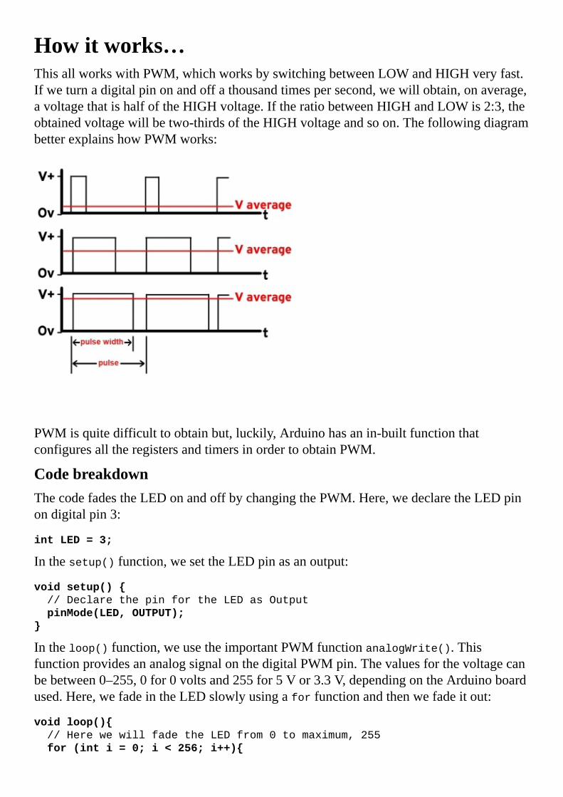
Howitworks…ThisallworkswithPWM,whichworksbyswitchingbetweenLOWandHIGHveryfast.Ifweturnadigitalpinonandoffathousandtimespersecond,wewillobtain,onaverage,avoltagethatishalfoftheHIGHvoltage.IftheratiobetweenHIGHandLOWis2:3,theobtainedvoltagewillbetwo-thirdsoftheHIGHvoltageandsoon.ThefollowingdiagrambetterexplainshowPWMworks:
PWMisquitedifficulttoobtainbut,luckily,Arduinohasanin-builtfunctionthatconfiguresalltheregistersandtimersinordertoobtainPWM.
CodebreakdownThecodefadestheLEDonandoffbychangingthePWM.Here,wedeclaretheLEDpinondigitalpin3:
intLED=3;
Inthesetup()function,wesettheLEDpinasanoutput:
voidsetup()
//DeclarethepinfortheLEDasOutput
pinMode(LED,OUTPUT);
Intheloop()function,weusetheimportantPWMfunctionanalogWrite().ThisfunctionprovidesananalogsignalonthedigitalPWMpin.Thevaluesforthevoltagecanbebetween0–255,0for0voltsand255for5Vor3.3V,dependingontheArduinoboardused.Here,wefadeintheLEDslowlyusingaforfunctionandthenwefadeitout:
voidloop()
//HerewewillfadetheLEDfrom0tomaximum,255
for(inti=0;i<256;i++)

analogWrite(LED,i);
delay(5);
//FadetheLEDfrommaximumto0
for(inti=255;i>=0;i--)
analogWrite(LED,i);
delay(5);

There’smore…ThePWMtechniqueisusedinalmostalldigitalsystems.Soundisdigitallyproducedusingthistechnique;that’showwecanlistentomusiconacomputer.ArduinoonlyhasafewpinsforPWM.Theyareusuallylabeledwitha~sign.TheanalogWrite()functionwillnotworkonnon-PWMpins.

SeealsoFormoreinformationonPWM,takealookatthefollowingrecipesandlinks:
TheRGBLEDrecipehttp://makezine.com/2011/06/01/circuit-skills-pwm-pulse-width-modulation-sponsored-by-jameco-electronics/


RGBLEDWecangetLEDsinavarietyofcolorsthesedays,butwhataboutanLEDthatcanchangecolor?WeallknowthatacombinationofRed,Green,andBlue(RGB)cangiveusanycolor.UsingtheArduinoPWMfunctionality,wewillseehowwecanobtain16millioncolorcombinationswithanRGBLED.
RGBLEDstandsforRedGreenBlueLED.InsidesuchanLEDwecanfindonered,onegreen,andoneblueLED,mountedtogether.

GettingreadyThefollowingaretheingredientsneededforthisrecipe:
AnArduinoboardconnectedtothecomputerviaUSBAbreadboardandjumperwiresAnRGBLEDThreeequalresistorsbetween220–1,000ohm

Howtodoit…FollowthesestepsinordertoconnectanRGBLEDtoanArduinoboard:
1. MounttheRGBLEDonthebreadboard.2. Weneedtoidentifywhichpinrepresentswhichcolorandwhichpinisthecommon
one.Thefollowinggraphicexplainsjustthat:
3. Connect5Vtothecommonanode(+)oftheRGBLED.Thisisthelongestofthefourpins.
4. Connecteachsmallercathode(-)pintooneindividualresistor.5. ConnecteachremainingpinoneachresistortoanindividualPWMpinonthe
Arduino.
SomeRGBLEDsareacommoncathode(-)configuration.Inthiscase,connectthecathode(-)toGND.
SchematicThisisonepossibleimplementationusingacommonanode(+)RGBLEDonthePWM,pins9,10,and11:

Hereisonewayofwiringeverythingonthebreadboard:

CodeThefollowingcodewillmaketheRGBLEDchangeafewcolors:
//DeclarethePWMLEDpins
intredLED=9;
intgreenLED=10;
intblueLED=11;
voidsetup()
//DeclarethepinsfortheLEDasOutput
pinMode(redLED,OUTPUT);
pinMode(greenLED,OUTPUT);
pinMode(blueLED,OUTPUT);
//Asimplefunctiontosetthelevelforeachcolorfrom0to255
voidsetColor(intredValue,intgreenValue,intblueValue)
analogWrite(redLED,255-redValue);
analogWrite(greenLED,255-greenValue);
analogWrite(blueLED,255-blueValue);
voidloop()
//Changeafewcolors
setColor(255,0,0);//RedColor
delay(500);
setColor(0,255,0);//GreenColor
delay(500);
setColor(0,0,255);//BlueColor
delay(500);
setColor(255,255,0);//Yellow
delay(500);
setColor(0,255,255);//Cyan
delay(500);
setColor(255,0,255);//Magenta
delay(500);
setColor(255,255,255);//White
delay(500);
TipIftheRGBLEDisconnectedtodifferentPWMpins,simplychangethevaluesofredLED,greenLED,andblueLEDtothevaluesofthepinsthathavebeenused.

Howitworks…RGBLEDsaremadeupofthreeLEDs:onered,onegreen,andoneblue.Becausetheyarephysicallyclosetogether,ifwemanipulatethemindividually,thecolorwewillseeistheresultingcombinationofthethreeLEDcolors.
CodebreakdownThecodecontrolsthreeLEDsindividuallyusingthesametechniquefromtheFadingtheExternalLEDrecipe.Here,wedeclarethethreeLEDpinsonthePWMchannels9,10,and11:
intredLED=9;
intgreenLED=10;
intblueLED=11;
Inthesetup()function,wesettheLEDpinsasoutputs:
voidsetup()
//DeclarethepinsfortheLEDasOutput
pinMode(redLED,OUTPUT);
pinMode(greenLED,OUTPUT);
pinMode(blueLED,OUTPUT);
HereisacustomfunctioncalledsetColor()thatmakeseverythingeasier.ThefunctionhasthreeparametersandthepowerforeachR,G,andBLED.Thevaluescanvaryfrom0–255foreachLED,whichmeanswehave16,581,375possiblecolors.Inreality,wewillneverusethatmany.
voidsetColor(intredValue,intgreenValue,intblueValue)
analogWrite(redLED,255-redValue);
analogWrite(greenLED,255-greenValue);
analogWrite(blueLED,255-blueValue);
TipInthisexample,weuseacommonanode(+)RGBLED.ThismeansthatwecontrolthecurrentthatgoesintotheArduinopin—andnotout—asweusuallydo.Code-wiseinthisconfiguration,whenweturnthepintoHIGHorto255,theLEDwillbeOFF.Thisisthereasonforthe255–redValueparameter;itinvertsthevalue.
Weusetheloop()functionwecreatedtoobtainafewcombinations.Here,weonlyuseeitherfullpower(255)or0.Wecanexperimentwithin-betweenvaluestoobtaindifferentcolors.Giveitatrywiththiscode:
voidloop()
setColor(255,255,0);//Yellow
delay(500);
setColor(0,255,255);//Cyan
delay(500);

setColor(255,0,255);//Magenta
delay(500);

There’smore…TherearemanytypesofRGBLEDs.LargedisplaysthatwefindinconcertsoroncommercialboardshavethousandsofRGBLEDstoshowtheimage.Therearealsomanymorewaysofconnectingthem.
Commonanode(+)orcommoncathode(-)AnRGBLEDhasthreeLEDswithin,withonepintiedtogether.Inacommonanode(+)version,wewillhavethreeLEDswiththeiranodes(+)connectedtogether.Thesameholdstrueforacommoncathode(-)configuration,onlythatthecathode(-)istiedtogetheramongsttheLEDs.Commoncathodesareeasiertousebuthardertofind.
Foracommoncathode(-),weconnectthecathodetotheGNDandthethreeindividualanodestoanindividualdigitalpinontheArduinousingresistors.
WithoutPWMWedon’talwaysneed16millioncolors.SimplyusethedigitalWrite()functionsandwecanstillobtainsevencolorsfromtheLED.


LEDbargraphWeallhateprogressbars!Theyarealwaysdelayingusfromdoingsomething.ButintheArduinoworldtheycanbeveryhandy.Here,wewillseehowtobuildonewithLEDs.AnLEDbargraphisjustabunchofLEDsputtogetherinafancycase,buttherearemanyusesforit.Wecandisplaythedatefromasensor,showacriticalcondition,ormakeafunnylightshowwithit.

GettingreadyWewillneedthefollowingingredientstoexecutethisrecipe:
AnArduinoboardconnectedtothecomputerviaUSBAbreadboardandjumperwiresAnLEDbargraphResistorsbetween220–1,000ohm

Howtodoit…Followingarethestepstoconnecta10-segmentbargraphtotheArduino:
1. MounttheLEDbargraphontothebreadboard.2. Ifthebargraphisacommonanode(+)configuration,connectthecommonanode(+)
pintothe5VportontheArduino.Ifthebargraphisacommoncathode(-),connectthepintotheGNDportontheArduino.
3. ConnecteachindividualsegmentpintooneindividualArduinodigitalpin,usingaresistor.Tomakethingssimple,connectallthesegmentpinstosuccessivedigitalpinsontheArduino.
SchematicThisisonepossibleimplementationofacommonanode(+)10-segmentLEDbargraph:
Hereisonepossiblewayofwiringitonabreadboard:

CodeThefollowingcodewillmaketheLEDbargraphfullandthenempty:
//DeclarethefirstandlastPinoftheLEDBar
intpin1=2;
intpin10=11;
voidsetup()
//DeclarethepinsasOutputs
for(inti=pin1;i<=pin10;i++)
pinMode(i,OUTPUT);
//AsimplefunctiontosetthevalueoftheLEDBar
voidsetBarValue(intvalue)
//Firstweturneverythingoff
for(inti=pin1;i<=pin10;i++)
digitalWrite(i,HIGH);
//Writethevaluewewant
for(inti=pin1;i<=pin1+value;i++)
digitalWrite(i,LOW);
//Incasewehavevalue0
if(value==0)
digitalWrite(pin1,HIGH);
voidloop()
//Playwithafewdisplays

//Ping-Pong
for(inti=0;i<=10;i++)
setBarValue(i);
delay(100);
for(inti=10;i>=0;i--)
setBarValue(i);
delay(100);
TipThiswasdesignedforacommonanode(+)configuration.Foracommoncathode(-)configuration,weneedtochangethedigitalWritefunctiontooutputthereverse.IfitisHIGH,itshouldoutputLOW.

Howitworks…AnLEDbargraphisassembledfrommultipleLEDs.WecancontroleachLEDindividuallytoobtainthedesiredeffect.TakealookattheConnectinganexternalLEDrecipeformoredetailsonexternalLEDs.Inthisexample,wewillwriteafunctiontosettheprogressvalueontheLEDbargraph.
CodebreakdownThiscodeloadsandunloadstheLEDbargraphjustlikeaprogressbar.Here,wedeclarethefirstandthelastpinsusedintheLEDbar.Thereisnopointindeclaringallofthemasweknowtheyareconsecutiveinthisimplementation:
intpin1=2;
intpin10=11;
Inthesetup()function,weseteachLEDpinasanoutput.Thissimpletrick,usedhere,helpstosetallthepinsbetweenpin1andpin10asoutputs:
voidsetup()
//DeclarethepinsasOutputs
for(inti=pin1;i<=pin10;i++)
pinMode(i,OUTPUT);
InthecustomsetBarValue()function,wemakethebarshowacertainprogresslevel.Asthemaximumis10andtheminimumis0,ifwewrite5,halftheLEDsonthebarwillbeonwhiletheotherhalfareoff:
//AsimplefunctiontosetthevalueoftheLEDBar
voidsetBarValue(intvalue)
//Firstweturneverythingoff
for(inti=pin1;i<=pin10;i++)
digitalWrite(i,HIGH);
//Writethevaluewewant
for(inti=pin1;i<=pin1+value;i++)
digitalWrite(i,LOW);
//Incasewehavevalue0
if(value==0)digitalWrite(pin1,HIGH);
Finally,intheloop()function,weuseourcustomfunctiontoloadthebarandthenunloadit.Inthefollowingcode,weuseaforlooptoincreasethebarvaluetothemaximumandthenwedecreaseitbackto0:
voidloop()
for(inti=0;i<=10;i++)
setBarValue(i);
delay(100);
for(inti=10;i>=0;i--)

setBarValue(i);
delay(100);

There’smore…LEDbargraphscanbeveryhelpfulinvarioussituations.Usuallytheyareusedtoshowthebatterylevelonasystemorthevalueofasensor.Afewvariationsonthebarcanbeseenasfollows.
Commonanode(+)andcommoncathode(-)EachLEDbariseitheracommonanode(+)oracommoncathode(-).Ifit’sacommonanode(+),weconnecttheanodeto5V,eachotherpintoaresistor,andtheresistorstoindividualdigitalpinsontheArduino.Forthecommoncathode(-),connectthecathodetotheGNDandeachpin,usingaresistor,toindividualArduinodigitalpins.
BargraphvariationsLEDbargraphscomeinmultiplesizesandshapes.Theycanhave5to50LEDs.Therearesomewhichareround.AlotofthemhavefourtofivecolorsofLEDsinonebar.Choosewhatfitsyourdesignortastebest.

SeealsoForothertopicsregardingLEDassemblies,pleasecheckthefollowingrecipe:
The7-segmentdisplayrecipe


The7-segmentdisplaySincethebeginningofelectronics,7-segmentdisplayshavebeenusedtodisplaynumbers.Theyareeasytoconnectandunderstand,andquitefuntouseoncetheyareproperlyimplemented.Wecanusesuchadisplaytoshowthestatusofoursystemortoshowdatafromasensor.

GettingreadyThefollowingingredientsareneededforthisrecipe:
AnArduinoboardconnectedtothecomputerviaUSBAbreadboardandjumperwiresA7-segmentdisplayResistorsbetween220–1,000ohm

Howtodoit…Followthesestepsinordertoconnecta7-segmentdisplaytotheArduino:
1. Mountthe7-segmentdisplayonthebreadboard.2. Ifthedisplayisacommonanode(+)configuration,connectthecommonanode(+)
pintotheVCCportontheArduino.Ifitisacommoncathode(-),connectthecathodetotheGNDportontheArduino.
3. ConnecteachindividualsegmentpintooneindividualArduinodigitalpinusingaresistor.
SchematicHereisonepossibleimplementationofacommonanode(+)7-segmentdisplay:
Hereisonepossiblewayofwiringitonabreadboard:

CodeThefollowingcodewillmakethe7-segmentdisplaycountdownfrom3andrestart:
//DeclarethepinsfortheSegmentdisplay
intpinUP=2;//Uppersegment
intpinUPR=3;//Up-rightsegment
intpinDWR=4;//Down-rightsegment
intpinDW=5;//Downsegment
intpinDWL=6;//Down-leftsegment
intpinUPL=7;//Up-leftsegment
intpinCT=8;//Centersegment
voidsetup()
//DeclarethepinsasOutputs
pinMode(pinUP,OUTPUT);
pinMode(pinUPR,OUTPUT);
pinMode(pinDWR,OUTPUT);
pinMode(pinDW,OUTPUT);
pinMode(pinDWL,OUTPUT);
pinMode(pinUPL,OUTPUT);
pinMode(pinCT,OUTPUT);
voidwriteNumber(intvalue)
//Firstweerasethepreviousvalue
digitalWrite(pinUP,HIGH);
digitalWrite(pinUPR,HIGH);
digitalWrite(pinDWR,HIGH);
digitalWrite(pinDW,HIGH);

digitalWrite(pinDWL,HIGH);
digitalWrite(pinUPL,HIGH);
digitalWrite(pinCT,HIGH);
//Ifwewanttowrite0
if(value==0)
digitalWrite(pinUP,LOW);
digitalWrite(pinUPR,LOW);
digitalWrite(pinDWR,LOW);
digitalWrite(pinDW,LOW);
digitalWrite(pinDWL,LOW);
digitalWrite(pinUPL,LOW);
//Ifwewanttowrite1
if(value==1)
digitalWrite(pinUPR,LOW);
digitalWrite(pinDWR,LOW);
//Ifwewanttowrite2
if(value==2)
digitalWrite(pinUP,LOW);
digitalWrite(pinUPR,LOW);
digitalWrite(pinCT,LOW);
digitalWrite(pinDWL,LOW);
digitalWrite(pinDW,LOW);
//Ifwewanttowrite3
if(value==3)
digitalWrite(pinUP,LOW);
digitalWrite(pinUPR,LOW);
digitalWrite(pinCT,LOW);
digitalWrite(pinDWR,LOW);
digitalWrite(pinDW,LOW);
voidloop()
//Aresettingcount-down
writeNumber(3);
delay(1000);
writeNumber(2);
delay(1000);
writeNumber(1);
delay(1000);
writeNumber(0);
delay(1000);
TipThiswasdesignedforacommonanode(+)configuration.Foracommoncathode(-)configuration,weneedtochangethedigitalWritefunctionstooutputtheinverse.IfitisHIGHitshouldoutputLOW,forexample.

Howitworks…A7-segmentdisplayismadeupofsevenLEDsconnectedtogetherinacertainphysicalpattern.Ifwecontrolthesevensegmentsindividually,wecanwriteanydigitonthedisplayandsomeletterstoo.Let’slookintothecode.
CodebreakdownThecodemakesthe7-segmentdisplaycountdownfrom3to0andthenreset.Here,wedeclaretheindividualpinsforeachLEDsegmentonthedisplay:
intpinUP=2;//Uppersegment
intpinUPR=3;//Up-rightsegment
intpinDWR=4;//Down-rightsegment
intpinDW=5;//Downsegment
intpinDWL=6;//Down-leftsegment
intpinUPL=7;//Up-leftsegment
intpinCT=8;//Centersegment
Inthesetup()function,weseteachLEDpinasanoutput:
voidsetup()
pinMode(pinUP,OUTPUT);
pinMode(pinUPR,OUTPUT);
pinMode(pinDWR,OUTPUT);
pinMode(pinDW,OUTPUT);
pinMode(pinDWL,OUTPUT);
pinMode(pinUPL,OUTPUT);
pinMode(pinCT,OUTPUT);
ThecustomwriteNumber()functiontakesanumberwewanttoshowonthedisplayastheargument.Afterthat,iterasesthedisplayandlightsupeachindividualsegment,inordertoobtainthewantedpattern:
voidwriteNumber(intvalue)
//Firstweerasethepreviousvalue
digitalWrite(pinUP,HIGH);
digitalWrite(pinUPR,HIGH);
digitalWrite(pinDWR,HIGH);
digitalWrite(pinDW,HIGH);
digitalWrite(pinDWL,HIGH);
digitalWrite(pinUPL,HIGH);
digitalWrite(pinCT,HIGH);
//Ifwewanttowrite1
if(value==1)
digitalWrite(pinUPR,LOW);
digitalWrite(pinDWR,LOW);
Intheloop()function,weuseourcustomfunctiontomakethedisplaycountdown:
voidloop()
writeNumber(2);

delay(1000);
writeNumber(1);
delay(1000);
writeNumber(0);
delay(1000);

There’smore…The7-segmentdisplayscanbeusedinmultipleapplications.Displayingadigitvalueisthemostused,however.Intotal,wecandisplayalldigitsfrom0to9,togetherwiththelettersA,b,c,C,d,E,F,h,andH.Hereareafewthingstoconsider:
Commonanode(+)andcommoncathode(-)Each7-segmentdisplayiseithercommonanode(+)orcommoncathode(-).Ifit’sacommonanode(+),weconnecttheanodeto5VandeachotherpinwithresistorstoindividualdigitalpinsontheArduino.Forthecommoncathode(-),connectthecathodetotheGNDportandtheotherpins,usingresistors,toindividualArduinodigitalpins.
ThedotMost7-segmentdisplaysactuallyhaveaneighthsegment.It’sthesmalldotinthebottomrightcorner.Whenweusemultiple7-segmentsdisplays,wecanusethatdottocorrectlyrepresent,forexample,thenumber3.14.
VariationsThe7-segmentdisplayisjustthemostpopularconfiguration.Thereareothertypes,suchasthe9-segment,the14-segment,andthe16-segment.Onthe16-segment,anyEnglishcharactercanbedisplayed.

Chapter3.WorkingwithButtonsInthischapter,wewillcoverthefollowingrecipes:
ConnectingabuttonButtonwithnoresistorThetoggle.switchButtontoserialButtondebouncing1,000buttons,1pinButtonmultiplexing

IntroductionButtonsarethebasisofhumaninteractionwiththeArduino.Wepressabutton,andsomethinghappens.Theyaresimplecomponents,astheyonlyhavetwostates:openedorclosed.Whenabuttonisclosed,currentcanpassthoughit.Whenit’sopened,nocurrentcanpass.Somebuttonsareclosedwhenwepushthem,somewhentheyarereleased.
Inthischapter,wewillexplorevariousbuttonconfigurationsandseehowtotacklecommonproblemswiththese.Let’sjumpin!


ConnectingabuttonOneofthebasicinteractionsyoucanhavewiththeArduinoispushingabutton,whichcausesanotheraction.Here,wewillseehowtoconnectanduseabutton.
Tokeeptheexamplesimple,wewillconnectabuttontotheArduino,andwheneverwepressandholdit,theinternalArduinoLEDwilllightup.Butfirst,weneedtotalkalittleaboutbuttons.Thereareafewcommonconfigurationsfoundineverydayelectronics.Wecancategorizebuttons/switchesbasedonthreemaincharacteristics:
MomentaryandmaintainedbuttonsOpenorclosedbuttonsPolesandthrows
Momentarybuttonsareactiveaslongastheyarepressed,whilemaintainedbuttonskeepthestateweletthemin.Keyboardshavemomentarybuttonswhilethetypicallightswitchisamaintainedbutton.
Momentarybuttonscaneitherbeopenedorclosed.Thisreflectstheconnectionstatewhennotpressed.Aclosedmomentaryswitchwillconductcurrentwhilenotpressedandinterruptthecurrentwhenpressed.Anopenedbuttonwilldotheopposite.
Lastly,therearepolesandthrows.Thefollowingfigureexplainsthemaintwotypes:
SinglePoleSingleThrow(SPST)switcheshaveaclosedstateinwhichtheyconductcurrent,andanopenedstateinwhichtheydonotconductcurrent.MostmomentarybuttonsareSPST.

SinglePoleDoubleThrow(SPDT)switchesroutethecurrentfromthecommonpintooneofthetwooutputs.Theyaretypicallymaintained;oneexampleofthisisthecommonlightswitch.
Thecommonbuttonwe’llbeusinginthischapterisapushbutton.It’sasmallmomentaryopenedswitch.Ittypicallycomesina4-pincase:
Thepinsinsidethetworedellipsesareshortedtogether.Whenwepressthebutton,allfourpinsareconnected.

GettingreadyThesearetheingredientsneededtoexecutethisrecipe:
AnArduinoboardconnectedtoacomputerviaUSBAbreadboardandjumperwiresApushbutton,whichcanbefoundatanyelectronicsstore,suchastheonlineshopsofSparkfun,Radioshack,Adafruit,andPololuAresistorbetween1K–100Kohm

Howtodoit…Thefollowingarethestepstoconnectabutton:
1. ConnecttheArduinoGNDand5Vtoseparatelongstripsonthebreadboard.2. Mountthepushbuttononthebreadboardandconnectoneterminaltothe5Vlong
stripandtheothertoadigitalpinontheArduino—inthisexample,pin2.3. MounttheresistorbetweenthechosendigitalpinandtheGNDstrip.Thisiscalleda
pull-downsetup.Moreonthislater.
SchematicThisisonepossibleimplementationontheseconddigitalpin.Otherdigitalpinscanalsobeused.
Hereisanexampleofwiringitonabreadboard:
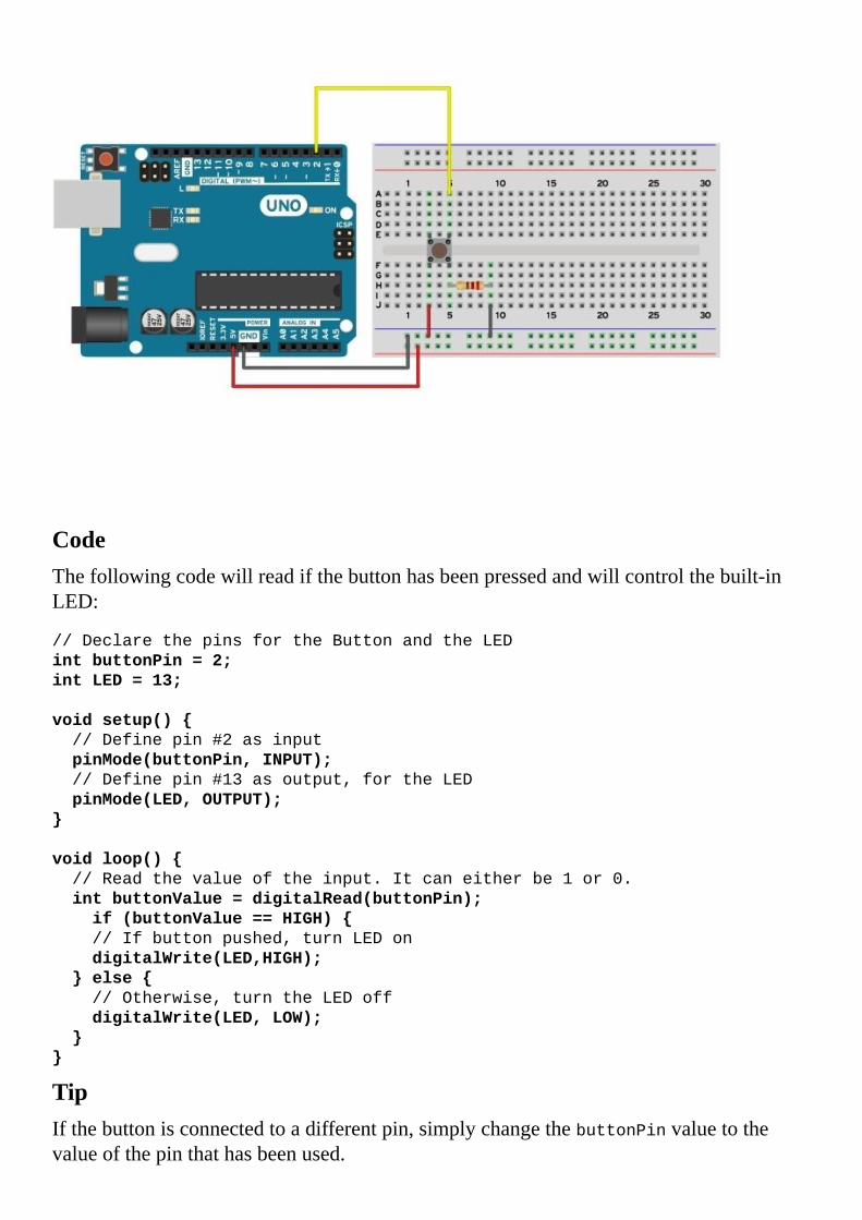
CodeThefollowingcodewillreadifthebuttonhasbeenpressedandwillcontrolthebuilt-inLED:
//DeclarethepinsfortheButtonandtheLED
intbuttonPin=2;
intLED=13;
voidsetup()
//Definepin#2asinput
pinMode(buttonPin,INPUT);
//Definepin#13asoutput,fortheLED
pinMode(LED,OUTPUT);
voidloop()
//Readthevalueoftheinput.Itcaneitherbe1or0.
intbuttonValue=digitalRead(buttonPin);
if(buttonValue==HIGH)
//Ifbuttonpushed,turnLEDon
digitalWrite(LED,HIGH);
else
//Otherwise,turntheLEDoff
digitalWrite(LED,LOW);
TipIfthebuttonisconnectedtoadifferentpin,simplychangethebuttonPinvaluetothevalueofthepinthathasbeenused.

Howitworks…Thepurposeofthebuttonistodrivethedigitalpintowhichit’sconnectedtoeitherHIGHorLOW.Intheory,thisshouldbeverysimple:justconnectoneendofthebuttontothepinandtheotherto5V.Whennotpressed,thevoltagewillbeLOW;otherwiseitwillbe5V,HIGH.However,thereisaproblem.Whenthebuttonisnotpressed,theinputwillnotbeLOWbutinsteadadifferentstatecalledfloating.Inthisstate,thepincanbeeitherLOWorHIGHdependingoninterferencewithothercomponents,pins,andevenatmosphericconditions!
That’swheretheresistorcomesin.Itiscalledapull-downresistorasitpullsthevoltagedowntoGNDwhenthebuttonisnotpressed.Thisisaverysafemethodwhentheresistorvalueishighenough.Anyvalueover1Kwillworkjustfine,but10Kohmisrecommended.
CodebreakdownThecodetakesthevaluefromthebutton.Ifthebuttonispressed,itwillstartthebuilt-inLED.Otherwise,itwillturnitoff.
Here,wedeclarethepintowhichthebuttonisconnectedaspin2,andthebuilt-inLEDonpin13:
intbuttonPin=2;
intLED=13;
Inthesetup()function,wesetthebuttonpinasadigitalinputandtheLEDpinasanoutput:
voidsetup()
pinMode(buttonPin,INPUT);
pinMode(LED,OUTPUT);
Theimportantpartcomesintheloop()function.Thefirststepistodeclareavariablethatwillequalthevalueofthebuttonstate.ThisisobtainedusingthedigitalRead()function:
intbuttonValue=digitalRead(buttonPin);
Lastly,dependingonthebuttonstate,weinitiateanotheraction.Inthiscase,wejustlightuptheLEDorturnitoff:
if(buttonValue==HIGH)
digitalWrite(LED,HIGH);
else
//Otherwise,turntheLEDoff
digitalWrite(LED,LOW);

There’smore…Inthisexample,we’veseenhowtoconnectthebuttonwithapull-downresistor.However,thisisnottheonlyway.Itcanalsobeconnectedusingapull-upresistor.
Pull-upconfigurationInapull-upconfiguration,theresistorwillpullupthevoltageto5Vwhenthebuttonisnotpressed.Toimplementit,connectoneterminalofthebuttontothedigitalpinandtheotheronetoGND.Now,connecttheresistorbetweenthedigitalpinand5V.
Thisconfigurationwillreturninvertedvalues.Whenpressed,thebuttonwillgiveLOW,notHIGH,asitwilldrawthepindowntoGND,0V.However,itbringsnoadvantagesoverthepull-downconfiguration.
MultiplebuttonsWhatifwewanttoimplementmultiplebuttons?Weonlyneedtouseonedigitalpinconfiguredasinputforeachbuttonweuse.Also,eachbuttonneedsitsindependentpull-downorpull-upresistor.

SeealsoForothertopicsregardingbuttons,checkthefollowingimportantrecipesinthischapter:
TheButtonwithnoresistorrecipeTheButtontoserialrecipeTheButtondebouncingrecipe


ButtonwithnoresistorItissimpletoconnectabuttontotheArduino.Youneedthebutton,somewires,andaresistor.Butwhatifwenolongerneedtheresistorandwanttostillbeabletousethebuttonwithnofalsereadings?
Theresistorismandatoryforproperoperationofabutton,andeverybodywillinsistonusingit.However,thereisalittlesecretembeddedineachArduinopin.Eachpinalreadyhasapull-upresistorthatwecanenablewithjustonesmallchangeinourcode.

GettingreadyForthisrecipe,youwillneedjusttwocomponents:
AnArduinoboardconnectedtoacomputerviaUSBApushbutton

Howtodoit…Thereisjustonesimplestepinthisrecipe:
1. ConnecttheArduinoGNDtoaterminalonthebuttonandconnectthechosendigitalpintotheotherterminal.
SchematicHereisoneimplementationonthe12thdigitalpin.Otherdigitalpinscanalsobeused.
Hereisasimplewayofwiringthebutton:

Formostbuttonswithstandardthrough-holeterminals,wecandirectlyinputthepinsintotheterminalsontheArduino.
CodeThefollowingcodewillreadifthebuttonhasbeenpressedandwillcontrolthebuilt-inLED:
//DeclarethepinsfortheButtonandtheLED
intbuttonPin=12;
intLED=13;
voidsetup()
//Definepin#12asinputandactivatetheinternalpull-upresistor
pinMode(buttonPin,INPUT_PULLUP);
//Definepin#13asoutput,fortheLED
pinMode(LED,OUTPUT);
voidloop()
//Readthevalueoftheinput.Itcaneitherbe1or0
intbuttonValue=digitalRead(buttonPin);
if(buttonValue==LOW)
//Ifbuttonpushed,turnLEDon
digitalWrite(LED,HIGH);
else
//Otherwise,turntheLEDoff
digitalWrite(LED,LOW);
Tip

Ifthebuttonisconnectedtoadifferentpin,changethebuttonPinvaluetothevalueofthepinthathasbeenused.

Howitworks…Whenwepressthebutton,thevalueoftheArduinopinshouldbeeitherLOWorHIGH.Inthisconfiguration,whenwepressthebutton,thepinisconnecteddirectlytoGND,resultinginLOW.However,whenitisnotpressed,thepinwillhavenovalue;itwillbeinafloatingstate.
Toavoidthis,aninternalpull-upresistorisconnectedbetweeneachpinand5V.Whenweactivatetheresistor,itwillkeepthepinatHIGHuntilwepressthebutton,thusconnectingthepintoGND.
CodebreakdownThecodetakesthevaluefromthebutton.Ifthebuttonispressed,itwillstartthebuilt-inLED.Otherwiseitwillturnitoff.
Here,wedeclarethepintowhichthebuttonisconnectedaspin12,andthebuilt-inLEDaspin13:
intbuttonPin=12;
intLED=13;
Inthesetup()function,wesetthebuttonpinasadigitalinputandweactivatetheinternalpull-upresistorusingtheINPUT_PULLUPmacro.TheLEDpinisdeclaredasanoutput:
voidsetup()
pinMode(buttonPin,INPUT_PULLUP);
pinMode(LED,OUTPUT);
Intheloop()function,wecontinuouslyreadthevalueofthebuttonusingthedigitalRead()function,andwestoreitinanewlydeclaredvariablecalledbuttonValue:
intbuttonValue=digitalRead(buttonPin);
Lastly,dependingonthebuttonstate,weinitiateanotheraction.Inthiscase,wejustlightuptheLEDorturnitoff:
if(buttonValue==LOW)
//Ifbuttonpushed,turnLEDon
digitalWrite(LED,HIGH);
else
//Otherwise,turntheLEDoff
digitalWrite(LED,LOW);

There’smore…ItiseasytoconnectabuttontotheArduinowithoutanyresistors.Whatifweneedmorebuttons?
MultiplebuttonsEachbuttonrequiresitsowndigitalpinandresistor.TheArduinoalreadyhasonepull-upresistorineachdigitalandanalogpin,sointheend,allthatisneededisonepinforeachindividualbutton.TheotherterminalofthebuttonsistiedtogethertoGND.

SeealsoForothertopicsregardingbuttons,checkthefollowingimportantrecipesinthischapter:
TheButtontoserialrecipeTheButtondebouncingrecipe


ThetoggleswitchAtoggleswitchcanbeveryusefulforvariousprojects.Itcanholdoneormoreconstantstates.Forexample,wecanhaveafewofthemandconfigureacertainsystemtoworkacertainwaybasedontheconfiguration.Thisisdoneallthetimeoncomputermotherboardsandotherelectronicdevices.
Atwo-statetoggleswitchisjustlikeastandardpushbutton;only,itremainsinthestateweputitin.Anon-offswitchisatwo-statetoggleswitch.Itbecomesmoreusefulwhenwehaveathree-statetoggleswitchasinthisrecipe.Ithastwousablestatesandanoffstate.
Inthisrecipe,wewilluseabasictoggleswitchtolightuptwoLEDs.Whenthetoggleswitchisinoneendposition,onlyoneLEDwillbeswitchedon.Ifitisintheotherendposition,theotherLEDwillbeswitchedon.Finally,ifthetoggleswitchisinthecenter,bothLEDswillbeswitchedoff.

GettingreadyThefollowingaretheingredientsrequiredtoexecutethisrecipe:
AnArduinoboardconnectedtoacomputerviaUSBAbreadboardandjumperwiresAtleastonetoggleswitch,whichwecanalwaystakeoutofanoldelectrictoyorbuyfromSparkfun,Digikey,andsoonTwoLEDsandtworesistorsbetween220–1,000ohm

Howtodoit…FollowthesestepsinordertoconnectthetoggleswitchtotheLEDs:
1. ConnecttheArduinoGNDtoalongstriponthebreadboard.2. MountthetoggleswitchandconnectthemiddleterminaltothelongGNDstripon
thebreadboard.3. Connecttheothertwoterminalsofthetoggleswitchtodigitalpins2and3onthe
Arduinoboard.4. MountthetwoLEDsandconnecttheirgroundterminaltothelongGNDstriponthe
breadboard.5. Connectpin5tooneoftheLEDsusingaresistorbetweenpin5andtheinputofthe
LED.Dothesameforpin6andtheotherLED.
SchematicThisisonepossibleimplementation.Otherdigitalpinscanalsobeused.
Hereisapossiblebreadboardimplementation:

CodeThefollowingcodewillcheckthestatusofthetoggleswitchandwilldrivetheLEDsaccordingly:
intbuttonPin1=2;
intbuttonPin2=3;
intLED1=5;
intLED2=6;
voidsetup()
//DefinethetwoLEDpinsasoutputs
pinMode(LED1,OUTPUT);
pinMode(LED2,OUTPUT);
//Definethetwobuttonsasinputswiththeinternalpull-upresistor
activated
pinMode(buttonPin1,INPUT_PULLUP);
pinMode(buttonPin2,INPUT_PULLUP);
voidloop()
//Readthevalueoftheinputs.Itcanbeeither0or1
//0iftoggledinthatdirectionand1otherwise
intbuttonValue1=digitalRead(buttonPin1);
intbuttonValue2=digitalRead(buttonPin2);
if(buttonValue1==HIGH&&buttonValue2==HIGH)
//Switchtoggledtothemiddle.TurnLEDsoff
digitalWrite(LED1,LOW);
digitalWrite(LED2,LOW);
elseif(buttonValue1==LOW)
//Buttonistoggledtothesecondpin

digitalWrite(LED1,LOW);
digitalWrite(LED2,HIGH);
else
//Buttonistoggledtothethirdpin
digitalWrite(LED1,HIGH);
digitalWrite(LED2,LOW);
TipIfthetoggleswitchisconnectedtootherpins,simplychangethebuttonPin1andbuttonPin2variables.ThesamegoesfortheLEDpins.

Howitworks…Whenthetoggleswitchistoggledtooneofthetwoendpositions,itwillconnectoneoftheArduinopinstoGND.ThepinthatisnotconnectedtoGNDwillstayHIGHduetotheinternalpull-upresistorintheArduinopin.Ifthetoggleswitchisinthecentralposition,nopinwillbeconnectedtoGNDandbothwillbeHIGH.
CodebreakdownThecodetakesthevaluefromthetwopinsconnectedtothetoggleswitch.IfoneofthemgoesLOW,itwillturnononeoftheLEDs.
Here,wedeclarethepinstowhichthetoggleswitchisconnectedaspins2and3.TheLEDsaredefinedonpins5and6:
intbuttonPin1=2;
intbuttonPin2=3;
intLED1=5;
intLED2=6;
Inthesetup()function,wesetthepinsfortheLEDsasoutputsandthetwopinsgoingtothetoggleswitchasinputs.Also,weactivatetheinternalpull-upresistorsothatitdoesnotneedanexternalone:
voidsetup()
//DefinethetwoLEDpinsasoutputs
pinMode(LED1,OUTPUT);
pinMode(LED2,OUTPUT);
//Definethetwobuttonsasinputswiththeinternalpull-upresistor
activated
pinMode(buttonPin1,INPUT_PULLUP);
pinMode(buttonPin2,INPUT_PULLUP);
Intheloop()function,wecontinuouslyreadthevaluesofthetwopinsgoingtothetoggleswitch,andwestoretheminthevariablesbuttonValue1andbuttonValue2:
intbuttonValue1=digitalRead(buttonPin1);
intbuttonValue2=digitalRead(buttonPin2);
Lastly,dependingonthetoggleswitchstate,weinitiateanotheraction:
if(buttonValue1==HIGH&&buttonValue2==HIGH)
//Switchtoggledtothemiddle.TurnLEDsoff
elseif(buttonValue1==LOW)
//Buttonistoggledtothesecondpin,oneLEDON
else
//Buttonistoggledtothethirdpin,theotherLEDON

There’smore…Toggleswitchescanbeveryusefulwhenusedtogether.ADIPswitchisveryinteresting,asitusuallyhasmultiplesmalltoggleswitches.Eachtimeweaddatoggleswitch,wedoublethenumberofconfigurations.Withfourtwo-stateswitches,wecanhaveupto16configurations.
Thisisusefulwhenwehaveasystemthatneedsalotofconfigurations.Ratherthanuploadingcodeagainandagain,wecanusethetoggleswitchestochoosewhattodo.

SeealsoUsethefollowinglinkstofindsomecommonswitchesyoucanbuy:
https://www.sparkfun.com/products/9276https://www.sparkfun.com/products/8034


ButtontoserialIfwewanttoeasilytrackhowabuttonacts,serialcommunicationisthebestandsimplestway.Allweneedtodoistoreadthestatusofthebuttonandprintittotheserialconnection.
TestingwhetherabuttonisworkingcanbesolvedbyusinganLED.However,ifweneedtochecktwobuttonsorbetterunderstandwhat’shappeningwhenthebuttonispressed,serialcommunicationismuchsaferandmayevenbesimpler.

GettingreadyThefollowingaretheingredientsrequiredtoexecutethisrecipe:
AnArduinoboardconnectedtoacomputerviaUSBAbutton
Howtodoit…ThisrecipeusestheButtonwithnoresistorrecipe’shardwareimplementation.Pleaseimplementthesameschematicasinthatrecipe.Wewillhavedifferentcodehere,whichwilloutputthevaluesontheserialconnection.
CodeThefollowingcodewillprintthebuttonstatusontheserialconnection:
intbuttonPin=2;
voidsetup()
//Definepin#2asinput
pinMode(buttonPin,INPUT_PULLUP);
//EstablishtheSerialconnectionwithabaudrateof9600
Serial.begin(9600);
voidloop()
//Readthevalueoftheinput.Itcaneitherbe1or0.
intbuttonValue=digitalRead(buttonPin);
//Sendthebuttonvaluetotheserialconnection
Serial.println(buttonValue);
//Delaystheexecutiontoallowtimefortheserialtransmission
delay(25);
TipIfthebuttonisconnectedtoanotherdigitalpin,simplychangethevalueofbuttonPintothedigitalpinthathasbeenused.

Howitworks…Whenthebuttonispressed,itcaneitherreturnavalueof1or0.Becauseweactivatedtheinternalpull-upresistorinsidetheArduinopin,thevalueswillbesafe,andnofloatingconditionwillbeobtained.Afterwereadthevalueofthepin,wesendittotheserialconnection.
CodebreakdownThecodetakesthevaluefromthebuttonconnectedtodigitalpin2andwritesittotheserial.
Inthesetup()function,wesetthebuttonpinasaninputandactivatetheinternalpull-upresistor.Then,westarttheSerialconnectionwithaspeedof9,600bitspersecond:
voidsetup()
pinMode(buttonPin,INPUT_PULLUP);
Serial.begin(9600);
Intheloop()function,wecontinuouslyreadthevalueoftheconnectedbutton:
intbuttonValue=digitalRead(buttonPin);
Then,weprintthevalueusingtheSerial.println()command.WecanalsouseSerial.print();however,printlnwillwritethevalueandgotoanewlineafterwards.Thislooksmuchbetteranditiseasiertounderstand:
Serial.println(buttonValue);
Attheend,weneedadelaytoallowthedatatobetransmitted.Thedelaycanbeshortsinceweonlysendonevalue;however,itismandatorytohaveit.Otherwise,theserialwillconstantlyoverflowandnogoodvalueswillreachthecomputer:
delay(25);

There’smore…Toprintmorethanonebutton,wecanusetheSerial.print()functiontowriteeachbuttonstateinlineandthenusetheSerial.println()functiontogotothenextline.Hereisasimpleimplementation:
Serial.print(buttonValue1);//Printfirstvalue
Serial.print("");//Leaveanemptyspacebetween
Serial.println(buttonValue2);//Printthesecondvalue


ButtondebouncingAbuttonisasimpledevice;whenwepushit,itgivesavalue,otherwiseitgivesanothervalue.Unfortunately,itisnotalwayslikethat.Whenwepushorreleaseabutton,foraverysmallamountoftimethebuttonbouncesbetweenpushedornot.Thisisduetomechanicalerrorsandwearandtearinthebutton.
Evenifitisasmallamountoftime,theArduinoisquick,andwhenwepressthebutton,itmayreadvaluesthatarequicklybouncingbetweenpressedandnotpressed.Inmostcases,thisisnotaproblem;butinmanycases,thishappensanditcantakehourstodetectwhatisgoingwrong.Betterbesafethansorry!
Anotherveryimportantapplicationofthisisreadingabuttononlyonce.Whenwepressthebutton,wekeepitpressedforafewmilliseconds.Inthistime,theArduinocanreadithundreds,eventhousandsoftimes.Itdetectsafewhundredtimesinsteadofoncethatwepushedthebutton.ThisistheprimaryuseofdebouncingintheArduinoworld.

GettingreadyThefollowingaretheingredientsrequiredforthisrecipe:
AnArduinoboardconnectedtoacomputerviaUSBAbutton

Howtodoit…ThisrecipeusesthehardwareimplementationintheButtonwithnoresistorrecipe.Pleaseimplementthesameschematicasinthatrecipe.Wewillhaveadifferentcodehere,whichwilloutputthedebouncedvaluesontheserialconnection.
CodeThefollowingcodewillreadthestatusofthebuttonandprintitovertheserialconnection:
//Declarethepinforthebutton
intbuttonPin=2;
//Variableforkeepingthepreviousbuttonstate
intpreviousButtonValue=HIGH;
longlastDebounce=0;//Lasttimethebuttonwaspressed
longdebounceTime=50;//Debouncedelay
voidsetup()
//Definepin#2asinputandactivatetheinternalpull-upresistor
pinMode(buttonPin,INPUT_PULLUP);
//EstablishtheSerialconnectionwithabaudrateof115200
Serial.begin(115200);
voidloop()
//Readthevalueoftheinput.Itcaneitherbe1or0
intbuttonValue=digitalRead(buttonPin);
if(buttonValue!=previousButtonValue&&millis()-lastDebounce>=
debounceTime)
//Readingisuseable,printit
Serial.println(buttonValue);
//Resetthedebouncingtimer
lastDebounce=millis();
//Changetothelatestbuttonstate
previousButtonValue=buttonValue;
//AllowsomedelayfortheSerialdatatobetransmitted
delay(10);
TipIfthebuttonisconnectedtoanotherdigitalpin,changethevalueofbuttonPintothevalueofthedigitalpinthathasbeenused.

Howitworks…Toavoidreadingthebuttonmultipletimesanddetectingfalsereadings,therearetwoimportantsteps.First,weonlyreadchangesinthebuttonstate.Ifthebuttonhasthesamevalueasatthelastreading,weignoreit.Second—andhereistheimportantstep—ifthebuttonhasbeenpressedorreleased,wedon’tevaluateitsvalueforthefollowingfewmilliseconds.Thiswillmakesurethatnorapidoscillationsinthebuttonstateareread.
Itispossibletoimplementthiswithasimpledelay()function;however,delay()stopstheArduinoboardfromexecutinganythingelse.
CodebreakdownThecodetakesthevaluefromthebuttonconnectedondigitalpin2andusesdebouncinglogictoassureproperoutput.
Weneedtodeclareafewvariables.ThepreviousButtonValuevariablekeepstrackofthepreviousstateofthebutton.ThelastDebouncevariableisimportant;itstorestheparticulartimeatwhichthebuttonwaspressedearlier.ThedebounceTimevariableistheamountoftimeinmillisecondsbetweeneachreading.Itisimportantforthesetwovariablestobedeclaredaslongtype,becausethenumbersgetprettybigquitefast.
intpreviousButtonValue=HIGH;
longlastDebounce=0;//Lasttimethebuttonwaspressed
intdebounceTime=50;//Debouncedelay
NoteTheArduinokeepsaninternalcountoftimepassedsincetheprogrambeganrunning.Toaccessthistime,wecanusethemillis()function,whichreturnsthetimeinmilliseconds.
Inthesetup()function,wesetthebuttonpinasaninputandweactivatetheinternalpull-upresistor.Then,westarttheserialconnectionwithaspeedof115,200bitspersecond:
voidsetup()
pinMode(buttonPin,INPUT_PULLUP);
Serial.begin(115200);
Intheloop()function,wecontinuouslyreadthevalueoftheconnectedbutton:
intbuttonValue=digitalRead(buttonPin);
Nowweneedtoapplythedebouncingpartofthecode.ItconsistsofanIFclausewithtwoconditions:
Thefirstconditioncheckswhetherthenewreadingisdifferentfromthelastone.Wedon’twanttodetectabuttonpushahundredtimeswhenwepressonce.Thesecondconditioncheckswhetherenoughtimehaspassedsincethelastreading.Thismakessurethevaluedoesn’tbouncebetweenstates.
ThetimeisdeclaredinthedebounceTimevariable.Agoodvalueisaround50

milliseconds.Itcanbelower,butwewillonlyneedittobelowerifwewanttopressthebuttonmorethan20timesasecond.
if(buttonValue!=previousButtonValue&&millis()–lastDebounce>=
debounceTime)
Then,weprintthevalueusingtheSerial.println()command:
Serial.println(buttonValue);
ItisveryimportantoneachusablereadingtoupdatethelastDebounceandpreviousButtonValuevariables.Thesewillbethenewvaluesthatthedebouncingfilterwillcompare.
lastDebounce=millis();
previousButtonValue=buttonValue;
Attheend,weneedashortdelaytoallowthedatatobetransmitted:
delay(10);

SeealsoToclearlyunderstandwhatcontactbouncingis,visithttp://en.wikipedia.org/wiki/Debounce#Contact_bounce.


1,000buttonsto1pinOnebutton,onepin—thatisthewaythingsareusuallydoneonArduinoboards.Butitissolimiting.Therearesometricksthatletyouconnectmorethanonebuttontoapin.Actually,itisevenpossibletoconnect1,000buttonstojust1pin.Wewillexplorethispossibilityinthisrecipe.

GettingreadyThefollowingaretheingredientsrequiredforthisrecipe:
AnArduinoboardconnectedtoacomputerviaUSBAbreadboardandjumperwiresThreebuttonsFourresistorsofequalvalue:1Kohmworkswell

Howtodoit…Weimplementasimpleconfigurationusingonlythreebuttonsonthesamepin.Herearethesteps:
1. ConnecttheArduinoGNDtoalongstriponthebreadboard.AlsoconnecttheArduino5Vtoalongstrip.
2. ConnectoneoftheresistorsfromtheGNDstriptoananalogpin—here,pinA0—ontheArduino.
3. Connectthreeresistorsinseriesstartingatthe5Vstrip.4. Ateachjunctionoftworesistors,connectonebutton.Alsoconnectthethirdbuttonat
theendoftheresistorseries.5. ConnecttheotherterminalsofthebuttonstogetherandtotheA0analogpinonthe
Arduino.
SchematicThisisonepossibleimplementation.Otheranalogpinscanalsobeused.
Thisisapossiblebreadboardimplementation:

CodeThefollowingcodewillreadtheanalogpinontheArduinoboardanddetectwhichbuttonispressed:
//DeclaretheAnalogpinontheArduinoboard
intbuttonPin=A0;
voidsetup()
//EstablishtheSerialconnectionwithabaudrateof9600
Serial.begin(9600);
voidloop()
//Readthevalueoftheinput.Itcanvaryfrom0-1023
intbuttonValue=analogRead(buttonPin);
if(buttonValue<200)
//Avalueunder200representsnobuttonpushed
Serial.println("0");
elseif(buttonValue>=200&&buttonValue<300)
//Avaluebetween200-300representsthethirdbutton
Serial.println("S3");
elseif(buttonValue>=300&&buttonValue<400)
//Avaluebetween300-400representsthesecondbutton
Serial.println("S2");
elseif(buttonValue>=400)
//Avaluegreaterthan400representsthefirstbutton
Serial.println("S1");
//DelaystheexecutiontoallowtimefortheSerialtransmission
delay(25);
Tip

Ifthebuttonsareconnectedtoanotheranalogpin,simplychangethebuttonPinvariabletotheanalogpinthathasbeenused.

Howitworks…Thisisallpossibleduetoanelectriccircuitcalledthevoltagedivider.Eachtimeabuttonispressed,adifferentvoltagedivideriscreated.EachbuttonbringsadifferentvoltagetotheanalogpinontheArduino.Wecanreadthisanalogvoltageandattributeaspecificvaluetoeachbutton.
CodebreakdownThecodetakesthevaluefromtheanalogpinandcheckstowhichbuttonitcorresponds.Itprintsoutontheserialwhichbuttonhasbeenpushed.
Here,wedeclaretheanalogpinthathasbeenused:
intbuttonPin=A0;
Inthesetupfunction,westarttheserialconnectionwithaspeedof9,600bitspersecond:
voidsetup()
Serial.begin(9600);
Intheloop()function,wecontinuouslyreadthevalueoftheanalogpin,whichcanbefrom0–1023:
intbuttonValue=analogRead(buttonPin);
Then,wecheckwhichbuttonispressed.Weshouldbeabletoattributeoneexactvaluetoeachbutton.However,duetocomponenttolerancesanderrors,it’smuchsafertouseaninterval.Iftheexpectedvalueis250andthebuttonreturns251,thecodewillnotdetectthebutton.Inthisexample,theintervalsareextreme:0–200fornobutton,200–300forthethirdbutton,300–400forthesecondbutton,andover400forthefirst.Thebestwaytofindoutthevaluesistomakeasimpleprogramprinttheanalogvalueofthepinontheserial:
if(buttonValue<200)
//Avalueunder200representsnobuttonpushed
Serial.println("0");
elseif(buttonValue>=200&&buttonValue<300)
//Avaluebetween200-300representsthethirdbutton
Serial.println("S3");
elseif(buttonValue>=300&&buttonValue<400)
//Avaluebetween300-400representsthesecondbutton
Serial.println("S2");
elseif(buttonValue>=400)
//Avaluegreaterthan400representsthefirstbutton
Serial.println("S1");
Intheend,alwayshavesomedelaywhenworkingwithserialcommunicationtoavoidoverflow:
delay(25);

There’smore…Thisisaveryusefulsolutionwhenweneedmultiplebuttonsbuthaveonlyafewpinsleft.Anotheradvantageisthetimeneededtoreadtheanalogpin.Ittakesaround0.1millisecondtoreadtheanalogpin,whichsolvessomeproblemswithdebouncing.
Hereareafewtipsonhowtoeasilydomorewiththisconfiguration.
MorebuttonsThetitlesays1,000butthereareonlythreebuttonshere.However,theprincipleisthesame.Wecanconnectasmanybuttonsaswehavetoatheoreticalmaximumof1023.Eachbuttonneedsaresistor,soforaconfigurationof100buttons,wewilluse100resistorsinseriesandateachjunctionoftworesistors,wewillmountabutton.Again,wewillmountthehundredthbuttonattheend.TheRdresistorthatconnectsthepintoGNDisalsomandatory.
Thevaluesoftheresistorsarealsoveryimportant.ItisrecommendedtohaveahighvaluefortheRdresistor:somewherebetween100K–1Mohm.Theotherresistorsshouldbeequaltomakethingseasier:somewherebetween1K–10Kohm.
FindingeachbuttonThesimplestwaytofindthevalueofeverybuttonconnectedistoprintthevalueoftheanalogpinrepeatedlywhilepressingthebuttonsoneatatime.Eachoneshouldgiveauniquevalueandavaluecloseto0whennobuttonispressed.HereisthecodetoprintpinA0:
Serial.println(analogRead(A0));
delay(10);
PressingmultiplebuttonsIfwedon’tusetoomanybuttons,wecanactuallydetectmultiplebuttonpresses.Whenwepresstwobuttons,theresistorswillbeconnectedinparallelandtheoverallresistancewilldrop.Thiswillcausetheanalogreadingtobehigher.Usetheserialoutputtocheckwhathappensinyourconfiguration.

SeealsoTounderstandhowavoltagedividerworks,visithttp://en.wikipedia.org/wiki/Voltage_divider.


ButtonmultiplexingUsingamultiplexer,itispossibletomaketheArduinoreadoverahundredbuttonseasily.Amultiplexer/demultiplexerisanintegratedcircuitthatselectsoneofseveralinputsandforwardsthemtotheoutput.Itrequiresafewcontrolpinstodeterminewhichinputtoforwardtotheoutput.

GettingreadyFollowingaretheingredientsrequiredforthisrecipe:
AnArduinoboardconnectedtoacomputerviaUSBAbreadboardandjumperwiresFourbuttonsA4051multiplexerorsimilar,whichwecanfindatanyelectronicsstoreandonlineatDigikey,Sparkfun,Adafruit,andsoon

Howtodoit…Weimplementasimpleconfigurationusingonlyfourbuttons.Herearethesteps:
1. ConnecttheArduinoGNDtoalongstriponthebreadboard.AlsoconnecttheArduino5Vtoalongstrip.
2. MountthefourbuttonsandconnectoneoftheirterminalstothelongGNDstrip.3. Connecttheotherterminalofeachbuttontoanindividualinput/outputpinonthe
4051—inthiscase,pinsy0,y1,y2,andy3.4. ConnecttheE,VEE,andGNDpinsofthe4051multiplexertothelongGNDstrip.5. ConnecttheVccpinonthe4051tothe5Vstriponthebreadboard.6. ConnectS0,S1,andS2tothreedigitalpinsontheArduino—inthisexample,8,9,
and10.
SchematicThisisonepossibleimplementation.Otherpinscanalsobeused.
Thisisapossiblebreadboardimplementation:

CodeThefollowingcodewillreadthefourbuttonsconnectedtothemultiplexerbyswitchingtheactivepinonit:
//DefinetheinputpinontheArduinoandthe3selectionpinsconnected
tothe4051
intbuttonPin=2;
intA=10;
intB=9;
intC=8;
voidsetup()
//Definepin#2asinputwiththepullupresistoron
pinMode(buttonPin,INPUT_PULLUP);
//DefinetheoutputpinsgoingtothecontrollinesoftheMultiplexer
pinMode(A,OUTPUT);
pinMode(B,OUTPUT);
pinMode(C,OUTPUT);
//EstablishtheSerialconnectionwithabaudrateof9600
Serial.begin(9600);
voidloop()
//WefirstreadportIO0
digitalWrite(A,LOW);
digitalWrite(B,LOW);
digitalWrite(C,LOW);
intbuttonIO0=digitalRead(buttonPin);
//ThenwereadportIO1
digitalWrite(A,HIGH);
digitalWrite(B,LOW);
digitalWrite(C,LOW);

intbuttonIO1=digitalRead(buttonPin);
//ThenwereadportIO2
digitalWrite(A,LOW);
digitalWrite(B,HIGH);
digitalWrite(C,LOW);
intbuttonIO2=digitalRead(buttonPin);
//ThenwereadportIO3
digitalWrite(A,HIGH);
digitalWrite(B,HIGH);
digitalWrite(C,LOW);
intbuttonIO3=digitalRead(buttonPin);
//ThenweprinttoSerialthevalues
//Weprintthemin-lineseparatedbyaspace
Serial.print(buttonIO0);
Serial.print("");
Serial.print(buttonIO1);
Serial.print("");
Serial.print(buttonIO2);
Serial.print("");
Serial.println(buttonIO3);
//Delaystheexecutiontoallowtimefortheserial
delay(25);

Howitworks…Themultiplexer/demultiplexerisausefulcomponent,but,alittletrickytounderstand.
Hereweusedademultiplexerconfiguration.Eachdemultiplexerhasoneoutputandanumberofinputs—inourcase,eight.Also,ithascontrollines—inourexample,three.Eachcontrollinerepresentsanumber:powerof2minus1.Forthe4051,A=1,B=2andC=4.IfwewanttoreadinputIO5,wesetAandCtoHIGHandS1toLOW.ThismeanstheoutputwillbeconnectedtoA+C=5input;therefore,pinIO5.
Basically,amultiplexergivesthepowertoconnectoneArduinopintooneI/Opinonthemultiplexer.Onlyonepincanbeconnectedatanyparticulartime.
CodebreakdownThecodecommandstheconnectiononthemultiplexerusingthethreecommandlines.Itusesoneinputdigitalpintogetthevaluefromthebuttonsandprintsitontheserialconnection.
Here,wedeclaretheusedpins:
intbuttonPin=2;
intA=10;
intB=9;
intC=8;
Intheloop()function,wesetthemultiplexertoeachpinwewanttoreadandwereadit.InordertoreadpinIO0,wesetA,B,andCtolow,sotheirsumis0.Whenwewanttoreadpin1,wesetAto1.IO3willresultAandBtoHIGH:
digitalWrite(A,HIGH);
digitalWrite(B,LOW);
digitalWrite(C,LOW);
intbuttonIO1=digitalRead(buttonPin);
Wedothisforeachbuttonwewanttoreadandthenweprinttheoutputvaluesontheserial.

There’smore…Herewehaveonlyfourbuttonsonfourpins—notaverygoodratioofpinstobuttons.However,forthesamenumberofpinswecangeteightbuttons,astherearefourfreepinsonthemultiplexer.
MorebuttonsEveneightbuttonsonfourpinsisnottoomuch.Thereare16-channelmultiplexers,suchasthe4067thatrequirefourcontrollines,totalingsixteenbuttonsonfivepins.Wecangoevenfurther!Wecanusemoremultiplexers,andweonlyneedonenewlineforeachmultiplexertoconnecttoitsoutputwhilesharingthecontrollines.Usinga4067andallthepins,except0and1,ontheArduinoUno,wecanread224buttons.OntheArduinoMega,thiswillresultin800buttons.Theskyisthelimitwithmultiplexers.

SeealsoForanin-depthexplanationonmultiplexers,visithttp://en.wikipedia.org/wiki/Multiplexer.


Chapter4.SensorsInthischapter,wewillcoverthefollowingtopics:
Simplesensor–potentiometerTemperaturesensorDetectingmotion–PIRSensorMeasuringdistance–infraredandultrasonicNoisereductionAccelerometerLocalization–GPS

IntroductionAcquiringdatafromtheenvironmentisthefundamentalfunctionofanyautonomoussystem.AndontheArduino,thisfeatureissosimpleandpowerful.Wecanfindsensorsforanythingthesedays,fromhighradiationtosound.Mostofthemevensharethesameinterface,soconnectingandusingthemiseasyonceweunderstandthesimplelogicunderneath.Inthischapter,wewilldiveintothemostcommongroupsofsensorsandwewillseehoweasyitistousethem.
WecanacquireinterestingandusefulsensorsfromDIYelectronicsandroboticsshops.Online,ThesecouldbeSparkfun,Pololu,Adafruit,andTechnobots,justtonameafew.


Simplesensor–potentiometerApotentiometer,alsocalledavariableresistor,isabasiccomponentthatallowsustomodifyitsinternalresistance.Wecanuseittoadjustsettingsinourprogramatanytime.Or,wecanusethemtocontrolthings,suchasarobotichandortheintensityofaparticularlight.Here,wewillmakethebuilt-inLEDblinkwithafrequencythatwewillcontrolviathepotentiometer.Wewillalsoprintthevaluesoverserial.

GettingreadyFollowingaretheingredientsrequiredforthisrecipe:
AnArduinoboardconnectedtoacomputerviaUSBJumperwiresA10K–1Mohmpotentiometer/variableresistor

Howtodoit…Hookingupapotentiometeriseasy,andherearethesteps:
1. Thepotentiometerhasthreeterminals.Connecttheterminalinthecentertoananalogpin;here,wewillconnectittoA2.
2. ConnectoneoftheotherterminalstoGND.3. Connectthethirdterminalto5V.
SchematicThisisonepossibleimplementationusingpinA2astheanaloginput:
Hereisanexampleofhowtowireit:

CodeThefollowingcodewillreadthevalueofthepotentiometer,printitontheserialconnection,andvarytheLEDpulsingfrequencyaccordingly:
intLED=13;//Declarethebuilt-inLED
intsensorPin=A2;//Declaretheanalogportweconnected
voidsetup()
//StarttheSerialconnection
Serial.begin(9600);
//SetthebuiltinLEDpinasOUTPUT
pinMode(LED,OUTPUT);
voidloop()
//Readthevalueofthesensor
intval=analogRead(sensorPin);
//PrintittotheSerial
Serial.println(val);
//BlinktheLEDwithadelayofaforthofthesensorvalue
digitalWrite(LED,HIGH);
delay(val/4);
digitalWrite(LED,LOW);
delay(val/4);
TipIfthesensorisconnectedtoanotheranaloginput,justchangethesensorPinvaluetomatchthevalueoftheinput.
RotatethepotentiometerheadandobservehowtheLEDchangesitspulsingfrequency.

Howitworks…InsideeachArduinothereisanAnalog-to-DigitalConverter(ADC).Thiscomponentcanconvertananalogsignalvaluetoadigitalrepresentation.ADCscomeinavarietyofranges,accuracies,andresolutions.TheintegratedmodelsfromtheUno,Leonardo,andothernormalArduinoshavea10-bitresolution.Thismeansthatavoltagebetween0and5Von5VArduinoswillberepresentedbyacorrespondingvaluebetween0and1023.Avoltageof2.5Vwillbeequalto512,whichishalfoftherange.
Weshouldneverexceedthemaximumvoltageoftheboardontheanaloginputs.Inmostboards,thisis5V,butontheDueandafewothers,thevoltagecanbe3.3V.Let’sseehowthecodeworksinthecodebreakdown.
Apotentiometerworksbyadjustingtheconductorlengthbetweenthecentralandsideterminals.Itisrecommendedtouseahigh-resistancepotentiometer;otherwise,alotofcurrentwillpassthrough,heatingitup.Anyvalueover10Kohmshouldbegood.
CodebreakdownFirst,wedeclaretwovariablesforthebuilt-inLEDandfortheusedanalogport,towhichweconnectedthepotentiometer:
intLED=13;
intsensorPin=A2;
Inthesetup()function,westarttheserialconnectionandwedeclaretheLEDpinasanoutput:
voidsetup()
Serial.begin(9600);
pinMode(LED,OUTPUT);
Thedealbreakeristhefollowingfunction.Itreadstheanalogvalueofthespecifiedanaloginputanditreturnsitasanumberbetween0and1023.Rememberthatthisconversiontakesaround100microsecondsonmostArduinoboards.
intval=analogRead(sensorPin);
Andnowwedotwothings.Weprintthevalueontheserialconnection,andthenwemaketheLEDblinkwithanin-betweendelayofthereadvaluedividedbyfour,tomakeitblinkfast:
Serial.println(val);
digitalWrite(LED,HIGH);
delay(val/4);
digitalWrite(LED,LOW);
delay(val/4);

There’smore…TheanalogRead()functionisoneofthemostimportantfunctionsontheArduinoplatform.Almosteverysensorusesthiskindofinterfacing.Thereareafewmorethingstoknow.
ArduinoDueTheArduinoDuehasafewgreatfeaturesontheanalogside.Firstofall,ithasanintegrated12-bitADC,soitcanreturnmoreprecisevaluesbetween0and4095.However,itcomespreconfiguredtoonlyoutput10bit.WecanchangethatusingtheanalogReadResolution(bits)function.
Forexample,analogReadResolution(12)willmaketheanalogRead()functionoutput12-bitvalues.
NoteRememberthattheDueisdesignedforamaximumof3.3V,not5V;applyingmorethan3.3Vwilldamagetheboard.
Analogreference(AREF)MostArduinoshaveanAREFpinthatenablesustogivethevoltagerangeonwhichtheADCwillreturn.Soifweinput2VtotheAREFpinandconfigurethecode,itwilloutput1023for2Vand0for0V.Thisfeatureisusefulifwehavesensorsthatoutputlessthan5Vandweneedmoreprecision.
TotelltheArduinoweareusinganexternalreferenceonAREF,weneedtousetheanalogReference(type)function.Thetypeargumentcantakethefollowingvalues:
DEFAULT:Thisisthestandardconfigurationwitharangefrom0Vto5VEXTERNAL:ThiswillusethevalueonAREFforreference
AnotherimportantthingtorememberistousetheanalogReference()functionfirst,beforeusingtheanalogRead()function.IfthereferencetypeisnotsettoEXTERNAL,butwedoapplyavoltagetoAREF,whenweusetheanalogRead()functionwewillbasicallyshortthemicrocontroller.Thiscandamagetheboard.
Formoredetailsaboutothertypesofanalogreferences,checktheSeealsosection.

SeealsoFormoreinformationontheArduinoDueanalogReadResolution()functionandmoreanalogreferences,visitthefollowinglinks:
http://arduino.cc/en/Reference/AnalogReadResolutionhttp://arduino.cc/en/Reference/AnalogReference


TemperaturesensorAlmostallsensorsusethesameanaloginterface.Here,weexploreaveryusefulandfunsensorthatusesthesame.Temperaturesensorsareusefulforobtainingdatafromtheenvironment.Theycomeinavarietyofshapes,sizes,andspecifications.Wecanmountoneattheendofarobotichandandmeasurethetemperatureindangerousliquids.Orwecanjustbuildathermometer.
Here,wewillbuildasmallthermometerusingtheclassicLM35andabunchofLEDs.

GettingreadyThefollowingaretheingredientsrequiredforthisrecipe:
AnArduinoboardconnectedtoacomputerviaUSBALM35temperaturesensorAbreadboardandjumperwiresAbunchofLEDs,differentcolorsforabettereffectSomeresistorsbetween220–1,000ohm

Howtodoit…Thefollowingarethestepstoconnectabuttonwithoutaresistor:
1. ConnecttheLEDsnexttoeachotheronthebreadboard.2. ConnectallLEDnegativeterminals—thecathodes—togetherandthenconnectthem
totheArduinoGND.3. ConnectaresistortoeachpositiveterminaloftheLED.Then,connecteachofthe
remainingresistorterminalstoadigitalpinontheArduino.Here,weusedpins2to6.
4. PlugtheLM35inthebreadboardandconnectitsgroundtotheGNDline.TheGNDpinistheoneontheright,whenlookingattheflatface.
5. ConnecttheleftmostpinontheLM35to5VontheArduino.6. Lastly,useajumperwiretoconnectthecenterLM35pintoananaloginputonthe
Arduino.HereweusedtheA0analogpin.
SchematicThisisonepossibleimplementationusingthepinA0foranaloginputandpins2to6fortheLEDs:

Hereisapossiblebreadboardimplementation:
CodeThefollowingcodewillreadthetemperaturefromtheLM35sensor,writeitontheserial,andlightuptheLEDstocreateathermometereffect:
//DeclaretheLEDsinanarray
intLED[5]=2,3,4,5,6;
intsensorPin=A0;//Declaretheusedsensorpin
voidsetup()
//StarttheSerialconnection
Serial.begin(9600);
//SetallLEDsasOUTPUTS
for(inti=0;i<5;i++)
pinMode(LED[i],OUTPUT);
voidloop()
//Readthevalueofthesensor
intval=analogRead(sensorPin);
Serial.println(val);//PrintittotheSerial
//OntheLM35eachdegreeCelsiusequals10mV
//20Cisrepresentedby200mVwhichmeans0.2V/5V*1023=41

//Eachdegreeisrepresentedbyananaloguevaluechangeof
approximately2
//SetallLEDsoff
for(inti=0;i<5;i++)
digitalWrite(LED[i],LOW);
if(val>40&&val<45)//20-22C
digitalWrite(LED[0],HIGH);
elseif(val>45&&val<49)//22-24C
digitalWrite(LED[0],HIGH);
digitalWrite(LED[1],HIGH);
elseif(val>49&&val<53)//24-26C
digitalWrite(LED[0],HIGH);
digitalWrite(LED[1],HIGH);
digitalWrite(LED[2],HIGH);
elseif(val>53&&val<57)//26-28C
digitalWrite(LED[0],HIGH);
digitalWrite(LED[1],HIGH);
digitalWrite(LED[2],HIGH);
digitalWrite(LED[3],HIGH);
elseif(val>57)//Over28C
digitalWrite(LED[0],HIGH);
digitalWrite(LED[1],HIGH);
digitalWrite(LED[2],HIGH);
digitalWrite(LED[3],HIGH);
digitalWrite(LED[4],HIGH);
delay(100);//SmalldelayfortheSerialtosend
Blowintothetemperaturesensortoobservehowthetemperaturegoesupordown.

Howitworks…TheLM35isaverysimpleandreliablesensor.Itoutputsananalogvoltageonthecenterpinthatisproportionaltothetemperature.Moreexactly,itoutputs10mVforeachdegreeCelsius.Foracommonvalueof25degrees,itwilloutput250mV,or0.25V.WeusetheADCinsidetheArduinotoreadthatvoltageandlightupLEDsaccordingly.
Ifit’shot,welightupmoreofthem,ifnot,less.IftheLEDsareinorder,wewillgetanicethermometereffect.
CodebreakdownFirst,wedeclaretheusedLEDpinsandtheanaloginputtowhichweconnectedthesensor.WehavefiveLEDstodeclareso,ratherthandefiningfivevariables,wecanstoreallfivepinnumbersinanarraywith5elements:
intLED[5]=2,3,4,5,6;
intsensorPin=A0;
Weusethesamearraytricktosimplifysettingeachpinasanoutputinthesetup()function.RatherthanusingthepinMode()functionfivetimes,wehaveaforloopthatwilldoitforus.ItwilliteratethrougheachvalueintheLED[i]arrayandseteachpinasoutput:
voidsetup()
Serial.begin(9600);
for(inti=0;i<5;i++)
pinMode(LED[i],OUTPUT);
Intheloop()function,wecontinuouslyreadthevalueofthesensorusingtheanalogRead()function;thenweprintitontheserial:
intval=analogRead(sensorPin);
Serial.println(val);
Atlast,wecreateourthermometereffect.ForeachdegreeCelsius,theLM35returns10mVmore.WecanconvertthistoouranalogRead()valueinthisway:5Vreturns1023,soavalueof0.20V,correspondingto20degreesCelsius,willreturn0.20V/5V*1023,whichwillbeequaltoaround41.
Wehavefivedifferenttemperatureareas;we’llusestandardifandelsecasualstodeterminewhichregionwearein.ThenwelighttherequiredLEDs.

There’smore…Almostallanalogsensorsusethismethodtoreturnavalue.TheybringaproportionalvoltagetothevaluetheyreadthatwecanreadusingtheanalogRead()function.
Herearejustafewofthesensortypeswecanusewiththisinterface:
Temperature Humidity Pressure Altitude Depth Liquidlevel
Distance Radiation Interference Current Voltage Inductance
Resistance Capacitance Acceleration Orientation Angularvelocity Magnetism
Compass Infrared Flexing Weight Force Alcohol
Methaneandothergases Light Sound Pulse UniqueIDsuchasfingerprint Ghost!


Detectingmotion–PIRsensorEverwonderedhowthosemotionsensorswork?Usually,wefindtheminlightsthatturnupwhenwemove.AlmostallofthemuseasimpleandcommonsensorcalledaPassiveInfrared(PIR)sensor.
Here,wewillbuildoneofthoseannoyingmovement-sensitivelights,usinganArduino,itsbuilt-inLED,andaPIRsensor.

GettingreadyThefollowingaretheingredientsneededtoexecutethisrecipe:
AnArduinoboardconnectedtoacomputerviaUSBJumperwiresAPIRsensor

Howtodoit…HookingupaPIRsensoriseasy:
1. Ithasthreeterminals.Oneisthevoltageinput,oneistheground,andthelastoneisthedatapin.
2. ConnectthegroundonthePIRtooneoftheGNDpinsontheArduino.Connectthevoltageinputto5V,andfinally,connectthedatapintoonedigitalpin.Hereweusedpin2.
SchematicThisisonepossibleimplementationusingpinD2astheinput:
Hereisanexampleofhowtowireit:

CodeThefollowingcodewillreadthevalueofthedigitalpinonwhichthePIRsensorisconnected.Ifitdetectsmotion,itwillmaketheLEDblink:
intLED=13;//Declarethebuilt-inLED
intsensorPin=2;//Declaretheusedsensorpin
voidsetup()
//SettheLEDpinasOUTPUT
pinMode(LED,OUTPUT);
//Setthesensorpinasdigitalinputandactivatetheinternalpull-up
resistor
pinMode(sensorPin,INPUT_PULLUP);
//Waitforthesensortotakeasnapshotoftheroom
//Approximately1-2seconds
delay(3000);//Wearewaiting3
voidloop()
//Readthesensor,ifitgoeslow,weblindtheLEDfor1second
if(digitalRead(sensorPin)==LOW)
digitalWrite(LED,HIGH);
delay(1000);
digitalWrite(LED,LOW);

Howitworks…ThePIRsensorusestheradiatedtemperatureofeveryobjectitseesintheinfraredspectrum.Thefirsttimeitpowersup,itrecordshowtheareainfrontlooksandthenitcompareseverythingtothat.Ifitseesasignificantdifference,suchasahumanpassingby,itwillpullitsdatapintoLOW,thusalertingustothemovement.
CodebreakdownFirstly,wedeclarethedigitalpinandthebuilt-inLEDwehaveused:
intLED=13;
intsensorPin=2;
ThePIRinitiallytakesasnapshotoftheenvironmentitisin.Thisprocesstakesaroundoneortwosecondssowecanwaitforaroundthreeseconds,inthesetup()function,tomakesurethesensorisupandready.Also,wedeclarethepinweusedasINPUT_PULLUP.
Thesensorwillpulldownthevoltageonceitdetectsmotion,butforthatitneedssomevoltagetopulldown.Byconfiguringtheinputasapullup,weactivatethebuilt-inresistoronthepinthatwillbringthevoltageupto5V:
voidsetup()
pinMode(LED,OUTPUT);
pinMode(sensorPin,INPUT_PULLUP);
delay(3000);
Intheloop()function,wecontinuouslycheckwhetherthesensordetectsmotionbypullingdownthevoltage.ThiswillreturntheLOWvoltageforwhichwearelooking.Oncewedetectmotion,wesimplygettheLEDtoblink,tomakealessannoyingmotion-activatedlight:
if(digitalRead(sensorPin)==LOW)
digitalWrite(LED,HIGH);
delay(1000);
digitalWrite(LED,LOW);


Measuringdistance–infraredandultrasonicAdistancesensoristhemostimportantsensorforanyrobot.It’susuallyreferredtoasthe“eyes”ofarobot.Distancesensorsareveryusefulaswecanmakesystemsthatreactbasedonhowclosewearetothemorbasedonthepresenceofvariousobstacles.
Therearetwocommontechnologiesusedinamateurdistancesensing:infraredsensors,suchastheclassicSharpIR,andultrasonicsensors,usuallycalledsonars.Now,let’sbuildadistance-controlledLED!

GettingreadyTobuildadistance-controlledLED,wewillneedthefollowingingredients:
AnArduinoboardconnectedtoacomputerviaUSBOneLEDASharpinfraredproximitysensorsuchastheGP2Y0A21YKortheGP2Y0A02YK0F

Howtodoit…ConnectingaSharpIRiseasy.Maybethisiswhyit’ssopopular.Followthesesimplestepstoconnectone:
1. EachSharpIRhasthreepins.Oneisthepowerinput,whichweconnectto5V.AnotheristhegroundthatwewillconnecttooneGNDpin.Lastly,thereistheanalogoutputpinthatneedstobeconnectedtoananaloginput.Here,weusedpinA0.
2. Wewillmakeasmallillegalconnectionhere.WewilldirectlyconnecttheLEDtotheArduinowithoutanyresistor.Forlow-powerLEDs,thereisnoproblem,andneithertheArduinonortheLEDwillbeaffected.PlugthenegativeterminaltoGNDandtheotherterminaltooneofthepinscloseby.Here,weusedpin11foritsPWMfunctionality.
TipButpleasedon’texceeda3mm,10–20mALED.Nohigh-powerLEDshere!ItcouldeasilyfrytheLEDortheArduino.Ifwedon’tknowhowpowerfulourLEDis,weshouldjustmounta220-ohmresistorinseries.
SchematicThisisonepossibleimplementationusingpinA0astheanaloginputandpin11astheLEDoutput:

Hereisanexampleofhowtowireit:

CodeThefollowingcodewillreadthevalueofthesensor,printitontheserialconnection,andvarytheLEDintensityusingPWM,tomatchthedistance:
intsensorPin=A0;//Declaretheusedsensorpin
intLED=11;//DeclaretheconnectedLED
voidsetup()
Serial.begin(9600);//StarttheSerialconnection
voidloop()
//Readtheanalogvalueofthesensor
intval=analogRead(A0);
//PrintthevalueoverSerial
Serial.println(val);
//WritethevaluetotheLEDusingPWM
analogWrite(LED,val/4);
//Waitalittleforthedatatoprint
delay(100);

Howitworks…SharpIRsensorsmeasuredistanceusinganinfraredbeamthatreflectsontheobjectbeforeit.Theinfraredbeamisprojectedatasmallangle.Whenithitsanobject,itisreflectedatadifferentangle,dependingonthedistancetotheobject.Thesensordetectsthisangleandoutputsthedistance.
CodebreakdownFirst,wedeclaretwovariablesforthebuilt-inLEDandfortheusedanalogporttowhichweconnectedtheSharpIRsensor:
intsensorPin=A0;
intLED=11;
Inthesetup()function,weonlystarttheserialconnection.Wedon’tneedtodeclaretheLEDpinasoutputbecauseweusetheanalogWrite()function,whichdoesn’trequireadeclaration.
Intheloop()function,wereadthesensor,writethevalueoverserial,andthensettheintensityoftheLEDusingPWM.SincePWMtakesvaluesfrom0to255andtheanalogRead()functionreturnsvaluesfrom0to1023,wedividethevalueofanalogRead()by4whenweuseitinanalogWrite().

There’smore…Distancesensorshaveahugemarketwithhundredsuponhundredsofdifferentmodels.Generally,inthecheap,hobbyistsection,wecaneitherfindinfraredsensors—suchastheSharpIR—orultrasonicsensors.
Aninfraredsensorhasaverynarrowsensingbeam.Thismeansitcandetectobjectsintightplaceswithoutinterferingwithotherobjects.However,ifanobjectistoothinorhasholesinitsbody,thesensorbeammightgothroughitandgivefalsereadings.
Anultrasonicsensor,typicallycalledsonar,usessoundabovethenormalhearingfrequencytodetectdistance.Itdoessobyemittingashortsoundpulseandwaitingforittoreturn.Itmeasuresthetimeittakesforthesoundtotravel,bounceonobjects,andthentravelbacktothesensor.
Becausethespeedofsoundisknown,thetotaltimeittakesforthesoundtoreturnisdependentonthedistancetotheobjects.Thiscreatesaverywidesensingbeam.Itisusefulinmanyapplications,especiallywhenweneedtodetectlarge,complexobjects.However,thewidebeamwillcreateinterferenceifwehavetwoobjectsinrange.Itwillalwaysdetectthecloserone.
Animportantthingtorememberisthatinfraredsensorsaredependentonthecolorofthemeasuredobjectswhilesonarisgenerallynotaffectedbyparametersexcepttheshapeanddistanceoftheobject.

SeealsoHereareafewreferencesabouthowsensorswork:
http://www.societyofrobots.com/sensors_sonar.shtmlTheNoisereductionrecipeforthebetterhandlingofsensordata


NoisereductionNoiseiseverywhere.Thisworldismadeofnoise.Thisiswhateverybodyrelatedtosensorswillconstantlyrepeat.Butwhatisnoise?It’sunexpecteddatageneratedbysensorsorsignalsources.Itcancompletelyruinthebehaviorofanautonomoussystemifnottreatedproperly.
Here,wewillusetheimplementationfromtheMeasuringdistance–infraredandultrasonicrecipe.TheSharpIRisknownforitsinterferencewithbasicallyanything,andherewewillexploretwostandardmethodsoffilteringthedatageneratedbythesensor.

GettingreadyThefollowingaretheingredientsneededforthisrecipe:
AnArduinoboardconnectedtoacomputerviaUSBASharpinfraredproximitysensorsuchastheGP2Y0A21YKortheGP2Y0A02YK0F

Howtodoit…ThisrecipeusestheimplementationfromtheMeasuringdistance–infraredandultrasonicrecipe.Pleaseimplementthesamecircuitasyoudidthere.
CodeThefollowingcodewillreadtheoutputoftheSharpIRsensorandwillusetwofilteringmethodstofilteritandthenprintitovertheserialconnection:
intsensorPin=A0;//Declaretheusedsensorpin
//Functionthatreadsasensorwithspecifiednumberofsamples
//Returnsthemeanfilteredvalue
intreadMean(intpin,intsamples)
//Variabletostorethesumofreadings
intsum=0;
//Readthesamplesandaddthemall
for(inti=0;i<samples;i++)
sum=sum+analogRead(pin);
//Dividethesumbythenumberofsamples
sum=sum/samples;
//Returnthesum
returnsum;
//Functionthatreadsasensorwithspecifiednumberofsamples
//Returnsthemedianfilteredvalue
intreadMedian(intpin,intsamples)
//Variabletostorethereadings
intraw[samples];
//Readthesampleseachasavalueinthevector
for(inti=0;i<samples;i++)
raw[i]=analogRead(pin);
//Sortthevalues
//Lazybubblesort
inttemp=0;//tempvalue
for(inti=0;i<samples;i++)
for(intj=i;j<samples-1;j++)
//Checkifvaluesoutoforder
if(raw[j]>raw[j+1])
//Ifso,swapthem
temp=raw[j];
raw[j]=raw[j+1];
raw[j+1]=temp;
//Returnthemiddlevalue
returnraw[samples/2];

voidsetup()
//StarttheSerialconnection
Serial.begin(9600);
voidloop()
//Printthenormalvalueandthenaspace
Serial.print(analogRead(sensorPin));
Serial.print("");
//Printthemeanfilteredvalueandthenaspace
Serial.print(readMean(sensorPin,15));
Serial.print("");
//Printthemedianfilteredvalue
Serial.println(readMedian(sensorPin,15));
//ShortdelayfortheSerial
delay(100);

Howitworks…Therearehundredsofnoisereductionfilters,eachwiththeirownadvantagesanddisadvantages.Here,weexploretwoverycommonandusefulones:themeanfilterandthemedianfilter.Afiltertakessomevaluesandusestherelationbetweenthemtofigureoutwhichoneisclosertoreality.
NoiseforaSharpIR,forexample,canbearandomreadingof80cmwhentheobjectisat25cm.Thesensormightcontinuouslyoutput25cmandthensuddenly,justforonereading,outputaglitchof80cm.Thiscancausecatastrophiceffectsonanyautonomoussystemthatiscriticallydependentonthedistance.
Let’slookateachofthetwoalgorithmsindividually.
MeanfilterThemeanfiltertakesafewreadingsandthenaveragesthem.Thisgenerallyreducesnoise,butattheexpenseofalowerresponserate.Becausewehavetoreadmultiplesamplesandaveragethem,weincreasetherequiredtimeanddecreasetheoverallresponsefrequency.Mostofthetime,thisisnotaluxuryanditisrequired.Goodandslowvaluesaremuchbetterthanbadvalues.
1. Wedeclareafunctionwithtwoparameters:onewillbethepintowhichthesensorisconnected,andthesecondonewillbethenumberofsamples:
intreadMean(intpin,intsamples)
2. Thenwecontinuouslyreadtheanaloginputusingaforloopwhileaddingthevaluestoasumvariable:
intsum=0;
for(inti=0;i<samples;i++)
sum=sum+analogRead(pin);
3. Andherecomestheaveraging.Wedividethesumofallsamplesbythenumberofsamples,thusobtainingtheaveragevalue:
sum=sum/samples;
Intheend,wejustreturnthisaveragedsumvalueusingreturnsum.
MedianfilterThemedianfilterisabitmorecomplicatedbutverypowerful.Itismuchmoreresponsivethanthemeanfilter,asitdoesn’tmanipulatethevaluesinanyway.Itworksontheassumptionthatnoisewillbebothovershootingandundershooting.Overshootingmeansthatthereturnedvalueisgreaterthantheactualvaluewhileundershootingistheopposite.
Thefilterworksbytakinganumberofsamples,sortingtheminascendingorder,andthenreturningthecentralvalue.Usually,ifthenoiseisroughlyequalinbothdirections,the

filteredvaluewillbetheexpectedvalue.
1. Aswiththemeanfilter,wedeclareafunctionwithapinandasampleparameter:
intreadMedian(intpin,intsamples)
2. Thenwedeclareanarraytoholdallthevaluesthatwealsoreadinaforloop:
intraw[samples];
for(inti=0;i<samples;i++)
raw[i]=analogRead(pin);
Herecomestheimportantpart—sortingthearray.Hereweuseabubblesort,thelaziestofallsortingalgorithms,butalsotheeasiesttounderstandandimplement.TakealookattheSeealsosectionformoreinformationaboutit.Thealgorithmwillreturnasortedvectorwiththesmallestsamplesatthebeginningandthelargestonesattheendofit.
Lastly,wereturnthevalueinthecenter,whichshouldbeveryclosetotheexpectedvalue:
returnraw[samples/2];
Mainloop()Intheloop()functionwejustprintthenormalvalue,themeanfilteredvalue,andthemedianfilteredvalue,allusingaserialconnection:
Serial.print(analogRead(sensorPin));
Serial.print("");
Serial.print(readMean(sensorPin,15));
Serial.print("");
Serial.println(readMedian(sensorPin,15));
delay(100);
Totest,setasamplesizeof15andrunthecode.Moveanobjectinfrontofthesensorandthencopythedataandputitinchart-generatingsoftwaresuchasMicrosoftOfficeExcel.Varythesamplesizeuntilitfitsyourapplication.

SeealsoFormoreaboutthebubblesortalgorithm,visithttp://en.wikipedia.org/wiki/Bubble_sort.


AccelerometerAccelerometersareadvancedcomponentsthatcanmeasureacceleration.Initially,theyweredesignedforairplanesandrockets,butnowwecanfindtheminanyphone,laptop,harddrive,andawholebunchoftoys.
Bymeasuringacceleration,wecandetermineifanobjectismoving,howrapidlyitischangingdirection,andbenefitfromitsmostpopularuse—determiningtheorientationoftheobject.Accelerometerscomeinvarioustypesandthenumberofaxestheycansenseisthebasisoftheircategorization.Now,almostallaccelerometerscansensethreeaxes—meaningtheycansenseaccelerationinanydirectionithappens.
Inthisexample,wewillreadthedatafromtheaccelerometerandprintitoveraserialconnection.

GettingreadyToexecutethisrecipe,youwillneedthefollowingingredients:
AnArduinoboardconnectedtoacomputerviaUSBAnanalogaccelerometerboard;inthiscase,weusedSparkfunADXL335Abreadboardandjumperwires

Howtodoit…Analogaccelerometersarenotdifficulttoconnect.Thesestepsshouldmakeitallwork:
1. Identifythevoltagesupplyontheaccelerometerboard.It’stypicallylabeledwithVCCor5V.ConnectittotheArduino5V.AlsoconnecttheaccelerometerGNDtotheArduinoGND.
2. Eachaxisshouldhaveananalogoutputpin.ConnecteachanalogoutputtoananaloginputontheArduino.HereweusedanaloginputsA0,A1,andA2ontheArduino.
SchematicThefollowingisapossibleimplementationusinganADXL335accelerometerbreakoutboardfromSparkfun:
Hereisanexampleofhowtowireit:

CodeThefollowingcodewillreadthevaluesfromtheaccelerometerandprintthemtotheserialconnection.Ifitdetectsmovement,itwillalsoblinkthebuilt-inLED:
//Declarebuilt-inLEDpin
intLED=13;
//DeclaretheX,Y,Zanalogpins
intxPin=A0;
intyPin=A1;
intzPin=A2;
voidsetup()
Serial.begin(9600);
pinMode(LED,OUTPUT);
voidloop()
//Readthe3values
intxVal=analogRead(xPin);
intyVal=analogRead(yPin);
intzVal=analogRead(zPin);
//Printthe3valuesontheSerial
Serial.print(xVal);
Serial.print("");
Serial.print(yVal);
Serial.print("");
Serial.println(zVal);
//Checkformovement
//Valuesatrest:
//X~330
//Y~330
//Z~400

//Ifmovement,blinkthebuilt-inLED
if(xVal<310||xVal>350||yVal<310||yVal>350||zVal<380||
zVal>420)
digitalWrite(LED,HIGH);
delay(300);
digitalWrite(LED,LOW);
//SmalldelayfortheSerial
delay(50);

Howitworks…Accelerometershavedifferenttechnologiestomakethemreadacceleration.ThemostusedoneinembeddedelectronicsisMEMS.Insidethesensor,wecanfindsomepartsthatarefreelymoving.Whenthisishappening,theychangetheirinternalresistance,andsooutputadifferentvoltagebasedontheamountofmovement.TakealookattheSeealsosectionforamoredetailedexplanation.
CodebreakdownAfterwedeclaretheusedpinsinindividualvariables,wedeclaretheLEDpinasanoutputinthesetup()function.There,wealsoinitiatetheserialconnection.
Intheloop()function,wefirstreadthevaluesofthethreeaccelerometeroutputs:
intxVal=analogRead(xPin);
intyVal=analogRead(yPin);
intzVal=analogRead(zPin);
Thenweprintthemovertheserial,onenexttotheother.Whenthesensorisstandingstillonaflatsurface,itreturnsvaluesofaround330,330,and400onthex,y,andzaxesrespectively.However,ifwemoveorinclineit,thevalueswillrapidlychange.Thefollowinglongifclausechecksforeachanalogpin,ifmovementwasdetected,bycheckingagainstaninterval.Ifanyofthepinsexceedthespecifiedinterval,theArduinowillblinktheinternalLED:
if(xVal<310||xVal>350||yVal<310||yVal>350||zVal<380||
zVal>420)
digitalWrite(LED,HIGH);
delay(300);
digitalWrite(LED,LOW);

There’smore…Accelerometersareveryhandyformeasuringmovementandorientation.Ifweintegratetheaccelerationovertime,wecanfindouthowmuchanobjectmoved.Theproblemisthattheyareverysusceptibletovibrations,whichcancompletelyruinthereadings.Inmostmobilephones,anInertialMeasurementUnit(IMU),whichcombinesanaccelerometerandagyroscope,isusedtoobtainbetterorientationreadings.

SeealsoTounderstandhowanaccelerometerworks,visithttp://www.explainthatstuff.com/accelerometers.html.


Localization–GPSTheGlobalPositioningSystem(GPS)usesanarrayofsatellitesorbitingaroundtheEarthandsendingtimeinformation.AGPSreceiverpicksupthesignaltransmittedfromthesatellites,calculatesthetimeittookforthesignaltoarrive,andbyidentifyingthepositionofthesatellites,triangulatesthepositiononthesurfaceoftheglobe.
GPSisveryusefulinautonomouscars,RCplanesordrones,anddataloggingapplications.Here,wewilllearnhowtoreadthedatafromaGPS,whichissurprisinglyeasy.Inthisrecipe,wewillusetheSoftwareSeriallibrarythatisbetterdetailedintheCommunicationchapter.

GettingreadyFollowingaretheingredientsneededforthisrecipe:
AnArduinoboardconnectedtoacomputerviaUSBJumperwiresandabreadboardAUART-compatible5VGPSreceiversuchastheCopernicus

Howtodoit…Hookingupapotentiometeriseasyandherearethesteps:
1. PlugtheGPSreceiverintothebreadboard.2. ConnectthegroundandpowerontheGPStotheGNDand5VlinesontheArduino.3. ConnecttheTXoftheGPStoadigitalpinontheArduino.Hereweusedpin8.4. ConnecttheRXoftheGPStoanotherdigitalpinontheArduino.Hereweusedpin
9.
SchematicThisisonepossibleimplementationusingpins8and9forasoftserial:
Hereisanexampleofhowtowireit:

CodeThefollowingcodewillreadtheoutputoftheGPSusingasoftserialconnectionandwriteittothecomputerusingtherealserialport:
//IncludetheSoftwareSeriallibrary
#include<SoftwareSerial.h>
//DefineaSoftwareSerialobjectandtheusedpins
//ConnectGPSTXtoSoftSerialRXandGPSRXtoSoftSerialTX
SoftwareSerialsoftSerial(8,9);//RX,TX
voidsetup()
Serial.begin(9600);//NormalSerial
softSerial.begin(9600);//SoftSerial
voidloop()
//CheckforreceivedcharactersfromtheGPS
if(softSerial.available())
//Writewhatisreceivedtotherealserial
Serial.write(softSerial.read());

Howitworks…AGPSsensorconstantlyoutputsastringfullofinformationviaaserialport.Generally,itoutputslocation,thesatellitesavailable,andthesignalstrength,butmoredatacanbeusuallyfound.Here,wejustreadthedataandprintittothecomputer.
CodebreakdownFirst,weincludetherequiredSoftwareSerial.hlibrary:
#include<SoftwareSerial.h>
ThenwedeclareaSoftwareSerialport:
SoftwareSerialsoftSerial(8,9);//RX,TX
Webeginbothserialconnectionsinthesetup()function:
voidsetup()
Serial.begin(9600);//NormalSerial
softSerial.begin(9600);//SoftSerial
Intheloop()function,wecheckwhetherthereisanycharacteravailableonthesoftserial.Ifthereis,wedirectlysendittotherealserialport,whichisconnectedtothecomputer.ThisbasicallymakesArduinoawirethattransfersallthedatafromtheGPStothecomputer:
if(softSerial.available())
Serial.write(softSerial.read());
Ifwerunthecodenow,withtheGPSconnected,wewillseequiteabitofdataintheserialmonitor.TheGPSwillprintthelongitude,latitude,numberofsatellitesfound,andthesignalstrength.MoredetailsmaybeprintedifavailableanddependingontheGPSmodule.
UsingtheCopernicusmoduleinsideathickbuilding,theArduinocontinuouslyprinted:
$GPGGA,,5316.82829,N,08650.76721,W,7,03,,,,,,,*4E
Thisrepresents53.1682829latitudewith8.65207672longitude,whichcorrespondstoNorthBremen,Germany.Italsoshowsthatthreesatellitesareavailableandthesignalqualityisaround7.

There’smore…TheArduinocanactuallyusethedatafromtheGPS.Withsomestringmanipulation,wecanextractthelongitudeandlatitudeanduseitforlocalizationornavigationpurposes.Forexample,wecanbuildanautonomousboatintowhichweinputtheGPScoordinatesofalargelake,andtheboatcantraveltherebycheckingthedifferencebetweenthecurrentlocationandthedestination.ChecktheSeealsosectionforfurtherreferencesaboutstringmanipulation.

SeealsoTolearnhowGPStriangulationworks,visithttp://electronics.howstuffworks.com/gadgets/travel/gps.htmFormoredetailsaboutArduinostringmanipulation,visithttp://arduino.cc/en/Reference/StrsingObject


Chapter5.MotorControlInthischapter,wewillcoverthefollowingtopics:
ControllingsmallmotorsControllingmotorswithtransistorsControllingspeedwithPWMSpinningmotorsbothwaysServomotorSteppermotorBipolarsteppermotorBrushlessmotor

IntroductionThischapterdealswithcommontypesofmotorsandhowtheycanbeoperatedwithArduino.WhilemakinganLEDblinkorshowingsometextonascreencanbecool,nothingismorepowerfulthanmakingsomethingmove.Here,wewilltacklemostofthetypesofmotorthatwecanfindthesedays.
Therearemanythingsthatcanbedoneusingmotors.Usingasimpleservomotor,wecanpositionthingsprecisely.Forexample,arobotichandisusuallyjustabunchofservomotorsgluedtogether.ByusingafewstandardDCmotors,wecanmakeacarmove,makearobotturn,ormakeaboatmoveforward.
WewillexplorestandardDCmotors,servomotors,steppermotors,andbrushlessmotorsinthischapter.


ControllingsmallmotorsControllingasmallmotorcanbeverysimple.Ifthemotorissmallenough,itcanbedirectlyconnectedtotheArduinopin,andsimplyturningthepintoHIGHorLOWwillcontrolthemotor.
Thisrecipewillteachyouthebasiclogicofhowtocontrolamotor;however,thisisnotatypicalwayofconnectingamotortotheArduino.Itisrecommendedthatyoufirstunderstandthisrecipeandthenapplythefollowingone,Controllingmotorswithtransistors.

GettingreadyFollowingaretheingredientsrequiredtoexecutethisrecipe:
AnArduinoboardconnectedtoacomputerviaUSBA220-ohmresistorAverysmallDCmotor—usuallyavibrationmotorwillwork—thatcanbefoundinold(andnew)mobilephonesorcantypicallybebroughtfromwebsitessuchasSparkfunorAdafruit
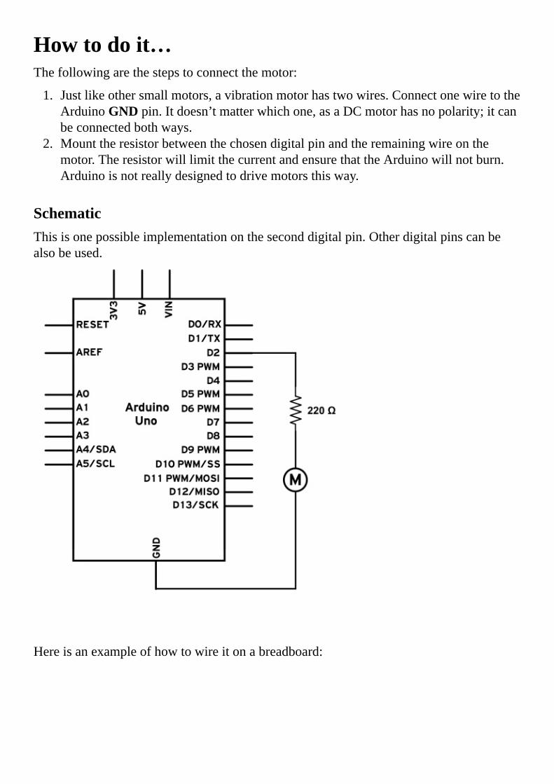
Howtodoit…Thefollowingarethestepstoconnectthemotor:
1. Justlikeothersmallmotors,avibrationmotorhastwowires.ConnectonewiretotheArduinoGNDpin.Itdoesn’tmatterwhichone,asaDCmotorhasnopolarity;itcanbeconnectedbothways.
2. Mounttheresistorbetweenthechosendigitalpinandtheremainingwireonthemotor.TheresistorwilllimitthecurrentandensurethattheArduinowillnotburn.Arduinoisnotreallydesignedtodrivemotorsthisway.
SchematicThisisonepossibleimplementationontheseconddigitalpin.Otherdigitalpinscanbealsobeused.
Hereisanexampleofhowtowireitonabreadboard:

CodeThefollowingcodewillstartthemotorfor1secondandthenstopitforanother:
//Declarethepinforthemotor
intmotorPin=2;
voidsetup()
//Definepin#2asoutput
pinMode(motorPin,OUTPUT);
voidloop()
//Turnmotoron
digitalWrite(motorPin,HIGH);
//Wait1000ms
delay(1000);
//Turnmotoroff
digitalWrite(motorPin,LOW);
//Waitanother1000ms
delay(1000);
TipIfthemotorisconnectedonadifferentpin,simplychangethemotorPinvaluetothevalueofthepinthathasbeenused.

Howitworks…WheneverwesetthepinatHIGH,currentwillflowfromthedigitalpinthroughtheresistor,throughthemotor,andtoground.Ifthemotorissmallenough,itwillstartspinningifit’sastandardDCmotor;elseitwillstartvibrating,ifitisavibrationmotor.
Theresistorisveryimportantinthiscircuit.EachArduinodigitalpincanonlyhandleupto40mA,with20mAastherecommendedmaximum.Thechosen220-ohmvaluewilllimitthecurrentto22mA,andbecausethemotorisinserieswithanotherresistor,thecurrentwillbeless.Ifthetotalresistanceofthemotorishigherthan200Ohmsthenit’ssafetoomittheresistoranddirectlyconnectthemotortothedigitalpinandGND.
There’smore…Inthisexample,we’veseenhowtoconnectonemotordirectlytoadigitalpin.Butwecanalsoconnectmorethanone.
MultiplemotorsMultiplemotorscanbeconnectedusingdifferentdigitalpinsontheArduinoboard.Forexample,pins2,3,and4canindependentlycontroldifferentmotors.EachdigitalpinontheArduinocancontrolonemotor.However,it’sgenerallyadvisednottodothis,asitwillincreasethecurrentpassingthroughtheArduinountilitburns.Let’slimitourselvestoonemotoronlywiththisimplementation.
ElectricalspikesEveryDCmotorisalsoaninductor.Whenwestopsupplyingthemotorwithcurrent,orwhenwespinthemotorbyhand,itwillgeneratehigh-voltageelectricspikes.Thiscaneasilyburnelectroniccomponents.Toavoidthis,weshouldconnectadiodefromthedigitalpinto5V,withthediodepointingto5V.Wheneverthemotorgeneratesaspike,thediodewillpassittothe5Vline,whichcantolerateit.Luckily,theArduinohasabuilt-inprotectiondiodeoneachpin.

SeealsoTheControllingmotorswithtransistorsrecipeTheControllingspeedwithPWMrecipeTheSpinningmotorsbothwaysrecipeTofindoutmoreaboutthedigitalpinsoftheArduino,takealookattheI/O-PortssectionintheATMega328Pmicrocontroller,foundinArduinoUnoathttp://www.atmel.com/images/Atmel-8271-8-bit-AVR-Microcontroller-ATmega48A-48PA-88A-88PA-168A-168PA-328-328P_datasheet_Complete.pdfTolearnindetailhowaDCmotorworks,visithttp://electronics.howstuffworks.com/motor.htm


ControllingmotorswithtransistorsWecancontrolamotorbydirectlyconnectingittotheArduinodigitalpin;however,anymotorbiggerthanacoinwouldkillthedigitalpinandmostprobablyburnArduino.Thesolutionistouseasimpleamplificationdevice,thetransistor,toaidincontrollingmotorsofanysize.
Here,wewillexplorehowtocontrollargermotorsusingbothNPNandPNPtransistors.

GettingreadyToexecutethisrecipe,youwillrequirethefollowingingredients:
AnArduinoboardconnectedtoacomputerviaUSBADCmotorAresistorbetween220ohmand10KohmAstandardNPNtransistor(BC547,2N3904,N2222A,TIP120)Astandarddiode(1N4148,1N4001,1N4007)
AllthesecomponentscanbefoundonwebsitessuchasAdafruit,Pololu,andSparkfun,orinanygeneralelectronicsstore.

Howtodoit…Thefollowingarethestepstoconnectamotorusingatransistor:
1. ConnecttheArduinoGNDtothelongstriponthebreadboard.2. ConnectoneofthemotorterminalstoVINor5VontheArduino.Weuse5Vifwe
powertheboardfromtheUSBport.Ifwewanthighervoltages,wecoulduseanexternalpowersource,suchasabattery,andconnectittothepowerjackonArduino.However,eventhepowerjackhasaninputvoltagerangeof7V–12V.Don’texceedtheselimitations.
3. ConnecttheotherterminalofthemotortothecollectorpinontheNPNtransistor.Checkthedatasheettoidentifywhichterminalonthetransistoristhecollector.
4. ConnecttheemitterpinoftheNPNtransistortotheGNDusingthelongstriporalongconnection.
5. MountaresistorbetweenthebasepinoftheNPNtransistorandonedigitalpinontheArduinoboard.
6. Mountaprotectiondiodeinparallelwiththemotor.Thediodeshouldpointto5Vifthemotorispoweredby5V,orshouldpointtoVINifweuseanexternalpowersupply.
SchematicThisisonepossibleimplementationontheninthdigitalpin.TheArduinohastobepoweredbyanexternalsupply.Ifnot,wecanconnectthemotorto5Vanditwillbepoweredwith5volts.

Hereisonewayofhookingupthemotorandthetransistoronabreadboard:
CodeForthecodingpart,nothingchangesifwecompareitwithasmallmotordirectlymountedonthepin.Thecodewillstartthemotorfor1secondandthenstopitforanotherone:
//Declarethepinforthemotor
intmotorPin=2;
voidsetup()
//Definepin#2asoutput
pinMode(motorPin,OUTPUT);
voidloop()
//Turnmotoron
digitalWrite(motorPin,HIGH);
//Wait1000ms
delay(1000);
//Turnmotoroff
digitalWrite(motorPin,LOW);
//Waitanother1000ms
delay(1000);
TipIfthemotorisconnectedtoadifferentpin,simplychangethemotorPinvaluetothevalueofthepinthathasbeenused.

Howitworks…Transistorsareveryneatcomponentsthatareunfortunatelyhardtounderstand.Weshouldthinkofatransistorasanelectricvalve:themorecurrentweputintothevalve,themorewateritwillallowtoflow.Thesamehappenswithatransistor;onlyhere,currentflows.Ifweapplyacurrentonthebaseofthetransistor,aproportionalcurrentwillbeallowedtopassfromthecollectortotheemitter,inthecaseofanNPNtransistor.Themorecurrentweputonthebase,themoretheflowofcurrentwillbebetweentheothertwoterminals.
WhenwesetthedigitalpinatHIGHontheArduino,currentpassesfromthepintothebaseoftheNPNtransistor,thusallowingcurrenttopassthroughtheothertwoterminals.WhenwesetthepinatLOW,nocurrentgoestothebaseandso,nocurrentwillpassthroughtheothertwoterminals.Anotheranalogywouldbeadigitalswitchthatallowscurrenttopassfromthecollectortotheemitteronlywhenwe‘push’thebasewithcurrent.
Transistorsareveryusefulbecause,withaverysmallcurrentonthebase,wecancontrolaverylargecurrentfromthecollectortotheemitter.Atypicalamplificationfactorcalledbforatransistoris200.Thismeansthat,forabasecurrentof1mA,thetransistorwillallowamaximumof200mAtopassfromthecollectortotheemitter.
Animportantcomponentisthediode,whichshouldneverbeomitted.Amotorisalsoaninductor;wheneveraninductoriscutfrompoweritmaygeneratelargevoltagespikes,whichcouldeasilydestroyatransistor.Thediodemakessurethatallcurrentcomingout

ofthemotorgoesbacktothepowersupplyandnottothemotor.

There’smore…Transistorsarehandydevices;hereareafewmorethingsthatcanbedonewiththem.
Pull-downresistorThebaseofatransistorisverysensitive.Eventouchingitwithafingermightmakethemotorturn.Asolutiontoavoidunwantednoiseandstartingthemotoristouseapull-downresistoronthebasepin,asshowninthefollowingfigure.Avalueofaround10Kisrecommended,anditwillsafeguardthetransistorfromaccidentallystarting.
PNPtransistorsAPNPtransistorisevenhardertounderstand.Itusesthesameprinciple,butinreverse.CurrentflowsfromthebasetothedigitalpinontheArduino;ifweallowthatcurrenttoflow,thetransistorwillallowcurrenttopassfromitsemittertoitscollector(yes,theoppositeofwhathappenswithanNPNtransistor).AnotherimportantpointisthatthePNPismountedbetweenthepowersourceandtheloadwewanttopowerup.Theload,inthiscaseamotor,willbeconnectedbetweenthecollectoronthePNPandtheground.

AkeypointtorememberwhileusingPNPtransistorswithArduinoisthatthemaximumvoltageontheemitteris5V,sothemotorwillneverreceivemorethan5V.Ifweuseanexternalpowersupplyforthemotor,thebasewillhaveavoltagehigherthan5VandwillburntheArduino.Onepossiblesolution,whichisquitecomplicated,hasbeenshownhere:

MOSFETsLet’sfaceit;NPNandPNPtransistorsareold.Therearebetterthingsthesedaysthatcanprovidemuchbetterperformance.TheyarecalledMetal-oxide-semiconductorfield-effecttransistors.NormalpeoplejustcallthemMOSFETsandtheyworkmostlythesame.Thethreepinsonanormaltransistorarecalledcollector,base,andemitter.OntheMOSFET,theyarecalleddrain,gate,andsource.Operation-wise,wecanusethemexactlythesamewayaswithnormaltransistors.Whenvoltageisappliedatthegate,currentwillpassfromthedraintothesourceinthecaseofanN-channelMOSFET.AP-channelistheequivalentofaPNPtransistor.
However,therearesomeimportantdifferencesinthewayaMOSFETworkscomparedwithanormaltransistor.NotallMOSFETscanbeproperlypoweredonbytheArduino.Usuallylogic-levelMOSFETswillwork.SomeofthefamousN-channelMOSFETsaretheFQP30N06,theIRF510,andtheIRF520.Thefirstonecanhandleupto30Aand60Vwhilethefollowingtwocanhandle5.6Aand10A,respectively,at100V.
Hereisoneimplementationofthepreviouscircuit,thistimeusinganN-channelMOSFET:

Wecanalsousethefollowingbreadboardarrangement:
DifferentloadsAmotorisnottheonlythingwecancontrolwithatransistor.AnykindofDCloadcanbecontrolled.AnLED,alightorothertools,evenanotherArduinocanbepoweredupbyanArduinoandaPNPorNPNtransistor.Arduinoception!

SeealsoTheControllingspeedwithPWMrecipe.Forgeneralandeasytousemotors,Solarboticsisquitenice.Visitthesiteathttps://solarbotics.com/catalog/motors-servos/.Forhigher-endmotorsthatpackquitesomepower,Pololuhasmadeanameforitself.Visitthesiteathttps://www.pololu.com/category/51/pololu-metal-gearmotors.


ControllingspeedwithPWMAmotorthatcanonlybeonoroffisnotthatuseful.Weneedtocontrolthespeedofamotorusingcode.Sometimes,wewantthemotorathalfspeed;sometimeswewantitfasterandsometimesslower.However,themotorisconnectedtoadigitalpin,whosevaluecaneitherbemaximumornothing.Howcanwemakethisclear1and0intosomethingin-between?WithPulseWidthModulationorPWM.

GettingreadyFollowingaretheingredientsneededforthisrecipe:
ADCmotorAresistorbetween220ohmand4,700ohmAstandardNPNtransistor(BC547,2N3904,N2222A,TIP120)oralogic-levelcompatibleMOSFET(IRF510,IRF520)Astandarddiode(1N4148,1N4001,1N4007)
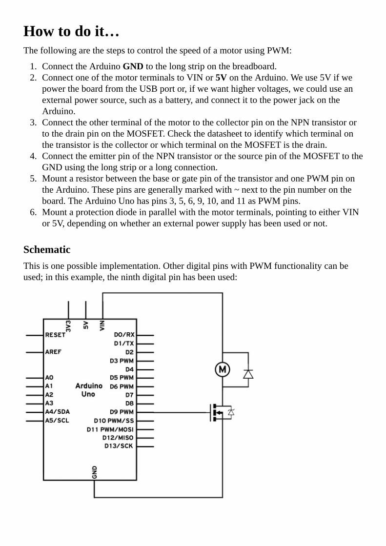
Howtodoit…ThefollowingarethestepstocontrolthespeedofamotorusingPWM:
1. ConnecttheArduinoGNDtothelongstriponthebreadboard.2. ConnectoneofthemotorterminalstoVINor5VontheArduino.Weuse5Vifwe
powertheboardfromtheUSBportor,ifwewanthighervoltages,wecoulduseanexternalpowersource,suchasabattery,andconnectittothepowerjackontheArduino.
3. ConnecttheotherterminalofthemotortothecollectorpinontheNPNtransistorortothedrainpinontheMOSFET.CheckthedatasheettoidentifywhichterminalonthetransistoristhecollectororwhichterminalontheMOSFETisthedrain.
4. ConnecttheemitterpinoftheNPNtransistororthesourcepinoftheMOSFETtotheGNDusingthelongstriporalongconnection.
5. MountaresistorbetweenthebaseorgatepinofthetransistorandonePWMpinontheArduino.Thesepinsaregenerallymarkedwith~nexttothepinnumberontheboard.TheArduinoUnohaspins3,5,6,9,10,and11asPWMpins.
6. Mountaprotectiondiodeinparallelwiththemotorterminals,pointingtoeitherVINor5V,dependingonwhetheranexternalpowersupplyhasbeenusedornot.
SchematicThisisonepossibleimplementation.OtherdigitalpinswithPWMfunctionalitycanbeused;inthisexample,theninthdigitalpinhasbeenused:

Hereisapossiblebreadboardimplementation:
CodeThefollowingcodewillstartthemotoratmaximumspeedandthengraduallyreduceitsspeeduntilitstopsit:
//Declarethepinforthemotor
intmotorPin=9;
voidsetup()
//PWMpinsdon'trequirethepinMode()function
voidloop()
//Turnmotorontomaximum
analogWrite(motorPin,255);
//Wait1000ms
delay(1000);
//Turnmotorto1/2power
analogWrite(motorPin,127);
//Wait1000ms
delay(1000);
//Turnmotoroff
analogWrite(motorPin,0);
//Wait1000ms
delay(1000);
TipIfthemotorisconnectedtoadifferentpin,simplychangethemotorPinvaluetothevalueofthepinthathasbeenused.However,ithastobeaPWM-enabledpin.

Howitworks…PWMisaclevertrickthatallowsadigitalpin,whichcanonlyoutput1or0,tosimulatevaluesin-between.Itworksbyswitchingthedigitalpinonandoffveryfast.Forexample,ifweswitchadigitalpinonfor1millisecondandoffforanothermillisecond,wewillbedoingthison-offcycle500timesasecond.Ifwehaveamotorconnectedtothepin,themotorwillspinathalfspeed.Why?Because,firstofall,weareactuallygivingitpowerhalfofthetime,sincethepinisofffor1millisecondevery2milliseconds.
Inpractice,thismeansweareturningitonandoff,butduetothehighfrequencyatwhichwearedoingit,theresultwillbeamotorwithhalfpower.This,ofcourse,doesn’tworkatlowfrequencies.Ifweturnthemotoronforasecondandoffforanotherone,theresultwillbeamotorthatistrulystartingandstopping;so,thehigherthefrequency,thebetter.
Thisdoesn’tmeanthatwecanonlyhavehalf-speed.Byvaryingthetimethatitisonandthetimeitisoff,wecanobtainmanyspeedvariations.AndthebestpartisthattheArduinohasaninbuiltlibrarytohandlethis.Thefollowingdiagramshowshowallofthisworksinamoregraphicway:
WecanseeinthefirstpartofthegraphicthatwearemostlykeepingthepinLOW,to0V,andthustheaveragevoltageoutputisquitelow.Inthemiddleofthegraphic,weareroughlykeepingthepinHIGHandLOWforanequalamountoftime,andtheresultingvoltageishalf.Inthelastpart,weseethatthetimethepinisHIGHiscalledPulseWidth.ThetotaltimebetweenthebeginningofeachpulseiscalledtheperiodofthePWMsignal.
AfewpinsontheArduinoarePWM-enabledandcanbeusedtogeneratethisPWMsignal.OnalmostallArduinos,thePWMpinsare3,5,6,9,10,and11.TheexceptionsaretheArduinoDueandMega,whichhavemorePWMsonpins2to13.
AlmostallArduinoscanoutput8-bitPWMsignalsatafrequencyof490HzExceptionsarethenewerboardssuchastheUnothat,forpins5and6,output980Hz.An8-bitPWM

meansthatwecanoutputalevelbetween0,whichistheequivalentofLOW,upto255,whichistheequivalentofHIGH.Themiddleisroughlyat127.
CodebreakdownThecodeusestheanalogWrite()function,whichoutputsaPWMsignalonaPWM-enabledpin,atthespecifiedlevel:
analogWrite(motorPin,127);
ThisfunctionwilloutputthePWMsignalatthevalueof127,whichisroughlyhalfofthe0–255range.Othervaluescanbeprovided,suchas85forone-thirdand170fortwo-thirds.
AverygoodthingtorememberisthattheanalogWrite()functionusedonPWM-compatiblepinswillnotusetheprocessorcontinuously.OncewecallanalogWrite()ataspecificlevel,thecodeexecutionwillcontinueandthePWMsignalwillbegeneratedcontinuously,untilstopped.ThisisaverygoodthingbecausewecanleaveallPWMatthelevelswewantandthenexecutetherestofthecodewithnointerruption.

There’smore…ThePWMpinsareveryuseful.Anyloadcanbecontrolledwiththem;forexample,LEDintensity,motors,orspeakers.InordertousemultiplePWMpins,intheanalogWrite()pinvalue,wejustneedtomodifythepinargumenttothepinwewanttochange.


SpinningmotorsbothwaysIt’sverysimpletocontrolamotorwithatransistor.However,spinningthemotorinjustonedirectionisnotalwaysthatuseful.It’sjusthalfofwhatispossible.MostDCmotorscanspinbothways.Whenweapplythevoltageinonedirection,themotorwillspinononeside.Ifwereversethevoltageontheterminals,themotorwillspintheoppositeway.ButhowcanwedothatwiththeArduino?WeneedtouseanH-Bridge.

GettingreadyFollowingaretheingredientsrequiredforthisrecipe:
AnArduinoboardconnectedtoacomputerviaUSBAnArduino-compatiblemotorshield;thereisanofficialArduinomotorshieldandafewotheroptionsfromdifferentcompaniessuchasSparkfun,Pololu,orAdafruitADCmotor

Howtodoit…ArduinoshieldsareveryusefulbecausetheycansimplybepluggedintotheArduinoandeverythingisalreadymade.Wedon’tneedtospendalotoftimeroutingwirestobreadboardsandtesting.Everythingjustworks.
Thefollowingarethestepstoconnectamotorusingamotorshield:
1. PlugthemotorshieldintotheArduino.2. Connectthetwowireterminalsofthemotortooneofthemotorterminalports.
HereisaschematicofthelogicalconnectionsneededbetweentheArduinoandtheshield.Inthisexample,weareonlyusingtwoofthesixpinstocontrolonemotor.
Thisisaviewoftheshieldconnectedtothemotorandthemotorconnectedtotheshield:

CodeThefollowingcodewilldefineamotorcontrolfunctionandwilluseittospinthemotorforwardathalfspeed,fullspeed,andthenstop;themotorwillthenreverseathalfspeed,reverseatfullspeed,andstopagain:
//Declaretheusedpins
intdirectionPin=12;
intpwmPin=3;
voidsetup()
//SetthedirectionPinasOUTPUT
pinMode(directionPin,OUTPUT);
//PWMpinsdon'trequirethepinMode()function
//Customfunctionwhichcontrolsthespeedanddirectionusingone
variable.
voidsetMotor(intval)
//Ifvalisfrom0to255themotorwillspinforwards
if(val>=0)
//Setthedirection
digitalWrite(directionPin,HIGH);
//Setthespeed
analogWrite(pwmPin,val);
//Ifthevalueisfrom-255to0themotorwillspinbackwards
if(val<0)
//Setthedirection
digitalWrite(directionPin,LOW);
//Setthespeed,-valbecausethevalueisnegativeandpositiveis
requried

analogWrite(pwmPin,-val);
voidloop()
//Turnmotoronhalfspeedforwards
setMotor(127);
delay(1000);
//Motorfullspeedforwards
setMotor(255);
delay(1000);
//Motorstop
setMotor(0);
delay(1000);
//Motorhalfspeedbackwards
setMotor(-127);
delay(1000);
//Motorfullspeedbackwards
setMotor(-255);
delay(1000);
//Motorstop
setMotor(0);
delay(1000);
TipTherearemultipletypesofmotorshieldsfortheArduino.ThepresentedcodewillonlycontrolonemotorontheofficialArduinoMotorShield.VariationshavebeenprovidedintheThere’smore…sectionofthisrecipe.

Howitworks…Inordertospinamotortwoways,weneedacircuitcalledtheH-bridge.Itiscomposedoffourtransistorsthatcontrolthecurrentdirectionthroughthemotor.However,thiscircuitisquitecomplicatedandit’sveryeasytoaccidentallyburnit.ThegoodnewsisthatthereareintegratedcircuitsthatalreadyimplementthisH-bridgeconceptandaddsafetyfeaturessuchasshortprotection,over-currentprotection,andover-temperatureshutdown.
Forthepurposeofthisrecipe,wewillnotdiscussindepthhowtheH-bridgeworks;thatwillbecoveredinafurtherrecipe.Infact,therearesomanymotorshieldsandmotordriversouttherethatmostprobablywewillneverneedtoimplementafullH-bridgebyourselves.
However,therearesomevariationsevenintheshieldsthatarecommonlyused.Someuseonlyonepintocontrolthedirectionandspeedofamotor,someusetwo,somethreeandsomeevenfour.Somedriverscanhandleonemotor;somecanhandletwomotors.Next,wewillbreakdownthecodetocontrolonemotorontheArduinoMotorDriverShield.
CodebreakdownThecodedefinesthetwopinsrequiredtocontrolonemotor.Oneisthedirectionpin,whichsetsthedirectionofthemotor.WhenitisHIGH,themotorwillspinoneway,andwhenitisLOW,theotherway.TheotherpinisthePWMpinthatcontrolsthespeedofthemotor.If,forexample,wesetthedirectionpintoHIGHandspeedto127,themotorwillturnonedirectionwithroughlyhalfthespeed.IfwethenchangethedirectionpintoLOW,itwillreverseitsdirectionandmaintainroughlyhalfthespeed.
Inthesetup()function,wedeclaredirectionPinasanoutput.PWMpinsdon’tneedtobedeclared:
voidsetup()
//SetthedirectionPinasOUTPUT
pinMode(directionPin,OUTPUT);
//PWMpinsdon'trequirethepinMode()function
ThecustomsetMotor()functiontakesoneargument:thespeedofthemotor.Ifthespeedisbetween0and255,themotorwillspinforwardwiththerespectivespeed.For0,itwillnotmoveofcourse.Ifthevalueisfrom-1to-255,themotorwillspinbackwardswithapowerof1to255.
Wedothisusingasimpleifstatement.Ifthevalueisover0,wesetthedirectionpinasHIGHandsetthespeeddirectly:
//Customfunctionwhichcontrolsthespeedanddirectionusingone
variable
voidsetMotor(intval)
//Ifvalisfrom0to255themotorwillspinforwards
if(val>=0)
//Setthedirection
digitalWrite(directionPin,HIGH);

//Setthespeed
analogWrite(pwmPin,val);
Butifthespeedisnegative,wesetthedirectionpinasLOWandthenweuseasimpletrickfortheanalogWrite()function.Itdoesn’tacceptnegativevalues,butbyputtingaminussignbeforethevalue,wereversethesign.Thisway,-valwillequalthepositivepartofvalwhenvalisnegative:
//Ifthevalueisfrom-255to0themotorwillspinbackwards
if(val<0)
//Setthedirection
digitalWrite(directionPin,LOW);
//Setthespeed,-valbecausethevalueisnegativeandpositiveis
requried
analogWrite(pwmPin,-val);
Then,intheloop()function,wejusttestourcustomfunctionbyturningthemotorindifferentdirections.Thecommentsexplainbestwhatishappening.

There’smore…TheArduinoMotorShieldcancontroltwomotorsatthesametime.Also,itisnottheonlyshieldonthemarketthatcancontrolmotors.Actually,therearehundredsofmotorshieldsandmotordrivers.TheyallsharethesameH-Bridgeprincipleandsotheyareallcontrolledinsimilarways.Here,wewillexploreafewtypicalconfigurationsandunderstandhowtoadjustoursetMotor()functiontobecompatiblewithothermotors.
Controlusingthedirectionpin,PWMpin,andbrakepinTheArduinoMotorShieldusesonedirectionandonePWMpin.Anditisnottheonlyonetodoso;theSparkfunArdumotoshieldhasidenticalpinmappings.Thepinsareasfollows:
Function PinforMotorA PinforMotorB
Directionpin 12 13
PWMpin 3 11
Brakepin 9 8
Now,whatisthebrakepin?TheArduinoMotorShieldhasthispinthat,whenturnedHIGH,willstopthemotor.WecanadjustoursetMotor()functionwiththisnewfeatureasfollows:
voidsetMotor(intval)
//Ifvalis0brakingwillbeapplied
if(val==0)
//Startbraking
digitalWrite(brakePin,HIGH);
//Ifvalisfrom1to255themotorwillspinforwards
if(val>0)
//Setthedirection
digitalWrite(directionPin,HIGH);
//Setthespeed
analogWrite(pwmPin,val);
//Stopthebraking
digitalWrite(brakePin,LOW);
//Ifthevalueisfrom-255to0themotorwillspinbackwards
if(val<0)
//Setthedirection
digitalWrite(directionPin,LOW);
//Setthespeed,-valbecausethevalueisnegativeandpositiveis
requried
analogWrite(pwmPin,-val);
//Stopthebraking
digitalWrite(brakePin,LOW);

NowwecanusethesetMotor()function,andwhenwewanttobrake,wesimplyneedtopass0asthemotorspeed.
ControlusingInputA,InputB,andPWMTherearesomanyvariations,butthisisapopularone.ItusestwodigitalpinsfordirectionandoneforPWM.ThisonlyusesonePWMpinwhiletheothertwocanbedigital.
Buthowdowemakethedrivergoforward,backward,orevenbrake?Hereisareferencetable:
InputA InputB Result
0 0 Lowbrake
0 1 Forward
1 0 Backward
1 1 Highbrake
Highsideandlowsidebrakingareinterestingconcepts.Inhighsidebraking,bothmotorterminalsareconnectedtothepowersupply,whileinlowsidebraking,bothareconnectedtoground.Thiswillmakethemotorbrake.
Howdowecontrolthespeed?WecanusethePWMinput.WithInputAandB,wesetthedirection,andwithPWM,thespeed.Nowwecanstopthemotorbyeithersendinga0or11ontheABpins,orbyjustwriting0tothePWM.HereisoursetMotor()functionforthisconfiguration:
voidsetMotor(intval)
//Ifvalis0brakingwillbeapplied
if(val==0)
//Startbraking
digitalWrite(pinA,LOW);
digitalWrite(pinB,LOW);
//Ifvalisfrom1to255themotorwillspinforwards
if(val>0)
//Setthedirection
digitalWrite(pinA,LOW);
digitalWrite(pinB,HIGH);
//Setthespeed
analogWrite(pwmPin,val);
//Ifvalueisfrom-255to-1themotorwillspinback
if(val<0)
//Setthedirection
digitalWrite(pinA,HIGH);
digitalWrite(pinB,LOW);
//Setthespeed
analogWrite(pwmPin,-val);

SomedriversalsohaveanenablepinwhichweneedtoeithersetasHIGHorLOWinordertoenablethemotor.Sometimes,thesedriversareactuallymissingthePWMpinbuthaveanenablepin.ByapplyingPWMtoit,wecanobtainthesameresult.
Custom-madeL293DdriverThisoneisforthebrave!WecanbuildourownH-bridgedriverusingthefamousL293DH-bridgedriver.Whenwedon’treallyhavespace,wecanmakeourcustomelectronicsboardwiththefollowingschematic,whichcontrolstwomotors:
Butifwewanttoimplementitonthebreadboard,thisisonepossibleway:

ThereisanotherIntegratedCircuit(IC)thatfunctionsidenticaltoL293D;heck,itevenlooksthesame—allthepinsarethesame.It’salittlecheaper,andit’scalledSN754410.

SeealsoWheneverweareusinganIC,weshouldcheckitsdatasheet.YoucanfindthedatasheetforL293Dathttp://www.ti.com/lit/ds/symlink/l293d.pdf


ServomotorServomotorsaregreatdevicesthatcanturntoaspecifiedposition.Usually,theyhaveaservoarmthatcanturn180degrees.UsingtheArduino,wecantellaservotogotoaspecifiedpositionanditwillgothere.Assimpleasthat!
ServomotorswerefirstusedintheRemoteControl(RC)world,usuallytocontrolthesteeringofRCcarsortheflapsonaRCplane.Withtime,theyfoundtheirusesinrobotics,automation,andofcourse,theArduinoworld.
Herewewillseehowtoconnectaservomotor26andthenhowtoturnittodifferentpositions.
ThefirstmotorIeverconnectedtoanArduino,sevenyearsago,wasaServomotor.Nostalgicmomentover,backtowork!

GettingreadyForthisrecipe,youwillneedthefollowingingredients:
AnArduinoboardconnectedtoacomputerviaUSBAservomotorJumperwires
Therearefewbignamesintheservomotorworld.HitehandFutabaaretheleadingRCservomanufacturers.GoodplacestobuythemareServocity,Sparkfun,andHobbyking.

Howtodoit…Aservomotorhaseverythingbuiltin:amotor,afeedbackcircuit,andmostimportant,amotordriver.Itjustneedsonepowerline,oneground,andonecontrolpin.
FollowingarethestepstoconnectaservomotortotheArduino:
1. Theservomotorhasafemaleconnectorwiththreepins.Thedarkestorevenblackoneisusuallytheground.ConnectthistotheArduinoGND.
2. Connectthepowercablethatinallstandardsshouldberedto5VontheArduino.3. ConnecttheremaininglineontheservoconnectortoadigitalpinontheArduino.
ThisisaviewoftheservomotorconnectedtotheArduino:
CodeThefollowingcodewillturnaservomotorto0degrees,wait1second,thenturnitto90,waitonemoresecond,turnitto180,andthengoback.
//IncludetheServolibrary
#include<Servo.h>
//DeclaretheServopin
intservoPin=3;
//Createaservoobject
ServoServo1;
voidsetup()
//Weneedtoattachtheservototheusedpinnumber
Servo1.attach(servoPin);

voidloop()
//Makeservogoto0degrees
Servo1.write(0);
delay(1000);
//Makeservogoto90degrees
Servo1.write(90);
delay(1000);
//Makeservogoto180degrees
Servo1.write(180);
delay(1000);
TipIftheservomotorisconnectedonanotherdigitalpin,simplychangethevalueofservoPintothevalueofthedigitalpinthathasbeenused.

Howitworks…Servosarecleverdevices.Usingjustoneinputpin,theyreceivethepositionfromtheArduinoandtheygothere.Internally,theyhaveamotordriverandafeedbackcircuitthatmakessurethattheservoarmreachesthedesiredposition.Butwhatkindofsignaldotheyreceiveontheinputpin?
ItisasquarewavesimilartoPWM.Eachcycleinthesignallastsfor20millisecondsandformostofthetime,thevalueisLOW.Atthebeginningofeachcycle,thesignalisHIGHforatimebetween1and2milliseconds.At1milliseconditrepresents0degreesandat2millisecondsitrepresents180degrees.Inbetween,itrepresentsthevaluefrom0–180.Thisisaverygoodandreliablemethod.Thefollowinggraphicmakesitalittleeasiertounderstand:
RememberthatusingtheServolibraryautomaticallydisablesPWMfunctionalityonPWMpins9and10ontheArduinoUNOandsimilarboards.
CodebreakdownThecodesimplydeclarestheservoobjectandtheninitializestheservobyusingtheservo.attach()function.Weshouldn’tforgettoincludetheservolibrary.Intheloop(),wesettheservoto0degrees,wait,thensetitto90,andlaterto180degrees.

There’smore…Controllingservosiseasy,andhereareafewmoretrickswecanuse.
ControllingtheexactpulsetimeArduinohasabuilt-infunctionservo.write(degrees)thatsimplifiesthecontrolofservos.However,notallservosrespectthesametimingsforallpositions.Usually,1millisecondmeans0degrees,1.5millisecondsmean90degrees,and,ofcourse,2millisecondsmean180degrees.Someservoshavesmallerorlargerranges.
Forbettercontrol,wecanusetheservo.writeMicroseconds(us)function,whichtakestheexactnumberofmicrosecondsasaparameter.Remember,1millisecondequals1,000microseconds.
MoreservosInordertousemorethanoneservo,weneedtodeclaremultipleservoobjects,attachdifferentpinstoeachone,andaddresseachservoindividually.
First,weneedtodeclaretheservoobjects—asmanyasweneed:
//Createservoobjects
ServoServo1,Servo2,Servo3;
Thenweneedtoattacheachobjecttooneservomotor.Remember,everyservomotorusesanindividualpin:
Servo1.attach(servoPin1);
Servo2.attach(servoPin2);
Servo3.attach(servoPin3);
Intheend,wejusthavetoaddresseachservoobjectindividually:
Servo1.write(0);//SetServo1to0degrees
Servo2.write(90);//SetServo2to90degrees
Connection-wise,thegroundsfromtheservosgotoGNDontheArduino,theservopowerto5VorVIN(dependingonthepowerinput),andintheend,eachsignallinehastobeconnectedtoadifferentdigitalpin.Contrarytopopularbelief,servosdon’tneedtobecontrolledbyPWMpins—anydigitalpinwillwork.
ContinuousrotationservosThereisaspecialbreedofservoslabelledascontinuousrotationservos.Whileanormalservogoestoaspecificpositiondependingontheinputsignal,acontinuousrotationservoeitherrotatesclockwiseorcounter-clockwiseataspeedproportionaltothesignal.Forexample,theServo1.write(0)functionwillmaketheservomotorspincounter-clockwiseatfullspeed.TheServo1.write(90)functionwillstopthemotorandServo1.write(180)willturnthemotorclockwiseatfullspeed.
Therearemultipleusesforsuchservos;however,theyarereallyslow.Ifyouarebuildingamicrowaveandneedamotortoturnthefood,thisisyourchoice.Butbecareful,

microwavesaredangerous!

SeealsoAservomotorofferseaseofusewithhighprecisionandpower.However,thereareothermotortypesofferingthesameandtheyevenhavefullcontinuousrotation.TheSteppermotorrecipetalksaboutthemindetail.


SteppermotorWhenweneedprecisionandrepeatability,asteppermotorisalwaysthesolution.Withthewayitisdesigned,asteppercanonlymovefromonesteptothenextandfixinthatposition.Atypicalmotorhas200stepsperrevolution;ifwetellthemotortogo100stepsinonedirection,itwillturnexactly180degrees.Itgetsinterestingwhenweonlytellittogoonestepanditturnsexactly1.8degrees.
Steppermotorsarefoundinprinters,scanners,industrialrobotarms,3Dprinters,andprettymuchineveryprecisionmotiondevice.
Therearetwotypesofsteppermotors:unipolarandbipolar.Unipolarmotorsareeasiertocontrolwhilebipolarmotorsaremorepowerful.
Inthisrecipe,wewillseehowtoconnectaunipolarsteppermotorusingacommonintegratedcircuit.

GettingreadyThefollowingaretheingredientsrequiredtoexecutethisrecipe:
AnArduinoboardconnectedtoacomputerviaUSB.AbreadboardandjumperwiresAunipolarsteppermotor.AULN2003AorULN2004DarlingtonArrayIntegratedCircuit.JustrememberULN2003AorULN2004;theyarebasicallyseventransistorsstackedtogetherinaconvenientpackage.
WecantypicallybuySteppermotorsfromSparkfun,Pololu,Adafruit,commonelectronicsstores,oreventakethemoutfromoldprinters.

Howtodoit…WeimplementasimplecircuitinwhichweonlyneedtheArduino,theULNIConabreadboard,andtheUnipolarsteppermotor,inthefollowingmanner:
1. ConnecttheArduinoGNDtoalongstriponthebreadboard.2. ConnecttheULN2003ortheULN2004tothecenterofthebreadboard.3. Connectpins1to4—thefirstfourpinsontheleftoftheIC—tofourdigitalpinson
theArduino.4. Thesteppermotorhassixwires.Twoarethecenterofeachwinding.Weneedto
identifythesecenters.Thesimplestwayistotakeamultimeterandusetheresistancemode.Sincethecenterpinisbetweentwoidenticalwindings,ithastogiveanequalresistancewitheitherone.Soifwetestallcablecombinations,whenwefindawirewithequalresistancetotheothertwo,wehavefoundacenter.Whenwefindboth,weconnectthemtogethertopin9ontheIC.
5. WeconnecttheotherfourcablesonthestepperdirectlytotheoutputoftheIC;inthiscase,pins13to16.
6. Nowweneedtoconnectthepowersupply.Ifwepowerthestepperfromthebuilt-in5V,weconnect5Vtothecommonpin—pin9ontheIC.Ifweuseanexternalpowersupply,wecanconnectthepositiveterminalthereorconnectpin9totheVIN,iftheArduinoispoweredfromanexternalpowersupply.
7. Lastly,weconnectgroundtotheIC.Connectthe0Vpin,pin8totheGNDstripwemadeearlierinstep1.
SchematicThisisonepossibleimplementation.Otherpinscanalsobeused.TheCOMpincanbeconnectedto5Voranexternalpowersupply.

Hereisapossiblebreadboardimplementation:
CodeThefollowingcodewillspinaunipolarstepper180degreesinonedirectionandthenback:
//IncludetheStepperlibrary
#include<Stepper.h>
//DeclareaSteppermotorwith200steps
//connectedonpins2,3,4,5
//Syntax:stepper1(stepsPerRevolution,pin1,pin2,pin3,pin4)
Stepperstepper1(200,2,3,4,5);
voidsetup()
//SetthespeedofthestepperinRPM
stepper1.setSpeed(60);
voidloop()
//Turnthestepper100stepswhichmeans180degrees
stepper1.step(100);
//Waithalfsecond
delay(500);
//Turnthestepper100stepsback
stepper1.step(-100);
//Waithalfsecond
delay(500);
TipOtherdigitalpinscanbeusedwhendeclaringthesteppermotor.Also,otherspeedscanbetried.However,keepinmindthatsteppermotorsarenotverygoodwithspeed.

Howitworks…SteppermotorsdifferfromnormalDCmotorsinthat,ratherthanjustspinninginonedirectionoranother,theymoveinsmallincrementsinagivendirection.Thesesmallincrementsarecalledsteps.Wecantellasteppertogooneormorestepsinoneparticulardirection.Theyarenotnecessarilyfast,buttheyhavehighprecisionandquitesometorque.Forexample,thepaperfeederonaprinterusesasteppermotor.3DprintersandCNCmachinesusethemforveryhighprecisionandrepeatability.
Luckily,theArduinohasabuilt-inlibrarytocontrolunipolarsteppermotors.Andtheyareveryeasytocontrolindeed.
CodebreakdownThecodedeclaresasteppermotor,selectsaspeed,andmakesitturninbothdirections.
Here,wedeclarethesteppermotor.Thesyntaxrequiresthenumberofstepsofthemotorasthefirstparameterandthenthefourpinstowhichweconnectedthemotor:
Stepperstepper1(200,2,3,4,5);
Anotherimportantstepisdeclaringthespeedatwhichwewantthemotortoturn.If,forexample,wesetaspeedof60RPMasinthiscase,andthemotorhas200steps,itwilltakearound5millisecondstoincrementonestep.Thespeedofthemotorcanbechangedatanytime.
stepper1.setSpeed(60);
Lastly,tomakethemotormove,weneedtoorderthenumberofstepstoincrement.Ifwefeedanegativenumberofsteps,itwillmoveintheoppositedirection.Notethatthestep()functionwillpausetheexecutionoftheprogramuntilthemotorspinscompletely.If,forexample,weset200stepsataspeedof1RPM,itwilltakeonefullminuteuntiltheArduinowillcontinueexecution.
stepper1.step(-100);
NoteArduinoassumesthesteppermoveswhileitordersittomove.Thestepperhasnofeedbackcircuit,soifweholdtheshaftofthemotor,theArduinowillbelieveitismovingthoughthesteppermightnotbemoving.

There’smore…TheULN2003AandULN2004integratedcircuitsareveryusefullittledevices,especiallywhenwecontrolunipolarsteppermotors,astheyhaveeverythingbuiltin—thetransistor,thediode,andeverythingelse.However,ifit’sreallyneeded,wecanjustusefourtransistors,fourdiodes,andfourresistorstospinaunipolarmotor.
TransistorunipolarstepperdriverHereisonepossibleimplementationofacustomunipolarstepperdriver.WecanuseanystandardNPNtransistor.Darlingtonpairsarepreferred,suchastheTIP120,TIP121,or2N6045.Rememberthatsteppermotorsusequitealotofcurrent,usuallyintherangeof2–5A,sothechosentransistorhastobeabletohandleit.Hereisonerecommendedimplementation:
IdentifyingthesteppermotortypeTherearemultiplesteppermotortechnologies.Thisisasimpleguideonidentifyingthetype.Afour-cablesteppermotorisusuallybipolar.Withsixcables,itismostprobablyunipolarwherethetwocentercoilcableshavetobeconnectedtogether.Therearesomeversionswithonlyfivecablesthatarealsounipolarandalreadyhavethetwocentercoilsconnectedtogetherinternally.Also,therearesteppermotorswitheightcables,buttheyareincrediblyrare.Theyarealsounipolarandthefourcentercableshavetobeconnectedtogether.

SeealsoFindacomprehensivetutorialonsteppermotorsathttps://learn.adafruit.com/all-about-stepper-motors/what-is-a-stepper-motor


BipolarsteppermotorsUnipolarsteppermotorsareeasytocontrolatthecostoflowefficiencyandpower.Bipolarsteppermotorshavemuchhigherefficiencyandtorque;howevertheyaremuchhardertocontrol.Tofullycontrolone,twoH-bridgesarerequired.LuckilytherearemultipleArduino-compatiblebipolarstepperdriversoutthere.Herewewillexploreafewoptions.

GettingreadyWecancontrolabipolarsteppermotorusingtheArduinoMotorShield.Herearetheingredientsneededforthisrecipe:
AnArduinoboardconnectedtoacomputerviaUSBAnArduinoMotorShieldAbipolarsteppermotor

Howtodoit…Weconnectthesteppermotortotheshieldusingthefollowingsteps:
1. CarefullymounttheArduinoMotorShieldontopoftheArduino.Becarefulnottobendanypins.
2. Identifythetwocoils.Useamultimetertomeasuretheresistancebetweenallthewires.Theoneswithalowresistanceinbetweenarethecoils.
3. ConnectthefourstepperwirestothemainterminaloutputoftheShield.Onecoilgoestoonemotoroutputandtheotheronetotheotheroutput.
Here’showitshouldlook:
CodeThefollowingcodewillspinthesteppermotor100stepsinonedirectionand100stepsintheother:
//IncludetheStepperlibrary
#include<Stepper.h>
//Declaretheusedpins
intdirA=12;
intdirB=13;
intpwmA=3;
intpwmB=11;
//DeclareaSteppermotorwith200steps
Stepperstepper1(200,dirA,dirB);
voidsetup()
//PWMpinsrequiredeclarationwhenusedasDigital
pinMode(pwmA,OUTPUT);

pinMode(pwmB,OUTPUT);
//SetPWMpinsasalwaysHIGH
digitalWrite(pwmA,HIGH);
digitalWrite(pwmB,HIGH);
//Setsteppermotorspeed
stepper1.setSpeed(60);
voidloop()
//Turnthestepper100stepswhichmeans180degrees
stepper1.step(100);
//Waithalfsecond
delay(500);
//Turnthestepper100stepsback
stepper1.step(-100);
//Waithalfsecond
delay(500);

Howitworks…Abipolarsteppermotoronlyhastwocoilswithnocentertap,incontrasttoaunipolardesign.Thismeansthatthecoilshavetobeturnedoninbothdirectionsatdifferenttimes.Asacomparison,abipolarstepperisexactlyliketwoDCmotorswhichalwayshavetobecontrolledintheoppositedirectionatthesametime.Whenonecoilisexcitedinonedirection,theotheronehastobereversed.Byshiftingthis,wegenerateapulsewhichmakesthestepperspin.
CodebreakdownOnlythedifferencesfromthepreviousunipolarstepperrecipewillbeexplainedhere.Thecodewilldothesame—itwillturnthemotor100stepsinonedirectionandtheninreverse.
WeonlyneedtodeclarethetwodirectionpinsoftheArduinoMotorShield.AsexplainedintheSpinningmotorsbothwaysrecipe,thedirectionpinsetswhichdirectionthecoilwillbeexcitedin.
Stepperstepper1(200,dirA,dirB);
ThetwoPWMpinsselecthowmuchpowerweattributetothecoils.However,asthisisastepper,wealwayswantfullpower;sowewillsimplifyanddirectlysetthePWMpinsalwaysasHIGH:
//PWMpinsrequiredeclarationwhenusedasDigital
pinMode(pwmA,OUTPUT);
pinMode(pwmB,OUTPUT);
//SetPWMpinsasalwaysHIGH
digitalWrite(pwmA,HIGH);
digitalWrite(pwmB,HIGH);

There’smore…Bipolarsteppersarethemostcommonbreed.Theyarehighlyefficientandpowerfulatthepriceofhavingcomplexdrivers.Andtherearealotofdriversforthem,waytoomanytobecovered.Eachonehasadifferentinputtype.Thebestadviceistocheckafewwell-knownstepperdriverproducerssuchasSparkfun,Pololu,orAdafruit.Theyofferguidesforeachoftheirstepperdrivers,andtheseareusuallyveryeasytouse.


BrushlessmotorsLet’stalkalittleabouttheedgeofelectricmotors.Atypicalelectricmotorhasarotor,astator,andbrushes.Thebrushestransmittheelectricalcurrenttotherotor,thusspinningthemotor.Thedrawbackofthebrushesisthattheycontinuouslyrubonthecommutator.Asananalogy,imaginedrivingacarwiththebreakspartiallypressed.That’swhatthebrushesdotothemotor.However,thereisasolution!
Brushlessmotors,asthenameimplies,donothaveanybrushes.Thismeanstheyaremuchmoreefficient,theylastlonger,andtheyaremorepowerful.Butofcoursethereisadrawback;theyrequirecomplicatedcontrol.Luckily,brushlessmotorshavefoundtheirwayintotheremote-controlledworldandwecannowfindcheapandusefulbrushlessmotorsandbrushlessmotorcontrollersorElectronicSpeedControl(ESC).

GettingreadyTomakethisrecipework,wewillneedafewbasicthings:
AnArduinoboardconnectedtoacomputerviaUSB.AnRCbrushlessmotor,whichisavailableintwotypes—inrunnersandoutrunners.InrunnerslooksimilartoanormalDCmotorbuttheyrunatveryhighspeeds,whileoutrunnersarewiderandshorter,and—waitforit—theircaserotates,notthecenterofthemotor.Isn’tthatstrange?WecanfindbrushlessmotorsinanyRCmodelstore.SomefamousstorestheyaresoldinareConradforEuropeandHobbykingforUSAandworldwide.AbrushlessmotordriverorESC,Careful!ThereareESCsforstandardDCmotors—notmany—butthereare.AquickwaytodetermineifanESCisforbrushlessmotors(otherthanreadingthedescription)istocheckhowmanyoutputcablesithas.Ifithasthreecables,itisforbrushlessmotors.Otherwise,keepsearching.Theycanbefoundatanystorethatsellsbrushlessmotors.

Howtodoit…AbrushlessmotordriverusesthesamestandardconnectorandsignalasanRCservo.Herearethestepstoconnecteverything:
1. ConnectthethreewiresofthemotortothethreeoutputwiresoftheESC.2. TheESCneedspower,andbrushlessmotorsareveryhungry!Itisrecommendedto
usealithium-ionorlithiumpolymerbattery,designedforhighloads,inordertocontrolsuchmotors.Don’tbemisledbythe9Vbatteryinthegraphic.
3. Lastly,connectthecontrolwiretotheArduino.Remember,ESCsusethesamestandardconnectorandsignalasanyRCservo.Wemayomitthered,5Vconnection,asESCsarepoweredbythebattery.AneatthingtorememberisthatmostESCshaveinternal5Vregulators,calledBatteryEliminationCircuit(BEC).ThismeanswecanpowerupArduinofromtheESC,byconnectingthe5VoutputoftheESCtothe5VlineontheArduino.
Here’showitshouldlook:
CodeThefollowingcodewillarmtheESCandthenstartthemotorfor5seconds,stopitforanotherfive,anddothatagainandagainandagain:
//IncludetheServolibrary
#include<Servo.h>
//DeclaretheServopinfortheESC
intservoPin=3;
//Createaservoobject
ServoServo1;

voidsetup()
//Weneedtoattachtheservototheusedpinnumber
Servo1.attach(servoPin);
//ArmtheESC,apulsebetween0.7-1msusuallywilldo
Servo1.writeMicroseconds(700);
delay(3000);//LeavesometimetoarmtheESC
voidloop()
//Startthemotoraquarterspeed
Servo1.write(64);
delay(5000);//Wait5seconds
//Stopthemotorfor5seconds
Servo1.write(0);
delay(5000);

Howitworks…Brushlessmotorsandbrushlessmotorcontrolarequiteadvancedtopics.TakealookattheSeealsosectionformoredetailsonthese.However,wedon’treallyneedtounderstandhowtheyworkinordertousethem.That’swhatArduino’sallabout:makingthingssimple.
BrushlessmotorcontrollersorESCsusethesamestandardasanRCservo.Ifweapplyapulsewithadurationof1millisecond,or0degrees,intheServo.write()function,thecontrollerwillstopthemotor.Apulseof2milliseconds,or180degrees,willresultinmaximumpower.Valuesinbetweenwillresultinmotorspeedsinbetween.
Becausebrushlessmotorsarequitepowerful,everyESChastobefirstarmedinordertoallowthemotortodoanything.Todothis,wesendapulsewithaverylowduration,somewherebetween0.7–1millisecondforaround3seconds.Whenthecontrollerarmsthemotor,itwillstartbuzzingafewtimes.Afterthat,allthepowercanbeunleashed.
CodebreakdownThecodeisverysimilartotheservomotorcode,asbothusethesamestandard.Onedifferenceisinthearming,asshownhere:
voidsetup()
Servo1.attach(servoPin);
//ArmtheESC
Servo1.writeMicroseconds(700);
delay(3000);//LeavesometimetoarmtheESC
Weneedtooutputashortpulseforaround3secondsinordertoarmthemotor.WedothisusingtheServo1.writeMicroseconds(700)function,whichoutputsa700-microsecondpulse.
Oncethemotorisarmed,wecancontrolitusingstandardServo1.write()commands.

SeealsoTounderstandhowabrushlessmotorworks,finedagreatexplanationinthisvideoathttps://www.youtube.com/watch?v=bCEiOnuODac


Chapter6.MoreOutputDevicesInthischapter,wewillcoverthefollowingtopics:
CreatingsoundTransistordriverRelaydriverOptocouplers/OptoisolatorsMoreoutputs–shiftregisters

IntroductionInthischapter,wewilllookoversomemoregeneralapplicationsofArduinooutputs.Sometimes,wedon’thaveenoughdigitalpinsforourproject,butwecanextendthatusingshiftregisters!Also,wecantrymakingsomemusicbyjustaddingaspeaker.ButwhatifweneedtoconnectanACcircuittotheArduino?Alltheanswers,andmore,canbefoundinthischapter.


CreatingsoundSoundisaverypowerfuloutputthatisusuallytakenforgranted.WeseethingssuchasLEDs,wefeelthingssuchasmotors,butwealsohear.ArduinohasanicelittlelibrarycalledTonethataidsingeneratingsoundsatspecificfrequencies.Forpeoplepassionateaboutmusic,wecanactuallyplaymonophonicsongsforthemostgeekishsoundpossible.

GettingreadyFollowingaretheingredientsrequiredtoexecutethisrecipe:
AnArduinoboardconnectedtoacomputerviaUSB.Asmall8-ohmspeaker.A120-ohmresistor;largervaluesalsowork,butthesoundwillbelesspowerful.Don’tuseresistorsunder100ohms.

Howtodoit…FollowthesestepstoconnectaspeakertotheArduino:
1. ConnectoneterminalofthespeakerdirectlyintotheGNDoftheArduino.2. Usinga120-ohmresistorinseries,connecttheotherterminaltoanavailabledigital
pin;inthisexample,pin12.
SchematicThisisonepossibleimplementationonthe13thdigitalpin.Otherdigitalpinscanalsobeused.
Hereisanexampleofhowtowireitintheair.Nobreadboardneededhere:
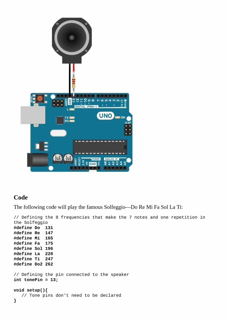
CodeThefollowingcodewillplaythefamousSolfeggio—DoReMiFaSolLaTi:
//Definingthe8frequenciesthatmakethe7notesandonerepetitionin
theSolfeggio
#defineDo131
#defineRe147
#defineMi165
#defineFa175
#defineSol196
#defineLa220
#defineTi247
#defineDo2262
//Definingthepinconnectedtothespeaker
inttonePin=13;
voidsetup()
//Tonepinsdon'tneedtobedeclared

voidloop()
//Do
tone(tonePin,Do,125);
delay(125);
//Re
tone(tonePin,Re,125);
delay(125);
//Mi
tone(tonePin,Mi,125);
delay(125);
//Fa
tone(tonePin,Fa,125);
delay(125);
//Sol
tone(tonePin,Sol,125);
delay(125);
//La
tone(tonePin,La,125);
delay(125);
//Ti
tone(tonePin,Ti,125);
delay(125);
//HigherDo
tone(tonePin,Do2,125);
delay(125);
TipIfthespeakerisconnectedtoadifferentpin,simplychangethetonePinvaluetothevalueofthepinthathasbeenused.

Howitworks…Thetone()functionisveryeasytouse.Itgeneratesasquarewaveof50%dutycycleatthespecifiedfrequency.Whatdoesthatmean?ItmeansthattheusedpinwillbeHIGHhalfthetimeandLOWhalfthetime.Itwillchangebetweenthesetwostatesatthespecifiedfrequency.
Everymusicalnotehasaspecificfrequency;inourcase,Do,whichisaC3,hasthefrequencyof131Hz.Thiswavewillmakethespeakervibrateandgeneratesound.ArduinocanonlysupportmonophonicsoundusingtheTonefunction.Thismeansitcanonlygenerateonenoteatatime.Still,itisquiteusefulandfun.Nowontothecodebreakdown!
CodebreakdownThecodesimplyusesthebuilt-intonefunction,whichhasthefollowingparameters:
tone(pin,frequency,duration)
First,wedeclaretheusedpin:
inttonePin=13;
Then,inloop(),wesimplyusetheTonefunctionforeachnote,oneaftertheother,withadurationof125millisecondsonthedeclaredtonePin:
voidloop()
//Do
tone(tonePin,Do,125);
delay(125);
…
TipWeneedtomakesurewearenotcallingthetone()functionagaininthefollowing125milliseconds,asitwillchangethefrequency.
Itwouldbeeasiertodeclareanarraycontainingallthenotesanduseaforlooptoplaythemall:
//Arrayapproach
intsolfege[]=Do,Re,Mi,Fa,Sol,La,Ti,Do2;
for(inti=0;i<8;i++)
tone(tonePin,solfege[i],125);
delay(125);
TipThetone()functioncannotplaysoundsunder31Hz,andonboardsotherthantheMega,itwillinterferewithPWMpins3and11.

There’smore…ThereisalittlemorefunctionalityintheTonefunction.Hereareafewmorethingswecando:
TonewithnodurationToneonmultiplepins
Let’sseewhattheyare.
TonewithnodurationThetone()functionhastwovariants.Theoneweusedplaysthenoteuntilthetimeexpiresoruntilweusethetone()functionagain,whichevercomesfirst.However,thereisasimplervariantthatdoesn’thavethedurationparameter;itonlycontainsthepinandthefrequency.Whenweusethatfunction,thenotewillstartplayingcontinuously.Inordertostopthenote,weneedtousethenoTone(tonepin)function.Hereisanexample:
tone(tonePin,Do);
delay(100);
noTone(tonePin);
ThenoTone()functionhasonlyoneparameter:thepinnumber.Weneedtousethesamepinnumberastheoneusedinourtone()function;otherwise,itwillnotstopthesoundanditmightinterferewithourcode.
ToneonmultiplepinsTheTonefunctioncanonlyplayonenoteononepinatatime.However,wecanstopplayingonapinandbeginplayingonanotherone.Inthefollowingexample,weplayDoonthe12thpinandthenReonthe13thpin.This,ofcourse,requirestwospeakers:
//Doonpin12
tone(12,Do,125);
delay(125);
noTone(12);
//Reonpin13
tone(13,Re,125);
delay(125);
noTone(13);

SeealsoForareferenceforthefrequenciesofeachnote,visithttp://www.phy.mtu.edu/~suits/notefreqs.html.RememberthatArduinocannotplayfrequenciesunder31Hz(C1isthefirstnoteitcanplay).Wonderingwhyitcannotplaylessthan31Hz?Findoutathttp://forum.arduino.cc/index.php?topic=28055.0.Ifwewanttouseamorepowerfulspeaker,weshouldamplifythelimitedpowerontheArduinodigitalpinsusingatransistordriver.MoredetailscanbefoundintheTransistordriverrecipe.


TransistordriverEachArduinodigitalpincanoutputalimitedamountofcurrent,anabsolutemaximumof40mA.ThisisenoughtopoweranLED,asmallbuzzerspeaker,ormaybeasmallvibratingmotor.However,weneedmorecurrentforourapplicationsmostofthetime.
Usingatransistordriver,wecaneasilypowerupmoredemandingloads.Here,wewillquicklyexplorehowtobuildageneraltransistordriver.

GettingreadyFollowingaretheingredientsforthisrecipe:
AnArduinoboardconnectedtoacomputerviaUSBAresistorbetween220and4,700ohmAstandardNPNtransistor(BC547,2N3904,N2222A,TIP120)Astandarddiode(1N4148,1N4001,1N4007)

Howtodoit…FollowthesestepstoconnectanexternalloadtotheArduinousinganNPNtransistor:
1. Connectoneoftheterminalsoftheloadto5VorVIN.Ifweareusingaloadthatrequiresavoltagehigherthan5VorhighercurrentthantheArduino5Vcanprovide(around500mA),wecanusetheVINpinandconnectanexternalpowersupplyorbatterytotheArduinopowerconnector.
2. Checkthedatasheetofthetransistor.Weneedtocorrectlyidentifythebase,collector,andemitterpins.
3. ConnecttheemitterpintoGND.4. ConnectthebasepinofthetransistortoonedigitalpinoftheArduino,usinga
resistorbetween220and4,700ohm.5. Connecttheotherfreeterminaloftheloadtothecollector.6. Forsecurityreasons,connectadiodeacrosstheloadresistor.Thediodehastopoint
fromthecollectortothepowersupply.Thiswillprotectthetransistorfromspikesgeneratedbyanyinductiveloadssuchasamotororarelay.
SchematicThisisonepossibleimplementationonthe9thdigitalpin.Otherdigitalpinscanalsobeused.
Tip

Iftheusedloadispolarized(itcontainsapositiveandanegativeterminal),connectthenegativeterminaltothecollectorontheNPNtransistorandthepositiveterminaltothepowersupplythathasbeenused(5VorVIN).
CodeThefollowingcodewillturntheloadonandoffatanintervalof500milliseconds:
//Declaretheusedpin
intloadPin=9;
voidsetup()
//Declaretheusedpinasoutput
pinMode(loadPin,OUTPUT);
voidloop()
//TurnontheLoad
digitalWrite(loadPin,HIGH);
delay(500);
//500mslater,turnofftheLoad
digitalWrite(loadPin,LOW);
delay(500);
TipIftheloadisconnectedtoadifferentpin,simplychangetheloadPinvaluetothevalueofthepinthathasbeenused.

Howitworks…WhenwesetthedigitalpinasHIGH,usingthedigitalWrite()command,thetransistorwillgetcurrentinthebase.WhenanNPNtransistorreceivesenoughcurrentinthebase,itwillallowcurrenttopassfromthecollectortotheemitter,actinglikeaclosedswitch.Whenthereisnocurrentatthebase,thecollectorandemitterpinswillactlikeopenedswitches.Thisisasimplejelly-beamexplanationofhowatransistorworks.Thefollowinggraphicfurtherexplainstheconcept.Asmallcurrentfromthebasetotheemitterwillallowalargecurrenttopassfromthecollectortotheemitter.

SeealsoThiswasaverysimpleintroductiontohowtouseNPNtransistorsforgeneralpurposes.Formoredetails,takealookatthefollowingrecipes:
TheControllingmotorswithtransistorsrecipeinChapter5,MotorControlTheControllingspeedwithPWMrecipeinChapter5,MotorControl


RelaydriverSometimeswejustneedtoeasilyswitchonandoffanexternalload.MaybetheloadispoweredbyACcurrent;maybeit’sveryhighvoltagethattheArduinocan’thandle.Atransistorisusuallyusedtopoweronsuchthings;however,transistorsarequitecomplicated.Thereisasimplerdevicethatcanjustswitchonoroff,atslowspeeds,anexternalload.Thisdeviceisknownasarelay.

GettingreadyToexecutethisrecipe,wewillneedthefollowingingredients:
AnArduinoboardconnectedtoacomputerviaUSBAgeneral5VrelayAresistorbetween220ohmand4700ohmAstandardNPNtransistor(BC547,2N3904,N2222A,TIP120)Astandarddiode(1N4148,1N4001,1N4007)

Howtodoit…Therelaycoilunfortunatelyusesquitealotofcurrent.TopreventthisfromburningtheArduinopins,wewilluseatransistordrivertostarttherelay:
1. Connectoneoftheterminalsoftherelaycoiltothe5VpinontheArduino.2. Checkthedatasheetofthetransistor.Weneedtocorrectlyidentifythebase,
collector,andemitterpins.3. ConnecttheemitterpintoGND.4. ConnectthebasepinofthetransistortoonedigitalpinoftheArduinousinga
resistorbetween220and4,700ohm.5. Connecttheotherfreeterminaloftherelaycoiltothecollector.6. Therelayisaninductiveload.Whenweturnitoff,itcancreatehighvoltagespikes
thatmightburnthetransistor.Toprotectagainstthis,connectadiodefromthecollectorto5V,pointingtothe5Vpin.
SchematicThisisonepossibleimplementation.Otherdigitalpinscanalsobeused.
CodeInthisrecipe,weusethesamecodefromthepreviousrecipe,Transistordriver,whichsimplyturnstherelayonandoffevery500milliseconds:
//Declaretheusedpin
intrelayPin=9;
voidsetup()

//Declaretheusedpinasoutput
pinMode(relayPin,OUTPUT);
voidloop()
//TurnontheRelay
digitalWrite(relayPin,HIGH);
delay(3000);
//3secondslater,turnofftheRelay
digitalWrite(relayPin,LOW);
delay(3000);
TipIfthetransistorisconnectedtoadifferentpin,simplychangetherelayPinvaluetothevalueofthepinthathasbeenused.

Howitworks…Arelayisnothingmorethanasimpleswitchoperatedbycurrent.Whenweapplyenoughcurrenttothecoilpins,itwillgenerateanelectromagneticfieldthatwillclosetheswitch.Whenwestopapplyingthecurrent,therelaywillreleasetheswitchbacktotheopenposition.
EachtimewewriteaHIGHtothedigitalpin,thetransistorswitchesthecoilonandtheinternalswitchintherelaycloses.Now,electricitywillpassbetweenthetwoconnectedoutputterminalsoftherelay,andourloadwillreceivecurrent.
RelaysareverygoodforswitchingACcurrents.Also,theloadcircuitandtheArduinocontrolcircuitsarecompletelyindependent,whichisverysafe.Anotherveryimportantfeatureofanyrelayisthatitcanhandlecurrentinanydirection;thisiswhatmakesithandleACcurrents.
TipThisrecipeusesatransistordriverinordertostarttherelaycoil.Formoredetailsonhowthetransistorworks,pleasechecktheTransistordriverrecipeinthischapter.


Optocouplers/OptoisolatorsTherearetimeswhenwewanttocompletelyinsulatetwocircuits,butstillpasssignalsbetweenthem.Wecandothatwitharelay.However,arelayisveryslow.Ittakesaround10–30millisecondstoswitchonoroff.Wecan’tdoPWMorcommunicationsatthispace.However,thereisacleverIntegratedCircuit(IC),calledeithertheoptocouplerortheoptoisolator,whichdoesexactlythat.
Inthisrecipe,wewilluseanoptocouplertoswitchonanLEDwithacompletelydifferentcircuitthathasitsownindependentpowersupply.

GettingreadyFollowingaretheingredientsneededforthisrecipe:
AnArduinoboardconnectedtoacomputerviaUSBTwogeneral220-ohmto1,000-ohmresistorsAbreadboardA1.5–3.0Vbattery,preferablywithwireterminalsAgeneralLEDAgeneraloptocoupler/optoisolatorsuchastheTLP621,4N35,orLTV-816

Howtodoit…FollowingarethegeneralstepstoconnectanoptocouplertotheArduinoandthentoconnectanothercircuitcontaininganLED,resistor,andpowersupplytotheoptocoupleroutput:
1. Connecttheanode(positiveterminaloftheLED)oftheoptocouplertoadigitalpinontheArduino,usingastandard220–1,000ohmresistor.
2. Connectthecathode(LEDnegativeterminal)oftheoptocouplertoGND.3. Nowtheoptocouplerisconnected.Weneedtoconnectsomethingtoitsoutput.In
thiscase,wewillconnectanLEDusingaresistorandexternalpowersupply.4. ConnectthecathodeoftheLED(negativeterminal)tothecollectoroutputonthe
optocoupler.5. Connecttheemitteroutputoftheoptocouplertothenegativeterminalofthebattery.6. Useastandard220–1,000ohmresistortoconnecttheanodetothepositiveterminal
ofthebattery.
SchematicThisisatypicalimplementationusingdigitalpin9:
Andonthebreadboard,thisworksjustfine:

CodeWeareusingthesamecodefromthepreviousrecipe,Transistordriver,whichsimplyturnstheLEDonandoffusingtheoptocouplerevery500milliseconds:
//Declaretheusedpin
intoptoPin=9;
voidsetup()
//Declaretheusedpinasoutput
pinMode(optoPin,OUTPUT);
voidloop()
//Turnontheoptocoupler
digitalWrite(optoPin,HIGH);
delay(500);
//500mslater,turnofftheoptocoupler
digitalWrite(optoPin,LOW);
delay(500);
TipIftheoptocouplerisconnectedtoanotherdigitalpin,simplychangethevalueofoptoPintothevalueofthedigitalpinthathasbeenused.

Howitworks…AnoptocouplerismadeofanLEDandaphototransistor.Itisacleverlittledevice.WhenweturnontheLED,itlightsupthetransistor.Thedifferencebetweenthisphototransistorandatypicaltransistoristhatthebaseislight-sensitive.Whenlighthitsit,itallowscurrenttopassfromthecollectortotheemitter.Thismakestheinputandtheoutputcompletelyindependent.Operation-wise,itworksjustlikeatransistorwithanextracathodepinfortheLEDinput,whichmustbeconnectedtothesamegroundastheArduino.


Moreoutputs–shiftregistersArduinohasalimitednumberofdigitalpins.Sometimes,wewanttobuildprojectsthatrequiremorepinsthanwehaveavailableonourboards.Thisisactuallyacommonprobleminelectronics,whichledtotheinventionoftheshiftregister.
Ashiftregistertransformsserialdatatoparalleloutput.Basically,wetelltheregisterwhatvaluetosetforeachoutputpinithas.If,forexample,ithaseightoutputpins,wewillfirstsaythevalueofthe8thpinandthenthe7thpinuntilwegettothefirstone.TheadvantageisthatweareusingaroundthreeArduinopinstogeteightorevensixteen,whichisveryconvenient.
Therearealotofshiftregistersavailableandtheymostlyworkthesame.Forsimplicity,wewillonlyaddressthecommonlyavailable74HC595tocontroleightLEDswithjustthreepins.

GettingreadyForthisrecipe,wewillrequirethefollowingingredients:
AnArduinoboardconnectedtoacomputerviaUSBA74HC595shiftregisterAbreadboardalongwithjumperwires8LEDs8commonresistorsbetween220–1,000ohm

Howtodoit…Thisisquiteabigcircuit,andputtingittogetherrequiressomepatience:
1. Pluginthe74HC595inthecenterofthebreadboardsothatitspinsgooneachside.Beconsideratewithspace;alotwillbeused.It’sbettertomountitononesideofthebreadboard.
2. MounttheeightLEDsandconnecta220–1,000ohmseriesresistortoeach.3. Connectthecathode(negativeterminal)ofeachLEDtoacommonpointandconnect
thatpointtotheArduinoGND.4. ConnecttheGNDoftheshiftregistertotheArduinoGND.AlsoconnectVCCand
MRtogethertotheArduino5Vpin.5. ConnecteachindividualresistortooneoftheoutputQ0,Q1,Q2,uptoQ7pins.
SchematicThisisonepossibleimplementationofthecircuit.Otherpinscanbechosentocommunicatewiththeshiftregister:
Hereisanexampleofhowtowireitonabreadboard:

CodeThefollowingcodewillmakeaflowillusionpatternontheLEDs:
//Declaringthe3usedpinstoconnecttotheRegister
intDS=8;
intST_CP=10;
intSH_CP=11;
//WemakeanArraywiththevaluesofeachpinoutputonthe
//ShiftRegister
booleanout[8];
voidsetup()
//Setthepinsasoutputs
pinMode(DS,OUTPUT);//Pinfortheactualdata
pinMode(ST_CP,OUTPUT);//Clockpin
pinMode(SH_CP,OUTPUT);//Latchpin
voidwritePins()
//WefirstsettheLatchPinLOW
digitalWrite(SH_CP,LOW);
//Thenwewriteeachbitindividually
for(inti=7;i>=0;i--)
digitalWrite(ST_CP,LOW);
digitalWrite(DS,out[i]);
digitalWrite(ST_CP,HIGH);
//Latchthepinback
digitalWrite(SH_CP,HIGH);

voidloop()
//WewillmanuallymakeeachEVENoutputHIGH
out[0]=HIGH;out[1]=LOW;
out[2]=HIGH;out[3]=LOW;
out[4]=HIGH;out[5]=LOW;
out[6]=HIGH;out[7]=LOW;
//WritetotheShiftRegister
writePins();
delay(300);
//AndtheneachODDoutputHIGH
out[0]=LOW;out[1]=HIGH;
out[2]=LOW;out[3]=HIGH;
out[4]=LOW;out[5]=HIGH;
out[6]=LOW;out[7]=HIGH;
writePins();
delay(300);

Howitworks…Theshiftregisterhasaninputpintowhichwesendthevaluesoftheoutputs.Forexample,onashiftregisterwithfouroutputpins—Q0,Q1,Q2,andQ3—ifwesendonthedatapininsuccession:1,0,1,0,itwillmakeQ0high,Q1low,Q2high,andQ3low.
However,wewanttobeabletowritewithoutaffectingthecurrentoutputoftheshiftregister,andafterwefinishwritingeveryoutput,wewanttomaketheregisterapplythenewvaluestoitsoutputpins.Forthisweusethelatchpin.WhenwegetthepinatLOW,inourcase,itwillnotchangethecurrentoutputvaluesuntilweputthepinatHIGHagain.Also,itneedsawayofknowingwhenwesenda1ora0;itneedsaclocktomakesureitreadseachbitattherightinterval.Forthat,weusetheclockpin.
CodebreakdownFirst,wehavetodeclarethethreepinsthathavebeenused:
intDS=8;
intST_CP=10;
intSH_CP=11;
ThenwemakeanarraycontainingtheoutputvaluesLOWorHIGHofeachshiftregisterpin:
booleanout[8];
Now,weneedtomakeasimplefunctionthatwritesthevaluestotheshiftregister.Insideit,wefirstlatchthepin:
digitalWrite(SH_CP,LOW);
Followingthis,weneedtogivetheclocktotheregisterandinputonebitatatime.Wedothisinaforloop.Weneedtogotheoppositewayinthearray,astheregistertakesthevaluesinreverse:
for(inti=7;i>=0;i--)
digitalWrite(ST_CP,LOW);
digitalWrite(DS,out[i]);
digitalWrite(ST_CP,HIGH);
Attheend,wesimplylatchbacktheSH_CPpin:
digitalWrite(SH_CP,HIGH);
Inloop(),weassignHIGHandLOWvaluestoeachoutputandthenweuseourWritePins()functiontowritethosevalues:
out[0]=HIGH;out[1]=LOW;
out[2]=HIGH;out[3]=LOW;
out[4]=HIGH;out[5]=LOW;
out[6]=HIGH;out[7]=LOW;
//WritetotheShiftRegister
writePins(

);


Chapter7.DigitalCommunicationwithArduinoInthischapter,wewillcoverthefollowingrecipes:
SerialoutputControllingtheArduinooverserialSoftwareserialandUARTbetweenArduinosWirelessserialI2CbetweenArduinosSDcardsLCDcharacterdisplaysEthernet

IntroductionArduinoisnotaloneintheuniverse;itcanusedifferentdigitalcommunicationprotocolstotalkwithquiteafewothersystems.It’soneofthegreatfeaturesoftheplatform;ithasallofthestandardprotocolsbuiltin,allowingittocommunicatewiththousandsofdifferentdevices.
Digitalcommunicationhasnumerousadvantages.Itislesssusceptibletonoisethananalogcommunication,anditusuallyonlyrequirestwolinestocommunicatetohundredsofdevices.Thisallowscommunicationwiththecomputer,withothermicrocontrollerssuchastheArduino,withtheInternet,andevenpagestostoredata.


SerialoutputThisisthedefaultfordebuggingandcommunicationintheArduinoworld.WheneverwewanttodeterminewhatishappeninginArduino,howasensorisperformingorjustgeneralcodedebugging,wecanusetheserialoutputfunctionstowriteamessagetothecomputer.
Here,wewillexplorethebasicsfollowedbyafewtipsandtricksonhowtowritedifferenttypesofdata.AnimportantthingaboutserialcommunicationonArduinoisthatitcanonlybedonebetweentwodevices.Itisnotpossibletohavethreeormoredevicesonthesameserialconnection.

GettingreadyJustoneingredientisneededforthisrecipe—anArduinoboardconnectedtoacomputerviaUSB.

Howtodoit…WejustneedtoconnecttheArduinotothecomputerandbeginprogramming.
ThefollowingcodewillprinthalfaChristmastreeintheserialmonitorandthenthevaluesoftwoanalogports,providingthemostcommontypesofserialoutputencounteredonArduino:
voidsetup()
//InitializetheSerialcommunicationwitha9600baudrate
Serial.begin(9600);
voidloop()
//PrintahalfChristmastree
for(inti=1;i<=8;i++)
for(intj=0;j<i;j++)
Serial.print("*");
Serial.println();
//Printthetrunkofthehalftree
Serial.println("=");
//Leaveanemptyspace
Serial.println("");
//ReadthevalueofA0andprintit
intval=analogRead(A0);
Serial.println(val);
//Simplerwayofprintingavalue
Serial.println(analogRead(A1));
//Leaveanemptyspace
Serial.println("");
//Adelaytonotoverflowthebufferandkeeptheterminalclean
delay(500);
Ifeverythingworksout,weshouldgetthefollowingoutputintheserialmonitor:
*
**
***
****
*****
******
*******
********
=

299
296

Howitworks…Wheneverwewanttowritesomethingtothecomputer,weusethebuilt-inUSBconnection.However,themicrocontrollerinsidetheArduinousesaUARTconnection,whichispassedthroughaUART-USBconverter.ThiscreatestheconnectionbetweenthecomputerandArduino.Wewillseehowthisworksinthefollowingsubsection.
CodebreakdownThefirstthingweneedtodoisopenaserialconnection.Weusuallydothisinthesetup()functionaswekeepitopenforever.TheSerial.begin(val)functionstartstheconnection.Thevalargumentisthespeedoftheconnection.Bothdevicesneedtobesettothesamespeed,whichiscalledthebaudrate.TosettherateonthePCside,usetheboxontheserialmonitorwindowinArduino.
Intheloop()function,wefirstprintthehalfChristmastree.WeusetheSerial.print("*")functiontoprintoneasteriskcharacter.Whenwefinisharow,wecreateanewoneusingprintln();.
Afterthis,wereadavaluefromtheanalogportandprintitontheserialport:
intval=analogRead(A0);
Serial.println(val);
WereadthevalueoftheA0portinthevalvariableandprintit,goingtoanewlineeachtime.Inthenextline,weuseamoreelegantwayofprintingoutthevalueontheanalogportA1:
Serial.println(analogRead(A1));
Asapractice,trytomakethefullChristmastreeusingforloops.Onlythencanyoucallyourselfamasterintheserialterminal.

SeealsoItishighlyrecommendedtocheckthefollowingrecipesforpropermotorcontrol:
TheControllingtheArduinooverserialrecipe


ControllingtheArduinooverserialIntheSerialoutputrecipe,we’veseenhoweasyitistoprintsomedatafromArduinotothecomputer.However,thiscanworktheotherway.IntheserialmonitorwindowintheArduinoIDE,wecanwriteastringandsendittoArduino.
Here,youwilllearnwhattodowiththatstringandhowyoucanuseittocontrolthings.

GettingreadyThereisjustoneingredientneededtoimplementthisrecipe—anArduinoboardconnectedtoacomputerviaUSB.
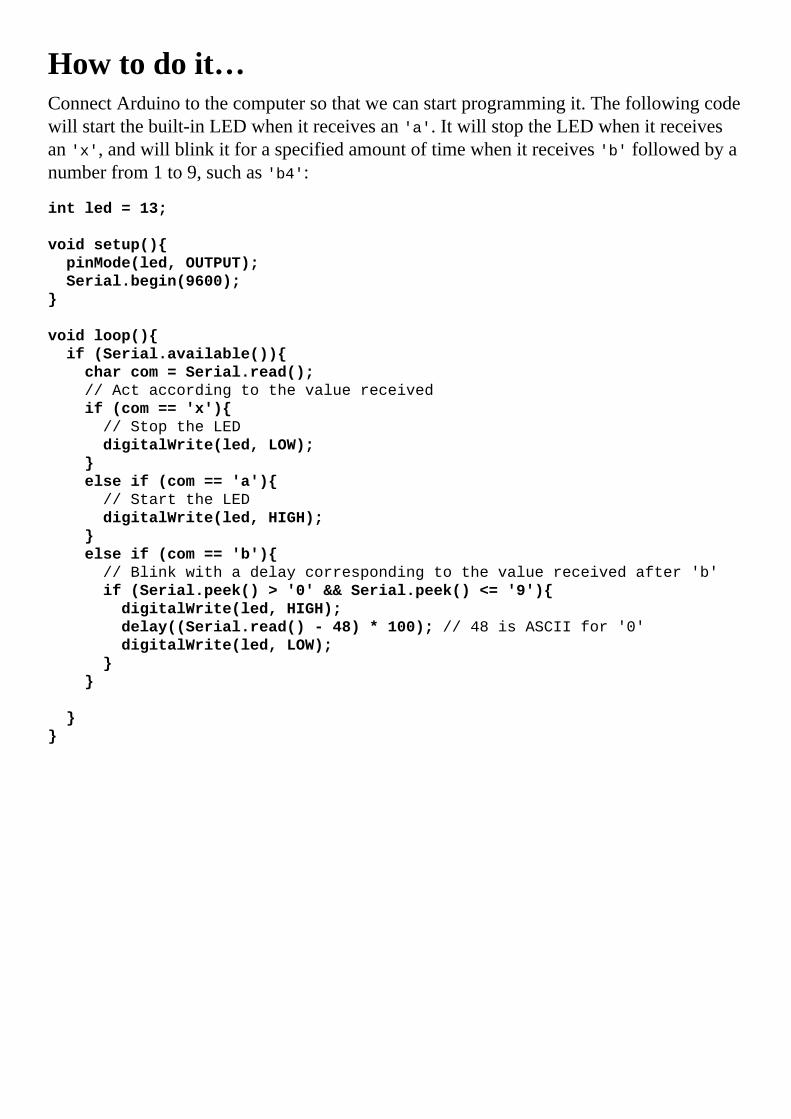
Howtodoit…ConnectArduinotothecomputersothatwecanstartprogrammingit.Thefollowingcodewillstartthebuilt-inLEDwhenitreceivesan'a'.ItwillstoptheLEDwhenitreceivesan'x',andwillblinkitforaspecifiedamountoftimewhenitreceives'b'followedbyanumberfrom1to9,suchas'b4':
intled=13;
voidsetup()
pinMode(led,OUTPUT);
Serial.begin(9600);
voidloop()
if(Serial.available())
charcom=Serial.read();
//Actaccordingtothevaluereceived
if(com=='x')
//StoptheLED
digitalWrite(led,LOW);
elseif(com=='a')
//StarttheLED
digitalWrite(led,HIGH);
elseif(com=='b')
//Blinkwithadelaycorrespondingtothevaluereceivedafter'b'
if(Serial.peek()>'0'&&Serial.peek()<='9')
digitalWrite(led,HIGH);
delay((Serial.read()-48)*100);//48isASCIIfor'0'
digitalWrite(led,LOW);
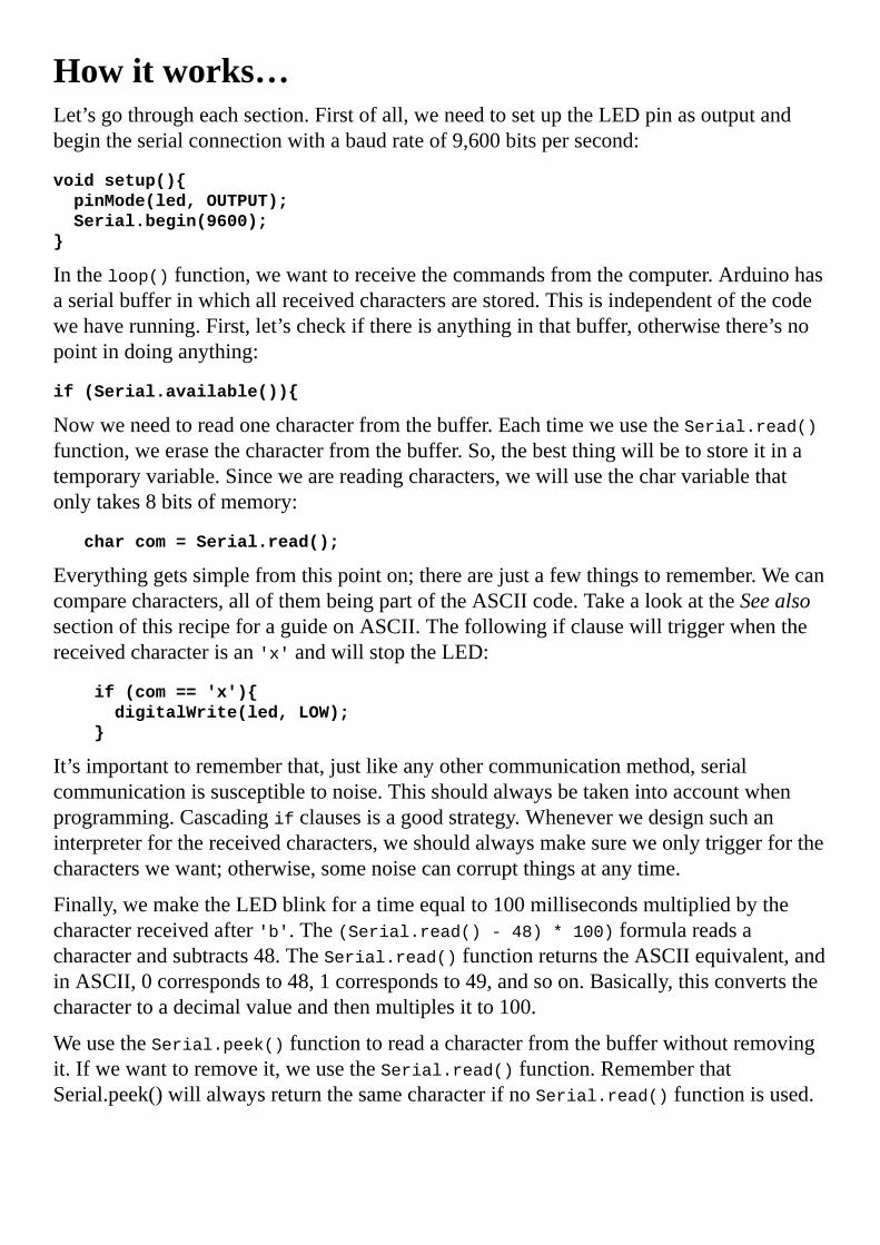
Howitworks…Let’sgothrougheachsection.Firstofall,weneedtosetuptheLEDpinasoutputandbegintheserialconnectionwithabaudrateof9,600bitspersecond:
voidsetup()
pinMode(led,OUTPUT);
Serial.begin(9600);
Intheloop()function,wewanttoreceivethecommandsfromthecomputer.Arduinohasaserialbufferinwhichallreceivedcharactersarestored.Thisisindependentofthecodewehaverunning.First,let’scheckifthereisanythinginthatbuffer,otherwisethere’snopointindoinganything:
if(Serial.available())
Nowweneedtoreadonecharacterfromthebuffer.EachtimeweusetheSerial.read()function,weerasethecharacterfromthebuffer.So,thebestthingwillbetostoreitinatemporaryvariable.Sincewearereadingcharacters,wewillusethecharvariablethatonlytakes8bitsofmemory:
charcom=Serial.read();
Everythinggetssimplefromthispointon;therearejustafewthingstoremember.Wecancomparecharacters,allofthembeingpartoftheASCIIcode.TakealookattheSeealsosectionofthisrecipeforaguideonASCII.Thefollowingifclausewilltriggerwhenthereceivedcharacterisan'x'andwillstoptheLED:
if(com=='x')
digitalWrite(led,LOW);
It’simportanttorememberthat,justlikeanyothercommunicationmethod,serialcommunicationissusceptibletonoise.Thisshouldalwaysbetakenintoaccountwhenprogramming.Cascadingifclausesisagoodstrategy.Wheneverwedesignsuchaninterpreterforthereceivedcharacters,weshouldalwaysmakesureweonlytriggerforthecharacterswewant;otherwise,somenoisecancorruptthingsatanytime.
Finally,wemaketheLEDblinkforatimeequalto100millisecondsmultipliedbythecharacterreceivedafter'b'.The(Serial.read()-48)*100)formulareadsacharacterandsubtracts48.TheSerial.read()functionreturnstheASCIIequivalent,andinASCII,0correspondsto48,1correspondsto49,andsoon.Basically,thisconvertsthecharactertoadecimalvalueandthenmultiplesitto100.
WeusetheSerial.peek()functiontoreadacharacterfromthebufferwithoutremovingit.Ifwewanttoremoveit,weusetheSerial.read()function.RememberthatSerial.peek()willalwaysreturnthesamecharacterifnoSerial.read()functionisused.

There’smore…Serialcommunicationisahugesubjectingeneral.Hereareafewmoretipsthatshouldbeuseful.
ArduinoMegaThereareafewArduinoplatformsthathavemorethanoneserial/UARTconnection.Inthosecases,wewon’tbeaddressingusingSerial.read(),Serial.print(),andsoon.Forthem,wewillbeusingSerial1insteadofjustSerial.
Forexample,Serial1.begin(9600)willstartthefirstserialportwiththebaudrateof9600.OnanArduinoplatformwithmultipleserialconnections,Serial1isusuallytheoneconnectedtotheUSBport.OntheArduinoYùn,however,wecanuseSerial.begin()foraUSBconnection.
TransmittingvaluestoArduinoTherearetimeswhenwewanttosendavaluefromthecomputertotheArduino.Let’sdesignasmallsystemthatsupportssendingvaluesfrom0to999.Inordertomakeeverythingsimple,wewilluseacharacterthatindicatesthatanumberfollows.Thenumberwillalwayshavethreecharacters.Thus,0willberepresentedby'n000'and12willberepresentedby'n012'.Hereisthesimplealgorithm:
if(com=='n')
intval=(Serial.read()-48)*100+
(Serial.read()-48)*10+
(Serial.read()-48);
ThefirstSerial.read()functionwillreturnthehundreds,thesecondonewillreturnthetens,andthethirdonewillreturntheunities.

SeealsoYoucanfindanASCIItableathttp://www.asciitable.com/.ThistableisaveryimportantconceptforArduinoserialcommunication.


SoftwareserialandUARTbetweenArduinosTheserialport,professionallycalledUniversalAsynchronousReceiver/Transmitter(UART)communication,isgenerallyusedtoprogramanddebugtheArduinoviatheUSBport.TherearemultiplesensorsandsystemsthatuseUARTasthemaincommunicationmethod,andsometimesweneedtodiscussbetweentwoArduinostoshareinformation,workload,andsoon.
However,mostArduinosonlyhaveoneserialport,whichisusedbytheUSBconnection.Serialcommunicationcanonlyhappenbetweentwodevices.Whatcanwedonow?Withabitofluck,we’llhaveanArduinoMegaorsimilarthathasuptofourserialports,butifwedon’t,therestillisasolution.AspeciallibraryhasbeenwrittenthatsimulatesanUARTportonotherdigitalpins.Thereareafewdrawbacks,butitgenerallyworks.

GettingreadyFollowingaretheingredientsneededforthisrecipe:
2ArduinosJumpercables

Howtodoit…FollowstepstoconnecttwoArduinoUNOsusingsoftwareserial:
1. Assumingweusepins8and9forRXandTXonbothArduinos,connectpin8ononeArduinowithpin9ontheotherone,andpin9onthefirstArduinotopin8onthesecondone.
2. ConnecttheGNDofbothArduinostogether.3. Ifwedon’tpowerupbothArduinosviaUSB,thenweneedtopowerupatleastone
andconnect5Voneachtogether.
SchematicHereisanimplementationusingpins8and9forRXandTX:
Hereisapossiblebreadboardimplementation:
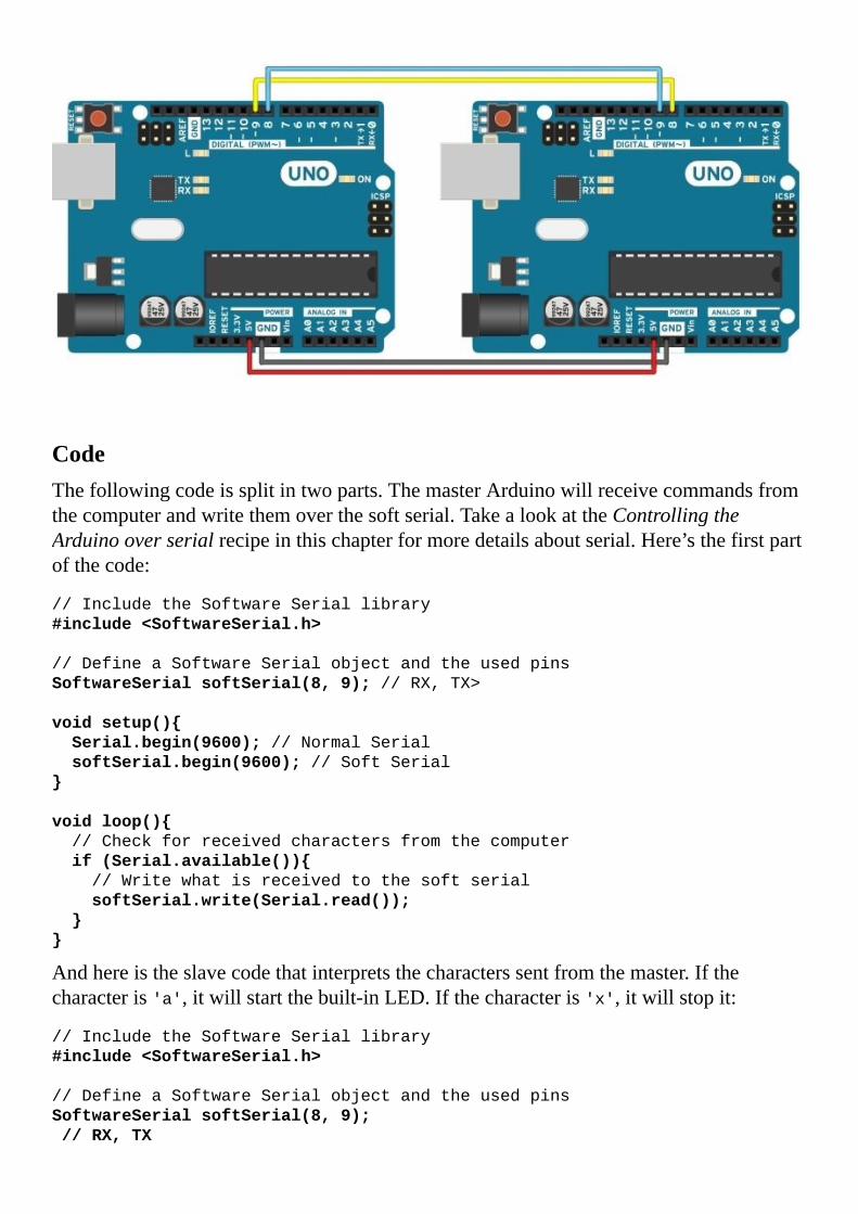
CodeThefollowingcodeissplitintwoparts.ThemasterArduinowillreceivecommandsfromthecomputerandwritethemoverthesoftserial.TakealookattheControllingtheArduinooverserialrecipeinthischapterformoredetailsaboutserial.Here’sthefirstpartofthecode:
//IncludetheSoftwareSeriallibrary
#include<SoftwareSerial.h>
//DefineaSoftwareSerialobjectandtheusedpins
SoftwareSerialsoftSerial(8,9);//RX,TX>
voidsetup()
Serial.begin(9600);//NormalSerial
softSerial.begin(9600);//SoftSerial
voidloop()
//Checkforreceivedcharactersfromthecomputer
if(Serial.available())
//Writewhatisreceivedtothesoftserial
softSerial.write(Serial.read());
Andhereistheslavecodethatinterpretsthecharacterssentfromthemaster.Ifthecharacteris'a',itwillstartthebuilt-inLED.Ifthecharacteris'x',itwillstopit:
//IncludetheSoftwareSeriallibrary
#include<SoftwareSerial.h>
//DefineaSoftwareSerialobjectandtheusedpins
SoftwareSerialsoftSerial(8,9);
//RX,TX

//LEDPin
intLED=13;
voidsetup()
softSerial.begin(9600);//SoftSerial
pinMode(LED,OUTPUT);//DefineLEDpinmode
voidloop()
//CheckifthereisanythinginthesoftSerialBuffer
if(softSerial.available())
//Readonevaluefromthesoftserialbufferandstoreitinthe
variablecom
intcom=softSerial.read();
//Actaccordingtothevaluereceived
if(com=='x')
//StoptheLED
digitalWrite(LED,LOW);
elseif(com=='a')
//StarttheLED
digitalWrite(LED,HIGH);

Howitworks…SoftwareserialsimulatesastandardserialportondifferentdigitalpinsontheArduino.Itisveryhandyingeneral;however,itissimulated,soitdoesn’thavededicatedhardware.Thismeansitwilltakeresources,particularlyexecutiontimeandmemory.Otherwise,itworksjustlikeanormalserialconnection.Allthefunctionspresentinthenormalserialportarealsopresentinsoftwareserial.
CodebreakdownFirst,wewilllookinthemaster,whichtakescharactersreceivedonthenormalserialportandwritesthemtooursimulatedserialconnection.Inthebeginning,weincludetheSoftwareSerial.hlibrary:
#include<SoftwareSerial.h>
Then,weneedtodeclareaserialobject.Wedosousingthefollowingsyntax:
SoftwareSerialsoftSerial(8,9);//RX,TX
Theserialconnectionwillbecalled,inthiscase,softSerial.Itwillusepin8forRXandpin9forTX.TakealookattheThere’smore…sectionforsomeinformationonwhichpinswecanuse.
UsingthesoftSerialobject,wecanuseallfunctionsfoundinanormalserialconnection,suchassoftSerial.read(),softSerial.write(),andsoon.Inthiscode,wecheckifthereisanythingintherealserialbuffer.Ifthereis,wereaditfromthatbufferandwewriteittothesoftwareserial:
if(Serial.available())
softSerial.write(Serial.read());
Intheslavecode,werunasimplifiedversionofthecodefromtheControllingtheArduinooverserialrecipe,exceptthatweuseasoftwareserial.ThisonlychangesthedeclarationandinsteadofwritingSerial.read(),Serial.available(),andsoon,wewritesoftSerial.read()andsoftSerial.available().

There’smore…Softwareserialhassomeimportantconsiderationsanddrawbacks.Herewetackleafewofthem.
UsablepinsWecan’tuseeverypinontheArduinoforsoftwareserial.ForTX,generally,anythingcanbeused,butfortheRXpin,onlyinterrupt-enabledpinscan.OntheArduinoLeonardoandMicro,onlypins8,9,10,11,14,15,and16canbeused,whileontheMegaorMega2560only10,11,12,13,50,51,52,53,62,63,64,65,66,67,68,and69canbeused.
MoresoftwareserialconnectionsItispossibletohavemorethanonesoftwareserialconnection;however,onlyonecanreceivedataatatime.Thiswillgenerallycausedataloss.ThereisanalternativesoftwareseriallibrarywrittenbyPaulStoffregen,whichtacklesexactlythisproblem.ThelinkcanbefoundintheSeealsosectionofthisrecipe.
InterferenceThesoftwareseriallibraryusesthesametimerasafewotherlibraries.Thismeansthatotherfunctionsmightbeaffectedbytheuseofasimulatedserialport.ThebestknowninterferenceiswiththeServolibrary.ThebestwaytoovercomethisistousetheArduinoMega,orsomethingsimilar,whichhasfourhardwareserialports—enoughforanyproject.
GeneralconnectiontipsUARTconnectionsareverysimple;however,therearethreekeyaspectstoremember.Wheneverconnectingtwoserialdevices,theTXpinononedevicegoestotheRXpinontheotherdevice.Ifwedothattheoppositeway,wemightkillthedevice!Also,thedevicesneedtoatleastsharethesameGround(GND).Lastly,thedeviceshavetobesetatthesamespeed,typicallyreferredtoasthebaudrate.

SeealsoFindanalternativetothesoftwareseriallibrarywrittenbyPaulStoffregenathttp://www.pjrc.com/teensy/td_libs_AltSoftSerial.html


WirelessserialSometimeswejustwanttocutthewiresandsenddataoverair.Believeitornot,it’snotthatdifficult.Wecanquicklytransformaserialorsoftwareserialportintoawirelessoneifwehaveawirelesstransmitterandreceiverpair.Thesewirelesscomponentsarequitecheapandeasytofind.Theyareavailableinafewdifferentfrequencies,andtheyareveryeasytosetup.
Wewillusethecodefromthepreviousrecipe,SoftwareserialandUARTbetweenArduinos;exceptthatwewillimplementtheserialoverair.Thereisacatch;wecanonlysenddatainonedirection.

GettingreadyToexecutethisrecipe,weneedthefollowingingredients:
2ArduinosJumpercablesOneRFlinktransmitterandRFlinkreceiverpair

Howtodoit…ThefollowingarethestepstoconnecttwoArduinoUNOsusingSoftwareSerialoverwireless:
1. Assumingweusepins8and9forRXandTXonbothArduinos,connectpin9onthemasterArduinototheDATApinonthetransmitter.
2. Connectpin8ontheslaveArduinototheDATApinofthereceiver.3. ConnecttheGNDandthe5VofthetransmittertothemasterArduino.4. ConnecttheGNDandthe5VofthereceivertotheslaveArduino.5. Usethesamecodeasthepreviousrecipe,SoftwareserialandUARTbetweenArduinos.
SchematicHereisanimplementationusingpins8and9forRXandTXwiththetransmitteronthemasterArduinoandthereceiverontheslave:
Hereisapossiblebreadboardimplementation:


Howitworks…TheRFLinkTransmitterReceiverpairissimpletosetupanduse.Basically,thetransmitteroutputsaradiosignalcorrespondingtoanythingitgetsontheDATApin.Inthesameway,thereceiveroutputsanythingitreceives.Theydon’tcareaboutthebaudrateaslongasitisslowenough.
Thiskindofwirelesscommunicationisverysusceptibletonoise.Itisrecommendedtouseverylowbaudrates—9,600oreven4,800aregoodcandidates.Also,thegreaterthedistance,themorenoiseweget.Inordertocombatthiswecan,again,lowerthebaudrate.

There’smore…Wecanimplementatwo-waysystemifweusetwoRFLinkpairsofdifferentfrequencies.Iftheyarenotofdifferentfrequencies,theywillcompletelyinterferewithoneanotherandboththemasterandtheslaveArduinoswillreceivewhateverisbeingtransmittedbyeither.

SeealsoThereare,however,someprofessionalmodulesdesignedtofacilitatetwo-wayserialcommunication.TheyarecalledXbeeandcomeinallkindsofflavors.Moreaboutthesecanbefoundathttps://www.sparkfun.com/pages/xbee_guide.


I2CbetweenArduinosMaybesometimeswewanttosharetheworkloadofoneArduinowithanother.Ormaybewewantmoredigitaloranalogpins.Inter-IntegratedCircuitorI2C(pronouncedIsquaredC)isthebestsolution.
I2Cisaninterestingprotocol.It’susuallyusedtocommunicatebetweencomponentsonmotherboardsincamerasandinanyembeddedelectronicsystem.
Here,wewillmakeanI2CbususingtwoArduinos.WewillprogramonemasterArduinotocommandtheotherslaveArduinotoblinkitsbuilt-inLEDonceortwicedependingonthereceivedvalue.

GettingreadyFollowingaretheingredientsneededforthisrecipe:
2ArduinosJumpercables
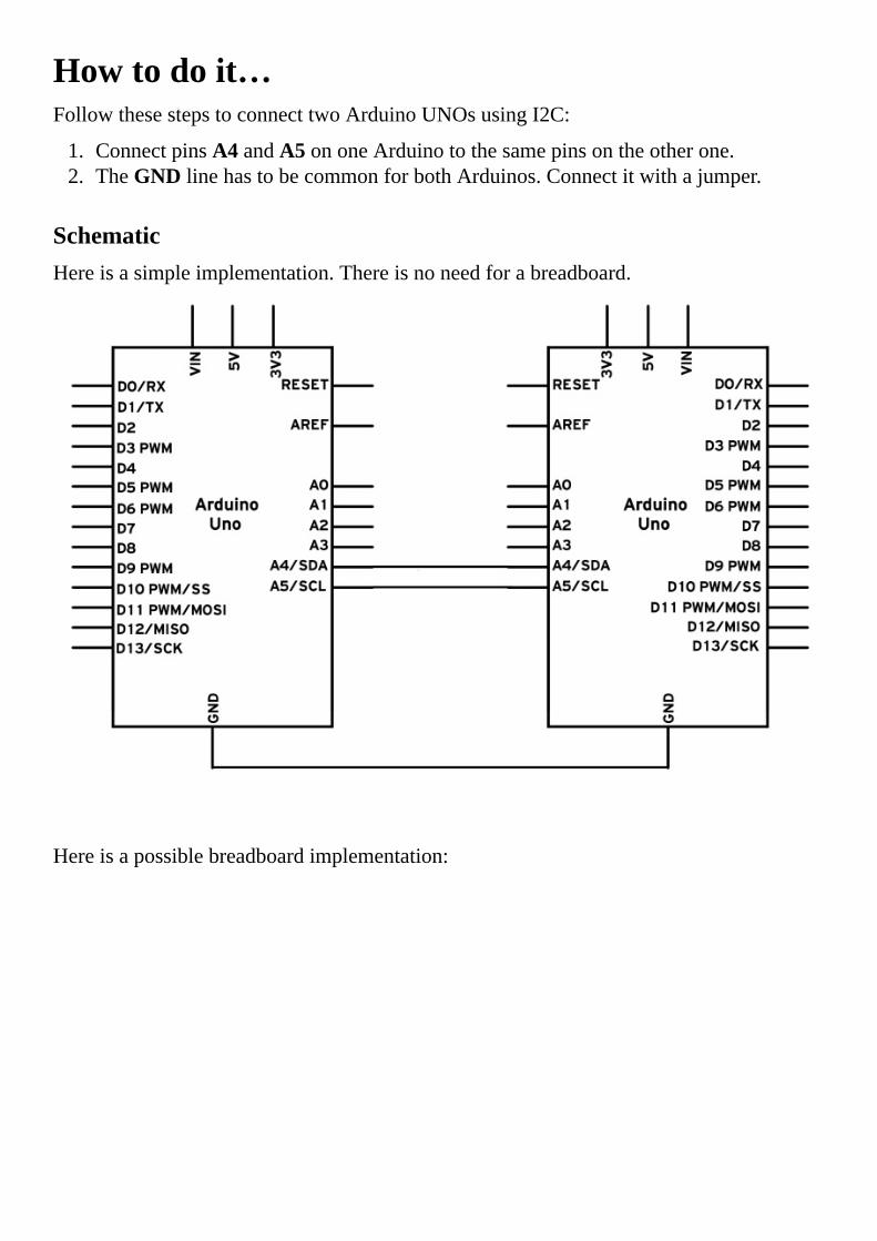
Howtodoit…FollowthesestepstoconnecttwoArduinoUNOsusingI2C:
1. ConnectpinsA4andA5ononeArduinotothesamepinsontheotherone.2. TheGNDlinehastobecommonforbothArduinos.Connectitwithajumper.
SchematicHereisasimpleimplementation.Thereisnoneedforabreadboard.
Hereisapossiblebreadboardimplementation:

NoteRemembernevertoconnect5Vand3.3VArduinostogether.Itwon’thurtthe5VArduino,butitwillcertainlyannoyits3.3Vbrother.
CodeThefollowingcodeissplitintwoparts:themastercodeandtheslavecode,whichrunontwodifferentArduinos.First,let’stakealookatthemastercode:
//IncludethestandardWirelibraryforI2C
#include<Wire.h>
intx=0;
voidsetup()
//StarttheI2CBusasMaster
Wire.begin();
voidloop()
Wire.beginTransmission(9);//transmittodevice#9
Wire.write(x);//sendsx
Wire.endTransmission();//stoptransmitting
x++;//Incrementx
if(x>5)x=0;//resetxonceitgets6
delay(500);
Andhereistheslavecodethatinterpretsthecharacterssentfromthemaster:
#include<Wire.h>
intLED=13;
intx=0;

voidsetup()
pinMode(LED,OUTPUT);
//StarttheI2CBusasSlaveonaddress9
Wire.begin(9);
//Attachafunctiontotriggerwhensomethingisreceived.
Wire.onReceive(receiveEvent);
voidreceiveEvent(intbytes)
x=Wire.read();//readonecharacterfromtheI2C
voidloop()
//Ifvaluereceivedis0blinkLEDfor200ms
if(x=='0')
digitalWrite(LED,HIGH);
delay(200);
digitalWrite(LED,LOW);
delay(200);
//Ifvaluereceivedis3blinkLEDfor400ms
if(x=='3')
digitalWrite(LED,HIGH);
delay(400);
digitalWrite(LED,LOW);
delay(400);

Howitworks…Tobrieflygothroughthetheory,I2Crequirestwodigitallines:SerialDataline(SDA)totransferdataandSerialClockLine(SCL)tokeeptheclock.EachI2Cconnectioncanhaveonemasterandmultipleslaves.Amastercanwritetoslavesandrequesttheslavestogivedata,butnoslavecandirectlywritetothemasterortoanotherslave.Everyslavehasauniqueaddressonthebus,andthemasterneedstoknowtheaddressesofeachslaveitwantstoaccess.Nowlet’sgothroughthecode.
CodebreakdownFirst,let’slookatthemaster.WeneedtoincludetherequiredWire.hlibrary:
#include<Wire.h>
Then,inthesetupfunction,webegintheI2CbususingtheWire.begin()function.Ifnoargumentisprovidedinthefunction,Arduinowillstartasamaster.
Lastly,wesendacharacterx,whichisbetween0and5.Weusethefollowingfunctionstobeginatransmissiontothedevicewiththeaddress9,writethecharacter,andthenstopthetransmission:
Wire.beginTransmission(9);//transmittodevice#9
Wire.write(x);//sendsx
Wire.endTransmission();//stoptransmitting
Nowlet’sexploretheslaveArduinocode.WealsoincludetheWire.hlibraryhere,butnowwestarttheI2CbususingWire.begin(9).ThenumberintheargumentistheaddresswewanttousefortheArduino.Alldeviceswithaddress9willreceivethetransmission.
NowweneedtoreactsomehowwhenwereceiveanI2Ctransmission.Thefollowingfunctionappendsatriggerfunctionwheneveracharacterisreceived.Bettersaid,whenevertheArduinoreceivesacharacteronI2C,itwillrunthefunctionwetellittorun:
Wire.onReceive(receiveEvent);
Andthisisthefunction.Here,wesimplystorethevalueofthereceivedcharacter:
voidreceiveEvent(intbytes)
x=Wire.read();
Inloop(),wesimplyinterpretthatcharactertoblinkthebuilt-inLEDatdifferentspeedsdependingonthereceivedcharacter.

There’smore…I2Cisacomplicatedtransmissionprotocol,butit’sveryuseful.AllArduinosimplementit,withafewdifferencesinpinmappings.
ComparingdifferentArduinocategoriesThepinsforI2CaredifferentindifferentArduinocategories.Herearethemostcommon:
Board I2Cpins
Uno,ProMini A4(SDA),A5(SCL)
Mega,Due 20(SDA),21(SCL)
Leonardo,Yún 2(SDA),3(SCL)
MoreaboutI2CEachI2Cbuscansupportupto112devices.AlldevicesneedtoshareGND.Thespeedisaround100kb/s—notveryfastbutstillrespectableandquiteuseable.Itispossibletohavemorethanonemasteronabus,butit’sreallycomplicatedandgenerallyavoided.
AlotofsensorsuseI2Ctocommunicate,typicallyInertialMeasurementUnits,barometers,temperaturesensors,andsomeSonars.RememberthatI2Cisnotdesignedforlongcablelengths.Dependingonthecabletypeused,2mmightalreadycauseproblems.
ConnectingmoredevicesIfweneedtoconnectmorethantwodevicesonanI2Cbus,wejusthavetoconnectallSDAandSCLlinestogether.WewillneedtheaddressofeveryslavetobeaddressedfromthemasterArduino.

SeealsoYoucanfindagoodexplanationonhowamastershouldrequestinformationtoaslaveathttp://arduino.cc/en/Tutorial/MasterReader.Thisisanexampleclosertoreallife,asthisisthewayweusuallyrequestinformationfromsensors.


SDcardsSDcardsaregreattostoredatainthelongterm.Arduinohasalibraryspecificallydesignedtotalktothem.Withthislibrary,wecancreate,write,read,anddestroyfiles.Thisisveryhandy,especiallyindataloggingapplications.WecanhaveanArduinorunningformonths,recordingdata,andwritingittotheSDcard.
Inthisexample,wewillreadthedatafromtwoanalogportsandwriteittotheSDcard.

GettingreadyThefollowingaretheingredientsneededforthisrecipe:
AnArduinoboardconnectedtoacomputerviaUSB.AformattedSDcard;ArduinoacceptsonlyFAT16orFAT32formatting.AnEthernetshieldoranyotherArduino-compatibleSDshield.Optionally,twoanalogsensors.WewillstoretheirvaluesontheSDcard.Itworkswithoutthem,butwewillonlyrecordrandomvaluesontheanalogports.

Howtodoit…FollowthesestepstopreparetouseanSDcard:
1. PlugtheArduino-compatibleSDshieldintotheArduino.2. FormattheSDcardtoeitherFAT16orFAT32.3. InserttheSDcardintotheSDcardslotontheshield.
CodeThefollowingcodewillreadtheanalogvaluesfromA0andA1andwritethemtothelog.txtfileontheSDcard:
#include<SD.h>
//DeclaretheselectSPIpin.Pin4fortheEthernetshield
intselectSPI=4;
voidsetup()
Serial.begin(9600);//Serialfordebugging
//DeclarethestandardselectSPIpinasOUPTUT.Pin53forMega-like
boards
pinMode(10,OUTPUT);
//CheckifthereisanySDcardpresent
if(!SD.begin(selectSPI))
Serial.println("Cardnotfound");
return;//stopexecution
Serial.println("Cardfound");
voidloop()
//ReadA0andA1
intval1=analogRead(A0);
intval2=analogRead(A1);
//Openthefile
FilelogFile=SD.open("log.txt",FILE_WRITE);
//Checkifthefileisavailable
if(logFile)
logFile.print(val1);//Writefirstvalue
logFile.print("");//Writeaspace
logFile.println(val2);//Writesecondvalue
logFile.close();//closethefile
else
//ifthefilecan'tbeopened,alert
Serial.println("erroropeningfile");

Howitworks…SDcardsuseatechnologycalledSerialProtocolInterface(SPI)tocommunicate.ArduinohasoneSPIconnectionembeddedintoit.Inthecodebreakdown,wewillexplorehowitallworks.
CodebreakdownThefirstthingwedoisincludetheSD.hlibrary.Afterthat,weinitializeavariablethatwillrepresenttheselectpinforSPI.SPIcanhandlecommunicationbetweenmultipledevices.Inordertoknowwhichdeviceweareaddressing,aselectpinisimplemented.InthecaseoftheEthernetshield,whichembedsanSDcardadapter,thisispinnumber4.
Followingthis,andduetothewaySPIisimplementedintheArduinomicrocontroller,weneedtoselectthestandardselectpinasOutput,regardlessofwhetherweareusingit.ForstandardArduinos,thatispin10andforMega,it’spin53:
pinMode(10,OUTPUT);
Nowwecanstarttheconnectionandcheckifanycardispresent.Ifnot,wewillstoptheprogramcompletely.WeneedtotelltheSDlibrarytheselectpinonwhichitcanfindtheSDcard:
if(!SD.begin(selectSPI))
Serial.println("Cardnotfound");
return;//stopexecution
Intheloop()function,wereadthevalueofthetwoanalogports.Afterthat,weopenthefileusingthefollowingfunction:
FilelogFile=SD.open("log.txt",FILE_WRITE);
Ifthefiledoesn’texist,itwillbecreated.Weshouldcheckifthefileisavailableforwriting.WeuseanifclauseonthelogFilefile.Ifitisavailable,wewillsimplywritetoit:
if(logFile)
logFile.print(val1);//Writefirstvalue
logFile.print("");//Writeaspace
logFile.println(val2);//Writesecondvalue
logFile.close();//closethefile
Otherwise,wejustalertusingtheserialconnectionthatwestartedfordebugging.

There’smore…SDcardsandSPIsarequitecomplexingeneral.Hereareafewthingstoknow:
Notallcardswork:Therearecaseswhenfastcardswillnotwork.Generally,cardsofclass4workwell,whilecardsofclass6andfasterpresentproblems.Toeasilyfindinformationaboutacard,runtheArduinoIDEbuilt-inexamplefoundunderFile|Examples|SD|CardInfo.ItwillprintoutallthedetailsitcanacquireabouttheSDcard.ReadingfromSDcards:Readingisofcoursepossible.Itusesthesameprotocolastheserialconnection.TheArduinoIDEexampleReadWritefoundunderFile|Examples|SDgivesagoodexplanation.Noteonelectronicconnections:MostArduinosworkon5VwhilethestandardforSDcardsis3.3V.TheEthernetshieldandotherArduino-compatibleSDshieldsallhaveabuilt-inlogiclevelshifterthatshiftsthevoltagesfrom5Vto3.3Vandviceversa.IfweareimplementingacustomSDcardconnector,weshouldatleastuseavoltagedividerfortheoutputsignalsfromtheArduinototheSD;otherwise,wewillburntheSDcard.SparkfunsellsaveryhandyLogicLevelShifter,whichwillworkperfectlyinthisapplication.


LCDcharacterdisplaysThereisnothingbetterthanwritinganyinformationfromtheArduinotoasmallLCDcharacterdisplay.Theyareincrediblyhandyandjustlookplaincool.Evenbetter,Arduinohasabuilt-inlibrarytodothis.Let’sexplorehowwecanimplementit.

GettingreadyWewillneedthefollowingingredientsforthisrecipe:
AnArduinoboardconnectedtoacomputerviaUSBAnLCDcharacterdisplayofanydimension—16x2isthestandardsizeA10K-ohmpotentiometerJumperwires

Howtodoit…First,weneedtoconnectthemonitortotheArduino.Thisgenerallyrequiresaminimumof6digitalpinsasshowninthefollowingdiagram:
Thisisonepossiblebreadboardimplementation:
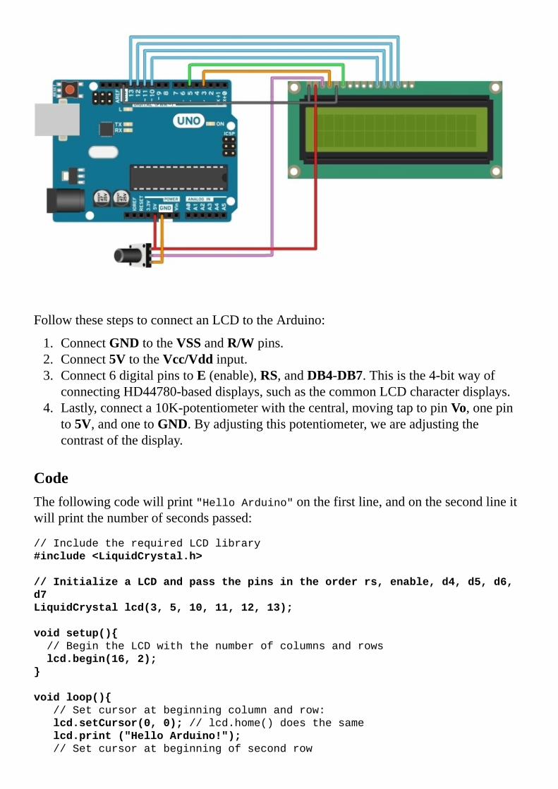
FollowthesestepstoconnectanLCDtotheArduino:
1. ConnectGNDtotheVSSandR/Wpins.2. Connect5VtotheVcc/Vddinput.3. Connect6digitalpinstoE(enable),RS,andDB4-DB7.Thisisthe4-bitwayof
connectingHD44780-baseddisplays,suchasthecommonLCDcharacterdisplays.4. Lastly,connecta10K-potentiometerwiththecentral,movingtaptopinVo,onepin
to5V,andonetoGND.Byadjustingthispotentiometer,weareadjustingthecontrastofthedisplay.
CodeThefollowingcodewillprint"HelloArduino"onthefirstline,andonthesecondlineitwillprintthenumberofsecondspassed:
//IncludetherequiredLCDlibrary
#include<LiquidCrystal.h>
//InitializeaLCDandpassthepinsintheorderrs,enable,d4,d5,d6,
d7
LiquidCrystallcd(3,5,10,11,12,13);
voidsetup()
//BegintheLCDwiththenumberofcolumnsandrows
lcd.begin(16,2);
voidloop()
//Setcursoratbeginningcolumnandrow:
lcd.setCursor(0,0);//lcd.home()doesthesame
lcd.print("HelloArduino!");
//Setcursoratbeginningofsecondrow

lcd.setCursor(0,1);
lcd.print(millis()/1000);
TipAnydigitalpinscanbeusedtoconnectanLCDaslongastheyarenotusedbyanythingelse.

Howitworks…AlmostallLCDcharacterdisplaysusetheHitachiHD44780driverstandard,whichisimplementedasalibraryintheArduinoenvironment.EachLCDhasanumberofcolumnsandrows,withthemosttypicalconfigurationsbeing8x2,16x2,and20x4.Werequireatleastsixdigitalpinstocontrolthesedisplays.
CodebreakdownInitially,wejustincludetheLiquidCrystal.hlibrary.ThenwecreateaLiquidCrystalobjectcalledLCDinwhichwewritethepinnumbersused:
LiquidCrystallcd(3,5,10,11,12,13);
Afterwards,inthesetup()function,weinitializethedisplayusinglcd.begin(columns,rows).Intheend,wecansimplyjumptoanylocationandwriteanythingwewant:
lcd.setCursor(0,0);
lcd.print("HelloArduino!");
lcd.setCursor(0,1);
lcd.print(millis()/1000);

There’smore…ThereareafewmorethingswecandowithLCDs:
Morewaysofconnecting:Inthisexample,weimplementedthesimplestofallversions.Itrequirestheminimumamountofcables;however,therearefourtypesintotal:
LiquidCrystal(rs,enable,d4,d5,d6,d7)
LiquidCrystal(rs,rw,enable,d4,d5,d6,d7)
LiquidCrystal(rs,enable,d0,d1,d2,d3,d4,d5,d6,d7)
LiquidCrystal(rs,rw,enable,d0,d1,d2,d3,d4,d5,d6,d7)
HavingaccesstotheRWpinwillallowustoreadfromthemonitor,whichisnotreallyusefulaswearetheoneswhoalsowriteonit.Usually,thispinisjustconnectedtoGNDtomakeitstayinreceivemode.Usingalleightdatalinesisnotnecessarybutistwiceasfastasonlyusingfour.
TherearealsosomeI2C-basedLCDdisplaysthatonlyrequirethetwoI2Cpins.Ifwearetightonpins,thatisthesolution.
Noimage:Whenwesetupthecircuitforthefirsttime,therearealotofchancesofnotextshowingup.Weshouldplaywiththecontrastpotentiometertomakesureit’snotkillingorsupersaturatingthecontrast.Backlight:SomeLCDdisplaysalsohaveabuilt-inbacklight.Checkthedatasheetforthescreenusedtofindouthowtoenableit.Mostrequireanexternalresistorthatisalwaysspecifiedinthedatasheet.


EthernetUsinganEthernetshield,wecanconnectanArduinototheInternet.AllthepowerandawesomenessoftheInternetcancometothissmallblueboardweareprogramming.Thisisahugetopic;however,theArduinoEthernetlibrarymakesitallsimple.
Here,wewillcreateaninterestingapplicationforthisfunctionality.WewillmaketheArduinoalocalwebservertowhichwecanconnecttofindoutthereadingsofthefirstthreeanaloginputs,usingourbrowser.

GettingreadyThefollowingaretheingredientsneededforthisrecipe:
AnArduinoAnArduinoEthernetshieldArouterorjustanEthernetcable

Howtodoit…Followthesestepstobuildtheserver:
1. CarefullyplugtheEthernetshieldintotheArduino.2. ConnectanEthernetcabletotheshield.3. ConnecttheotherendoftheEthernetcabletothesameroutertowhichyour
computerisconnected.
CodeThefollowingcodeattemptstoconnecttoarouterusingDHCP.Onceitdoes,itwilloutputtheIPviaserialandthenitwillwaitforincomingconnections.Whenaconnectionisset,itwilloutputthevaluesofthefirstthreeanaloginputsviaanHTMLpage.Thecodeisasfollows:
//IncludetherequiredSPIandEthernetLibraries
#include<SPI.h>
#include<Ethernet.h>
//MACAddressfortheEthernetShield
bytemac[]=0x00,0xAA,0xBB,0xCC,0xDD,0x01;
//CreateanEthernetServerobjectonport80
EthernetServerserver(80);
voidsetup()
Serial.begin(9600);//StartSerial
//StarttheEthernetconnectionandcheckifsucceeded
while(Ethernet.begin(mac)==0)
Serial.println("FailedtoconfigureEthernetusingDHCP");
delay(500);
Serial.println("ConnectionEstablished");
//PrinttheIPAddress
Serial.print("ServerIPaddress:");
Serial.println(Ethernet.localIP());
voidloop()
//Checkforclients
EthernetClientclient=server.available();
//Whenthereisaclient
if(client)
while(client.connected())
if(client.available())
//GETrequestsfromclientsendinanemptynewline
//Ifanewlinecharacterisfoundandthesecondcharacterisa
newline
if(client.read()=='/n'&&client.read()=='/n')
//SendaHTTPresponse

//HTTPheader:
client.println("HTTP/1.1200OK");
client.println("Content-Type:text/html");
client.println("Connection:close");//Connection
closesafterresponse
client.println("Refresh:3");//Refreshpageevery3seconds
client.println();
//HTMLPage:
client.println("<!DOCTYPEHTML>");
client.println("<html><body>");
//Writethevaluesofthefirst3AnalogInputsinparagraphs
for(intanIn=0;anIn<3;anIn++)
client.print("<p>");//Beginparagraph
client.print("AnalogInput");
client.print(anIn);//Printtheanaloginputnumber
client.print("=");
client.print(analogRead(anIn));//Printchannelvalue
client.println("</p>");//Endparagraph
client.println("</body></html>");
//Allowmessagetobeprocessedbybrowser
delay(10);
//Closeconnectiontoclient
client.stop();
Serial.println("ClientDisconnected");
HowtotestIftheEthernetshieldispluggedintothesamerouterasyourcomputer,checkfortheIPtheArduinogivesoverserial.Then,inyourbrowseraddressbar,writethatIPandhitEnter.Itwilltakeyoutothecustompage.

Howitworks…TheEthernetshieldhasapowerfulprocessorinside,designedjusttotacklealltheprotocolsofEthernet,TCP,UDP,andsoon.Itisaveryadvancedcomponent.TheshieldusestheSPIcommunicationprotocolforhigh-speedcommunicationwiththeArduino.Thankfully,Arduinohasalibrarytosimplifyeverything,aswecanseeinthecodebreakdown.
CodebreakdownBothSPIandEthernetlibrarieshavetobeincludedforthisbadboytowork:
#include<SPI.h>
#include<Ethernet.h>
AnythingconnectedtotheInternetoranylocalnetworkrequiresauniqueMACaddress.Here,wewillwritearandomoneinabytearrayandhopenootherdevicehasit:
bytemac[]=0x00,0xAA,0xBB,0xCC,0xDD,0x01;
WeneedtocreateanEthernetServerobjecttotackleallthecomplexconnectionprotocols.Theargumentofthefunctionistheportonwhichtheserverwilllistenforconnections.Port80isthestandard:
EthernetServerserver(80);
Here,weattempttostarttheEthernetconnectionwiththespecifiedMACaddress.Ifitfailsandreturns0,itwillattemptagain.However,therearefewchancesifitdoesn’tworkfromthefirstattempt.Thisistherequiredcode:
while(Ethernet.begin(mac)==0)
Serial.println("FailedtoconfigureEthernetusingDHCP");
delay(500);
OncetheDHCPhasbeenset,weneedtoknowtheIPoftheserver.ThefollowingfunctionwillprinttheIPaddressovertheserial:
Serial.print("ServerIPaddress:");
Serial.println(Ethernet.localIP());
Intheloop()function,wefirstdeclareavariableoftypeEthernetClient,whichwilltakethevalueoftheavailabilityofaclient:
EthernetClientclient=server.available();
Oncewehaveaclient,whileitisconnected,wecheckifitisavailable,usingthefollowingsyntax:
if(client)
while(client.connected())
if(client.available())
NowweneedtolistentoGETcommandsfromtheclient.Thesecommandsrequest

informationtobesentbacktotheclient.AttheendofeachGETrequest,wehaveanemptylinethatwecanfindusingthefollowingsyntax:
if(client.read()=='/n'&&client.read()=='/n')
Ifwedetectsuchacommand,werespondwithawebsite.EachwebsitestartswithaHTTPanswerheader,whichincludessomebasicdetailsabouttheconnectionandthewebsite.Inourcase,wetellthebrowsertorefresheverythreesecondstoseetheupdatesinthevalues:
client.println("HTTP/1.1200OK");
client.println("Content-Type:text/html");
client.println("Connection:close");
client.println("Refresh:3");
client.println();
AndthenwewritetheactualwebsiteHTMLcode.FormoredetailsaboutHTML,takealookattheSeealsosectionofthisrecipe.
Intheend,weclosetheconnectionandloopbacktowaitforotherconnections.

There’smore…WecanactuallymakethisdataavailableacrosstheInternet,butforthisweneedtohaveaprivateIPaddress.Ifindeedwehaveoneofthese,wecanchangetheconnectioncodetothefollowing:
bytemac[]=0xDE,0xAD,0xBE,0xEF,0xFE,0xED;
IPAddressip(192,168,1,177);//YourprivateIP
EthernetServerserver(80);
ThiswillsetuptheserverusingthespecifiedIP.IfindeedwehaveaprivateIPandwestarttheserveronthatIP,wecanaccessitfromanywhereintheworldbyjusttypingthatIPaddressintoourbrowseraddressbar.

SeealsoTheEthernetshieldcandoatonofthings.Formoreinformationaboutit,visithttp://arduino.cc/en/Reference/Ethernet.ForanHTMLprimer,visithttp://www.w3schools.com/html/.


Chapter8.HackingInthischapter,wewillcoverthefollowingtopics:
MoredigitalpinsFasterPWMStoringdatainternally–EEPROMTimingArduinocodeExternalinterrupts

IntroductionThischapterisfortherebels!It’saboutthetipsandtricksthatpushtheArduinosdevelopmentalittletotheedge.Sometimes,wemaywanttoexecutesomecodeatpreciselythetimesomethinghappens,evenwhenwearedoingsomethingcompletelydifferent.OrwemaywanttostoredatawithinArduinoevenifwepoweritoff.Allofthatandmorecanbelearnedinthischapter,folks!


MoredigitalpinsTherearetimeswhenweneedmoredigitalpinsontheArduinowithoutanyotherexternalcomponents.AnArduinoUnohas14digitalpins,from0to14,right?Wrong!Itactuallyhas20.Theanaloginportscanatalltimesbeusedasdigitalports,andtheyhaveallthefunctionalityofnormaldigitalports.
TipAwordofcaution:pins0and1aretheUARTportsusedforprogrammingneedtotakeextracareaboutwhatweconnectthere,becausewhenweareprogrammingtheboard,thosepinswillswitchfromHIGHtoLOWthousandsoftimes.

GettingreadyJustoneingredientisneededforthisrecipe—anArduinoBoardconnectedtoacomputerviaUSB.

Howtodoit…ThefollowingcodeshowshowtousepinsA0andA1asnormaldigitalpins:
voidsetup()
pinMode(A0,OUTPUT);
pinMode(A1,OUTPUT);
voidloop()
digitalWrite(A0,HIGH);
digitalWrite(A1,LOW);
delay(500);
digitalWrite(A0,LOW);
digitalWrite(A1,HIGH);
delay(500);

Howitworks…Internally,allpinsonArduinoboardshavedifferentfunctions.Theonlyfunctiontheyallshareisthebasicdigitalinputandoutput.AllofthemcanoutputeitherHIGHorLOWandallofthemcanreadeitherHIGHorLOW.
Inotherwords,allofthefollowingfunctionswillworkthesamewayasonanyrandomdigitalport:
pinMode(A0,OUTPUT);
pinMode(A1,INPUT);
pinMode(A2,INPUT_PULLUP);//SetasaninputwithPULLUPresistor
digitalWrite(A0,LOW);
digitalRead(A1);


FasterPWMThisisanexoticprocedure!ThestandardPWMfrequencyontheArduinoisaround490Hz.Whileitcangetmostjobsdone,itisnotreallythatfast.However,wecanchangethat.
FasterPWMisespeciallyusefulwhencontrollingmotors.AtlowPWM,thetorqueisgreatlyaffected,anditcanalsocreateaudiblenoise.ThebestwaytotestthisistoimplementtheControllingspeedwithPWMrecipefromChapter5,MotorControl,andincreasethePWMfrequency.
NoteAnotetoremember:thismightinterferewithotherfunctions,suchasdelay().Wehavetobeextracarefulwhenthishappens.

GettingreadyFollowingaretheingredientsrequiredtoimplementthisrecipe:
AnArduinoboardconnectedtoacomputerviaUSBADCmotorAresistorbetween220ohmand4,700ohmAstandardNPNtransistor(BC547,2N3904,N2222A,TIP120)oralogiclevel-compatibleMOSFET(IRF510,IRF520)Astandarddiode(1N4148,1N4001,1N4007)

Howtodoit…AfterweimplementthesamecircuitasintheControllingspeedwithPWMrecipefromChapter5,MotorControl,whichstartsamotoronpin9,wejusthavetoaddonelinetothesetup()function:
//Declarethepinforthemotor
intmotorPin=9;
voidsetup()
//ChangeTimer1dividerwhichwillmakethePWMfaster
//InthisSettingitwillhaveafrequencyof31372.55Hz
TCCR1B=TCCR1B&0b11111000|0x01;
voidloop()
//Fadethemotorin
for(inti=0;i<256;i++)
analogWrite(motorPin,i);
delay(20);
//Stopthemotor
analogWrite(motorPin,0);
delay(2000);

Howitworks…InternaltimersinsidetheATMegachipdrivePWMpinsoneachArduino.Atimerisacomponentthatkeepstime;shocking,isn’tit?TheArduinoUNOhasthreesuchtimers:
Timer0Timer1Timer2
TwoPWMpinsareassignedtoeachofthesetimers.Pins9and10areassignedtoTimer1,pins11and3totimer2,andpins5and6toTimer0.Timers1and2sharethesamePWMfrequencyof490HzwhileTimer0istherebelwithawhopping976Hz.
Eachtimerhasaninternalprescalerthatdividestheclockrate,whichistypicallygivenbythe16MHzquartzoscillator.Ifwechangetheprescalervalue,allfunctionsallocatedtothattimerwillchangethefrequency.PWMisoneofthosefunctions.Thereisjustonelineofcodethatchangesthedividerofonetimer:
TCCR1B=TCCR1B&0b11111000|0x01;
Nowthatlooksfunky.Itactuallyisverysimple.AllweneedtoknowisthatTCCRxBrepresentstimerx.Sotimer0isTCCR0B,timer1isTCCR1B,andsoon.Thefullsyntaxisasfollows:
TCCRxB=TCCRxB&0b11111000|setting;
Herexisthetimernumberandsettingisthesettingweareusingtochangethedivider.Thefollowingtableswillelucidateeverything.
Timer0ThistimercontrolsthePWMpins5and6.PleasereadtheThere’smore…sectionofthisrecipeaboutinterferencewiththedelay()function.
Setting Divider Frequency
0x01 1 62,500Hz
0x02 8 7,812.5Hz
0x03 64 976.5625Hz(Default)
0x04 256 244.14Hz
0x05 1024 61.035Hz
SoifwewanttomakeTimer0runat62500Hz,wehavetoimplementinthesetup()function:
TCCR0B=TCCR0B&0b11111000|0x01;
Timer1

ThisisresponsibleforPWMpins9and10.
Setting Divider Frequency
0x01 1 31,372.55Hz
0x02 8 3,921.16Hz
0x03 64 490.20Hz(Default)
0x04 256 122.55Hz
0x05 1024 30.64Hz
Timer2ThisisresponsibleforPWMpins11and3.
Setting Divider Frequency
0x01 1 31,372.55Hz
0x02 8 3,921.16Hz
0x03 32 980.39Hz
0x04 64 490.20Hz(Default)
0x05 128 245.10Hz
0x06 256 122.55Hz
0x07 1024 30.64Hz
Wecanmodifythesettingofallthreetimersifwewant,bywritingthethreemodifiersinthesetup()function.
AllofthiscanbefoundundertheTimer/Counter0andTimer/Counter1PrescalerssectionintheATmega328Pdatasheet.TakealookattheSeealsosectionofthisrecipe.

There’smore…Thereareafewmorethingstoknowaboutthisexoticprocedure.
InterferenceTimersareveryimportantintheArduinoworld.Alotoffunctionsandlibrariesusethem.Whenwechangethefrequencyofthetimer,itaffectsthefrequencyofalllibrariesthatuseit.TheServo,Stepper,SoftwareSerial,orevenbasicfunctionssuchasdelay()willbeaffected.Herewewilltalkaboutthedelay()function.
Thedelay()functionusesTimer0torecordthetimepassed.Ifwechangethedivideronthetimer,itwilldirectlyaffectthefunction.Forexample,ifwechangethesettingfromthedefault0x03to0x02,itwillchangethedividerfrom64to8;wewillthusmakethefunctioneighttimesfaster.Thismeansthatdelay(1000)willnotlast1,000millisecondsbut125milliseconds.Tocorrectthis,wecannowwritedelay(8000),whichwillrunforafullsecond.
NotePaygreatattentiontothefunctionalitythetimerdivisionchangeaffects.Evencommoneverydaythingscanbeaffected.Thebestwaytofindoutisthroughexperimentation.Ifsomethingnolongerworksafteratimerdivisionchange,youhavetheculprit.
OtherArduinosAllArduinoshaveinternaltimers.Inordertochangethem,wehavetocheckthedatasheetoftheATMegainsidetheusedArduinoandseewhatsettingswecanchange.Forexample,theArduinoMegaandMega2560havethefollowingtimerslinkedtothefollowingpins:
Timer PWMpins
Timer0 4,13
Timer1 11,12
Timer2 9,10
Timer3 2,3,5
Timer4 6,7,8

SeealsoFormoreinformationaboutTimerandPWMhacking,readthisarticlebyKenShirriffathttp://arduino.cc/en/Tutorial/SecretsOfArduinoPWM.AbetterwaytohavemorecontroloverPWMistousespecializedICsthatdojustthat.HereisaverynicePWMShieldfromSparkfun,whichyoucanfindathttps://www.sparkfun.com/products/10615.ThebiblicaldatasheetoftheATMega328P,thebrainoftheArduinoUnocanbefoundathttp://www.atmel.com/images/Atmel-8271-8-bit-AVR-Microcontroller-ATmega48A-48PA-88A-88PA-168A-168PA-328-328P_datasheet_Complete.pdf.


Storingdatainternally–EEPROMSometimeswewanttostoresomevaluesinsidetheArduinoevenwhenweturnitoff.Luckily,eachArduinohasaninternalElectricallyErasableProgrammableRead-OnlyMemory(EEPROM)justforthat.
AnoteforusingEEPROM–—theEEPROMsinsidetheArduinoshavealifecycleof100,000reads/writes.Itmayseemalot,butitisn’t.OnlyusetheEEPROMwhenstrictlyneeded.
HerewewillprogramArduinotorecordhowmanytimeswepressedabutton.Ifthepoweriscut,itwillstillrememberthelastcountusingtheEEPROM.

GettingreadyFollowingaretheingredientsneededtoexecutethisrecipe:
AnArduinoBoardconnectedtothecomputerviaUSBApushbutton
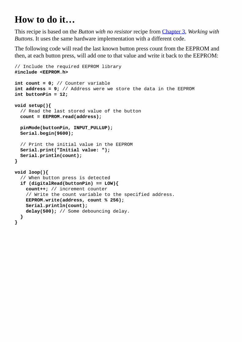
Howtodoit…ThisrecipeisbasedontheButtonwithnoresistorrecipefromChapter3,WorkingwithButtons.Itusesthesamehardwareimplementationwithadifferentcode.
ThefollowingcodewillreadthelastknownbuttonpresscountfromtheEEPROMandthen,ateachbuttonpress,willaddonetothatvalueandwriteitbacktotheEEPROM:
//IncludetherequiredEEPROMlibrary
#include<EEPROM.h>
intcount=0;//Countervariable
intaddress=9;//AddresswerewestorethedataintheEEPROM
intbuttonPin=12;
voidsetup()
//Readthelaststoredvalueofthebutton
count=EEPROM.read(address);
pinMode(buttonPin,INPUT_PULLUP);
Serial.begin(9600);
//PrinttheinitialvalueintheEEPROM
Serial.print("Initialvalue:");
Serial.println(count);
voidloop()
//Whenbuttonpressisdetected
if(digitalRead(buttonPin)==LOW)
count++;//incrementcounter
//Writethecountvariabletothespecifiedaddress.
EEPROM.write(address,count%256);
Serial.println(count);
delay(500);//Somedebouncingdelay.

Howitworks…ThemicrocontrolleroneachArduinohasasmallinternalEEPROMdesignedtoholddataevenwhennopowerisapplied.Thesizeavailablevariesdependingonthemicrocontrollerused.Forexample,theArduinoUnothatusestheATMega328has1KB,whiletheATMega2560foundintheArduinoMega2560has4KB.ThismeansthatanArduinoUnohas1,024addresseswith1byteeach.Inthecodebreakdown,wewillexplorehowtousetheEEPROMandtheEEPROMlibrary.
CodebreakdownAsalways,weneedtoincludetheEEPROM.hlibrary:
#include<EEPROM.h>
ThefirstfunctionweuseintheEEPROMlibraryisthefollowing:
count=EEPROM.read(address);
Here,wereadthevaluefoundintheEEPROMatthatspecifiedaddress,andstoreitinourcountvariable.Wedothisinthesetup()functionsothatwecanbegincountingatthelastsavedvalue.
Followingthis,wedetecteachtimethebuttonispressed.Whenwedetectthat,weincrementthecounterandwritethelatestvaluetothesameaddressontheEEPROM:
EEPROM.write(address,count%256);
TheEEPROMismadeoutof1-bytecells,sowecannotwriteanumbergreaterthan255withoutoverflowing.Wecanusemultiplebytestostorelargervalues,butinthiscase,asit’sjustasimpledemonstration,weusecount%256tosafelystartfrom0when255ispassed.


TimingArduinocodeThisisaquickandveryhelpfulrecipe.Thereareseveraltime-sensitiveapplicationsontheArduino,andsometimesweneedtofindthespeedatwhichtheArduinoexecutesvariouscommands.HerewehaveasimpleimplementationthatwilltellushowmuchtimeittakestosetadigitalpinatHIGHandLOW10,000times.

GettingreadyForthisrecipe,werequireanArduinoboardconnectedtoacomputerviaUSB.

Howtodoit…Wejustneedtowritethefollowingcode:
//Variabletoholdthepassedtime
unsignedlongtime=0;
intpin=3;//Declareapin
voidsetup()
Serial.begin(115200);//HighspeedSerial
pinMode(pin,OUTPUT);
voidloop()
//Getcurrenttime
time=micros();
//Codetobetestedforexecutiontime
for(inti=0;i<10000;i++)
digitalWrite(pin,HIGH);
digitalWrite(pin,LOW);
//Findthepassedtimeandprintit
Serial.println(micros()-time);

Howitworks…Themicros()functionreturnsthenumberofmicrosecondspassedsincetheArduinowasturnedon.Remember,thereare1,000microsecondsinamillisecondand1,000,000microsecondsinonesecond.
Thecodesimplyworksbyrecordingthetimebeforethefunctionwewanttotimeandafter.Then,itsubtractsthetwoandobtainsthetimepassed.Indeed,wewillalsorecordthetimeittakestomakethesubtraction,sothemethodisnotperfect.However,wecandeterminehowlongittakestomakethatsubtractionbyrepeatingit10,000timesandrecordingthetime.


ExternalinterruptsInterruptsareweirdthingsintheArduinoworld;however,theyareimmenselyuseful.Sowhatarethey?Interruptssignaltothemicrocontrollerthatsomethinghashappenedanditneedstotakesomeaction.Basicallytheyworklikethis:wecanattachaninterrupttoadigitalpin.Wheneveritdetectsachange,itwillpauseanythingthemicrocontrollerisdoing,executeafunctionwetellittoexecute,andthenresumenormaloperation.
Inthisexample,wewillfadetwoLEDsusingPWMandwhilethatishappening,wewillbeabletoselectwhichLEDisfadingusingthebuttonconnectedtoaninterrupt.

GettingreadyFollowingaretheingredientsneededforthisrecipe:
AnArduinoboardconnectedtoacomputerviaUSBJumpercablesandabreadboardTwostandardLEDsTworesistorsbetween220–1,000ohmApushbutton

Howtodoit…ThefollowingarethestepstoconnectthetwoLEDsandthebutton:
1. ConnectthetwoLEDstothebreadboardandconnecttheirnegativeterminalstogetherandtoGND.
2. ConnecttoeachpositiveLEDterminaloneresistorandconnecttheotherterminaltopin5andpin6.
3. ConnectoneterminalofthepushbuttontoGNDandtheotheronetopin3,whichisinternallyconnectedtointerrupt1.
SchematicHereisonepossibleimplementationusingpins3,5,and6:
Hereisapossiblebreadboardimplementation:

CodeThefollowingcodewillfadeoneexternalLED.Whenwepressthebutton,itwillchangewhichLEDisfading:
//IncludetherequiredWirelibraryforI2C
intLED1=5;
intLED2=6;
//Setavariablewhichwecanchangeintheinterruptfunction
volatileintcurrentLED=LED1;
voidsetup()
//SetthebuttonpinasaninputwithPULLUPresistor
pinMode(3,INPUT_PULLUP);
//Attachaninterrupttothatpinwhichcorrespondstointerrupt1
//ItwilltriggerwhentheinputsignalsisFALLING
attachInterrupt(1,changeLED,FALLING);
//Functionthatisbeingtriggeredbytheinterrupt
voidchangeLED()
if(currentLED==LED1)currentLED=LED2;
elsecurrentLED=LED1;
voidloop()
//FadeIn
for(inti=0;i<256;i++)
analogWrite(currentLED,i);
delay(10);
//FadeIn
for(inti=255;i>0;i--)
analogWrite(currentLED,i);

delay(10);
NoteDuetobouncingofthebuttonwhenwepressit,theinterruptmighttriggerseveraltimesandunexpectedbehaviormightoccur.

Howitworks…Whenachangeisdetectedonaninterruptpin,thecodeispaused,thespecifiedfunctionisrun,andthecodeexecutionisresumed.Thechangecanbeafallingorrisingedge,andafewmorethings.TakealookattheThere’smore…sectionofthisrecipe.
Let’slookinthecodebreakdown.
CodebreakdownThefirstimportantdifferenceweseeisthevolatilevariabletype:
volatileintcurrentLED=LED1;
Thevolatilevariabletypeisadirectivetothecompiler.IttellstostorethevariableineasilyaccessibleRAMasitwillbeaccessedduringexecution.Anyvariablewechangeduringaninterrupt-attachedfunctionhastobevolatile,otherwiseweirdthingswillhappen.
Inthesetup()function,weattachafunctiontointerrupt1.WecallthechangeLED()functionanditwilltriggerwhenthereisafallingedgeinthesignalontheinterruptpin.Formoreabouttriggertypes,takealookattheThere’smore…sectionofthisrecipe.
attachInterrupt(1,changeLED,FALLING);
Nowlet’sexplorethechangeLEDfunction.Anyfunctionattachedtoaninterruptcannotreturnanything(ithastobeavoidfunction)andcannothaveanyarguments.Anyvariablemodifiedinsideanattachedfunctionhastobevolatile.
voidchangeLED()
if(currentLED==LED1)currentLED=LED2;
elsecurrentLED=LED1;
Inthisfunction,weinvertthecurrentvalueofthecurrentLEDvariable.Ifit’sLED1itbecomesLED2andsoon.ThisfunctioncanexecuteatanytimeaFALLINGedgeisdetectedontheinterruptpin.

There’smore…Herewewilllookalittlemoredeeplyintothedifferentthingsinterruptscando.
InterruptsonvariousArduinosDifferentArduinoshaveadifferentamountofexternalinterrupts.Remember,intheattachInterrupt()function,thefirstparameteristhenumberoftheinterrupt,notthedigitalpinonwhichitcanbefound.Thefollowingtableisagoodreference:
Board Interrupt0 Interrupt1 Interrupt2 Interrupt3 Interrupt4 Interrupt5
Uno,ProMini 2 3 - - - -
Mega2560 2 3 21 20 19 18
Leonardo 3 2 0 1 7 -
Yún 3 2 0 1 7
OntheYún,pins0and1arealsousedforserialcommunication,sotrytoavoidthem.
TheArduinoDue,however,isanexception.Wecanassignaninterrupttoanydigitalpin.IntheattachInterruptfunction,thefirstargumentwillactuallybedigitalPinwewanttouse.
Aboutinterrupt-attachedfunctionsRememberthatthecodepauseswhenaninterruptisdetectedandourfunctionisexecuted.Becauseoftimerinterference,thedelay()functionwillnotwork.Also,charactersreceivedbytheserialduringtheexecutionofourinterruptfunctionmightbedropped.However,thedelayMicrosecond()functionshouldworkjustfine.
Ingeneral,functionstriggeredbyinterruptshouldbeasshortaspossiblewithminimumimpactandexecutiontime.Otherwise,theymightjustdoverystrangethings.
DifferenttriggeringmodesThelastargumentoftheattachInterrupt()functionisthetriggeringmode.TherearefourdifferentmodeswithafifthcustommodefortheArduinoDue:
LOW:ThistriggersthefunctionwheneverthevalueontheinterruptpinisLOW.IfthefunctionfinishesexecutionandthepinisstillLOW,itwillexecuteagainandagainuntilthepinisHIGH.CHANGE:Thistriggersthefunctionwheneverachangeisdetectedontheinterruptpin.ChangemeansthateitherthepinswitchesfromLOWtoHIGHorfromHIGHtoLOW.RISING:ThiswilltriggerthefunctionwheneverthesignalontheinterruptpinchangesfromLOWtoHIGH.FALLING:ThiswilltriggerthefunctionwheneverthesignalontheinterruptpinchangesfromHIGHtoLOW.

HIGH:ThisisaDueexclusiveandworksexactlylikeLOWmode,exceptthatittriggerswhenthesignalisHIGH.
DetachinganinterruptThereisalsoafunctionthatdetachesinterrupts:
detachInterrupt(interrupt);
Itrequirestheinterruptnumberastheargument.OntheDue,itrequiresthepinnumbertowhichtheinterruptwasattached.
OncethedetachInterrupt()functionisused,adifferentfunctioncanbeattachedusingtheattachInterrupt()function.


AppendixA.Electronics–theBasicsTheArduinoisanelectronicplatform.Inordertouseitproperly,weneedtoknowatleastsomebasicsaboutelectronics,suchas:
WorkingofelectriccurrentOhm’slawDiodesandLEDsWorkingwithbreadboards

WorkingofelectriccurrentHere,wewillexplorehowelectriccurrentworks.Electriccurrentrepresentstheflowofelectricalchargeinaconductorandit’smeasuredinamperes,symbolizedbyA.Voltagerepresentsthedifferenceinelectricalpotentialbetweentwopointsofacircuit.Itismeasuredinvolts,symbolizedbyV.Let’sthinkofabattery.Eachbatterycanbeconsideredavoltagesource,andithastwoterminals,apositive(+)andanegative(-).Followingisoneofthestandardizedsymbolsforvoltagesources:
Inthediagram,weseeavoltagesourcethatproduces9volts.Thismeansthatthepositiveterminalhasa9Vdifferenceoverthenegativeterminal.Thenegativeterminalisusuallyreferredtoasground,GNDforshort.Animportantconventionwhendealingwithcurrentisthedirectionofcurrentflow—fromhigherpotential(voltage)tolower.Thefollowingdiagramshowshowthecurrentflowsfromthepositiveterminal,througharesistor,backtothenegativeterminal:
Resistanceisthemeasureofthepropertyofamaterialtoopposecurrentflow.It’smeasuredinohms,symbolizedbytheGreekletterΩ.Theresistoristhecomponentthatusesitsinternalresistancetorestrictcurrentflow.Thisistheschematicsymbol,andnexttoit,anormalresistor:

Inthefollowingsection,wewillseehowresistorsfunctioninacircuit.


Ohm’slawElectronicsisallrelatedtoOhm’slaw.Thisprovidestherelationbetweenvoltage,current,andresistanceinacircuit.Thelawstatesthatthecurrentpassingthrougharesistorisdirectlyproportionaltotheappliedvoltageacrossit.Inmathematicalforms,itlookslikethis:
Asimplewaytorememberandapplyitaccordingtoeitherofthevariablesisthefollowingtriangle:
Ifwewanttofindthecurrent,wecoverIandwegetVdividedbyR.ThesamegoesforR:wecoveritandweobtainVdividedbyI.Lastly,VwillequalImultipliedwithR.Let’snowapplythisknowledgetothefollowingcircuit:

Here,wehaveone5-voltvoltagesourceinserieswithoneresistorR1witharesistanceof100Ω.Becausewehaveonlyoneresistor,thetotalvoltageacrossitwillbeequaltothevoltageofthesource,5V.WecannowapplyOhm’slawtofindthecurrentinthecircuit:
Rememberthat1ampereequals1,000milliamperes,representedbytheunitmA.

ResistorconfigurationsIfwehavemorethanoneresistorinseries,wecanusetheruleofseriesresistance.Itstatesthatanynumberofresistorsinseriescanbereplacedbyonlyone,withtheresistanceequaltothesumofallreplacedresistances.Mathematically,itisdepictedasseenhere:
ThefollowingdiagramshowsthetworesistorsontheleftinseriesR1andR2.Ontheright,itshowsthesamecircuit,butnowwithanequivalentresistorR3,whichequalsR1+R2.
Thereisalsotheparallelresistorconfiguration.Whenwemounttwoormoreresistorsinparallel,thecurrentissplitamongthem.Thisresultsinaloweroverallresistance.Fortworesistors,theformulalookslikethis:
Thefollowingdiagramprovesjustthat.Ontheleftwehavethenormalcircuitwithtworesistorsinparallel,andontherightwehavetheequivalentresistorvalue:

Wecanbuyresistorswithavarietyofinternalresistances.Toeasilydeterminewhatresistancearesistorhas,acolorcodehasbeencreated.Wecanfindthecolorstripesoneveryresistor.Thisisahelperdiagram,whichshowshowtoreadtheresistorcolorcode:
Youcanfindanonlineequivalentresistancecalculatorathttp://calculator.tutorvista.com/equivalent-resistance-calculator.html.


DiodesandLEDsTherearetwomorecomponentsweshoulddiscuss:diodesandLEDs.

DiodesAdiodeisacomponentthatonlyallowscurrenttopassinonedirection.Thearrowinthecircuitsymbolindicatesthisdirection:
Nexttothecircuitsymbolontheleft,wehavearealdiode.Thestriperepresentsthestripeinthecircuitsymbol,andthedirectionwherethecurrentgoesoutofthediode.
Ifwelookatthefollowingcircuits,theoneontheleftwillconductcurrentwhiletheoneontherightwillnot:
However,evenwhenadiodeallowscurrenttopass,itdropsthevoltage.Foratypicalvalue,itdropsthevoltageby0.7V.Let’stryandapplyOhm’slawtotheleftcircuitagain.Ifthediodedropsthevoltageby0.7V,itmeanswehave4.3Vacrosstheresistor.Thiswillresultin:

LEDsThereisavariationofthenormaldiode,calledLightEmittingDiodeorLED.It’sbasicallyaverysmallandefficientlightbulb.WecanfindLEDsineverythingthesedays:displays,phones,computers,toys,andsoon.Theyhavethesamefunctionasadiode,exceptthattheyalsoemitlightwhencurrentpassesthroughthem.Theelectricalsymbolisalmostthesame,butitlookscompletelydifferentinreallife:
Theycomeinavarietyofcolorsandpowerratings.Atypical3-mmgreenLEDwillconsumearound20mAandwillcausea1.9Vdropacrossit.Adiodedoesn’trestricttheamountofcurrentthroughit,soweshouldalwaysconnectaresistorinserieswithadiodeorLED.Inthefollowingschematic,wehavea20mALEDthatcausesa1.9Vdrop.Let’strytocalculatetheperfectresistanceforit:
Duetothe1.9-voltdropacrosstheLED,weonlyhave3.1Vacrosstheresistor.NowwecanapplyOhm’slawtofindtheresistance:

YoucanfindanonlineLEDresistancecalculatorathttp://www.hebeiltd.com.cn/?p=zz.led.resistor.calculator.


WorkingwithbreadboardsWhenweneedtotestaschematic,wecanquicklyassembleelectroniccomponentsonabreadboard.Itisasimpleandverypowerfulinventionthatmakeselectronicsprototypingeasy.
Lookatthebreadboardandcorrelatewiththefollowingdiagram.Breadboardsdifferinsize,shape,andcolorbuttheyallsharethesameprinciple:
Ontheleftwehaveasimplebreadboard;ontheright,wehavethesamebreadboardwiththeinternalconnectionsshown.Atthebottomandthetopoftheboardwecanseeletters.Ifwefollow,wecanseethat,oneachrow,thelettersA,B,C,D,andEareinterconnected,asshownbytheyellowwire.
Thismeansthat,ifweplugapininA,wewillhaveaconnectiontoB,C,DandEonthesamerow.Rowsarenotinterconnected.Asseeninthediagram,eachrowisindividual.Also,onthesamerow,A,B,C,D,andEarenotconnectedinanywaytoF,G,H,I,andJ.
Somebreadboardsalsohavelongpowerconnectorsonthesides.Wecanseetheminthisexamplebytheredandblackcable.TheselongstripsareveryusefulforsupplyingpowerandGNDtodifferentpartsoftheboardeasily.
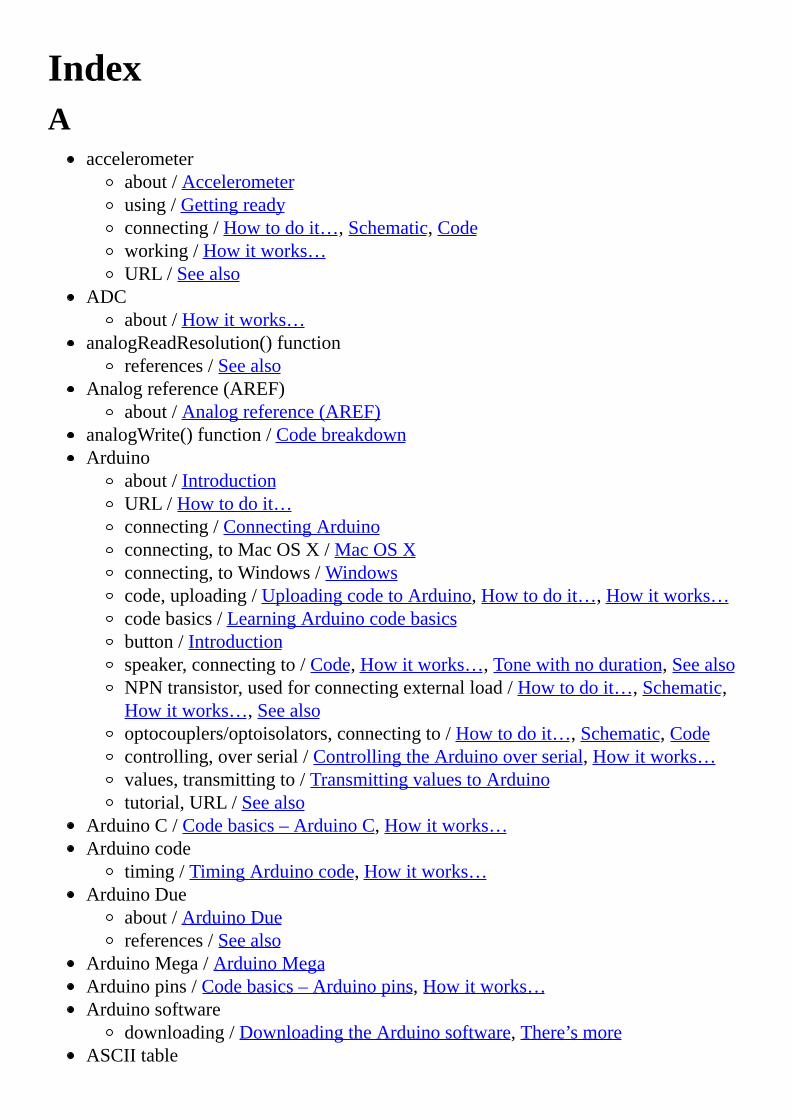
IndexA
accelerometerabout/Accelerometerusing/Gettingreadyconnecting/Howtodoit…,Schematic,Codeworking/Howitworks…URL/Seealso
ADCabout/Howitworks…
analogReadResolution()functionreferences/Seealso
Analogreference(AREF)about/Analogreference(AREF)
analogWrite()function/CodebreakdownArduino
about/IntroductionURL/Howtodoit…connecting/ConnectingArduinoconnecting,toMacOSX/MacOSXconnecting,toWindows/Windowscode,uploading/UploadingcodetoArduino,Howtodoit…,Howitworks…codebasics/LearningArduinocodebasicsbutton/Introductionspeaker,connectingto/Code,Howitworks…,Tonewithnoduration,SeealsoNPNtransistor,usedforconnectingexternalload/Howtodoit…,Schematic,Howitworks…,Seealsooptocouplers/optoisolators,connectingto/Howtodoit…,Schematic,Codecontrolling,overserial/ControllingtheArduinooverserial,Howitworks…values,transmittingto/TransmittingvaluestoArduinotutorial,URL/Seealso
ArduinoC/Codebasics–ArduinoC,Howitworks…Arduinocode
timing/TimingArduinocode,Howitworks…ArduinoDue
about/ArduinoDuereferences/Seealso
ArduinoMega/ArduinoMegaArduinopins/Codebasics–Arduinopins,Howitworks…Arduinosoftware
downloading/DownloadingtheArduinosoftware,There’smoreASCIItable

URL/SeealsoATMega328P
URL/SeealsoattachInterrupt()function/InterruptsonvariousArduinos

BBatteryEliminationCircuit(BEC)/Howtodoit…bipolarsteppermotor
about/Bipolarsteppermotors,Gettingreadyconnecting/Howtodoit…,Code,Howitworks…
breadboardsworkingwith/Workingwithbreadboards
brushlessmotorsabout/Brushlessmotorsconnecting/Howtodoit…,Codeworking/Howitworks…URL/Seealso
bubblesortalgorithmURL/Seealso
buttonabout/Introductionconnecting/Connectingabutton,Gettingready,Schematic,Code,Howitworks…momentarybuttons/Connectingabuttonmaintainedbuttons/Connectingabuttonpull-upconfiguration/Pull-upconfigurationmultiplebuttons/Multiplebuttonsconnecting,toserial/Buttontoserial,Howtodoit…,Codebreakdowndebouncing/Buttondebouncing,Howtodoit…,Howitworks…,Codebreakdownmultiplebuttons,connectingtosinglepin/1,000buttonsto1pin,Schematic,Code,Codebreakdown,There’smore…value,finding/Findingeachbuttonmultiplebuttons,pressing/Pressingmultiplebuttonsmultiplexing/Buttonmultiplexing,Schematic,Howitworks…,There’smore…
button,withnoresistorconnecting/Buttonwithnoresistor,Howtodoit…,Schematic,Code,Howitworks…,Seealsomultiplebuttons/Multiplebuttons
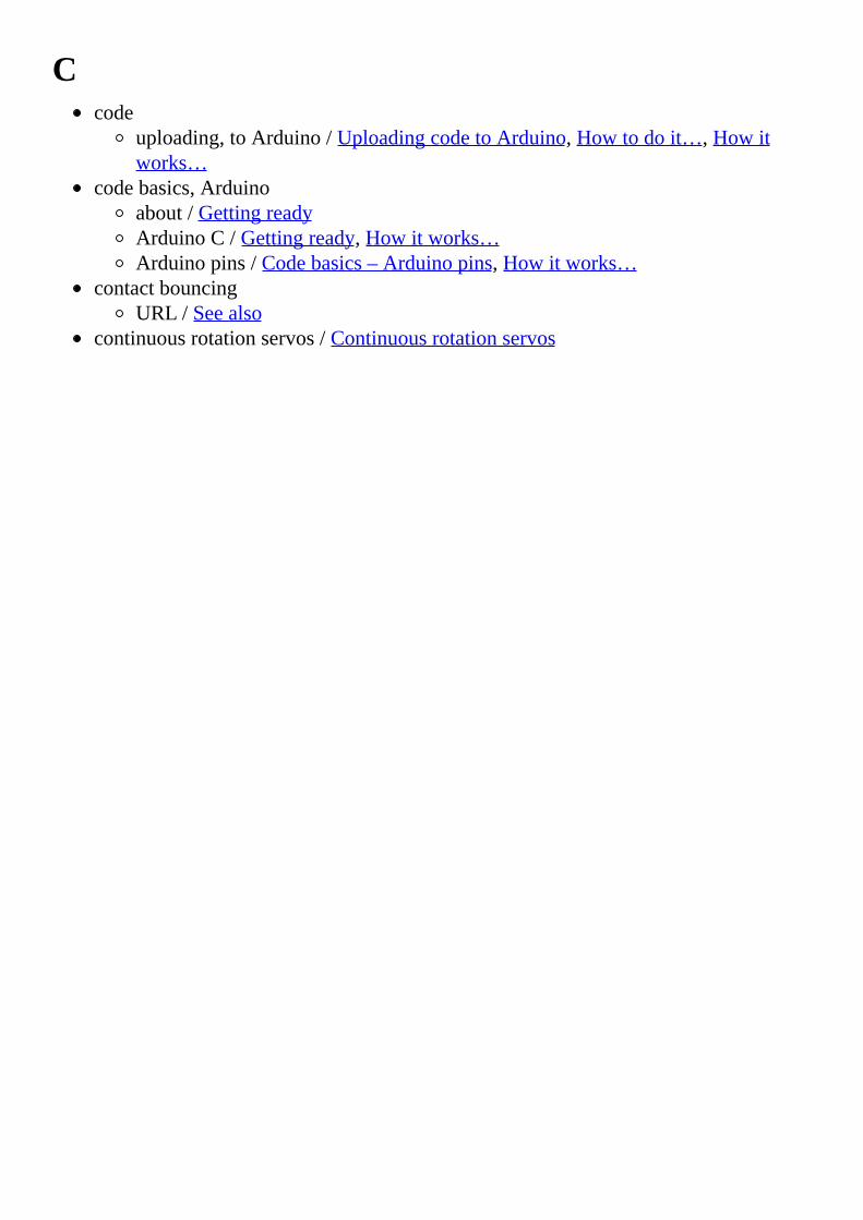
Ccode
uploading,toArduino/UploadingcodetoArduino,Howtodoit…,Howitworks…
codebasics,Arduinoabout/GettingreadyArduinoC/Gettingready,Howitworks…Arduinopins/Codebasics–Arduinopins,Howitworks…
contactbouncingURL/Seealso
continuousrotationservos/Continuousrotationservos

Ddatasheet,forL293D
URL/SeealsoDCmotor
URL/Seealsodelay()function/Howitworks…,Howitworks…,Interferencedemultiplexer
using/Buttonmultiplexing,Schematic,Code,Howitworks…,There’smore…digitalcommunication
advantages/Introductiondigitalpins
URL/Seealsoabout/Moredigitalpinsusing/Gettingready
digitalWrite()function/Howitworks…diodes
about/Diodesdistance-controlledLED
building/Gettingready,Schematic,Code,Howitworks…,There’smore…distancesensor
about/Measuringdistance–infraredandultrasonic
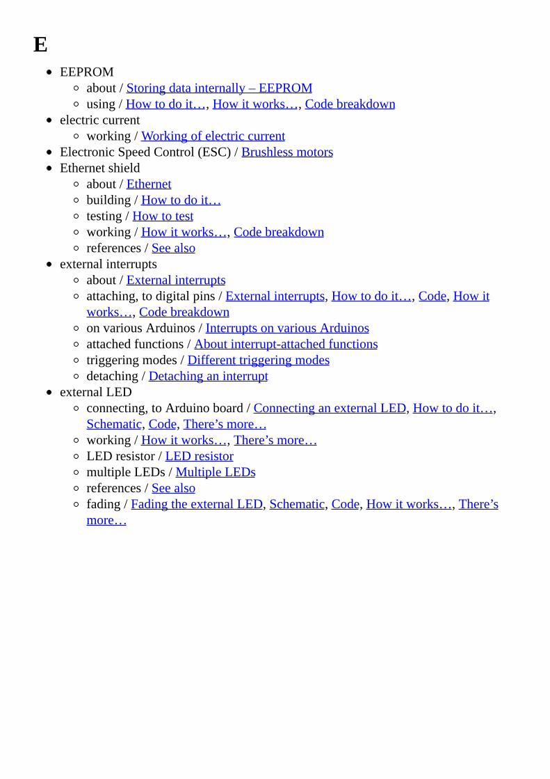
EEEPROM
about/Storingdatainternally–EEPROMusing/Howtodoit…,Howitworks…,Codebreakdown
electriccurrentworking/Workingofelectriccurrent
ElectronicSpeedControl(ESC)/BrushlessmotorsEthernetshield
about/Ethernetbuilding/Howtodoit…testing/Howtotestworking/Howitworks…,Codebreakdownreferences/Seealso
externalinterruptsabout/Externalinterruptsattaching,todigitalpins/Externalinterrupts,Howtodoit…,Code,Howitworks…,CodebreakdownonvariousArduinos/InterruptsonvariousArduinosattachedfunctions/Aboutinterrupt-attachedfunctionstriggeringmodes/Differenttriggeringmodesdetaching/Detachinganinterrupt
externalLEDconnecting,toArduinoboard/ConnectinganexternalLED,Howtodoit…,Schematic,Code,There’smore…working/Howitworks…,There’smore…LEDresistor/LEDresistormultipleLEDs/MultipleLEDsreferences/Seealsofading/FadingtheexternalLED,Schematic,Code,Howitworks…,There’smore…

Ffrequencies,musicnote
URL/Seealso

GGNDport/Commonanode(+)andcommoncathode(-)GPS
about/Localization–GPSusing/Howtodoit…,Schematic,Codeworking/Howitworks…,Codebreakdownreferences/Seealso
Ground(GND)/Generalconnectiontips

II2C
about/I2CbetweenArduinos,MoreaboutI2Cused,forconnectingtwoArduinoUNOs/Code,Howitworks…,Codebreakdowncomparing,indifferentArduinocategories/ComparingdifferentArduinocategoriesdevices,connecting/Connectingmoredevices
IDEabout/DownloadingtheArduinosoftware
InertialMeasurementUnit(IMU)/There’smore…input/output(I/O)pins/Codebasics–ArduinopinsIntegratedCircuit(IC)/Custom-madeL293Ddriver,Optocouplers/Optoisolators

LLCDcharacterdisplays
about/LCDcharacterdisplays,There’smore…using/Howtodoit…connecting,toArduino/Howtodoit…,Codeworking/Howitworks…,There’smore…backlight/There’smore…
LEDabout/Introduction,LEDsblinking,withoutdelay/BlinkingLEDwithoutdelay(),Howtodoit…,Howitworks…,Breakingdownthecodecode,breakingdown/BreakingdownthecodeURL/LEDs
LEDbargraphabout/LEDbargraphconnecting,toArduino/Howtodoit…,Schematic,Howitworks…,Codebreakdownworking/Howitworks…commonanode(+)/Commonanode(+)andcommoncathode(-)commoncathode(-)/Commonanode(+)andcommoncathode(-)variations/Bargraphvariations
loop()function/Howitworks…

MMacOSX
Arduino,connectingto/MacOSXmaintainedbuttons/Connectingabuttonmillis()function/Howitworks…momentarybuttons/ConnectingabuttonMOSFETs/MOSFETsmotors
about/Introductionsmallmotors/Controllingsmallmotorscontrolling,withtransistors/Controllingmotorswithtransistors,Gettingready,Schematic,Code,Howitworks…spinning,inbothdirection/Spinningmotorsbothways,Howtodoit…,Code,Howitworks…,Codebreakdowndirectionpin,using/Controlusingthedirectionpin,PWMpin,andbrakepinPWMpin,using/Controlusingthedirectionpin,PWMpin,andbrakepinbrakepin,using/Controlusingthedirectionpin,PWMpin,andbrakepinInputA,using/ControlusingInputA,InputB,andPWMInputB,using/ControlusingInputA,InputB,andPWMPWM,using/ControlusingInputA,InputB,andPWMcustom-madeL293Ddriver/Custom-madeL293Ddriverservomotors/Servomotorsteppermotor/Steppermotorbipolarsteppermotor/Bipolarsteppermotorsbrushlessmotors/Brushlessmotors
multiplexerusing/Buttonmultiplexing,Schematic,Code,Howitworks…,CodebreakdownURL/Seealso

Nnoisereduction
about/Noisereductionrequisites/Gettingreadysteps/Howtodoit…,Howitworks…filters/Howitworks…
noisereductionfiltersmeanfilter/Meanfiltermedianfilter/MedianfilterMainloop()/Mainloop()
NPNtransistorused,forconnectingexternalloadtoArduino/Howtodoit…,Code,Howitworks…,Seealso

OOhm’slaw
about/Ohm’slawresistorconfigurations/Resistorconfigurations
Ohm’slawabout/Ohm’slaw
optocouplers/optoisolatorsabout/Optocouplers/Optoisolatorsconnecting,toArduino/Howtodoit…,Howitworks…
PpinMode()function/Howitworks…PIRsensor
about/Detectingmotion–PIRsensorhookingup/Howtodoit…,Schematic,Code,Howitworks…
PNPtransistor/PNPtransistorspotentiometer
about/Simplesensor–potentiometerrequisites/Gettingreadyhookingup/Howtodoit…,Schematic,Code,Howitworks…,There’smore…ArduinoDue/ArduinoDueAnalogreference(AREF)/Analogreference(AREF)
pull-downresistor/Pull-downresistorPWM
about/FadingtheexternalLED,FasterPWM,Gettingreadyreferences/Seealsoused,forcontrollingspeed/ControllingspeedwithPWM,Howtodoit…,Schematic,Code,Howitworks…,Codebreakdownworking/Howitworks…,Timer2interference/Interference
PWMhackingURL/Seealso
PWMShieldURL/Seealso

Rrelaydriver
about/Relaydriver,Gettingreadyusing/Howtodoit…,Code,Howitworks…working/Howitworks…
RemoteControl(RC)/Servomotorresistancecalculator
URL/ResistorconfigurationsRGBLED
about/RGBLEDconnecting,toArduinoboard/Howtodoit…,Schematic,Code,Codebreakdown,There’smore…commonanode(+)/Commonanode(+)orcommoncathode(-)commoncathode(-)/Commonanode(+)orcommoncathode(-)PWM,avoiding/WithoutPWM

S7-segmentdisplay
about/The7-segmentdisplayconnecting,toArduino/Howtodoit…,Schematic,Code,Howitworks…,Codebreakdowncommonanode(+)/Commonanode(+)andcommoncathode(-)commoncathode(-)/Commonanode(+)andcommoncathode(-)dot/Thedotvariations/Variations
SDcardsabout/SDcards,Gettingreadyusing,preparationsteps/Howtodoit…,Howitworks…,Codebreakdownlimitations/There’smore…
sensorspotentiometer/Simplesensor–potentiometertemperaturesensors/TemperaturesensorPIRsensor/Detectingmotion–PIRsensordistancesensors/Measuringdistance–infraredandultrasonicdistance-controlledLED/Gettingreadyreferences/Seealsoaccelerometer/Accelerometer
Serial.peek()function/Howitworks…Serial.print()function/There’smore…Serial.println()command/CodebreakdownSerial.read()function/TransmittingvaluestoArduinoSerialClockLine(SCL)/Howitworks…SerialDataline(SDA)/Howitworks…serialoutput
obtaining/Serialoutput,Howitworks…,CodebreakdownSerialProtocolInterface(SPI)/Howitworks…servomotors
about/Servomotorconnecting,toArduino/Howtodoit…,Code,Howitworks…,Codebreakdownexactpulsetime,controlling/Controllingtheexactpulsetimeservos/Moreservoscontinuousrotationservos/Continuousrotationservos
setMotor()function/There’smore…setup()function/Howitworks…,Codebreakdownshiftregisters
about/Moreoutputs–shiftregistersconnecting/Howtodoit…working/Howitworks…,Codebreakdown

SinglePoleDoubleThrow(SPDT)/ConnectingabuttonSinglePoleSingleThrow(SPST)/Connectingabuttonsmallmotors
about/Controllingsmallmotorscontrolling/Gettingready,Schematic,Howitworks…multiplemotors/Multiplemotorselectricalspikes/Electricalspikesreferences/Seealso
softwareserialandUARTbetweenArduinos/SoftwareserialandUARTbetweenArduinos,Gettingreadyused,forconnectingArduinoUNOs/Howtodoit…,Schematic,Codeworking/Howitworks…,Codebreakdownusablepins/Usablepinsmultipleconnections/Moresoftwareserialconnectionsinterference/Interferenceconnectiontips/Generalconnectiontipslibrary,URL/Seealso
sonars/Measuringdistance–infraredandultrasonicsound
creating/Creatingsound,Howtodoit…,Schematic,Code,Howitworks…,There’smore…,Seealso
speakerconnecting,toArduino/Howtodoit…,Code,Tonewithnoduration,Seealso
steppermotorabout/Steppermotor,Gettingreadyunipolar/Steppermotorbipolar/Steppermotorconnecting,commonintegratedcircuitused/Steppermotor,Gettingready,Code,Howitworks…,Codebreakdowntransistorunipolarstepperdriver/Transistorunipolarstepperdrivertype,identifying/IdentifyingthesteppermotortypeURLs/Seealso

Ttemperaturesensors
about/Temperaturesensor,Howtodoit…,Codeworking/Howitworks…,Codebreakdown
TimerURL/Seealso
toggleswitchabout/Thetoggleswitchtwo-statetoggleswitch/Thetoggleswitchusing/Thetoggleswitch,Gettingready,Schematic,Code,Howitworks…,There’smore…connecting,toLEDs/Howtodoit…references/Seealso
tone()functionusing/Howitworks…about/Codebreakdownwithnoduration/Tonewithnodurationonmultiplepins/Toneonmultiplepins
ToolBarVerifybutton/There’smoreUploadbutton/There’smoreNewbutton/There’smoreOpenbutton/There’smoreSavebutton/There’smore
transistordriverabout/Transistordriver
transistorsused,forcontrollingmotors/Controllingmotorswithtransistors,Howtodoit…,Schematic,Code,Howitworks…pull-downresistor/Pull-downresistorPNPtransistor/PNPtransistorsMOSFETs/MOSFETsdifferentloads/Differentloadsreferences/Seealso

UUART
betweenArduinos,andsoftwareserial/SoftwareserialandUARTbetweenArduinos,Schematic,Code
UbuntuLinuxcomputerURL/Seealso

Vvariableresistor/Simplesensor–potentiometervoltagedivider
URL/Seealso

WWindows
Arduino,connectingto/Windowswirelessserial
using/Wirelessserial,Howitworks…

XXbe
URL/Seealso