arduino simulator 1.5 user manual - xevro · connect the arduino simulator to the arduino board...
TRANSCRIPT

Arduino Simulator 1.5
ARDUINO SIMULATOR 1.5
USER MANUAL
XEVRO
Version 1.5
Xevro© 2018
This manual describes all features and capabilities of the Arduino Simulator.

Arduino Simulator 1.5
INTRODUCTION
The Arduino Simulator gives you the tools and components you need to stimulate
your Arduino IO. It’s made for quick tests and small projects and there is still further
developed in order to obtain the widest possible IO functions.
This Arduino IO Simulator is designed to test an Arduino program quickly with the
Arduino board without really having connections to external IO (buttons,
potentiometers, LEDs, LCD displays, ...) and add a nice custom drawing around it to
get a better simulation experience.
To use the simulator we need 3 programs:
- Java JRE
- The Arduino simulation program
- The Arduino IDE
In order to use the Simulator we need to download the Java JRE on our computer,
you can find the download link on the website of Xevro.
ARDUINO IDE
For we start using the Arduino Simulator we need the Arduino software, it is also
freely available on the Arduino website: http://arduino.cc/en/Main/Software
Arduino Simulator 1.5
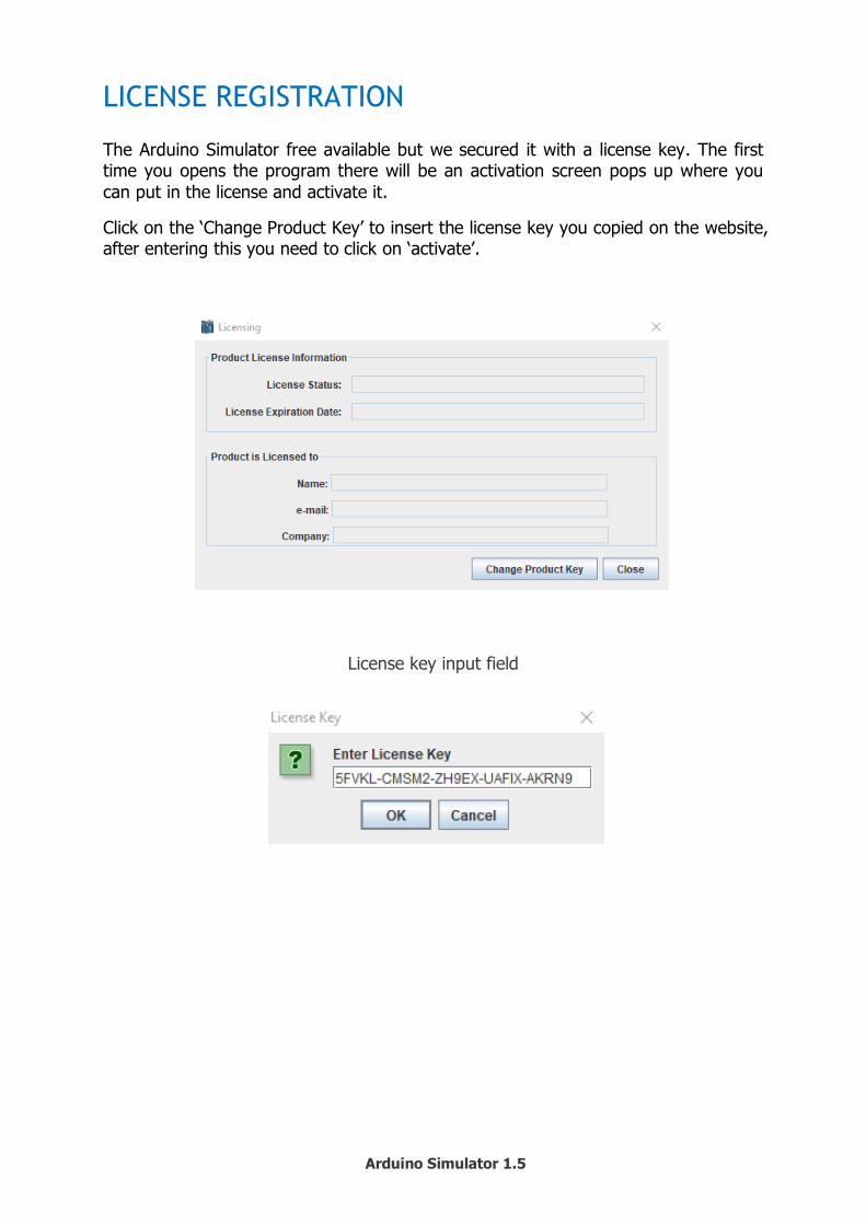
LICENSE REGISTRATION
The Arduino Simulator free available but we secured it with a license key. The first time you opens the program there will be an activation screen pops up where you
can put in the license and activate it.
Click on the ‘Change Product Key’ to insert the license key you copied on the website, after entering this you need to click on ‘activate’.
License key input field

Arduino Simulator 1.5
CODE CHANGES
The Arduino IDE works with instructions that the IO read and write, we must convert
this to serial communication, now we need to write new instructions for this.
We don’t want to change the real instructions so we decided to make the first char-acter as a capital, the instructions with a point in it are changed with no point.
Example 1:
digitalWrite(12, HIGH);
Become DigitalWrite(12, HIGH);
Example 2: lcd.print(“Hello world”);
Become lcdprint(“Hello world”);
The first letter is now a case of removing the tip:
Instructions Arduino Instructions Arduino Simulator
digitalWrite(x,y); = DigitalWrite(x,y); attention: capital letter
digitalRead(x); = DigitalRead(x); attention: capital letter
analogWrite(x,y); = AnalogWrite(x,y); attention: capital letter
analogRead(x); = AnalogRead(x); attention: capital letter
myservo.write(x); = myservowrite(x); attention: the ‘.’ remove
Serial.print(x); = Serialprint(x); attention: the ‘.’ remove
tone(x,y ,z); = Tone(x,y ,z); attention: capital letter
noTone (x); = NoTone(x); attention: capital letter
lcd.setCursor(x,y); = lcdsetCursor(x,y); attention: the ‘.’ remove
lcd.print(long x); = lcdLprint(x); attention: the ‘.’ remove
lcd.print(“x”); = lcdprint("x"); attention: the ‘.’ remove
lcd.autoscroll(); = lcdautoscroll(); attention: the ‘.’ remove
lcd.noAutoscroll(); = lcdnoAutoscroll(); attention: the ‘.’ remove
lcd.clear(); = lcdclear(); attention: the ‘.’ remove
lcd.display(); = lcddisplay(); attention: the ‘.’ remove
lcd.noDisplay(); = lcdnoDisplay(); attention: the ‘.’ remove
lcd.blink(); = lcdblink(); attention: the ‘.’ remove
lcd.noBlink(); = lcdnoBlink(); attention: the ‘.’ remove
Arduino Simulator 1.5
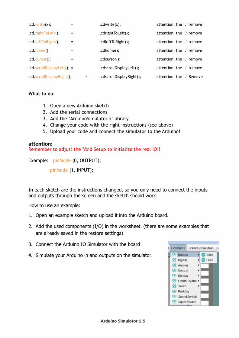
lcd.write(x); = lcdwrite(x); attention: the ‘.’ remove
lcd.rightToLeft(); = lcdrightToLeft(); attention: the ‘.’ remove
lcd.leftToRight(); = lcdleftToRight(); attention: the ‘.’ remove
lcd.home(); = lcdhome(); attention: the ‘.’ remove
lcd.cursor(); = lcdcursor(); attention: the ‘.’ remove
lcd.scrollDisplayLeft(); = lcdscrollDisplayLeft(); attention: the ‘.’ remove
lcd.scrollDisplayRight(); = lcdscrollDisplayRight(); attention: the ‘.’ Remove
What to do:
1. Open a new Arduino sketch
2. Add the serial connections
3. Add the ‘ArduinoSimulator.h’ library
4. Change your code with the right instructions (see above)
5. Upload your code and connect the simulator to the Arduino!
attention: Remember to adjust the 'Void Setup to initialize the real IO!! Example: pinMode (0, OUTPUT);
pinMode (1, INPUT);
In each sketch are the instructions changed, so you only need to connect the inputs and outputs through the screen and the sketch should work.
How to use an example:
1. Open an example sketch and upload it into the Arduino board.
2. Add the used components (I/O) in the worksheet. (there are some examples that
are already saved in the restore settings)
3. Connect the Arduino IO Simulator with the board
4. Simulate your Arduino in and outputs on the simulator.

Arduino Simulator 1.5
HOW TO USE IT
The Arduino Simulator is very easy to understand. The simulator needs 5 simple things in order to work correctly.
1. Connect the Arduino board
2. Upload your custom Arduino code with the corresponding library file 3. Change the original Arduino code
4. Select the used in-outputs in the Arduino Simulator 5. Connect the Arduino Simulator to the Arduino board with the right COM port
1. Connect the Arduino Board
The Arduino Simulator works with a lot of Arduino boards:
Arduino UNO Arduino Mega
Arduino Nano Arduino Leonardo
Arduino ... Only the digital and analog pins that are available on the Simulator can be used!
Disconnect the Arduino Simulator before uploading the Arduino code.
2. Upload your custom Arduino code with the corresponding library file
Open the simulator and go to 'Help -> Arduino UNO programming code -> Arduino UNO programming code (Ino)’.
This will open an Arduino (ino) file with the corresponding library and important code in it.
3. Change the original Arduino code
In order to let the Simulator understand the code, we have devised our own instruc-
tions. To maintain the usability, we have decided to change the current instructions a little bit and replace only the first letter with a capital letter. We have modified the instructions with a point so that the point may be omitted.
digitalWrite(13, HIGH); -> DigitalWrite(13, HIGH);
lcd.print("x"); -> lcdprint("x");
4. Select the used in-outputs in the Arduino Simulator
Each input and output on the Simulator has a selection box where the used digital or analog pin can be connected.
5. Connect the Arduino Simulator to the Arduino board with the right COM
port
The Arduino Simulator knows which port is the Arduino board.
Make sure the Arduino is disconnected while uploading the Arduino code.

Arduino Simulator 1.5
PREPARING THE ARDUINO UNO PROGRAM
Open a new sketch (xx.ino)
The Simulator UNO-program (.ino) and the Simulator library “SimulatorProgram.h”
can found under Help:
Start the “Arduino UNO programming code” application Now you can set your own code into the Arduino if its upload in the Arduino you
can test it with the Simulator.
Attention: The library “SimulatorProgram.h” stand by the Simulator.
Uploading of a new program to the Arduino board
Start the Arduino application
Open the sketch
Arduino UNO connecting with the pc:
Select board “Arduino UNO”
Select the serial port
Upload the program into the Arduino UNO
Attention: The BaudRate on the simulator is 9600.

Arduino Simulator 1.5
CONFIGURE THE COM PORT
Set the BaudRate
The BaudRate is by default set to 9600 or chance the BaudRate in the Arduino code
and in the Simulator.
Set the Com port
First, you need to select the COM port, the USB port that is used by the Arduino.
The Simulator auto detects the Arduino and turns ‘red’.
Before the selection After the selection
Attention:
- At start-up, we also see the state of the simulator at the bottom of the COM port:
Once you have selected the correct COM port changes to this text:
- If you choose the wrong COM port or there is no Arduino connected than you get this message:
- If you select an in or output that is already used you will get an error message:

Arduino Simulator 1.5
USE THE DIGITAL IO
Digital Inputs
The Arduino UNO has 14 digital IO pins that we can
configure into inputs or outputs (IO). These pins get
symbolic images as D0 to D13 and the text change red if
it’s select.
BUTTONS
There are 8 buttons available. The combobox is used to connect the button to one of the 14 IO pins.
The light blue pin can be used to hold down the button
while doing other things, the border changes to red when it’s pressed.
The buttons can be controlled with the DigitalRead() function.
LEDS
There are 14 LEDs available, for every pin of the Arduino 1 led. Use the combobox to connect it with the Arduino. By clicking on the led you can change the color.
The LEDs can be controlled with the DigitalWrite() function.

Arduino Simulator 1.5
BUZZER
The buzzer is used to make a noise with a custom frequency. The combobox is used to connect the buzzer with the Arduino.
The buzzer can be controlled with the DigitalWrite(); function. By sending out a Digi-talWrite(pin, HIGH); signal in the Arduino code, the buzzer will make a noise with the
adjustable frequency (use the slider to change the frequency).
7 SEGMENT DISPLAY
The 7 segment display has 7 digital pins that can connect to D0-6 on the Arduino. The display can be connected in common anode or common cathode.
To light up the display-use DigitalWrite(D0-6);
See the example: Parking.
SLIDERS
There are 3 sliders to connect with one of the 6 analog pins (A0-A5). The sliders can be read by the Arduino with the AnalogRead() function. On the Arduino, you have a white box where the slider value is shown.

Arduino Simulator 1.5
NOISE DETECTION
The noise detection is used to send an analog (0-1023) signal to the Arduino de-pends on the noise level. The combobox is used to connect the noise detector to one of the 6 analog pins (A0-A5).
When you click on the ‘Start Noise Detection’ the detection starts listening to the mi-
crophone noise level. When the noise level exceeded the slider value then it will be send the signal (0-1023) to the Arduino. The limit value in the Arduino code needs to
be lower than the noise detection slider because the signal will be send when the noise is detected.
The noise detection can be controlled with the AnalogRead() function.
BARGRAPH
The bargraph can be connected to one of the 6 digital PWM pins of the Arduino. The bargraph shows the % of your value (0-1023), this can be used to simulate a PWM signal as a % bar.
Use AnologWrite(pin, value); to control the bargraph (See example: sound switch).

Arduino Simulator 1.5
SOUND GENERATOR
The sound generator can be connected to one of the 6 digital PWM pins of the Ar-duino.
By changing the time (ms) you change the duration that the sound goes off (1ms – 10 000ms). The frequency can go from 10hz to 10Khz.
Use AnalogWrite(pin, value); to control the sound generator.
SERVO
The servo can be connected to one digital pin (D12) of the Arduino. The amount of
degrees (°) are visible in the servo. With the MyservoWrite() you can control servo.
LCD DISPLAY
The LCD display can be connected to the Arduino by connecting D2-5, D11 and D12. All the instruction that controls the LCD are changed by removing the ‘.’ point.
example: lcd.print() = lcdprint().
TONE MELODY
The tone melody can be connected to digital pin D8 of the Arduino. The frequency and time of the sound (milliseconds) are present in the light green boxes.
Use Tone(8, f, d); and NoTone(8); (See example: Tone Melody)
NoTone() stops playing sound.
f = frequency
d = duration
Arduino Simulator 1.5
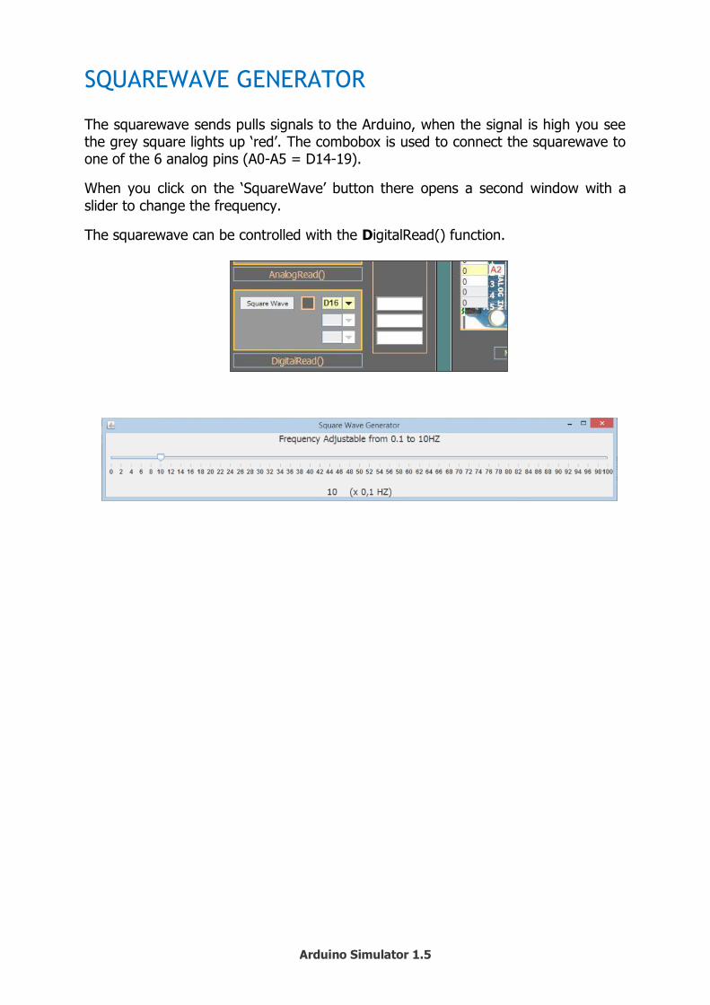
SQUAREWAVE GENERATOR
The squarewave sends pulls signals to the Arduino, when the signal is high you see the grey square lights up ‘red’. The combobox is used to connect the squarewave to one of the 6 analog pins (A0-A5 = D14-19).
When you click on the ‘SquareWave’ button there opens a second window with a
slider to change the frequency.
The squarewave can be controlled with the DigitalRead() function.
Arduino Simulator 1.5
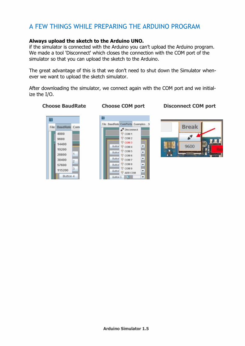
A FEW THINGS WHILE PREPARING THE ARDUINO PROGRAM
Always upload the sketch to the Arduino UNO. if the simulator is connected with the Arduino you can’t upload the Arduino program. We made a tool 'Disconnect' which closes the connection with the COM port of the
simulator so that you can upload the sketch to the Arduino.
The great advantage of this is that we don’t need to shut down the Simulator when-
ever we want to upload the sketch simulator.
After downloading the simulator, we connect again with the COM port and we initial-
ize the I/O.
Choose BaudRate Choose COM port Disconnect COM port
Arduino Simulator 1.5
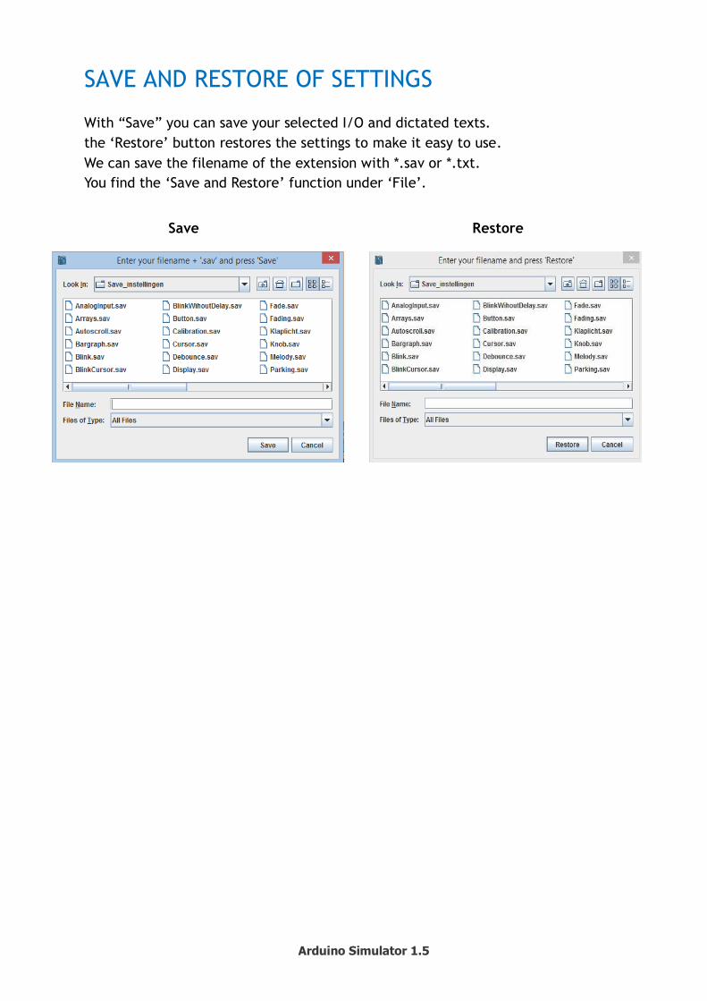
SAVE AND RESTORE OF SETTINGS
With “Save” you can save your selected I/O and dictated texts.
the ‘Restore’ button restores the settings to make it easy to use.
We can save the filename of the extension with *.sav or *.txt.
You find the ‘Save and Restore’ function under ‘File’.
Save Restore
Arduino Simulator 1.5
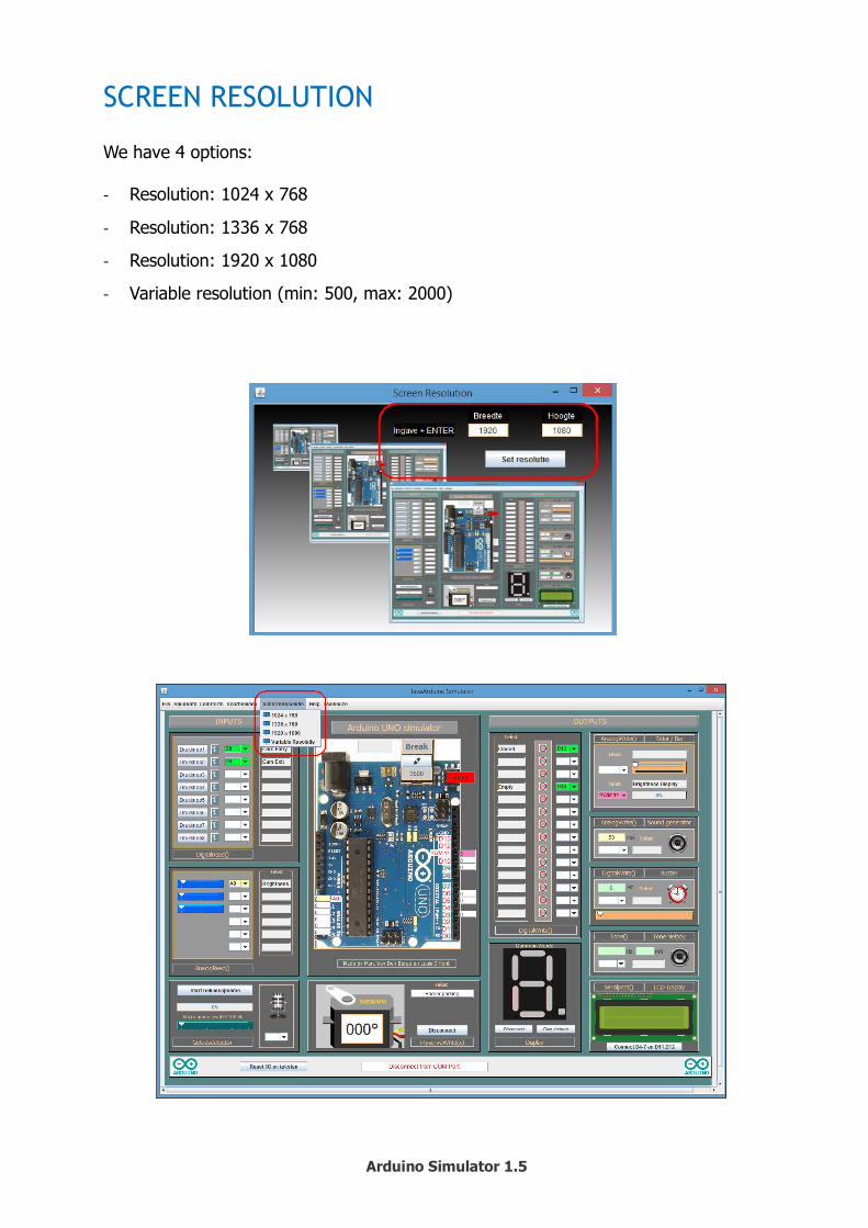
SCREEN RESOLUTION
We have 4 options: - Resolution: 1024 x 768
- Resolution: 1336 x 768
- Resolution: 1920 x 1080
- Variable resolution (min: 500, max: 2000)