arema 2008 annual conference · does the bridge design provide the grade ... computer simulations...
TRANSCRIPT

AREMA 2008 Annual Conference
LOW PROFILE RAILROAD BRIDGE Steve K. Jacobsen, PE
NNW, Inc. Rochester, Minnesota 55904
507-281-5188

Steve K. Jacobsen, PE 2
LOW PROFILE RAILROAD BRIDGE
Steve K. Jacobsen, PE
2,412 word plus tables and figures

Steve K. Jacobsen, PE 3
ABSTRACT A unique low-profile steel box girder railroad bridge design is discussed in this paper which requires
low fabrication and maintenance costs. A 100 foot span was designed with a depth between bottom of
girder and top of rails of 5’-4” which meets the stiffness requirement of AREMA. Computer simulations
were preformed using STAAD using a 3-D model of the bridge. The STAAD analysis verified the
exterior web’s ability to support the external loading and the box’s torsional stiffness to distribute the
loads to all the webs. Based on the STAAD analysis, additional transverse reinforcing steel was added at
the center of the concrete deck in the sidewalk area. The steel box girder design offered an economical
low profile between the rail and the bottom of the girder as is often needed in the railway over the
roadway grade separation. The low profile box girder bridge was successfully built in Iowa City, Iowa,
at a substantial savings of approximately $1 million over a traditional through-girder bridge.
INTRODUCTION
STEEL BRIDGES
Throughout history bridges have been used to extend roadways and railways across bodies of water and
diverse obstacles. In bridge building various materials are used- among the most common are timber,
concrete and structural steel. While timber and concrete are good substances for building bridges of any
type, size or for any purpose, for railroad bridges, the option of choice is steel. This hard, durable and
strong metal is readily available and can be fabricated rather economically. Nevertheless, over the past
few years the cost of labor has increased dramatically. This factor lead us to pursue different options
resulting in the design of a cost efficient bridge demanding the least amount of manual labor possible
during construction. We designed a unique low-profile steel box girder bridge that fit the job site
perfectly, provided pleasing aesthetics and allowed the necessary clearance for traffic below.

Steve K. Jacobsen, PE 4
Figure 1: Conventional Through Plate Girder Cross Section
Through Plate Girder Bridges Many of the railroad bridges over roadways in the United States today are through-plate girder bridges
similar to the one shown above: Through-plate girder bridges have been used for railroads in areas
where the clearance below the bridge was of concern. Another element considered when working with
bridges and with respect to sufficient clearance is grade. Does the bridge design provide the grade
separation necessary to obtain the desired clearance? Raising the railroad grade is very expensive since
raising the railroad tracks would require thousands of feet of grade work in each direction from the
bridge to accommodate the maximum slope requirements. However, this design allows for the rails to
be low in relation to the bottom of the plate girders to attain the desired clearance. These deep exterior
girders are required to support the heavy railroad loads and meet the deflection criteria.

Steve K. Jacobsen, PE 5 The cross section shown in Figure 1 illustrates a conventional through plate girder bridge which was not
a feasible option since it required the use of large amounts of steel that needed to be manually fabricated
and assembled. As stated earlier, steel fabrication is very economical provided automatic welding
processes can be used; however, the process of fabricating and assembling required by the above design
is very labor intensive. Stiffeners are required every couple of feet to provide internal support to the
compression flange. Additionally, a floor beam is required every three feet for railroad load transfer to
the main girders. A steel ballast pan is then set on these crossbeams to form a trough, which will hold
all the ballast, ties, and rail. This system requires many pieces and multiple connections all of which
are very labor intensive.
Steel Box Girder Design Recently, the author designed a steel box girder bridge to span 100 feet over a roadway. A cross section
of the bridge is shown Figure 2:
J2
J
Figure 2: Steel Box Girder Cross Section
Steve K. Jacobsen, PE 6 The box girder consists of three cells with steel bottom and web plates composite with a folded concrete
deck. The folded deck forms the trough for the railroad ballast. Expensive diaphragm fabrication is
avoided due to the inherent torsional stability of the box section. The proposed bridge was successfully
built at a substantial savings over the traditional through-girder bridge.
The cross section had a depth between bottom of girder and top of rails of 5’-4” which made this a low-
profile bridge. The steel “tub” was fabricated in two sections 100’ long joined with a splice at the center
as seen in Figure 2. The box girder design utilizes the concrete deck as a compression member which
makes efficient use of the concrete compression strength. To further streamline the design, the box
girder used a concrete diaphragm rather than steel diaphragm at midspan and at the supports.
The concrete deck inherently forms a trough for the ballast to be placed. Deck drains where placed on
each side to drain to one abutment. After this was completed, the railroad ties and rails where placed in
the ballast.
Design Requirements
The bridge superstructure was designed to meet AREMA1 specifications and had many design
components taken into account. The following is a list of some of the major design criteria:
• Stress in box steel: the steel stresses were taken to be less than 0.55Fy.
• Live load deflection criteria: L/640 deflection limit, which is 1.875 inches for a 100 foot span.
The materials chosen to resist the loads and construct the box were:
• Steel Plates: ASTM A709, Grade 50
• Concrete deck: Minimum concrete compression stress of 5,000 psi.
Both of these materials are readily available in the area where this bridge was constructed.
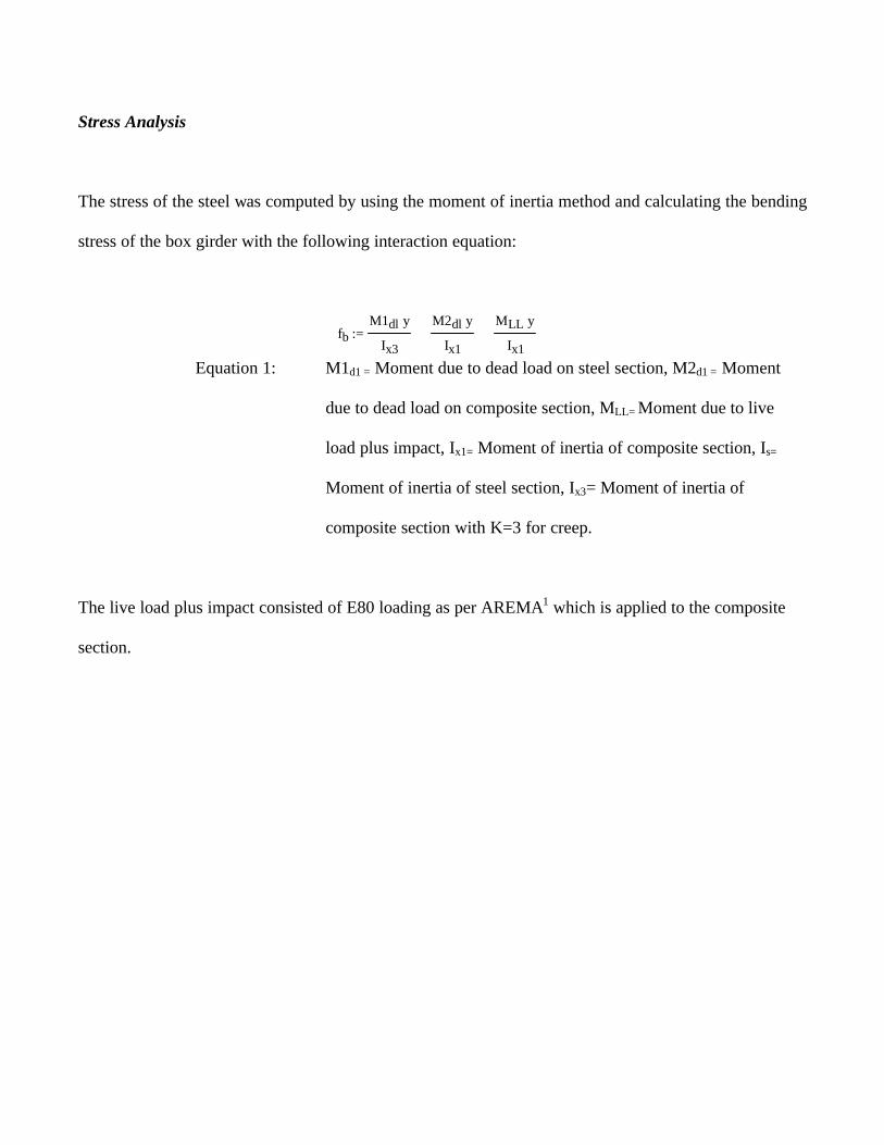
Steve K. Jacobsen, PE 7 Stress Analysis
The stress of the steel was computed by using the moment of inertia method and calculating the bending
stress of the box girder with the following interaction equation:
fbM1dl y⋅
Ix3
M2dl y⋅
Ix1+
MLL y⋅
Ix1+:=
Equation 1: M1d1 = Moment due to dead load on steel section, M2d1 = Moment
due to dead load on composite section, MLL= Moment due to live
load plus impact, Ix1= Moment of inertia of composite section, Is=
Moment of inertia of steel section, Ix3= Moment of inertia of
composite section with K=3 for creep.
The live load plus impact consisted of E80 loading as per AREMA1 which is applied to the composite
section.

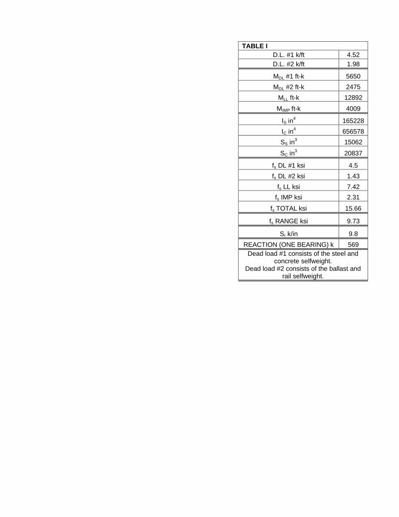
Steve K. Jacobsen, PE 8
The dead loads are a combination of the concrete and steel
which are applied to the steel section, and ballast, and rail
which are applied to the composite section with a k value of 3
to account for creep in the concrete deck. The total stress in
the box girder steel was 15.66 ksi (see table 1) which is much
less than the allowable stress of 27.5 ksi.
Deflection Analysis
The steel design was governed by the live load deflection
criteria of L/640 as required by AREMA1. The live load
deflection had to be less than 1.875 inches for the 100-foot
span.
The bottom plate thickness and the thickness of the upper concrete flanges over the exterior webs were
the variables used to obtain the required stiffness. The lower concrete flange was too close to the neutral
axis to be very effective so its thickness was held at 8 inches. These variables could be adjusted without
substantially affecting the depth of the structure between the top of rail and bottom of girder. The final
dimensions were 2 inches for the bottom plate and 12 inches for the upper concrete flanges. The live
load deflection was verified by STAAD.
TABLE I D.L. #1 k/ft 4.52 D.L. #2 k/ft 1.98
MDL #1 ft-k 5650
MDL #2 ft-k 2475
MLL ft-k 12892
MIMP ft-k 4009
IS in4 165228
IC in4 656578
SS in3 15062
SC in3 20837
fs DL #1 ksi 4.5
fs DL #2 ksi 1.43
fs LL ksi 7.42
fs IMP ksi 2.31
fs TOTAL ksi 15.66
fs RANGE ksi 9.73
Sr k/in 9.8
REACTION (ONE BEARING) k 569 Dead load #1 consists of the steel and
concrete selfweight. Dead load #2 consists of the ballast and
rail selfweight.

Steve K. Jacobsen, PE 9 Compression Flange Analysis The upper concrete flanges were designed as concrete columns, fully supported. The longitudinal steel
in the flanges were computed using the following equation:
ΦPo 0.80 Φ⋅ 0.85 f'c⋅ Ag As−( )⋅ As fy⋅+ ⋅:=
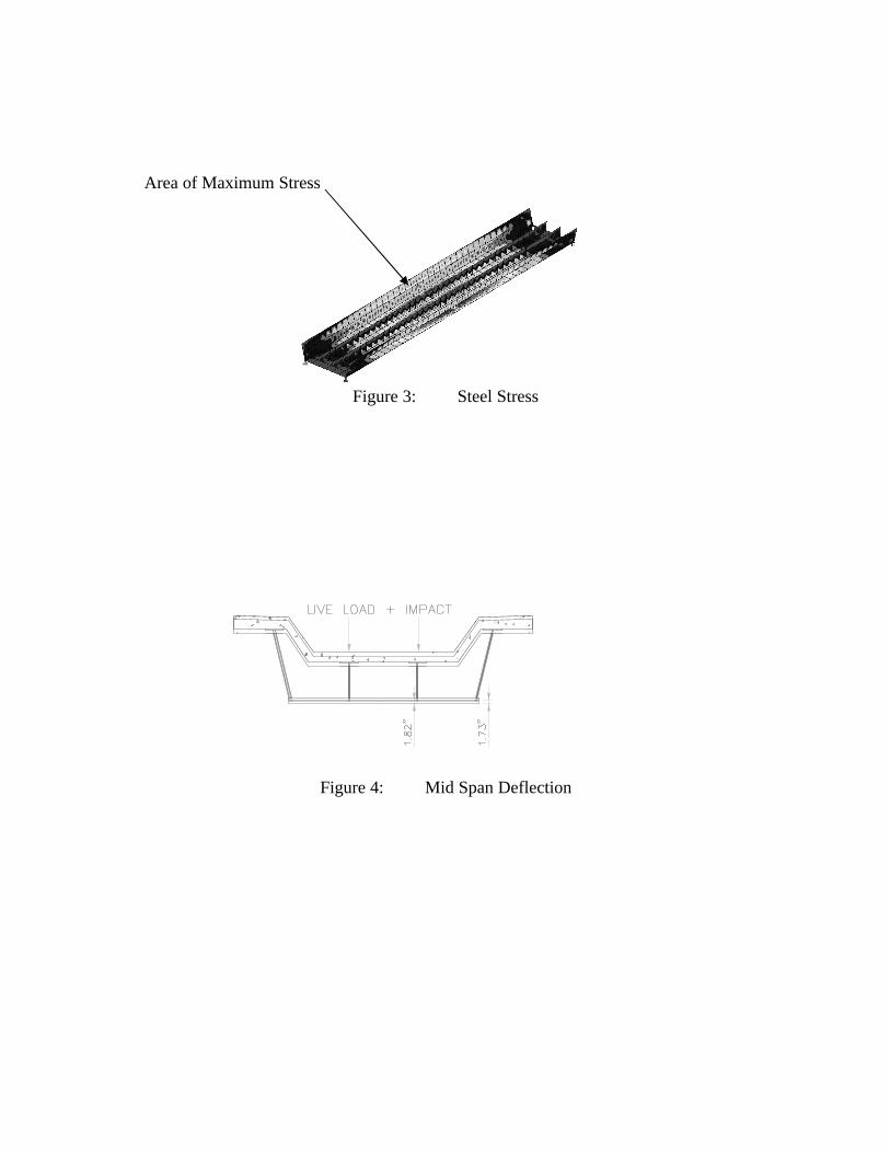
Equation 2: Concrete Compression Strength The concrete deck utilized the inherent compression capacity of concrete. A subsequent review of all the above equations was completed by performing a finite element analysis
of the superstructure. Computer simulations were preformed by STAAD using a 3-D model of the
bridge. As expected, the stress in the steel was greatest at midspan as shown in Figure 3:
Area of Maximum Stress
Figure 3: Steel Stress
The geometry of this design requires the live load to be applied over the shorter (interior) webs. This,
plus the fact that there is a significant difference in web heights, and thus stiffness, caused some concern
as to the ability of the exterior webs to pick up the load. A STAAD analysis confirmed the exterior
webs ability to pick up the load and vanished any concerns that had surfaced. Since the deflection at the
bottom of the box was nearly the same at the interior web as at the exterior web it was concluded the
torsional stiffness of the box was adequately transferring the load (see Figure 4).

Steve K. Jacobsen, PE 10
Figure 4: Mid Span Deflection
STAAD also showed an unanticipated stress in the center of the concrete deck. This section near the
middle of the span in the sidewalk areas required additional transverse reinforcing steel to compensate
for this transverse stress. The higher stress in the sidewalk near midspan is shown in Figure 5.
Area of Maximum Stress
Figure 5: Concrete Stress
Box Webs and Diaphragms To further simplify fabrication, the idea of steel diaphragms was discarded and concrete diaphragms
were used instead. These concrete diaphragms are attached to the steel box by standard shear studs
welded to the steel plate and connected to the concrete slab with stirrup reinforcing.
The steel webs were sized to meet the thickness requirements of AREMA1 without stiffeners. The
exterior webs are 1.25 inches and the interior webs are ¾ inches thick. Although this meant more steel
Steve K. Jacobsen, PE 11 than standard transversely stiffened webs, significant savings were realized in the simplicity of the
fabrication.
Economy The estimated savings using this low profile box is approximately $1,000,000. Currently, the average
cost per pound of fabricated and erected steel is this region is $1.57. The cost for this bridge was $1.07
per pound. Although the web steel added some additional pounds, the 1/3 savings in the unit cost
effectively compensated for the additional weight. The cost of the basic 100-foot span bridge was
$960,000 with an additional $ 315,000 spent on aesthetics items such as limestone, lighting and
decorative railing. The temporary shoo-fly added and additional $520,000 bringing the total
construction cost to $1,795,000.
ADVANTAGES OF THE BOX GIRDER SYSTEM The box girder design utilizes the concrete deck as a compression member, which makes efficient use of
the concrete compression strength. Also, the folded deck allows the lowest possible railway to roadway
difference and enables clearance requirements to be met. To follow are photographs (Figure 6 through
10) that show certain phases of the construction process:

Steve K. Jacobsen, PE 12
Figure 6: Placement of Steel Girders Figure 7: Bottom Girder Assembly
Figure 8: Placement of Deck Reinforcing Figure 9: Poured Concrete Deck
Figure 10: Placement of Rails Figure 11: Open for Business

Steve K. Jacobsen, PE 13 The time needed to construct the bridge was accelerated by eliminating the need for any field welding.
The steel beams were brought to the site in two separate pieces, spliced together, set in place and then
ready to have the concrete deck formed. As seen in figure 9, the deck forms a nice trough for the ballast
and rails, which worked to provide a smooth transition across the bridge.
AESTHETICS Some fundamentals on what aesthetically pleasing bridges have in common are:
• they are simple (fewer individual members)
• girders are relatively thin (large span to depth ratios)
• the lines in the structure are continuous
The box girder design eliminates the need for all interior bracing members of a through plate girder
bridge. This keeps the design looking simple, clean and appealing.
The typical railroad bridge appears to be bulky from the roadway below due to the large plate girders on
each side of the tracks. The box girder design decreases the depth of the structure thus making the
bridge more attractive.
Finally, the box girder design has two continuous lines running the length of the bridge. The top line is
the concrete slab and the bottom the actual steel girder. Using two lines is more aesthetically pleasing
since the appearance of two thin lines is more appealing than one thick line.
Completing its appeal is fiber optic lighting running next to the bridge girders which accentuates this
bridge and adds a line of interest at the steel/concrete interface. The limestone veneer applied to the
columns of the abutments enhances its beauty while virtually see thru rail keeps the bridge looking

Steve K. Jacobsen, PE 14 slender. These features along with special landscaping make the bridge a useful yet aesthetically
pleasing structure fulfilling its purpose and existing in harmony with the distinctive surroundings of a
unique town full of architectural virtues.
Figure 12: Elevation of Bridge CONCLUSIONS
The steel box girder design offers an economical low profile between the rails and the bottom of the
girder as needed in most railway over roadway applications. While the price of producing steel has not
risen in recent years the increased cost of labor has caused the expense of fabricating steel bridges to rise
significantly. This box girder design minimizes the fabrication costs while maintaining all design
requirements. Overall it produces a clean, aesthetically pleasing, and cost effective bridge.

Steve K. Jacobsen, PE 15
REFERENCES
1. American Railway Engineering and Maintenance of Way Association (AREMA), 2000,
“Manual For Railway Engineering.”

Steve K. Jacobsen, PE 16 Equations Used in Paper
Equation 1: Stress Equation
Equation 2: Concrete Compression Strength
Figures Used in Paper
Figure 1: Conventional Through Plate Girder Cross Section Figure 2: Steel Box Girder Cross Section Figure 3: Steel Stress Figure 4: Mid Span Deflection Figure 5: Concrete Stress Figure 6: Placement of Steel Girders Figure 7: Bottom Girder Assembly Figure 8: Placement of Deck Reinforcing Figure 9: Poured Concrete Deck Figure 10: Placement of Rails Figure 11: Open for Business
Tables used in Paper-
Table 1: Loads, Section Properties and Stresses
Steve K. Jacobsen, PE 17
TABLE I D.L. #1 k/ft 4.52 D.L. #2 k/ft 1.98
MDL #1 ft-k 5650
MDL #2 ft-k 2475
MLL ft-k 12892
MIMP ft-k 4009
IS in4 165228
IC in4 656578
SS in3 15062
SC in3 20837
fs DL #1 ksi 4.5
fs DL #2 ksi 1.43
fs LL ksi 7.42
fs IMP ksi 2.31
fs TOTAL ksi 15.66
fs RANGE ksi 9.73
Sr k/in 9.8
REACTION (ONE BEARING) k 569 Dead load #1 consists of the steel and
concrete selfweight. Dead load #2 consists of the ballast and
rail selfweight.

Steve K. Jacobsen, PE 18 BLACK AND WHITE FIGURES
Figure 1: Conventional Through Plate Girder Cross Section
J2
J
Figure 2: Steel Box Girder Cross Section
Steve K. Jacobsen, PE 19
Area of Maximum Stress
Figure 3: Steel Stress
Figure 4: Mid Span Deflection

Steve K. Jacobsen, PE 20 Area of Maximum Stress
Figure 5: Concrete Stress

Steve K. Jacobsen, PE 21
Figure 6: Placement of Steel Girders Figure 7: Bottom Girder Assembly
Figure 8: Placement of Deck Reinforcing Figure 9: Poured Concrete Deck
Figure 8: Placement of Deck Reinforcing Figure 9: Poured Concrete Deck

Steve K. Jacobsen, PE 22
Figure 10: Placement of Rails Figure 11: Open for Business
Figure 12: Elevation of Bridge