ares - an electron linac for reaching the atto … · ares - an electron linac for reaching the...
TRANSCRIPT

ARES - An electron linac
for reaching the atto-second regime
at SINBAD
B. Marchetti (DESY) PI SINBAD-ARES linac
ARD lunch seminar
18.03.2016 – DESY Hamburg

Barbara Marchetti | ARD Seminar | 2016 | Page 2
Outline
> Introduction: Why Short Bunches and the SINBAD Facility?
> The ARES linac: A Design for Sub-Femto Second Bunches
> Plasma Acceleration with the ARES linac
> Final Considerations and Summary

Barbara Marchetti | ARD Seminar | 2016 | Page 3
Outline
> Introduction: Why Short Bunches and the SINBAD Facility?
> The ARES linac: A Design for Sub-Femto Second Bunches
> Plasma Acceleration with the ARES linac
> Final Considerations and Summary

Barbara Marchetti | ARD Seminar | 2016 | Page 4
Applications of accelerators
Accelerators are of fundamental importance
for:
> Research in high energy physics
> Radiation generation (SR and CSR, FELs,
CTR etc.)
> Medical applications (radiation therapy,
hadron therapy etc.)
> …
LHC 27 km circumference
European XFEL 3.4 km
length
Many applications demand for
• Compactness
• Cost efficiency

Barbara Marchetti | ARD Seminar | 2016 | Page 5
Scaling of the accelerating gradient and dimensions with
the RF frequency
• Correlation
• RF frequency
• gradient
• cell length
• Moving to higher
frequencies the
accelerators are more
compact
• W-band is attractive
but not trivial to
achieve because…
Advanced acceleration

Barbara Marchetti | ARD Seminar | 2016 | Page 6
> No klystrons for high frequencies! Use particle bunches or laser
pulses as drivers.
> Material limitations dielectric materials, plasma cavities, …
Plasma
Accelerator Laser- or beam driven
Dynamic Plasma Structure
Plasma field calculations
High Gradient Accelerators
Microstructure
Accelerator Laser- or beam driven
Vacuum accelerators
Conventional field design
1 2
Two main directions:
High
Gradients
(1-100 GV/m)
High
Gradients
(1-100 GV/m)
High
Frequencies
(> 100 GHz)
High
Frequencies
(> 100 GHz)
Small
Dimensions
(< 1 mm)
Small
Dimensions
(< 1 mm)
Barbara Marchetti | ARD Seminar | 2016 | Page 7
Examples of novel high gradient acceleration techniques
(1/3)
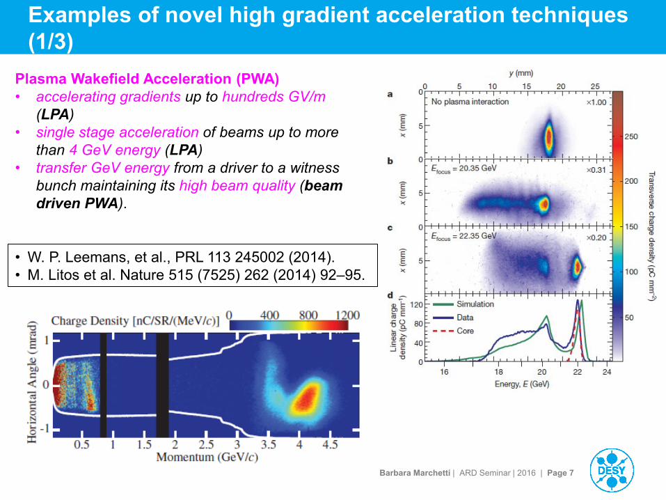
Plasma Wakefield Acceleration (PWA)
• accelerating gradients up to hundreds GV/m
(LPA)
• single stage acceleration of beams up to more
than 4 GeV energy (LPA)
• transfer GeV energy from a driver to a witness
bunch maintaining its high beam quality (beam
driven PWA).
• W. P. Leemans, et al., PRL 113 245002 (2014).
• M. Litos et al. Nature 515 (7525) 262 (2014) 92–95.

Barbara Marchetti | ARD Seminar | 2016 | Page 8
Examples of novel high gradient acceleration techniques
(2/3) Dielectric Wakefield Acceleration (DWA)
• Driver electron beam to load wake-fields
on the dielectric structure
• Gradients up to few GV/m have been
demonstrated
• M. C. Thompson, et al., Phys.
Rev. Lett. 100 310 (2008)
214801.
Dielectric Laser Acceleration (DLA)
• μJ laser pulse having μm wavelength.
• micro-structure made by a dielectric
material, e.g. SiO2 or Si.
• The achievable gradients are of the order of
few hundreds MV/m.
• E. A. Peralta, et al., Nature 503
(2013) 91–94.

Barbara Marchetti | ARD Seminar | 2016 | Page 9
Examples of novel high gradient acceleration techniques
(3/3)
THz based acceleration
• mJ THz laser
• metallic structure loaded with dielectrics
• In principle should allow reaching high
gradients (GV/m) together with a high
repetition rate
• E. A. Nanni, et al., Nat. 312 Comm. 6
(2015) 8486.
Hosted at SINBAD belongs to
this category.

Barbara Marchetti | ARD Seminar | 2016 | Page 10
… Interim Summary
> Novel accelerators operate with short wavelengths
> Require short bunch lengths for injection to minimize RF curvature
effect
> In some cases relativistic beam energies help with the phase velocity
matching
> … Very short, relativistic bunches not easily available, therefore
SINBAD facility and ARES linac.

Barbara Marchetti | ARD Seminar | 2016 | Page 11
SINBAD (Short and INnovative Bunches and Accelerators at Desy)
Dedicated multi-
purpose accelerator
R&D facility with
several experiments
for ultra-fast science
and high gradient
accelerator modules.
Project Leader:
Ulrich Dorda
ACHIP use of ARES short bunches for
an accelerator on a chip
SINBAD linac Ultra-fast science
AXSIS Atto-second science with THz
laser acceleration

Barbara Marchetti | ARD Seminar | 2016 | Page 12
SINBAD (Short and INnovative Bunches and Accelerators at Desy)
Dedicated multi-
purpose accelerator
R&D facility with
several experiments
for ultra-fast science
and high gradient
accelerator modules.
Project Leader:
Ulrich Dorda
ACHIP use of ARES short bunches for
an accelerator on a chip
SINBAD linac Ultra-fast science
AXSIS Atto-second science with THz
laser acceleration
PI ARES linac at SINBAD: B. Marchetti

Barbara Marchetti | ARD Seminar | 2016 | Page 13
SINBAD (Short and INnovative Bunches and Accelerators at Desy)
2014
Today

Barbara Marchetti | ARD Seminar | 2016 | Page 14
Outline
> Introduction: Why Short Bunches and the SINBAD Facility?
> The ARES linac: A Design for Sub-Femto Second Bunches
SINBAD-ARES as an accelerator R&D experiment
Design Philosophy from Application Boundary Conditions
Layout and some technical highlights
Beam parameters and compression techniques
> Plasma Acceleration with the ARES linac
> Final Considerations and Summary

Barbara Marchetti | ARD Seminar | 2016 | Page 15
ARES (Accelerator Research Experiment at Sinbad)
• Conventional linac (S-band norm. cond.) for the production of ultra-short bunches:
Charge: 0.5-20 pC (up to 1nC)
Energy ~ 100 MeV
Bunch length: few fs / sub-fs
Transverse norm. emittance < 0.5 mm*mrad
Arrival Time jitter stability < 10 fs RMS
E=100 MeV

Barbara Marchetti | ARD Seminar | 2016 | Page 16
SINBAD-ARES linac as an Accelerator R&D Experiment
• Goal: production & characterization of ultra-short bunches (tFWHM≤1fs)
Charge as high as possible
Relaxed transverse spot-size (>100 μm)
Mainly technical challenges
Challenges in beam
diagnostics: Low charge:
Low signal/noise ratio
Some diagnostics not yet
available/under development
Sub-fs longitudinal resolution is needed:
state of the art are Xband TDS with 1 fs
resolution.
Challenges in
synchronization:
fs level synchronization is needed
(both RF-RF and laser-RF).
The requirements demand a very careful design of all systems (e.g. water cooling).

Barbara Marchetti | ARD Seminar | 2016 | Page 17
SINBAD-ARES linac as an Accelerator R&D Experiment
• Goal: production & characterization of ultra-short bunches (tFWHM≤1fs)
Charge as high as possible
Relaxed transverse spot-size (>100 μm)
Mainly technical challenges
Challenges in beam
diagnostics: Low charge:
Low signal/noise ratio
Some diagnostics not yet
available/under development
Sub-fs longitudinal resolution is needed:
state of the art are Xband TDS with 1 fs
resolution.
Challenges in
synchronization:
fs level synchronization is needed
(both RF-RF and laser-RF).
The requirements demand a very careful design of all systems (e.g. water cooling).

Barbara Marchetti | ARD Seminar | 2016 | Page 18
SINBAD-ARES linac - general philosophy for future
experiments
• Who will be the „users“ of the SINBAD linac?
Experiments involving Novel High Gradient Acceleration Techniques: e.g. LPWA,
Dielectric Wake-Field Acceleration, THz laser acceleration in dielectric-loaded structures…
• What types of e-beam will such experiments need?
Initially
characterization of the
acceleration method and
optimization of the beam
quality of the accelerated
beam
At a later stage
pilot user experiments
involving e.g. radiation
production (via FEL, ICS …)
• Ultra-short probes time resolution
• Ultra-high stability synchronization
• Small transverse focus (tens of μm – few
μm)
• Sufficiently high brightness radiation
generation
• The e-bunch duration has to be tuned,
according to the requirements for the
production of radiation.

Barbara Marchetti | ARD Seminar | 2016 | Page 19
SINBAD-ARES linac – some technical details
25.3m
Bunch compressor
R56= -10mm
Dogleg tunable R56
Range -10/10mm
-3.49o
-3.49o
+3.49o
+3.49o
30.2m
Slit
Special attention is being given to the flexibility and the stability of the
elements:
• Load-lock system for cathode exchange
• 2 gun solenoids respectively for low charge/high charge WPs
• Each RF cavity fed by one klystron. No SLEDs.
• Flexible photo-cathode laser system
Gun
solenoid
RF gun, 2.998 GHz
(REGAE-type)
Beam final
energy~5MeV
TW RF cavity, 2.998 GHz
To be used as RF
compressor
Solenoids
TW RF cavity, 2.998 GHz
Max. accelerating
gradient ~ 20 MV/m
Space for future beam
energy upgrade

Barbara Marchetti | ARD Seminar | 2016 | Page 20
ARES Photo-Cathode laser (specified and already installed at temporary location)
> Production of short pulses starts at the photo-cathode:
Specifications coming from beam dynamics (flexibility WP bunch compression)
• Cs2Te:
• QE = 4%-11%
• Response
time~ps
• Cu:
• QE = 0.014%
• Response
time<ps

Barbara Marchetti | ARD Seminar | 2016 | Page 21
ARES Photo-Cathode laser (specified and already installed at temporary location)
> Production of short pulses starts at the photo-cathode:
Specifications coming from beam dynamics (flexibility WP bunch compression)
Experience with available laser systems on the market (laser group, LAOLA
colleagues…)

Barbara Marchetti | ARD Seminar | 2016 | Page 22
ARES Photo-Cathode laser (specified and already installed at temporary location)
> Production of short pulses starts at the photo-cathode:
Specifications coming from beam dynamics (flexibility WP bunch compression)
Experience with available laser systems on the market (laser group, LAOLA
colleagues…)
> Optimal solution identified:
• Yb doped laser
• Pulse energy ≥1mJ
• Central wavelength: 1030 nm (4th harmonic 257 nm)
• Pulse length range tunable: 180fs-10ps
> Note: This is different from other photo cathode lasers at DESY.

Barbara Marchetti | ARD Seminar | 2016 | Page 23
ARES Photo-Cathode laser at DESY
• Laser setup in I. Hartl‘s laboratory.
• It is operated by Lutz Winkelmann for
experiments on laser shaping.

Barbara Marchetti | ARD Seminar | 2016 | Page 24
ARES – planned diagnostics in the RF gun region
Gun + coupler +
laser vacuum
mirror
Low
charge
solenoid
Dual
plane
steerer
Vacuum
valve
Reference
for BPM
Diagnostics cross-
section
(screen + pepperpot+
collimator + faraday
cup)
Dipole
Dual
plane
steerer
Diagnostics cross-
section
(screen + collimator)
BPM
BCM
Vacuum
valve
BAM

Barbara Marchetti | ARD Seminar | 2016 | Page 25
ARES: compression techniques and beam dynamics
> Very short bunches must address many physics limitations:
Space charge
Non-linearity of phase space
CSR
Tolerances …
> Three techniques studied and possible to implement:
Velocity Bunching (VB)
Magnetic Compression with slit (MC)
Hybrid combination of VB and MC:
In the chicane (fixed R56= -10 mm)
In the dogleg (variable -10mm< R56 <+10mm)
> All of them have their advantages and disadvantages
> Now: Going through in detail...

Barbara Marchetti | ARD Seminar | 2016 | Page 26
Bunch compression by velocity bunching
• L. Serafini and M. Ferrario, AIP Conf. Proc. 581, 87-106 (2001).
• S.G. Anderson et al. PRSTAB 8 014401 (2005).
• M. Ferrario et al. PRL 104 054801 (2010).
• A. Bacci, A.R.Rossi NIM A 740 (2014) 42-47.
Simultaneous
compression and
acceleration of a
non-yet-relativistic beam

Barbara Marchetti | ARD Seminar | 2016 | Page 27
VELOCITY BUNCHING
BC
entrance
Parameter VB1 VB2
FWHM [fs] 2.7 4
ΔE/E [%] 0.1 0.3
σx,y [mm] 0.15 0.009
nεx,y [μm] 0.05 0.05
Ip (1 FWHM) [A] 115 87
Q=0.5pC
E=110 MeV

Barbara Marchetti | ARD Seminar | 2016 | Page 28
Injection of WP3 in a THz driven dielectric loaded structure (AXSIS
type)
Simulation by
Ulrich Dorda
U. Dorda et al.
doi:10.1016/j.nima.2016.01.067

Barbara Marchetti | ARD Seminar | 2016 | Page 29
Bunch slicing in a magnetic compressor
• M. Borland, Proceed. PAC’01, (2001).
• P. Emma et al., PRL 92 7 (2004).
• S. Di Mitri et al., PRSTAB 16, 042801 (2013).
Study done by Jun Zhu –
PhD student designing the magnetic lattice of ARES linac
Supervisor: B. Marchetti
J. Zhu, R. Assmann, M. Dohlus, U. Dorda, B.
Marchetti,
„Sub-fs electron bunch generation with sub-
10-fs bunch arrival-time jitter via bunch slicing
in a magnetic chicane“, submitted manuscript.

Barbara Marchetti | ARD Seminar | 2016 | Page 30
Summary of the working points for the main beamline
*Peak current:
𝐼 =𝑄𝑡𝑜𝑡
3.5𝑡𝑅𝑀𝑆
**Local peak current:
𝐼𝐿 =𝑄𝑡𝑜𝑡𝑡𝐹𝑊𝐻𝑀
*** Brightness:
𝐵 =𝐼
𝑛𝜀𝑥𝑛𝜀𝑦
VB (Velocity
Bunching)
MC (Magnetic
Compression)
VB+MC
Q final [pC] 0.5 0.7 2.7
Q initial [pC] 0.5 20 10
tRMS [fs] 2.486 0.21 (0.27) 0.66 (0.87)
tFWHM [fs] 4.1 0.14 (0.29) 1.53 (1.42)
E [MeV] 110.9 100.2 (100.2) 101.6 (101.8)
ΔE/E 0.3% 0.20% (0.18%) 0.18% (0.16%)
xRMS [mm] 0.009 0.058 (0.057) 0.084 (0.083)
yRMS [mm] 0.009 0.059 (0.058) 0.092 (0.088)
nεx [μm] 0.054 0.068 (0.072) 0.19 (0.21)
nεy [μm] 0.054 0.063 (0.065) 0.16 (0.15)
Peak current I [A]* 57 953 (759) 1173 (879)
B [A/m2]*** 1.97 * 1016 2.13 (1.63) * 1017 3.74 (2.71) * 1016

Barbara Marchetti | ARD Seminar | 2016 | Page 31
Sources of Arrival Time Jitter
Timing
Laser-to-RF
Laser
intensity
(charge)
RF-Gun
Phase/amplitude
TW1
Phase/amplitude TW2
Phase/amplitude
BC
B-fields
Beam arrival time jitter
𝝈𝒕𝒃 Beam arrival time jitter
𝝈𝒕𝒃

Barbara Marchetti | ARD Seminar | 2016 | Page 32
Jitter source Unit
Sensitivity for 10-fs timing jitter RMS tolerance
0.7 pC
MC
2.7 pC
VB+MC
0.5 pC
VB
0.7 pC
MC
2.7 pC
VB+MC
0.5 pC
VB
Laser-to-RF fs 42437.1 159.8 125.1 200.0 50.0 50.0
Gun charge % 5.8 301.6 1010.1 1.0 4.0 4.0
Gun phase deg 1.75 0.61 0.49 0.06 0.06 0.06
Gun voltage % 0.61 0.72 0.40 0.06 0.06 0.06
TWS1 phase deg 0.021 0.011 0.0098 0.013 0.009 0.009
TWS2 phase deg 0.022 0.13 4.21 0.013 0.011 0.011
TWS1 voltage % 0.055 0.073 0.10 0.013 0.009 0.009
TWS2 voltage % 0.064 0.040 1.2 0.013 0.011 0.011
BC B-field % 0.030 0.030 \ 0.01 0.01 0.01
𝜎𝑡𝑏 fs \ \ \ 9.98 9.72 10.24
Tolerances

Barbara Marchetti | ARD Seminar | 2016 | Page 33
• Basic idea:
compressing the e-bunch via VB+MC while compensating the arrival time jitter at
the dogleg exit.
• Analytical approach firstly proposed in:
R. Brinkmann, Ideenmarkt Beschleuniger Seminar, DESY 2012.
Compression of the beam along the dogleg with RF
phase jitter compensation
We restrict ourselves to the
study of the compensation
of the phase jitter in TW1
(dominant jitter for VB+MC)
B. Marchetti et al.
doi:10.1016/j.nima.2016.03.041

Barbara Marchetti | ARD Seminar | 2016 | Page 34
Constraint on beam compression
𝒉𝟏
Maximum compression:
∆𝑝
𝑝= ℎ1𝑧 + ℎ2𝑧
2 + ℎ3𝑧3
𝑹𝟓𝟔𝒎𝒄 = −1
ℎ1
R56mc

Barbara Marchetti | ARD Seminar | 2016 | Page 35
Constraint on jitter compensation
dt2, R56jc
Δφ
𝒅𝒕𝟏 𝒅𝝋
𝒅𝜸
𝜸𝒅𝝋
Jitter compensation:
𝑑𝑡1 = −𝑑𝑡2
𝑑𝑡2 =𝑅56𝑐
𝑑𝛾
𝛾
𝑹𝟓𝟔𝒋𝒄 = −𝑐𝑑𝑡1𝑑𝛾𝛾

Barbara Marchetti | ARD Seminar | 2016 | Page 36
Semi-analytical approach
> Start with a certain machine setup (laser param., solenoids,
RF gradients etc.)
> Scan of phase of RF compressor with ASTRA simulations
> ASTRA’s outputs read by Matlab routines analyzing the
phase-space and jitter of the beam
>Calculation of R56mc and R56jc
> Extrapolation of information for finding a new working point
(hopefully better)

Barbara Marchetti | ARD Seminar | 2016 | Page 37
Can we have R56jc=R56mc?
Starting point:
• Beam compressed in TW1
and accelerated in TW2
• Maximum compression at the
linac exit
Z1

Barbara Marchetti | ARD Seminar | 2016 | Page 38
Can we have R56jc=R56mc?
• Full compensation of the
jitter happens for:
• high positive R56 values
• over-compression of the
beam at the linac exit
• Equivalent to running TW1 on
crest and using the space
charge chirp to compress the
beam (*)
• We can have also a partial
compensation of the jitter.
Scan of the phase of the RF
compressor
(*) A. He, et al., Design of low energy bunch
compressors with space charge effects, Phys. Rev. ST
Accel. Beams 18 (2015) 014201

Barbara Marchetti | ARD Seminar | 2016 | Page 39
Can we have R56jc=R56mc?
WPC:
• The second TW is operated
off-crest (the VB is distributed
between 2 cavities)
• E~50MeV
The correlation of the chirp of
the arrival time jitter switches
sign!
• No full jitter compensation possible
• Partial jitter compensation occurs for:
• under-compressed beams at
linac exit
• using a small negative R56.

Barbara Marchetti | ARD Seminar | 2016 | Page 40
Examples of new working points at the dogleg exit
• Beam3 has an excellent stability
• The beams have completely different evolution and characteristics
• Exciting experimental work can be done to compare those different setups at
ARES!
ΔφTW1 = 0.02 deg
WPC WPA WPA

Barbara Marchetti | ARD Seminar | 2016 | Page 41
Outline
> Introduction: Why Short Bunches and the SINBAD Facility?
> The ARES linac: A Design for Sub-Femto Second Bunches
> Plasma Acceleration with the ARES linac
Goals of LPWA @ SINBAD: high quality acceleration
ATHENAe
> Final Considerations and Summary

Barbara Marchetti | ARD Seminar | 2016 | Page 42
SINBAD as host to ATHENAe
• Plasma experiment at SINBAD funded through
the ATHENA proposal
• Skip the proposal details want to focus on the
ARES beam quality for plasma applications

Barbara Marchetti | ARD Seminar | 2016 | Page 43
Main extension to ARES through ATHENA
• Energy upgrade of linac
• X-band for Transverse Deflecting Structure (TDS) and Phase Space
(PS) linearization
• Timing synchronization upgrade
• Additional undulators
• Imaging beam line

Barbara Marchetti | ARD Seminar | 2016 | Page 44
• Work at low plasma density (1016-1017cm-3)
Accelerating gradient: 𝐸0(𝑉/𝑚) ≅ 96 𝑛0(𝑐𝑚−3)
Plasma wavelength: 𝜆𝑝~1
𝑛0
Acceleration length (depends on diffraction and dephasing): 𝐿~1
𝑛03
Plasma acceleration with external injection at SINBAD

Barbara Marchetti | ARD Seminar | 2016 | Page 45
• ARES = 100MeV → less de-phasing issue at the injection
Plasma acceleration with external injection at SINBAD
Laser pulse, plasma wave travel with vwave=vg<c
Electrons travel with ve≈c>vwave
R. Assmann, J. Grebenyuk,
TUOBB01, Proceedings of
IPAC2014.

Barbara Marchetti | ARD Seminar | 2016 | Page 46
Matching of the beam
Lower plasma
density increases
beta function
The ion channel left in axis, where the beam passes, induces an
extremely strong focusing field:
𝑔 = 960𝜋𝑛0
1014𝑐𝑚−3
𝑇
𝑚
In order to avoid un-controlled growth of the transerse emittance of
the beam, the injected e-bunch has to be matched with the
focusing channel described by:
𝑘𝛽 = 0.2998𝑔
𝐸
𝛽 =1
𝑘𝛽, 𝛼 = 0
300 kT/m for 1016 cm-3
b = 1.1 mm for 100 MeV
Courtesy of R. Assmann

Barbara Marchetti | ARD Seminar | 2016 | Page 47
Matching of the beam
Lower plasma
density increases
beta function
The ion channel left in axis, where the beam passes, induces an
extremely strong focusing field:
𝑔 = 960𝜋𝑛0
1014𝑐𝑚−3
𝑇
𝑚
In order to avoid un-controlled growth of the transerse emittance of
the beam, the injected e-bunch has to be matched with the
focusing channel described by:
𝑘𝛽 = 0.2998𝑔
𝐸
𝛽 =1
𝑘𝛽, 𝛼 = 0
300 kT/m for 1016 cm-3
b = 1.1 mm for 100 MeV
This requirement can be additionally relaxed
by using a tailored plasma profile!
Cfr: I. Dornmair et al. PRSTAB 18, 041302
(2015). Courtesy of R. Assmann

Barbara Marchetti | ARD Seminar | 2016 | Page 48
Matching of the beam from the BC exit at SINBAD
• Elongation of the bunch length along a drift for a SC dominated beam:
𝜎𝑧 ≈ 𝑒𝐿ℎ/𝛾2𝜎𝑧,0
• Emittance growth due to chromatic aberrations: ∆𝜀𝑥,𝑦
𝜀𝑥,𝑦=1
2𝜎𝛿
2𝛽𝑥,𝑦2/𝐿2
• Increase in the spot-size due to chromatic aberrations: ∆𝜎𝑥,𝑦
𝜎𝑥,𝑦=1
2𝜎𝛿
𝐿
𝛽𝑥,𝑦
σt @ BC exit = 0.35fs σt @ plasma chamber entrance = 1.5 fs
CS parameters at the
plasma target:
ßx=2.1 cm
αx=0.34
nεx=0.16 μm
ßy=2.7 cm
αy=0.18
nεy=0.14 μm
Cfr: J. Zhu et al.
doi:10.1016/j.nima.2016.01.066

Barbara Marchetti | ARD Seminar | 2016 | Page 49
Start to end simulation using the ARES beam Simulations by
Maria Weikum
n=4.25*1016 cm-3 Almost hard-edge plasma
model + laser guiding

Barbara Marchetti | ARD Seminar | 2016 | Page 50
Outline
> Introduction: Why Short Bunches and the SINBAD Facility?
> The ARES linac: A Design for Sub-Femto Second Bunches
> Plasma Acceleration with the ARES linac
> Final Considerations and Summary

Barbara Marchetti | ARD Seminar | 2016 | Page 51
Summary
> The ARES linac is the central part of the SINBAD facility, designed to address
needs for ultra-fast science and R&D on novel acceleration techniques.
> A detailed conceptual design with a large flexibility in working points has been
worked out, with bunch lengths down to 0.2 fs (rms).
> Sensitivity and tolerances have been specified.
> The technical implementation of the linac design is ongoing:
First crucial components have been procured, e.g. an optimized photo-injector
laser.
Iterations of the machine technical design and procurement of other components
ongoing. Major work spent on detailed technical specifications (not shown here).
> First start to end simulations for applications on plasma accelerators have
been performed and presented.
> Further work ongoing for R&D with ARES for dielectric accelerators (ACHIP
and AXSIS), ultra-fast science, medical imaging, …
> Thanks to the support from my DESY colleagues!

Barbara Marchetti | ARD Seminar | 2016 | Page 52
Acknowledgments (1/2)
> A special thank you goes to the colleagues in the ARD and MPY
collaborating with the SINBAD project. In particular I would like
to thank the following colleagues for profitable discussions, advices and help:
R. Assmann, U. Dorda, J. Zhu
K. Floettmann, R. Brinkmann, J. Grebenyuk, M. Weikum
R. Mundt
…Old
picture!
We are many
more now
ARD group @ DESY

Barbara Marchetti | ARD Seminar | 2016 | Page 53
Acknowledgments (2/2)
> A special thank you goes to the colleagues in the MPY and ARD
collaborating with the SINBAD project. In particular I would like
to thank the following colleagues for profitable discussions, advices and help:
R. Assmann, U. Dorda, J. Zhu
K. Floettmann, R. Brinkmann, J. Grebenyuk, M. Weikum
R. Mundt
> SINBAD is built on the support of all involved DESY groups! (MEA, MSK,
MIN, MDI, FS-LA, MKK, MCS, MVS, MPS, D3, D5, IT, BAU …). In
particular I would like to thank:
S. Baark, J. Kuhlmann, B. Krause, H-J. Eckold, M. Koerfer, K. Wittemburg, M. Huening, I.
Peperkorn, J. Herrmann, H. Schlarb, L. Frank, S. Pfeifer, M. K. Czwalinna, L. Lilje, S. Lederer, I.
Hartl, L. Winkelmann … and MANY others!
> Finally I would like to thank the colleagues part of the
LAOLA collaboration!