aries-at maintenance system definition and...
TRANSCRIPT

ARIES-CS Maintenance System Final ReportWaganer, 05/10/23, 3:07 PM
ARIES-CS Maintenance System Definition and AnalysisBy
Lester M. Waganer and Richard J. Peipert-Jr The Boeing Company,
Xueren R. Wang and Siegfried Malang, University of California, San Diego
andThe ARIES Team
Corresponding Author
Lester M. WaganerThe Boeing CompanyMail Code S270-3760
PO Box 516St. Louis, MO 63166Phone: 314-233-8617
Fax: 314-233-7338
[email protected] Words:
ARIES, fusion, stellarator, maintenance, availability, power core
Number of pages: xx pages
Number of tables: 4 tables
Number of figures: 19 figures
Page 1

ARIES-CS Maintenance System Final ReportWaganer, 05/10/23, 3:07 PM
ARIES-CS Maintenance System Definition and AnalysisBy
Lester M. Waganer The Boeing Company
andThe ARIES Team
AbstractThe goal of the ARIES-Compact Stellarator is to define and assess a stellarator-based fusion
power plant to provide electrical power as competitively as possible by balancing performance,
cost, and plant availability. The traditional stellarator concepts are made as compact as possible
to reduce the plant capital costs, which are driven by the power core volume, weight, and
specific cost. Different coil configurations are defined and assessed trading plasma performance,
power core design, access between the coils, and overall capital cost. Maintenance options are
assessed and the port maintenance of first wall/blanket and divertor modules is selected as the
most feasible approach. Access through the coils is very important because the plasma facing
components have a limited lifetime. The available port access areas between the coils determine
the maximum module envelope. With the maintenance approach selected, the frequency of
maintenance determined, and module size defined, features of the maintenance approach are
developed to maximize the power plant availability. After the preliminary maintenance
approach details for the power core components and facilities are finalized, a maintenance
assessment is developed by analyzing the nominal times to conduct the maintenance actions. It
is estimated that the ARIES-CS plant availability could reasonably be in the range of 85%.
Page 2
ARIES-CS Maintenance System Final ReportWaganer, 05/10/23, 3:07 PM
IntroductionThe ARIES studies, sponsored by DOE and led by UCSD, have explored, developed, and
examined numerous magnetic and inertially confined conceptual commercial electric power
plants. The ARIES-Compact Stellarator (ARIES_CS) power plant1 is the current fusion power
plant study. The goals of this study is to capture the very attractive operational features of a
stellarator while packaging it very compactly to bring the capital cost closer to the tokamak and
without impacting the usability of the device. A measure of the usability is the plant availability
that directly influences the busbar cost of electricity (COE), just as does the plant performance
(gross electrical power), net plant efficiency, and annual operational costs.
This chapter will specifically examine the how the compactness of the stellarator impacts the
maintenance approach and the design of the maintenance facilities and hardware. Moreover, the
approach and maintenance equipment and facilities will be used to analyze the scheduled power
core maintenance actions and the overall plant availability factor. Other ARIES-CS chapters will
address the overall power core design and discuss how the physics and coil definition determine
and influence the power core elements. Especially important to the maintenance approach is the
geometry definition of the toroidal coils, which directly determines the location and size of the
available maintenance ports.
The power core is defined to be the innermost subsystems that produce and contain the
plasma and convert the fusion power into thermal power. The power core consists of the first
wall, blanket, shield, divertor, in-vessel shielding, internal structure, modular TF and PF coils,
vacuum vessel, cryostat, and plasma heating for startup. No current drive systems are required
for a stellarator device. The power core systems are a part of the Reactor Plant Equipment that is
uniquely configured to the particular magnetic confinement concept.
Page 3

ARIES-CS Maintenance System Final ReportWaganer, 05/10/23, 3:07 PM
Power Core Maintenance PhilosophyTwo of the primary guiding principles, or goals, for the overall fusion power plant continue
to significantly influence the design and operation of its maintenance system — the plant must
be safe and economical.
The plant must be safe both to the general population and to the plant workers, including the
maintenance workers. A fusion power plant is a nuclear device that emits high-energy neutrons
during operation. During operation, sufficient shielding within the power core and the biological
shield (bioshield) is provided for the plant operational personnel. These personnel are not
allowed inside the bioshield during operation. During shutdown periods, secondary reactions
from the highly irradiated power core materials continue to produce beta and gamma radiation
inside the power core at a lower rate as compared to the dose rate during operation. The power
core materials are chosen to minimize these secondary radiation levels and long-lived radioactive
waste products. After a 24-hour cooling off period, the radiation level within the power core will
decrease by roughly two orders of magnitude to a level suitable for remote access with radiation-
hardened maintenance equipment, as documented in ARIES-RS2. It is anticipated that the
governing regulations for allowable radiation levels for nuclear plant workers will continue to be
upgraded to assure no hazardous exposure. This assumption would effectively mandate that all
maintenance and refurbishment of power core replaceable components would be accomplished
entirely by robotic equipment, both within the power core, during transit to the Hot Cell, and any
disposal or refurbishment in the Hot Cell. No hands-on maintenance of the power core
components is allowed or required.
For the power plant to be as economical as possible, the plant availability must be as high as
possible. Current power plants annual availability experience is in the mid 80% range, with
Page 4
ARIES-CS Maintenance System Final ReportWaganer, 05/10/23, 3:07 PM
some instances in the 90% range. Thus an availability goal or at least 85% is the nominal goal
for potential fusion power plants.
The definition of Availability is the amount of time the plant is available for power
production divided by the total time, which is the sum of the operational time and the down time.
For a base-loaded plant, it is assumed that all downtime is associated exclusively with either
scheduled or unscheduled maintenance.
Operational Time is the power production time over a set period of time. Scheduled Down
Time is the sum of regularly scheduled maintenance periods for the power core, other reactor
plant equipment, and balance of plant equipment. The Unscheduled Down Time is the
summation of maintenance times to repair operation failures that cause the plant to cease power
production. Failures that do not cause a power interruption are not considered.
The primary interest for this aspect of the study is the influence of the power core
components on the plant availability. The maintenance actions for both the scheduled and
unscheduled actions are generally related for the components with a limited lifetime. All other
plant items can also fail and must be replaced with a very low probability of failure. Thus, they
will not be addressed herein except that they must be designed such that they are repairable or
replaceable.
The maintenance of the internal power core components must be efficient and expedient to
keep the maintenance downtimes as short as possible. It is assumed that aggressive maintenance
research and development programs will be implemented to accomplish an automated robotic
maintenance system that can quickly and efficiently inspect, diagnose, repair, remove, replace,
Page 5

ARIES-CS Maintenance System Final ReportWaganer, 05/10/23, 3:07 PM
and inspect all components of the power core. The degree of automation and autonomy is
unknown at this point, but the trend is toward a higher degree of autonomy, that is, self
determination of the actions to be accomplished. Since this power plant design is based on a
tenth of a kind plant, all design definition and maintenance actions would have been fully vetted
and a highly efficient maintenance operation is likely. The use of expert systems will be
expanded to help develop and enhance experience databases for maintenance systems. Fuzzy
logic will be applied to help analyze new variations on maintenance situations. Vision, position,
and feedback control will be enhanced to provide precise position and motion control that would
compensate for unexpected position and loading conditions. Optimization programs will refine
the maintenance procedures to speed the overall process. The ability to predict component wear-
out and incipient failures will continue to be improved.
Maintenance Impact of a Compact Stellarator DesignThe overall goal of the ARIES-CS study was to investigate the inherent advantages and
issues that would arise in adopting a very compact stellarator design. The initial step was to
investigate and define the potential modular toroidal field coil sets that would offer a stable, high
beta plasma with attractive engineering features. These engineering features would include
reasonable coil bend radii, moderate out of plane excursions for the coils, sufficient access
between coils, and adequate space for access (maintenance, support, heat transport plumbing,
vacuum ducts, and plasma startup heating).
Selection of a Coil Configuration - Several classes of coils were assessed3, including two that
were more intensively examined, namely the quasi-axisymmetric stability derivative of the
NCSX (National Compact Stellarator)4 three-field period configuration designated as ARE and a
MHH2 two-field period configuration. These are shown below in Figure 1. A greater physics
Page 6

ARIES-CS Maintenance System Final ReportWaganer, 05/10/23, 3:07 PM
basis and design experience from NCSX led to an earlier and more extensive examination of the
ARE case, which was adopted for the baseline ARIES coil configuration. A more in-depth
assessment is provided in Reference 3.
Figure 1. ARIES-CS ARE and MHH2 Plasma and Coil Configurations
Selection of a Maintenance Scheme - In concert with the coil/plasma selection and the
definition of the internal power core components, the maintenance approach was evaluated and
defined. One approach was to remove and replace individual coil structures and all related
internal power core components as complete assemblies through individual large access ports.
This would be very difficult to implement as the coils are very convoluted and would require
similarly convoluted poloidal segmentation of all internal components with very difficult
plumbing of all power core components. This approach of coil segmentation was not pursued
beyond the initial evaluation.
Page 7
ARE Three Field Period MHH2 Two Field Period

ARIES-CS Maintenance System Final ReportWaganer, 05/10/23, 3:07 PM
The second maintenance approach was to remove complete field period sectors. After the
field period sectors are translated radially outward a short distance (implying a much larger
enclosing bioshield), the blanket and divertor modules would be removed toroidally in sequential
order. The convoluted geometry of the first wall and blanket required a 3-D analysis to
determine if the blanket modules could be extracted toroidally inside the convoluted hot shield.
In a few instances, the hot shield was slightly modified to allow additional space. A field period
sector of the power core is a very large and massive component to be moved (approximately 4 M
kg), the superconducting coils have to be de-energized and warmed, and all lifetime components
have to be disconnected and realigned upon reinsertion. This approach was evaluated in some
detail, but is not recommended as the baseline maintenance approach.
The third maintenance approach is to leave all lifetime components (hot shield, coolant
manifold/hot structure, vacuum vessel, and coils/coil structure) in place and only remove the life-
limited components (first wall, blanket, divertor, and a few elements of the shield). These
replaceable components would be removed through the main ports. The size of the main
maintenance ports determines the blanket and divertor module sizes and geometries. This is the
adopted approach. A more detailed assessment of the maintenance approaches is discussed in
the ARIES-CS Power Core chapter5.
Selection of Coil Structural Approach - The usual design approach for the stellarator coil
structural support in existing experiments is to create a coil structure for each coil. Then the
conducting cables would be wound onto individual structures. In turn, the structures would be
joined to each other to form a field period and then field periods would be joined. Usually for
the larger radii stellarators, the coil interconnecting structures are a rather open lattice structures
with much open space between individual coil structures. In the case of more compact NCSX
Page 8

ARIES-CS Maintenance System Final ReportWaganer, 05/10/23, 3:07 PM
experiment, each individual coil structure has integral bridging structure including bolted flanges
for connection to the adjacent coil structures.
For ARIES-CS, the adopted approach5,6 was to adopt a single monolithic field period coil
structure that contains internal grooves for the superconducting coils, thicker side and outside
(away from plasma) structural support for the coil EM forces, and a thinner connecting structure
in regions further away from the coils. This monolithic structure will be operated at cryogenic
temperatures and accommodate all penetrations for maintenance, vacuum pumping, heat
transport plumbing, and plasma startup heating systems. A single field period, without and with
coils are shown in Figure 2.
Figure 2. Coil structure without and with coils in the internal grooves
Selection of Port Locations - The coil configurations were carefully examined for locations
to maximize the necessary penetration envelopes, allow adequate functionality of the penetrating
component, and still have sufficient structural strength and minimal deflection under design
loading conditions. Table 1 is a tabular listing of the ports provided through the coil structure.
For maintenance, three large ports are located outboard on the 0°, 120°, and 240° planes and
centered on the horizontal midplane.
Page 9
ARIES-CS Maintenance System Final ReportWaganer, 05/10/23, 3:07 PM
Number of the openings
Opening in the vacuum vessel
Opening in the coil structure tube (VV wall ~0.1 m;
insulation ~0.02 m)
Maintenance port
3 1.85 m (tor.) x 3.85 m (pol.)
2.09 m (tor.) x 4.09 m (pol.)
ECH/Auxiliary port
3 1.52 m (tor.) x 1.54 m (pol.)
(waveguide: 0.24 m x 0.54 m)
1.76 m (tor.) x 1.78 m (pol.)
Diverter access pipe
24 D=0.6 m D=0.64 m
Vacuum pumping duct
12 1.0 m (tor.) x 1.25 m (pol.)
1.24 m (tor.) x 1.49 m (pol.)
He/PbLi pipe connecting
to HXs
6+6 D=0.74 m D=0.78 m
Hot supporting leg
9 D=1.0 m D=1.04 m
Cold supporting leg
9 D=0.75 m D=0.79 m
Table 1. Port openings through the coil support structure with the ARE baseline coil set
Impact of Radial Build - Moving the coils inward to be as compact as possible also has a
profound impact on the power core components internal to the coils, namely the first wall,
blanket, divertor, shielding and internal supporting structures. The intent is to maximize the
content of the lifetime components while minimizing the replaceable components. L. El-
Guebaly7 documents this approach to create an optimized radial build for all regions of the
compact stellarator. A further refinement is to create a specialized tapered blanket/shielding
region that is radially much more compact that allows further minimizing the radial thickness of
the stellarator configuration in the critical areas.
Page 10

ARIES-CS Maintenance System Final ReportWaganer, 05/10/23, 3:07 PM
Feasibility Groundrule - One other study premise has a profound effect on the maintenance
approach and analysis for ARIES-CS. The ARIES project has a ground-rule that any design
approach must be demonstrated or deemed feasible based upon today’s technology and not rely
on a completely unproven future development to achieve a viable solution. For the maintenance
approach, the current approach is to connect all high temperature heat transfer fluid piping with
welded joints and disconnect/reconnect these joints by grinding, cutting, and re-welding the
pipes. Thus all blanket heat transfer fluid piping must use the cutting and welding approach. An
advanced connection approach that would allow a much faster blanket replacement was
proposed, but is considered only as an advanced maintenance option.
The design approaches and guidelines outlined above are the basis for the development of the
maintenance approach for the ARIES-Compact Stellarator.
Design Approach for Maintenance Equipment and Maintenance FacilitiesMaintenance Port Definition - With the study goals and the basic design precepts in place,
the design approach for the maintenance equipment could be developed. The port maintenance
is the baseline approach with all blanket and divertor modules passing through large maintenance
ports. As noted in Table 1, there is only room for a single large maintenance port per field
period that is located outboard at the 0º poloidal position on the horizontal midplane. This
maintenance port envelope is 4.0 meters high and 1.8 meters wide. Slightly larger dimensions is
possible with some corners clipped to clear the close TF modular coils, but this is deemed to be
1
2
Page 11

Figure 3. Operational view of power core
ARIES-CS Maintenance System Final ReportWaganer, 05/10/23, 3:07 PM
an undesirable envelope and not pursued. Likewise, a slightly larger envelope was possible if
the envelope is tilted, however, this idea is also rejected.
Maintenance Port Access Provisions - Figure 3 shows an operational power core cross-
section view at the 0º poloidal position, with the plasma shown in the interior of the power core.
To gain access to the power core vacuum vessel maintenance port, a section of the bioshield is
removable. This sizable bioshield door is on hinges or rollers that will allow it to be withdrawn
and stored to the side. This allows access to the vacuum vessel main maintenance port. The 4-
meter high and 1.8-m wide opening is the inside dimensions of the vacuum vessel port extension.
Since both the vacuum vessel and the coil structure have openings in their structure, an
equivalent shielding component is provided in
the port vacuum duct area. There is a
removable shield element (Port Shielding)
inside the vacuum vessel port duct. Due the
nuclear heating in this region, this removable
component must be cooled. This element will
also be removed and placed outside the power
core. Removal of these elements allows access
to the internals of the power core.
These design parameters are used to develop an approach for port maintenance equipment
and maintenance facilities. The design approach described is not unique, but it would be
representative of a reasonable means to accomplish the desired maintenance.
Transfer Chamber Approach and Definition - Figure 4 shows the operational power core
view with a permanently attached transfer chamber. The ARIES-RS8 and ARIES- AT9
Page 12
Figure 4. Operational power core with attached transfer chamber
ARIES-CS Maintenance System Final ReportWaganer, 05/10/23, 3:07 PM
maintenance approaches used a maintenance corridor directly outside the bioshield to dock large
mobile transporters for the removed power core sections. In the ARIES-RS and ARIES-AT
design approaches, the time to transport the few large components was short in comparison to the
other maintenance actions. But with the
ARIES-CS design, there are a total of 198
blanket modules and 24 divertor modules to be
removed. The adopted approach is to use a
fixed transfer chamber permanently attached to
the bioshield, as shown in Figure 4. The size
of the internal transfer chamber is not defined
other than it should be large enough to
accommodate the maintenance equipment and
removed and stored power core components. The transfer chamber has airlocks that allows
ingress and egress of mobile extractor machines to remove the blanket and divertor modules and
place them into smaller mobile transporters. These mobile transporters dock to the transfer
chamber, accept the used modules, and transfer them quickly to the hot cell for refurbishment or
disposal. New modules are brought to the transfer chamber and subsequently installed into the
power core. On the far side of the transfer chamber, as shown in Figure 4, the transfer airlock
door is shown, which prevents any connection between the plasma chamber and building
atmosphere during maintenance.
This transfer chamber approach allows the extractor equipment to work at maximum
efficiency by disconnecting the power core modules, removing them from the core, bringing
them inside the transfer chamber, and transferring them into the awaiting mobile transfer
Page 13
ARIES-CS Maintenance System Final ReportWaganer, 05/10/23, 3:07 PM
modules for transit to the Hot Cell. Then, the transfer modules independently transfer the
removed components back to the Hot Cell. Thus, the interior power core operations and the
external operations are accomplished in parallel except for common operations at the transfer
airlock door. This concept of the fixed transfer chamber has a safety advantage as providing a
more secure containment barrier, as discussed in Reference 10.
Initial Maintenance Actions for Access to Power Core Interior - For both scheduled and
unscheduled maintenance actions, the power core must be powered down with plasma
extinguishment. The coils will be de-energized, but will remain in at cryogenic temperatures.
The heat transfer fluids and coolants continue to be circulated to remove the stored energy and
decay heat. This is accomplished over a 24-hour deactivation and cooling-down period. During
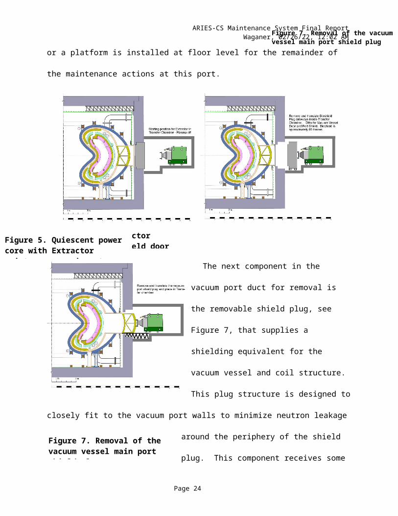
this time, the power core maintenance equipment, the Extractor, is readied and positioned for
entry into the power core, as shown in Figure 5. Just outside the bioshield is a lower region of
the Transfer Chamber that allows the bioshield door to be removed and translated to the side as
shown in Figure 6. The vacuum vessel door is then removed and set aside. After this vacuum
door is in the storage position, the floor is raised or a platform is installed at floor level for the
remainder of the maintenance actions at this port.
Page 14

Figure 6. Extractor removing Bioshield door
Figure 7. Removal of the vacuum vessel main port shield plug
ARIES-CS Maintenance System Final ReportWaganer, 05/10/23, 3:07 PM
The next component in the vacuum port duct
for removal is the removable shield plug, see
Figure 7, that supplies a shielding equivalent for
the vacuum vessel and coil structure. This plug
structure is designed to closely fit to the vacuum
port walls to minimize neutron leakage around the
periphery of the shield plug. This component
receives some nuclear heating that requires active
cooling. Plumbing connections are not defined at
present.
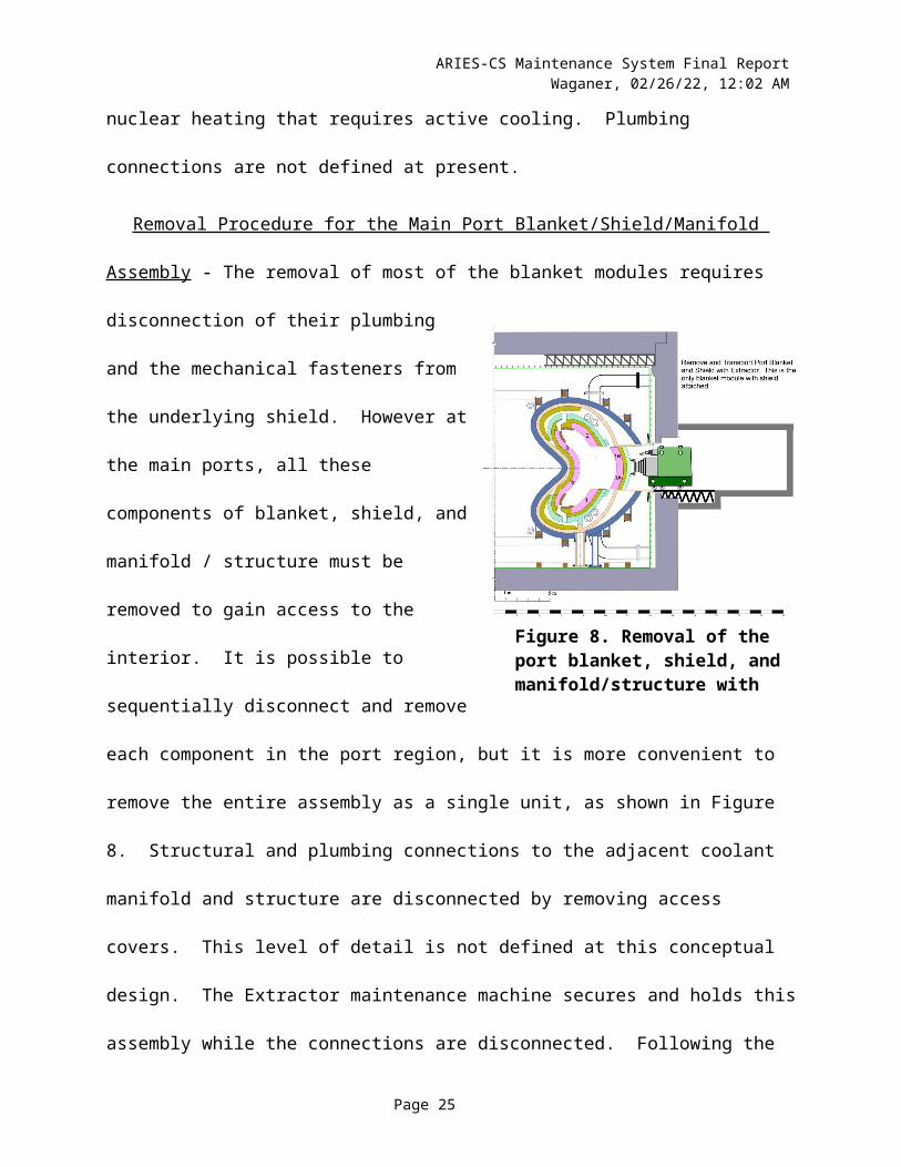
Removal Procedure for the Main Port
Blanket/Shield/Manifold Assembly - The removal
of most of the blanket modules requires
disconnection of their plumbing and the
Page 15
Figure 7. Removal of the vacuum vessel main port shield plug
Figure 8. Removal of the port blanket, shield, and manifold/structure with Extractor
Figure 5. Quiescent power core with Extractor maintenance equipment inside transfer chamber

ARIES-CS Maintenance System Final ReportWaganer, 05/10/23, 3:07 PM
mechanical fasteners from the underlying shield. However at the main ports, all these
components of blanket, shield, and manifold / structure must be removed to gain access to the
interior. It is possible to sequentially disconnect and remove each component in the port region,
but it is more convenient to remove the entire assembly as a single unit, as shown in Figure 8.
Structural and plumbing connections to the adjacent coolant manifold and structure are
disconnected by removing access covers. This level of detail is not defined at this conceptual
design. The Extractor maintenance machine secures and holds this assembly while the
connections are disconnected. Following the disconnection of the plumbing and structural
connections, this port assembly is removed through the vacuum vessel port, as shown in Figure
8. This assembly is as large as possible while still fitting through the port area.
Blanket Module Maintenance Provisions - The removal of the vacuum vessel port shielding
plug opens up the main maintenance vacuum port and provides access to the power core
elements for removal and replacement. All life-limited first wall/blanket modules are
mechanically attached to hot shield throughout the power core, as explained in Reference 5. In
turn, the hot shield is structurally attached to the hot coolant manifold / structure, which, in turn,
is supported by the vacuum vessel and power core structure. The physical attachment of the
blanket modules to the hot shield is tentatively defined as four mechanical fasteners accessed
from the face of the first wall. These fasteners are located deep in the
blanket, close to the shield, to minimize the radiation damage. In
addition to the physical connection, there are fluid connections at the
back of the blanket that are disconnected before blanket module
removal. The connection is at the back of the blanket module and is
completely inaccessible from the front as shown in Figure 9. Access
Page 16
Figure 9. Back of Blanket module showing two coaxial heat transfer fluid pipes

ARIES-CS Maintenance System Final ReportWaganer, 05/10/23, 3:07 PM
to the coolant connections is provided by removing shielding blocks behind an adjacent module,
previously removed, and around the pipe connections as shown in Figure 10. Shielding block #1
is accessible and removable after its overlaying blanket module is removed. Then the
semicircular shielding block #2 is translated from behind the blanket module and removed. Then
the semi-circular shielding ring (shielding block #3) is then rotated 180° and removed. This
provides a small annular access area around each tube.
A cutting machine is inserted into the annular ring area
to disconnect the outer heat transfer pipe. The inner
pipe has a slip joint in this area that does not require
cutting the pipe. This subject is discussed in detail in
Reference 5.
Divertor Module Maintenance Provisions - The
other type of module to be removed from inside the power
core is the divertor module. The divertor modules (shown
in Figures 5, 6, and 7) are only located near the
pointed sections of the plasma and only in certain
poloidal regions. There are 24 individual divertor
modules. The divertor modules are not anchored on
the structural manifold; rather they are structurally
attached to the vacuum vessel via their coolant
piping. Figure 11 shows that structural and
plumbing arrangement. The internal shielding inside
the pipe is designed to reduce the neutron streaming
Page 17
Figure 10. Exploded view of removed shielding blocks and rings for access to heat transfer pipes
Figure 11. Divertor Structural and Plumbing Arrangement
ARIES-CS Maintenance System Final ReportWaganer, 05/10/23, 3:07 PM
down the pipe to acceptable levels and protect the manifold regions to achieve life-of-plant
lifetimes.
Technique for Disconnecting Divertor Module Plumbing - The initial step of the divertor
module replacement is to open access ports in the divertor plumbing near the center of the power
core outside the vacuum vessel and coil structure. This allows the central maintenance machine
to reach in and remove the inner pipe and internal pipe shielding. Further explanation of the
central maintenance machine is provided in a later section. Removing the inner pipe and
shielding is possible because the inner pipe connection is designed to be a slip joint near the back
of the divertor. Once the inner pipe assembly is removed, there is sufficient access inside the
pipe to bring in a cutting machine to cut the smaller diameter section of the outer pipe close to
the divertor back surface. The cut has to be close to the divertor because cutting the larger
diameter pipe would trap the divertor pipe behind blanket. During the cutting operation, the
articulated arm of the extractor machine inside the power core is supporting the divertor module.
Once the outer pipe cut is accomplished, the maintenance extractor removes the divertor module
and takes it out the main port. Because the first pipe cut was made close to the plasma, the
remaining pipe will have been sufficiently damaged by neutrons so that it cannot be re-welded.
Thus, a second cut is done further away from the plasma, perhaps near the vacuum vessel or coil
structure in a region where re-welding is possible. During this second cut, the articulated arm of
the extractor machine holds the larger divertor coolant pipe while the pipe is being cut. Then the
second section of pipe is removed by the interior articulated maintenance arm. These
maintenance actions are explained in more detail in subsequent sections that discuss the
maintenance equipment.
Page 18

ARIES-CS Maintenance System Final ReportWaganer, 05/10/23, 3:07 PM
Technique for Removing Hot Shield Blocks for Blanket Plumbing Access - In a prior
paragraph, the approach of removing shield blocks to gain access to cut the heat transfer fluid
plumbing lines is discussed, as shown in the exploded view of Figure 10. Now we will discuss
how these shielding blocks are planned to be removed. One option is that the main extractor
maintenance machine, shown in Figure 8, is used to bring in end effectors to translate, rotate, and
remove the shielding blocks and take them back into the transfer chamber for removal. Then a
cutting machine is brought in and cut the two outer coolant pipes. These operations are either
done by the main articulated boom or by one or more smaller auxiliary booms from the main
port. Then the main boom engages the main mounting fasteners from the front of the blanket
module, disconnects the fasteners, and removes the module out to the transfer chamber. This
option is comprised of all serial operations that can only be done through the main port, which is
very time extensive. Due to the long duration of the serial operations, this is not the chosen
approach.
A more time efficient approach is to remove the shielding blocks and cut the pipe in parallel
while the main port extractor machine is removing a disengaged blanket module. This requires
another auxiliary maintenance port in this field period. There is a requirement to have ECH for
heating the plasma during startup. The size of the port is approximately a square meter in size,
which is an appropriate size for use as an auxiliary maintenance port. A region was found5,6 at a
toroidal angle of 35° slightly above the horizontal midplane with low stresses in the coil structure
that accommodates a port of 1 m2. One ECH port per field period is required and this is in
agreement with the use of the port for supporting maintenance actions.
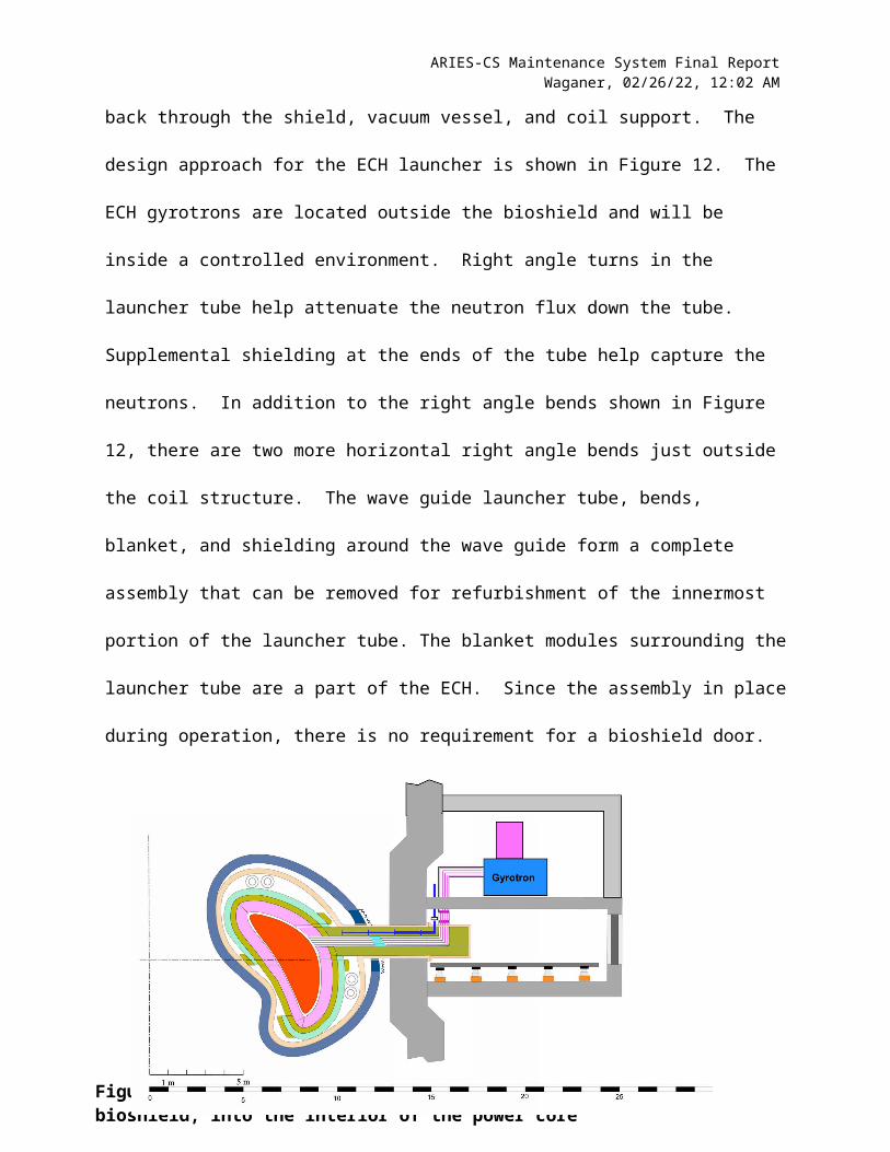
Definition of ECH Launcher Assembly - The ECH system requires a waveguide launcher
that extends from the first wall surface back through the shield, vacuum vessel, and coil support.
Page 19

ARIES-CS Maintenance System Final ReportWaganer, 05/10/23, 3:07 PM
The design approach for the ECH launcher is shown in Figure 12. The ECH gyrotrons are
located outside the bioshield and will be inside a controlled environment. Right angle turns in
the launcher tube help attenuate the neutron flux down the tube. Supplemental shielding at the
ends of the tube help capture the neutrons. In addition to the right angle bends shown in Figure
12, there are two more horizontal right angle bends just outside the coil structure. The wave
guide launcher tube, bends, blanket, and shielding around the wave guide form a complete
assembly that can be removed for refurbishment of the innermost portion of the launcher tube.
The blanket modules surrounding the launcher tube are a part of the ECH. Since the assembly in
place during operation, there is no requirement for a bioshield door.
Page 20
Figure 12. ECH Launcher Assembly that extends through the bioshield, into the interior of the power core

ARIES-CS Maintenance System Final ReportWaganer, 05/10/23, 3:07 PM
Provisions for ECH Assembly Removal – The ECH launcher assembly is designed to be a
self-contained unit of launcher, blanket, and shielding that is separately cooled and removed as a
single unit. Figure 13 shows the ECH assembly after removal from the power core and in the
ECH and auxiliary maintenance transfer chamber. A section of the ECH launcher tube is
removed and set aside to allow the assembly to be translated into the transfer chamber. An
adjustable floor is adjustable in height to accommodate both the ECH assembly and the auxiliary
maintenance equipment. The ECH/auxiliary maintenance transfer chamber is very compact, so a
special extraction mechanism might be employed to withdraw the assembly into the chamber.
Figure 13. Withdrawal of ECH Assembly into the ECH and Aux Maintenance Transfer Chamber
The next step transfers the ECH assembly from the transfer chamber into a smaller transporter
for transit to the Hot Cell for refurbishment. This sequence is shown in Figure 14.
Page 21

ARIES-CS Maintenance System Final ReportWaganer, 05/10/23, 3:07 PM
Figure 14. ECH module transfer into the mobile ECH assembly
Auxiliary Maintenance Operations Conducted Through ECH Port – After the removal of the
ECH assembly, the auxiliary maintenance equipment is brought into the transfer chamber and
power core interior to assist in the disassembly of the blanket modules from the underlying
shielding. This is shown in Figure 15. This auxiliary maintenance equipment specializes in
removing the access shielding around the blanket piping allows the main port maintenance
equipment to operate at a higher degree of efficiency removing the divertor and blanket modules.
It is envisioned that one or more specialized end effectors is used to remove the shielding pieces.
As they
Figure 15. Insertion of the Auxiliary Maintenance Module operating in the ECH port with several articulated booms disconnecting shielding blocks to access blanket coolant
are removed, another arm will collect them in a basket or container for retrieval. After all the
shielding blocks are removed for access to the piping for a particular blanket, a specialized pipe
Page 22
ARIES-CS Maintenance System Final ReportWaganer, 05/10/23, 3:07 PM
cutting machine is positioned around the pipe in the annular opening inside the power core.
These cutting machines currently exist to access the pipe in the envelope defined. These cutting
machines also collect all debris from the cutting action. There are welding units of a similar size
are used for the reassembly of the blanket piping.
Page 23
ARIES-CS Maintenance System Final ReportWaganer, 05/10/23, 3:07 PM
Equipment and Procedures for Divertor Module Removal – Before the remaining blanket
modules are replaced, the divertor modules are
removed as they overlay the blanket modules. As
stated previously, the divertor modules are supported
from the coil structure with the divertor piping. The
technique of cutting the supporting outer coolant
piping was discussed earlier. This section will
discuss the maintenance equipment to accomplish
the blanket removal. First, the inner divertor coolant
pipe and shielding is removed from the outside of the
coil structure and vacuum vessel. Figure 16 shows the
two sets of central maintenance equipment that
removes the inner first divertor coolant piping at the
inner, upper, and lower regions of the power core for
24 locations total. There are two maintenance
machines located outside the coil structure that are
located on the power core central vertical axis (upper
and lower). These maintenance machines have
multiple articulated arms to gain access to the
divertor plumbing access ports. A retrieval end
effector removes access panels and the inner divertor pipe and shielding assemblies. After
removal, robot cutter and cleanup end effectors cut and cleanup the outer divertor pipe. During
the latter operation, the divertor module is supported by the main port articulated boom (also
Page 24
Figure 16. Removal of Divertor inner pipe and shielding to allow entry of cutting and cleanup robots inside outer diameter divertor tube
ARIES-CS Maintenance System Final ReportWaganer, 05/10/23, 3:07 PM
shown in Figure 16) as the supporting divertor pipe is being cut. Following the cutting of the
supporting pipe, the divertor module is removed from the power core with the main articulated
boom and moved to the transfer chamber through the main port opening, as shown in Figure 17.
Page 25
Figure 17. Main articulated boom can now remove and transport divertor plate modules to transfer chamber

ARIES-CS Maintenance System Final ReportWaganer, 05/10/23, 3:07 PM
Equipment and Procedures for Blanket Module Removal – Now that the overlying divertor
modules are removed, the blanket module removal commences. As shown previously in Figure
15, the auxiliary articulated arms in the ECH port are removing the shielding blocks and severing
the blanket coolant pipes. Following the final cutting operation on the blanket coolant tubes, the
auxiliary articulated arms commence operations on the next available blanket module shielding
blocks. Once the blanket coolant pipes are severed and debris removed, the main port articulated
arm begins actions to remove the blanket modules.
Figure 18 shows the main port articulated arm
attached to a blanket module near the blanket port.
It inserts special tools deep into the face the blanket
module. The end effectors expand against the side
walls of the holes with sufficient force to engage the
fasteners. The four fasteners to the underlying
shield are then disengaged. The end effectors
continue to grip the holes, allowing the blanket
module removal for transit to the hot cells, as
shown in Figure 19. The same sequence of
removing the shielding blocks, cutting the blanket
cooling tubes by the auxiliary articulated arms, and
removal of the overlying blanket modules is
continued for the remainder of the blanket modules
Page 26
Figure 19. Transfer of Blanket Module #4 into Transfer Chamber
Figure 18. Main articulated boom removing a Blanket Module #4 near main maintenance port

ARIES-CS Maintenance System Final ReportWaganer, 05/10/23, 3:07 PM
in the field period. As mentioned previously, these maintenance actions are being conducted in
parallel in all three field periods.
Inspection and Refurbishment of Power Core Interior – After the removal of all the divertor
and blanket modules, the entire surface of the shield is exposed. At this time, inspection end
effectors is placed on the auxiliary maintenance articulated arms to inspect and survey the entire
shield surface for a field period. The inspection is to detect surface damage that would warrant
further investigation of local areas for repair and/or replacement. The inspection also surveys all
the fiducial datums on the shield to determine if any distortions occurred on the lifetime
components. This data are used to make adjustments for the attachment of the replacement
divertor and blanket modules. Time is allotted for these actions.
Reassembly of the Power Core – The reverse sequence of operations is required for
reassembly of the power core modules. Additional time is required for joining the coolant
connections, cleaning up the weld residue, inspecting for leaks, and securing mechanical
connections. This is the sequence of operations for the initial build of the power core.
Cleaning, Bakeout, Power Up, and Systems Checkout – To bring the power core back to an
operational state, the new divertor modules, new blanket modules, and refurbished ECH
assemblies are cleaned, baked out, powered up, and checked out prior to commencing full power
operation.
Assessment of Scheduled Power Core Maintenance Scheduling Options
The prior discussions focused on how the power core is maintained and refurbished. This
section addresses scheduling of maintenance and duration of each operation. Each field period is
identical in its makeup of modules and ancillary equipment. Thus scheduled maintenance is
Page 27

ARIES-CS Maintenance System Final ReportWaganer, 05/10/23, 3:07 PM
conducted simultaneously at all three ports at the end of the current blanket and divertor lifetime
of 3.0 FPY. This provides the shortest maintenance time, but requires three complete sets of
maintenance equipment plus any required spares.
A second option is to only replace only half the divertor and blanket modules in all three
field periods, alternating the right and left half of each field period every 1.5 FPY. Since the
blanket modules cannot be individually removed, they have to be removed in a certain sequence,
starting from the main port opening. Therefore, the right and left replacement scheme always
has to remove those blankets in the port sector each time. They cannot be re-welded due to
radiation damage to their piping, thus they have to be replaced every 1.5 FPY. Therefore there is
additional cost and time associated with the right/left replacement scheme. It still requires three
full sets of maintenance equipment.
Another option is to replace only on one field period at a time, once every three years. There
is no extra replacement hardware required for this option. And it only uses one set of
maintenance equipment, but that set of maintenance equipment is used three times as often. The
downside is that the downtime for cooldown, access to the machine, inspection, checkout, and
startup are duplicated three times every 3.0 full power years as opposed to once for the first
option and twice for the second option.
The decision which of the three options is the most suitable also depends on the frequency
and duration of general plant maintenance. The down time needed for scheduled maintenance of
the entire plant can be used for the parallel replacement of power core components. If, for
example, the plant is shut down for two weeks once every year, this time could be used for the
replacement of a part of the blanket modules, reducing in this way the impact of power core
replacement on total availability. This method is employed in fission power plants where, for
Page 28
ARIES-CS Maintenance System Final ReportWaganer, 05/10/23, 3:07 PM
example, every year a third of the fuel elements is replaced during the scheduled maintenance of
the entire plant. This corresponds with the option three described above with either the
replacement of all blanket modules in one field period, or the replacement of half the modules in
two field periods. However, there is strong incentive to push for the option with the highest
availability and extend the all of the plant scheduled maintenance periods to match that of the
power core.
Since it was not possible in the frame of this study to get sufficient information on the
required maintenance of the entire plant, the first option of maintaining all three field periods
simultaneously is selected as the baseline maintenance approach. There is a trade off between
option 1 and 3 depending on the times and the cost of maintenance equipment that may need to
be revisited in the future when more detail is known.
The technology of forecasting failures in the blanket modules will be a necessary research
and development effort because the financial impact of having a large base-loaded plant out of
service is significant. Unscheduled downtimes can have a more profound impact on availability
as compared to scheduled downtimes. So it is anticipated that a predicted impending failure
might be capable of being forecast in the time frame of this plant. The decision to remove
enough divertor and blanket modules to replace the faulty one or replace all the modules in a
field period will have to be made based on the remaining core lifetime. The geometry constraint
of the Compact Stellarator blanket modules is such that, on average, many modules may have to
be removed in sequence to obtain access to the faulty module.
Page 29

ARIES-CS Maintenance System Final ReportWaganer, 05/10/23, 3:07 PM
Maintenance and Availability AnalysisThe maintenance approach is defined and supported with selected maintenance equipment
and facilities. The following sections analyzes the maintenance actions and durations necessary
to remove and replace the life-limited power core parts.
Maintenance Analysis Basis – The maintenance actions are defined to be those necessary to
gain access to, remove, and replace all life-limited components inside the power core. Those
components are the divertor modules, blanket modules and parts of the ECH launcher assembly.
All these components are designed to have the same operational lifetime of 3.0 full power years
(FPY). The chosen maintenance scenario replaces all components at one time. Since there is a
varying neutron wall load on the first wall surface, one or more blanket modules will be at its
end of life, while others in a lower NWL region are replaced before their actual end of life. But
the cost of blanket modules is small compared to those costs associated with plant downtime.
Each maintenance action is identified and an estimate of the time to complete the action is
defined. The basis for this conceptual design is that it is representative of a tenth of a kind plant.
There will also be a demonstration plant and a prototype plant that will precede the commercial
plants. Further, it is assumed that the maintenance facilities, equipment, procedures, and
timelines have been defined, developed and refined to achieve a mature process at the 10th of a
kind plant.
The maintenance equipment is remotely operated and nuclear hardened due to the radiation
hazard. Also the equipment is highly autonomous with known actions predetermined. The
degree of human intervention is anticipated to be minimal except for abnormal situations. The
paths of the articulated arms is fully defined in advance and optimized for step duration,
Page 30

ARIES-CS Maintenance System Final ReportWaganer, 05/10/23, 3:07 PM
component safety, maintenance equipment load, and arm deflection. The duration estimates are
based upon these assumptions.
Maintenance Timelines – All the steps in the shutdown period, removal operations,
inspection and repair, reassembly, and startup are estimated. These time steps are summarized at
a high level in Table 2. Each time step was analyzed for the distance traveled, mass and shape of
the object transported, and the path and constraints observed. Appendix A contains the detail
time steps for all the actions shown in the summary chart. For example, there are 48 steps in the
Removal of the Main Port Opening to remove the main port bio shield door, remove the vacuum
vessel main port shielding assembly, and remove the main port blanket/shield/coolant manifold
assembly, which takes about 10 hours to complete. Table 2 shows all the governing steps along
with the other operations that are conducted in parallel with the governing operations. The
Shutdown and Preparation for Maintenance and removal of the Main Port Opening are singular
tasks that must be done each time interior power core maintenance is performed. Likewise, there
are similar operations on closing the power core and startup sequences. After access is provided
to the interior of the power core, the repetitive tasks commence, such as removal of the divertor
plates or modules and the blanket modules. The data shown in Table 2 is just summary times for
the sets of operations. Full detail of the sequence and durations of maintenance actions are
reported in the Appendix A.
The total disassembly time is 475 hours and the reassembly time is 753 hours. The time
difference is due to a slower movements and installation procedures. There is additional time for
inspection and checkout of components and systems. The total downtime is estimated to be 1230
hours every 3.0 full power years. This equates to an inherent availability of 95.5% for the power
core replaceable items.
Page 31
ARIES-CS Maintenance System Final ReportWaganer, 05/10/23, 3:07 PM
Duration of Serial Subtotal for Set Duration of ParallelMaintenance Task(s) Operations, Hours of Operations, Hours Operations, Hours
Shutdown And Preparation For Maintenance. 30.00 7.40Removal Maintenance TasksRemoval of Main Port Opening 10.20Removal of ECH/ AUX. Port Opening 8.40Removal of Diverter Plate Inner Coolant Tubes 9.40Removal of Diverter Plates 20.40 6.40Blanket Shielding Blocks and Module Removal 240.50 39.00Shield Ring and Coolant Tube Removal 139.75Diverter Outer Coolant Tube Section Removal 8.80Shield and Support System Inspection and Repair 26.00 36.00TOTAL DISASSEMBLY TIME 475.65 106.60
Duration of Serial Subtotal for Set Duration of ParallelMaintenance Task(s) Operations, Hours of Operations, Hours Operations, Hours
Replacement Maintenance TasksDiverter Outer Coolant Tube Section Installation 14.40Shielding Ring and Coolant Tube Installation 230.75Blanket Shielding Blocks and Module Installation 429.00 39.00Replace of Diverter Plates 26.40 8.00NDI of Diverter Plates Welds 2.80Chamber Inspection 2.00 2.00NDI Robot Secured 0.55Main Port Closure 13.40Closure of ECH/AUX. Port Opening 10.00Replacement of Diverter Plate Inner Coolant Tubes 9.60Inspection, Diagnostics and Preparation for Operations 38.00 13.10TOTAL ASSEMBLY TIME 753.95 85.05
TOTAL DISASSEMBLY TIME 475.65 106.60TOTAL ASSEMBLY TIME 753.95 85.05TOTAL TIME 1,229.60 191.65
Full power years 3.00Number of Available Days 1,095.75
Number of Available Hours 26,298.00Nominal hours to replace three field periods 1,229.60
Inherent Availability 95.5%
ARIES Estimated Maintenance Times
KEYSOperational Tasks
Parallel/Simultaneous Tasks
Table 2. Summary of Scheduled Power Core Maintenance Times
The main time advantage of the maintenance scheme proposed in this approach is that there
are many simultaneous parallel operations. Table 3 shows a summary of the maintenance
actions that are being conducted in the main port, auxiliary port and the central bio chamber
manipulators. The shaded cells indicate which operations are governing and which are being
conducted in parallel or setting idle. The table illustrates that removing the shielding blocks to
gain access to the blanket coolant tubes and cutting the tubes is the most time consuming
operation. This is also true for the reconnection of the blanket coolant pipes and replacing the
Page 32

ARIES-CS Maintenance System Final ReportWaganer, 05/10/23, 3:07 PM
shielding blocks. The overall maintenance operation could significantly improve if the method
of blanket plumbing disconnection and reconnections were simpler and more accessible.
Table 3. Summary of maintenance actions with three types of maintenance equipment
Availability Analysis – With these durations of the scheduled maintenance periods for the
major scheduled actions for the power core, the plant availability is computed. With a total
scheduled time of 1229.6 hours or 51.12 days occurring every 3 FPY, this translates into an
annual maintenance time of 17.08 days/FPY or an inherent availability of 95.5%. To be
comparable with the ARIES-AT9 maintenance results, the maintenance estimates for the minor
scheduled power core, unscheduled power core, scheduled and unscheduled reactor plant
equipment, and scheduled and unscheduled balance of plant are adopted as shown in Table 4.
The resultant total power plant availability is 84.6%. This value of plant availability will be used
in the ARIES-CS Systems Assessment11. This is consistent with the experience of existing power
plants for the reactor plant and balance of plant inherent availabilities. This trend is expected to
Page 33
Main Port Shutdown Port Opening
Diverter Plates
Shielding Blocks
&Blanket Modules
Shielding Rings & Coolant Tubes
Diverter Outer
Coolant Tube
Shield & Support System
Insp.
Diverter Outer
Coolant Tube
Shielding Rings & Coolant Tubes
Shielding Blocks
&Blanket Modules
Diverter Plates
Chamber Inspection
Port Installation Start-Up
TaskShutdown &
Prep for Maint.
Open Three Main Maint.
Ports
Twenty-four Diverter
Plates (8 x 3 Sectors)
Blanket Modules (65 x 3 Sectors)
Shielding Rings & Inner Coolant Tube
(65 x 2 x 3 Sectors)
Diverter Outer Coolant Tube (8x3 Sectors)
Inspect, Clean &
Vacuum - Inspect Repairs
Diverter Outer Coolant Tube (8x3 Sectors)
Shielding Rings & Inner Coolant Tube
(65 x 2 x 3 Sectors)
Blanket Modules (65 x 3 Sectors)
Twenty-four Diverter
Plates (8 x 3 Sectors)
Inspect Chamber
After Build-Up
Close Three Main Maint.
Ports
Inspect, Diagnostics &
Prep for Operation
Time (Hrs) 30.00 10.20 20.40 240.50 139.75 8.80 26.00 14.40 230.75 429.00 26.40 2.00 13.40 38.00
ECH/Aux Port Shutdown ECH Assembly
Shielding Blocks
&Blanket Modules
Shielding Rings & Coolant Tubes
Diverter Outer
Coolant Tube
Shield & Support System
Insp.
Diverter Outer
Coolant Tube
Shielding Rings & Coolant Tubes
Shielding Blocks
&Blanket Modules
Chamber Inspection
ECH Installation Start-Up
TaskShutdown &
Prep for Maint.
Remove Three ECH Assemblies
Shielding Blocks & Cut Weld (65x 6 x 3 Sectors)
Shielding Rings & Inner Coolant Tube
(65 x 2 x 3 Sectors)
Diverter Outer Coolant Tube (8x3 Sectors)
Make Any Needed Repairs
Diverter Outer Coolant Tube (8x3 Sectors)
Shielding Rings & Inner Coolant Tube
(65 x 2 x 3 Sectors)
Shielding Blocks &
Welds (65x 6 x 3 Sectors)
Inspect Chamber
After Build-Up
Install Three ECH
Assemblies
Time (Hrs) 30.00 8.40 240.50 139.75 8.80 24.00 14.40 230.75 429.00 2.00 9.60 38.00
BIO-Chamber ShutdownDiverter Coolant Tubes
Diverter Plates
Shield & Support System
Insp.
Diverter Plates NDI Welds
Coolant Tubes
InstallationStart-Up
TaskShutdown &
Prep for Maint.
Twenty-four Coolant
Tubes (8 x 3 Sectors)
Cut Plates Coolant Tube Weld (8 x 3
Sectors)
Inspect Outside for Damage &
Repair
Weld Plates Coolant Tube
(8 x 3 Sectors)
Complete Coolant Tube Weld Inspect.
Twenty-four Coolant
Tubes (8 x 3 Sectors)
Time (Hrs) 30.00 9.40 20.40 12.00 26.40 0.55 13.10 38.00Total Time (Hrs) Total Time (Hrs)
ECH
/Aux
iliar
y Po
rtM
ain
Port
Bio
-Cha
mbe
r
KEYSOperational Tasks
Parallel/Simultaneous Tasks
ARIES MAINTENANCE TASKS
Disassembly 475.65 Hrs. Replacement 753.95 Hrs.Total Maintenance Time 1,229.6 Hrs. Inherent Availability 95.5%
Removal Tasks Replacement Tasks

ARIES-CS Maintenance System Final ReportWaganer, 05/10/23, 3:07 PM
continue in this future time period. The scheduled minor power core maintenance will likely be
a fraction of the major scheduled maintenance times as much of the repair of these minor
components can be done off line. The most difficult issue is the prediction of unscheduled major
power core maintenance. A time of 20 days per year has been allocated for this purpose. If it is
assumed that on average, an unscheduled failure would require, on average, removal of one
fourth of the modules in a field period (one side of the main port and half of the modules on that
side would be replaced), the unscheduled time might be on the order of 16 days (accounting for
ingress and egress and half of component removal) per failure. Therefore the allocation of 20.56
days/FPY would be sufficient for a major failure each FPY with some additional time left over
for minor leaks that would be repairable in-situ.
Summary of Maintenance Actions Maintenance Days, Total
Maintenance Days/FPY
Availability
Scheduled Power Core, Major 51.23 17.08 95.5
Scheduled Power Core, Minor (ref ARIES-AT9) 6.05 98.4
Unscheduled Power Core (ref ARIES-AT9) 20.56 94.7
Reactor Plant Equipment, Scheduled + Unscheduled
(ref ARIES-AT9) 9.37 97.5
Balance of Plant, Scheduled + Unscheduled
(ref ARIES-AT9) 9.37 97.5
Total 84.6
Table 4. Summary of maintenance durations and inherent availability
Summary and Conclusions
Page 34

ARIES-CS Maintenance System Final ReportWaganer, 05/10/23, 3:07 PM
A conceptual design approach for the maintenance approach for the ARIES-Compact
Stellarator is defined to include the techniques to maintain the power core, the required
maintenance equipment, and associated maintenance facilities. Maintenance procedures to
remove, inspect, and replace life-limited power core components down to individual
maintenance actions are defined and estimates of action durations are estimated. These
procedures are analyzed for parallel and sequential operations to estimate the scheduled
maintenance times for power core refurbishment. These scheduled actions are combined with
representative maintenance times for unscheduled power core and total maintenance durations
for reactor plant equipment and balance of plant equipment as used in the ARIES-AT study to
determine the estimated plant availability for the ARIES-CS power plant. With the utilization of
the postulated maintenance approaches and procedures, it is predicted ARIES-CS could achieve
a plant availability of 85% with only one third of the unavailability caused by scheduled power
core maintenance. This availability would be in line with other competing base load power
generation capabilities and would help fusion power plants be economically competitive.
Page 35

ARIES-CS Maintenance System Final ReportWaganer, 05/10/23, 3:07 PM
References
. F. Najmabadi, et al, “Overview of ARIES-Compact Stellarator Power Plant Study”, to be published in this issue of Fusion Science and Technology Journal, 2007.
2. L.A. El-Guebaly, “Overview of ARIES-RS neutronics and radiation shielding: key issues and main conclusions,” Fus. Eng. and Des., 38 (1997) 139-158.
3. L. P. Ku, et al., “Physics Design of ARIES-CS”, to be published in this issue of Fusion Science and Technology Journal, 2007.
4. G. H. Neilson, M.C. Zarnstorff, L. P. Ku, et al., “Physics Considerations in the Design of NCSX,” 19th IAEA Fusion Energy Conference, Lyon, France, 14-19, October 2002
5. R. Raffray, et. al, “Engineering Design and Analysis of the ARIES-CS Power Core,” to be published in this issue of Fusion Science and Technology Journal, 2007.
6. X. R. Wang, S. Malang, et al., “ARIES-CS Magnet Conductor and Structure Evaluation,” to be published in this issue of Fusion Science and Technology Journal, 2007.
7. L. El-Guebaly, P. Wilson, and the ARIES Team, “Designing ARIES-CS Compact Radial Build and Nuclear System: Neutronics, Shielding, and Activation,” to be published in this issue of Fusion Science and Technology Journal, 2007.
8. S. Malang, F. Najmabadi, L.M. Waganer, and M.S. Tillack, “ARIES-RS Maintenance Approach for High Availability,” 4th International Symposium on Fusion Nuclear Technology, Tokyo, April 1997.
9. L. M. Waganer and the ARIES Team, “ARIES-AT Maintenance System Definitions and Analysis,” Fusion Engineering and Design Journal, 2001.
10. B. Merrill, L. El-Guebaly, C. Martin, “Safety and Environmental Assessment of the ARIES Compact Stellarator Design,” to be published in this issue of Fusion Science and Technology Journal, 2007.
11. J. F. Lyon, L-P. Ku, L. El-Guebaly, L. Bromberg, and the UCSD ARIES Team, “Determination of ARIES-CS Plasma and Device Parameters and Costing,” to be published in this issue of Fusion Science and Technology Journal, 2007.
Page 36

ARIES-CS Maintenance System Final ReportWaganer, 05/10/23, 3:07 PM
Appendix A. Detailed ARIES-CS Maintenance Analysis
Duration of Serial Subtotal for Set Duration of ParallelMaintenance Task(s) Operations, Hours of Operations, Hours Operations, Hours
Shutdown And Preparation For Maintenance.Cool down of systems, afterheat decay 24.00 De-energize coils, keep cryogenic 2.00 Pressurize power core with inert gas 2.00 Move Maint Machine(s) transport(s) to outer isolation door 1.00 Move mobile transporters to outer transfer airlock door(s) 1.00 Move ECH mobile transporters to outer transfer airlock doors. 1.00Drain Coolants, fill with inert gas 6.00 Open transfer chamber(s) outer main isolation door(s) 0.10 Move Maint Machine(s) into transfer chamber(s) 0.20 Close transfer chamber(s) outer main isolation door(s) 0.10
TOTAL 30.00 7.40
ARIES Estimated Maintenance Times
Page 37

ARIES-CS Maintenance System Final ReportWaganer, 05/10/23, 3:07 PM
Duration of Serial Subtotal for Set Duration of ParallelMaintenance Task(s) Operations, Hours of Operations, Hours Operations, Hours
Removal Maintenance TasksRemoval of Main Port OpeningMove Maint Machine into position 0.10Move boom forward and engage bio-shield plug 0.10Remove and set aside bio-shield plug 0.50Retrieve and place bridging structure into place 0.30Move Maint Machine into position 0.10Move boom forward and engage vacuum seals on vacuum vessel door 0.10Disconnect vacuum seals around vacuum vessel door 2.00Disengage and remove vacuum vessel door 0.30Retract Maint Machine and set vacuum vessel door aside 0.20Move Maint Machine into position 0.10Move boom forward and engage post shield plug 0.10Disconnect post shield plug 0.20Remove port shield plug 0.30Retract Maint Machine set aside port shield plug(s) 0.50Move Maint Machine into position 0.10Move boom forward and engage manifold shield plug closure disk 0.10Disengage and remove removable manifold shield plug closure 0.20Retract boom with closure disk 0.10Retract Maint Machine and place close disk into transfer airlock and close airlock 0.10
Move Maint Machine into position 0.10Move boom forward and engage 1st inner coolant tube 0.10Disconnect and remove inner coolant tube via sliding joints 0.30Retract boom with inner coolant tube 0.10Retract Maint Machine and place inner coolant tube into transfer airlock and close airlock 0.10
Move Maint Machine into position 0.10Move boom forward and engage 2nd inner coolant tube 0.10Disconnect and remove inner coolant tube via sliding joints 0.30Retract boom with inner coolant tube 0.10Retract Maint Machine and place inner coolant tube into transfer airlock and close airlock 0.10
Move Maint Machine into position 0.10Move boom forward and insert cutting tool 0.10Cut assembly welds at second cut position 0.50Retract boom 0.10Move boom forward and insert cutting tool 0.10Cut assembly welds at second cut position (Second Location) 0.50Retract boom 0.10Move Maint Machine into position 0.10Move Maint Machine into port position and secure 0.10Move boom forward and position for removable manifold shield plug module removable 0.10Disengage removable manifold shield plug(s) modules 0.20Retract boom with removable manifold shield plug(s) modules 0.20Retract Maint Machine into transfer chamber with removable manifold shield plug's) modules 0.10Place removable manifold shield plug(s) modules into transfer airlock and close airlock 0.10Move Maint Machine into port position and secure 0.10Move boom forward and engage Shield and Blanket Modules 0.10Disengage Shield and Blanket Modules 0.30Retract boom with Shield and Blanket Modules 0.20Retract Maint Machine into transfer chamber with Shield and Blanket Modules 0.10
Place Shield and Blanket Modules into transfer airlock and close airlock 0.10
TOTAL 10.20
Page 38

ARIES-CS Maintenance System Final ReportWaganer, 05/10/23, 3:07 PM
Duration of Serial Subtotal for Set Duration of ParallelMaintenance Task(s) Operations, Hours of Operations, Hours Operations, Hours
Removal Maintenance TasksRemoval of ECH/ AUX. Port Opening Move Maint Machine into position 0.10 Move boom forward and engage ECH coaxial cable 0.10 Disconnect ECH coaxial cable (two places) 0.40 Retract boom and set ECH coaxial cable aside 0.10 Move Maint Machine into position 0.10 Move boom forward and engage ECH shielding coolant tube 0.10 Disconnect ECH shielding coolant tube 0.30 Move boom and set ECH shielding coolant tube aside 0.10 Open transfer chamber(s) outer main isolation door(s) 0.10 Move Maint Machine(s) into transport(s) 0.10 Close transfer chamber(s) outer main isolation door(s) 0.10 Open transfer chamber(s) rear outer main isolation door(s) 0.10 Open ECH transporter(s) main isolation door(s) 0.10 Raise transfer chamber floor to expose ECH guide rails & conveyor 0.25
Using conveyor assembly retract ECH assembly into transfer chamber 3.00
Using conveyor assembly insert ECH assembly into ECH mobile transporter(s) 2.50 Close ECH transporter(s) main isolation door(s) 0.10 Close transfer chamber(s) rear outer main isolation door(s) 0.10 Lower transfer chamber floor to cover ECH guide rails & conveyor 0.25 Open transfer chamber(s) outer main isolation door(s) 0.10 Move Maint Machine(s) into transfer chamber(s) 0.20 Close transfer chamber(s) outer main isolation door(s) 0.10
TOTAL 8.40
Duration of Serial Subtotal for Set Duration of ParallelMaintenance Task(s) Operations, Hours of Operations, Hours Operations, Hours
Removal Maintenance TasksRemoval of Diverter Plate Inner Coolant Tubes Move remote handling manipulator over coolant tube opening. 0.10 Remove locking device securing coolant tube covering. 0.20 Open coolant tube cover. 0.05 Position remote handling manipulator inside coolant tube. 0.05 Move and disengage coolant tube sliding ring. 0.10 Secure inner coolant tube turn elbow. 0.10 Disengage inner coolant tube elbow. 0.15 Remove inner coolant tube elbow from coolant tube. 0.10 Move remote handling manipulator to transfer airlock door. 0.10 Open transfer airlock door. 0.05 Place inner coolant tube elbow into airlock. 0.10 Close transfer airlock door. 0.05 Move remote handling manipulator over coolant tube opening. 0.10 Position remote handling manipulator inside coolant tube. 0.10 Secure inner coolant tube. (tube, shielding block & shielding ring) 0.10 Disengage inner coolant tube. 0.30 Remove inner coolant tube from coolant tube. 0.25 Move remote handling manipulator to transfer airlock door. 0.10 Open transfer airlock door. 0.05 Place inner coolant tube into airlock. 0.15 Close transfer airlock door. 0.05
TOTAL 2.35
Repeat above sequence of steps for 3 additional coolant tubes. Total repetitive time = 3 x 2.35 Hr. 7.05 (NOTE: There are a total of 24 coolant tubes)
TOTAL 7.05
Page 39

ARIES-CS Maintenance System Final ReportWaganer, 05/10/23, 3:07 PM
Duration of Serial Subtotal for Set Duration of ParallelMaintenance Task(s) Operations, Hours of Operations, Hours Operations, Hours
Removal Maintenance TasksRemoval of Diverter PlatesMove remote handling manipulator to transfer airlock door. 0.10Open transfer airlock door. 0.05Secure bore tool (weld cutting) robot. 0.10Close transfer airlock door. 0.05Move remote handling manipulator over coolant tube opening. 0.10 Move Maint Machine into port position and secure 0.10Position bore tool (weld cutting) robot inside coolant tube. 0.10 Move boom forward and position over diverter plate. 0.10Move bore tool (weld cutting) robot to assembly weld of coolant tube. 0.20 Move boom forward engage and secure diverter plate. 0.10Position bore tool (weld cutting) robot and cut assembly weld. 1.25Disengage bore tool (weld cutting) robot and retract. 0.20 Retract boom with removed diverter shield 0.20Secure bore tool (weld cutting) robot. 0.10 Retract Maint Machine into transfer chamber with diverter plate. 0.10Move remote handling manipulator to transfer airlock door. 0.10 Place diverter plate into transfer airlock and close airlock 0.20Open transfer airlock door. 0.05Place bore tool (weld cutting) robot into air lock. 0.10Close transfer airlock door. 0.05
TOTAL 2.55 0.80
Repeat above sequence of steps for 7 additional diverter plates. Total repetitive time = 7 x 2.55 Hr. 17.85 5.60 (NOTE: There are a total of 24 coolant tubes)
TOTAL 17.85 5.60
Duration of Serial Subtotal for Set Duration of ParallelMaintenance Task(s) Operations, Hours of Operations, Hours Operations, Hours
Removal Maintenance TasksBlanket Shielding Blocks and Module RemovalMove Maint Machine into port position and secure 0.10 Move Maint Machine into port position and secure 0.10Move boom forward and position over blanket module inside chamber 0.20 Move boom forward and position & remove shielding block #1 0.20Move boom forward and engage blanket module 0.20 Retract boom and place shielding block #1 into transfer bucket 0.10Move boom forward and position & remove shielding block #2. 0.20Retract boom and place shielding block #2 into transfer bucket 0.10Move boom forward and position & remove shielding block #3. 0.30Retract boom and place shielding block #3 into transfer bucket 0.10Move boom forward into position and cut access pipe #1 0.50Move boom forward and position & remove shielding block #1 0.20Retract boom and place shielding block #1 into transfer bucket 0.10Move boom forward and position & remove shielding block #2. 0.20Retract boom and place shielding block #2 into transfer bucket 0.10Move boom forward and position & remove shielding block #3. 0.30Retract boom and place shielding block #3 into transfer bucket 0.10Move boom forward into position and cut access pipe #2 0.50 Disengage blanket module/diverter shield to be replaced 0.20Retract boom clear of blanket module & pick up transfer bucket 0.10Retract boom with removed blanket module 0.20 Retract boom with transfer bucket 0.20Retract Maint Machine into transfer chamber with blanket module 0.10 Retract Maint Machine into transfer chamber with transfer bucket 0.10Place blanket module into transfer airlock and close airlock 0.10Place transfer bucket into transfer airlock and close airlock 0.10
TOTAL 3.70 0.60
Repeat above sequence of steps for 64 blanket modules Total repetitive time = 64 x 3.70 Hr. 236.80
TOTAL 236.80 38.40
Page 40

ARIES-CS Maintenance System Final ReportWaganer, 05/10/23, 3:07 PM
Duration of Serial Subtotal for Set Duration of ParallelMaintenance Task(s) Operations, Hours of Operations, Hours Operations, Hours
Removal Maintenance TasksShield Ring and Coolant Tube RemovalMaint Machine secures Shielding Rings transfer bucket 0.10Move Maint Machine into port position and secure 0.10Move boom forward and place bucket inside chamber 0.20Move boom forward and position over 1st inner coolant tube 0.10Move boom forward and engage inner coolant tube 0.10Disengage inner coolant tube 0.10Retract boom and place inner coolant tube into transfer bucket 0.10Move boom forward into position over shielding ring 0.10Insert cutting tool and make second cut of shielding ring 0.50Retract cutting tool and engage shielding ring 0.10Move boom and place shielding ring into transfer bucket 0.10Move boom into position over removed shielding ring 0.10Insert tool to clean and inspect area 0.30Retract tool 0.10Move boom forward and position over 2nd inner coolant tube 0.10Move boom forward and engage inner coolant tube 0.10Disengage inner coolant tube 0.10Retract boom and place inner coolant tube into transfer bucket 0.10Move boom forward into position over shielding ring 0.10Insert cutting tool and make second cut of shielding ring 0.50Retract cutting tool and engage shielding ring 0.10Move boom and place shielding ring into transfer bucket 0.10Move boom into position over removed shielding ring 0.10Insert tool to clean and inspect area 0.30Retract tool 0.10Move boom engage and secure transfer bucket 0.10Retract boom with transfer bucket 0.20Retract Maint Machine into transfer chamber with transfer bucket 0.10Place transfer bucket into transfer airlock and close airlock 0.10
TOTAL 4.30
Repeat above sequence of steps for 31.5 sets Total repetitive time = 31.5 x 4.30 Hr. 135.45
TOTAL 135.45
Page 41
ARIES-CS Maintenance System Final ReportWaganer, 05/10/23, 3:07 PM
Duration of Serial Subtotal for Set Duration of ParallelMaintenance Task(s) Operations, Hours of Operations, Hours Operations, Hours
Removal Maintenance TasksDiverter Outer Coolant Tube Section RemovalMaint Machine secures Diverter Outer Coolant Tube transfer bucket 0.10Move Maint Machine into port position and secure 0.10Move boom forward and place bucket inside chamber 0.20Move boom forward into position over Diverter Outer Coolant Tube 0.10Insert cutting tool and make second cut of Diverter Outer Coolant Tube 0.50Retract cutting tool and engage Diverter Outer Coolant Tube 0.10Move boom and place Tube Section into transfer bucket 0.10Move boom into position over removed Diverter Outer Coolant Tube 0.10Insert tool to clean and inspect area 0.30Retract tool 0.10Move boom engage and secure transfer bucket 0.10Retract boom with transfer bucket 0.20Retract Maint Machine into transfer chamber with transfer bucket 0.10Place transfer bucket into transfer airlock and close airlock 0.10
TOTAL 2.20
Repeat above sequence of steps for 3 additional coolant tubes. Total repetitive time = 3 x 2.20 Hr. 6.60
TOTAL 6.60
Duration of Serial Subtotal for Set Duration of ParallelMaintenance Task(s) Operations, Hours of Operations, Hours Operations, Hours
Shield and Support System Inspection and RepairInspection of shield for damage and displacement, record data 12.00 Inspection of outside for damage and displacement, record data 12.00 Allocate time for potential repair of fasteners, alignment features, 24.00 and plumbing connections.Clean and/or vacuum interior of reactor from teardown of interior 12.00Repair Inspection 2.00
TOTAL 26.00 36.00
TOTAL DISASSEMBLY TIME 475.65 106.60
Page 42

ARIES-CS Maintenance System Final ReportWaganer, 05/10/23, 3:07 PM
Duration of Serial Subtotal for Set Duration of ParallelMaintenance Task(s) Operations, Hours of Operations, Hours Operations, Hours
Replacement Maintenance TasksDiverter Outer Coolant Tube Section InstallationRetrieve transfer bucket from transfer airlock and close airlock 0.10Move Maint Machine into port position and secure 0.10Move boom forward and place bucket inside chamber 0.20Move boom and secure diverter outer coolant tube section 0.10Move boom forward and place diverter outer coolant tube into opening 0.10Move boom to ensure tube section is fully and properly seated 0.10Holding tube section in place using boom tack weld in place 0.20Retract boom and insert welding tool 0.10Weld diverter outer tube section into position at second cut position 0.75Retract welding tool and allow weld to cool 0.20Inset inspection/NDI tool 0.10Inspect shielding ring weld 0.25Remove inspection/NDI tool 0.10Insert grinding tool and clean up weld as required 0.20Remove grinding tool 0.10Move boom forward to inspect and clean area 0.20Retract boom 0.10Retract boom 0.10Retrieve and secure transfer bucket 0.10Retract boom with transfer bucket 0.20Retract Maint Machine into transfer chamber with transfer bucket 0.10Place transfer bucket into airlock and close airlock 0.10
TOTAL 3.60
Repeat above sequence of steps for 3 additional coolant tubes. Total repetitive time = 3 x 3.610 Hr. 10.80
TOTAL 10.80
Page 43
ARIES-CS Maintenance System Final ReportWaganer, 05/10/23, 3:07 PM
Duration of Serial Subtotal for Set Duration of ParallelMaintenance Task(s) Operations, Hours of Operations, Hours Operations, Hours
Replacement Maintenance TasksShielding Ring and Coolant Tube InstallationRetrieve transfer bucket from transfer airlock and close airlock 0.10Move Maint Machine into port position and secure 0.10Move boom forward and place bucket inside chamber 0.20Move boom and secure shielding ring 0.10Move boom forward and place shielding ring into 1st opening 0.10Move boom to ensure shielding ring is fully and properly seated 0.10Holding shielding ring in place using boom tack weld in place 0.20Retract boom and insert welding tool 0.10Weld shielding ring into position at second cut position 0.75Retract welding tool and allow weld to cool 0.20Inset inspection/NDI tool 0.10Inspect shielding ring weld 0.25Remove inspection/NDI tool 0.10Insert grinding tool and clean up weld as required 0.20Remove grinding tool 0.10Move boom forward to inspect and clean area 0.20Retract boom 0.10Retrieve inner coolant tube from transfer bucket 0.10Move boom forward and install coolant tube into position 0.20Move boom to ensure coolant tube is fully and properly seated 0.10Retract boom 0.10Retrieve and secure 2nd shielding ring 0.10Move boom forward and place shielding ring into 2nd opening 0.10Move boom to ensure shielding ring is fully and properly seated 0.10Holding shielding ring in place using boom tack weld in place 0.20Retract boom and insert welding tool 0.10Weld shielding ring into position at second cut position 0.75Retract welding tool and allow weld to cool 0.20Inset inspection/NDI tool 0.10Inspect shielding ring weld 0.25Remove inspection/NDI tool 0.10Insert grinding tool and clean up weld as required 0.20Remove grinding tool 0.10Move boom forward to inspect and clean area 0.20Retract boom 0.10Retrieve inner coolant tube from transfer bucket 0.10Move boom forward and install coolant tube into position 0.20Move boom to ensure coolant tube is fully and properly seated 0.10Retract boom 0.10Retrieve and secure transfer bucket 0.10Retract boom with transfer bucket 0.20Retract Maint Machine into transfer chamber with transfer bucket 0.10Place transfer bucket into airlock and close airlock 0.10
TOTAL 7.10
Repeat above sequence of steps for 31.5 sets Total repetitive time = 31.5 x 7.10 Hr. 223.65
TOTAL 223.65
Page 44

ARIES-CS Maintenance System Final ReportWaganer, 05/10/23, 3:07 PM
Duration of Serial Subtotal for Set Duration of ParallelMaintenance Task(s) Operations, Hours of Operations, Hours Operations, Hours
Replacement Maintenance TasksBlanket Shielding Blocks and Module InstallationRetrieve new blanket module from transfer chamber and close airlock 0.10 Retrieve shielding blocks transfer bucket from transfer chamber and close air lock 0.10Move Maint Machine into port position and secure 0.10 Move Maint Machine into port position and secure 0.10Move boom forward and position blanket module inside chamber 0.20 Move boom forward and place transfer bucket inside chamber 0.20Engage and secure new blanket module. 0.20Move boom forward and position welding tool at 1st cut position 0.20Weld blanket module to shielding ring 0.75Retract welding tool 0.10Move boom forward and position welding tool at 1st cut position 0.20Weld blanket module to shielding ring 0.75Retract welding tool 0.10Move boom forward and insert inspection/NDI tool (1st Weld) 0.10Inspect first weld 0.25Remove Inspection/NDI tool 0.10Move boom forward and insert inspection/NDI tool (2nd Weld) 0.10Inspect first weld 0.25Remove Inspection/NDI tool 0.10Retract boom 0.10Move boom forward and retrieve shielding block #3 0.10Move boom forward and position shielding block #3 at opening 0.10Insert shielding block #3 into position 0.25Retract boom 0.10Move boom forward and retrieve shielding block #2 0.10Move boom forward and position shielding block #2 at opening 0.10Insert shielding block #2 into position 0.10Retract boom 0.10Move boom forward and retrieve shielding block #1 0.10Move boom forward and position shielding block #1 at opening 0.10Insert shielding block #1 into position 0.10Retract boom 0.10Move boom forward and retrieve shielding block #3 0.10Move boom forward and position shielding block #3 at opening 0.10Insert shielding block #3 into position 0.25Retract boom 0.10Move boom forward and retrieve shielding block #2 0.10Move boom forward and position shielding block #2 at opening 0.10Insert shielding block #2 into position 0.10Retract boom 0.10Move boom forward and retrieve shielding block #1 0.10Move boom forward and position shielding block #1 at opening 0.10Insert shielding block #1 into position 0.10Retract boom 0.10Disengage boom from blanket module 0.10 Move boom forward and retrieve transfer bucket 0.10Retract boom 0.10 Retract boom 0.10
TOTAL 6.60 0.60
Repeat above sequence of steps for 64 blanket modules Total repetitive time = 64 x 6.60 Hr. 422.40
TOTAL 422.40 38.40
Page 45

ARIES-CS Maintenance System Final ReportWaganer, 05/10/23, 3:07 PM
Duration of Serial Subtotal for Set Duration of ParallelMaintenance Task(s) Operations, Hours of Operations, Hours Operations, Hours
Replacement Maintenance TasksReplace of Diverter PlatesMove remote handling manipulator to transfer airlock door. 0.10 Move Maint Machine in front of airlock 0.10Open transfer airlock door. 0.05 Open transfer airlock 0.10Secure bore tool (welding & NDI) robots. 0.10 Secure diverter plate 0.10Close transfer airlock door. 0.05 Close transfer airlock 0.10Move remote handling manipulator over coolant tube opening. 0.10 Move Maint Machine into port position and secure 0.10Position bore tool (welding) robot inside coolant tube. 0.10 Move boom forward and position diverter plate. 0.10Move bore tool (welding) robot to assembly weld of coolant tube. 0.20 Move boom forward set diverter plate in place. 0.10Position bore tool (welding) robot and make assembly weld. 2.30Disengage bore tool (welding) robot and retract. 0.20 Disengage and retract boom 0.20Secure bore tool (welding) robot. 0.10 Retract Maint Machine into transfer chamber 0.10
TOTAL 3.30 1.00
Repeat above sequence of steps for 7 additional diverter plates. Total repetitive time = 7 x 3.30 Hr. (NOTE: There are a total of 24 coolant tubes)
TOTAL 23.10 7.00
Duration of Serial Subtotal for Set Duration of ParallelMaintenance Task(s) Operations, Hours of Operations, Hours Operations, Hours
Replacement Maintenance TasksNDI of Diverter Plates WeldsMove remote handling manipulator over coolant tube opening. 0.10Position bore tool (NDI) robot inside coolant tube. 0.10Move bore tool (NDI) robot to assembly weld of coolant tube. 0.20Position bore tool (NDI) robot and make assembly weld. 0.10Position bore tool (NDI) robot and inspect assembly weld. 2.00Disengage bore tool (NDI) robot and retract. 0.20Secure bore tool (NDI) robot. 0.10
TOTAL 2.80
Duration of Serial Subtotal for Set Duration of ParallelMaintenance Task(s) Operations, Hours of Operations, Hours Operations, Hours
Replacement Maintenance TasksChamber InspectionAfter Maintenance Inspection of chamber 2.00 After Maintenance Clean-Up & Repair (If Required) 2.00
TOTAL 2.00 2.00
Duration of Serial Subtotal for Set Duration of ParallelMaintenance Task(s) Operations, Hours of Operations, Hours Operations, Hours
Replacement Maintenance TasksNDI Robot SecuredMove remote handling manipulator over coolant tube opening. 0.10Secure bore tool (NDI) robot. 0.10 Move remote handling manipulator to transfer airlock door. 0.10 Open transfer airlock door. 0.05 Place inner coolant tube into airlock. 0.15 Close transfer airlock door. 0.05
TOTAL 0.55
Page 46

ARIES-CS Maintenance System Final ReportWaganer, 05/10/23, 3:07 PM
Duration of Serial Subtotal for Set Duration of ParallelMaintenance Task(s) Operations, Hours of Operations, Hours Operations, Hours
Replacement Maintenance TasksMain Port Closure
Retrieve Shield & Blanket Modules from transfer airlock and close airlock 0.10
Move Maint Machine into port position and secure 0.10Move boom forward and position Shield & Blanket Module 0.20Engage and secure Shield & Blanket Module 0.30Disengage and retract boom 0.10Retract Maint Machine into transfer chamber 0.10Retrieve removable manifold shield plug module from transfer airlock and close airlock 0.10
Move Maint Machine into port position and secure 0.10Move boom forward and position removable manifold shield plug 0.30Engage and secure removable manifold shield plug 0.20Disengage and retract boom 0.10Insert welding tool into removable manifold shield closure disk opening 0.10Weld 1st removable shield ring to coolant manifold 0.75Retract welding tool 0.10Insert welding tool into removable manifold shield closure disk opening 0.10Weld 2nd removable shield ring to coolant manifold 0.75Retract welding tool 0.10Insert inspection/NDI tool into removable manifold shield closure disk opening 0.10
Inspect first weld assembly 0.25Retract inspection/NDI tool 0.10Insert inspection/NDI tool into removable manifold shield closure disk opening 0.10
Inspect second weld assembly 0.25Retract inspection/NDI tool 0.10Retract Maint Machine into transfer chamber 0.10Retrieve 1st inner coolant tubes from transfer airlock and close airlock 0.10Move Maint Machine into port position and secure 0.10Move boom forward and position inner coolant tube 0.20Engage and secure inner coolant tube via sliding joint 0.30Retract boom 0.10Retract Maint Machine into transfer chamber 0.10Retrieve 2nd inner coolant tubes from transfer airlock and close airlock 0.10Move Maint Machine into port position and secure 0.10Move boom forward and position inner coolant tube 0.20Engage and secure inner coolant tube via sliding joint 0.30Retract boom 0.10Retract Maint Machine into transfer chamber 0.10Retrieve removable manifold shield plug closure disk from transfer airlock and close airlock 0.10
Move Maint Machine into port position and secure 0.10Move boom forward and position closure disk 0.20Engage and secure closure disk 0.20Disengage and retract boom 0.10Retract Maint Machine into transfer chamber 0.10Retrieve port shield plug 0.10Move Maint Machine into position and insert port shield plug 0.20Engage and secure port shield plug into position 0.40Retract Maint Machine into transfer chamber 0.10Retract Maint Machine into transfer chamber 0.10Retrieve Vacuum Vessel Door 0.10Move Maint Machine into position and insert vacuum vessel door 0.20Engage and secure vacuum vessel door 0.40Disengage and retract boom 0.10Connect and secure vacuum seals around vacuum vessel door 3.00Retract boom 0.10Retract Maint Machine into transfer chamber 0.10Retrieve and place bridging structure inside transfer chamber 0.30Retrieve and place bio-shield plug into position 0.50Disengage and secure boom 0.10Open transfer chamber(s) outer main isolation door(s) 0.10Move Maint Machine(s) into transporter(s) 0.20Close transfer chamber(s) outer main isolation door(s) 0.10
TOTAL 13.40
Page 47

ARIES-CS Maintenance System Final ReportWaganer, 05/10/23, 3:07 PM
Duration of Serial Subtotal for Set Duration of ParallelMaintenance Task(s) Operations, Hours of Operations, Hours Operations, Hours
Replacement Maintenance TasksClosure of ECH/AUX. Port Opening Open transfer chamber(s) outer main isolation door(s) 0.10 Move Maint Machine(s) into transporter(s) 0.20 Close transfer chamber(s) outer main isolation door(s) 0.10 Raise transfer chamber floor to expose ECH guide rails & conveyor 0.25 Open transfer chamber(s) rear outer main isolation door(s) 0.10 Open ECH transporter(s) main isolation door(s) 0.10
Using conveyor assembly retract ECH assembly from ECH mobile Transporter(s) into transfer chamber
2.50
Using conveyor assembly insert ECH assembly into ECH opening 4.00 Close ECH transporter(s) main isolation door(s) 0.10 Close transfer chamber(s) rear outer main isolation door(s) 0.10 Lower transfer chamber floor to cover ECH guide rails & conveyor 0.25 Open transfer chamber(s) outer main isolation door(s) 0.10 Move Maint Machine(s) into transfer chamber(s) 0.20 Close transfer chamber(s) outer main isolation door(s) 0.10 Move Maint Machine into position 0.10 Move boom forward engage & secure ECH coaxial cable 0.10 Move boom forward and position ECH coaxial cable 0.10 Connect ECH coaxial cable (two places) 0.40 Disengage & retract boom. 0.10 Move Maint Machine into position 0.10 Move boom forward engage & secure ECH shielding coolant tube 0.10 Move boom forward and position ECH shielding coolant tube 0.10 Connect ECH shielding coolant tube 0.30 Disengage & retract boom. 0.10 Open transfer chamber(s) outer main isolation door(s) 0.10 Move Maint Machine(s) into transport(s) 0.10 Close transfer chamber(s) outer main isolation door(s) 0.10
TOTAL 10.00
Duration of Serial Subtotal for Set Duration of ParallelMaintenance Task(s) Operations, Hours of Operations, Hours Operations, Hours
Replacement Maintenance TasksReplacement of Diverter Plate Inner Coolant Tubes Move remote handling manipulator to transfer airlock door. 0.10 Open transfer airlock door 0.05 Secure inner coolant tube (tube, shielding block & shielding ring). 0.15 Close transfer airlock 0.05 Move remote handling manipulator over coolant tube opening. 0.10 Position inner coolant tube inside coolant tube. 0.25 Move remote handling manipulator forward & secure inner coolant tube. 0.35 Disengage and retract remote handling manipulator 0.10 Move remote handling manipulator to transfer airlock door. 0.10 Secure inner coolant tube turn elbow. 0.10 Move remote handling manipulator over coolant tube opening. 0.10 Position inner coolant tube turn elbow inside coolant tube. 0.10 Secure inner coolant tube turn elbow to inner coolant tube. 0.20 Release inner coolant tube turn elbow 0.10 Move and engage inner coolant tube sliding ring. 0.10 Retract remote handling manipulator 0.10 Move remote handling manipulator over coolant tube opening. 0.10 Close coolant tube cover. 0.05 Securing coolant tube cover locking device. 0.20
TOTAL 2.40
Repeat above sequence of steps for 3 additional coolant tubes. Total repetitive time = 3 x 2.40 Hr. (NOTE: There are a total of 24 coolant tubes)
TOTAL 7.20
Page 48
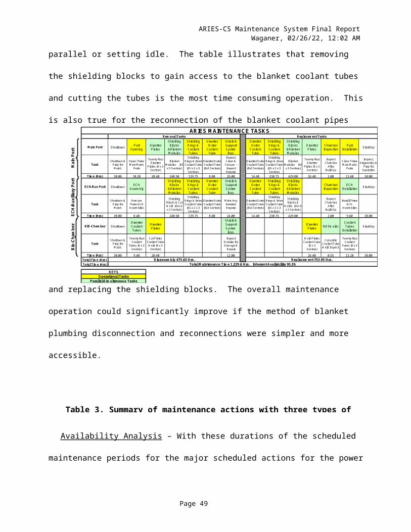
ARIES-CS Maintenance System Final ReportWaganer, 05/10/23, 3:07 PM
Duration of Serial Subtotal for Set Duration of ParallelMaintenance Task(s) Operations, Hours of Operations, Hours Operations, Hours
Inspection, Diagnostics and Preparation for OperationsPressurize coolant systems and test with test gas for leaks 4.00Evacuate power core interior 10.00 Initiate trace or helium heating 10.00 Pick up VV door, move into position, and secure 0.30 Reestablish vacuum door seal 2.00 Acquire port bio shield door, align, and move into position 0.50 Remove maintenance machine from transfer chamber 0.20 Close transfer chamber outer main isolation door 0.10Fill power core coolants 8.00Bake out (clean) power core chamber 12.00Check out and power up systems 4.00
TOTAL 38.00 13.10
TOTAL ASSEMBLY TIME 753.95 85.05
TOTAL DISASSEMBLY TIME 475.65 106.60TOTAL ASSEMBLY TIME 753.95 85.05TOTAL TIME 1,229.60 191.65
Full power years 3.00Number of Available Days 1,095.75
Number of Available Hours 26,298.00Nominal hours to replace three field periods 1,229.60
Inherent Availability 95.5%
Page 49