arm artisan sc benchmarking · microsoft powerpoint - arm_artisan_sc_benchmarking.pptx author:...
TRANSCRIPT

1
Standard Cell Benchmarking:Avoiding 5 Common Pitfalls
2012/2013
2
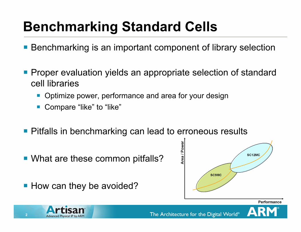
Benchmarking Standard Cells� Benchmarking is an important component of library selection
� Proper evaluation yields an appropriate selection of standard cell libraries� Optimize power, performance and area for your design� Compare “like” to “like”
� Pitfalls in benchmarking can lead to erroneous results
� What are these common pitfalls?
� How can they be avoided?

3
Critical Logic Benchmark StepsSynthesis
Floorplanning
Placement
DRC/LVS/DFM
Timing Analysis
Signal Integrity
Power/IR AnalysisATPG
CTS
Test Insertion
Routing
LEC
Simulation
Select representing Design
For logic avoid memories if possible,
power network is critical
Can be simplified
Key for utilization, area and performance
Not necessary toclean all issues
Can have big impacton Si performance as <=28nm designs are sensitive to IR-drop
Critical for benchmark implementation Critical for benchmark verification

4
Pitfall #1: Proper ConstraintsSet proper constraints� Control maximum transitions� ARM standard cells are clean to foundry guidelines for electromigration (EM)� EM is ensured by controlling edge rates, also referred to as transition times� Set in synthesis: 2/3 of the Liberty value
� Control maximum wire length � Wires have significant resistance variations in small geometries
� Control IO constraints� Relax if not important to prevent penalizing high frequency libraries
� Controlling transition and wire lengths have other benefits� Reduces long term reliability issues� Prevents timing closure issues during STA� Timing closure issues can arise due to wide wire resistance variation
� Causes extrapolation outside tables� Seen at fast process corners and high temperature
� Match constraints for all benchmarks

5
Pitfall #1: Proper Constraints, “dont_use” Lists
Set proper constraints� “dont_use” lists should vary with design targets
� High Performance targets� Don’t use low drive cells, except low drive BUF/INV for hold fixing� Don’t use cells targeting low power or high density� Use any cell types with optimized timing arcs
� High Density / Low Power targets� Use low drive cells� Don’t use cells with high pin densities� Don’t use cells targeting high performance (ex: cells with optimized timing arcs)
� All benchmarks� Don’t use delay cells, except for hold fixing � Don’t use specialty cells with same function as general cells (ex: latch-free clock gate)� Don’t use non-scan flops, unless required by design

6
Pitfall #2: ParasiticsAccount for parasitics� WLM refers to the wire load models included in
the Liberty (.lib) model� Very inaccurate for most design� Why? Wiring parasitics can dominate, especially
at small geometries
� If WLMs must be used, the SAME WLMs should be used for all vendors
� Use parasitic tables and physical synthesis� Physical synthesis supported by synthesis tools� Uses parasitic tables � Included in the ARM Routing Technology Kit
or� Provided by the foundry
Simulation
P&R
Synthesis
AnalysisLibrary Data Models
Design Info
ARMTech

7
Pitfall #3: Power Network
X nm
Align power network to the architecture� Architecture affects routing� Determines metal direction(s), best VIAs, pin accessibility� Direct relationship to best power grid � May affect proximity effects
M1M2
PolyY nm
Different architectures with different metal directions. Ideal power networks will vary.

8
Pitfall #3: Power Network and RoutabilityAlign power network to the architecture� The power network is an important part of a benchmark � Poor cell design can result in a significant area hit with a power grid in place� Poor power grid can unnecessarily block routing resources
� ARM architects standard cells for optimal use with a power grid� Layouts consider a lower 2D grid on M2/M3 for libraries using M2 rails
� A proper power grid � Minimizes IR drop and EM� Allows for fast di/dt (switching) response
� Uses narrow evenly spaced straps placed frequently
� Places power and ground straps alternately
� A benchmark without a power grid does not account for library routability

9
Power Supply OverviewRecommendations & Considerations
Standard Cell Designer
(IP Vendor)
Chip/block Design (Customer) Reason
Largest cell supply rail possible
� Reduces IR drop� Improves EM characteristics� Allows for greater redundancy of supply VIAs (IR,
EM, yield)
Lower 2D supply grid� M2/M3 grid for
libraries w/M2 rails� M1/M2 grid for
libraries w/M1 rails
� Reduces di/dt� Reduces resistance � Reduces on-chip inductance to local decoupling
capacitance� Reduces VIA resistance versus using only an upper
supply grid
Upper 2D supply grid(top 2 metals)
� Reduces IR drop� Handles global supply distribution� Improves routing by freeing lower planes for signal
routing

10
Use the appropriate tech file for routing� Architecture affects routing� Different architectures may optimize for different metal pitch and VIA
connections� Different vendor tech files may include different VIAs� Use vendor supplied tech files!
Pitfall #4: Tech file for routing
M1
M2
VIA12 cut
“right way” VIAsM1/M2 are horizontal;the same direction as
for M2 routing
Not “right way” VIAs; M1/M2 direction is
opposite of M2 routing
“Traditional” VIAs “Wide” VIAs

11
Pitfall #5: Optimize Utilization
Most designs close blocks with a utilization between 70-85%
Optimize utilization for the architecture and your design � Architecture and power grid can affect utilization� Local routing congestion can limit utilization� Dial up utilization during benchmark
Frequency
Util
izat
ion
Ach
ieve
d High Performance Library UtilHigh Density Library Util

12
GETTING RESULTSFOR YOUR DESIGN

13
Determining the Fastest Library� Run synthesis and place and route (SP&R) on the RTL at smaller and
smaller cycle times� Use a pin-and-aspect-ratio floorplan – sets relative pin locations and aspect ratio� Include power grid: lower grid may differ across libraries� A rough initial cell utilization of 75% or higher is suggested for benchmarking
� After CTS, routing, etc. this will be higher
� When the worst negative slack (WNS) starts increasing � You have found the theoretical fastest speed one can implement that library/design
combination� The library that produces the fastest design is the fastest library: the winner� The area/routability/power consumption is *not* being measured here
Remember…#1 The x and y of the floorplan and relative pin positions of the slowest library#2 The maximum frequency of the slowest library
14
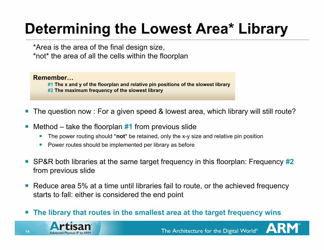
Determining the Lowest Area* Library
� The question now : For a given speed & lowest area, which library will still route?
� Method – take the floorplan #1 from previous slide� The power routing should *not* be retained, only the x-y size and relative pin position� Power routes should be implemented per library as before
� SP&R both libraries at the same target frequency in this floorplan: Frequency #2from previous slide
� Reduce area 5% at a time until libraries fail to route, or the achieved frequency starts to fall: either is considered the end point
� The library that routes in the smallest area at the target frequency wins
Remember…#1 The x and y of the floorplan and relative pin positions of the slowest library#2 The maximum frequency of the slowest library
*Area is the area of the final design size,*not* the area of all the cells within the floorplan

15
Determining the Lowest Power Library�Method � Take the final design from the previous step for each library� Take the last run before the end point
� Measure the dynamic and static powers for each of the 2 designs
� The winner is the one with the lowest power
16
ARM Internal Benchmarks � Target a large design without large run times
� Understand critical path and logic levels
� Know constraints� max_transition� Utilization target
� Perform full flow� Synthesis, P&R with a power grid, CTS, hold fixing
� Use current EDA tools for library
17
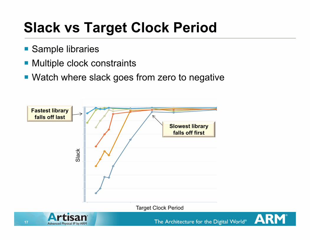
Slack vs Target Clock Period
Slowest library falls off first
Target Clock Period
Sla
ck
� Sample libraries � Multiple clock constraints� Watch where slack goes from zero to negative
Fastest library falls off last
18
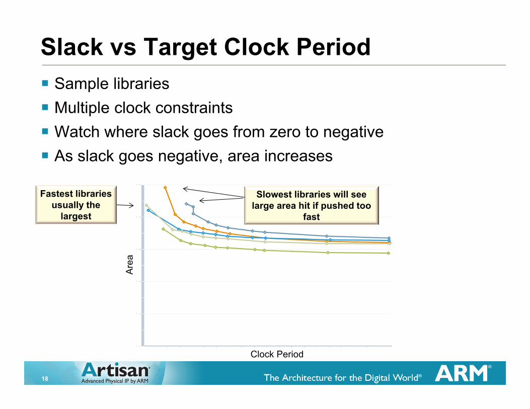
Slack vs Target Clock Period
Clock Period
Are
a
� Sample libraries � Multiple clock constraints� Watch where slack goes from zero to negative� As slack goes negative, area increases
Fastest libraries usually the
largest
Slowest libraries will see large area hit if pushed too
fast
19
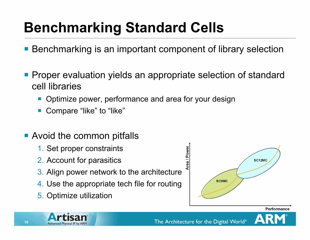
Benchmarking Standard Cells� Benchmarking is an important component of library selection
� Proper evaluation yields an appropriate selection of standard cell libraries� Optimize power, performance and area for your design� Compare “like” to “like”
� Avoid the common pitfalls1. Set proper constraints2. Account for parasitics3. Align power network to the architecture4. Use the appropriate tech file for routing5. Optimize utilization

20
5 Common Pitfalls1. Set proper constraints� Select target PPA priority and conduct benchmark� Optimize cell set with “dont_use” lists� Edge rates & wire lengths
2. Account for parasitics� Use the same parasitic tables for all vendors
3. Align power network to the architecture� Watch for blocked resources
4. Use the appropriate tech file for routing� VIA selection can be important� Metal pitch can change with architecture
5. Optimize utilization � Different libraries will have different utilization limits