arm how-to guide interfacing spi- ethernet with · pdf file25/12/2014 ·...
TRANSCRIPT
ARM HOW-TO GUIDE
Interfacing SPI-
Ethernet with LPC2148

Join the Technical Community Today!
http://www.pantechsolutions.net
Contents at a Glance
ARM7 LPC2148 Slicker Board ........................................... 3
SPI (Serial Peripheral Interface) ........................................ 3
Ethernet .......................................................................... 4
The ENC28J60 Ethernet Controller ................................... 4
Interfacing SPI-Ethernet ................................................... 5
Interfacing SPI-Ethernet with LPC2148 ............................. 7
Pin Assignment with LPC2148 .......................................... 7
Circuit Diagram to Interface SPI-Ethernet with LPC2148 ... 8
Source Code .................................................................... 8
C Program to interface Ethernet with LPC2148 ................. 9
Testing the SPI-Ethernet with LPC2148 ........................... 16
General Information ...................................................... 17

Join the Technical Community Today!
http://www.pantechsolutions.net
ARM7 LPC2148 Slicker Board
The ARM7 LPC2148 Slicker board is specifically
designed to help students to master the required skills in
the area of embedded systems. The kit is designed in such
way that all the possible features of the microcontroller will
be easily used by the students. The kit supports in system
programming (ISP) which is done through serial port.
NXP’s ARM7 (LPC2148), ARM Slicker Kit is proposed to
smooth the progress of developing and debugging of
various designs encompassing of High speed 32-bit
Microcontrollers.
SPI (Serial Peripheral Interface)
Serial Peripheral Interface (SPI) is a synchronous serial
data protocol used by microcontrollers for communicating
with one or more peripheral devices quickly over short
distances. It can also be used for communication between
two microcontrollers.
Join the Technical Community Today!
http://www.pantechsolutions.net
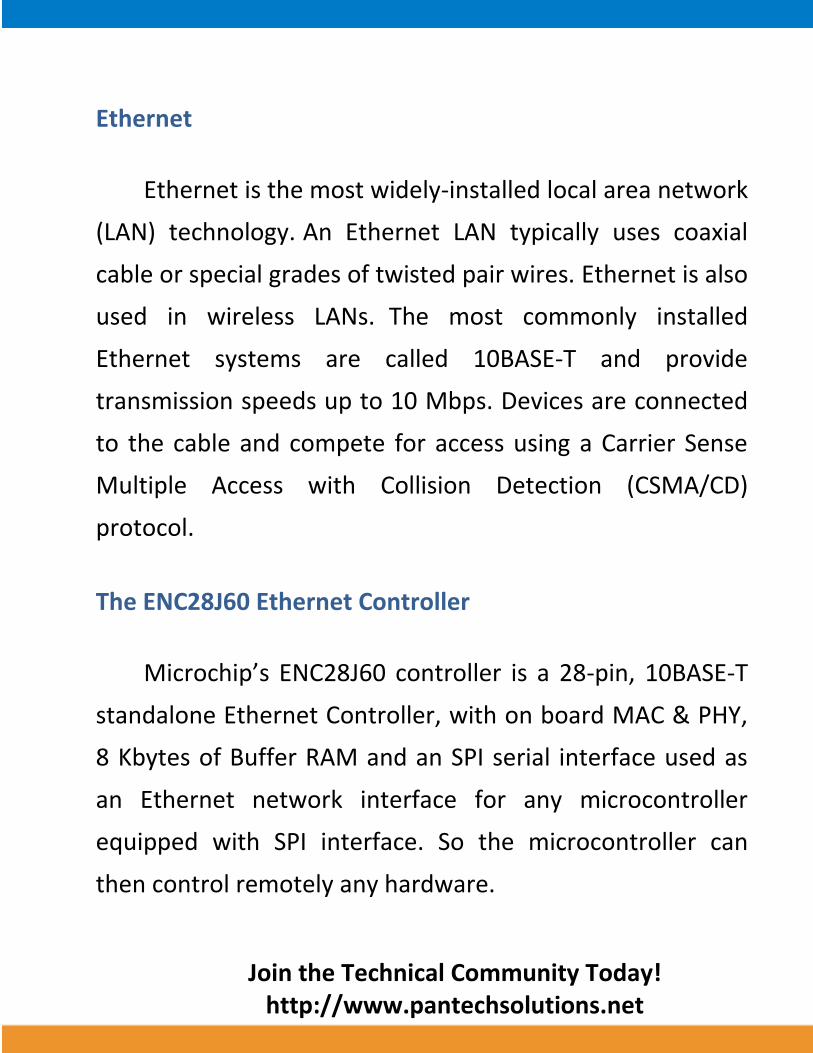
Ethernet
Ethernet is the most widely-installed local area network
(LAN) technology. An Ethernet LAN typically uses coaxial
cable or special grades of twisted pair wires. Ethernet is also
used in wireless LANs. The most commonly installed
Ethernet systems are called 10BASE-T and provide
transmission speeds up to 10 Mbps. Devices are connected
to the cable and compete for access using a Carrier Sense
Multiple Access with Collision Detection (CSMA/CD)
protocol.
The ENC28J60 Ethernet Controller
Microchip’s ENC28J60 controller is a 28-pin, 10BASE-T
standalone Ethernet Controller, with on board MAC & PHY,
8 Kbytes of Buffer RAM and an SPI serial interface used as
an Ethernet network interface for any microcontroller
equipped with SPI interface. So the microcontroller can
then control remotely any hardware.

Join the Technical Community Today!
http://www.pantechsolutions.net
Interfacing SPI-Ethernet
Fig. 1 shows how to interface the SPI-Ethernet to
microcontroller. With an SPI connection there is always one
master device (usually a microcontroller) which controls the
peripheral devices. Typically there are three lines common
to all the devices,
Master In Slave Out (MISO) - The Slave line for
sending data to the master,
Master Out Slave In (MOSI) - The Master line for
sending data to the peripherals,
Serial Clock (SCK) - The clock pulses which
synchronize data transmission generated by the master,
and
Slave Select pin - the pin on each device that the
master can use to enable and disable specific devices. When
a device's Slave Select pin is low, it communicates with the
master. When it's high, it ignores the master.

Join the Technical Community Today!
http://www.pantechsolutions.net
This allows you to have multiple SPI devices sharing the
same MISO, MOSI, and CLK lines.
Fig. 1 Interfacing SPI-Ethernet to Microcontroller
The Ethernet buffer contains transmit and receive
memory used by the Ethernet controller. The entire buffer
is 8 Kbytes, divided into separate receive and transmit
buffer spaces. The sizes and locations of transmit and
receive memory are fully programmable by the host
controller using the SPI interface. Any space within the 8-
Kbyte memory, which is not programmed as part of the
receive FIFO buffer, is considered to be the transmit buffer.

Join the Technical Community Today!
http://www.pantechsolutions.net
Interfacing SPI-Ethernet with LPC2148
In SPI, the clock signal is controlled by the master
device LPC2148 Slicker Board. All data is clocked in and out
using this pin. These lines need to be connected to the
relevant pins on the LPC2148 Slicker Board. Any unused GIO
pin can be used for CS, instead pull this pin high. The
ENC28J60 requires a single per packet control byte to
precede the packet for transmission to Microcontroller. An
IP address is used to access the Ethernet control. The
ENC28J60 SPI connections with LPC2148 have four I/O lines
required.
Pin Assignment with LPC2148
SPI Connector
LPC2148
Processor Lines
UA
RT0
(P1
)
ISP
PG
M
SCK P0.4
MOSI P0.5
UA
RT1
(P2
) MISO P0.6
CS P0.7
Join the Technical Community Today!
http://www.pantechsolutions.net
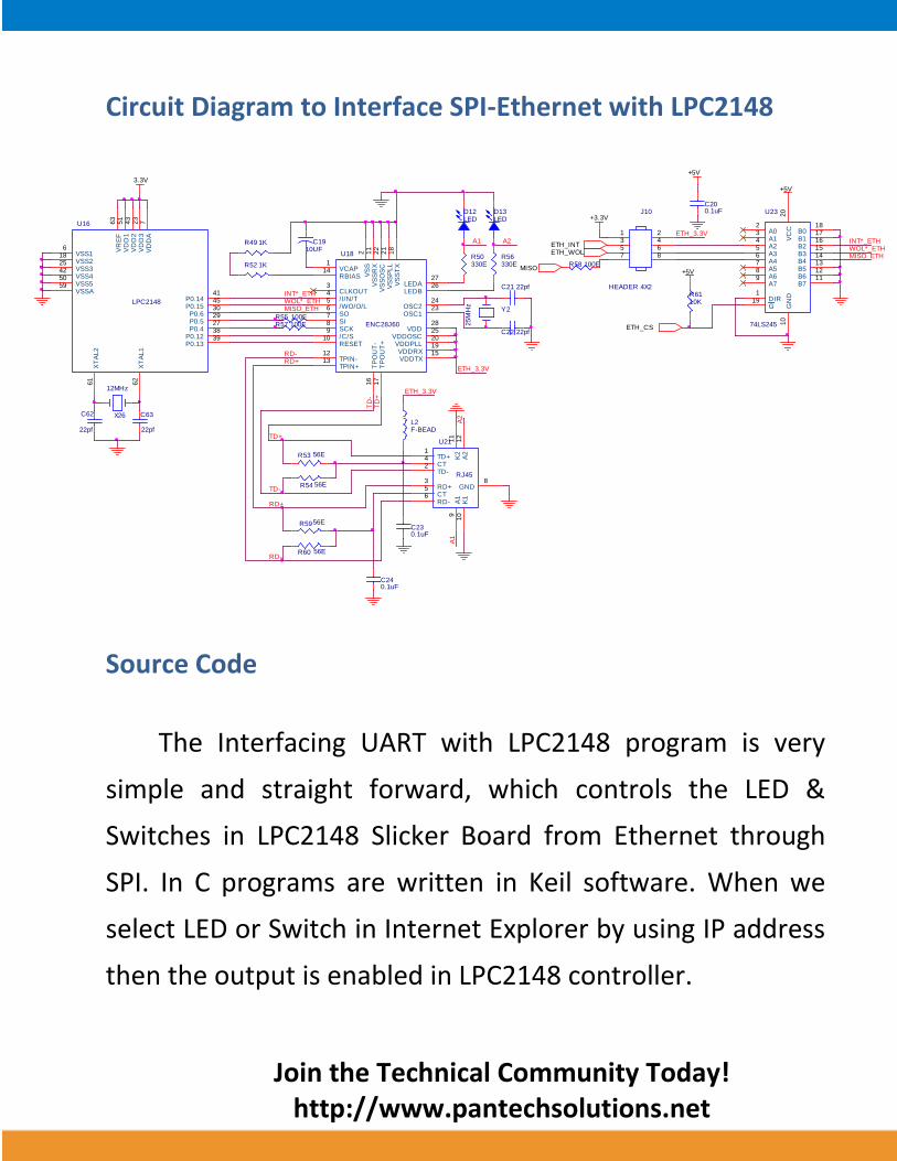
Circuit Diagram to Interface SPI-Ethernet with LPC2148
Source Code
The Interfacing UART with LPC2148 program is very
simple and straight forward, which controls the LED &
Switches in LPC2148 Slicker Board from Ethernet through
SPI. In C programs are written in Keil software. When we
select LED or Switch in Internet Explorer by using IP address
then the output is enabled in LPC2148 controller.
+3.3VJ10
HEADER 4X2
2468
1357
ETH_3.3V
ETH_CS
INT*_ETH
U23
74LS245
A02
A13
A24
A35
A46
A57
A68
A79
G19 DIR1
B018
B117
B216
B315
B414
B513
B612
B711
VC
C20
GN
D10
MISO_ETHWOL*_ETH
+5V
+5VR58 100E
+5V
R6110K
ETH_WOLETH_INT
MISO
C200.1uF
3.3V
C62
22pf
C63
22pf
X26
12MHz
LPC2148
U16
VSS16 V
DD
A7
VSS218
VD
D3
23
VSS325
VD
D2
43
VSS442
VR
EF
63
XT
AL1
62
XT
AL2
61
VSSA59
VD
D1
51
VSS550
P0.1238
P0.630
P0.529
P0.427
P0.1339
P0.1441
P0.1545
A1
A2
U21
RJ45
TD+1
CT4
TD-2
RD+3
CT5
RD-6
K2
11
A2
12
K1
10
A1
9
GND8
R54 56E
R53 56E
TD+
TD-
C240.1uF
C230.1uF
RD+
L2F-BEAD
R5956E
RD-R60 56E
ETH_3.3V
R49 1K C1910UF
TD
+
MISO_ETHWOL*_ETHINT*_ETH
R55 100ER57 100E
R52 1K
U18
ENC28J60
VCAP1
VS
S2
CLKOUT3
/I/N/T4
/WO/O/L5
SO6
SI7
SCK8
/C/S9
RESET10
VS
SR
X11
TPIN-12
TPIN+13
RBIAS14
VDD28
LEDA27
LEDB26
VDDOSC25
OSC224
OSC123
VS
SO
SC
22
VS
SP
LL
21
VDDPLL20
VDDRX19
VS
ST
X18
TP
OU
T+
17
TP
OU
T-
16
VDDTX15
R56330E
R50330E
Y2
25M
Hz
D12LED
A1
D13LED
A2
C21 22pf
RD+T
D-
RD-
C22 22pf
ETH_3.3V
Join the Technical Community Today!
http://www.pantechsolutions.net
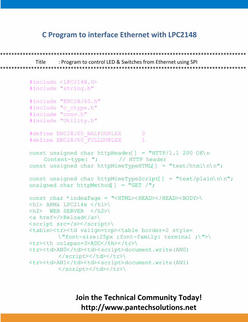
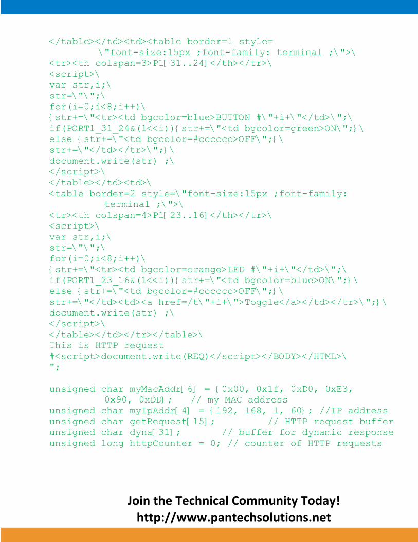
C Program to interface Ethernet with LPC2148
*************************************************************************************** Title : Program to control LED & Switches from Ethernet using SPI
***************************************************************************************
#include <LPC214X.H>
#include "string.h"
#include "ENC28J60.h"
#include "c_ctype.h"
#include "conv.h"
#include "Utility.h"
#define ENC28J60_HALFDUPLEX 0
#define ENC28J60_FULLDUPLEX 1
const unsigned char httpHeader[] = "HTTP/1.1 200 OK\n
Content-type: "; // HTTP header
const unsigned char httpMimeTypeHTML[] = "text/html\n\n";
const unsigned char httpMimeTypeScript[] = "text/plain\n\n";
unsigned char httpMethod[] = "GET /";
const char *indexPage = "<HTML><HEAD></HEAD><BODY>\
<h1> ARM& LPC214x </h1>\
<h2> WEB SERVER </h2>\
<a href=/>Reload</a>\
<script src=/s></script>\
<table><tr><td valign=top><table border=2 style=
\"font-size:25px ;font-family: terminal ;\">\
<tr><th colspan=3>ADC</th></tr>\
<tr><td>AN0</td><td><script>document.write(AN0)
</script></td></tr>\
<tr><td>AN1</td><td><script>document.write(AN1)
</script></td></tr>\
Join the Technical Community Today!
http://www.pantechsolutions.net
</table></td><td><table border=1 style=
\"font-size:15px ;font-family: terminal ;\">\
<tr><th colspan=3>P1[31..24]</th></tr>\
<script>\
var str,i;\
str=\"\";\
for(i=0;i<8;i++)\
{str+=\"<tr><td bgcolor=blue>BUTTON #\"+i+\"</td>\";\
if(PORT1_31_24&(1<<i)){str+=\"<td bgcolor=green>ON\";}\
else {str+=\"<td bgcolor=#cccccc>OFF\";}\
str+=\"</td></tr>\";}\
document.write(str) ;\
</script>\
</table></td><td>\
<table border=2 style=\"font-size:15px ;font-family:
terminal ;\">\
<tr><th colspan=4>P1[23..16]</th></tr>\
<script>\
var str,i;\
str=\"\";\
for(i=0;i<8;i++)\
{str+=\"<tr><td bgcolor=orange>LED #\"+i+\"</td>\";\
if(PORT1_23_16&(1<<i)){str+=\"<td bgcolor=blue>ON\";}\
else {str+=\"<td bgcolor=#cccccc>OFF\";}\
str+=\"</td><td><a href=/t\"+i+\">Toggle</a></td></tr>\";}\
document.write(str) ;\
</script>\
</table></td></tr></table>\
This is HTTP request
#<script>document.write(REQ)</script></BODY></HTML>\
";
unsigned char myMacAddr[6] = {0x00, 0x1f, 0xD0, 0xE3,
0x90, 0xDD}; // my MAC address
unsigned char myIpAddr[4] = {192, 168, 1, 60}; //IP address
unsigned char getRequest[15]; // HTTP request buffer
unsigned char dyna[31]; // buffer for dynamic response
unsigned long httpCounter = 0; // counter of HTTP requests
Join the Technical Community Today!
http://www.pantechsolutions.net
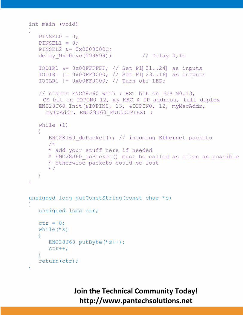
int main (void)
{
PINSEL0 = 0;
PINSEL1 = 0;
PINSEL2 &= 0x0000000C;
delay_Nx10cyc(599999); // Delay 0,1s
IODIR1 &= 0x00FFFFFF; // Set P1[31..24] as inputs
IODIR1 |= 0x00FF0000; // Set P1[23..16] as outputs
IOCLR1 |= 0x00FF0000; // Turn off LEDs
// starts ENC28J60 with : RST bit on IOPIN0.13,
CS bit on IOPIN0.12, my MAC & IP address, full duplex
ENC28J60_Init(&IOPIN0, 13, &IOPIN0, 12, myMacAddr,
myIpAddr, ENC28J60_FULLDUPLEX) ;
while (1)
{
ENC28J60_doPacket(); // incoming Ethernet packets
/*
* add your stuff here if needed
* ENC28J60_doPacket() must be called as often as possible
* otherwise packets could be lost
*/
}
}
unsigned long putConstString(const char *s)
{
unsigned long ctr;
ctr = 0;
while(*s)
{
ENC28J60_putByte(*s++);
ctr++;
}
return(ctr);
}

Join the Technical Community Today!
http://www.pantechsolutions.net
unsigned long putString(char *s)
{
unsigned long ctr;
ctr = 0;
while(*s)
{
ENC28J60_putByte(*s++);
ctr++;
}
return(ctr);
}
unsigned long ENC28J60_userTCP(unsigned char *remoteHost,
unsigned long remotePort, unsigned long localPort,
unsigned long reqLength)
{
unsigned long
len, // my reply length
i, // general purpose integer
bitMask; // for bit mask
i = (unsigned long) remoteHost;
i = remotePort;
i = reqLength;
len = 0;
bitMask = 0;
if (localPort != 80)
return(0) ;
for (i = 0; i < 10; i++)
getRequest[i] = ENC28J60_getByte();
getRequest[i] = 0;
if (memcmp(getRequest, httpMethod, 5))
return(0);
Join the Technical Community Today!
http://www.pantechsolutions.net
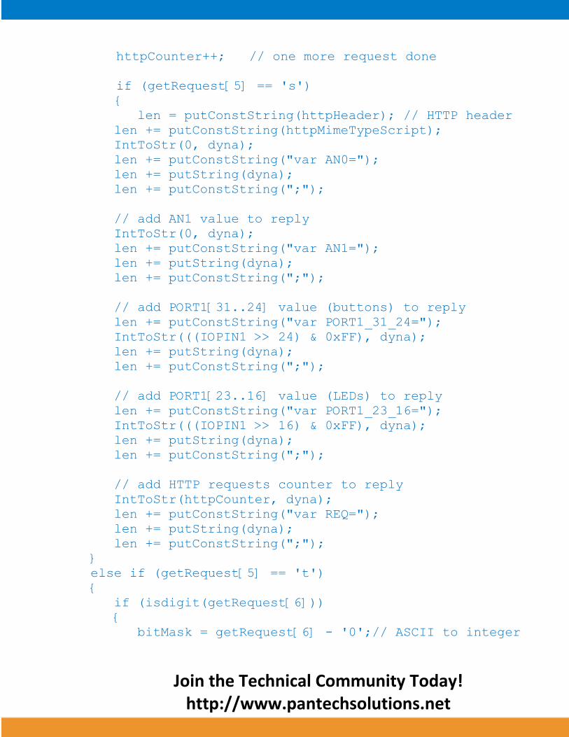
httpCounter++; // one more request done
if (getRequest[5] == 's')
{
len = putConstString(httpHeader); // HTTP header
len += putConstString(httpMimeTypeScript);
IntToStr(0, dyna);
len += putConstString("var AN0=");
len += putString(dyna);
len += putConstString(";");
// add AN1 value to reply
IntToStr(0, dyna);
len += putConstString("var AN1=");
len += putString(dyna);
len += putConstString(";");
// add PORT1[31..24] value (buttons) to reply
len += putConstString("var PORT1_31_24=");
IntToStr(((IOPIN1 >> 24) & 0xFF), dyna);
len += putString(dyna);
len += putConstString(";");
// add PORT1[23..16] value (LEDs) to reply
len += putConstString("var PORT1_23_16=");
IntToStr(((IOPIN1 >> 16) & 0xFF), dyna);
len += putString(dyna);
len += putConstString(";");
// add HTTP requests counter to reply
IntToStr(httpCounter, dyna);
len += putConstString("var REQ=");
len += putString(dyna);
len += putConstString(";");
}
else if (getRequest[5] == 't')
{
if (isdigit(getRequest[6]))
{
bitMask = getRequest[6] - '0';// ASCII to integer

Join the Technical Community Today!
http://www.pantechsolutions.net
bitMask = 1 << (bitMask + 16);// create bit mask
if ((IOPIN1 & bitMask) != 0) // Toggled LED
IOCLR1 |= bitMask;
else
IOSET1 |= bitMask;
}
}
if (len == 0) // what do to by default
{
len = putConstString(httpHeader); // HTTP header
len += putConstString(httpMimeTypeHTML);// MIME type
len += putConstString(indexPage); // HTML page
}
return (len);
}
unsigned long ENC28J60_userUDP(unsigned char *remoteHost,
unsigned long remotePort, unsigned long destPort,
unsigned long reqLength)
{
unsigned long
len; // my reply length
unsigned char
*ptr;
ByteToStr(remoteHost[0], dyna); // first IP address byte
dyna[3] = '.';
ByteToStr(remoteHost[1], dyna + 4); // second
dyna[7] = '.';
ByteToStr(remoteHost[2], dyna + 8); // third
dyna[11] = '.';
ByteToStr(remoteHost[3], dyna + 12); // fourth
dyna[15] = ':'; // add separator
IntToStr(remotePort, dyna + 16);
dyna[22] = '[';
IntToStr(destPort, dyna + 23);
dyna[29] = ']';

Join the Technical Community Today!
http://www.pantechsolutions.net
dyna[30] = 0;
// the total length of the request is the length of the
dynamic string plus the text of the request
len = 30 + reqLength;
// puts the dynamic string into the transmit buffer
ptr = dyna;
while (*ptr)
ENC28J60_putByte(*ptr++);
// then puts the request string converted into upper char
into the transmit buffer
while (reqLength--)
ENC28J60_putByte(toupper(ENC28J60_getByte()));
return (len); // back to the library with the length of the
UDP reply
}
To compile the above C code you need the KEIL software.
They must be properly set up and a project with correct
settings must be created in order to compile the code. To
compile the above code, the C file must be added to the
project.
In KEIL, you want to develop or debug the project
without any hardware setup. You must compile the code for
Join the Technical Community Today!
http://www.pantechsolutions.net
generating HEX file. In debugging Mode, you want to check
the port output without LPC2148 Slicker Board.
The Flash Magic software is used to download the hex
file into your microcontroller IC LPC2148 through UART0.
Testing the SPI-Ethernet with LPC2148
Give +3.3V power supply to LPC2148 Slicker Board; the
SPI-Ethernet is connected with LPC2148 Slicker Board.
Connect your board to a hub with a straight cable. LEDA
should now turn on with LEDB still blinking. LEDA ON means
that the adapter is correctly linked to the network. The
network link LED of the other side hub should also turn on.
Open the Internet Explorer window and give the IP
address. If the entire connections are connected correctly,
then the IP address display the LED, switch levels.
Now you can control the input & output port lines (LED
& switch) of LPC2148 Slicker Board from Internet Explorer

Join the Technical Community Today!
http://www.pantechsolutions.net
through SPI - Ethernet. If you are not reading any output
from LED, then you just check the jumper connections &
check the LED is working.
If you are not controlled the I/O port lines of LPC2148
Slicker Board from Internet Explorer, then you just check
the IP address & Ethernet connections. Otherwise you just
check the code with debugging mode in KEIL. If you want to
see more details about debugging just see the videos in
below link.
How to Create & Debug a Project in KEIL.
General Information
For proper working use the components of exact values
as shown in Circuit file. Wherever possible use new
components.
Join the Technical Community Today!
http://www.pantechsolutions.net
Solder everything in a clean way. A major problem
arises due to improper soldering, solder jumps and
loose joints.
Use the exact value crystal shown in schematic.
The straight cable only used between LPC2148 Slicker
Board hub & the network cable hub.
Don't plug the ENC28J60 in its socket, then power to
the board and verify the 3.3V power supply on each pin
of the ENC.
More instructions are available in following articles,
User Manual of LPC2148 Slicker Board.
Tutorial of how to create & Debug a project in
KEIL.
Interfacing LED with LPC2148.
Interfacing switch with LPC2148.

Join the Technical Community Today!
http://www.pantechsolutions.net
Pantech solutions creates information packed technical
documents like this one every month. And our website is a rich
and trusted resource used by a vibrant online community of
more than 1,00,000 members from organization of all shapes
and sizes.
Did you enjoy the read?

Join the Technical Community Today!
http://www.pantechsolutions.net
What do we sell?
Our products range from Various Microcontroller
development boards, DSP Boards, FPGA/CPLD boards,
Communication Kits, Power electronics, Basic electronics,
Robotics, Sensors, Electronic components and much more . Our
goal is to make finding the parts and information you need
easier and affordable so you can create awesome projects and
training from Basic to Cutting edge technology.