freyssinet · tierra armada s.a. buenos aires phone: (54.11) 43 72 72 91 fax: (54.11) 43 72 51 79...
TRANSCRIPT

reyssinet
FreyssinetJuly 2000 / No. 208
M A G A Z I N E
Kuwait
Rehabilitation of the BubiyanBridge
GB 208/couve 20/10/00 17:25 Page 2

Co
nte
nts
Contents
2Freyssinet magazine July 2000 / No.208
ARGENTINA Freyssinet S.A. Buenos AiresPhone: (54.11) 43 72 72 91Fax: (54.11) 43 72 51 79
Tierra Armada S.A.Buenos AiresPhone: (54.11) 43 72 72 91Fax: (54.11) 43 72 51 79
BRAZIL STUP Premoldados Ltda São PauloPhone: (55.11) 3873 27 34Fax: (55.11) 262 85 02
FreyssinetRio de JaneiroPhone: (55.21) 221 85 00Fax: (55.21) 852 79 26
Terra Armada S.A.Rio de JaneiroPhone: (55.21) 233 73 53Fax: (55.21) 263 48 42
CANADAReinforced Earth Company LtdOntarioPhone: (1.905) 564 08 96Fax: (1.905) 564 26 09
Freyssinet Ltée MontréalPhone: (1.450) 466 65 66Fax: (1.450) 466 60 03
COLOMBIASTUP de ColombiaBogotaPhone: (57.1) 257 41 03
236 37 86Fax: (57.1) 610 38 98
Tierra ArmadaBogotaPhone: (57.1) 236 37 86Fax: (57.1) 610 38 98
EL SALVADORFessic S.A. de C.V. La LibertadPhone: (503) 2 78 07 55
2 78 86 03 Fax: (503) 2 78 04 45
GUATEMALAPresforzados Técnicos S.A.Ciudad Guatemala Phone: (502) 282 481Fax: (502) 2500 150
MEXICOFreyssinet de México S.A. de C.V.Mexico D.F.Phone: (52.5) 250 70 00Fax: (52.5) 255 01 65
Tierra Armada S.A. de C.V.México D.F.Phone: (52) 5250 17 26
(52) 5254 54 00Fax: (52) 5254 86 65
PERUSTUP del Perù S.A. LimaPhone: (51.1) 372 21 86Fax: (51.1) 372 25 66
UNITED STATESFreyssinet PTSC LLC Chantilly, VA Phone: (1.703) 378 25 00Fax: (1.703) 378 27 00
Ménard LLCVienna, VA Phone: (1.703) 821 10 54Fax: (1.703) 821 14 79
The Reinforced Earth CompanyVienna, VA Phone: (1.703) 821 11 75Fax: (1.703) 821 18 15
VENEZUELATierra Armada CaCaracasPhone: (58.2) 574 90 38/10 61Fax: (58.2) 574 77 50
BELGIUMCinec N.V.VilvoordePhone: (32.2) 252 07 40Fax: (32.2) 252 24 43
BeneltaVilvoordePhone: (32.2) 252 07 40Fax: (32.2) 252 24 43
DENMARKA/S SkandinaviskSpaendbetonVaerlosePhone: (45.44) 48 08 25Fax: (45.44) 48 12 45
FINLANDOY Jannibetoni ABVaerlose
FRANCEFreyssinet International & CieVélizyPhone: (33.1) 46 01 84 84Fax: (33.1) 46 01 85 85
Freyssinet FranceVélizyPhone: (33.1) 30 13 91 99Fax: (33.1) 34 61 65 47
PPCSaint-RémyPhone: (33.3) 85 42 15 15Fax: (33.3) 85 42 15 10
Menard SoltraitementNozayPhone: (33.1) 69 01 37 38Fax: (33.1) 69 01 75 05
FYROMMigal Inzinjering & Konsalting SkopjePhone: (389) 91 120 151Fax: (389) 91 120 151
GERMANYSBT Brückentechnik GmbHPlüderhausenPhone: (49.7181) 99 00 0Fax: (49.7181) 99 00 66
Bewerhete Erde GmbHPlüderhausenPhone: (49.71 81) 99 00 70Fax: (49.71 81) 99 00 75
GREECEFreyssinet Hellas S.A.AthensPhone: (30.1) 69 15 926Fax: (30.1) 69 28 137
FredraAthensPhone: (30.1) 60 20 500Fax: (30.1) 66 27 748
HUNGARYPannon FreyssinetBudapestPhone: (36.1) 209 15 10Fax: (36.1) 209 15 10
IRELANDReinforced Earth Co.KildarePhone: (353) 4543 10 88Fax: (353) 4543 31 45
ITALYFreyssinet Italia S.r.l.RomaPhone: (39.06) 6880 29 22Fax: (39.06) 687 39 38
Freyssinet Italia S.r.l.MilanPhone: (39.02) 895 402 76Fax: (39.02) 895 404 46
Terra Armata S.p.A.RomaPhone: (39.06) 806 87 275Fax: (39.06) 808 82 64
NETHERLANDSSamaco B.V.WaddinxveenPhone: (31.18) 26 30 888Fax: (31.18) 26 30 152
Terre Armée B.V.BredaPhone: (31.76) 531 93 32Fax: (31.76) 531 99 43
NORWAYA/S Skandinavisk Spennbeton SnarøyaPhone: (47.67) 53 91 74
POLANDFreyssinet Polska Sp. z o.o.MilanõwekPhone: (48.22) 792 13 86Fax: (48.22) 724 84 67
PORTUGALArmol-Freyssinet LtdaLisbonPhone: (351.21) 716 16 75Fax: (351.21) 716 40 51
Terra Armada LtdaLisbonPhone: (351.21) 792 37 97Fax: (351.21) 792 37 01
ROMANIAFreyrom S.A.BucarestPhone: (40.1) 220 35 50Fax: (40.1) 220 45 41
SPAINFreyssinet S.A.MadridPhone: (34.91) 323 95 50Fax: (34.91) 323 95 51
Freyssinet S.A.BarcelonaPhone: (34.93) 226 44 60Fax: (34.93) 226 59 98
Tierra Armada S.A.MadridPhone: (34.91) 323 95 00Fax: (34.91) 323 95 11
SWEDENAB Skandinavisk Spaennbeton MalmöPhone: (46.40) 98 14 00
UNITED KINGDOMFreyssinet UKTelfordPhone: (44) 1952 201 901Fax: (44) 1952 201 753
Reinforced Earth Company LtdTelfordPhone: (44) 1952 201 901Fax: (44) 1952 201 753
United Kingdom
ExCel: Post-tensioned
concrete slabsp. 14
Am
United Kingdom
A reconvertedflour mill
p. 15
EUROPE EUROPE
Freyssinet Magazine, 1 bis, rue du Petit-Clamart 78148 Vélizy Cedex - France. Tel.: 01 46 01 84 21. Fax: 01 46 01 86 86.Internet: www.freyssinet.comPublication manager:Françoise Muteaud. Contributed to this issue: Bill Brockbank, Laure Céleste, Bruno Florin, Jean-Philippe Fuzier, Basilio C. Gaoat, Diane Griffiths, Roger Lacroix, Eric Laurent, Lorraine Leong, Jean-Paul Marquet, ChaleeMauleekoonphiroj, Paul McBarron, Yvonne McDonald, Fernand de Melo, Gustavo Mello, Giovanni Mucciacia, SylvianeMullenberg, C.W.M. Noort, Tomas Palomares, Pedro Pinto Da Sousa, Pierre-Yves Riou, John Ritchie, Eric Romagna,Freddie Siew, Steve Truby, Roger Warwick, Kenny Yee. Artistic management: Antoine Depoid. Layout: Grafik Tribu.Computer graphics: Alain Kugel. Translation: Netword. Project leader: Stéphane Tourneur. Editorial secretariat:Nathalie Laville. Photos: Francis Vigouroux, Claude Cieutat, Freyssinet photo library. Cover page: Bubiyan bridge,photo Francis Vigouroux. Photo-engraving: Grafik Tribu. Printing: SIO.
SWITZERLANDFreyssinet S.A. MoudonPhone: (41.21) 905 48 02Fax: (41.21) 905 11 01
TURKEYFreysasIstanbulPhone: (90.216) 349 87 75
349 87 74Fax: (90.216) 349 63 75
Reinforced Earth Company Ltd IstanbulPhone: (90.216) 492 8424Fax: (90.216) 492 3306
AFRICAEGYPTFreyssinet EgyptGisaPhone: (20.2) 303 69 65Fax: (20.2) 345 52 37
345 81 65
SOUTH AFRICA
Freyssinet S.A. (Pty) LtdOlifantsfonteinPhone: (27.11) 316 21 74Fax: (27.11) 316 29 18
Reinforced Earth Pty LtdJohannesburgPhone: (27.11) 726 6180Fax: (27.11) 726 5908
UNITED ARAB EMIRATESFreyssinet-TAI Middle-EastAbou DhabiPhone: (971) 2 667 9871Fax: (971) 2 667 9872
Although Freyssinet makes every effort to ensure that the information that it provides is as correct as possible, the editors,employees and agents cannot guarantee the results or be responsible for them in any way.
AMERICA
GB 208 Freys Mag 20/10/00 17:29 Page 2

Contents
3Freyssinet magazine July 2000 / No. 208
ASIA
HONG KONGFreyssinet Hong Kong LtdKowloon TongPhone: (852) 27 94 03 22
23 39 83 70Fax: (852) 23 38 32 64:
Reinforced Earth Pacific LtdKowloonPhone: (852) 27 823 163Fax: (852) 23 325 521
INDIATAI Aimil joint ventureNew DelhiPhone: (91.11) 695 98 18Fax: (91.11) 695 94 56
INDONESIAPT Freyssinet TotalTechnologyDjakartaPhone: (62.21) 830 02 19/22
830 56 89/90Fax: (62.21) 830 98 41
720 69 36
JAPANF.K.K. TokyoPhone: (81.3) 35 71 86 51/54Fax: (81.3) 35 74 07 10
35 71 44 69
Terre Armée K.K.TokyoPhone: (81) 427 22 1134Fax: (81) 427 22 1134
KUWAITFreyssinet International et CieSafatPhone: (965) 571 49 74Fax: (965) 573 57 48
LEBANONO.P.C. BeyrouthPhone: (966.1) 463 04 62Fax: (966.1) 463 04 62
MALAYSIAFreyssinet PSC (M) Sdn BhdKuala LumpurPhone: (60.3) 782 85 99Fax: (60.3) 781 55 30
Freyssinet AsiaKuala LumpurPhone: (60.3) 282 95 88/75 88/
05 88/96 88Fax: (60.3) 282 96 88
OCEANIA
AUSTRALIAAustress Freyssinet Pty LtdSydneyPhone: (61.2) 9674 40 44Fax: (61.2) 9674 59 67
Austress Freyssinet (VIC)Pty LtdMelbournePhone: (61.3) 9326 58 85Fax: (61.3) 9326 89 96
Reinforced Earth Pty LtdHornsbyPhone: (61.2) 9910 9910Fax: (61.2) 9910 9999
NEW-ZELANDReinforced Earth LtdDruryPhone: (64) 9 294 92 86Fax: (64) 9 294 92 87
ASIA
Netherlands
msterdamSchipol airportp. 19
Italy
TechSpan®
arches with a
large spanp. 13
France
Paris zoological Gardens p. 16
Malaysia
The “bottomfeed” method p. 18
France
Hospital renovationp. 19
Kuwait
Rehabilitation of the BubiyanBridgep. 8
Australia
A new rail linkp. 17
Interview
A solid balance
sheetp. 4
Freyssinet APTO (M) Sdn BhdKuala LumpurPhone: (60.3) 282 95 88/75 88/
05 88/96 88Fax: (60.3) 282 96 88
Menard Geosystem Sdn BhdKuala LumpurPhone: (60.3) 732 1581Fax: (60.3) 732 1582
Reinforced Earth ManagementKuala LumpurPhone: (60.3) 634 6162Fax: (60.3) 634 7212
PHILIPPINES Freyssinet Philippines S.A. Quezon CityPhone: (63.2) 921 3789 Fax: (63.2) 921 1223/6124
SINGAPOREPSC Freyssinet (S) Pte LtdSingapourPhone: (65) 272 96 97Fax: (65) 272 38 80Direct: (65) 276 39 59
Reinforced Earth Pte LtdSingapourPhone: (65) 467 4977Fax: (65) 467 0728
SOUTH KOREAFreyssinet Korea Co, LtdSeoulPhone: (82.2) 515-4182/4183/4184Fax: (82.2) 515-41 85/67 07
Sangjee Menard Co LtdSeoulPhone: (82.2) 587 9286Fax: (82.2) 587 9285
TAIWANFreyssinet Taiwan EngineeringCo, LtdTaipei Phone: (886.2) 274 702 77Fax: (886.2) 276 650 58
THAILANDFreyssinet Thailand LtdBangkokPhone: (662) 266 6088/6090Fax: (662) 266 6091
VIETNAMFreyssinet International et CieHanoiPhone: (84.4) 826 14 16Fax: (84.4) 826 11 18
Freyssinet International et CieHo Chi Minh-VillePhone: (84.8) 829 92 28/29 31 09Fax: (84.8) 822 35 08
GB 208 Freys Mag 20/10/00 17:29 Page 3

Freyssinet published its 1999 annualreport in May 2000. What significantfacts were there in this year?
Jean-François Gouédard: It is some-times difficult to maintain internal andexternal growth at the same time as financ-ing a sustained research and developmenteffort and keeping a sound balance, but wesuccessfully achieved this in 1999.The year was marked by strong growth inour activity and results, and by a new bal-ance sheet in our specialties and GeographicAreas.It is the result of a fairly complex compro-mise between a tailored sales approachwith selective order taking, constructionexpertise recognized by the market result-ing in good performances on our sites,and finally a range of innovative productsat competitive prices satisfying our cus-tomer needs.The activity growth (about 59%) is obvi-ously largely the result of integrating the Terre Armée Internationale Groupacquired at the end of 1998, and alsoanother recurrent factor, namely thegroup's continuous internal growth ofabout 10%. This is a sustained rhythm fol-lowing the trend of the years 1996 to 1998.The consequences are that all our resultsare significantly stronger, despite relativelylarge non recurring expenses during the
Interview
4Freyssinet magazine
Fiscal year 1999
A solid balance sheetJean-François Gouédard* goes back over 1999. He confirms that the improvement and extended life market will be one of the Group's essential growth factors.
July 2000 / No. 208
period, mainly due to reorganization anddevelopment of the Group. Note that the global environment was not verygood; a weaker situation on some marketslike Asia and the continuingly weak civilworks sector in Europe.
What is the result of the new bal-ance in activities between special-ties and Geographic areas?
J.-F. G.: Freyssinet has a strong presencethroughout the world including Europe,the Group's original market, Pacific Asia,Latin America and North America, andalso in Africa that is a quickly developingmarket. Whereas in 1998, Europe rep-resented 60% of sales and Asia-Pacific30%, the activity in 1999 is now more bal-anced: 50% in Europe, 25% in Asia-Pacific et 20% in North America. As faras the specialities are concerned, thegeotechnical activity went from 10% to35% of the total partly due to the inte-gration of Terre Armée Internationaleand Ménard Soltraitement and partly tothe development of Freyssinet's traditionalgeotechnical activity.Note also the rebalancing between Newworks/Repair works in the Structuresactivity, with repair works accounting forhalf of the total.The year 2000 will be another year ofgrowth in the improvement and extend-
*Jean-François Gouédardis the Freyssinet Group’sDeputy ManagingDirector, Financial, Legal and DevelopmentDivision.
“The year 2000 will beanother year of growth in the improvement andextended life market”.
GB 208 Freys Mag 20/10/00 17:29 Page 4

Interview
5Freyssinet magazine July 2000 / No. 208
ed life market, which will be one of theGroup's essential growth factors.
Has Freyssinet been on this marketfor a long time?
J.-F. G.: The Freyssinet Group is a leader in this field in Europe, and particularly in France. Some of our projects were donemany years ago, for example raising the Abu Simbel temple in Egypt in 1967.Freyssinet's position on this market is very strong, and is not due to chance.The Group decided to specialize on thismarket long before the slowdown in newconstruction contract and the increase inbudgets dedicated to building mainte-nance. Initially, know how, products and
techniques developed by Freyssinet for new construction were used for repairapplications.We developed special purpose products andprocesses later on.The excellence of our services for newworks gave customers confidence in ourtechnically advanced solutions for improv-ing and extending the life of Structures.No other company in the world has moreexperience in this subject than Freyssinet. Itis a highly technical market, like new con-struction and geotechnical works, whichrequires good knowledge of materials andthe behavior of structures.The repair of the Channel tunnel damagedby the 1996 fire demonstrated Freyssinet'sengineering expertise and its ability tomanage tight deadlines and teams as a maincontractor. Projects now under way such asthe repair and widening of Saigon bridge inVietnam, repair of Bubiyan bridge inKuwait and the Brenner pass viaducts inItaly, the Burnley tunnel in Australia, are allexamples of applications of our know how.
Is Freyssinet's activity to improve andextend the life of structures thesame throughout the world?
J.-F. G.: It exists in almost all countries inwhich we are present, but the proportion ofthis activity is relatively smaller in somedeveloping countries and in countries inwhich the new construction market is stillvery strong. This is why there is an enor-
To be saved from the Aswan’s dam waters in 1967, the Abu-Simbel temple in Egypt was raised by 63 m. Freyssinet’s jacks were used to set the new columns into position.
mous potential in the market for renova-tions and extended structural life providinga challenge for the Group's continueddevelopment.
How does Freyssinet intend to devel-op this activity?
J.-F. G.: The function of the TransversePole within the Group is to share knowl-edge and experience by working jointlywith subsidiaries with less experience inthis field. We organize transfers of knowhow on sites or during training seminarsdealing with commercial, technical andconstruction aspects.The Group has its own techniques provenby our construction teams, so that we canoffer innovative solutions in all countries.TFC® (Carbon Fibre Fabrics) is an idealcomposite material for the reinforcement ofconcrete, steel or wood structures, and is agood example of this. This patented prod-uct was put on the French market two yearsago, and significant volumes of it havealready been used.It has been used in Malaysia, Italy andAustralia over the last year.Further growth is expected in the mainte-nance and repair market, and our sub-sidiaries are ready to take advantage of it.This is undoubtedly one of the spring-boards for the Group's future growth.
Located to the North of Hô Chi Minh-City,the Saigon bridge has beenstrenghtened and widened by Freyssinet to accommodatetwo new trafficlanes.
GB 208 Freys Mag 20/10/00 17:29 Page 5

France
Compacting of old opencast mines
In brief
Canada
Route 23made safeThe Reinforced Earth Company Ltdof Canada has recently built a culvert in Canada including 22m high TerraClass™ retainingwalls combined with a 20m longTechSpan® precast arch with a 10m wide span.The Holdich Creek culvert onhighway 23 in British Columbiawas replaced as part of anemergency procedure funded by the Federal Government of Canada. The objective was to make an emergency spillwayacross the embankment, thusprotecting the only road access to Revelstoke. The ReinforcedEarth Company Ltd solution allowsto minimize the length of the archand the volume of backfill, thus enabling the constructiontime to be brought forward.The erection of the walls tookplace throughout the night andduring the day. The ReinforcedEarth Company staff providedassistance throughout the wholeconstruction period.
South Africa
TerraTrel™
wallsReinforced Earth Co. Ltd is building 6000 m2
of TerraTrel™ retaining walls on behalf of the South African Road Board at Kei Cuttings on NationalRoute 2 (for its widening).Soil nails are used to provideshort term stability in order to accomodate the traffic loadsand improve the overall stabilityof the road. The nails requiredfor overall stability purposes are extended through the TerraTrel™ MSE mass.
Freyssinet magazine 6 July 2000 / No. 208
Ménard Soltraitement has been working on dynamic compaction of the Montrambert/Pigeot industrial and business park in Saint-Etienne since April the 5th, 2000. The site is on a former opencast mining area backfilled in 1990 and 1991.The basic principle of dynamic compactionconsists of transmitting high energy shocksto the surface of an initially compressiblesoil with low bearing capacity in order toimprove its in-depth mechanical properties.A particularly rigorous geotechnical check is carried out at the same time as these shocks are applied. In practice, the method used is to drop a weight of 8 to 25t in free fall from a height of 15 to 25m according to an impacts grid defined as a function of the site
to be treated and the future structure. The backfill on the Montrambert/ Pigeotindustrial and business park covers 4 hectares and its thickness varies up to about 60meters. The objective was to create a site with low settlements. It was decided to improve the mechanicalproperties of the backfill over a thickness of 10m below the surface to create a compact crust reducing differential and absolute settlements.These results were achieved in two phases,using a high energy workshop (700txm)capable of releasing a 25 t weight from a height of 25m. The 3rd and 4th phasesdesigned to compact a 0 to 5m surfacelayer are carried out using a conventionalcompaction workshop (300 txm).
Henry Walker Eltin chose a full ReinforcedEarth package consisting of a 115 m long and 7 m high of TechSpan arch of 17.7 m span to act as a rail underpass below the Mitchell Freeway, near Perth. The project included 1000 sq. m of Reinforced Earth retaining walls. Construction costs are reduced because the arch is no larger than necessary
to satisfy railway gauges and due to itsminimum thickness. The TechSpan® tunnelconsisting of 131 arch segments, was put into position in a single weekend during which the line was shut down. After this project,Reinforced Earth Pty Ltd has recently beenawarded another contract in Western Australiafor the supply of twelve bridge abutments to bebuilt on the Kwinana Freeway in Perth.
Australia
A TechSpan® arch for the Mitchell freeway, near Perth
GB 208 Freys Mag 20/10/00 17:29 Page 6
In brief
Quality
New certifications
7 July 2000 / No. 208Freyssinet magazine
Venezuela
The planned“Eastern Motorway“projectThe increased traffic between Caracas and the eastern part of the country makes a large motorway necessary. Tierra Armada SA will build about fifteen bridgeabutments and their access ramps. The complete project will represent an area of about 15000 m2, of which 2 700 m2 are already under construction.Reinforced Earth walls were chosen for safety and flexibility reasons, and due to the short construction times. All of this work forms part of a roadnetwork development plan funded by the Republic of Venezuela Ministry of Development. Tierra Armada SA is working as project leader, and supplierand technical adviser for retaining walland abutment construction works.
Brazil
Cable stayed footbridgeMotorway operations concessions have introduced new concepts and new construction methods.Freyssinet is participating in thedevelopment of this market, and has just constructed a cable stayed footbridge for Nova Dutra, the company holding the concession for the largest road in the countrybetween Sao Paulo and Rio de Janeiro.Construction was completed withoutinterrupting traffic, the bridge being built in two parts at the side of the road.The deck and towers are made of steel.Concrete is used to fill the steel tower,the end spans acting as counterweights,the access ramps and the prefabricatedslabs. The two parts of the footbridgewere put into position by rotation using a system of monostrand jacks installedon the towers.
Thailand
Wat Nakom In bridge
Wat Nakom In bridge and its accessroads are constructed under fivedifferent contracts awarded to theSCITD joint venture (SumitomoConstruction and Ital-ThaiDevelopment). The first contractincluded the main bridge crossing the Chao Phraya, the approachviaduct, and two major bridgescrossing over the Bangbuathong road on the Tonburi side andPhacharat road on the Bangkok side.These latter bridges are constructedspan by span with precast segments
and external prestressing. The mainbridge is erected using the cast in-situsegments cantilever bridge method.The approach viaduct on the Tonburiside is composed of a cast in-situ boxgirder constructed span by span,while the approach viaduct on the Bangkok side is a cast in-situsegmental box girder. FreyssinetThailand Ltd is responsible for thesupply, installation, and technicalassistance for all prestressing workand for the design of bridgeconstruction methods.
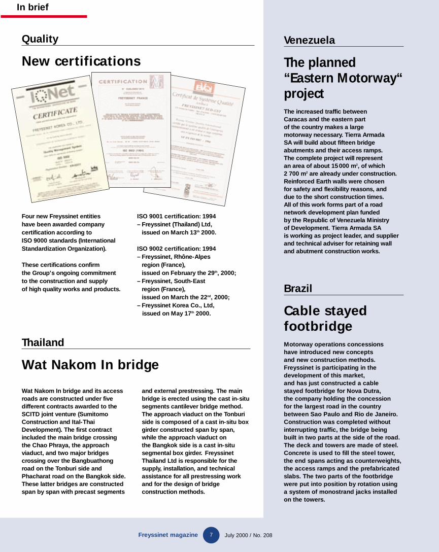
Four new Freyssinet entities have been awarded companycertification according to ISO 9000 standards (InternationalStandardization Organization).
These certifications confirm the Group's ongoing commitment to the construction and supply of high quality works and products.
ISO 9001 certification: 1994– Freyssinet (Thailand) Ltd,
issued on March 13th 2000.
ISO 9002 certification: 1994– Freyssinet, Rhône-Alpes
region (France), issued on February the 29th, 2000;
– Freyssinet, South-East region (France), issued on March the 22nd, 2000;
– Freyssinet Korea Co., Ltd, issued on May 17th 2000.
GB 208 Freys Mag 20/10/00 17:29 Page 7
Kuwait
8
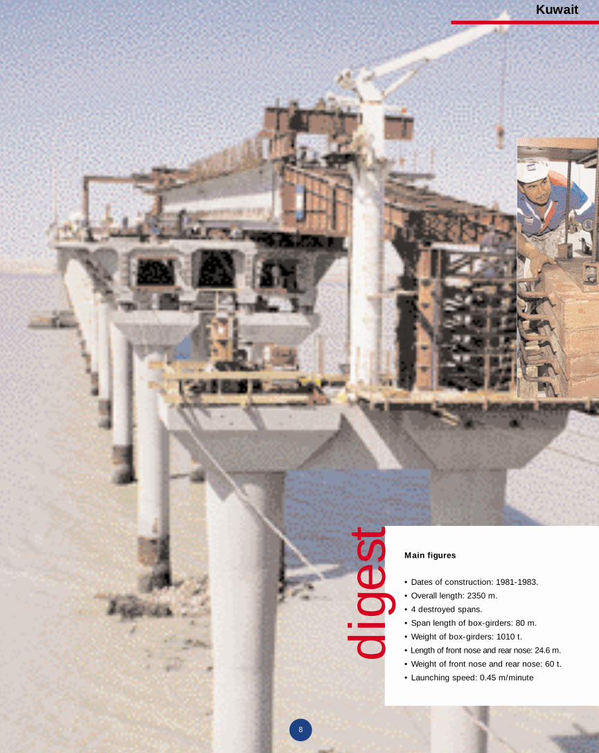
Main figures
• Dates of construction: 1981-1983.
• Overall length: 2350 m.
• 4 destroyed spans.
• Span length of box-girders: 80 m.
• Weight of box-girders: 1010 t.
• Length of front nose and rear nose: 24.6 m.
• Weight of front nose and rear nose: 60 t.
• Launching speed: 0.45 m/minute
dige
st
GB 208 Freys Mag 20/10/00 17:29 Page 8

Kuwait
9Freyssinet magazine July 2000 / No. 208
Bubiyan Bridge was seri-
ously damaged during the
Gulf War in 1991, when
four of its spans were completely
destroyed. Since 1999, Freyssinet has
been repairing and providing general
strengthening of this structure.
digest
Rehabilitation of the BubiyanBridge
Launching
Freyssinet, who have already workedin 1995 to make the structure safe,are rebuilding thedestroyed spans by incrementallaunching of box-girders.
GB 208 Freys Mag 20/10/00 17:29 Page 9

T he Bubiyan Bridge, which crosses theSubiya Canal, links the mainland toBubiyan Island, to the east of Kuwait.
Built between 1981 and 1983 by Bouygues, thisbridge is approximately 2.380 m long and hasfifty-nine spans around 40 m long. In 1991,four of the structure’s spans were completelydestroyed (P8 to P10 and P48 to P50), opening80 m long breaches. It suffered a lot of otherdamage, including perforation of a span andlifting of the deck at certain piers. Freyssinet,who had already worked in 1995 to make thestructure safe, have been providing general
strengthening of the structure and rebuildingthe four destroyed spans since 1999. The con-tract, awarded to Freyssinet by the MilitaryEngineering Department of Kuwait’s Ministryof Defence, includes reconstruction of the fourdestroyed spans, repair and strengthening ofthe adjacent spans, i.e., spans 7-8, 10-11, 47-48and 50-51, and the perforated span (45-46).
Box-girders with precast segments
The solution chosen by Freyssinet consists of rebuilding the four destroyed spans byassembling and launching precast segmentbox-girders on the intact spans. These recon-struction operations required prior repair ofthe damaged spans (replacement of the bot-tom slab, repair of concrete, making good,etc.) and strengthening of the structure byadditional prestressing. To provide the pre-stressing, composed of 7C15 cables withducted and greased strands for final strength-enings or standard strands for temporarystrengthenings, concrete blocks and deviatorswere built. This structural strengtheningallowed the segment assembly bench to beinstalled on the deck for reconstruction of thedestroyed spans. A system of concrete longi-tudinal beams is used for positioning the pre-cast segments, which, once they are assem-bled and fitted with a front nose and rearnose at their ends, are slid crosswise bytransversal beams. They are then pulled byjacks mounted on an incremental launchingbeam.The segments are manufactured 100 kilome-tres away from the site by a local subcontrac-tor, Recafco. The new deck is composed oftwo parallel prestressed concrete boxes that
Freyssinet magazine July 2000 / No. 208
Kuwait
10
GB 208 Freys Mag 20/10/00 17:29 Page 10

11Freyssinet magazine July 2000 / No. 208
A - Precast segments are assembled on theexisting deck and form a box-girder. The box-girder is slid crosswiseuntil it is aligned on sliding saddles.
B - The box-girder moves on Teflon supports at an instantaneoustracking speed of 0.45 m per minute.
C - At the end of launching,the span rests on threebearing lines at the piers.
D - Positioning the end support towers. Loads are transferredfrom the front and rearnoses to the support towers. The front and rear noses are removed.
E - The box-girder is lowered in 10 cmstages until it reaches its final bearings.
Kuwait
A
B
C
D
E
GB 208 Freys Mag 20/10/00 17:29 Page 11

Kuwait
12Freyssinet magazine July 2000 / No. 208
downward slope of one of the spans,requiring constant checking of the coeffi-cient of friction in order to control thespans gliding movement.For lowering the span, the front nose, rearnose and sliding saddles are removed. Thenew span now rests on a system of thirteen5 m high support towers (four at each endand five on the intermediate pier) wherejacks are installed. This equipment takesover from the front nose and rear nose,which are disconnected from the concrete.The span is gradually lowered in 10 cmstages, bearing on the four 250 tonne jacksat each end of the beam and on the 900 tonne jack on the intermediate pier.All these operations are continually moni-
are necessary for the launching operation, andwhich are connected by top and bottom slabsafter positioning and connection to the exist-ing deck. For aesthetic reasons and to ensurethe structure’s overall consistency, the seg-ments have the same appearance as the origi-nal deck: sloping struts connecting the can-tilever of the top slab to the bottom slab. Thesegments are brought by truck to the site,placed by a gantry crane on Teflon skidsinstalled on longitudinal rails, then pulled bya winch to their final position. Once the 35segments are unloaded, they are assembled onthe existing deck by gluing and by centredprestressing to form a box-girder more than80 m long, i.e. over two spans, and weighing1 010 tonnes (950 tonnes without the frontand rear noses).
Launching and lowering of the box-girder
The ends of the box-girder are fitted with afront nose and a rear nose, 24.6 m long. It isshifted crosswise until it is aligned on slid-ing saddles. Apart from the additional pre-stressing, spans adjacent to the destroyedspans are strengthened by steel bars,36 mm in diameter. The central pier, whichbears the new span, is cable stayed on eachside of the existing deck to take the hor-izontal loading caused by incrementallaunching and has five steel temporarysupport towers for docking the front nose.The box-girder is launched at an instanta-neous tracking speed of 0.45 m per minuteby two cable jacks located at the rear of thespan. At the end of launching, it rests onthree bearing lines at the piers. This opera-tion is very tricky because of the 2.8%
tored. Once the lowering operation is fin-ished and the span is resting on its finalbearings, concrete keying joints are cast insitu at each junction of the box-girder andthe old deck. Continuity between spans isprovided by installing final prestressingconsisting of steel bars in the bottomflange, and Freyssinet 12C15 and 19C15cables in the box-girder.
ParticipantsClient and Project Manager: Military EngineeringProjects Department, Ministry of Defence, Kuwait.General contractor: Freyssinet.Consulting engineer: PX Consultant/Europe Etudes Gecti.
GB 208 Freys Mag 20/10/00 17:29 Page 12

Italy
13Freyssinet magazine July 2000 / No. 208
Milan-Naples motorway
T he very busy A1 motorway links theItalian cities of Milan, Roma andNaples. It needs to be widened from
two to three lanes in each direction. Thetwo tunnels in Orte a Fiano, 35 km northof Rome, need to be widened by 11 m tocarry these additional lanes.Terra Armata proposed the constructionof approach tunnels at the entrance andexit of the two tunnels. This solution usesthe TechSpan® process that enables fasterconstruction of an arch by means of pre-fabricated half-shells assembled with akeyed joint.
A large span
Night time construction reduced inter-ruption of services to the very dense dailyroad traffic. Thus twenty-eight arch segments with widths varying between1.10 m and 1.80 m and weighing 35 t,were put into position. Each arch is com-posed of two half-shells and has a greatspan of 21 m. These 20 m high arches aresupported on 4.5 m deep upstands, thusenabling prefabrication of shorter andlighter weight shells. These TechSpan®
arches are amongst of the largest archesin the world
Fast and simple construction
The half shells are transported from thestorage area by a tank carrier. Two cranesare used initially to assemble them. Oncea number of arches have been assembledand longitudinal stability has beenachieved, a single crane is sufficient forthe remaining assembly operations.A cast in-situ concrete beam connects the
half shells together when all the segmentshave been installed. An average of sevento ten TechSpan® arches are assembledevery ten hours.Terra Armata worked as a subcontractorfor the Ferrovial Agroman Company, andhas benefited from the technical assis-tance of the Tierra Armada design office.
ParticipantsClient: Autostrada Spa.General contractor: Ferrovial Agroman.Specialized contractor:Terra Armata-Italia Spa.
TechSpan® arches with a large span
Terra Armata has recently built arches with an impressive span, at the entrance and exit of two tunnels, before their widening.
GB 208 Freys Mag 20/10/00 17:29 Page 13

14 July 2000 / No. 208
T he “ExCeL” centre will provide an enor-mous 65 000 m2 exhibition space when itopens in 2001. Access to the building is
very accessible since the car park is on theground floor and exhibition space is locatedon the first floor. The specified live load forthe exhibition floor is high, equal to 20 kN/m2
on average. The centre is designed for eventsfor which high capacity lifting vehicles (forexample 25 t cranes) are necessary to installthe stand, or for exhibiting heavy equipment(such as 62 t Challenger tanks or 40 t lorries).
A rapid solution
The original solution proposed the use of0.8 m thick reinforced concrete ribbed slabssupported on 1 m deep reinforced concretebeams. The Harrington Company consideredthat this design was too complex to satisfy theconstruction schedule, and asked Freyssinetto design a post-tensioned constructionschedule. The adopted proposal was to use a0.24 m thick slabs spanning onto 1.5 x0.475 m deep band beams. The beams are
Prestressed concrete slabs
United Kingdom
Freyssinet magazine
aligned with the longitudinal axis of thebuilding, which simplifies table forms place-ment and removal operations under the slab,on a reduced time basis. The formworkunder the beams was an in-situ strip. Usingthis system, a nine-day cycle was achievedbetween one concrete pour and the next withproduction peaking at 5 500 m2 , seven poursper week.
Extensive prestressing work
The grid is generally 7.8 m square, except inone area in the south hall where it is 10.5 mby 9.1 m, where section sizes increase to 0.3 mand 2.1 x 0.475 m beams. The exhibitionspace is split into two halls, north and south,each 375 m long and 86 m wide. Movementjoints divide both areas into three blocks, thelargest measuring 145 x 86 m. Each hall isbeing concreted with site-batched concrete in36 typical pours, each 31 x 29 m.The many reinforced concrete shear walls in
the original design have been replaced by steelcross-bracing, which is left slack while theslab shorten under the effects of stressing,thus allowing the fast track programme to bemaintained.Freyssinet also built the two lorry access slabswhich carry a 2/3 HA loading and the WestPodium slab, which spans 22 m. The totalpost-tensioned slab area for the project is78 600 m2.
Participants
Client: ExCeL Plc.Architect: Moxley Architects.Structural engineer: McAlpine Design Group.Main contractor: Sir Robert McAlpine Ltd.Structural concrete: P C Harrington.Post-tensioning contractor: Freyssinet Ltd.Work commenced: November 1999.
Freyssinet constructed the post-tensioned concrete slabs for the newLondon exhibition centre within very tight construction periods.
ExCel: Post-tensionedconcrete slabs
The specified live load for the exhibition floor is very high, 20 kN/m2 on average, thus facilitating heavy equipment exhibitions.
GB 208 Freys Mag 20/10/00 17:29 Page 14

Freyssinet magazine July 2000 / No. 208
United Kingdom
15
Prestressed concrete slabs
T he transformation of the former Balticflour mill into a modern art centre is anambitious project. The mill was built
in Gateshead in the early 1900’s on the banksof the river Tyne, and forms an integral partof the landscape. The main 55 by 31 by 14mhigh building has been gutted, and threepost-tensioned concrete exhibition floorsand three reinforced concrete mezzanineswere then added.Each exhibition floor is suspended on fivepost-tensioned beams that span 18.2 m.New ‘T’ shaped columns have been con-structed 2.3 m inside the façade to allowaccess for stressing the two 12K 15 tendonsin each beam. On level 2, the beams are 1.2 m deep and 0.45 m wide at the soffit,tapering to 0.65 m at the slab. The slab con-sists of 0.15 m in-situ concrete poured onOmnideck precast planks spanning the 5 mbetween adjacent beams.
A complex geometry
The Omnideck floor consists of a thin baseof concrete into which steel lattices are cast assupport. Short term they span unaided, longterm they act integrally with the structuraltopping. On levels 3 and 4, there is a 0.225by 0.45 m deep ventilation duct within thebeam and a 0.32 by 0.1 m deep channelalong the top of the beam, both along the fulllength of the beam. To accommodate theserequirements, the beam width increases to0.65 m at the soffit and 0.85 m at the slab, thedepth remaining at 1.2 m.This complicated geometry was modelledusing the RAPT (Reinforced And Post-Tensioned) program developed by PCDC.This allows beams with tapered sides, inter-nal voids of various shapes, and flanges at the
The conversion of the Gateshead flour mill into an art centre requiresimprovements and partial transformation of the building.
top, below or part-way up a beam. Thefloors were designed for 5 kN/m2 of live loadtogether with an allowance of 60 kN over a 1.75 m square area for heavy exhibits.Finishes add an extra 2.3 kN/m2. As con-struction of this landmark project nearscompletion, the art world is preparing for anexciting new venue.
Participants
Client: Gateshead Metropolitan Council.Architect: Ellis williams Architect.Consulting Engineer: Atelier One.Main Contractor: DBG Construction Ltd.Specialized contractor: Freyssinet.
A reconvertedflour mill
To accomodate the art centre, the Baltic flour mill structure is transformed to receive three RC floors and three RC mezzanines.
GB 208 Freys Mag 20/10/00 17:29 Page 15

A t the request of the Natural HistoryMuseum and I.E.E., Freyssinet ismainly working on the Fauverie build-
ing (adjacent to the Large Rock), on thePassage des Algazelles et des Fennecs, andPassage du Poste des Gardes. For all thesestructures, the volumes must be meticulouslyreconstructed, identical to the originals. Thisoperation faces certain difficulties, consider-ing the absence of detailed drawings of theartificial rocks. Their shells are reconstitutedby shotcreting around 6 cm thick.
Fauverie building
The Fauverie building, which supports anartificial rock, was extremely deteriorated
and needed urgent repair. The work consistsin partial repair of the shell of the artificialrock, demolition of the posts and beams ofthe load-bearing structure and their com-plete reconstruction, after concrete repairs ofthe damaged areas. In parallel, the protectionof the six glass roofs located under the shell,which were damaged by falling pieces of con-crete, is improved by 8x23 thick plankswhose ends are bedded in the brick walls, anddecking in 40 mm thick close boards. It isprotected by a roof composed of ribbed gal-vanised steel pans that provide water-tight-ness. The purpose of this work on the glassroofs is to provide sufficient temporary pro-tection so that the underlying premises canbe used.
From “Passage des Algazelles” to“Passage du Poste des Gardes”
Passage des Algazelles, a busy path used a lot bythe public, was also very deteriorated, as was itssupporting structure supporting it, composed ofthree reinforced concrete truss girders. In addi-tion to reconstructing the posts, beams, diagonalmembers and haunches in reinforced concrete,Freyssinet is repairing the suspension elements ofthe underside of the passage by means of stainlesssteel threaded rods with galvanised struts fixedabove the beams. Work on the passage known as“Passage du Poste des Gardes” consists in repair-ing the shell of the artificial rock; the internalstructure is in satisfactory condition. The zoolog-ical gardens remain open to the public through-out the entire works. Therefore great care is takento provide a safe, pleasant environment for visi-tors as well as for the animals.
ParticipantsClient: Muséum national d’histoire naturelle (Natural History Museum)Project Manager: I.E.E. (Ingénierie, Etudes, Entreprise)General contractor: Freyssinet.
Paris zoological gardens
Vincennes
Freyssinet is currently repairing various structures in Paris zoological gardens.
France
16Freyssinet magazine July 2000 / No. 208
GB 208 Freys Mag 20/10/00 17:29 Page 16

Freyssinet magazine July 2000 / No. 208
Australia
17
I n April of 1998 the Queensland Governmentand the consortium Airtrain City link(Transfield Constructions, Macquarie bank
and Reduct) entered into a legal agreement todevelop a connection between Brisbane’s exist-ing rail network and the international Airport. Itwas established on the basis of a QueenslandGovernment mandate which required that thepublic transport system in South EastQueensland be upgraded by providing a highquality, environmentally friendly and acceptablealternative to the motor car for journeys toBrisbane Airport. The consortium awarded thedesign and construct package to TransfieldConstructions.The project comprises a 8.5 km elevated electri-
cal spur line. The track viaduct is supported onpiled foundations and concrete columns spacedat 30 to 45 meters apart and spanned with pre-cast concrete girders. Overall 2300 piles rangingfrom 12-40 m in depth and 1200 precast girdersaveraging 75 tonnes each will be required tocomplete the project.
Manœuvering flexibility:the Freyssinet solution
Austress Freyssinet Pty Ltd seccured the contractfor all post tensioned elements located through-out the structure. These are the transversestressing of the girders, vertical stressing of thecolumns and horizontal stressing of the head-
stocks. The transverse stressing pinned togetherthe 3 No precast I girders that spanned betweenthe columns. It is formed of 10 No tendons perspan that are inserted perpendicularly through the flanges of the precast girders 5 top and 5bottom at 6 m centres. Each tendon comprises4x12.7 mm low relaxation strands. A crew of twomen working from a boom lift can cut strand,install, stress and seal two single spans in a day.
Originally the design called for a 29 mm bar forthe transverse post-tensioning but it was consid-ered that the rigid bar might incur difficultywith installation if there was a slight misalign-ment of the precast girders. Austress FreyssinetPty Ltd proposed the strand alternative to allowthe flexibility for manoeuvring through mis-alignments. For this proposal however, AustressFreyssinet Pty Ltd had to overcome the problemof the substantial loss of load due to wedge drawon a tendon length of only 3 m. The develop-ment of a hydraulic lock off nose for the monostrand jack that applied significant load to thewedges prior to releasing the strand reduced thedraw in losses to only 5%. The five piers thatbridged the gateway motorway each required 12 No x 27C15 vertical tendons. These wereinstalled in two stages, firstly a 3 m long deadend was cast into the pile cap while the balancewas installed during fabrication of the columns.The strands were connected between the twostages with mono strand couplers.The rail link will be brought into commissionover the four months beginning January of 2001.
Participants
Client: Air Train City Link.Engineer: EGIS.Main contractor: Transfield Constructions.Specialized contractor: Austress Freyssinet.
A new rail link
Brisbane
Austress Freyssinet Pty Ltd is participating in theconstruction of a viaduct to carry the new raillink between Brisbane and its airport.
GB 208 Freys Mag 20/10/00 17:29 Page 17

Freyssinet magazine July 2000 / No. 208
Malaysia
18
The “bottom feed”methodThe stone columns on the Kajang Ring Road were constructed using a clean and fast technique.
M enard Geosystems, the leading soilimprovement specialist contrac-tor, recently used the bottom feed
dry method of installing stone columns forthe Kajang Ring Road project in KualaLumpur. The work was done using theTerrafirmer rig specially designed for thepurpose and powered by a 300 HPCaterpillar engine, capable of drilling at arate of 0.5 to 1 m per minute. The averagedaily production rate is about 300 m ofstone column per day per rig. Apart fromthe speed, this method is also remarkablefor its clean working environment. TheVibroflot (the compaction unit) penetratesto the required depth aided by vibration,compressed air and thrust. There are nowater jets, unlike conventional methods.Hence, the working area is not flooded andthere is no ground water pollution.
Kajang Ring Road
The site is located to the south of KualaLumpur city.The 4 700 m2 site consists of silty clay andsandy silt. The standard SPT (test to mea-sure soil strength) N value varied between3 and 8. The thickness of this layer variesfrom 4 to 8 m. Below 10 m, there is a layerof very stiff clayey silt with SPT N > 15.The stone columns were designed to sup-port a 9 m high embankment with totaldesign load of 180 kN/m2. Preliminary
cone penetration tests were carried out.The stone columns were built to a maxi-mum depth of 10 m, on a 1.6 m triangulargrid. Two rigs were employed, firstly a con-ventional pendulum Vibroflot suspendedfrom a crawler crane (with gravity feedfrom the top) and the Terrafirmer. Thetotal number of 9 800 stone columns wereconstructed.Throughout the installation process, thequality control of the stone columns wasclosely monitored by an on-board comput-
er controlled QC system and plate loadingtests were carried out on the completedstone columns. The load carrying capacityof each stone column exceeded 25 tons.
ParticipantsClient: Jabatan Kerja Raya Malaysia (PWD).Engineer:Arup Jurunding & Isotech Consult.Main contractor: Sunway Construction Bhd.Specialized contractor: Menard Geosystems.
Kuala Lumpur
Using a compaction unit to install a stone column. This operation is usually carried out in successive 30 to 50 cm steps. The stone column acts as a load-bearing element and vertical drain.
GB 208 Freys Mag 20/10/00 17:29 Page 18

Freyssinet uses the TFC® gluing technique to strengthenthe floors of a hospital building.
Freyssinet magazine July 2000 / No. 208
France
19
A beautiful park is currently being laidout in a typical Dutch landscape nearAmsterdam airport. A communica-
tions network has been developed in itincluding roads (some reserved for publictransport), footpaths and cycle tracks. It willhost the Floralies flower show in 2002.A cable stayed bridge was chosen to carry thefootpaths and cycle tracks over the motorway.It was decided to build the pylon in the shapeof a tulip to give a more aesthetically pleasinglook to complement the existing surround-ings. The concrete deck is carried by 22Macalloy bars and is retained by 2 Freyssinetstay cables. The bars are brought to site fitted
with their couplers, and after being installedthey are stressed by special prestressing cou-plers and the tools necessary for their usedeveloped and supplied by Samaco especiallyfor this project. Each stay cable consists of apair of 15.7 mm cables anchored in the abut-ments. The longest bar is 55 meters long andthe side stay cables are 44.4 meters long.
ParticipantsClient:Amsterdam Schipol airport.Engineering: Engineering Office Amsterdam.Specialized contractor: Samaco,Dutch subsidiary of Freyssinet.
Amsterdam Schipolairport
T he Hopale Group includes all spe-cialised hospitals in Berck-sur-Mer, inthe Pas-de-Calais Department of
France. One of the buildings had to bestrengthened as part of a project to changeits function. This work, awarded toFreyssinet, was designed to strengthen thefloors on three levels in the building.This essential strengthening was necessarydue to insufficient reinforcement in thebeams and also to create a number of open-
ings. The TFC® (Carbon Fibre Fabrics) glu-ing technique was adopted instead of theoriginally designed steel reinforcementsolution. TFC® saves time in the generalconstruction planning, limits space occu-pied in false ceilings and reduce the con-straints for department operators andpatients, all work being done within thehospital without interrupting the hospitalservice.Freyssinet's work was done between mid
April-and mid-June, and included about400 m2 preparation of the underside of thefloors and the placement of 1 400 m2 ofTFC® in two, three and four layers. Flockingwas done on the TFC® after installation inorder to make it fireproof.
ParticipantsClient: Groupe Hopale.Engineer: Sogisnord.Main contractor: Freyssinet.
Hospital renovation
Netherlands
A cable stayed bridge specially designed to blend into a landscaped park close to Amsterdam.
Berck-sur-Mer
A cable stayed bridge
GB 208 Freys Mag 20/10/00 17:29 Page 19

reyssinet
Terra Armata has built 21 m-span TechSpan arches as part of the A1 motorway tunnel widening near Rome.
Photo: Claude Cieutat
GB 208/couve 20/10/00 17:25 Page 1