armorstart® dlr reference architecture - literature...
TRANSCRIPT

ArmorStartreg DLR Reference Architecture
Application Guide
Important User Information
Because of the variety of uses for the products described in this publication those responsible for the application and use of this control equipment must satisfy themselves that all necessary steps have been taken to assure that each application and use meets all performance and safety requirements including any applicable laws regulations codes and standards
The illustrations charts sample programs and layout examples shown in this guide are intended solely for purposes of example Since there are many variables and requirements associated with any particular installation Rockwell Automation does not assume responsibility or liability (to include intellectual property liability) for actual use based upon the examples shown in this publication
Solid-state equipment has operational characteristics differing from those of electromechanical equipment Safety Guidelines for the Application Installation and Maintenance of Solid State Controls (Publication SGI-11 available from your local Rockwell Automation sales office or online at httpwwwrockwellautomationcomliterature) describes some important differences between solid-state equipment and hard-wired electromechanical devices Because of this difference and also because of the wide variety of uses for solid-state equipment all persons responsible for applying this equipment must satisfy themselves that each intended application of this equipment is acceptable
In no event will Rockwell Automation Inc be responsible or liable for indirect or consequential damages resulting from the use or application of this equipment
The examples and diagrams in this manual are included solely for illustrative purposes Because of the many variables and requirements associated with any particular installation Rockwell Automation Inc cannot assume responsibility or liability for actual use based on the examples and diagrams
No patent liability is assumed by Rockwell Automation Inc with respect to use of information circuits equipment or software described in this manual
Reproduction of the contents of this manual in whole or in part without written permission of Rockwell Automation Inc is prohibited
Throughout this manual when necessary we use notes to make you aware of safety considerations
WARNING Identifies information about practices or circumstances that can cause an explosion in a hazardous environment which may lead to personal injury or death property damage or economic loss
ATTENTION Identifies information about practices or circumstances that can lead to personal injury or death property damage or economic loss Attentions help you identify a hazard avoid a hazard and recognize the consequence
SHOCK HAZARD Labels may be on or inside the equipment for example a drive or motor to alert people that dangerous voltage may be present
BURN HAZARD Labels may be on or inside the equipment for example a drive or motor to alert people that surfaces may reach dangerous temperatures
IMPORTANT Identifies information that is critical for successful application and understanding of the product
General Precautions
In addition to the precautions listed throughout this manual the following statements which are general to the system must be read and understood
ATTENTION This manual is intended for qualified service personnel responsible for setting up and servicing these devices The user must have previous experience with and a basic understanding of electrical terminology configuration procedures required equipment and safety precautions
WARNING The National Electrical Code (NEC) NFPA79 and any other governing regional or local code will overrule the information in this manual Rockwell Automation cannot assume responsibility for the compliance or proper installation of the ArmorStart LT or associated equipment A hazard of personal injury andor equipment damage exists if codes are ignored during installation
ATTENTION The controller contains ESD (electrostatic discharge) sensitive parts and assemblies Static control precautions are required when installing testing servicing or repairing the assembly Component damage may result if ESD control procedures are not followed If you are not familiar with static control procedures refer to Publication 8000-452 Guarding against Electrostatic Discharge or any other applicable ESD protection handbooks
ATTENTION Only personnel familiar with the controller and associated machinery should plan or implement the installation startup and subsequent maintenance of the system Failure to do this may result in personal injury andor equipment damage
Rockwell Automation Publication 290E-AT001A-EN-P - November 2012 3
Software Requirements
This table lists the versions of software that are required
Additional Resources
These documents and websites contain additional information concerning related Rockwell Automation products
You can view or download publications at httpwwwrockwellautomationcomliterature To order paper copies of technical documentation contact your local Allen-Bradley distributor or Rockwell Automation sales representative
Table 1 - Rockwell Automation Industrial Network Resources
Software Version
RSLinx Classic 256 or later
RSLogix 5000 1701 or laterDownload the most current version of the Add-On Profile fromhttpwwwrockwellautomationcomsupportdownloadshtml
BOOTPDHCP Version 23 or later
Resource Description
httpwwwabcomnetworks Rockwell Automation networks and communication website
httpwwwabcomnetworksethernet Rockwell Automation EtherNetIP website
httpwwwrockwellautomationcomservicesnetworkshttpwwwrockwellautomationcomservicessecurity
Rockwell Automation network and security services websites
httpwwwabcomnetworksarchitectureshtml Education series webcasts for IT and controls professionals
EtherNetIP Embedded Switch Technology Application Guide Publication ENET-AP005 Describes how to install configure and maintain linear and Device-level Ring (DLR) networks using Rockwell Automation EtherNetIP devices with embedded switch technology
EtherNetIP Network Configuration User Manual Publication ENET-UM001 Describes how to configure and use EtherNetIP communication modules with a Logix5000 controller and communicate with various devices on the Ethernet network
EtherNet Design Consideration Publication ENET-RM002 Provides details on ethernet design and infrastructure
EtherNetIP Modules in Logix5000 Control Systems User Manual Publication ENET-UM001 Provides details about how to configure your module
EtherNetIP Embedded Switch Technology Application Guide Publication ENET-AP005 Provides information about using products with embedded switch technology to construct networks with linear and ring topologies
EtherNetIP Industrial Protocol White Paper Publication ENET-WP001 Describes how to implement services and data objects on a TCPUDPIP based Ethernet network
Industrial Automation Wiring and Grounding Guidelines Publication 1770-41 Provides general guidelines for installing a Rockwell Automation industrial system
Wiring and Grounding Guidelines (PWM) AC Drives Publication DRIVES-IN001 Describes wiring and grounding guidelines for Pulse Width Modulated (PWM) AC Drives
Product Certifications websitehttpwwwrockwellautomationcomproductscertification
Provides declarations of conformity certificates and other certification details
4 Rockwell Automation Publication 290E-AT001A-EN-P - November 2012
Table 3 - Product Selection Resources
Rockwell Automation Support
Rockwell Automation provides technical information on the Web to assist you in using its products At httpwwwrockwellautomationcomsupport you can find technical manuals a knowledge base of FAQs technical and application notes sample code and links to software service packs and a MySupport feature that you can customize to make the best use of these tools
Installation Assistance
If you experience a problem within the first 24 hours of installation contact Customer Support
Table 2 - ODVA Resources
Resource Description
httpwwwodvaorg Open DeviceNet Vendors Association (ODVA) website
httpwwwodvaorgdefaultaspxtabid=54 The CIP Advantage websitebull CIP features and benefits bull How to get started
Ethernet Media Planning and Installation Manual ODVA publicationhttpwwwodvaorgPortals0LibraryPublications_NumberedPUB00148R0_EtherNetIP_Media_Planning_and_Installation_Manualpdf
Describes the required media components and how to plan for install verify troubleshoot and certify an Ethernet network
Network Infrastructure for EtherNetIP Introduction and Considerations ODVA publicationhttpwwwodvaorgPortals0LibraryPublications_NumberedPUB00035R0_Infrastructure_Guidepdf
Provides an overview of the technologies used in EtherNetIP networks and provides guidelines for deploying infrastructure devices in EtherNetIP networks
Resource Description
Industrial Controls catalog website httpwwwabcomcatalogs
Industrial Controls catalog website
ArmorStart LT Distributed Motor Controller Selection Guide Publication 290-SG001 Product selection guide
Table 4 - Cisco and Rockwell Automation Alliance Resources
Resource Description
httpwwwabcomnetworksarchitectureshtml Rockwell Automation and Cisco Systems reference architecture website
Converged Plantwide Ethernet (CPwE) Design and Implementation Guide Publication ENET-TD001
Represents a collaborative development effort from Rockwell Automation and Cisco Systems The design guide is built on and adds to design guidelines from the Cisco Ethernet-to-the-Factory (EttF) solution and the Rockwell Automation Integrated Architecture The design guide focuses on the manufacturing industry
United States or Canada 14406463434
Outside United States or Canada
Use the Worldwide Locator at httpwwwrockwellautomationcomsupportamericasphone_enhtml or contact your local Rockwell Automation representative
Rockwell Automation Publication 290E-AT001A-EN-P - November 2012 5
New Product Satisfaction Return
Rockwell Automation tests all of its products to ensure that they are fully operational when shipped from the manufacturing facility However if your product is not functioning and needs to be returned follow these procedures
United States Contact your distributor You must provide a Customer Support case number (call the phone number listed earlier to obtain one) to your distributor to complete the return process
Outside United States Please contact your local Rockwell Automation representative for the return procedure
6 Rockwell Automation Publication 290E-AT001A-EN-P - November 2012
Table of Contents
Important Information 2General Precautions 3Software Requirements 4Additional Resources 4Rockwell Automation Support 5Installation Assistance 5New Product Satisfaction Return 6
Chapter 1Device-Level Ring (DLR) Basics Introduction 9
ArmorStart EtherNet IP Overview 9What is a DLR Network 10DLR Network Elements 10DLR Network Operation 12Number of Nodes on a DLR Network 13DLR Network Fault Management 14
Chapter 2Construct and Configure a Device-Level Ring (DLR) Network
Introduction 15EtherNet Capacity Tool 15Install Devices on a DLR Network 16Addressing Configuration 17
Using the BootPDHCP Server 17Using the Rotary Network Address Switches 17Using the ArmorStart Internal Web Server 19
Configure Supervisor Nodes on a DLR Network 21Configure a Ring Supervisor in RSLogix 5000 Programming Software 21Adding an ArmorStart to RSLogix 5000 22Enable a Ring Supervisor in RSLogix 5000 27Configure and Enable a Ring Supervisor in RSLinx Classic Communication Software 29
Complete the Physical Connections of the Network 33Verify Supervisor Configuration 34IGMP Snooping 35
Rockwell Automation Publication 290E-AT001A-EN-P - November 2012 7
Table of Contents
Chapter 3Monitor a Device-level (DLR) Network
Introduction 37Methods to Monitor a DLR Network 37Monitor Status Pages 39How to Access the ArmorStart EtherNetIP Internal Web Server 44Monitor Diagnostics via MSG Instructions 46
Chapter 4Troubleshoot a Device-level (DLR) Network
Introduction 53General Solutions for Linear or DLR Networks 53Duplicate IP Address Detection 54Specific Issues on the DLR Network 55Network Recovery Performance 58Device Port Debugging Mode 59
Appendix ANetwork Usage Guidelines and Recommendations
Network Usage Guidelines and Recommendations 61
Appendix BRequired Firmware Revisions Required Firmware Revision for an Add-On Profile 65
Required Firmware Revision for RSLinx Communication Software 66
8 Rockwell Automation Publication 290E-AT001A-EN-P - November 2012
Chapter 1
Device-Level Ring (DLR) Basics
Introduction Prior to the introduction of products with embedded switch technology the traditional EtherNetIP network topology has been a star type End devices are connected and communicate with each other via a switch
The EtherNetIP embedded switch technology offers alternative network topologies for interconnecting EtherNetIP devices It embeds switches into the end devices themselves
ArmorStart with EtherNetIP Overview
The ArmorStart with EtherNetIP incorporates the advantages of distributed motor control EtherNetIP communication and Embedded Switch Technology The ArmorStart EtherNetIP family includes full voltage or Sensorless Vector Control AC drive motor starters designed for most of your critical applications ArmorStart with EtherNetIP is a simple seamless and cost-effective method of integrating pre-engineered starters IO and network capabilities in your On-Machine architecture The dual port 10100 Mbps embedded Ethernet switch supports Linear and Device Level Ring Topologies in addition to the traditional star topology
Topic Page
Introduction 9
ArmorStart with EtherNet IP Overview 9
What is a DLR Network 10
DLR Network Elements 10
DLR Network Operation 12
Number of Nodes on a DLR Network 13
DLR Network Fault Management 14
IMPORTANT Products with EtherNetIP embedded switch technology have two ports to connect to a linear or DLR network in a single subnetThese ports cannot be used as two Network Interface Cards (NICs) connected to two different subnets The two ports share one IP Address and MAC Address
Rockwell Automation Publication 290E-AT001A-EN-P - November 2012 9
Chapter 1 Device-Level Ring (DLR) Basics
What is a Device-level Ring (DLR) Network
A DLR network is a single-fault tolerant ring network intended for the interconnection of automation devices This topology is also implemented at the device level No additional switches are required
The graphic below shows an example of an ArmorStart LT Bulletins 291 and 291E and an ArmorStart Distributed Motor Controller Bulletin 280E in a DLR network
Figure 1 - Example DLR Network
The advantages of the DLR network include
bull Simple installation
bull Media resiliency to a single point of failure on the network
bull Fast recovery time when a single fault occurs on the network (lt3 ms convergence for up to 50 nodes on ring)
The primary disadvantage of the DLR topology is the additional effort required to set up and use the network when compared to a linear or star network However use of this Application Guide should minimize the amount of additional effort that is required
DLR Network Elements A DLR network is made up of the following devicesbull Supervisor Node
ndash Active Supervisor Nodendash Back-up Supervisor Node (optional)
bull Ring Node
Each of these device types and how they work in a DLR network are described in the following sections
10 Rockwell Automation Publication 290E-AT001A-EN-P - November 2012
Device-Level Ring (DLR) Basics Chapter 1
Supervisor Node
A DLR network requires at least one node to be configured as a ring supervisor Currently several Rockwell Automation products support the ring supervisor functionality
Active Ring Supervisor
When multiple nodes are enabled as supervisor the node with the numerically highest precedence value becomes the active ring supervisor the other nodes automatically become back-up supervisors
The ring supervisor provides the following primary functionsbull Verifies the integrity of the ringbull Reconfigures the ring to recover from a single fault bull Collects diagnostic information for the ring
Back-up Supervisor Node
At any point in time there will be only one active supervisor on a DLR network However we recommend that at least one other supervisor-capable node be configured to act as a back-up supervisor During normal operation a back-up supervisor behaves like a ring node If the active supervisor node operation is interrupted for example it experiences a power-cycle the back-up supervisor with the next numerically highest precedence value becomes the active supervisor
If multiple supervisors are configured with the same precedence value (the factory default value for all supervisor-capable devices is 0) the node with the numerically highest MAC address becomes the active supervisor
We recommend that youbull Configure at least one back-up supervisorbull Configure your desired active ring supervisor with a numerically higher
precedence value as compared to the back-up supervisors
IMPORTANT Out of the box the supervisor-capable devices have their supervisor function disabled so they are ready to participate in either a linearstar network topology or as a ring node on an existing DLR networkIn a DLR network at least one of the supervisor-capable devices must be configured as the ring supervisor before physically closing the ring If not the DLR network will cause significant network issues that can only be resolved by disconnecting the final connection
IMPORTANT While a back-up supervisor is not required on a DLR network it is recommended that at least one back up ring supervisor be configured for the ring network
Rockwell Automation Publication 290E-AT001A-EN-P - November 2012 11
Chapter 1 Device-Level Ring (DLR) Basics
bull Keep track of your networkrsquos supervisor-precedence values for all supervisor-enabled nodes
For more information about how to configure a supervisor see Construct and Configure a Device-level Ring Network on page 15
Ring Node
A ring node is any node that operates on the network to process data that is transmitted over the network or to pass on the data to the next node on the network When a fault occurs on the DLR network these reconfigure themselves and relearn the network topology Additionally ring nodes can report fault locations to the active ring supervisor
DLR Network Operation During normal network operation an active ring supervisor uses beacon and other DLR protocol frames to monitor the health of the network Back-up supervisor nodes and ring nodes monitor the beacon frames to track ring transitions between Normal (all links working) and Faulted (the ring is broken in at least one place)
Two beacon-related parameters can be configured
bull Beacon interval - Frequency at which the active ring supervisor transmits a beacon frame through both of its ring ports
bull Beacon timeout - Amount of time that supervisor or ring nodes wait before timing out the reception of beacon frames and taking appropriate action
These parameters impact Network Recovery Performance For information on these performance times see page 58 For information on how to set these parameters see Construct and Configure a Device-level Ring Network on page 15
IMPORTANT Do not connect non-DLR (single port) devices directly to the DLR network Non-DLR devices should be connected to the network through 1783-ETAP 1783-ETAP1F or 1783-ETAP2F EtherNetIP taps like the examples shown below
12 Rockwell Automation Publication 290E-AT001A-EN-P - November 2012
Device-Level Ring (DLR) Basics Chapter 1
During normal operation one of the active supervisor nodersquos network ports is blocked for DLR protocol frames However the active supervisor node continues to send beacon frames out of both network ports to monitor network health The following graphic shows the use of beacon frames sent from the active ring supervisor
Figure 2 - Normal DLR Network Operation
A second category of ring nodes known as announce frame ring nodes can be designed to participate in a DLR network The active supervisor sends announce frames out one of its ports once per second or on detection of a ring fault DLR networks with announce frame ring nodes have slightly longer recovery times than beacon frame nodes
Number of Nodes on a DLR Network
Rockwell Automation recommends that you use no more than 50 nodes on a single DLR or linear network If your application requires more than 50 nodes we recommend that the nodes are segmented into separate but linked DLR networks
With smaller networksbull There is better management of traffic on the networkbull The networks are easier to maintainbull There is a lower likelihood of multiple faultsbull Recovery time is shorter
Additionally on a DLR network with more than 50 nodes network recovery times from faults are higher than those listed in Network Recovery Performance on page 58
Rockwell Automation Publication 290E-AT001A-EN-P - November 2012 13
Chapter 1 Device-Level Ring (DLR) Basics
DLR Network Fault Management
The network may occasionally experience faults that prevent the normal transmission of data between nodes The DLR network can protect your application from interruptions resulting from a single fault To maintain the resiliency of your ring your application should monitor the health of the ring The ring may be faulted while all higher-level network functions such as IO connections are operating normally
Fault location information is available from the active supervisor For more information on how to obtain fault location information see Monitor a DLR Network on page 37
After a fault occurs the active supervisor reconfigures the network to continue sending data on the network
Network Reconfiguration after a Fault
The following graphic shows the network configuration after a failure occurs with the active ring supervisor passing traffic through both of its ports thus maintaining communication on the network
14 Rockwell Automation Publication 290E-AT001A-EN-P - November 2012
Chapter 2
Construct and Configure a Device-level Ring Network with ArmorStarts
Introduction Use this chapter to learn how to construct and configure a DLR network
Ethernet Capacity Tool The EtherNetIP Capacity Tool is free software that is intended to help in the initial layout of your EtherNetIP network by calculating resources (Connections Packets per Second) used by a proposed network You choose icons to indicate the type and number of nodes on the network along with associated parameters such as Update Rate desired The tool then calculates the resources used and what is still available This format makes it easy to try different configurationsparameters and see how the outcome is affected
To download the Ethernet Capacity Tool go to httpwwwabcomgoiatools
Topic Page
Ethernet Capacity Tool 15
Install Devices on a DLR Network 16
ArmorStart Addressing Configuration 17
Using the BootPDHCP Server 17
Using the Rotary Network Address Switches 17
Using the ArmorStart Internal Web Server 19
Configure Supervisor Nodes on a DLR Network 21
Configure a Ring Supervisor in RSLogix 5000 21
Adding an ArmorStart to RSLogix 5000 22
Enable a Ring Supervisor in RSLogix 5000 27
Configure and Enable a Ring Supervisor in RSLinx Classic 29
Complete the Physical Connections of the Network 33
Verify Supervisor Configuration 34
IGMP Snooping 35
Rockwell Automation Publication 290E-AT001A-EN-P - November 2012 15
Chapter 2 Construct and Configure a Device-level Ring Network with ArmorStarts
Install Devices on a DLR Network
The next step to configure a DLR network is to connect all devices to the network One connection should be left unmade That is temporarily omit the physical connection between two nodes on the ring network because the factory default settings of DLR devices are set to operate in linearstar mode or as ring nodes on existing DLR networks
For more information on installing the EtherNetIP network (cable requirements maximum distance etchellip) refer to the EtherNetIP Media Planning and Installation Manual which can be downloaded here
httpliteraturerockwellautomationcomidcgroupsliteraturedocumentsrmenet-rm002_-en-ppdf
Figure 3 - Example Device-level Ring Topology with One Connection Left Unmade
Use the installation instructions below for each device to connect it to the network Publication Numbers can be downloaded at httpwwwrockwellautomationcomliteratureliteraturehtml
IMPORTANT If your DLR network is fully connected without a supervisor configured a network storm may result rendering the network unusable until one link is disconnected and at least one supervisor is enabled
Description Installation Instructions CatNo
ControlLogix EtherNetIP module 1756-IN612 1756-EN2TR
EtherNetIP tap 1783-IN007 1783-ETAP
ArmorStart LT Motor Controller 290-UM001 291E-FAZ-G2
ArmorStart Motor Controller 280G-UM001 280E-F12Z-10A-CR-3
Stratix 6000 Ethernet Switch 1783-IN004 1783-EMS08TA
16 Rockwell Automation Publication 290E-AT001A-EN-P - November 2012
Construct and Configure a Device-level Ring Network with ArmorStarts Chapter 2
ArmorStart Addressing Configuration
Before using the ArmorStart in an EtherNetIP network an IP address subnet mask and optional Gateway address must be configured This section describes how to set up the IP Address of an ArmorStart in three different ways using the BootPDHCP Server the Rotary Network Address Switches and the internal web server
Note When using the AOP it is not configuring the IP Address of the ArmorStart it is just assigning the same IP address that was set-up using the Rotary Network Address Switches or the web page so that communication is established
Using the BootPDHCP Server
The Rockwell Automation BootPDHCP utility is a standalone program that incorporates the functionality of standard BootP software with a user-friendly graphical interface It is located in the Utils directory on the RSLogix 5000 installation CD The ArmorStart EtherNetIP adapter must have DHCP enabled (factory default) to use the utility
DHCP (Dynamic Host Configuration Protocol) software automatically assigns IP addresses to client stations logging onto a TCPIP network When DHCP is enabled (factory default enabled) the unit will request its network configuration from a BootPDHCP server Any configuration received from a DHCP server will be stored in non-volatile memory The ArmorStart EtherNetIP will remember the last successful address if the DHCP is enabled The possibility exists that the adapter will be assigned a different IP address which would cause the adapter to stop communicating with the ControlLogix controller
Using the Rotary Network Address Switches
The three rotary network address switches can be found on the IO section of the ArmorStart The rotary network address switches are set to 999 and the DHCP is enabled as the factory default The ArmorStart reads these switches first to determine if the switches are set to a valid IP address between 1hellip254 When switches are set to a valid number the IP address will be 1921681_ _ _ [switch setting]
RJ45 ndash RJ45 Ethernet cable ENET-IN001A 1585J-M8PBJM-2
RJ45 ndash M12 Ethernet cable ENET-IN001A 1585D-M4TBJM-1
M12 ndash M12 Ethernet cable ENET-IN001A 1585D-M4TBDE-2
Description Installation Instructions CatNo
Rockwell Automation Publication 290E-AT001A-EN-P - November 2012 17
Chapter 2 Construct and Configure a Device-level Ring Network with ArmorStarts
To set up the IP Address using the rotary network address switches
1 Remove the protective caps from the rotary switches
2 Set the Network IP address by adjusting the three switches on the front of the IO module using a flat head screwdriver
3 Set up the switches in a range from 001 to 254 In this example they are set to a1 When the switches are set to a valid number the adapterrsquos IP address will be 1921681xxx (where xxx represents the number set on the switches) In this example the IP address is 1921681163 The adapterrsquos subnet mask will be 2552552550 and the gateway address is set to 0000 A power cycle or a type 1 network reset is required for any new IP address switch setting to take effect
Note The user cannot change the IP address from 1921681xxx when using the IP address switches The top three octets are fixed DHCP or the embedded web server must be used to configure the address to a value different than 1921681xxx Also the adapter will not have a host name assigned or use any Domain name System when using the rotary switch settings
4 If the switches are set to an invalid value (such as 000 or value greater than 254) the adapter will check to see if the DHCP is enabled If so the adapter requests an address from a DHCP server The DHCP server will also assign other Transport Control Protocol (TCP) parameters If DHCP is not enabled the adapter will use the IP address (along with other TCP configurable parameters) stored in nonvolatile memory
18 Rockwell Automation Publication 290E-AT001A-EN-P - November 2012
Construct and Configure a Device-level Ring Network with ArmorStarts Chapter 2
Using the ArmorStart Internal Web Server
Rockwell Automation provides an internal embedded web server with each EtherNetIP version of ArmorStart The internal web server allows you to view information and configure the ArmorStart via a web browser The internal web server can be used to set up the ArmorStart IP address by performing the following this steps
1 Open your preferred internet web browser
2 Enter the IP address of the desired ArmorStart For this example use 1921681163
Note 1921681163 is not the factory default IP address
3 The web server shown below should appear in your web browser
Rockwell Automation Publication 290E-AT001A-EN-P - November 2012 19
Chapter 2 Construct and Configure a Device-level Ring Network with ArmorStarts
4 Click in the administrative settings folder to expand it and the following is displayed
5 Click in the Network Configuration tab and a prompt to enter a User Name and a Password is displayed Enter the pre-set User Name and Password or if they have not been set up previously use the default User Name The default User Name is Administrator and there is no password set by default
6 After the appropriate User Name and Password is entered the screen below is displayed From this screen the Ethernet Configuration can be changed For example the default IP address shown is changed from 1921681163 to 101010101 After a power cycle the new address must be used to access the web page and the other devices on the network would also require their IP addresses to be reconfigured
20 Rockwell Automation Publication 290E-AT001A-EN-P - November 2012
Construct and Configure a Device-level Ring Network with ArmorStarts Chapter 2
Configure Supervisor Nodes on a DLR Network
After the devices are installed on the DLR network at least one supervisor node must be configured Ring nodes do not require any DLR network configuration
Before a DLR network can be completed (install your devices on the network and make all physical connections) a ring supervisor must be configured and enabled in
bull RSLogix 5000 programming software orbull RSLinx Classic communication software
This section shows how to use RSLogix 5000 programming software beginning on page 22 and RSLinx Classic communication software beginning on page 29 to configure and enable a ring supervisor
Configure a Ring Supervisor in RSLogix 5000 Programming Software
To configure the 1756-EN2TR module or the 1783-ETAP 1783-ETAP1F or 1783-ETAP2F taps as a ring supervisor use the devicersquos Add-on Profile (AOP) in RSLogix 5000 programming software version 1701 or later
For more information regarding the Required Add-On Profile Revision required go to Appendix B
To configure a ring supervisor in RSLogix 5000 programming software follow these steps
IMPORTANT The steps to configure a ring supervisor via software are basically the same for the 1756-EN2TR module and the 1783-ETAP 1783-ETAP1F and 1783-ETAP2F taps This example shows how to configure the 1756-EN2TR moduleOnly the 1783-ETAP 1783-ETAP1F and 1783-ETAP2F taps in the IO Configuration must be configured if you plan to enable the tap as a ring supervisor If the tap will not be used as a ring supervisor we recommend that it is not added to the IO ConfigurationAdditionally to configure a 1783-ETAP 1783-ETAP1F or 1783-ETAP2F tap as a supervisor via software or with its DIP switches an IP address must first be assigned The tap does not require an IP address if it is used as a ring node or has its supervisor function enabled by a DIP switchFor more information on how to use a tap switch to configure it as a ring supervisor see Chapter 5 in the EtherNetIP Embedded Switch Technology Manual To download the manual go to httpliteraturerockwellautomationcomidcgroupsliteraturedocumentsapenet-ap005_-en-ppdf
Rockwell Automation Publication 290E-AT001A-EN-P - November 2012 21
Chapter 2 Construct and Configure a Device-level Ring Network with ArmorStarts
Adding an Armorstart to RSLogix 5000
This section will show how to add an ArmorStart to RSLogix 5000
1 Open RSLogix 5000
2 Select File gt New to create a new project
3 Enter the name of the project and select your controller from the Type drop down menu For this example a 1756-L63 and software revision 20 will be used Then click OK
22 Rockwell Automation Publication 290E-AT001A-EN-P - November 2012
Construct and Configure a Device-level Ring Network with ArmorStarts Chapter 2
4 Add the 1756-EN2TR module to your projecta Right-click 1756 Backplane and choose New Module
Rockwell Automation Publication 290E-AT001A-EN-P - November 2012 23
Chapter 2 Construct and Configure a Device-level Ring Network with ArmorStarts
b Select the modulec Click Create
5 To add a new module to the tree right-click on Ethernet and select New Module This allows a new ArmorStart to be added to the Logix Project
24 Rockwell Automation Publication 290E-AT001A-EN-P - November 2012
Construct and Configure a Device-level Ring Network with ArmorStarts Chapter 2
6 Select the ArmorStart in your application and click OK
7 Enter a Name for this ArmorStart and an Ethernet address For this example the Private Network setting will be used This should be set to match the IP address switch setting on the ArmorStart Then press OK
Note Refer to ArmorStart Addressing Configuration on page 17 to set an IP address on the device
Rockwell Automation Publication 290E-AT001A-EN-P - November 2012 25
Chapter 2 Construct and Configure a Device-level Ring Network with ArmorStarts
8 Complete configuration information for the module in your RSLogix 5000 project
The following graphic shows the IO configuration for an example DLR network
9 Download the program to the Logix controller
10 Go online with the controller and leave it in Program mode
26 Rockwell Automation Publication 290E-AT001A-EN-P - November 2012
Construct and Configure a Device-level Ring Network with ArmorStarts Chapter 2
Enable Ring Supervisor in RSLogix 5000 Programming Software
After 1756-EN2TR module or 1783-ETAP 1783-ETAP1F or 1783-ETAP2F taps have been added to your RSLogix 5000 programming software project the ring supervisor mode must be enabled
If using RSLogix 5000 programming software to configure the ring supervisor and monitor diagnostics on the DLR network the controller must be online
To enable the 1756-EN2TR module or 1783-ETAP 1783-ETAP1F or 1783-ETAP2F tap as a ring supervisor follow these steps
The steps to enable a ring supervisor are basically the same for the 1756-EN2TR module or 1783-ETAP 1783-ETAP1F or 1783-ETAP2F tap This example shows how to do it for the 1756-EN2TR module
1 For your project online with the controller double-click on a supervisor-capable device in the IO configuration tree
Rockwell Automation Publication 290E-AT001A-EN-P - November 2012 27
Chapter 2 Construct and Configure a Device-level Ring Network with ArmorStarts
2 Click the Network tab to Enable Supervisor Mode
Configuration takes effect immediately you do not need to click Apply or OK
3 Click the Advanced button on the Network tab
4 Configure supervisor-related parameters as shown in the screen shot below
For these parameters you must click Set after entering a value
5 Click Set
28 Rockwell Automation Publication 290E-AT001A-EN-P - November 2012
Construct and Configure a Device-level Ring Network with ArmorStarts Chapter 2
Configure and Enable a Ring Supervisor in RSLinx Classic Communication Software
A ring supervisor can be configured for the DLR network through RSLinx Classic communication software
For more information regarding the Required RSLinx Classic Communication software Revision required refer to Appendix B
To configure a ring supervisor in RSLinx Classic Communication Software follow these steps
This example is for the 1783-ETAP tap Follow these steps
1 Launch RSLinx Classic Communication Software
2 Browse to the DLR network that is being set up
IMPORTANT For Beacon Interval Beacon Timeout and Ring Protocol VLAN ID we recommend that the default values be used
Functionality Description Default Setting
Supervisor Precedence A supervisor precedence number may be configured for each device that is configured as a ring supervisor The highest possible supervisor precedence value is 255When multiple nodes are enabled as supervisors the node with the highest precedence value is assigned as the active ring supervisor the other nodes automatically become back-up supervisorsWe recommend that youbull configure at least one back-up supervisor nodebull set the desired Active Ring Supervisor with a relatively high supervisor-
precedence value compared to the back-up node(s)bull keep track of the networkrsquos supervisor-precedence valuesIf multiple supervisors are configured with the same precedence value (the factory default value for all supervisor-capable devices is 0) the node with the numerically highest MAC address becomes the active supervisor
0
Beacon Interval Beacon interval is the frequency of the active ring supervisor transmitting a beacon frame through both of its Ethernet ports This parameter is user configurable for any time between 200 μS and 100 mSFor more information on how this parameter relates to network performance see page 61
400 μS
Beacon Timeout The beacon timeout is the amount of time that nodes wait before timing out the reception of beacon frames and taking appropriate action Supervisors support a range from 400μS to 500mSFor more information on how this parameter relates to network performance see page 61
1960 μS
Ring Protocol VLAN ID Reserved for future use 0
Rockwell Automation Publication 290E-AT001A-EN-P - November 2012 29
Chapter 2 Construct and Configure a Device-level Ring Network with ArmorStarts
If the Electronic Data Sheet (EDS) file is not installed on the module configured to be the ring supervisor it will appear with a question mark () To obtain and use the EDS file
bull right-click the module and choose to upload the EDS file from the device or
bull download the EDS file from httpwwwrockwellautomationcomrockwellautomationsupportnetworksedspage
3 Access the supervisor-capable nodersquos propertiesa Right-click the nodeb Choose Module Configuration
The General tab appears with information about the module
4 Click the Network tab to Enable Supervisor Mode
Configuration takes effect immediately there is no need to click Apply or OK
30 Rockwell Automation Publication 290E-AT001A-EN-P - November 2012
Construct and Configure a Device-level Ring Network with ArmorStarts Chapter 2
5 Click the Advanced button to configure supervisor-related parameters
Rockwell Automation Publication 290E-AT001A-EN-P - November 2012 31
Chapter 2 Construct and Configure a Device-level Ring Network with ArmorStarts
IMPORTANT For Beacon Interval Beacon Timeout and Ring Protocol VLAN ID use the default values
Functionality Description Default Setting
Supervisor Precedence
You may configure a supervisor precedence number for each device configured as a ring supervisor The highest possible supervisor precedence value is 255When multiple nodes are enabled as supervisor the node with the highest precedence value is assigned as the active ring supervisor the other nodes automatically become back-up supervisorsWe recommend that youbull configure at least one back-up supervisor nodebull set the desired Active Ring Supervisor with a relatively high supervisor-
precedence value compared to the back-up node(s)bull keep track of the networkrsquos supervisor-precedence valuesIf multiple supervisors are configured with the same precedence value (the factory default value for all supervisor-capable devices is 0) the node with the numerically highest MAC address becomes the active supervisor
0
Beacon Interval Beacon Interval is the frequency to which the active ring supervisor transmits a beacon frame through both of its Ethernet ports This parameter is user configurable for any time between 200 μS and 100 mSFor more information on how this parameter relates to network performance see page 58
400 μS
Beacon Timeout The beacon timeout is amount of time nodes wait before timing out the reception of beacon frames and taking appropriate action Supervisors support a range from 400 μS to 500 mSFor more information on how this parameter relates to network performance seepage 58
1960 μS
Ring Protocol VLAN ID
Reserved for future use 0
Enable IGMP Snooping
For more information on IGMP Snooping see page 35 Enabled
Enable IGMP Querier
For more information on IGMP Querier see page 35 Disabled
Enable Device Port Debugging Mode
For more information on Device Port Debugging Mode see page 59 Disabled
32 Rockwell Automation Publication 290E-AT001A-EN-P - November 2012
Construct and Configure a Device-level Ring Network with ArmorStarts Chapter 2
Complete the Physical Connections of the Network
After the ring supervisor nodes are configured and enabled the physical connection of the network must be completed to establish a complete DLR network
The figure below shows an example DLR network with all physical connections complete
Figure 4 - Example Device-level Ring Topology with All Connections Complete
Rockwell Automation Publication 290E-AT001A-EN-P - November 2012 33
Chapter 2 Construct and Configure a Device-level Ring Network with ArmorStarts
Verify Supervisor Configuration
The configuration and overall DLR network status can be verified in either RSLogix 5000 programming software or RSLinx Classic communication software
1 Access the supervisor nodersquos properties as shown previously in this chapter
2 Click the Network tab
3 Check the Network Topology and Network Status Fields
For a 1756-EN2TR module or the 1783-ETAP 1783-ETAP1F and 1783-ETAP2F tap the supervisor configuration can also be verified through the modulersquos diagnostic web pages For more information on monitoring diagnostics via an EtherNetIP modulersquos web pages see Monitor a DLR Network starting on page 37
34 Rockwell Automation Publication 290E-AT001A-EN-P - November 2012
Construct and Configure a Device-level Ring Network with ArmorStarts Chapter 2
IGMP Snooping This functionality is enabled by default in the 1783-ETAP 1783-ETAP1F and 1783-ETAP2F taps and is commonly used to manage multicast traffic on the network When in use this functionality allows the tap to multicast data to only those devices that need the data rather than to all devices connected to the network
For snooping to work there must be a device present that is running a querier Typically the device is a router or a switch such as the Stratix 6000 Stratix 8000 or Stratix 8300 managed switch
Once DHCP is enabled the switch could change the IP addresses on the ArmorStarts depending on network demand which could cause RSlogix5000 to loose communication with the device as connectivity is established via the AOP in the initial configuration
IGMP Querier This functionality is disabled by default The IGMP Querier functionality enables a 1783-ETAP 1783-ETAP1F or 1783-ETAP2F tap or switch such as a Stratix managed switch to send out a query to all devices on the network It determines what multicast addresses are of interest to a specific node or a group of nodes
The IGMP Querier functionality should be enabled for at least one node on the network The 1783-ETAP 1783-ETAP1F or 1783-ETAP2F tap managed switches and routers are examples of devices that support IGMP Querier functionality
IMPORTANT If DHCP for the Armostart is still required the Internet Group Management Protocol (IGMP) snooping on the E-tap must be disabled via the AOP
IMPORTANT If the IGMP Querier functionality is not enabled for at least one node on the network multicast traffic on the network may eventually create network performance issues
Rockwell Automation Publication 290E-AT001A-EN-P - November 2012 35
Chapter 2 Construct and Configure a Device-level Ring Network with ArmorStarts
However for all devices that are configured on the network with the IGMP Querier parameter enabled an IP address other than the factory default value must also be set for those devices If multiple devices on the network enable this functionality only the node with the lowest IP address becomes the active IGMP Querier node
IGMP Version
If the IGMP Querier is enabled a Querier Version must be selected The default version is Version 2
36 Rockwell Automation Publication 290E-AT001A-EN-P - November 2012
Chapter 3
Monitor a DLR Network
Introduction Use this chapter to learn how to monitor the DLR network
Methods to Monitor a DLR Network
Network diagnostic information can be retrieved from the ring supervisor-capable devices using the following
bull RSLogix 5000 programming software status pages
bull RSLinx communication software status pages
bull Device web pages
bull EtherNetIP Device Level Ring (DLR) network diagnostics faceplate
bull Programmatically through the use of a MSG instruction
RSLogix 5000 Programming Software Status Pages
RSLogix 5000 programming software version 1701 or later must be used and the appropriate AOPs installed to use the softwarersquos profile status pages
RSLinx Communication Software Status Pages
To monitor the network with this method the RSLinx communication software version 255 or later must be used
Topic Page
Methods to Monitor a DLR Network 37
Monitor Status Pages 39
Monitor ArmorStart Internal Web Server 44
Monitor via Faceplate Integration 45
Monitor Diagnostics via MSG Instructions 46
Rockwell Automation Publication 290E-AT001A-EN-P - November 2012 37
Chapter 3 Monitor a DLR Network
ArmorStart Internal Web Server
Rockwell Automation provides an internal embedded web server with each ArmorStart EtherNetIP The internal web server allows you to view information and configure the ArmorStart via a web browser The ArmorStart EtherNetIP can also be set up from the web server to send e-mail notifications The embedded web server is used to access configuration and status data It provides the user with the ability to view and modify the device configuration without having access to RSLogix 5000 Security in the form of an administrative password can be set The default login is Administrator There is no password set by default
EtherNetIP Device Level Ring (DLR) Network Diagnostics Faceplate
The diagnostics faceplate contains two major components
bull Logic code (encapsulated in an Add-On Instruction) that allows the controller to retrieve real-time DLR network status information
bull HMI faceplate graphics to allow the data to be visualized on an operator interface
Programmatically Through the Use of a MSG Instruction
For more information on how to monitor the DLR network via MSG Instructions see page 46
38 Rockwell Automation Publication 290E-AT001A-EN-P - November 2012
Monitor a DLR Network Chapter 3
Monitor Status Pages Both RSLogix 5000 programming software and RSLinx Classic communication software offer status pages that can be used to monitor the networkrsquos performance
RSLogix 5000 Programming Software Status Pages
Monitor the networkrsquos diagnostic information through the RSLogix 5000 programming software when the software is online
To monitor the network in RSLogix 5000 programming software follow these steps
1 Verify that the project is online
2 Access the active supervisor nodersquos propertiesa Right-click the modulersquos entry in the Controller Organizerb Click properties
Rockwell Automation Publication 290E-AT001A-EN-P - November 2012 39
Chapter 3 Monitor a DLR Network
3 Use the Network tab to monitor diagnostics
40 Rockwell Automation Publication 290E-AT001A-EN-P - November 2012
Monitor a DLR Network Chapter 3
RSLinx Communication Software
To monitor the network in RSLinx communication software follow these steps
1 Click RSWho to browse the network
2 Access the property pages for the active supervisor nodea Open the driver that shows the nodes on the DLR networkb Right-click the node that you want to monitor performancec Click on the choice that you need to access
Multiple choices appear
These options are shown in the following sections
Rockwell Automation Publication 290E-AT001A-EN-P - November 2012 41
Chapter 3 Monitor a DLR Network
Module Configuration
This series of tabs providesbull General informationbull Connection informationbull Module informationbull Internet protocolbull Port configurationbull Network information
The example below shows a ring fault between nodes at IP addresses 10888021 and MAC ID 00-00-BC-02-48-D5
42 Rockwell Automation Publication 290E-AT001A-EN-P - November 2012
Monitor a DLR Network Chapter 3
There are multiple fields used to monitor network diagnostics
Field Definition
Network Topology Possible values here can be Linear or Ring
Network Status Displays if the network is operating normally (Normal) or has experienced a fault (Ring Fault) as shown in the previous example screen
Active Ring Supervisor Displays the IP address or MAC address of the active ring supervisor
Active Supervisor Precedence For more information on this field see Active Ring Supervisor on page 11
Enable Ring Supervisor Configurable field that lets you to set the node as a ring supervisor
Ring Faults Detected Number of faults detected on the network since the last module power cycle or counter reset
Supervisor Status Displays whether this node is the active ring supervisor (Active) a back-up supervisor (Back-up) a ring node or part of a linear network
Last Active Node on Port 1 The last node the active ring supervisor can communicate with on Port 1 This value is an IP address or a MAC ID and remains latched until the Verify Fault Location button is clicked
Last Active Node on Port 2 The last node the active ring supervisor can communicate with on Port 2 This value is an IP address or a MAC ID and remains latched until the Verify Fault Location button is clicked
Status Displays whether a fault exists on the ring
IMPORTANT If the Network Topology field = Ring and the Network Status field = Normal the Last Active Node fields will display the last fault information even though it has been correctedTo clear the last fault information from these fields click Verify Fault Location You may see a message informing you that the supervisor is no longer in fault mode and the fields will be cleared
Rockwell Automation Publication 290E-AT001A-EN-P - November 2012 43
Chapter 3 Monitor a DLR Network
How to Access the ArmorStart EtherNetIP Internal Web Server
Open your preferred internet web browser and enter the IP address of the desired ArmorStart For this example 192168122 will be used
Use the links on the left-most navigation bar to see each available web page The screen below shows Ring Statistics for the ArmorStart 280E
44 Rockwell Automation Publication 290E-AT001A-EN-P - November 2012
Monitor a DLR Network Chapter 3
EtherNetIP Device Level Ring (DLR) Network Diagnostics Faceplate Overview
The EtherNetIP Device Level Ring (DLR) network diagnostics faceplate provides basic DLR network status information to the user to assist with monitoring and troubleshooting a DLR network
The diagnostics faceplate contains two major components
bull Logic code (encapsulated in an Add-On Instruction) that allows the controller to retrieve real-time DLR network status information
bull HMI faceplate graphics to allow the data to be visualized on an operator interface
The DLR diagnostics faceplate application can be downloaded from the Rockwell Automation Sample Code website at httpsamplecoderockwellautomationcom
Besides the individual Logix and View project components a demo application is also included with the downloaded file
Rockwell Automation Publication 290E-AT001A-EN-P - November 2012 45
Chapter 3 Monitor a DLR Network
Monitor Diagnostics via MSG Instructions
Network diagnostic information can also be obtained programmatically via MSG instructions in RSLogix 5000 programming software For example you can
bull Get all ring diagnostic informationbull Get a ring participant listbull Get the active supervisorbull Clear rapid ring faultsbull Verify a fault locationbull Reset a fault counterbull Enable and configure a ring supervisor
This information can be displayed on an HMI device or manipulated in the project code
Figure 5 - Example Use of MSG Instruction
This example describes how to retrieve diagnostic information from the DLR network Follow these steps
1 Enter a MSG instruction into the rung of logic
2 Configure the MSG instruction to retrieve ring diagnostic information service as shown in the following screen shots
IMPORTANT Make sure the tag created is sized appropriately to hold all of the data that you are reading or writing For more information see page 48
46 Rockwell Automation Publication 290E-AT001A-EN-P - November 2012
Monitor a DLR Network Chapter 3
3 Configure the MSG instructionrsquos communication path to point to the active supervisor node
The path on the following screen is one example path
IMPORTANT When using the Custom Get_Attributes_All (01) service pointing to an active supervisor node will retrieve all of the attributes listed in Retrieve All Diagnostic Information Attribute Description on page 50Pointing to a non-supervisor node will retrieve only the Network Topology and Network Status attribute informationPointing to backup supervisor node will retrieve the current active supervisorrsquos IP address
Rockwell Automation Publication 290E-AT001A-EN-P - November 2012 47
Chapter 3 Monitor a DLR Network
Use Specific Values on the Configuration Tab
Use the values on the Configuration tab of your MSG instruction to perform specific services Sample DLR network diagnostic application code for example Add-on Instruction or HMI faceplate graphics is available on the Rockwell Automation Sample Code Library For more information about the Rockwell Automation Sample Code Library see httpwwwrockwellautomationcomsolutionsintegratedarchitectureresources5html
➊ This request only works if there are fewer than 40 nodes on the network If there are more nodes than will fit in a single message an error will be returned➋ Use a Destination Length of 54 bytes if using firmware revision 3x or later for the 1756-EN2TR module or firmware revision 2x or later for the 1783-ETAP
1783-ETAP1F or 1783-ETAP2F taps
Request Description Message Type
Service Type
Service Code (HEX)
Class (HEX)
Instance Attribute (HEX)
Source Element
Source Length (Bytes)
Destination Destination Length (bytes)
Retrieve All Ring Diagnostic Information
Information for this request is listed in Retrieve All Ring Diagnostic Information on page 49
CIP Generic Custom 1 47 1 NA LeftBlank
0 Tag 50or54 ➋
Request Ring Participant List ➊
Information for this request is listed in Request the Ring Participant List on page 51
CIP Generic Get Attribute Single
e 47 1 9 NA NA Tag 10node
Get Active Supervisor
Obtain the IP address and MAC ID of the active supervisor on the DLR network
CIP Generic Get Attribute Single
e 47 1 a NA NA Tag 10
Acknowledge Rapid Ring Faults Condition
Request supervisor to resume normal operation after encountering a rapid ring fault condition
CIP Generic Custom 4c 47 1 NA NA NA NA
Verify a Fault Location
Request supervisor to update Last Active Node values
CIP Generic 4b 47 1 NA NA NA NA NA
Reset the Ring Fault Counter
Reset the number of ring faults detected on the DLR network
CIP Generic Set Attribute Single
10 47 1 5 Tag 2 NA NA
Enable and Configure a Ring Supervisor
Information for this request is listed in Enable and Configure a Ring Supervisor on page 52
CIP Generic Set Attribute Single
10 47 1 4 Tag 12 NA NA
48 Rockwell Automation Publication 290E-AT001A-EN-P - November 2012
Monitor a DLR Network Chapter 3
Retrieve All Ring Diagnostic Information
By performing the Retrieve All Ring Diagnostic Information request on an active supervisor the MSG instruction returns the following information
➊ RSLogix 5000 programming software may display the value in this field as negative numbers To better understand the value we recommend you view it in HEX format
Destination Tag Attribute Name Description Possible Values
SINT [0] Network Topology Current network topology mode 0 = Linear
1 = Ring
SINT [1] Network Status Current status of the network 0 = Normal
1 = Ring Fault
2 = Unexpected Loop Detected
3 = Partial Network Fault
4 = Rapid FaultRestore Cycle
SINT [2] Ring Supervisor Status Ring supervisor active status flag 0 = Node is functioning as a backup
1 = Node is functioning as the active ring supervisor
2 = Node is functioning as a normal ring node
3 = Node is operating in a non-DLR topology
4 = Node cannot support the currently operating ring parameters thatis Beacon Interval andor Beacon Timeout
Ring Supervisor Config Ring Supervisor configuration parameters
SINT [3] Ring Supervisor Enable Ring supervisor enable flag 0 = Node is configured as a normal ring node (default configuration)
1 = Node is configured as a ring supervisor
SINT [4] Ring Supervisor Precedence Precedence value of a ring supervisor ➊ Valid value range = 0hellip255
0 = Default value
SINT [5-8] Beacon Interval Duration of ring beacon interval Valid value range = 200 μshellip100 ms
Default = 400 μs
SINT [9-12] Beacon Timeout Duration of ring beacon timeout Value value range = 400 μshellip500 ms
Default value = 1960 μs
SINT [13-14] DLR VLAN ID Valid ID to use in ring protocol messages Valid value range = 0hellip4094
Default value = 0
SINT [15-16] Ring Faults Count Number of ring faults since power up ➊
Rockwell Automation Publication 290E-AT001A-EN-P - November 2012 49
Chapter 3 Monitor a DLR Network
Retrieve All Diagnostic Information Attribute Description
➊ This destination tag is available only with the 1756-EN2TR module firmware revision 3x or later 1783-ETAP 1783-ETAP1F and 1783-ETAP2F taps firmware revisions 2x or later If using the 1783-ETAP tap firmware revision 1x your program does not include this destination tag
➋ RSLogix 5000 programming software may display the value in this field as negative numbers To better understand the value we recommend you view it in HEX format
Destination Tag Attribute Name Description Possible Values
Last Active Node on Port 1 Last active node at the end of the chain through port 1 of the active ring supervisor during a ring fault
SINT [17-20] Device IP address ➋ Any valid IP address value
A value = 0 indicates no IP address has been configured for the device
SINT [21-26] Device MAC address ➋ Any valid Ethernet MAC address
Last Active Node on Port 2 Last active node at the end of the chain through port 2 of the active ring supervisor during a ring fault
SINT [27-30] Device IP address ➋ Any valid IP address value
A value = 0 indicates no IP address has been configured for the device
SINT [31-36] Device MAC address ➋ Any valid Ethernet MAC address
SINT [37-38] Ring Protocol Participants Count
Number of devices in the ring protocol participants list
Active Supervisor Address IP andor Ethernet MAC address of the active ring supervisor
SINT [39-42] Supervisor IP address Any valid IP address value
A value = 0 indicates no IP address has been configured for the device
SINT [43-48] Supervisor MAC address Any valid Ethernet MAC address
SINT [49] Active Supervisor Precedence
Precedence value of the active ring supervisor
SINT [50-53]➊ Capability Flags Alerts you that the device is capable of operating as a supervisor and beacon-based ring node
0x22
50 Rockwell Automation Publication 290E-AT001A-EN-P - November 2012
Monitor a DLR Network Chapter 3
Request the Ring Participant List
When requesting the Ring Participant List service on the DLR network the MSG instruction returns the following information
Request the Ring Participant List Attribute Description
➊ This attribute will return an array of the data shown one entry for each node The Ring Protocol Participants Count attribute determines the number entries
➋ This tag displays only IP addresses for ring participants that have been configured with one For example you may have a 1783-ETAP tap connected to the network that has not been assigned an IP address In that case no address is shown for the 1783-ETAP tap
➌ RSLogix 5000 programming software may display the value in this field as negative numbers To better understand the value we recommend you view it in HEX format
➍ Unlike destination tag SINT [0-3] where IP addresses are displayed only for ring participants configured with an IP address this tag displays MAC addresses for all ring participants because every ring participant has a MAC address
Destination Tag Attribute Name Description Possible Values
Ring Protocol Participants List ➊
List of devices participating in ring protocol
SINT [0-3] Device IP address ➋➌ Any valid IP address value
A value = 0 indicates no IP address has been configured for the device
SINT [4-9] Device MAC address ➌➍ Any valid Ethernet MAC address
Rockwell Automation Publication 290E-AT001A-EN-P - November 2012 51
Chapter 3 Monitor a DLR Network
Enable and Configure a Ring Supervisor
When performing the Enable and Configure a Ring Supervisor request on a supervisor-capable device configure the MSG instruction with the following information
Enable and Configure a Ring Supervisor Attribute Description
➊ RSLogix 5000 programming software may display the value in this field as negative numbers To better understand the value we recommend you view it in HEX format
Source Tag Attribute Name Description Possible Values
Ring Supervisor Config Ring Supervisor configuration parameters
SINT [0] Ring Supervisor Enable Ring supervisor enable flag 0 = Node is configured as a normal ring node (default configuration)1 = Node is configured as a ring supervisor
SINT [1] Ring Supervisor Precedence Precedence value of a ring supervisor ➊
Valid value range = 0hellip2550 = Default value
SINT [2-5] Beacon Interval Duration of ring beacon interval
Valid value range = 200 μshellip100 000 μsDefault = 400 μs
SINT [6-9] Beacon Timeout Duration of ring beacon timeout ➊
Value value range = 400 μshellip500 000 μsDefault value = 1960 μs
SINT [10-11] DLR VLAN ID Valid ID to use in ring protocol messages ➊
Valid value range = 0hellip4094Default value = 0
52 Rockwell Automation Publication 290E-AT001A-EN-P - November 2012
Chapter 4
Troubleshoot a DLR Network
Introduction Use this chapter to learn how to troubleshoot the DLR network
General Solutions for Linear or DLR Networks
Before attempting to correct specific faults on the linear or DLR network we recommend that you first take the following actions when a fault appears
bull For a DLR networkndash Verify that at least one node has been configured as a supervisor
on the network and that Network Topology = Ringndash Verify that all cables on the network are securely connected
to each devicendash Verify that all devices that require an IP address have one assigned
correctlyndash Check the Network Status field on the active supervisor nodersquos status
page to determine the fault typebull For a linear network
ndash Verify that none of the nodes are configured as a supervisor on the network and that Network Topology = LinearIf any nodes on a linear network are configured as a supervisor it may impact communication to other devices connected to the network
ndash Verify that all cables on the network are securely connected to each device
ndash Verify that all devices that require an IP address have one assigned correctly
If the fault is not cleared after completing the actions listed above use the tables in the rest of this chapter to troubleshoot issues specific to a DLR network or a linear network
Topic Page
General Solutions for the Linear or DLR Networks 53
Duplicate IP Address Detection 54
Specific Issues on the DLR Network 55
Network Recovery Performance 58
Device Port Debugging Mode 59
Rockwell Automation Publication 290E-AT001A-EN-P - November 2012 53
Chapter 4 Troubleshoot a DLR Network
Duplicate IP Address Detection
Some EtherNetIP communication modules support duplicate IP address detection The module verifies that its IP address does not match any other network devicersquos IP address when performing either of these tasks
bull Connect the module to an EtherNetIP network
bull Change the modulersquos IP address
If the modulersquos IP address matches that of another device on the network the modulersquos EtherNetIP port transitions to Conflict mode In Conflict mode these conditions exist
bull OK status indicator is blinking red
bull Network (NET) status indicator is solid red
bull On some EtherNetIP communication modules the module status display indicates the conflict
The display scrollsOK ltIP_address_of_this_modulegt Duplicate IP
ltMac_address_of_duplicate_node_detectedgt
For example OK 108860196 Duplicate IP - 0000BC0234B4
bull On some EtherNetIP communication modules the modulersquos diagnostic webpage displays information about duplicate IP address detection
For more information on which EtherNetIP communication modules support displaying duplicate IP address on their diagnostic webpage see the Technical Note titled Logix modules Duplicate IP address detection enhancement 118216 in the Technical Support Knowledgebase available at httpwwwrockwellautomationcomknowledgebase
54 Rockwell Automation Publication 290E-AT001A-EN-P - November 2012
Troubleshoot a DLR Network Chapter 4
Specific Issues on the DLR Network
Use the following table to troubleshoot possible specific issues on the DLR or linear network that are not solved by the actions described on the previous page
Issue Description Solution
Supervisor Reports a Ring Fault A link on the DLR network may be brokenbull intentionally for example because of adding or deleting nodes but not making all
physical connections to restore the setup of the network withwithout the nodebull unintentionally for example because a cable is broken or a device malfunctionsWhen this fault occurs the adjacent nodes to the faulted part of the network are displayed in the Ring Fault group and the Network Status field = Ring FaultThe screen shot below shows the Ring Fault section with IP addresses appearing for the last active nodes The faulted node is between nodes 108880115 and 108880208 If the IP address of either node is not available the software will display the nodersquos MAC ID
Once the fault is corrected the ring is automatically restored and the Network Status field returns to Normal
Determine where the fault condition exists and correct itClick the Refresh Communication link as needed to update the Ring Fault information to determine where the fault condition existsFinally DevicePort Debugging Mode functionality on the 1783-ETAP tap may be used to analyze a suspicious nodeFor more information refer to Device Port Debugging Mode on page 59
Rockwell Automation Publication 290E-AT001A-EN-P - November 2012 55
Chapter 4 Troubleshoot a DLR Network
Issue Description Solution
Rapid Ring Fault When a Rapid Ring Fault occurs the following events occurbull The active supervisor will block traffic on port 2 resulting in possible network
segmentation that is some nodes may become unreachablebull The Link 2 status indicator on the active supervisor is offbull As soon as the fault occurs for both RSLogix 5000 programming software and
RSLinx communication software the Status field = Rapid FaultRestore Cycles
Any of the following may cause a Rapid Ring Faultbull 5 intentional disconnectionsreconnections of a node from the network within 30
secondsbull A duplex mismatch between two connected devicesbull Electromagnetic noise on the networkbull Unstable physical connections such as intermittent connectorsGiven the nature of a Rapid Ring Fault the Last Active Node information may not be accurate when a Rapid Ring Fault condition is present
Multiple possible solutions existbull For the disconnections and reconnections issue no
solution is requiredClear the fault after reconnecting the device to the network permanentlybull For the duplex mismatch issue reconfigure the duplex
parameters to make sure they match between the devices
bull For the electromagnetic noise issue determine where the noise exists and eliminate it or use a protective shield in that location
bull For the unstable connections issue determine where they exist on the network and correct them
bull Check the media counters for all devices on the network The device with the highest media counter count is most likely causing the Rapid Ring Fault
bull Remove devices from the network one by one If the Rapid Ring Fault disappears after a device is removed that device is causing the fault
bull DevicePort Debugging Mode functionality on the 1783-ETAP tap may be used to analyze a suspicious node
For more information refer to Device Port Debugging Mode on page 59bull Finally the Beacon Interval or Timeout configuration
may not be appropriate for the networkHowever if these values need to be changed we recommend that you contact Rockwell Automation technical supportOnce the fault is fixed click Clear Fault
56 Rockwell Automation Publication 290E-AT001A-EN-P - November 2012
Troubleshoot a DLR Network Chapter 4
Issue Description Solution
Partial Fault Condition A partial network fault occurs when traffic is lost in only one direction on the network because a ring member is not forwarding beacons in both directions for example a component failureThe active ring supervisor detects a partial fault by monitoring the loss of Beacon frames on one port and the fault location appears in the Ring Fault section of the Network tab When a partial fault is detected the active ring supervisor blocks traffic on one port At this point the ring is segmented due to the partial fault condition The nodes adjacent to the faulted part of the network are displayed in the Ring Fault group with either IP addresses or MAC IDs for each node displayedWhen this fault occurs the Network Status field = Partial Fault ConditionOnce the fault is corrected it automatically clears and the Network Status field returns to Normal
Determine where the fault condition exists and correct itAdditionally the DevicePort Debugging Mode functionality also known as Port Mirroring on a 1783-ETAP 1783-ETAP1F or 1783-ETAP2F tap may be used to analyze a suspicious nodeFor more information refer to Device Port Debugging Mode on page 59
Media Counter Errors or Collisions
The media counters screen displays the number of physical layer errors or collisions The screen below indicates where to check for errors encountered Error levels are displayed depending on what caused the error For example an Alignment Error is displayed in the Alignment Error field
On a DLR network it is not uncommon to see low levels of media counter errors For example if the network breaks a low level of media counter errors appears With a low level of media counter errors the value typically does not continuously increase and often clearsA high level of media counter errors typically continues to increase and does not clear For example there is a mismatch of speed between two linked nodes a high level of media counter errors appears steadily increasing and not clearingTo access the RSLinx screen above browse the network right-click on the device select Module Properties and click the Port Diagnostics tab
Some example solutions includebull Check for a mismatch of speed andor duplex between
two linked nodesbull Verify that all cables on the network are securely
connected to each devicebull Check for electromagnetic noise on the network If you
find it eliminate it or use a protective shield in that location
Rockwell Automation Publication 290E-AT001A-EN-P - November 2012 57
Chapter 4 Troubleshoot a DLR Network
Network Recovery Performance
When measuring the networkrsquos performance with regard to dealing with fault conditions consider the network recovery time Network recovery is the time for all of the following to take place
1 The supervisor node recognizes that a fault exists on the network
2 The supervisor node reconfigures the network because of the fault
3 The supervisor node communicates to the network nodes that a fault condition exists
4 The network nodes reconfigure themselves because of the fault
With the default beacon interval value of 400 mS and beacon timeout value of 1960 mS the worst-case time for network recovery times are
bull 2890 mS for a copper DLR network This recovery time is based on 100 m copper segments between nodes on the network
bull 3140 mS for a fiber-optic DLR network This recovery time is based on 2 kM fiber-optic cable segments between nodes on the network
When considering the values listed above keep in mind
bull Recovery time may actually occur faster than the times listed
bull The recovery times listed above assume that your networkrsquos nodes are operating at 100 Mbps speed and full-duplex mode We recommend that your nodes generally operate in this mode for DLR networks
bull If other node conditions exist such as a node operating at 10 Mbps full-duplex or 10100 Mbps half-duplex the recovery times will vary from the times listed above
If this is the case for your application the beacon interval and beacon timeout will need to be changed We recommend that you first contact Rockwell Automation technical support if these parameters need to be changed
bull The value assumes that the majority of the traffic on your network is EtherNetIP traffic
58 Rockwell Automation Publication 290E-AT001A-EN-P - November 2012
Troubleshoot a DLR Network Chapter 4
Device Port Debugging Mode
This functionality is disabled by default Device Port Debugging mode which is similar to port mirroring can be used to monitor data received on the 1783-ETAP 1783-ETAP1F or 1783-ETAP2F taprsquos two network ports Monitor the data over the device port to a device such as a personal computer running a protocol analyzer application for advanced network debugging or analysis
When device port debugging is used on a 1783-ETAP the device connected to the 1783-ETAP taprsquos front port receives all of the data traversing the ring (both directions)
Device Port Debugging Example Network
When using the Device Port Debugging mode functionality insert the 1783-ETAP with the network analyzer connected to the device port It is inserted at the spot on the ring network where the node in question is located The graphic below shows a 1783-ETAP tap inserted in the network
IMPORTANT This functionality should be used only when troubleshooting the network and not in normal network operation
Rockwell Automation Publication 290E-AT001A-EN-P - November 2012 59
Chapter 4 Troubleshoot a DLR Network
Combined total network bandwidth of the traffic received on the two 1783-ETAP 1783-ETAP1F or 1783-ETAP2F taprsquos ports connected to the network should not exceed the taprsquos device port capacity The speed setting determines the device portrsquos capacity
Configure the device port on a 1783-ETAP 1783-ETAP1F or 1783-ETAP2F tap to either of two speed settings
bull 100 Mbps - default settingbull 10 Mbps
If the bandwidth exceeds the capacity of the taprsquos device port some frames from the ring will be dropped before reaching the device port These dropped frames do not impact the traffic on the rest of the DLR network
The device port setting determines how much network traffic the 1783-ETAP 1783-ETAP1F or 1783-ETAP2F tap can handle before dropping frames The circled section in the graphic below shows the Port Buffer Utilization of the Device Port In this example the value is zero because a ring fault exists on the network
60 Rockwell Automation Publication 290E-AT001A-EN-P - November 2012
Appendix A
Network Usage Guidelines and Recommendations
Consider the following guidelines and recommendations when using a DLR or linear network
GuidelineRecommendation Explanation
Use fewer than 50 nodes on a single DLR networkIf your application requires more than 50 nodes we recommend that the nodes are broken into separate but linked DLR networks
If you use more than 50 nodes on a single DLR networkbull Your network has a greater chance of multiple faults
occurring on the networkbull Network recovery times from faulted DLR network
are higher
Do not configure a supervisor on a linear network If your linear network includes non-DLR nodes and has a supervisor-enabled node on the network it may impact communication to non-DLR devices connected to the linear network
If you must connect a device that is running at 10 Mbps to a DLR or linear network do so through a 1783-ETAP 1783-ETAP1F or 1783-ETAP2F tap device port
The 1783-ETAP 1783-ETAP1F and 1783-ETAP2F taps can operate at 100 Mbps on the DLR network this is the optimal speed for a network If you connect a 10 Mbps device directly to the network instead of through a tap the linear or DLR network traffic slows to 10 MbpsAdditionally if the 10 Mbps device is connected to the network without a 1783-ETAP tap network recovery times are significantly impacted
Configure multiple supervisor nodes per ring If your DLR network only has one supervisor and the supervisor experiences a fault none of the other nodes become the active supervisor In this case the network becomes a linear network until the fault is corrected and the DLR network restoredAnother reason to configure multiple supervisor nodes is for replacing an active supervisor node with an out-of-box replacement the new device will not be enabled as a supervisor (by default) and there would still be no supervisor on the network
Rockwell Automation Publication 290E-AT001A-EN-P - November 2012 61
Appendix A Network Usage Guidelines and Recommendations
GuidelineRecommendation Explanation
Connect switches to a DLR network via 1783-ETAP 1783-ETAP1F or 1783-ETAP2F taps
If switches are connected to the DLR network without the use of a 1783-ETAP 1783-ETAP1F or 1783-ETAP2F tap the network may experience unpredictable behavior and network performance is unknown
Run all nodes on the DLR network at 100 Mbps and in Full-Duplex mode
These configuration values provide the best performance for your networkAdditionally we recommend that youbull Use auto-negotiate for all nodes on the DLR networkbull Do not use auto-negotiate on one node and then force
speed on the next node linked to it
In a linear network the number of nodes to use is application specific based on the considerations described in the next box
When determining the number of nodes to use on a linear network consider the followingbull There is a delay per node as information is transmitted
to each successive node used on the networkndash The typical delay on a linear network with 100 m
copper segments between nodes is 30 mSndash The typical delay on a linear network with 2 kM
fiber-optic segments between nodes is 40 mS
The greater the number of nodes on the network the longer the total time for information to be transmitted across the entire networkbull The single point of failure possibility is greater with
each additional connectionbull Troubleshooting the network may be more difficult
with a higher number of nodes
The total time for information to be transmitted across the entire network and its effect on how many nodes to use on a linear network is related to the Requested Packet Interval (RPI)Verify that the total time to transmit information from the first node to the last node on the network is less than the RPI Make sure the network is not loaded beyond 90 of capacity
62 Rockwell Automation Publication 290E-AT001A-EN-P - November 2012
Network Usage Guidelines and Recommendations Appendix A
GuidelineRecommendation Explanation
Do not physically close a DLR network without a supervisor configured on the network
A DLR network without a supervisor node results in a network stormIf you do close the DLR network without a supervisor configured break the ring and configure at least one supervisor before physically reconnecting the network
Use the default values for the followingbull Beacon Intervalbull Beacon Timeoutbull Ring Protocol VLAN ID
Changing the default values for the parameters Beacon Interval Beacon Timeout and Ring Protocol VLAN ID can result in unpredictable network behavior and negatively impacted network performanceThe default values are optimized for a network withbull 50 or fewer nodes are on the networkbull All nodes are operating at 100 Mbps and full-duplex
modebull At least 50 of the network traffic bandwidth being
EtherNetIP trafficIf you think the values of the Beacon Interval Beacon Timeout or Ring Protocol VLAN ID need to be changed for example if any node on ring is not operating at 100 Mbps and full-duplex mode we recommend that you first contact Rockwell Automation technical support
If DHCP for the ArmorStarts is still required you will need to disable Internet Group Management Protocol (IGMP) snooping on the E-tap via the AOP
IGMP Snooping is enabled by default in the 1783-ETAP 1783-ETAP1F and 1783-ETAP2F taps and is commonly used to manage multicast traffic on the network When in use this functionality allows the tap to multicast data to only those devices that need the data rather than to all devices connected to the networkOnce DHCP is enabled the switch could change the IP addresses on the ArmorStarts depending on network demand which could cause RSlogix5000 to loose communication with the device as connectivity is established via the AOP in the initial configuration
The IGMP Querier functionality should be enabled for at least one node on the network
This functionality is disabled by default The IGMP Querier functionality enables a 1783-ETAP 1783-ETAP1F or 1783-ETAP2F tap or switch such as a Stratix managed switch to send out a query to all devices on the network to determine what multicast addresses are of interest to a specific node or a group of nodesIf the IGMP Querier functionality is not enabled for at least one node on the network multicast traffic on the network may eventually create network performance issuesThe 1783-ETAP 1783-ETAP1F or 1783-ETAP2F taps managed switches and routers are examples of devices that support IGMP Querier functionality
Rockwell Automation Publication 290E-AT001A-EN-P - November 2012 63
Appendix A Network Usage Guidelines and Recommendations
Notes
64 Rockwell Automation Publication 290E-AT001A-EN-P - November 2012
Appendix B
Required Firmware Revisions
Required Firmware Revision for an Add-On Profile
➊ The ControlFLASH Firmware Upgrade software tcan be used o upgrade a 1756-EN2TR module from firmware revision 21 to 3x or later1x or later3x or later2x or later
➋ The ControlFLASH Firmware Upgrade software can be used to upgrade a 1783-ETAP tap from firmware revision 11 to 2x or later
To download new firmware go to httpwwwrockwellautomationcomsupportamericasindex_enhtml
If the firmware revision is upgraded on the module or tap the required AOP revision listed above must be used for that revision For example if the 1756-EN2TR module is upgraded to firmware revision 3x or later AOP revision 2x or later must be used in the RSLogix 5000 programming software
Additionally if the firmware revision is upgraded on the module or tap the required RSLinx communication software must also be used for that firmware revision For more information on which RSLinx software version is required for each firmware revision see page 66
For both the 1756-EN2TR module and 1783-ETAP tap make sure that the Major Revision configured on the General tab of the devicersquos RSLogix 5000 programming software configuration matches the major revision of the physical module
IMPORTANT To download an AOP go to httpsupportrockwellautomationcomcontrolflashLogixProfileraspDepending on the firmware revision of your product a specific AOP version must be used
Firmware Revision Add-On Profile Revision Cat No
21 ➊ 1x or later 1756-EN2TR
3x or later 2x or later
11 ➋ 1x or later 1783-ETAP
2x or later 2x or later
2x or later 2x or later 1783-ETAP1F
1783-ETAP2F
Rockwell Automation Publication 290E-AT001A-EN-P - November 2012 65
Appendix B Required Firmware Revisions
If the device configuration on the General tab does not match the physical module the programming software alerts you to this mismatch when attempting to configure the Internet Protocol Port Configuration and Network tabs for that device
Required Firmware Revision for RSLinx Communication Software
➊ The ControlFLASH Firmware Upgrade software can be used to upgrade a 1756-EN2TR module from firmware revision 21 to 3x or later1x or later3x or later255 or later3x or later256 or later
➋ The ControlFLASH Firmware Upgrade software can be used to upgrade a 1783-ETAP tap from firmware revision 11 to 2x or later
To download new firmware go to httpwwwrockwellautomationcomsupportamericasindex_enhtml
If the firmware revision is upgraded on the module or tap the required RSLinx communication software listed above must be used for that revision For example if the 1756-EN2TR module is upgraded to firmware revision 3x or later AOP revision 2x or later must be used in your RSLogix 5000 programming software
Additionally if the firmware revision is upgraded on the module or tap the required AOP revision must also be used for that firmware revision For more information on which AOP revision is required for each firmware revision see page 65
IMPORTANT Depending on the firmware revision of your product specific versions of RSLinx communication software must be used
Firmware Revision Required RSLinx Communication Software Version
Cat No
21 ➊ 255 or later 1756-EN2TR
3x or later 256 or later
11 ➋ 255 or later 1783-ETAP
2x or later 256 or later
2x or later 256 or later 1783-ETAP1F
1783-ETAP2F
66 Rockwell Automation Publication 290E-AT001A-EN-P - November 2012
Rockwell Otomasyon Ticaret AŞ Kar Plaza İş Merkezi E Blok Kat6 34752 İccedilerenkoumly İstanbul Tel +90 (216) 5698400
Rockwell Automation Publication 290E-AT001A-EN-P ndash November 2012 68 Copyright copy 2012 Rockwell Automation Inc All rights reserved Printed in the USA
Rockwell Automation Support
Rockwell Automation provides technical information on the Web to assist you in using its products At httpwwwrockwellautomationcomsupport you can find technical manuals a knowledge base of FAQs technical and application notes sample code and links to software service packs and a MySupport feature that you can customize to make thebest use of these tools
For an additional level of technical phone support for installation configuration and troubleshooting we offer TechConnectSM support programs For more information contact your local distributor or Rockwell Automation representative or visit httpwwwrockwellautomationcomsupport
Installation Assistance
If you experience a problem within the first 24 hours of installation review the information that is contained in this manualYou can contact Customer Support for initial help in getting your product up and running
New Product Satisfaction Return
Rockwell Automation tests all of its products to ensure that they are fully operational when shipped from the manufacturing facility However if your product is not functioning and needs to be returned follow these procedures
Documentation Feedback
Your comments will help us serve your documentation needs better If you have any suggestions on how to improve this document complete this form publication RA-DU002 available at httpwwwrockwellautomationcomliterature
United States or Canada 14406463434
Outside United States or Canada Use the Worldwide Locator at httpwwwrockwellautomationcomsupportamericasphone_enhtml or contact your local Rockwell Automation representative
United States Contact your distributor You must provide a Customer Support case number (call the phone number above to obtain one) to your distributor to complete the return process
Outside United States Please contact your local Rockwell Automation representative for the return procedure
- Important User Information
- General Precautions
- Software Requirements
- Additional Resources
- Rockwell Automation Support
- Installation Assistance
- New Product Satisfaction Return
- Table of Contents
- Chapter 1
-
- Device-Level Ring (DLR) Basics
-
- Introduction
- ArmorStart with EtherNetIP Overview
- What is a Device-level Ring (DLR) Network
- DLR Network Elements
-
- Supervisor Node
- Ring Node
-
- DLR Network Operation
- Number of Nodes on a DLR Network
- DLR Network Fault Management
-
- Network Reconfiguration after a Fault
-
- Chapter 2
-
- Construct and Configure a Device-level Ring Network with ArmorStarts
-
- Introduction
- Ethernet Capacity Tool
- Install Devices on a DLR Network
- ArmorStart Addressing Configuration
-
- Using the BootPDHCP Server
- Using the Rotary Network Address Switches
- Using the ArmorStart Internal Web Server
-
- Configure Supervisor Nodes on a DLR Network
-
- Configure a Ring Supervisor in RSLogix 5000 Programming Software
- Adding an Armorstart to RSLogix 5000
- Enable Ring Supervisor in RSLogix 5000 Programming Software
- Configure and Enable a Ring Supervisor in RSLinx Classic Communication Software
-
- Complete the Physical Connections of the Network
- Verify Supervisor Configuration
- IGMP Snooping
- IGMP Querier
-
- Chapter 3
-
- Monitor a DLR Network
-
- Introduction
- Methods to Monitor a DLR Network
-
- RSLogix 5000 Programming Software Status Pages
- RSLinx Communication Software Status Pages
- ArmorStart Internal Web Server
- EtherNetIP Device Level Ring (DLR) Network Diagnostics Faceplate
- Programmatically Through the Use of a MSG Instruction
-
- Monitor Status Pages
-
- RSLogix 5000 Programming Software Status Pages
- RSLinx Communication Software
-
- How to Access the ArmorStart EtherNetIP Internal Web Server
-
- EtherNetIP Device Level Ring (DLR) Network Diagnostics Faceplate Overview
-
- Monitor Diagnostics via MSG Instructions
-
- Use Specific Values on the Configuration Tab
- Retrieve All Ring Diagnostic Information
- Retrieve All Diagnostic Information Attribute Description
- Request the Ring Participant List
- Request the Ring Participant List Attribute Description
-
- Enable and Configure a Ring Supervisor
-
- Enable and Configure a Ring Supervisor Attribute Description
-
- Chapter 4
-
- Troubleshoot a DLR Network
-
- Introduction
- General Solutions for Linear or DLR Networks
- Duplicate IP Address Detection
- Specific Issues on the DLR Network
- Network Recovery Performance
- Device Port Debugging Mode
-
- Device Port Debugging Example Network
-
- Appendix A
-
- Network Usage Guidelines and Recommendations
-
- Notes
-
- Appendix B
-
- Required Firmware Revisions
-
- Required Firmware Revision for an Add-On Profile
- Required Firmware Revision for RSLinx Communication Software
-
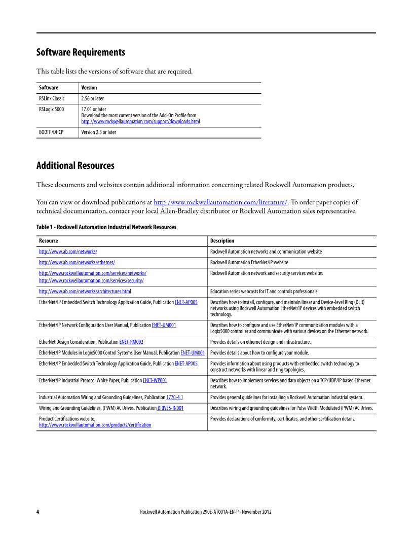

New Product Satisfaction Return
Rockwell Automation tests all of its products to ensure that they are fully operational when shipped from the manufacturing facility However if your product is not functioning and needs to be returned follow these procedures
United States Contact your distributor You must provide a Customer Support case number (call the phone number listed earlier to obtain one) to your distributor to complete the return process
Outside United States Please contact your local Rockwell Automation representative for the return procedure
6 Rockwell Automation Publication 290E-AT001A-EN-P - November 2012
Table of Contents
Important Information 2General Precautions 3Software Requirements 4Additional Resources 4Rockwell Automation Support 5Installation Assistance 5New Product Satisfaction Return 6
Chapter 1Device-Level Ring (DLR) Basics Introduction 9
ArmorStart EtherNet IP Overview 9What is a DLR Network 10DLR Network Elements 10DLR Network Operation 12Number of Nodes on a DLR Network 13DLR Network Fault Management 14
Chapter 2Construct and Configure a Device-Level Ring (DLR) Network
Introduction 15EtherNet Capacity Tool 15Install Devices on a DLR Network 16Addressing Configuration 17
Using the BootPDHCP Server 17Using the Rotary Network Address Switches 17Using the ArmorStart Internal Web Server 19
Configure Supervisor Nodes on a DLR Network 21Configure a Ring Supervisor in RSLogix 5000 Programming Software 21Adding an ArmorStart to RSLogix 5000 22Enable a Ring Supervisor in RSLogix 5000 27Configure and Enable a Ring Supervisor in RSLinx Classic Communication Software 29
Complete the Physical Connections of the Network 33Verify Supervisor Configuration 34IGMP Snooping 35
Rockwell Automation Publication 290E-AT001A-EN-P - November 2012 7
Table of Contents
Chapter 3Monitor a Device-level (DLR) Network
Introduction 37Methods to Monitor a DLR Network 37Monitor Status Pages 39How to Access the ArmorStart EtherNetIP Internal Web Server 44Monitor Diagnostics via MSG Instructions 46
Chapter 4Troubleshoot a Device-level (DLR) Network
Introduction 53General Solutions for Linear or DLR Networks 53Duplicate IP Address Detection 54Specific Issues on the DLR Network 55Network Recovery Performance 58Device Port Debugging Mode 59
Appendix ANetwork Usage Guidelines and Recommendations
Network Usage Guidelines and Recommendations 61
Appendix BRequired Firmware Revisions Required Firmware Revision for an Add-On Profile 65
Required Firmware Revision for RSLinx Communication Software 66
8 Rockwell Automation Publication 290E-AT001A-EN-P - November 2012
Chapter 1
Device-Level Ring (DLR) Basics
Introduction Prior to the introduction of products with embedded switch technology the traditional EtherNetIP network topology has been a star type End devices are connected and communicate with each other via a switch
The EtherNetIP embedded switch technology offers alternative network topologies for interconnecting EtherNetIP devices It embeds switches into the end devices themselves
ArmorStart with EtherNetIP Overview
The ArmorStart with EtherNetIP incorporates the advantages of distributed motor control EtherNetIP communication and Embedded Switch Technology The ArmorStart EtherNetIP family includes full voltage or Sensorless Vector Control AC drive motor starters designed for most of your critical applications ArmorStart with EtherNetIP is a simple seamless and cost-effective method of integrating pre-engineered starters IO and network capabilities in your On-Machine architecture The dual port 10100 Mbps embedded Ethernet switch supports Linear and Device Level Ring Topologies in addition to the traditional star topology
Topic Page
Introduction 9
ArmorStart with EtherNet IP Overview 9
What is a DLR Network 10
DLR Network Elements 10
DLR Network Operation 12
Number of Nodes on a DLR Network 13
DLR Network Fault Management 14
IMPORTANT Products with EtherNetIP embedded switch technology have two ports to connect to a linear or DLR network in a single subnetThese ports cannot be used as two Network Interface Cards (NICs) connected to two different subnets The two ports share one IP Address and MAC Address
Rockwell Automation Publication 290E-AT001A-EN-P - November 2012 9
Chapter 1 Device-Level Ring (DLR) Basics
What is a Device-level Ring (DLR) Network
A DLR network is a single-fault tolerant ring network intended for the interconnection of automation devices This topology is also implemented at the device level No additional switches are required
The graphic below shows an example of an ArmorStart LT Bulletins 291 and 291E and an ArmorStart Distributed Motor Controller Bulletin 280E in a DLR network
Figure 1 - Example DLR Network
The advantages of the DLR network include
bull Simple installation
bull Media resiliency to a single point of failure on the network
bull Fast recovery time when a single fault occurs on the network (lt3 ms convergence for up to 50 nodes on ring)
The primary disadvantage of the DLR topology is the additional effort required to set up and use the network when compared to a linear or star network However use of this Application Guide should minimize the amount of additional effort that is required
DLR Network Elements A DLR network is made up of the following devicesbull Supervisor Node
ndash Active Supervisor Nodendash Back-up Supervisor Node (optional)
bull Ring Node
Each of these device types and how they work in a DLR network are described in the following sections
10 Rockwell Automation Publication 290E-AT001A-EN-P - November 2012
Device-Level Ring (DLR) Basics Chapter 1
Supervisor Node
A DLR network requires at least one node to be configured as a ring supervisor Currently several Rockwell Automation products support the ring supervisor functionality
Active Ring Supervisor
When multiple nodes are enabled as supervisor the node with the numerically highest precedence value becomes the active ring supervisor the other nodes automatically become back-up supervisors
The ring supervisor provides the following primary functionsbull Verifies the integrity of the ringbull Reconfigures the ring to recover from a single fault bull Collects diagnostic information for the ring
Back-up Supervisor Node
At any point in time there will be only one active supervisor on a DLR network However we recommend that at least one other supervisor-capable node be configured to act as a back-up supervisor During normal operation a back-up supervisor behaves like a ring node If the active supervisor node operation is interrupted for example it experiences a power-cycle the back-up supervisor with the next numerically highest precedence value becomes the active supervisor
If multiple supervisors are configured with the same precedence value (the factory default value for all supervisor-capable devices is 0) the node with the numerically highest MAC address becomes the active supervisor
We recommend that youbull Configure at least one back-up supervisorbull Configure your desired active ring supervisor with a numerically higher
precedence value as compared to the back-up supervisors
IMPORTANT Out of the box the supervisor-capable devices have their supervisor function disabled so they are ready to participate in either a linearstar network topology or as a ring node on an existing DLR networkIn a DLR network at least one of the supervisor-capable devices must be configured as the ring supervisor before physically closing the ring If not the DLR network will cause significant network issues that can only be resolved by disconnecting the final connection
IMPORTANT While a back-up supervisor is not required on a DLR network it is recommended that at least one back up ring supervisor be configured for the ring network
Rockwell Automation Publication 290E-AT001A-EN-P - November 2012 11
Chapter 1 Device-Level Ring (DLR) Basics
bull Keep track of your networkrsquos supervisor-precedence values for all supervisor-enabled nodes
For more information about how to configure a supervisor see Construct and Configure a Device-level Ring Network on page 15
Ring Node
A ring node is any node that operates on the network to process data that is transmitted over the network or to pass on the data to the next node on the network When a fault occurs on the DLR network these reconfigure themselves and relearn the network topology Additionally ring nodes can report fault locations to the active ring supervisor
DLR Network Operation During normal network operation an active ring supervisor uses beacon and other DLR protocol frames to monitor the health of the network Back-up supervisor nodes and ring nodes monitor the beacon frames to track ring transitions between Normal (all links working) and Faulted (the ring is broken in at least one place)
Two beacon-related parameters can be configured
bull Beacon interval - Frequency at which the active ring supervisor transmits a beacon frame through both of its ring ports
bull Beacon timeout - Amount of time that supervisor or ring nodes wait before timing out the reception of beacon frames and taking appropriate action
These parameters impact Network Recovery Performance For information on these performance times see page 58 For information on how to set these parameters see Construct and Configure a Device-level Ring Network on page 15
IMPORTANT Do not connect non-DLR (single port) devices directly to the DLR network Non-DLR devices should be connected to the network through 1783-ETAP 1783-ETAP1F or 1783-ETAP2F EtherNetIP taps like the examples shown below
12 Rockwell Automation Publication 290E-AT001A-EN-P - November 2012
Device-Level Ring (DLR) Basics Chapter 1
During normal operation one of the active supervisor nodersquos network ports is blocked for DLR protocol frames However the active supervisor node continues to send beacon frames out of both network ports to monitor network health The following graphic shows the use of beacon frames sent from the active ring supervisor
Figure 2 - Normal DLR Network Operation
A second category of ring nodes known as announce frame ring nodes can be designed to participate in a DLR network The active supervisor sends announce frames out one of its ports once per second or on detection of a ring fault DLR networks with announce frame ring nodes have slightly longer recovery times than beacon frame nodes
Number of Nodes on a DLR Network
Rockwell Automation recommends that you use no more than 50 nodes on a single DLR or linear network If your application requires more than 50 nodes we recommend that the nodes are segmented into separate but linked DLR networks
With smaller networksbull There is better management of traffic on the networkbull The networks are easier to maintainbull There is a lower likelihood of multiple faultsbull Recovery time is shorter
Additionally on a DLR network with more than 50 nodes network recovery times from faults are higher than those listed in Network Recovery Performance on page 58
Rockwell Automation Publication 290E-AT001A-EN-P - November 2012 13
Chapter 1 Device-Level Ring (DLR) Basics
DLR Network Fault Management
The network may occasionally experience faults that prevent the normal transmission of data between nodes The DLR network can protect your application from interruptions resulting from a single fault To maintain the resiliency of your ring your application should monitor the health of the ring The ring may be faulted while all higher-level network functions such as IO connections are operating normally
Fault location information is available from the active supervisor For more information on how to obtain fault location information see Monitor a DLR Network on page 37
After a fault occurs the active supervisor reconfigures the network to continue sending data on the network
Network Reconfiguration after a Fault
The following graphic shows the network configuration after a failure occurs with the active ring supervisor passing traffic through both of its ports thus maintaining communication on the network
14 Rockwell Automation Publication 290E-AT001A-EN-P - November 2012
Chapter 2
Construct and Configure a Device-level Ring Network with ArmorStarts
Introduction Use this chapter to learn how to construct and configure a DLR network
Ethernet Capacity Tool The EtherNetIP Capacity Tool is free software that is intended to help in the initial layout of your EtherNetIP network by calculating resources (Connections Packets per Second) used by a proposed network You choose icons to indicate the type and number of nodes on the network along with associated parameters such as Update Rate desired The tool then calculates the resources used and what is still available This format makes it easy to try different configurationsparameters and see how the outcome is affected
To download the Ethernet Capacity Tool go to httpwwwabcomgoiatools
Topic Page
Ethernet Capacity Tool 15
Install Devices on a DLR Network 16
ArmorStart Addressing Configuration 17
Using the BootPDHCP Server 17
Using the Rotary Network Address Switches 17
Using the ArmorStart Internal Web Server 19
Configure Supervisor Nodes on a DLR Network 21
Configure a Ring Supervisor in RSLogix 5000 21
Adding an ArmorStart to RSLogix 5000 22
Enable a Ring Supervisor in RSLogix 5000 27
Configure and Enable a Ring Supervisor in RSLinx Classic 29
Complete the Physical Connections of the Network 33
Verify Supervisor Configuration 34
IGMP Snooping 35
Rockwell Automation Publication 290E-AT001A-EN-P - November 2012 15
Chapter 2 Construct and Configure a Device-level Ring Network with ArmorStarts
Install Devices on a DLR Network
The next step to configure a DLR network is to connect all devices to the network One connection should be left unmade That is temporarily omit the physical connection between two nodes on the ring network because the factory default settings of DLR devices are set to operate in linearstar mode or as ring nodes on existing DLR networks
For more information on installing the EtherNetIP network (cable requirements maximum distance etchellip) refer to the EtherNetIP Media Planning and Installation Manual which can be downloaded here
httpliteraturerockwellautomationcomidcgroupsliteraturedocumentsrmenet-rm002_-en-ppdf
Figure 3 - Example Device-level Ring Topology with One Connection Left Unmade
Use the installation instructions below for each device to connect it to the network Publication Numbers can be downloaded at httpwwwrockwellautomationcomliteratureliteraturehtml
IMPORTANT If your DLR network is fully connected without a supervisor configured a network storm may result rendering the network unusable until one link is disconnected and at least one supervisor is enabled
Description Installation Instructions CatNo
ControlLogix EtherNetIP module 1756-IN612 1756-EN2TR
EtherNetIP tap 1783-IN007 1783-ETAP
ArmorStart LT Motor Controller 290-UM001 291E-FAZ-G2
ArmorStart Motor Controller 280G-UM001 280E-F12Z-10A-CR-3
Stratix 6000 Ethernet Switch 1783-IN004 1783-EMS08TA
16 Rockwell Automation Publication 290E-AT001A-EN-P - November 2012
Construct and Configure a Device-level Ring Network with ArmorStarts Chapter 2
ArmorStart Addressing Configuration
Before using the ArmorStart in an EtherNetIP network an IP address subnet mask and optional Gateway address must be configured This section describes how to set up the IP Address of an ArmorStart in three different ways using the BootPDHCP Server the Rotary Network Address Switches and the internal web server
Note When using the AOP it is not configuring the IP Address of the ArmorStart it is just assigning the same IP address that was set-up using the Rotary Network Address Switches or the web page so that communication is established
Using the BootPDHCP Server
The Rockwell Automation BootPDHCP utility is a standalone program that incorporates the functionality of standard BootP software with a user-friendly graphical interface It is located in the Utils directory on the RSLogix 5000 installation CD The ArmorStart EtherNetIP adapter must have DHCP enabled (factory default) to use the utility
DHCP (Dynamic Host Configuration Protocol) software automatically assigns IP addresses to client stations logging onto a TCPIP network When DHCP is enabled (factory default enabled) the unit will request its network configuration from a BootPDHCP server Any configuration received from a DHCP server will be stored in non-volatile memory The ArmorStart EtherNetIP will remember the last successful address if the DHCP is enabled The possibility exists that the adapter will be assigned a different IP address which would cause the adapter to stop communicating with the ControlLogix controller
Using the Rotary Network Address Switches
The three rotary network address switches can be found on the IO section of the ArmorStart The rotary network address switches are set to 999 and the DHCP is enabled as the factory default The ArmorStart reads these switches first to determine if the switches are set to a valid IP address between 1hellip254 When switches are set to a valid number the IP address will be 1921681_ _ _ [switch setting]
RJ45 ndash RJ45 Ethernet cable ENET-IN001A 1585J-M8PBJM-2
RJ45 ndash M12 Ethernet cable ENET-IN001A 1585D-M4TBJM-1
M12 ndash M12 Ethernet cable ENET-IN001A 1585D-M4TBDE-2
Description Installation Instructions CatNo
Rockwell Automation Publication 290E-AT001A-EN-P - November 2012 17
Chapter 2 Construct and Configure a Device-level Ring Network with ArmorStarts
To set up the IP Address using the rotary network address switches
1 Remove the protective caps from the rotary switches
2 Set the Network IP address by adjusting the three switches on the front of the IO module using a flat head screwdriver
3 Set up the switches in a range from 001 to 254 In this example they are set to a1 When the switches are set to a valid number the adapterrsquos IP address will be 1921681xxx (where xxx represents the number set on the switches) In this example the IP address is 1921681163 The adapterrsquos subnet mask will be 2552552550 and the gateway address is set to 0000 A power cycle or a type 1 network reset is required for any new IP address switch setting to take effect
Note The user cannot change the IP address from 1921681xxx when using the IP address switches The top three octets are fixed DHCP or the embedded web server must be used to configure the address to a value different than 1921681xxx Also the adapter will not have a host name assigned or use any Domain name System when using the rotary switch settings
4 If the switches are set to an invalid value (such as 000 or value greater than 254) the adapter will check to see if the DHCP is enabled If so the adapter requests an address from a DHCP server The DHCP server will also assign other Transport Control Protocol (TCP) parameters If DHCP is not enabled the adapter will use the IP address (along with other TCP configurable parameters) stored in nonvolatile memory
18 Rockwell Automation Publication 290E-AT001A-EN-P - November 2012
Construct and Configure a Device-level Ring Network with ArmorStarts Chapter 2
Using the ArmorStart Internal Web Server
Rockwell Automation provides an internal embedded web server with each EtherNetIP version of ArmorStart The internal web server allows you to view information and configure the ArmorStart via a web browser The internal web server can be used to set up the ArmorStart IP address by performing the following this steps
1 Open your preferred internet web browser
2 Enter the IP address of the desired ArmorStart For this example use 1921681163
Note 1921681163 is not the factory default IP address
3 The web server shown below should appear in your web browser
Rockwell Automation Publication 290E-AT001A-EN-P - November 2012 19
Chapter 2 Construct and Configure a Device-level Ring Network with ArmorStarts
4 Click in the administrative settings folder to expand it and the following is displayed
5 Click in the Network Configuration tab and a prompt to enter a User Name and a Password is displayed Enter the pre-set User Name and Password or if they have not been set up previously use the default User Name The default User Name is Administrator and there is no password set by default
6 After the appropriate User Name and Password is entered the screen below is displayed From this screen the Ethernet Configuration can be changed For example the default IP address shown is changed from 1921681163 to 101010101 After a power cycle the new address must be used to access the web page and the other devices on the network would also require their IP addresses to be reconfigured
20 Rockwell Automation Publication 290E-AT001A-EN-P - November 2012
Construct and Configure a Device-level Ring Network with ArmorStarts Chapter 2
Configure Supervisor Nodes on a DLR Network
After the devices are installed on the DLR network at least one supervisor node must be configured Ring nodes do not require any DLR network configuration
Before a DLR network can be completed (install your devices on the network and make all physical connections) a ring supervisor must be configured and enabled in
bull RSLogix 5000 programming software orbull RSLinx Classic communication software
This section shows how to use RSLogix 5000 programming software beginning on page 22 and RSLinx Classic communication software beginning on page 29 to configure and enable a ring supervisor
Configure a Ring Supervisor in RSLogix 5000 Programming Software
To configure the 1756-EN2TR module or the 1783-ETAP 1783-ETAP1F or 1783-ETAP2F taps as a ring supervisor use the devicersquos Add-on Profile (AOP) in RSLogix 5000 programming software version 1701 or later
For more information regarding the Required Add-On Profile Revision required go to Appendix B
To configure a ring supervisor in RSLogix 5000 programming software follow these steps
IMPORTANT The steps to configure a ring supervisor via software are basically the same for the 1756-EN2TR module and the 1783-ETAP 1783-ETAP1F and 1783-ETAP2F taps This example shows how to configure the 1756-EN2TR moduleOnly the 1783-ETAP 1783-ETAP1F and 1783-ETAP2F taps in the IO Configuration must be configured if you plan to enable the tap as a ring supervisor If the tap will not be used as a ring supervisor we recommend that it is not added to the IO ConfigurationAdditionally to configure a 1783-ETAP 1783-ETAP1F or 1783-ETAP2F tap as a supervisor via software or with its DIP switches an IP address must first be assigned The tap does not require an IP address if it is used as a ring node or has its supervisor function enabled by a DIP switchFor more information on how to use a tap switch to configure it as a ring supervisor see Chapter 5 in the EtherNetIP Embedded Switch Technology Manual To download the manual go to httpliteraturerockwellautomationcomidcgroupsliteraturedocumentsapenet-ap005_-en-ppdf
Rockwell Automation Publication 290E-AT001A-EN-P - November 2012 21
Chapter 2 Construct and Configure a Device-level Ring Network with ArmorStarts
Adding an Armorstart to RSLogix 5000
This section will show how to add an ArmorStart to RSLogix 5000
1 Open RSLogix 5000
2 Select File gt New to create a new project
3 Enter the name of the project and select your controller from the Type drop down menu For this example a 1756-L63 and software revision 20 will be used Then click OK
22 Rockwell Automation Publication 290E-AT001A-EN-P - November 2012
Construct and Configure a Device-level Ring Network with ArmorStarts Chapter 2
4 Add the 1756-EN2TR module to your projecta Right-click 1756 Backplane and choose New Module
Rockwell Automation Publication 290E-AT001A-EN-P - November 2012 23
Chapter 2 Construct and Configure a Device-level Ring Network with ArmorStarts
b Select the modulec Click Create
5 To add a new module to the tree right-click on Ethernet and select New Module This allows a new ArmorStart to be added to the Logix Project
24 Rockwell Automation Publication 290E-AT001A-EN-P - November 2012
Construct and Configure a Device-level Ring Network with ArmorStarts Chapter 2
6 Select the ArmorStart in your application and click OK
7 Enter a Name for this ArmorStart and an Ethernet address For this example the Private Network setting will be used This should be set to match the IP address switch setting on the ArmorStart Then press OK
Note Refer to ArmorStart Addressing Configuration on page 17 to set an IP address on the device
Rockwell Automation Publication 290E-AT001A-EN-P - November 2012 25
Chapter 2 Construct and Configure a Device-level Ring Network with ArmorStarts
8 Complete configuration information for the module in your RSLogix 5000 project
The following graphic shows the IO configuration for an example DLR network
9 Download the program to the Logix controller
10 Go online with the controller and leave it in Program mode
26 Rockwell Automation Publication 290E-AT001A-EN-P - November 2012
Construct and Configure a Device-level Ring Network with ArmorStarts Chapter 2
Enable Ring Supervisor in RSLogix 5000 Programming Software
After 1756-EN2TR module or 1783-ETAP 1783-ETAP1F or 1783-ETAP2F taps have been added to your RSLogix 5000 programming software project the ring supervisor mode must be enabled
If using RSLogix 5000 programming software to configure the ring supervisor and monitor diagnostics on the DLR network the controller must be online
To enable the 1756-EN2TR module or 1783-ETAP 1783-ETAP1F or 1783-ETAP2F tap as a ring supervisor follow these steps
The steps to enable a ring supervisor are basically the same for the 1756-EN2TR module or 1783-ETAP 1783-ETAP1F or 1783-ETAP2F tap This example shows how to do it for the 1756-EN2TR module
1 For your project online with the controller double-click on a supervisor-capable device in the IO configuration tree
Rockwell Automation Publication 290E-AT001A-EN-P - November 2012 27
Chapter 2 Construct and Configure a Device-level Ring Network with ArmorStarts
2 Click the Network tab to Enable Supervisor Mode
Configuration takes effect immediately you do not need to click Apply or OK
3 Click the Advanced button on the Network tab
4 Configure supervisor-related parameters as shown in the screen shot below
For these parameters you must click Set after entering a value
5 Click Set
28 Rockwell Automation Publication 290E-AT001A-EN-P - November 2012
Construct and Configure a Device-level Ring Network with ArmorStarts Chapter 2
Configure and Enable a Ring Supervisor in RSLinx Classic Communication Software
A ring supervisor can be configured for the DLR network through RSLinx Classic communication software
For more information regarding the Required RSLinx Classic Communication software Revision required refer to Appendix B
To configure a ring supervisor in RSLinx Classic Communication Software follow these steps
This example is for the 1783-ETAP tap Follow these steps
1 Launch RSLinx Classic Communication Software
2 Browse to the DLR network that is being set up
IMPORTANT For Beacon Interval Beacon Timeout and Ring Protocol VLAN ID we recommend that the default values be used
Functionality Description Default Setting
Supervisor Precedence A supervisor precedence number may be configured for each device that is configured as a ring supervisor The highest possible supervisor precedence value is 255When multiple nodes are enabled as supervisors the node with the highest precedence value is assigned as the active ring supervisor the other nodes automatically become back-up supervisorsWe recommend that youbull configure at least one back-up supervisor nodebull set the desired Active Ring Supervisor with a relatively high supervisor-
precedence value compared to the back-up node(s)bull keep track of the networkrsquos supervisor-precedence valuesIf multiple supervisors are configured with the same precedence value (the factory default value for all supervisor-capable devices is 0) the node with the numerically highest MAC address becomes the active supervisor
0
Beacon Interval Beacon interval is the frequency of the active ring supervisor transmitting a beacon frame through both of its Ethernet ports This parameter is user configurable for any time between 200 μS and 100 mSFor more information on how this parameter relates to network performance see page 61
400 μS
Beacon Timeout The beacon timeout is the amount of time that nodes wait before timing out the reception of beacon frames and taking appropriate action Supervisors support a range from 400μS to 500mSFor more information on how this parameter relates to network performance see page 61
1960 μS
Ring Protocol VLAN ID Reserved for future use 0
Rockwell Automation Publication 290E-AT001A-EN-P - November 2012 29
Chapter 2 Construct and Configure a Device-level Ring Network with ArmorStarts
If the Electronic Data Sheet (EDS) file is not installed on the module configured to be the ring supervisor it will appear with a question mark () To obtain and use the EDS file
bull right-click the module and choose to upload the EDS file from the device or
bull download the EDS file from httpwwwrockwellautomationcomrockwellautomationsupportnetworksedspage
3 Access the supervisor-capable nodersquos propertiesa Right-click the nodeb Choose Module Configuration
The General tab appears with information about the module
4 Click the Network tab to Enable Supervisor Mode
Configuration takes effect immediately there is no need to click Apply or OK
30 Rockwell Automation Publication 290E-AT001A-EN-P - November 2012
Construct and Configure a Device-level Ring Network with ArmorStarts Chapter 2
5 Click the Advanced button to configure supervisor-related parameters
Rockwell Automation Publication 290E-AT001A-EN-P - November 2012 31
Chapter 2 Construct and Configure a Device-level Ring Network with ArmorStarts
IMPORTANT For Beacon Interval Beacon Timeout and Ring Protocol VLAN ID use the default values
Functionality Description Default Setting
Supervisor Precedence
You may configure a supervisor precedence number for each device configured as a ring supervisor The highest possible supervisor precedence value is 255When multiple nodes are enabled as supervisor the node with the highest precedence value is assigned as the active ring supervisor the other nodes automatically become back-up supervisorsWe recommend that youbull configure at least one back-up supervisor nodebull set the desired Active Ring Supervisor with a relatively high supervisor-
precedence value compared to the back-up node(s)bull keep track of the networkrsquos supervisor-precedence valuesIf multiple supervisors are configured with the same precedence value (the factory default value for all supervisor-capable devices is 0) the node with the numerically highest MAC address becomes the active supervisor
0
Beacon Interval Beacon Interval is the frequency to which the active ring supervisor transmits a beacon frame through both of its Ethernet ports This parameter is user configurable for any time between 200 μS and 100 mSFor more information on how this parameter relates to network performance see page 58
400 μS
Beacon Timeout The beacon timeout is amount of time nodes wait before timing out the reception of beacon frames and taking appropriate action Supervisors support a range from 400 μS to 500 mSFor more information on how this parameter relates to network performance seepage 58
1960 μS
Ring Protocol VLAN ID
Reserved for future use 0
Enable IGMP Snooping
For more information on IGMP Snooping see page 35 Enabled
Enable IGMP Querier
For more information on IGMP Querier see page 35 Disabled
Enable Device Port Debugging Mode
For more information on Device Port Debugging Mode see page 59 Disabled
32 Rockwell Automation Publication 290E-AT001A-EN-P - November 2012
Construct and Configure a Device-level Ring Network with ArmorStarts Chapter 2
Complete the Physical Connections of the Network
After the ring supervisor nodes are configured and enabled the physical connection of the network must be completed to establish a complete DLR network
The figure below shows an example DLR network with all physical connections complete
Figure 4 - Example Device-level Ring Topology with All Connections Complete
Rockwell Automation Publication 290E-AT001A-EN-P - November 2012 33
Chapter 2 Construct and Configure a Device-level Ring Network with ArmorStarts
Verify Supervisor Configuration
The configuration and overall DLR network status can be verified in either RSLogix 5000 programming software or RSLinx Classic communication software
1 Access the supervisor nodersquos properties as shown previously in this chapter
2 Click the Network tab
3 Check the Network Topology and Network Status Fields
For a 1756-EN2TR module or the 1783-ETAP 1783-ETAP1F and 1783-ETAP2F tap the supervisor configuration can also be verified through the modulersquos diagnostic web pages For more information on monitoring diagnostics via an EtherNetIP modulersquos web pages see Monitor a DLR Network starting on page 37
34 Rockwell Automation Publication 290E-AT001A-EN-P - November 2012
Construct and Configure a Device-level Ring Network with ArmorStarts Chapter 2
IGMP Snooping This functionality is enabled by default in the 1783-ETAP 1783-ETAP1F and 1783-ETAP2F taps and is commonly used to manage multicast traffic on the network When in use this functionality allows the tap to multicast data to only those devices that need the data rather than to all devices connected to the network
For snooping to work there must be a device present that is running a querier Typically the device is a router or a switch such as the Stratix 6000 Stratix 8000 or Stratix 8300 managed switch
Once DHCP is enabled the switch could change the IP addresses on the ArmorStarts depending on network demand which could cause RSlogix5000 to loose communication with the device as connectivity is established via the AOP in the initial configuration
IGMP Querier This functionality is disabled by default The IGMP Querier functionality enables a 1783-ETAP 1783-ETAP1F or 1783-ETAP2F tap or switch such as a Stratix managed switch to send out a query to all devices on the network It determines what multicast addresses are of interest to a specific node or a group of nodes
The IGMP Querier functionality should be enabled for at least one node on the network The 1783-ETAP 1783-ETAP1F or 1783-ETAP2F tap managed switches and routers are examples of devices that support IGMP Querier functionality
IMPORTANT If DHCP for the Armostart is still required the Internet Group Management Protocol (IGMP) snooping on the E-tap must be disabled via the AOP
IMPORTANT If the IGMP Querier functionality is not enabled for at least one node on the network multicast traffic on the network may eventually create network performance issues
Rockwell Automation Publication 290E-AT001A-EN-P - November 2012 35
Chapter 2 Construct and Configure a Device-level Ring Network with ArmorStarts
However for all devices that are configured on the network with the IGMP Querier parameter enabled an IP address other than the factory default value must also be set for those devices If multiple devices on the network enable this functionality only the node with the lowest IP address becomes the active IGMP Querier node
IGMP Version
If the IGMP Querier is enabled a Querier Version must be selected The default version is Version 2
36 Rockwell Automation Publication 290E-AT001A-EN-P - November 2012
Chapter 3
Monitor a DLR Network
Introduction Use this chapter to learn how to monitor the DLR network
Methods to Monitor a DLR Network
Network diagnostic information can be retrieved from the ring supervisor-capable devices using the following
bull RSLogix 5000 programming software status pages
bull RSLinx communication software status pages
bull Device web pages
bull EtherNetIP Device Level Ring (DLR) network diagnostics faceplate
bull Programmatically through the use of a MSG instruction
RSLogix 5000 Programming Software Status Pages
RSLogix 5000 programming software version 1701 or later must be used and the appropriate AOPs installed to use the softwarersquos profile status pages
RSLinx Communication Software Status Pages
To monitor the network with this method the RSLinx communication software version 255 or later must be used
Topic Page
Methods to Monitor a DLR Network 37
Monitor Status Pages 39
Monitor ArmorStart Internal Web Server 44
Monitor via Faceplate Integration 45
Monitor Diagnostics via MSG Instructions 46
Rockwell Automation Publication 290E-AT001A-EN-P - November 2012 37
Chapter 3 Monitor a DLR Network
ArmorStart Internal Web Server
Rockwell Automation provides an internal embedded web server with each ArmorStart EtherNetIP The internal web server allows you to view information and configure the ArmorStart via a web browser The ArmorStart EtherNetIP can also be set up from the web server to send e-mail notifications The embedded web server is used to access configuration and status data It provides the user with the ability to view and modify the device configuration without having access to RSLogix 5000 Security in the form of an administrative password can be set The default login is Administrator There is no password set by default
EtherNetIP Device Level Ring (DLR) Network Diagnostics Faceplate
The diagnostics faceplate contains two major components
bull Logic code (encapsulated in an Add-On Instruction) that allows the controller to retrieve real-time DLR network status information
bull HMI faceplate graphics to allow the data to be visualized on an operator interface
Programmatically Through the Use of a MSG Instruction
For more information on how to monitor the DLR network via MSG Instructions see page 46
38 Rockwell Automation Publication 290E-AT001A-EN-P - November 2012
Monitor a DLR Network Chapter 3
Monitor Status Pages Both RSLogix 5000 programming software and RSLinx Classic communication software offer status pages that can be used to monitor the networkrsquos performance
RSLogix 5000 Programming Software Status Pages
Monitor the networkrsquos diagnostic information through the RSLogix 5000 programming software when the software is online
To monitor the network in RSLogix 5000 programming software follow these steps
1 Verify that the project is online
2 Access the active supervisor nodersquos propertiesa Right-click the modulersquos entry in the Controller Organizerb Click properties
Rockwell Automation Publication 290E-AT001A-EN-P - November 2012 39
Chapter 3 Monitor a DLR Network
3 Use the Network tab to monitor diagnostics
40 Rockwell Automation Publication 290E-AT001A-EN-P - November 2012
Monitor a DLR Network Chapter 3
RSLinx Communication Software
To monitor the network in RSLinx communication software follow these steps
1 Click RSWho to browse the network
2 Access the property pages for the active supervisor nodea Open the driver that shows the nodes on the DLR networkb Right-click the node that you want to monitor performancec Click on the choice that you need to access
Multiple choices appear
These options are shown in the following sections
Rockwell Automation Publication 290E-AT001A-EN-P - November 2012 41
Chapter 3 Monitor a DLR Network
Module Configuration
This series of tabs providesbull General informationbull Connection informationbull Module informationbull Internet protocolbull Port configurationbull Network information
The example below shows a ring fault between nodes at IP addresses 10888021 and MAC ID 00-00-BC-02-48-D5
42 Rockwell Automation Publication 290E-AT001A-EN-P - November 2012
Monitor a DLR Network Chapter 3
There are multiple fields used to monitor network diagnostics
Field Definition
Network Topology Possible values here can be Linear or Ring
Network Status Displays if the network is operating normally (Normal) or has experienced a fault (Ring Fault) as shown in the previous example screen
Active Ring Supervisor Displays the IP address or MAC address of the active ring supervisor
Active Supervisor Precedence For more information on this field see Active Ring Supervisor on page 11
Enable Ring Supervisor Configurable field that lets you to set the node as a ring supervisor
Ring Faults Detected Number of faults detected on the network since the last module power cycle or counter reset
Supervisor Status Displays whether this node is the active ring supervisor (Active) a back-up supervisor (Back-up) a ring node or part of a linear network
Last Active Node on Port 1 The last node the active ring supervisor can communicate with on Port 1 This value is an IP address or a MAC ID and remains latched until the Verify Fault Location button is clicked
Last Active Node on Port 2 The last node the active ring supervisor can communicate with on Port 2 This value is an IP address or a MAC ID and remains latched until the Verify Fault Location button is clicked
Status Displays whether a fault exists on the ring
IMPORTANT If the Network Topology field = Ring and the Network Status field = Normal the Last Active Node fields will display the last fault information even though it has been correctedTo clear the last fault information from these fields click Verify Fault Location You may see a message informing you that the supervisor is no longer in fault mode and the fields will be cleared
Rockwell Automation Publication 290E-AT001A-EN-P - November 2012 43
Chapter 3 Monitor a DLR Network
How to Access the ArmorStart EtherNetIP Internal Web Server
Open your preferred internet web browser and enter the IP address of the desired ArmorStart For this example 192168122 will be used
Use the links on the left-most navigation bar to see each available web page The screen below shows Ring Statistics for the ArmorStart 280E
44 Rockwell Automation Publication 290E-AT001A-EN-P - November 2012
Monitor a DLR Network Chapter 3
EtherNetIP Device Level Ring (DLR) Network Diagnostics Faceplate Overview
The EtherNetIP Device Level Ring (DLR) network diagnostics faceplate provides basic DLR network status information to the user to assist with monitoring and troubleshooting a DLR network
The diagnostics faceplate contains two major components
bull Logic code (encapsulated in an Add-On Instruction) that allows the controller to retrieve real-time DLR network status information
bull HMI faceplate graphics to allow the data to be visualized on an operator interface
The DLR diagnostics faceplate application can be downloaded from the Rockwell Automation Sample Code website at httpsamplecoderockwellautomationcom
Besides the individual Logix and View project components a demo application is also included with the downloaded file
Rockwell Automation Publication 290E-AT001A-EN-P - November 2012 45
Chapter 3 Monitor a DLR Network
Monitor Diagnostics via MSG Instructions
Network diagnostic information can also be obtained programmatically via MSG instructions in RSLogix 5000 programming software For example you can
bull Get all ring diagnostic informationbull Get a ring participant listbull Get the active supervisorbull Clear rapid ring faultsbull Verify a fault locationbull Reset a fault counterbull Enable and configure a ring supervisor
This information can be displayed on an HMI device or manipulated in the project code
Figure 5 - Example Use of MSG Instruction
This example describes how to retrieve diagnostic information from the DLR network Follow these steps
1 Enter a MSG instruction into the rung of logic
2 Configure the MSG instruction to retrieve ring diagnostic information service as shown in the following screen shots
IMPORTANT Make sure the tag created is sized appropriately to hold all of the data that you are reading or writing For more information see page 48
46 Rockwell Automation Publication 290E-AT001A-EN-P - November 2012
Monitor a DLR Network Chapter 3
3 Configure the MSG instructionrsquos communication path to point to the active supervisor node
The path on the following screen is one example path
IMPORTANT When using the Custom Get_Attributes_All (01) service pointing to an active supervisor node will retrieve all of the attributes listed in Retrieve All Diagnostic Information Attribute Description on page 50Pointing to a non-supervisor node will retrieve only the Network Topology and Network Status attribute informationPointing to backup supervisor node will retrieve the current active supervisorrsquos IP address
Rockwell Automation Publication 290E-AT001A-EN-P - November 2012 47
Chapter 3 Monitor a DLR Network
Use Specific Values on the Configuration Tab
Use the values on the Configuration tab of your MSG instruction to perform specific services Sample DLR network diagnostic application code for example Add-on Instruction or HMI faceplate graphics is available on the Rockwell Automation Sample Code Library For more information about the Rockwell Automation Sample Code Library see httpwwwrockwellautomationcomsolutionsintegratedarchitectureresources5html
➊ This request only works if there are fewer than 40 nodes on the network If there are more nodes than will fit in a single message an error will be returned➋ Use a Destination Length of 54 bytes if using firmware revision 3x or later for the 1756-EN2TR module or firmware revision 2x or later for the 1783-ETAP
1783-ETAP1F or 1783-ETAP2F taps
Request Description Message Type
Service Type
Service Code (HEX)
Class (HEX)
Instance Attribute (HEX)
Source Element
Source Length (Bytes)
Destination Destination Length (bytes)
Retrieve All Ring Diagnostic Information
Information for this request is listed in Retrieve All Ring Diagnostic Information on page 49
CIP Generic Custom 1 47 1 NA LeftBlank
0 Tag 50or54 ➋
Request Ring Participant List ➊
Information for this request is listed in Request the Ring Participant List on page 51
CIP Generic Get Attribute Single
e 47 1 9 NA NA Tag 10node
Get Active Supervisor
Obtain the IP address and MAC ID of the active supervisor on the DLR network
CIP Generic Get Attribute Single
e 47 1 a NA NA Tag 10
Acknowledge Rapid Ring Faults Condition
Request supervisor to resume normal operation after encountering a rapid ring fault condition
CIP Generic Custom 4c 47 1 NA NA NA NA
Verify a Fault Location
Request supervisor to update Last Active Node values
CIP Generic 4b 47 1 NA NA NA NA NA
Reset the Ring Fault Counter
Reset the number of ring faults detected on the DLR network
CIP Generic Set Attribute Single
10 47 1 5 Tag 2 NA NA
Enable and Configure a Ring Supervisor
Information for this request is listed in Enable and Configure a Ring Supervisor on page 52
CIP Generic Set Attribute Single
10 47 1 4 Tag 12 NA NA
48 Rockwell Automation Publication 290E-AT001A-EN-P - November 2012
Monitor a DLR Network Chapter 3
Retrieve All Ring Diagnostic Information
By performing the Retrieve All Ring Diagnostic Information request on an active supervisor the MSG instruction returns the following information
➊ RSLogix 5000 programming software may display the value in this field as negative numbers To better understand the value we recommend you view it in HEX format
Destination Tag Attribute Name Description Possible Values
SINT [0] Network Topology Current network topology mode 0 = Linear
1 = Ring
SINT [1] Network Status Current status of the network 0 = Normal
1 = Ring Fault
2 = Unexpected Loop Detected
3 = Partial Network Fault
4 = Rapid FaultRestore Cycle
SINT [2] Ring Supervisor Status Ring supervisor active status flag 0 = Node is functioning as a backup
1 = Node is functioning as the active ring supervisor
2 = Node is functioning as a normal ring node
3 = Node is operating in a non-DLR topology
4 = Node cannot support the currently operating ring parameters thatis Beacon Interval andor Beacon Timeout
Ring Supervisor Config Ring Supervisor configuration parameters
SINT [3] Ring Supervisor Enable Ring supervisor enable flag 0 = Node is configured as a normal ring node (default configuration)
1 = Node is configured as a ring supervisor
SINT [4] Ring Supervisor Precedence Precedence value of a ring supervisor ➊ Valid value range = 0hellip255
0 = Default value
SINT [5-8] Beacon Interval Duration of ring beacon interval Valid value range = 200 μshellip100 ms
Default = 400 μs
SINT [9-12] Beacon Timeout Duration of ring beacon timeout Value value range = 400 μshellip500 ms
Default value = 1960 μs
SINT [13-14] DLR VLAN ID Valid ID to use in ring protocol messages Valid value range = 0hellip4094
Default value = 0
SINT [15-16] Ring Faults Count Number of ring faults since power up ➊
Rockwell Automation Publication 290E-AT001A-EN-P - November 2012 49
Chapter 3 Monitor a DLR Network
Retrieve All Diagnostic Information Attribute Description
➊ This destination tag is available only with the 1756-EN2TR module firmware revision 3x or later 1783-ETAP 1783-ETAP1F and 1783-ETAP2F taps firmware revisions 2x or later If using the 1783-ETAP tap firmware revision 1x your program does not include this destination tag
➋ RSLogix 5000 programming software may display the value in this field as negative numbers To better understand the value we recommend you view it in HEX format
Destination Tag Attribute Name Description Possible Values
Last Active Node on Port 1 Last active node at the end of the chain through port 1 of the active ring supervisor during a ring fault
SINT [17-20] Device IP address ➋ Any valid IP address value
A value = 0 indicates no IP address has been configured for the device
SINT [21-26] Device MAC address ➋ Any valid Ethernet MAC address
Last Active Node on Port 2 Last active node at the end of the chain through port 2 of the active ring supervisor during a ring fault
SINT [27-30] Device IP address ➋ Any valid IP address value
A value = 0 indicates no IP address has been configured for the device
SINT [31-36] Device MAC address ➋ Any valid Ethernet MAC address
SINT [37-38] Ring Protocol Participants Count
Number of devices in the ring protocol participants list
Active Supervisor Address IP andor Ethernet MAC address of the active ring supervisor
SINT [39-42] Supervisor IP address Any valid IP address value
A value = 0 indicates no IP address has been configured for the device
SINT [43-48] Supervisor MAC address Any valid Ethernet MAC address
SINT [49] Active Supervisor Precedence
Precedence value of the active ring supervisor
SINT [50-53]➊ Capability Flags Alerts you that the device is capable of operating as a supervisor and beacon-based ring node
0x22
50 Rockwell Automation Publication 290E-AT001A-EN-P - November 2012
Monitor a DLR Network Chapter 3
Request the Ring Participant List
When requesting the Ring Participant List service on the DLR network the MSG instruction returns the following information
Request the Ring Participant List Attribute Description
➊ This attribute will return an array of the data shown one entry for each node The Ring Protocol Participants Count attribute determines the number entries
➋ This tag displays only IP addresses for ring participants that have been configured with one For example you may have a 1783-ETAP tap connected to the network that has not been assigned an IP address In that case no address is shown for the 1783-ETAP tap
➌ RSLogix 5000 programming software may display the value in this field as negative numbers To better understand the value we recommend you view it in HEX format
➍ Unlike destination tag SINT [0-3] where IP addresses are displayed only for ring participants configured with an IP address this tag displays MAC addresses for all ring participants because every ring participant has a MAC address
Destination Tag Attribute Name Description Possible Values
Ring Protocol Participants List ➊
List of devices participating in ring protocol
SINT [0-3] Device IP address ➋➌ Any valid IP address value
A value = 0 indicates no IP address has been configured for the device
SINT [4-9] Device MAC address ➌➍ Any valid Ethernet MAC address
Rockwell Automation Publication 290E-AT001A-EN-P - November 2012 51
Chapter 3 Monitor a DLR Network
Enable and Configure a Ring Supervisor
When performing the Enable and Configure a Ring Supervisor request on a supervisor-capable device configure the MSG instruction with the following information
Enable and Configure a Ring Supervisor Attribute Description
➊ RSLogix 5000 programming software may display the value in this field as negative numbers To better understand the value we recommend you view it in HEX format
Source Tag Attribute Name Description Possible Values
Ring Supervisor Config Ring Supervisor configuration parameters
SINT [0] Ring Supervisor Enable Ring supervisor enable flag 0 = Node is configured as a normal ring node (default configuration)1 = Node is configured as a ring supervisor
SINT [1] Ring Supervisor Precedence Precedence value of a ring supervisor ➊
Valid value range = 0hellip2550 = Default value
SINT [2-5] Beacon Interval Duration of ring beacon interval
Valid value range = 200 μshellip100 000 μsDefault = 400 μs
SINT [6-9] Beacon Timeout Duration of ring beacon timeout ➊
Value value range = 400 μshellip500 000 μsDefault value = 1960 μs
SINT [10-11] DLR VLAN ID Valid ID to use in ring protocol messages ➊
Valid value range = 0hellip4094Default value = 0
52 Rockwell Automation Publication 290E-AT001A-EN-P - November 2012
Chapter 4
Troubleshoot a DLR Network
Introduction Use this chapter to learn how to troubleshoot the DLR network
General Solutions for Linear or DLR Networks
Before attempting to correct specific faults on the linear or DLR network we recommend that you first take the following actions when a fault appears
bull For a DLR networkndash Verify that at least one node has been configured as a supervisor
on the network and that Network Topology = Ringndash Verify that all cables on the network are securely connected
to each devicendash Verify that all devices that require an IP address have one assigned
correctlyndash Check the Network Status field on the active supervisor nodersquos status
page to determine the fault typebull For a linear network
ndash Verify that none of the nodes are configured as a supervisor on the network and that Network Topology = LinearIf any nodes on a linear network are configured as a supervisor it may impact communication to other devices connected to the network
ndash Verify that all cables on the network are securely connected to each device
ndash Verify that all devices that require an IP address have one assigned correctly
If the fault is not cleared after completing the actions listed above use the tables in the rest of this chapter to troubleshoot issues specific to a DLR network or a linear network
Topic Page
General Solutions for the Linear or DLR Networks 53
Duplicate IP Address Detection 54
Specific Issues on the DLR Network 55
Network Recovery Performance 58
Device Port Debugging Mode 59
Rockwell Automation Publication 290E-AT001A-EN-P - November 2012 53
Chapter 4 Troubleshoot a DLR Network
Duplicate IP Address Detection
Some EtherNetIP communication modules support duplicate IP address detection The module verifies that its IP address does not match any other network devicersquos IP address when performing either of these tasks
bull Connect the module to an EtherNetIP network
bull Change the modulersquos IP address
If the modulersquos IP address matches that of another device on the network the modulersquos EtherNetIP port transitions to Conflict mode In Conflict mode these conditions exist
bull OK status indicator is blinking red
bull Network (NET) status indicator is solid red
bull On some EtherNetIP communication modules the module status display indicates the conflict
The display scrollsOK ltIP_address_of_this_modulegt Duplicate IP
ltMac_address_of_duplicate_node_detectedgt
For example OK 108860196 Duplicate IP - 0000BC0234B4
bull On some EtherNetIP communication modules the modulersquos diagnostic webpage displays information about duplicate IP address detection
For more information on which EtherNetIP communication modules support displaying duplicate IP address on their diagnostic webpage see the Technical Note titled Logix modules Duplicate IP address detection enhancement 118216 in the Technical Support Knowledgebase available at httpwwwrockwellautomationcomknowledgebase
54 Rockwell Automation Publication 290E-AT001A-EN-P - November 2012
Troubleshoot a DLR Network Chapter 4
Specific Issues on the DLR Network
Use the following table to troubleshoot possible specific issues on the DLR or linear network that are not solved by the actions described on the previous page
Issue Description Solution
Supervisor Reports a Ring Fault A link on the DLR network may be brokenbull intentionally for example because of adding or deleting nodes but not making all
physical connections to restore the setup of the network withwithout the nodebull unintentionally for example because a cable is broken or a device malfunctionsWhen this fault occurs the adjacent nodes to the faulted part of the network are displayed in the Ring Fault group and the Network Status field = Ring FaultThe screen shot below shows the Ring Fault section with IP addresses appearing for the last active nodes The faulted node is between nodes 108880115 and 108880208 If the IP address of either node is not available the software will display the nodersquos MAC ID
Once the fault is corrected the ring is automatically restored and the Network Status field returns to Normal
Determine where the fault condition exists and correct itClick the Refresh Communication link as needed to update the Ring Fault information to determine where the fault condition existsFinally DevicePort Debugging Mode functionality on the 1783-ETAP tap may be used to analyze a suspicious nodeFor more information refer to Device Port Debugging Mode on page 59
Rockwell Automation Publication 290E-AT001A-EN-P - November 2012 55
Chapter 4 Troubleshoot a DLR Network
Issue Description Solution
Rapid Ring Fault When a Rapid Ring Fault occurs the following events occurbull The active supervisor will block traffic on port 2 resulting in possible network
segmentation that is some nodes may become unreachablebull The Link 2 status indicator on the active supervisor is offbull As soon as the fault occurs for both RSLogix 5000 programming software and
RSLinx communication software the Status field = Rapid FaultRestore Cycles
Any of the following may cause a Rapid Ring Faultbull 5 intentional disconnectionsreconnections of a node from the network within 30
secondsbull A duplex mismatch between two connected devicesbull Electromagnetic noise on the networkbull Unstable physical connections such as intermittent connectorsGiven the nature of a Rapid Ring Fault the Last Active Node information may not be accurate when a Rapid Ring Fault condition is present
Multiple possible solutions existbull For the disconnections and reconnections issue no
solution is requiredClear the fault after reconnecting the device to the network permanentlybull For the duplex mismatch issue reconfigure the duplex
parameters to make sure they match between the devices
bull For the electromagnetic noise issue determine where the noise exists and eliminate it or use a protective shield in that location
bull For the unstable connections issue determine where they exist on the network and correct them
bull Check the media counters for all devices on the network The device with the highest media counter count is most likely causing the Rapid Ring Fault
bull Remove devices from the network one by one If the Rapid Ring Fault disappears after a device is removed that device is causing the fault
bull DevicePort Debugging Mode functionality on the 1783-ETAP tap may be used to analyze a suspicious node
For more information refer to Device Port Debugging Mode on page 59bull Finally the Beacon Interval or Timeout configuration
may not be appropriate for the networkHowever if these values need to be changed we recommend that you contact Rockwell Automation technical supportOnce the fault is fixed click Clear Fault
56 Rockwell Automation Publication 290E-AT001A-EN-P - November 2012
Troubleshoot a DLR Network Chapter 4
Issue Description Solution
Partial Fault Condition A partial network fault occurs when traffic is lost in only one direction on the network because a ring member is not forwarding beacons in both directions for example a component failureThe active ring supervisor detects a partial fault by monitoring the loss of Beacon frames on one port and the fault location appears in the Ring Fault section of the Network tab When a partial fault is detected the active ring supervisor blocks traffic on one port At this point the ring is segmented due to the partial fault condition The nodes adjacent to the faulted part of the network are displayed in the Ring Fault group with either IP addresses or MAC IDs for each node displayedWhen this fault occurs the Network Status field = Partial Fault ConditionOnce the fault is corrected it automatically clears and the Network Status field returns to Normal
Determine where the fault condition exists and correct itAdditionally the DevicePort Debugging Mode functionality also known as Port Mirroring on a 1783-ETAP 1783-ETAP1F or 1783-ETAP2F tap may be used to analyze a suspicious nodeFor more information refer to Device Port Debugging Mode on page 59
Media Counter Errors or Collisions
The media counters screen displays the number of physical layer errors or collisions The screen below indicates where to check for errors encountered Error levels are displayed depending on what caused the error For example an Alignment Error is displayed in the Alignment Error field
On a DLR network it is not uncommon to see low levels of media counter errors For example if the network breaks a low level of media counter errors appears With a low level of media counter errors the value typically does not continuously increase and often clearsA high level of media counter errors typically continues to increase and does not clear For example there is a mismatch of speed between two linked nodes a high level of media counter errors appears steadily increasing and not clearingTo access the RSLinx screen above browse the network right-click on the device select Module Properties and click the Port Diagnostics tab
Some example solutions includebull Check for a mismatch of speed andor duplex between
two linked nodesbull Verify that all cables on the network are securely
connected to each devicebull Check for electromagnetic noise on the network If you
find it eliminate it or use a protective shield in that location
Rockwell Automation Publication 290E-AT001A-EN-P - November 2012 57
Chapter 4 Troubleshoot a DLR Network
Network Recovery Performance
When measuring the networkrsquos performance with regard to dealing with fault conditions consider the network recovery time Network recovery is the time for all of the following to take place
1 The supervisor node recognizes that a fault exists on the network
2 The supervisor node reconfigures the network because of the fault
3 The supervisor node communicates to the network nodes that a fault condition exists
4 The network nodes reconfigure themselves because of the fault
With the default beacon interval value of 400 mS and beacon timeout value of 1960 mS the worst-case time for network recovery times are
bull 2890 mS for a copper DLR network This recovery time is based on 100 m copper segments between nodes on the network
bull 3140 mS for a fiber-optic DLR network This recovery time is based on 2 kM fiber-optic cable segments between nodes on the network
When considering the values listed above keep in mind
bull Recovery time may actually occur faster than the times listed
bull The recovery times listed above assume that your networkrsquos nodes are operating at 100 Mbps speed and full-duplex mode We recommend that your nodes generally operate in this mode for DLR networks
bull If other node conditions exist such as a node operating at 10 Mbps full-duplex or 10100 Mbps half-duplex the recovery times will vary from the times listed above
If this is the case for your application the beacon interval and beacon timeout will need to be changed We recommend that you first contact Rockwell Automation technical support if these parameters need to be changed
bull The value assumes that the majority of the traffic on your network is EtherNetIP traffic
58 Rockwell Automation Publication 290E-AT001A-EN-P - November 2012
Troubleshoot a DLR Network Chapter 4
Device Port Debugging Mode
This functionality is disabled by default Device Port Debugging mode which is similar to port mirroring can be used to monitor data received on the 1783-ETAP 1783-ETAP1F or 1783-ETAP2F taprsquos two network ports Monitor the data over the device port to a device such as a personal computer running a protocol analyzer application for advanced network debugging or analysis
When device port debugging is used on a 1783-ETAP the device connected to the 1783-ETAP taprsquos front port receives all of the data traversing the ring (both directions)
Device Port Debugging Example Network
When using the Device Port Debugging mode functionality insert the 1783-ETAP with the network analyzer connected to the device port It is inserted at the spot on the ring network where the node in question is located The graphic below shows a 1783-ETAP tap inserted in the network
IMPORTANT This functionality should be used only when troubleshooting the network and not in normal network operation
Rockwell Automation Publication 290E-AT001A-EN-P - November 2012 59
Chapter 4 Troubleshoot a DLR Network
Combined total network bandwidth of the traffic received on the two 1783-ETAP 1783-ETAP1F or 1783-ETAP2F taprsquos ports connected to the network should not exceed the taprsquos device port capacity The speed setting determines the device portrsquos capacity
Configure the device port on a 1783-ETAP 1783-ETAP1F or 1783-ETAP2F tap to either of two speed settings
bull 100 Mbps - default settingbull 10 Mbps
If the bandwidth exceeds the capacity of the taprsquos device port some frames from the ring will be dropped before reaching the device port These dropped frames do not impact the traffic on the rest of the DLR network
The device port setting determines how much network traffic the 1783-ETAP 1783-ETAP1F or 1783-ETAP2F tap can handle before dropping frames The circled section in the graphic below shows the Port Buffer Utilization of the Device Port In this example the value is zero because a ring fault exists on the network
60 Rockwell Automation Publication 290E-AT001A-EN-P - November 2012
Appendix A
Network Usage Guidelines and Recommendations
Consider the following guidelines and recommendations when using a DLR or linear network
GuidelineRecommendation Explanation
Use fewer than 50 nodes on a single DLR networkIf your application requires more than 50 nodes we recommend that the nodes are broken into separate but linked DLR networks
If you use more than 50 nodes on a single DLR networkbull Your network has a greater chance of multiple faults
occurring on the networkbull Network recovery times from faulted DLR network
are higher
Do not configure a supervisor on a linear network If your linear network includes non-DLR nodes and has a supervisor-enabled node on the network it may impact communication to non-DLR devices connected to the linear network
If you must connect a device that is running at 10 Mbps to a DLR or linear network do so through a 1783-ETAP 1783-ETAP1F or 1783-ETAP2F tap device port
The 1783-ETAP 1783-ETAP1F and 1783-ETAP2F taps can operate at 100 Mbps on the DLR network this is the optimal speed for a network If you connect a 10 Mbps device directly to the network instead of through a tap the linear or DLR network traffic slows to 10 MbpsAdditionally if the 10 Mbps device is connected to the network without a 1783-ETAP tap network recovery times are significantly impacted
Configure multiple supervisor nodes per ring If your DLR network only has one supervisor and the supervisor experiences a fault none of the other nodes become the active supervisor In this case the network becomes a linear network until the fault is corrected and the DLR network restoredAnother reason to configure multiple supervisor nodes is for replacing an active supervisor node with an out-of-box replacement the new device will not be enabled as a supervisor (by default) and there would still be no supervisor on the network
Rockwell Automation Publication 290E-AT001A-EN-P - November 2012 61
Appendix A Network Usage Guidelines and Recommendations
GuidelineRecommendation Explanation
Connect switches to a DLR network via 1783-ETAP 1783-ETAP1F or 1783-ETAP2F taps
If switches are connected to the DLR network without the use of a 1783-ETAP 1783-ETAP1F or 1783-ETAP2F tap the network may experience unpredictable behavior and network performance is unknown
Run all nodes on the DLR network at 100 Mbps and in Full-Duplex mode
These configuration values provide the best performance for your networkAdditionally we recommend that youbull Use auto-negotiate for all nodes on the DLR networkbull Do not use auto-negotiate on one node and then force
speed on the next node linked to it
In a linear network the number of nodes to use is application specific based on the considerations described in the next box
When determining the number of nodes to use on a linear network consider the followingbull There is a delay per node as information is transmitted
to each successive node used on the networkndash The typical delay on a linear network with 100 m
copper segments between nodes is 30 mSndash The typical delay on a linear network with 2 kM
fiber-optic segments between nodes is 40 mS
The greater the number of nodes on the network the longer the total time for information to be transmitted across the entire networkbull The single point of failure possibility is greater with
each additional connectionbull Troubleshooting the network may be more difficult
with a higher number of nodes
The total time for information to be transmitted across the entire network and its effect on how many nodes to use on a linear network is related to the Requested Packet Interval (RPI)Verify that the total time to transmit information from the first node to the last node on the network is less than the RPI Make sure the network is not loaded beyond 90 of capacity
62 Rockwell Automation Publication 290E-AT001A-EN-P - November 2012
Network Usage Guidelines and Recommendations Appendix A
GuidelineRecommendation Explanation
Do not physically close a DLR network without a supervisor configured on the network
A DLR network without a supervisor node results in a network stormIf you do close the DLR network without a supervisor configured break the ring and configure at least one supervisor before physically reconnecting the network
Use the default values for the followingbull Beacon Intervalbull Beacon Timeoutbull Ring Protocol VLAN ID
Changing the default values for the parameters Beacon Interval Beacon Timeout and Ring Protocol VLAN ID can result in unpredictable network behavior and negatively impacted network performanceThe default values are optimized for a network withbull 50 or fewer nodes are on the networkbull All nodes are operating at 100 Mbps and full-duplex
modebull At least 50 of the network traffic bandwidth being
EtherNetIP trafficIf you think the values of the Beacon Interval Beacon Timeout or Ring Protocol VLAN ID need to be changed for example if any node on ring is not operating at 100 Mbps and full-duplex mode we recommend that you first contact Rockwell Automation technical support
If DHCP for the ArmorStarts is still required you will need to disable Internet Group Management Protocol (IGMP) snooping on the E-tap via the AOP
IGMP Snooping is enabled by default in the 1783-ETAP 1783-ETAP1F and 1783-ETAP2F taps and is commonly used to manage multicast traffic on the network When in use this functionality allows the tap to multicast data to only those devices that need the data rather than to all devices connected to the networkOnce DHCP is enabled the switch could change the IP addresses on the ArmorStarts depending on network demand which could cause RSlogix5000 to loose communication with the device as connectivity is established via the AOP in the initial configuration
The IGMP Querier functionality should be enabled for at least one node on the network
This functionality is disabled by default The IGMP Querier functionality enables a 1783-ETAP 1783-ETAP1F or 1783-ETAP2F tap or switch such as a Stratix managed switch to send out a query to all devices on the network to determine what multicast addresses are of interest to a specific node or a group of nodesIf the IGMP Querier functionality is not enabled for at least one node on the network multicast traffic on the network may eventually create network performance issuesThe 1783-ETAP 1783-ETAP1F or 1783-ETAP2F taps managed switches and routers are examples of devices that support IGMP Querier functionality
Rockwell Automation Publication 290E-AT001A-EN-P - November 2012 63
Appendix A Network Usage Guidelines and Recommendations
Notes
64 Rockwell Automation Publication 290E-AT001A-EN-P - November 2012
Appendix B
Required Firmware Revisions
Required Firmware Revision for an Add-On Profile
➊ The ControlFLASH Firmware Upgrade software tcan be used o upgrade a 1756-EN2TR module from firmware revision 21 to 3x or later1x or later3x or later2x or later
➋ The ControlFLASH Firmware Upgrade software can be used to upgrade a 1783-ETAP tap from firmware revision 11 to 2x or later
To download new firmware go to httpwwwrockwellautomationcomsupportamericasindex_enhtml
If the firmware revision is upgraded on the module or tap the required AOP revision listed above must be used for that revision For example if the 1756-EN2TR module is upgraded to firmware revision 3x or later AOP revision 2x or later must be used in the RSLogix 5000 programming software
Additionally if the firmware revision is upgraded on the module or tap the required RSLinx communication software must also be used for that firmware revision For more information on which RSLinx software version is required for each firmware revision see page 66
For both the 1756-EN2TR module and 1783-ETAP tap make sure that the Major Revision configured on the General tab of the devicersquos RSLogix 5000 programming software configuration matches the major revision of the physical module
IMPORTANT To download an AOP go to httpsupportrockwellautomationcomcontrolflashLogixProfileraspDepending on the firmware revision of your product a specific AOP version must be used
Firmware Revision Add-On Profile Revision Cat No
21 ➊ 1x or later 1756-EN2TR
3x or later 2x or later
11 ➋ 1x or later 1783-ETAP
2x or later 2x or later
2x or later 2x or later 1783-ETAP1F
1783-ETAP2F
Rockwell Automation Publication 290E-AT001A-EN-P - November 2012 65
Appendix B Required Firmware Revisions
If the device configuration on the General tab does not match the physical module the programming software alerts you to this mismatch when attempting to configure the Internet Protocol Port Configuration and Network tabs for that device
Required Firmware Revision for RSLinx Communication Software
➊ The ControlFLASH Firmware Upgrade software can be used to upgrade a 1756-EN2TR module from firmware revision 21 to 3x or later1x or later3x or later255 or later3x or later256 or later
➋ The ControlFLASH Firmware Upgrade software can be used to upgrade a 1783-ETAP tap from firmware revision 11 to 2x or later
To download new firmware go to httpwwwrockwellautomationcomsupportamericasindex_enhtml
If the firmware revision is upgraded on the module or tap the required RSLinx communication software listed above must be used for that revision For example if the 1756-EN2TR module is upgraded to firmware revision 3x or later AOP revision 2x or later must be used in your RSLogix 5000 programming software
Additionally if the firmware revision is upgraded on the module or tap the required AOP revision must also be used for that firmware revision For more information on which AOP revision is required for each firmware revision see page 65
IMPORTANT Depending on the firmware revision of your product specific versions of RSLinx communication software must be used
Firmware Revision Required RSLinx Communication Software Version
Cat No
21 ➊ 255 or later 1756-EN2TR
3x or later 256 or later
11 ➋ 255 or later 1783-ETAP
2x or later 256 or later
2x or later 256 or later 1783-ETAP1F
1783-ETAP2F
66 Rockwell Automation Publication 290E-AT001A-EN-P - November 2012
Rockwell Otomasyon Ticaret AŞ Kar Plaza İş Merkezi E Blok Kat6 34752 İccedilerenkoumly İstanbul Tel +90 (216) 5698400
Rockwell Automation Publication 290E-AT001A-EN-P ndash November 2012 68 Copyright copy 2012 Rockwell Automation Inc All rights reserved Printed in the USA
Rockwell Automation Support
Rockwell Automation provides technical information on the Web to assist you in using its products At httpwwwrockwellautomationcomsupport you can find technical manuals a knowledge base of FAQs technical and application notes sample code and links to software service packs and a MySupport feature that you can customize to make thebest use of these tools
For an additional level of technical phone support for installation configuration and troubleshooting we offer TechConnectSM support programs For more information contact your local distributor or Rockwell Automation representative or visit httpwwwrockwellautomationcomsupport
Installation Assistance
If you experience a problem within the first 24 hours of installation review the information that is contained in this manualYou can contact Customer Support for initial help in getting your product up and running
New Product Satisfaction Return
Rockwell Automation tests all of its products to ensure that they are fully operational when shipped from the manufacturing facility However if your product is not functioning and needs to be returned follow these procedures
Documentation Feedback
Your comments will help us serve your documentation needs better If you have any suggestions on how to improve this document complete this form publication RA-DU002 available at httpwwwrockwellautomationcomliterature
United States or Canada 14406463434
Outside United States or Canada Use the Worldwide Locator at httpwwwrockwellautomationcomsupportamericasphone_enhtml or contact your local Rockwell Automation representative
United States Contact your distributor You must provide a Customer Support case number (call the phone number above to obtain one) to your distributor to complete the return process
Outside United States Please contact your local Rockwell Automation representative for the return procedure
- Important User Information
- General Precautions
- Software Requirements
- Additional Resources
- Rockwell Automation Support
- Installation Assistance
- New Product Satisfaction Return
- Table of Contents
- Chapter 1
-
- Device-Level Ring (DLR) Basics
-
- Introduction
- ArmorStart with EtherNetIP Overview
- What is a Device-level Ring (DLR) Network
- DLR Network Elements
-
- Supervisor Node
- Ring Node
-
- DLR Network Operation
- Number of Nodes on a DLR Network
- DLR Network Fault Management
-
- Network Reconfiguration after a Fault
-
- Chapter 2
-
- Construct and Configure a Device-level Ring Network with ArmorStarts
-
- Introduction
- Ethernet Capacity Tool
- Install Devices on a DLR Network
- ArmorStart Addressing Configuration
-
- Using the BootPDHCP Server
- Using the Rotary Network Address Switches
- Using the ArmorStart Internal Web Server
-
- Configure Supervisor Nodes on a DLR Network
-
- Configure a Ring Supervisor in RSLogix 5000 Programming Software
- Adding an Armorstart to RSLogix 5000
- Enable Ring Supervisor in RSLogix 5000 Programming Software
- Configure and Enable a Ring Supervisor in RSLinx Classic Communication Software
-
- Complete the Physical Connections of the Network
- Verify Supervisor Configuration
- IGMP Snooping
- IGMP Querier
-
- Chapter 3
-
- Monitor a DLR Network
-
- Introduction
- Methods to Monitor a DLR Network
-
- RSLogix 5000 Programming Software Status Pages
- RSLinx Communication Software Status Pages
- ArmorStart Internal Web Server
- EtherNetIP Device Level Ring (DLR) Network Diagnostics Faceplate
- Programmatically Through the Use of a MSG Instruction
-
- Monitor Status Pages
-
- RSLogix 5000 Programming Software Status Pages
- RSLinx Communication Software
-
- How to Access the ArmorStart EtherNetIP Internal Web Server
-
- EtherNetIP Device Level Ring (DLR) Network Diagnostics Faceplate Overview
-
- Monitor Diagnostics via MSG Instructions
-
- Use Specific Values on the Configuration Tab
- Retrieve All Ring Diagnostic Information
- Retrieve All Diagnostic Information Attribute Description
- Request the Ring Participant List
- Request the Ring Participant List Attribute Description
-
- Enable and Configure a Ring Supervisor
-
- Enable and Configure a Ring Supervisor Attribute Description
-
- Chapter 4
-
- Troubleshoot a DLR Network
-
- Introduction
- General Solutions for Linear or DLR Networks
- Duplicate IP Address Detection
- Specific Issues on the DLR Network
- Network Recovery Performance
- Device Port Debugging Mode
-
- Device Port Debugging Example Network
-
- Appendix A
-
- Network Usage Guidelines and Recommendations
-
- Notes
-
- Appendix B
-
- Required Firmware Revisions
-
- Required Firmware Revision for an Add-On Profile
- Required Firmware Revision for RSLinx Communication Software
-

Table of Contents
Important Information 2General Precautions 3Software Requirements 4Additional Resources 4Rockwell Automation Support 5Installation Assistance 5New Product Satisfaction Return 6
Chapter 1Device-Level Ring (DLR) Basics Introduction 9
ArmorStart EtherNet IP Overview 9What is a DLR Network 10DLR Network Elements 10DLR Network Operation 12Number of Nodes on a DLR Network 13DLR Network Fault Management 14
Chapter 2Construct and Configure a Device-Level Ring (DLR) Network
Introduction 15EtherNet Capacity Tool 15Install Devices on a DLR Network 16Addressing Configuration 17
Using the BootPDHCP Server 17Using the Rotary Network Address Switches 17Using the ArmorStart Internal Web Server 19
Configure Supervisor Nodes on a DLR Network 21Configure a Ring Supervisor in RSLogix 5000 Programming Software 21Adding an ArmorStart to RSLogix 5000 22Enable a Ring Supervisor in RSLogix 5000 27Configure and Enable a Ring Supervisor in RSLinx Classic Communication Software 29
Complete the Physical Connections of the Network 33Verify Supervisor Configuration 34IGMP Snooping 35
Rockwell Automation Publication 290E-AT001A-EN-P - November 2012 7
Table of Contents
Chapter 3Monitor a Device-level (DLR) Network
Introduction 37Methods to Monitor a DLR Network 37Monitor Status Pages 39How to Access the ArmorStart EtherNetIP Internal Web Server 44Monitor Diagnostics via MSG Instructions 46
Chapter 4Troubleshoot a Device-level (DLR) Network
Introduction 53General Solutions for Linear or DLR Networks 53Duplicate IP Address Detection 54Specific Issues on the DLR Network 55Network Recovery Performance 58Device Port Debugging Mode 59
Appendix ANetwork Usage Guidelines and Recommendations
Network Usage Guidelines and Recommendations 61
Appendix BRequired Firmware Revisions Required Firmware Revision for an Add-On Profile 65
Required Firmware Revision for RSLinx Communication Software 66
8 Rockwell Automation Publication 290E-AT001A-EN-P - November 2012
Chapter 1
Device-Level Ring (DLR) Basics
Introduction Prior to the introduction of products with embedded switch technology the traditional EtherNetIP network topology has been a star type End devices are connected and communicate with each other via a switch
The EtherNetIP embedded switch technology offers alternative network topologies for interconnecting EtherNetIP devices It embeds switches into the end devices themselves
ArmorStart with EtherNetIP Overview
The ArmorStart with EtherNetIP incorporates the advantages of distributed motor control EtherNetIP communication and Embedded Switch Technology The ArmorStart EtherNetIP family includes full voltage or Sensorless Vector Control AC drive motor starters designed for most of your critical applications ArmorStart with EtherNetIP is a simple seamless and cost-effective method of integrating pre-engineered starters IO and network capabilities in your On-Machine architecture The dual port 10100 Mbps embedded Ethernet switch supports Linear and Device Level Ring Topologies in addition to the traditional star topology
Topic Page
Introduction 9
ArmorStart with EtherNet IP Overview 9
What is a DLR Network 10
DLR Network Elements 10
DLR Network Operation 12
Number of Nodes on a DLR Network 13
DLR Network Fault Management 14
IMPORTANT Products with EtherNetIP embedded switch technology have two ports to connect to a linear or DLR network in a single subnetThese ports cannot be used as two Network Interface Cards (NICs) connected to two different subnets The two ports share one IP Address and MAC Address
Rockwell Automation Publication 290E-AT001A-EN-P - November 2012 9
Chapter 1 Device-Level Ring (DLR) Basics
What is a Device-level Ring (DLR) Network
A DLR network is a single-fault tolerant ring network intended for the interconnection of automation devices This topology is also implemented at the device level No additional switches are required
The graphic below shows an example of an ArmorStart LT Bulletins 291 and 291E and an ArmorStart Distributed Motor Controller Bulletin 280E in a DLR network
Figure 1 - Example DLR Network
The advantages of the DLR network include
bull Simple installation
bull Media resiliency to a single point of failure on the network
bull Fast recovery time when a single fault occurs on the network (lt3 ms convergence for up to 50 nodes on ring)
The primary disadvantage of the DLR topology is the additional effort required to set up and use the network when compared to a linear or star network However use of this Application Guide should minimize the amount of additional effort that is required
DLR Network Elements A DLR network is made up of the following devicesbull Supervisor Node
ndash Active Supervisor Nodendash Back-up Supervisor Node (optional)
bull Ring Node
Each of these device types and how they work in a DLR network are described in the following sections
10 Rockwell Automation Publication 290E-AT001A-EN-P - November 2012
Device-Level Ring (DLR) Basics Chapter 1
Supervisor Node
A DLR network requires at least one node to be configured as a ring supervisor Currently several Rockwell Automation products support the ring supervisor functionality
Active Ring Supervisor
When multiple nodes are enabled as supervisor the node with the numerically highest precedence value becomes the active ring supervisor the other nodes automatically become back-up supervisors
The ring supervisor provides the following primary functionsbull Verifies the integrity of the ringbull Reconfigures the ring to recover from a single fault bull Collects diagnostic information for the ring
Back-up Supervisor Node
At any point in time there will be only one active supervisor on a DLR network However we recommend that at least one other supervisor-capable node be configured to act as a back-up supervisor During normal operation a back-up supervisor behaves like a ring node If the active supervisor node operation is interrupted for example it experiences a power-cycle the back-up supervisor with the next numerically highest precedence value becomes the active supervisor
If multiple supervisors are configured with the same precedence value (the factory default value for all supervisor-capable devices is 0) the node with the numerically highest MAC address becomes the active supervisor
We recommend that youbull Configure at least one back-up supervisorbull Configure your desired active ring supervisor with a numerically higher
precedence value as compared to the back-up supervisors
IMPORTANT Out of the box the supervisor-capable devices have their supervisor function disabled so they are ready to participate in either a linearstar network topology or as a ring node on an existing DLR networkIn a DLR network at least one of the supervisor-capable devices must be configured as the ring supervisor before physically closing the ring If not the DLR network will cause significant network issues that can only be resolved by disconnecting the final connection
IMPORTANT While a back-up supervisor is not required on a DLR network it is recommended that at least one back up ring supervisor be configured for the ring network
Rockwell Automation Publication 290E-AT001A-EN-P - November 2012 11
Chapter 1 Device-Level Ring (DLR) Basics
bull Keep track of your networkrsquos supervisor-precedence values for all supervisor-enabled nodes
For more information about how to configure a supervisor see Construct and Configure a Device-level Ring Network on page 15
Ring Node
A ring node is any node that operates on the network to process data that is transmitted over the network or to pass on the data to the next node on the network When a fault occurs on the DLR network these reconfigure themselves and relearn the network topology Additionally ring nodes can report fault locations to the active ring supervisor
DLR Network Operation During normal network operation an active ring supervisor uses beacon and other DLR protocol frames to monitor the health of the network Back-up supervisor nodes and ring nodes monitor the beacon frames to track ring transitions between Normal (all links working) and Faulted (the ring is broken in at least one place)
Two beacon-related parameters can be configured
bull Beacon interval - Frequency at which the active ring supervisor transmits a beacon frame through both of its ring ports
bull Beacon timeout - Amount of time that supervisor or ring nodes wait before timing out the reception of beacon frames and taking appropriate action
These parameters impact Network Recovery Performance For information on these performance times see page 58 For information on how to set these parameters see Construct and Configure a Device-level Ring Network on page 15
IMPORTANT Do not connect non-DLR (single port) devices directly to the DLR network Non-DLR devices should be connected to the network through 1783-ETAP 1783-ETAP1F or 1783-ETAP2F EtherNetIP taps like the examples shown below
12 Rockwell Automation Publication 290E-AT001A-EN-P - November 2012
Device-Level Ring (DLR) Basics Chapter 1
During normal operation one of the active supervisor nodersquos network ports is blocked for DLR protocol frames However the active supervisor node continues to send beacon frames out of both network ports to monitor network health The following graphic shows the use of beacon frames sent from the active ring supervisor
Figure 2 - Normal DLR Network Operation
A second category of ring nodes known as announce frame ring nodes can be designed to participate in a DLR network The active supervisor sends announce frames out one of its ports once per second or on detection of a ring fault DLR networks with announce frame ring nodes have slightly longer recovery times than beacon frame nodes
Number of Nodes on a DLR Network
Rockwell Automation recommends that you use no more than 50 nodes on a single DLR or linear network If your application requires more than 50 nodes we recommend that the nodes are segmented into separate but linked DLR networks
With smaller networksbull There is better management of traffic on the networkbull The networks are easier to maintainbull There is a lower likelihood of multiple faultsbull Recovery time is shorter
Additionally on a DLR network with more than 50 nodes network recovery times from faults are higher than those listed in Network Recovery Performance on page 58
Rockwell Automation Publication 290E-AT001A-EN-P - November 2012 13
Chapter 1 Device-Level Ring (DLR) Basics
DLR Network Fault Management
The network may occasionally experience faults that prevent the normal transmission of data between nodes The DLR network can protect your application from interruptions resulting from a single fault To maintain the resiliency of your ring your application should monitor the health of the ring The ring may be faulted while all higher-level network functions such as IO connections are operating normally
Fault location information is available from the active supervisor For more information on how to obtain fault location information see Monitor a DLR Network on page 37
After a fault occurs the active supervisor reconfigures the network to continue sending data on the network
Network Reconfiguration after a Fault
The following graphic shows the network configuration after a failure occurs with the active ring supervisor passing traffic through both of its ports thus maintaining communication on the network
14 Rockwell Automation Publication 290E-AT001A-EN-P - November 2012
Chapter 2
Construct and Configure a Device-level Ring Network with ArmorStarts
Introduction Use this chapter to learn how to construct and configure a DLR network
Ethernet Capacity Tool The EtherNetIP Capacity Tool is free software that is intended to help in the initial layout of your EtherNetIP network by calculating resources (Connections Packets per Second) used by a proposed network You choose icons to indicate the type and number of nodes on the network along with associated parameters such as Update Rate desired The tool then calculates the resources used and what is still available This format makes it easy to try different configurationsparameters and see how the outcome is affected
To download the Ethernet Capacity Tool go to httpwwwabcomgoiatools
Topic Page
Ethernet Capacity Tool 15
Install Devices on a DLR Network 16
ArmorStart Addressing Configuration 17
Using the BootPDHCP Server 17
Using the Rotary Network Address Switches 17
Using the ArmorStart Internal Web Server 19
Configure Supervisor Nodes on a DLR Network 21
Configure a Ring Supervisor in RSLogix 5000 21
Adding an ArmorStart to RSLogix 5000 22
Enable a Ring Supervisor in RSLogix 5000 27
Configure and Enable a Ring Supervisor in RSLinx Classic 29
Complete the Physical Connections of the Network 33
Verify Supervisor Configuration 34
IGMP Snooping 35
Rockwell Automation Publication 290E-AT001A-EN-P - November 2012 15
Chapter 2 Construct and Configure a Device-level Ring Network with ArmorStarts
Install Devices on a DLR Network
The next step to configure a DLR network is to connect all devices to the network One connection should be left unmade That is temporarily omit the physical connection between two nodes on the ring network because the factory default settings of DLR devices are set to operate in linearstar mode or as ring nodes on existing DLR networks
For more information on installing the EtherNetIP network (cable requirements maximum distance etchellip) refer to the EtherNetIP Media Planning and Installation Manual which can be downloaded here
httpliteraturerockwellautomationcomidcgroupsliteraturedocumentsrmenet-rm002_-en-ppdf
Figure 3 - Example Device-level Ring Topology with One Connection Left Unmade
Use the installation instructions below for each device to connect it to the network Publication Numbers can be downloaded at httpwwwrockwellautomationcomliteratureliteraturehtml
IMPORTANT If your DLR network is fully connected without a supervisor configured a network storm may result rendering the network unusable until one link is disconnected and at least one supervisor is enabled
Description Installation Instructions CatNo
ControlLogix EtherNetIP module 1756-IN612 1756-EN2TR
EtherNetIP tap 1783-IN007 1783-ETAP
ArmorStart LT Motor Controller 290-UM001 291E-FAZ-G2
ArmorStart Motor Controller 280G-UM001 280E-F12Z-10A-CR-3
Stratix 6000 Ethernet Switch 1783-IN004 1783-EMS08TA
16 Rockwell Automation Publication 290E-AT001A-EN-P - November 2012
Construct and Configure a Device-level Ring Network with ArmorStarts Chapter 2
ArmorStart Addressing Configuration
Before using the ArmorStart in an EtherNetIP network an IP address subnet mask and optional Gateway address must be configured This section describes how to set up the IP Address of an ArmorStart in three different ways using the BootPDHCP Server the Rotary Network Address Switches and the internal web server
Note When using the AOP it is not configuring the IP Address of the ArmorStart it is just assigning the same IP address that was set-up using the Rotary Network Address Switches or the web page so that communication is established
Using the BootPDHCP Server
The Rockwell Automation BootPDHCP utility is a standalone program that incorporates the functionality of standard BootP software with a user-friendly graphical interface It is located in the Utils directory on the RSLogix 5000 installation CD The ArmorStart EtherNetIP adapter must have DHCP enabled (factory default) to use the utility
DHCP (Dynamic Host Configuration Protocol) software automatically assigns IP addresses to client stations logging onto a TCPIP network When DHCP is enabled (factory default enabled) the unit will request its network configuration from a BootPDHCP server Any configuration received from a DHCP server will be stored in non-volatile memory The ArmorStart EtherNetIP will remember the last successful address if the DHCP is enabled The possibility exists that the adapter will be assigned a different IP address which would cause the adapter to stop communicating with the ControlLogix controller
Using the Rotary Network Address Switches
The three rotary network address switches can be found on the IO section of the ArmorStart The rotary network address switches are set to 999 and the DHCP is enabled as the factory default The ArmorStart reads these switches first to determine if the switches are set to a valid IP address between 1hellip254 When switches are set to a valid number the IP address will be 1921681_ _ _ [switch setting]
RJ45 ndash RJ45 Ethernet cable ENET-IN001A 1585J-M8PBJM-2
RJ45 ndash M12 Ethernet cable ENET-IN001A 1585D-M4TBJM-1
M12 ndash M12 Ethernet cable ENET-IN001A 1585D-M4TBDE-2
Description Installation Instructions CatNo
Rockwell Automation Publication 290E-AT001A-EN-P - November 2012 17
Chapter 2 Construct and Configure a Device-level Ring Network with ArmorStarts
To set up the IP Address using the rotary network address switches
1 Remove the protective caps from the rotary switches
2 Set the Network IP address by adjusting the three switches on the front of the IO module using a flat head screwdriver
3 Set up the switches in a range from 001 to 254 In this example they are set to a1 When the switches are set to a valid number the adapterrsquos IP address will be 1921681xxx (where xxx represents the number set on the switches) In this example the IP address is 1921681163 The adapterrsquos subnet mask will be 2552552550 and the gateway address is set to 0000 A power cycle or a type 1 network reset is required for any new IP address switch setting to take effect
Note The user cannot change the IP address from 1921681xxx when using the IP address switches The top three octets are fixed DHCP or the embedded web server must be used to configure the address to a value different than 1921681xxx Also the adapter will not have a host name assigned or use any Domain name System when using the rotary switch settings
4 If the switches are set to an invalid value (such as 000 or value greater than 254) the adapter will check to see if the DHCP is enabled If so the adapter requests an address from a DHCP server The DHCP server will also assign other Transport Control Protocol (TCP) parameters If DHCP is not enabled the adapter will use the IP address (along with other TCP configurable parameters) stored in nonvolatile memory
18 Rockwell Automation Publication 290E-AT001A-EN-P - November 2012
Construct and Configure a Device-level Ring Network with ArmorStarts Chapter 2
Using the ArmorStart Internal Web Server
Rockwell Automation provides an internal embedded web server with each EtherNetIP version of ArmorStart The internal web server allows you to view information and configure the ArmorStart via a web browser The internal web server can be used to set up the ArmorStart IP address by performing the following this steps
1 Open your preferred internet web browser
2 Enter the IP address of the desired ArmorStart For this example use 1921681163
Note 1921681163 is not the factory default IP address
3 The web server shown below should appear in your web browser
Rockwell Automation Publication 290E-AT001A-EN-P - November 2012 19
Chapter 2 Construct and Configure a Device-level Ring Network with ArmorStarts
4 Click in the administrative settings folder to expand it and the following is displayed
5 Click in the Network Configuration tab and a prompt to enter a User Name and a Password is displayed Enter the pre-set User Name and Password or if they have not been set up previously use the default User Name The default User Name is Administrator and there is no password set by default
6 After the appropriate User Name and Password is entered the screen below is displayed From this screen the Ethernet Configuration can be changed For example the default IP address shown is changed from 1921681163 to 101010101 After a power cycle the new address must be used to access the web page and the other devices on the network would also require their IP addresses to be reconfigured
20 Rockwell Automation Publication 290E-AT001A-EN-P - November 2012
Construct and Configure a Device-level Ring Network with ArmorStarts Chapter 2
Configure Supervisor Nodes on a DLR Network
After the devices are installed on the DLR network at least one supervisor node must be configured Ring nodes do not require any DLR network configuration
Before a DLR network can be completed (install your devices on the network and make all physical connections) a ring supervisor must be configured and enabled in
bull RSLogix 5000 programming software orbull RSLinx Classic communication software
This section shows how to use RSLogix 5000 programming software beginning on page 22 and RSLinx Classic communication software beginning on page 29 to configure and enable a ring supervisor
Configure a Ring Supervisor in RSLogix 5000 Programming Software
To configure the 1756-EN2TR module or the 1783-ETAP 1783-ETAP1F or 1783-ETAP2F taps as a ring supervisor use the devicersquos Add-on Profile (AOP) in RSLogix 5000 programming software version 1701 or later
For more information regarding the Required Add-On Profile Revision required go to Appendix B
To configure a ring supervisor in RSLogix 5000 programming software follow these steps
IMPORTANT The steps to configure a ring supervisor via software are basically the same for the 1756-EN2TR module and the 1783-ETAP 1783-ETAP1F and 1783-ETAP2F taps This example shows how to configure the 1756-EN2TR moduleOnly the 1783-ETAP 1783-ETAP1F and 1783-ETAP2F taps in the IO Configuration must be configured if you plan to enable the tap as a ring supervisor If the tap will not be used as a ring supervisor we recommend that it is not added to the IO ConfigurationAdditionally to configure a 1783-ETAP 1783-ETAP1F or 1783-ETAP2F tap as a supervisor via software or with its DIP switches an IP address must first be assigned The tap does not require an IP address if it is used as a ring node or has its supervisor function enabled by a DIP switchFor more information on how to use a tap switch to configure it as a ring supervisor see Chapter 5 in the EtherNetIP Embedded Switch Technology Manual To download the manual go to httpliteraturerockwellautomationcomidcgroupsliteraturedocumentsapenet-ap005_-en-ppdf
Rockwell Automation Publication 290E-AT001A-EN-P - November 2012 21
Chapter 2 Construct and Configure a Device-level Ring Network with ArmorStarts
Adding an Armorstart to RSLogix 5000
This section will show how to add an ArmorStart to RSLogix 5000
1 Open RSLogix 5000
2 Select File gt New to create a new project
3 Enter the name of the project and select your controller from the Type drop down menu For this example a 1756-L63 and software revision 20 will be used Then click OK
22 Rockwell Automation Publication 290E-AT001A-EN-P - November 2012
Construct and Configure a Device-level Ring Network with ArmorStarts Chapter 2
4 Add the 1756-EN2TR module to your projecta Right-click 1756 Backplane and choose New Module
Rockwell Automation Publication 290E-AT001A-EN-P - November 2012 23
Chapter 2 Construct and Configure a Device-level Ring Network with ArmorStarts
b Select the modulec Click Create
5 To add a new module to the tree right-click on Ethernet and select New Module This allows a new ArmorStart to be added to the Logix Project
24 Rockwell Automation Publication 290E-AT001A-EN-P - November 2012
Construct and Configure a Device-level Ring Network with ArmorStarts Chapter 2
6 Select the ArmorStart in your application and click OK
7 Enter a Name for this ArmorStart and an Ethernet address For this example the Private Network setting will be used This should be set to match the IP address switch setting on the ArmorStart Then press OK
Note Refer to ArmorStart Addressing Configuration on page 17 to set an IP address on the device
Rockwell Automation Publication 290E-AT001A-EN-P - November 2012 25
Chapter 2 Construct and Configure a Device-level Ring Network with ArmorStarts
8 Complete configuration information for the module in your RSLogix 5000 project
The following graphic shows the IO configuration for an example DLR network
9 Download the program to the Logix controller
10 Go online with the controller and leave it in Program mode
26 Rockwell Automation Publication 290E-AT001A-EN-P - November 2012
Construct and Configure a Device-level Ring Network with ArmorStarts Chapter 2
Enable Ring Supervisor in RSLogix 5000 Programming Software
After 1756-EN2TR module or 1783-ETAP 1783-ETAP1F or 1783-ETAP2F taps have been added to your RSLogix 5000 programming software project the ring supervisor mode must be enabled
If using RSLogix 5000 programming software to configure the ring supervisor and monitor diagnostics on the DLR network the controller must be online
To enable the 1756-EN2TR module or 1783-ETAP 1783-ETAP1F or 1783-ETAP2F tap as a ring supervisor follow these steps
The steps to enable a ring supervisor are basically the same for the 1756-EN2TR module or 1783-ETAP 1783-ETAP1F or 1783-ETAP2F tap This example shows how to do it for the 1756-EN2TR module
1 For your project online with the controller double-click on a supervisor-capable device in the IO configuration tree
Rockwell Automation Publication 290E-AT001A-EN-P - November 2012 27
Chapter 2 Construct and Configure a Device-level Ring Network with ArmorStarts
2 Click the Network tab to Enable Supervisor Mode
Configuration takes effect immediately you do not need to click Apply or OK
3 Click the Advanced button on the Network tab
4 Configure supervisor-related parameters as shown in the screen shot below
For these parameters you must click Set after entering a value
5 Click Set
28 Rockwell Automation Publication 290E-AT001A-EN-P - November 2012
Construct and Configure a Device-level Ring Network with ArmorStarts Chapter 2
Configure and Enable a Ring Supervisor in RSLinx Classic Communication Software
A ring supervisor can be configured for the DLR network through RSLinx Classic communication software
For more information regarding the Required RSLinx Classic Communication software Revision required refer to Appendix B
To configure a ring supervisor in RSLinx Classic Communication Software follow these steps
This example is for the 1783-ETAP tap Follow these steps
1 Launch RSLinx Classic Communication Software
2 Browse to the DLR network that is being set up
IMPORTANT For Beacon Interval Beacon Timeout and Ring Protocol VLAN ID we recommend that the default values be used
Functionality Description Default Setting
Supervisor Precedence A supervisor precedence number may be configured for each device that is configured as a ring supervisor The highest possible supervisor precedence value is 255When multiple nodes are enabled as supervisors the node with the highest precedence value is assigned as the active ring supervisor the other nodes automatically become back-up supervisorsWe recommend that youbull configure at least one back-up supervisor nodebull set the desired Active Ring Supervisor with a relatively high supervisor-
precedence value compared to the back-up node(s)bull keep track of the networkrsquos supervisor-precedence valuesIf multiple supervisors are configured with the same precedence value (the factory default value for all supervisor-capable devices is 0) the node with the numerically highest MAC address becomes the active supervisor
0
Beacon Interval Beacon interval is the frequency of the active ring supervisor transmitting a beacon frame through both of its Ethernet ports This parameter is user configurable for any time between 200 μS and 100 mSFor more information on how this parameter relates to network performance see page 61
400 μS
Beacon Timeout The beacon timeout is the amount of time that nodes wait before timing out the reception of beacon frames and taking appropriate action Supervisors support a range from 400μS to 500mSFor more information on how this parameter relates to network performance see page 61
1960 μS
Ring Protocol VLAN ID Reserved for future use 0
Rockwell Automation Publication 290E-AT001A-EN-P - November 2012 29
Chapter 2 Construct and Configure a Device-level Ring Network with ArmorStarts
If the Electronic Data Sheet (EDS) file is not installed on the module configured to be the ring supervisor it will appear with a question mark () To obtain and use the EDS file
bull right-click the module and choose to upload the EDS file from the device or
bull download the EDS file from httpwwwrockwellautomationcomrockwellautomationsupportnetworksedspage
3 Access the supervisor-capable nodersquos propertiesa Right-click the nodeb Choose Module Configuration
The General tab appears with information about the module
4 Click the Network tab to Enable Supervisor Mode
Configuration takes effect immediately there is no need to click Apply or OK
30 Rockwell Automation Publication 290E-AT001A-EN-P - November 2012
Construct and Configure a Device-level Ring Network with ArmorStarts Chapter 2
5 Click the Advanced button to configure supervisor-related parameters
Rockwell Automation Publication 290E-AT001A-EN-P - November 2012 31
Chapter 2 Construct and Configure a Device-level Ring Network with ArmorStarts
IMPORTANT For Beacon Interval Beacon Timeout and Ring Protocol VLAN ID use the default values
Functionality Description Default Setting
Supervisor Precedence
You may configure a supervisor precedence number for each device configured as a ring supervisor The highest possible supervisor precedence value is 255When multiple nodes are enabled as supervisor the node with the highest precedence value is assigned as the active ring supervisor the other nodes automatically become back-up supervisorsWe recommend that youbull configure at least one back-up supervisor nodebull set the desired Active Ring Supervisor with a relatively high supervisor-
precedence value compared to the back-up node(s)bull keep track of the networkrsquos supervisor-precedence valuesIf multiple supervisors are configured with the same precedence value (the factory default value for all supervisor-capable devices is 0) the node with the numerically highest MAC address becomes the active supervisor
0
Beacon Interval Beacon Interval is the frequency to which the active ring supervisor transmits a beacon frame through both of its Ethernet ports This parameter is user configurable for any time between 200 μS and 100 mSFor more information on how this parameter relates to network performance see page 58
400 μS
Beacon Timeout The beacon timeout is amount of time nodes wait before timing out the reception of beacon frames and taking appropriate action Supervisors support a range from 400 μS to 500 mSFor more information on how this parameter relates to network performance seepage 58
1960 μS
Ring Protocol VLAN ID
Reserved for future use 0
Enable IGMP Snooping
For more information on IGMP Snooping see page 35 Enabled
Enable IGMP Querier
For more information on IGMP Querier see page 35 Disabled
Enable Device Port Debugging Mode
For more information on Device Port Debugging Mode see page 59 Disabled
32 Rockwell Automation Publication 290E-AT001A-EN-P - November 2012
Construct and Configure a Device-level Ring Network with ArmorStarts Chapter 2
Complete the Physical Connections of the Network
After the ring supervisor nodes are configured and enabled the physical connection of the network must be completed to establish a complete DLR network
The figure below shows an example DLR network with all physical connections complete
Figure 4 - Example Device-level Ring Topology with All Connections Complete
Rockwell Automation Publication 290E-AT001A-EN-P - November 2012 33
Chapter 2 Construct and Configure a Device-level Ring Network with ArmorStarts
Verify Supervisor Configuration
The configuration and overall DLR network status can be verified in either RSLogix 5000 programming software or RSLinx Classic communication software
1 Access the supervisor nodersquos properties as shown previously in this chapter
2 Click the Network tab
3 Check the Network Topology and Network Status Fields
For a 1756-EN2TR module or the 1783-ETAP 1783-ETAP1F and 1783-ETAP2F tap the supervisor configuration can also be verified through the modulersquos diagnostic web pages For more information on monitoring diagnostics via an EtherNetIP modulersquos web pages see Monitor a DLR Network starting on page 37
34 Rockwell Automation Publication 290E-AT001A-EN-P - November 2012
Construct and Configure a Device-level Ring Network with ArmorStarts Chapter 2
IGMP Snooping This functionality is enabled by default in the 1783-ETAP 1783-ETAP1F and 1783-ETAP2F taps and is commonly used to manage multicast traffic on the network When in use this functionality allows the tap to multicast data to only those devices that need the data rather than to all devices connected to the network
For snooping to work there must be a device present that is running a querier Typically the device is a router or a switch such as the Stratix 6000 Stratix 8000 or Stratix 8300 managed switch
Once DHCP is enabled the switch could change the IP addresses on the ArmorStarts depending on network demand which could cause RSlogix5000 to loose communication with the device as connectivity is established via the AOP in the initial configuration
IGMP Querier This functionality is disabled by default The IGMP Querier functionality enables a 1783-ETAP 1783-ETAP1F or 1783-ETAP2F tap or switch such as a Stratix managed switch to send out a query to all devices on the network It determines what multicast addresses are of interest to a specific node or a group of nodes
The IGMP Querier functionality should be enabled for at least one node on the network The 1783-ETAP 1783-ETAP1F or 1783-ETAP2F tap managed switches and routers are examples of devices that support IGMP Querier functionality
IMPORTANT If DHCP for the Armostart is still required the Internet Group Management Protocol (IGMP) snooping on the E-tap must be disabled via the AOP
IMPORTANT If the IGMP Querier functionality is not enabled for at least one node on the network multicast traffic on the network may eventually create network performance issues
Rockwell Automation Publication 290E-AT001A-EN-P - November 2012 35
Chapter 2 Construct and Configure a Device-level Ring Network with ArmorStarts
However for all devices that are configured on the network with the IGMP Querier parameter enabled an IP address other than the factory default value must also be set for those devices If multiple devices on the network enable this functionality only the node with the lowest IP address becomes the active IGMP Querier node
IGMP Version
If the IGMP Querier is enabled a Querier Version must be selected The default version is Version 2
36 Rockwell Automation Publication 290E-AT001A-EN-P - November 2012
Chapter 3
Monitor a DLR Network
Introduction Use this chapter to learn how to monitor the DLR network
Methods to Monitor a DLR Network
Network diagnostic information can be retrieved from the ring supervisor-capable devices using the following
bull RSLogix 5000 programming software status pages
bull RSLinx communication software status pages
bull Device web pages
bull EtherNetIP Device Level Ring (DLR) network diagnostics faceplate
bull Programmatically through the use of a MSG instruction
RSLogix 5000 Programming Software Status Pages
RSLogix 5000 programming software version 1701 or later must be used and the appropriate AOPs installed to use the softwarersquos profile status pages
RSLinx Communication Software Status Pages
To monitor the network with this method the RSLinx communication software version 255 or later must be used
Topic Page
Methods to Monitor a DLR Network 37
Monitor Status Pages 39
Monitor ArmorStart Internal Web Server 44
Monitor via Faceplate Integration 45
Monitor Diagnostics via MSG Instructions 46
Rockwell Automation Publication 290E-AT001A-EN-P - November 2012 37
Chapter 3 Monitor a DLR Network
ArmorStart Internal Web Server
Rockwell Automation provides an internal embedded web server with each ArmorStart EtherNetIP The internal web server allows you to view information and configure the ArmorStart via a web browser The ArmorStart EtherNetIP can also be set up from the web server to send e-mail notifications The embedded web server is used to access configuration and status data It provides the user with the ability to view and modify the device configuration without having access to RSLogix 5000 Security in the form of an administrative password can be set The default login is Administrator There is no password set by default
EtherNetIP Device Level Ring (DLR) Network Diagnostics Faceplate
The diagnostics faceplate contains two major components
bull Logic code (encapsulated in an Add-On Instruction) that allows the controller to retrieve real-time DLR network status information
bull HMI faceplate graphics to allow the data to be visualized on an operator interface
Programmatically Through the Use of a MSG Instruction
For more information on how to monitor the DLR network via MSG Instructions see page 46
38 Rockwell Automation Publication 290E-AT001A-EN-P - November 2012
Monitor a DLR Network Chapter 3
Monitor Status Pages Both RSLogix 5000 programming software and RSLinx Classic communication software offer status pages that can be used to monitor the networkrsquos performance
RSLogix 5000 Programming Software Status Pages
Monitor the networkrsquos diagnostic information through the RSLogix 5000 programming software when the software is online
To monitor the network in RSLogix 5000 programming software follow these steps
1 Verify that the project is online
2 Access the active supervisor nodersquos propertiesa Right-click the modulersquos entry in the Controller Organizerb Click properties
Rockwell Automation Publication 290E-AT001A-EN-P - November 2012 39
Chapter 3 Monitor a DLR Network
3 Use the Network tab to monitor diagnostics
40 Rockwell Automation Publication 290E-AT001A-EN-P - November 2012
Monitor a DLR Network Chapter 3
RSLinx Communication Software
To monitor the network in RSLinx communication software follow these steps
1 Click RSWho to browse the network
2 Access the property pages for the active supervisor nodea Open the driver that shows the nodes on the DLR networkb Right-click the node that you want to monitor performancec Click on the choice that you need to access
Multiple choices appear
These options are shown in the following sections
Rockwell Automation Publication 290E-AT001A-EN-P - November 2012 41
Chapter 3 Monitor a DLR Network
Module Configuration
This series of tabs providesbull General informationbull Connection informationbull Module informationbull Internet protocolbull Port configurationbull Network information
The example below shows a ring fault between nodes at IP addresses 10888021 and MAC ID 00-00-BC-02-48-D5
42 Rockwell Automation Publication 290E-AT001A-EN-P - November 2012
Monitor a DLR Network Chapter 3
There are multiple fields used to monitor network diagnostics
Field Definition
Network Topology Possible values here can be Linear or Ring
Network Status Displays if the network is operating normally (Normal) or has experienced a fault (Ring Fault) as shown in the previous example screen
Active Ring Supervisor Displays the IP address or MAC address of the active ring supervisor
Active Supervisor Precedence For more information on this field see Active Ring Supervisor on page 11
Enable Ring Supervisor Configurable field that lets you to set the node as a ring supervisor
Ring Faults Detected Number of faults detected on the network since the last module power cycle or counter reset
Supervisor Status Displays whether this node is the active ring supervisor (Active) a back-up supervisor (Back-up) a ring node or part of a linear network
Last Active Node on Port 1 The last node the active ring supervisor can communicate with on Port 1 This value is an IP address or a MAC ID and remains latched until the Verify Fault Location button is clicked
Last Active Node on Port 2 The last node the active ring supervisor can communicate with on Port 2 This value is an IP address or a MAC ID and remains latched until the Verify Fault Location button is clicked
Status Displays whether a fault exists on the ring
IMPORTANT If the Network Topology field = Ring and the Network Status field = Normal the Last Active Node fields will display the last fault information even though it has been correctedTo clear the last fault information from these fields click Verify Fault Location You may see a message informing you that the supervisor is no longer in fault mode and the fields will be cleared
Rockwell Automation Publication 290E-AT001A-EN-P - November 2012 43
Chapter 3 Monitor a DLR Network
How to Access the ArmorStart EtherNetIP Internal Web Server
Open your preferred internet web browser and enter the IP address of the desired ArmorStart For this example 192168122 will be used
Use the links on the left-most navigation bar to see each available web page The screen below shows Ring Statistics for the ArmorStart 280E
44 Rockwell Automation Publication 290E-AT001A-EN-P - November 2012
Monitor a DLR Network Chapter 3
EtherNetIP Device Level Ring (DLR) Network Diagnostics Faceplate Overview
The EtherNetIP Device Level Ring (DLR) network diagnostics faceplate provides basic DLR network status information to the user to assist with monitoring and troubleshooting a DLR network
The diagnostics faceplate contains two major components
bull Logic code (encapsulated in an Add-On Instruction) that allows the controller to retrieve real-time DLR network status information
bull HMI faceplate graphics to allow the data to be visualized on an operator interface
The DLR diagnostics faceplate application can be downloaded from the Rockwell Automation Sample Code website at httpsamplecoderockwellautomationcom
Besides the individual Logix and View project components a demo application is also included with the downloaded file
Rockwell Automation Publication 290E-AT001A-EN-P - November 2012 45
Chapter 3 Monitor a DLR Network
Monitor Diagnostics via MSG Instructions
Network diagnostic information can also be obtained programmatically via MSG instructions in RSLogix 5000 programming software For example you can
bull Get all ring diagnostic informationbull Get a ring participant listbull Get the active supervisorbull Clear rapid ring faultsbull Verify a fault locationbull Reset a fault counterbull Enable and configure a ring supervisor
This information can be displayed on an HMI device or manipulated in the project code
Figure 5 - Example Use of MSG Instruction
This example describes how to retrieve diagnostic information from the DLR network Follow these steps
1 Enter a MSG instruction into the rung of logic
2 Configure the MSG instruction to retrieve ring diagnostic information service as shown in the following screen shots
IMPORTANT Make sure the tag created is sized appropriately to hold all of the data that you are reading or writing For more information see page 48
46 Rockwell Automation Publication 290E-AT001A-EN-P - November 2012
Monitor a DLR Network Chapter 3
3 Configure the MSG instructionrsquos communication path to point to the active supervisor node
The path on the following screen is one example path
IMPORTANT When using the Custom Get_Attributes_All (01) service pointing to an active supervisor node will retrieve all of the attributes listed in Retrieve All Diagnostic Information Attribute Description on page 50Pointing to a non-supervisor node will retrieve only the Network Topology and Network Status attribute informationPointing to backup supervisor node will retrieve the current active supervisorrsquos IP address
Rockwell Automation Publication 290E-AT001A-EN-P - November 2012 47
Chapter 3 Monitor a DLR Network
Use Specific Values on the Configuration Tab
Use the values on the Configuration tab of your MSG instruction to perform specific services Sample DLR network diagnostic application code for example Add-on Instruction or HMI faceplate graphics is available on the Rockwell Automation Sample Code Library For more information about the Rockwell Automation Sample Code Library see httpwwwrockwellautomationcomsolutionsintegratedarchitectureresources5html
➊ This request only works if there are fewer than 40 nodes on the network If there are more nodes than will fit in a single message an error will be returned➋ Use a Destination Length of 54 bytes if using firmware revision 3x or later for the 1756-EN2TR module or firmware revision 2x or later for the 1783-ETAP
1783-ETAP1F or 1783-ETAP2F taps
Request Description Message Type
Service Type
Service Code (HEX)
Class (HEX)
Instance Attribute (HEX)
Source Element
Source Length (Bytes)
Destination Destination Length (bytes)
Retrieve All Ring Diagnostic Information
Information for this request is listed in Retrieve All Ring Diagnostic Information on page 49
CIP Generic Custom 1 47 1 NA LeftBlank
0 Tag 50or54 ➋
Request Ring Participant List ➊
Information for this request is listed in Request the Ring Participant List on page 51
CIP Generic Get Attribute Single
e 47 1 9 NA NA Tag 10node
Get Active Supervisor
Obtain the IP address and MAC ID of the active supervisor on the DLR network
CIP Generic Get Attribute Single
e 47 1 a NA NA Tag 10
Acknowledge Rapid Ring Faults Condition
Request supervisor to resume normal operation after encountering a rapid ring fault condition
CIP Generic Custom 4c 47 1 NA NA NA NA
Verify a Fault Location
Request supervisor to update Last Active Node values
CIP Generic 4b 47 1 NA NA NA NA NA
Reset the Ring Fault Counter
Reset the number of ring faults detected on the DLR network
CIP Generic Set Attribute Single
10 47 1 5 Tag 2 NA NA
Enable and Configure a Ring Supervisor
Information for this request is listed in Enable and Configure a Ring Supervisor on page 52
CIP Generic Set Attribute Single
10 47 1 4 Tag 12 NA NA
48 Rockwell Automation Publication 290E-AT001A-EN-P - November 2012
Monitor a DLR Network Chapter 3
Retrieve All Ring Diagnostic Information
By performing the Retrieve All Ring Diagnostic Information request on an active supervisor the MSG instruction returns the following information
➊ RSLogix 5000 programming software may display the value in this field as negative numbers To better understand the value we recommend you view it in HEX format
Destination Tag Attribute Name Description Possible Values
SINT [0] Network Topology Current network topology mode 0 = Linear
1 = Ring
SINT [1] Network Status Current status of the network 0 = Normal
1 = Ring Fault
2 = Unexpected Loop Detected
3 = Partial Network Fault
4 = Rapid FaultRestore Cycle
SINT [2] Ring Supervisor Status Ring supervisor active status flag 0 = Node is functioning as a backup
1 = Node is functioning as the active ring supervisor
2 = Node is functioning as a normal ring node
3 = Node is operating in a non-DLR topology
4 = Node cannot support the currently operating ring parameters thatis Beacon Interval andor Beacon Timeout
Ring Supervisor Config Ring Supervisor configuration parameters
SINT [3] Ring Supervisor Enable Ring supervisor enable flag 0 = Node is configured as a normal ring node (default configuration)
1 = Node is configured as a ring supervisor
SINT [4] Ring Supervisor Precedence Precedence value of a ring supervisor ➊ Valid value range = 0hellip255
0 = Default value
SINT [5-8] Beacon Interval Duration of ring beacon interval Valid value range = 200 μshellip100 ms
Default = 400 μs
SINT [9-12] Beacon Timeout Duration of ring beacon timeout Value value range = 400 μshellip500 ms
Default value = 1960 μs
SINT [13-14] DLR VLAN ID Valid ID to use in ring protocol messages Valid value range = 0hellip4094
Default value = 0
SINT [15-16] Ring Faults Count Number of ring faults since power up ➊
Rockwell Automation Publication 290E-AT001A-EN-P - November 2012 49
Chapter 3 Monitor a DLR Network
Retrieve All Diagnostic Information Attribute Description
➊ This destination tag is available only with the 1756-EN2TR module firmware revision 3x or later 1783-ETAP 1783-ETAP1F and 1783-ETAP2F taps firmware revisions 2x or later If using the 1783-ETAP tap firmware revision 1x your program does not include this destination tag
➋ RSLogix 5000 programming software may display the value in this field as negative numbers To better understand the value we recommend you view it in HEX format
Destination Tag Attribute Name Description Possible Values
Last Active Node on Port 1 Last active node at the end of the chain through port 1 of the active ring supervisor during a ring fault
SINT [17-20] Device IP address ➋ Any valid IP address value
A value = 0 indicates no IP address has been configured for the device
SINT [21-26] Device MAC address ➋ Any valid Ethernet MAC address
Last Active Node on Port 2 Last active node at the end of the chain through port 2 of the active ring supervisor during a ring fault
SINT [27-30] Device IP address ➋ Any valid IP address value
A value = 0 indicates no IP address has been configured for the device
SINT [31-36] Device MAC address ➋ Any valid Ethernet MAC address
SINT [37-38] Ring Protocol Participants Count
Number of devices in the ring protocol participants list
Active Supervisor Address IP andor Ethernet MAC address of the active ring supervisor
SINT [39-42] Supervisor IP address Any valid IP address value
A value = 0 indicates no IP address has been configured for the device
SINT [43-48] Supervisor MAC address Any valid Ethernet MAC address
SINT [49] Active Supervisor Precedence
Precedence value of the active ring supervisor
SINT [50-53]➊ Capability Flags Alerts you that the device is capable of operating as a supervisor and beacon-based ring node
0x22
50 Rockwell Automation Publication 290E-AT001A-EN-P - November 2012
Monitor a DLR Network Chapter 3
Request the Ring Participant List
When requesting the Ring Participant List service on the DLR network the MSG instruction returns the following information
Request the Ring Participant List Attribute Description
➊ This attribute will return an array of the data shown one entry for each node The Ring Protocol Participants Count attribute determines the number entries
➋ This tag displays only IP addresses for ring participants that have been configured with one For example you may have a 1783-ETAP tap connected to the network that has not been assigned an IP address In that case no address is shown for the 1783-ETAP tap
➌ RSLogix 5000 programming software may display the value in this field as negative numbers To better understand the value we recommend you view it in HEX format
➍ Unlike destination tag SINT [0-3] where IP addresses are displayed only for ring participants configured with an IP address this tag displays MAC addresses for all ring participants because every ring participant has a MAC address
Destination Tag Attribute Name Description Possible Values
Ring Protocol Participants List ➊
List of devices participating in ring protocol
SINT [0-3] Device IP address ➋➌ Any valid IP address value
A value = 0 indicates no IP address has been configured for the device
SINT [4-9] Device MAC address ➌➍ Any valid Ethernet MAC address
Rockwell Automation Publication 290E-AT001A-EN-P - November 2012 51
Chapter 3 Monitor a DLR Network
Enable and Configure a Ring Supervisor
When performing the Enable and Configure a Ring Supervisor request on a supervisor-capable device configure the MSG instruction with the following information
Enable and Configure a Ring Supervisor Attribute Description
➊ RSLogix 5000 programming software may display the value in this field as negative numbers To better understand the value we recommend you view it in HEX format
Source Tag Attribute Name Description Possible Values
Ring Supervisor Config Ring Supervisor configuration parameters
SINT [0] Ring Supervisor Enable Ring supervisor enable flag 0 = Node is configured as a normal ring node (default configuration)1 = Node is configured as a ring supervisor
SINT [1] Ring Supervisor Precedence Precedence value of a ring supervisor ➊
Valid value range = 0hellip2550 = Default value
SINT [2-5] Beacon Interval Duration of ring beacon interval
Valid value range = 200 μshellip100 000 μsDefault = 400 μs
SINT [6-9] Beacon Timeout Duration of ring beacon timeout ➊
Value value range = 400 μshellip500 000 μsDefault value = 1960 μs
SINT [10-11] DLR VLAN ID Valid ID to use in ring protocol messages ➊
Valid value range = 0hellip4094Default value = 0
52 Rockwell Automation Publication 290E-AT001A-EN-P - November 2012
Chapter 4
Troubleshoot a DLR Network
Introduction Use this chapter to learn how to troubleshoot the DLR network
General Solutions for Linear or DLR Networks
Before attempting to correct specific faults on the linear or DLR network we recommend that you first take the following actions when a fault appears
bull For a DLR networkndash Verify that at least one node has been configured as a supervisor
on the network and that Network Topology = Ringndash Verify that all cables on the network are securely connected
to each devicendash Verify that all devices that require an IP address have one assigned
correctlyndash Check the Network Status field on the active supervisor nodersquos status
page to determine the fault typebull For a linear network
ndash Verify that none of the nodes are configured as a supervisor on the network and that Network Topology = LinearIf any nodes on a linear network are configured as a supervisor it may impact communication to other devices connected to the network
ndash Verify that all cables on the network are securely connected to each device
ndash Verify that all devices that require an IP address have one assigned correctly
If the fault is not cleared after completing the actions listed above use the tables in the rest of this chapter to troubleshoot issues specific to a DLR network or a linear network
Topic Page
General Solutions for the Linear or DLR Networks 53
Duplicate IP Address Detection 54
Specific Issues on the DLR Network 55
Network Recovery Performance 58
Device Port Debugging Mode 59
Rockwell Automation Publication 290E-AT001A-EN-P - November 2012 53
Chapter 4 Troubleshoot a DLR Network
Duplicate IP Address Detection
Some EtherNetIP communication modules support duplicate IP address detection The module verifies that its IP address does not match any other network devicersquos IP address when performing either of these tasks
bull Connect the module to an EtherNetIP network
bull Change the modulersquos IP address
If the modulersquos IP address matches that of another device on the network the modulersquos EtherNetIP port transitions to Conflict mode In Conflict mode these conditions exist
bull OK status indicator is blinking red
bull Network (NET) status indicator is solid red
bull On some EtherNetIP communication modules the module status display indicates the conflict
The display scrollsOK ltIP_address_of_this_modulegt Duplicate IP
ltMac_address_of_duplicate_node_detectedgt
For example OK 108860196 Duplicate IP - 0000BC0234B4
bull On some EtherNetIP communication modules the modulersquos diagnostic webpage displays information about duplicate IP address detection
For more information on which EtherNetIP communication modules support displaying duplicate IP address on their diagnostic webpage see the Technical Note titled Logix modules Duplicate IP address detection enhancement 118216 in the Technical Support Knowledgebase available at httpwwwrockwellautomationcomknowledgebase
54 Rockwell Automation Publication 290E-AT001A-EN-P - November 2012
Troubleshoot a DLR Network Chapter 4
Specific Issues on the DLR Network
Use the following table to troubleshoot possible specific issues on the DLR or linear network that are not solved by the actions described on the previous page
Issue Description Solution
Supervisor Reports a Ring Fault A link on the DLR network may be brokenbull intentionally for example because of adding or deleting nodes but not making all
physical connections to restore the setup of the network withwithout the nodebull unintentionally for example because a cable is broken or a device malfunctionsWhen this fault occurs the adjacent nodes to the faulted part of the network are displayed in the Ring Fault group and the Network Status field = Ring FaultThe screen shot below shows the Ring Fault section with IP addresses appearing for the last active nodes The faulted node is between nodes 108880115 and 108880208 If the IP address of either node is not available the software will display the nodersquos MAC ID
Once the fault is corrected the ring is automatically restored and the Network Status field returns to Normal
Determine where the fault condition exists and correct itClick the Refresh Communication link as needed to update the Ring Fault information to determine where the fault condition existsFinally DevicePort Debugging Mode functionality on the 1783-ETAP tap may be used to analyze a suspicious nodeFor more information refer to Device Port Debugging Mode on page 59
Rockwell Automation Publication 290E-AT001A-EN-P - November 2012 55
Chapter 4 Troubleshoot a DLR Network
Issue Description Solution
Rapid Ring Fault When a Rapid Ring Fault occurs the following events occurbull The active supervisor will block traffic on port 2 resulting in possible network
segmentation that is some nodes may become unreachablebull The Link 2 status indicator on the active supervisor is offbull As soon as the fault occurs for both RSLogix 5000 programming software and
RSLinx communication software the Status field = Rapid FaultRestore Cycles
Any of the following may cause a Rapid Ring Faultbull 5 intentional disconnectionsreconnections of a node from the network within 30
secondsbull A duplex mismatch between two connected devicesbull Electromagnetic noise on the networkbull Unstable physical connections such as intermittent connectorsGiven the nature of a Rapid Ring Fault the Last Active Node information may not be accurate when a Rapid Ring Fault condition is present
Multiple possible solutions existbull For the disconnections and reconnections issue no
solution is requiredClear the fault after reconnecting the device to the network permanentlybull For the duplex mismatch issue reconfigure the duplex
parameters to make sure they match between the devices
bull For the electromagnetic noise issue determine where the noise exists and eliminate it or use a protective shield in that location
bull For the unstable connections issue determine where they exist on the network and correct them
bull Check the media counters for all devices on the network The device with the highest media counter count is most likely causing the Rapid Ring Fault
bull Remove devices from the network one by one If the Rapid Ring Fault disappears after a device is removed that device is causing the fault
bull DevicePort Debugging Mode functionality on the 1783-ETAP tap may be used to analyze a suspicious node
For more information refer to Device Port Debugging Mode on page 59bull Finally the Beacon Interval or Timeout configuration
may not be appropriate for the networkHowever if these values need to be changed we recommend that you contact Rockwell Automation technical supportOnce the fault is fixed click Clear Fault
56 Rockwell Automation Publication 290E-AT001A-EN-P - November 2012
Troubleshoot a DLR Network Chapter 4
Issue Description Solution
Partial Fault Condition A partial network fault occurs when traffic is lost in only one direction on the network because a ring member is not forwarding beacons in both directions for example a component failureThe active ring supervisor detects a partial fault by monitoring the loss of Beacon frames on one port and the fault location appears in the Ring Fault section of the Network tab When a partial fault is detected the active ring supervisor blocks traffic on one port At this point the ring is segmented due to the partial fault condition The nodes adjacent to the faulted part of the network are displayed in the Ring Fault group with either IP addresses or MAC IDs for each node displayedWhen this fault occurs the Network Status field = Partial Fault ConditionOnce the fault is corrected it automatically clears and the Network Status field returns to Normal
Determine where the fault condition exists and correct itAdditionally the DevicePort Debugging Mode functionality also known as Port Mirroring on a 1783-ETAP 1783-ETAP1F or 1783-ETAP2F tap may be used to analyze a suspicious nodeFor more information refer to Device Port Debugging Mode on page 59
Media Counter Errors or Collisions
The media counters screen displays the number of physical layer errors or collisions The screen below indicates where to check for errors encountered Error levels are displayed depending on what caused the error For example an Alignment Error is displayed in the Alignment Error field
On a DLR network it is not uncommon to see low levels of media counter errors For example if the network breaks a low level of media counter errors appears With a low level of media counter errors the value typically does not continuously increase and often clearsA high level of media counter errors typically continues to increase and does not clear For example there is a mismatch of speed between two linked nodes a high level of media counter errors appears steadily increasing and not clearingTo access the RSLinx screen above browse the network right-click on the device select Module Properties and click the Port Diagnostics tab
Some example solutions includebull Check for a mismatch of speed andor duplex between
two linked nodesbull Verify that all cables on the network are securely
connected to each devicebull Check for electromagnetic noise on the network If you
find it eliminate it or use a protective shield in that location
Rockwell Automation Publication 290E-AT001A-EN-P - November 2012 57
Chapter 4 Troubleshoot a DLR Network
Network Recovery Performance
When measuring the networkrsquos performance with regard to dealing with fault conditions consider the network recovery time Network recovery is the time for all of the following to take place
1 The supervisor node recognizes that a fault exists on the network
2 The supervisor node reconfigures the network because of the fault
3 The supervisor node communicates to the network nodes that a fault condition exists
4 The network nodes reconfigure themselves because of the fault
With the default beacon interval value of 400 mS and beacon timeout value of 1960 mS the worst-case time for network recovery times are
bull 2890 mS for a copper DLR network This recovery time is based on 100 m copper segments between nodes on the network
bull 3140 mS for a fiber-optic DLR network This recovery time is based on 2 kM fiber-optic cable segments between nodes on the network
When considering the values listed above keep in mind
bull Recovery time may actually occur faster than the times listed
bull The recovery times listed above assume that your networkrsquos nodes are operating at 100 Mbps speed and full-duplex mode We recommend that your nodes generally operate in this mode for DLR networks
bull If other node conditions exist such as a node operating at 10 Mbps full-duplex or 10100 Mbps half-duplex the recovery times will vary from the times listed above
If this is the case for your application the beacon interval and beacon timeout will need to be changed We recommend that you first contact Rockwell Automation technical support if these parameters need to be changed
bull The value assumes that the majority of the traffic on your network is EtherNetIP traffic
58 Rockwell Automation Publication 290E-AT001A-EN-P - November 2012
Troubleshoot a DLR Network Chapter 4
Device Port Debugging Mode
This functionality is disabled by default Device Port Debugging mode which is similar to port mirroring can be used to monitor data received on the 1783-ETAP 1783-ETAP1F or 1783-ETAP2F taprsquos two network ports Monitor the data over the device port to a device such as a personal computer running a protocol analyzer application for advanced network debugging or analysis
When device port debugging is used on a 1783-ETAP the device connected to the 1783-ETAP taprsquos front port receives all of the data traversing the ring (both directions)
Device Port Debugging Example Network
When using the Device Port Debugging mode functionality insert the 1783-ETAP with the network analyzer connected to the device port It is inserted at the spot on the ring network where the node in question is located The graphic below shows a 1783-ETAP tap inserted in the network
IMPORTANT This functionality should be used only when troubleshooting the network and not in normal network operation
Rockwell Automation Publication 290E-AT001A-EN-P - November 2012 59
Chapter 4 Troubleshoot a DLR Network
Combined total network bandwidth of the traffic received on the two 1783-ETAP 1783-ETAP1F or 1783-ETAP2F taprsquos ports connected to the network should not exceed the taprsquos device port capacity The speed setting determines the device portrsquos capacity
Configure the device port on a 1783-ETAP 1783-ETAP1F or 1783-ETAP2F tap to either of two speed settings
bull 100 Mbps - default settingbull 10 Mbps
If the bandwidth exceeds the capacity of the taprsquos device port some frames from the ring will be dropped before reaching the device port These dropped frames do not impact the traffic on the rest of the DLR network
The device port setting determines how much network traffic the 1783-ETAP 1783-ETAP1F or 1783-ETAP2F tap can handle before dropping frames The circled section in the graphic below shows the Port Buffer Utilization of the Device Port In this example the value is zero because a ring fault exists on the network
60 Rockwell Automation Publication 290E-AT001A-EN-P - November 2012
Appendix A
Network Usage Guidelines and Recommendations
Consider the following guidelines and recommendations when using a DLR or linear network
GuidelineRecommendation Explanation
Use fewer than 50 nodes on a single DLR networkIf your application requires more than 50 nodes we recommend that the nodes are broken into separate but linked DLR networks
If you use more than 50 nodes on a single DLR networkbull Your network has a greater chance of multiple faults
occurring on the networkbull Network recovery times from faulted DLR network
are higher
Do not configure a supervisor on a linear network If your linear network includes non-DLR nodes and has a supervisor-enabled node on the network it may impact communication to non-DLR devices connected to the linear network
If you must connect a device that is running at 10 Mbps to a DLR or linear network do so through a 1783-ETAP 1783-ETAP1F or 1783-ETAP2F tap device port
The 1783-ETAP 1783-ETAP1F and 1783-ETAP2F taps can operate at 100 Mbps on the DLR network this is the optimal speed for a network If you connect a 10 Mbps device directly to the network instead of through a tap the linear or DLR network traffic slows to 10 MbpsAdditionally if the 10 Mbps device is connected to the network without a 1783-ETAP tap network recovery times are significantly impacted
Configure multiple supervisor nodes per ring If your DLR network only has one supervisor and the supervisor experiences a fault none of the other nodes become the active supervisor In this case the network becomes a linear network until the fault is corrected and the DLR network restoredAnother reason to configure multiple supervisor nodes is for replacing an active supervisor node with an out-of-box replacement the new device will not be enabled as a supervisor (by default) and there would still be no supervisor on the network
Rockwell Automation Publication 290E-AT001A-EN-P - November 2012 61
Appendix A Network Usage Guidelines and Recommendations
GuidelineRecommendation Explanation
Connect switches to a DLR network via 1783-ETAP 1783-ETAP1F or 1783-ETAP2F taps
If switches are connected to the DLR network without the use of a 1783-ETAP 1783-ETAP1F or 1783-ETAP2F tap the network may experience unpredictable behavior and network performance is unknown
Run all nodes on the DLR network at 100 Mbps and in Full-Duplex mode
These configuration values provide the best performance for your networkAdditionally we recommend that youbull Use auto-negotiate for all nodes on the DLR networkbull Do not use auto-negotiate on one node and then force
speed on the next node linked to it
In a linear network the number of nodes to use is application specific based on the considerations described in the next box
When determining the number of nodes to use on a linear network consider the followingbull There is a delay per node as information is transmitted
to each successive node used on the networkndash The typical delay on a linear network with 100 m
copper segments between nodes is 30 mSndash The typical delay on a linear network with 2 kM
fiber-optic segments between nodes is 40 mS
The greater the number of nodes on the network the longer the total time for information to be transmitted across the entire networkbull The single point of failure possibility is greater with
each additional connectionbull Troubleshooting the network may be more difficult
with a higher number of nodes
The total time for information to be transmitted across the entire network and its effect on how many nodes to use on a linear network is related to the Requested Packet Interval (RPI)Verify that the total time to transmit information from the first node to the last node on the network is less than the RPI Make sure the network is not loaded beyond 90 of capacity
62 Rockwell Automation Publication 290E-AT001A-EN-P - November 2012
Network Usage Guidelines and Recommendations Appendix A
GuidelineRecommendation Explanation
Do not physically close a DLR network without a supervisor configured on the network
A DLR network without a supervisor node results in a network stormIf you do close the DLR network without a supervisor configured break the ring and configure at least one supervisor before physically reconnecting the network
Use the default values for the followingbull Beacon Intervalbull Beacon Timeoutbull Ring Protocol VLAN ID
Changing the default values for the parameters Beacon Interval Beacon Timeout and Ring Protocol VLAN ID can result in unpredictable network behavior and negatively impacted network performanceThe default values are optimized for a network withbull 50 or fewer nodes are on the networkbull All nodes are operating at 100 Mbps and full-duplex
modebull At least 50 of the network traffic bandwidth being
EtherNetIP trafficIf you think the values of the Beacon Interval Beacon Timeout or Ring Protocol VLAN ID need to be changed for example if any node on ring is not operating at 100 Mbps and full-duplex mode we recommend that you first contact Rockwell Automation technical support
If DHCP for the ArmorStarts is still required you will need to disable Internet Group Management Protocol (IGMP) snooping on the E-tap via the AOP
IGMP Snooping is enabled by default in the 1783-ETAP 1783-ETAP1F and 1783-ETAP2F taps and is commonly used to manage multicast traffic on the network When in use this functionality allows the tap to multicast data to only those devices that need the data rather than to all devices connected to the networkOnce DHCP is enabled the switch could change the IP addresses on the ArmorStarts depending on network demand which could cause RSlogix5000 to loose communication with the device as connectivity is established via the AOP in the initial configuration
The IGMP Querier functionality should be enabled for at least one node on the network
This functionality is disabled by default The IGMP Querier functionality enables a 1783-ETAP 1783-ETAP1F or 1783-ETAP2F tap or switch such as a Stratix managed switch to send out a query to all devices on the network to determine what multicast addresses are of interest to a specific node or a group of nodesIf the IGMP Querier functionality is not enabled for at least one node on the network multicast traffic on the network may eventually create network performance issuesThe 1783-ETAP 1783-ETAP1F or 1783-ETAP2F taps managed switches and routers are examples of devices that support IGMP Querier functionality
Rockwell Automation Publication 290E-AT001A-EN-P - November 2012 63
Appendix A Network Usage Guidelines and Recommendations
Notes
64 Rockwell Automation Publication 290E-AT001A-EN-P - November 2012
Appendix B
Required Firmware Revisions
Required Firmware Revision for an Add-On Profile
➊ The ControlFLASH Firmware Upgrade software tcan be used o upgrade a 1756-EN2TR module from firmware revision 21 to 3x or later1x or later3x or later2x or later
➋ The ControlFLASH Firmware Upgrade software can be used to upgrade a 1783-ETAP tap from firmware revision 11 to 2x or later
To download new firmware go to httpwwwrockwellautomationcomsupportamericasindex_enhtml
If the firmware revision is upgraded on the module or tap the required AOP revision listed above must be used for that revision For example if the 1756-EN2TR module is upgraded to firmware revision 3x or later AOP revision 2x or later must be used in the RSLogix 5000 programming software
Additionally if the firmware revision is upgraded on the module or tap the required RSLinx communication software must also be used for that firmware revision For more information on which RSLinx software version is required for each firmware revision see page 66
For both the 1756-EN2TR module and 1783-ETAP tap make sure that the Major Revision configured on the General tab of the devicersquos RSLogix 5000 programming software configuration matches the major revision of the physical module
IMPORTANT To download an AOP go to httpsupportrockwellautomationcomcontrolflashLogixProfileraspDepending on the firmware revision of your product a specific AOP version must be used
Firmware Revision Add-On Profile Revision Cat No
21 ➊ 1x or later 1756-EN2TR
3x or later 2x or later
11 ➋ 1x or later 1783-ETAP
2x or later 2x or later
2x or later 2x or later 1783-ETAP1F
1783-ETAP2F
Rockwell Automation Publication 290E-AT001A-EN-P - November 2012 65
Appendix B Required Firmware Revisions
If the device configuration on the General tab does not match the physical module the programming software alerts you to this mismatch when attempting to configure the Internet Protocol Port Configuration and Network tabs for that device
Required Firmware Revision for RSLinx Communication Software
➊ The ControlFLASH Firmware Upgrade software can be used to upgrade a 1756-EN2TR module from firmware revision 21 to 3x or later1x or later3x or later255 or later3x or later256 or later
➋ The ControlFLASH Firmware Upgrade software can be used to upgrade a 1783-ETAP tap from firmware revision 11 to 2x or later
To download new firmware go to httpwwwrockwellautomationcomsupportamericasindex_enhtml
If the firmware revision is upgraded on the module or tap the required RSLinx communication software listed above must be used for that revision For example if the 1756-EN2TR module is upgraded to firmware revision 3x or later AOP revision 2x or later must be used in your RSLogix 5000 programming software
Additionally if the firmware revision is upgraded on the module or tap the required AOP revision must also be used for that firmware revision For more information on which AOP revision is required for each firmware revision see page 65
IMPORTANT Depending on the firmware revision of your product specific versions of RSLinx communication software must be used
Firmware Revision Required RSLinx Communication Software Version
Cat No
21 ➊ 255 or later 1756-EN2TR
3x or later 256 or later
11 ➋ 255 or later 1783-ETAP
2x or later 256 or later
2x or later 256 or later 1783-ETAP1F
1783-ETAP2F
66 Rockwell Automation Publication 290E-AT001A-EN-P - November 2012
Rockwell Otomasyon Ticaret AŞ Kar Plaza İş Merkezi E Blok Kat6 34752 İccedilerenkoumly İstanbul Tel +90 (216) 5698400
Rockwell Automation Publication 290E-AT001A-EN-P ndash November 2012 68 Copyright copy 2012 Rockwell Automation Inc All rights reserved Printed in the USA
Rockwell Automation Support
Rockwell Automation provides technical information on the Web to assist you in using its products At httpwwwrockwellautomationcomsupport you can find technical manuals a knowledge base of FAQs technical and application notes sample code and links to software service packs and a MySupport feature that you can customize to make thebest use of these tools
For an additional level of technical phone support for installation configuration and troubleshooting we offer TechConnectSM support programs For more information contact your local distributor or Rockwell Automation representative or visit httpwwwrockwellautomationcomsupport
Installation Assistance
If you experience a problem within the first 24 hours of installation review the information that is contained in this manualYou can contact Customer Support for initial help in getting your product up and running
New Product Satisfaction Return
Rockwell Automation tests all of its products to ensure that they are fully operational when shipped from the manufacturing facility However if your product is not functioning and needs to be returned follow these procedures
Documentation Feedback
Your comments will help us serve your documentation needs better If you have any suggestions on how to improve this document complete this form publication RA-DU002 available at httpwwwrockwellautomationcomliterature
United States or Canada 14406463434
Outside United States or Canada Use the Worldwide Locator at httpwwwrockwellautomationcomsupportamericasphone_enhtml or contact your local Rockwell Automation representative
United States Contact your distributor You must provide a Customer Support case number (call the phone number above to obtain one) to your distributor to complete the return process
Outside United States Please contact your local Rockwell Automation representative for the return procedure
- Important User Information
- General Precautions
- Software Requirements
- Additional Resources
- Rockwell Automation Support
- Installation Assistance
- New Product Satisfaction Return
- Table of Contents
- Chapter 1
-
- Device-Level Ring (DLR) Basics
-
- Introduction
- ArmorStart with EtherNetIP Overview
- What is a Device-level Ring (DLR) Network
- DLR Network Elements
-
- Supervisor Node
- Ring Node
-
- DLR Network Operation
- Number of Nodes on a DLR Network
- DLR Network Fault Management
-
- Network Reconfiguration after a Fault
-
- Chapter 2
-
- Construct and Configure a Device-level Ring Network with ArmorStarts
-
- Introduction
- Ethernet Capacity Tool
- Install Devices on a DLR Network
- ArmorStart Addressing Configuration
-
- Using the BootPDHCP Server
- Using the Rotary Network Address Switches
- Using the ArmorStart Internal Web Server
-
- Configure Supervisor Nodes on a DLR Network
-
- Configure a Ring Supervisor in RSLogix 5000 Programming Software
- Adding an Armorstart to RSLogix 5000
- Enable Ring Supervisor in RSLogix 5000 Programming Software
- Configure and Enable a Ring Supervisor in RSLinx Classic Communication Software
-
- Complete the Physical Connections of the Network
- Verify Supervisor Configuration
- IGMP Snooping
- IGMP Querier
-
- Chapter 3
-
- Monitor a DLR Network
-
- Introduction
- Methods to Monitor a DLR Network
-
- RSLogix 5000 Programming Software Status Pages
- RSLinx Communication Software Status Pages
- ArmorStart Internal Web Server
- EtherNetIP Device Level Ring (DLR) Network Diagnostics Faceplate
- Programmatically Through the Use of a MSG Instruction
-
- Monitor Status Pages
-
- RSLogix 5000 Programming Software Status Pages
- RSLinx Communication Software
-
- How to Access the ArmorStart EtherNetIP Internal Web Server
-
- EtherNetIP Device Level Ring (DLR) Network Diagnostics Faceplate Overview
-
- Monitor Diagnostics via MSG Instructions
-
- Use Specific Values on the Configuration Tab
- Retrieve All Ring Diagnostic Information
- Retrieve All Diagnostic Information Attribute Description
- Request the Ring Participant List
- Request the Ring Participant List Attribute Description
-
- Enable and Configure a Ring Supervisor
-
- Enable and Configure a Ring Supervisor Attribute Description
-
- Chapter 4
-
- Troubleshoot a DLR Network
-
- Introduction
- General Solutions for Linear or DLR Networks
- Duplicate IP Address Detection
- Specific Issues on the DLR Network
- Network Recovery Performance
- Device Port Debugging Mode
-
- Device Port Debugging Example Network
-
- Appendix A
-
- Network Usage Guidelines and Recommendations
-
- Notes
-
- Appendix B
-
- Required Firmware Revisions
-
- Required Firmware Revision for an Add-On Profile
- Required Firmware Revision for RSLinx Communication Software
-

Chapter 1 Device-Level Ring (DLR) Basics
What is a Device-level Ring (DLR) Network
A DLR network is a single-fault tolerant ring network intended for the interconnection of automation devices This topology is also implemented at the device level No additional switches are required
The graphic below shows an example of an ArmorStart LT Bulletins 291 and 291E and an ArmorStart Distributed Motor Controller Bulletin 280E in a DLR network
Figure 1 - Example DLR Network
The advantages of the DLR network include
bull Simple installation
bull Media resiliency to a single point of failure on the network
bull Fast recovery time when a single fault occurs on the network (lt3 ms convergence for up to 50 nodes on ring)
The primary disadvantage of the DLR topology is the additional effort required to set up and use the network when compared to a linear or star network However use of this Application Guide should minimize the amount of additional effort that is required
DLR Network Elements A DLR network is made up of the following devicesbull Supervisor Node
ndash Active Supervisor Nodendash Back-up Supervisor Node (optional)
bull Ring Node
Each of these device types and how they work in a DLR network are described in the following sections
10 Rockwell Automation Publication 290E-AT001A-EN-P - November 2012
Device-Level Ring (DLR) Basics Chapter 1
Supervisor Node
A DLR network requires at least one node to be configured as a ring supervisor Currently several Rockwell Automation products support the ring supervisor functionality
Active Ring Supervisor
When multiple nodes are enabled as supervisor the node with the numerically highest precedence value becomes the active ring supervisor the other nodes automatically become back-up supervisors
The ring supervisor provides the following primary functionsbull Verifies the integrity of the ringbull Reconfigures the ring to recover from a single fault bull Collects diagnostic information for the ring
Back-up Supervisor Node
At any point in time there will be only one active supervisor on a DLR network However we recommend that at least one other supervisor-capable node be configured to act as a back-up supervisor During normal operation a back-up supervisor behaves like a ring node If the active supervisor node operation is interrupted for example it experiences a power-cycle the back-up supervisor with the next numerically highest precedence value becomes the active supervisor
If multiple supervisors are configured with the same precedence value (the factory default value for all supervisor-capable devices is 0) the node with the numerically highest MAC address becomes the active supervisor
We recommend that youbull Configure at least one back-up supervisorbull Configure your desired active ring supervisor with a numerically higher
precedence value as compared to the back-up supervisors
IMPORTANT Out of the box the supervisor-capable devices have their supervisor function disabled so they are ready to participate in either a linearstar network topology or as a ring node on an existing DLR networkIn a DLR network at least one of the supervisor-capable devices must be configured as the ring supervisor before physically closing the ring If not the DLR network will cause significant network issues that can only be resolved by disconnecting the final connection
IMPORTANT While a back-up supervisor is not required on a DLR network it is recommended that at least one back up ring supervisor be configured for the ring network
Rockwell Automation Publication 290E-AT001A-EN-P - November 2012 11
Chapter 1 Device-Level Ring (DLR) Basics
bull Keep track of your networkrsquos supervisor-precedence values for all supervisor-enabled nodes
For more information about how to configure a supervisor see Construct and Configure a Device-level Ring Network on page 15
Ring Node
A ring node is any node that operates on the network to process data that is transmitted over the network or to pass on the data to the next node on the network When a fault occurs on the DLR network these reconfigure themselves and relearn the network topology Additionally ring nodes can report fault locations to the active ring supervisor
DLR Network Operation During normal network operation an active ring supervisor uses beacon and other DLR protocol frames to monitor the health of the network Back-up supervisor nodes and ring nodes monitor the beacon frames to track ring transitions between Normal (all links working) and Faulted (the ring is broken in at least one place)
Two beacon-related parameters can be configured
bull Beacon interval - Frequency at which the active ring supervisor transmits a beacon frame through both of its ring ports
bull Beacon timeout - Amount of time that supervisor or ring nodes wait before timing out the reception of beacon frames and taking appropriate action
These parameters impact Network Recovery Performance For information on these performance times see page 58 For information on how to set these parameters see Construct and Configure a Device-level Ring Network on page 15
IMPORTANT Do not connect non-DLR (single port) devices directly to the DLR network Non-DLR devices should be connected to the network through 1783-ETAP 1783-ETAP1F or 1783-ETAP2F EtherNetIP taps like the examples shown below
12 Rockwell Automation Publication 290E-AT001A-EN-P - November 2012
Device-Level Ring (DLR) Basics Chapter 1
During normal operation one of the active supervisor nodersquos network ports is blocked for DLR protocol frames However the active supervisor node continues to send beacon frames out of both network ports to monitor network health The following graphic shows the use of beacon frames sent from the active ring supervisor
Figure 2 - Normal DLR Network Operation
A second category of ring nodes known as announce frame ring nodes can be designed to participate in a DLR network The active supervisor sends announce frames out one of its ports once per second or on detection of a ring fault DLR networks with announce frame ring nodes have slightly longer recovery times than beacon frame nodes
Number of Nodes on a DLR Network
Rockwell Automation recommends that you use no more than 50 nodes on a single DLR or linear network If your application requires more than 50 nodes we recommend that the nodes are segmented into separate but linked DLR networks
With smaller networksbull There is better management of traffic on the networkbull The networks are easier to maintainbull There is a lower likelihood of multiple faultsbull Recovery time is shorter
Additionally on a DLR network with more than 50 nodes network recovery times from faults are higher than those listed in Network Recovery Performance on page 58
Rockwell Automation Publication 290E-AT001A-EN-P - November 2012 13
Chapter 1 Device-Level Ring (DLR) Basics
DLR Network Fault Management
The network may occasionally experience faults that prevent the normal transmission of data between nodes The DLR network can protect your application from interruptions resulting from a single fault To maintain the resiliency of your ring your application should monitor the health of the ring The ring may be faulted while all higher-level network functions such as IO connections are operating normally
Fault location information is available from the active supervisor For more information on how to obtain fault location information see Monitor a DLR Network on page 37
After a fault occurs the active supervisor reconfigures the network to continue sending data on the network
Network Reconfiguration after a Fault
The following graphic shows the network configuration after a failure occurs with the active ring supervisor passing traffic through both of its ports thus maintaining communication on the network
14 Rockwell Automation Publication 290E-AT001A-EN-P - November 2012
Chapter 2
Construct and Configure a Device-level Ring Network with ArmorStarts
Introduction Use this chapter to learn how to construct and configure a DLR network
Ethernet Capacity Tool The EtherNetIP Capacity Tool is free software that is intended to help in the initial layout of your EtherNetIP network by calculating resources (Connections Packets per Second) used by a proposed network You choose icons to indicate the type and number of nodes on the network along with associated parameters such as Update Rate desired The tool then calculates the resources used and what is still available This format makes it easy to try different configurationsparameters and see how the outcome is affected
To download the Ethernet Capacity Tool go to httpwwwabcomgoiatools
Topic Page
Ethernet Capacity Tool 15
Install Devices on a DLR Network 16
ArmorStart Addressing Configuration 17
Using the BootPDHCP Server 17
Using the Rotary Network Address Switches 17
Using the ArmorStart Internal Web Server 19
Configure Supervisor Nodes on a DLR Network 21
Configure a Ring Supervisor in RSLogix 5000 21
Adding an ArmorStart to RSLogix 5000 22
Enable a Ring Supervisor in RSLogix 5000 27
Configure and Enable a Ring Supervisor in RSLinx Classic 29
Complete the Physical Connections of the Network 33
Verify Supervisor Configuration 34
IGMP Snooping 35
Rockwell Automation Publication 290E-AT001A-EN-P - November 2012 15
Chapter 2 Construct and Configure a Device-level Ring Network with ArmorStarts
Install Devices on a DLR Network
The next step to configure a DLR network is to connect all devices to the network One connection should be left unmade That is temporarily omit the physical connection between two nodes on the ring network because the factory default settings of DLR devices are set to operate in linearstar mode or as ring nodes on existing DLR networks
For more information on installing the EtherNetIP network (cable requirements maximum distance etchellip) refer to the EtherNetIP Media Planning and Installation Manual which can be downloaded here
httpliteraturerockwellautomationcomidcgroupsliteraturedocumentsrmenet-rm002_-en-ppdf
Figure 3 - Example Device-level Ring Topology with One Connection Left Unmade
Use the installation instructions below for each device to connect it to the network Publication Numbers can be downloaded at httpwwwrockwellautomationcomliteratureliteraturehtml
IMPORTANT If your DLR network is fully connected without a supervisor configured a network storm may result rendering the network unusable until one link is disconnected and at least one supervisor is enabled
Description Installation Instructions CatNo
ControlLogix EtherNetIP module 1756-IN612 1756-EN2TR
EtherNetIP tap 1783-IN007 1783-ETAP
ArmorStart LT Motor Controller 290-UM001 291E-FAZ-G2
ArmorStart Motor Controller 280G-UM001 280E-F12Z-10A-CR-3
Stratix 6000 Ethernet Switch 1783-IN004 1783-EMS08TA
16 Rockwell Automation Publication 290E-AT001A-EN-P - November 2012
Construct and Configure a Device-level Ring Network with ArmorStarts Chapter 2
ArmorStart Addressing Configuration
Before using the ArmorStart in an EtherNetIP network an IP address subnet mask and optional Gateway address must be configured This section describes how to set up the IP Address of an ArmorStart in three different ways using the BootPDHCP Server the Rotary Network Address Switches and the internal web server
Note When using the AOP it is not configuring the IP Address of the ArmorStart it is just assigning the same IP address that was set-up using the Rotary Network Address Switches or the web page so that communication is established
Using the BootPDHCP Server
The Rockwell Automation BootPDHCP utility is a standalone program that incorporates the functionality of standard BootP software with a user-friendly graphical interface It is located in the Utils directory on the RSLogix 5000 installation CD The ArmorStart EtherNetIP adapter must have DHCP enabled (factory default) to use the utility
DHCP (Dynamic Host Configuration Protocol) software automatically assigns IP addresses to client stations logging onto a TCPIP network When DHCP is enabled (factory default enabled) the unit will request its network configuration from a BootPDHCP server Any configuration received from a DHCP server will be stored in non-volatile memory The ArmorStart EtherNetIP will remember the last successful address if the DHCP is enabled The possibility exists that the adapter will be assigned a different IP address which would cause the adapter to stop communicating with the ControlLogix controller
Using the Rotary Network Address Switches
The three rotary network address switches can be found on the IO section of the ArmorStart The rotary network address switches are set to 999 and the DHCP is enabled as the factory default The ArmorStart reads these switches first to determine if the switches are set to a valid IP address between 1hellip254 When switches are set to a valid number the IP address will be 1921681_ _ _ [switch setting]
RJ45 ndash RJ45 Ethernet cable ENET-IN001A 1585J-M8PBJM-2
RJ45 ndash M12 Ethernet cable ENET-IN001A 1585D-M4TBJM-1
M12 ndash M12 Ethernet cable ENET-IN001A 1585D-M4TBDE-2
Description Installation Instructions CatNo
Rockwell Automation Publication 290E-AT001A-EN-P - November 2012 17
Chapter 2 Construct and Configure a Device-level Ring Network with ArmorStarts
To set up the IP Address using the rotary network address switches
1 Remove the protective caps from the rotary switches
2 Set the Network IP address by adjusting the three switches on the front of the IO module using a flat head screwdriver
3 Set up the switches in a range from 001 to 254 In this example they are set to a1 When the switches are set to a valid number the adapterrsquos IP address will be 1921681xxx (where xxx represents the number set on the switches) In this example the IP address is 1921681163 The adapterrsquos subnet mask will be 2552552550 and the gateway address is set to 0000 A power cycle or a type 1 network reset is required for any new IP address switch setting to take effect
Note The user cannot change the IP address from 1921681xxx when using the IP address switches The top three octets are fixed DHCP or the embedded web server must be used to configure the address to a value different than 1921681xxx Also the adapter will not have a host name assigned or use any Domain name System when using the rotary switch settings
4 If the switches are set to an invalid value (such as 000 or value greater than 254) the adapter will check to see if the DHCP is enabled If so the adapter requests an address from a DHCP server The DHCP server will also assign other Transport Control Protocol (TCP) parameters If DHCP is not enabled the adapter will use the IP address (along with other TCP configurable parameters) stored in nonvolatile memory
18 Rockwell Automation Publication 290E-AT001A-EN-P - November 2012
Construct and Configure a Device-level Ring Network with ArmorStarts Chapter 2
Using the ArmorStart Internal Web Server
Rockwell Automation provides an internal embedded web server with each EtherNetIP version of ArmorStart The internal web server allows you to view information and configure the ArmorStart via a web browser The internal web server can be used to set up the ArmorStart IP address by performing the following this steps
1 Open your preferred internet web browser
2 Enter the IP address of the desired ArmorStart For this example use 1921681163
Note 1921681163 is not the factory default IP address
3 The web server shown below should appear in your web browser
Rockwell Automation Publication 290E-AT001A-EN-P - November 2012 19
Chapter 2 Construct and Configure a Device-level Ring Network with ArmorStarts
4 Click in the administrative settings folder to expand it and the following is displayed
5 Click in the Network Configuration tab and a prompt to enter a User Name and a Password is displayed Enter the pre-set User Name and Password or if they have not been set up previously use the default User Name The default User Name is Administrator and there is no password set by default
6 After the appropriate User Name and Password is entered the screen below is displayed From this screen the Ethernet Configuration can be changed For example the default IP address shown is changed from 1921681163 to 101010101 After a power cycle the new address must be used to access the web page and the other devices on the network would also require their IP addresses to be reconfigured
20 Rockwell Automation Publication 290E-AT001A-EN-P - November 2012
Construct and Configure a Device-level Ring Network with ArmorStarts Chapter 2
Configure Supervisor Nodes on a DLR Network
After the devices are installed on the DLR network at least one supervisor node must be configured Ring nodes do not require any DLR network configuration
Before a DLR network can be completed (install your devices on the network and make all physical connections) a ring supervisor must be configured and enabled in
bull RSLogix 5000 programming software orbull RSLinx Classic communication software
This section shows how to use RSLogix 5000 programming software beginning on page 22 and RSLinx Classic communication software beginning on page 29 to configure and enable a ring supervisor
Configure a Ring Supervisor in RSLogix 5000 Programming Software
To configure the 1756-EN2TR module or the 1783-ETAP 1783-ETAP1F or 1783-ETAP2F taps as a ring supervisor use the devicersquos Add-on Profile (AOP) in RSLogix 5000 programming software version 1701 or later
For more information regarding the Required Add-On Profile Revision required go to Appendix B
To configure a ring supervisor in RSLogix 5000 programming software follow these steps
IMPORTANT The steps to configure a ring supervisor via software are basically the same for the 1756-EN2TR module and the 1783-ETAP 1783-ETAP1F and 1783-ETAP2F taps This example shows how to configure the 1756-EN2TR moduleOnly the 1783-ETAP 1783-ETAP1F and 1783-ETAP2F taps in the IO Configuration must be configured if you plan to enable the tap as a ring supervisor If the tap will not be used as a ring supervisor we recommend that it is not added to the IO ConfigurationAdditionally to configure a 1783-ETAP 1783-ETAP1F or 1783-ETAP2F tap as a supervisor via software or with its DIP switches an IP address must first be assigned The tap does not require an IP address if it is used as a ring node or has its supervisor function enabled by a DIP switchFor more information on how to use a tap switch to configure it as a ring supervisor see Chapter 5 in the EtherNetIP Embedded Switch Technology Manual To download the manual go to httpliteraturerockwellautomationcomidcgroupsliteraturedocumentsapenet-ap005_-en-ppdf
Rockwell Automation Publication 290E-AT001A-EN-P - November 2012 21
Chapter 2 Construct and Configure a Device-level Ring Network with ArmorStarts
Adding an Armorstart to RSLogix 5000
This section will show how to add an ArmorStart to RSLogix 5000
1 Open RSLogix 5000
2 Select File gt New to create a new project
3 Enter the name of the project and select your controller from the Type drop down menu For this example a 1756-L63 and software revision 20 will be used Then click OK
22 Rockwell Automation Publication 290E-AT001A-EN-P - November 2012
Construct and Configure a Device-level Ring Network with ArmorStarts Chapter 2
4 Add the 1756-EN2TR module to your projecta Right-click 1756 Backplane and choose New Module
Rockwell Automation Publication 290E-AT001A-EN-P - November 2012 23
Chapter 2 Construct and Configure a Device-level Ring Network with ArmorStarts
b Select the modulec Click Create
5 To add a new module to the tree right-click on Ethernet and select New Module This allows a new ArmorStart to be added to the Logix Project
24 Rockwell Automation Publication 290E-AT001A-EN-P - November 2012
Construct and Configure a Device-level Ring Network with ArmorStarts Chapter 2
6 Select the ArmorStart in your application and click OK
7 Enter a Name for this ArmorStart and an Ethernet address For this example the Private Network setting will be used This should be set to match the IP address switch setting on the ArmorStart Then press OK
Note Refer to ArmorStart Addressing Configuration on page 17 to set an IP address on the device
Rockwell Automation Publication 290E-AT001A-EN-P - November 2012 25
Chapter 2 Construct and Configure a Device-level Ring Network with ArmorStarts
8 Complete configuration information for the module in your RSLogix 5000 project
The following graphic shows the IO configuration for an example DLR network
9 Download the program to the Logix controller
10 Go online with the controller and leave it in Program mode
26 Rockwell Automation Publication 290E-AT001A-EN-P - November 2012
Construct and Configure a Device-level Ring Network with ArmorStarts Chapter 2
Enable Ring Supervisor in RSLogix 5000 Programming Software
After 1756-EN2TR module or 1783-ETAP 1783-ETAP1F or 1783-ETAP2F taps have been added to your RSLogix 5000 programming software project the ring supervisor mode must be enabled
If using RSLogix 5000 programming software to configure the ring supervisor and monitor diagnostics on the DLR network the controller must be online
To enable the 1756-EN2TR module or 1783-ETAP 1783-ETAP1F or 1783-ETAP2F tap as a ring supervisor follow these steps
The steps to enable a ring supervisor are basically the same for the 1756-EN2TR module or 1783-ETAP 1783-ETAP1F or 1783-ETAP2F tap This example shows how to do it for the 1756-EN2TR module
1 For your project online with the controller double-click on a supervisor-capable device in the IO configuration tree
Rockwell Automation Publication 290E-AT001A-EN-P - November 2012 27
Chapter 2 Construct and Configure a Device-level Ring Network with ArmorStarts
2 Click the Network tab to Enable Supervisor Mode
Configuration takes effect immediately you do not need to click Apply or OK
3 Click the Advanced button on the Network tab
4 Configure supervisor-related parameters as shown in the screen shot below
For these parameters you must click Set after entering a value
5 Click Set
28 Rockwell Automation Publication 290E-AT001A-EN-P - November 2012
Construct and Configure a Device-level Ring Network with ArmorStarts Chapter 2
Configure and Enable a Ring Supervisor in RSLinx Classic Communication Software
A ring supervisor can be configured for the DLR network through RSLinx Classic communication software
For more information regarding the Required RSLinx Classic Communication software Revision required refer to Appendix B
To configure a ring supervisor in RSLinx Classic Communication Software follow these steps
This example is for the 1783-ETAP tap Follow these steps
1 Launch RSLinx Classic Communication Software
2 Browse to the DLR network that is being set up
IMPORTANT For Beacon Interval Beacon Timeout and Ring Protocol VLAN ID we recommend that the default values be used
Functionality Description Default Setting
Supervisor Precedence A supervisor precedence number may be configured for each device that is configured as a ring supervisor The highest possible supervisor precedence value is 255When multiple nodes are enabled as supervisors the node with the highest precedence value is assigned as the active ring supervisor the other nodes automatically become back-up supervisorsWe recommend that youbull configure at least one back-up supervisor nodebull set the desired Active Ring Supervisor with a relatively high supervisor-
precedence value compared to the back-up node(s)bull keep track of the networkrsquos supervisor-precedence valuesIf multiple supervisors are configured with the same precedence value (the factory default value for all supervisor-capable devices is 0) the node with the numerically highest MAC address becomes the active supervisor
0
Beacon Interval Beacon interval is the frequency of the active ring supervisor transmitting a beacon frame through both of its Ethernet ports This parameter is user configurable for any time between 200 μS and 100 mSFor more information on how this parameter relates to network performance see page 61
400 μS
Beacon Timeout The beacon timeout is the amount of time that nodes wait before timing out the reception of beacon frames and taking appropriate action Supervisors support a range from 400μS to 500mSFor more information on how this parameter relates to network performance see page 61
1960 μS
Ring Protocol VLAN ID Reserved for future use 0
Rockwell Automation Publication 290E-AT001A-EN-P - November 2012 29
Chapter 2 Construct and Configure a Device-level Ring Network with ArmorStarts
If the Electronic Data Sheet (EDS) file is not installed on the module configured to be the ring supervisor it will appear with a question mark () To obtain and use the EDS file
bull right-click the module and choose to upload the EDS file from the device or
bull download the EDS file from httpwwwrockwellautomationcomrockwellautomationsupportnetworksedspage
3 Access the supervisor-capable nodersquos propertiesa Right-click the nodeb Choose Module Configuration
The General tab appears with information about the module
4 Click the Network tab to Enable Supervisor Mode
Configuration takes effect immediately there is no need to click Apply or OK
30 Rockwell Automation Publication 290E-AT001A-EN-P - November 2012
Construct and Configure a Device-level Ring Network with ArmorStarts Chapter 2
5 Click the Advanced button to configure supervisor-related parameters
Rockwell Automation Publication 290E-AT001A-EN-P - November 2012 31
Chapter 2 Construct and Configure a Device-level Ring Network with ArmorStarts
IMPORTANT For Beacon Interval Beacon Timeout and Ring Protocol VLAN ID use the default values
Functionality Description Default Setting
Supervisor Precedence
You may configure a supervisor precedence number for each device configured as a ring supervisor The highest possible supervisor precedence value is 255When multiple nodes are enabled as supervisor the node with the highest precedence value is assigned as the active ring supervisor the other nodes automatically become back-up supervisorsWe recommend that youbull configure at least one back-up supervisor nodebull set the desired Active Ring Supervisor with a relatively high supervisor-
precedence value compared to the back-up node(s)bull keep track of the networkrsquos supervisor-precedence valuesIf multiple supervisors are configured with the same precedence value (the factory default value for all supervisor-capable devices is 0) the node with the numerically highest MAC address becomes the active supervisor
0
Beacon Interval Beacon Interval is the frequency to which the active ring supervisor transmits a beacon frame through both of its Ethernet ports This parameter is user configurable for any time between 200 μS and 100 mSFor more information on how this parameter relates to network performance see page 58
400 μS
Beacon Timeout The beacon timeout is amount of time nodes wait before timing out the reception of beacon frames and taking appropriate action Supervisors support a range from 400 μS to 500 mSFor more information on how this parameter relates to network performance seepage 58
1960 μS
Ring Protocol VLAN ID
Reserved for future use 0
Enable IGMP Snooping
For more information on IGMP Snooping see page 35 Enabled
Enable IGMP Querier
For more information on IGMP Querier see page 35 Disabled
Enable Device Port Debugging Mode
For more information on Device Port Debugging Mode see page 59 Disabled
32 Rockwell Automation Publication 290E-AT001A-EN-P - November 2012
Construct and Configure a Device-level Ring Network with ArmorStarts Chapter 2
Complete the Physical Connections of the Network
After the ring supervisor nodes are configured and enabled the physical connection of the network must be completed to establish a complete DLR network
The figure below shows an example DLR network with all physical connections complete
Figure 4 - Example Device-level Ring Topology with All Connections Complete
Rockwell Automation Publication 290E-AT001A-EN-P - November 2012 33
Chapter 2 Construct and Configure a Device-level Ring Network with ArmorStarts
Verify Supervisor Configuration
The configuration and overall DLR network status can be verified in either RSLogix 5000 programming software or RSLinx Classic communication software
1 Access the supervisor nodersquos properties as shown previously in this chapter
2 Click the Network tab
3 Check the Network Topology and Network Status Fields
For a 1756-EN2TR module or the 1783-ETAP 1783-ETAP1F and 1783-ETAP2F tap the supervisor configuration can also be verified through the modulersquos diagnostic web pages For more information on monitoring diagnostics via an EtherNetIP modulersquos web pages see Monitor a DLR Network starting on page 37
34 Rockwell Automation Publication 290E-AT001A-EN-P - November 2012
Construct and Configure a Device-level Ring Network with ArmorStarts Chapter 2
IGMP Snooping This functionality is enabled by default in the 1783-ETAP 1783-ETAP1F and 1783-ETAP2F taps and is commonly used to manage multicast traffic on the network When in use this functionality allows the tap to multicast data to only those devices that need the data rather than to all devices connected to the network
For snooping to work there must be a device present that is running a querier Typically the device is a router or a switch such as the Stratix 6000 Stratix 8000 or Stratix 8300 managed switch
Once DHCP is enabled the switch could change the IP addresses on the ArmorStarts depending on network demand which could cause RSlogix5000 to loose communication with the device as connectivity is established via the AOP in the initial configuration
IGMP Querier This functionality is disabled by default The IGMP Querier functionality enables a 1783-ETAP 1783-ETAP1F or 1783-ETAP2F tap or switch such as a Stratix managed switch to send out a query to all devices on the network It determines what multicast addresses are of interest to a specific node or a group of nodes
The IGMP Querier functionality should be enabled for at least one node on the network The 1783-ETAP 1783-ETAP1F or 1783-ETAP2F tap managed switches and routers are examples of devices that support IGMP Querier functionality
IMPORTANT If DHCP for the Armostart is still required the Internet Group Management Protocol (IGMP) snooping on the E-tap must be disabled via the AOP
IMPORTANT If the IGMP Querier functionality is not enabled for at least one node on the network multicast traffic on the network may eventually create network performance issues
Rockwell Automation Publication 290E-AT001A-EN-P - November 2012 35
Chapter 2 Construct and Configure a Device-level Ring Network with ArmorStarts
However for all devices that are configured on the network with the IGMP Querier parameter enabled an IP address other than the factory default value must also be set for those devices If multiple devices on the network enable this functionality only the node with the lowest IP address becomes the active IGMP Querier node
IGMP Version
If the IGMP Querier is enabled a Querier Version must be selected The default version is Version 2
36 Rockwell Automation Publication 290E-AT001A-EN-P - November 2012
Chapter 3
Monitor a DLR Network
Introduction Use this chapter to learn how to monitor the DLR network
Methods to Monitor a DLR Network
Network diagnostic information can be retrieved from the ring supervisor-capable devices using the following
bull RSLogix 5000 programming software status pages
bull RSLinx communication software status pages
bull Device web pages
bull EtherNetIP Device Level Ring (DLR) network diagnostics faceplate
bull Programmatically through the use of a MSG instruction
RSLogix 5000 Programming Software Status Pages
RSLogix 5000 programming software version 1701 or later must be used and the appropriate AOPs installed to use the softwarersquos profile status pages
RSLinx Communication Software Status Pages
To monitor the network with this method the RSLinx communication software version 255 or later must be used
Topic Page
Methods to Monitor a DLR Network 37
Monitor Status Pages 39
Monitor ArmorStart Internal Web Server 44
Monitor via Faceplate Integration 45
Monitor Diagnostics via MSG Instructions 46
Rockwell Automation Publication 290E-AT001A-EN-P - November 2012 37
Chapter 3 Monitor a DLR Network
ArmorStart Internal Web Server
Rockwell Automation provides an internal embedded web server with each ArmorStart EtherNetIP The internal web server allows you to view information and configure the ArmorStart via a web browser The ArmorStart EtherNetIP can also be set up from the web server to send e-mail notifications The embedded web server is used to access configuration and status data It provides the user with the ability to view and modify the device configuration without having access to RSLogix 5000 Security in the form of an administrative password can be set The default login is Administrator There is no password set by default
EtherNetIP Device Level Ring (DLR) Network Diagnostics Faceplate
The diagnostics faceplate contains two major components
bull Logic code (encapsulated in an Add-On Instruction) that allows the controller to retrieve real-time DLR network status information
bull HMI faceplate graphics to allow the data to be visualized on an operator interface
Programmatically Through the Use of a MSG Instruction
For more information on how to monitor the DLR network via MSG Instructions see page 46
38 Rockwell Automation Publication 290E-AT001A-EN-P - November 2012
Monitor a DLR Network Chapter 3
Monitor Status Pages Both RSLogix 5000 programming software and RSLinx Classic communication software offer status pages that can be used to monitor the networkrsquos performance
RSLogix 5000 Programming Software Status Pages
Monitor the networkrsquos diagnostic information through the RSLogix 5000 programming software when the software is online
To monitor the network in RSLogix 5000 programming software follow these steps
1 Verify that the project is online
2 Access the active supervisor nodersquos propertiesa Right-click the modulersquos entry in the Controller Organizerb Click properties
Rockwell Automation Publication 290E-AT001A-EN-P - November 2012 39
Chapter 3 Monitor a DLR Network
3 Use the Network tab to monitor diagnostics
40 Rockwell Automation Publication 290E-AT001A-EN-P - November 2012
Monitor a DLR Network Chapter 3
RSLinx Communication Software
To monitor the network in RSLinx communication software follow these steps
1 Click RSWho to browse the network
2 Access the property pages for the active supervisor nodea Open the driver that shows the nodes on the DLR networkb Right-click the node that you want to monitor performancec Click on the choice that you need to access
Multiple choices appear
These options are shown in the following sections
Rockwell Automation Publication 290E-AT001A-EN-P - November 2012 41
Chapter 3 Monitor a DLR Network
Module Configuration
This series of tabs providesbull General informationbull Connection informationbull Module informationbull Internet protocolbull Port configurationbull Network information
The example below shows a ring fault between nodes at IP addresses 10888021 and MAC ID 00-00-BC-02-48-D5
42 Rockwell Automation Publication 290E-AT001A-EN-P - November 2012
Monitor a DLR Network Chapter 3
There are multiple fields used to monitor network diagnostics
Field Definition
Network Topology Possible values here can be Linear or Ring
Network Status Displays if the network is operating normally (Normal) or has experienced a fault (Ring Fault) as shown in the previous example screen
Active Ring Supervisor Displays the IP address or MAC address of the active ring supervisor
Active Supervisor Precedence For more information on this field see Active Ring Supervisor on page 11
Enable Ring Supervisor Configurable field that lets you to set the node as a ring supervisor
Ring Faults Detected Number of faults detected on the network since the last module power cycle or counter reset
Supervisor Status Displays whether this node is the active ring supervisor (Active) a back-up supervisor (Back-up) a ring node or part of a linear network
Last Active Node on Port 1 The last node the active ring supervisor can communicate with on Port 1 This value is an IP address or a MAC ID and remains latched until the Verify Fault Location button is clicked
Last Active Node on Port 2 The last node the active ring supervisor can communicate with on Port 2 This value is an IP address or a MAC ID and remains latched until the Verify Fault Location button is clicked
Status Displays whether a fault exists on the ring
IMPORTANT If the Network Topology field = Ring and the Network Status field = Normal the Last Active Node fields will display the last fault information even though it has been correctedTo clear the last fault information from these fields click Verify Fault Location You may see a message informing you that the supervisor is no longer in fault mode and the fields will be cleared
Rockwell Automation Publication 290E-AT001A-EN-P - November 2012 43
Chapter 3 Monitor a DLR Network
How to Access the ArmorStart EtherNetIP Internal Web Server
Open your preferred internet web browser and enter the IP address of the desired ArmorStart For this example 192168122 will be used
Use the links on the left-most navigation bar to see each available web page The screen below shows Ring Statistics for the ArmorStart 280E
44 Rockwell Automation Publication 290E-AT001A-EN-P - November 2012
Monitor a DLR Network Chapter 3
EtherNetIP Device Level Ring (DLR) Network Diagnostics Faceplate Overview
The EtherNetIP Device Level Ring (DLR) network diagnostics faceplate provides basic DLR network status information to the user to assist with monitoring and troubleshooting a DLR network
The diagnostics faceplate contains two major components
bull Logic code (encapsulated in an Add-On Instruction) that allows the controller to retrieve real-time DLR network status information
bull HMI faceplate graphics to allow the data to be visualized on an operator interface
The DLR diagnostics faceplate application can be downloaded from the Rockwell Automation Sample Code website at httpsamplecoderockwellautomationcom
Besides the individual Logix and View project components a demo application is also included with the downloaded file
Rockwell Automation Publication 290E-AT001A-EN-P - November 2012 45
Chapter 3 Monitor a DLR Network
Monitor Diagnostics via MSG Instructions
Network diagnostic information can also be obtained programmatically via MSG instructions in RSLogix 5000 programming software For example you can
bull Get all ring diagnostic informationbull Get a ring participant listbull Get the active supervisorbull Clear rapid ring faultsbull Verify a fault locationbull Reset a fault counterbull Enable and configure a ring supervisor
This information can be displayed on an HMI device or manipulated in the project code
Figure 5 - Example Use of MSG Instruction
This example describes how to retrieve diagnostic information from the DLR network Follow these steps
1 Enter a MSG instruction into the rung of logic
2 Configure the MSG instruction to retrieve ring diagnostic information service as shown in the following screen shots
IMPORTANT Make sure the tag created is sized appropriately to hold all of the data that you are reading or writing For more information see page 48
46 Rockwell Automation Publication 290E-AT001A-EN-P - November 2012
Monitor a DLR Network Chapter 3
3 Configure the MSG instructionrsquos communication path to point to the active supervisor node
The path on the following screen is one example path
IMPORTANT When using the Custom Get_Attributes_All (01) service pointing to an active supervisor node will retrieve all of the attributes listed in Retrieve All Diagnostic Information Attribute Description on page 50Pointing to a non-supervisor node will retrieve only the Network Topology and Network Status attribute informationPointing to backup supervisor node will retrieve the current active supervisorrsquos IP address
Rockwell Automation Publication 290E-AT001A-EN-P - November 2012 47
Chapter 3 Monitor a DLR Network
Use Specific Values on the Configuration Tab
Use the values on the Configuration tab of your MSG instruction to perform specific services Sample DLR network diagnostic application code for example Add-on Instruction or HMI faceplate graphics is available on the Rockwell Automation Sample Code Library For more information about the Rockwell Automation Sample Code Library see httpwwwrockwellautomationcomsolutionsintegratedarchitectureresources5html
➊ This request only works if there are fewer than 40 nodes on the network If there are more nodes than will fit in a single message an error will be returned➋ Use a Destination Length of 54 bytes if using firmware revision 3x or later for the 1756-EN2TR module or firmware revision 2x or later for the 1783-ETAP
1783-ETAP1F or 1783-ETAP2F taps
Request Description Message Type
Service Type
Service Code (HEX)
Class (HEX)
Instance Attribute (HEX)
Source Element
Source Length (Bytes)
Destination Destination Length (bytes)
Retrieve All Ring Diagnostic Information
Information for this request is listed in Retrieve All Ring Diagnostic Information on page 49
CIP Generic Custom 1 47 1 NA LeftBlank
0 Tag 50or54 ➋
Request Ring Participant List ➊
Information for this request is listed in Request the Ring Participant List on page 51
CIP Generic Get Attribute Single
e 47 1 9 NA NA Tag 10node
Get Active Supervisor
Obtain the IP address and MAC ID of the active supervisor on the DLR network
CIP Generic Get Attribute Single
e 47 1 a NA NA Tag 10
Acknowledge Rapid Ring Faults Condition
Request supervisor to resume normal operation after encountering a rapid ring fault condition
CIP Generic Custom 4c 47 1 NA NA NA NA
Verify a Fault Location
Request supervisor to update Last Active Node values
CIP Generic 4b 47 1 NA NA NA NA NA
Reset the Ring Fault Counter
Reset the number of ring faults detected on the DLR network
CIP Generic Set Attribute Single
10 47 1 5 Tag 2 NA NA
Enable and Configure a Ring Supervisor
Information for this request is listed in Enable and Configure a Ring Supervisor on page 52
CIP Generic Set Attribute Single
10 47 1 4 Tag 12 NA NA
48 Rockwell Automation Publication 290E-AT001A-EN-P - November 2012
Monitor a DLR Network Chapter 3
Retrieve All Ring Diagnostic Information
By performing the Retrieve All Ring Diagnostic Information request on an active supervisor the MSG instruction returns the following information
➊ RSLogix 5000 programming software may display the value in this field as negative numbers To better understand the value we recommend you view it in HEX format
Destination Tag Attribute Name Description Possible Values
SINT [0] Network Topology Current network topology mode 0 = Linear
1 = Ring
SINT [1] Network Status Current status of the network 0 = Normal
1 = Ring Fault
2 = Unexpected Loop Detected
3 = Partial Network Fault
4 = Rapid FaultRestore Cycle
SINT [2] Ring Supervisor Status Ring supervisor active status flag 0 = Node is functioning as a backup
1 = Node is functioning as the active ring supervisor
2 = Node is functioning as a normal ring node
3 = Node is operating in a non-DLR topology
4 = Node cannot support the currently operating ring parameters thatis Beacon Interval andor Beacon Timeout
Ring Supervisor Config Ring Supervisor configuration parameters
SINT [3] Ring Supervisor Enable Ring supervisor enable flag 0 = Node is configured as a normal ring node (default configuration)
1 = Node is configured as a ring supervisor
SINT [4] Ring Supervisor Precedence Precedence value of a ring supervisor ➊ Valid value range = 0hellip255
0 = Default value
SINT [5-8] Beacon Interval Duration of ring beacon interval Valid value range = 200 μshellip100 ms
Default = 400 μs
SINT [9-12] Beacon Timeout Duration of ring beacon timeout Value value range = 400 μshellip500 ms
Default value = 1960 μs
SINT [13-14] DLR VLAN ID Valid ID to use in ring protocol messages Valid value range = 0hellip4094
Default value = 0
SINT [15-16] Ring Faults Count Number of ring faults since power up ➊
Rockwell Automation Publication 290E-AT001A-EN-P - November 2012 49
Chapter 3 Monitor a DLR Network
Retrieve All Diagnostic Information Attribute Description
➊ This destination tag is available only with the 1756-EN2TR module firmware revision 3x or later 1783-ETAP 1783-ETAP1F and 1783-ETAP2F taps firmware revisions 2x or later If using the 1783-ETAP tap firmware revision 1x your program does not include this destination tag
➋ RSLogix 5000 programming software may display the value in this field as negative numbers To better understand the value we recommend you view it in HEX format
Destination Tag Attribute Name Description Possible Values
Last Active Node on Port 1 Last active node at the end of the chain through port 1 of the active ring supervisor during a ring fault
SINT [17-20] Device IP address ➋ Any valid IP address value
A value = 0 indicates no IP address has been configured for the device
SINT [21-26] Device MAC address ➋ Any valid Ethernet MAC address
Last Active Node on Port 2 Last active node at the end of the chain through port 2 of the active ring supervisor during a ring fault
SINT [27-30] Device IP address ➋ Any valid IP address value
A value = 0 indicates no IP address has been configured for the device
SINT [31-36] Device MAC address ➋ Any valid Ethernet MAC address
SINT [37-38] Ring Protocol Participants Count
Number of devices in the ring protocol participants list
Active Supervisor Address IP andor Ethernet MAC address of the active ring supervisor
SINT [39-42] Supervisor IP address Any valid IP address value
A value = 0 indicates no IP address has been configured for the device
SINT [43-48] Supervisor MAC address Any valid Ethernet MAC address
SINT [49] Active Supervisor Precedence
Precedence value of the active ring supervisor
SINT [50-53]➊ Capability Flags Alerts you that the device is capable of operating as a supervisor and beacon-based ring node
0x22
50 Rockwell Automation Publication 290E-AT001A-EN-P - November 2012
Monitor a DLR Network Chapter 3
Request the Ring Participant List
When requesting the Ring Participant List service on the DLR network the MSG instruction returns the following information
Request the Ring Participant List Attribute Description
➊ This attribute will return an array of the data shown one entry for each node The Ring Protocol Participants Count attribute determines the number entries
➋ This tag displays only IP addresses for ring participants that have been configured with one For example you may have a 1783-ETAP tap connected to the network that has not been assigned an IP address In that case no address is shown for the 1783-ETAP tap
➌ RSLogix 5000 programming software may display the value in this field as negative numbers To better understand the value we recommend you view it in HEX format
➍ Unlike destination tag SINT [0-3] where IP addresses are displayed only for ring participants configured with an IP address this tag displays MAC addresses for all ring participants because every ring participant has a MAC address
Destination Tag Attribute Name Description Possible Values
Ring Protocol Participants List ➊
List of devices participating in ring protocol
SINT [0-3] Device IP address ➋➌ Any valid IP address value
A value = 0 indicates no IP address has been configured for the device
SINT [4-9] Device MAC address ➌➍ Any valid Ethernet MAC address
Rockwell Automation Publication 290E-AT001A-EN-P - November 2012 51
Chapter 3 Monitor a DLR Network
Enable and Configure a Ring Supervisor
When performing the Enable and Configure a Ring Supervisor request on a supervisor-capable device configure the MSG instruction with the following information
Enable and Configure a Ring Supervisor Attribute Description
➊ RSLogix 5000 programming software may display the value in this field as negative numbers To better understand the value we recommend you view it in HEX format
Source Tag Attribute Name Description Possible Values
Ring Supervisor Config Ring Supervisor configuration parameters
SINT [0] Ring Supervisor Enable Ring supervisor enable flag 0 = Node is configured as a normal ring node (default configuration)1 = Node is configured as a ring supervisor
SINT [1] Ring Supervisor Precedence Precedence value of a ring supervisor ➊
Valid value range = 0hellip2550 = Default value
SINT [2-5] Beacon Interval Duration of ring beacon interval
Valid value range = 200 μshellip100 000 μsDefault = 400 μs
SINT [6-9] Beacon Timeout Duration of ring beacon timeout ➊
Value value range = 400 μshellip500 000 μsDefault value = 1960 μs
SINT [10-11] DLR VLAN ID Valid ID to use in ring protocol messages ➊
Valid value range = 0hellip4094Default value = 0
52 Rockwell Automation Publication 290E-AT001A-EN-P - November 2012
Chapter 4
Troubleshoot a DLR Network
Introduction Use this chapter to learn how to troubleshoot the DLR network
General Solutions for Linear or DLR Networks
Before attempting to correct specific faults on the linear or DLR network we recommend that you first take the following actions when a fault appears
bull For a DLR networkndash Verify that at least one node has been configured as a supervisor
on the network and that Network Topology = Ringndash Verify that all cables on the network are securely connected
to each devicendash Verify that all devices that require an IP address have one assigned
correctlyndash Check the Network Status field on the active supervisor nodersquos status
page to determine the fault typebull For a linear network
ndash Verify that none of the nodes are configured as a supervisor on the network and that Network Topology = LinearIf any nodes on a linear network are configured as a supervisor it may impact communication to other devices connected to the network
ndash Verify that all cables on the network are securely connected to each device
ndash Verify that all devices that require an IP address have one assigned correctly
If the fault is not cleared after completing the actions listed above use the tables in the rest of this chapter to troubleshoot issues specific to a DLR network or a linear network
Topic Page
General Solutions for the Linear or DLR Networks 53
Duplicate IP Address Detection 54
Specific Issues on the DLR Network 55
Network Recovery Performance 58
Device Port Debugging Mode 59
Rockwell Automation Publication 290E-AT001A-EN-P - November 2012 53
Chapter 4 Troubleshoot a DLR Network
Duplicate IP Address Detection
Some EtherNetIP communication modules support duplicate IP address detection The module verifies that its IP address does not match any other network devicersquos IP address when performing either of these tasks
bull Connect the module to an EtherNetIP network
bull Change the modulersquos IP address
If the modulersquos IP address matches that of another device on the network the modulersquos EtherNetIP port transitions to Conflict mode In Conflict mode these conditions exist
bull OK status indicator is blinking red
bull Network (NET) status indicator is solid red
bull On some EtherNetIP communication modules the module status display indicates the conflict
The display scrollsOK ltIP_address_of_this_modulegt Duplicate IP
ltMac_address_of_duplicate_node_detectedgt
For example OK 108860196 Duplicate IP - 0000BC0234B4
bull On some EtherNetIP communication modules the modulersquos diagnostic webpage displays information about duplicate IP address detection
For more information on which EtherNetIP communication modules support displaying duplicate IP address on their diagnostic webpage see the Technical Note titled Logix modules Duplicate IP address detection enhancement 118216 in the Technical Support Knowledgebase available at httpwwwrockwellautomationcomknowledgebase
54 Rockwell Automation Publication 290E-AT001A-EN-P - November 2012
Troubleshoot a DLR Network Chapter 4
Specific Issues on the DLR Network
Use the following table to troubleshoot possible specific issues on the DLR or linear network that are not solved by the actions described on the previous page
Issue Description Solution
Supervisor Reports a Ring Fault A link on the DLR network may be brokenbull intentionally for example because of adding or deleting nodes but not making all
physical connections to restore the setup of the network withwithout the nodebull unintentionally for example because a cable is broken or a device malfunctionsWhen this fault occurs the adjacent nodes to the faulted part of the network are displayed in the Ring Fault group and the Network Status field = Ring FaultThe screen shot below shows the Ring Fault section with IP addresses appearing for the last active nodes The faulted node is between nodes 108880115 and 108880208 If the IP address of either node is not available the software will display the nodersquos MAC ID
Once the fault is corrected the ring is automatically restored and the Network Status field returns to Normal
Determine where the fault condition exists and correct itClick the Refresh Communication link as needed to update the Ring Fault information to determine where the fault condition existsFinally DevicePort Debugging Mode functionality on the 1783-ETAP tap may be used to analyze a suspicious nodeFor more information refer to Device Port Debugging Mode on page 59
Rockwell Automation Publication 290E-AT001A-EN-P - November 2012 55
Chapter 4 Troubleshoot a DLR Network
Issue Description Solution
Rapid Ring Fault When a Rapid Ring Fault occurs the following events occurbull The active supervisor will block traffic on port 2 resulting in possible network
segmentation that is some nodes may become unreachablebull The Link 2 status indicator on the active supervisor is offbull As soon as the fault occurs for both RSLogix 5000 programming software and
RSLinx communication software the Status field = Rapid FaultRestore Cycles
Any of the following may cause a Rapid Ring Faultbull 5 intentional disconnectionsreconnections of a node from the network within 30
secondsbull A duplex mismatch between two connected devicesbull Electromagnetic noise on the networkbull Unstable physical connections such as intermittent connectorsGiven the nature of a Rapid Ring Fault the Last Active Node information may not be accurate when a Rapid Ring Fault condition is present
Multiple possible solutions existbull For the disconnections and reconnections issue no
solution is requiredClear the fault after reconnecting the device to the network permanentlybull For the duplex mismatch issue reconfigure the duplex
parameters to make sure they match between the devices
bull For the electromagnetic noise issue determine where the noise exists and eliminate it or use a protective shield in that location
bull For the unstable connections issue determine where they exist on the network and correct them
bull Check the media counters for all devices on the network The device with the highest media counter count is most likely causing the Rapid Ring Fault
bull Remove devices from the network one by one If the Rapid Ring Fault disappears after a device is removed that device is causing the fault
bull DevicePort Debugging Mode functionality on the 1783-ETAP tap may be used to analyze a suspicious node
For more information refer to Device Port Debugging Mode on page 59bull Finally the Beacon Interval or Timeout configuration
may not be appropriate for the networkHowever if these values need to be changed we recommend that you contact Rockwell Automation technical supportOnce the fault is fixed click Clear Fault
56 Rockwell Automation Publication 290E-AT001A-EN-P - November 2012
Troubleshoot a DLR Network Chapter 4
Issue Description Solution
Partial Fault Condition A partial network fault occurs when traffic is lost in only one direction on the network because a ring member is not forwarding beacons in both directions for example a component failureThe active ring supervisor detects a partial fault by monitoring the loss of Beacon frames on one port and the fault location appears in the Ring Fault section of the Network tab When a partial fault is detected the active ring supervisor blocks traffic on one port At this point the ring is segmented due to the partial fault condition The nodes adjacent to the faulted part of the network are displayed in the Ring Fault group with either IP addresses or MAC IDs for each node displayedWhen this fault occurs the Network Status field = Partial Fault ConditionOnce the fault is corrected it automatically clears and the Network Status field returns to Normal
Determine where the fault condition exists and correct itAdditionally the DevicePort Debugging Mode functionality also known as Port Mirroring on a 1783-ETAP 1783-ETAP1F or 1783-ETAP2F tap may be used to analyze a suspicious nodeFor more information refer to Device Port Debugging Mode on page 59
Media Counter Errors or Collisions
The media counters screen displays the number of physical layer errors or collisions The screen below indicates where to check for errors encountered Error levels are displayed depending on what caused the error For example an Alignment Error is displayed in the Alignment Error field
On a DLR network it is not uncommon to see low levels of media counter errors For example if the network breaks a low level of media counter errors appears With a low level of media counter errors the value typically does not continuously increase and often clearsA high level of media counter errors typically continues to increase and does not clear For example there is a mismatch of speed between two linked nodes a high level of media counter errors appears steadily increasing and not clearingTo access the RSLinx screen above browse the network right-click on the device select Module Properties and click the Port Diagnostics tab
Some example solutions includebull Check for a mismatch of speed andor duplex between
two linked nodesbull Verify that all cables on the network are securely
connected to each devicebull Check for electromagnetic noise on the network If you
find it eliminate it or use a protective shield in that location
Rockwell Automation Publication 290E-AT001A-EN-P - November 2012 57
Chapter 4 Troubleshoot a DLR Network
Network Recovery Performance
When measuring the networkrsquos performance with regard to dealing with fault conditions consider the network recovery time Network recovery is the time for all of the following to take place
1 The supervisor node recognizes that a fault exists on the network
2 The supervisor node reconfigures the network because of the fault
3 The supervisor node communicates to the network nodes that a fault condition exists
4 The network nodes reconfigure themselves because of the fault
With the default beacon interval value of 400 mS and beacon timeout value of 1960 mS the worst-case time for network recovery times are
bull 2890 mS for a copper DLR network This recovery time is based on 100 m copper segments between nodes on the network
bull 3140 mS for a fiber-optic DLR network This recovery time is based on 2 kM fiber-optic cable segments between nodes on the network
When considering the values listed above keep in mind
bull Recovery time may actually occur faster than the times listed
bull The recovery times listed above assume that your networkrsquos nodes are operating at 100 Mbps speed and full-duplex mode We recommend that your nodes generally operate in this mode for DLR networks
bull If other node conditions exist such as a node operating at 10 Mbps full-duplex or 10100 Mbps half-duplex the recovery times will vary from the times listed above
If this is the case for your application the beacon interval and beacon timeout will need to be changed We recommend that you first contact Rockwell Automation technical support if these parameters need to be changed
bull The value assumes that the majority of the traffic on your network is EtherNetIP traffic
58 Rockwell Automation Publication 290E-AT001A-EN-P - November 2012
Troubleshoot a DLR Network Chapter 4
Device Port Debugging Mode
This functionality is disabled by default Device Port Debugging mode which is similar to port mirroring can be used to monitor data received on the 1783-ETAP 1783-ETAP1F or 1783-ETAP2F taprsquos two network ports Monitor the data over the device port to a device such as a personal computer running a protocol analyzer application for advanced network debugging or analysis
When device port debugging is used on a 1783-ETAP the device connected to the 1783-ETAP taprsquos front port receives all of the data traversing the ring (both directions)
Device Port Debugging Example Network
When using the Device Port Debugging mode functionality insert the 1783-ETAP with the network analyzer connected to the device port It is inserted at the spot on the ring network where the node in question is located The graphic below shows a 1783-ETAP tap inserted in the network
IMPORTANT This functionality should be used only when troubleshooting the network and not in normal network operation
Rockwell Automation Publication 290E-AT001A-EN-P - November 2012 59
Chapter 4 Troubleshoot a DLR Network
Combined total network bandwidth of the traffic received on the two 1783-ETAP 1783-ETAP1F or 1783-ETAP2F taprsquos ports connected to the network should not exceed the taprsquos device port capacity The speed setting determines the device portrsquos capacity
Configure the device port on a 1783-ETAP 1783-ETAP1F or 1783-ETAP2F tap to either of two speed settings
bull 100 Mbps - default settingbull 10 Mbps
If the bandwidth exceeds the capacity of the taprsquos device port some frames from the ring will be dropped before reaching the device port These dropped frames do not impact the traffic on the rest of the DLR network
The device port setting determines how much network traffic the 1783-ETAP 1783-ETAP1F or 1783-ETAP2F tap can handle before dropping frames The circled section in the graphic below shows the Port Buffer Utilization of the Device Port In this example the value is zero because a ring fault exists on the network
60 Rockwell Automation Publication 290E-AT001A-EN-P - November 2012
Appendix A
Network Usage Guidelines and Recommendations
Consider the following guidelines and recommendations when using a DLR or linear network
GuidelineRecommendation Explanation
Use fewer than 50 nodes on a single DLR networkIf your application requires more than 50 nodes we recommend that the nodes are broken into separate but linked DLR networks
If you use more than 50 nodes on a single DLR networkbull Your network has a greater chance of multiple faults
occurring on the networkbull Network recovery times from faulted DLR network
are higher
Do not configure a supervisor on a linear network If your linear network includes non-DLR nodes and has a supervisor-enabled node on the network it may impact communication to non-DLR devices connected to the linear network
If you must connect a device that is running at 10 Mbps to a DLR or linear network do so through a 1783-ETAP 1783-ETAP1F or 1783-ETAP2F tap device port
The 1783-ETAP 1783-ETAP1F and 1783-ETAP2F taps can operate at 100 Mbps on the DLR network this is the optimal speed for a network If you connect a 10 Mbps device directly to the network instead of through a tap the linear or DLR network traffic slows to 10 MbpsAdditionally if the 10 Mbps device is connected to the network without a 1783-ETAP tap network recovery times are significantly impacted
Configure multiple supervisor nodes per ring If your DLR network only has one supervisor and the supervisor experiences a fault none of the other nodes become the active supervisor In this case the network becomes a linear network until the fault is corrected and the DLR network restoredAnother reason to configure multiple supervisor nodes is for replacing an active supervisor node with an out-of-box replacement the new device will not be enabled as a supervisor (by default) and there would still be no supervisor on the network
Rockwell Automation Publication 290E-AT001A-EN-P - November 2012 61
Appendix A Network Usage Guidelines and Recommendations
GuidelineRecommendation Explanation
Connect switches to a DLR network via 1783-ETAP 1783-ETAP1F or 1783-ETAP2F taps
If switches are connected to the DLR network without the use of a 1783-ETAP 1783-ETAP1F or 1783-ETAP2F tap the network may experience unpredictable behavior and network performance is unknown
Run all nodes on the DLR network at 100 Mbps and in Full-Duplex mode
These configuration values provide the best performance for your networkAdditionally we recommend that youbull Use auto-negotiate for all nodes on the DLR networkbull Do not use auto-negotiate on one node and then force
speed on the next node linked to it
In a linear network the number of nodes to use is application specific based on the considerations described in the next box
When determining the number of nodes to use on a linear network consider the followingbull There is a delay per node as information is transmitted
to each successive node used on the networkndash The typical delay on a linear network with 100 m
copper segments between nodes is 30 mSndash The typical delay on a linear network with 2 kM
fiber-optic segments between nodes is 40 mS
The greater the number of nodes on the network the longer the total time for information to be transmitted across the entire networkbull The single point of failure possibility is greater with
each additional connectionbull Troubleshooting the network may be more difficult
with a higher number of nodes
The total time for information to be transmitted across the entire network and its effect on how many nodes to use on a linear network is related to the Requested Packet Interval (RPI)Verify that the total time to transmit information from the first node to the last node on the network is less than the RPI Make sure the network is not loaded beyond 90 of capacity
62 Rockwell Automation Publication 290E-AT001A-EN-P - November 2012
Network Usage Guidelines and Recommendations Appendix A
GuidelineRecommendation Explanation
Do not physically close a DLR network without a supervisor configured on the network
A DLR network without a supervisor node results in a network stormIf you do close the DLR network without a supervisor configured break the ring and configure at least one supervisor before physically reconnecting the network
Use the default values for the followingbull Beacon Intervalbull Beacon Timeoutbull Ring Protocol VLAN ID
Changing the default values for the parameters Beacon Interval Beacon Timeout and Ring Protocol VLAN ID can result in unpredictable network behavior and negatively impacted network performanceThe default values are optimized for a network withbull 50 or fewer nodes are on the networkbull All nodes are operating at 100 Mbps and full-duplex
modebull At least 50 of the network traffic bandwidth being
EtherNetIP trafficIf you think the values of the Beacon Interval Beacon Timeout or Ring Protocol VLAN ID need to be changed for example if any node on ring is not operating at 100 Mbps and full-duplex mode we recommend that you first contact Rockwell Automation technical support
If DHCP for the ArmorStarts is still required you will need to disable Internet Group Management Protocol (IGMP) snooping on the E-tap via the AOP
IGMP Snooping is enabled by default in the 1783-ETAP 1783-ETAP1F and 1783-ETAP2F taps and is commonly used to manage multicast traffic on the network When in use this functionality allows the tap to multicast data to only those devices that need the data rather than to all devices connected to the networkOnce DHCP is enabled the switch could change the IP addresses on the ArmorStarts depending on network demand which could cause RSlogix5000 to loose communication with the device as connectivity is established via the AOP in the initial configuration
The IGMP Querier functionality should be enabled for at least one node on the network
This functionality is disabled by default The IGMP Querier functionality enables a 1783-ETAP 1783-ETAP1F or 1783-ETAP2F tap or switch such as a Stratix managed switch to send out a query to all devices on the network to determine what multicast addresses are of interest to a specific node or a group of nodesIf the IGMP Querier functionality is not enabled for at least one node on the network multicast traffic on the network may eventually create network performance issuesThe 1783-ETAP 1783-ETAP1F or 1783-ETAP2F taps managed switches and routers are examples of devices that support IGMP Querier functionality
Rockwell Automation Publication 290E-AT001A-EN-P - November 2012 63
Appendix A Network Usage Guidelines and Recommendations
Notes
64 Rockwell Automation Publication 290E-AT001A-EN-P - November 2012
Appendix B
Required Firmware Revisions
Required Firmware Revision for an Add-On Profile
➊ The ControlFLASH Firmware Upgrade software tcan be used o upgrade a 1756-EN2TR module from firmware revision 21 to 3x or later1x or later3x or later2x or later
➋ The ControlFLASH Firmware Upgrade software can be used to upgrade a 1783-ETAP tap from firmware revision 11 to 2x or later
To download new firmware go to httpwwwrockwellautomationcomsupportamericasindex_enhtml
If the firmware revision is upgraded on the module or tap the required AOP revision listed above must be used for that revision For example if the 1756-EN2TR module is upgraded to firmware revision 3x or later AOP revision 2x or later must be used in the RSLogix 5000 programming software
Additionally if the firmware revision is upgraded on the module or tap the required RSLinx communication software must also be used for that firmware revision For more information on which RSLinx software version is required for each firmware revision see page 66
For both the 1756-EN2TR module and 1783-ETAP tap make sure that the Major Revision configured on the General tab of the devicersquos RSLogix 5000 programming software configuration matches the major revision of the physical module
IMPORTANT To download an AOP go to httpsupportrockwellautomationcomcontrolflashLogixProfileraspDepending on the firmware revision of your product a specific AOP version must be used
Firmware Revision Add-On Profile Revision Cat No
21 ➊ 1x or later 1756-EN2TR
3x or later 2x or later
11 ➋ 1x or later 1783-ETAP
2x or later 2x or later
2x or later 2x or later 1783-ETAP1F
1783-ETAP2F
Rockwell Automation Publication 290E-AT001A-EN-P - November 2012 65
Appendix B Required Firmware Revisions
If the device configuration on the General tab does not match the physical module the programming software alerts you to this mismatch when attempting to configure the Internet Protocol Port Configuration and Network tabs for that device
Required Firmware Revision for RSLinx Communication Software
➊ The ControlFLASH Firmware Upgrade software can be used to upgrade a 1756-EN2TR module from firmware revision 21 to 3x or later1x or later3x or later255 or later3x or later256 or later
➋ The ControlFLASH Firmware Upgrade software can be used to upgrade a 1783-ETAP tap from firmware revision 11 to 2x or later
To download new firmware go to httpwwwrockwellautomationcomsupportamericasindex_enhtml
If the firmware revision is upgraded on the module or tap the required RSLinx communication software listed above must be used for that revision For example if the 1756-EN2TR module is upgraded to firmware revision 3x or later AOP revision 2x or later must be used in your RSLogix 5000 programming software
Additionally if the firmware revision is upgraded on the module or tap the required AOP revision must also be used for that firmware revision For more information on which AOP revision is required for each firmware revision see page 65
IMPORTANT Depending on the firmware revision of your product specific versions of RSLinx communication software must be used
Firmware Revision Required RSLinx Communication Software Version
Cat No
21 ➊ 255 or later 1756-EN2TR
3x or later 256 or later
11 ➋ 255 or later 1783-ETAP
2x or later 256 or later
2x or later 256 or later 1783-ETAP1F
1783-ETAP2F
66 Rockwell Automation Publication 290E-AT001A-EN-P - November 2012
Rockwell Otomasyon Ticaret AŞ Kar Plaza İş Merkezi E Blok Kat6 34752 İccedilerenkoumly İstanbul Tel +90 (216) 5698400
Rockwell Automation Publication 290E-AT001A-EN-P ndash November 2012 68 Copyright copy 2012 Rockwell Automation Inc All rights reserved Printed in the USA
Rockwell Automation Support
Rockwell Automation provides technical information on the Web to assist you in using its products At httpwwwrockwellautomationcomsupport you can find technical manuals a knowledge base of FAQs technical and application notes sample code and links to software service packs and a MySupport feature that you can customize to make thebest use of these tools
For an additional level of technical phone support for installation configuration and troubleshooting we offer TechConnectSM support programs For more information contact your local distributor or Rockwell Automation representative or visit httpwwwrockwellautomationcomsupport
Installation Assistance
If you experience a problem within the first 24 hours of installation review the information that is contained in this manualYou can contact Customer Support for initial help in getting your product up and running
New Product Satisfaction Return
Rockwell Automation tests all of its products to ensure that they are fully operational when shipped from the manufacturing facility However if your product is not functioning and needs to be returned follow these procedures
Documentation Feedback
Your comments will help us serve your documentation needs better If you have any suggestions on how to improve this document complete this form publication RA-DU002 available at httpwwwrockwellautomationcomliterature
United States or Canada 14406463434
Outside United States or Canada Use the Worldwide Locator at httpwwwrockwellautomationcomsupportamericasphone_enhtml or contact your local Rockwell Automation representative
United States Contact your distributor You must provide a Customer Support case number (call the phone number above to obtain one) to your distributor to complete the return process
Outside United States Please contact your local Rockwell Automation representative for the return procedure
- Important User Information
- General Precautions
- Software Requirements
- Additional Resources
- Rockwell Automation Support
- Installation Assistance
- New Product Satisfaction Return
- Table of Contents
- Chapter 1
-
- Device-Level Ring (DLR) Basics
-
- Introduction
- ArmorStart with EtherNetIP Overview
- What is a Device-level Ring (DLR) Network
- DLR Network Elements
-
- Supervisor Node
- Ring Node
-
- DLR Network Operation
- Number of Nodes on a DLR Network
- DLR Network Fault Management
-
- Network Reconfiguration after a Fault
-
- Chapter 2
-
- Construct and Configure a Device-level Ring Network with ArmorStarts
-
- Introduction
- Ethernet Capacity Tool
- Install Devices on a DLR Network
- ArmorStart Addressing Configuration
-
- Using the BootPDHCP Server
- Using the Rotary Network Address Switches
- Using the ArmorStart Internal Web Server
-
- Configure Supervisor Nodes on a DLR Network
-
- Configure a Ring Supervisor in RSLogix 5000 Programming Software
- Adding an Armorstart to RSLogix 5000
- Enable Ring Supervisor in RSLogix 5000 Programming Software
- Configure and Enable a Ring Supervisor in RSLinx Classic Communication Software
-
- Complete the Physical Connections of the Network
- Verify Supervisor Configuration
- IGMP Snooping
- IGMP Querier
-
- Chapter 3
-
- Monitor a DLR Network
-
- Introduction
- Methods to Monitor a DLR Network
-
- RSLogix 5000 Programming Software Status Pages
- RSLinx Communication Software Status Pages
- ArmorStart Internal Web Server
- EtherNetIP Device Level Ring (DLR) Network Diagnostics Faceplate
- Programmatically Through the Use of a MSG Instruction
-
- Monitor Status Pages
-
- RSLogix 5000 Programming Software Status Pages
- RSLinx Communication Software
-
- How to Access the ArmorStart EtherNetIP Internal Web Server
-
- EtherNetIP Device Level Ring (DLR) Network Diagnostics Faceplate Overview
-
- Monitor Diagnostics via MSG Instructions
-
- Use Specific Values on the Configuration Tab
- Retrieve All Ring Diagnostic Information
- Retrieve All Diagnostic Information Attribute Description
- Request the Ring Participant List
- Request the Ring Participant List Attribute Description
-
- Enable and Configure a Ring Supervisor
-
- Enable and Configure a Ring Supervisor Attribute Description
-
- Chapter 4
-
- Troubleshoot a DLR Network
-
- Introduction
- General Solutions for Linear or DLR Networks
- Duplicate IP Address Detection
- Specific Issues on the DLR Network
- Network Recovery Performance
- Device Port Debugging Mode
-
- Device Port Debugging Example Network
-
- Appendix A
-
- Network Usage Guidelines and Recommendations
-
- Notes
-
- Appendix B
-
- Required Firmware Revisions
-
- Required Firmware Revision for an Add-On Profile
- Required Firmware Revision for RSLinx Communication Software
-

Device-Level Ring (DLR) Basics Chapter 1
Supervisor Node
A DLR network requires at least one node to be configured as a ring supervisor Currently several Rockwell Automation products support the ring supervisor functionality
Active Ring Supervisor
When multiple nodes are enabled as supervisor the node with the numerically highest precedence value becomes the active ring supervisor the other nodes automatically become back-up supervisors
The ring supervisor provides the following primary functionsbull Verifies the integrity of the ringbull Reconfigures the ring to recover from a single fault bull Collects diagnostic information for the ring
Back-up Supervisor Node
At any point in time there will be only one active supervisor on a DLR network However we recommend that at least one other supervisor-capable node be configured to act as a back-up supervisor During normal operation a back-up supervisor behaves like a ring node If the active supervisor node operation is interrupted for example it experiences a power-cycle the back-up supervisor with the next numerically highest precedence value becomes the active supervisor
If multiple supervisors are configured with the same precedence value (the factory default value for all supervisor-capable devices is 0) the node with the numerically highest MAC address becomes the active supervisor
We recommend that youbull Configure at least one back-up supervisorbull Configure your desired active ring supervisor with a numerically higher
precedence value as compared to the back-up supervisors
IMPORTANT Out of the box the supervisor-capable devices have their supervisor function disabled so they are ready to participate in either a linearstar network topology or as a ring node on an existing DLR networkIn a DLR network at least one of the supervisor-capable devices must be configured as the ring supervisor before physically closing the ring If not the DLR network will cause significant network issues that can only be resolved by disconnecting the final connection
IMPORTANT While a back-up supervisor is not required on a DLR network it is recommended that at least one back up ring supervisor be configured for the ring network
Rockwell Automation Publication 290E-AT001A-EN-P - November 2012 11
Chapter 1 Device-Level Ring (DLR) Basics
bull Keep track of your networkrsquos supervisor-precedence values for all supervisor-enabled nodes
For more information about how to configure a supervisor see Construct and Configure a Device-level Ring Network on page 15
Ring Node
A ring node is any node that operates on the network to process data that is transmitted over the network or to pass on the data to the next node on the network When a fault occurs on the DLR network these reconfigure themselves and relearn the network topology Additionally ring nodes can report fault locations to the active ring supervisor
DLR Network Operation During normal network operation an active ring supervisor uses beacon and other DLR protocol frames to monitor the health of the network Back-up supervisor nodes and ring nodes monitor the beacon frames to track ring transitions between Normal (all links working) and Faulted (the ring is broken in at least one place)
Two beacon-related parameters can be configured
bull Beacon interval - Frequency at which the active ring supervisor transmits a beacon frame through both of its ring ports
bull Beacon timeout - Amount of time that supervisor or ring nodes wait before timing out the reception of beacon frames and taking appropriate action
These parameters impact Network Recovery Performance For information on these performance times see page 58 For information on how to set these parameters see Construct and Configure a Device-level Ring Network on page 15
IMPORTANT Do not connect non-DLR (single port) devices directly to the DLR network Non-DLR devices should be connected to the network through 1783-ETAP 1783-ETAP1F or 1783-ETAP2F EtherNetIP taps like the examples shown below
12 Rockwell Automation Publication 290E-AT001A-EN-P - November 2012
Device-Level Ring (DLR) Basics Chapter 1
During normal operation one of the active supervisor nodersquos network ports is blocked for DLR protocol frames However the active supervisor node continues to send beacon frames out of both network ports to monitor network health The following graphic shows the use of beacon frames sent from the active ring supervisor
Figure 2 - Normal DLR Network Operation
A second category of ring nodes known as announce frame ring nodes can be designed to participate in a DLR network The active supervisor sends announce frames out one of its ports once per second or on detection of a ring fault DLR networks with announce frame ring nodes have slightly longer recovery times than beacon frame nodes
Number of Nodes on a DLR Network
Rockwell Automation recommends that you use no more than 50 nodes on a single DLR or linear network If your application requires more than 50 nodes we recommend that the nodes are segmented into separate but linked DLR networks
With smaller networksbull There is better management of traffic on the networkbull The networks are easier to maintainbull There is a lower likelihood of multiple faultsbull Recovery time is shorter
Additionally on a DLR network with more than 50 nodes network recovery times from faults are higher than those listed in Network Recovery Performance on page 58
Rockwell Automation Publication 290E-AT001A-EN-P - November 2012 13
Chapter 1 Device-Level Ring (DLR) Basics
DLR Network Fault Management
The network may occasionally experience faults that prevent the normal transmission of data between nodes The DLR network can protect your application from interruptions resulting from a single fault To maintain the resiliency of your ring your application should monitor the health of the ring The ring may be faulted while all higher-level network functions such as IO connections are operating normally
Fault location information is available from the active supervisor For more information on how to obtain fault location information see Monitor a DLR Network on page 37
After a fault occurs the active supervisor reconfigures the network to continue sending data on the network
Network Reconfiguration after a Fault
The following graphic shows the network configuration after a failure occurs with the active ring supervisor passing traffic through both of its ports thus maintaining communication on the network
14 Rockwell Automation Publication 290E-AT001A-EN-P - November 2012
Chapter 2
Construct and Configure a Device-level Ring Network with ArmorStarts
Introduction Use this chapter to learn how to construct and configure a DLR network
Ethernet Capacity Tool The EtherNetIP Capacity Tool is free software that is intended to help in the initial layout of your EtherNetIP network by calculating resources (Connections Packets per Second) used by a proposed network You choose icons to indicate the type and number of nodes on the network along with associated parameters such as Update Rate desired The tool then calculates the resources used and what is still available This format makes it easy to try different configurationsparameters and see how the outcome is affected
To download the Ethernet Capacity Tool go to httpwwwabcomgoiatools
Topic Page
Ethernet Capacity Tool 15
Install Devices on a DLR Network 16
ArmorStart Addressing Configuration 17
Using the BootPDHCP Server 17
Using the Rotary Network Address Switches 17
Using the ArmorStart Internal Web Server 19
Configure Supervisor Nodes on a DLR Network 21
Configure a Ring Supervisor in RSLogix 5000 21
Adding an ArmorStart to RSLogix 5000 22
Enable a Ring Supervisor in RSLogix 5000 27
Configure and Enable a Ring Supervisor in RSLinx Classic 29
Complete the Physical Connections of the Network 33
Verify Supervisor Configuration 34
IGMP Snooping 35
Rockwell Automation Publication 290E-AT001A-EN-P - November 2012 15
Chapter 2 Construct and Configure a Device-level Ring Network with ArmorStarts
Install Devices on a DLR Network
The next step to configure a DLR network is to connect all devices to the network One connection should be left unmade That is temporarily omit the physical connection between two nodes on the ring network because the factory default settings of DLR devices are set to operate in linearstar mode or as ring nodes on existing DLR networks
For more information on installing the EtherNetIP network (cable requirements maximum distance etchellip) refer to the EtherNetIP Media Planning and Installation Manual which can be downloaded here
httpliteraturerockwellautomationcomidcgroupsliteraturedocumentsrmenet-rm002_-en-ppdf
Figure 3 - Example Device-level Ring Topology with One Connection Left Unmade
Use the installation instructions below for each device to connect it to the network Publication Numbers can be downloaded at httpwwwrockwellautomationcomliteratureliteraturehtml
IMPORTANT If your DLR network is fully connected without a supervisor configured a network storm may result rendering the network unusable until one link is disconnected and at least one supervisor is enabled
Description Installation Instructions CatNo
ControlLogix EtherNetIP module 1756-IN612 1756-EN2TR
EtherNetIP tap 1783-IN007 1783-ETAP
ArmorStart LT Motor Controller 290-UM001 291E-FAZ-G2
ArmorStart Motor Controller 280G-UM001 280E-F12Z-10A-CR-3
Stratix 6000 Ethernet Switch 1783-IN004 1783-EMS08TA
16 Rockwell Automation Publication 290E-AT001A-EN-P - November 2012
Construct and Configure a Device-level Ring Network with ArmorStarts Chapter 2
ArmorStart Addressing Configuration
Before using the ArmorStart in an EtherNetIP network an IP address subnet mask and optional Gateway address must be configured This section describes how to set up the IP Address of an ArmorStart in three different ways using the BootPDHCP Server the Rotary Network Address Switches and the internal web server
Note When using the AOP it is not configuring the IP Address of the ArmorStart it is just assigning the same IP address that was set-up using the Rotary Network Address Switches or the web page so that communication is established
Using the BootPDHCP Server
The Rockwell Automation BootPDHCP utility is a standalone program that incorporates the functionality of standard BootP software with a user-friendly graphical interface It is located in the Utils directory on the RSLogix 5000 installation CD The ArmorStart EtherNetIP adapter must have DHCP enabled (factory default) to use the utility
DHCP (Dynamic Host Configuration Protocol) software automatically assigns IP addresses to client stations logging onto a TCPIP network When DHCP is enabled (factory default enabled) the unit will request its network configuration from a BootPDHCP server Any configuration received from a DHCP server will be stored in non-volatile memory The ArmorStart EtherNetIP will remember the last successful address if the DHCP is enabled The possibility exists that the adapter will be assigned a different IP address which would cause the adapter to stop communicating with the ControlLogix controller
Using the Rotary Network Address Switches
The three rotary network address switches can be found on the IO section of the ArmorStart The rotary network address switches are set to 999 and the DHCP is enabled as the factory default The ArmorStart reads these switches first to determine if the switches are set to a valid IP address between 1hellip254 When switches are set to a valid number the IP address will be 1921681_ _ _ [switch setting]
RJ45 ndash RJ45 Ethernet cable ENET-IN001A 1585J-M8PBJM-2
RJ45 ndash M12 Ethernet cable ENET-IN001A 1585D-M4TBJM-1
M12 ndash M12 Ethernet cable ENET-IN001A 1585D-M4TBDE-2
Description Installation Instructions CatNo
Rockwell Automation Publication 290E-AT001A-EN-P - November 2012 17
Chapter 2 Construct and Configure a Device-level Ring Network with ArmorStarts
To set up the IP Address using the rotary network address switches
1 Remove the protective caps from the rotary switches
2 Set the Network IP address by adjusting the three switches on the front of the IO module using a flat head screwdriver
3 Set up the switches in a range from 001 to 254 In this example they are set to a1 When the switches are set to a valid number the adapterrsquos IP address will be 1921681xxx (where xxx represents the number set on the switches) In this example the IP address is 1921681163 The adapterrsquos subnet mask will be 2552552550 and the gateway address is set to 0000 A power cycle or a type 1 network reset is required for any new IP address switch setting to take effect
Note The user cannot change the IP address from 1921681xxx when using the IP address switches The top three octets are fixed DHCP or the embedded web server must be used to configure the address to a value different than 1921681xxx Also the adapter will not have a host name assigned or use any Domain name System when using the rotary switch settings
4 If the switches are set to an invalid value (such as 000 or value greater than 254) the adapter will check to see if the DHCP is enabled If so the adapter requests an address from a DHCP server The DHCP server will also assign other Transport Control Protocol (TCP) parameters If DHCP is not enabled the adapter will use the IP address (along with other TCP configurable parameters) stored in nonvolatile memory
18 Rockwell Automation Publication 290E-AT001A-EN-P - November 2012
Construct and Configure a Device-level Ring Network with ArmorStarts Chapter 2
Using the ArmorStart Internal Web Server
Rockwell Automation provides an internal embedded web server with each EtherNetIP version of ArmorStart The internal web server allows you to view information and configure the ArmorStart via a web browser The internal web server can be used to set up the ArmorStart IP address by performing the following this steps
1 Open your preferred internet web browser
2 Enter the IP address of the desired ArmorStart For this example use 1921681163
Note 1921681163 is not the factory default IP address
3 The web server shown below should appear in your web browser
Rockwell Automation Publication 290E-AT001A-EN-P - November 2012 19
Chapter 2 Construct and Configure a Device-level Ring Network with ArmorStarts
4 Click in the administrative settings folder to expand it and the following is displayed
5 Click in the Network Configuration tab and a prompt to enter a User Name and a Password is displayed Enter the pre-set User Name and Password or if they have not been set up previously use the default User Name The default User Name is Administrator and there is no password set by default
6 After the appropriate User Name and Password is entered the screen below is displayed From this screen the Ethernet Configuration can be changed For example the default IP address shown is changed from 1921681163 to 101010101 After a power cycle the new address must be used to access the web page and the other devices on the network would also require their IP addresses to be reconfigured
20 Rockwell Automation Publication 290E-AT001A-EN-P - November 2012
Construct and Configure a Device-level Ring Network with ArmorStarts Chapter 2
Configure Supervisor Nodes on a DLR Network
After the devices are installed on the DLR network at least one supervisor node must be configured Ring nodes do not require any DLR network configuration
Before a DLR network can be completed (install your devices on the network and make all physical connections) a ring supervisor must be configured and enabled in
bull RSLogix 5000 programming software orbull RSLinx Classic communication software
This section shows how to use RSLogix 5000 programming software beginning on page 22 and RSLinx Classic communication software beginning on page 29 to configure and enable a ring supervisor
Configure a Ring Supervisor in RSLogix 5000 Programming Software
To configure the 1756-EN2TR module or the 1783-ETAP 1783-ETAP1F or 1783-ETAP2F taps as a ring supervisor use the devicersquos Add-on Profile (AOP) in RSLogix 5000 programming software version 1701 or later
For more information regarding the Required Add-On Profile Revision required go to Appendix B
To configure a ring supervisor in RSLogix 5000 programming software follow these steps
IMPORTANT The steps to configure a ring supervisor via software are basically the same for the 1756-EN2TR module and the 1783-ETAP 1783-ETAP1F and 1783-ETAP2F taps This example shows how to configure the 1756-EN2TR moduleOnly the 1783-ETAP 1783-ETAP1F and 1783-ETAP2F taps in the IO Configuration must be configured if you plan to enable the tap as a ring supervisor If the tap will not be used as a ring supervisor we recommend that it is not added to the IO ConfigurationAdditionally to configure a 1783-ETAP 1783-ETAP1F or 1783-ETAP2F tap as a supervisor via software or with its DIP switches an IP address must first be assigned The tap does not require an IP address if it is used as a ring node or has its supervisor function enabled by a DIP switchFor more information on how to use a tap switch to configure it as a ring supervisor see Chapter 5 in the EtherNetIP Embedded Switch Technology Manual To download the manual go to httpliteraturerockwellautomationcomidcgroupsliteraturedocumentsapenet-ap005_-en-ppdf
Rockwell Automation Publication 290E-AT001A-EN-P - November 2012 21
Chapter 2 Construct and Configure a Device-level Ring Network with ArmorStarts
Adding an Armorstart to RSLogix 5000
This section will show how to add an ArmorStart to RSLogix 5000
1 Open RSLogix 5000
2 Select File gt New to create a new project
3 Enter the name of the project and select your controller from the Type drop down menu For this example a 1756-L63 and software revision 20 will be used Then click OK
22 Rockwell Automation Publication 290E-AT001A-EN-P - November 2012
Construct and Configure a Device-level Ring Network with ArmorStarts Chapter 2
4 Add the 1756-EN2TR module to your projecta Right-click 1756 Backplane and choose New Module
Rockwell Automation Publication 290E-AT001A-EN-P - November 2012 23
Chapter 2 Construct and Configure a Device-level Ring Network with ArmorStarts
b Select the modulec Click Create
5 To add a new module to the tree right-click on Ethernet and select New Module This allows a new ArmorStart to be added to the Logix Project
24 Rockwell Automation Publication 290E-AT001A-EN-P - November 2012
Construct and Configure a Device-level Ring Network with ArmorStarts Chapter 2
6 Select the ArmorStart in your application and click OK
7 Enter a Name for this ArmorStart and an Ethernet address For this example the Private Network setting will be used This should be set to match the IP address switch setting on the ArmorStart Then press OK
Note Refer to ArmorStart Addressing Configuration on page 17 to set an IP address on the device
Rockwell Automation Publication 290E-AT001A-EN-P - November 2012 25
Chapter 2 Construct and Configure a Device-level Ring Network with ArmorStarts
8 Complete configuration information for the module in your RSLogix 5000 project
The following graphic shows the IO configuration for an example DLR network
9 Download the program to the Logix controller
10 Go online with the controller and leave it in Program mode
26 Rockwell Automation Publication 290E-AT001A-EN-P - November 2012
Construct and Configure a Device-level Ring Network with ArmorStarts Chapter 2
Enable Ring Supervisor in RSLogix 5000 Programming Software
After 1756-EN2TR module or 1783-ETAP 1783-ETAP1F or 1783-ETAP2F taps have been added to your RSLogix 5000 programming software project the ring supervisor mode must be enabled
If using RSLogix 5000 programming software to configure the ring supervisor and monitor diagnostics on the DLR network the controller must be online
To enable the 1756-EN2TR module or 1783-ETAP 1783-ETAP1F or 1783-ETAP2F tap as a ring supervisor follow these steps
The steps to enable a ring supervisor are basically the same for the 1756-EN2TR module or 1783-ETAP 1783-ETAP1F or 1783-ETAP2F tap This example shows how to do it for the 1756-EN2TR module
1 For your project online with the controller double-click on a supervisor-capable device in the IO configuration tree
Rockwell Automation Publication 290E-AT001A-EN-P - November 2012 27
Chapter 2 Construct and Configure a Device-level Ring Network with ArmorStarts
2 Click the Network tab to Enable Supervisor Mode
Configuration takes effect immediately you do not need to click Apply or OK
3 Click the Advanced button on the Network tab
4 Configure supervisor-related parameters as shown in the screen shot below
For these parameters you must click Set after entering a value
5 Click Set
28 Rockwell Automation Publication 290E-AT001A-EN-P - November 2012
Construct and Configure a Device-level Ring Network with ArmorStarts Chapter 2
Configure and Enable a Ring Supervisor in RSLinx Classic Communication Software
A ring supervisor can be configured for the DLR network through RSLinx Classic communication software
For more information regarding the Required RSLinx Classic Communication software Revision required refer to Appendix B
To configure a ring supervisor in RSLinx Classic Communication Software follow these steps
This example is for the 1783-ETAP tap Follow these steps
1 Launch RSLinx Classic Communication Software
2 Browse to the DLR network that is being set up
IMPORTANT For Beacon Interval Beacon Timeout and Ring Protocol VLAN ID we recommend that the default values be used
Functionality Description Default Setting
Supervisor Precedence A supervisor precedence number may be configured for each device that is configured as a ring supervisor The highest possible supervisor precedence value is 255When multiple nodes are enabled as supervisors the node with the highest precedence value is assigned as the active ring supervisor the other nodes automatically become back-up supervisorsWe recommend that youbull configure at least one back-up supervisor nodebull set the desired Active Ring Supervisor with a relatively high supervisor-
precedence value compared to the back-up node(s)bull keep track of the networkrsquos supervisor-precedence valuesIf multiple supervisors are configured with the same precedence value (the factory default value for all supervisor-capable devices is 0) the node with the numerically highest MAC address becomes the active supervisor
0
Beacon Interval Beacon interval is the frequency of the active ring supervisor transmitting a beacon frame through both of its Ethernet ports This parameter is user configurable for any time between 200 μS and 100 mSFor more information on how this parameter relates to network performance see page 61
400 μS
Beacon Timeout The beacon timeout is the amount of time that nodes wait before timing out the reception of beacon frames and taking appropriate action Supervisors support a range from 400μS to 500mSFor more information on how this parameter relates to network performance see page 61
1960 μS
Ring Protocol VLAN ID Reserved for future use 0
Rockwell Automation Publication 290E-AT001A-EN-P - November 2012 29
Chapter 2 Construct and Configure a Device-level Ring Network with ArmorStarts
If the Electronic Data Sheet (EDS) file is not installed on the module configured to be the ring supervisor it will appear with a question mark () To obtain and use the EDS file
bull right-click the module and choose to upload the EDS file from the device or
bull download the EDS file from httpwwwrockwellautomationcomrockwellautomationsupportnetworksedspage
3 Access the supervisor-capable nodersquos propertiesa Right-click the nodeb Choose Module Configuration
The General tab appears with information about the module
4 Click the Network tab to Enable Supervisor Mode
Configuration takes effect immediately there is no need to click Apply or OK
30 Rockwell Automation Publication 290E-AT001A-EN-P - November 2012
Construct and Configure a Device-level Ring Network with ArmorStarts Chapter 2
5 Click the Advanced button to configure supervisor-related parameters
Rockwell Automation Publication 290E-AT001A-EN-P - November 2012 31
Chapter 2 Construct and Configure a Device-level Ring Network with ArmorStarts
IMPORTANT For Beacon Interval Beacon Timeout and Ring Protocol VLAN ID use the default values
Functionality Description Default Setting
Supervisor Precedence
You may configure a supervisor precedence number for each device configured as a ring supervisor The highest possible supervisor precedence value is 255When multiple nodes are enabled as supervisor the node with the highest precedence value is assigned as the active ring supervisor the other nodes automatically become back-up supervisorsWe recommend that youbull configure at least one back-up supervisor nodebull set the desired Active Ring Supervisor with a relatively high supervisor-
precedence value compared to the back-up node(s)bull keep track of the networkrsquos supervisor-precedence valuesIf multiple supervisors are configured with the same precedence value (the factory default value for all supervisor-capable devices is 0) the node with the numerically highest MAC address becomes the active supervisor
0
Beacon Interval Beacon Interval is the frequency to which the active ring supervisor transmits a beacon frame through both of its Ethernet ports This parameter is user configurable for any time between 200 μS and 100 mSFor more information on how this parameter relates to network performance see page 58
400 μS
Beacon Timeout The beacon timeout is amount of time nodes wait before timing out the reception of beacon frames and taking appropriate action Supervisors support a range from 400 μS to 500 mSFor more information on how this parameter relates to network performance seepage 58
1960 μS
Ring Protocol VLAN ID
Reserved for future use 0
Enable IGMP Snooping
For more information on IGMP Snooping see page 35 Enabled
Enable IGMP Querier
For more information on IGMP Querier see page 35 Disabled
Enable Device Port Debugging Mode
For more information on Device Port Debugging Mode see page 59 Disabled
32 Rockwell Automation Publication 290E-AT001A-EN-P - November 2012
Construct and Configure a Device-level Ring Network with ArmorStarts Chapter 2
Complete the Physical Connections of the Network
After the ring supervisor nodes are configured and enabled the physical connection of the network must be completed to establish a complete DLR network
The figure below shows an example DLR network with all physical connections complete
Figure 4 - Example Device-level Ring Topology with All Connections Complete
Rockwell Automation Publication 290E-AT001A-EN-P - November 2012 33
Chapter 2 Construct and Configure a Device-level Ring Network with ArmorStarts
Verify Supervisor Configuration
The configuration and overall DLR network status can be verified in either RSLogix 5000 programming software or RSLinx Classic communication software
1 Access the supervisor nodersquos properties as shown previously in this chapter
2 Click the Network tab
3 Check the Network Topology and Network Status Fields
For a 1756-EN2TR module or the 1783-ETAP 1783-ETAP1F and 1783-ETAP2F tap the supervisor configuration can also be verified through the modulersquos diagnostic web pages For more information on monitoring diagnostics via an EtherNetIP modulersquos web pages see Monitor a DLR Network starting on page 37
34 Rockwell Automation Publication 290E-AT001A-EN-P - November 2012
Construct and Configure a Device-level Ring Network with ArmorStarts Chapter 2
IGMP Snooping This functionality is enabled by default in the 1783-ETAP 1783-ETAP1F and 1783-ETAP2F taps and is commonly used to manage multicast traffic on the network When in use this functionality allows the tap to multicast data to only those devices that need the data rather than to all devices connected to the network
For snooping to work there must be a device present that is running a querier Typically the device is a router or a switch such as the Stratix 6000 Stratix 8000 or Stratix 8300 managed switch
Once DHCP is enabled the switch could change the IP addresses on the ArmorStarts depending on network demand which could cause RSlogix5000 to loose communication with the device as connectivity is established via the AOP in the initial configuration
IGMP Querier This functionality is disabled by default The IGMP Querier functionality enables a 1783-ETAP 1783-ETAP1F or 1783-ETAP2F tap or switch such as a Stratix managed switch to send out a query to all devices on the network It determines what multicast addresses are of interest to a specific node or a group of nodes
The IGMP Querier functionality should be enabled for at least one node on the network The 1783-ETAP 1783-ETAP1F or 1783-ETAP2F tap managed switches and routers are examples of devices that support IGMP Querier functionality
IMPORTANT If DHCP for the Armostart is still required the Internet Group Management Protocol (IGMP) snooping on the E-tap must be disabled via the AOP
IMPORTANT If the IGMP Querier functionality is not enabled for at least one node on the network multicast traffic on the network may eventually create network performance issues
Rockwell Automation Publication 290E-AT001A-EN-P - November 2012 35
Chapter 2 Construct and Configure a Device-level Ring Network with ArmorStarts
However for all devices that are configured on the network with the IGMP Querier parameter enabled an IP address other than the factory default value must also be set for those devices If multiple devices on the network enable this functionality only the node with the lowest IP address becomes the active IGMP Querier node
IGMP Version
If the IGMP Querier is enabled a Querier Version must be selected The default version is Version 2
36 Rockwell Automation Publication 290E-AT001A-EN-P - November 2012
Chapter 3
Monitor a DLR Network
Introduction Use this chapter to learn how to monitor the DLR network
Methods to Monitor a DLR Network
Network diagnostic information can be retrieved from the ring supervisor-capable devices using the following
bull RSLogix 5000 programming software status pages
bull RSLinx communication software status pages
bull Device web pages
bull EtherNetIP Device Level Ring (DLR) network diagnostics faceplate
bull Programmatically through the use of a MSG instruction
RSLogix 5000 Programming Software Status Pages
RSLogix 5000 programming software version 1701 or later must be used and the appropriate AOPs installed to use the softwarersquos profile status pages
RSLinx Communication Software Status Pages
To monitor the network with this method the RSLinx communication software version 255 or later must be used
Topic Page
Methods to Monitor a DLR Network 37
Monitor Status Pages 39
Monitor ArmorStart Internal Web Server 44
Monitor via Faceplate Integration 45
Monitor Diagnostics via MSG Instructions 46
Rockwell Automation Publication 290E-AT001A-EN-P - November 2012 37
Chapter 3 Monitor a DLR Network
ArmorStart Internal Web Server
Rockwell Automation provides an internal embedded web server with each ArmorStart EtherNetIP The internal web server allows you to view information and configure the ArmorStart via a web browser The ArmorStart EtherNetIP can also be set up from the web server to send e-mail notifications The embedded web server is used to access configuration and status data It provides the user with the ability to view and modify the device configuration without having access to RSLogix 5000 Security in the form of an administrative password can be set The default login is Administrator There is no password set by default
EtherNetIP Device Level Ring (DLR) Network Diagnostics Faceplate
The diagnostics faceplate contains two major components
bull Logic code (encapsulated in an Add-On Instruction) that allows the controller to retrieve real-time DLR network status information
bull HMI faceplate graphics to allow the data to be visualized on an operator interface
Programmatically Through the Use of a MSG Instruction
For more information on how to monitor the DLR network via MSG Instructions see page 46
38 Rockwell Automation Publication 290E-AT001A-EN-P - November 2012
Monitor a DLR Network Chapter 3
Monitor Status Pages Both RSLogix 5000 programming software and RSLinx Classic communication software offer status pages that can be used to monitor the networkrsquos performance
RSLogix 5000 Programming Software Status Pages
Monitor the networkrsquos diagnostic information through the RSLogix 5000 programming software when the software is online
To monitor the network in RSLogix 5000 programming software follow these steps
1 Verify that the project is online
2 Access the active supervisor nodersquos propertiesa Right-click the modulersquos entry in the Controller Organizerb Click properties
Rockwell Automation Publication 290E-AT001A-EN-P - November 2012 39
Chapter 3 Monitor a DLR Network
3 Use the Network tab to monitor diagnostics
40 Rockwell Automation Publication 290E-AT001A-EN-P - November 2012
Monitor a DLR Network Chapter 3
RSLinx Communication Software
To monitor the network in RSLinx communication software follow these steps
1 Click RSWho to browse the network
2 Access the property pages for the active supervisor nodea Open the driver that shows the nodes on the DLR networkb Right-click the node that you want to monitor performancec Click on the choice that you need to access
Multiple choices appear
These options are shown in the following sections
Rockwell Automation Publication 290E-AT001A-EN-P - November 2012 41
Chapter 3 Monitor a DLR Network
Module Configuration
This series of tabs providesbull General informationbull Connection informationbull Module informationbull Internet protocolbull Port configurationbull Network information
The example below shows a ring fault between nodes at IP addresses 10888021 and MAC ID 00-00-BC-02-48-D5
42 Rockwell Automation Publication 290E-AT001A-EN-P - November 2012
Monitor a DLR Network Chapter 3
There are multiple fields used to monitor network diagnostics
Field Definition
Network Topology Possible values here can be Linear or Ring
Network Status Displays if the network is operating normally (Normal) or has experienced a fault (Ring Fault) as shown in the previous example screen
Active Ring Supervisor Displays the IP address or MAC address of the active ring supervisor
Active Supervisor Precedence For more information on this field see Active Ring Supervisor on page 11
Enable Ring Supervisor Configurable field that lets you to set the node as a ring supervisor
Ring Faults Detected Number of faults detected on the network since the last module power cycle or counter reset
Supervisor Status Displays whether this node is the active ring supervisor (Active) a back-up supervisor (Back-up) a ring node or part of a linear network
Last Active Node on Port 1 The last node the active ring supervisor can communicate with on Port 1 This value is an IP address or a MAC ID and remains latched until the Verify Fault Location button is clicked
Last Active Node on Port 2 The last node the active ring supervisor can communicate with on Port 2 This value is an IP address or a MAC ID and remains latched until the Verify Fault Location button is clicked
Status Displays whether a fault exists on the ring
IMPORTANT If the Network Topology field = Ring and the Network Status field = Normal the Last Active Node fields will display the last fault information even though it has been correctedTo clear the last fault information from these fields click Verify Fault Location You may see a message informing you that the supervisor is no longer in fault mode and the fields will be cleared
Rockwell Automation Publication 290E-AT001A-EN-P - November 2012 43
Chapter 3 Monitor a DLR Network
How to Access the ArmorStart EtherNetIP Internal Web Server
Open your preferred internet web browser and enter the IP address of the desired ArmorStart For this example 192168122 will be used
Use the links on the left-most navigation bar to see each available web page The screen below shows Ring Statistics for the ArmorStart 280E
44 Rockwell Automation Publication 290E-AT001A-EN-P - November 2012
Monitor a DLR Network Chapter 3
EtherNetIP Device Level Ring (DLR) Network Diagnostics Faceplate Overview
The EtherNetIP Device Level Ring (DLR) network diagnostics faceplate provides basic DLR network status information to the user to assist with monitoring and troubleshooting a DLR network
The diagnostics faceplate contains two major components
bull Logic code (encapsulated in an Add-On Instruction) that allows the controller to retrieve real-time DLR network status information
bull HMI faceplate graphics to allow the data to be visualized on an operator interface
The DLR diagnostics faceplate application can be downloaded from the Rockwell Automation Sample Code website at httpsamplecoderockwellautomationcom
Besides the individual Logix and View project components a demo application is also included with the downloaded file
Rockwell Automation Publication 290E-AT001A-EN-P - November 2012 45
Chapter 3 Monitor a DLR Network
Monitor Diagnostics via MSG Instructions
Network diagnostic information can also be obtained programmatically via MSG instructions in RSLogix 5000 programming software For example you can
bull Get all ring diagnostic informationbull Get a ring participant listbull Get the active supervisorbull Clear rapid ring faultsbull Verify a fault locationbull Reset a fault counterbull Enable and configure a ring supervisor
This information can be displayed on an HMI device or manipulated in the project code
Figure 5 - Example Use of MSG Instruction
This example describes how to retrieve diagnostic information from the DLR network Follow these steps
1 Enter a MSG instruction into the rung of logic
2 Configure the MSG instruction to retrieve ring diagnostic information service as shown in the following screen shots
IMPORTANT Make sure the tag created is sized appropriately to hold all of the data that you are reading or writing For more information see page 48
46 Rockwell Automation Publication 290E-AT001A-EN-P - November 2012
Monitor a DLR Network Chapter 3
3 Configure the MSG instructionrsquos communication path to point to the active supervisor node
The path on the following screen is one example path
IMPORTANT When using the Custom Get_Attributes_All (01) service pointing to an active supervisor node will retrieve all of the attributes listed in Retrieve All Diagnostic Information Attribute Description on page 50Pointing to a non-supervisor node will retrieve only the Network Topology and Network Status attribute informationPointing to backup supervisor node will retrieve the current active supervisorrsquos IP address
Rockwell Automation Publication 290E-AT001A-EN-P - November 2012 47
Chapter 3 Monitor a DLR Network
Use Specific Values on the Configuration Tab
Use the values on the Configuration tab of your MSG instruction to perform specific services Sample DLR network diagnostic application code for example Add-on Instruction or HMI faceplate graphics is available on the Rockwell Automation Sample Code Library For more information about the Rockwell Automation Sample Code Library see httpwwwrockwellautomationcomsolutionsintegratedarchitectureresources5html
➊ This request only works if there are fewer than 40 nodes on the network If there are more nodes than will fit in a single message an error will be returned➋ Use a Destination Length of 54 bytes if using firmware revision 3x or later for the 1756-EN2TR module or firmware revision 2x or later for the 1783-ETAP
1783-ETAP1F or 1783-ETAP2F taps
Request Description Message Type
Service Type
Service Code (HEX)
Class (HEX)
Instance Attribute (HEX)
Source Element
Source Length (Bytes)
Destination Destination Length (bytes)
Retrieve All Ring Diagnostic Information
Information for this request is listed in Retrieve All Ring Diagnostic Information on page 49
CIP Generic Custom 1 47 1 NA LeftBlank
0 Tag 50or54 ➋
Request Ring Participant List ➊
Information for this request is listed in Request the Ring Participant List on page 51
CIP Generic Get Attribute Single
e 47 1 9 NA NA Tag 10node
Get Active Supervisor
Obtain the IP address and MAC ID of the active supervisor on the DLR network
CIP Generic Get Attribute Single
e 47 1 a NA NA Tag 10
Acknowledge Rapid Ring Faults Condition
Request supervisor to resume normal operation after encountering a rapid ring fault condition
CIP Generic Custom 4c 47 1 NA NA NA NA
Verify a Fault Location
Request supervisor to update Last Active Node values
CIP Generic 4b 47 1 NA NA NA NA NA
Reset the Ring Fault Counter
Reset the number of ring faults detected on the DLR network
CIP Generic Set Attribute Single
10 47 1 5 Tag 2 NA NA
Enable and Configure a Ring Supervisor
Information for this request is listed in Enable and Configure a Ring Supervisor on page 52
CIP Generic Set Attribute Single
10 47 1 4 Tag 12 NA NA
48 Rockwell Automation Publication 290E-AT001A-EN-P - November 2012
Monitor a DLR Network Chapter 3
Retrieve All Ring Diagnostic Information
By performing the Retrieve All Ring Diagnostic Information request on an active supervisor the MSG instruction returns the following information
➊ RSLogix 5000 programming software may display the value in this field as negative numbers To better understand the value we recommend you view it in HEX format
Destination Tag Attribute Name Description Possible Values
SINT [0] Network Topology Current network topology mode 0 = Linear
1 = Ring
SINT [1] Network Status Current status of the network 0 = Normal
1 = Ring Fault
2 = Unexpected Loop Detected
3 = Partial Network Fault
4 = Rapid FaultRestore Cycle
SINT [2] Ring Supervisor Status Ring supervisor active status flag 0 = Node is functioning as a backup
1 = Node is functioning as the active ring supervisor
2 = Node is functioning as a normal ring node
3 = Node is operating in a non-DLR topology
4 = Node cannot support the currently operating ring parameters thatis Beacon Interval andor Beacon Timeout
Ring Supervisor Config Ring Supervisor configuration parameters
SINT [3] Ring Supervisor Enable Ring supervisor enable flag 0 = Node is configured as a normal ring node (default configuration)
1 = Node is configured as a ring supervisor
SINT [4] Ring Supervisor Precedence Precedence value of a ring supervisor ➊ Valid value range = 0hellip255
0 = Default value
SINT [5-8] Beacon Interval Duration of ring beacon interval Valid value range = 200 μshellip100 ms
Default = 400 μs
SINT [9-12] Beacon Timeout Duration of ring beacon timeout Value value range = 400 μshellip500 ms
Default value = 1960 μs
SINT [13-14] DLR VLAN ID Valid ID to use in ring protocol messages Valid value range = 0hellip4094
Default value = 0
SINT [15-16] Ring Faults Count Number of ring faults since power up ➊
Rockwell Automation Publication 290E-AT001A-EN-P - November 2012 49
Chapter 3 Monitor a DLR Network
Retrieve All Diagnostic Information Attribute Description
➊ This destination tag is available only with the 1756-EN2TR module firmware revision 3x or later 1783-ETAP 1783-ETAP1F and 1783-ETAP2F taps firmware revisions 2x or later If using the 1783-ETAP tap firmware revision 1x your program does not include this destination tag
➋ RSLogix 5000 programming software may display the value in this field as negative numbers To better understand the value we recommend you view it in HEX format
Destination Tag Attribute Name Description Possible Values
Last Active Node on Port 1 Last active node at the end of the chain through port 1 of the active ring supervisor during a ring fault
SINT [17-20] Device IP address ➋ Any valid IP address value
A value = 0 indicates no IP address has been configured for the device
SINT [21-26] Device MAC address ➋ Any valid Ethernet MAC address
Last Active Node on Port 2 Last active node at the end of the chain through port 2 of the active ring supervisor during a ring fault
SINT [27-30] Device IP address ➋ Any valid IP address value
A value = 0 indicates no IP address has been configured for the device
SINT [31-36] Device MAC address ➋ Any valid Ethernet MAC address
SINT [37-38] Ring Protocol Participants Count
Number of devices in the ring protocol participants list
Active Supervisor Address IP andor Ethernet MAC address of the active ring supervisor
SINT [39-42] Supervisor IP address Any valid IP address value
A value = 0 indicates no IP address has been configured for the device
SINT [43-48] Supervisor MAC address Any valid Ethernet MAC address
SINT [49] Active Supervisor Precedence
Precedence value of the active ring supervisor
SINT [50-53]➊ Capability Flags Alerts you that the device is capable of operating as a supervisor and beacon-based ring node
0x22
50 Rockwell Automation Publication 290E-AT001A-EN-P - November 2012
Monitor a DLR Network Chapter 3
Request the Ring Participant List
When requesting the Ring Participant List service on the DLR network the MSG instruction returns the following information
Request the Ring Participant List Attribute Description
➊ This attribute will return an array of the data shown one entry for each node The Ring Protocol Participants Count attribute determines the number entries
➋ This tag displays only IP addresses for ring participants that have been configured with one For example you may have a 1783-ETAP tap connected to the network that has not been assigned an IP address In that case no address is shown for the 1783-ETAP tap
➌ RSLogix 5000 programming software may display the value in this field as negative numbers To better understand the value we recommend you view it in HEX format
➍ Unlike destination tag SINT [0-3] where IP addresses are displayed only for ring participants configured with an IP address this tag displays MAC addresses for all ring participants because every ring participant has a MAC address
Destination Tag Attribute Name Description Possible Values
Ring Protocol Participants List ➊
List of devices participating in ring protocol
SINT [0-3] Device IP address ➋➌ Any valid IP address value
A value = 0 indicates no IP address has been configured for the device
SINT [4-9] Device MAC address ➌➍ Any valid Ethernet MAC address
Rockwell Automation Publication 290E-AT001A-EN-P - November 2012 51
Chapter 3 Monitor a DLR Network
Enable and Configure a Ring Supervisor
When performing the Enable and Configure a Ring Supervisor request on a supervisor-capable device configure the MSG instruction with the following information
Enable and Configure a Ring Supervisor Attribute Description
➊ RSLogix 5000 programming software may display the value in this field as negative numbers To better understand the value we recommend you view it in HEX format
Source Tag Attribute Name Description Possible Values
Ring Supervisor Config Ring Supervisor configuration parameters
SINT [0] Ring Supervisor Enable Ring supervisor enable flag 0 = Node is configured as a normal ring node (default configuration)1 = Node is configured as a ring supervisor
SINT [1] Ring Supervisor Precedence Precedence value of a ring supervisor ➊
Valid value range = 0hellip2550 = Default value
SINT [2-5] Beacon Interval Duration of ring beacon interval
Valid value range = 200 μshellip100 000 μsDefault = 400 μs
SINT [6-9] Beacon Timeout Duration of ring beacon timeout ➊
Value value range = 400 μshellip500 000 μsDefault value = 1960 μs
SINT [10-11] DLR VLAN ID Valid ID to use in ring protocol messages ➊
Valid value range = 0hellip4094Default value = 0
52 Rockwell Automation Publication 290E-AT001A-EN-P - November 2012
Chapter 4
Troubleshoot a DLR Network
Introduction Use this chapter to learn how to troubleshoot the DLR network
General Solutions for Linear or DLR Networks
Before attempting to correct specific faults on the linear or DLR network we recommend that you first take the following actions when a fault appears
bull For a DLR networkndash Verify that at least one node has been configured as a supervisor
on the network and that Network Topology = Ringndash Verify that all cables on the network are securely connected
to each devicendash Verify that all devices that require an IP address have one assigned
correctlyndash Check the Network Status field on the active supervisor nodersquos status
page to determine the fault typebull For a linear network
ndash Verify that none of the nodes are configured as a supervisor on the network and that Network Topology = LinearIf any nodes on a linear network are configured as a supervisor it may impact communication to other devices connected to the network
ndash Verify that all cables on the network are securely connected to each device
ndash Verify that all devices that require an IP address have one assigned correctly
If the fault is not cleared after completing the actions listed above use the tables in the rest of this chapter to troubleshoot issues specific to a DLR network or a linear network
Topic Page
General Solutions for the Linear or DLR Networks 53
Duplicate IP Address Detection 54
Specific Issues on the DLR Network 55
Network Recovery Performance 58
Device Port Debugging Mode 59
Rockwell Automation Publication 290E-AT001A-EN-P - November 2012 53
Chapter 4 Troubleshoot a DLR Network
Duplicate IP Address Detection
Some EtherNetIP communication modules support duplicate IP address detection The module verifies that its IP address does not match any other network devicersquos IP address when performing either of these tasks
bull Connect the module to an EtherNetIP network
bull Change the modulersquos IP address
If the modulersquos IP address matches that of another device on the network the modulersquos EtherNetIP port transitions to Conflict mode In Conflict mode these conditions exist
bull OK status indicator is blinking red
bull Network (NET) status indicator is solid red
bull On some EtherNetIP communication modules the module status display indicates the conflict
The display scrollsOK ltIP_address_of_this_modulegt Duplicate IP
ltMac_address_of_duplicate_node_detectedgt
For example OK 108860196 Duplicate IP - 0000BC0234B4
bull On some EtherNetIP communication modules the modulersquos diagnostic webpage displays information about duplicate IP address detection
For more information on which EtherNetIP communication modules support displaying duplicate IP address on their diagnostic webpage see the Technical Note titled Logix modules Duplicate IP address detection enhancement 118216 in the Technical Support Knowledgebase available at httpwwwrockwellautomationcomknowledgebase
54 Rockwell Automation Publication 290E-AT001A-EN-P - November 2012
Troubleshoot a DLR Network Chapter 4
Specific Issues on the DLR Network
Use the following table to troubleshoot possible specific issues on the DLR or linear network that are not solved by the actions described on the previous page
Issue Description Solution
Supervisor Reports a Ring Fault A link on the DLR network may be brokenbull intentionally for example because of adding or deleting nodes but not making all
physical connections to restore the setup of the network withwithout the nodebull unintentionally for example because a cable is broken or a device malfunctionsWhen this fault occurs the adjacent nodes to the faulted part of the network are displayed in the Ring Fault group and the Network Status field = Ring FaultThe screen shot below shows the Ring Fault section with IP addresses appearing for the last active nodes The faulted node is between nodes 108880115 and 108880208 If the IP address of either node is not available the software will display the nodersquos MAC ID
Once the fault is corrected the ring is automatically restored and the Network Status field returns to Normal
Determine where the fault condition exists and correct itClick the Refresh Communication link as needed to update the Ring Fault information to determine where the fault condition existsFinally DevicePort Debugging Mode functionality on the 1783-ETAP tap may be used to analyze a suspicious nodeFor more information refer to Device Port Debugging Mode on page 59
Rockwell Automation Publication 290E-AT001A-EN-P - November 2012 55
Chapter 4 Troubleshoot a DLR Network
Issue Description Solution
Rapid Ring Fault When a Rapid Ring Fault occurs the following events occurbull The active supervisor will block traffic on port 2 resulting in possible network
segmentation that is some nodes may become unreachablebull The Link 2 status indicator on the active supervisor is offbull As soon as the fault occurs for both RSLogix 5000 programming software and
RSLinx communication software the Status field = Rapid FaultRestore Cycles
Any of the following may cause a Rapid Ring Faultbull 5 intentional disconnectionsreconnections of a node from the network within 30
secondsbull A duplex mismatch between two connected devicesbull Electromagnetic noise on the networkbull Unstable physical connections such as intermittent connectorsGiven the nature of a Rapid Ring Fault the Last Active Node information may not be accurate when a Rapid Ring Fault condition is present
Multiple possible solutions existbull For the disconnections and reconnections issue no
solution is requiredClear the fault after reconnecting the device to the network permanentlybull For the duplex mismatch issue reconfigure the duplex
parameters to make sure they match between the devices
bull For the electromagnetic noise issue determine where the noise exists and eliminate it or use a protective shield in that location
bull For the unstable connections issue determine where they exist on the network and correct them
bull Check the media counters for all devices on the network The device with the highest media counter count is most likely causing the Rapid Ring Fault
bull Remove devices from the network one by one If the Rapid Ring Fault disappears after a device is removed that device is causing the fault
bull DevicePort Debugging Mode functionality on the 1783-ETAP tap may be used to analyze a suspicious node
For more information refer to Device Port Debugging Mode on page 59bull Finally the Beacon Interval or Timeout configuration
may not be appropriate for the networkHowever if these values need to be changed we recommend that you contact Rockwell Automation technical supportOnce the fault is fixed click Clear Fault
56 Rockwell Automation Publication 290E-AT001A-EN-P - November 2012
Troubleshoot a DLR Network Chapter 4
Issue Description Solution
Partial Fault Condition A partial network fault occurs when traffic is lost in only one direction on the network because a ring member is not forwarding beacons in both directions for example a component failureThe active ring supervisor detects a partial fault by monitoring the loss of Beacon frames on one port and the fault location appears in the Ring Fault section of the Network tab When a partial fault is detected the active ring supervisor blocks traffic on one port At this point the ring is segmented due to the partial fault condition The nodes adjacent to the faulted part of the network are displayed in the Ring Fault group with either IP addresses or MAC IDs for each node displayedWhen this fault occurs the Network Status field = Partial Fault ConditionOnce the fault is corrected it automatically clears and the Network Status field returns to Normal
Determine where the fault condition exists and correct itAdditionally the DevicePort Debugging Mode functionality also known as Port Mirroring on a 1783-ETAP 1783-ETAP1F or 1783-ETAP2F tap may be used to analyze a suspicious nodeFor more information refer to Device Port Debugging Mode on page 59
Media Counter Errors or Collisions
The media counters screen displays the number of physical layer errors or collisions The screen below indicates where to check for errors encountered Error levels are displayed depending on what caused the error For example an Alignment Error is displayed in the Alignment Error field
On a DLR network it is not uncommon to see low levels of media counter errors For example if the network breaks a low level of media counter errors appears With a low level of media counter errors the value typically does not continuously increase and often clearsA high level of media counter errors typically continues to increase and does not clear For example there is a mismatch of speed between two linked nodes a high level of media counter errors appears steadily increasing and not clearingTo access the RSLinx screen above browse the network right-click on the device select Module Properties and click the Port Diagnostics tab
Some example solutions includebull Check for a mismatch of speed andor duplex between
two linked nodesbull Verify that all cables on the network are securely
connected to each devicebull Check for electromagnetic noise on the network If you
find it eliminate it or use a protective shield in that location
Rockwell Automation Publication 290E-AT001A-EN-P - November 2012 57
Chapter 4 Troubleshoot a DLR Network
Network Recovery Performance
When measuring the networkrsquos performance with regard to dealing with fault conditions consider the network recovery time Network recovery is the time for all of the following to take place
1 The supervisor node recognizes that a fault exists on the network
2 The supervisor node reconfigures the network because of the fault
3 The supervisor node communicates to the network nodes that a fault condition exists
4 The network nodes reconfigure themselves because of the fault
With the default beacon interval value of 400 mS and beacon timeout value of 1960 mS the worst-case time for network recovery times are
bull 2890 mS for a copper DLR network This recovery time is based on 100 m copper segments between nodes on the network
bull 3140 mS for a fiber-optic DLR network This recovery time is based on 2 kM fiber-optic cable segments between nodes on the network
When considering the values listed above keep in mind
bull Recovery time may actually occur faster than the times listed
bull The recovery times listed above assume that your networkrsquos nodes are operating at 100 Mbps speed and full-duplex mode We recommend that your nodes generally operate in this mode for DLR networks
bull If other node conditions exist such as a node operating at 10 Mbps full-duplex or 10100 Mbps half-duplex the recovery times will vary from the times listed above
If this is the case for your application the beacon interval and beacon timeout will need to be changed We recommend that you first contact Rockwell Automation technical support if these parameters need to be changed
bull The value assumes that the majority of the traffic on your network is EtherNetIP traffic
58 Rockwell Automation Publication 290E-AT001A-EN-P - November 2012
Troubleshoot a DLR Network Chapter 4
Device Port Debugging Mode
This functionality is disabled by default Device Port Debugging mode which is similar to port mirroring can be used to monitor data received on the 1783-ETAP 1783-ETAP1F or 1783-ETAP2F taprsquos two network ports Monitor the data over the device port to a device such as a personal computer running a protocol analyzer application for advanced network debugging or analysis
When device port debugging is used on a 1783-ETAP the device connected to the 1783-ETAP taprsquos front port receives all of the data traversing the ring (both directions)
Device Port Debugging Example Network
When using the Device Port Debugging mode functionality insert the 1783-ETAP with the network analyzer connected to the device port It is inserted at the spot on the ring network where the node in question is located The graphic below shows a 1783-ETAP tap inserted in the network
IMPORTANT This functionality should be used only when troubleshooting the network and not in normal network operation
Rockwell Automation Publication 290E-AT001A-EN-P - November 2012 59
Chapter 4 Troubleshoot a DLR Network
Combined total network bandwidth of the traffic received on the two 1783-ETAP 1783-ETAP1F or 1783-ETAP2F taprsquos ports connected to the network should not exceed the taprsquos device port capacity The speed setting determines the device portrsquos capacity
Configure the device port on a 1783-ETAP 1783-ETAP1F or 1783-ETAP2F tap to either of two speed settings
bull 100 Mbps - default settingbull 10 Mbps
If the bandwidth exceeds the capacity of the taprsquos device port some frames from the ring will be dropped before reaching the device port These dropped frames do not impact the traffic on the rest of the DLR network
The device port setting determines how much network traffic the 1783-ETAP 1783-ETAP1F or 1783-ETAP2F tap can handle before dropping frames The circled section in the graphic below shows the Port Buffer Utilization of the Device Port In this example the value is zero because a ring fault exists on the network
60 Rockwell Automation Publication 290E-AT001A-EN-P - November 2012
Appendix A
Network Usage Guidelines and Recommendations
Consider the following guidelines and recommendations when using a DLR or linear network
GuidelineRecommendation Explanation
Use fewer than 50 nodes on a single DLR networkIf your application requires more than 50 nodes we recommend that the nodes are broken into separate but linked DLR networks
If you use more than 50 nodes on a single DLR networkbull Your network has a greater chance of multiple faults
occurring on the networkbull Network recovery times from faulted DLR network
are higher
Do not configure a supervisor on a linear network If your linear network includes non-DLR nodes and has a supervisor-enabled node on the network it may impact communication to non-DLR devices connected to the linear network
If you must connect a device that is running at 10 Mbps to a DLR or linear network do so through a 1783-ETAP 1783-ETAP1F or 1783-ETAP2F tap device port
The 1783-ETAP 1783-ETAP1F and 1783-ETAP2F taps can operate at 100 Mbps on the DLR network this is the optimal speed for a network If you connect a 10 Mbps device directly to the network instead of through a tap the linear or DLR network traffic slows to 10 MbpsAdditionally if the 10 Mbps device is connected to the network without a 1783-ETAP tap network recovery times are significantly impacted
Configure multiple supervisor nodes per ring If your DLR network only has one supervisor and the supervisor experiences a fault none of the other nodes become the active supervisor In this case the network becomes a linear network until the fault is corrected and the DLR network restoredAnother reason to configure multiple supervisor nodes is for replacing an active supervisor node with an out-of-box replacement the new device will not be enabled as a supervisor (by default) and there would still be no supervisor on the network
Rockwell Automation Publication 290E-AT001A-EN-P - November 2012 61
Appendix A Network Usage Guidelines and Recommendations
GuidelineRecommendation Explanation
Connect switches to a DLR network via 1783-ETAP 1783-ETAP1F or 1783-ETAP2F taps
If switches are connected to the DLR network without the use of a 1783-ETAP 1783-ETAP1F or 1783-ETAP2F tap the network may experience unpredictable behavior and network performance is unknown
Run all nodes on the DLR network at 100 Mbps and in Full-Duplex mode
These configuration values provide the best performance for your networkAdditionally we recommend that youbull Use auto-negotiate for all nodes on the DLR networkbull Do not use auto-negotiate on one node and then force
speed on the next node linked to it
In a linear network the number of nodes to use is application specific based on the considerations described in the next box
When determining the number of nodes to use on a linear network consider the followingbull There is a delay per node as information is transmitted
to each successive node used on the networkndash The typical delay on a linear network with 100 m
copper segments between nodes is 30 mSndash The typical delay on a linear network with 2 kM
fiber-optic segments between nodes is 40 mS
The greater the number of nodes on the network the longer the total time for information to be transmitted across the entire networkbull The single point of failure possibility is greater with
each additional connectionbull Troubleshooting the network may be more difficult
with a higher number of nodes
The total time for information to be transmitted across the entire network and its effect on how many nodes to use on a linear network is related to the Requested Packet Interval (RPI)Verify that the total time to transmit information from the first node to the last node on the network is less than the RPI Make sure the network is not loaded beyond 90 of capacity
62 Rockwell Automation Publication 290E-AT001A-EN-P - November 2012
Network Usage Guidelines and Recommendations Appendix A
GuidelineRecommendation Explanation
Do not physically close a DLR network without a supervisor configured on the network
A DLR network without a supervisor node results in a network stormIf you do close the DLR network without a supervisor configured break the ring and configure at least one supervisor before physically reconnecting the network
Use the default values for the followingbull Beacon Intervalbull Beacon Timeoutbull Ring Protocol VLAN ID
Changing the default values for the parameters Beacon Interval Beacon Timeout and Ring Protocol VLAN ID can result in unpredictable network behavior and negatively impacted network performanceThe default values are optimized for a network withbull 50 or fewer nodes are on the networkbull All nodes are operating at 100 Mbps and full-duplex
modebull At least 50 of the network traffic bandwidth being
EtherNetIP trafficIf you think the values of the Beacon Interval Beacon Timeout or Ring Protocol VLAN ID need to be changed for example if any node on ring is not operating at 100 Mbps and full-duplex mode we recommend that you first contact Rockwell Automation technical support
If DHCP for the ArmorStarts is still required you will need to disable Internet Group Management Protocol (IGMP) snooping on the E-tap via the AOP
IGMP Snooping is enabled by default in the 1783-ETAP 1783-ETAP1F and 1783-ETAP2F taps and is commonly used to manage multicast traffic on the network When in use this functionality allows the tap to multicast data to only those devices that need the data rather than to all devices connected to the networkOnce DHCP is enabled the switch could change the IP addresses on the ArmorStarts depending on network demand which could cause RSlogix5000 to loose communication with the device as connectivity is established via the AOP in the initial configuration
The IGMP Querier functionality should be enabled for at least one node on the network
This functionality is disabled by default The IGMP Querier functionality enables a 1783-ETAP 1783-ETAP1F or 1783-ETAP2F tap or switch such as a Stratix managed switch to send out a query to all devices on the network to determine what multicast addresses are of interest to a specific node or a group of nodesIf the IGMP Querier functionality is not enabled for at least one node on the network multicast traffic on the network may eventually create network performance issuesThe 1783-ETAP 1783-ETAP1F or 1783-ETAP2F taps managed switches and routers are examples of devices that support IGMP Querier functionality
Rockwell Automation Publication 290E-AT001A-EN-P - November 2012 63
Appendix A Network Usage Guidelines and Recommendations
Notes
64 Rockwell Automation Publication 290E-AT001A-EN-P - November 2012
Appendix B
Required Firmware Revisions
Required Firmware Revision for an Add-On Profile
➊ The ControlFLASH Firmware Upgrade software tcan be used o upgrade a 1756-EN2TR module from firmware revision 21 to 3x or later1x or later3x or later2x or later
➋ The ControlFLASH Firmware Upgrade software can be used to upgrade a 1783-ETAP tap from firmware revision 11 to 2x or later
To download new firmware go to httpwwwrockwellautomationcomsupportamericasindex_enhtml
If the firmware revision is upgraded on the module or tap the required AOP revision listed above must be used for that revision For example if the 1756-EN2TR module is upgraded to firmware revision 3x or later AOP revision 2x or later must be used in the RSLogix 5000 programming software
Additionally if the firmware revision is upgraded on the module or tap the required RSLinx communication software must also be used for that firmware revision For more information on which RSLinx software version is required for each firmware revision see page 66
For both the 1756-EN2TR module and 1783-ETAP tap make sure that the Major Revision configured on the General tab of the devicersquos RSLogix 5000 programming software configuration matches the major revision of the physical module
IMPORTANT To download an AOP go to httpsupportrockwellautomationcomcontrolflashLogixProfileraspDepending on the firmware revision of your product a specific AOP version must be used
Firmware Revision Add-On Profile Revision Cat No
21 ➊ 1x or later 1756-EN2TR
3x or later 2x or later
11 ➋ 1x or later 1783-ETAP
2x or later 2x or later
2x or later 2x or later 1783-ETAP1F
1783-ETAP2F
Rockwell Automation Publication 290E-AT001A-EN-P - November 2012 65
Appendix B Required Firmware Revisions
If the device configuration on the General tab does not match the physical module the programming software alerts you to this mismatch when attempting to configure the Internet Protocol Port Configuration and Network tabs for that device
Required Firmware Revision for RSLinx Communication Software
➊ The ControlFLASH Firmware Upgrade software can be used to upgrade a 1756-EN2TR module from firmware revision 21 to 3x or later1x or later3x or later255 or later3x or later256 or later
➋ The ControlFLASH Firmware Upgrade software can be used to upgrade a 1783-ETAP tap from firmware revision 11 to 2x or later
To download new firmware go to httpwwwrockwellautomationcomsupportamericasindex_enhtml
If the firmware revision is upgraded on the module or tap the required RSLinx communication software listed above must be used for that revision For example if the 1756-EN2TR module is upgraded to firmware revision 3x or later AOP revision 2x or later must be used in your RSLogix 5000 programming software
Additionally if the firmware revision is upgraded on the module or tap the required AOP revision must also be used for that firmware revision For more information on which AOP revision is required for each firmware revision see page 65
IMPORTANT Depending on the firmware revision of your product specific versions of RSLinx communication software must be used
Firmware Revision Required RSLinx Communication Software Version
Cat No
21 ➊ 255 or later 1756-EN2TR
3x or later 256 or later
11 ➋ 255 or later 1783-ETAP
2x or later 256 or later
2x or later 256 or later 1783-ETAP1F
1783-ETAP2F
66 Rockwell Automation Publication 290E-AT001A-EN-P - November 2012
Rockwell Otomasyon Ticaret AŞ Kar Plaza İş Merkezi E Blok Kat6 34752 İccedilerenkoumly İstanbul Tel +90 (216) 5698400
Rockwell Automation Publication 290E-AT001A-EN-P ndash November 2012 68 Copyright copy 2012 Rockwell Automation Inc All rights reserved Printed in the USA
Rockwell Automation Support
Rockwell Automation provides technical information on the Web to assist you in using its products At httpwwwrockwellautomationcomsupport you can find technical manuals a knowledge base of FAQs technical and application notes sample code and links to software service packs and a MySupport feature that you can customize to make thebest use of these tools
For an additional level of technical phone support for installation configuration and troubleshooting we offer TechConnectSM support programs For more information contact your local distributor or Rockwell Automation representative or visit httpwwwrockwellautomationcomsupport
Installation Assistance
If you experience a problem within the first 24 hours of installation review the information that is contained in this manualYou can contact Customer Support for initial help in getting your product up and running
New Product Satisfaction Return
Rockwell Automation tests all of its products to ensure that they are fully operational when shipped from the manufacturing facility However if your product is not functioning and needs to be returned follow these procedures
Documentation Feedback
Your comments will help us serve your documentation needs better If you have any suggestions on how to improve this document complete this form publication RA-DU002 available at httpwwwrockwellautomationcomliterature
United States or Canada 14406463434
Outside United States or Canada Use the Worldwide Locator at httpwwwrockwellautomationcomsupportamericasphone_enhtml or contact your local Rockwell Automation representative
United States Contact your distributor You must provide a Customer Support case number (call the phone number above to obtain one) to your distributor to complete the return process
Outside United States Please contact your local Rockwell Automation representative for the return procedure
- Important User Information
- General Precautions
- Software Requirements
- Additional Resources
- Rockwell Automation Support
- Installation Assistance
- New Product Satisfaction Return
- Table of Contents
- Chapter 1
-
- Device-Level Ring (DLR) Basics
-
- Introduction
- ArmorStart with EtherNetIP Overview
- What is a Device-level Ring (DLR) Network
- DLR Network Elements
-
- Supervisor Node
- Ring Node
-
- DLR Network Operation
- Number of Nodes on a DLR Network
- DLR Network Fault Management
-
- Network Reconfiguration after a Fault
-
- Chapter 2
-
- Construct and Configure a Device-level Ring Network with ArmorStarts
-
- Introduction
- Ethernet Capacity Tool
- Install Devices on a DLR Network
- ArmorStart Addressing Configuration
-
- Using the BootPDHCP Server
- Using the Rotary Network Address Switches
- Using the ArmorStart Internal Web Server
-
- Configure Supervisor Nodes on a DLR Network
-
- Configure a Ring Supervisor in RSLogix 5000 Programming Software
- Adding an Armorstart to RSLogix 5000
- Enable Ring Supervisor in RSLogix 5000 Programming Software
- Configure and Enable a Ring Supervisor in RSLinx Classic Communication Software
-
- Complete the Physical Connections of the Network
- Verify Supervisor Configuration
- IGMP Snooping
- IGMP Querier
-
- Chapter 3
-
- Monitor a DLR Network
-
- Introduction
- Methods to Monitor a DLR Network
-
- RSLogix 5000 Programming Software Status Pages
- RSLinx Communication Software Status Pages
- ArmorStart Internal Web Server
- EtherNetIP Device Level Ring (DLR) Network Diagnostics Faceplate
- Programmatically Through the Use of a MSG Instruction
-
- Monitor Status Pages
-
- RSLogix 5000 Programming Software Status Pages
- RSLinx Communication Software
-
- How to Access the ArmorStart EtherNetIP Internal Web Server
-
- EtherNetIP Device Level Ring (DLR) Network Diagnostics Faceplate Overview
-
- Monitor Diagnostics via MSG Instructions
-
- Use Specific Values on the Configuration Tab
- Retrieve All Ring Diagnostic Information
- Retrieve All Diagnostic Information Attribute Description
- Request the Ring Participant List
- Request the Ring Participant List Attribute Description
-
- Enable and Configure a Ring Supervisor
-
- Enable and Configure a Ring Supervisor Attribute Description
-
- Chapter 4
-
- Troubleshoot a DLR Network
-
- Introduction
- General Solutions for Linear or DLR Networks
- Duplicate IP Address Detection
- Specific Issues on the DLR Network
- Network Recovery Performance
- Device Port Debugging Mode
-
- Device Port Debugging Example Network
-
- Appendix A
-
- Network Usage Guidelines and Recommendations
-
- Notes
-
- Appendix B
-
- Required Firmware Revisions
-
- Required Firmware Revision for an Add-On Profile
- Required Firmware Revision for RSLinx Communication Software
-

Chapter 1 Device-Level Ring (DLR) Basics
bull Keep track of your networkrsquos supervisor-precedence values for all supervisor-enabled nodes
For more information about how to configure a supervisor see Construct and Configure a Device-level Ring Network on page 15
Ring Node
A ring node is any node that operates on the network to process data that is transmitted over the network or to pass on the data to the next node on the network When a fault occurs on the DLR network these reconfigure themselves and relearn the network topology Additionally ring nodes can report fault locations to the active ring supervisor
DLR Network Operation During normal network operation an active ring supervisor uses beacon and other DLR protocol frames to monitor the health of the network Back-up supervisor nodes and ring nodes monitor the beacon frames to track ring transitions between Normal (all links working) and Faulted (the ring is broken in at least one place)
Two beacon-related parameters can be configured
bull Beacon interval - Frequency at which the active ring supervisor transmits a beacon frame through both of its ring ports
bull Beacon timeout - Amount of time that supervisor or ring nodes wait before timing out the reception of beacon frames and taking appropriate action
These parameters impact Network Recovery Performance For information on these performance times see page 58 For information on how to set these parameters see Construct and Configure a Device-level Ring Network on page 15
IMPORTANT Do not connect non-DLR (single port) devices directly to the DLR network Non-DLR devices should be connected to the network through 1783-ETAP 1783-ETAP1F or 1783-ETAP2F EtherNetIP taps like the examples shown below
12 Rockwell Automation Publication 290E-AT001A-EN-P - November 2012
Device-Level Ring (DLR) Basics Chapter 1
During normal operation one of the active supervisor nodersquos network ports is blocked for DLR protocol frames However the active supervisor node continues to send beacon frames out of both network ports to monitor network health The following graphic shows the use of beacon frames sent from the active ring supervisor
Figure 2 - Normal DLR Network Operation
A second category of ring nodes known as announce frame ring nodes can be designed to participate in a DLR network The active supervisor sends announce frames out one of its ports once per second or on detection of a ring fault DLR networks with announce frame ring nodes have slightly longer recovery times than beacon frame nodes
Number of Nodes on a DLR Network
Rockwell Automation recommends that you use no more than 50 nodes on a single DLR or linear network If your application requires more than 50 nodes we recommend that the nodes are segmented into separate but linked DLR networks
With smaller networksbull There is better management of traffic on the networkbull The networks are easier to maintainbull There is a lower likelihood of multiple faultsbull Recovery time is shorter
Additionally on a DLR network with more than 50 nodes network recovery times from faults are higher than those listed in Network Recovery Performance on page 58
Rockwell Automation Publication 290E-AT001A-EN-P - November 2012 13
Chapter 1 Device-Level Ring (DLR) Basics
DLR Network Fault Management
The network may occasionally experience faults that prevent the normal transmission of data between nodes The DLR network can protect your application from interruptions resulting from a single fault To maintain the resiliency of your ring your application should monitor the health of the ring The ring may be faulted while all higher-level network functions such as IO connections are operating normally
Fault location information is available from the active supervisor For more information on how to obtain fault location information see Monitor a DLR Network on page 37
After a fault occurs the active supervisor reconfigures the network to continue sending data on the network
Network Reconfiguration after a Fault
The following graphic shows the network configuration after a failure occurs with the active ring supervisor passing traffic through both of its ports thus maintaining communication on the network
14 Rockwell Automation Publication 290E-AT001A-EN-P - November 2012
Chapter 2
Construct and Configure a Device-level Ring Network with ArmorStarts
Introduction Use this chapter to learn how to construct and configure a DLR network
Ethernet Capacity Tool The EtherNetIP Capacity Tool is free software that is intended to help in the initial layout of your EtherNetIP network by calculating resources (Connections Packets per Second) used by a proposed network You choose icons to indicate the type and number of nodes on the network along with associated parameters such as Update Rate desired The tool then calculates the resources used and what is still available This format makes it easy to try different configurationsparameters and see how the outcome is affected
To download the Ethernet Capacity Tool go to httpwwwabcomgoiatools
Topic Page
Ethernet Capacity Tool 15
Install Devices on a DLR Network 16
ArmorStart Addressing Configuration 17
Using the BootPDHCP Server 17
Using the Rotary Network Address Switches 17
Using the ArmorStart Internal Web Server 19
Configure Supervisor Nodes on a DLR Network 21
Configure a Ring Supervisor in RSLogix 5000 21
Adding an ArmorStart to RSLogix 5000 22
Enable a Ring Supervisor in RSLogix 5000 27
Configure and Enable a Ring Supervisor in RSLinx Classic 29
Complete the Physical Connections of the Network 33
Verify Supervisor Configuration 34
IGMP Snooping 35
Rockwell Automation Publication 290E-AT001A-EN-P - November 2012 15
Chapter 2 Construct and Configure a Device-level Ring Network with ArmorStarts
Install Devices on a DLR Network
The next step to configure a DLR network is to connect all devices to the network One connection should be left unmade That is temporarily omit the physical connection between two nodes on the ring network because the factory default settings of DLR devices are set to operate in linearstar mode or as ring nodes on existing DLR networks
For more information on installing the EtherNetIP network (cable requirements maximum distance etchellip) refer to the EtherNetIP Media Planning and Installation Manual which can be downloaded here
httpliteraturerockwellautomationcomidcgroupsliteraturedocumentsrmenet-rm002_-en-ppdf
Figure 3 - Example Device-level Ring Topology with One Connection Left Unmade
Use the installation instructions below for each device to connect it to the network Publication Numbers can be downloaded at httpwwwrockwellautomationcomliteratureliteraturehtml
IMPORTANT If your DLR network is fully connected without a supervisor configured a network storm may result rendering the network unusable until one link is disconnected and at least one supervisor is enabled
Description Installation Instructions CatNo
ControlLogix EtherNetIP module 1756-IN612 1756-EN2TR
EtherNetIP tap 1783-IN007 1783-ETAP
ArmorStart LT Motor Controller 290-UM001 291E-FAZ-G2
ArmorStart Motor Controller 280G-UM001 280E-F12Z-10A-CR-3
Stratix 6000 Ethernet Switch 1783-IN004 1783-EMS08TA
16 Rockwell Automation Publication 290E-AT001A-EN-P - November 2012
Construct and Configure a Device-level Ring Network with ArmorStarts Chapter 2
ArmorStart Addressing Configuration
Before using the ArmorStart in an EtherNetIP network an IP address subnet mask and optional Gateway address must be configured This section describes how to set up the IP Address of an ArmorStart in three different ways using the BootPDHCP Server the Rotary Network Address Switches and the internal web server
Note When using the AOP it is not configuring the IP Address of the ArmorStart it is just assigning the same IP address that was set-up using the Rotary Network Address Switches or the web page so that communication is established
Using the BootPDHCP Server
The Rockwell Automation BootPDHCP utility is a standalone program that incorporates the functionality of standard BootP software with a user-friendly graphical interface It is located in the Utils directory on the RSLogix 5000 installation CD The ArmorStart EtherNetIP adapter must have DHCP enabled (factory default) to use the utility
DHCP (Dynamic Host Configuration Protocol) software automatically assigns IP addresses to client stations logging onto a TCPIP network When DHCP is enabled (factory default enabled) the unit will request its network configuration from a BootPDHCP server Any configuration received from a DHCP server will be stored in non-volatile memory The ArmorStart EtherNetIP will remember the last successful address if the DHCP is enabled The possibility exists that the adapter will be assigned a different IP address which would cause the adapter to stop communicating with the ControlLogix controller
Using the Rotary Network Address Switches
The three rotary network address switches can be found on the IO section of the ArmorStart The rotary network address switches are set to 999 and the DHCP is enabled as the factory default The ArmorStart reads these switches first to determine if the switches are set to a valid IP address between 1hellip254 When switches are set to a valid number the IP address will be 1921681_ _ _ [switch setting]
RJ45 ndash RJ45 Ethernet cable ENET-IN001A 1585J-M8PBJM-2
RJ45 ndash M12 Ethernet cable ENET-IN001A 1585D-M4TBJM-1
M12 ndash M12 Ethernet cable ENET-IN001A 1585D-M4TBDE-2
Description Installation Instructions CatNo
Rockwell Automation Publication 290E-AT001A-EN-P - November 2012 17
Chapter 2 Construct and Configure a Device-level Ring Network with ArmorStarts
To set up the IP Address using the rotary network address switches
1 Remove the protective caps from the rotary switches
2 Set the Network IP address by adjusting the three switches on the front of the IO module using a flat head screwdriver
3 Set up the switches in a range from 001 to 254 In this example they are set to a1 When the switches are set to a valid number the adapterrsquos IP address will be 1921681xxx (where xxx represents the number set on the switches) In this example the IP address is 1921681163 The adapterrsquos subnet mask will be 2552552550 and the gateway address is set to 0000 A power cycle or a type 1 network reset is required for any new IP address switch setting to take effect
Note The user cannot change the IP address from 1921681xxx when using the IP address switches The top three octets are fixed DHCP or the embedded web server must be used to configure the address to a value different than 1921681xxx Also the adapter will not have a host name assigned or use any Domain name System when using the rotary switch settings
4 If the switches are set to an invalid value (such as 000 or value greater than 254) the adapter will check to see if the DHCP is enabled If so the adapter requests an address from a DHCP server The DHCP server will also assign other Transport Control Protocol (TCP) parameters If DHCP is not enabled the adapter will use the IP address (along with other TCP configurable parameters) stored in nonvolatile memory
18 Rockwell Automation Publication 290E-AT001A-EN-P - November 2012
Construct and Configure a Device-level Ring Network with ArmorStarts Chapter 2
Using the ArmorStart Internal Web Server
Rockwell Automation provides an internal embedded web server with each EtherNetIP version of ArmorStart The internal web server allows you to view information and configure the ArmorStart via a web browser The internal web server can be used to set up the ArmorStart IP address by performing the following this steps
1 Open your preferred internet web browser
2 Enter the IP address of the desired ArmorStart For this example use 1921681163
Note 1921681163 is not the factory default IP address
3 The web server shown below should appear in your web browser
Rockwell Automation Publication 290E-AT001A-EN-P - November 2012 19
Chapter 2 Construct and Configure a Device-level Ring Network with ArmorStarts
4 Click in the administrative settings folder to expand it and the following is displayed
5 Click in the Network Configuration tab and a prompt to enter a User Name and a Password is displayed Enter the pre-set User Name and Password or if they have not been set up previously use the default User Name The default User Name is Administrator and there is no password set by default
6 After the appropriate User Name and Password is entered the screen below is displayed From this screen the Ethernet Configuration can be changed For example the default IP address shown is changed from 1921681163 to 101010101 After a power cycle the new address must be used to access the web page and the other devices on the network would also require their IP addresses to be reconfigured
20 Rockwell Automation Publication 290E-AT001A-EN-P - November 2012
Construct and Configure a Device-level Ring Network with ArmorStarts Chapter 2
Configure Supervisor Nodes on a DLR Network
After the devices are installed on the DLR network at least one supervisor node must be configured Ring nodes do not require any DLR network configuration
Before a DLR network can be completed (install your devices on the network and make all physical connections) a ring supervisor must be configured and enabled in
bull RSLogix 5000 programming software orbull RSLinx Classic communication software
This section shows how to use RSLogix 5000 programming software beginning on page 22 and RSLinx Classic communication software beginning on page 29 to configure and enable a ring supervisor
Configure a Ring Supervisor in RSLogix 5000 Programming Software
To configure the 1756-EN2TR module or the 1783-ETAP 1783-ETAP1F or 1783-ETAP2F taps as a ring supervisor use the devicersquos Add-on Profile (AOP) in RSLogix 5000 programming software version 1701 or later
For more information regarding the Required Add-On Profile Revision required go to Appendix B
To configure a ring supervisor in RSLogix 5000 programming software follow these steps
IMPORTANT The steps to configure a ring supervisor via software are basically the same for the 1756-EN2TR module and the 1783-ETAP 1783-ETAP1F and 1783-ETAP2F taps This example shows how to configure the 1756-EN2TR moduleOnly the 1783-ETAP 1783-ETAP1F and 1783-ETAP2F taps in the IO Configuration must be configured if you plan to enable the tap as a ring supervisor If the tap will not be used as a ring supervisor we recommend that it is not added to the IO ConfigurationAdditionally to configure a 1783-ETAP 1783-ETAP1F or 1783-ETAP2F tap as a supervisor via software or with its DIP switches an IP address must first be assigned The tap does not require an IP address if it is used as a ring node or has its supervisor function enabled by a DIP switchFor more information on how to use a tap switch to configure it as a ring supervisor see Chapter 5 in the EtherNetIP Embedded Switch Technology Manual To download the manual go to httpliteraturerockwellautomationcomidcgroupsliteraturedocumentsapenet-ap005_-en-ppdf
Rockwell Automation Publication 290E-AT001A-EN-P - November 2012 21
Chapter 2 Construct and Configure a Device-level Ring Network with ArmorStarts
Adding an Armorstart to RSLogix 5000
This section will show how to add an ArmorStart to RSLogix 5000
1 Open RSLogix 5000
2 Select File gt New to create a new project
3 Enter the name of the project and select your controller from the Type drop down menu For this example a 1756-L63 and software revision 20 will be used Then click OK
22 Rockwell Automation Publication 290E-AT001A-EN-P - November 2012
Construct and Configure a Device-level Ring Network with ArmorStarts Chapter 2
4 Add the 1756-EN2TR module to your projecta Right-click 1756 Backplane and choose New Module
Rockwell Automation Publication 290E-AT001A-EN-P - November 2012 23
Chapter 2 Construct and Configure a Device-level Ring Network with ArmorStarts
b Select the modulec Click Create
5 To add a new module to the tree right-click on Ethernet and select New Module This allows a new ArmorStart to be added to the Logix Project
24 Rockwell Automation Publication 290E-AT001A-EN-P - November 2012
Construct and Configure a Device-level Ring Network with ArmorStarts Chapter 2
6 Select the ArmorStart in your application and click OK
7 Enter a Name for this ArmorStart and an Ethernet address For this example the Private Network setting will be used This should be set to match the IP address switch setting on the ArmorStart Then press OK
Note Refer to ArmorStart Addressing Configuration on page 17 to set an IP address on the device
Rockwell Automation Publication 290E-AT001A-EN-P - November 2012 25
Chapter 2 Construct and Configure a Device-level Ring Network with ArmorStarts
8 Complete configuration information for the module in your RSLogix 5000 project
The following graphic shows the IO configuration for an example DLR network
9 Download the program to the Logix controller
10 Go online with the controller and leave it in Program mode
26 Rockwell Automation Publication 290E-AT001A-EN-P - November 2012
Construct and Configure a Device-level Ring Network with ArmorStarts Chapter 2
Enable Ring Supervisor in RSLogix 5000 Programming Software
After 1756-EN2TR module or 1783-ETAP 1783-ETAP1F or 1783-ETAP2F taps have been added to your RSLogix 5000 programming software project the ring supervisor mode must be enabled
If using RSLogix 5000 programming software to configure the ring supervisor and monitor diagnostics on the DLR network the controller must be online
To enable the 1756-EN2TR module or 1783-ETAP 1783-ETAP1F or 1783-ETAP2F tap as a ring supervisor follow these steps
The steps to enable a ring supervisor are basically the same for the 1756-EN2TR module or 1783-ETAP 1783-ETAP1F or 1783-ETAP2F tap This example shows how to do it for the 1756-EN2TR module
1 For your project online with the controller double-click on a supervisor-capable device in the IO configuration tree
Rockwell Automation Publication 290E-AT001A-EN-P - November 2012 27
Chapter 2 Construct and Configure a Device-level Ring Network with ArmorStarts
2 Click the Network tab to Enable Supervisor Mode
Configuration takes effect immediately you do not need to click Apply or OK
3 Click the Advanced button on the Network tab
4 Configure supervisor-related parameters as shown in the screen shot below
For these parameters you must click Set after entering a value
5 Click Set
28 Rockwell Automation Publication 290E-AT001A-EN-P - November 2012
Construct and Configure a Device-level Ring Network with ArmorStarts Chapter 2
Configure and Enable a Ring Supervisor in RSLinx Classic Communication Software
A ring supervisor can be configured for the DLR network through RSLinx Classic communication software
For more information regarding the Required RSLinx Classic Communication software Revision required refer to Appendix B
To configure a ring supervisor in RSLinx Classic Communication Software follow these steps
This example is for the 1783-ETAP tap Follow these steps
1 Launch RSLinx Classic Communication Software
2 Browse to the DLR network that is being set up
IMPORTANT For Beacon Interval Beacon Timeout and Ring Protocol VLAN ID we recommend that the default values be used
Functionality Description Default Setting
Supervisor Precedence A supervisor precedence number may be configured for each device that is configured as a ring supervisor The highest possible supervisor precedence value is 255When multiple nodes are enabled as supervisors the node with the highest precedence value is assigned as the active ring supervisor the other nodes automatically become back-up supervisorsWe recommend that youbull configure at least one back-up supervisor nodebull set the desired Active Ring Supervisor with a relatively high supervisor-
precedence value compared to the back-up node(s)bull keep track of the networkrsquos supervisor-precedence valuesIf multiple supervisors are configured with the same precedence value (the factory default value for all supervisor-capable devices is 0) the node with the numerically highest MAC address becomes the active supervisor
0
Beacon Interval Beacon interval is the frequency of the active ring supervisor transmitting a beacon frame through both of its Ethernet ports This parameter is user configurable for any time between 200 μS and 100 mSFor more information on how this parameter relates to network performance see page 61
400 μS
Beacon Timeout The beacon timeout is the amount of time that nodes wait before timing out the reception of beacon frames and taking appropriate action Supervisors support a range from 400μS to 500mSFor more information on how this parameter relates to network performance see page 61
1960 μS
Ring Protocol VLAN ID Reserved for future use 0
Rockwell Automation Publication 290E-AT001A-EN-P - November 2012 29
Chapter 2 Construct and Configure a Device-level Ring Network with ArmorStarts
If the Electronic Data Sheet (EDS) file is not installed on the module configured to be the ring supervisor it will appear with a question mark () To obtain and use the EDS file
bull right-click the module and choose to upload the EDS file from the device or
bull download the EDS file from httpwwwrockwellautomationcomrockwellautomationsupportnetworksedspage
3 Access the supervisor-capable nodersquos propertiesa Right-click the nodeb Choose Module Configuration
The General tab appears with information about the module
4 Click the Network tab to Enable Supervisor Mode
Configuration takes effect immediately there is no need to click Apply or OK
30 Rockwell Automation Publication 290E-AT001A-EN-P - November 2012
Construct and Configure a Device-level Ring Network with ArmorStarts Chapter 2
5 Click the Advanced button to configure supervisor-related parameters
Rockwell Automation Publication 290E-AT001A-EN-P - November 2012 31
Chapter 2 Construct and Configure a Device-level Ring Network with ArmorStarts
IMPORTANT For Beacon Interval Beacon Timeout and Ring Protocol VLAN ID use the default values
Functionality Description Default Setting
Supervisor Precedence
You may configure a supervisor precedence number for each device configured as a ring supervisor The highest possible supervisor precedence value is 255When multiple nodes are enabled as supervisor the node with the highest precedence value is assigned as the active ring supervisor the other nodes automatically become back-up supervisorsWe recommend that youbull configure at least one back-up supervisor nodebull set the desired Active Ring Supervisor with a relatively high supervisor-
precedence value compared to the back-up node(s)bull keep track of the networkrsquos supervisor-precedence valuesIf multiple supervisors are configured with the same precedence value (the factory default value for all supervisor-capable devices is 0) the node with the numerically highest MAC address becomes the active supervisor
0
Beacon Interval Beacon Interval is the frequency to which the active ring supervisor transmits a beacon frame through both of its Ethernet ports This parameter is user configurable for any time between 200 μS and 100 mSFor more information on how this parameter relates to network performance see page 58
400 μS
Beacon Timeout The beacon timeout is amount of time nodes wait before timing out the reception of beacon frames and taking appropriate action Supervisors support a range from 400 μS to 500 mSFor more information on how this parameter relates to network performance seepage 58
1960 μS
Ring Protocol VLAN ID
Reserved for future use 0
Enable IGMP Snooping
For more information on IGMP Snooping see page 35 Enabled
Enable IGMP Querier
For more information on IGMP Querier see page 35 Disabled
Enable Device Port Debugging Mode
For more information on Device Port Debugging Mode see page 59 Disabled
32 Rockwell Automation Publication 290E-AT001A-EN-P - November 2012
Construct and Configure a Device-level Ring Network with ArmorStarts Chapter 2
Complete the Physical Connections of the Network
After the ring supervisor nodes are configured and enabled the physical connection of the network must be completed to establish a complete DLR network
The figure below shows an example DLR network with all physical connections complete
Figure 4 - Example Device-level Ring Topology with All Connections Complete
Rockwell Automation Publication 290E-AT001A-EN-P - November 2012 33
Chapter 2 Construct and Configure a Device-level Ring Network with ArmorStarts
Verify Supervisor Configuration
The configuration and overall DLR network status can be verified in either RSLogix 5000 programming software or RSLinx Classic communication software
1 Access the supervisor nodersquos properties as shown previously in this chapter
2 Click the Network tab
3 Check the Network Topology and Network Status Fields
For a 1756-EN2TR module or the 1783-ETAP 1783-ETAP1F and 1783-ETAP2F tap the supervisor configuration can also be verified through the modulersquos diagnostic web pages For more information on monitoring diagnostics via an EtherNetIP modulersquos web pages see Monitor a DLR Network starting on page 37
34 Rockwell Automation Publication 290E-AT001A-EN-P - November 2012
Construct and Configure a Device-level Ring Network with ArmorStarts Chapter 2
IGMP Snooping This functionality is enabled by default in the 1783-ETAP 1783-ETAP1F and 1783-ETAP2F taps and is commonly used to manage multicast traffic on the network When in use this functionality allows the tap to multicast data to only those devices that need the data rather than to all devices connected to the network
For snooping to work there must be a device present that is running a querier Typically the device is a router or a switch such as the Stratix 6000 Stratix 8000 or Stratix 8300 managed switch
Once DHCP is enabled the switch could change the IP addresses on the ArmorStarts depending on network demand which could cause RSlogix5000 to loose communication with the device as connectivity is established via the AOP in the initial configuration
IGMP Querier This functionality is disabled by default The IGMP Querier functionality enables a 1783-ETAP 1783-ETAP1F or 1783-ETAP2F tap or switch such as a Stratix managed switch to send out a query to all devices on the network It determines what multicast addresses are of interest to a specific node or a group of nodes
The IGMP Querier functionality should be enabled for at least one node on the network The 1783-ETAP 1783-ETAP1F or 1783-ETAP2F tap managed switches and routers are examples of devices that support IGMP Querier functionality
IMPORTANT If DHCP for the Armostart is still required the Internet Group Management Protocol (IGMP) snooping on the E-tap must be disabled via the AOP
IMPORTANT If the IGMP Querier functionality is not enabled for at least one node on the network multicast traffic on the network may eventually create network performance issues
Rockwell Automation Publication 290E-AT001A-EN-P - November 2012 35
Chapter 2 Construct and Configure a Device-level Ring Network with ArmorStarts
However for all devices that are configured on the network with the IGMP Querier parameter enabled an IP address other than the factory default value must also be set for those devices If multiple devices on the network enable this functionality only the node with the lowest IP address becomes the active IGMP Querier node
IGMP Version
If the IGMP Querier is enabled a Querier Version must be selected The default version is Version 2
36 Rockwell Automation Publication 290E-AT001A-EN-P - November 2012
Chapter 3
Monitor a DLR Network
Introduction Use this chapter to learn how to monitor the DLR network
Methods to Monitor a DLR Network
Network diagnostic information can be retrieved from the ring supervisor-capable devices using the following
bull RSLogix 5000 programming software status pages
bull RSLinx communication software status pages
bull Device web pages
bull EtherNetIP Device Level Ring (DLR) network diagnostics faceplate
bull Programmatically through the use of a MSG instruction
RSLogix 5000 Programming Software Status Pages
RSLogix 5000 programming software version 1701 or later must be used and the appropriate AOPs installed to use the softwarersquos profile status pages
RSLinx Communication Software Status Pages
To monitor the network with this method the RSLinx communication software version 255 or later must be used
Topic Page
Methods to Monitor a DLR Network 37
Monitor Status Pages 39
Monitor ArmorStart Internal Web Server 44
Monitor via Faceplate Integration 45
Monitor Diagnostics via MSG Instructions 46
Rockwell Automation Publication 290E-AT001A-EN-P - November 2012 37
Chapter 3 Monitor a DLR Network
ArmorStart Internal Web Server
Rockwell Automation provides an internal embedded web server with each ArmorStart EtherNetIP The internal web server allows you to view information and configure the ArmorStart via a web browser The ArmorStart EtherNetIP can also be set up from the web server to send e-mail notifications The embedded web server is used to access configuration and status data It provides the user with the ability to view and modify the device configuration without having access to RSLogix 5000 Security in the form of an administrative password can be set The default login is Administrator There is no password set by default
EtherNetIP Device Level Ring (DLR) Network Diagnostics Faceplate
The diagnostics faceplate contains two major components
bull Logic code (encapsulated in an Add-On Instruction) that allows the controller to retrieve real-time DLR network status information
bull HMI faceplate graphics to allow the data to be visualized on an operator interface
Programmatically Through the Use of a MSG Instruction
For more information on how to monitor the DLR network via MSG Instructions see page 46
38 Rockwell Automation Publication 290E-AT001A-EN-P - November 2012
Monitor a DLR Network Chapter 3
Monitor Status Pages Both RSLogix 5000 programming software and RSLinx Classic communication software offer status pages that can be used to monitor the networkrsquos performance
RSLogix 5000 Programming Software Status Pages
Monitor the networkrsquos diagnostic information through the RSLogix 5000 programming software when the software is online
To monitor the network in RSLogix 5000 programming software follow these steps
1 Verify that the project is online
2 Access the active supervisor nodersquos propertiesa Right-click the modulersquos entry in the Controller Organizerb Click properties
Rockwell Automation Publication 290E-AT001A-EN-P - November 2012 39
Chapter 3 Monitor a DLR Network
3 Use the Network tab to monitor diagnostics
40 Rockwell Automation Publication 290E-AT001A-EN-P - November 2012
Monitor a DLR Network Chapter 3
RSLinx Communication Software
To monitor the network in RSLinx communication software follow these steps
1 Click RSWho to browse the network
2 Access the property pages for the active supervisor nodea Open the driver that shows the nodes on the DLR networkb Right-click the node that you want to monitor performancec Click on the choice that you need to access
Multiple choices appear
These options are shown in the following sections
Rockwell Automation Publication 290E-AT001A-EN-P - November 2012 41
Chapter 3 Monitor a DLR Network
Module Configuration
This series of tabs providesbull General informationbull Connection informationbull Module informationbull Internet protocolbull Port configurationbull Network information
The example below shows a ring fault between nodes at IP addresses 10888021 and MAC ID 00-00-BC-02-48-D5
42 Rockwell Automation Publication 290E-AT001A-EN-P - November 2012
Monitor a DLR Network Chapter 3
There are multiple fields used to monitor network diagnostics
Field Definition
Network Topology Possible values here can be Linear or Ring
Network Status Displays if the network is operating normally (Normal) or has experienced a fault (Ring Fault) as shown in the previous example screen
Active Ring Supervisor Displays the IP address or MAC address of the active ring supervisor
Active Supervisor Precedence For more information on this field see Active Ring Supervisor on page 11
Enable Ring Supervisor Configurable field that lets you to set the node as a ring supervisor
Ring Faults Detected Number of faults detected on the network since the last module power cycle or counter reset
Supervisor Status Displays whether this node is the active ring supervisor (Active) a back-up supervisor (Back-up) a ring node or part of a linear network
Last Active Node on Port 1 The last node the active ring supervisor can communicate with on Port 1 This value is an IP address or a MAC ID and remains latched until the Verify Fault Location button is clicked
Last Active Node on Port 2 The last node the active ring supervisor can communicate with on Port 2 This value is an IP address or a MAC ID and remains latched until the Verify Fault Location button is clicked
Status Displays whether a fault exists on the ring
IMPORTANT If the Network Topology field = Ring and the Network Status field = Normal the Last Active Node fields will display the last fault information even though it has been correctedTo clear the last fault information from these fields click Verify Fault Location You may see a message informing you that the supervisor is no longer in fault mode and the fields will be cleared
Rockwell Automation Publication 290E-AT001A-EN-P - November 2012 43
Chapter 3 Monitor a DLR Network
How to Access the ArmorStart EtherNetIP Internal Web Server
Open your preferred internet web browser and enter the IP address of the desired ArmorStart For this example 192168122 will be used
Use the links on the left-most navigation bar to see each available web page The screen below shows Ring Statistics for the ArmorStart 280E
44 Rockwell Automation Publication 290E-AT001A-EN-P - November 2012
Monitor a DLR Network Chapter 3
EtherNetIP Device Level Ring (DLR) Network Diagnostics Faceplate Overview
The EtherNetIP Device Level Ring (DLR) network diagnostics faceplate provides basic DLR network status information to the user to assist with monitoring and troubleshooting a DLR network
The diagnostics faceplate contains two major components
bull Logic code (encapsulated in an Add-On Instruction) that allows the controller to retrieve real-time DLR network status information
bull HMI faceplate graphics to allow the data to be visualized on an operator interface
The DLR diagnostics faceplate application can be downloaded from the Rockwell Automation Sample Code website at httpsamplecoderockwellautomationcom
Besides the individual Logix and View project components a demo application is also included with the downloaded file
Rockwell Automation Publication 290E-AT001A-EN-P - November 2012 45
Chapter 3 Monitor a DLR Network
Monitor Diagnostics via MSG Instructions
Network diagnostic information can also be obtained programmatically via MSG instructions in RSLogix 5000 programming software For example you can
bull Get all ring diagnostic informationbull Get a ring participant listbull Get the active supervisorbull Clear rapid ring faultsbull Verify a fault locationbull Reset a fault counterbull Enable and configure a ring supervisor
This information can be displayed on an HMI device or manipulated in the project code
Figure 5 - Example Use of MSG Instruction
This example describes how to retrieve diagnostic information from the DLR network Follow these steps
1 Enter a MSG instruction into the rung of logic
2 Configure the MSG instruction to retrieve ring diagnostic information service as shown in the following screen shots
IMPORTANT Make sure the tag created is sized appropriately to hold all of the data that you are reading or writing For more information see page 48
46 Rockwell Automation Publication 290E-AT001A-EN-P - November 2012
Monitor a DLR Network Chapter 3
3 Configure the MSG instructionrsquos communication path to point to the active supervisor node
The path on the following screen is one example path
IMPORTANT When using the Custom Get_Attributes_All (01) service pointing to an active supervisor node will retrieve all of the attributes listed in Retrieve All Diagnostic Information Attribute Description on page 50Pointing to a non-supervisor node will retrieve only the Network Topology and Network Status attribute informationPointing to backup supervisor node will retrieve the current active supervisorrsquos IP address
Rockwell Automation Publication 290E-AT001A-EN-P - November 2012 47
Chapter 3 Monitor a DLR Network
Use Specific Values on the Configuration Tab
Use the values on the Configuration tab of your MSG instruction to perform specific services Sample DLR network diagnostic application code for example Add-on Instruction or HMI faceplate graphics is available on the Rockwell Automation Sample Code Library For more information about the Rockwell Automation Sample Code Library see httpwwwrockwellautomationcomsolutionsintegratedarchitectureresources5html
➊ This request only works if there are fewer than 40 nodes on the network If there are more nodes than will fit in a single message an error will be returned➋ Use a Destination Length of 54 bytes if using firmware revision 3x or later for the 1756-EN2TR module or firmware revision 2x or later for the 1783-ETAP
1783-ETAP1F or 1783-ETAP2F taps
Request Description Message Type
Service Type
Service Code (HEX)
Class (HEX)
Instance Attribute (HEX)
Source Element
Source Length (Bytes)
Destination Destination Length (bytes)
Retrieve All Ring Diagnostic Information
Information for this request is listed in Retrieve All Ring Diagnostic Information on page 49
CIP Generic Custom 1 47 1 NA LeftBlank
0 Tag 50or54 ➋
Request Ring Participant List ➊
Information for this request is listed in Request the Ring Participant List on page 51
CIP Generic Get Attribute Single
e 47 1 9 NA NA Tag 10node
Get Active Supervisor
Obtain the IP address and MAC ID of the active supervisor on the DLR network
CIP Generic Get Attribute Single
e 47 1 a NA NA Tag 10
Acknowledge Rapid Ring Faults Condition
Request supervisor to resume normal operation after encountering a rapid ring fault condition
CIP Generic Custom 4c 47 1 NA NA NA NA
Verify a Fault Location
Request supervisor to update Last Active Node values
CIP Generic 4b 47 1 NA NA NA NA NA
Reset the Ring Fault Counter
Reset the number of ring faults detected on the DLR network
CIP Generic Set Attribute Single
10 47 1 5 Tag 2 NA NA
Enable and Configure a Ring Supervisor
Information for this request is listed in Enable and Configure a Ring Supervisor on page 52
CIP Generic Set Attribute Single
10 47 1 4 Tag 12 NA NA
48 Rockwell Automation Publication 290E-AT001A-EN-P - November 2012
Monitor a DLR Network Chapter 3
Retrieve All Ring Diagnostic Information
By performing the Retrieve All Ring Diagnostic Information request on an active supervisor the MSG instruction returns the following information
➊ RSLogix 5000 programming software may display the value in this field as negative numbers To better understand the value we recommend you view it in HEX format
Destination Tag Attribute Name Description Possible Values
SINT [0] Network Topology Current network topology mode 0 = Linear
1 = Ring
SINT [1] Network Status Current status of the network 0 = Normal
1 = Ring Fault
2 = Unexpected Loop Detected
3 = Partial Network Fault
4 = Rapid FaultRestore Cycle
SINT [2] Ring Supervisor Status Ring supervisor active status flag 0 = Node is functioning as a backup
1 = Node is functioning as the active ring supervisor
2 = Node is functioning as a normal ring node
3 = Node is operating in a non-DLR topology
4 = Node cannot support the currently operating ring parameters thatis Beacon Interval andor Beacon Timeout
Ring Supervisor Config Ring Supervisor configuration parameters
SINT [3] Ring Supervisor Enable Ring supervisor enable flag 0 = Node is configured as a normal ring node (default configuration)
1 = Node is configured as a ring supervisor
SINT [4] Ring Supervisor Precedence Precedence value of a ring supervisor ➊ Valid value range = 0hellip255
0 = Default value
SINT [5-8] Beacon Interval Duration of ring beacon interval Valid value range = 200 μshellip100 ms
Default = 400 μs
SINT [9-12] Beacon Timeout Duration of ring beacon timeout Value value range = 400 μshellip500 ms
Default value = 1960 μs
SINT [13-14] DLR VLAN ID Valid ID to use in ring protocol messages Valid value range = 0hellip4094
Default value = 0
SINT [15-16] Ring Faults Count Number of ring faults since power up ➊
Rockwell Automation Publication 290E-AT001A-EN-P - November 2012 49
Chapter 3 Monitor a DLR Network
Retrieve All Diagnostic Information Attribute Description
➊ This destination tag is available only with the 1756-EN2TR module firmware revision 3x or later 1783-ETAP 1783-ETAP1F and 1783-ETAP2F taps firmware revisions 2x or later If using the 1783-ETAP tap firmware revision 1x your program does not include this destination tag
➋ RSLogix 5000 programming software may display the value in this field as negative numbers To better understand the value we recommend you view it in HEX format
Destination Tag Attribute Name Description Possible Values
Last Active Node on Port 1 Last active node at the end of the chain through port 1 of the active ring supervisor during a ring fault
SINT [17-20] Device IP address ➋ Any valid IP address value
A value = 0 indicates no IP address has been configured for the device
SINT [21-26] Device MAC address ➋ Any valid Ethernet MAC address
Last Active Node on Port 2 Last active node at the end of the chain through port 2 of the active ring supervisor during a ring fault
SINT [27-30] Device IP address ➋ Any valid IP address value
A value = 0 indicates no IP address has been configured for the device
SINT [31-36] Device MAC address ➋ Any valid Ethernet MAC address
SINT [37-38] Ring Protocol Participants Count
Number of devices in the ring protocol participants list
Active Supervisor Address IP andor Ethernet MAC address of the active ring supervisor
SINT [39-42] Supervisor IP address Any valid IP address value
A value = 0 indicates no IP address has been configured for the device
SINT [43-48] Supervisor MAC address Any valid Ethernet MAC address
SINT [49] Active Supervisor Precedence
Precedence value of the active ring supervisor
SINT [50-53]➊ Capability Flags Alerts you that the device is capable of operating as a supervisor and beacon-based ring node
0x22
50 Rockwell Automation Publication 290E-AT001A-EN-P - November 2012
Monitor a DLR Network Chapter 3
Request the Ring Participant List
When requesting the Ring Participant List service on the DLR network the MSG instruction returns the following information
Request the Ring Participant List Attribute Description
➊ This attribute will return an array of the data shown one entry for each node The Ring Protocol Participants Count attribute determines the number entries
➋ This tag displays only IP addresses for ring participants that have been configured with one For example you may have a 1783-ETAP tap connected to the network that has not been assigned an IP address In that case no address is shown for the 1783-ETAP tap
➌ RSLogix 5000 programming software may display the value in this field as negative numbers To better understand the value we recommend you view it in HEX format
➍ Unlike destination tag SINT [0-3] where IP addresses are displayed only for ring participants configured with an IP address this tag displays MAC addresses for all ring participants because every ring participant has a MAC address
Destination Tag Attribute Name Description Possible Values
Ring Protocol Participants List ➊
List of devices participating in ring protocol
SINT [0-3] Device IP address ➋➌ Any valid IP address value
A value = 0 indicates no IP address has been configured for the device
SINT [4-9] Device MAC address ➌➍ Any valid Ethernet MAC address
Rockwell Automation Publication 290E-AT001A-EN-P - November 2012 51
Chapter 3 Monitor a DLR Network
Enable and Configure a Ring Supervisor
When performing the Enable and Configure a Ring Supervisor request on a supervisor-capable device configure the MSG instruction with the following information
Enable and Configure a Ring Supervisor Attribute Description
➊ RSLogix 5000 programming software may display the value in this field as negative numbers To better understand the value we recommend you view it in HEX format
Source Tag Attribute Name Description Possible Values
Ring Supervisor Config Ring Supervisor configuration parameters
SINT [0] Ring Supervisor Enable Ring supervisor enable flag 0 = Node is configured as a normal ring node (default configuration)1 = Node is configured as a ring supervisor
SINT [1] Ring Supervisor Precedence Precedence value of a ring supervisor ➊
Valid value range = 0hellip2550 = Default value
SINT [2-5] Beacon Interval Duration of ring beacon interval
Valid value range = 200 μshellip100 000 μsDefault = 400 μs
SINT [6-9] Beacon Timeout Duration of ring beacon timeout ➊
Value value range = 400 μshellip500 000 μsDefault value = 1960 μs
SINT [10-11] DLR VLAN ID Valid ID to use in ring protocol messages ➊
Valid value range = 0hellip4094Default value = 0
52 Rockwell Automation Publication 290E-AT001A-EN-P - November 2012
Chapter 4
Troubleshoot a DLR Network
Introduction Use this chapter to learn how to troubleshoot the DLR network
General Solutions for Linear or DLR Networks
Before attempting to correct specific faults on the linear or DLR network we recommend that you first take the following actions when a fault appears
bull For a DLR networkndash Verify that at least one node has been configured as a supervisor
on the network and that Network Topology = Ringndash Verify that all cables on the network are securely connected
to each devicendash Verify that all devices that require an IP address have one assigned
correctlyndash Check the Network Status field on the active supervisor nodersquos status
page to determine the fault typebull For a linear network
ndash Verify that none of the nodes are configured as a supervisor on the network and that Network Topology = LinearIf any nodes on a linear network are configured as a supervisor it may impact communication to other devices connected to the network
ndash Verify that all cables on the network are securely connected to each device
ndash Verify that all devices that require an IP address have one assigned correctly
If the fault is not cleared after completing the actions listed above use the tables in the rest of this chapter to troubleshoot issues specific to a DLR network or a linear network
Topic Page
General Solutions for the Linear or DLR Networks 53
Duplicate IP Address Detection 54
Specific Issues on the DLR Network 55
Network Recovery Performance 58
Device Port Debugging Mode 59
Rockwell Automation Publication 290E-AT001A-EN-P - November 2012 53
Chapter 4 Troubleshoot a DLR Network
Duplicate IP Address Detection
Some EtherNetIP communication modules support duplicate IP address detection The module verifies that its IP address does not match any other network devicersquos IP address when performing either of these tasks
bull Connect the module to an EtherNetIP network
bull Change the modulersquos IP address
If the modulersquos IP address matches that of another device on the network the modulersquos EtherNetIP port transitions to Conflict mode In Conflict mode these conditions exist
bull OK status indicator is blinking red
bull Network (NET) status indicator is solid red
bull On some EtherNetIP communication modules the module status display indicates the conflict
The display scrollsOK ltIP_address_of_this_modulegt Duplicate IP
ltMac_address_of_duplicate_node_detectedgt
For example OK 108860196 Duplicate IP - 0000BC0234B4
bull On some EtherNetIP communication modules the modulersquos diagnostic webpage displays information about duplicate IP address detection
For more information on which EtherNetIP communication modules support displaying duplicate IP address on their diagnostic webpage see the Technical Note titled Logix modules Duplicate IP address detection enhancement 118216 in the Technical Support Knowledgebase available at httpwwwrockwellautomationcomknowledgebase
54 Rockwell Automation Publication 290E-AT001A-EN-P - November 2012
Troubleshoot a DLR Network Chapter 4
Specific Issues on the DLR Network
Use the following table to troubleshoot possible specific issues on the DLR or linear network that are not solved by the actions described on the previous page
Issue Description Solution
Supervisor Reports a Ring Fault A link on the DLR network may be brokenbull intentionally for example because of adding or deleting nodes but not making all
physical connections to restore the setup of the network withwithout the nodebull unintentionally for example because a cable is broken or a device malfunctionsWhen this fault occurs the adjacent nodes to the faulted part of the network are displayed in the Ring Fault group and the Network Status field = Ring FaultThe screen shot below shows the Ring Fault section with IP addresses appearing for the last active nodes The faulted node is between nodes 108880115 and 108880208 If the IP address of either node is not available the software will display the nodersquos MAC ID
Once the fault is corrected the ring is automatically restored and the Network Status field returns to Normal
Determine where the fault condition exists and correct itClick the Refresh Communication link as needed to update the Ring Fault information to determine where the fault condition existsFinally DevicePort Debugging Mode functionality on the 1783-ETAP tap may be used to analyze a suspicious nodeFor more information refer to Device Port Debugging Mode on page 59
Rockwell Automation Publication 290E-AT001A-EN-P - November 2012 55
Chapter 4 Troubleshoot a DLR Network
Issue Description Solution
Rapid Ring Fault When a Rapid Ring Fault occurs the following events occurbull The active supervisor will block traffic on port 2 resulting in possible network
segmentation that is some nodes may become unreachablebull The Link 2 status indicator on the active supervisor is offbull As soon as the fault occurs for both RSLogix 5000 programming software and
RSLinx communication software the Status field = Rapid FaultRestore Cycles
Any of the following may cause a Rapid Ring Faultbull 5 intentional disconnectionsreconnections of a node from the network within 30
secondsbull A duplex mismatch between two connected devicesbull Electromagnetic noise on the networkbull Unstable physical connections such as intermittent connectorsGiven the nature of a Rapid Ring Fault the Last Active Node information may not be accurate when a Rapid Ring Fault condition is present
Multiple possible solutions existbull For the disconnections and reconnections issue no
solution is requiredClear the fault after reconnecting the device to the network permanentlybull For the duplex mismatch issue reconfigure the duplex
parameters to make sure they match between the devices
bull For the electromagnetic noise issue determine where the noise exists and eliminate it or use a protective shield in that location
bull For the unstable connections issue determine where they exist on the network and correct them
bull Check the media counters for all devices on the network The device with the highest media counter count is most likely causing the Rapid Ring Fault
bull Remove devices from the network one by one If the Rapid Ring Fault disappears after a device is removed that device is causing the fault
bull DevicePort Debugging Mode functionality on the 1783-ETAP tap may be used to analyze a suspicious node
For more information refer to Device Port Debugging Mode on page 59bull Finally the Beacon Interval or Timeout configuration
may not be appropriate for the networkHowever if these values need to be changed we recommend that you contact Rockwell Automation technical supportOnce the fault is fixed click Clear Fault
56 Rockwell Automation Publication 290E-AT001A-EN-P - November 2012
Troubleshoot a DLR Network Chapter 4
Issue Description Solution
Partial Fault Condition A partial network fault occurs when traffic is lost in only one direction on the network because a ring member is not forwarding beacons in both directions for example a component failureThe active ring supervisor detects a partial fault by monitoring the loss of Beacon frames on one port and the fault location appears in the Ring Fault section of the Network tab When a partial fault is detected the active ring supervisor blocks traffic on one port At this point the ring is segmented due to the partial fault condition The nodes adjacent to the faulted part of the network are displayed in the Ring Fault group with either IP addresses or MAC IDs for each node displayedWhen this fault occurs the Network Status field = Partial Fault ConditionOnce the fault is corrected it automatically clears and the Network Status field returns to Normal
Determine where the fault condition exists and correct itAdditionally the DevicePort Debugging Mode functionality also known as Port Mirroring on a 1783-ETAP 1783-ETAP1F or 1783-ETAP2F tap may be used to analyze a suspicious nodeFor more information refer to Device Port Debugging Mode on page 59
Media Counter Errors or Collisions
The media counters screen displays the number of physical layer errors or collisions The screen below indicates where to check for errors encountered Error levels are displayed depending on what caused the error For example an Alignment Error is displayed in the Alignment Error field
On a DLR network it is not uncommon to see low levels of media counter errors For example if the network breaks a low level of media counter errors appears With a low level of media counter errors the value typically does not continuously increase and often clearsA high level of media counter errors typically continues to increase and does not clear For example there is a mismatch of speed between two linked nodes a high level of media counter errors appears steadily increasing and not clearingTo access the RSLinx screen above browse the network right-click on the device select Module Properties and click the Port Diagnostics tab
Some example solutions includebull Check for a mismatch of speed andor duplex between
two linked nodesbull Verify that all cables on the network are securely
connected to each devicebull Check for electromagnetic noise on the network If you
find it eliminate it or use a protective shield in that location
Rockwell Automation Publication 290E-AT001A-EN-P - November 2012 57
Chapter 4 Troubleshoot a DLR Network
Network Recovery Performance
When measuring the networkrsquos performance with regard to dealing with fault conditions consider the network recovery time Network recovery is the time for all of the following to take place
1 The supervisor node recognizes that a fault exists on the network
2 The supervisor node reconfigures the network because of the fault
3 The supervisor node communicates to the network nodes that a fault condition exists
4 The network nodes reconfigure themselves because of the fault
With the default beacon interval value of 400 mS and beacon timeout value of 1960 mS the worst-case time for network recovery times are
bull 2890 mS for a copper DLR network This recovery time is based on 100 m copper segments between nodes on the network
bull 3140 mS for a fiber-optic DLR network This recovery time is based on 2 kM fiber-optic cable segments between nodes on the network
When considering the values listed above keep in mind
bull Recovery time may actually occur faster than the times listed
bull The recovery times listed above assume that your networkrsquos nodes are operating at 100 Mbps speed and full-duplex mode We recommend that your nodes generally operate in this mode for DLR networks
bull If other node conditions exist such as a node operating at 10 Mbps full-duplex or 10100 Mbps half-duplex the recovery times will vary from the times listed above
If this is the case for your application the beacon interval and beacon timeout will need to be changed We recommend that you first contact Rockwell Automation technical support if these parameters need to be changed
bull The value assumes that the majority of the traffic on your network is EtherNetIP traffic
58 Rockwell Automation Publication 290E-AT001A-EN-P - November 2012
Troubleshoot a DLR Network Chapter 4
Device Port Debugging Mode
This functionality is disabled by default Device Port Debugging mode which is similar to port mirroring can be used to monitor data received on the 1783-ETAP 1783-ETAP1F or 1783-ETAP2F taprsquos two network ports Monitor the data over the device port to a device such as a personal computer running a protocol analyzer application for advanced network debugging or analysis
When device port debugging is used on a 1783-ETAP the device connected to the 1783-ETAP taprsquos front port receives all of the data traversing the ring (both directions)
Device Port Debugging Example Network
When using the Device Port Debugging mode functionality insert the 1783-ETAP with the network analyzer connected to the device port It is inserted at the spot on the ring network where the node in question is located The graphic below shows a 1783-ETAP tap inserted in the network
IMPORTANT This functionality should be used only when troubleshooting the network and not in normal network operation
Rockwell Automation Publication 290E-AT001A-EN-P - November 2012 59
Chapter 4 Troubleshoot a DLR Network
Combined total network bandwidth of the traffic received on the two 1783-ETAP 1783-ETAP1F or 1783-ETAP2F taprsquos ports connected to the network should not exceed the taprsquos device port capacity The speed setting determines the device portrsquos capacity
Configure the device port on a 1783-ETAP 1783-ETAP1F or 1783-ETAP2F tap to either of two speed settings
bull 100 Mbps - default settingbull 10 Mbps
If the bandwidth exceeds the capacity of the taprsquos device port some frames from the ring will be dropped before reaching the device port These dropped frames do not impact the traffic on the rest of the DLR network
The device port setting determines how much network traffic the 1783-ETAP 1783-ETAP1F or 1783-ETAP2F tap can handle before dropping frames The circled section in the graphic below shows the Port Buffer Utilization of the Device Port In this example the value is zero because a ring fault exists on the network
60 Rockwell Automation Publication 290E-AT001A-EN-P - November 2012
Appendix A
Network Usage Guidelines and Recommendations
Consider the following guidelines and recommendations when using a DLR or linear network
GuidelineRecommendation Explanation
Use fewer than 50 nodes on a single DLR networkIf your application requires more than 50 nodes we recommend that the nodes are broken into separate but linked DLR networks
If you use more than 50 nodes on a single DLR networkbull Your network has a greater chance of multiple faults
occurring on the networkbull Network recovery times from faulted DLR network
are higher
Do not configure a supervisor on a linear network If your linear network includes non-DLR nodes and has a supervisor-enabled node on the network it may impact communication to non-DLR devices connected to the linear network
If you must connect a device that is running at 10 Mbps to a DLR or linear network do so through a 1783-ETAP 1783-ETAP1F or 1783-ETAP2F tap device port
The 1783-ETAP 1783-ETAP1F and 1783-ETAP2F taps can operate at 100 Mbps on the DLR network this is the optimal speed for a network If you connect a 10 Mbps device directly to the network instead of through a tap the linear or DLR network traffic slows to 10 MbpsAdditionally if the 10 Mbps device is connected to the network without a 1783-ETAP tap network recovery times are significantly impacted
Configure multiple supervisor nodes per ring If your DLR network only has one supervisor and the supervisor experiences a fault none of the other nodes become the active supervisor In this case the network becomes a linear network until the fault is corrected and the DLR network restoredAnother reason to configure multiple supervisor nodes is for replacing an active supervisor node with an out-of-box replacement the new device will not be enabled as a supervisor (by default) and there would still be no supervisor on the network
Rockwell Automation Publication 290E-AT001A-EN-P - November 2012 61
Appendix A Network Usage Guidelines and Recommendations
GuidelineRecommendation Explanation
Connect switches to a DLR network via 1783-ETAP 1783-ETAP1F or 1783-ETAP2F taps
If switches are connected to the DLR network without the use of a 1783-ETAP 1783-ETAP1F or 1783-ETAP2F tap the network may experience unpredictable behavior and network performance is unknown
Run all nodes on the DLR network at 100 Mbps and in Full-Duplex mode
These configuration values provide the best performance for your networkAdditionally we recommend that youbull Use auto-negotiate for all nodes on the DLR networkbull Do not use auto-negotiate on one node and then force
speed on the next node linked to it
In a linear network the number of nodes to use is application specific based on the considerations described in the next box
When determining the number of nodes to use on a linear network consider the followingbull There is a delay per node as information is transmitted
to each successive node used on the networkndash The typical delay on a linear network with 100 m
copper segments between nodes is 30 mSndash The typical delay on a linear network with 2 kM
fiber-optic segments between nodes is 40 mS
The greater the number of nodes on the network the longer the total time for information to be transmitted across the entire networkbull The single point of failure possibility is greater with
each additional connectionbull Troubleshooting the network may be more difficult
with a higher number of nodes
The total time for information to be transmitted across the entire network and its effect on how many nodes to use on a linear network is related to the Requested Packet Interval (RPI)Verify that the total time to transmit information from the first node to the last node on the network is less than the RPI Make sure the network is not loaded beyond 90 of capacity
62 Rockwell Automation Publication 290E-AT001A-EN-P - November 2012
Network Usage Guidelines and Recommendations Appendix A
GuidelineRecommendation Explanation
Do not physically close a DLR network without a supervisor configured on the network
A DLR network without a supervisor node results in a network stormIf you do close the DLR network without a supervisor configured break the ring and configure at least one supervisor before physically reconnecting the network
Use the default values for the followingbull Beacon Intervalbull Beacon Timeoutbull Ring Protocol VLAN ID
Changing the default values for the parameters Beacon Interval Beacon Timeout and Ring Protocol VLAN ID can result in unpredictable network behavior and negatively impacted network performanceThe default values are optimized for a network withbull 50 or fewer nodes are on the networkbull All nodes are operating at 100 Mbps and full-duplex
modebull At least 50 of the network traffic bandwidth being
EtherNetIP trafficIf you think the values of the Beacon Interval Beacon Timeout or Ring Protocol VLAN ID need to be changed for example if any node on ring is not operating at 100 Mbps and full-duplex mode we recommend that you first contact Rockwell Automation technical support
If DHCP for the ArmorStarts is still required you will need to disable Internet Group Management Protocol (IGMP) snooping on the E-tap via the AOP
IGMP Snooping is enabled by default in the 1783-ETAP 1783-ETAP1F and 1783-ETAP2F taps and is commonly used to manage multicast traffic on the network When in use this functionality allows the tap to multicast data to only those devices that need the data rather than to all devices connected to the networkOnce DHCP is enabled the switch could change the IP addresses on the ArmorStarts depending on network demand which could cause RSlogix5000 to loose communication with the device as connectivity is established via the AOP in the initial configuration
The IGMP Querier functionality should be enabled for at least one node on the network
This functionality is disabled by default The IGMP Querier functionality enables a 1783-ETAP 1783-ETAP1F or 1783-ETAP2F tap or switch such as a Stratix managed switch to send out a query to all devices on the network to determine what multicast addresses are of interest to a specific node or a group of nodesIf the IGMP Querier functionality is not enabled for at least one node on the network multicast traffic on the network may eventually create network performance issuesThe 1783-ETAP 1783-ETAP1F or 1783-ETAP2F taps managed switches and routers are examples of devices that support IGMP Querier functionality
Rockwell Automation Publication 290E-AT001A-EN-P - November 2012 63
Appendix A Network Usage Guidelines and Recommendations
Notes
64 Rockwell Automation Publication 290E-AT001A-EN-P - November 2012
Appendix B
Required Firmware Revisions
Required Firmware Revision for an Add-On Profile
➊ The ControlFLASH Firmware Upgrade software tcan be used o upgrade a 1756-EN2TR module from firmware revision 21 to 3x or later1x or later3x or later2x or later
➋ The ControlFLASH Firmware Upgrade software can be used to upgrade a 1783-ETAP tap from firmware revision 11 to 2x or later
To download new firmware go to httpwwwrockwellautomationcomsupportamericasindex_enhtml
If the firmware revision is upgraded on the module or tap the required AOP revision listed above must be used for that revision For example if the 1756-EN2TR module is upgraded to firmware revision 3x or later AOP revision 2x or later must be used in the RSLogix 5000 programming software
Additionally if the firmware revision is upgraded on the module or tap the required RSLinx communication software must also be used for that firmware revision For more information on which RSLinx software version is required for each firmware revision see page 66
For both the 1756-EN2TR module and 1783-ETAP tap make sure that the Major Revision configured on the General tab of the devicersquos RSLogix 5000 programming software configuration matches the major revision of the physical module
IMPORTANT To download an AOP go to httpsupportrockwellautomationcomcontrolflashLogixProfileraspDepending on the firmware revision of your product a specific AOP version must be used
Firmware Revision Add-On Profile Revision Cat No
21 ➊ 1x or later 1756-EN2TR
3x or later 2x or later
11 ➋ 1x or later 1783-ETAP
2x or later 2x or later
2x or later 2x or later 1783-ETAP1F
1783-ETAP2F
Rockwell Automation Publication 290E-AT001A-EN-P - November 2012 65
Appendix B Required Firmware Revisions
If the device configuration on the General tab does not match the physical module the programming software alerts you to this mismatch when attempting to configure the Internet Protocol Port Configuration and Network tabs for that device
Required Firmware Revision for RSLinx Communication Software
➊ The ControlFLASH Firmware Upgrade software can be used to upgrade a 1756-EN2TR module from firmware revision 21 to 3x or later1x or later3x or later255 or later3x or later256 or later
➋ The ControlFLASH Firmware Upgrade software can be used to upgrade a 1783-ETAP tap from firmware revision 11 to 2x or later
To download new firmware go to httpwwwrockwellautomationcomsupportamericasindex_enhtml
If the firmware revision is upgraded on the module or tap the required RSLinx communication software listed above must be used for that revision For example if the 1756-EN2TR module is upgraded to firmware revision 3x or later AOP revision 2x or later must be used in your RSLogix 5000 programming software
Additionally if the firmware revision is upgraded on the module or tap the required AOP revision must also be used for that firmware revision For more information on which AOP revision is required for each firmware revision see page 65
IMPORTANT Depending on the firmware revision of your product specific versions of RSLinx communication software must be used
Firmware Revision Required RSLinx Communication Software Version
Cat No
21 ➊ 255 or later 1756-EN2TR
3x or later 256 or later
11 ➋ 255 or later 1783-ETAP
2x or later 256 or later
2x or later 256 or later 1783-ETAP1F
1783-ETAP2F
66 Rockwell Automation Publication 290E-AT001A-EN-P - November 2012
Rockwell Otomasyon Ticaret AŞ Kar Plaza İş Merkezi E Blok Kat6 34752 İccedilerenkoumly İstanbul Tel +90 (216) 5698400
Rockwell Automation Publication 290E-AT001A-EN-P ndash November 2012 68 Copyright copy 2012 Rockwell Automation Inc All rights reserved Printed in the USA
Rockwell Automation Support
Rockwell Automation provides technical information on the Web to assist you in using its products At httpwwwrockwellautomationcomsupport you can find technical manuals a knowledge base of FAQs technical and application notes sample code and links to software service packs and a MySupport feature that you can customize to make thebest use of these tools
For an additional level of technical phone support for installation configuration and troubleshooting we offer TechConnectSM support programs For more information contact your local distributor or Rockwell Automation representative or visit httpwwwrockwellautomationcomsupport
Installation Assistance
If you experience a problem within the first 24 hours of installation review the information that is contained in this manualYou can contact Customer Support for initial help in getting your product up and running
New Product Satisfaction Return
Rockwell Automation tests all of its products to ensure that they are fully operational when shipped from the manufacturing facility However if your product is not functioning and needs to be returned follow these procedures
Documentation Feedback
Your comments will help us serve your documentation needs better If you have any suggestions on how to improve this document complete this form publication RA-DU002 available at httpwwwrockwellautomationcomliterature
United States or Canada 14406463434
Outside United States or Canada Use the Worldwide Locator at httpwwwrockwellautomationcomsupportamericasphone_enhtml or contact your local Rockwell Automation representative
United States Contact your distributor You must provide a Customer Support case number (call the phone number above to obtain one) to your distributor to complete the return process
Outside United States Please contact your local Rockwell Automation representative for the return procedure
- Important User Information
- General Precautions
- Software Requirements
- Additional Resources
- Rockwell Automation Support
- Installation Assistance
- New Product Satisfaction Return
- Table of Contents
- Chapter 1
-
- Device-Level Ring (DLR) Basics
-
- Introduction
- ArmorStart with EtherNetIP Overview
- What is a Device-level Ring (DLR) Network
- DLR Network Elements
-
- Supervisor Node
- Ring Node
-
- DLR Network Operation
- Number of Nodes on a DLR Network
- DLR Network Fault Management
-
- Network Reconfiguration after a Fault
-
- Chapter 2
-
- Construct and Configure a Device-level Ring Network with ArmorStarts
-
- Introduction
- Ethernet Capacity Tool
- Install Devices on a DLR Network
- ArmorStart Addressing Configuration
-
- Using the BootPDHCP Server
- Using the Rotary Network Address Switches
- Using the ArmorStart Internal Web Server
-
- Configure Supervisor Nodes on a DLR Network
-
- Configure a Ring Supervisor in RSLogix 5000 Programming Software
- Adding an Armorstart to RSLogix 5000
- Enable Ring Supervisor in RSLogix 5000 Programming Software
- Configure and Enable a Ring Supervisor in RSLinx Classic Communication Software
-
- Complete the Physical Connections of the Network
- Verify Supervisor Configuration
- IGMP Snooping
- IGMP Querier
-
- Chapter 3
-
- Monitor a DLR Network
-
- Introduction
- Methods to Monitor a DLR Network
-
- RSLogix 5000 Programming Software Status Pages
- RSLinx Communication Software Status Pages
- ArmorStart Internal Web Server
- EtherNetIP Device Level Ring (DLR) Network Diagnostics Faceplate
- Programmatically Through the Use of a MSG Instruction
-
- Monitor Status Pages
-
- RSLogix 5000 Programming Software Status Pages
- RSLinx Communication Software
-
- How to Access the ArmorStart EtherNetIP Internal Web Server
-
- EtherNetIP Device Level Ring (DLR) Network Diagnostics Faceplate Overview
-
- Monitor Diagnostics via MSG Instructions
-
- Use Specific Values on the Configuration Tab
- Retrieve All Ring Diagnostic Information
- Retrieve All Diagnostic Information Attribute Description
- Request the Ring Participant List
- Request the Ring Participant List Attribute Description
-
- Enable and Configure a Ring Supervisor
-
- Enable and Configure a Ring Supervisor Attribute Description
-
- Chapter 4
-
- Troubleshoot a DLR Network
-
- Introduction
- General Solutions for Linear or DLR Networks
- Duplicate IP Address Detection
- Specific Issues on the DLR Network
- Network Recovery Performance
- Device Port Debugging Mode
-
- Device Port Debugging Example Network
-
- Appendix A
-
- Network Usage Guidelines and Recommendations
-
- Notes
-
- Appendix B
-
- Required Firmware Revisions
-
- Required Firmware Revision for an Add-On Profile
- Required Firmware Revision for RSLinx Communication Software
-
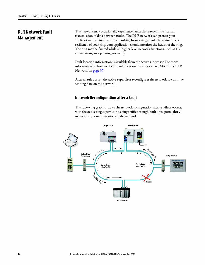
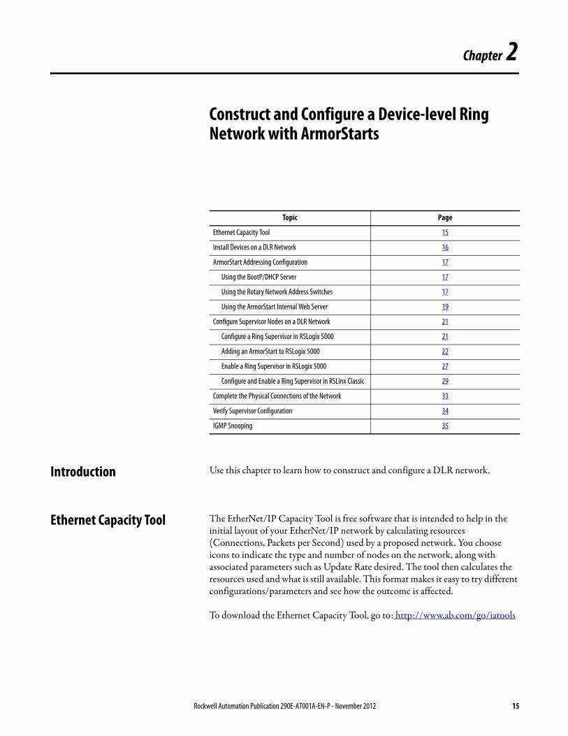

Chapter 2 Construct and Configure a Device-level Ring Network with ArmorStarts
Install Devices on a DLR Network
The next step to configure a DLR network is to connect all devices to the network One connection should be left unmade That is temporarily omit the physical connection between two nodes on the ring network because the factory default settings of DLR devices are set to operate in linearstar mode or as ring nodes on existing DLR networks
For more information on installing the EtherNetIP network (cable requirements maximum distance etchellip) refer to the EtherNetIP Media Planning and Installation Manual which can be downloaded here
httpliteraturerockwellautomationcomidcgroupsliteraturedocumentsrmenet-rm002_-en-ppdf
Figure 3 - Example Device-level Ring Topology with One Connection Left Unmade
Use the installation instructions below for each device to connect it to the network Publication Numbers can be downloaded at httpwwwrockwellautomationcomliteratureliteraturehtml
IMPORTANT If your DLR network is fully connected without a supervisor configured a network storm may result rendering the network unusable until one link is disconnected and at least one supervisor is enabled
Description Installation Instructions CatNo
ControlLogix EtherNetIP module 1756-IN612 1756-EN2TR
EtherNetIP tap 1783-IN007 1783-ETAP
ArmorStart LT Motor Controller 290-UM001 291E-FAZ-G2
ArmorStart Motor Controller 280G-UM001 280E-F12Z-10A-CR-3
Stratix 6000 Ethernet Switch 1783-IN004 1783-EMS08TA
16 Rockwell Automation Publication 290E-AT001A-EN-P - November 2012
Construct and Configure a Device-level Ring Network with ArmorStarts Chapter 2
ArmorStart Addressing Configuration
Before using the ArmorStart in an EtherNetIP network an IP address subnet mask and optional Gateway address must be configured This section describes how to set up the IP Address of an ArmorStart in three different ways using the BootPDHCP Server the Rotary Network Address Switches and the internal web server
Note When using the AOP it is not configuring the IP Address of the ArmorStart it is just assigning the same IP address that was set-up using the Rotary Network Address Switches or the web page so that communication is established
Using the BootPDHCP Server
The Rockwell Automation BootPDHCP utility is a standalone program that incorporates the functionality of standard BootP software with a user-friendly graphical interface It is located in the Utils directory on the RSLogix 5000 installation CD The ArmorStart EtherNetIP adapter must have DHCP enabled (factory default) to use the utility
DHCP (Dynamic Host Configuration Protocol) software automatically assigns IP addresses to client stations logging onto a TCPIP network When DHCP is enabled (factory default enabled) the unit will request its network configuration from a BootPDHCP server Any configuration received from a DHCP server will be stored in non-volatile memory The ArmorStart EtherNetIP will remember the last successful address if the DHCP is enabled The possibility exists that the adapter will be assigned a different IP address which would cause the adapter to stop communicating with the ControlLogix controller
Using the Rotary Network Address Switches
The three rotary network address switches can be found on the IO section of the ArmorStart The rotary network address switches are set to 999 and the DHCP is enabled as the factory default The ArmorStart reads these switches first to determine if the switches are set to a valid IP address between 1hellip254 When switches are set to a valid number the IP address will be 1921681_ _ _ [switch setting]
RJ45 ndash RJ45 Ethernet cable ENET-IN001A 1585J-M8PBJM-2
RJ45 ndash M12 Ethernet cable ENET-IN001A 1585D-M4TBJM-1
M12 ndash M12 Ethernet cable ENET-IN001A 1585D-M4TBDE-2
Description Installation Instructions CatNo
Rockwell Automation Publication 290E-AT001A-EN-P - November 2012 17
Chapter 2 Construct and Configure a Device-level Ring Network with ArmorStarts
To set up the IP Address using the rotary network address switches
1 Remove the protective caps from the rotary switches
2 Set the Network IP address by adjusting the three switches on the front of the IO module using a flat head screwdriver
3 Set up the switches in a range from 001 to 254 In this example they are set to a1 When the switches are set to a valid number the adapterrsquos IP address will be 1921681xxx (where xxx represents the number set on the switches) In this example the IP address is 1921681163 The adapterrsquos subnet mask will be 2552552550 and the gateway address is set to 0000 A power cycle or a type 1 network reset is required for any new IP address switch setting to take effect
Note The user cannot change the IP address from 1921681xxx when using the IP address switches The top three octets are fixed DHCP or the embedded web server must be used to configure the address to a value different than 1921681xxx Also the adapter will not have a host name assigned or use any Domain name System when using the rotary switch settings
4 If the switches are set to an invalid value (such as 000 or value greater than 254) the adapter will check to see if the DHCP is enabled If so the adapter requests an address from a DHCP server The DHCP server will also assign other Transport Control Protocol (TCP) parameters If DHCP is not enabled the adapter will use the IP address (along with other TCP configurable parameters) stored in nonvolatile memory
18 Rockwell Automation Publication 290E-AT001A-EN-P - November 2012
Construct and Configure a Device-level Ring Network with ArmorStarts Chapter 2
Using the ArmorStart Internal Web Server
Rockwell Automation provides an internal embedded web server with each EtherNetIP version of ArmorStart The internal web server allows you to view information and configure the ArmorStart via a web browser The internal web server can be used to set up the ArmorStart IP address by performing the following this steps
1 Open your preferred internet web browser
2 Enter the IP address of the desired ArmorStart For this example use 1921681163
Note 1921681163 is not the factory default IP address
3 The web server shown below should appear in your web browser
Rockwell Automation Publication 290E-AT001A-EN-P - November 2012 19
Chapter 2 Construct and Configure a Device-level Ring Network with ArmorStarts
4 Click in the administrative settings folder to expand it and the following is displayed
5 Click in the Network Configuration tab and a prompt to enter a User Name and a Password is displayed Enter the pre-set User Name and Password or if they have not been set up previously use the default User Name The default User Name is Administrator and there is no password set by default
6 After the appropriate User Name and Password is entered the screen below is displayed From this screen the Ethernet Configuration can be changed For example the default IP address shown is changed from 1921681163 to 101010101 After a power cycle the new address must be used to access the web page and the other devices on the network would also require their IP addresses to be reconfigured
20 Rockwell Automation Publication 290E-AT001A-EN-P - November 2012
Construct and Configure a Device-level Ring Network with ArmorStarts Chapter 2
Configure Supervisor Nodes on a DLR Network
After the devices are installed on the DLR network at least one supervisor node must be configured Ring nodes do not require any DLR network configuration
Before a DLR network can be completed (install your devices on the network and make all physical connections) a ring supervisor must be configured and enabled in
bull RSLogix 5000 programming software orbull RSLinx Classic communication software
This section shows how to use RSLogix 5000 programming software beginning on page 22 and RSLinx Classic communication software beginning on page 29 to configure and enable a ring supervisor
Configure a Ring Supervisor in RSLogix 5000 Programming Software
To configure the 1756-EN2TR module or the 1783-ETAP 1783-ETAP1F or 1783-ETAP2F taps as a ring supervisor use the devicersquos Add-on Profile (AOP) in RSLogix 5000 programming software version 1701 or later
For more information regarding the Required Add-On Profile Revision required go to Appendix B
To configure a ring supervisor in RSLogix 5000 programming software follow these steps
IMPORTANT The steps to configure a ring supervisor via software are basically the same for the 1756-EN2TR module and the 1783-ETAP 1783-ETAP1F and 1783-ETAP2F taps This example shows how to configure the 1756-EN2TR moduleOnly the 1783-ETAP 1783-ETAP1F and 1783-ETAP2F taps in the IO Configuration must be configured if you plan to enable the tap as a ring supervisor If the tap will not be used as a ring supervisor we recommend that it is not added to the IO ConfigurationAdditionally to configure a 1783-ETAP 1783-ETAP1F or 1783-ETAP2F tap as a supervisor via software or with its DIP switches an IP address must first be assigned The tap does not require an IP address if it is used as a ring node or has its supervisor function enabled by a DIP switchFor more information on how to use a tap switch to configure it as a ring supervisor see Chapter 5 in the EtherNetIP Embedded Switch Technology Manual To download the manual go to httpliteraturerockwellautomationcomidcgroupsliteraturedocumentsapenet-ap005_-en-ppdf
Rockwell Automation Publication 290E-AT001A-EN-P - November 2012 21
Chapter 2 Construct and Configure a Device-level Ring Network with ArmorStarts
Adding an Armorstart to RSLogix 5000
This section will show how to add an ArmorStart to RSLogix 5000
1 Open RSLogix 5000
2 Select File gt New to create a new project
3 Enter the name of the project and select your controller from the Type drop down menu For this example a 1756-L63 and software revision 20 will be used Then click OK
22 Rockwell Automation Publication 290E-AT001A-EN-P - November 2012
Construct and Configure a Device-level Ring Network with ArmorStarts Chapter 2
4 Add the 1756-EN2TR module to your projecta Right-click 1756 Backplane and choose New Module
Rockwell Automation Publication 290E-AT001A-EN-P - November 2012 23
Chapter 2 Construct and Configure a Device-level Ring Network with ArmorStarts
b Select the modulec Click Create
5 To add a new module to the tree right-click on Ethernet and select New Module This allows a new ArmorStart to be added to the Logix Project
24 Rockwell Automation Publication 290E-AT001A-EN-P - November 2012
Construct and Configure a Device-level Ring Network with ArmorStarts Chapter 2
6 Select the ArmorStart in your application and click OK
7 Enter a Name for this ArmorStart and an Ethernet address For this example the Private Network setting will be used This should be set to match the IP address switch setting on the ArmorStart Then press OK
Note Refer to ArmorStart Addressing Configuration on page 17 to set an IP address on the device
Rockwell Automation Publication 290E-AT001A-EN-P - November 2012 25
Chapter 2 Construct and Configure a Device-level Ring Network with ArmorStarts
8 Complete configuration information for the module in your RSLogix 5000 project
The following graphic shows the IO configuration for an example DLR network
9 Download the program to the Logix controller
10 Go online with the controller and leave it in Program mode
26 Rockwell Automation Publication 290E-AT001A-EN-P - November 2012
Construct and Configure a Device-level Ring Network with ArmorStarts Chapter 2
Enable Ring Supervisor in RSLogix 5000 Programming Software
After 1756-EN2TR module or 1783-ETAP 1783-ETAP1F or 1783-ETAP2F taps have been added to your RSLogix 5000 programming software project the ring supervisor mode must be enabled
If using RSLogix 5000 programming software to configure the ring supervisor and monitor diagnostics on the DLR network the controller must be online
To enable the 1756-EN2TR module or 1783-ETAP 1783-ETAP1F or 1783-ETAP2F tap as a ring supervisor follow these steps
The steps to enable a ring supervisor are basically the same for the 1756-EN2TR module or 1783-ETAP 1783-ETAP1F or 1783-ETAP2F tap This example shows how to do it for the 1756-EN2TR module
1 For your project online with the controller double-click on a supervisor-capable device in the IO configuration tree
Rockwell Automation Publication 290E-AT001A-EN-P - November 2012 27
Chapter 2 Construct and Configure a Device-level Ring Network with ArmorStarts
2 Click the Network tab to Enable Supervisor Mode
Configuration takes effect immediately you do not need to click Apply or OK
3 Click the Advanced button on the Network tab
4 Configure supervisor-related parameters as shown in the screen shot below
For these parameters you must click Set after entering a value
5 Click Set
28 Rockwell Automation Publication 290E-AT001A-EN-P - November 2012
Construct and Configure a Device-level Ring Network with ArmorStarts Chapter 2
Configure and Enable a Ring Supervisor in RSLinx Classic Communication Software
A ring supervisor can be configured for the DLR network through RSLinx Classic communication software
For more information regarding the Required RSLinx Classic Communication software Revision required refer to Appendix B
To configure a ring supervisor in RSLinx Classic Communication Software follow these steps
This example is for the 1783-ETAP tap Follow these steps
1 Launch RSLinx Classic Communication Software
2 Browse to the DLR network that is being set up
IMPORTANT For Beacon Interval Beacon Timeout and Ring Protocol VLAN ID we recommend that the default values be used
Functionality Description Default Setting
Supervisor Precedence A supervisor precedence number may be configured for each device that is configured as a ring supervisor The highest possible supervisor precedence value is 255When multiple nodes are enabled as supervisors the node with the highest precedence value is assigned as the active ring supervisor the other nodes automatically become back-up supervisorsWe recommend that youbull configure at least one back-up supervisor nodebull set the desired Active Ring Supervisor with a relatively high supervisor-
precedence value compared to the back-up node(s)bull keep track of the networkrsquos supervisor-precedence valuesIf multiple supervisors are configured with the same precedence value (the factory default value for all supervisor-capable devices is 0) the node with the numerically highest MAC address becomes the active supervisor
0
Beacon Interval Beacon interval is the frequency of the active ring supervisor transmitting a beacon frame through both of its Ethernet ports This parameter is user configurable for any time between 200 μS and 100 mSFor more information on how this parameter relates to network performance see page 61
400 μS
Beacon Timeout The beacon timeout is the amount of time that nodes wait before timing out the reception of beacon frames and taking appropriate action Supervisors support a range from 400μS to 500mSFor more information on how this parameter relates to network performance see page 61
1960 μS
Ring Protocol VLAN ID Reserved for future use 0
Rockwell Automation Publication 290E-AT001A-EN-P - November 2012 29
Chapter 2 Construct and Configure a Device-level Ring Network with ArmorStarts
If the Electronic Data Sheet (EDS) file is not installed on the module configured to be the ring supervisor it will appear with a question mark () To obtain and use the EDS file
bull right-click the module and choose to upload the EDS file from the device or
bull download the EDS file from httpwwwrockwellautomationcomrockwellautomationsupportnetworksedspage
3 Access the supervisor-capable nodersquos propertiesa Right-click the nodeb Choose Module Configuration
The General tab appears with information about the module
4 Click the Network tab to Enable Supervisor Mode
Configuration takes effect immediately there is no need to click Apply or OK
30 Rockwell Automation Publication 290E-AT001A-EN-P - November 2012
Construct and Configure a Device-level Ring Network with ArmorStarts Chapter 2
5 Click the Advanced button to configure supervisor-related parameters
Rockwell Automation Publication 290E-AT001A-EN-P - November 2012 31
Chapter 2 Construct and Configure a Device-level Ring Network with ArmorStarts
IMPORTANT For Beacon Interval Beacon Timeout and Ring Protocol VLAN ID use the default values
Functionality Description Default Setting
Supervisor Precedence
You may configure a supervisor precedence number for each device configured as a ring supervisor The highest possible supervisor precedence value is 255When multiple nodes are enabled as supervisor the node with the highest precedence value is assigned as the active ring supervisor the other nodes automatically become back-up supervisorsWe recommend that youbull configure at least one back-up supervisor nodebull set the desired Active Ring Supervisor with a relatively high supervisor-
precedence value compared to the back-up node(s)bull keep track of the networkrsquos supervisor-precedence valuesIf multiple supervisors are configured with the same precedence value (the factory default value for all supervisor-capable devices is 0) the node with the numerically highest MAC address becomes the active supervisor
0
Beacon Interval Beacon Interval is the frequency to which the active ring supervisor transmits a beacon frame through both of its Ethernet ports This parameter is user configurable for any time between 200 μS and 100 mSFor more information on how this parameter relates to network performance see page 58
400 μS
Beacon Timeout The beacon timeout is amount of time nodes wait before timing out the reception of beacon frames and taking appropriate action Supervisors support a range from 400 μS to 500 mSFor more information on how this parameter relates to network performance seepage 58
1960 μS
Ring Protocol VLAN ID
Reserved for future use 0
Enable IGMP Snooping
For more information on IGMP Snooping see page 35 Enabled
Enable IGMP Querier
For more information on IGMP Querier see page 35 Disabled
Enable Device Port Debugging Mode
For more information on Device Port Debugging Mode see page 59 Disabled
32 Rockwell Automation Publication 290E-AT001A-EN-P - November 2012
Construct and Configure a Device-level Ring Network with ArmorStarts Chapter 2
Complete the Physical Connections of the Network
After the ring supervisor nodes are configured and enabled the physical connection of the network must be completed to establish a complete DLR network
The figure below shows an example DLR network with all physical connections complete
Figure 4 - Example Device-level Ring Topology with All Connections Complete
Rockwell Automation Publication 290E-AT001A-EN-P - November 2012 33
Chapter 2 Construct and Configure a Device-level Ring Network with ArmorStarts
Verify Supervisor Configuration
The configuration and overall DLR network status can be verified in either RSLogix 5000 programming software or RSLinx Classic communication software
1 Access the supervisor nodersquos properties as shown previously in this chapter
2 Click the Network tab
3 Check the Network Topology and Network Status Fields
For a 1756-EN2TR module or the 1783-ETAP 1783-ETAP1F and 1783-ETAP2F tap the supervisor configuration can also be verified through the modulersquos diagnostic web pages For more information on monitoring diagnostics via an EtherNetIP modulersquos web pages see Monitor a DLR Network starting on page 37
34 Rockwell Automation Publication 290E-AT001A-EN-P - November 2012
Construct and Configure a Device-level Ring Network with ArmorStarts Chapter 2
IGMP Snooping This functionality is enabled by default in the 1783-ETAP 1783-ETAP1F and 1783-ETAP2F taps and is commonly used to manage multicast traffic on the network When in use this functionality allows the tap to multicast data to only those devices that need the data rather than to all devices connected to the network
For snooping to work there must be a device present that is running a querier Typically the device is a router or a switch such as the Stratix 6000 Stratix 8000 or Stratix 8300 managed switch
Once DHCP is enabled the switch could change the IP addresses on the ArmorStarts depending on network demand which could cause RSlogix5000 to loose communication with the device as connectivity is established via the AOP in the initial configuration
IGMP Querier This functionality is disabled by default The IGMP Querier functionality enables a 1783-ETAP 1783-ETAP1F or 1783-ETAP2F tap or switch such as a Stratix managed switch to send out a query to all devices on the network It determines what multicast addresses are of interest to a specific node or a group of nodes
The IGMP Querier functionality should be enabled for at least one node on the network The 1783-ETAP 1783-ETAP1F or 1783-ETAP2F tap managed switches and routers are examples of devices that support IGMP Querier functionality
IMPORTANT If DHCP for the Armostart is still required the Internet Group Management Protocol (IGMP) snooping on the E-tap must be disabled via the AOP
IMPORTANT If the IGMP Querier functionality is not enabled for at least one node on the network multicast traffic on the network may eventually create network performance issues
Rockwell Automation Publication 290E-AT001A-EN-P - November 2012 35
Chapter 2 Construct and Configure a Device-level Ring Network with ArmorStarts
However for all devices that are configured on the network with the IGMP Querier parameter enabled an IP address other than the factory default value must also be set for those devices If multiple devices on the network enable this functionality only the node with the lowest IP address becomes the active IGMP Querier node
IGMP Version
If the IGMP Querier is enabled a Querier Version must be selected The default version is Version 2
36 Rockwell Automation Publication 290E-AT001A-EN-P - November 2012
Chapter 3
Monitor a DLR Network
Introduction Use this chapter to learn how to monitor the DLR network
Methods to Monitor a DLR Network
Network diagnostic information can be retrieved from the ring supervisor-capable devices using the following
bull RSLogix 5000 programming software status pages
bull RSLinx communication software status pages
bull Device web pages
bull EtherNetIP Device Level Ring (DLR) network diagnostics faceplate
bull Programmatically through the use of a MSG instruction
RSLogix 5000 Programming Software Status Pages
RSLogix 5000 programming software version 1701 or later must be used and the appropriate AOPs installed to use the softwarersquos profile status pages
RSLinx Communication Software Status Pages
To monitor the network with this method the RSLinx communication software version 255 or later must be used
Topic Page
Methods to Monitor a DLR Network 37
Monitor Status Pages 39
Monitor ArmorStart Internal Web Server 44
Monitor via Faceplate Integration 45
Monitor Diagnostics via MSG Instructions 46
Rockwell Automation Publication 290E-AT001A-EN-P - November 2012 37
Chapter 3 Monitor a DLR Network
ArmorStart Internal Web Server
Rockwell Automation provides an internal embedded web server with each ArmorStart EtherNetIP The internal web server allows you to view information and configure the ArmorStart via a web browser The ArmorStart EtherNetIP can also be set up from the web server to send e-mail notifications The embedded web server is used to access configuration and status data It provides the user with the ability to view and modify the device configuration without having access to RSLogix 5000 Security in the form of an administrative password can be set The default login is Administrator There is no password set by default
EtherNetIP Device Level Ring (DLR) Network Diagnostics Faceplate
The diagnostics faceplate contains two major components
bull Logic code (encapsulated in an Add-On Instruction) that allows the controller to retrieve real-time DLR network status information
bull HMI faceplate graphics to allow the data to be visualized on an operator interface
Programmatically Through the Use of a MSG Instruction
For more information on how to monitor the DLR network via MSG Instructions see page 46
38 Rockwell Automation Publication 290E-AT001A-EN-P - November 2012
Monitor a DLR Network Chapter 3
Monitor Status Pages Both RSLogix 5000 programming software and RSLinx Classic communication software offer status pages that can be used to monitor the networkrsquos performance
RSLogix 5000 Programming Software Status Pages
Monitor the networkrsquos diagnostic information through the RSLogix 5000 programming software when the software is online
To monitor the network in RSLogix 5000 programming software follow these steps
1 Verify that the project is online
2 Access the active supervisor nodersquos propertiesa Right-click the modulersquos entry in the Controller Organizerb Click properties
Rockwell Automation Publication 290E-AT001A-EN-P - November 2012 39
Chapter 3 Monitor a DLR Network
3 Use the Network tab to monitor diagnostics
40 Rockwell Automation Publication 290E-AT001A-EN-P - November 2012
Monitor a DLR Network Chapter 3
RSLinx Communication Software
To monitor the network in RSLinx communication software follow these steps
1 Click RSWho to browse the network
2 Access the property pages for the active supervisor nodea Open the driver that shows the nodes on the DLR networkb Right-click the node that you want to monitor performancec Click on the choice that you need to access
Multiple choices appear
These options are shown in the following sections
Rockwell Automation Publication 290E-AT001A-EN-P - November 2012 41
Chapter 3 Monitor a DLR Network
Module Configuration
This series of tabs providesbull General informationbull Connection informationbull Module informationbull Internet protocolbull Port configurationbull Network information
The example below shows a ring fault between nodes at IP addresses 10888021 and MAC ID 00-00-BC-02-48-D5
42 Rockwell Automation Publication 290E-AT001A-EN-P - November 2012
Monitor a DLR Network Chapter 3
There are multiple fields used to monitor network diagnostics
Field Definition
Network Topology Possible values here can be Linear or Ring
Network Status Displays if the network is operating normally (Normal) or has experienced a fault (Ring Fault) as shown in the previous example screen
Active Ring Supervisor Displays the IP address or MAC address of the active ring supervisor
Active Supervisor Precedence For more information on this field see Active Ring Supervisor on page 11
Enable Ring Supervisor Configurable field that lets you to set the node as a ring supervisor
Ring Faults Detected Number of faults detected on the network since the last module power cycle or counter reset
Supervisor Status Displays whether this node is the active ring supervisor (Active) a back-up supervisor (Back-up) a ring node or part of a linear network
Last Active Node on Port 1 The last node the active ring supervisor can communicate with on Port 1 This value is an IP address or a MAC ID and remains latched until the Verify Fault Location button is clicked
Last Active Node on Port 2 The last node the active ring supervisor can communicate with on Port 2 This value is an IP address or a MAC ID and remains latched until the Verify Fault Location button is clicked
Status Displays whether a fault exists on the ring
IMPORTANT If the Network Topology field = Ring and the Network Status field = Normal the Last Active Node fields will display the last fault information even though it has been correctedTo clear the last fault information from these fields click Verify Fault Location You may see a message informing you that the supervisor is no longer in fault mode and the fields will be cleared
Rockwell Automation Publication 290E-AT001A-EN-P - November 2012 43
Chapter 3 Monitor a DLR Network
How to Access the ArmorStart EtherNetIP Internal Web Server
Open your preferred internet web browser and enter the IP address of the desired ArmorStart For this example 192168122 will be used
Use the links on the left-most navigation bar to see each available web page The screen below shows Ring Statistics for the ArmorStart 280E
44 Rockwell Automation Publication 290E-AT001A-EN-P - November 2012
Monitor a DLR Network Chapter 3
EtherNetIP Device Level Ring (DLR) Network Diagnostics Faceplate Overview
The EtherNetIP Device Level Ring (DLR) network diagnostics faceplate provides basic DLR network status information to the user to assist with monitoring and troubleshooting a DLR network
The diagnostics faceplate contains two major components
bull Logic code (encapsulated in an Add-On Instruction) that allows the controller to retrieve real-time DLR network status information
bull HMI faceplate graphics to allow the data to be visualized on an operator interface
The DLR diagnostics faceplate application can be downloaded from the Rockwell Automation Sample Code website at httpsamplecoderockwellautomationcom
Besides the individual Logix and View project components a demo application is also included with the downloaded file
Rockwell Automation Publication 290E-AT001A-EN-P - November 2012 45
Chapter 3 Monitor a DLR Network
Monitor Diagnostics via MSG Instructions
Network diagnostic information can also be obtained programmatically via MSG instructions in RSLogix 5000 programming software For example you can
bull Get all ring diagnostic informationbull Get a ring participant listbull Get the active supervisorbull Clear rapid ring faultsbull Verify a fault locationbull Reset a fault counterbull Enable and configure a ring supervisor
This information can be displayed on an HMI device or manipulated in the project code
Figure 5 - Example Use of MSG Instruction
This example describes how to retrieve diagnostic information from the DLR network Follow these steps
1 Enter a MSG instruction into the rung of logic
2 Configure the MSG instruction to retrieve ring diagnostic information service as shown in the following screen shots
IMPORTANT Make sure the tag created is sized appropriately to hold all of the data that you are reading or writing For more information see page 48
46 Rockwell Automation Publication 290E-AT001A-EN-P - November 2012
Monitor a DLR Network Chapter 3
3 Configure the MSG instructionrsquos communication path to point to the active supervisor node
The path on the following screen is one example path
IMPORTANT When using the Custom Get_Attributes_All (01) service pointing to an active supervisor node will retrieve all of the attributes listed in Retrieve All Diagnostic Information Attribute Description on page 50Pointing to a non-supervisor node will retrieve only the Network Topology and Network Status attribute informationPointing to backup supervisor node will retrieve the current active supervisorrsquos IP address
Rockwell Automation Publication 290E-AT001A-EN-P - November 2012 47
Chapter 3 Monitor a DLR Network
Use Specific Values on the Configuration Tab
Use the values on the Configuration tab of your MSG instruction to perform specific services Sample DLR network diagnostic application code for example Add-on Instruction or HMI faceplate graphics is available on the Rockwell Automation Sample Code Library For more information about the Rockwell Automation Sample Code Library see httpwwwrockwellautomationcomsolutionsintegratedarchitectureresources5html
➊ This request only works if there are fewer than 40 nodes on the network If there are more nodes than will fit in a single message an error will be returned➋ Use a Destination Length of 54 bytes if using firmware revision 3x or later for the 1756-EN2TR module or firmware revision 2x or later for the 1783-ETAP
1783-ETAP1F or 1783-ETAP2F taps
Request Description Message Type
Service Type
Service Code (HEX)
Class (HEX)
Instance Attribute (HEX)
Source Element
Source Length (Bytes)
Destination Destination Length (bytes)
Retrieve All Ring Diagnostic Information
Information for this request is listed in Retrieve All Ring Diagnostic Information on page 49
CIP Generic Custom 1 47 1 NA LeftBlank
0 Tag 50or54 ➋
Request Ring Participant List ➊
Information for this request is listed in Request the Ring Participant List on page 51
CIP Generic Get Attribute Single
e 47 1 9 NA NA Tag 10node
Get Active Supervisor
Obtain the IP address and MAC ID of the active supervisor on the DLR network
CIP Generic Get Attribute Single
e 47 1 a NA NA Tag 10
Acknowledge Rapid Ring Faults Condition
Request supervisor to resume normal operation after encountering a rapid ring fault condition
CIP Generic Custom 4c 47 1 NA NA NA NA
Verify a Fault Location
Request supervisor to update Last Active Node values
CIP Generic 4b 47 1 NA NA NA NA NA
Reset the Ring Fault Counter
Reset the number of ring faults detected on the DLR network
CIP Generic Set Attribute Single
10 47 1 5 Tag 2 NA NA
Enable and Configure a Ring Supervisor
Information for this request is listed in Enable and Configure a Ring Supervisor on page 52
CIP Generic Set Attribute Single
10 47 1 4 Tag 12 NA NA
48 Rockwell Automation Publication 290E-AT001A-EN-P - November 2012
Monitor a DLR Network Chapter 3
Retrieve All Ring Diagnostic Information
By performing the Retrieve All Ring Diagnostic Information request on an active supervisor the MSG instruction returns the following information
➊ RSLogix 5000 programming software may display the value in this field as negative numbers To better understand the value we recommend you view it in HEX format
Destination Tag Attribute Name Description Possible Values
SINT [0] Network Topology Current network topology mode 0 = Linear
1 = Ring
SINT [1] Network Status Current status of the network 0 = Normal
1 = Ring Fault
2 = Unexpected Loop Detected
3 = Partial Network Fault
4 = Rapid FaultRestore Cycle
SINT [2] Ring Supervisor Status Ring supervisor active status flag 0 = Node is functioning as a backup
1 = Node is functioning as the active ring supervisor
2 = Node is functioning as a normal ring node
3 = Node is operating in a non-DLR topology
4 = Node cannot support the currently operating ring parameters thatis Beacon Interval andor Beacon Timeout
Ring Supervisor Config Ring Supervisor configuration parameters
SINT [3] Ring Supervisor Enable Ring supervisor enable flag 0 = Node is configured as a normal ring node (default configuration)
1 = Node is configured as a ring supervisor
SINT [4] Ring Supervisor Precedence Precedence value of a ring supervisor ➊ Valid value range = 0hellip255
0 = Default value
SINT [5-8] Beacon Interval Duration of ring beacon interval Valid value range = 200 μshellip100 ms
Default = 400 μs
SINT [9-12] Beacon Timeout Duration of ring beacon timeout Value value range = 400 μshellip500 ms
Default value = 1960 μs
SINT [13-14] DLR VLAN ID Valid ID to use in ring protocol messages Valid value range = 0hellip4094
Default value = 0
SINT [15-16] Ring Faults Count Number of ring faults since power up ➊
Rockwell Automation Publication 290E-AT001A-EN-P - November 2012 49
Chapter 3 Monitor a DLR Network
Retrieve All Diagnostic Information Attribute Description
➊ This destination tag is available only with the 1756-EN2TR module firmware revision 3x or later 1783-ETAP 1783-ETAP1F and 1783-ETAP2F taps firmware revisions 2x or later If using the 1783-ETAP tap firmware revision 1x your program does not include this destination tag
➋ RSLogix 5000 programming software may display the value in this field as negative numbers To better understand the value we recommend you view it in HEX format
Destination Tag Attribute Name Description Possible Values
Last Active Node on Port 1 Last active node at the end of the chain through port 1 of the active ring supervisor during a ring fault
SINT [17-20] Device IP address ➋ Any valid IP address value
A value = 0 indicates no IP address has been configured for the device
SINT [21-26] Device MAC address ➋ Any valid Ethernet MAC address
Last Active Node on Port 2 Last active node at the end of the chain through port 2 of the active ring supervisor during a ring fault
SINT [27-30] Device IP address ➋ Any valid IP address value
A value = 0 indicates no IP address has been configured for the device
SINT [31-36] Device MAC address ➋ Any valid Ethernet MAC address
SINT [37-38] Ring Protocol Participants Count
Number of devices in the ring protocol participants list
Active Supervisor Address IP andor Ethernet MAC address of the active ring supervisor
SINT [39-42] Supervisor IP address Any valid IP address value
A value = 0 indicates no IP address has been configured for the device
SINT [43-48] Supervisor MAC address Any valid Ethernet MAC address
SINT [49] Active Supervisor Precedence
Precedence value of the active ring supervisor
SINT [50-53]➊ Capability Flags Alerts you that the device is capable of operating as a supervisor and beacon-based ring node
0x22
50 Rockwell Automation Publication 290E-AT001A-EN-P - November 2012
Monitor a DLR Network Chapter 3
Request the Ring Participant List
When requesting the Ring Participant List service on the DLR network the MSG instruction returns the following information
Request the Ring Participant List Attribute Description
➊ This attribute will return an array of the data shown one entry for each node The Ring Protocol Participants Count attribute determines the number entries
➋ This tag displays only IP addresses for ring participants that have been configured with one For example you may have a 1783-ETAP tap connected to the network that has not been assigned an IP address In that case no address is shown for the 1783-ETAP tap
➌ RSLogix 5000 programming software may display the value in this field as negative numbers To better understand the value we recommend you view it in HEX format
➍ Unlike destination tag SINT [0-3] where IP addresses are displayed only for ring participants configured with an IP address this tag displays MAC addresses for all ring participants because every ring participant has a MAC address
Destination Tag Attribute Name Description Possible Values
Ring Protocol Participants List ➊
List of devices participating in ring protocol
SINT [0-3] Device IP address ➋➌ Any valid IP address value
A value = 0 indicates no IP address has been configured for the device
SINT [4-9] Device MAC address ➌➍ Any valid Ethernet MAC address
Rockwell Automation Publication 290E-AT001A-EN-P - November 2012 51
Chapter 3 Monitor a DLR Network
Enable and Configure a Ring Supervisor
When performing the Enable and Configure a Ring Supervisor request on a supervisor-capable device configure the MSG instruction with the following information
Enable and Configure a Ring Supervisor Attribute Description
➊ RSLogix 5000 programming software may display the value in this field as negative numbers To better understand the value we recommend you view it in HEX format
Source Tag Attribute Name Description Possible Values
Ring Supervisor Config Ring Supervisor configuration parameters
SINT [0] Ring Supervisor Enable Ring supervisor enable flag 0 = Node is configured as a normal ring node (default configuration)1 = Node is configured as a ring supervisor
SINT [1] Ring Supervisor Precedence Precedence value of a ring supervisor ➊
Valid value range = 0hellip2550 = Default value
SINT [2-5] Beacon Interval Duration of ring beacon interval
Valid value range = 200 μshellip100 000 μsDefault = 400 μs
SINT [6-9] Beacon Timeout Duration of ring beacon timeout ➊
Value value range = 400 μshellip500 000 μsDefault value = 1960 μs
SINT [10-11] DLR VLAN ID Valid ID to use in ring protocol messages ➊
Valid value range = 0hellip4094Default value = 0
52 Rockwell Automation Publication 290E-AT001A-EN-P - November 2012
Chapter 4
Troubleshoot a DLR Network
Introduction Use this chapter to learn how to troubleshoot the DLR network
General Solutions for Linear or DLR Networks
Before attempting to correct specific faults on the linear or DLR network we recommend that you first take the following actions when a fault appears
bull For a DLR networkndash Verify that at least one node has been configured as a supervisor
on the network and that Network Topology = Ringndash Verify that all cables on the network are securely connected
to each devicendash Verify that all devices that require an IP address have one assigned
correctlyndash Check the Network Status field on the active supervisor nodersquos status
page to determine the fault typebull For a linear network
ndash Verify that none of the nodes are configured as a supervisor on the network and that Network Topology = LinearIf any nodes on a linear network are configured as a supervisor it may impact communication to other devices connected to the network
ndash Verify that all cables on the network are securely connected to each device
ndash Verify that all devices that require an IP address have one assigned correctly
If the fault is not cleared after completing the actions listed above use the tables in the rest of this chapter to troubleshoot issues specific to a DLR network or a linear network
Topic Page
General Solutions for the Linear or DLR Networks 53
Duplicate IP Address Detection 54
Specific Issues on the DLR Network 55
Network Recovery Performance 58
Device Port Debugging Mode 59
Rockwell Automation Publication 290E-AT001A-EN-P - November 2012 53
Chapter 4 Troubleshoot a DLR Network
Duplicate IP Address Detection
Some EtherNetIP communication modules support duplicate IP address detection The module verifies that its IP address does not match any other network devicersquos IP address when performing either of these tasks
bull Connect the module to an EtherNetIP network
bull Change the modulersquos IP address
If the modulersquos IP address matches that of another device on the network the modulersquos EtherNetIP port transitions to Conflict mode In Conflict mode these conditions exist
bull OK status indicator is blinking red
bull Network (NET) status indicator is solid red
bull On some EtherNetIP communication modules the module status display indicates the conflict
The display scrollsOK ltIP_address_of_this_modulegt Duplicate IP
ltMac_address_of_duplicate_node_detectedgt
For example OK 108860196 Duplicate IP - 0000BC0234B4
bull On some EtherNetIP communication modules the modulersquos diagnostic webpage displays information about duplicate IP address detection
For more information on which EtherNetIP communication modules support displaying duplicate IP address on their diagnostic webpage see the Technical Note titled Logix modules Duplicate IP address detection enhancement 118216 in the Technical Support Knowledgebase available at httpwwwrockwellautomationcomknowledgebase
54 Rockwell Automation Publication 290E-AT001A-EN-P - November 2012
Troubleshoot a DLR Network Chapter 4
Specific Issues on the DLR Network
Use the following table to troubleshoot possible specific issues on the DLR or linear network that are not solved by the actions described on the previous page
Issue Description Solution
Supervisor Reports a Ring Fault A link on the DLR network may be brokenbull intentionally for example because of adding or deleting nodes but not making all
physical connections to restore the setup of the network withwithout the nodebull unintentionally for example because a cable is broken or a device malfunctionsWhen this fault occurs the adjacent nodes to the faulted part of the network are displayed in the Ring Fault group and the Network Status field = Ring FaultThe screen shot below shows the Ring Fault section with IP addresses appearing for the last active nodes The faulted node is between nodes 108880115 and 108880208 If the IP address of either node is not available the software will display the nodersquos MAC ID
Once the fault is corrected the ring is automatically restored and the Network Status field returns to Normal
Determine where the fault condition exists and correct itClick the Refresh Communication link as needed to update the Ring Fault information to determine where the fault condition existsFinally DevicePort Debugging Mode functionality on the 1783-ETAP tap may be used to analyze a suspicious nodeFor more information refer to Device Port Debugging Mode on page 59
Rockwell Automation Publication 290E-AT001A-EN-P - November 2012 55
Chapter 4 Troubleshoot a DLR Network
Issue Description Solution
Rapid Ring Fault When a Rapid Ring Fault occurs the following events occurbull The active supervisor will block traffic on port 2 resulting in possible network
segmentation that is some nodes may become unreachablebull The Link 2 status indicator on the active supervisor is offbull As soon as the fault occurs for both RSLogix 5000 programming software and
RSLinx communication software the Status field = Rapid FaultRestore Cycles
Any of the following may cause a Rapid Ring Faultbull 5 intentional disconnectionsreconnections of a node from the network within 30
secondsbull A duplex mismatch between two connected devicesbull Electromagnetic noise on the networkbull Unstable physical connections such as intermittent connectorsGiven the nature of a Rapid Ring Fault the Last Active Node information may not be accurate when a Rapid Ring Fault condition is present
Multiple possible solutions existbull For the disconnections and reconnections issue no
solution is requiredClear the fault after reconnecting the device to the network permanentlybull For the duplex mismatch issue reconfigure the duplex
parameters to make sure they match between the devices
bull For the electromagnetic noise issue determine where the noise exists and eliminate it or use a protective shield in that location
bull For the unstable connections issue determine where they exist on the network and correct them
bull Check the media counters for all devices on the network The device with the highest media counter count is most likely causing the Rapid Ring Fault
bull Remove devices from the network one by one If the Rapid Ring Fault disappears after a device is removed that device is causing the fault
bull DevicePort Debugging Mode functionality on the 1783-ETAP tap may be used to analyze a suspicious node
For more information refer to Device Port Debugging Mode on page 59bull Finally the Beacon Interval or Timeout configuration
may not be appropriate for the networkHowever if these values need to be changed we recommend that you contact Rockwell Automation technical supportOnce the fault is fixed click Clear Fault
56 Rockwell Automation Publication 290E-AT001A-EN-P - November 2012
Troubleshoot a DLR Network Chapter 4
Issue Description Solution
Partial Fault Condition A partial network fault occurs when traffic is lost in only one direction on the network because a ring member is not forwarding beacons in both directions for example a component failureThe active ring supervisor detects a partial fault by monitoring the loss of Beacon frames on one port and the fault location appears in the Ring Fault section of the Network tab When a partial fault is detected the active ring supervisor blocks traffic on one port At this point the ring is segmented due to the partial fault condition The nodes adjacent to the faulted part of the network are displayed in the Ring Fault group with either IP addresses or MAC IDs for each node displayedWhen this fault occurs the Network Status field = Partial Fault ConditionOnce the fault is corrected it automatically clears and the Network Status field returns to Normal
Determine where the fault condition exists and correct itAdditionally the DevicePort Debugging Mode functionality also known as Port Mirroring on a 1783-ETAP 1783-ETAP1F or 1783-ETAP2F tap may be used to analyze a suspicious nodeFor more information refer to Device Port Debugging Mode on page 59
Media Counter Errors or Collisions
The media counters screen displays the number of physical layer errors or collisions The screen below indicates where to check for errors encountered Error levels are displayed depending on what caused the error For example an Alignment Error is displayed in the Alignment Error field
On a DLR network it is not uncommon to see low levels of media counter errors For example if the network breaks a low level of media counter errors appears With a low level of media counter errors the value typically does not continuously increase and often clearsA high level of media counter errors typically continues to increase and does not clear For example there is a mismatch of speed between two linked nodes a high level of media counter errors appears steadily increasing and not clearingTo access the RSLinx screen above browse the network right-click on the device select Module Properties and click the Port Diagnostics tab
Some example solutions includebull Check for a mismatch of speed andor duplex between
two linked nodesbull Verify that all cables on the network are securely
connected to each devicebull Check for electromagnetic noise on the network If you
find it eliminate it or use a protective shield in that location
Rockwell Automation Publication 290E-AT001A-EN-P - November 2012 57
Chapter 4 Troubleshoot a DLR Network
Network Recovery Performance
When measuring the networkrsquos performance with regard to dealing with fault conditions consider the network recovery time Network recovery is the time for all of the following to take place
1 The supervisor node recognizes that a fault exists on the network
2 The supervisor node reconfigures the network because of the fault
3 The supervisor node communicates to the network nodes that a fault condition exists
4 The network nodes reconfigure themselves because of the fault
With the default beacon interval value of 400 mS and beacon timeout value of 1960 mS the worst-case time for network recovery times are
bull 2890 mS for a copper DLR network This recovery time is based on 100 m copper segments between nodes on the network
bull 3140 mS for a fiber-optic DLR network This recovery time is based on 2 kM fiber-optic cable segments between nodes on the network
When considering the values listed above keep in mind
bull Recovery time may actually occur faster than the times listed
bull The recovery times listed above assume that your networkrsquos nodes are operating at 100 Mbps speed and full-duplex mode We recommend that your nodes generally operate in this mode for DLR networks
bull If other node conditions exist such as a node operating at 10 Mbps full-duplex or 10100 Mbps half-duplex the recovery times will vary from the times listed above
If this is the case for your application the beacon interval and beacon timeout will need to be changed We recommend that you first contact Rockwell Automation technical support if these parameters need to be changed
bull The value assumes that the majority of the traffic on your network is EtherNetIP traffic
58 Rockwell Automation Publication 290E-AT001A-EN-P - November 2012
Troubleshoot a DLR Network Chapter 4
Device Port Debugging Mode
This functionality is disabled by default Device Port Debugging mode which is similar to port mirroring can be used to monitor data received on the 1783-ETAP 1783-ETAP1F or 1783-ETAP2F taprsquos two network ports Monitor the data over the device port to a device such as a personal computer running a protocol analyzer application for advanced network debugging or analysis
When device port debugging is used on a 1783-ETAP the device connected to the 1783-ETAP taprsquos front port receives all of the data traversing the ring (both directions)
Device Port Debugging Example Network
When using the Device Port Debugging mode functionality insert the 1783-ETAP with the network analyzer connected to the device port It is inserted at the spot on the ring network where the node in question is located The graphic below shows a 1783-ETAP tap inserted in the network
IMPORTANT This functionality should be used only when troubleshooting the network and not in normal network operation
Rockwell Automation Publication 290E-AT001A-EN-P - November 2012 59
Chapter 4 Troubleshoot a DLR Network
Combined total network bandwidth of the traffic received on the two 1783-ETAP 1783-ETAP1F or 1783-ETAP2F taprsquos ports connected to the network should not exceed the taprsquos device port capacity The speed setting determines the device portrsquos capacity
Configure the device port on a 1783-ETAP 1783-ETAP1F or 1783-ETAP2F tap to either of two speed settings
bull 100 Mbps - default settingbull 10 Mbps
If the bandwidth exceeds the capacity of the taprsquos device port some frames from the ring will be dropped before reaching the device port These dropped frames do not impact the traffic on the rest of the DLR network
The device port setting determines how much network traffic the 1783-ETAP 1783-ETAP1F or 1783-ETAP2F tap can handle before dropping frames The circled section in the graphic below shows the Port Buffer Utilization of the Device Port In this example the value is zero because a ring fault exists on the network
60 Rockwell Automation Publication 290E-AT001A-EN-P - November 2012
Appendix A
Network Usage Guidelines and Recommendations
Consider the following guidelines and recommendations when using a DLR or linear network
GuidelineRecommendation Explanation
Use fewer than 50 nodes on a single DLR networkIf your application requires more than 50 nodes we recommend that the nodes are broken into separate but linked DLR networks
If you use more than 50 nodes on a single DLR networkbull Your network has a greater chance of multiple faults
occurring on the networkbull Network recovery times from faulted DLR network
are higher
Do not configure a supervisor on a linear network If your linear network includes non-DLR nodes and has a supervisor-enabled node on the network it may impact communication to non-DLR devices connected to the linear network
If you must connect a device that is running at 10 Mbps to a DLR or linear network do so through a 1783-ETAP 1783-ETAP1F or 1783-ETAP2F tap device port
The 1783-ETAP 1783-ETAP1F and 1783-ETAP2F taps can operate at 100 Mbps on the DLR network this is the optimal speed for a network If you connect a 10 Mbps device directly to the network instead of through a tap the linear or DLR network traffic slows to 10 MbpsAdditionally if the 10 Mbps device is connected to the network without a 1783-ETAP tap network recovery times are significantly impacted
Configure multiple supervisor nodes per ring If your DLR network only has one supervisor and the supervisor experiences a fault none of the other nodes become the active supervisor In this case the network becomes a linear network until the fault is corrected and the DLR network restoredAnother reason to configure multiple supervisor nodes is for replacing an active supervisor node with an out-of-box replacement the new device will not be enabled as a supervisor (by default) and there would still be no supervisor on the network
Rockwell Automation Publication 290E-AT001A-EN-P - November 2012 61
Appendix A Network Usage Guidelines and Recommendations
GuidelineRecommendation Explanation
Connect switches to a DLR network via 1783-ETAP 1783-ETAP1F or 1783-ETAP2F taps
If switches are connected to the DLR network without the use of a 1783-ETAP 1783-ETAP1F or 1783-ETAP2F tap the network may experience unpredictable behavior and network performance is unknown
Run all nodes on the DLR network at 100 Mbps and in Full-Duplex mode
These configuration values provide the best performance for your networkAdditionally we recommend that youbull Use auto-negotiate for all nodes on the DLR networkbull Do not use auto-negotiate on one node and then force
speed on the next node linked to it
In a linear network the number of nodes to use is application specific based on the considerations described in the next box
When determining the number of nodes to use on a linear network consider the followingbull There is a delay per node as information is transmitted
to each successive node used on the networkndash The typical delay on a linear network with 100 m
copper segments between nodes is 30 mSndash The typical delay on a linear network with 2 kM
fiber-optic segments between nodes is 40 mS
The greater the number of nodes on the network the longer the total time for information to be transmitted across the entire networkbull The single point of failure possibility is greater with
each additional connectionbull Troubleshooting the network may be more difficult
with a higher number of nodes
The total time for information to be transmitted across the entire network and its effect on how many nodes to use on a linear network is related to the Requested Packet Interval (RPI)Verify that the total time to transmit information from the first node to the last node on the network is less than the RPI Make sure the network is not loaded beyond 90 of capacity
62 Rockwell Automation Publication 290E-AT001A-EN-P - November 2012
Network Usage Guidelines and Recommendations Appendix A
GuidelineRecommendation Explanation
Do not physically close a DLR network without a supervisor configured on the network
A DLR network without a supervisor node results in a network stormIf you do close the DLR network without a supervisor configured break the ring and configure at least one supervisor before physically reconnecting the network
Use the default values for the followingbull Beacon Intervalbull Beacon Timeoutbull Ring Protocol VLAN ID
Changing the default values for the parameters Beacon Interval Beacon Timeout and Ring Protocol VLAN ID can result in unpredictable network behavior and negatively impacted network performanceThe default values are optimized for a network withbull 50 or fewer nodes are on the networkbull All nodes are operating at 100 Mbps and full-duplex
modebull At least 50 of the network traffic bandwidth being
EtherNetIP trafficIf you think the values of the Beacon Interval Beacon Timeout or Ring Protocol VLAN ID need to be changed for example if any node on ring is not operating at 100 Mbps and full-duplex mode we recommend that you first contact Rockwell Automation technical support
If DHCP for the ArmorStarts is still required you will need to disable Internet Group Management Protocol (IGMP) snooping on the E-tap via the AOP
IGMP Snooping is enabled by default in the 1783-ETAP 1783-ETAP1F and 1783-ETAP2F taps and is commonly used to manage multicast traffic on the network When in use this functionality allows the tap to multicast data to only those devices that need the data rather than to all devices connected to the networkOnce DHCP is enabled the switch could change the IP addresses on the ArmorStarts depending on network demand which could cause RSlogix5000 to loose communication with the device as connectivity is established via the AOP in the initial configuration
The IGMP Querier functionality should be enabled for at least one node on the network
This functionality is disabled by default The IGMP Querier functionality enables a 1783-ETAP 1783-ETAP1F or 1783-ETAP2F tap or switch such as a Stratix managed switch to send out a query to all devices on the network to determine what multicast addresses are of interest to a specific node or a group of nodesIf the IGMP Querier functionality is not enabled for at least one node on the network multicast traffic on the network may eventually create network performance issuesThe 1783-ETAP 1783-ETAP1F or 1783-ETAP2F taps managed switches and routers are examples of devices that support IGMP Querier functionality
Rockwell Automation Publication 290E-AT001A-EN-P - November 2012 63
Appendix A Network Usage Guidelines and Recommendations
Notes
64 Rockwell Automation Publication 290E-AT001A-EN-P - November 2012
Appendix B
Required Firmware Revisions
Required Firmware Revision for an Add-On Profile
➊ The ControlFLASH Firmware Upgrade software tcan be used o upgrade a 1756-EN2TR module from firmware revision 21 to 3x or later1x or later3x or later2x or later
➋ The ControlFLASH Firmware Upgrade software can be used to upgrade a 1783-ETAP tap from firmware revision 11 to 2x or later
To download new firmware go to httpwwwrockwellautomationcomsupportamericasindex_enhtml
If the firmware revision is upgraded on the module or tap the required AOP revision listed above must be used for that revision For example if the 1756-EN2TR module is upgraded to firmware revision 3x or later AOP revision 2x or later must be used in the RSLogix 5000 programming software
Additionally if the firmware revision is upgraded on the module or tap the required RSLinx communication software must also be used for that firmware revision For more information on which RSLinx software version is required for each firmware revision see page 66
For both the 1756-EN2TR module and 1783-ETAP tap make sure that the Major Revision configured on the General tab of the devicersquos RSLogix 5000 programming software configuration matches the major revision of the physical module
IMPORTANT To download an AOP go to httpsupportrockwellautomationcomcontrolflashLogixProfileraspDepending on the firmware revision of your product a specific AOP version must be used
Firmware Revision Add-On Profile Revision Cat No
21 ➊ 1x or later 1756-EN2TR
3x or later 2x or later
11 ➋ 1x or later 1783-ETAP
2x or later 2x or later
2x or later 2x or later 1783-ETAP1F
1783-ETAP2F
Rockwell Automation Publication 290E-AT001A-EN-P - November 2012 65
Appendix B Required Firmware Revisions
If the device configuration on the General tab does not match the physical module the programming software alerts you to this mismatch when attempting to configure the Internet Protocol Port Configuration and Network tabs for that device
Required Firmware Revision for RSLinx Communication Software
➊ The ControlFLASH Firmware Upgrade software can be used to upgrade a 1756-EN2TR module from firmware revision 21 to 3x or later1x or later3x or later255 or later3x or later256 or later
➋ The ControlFLASH Firmware Upgrade software can be used to upgrade a 1783-ETAP tap from firmware revision 11 to 2x or later
To download new firmware go to httpwwwrockwellautomationcomsupportamericasindex_enhtml
If the firmware revision is upgraded on the module or tap the required RSLinx communication software listed above must be used for that revision For example if the 1756-EN2TR module is upgraded to firmware revision 3x or later AOP revision 2x or later must be used in your RSLogix 5000 programming software
Additionally if the firmware revision is upgraded on the module or tap the required AOP revision must also be used for that firmware revision For more information on which AOP revision is required for each firmware revision see page 65
IMPORTANT Depending on the firmware revision of your product specific versions of RSLinx communication software must be used
Firmware Revision Required RSLinx Communication Software Version
Cat No
21 ➊ 255 or later 1756-EN2TR
3x or later 256 or later
11 ➋ 255 or later 1783-ETAP
2x or later 256 or later
2x or later 256 or later 1783-ETAP1F
1783-ETAP2F
66 Rockwell Automation Publication 290E-AT001A-EN-P - November 2012
Rockwell Otomasyon Ticaret AŞ Kar Plaza İş Merkezi E Blok Kat6 34752 İccedilerenkoumly İstanbul Tel +90 (216) 5698400
Rockwell Automation Publication 290E-AT001A-EN-P ndash November 2012 68 Copyright copy 2012 Rockwell Automation Inc All rights reserved Printed in the USA
Rockwell Automation Support
Rockwell Automation provides technical information on the Web to assist you in using its products At httpwwwrockwellautomationcomsupport you can find technical manuals a knowledge base of FAQs technical and application notes sample code and links to software service packs and a MySupport feature that you can customize to make thebest use of these tools
For an additional level of technical phone support for installation configuration and troubleshooting we offer TechConnectSM support programs For more information contact your local distributor or Rockwell Automation representative or visit httpwwwrockwellautomationcomsupport
Installation Assistance
If you experience a problem within the first 24 hours of installation review the information that is contained in this manualYou can contact Customer Support for initial help in getting your product up and running
New Product Satisfaction Return
Rockwell Automation tests all of its products to ensure that they are fully operational when shipped from the manufacturing facility However if your product is not functioning and needs to be returned follow these procedures
Documentation Feedback
Your comments will help us serve your documentation needs better If you have any suggestions on how to improve this document complete this form publication RA-DU002 available at httpwwwrockwellautomationcomliterature
United States or Canada 14406463434
Outside United States or Canada Use the Worldwide Locator at httpwwwrockwellautomationcomsupportamericasphone_enhtml or contact your local Rockwell Automation representative
United States Contact your distributor You must provide a Customer Support case number (call the phone number above to obtain one) to your distributor to complete the return process
Outside United States Please contact your local Rockwell Automation representative for the return procedure
- Important User Information
- General Precautions
- Software Requirements
- Additional Resources
- Rockwell Automation Support
- Installation Assistance
- New Product Satisfaction Return
- Table of Contents
- Chapter 1
-
- Device-Level Ring (DLR) Basics
-
- Introduction
- ArmorStart with EtherNetIP Overview
- What is a Device-level Ring (DLR) Network
- DLR Network Elements
-
- Supervisor Node
- Ring Node
-
- DLR Network Operation
- Number of Nodes on a DLR Network
- DLR Network Fault Management
-
- Network Reconfiguration after a Fault
-
- Chapter 2
-
- Construct and Configure a Device-level Ring Network with ArmorStarts
-
- Introduction
- Ethernet Capacity Tool
- Install Devices on a DLR Network
- ArmorStart Addressing Configuration
-
- Using the BootPDHCP Server
- Using the Rotary Network Address Switches
- Using the ArmorStart Internal Web Server
-
- Configure Supervisor Nodes on a DLR Network
-
- Configure a Ring Supervisor in RSLogix 5000 Programming Software
- Adding an Armorstart to RSLogix 5000
- Enable Ring Supervisor in RSLogix 5000 Programming Software
- Configure and Enable a Ring Supervisor in RSLinx Classic Communication Software
-
- Complete the Physical Connections of the Network
- Verify Supervisor Configuration
- IGMP Snooping
- IGMP Querier
-
- Chapter 3
-
- Monitor a DLR Network
-
- Introduction
- Methods to Monitor a DLR Network
-
- RSLogix 5000 Programming Software Status Pages
- RSLinx Communication Software Status Pages
- ArmorStart Internal Web Server
- EtherNetIP Device Level Ring (DLR) Network Diagnostics Faceplate
- Programmatically Through the Use of a MSG Instruction
-
- Monitor Status Pages
-
- RSLogix 5000 Programming Software Status Pages
- RSLinx Communication Software
-
- How to Access the ArmorStart EtherNetIP Internal Web Server
-
- EtherNetIP Device Level Ring (DLR) Network Diagnostics Faceplate Overview
-
- Monitor Diagnostics via MSG Instructions
-
- Use Specific Values on the Configuration Tab
- Retrieve All Ring Diagnostic Information
- Retrieve All Diagnostic Information Attribute Description
- Request the Ring Participant List
- Request the Ring Participant List Attribute Description
-
- Enable and Configure a Ring Supervisor
-
- Enable and Configure a Ring Supervisor Attribute Description
-
- Chapter 4
-
- Troubleshoot a DLR Network
-
- Introduction
- General Solutions for Linear or DLR Networks
- Duplicate IP Address Detection
- Specific Issues on the DLR Network
- Network Recovery Performance
- Device Port Debugging Mode
-
- Device Port Debugging Example Network
-
- Appendix A
-
- Network Usage Guidelines and Recommendations
-
- Notes
-
- Appendix B
-
- Required Firmware Revisions
-
- Required Firmware Revision for an Add-On Profile
- Required Firmware Revision for RSLinx Communication Software
-

Construct and Configure a Device-level Ring Network with ArmorStarts Chapter 2
ArmorStart Addressing Configuration
Before using the ArmorStart in an EtherNetIP network an IP address subnet mask and optional Gateway address must be configured This section describes how to set up the IP Address of an ArmorStart in three different ways using the BootPDHCP Server the Rotary Network Address Switches and the internal web server
Note When using the AOP it is not configuring the IP Address of the ArmorStart it is just assigning the same IP address that was set-up using the Rotary Network Address Switches or the web page so that communication is established
Using the BootPDHCP Server
The Rockwell Automation BootPDHCP utility is a standalone program that incorporates the functionality of standard BootP software with a user-friendly graphical interface It is located in the Utils directory on the RSLogix 5000 installation CD The ArmorStart EtherNetIP adapter must have DHCP enabled (factory default) to use the utility
DHCP (Dynamic Host Configuration Protocol) software automatically assigns IP addresses to client stations logging onto a TCPIP network When DHCP is enabled (factory default enabled) the unit will request its network configuration from a BootPDHCP server Any configuration received from a DHCP server will be stored in non-volatile memory The ArmorStart EtherNetIP will remember the last successful address if the DHCP is enabled The possibility exists that the adapter will be assigned a different IP address which would cause the adapter to stop communicating with the ControlLogix controller
Using the Rotary Network Address Switches
The three rotary network address switches can be found on the IO section of the ArmorStart The rotary network address switches are set to 999 and the DHCP is enabled as the factory default The ArmorStart reads these switches first to determine if the switches are set to a valid IP address between 1hellip254 When switches are set to a valid number the IP address will be 1921681_ _ _ [switch setting]
RJ45 ndash RJ45 Ethernet cable ENET-IN001A 1585J-M8PBJM-2
RJ45 ndash M12 Ethernet cable ENET-IN001A 1585D-M4TBJM-1
M12 ndash M12 Ethernet cable ENET-IN001A 1585D-M4TBDE-2
Description Installation Instructions CatNo
Rockwell Automation Publication 290E-AT001A-EN-P - November 2012 17
Chapter 2 Construct and Configure a Device-level Ring Network with ArmorStarts
To set up the IP Address using the rotary network address switches
1 Remove the protective caps from the rotary switches
2 Set the Network IP address by adjusting the three switches on the front of the IO module using a flat head screwdriver
3 Set up the switches in a range from 001 to 254 In this example they are set to a1 When the switches are set to a valid number the adapterrsquos IP address will be 1921681xxx (where xxx represents the number set on the switches) In this example the IP address is 1921681163 The adapterrsquos subnet mask will be 2552552550 and the gateway address is set to 0000 A power cycle or a type 1 network reset is required for any new IP address switch setting to take effect
Note The user cannot change the IP address from 1921681xxx when using the IP address switches The top three octets are fixed DHCP or the embedded web server must be used to configure the address to a value different than 1921681xxx Also the adapter will not have a host name assigned or use any Domain name System when using the rotary switch settings
4 If the switches are set to an invalid value (such as 000 or value greater than 254) the adapter will check to see if the DHCP is enabled If so the adapter requests an address from a DHCP server The DHCP server will also assign other Transport Control Protocol (TCP) parameters If DHCP is not enabled the adapter will use the IP address (along with other TCP configurable parameters) stored in nonvolatile memory
18 Rockwell Automation Publication 290E-AT001A-EN-P - November 2012
Construct and Configure a Device-level Ring Network with ArmorStarts Chapter 2
Using the ArmorStart Internal Web Server
Rockwell Automation provides an internal embedded web server with each EtherNetIP version of ArmorStart The internal web server allows you to view information and configure the ArmorStart via a web browser The internal web server can be used to set up the ArmorStart IP address by performing the following this steps
1 Open your preferred internet web browser
2 Enter the IP address of the desired ArmorStart For this example use 1921681163
Note 1921681163 is not the factory default IP address
3 The web server shown below should appear in your web browser
Rockwell Automation Publication 290E-AT001A-EN-P - November 2012 19
Chapter 2 Construct and Configure a Device-level Ring Network with ArmorStarts
4 Click in the administrative settings folder to expand it and the following is displayed
5 Click in the Network Configuration tab and a prompt to enter a User Name and a Password is displayed Enter the pre-set User Name and Password or if they have not been set up previously use the default User Name The default User Name is Administrator and there is no password set by default
6 After the appropriate User Name and Password is entered the screen below is displayed From this screen the Ethernet Configuration can be changed For example the default IP address shown is changed from 1921681163 to 101010101 After a power cycle the new address must be used to access the web page and the other devices on the network would also require their IP addresses to be reconfigured
20 Rockwell Automation Publication 290E-AT001A-EN-P - November 2012
Construct and Configure a Device-level Ring Network with ArmorStarts Chapter 2
Configure Supervisor Nodes on a DLR Network
After the devices are installed on the DLR network at least one supervisor node must be configured Ring nodes do not require any DLR network configuration
Before a DLR network can be completed (install your devices on the network and make all physical connections) a ring supervisor must be configured and enabled in
bull RSLogix 5000 programming software orbull RSLinx Classic communication software
This section shows how to use RSLogix 5000 programming software beginning on page 22 and RSLinx Classic communication software beginning on page 29 to configure and enable a ring supervisor
Configure a Ring Supervisor in RSLogix 5000 Programming Software
To configure the 1756-EN2TR module or the 1783-ETAP 1783-ETAP1F or 1783-ETAP2F taps as a ring supervisor use the devicersquos Add-on Profile (AOP) in RSLogix 5000 programming software version 1701 or later
For more information regarding the Required Add-On Profile Revision required go to Appendix B
To configure a ring supervisor in RSLogix 5000 programming software follow these steps
IMPORTANT The steps to configure a ring supervisor via software are basically the same for the 1756-EN2TR module and the 1783-ETAP 1783-ETAP1F and 1783-ETAP2F taps This example shows how to configure the 1756-EN2TR moduleOnly the 1783-ETAP 1783-ETAP1F and 1783-ETAP2F taps in the IO Configuration must be configured if you plan to enable the tap as a ring supervisor If the tap will not be used as a ring supervisor we recommend that it is not added to the IO ConfigurationAdditionally to configure a 1783-ETAP 1783-ETAP1F or 1783-ETAP2F tap as a supervisor via software or with its DIP switches an IP address must first be assigned The tap does not require an IP address if it is used as a ring node or has its supervisor function enabled by a DIP switchFor more information on how to use a tap switch to configure it as a ring supervisor see Chapter 5 in the EtherNetIP Embedded Switch Technology Manual To download the manual go to httpliteraturerockwellautomationcomidcgroupsliteraturedocumentsapenet-ap005_-en-ppdf
Rockwell Automation Publication 290E-AT001A-EN-P - November 2012 21
Chapter 2 Construct and Configure a Device-level Ring Network with ArmorStarts
Adding an Armorstart to RSLogix 5000
This section will show how to add an ArmorStart to RSLogix 5000
1 Open RSLogix 5000
2 Select File gt New to create a new project
3 Enter the name of the project and select your controller from the Type drop down menu For this example a 1756-L63 and software revision 20 will be used Then click OK
22 Rockwell Automation Publication 290E-AT001A-EN-P - November 2012
Construct and Configure a Device-level Ring Network with ArmorStarts Chapter 2
4 Add the 1756-EN2TR module to your projecta Right-click 1756 Backplane and choose New Module
Rockwell Automation Publication 290E-AT001A-EN-P - November 2012 23
Chapter 2 Construct and Configure a Device-level Ring Network with ArmorStarts
b Select the modulec Click Create
5 To add a new module to the tree right-click on Ethernet and select New Module This allows a new ArmorStart to be added to the Logix Project
24 Rockwell Automation Publication 290E-AT001A-EN-P - November 2012
Construct and Configure a Device-level Ring Network with ArmorStarts Chapter 2
6 Select the ArmorStart in your application and click OK
7 Enter a Name for this ArmorStart and an Ethernet address For this example the Private Network setting will be used This should be set to match the IP address switch setting on the ArmorStart Then press OK
Note Refer to ArmorStart Addressing Configuration on page 17 to set an IP address on the device
Rockwell Automation Publication 290E-AT001A-EN-P - November 2012 25
Chapter 2 Construct and Configure a Device-level Ring Network with ArmorStarts
8 Complete configuration information for the module in your RSLogix 5000 project
The following graphic shows the IO configuration for an example DLR network
9 Download the program to the Logix controller
10 Go online with the controller and leave it in Program mode
26 Rockwell Automation Publication 290E-AT001A-EN-P - November 2012
Construct and Configure a Device-level Ring Network with ArmorStarts Chapter 2
Enable Ring Supervisor in RSLogix 5000 Programming Software
After 1756-EN2TR module or 1783-ETAP 1783-ETAP1F or 1783-ETAP2F taps have been added to your RSLogix 5000 programming software project the ring supervisor mode must be enabled
If using RSLogix 5000 programming software to configure the ring supervisor and monitor diagnostics on the DLR network the controller must be online
To enable the 1756-EN2TR module or 1783-ETAP 1783-ETAP1F or 1783-ETAP2F tap as a ring supervisor follow these steps
The steps to enable a ring supervisor are basically the same for the 1756-EN2TR module or 1783-ETAP 1783-ETAP1F or 1783-ETAP2F tap This example shows how to do it for the 1756-EN2TR module
1 For your project online with the controller double-click on a supervisor-capable device in the IO configuration tree
Rockwell Automation Publication 290E-AT001A-EN-P - November 2012 27
Chapter 2 Construct and Configure a Device-level Ring Network with ArmorStarts
2 Click the Network tab to Enable Supervisor Mode
Configuration takes effect immediately you do not need to click Apply or OK
3 Click the Advanced button on the Network tab
4 Configure supervisor-related parameters as shown in the screen shot below
For these parameters you must click Set after entering a value
5 Click Set
28 Rockwell Automation Publication 290E-AT001A-EN-P - November 2012
Construct and Configure a Device-level Ring Network with ArmorStarts Chapter 2
Configure and Enable a Ring Supervisor in RSLinx Classic Communication Software
A ring supervisor can be configured for the DLR network through RSLinx Classic communication software
For more information regarding the Required RSLinx Classic Communication software Revision required refer to Appendix B
To configure a ring supervisor in RSLinx Classic Communication Software follow these steps
This example is for the 1783-ETAP tap Follow these steps
1 Launch RSLinx Classic Communication Software
2 Browse to the DLR network that is being set up
IMPORTANT For Beacon Interval Beacon Timeout and Ring Protocol VLAN ID we recommend that the default values be used
Functionality Description Default Setting
Supervisor Precedence A supervisor precedence number may be configured for each device that is configured as a ring supervisor The highest possible supervisor precedence value is 255When multiple nodes are enabled as supervisors the node with the highest precedence value is assigned as the active ring supervisor the other nodes automatically become back-up supervisorsWe recommend that youbull configure at least one back-up supervisor nodebull set the desired Active Ring Supervisor with a relatively high supervisor-
precedence value compared to the back-up node(s)bull keep track of the networkrsquos supervisor-precedence valuesIf multiple supervisors are configured with the same precedence value (the factory default value for all supervisor-capable devices is 0) the node with the numerically highest MAC address becomes the active supervisor
0
Beacon Interval Beacon interval is the frequency of the active ring supervisor transmitting a beacon frame through both of its Ethernet ports This parameter is user configurable for any time between 200 μS and 100 mSFor more information on how this parameter relates to network performance see page 61
400 μS
Beacon Timeout The beacon timeout is the amount of time that nodes wait before timing out the reception of beacon frames and taking appropriate action Supervisors support a range from 400μS to 500mSFor more information on how this parameter relates to network performance see page 61
1960 μS
Ring Protocol VLAN ID Reserved for future use 0
Rockwell Automation Publication 290E-AT001A-EN-P - November 2012 29
Chapter 2 Construct and Configure a Device-level Ring Network with ArmorStarts
If the Electronic Data Sheet (EDS) file is not installed on the module configured to be the ring supervisor it will appear with a question mark () To obtain and use the EDS file
bull right-click the module and choose to upload the EDS file from the device or
bull download the EDS file from httpwwwrockwellautomationcomrockwellautomationsupportnetworksedspage
3 Access the supervisor-capable nodersquos propertiesa Right-click the nodeb Choose Module Configuration
The General tab appears with information about the module
4 Click the Network tab to Enable Supervisor Mode
Configuration takes effect immediately there is no need to click Apply or OK
30 Rockwell Automation Publication 290E-AT001A-EN-P - November 2012
Construct and Configure a Device-level Ring Network with ArmorStarts Chapter 2
5 Click the Advanced button to configure supervisor-related parameters
Rockwell Automation Publication 290E-AT001A-EN-P - November 2012 31
Chapter 2 Construct and Configure a Device-level Ring Network with ArmorStarts
IMPORTANT For Beacon Interval Beacon Timeout and Ring Protocol VLAN ID use the default values
Functionality Description Default Setting
Supervisor Precedence
You may configure a supervisor precedence number for each device configured as a ring supervisor The highest possible supervisor precedence value is 255When multiple nodes are enabled as supervisor the node with the highest precedence value is assigned as the active ring supervisor the other nodes automatically become back-up supervisorsWe recommend that youbull configure at least one back-up supervisor nodebull set the desired Active Ring Supervisor with a relatively high supervisor-
precedence value compared to the back-up node(s)bull keep track of the networkrsquos supervisor-precedence valuesIf multiple supervisors are configured with the same precedence value (the factory default value for all supervisor-capable devices is 0) the node with the numerically highest MAC address becomes the active supervisor
0
Beacon Interval Beacon Interval is the frequency to which the active ring supervisor transmits a beacon frame through both of its Ethernet ports This parameter is user configurable for any time between 200 μS and 100 mSFor more information on how this parameter relates to network performance see page 58
400 μS
Beacon Timeout The beacon timeout is amount of time nodes wait before timing out the reception of beacon frames and taking appropriate action Supervisors support a range from 400 μS to 500 mSFor more information on how this parameter relates to network performance seepage 58
1960 μS
Ring Protocol VLAN ID
Reserved for future use 0
Enable IGMP Snooping
For more information on IGMP Snooping see page 35 Enabled
Enable IGMP Querier
For more information on IGMP Querier see page 35 Disabled
Enable Device Port Debugging Mode
For more information on Device Port Debugging Mode see page 59 Disabled
32 Rockwell Automation Publication 290E-AT001A-EN-P - November 2012
Construct and Configure a Device-level Ring Network with ArmorStarts Chapter 2
Complete the Physical Connections of the Network
After the ring supervisor nodes are configured and enabled the physical connection of the network must be completed to establish a complete DLR network
The figure below shows an example DLR network with all physical connections complete
Figure 4 - Example Device-level Ring Topology with All Connections Complete
Rockwell Automation Publication 290E-AT001A-EN-P - November 2012 33
Chapter 2 Construct and Configure a Device-level Ring Network with ArmorStarts
Verify Supervisor Configuration
The configuration and overall DLR network status can be verified in either RSLogix 5000 programming software or RSLinx Classic communication software
1 Access the supervisor nodersquos properties as shown previously in this chapter
2 Click the Network tab
3 Check the Network Topology and Network Status Fields
For a 1756-EN2TR module or the 1783-ETAP 1783-ETAP1F and 1783-ETAP2F tap the supervisor configuration can also be verified through the modulersquos diagnostic web pages For more information on monitoring diagnostics via an EtherNetIP modulersquos web pages see Monitor a DLR Network starting on page 37
34 Rockwell Automation Publication 290E-AT001A-EN-P - November 2012
Construct and Configure a Device-level Ring Network with ArmorStarts Chapter 2
IGMP Snooping This functionality is enabled by default in the 1783-ETAP 1783-ETAP1F and 1783-ETAP2F taps and is commonly used to manage multicast traffic on the network When in use this functionality allows the tap to multicast data to only those devices that need the data rather than to all devices connected to the network
For snooping to work there must be a device present that is running a querier Typically the device is a router or a switch such as the Stratix 6000 Stratix 8000 or Stratix 8300 managed switch
Once DHCP is enabled the switch could change the IP addresses on the ArmorStarts depending on network demand which could cause RSlogix5000 to loose communication with the device as connectivity is established via the AOP in the initial configuration
IGMP Querier This functionality is disabled by default The IGMP Querier functionality enables a 1783-ETAP 1783-ETAP1F or 1783-ETAP2F tap or switch such as a Stratix managed switch to send out a query to all devices on the network It determines what multicast addresses are of interest to a specific node or a group of nodes
The IGMP Querier functionality should be enabled for at least one node on the network The 1783-ETAP 1783-ETAP1F or 1783-ETAP2F tap managed switches and routers are examples of devices that support IGMP Querier functionality
IMPORTANT If DHCP for the Armostart is still required the Internet Group Management Protocol (IGMP) snooping on the E-tap must be disabled via the AOP
IMPORTANT If the IGMP Querier functionality is not enabled for at least one node on the network multicast traffic on the network may eventually create network performance issues
Rockwell Automation Publication 290E-AT001A-EN-P - November 2012 35
Chapter 2 Construct and Configure a Device-level Ring Network with ArmorStarts
However for all devices that are configured on the network with the IGMP Querier parameter enabled an IP address other than the factory default value must also be set for those devices If multiple devices on the network enable this functionality only the node with the lowest IP address becomes the active IGMP Querier node
IGMP Version
If the IGMP Querier is enabled a Querier Version must be selected The default version is Version 2
36 Rockwell Automation Publication 290E-AT001A-EN-P - November 2012
Chapter 3
Monitor a DLR Network
Introduction Use this chapter to learn how to monitor the DLR network
Methods to Monitor a DLR Network
Network diagnostic information can be retrieved from the ring supervisor-capable devices using the following
bull RSLogix 5000 programming software status pages
bull RSLinx communication software status pages
bull Device web pages
bull EtherNetIP Device Level Ring (DLR) network diagnostics faceplate
bull Programmatically through the use of a MSG instruction
RSLogix 5000 Programming Software Status Pages
RSLogix 5000 programming software version 1701 or later must be used and the appropriate AOPs installed to use the softwarersquos profile status pages
RSLinx Communication Software Status Pages
To monitor the network with this method the RSLinx communication software version 255 or later must be used
Topic Page
Methods to Monitor a DLR Network 37
Monitor Status Pages 39
Monitor ArmorStart Internal Web Server 44
Monitor via Faceplate Integration 45
Monitor Diagnostics via MSG Instructions 46
Rockwell Automation Publication 290E-AT001A-EN-P - November 2012 37
Chapter 3 Monitor a DLR Network
ArmorStart Internal Web Server
Rockwell Automation provides an internal embedded web server with each ArmorStart EtherNetIP The internal web server allows you to view information and configure the ArmorStart via a web browser The ArmorStart EtherNetIP can also be set up from the web server to send e-mail notifications The embedded web server is used to access configuration and status data It provides the user with the ability to view and modify the device configuration without having access to RSLogix 5000 Security in the form of an administrative password can be set The default login is Administrator There is no password set by default
EtherNetIP Device Level Ring (DLR) Network Diagnostics Faceplate
The diagnostics faceplate contains two major components
bull Logic code (encapsulated in an Add-On Instruction) that allows the controller to retrieve real-time DLR network status information
bull HMI faceplate graphics to allow the data to be visualized on an operator interface
Programmatically Through the Use of a MSG Instruction
For more information on how to monitor the DLR network via MSG Instructions see page 46
38 Rockwell Automation Publication 290E-AT001A-EN-P - November 2012
Monitor a DLR Network Chapter 3
Monitor Status Pages Both RSLogix 5000 programming software and RSLinx Classic communication software offer status pages that can be used to monitor the networkrsquos performance
RSLogix 5000 Programming Software Status Pages
Monitor the networkrsquos diagnostic information through the RSLogix 5000 programming software when the software is online
To monitor the network in RSLogix 5000 programming software follow these steps
1 Verify that the project is online
2 Access the active supervisor nodersquos propertiesa Right-click the modulersquos entry in the Controller Organizerb Click properties
Rockwell Automation Publication 290E-AT001A-EN-P - November 2012 39
Chapter 3 Monitor a DLR Network
3 Use the Network tab to monitor diagnostics
40 Rockwell Automation Publication 290E-AT001A-EN-P - November 2012
Monitor a DLR Network Chapter 3
RSLinx Communication Software
To monitor the network in RSLinx communication software follow these steps
1 Click RSWho to browse the network
2 Access the property pages for the active supervisor nodea Open the driver that shows the nodes on the DLR networkb Right-click the node that you want to monitor performancec Click on the choice that you need to access
Multiple choices appear
These options are shown in the following sections
Rockwell Automation Publication 290E-AT001A-EN-P - November 2012 41
Chapter 3 Monitor a DLR Network
Module Configuration
This series of tabs providesbull General informationbull Connection informationbull Module informationbull Internet protocolbull Port configurationbull Network information
The example below shows a ring fault between nodes at IP addresses 10888021 and MAC ID 00-00-BC-02-48-D5
42 Rockwell Automation Publication 290E-AT001A-EN-P - November 2012
Monitor a DLR Network Chapter 3
There are multiple fields used to monitor network diagnostics
Field Definition
Network Topology Possible values here can be Linear or Ring
Network Status Displays if the network is operating normally (Normal) or has experienced a fault (Ring Fault) as shown in the previous example screen
Active Ring Supervisor Displays the IP address or MAC address of the active ring supervisor
Active Supervisor Precedence For more information on this field see Active Ring Supervisor on page 11
Enable Ring Supervisor Configurable field that lets you to set the node as a ring supervisor
Ring Faults Detected Number of faults detected on the network since the last module power cycle or counter reset
Supervisor Status Displays whether this node is the active ring supervisor (Active) a back-up supervisor (Back-up) a ring node or part of a linear network
Last Active Node on Port 1 The last node the active ring supervisor can communicate with on Port 1 This value is an IP address or a MAC ID and remains latched until the Verify Fault Location button is clicked
Last Active Node on Port 2 The last node the active ring supervisor can communicate with on Port 2 This value is an IP address or a MAC ID and remains latched until the Verify Fault Location button is clicked
Status Displays whether a fault exists on the ring
IMPORTANT If the Network Topology field = Ring and the Network Status field = Normal the Last Active Node fields will display the last fault information even though it has been correctedTo clear the last fault information from these fields click Verify Fault Location You may see a message informing you that the supervisor is no longer in fault mode and the fields will be cleared
Rockwell Automation Publication 290E-AT001A-EN-P - November 2012 43
Chapter 3 Monitor a DLR Network
How to Access the ArmorStart EtherNetIP Internal Web Server
Open your preferred internet web browser and enter the IP address of the desired ArmorStart For this example 192168122 will be used
Use the links on the left-most navigation bar to see each available web page The screen below shows Ring Statistics for the ArmorStart 280E
44 Rockwell Automation Publication 290E-AT001A-EN-P - November 2012
Monitor a DLR Network Chapter 3
EtherNetIP Device Level Ring (DLR) Network Diagnostics Faceplate Overview
The EtherNetIP Device Level Ring (DLR) network diagnostics faceplate provides basic DLR network status information to the user to assist with monitoring and troubleshooting a DLR network
The diagnostics faceplate contains two major components
bull Logic code (encapsulated in an Add-On Instruction) that allows the controller to retrieve real-time DLR network status information
bull HMI faceplate graphics to allow the data to be visualized on an operator interface
The DLR diagnostics faceplate application can be downloaded from the Rockwell Automation Sample Code website at httpsamplecoderockwellautomationcom
Besides the individual Logix and View project components a demo application is also included with the downloaded file
Rockwell Automation Publication 290E-AT001A-EN-P - November 2012 45
Chapter 3 Monitor a DLR Network
Monitor Diagnostics via MSG Instructions
Network diagnostic information can also be obtained programmatically via MSG instructions in RSLogix 5000 programming software For example you can
bull Get all ring diagnostic informationbull Get a ring participant listbull Get the active supervisorbull Clear rapid ring faultsbull Verify a fault locationbull Reset a fault counterbull Enable and configure a ring supervisor
This information can be displayed on an HMI device or manipulated in the project code
Figure 5 - Example Use of MSG Instruction
This example describes how to retrieve diagnostic information from the DLR network Follow these steps
1 Enter a MSG instruction into the rung of logic
2 Configure the MSG instruction to retrieve ring diagnostic information service as shown in the following screen shots
IMPORTANT Make sure the tag created is sized appropriately to hold all of the data that you are reading or writing For more information see page 48
46 Rockwell Automation Publication 290E-AT001A-EN-P - November 2012
Monitor a DLR Network Chapter 3
3 Configure the MSG instructionrsquos communication path to point to the active supervisor node
The path on the following screen is one example path
IMPORTANT When using the Custom Get_Attributes_All (01) service pointing to an active supervisor node will retrieve all of the attributes listed in Retrieve All Diagnostic Information Attribute Description on page 50Pointing to a non-supervisor node will retrieve only the Network Topology and Network Status attribute informationPointing to backup supervisor node will retrieve the current active supervisorrsquos IP address
Rockwell Automation Publication 290E-AT001A-EN-P - November 2012 47
Chapter 3 Monitor a DLR Network
Use Specific Values on the Configuration Tab
Use the values on the Configuration tab of your MSG instruction to perform specific services Sample DLR network diagnostic application code for example Add-on Instruction or HMI faceplate graphics is available on the Rockwell Automation Sample Code Library For more information about the Rockwell Automation Sample Code Library see httpwwwrockwellautomationcomsolutionsintegratedarchitectureresources5html
➊ This request only works if there are fewer than 40 nodes on the network If there are more nodes than will fit in a single message an error will be returned➋ Use a Destination Length of 54 bytes if using firmware revision 3x or later for the 1756-EN2TR module or firmware revision 2x or later for the 1783-ETAP
1783-ETAP1F or 1783-ETAP2F taps
Request Description Message Type
Service Type
Service Code (HEX)
Class (HEX)
Instance Attribute (HEX)
Source Element
Source Length (Bytes)
Destination Destination Length (bytes)
Retrieve All Ring Diagnostic Information
Information for this request is listed in Retrieve All Ring Diagnostic Information on page 49
CIP Generic Custom 1 47 1 NA LeftBlank
0 Tag 50or54 ➋
Request Ring Participant List ➊
Information for this request is listed in Request the Ring Participant List on page 51
CIP Generic Get Attribute Single
e 47 1 9 NA NA Tag 10node
Get Active Supervisor
Obtain the IP address and MAC ID of the active supervisor on the DLR network
CIP Generic Get Attribute Single
e 47 1 a NA NA Tag 10
Acknowledge Rapid Ring Faults Condition
Request supervisor to resume normal operation after encountering a rapid ring fault condition
CIP Generic Custom 4c 47 1 NA NA NA NA
Verify a Fault Location
Request supervisor to update Last Active Node values
CIP Generic 4b 47 1 NA NA NA NA NA
Reset the Ring Fault Counter
Reset the number of ring faults detected on the DLR network
CIP Generic Set Attribute Single
10 47 1 5 Tag 2 NA NA
Enable and Configure a Ring Supervisor
Information for this request is listed in Enable and Configure a Ring Supervisor on page 52
CIP Generic Set Attribute Single
10 47 1 4 Tag 12 NA NA
48 Rockwell Automation Publication 290E-AT001A-EN-P - November 2012
Monitor a DLR Network Chapter 3
Retrieve All Ring Diagnostic Information
By performing the Retrieve All Ring Diagnostic Information request on an active supervisor the MSG instruction returns the following information
➊ RSLogix 5000 programming software may display the value in this field as negative numbers To better understand the value we recommend you view it in HEX format
Destination Tag Attribute Name Description Possible Values
SINT [0] Network Topology Current network topology mode 0 = Linear
1 = Ring
SINT [1] Network Status Current status of the network 0 = Normal
1 = Ring Fault
2 = Unexpected Loop Detected
3 = Partial Network Fault
4 = Rapid FaultRestore Cycle
SINT [2] Ring Supervisor Status Ring supervisor active status flag 0 = Node is functioning as a backup
1 = Node is functioning as the active ring supervisor
2 = Node is functioning as a normal ring node
3 = Node is operating in a non-DLR topology
4 = Node cannot support the currently operating ring parameters thatis Beacon Interval andor Beacon Timeout
Ring Supervisor Config Ring Supervisor configuration parameters
SINT [3] Ring Supervisor Enable Ring supervisor enable flag 0 = Node is configured as a normal ring node (default configuration)
1 = Node is configured as a ring supervisor
SINT [4] Ring Supervisor Precedence Precedence value of a ring supervisor ➊ Valid value range = 0hellip255
0 = Default value
SINT [5-8] Beacon Interval Duration of ring beacon interval Valid value range = 200 μshellip100 ms
Default = 400 μs
SINT [9-12] Beacon Timeout Duration of ring beacon timeout Value value range = 400 μshellip500 ms
Default value = 1960 μs
SINT [13-14] DLR VLAN ID Valid ID to use in ring protocol messages Valid value range = 0hellip4094
Default value = 0
SINT [15-16] Ring Faults Count Number of ring faults since power up ➊
Rockwell Automation Publication 290E-AT001A-EN-P - November 2012 49
Chapter 3 Monitor a DLR Network
Retrieve All Diagnostic Information Attribute Description
➊ This destination tag is available only with the 1756-EN2TR module firmware revision 3x or later 1783-ETAP 1783-ETAP1F and 1783-ETAP2F taps firmware revisions 2x or later If using the 1783-ETAP tap firmware revision 1x your program does not include this destination tag
➋ RSLogix 5000 programming software may display the value in this field as negative numbers To better understand the value we recommend you view it in HEX format
Destination Tag Attribute Name Description Possible Values
Last Active Node on Port 1 Last active node at the end of the chain through port 1 of the active ring supervisor during a ring fault
SINT [17-20] Device IP address ➋ Any valid IP address value
A value = 0 indicates no IP address has been configured for the device
SINT [21-26] Device MAC address ➋ Any valid Ethernet MAC address
Last Active Node on Port 2 Last active node at the end of the chain through port 2 of the active ring supervisor during a ring fault
SINT [27-30] Device IP address ➋ Any valid IP address value
A value = 0 indicates no IP address has been configured for the device
SINT [31-36] Device MAC address ➋ Any valid Ethernet MAC address
SINT [37-38] Ring Protocol Participants Count
Number of devices in the ring protocol participants list
Active Supervisor Address IP andor Ethernet MAC address of the active ring supervisor
SINT [39-42] Supervisor IP address Any valid IP address value
A value = 0 indicates no IP address has been configured for the device
SINT [43-48] Supervisor MAC address Any valid Ethernet MAC address
SINT [49] Active Supervisor Precedence
Precedence value of the active ring supervisor
SINT [50-53]➊ Capability Flags Alerts you that the device is capable of operating as a supervisor and beacon-based ring node
0x22
50 Rockwell Automation Publication 290E-AT001A-EN-P - November 2012
Monitor a DLR Network Chapter 3
Request the Ring Participant List
When requesting the Ring Participant List service on the DLR network the MSG instruction returns the following information
Request the Ring Participant List Attribute Description
➊ This attribute will return an array of the data shown one entry for each node The Ring Protocol Participants Count attribute determines the number entries
➋ This tag displays only IP addresses for ring participants that have been configured with one For example you may have a 1783-ETAP tap connected to the network that has not been assigned an IP address In that case no address is shown for the 1783-ETAP tap
➌ RSLogix 5000 programming software may display the value in this field as negative numbers To better understand the value we recommend you view it in HEX format
➍ Unlike destination tag SINT [0-3] where IP addresses are displayed only for ring participants configured with an IP address this tag displays MAC addresses for all ring participants because every ring participant has a MAC address
Destination Tag Attribute Name Description Possible Values
Ring Protocol Participants List ➊
List of devices participating in ring protocol
SINT [0-3] Device IP address ➋➌ Any valid IP address value
A value = 0 indicates no IP address has been configured for the device
SINT [4-9] Device MAC address ➌➍ Any valid Ethernet MAC address
Rockwell Automation Publication 290E-AT001A-EN-P - November 2012 51
Chapter 3 Monitor a DLR Network
Enable and Configure a Ring Supervisor
When performing the Enable and Configure a Ring Supervisor request on a supervisor-capable device configure the MSG instruction with the following information
Enable and Configure a Ring Supervisor Attribute Description
➊ RSLogix 5000 programming software may display the value in this field as negative numbers To better understand the value we recommend you view it in HEX format
Source Tag Attribute Name Description Possible Values
Ring Supervisor Config Ring Supervisor configuration parameters
SINT [0] Ring Supervisor Enable Ring supervisor enable flag 0 = Node is configured as a normal ring node (default configuration)1 = Node is configured as a ring supervisor
SINT [1] Ring Supervisor Precedence Precedence value of a ring supervisor ➊
Valid value range = 0hellip2550 = Default value
SINT [2-5] Beacon Interval Duration of ring beacon interval
Valid value range = 200 μshellip100 000 μsDefault = 400 μs
SINT [6-9] Beacon Timeout Duration of ring beacon timeout ➊
Value value range = 400 μshellip500 000 μsDefault value = 1960 μs
SINT [10-11] DLR VLAN ID Valid ID to use in ring protocol messages ➊
Valid value range = 0hellip4094Default value = 0
52 Rockwell Automation Publication 290E-AT001A-EN-P - November 2012
Chapter 4
Troubleshoot a DLR Network
Introduction Use this chapter to learn how to troubleshoot the DLR network
General Solutions for Linear or DLR Networks
Before attempting to correct specific faults on the linear or DLR network we recommend that you first take the following actions when a fault appears
bull For a DLR networkndash Verify that at least one node has been configured as a supervisor
on the network and that Network Topology = Ringndash Verify that all cables on the network are securely connected
to each devicendash Verify that all devices that require an IP address have one assigned
correctlyndash Check the Network Status field on the active supervisor nodersquos status
page to determine the fault typebull For a linear network
ndash Verify that none of the nodes are configured as a supervisor on the network and that Network Topology = LinearIf any nodes on a linear network are configured as a supervisor it may impact communication to other devices connected to the network
ndash Verify that all cables on the network are securely connected to each device
ndash Verify that all devices that require an IP address have one assigned correctly
If the fault is not cleared after completing the actions listed above use the tables in the rest of this chapter to troubleshoot issues specific to a DLR network or a linear network
Topic Page
General Solutions for the Linear or DLR Networks 53
Duplicate IP Address Detection 54
Specific Issues on the DLR Network 55
Network Recovery Performance 58
Device Port Debugging Mode 59
Rockwell Automation Publication 290E-AT001A-EN-P - November 2012 53
Chapter 4 Troubleshoot a DLR Network
Duplicate IP Address Detection
Some EtherNetIP communication modules support duplicate IP address detection The module verifies that its IP address does not match any other network devicersquos IP address when performing either of these tasks
bull Connect the module to an EtherNetIP network
bull Change the modulersquos IP address
If the modulersquos IP address matches that of another device on the network the modulersquos EtherNetIP port transitions to Conflict mode In Conflict mode these conditions exist
bull OK status indicator is blinking red
bull Network (NET) status indicator is solid red
bull On some EtherNetIP communication modules the module status display indicates the conflict
The display scrollsOK ltIP_address_of_this_modulegt Duplicate IP
ltMac_address_of_duplicate_node_detectedgt
For example OK 108860196 Duplicate IP - 0000BC0234B4
bull On some EtherNetIP communication modules the modulersquos diagnostic webpage displays information about duplicate IP address detection
For more information on which EtherNetIP communication modules support displaying duplicate IP address on their diagnostic webpage see the Technical Note titled Logix modules Duplicate IP address detection enhancement 118216 in the Technical Support Knowledgebase available at httpwwwrockwellautomationcomknowledgebase
54 Rockwell Automation Publication 290E-AT001A-EN-P - November 2012
Troubleshoot a DLR Network Chapter 4
Specific Issues on the DLR Network
Use the following table to troubleshoot possible specific issues on the DLR or linear network that are not solved by the actions described on the previous page
Issue Description Solution
Supervisor Reports a Ring Fault A link on the DLR network may be brokenbull intentionally for example because of adding or deleting nodes but not making all
physical connections to restore the setup of the network withwithout the nodebull unintentionally for example because a cable is broken or a device malfunctionsWhen this fault occurs the adjacent nodes to the faulted part of the network are displayed in the Ring Fault group and the Network Status field = Ring FaultThe screen shot below shows the Ring Fault section with IP addresses appearing for the last active nodes The faulted node is between nodes 108880115 and 108880208 If the IP address of either node is not available the software will display the nodersquos MAC ID
Once the fault is corrected the ring is automatically restored and the Network Status field returns to Normal
Determine where the fault condition exists and correct itClick the Refresh Communication link as needed to update the Ring Fault information to determine where the fault condition existsFinally DevicePort Debugging Mode functionality on the 1783-ETAP tap may be used to analyze a suspicious nodeFor more information refer to Device Port Debugging Mode on page 59
Rockwell Automation Publication 290E-AT001A-EN-P - November 2012 55
Chapter 4 Troubleshoot a DLR Network
Issue Description Solution
Rapid Ring Fault When a Rapid Ring Fault occurs the following events occurbull The active supervisor will block traffic on port 2 resulting in possible network
segmentation that is some nodes may become unreachablebull The Link 2 status indicator on the active supervisor is offbull As soon as the fault occurs for both RSLogix 5000 programming software and
RSLinx communication software the Status field = Rapid FaultRestore Cycles
Any of the following may cause a Rapid Ring Faultbull 5 intentional disconnectionsreconnections of a node from the network within 30
secondsbull A duplex mismatch between two connected devicesbull Electromagnetic noise on the networkbull Unstable physical connections such as intermittent connectorsGiven the nature of a Rapid Ring Fault the Last Active Node information may not be accurate when a Rapid Ring Fault condition is present
Multiple possible solutions existbull For the disconnections and reconnections issue no
solution is requiredClear the fault after reconnecting the device to the network permanentlybull For the duplex mismatch issue reconfigure the duplex
parameters to make sure they match between the devices
bull For the electromagnetic noise issue determine where the noise exists and eliminate it or use a protective shield in that location
bull For the unstable connections issue determine where they exist on the network and correct them
bull Check the media counters for all devices on the network The device with the highest media counter count is most likely causing the Rapid Ring Fault
bull Remove devices from the network one by one If the Rapid Ring Fault disappears after a device is removed that device is causing the fault
bull DevicePort Debugging Mode functionality on the 1783-ETAP tap may be used to analyze a suspicious node
For more information refer to Device Port Debugging Mode on page 59bull Finally the Beacon Interval or Timeout configuration
may not be appropriate for the networkHowever if these values need to be changed we recommend that you contact Rockwell Automation technical supportOnce the fault is fixed click Clear Fault
56 Rockwell Automation Publication 290E-AT001A-EN-P - November 2012
Troubleshoot a DLR Network Chapter 4
Issue Description Solution
Partial Fault Condition A partial network fault occurs when traffic is lost in only one direction on the network because a ring member is not forwarding beacons in both directions for example a component failureThe active ring supervisor detects a partial fault by monitoring the loss of Beacon frames on one port and the fault location appears in the Ring Fault section of the Network tab When a partial fault is detected the active ring supervisor blocks traffic on one port At this point the ring is segmented due to the partial fault condition The nodes adjacent to the faulted part of the network are displayed in the Ring Fault group with either IP addresses or MAC IDs for each node displayedWhen this fault occurs the Network Status field = Partial Fault ConditionOnce the fault is corrected it automatically clears and the Network Status field returns to Normal
Determine where the fault condition exists and correct itAdditionally the DevicePort Debugging Mode functionality also known as Port Mirroring on a 1783-ETAP 1783-ETAP1F or 1783-ETAP2F tap may be used to analyze a suspicious nodeFor more information refer to Device Port Debugging Mode on page 59
Media Counter Errors or Collisions
The media counters screen displays the number of physical layer errors or collisions The screen below indicates where to check for errors encountered Error levels are displayed depending on what caused the error For example an Alignment Error is displayed in the Alignment Error field
On a DLR network it is not uncommon to see low levels of media counter errors For example if the network breaks a low level of media counter errors appears With a low level of media counter errors the value typically does not continuously increase and often clearsA high level of media counter errors typically continues to increase and does not clear For example there is a mismatch of speed between two linked nodes a high level of media counter errors appears steadily increasing and not clearingTo access the RSLinx screen above browse the network right-click on the device select Module Properties and click the Port Diagnostics tab
Some example solutions includebull Check for a mismatch of speed andor duplex between
two linked nodesbull Verify that all cables on the network are securely
connected to each devicebull Check for electromagnetic noise on the network If you
find it eliminate it or use a protective shield in that location
Rockwell Automation Publication 290E-AT001A-EN-P - November 2012 57
Chapter 4 Troubleshoot a DLR Network
Network Recovery Performance
When measuring the networkrsquos performance with regard to dealing with fault conditions consider the network recovery time Network recovery is the time for all of the following to take place
1 The supervisor node recognizes that a fault exists on the network
2 The supervisor node reconfigures the network because of the fault
3 The supervisor node communicates to the network nodes that a fault condition exists
4 The network nodes reconfigure themselves because of the fault
With the default beacon interval value of 400 mS and beacon timeout value of 1960 mS the worst-case time for network recovery times are
bull 2890 mS for a copper DLR network This recovery time is based on 100 m copper segments between nodes on the network
bull 3140 mS for a fiber-optic DLR network This recovery time is based on 2 kM fiber-optic cable segments between nodes on the network
When considering the values listed above keep in mind
bull Recovery time may actually occur faster than the times listed
bull The recovery times listed above assume that your networkrsquos nodes are operating at 100 Mbps speed and full-duplex mode We recommend that your nodes generally operate in this mode for DLR networks
bull If other node conditions exist such as a node operating at 10 Mbps full-duplex or 10100 Mbps half-duplex the recovery times will vary from the times listed above
If this is the case for your application the beacon interval and beacon timeout will need to be changed We recommend that you first contact Rockwell Automation technical support if these parameters need to be changed
bull The value assumes that the majority of the traffic on your network is EtherNetIP traffic
58 Rockwell Automation Publication 290E-AT001A-EN-P - November 2012
Troubleshoot a DLR Network Chapter 4
Device Port Debugging Mode
This functionality is disabled by default Device Port Debugging mode which is similar to port mirroring can be used to monitor data received on the 1783-ETAP 1783-ETAP1F or 1783-ETAP2F taprsquos two network ports Monitor the data over the device port to a device such as a personal computer running a protocol analyzer application for advanced network debugging or analysis
When device port debugging is used on a 1783-ETAP the device connected to the 1783-ETAP taprsquos front port receives all of the data traversing the ring (both directions)
Device Port Debugging Example Network
When using the Device Port Debugging mode functionality insert the 1783-ETAP with the network analyzer connected to the device port It is inserted at the spot on the ring network where the node in question is located The graphic below shows a 1783-ETAP tap inserted in the network
IMPORTANT This functionality should be used only when troubleshooting the network and not in normal network operation
Rockwell Automation Publication 290E-AT001A-EN-P - November 2012 59
Chapter 4 Troubleshoot a DLR Network
Combined total network bandwidth of the traffic received on the two 1783-ETAP 1783-ETAP1F or 1783-ETAP2F taprsquos ports connected to the network should not exceed the taprsquos device port capacity The speed setting determines the device portrsquos capacity
Configure the device port on a 1783-ETAP 1783-ETAP1F or 1783-ETAP2F tap to either of two speed settings
bull 100 Mbps - default settingbull 10 Mbps
If the bandwidth exceeds the capacity of the taprsquos device port some frames from the ring will be dropped before reaching the device port These dropped frames do not impact the traffic on the rest of the DLR network
The device port setting determines how much network traffic the 1783-ETAP 1783-ETAP1F or 1783-ETAP2F tap can handle before dropping frames The circled section in the graphic below shows the Port Buffer Utilization of the Device Port In this example the value is zero because a ring fault exists on the network
60 Rockwell Automation Publication 290E-AT001A-EN-P - November 2012
Appendix A
Network Usage Guidelines and Recommendations
Consider the following guidelines and recommendations when using a DLR or linear network
GuidelineRecommendation Explanation
Use fewer than 50 nodes on a single DLR networkIf your application requires more than 50 nodes we recommend that the nodes are broken into separate but linked DLR networks
If you use more than 50 nodes on a single DLR networkbull Your network has a greater chance of multiple faults
occurring on the networkbull Network recovery times from faulted DLR network
are higher
Do not configure a supervisor on a linear network If your linear network includes non-DLR nodes and has a supervisor-enabled node on the network it may impact communication to non-DLR devices connected to the linear network
If you must connect a device that is running at 10 Mbps to a DLR or linear network do so through a 1783-ETAP 1783-ETAP1F or 1783-ETAP2F tap device port
The 1783-ETAP 1783-ETAP1F and 1783-ETAP2F taps can operate at 100 Mbps on the DLR network this is the optimal speed for a network If you connect a 10 Mbps device directly to the network instead of through a tap the linear or DLR network traffic slows to 10 MbpsAdditionally if the 10 Mbps device is connected to the network without a 1783-ETAP tap network recovery times are significantly impacted
Configure multiple supervisor nodes per ring If your DLR network only has one supervisor and the supervisor experiences a fault none of the other nodes become the active supervisor In this case the network becomes a linear network until the fault is corrected and the DLR network restoredAnother reason to configure multiple supervisor nodes is for replacing an active supervisor node with an out-of-box replacement the new device will not be enabled as a supervisor (by default) and there would still be no supervisor on the network
Rockwell Automation Publication 290E-AT001A-EN-P - November 2012 61
Appendix A Network Usage Guidelines and Recommendations
GuidelineRecommendation Explanation
Connect switches to a DLR network via 1783-ETAP 1783-ETAP1F or 1783-ETAP2F taps
If switches are connected to the DLR network without the use of a 1783-ETAP 1783-ETAP1F or 1783-ETAP2F tap the network may experience unpredictable behavior and network performance is unknown
Run all nodes on the DLR network at 100 Mbps and in Full-Duplex mode
These configuration values provide the best performance for your networkAdditionally we recommend that youbull Use auto-negotiate for all nodes on the DLR networkbull Do not use auto-negotiate on one node and then force
speed on the next node linked to it
In a linear network the number of nodes to use is application specific based on the considerations described in the next box
When determining the number of nodes to use on a linear network consider the followingbull There is a delay per node as information is transmitted
to each successive node used on the networkndash The typical delay on a linear network with 100 m
copper segments between nodes is 30 mSndash The typical delay on a linear network with 2 kM
fiber-optic segments between nodes is 40 mS
The greater the number of nodes on the network the longer the total time for information to be transmitted across the entire networkbull The single point of failure possibility is greater with
each additional connectionbull Troubleshooting the network may be more difficult
with a higher number of nodes
The total time for information to be transmitted across the entire network and its effect on how many nodes to use on a linear network is related to the Requested Packet Interval (RPI)Verify that the total time to transmit information from the first node to the last node on the network is less than the RPI Make sure the network is not loaded beyond 90 of capacity
62 Rockwell Automation Publication 290E-AT001A-EN-P - November 2012
Network Usage Guidelines and Recommendations Appendix A
GuidelineRecommendation Explanation
Do not physically close a DLR network without a supervisor configured on the network
A DLR network without a supervisor node results in a network stormIf you do close the DLR network without a supervisor configured break the ring and configure at least one supervisor before physically reconnecting the network
Use the default values for the followingbull Beacon Intervalbull Beacon Timeoutbull Ring Protocol VLAN ID
Changing the default values for the parameters Beacon Interval Beacon Timeout and Ring Protocol VLAN ID can result in unpredictable network behavior and negatively impacted network performanceThe default values are optimized for a network withbull 50 or fewer nodes are on the networkbull All nodes are operating at 100 Mbps and full-duplex
modebull At least 50 of the network traffic bandwidth being
EtherNetIP trafficIf you think the values of the Beacon Interval Beacon Timeout or Ring Protocol VLAN ID need to be changed for example if any node on ring is not operating at 100 Mbps and full-duplex mode we recommend that you first contact Rockwell Automation technical support
If DHCP for the ArmorStarts is still required you will need to disable Internet Group Management Protocol (IGMP) snooping on the E-tap via the AOP
IGMP Snooping is enabled by default in the 1783-ETAP 1783-ETAP1F and 1783-ETAP2F taps and is commonly used to manage multicast traffic on the network When in use this functionality allows the tap to multicast data to only those devices that need the data rather than to all devices connected to the networkOnce DHCP is enabled the switch could change the IP addresses on the ArmorStarts depending on network demand which could cause RSlogix5000 to loose communication with the device as connectivity is established via the AOP in the initial configuration
The IGMP Querier functionality should be enabled for at least one node on the network
This functionality is disabled by default The IGMP Querier functionality enables a 1783-ETAP 1783-ETAP1F or 1783-ETAP2F tap or switch such as a Stratix managed switch to send out a query to all devices on the network to determine what multicast addresses are of interest to a specific node or a group of nodesIf the IGMP Querier functionality is not enabled for at least one node on the network multicast traffic on the network may eventually create network performance issuesThe 1783-ETAP 1783-ETAP1F or 1783-ETAP2F taps managed switches and routers are examples of devices that support IGMP Querier functionality
Rockwell Automation Publication 290E-AT001A-EN-P - November 2012 63
Appendix A Network Usage Guidelines and Recommendations
Notes
64 Rockwell Automation Publication 290E-AT001A-EN-P - November 2012
Appendix B
Required Firmware Revisions
Required Firmware Revision for an Add-On Profile
➊ The ControlFLASH Firmware Upgrade software tcan be used o upgrade a 1756-EN2TR module from firmware revision 21 to 3x or later1x or later3x or later2x or later
➋ The ControlFLASH Firmware Upgrade software can be used to upgrade a 1783-ETAP tap from firmware revision 11 to 2x or later
To download new firmware go to httpwwwrockwellautomationcomsupportamericasindex_enhtml
If the firmware revision is upgraded on the module or tap the required AOP revision listed above must be used for that revision For example if the 1756-EN2TR module is upgraded to firmware revision 3x or later AOP revision 2x or later must be used in the RSLogix 5000 programming software
Additionally if the firmware revision is upgraded on the module or tap the required RSLinx communication software must also be used for that firmware revision For more information on which RSLinx software version is required for each firmware revision see page 66
For both the 1756-EN2TR module and 1783-ETAP tap make sure that the Major Revision configured on the General tab of the devicersquos RSLogix 5000 programming software configuration matches the major revision of the physical module
IMPORTANT To download an AOP go to httpsupportrockwellautomationcomcontrolflashLogixProfileraspDepending on the firmware revision of your product a specific AOP version must be used
Firmware Revision Add-On Profile Revision Cat No
21 ➊ 1x or later 1756-EN2TR
3x or later 2x or later
11 ➋ 1x or later 1783-ETAP
2x or later 2x or later
2x or later 2x or later 1783-ETAP1F
1783-ETAP2F
Rockwell Automation Publication 290E-AT001A-EN-P - November 2012 65
Appendix B Required Firmware Revisions
If the device configuration on the General tab does not match the physical module the programming software alerts you to this mismatch when attempting to configure the Internet Protocol Port Configuration and Network tabs for that device
Required Firmware Revision for RSLinx Communication Software
➊ The ControlFLASH Firmware Upgrade software can be used to upgrade a 1756-EN2TR module from firmware revision 21 to 3x or later1x or later3x or later255 or later3x or later256 or later
➋ The ControlFLASH Firmware Upgrade software can be used to upgrade a 1783-ETAP tap from firmware revision 11 to 2x or later
To download new firmware go to httpwwwrockwellautomationcomsupportamericasindex_enhtml
If the firmware revision is upgraded on the module or tap the required RSLinx communication software listed above must be used for that revision For example if the 1756-EN2TR module is upgraded to firmware revision 3x or later AOP revision 2x or later must be used in your RSLogix 5000 programming software
Additionally if the firmware revision is upgraded on the module or tap the required AOP revision must also be used for that firmware revision For more information on which AOP revision is required for each firmware revision see page 65
IMPORTANT Depending on the firmware revision of your product specific versions of RSLinx communication software must be used
Firmware Revision Required RSLinx Communication Software Version
Cat No
21 ➊ 255 or later 1756-EN2TR
3x or later 256 or later
11 ➋ 255 or later 1783-ETAP
2x or later 256 or later
2x or later 256 or later 1783-ETAP1F
1783-ETAP2F
66 Rockwell Automation Publication 290E-AT001A-EN-P - November 2012
Rockwell Otomasyon Ticaret AŞ Kar Plaza İş Merkezi E Blok Kat6 34752 İccedilerenkoumly İstanbul Tel +90 (216) 5698400
Rockwell Automation Publication 290E-AT001A-EN-P ndash November 2012 68 Copyright copy 2012 Rockwell Automation Inc All rights reserved Printed in the USA
Rockwell Automation Support
Rockwell Automation provides technical information on the Web to assist you in using its products At httpwwwrockwellautomationcomsupport you can find technical manuals a knowledge base of FAQs technical and application notes sample code and links to software service packs and a MySupport feature that you can customize to make thebest use of these tools
For an additional level of technical phone support for installation configuration and troubleshooting we offer TechConnectSM support programs For more information contact your local distributor or Rockwell Automation representative or visit httpwwwrockwellautomationcomsupport
Installation Assistance
If you experience a problem within the first 24 hours of installation review the information that is contained in this manualYou can contact Customer Support for initial help in getting your product up and running
New Product Satisfaction Return
Rockwell Automation tests all of its products to ensure that they are fully operational when shipped from the manufacturing facility However if your product is not functioning and needs to be returned follow these procedures
Documentation Feedback
Your comments will help us serve your documentation needs better If you have any suggestions on how to improve this document complete this form publication RA-DU002 available at httpwwwrockwellautomationcomliterature
United States or Canada 14406463434
Outside United States or Canada Use the Worldwide Locator at httpwwwrockwellautomationcomsupportamericasphone_enhtml or contact your local Rockwell Automation representative
United States Contact your distributor You must provide a Customer Support case number (call the phone number above to obtain one) to your distributor to complete the return process
Outside United States Please contact your local Rockwell Automation representative for the return procedure
- Important User Information
- General Precautions
- Software Requirements
- Additional Resources
- Rockwell Automation Support
- Installation Assistance
- New Product Satisfaction Return
- Table of Contents
- Chapter 1
-
- Device-Level Ring (DLR) Basics
-
- Introduction
- ArmorStart with EtherNetIP Overview
- What is a Device-level Ring (DLR) Network
- DLR Network Elements
-
- Supervisor Node
- Ring Node
-
- DLR Network Operation
- Number of Nodes on a DLR Network
- DLR Network Fault Management
-
- Network Reconfiguration after a Fault
-
- Chapter 2
-
- Construct and Configure a Device-level Ring Network with ArmorStarts
-
- Introduction
- Ethernet Capacity Tool
- Install Devices on a DLR Network
- ArmorStart Addressing Configuration
-
- Using the BootPDHCP Server
- Using the Rotary Network Address Switches
- Using the ArmorStart Internal Web Server
-
- Configure Supervisor Nodes on a DLR Network
-
- Configure a Ring Supervisor in RSLogix 5000 Programming Software
- Adding an Armorstart to RSLogix 5000
- Enable Ring Supervisor in RSLogix 5000 Programming Software
- Configure and Enable a Ring Supervisor in RSLinx Classic Communication Software
-
- Complete the Physical Connections of the Network
- Verify Supervisor Configuration
- IGMP Snooping
- IGMP Querier
-
- Chapter 3
-
- Monitor a DLR Network
-
- Introduction
- Methods to Monitor a DLR Network
-
- RSLogix 5000 Programming Software Status Pages
- RSLinx Communication Software Status Pages
- ArmorStart Internal Web Server
- EtherNetIP Device Level Ring (DLR) Network Diagnostics Faceplate
- Programmatically Through the Use of a MSG Instruction
-
- Monitor Status Pages
-
- RSLogix 5000 Programming Software Status Pages
- RSLinx Communication Software
-
- How to Access the ArmorStart EtherNetIP Internal Web Server
-
- EtherNetIP Device Level Ring (DLR) Network Diagnostics Faceplate Overview
-
- Monitor Diagnostics via MSG Instructions
-
- Use Specific Values on the Configuration Tab
- Retrieve All Ring Diagnostic Information
- Retrieve All Diagnostic Information Attribute Description
- Request the Ring Participant List
- Request the Ring Participant List Attribute Description
-
- Enable and Configure a Ring Supervisor
-
- Enable and Configure a Ring Supervisor Attribute Description
-
- Chapter 4
-
- Troubleshoot a DLR Network
-
- Introduction
- General Solutions for Linear or DLR Networks
- Duplicate IP Address Detection
- Specific Issues on the DLR Network
- Network Recovery Performance
- Device Port Debugging Mode
-
- Device Port Debugging Example Network
-
- Appendix A
-
- Network Usage Guidelines and Recommendations
-
- Notes
-
- Appendix B
-
- Required Firmware Revisions
-
- Required Firmware Revision for an Add-On Profile
- Required Firmware Revision for RSLinx Communication Software
-

Chapter 2 Construct and Configure a Device-level Ring Network with ArmorStarts
To set up the IP Address using the rotary network address switches
1 Remove the protective caps from the rotary switches
2 Set the Network IP address by adjusting the three switches on the front of the IO module using a flat head screwdriver
3 Set up the switches in a range from 001 to 254 In this example they are set to a1 When the switches are set to a valid number the adapterrsquos IP address will be 1921681xxx (where xxx represents the number set on the switches) In this example the IP address is 1921681163 The adapterrsquos subnet mask will be 2552552550 and the gateway address is set to 0000 A power cycle or a type 1 network reset is required for any new IP address switch setting to take effect
Note The user cannot change the IP address from 1921681xxx when using the IP address switches The top three octets are fixed DHCP or the embedded web server must be used to configure the address to a value different than 1921681xxx Also the adapter will not have a host name assigned or use any Domain name System when using the rotary switch settings
4 If the switches are set to an invalid value (such as 000 or value greater than 254) the adapter will check to see if the DHCP is enabled If so the adapter requests an address from a DHCP server The DHCP server will also assign other Transport Control Protocol (TCP) parameters If DHCP is not enabled the adapter will use the IP address (along with other TCP configurable parameters) stored in nonvolatile memory
18 Rockwell Automation Publication 290E-AT001A-EN-P - November 2012
Construct and Configure a Device-level Ring Network with ArmorStarts Chapter 2
Using the ArmorStart Internal Web Server
Rockwell Automation provides an internal embedded web server with each EtherNetIP version of ArmorStart The internal web server allows you to view information and configure the ArmorStart via a web browser The internal web server can be used to set up the ArmorStart IP address by performing the following this steps
1 Open your preferred internet web browser
2 Enter the IP address of the desired ArmorStart For this example use 1921681163
Note 1921681163 is not the factory default IP address
3 The web server shown below should appear in your web browser
Rockwell Automation Publication 290E-AT001A-EN-P - November 2012 19
Chapter 2 Construct and Configure a Device-level Ring Network with ArmorStarts
4 Click in the administrative settings folder to expand it and the following is displayed
5 Click in the Network Configuration tab and a prompt to enter a User Name and a Password is displayed Enter the pre-set User Name and Password or if they have not been set up previously use the default User Name The default User Name is Administrator and there is no password set by default
6 After the appropriate User Name and Password is entered the screen below is displayed From this screen the Ethernet Configuration can be changed For example the default IP address shown is changed from 1921681163 to 101010101 After a power cycle the new address must be used to access the web page and the other devices on the network would also require their IP addresses to be reconfigured
20 Rockwell Automation Publication 290E-AT001A-EN-P - November 2012
Construct and Configure a Device-level Ring Network with ArmorStarts Chapter 2
Configure Supervisor Nodes on a DLR Network
After the devices are installed on the DLR network at least one supervisor node must be configured Ring nodes do not require any DLR network configuration
Before a DLR network can be completed (install your devices on the network and make all physical connections) a ring supervisor must be configured and enabled in
bull RSLogix 5000 programming software orbull RSLinx Classic communication software
This section shows how to use RSLogix 5000 programming software beginning on page 22 and RSLinx Classic communication software beginning on page 29 to configure and enable a ring supervisor
Configure a Ring Supervisor in RSLogix 5000 Programming Software
To configure the 1756-EN2TR module or the 1783-ETAP 1783-ETAP1F or 1783-ETAP2F taps as a ring supervisor use the devicersquos Add-on Profile (AOP) in RSLogix 5000 programming software version 1701 or later
For more information regarding the Required Add-On Profile Revision required go to Appendix B
To configure a ring supervisor in RSLogix 5000 programming software follow these steps
IMPORTANT The steps to configure a ring supervisor via software are basically the same for the 1756-EN2TR module and the 1783-ETAP 1783-ETAP1F and 1783-ETAP2F taps This example shows how to configure the 1756-EN2TR moduleOnly the 1783-ETAP 1783-ETAP1F and 1783-ETAP2F taps in the IO Configuration must be configured if you plan to enable the tap as a ring supervisor If the tap will not be used as a ring supervisor we recommend that it is not added to the IO ConfigurationAdditionally to configure a 1783-ETAP 1783-ETAP1F or 1783-ETAP2F tap as a supervisor via software or with its DIP switches an IP address must first be assigned The tap does not require an IP address if it is used as a ring node or has its supervisor function enabled by a DIP switchFor more information on how to use a tap switch to configure it as a ring supervisor see Chapter 5 in the EtherNetIP Embedded Switch Technology Manual To download the manual go to httpliteraturerockwellautomationcomidcgroupsliteraturedocumentsapenet-ap005_-en-ppdf
Rockwell Automation Publication 290E-AT001A-EN-P - November 2012 21
Chapter 2 Construct and Configure a Device-level Ring Network with ArmorStarts
Adding an Armorstart to RSLogix 5000
This section will show how to add an ArmorStart to RSLogix 5000
1 Open RSLogix 5000
2 Select File gt New to create a new project
3 Enter the name of the project and select your controller from the Type drop down menu For this example a 1756-L63 and software revision 20 will be used Then click OK
22 Rockwell Automation Publication 290E-AT001A-EN-P - November 2012
Construct and Configure a Device-level Ring Network with ArmorStarts Chapter 2
4 Add the 1756-EN2TR module to your projecta Right-click 1756 Backplane and choose New Module
Rockwell Automation Publication 290E-AT001A-EN-P - November 2012 23
Chapter 2 Construct and Configure a Device-level Ring Network with ArmorStarts
b Select the modulec Click Create
5 To add a new module to the tree right-click on Ethernet and select New Module This allows a new ArmorStart to be added to the Logix Project
24 Rockwell Automation Publication 290E-AT001A-EN-P - November 2012
Construct and Configure a Device-level Ring Network with ArmorStarts Chapter 2
6 Select the ArmorStart in your application and click OK
7 Enter a Name for this ArmorStart and an Ethernet address For this example the Private Network setting will be used This should be set to match the IP address switch setting on the ArmorStart Then press OK
Note Refer to ArmorStart Addressing Configuration on page 17 to set an IP address on the device
Rockwell Automation Publication 290E-AT001A-EN-P - November 2012 25
Chapter 2 Construct and Configure a Device-level Ring Network with ArmorStarts
8 Complete configuration information for the module in your RSLogix 5000 project
The following graphic shows the IO configuration for an example DLR network
9 Download the program to the Logix controller
10 Go online with the controller and leave it in Program mode
26 Rockwell Automation Publication 290E-AT001A-EN-P - November 2012
Construct and Configure a Device-level Ring Network with ArmorStarts Chapter 2
Enable Ring Supervisor in RSLogix 5000 Programming Software
After 1756-EN2TR module or 1783-ETAP 1783-ETAP1F or 1783-ETAP2F taps have been added to your RSLogix 5000 programming software project the ring supervisor mode must be enabled
If using RSLogix 5000 programming software to configure the ring supervisor and monitor diagnostics on the DLR network the controller must be online
To enable the 1756-EN2TR module or 1783-ETAP 1783-ETAP1F or 1783-ETAP2F tap as a ring supervisor follow these steps
The steps to enable a ring supervisor are basically the same for the 1756-EN2TR module or 1783-ETAP 1783-ETAP1F or 1783-ETAP2F tap This example shows how to do it for the 1756-EN2TR module
1 For your project online with the controller double-click on a supervisor-capable device in the IO configuration tree
Rockwell Automation Publication 290E-AT001A-EN-P - November 2012 27
Chapter 2 Construct and Configure a Device-level Ring Network with ArmorStarts
2 Click the Network tab to Enable Supervisor Mode
Configuration takes effect immediately you do not need to click Apply or OK
3 Click the Advanced button on the Network tab
4 Configure supervisor-related parameters as shown in the screen shot below
For these parameters you must click Set after entering a value
5 Click Set
28 Rockwell Automation Publication 290E-AT001A-EN-P - November 2012
Construct and Configure a Device-level Ring Network with ArmorStarts Chapter 2
Configure and Enable a Ring Supervisor in RSLinx Classic Communication Software
A ring supervisor can be configured for the DLR network through RSLinx Classic communication software
For more information regarding the Required RSLinx Classic Communication software Revision required refer to Appendix B
To configure a ring supervisor in RSLinx Classic Communication Software follow these steps
This example is for the 1783-ETAP tap Follow these steps
1 Launch RSLinx Classic Communication Software
2 Browse to the DLR network that is being set up
IMPORTANT For Beacon Interval Beacon Timeout and Ring Protocol VLAN ID we recommend that the default values be used
Functionality Description Default Setting
Supervisor Precedence A supervisor precedence number may be configured for each device that is configured as a ring supervisor The highest possible supervisor precedence value is 255When multiple nodes are enabled as supervisors the node with the highest precedence value is assigned as the active ring supervisor the other nodes automatically become back-up supervisorsWe recommend that youbull configure at least one back-up supervisor nodebull set the desired Active Ring Supervisor with a relatively high supervisor-
precedence value compared to the back-up node(s)bull keep track of the networkrsquos supervisor-precedence valuesIf multiple supervisors are configured with the same precedence value (the factory default value for all supervisor-capable devices is 0) the node with the numerically highest MAC address becomes the active supervisor
0
Beacon Interval Beacon interval is the frequency of the active ring supervisor transmitting a beacon frame through both of its Ethernet ports This parameter is user configurable for any time between 200 μS and 100 mSFor more information on how this parameter relates to network performance see page 61
400 μS
Beacon Timeout The beacon timeout is the amount of time that nodes wait before timing out the reception of beacon frames and taking appropriate action Supervisors support a range from 400μS to 500mSFor more information on how this parameter relates to network performance see page 61
1960 μS
Ring Protocol VLAN ID Reserved for future use 0
Rockwell Automation Publication 290E-AT001A-EN-P - November 2012 29
Chapter 2 Construct and Configure a Device-level Ring Network with ArmorStarts
If the Electronic Data Sheet (EDS) file is not installed on the module configured to be the ring supervisor it will appear with a question mark () To obtain and use the EDS file
bull right-click the module and choose to upload the EDS file from the device or
bull download the EDS file from httpwwwrockwellautomationcomrockwellautomationsupportnetworksedspage
3 Access the supervisor-capable nodersquos propertiesa Right-click the nodeb Choose Module Configuration
The General tab appears with information about the module
4 Click the Network tab to Enable Supervisor Mode
Configuration takes effect immediately there is no need to click Apply or OK
30 Rockwell Automation Publication 290E-AT001A-EN-P - November 2012
Construct and Configure a Device-level Ring Network with ArmorStarts Chapter 2
5 Click the Advanced button to configure supervisor-related parameters
Rockwell Automation Publication 290E-AT001A-EN-P - November 2012 31
Chapter 2 Construct and Configure a Device-level Ring Network with ArmorStarts
IMPORTANT For Beacon Interval Beacon Timeout and Ring Protocol VLAN ID use the default values
Functionality Description Default Setting
Supervisor Precedence
You may configure a supervisor precedence number for each device configured as a ring supervisor The highest possible supervisor precedence value is 255When multiple nodes are enabled as supervisor the node with the highest precedence value is assigned as the active ring supervisor the other nodes automatically become back-up supervisorsWe recommend that youbull configure at least one back-up supervisor nodebull set the desired Active Ring Supervisor with a relatively high supervisor-
precedence value compared to the back-up node(s)bull keep track of the networkrsquos supervisor-precedence valuesIf multiple supervisors are configured with the same precedence value (the factory default value for all supervisor-capable devices is 0) the node with the numerically highest MAC address becomes the active supervisor
0
Beacon Interval Beacon Interval is the frequency to which the active ring supervisor transmits a beacon frame through both of its Ethernet ports This parameter is user configurable for any time between 200 μS and 100 mSFor more information on how this parameter relates to network performance see page 58
400 μS
Beacon Timeout The beacon timeout is amount of time nodes wait before timing out the reception of beacon frames and taking appropriate action Supervisors support a range from 400 μS to 500 mSFor more information on how this parameter relates to network performance seepage 58
1960 μS
Ring Protocol VLAN ID
Reserved for future use 0
Enable IGMP Snooping
For more information on IGMP Snooping see page 35 Enabled
Enable IGMP Querier
For more information on IGMP Querier see page 35 Disabled
Enable Device Port Debugging Mode
For more information on Device Port Debugging Mode see page 59 Disabled
32 Rockwell Automation Publication 290E-AT001A-EN-P - November 2012
Construct and Configure a Device-level Ring Network with ArmorStarts Chapter 2
Complete the Physical Connections of the Network
After the ring supervisor nodes are configured and enabled the physical connection of the network must be completed to establish a complete DLR network
The figure below shows an example DLR network with all physical connections complete
Figure 4 - Example Device-level Ring Topology with All Connections Complete
Rockwell Automation Publication 290E-AT001A-EN-P - November 2012 33
Chapter 2 Construct and Configure a Device-level Ring Network with ArmorStarts
Verify Supervisor Configuration
The configuration and overall DLR network status can be verified in either RSLogix 5000 programming software or RSLinx Classic communication software
1 Access the supervisor nodersquos properties as shown previously in this chapter
2 Click the Network tab
3 Check the Network Topology and Network Status Fields
For a 1756-EN2TR module or the 1783-ETAP 1783-ETAP1F and 1783-ETAP2F tap the supervisor configuration can also be verified through the modulersquos diagnostic web pages For more information on monitoring diagnostics via an EtherNetIP modulersquos web pages see Monitor a DLR Network starting on page 37
34 Rockwell Automation Publication 290E-AT001A-EN-P - November 2012
Construct and Configure a Device-level Ring Network with ArmorStarts Chapter 2
IGMP Snooping This functionality is enabled by default in the 1783-ETAP 1783-ETAP1F and 1783-ETAP2F taps and is commonly used to manage multicast traffic on the network When in use this functionality allows the tap to multicast data to only those devices that need the data rather than to all devices connected to the network
For snooping to work there must be a device present that is running a querier Typically the device is a router or a switch such as the Stratix 6000 Stratix 8000 or Stratix 8300 managed switch
Once DHCP is enabled the switch could change the IP addresses on the ArmorStarts depending on network demand which could cause RSlogix5000 to loose communication with the device as connectivity is established via the AOP in the initial configuration
IGMP Querier This functionality is disabled by default The IGMP Querier functionality enables a 1783-ETAP 1783-ETAP1F or 1783-ETAP2F tap or switch such as a Stratix managed switch to send out a query to all devices on the network It determines what multicast addresses are of interest to a specific node or a group of nodes
The IGMP Querier functionality should be enabled for at least one node on the network The 1783-ETAP 1783-ETAP1F or 1783-ETAP2F tap managed switches and routers are examples of devices that support IGMP Querier functionality
IMPORTANT If DHCP for the Armostart is still required the Internet Group Management Protocol (IGMP) snooping on the E-tap must be disabled via the AOP
IMPORTANT If the IGMP Querier functionality is not enabled for at least one node on the network multicast traffic on the network may eventually create network performance issues
Rockwell Automation Publication 290E-AT001A-EN-P - November 2012 35
Chapter 2 Construct and Configure a Device-level Ring Network with ArmorStarts
However for all devices that are configured on the network with the IGMP Querier parameter enabled an IP address other than the factory default value must also be set for those devices If multiple devices on the network enable this functionality only the node with the lowest IP address becomes the active IGMP Querier node
IGMP Version
If the IGMP Querier is enabled a Querier Version must be selected The default version is Version 2
36 Rockwell Automation Publication 290E-AT001A-EN-P - November 2012
Chapter 3
Monitor a DLR Network
Introduction Use this chapter to learn how to monitor the DLR network
Methods to Monitor a DLR Network
Network diagnostic information can be retrieved from the ring supervisor-capable devices using the following
bull RSLogix 5000 programming software status pages
bull RSLinx communication software status pages
bull Device web pages
bull EtherNetIP Device Level Ring (DLR) network diagnostics faceplate
bull Programmatically through the use of a MSG instruction
RSLogix 5000 Programming Software Status Pages
RSLogix 5000 programming software version 1701 or later must be used and the appropriate AOPs installed to use the softwarersquos profile status pages
RSLinx Communication Software Status Pages
To monitor the network with this method the RSLinx communication software version 255 or later must be used
Topic Page
Methods to Monitor a DLR Network 37
Monitor Status Pages 39
Monitor ArmorStart Internal Web Server 44
Monitor via Faceplate Integration 45
Monitor Diagnostics via MSG Instructions 46
Rockwell Automation Publication 290E-AT001A-EN-P - November 2012 37
Chapter 3 Monitor a DLR Network
ArmorStart Internal Web Server
Rockwell Automation provides an internal embedded web server with each ArmorStart EtherNetIP The internal web server allows you to view information and configure the ArmorStart via a web browser The ArmorStart EtherNetIP can also be set up from the web server to send e-mail notifications The embedded web server is used to access configuration and status data It provides the user with the ability to view and modify the device configuration without having access to RSLogix 5000 Security in the form of an administrative password can be set The default login is Administrator There is no password set by default
EtherNetIP Device Level Ring (DLR) Network Diagnostics Faceplate
The diagnostics faceplate contains two major components
bull Logic code (encapsulated in an Add-On Instruction) that allows the controller to retrieve real-time DLR network status information
bull HMI faceplate graphics to allow the data to be visualized on an operator interface
Programmatically Through the Use of a MSG Instruction
For more information on how to monitor the DLR network via MSG Instructions see page 46
38 Rockwell Automation Publication 290E-AT001A-EN-P - November 2012
Monitor a DLR Network Chapter 3
Monitor Status Pages Both RSLogix 5000 programming software and RSLinx Classic communication software offer status pages that can be used to monitor the networkrsquos performance
RSLogix 5000 Programming Software Status Pages
Monitor the networkrsquos diagnostic information through the RSLogix 5000 programming software when the software is online
To monitor the network in RSLogix 5000 programming software follow these steps
1 Verify that the project is online
2 Access the active supervisor nodersquos propertiesa Right-click the modulersquos entry in the Controller Organizerb Click properties
Rockwell Automation Publication 290E-AT001A-EN-P - November 2012 39
Chapter 3 Monitor a DLR Network
3 Use the Network tab to monitor diagnostics
40 Rockwell Automation Publication 290E-AT001A-EN-P - November 2012
Monitor a DLR Network Chapter 3
RSLinx Communication Software
To monitor the network in RSLinx communication software follow these steps
1 Click RSWho to browse the network
2 Access the property pages for the active supervisor nodea Open the driver that shows the nodes on the DLR networkb Right-click the node that you want to monitor performancec Click on the choice that you need to access
Multiple choices appear
These options are shown in the following sections
Rockwell Automation Publication 290E-AT001A-EN-P - November 2012 41
Chapter 3 Monitor a DLR Network
Module Configuration
This series of tabs providesbull General informationbull Connection informationbull Module informationbull Internet protocolbull Port configurationbull Network information
The example below shows a ring fault between nodes at IP addresses 10888021 and MAC ID 00-00-BC-02-48-D5
42 Rockwell Automation Publication 290E-AT001A-EN-P - November 2012
Monitor a DLR Network Chapter 3
There are multiple fields used to monitor network diagnostics
Field Definition
Network Topology Possible values here can be Linear or Ring
Network Status Displays if the network is operating normally (Normal) or has experienced a fault (Ring Fault) as shown in the previous example screen
Active Ring Supervisor Displays the IP address or MAC address of the active ring supervisor
Active Supervisor Precedence For more information on this field see Active Ring Supervisor on page 11
Enable Ring Supervisor Configurable field that lets you to set the node as a ring supervisor
Ring Faults Detected Number of faults detected on the network since the last module power cycle or counter reset
Supervisor Status Displays whether this node is the active ring supervisor (Active) a back-up supervisor (Back-up) a ring node or part of a linear network
Last Active Node on Port 1 The last node the active ring supervisor can communicate with on Port 1 This value is an IP address or a MAC ID and remains latched until the Verify Fault Location button is clicked
Last Active Node on Port 2 The last node the active ring supervisor can communicate with on Port 2 This value is an IP address or a MAC ID and remains latched until the Verify Fault Location button is clicked
Status Displays whether a fault exists on the ring
IMPORTANT If the Network Topology field = Ring and the Network Status field = Normal the Last Active Node fields will display the last fault information even though it has been correctedTo clear the last fault information from these fields click Verify Fault Location You may see a message informing you that the supervisor is no longer in fault mode and the fields will be cleared
Rockwell Automation Publication 290E-AT001A-EN-P - November 2012 43
Chapter 3 Monitor a DLR Network
How to Access the ArmorStart EtherNetIP Internal Web Server
Open your preferred internet web browser and enter the IP address of the desired ArmorStart For this example 192168122 will be used
Use the links on the left-most navigation bar to see each available web page The screen below shows Ring Statistics for the ArmorStart 280E
44 Rockwell Automation Publication 290E-AT001A-EN-P - November 2012
Monitor a DLR Network Chapter 3
EtherNetIP Device Level Ring (DLR) Network Diagnostics Faceplate Overview
The EtherNetIP Device Level Ring (DLR) network diagnostics faceplate provides basic DLR network status information to the user to assist with monitoring and troubleshooting a DLR network
The diagnostics faceplate contains two major components
bull Logic code (encapsulated in an Add-On Instruction) that allows the controller to retrieve real-time DLR network status information
bull HMI faceplate graphics to allow the data to be visualized on an operator interface
The DLR diagnostics faceplate application can be downloaded from the Rockwell Automation Sample Code website at httpsamplecoderockwellautomationcom
Besides the individual Logix and View project components a demo application is also included with the downloaded file
Rockwell Automation Publication 290E-AT001A-EN-P - November 2012 45
Chapter 3 Monitor a DLR Network
Monitor Diagnostics via MSG Instructions
Network diagnostic information can also be obtained programmatically via MSG instructions in RSLogix 5000 programming software For example you can
bull Get all ring diagnostic informationbull Get a ring participant listbull Get the active supervisorbull Clear rapid ring faultsbull Verify a fault locationbull Reset a fault counterbull Enable and configure a ring supervisor
This information can be displayed on an HMI device or manipulated in the project code
Figure 5 - Example Use of MSG Instruction
This example describes how to retrieve diagnostic information from the DLR network Follow these steps
1 Enter a MSG instruction into the rung of logic
2 Configure the MSG instruction to retrieve ring diagnostic information service as shown in the following screen shots
IMPORTANT Make sure the tag created is sized appropriately to hold all of the data that you are reading or writing For more information see page 48
46 Rockwell Automation Publication 290E-AT001A-EN-P - November 2012
Monitor a DLR Network Chapter 3
3 Configure the MSG instructionrsquos communication path to point to the active supervisor node
The path on the following screen is one example path
IMPORTANT When using the Custom Get_Attributes_All (01) service pointing to an active supervisor node will retrieve all of the attributes listed in Retrieve All Diagnostic Information Attribute Description on page 50Pointing to a non-supervisor node will retrieve only the Network Topology and Network Status attribute informationPointing to backup supervisor node will retrieve the current active supervisorrsquos IP address
Rockwell Automation Publication 290E-AT001A-EN-P - November 2012 47
Chapter 3 Monitor a DLR Network
Use Specific Values on the Configuration Tab
Use the values on the Configuration tab of your MSG instruction to perform specific services Sample DLR network diagnostic application code for example Add-on Instruction or HMI faceplate graphics is available on the Rockwell Automation Sample Code Library For more information about the Rockwell Automation Sample Code Library see httpwwwrockwellautomationcomsolutionsintegratedarchitectureresources5html
➊ This request only works if there are fewer than 40 nodes on the network If there are more nodes than will fit in a single message an error will be returned➋ Use a Destination Length of 54 bytes if using firmware revision 3x or later for the 1756-EN2TR module or firmware revision 2x or later for the 1783-ETAP
1783-ETAP1F or 1783-ETAP2F taps
Request Description Message Type
Service Type
Service Code (HEX)
Class (HEX)
Instance Attribute (HEX)
Source Element
Source Length (Bytes)
Destination Destination Length (bytes)
Retrieve All Ring Diagnostic Information
Information for this request is listed in Retrieve All Ring Diagnostic Information on page 49
CIP Generic Custom 1 47 1 NA LeftBlank
0 Tag 50or54 ➋
Request Ring Participant List ➊
Information for this request is listed in Request the Ring Participant List on page 51
CIP Generic Get Attribute Single
e 47 1 9 NA NA Tag 10node
Get Active Supervisor
Obtain the IP address and MAC ID of the active supervisor on the DLR network
CIP Generic Get Attribute Single
e 47 1 a NA NA Tag 10
Acknowledge Rapid Ring Faults Condition
Request supervisor to resume normal operation after encountering a rapid ring fault condition
CIP Generic Custom 4c 47 1 NA NA NA NA
Verify a Fault Location
Request supervisor to update Last Active Node values
CIP Generic 4b 47 1 NA NA NA NA NA
Reset the Ring Fault Counter
Reset the number of ring faults detected on the DLR network
CIP Generic Set Attribute Single
10 47 1 5 Tag 2 NA NA
Enable and Configure a Ring Supervisor
Information for this request is listed in Enable and Configure a Ring Supervisor on page 52
CIP Generic Set Attribute Single
10 47 1 4 Tag 12 NA NA
48 Rockwell Automation Publication 290E-AT001A-EN-P - November 2012
Monitor a DLR Network Chapter 3
Retrieve All Ring Diagnostic Information
By performing the Retrieve All Ring Diagnostic Information request on an active supervisor the MSG instruction returns the following information
➊ RSLogix 5000 programming software may display the value in this field as negative numbers To better understand the value we recommend you view it in HEX format
Destination Tag Attribute Name Description Possible Values
SINT [0] Network Topology Current network topology mode 0 = Linear
1 = Ring
SINT [1] Network Status Current status of the network 0 = Normal
1 = Ring Fault
2 = Unexpected Loop Detected
3 = Partial Network Fault
4 = Rapid FaultRestore Cycle
SINT [2] Ring Supervisor Status Ring supervisor active status flag 0 = Node is functioning as a backup
1 = Node is functioning as the active ring supervisor
2 = Node is functioning as a normal ring node
3 = Node is operating in a non-DLR topology
4 = Node cannot support the currently operating ring parameters thatis Beacon Interval andor Beacon Timeout
Ring Supervisor Config Ring Supervisor configuration parameters
SINT [3] Ring Supervisor Enable Ring supervisor enable flag 0 = Node is configured as a normal ring node (default configuration)
1 = Node is configured as a ring supervisor
SINT [4] Ring Supervisor Precedence Precedence value of a ring supervisor ➊ Valid value range = 0hellip255
0 = Default value
SINT [5-8] Beacon Interval Duration of ring beacon interval Valid value range = 200 μshellip100 ms
Default = 400 μs
SINT [9-12] Beacon Timeout Duration of ring beacon timeout Value value range = 400 μshellip500 ms
Default value = 1960 μs
SINT [13-14] DLR VLAN ID Valid ID to use in ring protocol messages Valid value range = 0hellip4094
Default value = 0
SINT [15-16] Ring Faults Count Number of ring faults since power up ➊
Rockwell Automation Publication 290E-AT001A-EN-P - November 2012 49
Chapter 3 Monitor a DLR Network
Retrieve All Diagnostic Information Attribute Description
➊ This destination tag is available only with the 1756-EN2TR module firmware revision 3x or later 1783-ETAP 1783-ETAP1F and 1783-ETAP2F taps firmware revisions 2x or later If using the 1783-ETAP tap firmware revision 1x your program does not include this destination tag
➋ RSLogix 5000 programming software may display the value in this field as negative numbers To better understand the value we recommend you view it in HEX format
Destination Tag Attribute Name Description Possible Values
Last Active Node on Port 1 Last active node at the end of the chain through port 1 of the active ring supervisor during a ring fault
SINT [17-20] Device IP address ➋ Any valid IP address value
A value = 0 indicates no IP address has been configured for the device
SINT [21-26] Device MAC address ➋ Any valid Ethernet MAC address
Last Active Node on Port 2 Last active node at the end of the chain through port 2 of the active ring supervisor during a ring fault
SINT [27-30] Device IP address ➋ Any valid IP address value
A value = 0 indicates no IP address has been configured for the device
SINT [31-36] Device MAC address ➋ Any valid Ethernet MAC address
SINT [37-38] Ring Protocol Participants Count
Number of devices in the ring protocol participants list
Active Supervisor Address IP andor Ethernet MAC address of the active ring supervisor
SINT [39-42] Supervisor IP address Any valid IP address value
A value = 0 indicates no IP address has been configured for the device
SINT [43-48] Supervisor MAC address Any valid Ethernet MAC address
SINT [49] Active Supervisor Precedence
Precedence value of the active ring supervisor
SINT [50-53]➊ Capability Flags Alerts you that the device is capable of operating as a supervisor and beacon-based ring node
0x22
50 Rockwell Automation Publication 290E-AT001A-EN-P - November 2012
Monitor a DLR Network Chapter 3
Request the Ring Participant List
When requesting the Ring Participant List service on the DLR network the MSG instruction returns the following information
Request the Ring Participant List Attribute Description
➊ This attribute will return an array of the data shown one entry for each node The Ring Protocol Participants Count attribute determines the number entries
➋ This tag displays only IP addresses for ring participants that have been configured with one For example you may have a 1783-ETAP tap connected to the network that has not been assigned an IP address In that case no address is shown for the 1783-ETAP tap
➌ RSLogix 5000 programming software may display the value in this field as negative numbers To better understand the value we recommend you view it in HEX format
➍ Unlike destination tag SINT [0-3] where IP addresses are displayed only for ring participants configured with an IP address this tag displays MAC addresses for all ring participants because every ring participant has a MAC address
Destination Tag Attribute Name Description Possible Values
Ring Protocol Participants List ➊
List of devices participating in ring protocol
SINT [0-3] Device IP address ➋➌ Any valid IP address value
A value = 0 indicates no IP address has been configured for the device
SINT [4-9] Device MAC address ➌➍ Any valid Ethernet MAC address
Rockwell Automation Publication 290E-AT001A-EN-P - November 2012 51
Chapter 3 Monitor a DLR Network
Enable and Configure a Ring Supervisor
When performing the Enable and Configure a Ring Supervisor request on a supervisor-capable device configure the MSG instruction with the following information
Enable and Configure a Ring Supervisor Attribute Description
➊ RSLogix 5000 programming software may display the value in this field as negative numbers To better understand the value we recommend you view it in HEX format
Source Tag Attribute Name Description Possible Values
Ring Supervisor Config Ring Supervisor configuration parameters
SINT [0] Ring Supervisor Enable Ring supervisor enable flag 0 = Node is configured as a normal ring node (default configuration)1 = Node is configured as a ring supervisor
SINT [1] Ring Supervisor Precedence Precedence value of a ring supervisor ➊
Valid value range = 0hellip2550 = Default value
SINT [2-5] Beacon Interval Duration of ring beacon interval
Valid value range = 200 μshellip100 000 μsDefault = 400 μs
SINT [6-9] Beacon Timeout Duration of ring beacon timeout ➊
Value value range = 400 μshellip500 000 μsDefault value = 1960 μs
SINT [10-11] DLR VLAN ID Valid ID to use in ring protocol messages ➊
Valid value range = 0hellip4094Default value = 0
52 Rockwell Automation Publication 290E-AT001A-EN-P - November 2012
Chapter 4
Troubleshoot a DLR Network
Introduction Use this chapter to learn how to troubleshoot the DLR network
General Solutions for Linear or DLR Networks
Before attempting to correct specific faults on the linear or DLR network we recommend that you first take the following actions when a fault appears
bull For a DLR networkndash Verify that at least one node has been configured as a supervisor
on the network and that Network Topology = Ringndash Verify that all cables on the network are securely connected
to each devicendash Verify that all devices that require an IP address have one assigned
correctlyndash Check the Network Status field on the active supervisor nodersquos status
page to determine the fault typebull For a linear network
ndash Verify that none of the nodes are configured as a supervisor on the network and that Network Topology = LinearIf any nodes on a linear network are configured as a supervisor it may impact communication to other devices connected to the network
ndash Verify that all cables on the network are securely connected to each device
ndash Verify that all devices that require an IP address have one assigned correctly
If the fault is not cleared after completing the actions listed above use the tables in the rest of this chapter to troubleshoot issues specific to a DLR network or a linear network
Topic Page
General Solutions for the Linear or DLR Networks 53
Duplicate IP Address Detection 54
Specific Issues on the DLR Network 55
Network Recovery Performance 58
Device Port Debugging Mode 59
Rockwell Automation Publication 290E-AT001A-EN-P - November 2012 53
Chapter 4 Troubleshoot a DLR Network
Duplicate IP Address Detection
Some EtherNetIP communication modules support duplicate IP address detection The module verifies that its IP address does not match any other network devicersquos IP address when performing either of these tasks
bull Connect the module to an EtherNetIP network
bull Change the modulersquos IP address
If the modulersquos IP address matches that of another device on the network the modulersquos EtherNetIP port transitions to Conflict mode In Conflict mode these conditions exist
bull OK status indicator is blinking red
bull Network (NET) status indicator is solid red
bull On some EtherNetIP communication modules the module status display indicates the conflict
The display scrollsOK ltIP_address_of_this_modulegt Duplicate IP
ltMac_address_of_duplicate_node_detectedgt
For example OK 108860196 Duplicate IP - 0000BC0234B4
bull On some EtherNetIP communication modules the modulersquos diagnostic webpage displays information about duplicate IP address detection
For more information on which EtherNetIP communication modules support displaying duplicate IP address on their diagnostic webpage see the Technical Note titled Logix modules Duplicate IP address detection enhancement 118216 in the Technical Support Knowledgebase available at httpwwwrockwellautomationcomknowledgebase
54 Rockwell Automation Publication 290E-AT001A-EN-P - November 2012
Troubleshoot a DLR Network Chapter 4
Specific Issues on the DLR Network
Use the following table to troubleshoot possible specific issues on the DLR or linear network that are not solved by the actions described on the previous page
Issue Description Solution
Supervisor Reports a Ring Fault A link on the DLR network may be brokenbull intentionally for example because of adding or deleting nodes but not making all
physical connections to restore the setup of the network withwithout the nodebull unintentionally for example because a cable is broken or a device malfunctionsWhen this fault occurs the adjacent nodes to the faulted part of the network are displayed in the Ring Fault group and the Network Status field = Ring FaultThe screen shot below shows the Ring Fault section with IP addresses appearing for the last active nodes The faulted node is between nodes 108880115 and 108880208 If the IP address of either node is not available the software will display the nodersquos MAC ID
Once the fault is corrected the ring is automatically restored and the Network Status field returns to Normal
Determine where the fault condition exists and correct itClick the Refresh Communication link as needed to update the Ring Fault information to determine where the fault condition existsFinally DevicePort Debugging Mode functionality on the 1783-ETAP tap may be used to analyze a suspicious nodeFor more information refer to Device Port Debugging Mode on page 59
Rockwell Automation Publication 290E-AT001A-EN-P - November 2012 55
Chapter 4 Troubleshoot a DLR Network
Issue Description Solution
Rapid Ring Fault When a Rapid Ring Fault occurs the following events occurbull The active supervisor will block traffic on port 2 resulting in possible network
segmentation that is some nodes may become unreachablebull The Link 2 status indicator on the active supervisor is offbull As soon as the fault occurs for both RSLogix 5000 programming software and
RSLinx communication software the Status field = Rapid FaultRestore Cycles
Any of the following may cause a Rapid Ring Faultbull 5 intentional disconnectionsreconnections of a node from the network within 30
secondsbull A duplex mismatch between two connected devicesbull Electromagnetic noise on the networkbull Unstable physical connections such as intermittent connectorsGiven the nature of a Rapid Ring Fault the Last Active Node information may not be accurate when a Rapid Ring Fault condition is present
Multiple possible solutions existbull For the disconnections and reconnections issue no
solution is requiredClear the fault after reconnecting the device to the network permanentlybull For the duplex mismatch issue reconfigure the duplex
parameters to make sure they match between the devices
bull For the electromagnetic noise issue determine where the noise exists and eliminate it or use a protective shield in that location
bull For the unstable connections issue determine where they exist on the network and correct them
bull Check the media counters for all devices on the network The device with the highest media counter count is most likely causing the Rapid Ring Fault
bull Remove devices from the network one by one If the Rapid Ring Fault disappears after a device is removed that device is causing the fault
bull DevicePort Debugging Mode functionality on the 1783-ETAP tap may be used to analyze a suspicious node
For more information refer to Device Port Debugging Mode on page 59bull Finally the Beacon Interval or Timeout configuration
may not be appropriate for the networkHowever if these values need to be changed we recommend that you contact Rockwell Automation technical supportOnce the fault is fixed click Clear Fault
56 Rockwell Automation Publication 290E-AT001A-EN-P - November 2012
Troubleshoot a DLR Network Chapter 4
Issue Description Solution
Partial Fault Condition A partial network fault occurs when traffic is lost in only one direction on the network because a ring member is not forwarding beacons in both directions for example a component failureThe active ring supervisor detects a partial fault by monitoring the loss of Beacon frames on one port and the fault location appears in the Ring Fault section of the Network tab When a partial fault is detected the active ring supervisor blocks traffic on one port At this point the ring is segmented due to the partial fault condition The nodes adjacent to the faulted part of the network are displayed in the Ring Fault group with either IP addresses or MAC IDs for each node displayedWhen this fault occurs the Network Status field = Partial Fault ConditionOnce the fault is corrected it automatically clears and the Network Status field returns to Normal
Determine where the fault condition exists and correct itAdditionally the DevicePort Debugging Mode functionality also known as Port Mirroring on a 1783-ETAP 1783-ETAP1F or 1783-ETAP2F tap may be used to analyze a suspicious nodeFor more information refer to Device Port Debugging Mode on page 59
Media Counter Errors or Collisions
The media counters screen displays the number of physical layer errors or collisions The screen below indicates where to check for errors encountered Error levels are displayed depending on what caused the error For example an Alignment Error is displayed in the Alignment Error field
On a DLR network it is not uncommon to see low levels of media counter errors For example if the network breaks a low level of media counter errors appears With a low level of media counter errors the value typically does not continuously increase and often clearsA high level of media counter errors typically continues to increase and does not clear For example there is a mismatch of speed between two linked nodes a high level of media counter errors appears steadily increasing and not clearingTo access the RSLinx screen above browse the network right-click on the device select Module Properties and click the Port Diagnostics tab
Some example solutions includebull Check for a mismatch of speed andor duplex between
two linked nodesbull Verify that all cables on the network are securely
connected to each devicebull Check for electromagnetic noise on the network If you
find it eliminate it or use a protective shield in that location
Rockwell Automation Publication 290E-AT001A-EN-P - November 2012 57
Chapter 4 Troubleshoot a DLR Network
Network Recovery Performance
When measuring the networkrsquos performance with regard to dealing with fault conditions consider the network recovery time Network recovery is the time for all of the following to take place
1 The supervisor node recognizes that a fault exists on the network
2 The supervisor node reconfigures the network because of the fault
3 The supervisor node communicates to the network nodes that a fault condition exists
4 The network nodes reconfigure themselves because of the fault
With the default beacon interval value of 400 mS and beacon timeout value of 1960 mS the worst-case time for network recovery times are
bull 2890 mS for a copper DLR network This recovery time is based on 100 m copper segments between nodes on the network
bull 3140 mS for a fiber-optic DLR network This recovery time is based on 2 kM fiber-optic cable segments between nodes on the network
When considering the values listed above keep in mind
bull Recovery time may actually occur faster than the times listed
bull The recovery times listed above assume that your networkrsquos nodes are operating at 100 Mbps speed and full-duplex mode We recommend that your nodes generally operate in this mode for DLR networks
bull If other node conditions exist such as a node operating at 10 Mbps full-duplex or 10100 Mbps half-duplex the recovery times will vary from the times listed above
If this is the case for your application the beacon interval and beacon timeout will need to be changed We recommend that you first contact Rockwell Automation technical support if these parameters need to be changed
bull The value assumes that the majority of the traffic on your network is EtherNetIP traffic
58 Rockwell Automation Publication 290E-AT001A-EN-P - November 2012
Troubleshoot a DLR Network Chapter 4
Device Port Debugging Mode
This functionality is disabled by default Device Port Debugging mode which is similar to port mirroring can be used to monitor data received on the 1783-ETAP 1783-ETAP1F or 1783-ETAP2F taprsquos two network ports Monitor the data over the device port to a device such as a personal computer running a protocol analyzer application for advanced network debugging or analysis
When device port debugging is used on a 1783-ETAP the device connected to the 1783-ETAP taprsquos front port receives all of the data traversing the ring (both directions)
Device Port Debugging Example Network
When using the Device Port Debugging mode functionality insert the 1783-ETAP with the network analyzer connected to the device port It is inserted at the spot on the ring network where the node in question is located The graphic below shows a 1783-ETAP tap inserted in the network
IMPORTANT This functionality should be used only when troubleshooting the network and not in normal network operation
Rockwell Automation Publication 290E-AT001A-EN-P - November 2012 59
Chapter 4 Troubleshoot a DLR Network
Combined total network bandwidth of the traffic received on the two 1783-ETAP 1783-ETAP1F or 1783-ETAP2F taprsquos ports connected to the network should not exceed the taprsquos device port capacity The speed setting determines the device portrsquos capacity
Configure the device port on a 1783-ETAP 1783-ETAP1F or 1783-ETAP2F tap to either of two speed settings
bull 100 Mbps - default settingbull 10 Mbps
If the bandwidth exceeds the capacity of the taprsquos device port some frames from the ring will be dropped before reaching the device port These dropped frames do not impact the traffic on the rest of the DLR network
The device port setting determines how much network traffic the 1783-ETAP 1783-ETAP1F or 1783-ETAP2F tap can handle before dropping frames The circled section in the graphic below shows the Port Buffer Utilization of the Device Port In this example the value is zero because a ring fault exists on the network
60 Rockwell Automation Publication 290E-AT001A-EN-P - November 2012
Appendix A
Network Usage Guidelines and Recommendations
Consider the following guidelines and recommendations when using a DLR or linear network
GuidelineRecommendation Explanation
Use fewer than 50 nodes on a single DLR networkIf your application requires more than 50 nodes we recommend that the nodes are broken into separate but linked DLR networks
If you use more than 50 nodes on a single DLR networkbull Your network has a greater chance of multiple faults
occurring on the networkbull Network recovery times from faulted DLR network
are higher
Do not configure a supervisor on a linear network If your linear network includes non-DLR nodes and has a supervisor-enabled node on the network it may impact communication to non-DLR devices connected to the linear network
If you must connect a device that is running at 10 Mbps to a DLR or linear network do so through a 1783-ETAP 1783-ETAP1F or 1783-ETAP2F tap device port
The 1783-ETAP 1783-ETAP1F and 1783-ETAP2F taps can operate at 100 Mbps on the DLR network this is the optimal speed for a network If you connect a 10 Mbps device directly to the network instead of through a tap the linear or DLR network traffic slows to 10 MbpsAdditionally if the 10 Mbps device is connected to the network without a 1783-ETAP tap network recovery times are significantly impacted
Configure multiple supervisor nodes per ring If your DLR network only has one supervisor and the supervisor experiences a fault none of the other nodes become the active supervisor In this case the network becomes a linear network until the fault is corrected and the DLR network restoredAnother reason to configure multiple supervisor nodes is for replacing an active supervisor node with an out-of-box replacement the new device will not be enabled as a supervisor (by default) and there would still be no supervisor on the network
Rockwell Automation Publication 290E-AT001A-EN-P - November 2012 61
Appendix A Network Usage Guidelines and Recommendations
GuidelineRecommendation Explanation
Connect switches to a DLR network via 1783-ETAP 1783-ETAP1F or 1783-ETAP2F taps
If switches are connected to the DLR network without the use of a 1783-ETAP 1783-ETAP1F or 1783-ETAP2F tap the network may experience unpredictable behavior and network performance is unknown
Run all nodes on the DLR network at 100 Mbps and in Full-Duplex mode
These configuration values provide the best performance for your networkAdditionally we recommend that youbull Use auto-negotiate for all nodes on the DLR networkbull Do not use auto-negotiate on one node and then force
speed on the next node linked to it
In a linear network the number of nodes to use is application specific based on the considerations described in the next box
When determining the number of nodes to use on a linear network consider the followingbull There is a delay per node as information is transmitted
to each successive node used on the networkndash The typical delay on a linear network with 100 m
copper segments between nodes is 30 mSndash The typical delay on a linear network with 2 kM
fiber-optic segments between nodes is 40 mS
The greater the number of nodes on the network the longer the total time for information to be transmitted across the entire networkbull The single point of failure possibility is greater with
each additional connectionbull Troubleshooting the network may be more difficult
with a higher number of nodes
The total time for information to be transmitted across the entire network and its effect on how many nodes to use on a linear network is related to the Requested Packet Interval (RPI)Verify that the total time to transmit information from the first node to the last node on the network is less than the RPI Make sure the network is not loaded beyond 90 of capacity
62 Rockwell Automation Publication 290E-AT001A-EN-P - November 2012
Network Usage Guidelines and Recommendations Appendix A
GuidelineRecommendation Explanation
Do not physically close a DLR network without a supervisor configured on the network
A DLR network without a supervisor node results in a network stormIf you do close the DLR network without a supervisor configured break the ring and configure at least one supervisor before physically reconnecting the network
Use the default values for the followingbull Beacon Intervalbull Beacon Timeoutbull Ring Protocol VLAN ID
Changing the default values for the parameters Beacon Interval Beacon Timeout and Ring Protocol VLAN ID can result in unpredictable network behavior and negatively impacted network performanceThe default values are optimized for a network withbull 50 or fewer nodes are on the networkbull All nodes are operating at 100 Mbps and full-duplex
modebull At least 50 of the network traffic bandwidth being
EtherNetIP trafficIf you think the values of the Beacon Interval Beacon Timeout or Ring Protocol VLAN ID need to be changed for example if any node on ring is not operating at 100 Mbps and full-duplex mode we recommend that you first contact Rockwell Automation technical support
If DHCP for the ArmorStarts is still required you will need to disable Internet Group Management Protocol (IGMP) snooping on the E-tap via the AOP
IGMP Snooping is enabled by default in the 1783-ETAP 1783-ETAP1F and 1783-ETAP2F taps and is commonly used to manage multicast traffic on the network When in use this functionality allows the tap to multicast data to only those devices that need the data rather than to all devices connected to the networkOnce DHCP is enabled the switch could change the IP addresses on the ArmorStarts depending on network demand which could cause RSlogix5000 to loose communication with the device as connectivity is established via the AOP in the initial configuration
The IGMP Querier functionality should be enabled for at least one node on the network
This functionality is disabled by default The IGMP Querier functionality enables a 1783-ETAP 1783-ETAP1F or 1783-ETAP2F tap or switch such as a Stratix managed switch to send out a query to all devices on the network to determine what multicast addresses are of interest to a specific node or a group of nodesIf the IGMP Querier functionality is not enabled for at least one node on the network multicast traffic on the network may eventually create network performance issuesThe 1783-ETAP 1783-ETAP1F or 1783-ETAP2F taps managed switches and routers are examples of devices that support IGMP Querier functionality
Rockwell Automation Publication 290E-AT001A-EN-P - November 2012 63
Appendix A Network Usage Guidelines and Recommendations
Notes
64 Rockwell Automation Publication 290E-AT001A-EN-P - November 2012
Appendix B
Required Firmware Revisions
Required Firmware Revision for an Add-On Profile
➊ The ControlFLASH Firmware Upgrade software tcan be used o upgrade a 1756-EN2TR module from firmware revision 21 to 3x or later1x or later3x or later2x or later
➋ The ControlFLASH Firmware Upgrade software can be used to upgrade a 1783-ETAP tap from firmware revision 11 to 2x or later
To download new firmware go to httpwwwrockwellautomationcomsupportamericasindex_enhtml
If the firmware revision is upgraded on the module or tap the required AOP revision listed above must be used for that revision For example if the 1756-EN2TR module is upgraded to firmware revision 3x or later AOP revision 2x or later must be used in the RSLogix 5000 programming software
Additionally if the firmware revision is upgraded on the module or tap the required RSLinx communication software must also be used for that firmware revision For more information on which RSLinx software version is required for each firmware revision see page 66
For both the 1756-EN2TR module and 1783-ETAP tap make sure that the Major Revision configured on the General tab of the devicersquos RSLogix 5000 programming software configuration matches the major revision of the physical module
IMPORTANT To download an AOP go to httpsupportrockwellautomationcomcontrolflashLogixProfileraspDepending on the firmware revision of your product a specific AOP version must be used
Firmware Revision Add-On Profile Revision Cat No
21 ➊ 1x or later 1756-EN2TR
3x or later 2x or later
11 ➋ 1x or later 1783-ETAP
2x or later 2x or later
2x or later 2x or later 1783-ETAP1F
1783-ETAP2F
Rockwell Automation Publication 290E-AT001A-EN-P - November 2012 65
Appendix B Required Firmware Revisions
If the device configuration on the General tab does not match the physical module the programming software alerts you to this mismatch when attempting to configure the Internet Protocol Port Configuration and Network tabs for that device
Required Firmware Revision for RSLinx Communication Software
➊ The ControlFLASH Firmware Upgrade software can be used to upgrade a 1756-EN2TR module from firmware revision 21 to 3x or later1x or later3x or later255 or later3x or later256 or later
➋ The ControlFLASH Firmware Upgrade software can be used to upgrade a 1783-ETAP tap from firmware revision 11 to 2x or later
To download new firmware go to httpwwwrockwellautomationcomsupportamericasindex_enhtml
If the firmware revision is upgraded on the module or tap the required RSLinx communication software listed above must be used for that revision For example if the 1756-EN2TR module is upgraded to firmware revision 3x or later AOP revision 2x or later must be used in your RSLogix 5000 programming software
Additionally if the firmware revision is upgraded on the module or tap the required AOP revision must also be used for that firmware revision For more information on which AOP revision is required for each firmware revision see page 65
IMPORTANT Depending on the firmware revision of your product specific versions of RSLinx communication software must be used
Firmware Revision Required RSLinx Communication Software Version
Cat No
21 ➊ 255 or later 1756-EN2TR
3x or later 256 or later
11 ➋ 255 or later 1783-ETAP
2x or later 256 or later
2x or later 256 or later 1783-ETAP1F
1783-ETAP2F
66 Rockwell Automation Publication 290E-AT001A-EN-P - November 2012
Rockwell Otomasyon Ticaret AŞ Kar Plaza İş Merkezi E Blok Kat6 34752 İccedilerenkoumly İstanbul Tel +90 (216) 5698400
Rockwell Automation Publication 290E-AT001A-EN-P ndash November 2012 68 Copyright copy 2012 Rockwell Automation Inc All rights reserved Printed in the USA
Rockwell Automation Support
Rockwell Automation provides technical information on the Web to assist you in using its products At httpwwwrockwellautomationcomsupport you can find technical manuals a knowledge base of FAQs technical and application notes sample code and links to software service packs and a MySupport feature that you can customize to make thebest use of these tools
For an additional level of technical phone support for installation configuration and troubleshooting we offer TechConnectSM support programs For more information contact your local distributor or Rockwell Automation representative or visit httpwwwrockwellautomationcomsupport
Installation Assistance
If you experience a problem within the first 24 hours of installation review the information that is contained in this manualYou can contact Customer Support for initial help in getting your product up and running
New Product Satisfaction Return
Rockwell Automation tests all of its products to ensure that they are fully operational when shipped from the manufacturing facility However if your product is not functioning and needs to be returned follow these procedures
Documentation Feedback
Your comments will help us serve your documentation needs better If you have any suggestions on how to improve this document complete this form publication RA-DU002 available at httpwwwrockwellautomationcomliterature
United States or Canada 14406463434
Outside United States or Canada Use the Worldwide Locator at httpwwwrockwellautomationcomsupportamericasphone_enhtml or contact your local Rockwell Automation representative
United States Contact your distributor You must provide a Customer Support case number (call the phone number above to obtain one) to your distributor to complete the return process
Outside United States Please contact your local Rockwell Automation representative for the return procedure
- Important User Information
- General Precautions
- Software Requirements
- Additional Resources
- Rockwell Automation Support
- Installation Assistance
- New Product Satisfaction Return
- Table of Contents
- Chapter 1
-
- Device-Level Ring (DLR) Basics
-
- Introduction
- ArmorStart with EtherNetIP Overview
- What is a Device-level Ring (DLR) Network
- DLR Network Elements
-
- Supervisor Node
- Ring Node
-
- DLR Network Operation
- Number of Nodes on a DLR Network
- DLR Network Fault Management
-
- Network Reconfiguration after a Fault
-
- Chapter 2
-
- Construct and Configure a Device-level Ring Network with ArmorStarts
-
- Introduction
- Ethernet Capacity Tool
- Install Devices on a DLR Network
- ArmorStart Addressing Configuration
-
- Using the BootPDHCP Server
- Using the Rotary Network Address Switches
- Using the ArmorStart Internal Web Server
-
- Configure Supervisor Nodes on a DLR Network
-
- Configure a Ring Supervisor in RSLogix 5000 Programming Software
- Adding an Armorstart to RSLogix 5000
- Enable Ring Supervisor in RSLogix 5000 Programming Software
- Configure and Enable a Ring Supervisor in RSLinx Classic Communication Software
-
- Complete the Physical Connections of the Network
- Verify Supervisor Configuration
- IGMP Snooping
- IGMP Querier
-
- Chapter 3
-
- Monitor a DLR Network
-
- Introduction
- Methods to Monitor a DLR Network
-
- RSLogix 5000 Programming Software Status Pages
- RSLinx Communication Software Status Pages
- ArmorStart Internal Web Server
- EtherNetIP Device Level Ring (DLR) Network Diagnostics Faceplate
- Programmatically Through the Use of a MSG Instruction
-
- Monitor Status Pages
-
- RSLogix 5000 Programming Software Status Pages
- RSLinx Communication Software
-
- How to Access the ArmorStart EtherNetIP Internal Web Server
-
- EtherNetIP Device Level Ring (DLR) Network Diagnostics Faceplate Overview
-
- Monitor Diagnostics via MSG Instructions
-
- Use Specific Values on the Configuration Tab
- Retrieve All Ring Diagnostic Information
- Retrieve All Diagnostic Information Attribute Description
- Request the Ring Participant List
- Request the Ring Participant List Attribute Description
-
- Enable and Configure a Ring Supervisor
-
- Enable and Configure a Ring Supervisor Attribute Description
-
- Chapter 4
-
- Troubleshoot a DLR Network
-
- Introduction
- General Solutions for Linear or DLR Networks
- Duplicate IP Address Detection
- Specific Issues on the DLR Network
- Network Recovery Performance
- Device Port Debugging Mode
-
- Device Port Debugging Example Network
-
- Appendix A
-
- Network Usage Guidelines and Recommendations
-
- Notes
-
- Appendix B
-
- Required Firmware Revisions
-
- Required Firmware Revision for an Add-On Profile
- Required Firmware Revision for RSLinx Communication Software
-

Construct and Configure a Device-level Ring Network with ArmorStarts Chapter 2
Using the ArmorStart Internal Web Server
Rockwell Automation provides an internal embedded web server with each EtherNetIP version of ArmorStart The internal web server allows you to view information and configure the ArmorStart via a web browser The internal web server can be used to set up the ArmorStart IP address by performing the following this steps
1 Open your preferred internet web browser
2 Enter the IP address of the desired ArmorStart For this example use 1921681163
Note 1921681163 is not the factory default IP address
3 The web server shown below should appear in your web browser
Rockwell Automation Publication 290E-AT001A-EN-P - November 2012 19
Chapter 2 Construct and Configure a Device-level Ring Network with ArmorStarts
4 Click in the administrative settings folder to expand it and the following is displayed
5 Click in the Network Configuration tab and a prompt to enter a User Name and a Password is displayed Enter the pre-set User Name and Password or if they have not been set up previously use the default User Name The default User Name is Administrator and there is no password set by default
6 After the appropriate User Name and Password is entered the screen below is displayed From this screen the Ethernet Configuration can be changed For example the default IP address shown is changed from 1921681163 to 101010101 After a power cycle the new address must be used to access the web page and the other devices on the network would also require their IP addresses to be reconfigured
20 Rockwell Automation Publication 290E-AT001A-EN-P - November 2012
Construct and Configure a Device-level Ring Network with ArmorStarts Chapter 2
Configure Supervisor Nodes on a DLR Network
After the devices are installed on the DLR network at least one supervisor node must be configured Ring nodes do not require any DLR network configuration
Before a DLR network can be completed (install your devices on the network and make all physical connections) a ring supervisor must be configured and enabled in
bull RSLogix 5000 programming software orbull RSLinx Classic communication software
This section shows how to use RSLogix 5000 programming software beginning on page 22 and RSLinx Classic communication software beginning on page 29 to configure and enable a ring supervisor
Configure a Ring Supervisor in RSLogix 5000 Programming Software
To configure the 1756-EN2TR module or the 1783-ETAP 1783-ETAP1F or 1783-ETAP2F taps as a ring supervisor use the devicersquos Add-on Profile (AOP) in RSLogix 5000 programming software version 1701 or later
For more information regarding the Required Add-On Profile Revision required go to Appendix B
To configure a ring supervisor in RSLogix 5000 programming software follow these steps
IMPORTANT The steps to configure a ring supervisor via software are basically the same for the 1756-EN2TR module and the 1783-ETAP 1783-ETAP1F and 1783-ETAP2F taps This example shows how to configure the 1756-EN2TR moduleOnly the 1783-ETAP 1783-ETAP1F and 1783-ETAP2F taps in the IO Configuration must be configured if you plan to enable the tap as a ring supervisor If the tap will not be used as a ring supervisor we recommend that it is not added to the IO ConfigurationAdditionally to configure a 1783-ETAP 1783-ETAP1F or 1783-ETAP2F tap as a supervisor via software or with its DIP switches an IP address must first be assigned The tap does not require an IP address if it is used as a ring node or has its supervisor function enabled by a DIP switchFor more information on how to use a tap switch to configure it as a ring supervisor see Chapter 5 in the EtherNetIP Embedded Switch Technology Manual To download the manual go to httpliteraturerockwellautomationcomidcgroupsliteraturedocumentsapenet-ap005_-en-ppdf
Rockwell Automation Publication 290E-AT001A-EN-P - November 2012 21
Chapter 2 Construct and Configure a Device-level Ring Network with ArmorStarts
Adding an Armorstart to RSLogix 5000
This section will show how to add an ArmorStart to RSLogix 5000
1 Open RSLogix 5000
2 Select File gt New to create a new project
3 Enter the name of the project and select your controller from the Type drop down menu For this example a 1756-L63 and software revision 20 will be used Then click OK
22 Rockwell Automation Publication 290E-AT001A-EN-P - November 2012
Construct and Configure a Device-level Ring Network with ArmorStarts Chapter 2
4 Add the 1756-EN2TR module to your projecta Right-click 1756 Backplane and choose New Module
Rockwell Automation Publication 290E-AT001A-EN-P - November 2012 23
Chapter 2 Construct and Configure a Device-level Ring Network with ArmorStarts
b Select the modulec Click Create
5 To add a new module to the tree right-click on Ethernet and select New Module This allows a new ArmorStart to be added to the Logix Project
24 Rockwell Automation Publication 290E-AT001A-EN-P - November 2012
Construct and Configure a Device-level Ring Network with ArmorStarts Chapter 2
6 Select the ArmorStart in your application and click OK
7 Enter a Name for this ArmorStart and an Ethernet address For this example the Private Network setting will be used This should be set to match the IP address switch setting on the ArmorStart Then press OK
Note Refer to ArmorStart Addressing Configuration on page 17 to set an IP address on the device
Rockwell Automation Publication 290E-AT001A-EN-P - November 2012 25
Chapter 2 Construct and Configure a Device-level Ring Network with ArmorStarts
8 Complete configuration information for the module in your RSLogix 5000 project
The following graphic shows the IO configuration for an example DLR network
9 Download the program to the Logix controller
10 Go online with the controller and leave it in Program mode
26 Rockwell Automation Publication 290E-AT001A-EN-P - November 2012
Construct and Configure a Device-level Ring Network with ArmorStarts Chapter 2
Enable Ring Supervisor in RSLogix 5000 Programming Software
After 1756-EN2TR module or 1783-ETAP 1783-ETAP1F or 1783-ETAP2F taps have been added to your RSLogix 5000 programming software project the ring supervisor mode must be enabled
If using RSLogix 5000 programming software to configure the ring supervisor and monitor diagnostics on the DLR network the controller must be online
To enable the 1756-EN2TR module or 1783-ETAP 1783-ETAP1F or 1783-ETAP2F tap as a ring supervisor follow these steps
The steps to enable a ring supervisor are basically the same for the 1756-EN2TR module or 1783-ETAP 1783-ETAP1F or 1783-ETAP2F tap This example shows how to do it for the 1756-EN2TR module
1 For your project online with the controller double-click on a supervisor-capable device in the IO configuration tree
Rockwell Automation Publication 290E-AT001A-EN-P - November 2012 27
Chapter 2 Construct and Configure a Device-level Ring Network with ArmorStarts
2 Click the Network tab to Enable Supervisor Mode
Configuration takes effect immediately you do not need to click Apply or OK
3 Click the Advanced button on the Network tab
4 Configure supervisor-related parameters as shown in the screen shot below
For these parameters you must click Set after entering a value
5 Click Set
28 Rockwell Automation Publication 290E-AT001A-EN-P - November 2012
Construct and Configure a Device-level Ring Network with ArmorStarts Chapter 2
Configure and Enable a Ring Supervisor in RSLinx Classic Communication Software
A ring supervisor can be configured for the DLR network through RSLinx Classic communication software
For more information regarding the Required RSLinx Classic Communication software Revision required refer to Appendix B
To configure a ring supervisor in RSLinx Classic Communication Software follow these steps
This example is for the 1783-ETAP tap Follow these steps
1 Launch RSLinx Classic Communication Software
2 Browse to the DLR network that is being set up
IMPORTANT For Beacon Interval Beacon Timeout and Ring Protocol VLAN ID we recommend that the default values be used
Functionality Description Default Setting
Supervisor Precedence A supervisor precedence number may be configured for each device that is configured as a ring supervisor The highest possible supervisor precedence value is 255When multiple nodes are enabled as supervisors the node with the highest precedence value is assigned as the active ring supervisor the other nodes automatically become back-up supervisorsWe recommend that youbull configure at least one back-up supervisor nodebull set the desired Active Ring Supervisor with a relatively high supervisor-
precedence value compared to the back-up node(s)bull keep track of the networkrsquos supervisor-precedence valuesIf multiple supervisors are configured with the same precedence value (the factory default value for all supervisor-capable devices is 0) the node with the numerically highest MAC address becomes the active supervisor
0
Beacon Interval Beacon interval is the frequency of the active ring supervisor transmitting a beacon frame through both of its Ethernet ports This parameter is user configurable for any time between 200 μS and 100 mSFor more information on how this parameter relates to network performance see page 61
400 μS
Beacon Timeout The beacon timeout is the amount of time that nodes wait before timing out the reception of beacon frames and taking appropriate action Supervisors support a range from 400μS to 500mSFor more information on how this parameter relates to network performance see page 61
1960 μS
Ring Protocol VLAN ID Reserved for future use 0
Rockwell Automation Publication 290E-AT001A-EN-P - November 2012 29
Chapter 2 Construct and Configure a Device-level Ring Network with ArmorStarts
If the Electronic Data Sheet (EDS) file is not installed on the module configured to be the ring supervisor it will appear with a question mark () To obtain and use the EDS file
bull right-click the module and choose to upload the EDS file from the device or
bull download the EDS file from httpwwwrockwellautomationcomrockwellautomationsupportnetworksedspage
3 Access the supervisor-capable nodersquos propertiesa Right-click the nodeb Choose Module Configuration
The General tab appears with information about the module
4 Click the Network tab to Enable Supervisor Mode
Configuration takes effect immediately there is no need to click Apply or OK
30 Rockwell Automation Publication 290E-AT001A-EN-P - November 2012
Construct and Configure a Device-level Ring Network with ArmorStarts Chapter 2
5 Click the Advanced button to configure supervisor-related parameters
Rockwell Automation Publication 290E-AT001A-EN-P - November 2012 31
Chapter 2 Construct and Configure a Device-level Ring Network with ArmorStarts
IMPORTANT For Beacon Interval Beacon Timeout and Ring Protocol VLAN ID use the default values
Functionality Description Default Setting
Supervisor Precedence
You may configure a supervisor precedence number for each device configured as a ring supervisor The highest possible supervisor precedence value is 255When multiple nodes are enabled as supervisor the node with the highest precedence value is assigned as the active ring supervisor the other nodes automatically become back-up supervisorsWe recommend that youbull configure at least one back-up supervisor nodebull set the desired Active Ring Supervisor with a relatively high supervisor-
precedence value compared to the back-up node(s)bull keep track of the networkrsquos supervisor-precedence valuesIf multiple supervisors are configured with the same precedence value (the factory default value for all supervisor-capable devices is 0) the node with the numerically highest MAC address becomes the active supervisor
0
Beacon Interval Beacon Interval is the frequency to which the active ring supervisor transmits a beacon frame through both of its Ethernet ports This parameter is user configurable for any time between 200 μS and 100 mSFor more information on how this parameter relates to network performance see page 58
400 μS
Beacon Timeout The beacon timeout is amount of time nodes wait before timing out the reception of beacon frames and taking appropriate action Supervisors support a range from 400 μS to 500 mSFor more information on how this parameter relates to network performance seepage 58
1960 μS
Ring Protocol VLAN ID
Reserved for future use 0
Enable IGMP Snooping
For more information on IGMP Snooping see page 35 Enabled
Enable IGMP Querier
For more information on IGMP Querier see page 35 Disabled
Enable Device Port Debugging Mode
For more information on Device Port Debugging Mode see page 59 Disabled
32 Rockwell Automation Publication 290E-AT001A-EN-P - November 2012
Construct and Configure a Device-level Ring Network with ArmorStarts Chapter 2
Complete the Physical Connections of the Network
After the ring supervisor nodes are configured and enabled the physical connection of the network must be completed to establish a complete DLR network
The figure below shows an example DLR network with all physical connections complete
Figure 4 - Example Device-level Ring Topology with All Connections Complete
Rockwell Automation Publication 290E-AT001A-EN-P - November 2012 33
Chapter 2 Construct and Configure a Device-level Ring Network with ArmorStarts
Verify Supervisor Configuration
The configuration and overall DLR network status can be verified in either RSLogix 5000 programming software or RSLinx Classic communication software
1 Access the supervisor nodersquos properties as shown previously in this chapter
2 Click the Network tab
3 Check the Network Topology and Network Status Fields
For a 1756-EN2TR module or the 1783-ETAP 1783-ETAP1F and 1783-ETAP2F tap the supervisor configuration can also be verified through the modulersquos diagnostic web pages For more information on monitoring diagnostics via an EtherNetIP modulersquos web pages see Monitor a DLR Network starting on page 37
34 Rockwell Automation Publication 290E-AT001A-EN-P - November 2012
Construct and Configure a Device-level Ring Network with ArmorStarts Chapter 2
IGMP Snooping This functionality is enabled by default in the 1783-ETAP 1783-ETAP1F and 1783-ETAP2F taps and is commonly used to manage multicast traffic on the network When in use this functionality allows the tap to multicast data to only those devices that need the data rather than to all devices connected to the network
For snooping to work there must be a device present that is running a querier Typically the device is a router or a switch such as the Stratix 6000 Stratix 8000 or Stratix 8300 managed switch
Once DHCP is enabled the switch could change the IP addresses on the ArmorStarts depending on network demand which could cause RSlogix5000 to loose communication with the device as connectivity is established via the AOP in the initial configuration
IGMP Querier This functionality is disabled by default The IGMP Querier functionality enables a 1783-ETAP 1783-ETAP1F or 1783-ETAP2F tap or switch such as a Stratix managed switch to send out a query to all devices on the network It determines what multicast addresses are of interest to a specific node or a group of nodes
The IGMP Querier functionality should be enabled for at least one node on the network The 1783-ETAP 1783-ETAP1F or 1783-ETAP2F tap managed switches and routers are examples of devices that support IGMP Querier functionality
IMPORTANT If DHCP for the Armostart is still required the Internet Group Management Protocol (IGMP) snooping on the E-tap must be disabled via the AOP
IMPORTANT If the IGMP Querier functionality is not enabled for at least one node on the network multicast traffic on the network may eventually create network performance issues
Rockwell Automation Publication 290E-AT001A-EN-P - November 2012 35
Chapter 2 Construct and Configure a Device-level Ring Network with ArmorStarts
However for all devices that are configured on the network with the IGMP Querier parameter enabled an IP address other than the factory default value must also be set for those devices If multiple devices on the network enable this functionality only the node with the lowest IP address becomes the active IGMP Querier node
IGMP Version
If the IGMP Querier is enabled a Querier Version must be selected The default version is Version 2
36 Rockwell Automation Publication 290E-AT001A-EN-P - November 2012
Chapter 3
Monitor a DLR Network
Introduction Use this chapter to learn how to monitor the DLR network
Methods to Monitor a DLR Network
Network diagnostic information can be retrieved from the ring supervisor-capable devices using the following
bull RSLogix 5000 programming software status pages
bull RSLinx communication software status pages
bull Device web pages
bull EtherNetIP Device Level Ring (DLR) network diagnostics faceplate
bull Programmatically through the use of a MSG instruction
RSLogix 5000 Programming Software Status Pages
RSLogix 5000 programming software version 1701 or later must be used and the appropriate AOPs installed to use the softwarersquos profile status pages
RSLinx Communication Software Status Pages
To monitor the network with this method the RSLinx communication software version 255 or later must be used
Topic Page
Methods to Monitor a DLR Network 37
Monitor Status Pages 39
Monitor ArmorStart Internal Web Server 44
Monitor via Faceplate Integration 45
Monitor Diagnostics via MSG Instructions 46
Rockwell Automation Publication 290E-AT001A-EN-P - November 2012 37
Chapter 3 Monitor a DLR Network
ArmorStart Internal Web Server
Rockwell Automation provides an internal embedded web server with each ArmorStart EtherNetIP The internal web server allows you to view information and configure the ArmorStart via a web browser The ArmorStart EtherNetIP can also be set up from the web server to send e-mail notifications The embedded web server is used to access configuration and status data It provides the user with the ability to view and modify the device configuration without having access to RSLogix 5000 Security in the form of an administrative password can be set The default login is Administrator There is no password set by default
EtherNetIP Device Level Ring (DLR) Network Diagnostics Faceplate
The diagnostics faceplate contains two major components
bull Logic code (encapsulated in an Add-On Instruction) that allows the controller to retrieve real-time DLR network status information
bull HMI faceplate graphics to allow the data to be visualized on an operator interface
Programmatically Through the Use of a MSG Instruction
For more information on how to monitor the DLR network via MSG Instructions see page 46
38 Rockwell Automation Publication 290E-AT001A-EN-P - November 2012
Monitor a DLR Network Chapter 3
Monitor Status Pages Both RSLogix 5000 programming software and RSLinx Classic communication software offer status pages that can be used to monitor the networkrsquos performance
RSLogix 5000 Programming Software Status Pages
Monitor the networkrsquos diagnostic information through the RSLogix 5000 programming software when the software is online
To monitor the network in RSLogix 5000 programming software follow these steps
1 Verify that the project is online
2 Access the active supervisor nodersquos propertiesa Right-click the modulersquos entry in the Controller Organizerb Click properties
Rockwell Automation Publication 290E-AT001A-EN-P - November 2012 39
Chapter 3 Monitor a DLR Network
3 Use the Network tab to monitor diagnostics
40 Rockwell Automation Publication 290E-AT001A-EN-P - November 2012
Monitor a DLR Network Chapter 3
RSLinx Communication Software
To monitor the network in RSLinx communication software follow these steps
1 Click RSWho to browse the network
2 Access the property pages for the active supervisor nodea Open the driver that shows the nodes on the DLR networkb Right-click the node that you want to monitor performancec Click on the choice that you need to access
Multiple choices appear
These options are shown in the following sections
Rockwell Automation Publication 290E-AT001A-EN-P - November 2012 41
Chapter 3 Monitor a DLR Network
Module Configuration
This series of tabs providesbull General informationbull Connection informationbull Module informationbull Internet protocolbull Port configurationbull Network information
The example below shows a ring fault between nodes at IP addresses 10888021 and MAC ID 00-00-BC-02-48-D5
42 Rockwell Automation Publication 290E-AT001A-EN-P - November 2012
Monitor a DLR Network Chapter 3
There are multiple fields used to monitor network diagnostics
Field Definition
Network Topology Possible values here can be Linear or Ring
Network Status Displays if the network is operating normally (Normal) or has experienced a fault (Ring Fault) as shown in the previous example screen
Active Ring Supervisor Displays the IP address or MAC address of the active ring supervisor
Active Supervisor Precedence For more information on this field see Active Ring Supervisor on page 11
Enable Ring Supervisor Configurable field that lets you to set the node as a ring supervisor
Ring Faults Detected Number of faults detected on the network since the last module power cycle or counter reset
Supervisor Status Displays whether this node is the active ring supervisor (Active) a back-up supervisor (Back-up) a ring node or part of a linear network
Last Active Node on Port 1 The last node the active ring supervisor can communicate with on Port 1 This value is an IP address or a MAC ID and remains latched until the Verify Fault Location button is clicked
Last Active Node on Port 2 The last node the active ring supervisor can communicate with on Port 2 This value is an IP address or a MAC ID and remains latched until the Verify Fault Location button is clicked
Status Displays whether a fault exists on the ring
IMPORTANT If the Network Topology field = Ring and the Network Status field = Normal the Last Active Node fields will display the last fault information even though it has been correctedTo clear the last fault information from these fields click Verify Fault Location You may see a message informing you that the supervisor is no longer in fault mode and the fields will be cleared
Rockwell Automation Publication 290E-AT001A-EN-P - November 2012 43
Chapter 3 Monitor a DLR Network
How to Access the ArmorStart EtherNetIP Internal Web Server
Open your preferred internet web browser and enter the IP address of the desired ArmorStart For this example 192168122 will be used
Use the links on the left-most navigation bar to see each available web page The screen below shows Ring Statistics for the ArmorStart 280E
44 Rockwell Automation Publication 290E-AT001A-EN-P - November 2012
Monitor a DLR Network Chapter 3
EtherNetIP Device Level Ring (DLR) Network Diagnostics Faceplate Overview
The EtherNetIP Device Level Ring (DLR) network diagnostics faceplate provides basic DLR network status information to the user to assist with monitoring and troubleshooting a DLR network
The diagnostics faceplate contains two major components
bull Logic code (encapsulated in an Add-On Instruction) that allows the controller to retrieve real-time DLR network status information
bull HMI faceplate graphics to allow the data to be visualized on an operator interface
The DLR diagnostics faceplate application can be downloaded from the Rockwell Automation Sample Code website at httpsamplecoderockwellautomationcom
Besides the individual Logix and View project components a demo application is also included with the downloaded file
Rockwell Automation Publication 290E-AT001A-EN-P - November 2012 45
Chapter 3 Monitor a DLR Network
Monitor Diagnostics via MSG Instructions
Network diagnostic information can also be obtained programmatically via MSG instructions in RSLogix 5000 programming software For example you can
bull Get all ring diagnostic informationbull Get a ring participant listbull Get the active supervisorbull Clear rapid ring faultsbull Verify a fault locationbull Reset a fault counterbull Enable and configure a ring supervisor
This information can be displayed on an HMI device or manipulated in the project code
Figure 5 - Example Use of MSG Instruction
This example describes how to retrieve diagnostic information from the DLR network Follow these steps
1 Enter a MSG instruction into the rung of logic
2 Configure the MSG instruction to retrieve ring diagnostic information service as shown in the following screen shots
IMPORTANT Make sure the tag created is sized appropriately to hold all of the data that you are reading or writing For more information see page 48
46 Rockwell Automation Publication 290E-AT001A-EN-P - November 2012
Monitor a DLR Network Chapter 3
3 Configure the MSG instructionrsquos communication path to point to the active supervisor node
The path on the following screen is one example path
IMPORTANT When using the Custom Get_Attributes_All (01) service pointing to an active supervisor node will retrieve all of the attributes listed in Retrieve All Diagnostic Information Attribute Description on page 50Pointing to a non-supervisor node will retrieve only the Network Topology and Network Status attribute informationPointing to backup supervisor node will retrieve the current active supervisorrsquos IP address
Rockwell Automation Publication 290E-AT001A-EN-P - November 2012 47
Chapter 3 Monitor a DLR Network
Use Specific Values on the Configuration Tab
Use the values on the Configuration tab of your MSG instruction to perform specific services Sample DLR network diagnostic application code for example Add-on Instruction or HMI faceplate graphics is available on the Rockwell Automation Sample Code Library For more information about the Rockwell Automation Sample Code Library see httpwwwrockwellautomationcomsolutionsintegratedarchitectureresources5html
➊ This request only works if there are fewer than 40 nodes on the network If there are more nodes than will fit in a single message an error will be returned➋ Use a Destination Length of 54 bytes if using firmware revision 3x or later for the 1756-EN2TR module or firmware revision 2x or later for the 1783-ETAP
1783-ETAP1F or 1783-ETAP2F taps
Request Description Message Type
Service Type
Service Code (HEX)
Class (HEX)
Instance Attribute (HEX)
Source Element
Source Length (Bytes)
Destination Destination Length (bytes)
Retrieve All Ring Diagnostic Information
Information for this request is listed in Retrieve All Ring Diagnostic Information on page 49
CIP Generic Custom 1 47 1 NA LeftBlank
0 Tag 50or54 ➋
Request Ring Participant List ➊
Information for this request is listed in Request the Ring Participant List on page 51
CIP Generic Get Attribute Single
e 47 1 9 NA NA Tag 10node
Get Active Supervisor
Obtain the IP address and MAC ID of the active supervisor on the DLR network
CIP Generic Get Attribute Single
e 47 1 a NA NA Tag 10
Acknowledge Rapid Ring Faults Condition
Request supervisor to resume normal operation after encountering a rapid ring fault condition
CIP Generic Custom 4c 47 1 NA NA NA NA
Verify a Fault Location
Request supervisor to update Last Active Node values
CIP Generic 4b 47 1 NA NA NA NA NA
Reset the Ring Fault Counter
Reset the number of ring faults detected on the DLR network
CIP Generic Set Attribute Single
10 47 1 5 Tag 2 NA NA
Enable and Configure a Ring Supervisor
Information for this request is listed in Enable and Configure a Ring Supervisor on page 52
CIP Generic Set Attribute Single
10 47 1 4 Tag 12 NA NA
48 Rockwell Automation Publication 290E-AT001A-EN-P - November 2012
Monitor a DLR Network Chapter 3
Retrieve All Ring Diagnostic Information
By performing the Retrieve All Ring Diagnostic Information request on an active supervisor the MSG instruction returns the following information
➊ RSLogix 5000 programming software may display the value in this field as negative numbers To better understand the value we recommend you view it in HEX format
Destination Tag Attribute Name Description Possible Values
SINT [0] Network Topology Current network topology mode 0 = Linear
1 = Ring
SINT [1] Network Status Current status of the network 0 = Normal
1 = Ring Fault
2 = Unexpected Loop Detected
3 = Partial Network Fault
4 = Rapid FaultRestore Cycle
SINT [2] Ring Supervisor Status Ring supervisor active status flag 0 = Node is functioning as a backup
1 = Node is functioning as the active ring supervisor
2 = Node is functioning as a normal ring node
3 = Node is operating in a non-DLR topology
4 = Node cannot support the currently operating ring parameters thatis Beacon Interval andor Beacon Timeout
Ring Supervisor Config Ring Supervisor configuration parameters
SINT [3] Ring Supervisor Enable Ring supervisor enable flag 0 = Node is configured as a normal ring node (default configuration)
1 = Node is configured as a ring supervisor
SINT [4] Ring Supervisor Precedence Precedence value of a ring supervisor ➊ Valid value range = 0hellip255
0 = Default value
SINT [5-8] Beacon Interval Duration of ring beacon interval Valid value range = 200 μshellip100 ms
Default = 400 μs
SINT [9-12] Beacon Timeout Duration of ring beacon timeout Value value range = 400 μshellip500 ms
Default value = 1960 μs
SINT [13-14] DLR VLAN ID Valid ID to use in ring protocol messages Valid value range = 0hellip4094
Default value = 0
SINT [15-16] Ring Faults Count Number of ring faults since power up ➊
Rockwell Automation Publication 290E-AT001A-EN-P - November 2012 49
Chapter 3 Monitor a DLR Network
Retrieve All Diagnostic Information Attribute Description
➊ This destination tag is available only with the 1756-EN2TR module firmware revision 3x or later 1783-ETAP 1783-ETAP1F and 1783-ETAP2F taps firmware revisions 2x or later If using the 1783-ETAP tap firmware revision 1x your program does not include this destination tag
➋ RSLogix 5000 programming software may display the value in this field as negative numbers To better understand the value we recommend you view it in HEX format
Destination Tag Attribute Name Description Possible Values
Last Active Node on Port 1 Last active node at the end of the chain through port 1 of the active ring supervisor during a ring fault
SINT [17-20] Device IP address ➋ Any valid IP address value
A value = 0 indicates no IP address has been configured for the device
SINT [21-26] Device MAC address ➋ Any valid Ethernet MAC address
Last Active Node on Port 2 Last active node at the end of the chain through port 2 of the active ring supervisor during a ring fault
SINT [27-30] Device IP address ➋ Any valid IP address value
A value = 0 indicates no IP address has been configured for the device
SINT [31-36] Device MAC address ➋ Any valid Ethernet MAC address
SINT [37-38] Ring Protocol Participants Count
Number of devices in the ring protocol participants list
Active Supervisor Address IP andor Ethernet MAC address of the active ring supervisor
SINT [39-42] Supervisor IP address Any valid IP address value
A value = 0 indicates no IP address has been configured for the device
SINT [43-48] Supervisor MAC address Any valid Ethernet MAC address
SINT [49] Active Supervisor Precedence
Precedence value of the active ring supervisor
SINT [50-53]➊ Capability Flags Alerts you that the device is capable of operating as a supervisor and beacon-based ring node
0x22
50 Rockwell Automation Publication 290E-AT001A-EN-P - November 2012
Monitor a DLR Network Chapter 3
Request the Ring Participant List
When requesting the Ring Participant List service on the DLR network the MSG instruction returns the following information
Request the Ring Participant List Attribute Description
➊ This attribute will return an array of the data shown one entry for each node The Ring Protocol Participants Count attribute determines the number entries
➋ This tag displays only IP addresses for ring participants that have been configured with one For example you may have a 1783-ETAP tap connected to the network that has not been assigned an IP address In that case no address is shown for the 1783-ETAP tap
➌ RSLogix 5000 programming software may display the value in this field as negative numbers To better understand the value we recommend you view it in HEX format
➍ Unlike destination tag SINT [0-3] where IP addresses are displayed only for ring participants configured with an IP address this tag displays MAC addresses for all ring participants because every ring participant has a MAC address
Destination Tag Attribute Name Description Possible Values
Ring Protocol Participants List ➊
List of devices participating in ring protocol
SINT [0-3] Device IP address ➋➌ Any valid IP address value
A value = 0 indicates no IP address has been configured for the device
SINT [4-9] Device MAC address ➌➍ Any valid Ethernet MAC address
Rockwell Automation Publication 290E-AT001A-EN-P - November 2012 51
Chapter 3 Monitor a DLR Network
Enable and Configure a Ring Supervisor
When performing the Enable and Configure a Ring Supervisor request on a supervisor-capable device configure the MSG instruction with the following information
Enable and Configure a Ring Supervisor Attribute Description
➊ RSLogix 5000 programming software may display the value in this field as negative numbers To better understand the value we recommend you view it in HEX format
Source Tag Attribute Name Description Possible Values
Ring Supervisor Config Ring Supervisor configuration parameters
SINT [0] Ring Supervisor Enable Ring supervisor enable flag 0 = Node is configured as a normal ring node (default configuration)1 = Node is configured as a ring supervisor
SINT [1] Ring Supervisor Precedence Precedence value of a ring supervisor ➊
Valid value range = 0hellip2550 = Default value
SINT [2-5] Beacon Interval Duration of ring beacon interval
Valid value range = 200 μshellip100 000 μsDefault = 400 μs
SINT [6-9] Beacon Timeout Duration of ring beacon timeout ➊
Value value range = 400 μshellip500 000 μsDefault value = 1960 μs
SINT [10-11] DLR VLAN ID Valid ID to use in ring protocol messages ➊
Valid value range = 0hellip4094Default value = 0
52 Rockwell Automation Publication 290E-AT001A-EN-P - November 2012
Chapter 4
Troubleshoot a DLR Network
Introduction Use this chapter to learn how to troubleshoot the DLR network
General Solutions for Linear or DLR Networks
Before attempting to correct specific faults on the linear or DLR network we recommend that you first take the following actions when a fault appears
bull For a DLR networkndash Verify that at least one node has been configured as a supervisor
on the network and that Network Topology = Ringndash Verify that all cables on the network are securely connected
to each devicendash Verify that all devices that require an IP address have one assigned
correctlyndash Check the Network Status field on the active supervisor nodersquos status
page to determine the fault typebull For a linear network
ndash Verify that none of the nodes are configured as a supervisor on the network and that Network Topology = LinearIf any nodes on a linear network are configured as a supervisor it may impact communication to other devices connected to the network
ndash Verify that all cables on the network are securely connected to each device
ndash Verify that all devices that require an IP address have one assigned correctly
If the fault is not cleared after completing the actions listed above use the tables in the rest of this chapter to troubleshoot issues specific to a DLR network or a linear network
Topic Page
General Solutions for the Linear or DLR Networks 53
Duplicate IP Address Detection 54
Specific Issues on the DLR Network 55
Network Recovery Performance 58
Device Port Debugging Mode 59
Rockwell Automation Publication 290E-AT001A-EN-P - November 2012 53
Chapter 4 Troubleshoot a DLR Network
Duplicate IP Address Detection
Some EtherNetIP communication modules support duplicate IP address detection The module verifies that its IP address does not match any other network devicersquos IP address when performing either of these tasks
bull Connect the module to an EtherNetIP network
bull Change the modulersquos IP address
If the modulersquos IP address matches that of another device on the network the modulersquos EtherNetIP port transitions to Conflict mode In Conflict mode these conditions exist
bull OK status indicator is blinking red
bull Network (NET) status indicator is solid red
bull On some EtherNetIP communication modules the module status display indicates the conflict
The display scrollsOK ltIP_address_of_this_modulegt Duplicate IP
ltMac_address_of_duplicate_node_detectedgt
For example OK 108860196 Duplicate IP - 0000BC0234B4
bull On some EtherNetIP communication modules the modulersquos diagnostic webpage displays information about duplicate IP address detection
For more information on which EtherNetIP communication modules support displaying duplicate IP address on their diagnostic webpage see the Technical Note titled Logix modules Duplicate IP address detection enhancement 118216 in the Technical Support Knowledgebase available at httpwwwrockwellautomationcomknowledgebase
54 Rockwell Automation Publication 290E-AT001A-EN-P - November 2012
Troubleshoot a DLR Network Chapter 4
Specific Issues on the DLR Network
Use the following table to troubleshoot possible specific issues on the DLR or linear network that are not solved by the actions described on the previous page
Issue Description Solution
Supervisor Reports a Ring Fault A link on the DLR network may be brokenbull intentionally for example because of adding or deleting nodes but not making all
physical connections to restore the setup of the network withwithout the nodebull unintentionally for example because a cable is broken or a device malfunctionsWhen this fault occurs the adjacent nodes to the faulted part of the network are displayed in the Ring Fault group and the Network Status field = Ring FaultThe screen shot below shows the Ring Fault section with IP addresses appearing for the last active nodes The faulted node is between nodes 108880115 and 108880208 If the IP address of either node is not available the software will display the nodersquos MAC ID
Once the fault is corrected the ring is automatically restored and the Network Status field returns to Normal
Determine where the fault condition exists and correct itClick the Refresh Communication link as needed to update the Ring Fault information to determine where the fault condition existsFinally DevicePort Debugging Mode functionality on the 1783-ETAP tap may be used to analyze a suspicious nodeFor more information refer to Device Port Debugging Mode on page 59
Rockwell Automation Publication 290E-AT001A-EN-P - November 2012 55
Chapter 4 Troubleshoot a DLR Network
Issue Description Solution
Rapid Ring Fault When a Rapid Ring Fault occurs the following events occurbull The active supervisor will block traffic on port 2 resulting in possible network
segmentation that is some nodes may become unreachablebull The Link 2 status indicator on the active supervisor is offbull As soon as the fault occurs for both RSLogix 5000 programming software and
RSLinx communication software the Status field = Rapid FaultRestore Cycles
Any of the following may cause a Rapid Ring Faultbull 5 intentional disconnectionsreconnections of a node from the network within 30
secondsbull A duplex mismatch between two connected devicesbull Electromagnetic noise on the networkbull Unstable physical connections such as intermittent connectorsGiven the nature of a Rapid Ring Fault the Last Active Node information may not be accurate when a Rapid Ring Fault condition is present
Multiple possible solutions existbull For the disconnections and reconnections issue no
solution is requiredClear the fault after reconnecting the device to the network permanentlybull For the duplex mismatch issue reconfigure the duplex
parameters to make sure they match between the devices
bull For the electromagnetic noise issue determine where the noise exists and eliminate it or use a protective shield in that location
bull For the unstable connections issue determine where they exist on the network and correct them
bull Check the media counters for all devices on the network The device with the highest media counter count is most likely causing the Rapid Ring Fault
bull Remove devices from the network one by one If the Rapid Ring Fault disappears after a device is removed that device is causing the fault
bull DevicePort Debugging Mode functionality on the 1783-ETAP tap may be used to analyze a suspicious node
For more information refer to Device Port Debugging Mode on page 59bull Finally the Beacon Interval or Timeout configuration
may not be appropriate for the networkHowever if these values need to be changed we recommend that you contact Rockwell Automation technical supportOnce the fault is fixed click Clear Fault
56 Rockwell Automation Publication 290E-AT001A-EN-P - November 2012
Troubleshoot a DLR Network Chapter 4
Issue Description Solution
Partial Fault Condition A partial network fault occurs when traffic is lost in only one direction on the network because a ring member is not forwarding beacons in both directions for example a component failureThe active ring supervisor detects a partial fault by monitoring the loss of Beacon frames on one port and the fault location appears in the Ring Fault section of the Network tab When a partial fault is detected the active ring supervisor blocks traffic on one port At this point the ring is segmented due to the partial fault condition The nodes adjacent to the faulted part of the network are displayed in the Ring Fault group with either IP addresses or MAC IDs for each node displayedWhen this fault occurs the Network Status field = Partial Fault ConditionOnce the fault is corrected it automatically clears and the Network Status field returns to Normal
Determine where the fault condition exists and correct itAdditionally the DevicePort Debugging Mode functionality also known as Port Mirroring on a 1783-ETAP 1783-ETAP1F or 1783-ETAP2F tap may be used to analyze a suspicious nodeFor more information refer to Device Port Debugging Mode on page 59
Media Counter Errors or Collisions
The media counters screen displays the number of physical layer errors or collisions The screen below indicates where to check for errors encountered Error levels are displayed depending on what caused the error For example an Alignment Error is displayed in the Alignment Error field
On a DLR network it is not uncommon to see low levels of media counter errors For example if the network breaks a low level of media counter errors appears With a low level of media counter errors the value typically does not continuously increase and often clearsA high level of media counter errors typically continues to increase and does not clear For example there is a mismatch of speed between two linked nodes a high level of media counter errors appears steadily increasing and not clearingTo access the RSLinx screen above browse the network right-click on the device select Module Properties and click the Port Diagnostics tab
Some example solutions includebull Check for a mismatch of speed andor duplex between
two linked nodesbull Verify that all cables on the network are securely
connected to each devicebull Check for electromagnetic noise on the network If you
find it eliminate it or use a protective shield in that location
Rockwell Automation Publication 290E-AT001A-EN-P - November 2012 57
Chapter 4 Troubleshoot a DLR Network
Network Recovery Performance
When measuring the networkrsquos performance with regard to dealing with fault conditions consider the network recovery time Network recovery is the time for all of the following to take place
1 The supervisor node recognizes that a fault exists on the network
2 The supervisor node reconfigures the network because of the fault
3 The supervisor node communicates to the network nodes that a fault condition exists
4 The network nodes reconfigure themselves because of the fault
With the default beacon interval value of 400 mS and beacon timeout value of 1960 mS the worst-case time for network recovery times are
bull 2890 mS for a copper DLR network This recovery time is based on 100 m copper segments between nodes on the network
bull 3140 mS for a fiber-optic DLR network This recovery time is based on 2 kM fiber-optic cable segments between nodes on the network
When considering the values listed above keep in mind
bull Recovery time may actually occur faster than the times listed
bull The recovery times listed above assume that your networkrsquos nodes are operating at 100 Mbps speed and full-duplex mode We recommend that your nodes generally operate in this mode for DLR networks
bull If other node conditions exist such as a node operating at 10 Mbps full-duplex or 10100 Mbps half-duplex the recovery times will vary from the times listed above
If this is the case for your application the beacon interval and beacon timeout will need to be changed We recommend that you first contact Rockwell Automation technical support if these parameters need to be changed
bull The value assumes that the majority of the traffic on your network is EtherNetIP traffic
58 Rockwell Automation Publication 290E-AT001A-EN-P - November 2012
Troubleshoot a DLR Network Chapter 4
Device Port Debugging Mode
This functionality is disabled by default Device Port Debugging mode which is similar to port mirroring can be used to monitor data received on the 1783-ETAP 1783-ETAP1F or 1783-ETAP2F taprsquos two network ports Monitor the data over the device port to a device such as a personal computer running a protocol analyzer application for advanced network debugging or analysis
When device port debugging is used on a 1783-ETAP the device connected to the 1783-ETAP taprsquos front port receives all of the data traversing the ring (both directions)
Device Port Debugging Example Network
When using the Device Port Debugging mode functionality insert the 1783-ETAP with the network analyzer connected to the device port It is inserted at the spot on the ring network where the node in question is located The graphic below shows a 1783-ETAP tap inserted in the network
IMPORTANT This functionality should be used only when troubleshooting the network and not in normal network operation
Rockwell Automation Publication 290E-AT001A-EN-P - November 2012 59
Chapter 4 Troubleshoot a DLR Network
Combined total network bandwidth of the traffic received on the two 1783-ETAP 1783-ETAP1F or 1783-ETAP2F taprsquos ports connected to the network should not exceed the taprsquos device port capacity The speed setting determines the device portrsquos capacity
Configure the device port on a 1783-ETAP 1783-ETAP1F or 1783-ETAP2F tap to either of two speed settings
bull 100 Mbps - default settingbull 10 Mbps
If the bandwidth exceeds the capacity of the taprsquos device port some frames from the ring will be dropped before reaching the device port These dropped frames do not impact the traffic on the rest of the DLR network
The device port setting determines how much network traffic the 1783-ETAP 1783-ETAP1F or 1783-ETAP2F tap can handle before dropping frames The circled section in the graphic below shows the Port Buffer Utilization of the Device Port In this example the value is zero because a ring fault exists on the network
60 Rockwell Automation Publication 290E-AT001A-EN-P - November 2012
Appendix A
Network Usage Guidelines and Recommendations
Consider the following guidelines and recommendations when using a DLR or linear network
GuidelineRecommendation Explanation
Use fewer than 50 nodes on a single DLR networkIf your application requires more than 50 nodes we recommend that the nodes are broken into separate but linked DLR networks
If you use more than 50 nodes on a single DLR networkbull Your network has a greater chance of multiple faults
occurring on the networkbull Network recovery times from faulted DLR network
are higher
Do not configure a supervisor on a linear network If your linear network includes non-DLR nodes and has a supervisor-enabled node on the network it may impact communication to non-DLR devices connected to the linear network
If you must connect a device that is running at 10 Mbps to a DLR or linear network do so through a 1783-ETAP 1783-ETAP1F or 1783-ETAP2F tap device port
The 1783-ETAP 1783-ETAP1F and 1783-ETAP2F taps can operate at 100 Mbps on the DLR network this is the optimal speed for a network If you connect a 10 Mbps device directly to the network instead of through a tap the linear or DLR network traffic slows to 10 MbpsAdditionally if the 10 Mbps device is connected to the network without a 1783-ETAP tap network recovery times are significantly impacted
Configure multiple supervisor nodes per ring If your DLR network only has one supervisor and the supervisor experiences a fault none of the other nodes become the active supervisor In this case the network becomes a linear network until the fault is corrected and the DLR network restoredAnother reason to configure multiple supervisor nodes is for replacing an active supervisor node with an out-of-box replacement the new device will not be enabled as a supervisor (by default) and there would still be no supervisor on the network
Rockwell Automation Publication 290E-AT001A-EN-P - November 2012 61
Appendix A Network Usage Guidelines and Recommendations
GuidelineRecommendation Explanation
Connect switches to a DLR network via 1783-ETAP 1783-ETAP1F or 1783-ETAP2F taps
If switches are connected to the DLR network without the use of a 1783-ETAP 1783-ETAP1F or 1783-ETAP2F tap the network may experience unpredictable behavior and network performance is unknown
Run all nodes on the DLR network at 100 Mbps and in Full-Duplex mode
These configuration values provide the best performance for your networkAdditionally we recommend that youbull Use auto-negotiate for all nodes on the DLR networkbull Do not use auto-negotiate on one node and then force
speed on the next node linked to it
In a linear network the number of nodes to use is application specific based on the considerations described in the next box
When determining the number of nodes to use on a linear network consider the followingbull There is a delay per node as information is transmitted
to each successive node used on the networkndash The typical delay on a linear network with 100 m
copper segments between nodes is 30 mSndash The typical delay on a linear network with 2 kM
fiber-optic segments between nodes is 40 mS
The greater the number of nodes on the network the longer the total time for information to be transmitted across the entire networkbull The single point of failure possibility is greater with
each additional connectionbull Troubleshooting the network may be more difficult
with a higher number of nodes
The total time for information to be transmitted across the entire network and its effect on how many nodes to use on a linear network is related to the Requested Packet Interval (RPI)Verify that the total time to transmit information from the first node to the last node on the network is less than the RPI Make sure the network is not loaded beyond 90 of capacity
62 Rockwell Automation Publication 290E-AT001A-EN-P - November 2012
Network Usage Guidelines and Recommendations Appendix A
GuidelineRecommendation Explanation
Do not physically close a DLR network without a supervisor configured on the network
A DLR network without a supervisor node results in a network stormIf you do close the DLR network without a supervisor configured break the ring and configure at least one supervisor before physically reconnecting the network
Use the default values for the followingbull Beacon Intervalbull Beacon Timeoutbull Ring Protocol VLAN ID
Changing the default values for the parameters Beacon Interval Beacon Timeout and Ring Protocol VLAN ID can result in unpredictable network behavior and negatively impacted network performanceThe default values are optimized for a network withbull 50 or fewer nodes are on the networkbull All nodes are operating at 100 Mbps and full-duplex
modebull At least 50 of the network traffic bandwidth being
EtherNetIP trafficIf you think the values of the Beacon Interval Beacon Timeout or Ring Protocol VLAN ID need to be changed for example if any node on ring is not operating at 100 Mbps and full-duplex mode we recommend that you first contact Rockwell Automation technical support
If DHCP for the ArmorStarts is still required you will need to disable Internet Group Management Protocol (IGMP) snooping on the E-tap via the AOP
IGMP Snooping is enabled by default in the 1783-ETAP 1783-ETAP1F and 1783-ETAP2F taps and is commonly used to manage multicast traffic on the network When in use this functionality allows the tap to multicast data to only those devices that need the data rather than to all devices connected to the networkOnce DHCP is enabled the switch could change the IP addresses on the ArmorStarts depending on network demand which could cause RSlogix5000 to loose communication with the device as connectivity is established via the AOP in the initial configuration
The IGMP Querier functionality should be enabled for at least one node on the network
This functionality is disabled by default The IGMP Querier functionality enables a 1783-ETAP 1783-ETAP1F or 1783-ETAP2F tap or switch such as a Stratix managed switch to send out a query to all devices on the network to determine what multicast addresses are of interest to a specific node or a group of nodesIf the IGMP Querier functionality is not enabled for at least one node on the network multicast traffic on the network may eventually create network performance issuesThe 1783-ETAP 1783-ETAP1F or 1783-ETAP2F taps managed switches and routers are examples of devices that support IGMP Querier functionality
Rockwell Automation Publication 290E-AT001A-EN-P - November 2012 63
Appendix A Network Usage Guidelines and Recommendations
Notes
64 Rockwell Automation Publication 290E-AT001A-EN-P - November 2012
Appendix B
Required Firmware Revisions
Required Firmware Revision for an Add-On Profile
➊ The ControlFLASH Firmware Upgrade software tcan be used o upgrade a 1756-EN2TR module from firmware revision 21 to 3x or later1x or later3x or later2x or later
➋ The ControlFLASH Firmware Upgrade software can be used to upgrade a 1783-ETAP tap from firmware revision 11 to 2x or later
To download new firmware go to httpwwwrockwellautomationcomsupportamericasindex_enhtml
If the firmware revision is upgraded on the module or tap the required AOP revision listed above must be used for that revision For example if the 1756-EN2TR module is upgraded to firmware revision 3x or later AOP revision 2x or later must be used in the RSLogix 5000 programming software
Additionally if the firmware revision is upgraded on the module or tap the required RSLinx communication software must also be used for that firmware revision For more information on which RSLinx software version is required for each firmware revision see page 66
For both the 1756-EN2TR module and 1783-ETAP tap make sure that the Major Revision configured on the General tab of the devicersquos RSLogix 5000 programming software configuration matches the major revision of the physical module
IMPORTANT To download an AOP go to httpsupportrockwellautomationcomcontrolflashLogixProfileraspDepending on the firmware revision of your product a specific AOP version must be used
Firmware Revision Add-On Profile Revision Cat No
21 ➊ 1x or later 1756-EN2TR
3x or later 2x or later
11 ➋ 1x or later 1783-ETAP
2x or later 2x or later
2x or later 2x or later 1783-ETAP1F
1783-ETAP2F
Rockwell Automation Publication 290E-AT001A-EN-P - November 2012 65
Appendix B Required Firmware Revisions
If the device configuration on the General tab does not match the physical module the programming software alerts you to this mismatch when attempting to configure the Internet Protocol Port Configuration and Network tabs for that device
Required Firmware Revision for RSLinx Communication Software
➊ The ControlFLASH Firmware Upgrade software can be used to upgrade a 1756-EN2TR module from firmware revision 21 to 3x or later1x or later3x or later255 or later3x or later256 or later
➋ The ControlFLASH Firmware Upgrade software can be used to upgrade a 1783-ETAP tap from firmware revision 11 to 2x or later
To download new firmware go to httpwwwrockwellautomationcomsupportamericasindex_enhtml
If the firmware revision is upgraded on the module or tap the required RSLinx communication software listed above must be used for that revision For example if the 1756-EN2TR module is upgraded to firmware revision 3x or later AOP revision 2x or later must be used in your RSLogix 5000 programming software
Additionally if the firmware revision is upgraded on the module or tap the required AOP revision must also be used for that firmware revision For more information on which AOP revision is required for each firmware revision see page 65
IMPORTANT Depending on the firmware revision of your product specific versions of RSLinx communication software must be used
Firmware Revision Required RSLinx Communication Software Version
Cat No
21 ➊ 255 or later 1756-EN2TR
3x or later 256 or later
11 ➋ 255 or later 1783-ETAP
2x or later 256 or later
2x or later 256 or later 1783-ETAP1F
1783-ETAP2F
66 Rockwell Automation Publication 290E-AT001A-EN-P - November 2012
Rockwell Otomasyon Ticaret AŞ Kar Plaza İş Merkezi E Blok Kat6 34752 İccedilerenkoumly İstanbul Tel +90 (216) 5698400
Rockwell Automation Publication 290E-AT001A-EN-P ndash November 2012 68 Copyright copy 2012 Rockwell Automation Inc All rights reserved Printed in the USA
Rockwell Automation Support
Rockwell Automation provides technical information on the Web to assist you in using its products At httpwwwrockwellautomationcomsupport you can find technical manuals a knowledge base of FAQs technical and application notes sample code and links to software service packs and a MySupport feature that you can customize to make thebest use of these tools
For an additional level of technical phone support for installation configuration and troubleshooting we offer TechConnectSM support programs For more information contact your local distributor or Rockwell Automation representative or visit httpwwwrockwellautomationcomsupport
Installation Assistance
If you experience a problem within the first 24 hours of installation review the information that is contained in this manualYou can contact Customer Support for initial help in getting your product up and running
New Product Satisfaction Return
Rockwell Automation tests all of its products to ensure that they are fully operational when shipped from the manufacturing facility However if your product is not functioning and needs to be returned follow these procedures
Documentation Feedback
Your comments will help us serve your documentation needs better If you have any suggestions on how to improve this document complete this form publication RA-DU002 available at httpwwwrockwellautomationcomliterature
United States or Canada 14406463434
Outside United States or Canada Use the Worldwide Locator at httpwwwrockwellautomationcomsupportamericasphone_enhtml or contact your local Rockwell Automation representative
United States Contact your distributor You must provide a Customer Support case number (call the phone number above to obtain one) to your distributor to complete the return process
Outside United States Please contact your local Rockwell Automation representative for the return procedure
- Important User Information
- General Precautions
- Software Requirements
- Additional Resources
- Rockwell Automation Support
- Installation Assistance
- New Product Satisfaction Return
- Table of Contents
- Chapter 1
-
- Device-Level Ring (DLR) Basics
-
- Introduction
- ArmorStart with EtherNetIP Overview
- What is a Device-level Ring (DLR) Network
- DLR Network Elements
-
- Supervisor Node
- Ring Node
-
- DLR Network Operation
- Number of Nodes on a DLR Network
- DLR Network Fault Management
-
- Network Reconfiguration after a Fault
-
- Chapter 2
-
- Construct and Configure a Device-level Ring Network with ArmorStarts
-
- Introduction
- Ethernet Capacity Tool
- Install Devices on a DLR Network
- ArmorStart Addressing Configuration
-
- Using the BootPDHCP Server
- Using the Rotary Network Address Switches
- Using the ArmorStart Internal Web Server
-
- Configure Supervisor Nodes on a DLR Network
-
- Configure a Ring Supervisor in RSLogix 5000 Programming Software
- Adding an Armorstart to RSLogix 5000
- Enable Ring Supervisor in RSLogix 5000 Programming Software
- Configure and Enable a Ring Supervisor in RSLinx Classic Communication Software
-
- Complete the Physical Connections of the Network
- Verify Supervisor Configuration
- IGMP Snooping
- IGMP Querier
-
- Chapter 3
-
- Monitor a DLR Network
-
- Introduction
- Methods to Monitor a DLR Network
-
- RSLogix 5000 Programming Software Status Pages
- RSLinx Communication Software Status Pages
- ArmorStart Internal Web Server
- EtherNetIP Device Level Ring (DLR) Network Diagnostics Faceplate
- Programmatically Through the Use of a MSG Instruction
-
- Monitor Status Pages
-
- RSLogix 5000 Programming Software Status Pages
- RSLinx Communication Software
-
- How to Access the ArmorStart EtherNetIP Internal Web Server
-
- EtherNetIP Device Level Ring (DLR) Network Diagnostics Faceplate Overview
-
- Monitor Diagnostics via MSG Instructions
-
- Use Specific Values on the Configuration Tab
- Retrieve All Ring Diagnostic Information
- Retrieve All Diagnostic Information Attribute Description
- Request the Ring Participant List
- Request the Ring Participant List Attribute Description
-
- Enable and Configure a Ring Supervisor
-
- Enable and Configure a Ring Supervisor Attribute Description
-
- Chapter 4
-
- Troubleshoot a DLR Network
-
- Introduction
- General Solutions for Linear or DLR Networks
- Duplicate IP Address Detection
- Specific Issues on the DLR Network
- Network Recovery Performance
- Device Port Debugging Mode
-
- Device Port Debugging Example Network
-
- Appendix A
-
- Network Usage Guidelines and Recommendations
-
- Notes
-
- Appendix B
-
- Required Firmware Revisions
-
- Required Firmware Revision for an Add-On Profile
- Required Firmware Revision for RSLinx Communication Software
-
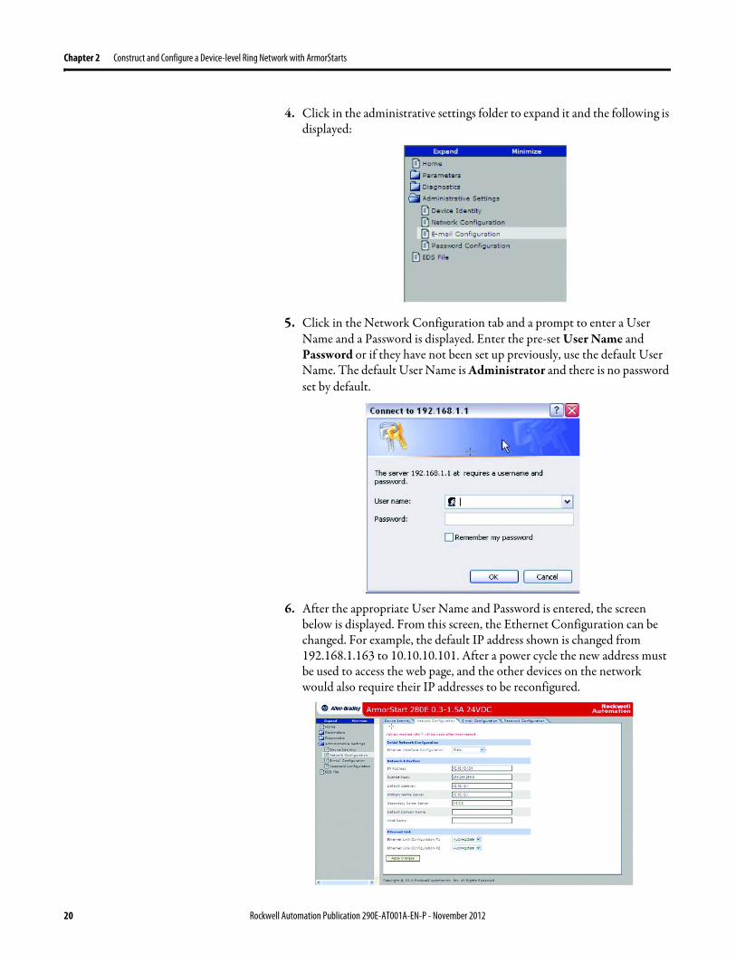
Chapter 2 Construct and Configure a Device-level Ring Network with ArmorStarts
4 Click in the administrative settings folder to expand it and the following is displayed
5 Click in the Network Configuration tab and a prompt to enter a User Name and a Password is displayed Enter the pre-set User Name and Password or if they have not been set up previously use the default User Name The default User Name is Administrator and there is no password set by default
6 After the appropriate User Name and Password is entered the screen below is displayed From this screen the Ethernet Configuration can be changed For example the default IP address shown is changed from 1921681163 to 101010101 After a power cycle the new address must be used to access the web page and the other devices on the network would also require their IP addresses to be reconfigured
20 Rockwell Automation Publication 290E-AT001A-EN-P - November 2012
Construct and Configure a Device-level Ring Network with ArmorStarts Chapter 2
Configure Supervisor Nodes on a DLR Network
After the devices are installed on the DLR network at least one supervisor node must be configured Ring nodes do not require any DLR network configuration
Before a DLR network can be completed (install your devices on the network and make all physical connections) a ring supervisor must be configured and enabled in
bull RSLogix 5000 programming software orbull RSLinx Classic communication software
This section shows how to use RSLogix 5000 programming software beginning on page 22 and RSLinx Classic communication software beginning on page 29 to configure and enable a ring supervisor
Configure a Ring Supervisor in RSLogix 5000 Programming Software
To configure the 1756-EN2TR module or the 1783-ETAP 1783-ETAP1F or 1783-ETAP2F taps as a ring supervisor use the devicersquos Add-on Profile (AOP) in RSLogix 5000 programming software version 1701 or later
For more information regarding the Required Add-On Profile Revision required go to Appendix B
To configure a ring supervisor in RSLogix 5000 programming software follow these steps
IMPORTANT The steps to configure a ring supervisor via software are basically the same for the 1756-EN2TR module and the 1783-ETAP 1783-ETAP1F and 1783-ETAP2F taps This example shows how to configure the 1756-EN2TR moduleOnly the 1783-ETAP 1783-ETAP1F and 1783-ETAP2F taps in the IO Configuration must be configured if you plan to enable the tap as a ring supervisor If the tap will not be used as a ring supervisor we recommend that it is not added to the IO ConfigurationAdditionally to configure a 1783-ETAP 1783-ETAP1F or 1783-ETAP2F tap as a supervisor via software or with its DIP switches an IP address must first be assigned The tap does not require an IP address if it is used as a ring node or has its supervisor function enabled by a DIP switchFor more information on how to use a tap switch to configure it as a ring supervisor see Chapter 5 in the EtherNetIP Embedded Switch Technology Manual To download the manual go to httpliteraturerockwellautomationcomidcgroupsliteraturedocumentsapenet-ap005_-en-ppdf
Rockwell Automation Publication 290E-AT001A-EN-P - November 2012 21
Chapter 2 Construct and Configure a Device-level Ring Network with ArmorStarts
Adding an Armorstart to RSLogix 5000
This section will show how to add an ArmorStart to RSLogix 5000
1 Open RSLogix 5000
2 Select File gt New to create a new project
3 Enter the name of the project and select your controller from the Type drop down menu For this example a 1756-L63 and software revision 20 will be used Then click OK
22 Rockwell Automation Publication 290E-AT001A-EN-P - November 2012
Construct and Configure a Device-level Ring Network with ArmorStarts Chapter 2
4 Add the 1756-EN2TR module to your projecta Right-click 1756 Backplane and choose New Module
Rockwell Automation Publication 290E-AT001A-EN-P - November 2012 23
Chapter 2 Construct and Configure a Device-level Ring Network with ArmorStarts
b Select the modulec Click Create
5 To add a new module to the tree right-click on Ethernet and select New Module This allows a new ArmorStart to be added to the Logix Project
24 Rockwell Automation Publication 290E-AT001A-EN-P - November 2012
Construct and Configure a Device-level Ring Network with ArmorStarts Chapter 2
6 Select the ArmorStart in your application and click OK
7 Enter a Name for this ArmorStart and an Ethernet address For this example the Private Network setting will be used This should be set to match the IP address switch setting on the ArmorStart Then press OK
Note Refer to ArmorStart Addressing Configuration on page 17 to set an IP address on the device
Rockwell Automation Publication 290E-AT001A-EN-P - November 2012 25
Chapter 2 Construct and Configure a Device-level Ring Network with ArmorStarts
8 Complete configuration information for the module in your RSLogix 5000 project
The following graphic shows the IO configuration for an example DLR network
9 Download the program to the Logix controller
10 Go online with the controller and leave it in Program mode
26 Rockwell Automation Publication 290E-AT001A-EN-P - November 2012
Construct and Configure a Device-level Ring Network with ArmorStarts Chapter 2
Enable Ring Supervisor in RSLogix 5000 Programming Software
After 1756-EN2TR module or 1783-ETAP 1783-ETAP1F or 1783-ETAP2F taps have been added to your RSLogix 5000 programming software project the ring supervisor mode must be enabled
If using RSLogix 5000 programming software to configure the ring supervisor and monitor diagnostics on the DLR network the controller must be online
To enable the 1756-EN2TR module or 1783-ETAP 1783-ETAP1F or 1783-ETAP2F tap as a ring supervisor follow these steps
The steps to enable a ring supervisor are basically the same for the 1756-EN2TR module or 1783-ETAP 1783-ETAP1F or 1783-ETAP2F tap This example shows how to do it for the 1756-EN2TR module
1 For your project online with the controller double-click on a supervisor-capable device in the IO configuration tree
Rockwell Automation Publication 290E-AT001A-EN-P - November 2012 27
Chapter 2 Construct and Configure a Device-level Ring Network with ArmorStarts
2 Click the Network tab to Enable Supervisor Mode
Configuration takes effect immediately you do not need to click Apply or OK
3 Click the Advanced button on the Network tab
4 Configure supervisor-related parameters as shown in the screen shot below
For these parameters you must click Set after entering a value
5 Click Set
28 Rockwell Automation Publication 290E-AT001A-EN-P - November 2012
Construct and Configure a Device-level Ring Network with ArmorStarts Chapter 2
Configure and Enable a Ring Supervisor in RSLinx Classic Communication Software
A ring supervisor can be configured for the DLR network through RSLinx Classic communication software
For more information regarding the Required RSLinx Classic Communication software Revision required refer to Appendix B
To configure a ring supervisor in RSLinx Classic Communication Software follow these steps
This example is for the 1783-ETAP tap Follow these steps
1 Launch RSLinx Classic Communication Software
2 Browse to the DLR network that is being set up
IMPORTANT For Beacon Interval Beacon Timeout and Ring Protocol VLAN ID we recommend that the default values be used
Functionality Description Default Setting
Supervisor Precedence A supervisor precedence number may be configured for each device that is configured as a ring supervisor The highest possible supervisor precedence value is 255When multiple nodes are enabled as supervisors the node with the highest precedence value is assigned as the active ring supervisor the other nodes automatically become back-up supervisorsWe recommend that youbull configure at least one back-up supervisor nodebull set the desired Active Ring Supervisor with a relatively high supervisor-
precedence value compared to the back-up node(s)bull keep track of the networkrsquos supervisor-precedence valuesIf multiple supervisors are configured with the same precedence value (the factory default value for all supervisor-capable devices is 0) the node with the numerically highest MAC address becomes the active supervisor
0
Beacon Interval Beacon interval is the frequency of the active ring supervisor transmitting a beacon frame through both of its Ethernet ports This parameter is user configurable for any time between 200 μS and 100 mSFor more information on how this parameter relates to network performance see page 61
400 μS
Beacon Timeout The beacon timeout is the amount of time that nodes wait before timing out the reception of beacon frames and taking appropriate action Supervisors support a range from 400μS to 500mSFor more information on how this parameter relates to network performance see page 61
1960 μS
Ring Protocol VLAN ID Reserved for future use 0
Rockwell Automation Publication 290E-AT001A-EN-P - November 2012 29
Chapter 2 Construct and Configure a Device-level Ring Network with ArmorStarts
If the Electronic Data Sheet (EDS) file is not installed on the module configured to be the ring supervisor it will appear with a question mark () To obtain and use the EDS file
bull right-click the module and choose to upload the EDS file from the device or
bull download the EDS file from httpwwwrockwellautomationcomrockwellautomationsupportnetworksedspage
3 Access the supervisor-capable nodersquos propertiesa Right-click the nodeb Choose Module Configuration
The General tab appears with information about the module
4 Click the Network tab to Enable Supervisor Mode
Configuration takes effect immediately there is no need to click Apply or OK
30 Rockwell Automation Publication 290E-AT001A-EN-P - November 2012
Construct and Configure a Device-level Ring Network with ArmorStarts Chapter 2
5 Click the Advanced button to configure supervisor-related parameters
Rockwell Automation Publication 290E-AT001A-EN-P - November 2012 31
Chapter 2 Construct and Configure a Device-level Ring Network with ArmorStarts
IMPORTANT For Beacon Interval Beacon Timeout and Ring Protocol VLAN ID use the default values
Functionality Description Default Setting
Supervisor Precedence
You may configure a supervisor precedence number for each device configured as a ring supervisor The highest possible supervisor precedence value is 255When multiple nodes are enabled as supervisor the node with the highest precedence value is assigned as the active ring supervisor the other nodes automatically become back-up supervisorsWe recommend that youbull configure at least one back-up supervisor nodebull set the desired Active Ring Supervisor with a relatively high supervisor-
precedence value compared to the back-up node(s)bull keep track of the networkrsquos supervisor-precedence valuesIf multiple supervisors are configured with the same precedence value (the factory default value for all supervisor-capable devices is 0) the node with the numerically highest MAC address becomes the active supervisor
0
Beacon Interval Beacon Interval is the frequency to which the active ring supervisor transmits a beacon frame through both of its Ethernet ports This parameter is user configurable for any time between 200 μS and 100 mSFor more information on how this parameter relates to network performance see page 58
400 μS
Beacon Timeout The beacon timeout is amount of time nodes wait before timing out the reception of beacon frames and taking appropriate action Supervisors support a range from 400 μS to 500 mSFor more information on how this parameter relates to network performance seepage 58
1960 μS
Ring Protocol VLAN ID
Reserved for future use 0
Enable IGMP Snooping
For more information on IGMP Snooping see page 35 Enabled
Enable IGMP Querier
For more information on IGMP Querier see page 35 Disabled
Enable Device Port Debugging Mode
For more information on Device Port Debugging Mode see page 59 Disabled
32 Rockwell Automation Publication 290E-AT001A-EN-P - November 2012
Construct and Configure a Device-level Ring Network with ArmorStarts Chapter 2
Complete the Physical Connections of the Network
After the ring supervisor nodes are configured and enabled the physical connection of the network must be completed to establish a complete DLR network
The figure below shows an example DLR network with all physical connections complete
Figure 4 - Example Device-level Ring Topology with All Connections Complete
Rockwell Automation Publication 290E-AT001A-EN-P - November 2012 33
Chapter 2 Construct and Configure a Device-level Ring Network with ArmorStarts
Verify Supervisor Configuration
The configuration and overall DLR network status can be verified in either RSLogix 5000 programming software or RSLinx Classic communication software
1 Access the supervisor nodersquos properties as shown previously in this chapter
2 Click the Network tab
3 Check the Network Topology and Network Status Fields
For a 1756-EN2TR module or the 1783-ETAP 1783-ETAP1F and 1783-ETAP2F tap the supervisor configuration can also be verified through the modulersquos diagnostic web pages For more information on monitoring diagnostics via an EtherNetIP modulersquos web pages see Monitor a DLR Network starting on page 37
34 Rockwell Automation Publication 290E-AT001A-EN-P - November 2012
Construct and Configure a Device-level Ring Network with ArmorStarts Chapter 2
IGMP Snooping This functionality is enabled by default in the 1783-ETAP 1783-ETAP1F and 1783-ETAP2F taps and is commonly used to manage multicast traffic on the network When in use this functionality allows the tap to multicast data to only those devices that need the data rather than to all devices connected to the network
For snooping to work there must be a device present that is running a querier Typically the device is a router or a switch such as the Stratix 6000 Stratix 8000 or Stratix 8300 managed switch
Once DHCP is enabled the switch could change the IP addresses on the ArmorStarts depending on network demand which could cause RSlogix5000 to loose communication with the device as connectivity is established via the AOP in the initial configuration
IGMP Querier This functionality is disabled by default The IGMP Querier functionality enables a 1783-ETAP 1783-ETAP1F or 1783-ETAP2F tap or switch such as a Stratix managed switch to send out a query to all devices on the network It determines what multicast addresses are of interest to a specific node or a group of nodes
The IGMP Querier functionality should be enabled for at least one node on the network The 1783-ETAP 1783-ETAP1F or 1783-ETAP2F tap managed switches and routers are examples of devices that support IGMP Querier functionality
IMPORTANT If DHCP for the Armostart is still required the Internet Group Management Protocol (IGMP) snooping on the E-tap must be disabled via the AOP
IMPORTANT If the IGMP Querier functionality is not enabled for at least one node on the network multicast traffic on the network may eventually create network performance issues
Rockwell Automation Publication 290E-AT001A-EN-P - November 2012 35
Chapter 2 Construct and Configure a Device-level Ring Network with ArmorStarts
However for all devices that are configured on the network with the IGMP Querier parameter enabled an IP address other than the factory default value must also be set for those devices If multiple devices on the network enable this functionality only the node with the lowest IP address becomes the active IGMP Querier node
IGMP Version
If the IGMP Querier is enabled a Querier Version must be selected The default version is Version 2
36 Rockwell Automation Publication 290E-AT001A-EN-P - November 2012
Chapter 3
Monitor a DLR Network
Introduction Use this chapter to learn how to monitor the DLR network
Methods to Monitor a DLR Network
Network diagnostic information can be retrieved from the ring supervisor-capable devices using the following
bull RSLogix 5000 programming software status pages
bull RSLinx communication software status pages
bull Device web pages
bull EtherNetIP Device Level Ring (DLR) network diagnostics faceplate
bull Programmatically through the use of a MSG instruction
RSLogix 5000 Programming Software Status Pages
RSLogix 5000 programming software version 1701 or later must be used and the appropriate AOPs installed to use the softwarersquos profile status pages
RSLinx Communication Software Status Pages
To monitor the network with this method the RSLinx communication software version 255 or later must be used
Topic Page
Methods to Monitor a DLR Network 37
Monitor Status Pages 39
Monitor ArmorStart Internal Web Server 44
Monitor via Faceplate Integration 45
Monitor Diagnostics via MSG Instructions 46
Rockwell Automation Publication 290E-AT001A-EN-P - November 2012 37
Chapter 3 Monitor a DLR Network
ArmorStart Internal Web Server
Rockwell Automation provides an internal embedded web server with each ArmorStart EtherNetIP The internal web server allows you to view information and configure the ArmorStart via a web browser The ArmorStart EtherNetIP can also be set up from the web server to send e-mail notifications The embedded web server is used to access configuration and status data It provides the user with the ability to view and modify the device configuration without having access to RSLogix 5000 Security in the form of an administrative password can be set The default login is Administrator There is no password set by default
EtherNetIP Device Level Ring (DLR) Network Diagnostics Faceplate
The diagnostics faceplate contains two major components
bull Logic code (encapsulated in an Add-On Instruction) that allows the controller to retrieve real-time DLR network status information
bull HMI faceplate graphics to allow the data to be visualized on an operator interface
Programmatically Through the Use of a MSG Instruction
For more information on how to monitor the DLR network via MSG Instructions see page 46
38 Rockwell Automation Publication 290E-AT001A-EN-P - November 2012
Monitor a DLR Network Chapter 3
Monitor Status Pages Both RSLogix 5000 programming software and RSLinx Classic communication software offer status pages that can be used to monitor the networkrsquos performance
RSLogix 5000 Programming Software Status Pages
Monitor the networkrsquos diagnostic information through the RSLogix 5000 programming software when the software is online
To monitor the network in RSLogix 5000 programming software follow these steps
1 Verify that the project is online
2 Access the active supervisor nodersquos propertiesa Right-click the modulersquos entry in the Controller Organizerb Click properties
Rockwell Automation Publication 290E-AT001A-EN-P - November 2012 39
Chapter 3 Monitor a DLR Network
3 Use the Network tab to monitor diagnostics
40 Rockwell Automation Publication 290E-AT001A-EN-P - November 2012
Monitor a DLR Network Chapter 3
RSLinx Communication Software
To monitor the network in RSLinx communication software follow these steps
1 Click RSWho to browse the network
2 Access the property pages for the active supervisor nodea Open the driver that shows the nodes on the DLR networkb Right-click the node that you want to monitor performancec Click on the choice that you need to access
Multiple choices appear
These options are shown in the following sections
Rockwell Automation Publication 290E-AT001A-EN-P - November 2012 41
Chapter 3 Monitor a DLR Network
Module Configuration
This series of tabs providesbull General informationbull Connection informationbull Module informationbull Internet protocolbull Port configurationbull Network information
The example below shows a ring fault between nodes at IP addresses 10888021 and MAC ID 00-00-BC-02-48-D5
42 Rockwell Automation Publication 290E-AT001A-EN-P - November 2012
Monitor a DLR Network Chapter 3
There are multiple fields used to monitor network diagnostics
Field Definition
Network Topology Possible values here can be Linear or Ring
Network Status Displays if the network is operating normally (Normal) or has experienced a fault (Ring Fault) as shown in the previous example screen
Active Ring Supervisor Displays the IP address or MAC address of the active ring supervisor
Active Supervisor Precedence For more information on this field see Active Ring Supervisor on page 11
Enable Ring Supervisor Configurable field that lets you to set the node as a ring supervisor
Ring Faults Detected Number of faults detected on the network since the last module power cycle or counter reset
Supervisor Status Displays whether this node is the active ring supervisor (Active) a back-up supervisor (Back-up) a ring node or part of a linear network
Last Active Node on Port 1 The last node the active ring supervisor can communicate with on Port 1 This value is an IP address or a MAC ID and remains latched until the Verify Fault Location button is clicked
Last Active Node on Port 2 The last node the active ring supervisor can communicate with on Port 2 This value is an IP address or a MAC ID and remains latched until the Verify Fault Location button is clicked
Status Displays whether a fault exists on the ring
IMPORTANT If the Network Topology field = Ring and the Network Status field = Normal the Last Active Node fields will display the last fault information even though it has been correctedTo clear the last fault information from these fields click Verify Fault Location You may see a message informing you that the supervisor is no longer in fault mode and the fields will be cleared
Rockwell Automation Publication 290E-AT001A-EN-P - November 2012 43
Chapter 3 Monitor a DLR Network
How to Access the ArmorStart EtherNetIP Internal Web Server
Open your preferred internet web browser and enter the IP address of the desired ArmorStart For this example 192168122 will be used
Use the links on the left-most navigation bar to see each available web page The screen below shows Ring Statistics for the ArmorStart 280E
44 Rockwell Automation Publication 290E-AT001A-EN-P - November 2012
Monitor a DLR Network Chapter 3
EtherNetIP Device Level Ring (DLR) Network Diagnostics Faceplate Overview
The EtherNetIP Device Level Ring (DLR) network diagnostics faceplate provides basic DLR network status information to the user to assist with monitoring and troubleshooting a DLR network
The diagnostics faceplate contains two major components
bull Logic code (encapsulated in an Add-On Instruction) that allows the controller to retrieve real-time DLR network status information
bull HMI faceplate graphics to allow the data to be visualized on an operator interface
The DLR diagnostics faceplate application can be downloaded from the Rockwell Automation Sample Code website at httpsamplecoderockwellautomationcom
Besides the individual Logix and View project components a demo application is also included with the downloaded file
Rockwell Automation Publication 290E-AT001A-EN-P - November 2012 45
Chapter 3 Monitor a DLR Network
Monitor Diagnostics via MSG Instructions
Network diagnostic information can also be obtained programmatically via MSG instructions in RSLogix 5000 programming software For example you can
bull Get all ring diagnostic informationbull Get a ring participant listbull Get the active supervisorbull Clear rapid ring faultsbull Verify a fault locationbull Reset a fault counterbull Enable and configure a ring supervisor
This information can be displayed on an HMI device or manipulated in the project code
Figure 5 - Example Use of MSG Instruction
This example describes how to retrieve diagnostic information from the DLR network Follow these steps
1 Enter a MSG instruction into the rung of logic
2 Configure the MSG instruction to retrieve ring diagnostic information service as shown in the following screen shots
IMPORTANT Make sure the tag created is sized appropriately to hold all of the data that you are reading or writing For more information see page 48
46 Rockwell Automation Publication 290E-AT001A-EN-P - November 2012
Monitor a DLR Network Chapter 3
3 Configure the MSG instructionrsquos communication path to point to the active supervisor node
The path on the following screen is one example path
IMPORTANT When using the Custom Get_Attributes_All (01) service pointing to an active supervisor node will retrieve all of the attributes listed in Retrieve All Diagnostic Information Attribute Description on page 50Pointing to a non-supervisor node will retrieve only the Network Topology and Network Status attribute informationPointing to backup supervisor node will retrieve the current active supervisorrsquos IP address
Rockwell Automation Publication 290E-AT001A-EN-P - November 2012 47
Chapter 3 Monitor a DLR Network
Use Specific Values on the Configuration Tab
Use the values on the Configuration tab of your MSG instruction to perform specific services Sample DLR network diagnostic application code for example Add-on Instruction or HMI faceplate graphics is available on the Rockwell Automation Sample Code Library For more information about the Rockwell Automation Sample Code Library see httpwwwrockwellautomationcomsolutionsintegratedarchitectureresources5html
➊ This request only works if there are fewer than 40 nodes on the network If there are more nodes than will fit in a single message an error will be returned➋ Use a Destination Length of 54 bytes if using firmware revision 3x or later for the 1756-EN2TR module or firmware revision 2x or later for the 1783-ETAP
1783-ETAP1F or 1783-ETAP2F taps
Request Description Message Type
Service Type
Service Code (HEX)
Class (HEX)
Instance Attribute (HEX)
Source Element
Source Length (Bytes)
Destination Destination Length (bytes)
Retrieve All Ring Diagnostic Information
Information for this request is listed in Retrieve All Ring Diagnostic Information on page 49
CIP Generic Custom 1 47 1 NA LeftBlank
0 Tag 50or54 ➋
Request Ring Participant List ➊
Information for this request is listed in Request the Ring Participant List on page 51
CIP Generic Get Attribute Single
e 47 1 9 NA NA Tag 10node
Get Active Supervisor
Obtain the IP address and MAC ID of the active supervisor on the DLR network
CIP Generic Get Attribute Single
e 47 1 a NA NA Tag 10
Acknowledge Rapid Ring Faults Condition
Request supervisor to resume normal operation after encountering a rapid ring fault condition
CIP Generic Custom 4c 47 1 NA NA NA NA
Verify a Fault Location
Request supervisor to update Last Active Node values
CIP Generic 4b 47 1 NA NA NA NA NA
Reset the Ring Fault Counter
Reset the number of ring faults detected on the DLR network
CIP Generic Set Attribute Single
10 47 1 5 Tag 2 NA NA
Enable and Configure a Ring Supervisor
Information for this request is listed in Enable and Configure a Ring Supervisor on page 52
CIP Generic Set Attribute Single
10 47 1 4 Tag 12 NA NA
48 Rockwell Automation Publication 290E-AT001A-EN-P - November 2012
Monitor a DLR Network Chapter 3
Retrieve All Ring Diagnostic Information
By performing the Retrieve All Ring Diagnostic Information request on an active supervisor the MSG instruction returns the following information
➊ RSLogix 5000 programming software may display the value in this field as negative numbers To better understand the value we recommend you view it in HEX format
Destination Tag Attribute Name Description Possible Values
SINT [0] Network Topology Current network topology mode 0 = Linear
1 = Ring
SINT [1] Network Status Current status of the network 0 = Normal
1 = Ring Fault
2 = Unexpected Loop Detected
3 = Partial Network Fault
4 = Rapid FaultRestore Cycle
SINT [2] Ring Supervisor Status Ring supervisor active status flag 0 = Node is functioning as a backup
1 = Node is functioning as the active ring supervisor
2 = Node is functioning as a normal ring node
3 = Node is operating in a non-DLR topology
4 = Node cannot support the currently operating ring parameters thatis Beacon Interval andor Beacon Timeout
Ring Supervisor Config Ring Supervisor configuration parameters
SINT [3] Ring Supervisor Enable Ring supervisor enable flag 0 = Node is configured as a normal ring node (default configuration)
1 = Node is configured as a ring supervisor
SINT [4] Ring Supervisor Precedence Precedence value of a ring supervisor ➊ Valid value range = 0hellip255
0 = Default value
SINT [5-8] Beacon Interval Duration of ring beacon interval Valid value range = 200 μshellip100 ms
Default = 400 μs
SINT [9-12] Beacon Timeout Duration of ring beacon timeout Value value range = 400 μshellip500 ms
Default value = 1960 μs
SINT [13-14] DLR VLAN ID Valid ID to use in ring protocol messages Valid value range = 0hellip4094
Default value = 0
SINT [15-16] Ring Faults Count Number of ring faults since power up ➊
Rockwell Automation Publication 290E-AT001A-EN-P - November 2012 49
Chapter 3 Monitor a DLR Network
Retrieve All Diagnostic Information Attribute Description
➊ This destination tag is available only with the 1756-EN2TR module firmware revision 3x or later 1783-ETAP 1783-ETAP1F and 1783-ETAP2F taps firmware revisions 2x or later If using the 1783-ETAP tap firmware revision 1x your program does not include this destination tag
➋ RSLogix 5000 programming software may display the value in this field as negative numbers To better understand the value we recommend you view it in HEX format
Destination Tag Attribute Name Description Possible Values
Last Active Node on Port 1 Last active node at the end of the chain through port 1 of the active ring supervisor during a ring fault
SINT [17-20] Device IP address ➋ Any valid IP address value
A value = 0 indicates no IP address has been configured for the device
SINT [21-26] Device MAC address ➋ Any valid Ethernet MAC address
Last Active Node on Port 2 Last active node at the end of the chain through port 2 of the active ring supervisor during a ring fault
SINT [27-30] Device IP address ➋ Any valid IP address value
A value = 0 indicates no IP address has been configured for the device
SINT [31-36] Device MAC address ➋ Any valid Ethernet MAC address
SINT [37-38] Ring Protocol Participants Count
Number of devices in the ring protocol participants list
Active Supervisor Address IP andor Ethernet MAC address of the active ring supervisor
SINT [39-42] Supervisor IP address Any valid IP address value
A value = 0 indicates no IP address has been configured for the device
SINT [43-48] Supervisor MAC address Any valid Ethernet MAC address
SINT [49] Active Supervisor Precedence
Precedence value of the active ring supervisor
SINT [50-53]➊ Capability Flags Alerts you that the device is capable of operating as a supervisor and beacon-based ring node
0x22
50 Rockwell Automation Publication 290E-AT001A-EN-P - November 2012
Monitor a DLR Network Chapter 3
Request the Ring Participant List
When requesting the Ring Participant List service on the DLR network the MSG instruction returns the following information
Request the Ring Participant List Attribute Description
➊ This attribute will return an array of the data shown one entry for each node The Ring Protocol Participants Count attribute determines the number entries
➋ This tag displays only IP addresses for ring participants that have been configured with one For example you may have a 1783-ETAP tap connected to the network that has not been assigned an IP address In that case no address is shown for the 1783-ETAP tap
➌ RSLogix 5000 programming software may display the value in this field as negative numbers To better understand the value we recommend you view it in HEX format
➍ Unlike destination tag SINT [0-3] where IP addresses are displayed only for ring participants configured with an IP address this tag displays MAC addresses for all ring participants because every ring participant has a MAC address
Destination Tag Attribute Name Description Possible Values
Ring Protocol Participants List ➊
List of devices participating in ring protocol
SINT [0-3] Device IP address ➋➌ Any valid IP address value
A value = 0 indicates no IP address has been configured for the device
SINT [4-9] Device MAC address ➌➍ Any valid Ethernet MAC address
Rockwell Automation Publication 290E-AT001A-EN-P - November 2012 51
Chapter 3 Monitor a DLR Network
Enable and Configure a Ring Supervisor
When performing the Enable and Configure a Ring Supervisor request on a supervisor-capable device configure the MSG instruction with the following information
Enable and Configure a Ring Supervisor Attribute Description
➊ RSLogix 5000 programming software may display the value in this field as negative numbers To better understand the value we recommend you view it in HEX format
Source Tag Attribute Name Description Possible Values
Ring Supervisor Config Ring Supervisor configuration parameters
SINT [0] Ring Supervisor Enable Ring supervisor enable flag 0 = Node is configured as a normal ring node (default configuration)1 = Node is configured as a ring supervisor
SINT [1] Ring Supervisor Precedence Precedence value of a ring supervisor ➊
Valid value range = 0hellip2550 = Default value
SINT [2-5] Beacon Interval Duration of ring beacon interval
Valid value range = 200 μshellip100 000 μsDefault = 400 μs
SINT [6-9] Beacon Timeout Duration of ring beacon timeout ➊
Value value range = 400 μshellip500 000 μsDefault value = 1960 μs
SINT [10-11] DLR VLAN ID Valid ID to use in ring protocol messages ➊
Valid value range = 0hellip4094Default value = 0
52 Rockwell Automation Publication 290E-AT001A-EN-P - November 2012
Chapter 4
Troubleshoot a DLR Network
Introduction Use this chapter to learn how to troubleshoot the DLR network
General Solutions for Linear or DLR Networks
Before attempting to correct specific faults on the linear or DLR network we recommend that you first take the following actions when a fault appears
bull For a DLR networkndash Verify that at least one node has been configured as a supervisor
on the network and that Network Topology = Ringndash Verify that all cables on the network are securely connected
to each devicendash Verify that all devices that require an IP address have one assigned
correctlyndash Check the Network Status field on the active supervisor nodersquos status
page to determine the fault typebull For a linear network
ndash Verify that none of the nodes are configured as a supervisor on the network and that Network Topology = LinearIf any nodes on a linear network are configured as a supervisor it may impact communication to other devices connected to the network
ndash Verify that all cables on the network are securely connected to each device
ndash Verify that all devices that require an IP address have one assigned correctly
If the fault is not cleared after completing the actions listed above use the tables in the rest of this chapter to troubleshoot issues specific to a DLR network or a linear network
Topic Page
General Solutions for the Linear or DLR Networks 53
Duplicate IP Address Detection 54
Specific Issues on the DLR Network 55
Network Recovery Performance 58
Device Port Debugging Mode 59
Rockwell Automation Publication 290E-AT001A-EN-P - November 2012 53
Chapter 4 Troubleshoot a DLR Network
Duplicate IP Address Detection
Some EtherNetIP communication modules support duplicate IP address detection The module verifies that its IP address does not match any other network devicersquos IP address when performing either of these tasks
bull Connect the module to an EtherNetIP network
bull Change the modulersquos IP address
If the modulersquos IP address matches that of another device on the network the modulersquos EtherNetIP port transitions to Conflict mode In Conflict mode these conditions exist
bull OK status indicator is blinking red
bull Network (NET) status indicator is solid red
bull On some EtherNetIP communication modules the module status display indicates the conflict
The display scrollsOK ltIP_address_of_this_modulegt Duplicate IP
ltMac_address_of_duplicate_node_detectedgt
For example OK 108860196 Duplicate IP - 0000BC0234B4
bull On some EtherNetIP communication modules the modulersquos diagnostic webpage displays information about duplicate IP address detection
For more information on which EtherNetIP communication modules support displaying duplicate IP address on their diagnostic webpage see the Technical Note titled Logix modules Duplicate IP address detection enhancement 118216 in the Technical Support Knowledgebase available at httpwwwrockwellautomationcomknowledgebase
54 Rockwell Automation Publication 290E-AT001A-EN-P - November 2012
Troubleshoot a DLR Network Chapter 4
Specific Issues on the DLR Network
Use the following table to troubleshoot possible specific issues on the DLR or linear network that are not solved by the actions described on the previous page
Issue Description Solution
Supervisor Reports a Ring Fault A link on the DLR network may be brokenbull intentionally for example because of adding or deleting nodes but not making all
physical connections to restore the setup of the network withwithout the nodebull unintentionally for example because a cable is broken or a device malfunctionsWhen this fault occurs the adjacent nodes to the faulted part of the network are displayed in the Ring Fault group and the Network Status field = Ring FaultThe screen shot below shows the Ring Fault section with IP addresses appearing for the last active nodes The faulted node is between nodes 108880115 and 108880208 If the IP address of either node is not available the software will display the nodersquos MAC ID
Once the fault is corrected the ring is automatically restored and the Network Status field returns to Normal
Determine where the fault condition exists and correct itClick the Refresh Communication link as needed to update the Ring Fault information to determine where the fault condition existsFinally DevicePort Debugging Mode functionality on the 1783-ETAP tap may be used to analyze a suspicious nodeFor more information refer to Device Port Debugging Mode on page 59
Rockwell Automation Publication 290E-AT001A-EN-P - November 2012 55
Chapter 4 Troubleshoot a DLR Network
Issue Description Solution
Rapid Ring Fault When a Rapid Ring Fault occurs the following events occurbull The active supervisor will block traffic on port 2 resulting in possible network
segmentation that is some nodes may become unreachablebull The Link 2 status indicator on the active supervisor is offbull As soon as the fault occurs for both RSLogix 5000 programming software and
RSLinx communication software the Status field = Rapid FaultRestore Cycles
Any of the following may cause a Rapid Ring Faultbull 5 intentional disconnectionsreconnections of a node from the network within 30
secondsbull A duplex mismatch between two connected devicesbull Electromagnetic noise on the networkbull Unstable physical connections such as intermittent connectorsGiven the nature of a Rapid Ring Fault the Last Active Node information may not be accurate when a Rapid Ring Fault condition is present
Multiple possible solutions existbull For the disconnections and reconnections issue no
solution is requiredClear the fault after reconnecting the device to the network permanentlybull For the duplex mismatch issue reconfigure the duplex
parameters to make sure they match between the devices
bull For the electromagnetic noise issue determine where the noise exists and eliminate it or use a protective shield in that location
bull For the unstable connections issue determine where they exist on the network and correct them
bull Check the media counters for all devices on the network The device with the highest media counter count is most likely causing the Rapid Ring Fault
bull Remove devices from the network one by one If the Rapid Ring Fault disappears after a device is removed that device is causing the fault
bull DevicePort Debugging Mode functionality on the 1783-ETAP tap may be used to analyze a suspicious node
For more information refer to Device Port Debugging Mode on page 59bull Finally the Beacon Interval or Timeout configuration
may not be appropriate for the networkHowever if these values need to be changed we recommend that you contact Rockwell Automation technical supportOnce the fault is fixed click Clear Fault
56 Rockwell Automation Publication 290E-AT001A-EN-P - November 2012
Troubleshoot a DLR Network Chapter 4
Issue Description Solution
Partial Fault Condition A partial network fault occurs when traffic is lost in only one direction on the network because a ring member is not forwarding beacons in both directions for example a component failureThe active ring supervisor detects a partial fault by monitoring the loss of Beacon frames on one port and the fault location appears in the Ring Fault section of the Network tab When a partial fault is detected the active ring supervisor blocks traffic on one port At this point the ring is segmented due to the partial fault condition The nodes adjacent to the faulted part of the network are displayed in the Ring Fault group with either IP addresses or MAC IDs for each node displayedWhen this fault occurs the Network Status field = Partial Fault ConditionOnce the fault is corrected it automatically clears and the Network Status field returns to Normal
Determine where the fault condition exists and correct itAdditionally the DevicePort Debugging Mode functionality also known as Port Mirroring on a 1783-ETAP 1783-ETAP1F or 1783-ETAP2F tap may be used to analyze a suspicious nodeFor more information refer to Device Port Debugging Mode on page 59
Media Counter Errors or Collisions
The media counters screen displays the number of physical layer errors or collisions The screen below indicates where to check for errors encountered Error levels are displayed depending on what caused the error For example an Alignment Error is displayed in the Alignment Error field
On a DLR network it is not uncommon to see low levels of media counter errors For example if the network breaks a low level of media counter errors appears With a low level of media counter errors the value typically does not continuously increase and often clearsA high level of media counter errors typically continues to increase and does not clear For example there is a mismatch of speed between two linked nodes a high level of media counter errors appears steadily increasing and not clearingTo access the RSLinx screen above browse the network right-click on the device select Module Properties and click the Port Diagnostics tab
Some example solutions includebull Check for a mismatch of speed andor duplex between
two linked nodesbull Verify that all cables on the network are securely
connected to each devicebull Check for electromagnetic noise on the network If you
find it eliminate it or use a protective shield in that location
Rockwell Automation Publication 290E-AT001A-EN-P - November 2012 57
Chapter 4 Troubleshoot a DLR Network
Network Recovery Performance
When measuring the networkrsquos performance with regard to dealing with fault conditions consider the network recovery time Network recovery is the time for all of the following to take place
1 The supervisor node recognizes that a fault exists on the network
2 The supervisor node reconfigures the network because of the fault
3 The supervisor node communicates to the network nodes that a fault condition exists
4 The network nodes reconfigure themselves because of the fault
With the default beacon interval value of 400 mS and beacon timeout value of 1960 mS the worst-case time for network recovery times are
bull 2890 mS for a copper DLR network This recovery time is based on 100 m copper segments between nodes on the network
bull 3140 mS for a fiber-optic DLR network This recovery time is based on 2 kM fiber-optic cable segments between nodes on the network
When considering the values listed above keep in mind
bull Recovery time may actually occur faster than the times listed
bull The recovery times listed above assume that your networkrsquos nodes are operating at 100 Mbps speed and full-duplex mode We recommend that your nodes generally operate in this mode for DLR networks
bull If other node conditions exist such as a node operating at 10 Mbps full-duplex or 10100 Mbps half-duplex the recovery times will vary from the times listed above
If this is the case for your application the beacon interval and beacon timeout will need to be changed We recommend that you first contact Rockwell Automation technical support if these parameters need to be changed
bull The value assumes that the majority of the traffic on your network is EtherNetIP traffic
58 Rockwell Automation Publication 290E-AT001A-EN-P - November 2012
Troubleshoot a DLR Network Chapter 4
Device Port Debugging Mode
This functionality is disabled by default Device Port Debugging mode which is similar to port mirroring can be used to monitor data received on the 1783-ETAP 1783-ETAP1F or 1783-ETAP2F taprsquos two network ports Monitor the data over the device port to a device such as a personal computer running a protocol analyzer application for advanced network debugging or analysis
When device port debugging is used on a 1783-ETAP the device connected to the 1783-ETAP taprsquos front port receives all of the data traversing the ring (both directions)
Device Port Debugging Example Network
When using the Device Port Debugging mode functionality insert the 1783-ETAP with the network analyzer connected to the device port It is inserted at the spot on the ring network where the node in question is located The graphic below shows a 1783-ETAP tap inserted in the network
IMPORTANT This functionality should be used only when troubleshooting the network and not in normal network operation
Rockwell Automation Publication 290E-AT001A-EN-P - November 2012 59
Chapter 4 Troubleshoot a DLR Network
Combined total network bandwidth of the traffic received on the two 1783-ETAP 1783-ETAP1F or 1783-ETAP2F taprsquos ports connected to the network should not exceed the taprsquos device port capacity The speed setting determines the device portrsquos capacity
Configure the device port on a 1783-ETAP 1783-ETAP1F or 1783-ETAP2F tap to either of two speed settings
bull 100 Mbps - default settingbull 10 Mbps
If the bandwidth exceeds the capacity of the taprsquos device port some frames from the ring will be dropped before reaching the device port These dropped frames do not impact the traffic on the rest of the DLR network
The device port setting determines how much network traffic the 1783-ETAP 1783-ETAP1F or 1783-ETAP2F tap can handle before dropping frames The circled section in the graphic below shows the Port Buffer Utilization of the Device Port In this example the value is zero because a ring fault exists on the network
60 Rockwell Automation Publication 290E-AT001A-EN-P - November 2012
Appendix A
Network Usage Guidelines and Recommendations
Consider the following guidelines and recommendations when using a DLR or linear network
GuidelineRecommendation Explanation
Use fewer than 50 nodes on a single DLR networkIf your application requires more than 50 nodes we recommend that the nodes are broken into separate but linked DLR networks
If you use more than 50 nodes on a single DLR networkbull Your network has a greater chance of multiple faults
occurring on the networkbull Network recovery times from faulted DLR network
are higher
Do not configure a supervisor on a linear network If your linear network includes non-DLR nodes and has a supervisor-enabled node on the network it may impact communication to non-DLR devices connected to the linear network
If you must connect a device that is running at 10 Mbps to a DLR or linear network do so through a 1783-ETAP 1783-ETAP1F or 1783-ETAP2F tap device port
The 1783-ETAP 1783-ETAP1F and 1783-ETAP2F taps can operate at 100 Mbps on the DLR network this is the optimal speed for a network If you connect a 10 Mbps device directly to the network instead of through a tap the linear or DLR network traffic slows to 10 MbpsAdditionally if the 10 Mbps device is connected to the network without a 1783-ETAP tap network recovery times are significantly impacted
Configure multiple supervisor nodes per ring If your DLR network only has one supervisor and the supervisor experiences a fault none of the other nodes become the active supervisor In this case the network becomes a linear network until the fault is corrected and the DLR network restoredAnother reason to configure multiple supervisor nodes is for replacing an active supervisor node with an out-of-box replacement the new device will not be enabled as a supervisor (by default) and there would still be no supervisor on the network
Rockwell Automation Publication 290E-AT001A-EN-P - November 2012 61
Appendix A Network Usage Guidelines and Recommendations
GuidelineRecommendation Explanation
Connect switches to a DLR network via 1783-ETAP 1783-ETAP1F or 1783-ETAP2F taps
If switches are connected to the DLR network without the use of a 1783-ETAP 1783-ETAP1F or 1783-ETAP2F tap the network may experience unpredictable behavior and network performance is unknown
Run all nodes on the DLR network at 100 Mbps and in Full-Duplex mode
These configuration values provide the best performance for your networkAdditionally we recommend that youbull Use auto-negotiate for all nodes on the DLR networkbull Do not use auto-negotiate on one node and then force
speed on the next node linked to it
In a linear network the number of nodes to use is application specific based on the considerations described in the next box
When determining the number of nodes to use on a linear network consider the followingbull There is a delay per node as information is transmitted
to each successive node used on the networkndash The typical delay on a linear network with 100 m
copper segments between nodes is 30 mSndash The typical delay on a linear network with 2 kM
fiber-optic segments between nodes is 40 mS
The greater the number of nodes on the network the longer the total time for information to be transmitted across the entire networkbull The single point of failure possibility is greater with
each additional connectionbull Troubleshooting the network may be more difficult
with a higher number of nodes
The total time for information to be transmitted across the entire network and its effect on how many nodes to use on a linear network is related to the Requested Packet Interval (RPI)Verify that the total time to transmit information from the first node to the last node on the network is less than the RPI Make sure the network is not loaded beyond 90 of capacity
62 Rockwell Automation Publication 290E-AT001A-EN-P - November 2012
Network Usage Guidelines and Recommendations Appendix A
GuidelineRecommendation Explanation
Do not physically close a DLR network without a supervisor configured on the network
A DLR network without a supervisor node results in a network stormIf you do close the DLR network without a supervisor configured break the ring and configure at least one supervisor before physically reconnecting the network
Use the default values for the followingbull Beacon Intervalbull Beacon Timeoutbull Ring Protocol VLAN ID
Changing the default values for the parameters Beacon Interval Beacon Timeout and Ring Protocol VLAN ID can result in unpredictable network behavior and negatively impacted network performanceThe default values are optimized for a network withbull 50 or fewer nodes are on the networkbull All nodes are operating at 100 Mbps and full-duplex
modebull At least 50 of the network traffic bandwidth being
EtherNetIP trafficIf you think the values of the Beacon Interval Beacon Timeout or Ring Protocol VLAN ID need to be changed for example if any node on ring is not operating at 100 Mbps and full-duplex mode we recommend that you first contact Rockwell Automation technical support
If DHCP for the ArmorStarts is still required you will need to disable Internet Group Management Protocol (IGMP) snooping on the E-tap via the AOP
IGMP Snooping is enabled by default in the 1783-ETAP 1783-ETAP1F and 1783-ETAP2F taps and is commonly used to manage multicast traffic on the network When in use this functionality allows the tap to multicast data to only those devices that need the data rather than to all devices connected to the networkOnce DHCP is enabled the switch could change the IP addresses on the ArmorStarts depending on network demand which could cause RSlogix5000 to loose communication with the device as connectivity is established via the AOP in the initial configuration
The IGMP Querier functionality should be enabled for at least one node on the network
This functionality is disabled by default The IGMP Querier functionality enables a 1783-ETAP 1783-ETAP1F or 1783-ETAP2F tap or switch such as a Stratix managed switch to send out a query to all devices on the network to determine what multicast addresses are of interest to a specific node or a group of nodesIf the IGMP Querier functionality is not enabled for at least one node on the network multicast traffic on the network may eventually create network performance issuesThe 1783-ETAP 1783-ETAP1F or 1783-ETAP2F taps managed switches and routers are examples of devices that support IGMP Querier functionality
Rockwell Automation Publication 290E-AT001A-EN-P - November 2012 63
Appendix A Network Usage Guidelines and Recommendations
Notes
64 Rockwell Automation Publication 290E-AT001A-EN-P - November 2012
Appendix B
Required Firmware Revisions
Required Firmware Revision for an Add-On Profile
➊ The ControlFLASH Firmware Upgrade software tcan be used o upgrade a 1756-EN2TR module from firmware revision 21 to 3x or later1x or later3x or later2x or later
➋ The ControlFLASH Firmware Upgrade software can be used to upgrade a 1783-ETAP tap from firmware revision 11 to 2x or later
To download new firmware go to httpwwwrockwellautomationcomsupportamericasindex_enhtml
If the firmware revision is upgraded on the module or tap the required AOP revision listed above must be used for that revision For example if the 1756-EN2TR module is upgraded to firmware revision 3x or later AOP revision 2x or later must be used in the RSLogix 5000 programming software
Additionally if the firmware revision is upgraded on the module or tap the required RSLinx communication software must also be used for that firmware revision For more information on which RSLinx software version is required for each firmware revision see page 66
For both the 1756-EN2TR module and 1783-ETAP tap make sure that the Major Revision configured on the General tab of the devicersquos RSLogix 5000 programming software configuration matches the major revision of the physical module
IMPORTANT To download an AOP go to httpsupportrockwellautomationcomcontrolflashLogixProfileraspDepending on the firmware revision of your product a specific AOP version must be used
Firmware Revision Add-On Profile Revision Cat No
21 ➊ 1x or later 1756-EN2TR
3x or later 2x or later
11 ➋ 1x or later 1783-ETAP
2x or later 2x or later
2x or later 2x or later 1783-ETAP1F
1783-ETAP2F
Rockwell Automation Publication 290E-AT001A-EN-P - November 2012 65
Appendix B Required Firmware Revisions
If the device configuration on the General tab does not match the physical module the programming software alerts you to this mismatch when attempting to configure the Internet Protocol Port Configuration and Network tabs for that device
Required Firmware Revision for RSLinx Communication Software
➊ The ControlFLASH Firmware Upgrade software can be used to upgrade a 1756-EN2TR module from firmware revision 21 to 3x or later1x or later3x or later255 or later3x or later256 or later
➋ The ControlFLASH Firmware Upgrade software can be used to upgrade a 1783-ETAP tap from firmware revision 11 to 2x or later
To download new firmware go to httpwwwrockwellautomationcomsupportamericasindex_enhtml
If the firmware revision is upgraded on the module or tap the required RSLinx communication software listed above must be used for that revision For example if the 1756-EN2TR module is upgraded to firmware revision 3x or later AOP revision 2x or later must be used in your RSLogix 5000 programming software
Additionally if the firmware revision is upgraded on the module or tap the required AOP revision must also be used for that firmware revision For more information on which AOP revision is required for each firmware revision see page 65
IMPORTANT Depending on the firmware revision of your product specific versions of RSLinx communication software must be used
Firmware Revision Required RSLinx Communication Software Version
Cat No
21 ➊ 255 or later 1756-EN2TR
3x or later 256 or later
11 ➋ 255 or later 1783-ETAP
2x or later 256 or later
2x or later 256 or later 1783-ETAP1F
1783-ETAP2F
66 Rockwell Automation Publication 290E-AT001A-EN-P - November 2012
Rockwell Otomasyon Ticaret AŞ Kar Plaza İş Merkezi E Blok Kat6 34752 İccedilerenkoumly İstanbul Tel +90 (216) 5698400
Rockwell Automation Publication 290E-AT001A-EN-P ndash November 2012 68 Copyright copy 2012 Rockwell Automation Inc All rights reserved Printed in the USA
Rockwell Automation Support
Rockwell Automation provides technical information on the Web to assist you in using its products At httpwwwrockwellautomationcomsupport you can find technical manuals a knowledge base of FAQs technical and application notes sample code and links to software service packs and a MySupport feature that you can customize to make thebest use of these tools
For an additional level of technical phone support for installation configuration and troubleshooting we offer TechConnectSM support programs For more information contact your local distributor or Rockwell Automation representative or visit httpwwwrockwellautomationcomsupport
Installation Assistance
If you experience a problem within the first 24 hours of installation review the information that is contained in this manualYou can contact Customer Support for initial help in getting your product up and running
New Product Satisfaction Return
Rockwell Automation tests all of its products to ensure that they are fully operational when shipped from the manufacturing facility However if your product is not functioning and needs to be returned follow these procedures
Documentation Feedback
Your comments will help us serve your documentation needs better If you have any suggestions on how to improve this document complete this form publication RA-DU002 available at httpwwwrockwellautomationcomliterature
United States or Canada 14406463434
Outside United States or Canada Use the Worldwide Locator at httpwwwrockwellautomationcomsupportamericasphone_enhtml or contact your local Rockwell Automation representative
United States Contact your distributor You must provide a Customer Support case number (call the phone number above to obtain one) to your distributor to complete the return process
Outside United States Please contact your local Rockwell Automation representative for the return procedure
- Important User Information
- General Precautions
- Software Requirements
- Additional Resources
- Rockwell Automation Support
- Installation Assistance
- New Product Satisfaction Return
- Table of Contents
- Chapter 1
-
- Device-Level Ring (DLR) Basics
-
- Introduction
- ArmorStart with EtherNetIP Overview
- What is a Device-level Ring (DLR) Network
- DLR Network Elements
-
- Supervisor Node
- Ring Node
-
- DLR Network Operation
- Number of Nodes on a DLR Network
- DLR Network Fault Management
-
- Network Reconfiguration after a Fault
-
- Chapter 2
-
- Construct and Configure a Device-level Ring Network with ArmorStarts
-
- Introduction
- Ethernet Capacity Tool
- Install Devices on a DLR Network
- ArmorStart Addressing Configuration
-
- Using the BootPDHCP Server
- Using the Rotary Network Address Switches
- Using the ArmorStart Internal Web Server
-
- Configure Supervisor Nodes on a DLR Network
-
- Configure a Ring Supervisor in RSLogix 5000 Programming Software
- Adding an Armorstart to RSLogix 5000
- Enable Ring Supervisor in RSLogix 5000 Programming Software
- Configure and Enable a Ring Supervisor in RSLinx Classic Communication Software
-
- Complete the Physical Connections of the Network
- Verify Supervisor Configuration
- IGMP Snooping
- IGMP Querier
-
- Chapter 3
-
- Monitor a DLR Network
-
- Introduction
- Methods to Monitor a DLR Network
-
- RSLogix 5000 Programming Software Status Pages
- RSLinx Communication Software Status Pages
- ArmorStart Internal Web Server
- EtherNetIP Device Level Ring (DLR) Network Diagnostics Faceplate
- Programmatically Through the Use of a MSG Instruction
-
- Monitor Status Pages
-
- RSLogix 5000 Programming Software Status Pages
- RSLinx Communication Software
-
- How to Access the ArmorStart EtherNetIP Internal Web Server
-
- EtherNetIP Device Level Ring (DLR) Network Diagnostics Faceplate Overview
-
- Monitor Diagnostics via MSG Instructions
-
- Use Specific Values on the Configuration Tab
- Retrieve All Ring Diagnostic Information
- Retrieve All Diagnostic Information Attribute Description
- Request the Ring Participant List
- Request the Ring Participant List Attribute Description
-
- Enable and Configure a Ring Supervisor
-
- Enable and Configure a Ring Supervisor Attribute Description
-
- Chapter 4
-
- Troubleshoot a DLR Network
-
- Introduction
- General Solutions for Linear or DLR Networks
- Duplicate IP Address Detection
- Specific Issues on the DLR Network
- Network Recovery Performance
- Device Port Debugging Mode
-
- Device Port Debugging Example Network
-
- Appendix A
-
- Network Usage Guidelines and Recommendations
-
- Notes
-
- Appendix B
-
- Required Firmware Revisions
-
- Required Firmware Revision for an Add-On Profile
- Required Firmware Revision for RSLinx Communication Software
-
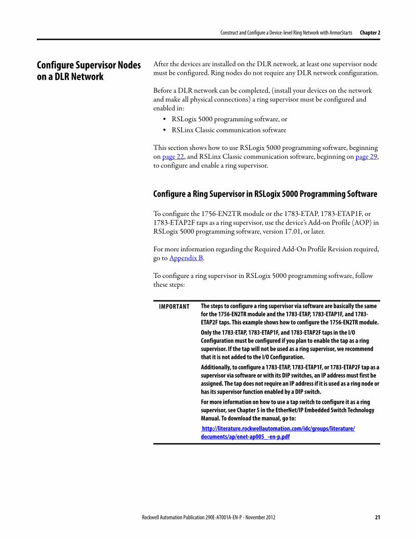
Construct and Configure a Device-level Ring Network with ArmorStarts Chapter 2
Configure Supervisor Nodes on a DLR Network
After the devices are installed on the DLR network at least one supervisor node must be configured Ring nodes do not require any DLR network configuration
Before a DLR network can be completed (install your devices on the network and make all physical connections) a ring supervisor must be configured and enabled in
bull RSLogix 5000 programming software orbull RSLinx Classic communication software
This section shows how to use RSLogix 5000 programming software beginning on page 22 and RSLinx Classic communication software beginning on page 29 to configure and enable a ring supervisor
Configure a Ring Supervisor in RSLogix 5000 Programming Software
To configure the 1756-EN2TR module or the 1783-ETAP 1783-ETAP1F or 1783-ETAP2F taps as a ring supervisor use the devicersquos Add-on Profile (AOP) in RSLogix 5000 programming software version 1701 or later
For more information regarding the Required Add-On Profile Revision required go to Appendix B
To configure a ring supervisor in RSLogix 5000 programming software follow these steps
IMPORTANT The steps to configure a ring supervisor via software are basically the same for the 1756-EN2TR module and the 1783-ETAP 1783-ETAP1F and 1783-ETAP2F taps This example shows how to configure the 1756-EN2TR moduleOnly the 1783-ETAP 1783-ETAP1F and 1783-ETAP2F taps in the IO Configuration must be configured if you plan to enable the tap as a ring supervisor If the tap will not be used as a ring supervisor we recommend that it is not added to the IO ConfigurationAdditionally to configure a 1783-ETAP 1783-ETAP1F or 1783-ETAP2F tap as a supervisor via software or with its DIP switches an IP address must first be assigned The tap does not require an IP address if it is used as a ring node or has its supervisor function enabled by a DIP switchFor more information on how to use a tap switch to configure it as a ring supervisor see Chapter 5 in the EtherNetIP Embedded Switch Technology Manual To download the manual go to httpliteraturerockwellautomationcomidcgroupsliteraturedocumentsapenet-ap005_-en-ppdf
Rockwell Automation Publication 290E-AT001A-EN-P - November 2012 21
Chapter 2 Construct and Configure a Device-level Ring Network with ArmorStarts
Adding an Armorstart to RSLogix 5000
This section will show how to add an ArmorStart to RSLogix 5000
1 Open RSLogix 5000
2 Select File gt New to create a new project
3 Enter the name of the project and select your controller from the Type drop down menu For this example a 1756-L63 and software revision 20 will be used Then click OK
22 Rockwell Automation Publication 290E-AT001A-EN-P - November 2012
Construct and Configure a Device-level Ring Network with ArmorStarts Chapter 2
4 Add the 1756-EN2TR module to your projecta Right-click 1756 Backplane and choose New Module
Rockwell Automation Publication 290E-AT001A-EN-P - November 2012 23
Chapter 2 Construct and Configure a Device-level Ring Network with ArmorStarts
b Select the modulec Click Create
5 To add a new module to the tree right-click on Ethernet and select New Module This allows a new ArmorStart to be added to the Logix Project
24 Rockwell Automation Publication 290E-AT001A-EN-P - November 2012
Construct and Configure a Device-level Ring Network with ArmorStarts Chapter 2
6 Select the ArmorStart in your application and click OK
7 Enter a Name for this ArmorStart and an Ethernet address For this example the Private Network setting will be used This should be set to match the IP address switch setting on the ArmorStart Then press OK
Note Refer to ArmorStart Addressing Configuration on page 17 to set an IP address on the device
Rockwell Automation Publication 290E-AT001A-EN-P - November 2012 25
Chapter 2 Construct and Configure a Device-level Ring Network with ArmorStarts
8 Complete configuration information for the module in your RSLogix 5000 project
The following graphic shows the IO configuration for an example DLR network
9 Download the program to the Logix controller
10 Go online with the controller and leave it in Program mode
26 Rockwell Automation Publication 290E-AT001A-EN-P - November 2012
Construct and Configure a Device-level Ring Network with ArmorStarts Chapter 2
Enable Ring Supervisor in RSLogix 5000 Programming Software
After 1756-EN2TR module or 1783-ETAP 1783-ETAP1F or 1783-ETAP2F taps have been added to your RSLogix 5000 programming software project the ring supervisor mode must be enabled
If using RSLogix 5000 programming software to configure the ring supervisor and monitor diagnostics on the DLR network the controller must be online
To enable the 1756-EN2TR module or 1783-ETAP 1783-ETAP1F or 1783-ETAP2F tap as a ring supervisor follow these steps
The steps to enable a ring supervisor are basically the same for the 1756-EN2TR module or 1783-ETAP 1783-ETAP1F or 1783-ETAP2F tap This example shows how to do it for the 1756-EN2TR module
1 For your project online with the controller double-click on a supervisor-capable device in the IO configuration tree
Rockwell Automation Publication 290E-AT001A-EN-P - November 2012 27
Chapter 2 Construct and Configure a Device-level Ring Network with ArmorStarts
2 Click the Network tab to Enable Supervisor Mode
Configuration takes effect immediately you do not need to click Apply or OK
3 Click the Advanced button on the Network tab
4 Configure supervisor-related parameters as shown in the screen shot below
For these parameters you must click Set after entering a value
5 Click Set
28 Rockwell Automation Publication 290E-AT001A-EN-P - November 2012
Construct and Configure a Device-level Ring Network with ArmorStarts Chapter 2
Configure and Enable a Ring Supervisor in RSLinx Classic Communication Software
A ring supervisor can be configured for the DLR network through RSLinx Classic communication software
For more information regarding the Required RSLinx Classic Communication software Revision required refer to Appendix B
To configure a ring supervisor in RSLinx Classic Communication Software follow these steps
This example is for the 1783-ETAP tap Follow these steps
1 Launch RSLinx Classic Communication Software
2 Browse to the DLR network that is being set up
IMPORTANT For Beacon Interval Beacon Timeout and Ring Protocol VLAN ID we recommend that the default values be used
Functionality Description Default Setting
Supervisor Precedence A supervisor precedence number may be configured for each device that is configured as a ring supervisor The highest possible supervisor precedence value is 255When multiple nodes are enabled as supervisors the node with the highest precedence value is assigned as the active ring supervisor the other nodes automatically become back-up supervisorsWe recommend that youbull configure at least one back-up supervisor nodebull set the desired Active Ring Supervisor with a relatively high supervisor-
precedence value compared to the back-up node(s)bull keep track of the networkrsquos supervisor-precedence valuesIf multiple supervisors are configured with the same precedence value (the factory default value for all supervisor-capable devices is 0) the node with the numerically highest MAC address becomes the active supervisor
0
Beacon Interval Beacon interval is the frequency of the active ring supervisor transmitting a beacon frame through both of its Ethernet ports This parameter is user configurable for any time between 200 μS and 100 mSFor more information on how this parameter relates to network performance see page 61
400 μS
Beacon Timeout The beacon timeout is the amount of time that nodes wait before timing out the reception of beacon frames and taking appropriate action Supervisors support a range from 400μS to 500mSFor more information on how this parameter relates to network performance see page 61
1960 μS
Ring Protocol VLAN ID Reserved for future use 0
Rockwell Automation Publication 290E-AT001A-EN-P - November 2012 29
Chapter 2 Construct and Configure a Device-level Ring Network with ArmorStarts
If the Electronic Data Sheet (EDS) file is not installed on the module configured to be the ring supervisor it will appear with a question mark () To obtain and use the EDS file
bull right-click the module and choose to upload the EDS file from the device or
bull download the EDS file from httpwwwrockwellautomationcomrockwellautomationsupportnetworksedspage
3 Access the supervisor-capable nodersquos propertiesa Right-click the nodeb Choose Module Configuration
The General tab appears with information about the module
4 Click the Network tab to Enable Supervisor Mode
Configuration takes effect immediately there is no need to click Apply or OK
30 Rockwell Automation Publication 290E-AT001A-EN-P - November 2012
Construct and Configure a Device-level Ring Network with ArmorStarts Chapter 2
5 Click the Advanced button to configure supervisor-related parameters
Rockwell Automation Publication 290E-AT001A-EN-P - November 2012 31
Chapter 2 Construct and Configure a Device-level Ring Network with ArmorStarts
IMPORTANT For Beacon Interval Beacon Timeout and Ring Protocol VLAN ID use the default values
Functionality Description Default Setting
Supervisor Precedence
You may configure a supervisor precedence number for each device configured as a ring supervisor The highest possible supervisor precedence value is 255When multiple nodes are enabled as supervisor the node with the highest precedence value is assigned as the active ring supervisor the other nodes automatically become back-up supervisorsWe recommend that youbull configure at least one back-up supervisor nodebull set the desired Active Ring Supervisor with a relatively high supervisor-
precedence value compared to the back-up node(s)bull keep track of the networkrsquos supervisor-precedence valuesIf multiple supervisors are configured with the same precedence value (the factory default value for all supervisor-capable devices is 0) the node with the numerically highest MAC address becomes the active supervisor
0
Beacon Interval Beacon Interval is the frequency to which the active ring supervisor transmits a beacon frame through both of its Ethernet ports This parameter is user configurable for any time between 200 μS and 100 mSFor more information on how this parameter relates to network performance see page 58
400 μS
Beacon Timeout The beacon timeout is amount of time nodes wait before timing out the reception of beacon frames and taking appropriate action Supervisors support a range from 400 μS to 500 mSFor more information on how this parameter relates to network performance seepage 58
1960 μS
Ring Protocol VLAN ID
Reserved for future use 0
Enable IGMP Snooping
For more information on IGMP Snooping see page 35 Enabled
Enable IGMP Querier
For more information on IGMP Querier see page 35 Disabled
Enable Device Port Debugging Mode
For more information on Device Port Debugging Mode see page 59 Disabled
32 Rockwell Automation Publication 290E-AT001A-EN-P - November 2012
Construct and Configure a Device-level Ring Network with ArmorStarts Chapter 2
Complete the Physical Connections of the Network
After the ring supervisor nodes are configured and enabled the physical connection of the network must be completed to establish a complete DLR network
The figure below shows an example DLR network with all physical connections complete
Figure 4 - Example Device-level Ring Topology with All Connections Complete
Rockwell Automation Publication 290E-AT001A-EN-P - November 2012 33
Chapter 2 Construct and Configure a Device-level Ring Network with ArmorStarts
Verify Supervisor Configuration
The configuration and overall DLR network status can be verified in either RSLogix 5000 programming software or RSLinx Classic communication software
1 Access the supervisor nodersquos properties as shown previously in this chapter
2 Click the Network tab
3 Check the Network Topology and Network Status Fields
For a 1756-EN2TR module or the 1783-ETAP 1783-ETAP1F and 1783-ETAP2F tap the supervisor configuration can also be verified through the modulersquos diagnostic web pages For more information on monitoring diagnostics via an EtherNetIP modulersquos web pages see Monitor a DLR Network starting on page 37
34 Rockwell Automation Publication 290E-AT001A-EN-P - November 2012
Construct and Configure a Device-level Ring Network with ArmorStarts Chapter 2
IGMP Snooping This functionality is enabled by default in the 1783-ETAP 1783-ETAP1F and 1783-ETAP2F taps and is commonly used to manage multicast traffic on the network When in use this functionality allows the tap to multicast data to only those devices that need the data rather than to all devices connected to the network
For snooping to work there must be a device present that is running a querier Typically the device is a router or a switch such as the Stratix 6000 Stratix 8000 or Stratix 8300 managed switch
Once DHCP is enabled the switch could change the IP addresses on the ArmorStarts depending on network demand which could cause RSlogix5000 to loose communication with the device as connectivity is established via the AOP in the initial configuration
IGMP Querier This functionality is disabled by default The IGMP Querier functionality enables a 1783-ETAP 1783-ETAP1F or 1783-ETAP2F tap or switch such as a Stratix managed switch to send out a query to all devices on the network It determines what multicast addresses are of interest to a specific node or a group of nodes
The IGMP Querier functionality should be enabled for at least one node on the network The 1783-ETAP 1783-ETAP1F or 1783-ETAP2F tap managed switches and routers are examples of devices that support IGMP Querier functionality
IMPORTANT If DHCP for the Armostart is still required the Internet Group Management Protocol (IGMP) snooping on the E-tap must be disabled via the AOP
IMPORTANT If the IGMP Querier functionality is not enabled for at least one node on the network multicast traffic on the network may eventually create network performance issues
Rockwell Automation Publication 290E-AT001A-EN-P - November 2012 35
Chapter 2 Construct and Configure a Device-level Ring Network with ArmorStarts
However for all devices that are configured on the network with the IGMP Querier parameter enabled an IP address other than the factory default value must also be set for those devices If multiple devices on the network enable this functionality only the node with the lowest IP address becomes the active IGMP Querier node
IGMP Version
If the IGMP Querier is enabled a Querier Version must be selected The default version is Version 2
36 Rockwell Automation Publication 290E-AT001A-EN-P - November 2012
Chapter 3
Monitor a DLR Network
Introduction Use this chapter to learn how to monitor the DLR network
Methods to Monitor a DLR Network
Network diagnostic information can be retrieved from the ring supervisor-capable devices using the following
bull RSLogix 5000 programming software status pages
bull RSLinx communication software status pages
bull Device web pages
bull EtherNetIP Device Level Ring (DLR) network diagnostics faceplate
bull Programmatically through the use of a MSG instruction
RSLogix 5000 Programming Software Status Pages
RSLogix 5000 programming software version 1701 or later must be used and the appropriate AOPs installed to use the softwarersquos profile status pages
RSLinx Communication Software Status Pages
To monitor the network with this method the RSLinx communication software version 255 or later must be used
Topic Page
Methods to Monitor a DLR Network 37
Monitor Status Pages 39
Monitor ArmorStart Internal Web Server 44
Monitor via Faceplate Integration 45
Monitor Diagnostics via MSG Instructions 46
Rockwell Automation Publication 290E-AT001A-EN-P - November 2012 37
Chapter 3 Monitor a DLR Network
ArmorStart Internal Web Server
Rockwell Automation provides an internal embedded web server with each ArmorStart EtherNetIP The internal web server allows you to view information and configure the ArmorStart via a web browser The ArmorStart EtherNetIP can also be set up from the web server to send e-mail notifications The embedded web server is used to access configuration and status data It provides the user with the ability to view and modify the device configuration without having access to RSLogix 5000 Security in the form of an administrative password can be set The default login is Administrator There is no password set by default
EtherNetIP Device Level Ring (DLR) Network Diagnostics Faceplate
The diagnostics faceplate contains two major components
bull Logic code (encapsulated in an Add-On Instruction) that allows the controller to retrieve real-time DLR network status information
bull HMI faceplate graphics to allow the data to be visualized on an operator interface
Programmatically Through the Use of a MSG Instruction
For more information on how to monitor the DLR network via MSG Instructions see page 46
38 Rockwell Automation Publication 290E-AT001A-EN-P - November 2012
Monitor a DLR Network Chapter 3
Monitor Status Pages Both RSLogix 5000 programming software and RSLinx Classic communication software offer status pages that can be used to monitor the networkrsquos performance
RSLogix 5000 Programming Software Status Pages
Monitor the networkrsquos diagnostic information through the RSLogix 5000 programming software when the software is online
To monitor the network in RSLogix 5000 programming software follow these steps
1 Verify that the project is online
2 Access the active supervisor nodersquos propertiesa Right-click the modulersquos entry in the Controller Organizerb Click properties
Rockwell Automation Publication 290E-AT001A-EN-P - November 2012 39
Chapter 3 Monitor a DLR Network
3 Use the Network tab to monitor diagnostics
40 Rockwell Automation Publication 290E-AT001A-EN-P - November 2012
Monitor a DLR Network Chapter 3
RSLinx Communication Software
To monitor the network in RSLinx communication software follow these steps
1 Click RSWho to browse the network
2 Access the property pages for the active supervisor nodea Open the driver that shows the nodes on the DLR networkb Right-click the node that you want to monitor performancec Click on the choice that you need to access
Multiple choices appear
These options are shown in the following sections
Rockwell Automation Publication 290E-AT001A-EN-P - November 2012 41
Chapter 3 Monitor a DLR Network
Module Configuration
This series of tabs providesbull General informationbull Connection informationbull Module informationbull Internet protocolbull Port configurationbull Network information
The example below shows a ring fault between nodes at IP addresses 10888021 and MAC ID 00-00-BC-02-48-D5
42 Rockwell Automation Publication 290E-AT001A-EN-P - November 2012
Monitor a DLR Network Chapter 3
There are multiple fields used to monitor network diagnostics
Field Definition
Network Topology Possible values here can be Linear or Ring
Network Status Displays if the network is operating normally (Normal) or has experienced a fault (Ring Fault) as shown in the previous example screen
Active Ring Supervisor Displays the IP address or MAC address of the active ring supervisor
Active Supervisor Precedence For more information on this field see Active Ring Supervisor on page 11
Enable Ring Supervisor Configurable field that lets you to set the node as a ring supervisor
Ring Faults Detected Number of faults detected on the network since the last module power cycle or counter reset
Supervisor Status Displays whether this node is the active ring supervisor (Active) a back-up supervisor (Back-up) a ring node or part of a linear network
Last Active Node on Port 1 The last node the active ring supervisor can communicate with on Port 1 This value is an IP address or a MAC ID and remains latched until the Verify Fault Location button is clicked
Last Active Node on Port 2 The last node the active ring supervisor can communicate with on Port 2 This value is an IP address or a MAC ID and remains latched until the Verify Fault Location button is clicked
Status Displays whether a fault exists on the ring
IMPORTANT If the Network Topology field = Ring and the Network Status field = Normal the Last Active Node fields will display the last fault information even though it has been correctedTo clear the last fault information from these fields click Verify Fault Location You may see a message informing you that the supervisor is no longer in fault mode and the fields will be cleared
Rockwell Automation Publication 290E-AT001A-EN-P - November 2012 43
Chapter 3 Monitor a DLR Network
How to Access the ArmorStart EtherNetIP Internal Web Server
Open your preferred internet web browser and enter the IP address of the desired ArmorStart For this example 192168122 will be used
Use the links on the left-most navigation bar to see each available web page The screen below shows Ring Statistics for the ArmorStart 280E
44 Rockwell Automation Publication 290E-AT001A-EN-P - November 2012
Monitor a DLR Network Chapter 3
EtherNetIP Device Level Ring (DLR) Network Diagnostics Faceplate Overview
The EtherNetIP Device Level Ring (DLR) network diagnostics faceplate provides basic DLR network status information to the user to assist with monitoring and troubleshooting a DLR network
The diagnostics faceplate contains two major components
bull Logic code (encapsulated in an Add-On Instruction) that allows the controller to retrieve real-time DLR network status information
bull HMI faceplate graphics to allow the data to be visualized on an operator interface
The DLR diagnostics faceplate application can be downloaded from the Rockwell Automation Sample Code website at httpsamplecoderockwellautomationcom
Besides the individual Logix and View project components a demo application is also included with the downloaded file
Rockwell Automation Publication 290E-AT001A-EN-P - November 2012 45
Chapter 3 Monitor a DLR Network
Monitor Diagnostics via MSG Instructions
Network diagnostic information can also be obtained programmatically via MSG instructions in RSLogix 5000 programming software For example you can
bull Get all ring diagnostic informationbull Get a ring participant listbull Get the active supervisorbull Clear rapid ring faultsbull Verify a fault locationbull Reset a fault counterbull Enable and configure a ring supervisor
This information can be displayed on an HMI device or manipulated in the project code
Figure 5 - Example Use of MSG Instruction
This example describes how to retrieve diagnostic information from the DLR network Follow these steps
1 Enter a MSG instruction into the rung of logic
2 Configure the MSG instruction to retrieve ring diagnostic information service as shown in the following screen shots
IMPORTANT Make sure the tag created is sized appropriately to hold all of the data that you are reading or writing For more information see page 48
46 Rockwell Automation Publication 290E-AT001A-EN-P - November 2012
Monitor a DLR Network Chapter 3
3 Configure the MSG instructionrsquos communication path to point to the active supervisor node
The path on the following screen is one example path
IMPORTANT When using the Custom Get_Attributes_All (01) service pointing to an active supervisor node will retrieve all of the attributes listed in Retrieve All Diagnostic Information Attribute Description on page 50Pointing to a non-supervisor node will retrieve only the Network Topology and Network Status attribute informationPointing to backup supervisor node will retrieve the current active supervisorrsquos IP address
Rockwell Automation Publication 290E-AT001A-EN-P - November 2012 47
Chapter 3 Monitor a DLR Network
Use Specific Values on the Configuration Tab
Use the values on the Configuration tab of your MSG instruction to perform specific services Sample DLR network diagnostic application code for example Add-on Instruction or HMI faceplate graphics is available on the Rockwell Automation Sample Code Library For more information about the Rockwell Automation Sample Code Library see httpwwwrockwellautomationcomsolutionsintegratedarchitectureresources5html
➊ This request only works if there are fewer than 40 nodes on the network If there are more nodes than will fit in a single message an error will be returned➋ Use a Destination Length of 54 bytes if using firmware revision 3x or later for the 1756-EN2TR module or firmware revision 2x or later for the 1783-ETAP
1783-ETAP1F or 1783-ETAP2F taps
Request Description Message Type
Service Type
Service Code (HEX)
Class (HEX)
Instance Attribute (HEX)
Source Element
Source Length (Bytes)
Destination Destination Length (bytes)
Retrieve All Ring Diagnostic Information
Information for this request is listed in Retrieve All Ring Diagnostic Information on page 49
CIP Generic Custom 1 47 1 NA LeftBlank
0 Tag 50or54 ➋
Request Ring Participant List ➊
Information for this request is listed in Request the Ring Participant List on page 51
CIP Generic Get Attribute Single
e 47 1 9 NA NA Tag 10node
Get Active Supervisor
Obtain the IP address and MAC ID of the active supervisor on the DLR network
CIP Generic Get Attribute Single
e 47 1 a NA NA Tag 10
Acknowledge Rapid Ring Faults Condition
Request supervisor to resume normal operation after encountering a rapid ring fault condition
CIP Generic Custom 4c 47 1 NA NA NA NA
Verify a Fault Location
Request supervisor to update Last Active Node values
CIP Generic 4b 47 1 NA NA NA NA NA
Reset the Ring Fault Counter
Reset the number of ring faults detected on the DLR network
CIP Generic Set Attribute Single
10 47 1 5 Tag 2 NA NA
Enable and Configure a Ring Supervisor
Information for this request is listed in Enable and Configure a Ring Supervisor on page 52
CIP Generic Set Attribute Single
10 47 1 4 Tag 12 NA NA
48 Rockwell Automation Publication 290E-AT001A-EN-P - November 2012
Monitor a DLR Network Chapter 3
Retrieve All Ring Diagnostic Information
By performing the Retrieve All Ring Diagnostic Information request on an active supervisor the MSG instruction returns the following information
➊ RSLogix 5000 programming software may display the value in this field as negative numbers To better understand the value we recommend you view it in HEX format
Destination Tag Attribute Name Description Possible Values
SINT [0] Network Topology Current network topology mode 0 = Linear
1 = Ring
SINT [1] Network Status Current status of the network 0 = Normal
1 = Ring Fault
2 = Unexpected Loop Detected
3 = Partial Network Fault
4 = Rapid FaultRestore Cycle
SINT [2] Ring Supervisor Status Ring supervisor active status flag 0 = Node is functioning as a backup
1 = Node is functioning as the active ring supervisor
2 = Node is functioning as a normal ring node
3 = Node is operating in a non-DLR topology
4 = Node cannot support the currently operating ring parameters thatis Beacon Interval andor Beacon Timeout
Ring Supervisor Config Ring Supervisor configuration parameters
SINT [3] Ring Supervisor Enable Ring supervisor enable flag 0 = Node is configured as a normal ring node (default configuration)
1 = Node is configured as a ring supervisor
SINT [4] Ring Supervisor Precedence Precedence value of a ring supervisor ➊ Valid value range = 0hellip255
0 = Default value
SINT [5-8] Beacon Interval Duration of ring beacon interval Valid value range = 200 μshellip100 ms
Default = 400 μs
SINT [9-12] Beacon Timeout Duration of ring beacon timeout Value value range = 400 μshellip500 ms
Default value = 1960 μs
SINT [13-14] DLR VLAN ID Valid ID to use in ring protocol messages Valid value range = 0hellip4094
Default value = 0
SINT [15-16] Ring Faults Count Number of ring faults since power up ➊
Rockwell Automation Publication 290E-AT001A-EN-P - November 2012 49
Chapter 3 Monitor a DLR Network
Retrieve All Diagnostic Information Attribute Description
➊ This destination tag is available only with the 1756-EN2TR module firmware revision 3x or later 1783-ETAP 1783-ETAP1F and 1783-ETAP2F taps firmware revisions 2x or later If using the 1783-ETAP tap firmware revision 1x your program does not include this destination tag
➋ RSLogix 5000 programming software may display the value in this field as negative numbers To better understand the value we recommend you view it in HEX format
Destination Tag Attribute Name Description Possible Values
Last Active Node on Port 1 Last active node at the end of the chain through port 1 of the active ring supervisor during a ring fault
SINT [17-20] Device IP address ➋ Any valid IP address value
A value = 0 indicates no IP address has been configured for the device
SINT [21-26] Device MAC address ➋ Any valid Ethernet MAC address
Last Active Node on Port 2 Last active node at the end of the chain through port 2 of the active ring supervisor during a ring fault
SINT [27-30] Device IP address ➋ Any valid IP address value
A value = 0 indicates no IP address has been configured for the device
SINT [31-36] Device MAC address ➋ Any valid Ethernet MAC address
SINT [37-38] Ring Protocol Participants Count
Number of devices in the ring protocol participants list
Active Supervisor Address IP andor Ethernet MAC address of the active ring supervisor
SINT [39-42] Supervisor IP address Any valid IP address value
A value = 0 indicates no IP address has been configured for the device
SINT [43-48] Supervisor MAC address Any valid Ethernet MAC address
SINT [49] Active Supervisor Precedence
Precedence value of the active ring supervisor
SINT [50-53]➊ Capability Flags Alerts you that the device is capable of operating as a supervisor and beacon-based ring node
0x22
50 Rockwell Automation Publication 290E-AT001A-EN-P - November 2012
Monitor a DLR Network Chapter 3
Request the Ring Participant List
When requesting the Ring Participant List service on the DLR network the MSG instruction returns the following information
Request the Ring Participant List Attribute Description
➊ This attribute will return an array of the data shown one entry for each node The Ring Protocol Participants Count attribute determines the number entries
➋ This tag displays only IP addresses for ring participants that have been configured with one For example you may have a 1783-ETAP tap connected to the network that has not been assigned an IP address In that case no address is shown for the 1783-ETAP tap
➌ RSLogix 5000 programming software may display the value in this field as negative numbers To better understand the value we recommend you view it in HEX format
➍ Unlike destination tag SINT [0-3] where IP addresses are displayed only for ring participants configured with an IP address this tag displays MAC addresses for all ring participants because every ring participant has a MAC address
Destination Tag Attribute Name Description Possible Values
Ring Protocol Participants List ➊
List of devices participating in ring protocol
SINT [0-3] Device IP address ➋➌ Any valid IP address value
A value = 0 indicates no IP address has been configured for the device
SINT [4-9] Device MAC address ➌➍ Any valid Ethernet MAC address
Rockwell Automation Publication 290E-AT001A-EN-P - November 2012 51
Chapter 3 Monitor a DLR Network
Enable and Configure a Ring Supervisor
When performing the Enable and Configure a Ring Supervisor request on a supervisor-capable device configure the MSG instruction with the following information
Enable and Configure a Ring Supervisor Attribute Description
➊ RSLogix 5000 programming software may display the value in this field as negative numbers To better understand the value we recommend you view it in HEX format
Source Tag Attribute Name Description Possible Values
Ring Supervisor Config Ring Supervisor configuration parameters
SINT [0] Ring Supervisor Enable Ring supervisor enable flag 0 = Node is configured as a normal ring node (default configuration)1 = Node is configured as a ring supervisor
SINT [1] Ring Supervisor Precedence Precedence value of a ring supervisor ➊
Valid value range = 0hellip2550 = Default value
SINT [2-5] Beacon Interval Duration of ring beacon interval
Valid value range = 200 μshellip100 000 μsDefault = 400 μs
SINT [6-9] Beacon Timeout Duration of ring beacon timeout ➊
Value value range = 400 μshellip500 000 μsDefault value = 1960 μs
SINT [10-11] DLR VLAN ID Valid ID to use in ring protocol messages ➊
Valid value range = 0hellip4094Default value = 0
52 Rockwell Automation Publication 290E-AT001A-EN-P - November 2012
Chapter 4
Troubleshoot a DLR Network
Introduction Use this chapter to learn how to troubleshoot the DLR network
General Solutions for Linear or DLR Networks
Before attempting to correct specific faults on the linear or DLR network we recommend that you first take the following actions when a fault appears
bull For a DLR networkndash Verify that at least one node has been configured as a supervisor
on the network and that Network Topology = Ringndash Verify that all cables on the network are securely connected
to each devicendash Verify that all devices that require an IP address have one assigned
correctlyndash Check the Network Status field on the active supervisor nodersquos status
page to determine the fault typebull For a linear network
ndash Verify that none of the nodes are configured as a supervisor on the network and that Network Topology = LinearIf any nodes on a linear network are configured as a supervisor it may impact communication to other devices connected to the network
ndash Verify that all cables on the network are securely connected to each device
ndash Verify that all devices that require an IP address have one assigned correctly
If the fault is not cleared after completing the actions listed above use the tables in the rest of this chapter to troubleshoot issues specific to a DLR network or a linear network
Topic Page
General Solutions for the Linear or DLR Networks 53
Duplicate IP Address Detection 54
Specific Issues on the DLR Network 55
Network Recovery Performance 58
Device Port Debugging Mode 59
Rockwell Automation Publication 290E-AT001A-EN-P - November 2012 53
Chapter 4 Troubleshoot a DLR Network
Duplicate IP Address Detection
Some EtherNetIP communication modules support duplicate IP address detection The module verifies that its IP address does not match any other network devicersquos IP address when performing either of these tasks
bull Connect the module to an EtherNetIP network
bull Change the modulersquos IP address
If the modulersquos IP address matches that of another device on the network the modulersquos EtherNetIP port transitions to Conflict mode In Conflict mode these conditions exist
bull OK status indicator is blinking red
bull Network (NET) status indicator is solid red
bull On some EtherNetIP communication modules the module status display indicates the conflict
The display scrollsOK ltIP_address_of_this_modulegt Duplicate IP
ltMac_address_of_duplicate_node_detectedgt
For example OK 108860196 Duplicate IP - 0000BC0234B4
bull On some EtherNetIP communication modules the modulersquos diagnostic webpage displays information about duplicate IP address detection
For more information on which EtherNetIP communication modules support displaying duplicate IP address on their diagnostic webpage see the Technical Note titled Logix modules Duplicate IP address detection enhancement 118216 in the Technical Support Knowledgebase available at httpwwwrockwellautomationcomknowledgebase
54 Rockwell Automation Publication 290E-AT001A-EN-P - November 2012
Troubleshoot a DLR Network Chapter 4
Specific Issues on the DLR Network
Use the following table to troubleshoot possible specific issues on the DLR or linear network that are not solved by the actions described on the previous page
Issue Description Solution
Supervisor Reports a Ring Fault A link on the DLR network may be brokenbull intentionally for example because of adding or deleting nodes but not making all
physical connections to restore the setup of the network withwithout the nodebull unintentionally for example because a cable is broken or a device malfunctionsWhen this fault occurs the adjacent nodes to the faulted part of the network are displayed in the Ring Fault group and the Network Status field = Ring FaultThe screen shot below shows the Ring Fault section with IP addresses appearing for the last active nodes The faulted node is between nodes 108880115 and 108880208 If the IP address of either node is not available the software will display the nodersquos MAC ID
Once the fault is corrected the ring is automatically restored and the Network Status field returns to Normal
Determine where the fault condition exists and correct itClick the Refresh Communication link as needed to update the Ring Fault information to determine where the fault condition existsFinally DevicePort Debugging Mode functionality on the 1783-ETAP tap may be used to analyze a suspicious nodeFor more information refer to Device Port Debugging Mode on page 59
Rockwell Automation Publication 290E-AT001A-EN-P - November 2012 55
Chapter 4 Troubleshoot a DLR Network
Issue Description Solution
Rapid Ring Fault When a Rapid Ring Fault occurs the following events occurbull The active supervisor will block traffic on port 2 resulting in possible network
segmentation that is some nodes may become unreachablebull The Link 2 status indicator on the active supervisor is offbull As soon as the fault occurs for both RSLogix 5000 programming software and
RSLinx communication software the Status field = Rapid FaultRestore Cycles
Any of the following may cause a Rapid Ring Faultbull 5 intentional disconnectionsreconnections of a node from the network within 30
secondsbull A duplex mismatch between two connected devicesbull Electromagnetic noise on the networkbull Unstable physical connections such as intermittent connectorsGiven the nature of a Rapid Ring Fault the Last Active Node information may not be accurate when a Rapid Ring Fault condition is present
Multiple possible solutions existbull For the disconnections and reconnections issue no
solution is requiredClear the fault after reconnecting the device to the network permanentlybull For the duplex mismatch issue reconfigure the duplex
parameters to make sure they match between the devices
bull For the electromagnetic noise issue determine where the noise exists and eliminate it or use a protective shield in that location
bull For the unstable connections issue determine where they exist on the network and correct them
bull Check the media counters for all devices on the network The device with the highest media counter count is most likely causing the Rapid Ring Fault
bull Remove devices from the network one by one If the Rapid Ring Fault disappears after a device is removed that device is causing the fault
bull DevicePort Debugging Mode functionality on the 1783-ETAP tap may be used to analyze a suspicious node
For more information refer to Device Port Debugging Mode on page 59bull Finally the Beacon Interval or Timeout configuration
may not be appropriate for the networkHowever if these values need to be changed we recommend that you contact Rockwell Automation technical supportOnce the fault is fixed click Clear Fault
56 Rockwell Automation Publication 290E-AT001A-EN-P - November 2012
Troubleshoot a DLR Network Chapter 4
Issue Description Solution
Partial Fault Condition A partial network fault occurs when traffic is lost in only one direction on the network because a ring member is not forwarding beacons in both directions for example a component failureThe active ring supervisor detects a partial fault by monitoring the loss of Beacon frames on one port and the fault location appears in the Ring Fault section of the Network tab When a partial fault is detected the active ring supervisor blocks traffic on one port At this point the ring is segmented due to the partial fault condition The nodes adjacent to the faulted part of the network are displayed in the Ring Fault group with either IP addresses or MAC IDs for each node displayedWhen this fault occurs the Network Status field = Partial Fault ConditionOnce the fault is corrected it automatically clears and the Network Status field returns to Normal
Determine where the fault condition exists and correct itAdditionally the DevicePort Debugging Mode functionality also known as Port Mirroring on a 1783-ETAP 1783-ETAP1F or 1783-ETAP2F tap may be used to analyze a suspicious nodeFor more information refer to Device Port Debugging Mode on page 59
Media Counter Errors or Collisions
The media counters screen displays the number of physical layer errors or collisions The screen below indicates where to check for errors encountered Error levels are displayed depending on what caused the error For example an Alignment Error is displayed in the Alignment Error field
On a DLR network it is not uncommon to see low levels of media counter errors For example if the network breaks a low level of media counter errors appears With a low level of media counter errors the value typically does not continuously increase and often clearsA high level of media counter errors typically continues to increase and does not clear For example there is a mismatch of speed between two linked nodes a high level of media counter errors appears steadily increasing and not clearingTo access the RSLinx screen above browse the network right-click on the device select Module Properties and click the Port Diagnostics tab
Some example solutions includebull Check for a mismatch of speed andor duplex between
two linked nodesbull Verify that all cables on the network are securely
connected to each devicebull Check for electromagnetic noise on the network If you
find it eliminate it or use a protective shield in that location
Rockwell Automation Publication 290E-AT001A-EN-P - November 2012 57
Chapter 4 Troubleshoot a DLR Network
Network Recovery Performance
When measuring the networkrsquos performance with regard to dealing with fault conditions consider the network recovery time Network recovery is the time for all of the following to take place
1 The supervisor node recognizes that a fault exists on the network
2 The supervisor node reconfigures the network because of the fault
3 The supervisor node communicates to the network nodes that a fault condition exists
4 The network nodes reconfigure themselves because of the fault
With the default beacon interval value of 400 mS and beacon timeout value of 1960 mS the worst-case time for network recovery times are
bull 2890 mS for a copper DLR network This recovery time is based on 100 m copper segments between nodes on the network
bull 3140 mS for a fiber-optic DLR network This recovery time is based on 2 kM fiber-optic cable segments between nodes on the network
When considering the values listed above keep in mind
bull Recovery time may actually occur faster than the times listed
bull The recovery times listed above assume that your networkrsquos nodes are operating at 100 Mbps speed and full-duplex mode We recommend that your nodes generally operate in this mode for DLR networks
bull If other node conditions exist such as a node operating at 10 Mbps full-duplex or 10100 Mbps half-duplex the recovery times will vary from the times listed above
If this is the case for your application the beacon interval and beacon timeout will need to be changed We recommend that you first contact Rockwell Automation technical support if these parameters need to be changed
bull The value assumes that the majority of the traffic on your network is EtherNetIP traffic
58 Rockwell Automation Publication 290E-AT001A-EN-P - November 2012
Troubleshoot a DLR Network Chapter 4
Device Port Debugging Mode
This functionality is disabled by default Device Port Debugging mode which is similar to port mirroring can be used to monitor data received on the 1783-ETAP 1783-ETAP1F or 1783-ETAP2F taprsquos two network ports Monitor the data over the device port to a device such as a personal computer running a protocol analyzer application for advanced network debugging or analysis
When device port debugging is used on a 1783-ETAP the device connected to the 1783-ETAP taprsquos front port receives all of the data traversing the ring (both directions)
Device Port Debugging Example Network
When using the Device Port Debugging mode functionality insert the 1783-ETAP with the network analyzer connected to the device port It is inserted at the spot on the ring network where the node in question is located The graphic below shows a 1783-ETAP tap inserted in the network
IMPORTANT This functionality should be used only when troubleshooting the network and not in normal network operation
Rockwell Automation Publication 290E-AT001A-EN-P - November 2012 59
Chapter 4 Troubleshoot a DLR Network
Combined total network bandwidth of the traffic received on the two 1783-ETAP 1783-ETAP1F or 1783-ETAP2F taprsquos ports connected to the network should not exceed the taprsquos device port capacity The speed setting determines the device portrsquos capacity
Configure the device port on a 1783-ETAP 1783-ETAP1F or 1783-ETAP2F tap to either of two speed settings
bull 100 Mbps - default settingbull 10 Mbps
If the bandwidth exceeds the capacity of the taprsquos device port some frames from the ring will be dropped before reaching the device port These dropped frames do not impact the traffic on the rest of the DLR network
The device port setting determines how much network traffic the 1783-ETAP 1783-ETAP1F or 1783-ETAP2F tap can handle before dropping frames The circled section in the graphic below shows the Port Buffer Utilization of the Device Port In this example the value is zero because a ring fault exists on the network
60 Rockwell Automation Publication 290E-AT001A-EN-P - November 2012
Appendix A
Network Usage Guidelines and Recommendations
Consider the following guidelines and recommendations when using a DLR or linear network
GuidelineRecommendation Explanation
Use fewer than 50 nodes on a single DLR networkIf your application requires more than 50 nodes we recommend that the nodes are broken into separate but linked DLR networks
If you use more than 50 nodes on a single DLR networkbull Your network has a greater chance of multiple faults
occurring on the networkbull Network recovery times from faulted DLR network
are higher
Do not configure a supervisor on a linear network If your linear network includes non-DLR nodes and has a supervisor-enabled node on the network it may impact communication to non-DLR devices connected to the linear network
If you must connect a device that is running at 10 Mbps to a DLR or linear network do so through a 1783-ETAP 1783-ETAP1F or 1783-ETAP2F tap device port
The 1783-ETAP 1783-ETAP1F and 1783-ETAP2F taps can operate at 100 Mbps on the DLR network this is the optimal speed for a network If you connect a 10 Mbps device directly to the network instead of through a tap the linear or DLR network traffic slows to 10 MbpsAdditionally if the 10 Mbps device is connected to the network without a 1783-ETAP tap network recovery times are significantly impacted
Configure multiple supervisor nodes per ring If your DLR network only has one supervisor and the supervisor experiences a fault none of the other nodes become the active supervisor In this case the network becomes a linear network until the fault is corrected and the DLR network restoredAnother reason to configure multiple supervisor nodes is for replacing an active supervisor node with an out-of-box replacement the new device will not be enabled as a supervisor (by default) and there would still be no supervisor on the network
Rockwell Automation Publication 290E-AT001A-EN-P - November 2012 61
Appendix A Network Usage Guidelines and Recommendations
GuidelineRecommendation Explanation
Connect switches to a DLR network via 1783-ETAP 1783-ETAP1F or 1783-ETAP2F taps
If switches are connected to the DLR network without the use of a 1783-ETAP 1783-ETAP1F or 1783-ETAP2F tap the network may experience unpredictable behavior and network performance is unknown
Run all nodes on the DLR network at 100 Mbps and in Full-Duplex mode
These configuration values provide the best performance for your networkAdditionally we recommend that youbull Use auto-negotiate for all nodes on the DLR networkbull Do not use auto-negotiate on one node and then force
speed on the next node linked to it
In a linear network the number of nodes to use is application specific based on the considerations described in the next box
When determining the number of nodes to use on a linear network consider the followingbull There is a delay per node as information is transmitted
to each successive node used on the networkndash The typical delay on a linear network with 100 m
copper segments between nodes is 30 mSndash The typical delay on a linear network with 2 kM
fiber-optic segments between nodes is 40 mS
The greater the number of nodes on the network the longer the total time for information to be transmitted across the entire networkbull The single point of failure possibility is greater with
each additional connectionbull Troubleshooting the network may be more difficult
with a higher number of nodes
The total time for information to be transmitted across the entire network and its effect on how many nodes to use on a linear network is related to the Requested Packet Interval (RPI)Verify that the total time to transmit information from the first node to the last node on the network is less than the RPI Make sure the network is not loaded beyond 90 of capacity
62 Rockwell Automation Publication 290E-AT001A-EN-P - November 2012
Network Usage Guidelines and Recommendations Appendix A
GuidelineRecommendation Explanation
Do not physically close a DLR network without a supervisor configured on the network
A DLR network without a supervisor node results in a network stormIf you do close the DLR network without a supervisor configured break the ring and configure at least one supervisor before physically reconnecting the network
Use the default values for the followingbull Beacon Intervalbull Beacon Timeoutbull Ring Protocol VLAN ID
Changing the default values for the parameters Beacon Interval Beacon Timeout and Ring Protocol VLAN ID can result in unpredictable network behavior and negatively impacted network performanceThe default values are optimized for a network withbull 50 or fewer nodes are on the networkbull All nodes are operating at 100 Mbps and full-duplex
modebull At least 50 of the network traffic bandwidth being
EtherNetIP trafficIf you think the values of the Beacon Interval Beacon Timeout or Ring Protocol VLAN ID need to be changed for example if any node on ring is not operating at 100 Mbps and full-duplex mode we recommend that you first contact Rockwell Automation technical support
If DHCP for the ArmorStarts is still required you will need to disable Internet Group Management Protocol (IGMP) snooping on the E-tap via the AOP
IGMP Snooping is enabled by default in the 1783-ETAP 1783-ETAP1F and 1783-ETAP2F taps and is commonly used to manage multicast traffic on the network When in use this functionality allows the tap to multicast data to only those devices that need the data rather than to all devices connected to the networkOnce DHCP is enabled the switch could change the IP addresses on the ArmorStarts depending on network demand which could cause RSlogix5000 to loose communication with the device as connectivity is established via the AOP in the initial configuration
The IGMP Querier functionality should be enabled for at least one node on the network
This functionality is disabled by default The IGMP Querier functionality enables a 1783-ETAP 1783-ETAP1F or 1783-ETAP2F tap or switch such as a Stratix managed switch to send out a query to all devices on the network to determine what multicast addresses are of interest to a specific node or a group of nodesIf the IGMP Querier functionality is not enabled for at least one node on the network multicast traffic on the network may eventually create network performance issuesThe 1783-ETAP 1783-ETAP1F or 1783-ETAP2F taps managed switches and routers are examples of devices that support IGMP Querier functionality
Rockwell Automation Publication 290E-AT001A-EN-P - November 2012 63
Appendix A Network Usage Guidelines and Recommendations
Notes
64 Rockwell Automation Publication 290E-AT001A-EN-P - November 2012
Appendix B
Required Firmware Revisions
Required Firmware Revision for an Add-On Profile
➊ The ControlFLASH Firmware Upgrade software tcan be used o upgrade a 1756-EN2TR module from firmware revision 21 to 3x or later1x or later3x or later2x or later
➋ The ControlFLASH Firmware Upgrade software can be used to upgrade a 1783-ETAP tap from firmware revision 11 to 2x or later
To download new firmware go to httpwwwrockwellautomationcomsupportamericasindex_enhtml
If the firmware revision is upgraded on the module or tap the required AOP revision listed above must be used for that revision For example if the 1756-EN2TR module is upgraded to firmware revision 3x or later AOP revision 2x or later must be used in the RSLogix 5000 programming software
Additionally if the firmware revision is upgraded on the module or tap the required RSLinx communication software must also be used for that firmware revision For more information on which RSLinx software version is required for each firmware revision see page 66
For both the 1756-EN2TR module and 1783-ETAP tap make sure that the Major Revision configured on the General tab of the devicersquos RSLogix 5000 programming software configuration matches the major revision of the physical module
IMPORTANT To download an AOP go to httpsupportrockwellautomationcomcontrolflashLogixProfileraspDepending on the firmware revision of your product a specific AOP version must be used
Firmware Revision Add-On Profile Revision Cat No
21 ➊ 1x or later 1756-EN2TR
3x or later 2x or later
11 ➋ 1x or later 1783-ETAP
2x or later 2x or later
2x or later 2x or later 1783-ETAP1F
1783-ETAP2F
Rockwell Automation Publication 290E-AT001A-EN-P - November 2012 65
Appendix B Required Firmware Revisions
If the device configuration on the General tab does not match the physical module the programming software alerts you to this mismatch when attempting to configure the Internet Protocol Port Configuration and Network tabs for that device
Required Firmware Revision for RSLinx Communication Software
➊ The ControlFLASH Firmware Upgrade software can be used to upgrade a 1756-EN2TR module from firmware revision 21 to 3x or later1x or later3x or later255 or later3x or later256 or later
➋ The ControlFLASH Firmware Upgrade software can be used to upgrade a 1783-ETAP tap from firmware revision 11 to 2x or later
To download new firmware go to httpwwwrockwellautomationcomsupportamericasindex_enhtml
If the firmware revision is upgraded on the module or tap the required RSLinx communication software listed above must be used for that revision For example if the 1756-EN2TR module is upgraded to firmware revision 3x or later AOP revision 2x or later must be used in your RSLogix 5000 programming software
Additionally if the firmware revision is upgraded on the module or tap the required AOP revision must also be used for that firmware revision For more information on which AOP revision is required for each firmware revision see page 65
IMPORTANT Depending on the firmware revision of your product specific versions of RSLinx communication software must be used
Firmware Revision Required RSLinx Communication Software Version
Cat No
21 ➊ 255 or later 1756-EN2TR
3x or later 256 or later
11 ➋ 255 or later 1783-ETAP
2x or later 256 or later
2x or later 256 or later 1783-ETAP1F
1783-ETAP2F
66 Rockwell Automation Publication 290E-AT001A-EN-P - November 2012
Rockwell Otomasyon Ticaret AŞ Kar Plaza İş Merkezi E Blok Kat6 34752 İccedilerenkoumly İstanbul Tel +90 (216) 5698400
Rockwell Automation Publication 290E-AT001A-EN-P ndash November 2012 68 Copyright copy 2012 Rockwell Automation Inc All rights reserved Printed in the USA
Rockwell Automation Support
Rockwell Automation provides technical information on the Web to assist you in using its products At httpwwwrockwellautomationcomsupport you can find technical manuals a knowledge base of FAQs technical and application notes sample code and links to software service packs and a MySupport feature that you can customize to make thebest use of these tools
For an additional level of technical phone support for installation configuration and troubleshooting we offer TechConnectSM support programs For more information contact your local distributor or Rockwell Automation representative or visit httpwwwrockwellautomationcomsupport
Installation Assistance
If you experience a problem within the first 24 hours of installation review the information that is contained in this manualYou can contact Customer Support for initial help in getting your product up and running
New Product Satisfaction Return
Rockwell Automation tests all of its products to ensure that they are fully operational when shipped from the manufacturing facility However if your product is not functioning and needs to be returned follow these procedures
Documentation Feedback
Your comments will help us serve your documentation needs better If you have any suggestions on how to improve this document complete this form publication RA-DU002 available at httpwwwrockwellautomationcomliterature
United States or Canada 14406463434
Outside United States or Canada Use the Worldwide Locator at httpwwwrockwellautomationcomsupportamericasphone_enhtml or contact your local Rockwell Automation representative
United States Contact your distributor You must provide a Customer Support case number (call the phone number above to obtain one) to your distributor to complete the return process
Outside United States Please contact your local Rockwell Automation representative for the return procedure
- Important User Information
- General Precautions
- Software Requirements
- Additional Resources
- Rockwell Automation Support
- Installation Assistance
- New Product Satisfaction Return
- Table of Contents
- Chapter 1
-
- Device-Level Ring (DLR) Basics
-
- Introduction
- ArmorStart with EtherNetIP Overview
- What is a Device-level Ring (DLR) Network
- DLR Network Elements
-
- Supervisor Node
- Ring Node
-
- DLR Network Operation
- Number of Nodes on a DLR Network
- DLR Network Fault Management
-
- Network Reconfiguration after a Fault
-
- Chapter 2
-
- Construct and Configure a Device-level Ring Network with ArmorStarts
-
- Introduction
- Ethernet Capacity Tool
- Install Devices on a DLR Network
- ArmorStart Addressing Configuration
-
- Using the BootPDHCP Server
- Using the Rotary Network Address Switches
- Using the ArmorStart Internal Web Server
-
- Configure Supervisor Nodes on a DLR Network
-
- Configure a Ring Supervisor in RSLogix 5000 Programming Software
- Adding an Armorstart to RSLogix 5000
- Enable Ring Supervisor in RSLogix 5000 Programming Software
- Configure and Enable a Ring Supervisor in RSLinx Classic Communication Software
-
- Complete the Physical Connections of the Network
- Verify Supervisor Configuration
- IGMP Snooping
- IGMP Querier
-
- Chapter 3
-
- Monitor a DLR Network
-
- Introduction
- Methods to Monitor a DLR Network
-
- RSLogix 5000 Programming Software Status Pages
- RSLinx Communication Software Status Pages
- ArmorStart Internal Web Server
- EtherNetIP Device Level Ring (DLR) Network Diagnostics Faceplate
- Programmatically Through the Use of a MSG Instruction
-
- Monitor Status Pages
-
- RSLogix 5000 Programming Software Status Pages
- RSLinx Communication Software
-
- How to Access the ArmorStart EtherNetIP Internal Web Server
-
- EtherNetIP Device Level Ring (DLR) Network Diagnostics Faceplate Overview
-
- Monitor Diagnostics via MSG Instructions
-
- Use Specific Values on the Configuration Tab
- Retrieve All Ring Diagnostic Information
- Retrieve All Diagnostic Information Attribute Description
- Request the Ring Participant List
- Request the Ring Participant List Attribute Description
-
- Enable and Configure a Ring Supervisor
-
- Enable and Configure a Ring Supervisor Attribute Description
-
- Chapter 4
-
- Troubleshoot a DLR Network
-
- Introduction
- General Solutions for Linear or DLR Networks
- Duplicate IP Address Detection
- Specific Issues on the DLR Network
- Network Recovery Performance
- Device Port Debugging Mode
-
- Device Port Debugging Example Network
-
- Appendix A
-
- Network Usage Guidelines and Recommendations
-
- Notes
-
- Appendix B
-
- Required Firmware Revisions
-
- Required Firmware Revision for an Add-On Profile
- Required Firmware Revision for RSLinx Communication Software
-
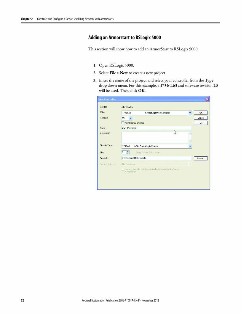
Chapter 2 Construct and Configure a Device-level Ring Network with ArmorStarts
Adding an Armorstart to RSLogix 5000
This section will show how to add an ArmorStart to RSLogix 5000
1 Open RSLogix 5000
2 Select File gt New to create a new project
3 Enter the name of the project and select your controller from the Type drop down menu For this example a 1756-L63 and software revision 20 will be used Then click OK
22 Rockwell Automation Publication 290E-AT001A-EN-P - November 2012
Construct and Configure a Device-level Ring Network with ArmorStarts Chapter 2
4 Add the 1756-EN2TR module to your projecta Right-click 1756 Backplane and choose New Module
Rockwell Automation Publication 290E-AT001A-EN-P - November 2012 23
Chapter 2 Construct and Configure a Device-level Ring Network with ArmorStarts
b Select the modulec Click Create
5 To add a new module to the tree right-click on Ethernet and select New Module This allows a new ArmorStart to be added to the Logix Project
24 Rockwell Automation Publication 290E-AT001A-EN-P - November 2012
Construct and Configure a Device-level Ring Network with ArmorStarts Chapter 2
6 Select the ArmorStart in your application and click OK
7 Enter a Name for this ArmorStart and an Ethernet address For this example the Private Network setting will be used This should be set to match the IP address switch setting on the ArmorStart Then press OK
Note Refer to ArmorStart Addressing Configuration on page 17 to set an IP address on the device
Rockwell Automation Publication 290E-AT001A-EN-P - November 2012 25
Chapter 2 Construct and Configure a Device-level Ring Network with ArmorStarts
8 Complete configuration information for the module in your RSLogix 5000 project
The following graphic shows the IO configuration for an example DLR network
9 Download the program to the Logix controller
10 Go online with the controller and leave it in Program mode
26 Rockwell Automation Publication 290E-AT001A-EN-P - November 2012
Construct and Configure a Device-level Ring Network with ArmorStarts Chapter 2
Enable Ring Supervisor in RSLogix 5000 Programming Software
After 1756-EN2TR module or 1783-ETAP 1783-ETAP1F or 1783-ETAP2F taps have been added to your RSLogix 5000 programming software project the ring supervisor mode must be enabled
If using RSLogix 5000 programming software to configure the ring supervisor and monitor diagnostics on the DLR network the controller must be online
To enable the 1756-EN2TR module or 1783-ETAP 1783-ETAP1F or 1783-ETAP2F tap as a ring supervisor follow these steps
The steps to enable a ring supervisor are basically the same for the 1756-EN2TR module or 1783-ETAP 1783-ETAP1F or 1783-ETAP2F tap This example shows how to do it for the 1756-EN2TR module
1 For your project online with the controller double-click on a supervisor-capable device in the IO configuration tree
Rockwell Automation Publication 290E-AT001A-EN-P - November 2012 27
Chapter 2 Construct and Configure a Device-level Ring Network with ArmorStarts
2 Click the Network tab to Enable Supervisor Mode
Configuration takes effect immediately you do not need to click Apply or OK
3 Click the Advanced button on the Network tab
4 Configure supervisor-related parameters as shown in the screen shot below
For these parameters you must click Set after entering a value
5 Click Set
28 Rockwell Automation Publication 290E-AT001A-EN-P - November 2012
Construct and Configure a Device-level Ring Network with ArmorStarts Chapter 2
Configure and Enable a Ring Supervisor in RSLinx Classic Communication Software
A ring supervisor can be configured for the DLR network through RSLinx Classic communication software
For more information regarding the Required RSLinx Classic Communication software Revision required refer to Appendix B
To configure a ring supervisor in RSLinx Classic Communication Software follow these steps
This example is for the 1783-ETAP tap Follow these steps
1 Launch RSLinx Classic Communication Software
2 Browse to the DLR network that is being set up
IMPORTANT For Beacon Interval Beacon Timeout and Ring Protocol VLAN ID we recommend that the default values be used
Functionality Description Default Setting
Supervisor Precedence A supervisor precedence number may be configured for each device that is configured as a ring supervisor The highest possible supervisor precedence value is 255When multiple nodes are enabled as supervisors the node with the highest precedence value is assigned as the active ring supervisor the other nodes automatically become back-up supervisorsWe recommend that youbull configure at least one back-up supervisor nodebull set the desired Active Ring Supervisor with a relatively high supervisor-
precedence value compared to the back-up node(s)bull keep track of the networkrsquos supervisor-precedence valuesIf multiple supervisors are configured with the same precedence value (the factory default value for all supervisor-capable devices is 0) the node with the numerically highest MAC address becomes the active supervisor
0
Beacon Interval Beacon interval is the frequency of the active ring supervisor transmitting a beacon frame through both of its Ethernet ports This parameter is user configurable for any time between 200 μS and 100 mSFor more information on how this parameter relates to network performance see page 61
400 μS
Beacon Timeout The beacon timeout is the amount of time that nodes wait before timing out the reception of beacon frames and taking appropriate action Supervisors support a range from 400μS to 500mSFor more information on how this parameter relates to network performance see page 61
1960 μS
Ring Protocol VLAN ID Reserved for future use 0
Rockwell Automation Publication 290E-AT001A-EN-P - November 2012 29
Chapter 2 Construct and Configure a Device-level Ring Network with ArmorStarts
If the Electronic Data Sheet (EDS) file is not installed on the module configured to be the ring supervisor it will appear with a question mark () To obtain and use the EDS file
bull right-click the module and choose to upload the EDS file from the device or
bull download the EDS file from httpwwwrockwellautomationcomrockwellautomationsupportnetworksedspage
3 Access the supervisor-capable nodersquos propertiesa Right-click the nodeb Choose Module Configuration
The General tab appears with information about the module
4 Click the Network tab to Enable Supervisor Mode
Configuration takes effect immediately there is no need to click Apply or OK
30 Rockwell Automation Publication 290E-AT001A-EN-P - November 2012
Construct and Configure a Device-level Ring Network with ArmorStarts Chapter 2
5 Click the Advanced button to configure supervisor-related parameters
Rockwell Automation Publication 290E-AT001A-EN-P - November 2012 31
Chapter 2 Construct and Configure a Device-level Ring Network with ArmorStarts
IMPORTANT For Beacon Interval Beacon Timeout and Ring Protocol VLAN ID use the default values
Functionality Description Default Setting
Supervisor Precedence
You may configure a supervisor precedence number for each device configured as a ring supervisor The highest possible supervisor precedence value is 255When multiple nodes are enabled as supervisor the node with the highest precedence value is assigned as the active ring supervisor the other nodes automatically become back-up supervisorsWe recommend that youbull configure at least one back-up supervisor nodebull set the desired Active Ring Supervisor with a relatively high supervisor-
precedence value compared to the back-up node(s)bull keep track of the networkrsquos supervisor-precedence valuesIf multiple supervisors are configured with the same precedence value (the factory default value for all supervisor-capable devices is 0) the node with the numerically highest MAC address becomes the active supervisor
0
Beacon Interval Beacon Interval is the frequency to which the active ring supervisor transmits a beacon frame through both of its Ethernet ports This parameter is user configurable for any time between 200 μS and 100 mSFor more information on how this parameter relates to network performance see page 58
400 μS
Beacon Timeout The beacon timeout is amount of time nodes wait before timing out the reception of beacon frames and taking appropriate action Supervisors support a range from 400 μS to 500 mSFor more information on how this parameter relates to network performance seepage 58
1960 μS
Ring Protocol VLAN ID
Reserved for future use 0
Enable IGMP Snooping
For more information on IGMP Snooping see page 35 Enabled
Enable IGMP Querier
For more information on IGMP Querier see page 35 Disabled
Enable Device Port Debugging Mode
For more information on Device Port Debugging Mode see page 59 Disabled
32 Rockwell Automation Publication 290E-AT001A-EN-P - November 2012
Construct and Configure a Device-level Ring Network with ArmorStarts Chapter 2
Complete the Physical Connections of the Network
After the ring supervisor nodes are configured and enabled the physical connection of the network must be completed to establish a complete DLR network
The figure below shows an example DLR network with all physical connections complete
Figure 4 - Example Device-level Ring Topology with All Connections Complete
Rockwell Automation Publication 290E-AT001A-EN-P - November 2012 33
Chapter 2 Construct and Configure a Device-level Ring Network with ArmorStarts
Verify Supervisor Configuration
The configuration and overall DLR network status can be verified in either RSLogix 5000 programming software or RSLinx Classic communication software
1 Access the supervisor nodersquos properties as shown previously in this chapter
2 Click the Network tab
3 Check the Network Topology and Network Status Fields
For a 1756-EN2TR module or the 1783-ETAP 1783-ETAP1F and 1783-ETAP2F tap the supervisor configuration can also be verified through the modulersquos diagnostic web pages For more information on monitoring diagnostics via an EtherNetIP modulersquos web pages see Monitor a DLR Network starting on page 37
34 Rockwell Automation Publication 290E-AT001A-EN-P - November 2012
Construct and Configure a Device-level Ring Network with ArmorStarts Chapter 2
IGMP Snooping This functionality is enabled by default in the 1783-ETAP 1783-ETAP1F and 1783-ETAP2F taps and is commonly used to manage multicast traffic on the network When in use this functionality allows the tap to multicast data to only those devices that need the data rather than to all devices connected to the network
For snooping to work there must be a device present that is running a querier Typically the device is a router or a switch such as the Stratix 6000 Stratix 8000 or Stratix 8300 managed switch
Once DHCP is enabled the switch could change the IP addresses on the ArmorStarts depending on network demand which could cause RSlogix5000 to loose communication with the device as connectivity is established via the AOP in the initial configuration
IGMP Querier This functionality is disabled by default The IGMP Querier functionality enables a 1783-ETAP 1783-ETAP1F or 1783-ETAP2F tap or switch such as a Stratix managed switch to send out a query to all devices on the network It determines what multicast addresses are of interest to a specific node or a group of nodes
The IGMP Querier functionality should be enabled for at least one node on the network The 1783-ETAP 1783-ETAP1F or 1783-ETAP2F tap managed switches and routers are examples of devices that support IGMP Querier functionality
IMPORTANT If DHCP for the Armostart is still required the Internet Group Management Protocol (IGMP) snooping on the E-tap must be disabled via the AOP
IMPORTANT If the IGMP Querier functionality is not enabled for at least one node on the network multicast traffic on the network may eventually create network performance issues
Rockwell Automation Publication 290E-AT001A-EN-P - November 2012 35
Chapter 2 Construct and Configure a Device-level Ring Network with ArmorStarts
However for all devices that are configured on the network with the IGMP Querier parameter enabled an IP address other than the factory default value must also be set for those devices If multiple devices on the network enable this functionality only the node with the lowest IP address becomes the active IGMP Querier node
IGMP Version
If the IGMP Querier is enabled a Querier Version must be selected The default version is Version 2
36 Rockwell Automation Publication 290E-AT001A-EN-P - November 2012
Chapter 3
Monitor a DLR Network
Introduction Use this chapter to learn how to monitor the DLR network
Methods to Monitor a DLR Network
Network diagnostic information can be retrieved from the ring supervisor-capable devices using the following
bull RSLogix 5000 programming software status pages
bull RSLinx communication software status pages
bull Device web pages
bull EtherNetIP Device Level Ring (DLR) network diagnostics faceplate
bull Programmatically through the use of a MSG instruction
RSLogix 5000 Programming Software Status Pages
RSLogix 5000 programming software version 1701 or later must be used and the appropriate AOPs installed to use the softwarersquos profile status pages
RSLinx Communication Software Status Pages
To monitor the network with this method the RSLinx communication software version 255 or later must be used
Topic Page
Methods to Monitor a DLR Network 37
Monitor Status Pages 39
Monitor ArmorStart Internal Web Server 44
Monitor via Faceplate Integration 45
Monitor Diagnostics via MSG Instructions 46
Rockwell Automation Publication 290E-AT001A-EN-P - November 2012 37
Chapter 3 Monitor a DLR Network
ArmorStart Internal Web Server
Rockwell Automation provides an internal embedded web server with each ArmorStart EtherNetIP The internal web server allows you to view information and configure the ArmorStart via a web browser The ArmorStart EtherNetIP can also be set up from the web server to send e-mail notifications The embedded web server is used to access configuration and status data It provides the user with the ability to view and modify the device configuration without having access to RSLogix 5000 Security in the form of an administrative password can be set The default login is Administrator There is no password set by default
EtherNetIP Device Level Ring (DLR) Network Diagnostics Faceplate
The diagnostics faceplate contains two major components
bull Logic code (encapsulated in an Add-On Instruction) that allows the controller to retrieve real-time DLR network status information
bull HMI faceplate graphics to allow the data to be visualized on an operator interface
Programmatically Through the Use of a MSG Instruction
For more information on how to monitor the DLR network via MSG Instructions see page 46
38 Rockwell Automation Publication 290E-AT001A-EN-P - November 2012
Monitor a DLR Network Chapter 3
Monitor Status Pages Both RSLogix 5000 programming software and RSLinx Classic communication software offer status pages that can be used to monitor the networkrsquos performance
RSLogix 5000 Programming Software Status Pages
Monitor the networkrsquos diagnostic information through the RSLogix 5000 programming software when the software is online
To monitor the network in RSLogix 5000 programming software follow these steps
1 Verify that the project is online
2 Access the active supervisor nodersquos propertiesa Right-click the modulersquos entry in the Controller Organizerb Click properties
Rockwell Automation Publication 290E-AT001A-EN-P - November 2012 39
Chapter 3 Monitor a DLR Network
3 Use the Network tab to monitor diagnostics
40 Rockwell Automation Publication 290E-AT001A-EN-P - November 2012
Monitor a DLR Network Chapter 3
RSLinx Communication Software
To monitor the network in RSLinx communication software follow these steps
1 Click RSWho to browse the network
2 Access the property pages for the active supervisor nodea Open the driver that shows the nodes on the DLR networkb Right-click the node that you want to monitor performancec Click on the choice that you need to access
Multiple choices appear
These options are shown in the following sections
Rockwell Automation Publication 290E-AT001A-EN-P - November 2012 41
Chapter 3 Monitor a DLR Network
Module Configuration
This series of tabs providesbull General informationbull Connection informationbull Module informationbull Internet protocolbull Port configurationbull Network information
The example below shows a ring fault between nodes at IP addresses 10888021 and MAC ID 00-00-BC-02-48-D5
42 Rockwell Automation Publication 290E-AT001A-EN-P - November 2012
Monitor a DLR Network Chapter 3
There are multiple fields used to monitor network diagnostics
Field Definition
Network Topology Possible values here can be Linear or Ring
Network Status Displays if the network is operating normally (Normal) or has experienced a fault (Ring Fault) as shown in the previous example screen
Active Ring Supervisor Displays the IP address or MAC address of the active ring supervisor
Active Supervisor Precedence For more information on this field see Active Ring Supervisor on page 11
Enable Ring Supervisor Configurable field that lets you to set the node as a ring supervisor
Ring Faults Detected Number of faults detected on the network since the last module power cycle or counter reset
Supervisor Status Displays whether this node is the active ring supervisor (Active) a back-up supervisor (Back-up) a ring node or part of a linear network
Last Active Node on Port 1 The last node the active ring supervisor can communicate with on Port 1 This value is an IP address or a MAC ID and remains latched until the Verify Fault Location button is clicked
Last Active Node on Port 2 The last node the active ring supervisor can communicate with on Port 2 This value is an IP address or a MAC ID and remains latched until the Verify Fault Location button is clicked
Status Displays whether a fault exists on the ring
IMPORTANT If the Network Topology field = Ring and the Network Status field = Normal the Last Active Node fields will display the last fault information even though it has been correctedTo clear the last fault information from these fields click Verify Fault Location You may see a message informing you that the supervisor is no longer in fault mode and the fields will be cleared
Rockwell Automation Publication 290E-AT001A-EN-P - November 2012 43
Chapter 3 Monitor a DLR Network
How to Access the ArmorStart EtherNetIP Internal Web Server
Open your preferred internet web browser and enter the IP address of the desired ArmorStart For this example 192168122 will be used
Use the links on the left-most navigation bar to see each available web page The screen below shows Ring Statistics for the ArmorStart 280E
44 Rockwell Automation Publication 290E-AT001A-EN-P - November 2012
Monitor a DLR Network Chapter 3
EtherNetIP Device Level Ring (DLR) Network Diagnostics Faceplate Overview
The EtherNetIP Device Level Ring (DLR) network diagnostics faceplate provides basic DLR network status information to the user to assist with monitoring and troubleshooting a DLR network
The diagnostics faceplate contains two major components
bull Logic code (encapsulated in an Add-On Instruction) that allows the controller to retrieve real-time DLR network status information
bull HMI faceplate graphics to allow the data to be visualized on an operator interface
The DLR diagnostics faceplate application can be downloaded from the Rockwell Automation Sample Code website at httpsamplecoderockwellautomationcom
Besides the individual Logix and View project components a demo application is also included with the downloaded file
Rockwell Automation Publication 290E-AT001A-EN-P - November 2012 45
Chapter 3 Monitor a DLR Network
Monitor Diagnostics via MSG Instructions
Network diagnostic information can also be obtained programmatically via MSG instructions in RSLogix 5000 programming software For example you can
bull Get all ring diagnostic informationbull Get a ring participant listbull Get the active supervisorbull Clear rapid ring faultsbull Verify a fault locationbull Reset a fault counterbull Enable and configure a ring supervisor
This information can be displayed on an HMI device or manipulated in the project code
Figure 5 - Example Use of MSG Instruction
This example describes how to retrieve diagnostic information from the DLR network Follow these steps
1 Enter a MSG instruction into the rung of logic
2 Configure the MSG instruction to retrieve ring diagnostic information service as shown in the following screen shots
IMPORTANT Make sure the tag created is sized appropriately to hold all of the data that you are reading or writing For more information see page 48
46 Rockwell Automation Publication 290E-AT001A-EN-P - November 2012
Monitor a DLR Network Chapter 3
3 Configure the MSG instructionrsquos communication path to point to the active supervisor node
The path on the following screen is one example path
IMPORTANT When using the Custom Get_Attributes_All (01) service pointing to an active supervisor node will retrieve all of the attributes listed in Retrieve All Diagnostic Information Attribute Description on page 50Pointing to a non-supervisor node will retrieve only the Network Topology and Network Status attribute informationPointing to backup supervisor node will retrieve the current active supervisorrsquos IP address
Rockwell Automation Publication 290E-AT001A-EN-P - November 2012 47
Chapter 3 Monitor a DLR Network
Use Specific Values on the Configuration Tab
Use the values on the Configuration tab of your MSG instruction to perform specific services Sample DLR network diagnostic application code for example Add-on Instruction or HMI faceplate graphics is available on the Rockwell Automation Sample Code Library For more information about the Rockwell Automation Sample Code Library see httpwwwrockwellautomationcomsolutionsintegratedarchitectureresources5html
➊ This request only works if there are fewer than 40 nodes on the network If there are more nodes than will fit in a single message an error will be returned➋ Use a Destination Length of 54 bytes if using firmware revision 3x or later for the 1756-EN2TR module or firmware revision 2x or later for the 1783-ETAP
1783-ETAP1F or 1783-ETAP2F taps
Request Description Message Type
Service Type
Service Code (HEX)
Class (HEX)
Instance Attribute (HEX)
Source Element
Source Length (Bytes)
Destination Destination Length (bytes)
Retrieve All Ring Diagnostic Information
Information for this request is listed in Retrieve All Ring Diagnostic Information on page 49
CIP Generic Custom 1 47 1 NA LeftBlank
0 Tag 50or54 ➋
Request Ring Participant List ➊
Information for this request is listed in Request the Ring Participant List on page 51
CIP Generic Get Attribute Single
e 47 1 9 NA NA Tag 10node
Get Active Supervisor
Obtain the IP address and MAC ID of the active supervisor on the DLR network
CIP Generic Get Attribute Single
e 47 1 a NA NA Tag 10
Acknowledge Rapid Ring Faults Condition
Request supervisor to resume normal operation after encountering a rapid ring fault condition
CIP Generic Custom 4c 47 1 NA NA NA NA
Verify a Fault Location
Request supervisor to update Last Active Node values
CIP Generic 4b 47 1 NA NA NA NA NA
Reset the Ring Fault Counter
Reset the number of ring faults detected on the DLR network
CIP Generic Set Attribute Single
10 47 1 5 Tag 2 NA NA
Enable and Configure a Ring Supervisor
Information for this request is listed in Enable and Configure a Ring Supervisor on page 52
CIP Generic Set Attribute Single
10 47 1 4 Tag 12 NA NA
48 Rockwell Automation Publication 290E-AT001A-EN-P - November 2012
Monitor a DLR Network Chapter 3
Retrieve All Ring Diagnostic Information
By performing the Retrieve All Ring Diagnostic Information request on an active supervisor the MSG instruction returns the following information
➊ RSLogix 5000 programming software may display the value in this field as negative numbers To better understand the value we recommend you view it in HEX format
Destination Tag Attribute Name Description Possible Values
SINT [0] Network Topology Current network topology mode 0 = Linear
1 = Ring
SINT [1] Network Status Current status of the network 0 = Normal
1 = Ring Fault
2 = Unexpected Loop Detected
3 = Partial Network Fault
4 = Rapid FaultRestore Cycle
SINT [2] Ring Supervisor Status Ring supervisor active status flag 0 = Node is functioning as a backup
1 = Node is functioning as the active ring supervisor
2 = Node is functioning as a normal ring node
3 = Node is operating in a non-DLR topology
4 = Node cannot support the currently operating ring parameters thatis Beacon Interval andor Beacon Timeout
Ring Supervisor Config Ring Supervisor configuration parameters
SINT [3] Ring Supervisor Enable Ring supervisor enable flag 0 = Node is configured as a normal ring node (default configuration)
1 = Node is configured as a ring supervisor
SINT [4] Ring Supervisor Precedence Precedence value of a ring supervisor ➊ Valid value range = 0hellip255
0 = Default value
SINT [5-8] Beacon Interval Duration of ring beacon interval Valid value range = 200 μshellip100 ms
Default = 400 μs
SINT [9-12] Beacon Timeout Duration of ring beacon timeout Value value range = 400 μshellip500 ms
Default value = 1960 μs
SINT [13-14] DLR VLAN ID Valid ID to use in ring protocol messages Valid value range = 0hellip4094
Default value = 0
SINT [15-16] Ring Faults Count Number of ring faults since power up ➊
Rockwell Automation Publication 290E-AT001A-EN-P - November 2012 49
Chapter 3 Monitor a DLR Network
Retrieve All Diagnostic Information Attribute Description
➊ This destination tag is available only with the 1756-EN2TR module firmware revision 3x or later 1783-ETAP 1783-ETAP1F and 1783-ETAP2F taps firmware revisions 2x or later If using the 1783-ETAP tap firmware revision 1x your program does not include this destination tag
➋ RSLogix 5000 programming software may display the value in this field as negative numbers To better understand the value we recommend you view it in HEX format
Destination Tag Attribute Name Description Possible Values
Last Active Node on Port 1 Last active node at the end of the chain through port 1 of the active ring supervisor during a ring fault
SINT [17-20] Device IP address ➋ Any valid IP address value
A value = 0 indicates no IP address has been configured for the device
SINT [21-26] Device MAC address ➋ Any valid Ethernet MAC address
Last Active Node on Port 2 Last active node at the end of the chain through port 2 of the active ring supervisor during a ring fault
SINT [27-30] Device IP address ➋ Any valid IP address value
A value = 0 indicates no IP address has been configured for the device
SINT [31-36] Device MAC address ➋ Any valid Ethernet MAC address
SINT [37-38] Ring Protocol Participants Count
Number of devices in the ring protocol participants list
Active Supervisor Address IP andor Ethernet MAC address of the active ring supervisor
SINT [39-42] Supervisor IP address Any valid IP address value
A value = 0 indicates no IP address has been configured for the device
SINT [43-48] Supervisor MAC address Any valid Ethernet MAC address
SINT [49] Active Supervisor Precedence
Precedence value of the active ring supervisor
SINT [50-53]➊ Capability Flags Alerts you that the device is capable of operating as a supervisor and beacon-based ring node
0x22
50 Rockwell Automation Publication 290E-AT001A-EN-P - November 2012
Monitor a DLR Network Chapter 3
Request the Ring Participant List
When requesting the Ring Participant List service on the DLR network the MSG instruction returns the following information
Request the Ring Participant List Attribute Description
➊ This attribute will return an array of the data shown one entry for each node The Ring Protocol Participants Count attribute determines the number entries
➋ This tag displays only IP addresses for ring participants that have been configured with one For example you may have a 1783-ETAP tap connected to the network that has not been assigned an IP address In that case no address is shown for the 1783-ETAP tap
➌ RSLogix 5000 programming software may display the value in this field as negative numbers To better understand the value we recommend you view it in HEX format
➍ Unlike destination tag SINT [0-3] where IP addresses are displayed only for ring participants configured with an IP address this tag displays MAC addresses for all ring participants because every ring participant has a MAC address
Destination Tag Attribute Name Description Possible Values
Ring Protocol Participants List ➊
List of devices participating in ring protocol
SINT [0-3] Device IP address ➋➌ Any valid IP address value
A value = 0 indicates no IP address has been configured for the device
SINT [4-9] Device MAC address ➌➍ Any valid Ethernet MAC address
Rockwell Automation Publication 290E-AT001A-EN-P - November 2012 51
Chapter 3 Monitor a DLR Network
Enable and Configure a Ring Supervisor
When performing the Enable and Configure a Ring Supervisor request on a supervisor-capable device configure the MSG instruction with the following information
Enable and Configure a Ring Supervisor Attribute Description
➊ RSLogix 5000 programming software may display the value in this field as negative numbers To better understand the value we recommend you view it in HEX format
Source Tag Attribute Name Description Possible Values
Ring Supervisor Config Ring Supervisor configuration parameters
SINT [0] Ring Supervisor Enable Ring supervisor enable flag 0 = Node is configured as a normal ring node (default configuration)1 = Node is configured as a ring supervisor
SINT [1] Ring Supervisor Precedence Precedence value of a ring supervisor ➊
Valid value range = 0hellip2550 = Default value
SINT [2-5] Beacon Interval Duration of ring beacon interval
Valid value range = 200 μshellip100 000 μsDefault = 400 μs
SINT [6-9] Beacon Timeout Duration of ring beacon timeout ➊
Value value range = 400 μshellip500 000 μsDefault value = 1960 μs
SINT [10-11] DLR VLAN ID Valid ID to use in ring protocol messages ➊
Valid value range = 0hellip4094Default value = 0
52 Rockwell Automation Publication 290E-AT001A-EN-P - November 2012
Chapter 4
Troubleshoot a DLR Network
Introduction Use this chapter to learn how to troubleshoot the DLR network
General Solutions for Linear or DLR Networks
Before attempting to correct specific faults on the linear or DLR network we recommend that you first take the following actions when a fault appears
bull For a DLR networkndash Verify that at least one node has been configured as a supervisor
on the network and that Network Topology = Ringndash Verify that all cables on the network are securely connected
to each devicendash Verify that all devices that require an IP address have one assigned
correctlyndash Check the Network Status field on the active supervisor nodersquos status
page to determine the fault typebull For a linear network
ndash Verify that none of the nodes are configured as a supervisor on the network and that Network Topology = LinearIf any nodes on a linear network are configured as a supervisor it may impact communication to other devices connected to the network
ndash Verify that all cables on the network are securely connected to each device
ndash Verify that all devices that require an IP address have one assigned correctly
If the fault is not cleared after completing the actions listed above use the tables in the rest of this chapter to troubleshoot issues specific to a DLR network or a linear network
Topic Page
General Solutions for the Linear or DLR Networks 53
Duplicate IP Address Detection 54
Specific Issues on the DLR Network 55
Network Recovery Performance 58
Device Port Debugging Mode 59
Rockwell Automation Publication 290E-AT001A-EN-P - November 2012 53
Chapter 4 Troubleshoot a DLR Network
Duplicate IP Address Detection
Some EtherNetIP communication modules support duplicate IP address detection The module verifies that its IP address does not match any other network devicersquos IP address when performing either of these tasks
bull Connect the module to an EtherNetIP network
bull Change the modulersquos IP address
If the modulersquos IP address matches that of another device on the network the modulersquos EtherNetIP port transitions to Conflict mode In Conflict mode these conditions exist
bull OK status indicator is blinking red
bull Network (NET) status indicator is solid red
bull On some EtherNetIP communication modules the module status display indicates the conflict
The display scrollsOK ltIP_address_of_this_modulegt Duplicate IP
ltMac_address_of_duplicate_node_detectedgt
For example OK 108860196 Duplicate IP - 0000BC0234B4
bull On some EtherNetIP communication modules the modulersquos diagnostic webpage displays information about duplicate IP address detection
For more information on which EtherNetIP communication modules support displaying duplicate IP address on their diagnostic webpage see the Technical Note titled Logix modules Duplicate IP address detection enhancement 118216 in the Technical Support Knowledgebase available at httpwwwrockwellautomationcomknowledgebase
54 Rockwell Automation Publication 290E-AT001A-EN-P - November 2012
Troubleshoot a DLR Network Chapter 4
Specific Issues on the DLR Network
Use the following table to troubleshoot possible specific issues on the DLR or linear network that are not solved by the actions described on the previous page
Issue Description Solution
Supervisor Reports a Ring Fault A link on the DLR network may be brokenbull intentionally for example because of adding or deleting nodes but not making all
physical connections to restore the setup of the network withwithout the nodebull unintentionally for example because a cable is broken or a device malfunctionsWhen this fault occurs the adjacent nodes to the faulted part of the network are displayed in the Ring Fault group and the Network Status field = Ring FaultThe screen shot below shows the Ring Fault section with IP addresses appearing for the last active nodes The faulted node is between nodes 108880115 and 108880208 If the IP address of either node is not available the software will display the nodersquos MAC ID
Once the fault is corrected the ring is automatically restored and the Network Status field returns to Normal
Determine where the fault condition exists and correct itClick the Refresh Communication link as needed to update the Ring Fault information to determine where the fault condition existsFinally DevicePort Debugging Mode functionality on the 1783-ETAP tap may be used to analyze a suspicious nodeFor more information refer to Device Port Debugging Mode on page 59
Rockwell Automation Publication 290E-AT001A-EN-P - November 2012 55
Chapter 4 Troubleshoot a DLR Network
Issue Description Solution
Rapid Ring Fault When a Rapid Ring Fault occurs the following events occurbull The active supervisor will block traffic on port 2 resulting in possible network
segmentation that is some nodes may become unreachablebull The Link 2 status indicator on the active supervisor is offbull As soon as the fault occurs for both RSLogix 5000 programming software and
RSLinx communication software the Status field = Rapid FaultRestore Cycles
Any of the following may cause a Rapid Ring Faultbull 5 intentional disconnectionsreconnections of a node from the network within 30
secondsbull A duplex mismatch between two connected devicesbull Electromagnetic noise on the networkbull Unstable physical connections such as intermittent connectorsGiven the nature of a Rapid Ring Fault the Last Active Node information may not be accurate when a Rapid Ring Fault condition is present
Multiple possible solutions existbull For the disconnections and reconnections issue no
solution is requiredClear the fault after reconnecting the device to the network permanentlybull For the duplex mismatch issue reconfigure the duplex
parameters to make sure they match between the devices
bull For the electromagnetic noise issue determine where the noise exists and eliminate it or use a protective shield in that location
bull For the unstable connections issue determine where they exist on the network and correct them
bull Check the media counters for all devices on the network The device with the highest media counter count is most likely causing the Rapid Ring Fault
bull Remove devices from the network one by one If the Rapid Ring Fault disappears after a device is removed that device is causing the fault
bull DevicePort Debugging Mode functionality on the 1783-ETAP tap may be used to analyze a suspicious node
For more information refer to Device Port Debugging Mode on page 59bull Finally the Beacon Interval or Timeout configuration
may not be appropriate for the networkHowever if these values need to be changed we recommend that you contact Rockwell Automation technical supportOnce the fault is fixed click Clear Fault
56 Rockwell Automation Publication 290E-AT001A-EN-P - November 2012
Troubleshoot a DLR Network Chapter 4
Issue Description Solution
Partial Fault Condition A partial network fault occurs when traffic is lost in only one direction on the network because a ring member is not forwarding beacons in both directions for example a component failureThe active ring supervisor detects a partial fault by monitoring the loss of Beacon frames on one port and the fault location appears in the Ring Fault section of the Network tab When a partial fault is detected the active ring supervisor blocks traffic on one port At this point the ring is segmented due to the partial fault condition The nodes adjacent to the faulted part of the network are displayed in the Ring Fault group with either IP addresses or MAC IDs for each node displayedWhen this fault occurs the Network Status field = Partial Fault ConditionOnce the fault is corrected it automatically clears and the Network Status field returns to Normal
Determine where the fault condition exists and correct itAdditionally the DevicePort Debugging Mode functionality also known as Port Mirroring on a 1783-ETAP 1783-ETAP1F or 1783-ETAP2F tap may be used to analyze a suspicious nodeFor more information refer to Device Port Debugging Mode on page 59
Media Counter Errors or Collisions
The media counters screen displays the number of physical layer errors or collisions The screen below indicates where to check for errors encountered Error levels are displayed depending on what caused the error For example an Alignment Error is displayed in the Alignment Error field
On a DLR network it is not uncommon to see low levels of media counter errors For example if the network breaks a low level of media counter errors appears With a low level of media counter errors the value typically does not continuously increase and often clearsA high level of media counter errors typically continues to increase and does not clear For example there is a mismatch of speed between two linked nodes a high level of media counter errors appears steadily increasing and not clearingTo access the RSLinx screen above browse the network right-click on the device select Module Properties and click the Port Diagnostics tab
Some example solutions includebull Check for a mismatch of speed andor duplex between
two linked nodesbull Verify that all cables on the network are securely
connected to each devicebull Check for electromagnetic noise on the network If you
find it eliminate it or use a protective shield in that location
Rockwell Automation Publication 290E-AT001A-EN-P - November 2012 57
Chapter 4 Troubleshoot a DLR Network
Network Recovery Performance
When measuring the networkrsquos performance with regard to dealing with fault conditions consider the network recovery time Network recovery is the time for all of the following to take place
1 The supervisor node recognizes that a fault exists on the network
2 The supervisor node reconfigures the network because of the fault
3 The supervisor node communicates to the network nodes that a fault condition exists
4 The network nodes reconfigure themselves because of the fault
With the default beacon interval value of 400 mS and beacon timeout value of 1960 mS the worst-case time for network recovery times are
bull 2890 mS for a copper DLR network This recovery time is based on 100 m copper segments between nodes on the network
bull 3140 mS for a fiber-optic DLR network This recovery time is based on 2 kM fiber-optic cable segments between nodes on the network
When considering the values listed above keep in mind
bull Recovery time may actually occur faster than the times listed
bull The recovery times listed above assume that your networkrsquos nodes are operating at 100 Mbps speed and full-duplex mode We recommend that your nodes generally operate in this mode for DLR networks
bull If other node conditions exist such as a node operating at 10 Mbps full-duplex or 10100 Mbps half-duplex the recovery times will vary from the times listed above
If this is the case for your application the beacon interval and beacon timeout will need to be changed We recommend that you first contact Rockwell Automation technical support if these parameters need to be changed
bull The value assumes that the majority of the traffic on your network is EtherNetIP traffic
58 Rockwell Automation Publication 290E-AT001A-EN-P - November 2012
Troubleshoot a DLR Network Chapter 4
Device Port Debugging Mode
This functionality is disabled by default Device Port Debugging mode which is similar to port mirroring can be used to monitor data received on the 1783-ETAP 1783-ETAP1F or 1783-ETAP2F taprsquos two network ports Monitor the data over the device port to a device such as a personal computer running a protocol analyzer application for advanced network debugging or analysis
When device port debugging is used on a 1783-ETAP the device connected to the 1783-ETAP taprsquos front port receives all of the data traversing the ring (both directions)
Device Port Debugging Example Network
When using the Device Port Debugging mode functionality insert the 1783-ETAP with the network analyzer connected to the device port It is inserted at the spot on the ring network where the node in question is located The graphic below shows a 1783-ETAP tap inserted in the network
IMPORTANT This functionality should be used only when troubleshooting the network and not in normal network operation
Rockwell Automation Publication 290E-AT001A-EN-P - November 2012 59
Chapter 4 Troubleshoot a DLR Network
Combined total network bandwidth of the traffic received on the two 1783-ETAP 1783-ETAP1F or 1783-ETAP2F taprsquos ports connected to the network should not exceed the taprsquos device port capacity The speed setting determines the device portrsquos capacity
Configure the device port on a 1783-ETAP 1783-ETAP1F or 1783-ETAP2F tap to either of two speed settings
bull 100 Mbps - default settingbull 10 Mbps
If the bandwidth exceeds the capacity of the taprsquos device port some frames from the ring will be dropped before reaching the device port These dropped frames do not impact the traffic on the rest of the DLR network
The device port setting determines how much network traffic the 1783-ETAP 1783-ETAP1F or 1783-ETAP2F tap can handle before dropping frames The circled section in the graphic below shows the Port Buffer Utilization of the Device Port In this example the value is zero because a ring fault exists on the network
60 Rockwell Automation Publication 290E-AT001A-EN-P - November 2012
Appendix A
Network Usage Guidelines and Recommendations
Consider the following guidelines and recommendations when using a DLR or linear network
GuidelineRecommendation Explanation
Use fewer than 50 nodes on a single DLR networkIf your application requires more than 50 nodes we recommend that the nodes are broken into separate but linked DLR networks
If you use more than 50 nodes on a single DLR networkbull Your network has a greater chance of multiple faults
occurring on the networkbull Network recovery times from faulted DLR network
are higher
Do not configure a supervisor on a linear network If your linear network includes non-DLR nodes and has a supervisor-enabled node on the network it may impact communication to non-DLR devices connected to the linear network
If you must connect a device that is running at 10 Mbps to a DLR or linear network do so through a 1783-ETAP 1783-ETAP1F or 1783-ETAP2F tap device port
The 1783-ETAP 1783-ETAP1F and 1783-ETAP2F taps can operate at 100 Mbps on the DLR network this is the optimal speed for a network If you connect a 10 Mbps device directly to the network instead of through a tap the linear or DLR network traffic slows to 10 MbpsAdditionally if the 10 Mbps device is connected to the network without a 1783-ETAP tap network recovery times are significantly impacted
Configure multiple supervisor nodes per ring If your DLR network only has one supervisor and the supervisor experiences a fault none of the other nodes become the active supervisor In this case the network becomes a linear network until the fault is corrected and the DLR network restoredAnother reason to configure multiple supervisor nodes is for replacing an active supervisor node with an out-of-box replacement the new device will not be enabled as a supervisor (by default) and there would still be no supervisor on the network
Rockwell Automation Publication 290E-AT001A-EN-P - November 2012 61
Appendix A Network Usage Guidelines and Recommendations
GuidelineRecommendation Explanation
Connect switches to a DLR network via 1783-ETAP 1783-ETAP1F or 1783-ETAP2F taps
If switches are connected to the DLR network without the use of a 1783-ETAP 1783-ETAP1F or 1783-ETAP2F tap the network may experience unpredictable behavior and network performance is unknown
Run all nodes on the DLR network at 100 Mbps and in Full-Duplex mode
These configuration values provide the best performance for your networkAdditionally we recommend that youbull Use auto-negotiate for all nodes on the DLR networkbull Do not use auto-negotiate on one node and then force
speed on the next node linked to it
In a linear network the number of nodes to use is application specific based on the considerations described in the next box
When determining the number of nodes to use on a linear network consider the followingbull There is a delay per node as information is transmitted
to each successive node used on the networkndash The typical delay on a linear network with 100 m
copper segments between nodes is 30 mSndash The typical delay on a linear network with 2 kM
fiber-optic segments between nodes is 40 mS
The greater the number of nodes on the network the longer the total time for information to be transmitted across the entire networkbull The single point of failure possibility is greater with
each additional connectionbull Troubleshooting the network may be more difficult
with a higher number of nodes
The total time for information to be transmitted across the entire network and its effect on how many nodes to use on a linear network is related to the Requested Packet Interval (RPI)Verify that the total time to transmit information from the first node to the last node on the network is less than the RPI Make sure the network is not loaded beyond 90 of capacity
62 Rockwell Automation Publication 290E-AT001A-EN-P - November 2012
Network Usage Guidelines and Recommendations Appendix A
GuidelineRecommendation Explanation
Do not physically close a DLR network without a supervisor configured on the network
A DLR network without a supervisor node results in a network stormIf you do close the DLR network without a supervisor configured break the ring and configure at least one supervisor before physically reconnecting the network
Use the default values for the followingbull Beacon Intervalbull Beacon Timeoutbull Ring Protocol VLAN ID
Changing the default values for the parameters Beacon Interval Beacon Timeout and Ring Protocol VLAN ID can result in unpredictable network behavior and negatively impacted network performanceThe default values are optimized for a network withbull 50 or fewer nodes are on the networkbull All nodes are operating at 100 Mbps and full-duplex
modebull At least 50 of the network traffic bandwidth being
EtherNetIP trafficIf you think the values of the Beacon Interval Beacon Timeout or Ring Protocol VLAN ID need to be changed for example if any node on ring is not operating at 100 Mbps and full-duplex mode we recommend that you first contact Rockwell Automation technical support
If DHCP for the ArmorStarts is still required you will need to disable Internet Group Management Protocol (IGMP) snooping on the E-tap via the AOP
IGMP Snooping is enabled by default in the 1783-ETAP 1783-ETAP1F and 1783-ETAP2F taps and is commonly used to manage multicast traffic on the network When in use this functionality allows the tap to multicast data to only those devices that need the data rather than to all devices connected to the networkOnce DHCP is enabled the switch could change the IP addresses on the ArmorStarts depending on network demand which could cause RSlogix5000 to loose communication with the device as connectivity is established via the AOP in the initial configuration
The IGMP Querier functionality should be enabled for at least one node on the network
This functionality is disabled by default The IGMP Querier functionality enables a 1783-ETAP 1783-ETAP1F or 1783-ETAP2F tap or switch such as a Stratix managed switch to send out a query to all devices on the network to determine what multicast addresses are of interest to a specific node or a group of nodesIf the IGMP Querier functionality is not enabled for at least one node on the network multicast traffic on the network may eventually create network performance issuesThe 1783-ETAP 1783-ETAP1F or 1783-ETAP2F taps managed switches and routers are examples of devices that support IGMP Querier functionality
Rockwell Automation Publication 290E-AT001A-EN-P - November 2012 63
Appendix A Network Usage Guidelines and Recommendations
Notes
64 Rockwell Automation Publication 290E-AT001A-EN-P - November 2012
Appendix B
Required Firmware Revisions
Required Firmware Revision for an Add-On Profile
➊ The ControlFLASH Firmware Upgrade software tcan be used o upgrade a 1756-EN2TR module from firmware revision 21 to 3x or later1x or later3x or later2x or later
➋ The ControlFLASH Firmware Upgrade software can be used to upgrade a 1783-ETAP tap from firmware revision 11 to 2x or later
To download new firmware go to httpwwwrockwellautomationcomsupportamericasindex_enhtml
If the firmware revision is upgraded on the module or tap the required AOP revision listed above must be used for that revision For example if the 1756-EN2TR module is upgraded to firmware revision 3x or later AOP revision 2x or later must be used in the RSLogix 5000 programming software
Additionally if the firmware revision is upgraded on the module or tap the required RSLinx communication software must also be used for that firmware revision For more information on which RSLinx software version is required for each firmware revision see page 66
For both the 1756-EN2TR module and 1783-ETAP tap make sure that the Major Revision configured on the General tab of the devicersquos RSLogix 5000 programming software configuration matches the major revision of the physical module
IMPORTANT To download an AOP go to httpsupportrockwellautomationcomcontrolflashLogixProfileraspDepending on the firmware revision of your product a specific AOP version must be used
Firmware Revision Add-On Profile Revision Cat No
21 ➊ 1x or later 1756-EN2TR
3x or later 2x or later
11 ➋ 1x or later 1783-ETAP
2x or later 2x or later
2x or later 2x or later 1783-ETAP1F
1783-ETAP2F
Rockwell Automation Publication 290E-AT001A-EN-P - November 2012 65
Appendix B Required Firmware Revisions
If the device configuration on the General tab does not match the physical module the programming software alerts you to this mismatch when attempting to configure the Internet Protocol Port Configuration and Network tabs for that device
Required Firmware Revision for RSLinx Communication Software
➊ The ControlFLASH Firmware Upgrade software can be used to upgrade a 1756-EN2TR module from firmware revision 21 to 3x or later1x or later3x or later255 or later3x or later256 or later
➋ The ControlFLASH Firmware Upgrade software can be used to upgrade a 1783-ETAP tap from firmware revision 11 to 2x or later
To download new firmware go to httpwwwrockwellautomationcomsupportamericasindex_enhtml
If the firmware revision is upgraded on the module or tap the required RSLinx communication software listed above must be used for that revision For example if the 1756-EN2TR module is upgraded to firmware revision 3x or later AOP revision 2x or later must be used in your RSLogix 5000 programming software
Additionally if the firmware revision is upgraded on the module or tap the required AOP revision must also be used for that firmware revision For more information on which AOP revision is required for each firmware revision see page 65
IMPORTANT Depending on the firmware revision of your product specific versions of RSLinx communication software must be used
Firmware Revision Required RSLinx Communication Software Version
Cat No
21 ➊ 255 or later 1756-EN2TR
3x or later 256 or later
11 ➋ 255 or later 1783-ETAP
2x or later 256 or later
2x or later 256 or later 1783-ETAP1F
1783-ETAP2F
66 Rockwell Automation Publication 290E-AT001A-EN-P - November 2012
Rockwell Otomasyon Ticaret AŞ Kar Plaza İş Merkezi E Blok Kat6 34752 İccedilerenkoumly İstanbul Tel +90 (216) 5698400
Rockwell Automation Publication 290E-AT001A-EN-P ndash November 2012 68 Copyright copy 2012 Rockwell Automation Inc All rights reserved Printed in the USA
Rockwell Automation Support
Rockwell Automation provides technical information on the Web to assist you in using its products At httpwwwrockwellautomationcomsupport you can find technical manuals a knowledge base of FAQs technical and application notes sample code and links to software service packs and a MySupport feature that you can customize to make thebest use of these tools
For an additional level of technical phone support for installation configuration and troubleshooting we offer TechConnectSM support programs For more information contact your local distributor or Rockwell Automation representative or visit httpwwwrockwellautomationcomsupport
Installation Assistance
If you experience a problem within the first 24 hours of installation review the information that is contained in this manualYou can contact Customer Support for initial help in getting your product up and running
New Product Satisfaction Return
Rockwell Automation tests all of its products to ensure that they are fully operational when shipped from the manufacturing facility However if your product is not functioning and needs to be returned follow these procedures
Documentation Feedback
Your comments will help us serve your documentation needs better If you have any suggestions on how to improve this document complete this form publication RA-DU002 available at httpwwwrockwellautomationcomliterature
United States or Canada 14406463434
Outside United States or Canada Use the Worldwide Locator at httpwwwrockwellautomationcomsupportamericasphone_enhtml or contact your local Rockwell Automation representative
United States Contact your distributor You must provide a Customer Support case number (call the phone number above to obtain one) to your distributor to complete the return process
Outside United States Please contact your local Rockwell Automation representative for the return procedure
- Important User Information
- General Precautions
- Software Requirements
- Additional Resources
- Rockwell Automation Support
- Installation Assistance
- New Product Satisfaction Return
- Table of Contents
- Chapter 1
-
- Device-Level Ring (DLR) Basics
-
- Introduction
- ArmorStart with EtherNetIP Overview
- What is a Device-level Ring (DLR) Network
- DLR Network Elements
-
- Supervisor Node
- Ring Node
-
- DLR Network Operation
- Number of Nodes on a DLR Network
- DLR Network Fault Management
-
- Network Reconfiguration after a Fault
-
- Chapter 2
-
- Construct and Configure a Device-level Ring Network with ArmorStarts
-
- Introduction
- Ethernet Capacity Tool
- Install Devices on a DLR Network
- ArmorStart Addressing Configuration
-
- Using the BootPDHCP Server
- Using the Rotary Network Address Switches
- Using the ArmorStart Internal Web Server
-
- Configure Supervisor Nodes on a DLR Network
-
- Configure a Ring Supervisor in RSLogix 5000 Programming Software
- Adding an Armorstart to RSLogix 5000
- Enable Ring Supervisor in RSLogix 5000 Programming Software
- Configure and Enable a Ring Supervisor in RSLinx Classic Communication Software
-
- Complete the Physical Connections of the Network
- Verify Supervisor Configuration
- IGMP Snooping
- IGMP Querier
-
- Chapter 3
-
- Monitor a DLR Network
-
- Introduction
- Methods to Monitor a DLR Network
-
- RSLogix 5000 Programming Software Status Pages
- RSLinx Communication Software Status Pages
- ArmorStart Internal Web Server
- EtherNetIP Device Level Ring (DLR) Network Diagnostics Faceplate
- Programmatically Through the Use of a MSG Instruction
-
- Monitor Status Pages
-
- RSLogix 5000 Programming Software Status Pages
- RSLinx Communication Software
-
- How to Access the ArmorStart EtherNetIP Internal Web Server
-
- EtherNetIP Device Level Ring (DLR) Network Diagnostics Faceplate Overview
-
- Monitor Diagnostics via MSG Instructions
-
- Use Specific Values on the Configuration Tab
- Retrieve All Ring Diagnostic Information
- Retrieve All Diagnostic Information Attribute Description
- Request the Ring Participant List
- Request the Ring Participant List Attribute Description
-
- Enable and Configure a Ring Supervisor
-
- Enable and Configure a Ring Supervisor Attribute Description
-
- Chapter 4
-
- Troubleshoot a DLR Network
-
- Introduction
- General Solutions for Linear or DLR Networks
- Duplicate IP Address Detection
- Specific Issues on the DLR Network
- Network Recovery Performance
- Device Port Debugging Mode
-
- Device Port Debugging Example Network
-
- Appendix A
-
- Network Usage Guidelines and Recommendations
-
- Notes
-
- Appendix B
-
- Required Firmware Revisions
-
- Required Firmware Revision for an Add-On Profile
- Required Firmware Revision for RSLinx Communication Software
-

Construct and Configure a Device-level Ring Network with ArmorStarts Chapter 2
4 Add the 1756-EN2TR module to your projecta Right-click 1756 Backplane and choose New Module
Rockwell Automation Publication 290E-AT001A-EN-P - November 2012 23
Chapter 2 Construct and Configure a Device-level Ring Network with ArmorStarts
b Select the modulec Click Create
5 To add a new module to the tree right-click on Ethernet and select New Module This allows a new ArmorStart to be added to the Logix Project
24 Rockwell Automation Publication 290E-AT001A-EN-P - November 2012
Construct and Configure a Device-level Ring Network with ArmorStarts Chapter 2
6 Select the ArmorStart in your application and click OK
7 Enter a Name for this ArmorStart and an Ethernet address For this example the Private Network setting will be used This should be set to match the IP address switch setting on the ArmorStart Then press OK
Note Refer to ArmorStart Addressing Configuration on page 17 to set an IP address on the device
Rockwell Automation Publication 290E-AT001A-EN-P - November 2012 25
Chapter 2 Construct and Configure a Device-level Ring Network with ArmorStarts
8 Complete configuration information for the module in your RSLogix 5000 project
The following graphic shows the IO configuration for an example DLR network
9 Download the program to the Logix controller
10 Go online with the controller and leave it in Program mode
26 Rockwell Automation Publication 290E-AT001A-EN-P - November 2012
Construct and Configure a Device-level Ring Network with ArmorStarts Chapter 2
Enable Ring Supervisor in RSLogix 5000 Programming Software
After 1756-EN2TR module or 1783-ETAP 1783-ETAP1F or 1783-ETAP2F taps have been added to your RSLogix 5000 programming software project the ring supervisor mode must be enabled
If using RSLogix 5000 programming software to configure the ring supervisor and monitor diagnostics on the DLR network the controller must be online
To enable the 1756-EN2TR module or 1783-ETAP 1783-ETAP1F or 1783-ETAP2F tap as a ring supervisor follow these steps
The steps to enable a ring supervisor are basically the same for the 1756-EN2TR module or 1783-ETAP 1783-ETAP1F or 1783-ETAP2F tap This example shows how to do it for the 1756-EN2TR module
1 For your project online with the controller double-click on a supervisor-capable device in the IO configuration tree
Rockwell Automation Publication 290E-AT001A-EN-P - November 2012 27
Chapter 2 Construct and Configure a Device-level Ring Network with ArmorStarts
2 Click the Network tab to Enable Supervisor Mode
Configuration takes effect immediately you do not need to click Apply or OK
3 Click the Advanced button on the Network tab
4 Configure supervisor-related parameters as shown in the screen shot below
For these parameters you must click Set after entering a value
5 Click Set
28 Rockwell Automation Publication 290E-AT001A-EN-P - November 2012
Construct and Configure a Device-level Ring Network with ArmorStarts Chapter 2
Configure and Enable a Ring Supervisor in RSLinx Classic Communication Software
A ring supervisor can be configured for the DLR network through RSLinx Classic communication software
For more information regarding the Required RSLinx Classic Communication software Revision required refer to Appendix B
To configure a ring supervisor in RSLinx Classic Communication Software follow these steps
This example is for the 1783-ETAP tap Follow these steps
1 Launch RSLinx Classic Communication Software
2 Browse to the DLR network that is being set up
IMPORTANT For Beacon Interval Beacon Timeout and Ring Protocol VLAN ID we recommend that the default values be used
Functionality Description Default Setting
Supervisor Precedence A supervisor precedence number may be configured for each device that is configured as a ring supervisor The highest possible supervisor precedence value is 255When multiple nodes are enabled as supervisors the node with the highest precedence value is assigned as the active ring supervisor the other nodes automatically become back-up supervisorsWe recommend that youbull configure at least one back-up supervisor nodebull set the desired Active Ring Supervisor with a relatively high supervisor-
precedence value compared to the back-up node(s)bull keep track of the networkrsquos supervisor-precedence valuesIf multiple supervisors are configured with the same precedence value (the factory default value for all supervisor-capable devices is 0) the node with the numerically highest MAC address becomes the active supervisor
0
Beacon Interval Beacon interval is the frequency of the active ring supervisor transmitting a beacon frame through both of its Ethernet ports This parameter is user configurable for any time between 200 μS and 100 mSFor more information on how this parameter relates to network performance see page 61
400 μS
Beacon Timeout The beacon timeout is the amount of time that nodes wait before timing out the reception of beacon frames and taking appropriate action Supervisors support a range from 400μS to 500mSFor more information on how this parameter relates to network performance see page 61
1960 μS
Ring Protocol VLAN ID Reserved for future use 0
Rockwell Automation Publication 290E-AT001A-EN-P - November 2012 29
Chapter 2 Construct and Configure a Device-level Ring Network with ArmorStarts
If the Electronic Data Sheet (EDS) file is not installed on the module configured to be the ring supervisor it will appear with a question mark () To obtain and use the EDS file
bull right-click the module and choose to upload the EDS file from the device or
bull download the EDS file from httpwwwrockwellautomationcomrockwellautomationsupportnetworksedspage
3 Access the supervisor-capable nodersquos propertiesa Right-click the nodeb Choose Module Configuration
The General tab appears with information about the module
4 Click the Network tab to Enable Supervisor Mode
Configuration takes effect immediately there is no need to click Apply or OK
30 Rockwell Automation Publication 290E-AT001A-EN-P - November 2012
Construct and Configure a Device-level Ring Network with ArmorStarts Chapter 2
5 Click the Advanced button to configure supervisor-related parameters
Rockwell Automation Publication 290E-AT001A-EN-P - November 2012 31
Chapter 2 Construct and Configure a Device-level Ring Network with ArmorStarts
IMPORTANT For Beacon Interval Beacon Timeout and Ring Protocol VLAN ID use the default values
Functionality Description Default Setting
Supervisor Precedence
You may configure a supervisor precedence number for each device configured as a ring supervisor The highest possible supervisor precedence value is 255When multiple nodes are enabled as supervisor the node with the highest precedence value is assigned as the active ring supervisor the other nodes automatically become back-up supervisorsWe recommend that youbull configure at least one back-up supervisor nodebull set the desired Active Ring Supervisor with a relatively high supervisor-
precedence value compared to the back-up node(s)bull keep track of the networkrsquos supervisor-precedence valuesIf multiple supervisors are configured with the same precedence value (the factory default value for all supervisor-capable devices is 0) the node with the numerically highest MAC address becomes the active supervisor
0
Beacon Interval Beacon Interval is the frequency to which the active ring supervisor transmits a beacon frame through both of its Ethernet ports This parameter is user configurable for any time between 200 μS and 100 mSFor more information on how this parameter relates to network performance see page 58
400 μS
Beacon Timeout The beacon timeout is amount of time nodes wait before timing out the reception of beacon frames and taking appropriate action Supervisors support a range from 400 μS to 500 mSFor more information on how this parameter relates to network performance seepage 58
1960 μS
Ring Protocol VLAN ID
Reserved for future use 0
Enable IGMP Snooping
For more information on IGMP Snooping see page 35 Enabled
Enable IGMP Querier
For more information on IGMP Querier see page 35 Disabled
Enable Device Port Debugging Mode
For more information on Device Port Debugging Mode see page 59 Disabled
32 Rockwell Automation Publication 290E-AT001A-EN-P - November 2012
Construct and Configure a Device-level Ring Network with ArmorStarts Chapter 2
Complete the Physical Connections of the Network
After the ring supervisor nodes are configured and enabled the physical connection of the network must be completed to establish a complete DLR network
The figure below shows an example DLR network with all physical connections complete
Figure 4 - Example Device-level Ring Topology with All Connections Complete
Rockwell Automation Publication 290E-AT001A-EN-P - November 2012 33
Chapter 2 Construct and Configure a Device-level Ring Network with ArmorStarts
Verify Supervisor Configuration
The configuration and overall DLR network status can be verified in either RSLogix 5000 programming software or RSLinx Classic communication software
1 Access the supervisor nodersquos properties as shown previously in this chapter
2 Click the Network tab
3 Check the Network Topology and Network Status Fields
For a 1756-EN2TR module or the 1783-ETAP 1783-ETAP1F and 1783-ETAP2F tap the supervisor configuration can also be verified through the modulersquos diagnostic web pages For more information on monitoring diagnostics via an EtherNetIP modulersquos web pages see Monitor a DLR Network starting on page 37
34 Rockwell Automation Publication 290E-AT001A-EN-P - November 2012
Construct and Configure a Device-level Ring Network with ArmorStarts Chapter 2
IGMP Snooping This functionality is enabled by default in the 1783-ETAP 1783-ETAP1F and 1783-ETAP2F taps and is commonly used to manage multicast traffic on the network When in use this functionality allows the tap to multicast data to only those devices that need the data rather than to all devices connected to the network
For snooping to work there must be a device present that is running a querier Typically the device is a router or a switch such as the Stratix 6000 Stratix 8000 or Stratix 8300 managed switch
Once DHCP is enabled the switch could change the IP addresses on the ArmorStarts depending on network demand which could cause RSlogix5000 to loose communication with the device as connectivity is established via the AOP in the initial configuration
IGMP Querier This functionality is disabled by default The IGMP Querier functionality enables a 1783-ETAP 1783-ETAP1F or 1783-ETAP2F tap or switch such as a Stratix managed switch to send out a query to all devices on the network It determines what multicast addresses are of interest to a specific node or a group of nodes
The IGMP Querier functionality should be enabled for at least one node on the network The 1783-ETAP 1783-ETAP1F or 1783-ETAP2F tap managed switches and routers are examples of devices that support IGMP Querier functionality
IMPORTANT If DHCP for the Armostart is still required the Internet Group Management Protocol (IGMP) snooping on the E-tap must be disabled via the AOP
IMPORTANT If the IGMP Querier functionality is not enabled for at least one node on the network multicast traffic on the network may eventually create network performance issues
Rockwell Automation Publication 290E-AT001A-EN-P - November 2012 35
Chapter 2 Construct and Configure a Device-level Ring Network with ArmorStarts
However for all devices that are configured on the network with the IGMP Querier parameter enabled an IP address other than the factory default value must also be set for those devices If multiple devices on the network enable this functionality only the node with the lowest IP address becomes the active IGMP Querier node
IGMP Version
If the IGMP Querier is enabled a Querier Version must be selected The default version is Version 2
36 Rockwell Automation Publication 290E-AT001A-EN-P - November 2012
Chapter 3
Monitor a DLR Network
Introduction Use this chapter to learn how to monitor the DLR network
Methods to Monitor a DLR Network
Network diagnostic information can be retrieved from the ring supervisor-capable devices using the following
bull RSLogix 5000 programming software status pages
bull RSLinx communication software status pages
bull Device web pages
bull EtherNetIP Device Level Ring (DLR) network diagnostics faceplate
bull Programmatically through the use of a MSG instruction
RSLogix 5000 Programming Software Status Pages
RSLogix 5000 programming software version 1701 or later must be used and the appropriate AOPs installed to use the softwarersquos profile status pages
RSLinx Communication Software Status Pages
To monitor the network with this method the RSLinx communication software version 255 or later must be used
Topic Page
Methods to Monitor a DLR Network 37
Monitor Status Pages 39
Monitor ArmorStart Internal Web Server 44
Monitor via Faceplate Integration 45
Monitor Diagnostics via MSG Instructions 46
Rockwell Automation Publication 290E-AT001A-EN-P - November 2012 37
Chapter 3 Monitor a DLR Network
ArmorStart Internal Web Server
Rockwell Automation provides an internal embedded web server with each ArmorStart EtherNetIP The internal web server allows you to view information and configure the ArmorStart via a web browser The ArmorStart EtherNetIP can also be set up from the web server to send e-mail notifications The embedded web server is used to access configuration and status data It provides the user with the ability to view and modify the device configuration without having access to RSLogix 5000 Security in the form of an administrative password can be set The default login is Administrator There is no password set by default
EtherNetIP Device Level Ring (DLR) Network Diagnostics Faceplate
The diagnostics faceplate contains two major components
bull Logic code (encapsulated in an Add-On Instruction) that allows the controller to retrieve real-time DLR network status information
bull HMI faceplate graphics to allow the data to be visualized on an operator interface
Programmatically Through the Use of a MSG Instruction
For more information on how to monitor the DLR network via MSG Instructions see page 46
38 Rockwell Automation Publication 290E-AT001A-EN-P - November 2012
Monitor a DLR Network Chapter 3
Monitor Status Pages Both RSLogix 5000 programming software and RSLinx Classic communication software offer status pages that can be used to monitor the networkrsquos performance
RSLogix 5000 Programming Software Status Pages
Monitor the networkrsquos diagnostic information through the RSLogix 5000 programming software when the software is online
To monitor the network in RSLogix 5000 programming software follow these steps
1 Verify that the project is online
2 Access the active supervisor nodersquos propertiesa Right-click the modulersquos entry in the Controller Organizerb Click properties
Rockwell Automation Publication 290E-AT001A-EN-P - November 2012 39
Chapter 3 Monitor a DLR Network
3 Use the Network tab to monitor diagnostics
40 Rockwell Automation Publication 290E-AT001A-EN-P - November 2012
Monitor a DLR Network Chapter 3
RSLinx Communication Software
To monitor the network in RSLinx communication software follow these steps
1 Click RSWho to browse the network
2 Access the property pages for the active supervisor nodea Open the driver that shows the nodes on the DLR networkb Right-click the node that you want to monitor performancec Click on the choice that you need to access
Multiple choices appear
These options are shown in the following sections
Rockwell Automation Publication 290E-AT001A-EN-P - November 2012 41
Chapter 3 Monitor a DLR Network
Module Configuration
This series of tabs providesbull General informationbull Connection informationbull Module informationbull Internet protocolbull Port configurationbull Network information
The example below shows a ring fault between nodes at IP addresses 10888021 and MAC ID 00-00-BC-02-48-D5
42 Rockwell Automation Publication 290E-AT001A-EN-P - November 2012
Monitor a DLR Network Chapter 3
There are multiple fields used to monitor network diagnostics
Field Definition
Network Topology Possible values here can be Linear or Ring
Network Status Displays if the network is operating normally (Normal) or has experienced a fault (Ring Fault) as shown in the previous example screen
Active Ring Supervisor Displays the IP address or MAC address of the active ring supervisor
Active Supervisor Precedence For more information on this field see Active Ring Supervisor on page 11
Enable Ring Supervisor Configurable field that lets you to set the node as a ring supervisor
Ring Faults Detected Number of faults detected on the network since the last module power cycle or counter reset
Supervisor Status Displays whether this node is the active ring supervisor (Active) a back-up supervisor (Back-up) a ring node or part of a linear network
Last Active Node on Port 1 The last node the active ring supervisor can communicate with on Port 1 This value is an IP address or a MAC ID and remains latched until the Verify Fault Location button is clicked
Last Active Node on Port 2 The last node the active ring supervisor can communicate with on Port 2 This value is an IP address or a MAC ID and remains latched until the Verify Fault Location button is clicked
Status Displays whether a fault exists on the ring
IMPORTANT If the Network Topology field = Ring and the Network Status field = Normal the Last Active Node fields will display the last fault information even though it has been correctedTo clear the last fault information from these fields click Verify Fault Location You may see a message informing you that the supervisor is no longer in fault mode and the fields will be cleared
Rockwell Automation Publication 290E-AT001A-EN-P - November 2012 43
Chapter 3 Monitor a DLR Network
How to Access the ArmorStart EtherNetIP Internal Web Server
Open your preferred internet web browser and enter the IP address of the desired ArmorStart For this example 192168122 will be used
Use the links on the left-most navigation bar to see each available web page The screen below shows Ring Statistics for the ArmorStart 280E
44 Rockwell Automation Publication 290E-AT001A-EN-P - November 2012
Monitor a DLR Network Chapter 3
EtherNetIP Device Level Ring (DLR) Network Diagnostics Faceplate Overview
The EtherNetIP Device Level Ring (DLR) network diagnostics faceplate provides basic DLR network status information to the user to assist with monitoring and troubleshooting a DLR network
The diagnostics faceplate contains two major components
bull Logic code (encapsulated in an Add-On Instruction) that allows the controller to retrieve real-time DLR network status information
bull HMI faceplate graphics to allow the data to be visualized on an operator interface
The DLR diagnostics faceplate application can be downloaded from the Rockwell Automation Sample Code website at httpsamplecoderockwellautomationcom
Besides the individual Logix and View project components a demo application is also included with the downloaded file
Rockwell Automation Publication 290E-AT001A-EN-P - November 2012 45
Chapter 3 Monitor a DLR Network
Monitor Diagnostics via MSG Instructions
Network diagnostic information can also be obtained programmatically via MSG instructions in RSLogix 5000 programming software For example you can
bull Get all ring diagnostic informationbull Get a ring participant listbull Get the active supervisorbull Clear rapid ring faultsbull Verify a fault locationbull Reset a fault counterbull Enable and configure a ring supervisor
This information can be displayed on an HMI device or manipulated in the project code
Figure 5 - Example Use of MSG Instruction
This example describes how to retrieve diagnostic information from the DLR network Follow these steps
1 Enter a MSG instruction into the rung of logic
2 Configure the MSG instruction to retrieve ring diagnostic information service as shown in the following screen shots
IMPORTANT Make sure the tag created is sized appropriately to hold all of the data that you are reading or writing For more information see page 48
46 Rockwell Automation Publication 290E-AT001A-EN-P - November 2012
Monitor a DLR Network Chapter 3
3 Configure the MSG instructionrsquos communication path to point to the active supervisor node
The path on the following screen is one example path
IMPORTANT When using the Custom Get_Attributes_All (01) service pointing to an active supervisor node will retrieve all of the attributes listed in Retrieve All Diagnostic Information Attribute Description on page 50Pointing to a non-supervisor node will retrieve only the Network Topology and Network Status attribute informationPointing to backup supervisor node will retrieve the current active supervisorrsquos IP address
Rockwell Automation Publication 290E-AT001A-EN-P - November 2012 47
Chapter 3 Monitor a DLR Network
Use Specific Values on the Configuration Tab
Use the values on the Configuration tab of your MSG instruction to perform specific services Sample DLR network diagnostic application code for example Add-on Instruction or HMI faceplate graphics is available on the Rockwell Automation Sample Code Library For more information about the Rockwell Automation Sample Code Library see httpwwwrockwellautomationcomsolutionsintegratedarchitectureresources5html
➊ This request only works if there are fewer than 40 nodes on the network If there are more nodes than will fit in a single message an error will be returned➋ Use a Destination Length of 54 bytes if using firmware revision 3x or later for the 1756-EN2TR module or firmware revision 2x or later for the 1783-ETAP
1783-ETAP1F or 1783-ETAP2F taps
Request Description Message Type
Service Type
Service Code (HEX)
Class (HEX)
Instance Attribute (HEX)
Source Element
Source Length (Bytes)
Destination Destination Length (bytes)
Retrieve All Ring Diagnostic Information
Information for this request is listed in Retrieve All Ring Diagnostic Information on page 49
CIP Generic Custom 1 47 1 NA LeftBlank
0 Tag 50or54 ➋
Request Ring Participant List ➊
Information for this request is listed in Request the Ring Participant List on page 51
CIP Generic Get Attribute Single
e 47 1 9 NA NA Tag 10node
Get Active Supervisor
Obtain the IP address and MAC ID of the active supervisor on the DLR network
CIP Generic Get Attribute Single
e 47 1 a NA NA Tag 10
Acknowledge Rapid Ring Faults Condition
Request supervisor to resume normal operation after encountering a rapid ring fault condition
CIP Generic Custom 4c 47 1 NA NA NA NA
Verify a Fault Location
Request supervisor to update Last Active Node values
CIP Generic 4b 47 1 NA NA NA NA NA
Reset the Ring Fault Counter
Reset the number of ring faults detected on the DLR network
CIP Generic Set Attribute Single
10 47 1 5 Tag 2 NA NA
Enable and Configure a Ring Supervisor
Information for this request is listed in Enable and Configure a Ring Supervisor on page 52
CIP Generic Set Attribute Single
10 47 1 4 Tag 12 NA NA
48 Rockwell Automation Publication 290E-AT001A-EN-P - November 2012
Monitor a DLR Network Chapter 3
Retrieve All Ring Diagnostic Information
By performing the Retrieve All Ring Diagnostic Information request on an active supervisor the MSG instruction returns the following information
➊ RSLogix 5000 programming software may display the value in this field as negative numbers To better understand the value we recommend you view it in HEX format
Destination Tag Attribute Name Description Possible Values
SINT [0] Network Topology Current network topology mode 0 = Linear
1 = Ring
SINT [1] Network Status Current status of the network 0 = Normal
1 = Ring Fault
2 = Unexpected Loop Detected
3 = Partial Network Fault
4 = Rapid FaultRestore Cycle
SINT [2] Ring Supervisor Status Ring supervisor active status flag 0 = Node is functioning as a backup
1 = Node is functioning as the active ring supervisor
2 = Node is functioning as a normal ring node
3 = Node is operating in a non-DLR topology
4 = Node cannot support the currently operating ring parameters thatis Beacon Interval andor Beacon Timeout
Ring Supervisor Config Ring Supervisor configuration parameters
SINT [3] Ring Supervisor Enable Ring supervisor enable flag 0 = Node is configured as a normal ring node (default configuration)
1 = Node is configured as a ring supervisor
SINT [4] Ring Supervisor Precedence Precedence value of a ring supervisor ➊ Valid value range = 0hellip255
0 = Default value
SINT [5-8] Beacon Interval Duration of ring beacon interval Valid value range = 200 μshellip100 ms
Default = 400 μs
SINT [9-12] Beacon Timeout Duration of ring beacon timeout Value value range = 400 μshellip500 ms
Default value = 1960 μs
SINT [13-14] DLR VLAN ID Valid ID to use in ring protocol messages Valid value range = 0hellip4094
Default value = 0
SINT [15-16] Ring Faults Count Number of ring faults since power up ➊
Rockwell Automation Publication 290E-AT001A-EN-P - November 2012 49
Chapter 3 Monitor a DLR Network
Retrieve All Diagnostic Information Attribute Description
➊ This destination tag is available only with the 1756-EN2TR module firmware revision 3x or later 1783-ETAP 1783-ETAP1F and 1783-ETAP2F taps firmware revisions 2x or later If using the 1783-ETAP tap firmware revision 1x your program does not include this destination tag
➋ RSLogix 5000 programming software may display the value in this field as negative numbers To better understand the value we recommend you view it in HEX format
Destination Tag Attribute Name Description Possible Values
Last Active Node on Port 1 Last active node at the end of the chain through port 1 of the active ring supervisor during a ring fault
SINT [17-20] Device IP address ➋ Any valid IP address value
A value = 0 indicates no IP address has been configured for the device
SINT [21-26] Device MAC address ➋ Any valid Ethernet MAC address
Last Active Node on Port 2 Last active node at the end of the chain through port 2 of the active ring supervisor during a ring fault
SINT [27-30] Device IP address ➋ Any valid IP address value
A value = 0 indicates no IP address has been configured for the device
SINT [31-36] Device MAC address ➋ Any valid Ethernet MAC address
SINT [37-38] Ring Protocol Participants Count
Number of devices in the ring protocol participants list
Active Supervisor Address IP andor Ethernet MAC address of the active ring supervisor
SINT [39-42] Supervisor IP address Any valid IP address value
A value = 0 indicates no IP address has been configured for the device
SINT [43-48] Supervisor MAC address Any valid Ethernet MAC address
SINT [49] Active Supervisor Precedence
Precedence value of the active ring supervisor
SINT [50-53]➊ Capability Flags Alerts you that the device is capable of operating as a supervisor and beacon-based ring node
0x22
50 Rockwell Automation Publication 290E-AT001A-EN-P - November 2012
Monitor a DLR Network Chapter 3
Request the Ring Participant List
When requesting the Ring Participant List service on the DLR network the MSG instruction returns the following information
Request the Ring Participant List Attribute Description
➊ This attribute will return an array of the data shown one entry for each node The Ring Protocol Participants Count attribute determines the number entries
➋ This tag displays only IP addresses for ring participants that have been configured with one For example you may have a 1783-ETAP tap connected to the network that has not been assigned an IP address In that case no address is shown for the 1783-ETAP tap
➌ RSLogix 5000 programming software may display the value in this field as negative numbers To better understand the value we recommend you view it in HEX format
➍ Unlike destination tag SINT [0-3] where IP addresses are displayed only for ring participants configured with an IP address this tag displays MAC addresses for all ring participants because every ring participant has a MAC address
Destination Tag Attribute Name Description Possible Values
Ring Protocol Participants List ➊
List of devices participating in ring protocol
SINT [0-3] Device IP address ➋➌ Any valid IP address value
A value = 0 indicates no IP address has been configured for the device
SINT [4-9] Device MAC address ➌➍ Any valid Ethernet MAC address
Rockwell Automation Publication 290E-AT001A-EN-P - November 2012 51
Chapter 3 Monitor a DLR Network
Enable and Configure a Ring Supervisor
When performing the Enable and Configure a Ring Supervisor request on a supervisor-capable device configure the MSG instruction with the following information
Enable and Configure a Ring Supervisor Attribute Description
➊ RSLogix 5000 programming software may display the value in this field as negative numbers To better understand the value we recommend you view it in HEX format
Source Tag Attribute Name Description Possible Values
Ring Supervisor Config Ring Supervisor configuration parameters
SINT [0] Ring Supervisor Enable Ring supervisor enable flag 0 = Node is configured as a normal ring node (default configuration)1 = Node is configured as a ring supervisor
SINT [1] Ring Supervisor Precedence Precedence value of a ring supervisor ➊
Valid value range = 0hellip2550 = Default value
SINT [2-5] Beacon Interval Duration of ring beacon interval
Valid value range = 200 μshellip100 000 μsDefault = 400 μs
SINT [6-9] Beacon Timeout Duration of ring beacon timeout ➊
Value value range = 400 μshellip500 000 μsDefault value = 1960 μs
SINT [10-11] DLR VLAN ID Valid ID to use in ring protocol messages ➊
Valid value range = 0hellip4094Default value = 0
52 Rockwell Automation Publication 290E-AT001A-EN-P - November 2012
Chapter 4
Troubleshoot a DLR Network
Introduction Use this chapter to learn how to troubleshoot the DLR network
General Solutions for Linear or DLR Networks
Before attempting to correct specific faults on the linear or DLR network we recommend that you first take the following actions when a fault appears
bull For a DLR networkndash Verify that at least one node has been configured as a supervisor
on the network and that Network Topology = Ringndash Verify that all cables on the network are securely connected
to each devicendash Verify that all devices that require an IP address have one assigned
correctlyndash Check the Network Status field on the active supervisor nodersquos status
page to determine the fault typebull For a linear network
ndash Verify that none of the nodes are configured as a supervisor on the network and that Network Topology = LinearIf any nodes on a linear network are configured as a supervisor it may impact communication to other devices connected to the network
ndash Verify that all cables on the network are securely connected to each device
ndash Verify that all devices that require an IP address have one assigned correctly
If the fault is not cleared after completing the actions listed above use the tables in the rest of this chapter to troubleshoot issues specific to a DLR network or a linear network
Topic Page
General Solutions for the Linear or DLR Networks 53
Duplicate IP Address Detection 54
Specific Issues on the DLR Network 55
Network Recovery Performance 58
Device Port Debugging Mode 59
Rockwell Automation Publication 290E-AT001A-EN-P - November 2012 53
Chapter 4 Troubleshoot a DLR Network
Duplicate IP Address Detection
Some EtherNetIP communication modules support duplicate IP address detection The module verifies that its IP address does not match any other network devicersquos IP address when performing either of these tasks
bull Connect the module to an EtherNetIP network
bull Change the modulersquos IP address
If the modulersquos IP address matches that of another device on the network the modulersquos EtherNetIP port transitions to Conflict mode In Conflict mode these conditions exist
bull OK status indicator is blinking red
bull Network (NET) status indicator is solid red
bull On some EtherNetIP communication modules the module status display indicates the conflict
The display scrollsOK ltIP_address_of_this_modulegt Duplicate IP
ltMac_address_of_duplicate_node_detectedgt
For example OK 108860196 Duplicate IP - 0000BC0234B4
bull On some EtherNetIP communication modules the modulersquos diagnostic webpage displays information about duplicate IP address detection
For more information on which EtherNetIP communication modules support displaying duplicate IP address on their diagnostic webpage see the Technical Note titled Logix modules Duplicate IP address detection enhancement 118216 in the Technical Support Knowledgebase available at httpwwwrockwellautomationcomknowledgebase
54 Rockwell Automation Publication 290E-AT001A-EN-P - November 2012
Troubleshoot a DLR Network Chapter 4
Specific Issues on the DLR Network
Use the following table to troubleshoot possible specific issues on the DLR or linear network that are not solved by the actions described on the previous page
Issue Description Solution
Supervisor Reports a Ring Fault A link on the DLR network may be brokenbull intentionally for example because of adding or deleting nodes but not making all
physical connections to restore the setup of the network withwithout the nodebull unintentionally for example because a cable is broken or a device malfunctionsWhen this fault occurs the adjacent nodes to the faulted part of the network are displayed in the Ring Fault group and the Network Status field = Ring FaultThe screen shot below shows the Ring Fault section with IP addresses appearing for the last active nodes The faulted node is between nodes 108880115 and 108880208 If the IP address of either node is not available the software will display the nodersquos MAC ID
Once the fault is corrected the ring is automatically restored and the Network Status field returns to Normal
Determine where the fault condition exists and correct itClick the Refresh Communication link as needed to update the Ring Fault information to determine where the fault condition existsFinally DevicePort Debugging Mode functionality on the 1783-ETAP tap may be used to analyze a suspicious nodeFor more information refer to Device Port Debugging Mode on page 59
Rockwell Automation Publication 290E-AT001A-EN-P - November 2012 55
Chapter 4 Troubleshoot a DLR Network
Issue Description Solution
Rapid Ring Fault When a Rapid Ring Fault occurs the following events occurbull The active supervisor will block traffic on port 2 resulting in possible network
segmentation that is some nodes may become unreachablebull The Link 2 status indicator on the active supervisor is offbull As soon as the fault occurs for both RSLogix 5000 programming software and
RSLinx communication software the Status field = Rapid FaultRestore Cycles
Any of the following may cause a Rapid Ring Faultbull 5 intentional disconnectionsreconnections of a node from the network within 30
secondsbull A duplex mismatch between two connected devicesbull Electromagnetic noise on the networkbull Unstable physical connections such as intermittent connectorsGiven the nature of a Rapid Ring Fault the Last Active Node information may not be accurate when a Rapid Ring Fault condition is present
Multiple possible solutions existbull For the disconnections and reconnections issue no
solution is requiredClear the fault after reconnecting the device to the network permanentlybull For the duplex mismatch issue reconfigure the duplex
parameters to make sure they match between the devices
bull For the electromagnetic noise issue determine where the noise exists and eliminate it or use a protective shield in that location
bull For the unstable connections issue determine where they exist on the network and correct them
bull Check the media counters for all devices on the network The device with the highest media counter count is most likely causing the Rapid Ring Fault
bull Remove devices from the network one by one If the Rapid Ring Fault disappears after a device is removed that device is causing the fault
bull DevicePort Debugging Mode functionality on the 1783-ETAP tap may be used to analyze a suspicious node
For more information refer to Device Port Debugging Mode on page 59bull Finally the Beacon Interval or Timeout configuration
may not be appropriate for the networkHowever if these values need to be changed we recommend that you contact Rockwell Automation technical supportOnce the fault is fixed click Clear Fault
56 Rockwell Automation Publication 290E-AT001A-EN-P - November 2012
Troubleshoot a DLR Network Chapter 4
Issue Description Solution
Partial Fault Condition A partial network fault occurs when traffic is lost in only one direction on the network because a ring member is not forwarding beacons in both directions for example a component failureThe active ring supervisor detects a partial fault by monitoring the loss of Beacon frames on one port and the fault location appears in the Ring Fault section of the Network tab When a partial fault is detected the active ring supervisor blocks traffic on one port At this point the ring is segmented due to the partial fault condition The nodes adjacent to the faulted part of the network are displayed in the Ring Fault group with either IP addresses or MAC IDs for each node displayedWhen this fault occurs the Network Status field = Partial Fault ConditionOnce the fault is corrected it automatically clears and the Network Status field returns to Normal
Determine where the fault condition exists and correct itAdditionally the DevicePort Debugging Mode functionality also known as Port Mirroring on a 1783-ETAP 1783-ETAP1F or 1783-ETAP2F tap may be used to analyze a suspicious nodeFor more information refer to Device Port Debugging Mode on page 59
Media Counter Errors or Collisions
The media counters screen displays the number of physical layer errors or collisions The screen below indicates where to check for errors encountered Error levels are displayed depending on what caused the error For example an Alignment Error is displayed in the Alignment Error field
On a DLR network it is not uncommon to see low levels of media counter errors For example if the network breaks a low level of media counter errors appears With a low level of media counter errors the value typically does not continuously increase and often clearsA high level of media counter errors typically continues to increase and does not clear For example there is a mismatch of speed between two linked nodes a high level of media counter errors appears steadily increasing and not clearingTo access the RSLinx screen above browse the network right-click on the device select Module Properties and click the Port Diagnostics tab
Some example solutions includebull Check for a mismatch of speed andor duplex between
two linked nodesbull Verify that all cables on the network are securely
connected to each devicebull Check for electromagnetic noise on the network If you
find it eliminate it or use a protective shield in that location
Rockwell Automation Publication 290E-AT001A-EN-P - November 2012 57
Chapter 4 Troubleshoot a DLR Network
Network Recovery Performance
When measuring the networkrsquos performance with regard to dealing with fault conditions consider the network recovery time Network recovery is the time for all of the following to take place
1 The supervisor node recognizes that a fault exists on the network
2 The supervisor node reconfigures the network because of the fault
3 The supervisor node communicates to the network nodes that a fault condition exists
4 The network nodes reconfigure themselves because of the fault
With the default beacon interval value of 400 mS and beacon timeout value of 1960 mS the worst-case time for network recovery times are
bull 2890 mS for a copper DLR network This recovery time is based on 100 m copper segments between nodes on the network
bull 3140 mS for a fiber-optic DLR network This recovery time is based on 2 kM fiber-optic cable segments between nodes on the network
When considering the values listed above keep in mind
bull Recovery time may actually occur faster than the times listed
bull The recovery times listed above assume that your networkrsquos nodes are operating at 100 Mbps speed and full-duplex mode We recommend that your nodes generally operate in this mode for DLR networks
bull If other node conditions exist such as a node operating at 10 Mbps full-duplex or 10100 Mbps half-duplex the recovery times will vary from the times listed above
If this is the case for your application the beacon interval and beacon timeout will need to be changed We recommend that you first contact Rockwell Automation technical support if these parameters need to be changed
bull The value assumes that the majority of the traffic on your network is EtherNetIP traffic
58 Rockwell Automation Publication 290E-AT001A-EN-P - November 2012
Troubleshoot a DLR Network Chapter 4
Device Port Debugging Mode
This functionality is disabled by default Device Port Debugging mode which is similar to port mirroring can be used to monitor data received on the 1783-ETAP 1783-ETAP1F or 1783-ETAP2F taprsquos two network ports Monitor the data over the device port to a device such as a personal computer running a protocol analyzer application for advanced network debugging or analysis
When device port debugging is used on a 1783-ETAP the device connected to the 1783-ETAP taprsquos front port receives all of the data traversing the ring (both directions)
Device Port Debugging Example Network
When using the Device Port Debugging mode functionality insert the 1783-ETAP with the network analyzer connected to the device port It is inserted at the spot on the ring network where the node in question is located The graphic below shows a 1783-ETAP tap inserted in the network
IMPORTANT This functionality should be used only when troubleshooting the network and not in normal network operation
Rockwell Automation Publication 290E-AT001A-EN-P - November 2012 59
Chapter 4 Troubleshoot a DLR Network
Combined total network bandwidth of the traffic received on the two 1783-ETAP 1783-ETAP1F or 1783-ETAP2F taprsquos ports connected to the network should not exceed the taprsquos device port capacity The speed setting determines the device portrsquos capacity
Configure the device port on a 1783-ETAP 1783-ETAP1F or 1783-ETAP2F tap to either of two speed settings
bull 100 Mbps - default settingbull 10 Mbps
If the bandwidth exceeds the capacity of the taprsquos device port some frames from the ring will be dropped before reaching the device port These dropped frames do not impact the traffic on the rest of the DLR network
The device port setting determines how much network traffic the 1783-ETAP 1783-ETAP1F or 1783-ETAP2F tap can handle before dropping frames The circled section in the graphic below shows the Port Buffer Utilization of the Device Port In this example the value is zero because a ring fault exists on the network
60 Rockwell Automation Publication 290E-AT001A-EN-P - November 2012
Appendix A
Network Usage Guidelines and Recommendations
Consider the following guidelines and recommendations when using a DLR or linear network
GuidelineRecommendation Explanation
Use fewer than 50 nodes on a single DLR networkIf your application requires more than 50 nodes we recommend that the nodes are broken into separate but linked DLR networks
If you use more than 50 nodes on a single DLR networkbull Your network has a greater chance of multiple faults
occurring on the networkbull Network recovery times from faulted DLR network
are higher
Do not configure a supervisor on a linear network If your linear network includes non-DLR nodes and has a supervisor-enabled node on the network it may impact communication to non-DLR devices connected to the linear network
If you must connect a device that is running at 10 Mbps to a DLR or linear network do so through a 1783-ETAP 1783-ETAP1F or 1783-ETAP2F tap device port
The 1783-ETAP 1783-ETAP1F and 1783-ETAP2F taps can operate at 100 Mbps on the DLR network this is the optimal speed for a network If you connect a 10 Mbps device directly to the network instead of through a tap the linear or DLR network traffic slows to 10 MbpsAdditionally if the 10 Mbps device is connected to the network without a 1783-ETAP tap network recovery times are significantly impacted
Configure multiple supervisor nodes per ring If your DLR network only has one supervisor and the supervisor experiences a fault none of the other nodes become the active supervisor In this case the network becomes a linear network until the fault is corrected and the DLR network restoredAnother reason to configure multiple supervisor nodes is for replacing an active supervisor node with an out-of-box replacement the new device will not be enabled as a supervisor (by default) and there would still be no supervisor on the network
Rockwell Automation Publication 290E-AT001A-EN-P - November 2012 61
Appendix A Network Usage Guidelines and Recommendations
GuidelineRecommendation Explanation
Connect switches to a DLR network via 1783-ETAP 1783-ETAP1F or 1783-ETAP2F taps
If switches are connected to the DLR network without the use of a 1783-ETAP 1783-ETAP1F or 1783-ETAP2F tap the network may experience unpredictable behavior and network performance is unknown
Run all nodes on the DLR network at 100 Mbps and in Full-Duplex mode
These configuration values provide the best performance for your networkAdditionally we recommend that youbull Use auto-negotiate for all nodes on the DLR networkbull Do not use auto-negotiate on one node and then force
speed on the next node linked to it
In a linear network the number of nodes to use is application specific based on the considerations described in the next box
When determining the number of nodes to use on a linear network consider the followingbull There is a delay per node as information is transmitted
to each successive node used on the networkndash The typical delay on a linear network with 100 m
copper segments between nodes is 30 mSndash The typical delay on a linear network with 2 kM
fiber-optic segments between nodes is 40 mS
The greater the number of nodes on the network the longer the total time for information to be transmitted across the entire networkbull The single point of failure possibility is greater with
each additional connectionbull Troubleshooting the network may be more difficult
with a higher number of nodes
The total time for information to be transmitted across the entire network and its effect on how many nodes to use on a linear network is related to the Requested Packet Interval (RPI)Verify that the total time to transmit information from the first node to the last node on the network is less than the RPI Make sure the network is not loaded beyond 90 of capacity
62 Rockwell Automation Publication 290E-AT001A-EN-P - November 2012
Network Usage Guidelines and Recommendations Appendix A
GuidelineRecommendation Explanation
Do not physically close a DLR network without a supervisor configured on the network
A DLR network without a supervisor node results in a network stormIf you do close the DLR network without a supervisor configured break the ring and configure at least one supervisor before physically reconnecting the network
Use the default values for the followingbull Beacon Intervalbull Beacon Timeoutbull Ring Protocol VLAN ID
Changing the default values for the parameters Beacon Interval Beacon Timeout and Ring Protocol VLAN ID can result in unpredictable network behavior and negatively impacted network performanceThe default values are optimized for a network withbull 50 or fewer nodes are on the networkbull All nodes are operating at 100 Mbps and full-duplex
modebull At least 50 of the network traffic bandwidth being
EtherNetIP trafficIf you think the values of the Beacon Interval Beacon Timeout or Ring Protocol VLAN ID need to be changed for example if any node on ring is not operating at 100 Mbps and full-duplex mode we recommend that you first contact Rockwell Automation technical support
If DHCP for the ArmorStarts is still required you will need to disable Internet Group Management Protocol (IGMP) snooping on the E-tap via the AOP
IGMP Snooping is enabled by default in the 1783-ETAP 1783-ETAP1F and 1783-ETAP2F taps and is commonly used to manage multicast traffic on the network When in use this functionality allows the tap to multicast data to only those devices that need the data rather than to all devices connected to the networkOnce DHCP is enabled the switch could change the IP addresses on the ArmorStarts depending on network demand which could cause RSlogix5000 to loose communication with the device as connectivity is established via the AOP in the initial configuration
The IGMP Querier functionality should be enabled for at least one node on the network
This functionality is disabled by default The IGMP Querier functionality enables a 1783-ETAP 1783-ETAP1F or 1783-ETAP2F tap or switch such as a Stratix managed switch to send out a query to all devices on the network to determine what multicast addresses are of interest to a specific node or a group of nodesIf the IGMP Querier functionality is not enabled for at least one node on the network multicast traffic on the network may eventually create network performance issuesThe 1783-ETAP 1783-ETAP1F or 1783-ETAP2F taps managed switches and routers are examples of devices that support IGMP Querier functionality
Rockwell Automation Publication 290E-AT001A-EN-P - November 2012 63
Appendix A Network Usage Guidelines and Recommendations
Notes
64 Rockwell Automation Publication 290E-AT001A-EN-P - November 2012
Appendix B
Required Firmware Revisions
Required Firmware Revision for an Add-On Profile
➊ The ControlFLASH Firmware Upgrade software tcan be used o upgrade a 1756-EN2TR module from firmware revision 21 to 3x or later1x or later3x or later2x or later
➋ The ControlFLASH Firmware Upgrade software can be used to upgrade a 1783-ETAP tap from firmware revision 11 to 2x or later
To download new firmware go to httpwwwrockwellautomationcomsupportamericasindex_enhtml
If the firmware revision is upgraded on the module or tap the required AOP revision listed above must be used for that revision For example if the 1756-EN2TR module is upgraded to firmware revision 3x or later AOP revision 2x or later must be used in the RSLogix 5000 programming software
Additionally if the firmware revision is upgraded on the module or tap the required RSLinx communication software must also be used for that firmware revision For more information on which RSLinx software version is required for each firmware revision see page 66
For both the 1756-EN2TR module and 1783-ETAP tap make sure that the Major Revision configured on the General tab of the devicersquos RSLogix 5000 programming software configuration matches the major revision of the physical module
IMPORTANT To download an AOP go to httpsupportrockwellautomationcomcontrolflashLogixProfileraspDepending on the firmware revision of your product a specific AOP version must be used
Firmware Revision Add-On Profile Revision Cat No
21 ➊ 1x or later 1756-EN2TR
3x or later 2x or later
11 ➋ 1x or later 1783-ETAP
2x or later 2x or later
2x or later 2x or later 1783-ETAP1F
1783-ETAP2F
Rockwell Automation Publication 290E-AT001A-EN-P - November 2012 65
Appendix B Required Firmware Revisions
If the device configuration on the General tab does not match the physical module the programming software alerts you to this mismatch when attempting to configure the Internet Protocol Port Configuration and Network tabs for that device
Required Firmware Revision for RSLinx Communication Software
➊ The ControlFLASH Firmware Upgrade software can be used to upgrade a 1756-EN2TR module from firmware revision 21 to 3x or later1x or later3x or later255 or later3x or later256 or later
➋ The ControlFLASH Firmware Upgrade software can be used to upgrade a 1783-ETAP tap from firmware revision 11 to 2x or later
To download new firmware go to httpwwwrockwellautomationcomsupportamericasindex_enhtml
If the firmware revision is upgraded on the module or tap the required RSLinx communication software listed above must be used for that revision For example if the 1756-EN2TR module is upgraded to firmware revision 3x or later AOP revision 2x or later must be used in your RSLogix 5000 programming software
Additionally if the firmware revision is upgraded on the module or tap the required AOP revision must also be used for that firmware revision For more information on which AOP revision is required for each firmware revision see page 65
IMPORTANT Depending on the firmware revision of your product specific versions of RSLinx communication software must be used
Firmware Revision Required RSLinx Communication Software Version
Cat No
21 ➊ 255 or later 1756-EN2TR
3x or later 256 or later
11 ➋ 255 or later 1783-ETAP
2x or later 256 or later
2x or later 256 or later 1783-ETAP1F
1783-ETAP2F
66 Rockwell Automation Publication 290E-AT001A-EN-P - November 2012
Rockwell Otomasyon Ticaret AŞ Kar Plaza İş Merkezi E Blok Kat6 34752 İccedilerenkoumly İstanbul Tel +90 (216) 5698400
Rockwell Automation Publication 290E-AT001A-EN-P ndash November 2012 68 Copyright copy 2012 Rockwell Automation Inc All rights reserved Printed in the USA
Rockwell Automation Support
Rockwell Automation provides technical information on the Web to assist you in using its products At httpwwwrockwellautomationcomsupport you can find technical manuals a knowledge base of FAQs technical and application notes sample code and links to software service packs and a MySupport feature that you can customize to make thebest use of these tools
For an additional level of technical phone support for installation configuration and troubleshooting we offer TechConnectSM support programs For more information contact your local distributor or Rockwell Automation representative or visit httpwwwrockwellautomationcomsupport
Installation Assistance
If you experience a problem within the first 24 hours of installation review the information that is contained in this manualYou can contact Customer Support for initial help in getting your product up and running
New Product Satisfaction Return
Rockwell Automation tests all of its products to ensure that they are fully operational when shipped from the manufacturing facility However if your product is not functioning and needs to be returned follow these procedures
Documentation Feedback
Your comments will help us serve your documentation needs better If you have any suggestions on how to improve this document complete this form publication RA-DU002 available at httpwwwrockwellautomationcomliterature
United States or Canada 14406463434
Outside United States or Canada Use the Worldwide Locator at httpwwwrockwellautomationcomsupportamericasphone_enhtml or contact your local Rockwell Automation representative
United States Contact your distributor You must provide a Customer Support case number (call the phone number above to obtain one) to your distributor to complete the return process
Outside United States Please contact your local Rockwell Automation representative for the return procedure
- Important User Information
- General Precautions
- Software Requirements
- Additional Resources
- Rockwell Automation Support
- Installation Assistance
- New Product Satisfaction Return
- Table of Contents
- Chapter 1
-
- Device-Level Ring (DLR) Basics
-
- Introduction
- ArmorStart with EtherNetIP Overview
- What is a Device-level Ring (DLR) Network
- DLR Network Elements
-
- Supervisor Node
- Ring Node
-
- DLR Network Operation
- Number of Nodes on a DLR Network
- DLR Network Fault Management
-
- Network Reconfiguration after a Fault
-
- Chapter 2
-
- Construct and Configure a Device-level Ring Network with ArmorStarts
-
- Introduction
- Ethernet Capacity Tool
- Install Devices on a DLR Network
- ArmorStart Addressing Configuration
-
- Using the BootPDHCP Server
- Using the Rotary Network Address Switches
- Using the ArmorStart Internal Web Server
-
- Configure Supervisor Nodes on a DLR Network
-
- Configure a Ring Supervisor in RSLogix 5000 Programming Software
- Adding an Armorstart to RSLogix 5000
- Enable Ring Supervisor in RSLogix 5000 Programming Software
- Configure and Enable a Ring Supervisor in RSLinx Classic Communication Software
-
- Complete the Physical Connections of the Network
- Verify Supervisor Configuration
- IGMP Snooping
- IGMP Querier
-
- Chapter 3
-
- Monitor a DLR Network
-
- Introduction
- Methods to Monitor a DLR Network
-
- RSLogix 5000 Programming Software Status Pages
- RSLinx Communication Software Status Pages
- ArmorStart Internal Web Server
- EtherNetIP Device Level Ring (DLR) Network Diagnostics Faceplate
- Programmatically Through the Use of a MSG Instruction
-
- Monitor Status Pages
-
- RSLogix 5000 Programming Software Status Pages
- RSLinx Communication Software
-
- How to Access the ArmorStart EtherNetIP Internal Web Server
-
- EtherNetIP Device Level Ring (DLR) Network Diagnostics Faceplate Overview
-
- Monitor Diagnostics via MSG Instructions
-
- Use Specific Values on the Configuration Tab
- Retrieve All Ring Diagnostic Information
- Retrieve All Diagnostic Information Attribute Description
- Request the Ring Participant List
- Request the Ring Participant List Attribute Description
-
- Enable and Configure a Ring Supervisor
-
- Enable and Configure a Ring Supervisor Attribute Description
-
- Chapter 4
-
- Troubleshoot a DLR Network
-
- Introduction
- General Solutions for Linear or DLR Networks
- Duplicate IP Address Detection
- Specific Issues on the DLR Network
- Network Recovery Performance
- Device Port Debugging Mode
-
- Device Port Debugging Example Network
-
- Appendix A
-
- Network Usage Guidelines and Recommendations
-
- Notes
-
- Appendix B
-
- Required Firmware Revisions
-
- Required Firmware Revision for an Add-On Profile
- Required Firmware Revision for RSLinx Communication Software
-
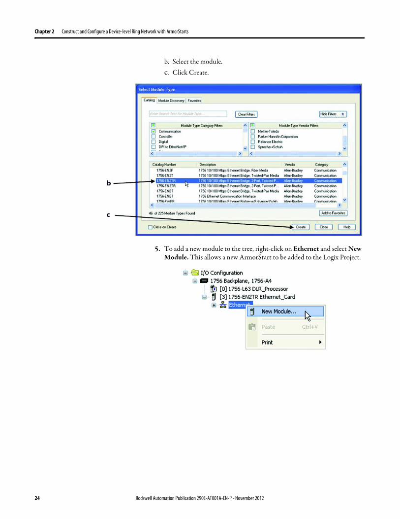
Chapter 2 Construct and Configure a Device-level Ring Network with ArmorStarts
b Select the modulec Click Create
5 To add a new module to the tree right-click on Ethernet and select New Module This allows a new ArmorStart to be added to the Logix Project
24 Rockwell Automation Publication 290E-AT001A-EN-P - November 2012
Construct and Configure a Device-level Ring Network with ArmorStarts Chapter 2
6 Select the ArmorStart in your application and click OK
7 Enter a Name for this ArmorStart and an Ethernet address For this example the Private Network setting will be used This should be set to match the IP address switch setting on the ArmorStart Then press OK
Note Refer to ArmorStart Addressing Configuration on page 17 to set an IP address on the device
Rockwell Automation Publication 290E-AT001A-EN-P - November 2012 25
Chapter 2 Construct and Configure a Device-level Ring Network with ArmorStarts
8 Complete configuration information for the module in your RSLogix 5000 project
The following graphic shows the IO configuration for an example DLR network
9 Download the program to the Logix controller
10 Go online with the controller and leave it in Program mode
26 Rockwell Automation Publication 290E-AT001A-EN-P - November 2012
Construct and Configure a Device-level Ring Network with ArmorStarts Chapter 2
Enable Ring Supervisor in RSLogix 5000 Programming Software
After 1756-EN2TR module or 1783-ETAP 1783-ETAP1F or 1783-ETAP2F taps have been added to your RSLogix 5000 programming software project the ring supervisor mode must be enabled
If using RSLogix 5000 programming software to configure the ring supervisor and monitor diagnostics on the DLR network the controller must be online
To enable the 1756-EN2TR module or 1783-ETAP 1783-ETAP1F or 1783-ETAP2F tap as a ring supervisor follow these steps
The steps to enable a ring supervisor are basically the same for the 1756-EN2TR module or 1783-ETAP 1783-ETAP1F or 1783-ETAP2F tap This example shows how to do it for the 1756-EN2TR module
1 For your project online with the controller double-click on a supervisor-capable device in the IO configuration tree
Rockwell Automation Publication 290E-AT001A-EN-P - November 2012 27
Chapter 2 Construct and Configure a Device-level Ring Network with ArmorStarts
2 Click the Network tab to Enable Supervisor Mode
Configuration takes effect immediately you do not need to click Apply or OK
3 Click the Advanced button on the Network tab
4 Configure supervisor-related parameters as shown in the screen shot below
For these parameters you must click Set after entering a value
5 Click Set
28 Rockwell Automation Publication 290E-AT001A-EN-P - November 2012
Construct and Configure a Device-level Ring Network with ArmorStarts Chapter 2
Configure and Enable a Ring Supervisor in RSLinx Classic Communication Software
A ring supervisor can be configured for the DLR network through RSLinx Classic communication software
For more information regarding the Required RSLinx Classic Communication software Revision required refer to Appendix B
To configure a ring supervisor in RSLinx Classic Communication Software follow these steps
This example is for the 1783-ETAP tap Follow these steps
1 Launch RSLinx Classic Communication Software
2 Browse to the DLR network that is being set up
IMPORTANT For Beacon Interval Beacon Timeout and Ring Protocol VLAN ID we recommend that the default values be used
Functionality Description Default Setting
Supervisor Precedence A supervisor precedence number may be configured for each device that is configured as a ring supervisor The highest possible supervisor precedence value is 255When multiple nodes are enabled as supervisors the node with the highest precedence value is assigned as the active ring supervisor the other nodes automatically become back-up supervisorsWe recommend that youbull configure at least one back-up supervisor nodebull set the desired Active Ring Supervisor with a relatively high supervisor-
precedence value compared to the back-up node(s)bull keep track of the networkrsquos supervisor-precedence valuesIf multiple supervisors are configured with the same precedence value (the factory default value for all supervisor-capable devices is 0) the node with the numerically highest MAC address becomes the active supervisor
0
Beacon Interval Beacon interval is the frequency of the active ring supervisor transmitting a beacon frame through both of its Ethernet ports This parameter is user configurable for any time between 200 μS and 100 mSFor more information on how this parameter relates to network performance see page 61
400 μS
Beacon Timeout The beacon timeout is the amount of time that nodes wait before timing out the reception of beacon frames and taking appropriate action Supervisors support a range from 400μS to 500mSFor more information on how this parameter relates to network performance see page 61
1960 μS
Ring Protocol VLAN ID Reserved for future use 0
Rockwell Automation Publication 290E-AT001A-EN-P - November 2012 29
Chapter 2 Construct and Configure a Device-level Ring Network with ArmorStarts
If the Electronic Data Sheet (EDS) file is not installed on the module configured to be the ring supervisor it will appear with a question mark () To obtain and use the EDS file
bull right-click the module and choose to upload the EDS file from the device or
bull download the EDS file from httpwwwrockwellautomationcomrockwellautomationsupportnetworksedspage
3 Access the supervisor-capable nodersquos propertiesa Right-click the nodeb Choose Module Configuration
The General tab appears with information about the module
4 Click the Network tab to Enable Supervisor Mode
Configuration takes effect immediately there is no need to click Apply or OK
30 Rockwell Automation Publication 290E-AT001A-EN-P - November 2012
Construct and Configure a Device-level Ring Network with ArmorStarts Chapter 2
5 Click the Advanced button to configure supervisor-related parameters
Rockwell Automation Publication 290E-AT001A-EN-P - November 2012 31
Chapter 2 Construct and Configure a Device-level Ring Network with ArmorStarts
IMPORTANT For Beacon Interval Beacon Timeout and Ring Protocol VLAN ID use the default values
Functionality Description Default Setting
Supervisor Precedence
You may configure a supervisor precedence number for each device configured as a ring supervisor The highest possible supervisor precedence value is 255When multiple nodes are enabled as supervisor the node with the highest precedence value is assigned as the active ring supervisor the other nodes automatically become back-up supervisorsWe recommend that youbull configure at least one back-up supervisor nodebull set the desired Active Ring Supervisor with a relatively high supervisor-
precedence value compared to the back-up node(s)bull keep track of the networkrsquos supervisor-precedence valuesIf multiple supervisors are configured with the same precedence value (the factory default value for all supervisor-capable devices is 0) the node with the numerically highest MAC address becomes the active supervisor
0
Beacon Interval Beacon Interval is the frequency to which the active ring supervisor transmits a beacon frame through both of its Ethernet ports This parameter is user configurable for any time between 200 μS and 100 mSFor more information on how this parameter relates to network performance see page 58
400 μS
Beacon Timeout The beacon timeout is amount of time nodes wait before timing out the reception of beacon frames and taking appropriate action Supervisors support a range from 400 μS to 500 mSFor more information on how this parameter relates to network performance seepage 58
1960 μS
Ring Protocol VLAN ID
Reserved for future use 0
Enable IGMP Snooping
For more information on IGMP Snooping see page 35 Enabled
Enable IGMP Querier
For more information on IGMP Querier see page 35 Disabled
Enable Device Port Debugging Mode
For more information on Device Port Debugging Mode see page 59 Disabled
32 Rockwell Automation Publication 290E-AT001A-EN-P - November 2012
Construct and Configure a Device-level Ring Network with ArmorStarts Chapter 2
Complete the Physical Connections of the Network
After the ring supervisor nodes are configured and enabled the physical connection of the network must be completed to establish a complete DLR network
The figure below shows an example DLR network with all physical connections complete
Figure 4 - Example Device-level Ring Topology with All Connections Complete
Rockwell Automation Publication 290E-AT001A-EN-P - November 2012 33
Chapter 2 Construct and Configure a Device-level Ring Network with ArmorStarts
Verify Supervisor Configuration
The configuration and overall DLR network status can be verified in either RSLogix 5000 programming software or RSLinx Classic communication software
1 Access the supervisor nodersquos properties as shown previously in this chapter
2 Click the Network tab
3 Check the Network Topology and Network Status Fields
For a 1756-EN2TR module or the 1783-ETAP 1783-ETAP1F and 1783-ETAP2F tap the supervisor configuration can also be verified through the modulersquos diagnostic web pages For more information on monitoring diagnostics via an EtherNetIP modulersquos web pages see Monitor a DLR Network starting on page 37
34 Rockwell Automation Publication 290E-AT001A-EN-P - November 2012
Construct and Configure a Device-level Ring Network with ArmorStarts Chapter 2
IGMP Snooping This functionality is enabled by default in the 1783-ETAP 1783-ETAP1F and 1783-ETAP2F taps and is commonly used to manage multicast traffic on the network When in use this functionality allows the tap to multicast data to only those devices that need the data rather than to all devices connected to the network
For snooping to work there must be a device present that is running a querier Typically the device is a router or a switch such as the Stratix 6000 Stratix 8000 or Stratix 8300 managed switch
Once DHCP is enabled the switch could change the IP addresses on the ArmorStarts depending on network demand which could cause RSlogix5000 to loose communication with the device as connectivity is established via the AOP in the initial configuration
IGMP Querier This functionality is disabled by default The IGMP Querier functionality enables a 1783-ETAP 1783-ETAP1F or 1783-ETAP2F tap or switch such as a Stratix managed switch to send out a query to all devices on the network It determines what multicast addresses are of interest to a specific node or a group of nodes
The IGMP Querier functionality should be enabled for at least one node on the network The 1783-ETAP 1783-ETAP1F or 1783-ETAP2F tap managed switches and routers are examples of devices that support IGMP Querier functionality
IMPORTANT If DHCP for the Armostart is still required the Internet Group Management Protocol (IGMP) snooping on the E-tap must be disabled via the AOP
IMPORTANT If the IGMP Querier functionality is not enabled for at least one node on the network multicast traffic on the network may eventually create network performance issues
Rockwell Automation Publication 290E-AT001A-EN-P - November 2012 35
Chapter 2 Construct and Configure a Device-level Ring Network with ArmorStarts
However for all devices that are configured on the network with the IGMP Querier parameter enabled an IP address other than the factory default value must also be set for those devices If multiple devices on the network enable this functionality only the node with the lowest IP address becomes the active IGMP Querier node
IGMP Version
If the IGMP Querier is enabled a Querier Version must be selected The default version is Version 2
36 Rockwell Automation Publication 290E-AT001A-EN-P - November 2012
Chapter 3
Monitor a DLR Network
Introduction Use this chapter to learn how to monitor the DLR network
Methods to Monitor a DLR Network
Network diagnostic information can be retrieved from the ring supervisor-capable devices using the following
bull RSLogix 5000 programming software status pages
bull RSLinx communication software status pages
bull Device web pages
bull EtherNetIP Device Level Ring (DLR) network diagnostics faceplate
bull Programmatically through the use of a MSG instruction
RSLogix 5000 Programming Software Status Pages
RSLogix 5000 programming software version 1701 or later must be used and the appropriate AOPs installed to use the softwarersquos profile status pages
RSLinx Communication Software Status Pages
To monitor the network with this method the RSLinx communication software version 255 or later must be used
Topic Page
Methods to Monitor a DLR Network 37
Monitor Status Pages 39
Monitor ArmorStart Internal Web Server 44
Monitor via Faceplate Integration 45
Monitor Diagnostics via MSG Instructions 46
Rockwell Automation Publication 290E-AT001A-EN-P - November 2012 37
Chapter 3 Monitor a DLR Network
ArmorStart Internal Web Server
Rockwell Automation provides an internal embedded web server with each ArmorStart EtherNetIP The internal web server allows you to view information and configure the ArmorStart via a web browser The ArmorStart EtherNetIP can also be set up from the web server to send e-mail notifications The embedded web server is used to access configuration and status data It provides the user with the ability to view and modify the device configuration without having access to RSLogix 5000 Security in the form of an administrative password can be set The default login is Administrator There is no password set by default
EtherNetIP Device Level Ring (DLR) Network Diagnostics Faceplate
The diagnostics faceplate contains two major components
bull Logic code (encapsulated in an Add-On Instruction) that allows the controller to retrieve real-time DLR network status information
bull HMI faceplate graphics to allow the data to be visualized on an operator interface
Programmatically Through the Use of a MSG Instruction
For more information on how to monitor the DLR network via MSG Instructions see page 46
38 Rockwell Automation Publication 290E-AT001A-EN-P - November 2012
Monitor a DLR Network Chapter 3
Monitor Status Pages Both RSLogix 5000 programming software and RSLinx Classic communication software offer status pages that can be used to monitor the networkrsquos performance
RSLogix 5000 Programming Software Status Pages
Monitor the networkrsquos diagnostic information through the RSLogix 5000 programming software when the software is online
To monitor the network in RSLogix 5000 programming software follow these steps
1 Verify that the project is online
2 Access the active supervisor nodersquos propertiesa Right-click the modulersquos entry in the Controller Organizerb Click properties
Rockwell Automation Publication 290E-AT001A-EN-P - November 2012 39
Chapter 3 Monitor a DLR Network
3 Use the Network tab to monitor diagnostics
40 Rockwell Automation Publication 290E-AT001A-EN-P - November 2012
Monitor a DLR Network Chapter 3
RSLinx Communication Software
To monitor the network in RSLinx communication software follow these steps
1 Click RSWho to browse the network
2 Access the property pages for the active supervisor nodea Open the driver that shows the nodes on the DLR networkb Right-click the node that you want to monitor performancec Click on the choice that you need to access
Multiple choices appear
These options are shown in the following sections
Rockwell Automation Publication 290E-AT001A-EN-P - November 2012 41
Chapter 3 Monitor a DLR Network
Module Configuration
This series of tabs providesbull General informationbull Connection informationbull Module informationbull Internet protocolbull Port configurationbull Network information
The example below shows a ring fault between nodes at IP addresses 10888021 and MAC ID 00-00-BC-02-48-D5
42 Rockwell Automation Publication 290E-AT001A-EN-P - November 2012
Monitor a DLR Network Chapter 3
There are multiple fields used to monitor network diagnostics
Field Definition
Network Topology Possible values here can be Linear or Ring
Network Status Displays if the network is operating normally (Normal) or has experienced a fault (Ring Fault) as shown in the previous example screen
Active Ring Supervisor Displays the IP address or MAC address of the active ring supervisor
Active Supervisor Precedence For more information on this field see Active Ring Supervisor on page 11
Enable Ring Supervisor Configurable field that lets you to set the node as a ring supervisor
Ring Faults Detected Number of faults detected on the network since the last module power cycle or counter reset
Supervisor Status Displays whether this node is the active ring supervisor (Active) a back-up supervisor (Back-up) a ring node or part of a linear network
Last Active Node on Port 1 The last node the active ring supervisor can communicate with on Port 1 This value is an IP address or a MAC ID and remains latched until the Verify Fault Location button is clicked
Last Active Node on Port 2 The last node the active ring supervisor can communicate with on Port 2 This value is an IP address or a MAC ID and remains latched until the Verify Fault Location button is clicked
Status Displays whether a fault exists on the ring
IMPORTANT If the Network Topology field = Ring and the Network Status field = Normal the Last Active Node fields will display the last fault information even though it has been correctedTo clear the last fault information from these fields click Verify Fault Location You may see a message informing you that the supervisor is no longer in fault mode and the fields will be cleared
Rockwell Automation Publication 290E-AT001A-EN-P - November 2012 43
Chapter 3 Monitor a DLR Network
How to Access the ArmorStart EtherNetIP Internal Web Server
Open your preferred internet web browser and enter the IP address of the desired ArmorStart For this example 192168122 will be used
Use the links on the left-most navigation bar to see each available web page The screen below shows Ring Statistics for the ArmorStart 280E
44 Rockwell Automation Publication 290E-AT001A-EN-P - November 2012
Monitor a DLR Network Chapter 3
EtherNetIP Device Level Ring (DLR) Network Diagnostics Faceplate Overview
The EtherNetIP Device Level Ring (DLR) network diagnostics faceplate provides basic DLR network status information to the user to assist with monitoring and troubleshooting a DLR network
The diagnostics faceplate contains two major components
bull Logic code (encapsulated in an Add-On Instruction) that allows the controller to retrieve real-time DLR network status information
bull HMI faceplate graphics to allow the data to be visualized on an operator interface
The DLR diagnostics faceplate application can be downloaded from the Rockwell Automation Sample Code website at httpsamplecoderockwellautomationcom
Besides the individual Logix and View project components a demo application is also included with the downloaded file
Rockwell Automation Publication 290E-AT001A-EN-P - November 2012 45
Chapter 3 Monitor a DLR Network
Monitor Diagnostics via MSG Instructions
Network diagnostic information can also be obtained programmatically via MSG instructions in RSLogix 5000 programming software For example you can
bull Get all ring diagnostic informationbull Get a ring participant listbull Get the active supervisorbull Clear rapid ring faultsbull Verify a fault locationbull Reset a fault counterbull Enable and configure a ring supervisor
This information can be displayed on an HMI device or manipulated in the project code
Figure 5 - Example Use of MSG Instruction
This example describes how to retrieve diagnostic information from the DLR network Follow these steps
1 Enter a MSG instruction into the rung of logic
2 Configure the MSG instruction to retrieve ring diagnostic information service as shown in the following screen shots
IMPORTANT Make sure the tag created is sized appropriately to hold all of the data that you are reading or writing For more information see page 48
46 Rockwell Automation Publication 290E-AT001A-EN-P - November 2012
Monitor a DLR Network Chapter 3
3 Configure the MSG instructionrsquos communication path to point to the active supervisor node
The path on the following screen is one example path
IMPORTANT When using the Custom Get_Attributes_All (01) service pointing to an active supervisor node will retrieve all of the attributes listed in Retrieve All Diagnostic Information Attribute Description on page 50Pointing to a non-supervisor node will retrieve only the Network Topology and Network Status attribute informationPointing to backup supervisor node will retrieve the current active supervisorrsquos IP address
Rockwell Automation Publication 290E-AT001A-EN-P - November 2012 47
Chapter 3 Monitor a DLR Network
Use Specific Values on the Configuration Tab
Use the values on the Configuration tab of your MSG instruction to perform specific services Sample DLR network diagnostic application code for example Add-on Instruction or HMI faceplate graphics is available on the Rockwell Automation Sample Code Library For more information about the Rockwell Automation Sample Code Library see httpwwwrockwellautomationcomsolutionsintegratedarchitectureresources5html
➊ This request only works if there are fewer than 40 nodes on the network If there are more nodes than will fit in a single message an error will be returned➋ Use a Destination Length of 54 bytes if using firmware revision 3x or later for the 1756-EN2TR module or firmware revision 2x or later for the 1783-ETAP
1783-ETAP1F or 1783-ETAP2F taps
Request Description Message Type
Service Type
Service Code (HEX)
Class (HEX)
Instance Attribute (HEX)
Source Element
Source Length (Bytes)
Destination Destination Length (bytes)
Retrieve All Ring Diagnostic Information
Information for this request is listed in Retrieve All Ring Diagnostic Information on page 49
CIP Generic Custom 1 47 1 NA LeftBlank
0 Tag 50or54 ➋
Request Ring Participant List ➊
Information for this request is listed in Request the Ring Participant List on page 51
CIP Generic Get Attribute Single
e 47 1 9 NA NA Tag 10node
Get Active Supervisor
Obtain the IP address and MAC ID of the active supervisor on the DLR network
CIP Generic Get Attribute Single
e 47 1 a NA NA Tag 10
Acknowledge Rapid Ring Faults Condition
Request supervisor to resume normal operation after encountering a rapid ring fault condition
CIP Generic Custom 4c 47 1 NA NA NA NA
Verify a Fault Location
Request supervisor to update Last Active Node values
CIP Generic 4b 47 1 NA NA NA NA NA
Reset the Ring Fault Counter
Reset the number of ring faults detected on the DLR network
CIP Generic Set Attribute Single
10 47 1 5 Tag 2 NA NA
Enable and Configure a Ring Supervisor
Information for this request is listed in Enable and Configure a Ring Supervisor on page 52
CIP Generic Set Attribute Single
10 47 1 4 Tag 12 NA NA
48 Rockwell Automation Publication 290E-AT001A-EN-P - November 2012
Monitor a DLR Network Chapter 3
Retrieve All Ring Diagnostic Information
By performing the Retrieve All Ring Diagnostic Information request on an active supervisor the MSG instruction returns the following information
➊ RSLogix 5000 programming software may display the value in this field as negative numbers To better understand the value we recommend you view it in HEX format
Destination Tag Attribute Name Description Possible Values
SINT [0] Network Topology Current network topology mode 0 = Linear
1 = Ring
SINT [1] Network Status Current status of the network 0 = Normal
1 = Ring Fault
2 = Unexpected Loop Detected
3 = Partial Network Fault
4 = Rapid FaultRestore Cycle
SINT [2] Ring Supervisor Status Ring supervisor active status flag 0 = Node is functioning as a backup
1 = Node is functioning as the active ring supervisor
2 = Node is functioning as a normal ring node
3 = Node is operating in a non-DLR topology
4 = Node cannot support the currently operating ring parameters thatis Beacon Interval andor Beacon Timeout
Ring Supervisor Config Ring Supervisor configuration parameters
SINT [3] Ring Supervisor Enable Ring supervisor enable flag 0 = Node is configured as a normal ring node (default configuration)
1 = Node is configured as a ring supervisor
SINT [4] Ring Supervisor Precedence Precedence value of a ring supervisor ➊ Valid value range = 0hellip255
0 = Default value
SINT [5-8] Beacon Interval Duration of ring beacon interval Valid value range = 200 μshellip100 ms
Default = 400 μs
SINT [9-12] Beacon Timeout Duration of ring beacon timeout Value value range = 400 μshellip500 ms
Default value = 1960 μs
SINT [13-14] DLR VLAN ID Valid ID to use in ring protocol messages Valid value range = 0hellip4094
Default value = 0
SINT [15-16] Ring Faults Count Number of ring faults since power up ➊
Rockwell Automation Publication 290E-AT001A-EN-P - November 2012 49
Chapter 3 Monitor a DLR Network
Retrieve All Diagnostic Information Attribute Description
➊ This destination tag is available only with the 1756-EN2TR module firmware revision 3x or later 1783-ETAP 1783-ETAP1F and 1783-ETAP2F taps firmware revisions 2x or later If using the 1783-ETAP tap firmware revision 1x your program does not include this destination tag
➋ RSLogix 5000 programming software may display the value in this field as negative numbers To better understand the value we recommend you view it in HEX format
Destination Tag Attribute Name Description Possible Values
Last Active Node on Port 1 Last active node at the end of the chain through port 1 of the active ring supervisor during a ring fault
SINT [17-20] Device IP address ➋ Any valid IP address value
A value = 0 indicates no IP address has been configured for the device
SINT [21-26] Device MAC address ➋ Any valid Ethernet MAC address
Last Active Node on Port 2 Last active node at the end of the chain through port 2 of the active ring supervisor during a ring fault
SINT [27-30] Device IP address ➋ Any valid IP address value
A value = 0 indicates no IP address has been configured for the device
SINT [31-36] Device MAC address ➋ Any valid Ethernet MAC address
SINT [37-38] Ring Protocol Participants Count
Number of devices in the ring protocol participants list
Active Supervisor Address IP andor Ethernet MAC address of the active ring supervisor
SINT [39-42] Supervisor IP address Any valid IP address value
A value = 0 indicates no IP address has been configured for the device
SINT [43-48] Supervisor MAC address Any valid Ethernet MAC address
SINT [49] Active Supervisor Precedence
Precedence value of the active ring supervisor
SINT [50-53]➊ Capability Flags Alerts you that the device is capable of operating as a supervisor and beacon-based ring node
0x22
50 Rockwell Automation Publication 290E-AT001A-EN-P - November 2012
Monitor a DLR Network Chapter 3
Request the Ring Participant List
When requesting the Ring Participant List service on the DLR network the MSG instruction returns the following information
Request the Ring Participant List Attribute Description
➊ This attribute will return an array of the data shown one entry for each node The Ring Protocol Participants Count attribute determines the number entries
➋ This tag displays only IP addresses for ring participants that have been configured with one For example you may have a 1783-ETAP tap connected to the network that has not been assigned an IP address In that case no address is shown for the 1783-ETAP tap
➌ RSLogix 5000 programming software may display the value in this field as negative numbers To better understand the value we recommend you view it in HEX format
➍ Unlike destination tag SINT [0-3] where IP addresses are displayed only for ring participants configured with an IP address this tag displays MAC addresses for all ring participants because every ring participant has a MAC address
Destination Tag Attribute Name Description Possible Values
Ring Protocol Participants List ➊
List of devices participating in ring protocol
SINT [0-3] Device IP address ➋➌ Any valid IP address value
A value = 0 indicates no IP address has been configured for the device
SINT [4-9] Device MAC address ➌➍ Any valid Ethernet MAC address
Rockwell Automation Publication 290E-AT001A-EN-P - November 2012 51
Chapter 3 Monitor a DLR Network
Enable and Configure a Ring Supervisor
When performing the Enable and Configure a Ring Supervisor request on a supervisor-capable device configure the MSG instruction with the following information
Enable and Configure a Ring Supervisor Attribute Description
➊ RSLogix 5000 programming software may display the value in this field as negative numbers To better understand the value we recommend you view it in HEX format
Source Tag Attribute Name Description Possible Values
Ring Supervisor Config Ring Supervisor configuration parameters
SINT [0] Ring Supervisor Enable Ring supervisor enable flag 0 = Node is configured as a normal ring node (default configuration)1 = Node is configured as a ring supervisor
SINT [1] Ring Supervisor Precedence Precedence value of a ring supervisor ➊
Valid value range = 0hellip2550 = Default value
SINT [2-5] Beacon Interval Duration of ring beacon interval
Valid value range = 200 μshellip100 000 μsDefault = 400 μs
SINT [6-9] Beacon Timeout Duration of ring beacon timeout ➊
Value value range = 400 μshellip500 000 μsDefault value = 1960 μs
SINT [10-11] DLR VLAN ID Valid ID to use in ring protocol messages ➊
Valid value range = 0hellip4094Default value = 0
52 Rockwell Automation Publication 290E-AT001A-EN-P - November 2012
Chapter 4
Troubleshoot a DLR Network
Introduction Use this chapter to learn how to troubleshoot the DLR network
General Solutions for Linear or DLR Networks
Before attempting to correct specific faults on the linear or DLR network we recommend that you first take the following actions when a fault appears
bull For a DLR networkndash Verify that at least one node has been configured as a supervisor
on the network and that Network Topology = Ringndash Verify that all cables on the network are securely connected
to each devicendash Verify that all devices that require an IP address have one assigned
correctlyndash Check the Network Status field on the active supervisor nodersquos status
page to determine the fault typebull For a linear network
ndash Verify that none of the nodes are configured as a supervisor on the network and that Network Topology = LinearIf any nodes on a linear network are configured as a supervisor it may impact communication to other devices connected to the network
ndash Verify that all cables on the network are securely connected to each device
ndash Verify that all devices that require an IP address have one assigned correctly
If the fault is not cleared after completing the actions listed above use the tables in the rest of this chapter to troubleshoot issues specific to a DLR network or a linear network
Topic Page
General Solutions for the Linear or DLR Networks 53
Duplicate IP Address Detection 54
Specific Issues on the DLR Network 55
Network Recovery Performance 58
Device Port Debugging Mode 59
Rockwell Automation Publication 290E-AT001A-EN-P - November 2012 53
Chapter 4 Troubleshoot a DLR Network
Duplicate IP Address Detection
Some EtherNetIP communication modules support duplicate IP address detection The module verifies that its IP address does not match any other network devicersquos IP address when performing either of these tasks
bull Connect the module to an EtherNetIP network
bull Change the modulersquos IP address
If the modulersquos IP address matches that of another device on the network the modulersquos EtherNetIP port transitions to Conflict mode In Conflict mode these conditions exist
bull OK status indicator is blinking red
bull Network (NET) status indicator is solid red
bull On some EtherNetIP communication modules the module status display indicates the conflict
The display scrollsOK ltIP_address_of_this_modulegt Duplicate IP
ltMac_address_of_duplicate_node_detectedgt
For example OK 108860196 Duplicate IP - 0000BC0234B4
bull On some EtherNetIP communication modules the modulersquos diagnostic webpage displays information about duplicate IP address detection
For more information on which EtherNetIP communication modules support displaying duplicate IP address on their diagnostic webpage see the Technical Note titled Logix modules Duplicate IP address detection enhancement 118216 in the Technical Support Knowledgebase available at httpwwwrockwellautomationcomknowledgebase
54 Rockwell Automation Publication 290E-AT001A-EN-P - November 2012
Troubleshoot a DLR Network Chapter 4
Specific Issues on the DLR Network
Use the following table to troubleshoot possible specific issues on the DLR or linear network that are not solved by the actions described on the previous page
Issue Description Solution
Supervisor Reports a Ring Fault A link on the DLR network may be brokenbull intentionally for example because of adding or deleting nodes but not making all
physical connections to restore the setup of the network withwithout the nodebull unintentionally for example because a cable is broken or a device malfunctionsWhen this fault occurs the adjacent nodes to the faulted part of the network are displayed in the Ring Fault group and the Network Status field = Ring FaultThe screen shot below shows the Ring Fault section with IP addresses appearing for the last active nodes The faulted node is between nodes 108880115 and 108880208 If the IP address of either node is not available the software will display the nodersquos MAC ID
Once the fault is corrected the ring is automatically restored and the Network Status field returns to Normal
Determine where the fault condition exists and correct itClick the Refresh Communication link as needed to update the Ring Fault information to determine where the fault condition existsFinally DevicePort Debugging Mode functionality on the 1783-ETAP tap may be used to analyze a suspicious nodeFor more information refer to Device Port Debugging Mode on page 59
Rockwell Automation Publication 290E-AT001A-EN-P - November 2012 55
Chapter 4 Troubleshoot a DLR Network
Issue Description Solution
Rapid Ring Fault When a Rapid Ring Fault occurs the following events occurbull The active supervisor will block traffic on port 2 resulting in possible network
segmentation that is some nodes may become unreachablebull The Link 2 status indicator on the active supervisor is offbull As soon as the fault occurs for both RSLogix 5000 programming software and
RSLinx communication software the Status field = Rapid FaultRestore Cycles
Any of the following may cause a Rapid Ring Faultbull 5 intentional disconnectionsreconnections of a node from the network within 30
secondsbull A duplex mismatch between two connected devicesbull Electromagnetic noise on the networkbull Unstable physical connections such as intermittent connectorsGiven the nature of a Rapid Ring Fault the Last Active Node information may not be accurate when a Rapid Ring Fault condition is present
Multiple possible solutions existbull For the disconnections and reconnections issue no
solution is requiredClear the fault after reconnecting the device to the network permanentlybull For the duplex mismatch issue reconfigure the duplex
parameters to make sure they match between the devices
bull For the electromagnetic noise issue determine where the noise exists and eliminate it or use a protective shield in that location
bull For the unstable connections issue determine where they exist on the network and correct them
bull Check the media counters for all devices on the network The device with the highest media counter count is most likely causing the Rapid Ring Fault
bull Remove devices from the network one by one If the Rapid Ring Fault disappears after a device is removed that device is causing the fault
bull DevicePort Debugging Mode functionality on the 1783-ETAP tap may be used to analyze a suspicious node
For more information refer to Device Port Debugging Mode on page 59bull Finally the Beacon Interval or Timeout configuration
may not be appropriate for the networkHowever if these values need to be changed we recommend that you contact Rockwell Automation technical supportOnce the fault is fixed click Clear Fault
56 Rockwell Automation Publication 290E-AT001A-EN-P - November 2012
Troubleshoot a DLR Network Chapter 4
Issue Description Solution
Partial Fault Condition A partial network fault occurs when traffic is lost in only one direction on the network because a ring member is not forwarding beacons in both directions for example a component failureThe active ring supervisor detects a partial fault by monitoring the loss of Beacon frames on one port and the fault location appears in the Ring Fault section of the Network tab When a partial fault is detected the active ring supervisor blocks traffic on one port At this point the ring is segmented due to the partial fault condition The nodes adjacent to the faulted part of the network are displayed in the Ring Fault group with either IP addresses or MAC IDs for each node displayedWhen this fault occurs the Network Status field = Partial Fault ConditionOnce the fault is corrected it automatically clears and the Network Status field returns to Normal
Determine where the fault condition exists and correct itAdditionally the DevicePort Debugging Mode functionality also known as Port Mirroring on a 1783-ETAP 1783-ETAP1F or 1783-ETAP2F tap may be used to analyze a suspicious nodeFor more information refer to Device Port Debugging Mode on page 59
Media Counter Errors or Collisions
The media counters screen displays the number of physical layer errors or collisions The screen below indicates where to check for errors encountered Error levels are displayed depending on what caused the error For example an Alignment Error is displayed in the Alignment Error field
On a DLR network it is not uncommon to see low levels of media counter errors For example if the network breaks a low level of media counter errors appears With a low level of media counter errors the value typically does not continuously increase and often clearsA high level of media counter errors typically continues to increase and does not clear For example there is a mismatch of speed between two linked nodes a high level of media counter errors appears steadily increasing and not clearingTo access the RSLinx screen above browse the network right-click on the device select Module Properties and click the Port Diagnostics tab
Some example solutions includebull Check for a mismatch of speed andor duplex between
two linked nodesbull Verify that all cables on the network are securely
connected to each devicebull Check for electromagnetic noise on the network If you
find it eliminate it or use a protective shield in that location
Rockwell Automation Publication 290E-AT001A-EN-P - November 2012 57
Chapter 4 Troubleshoot a DLR Network
Network Recovery Performance
When measuring the networkrsquos performance with regard to dealing with fault conditions consider the network recovery time Network recovery is the time for all of the following to take place
1 The supervisor node recognizes that a fault exists on the network
2 The supervisor node reconfigures the network because of the fault
3 The supervisor node communicates to the network nodes that a fault condition exists
4 The network nodes reconfigure themselves because of the fault
With the default beacon interval value of 400 mS and beacon timeout value of 1960 mS the worst-case time for network recovery times are
bull 2890 mS for a copper DLR network This recovery time is based on 100 m copper segments between nodes on the network
bull 3140 mS for a fiber-optic DLR network This recovery time is based on 2 kM fiber-optic cable segments between nodes on the network
When considering the values listed above keep in mind
bull Recovery time may actually occur faster than the times listed
bull The recovery times listed above assume that your networkrsquos nodes are operating at 100 Mbps speed and full-duplex mode We recommend that your nodes generally operate in this mode for DLR networks
bull If other node conditions exist such as a node operating at 10 Mbps full-duplex or 10100 Mbps half-duplex the recovery times will vary from the times listed above
If this is the case for your application the beacon interval and beacon timeout will need to be changed We recommend that you first contact Rockwell Automation technical support if these parameters need to be changed
bull The value assumes that the majority of the traffic on your network is EtherNetIP traffic
58 Rockwell Automation Publication 290E-AT001A-EN-P - November 2012
Troubleshoot a DLR Network Chapter 4
Device Port Debugging Mode
This functionality is disabled by default Device Port Debugging mode which is similar to port mirroring can be used to monitor data received on the 1783-ETAP 1783-ETAP1F or 1783-ETAP2F taprsquos two network ports Monitor the data over the device port to a device such as a personal computer running a protocol analyzer application for advanced network debugging or analysis
When device port debugging is used on a 1783-ETAP the device connected to the 1783-ETAP taprsquos front port receives all of the data traversing the ring (both directions)
Device Port Debugging Example Network
When using the Device Port Debugging mode functionality insert the 1783-ETAP with the network analyzer connected to the device port It is inserted at the spot on the ring network where the node in question is located The graphic below shows a 1783-ETAP tap inserted in the network
IMPORTANT This functionality should be used only when troubleshooting the network and not in normal network operation
Rockwell Automation Publication 290E-AT001A-EN-P - November 2012 59
Chapter 4 Troubleshoot a DLR Network
Combined total network bandwidth of the traffic received on the two 1783-ETAP 1783-ETAP1F or 1783-ETAP2F taprsquos ports connected to the network should not exceed the taprsquos device port capacity The speed setting determines the device portrsquos capacity
Configure the device port on a 1783-ETAP 1783-ETAP1F or 1783-ETAP2F tap to either of two speed settings
bull 100 Mbps - default settingbull 10 Mbps
If the bandwidth exceeds the capacity of the taprsquos device port some frames from the ring will be dropped before reaching the device port These dropped frames do not impact the traffic on the rest of the DLR network
The device port setting determines how much network traffic the 1783-ETAP 1783-ETAP1F or 1783-ETAP2F tap can handle before dropping frames The circled section in the graphic below shows the Port Buffer Utilization of the Device Port In this example the value is zero because a ring fault exists on the network
60 Rockwell Automation Publication 290E-AT001A-EN-P - November 2012
Appendix A
Network Usage Guidelines and Recommendations
Consider the following guidelines and recommendations when using a DLR or linear network
GuidelineRecommendation Explanation
Use fewer than 50 nodes on a single DLR networkIf your application requires more than 50 nodes we recommend that the nodes are broken into separate but linked DLR networks
If you use more than 50 nodes on a single DLR networkbull Your network has a greater chance of multiple faults
occurring on the networkbull Network recovery times from faulted DLR network
are higher
Do not configure a supervisor on a linear network If your linear network includes non-DLR nodes and has a supervisor-enabled node on the network it may impact communication to non-DLR devices connected to the linear network
If you must connect a device that is running at 10 Mbps to a DLR or linear network do so through a 1783-ETAP 1783-ETAP1F or 1783-ETAP2F tap device port
The 1783-ETAP 1783-ETAP1F and 1783-ETAP2F taps can operate at 100 Mbps on the DLR network this is the optimal speed for a network If you connect a 10 Mbps device directly to the network instead of through a tap the linear or DLR network traffic slows to 10 MbpsAdditionally if the 10 Mbps device is connected to the network without a 1783-ETAP tap network recovery times are significantly impacted
Configure multiple supervisor nodes per ring If your DLR network only has one supervisor and the supervisor experiences a fault none of the other nodes become the active supervisor In this case the network becomes a linear network until the fault is corrected and the DLR network restoredAnother reason to configure multiple supervisor nodes is for replacing an active supervisor node with an out-of-box replacement the new device will not be enabled as a supervisor (by default) and there would still be no supervisor on the network
Rockwell Automation Publication 290E-AT001A-EN-P - November 2012 61
Appendix A Network Usage Guidelines and Recommendations
GuidelineRecommendation Explanation
Connect switches to a DLR network via 1783-ETAP 1783-ETAP1F or 1783-ETAP2F taps
If switches are connected to the DLR network without the use of a 1783-ETAP 1783-ETAP1F or 1783-ETAP2F tap the network may experience unpredictable behavior and network performance is unknown
Run all nodes on the DLR network at 100 Mbps and in Full-Duplex mode
These configuration values provide the best performance for your networkAdditionally we recommend that youbull Use auto-negotiate for all nodes on the DLR networkbull Do not use auto-negotiate on one node and then force
speed on the next node linked to it
In a linear network the number of nodes to use is application specific based on the considerations described in the next box
When determining the number of nodes to use on a linear network consider the followingbull There is a delay per node as information is transmitted
to each successive node used on the networkndash The typical delay on a linear network with 100 m
copper segments between nodes is 30 mSndash The typical delay on a linear network with 2 kM
fiber-optic segments between nodes is 40 mS
The greater the number of nodes on the network the longer the total time for information to be transmitted across the entire networkbull The single point of failure possibility is greater with
each additional connectionbull Troubleshooting the network may be more difficult
with a higher number of nodes
The total time for information to be transmitted across the entire network and its effect on how many nodes to use on a linear network is related to the Requested Packet Interval (RPI)Verify that the total time to transmit information from the first node to the last node on the network is less than the RPI Make sure the network is not loaded beyond 90 of capacity
62 Rockwell Automation Publication 290E-AT001A-EN-P - November 2012
Network Usage Guidelines and Recommendations Appendix A
GuidelineRecommendation Explanation
Do not physically close a DLR network without a supervisor configured on the network
A DLR network without a supervisor node results in a network stormIf you do close the DLR network without a supervisor configured break the ring and configure at least one supervisor before physically reconnecting the network
Use the default values for the followingbull Beacon Intervalbull Beacon Timeoutbull Ring Protocol VLAN ID
Changing the default values for the parameters Beacon Interval Beacon Timeout and Ring Protocol VLAN ID can result in unpredictable network behavior and negatively impacted network performanceThe default values are optimized for a network withbull 50 or fewer nodes are on the networkbull All nodes are operating at 100 Mbps and full-duplex
modebull At least 50 of the network traffic bandwidth being
EtherNetIP trafficIf you think the values of the Beacon Interval Beacon Timeout or Ring Protocol VLAN ID need to be changed for example if any node on ring is not operating at 100 Mbps and full-duplex mode we recommend that you first contact Rockwell Automation technical support
If DHCP for the ArmorStarts is still required you will need to disable Internet Group Management Protocol (IGMP) snooping on the E-tap via the AOP
IGMP Snooping is enabled by default in the 1783-ETAP 1783-ETAP1F and 1783-ETAP2F taps and is commonly used to manage multicast traffic on the network When in use this functionality allows the tap to multicast data to only those devices that need the data rather than to all devices connected to the networkOnce DHCP is enabled the switch could change the IP addresses on the ArmorStarts depending on network demand which could cause RSlogix5000 to loose communication with the device as connectivity is established via the AOP in the initial configuration
The IGMP Querier functionality should be enabled for at least one node on the network
This functionality is disabled by default The IGMP Querier functionality enables a 1783-ETAP 1783-ETAP1F or 1783-ETAP2F tap or switch such as a Stratix managed switch to send out a query to all devices on the network to determine what multicast addresses are of interest to a specific node or a group of nodesIf the IGMP Querier functionality is not enabled for at least one node on the network multicast traffic on the network may eventually create network performance issuesThe 1783-ETAP 1783-ETAP1F or 1783-ETAP2F taps managed switches and routers are examples of devices that support IGMP Querier functionality
Rockwell Automation Publication 290E-AT001A-EN-P - November 2012 63
Appendix A Network Usage Guidelines and Recommendations
Notes
64 Rockwell Automation Publication 290E-AT001A-EN-P - November 2012
Appendix B
Required Firmware Revisions
Required Firmware Revision for an Add-On Profile
➊ The ControlFLASH Firmware Upgrade software tcan be used o upgrade a 1756-EN2TR module from firmware revision 21 to 3x or later1x or later3x or later2x or later
➋ The ControlFLASH Firmware Upgrade software can be used to upgrade a 1783-ETAP tap from firmware revision 11 to 2x or later
To download new firmware go to httpwwwrockwellautomationcomsupportamericasindex_enhtml
If the firmware revision is upgraded on the module or tap the required AOP revision listed above must be used for that revision For example if the 1756-EN2TR module is upgraded to firmware revision 3x or later AOP revision 2x or later must be used in the RSLogix 5000 programming software
Additionally if the firmware revision is upgraded on the module or tap the required RSLinx communication software must also be used for that firmware revision For more information on which RSLinx software version is required for each firmware revision see page 66
For both the 1756-EN2TR module and 1783-ETAP tap make sure that the Major Revision configured on the General tab of the devicersquos RSLogix 5000 programming software configuration matches the major revision of the physical module
IMPORTANT To download an AOP go to httpsupportrockwellautomationcomcontrolflashLogixProfileraspDepending on the firmware revision of your product a specific AOP version must be used
Firmware Revision Add-On Profile Revision Cat No
21 ➊ 1x or later 1756-EN2TR
3x or later 2x or later
11 ➋ 1x or later 1783-ETAP
2x or later 2x or later
2x or later 2x or later 1783-ETAP1F
1783-ETAP2F
Rockwell Automation Publication 290E-AT001A-EN-P - November 2012 65
Appendix B Required Firmware Revisions
If the device configuration on the General tab does not match the physical module the programming software alerts you to this mismatch when attempting to configure the Internet Protocol Port Configuration and Network tabs for that device
Required Firmware Revision for RSLinx Communication Software
➊ The ControlFLASH Firmware Upgrade software can be used to upgrade a 1756-EN2TR module from firmware revision 21 to 3x or later1x or later3x or later255 or later3x or later256 or later
➋ The ControlFLASH Firmware Upgrade software can be used to upgrade a 1783-ETAP tap from firmware revision 11 to 2x or later
To download new firmware go to httpwwwrockwellautomationcomsupportamericasindex_enhtml
If the firmware revision is upgraded on the module or tap the required RSLinx communication software listed above must be used for that revision For example if the 1756-EN2TR module is upgraded to firmware revision 3x or later AOP revision 2x or later must be used in your RSLogix 5000 programming software
Additionally if the firmware revision is upgraded on the module or tap the required AOP revision must also be used for that firmware revision For more information on which AOP revision is required for each firmware revision see page 65
IMPORTANT Depending on the firmware revision of your product specific versions of RSLinx communication software must be used
Firmware Revision Required RSLinx Communication Software Version
Cat No
21 ➊ 255 or later 1756-EN2TR
3x or later 256 or later
11 ➋ 255 or later 1783-ETAP
2x or later 256 or later
2x or later 256 or later 1783-ETAP1F
1783-ETAP2F
66 Rockwell Automation Publication 290E-AT001A-EN-P - November 2012
Rockwell Otomasyon Ticaret AŞ Kar Plaza İş Merkezi E Blok Kat6 34752 İccedilerenkoumly İstanbul Tel +90 (216) 5698400
Rockwell Automation Publication 290E-AT001A-EN-P ndash November 2012 68 Copyright copy 2012 Rockwell Automation Inc All rights reserved Printed in the USA
Rockwell Automation Support
Rockwell Automation provides technical information on the Web to assist you in using its products At httpwwwrockwellautomationcomsupport you can find technical manuals a knowledge base of FAQs technical and application notes sample code and links to software service packs and a MySupport feature that you can customize to make thebest use of these tools
For an additional level of technical phone support for installation configuration and troubleshooting we offer TechConnectSM support programs For more information contact your local distributor or Rockwell Automation representative or visit httpwwwrockwellautomationcomsupport
Installation Assistance
If you experience a problem within the first 24 hours of installation review the information that is contained in this manualYou can contact Customer Support for initial help in getting your product up and running
New Product Satisfaction Return
Rockwell Automation tests all of its products to ensure that they are fully operational when shipped from the manufacturing facility However if your product is not functioning and needs to be returned follow these procedures
Documentation Feedback
Your comments will help us serve your documentation needs better If you have any suggestions on how to improve this document complete this form publication RA-DU002 available at httpwwwrockwellautomationcomliterature
United States or Canada 14406463434
Outside United States or Canada Use the Worldwide Locator at httpwwwrockwellautomationcomsupportamericasphone_enhtml or contact your local Rockwell Automation representative
United States Contact your distributor You must provide a Customer Support case number (call the phone number above to obtain one) to your distributor to complete the return process
Outside United States Please contact your local Rockwell Automation representative for the return procedure
- Important User Information
- General Precautions
- Software Requirements
- Additional Resources
- Rockwell Automation Support
- Installation Assistance
- New Product Satisfaction Return
- Table of Contents
- Chapter 1
-
- Device-Level Ring (DLR) Basics
-
- Introduction
- ArmorStart with EtherNetIP Overview
- What is a Device-level Ring (DLR) Network
- DLR Network Elements
-
- Supervisor Node
- Ring Node
-
- DLR Network Operation
- Number of Nodes on a DLR Network
- DLR Network Fault Management
-
- Network Reconfiguration after a Fault
-
- Chapter 2
-
- Construct and Configure a Device-level Ring Network with ArmorStarts
-
- Introduction
- Ethernet Capacity Tool
- Install Devices on a DLR Network
- ArmorStart Addressing Configuration
-
- Using the BootPDHCP Server
- Using the Rotary Network Address Switches
- Using the ArmorStart Internal Web Server
-
- Configure Supervisor Nodes on a DLR Network
-
- Configure a Ring Supervisor in RSLogix 5000 Programming Software
- Adding an Armorstart to RSLogix 5000
- Enable Ring Supervisor in RSLogix 5000 Programming Software
- Configure and Enable a Ring Supervisor in RSLinx Classic Communication Software
-
- Complete the Physical Connections of the Network
- Verify Supervisor Configuration
- IGMP Snooping
- IGMP Querier
-
- Chapter 3
-
- Monitor a DLR Network
-
- Introduction
- Methods to Monitor a DLR Network
-
- RSLogix 5000 Programming Software Status Pages
- RSLinx Communication Software Status Pages
- ArmorStart Internal Web Server
- EtherNetIP Device Level Ring (DLR) Network Diagnostics Faceplate
- Programmatically Through the Use of a MSG Instruction
-
- Monitor Status Pages
-
- RSLogix 5000 Programming Software Status Pages
- RSLinx Communication Software
-
- How to Access the ArmorStart EtherNetIP Internal Web Server
-
- EtherNetIP Device Level Ring (DLR) Network Diagnostics Faceplate Overview
-
- Monitor Diagnostics via MSG Instructions
-
- Use Specific Values on the Configuration Tab
- Retrieve All Ring Diagnostic Information
- Retrieve All Diagnostic Information Attribute Description
- Request the Ring Participant List
- Request the Ring Participant List Attribute Description
-
- Enable and Configure a Ring Supervisor
-
- Enable and Configure a Ring Supervisor Attribute Description
-
- Chapter 4
-
- Troubleshoot a DLR Network
-
- Introduction
- General Solutions for Linear or DLR Networks
- Duplicate IP Address Detection
- Specific Issues on the DLR Network
- Network Recovery Performance
- Device Port Debugging Mode
-
- Device Port Debugging Example Network
-
- Appendix A
-
- Network Usage Guidelines and Recommendations
-
- Notes
-
- Appendix B
-
- Required Firmware Revisions
-
- Required Firmware Revision for an Add-On Profile
- Required Firmware Revision for RSLinx Communication Software
-
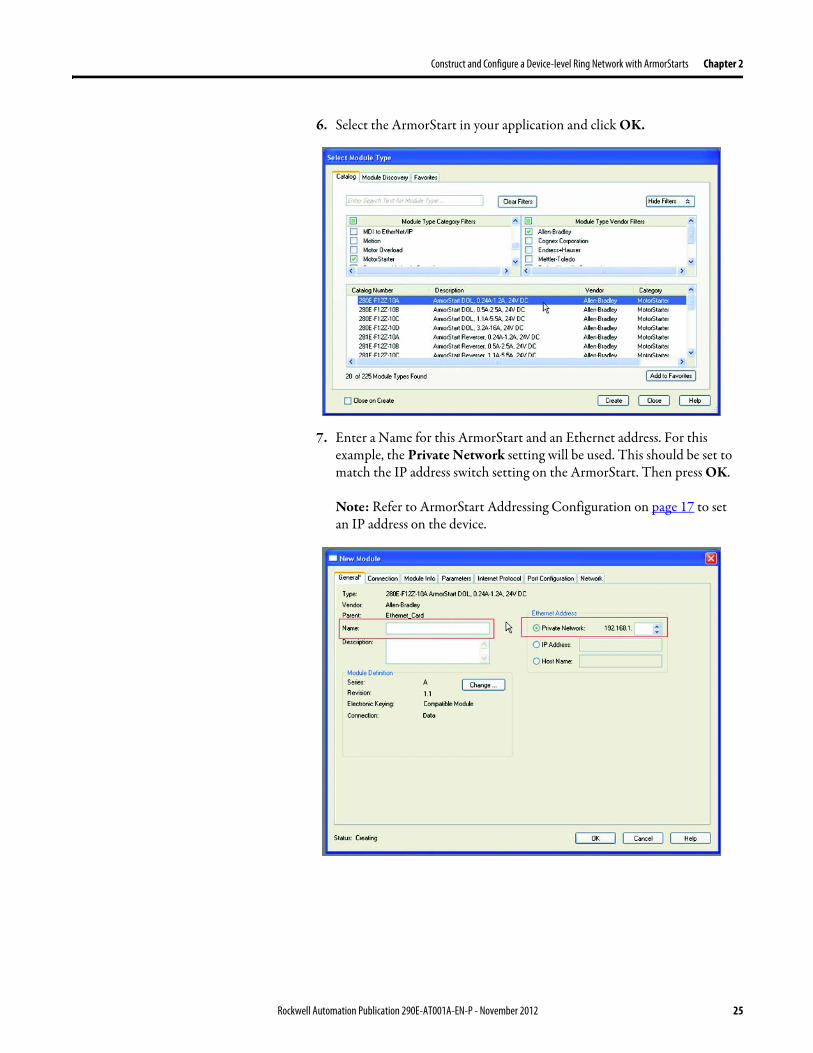
Construct and Configure a Device-level Ring Network with ArmorStarts Chapter 2
6 Select the ArmorStart in your application and click OK
7 Enter a Name for this ArmorStart and an Ethernet address For this example the Private Network setting will be used This should be set to match the IP address switch setting on the ArmorStart Then press OK
Note Refer to ArmorStart Addressing Configuration on page 17 to set an IP address on the device
Rockwell Automation Publication 290E-AT001A-EN-P - November 2012 25
Chapter 2 Construct and Configure a Device-level Ring Network with ArmorStarts
8 Complete configuration information for the module in your RSLogix 5000 project
The following graphic shows the IO configuration for an example DLR network
9 Download the program to the Logix controller
10 Go online with the controller and leave it in Program mode
26 Rockwell Automation Publication 290E-AT001A-EN-P - November 2012
Construct and Configure a Device-level Ring Network with ArmorStarts Chapter 2
Enable Ring Supervisor in RSLogix 5000 Programming Software
After 1756-EN2TR module or 1783-ETAP 1783-ETAP1F or 1783-ETAP2F taps have been added to your RSLogix 5000 programming software project the ring supervisor mode must be enabled
If using RSLogix 5000 programming software to configure the ring supervisor and monitor diagnostics on the DLR network the controller must be online
To enable the 1756-EN2TR module or 1783-ETAP 1783-ETAP1F or 1783-ETAP2F tap as a ring supervisor follow these steps
The steps to enable a ring supervisor are basically the same for the 1756-EN2TR module or 1783-ETAP 1783-ETAP1F or 1783-ETAP2F tap This example shows how to do it for the 1756-EN2TR module
1 For your project online with the controller double-click on a supervisor-capable device in the IO configuration tree
Rockwell Automation Publication 290E-AT001A-EN-P - November 2012 27
Chapter 2 Construct and Configure a Device-level Ring Network with ArmorStarts
2 Click the Network tab to Enable Supervisor Mode
Configuration takes effect immediately you do not need to click Apply or OK
3 Click the Advanced button on the Network tab
4 Configure supervisor-related parameters as shown in the screen shot below
For these parameters you must click Set after entering a value
5 Click Set
28 Rockwell Automation Publication 290E-AT001A-EN-P - November 2012
Construct and Configure a Device-level Ring Network with ArmorStarts Chapter 2
Configure and Enable a Ring Supervisor in RSLinx Classic Communication Software
A ring supervisor can be configured for the DLR network through RSLinx Classic communication software
For more information regarding the Required RSLinx Classic Communication software Revision required refer to Appendix B
To configure a ring supervisor in RSLinx Classic Communication Software follow these steps
This example is for the 1783-ETAP tap Follow these steps
1 Launch RSLinx Classic Communication Software
2 Browse to the DLR network that is being set up
IMPORTANT For Beacon Interval Beacon Timeout and Ring Protocol VLAN ID we recommend that the default values be used
Functionality Description Default Setting
Supervisor Precedence A supervisor precedence number may be configured for each device that is configured as a ring supervisor The highest possible supervisor precedence value is 255When multiple nodes are enabled as supervisors the node with the highest precedence value is assigned as the active ring supervisor the other nodes automatically become back-up supervisorsWe recommend that youbull configure at least one back-up supervisor nodebull set the desired Active Ring Supervisor with a relatively high supervisor-
precedence value compared to the back-up node(s)bull keep track of the networkrsquos supervisor-precedence valuesIf multiple supervisors are configured with the same precedence value (the factory default value for all supervisor-capable devices is 0) the node with the numerically highest MAC address becomes the active supervisor
0
Beacon Interval Beacon interval is the frequency of the active ring supervisor transmitting a beacon frame through both of its Ethernet ports This parameter is user configurable for any time between 200 μS and 100 mSFor more information on how this parameter relates to network performance see page 61
400 μS
Beacon Timeout The beacon timeout is the amount of time that nodes wait before timing out the reception of beacon frames and taking appropriate action Supervisors support a range from 400μS to 500mSFor more information on how this parameter relates to network performance see page 61
1960 μS
Ring Protocol VLAN ID Reserved for future use 0
Rockwell Automation Publication 290E-AT001A-EN-P - November 2012 29
Chapter 2 Construct and Configure a Device-level Ring Network with ArmorStarts
If the Electronic Data Sheet (EDS) file is not installed on the module configured to be the ring supervisor it will appear with a question mark () To obtain and use the EDS file
bull right-click the module and choose to upload the EDS file from the device or
bull download the EDS file from httpwwwrockwellautomationcomrockwellautomationsupportnetworksedspage
3 Access the supervisor-capable nodersquos propertiesa Right-click the nodeb Choose Module Configuration
The General tab appears with information about the module
4 Click the Network tab to Enable Supervisor Mode
Configuration takes effect immediately there is no need to click Apply or OK
30 Rockwell Automation Publication 290E-AT001A-EN-P - November 2012
Construct and Configure a Device-level Ring Network with ArmorStarts Chapter 2
5 Click the Advanced button to configure supervisor-related parameters
Rockwell Automation Publication 290E-AT001A-EN-P - November 2012 31
Chapter 2 Construct and Configure a Device-level Ring Network with ArmorStarts
IMPORTANT For Beacon Interval Beacon Timeout and Ring Protocol VLAN ID use the default values
Functionality Description Default Setting
Supervisor Precedence
You may configure a supervisor precedence number for each device configured as a ring supervisor The highest possible supervisor precedence value is 255When multiple nodes are enabled as supervisor the node with the highest precedence value is assigned as the active ring supervisor the other nodes automatically become back-up supervisorsWe recommend that youbull configure at least one back-up supervisor nodebull set the desired Active Ring Supervisor with a relatively high supervisor-
precedence value compared to the back-up node(s)bull keep track of the networkrsquos supervisor-precedence valuesIf multiple supervisors are configured with the same precedence value (the factory default value for all supervisor-capable devices is 0) the node with the numerically highest MAC address becomes the active supervisor
0
Beacon Interval Beacon Interval is the frequency to which the active ring supervisor transmits a beacon frame through both of its Ethernet ports This parameter is user configurable for any time between 200 μS and 100 mSFor more information on how this parameter relates to network performance see page 58
400 μS
Beacon Timeout The beacon timeout is amount of time nodes wait before timing out the reception of beacon frames and taking appropriate action Supervisors support a range from 400 μS to 500 mSFor more information on how this parameter relates to network performance seepage 58
1960 μS
Ring Protocol VLAN ID
Reserved for future use 0
Enable IGMP Snooping
For more information on IGMP Snooping see page 35 Enabled
Enable IGMP Querier
For more information on IGMP Querier see page 35 Disabled
Enable Device Port Debugging Mode
For more information on Device Port Debugging Mode see page 59 Disabled
32 Rockwell Automation Publication 290E-AT001A-EN-P - November 2012
Construct and Configure a Device-level Ring Network with ArmorStarts Chapter 2
Complete the Physical Connections of the Network
After the ring supervisor nodes are configured and enabled the physical connection of the network must be completed to establish a complete DLR network
The figure below shows an example DLR network with all physical connections complete
Figure 4 - Example Device-level Ring Topology with All Connections Complete
Rockwell Automation Publication 290E-AT001A-EN-P - November 2012 33
Chapter 2 Construct and Configure a Device-level Ring Network with ArmorStarts
Verify Supervisor Configuration
The configuration and overall DLR network status can be verified in either RSLogix 5000 programming software or RSLinx Classic communication software
1 Access the supervisor nodersquos properties as shown previously in this chapter
2 Click the Network tab
3 Check the Network Topology and Network Status Fields
For a 1756-EN2TR module or the 1783-ETAP 1783-ETAP1F and 1783-ETAP2F tap the supervisor configuration can also be verified through the modulersquos diagnostic web pages For more information on monitoring diagnostics via an EtherNetIP modulersquos web pages see Monitor a DLR Network starting on page 37
34 Rockwell Automation Publication 290E-AT001A-EN-P - November 2012
Construct and Configure a Device-level Ring Network with ArmorStarts Chapter 2
IGMP Snooping This functionality is enabled by default in the 1783-ETAP 1783-ETAP1F and 1783-ETAP2F taps and is commonly used to manage multicast traffic on the network When in use this functionality allows the tap to multicast data to only those devices that need the data rather than to all devices connected to the network
For snooping to work there must be a device present that is running a querier Typically the device is a router or a switch such as the Stratix 6000 Stratix 8000 or Stratix 8300 managed switch
Once DHCP is enabled the switch could change the IP addresses on the ArmorStarts depending on network demand which could cause RSlogix5000 to loose communication with the device as connectivity is established via the AOP in the initial configuration
IGMP Querier This functionality is disabled by default The IGMP Querier functionality enables a 1783-ETAP 1783-ETAP1F or 1783-ETAP2F tap or switch such as a Stratix managed switch to send out a query to all devices on the network It determines what multicast addresses are of interest to a specific node or a group of nodes
The IGMP Querier functionality should be enabled for at least one node on the network The 1783-ETAP 1783-ETAP1F or 1783-ETAP2F tap managed switches and routers are examples of devices that support IGMP Querier functionality
IMPORTANT If DHCP for the Armostart is still required the Internet Group Management Protocol (IGMP) snooping on the E-tap must be disabled via the AOP
IMPORTANT If the IGMP Querier functionality is not enabled for at least one node on the network multicast traffic on the network may eventually create network performance issues
Rockwell Automation Publication 290E-AT001A-EN-P - November 2012 35
Chapter 2 Construct and Configure a Device-level Ring Network with ArmorStarts
However for all devices that are configured on the network with the IGMP Querier parameter enabled an IP address other than the factory default value must also be set for those devices If multiple devices on the network enable this functionality only the node with the lowest IP address becomes the active IGMP Querier node
IGMP Version
If the IGMP Querier is enabled a Querier Version must be selected The default version is Version 2
36 Rockwell Automation Publication 290E-AT001A-EN-P - November 2012
Chapter 3
Monitor a DLR Network
Introduction Use this chapter to learn how to monitor the DLR network
Methods to Monitor a DLR Network
Network diagnostic information can be retrieved from the ring supervisor-capable devices using the following
bull RSLogix 5000 programming software status pages
bull RSLinx communication software status pages
bull Device web pages
bull EtherNetIP Device Level Ring (DLR) network diagnostics faceplate
bull Programmatically through the use of a MSG instruction
RSLogix 5000 Programming Software Status Pages
RSLogix 5000 programming software version 1701 or later must be used and the appropriate AOPs installed to use the softwarersquos profile status pages
RSLinx Communication Software Status Pages
To monitor the network with this method the RSLinx communication software version 255 or later must be used
Topic Page
Methods to Monitor a DLR Network 37
Monitor Status Pages 39
Monitor ArmorStart Internal Web Server 44
Monitor via Faceplate Integration 45
Monitor Diagnostics via MSG Instructions 46
Rockwell Automation Publication 290E-AT001A-EN-P - November 2012 37
Chapter 3 Monitor a DLR Network
ArmorStart Internal Web Server
Rockwell Automation provides an internal embedded web server with each ArmorStart EtherNetIP The internal web server allows you to view information and configure the ArmorStart via a web browser The ArmorStart EtherNetIP can also be set up from the web server to send e-mail notifications The embedded web server is used to access configuration and status data It provides the user with the ability to view and modify the device configuration without having access to RSLogix 5000 Security in the form of an administrative password can be set The default login is Administrator There is no password set by default
EtherNetIP Device Level Ring (DLR) Network Diagnostics Faceplate
The diagnostics faceplate contains two major components
bull Logic code (encapsulated in an Add-On Instruction) that allows the controller to retrieve real-time DLR network status information
bull HMI faceplate graphics to allow the data to be visualized on an operator interface
Programmatically Through the Use of a MSG Instruction
For more information on how to monitor the DLR network via MSG Instructions see page 46
38 Rockwell Automation Publication 290E-AT001A-EN-P - November 2012
Monitor a DLR Network Chapter 3
Monitor Status Pages Both RSLogix 5000 programming software and RSLinx Classic communication software offer status pages that can be used to monitor the networkrsquos performance
RSLogix 5000 Programming Software Status Pages
Monitor the networkrsquos diagnostic information through the RSLogix 5000 programming software when the software is online
To monitor the network in RSLogix 5000 programming software follow these steps
1 Verify that the project is online
2 Access the active supervisor nodersquos propertiesa Right-click the modulersquos entry in the Controller Organizerb Click properties
Rockwell Automation Publication 290E-AT001A-EN-P - November 2012 39
Chapter 3 Monitor a DLR Network
3 Use the Network tab to monitor diagnostics
40 Rockwell Automation Publication 290E-AT001A-EN-P - November 2012
Monitor a DLR Network Chapter 3
RSLinx Communication Software
To monitor the network in RSLinx communication software follow these steps
1 Click RSWho to browse the network
2 Access the property pages for the active supervisor nodea Open the driver that shows the nodes on the DLR networkb Right-click the node that you want to monitor performancec Click on the choice that you need to access
Multiple choices appear
These options are shown in the following sections
Rockwell Automation Publication 290E-AT001A-EN-P - November 2012 41
Chapter 3 Monitor a DLR Network
Module Configuration
This series of tabs providesbull General informationbull Connection informationbull Module informationbull Internet protocolbull Port configurationbull Network information
The example below shows a ring fault between nodes at IP addresses 10888021 and MAC ID 00-00-BC-02-48-D5
42 Rockwell Automation Publication 290E-AT001A-EN-P - November 2012
Monitor a DLR Network Chapter 3
There are multiple fields used to monitor network diagnostics
Field Definition
Network Topology Possible values here can be Linear or Ring
Network Status Displays if the network is operating normally (Normal) or has experienced a fault (Ring Fault) as shown in the previous example screen
Active Ring Supervisor Displays the IP address or MAC address of the active ring supervisor
Active Supervisor Precedence For more information on this field see Active Ring Supervisor on page 11
Enable Ring Supervisor Configurable field that lets you to set the node as a ring supervisor
Ring Faults Detected Number of faults detected on the network since the last module power cycle or counter reset
Supervisor Status Displays whether this node is the active ring supervisor (Active) a back-up supervisor (Back-up) a ring node or part of a linear network
Last Active Node on Port 1 The last node the active ring supervisor can communicate with on Port 1 This value is an IP address or a MAC ID and remains latched until the Verify Fault Location button is clicked
Last Active Node on Port 2 The last node the active ring supervisor can communicate with on Port 2 This value is an IP address or a MAC ID and remains latched until the Verify Fault Location button is clicked
Status Displays whether a fault exists on the ring
IMPORTANT If the Network Topology field = Ring and the Network Status field = Normal the Last Active Node fields will display the last fault information even though it has been correctedTo clear the last fault information from these fields click Verify Fault Location You may see a message informing you that the supervisor is no longer in fault mode and the fields will be cleared
Rockwell Automation Publication 290E-AT001A-EN-P - November 2012 43
Chapter 3 Monitor a DLR Network
How to Access the ArmorStart EtherNetIP Internal Web Server
Open your preferred internet web browser and enter the IP address of the desired ArmorStart For this example 192168122 will be used
Use the links on the left-most navigation bar to see each available web page The screen below shows Ring Statistics for the ArmorStart 280E
44 Rockwell Automation Publication 290E-AT001A-EN-P - November 2012
Monitor a DLR Network Chapter 3
EtherNetIP Device Level Ring (DLR) Network Diagnostics Faceplate Overview
The EtherNetIP Device Level Ring (DLR) network diagnostics faceplate provides basic DLR network status information to the user to assist with monitoring and troubleshooting a DLR network
The diagnostics faceplate contains two major components
bull Logic code (encapsulated in an Add-On Instruction) that allows the controller to retrieve real-time DLR network status information
bull HMI faceplate graphics to allow the data to be visualized on an operator interface
The DLR diagnostics faceplate application can be downloaded from the Rockwell Automation Sample Code website at httpsamplecoderockwellautomationcom
Besides the individual Logix and View project components a demo application is also included with the downloaded file
Rockwell Automation Publication 290E-AT001A-EN-P - November 2012 45
Chapter 3 Monitor a DLR Network
Monitor Diagnostics via MSG Instructions
Network diagnostic information can also be obtained programmatically via MSG instructions in RSLogix 5000 programming software For example you can
bull Get all ring diagnostic informationbull Get a ring participant listbull Get the active supervisorbull Clear rapid ring faultsbull Verify a fault locationbull Reset a fault counterbull Enable and configure a ring supervisor
This information can be displayed on an HMI device or manipulated in the project code
Figure 5 - Example Use of MSG Instruction
This example describes how to retrieve diagnostic information from the DLR network Follow these steps
1 Enter a MSG instruction into the rung of logic
2 Configure the MSG instruction to retrieve ring diagnostic information service as shown in the following screen shots
IMPORTANT Make sure the tag created is sized appropriately to hold all of the data that you are reading or writing For more information see page 48
46 Rockwell Automation Publication 290E-AT001A-EN-P - November 2012
Monitor a DLR Network Chapter 3
3 Configure the MSG instructionrsquos communication path to point to the active supervisor node
The path on the following screen is one example path
IMPORTANT When using the Custom Get_Attributes_All (01) service pointing to an active supervisor node will retrieve all of the attributes listed in Retrieve All Diagnostic Information Attribute Description on page 50Pointing to a non-supervisor node will retrieve only the Network Topology and Network Status attribute informationPointing to backup supervisor node will retrieve the current active supervisorrsquos IP address
Rockwell Automation Publication 290E-AT001A-EN-P - November 2012 47
Chapter 3 Monitor a DLR Network
Use Specific Values on the Configuration Tab
Use the values on the Configuration tab of your MSG instruction to perform specific services Sample DLR network diagnostic application code for example Add-on Instruction or HMI faceplate graphics is available on the Rockwell Automation Sample Code Library For more information about the Rockwell Automation Sample Code Library see httpwwwrockwellautomationcomsolutionsintegratedarchitectureresources5html
➊ This request only works if there are fewer than 40 nodes on the network If there are more nodes than will fit in a single message an error will be returned➋ Use a Destination Length of 54 bytes if using firmware revision 3x or later for the 1756-EN2TR module or firmware revision 2x or later for the 1783-ETAP
1783-ETAP1F or 1783-ETAP2F taps
Request Description Message Type
Service Type
Service Code (HEX)
Class (HEX)
Instance Attribute (HEX)
Source Element
Source Length (Bytes)
Destination Destination Length (bytes)
Retrieve All Ring Diagnostic Information
Information for this request is listed in Retrieve All Ring Diagnostic Information on page 49
CIP Generic Custom 1 47 1 NA LeftBlank
0 Tag 50or54 ➋
Request Ring Participant List ➊
Information for this request is listed in Request the Ring Participant List on page 51
CIP Generic Get Attribute Single
e 47 1 9 NA NA Tag 10node
Get Active Supervisor
Obtain the IP address and MAC ID of the active supervisor on the DLR network
CIP Generic Get Attribute Single
e 47 1 a NA NA Tag 10
Acknowledge Rapid Ring Faults Condition
Request supervisor to resume normal operation after encountering a rapid ring fault condition
CIP Generic Custom 4c 47 1 NA NA NA NA
Verify a Fault Location
Request supervisor to update Last Active Node values
CIP Generic 4b 47 1 NA NA NA NA NA
Reset the Ring Fault Counter
Reset the number of ring faults detected on the DLR network
CIP Generic Set Attribute Single
10 47 1 5 Tag 2 NA NA
Enable and Configure a Ring Supervisor
Information for this request is listed in Enable and Configure a Ring Supervisor on page 52
CIP Generic Set Attribute Single
10 47 1 4 Tag 12 NA NA
48 Rockwell Automation Publication 290E-AT001A-EN-P - November 2012
Monitor a DLR Network Chapter 3
Retrieve All Ring Diagnostic Information
By performing the Retrieve All Ring Diagnostic Information request on an active supervisor the MSG instruction returns the following information
➊ RSLogix 5000 programming software may display the value in this field as negative numbers To better understand the value we recommend you view it in HEX format
Destination Tag Attribute Name Description Possible Values
SINT [0] Network Topology Current network topology mode 0 = Linear
1 = Ring
SINT [1] Network Status Current status of the network 0 = Normal
1 = Ring Fault
2 = Unexpected Loop Detected
3 = Partial Network Fault
4 = Rapid FaultRestore Cycle
SINT [2] Ring Supervisor Status Ring supervisor active status flag 0 = Node is functioning as a backup
1 = Node is functioning as the active ring supervisor
2 = Node is functioning as a normal ring node
3 = Node is operating in a non-DLR topology
4 = Node cannot support the currently operating ring parameters thatis Beacon Interval andor Beacon Timeout
Ring Supervisor Config Ring Supervisor configuration parameters
SINT [3] Ring Supervisor Enable Ring supervisor enable flag 0 = Node is configured as a normal ring node (default configuration)
1 = Node is configured as a ring supervisor
SINT [4] Ring Supervisor Precedence Precedence value of a ring supervisor ➊ Valid value range = 0hellip255
0 = Default value
SINT [5-8] Beacon Interval Duration of ring beacon interval Valid value range = 200 μshellip100 ms
Default = 400 μs
SINT [9-12] Beacon Timeout Duration of ring beacon timeout Value value range = 400 μshellip500 ms
Default value = 1960 μs
SINT [13-14] DLR VLAN ID Valid ID to use in ring protocol messages Valid value range = 0hellip4094
Default value = 0
SINT [15-16] Ring Faults Count Number of ring faults since power up ➊
Rockwell Automation Publication 290E-AT001A-EN-P - November 2012 49
Chapter 3 Monitor a DLR Network
Retrieve All Diagnostic Information Attribute Description
➊ This destination tag is available only with the 1756-EN2TR module firmware revision 3x or later 1783-ETAP 1783-ETAP1F and 1783-ETAP2F taps firmware revisions 2x or later If using the 1783-ETAP tap firmware revision 1x your program does not include this destination tag
➋ RSLogix 5000 programming software may display the value in this field as negative numbers To better understand the value we recommend you view it in HEX format
Destination Tag Attribute Name Description Possible Values
Last Active Node on Port 1 Last active node at the end of the chain through port 1 of the active ring supervisor during a ring fault
SINT [17-20] Device IP address ➋ Any valid IP address value
A value = 0 indicates no IP address has been configured for the device
SINT [21-26] Device MAC address ➋ Any valid Ethernet MAC address
Last Active Node on Port 2 Last active node at the end of the chain through port 2 of the active ring supervisor during a ring fault
SINT [27-30] Device IP address ➋ Any valid IP address value
A value = 0 indicates no IP address has been configured for the device
SINT [31-36] Device MAC address ➋ Any valid Ethernet MAC address
SINT [37-38] Ring Protocol Participants Count
Number of devices in the ring protocol participants list
Active Supervisor Address IP andor Ethernet MAC address of the active ring supervisor
SINT [39-42] Supervisor IP address Any valid IP address value
A value = 0 indicates no IP address has been configured for the device
SINT [43-48] Supervisor MAC address Any valid Ethernet MAC address
SINT [49] Active Supervisor Precedence
Precedence value of the active ring supervisor
SINT [50-53]➊ Capability Flags Alerts you that the device is capable of operating as a supervisor and beacon-based ring node
0x22
50 Rockwell Automation Publication 290E-AT001A-EN-P - November 2012
Monitor a DLR Network Chapter 3
Request the Ring Participant List
When requesting the Ring Participant List service on the DLR network the MSG instruction returns the following information
Request the Ring Participant List Attribute Description
➊ This attribute will return an array of the data shown one entry for each node The Ring Protocol Participants Count attribute determines the number entries
➋ This tag displays only IP addresses for ring participants that have been configured with one For example you may have a 1783-ETAP tap connected to the network that has not been assigned an IP address In that case no address is shown for the 1783-ETAP tap
➌ RSLogix 5000 programming software may display the value in this field as negative numbers To better understand the value we recommend you view it in HEX format
➍ Unlike destination tag SINT [0-3] where IP addresses are displayed only for ring participants configured with an IP address this tag displays MAC addresses for all ring participants because every ring participant has a MAC address
Destination Tag Attribute Name Description Possible Values
Ring Protocol Participants List ➊
List of devices participating in ring protocol
SINT [0-3] Device IP address ➋➌ Any valid IP address value
A value = 0 indicates no IP address has been configured for the device
SINT [4-9] Device MAC address ➌➍ Any valid Ethernet MAC address
Rockwell Automation Publication 290E-AT001A-EN-P - November 2012 51
Chapter 3 Monitor a DLR Network
Enable and Configure a Ring Supervisor
When performing the Enable and Configure a Ring Supervisor request on a supervisor-capable device configure the MSG instruction with the following information
Enable and Configure a Ring Supervisor Attribute Description
➊ RSLogix 5000 programming software may display the value in this field as negative numbers To better understand the value we recommend you view it in HEX format
Source Tag Attribute Name Description Possible Values
Ring Supervisor Config Ring Supervisor configuration parameters
SINT [0] Ring Supervisor Enable Ring supervisor enable flag 0 = Node is configured as a normal ring node (default configuration)1 = Node is configured as a ring supervisor
SINT [1] Ring Supervisor Precedence Precedence value of a ring supervisor ➊
Valid value range = 0hellip2550 = Default value
SINT [2-5] Beacon Interval Duration of ring beacon interval
Valid value range = 200 μshellip100 000 μsDefault = 400 μs
SINT [6-9] Beacon Timeout Duration of ring beacon timeout ➊
Value value range = 400 μshellip500 000 μsDefault value = 1960 μs
SINT [10-11] DLR VLAN ID Valid ID to use in ring protocol messages ➊
Valid value range = 0hellip4094Default value = 0
52 Rockwell Automation Publication 290E-AT001A-EN-P - November 2012
Chapter 4
Troubleshoot a DLR Network
Introduction Use this chapter to learn how to troubleshoot the DLR network
General Solutions for Linear or DLR Networks
Before attempting to correct specific faults on the linear or DLR network we recommend that you first take the following actions when a fault appears
bull For a DLR networkndash Verify that at least one node has been configured as a supervisor
on the network and that Network Topology = Ringndash Verify that all cables on the network are securely connected
to each devicendash Verify that all devices that require an IP address have one assigned
correctlyndash Check the Network Status field on the active supervisor nodersquos status
page to determine the fault typebull For a linear network
ndash Verify that none of the nodes are configured as a supervisor on the network and that Network Topology = LinearIf any nodes on a linear network are configured as a supervisor it may impact communication to other devices connected to the network
ndash Verify that all cables on the network are securely connected to each device
ndash Verify that all devices that require an IP address have one assigned correctly
If the fault is not cleared after completing the actions listed above use the tables in the rest of this chapter to troubleshoot issues specific to a DLR network or a linear network
Topic Page
General Solutions for the Linear or DLR Networks 53
Duplicate IP Address Detection 54
Specific Issues on the DLR Network 55
Network Recovery Performance 58
Device Port Debugging Mode 59
Rockwell Automation Publication 290E-AT001A-EN-P - November 2012 53
Chapter 4 Troubleshoot a DLR Network
Duplicate IP Address Detection
Some EtherNetIP communication modules support duplicate IP address detection The module verifies that its IP address does not match any other network devicersquos IP address when performing either of these tasks
bull Connect the module to an EtherNetIP network
bull Change the modulersquos IP address
If the modulersquos IP address matches that of another device on the network the modulersquos EtherNetIP port transitions to Conflict mode In Conflict mode these conditions exist
bull OK status indicator is blinking red
bull Network (NET) status indicator is solid red
bull On some EtherNetIP communication modules the module status display indicates the conflict
The display scrollsOK ltIP_address_of_this_modulegt Duplicate IP
ltMac_address_of_duplicate_node_detectedgt
For example OK 108860196 Duplicate IP - 0000BC0234B4
bull On some EtherNetIP communication modules the modulersquos diagnostic webpage displays information about duplicate IP address detection
For more information on which EtherNetIP communication modules support displaying duplicate IP address on their diagnostic webpage see the Technical Note titled Logix modules Duplicate IP address detection enhancement 118216 in the Technical Support Knowledgebase available at httpwwwrockwellautomationcomknowledgebase
54 Rockwell Automation Publication 290E-AT001A-EN-P - November 2012
Troubleshoot a DLR Network Chapter 4
Specific Issues on the DLR Network
Use the following table to troubleshoot possible specific issues on the DLR or linear network that are not solved by the actions described on the previous page
Issue Description Solution
Supervisor Reports a Ring Fault A link on the DLR network may be brokenbull intentionally for example because of adding or deleting nodes but not making all
physical connections to restore the setup of the network withwithout the nodebull unintentionally for example because a cable is broken or a device malfunctionsWhen this fault occurs the adjacent nodes to the faulted part of the network are displayed in the Ring Fault group and the Network Status field = Ring FaultThe screen shot below shows the Ring Fault section with IP addresses appearing for the last active nodes The faulted node is between nodes 108880115 and 108880208 If the IP address of either node is not available the software will display the nodersquos MAC ID
Once the fault is corrected the ring is automatically restored and the Network Status field returns to Normal
Determine where the fault condition exists and correct itClick the Refresh Communication link as needed to update the Ring Fault information to determine where the fault condition existsFinally DevicePort Debugging Mode functionality on the 1783-ETAP tap may be used to analyze a suspicious nodeFor more information refer to Device Port Debugging Mode on page 59
Rockwell Automation Publication 290E-AT001A-EN-P - November 2012 55
Chapter 4 Troubleshoot a DLR Network
Issue Description Solution
Rapid Ring Fault When a Rapid Ring Fault occurs the following events occurbull The active supervisor will block traffic on port 2 resulting in possible network
segmentation that is some nodes may become unreachablebull The Link 2 status indicator on the active supervisor is offbull As soon as the fault occurs for both RSLogix 5000 programming software and
RSLinx communication software the Status field = Rapid FaultRestore Cycles
Any of the following may cause a Rapid Ring Faultbull 5 intentional disconnectionsreconnections of a node from the network within 30
secondsbull A duplex mismatch between two connected devicesbull Electromagnetic noise on the networkbull Unstable physical connections such as intermittent connectorsGiven the nature of a Rapid Ring Fault the Last Active Node information may not be accurate when a Rapid Ring Fault condition is present
Multiple possible solutions existbull For the disconnections and reconnections issue no
solution is requiredClear the fault after reconnecting the device to the network permanentlybull For the duplex mismatch issue reconfigure the duplex
parameters to make sure they match between the devices
bull For the electromagnetic noise issue determine where the noise exists and eliminate it or use a protective shield in that location
bull For the unstable connections issue determine where they exist on the network and correct them
bull Check the media counters for all devices on the network The device with the highest media counter count is most likely causing the Rapid Ring Fault
bull Remove devices from the network one by one If the Rapid Ring Fault disappears after a device is removed that device is causing the fault
bull DevicePort Debugging Mode functionality on the 1783-ETAP tap may be used to analyze a suspicious node
For more information refer to Device Port Debugging Mode on page 59bull Finally the Beacon Interval or Timeout configuration
may not be appropriate for the networkHowever if these values need to be changed we recommend that you contact Rockwell Automation technical supportOnce the fault is fixed click Clear Fault
56 Rockwell Automation Publication 290E-AT001A-EN-P - November 2012
Troubleshoot a DLR Network Chapter 4
Issue Description Solution
Partial Fault Condition A partial network fault occurs when traffic is lost in only one direction on the network because a ring member is not forwarding beacons in both directions for example a component failureThe active ring supervisor detects a partial fault by monitoring the loss of Beacon frames on one port and the fault location appears in the Ring Fault section of the Network tab When a partial fault is detected the active ring supervisor blocks traffic on one port At this point the ring is segmented due to the partial fault condition The nodes adjacent to the faulted part of the network are displayed in the Ring Fault group with either IP addresses or MAC IDs for each node displayedWhen this fault occurs the Network Status field = Partial Fault ConditionOnce the fault is corrected it automatically clears and the Network Status field returns to Normal
Determine where the fault condition exists and correct itAdditionally the DevicePort Debugging Mode functionality also known as Port Mirroring on a 1783-ETAP 1783-ETAP1F or 1783-ETAP2F tap may be used to analyze a suspicious nodeFor more information refer to Device Port Debugging Mode on page 59
Media Counter Errors or Collisions
The media counters screen displays the number of physical layer errors or collisions The screen below indicates where to check for errors encountered Error levels are displayed depending on what caused the error For example an Alignment Error is displayed in the Alignment Error field
On a DLR network it is not uncommon to see low levels of media counter errors For example if the network breaks a low level of media counter errors appears With a low level of media counter errors the value typically does not continuously increase and often clearsA high level of media counter errors typically continues to increase and does not clear For example there is a mismatch of speed between two linked nodes a high level of media counter errors appears steadily increasing and not clearingTo access the RSLinx screen above browse the network right-click on the device select Module Properties and click the Port Diagnostics tab
Some example solutions includebull Check for a mismatch of speed andor duplex between
two linked nodesbull Verify that all cables on the network are securely
connected to each devicebull Check for electromagnetic noise on the network If you
find it eliminate it or use a protective shield in that location
Rockwell Automation Publication 290E-AT001A-EN-P - November 2012 57
Chapter 4 Troubleshoot a DLR Network
Network Recovery Performance
When measuring the networkrsquos performance with regard to dealing with fault conditions consider the network recovery time Network recovery is the time for all of the following to take place
1 The supervisor node recognizes that a fault exists on the network
2 The supervisor node reconfigures the network because of the fault
3 The supervisor node communicates to the network nodes that a fault condition exists
4 The network nodes reconfigure themselves because of the fault
With the default beacon interval value of 400 mS and beacon timeout value of 1960 mS the worst-case time for network recovery times are
bull 2890 mS for a copper DLR network This recovery time is based on 100 m copper segments between nodes on the network
bull 3140 mS for a fiber-optic DLR network This recovery time is based on 2 kM fiber-optic cable segments between nodes on the network
When considering the values listed above keep in mind
bull Recovery time may actually occur faster than the times listed
bull The recovery times listed above assume that your networkrsquos nodes are operating at 100 Mbps speed and full-duplex mode We recommend that your nodes generally operate in this mode for DLR networks
bull If other node conditions exist such as a node operating at 10 Mbps full-duplex or 10100 Mbps half-duplex the recovery times will vary from the times listed above
If this is the case for your application the beacon interval and beacon timeout will need to be changed We recommend that you first contact Rockwell Automation technical support if these parameters need to be changed
bull The value assumes that the majority of the traffic on your network is EtherNetIP traffic
58 Rockwell Automation Publication 290E-AT001A-EN-P - November 2012
Troubleshoot a DLR Network Chapter 4
Device Port Debugging Mode
This functionality is disabled by default Device Port Debugging mode which is similar to port mirroring can be used to monitor data received on the 1783-ETAP 1783-ETAP1F or 1783-ETAP2F taprsquos two network ports Monitor the data over the device port to a device such as a personal computer running a protocol analyzer application for advanced network debugging or analysis
When device port debugging is used on a 1783-ETAP the device connected to the 1783-ETAP taprsquos front port receives all of the data traversing the ring (both directions)
Device Port Debugging Example Network
When using the Device Port Debugging mode functionality insert the 1783-ETAP with the network analyzer connected to the device port It is inserted at the spot on the ring network where the node in question is located The graphic below shows a 1783-ETAP tap inserted in the network
IMPORTANT This functionality should be used only when troubleshooting the network and not in normal network operation
Rockwell Automation Publication 290E-AT001A-EN-P - November 2012 59
Chapter 4 Troubleshoot a DLR Network
Combined total network bandwidth of the traffic received on the two 1783-ETAP 1783-ETAP1F or 1783-ETAP2F taprsquos ports connected to the network should not exceed the taprsquos device port capacity The speed setting determines the device portrsquos capacity
Configure the device port on a 1783-ETAP 1783-ETAP1F or 1783-ETAP2F tap to either of two speed settings
bull 100 Mbps - default settingbull 10 Mbps
If the bandwidth exceeds the capacity of the taprsquos device port some frames from the ring will be dropped before reaching the device port These dropped frames do not impact the traffic on the rest of the DLR network
The device port setting determines how much network traffic the 1783-ETAP 1783-ETAP1F or 1783-ETAP2F tap can handle before dropping frames The circled section in the graphic below shows the Port Buffer Utilization of the Device Port In this example the value is zero because a ring fault exists on the network
60 Rockwell Automation Publication 290E-AT001A-EN-P - November 2012
Appendix A
Network Usage Guidelines and Recommendations
Consider the following guidelines and recommendations when using a DLR or linear network
GuidelineRecommendation Explanation
Use fewer than 50 nodes on a single DLR networkIf your application requires more than 50 nodes we recommend that the nodes are broken into separate but linked DLR networks
If you use more than 50 nodes on a single DLR networkbull Your network has a greater chance of multiple faults
occurring on the networkbull Network recovery times from faulted DLR network
are higher
Do not configure a supervisor on a linear network If your linear network includes non-DLR nodes and has a supervisor-enabled node on the network it may impact communication to non-DLR devices connected to the linear network
If you must connect a device that is running at 10 Mbps to a DLR or linear network do so through a 1783-ETAP 1783-ETAP1F or 1783-ETAP2F tap device port
The 1783-ETAP 1783-ETAP1F and 1783-ETAP2F taps can operate at 100 Mbps on the DLR network this is the optimal speed for a network If you connect a 10 Mbps device directly to the network instead of through a tap the linear or DLR network traffic slows to 10 MbpsAdditionally if the 10 Mbps device is connected to the network without a 1783-ETAP tap network recovery times are significantly impacted
Configure multiple supervisor nodes per ring If your DLR network only has one supervisor and the supervisor experiences a fault none of the other nodes become the active supervisor In this case the network becomes a linear network until the fault is corrected and the DLR network restoredAnother reason to configure multiple supervisor nodes is for replacing an active supervisor node with an out-of-box replacement the new device will not be enabled as a supervisor (by default) and there would still be no supervisor on the network
Rockwell Automation Publication 290E-AT001A-EN-P - November 2012 61
Appendix A Network Usage Guidelines and Recommendations
GuidelineRecommendation Explanation
Connect switches to a DLR network via 1783-ETAP 1783-ETAP1F or 1783-ETAP2F taps
If switches are connected to the DLR network without the use of a 1783-ETAP 1783-ETAP1F or 1783-ETAP2F tap the network may experience unpredictable behavior and network performance is unknown
Run all nodes on the DLR network at 100 Mbps and in Full-Duplex mode
These configuration values provide the best performance for your networkAdditionally we recommend that youbull Use auto-negotiate for all nodes on the DLR networkbull Do not use auto-negotiate on one node and then force
speed on the next node linked to it
In a linear network the number of nodes to use is application specific based on the considerations described in the next box
When determining the number of nodes to use on a linear network consider the followingbull There is a delay per node as information is transmitted
to each successive node used on the networkndash The typical delay on a linear network with 100 m
copper segments between nodes is 30 mSndash The typical delay on a linear network with 2 kM
fiber-optic segments between nodes is 40 mS
The greater the number of nodes on the network the longer the total time for information to be transmitted across the entire networkbull The single point of failure possibility is greater with
each additional connectionbull Troubleshooting the network may be more difficult
with a higher number of nodes
The total time for information to be transmitted across the entire network and its effect on how many nodes to use on a linear network is related to the Requested Packet Interval (RPI)Verify that the total time to transmit information from the first node to the last node on the network is less than the RPI Make sure the network is not loaded beyond 90 of capacity
62 Rockwell Automation Publication 290E-AT001A-EN-P - November 2012
Network Usage Guidelines and Recommendations Appendix A
GuidelineRecommendation Explanation
Do not physically close a DLR network without a supervisor configured on the network
A DLR network without a supervisor node results in a network stormIf you do close the DLR network without a supervisor configured break the ring and configure at least one supervisor before physically reconnecting the network
Use the default values for the followingbull Beacon Intervalbull Beacon Timeoutbull Ring Protocol VLAN ID
Changing the default values for the parameters Beacon Interval Beacon Timeout and Ring Protocol VLAN ID can result in unpredictable network behavior and negatively impacted network performanceThe default values are optimized for a network withbull 50 or fewer nodes are on the networkbull All nodes are operating at 100 Mbps and full-duplex
modebull At least 50 of the network traffic bandwidth being
EtherNetIP trafficIf you think the values of the Beacon Interval Beacon Timeout or Ring Protocol VLAN ID need to be changed for example if any node on ring is not operating at 100 Mbps and full-duplex mode we recommend that you first contact Rockwell Automation technical support
If DHCP for the ArmorStarts is still required you will need to disable Internet Group Management Protocol (IGMP) snooping on the E-tap via the AOP
IGMP Snooping is enabled by default in the 1783-ETAP 1783-ETAP1F and 1783-ETAP2F taps and is commonly used to manage multicast traffic on the network When in use this functionality allows the tap to multicast data to only those devices that need the data rather than to all devices connected to the networkOnce DHCP is enabled the switch could change the IP addresses on the ArmorStarts depending on network demand which could cause RSlogix5000 to loose communication with the device as connectivity is established via the AOP in the initial configuration
The IGMP Querier functionality should be enabled for at least one node on the network
This functionality is disabled by default The IGMP Querier functionality enables a 1783-ETAP 1783-ETAP1F or 1783-ETAP2F tap or switch such as a Stratix managed switch to send out a query to all devices on the network to determine what multicast addresses are of interest to a specific node or a group of nodesIf the IGMP Querier functionality is not enabled for at least one node on the network multicast traffic on the network may eventually create network performance issuesThe 1783-ETAP 1783-ETAP1F or 1783-ETAP2F taps managed switches and routers are examples of devices that support IGMP Querier functionality
Rockwell Automation Publication 290E-AT001A-EN-P - November 2012 63
Appendix A Network Usage Guidelines and Recommendations
Notes
64 Rockwell Automation Publication 290E-AT001A-EN-P - November 2012
Appendix B
Required Firmware Revisions
Required Firmware Revision for an Add-On Profile
➊ The ControlFLASH Firmware Upgrade software tcan be used o upgrade a 1756-EN2TR module from firmware revision 21 to 3x or later1x or later3x or later2x or later
➋ The ControlFLASH Firmware Upgrade software can be used to upgrade a 1783-ETAP tap from firmware revision 11 to 2x or later
To download new firmware go to httpwwwrockwellautomationcomsupportamericasindex_enhtml
If the firmware revision is upgraded on the module or tap the required AOP revision listed above must be used for that revision For example if the 1756-EN2TR module is upgraded to firmware revision 3x or later AOP revision 2x or later must be used in the RSLogix 5000 programming software
Additionally if the firmware revision is upgraded on the module or tap the required RSLinx communication software must also be used for that firmware revision For more information on which RSLinx software version is required for each firmware revision see page 66
For both the 1756-EN2TR module and 1783-ETAP tap make sure that the Major Revision configured on the General tab of the devicersquos RSLogix 5000 programming software configuration matches the major revision of the physical module
IMPORTANT To download an AOP go to httpsupportrockwellautomationcomcontrolflashLogixProfileraspDepending on the firmware revision of your product a specific AOP version must be used
Firmware Revision Add-On Profile Revision Cat No
21 ➊ 1x or later 1756-EN2TR
3x or later 2x or later
11 ➋ 1x or later 1783-ETAP
2x or later 2x or later
2x or later 2x or later 1783-ETAP1F
1783-ETAP2F
Rockwell Automation Publication 290E-AT001A-EN-P - November 2012 65
Appendix B Required Firmware Revisions
If the device configuration on the General tab does not match the physical module the programming software alerts you to this mismatch when attempting to configure the Internet Protocol Port Configuration and Network tabs for that device
Required Firmware Revision for RSLinx Communication Software
➊ The ControlFLASH Firmware Upgrade software can be used to upgrade a 1756-EN2TR module from firmware revision 21 to 3x or later1x or later3x or later255 or later3x or later256 or later
➋ The ControlFLASH Firmware Upgrade software can be used to upgrade a 1783-ETAP tap from firmware revision 11 to 2x or later
To download new firmware go to httpwwwrockwellautomationcomsupportamericasindex_enhtml
If the firmware revision is upgraded on the module or tap the required RSLinx communication software listed above must be used for that revision For example if the 1756-EN2TR module is upgraded to firmware revision 3x or later AOP revision 2x or later must be used in your RSLogix 5000 programming software
Additionally if the firmware revision is upgraded on the module or tap the required AOP revision must also be used for that firmware revision For more information on which AOP revision is required for each firmware revision see page 65
IMPORTANT Depending on the firmware revision of your product specific versions of RSLinx communication software must be used
Firmware Revision Required RSLinx Communication Software Version
Cat No
21 ➊ 255 or later 1756-EN2TR
3x or later 256 or later
11 ➋ 255 or later 1783-ETAP
2x or later 256 or later
2x or later 256 or later 1783-ETAP1F
1783-ETAP2F
66 Rockwell Automation Publication 290E-AT001A-EN-P - November 2012
Rockwell Otomasyon Ticaret AŞ Kar Plaza İş Merkezi E Blok Kat6 34752 İccedilerenkoumly İstanbul Tel +90 (216) 5698400
Rockwell Automation Publication 290E-AT001A-EN-P ndash November 2012 68 Copyright copy 2012 Rockwell Automation Inc All rights reserved Printed in the USA
Rockwell Automation Support
Rockwell Automation provides technical information on the Web to assist you in using its products At httpwwwrockwellautomationcomsupport you can find technical manuals a knowledge base of FAQs technical and application notes sample code and links to software service packs and a MySupport feature that you can customize to make thebest use of these tools
For an additional level of technical phone support for installation configuration and troubleshooting we offer TechConnectSM support programs For more information contact your local distributor or Rockwell Automation representative or visit httpwwwrockwellautomationcomsupport
Installation Assistance
If you experience a problem within the first 24 hours of installation review the information that is contained in this manualYou can contact Customer Support for initial help in getting your product up and running
New Product Satisfaction Return
Rockwell Automation tests all of its products to ensure that they are fully operational when shipped from the manufacturing facility However if your product is not functioning and needs to be returned follow these procedures
Documentation Feedback
Your comments will help us serve your documentation needs better If you have any suggestions on how to improve this document complete this form publication RA-DU002 available at httpwwwrockwellautomationcomliterature
United States or Canada 14406463434
Outside United States or Canada Use the Worldwide Locator at httpwwwrockwellautomationcomsupportamericasphone_enhtml or contact your local Rockwell Automation representative
United States Contact your distributor You must provide a Customer Support case number (call the phone number above to obtain one) to your distributor to complete the return process
Outside United States Please contact your local Rockwell Automation representative for the return procedure
- Important User Information
- General Precautions
- Software Requirements
- Additional Resources
- Rockwell Automation Support
- Installation Assistance
- New Product Satisfaction Return
- Table of Contents
- Chapter 1
-
- Device-Level Ring (DLR) Basics
-
- Introduction
- ArmorStart with EtherNetIP Overview
- What is a Device-level Ring (DLR) Network
- DLR Network Elements
-
- Supervisor Node
- Ring Node
-
- DLR Network Operation
- Number of Nodes on a DLR Network
- DLR Network Fault Management
-
- Network Reconfiguration after a Fault
-
- Chapter 2
-
- Construct and Configure a Device-level Ring Network with ArmorStarts
-
- Introduction
- Ethernet Capacity Tool
- Install Devices on a DLR Network
- ArmorStart Addressing Configuration
-
- Using the BootPDHCP Server
- Using the Rotary Network Address Switches
- Using the ArmorStart Internal Web Server
-
- Configure Supervisor Nodes on a DLR Network
-
- Configure a Ring Supervisor in RSLogix 5000 Programming Software
- Adding an Armorstart to RSLogix 5000
- Enable Ring Supervisor in RSLogix 5000 Programming Software
- Configure and Enable a Ring Supervisor in RSLinx Classic Communication Software
-
- Complete the Physical Connections of the Network
- Verify Supervisor Configuration
- IGMP Snooping
- IGMP Querier
-
- Chapter 3
-
- Monitor a DLR Network
-
- Introduction
- Methods to Monitor a DLR Network
-
- RSLogix 5000 Programming Software Status Pages
- RSLinx Communication Software Status Pages
- ArmorStart Internal Web Server
- EtherNetIP Device Level Ring (DLR) Network Diagnostics Faceplate
- Programmatically Through the Use of a MSG Instruction
-
- Monitor Status Pages
-
- RSLogix 5000 Programming Software Status Pages
- RSLinx Communication Software
-
- How to Access the ArmorStart EtherNetIP Internal Web Server
-
- EtherNetIP Device Level Ring (DLR) Network Diagnostics Faceplate Overview
-
- Monitor Diagnostics via MSG Instructions
-
- Use Specific Values on the Configuration Tab
- Retrieve All Ring Diagnostic Information
- Retrieve All Diagnostic Information Attribute Description
- Request the Ring Participant List
- Request the Ring Participant List Attribute Description
-
- Enable and Configure a Ring Supervisor
-
- Enable and Configure a Ring Supervisor Attribute Description
-
- Chapter 4
-
- Troubleshoot a DLR Network
-
- Introduction
- General Solutions for Linear or DLR Networks
- Duplicate IP Address Detection
- Specific Issues on the DLR Network
- Network Recovery Performance
- Device Port Debugging Mode
-
- Device Port Debugging Example Network
-
- Appendix A
-
- Network Usage Guidelines and Recommendations
-
- Notes
-
- Appendix B
-
- Required Firmware Revisions
-
- Required Firmware Revision for an Add-On Profile
- Required Firmware Revision for RSLinx Communication Software
-
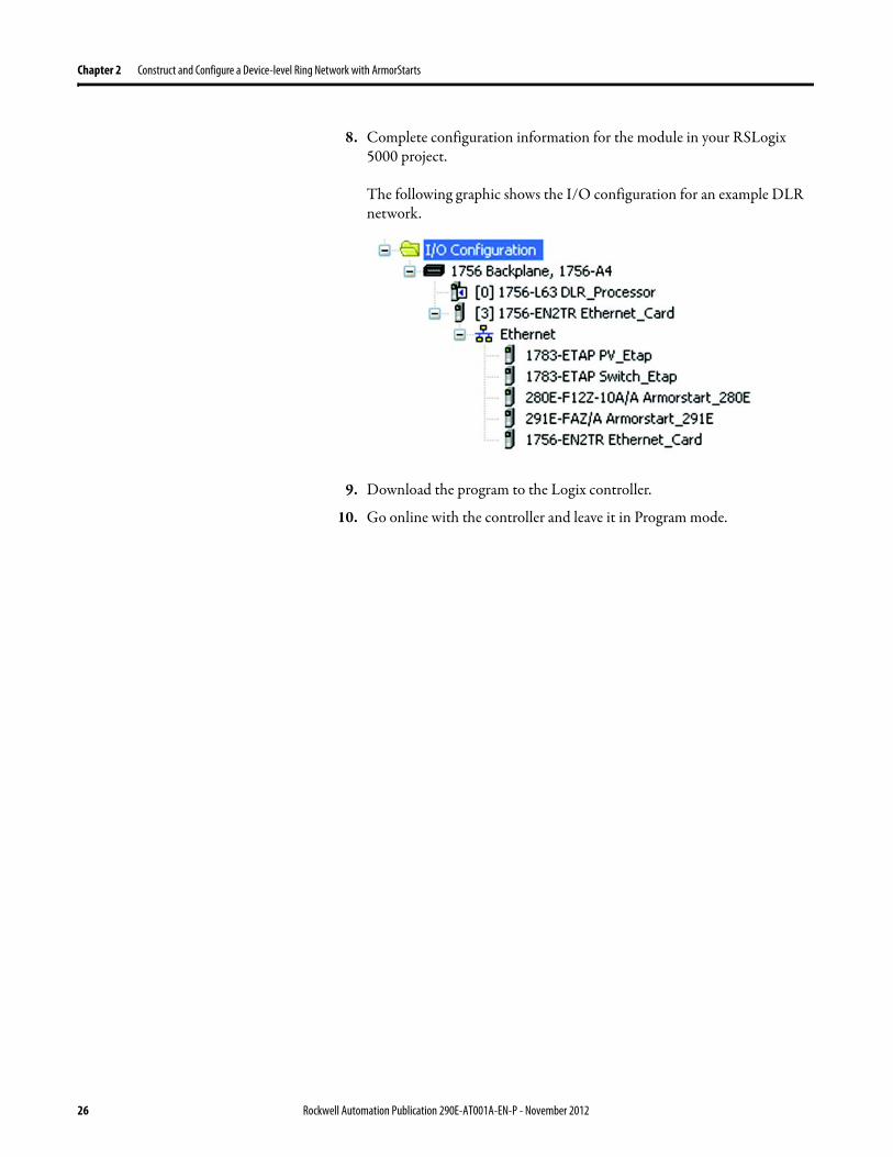
Chapter 2 Construct and Configure a Device-level Ring Network with ArmorStarts
8 Complete configuration information for the module in your RSLogix 5000 project
The following graphic shows the IO configuration for an example DLR network
9 Download the program to the Logix controller
10 Go online with the controller and leave it in Program mode
26 Rockwell Automation Publication 290E-AT001A-EN-P - November 2012
Construct and Configure a Device-level Ring Network with ArmorStarts Chapter 2
Enable Ring Supervisor in RSLogix 5000 Programming Software
After 1756-EN2TR module or 1783-ETAP 1783-ETAP1F or 1783-ETAP2F taps have been added to your RSLogix 5000 programming software project the ring supervisor mode must be enabled
If using RSLogix 5000 programming software to configure the ring supervisor and monitor diagnostics on the DLR network the controller must be online
To enable the 1756-EN2TR module or 1783-ETAP 1783-ETAP1F or 1783-ETAP2F tap as a ring supervisor follow these steps
The steps to enable a ring supervisor are basically the same for the 1756-EN2TR module or 1783-ETAP 1783-ETAP1F or 1783-ETAP2F tap This example shows how to do it for the 1756-EN2TR module
1 For your project online with the controller double-click on a supervisor-capable device in the IO configuration tree
Rockwell Automation Publication 290E-AT001A-EN-P - November 2012 27
Chapter 2 Construct and Configure a Device-level Ring Network with ArmorStarts
2 Click the Network tab to Enable Supervisor Mode
Configuration takes effect immediately you do not need to click Apply or OK
3 Click the Advanced button on the Network tab
4 Configure supervisor-related parameters as shown in the screen shot below
For these parameters you must click Set after entering a value
5 Click Set
28 Rockwell Automation Publication 290E-AT001A-EN-P - November 2012
Construct and Configure a Device-level Ring Network with ArmorStarts Chapter 2
Configure and Enable a Ring Supervisor in RSLinx Classic Communication Software
A ring supervisor can be configured for the DLR network through RSLinx Classic communication software
For more information regarding the Required RSLinx Classic Communication software Revision required refer to Appendix B
To configure a ring supervisor in RSLinx Classic Communication Software follow these steps
This example is for the 1783-ETAP tap Follow these steps
1 Launch RSLinx Classic Communication Software
2 Browse to the DLR network that is being set up
IMPORTANT For Beacon Interval Beacon Timeout and Ring Protocol VLAN ID we recommend that the default values be used
Functionality Description Default Setting
Supervisor Precedence A supervisor precedence number may be configured for each device that is configured as a ring supervisor The highest possible supervisor precedence value is 255When multiple nodes are enabled as supervisors the node with the highest precedence value is assigned as the active ring supervisor the other nodes automatically become back-up supervisorsWe recommend that youbull configure at least one back-up supervisor nodebull set the desired Active Ring Supervisor with a relatively high supervisor-
precedence value compared to the back-up node(s)bull keep track of the networkrsquos supervisor-precedence valuesIf multiple supervisors are configured with the same precedence value (the factory default value for all supervisor-capable devices is 0) the node with the numerically highest MAC address becomes the active supervisor
0
Beacon Interval Beacon interval is the frequency of the active ring supervisor transmitting a beacon frame through both of its Ethernet ports This parameter is user configurable for any time between 200 μS and 100 mSFor more information on how this parameter relates to network performance see page 61
400 μS
Beacon Timeout The beacon timeout is the amount of time that nodes wait before timing out the reception of beacon frames and taking appropriate action Supervisors support a range from 400μS to 500mSFor more information on how this parameter relates to network performance see page 61
1960 μS
Ring Protocol VLAN ID Reserved for future use 0
Rockwell Automation Publication 290E-AT001A-EN-P - November 2012 29
Chapter 2 Construct and Configure a Device-level Ring Network with ArmorStarts
If the Electronic Data Sheet (EDS) file is not installed on the module configured to be the ring supervisor it will appear with a question mark () To obtain and use the EDS file
bull right-click the module and choose to upload the EDS file from the device or
bull download the EDS file from httpwwwrockwellautomationcomrockwellautomationsupportnetworksedspage
3 Access the supervisor-capable nodersquos propertiesa Right-click the nodeb Choose Module Configuration
The General tab appears with information about the module
4 Click the Network tab to Enable Supervisor Mode
Configuration takes effect immediately there is no need to click Apply or OK
30 Rockwell Automation Publication 290E-AT001A-EN-P - November 2012
Construct and Configure a Device-level Ring Network with ArmorStarts Chapter 2
5 Click the Advanced button to configure supervisor-related parameters
Rockwell Automation Publication 290E-AT001A-EN-P - November 2012 31
Chapter 2 Construct and Configure a Device-level Ring Network with ArmorStarts
IMPORTANT For Beacon Interval Beacon Timeout and Ring Protocol VLAN ID use the default values
Functionality Description Default Setting
Supervisor Precedence
You may configure a supervisor precedence number for each device configured as a ring supervisor The highest possible supervisor precedence value is 255When multiple nodes are enabled as supervisor the node with the highest precedence value is assigned as the active ring supervisor the other nodes automatically become back-up supervisorsWe recommend that youbull configure at least one back-up supervisor nodebull set the desired Active Ring Supervisor with a relatively high supervisor-
precedence value compared to the back-up node(s)bull keep track of the networkrsquos supervisor-precedence valuesIf multiple supervisors are configured with the same precedence value (the factory default value for all supervisor-capable devices is 0) the node with the numerically highest MAC address becomes the active supervisor
0
Beacon Interval Beacon Interval is the frequency to which the active ring supervisor transmits a beacon frame through both of its Ethernet ports This parameter is user configurable for any time between 200 μS and 100 mSFor more information on how this parameter relates to network performance see page 58
400 μS
Beacon Timeout The beacon timeout is amount of time nodes wait before timing out the reception of beacon frames and taking appropriate action Supervisors support a range from 400 μS to 500 mSFor more information on how this parameter relates to network performance seepage 58
1960 μS
Ring Protocol VLAN ID
Reserved for future use 0
Enable IGMP Snooping
For more information on IGMP Snooping see page 35 Enabled
Enable IGMP Querier
For more information on IGMP Querier see page 35 Disabled
Enable Device Port Debugging Mode
For more information on Device Port Debugging Mode see page 59 Disabled
32 Rockwell Automation Publication 290E-AT001A-EN-P - November 2012
Construct and Configure a Device-level Ring Network with ArmorStarts Chapter 2
Complete the Physical Connections of the Network
After the ring supervisor nodes are configured and enabled the physical connection of the network must be completed to establish a complete DLR network
The figure below shows an example DLR network with all physical connections complete
Figure 4 - Example Device-level Ring Topology with All Connections Complete
Rockwell Automation Publication 290E-AT001A-EN-P - November 2012 33
Chapter 2 Construct and Configure a Device-level Ring Network with ArmorStarts
Verify Supervisor Configuration
The configuration and overall DLR network status can be verified in either RSLogix 5000 programming software or RSLinx Classic communication software
1 Access the supervisor nodersquos properties as shown previously in this chapter
2 Click the Network tab
3 Check the Network Topology and Network Status Fields
For a 1756-EN2TR module or the 1783-ETAP 1783-ETAP1F and 1783-ETAP2F tap the supervisor configuration can also be verified through the modulersquos diagnostic web pages For more information on monitoring diagnostics via an EtherNetIP modulersquos web pages see Monitor a DLR Network starting on page 37
34 Rockwell Automation Publication 290E-AT001A-EN-P - November 2012
Construct and Configure a Device-level Ring Network with ArmorStarts Chapter 2
IGMP Snooping This functionality is enabled by default in the 1783-ETAP 1783-ETAP1F and 1783-ETAP2F taps and is commonly used to manage multicast traffic on the network When in use this functionality allows the tap to multicast data to only those devices that need the data rather than to all devices connected to the network
For snooping to work there must be a device present that is running a querier Typically the device is a router or a switch such as the Stratix 6000 Stratix 8000 or Stratix 8300 managed switch
Once DHCP is enabled the switch could change the IP addresses on the ArmorStarts depending on network demand which could cause RSlogix5000 to loose communication with the device as connectivity is established via the AOP in the initial configuration
IGMP Querier This functionality is disabled by default The IGMP Querier functionality enables a 1783-ETAP 1783-ETAP1F or 1783-ETAP2F tap or switch such as a Stratix managed switch to send out a query to all devices on the network It determines what multicast addresses are of interest to a specific node or a group of nodes
The IGMP Querier functionality should be enabled for at least one node on the network The 1783-ETAP 1783-ETAP1F or 1783-ETAP2F tap managed switches and routers are examples of devices that support IGMP Querier functionality
IMPORTANT If DHCP for the Armostart is still required the Internet Group Management Protocol (IGMP) snooping on the E-tap must be disabled via the AOP
IMPORTANT If the IGMP Querier functionality is not enabled for at least one node on the network multicast traffic on the network may eventually create network performance issues
Rockwell Automation Publication 290E-AT001A-EN-P - November 2012 35
Chapter 2 Construct and Configure a Device-level Ring Network with ArmorStarts
However for all devices that are configured on the network with the IGMP Querier parameter enabled an IP address other than the factory default value must also be set for those devices If multiple devices on the network enable this functionality only the node with the lowest IP address becomes the active IGMP Querier node
IGMP Version
If the IGMP Querier is enabled a Querier Version must be selected The default version is Version 2
36 Rockwell Automation Publication 290E-AT001A-EN-P - November 2012
Chapter 3
Monitor a DLR Network
Introduction Use this chapter to learn how to monitor the DLR network
Methods to Monitor a DLR Network
Network diagnostic information can be retrieved from the ring supervisor-capable devices using the following
bull RSLogix 5000 programming software status pages
bull RSLinx communication software status pages
bull Device web pages
bull EtherNetIP Device Level Ring (DLR) network diagnostics faceplate
bull Programmatically through the use of a MSG instruction
RSLogix 5000 Programming Software Status Pages
RSLogix 5000 programming software version 1701 or later must be used and the appropriate AOPs installed to use the softwarersquos profile status pages
RSLinx Communication Software Status Pages
To monitor the network with this method the RSLinx communication software version 255 or later must be used
Topic Page
Methods to Monitor a DLR Network 37
Monitor Status Pages 39
Monitor ArmorStart Internal Web Server 44
Monitor via Faceplate Integration 45
Monitor Diagnostics via MSG Instructions 46
Rockwell Automation Publication 290E-AT001A-EN-P - November 2012 37
Chapter 3 Monitor a DLR Network
ArmorStart Internal Web Server
Rockwell Automation provides an internal embedded web server with each ArmorStart EtherNetIP The internal web server allows you to view information and configure the ArmorStart via a web browser The ArmorStart EtherNetIP can also be set up from the web server to send e-mail notifications The embedded web server is used to access configuration and status data It provides the user with the ability to view and modify the device configuration without having access to RSLogix 5000 Security in the form of an administrative password can be set The default login is Administrator There is no password set by default
EtherNetIP Device Level Ring (DLR) Network Diagnostics Faceplate
The diagnostics faceplate contains two major components
bull Logic code (encapsulated in an Add-On Instruction) that allows the controller to retrieve real-time DLR network status information
bull HMI faceplate graphics to allow the data to be visualized on an operator interface
Programmatically Through the Use of a MSG Instruction
For more information on how to monitor the DLR network via MSG Instructions see page 46
38 Rockwell Automation Publication 290E-AT001A-EN-P - November 2012
Monitor a DLR Network Chapter 3
Monitor Status Pages Both RSLogix 5000 programming software and RSLinx Classic communication software offer status pages that can be used to monitor the networkrsquos performance
RSLogix 5000 Programming Software Status Pages
Monitor the networkrsquos diagnostic information through the RSLogix 5000 programming software when the software is online
To monitor the network in RSLogix 5000 programming software follow these steps
1 Verify that the project is online
2 Access the active supervisor nodersquos propertiesa Right-click the modulersquos entry in the Controller Organizerb Click properties
Rockwell Automation Publication 290E-AT001A-EN-P - November 2012 39
Chapter 3 Monitor a DLR Network
3 Use the Network tab to monitor diagnostics
40 Rockwell Automation Publication 290E-AT001A-EN-P - November 2012
Monitor a DLR Network Chapter 3
RSLinx Communication Software
To monitor the network in RSLinx communication software follow these steps
1 Click RSWho to browse the network
2 Access the property pages for the active supervisor nodea Open the driver that shows the nodes on the DLR networkb Right-click the node that you want to monitor performancec Click on the choice that you need to access
Multiple choices appear
These options are shown in the following sections
Rockwell Automation Publication 290E-AT001A-EN-P - November 2012 41
Chapter 3 Monitor a DLR Network
Module Configuration
This series of tabs providesbull General informationbull Connection informationbull Module informationbull Internet protocolbull Port configurationbull Network information
The example below shows a ring fault between nodes at IP addresses 10888021 and MAC ID 00-00-BC-02-48-D5
42 Rockwell Automation Publication 290E-AT001A-EN-P - November 2012
Monitor a DLR Network Chapter 3
There are multiple fields used to monitor network diagnostics
Field Definition
Network Topology Possible values here can be Linear or Ring
Network Status Displays if the network is operating normally (Normal) or has experienced a fault (Ring Fault) as shown in the previous example screen
Active Ring Supervisor Displays the IP address or MAC address of the active ring supervisor
Active Supervisor Precedence For more information on this field see Active Ring Supervisor on page 11
Enable Ring Supervisor Configurable field that lets you to set the node as a ring supervisor
Ring Faults Detected Number of faults detected on the network since the last module power cycle or counter reset
Supervisor Status Displays whether this node is the active ring supervisor (Active) a back-up supervisor (Back-up) a ring node or part of a linear network
Last Active Node on Port 1 The last node the active ring supervisor can communicate with on Port 1 This value is an IP address or a MAC ID and remains latched until the Verify Fault Location button is clicked
Last Active Node on Port 2 The last node the active ring supervisor can communicate with on Port 2 This value is an IP address or a MAC ID and remains latched until the Verify Fault Location button is clicked
Status Displays whether a fault exists on the ring
IMPORTANT If the Network Topology field = Ring and the Network Status field = Normal the Last Active Node fields will display the last fault information even though it has been correctedTo clear the last fault information from these fields click Verify Fault Location You may see a message informing you that the supervisor is no longer in fault mode and the fields will be cleared
Rockwell Automation Publication 290E-AT001A-EN-P - November 2012 43
Chapter 3 Monitor a DLR Network
How to Access the ArmorStart EtherNetIP Internal Web Server
Open your preferred internet web browser and enter the IP address of the desired ArmorStart For this example 192168122 will be used
Use the links on the left-most navigation bar to see each available web page The screen below shows Ring Statistics for the ArmorStart 280E
44 Rockwell Automation Publication 290E-AT001A-EN-P - November 2012
Monitor a DLR Network Chapter 3
EtherNetIP Device Level Ring (DLR) Network Diagnostics Faceplate Overview
The EtherNetIP Device Level Ring (DLR) network diagnostics faceplate provides basic DLR network status information to the user to assist with monitoring and troubleshooting a DLR network
The diagnostics faceplate contains two major components
bull Logic code (encapsulated in an Add-On Instruction) that allows the controller to retrieve real-time DLR network status information
bull HMI faceplate graphics to allow the data to be visualized on an operator interface
The DLR diagnostics faceplate application can be downloaded from the Rockwell Automation Sample Code website at httpsamplecoderockwellautomationcom
Besides the individual Logix and View project components a demo application is also included with the downloaded file
Rockwell Automation Publication 290E-AT001A-EN-P - November 2012 45
Chapter 3 Monitor a DLR Network
Monitor Diagnostics via MSG Instructions
Network diagnostic information can also be obtained programmatically via MSG instructions in RSLogix 5000 programming software For example you can
bull Get all ring diagnostic informationbull Get a ring participant listbull Get the active supervisorbull Clear rapid ring faultsbull Verify a fault locationbull Reset a fault counterbull Enable and configure a ring supervisor
This information can be displayed on an HMI device or manipulated in the project code
Figure 5 - Example Use of MSG Instruction
This example describes how to retrieve diagnostic information from the DLR network Follow these steps
1 Enter a MSG instruction into the rung of logic
2 Configure the MSG instruction to retrieve ring diagnostic information service as shown in the following screen shots
IMPORTANT Make sure the tag created is sized appropriately to hold all of the data that you are reading or writing For more information see page 48
46 Rockwell Automation Publication 290E-AT001A-EN-P - November 2012
Monitor a DLR Network Chapter 3
3 Configure the MSG instructionrsquos communication path to point to the active supervisor node
The path on the following screen is one example path
IMPORTANT When using the Custom Get_Attributes_All (01) service pointing to an active supervisor node will retrieve all of the attributes listed in Retrieve All Diagnostic Information Attribute Description on page 50Pointing to a non-supervisor node will retrieve only the Network Topology and Network Status attribute informationPointing to backup supervisor node will retrieve the current active supervisorrsquos IP address
Rockwell Automation Publication 290E-AT001A-EN-P - November 2012 47
Chapter 3 Monitor a DLR Network
Use Specific Values on the Configuration Tab
Use the values on the Configuration tab of your MSG instruction to perform specific services Sample DLR network diagnostic application code for example Add-on Instruction or HMI faceplate graphics is available on the Rockwell Automation Sample Code Library For more information about the Rockwell Automation Sample Code Library see httpwwwrockwellautomationcomsolutionsintegratedarchitectureresources5html
➊ This request only works if there are fewer than 40 nodes on the network If there are more nodes than will fit in a single message an error will be returned➋ Use a Destination Length of 54 bytes if using firmware revision 3x or later for the 1756-EN2TR module or firmware revision 2x or later for the 1783-ETAP
1783-ETAP1F or 1783-ETAP2F taps
Request Description Message Type
Service Type
Service Code (HEX)
Class (HEX)
Instance Attribute (HEX)
Source Element
Source Length (Bytes)
Destination Destination Length (bytes)
Retrieve All Ring Diagnostic Information
Information for this request is listed in Retrieve All Ring Diagnostic Information on page 49
CIP Generic Custom 1 47 1 NA LeftBlank
0 Tag 50or54 ➋
Request Ring Participant List ➊
Information for this request is listed in Request the Ring Participant List on page 51
CIP Generic Get Attribute Single
e 47 1 9 NA NA Tag 10node
Get Active Supervisor
Obtain the IP address and MAC ID of the active supervisor on the DLR network
CIP Generic Get Attribute Single
e 47 1 a NA NA Tag 10
Acknowledge Rapid Ring Faults Condition
Request supervisor to resume normal operation after encountering a rapid ring fault condition
CIP Generic Custom 4c 47 1 NA NA NA NA
Verify a Fault Location
Request supervisor to update Last Active Node values
CIP Generic 4b 47 1 NA NA NA NA NA
Reset the Ring Fault Counter
Reset the number of ring faults detected on the DLR network
CIP Generic Set Attribute Single
10 47 1 5 Tag 2 NA NA
Enable and Configure a Ring Supervisor
Information for this request is listed in Enable and Configure a Ring Supervisor on page 52
CIP Generic Set Attribute Single
10 47 1 4 Tag 12 NA NA
48 Rockwell Automation Publication 290E-AT001A-EN-P - November 2012
Monitor a DLR Network Chapter 3
Retrieve All Ring Diagnostic Information
By performing the Retrieve All Ring Diagnostic Information request on an active supervisor the MSG instruction returns the following information
➊ RSLogix 5000 programming software may display the value in this field as negative numbers To better understand the value we recommend you view it in HEX format
Destination Tag Attribute Name Description Possible Values
SINT [0] Network Topology Current network topology mode 0 = Linear
1 = Ring
SINT [1] Network Status Current status of the network 0 = Normal
1 = Ring Fault
2 = Unexpected Loop Detected
3 = Partial Network Fault
4 = Rapid FaultRestore Cycle
SINT [2] Ring Supervisor Status Ring supervisor active status flag 0 = Node is functioning as a backup
1 = Node is functioning as the active ring supervisor
2 = Node is functioning as a normal ring node
3 = Node is operating in a non-DLR topology
4 = Node cannot support the currently operating ring parameters thatis Beacon Interval andor Beacon Timeout
Ring Supervisor Config Ring Supervisor configuration parameters
SINT [3] Ring Supervisor Enable Ring supervisor enable flag 0 = Node is configured as a normal ring node (default configuration)
1 = Node is configured as a ring supervisor
SINT [4] Ring Supervisor Precedence Precedence value of a ring supervisor ➊ Valid value range = 0hellip255
0 = Default value
SINT [5-8] Beacon Interval Duration of ring beacon interval Valid value range = 200 μshellip100 ms
Default = 400 μs
SINT [9-12] Beacon Timeout Duration of ring beacon timeout Value value range = 400 μshellip500 ms
Default value = 1960 μs
SINT [13-14] DLR VLAN ID Valid ID to use in ring protocol messages Valid value range = 0hellip4094
Default value = 0
SINT [15-16] Ring Faults Count Number of ring faults since power up ➊
Rockwell Automation Publication 290E-AT001A-EN-P - November 2012 49
Chapter 3 Monitor a DLR Network
Retrieve All Diagnostic Information Attribute Description
➊ This destination tag is available only with the 1756-EN2TR module firmware revision 3x or later 1783-ETAP 1783-ETAP1F and 1783-ETAP2F taps firmware revisions 2x or later If using the 1783-ETAP tap firmware revision 1x your program does not include this destination tag
➋ RSLogix 5000 programming software may display the value in this field as negative numbers To better understand the value we recommend you view it in HEX format
Destination Tag Attribute Name Description Possible Values
Last Active Node on Port 1 Last active node at the end of the chain through port 1 of the active ring supervisor during a ring fault
SINT [17-20] Device IP address ➋ Any valid IP address value
A value = 0 indicates no IP address has been configured for the device
SINT [21-26] Device MAC address ➋ Any valid Ethernet MAC address
Last Active Node on Port 2 Last active node at the end of the chain through port 2 of the active ring supervisor during a ring fault
SINT [27-30] Device IP address ➋ Any valid IP address value
A value = 0 indicates no IP address has been configured for the device
SINT [31-36] Device MAC address ➋ Any valid Ethernet MAC address
SINT [37-38] Ring Protocol Participants Count
Number of devices in the ring protocol participants list
Active Supervisor Address IP andor Ethernet MAC address of the active ring supervisor
SINT [39-42] Supervisor IP address Any valid IP address value
A value = 0 indicates no IP address has been configured for the device
SINT [43-48] Supervisor MAC address Any valid Ethernet MAC address
SINT [49] Active Supervisor Precedence
Precedence value of the active ring supervisor
SINT [50-53]➊ Capability Flags Alerts you that the device is capable of operating as a supervisor and beacon-based ring node
0x22
50 Rockwell Automation Publication 290E-AT001A-EN-P - November 2012
Monitor a DLR Network Chapter 3
Request the Ring Participant List
When requesting the Ring Participant List service on the DLR network the MSG instruction returns the following information
Request the Ring Participant List Attribute Description
➊ This attribute will return an array of the data shown one entry for each node The Ring Protocol Participants Count attribute determines the number entries
➋ This tag displays only IP addresses for ring participants that have been configured with one For example you may have a 1783-ETAP tap connected to the network that has not been assigned an IP address In that case no address is shown for the 1783-ETAP tap
➌ RSLogix 5000 programming software may display the value in this field as negative numbers To better understand the value we recommend you view it in HEX format
➍ Unlike destination tag SINT [0-3] where IP addresses are displayed only for ring participants configured with an IP address this tag displays MAC addresses for all ring participants because every ring participant has a MAC address
Destination Tag Attribute Name Description Possible Values
Ring Protocol Participants List ➊
List of devices participating in ring protocol
SINT [0-3] Device IP address ➋➌ Any valid IP address value
A value = 0 indicates no IP address has been configured for the device
SINT [4-9] Device MAC address ➌➍ Any valid Ethernet MAC address
Rockwell Automation Publication 290E-AT001A-EN-P - November 2012 51
Chapter 3 Monitor a DLR Network
Enable and Configure a Ring Supervisor
When performing the Enable and Configure a Ring Supervisor request on a supervisor-capable device configure the MSG instruction with the following information
Enable and Configure a Ring Supervisor Attribute Description
➊ RSLogix 5000 programming software may display the value in this field as negative numbers To better understand the value we recommend you view it in HEX format
Source Tag Attribute Name Description Possible Values
Ring Supervisor Config Ring Supervisor configuration parameters
SINT [0] Ring Supervisor Enable Ring supervisor enable flag 0 = Node is configured as a normal ring node (default configuration)1 = Node is configured as a ring supervisor
SINT [1] Ring Supervisor Precedence Precedence value of a ring supervisor ➊
Valid value range = 0hellip2550 = Default value
SINT [2-5] Beacon Interval Duration of ring beacon interval
Valid value range = 200 μshellip100 000 μsDefault = 400 μs
SINT [6-9] Beacon Timeout Duration of ring beacon timeout ➊
Value value range = 400 μshellip500 000 μsDefault value = 1960 μs
SINT [10-11] DLR VLAN ID Valid ID to use in ring protocol messages ➊
Valid value range = 0hellip4094Default value = 0
52 Rockwell Automation Publication 290E-AT001A-EN-P - November 2012
Chapter 4
Troubleshoot a DLR Network
Introduction Use this chapter to learn how to troubleshoot the DLR network
General Solutions for Linear or DLR Networks
Before attempting to correct specific faults on the linear or DLR network we recommend that you first take the following actions when a fault appears
bull For a DLR networkndash Verify that at least one node has been configured as a supervisor
on the network and that Network Topology = Ringndash Verify that all cables on the network are securely connected
to each devicendash Verify that all devices that require an IP address have one assigned
correctlyndash Check the Network Status field on the active supervisor nodersquos status
page to determine the fault typebull For a linear network
ndash Verify that none of the nodes are configured as a supervisor on the network and that Network Topology = LinearIf any nodes on a linear network are configured as a supervisor it may impact communication to other devices connected to the network
ndash Verify that all cables on the network are securely connected to each device
ndash Verify that all devices that require an IP address have one assigned correctly
If the fault is not cleared after completing the actions listed above use the tables in the rest of this chapter to troubleshoot issues specific to a DLR network or a linear network
Topic Page
General Solutions for the Linear or DLR Networks 53
Duplicate IP Address Detection 54
Specific Issues on the DLR Network 55
Network Recovery Performance 58
Device Port Debugging Mode 59
Rockwell Automation Publication 290E-AT001A-EN-P - November 2012 53
Chapter 4 Troubleshoot a DLR Network
Duplicate IP Address Detection
Some EtherNetIP communication modules support duplicate IP address detection The module verifies that its IP address does not match any other network devicersquos IP address when performing either of these tasks
bull Connect the module to an EtherNetIP network
bull Change the modulersquos IP address
If the modulersquos IP address matches that of another device on the network the modulersquos EtherNetIP port transitions to Conflict mode In Conflict mode these conditions exist
bull OK status indicator is blinking red
bull Network (NET) status indicator is solid red
bull On some EtherNetIP communication modules the module status display indicates the conflict
The display scrollsOK ltIP_address_of_this_modulegt Duplicate IP
ltMac_address_of_duplicate_node_detectedgt
For example OK 108860196 Duplicate IP - 0000BC0234B4
bull On some EtherNetIP communication modules the modulersquos diagnostic webpage displays information about duplicate IP address detection
For more information on which EtherNetIP communication modules support displaying duplicate IP address on their diagnostic webpage see the Technical Note titled Logix modules Duplicate IP address detection enhancement 118216 in the Technical Support Knowledgebase available at httpwwwrockwellautomationcomknowledgebase
54 Rockwell Automation Publication 290E-AT001A-EN-P - November 2012
Troubleshoot a DLR Network Chapter 4
Specific Issues on the DLR Network
Use the following table to troubleshoot possible specific issues on the DLR or linear network that are not solved by the actions described on the previous page
Issue Description Solution
Supervisor Reports a Ring Fault A link on the DLR network may be brokenbull intentionally for example because of adding or deleting nodes but not making all
physical connections to restore the setup of the network withwithout the nodebull unintentionally for example because a cable is broken or a device malfunctionsWhen this fault occurs the adjacent nodes to the faulted part of the network are displayed in the Ring Fault group and the Network Status field = Ring FaultThe screen shot below shows the Ring Fault section with IP addresses appearing for the last active nodes The faulted node is between nodes 108880115 and 108880208 If the IP address of either node is not available the software will display the nodersquos MAC ID
Once the fault is corrected the ring is automatically restored and the Network Status field returns to Normal
Determine where the fault condition exists and correct itClick the Refresh Communication link as needed to update the Ring Fault information to determine where the fault condition existsFinally DevicePort Debugging Mode functionality on the 1783-ETAP tap may be used to analyze a suspicious nodeFor more information refer to Device Port Debugging Mode on page 59
Rockwell Automation Publication 290E-AT001A-EN-P - November 2012 55
Chapter 4 Troubleshoot a DLR Network
Issue Description Solution
Rapid Ring Fault When a Rapid Ring Fault occurs the following events occurbull The active supervisor will block traffic on port 2 resulting in possible network
segmentation that is some nodes may become unreachablebull The Link 2 status indicator on the active supervisor is offbull As soon as the fault occurs for both RSLogix 5000 programming software and
RSLinx communication software the Status field = Rapid FaultRestore Cycles
Any of the following may cause a Rapid Ring Faultbull 5 intentional disconnectionsreconnections of a node from the network within 30
secondsbull A duplex mismatch between two connected devicesbull Electromagnetic noise on the networkbull Unstable physical connections such as intermittent connectorsGiven the nature of a Rapid Ring Fault the Last Active Node information may not be accurate when a Rapid Ring Fault condition is present
Multiple possible solutions existbull For the disconnections and reconnections issue no
solution is requiredClear the fault after reconnecting the device to the network permanentlybull For the duplex mismatch issue reconfigure the duplex
parameters to make sure they match between the devices
bull For the electromagnetic noise issue determine where the noise exists and eliminate it or use a protective shield in that location
bull For the unstable connections issue determine where they exist on the network and correct them
bull Check the media counters for all devices on the network The device with the highest media counter count is most likely causing the Rapid Ring Fault
bull Remove devices from the network one by one If the Rapid Ring Fault disappears after a device is removed that device is causing the fault
bull DevicePort Debugging Mode functionality on the 1783-ETAP tap may be used to analyze a suspicious node
For more information refer to Device Port Debugging Mode on page 59bull Finally the Beacon Interval or Timeout configuration
may not be appropriate for the networkHowever if these values need to be changed we recommend that you contact Rockwell Automation technical supportOnce the fault is fixed click Clear Fault
56 Rockwell Automation Publication 290E-AT001A-EN-P - November 2012
Troubleshoot a DLR Network Chapter 4
Issue Description Solution
Partial Fault Condition A partial network fault occurs when traffic is lost in only one direction on the network because a ring member is not forwarding beacons in both directions for example a component failureThe active ring supervisor detects a partial fault by monitoring the loss of Beacon frames on one port and the fault location appears in the Ring Fault section of the Network tab When a partial fault is detected the active ring supervisor blocks traffic on one port At this point the ring is segmented due to the partial fault condition The nodes adjacent to the faulted part of the network are displayed in the Ring Fault group with either IP addresses or MAC IDs for each node displayedWhen this fault occurs the Network Status field = Partial Fault ConditionOnce the fault is corrected it automatically clears and the Network Status field returns to Normal
Determine where the fault condition exists and correct itAdditionally the DevicePort Debugging Mode functionality also known as Port Mirroring on a 1783-ETAP 1783-ETAP1F or 1783-ETAP2F tap may be used to analyze a suspicious nodeFor more information refer to Device Port Debugging Mode on page 59
Media Counter Errors or Collisions
The media counters screen displays the number of physical layer errors or collisions The screen below indicates where to check for errors encountered Error levels are displayed depending on what caused the error For example an Alignment Error is displayed in the Alignment Error field
On a DLR network it is not uncommon to see low levels of media counter errors For example if the network breaks a low level of media counter errors appears With a low level of media counter errors the value typically does not continuously increase and often clearsA high level of media counter errors typically continues to increase and does not clear For example there is a mismatch of speed between two linked nodes a high level of media counter errors appears steadily increasing and not clearingTo access the RSLinx screen above browse the network right-click on the device select Module Properties and click the Port Diagnostics tab
Some example solutions includebull Check for a mismatch of speed andor duplex between
two linked nodesbull Verify that all cables on the network are securely
connected to each devicebull Check for electromagnetic noise on the network If you
find it eliminate it or use a protective shield in that location
Rockwell Automation Publication 290E-AT001A-EN-P - November 2012 57
Chapter 4 Troubleshoot a DLR Network
Network Recovery Performance
When measuring the networkrsquos performance with regard to dealing with fault conditions consider the network recovery time Network recovery is the time for all of the following to take place
1 The supervisor node recognizes that a fault exists on the network
2 The supervisor node reconfigures the network because of the fault
3 The supervisor node communicates to the network nodes that a fault condition exists
4 The network nodes reconfigure themselves because of the fault
With the default beacon interval value of 400 mS and beacon timeout value of 1960 mS the worst-case time for network recovery times are
bull 2890 mS for a copper DLR network This recovery time is based on 100 m copper segments between nodes on the network
bull 3140 mS for a fiber-optic DLR network This recovery time is based on 2 kM fiber-optic cable segments between nodes on the network
When considering the values listed above keep in mind
bull Recovery time may actually occur faster than the times listed
bull The recovery times listed above assume that your networkrsquos nodes are operating at 100 Mbps speed and full-duplex mode We recommend that your nodes generally operate in this mode for DLR networks
bull If other node conditions exist such as a node operating at 10 Mbps full-duplex or 10100 Mbps half-duplex the recovery times will vary from the times listed above
If this is the case for your application the beacon interval and beacon timeout will need to be changed We recommend that you first contact Rockwell Automation technical support if these parameters need to be changed
bull The value assumes that the majority of the traffic on your network is EtherNetIP traffic
58 Rockwell Automation Publication 290E-AT001A-EN-P - November 2012
Troubleshoot a DLR Network Chapter 4
Device Port Debugging Mode
This functionality is disabled by default Device Port Debugging mode which is similar to port mirroring can be used to monitor data received on the 1783-ETAP 1783-ETAP1F or 1783-ETAP2F taprsquos two network ports Monitor the data over the device port to a device such as a personal computer running a protocol analyzer application for advanced network debugging or analysis
When device port debugging is used on a 1783-ETAP the device connected to the 1783-ETAP taprsquos front port receives all of the data traversing the ring (both directions)
Device Port Debugging Example Network
When using the Device Port Debugging mode functionality insert the 1783-ETAP with the network analyzer connected to the device port It is inserted at the spot on the ring network where the node in question is located The graphic below shows a 1783-ETAP tap inserted in the network
IMPORTANT This functionality should be used only when troubleshooting the network and not in normal network operation
Rockwell Automation Publication 290E-AT001A-EN-P - November 2012 59
Chapter 4 Troubleshoot a DLR Network
Combined total network bandwidth of the traffic received on the two 1783-ETAP 1783-ETAP1F or 1783-ETAP2F taprsquos ports connected to the network should not exceed the taprsquos device port capacity The speed setting determines the device portrsquos capacity
Configure the device port on a 1783-ETAP 1783-ETAP1F or 1783-ETAP2F tap to either of two speed settings
bull 100 Mbps - default settingbull 10 Mbps
If the bandwidth exceeds the capacity of the taprsquos device port some frames from the ring will be dropped before reaching the device port These dropped frames do not impact the traffic on the rest of the DLR network
The device port setting determines how much network traffic the 1783-ETAP 1783-ETAP1F or 1783-ETAP2F tap can handle before dropping frames The circled section in the graphic below shows the Port Buffer Utilization of the Device Port In this example the value is zero because a ring fault exists on the network
60 Rockwell Automation Publication 290E-AT001A-EN-P - November 2012
Appendix A
Network Usage Guidelines and Recommendations
Consider the following guidelines and recommendations when using a DLR or linear network
GuidelineRecommendation Explanation
Use fewer than 50 nodes on a single DLR networkIf your application requires more than 50 nodes we recommend that the nodes are broken into separate but linked DLR networks
If you use more than 50 nodes on a single DLR networkbull Your network has a greater chance of multiple faults
occurring on the networkbull Network recovery times from faulted DLR network
are higher
Do not configure a supervisor on a linear network If your linear network includes non-DLR nodes and has a supervisor-enabled node on the network it may impact communication to non-DLR devices connected to the linear network
If you must connect a device that is running at 10 Mbps to a DLR or linear network do so through a 1783-ETAP 1783-ETAP1F or 1783-ETAP2F tap device port
The 1783-ETAP 1783-ETAP1F and 1783-ETAP2F taps can operate at 100 Mbps on the DLR network this is the optimal speed for a network If you connect a 10 Mbps device directly to the network instead of through a tap the linear or DLR network traffic slows to 10 MbpsAdditionally if the 10 Mbps device is connected to the network without a 1783-ETAP tap network recovery times are significantly impacted
Configure multiple supervisor nodes per ring If your DLR network only has one supervisor and the supervisor experiences a fault none of the other nodes become the active supervisor In this case the network becomes a linear network until the fault is corrected and the DLR network restoredAnother reason to configure multiple supervisor nodes is for replacing an active supervisor node with an out-of-box replacement the new device will not be enabled as a supervisor (by default) and there would still be no supervisor on the network
Rockwell Automation Publication 290E-AT001A-EN-P - November 2012 61
Appendix A Network Usage Guidelines and Recommendations
GuidelineRecommendation Explanation
Connect switches to a DLR network via 1783-ETAP 1783-ETAP1F or 1783-ETAP2F taps
If switches are connected to the DLR network without the use of a 1783-ETAP 1783-ETAP1F or 1783-ETAP2F tap the network may experience unpredictable behavior and network performance is unknown
Run all nodes on the DLR network at 100 Mbps and in Full-Duplex mode
These configuration values provide the best performance for your networkAdditionally we recommend that youbull Use auto-negotiate for all nodes on the DLR networkbull Do not use auto-negotiate on one node and then force
speed on the next node linked to it
In a linear network the number of nodes to use is application specific based on the considerations described in the next box
When determining the number of nodes to use on a linear network consider the followingbull There is a delay per node as information is transmitted
to each successive node used on the networkndash The typical delay on a linear network with 100 m
copper segments between nodes is 30 mSndash The typical delay on a linear network with 2 kM
fiber-optic segments between nodes is 40 mS
The greater the number of nodes on the network the longer the total time for information to be transmitted across the entire networkbull The single point of failure possibility is greater with
each additional connectionbull Troubleshooting the network may be more difficult
with a higher number of nodes
The total time for information to be transmitted across the entire network and its effect on how many nodes to use on a linear network is related to the Requested Packet Interval (RPI)Verify that the total time to transmit information from the first node to the last node on the network is less than the RPI Make sure the network is not loaded beyond 90 of capacity
62 Rockwell Automation Publication 290E-AT001A-EN-P - November 2012
Network Usage Guidelines and Recommendations Appendix A
GuidelineRecommendation Explanation
Do not physically close a DLR network without a supervisor configured on the network
A DLR network without a supervisor node results in a network stormIf you do close the DLR network without a supervisor configured break the ring and configure at least one supervisor before physically reconnecting the network
Use the default values for the followingbull Beacon Intervalbull Beacon Timeoutbull Ring Protocol VLAN ID
Changing the default values for the parameters Beacon Interval Beacon Timeout and Ring Protocol VLAN ID can result in unpredictable network behavior and negatively impacted network performanceThe default values are optimized for a network withbull 50 or fewer nodes are on the networkbull All nodes are operating at 100 Mbps and full-duplex
modebull At least 50 of the network traffic bandwidth being
EtherNetIP trafficIf you think the values of the Beacon Interval Beacon Timeout or Ring Protocol VLAN ID need to be changed for example if any node on ring is not operating at 100 Mbps and full-duplex mode we recommend that you first contact Rockwell Automation technical support
If DHCP for the ArmorStarts is still required you will need to disable Internet Group Management Protocol (IGMP) snooping on the E-tap via the AOP
IGMP Snooping is enabled by default in the 1783-ETAP 1783-ETAP1F and 1783-ETAP2F taps and is commonly used to manage multicast traffic on the network When in use this functionality allows the tap to multicast data to only those devices that need the data rather than to all devices connected to the networkOnce DHCP is enabled the switch could change the IP addresses on the ArmorStarts depending on network demand which could cause RSlogix5000 to loose communication with the device as connectivity is established via the AOP in the initial configuration
The IGMP Querier functionality should be enabled for at least one node on the network
This functionality is disabled by default The IGMP Querier functionality enables a 1783-ETAP 1783-ETAP1F or 1783-ETAP2F tap or switch such as a Stratix managed switch to send out a query to all devices on the network to determine what multicast addresses are of interest to a specific node or a group of nodesIf the IGMP Querier functionality is not enabled for at least one node on the network multicast traffic on the network may eventually create network performance issuesThe 1783-ETAP 1783-ETAP1F or 1783-ETAP2F taps managed switches and routers are examples of devices that support IGMP Querier functionality
Rockwell Automation Publication 290E-AT001A-EN-P - November 2012 63
Appendix A Network Usage Guidelines and Recommendations
Notes
64 Rockwell Automation Publication 290E-AT001A-EN-P - November 2012
Appendix B
Required Firmware Revisions
Required Firmware Revision for an Add-On Profile
➊ The ControlFLASH Firmware Upgrade software tcan be used o upgrade a 1756-EN2TR module from firmware revision 21 to 3x or later1x or later3x or later2x or later
➋ The ControlFLASH Firmware Upgrade software can be used to upgrade a 1783-ETAP tap from firmware revision 11 to 2x or later
To download new firmware go to httpwwwrockwellautomationcomsupportamericasindex_enhtml
If the firmware revision is upgraded on the module or tap the required AOP revision listed above must be used for that revision For example if the 1756-EN2TR module is upgraded to firmware revision 3x or later AOP revision 2x or later must be used in the RSLogix 5000 programming software
Additionally if the firmware revision is upgraded on the module or tap the required RSLinx communication software must also be used for that firmware revision For more information on which RSLinx software version is required for each firmware revision see page 66
For both the 1756-EN2TR module and 1783-ETAP tap make sure that the Major Revision configured on the General tab of the devicersquos RSLogix 5000 programming software configuration matches the major revision of the physical module
IMPORTANT To download an AOP go to httpsupportrockwellautomationcomcontrolflashLogixProfileraspDepending on the firmware revision of your product a specific AOP version must be used
Firmware Revision Add-On Profile Revision Cat No
21 ➊ 1x or later 1756-EN2TR
3x or later 2x or later
11 ➋ 1x or later 1783-ETAP
2x or later 2x or later
2x or later 2x or later 1783-ETAP1F
1783-ETAP2F
Rockwell Automation Publication 290E-AT001A-EN-P - November 2012 65
Appendix B Required Firmware Revisions
If the device configuration on the General tab does not match the physical module the programming software alerts you to this mismatch when attempting to configure the Internet Protocol Port Configuration and Network tabs for that device
Required Firmware Revision for RSLinx Communication Software
➊ The ControlFLASH Firmware Upgrade software can be used to upgrade a 1756-EN2TR module from firmware revision 21 to 3x or later1x or later3x or later255 or later3x or later256 or later
➋ The ControlFLASH Firmware Upgrade software can be used to upgrade a 1783-ETAP tap from firmware revision 11 to 2x or later
To download new firmware go to httpwwwrockwellautomationcomsupportamericasindex_enhtml
If the firmware revision is upgraded on the module or tap the required RSLinx communication software listed above must be used for that revision For example if the 1756-EN2TR module is upgraded to firmware revision 3x or later AOP revision 2x or later must be used in your RSLogix 5000 programming software
Additionally if the firmware revision is upgraded on the module or tap the required AOP revision must also be used for that firmware revision For more information on which AOP revision is required for each firmware revision see page 65
IMPORTANT Depending on the firmware revision of your product specific versions of RSLinx communication software must be used
Firmware Revision Required RSLinx Communication Software Version
Cat No
21 ➊ 255 or later 1756-EN2TR
3x or later 256 or later
11 ➋ 255 or later 1783-ETAP
2x or later 256 or later
2x or later 256 or later 1783-ETAP1F
1783-ETAP2F
66 Rockwell Automation Publication 290E-AT001A-EN-P - November 2012
Rockwell Otomasyon Ticaret AŞ Kar Plaza İş Merkezi E Blok Kat6 34752 İccedilerenkoumly İstanbul Tel +90 (216) 5698400
Rockwell Automation Publication 290E-AT001A-EN-P ndash November 2012 68 Copyright copy 2012 Rockwell Automation Inc All rights reserved Printed in the USA
Rockwell Automation Support
Rockwell Automation provides technical information on the Web to assist you in using its products At httpwwwrockwellautomationcomsupport you can find technical manuals a knowledge base of FAQs technical and application notes sample code and links to software service packs and a MySupport feature that you can customize to make thebest use of these tools
For an additional level of technical phone support for installation configuration and troubleshooting we offer TechConnectSM support programs For more information contact your local distributor or Rockwell Automation representative or visit httpwwwrockwellautomationcomsupport
Installation Assistance
If you experience a problem within the first 24 hours of installation review the information that is contained in this manualYou can contact Customer Support for initial help in getting your product up and running
New Product Satisfaction Return
Rockwell Automation tests all of its products to ensure that they are fully operational when shipped from the manufacturing facility However if your product is not functioning and needs to be returned follow these procedures
Documentation Feedback
Your comments will help us serve your documentation needs better If you have any suggestions on how to improve this document complete this form publication RA-DU002 available at httpwwwrockwellautomationcomliterature
United States or Canada 14406463434
Outside United States or Canada Use the Worldwide Locator at httpwwwrockwellautomationcomsupportamericasphone_enhtml or contact your local Rockwell Automation representative
United States Contact your distributor You must provide a Customer Support case number (call the phone number above to obtain one) to your distributor to complete the return process
Outside United States Please contact your local Rockwell Automation representative for the return procedure
- Important User Information
- General Precautions
- Software Requirements
- Additional Resources
- Rockwell Automation Support
- Installation Assistance
- New Product Satisfaction Return
- Table of Contents
- Chapter 1
-
- Device-Level Ring (DLR) Basics
-
- Introduction
- ArmorStart with EtherNetIP Overview
- What is a Device-level Ring (DLR) Network
- DLR Network Elements
-
- Supervisor Node
- Ring Node
-
- DLR Network Operation
- Number of Nodes on a DLR Network
- DLR Network Fault Management
-
- Network Reconfiguration after a Fault
-
- Chapter 2
-
- Construct and Configure a Device-level Ring Network with ArmorStarts
-
- Introduction
- Ethernet Capacity Tool
- Install Devices on a DLR Network
- ArmorStart Addressing Configuration
-
- Using the BootPDHCP Server
- Using the Rotary Network Address Switches
- Using the ArmorStart Internal Web Server
-
- Configure Supervisor Nodes on a DLR Network
-
- Configure a Ring Supervisor in RSLogix 5000 Programming Software
- Adding an Armorstart to RSLogix 5000
- Enable Ring Supervisor in RSLogix 5000 Programming Software
- Configure and Enable a Ring Supervisor in RSLinx Classic Communication Software
-
- Complete the Physical Connections of the Network
- Verify Supervisor Configuration
- IGMP Snooping
- IGMP Querier
-
- Chapter 3
-
- Monitor a DLR Network
-
- Introduction
- Methods to Monitor a DLR Network
-
- RSLogix 5000 Programming Software Status Pages
- RSLinx Communication Software Status Pages
- ArmorStart Internal Web Server
- EtherNetIP Device Level Ring (DLR) Network Diagnostics Faceplate
- Programmatically Through the Use of a MSG Instruction
-
- Monitor Status Pages
-
- RSLogix 5000 Programming Software Status Pages
- RSLinx Communication Software
-
- How to Access the ArmorStart EtherNetIP Internal Web Server
-
- EtherNetIP Device Level Ring (DLR) Network Diagnostics Faceplate Overview
-
- Monitor Diagnostics via MSG Instructions
-
- Use Specific Values on the Configuration Tab
- Retrieve All Ring Diagnostic Information
- Retrieve All Diagnostic Information Attribute Description
- Request the Ring Participant List
- Request the Ring Participant List Attribute Description
-
- Enable and Configure a Ring Supervisor
-
- Enable and Configure a Ring Supervisor Attribute Description
-
- Chapter 4
-
- Troubleshoot a DLR Network
-
- Introduction
- General Solutions for Linear or DLR Networks
- Duplicate IP Address Detection
- Specific Issues on the DLR Network
- Network Recovery Performance
- Device Port Debugging Mode
-
- Device Port Debugging Example Network
-
- Appendix A
-
- Network Usage Guidelines and Recommendations
-
- Notes
-
- Appendix B
-
- Required Firmware Revisions
-
- Required Firmware Revision for an Add-On Profile
- Required Firmware Revision for RSLinx Communication Software
-
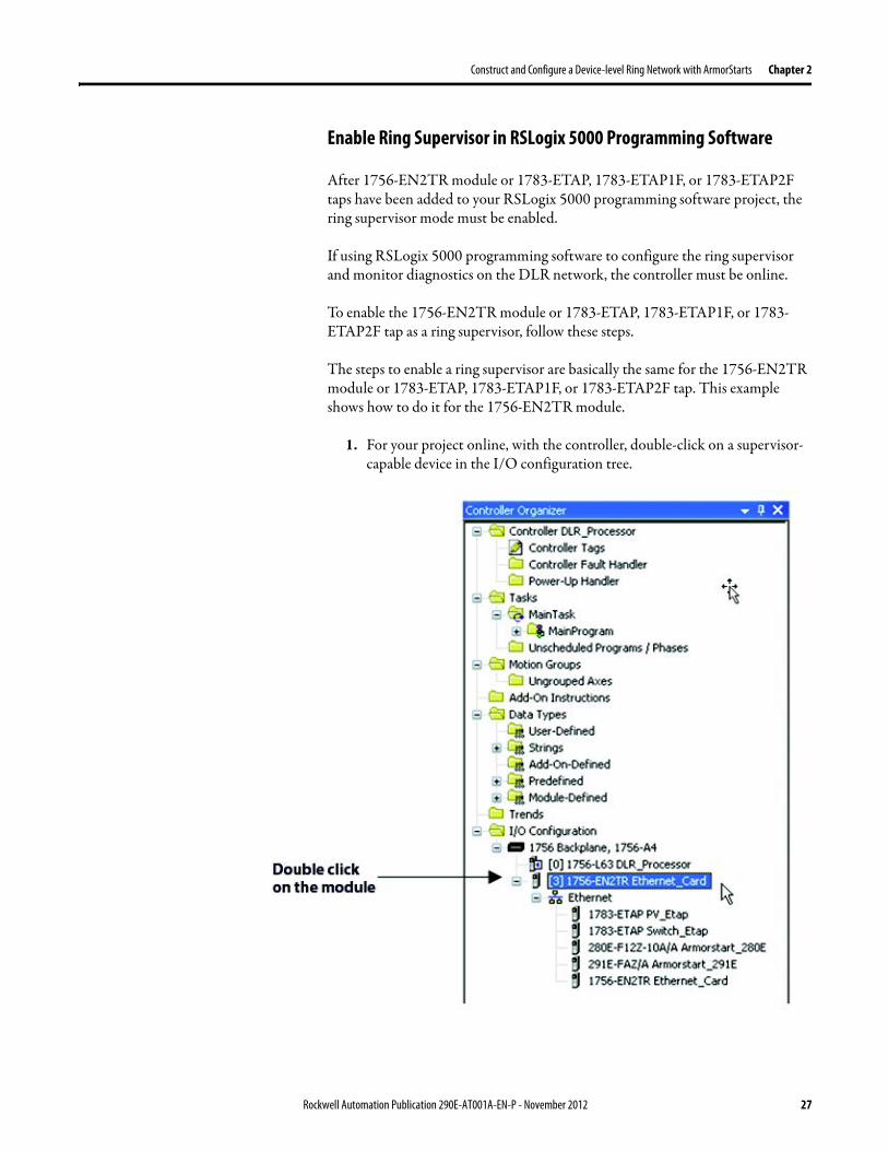
Construct and Configure a Device-level Ring Network with ArmorStarts Chapter 2
Enable Ring Supervisor in RSLogix 5000 Programming Software
After 1756-EN2TR module or 1783-ETAP 1783-ETAP1F or 1783-ETAP2F taps have been added to your RSLogix 5000 programming software project the ring supervisor mode must be enabled
If using RSLogix 5000 programming software to configure the ring supervisor and monitor diagnostics on the DLR network the controller must be online
To enable the 1756-EN2TR module or 1783-ETAP 1783-ETAP1F or 1783-ETAP2F tap as a ring supervisor follow these steps
The steps to enable a ring supervisor are basically the same for the 1756-EN2TR module or 1783-ETAP 1783-ETAP1F or 1783-ETAP2F tap This example shows how to do it for the 1756-EN2TR module
1 For your project online with the controller double-click on a supervisor-capable device in the IO configuration tree
Rockwell Automation Publication 290E-AT001A-EN-P - November 2012 27
Chapter 2 Construct and Configure a Device-level Ring Network with ArmorStarts
2 Click the Network tab to Enable Supervisor Mode
Configuration takes effect immediately you do not need to click Apply or OK
3 Click the Advanced button on the Network tab
4 Configure supervisor-related parameters as shown in the screen shot below
For these parameters you must click Set after entering a value
5 Click Set
28 Rockwell Automation Publication 290E-AT001A-EN-P - November 2012
Construct and Configure a Device-level Ring Network with ArmorStarts Chapter 2
Configure and Enable a Ring Supervisor in RSLinx Classic Communication Software
A ring supervisor can be configured for the DLR network through RSLinx Classic communication software
For more information regarding the Required RSLinx Classic Communication software Revision required refer to Appendix B
To configure a ring supervisor in RSLinx Classic Communication Software follow these steps
This example is for the 1783-ETAP tap Follow these steps
1 Launch RSLinx Classic Communication Software
2 Browse to the DLR network that is being set up
IMPORTANT For Beacon Interval Beacon Timeout and Ring Protocol VLAN ID we recommend that the default values be used
Functionality Description Default Setting
Supervisor Precedence A supervisor precedence number may be configured for each device that is configured as a ring supervisor The highest possible supervisor precedence value is 255When multiple nodes are enabled as supervisors the node with the highest precedence value is assigned as the active ring supervisor the other nodes automatically become back-up supervisorsWe recommend that youbull configure at least one back-up supervisor nodebull set the desired Active Ring Supervisor with a relatively high supervisor-
precedence value compared to the back-up node(s)bull keep track of the networkrsquos supervisor-precedence valuesIf multiple supervisors are configured with the same precedence value (the factory default value for all supervisor-capable devices is 0) the node with the numerically highest MAC address becomes the active supervisor
0
Beacon Interval Beacon interval is the frequency of the active ring supervisor transmitting a beacon frame through both of its Ethernet ports This parameter is user configurable for any time between 200 μS and 100 mSFor more information on how this parameter relates to network performance see page 61
400 μS
Beacon Timeout The beacon timeout is the amount of time that nodes wait before timing out the reception of beacon frames and taking appropriate action Supervisors support a range from 400μS to 500mSFor more information on how this parameter relates to network performance see page 61
1960 μS
Ring Protocol VLAN ID Reserved for future use 0
Rockwell Automation Publication 290E-AT001A-EN-P - November 2012 29
Chapter 2 Construct and Configure a Device-level Ring Network with ArmorStarts
If the Electronic Data Sheet (EDS) file is not installed on the module configured to be the ring supervisor it will appear with a question mark () To obtain and use the EDS file
bull right-click the module and choose to upload the EDS file from the device or
bull download the EDS file from httpwwwrockwellautomationcomrockwellautomationsupportnetworksedspage
3 Access the supervisor-capable nodersquos propertiesa Right-click the nodeb Choose Module Configuration
The General tab appears with information about the module
4 Click the Network tab to Enable Supervisor Mode
Configuration takes effect immediately there is no need to click Apply or OK
30 Rockwell Automation Publication 290E-AT001A-EN-P - November 2012
Construct and Configure a Device-level Ring Network with ArmorStarts Chapter 2
5 Click the Advanced button to configure supervisor-related parameters
Rockwell Automation Publication 290E-AT001A-EN-P - November 2012 31
Chapter 2 Construct and Configure a Device-level Ring Network with ArmorStarts
IMPORTANT For Beacon Interval Beacon Timeout and Ring Protocol VLAN ID use the default values
Functionality Description Default Setting
Supervisor Precedence
You may configure a supervisor precedence number for each device configured as a ring supervisor The highest possible supervisor precedence value is 255When multiple nodes are enabled as supervisor the node with the highest precedence value is assigned as the active ring supervisor the other nodes automatically become back-up supervisorsWe recommend that youbull configure at least one back-up supervisor nodebull set the desired Active Ring Supervisor with a relatively high supervisor-
precedence value compared to the back-up node(s)bull keep track of the networkrsquos supervisor-precedence valuesIf multiple supervisors are configured with the same precedence value (the factory default value for all supervisor-capable devices is 0) the node with the numerically highest MAC address becomes the active supervisor
0
Beacon Interval Beacon Interval is the frequency to which the active ring supervisor transmits a beacon frame through both of its Ethernet ports This parameter is user configurable for any time between 200 μS and 100 mSFor more information on how this parameter relates to network performance see page 58
400 μS
Beacon Timeout The beacon timeout is amount of time nodes wait before timing out the reception of beacon frames and taking appropriate action Supervisors support a range from 400 μS to 500 mSFor more information on how this parameter relates to network performance seepage 58
1960 μS
Ring Protocol VLAN ID
Reserved for future use 0
Enable IGMP Snooping
For more information on IGMP Snooping see page 35 Enabled
Enable IGMP Querier
For more information on IGMP Querier see page 35 Disabled
Enable Device Port Debugging Mode
For more information on Device Port Debugging Mode see page 59 Disabled
32 Rockwell Automation Publication 290E-AT001A-EN-P - November 2012
Construct and Configure a Device-level Ring Network with ArmorStarts Chapter 2
Complete the Physical Connections of the Network
After the ring supervisor nodes are configured and enabled the physical connection of the network must be completed to establish a complete DLR network
The figure below shows an example DLR network with all physical connections complete
Figure 4 - Example Device-level Ring Topology with All Connections Complete
Rockwell Automation Publication 290E-AT001A-EN-P - November 2012 33
Chapter 2 Construct and Configure a Device-level Ring Network with ArmorStarts
Verify Supervisor Configuration
The configuration and overall DLR network status can be verified in either RSLogix 5000 programming software or RSLinx Classic communication software
1 Access the supervisor nodersquos properties as shown previously in this chapter
2 Click the Network tab
3 Check the Network Topology and Network Status Fields
For a 1756-EN2TR module or the 1783-ETAP 1783-ETAP1F and 1783-ETAP2F tap the supervisor configuration can also be verified through the modulersquos diagnostic web pages For more information on monitoring diagnostics via an EtherNetIP modulersquos web pages see Monitor a DLR Network starting on page 37
34 Rockwell Automation Publication 290E-AT001A-EN-P - November 2012
Construct and Configure a Device-level Ring Network with ArmorStarts Chapter 2
IGMP Snooping This functionality is enabled by default in the 1783-ETAP 1783-ETAP1F and 1783-ETAP2F taps and is commonly used to manage multicast traffic on the network When in use this functionality allows the tap to multicast data to only those devices that need the data rather than to all devices connected to the network
For snooping to work there must be a device present that is running a querier Typically the device is a router or a switch such as the Stratix 6000 Stratix 8000 or Stratix 8300 managed switch
Once DHCP is enabled the switch could change the IP addresses on the ArmorStarts depending on network demand which could cause RSlogix5000 to loose communication with the device as connectivity is established via the AOP in the initial configuration
IGMP Querier This functionality is disabled by default The IGMP Querier functionality enables a 1783-ETAP 1783-ETAP1F or 1783-ETAP2F tap or switch such as a Stratix managed switch to send out a query to all devices on the network It determines what multicast addresses are of interest to a specific node or a group of nodes
The IGMP Querier functionality should be enabled for at least one node on the network The 1783-ETAP 1783-ETAP1F or 1783-ETAP2F tap managed switches and routers are examples of devices that support IGMP Querier functionality
IMPORTANT If DHCP for the Armostart is still required the Internet Group Management Protocol (IGMP) snooping on the E-tap must be disabled via the AOP
IMPORTANT If the IGMP Querier functionality is not enabled for at least one node on the network multicast traffic on the network may eventually create network performance issues
Rockwell Automation Publication 290E-AT001A-EN-P - November 2012 35
Chapter 2 Construct and Configure a Device-level Ring Network with ArmorStarts
However for all devices that are configured on the network with the IGMP Querier parameter enabled an IP address other than the factory default value must also be set for those devices If multiple devices on the network enable this functionality only the node with the lowest IP address becomes the active IGMP Querier node
IGMP Version
If the IGMP Querier is enabled a Querier Version must be selected The default version is Version 2
36 Rockwell Automation Publication 290E-AT001A-EN-P - November 2012
Chapter 3
Monitor a DLR Network
Introduction Use this chapter to learn how to monitor the DLR network
Methods to Monitor a DLR Network
Network diagnostic information can be retrieved from the ring supervisor-capable devices using the following
bull RSLogix 5000 programming software status pages
bull RSLinx communication software status pages
bull Device web pages
bull EtherNetIP Device Level Ring (DLR) network diagnostics faceplate
bull Programmatically through the use of a MSG instruction
RSLogix 5000 Programming Software Status Pages
RSLogix 5000 programming software version 1701 or later must be used and the appropriate AOPs installed to use the softwarersquos profile status pages
RSLinx Communication Software Status Pages
To monitor the network with this method the RSLinx communication software version 255 or later must be used
Topic Page
Methods to Monitor a DLR Network 37
Monitor Status Pages 39
Monitor ArmorStart Internal Web Server 44
Monitor via Faceplate Integration 45
Monitor Diagnostics via MSG Instructions 46
Rockwell Automation Publication 290E-AT001A-EN-P - November 2012 37
Chapter 3 Monitor a DLR Network
ArmorStart Internal Web Server
Rockwell Automation provides an internal embedded web server with each ArmorStart EtherNetIP The internal web server allows you to view information and configure the ArmorStart via a web browser The ArmorStart EtherNetIP can also be set up from the web server to send e-mail notifications The embedded web server is used to access configuration and status data It provides the user with the ability to view and modify the device configuration without having access to RSLogix 5000 Security in the form of an administrative password can be set The default login is Administrator There is no password set by default
EtherNetIP Device Level Ring (DLR) Network Diagnostics Faceplate
The diagnostics faceplate contains two major components
bull Logic code (encapsulated in an Add-On Instruction) that allows the controller to retrieve real-time DLR network status information
bull HMI faceplate graphics to allow the data to be visualized on an operator interface
Programmatically Through the Use of a MSG Instruction
For more information on how to monitor the DLR network via MSG Instructions see page 46
38 Rockwell Automation Publication 290E-AT001A-EN-P - November 2012
Monitor a DLR Network Chapter 3
Monitor Status Pages Both RSLogix 5000 programming software and RSLinx Classic communication software offer status pages that can be used to monitor the networkrsquos performance
RSLogix 5000 Programming Software Status Pages
Monitor the networkrsquos diagnostic information through the RSLogix 5000 programming software when the software is online
To monitor the network in RSLogix 5000 programming software follow these steps
1 Verify that the project is online
2 Access the active supervisor nodersquos propertiesa Right-click the modulersquos entry in the Controller Organizerb Click properties
Rockwell Automation Publication 290E-AT001A-EN-P - November 2012 39
Chapter 3 Monitor a DLR Network
3 Use the Network tab to monitor diagnostics
40 Rockwell Automation Publication 290E-AT001A-EN-P - November 2012
Monitor a DLR Network Chapter 3
RSLinx Communication Software
To monitor the network in RSLinx communication software follow these steps
1 Click RSWho to browse the network
2 Access the property pages for the active supervisor nodea Open the driver that shows the nodes on the DLR networkb Right-click the node that you want to monitor performancec Click on the choice that you need to access
Multiple choices appear
These options are shown in the following sections
Rockwell Automation Publication 290E-AT001A-EN-P - November 2012 41
Chapter 3 Monitor a DLR Network
Module Configuration
This series of tabs providesbull General informationbull Connection informationbull Module informationbull Internet protocolbull Port configurationbull Network information
The example below shows a ring fault between nodes at IP addresses 10888021 and MAC ID 00-00-BC-02-48-D5
42 Rockwell Automation Publication 290E-AT001A-EN-P - November 2012
Monitor a DLR Network Chapter 3
There are multiple fields used to monitor network diagnostics
Field Definition
Network Topology Possible values here can be Linear or Ring
Network Status Displays if the network is operating normally (Normal) or has experienced a fault (Ring Fault) as shown in the previous example screen
Active Ring Supervisor Displays the IP address or MAC address of the active ring supervisor
Active Supervisor Precedence For more information on this field see Active Ring Supervisor on page 11
Enable Ring Supervisor Configurable field that lets you to set the node as a ring supervisor
Ring Faults Detected Number of faults detected on the network since the last module power cycle or counter reset
Supervisor Status Displays whether this node is the active ring supervisor (Active) a back-up supervisor (Back-up) a ring node or part of a linear network
Last Active Node on Port 1 The last node the active ring supervisor can communicate with on Port 1 This value is an IP address or a MAC ID and remains latched until the Verify Fault Location button is clicked
Last Active Node on Port 2 The last node the active ring supervisor can communicate with on Port 2 This value is an IP address or a MAC ID and remains latched until the Verify Fault Location button is clicked
Status Displays whether a fault exists on the ring
IMPORTANT If the Network Topology field = Ring and the Network Status field = Normal the Last Active Node fields will display the last fault information even though it has been correctedTo clear the last fault information from these fields click Verify Fault Location You may see a message informing you that the supervisor is no longer in fault mode and the fields will be cleared
Rockwell Automation Publication 290E-AT001A-EN-P - November 2012 43
Chapter 3 Monitor a DLR Network
How to Access the ArmorStart EtherNetIP Internal Web Server
Open your preferred internet web browser and enter the IP address of the desired ArmorStart For this example 192168122 will be used
Use the links on the left-most navigation bar to see each available web page The screen below shows Ring Statistics for the ArmorStart 280E
44 Rockwell Automation Publication 290E-AT001A-EN-P - November 2012
Monitor a DLR Network Chapter 3
EtherNetIP Device Level Ring (DLR) Network Diagnostics Faceplate Overview
The EtherNetIP Device Level Ring (DLR) network diagnostics faceplate provides basic DLR network status information to the user to assist with monitoring and troubleshooting a DLR network
The diagnostics faceplate contains two major components
bull Logic code (encapsulated in an Add-On Instruction) that allows the controller to retrieve real-time DLR network status information
bull HMI faceplate graphics to allow the data to be visualized on an operator interface
The DLR diagnostics faceplate application can be downloaded from the Rockwell Automation Sample Code website at httpsamplecoderockwellautomationcom
Besides the individual Logix and View project components a demo application is also included with the downloaded file
Rockwell Automation Publication 290E-AT001A-EN-P - November 2012 45
Chapter 3 Monitor a DLR Network
Monitor Diagnostics via MSG Instructions
Network diagnostic information can also be obtained programmatically via MSG instructions in RSLogix 5000 programming software For example you can
bull Get all ring diagnostic informationbull Get a ring participant listbull Get the active supervisorbull Clear rapid ring faultsbull Verify a fault locationbull Reset a fault counterbull Enable and configure a ring supervisor
This information can be displayed on an HMI device or manipulated in the project code
Figure 5 - Example Use of MSG Instruction
This example describes how to retrieve diagnostic information from the DLR network Follow these steps
1 Enter a MSG instruction into the rung of logic
2 Configure the MSG instruction to retrieve ring diagnostic information service as shown in the following screen shots
IMPORTANT Make sure the tag created is sized appropriately to hold all of the data that you are reading or writing For more information see page 48
46 Rockwell Automation Publication 290E-AT001A-EN-P - November 2012
Monitor a DLR Network Chapter 3
3 Configure the MSG instructionrsquos communication path to point to the active supervisor node
The path on the following screen is one example path
IMPORTANT When using the Custom Get_Attributes_All (01) service pointing to an active supervisor node will retrieve all of the attributes listed in Retrieve All Diagnostic Information Attribute Description on page 50Pointing to a non-supervisor node will retrieve only the Network Topology and Network Status attribute informationPointing to backup supervisor node will retrieve the current active supervisorrsquos IP address
Rockwell Automation Publication 290E-AT001A-EN-P - November 2012 47
Chapter 3 Monitor a DLR Network
Use Specific Values on the Configuration Tab
Use the values on the Configuration tab of your MSG instruction to perform specific services Sample DLR network diagnostic application code for example Add-on Instruction or HMI faceplate graphics is available on the Rockwell Automation Sample Code Library For more information about the Rockwell Automation Sample Code Library see httpwwwrockwellautomationcomsolutionsintegratedarchitectureresources5html
➊ This request only works if there are fewer than 40 nodes on the network If there are more nodes than will fit in a single message an error will be returned➋ Use a Destination Length of 54 bytes if using firmware revision 3x or later for the 1756-EN2TR module or firmware revision 2x or later for the 1783-ETAP
1783-ETAP1F or 1783-ETAP2F taps
Request Description Message Type
Service Type
Service Code (HEX)
Class (HEX)
Instance Attribute (HEX)
Source Element
Source Length (Bytes)
Destination Destination Length (bytes)
Retrieve All Ring Diagnostic Information
Information for this request is listed in Retrieve All Ring Diagnostic Information on page 49
CIP Generic Custom 1 47 1 NA LeftBlank
0 Tag 50or54 ➋
Request Ring Participant List ➊
Information for this request is listed in Request the Ring Participant List on page 51
CIP Generic Get Attribute Single
e 47 1 9 NA NA Tag 10node
Get Active Supervisor
Obtain the IP address and MAC ID of the active supervisor on the DLR network
CIP Generic Get Attribute Single
e 47 1 a NA NA Tag 10
Acknowledge Rapid Ring Faults Condition
Request supervisor to resume normal operation after encountering a rapid ring fault condition
CIP Generic Custom 4c 47 1 NA NA NA NA
Verify a Fault Location
Request supervisor to update Last Active Node values
CIP Generic 4b 47 1 NA NA NA NA NA
Reset the Ring Fault Counter
Reset the number of ring faults detected on the DLR network
CIP Generic Set Attribute Single
10 47 1 5 Tag 2 NA NA
Enable and Configure a Ring Supervisor
Information for this request is listed in Enable and Configure a Ring Supervisor on page 52
CIP Generic Set Attribute Single
10 47 1 4 Tag 12 NA NA
48 Rockwell Automation Publication 290E-AT001A-EN-P - November 2012
Monitor a DLR Network Chapter 3
Retrieve All Ring Diagnostic Information
By performing the Retrieve All Ring Diagnostic Information request on an active supervisor the MSG instruction returns the following information
➊ RSLogix 5000 programming software may display the value in this field as negative numbers To better understand the value we recommend you view it in HEX format
Destination Tag Attribute Name Description Possible Values
SINT [0] Network Topology Current network topology mode 0 = Linear
1 = Ring
SINT [1] Network Status Current status of the network 0 = Normal
1 = Ring Fault
2 = Unexpected Loop Detected
3 = Partial Network Fault
4 = Rapid FaultRestore Cycle
SINT [2] Ring Supervisor Status Ring supervisor active status flag 0 = Node is functioning as a backup
1 = Node is functioning as the active ring supervisor
2 = Node is functioning as a normal ring node
3 = Node is operating in a non-DLR topology
4 = Node cannot support the currently operating ring parameters thatis Beacon Interval andor Beacon Timeout
Ring Supervisor Config Ring Supervisor configuration parameters
SINT [3] Ring Supervisor Enable Ring supervisor enable flag 0 = Node is configured as a normal ring node (default configuration)
1 = Node is configured as a ring supervisor
SINT [4] Ring Supervisor Precedence Precedence value of a ring supervisor ➊ Valid value range = 0hellip255
0 = Default value
SINT [5-8] Beacon Interval Duration of ring beacon interval Valid value range = 200 μshellip100 ms
Default = 400 μs
SINT [9-12] Beacon Timeout Duration of ring beacon timeout Value value range = 400 μshellip500 ms
Default value = 1960 μs
SINT [13-14] DLR VLAN ID Valid ID to use in ring protocol messages Valid value range = 0hellip4094
Default value = 0
SINT [15-16] Ring Faults Count Number of ring faults since power up ➊
Rockwell Automation Publication 290E-AT001A-EN-P - November 2012 49
Chapter 3 Monitor a DLR Network
Retrieve All Diagnostic Information Attribute Description
➊ This destination tag is available only with the 1756-EN2TR module firmware revision 3x or later 1783-ETAP 1783-ETAP1F and 1783-ETAP2F taps firmware revisions 2x or later If using the 1783-ETAP tap firmware revision 1x your program does not include this destination tag
➋ RSLogix 5000 programming software may display the value in this field as negative numbers To better understand the value we recommend you view it in HEX format
Destination Tag Attribute Name Description Possible Values
Last Active Node on Port 1 Last active node at the end of the chain through port 1 of the active ring supervisor during a ring fault
SINT [17-20] Device IP address ➋ Any valid IP address value
A value = 0 indicates no IP address has been configured for the device
SINT [21-26] Device MAC address ➋ Any valid Ethernet MAC address
Last Active Node on Port 2 Last active node at the end of the chain through port 2 of the active ring supervisor during a ring fault
SINT [27-30] Device IP address ➋ Any valid IP address value
A value = 0 indicates no IP address has been configured for the device
SINT [31-36] Device MAC address ➋ Any valid Ethernet MAC address
SINT [37-38] Ring Protocol Participants Count
Number of devices in the ring protocol participants list
Active Supervisor Address IP andor Ethernet MAC address of the active ring supervisor
SINT [39-42] Supervisor IP address Any valid IP address value
A value = 0 indicates no IP address has been configured for the device
SINT [43-48] Supervisor MAC address Any valid Ethernet MAC address
SINT [49] Active Supervisor Precedence
Precedence value of the active ring supervisor
SINT [50-53]➊ Capability Flags Alerts you that the device is capable of operating as a supervisor and beacon-based ring node
0x22
50 Rockwell Automation Publication 290E-AT001A-EN-P - November 2012
Monitor a DLR Network Chapter 3
Request the Ring Participant List
When requesting the Ring Participant List service on the DLR network the MSG instruction returns the following information
Request the Ring Participant List Attribute Description
➊ This attribute will return an array of the data shown one entry for each node The Ring Protocol Participants Count attribute determines the number entries
➋ This tag displays only IP addresses for ring participants that have been configured with one For example you may have a 1783-ETAP tap connected to the network that has not been assigned an IP address In that case no address is shown for the 1783-ETAP tap
➌ RSLogix 5000 programming software may display the value in this field as negative numbers To better understand the value we recommend you view it in HEX format
➍ Unlike destination tag SINT [0-3] where IP addresses are displayed only for ring participants configured with an IP address this tag displays MAC addresses for all ring participants because every ring participant has a MAC address
Destination Tag Attribute Name Description Possible Values
Ring Protocol Participants List ➊
List of devices participating in ring protocol
SINT [0-3] Device IP address ➋➌ Any valid IP address value
A value = 0 indicates no IP address has been configured for the device
SINT [4-9] Device MAC address ➌➍ Any valid Ethernet MAC address
Rockwell Automation Publication 290E-AT001A-EN-P - November 2012 51
Chapter 3 Monitor a DLR Network
Enable and Configure a Ring Supervisor
When performing the Enable and Configure a Ring Supervisor request on a supervisor-capable device configure the MSG instruction with the following information
Enable and Configure a Ring Supervisor Attribute Description
➊ RSLogix 5000 programming software may display the value in this field as negative numbers To better understand the value we recommend you view it in HEX format
Source Tag Attribute Name Description Possible Values
Ring Supervisor Config Ring Supervisor configuration parameters
SINT [0] Ring Supervisor Enable Ring supervisor enable flag 0 = Node is configured as a normal ring node (default configuration)1 = Node is configured as a ring supervisor
SINT [1] Ring Supervisor Precedence Precedence value of a ring supervisor ➊
Valid value range = 0hellip2550 = Default value
SINT [2-5] Beacon Interval Duration of ring beacon interval
Valid value range = 200 μshellip100 000 μsDefault = 400 μs
SINT [6-9] Beacon Timeout Duration of ring beacon timeout ➊
Value value range = 400 μshellip500 000 μsDefault value = 1960 μs
SINT [10-11] DLR VLAN ID Valid ID to use in ring protocol messages ➊
Valid value range = 0hellip4094Default value = 0
52 Rockwell Automation Publication 290E-AT001A-EN-P - November 2012
Chapter 4
Troubleshoot a DLR Network
Introduction Use this chapter to learn how to troubleshoot the DLR network
General Solutions for Linear or DLR Networks
Before attempting to correct specific faults on the linear or DLR network we recommend that you first take the following actions when a fault appears
bull For a DLR networkndash Verify that at least one node has been configured as a supervisor
on the network and that Network Topology = Ringndash Verify that all cables on the network are securely connected
to each devicendash Verify that all devices that require an IP address have one assigned
correctlyndash Check the Network Status field on the active supervisor nodersquos status
page to determine the fault typebull For a linear network
ndash Verify that none of the nodes are configured as a supervisor on the network and that Network Topology = LinearIf any nodes on a linear network are configured as a supervisor it may impact communication to other devices connected to the network
ndash Verify that all cables on the network are securely connected to each device
ndash Verify that all devices that require an IP address have one assigned correctly
If the fault is not cleared after completing the actions listed above use the tables in the rest of this chapter to troubleshoot issues specific to a DLR network or a linear network
Topic Page
General Solutions for the Linear or DLR Networks 53
Duplicate IP Address Detection 54
Specific Issues on the DLR Network 55
Network Recovery Performance 58
Device Port Debugging Mode 59
Rockwell Automation Publication 290E-AT001A-EN-P - November 2012 53
Chapter 4 Troubleshoot a DLR Network
Duplicate IP Address Detection
Some EtherNetIP communication modules support duplicate IP address detection The module verifies that its IP address does not match any other network devicersquos IP address when performing either of these tasks
bull Connect the module to an EtherNetIP network
bull Change the modulersquos IP address
If the modulersquos IP address matches that of another device on the network the modulersquos EtherNetIP port transitions to Conflict mode In Conflict mode these conditions exist
bull OK status indicator is blinking red
bull Network (NET) status indicator is solid red
bull On some EtherNetIP communication modules the module status display indicates the conflict
The display scrollsOK ltIP_address_of_this_modulegt Duplicate IP
ltMac_address_of_duplicate_node_detectedgt
For example OK 108860196 Duplicate IP - 0000BC0234B4
bull On some EtherNetIP communication modules the modulersquos diagnostic webpage displays information about duplicate IP address detection
For more information on which EtherNetIP communication modules support displaying duplicate IP address on their diagnostic webpage see the Technical Note titled Logix modules Duplicate IP address detection enhancement 118216 in the Technical Support Knowledgebase available at httpwwwrockwellautomationcomknowledgebase
54 Rockwell Automation Publication 290E-AT001A-EN-P - November 2012
Troubleshoot a DLR Network Chapter 4
Specific Issues on the DLR Network
Use the following table to troubleshoot possible specific issues on the DLR or linear network that are not solved by the actions described on the previous page
Issue Description Solution
Supervisor Reports a Ring Fault A link on the DLR network may be brokenbull intentionally for example because of adding or deleting nodes but not making all
physical connections to restore the setup of the network withwithout the nodebull unintentionally for example because a cable is broken or a device malfunctionsWhen this fault occurs the adjacent nodes to the faulted part of the network are displayed in the Ring Fault group and the Network Status field = Ring FaultThe screen shot below shows the Ring Fault section with IP addresses appearing for the last active nodes The faulted node is between nodes 108880115 and 108880208 If the IP address of either node is not available the software will display the nodersquos MAC ID
Once the fault is corrected the ring is automatically restored and the Network Status field returns to Normal
Determine where the fault condition exists and correct itClick the Refresh Communication link as needed to update the Ring Fault information to determine where the fault condition existsFinally DevicePort Debugging Mode functionality on the 1783-ETAP tap may be used to analyze a suspicious nodeFor more information refer to Device Port Debugging Mode on page 59
Rockwell Automation Publication 290E-AT001A-EN-P - November 2012 55
Chapter 4 Troubleshoot a DLR Network
Issue Description Solution
Rapid Ring Fault When a Rapid Ring Fault occurs the following events occurbull The active supervisor will block traffic on port 2 resulting in possible network
segmentation that is some nodes may become unreachablebull The Link 2 status indicator on the active supervisor is offbull As soon as the fault occurs for both RSLogix 5000 programming software and
RSLinx communication software the Status field = Rapid FaultRestore Cycles
Any of the following may cause a Rapid Ring Faultbull 5 intentional disconnectionsreconnections of a node from the network within 30
secondsbull A duplex mismatch between two connected devicesbull Electromagnetic noise on the networkbull Unstable physical connections such as intermittent connectorsGiven the nature of a Rapid Ring Fault the Last Active Node information may not be accurate when a Rapid Ring Fault condition is present
Multiple possible solutions existbull For the disconnections and reconnections issue no
solution is requiredClear the fault after reconnecting the device to the network permanentlybull For the duplex mismatch issue reconfigure the duplex
parameters to make sure they match between the devices
bull For the electromagnetic noise issue determine where the noise exists and eliminate it or use a protective shield in that location
bull For the unstable connections issue determine where they exist on the network and correct them
bull Check the media counters for all devices on the network The device with the highest media counter count is most likely causing the Rapid Ring Fault
bull Remove devices from the network one by one If the Rapid Ring Fault disappears after a device is removed that device is causing the fault
bull DevicePort Debugging Mode functionality on the 1783-ETAP tap may be used to analyze a suspicious node
For more information refer to Device Port Debugging Mode on page 59bull Finally the Beacon Interval or Timeout configuration
may not be appropriate for the networkHowever if these values need to be changed we recommend that you contact Rockwell Automation technical supportOnce the fault is fixed click Clear Fault
56 Rockwell Automation Publication 290E-AT001A-EN-P - November 2012
Troubleshoot a DLR Network Chapter 4
Issue Description Solution
Partial Fault Condition A partial network fault occurs when traffic is lost in only one direction on the network because a ring member is not forwarding beacons in both directions for example a component failureThe active ring supervisor detects a partial fault by monitoring the loss of Beacon frames on one port and the fault location appears in the Ring Fault section of the Network tab When a partial fault is detected the active ring supervisor blocks traffic on one port At this point the ring is segmented due to the partial fault condition The nodes adjacent to the faulted part of the network are displayed in the Ring Fault group with either IP addresses or MAC IDs for each node displayedWhen this fault occurs the Network Status field = Partial Fault ConditionOnce the fault is corrected it automatically clears and the Network Status field returns to Normal
Determine where the fault condition exists and correct itAdditionally the DevicePort Debugging Mode functionality also known as Port Mirroring on a 1783-ETAP 1783-ETAP1F or 1783-ETAP2F tap may be used to analyze a suspicious nodeFor more information refer to Device Port Debugging Mode on page 59
Media Counter Errors or Collisions
The media counters screen displays the number of physical layer errors or collisions The screen below indicates where to check for errors encountered Error levels are displayed depending on what caused the error For example an Alignment Error is displayed in the Alignment Error field
On a DLR network it is not uncommon to see low levels of media counter errors For example if the network breaks a low level of media counter errors appears With a low level of media counter errors the value typically does not continuously increase and often clearsA high level of media counter errors typically continues to increase and does not clear For example there is a mismatch of speed between two linked nodes a high level of media counter errors appears steadily increasing and not clearingTo access the RSLinx screen above browse the network right-click on the device select Module Properties and click the Port Diagnostics tab
Some example solutions includebull Check for a mismatch of speed andor duplex between
two linked nodesbull Verify that all cables on the network are securely
connected to each devicebull Check for electromagnetic noise on the network If you
find it eliminate it or use a protective shield in that location
Rockwell Automation Publication 290E-AT001A-EN-P - November 2012 57
Chapter 4 Troubleshoot a DLR Network
Network Recovery Performance
When measuring the networkrsquos performance with regard to dealing with fault conditions consider the network recovery time Network recovery is the time for all of the following to take place
1 The supervisor node recognizes that a fault exists on the network
2 The supervisor node reconfigures the network because of the fault
3 The supervisor node communicates to the network nodes that a fault condition exists
4 The network nodes reconfigure themselves because of the fault
With the default beacon interval value of 400 mS and beacon timeout value of 1960 mS the worst-case time for network recovery times are
bull 2890 mS for a copper DLR network This recovery time is based on 100 m copper segments between nodes on the network
bull 3140 mS for a fiber-optic DLR network This recovery time is based on 2 kM fiber-optic cable segments between nodes on the network
When considering the values listed above keep in mind
bull Recovery time may actually occur faster than the times listed
bull The recovery times listed above assume that your networkrsquos nodes are operating at 100 Mbps speed and full-duplex mode We recommend that your nodes generally operate in this mode for DLR networks
bull If other node conditions exist such as a node operating at 10 Mbps full-duplex or 10100 Mbps half-duplex the recovery times will vary from the times listed above
If this is the case for your application the beacon interval and beacon timeout will need to be changed We recommend that you first contact Rockwell Automation technical support if these parameters need to be changed
bull The value assumes that the majority of the traffic on your network is EtherNetIP traffic
58 Rockwell Automation Publication 290E-AT001A-EN-P - November 2012
Troubleshoot a DLR Network Chapter 4
Device Port Debugging Mode
This functionality is disabled by default Device Port Debugging mode which is similar to port mirroring can be used to monitor data received on the 1783-ETAP 1783-ETAP1F or 1783-ETAP2F taprsquos two network ports Monitor the data over the device port to a device such as a personal computer running a protocol analyzer application for advanced network debugging or analysis
When device port debugging is used on a 1783-ETAP the device connected to the 1783-ETAP taprsquos front port receives all of the data traversing the ring (both directions)
Device Port Debugging Example Network
When using the Device Port Debugging mode functionality insert the 1783-ETAP with the network analyzer connected to the device port It is inserted at the spot on the ring network where the node in question is located The graphic below shows a 1783-ETAP tap inserted in the network
IMPORTANT This functionality should be used only when troubleshooting the network and not in normal network operation
Rockwell Automation Publication 290E-AT001A-EN-P - November 2012 59
Chapter 4 Troubleshoot a DLR Network
Combined total network bandwidth of the traffic received on the two 1783-ETAP 1783-ETAP1F or 1783-ETAP2F taprsquos ports connected to the network should not exceed the taprsquos device port capacity The speed setting determines the device portrsquos capacity
Configure the device port on a 1783-ETAP 1783-ETAP1F or 1783-ETAP2F tap to either of two speed settings
bull 100 Mbps - default settingbull 10 Mbps
If the bandwidth exceeds the capacity of the taprsquos device port some frames from the ring will be dropped before reaching the device port These dropped frames do not impact the traffic on the rest of the DLR network
The device port setting determines how much network traffic the 1783-ETAP 1783-ETAP1F or 1783-ETAP2F tap can handle before dropping frames The circled section in the graphic below shows the Port Buffer Utilization of the Device Port In this example the value is zero because a ring fault exists on the network
60 Rockwell Automation Publication 290E-AT001A-EN-P - November 2012
Appendix A
Network Usage Guidelines and Recommendations
Consider the following guidelines and recommendations when using a DLR or linear network
GuidelineRecommendation Explanation
Use fewer than 50 nodes on a single DLR networkIf your application requires more than 50 nodes we recommend that the nodes are broken into separate but linked DLR networks
If you use more than 50 nodes on a single DLR networkbull Your network has a greater chance of multiple faults
occurring on the networkbull Network recovery times from faulted DLR network
are higher
Do not configure a supervisor on a linear network If your linear network includes non-DLR nodes and has a supervisor-enabled node on the network it may impact communication to non-DLR devices connected to the linear network
If you must connect a device that is running at 10 Mbps to a DLR or linear network do so through a 1783-ETAP 1783-ETAP1F or 1783-ETAP2F tap device port
The 1783-ETAP 1783-ETAP1F and 1783-ETAP2F taps can operate at 100 Mbps on the DLR network this is the optimal speed for a network If you connect a 10 Mbps device directly to the network instead of through a tap the linear or DLR network traffic slows to 10 MbpsAdditionally if the 10 Mbps device is connected to the network without a 1783-ETAP tap network recovery times are significantly impacted
Configure multiple supervisor nodes per ring If your DLR network only has one supervisor and the supervisor experiences a fault none of the other nodes become the active supervisor In this case the network becomes a linear network until the fault is corrected and the DLR network restoredAnother reason to configure multiple supervisor nodes is for replacing an active supervisor node with an out-of-box replacement the new device will not be enabled as a supervisor (by default) and there would still be no supervisor on the network
Rockwell Automation Publication 290E-AT001A-EN-P - November 2012 61
Appendix A Network Usage Guidelines and Recommendations
GuidelineRecommendation Explanation
Connect switches to a DLR network via 1783-ETAP 1783-ETAP1F or 1783-ETAP2F taps
If switches are connected to the DLR network without the use of a 1783-ETAP 1783-ETAP1F or 1783-ETAP2F tap the network may experience unpredictable behavior and network performance is unknown
Run all nodes on the DLR network at 100 Mbps and in Full-Duplex mode
These configuration values provide the best performance for your networkAdditionally we recommend that youbull Use auto-negotiate for all nodes on the DLR networkbull Do not use auto-negotiate on one node and then force
speed on the next node linked to it
In a linear network the number of nodes to use is application specific based on the considerations described in the next box
When determining the number of nodes to use on a linear network consider the followingbull There is a delay per node as information is transmitted
to each successive node used on the networkndash The typical delay on a linear network with 100 m
copper segments between nodes is 30 mSndash The typical delay on a linear network with 2 kM
fiber-optic segments between nodes is 40 mS
The greater the number of nodes on the network the longer the total time for information to be transmitted across the entire networkbull The single point of failure possibility is greater with
each additional connectionbull Troubleshooting the network may be more difficult
with a higher number of nodes
The total time for information to be transmitted across the entire network and its effect on how many nodes to use on a linear network is related to the Requested Packet Interval (RPI)Verify that the total time to transmit information from the first node to the last node on the network is less than the RPI Make sure the network is not loaded beyond 90 of capacity
62 Rockwell Automation Publication 290E-AT001A-EN-P - November 2012
Network Usage Guidelines and Recommendations Appendix A
GuidelineRecommendation Explanation
Do not physically close a DLR network without a supervisor configured on the network
A DLR network without a supervisor node results in a network stormIf you do close the DLR network without a supervisor configured break the ring and configure at least one supervisor before physically reconnecting the network
Use the default values for the followingbull Beacon Intervalbull Beacon Timeoutbull Ring Protocol VLAN ID
Changing the default values for the parameters Beacon Interval Beacon Timeout and Ring Protocol VLAN ID can result in unpredictable network behavior and negatively impacted network performanceThe default values are optimized for a network withbull 50 or fewer nodes are on the networkbull All nodes are operating at 100 Mbps and full-duplex
modebull At least 50 of the network traffic bandwidth being
EtherNetIP trafficIf you think the values of the Beacon Interval Beacon Timeout or Ring Protocol VLAN ID need to be changed for example if any node on ring is not operating at 100 Mbps and full-duplex mode we recommend that you first contact Rockwell Automation technical support
If DHCP for the ArmorStarts is still required you will need to disable Internet Group Management Protocol (IGMP) snooping on the E-tap via the AOP
IGMP Snooping is enabled by default in the 1783-ETAP 1783-ETAP1F and 1783-ETAP2F taps and is commonly used to manage multicast traffic on the network When in use this functionality allows the tap to multicast data to only those devices that need the data rather than to all devices connected to the networkOnce DHCP is enabled the switch could change the IP addresses on the ArmorStarts depending on network demand which could cause RSlogix5000 to loose communication with the device as connectivity is established via the AOP in the initial configuration
The IGMP Querier functionality should be enabled for at least one node on the network
This functionality is disabled by default The IGMP Querier functionality enables a 1783-ETAP 1783-ETAP1F or 1783-ETAP2F tap or switch such as a Stratix managed switch to send out a query to all devices on the network to determine what multicast addresses are of interest to a specific node or a group of nodesIf the IGMP Querier functionality is not enabled for at least one node on the network multicast traffic on the network may eventually create network performance issuesThe 1783-ETAP 1783-ETAP1F or 1783-ETAP2F taps managed switches and routers are examples of devices that support IGMP Querier functionality
Rockwell Automation Publication 290E-AT001A-EN-P - November 2012 63
Appendix A Network Usage Guidelines and Recommendations
Notes
64 Rockwell Automation Publication 290E-AT001A-EN-P - November 2012
Appendix B
Required Firmware Revisions
Required Firmware Revision for an Add-On Profile
➊ The ControlFLASH Firmware Upgrade software tcan be used o upgrade a 1756-EN2TR module from firmware revision 21 to 3x or later1x or later3x or later2x or later
➋ The ControlFLASH Firmware Upgrade software can be used to upgrade a 1783-ETAP tap from firmware revision 11 to 2x or later
To download new firmware go to httpwwwrockwellautomationcomsupportamericasindex_enhtml
If the firmware revision is upgraded on the module or tap the required AOP revision listed above must be used for that revision For example if the 1756-EN2TR module is upgraded to firmware revision 3x or later AOP revision 2x or later must be used in the RSLogix 5000 programming software
Additionally if the firmware revision is upgraded on the module or tap the required RSLinx communication software must also be used for that firmware revision For more information on which RSLinx software version is required for each firmware revision see page 66
For both the 1756-EN2TR module and 1783-ETAP tap make sure that the Major Revision configured on the General tab of the devicersquos RSLogix 5000 programming software configuration matches the major revision of the physical module
IMPORTANT To download an AOP go to httpsupportrockwellautomationcomcontrolflashLogixProfileraspDepending on the firmware revision of your product a specific AOP version must be used
Firmware Revision Add-On Profile Revision Cat No
21 ➊ 1x or later 1756-EN2TR
3x or later 2x or later
11 ➋ 1x or later 1783-ETAP
2x or later 2x or later
2x or later 2x or later 1783-ETAP1F
1783-ETAP2F
Rockwell Automation Publication 290E-AT001A-EN-P - November 2012 65
Appendix B Required Firmware Revisions
If the device configuration on the General tab does not match the physical module the programming software alerts you to this mismatch when attempting to configure the Internet Protocol Port Configuration and Network tabs for that device
Required Firmware Revision for RSLinx Communication Software
➊ The ControlFLASH Firmware Upgrade software can be used to upgrade a 1756-EN2TR module from firmware revision 21 to 3x or later1x or later3x or later255 or later3x or later256 or later
➋ The ControlFLASH Firmware Upgrade software can be used to upgrade a 1783-ETAP tap from firmware revision 11 to 2x or later
To download new firmware go to httpwwwrockwellautomationcomsupportamericasindex_enhtml
If the firmware revision is upgraded on the module or tap the required RSLinx communication software listed above must be used for that revision For example if the 1756-EN2TR module is upgraded to firmware revision 3x or later AOP revision 2x or later must be used in your RSLogix 5000 programming software
Additionally if the firmware revision is upgraded on the module or tap the required AOP revision must also be used for that firmware revision For more information on which AOP revision is required for each firmware revision see page 65
IMPORTANT Depending on the firmware revision of your product specific versions of RSLinx communication software must be used
Firmware Revision Required RSLinx Communication Software Version
Cat No
21 ➊ 255 or later 1756-EN2TR
3x or later 256 or later
11 ➋ 255 or later 1783-ETAP
2x or later 256 or later
2x or later 256 or later 1783-ETAP1F
1783-ETAP2F
66 Rockwell Automation Publication 290E-AT001A-EN-P - November 2012
Rockwell Otomasyon Ticaret AŞ Kar Plaza İş Merkezi E Blok Kat6 34752 İccedilerenkoumly İstanbul Tel +90 (216) 5698400
Rockwell Automation Publication 290E-AT001A-EN-P ndash November 2012 68 Copyright copy 2012 Rockwell Automation Inc All rights reserved Printed in the USA
Rockwell Automation Support
Rockwell Automation provides technical information on the Web to assist you in using its products At httpwwwrockwellautomationcomsupport you can find technical manuals a knowledge base of FAQs technical and application notes sample code and links to software service packs and a MySupport feature that you can customize to make thebest use of these tools
For an additional level of technical phone support for installation configuration and troubleshooting we offer TechConnectSM support programs For more information contact your local distributor or Rockwell Automation representative or visit httpwwwrockwellautomationcomsupport
Installation Assistance
If you experience a problem within the first 24 hours of installation review the information that is contained in this manualYou can contact Customer Support for initial help in getting your product up and running
New Product Satisfaction Return
Rockwell Automation tests all of its products to ensure that they are fully operational when shipped from the manufacturing facility However if your product is not functioning and needs to be returned follow these procedures
Documentation Feedback
Your comments will help us serve your documentation needs better If you have any suggestions on how to improve this document complete this form publication RA-DU002 available at httpwwwrockwellautomationcomliterature
United States or Canada 14406463434
Outside United States or Canada Use the Worldwide Locator at httpwwwrockwellautomationcomsupportamericasphone_enhtml or contact your local Rockwell Automation representative
United States Contact your distributor You must provide a Customer Support case number (call the phone number above to obtain one) to your distributor to complete the return process
Outside United States Please contact your local Rockwell Automation representative for the return procedure
- Important User Information
- General Precautions
- Software Requirements
- Additional Resources
- Rockwell Automation Support
- Installation Assistance
- New Product Satisfaction Return
- Table of Contents
- Chapter 1
-
- Device-Level Ring (DLR) Basics
-
- Introduction
- ArmorStart with EtherNetIP Overview
- What is a Device-level Ring (DLR) Network
- DLR Network Elements
-
- Supervisor Node
- Ring Node
-
- DLR Network Operation
- Number of Nodes on a DLR Network
- DLR Network Fault Management
-
- Network Reconfiguration after a Fault
-
- Chapter 2
-
- Construct and Configure a Device-level Ring Network with ArmorStarts
-
- Introduction
- Ethernet Capacity Tool
- Install Devices on a DLR Network
- ArmorStart Addressing Configuration
-
- Using the BootPDHCP Server
- Using the Rotary Network Address Switches
- Using the ArmorStart Internal Web Server
-
- Configure Supervisor Nodes on a DLR Network
-
- Configure a Ring Supervisor in RSLogix 5000 Programming Software
- Adding an Armorstart to RSLogix 5000
- Enable Ring Supervisor in RSLogix 5000 Programming Software
- Configure and Enable a Ring Supervisor in RSLinx Classic Communication Software
-
- Complete the Physical Connections of the Network
- Verify Supervisor Configuration
- IGMP Snooping
- IGMP Querier
-
- Chapter 3
-
- Monitor a DLR Network
-
- Introduction
- Methods to Monitor a DLR Network
-
- RSLogix 5000 Programming Software Status Pages
- RSLinx Communication Software Status Pages
- ArmorStart Internal Web Server
- EtherNetIP Device Level Ring (DLR) Network Diagnostics Faceplate
- Programmatically Through the Use of a MSG Instruction
-
- Monitor Status Pages
-
- RSLogix 5000 Programming Software Status Pages
- RSLinx Communication Software
-
- How to Access the ArmorStart EtherNetIP Internal Web Server
-
- EtherNetIP Device Level Ring (DLR) Network Diagnostics Faceplate Overview
-
- Monitor Diagnostics via MSG Instructions
-
- Use Specific Values on the Configuration Tab
- Retrieve All Ring Diagnostic Information
- Retrieve All Diagnostic Information Attribute Description
- Request the Ring Participant List
- Request the Ring Participant List Attribute Description
-
- Enable and Configure a Ring Supervisor
-
- Enable and Configure a Ring Supervisor Attribute Description
-
- Chapter 4
-
- Troubleshoot a DLR Network
-
- Introduction
- General Solutions for Linear or DLR Networks
- Duplicate IP Address Detection
- Specific Issues on the DLR Network
- Network Recovery Performance
- Device Port Debugging Mode
-
- Device Port Debugging Example Network
-
- Appendix A
-
- Network Usage Guidelines and Recommendations
-
- Notes
-
- Appendix B
-
- Required Firmware Revisions
-
- Required Firmware Revision for an Add-On Profile
- Required Firmware Revision for RSLinx Communication Software
-

Chapter 2 Construct and Configure a Device-level Ring Network with ArmorStarts
2 Click the Network tab to Enable Supervisor Mode
Configuration takes effect immediately you do not need to click Apply or OK
3 Click the Advanced button on the Network tab
4 Configure supervisor-related parameters as shown in the screen shot below
For these parameters you must click Set after entering a value
5 Click Set
28 Rockwell Automation Publication 290E-AT001A-EN-P - November 2012
Construct and Configure a Device-level Ring Network with ArmorStarts Chapter 2
Configure and Enable a Ring Supervisor in RSLinx Classic Communication Software
A ring supervisor can be configured for the DLR network through RSLinx Classic communication software
For more information regarding the Required RSLinx Classic Communication software Revision required refer to Appendix B
To configure a ring supervisor in RSLinx Classic Communication Software follow these steps
This example is for the 1783-ETAP tap Follow these steps
1 Launch RSLinx Classic Communication Software
2 Browse to the DLR network that is being set up
IMPORTANT For Beacon Interval Beacon Timeout and Ring Protocol VLAN ID we recommend that the default values be used
Functionality Description Default Setting
Supervisor Precedence A supervisor precedence number may be configured for each device that is configured as a ring supervisor The highest possible supervisor precedence value is 255When multiple nodes are enabled as supervisors the node with the highest precedence value is assigned as the active ring supervisor the other nodes automatically become back-up supervisorsWe recommend that youbull configure at least one back-up supervisor nodebull set the desired Active Ring Supervisor with a relatively high supervisor-
precedence value compared to the back-up node(s)bull keep track of the networkrsquos supervisor-precedence valuesIf multiple supervisors are configured with the same precedence value (the factory default value for all supervisor-capable devices is 0) the node with the numerically highest MAC address becomes the active supervisor
0
Beacon Interval Beacon interval is the frequency of the active ring supervisor transmitting a beacon frame through both of its Ethernet ports This parameter is user configurable for any time between 200 μS and 100 mSFor more information on how this parameter relates to network performance see page 61
400 μS
Beacon Timeout The beacon timeout is the amount of time that nodes wait before timing out the reception of beacon frames and taking appropriate action Supervisors support a range from 400μS to 500mSFor more information on how this parameter relates to network performance see page 61
1960 μS
Ring Protocol VLAN ID Reserved for future use 0
Rockwell Automation Publication 290E-AT001A-EN-P - November 2012 29
Chapter 2 Construct and Configure a Device-level Ring Network with ArmorStarts
If the Electronic Data Sheet (EDS) file is not installed on the module configured to be the ring supervisor it will appear with a question mark () To obtain and use the EDS file
bull right-click the module and choose to upload the EDS file from the device or
bull download the EDS file from httpwwwrockwellautomationcomrockwellautomationsupportnetworksedspage
3 Access the supervisor-capable nodersquos propertiesa Right-click the nodeb Choose Module Configuration
The General tab appears with information about the module
4 Click the Network tab to Enable Supervisor Mode
Configuration takes effect immediately there is no need to click Apply or OK
30 Rockwell Automation Publication 290E-AT001A-EN-P - November 2012
Construct and Configure a Device-level Ring Network with ArmorStarts Chapter 2
5 Click the Advanced button to configure supervisor-related parameters
Rockwell Automation Publication 290E-AT001A-EN-P - November 2012 31
Chapter 2 Construct and Configure a Device-level Ring Network with ArmorStarts
IMPORTANT For Beacon Interval Beacon Timeout and Ring Protocol VLAN ID use the default values
Functionality Description Default Setting
Supervisor Precedence
You may configure a supervisor precedence number for each device configured as a ring supervisor The highest possible supervisor precedence value is 255When multiple nodes are enabled as supervisor the node with the highest precedence value is assigned as the active ring supervisor the other nodes automatically become back-up supervisorsWe recommend that youbull configure at least one back-up supervisor nodebull set the desired Active Ring Supervisor with a relatively high supervisor-
precedence value compared to the back-up node(s)bull keep track of the networkrsquos supervisor-precedence valuesIf multiple supervisors are configured with the same precedence value (the factory default value for all supervisor-capable devices is 0) the node with the numerically highest MAC address becomes the active supervisor
0
Beacon Interval Beacon Interval is the frequency to which the active ring supervisor transmits a beacon frame through both of its Ethernet ports This parameter is user configurable for any time between 200 μS and 100 mSFor more information on how this parameter relates to network performance see page 58
400 μS
Beacon Timeout The beacon timeout is amount of time nodes wait before timing out the reception of beacon frames and taking appropriate action Supervisors support a range from 400 μS to 500 mSFor more information on how this parameter relates to network performance seepage 58
1960 μS
Ring Protocol VLAN ID
Reserved for future use 0
Enable IGMP Snooping
For more information on IGMP Snooping see page 35 Enabled
Enable IGMP Querier
For more information on IGMP Querier see page 35 Disabled
Enable Device Port Debugging Mode
For more information on Device Port Debugging Mode see page 59 Disabled
32 Rockwell Automation Publication 290E-AT001A-EN-P - November 2012
Construct and Configure a Device-level Ring Network with ArmorStarts Chapter 2
Complete the Physical Connections of the Network
After the ring supervisor nodes are configured and enabled the physical connection of the network must be completed to establish a complete DLR network
The figure below shows an example DLR network with all physical connections complete
Figure 4 - Example Device-level Ring Topology with All Connections Complete
Rockwell Automation Publication 290E-AT001A-EN-P - November 2012 33
Chapter 2 Construct and Configure a Device-level Ring Network with ArmorStarts
Verify Supervisor Configuration
The configuration and overall DLR network status can be verified in either RSLogix 5000 programming software or RSLinx Classic communication software
1 Access the supervisor nodersquos properties as shown previously in this chapter
2 Click the Network tab
3 Check the Network Topology and Network Status Fields
For a 1756-EN2TR module or the 1783-ETAP 1783-ETAP1F and 1783-ETAP2F tap the supervisor configuration can also be verified through the modulersquos diagnostic web pages For more information on monitoring diagnostics via an EtherNetIP modulersquos web pages see Monitor a DLR Network starting on page 37
34 Rockwell Automation Publication 290E-AT001A-EN-P - November 2012
Construct and Configure a Device-level Ring Network with ArmorStarts Chapter 2
IGMP Snooping This functionality is enabled by default in the 1783-ETAP 1783-ETAP1F and 1783-ETAP2F taps and is commonly used to manage multicast traffic on the network When in use this functionality allows the tap to multicast data to only those devices that need the data rather than to all devices connected to the network
For snooping to work there must be a device present that is running a querier Typically the device is a router or a switch such as the Stratix 6000 Stratix 8000 or Stratix 8300 managed switch
Once DHCP is enabled the switch could change the IP addresses on the ArmorStarts depending on network demand which could cause RSlogix5000 to loose communication with the device as connectivity is established via the AOP in the initial configuration
IGMP Querier This functionality is disabled by default The IGMP Querier functionality enables a 1783-ETAP 1783-ETAP1F or 1783-ETAP2F tap or switch such as a Stratix managed switch to send out a query to all devices on the network It determines what multicast addresses are of interest to a specific node or a group of nodes
The IGMP Querier functionality should be enabled for at least one node on the network The 1783-ETAP 1783-ETAP1F or 1783-ETAP2F tap managed switches and routers are examples of devices that support IGMP Querier functionality
IMPORTANT If DHCP for the Armostart is still required the Internet Group Management Protocol (IGMP) snooping on the E-tap must be disabled via the AOP
IMPORTANT If the IGMP Querier functionality is not enabled for at least one node on the network multicast traffic on the network may eventually create network performance issues
Rockwell Automation Publication 290E-AT001A-EN-P - November 2012 35
Chapter 2 Construct and Configure a Device-level Ring Network with ArmorStarts
However for all devices that are configured on the network with the IGMP Querier parameter enabled an IP address other than the factory default value must also be set for those devices If multiple devices on the network enable this functionality only the node with the lowest IP address becomes the active IGMP Querier node
IGMP Version
If the IGMP Querier is enabled a Querier Version must be selected The default version is Version 2
36 Rockwell Automation Publication 290E-AT001A-EN-P - November 2012
Chapter 3
Monitor a DLR Network
Introduction Use this chapter to learn how to monitor the DLR network
Methods to Monitor a DLR Network
Network diagnostic information can be retrieved from the ring supervisor-capable devices using the following
bull RSLogix 5000 programming software status pages
bull RSLinx communication software status pages
bull Device web pages
bull EtherNetIP Device Level Ring (DLR) network diagnostics faceplate
bull Programmatically through the use of a MSG instruction
RSLogix 5000 Programming Software Status Pages
RSLogix 5000 programming software version 1701 or later must be used and the appropriate AOPs installed to use the softwarersquos profile status pages
RSLinx Communication Software Status Pages
To monitor the network with this method the RSLinx communication software version 255 or later must be used
Topic Page
Methods to Monitor a DLR Network 37
Monitor Status Pages 39
Monitor ArmorStart Internal Web Server 44
Monitor via Faceplate Integration 45
Monitor Diagnostics via MSG Instructions 46
Rockwell Automation Publication 290E-AT001A-EN-P - November 2012 37
Chapter 3 Monitor a DLR Network
ArmorStart Internal Web Server
Rockwell Automation provides an internal embedded web server with each ArmorStart EtherNetIP The internal web server allows you to view information and configure the ArmorStart via a web browser The ArmorStart EtherNetIP can also be set up from the web server to send e-mail notifications The embedded web server is used to access configuration and status data It provides the user with the ability to view and modify the device configuration without having access to RSLogix 5000 Security in the form of an administrative password can be set The default login is Administrator There is no password set by default
EtherNetIP Device Level Ring (DLR) Network Diagnostics Faceplate
The diagnostics faceplate contains two major components
bull Logic code (encapsulated in an Add-On Instruction) that allows the controller to retrieve real-time DLR network status information
bull HMI faceplate graphics to allow the data to be visualized on an operator interface
Programmatically Through the Use of a MSG Instruction
For more information on how to monitor the DLR network via MSG Instructions see page 46
38 Rockwell Automation Publication 290E-AT001A-EN-P - November 2012
Monitor a DLR Network Chapter 3
Monitor Status Pages Both RSLogix 5000 programming software and RSLinx Classic communication software offer status pages that can be used to monitor the networkrsquos performance
RSLogix 5000 Programming Software Status Pages
Monitor the networkrsquos diagnostic information through the RSLogix 5000 programming software when the software is online
To monitor the network in RSLogix 5000 programming software follow these steps
1 Verify that the project is online
2 Access the active supervisor nodersquos propertiesa Right-click the modulersquos entry in the Controller Organizerb Click properties
Rockwell Automation Publication 290E-AT001A-EN-P - November 2012 39
Chapter 3 Monitor a DLR Network
3 Use the Network tab to monitor diagnostics
40 Rockwell Automation Publication 290E-AT001A-EN-P - November 2012
Monitor a DLR Network Chapter 3
RSLinx Communication Software
To monitor the network in RSLinx communication software follow these steps
1 Click RSWho to browse the network
2 Access the property pages for the active supervisor nodea Open the driver that shows the nodes on the DLR networkb Right-click the node that you want to monitor performancec Click on the choice that you need to access
Multiple choices appear
These options are shown in the following sections
Rockwell Automation Publication 290E-AT001A-EN-P - November 2012 41
Chapter 3 Monitor a DLR Network
Module Configuration
This series of tabs providesbull General informationbull Connection informationbull Module informationbull Internet protocolbull Port configurationbull Network information
The example below shows a ring fault between nodes at IP addresses 10888021 and MAC ID 00-00-BC-02-48-D5
42 Rockwell Automation Publication 290E-AT001A-EN-P - November 2012
Monitor a DLR Network Chapter 3
There are multiple fields used to monitor network diagnostics
Field Definition
Network Topology Possible values here can be Linear or Ring
Network Status Displays if the network is operating normally (Normal) or has experienced a fault (Ring Fault) as shown in the previous example screen
Active Ring Supervisor Displays the IP address or MAC address of the active ring supervisor
Active Supervisor Precedence For more information on this field see Active Ring Supervisor on page 11
Enable Ring Supervisor Configurable field that lets you to set the node as a ring supervisor
Ring Faults Detected Number of faults detected on the network since the last module power cycle or counter reset
Supervisor Status Displays whether this node is the active ring supervisor (Active) a back-up supervisor (Back-up) a ring node or part of a linear network
Last Active Node on Port 1 The last node the active ring supervisor can communicate with on Port 1 This value is an IP address or a MAC ID and remains latched until the Verify Fault Location button is clicked
Last Active Node on Port 2 The last node the active ring supervisor can communicate with on Port 2 This value is an IP address or a MAC ID and remains latched until the Verify Fault Location button is clicked
Status Displays whether a fault exists on the ring
IMPORTANT If the Network Topology field = Ring and the Network Status field = Normal the Last Active Node fields will display the last fault information even though it has been correctedTo clear the last fault information from these fields click Verify Fault Location You may see a message informing you that the supervisor is no longer in fault mode and the fields will be cleared
Rockwell Automation Publication 290E-AT001A-EN-P - November 2012 43
Chapter 3 Monitor a DLR Network
How to Access the ArmorStart EtherNetIP Internal Web Server
Open your preferred internet web browser and enter the IP address of the desired ArmorStart For this example 192168122 will be used
Use the links on the left-most navigation bar to see each available web page The screen below shows Ring Statistics for the ArmorStart 280E
44 Rockwell Automation Publication 290E-AT001A-EN-P - November 2012
Monitor a DLR Network Chapter 3
EtherNetIP Device Level Ring (DLR) Network Diagnostics Faceplate Overview
The EtherNetIP Device Level Ring (DLR) network diagnostics faceplate provides basic DLR network status information to the user to assist with monitoring and troubleshooting a DLR network
The diagnostics faceplate contains two major components
bull Logic code (encapsulated in an Add-On Instruction) that allows the controller to retrieve real-time DLR network status information
bull HMI faceplate graphics to allow the data to be visualized on an operator interface
The DLR diagnostics faceplate application can be downloaded from the Rockwell Automation Sample Code website at httpsamplecoderockwellautomationcom
Besides the individual Logix and View project components a demo application is also included with the downloaded file
Rockwell Automation Publication 290E-AT001A-EN-P - November 2012 45
Chapter 3 Monitor a DLR Network
Monitor Diagnostics via MSG Instructions
Network diagnostic information can also be obtained programmatically via MSG instructions in RSLogix 5000 programming software For example you can
bull Get all ring diagnostic informationbull Get a ring participant listbull Get the active supervisorbull Clear rapid ring faultsbull Verify a fault locationbull Reset a fault counterbull Enable and configure a ring supervisor
This information can be displayed on an HMI device or manipulated in the project code
Figure 5 - Example Use of MSG Instruction
This example describes how to retrieve diagnostic information from the DLR network Follow these steps
1 Enter a MSG instruction into the rung of logic
2 Configure the MSG instruction to retrieve ring diagnostic information service as shown in the following screen shots
IMPORTANT Make sure the tag created is sized appropriately to hold all of the data that you are reading or writing For more information see page 48
46 Rockwell Automation Publication 290E-AT001A-EN-P - November 2012
Monitor a DLR Network Chapter 3
3 Configure the MSG instructionrsquos communication path to point to the active supervisor node
The path on the following screen is one example path
IMPORTANT When using the Custom Get_Attributes_All (01) service pointing to an active supervisor node will retrieve all of the attributes listed in Retrieve All Diagnostic Information Attribute Description on page 50Pointing to a non-supervisor node will retrieve only the Network Topology and Network Status attribute informationPointing to backup supervisor node will retrieve the current active supervisorrsquos IP address
Rockwell Automation Publication 290E-AT001A-EN-P - November 2012 47
Chapter 3 Monitor a DLR Network
Use Specific Values on the Configuration Tab
Use the values on the Configuration tab of your MSG instruction to perform specific services Sample DLR network diagnostic application code for example Add-on Instruction or HMI faceplate graphics is available on the Rockwell Automation Sample Code Library For more information about the Rockwell Automation Sample Code Library see httpwwwrockwellautomationcomsolutionsintegratedarchitectureresources5html
➊ This request only works if there are fewer than 40 nodes on the network If there are more nodes than will fit in a single message an error will be returned➋ Use a Destination Length of 54 bytes if using firmware revision 3x or later for the 1756-EN2TR module or firmware revision 2x or later for the 1783-ETAP
1783-ETAP1F or 1783-ETAP2F taps
Request Description Message Type
Service Type
Service Code (HEX)
Class (HEX)
Instance Attribute (HEX)
Source Element
Source Length (Bytes)
Destination Destination Length (bytes)
Retrieve All Ring Diagnostic Information
Information for this request is listed in Retrieve All Ring Diagnostic Information on page 49
CIP Generic Custom 1 47 1 NA LeftBlank
0 Tag 50or54 ➋
Request Ring Participant List ➊
Information for this request is listed in Request the Ring Participant List on page 51
CIP Generic Get Attribute Single
e 47 1 9 NA NA Tag 10node
Get Active Supervisor
Obtain the IP address and MAC ID of the active supervisor on the DLR network
CIP Generic Get Attribute Single
e 47 1 a NA NA Tag 10
Acknowledge Rapid Ring Faults Condition
Request supervisor to resume normal operation after encountering a rapid ring fault condition
CIP Generic Custom 4c 47 1 NA NA NA NA
Verify a Fault Location
Request supervisor to update Last Active Node values
CIP Generic 4b 47 1 NA NA NA NA NA
Reset the Ring Fault Counter
Reset the number of ring faults detected on the DLR network
CIP Generic Set Attribute Single
10 47 1 5 Tag 2 NA NA
Enable and Configure a Ring Supervisor
Information for this request is listed in Enable and Configure a Ring Supervisor on page 52
CIP Generic Set Attribute Single
10 47 1 4 Tag 12 NA NA
48 Rockwell Automation Publication 290E-AT001A-EN-P - November 2012
Monitor a DLR Network Chapter 3
Retrieve All Ring Diagnostic Information
By performing the Retrieve All Ring Diagnostic Information request on an active supervisor the MSG instruction returns the following information
➊ RSLogix 5000 programming software may display the value in this field as negative numbers To better understand the value we recommend you view it in HEX format
Destination Tag Attribute Name Description Possible Values
SINT [0] Network Topology Current network topology mode 0 = Linear
1 = Ring
SINT [1] Network Status Current status of the network 0 = Normal
1 = Ring Fault
2 = Unexpected Loop Detected
3 = Partial Network Fault
4 = Rapid FaultRestore Cycle
SINT [2] Ring Supervisor Status Ring supervisor active status flag 0 = Node is functioning as a backup
1 = Node is functioning as the active ring supervisor
2 = Node is functioning as a normal ring node
3 = Node is operating in a non-DLR topology
4 = Node cannot support the currently operating ring parameters thatis Beacon Interval andor Beacon Timeout
Ring Supervisor Config Ring Supervisor configuration parameters
SINT [3] Ring Supervisor Enable Ring supervisor enable flag 0 = Node is configured as a normal ring node (default configuration)
1 = Node is configured as a ring supervisor
SINT [4] Ring Supervisor Precedence Precedence value of a ring supervisor ➊ Valid value range = 0hellip255
0 = Default value
SINT [5-8] Beacon Interval Duration of ring beacon interval Valid value range = 200 μshellip100 ms
Default = 400 μs
SINT [9-12] Beacon Timeout Duration of ring beacon timeout Value value range = 400 μshellip500 ms
Default value = 1960 μs
SINT [13-14] DLR VLAN ID Valid ID to use in ring protocol messages Valid value range = 0hellip4094
Default value = 0
SINT [15-16] Ring Faults Count Number of ring faults since power up ➊
Rockwell Automation Publication 290E-AT001A-EN-P - November 2012 49
Chapter 3 Monitor a DLR Network
Retrieve All Diagnostic Information Attribute Description
➊ This destination tag is available only with the 1756-EN2TR module firmware revision 3x or later 1783-ETAP 1783-ETAP1F and 1783-ETAP2F taps firmware revisions 2x or later If using the 1783-ETAP tap firmware revision 1x your program does not include this destination tag
➋ RSLogix 5000 programming software may display the value in this field as negative numbers To better understand the value we recommend you view it in HEX format
Destination Tag Attribute Name Description Possible Values
Last Active Node on Port 1 Last active node at the end of the chain through port 1 of the active ring supervisor during a ring fault
SINT [17-20] Device IP address ➋ Any valid IP address value
A value = 0 indicates no IP address has been configured for the device
SINT [21-26] Device MAC address ➋ Any valid Ethernet MAC address
Last Active Node on Port 2 Last active node at the end of the chain through port 2 of the active ring supervisor during a ring fault
SINT [27-30] Device IP address ➋ Any valid IP address value
A value = 0 indicates no IP address has been configured for the device
SINT [31-36] Device MAC address ➋ Any valid Ethernet MAC address
SINT [37-38] Ring Protocol Participants Count
Number of devices in the ring protocol participants list
Active Supervisor Address IP andor Ethernet MAC address of the active ring supervisor
SINT [39-42] Supervisor IP address Any valid IP address value
A value = 0 indicates no IP address has been configured for the device
SINT [43-48] Supervisor MAC address Any valid Ethernet MAC address
SINT [49] Active Supervisor Precedence
Precedence value of the active ring supervisor
SINT [50-53]➊ Capability Flags Alerts you that the device is capable of operating as a supervisor and beacon-based ring node
0x22
50 Rockwell Automation Publication 290E-AT001A-EN-P - November 2012
Monitor a DLR Network Chapter 3
Request the Ring Participant List
When requesting the Ring Participant List service on the DLR network the MSG instruction returns the following information
Request the Ring Participant List Attribute Description
➊ This attribute will return an array of the data shown one entry for each node The Ring Protocol Participants Count attribute determines the number entries
➋ This tag displays only IP addresses for ring participants that have been configured with one For example you may have a 1783-ETAP tap connected to the network that has not been assigned an IP address In that case no address is shown for the 1783-ETAP tap
➌ RSLogix 5000 programming software may display the value in this field as negative numbers To better understand the value we recommend you view it in HEX format
➍ Unlike destination tag SINT [0-3] where IP addresses are displayed only for ring participants configured with an IP address this tag displays MAC addresses for all ring participants because every ring participant has a MAC address
Destination Tag Attribute Name Description Possible Values
Ring Protocol Participants List ➊
List of devices participating in ring protocol
SINT [0-3] Device IP address ➋➌ Any valid IP address value
A value = 0 indicates no IP address has been configured for the device
SINT [4-9] Device MAC address ➌➍ Any valid Ethernet MAC address
Rockwell Automation Publication 290E-AT001A-EN-P - November 2012 51
Chapter 3 Monitor a DLR Network
Enable and Configure a Ring Supervisor
When performing the Enable and Configure a Ring Supervisor request on a supervisor-capable device configure the MSG instruction with the following information
Enable and Configure a Ring Supervisor Attribute Description
➊ RSLogix 5000 programming software may display the value in this field as negative numbers To better understand the value we recommend you view it in HEX format
Source Tag Attribute Name Description Possible Values
Ring Supervisor Config Ring Supervisor configuration parameters
SINT [0] Ring Supervisor Enable Ring supervisor enable flag 0 = Node is configured as a normal ring node (default configuration)1 = Node is configured as a ring supervisor
SINT [1] Ring Supervisor Precedence Precedence value of a ring supervisor ➊
Valid value range = 0hellip2550 = Default value
SINT [2-5] Beacon Interval Duration of ring beacon interval
Valid value range = 200 μshellip100 000 μsDefault = 400 μs
SINT [6-9] Beacon Timeout Duration of ring beacon timeout ➊
Value value range = 400 μshellip500 000 μsDefault value = 1960 μs
SINT [10-11] DLR VLAN ID Valid ID to use in ring protocol messages ➊
Valid value range = 0hellip4094Default value = 0
52 Rockwell Automation Publication 290E-AT001A-EN-P - November 2012
Chapter 4
Troubleshoot a DLR Network
Introduction Use this chapter to learn how to troubleshoot the DLR network
General Solutions for Linear or DLR Networks
Before attempting to correct specific faults on the linear or DLR network we recommend that you first take the following actions when a fault appears
bull For a DLR networkndash Verify that at least one node has been configured as a supervisor
on the network and that Network Topology = Ringndash Verify that all cables on the network are securely connected
to each devicendash Verify that all devices that require an IP address have one assigned
correctlyndash Check the Network Status field on the active supervisor nodersquos status
page to determine the fault typebull For a linear network
ndash Verify that none of the nodes are configured as a supervisor on the network and that Network Topology = LinearIf any nodes on a linear network are configured as a supervisor it may impact communication to other devices connected to the network
ndash Verify that all cables on the network are securely connected to each device
ndash Verify that all devices that require an IP address have one assigned correctly
If the fault is not cleared after completing the actions listed above use the tables in the rest of this chapter to troubleshoot issues specific to a DLR network or a linear network
Topic Page
General Solutions for the Linear or DLR Networks 53
Duplicate IP Address Detection 54
Specific Issues on the DLR Network 55
Network Recovery Performance 58
Device Port Debugging Mode 59
Rockwell Automation Publication 290E-AT001A-EN-P - November 2012 53
Chapter 4 Troubleshoot a DLR Network
Duplicate IP Address Detection
Some EtherNetIP communication modules support duplicate IP address detection The module verifies that its IP address does not match any other network devicersquos IP address when performing either of these tasks
bull Connect the module to an EtherNetIP network
bull Change the modulersquos IP address
If the modulersquos IP address matches that of another device on the network the modulersquos EtherNetIP port transitions to Conflict mode In Conflict mode these conditions exist
bull OK status indicator is blinking red
bull Network (NET) status indicator is solid red
bull On some EtherNetIP communication modules the module status display indicates the conflict
The display scrollsOK ltIP_address_of_this_modulegt Duplicate IP
ltMac_address_of_duplicate_node_detectedgt
For example OK 108860196 Duplicate IP - 0000BC0234B4
bull On some EtherNetIP communication modules the modulersquos diagnostic webpage displays information about duplicate IP address detection
For more information on which EtherNetIP communication modules support displaying duplicate IP address on their diagnostic webpage see the Technical Note titled Logix modules Duplicate IP address detection enhancement 118216 in the Technical Support Knowledgebase available at httpwwwrockwellautomationcomknowledgebase
54 Rockwell Automation Publication 290E-AT001A-EN-P - November 2012
Troubleshoot a DLR Network Chapter 4
Specific Issues on the DLR Network
Use the following table to troubleshoot possible specific issues on the DLR or linear network that are not solved by the actions described on the previous page
Issue Description Solution
Supervisor Reports a Ring Fault A link on the DLR network may be brokenbull intentionally for example because of adding or deleting nodes but not making all
physical connections to restore the setup of the network withwithout the nodebull unintentionally for example because a cable is broken or a device malfunctionsWhen this fault occurs the adjacent nodes to the faulted part of the network are displayed in the Ring Fault group and the Network Status field = Ring FaultThe screen shot below shows the Ring Fault section with IP addresses appearing for the last active nodes The faulted node is between nodes 108880115 and 108880208 If the IP address of either node is not available the software will display the nodersquos MAC ID
Once the fault is corrected the ring is automatically restored and the Network Status field returns to Normal
Determine where the fault condition exists and correct itClick the Refresh Communication link as needed to update the Ring Fault information to determine where the fault condition existsFinally DevicePort Debugging Mode functionality on the 1783-ETAP tap may be used to analyze a suspicious nodeFor more information refer to Device Port Debugging Mode on page 59
Rockwell Automation Publication 290E-AT001A-EN-P - November 2012 55
Chapter 4 Troubleshoot a DLR Network
Issue Description Solution
Rapid Ring Fault When a Rapid Ring Fault occurs the following events occurbull The active supervisor will block traffic on port 2 resulting in possible network
segmentation that is some nodes may become unreachablebull The Link 2 status indicator on the active supervisor is offbull As soon as the fault occurs for both RSLogix 5000 programming software and
RSLinx communication software the Status field = Rapid FaultRestore Cycles
Any of the following may cause a Rapid Ring Faultbull 5 intentional disconnectionsreconnections of a node from the network within 30
secondsbull A duplex mismatch between two connected devicesbull Electromagnetic noise on the networkbull Unstable physical connections such as intermittent connectorsGiven the nature of a Rapid Ring Fault the Last Active Node information may not be accurate when a Rapid Ring Fault condition is present
Multiple possible solutions existbull For the disconnections and reconnections issue no
solution is requiredClear the fault after reconnecting the device to the network permanentlybull For the duplex mismatch issue reconfigure the duplex
parameters to make sure they match between the devices
bull For the electromagnetic noise issue determine where the noise exists and eliminate it or use a protective shield in that location
bull For the unstable connections issue determine where they exist on the network and correct them
bull Check the media counters for all devices on the network The device with the highest media counter count is most likely causing the Rapid Ring Fault
bull Remove devices from the network one by one If the Rapid Ring Fault disappears after a device is removed that device is causing the fault
bull DevicePort Debugging Mode functionality on the 1783-ETAP tap may be used to analyze a suspicious node
For more information refer to Device Port Debugging Mode on page 59bull Finally the Beacon Interval or Timeout configuration
may not be appropriate for the networkHowever if these values need to be changed we recommend that you contact Rockwell Automation technical supportOnce the fault is fixed click Clear Fault
56 Rockwell Automation Publication 290E-AT001A-EN-P - November 2012
Troubleshoot a DLR Network Chapter 4
Issue Description Solution
Partial Fault Condition A partial network fault occurs when traffic is lost in only one direction on the network because a ring member is not forwarding beacons in both directions for example a component failureThe active ring supervisor detects a partial fault by monitoring the loss of Beacon frames on one port and the fault location appears in the Ring Fault section of the Network tab When a partial fault is detected the active ring supervisor blocks traffic on one port At this point the ring is segmented due to the partial fault condition The nodes adjacent to the faulted part of the network are displayed in the Ring Fault group with either IP addresses or MAC IDs for each node displayedWhen this fault occurs the Network Status field = Partial Fault ConditionOnce the fault is corrected it automatically clears and the Network Status field returns to Normal
Determine where the fault condition exists and correct itAdditionally the DevicePort Debugging Mode functionality also known as Port Mirroring on a 1783-ETAP 1783-ETAP1F or 1783-ETAP2F tap may be used to analyze a suspicious nodeFor more information refer to Device Port Debugging Mode on page 59
Media Counter Errors or Collisions
The media counters screen displays the number of physical layer errors or collisions The screen below indicates where to check for errors encountered Error levels are displayed depending on what caused the error For example an Alignment Error is displayed in the Alignment Error field
On a DLR network it is not uncommon to see low levels of media counter errors For example if the network breaks a low level of media counter errors appears With a low level of media counter errors the value typically does not continuously increase and often clearsA high level of media counter errors typically continues to increase and does not clear For example there is a mismatch of speed between two linked nodes a high level of media counter errors appears steadily increasing and not clearingTo access the RSLinx screen above browse the network right-click on the device select Module Properties and click the Port Diagnostics tab
Some example solutions includebull Check for a mismatch of speed andor duplex between
two linked nodesbull Verify that all cables on the network are securely
connected to each devicebull Check for electromagnetic noise on the network If you
find it eliminate it or use a protective shield in that location
Rockwell Automation Publication 290E-AT001A-EN-P - November 2012 57
Chapter 4 Troubleshoot a DLR Network
Network Recovery Performance
When measuring the networkrsquos performance with regard to dealing with fault conditions consider the network recovery time Network recovery is the time for all of the following to take place
1 The supervisor node recognizes that a fault exists on the network
2 The supervisor node reconfigures the network because of the fault
3 The supervisor node communicates to the network nodes that a fault condition exists
4 The network nodes reconfigure themselves because of the fault
With the default beacon interval value of 400 mS and beacon timeout value of 1960 mS the worst-case time for network recovery times are
bull 2890 mS for a copper DLR network This recovery time is based on 100 m copper segments between nodes on the network
bull 3140 mS for a fiber-optic DLR network This recovery time is based on 2 kM fiber-optic cable segments between nodes on the network
When considering the values listed above keep in mind
bull Recovery time may actually occur faster than the times listed
bull The recovery times listed above assume that your networkrsquos nodes are operating at 100 Mbps speed and full-duplex mode We recommend that your nodes generally operate in this mode for DLR networks
bull If other node conditions exist such as a node operating at 10 Mbps full-duplex or 10100 Mbps half-duplex the recovery times will vary from the times listed above
If this is the case for your application the beacon interval and beacon timeout will need to be changed We recommend that you first contact Rockwell Automation technical support if these parameters need to be changed
bull The value assumes that the majority of the traffic on your network is EtherNetIP traffic
58 Rockwell Automation Publication 290E-AT001A-EN-P - November 2012
Troubleshoot a DLR Network Chapter 4
Device Port Debugging Mode
This functionality is disabled by default Device Port Debugging mode which is similar to port mirroring can be used to monitor data received on the 1783-ETAP 1783-ETAP1F or 1783-ETAP2F taprsquos two network ports Monitor the data over the device port to a device such as a personal computer running a protocol analyzer application for advanced network debugging or analysis
When device port debugging is used on a 1783-ETAP the device connected to the 1783-ETAP taprsquos front port receives all of the data traversing the ring (both directions)
Device Port Debugging Example Network
When using the Device Port Debugging mode functionality insert the 1783-ETAP with the network analyzer connected to the device port It is inserted at the spot on the ring network where the node in question is located The graphic below shows a 1783-ETAP tap inserted in the network
IMPORTANT This functionality should be used only when troubleshooting the network and not in normal network operation
Rockwell Automation Publication 290E-AT001A-EN-P - November 2012 59
Chapter 4 Troubleshoot a DLR Network
Combined total network bandwidth of the traffic received on the two 1783-ETAP 1783-ETAP1F or 1783-ETAP2F taprsquos ports connected to the network should not exceed the taprsquos device port capacity The speed setting determines the device portrsquos capacity
Configure the device port on a 1783-ETAP 1783-ETAP1F or 1783-ETAP2F tap to either of two speed settings
bull 100 Mbps - default settingbull 10 Mbps
If the bandwidth exceeds the capacity of the taprsquos device port some frames from the ring will be dropped before reaching the device port These dropped frames do not impact the traffic on the rest of the DLR network
The device port setting determines how much network traffic the 1783-ETAP 1783-ETAP1F or 1783-ETAP2F tap can handle before dropping frames The circled section in the graphic below shows the Port Buffer Utilization of the Device Port In this example the value is zero because a ring fault exists on the network
60 Rockwell Automation Publication 290E-AT001A-EN-P - November 2012
Appendix A
Network Usage Guidelines and Recommendations
Consider the following guidelines and recommendations when using a DLR or linear network
GuidelineRecommendation Explanation
Use fewer than 50 nodes on a single DLR networkIf your application requires more than 50 nodes we recommend that the nodes are broken into separate but linked DLR networks
If you use more than 50 nodes on a single DLR networkbull Your network has a greater chance of multiple faults
occurring on the networkbull Network recovery times from faulted DLR network
are higher
Do not configure a supervisor on a linear network If your linear network includes non-DLR nodes and has a supervisor-enabled node on the network it may impact communication to non-DLR devices connected to the linear network
If you must connect a device that is running at 10 Mbps to a DLR or linear network do so through a 1783-ETAP 1783-ETAP1F or 1783-ETAP2F tap device port
The 1783-ETAP 1783-ETAP1F and 1783-ETAP2F taps can operate at 100 Mbps on the DLR network this is the optimal speed for a network If you connect a 10 Mbps device directly to the network instead of through a tap the linear or DLR network traffic slows to 10 MbpsAdditionally if the 10 Mbps device is connected to the network without a 1783-ETAP tap network recovery times are significantly impacted
Configure multiple supervisor nodes per ring If your DLR network only has one supervisor and the supervisor experiences a fault none of the other nodes become the active supervisor In this case the network becomes a linear network until the fault is corrected and the DLR network restoredAnother reason to configure multiple supervisor nodes is for replacing an active supervisor node with an out-of-box replacement the new device will not be enabled as a supervisor (by default) and there would still be no supervisor on the network
Rockwell Automation Publication 290E-AT001A-EN-P - November 2012 61
Appendix A Network Usage Guidelines and Recommendations
GuidelineRecommendation Explanation
Connect switches to a DLR network via 1783-ETAP 1783-ETAP1F or 1783-ETAP2F taps
If switches are connected to the DLR network without the use of a 1783-ETAP 1783-ETAP1F or 1783-ETAP2F tap the network may experience unpredictable behavior and network performance is unknown
Run all nodes on the DLR network at 100 Mbps and in Full-Duplex mode
These configuration values provide the best performance for your networkAdditionally we recommend that youbull Use auto-negotiate for all nodes on the DLR networkbull Do not use auto-negotiate on one node and then force
speed on the next node linked to it
In a linear network the number of nodes to use is application specific based on the considerations described in the next box
When determining the number of nodes to use on a linear network consider the followingbull There is a delay per node as information is transmitted
to each successive node used on the networkndash The typical delay on a linear network with 100 m
copper segments between nodes is 30 mSndash The typical delay on a linear network with 2 kM
fiber-optic segments between nodes is 40 mS
The greater the number of nodes on the network the longer the total time for information to be transmitted across the entire networkbull The single point of failure possibility is greater with
each additional connectionbull Troubleshooting the network may be more difficult
with a higher number of nodes
The total time for information to be transmitted across the entire network and its effect on how many nodes to use on a linear network is related to the Requested Packet Interval (RPI)Verify that the total time to transmit information from the first node to the last node on the network is less than the RPI Make sure the network is not loaded beyond 90 of capacity
62 Rockwell Automation Publication 290E-AT001A-EN-P - November 2012
Network Usage Guidelines and Recommendations Appendix A
GuidelineRecommendation Explanation
Do not physically close a DLR network without a supervisor configured on the network
A DLR network without a supervisor node results in a network stormIf you do close the DLR network without a supervisor configured break the ring and configure at least one supervisor before physically reconnecting the network
Use the default values for the followingbull Beacon Intervalbull Beacon Timeoutbull Ring Protocol VLAN ID
Changing the default values for the parameters Beacon Interval Beacon Timeout and Ring Protocol VLAN ID can result in unpredictable network behavior and negatively impacted network performanceThe default values are optimized for a network withbull 50 or fewer nodes are on the networkbull All nodes are operating at 100 Mbps and full-duplex
modebull At least 50 of the network traffic bandwidth being
EtherNetIP trafficIf you think the values of the Beacon Interval Beacon Timeout or Ring Protocol VLAN ID need to be changed for example if any node on ring is not operating at 100 Mbps and full-duplex mode we recommend that you first contact Rockwell Automation technical support
If DHCP for the ArmorStarts is still required you will need to disable Internet Group Management Protocol (IGMP) snooping on the E-tap via the AOP
IGMP Snooping is enabled by default in the 1783-ETAP 1783-ETAP1F and 1783-ETAP2F taps and is commonly used to manage multicast traffic on the network When in use this functionality allows the tap to multicast data to only those devices that need the data rather than to all devices connected to the networkOnce DHCP is enabled the switch could change the IP addresses on the ArmorStarts depending on network demand which could cause RSlogix5000 to loose communication with the device as connectivity is established via the AOP in the initial configuration
The IGMP Querier functionality should be enabled for at least one node on the network
This functionality is disabled by default The IGMP Querier functionality enables a 1783-ETAP 1783-ETAP1F or 1783-ETAP2F tap or switch such as a Stratix managed switch to send out a query to all devices on the network to determine what multicast addresses are of interest to a specific node or a group of nodesIf the IGMP Querier functionality is not enabled for at least one node on the network multicast traffic on the network may eventually create network performance issuesThe 1783-ETAP 1783-ETAP1F or 1783-ETAP2F taps managed switches and routers are examples of devices that support IGMP Querier functionality
Rockwell Automation Publication 290E-AT001A-EN-P - November 2012 63
Appendix A Network Usage Guidelines and Recommendations
Notes
64 Rockwell Automation Publication 290E-AT001A-EN-P - November 2012
Appendix B
Required Firmware Revisions
Required Firmware Revision for an Add-On Profile
➊ The ControlFLASH Firmware Upgrade software tcan be used o upgrade a 1756-EN2TR module from firmware revision 21 to 3x or later1x or later3x or later2x or later
➋ The ControlFLASH Firmware Upgrade software can be used to upgrade a 1783-ETAP tap from firmware revision 11 to 2x or later
To download new firmware go to httpwwwrockwellautomationcomsupportamericasindex_enhtml
If the firmware revision is upgraded on the module or tap the required AOP revision listed above must be used for that revision For example if the 1756-EN2TR module is upgraded to firmware revision 3x or later AOP revision 2x or later must be used in the RSLogix 5000 programming software
Additionally if the firmware revision is upgraded on the module or tap the required RSLinx communication software must also be used for that firmware revision For more information on which RSLinx software version is required for each firmware revision see page 66
For both the 1756-EN2TR module and 1783-ETAP tap make sure that the Major Revision configured on the General tab of the devicersquos RSLogix 5000 programming software configuration matches the major revision of the physical module
IMPORTANT To download an AOP go to httpsupportrockwellautomationcomcontrolflashLogixProfileraspDepending on the firmware revision of your product a specific AOP version must be used
Firmware Revision Add-On Profile Revision Cat No
21 ➊ 1x or later 1756-EN2TR
3x or later 2x or later
11 ➋ 1x or later 1783-ETAP
2x or later 2x or later
2x or later 2x or later 1783-ETAP1F
1783-ETAP2F
Rockwell Automation Publication 290E-AT001A-EN-P - November 2012 65
Appendix B Required Firmware Revisions
If the device configuration on the General tab does not match the physical module the programming software alerts you to this mismatch when attempting to configure the Internet Protocol Port Configuration and Network tabs for that device
Required Firmware Revision for RSLinx Communication Software
➊ The ControlFLASH Firmware Upgrade software can be used to upgrade a 1756-EN2TR module from firmware revision 21 to 3x or later1x or later3x or later255 or later3x or later256 or later
➋ The ControlFLASH Firmware Upgrade software can be used to upgrade a 1783-ETAP tap from firmware revision 11 to 2x or later
To download new firmware go to httpwwwrockwellautomationcomsupportamericasindex_enhtml
If the firmware revision is upgraded on the module or tap the required RSLinx communication software listed above must be used for that revision For example if the 1756-EN2TR module is upgraded to firmware revision 3x or later AOP revision 2x or later must be used in your RSLogix 5000 programming software
Additionally if the firmware revision is upgraded on the module or tap the required AOP revision must also be used for that firmware revision For more information on which AOP revision is required for each firmware revision see page 65
IMPORTANT Depending on the firmware revision of your product specific versions of RSLinx communication software must be used
Firmware Revision Required RSLinx Communication Software Version
Cat No
21 ➊ 255 or later 1756-EN2TR
3x or later 256 or later
11 ➋ 255 or later 1783-ETAP
2x or later 256 or later
2x or later 256 or later 1783-ETAP1F
1783-ETAP2F
66 Rockwell Automation Publication 290E-AT001A-EN-P - November 2012
Rockwell Otomasyon Ticaret AŞ Kar Plaza İş Merkezi E Blok Kat6 34752 İccedilerenkoumly İstanbul Tel +90 (216) 5698400
Rockwell Automation Publication 290E-AT001A-EN-P ndash November 2012 68 Copyright copy 2012 Rockwell Automation Inc All rights reserved Printed in the USA
Rockwell Automation Support
Rockwell Automation provides technical information on the Web to assist you in using its products At httpwwwrockwellautomationcomsupport you can find technical manuals a knowledge base of FAQs technical and application notes sample code and links to software service packs and a MySupport feature that you can customize to make thebest use of these tools
For an additional level of technical phone support for installation configuration and troubleshooting we offer TechConnectSM support programs For more information contact your local distributor or Rockwell Automation representative or visit httpwwwrockwellautomationcomsupport
Installation Assistance
If you experience a problem within the first 24 hours of installation review the information that is contained in this manualYou can contact Customer Support for initial help in getting your product up and running
New Product Satisfaction Return
Rockwell Automation tests all of its products to ensure that they are fully operational when shipped from the manufacturing facility However if your product is not functioning and needs to be returned follow these procedures
Documentation Feedback
Your comments will help us serve your documentation needs better If you have any suggestions on how to improve this document complete this form publication RA-DU002 available at httpwwwrockwellautomationcomliterature
United States or Canada 14406463434
Outside United States or Canada Use the Worldwide Locator at httpwwwrockwellautomationcomsupportamericasphone_enhtml or contact your local Rockwell Automation representative
United States Contact your distributor You must provide a Customer Support case number (call the phone number above to obtain one) to your distributor to complete the return process
Outside United States Please contact your local Rockwell Automation representative for the return procedure
- Important User Information
- General Precautions
- Software Requirements
- Additional Resources
- Rockwell Automation Support
- Installation Assistance
- New Product Satisfaction Return
- Table of Contents
- Chapter 1
-
- Device-Level Ring (DLR) Basics
-
- Introduction
- ArmorStart with EtherNetIP Overview
- What is a Device-level Ring (DLR) Network
- DLR Network Elements
-
- Supervisor Node
- Ring Node
-
- DLR Network Operation
- Number of Nodes on a DLR Network
- DLR Network Fault Management
-
- Network Reconfiguration after a Fault
-
- Chapter 2
-
- Construct and Configure a Device-level Ring Network with ArmorStarts
-
- Introduction
- Ethernet Capacity Tool
- Install Devices on a DLR Network
- ArmorStart Addressing Configuration
-
- Using the BootPDHCP Server
- Using the Rotary Network Address Switches
- Using the ArmorStart Internal Web Server
-
- Configure Supervisor Nodes on a DLR Network
-
- Configure a Ring Supervisor in RSLogix 5000 Programming Software
- Adding an Armorstart to RSLogix 5000
- Enable Ring Supervisor in RSLogix 5000 Programming Software
- Configure and Enable a Ring Supervisor in RSLinx Classic Communication Software
-
- Complete the Physical Connections of the Network
- Verify Supervisor Configuration
- IGMP Snooping
- IGMP Querier
-
- Chapter 3
-
- Monitor a DLR Network
-
- Introduction
- Methods to Monitor a DLR Network
-
- RSLogix 5000 Programming Software Status Pages
- RSLinx Communication Software Status Pages
- ArmorStart Internal Web Server
- EtherNetIP Device Level Ring (DLR) Network Diagnostics Faceplate
- Programmatically Through the Use of a MSG Instruction
-
- Monitor Status Pages
-
- RSLogix 5000 Programming Software Status Pages
- RSLinx Communication Software
-
- How to Access the ArmorStart EtherNetIP Internal Web Server
-
- EtherNetIP Device Level Ring (DLR) Network Diagnostics Faceplate Overview
-
- Monitor Diagnostics via MSG Instructions
-
- Use Specific Values on the Configuration Tab
- Retrieve All Ring Diagnostic Information
- Retrieve All Diagnostic Information Attribute Description
- Request the Ring Participant List
- Request the Ring Participant List Attribute Description
-
- Enable and Configure a Ring Supervisor
-
- Enable and Configure a Ring Supervisor Attribute Description
-
- Chapter 4
-
- Troubleshoot a DLR Network
-
- Introduction
- General Solutions for Linear or DLR Networks
- Duplicate IP Address Detection
- Specific Issues on the DLR Network
- Network Recovery Performance
- Device Port Debugging Mode
-
- Device Port Debugging Example Network
-
- Appendix A
-
- Network Usage Guidelines and Recommendations
-
- Notes
-
- Appendix B
-
- Required Firmware Revisions
-
- Required Firmware Revision for an Add-On Profile
- Required Firmware Revision for RSLinx Communication Software
-
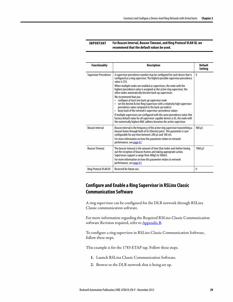
Construct and Configure a Device-level Ring Network with ArmorStarts Chapter 2
Configure and Enable a Ring Supervisor in RSLinx Classic Communication Software
A ring supervisor can be configured for the DLR network through RSLinx Classic communication software
For more information regarding the Required RSLinx Classic Communication software Revision required refer to Appendix B
To configure a ring supervisor in RSLinx Classic Communication Software follow these steps
This example is for the 1783-ETAP tap Follow these steps
1 Launch RSLinx Classic Communication Software
2 Browse to the DLR network that is being set up
IMPORTANT For Beacon Interval Beacon Timeout and Ring Protocol VLAN ID we recommend that the default values be used
Functionality Description Default Setting
Supervisor Precedence A supervisor precedence number may be configured for each device that is configured as a ring supervisor The highest possible supervisor precedence value is 255When multiple nodes are enabled as supervisors the node with the highest precedence value is assigned as the active ring supervisor the other nodes automatically become back-up supervisorsWe recommend that youbull configure at least one back-up supervisor nodebull set the desired Active Ring Supervisor with a relatively high supervisor-
precedence value compared to the back-up node(s)bull keep track of the networkrsquos supervisor-precedence valuesIf multiple supervisors are configured with the same precedence value (the factory default value for all supervisor-capable devices is 0) the node with the numerically highest MAC address becomes the active supervisor
0
Beacon Interval Beacon interval is the frequency of the active ring supervisor transmitting a beacon frame through both of its Ethernet ports This parameter is user configurable for any time between 200 μS and 100 mSFor more information on how this parameter relates to network performance see page 61
400 μS
Beacon Timeout The beacon timeout is the amount of time that nodes wait before timing out the reception of beacon frames and taking appropriate action Supervisors support a range from 400μS to 500mSFor more information on how this parameter relates to network performance see page 61
1960 μS
Ring Protocol VLAN ID Reserved for future use 0
Rockwell Automation Publication 290E-AT001A-EN-P - November 2012 29
Chapter 2 Construct and Configure a Device-level Ring Network with ArmorStarts
If the Electronic Data Sheet (EDS) file is not installed on the module configured to be the ring supervisor it will appear with a question mark () To obtain and use the EDS file
bull right-click the module and choose to upload the EDS file from the device or
bull download the EDS file from httpwwwrockwellautomationcomrockwellautomationsupportnetworksedspage
3 Access the supervisor-capable nodersquos propertiesa Right-click the nodeb Choose Module Configuration
The General tab appears with information about the module
4 Click the Network tab to Enable Supervisor Mode
Configuration takes effect immediately there is no need to click Apply or OK
30 Rockwell Automation Publication 290E-AT001A-EN-P - November 2012
Construct and Configure a Device-level Ring Network with ArmorStarts Chapter 2
5 Click the Advanced button to configure supervisor-related parameters
Rockwell Automation Publication 290E-AT001A-EN-P - November 2012 31
Chapter 2 Construct and Configure a Device-level Ring Network with ArmorStarts
IMPORTANT For Beacon Interval Beacon Timeout and Ring Protocol VLAN ID use the default values
Functionality Description Default Setting
Supervisor Precedence
You may configure a supervisor precedence number for each device configured as a ring supervisor The highest possible supervisor precedence value is 255When multiple nodes are enabled as supervisor the node with the highest precedence value is assigned as the active ring supervisor the other nodes automatically become back-up supervisorsWe recommend that youbull configure at least one back-up supervisor nodebull set the desired Active Ring Supervisor with a relatively high supervisor-
precedence value compared to the back-up node(s)bull keep track of the networkrsquos supervisor-precedence valuesIf multiple supervisors are configured with the same precedence value (the factory default value for all supervisor-capable devices is 0) the node with the numerically highest MAC address becomes the active supervisor
0
Beacon Interval Beacon Interval is the frequency to which the active ring supervisor transmits a beacon frame through both of its Ethernet ports This parameter is user configurable for any time between 200 μS and 100 mSFor more information on how this parameter relates to network performance see page 58
400 μS
Beacon Timeout The beacon timeout is amount of time nodes wait before timing out the reception of beacon frames and taking appropriate action Supervisors support a range from 400 μS to 500 mSFor more information on how this parameter relates to network performance seepage 58
1960 μS
Ring Protocol VLAN ID
Reserved for future use 0
Enable IGMP Snooping
For more information on IGMP Snooping see page 35 Enabled
Enable IGMP Querier
For more information on IGMP Querier see page 35 Disabled
Enable Device Port Debugging Mode
For more information on Device Port Debugging Mode see page 59 Disabled
32 Rockwell Automation Publication 290E-AT001A-EN-P - November 2012
Construct and Configure a Device-level Ring Network with ArmorStarts Chapter 2
Complete the Physical Connections of the Network
After the ring supervisor nodes are configured and enabled the physical connection of the network must be completed to establish a complete DLR network
The figure below shows an example DLR network with all physical connections complete
Figure 4 - Example Device-level Ring Topology with All Connections Complete
Rockwell Automation Publication 290E-AT001A-EN-P - November 2012 33
Chapter 2 Construct and Configure a Device-level Ring Network with ArmorStarts
Verify Supervisor Configuration
The configuration and overall DLR network status can be verified in either RSLogix 5000 programming software or RSLinx Classic communication software
1 Access the supervisor nodersquos properties as shown previously in this chapter
2 Click the Network tab
3 Check the Network Topology and Network Status Fields
For a 1756-EN2TR module or the 1783-ETAP 1783-ETAP1F and 1783-ETAP2F tap the supervisor configuration can also be verified through the modulersquos diagnostic web pages For more information on monitoring diagnostics via an EtherNetIP modulersquos web pages see Monitor a DLR Network starting on page 37
34 Rockwell Automation Publication 290E-AT001A-EN-P - November 2012
Construct and Configure a Device-level Ring Network with ArmorStarts Chapter 2
IGMP Snooping This functionality is enabled by default in the 1783-ETAP 1783-ETAP1F and 1783-ETAP2F taps and is commonly used to manage multicast traffic on the network When in use this functionality allows the tap to multicast data to only those devices that need the data rather than to all devices connected to the network
For snooping to work there must be a device present that is running a querier Typically the device is a router or a switch such as the Stratix 6000 Stratix 8000 or Stratix 8300 managed switch
Once DHCP is enabled the switch could change the IP addresses on the ArmorStarts depending on network demand which could cause RSlogix5000 to loose communication with the device as connectivity is established via the AOP in the initial configuration
IGMP Querier This functionality is disabled by default The IGMP Querier functionality enables a 1783-ETAP 1783-ETAP1F or 1783-ETAP2F tap or switch such as a Stratix managed switch to send out a query to all devices on the network It determines what multicast addresses are of interest to a specific node or a group of nodes
The IGMP Querier functionality should be enabled for at least one node on the network The 1783-ETAP 1783-ETAP1F or 1783-ETAP2F tap managed switches and routers are examples of devices that support IGMP Querier functionality
IMPORTANT If DHCP for the Armostart is still required the Internet Group Management Protocol (IGMP) snooping on the E-tap must be disabled via the AOP
IMPORTANT If the IGMP Querier functionality is not enabled for at least one node on the network multicast traffic on the network may eventually create network performance issues
Rockwell Automation Publication 290E-AT001A-EN-P - November 2012 35
Chapter 2 Construct and Configure a Device-level Ring Network with ArmorStarts
However for all devices that are configured on the network with the IGMP Querier parameter enabled an IP address other than the factory default value must also be set for those devices If multiple devices on the network enable this functionality only the node with the lowest IP address becomes the active IGMP Querier node
IGMP Version
If the IGMP Querier is enabled a Querier Version must be selected The default version is Version 2
36 Rockwell Automation Publication 290E-AT001A-EN-P - November 2012
Chapter 3
Monitor a DLR Network
Introduction Use this chapter to learn how to monitor the DLR network
Methods to Monitor a DLR Network
Network diagnostic information can be retrieved from the ring supervisor-capable devices using the following
bull RSLogix 5000 programming software status pages
bull RSLinx communication software status pages
bull Device web pages
bull EtherNetIP Device Level Ring (DLR) network diagnostics faceplate
bull Programmatically through the use of a MSG instruction
RSLogix 5000 Programming Software Status Pages
RSLogix 5000 programming software version 1701 or later must be used and the appropriate AOPs installed to use the softwarersquos profile status pages
RSLinx Communication Software Status Pages
To monitor the network with this method the RSLinx communication software version 255 or later must be used
Topic Page
Methods to Monitor a DLR Network 37
Monitor Status Pages 39
Monitor ArmorStart Internal Web Server 44
Monitor via Faceplate Integration 45
Monitor Diagnostics via MSG Instructions 46
Rockwell Automation Publication 290E-AT001A-EN-P - November 2012 37
Chapter 3 Monitor a DLR Network
ArmorStart Internal Web Server
Rockwell Automation provides an internal embedded web server with each ArmorStart EtherNetIP The internal web server allows you to view information and configure the ArmorStart via a web browser The ArmorStart EtherNetIP can also be set up from the web server to send e-mail notifications The embedded web server is used to access configuration and status data It provides the user with the ability to view and modify the device configuration without having access to RSLogix 5000 Security in the form of an administrative password can be set The default login is Administrator There is no password set by default
EtherNetIP Device Level Ring (DLR) Network Diagnostics Faceplate
The diagnostics faceplate contains two major components
bull Logic code (encapsulated in an Add-On Instruction) that allows the controller to retrieve real-time DLR network status information
bull HMI faceplate graphics to allow the data to be visualized on an operator interface
Programmatically Through the Use of a MSG Instruction
For more information on how to monitor the DLR network via MSG Instructions see page 46
38 Rockwell Automation Publication 290E-AT001A-EN-P - November 2012
Monitor a DLR Network Chapter 3
Monitor Status Pages Both RSLogix 5000 programming software and RSLinx Classic communication software offer status pages that can be used to monitor the networkrsquos performance
RSLogix 5000 Programming Software Status Pages
Monitor the networkrsquos diagnostic information through the RSLogix 5000 programming software when the software is online
To monitor the network in RSLogix 5000 programming software follow these steps
1 Verify that the project is online
2 Access the active supervisor nodersquos propertiesa Right-click the modulersquos entry in the Controller Organizerb Click properties
Rockwell Automation Publication 290E-AT001A-EN-P - November 2012 39
Chapter 3 Monitor a DLR Network
3 Use the Network tab to monitor diagnostics
40 Rockwell Automation Publication 290E-AT001A-EN-P - November 2012
Monitor a DLR Network Chapter 3
RSLinx Communication Software
To monitor the network in RSLinx communication software follow these steps
1 Click RSWho to browse the network
2 Access the property pages for the active supervisor nodea Open the driver that shows the nodes on the DLR networkb Right-click the node that you want to monitor performancec Click on the choice that you need to access
Multiple choices appear
These options are shown in the following sections
Rockwell Automation Publication 290E-AT001A-EN-P - November 2012 41
Chapter 3 Monitor a DLR Network
Module Configuration
This series of tabs providesbull General informationbull Connection informationbull Module informationbull Internet protocolbull Port configurationbull Network information
The example below shows a ring fault between nodes at IP addresses 10888021 and MAC ID 00-00-BC-02-48-D5
42 Rockwell Automation Publication 290E-AT001A-EN-P - November 2012
Monitor a DLR Network Chapter 3
There are multiple fields used to monitor network diagnostics
Field Definition
Network Topology Possible values here can be Linear or Ring
Network Status Displays if the network is operating normally (Normal) or has experienced a fault (Ring Fault) as shown in the previous example screen
Active Ring Supervisor Displays the IP address or MAC address of the active ring supervisor
Active Supervisor Precedence For more information on this field see Active Ring Supervisor on page 11
Enable Ring Supervisor Configurable field that lets you to set the node as a ring supervisor
Ring Faults Detected Number of faults detected on the network since the last module power cycle or counter reset
Supervisor Status Displays whether this node is the active ring supervisor (Active) a back-up supervisor (Back-up) a ring node or part of a linear network
Last Active Node on Port 1 The last node the active ring supervisor can communicate with on Port 1 This value is an IP address or a MAC ID and remains latched until the Verify Fault Location button is clicked
Last Active Node on Port 2 The last node the active ring supervisor can communicate with on Port 2 This value is an IP address or a MAC ID and remains latched until the Verify Fault Location button is clicked
Status Displays whether a fault exists on the ring
IMPORTANT If the Network Topology field = Ring and the Network Status field = Normal the Last Active Node fields will display the last fault information even though it has been correctedTo clear the last fault information from these fields click Verify Fault Location You may see a message informing you that the supervisor is no longer in fault mode and the fields will be cleared
Rockwell Automation Publication 290E-AT001A-EN-P - November 2012 43
Chapter 3 Monitor a DLR Network
How to Access the ArmorStart EtherNetIP Internal Web Server
Open your preferred internet web browser and enter the IP address of the desired ArmorStart For this example 192168122 will be used
Use the links on the left-most navigation bar to see each available web page The screen below shows Ring Statistics for the ArmorStart 280E
44 Rockwell Automation Publication 290E-AT001A-EN-P - November 2012
Monitor a DLR Network Chapter 3
EtherNetIP Device Level Ring (DLR) Network Diagnostics Faceplate Overview
The EtherNetIP Device Level Ring (DLR) network diagnostics faceplate provides basic DLR network status information to the user to assist with monitoring and troubleshooting a DLR network
The diagnostics faceplate contains two major components
bull Logic code (encapsulated in an Add-On Instruction) that allows the controller to retrieve real-time DLR network status information
bull HMI faceplate graphics to allow the data to be visualized on an operator interface
The DLR diagnostics faceplate application can be downloaded from the Rockwell Automation Sample Code website at httpsamplecoderockwellautomationcom
Besides the individual Logix and View project components a demo application is also included with the downloaded file
Rockwell Automation Publication 290E-AT001A-EN-P - November 2012 45
Chapter 3 Monitor a DLR Network
Monitor Diagnostics via MSG Instructions
Network diagnostic information can also be obtained programmatically via MSG instructions in RSLogix 5000 programming software For example you can
bull Get all ring diagnostic informationbull Get a ring participant listbull Get the active supervisorbull Clear rapid ring faultsbull Verify a fault locationbull Reset a fault counterbull Enable and configure a ring supervisor
This information can be displayed on an HMI device or manipulated in the project code
Figure 5 - Example Use of MSG Instruction
This example describes how to retrieve diagnostic information from the DLR network Follow these steps
1 Enter a MSG instruction into the rung of logic
2 Configure the MSG instruction to retrieve ring diagnostic information service as shown in the following screen shots
IMPORTANT Make sure the tag created is sized appropriately to hold all of the data that you are reading or writing For more information see page 48
46 Rockwell Automation Publication 290E-AT001A-EN-P - November 2012
Monitor a DLR Network Chapter 3
3 Configure the MSG instructionrsquos communication path to point to the active supervisor node
The path on the following screen is one example path
IMPORTANT When using the Custom Get_Attributes_All (01) service pointing to an active supervisor node will retrieve all of the attributes listed in Retrieve All Diagnostic Information Attribute Description on page 50Pointing to a non-supervisor node will retrieve only the Network Topology and Network Status attribute informationPointing to backup supervisor node will retrieve the current active supervisorrsquos IP address
Rockwell Automation Publication 290E-AT001A-EN-P - November 2012 47
Chapter 3 Monitor a DLR Network
Use Specific Values on the Configuration Tab
Use the values on the Configuration tab of your MSG instruction to perform specific services Sample DLR network diagnostic application code for example Add-on Instruction or HMI faceplate graphics is available on the Rockwell Automation Sample Code Library For more information about the Rockwell Automation Sample Code Library see httpwwwrockwellautomationcomsolutionsintegratedarchitectureresources5html
➊ This request only works if there are fewer than 40 nodes on the network If there are more nodes than will fit in a single message an error will be returned➋ Use a Destination Length of 54 bytes if using firmware revision 3x or later for the 1756-EN2TR module or firmware revision 2x or later for the 1783-ETAP
1783-ETAP1F or 1783-ETAP2F taps
Request Description Message Type
Service Type
Service Code (HEX)
Class (HEX)
Instance Attribute (HEX)
Source Element
Source Length (Bytes)
Destination Destination Length (bytes)
Retrieve All Ring Diagnostic Information
Information for this request is listed in Retrieve All Ring Diagnostic Information on page 49
CIP Generic Custom 1 47 1 NA LeftBlank
0 Tag 50or54 ➋
Request Ring Participant List ➊
Information for this request is listed in Request the Ring Participant List on page 51
CIP Generic Get Attribute Single
e 47 1 9 NA NA Tag 10node
Get Active Supervisor
Obtain the IP address and MAC ID of the active supervisor on the DLR network
CIP Generic Get Attribute Single
e 47 1 a NA NA Tag 10
Acknowledge Rapid Ring Faults Condition
Request supervisor to resume normal operation after encountering a rapid ring fault condition
CIP Generic Custom 4c 47 1 NA NA NA NA
Verify a Fault Location
Request supervisor to update Last Active Node values
CIP Generic 4b 47 1 NA NA NA NA NA
Reset the Ring Fault Counter
Reset the number of ring faults detected on the DLR network
CIP Generic Set Attribute Single
10 47 1 5 Tag 2 NA NA
Enable and Configure a Ring Supervisor
Information for this request is listed in Enable and Configure a Ring Supervisor on page 52
CIP Generic Set Attribute Single
10 47 1 4 Tag 12 NA NA
48 Rockwell Automation Publication 290E-AT001A-EN-P - November 2012
Monitor a DLR Network Chapter 3
Retrieve All Ring Diagnostic Information
By performing the Retrieve All Ring Diagnostic Information request on an active supervisor the MSG instruction returns the following information
➊ RSLogix 5000 programming software may display the value in this field as negative numbers To better understand the value we recommend you view it in HEX format
Destination Tag Attribute Name Description Possible Values
SINT [0] Network Topology Current network topology mode 0 = Linear
1 = Ring
SINT [1] Network Status Current status of the network 0 = Normal
1 = Ring Fault
2 = Unexpected Loop Detected
3 = Partial Network Fault
4 = Rapid FaultRestore Cycle
SINT [2] Ring Supervisor Status Ring supervisor active status flag 0 = Node is functioning as a backup
1 = Node is functioning as the active ring supervisor
2 = Node is functioning as a normal ring node
3 = Node is operating in a non-DLR topology
4 = Node cannot support the currently operating ring parameters thatis Beacon Interval andor Beacon Timeout
Ring Supervisor Config Ring Supervisor configuration parameters
SINT [3] Ring Supervisor Enable Ring supervisor enable flag 0 = Node is configured as a normal ring node (default configuration)
1 = Node is configured as a ring supervisor
SINT [4] Ring Supervisor Precedence Precedence value of a ring supervisor ➊ Valid value range = 0hellip255
0 = Default value
SINT [5-8] Beacon Interval Duration of ring beacon interval Valid value range = 200 μshellip100 ms
Default = 400 μs
SINT [9-12] Beacon Timeout Duration of ring beacon timeout Value value range = 400 μshellip500 ms
Default value = 1960 μs
SINT [13-14] DLR VLAN ID Valid ID to use in ring protocol messages Valid value range = 0hellip4094
Default value = 0
SINT [15-16] Ring Faults Count Number of ring faults since power up ➊
Rockwell Automation Publication 290E-AT001A-EN-P - November 2012 49
Chapter 3 Monitor a DLR Network
Retrieve All Diagnostic Information Attribute Description
➊ This destination tag is available only with the 1756-EN2TR module firmware revision 3x or later 1783-ETAP 1783-ETAP1F and 1783-ETAP2F taps firmware revisions 2x or later If using the 1783-ETAP tap firmware revision 1x your program does not include this destination tag
➋ RSLogix 5000 programming software may display the value in this field as negative numbers To better understand the value we recommend you view it in HEX format
Destination Tag Attribute Name Description Possible Values
Last Active Node on Port 1 Last active node at the end of the chain through port 1 of the active ring supervisor during a ring fault
SINT [17-20] Device IP address ➋ Any valid IP address value
A value = 0 indicates no IP address has been configured for the device
SINT [21-26] Device MAC address ➋ Any valid Ethernet MAC address
Last Active Node on Port 2 Last active node at the end of the chain through port 2 of the active ring supervisor during a ring fault
SINT [27-30] Device IP address ➋ Any valid IP address value
A value = 0 indicates no IP address has been configured for the device
SINT [31-36] Device MAC address ➋ Any valid Ethernet MAC address
SINT [37-38] Ring Protocol Participants Count
Number of devices in the ring protocol participants list
Active Supervisor Address IP andor Ethernet MAC address of the active ring supervisor
SINT [39-42] Supervisor IP address Any valid IP address value
A value = 0 indicates no IP address has been configured for the device
SINT [43-48] Supervisor MAC address Any valid Ethernet MAC address
SINT [49] Active Supervisor Precedence
Precedence value of the active ring supervisor
SINT [50-53]➊ Capability Flags Alerts you that the device is capable of operating as a supervisor and beacon-based ring node
0x22
50 Rockwell Automation Publication 290E-AT001A-EN-P - November 2012
Monitor a DLR Network Chapter 3
Request the Ring Participant List
When requesting the Ring Participant List service on the DLR network the MSG instruction returns the following information
Request the Ring Participant List Attribute Description
➊ This attribute will return an array of the data shown one entry for each node The Ring Protocol Participants Count attribute determines the number entries
➋ This tag displays only IP addresses for ring participants that have been configured with one For example you may have a 1783-ETAP tap connected to the network that has not been assigned an IP address In that case no address is shown for the 1783-ETAP tap
➌ RSLogix 5000 programming software may display the value in this field as negative numbers To better understand the value we recommend you view it in HEX format
➍ Unlike destination tag SINT [0-3] where IP addresses are displayed only for ring participants configured with an IP address this tag displays MAC addresses for all ring participants because every ring participant has a MAC address
Destination Tag Attribute Name Description Possible Values
Ring Protocol Participants List ➊
List of devices participating in ring protocol
SINT [0-3] Device IP address ➋➌ Any valid IP address value
A value = 0 indicates no IP address has been configured for the device
SINT [4-9] Device MAC address ➌➍ Any valid Ethernet MAC address
Rockwell Automation Publication 290E-AT001A-EN-P - November 2012 51
Chapter 3 Monitor a DLR Network
Enable and Configure a Ring Supervisor
When performing the Enable and Configure a Ring Supervisor request on a supervisor-capable device configure the MSG instruction with the following information
Enable and Configure a Ring Supervisor Attribute Description
➊ RSLogix 5000 programming software may display the value in this field as negative numbers To better understand the value we recommend you view it in HEX format
Source Tag Attribute Name Description Possible Values
Ring Supervisor Config Ring Supervisor configuration parameters
SINT [0] Ring Supervisor Enable Ring supervisor enable flag 0 = Node is configured as a normal ring node (default configuration)1 = Node is configured as a ring supervisor
SINT [1] Ring Supervisor Precedence Precedence value of a ring supervisor ➊
Valid value range = 0hellip2550 = Default value
SINT [2-5] Beacon Interval Duration of ring beacon interval
Valid value range = 200 μshellip100 000 μsDefault = 400 μs
SINT [6-9] Beacon Timeout Duration of ring beacon timeout ➊
Value value range = 400 μshellip500 000 μsDefault value = 1960 μs
SINT [10-11] DLR VLAN ID Valid ID to use in ring protocol messages ➊
Valid value range = 0hellip4094Default value = 0
52 Rockwell Automation Publication 290E-AT001A-EN-P - November 2012
Chapter 4
Troubleshoot a DLR Network
Introduction Use this chapter to learn how to troubleshoot the DLR network
General Solutions for Linear or DLR Networks
Before attempting to correct specific faults on the linear or DLR network we recommend that you first take the following actions when a fault appears
bull For a DLR networkndash Verify that at least one node has been configured as a supervisor
on the network and that Network Topology = Ringndash Verify that all cables on the network are securely connected
to each devicendash Verify that all devices that require an IP address have one assigned
correctlyndash Check the Network Status field on the active supervisor nodersquos status
page to determine the fault typebull For a linear network
ndash Verify that none of the nodes are configured as a supervisor on the network and that Network Topology = LinearIf any nodes on a linear network are configured as a supervisor it may impact communication to other devices connected to the network
ndash Verify that all cables on the network are securely connected to each device
ndash Verify that all devices that require an IP address have one assigned correctly
If the fault is not cleared after completing the actions listed above use the tables in the rest of this chapter to troubleshoot issues specific to a DLR network or a linear network
Topic Page
General Solutions for the Linear or DLR Networks 53
Duplicate IP Address Detection 54
Specific Issues on the DLR Network 55
Network Recovery Performance 58
Device Port Debugging Mode 59
Rockwell Automation Publication 290E-AT001A-EN-P - November 2012 53
Chapter 4 Troubleshoot a DLR Network
Duplicate IP Address Detection
Some EtherNetIP communication modules support duplicate IP address detection The module verifies that its IP address does not match any other network devicersquos IP address when performing either of these tasks
bull Connect the module to an EtherNetIP network
bull Change the modulersquos IP address
If the modulersquos IP address matches that of another device on the network the modulersquos EtherNetIP port transitions to Conflict mode In Conflict mode these conditions exist
bull OK status indicator is blinking red
bull Network (NET) status indicator is solid red
bull On some EtherNetIP communication modules the module status display indicates the conflict
The display scrollsOK ltIP_address_of_this_modulegt Duplicate IP
ltMac_address_of_duplicate_node_detectedgt
For example OK 108860196 Duplicate IP - 0000BC0234B4
bull On some EtherNetIP communication modules the modulersquos diagnostic webpage displays information about duplicate IP address detection
For more information on which EtherNetIP communication modules support displaying duplicate IP address on their diagnostic webpage see the Technical Note titled Logix modules Duplicate IP address detection enhancement 118216 in the Technical Support Knowledgebase available at httpwwwrockwellautomationcomknowledgebase
54 Rockwell Automation Publication 290E-AT001A-EN-P - November 2012
Troubleshoot a DLR Network Chapter 4
Specific Issues on the DLR Network
Use the following table to troubleshoot possible specific issues on the DLR or linear network that are not solved by the actions described on the previous page
Issue Description Solution
Supervisor Reports a Ring Fault A link on the DLR network may be brokenbull intentionally for example because of adding or deleting nodes but not making all
physical connections to restore the setup of the network withwithout the nodebull unintentionally for example because a cable is broken or a device malfunctionsWhen this fault occurs the adjacent nodes to the faulted part of the network are displayed in the Ring Fault group and the Network Status field = Ring FaultThe screen shot below shows the Ring Fault section with IP addresses appearing for the last active nodes The faulted node is between nodes 108880115 and 108880208 If the IP address of either node is not available the software will display the nodersquos MAC ID
Once the fault is corrected the ring is automatically restored and the Network Status field returns to Normal
Determine where the fault condition exists and correct itClick the Refresh Communication link as needed to update the Ring Fault information to determine where the fault condition existsFinally DevicePort Debugging Mode functionality on the 1783-ETAP tap may be used to analyze a suspicious nodeFor more information refer to Device Port Debugging Mode on page 59
Rockwell Automation Publication 290E-AT001A-EN-P - November 2012 55
Chapter 4 Troubleshoot a DLR Network
Issue Description Solution
Rapid Ring Fault When a Rapid Ring Fault occurs the following events occurbull The active supervisor will block traffic on port 2 resulting in possible network
segmentation that is some nodes may become unreachablebull The Link 2 status indicator on the active supervisor is offbull As soon as the fault occurs for both RSLogix 5000 programming software and
RSLinx communication software the Status field = Rapid FaultRestore Cycles
Any of the following may cause a Rapid Ring Faultbull 5 intentional disconnectionsreconnections of a node from the network within 30
secondsbull A duplex mismatch between two connected devicesbull Electromagnetic noise on the networkbull Unstable physical connections such as intermittent connectorsGiven the nature of a Rapid Ring Fault the Last Active Node information may not be accurate when a Rapid Ring Fault condition is present
Multiple possible solutions existbull For the disconnections and reconnections issue no
solution is requiredClear the fault after reconnecting the device to the network permanentlybull For the duplex mismatch issue reconfigure the duplex
parameters to make sure they match between the devices
bull For the electromagnetic noise issue determine where the noise exists and eliminate it or use a protective shield in that location
bull For the unstable connections issue determine where they exist on the network and correct them
bull Check the media counters for all devices on the network The device with the highest media counter count is most likely causing the Rapid Ring Fault
bull Remove devices from the network one by one If the Rapid Ring Fault disappears after a device is removed that device is causing the fault
bull DevicePort Debugging Mode functionality on the 1783-ETAP tap may be used to analyze a suspicious node
For more information refer to Device Port Debugging Mode on page 59bull Finally the Beacon Interval or Timeout configuration
may not be appropriate for the networkHowever if these values need to be changed we recommend that you contact Rockwell Automation technical supportOnce the fault is fixed click Clear Fault
56 Rockwell Automation Publication 290E-AT001A-EN-P - November 2012
Troubleshoot a DLR Network Chapter 4
Issue Description Solution
Partial Fault Condition A partial network fault occurs when traffic is lost in only one direction on the network because a ring member is not forwarding beacons in both directions for example a component failureThe active ring supervisor detects a partial fault by monitoring the loss of Beacon frames on one port and the fault location appears in the Ring Fault section of the Network tab When a partial fault is detected the active ring supervisor blocks traffic on one port At this point the ring is segmented due to the partial fault condition The nodes adjacent to the faulted part of the network are displayed in the Ring Fault group with either IP addresses or MAC IDs for each node displayedWhen this fault occurs the Network Status field = Partial Fault ConditionOnce the fault is corrected it automatically clears and the Network Status field returns to Normal
Determine where the fault condition exists and correct itAdditionally the DevicePort Debugging Mode functionality also known as Port Mirroring on a 1783-ETAP 1783-ETAP1F or 1783-ETAP2F tap may be used to analyze a suspicious nodeFor more information refer to Device Port Debugging Mode on page 59
Media Counter Errors or Collisions
The media counters screen displays the number of physical layer errors or collisions The screen below indicates where to check for errors encountered Error levels are displayed depending on what caused the error For example an Alignment Error is displayed in the Alignment Error field
On a DLR network it is not uncommon to see low levels of media counter errors For example if the network breaks a low level of media counter errors appears With a low level of media counter errors the value typically does not continuously increase and often clearsA high level of media counter errors typically continues to increase and does not clear For example there is a mismatch of speed between two linked nodes a high level of media counter errors appears steadily increasing and not clearingTo access the RSLinx screen above browse the network right-click on the device select Module Properties and click the Port Diagnostics tab
Some example solutions includebull Check for a mismatch of speed andor duplex between
two linked nodesbull Verify that all cables on the network are securely
connected to each devicebull Check for electromagnetic noise on the network If you
find it eliminate it or use a protective shield in that location
Rockwell Automation Publication 290E-AT001A-EN-P - November 2012 57
Chapter 4 Troubleshoot a DLR Network
Network Recovery Performance
When measuring the networkrsquos performance with regard to dealing with fault conditions consider the network recovery time Network recovery is the time for all of the following to take place
1 The supervisor node recognizes that a fault exists on the network
2 The supervisor node reconfigures the network because of the fault
3 The supervisor node communicates to the network nodes that a fault condition exists
4 The network nodes reconfigure themselves because of the fault
With the default beacon interval value of 400 mS and beacon timeout value of 1960 mS the worst-case time for network recovery times are
bull 2890 mS for a copper DLR network This recovery time is based on 100 m copper segments between nodes on the network
bull 3140 mS for a fiber-optic DLR network This recovery time is based on 2 kM fiber-optic cable segments between nodes on the network
When considering the values listed above keep in mind
bull Recovery time may actually occur faster than the times listed
bull The recovery times listed above assume that your networkrsquos nodes are operating at 100 Mbps speed and full-duplex mode We recommend that your nodes generally operate in this mode for DLR networks
bull If other node conditions exist such as a node operating at 10 Mbps full-duplex or 10100 Mbps half-duplex the recovery times will vary from the times listed above
If this is the case for your application the beacon interval and beacon timeout will need to be changed We recommend that you first contact Rockwell Automation technical support if these parameters need to be changed
bull The value assumes that the majority of the traffic on your network is EtherNetIP traffic
58 Rockwell Automation Publication 290E-AT001A-EN-P - November 2012
Troubleshoot a DLR Network Chapter 4
Device Port Debugging Mode
This functionality is disabled by default Device Port Debugging mode which is similar to port mirroring can be used to monitor data received on the 1783-ETAP 1783-ETAP1F or 1783-ETAP2F taprsquos two network ports Monitor the data over the device port to a device such as a personal computer running a protocol analyzer application for advanced network debugging or analysis
When device port debugging is used on a 1783-ETAP the device connected to the 1783-ETAP taprsquos front port receives all of the data traversing the ring (both directions)
Device Port Debugging Example Network
When using the Device Port Debugging mode functionality insert the 1783-ETAP with the network analyzer connected to the device port It is inserted at the spot on the ring network where the node in question is located The graphic below shows a 1783-ETAP tap inserted in the network
IMPORTANT This functionality should be used only when troubleshooting the network and not in normal network operation
Rockwell Automation Publication 290E-AT001A-EN-P - November 2012 59
Chapter 4 Troubleshoot a DLR Network
Combined total network bandwidth of the traffic received on the two 1783-ETAP 1783-ETAP1F or 1783-ETAP2F taprsquos ports connected to the network should not exceed the taprsquos device port capacity The speed setting determines the device portrsquos capacity
Configure the device port on a 1783-ETAP 1783-ETAP1F or 1783-ETAP2F tap to either of two speed settings
bull 100 Mbps - default settingbull 10 Mbps
If the bandwidth exceeds the capacity of the taprsquos device port some frames from the ring will be dropped before reaching the device port These dropped frames do not impact the traffic on the rest of the DLR network
The device port setting determines how much network traffic the 1783-ETAP 1783-ETAP1F or 1783-ETAP2F tap can handle before dropping frames The circled section in the graphic below shows the Port Buffer Utilization of the Device Port In this example the value is zero because a ring fault exists on the network
60 Rockwell Automation Publication 290E-AT001A-EN-P - November 2012
Appendix A
Network Usage Guidelines and Recommendations
Consider the following guidelines and recommendations when using a DLR or linear network
GuidelineRecommendation Explanation
Use fewer than 50 nodes on a single DLR networkIf your application requires more than 50 nodes we recommend that the nodes are broken into separate but linked DLR networks
If you use more than 50 nodes on a single DLR networkbull Your network has a greater chance of multiple faults
occurring on the networkbull Network recovery times from faulted DLR network
are higher
Do not configure a supervisor on a linear network If your linear network includes non-DLR nodes and has a supervisor-enabled node on the network it may impact communication to non-DLR devices connected to the linear network
If you must connect a device that is running at 10 Mbps to a DLR or linear network do so through a 1783-ETAP 1783-ETAP1F or 1783-ETAP2F tap device port
The 1783-ETAP 1783-ETAP1F and 1783-ETAP2F taps can operate at 100 Mbps on the DLR network this is the optimal speed for a network If you connect a 10 Mbps device directly to the network instead of through a tap the linear or DLR network traffic slows to 10 MbpsAdditionally if the 10 Mbps device is connected to the network without a 1783-ETAP tap network recovery times are significantly impacted
Configure multiple supervisor nodes per ring If your DLR network only has one supervisor and the supervisor experiences a fault none of the other nodes become the active supervisor In this case the network becomes a linear network until the fault is corrected and the DLR network restoredAnother reason to configure multiple supervisor nodes is for replacing an active supervisor node with an out-of-box replacement the new device will not be enabled as a supervisor (by default) and there would still be no supervisor on the network
Rockwell Automation Publication 290E-AT001A-EN-P - November 2012 61
Appendix A Network Usage Guidelines and Recommendations
GuidelineRecommendation Explanation
Connect switches to a DLR network via 1783-ETAP 1783-ETAP1F or 1783-ETAP2F taps
If switches are connected to the DLR network without the use of a 1783-ETAP 1783-ETAP1F or 1783-ETAP2F tap the network may experience unpredictable behavior and network performance is unknown
Run all nodes on the DLR network at 100 Mbps and in Full-Duplex mode
These configuration values provide the best performance for your networkAdditionally we recommend that youbull Use auto-negotiate for all nodes on the DLR networkbull Do not use auto-negotiate on one node and then force
speed on the next node linked to it
In a linear network the number of nodes to use is application specific based on the considerations described in the next box
When determining the number of nodes to use on a linear network consider the followingbull There is a delay per node as information is transmitted
to each successive node used on the networkndash The typical delay on a linear network with 100 m
copper segments between nodes is 30 mSndash The typical delay on a linear network with 2 kM
fiber-optic segments between nodes is 40 mS
The greater the number of nodes on the network the longer the total time for information to be transmitted across the entire networkbull The single point of failure possibility is greater with
each additional connectionbull Troubleshooting the network may be more difficult
with a higher number of nodes
The total time for information to be transmitted across the entire network and its effect on how many nodes to use on a linear network is related to the Requested Packet Interval (RPI)Verify that the total time to transmit information from the first node to the last node on the network is less than the RPI Make sure the network is not loaded beyond 90 of capacity
62 Rockwell Automation Publication 290E-AT001A-EN-P - November 2012
Network Usage Guidelines and Recommendations Appendix A
GuidelineRecommendation Explanation
Do not physically close a DLR network without a supervisor configured on the network
A DLR network without a supervisor node results in a network stormIf you do close the DLR network without a supervisor configured break the ring and configure at least one supervisor before physically reconnecting the network
Use the default values for the followingbull Beacon Intervalbull Beacon Timeoutbull Ring Protocol VLAN ID
Changing the default values for the parameters Beacon Interval Beacon Timeout and Ring Protocol VLAN ID can result in unpredictable network behavior and negatively impacted network performanceThe default values are optimized for a network withbull 50 or fewer nodes are on the networkbull All nodes are operating at 100 Mbps and full-duplex
modebull At least 50 of the network traffic bandwidth being
EtherNetIP trafficIf you think the values of the Beacon Interval Beacon Timeout or Ring Protocol VLAN ID need to be changed for example if any node on ring is not operating at 100 Mbps and full-duplex mode we recommend that you first contact Rockwell Automation technical support
If DHCP for the ArmorStarts is still required you will need to disable Internet Group Management Protocol (IGMP) snooping on the E-tap via the AOP
IGMP Snooping is enabled by default in the 1783-ETAP 1783-ETAP1F and 1783-ETAP2F taps and is commonly used to manage multicast traffic on the network When in use this functionality allows the tap to multicast data to only those devices that need the data rather than to all devices connected to the networkOnce DHCP is enabled the switch could change the IP addresses on the ArmorStarts depending on network demand which could cause RSlogix5000 to loose communication with the device as connectivity is established via the AOP in the initial configuration
The IGMP Querier functionality should be enabled for at least one node on the network
This functionality is disabled by default The IGMP Querier functionality enables a 1783-ETAP 1783-ETAP1F or 1783-ETAP2F tap or switch such as a Stratix managed switch to send out a query to all devices on the network to determine what multicast addresses are of interest to a specific node or a group of nodesIf the IGMP Querier functionality is not enabled for at least one node on the network multicast traffic on the network may eventually create network performance issuesThe 1783-ETAP 1783-ETAP1F or 1783-ETAP2F taps managed switches and routers are examples of devices that support IGMP Querier functionality
Rockwell Automation Publication 290E-AT001A-EN-P - November 2012 63
Appendix A Network Usage Guidelines and Recommendations
Notes
64 Rockwell Automation Publication 290E-AT001A-EN-P - November 2012
Appendix B
Required Firmware Revisions
Required Firmware Revision for an Add-On Profile
➊ The ControlFLASH Firmware Upgrade software tcan be used o upgrade a 1756-EN2TR module from firmware revision 21 to 3x or later1x or later3x or later2x or later
➋ The ControlFLASH Firmware Upgrade software can be used to upgrade a 1783-ETAP tap from firmware revision 11 to 2x or later
To download new firmware go to httpwwwrockwellautomationcomsupportamericasindex_enhtml
If the firmware revision is upgraded on the module or tap the required AOP revision listed above must be used for that revision For example if the 1756-EN2TR module is upgraded to firmware revision 3x or later AOP revision 2x or later must be used in the RSLogix 5000 programming software
Additionally if the firmware revision is upgraded on the module or tap the required RSLinx communication software must also be used for that firmware revision For more information on which RSLinx software version is required for each firmware revision see page 66
For both the 1756-EN2TR module and 1783-ETAP tap make sure that the Major Revision configured on the General tab of the devicersquos RSLogix 5000 programming software configuration matches the major revision of the physical module
IMPORTANT To download an AOP go to httpsupportrockwellautomationcomcontrolflashLogixProfileraspDepending on the firmware revision of your product a specific AOP version must be used
Firmware Revision Add-On Profile Revision Cat No
21 ➊ 1x or later 1756-EN2TR
3x or later 2x or later
11 ➋ 1x or later 1783-ETAP
2x or later 2x or later
2x or later 2x or later 1783-ETAP1F
1783-ETAP2F
Rockwell Automation Publication 290E-AT001A-EN-P - November 2012 65
Appendix B Required Firmware Revisions
If the device configuration on the General tab does not match the physical module the programming software alerts you to this mismatch when attempting to configure the Internet Protocol Port Configuration and Network tabs for that device
Required Firmware Revision for RSLinx Communication Software
➊ The ControlFLASH Firmware Upgrade software can be used to upgrade a 1756-EN2TR module from firmware revision 21 to 3x or later1x or later3x or later255 or later3x or later256 or later
➋ The ControlFLASH Firmware Upgrade software can be used to upgrade a 1783-ETAP tap from firmware revision 11 to 2x or later
To download new firmware go to httpwwwrockwellautomationcomsupportamericasindex_enhtml
If the firmware revision is upgraded on the module or tap the required RSLinx communication software listed above must be used for that revision For example if the 1756-EN2TR module is upgraded to firmware revision 3x or later AOP revision 2x or later must be used in your RSLogix 5000 programming software
Additionally if the firmware revision is upgraded on the module or tap the required AOP revision must also be used for that firmware revision For more information on which AOP revision is required for each firmware revision see page 65
IMPORTANT Depending on the firmware revision of your product specific versions of RSLinx communication software must be used
Firmware Revision Required RSLinx Communication Software Version
Cat No
21 ➊ 255 or later 1756-EN2TR
3x or later 256 or later
11 ➋ 255 or later 1783-ETAP
2x or later 256 or later
2x or later 256 or later 1783-ETAP1F
1783-ETAP2F
66 Rockwell Automation Publication 290E-AT001A-EN-P - November 2012
Rockwell Otomasyon Ticaret AŞ Kar Plaza İş Merkezi E Blok Kat6 34752 İccedilerenkoumly İstanbul Tel +90 (216) 5698400
Rockwell Automation Publication 290E-AT001A-EN-P ndash November 2012 68 Copyright copy 2012 Rockwell Automation Inc All rights reserved Printed in the USA
Rockwell Automation Support
Rockwell Automation provides technical information on the Web to assist you in using its products At httpwwwrockwellautomationcomsupport you can find technical manuals a knowledge base of FAQs technical and application notes sample code and links to software service packs and a MySupport feature that you can customize to make thebest use of these tools
For an additional level of technical phone support for installation configuration and troubleshooting we offer TechConnectSM support programs For more information contact your local distributor or Rockwell Automation representative or visit httpwwwrockwellautomationcomsupport
Installation Assistance
If you experience a problem within the first 24 hours of installation review the information that is contained in this manualYou can contact Customer Support for initial help in getting your product up and running
New Product Satisfaction Return
Rockwell Automation tests all of its products to ensure that they are fully operational when shipped from the manufacturing facility However if your product is not functioning and needs to be returned follow these procedures
Documentation Feedback
Your comments will help us serve your documentation needs better If you have any suggestions on how to improve this document complete this form publication RA-DU002 available at httpwwwrockwellautomationcomliterature
United States or Canada 14406463434
Outside United States or Canada Use the Worldwide Locator at httpwwwrockwellautomationcomsupportamericasphone_enhtml or contact your local Rockwell Automation representative
United States Contact your distributor You must provide a Customer Support case number (call the phone number above to obtain one) to your distributor to complete the return process
Outside United States Please contact your local Rockwell Automation representative for the return procedure
- Important User Information
- General Precautions
- Software Requirements
- Additional Resources
- Rockwell Automation Support
- Installation Assistance
- New Product Satisfaction Return
- Table of Contents
- Chapter 1
-
- Device-Level Ring (DLR) Basics
-
- Introduction
- ArmorStart with EtherNetIP Overview
- What is a Device-level Ring (DLR) Network
- DLR Network Elements
-
- Supervisor Node
- Ring Node
-
- DLR Network Operation
- Number of Nodes on a DLR Network
- DLR Network Fault Management
-
- Network Reconfiguration after a Fault
-
- Chapter 2
-
- Construct and Configure a Device-level Ring Network with ArmorStarts
-
- Introduction
- Ethernet Capacity Tool
- Install Devices on a DLR Network
- ArmorStart Addressing Configuration
-
- Using the BootPDHCP Server
- Using the Rotary Network Address Switches
- Using the ArmorStart Internal Web Server
-
- Configure Supervisor Nodes on a DLR Network
-
- Configure a Ring Supervisor in RSLogix 5000 Programming Software
- Adding an Armorstart to RSLogix 5000
- Enable Ring Supervisor in RSLogix 5000 Programming Software
- Configure and Enable a Ring Supervisor in RSLinx Classic Communication Software
-
- Complete the Physical Connections of the Network
- Verify Supervisor Configuration
- IGMP Snooping
- IGMP Querier
-
- Chapter 3
-
- Monitor a DLR Network
-
- Introduction
- Methods to Monitor a DLR Network
-
- RSLogix 5000 Programming Software Status Pages
- RSLinx Communication Software Status Pages
- ArmorStart Internal Web Server
- EtherNetIP Device Level Ring (DLR) Network Diagnostics Faceplate
- Programmatically Through the Use of a MSG Instruction
-
- Monitor Status Pages
-
- RSLogix 5000 Programming Software Status Pages
- RSLinx Communication Software
-
- How to Access the ArmorStart EtherNetIP Internal Web Server
-
- EtherNetIP Device Level Ring (DLR) Network Diagnostics Faceplate Overview
-
- Monitor Diagnostics via MSG Instructions
-
- Use Specific Values on the Configuration Tab
- Retrieve All Ring Diagnostic Information
- Retrieve All Diagnostic Information Attribute Description
- Request the Ring Participant List
- Request the Ring Participant List Attribute Description
-
- Enable and Configure a Ring Supervisor
-
- Enable and Configure a Ring Supervisor Attribute Description
-
- Chapter 4
-
- Troubleshoot a DLR Network
-
- Introduction
- General Solutions for Linear or DLR Networks
- Duplicate IP Address Detection
- Specific Issues on the DLR Network
- Network Recovery Performance
- Device Port Debugging Mode
-
- Device Port Debugging Example Network
-
- Appendix A
-
- Network Usage Guidelines and Recommendations
-
- Notes
-
- Appendix B
-
- Required Firmware Revisions
-
- Required Firmware Revision for an Add-On Profile
- Required Firmware Revision for RSLinx Communication Software
-

Chapter 2 Construct and Configure a Device-level Ring Network with ArmorStarts
If the Electronic Data Sheet (EDS) file is not installed on the module configured to be the ring supervisor it will appear with a question mark () To obtain and use the EDS file
bull right-click the module and choose to upload the EDS file from the device or
bull download the EDS file from httpwwwrockwellautomationcomrockwellautomationsupportnetworksedspage
3 Access the supervisor-capable nodersquos propertiesa Right-click the nodeb Choose Module Configuration
The General tab appears with information about the module
4 Click the Network tab to Enable Supervisor Mode
Configuration takes effect immediately there is no need to click Apply or OK
30 Rockwell Automation Publication 290E-AT001A-EN-P - November 2012
Construct and Configure a Device-level Ring Network with ArmorStarts Chapter 2
5 Click the Advanced button to configure supervisor-related parameters
Rockwell Automation Publication 290E-AT001A-EN-P - November 2012 31
Chapter 2 Construct and Configure a Device-level Ring Network with ArmorStarts
IMPORTANT For Beacon Interval Beacon Timeout and Ring Protocol VLAN ID use the default values
Functionality Description Default Setting
Supervisor Precedence
You may configure a supervisor precedence number for each device configured as a ring supervisor The highest possible supervisor precedence value is 255When multiple nodes are enabled as supervisor the node with the highest precedence value is assigned as the active ring supervisor the other nodes automatically become back-up supervisorsWe recommend that youbull configure at least one back-up supervisor nodebull set the desired Active Ring Supervisor with a relatively high supervisor-
precedence value compared to the back-up node(s)bull keep track of the networkrsquos supervisor-precedence valuesIf multiple supervisors are configured with the same precedence value (the factory default value for all supervisor-capable devices is 0) the node with the numerically highest MAC address becomes the active supervisor
0
Beacon Interval Beacon Interval is the frequency to which the active ring supervisor transmits a beacon frame through both of its Ethernet ports This parameter is user configurable for any time between 200 μS and 100 mSFor more information on how this parameter relates to network performance see page 58
400 μS
Beacon Timeout The beacon timeout is amount of time nodes wait before timing out the reception of beacon frames and taking appropriate action Supervisors support a range from 400 μS to 500 mSFor more information on how this parameter relates to network performance seepage 58
1960 μS
Ring Protocol VLAN ID
Reserved for future use 0
Enable IGMP Snooping
For more information on IGMP Snooping see page 35 Enabled
Enable IGMP Querier
For more information on IGMP Querier see page 35 Disabled
Enable Device Port Debugging Mode
For more information on Device Port Debugging Mode see page 59 Disabled
32 Rockwell Automation Publication 290E-AT001A-EN-P - November 2012
Construct and Configure a Device-level Ring Network with ArmorStarts Chapter 2
Complete the Physical Connections of the Network
After the ring supervisor nodes are configured and enabled the physical connection of the network must be completed to establish a complete DLR network
The figure below shows an example DLR network with all physical connections complete
Figure 4 - Example Device-level Ring Topology with All Connections Complete
Rockwell Automation Publication 290E-AT001A-EN-P - November 2012 33
Chapter 2 Construct and Configure a Device-level Ring Network with ArmorStarts
Verify Supervisor Configuration
The configuration and overall DLR network status can be verified in either RSLogix 5000 programming software or RSLinx Classic communication software
1 Access the supervisor nodersquos properties as shown previously in this chapter
2 Click the Network tab
3 Check the Network Topology and Network Status Fields
For a 1756-EN2TR module or the 1783-ETAP 1783-ETAP1F and 1783-ETAP2F tap the supervisor configuration can also be verified through the modulersquos diagnostic web pages For more information on monitoring diagnostics via an EtherNetIP modulersquos web pages see Monitor a DLR Network starting on page 37
34 Rockwell Automation Publication 290E-AT001A-EN-P - November 2012
Construct and Configure a Device-level Ring Network with ArmorStarts Chapter 2
IGMP Snooping This functionality is enabled by default in the 1783-ETAP 1783-ETAP1F and 1783-ETAP2F taps and is commonly used to manage multicast traffic on the network When in use this functionality allows the tap to multicast data to only those devices that need the data rather than to all devices connected to the network
For snooping to work there must be a device present that is running a querier Typically the device is a router or a switch such as the Stratix 6000 Stratix 8000 or Stratix 8300 managed switch
Once DHCP is enabled the switch could change the IP addresses on the ArmorStarts depending on network demand which could cause RSlogix5000 to loose communication with the device as connectivity is established via the AOP in the initial configuration
IGMP Querier This functionality is disabled by default The IGMP Querier functionality enables a 1783-ETAP 1783-ETAP1F or 1783-ETAP2F tap or switch such as a Stratix managed switch to send out a query to all devices on the network It determines what multicast addresses are of interest to a specific node or a group of nodes
The IGMP Querier functionality should be enabled for at least one node on the network The 1783-ETAP 1783-ETAP1F or 1783-ETAP2F tap managed switches and routers are examples of devices that support IGMP Querier functionality
IMPORTANT If DHCP for the Armostart is still required the Internet Group Management Protocol (IGMP) snooping on the E-tap must be disabled via the AOP
IMPORTANT If the IGMP Querier functionality is not enabled for at least one node on the network multicast traffic on the network may eventually create network performance issues
Rockwell Automation Publication 290E-AT001A-EN-P - November 2012 35
Chapter 2 Construct and Configure a Device-level Ring Network with ArmorStarts
However for all devices that are configured on the network with the IGMP Querier parameter enabled an IP address other than the factory default value must also be set for those devices If multiple devices on the network enable this functionality only the node with the lowest IP address becomes the active IGMP Querier node
IGMP Version
If the IGMP Querier is enabled a Querier Version must be selected The default version is Version 2
36 Rockwell Automation Publication 290E-AT001A-EN-P - November 2012
Chapter 3
Monitor a DLR Network
Introduction Use this chapter to learn how to monitor the DLR network
Methods to Monitor a DLR Network
Network diagnostic information can be retrieved from the ring supervisor-capable devices using the following
bull RSLogix 5000 programming software status pages
bull RSLinx communication software status pages
bull Device web pages
bull EtherNetIP Device Level Ring (DLR) network diagnostics faceplate
bull Programmatically through the use of a MSG instruction
RSLogix 5000 Programming Software Status Pages
RSLogix 5000 programming software version 1701 or later must be used and the appropriate AOPs installed to use the softwarersquos profile status pages
RSLinx Communication Software Status Pages
To monitor the network with this method the RSLinx communication software version 255 or later must be used
Topic Page
Methods to Monitor a DLR Network 37
Monitor Status Pages 39
Monitor ArmorStart Internal Web Server 44
Monitor via Faceplate Integration 45
Monitor Diagnostics via MSG Instructions 46
Rockwell Automation Publication 290E-AT001A-EN-P - November 2012 37
Chapter 3 Monitor a DLR Network
ArmorStart Internal Web Server
Rockwell Automation provides an internal embedded web server with each ArmorStart EtherNetIP The internal web server allows you to view information and configure the ArmorStart via a web browser The ArmorStart EtherNetIP can also be set up from the web server to send e-mail notifications The embedded web server is used to access configuration and status data It provides the user with the ability to view and modify the device configuration without having access to RSLogix 5000 Security in the form of an administrative password can be set The default login is Administrator There is no password set by default
EtherNetIP Device Level Ring (DLR) Network Diagnostics Faceplate
The diagnostics faceplate contains two major components
bull Logic code (encapsulated in an Add-On Instruction) that allows the controller to retrieve real-time DLR network status information
bull HMI faceplate graphics to allow the data to be visualized on an operator interface
Programmatically Through the Use of a MSG Instruction
For more information on how to monitor the DLR network via MSG Instructions see page 46
38 Rockwell Automation Publication 290E-AT001A-EN-P - November 2012
Monitor a DLR Network Chapter 3
Monitor Status Pages Both RSLogix 5000 programming software and RSLinx Classic communication software offer status pages that can be used to monitor the networkrsquos performance
RSLogix 5000 Programming Software Status Pages
Monitor the networkrsquos diagnostic information through the RSLogix 5000 programming software when the software is online
To monitor the network in RSLogix 5000 programming software follow these steps
1 Verify that the project is online
2 Access the active supervisor nodersquos propertiesa Right-click the modulersquos entry in the Controller Organizerb Click properties
Rockwell Automation Publication 290E-AT001A-EN-P - November 2012 39
Chapter 3 Monitor a DLR Network
3 Use the Network tab to monitor diagnostics
40 Rockwell Automation Publication 290E-AT001A-EN-P - November 2012
Monitor a DLR Network Chapter 3
RSLinx Communication Software
To monitor the network in RSLinx communication software follow these steps
1 Click RSWho to browse the network
2 Access the property pages for the active supervisor nodea Open the driver that shows the nodes on the DLR networkb Right-click the node that you want to monitor performancec Click on the choice that you need to access
Multiple choices appear
These options are shown in the following sections
Rockwell Automation Publication 290E-AT001A-EN-P - November 2012 41
Chapter 3 Monitor a DLR Network
Module Configuration
This series of tabs providesbull General informationbull Connection informationbull Module informationbull Internet protocolbull Port configurationbull Network information
The example below shows a ring fault between nodes at IP addresses 10888021 and MAC ID 00-00-BC-02-48-D5
42 Rockwell Automation Publication 290E-AT001A-EN-P - November 2012
Monitor a DLR Network Chapter 3
There are multiple fields used to monitor network diagnostics
Field Definition
Network Topology Possible values here can be Linear or Ring
Network Status Displays if the network is operating normally (Normal) or has experienced a fault (Ring Fault) as shown in the previous example screen
Active Ring Supervisor Displays the IP address or MAC address of the active ring supervisor
Active Supervisor Precedence For more information on this field see Active Ring Supervisor on page 11
Enable Ring Supervisor Configurable field that lets you to set the node as a ring supervisor
Ring Faults Detected Number of faults detected on the network since the last module power cycle or counter reset
Supervisor Status Displays whether this node is the active ring supervisor (Active) a back-up supervisor (Back-up) a ring node or part of a linear network
Last Active Node on Port 1 The last node the active ring supervisor can communicate with on Port 1 This value is an IP address or a MAC ID and remains latched until the Verify Fault Location button is clicked
Last Active Node on Port 2 The last node the active ring supervisor can communicate with on Port 2 This value is an IP address or a MAC ID and remains latched until the Verify Fault Location button is clicked
Status Displays whether a fault exists on the ring
IMPORTANT If the Network Topology field = Ring and the Network Status field = Normal the Last Active Node fields will display the last fault information even though it has been correctedTo clear the last fault information from these fields click Verify Fault Location You may see a message informing you that the supervisor is no longer in fault mode and the fields will be cleared
Rockwell Automation Publication 290E-AT001A-EN-P - November 2012 43
Chapter 3 Monitor a DLR Network
How to Access the ArmorStart EtherNetIP Internal Web Server
Open your preferred internet web browser and enter the IP address of the desired ArmorStart For this example 192168122 will be used
Use the links on the left-most navigation bar to see each available web page The screen below shows Ring Statistics for the ArmorStart 280E
44 Rockwell Automation Publication 290E-AT001A-EN-P - November 2012
Monitor a DLR Network Chapter 3
EtherNetIP Device Level Ring (DLR) Network Diagnostics Faceplate Overview
The EtherNetIP Device Level Ring (DLR) network diagnostics faceplate provides basic DLR network status information to the user to assist with monitoring and troubleshooting a DLR network
The diagnostics faceplate contains two major components
bull Logic code (encapsulated in an Add-On Instruction) that allows the controller to retrieve real-time DLR network status information
bull HMI faceplate graphics to allow the data to be visualized on an operator interface
The DLR diagnostics faceplate application can be downloaded from the Rockwell Automation Sample Code website at httpsamplecoderockwellautomationcom
Besides the individual Logix and View project components a demo application is also included with the downloaded file
Rockwell Automation Publication 290E-AT001A-EN-P - November 2012 45
Chapter 3 Monitor a DLR Network
Monitor Diagnostics via MSG Instructions
Network diagnostic information can also be obtained programmatically via MSG instructions in RSLogix 5000 programming software For example you can
bull Get all ring diagnostic informationbull Get a ring participant listbull Get the active supervisorbull Clear rapid ring faultsbull Verify a fault locationbull Reset a fault counterbull Enable and configure a ring supervisor
This information can be displayed on an HMI device or manipulated in the project code
Figure 5 - Example Use of MSG Instruction
This example describes how to retrieve diagnostic information from the DLR network Follow these steps
1 Enter a MSG instruction into the rung of logic
2 Configure the MSG instruction to retrieve ring diagnostic information service as shown in the following screen shots
IMPORTANT Make sure the tag created is sized appropriately to hold all of the data that you are reading or writing For more information see page 48
46 Rockwell Automation Publication 290E-AT001A-EN-P - November 2012
Monitor a DLR Network Chapter 3
3 Configure the MSG instructionrsquos communication path to point to the active supervisor node
The path on the following screen is one example path
IMPORTANT When using the Custom Get_Attributes_All (01) service pointing to an active supervisor node will retrieve all of the attributes listed in Retrieve All Diagnostic Information Attribute Description on page 50Pointing to a non-supervisor node will retrieve only the Network Topology and Network Status attribute informationPointing to backup supervisor node will retrieve the current active supervisorrsquos IP address
Rockwell Automation Publication 290E-AT001A-EN-P - November 2012 47
Chapter 3 Monitor a DLR Network
Use Specific Values on the Configuration Tab
Use the values on the Configuration tab of your MSG instruction to perform specific services Sample DLR network diagnostic application code for example Add-on Instruction or HMI faceplate graphics is available on the Rockwell Automation Sample Code Library For more information about the Rockwell Automation Sample Code Library see httpwwwrockwellautomationcomsolutionsintegratedarchitectureresources5html
➊ This request only works if there are fewer than 40 nodes on the network If there are more nodes than will fit in a single message an error will be returned➋ Use a Destination Length of 54 bytes if using firmware revision 3x or later for the 1756-EN2TR module or firmware revision 2x or later for the 1783-ETAP
1783-ETAP1F or 1783-ETAP2F taps
Request Description Message Type
Service Type
Service Code (HEX)
Class (HEX)
Instance Attribute (HEX)
Source Element
Source Length (Bytes)
Destination Destination Length (bytes)
Retrieve All Ring Diagnostic Information
Information for this request is listed in Retrieve All Ring Diagnostic Information on page 49
CIP Generic Custom 1 47 1 NA LeftBlank
0 Tag 50or54 ➋
Request Ring Participant List ➊
Information for this request is listed in Request the Ring Participant List on page 51
CIP Generic Get Attribute Single
e 47 1 9 NA NA Tag 10node
Get Active Supervisor
Obtain the IP address and MAC ID of the active supervisor on the DLR network
CIP Generic Get Attribute Single
e 47 1 a NA NA Tag 10
Acknowledge Rapid Ring Faults Condition
Request supervisor to resume normal operation after encountering a rapid ring fault condition
CIP Generic Custom 4c 47 1 NA NA NA NA
Verify a Fault Location
Request supervisor to update Last Active Node values
CIP Generic 4b 47 1 NA NA NA NA NA
Reset the Ring Fault Counter
Reset the number of ring faults detected on the DLR network
CIP Generic Set Attribute Single
10 47 1 5 Tag 2 NA NA
Enable and Configure a Ring Supervisor
Information for this request is listed in Enable and Configure a Ring Supervisor on page 52
CIP Generic Set Attribute Single
10 47 1 4 Tag 12 NA NA
48 Rockwell Automation Publication 290E-AT001A-EN-P - November 2012
Monitor a DLR Network Chapter 3
Retrieve All Ring Diagnostic Information
By performing the Retrieve All Ring Diagnostic Information request on an active supervisor the MSG instruction returns the following information
➊ RSLogix 5000 programming software may display the value in this field as negative numbers To better understand the value we recommend you view it in HEX format
Destination Tag Attribute Name Description Possible Values
SINT [0] Network Topology Current network topology mode 0 = Linear
1 = Ring
SINT [1] Network Status Current status of the network 0 = Normal
1 = Ring Fault
2 = Unexpected Loop Detected
3 = Partial Network Fault
4 = Rapid FaultRestore Cycle
SINT [2] Ring Supervisor Status Ring supervisor active status flag 0 = Node is functioning as a backup
1 = Node is functioning as the active ring supervisor
2 = Node is functioning as a normal ring node
3 = Node is operating in a non-DLR topology
4 = Node cannot support the currently operating ring parameters thatis Beacon Interval andor Beacon Timeout
Ring Supervisor Config Ring Supervisor configuration parameters
SINT [3] Ring Supervisor Enable Ring supervisor enable flag 0 = Node is configured as a normal ring node (default configuration)
1 = Node is configured as a ring supervisor
SINT [4] Ring Supervisor Precedence Precedence value of a ring supervisor ➊ Valid value range = 0hellip255
0 = Default value
SINT [5-8] Beacon Interval Duration of ring beacon interval Valid value range = 200 μshellip100 ms
Default = 400 μs
SINT [9-12] Beacon Timeout Duration of ring beacon timeout Value value range = 400 μshellip500 ms
Default value = 1960 μs
SINT [13-14] DLR VLAN ID Valid ID to use in ring protocol messages Valid value range = 0hellip4094
Default value = 0
SINT [15-16] Ring Faults Count Number of ring faults since power up ➊
Rockwell Automation Publication 290E-AT001A-EN-P - November 2012 49
Chapter 3 Monitor a DLR Network
Retrieve All Diagnostic Information Attribute Description
➊ This destination tag is available only with the 1756-EN2TR module firmware revision 3x or later 1783-ETAP 1783-ETAP1F and 1783-ETAP2F taps firmware revisions 2x or later If using the 1783-ETAP tap firmware revision 1x your program does not include this destination tag
➋ RSLogix 5000 programming software may display the value in this field as negative numbers To better understand the value we recommend you view it in HEX format
Destination Tag Attribute Name Description Possible Values
Last Active Node on Port 1 Last active node at the end of the chain through port 1 of the active ring supervisor during a ring fault
SINT [17-20] Device IP address ➋ Any valid IP address value
A value = 0 indicates no IP address has been configured for the device
SINT [21-26] Device MAC address ➋ Any valid Ethernet MAC address
Last Active Node on Port 2 Last active node at the end of the chain through port 2 of the active ring supervisor during a ring fault
SINT [27-30] Device IP address ➋ Any valid IP address value
A value = 0 indicates no IP address has been configured for the device
SINT [31-36] Device MAC address ➋ Any valid Ethernet MAC address
SINT [37-38] Ring Protocol Participants Count
Number of devices in the ring protocol participants list
Active Supervisor Address IP andor Ethernet MAC address of the active ring supervisor
SINT [39-42] Supervisor IP address Any valid IP address value
A value = 0 indicates no IP address has been configured for the device
SINT [43-48] Supervisor MAC address Any valid Ethernet MAC address
SINT [49] Active Supervisor Precedence
Precedence value of the active ring supervisor
SINT [50-53]➊ Capability Flags Alerts you that the device is capable of operating as a supervisor and beacon-based ring node
0x22
50 Rockwell Automation Publication 290E-AT001A-EN-P - November 2012
Monitor a DLR Network Chapter 3
Request the Ring Participant List
When requesting the Ring Participant List service on the DLR network the MSG instruction returns the following information
Request the Ring Participant List Attribute Description
➊ This attribute will return an array of the data shown one entry for each node The Ring Protocol Participants Count attribute determines the number entries
➋ This tag displays only IP addresses for ring participants that have been configured with one For example you may have a 1783-ETAP tap connected to the network that has not been assigned an IP address In that case no address is shown for the 1783-ETAP tap
➌ RSLogix 5000 programming software may display the value in this field as negative numbers To better understand the value we recommend you view it in HEX format
➍ Unlike destination tag SINT [0-3] where IP addresses are displayed only for ring participants configured with an IP address this tag displays MAC addresses for all ring participants because every ring participant has a MAC address
Destination Tag Attribute Name Description Possible Values
Ring Protocol Participants List ➊
List of devices participating in ring protocol
SINT [0-3] Device IP address ➋➌ Any valid IP address value
A value = 0 indicates no IP address has been configured for the device
SINT [4-9] Device MAC address ➌➍ Any valid Ethernet MAC address
Rockwell Automation Publication 290E-AT001A-EN-P - November 2012 51
Chapter 3 Monitor a DLR Network
Enable and Configure a Ring Supervisor
When performing the Enable and Configure a Ring Supervisor request on a supervisor-capable device configure the MSG instruction with the following information
Enable and Configure a Ring Supervisor Attribute Description
➊ RSLogix 5000 programming software may display the value in this field as negative numbers To better understand the value we recommend you view it in HEX format
Source Tag Attribute Name Description Possible Values
Ring Supervisor Config Ring Supervisor configuration parameters
SINT [0] Ring Supervisor Enable Ring supervisor enable flag 0 = Node is configured as a normal ring node (default configuration)1 = Node is configured as a ring supervisor
SINT [1] Ring Supervisor Precedence Precedence value of a ring supervisor ➊
Valid value range = 0hellip2550 = Default value
SINT [2-5] Beacon Interval Duration of ring beacon interval
Valid value range = 200 μshellip100 000 μsDefault = 400 μs
SINT [6-9] Beacon Timeout Duration of ring beacon timeout ➊
Value value range = 400 μshellip500 000 μsDefault value = 1960 μs
SINT [10-11] DLR VLAN ID Valid ID to use in ring protocol messages ➊
Valid value range = 0hellip4094Default value = 0
52 Rockwell Automation Publication 290E-AT001A-EN-P - November 2012
Chapter 4
Troubleshoot a DLR Network
Introduction Use this chapter to learn how to troubleshoot the DLR network
General Solutions for Linear or DLR Networks
Before attempting to correct specific faults on the linear or DLR network we recommend that you first take the following actions when a fault appears
bull For a DLR networkndash Verify that at least one node has been configured as a supervisor
on the network and that Network Topology = Ringndash Verify that all cables on the network are securely connected
to each devicendash Verify that all devices that require an IP address have one assigned
correctlyndash Check the Network Status field on the active supervisor nodersquos status
page to determine the fault typebull For a linear network
ndash Verify that none of the nodes are configured as a supervisor on the network and that Network Topology = LinearIf any nodes on a linear network are configured as a supervisor it may impact communication to other devices connected to the network
ndash Verify that all cables on the network are securely connected to each device
ndash Verify that all devices that require an IP address have one assigned correctly
If the fault is not cleared after completing the actions listed above use the tables in the rest of this chapter to troubleshoot issues specific to a DLR network or a linear network
Topic Page
General Solutions for the Linear or DLR Networks 53
Duplicate IP Address Detection 54
Specific Issues on the DLR Network 55
Network Recovery Performance 58
Device Port Debugging Mode 59
Rockwell Automation Publication 290E-AT001A-EN-P - November 2012 53
Chapter 4 Troubleshoot a DLR Network
Duplicate IP Address Detection
Some EtherNetIP communication modules support duplicate IP address detection The module verifies that its IP address does not match any other network devicersquos IP address when performing either of these tasks
bull Connect the module to an EtherNetIP network
bull Change the modulersquos IP address
If the modulersquos IP address matches that of another device on the network the modulersquos EtherNetIP port transitions to Conflict mode In Conflict mode these conditions exist
bull OK status indicator is blinking red
bull Network (NET) status indicator is solid red
bull On some EtherNetIP communication modules the module status display indicates the conflict
The display scrollsOK ltIP_address_of_this_modulegt Duplicate IP
ltMac_address_of_duplicate_node_detectedgt
For example OK 108860196 Duplicate IP - 0000BC0234B4
bull On some EtherNetIP communication modules the modulersquos diagnostic webpage displays information about duplicate IP address detection
For more information on which EtherNetIP communication modules support displaying duplicate IP address on their diagnostic webpage see the Technical Note titled Logix modules Duplicate IP address detection enhancement 118216 in the Technical Support Knowledgebase available at httpwwwrockwellautomationcomknowledgebase
54 Rockwell Automation Publication 290E-AT001A-EN-P - November 2012
Troubleshoot a DLR Network Chapter 4
Specific Issues on the DLR Network
Use the following table to troubleshoot possible specific issues on the DLR or linear network that are not solved by the actions described on the previous page
Issue Description Solution
Supervisor Reports a Ring Fault A link on the DLR network may be brokenbull intentionally for example because of adding or deleting nodes but not making all
physical connections to restore the setup of the network withwithout the nodebull unintentionally for example because a cable is broken or a device malfunctionsWhen this fault occurs the adjacent nodes to the faulted part of the network are displayed in the Ring Fault group and the Network Status field = Ring FaultThe screen shot below shows the Ring Fault section with IP addresses appearing for the last active nodes The faulted node is between nodes 108880115 and 108880208 If the IP address of either node is not available the software will display the nodersquos MAC ID
Once the fault is corrected the ring is automatically restored and the Network Status field returns to Normal
Determine where the fault condition exists and correct itClick the Refresh Communication link as needed to update the Ring Fault information to determine where the fault condition existsFinally DevicePort Debugging Mode functionality on the 1783-ETAP tap may be used to analyze a suspicious nodeFor more information refer to Device Port Debugging Mode on page 59
Rockwell Automation Publication 290E-AT001A-EN-P - November 2012 55
Chapter 4 Troubleshoot a DLR Network
Issue Description Solution
Rapid Ring Fault When a Rapid Ring Fault occurs the following events occurbull The active supervisor will block traffic on port 2 resulting in possible network
segmentation that is some nodes may become unreachablebull The Link 2 status indicator on the active supervisor is offbull As soon as the fault occurs for both RSLogix 5000 programming software and
RSLinx communication software the Status field = Rapid FaultRestore Cycles
Any of the following may cause a Rapid Ring Faultbull 5 intentional disconnectionsreconnections of a node from the network within 30
secondsbull A duplex mismatch between two connected devicesbull Electromagnetic noise on the networkbull Unstable physical connections such as intermittent connectorsGiven the nature of a Rapid Ring Fault the Last Active Node information may not be accurate when a Rapid Ring Fault condition is present
Multiple possible solutions existbull For the disconnections and reconnections issue no
solution is requiredClear the fault after reconnecting the device to the network permanentlybull For the duplex mismatch issue reconfigure the duplex
parameters to make sure they match between the devices
bull For the electromagnetic noise issue determine where the noise exists and eliminate it or use a protective shield in that location
bull For the unstable connections issue determine where they exist on the network and correct them
bull Check the media counters for all devices on the network The device with the highest media counter count is most likely causing the Rapid Ring Fault
bull Remove devices from the network one by one If the Rapid Ring Fault disappears after a device is removed that device is causing the fault
bull DevicePort Debugging Mode functionality on the 1783-ETAP tap may be used to analyze a suspicious node
For more information refer to Device Port Debugging Mode on page 59bull Finally the Beacon Interval or Timeout configuration
may not be appropriate for the networkHowever if these values need to be changed we recommend that you contact Rockwell Automation technical supportOnce the fault is fixed click Clear Fault
56 Rockwell Automation Publication 290E-AT001A-EN-P - November 2012
Troubleshoot a DLR Network Chapter 4
Issue Description Solution
Partial Fault Condition A partial network fault occurs when traffic is lost in only one direction on the network because a ring member is not forwarding beacons in both directions for example a component failureThe active ring supervisor detects a partial fault by monitoring the loss of Beacon frames on one port and the fault location appears in the Ring Fault section of the Network tab When a partial fault is detected the active ring supervisor blocks traffic on one port At this point the ring is segmented due to the partial fault condition The nodes adjacent to the faulted part of the network are displayed in the Ring Fault group with either IP addresses or MAC IDs for each node displayedWhen this fault occurs the Network Status field = Partial Fault ConditionOnce the fault is corrected it automatically clears and the Network Status field returns to Normal
Determine where the fault condition exists and correct itAdditionally the DevicePort Debugging Mode functionality also known as Port Mirroring on a 1783-ETAP 1783-ETAP1F or 1783-ETAP2F tap may be used to analyze a suspicious nodeFor more information refer to Device Port Debugging Mode on page 59
Media Counter Errors or Collisions
The media counters screen displays the number of physical layer errors or collisions The screen below indicates where to check for errors encountered Error levels are displayed depending on what caused the error For example an Alignment Error is displayed in the Alignment Error field
On a DLR network it is not uncommon to see low levels of media counter errors For example if the network breaks a low level of media counter errors appears With a low level of media counter errors the value typically does not continuously increase and often clearsA high level of media counter errors typically continues to increase and does not clear For example there is a mismatch of speed between two linked nodes a high level of media counter errors appears steadily increasing and not clearingTo access the RSLinx screen above browse the network right-click on the device select Module Properties and click the Port Diagnostics tab
Some example solutions includebull Check for a mismatch of speed andor duplex between
two linked nodesbull Verify that all cables on the network are securely
connected to each devicebull Check for electromagnetic noise on the network If you
find it eliminate it or use a protective shield in that location
Rockwell Automation Publication 290E-AT001A-EN-P - November 2012 57
Chapter 4 Troubleshoot a DLR Network
Network Recovery Performance
When measuring the networkrsquos performance with regard to dealing with fault conditions consider the network recovery time Network recovery is the time for all of the following to take place
1 The supervisor node recognizes that a fault exists on the network
2 The supervisor node reconfigures the network because of the fault
3 The supervisor node communicates to the network nodes that a fault condition exists
4 The network nodes reconfigure themselves because of the fault
With the default beacon interval value of 400 mS and beacon timeout value of 1960 mS the worst-case time for network recovery times are
bull 2890 mS for a copper DLR network This recovery time is based on 100 m copper segments between nodes on the network
bull 3140 mS for a fiber-optic DLR network This recovery time is based on 2 kM fiber-optic cable segments between nodes on the network
When considering the values listed above keep in mind
bull Recovery time may actually occur faster than the times listed
bull The recovery times listed above assume that your networkrsquos nodes are operating at 100 Mbps speed and full-duplex mode We recommend that your nodes generally operate in this mode for DLR networks
bull If other node conditions exist such as a node operating at 10 Mbps full-duplex or 10100 Mbps half-duplex the recovery times will vary from the times listed above
If this is the case for your application the beacon interval and beacon timeout will need to be changed We recommend that you first contact Rockwell Automation technical support if these parameters need to be changed
bull The value assumes that the majority of the traffic on your network is EtherNetIP traffic
58 Rockwell Automation Publication 290E-AT001A-EN-P - November 2012
Troubleshoot a DLR Network Chapter 4
Device Port Debugging Mode
This functionality is disabled by default Device Port Debugging mode which is similar to port mirroring can be used to monitor data received on the 1783-ETAP 1783-ETAP1F or 1783-ETAP2F taprsquos two network ports Monitor the data over the device port to a device such as a personal computer running a protocol analyzer application for advanced network debugging or analysis
When device port debugging is used on a 1783-ETAP the device connected to the 1783-ETAP taprsquos front port receives all of the data traversing the ring (both directions)
Device Port Debugging Example Network
When using the Device Port Debugging mode functionality insert the 1783-ETAP with the network analyzer connected to the device port It is inserted at the spot on the ring network where the node in question is located The graphic below shows a 1783-ETAP tap inserted in the network
IMPORTANT This functionality should be used only when troubleshooting the network and not in normal network operation
Rockwell Automation Publication 290E-AT001A-EN-P - November 2012 59
Chapter 4 Troubleshoot a DLR Network
Combined total network bandwidth of the traffic received on the two 1783-ETAP 1783-ETAP1F or 1783-ETAP2F taprsquos ports connected to the network should not exceed the taprsquos device port capacity The speed setting determines the device portrsquos capacity
Configure the device port on a 1783-ETAP 1783-ETAP1F or 1783-ETAP2F tap to either of two speed settings
bull 100 Mbps - default settingbull 10 Mbps
If the bandwidth exceeds the capacity of the taprsquos device port some frames from the ring will be dropped before reaching the device port These dropped frames do not impact the traffic on the rest of the DLR network
The device port setting determines how much network traffic the 1783-ETAP 1783-ETAP1F or 1783-ETAP2F tap can handle before dropping frames The circled section in the graphic below shows the Port Buffer Utilization of the Device Port In this example the value is zero because a ring fault exists on the network
60 Rockwell Automation Publication 290E-AT001A-EN-P - November 2012
Appendix A
Network Usage Guidelines and Recommendations
Consider the following guidelines and recommendations when using a DLR or linear network
GuidelineRecommendation Explanation
Use fewer than 50 nodes on a single DLR networkIf your application requires more than 50 nodes we recommend that the nodes are broken into separate but linked DLR networks
If you use more than 50 nodes on a single DLR networkbull Your network has a greater chance of multiple faults
occurring on the networkbull Network recovery times from faulted DLR network
are higher
Do not configure a supervisor on a linear network If your linear network includes non-DLR nodes and has a supervisor-enabled node on the network it may impact communication to non-DLR devices connected to the linear network
If you must connect a device that is running at 10 Mbps to a DLR or linear network do so through a 1783-ETAP 1783-ETAP1F or 1783-ETAP2F tap device port
The 1783-ETAP 1783-ETAP1F and 1783-ETAP2F taps can operate at 100 Mbps on the DLR network this is the optimal speed for a network If you connect a 10 Mbps device directly to the network instead of through a tap the linear or DLR network traffic slows to 10 MbpsAdditionally if the 10 Mbps device is connected to the network without a 1783-ETAP tap network recovery times are significantly impacted
Configure multiple supervisor nodes per ring If your DLR network only has one supervisor and the supervisor experiences a fault none of the other nodes become the active supervisor In this case the network becomes a linear network until the fault is corrected and the DLR network restoredAnother reason to configure multiple supervisor nodes is for replacing an active supervisor node with an out-of-box replacement the new device will not be enabled as a supervisor (by default) and there would still be no supervisor on the network
Rockwell Automation Publication 290E-AT001A-EN-P - November 2012 61
Appendix A Network Usage Guidelines and Recommendations
GuidelineRecommendation Explanation
Connect switches to a DLR network via 1783-ETAP 1783-ETAP1F or 1783-ETAP2F taps
If switches are connected to the DLR network without the use of a 1783-ETAP 1783-ETAP1F or 1783-ETAP2F tap the network may experience unpredictable behavior and network performance is unknown
Run all nodes on the DLR network at 100 Mbps and in Full-Duplex mode
These configuration values provide the best performance for your networkAdditionally we recommend that youbull Use auto-negotiate for all nodes on the DLR networkbull Do not use auto-negotiate on one node and then force
speed on the next node linked to it
In a linear network the number of nodes to use is application specific based on the considerations described in the next box
When determining the number of nodes to use on a linear network consider the followingbull There is a delay per node as information is transmitted
to each successive node used on the networkndash The typical delay on a linear network with 100 m
copper segments between nodes is 30 mSndash The typical delay on a linear network with 2 kM
fiber-optic segments between nodes is 40 mS
The greater the number of nodes on the network the longer the total time for information to be transmitted across the entire networkbull The single point of failure possibility is greater with
each additional connectionbull Troubleshooting the network may be more difficult
with a higher number of nodes
The total time for information to be transmitted across the entire network and its effect on how many nodes to use on a linear network is related to the Requested Packet Interval (RPI)Verify that the total time to transmit information from the first node to the last node on the network is less than the RPI Make sure the network is not loaded beyond 90 of capacity
62 Rockwell Automation Publication 290E-AT001A-EN-P - November 2012
Network Usage Guidelines and Recommendations Appendix A
GuidelineRecommendation Explanation
Do not physically close a DLR network without a supervisor configured on the network
A DLR network without a supervisor node results in a network stormIf you do close the DLR network without a supervisor configured break the ring and configure at least one supervisor before physically reconnecting the network
Use the default values for the followingbull Beacon Intervalbull Beacon Timeoutbull Ring Protocol VLAN ID
Changing the default values for the parameters Beacon Interval Beacon Timeout and Ring Protocol VLAN ID can result in unpredictable network behavior and negatively impacted network performanceThe default values are optimized for a network withbull 50 or fewer nodes are on the networkbull All nodes are operating at 100 Mbps and full-duplex
modebull At least 50 of the network traffic bandwidth being
EtherNetIP trafficIf you think the values of the Beacon Interval Beacon Timeout or Ring Protocol VLAN ID need to be changed for example if any node on ring is not operating at 100 Mbps and full-duplex mode we recommend that you first contact Rockwell Automation technical support
If DHCP for the ArmorStarts is still required you will need to disable Internet Group Management Protocol (IGMP) snooping on the E-tap via the AOP
IGMP Snooping is enabled by default in the 1783-ETAP 1783-ETAP1F and 1783-ETAP2F taps and is commonly used to manage multicast traffic on the network When in use this functionality allows the tap to multicast data to only those devices that need the data rather than to all devices connected to the networkOnce DHCP is enabled the switch could change the IP addresses on the ArmorStarts depending on network demand which could cause RSlogix5000 to loose communication with the device as connectivity is established via the AOP in the initial configuration
The IGMP Querier functionality should be enabled for at least one node on the network
This functionality is disabled by default The IGMP Querier functionality enables a 1783-ETAP 1783-ETAP1F or 1783-ETAP2F tap or switch such as a Stratix managed switch to send out a query to all devices on the network to determine what multicast addresses are of interest to a specific node or a group of nodesIf the IGMP Querier functionality is not enabled for at least one node on the network multicast traffic on the network may eventually create network performance issuesThe 1783-ETAP 1783-ETAP1F or 1783-ETAP2F taps managed switches and routers are examples of devices that support IGMP Querier functionality
Rockwell Automation Publication 290E-AT001A-EN-P - November 2012 63
Appendix A Network Usage Guidelines and Recommendations
Notes
64 Rockwell Automation Publication 290E-AT001A-EN-P - November 2012
Appendix B
Required Firmware Revisions
Required Firmware Revision for an Add-On Profile
➊ The ControlFLASH Firmware Upgrade software tcan be used o upgrade a 1756-EN2TR module from firmware revision 21 to 3x or later1x or later3x or later2x or later
➋ The ControlFLASH Firmware Upgrade software can be used to upgrade a 1783-ETAP tap from firmware revision 11 to 2x or later
To download new firmware go to httpwwwrockwellautomationcomsupportamericasindex_enhtml
If the firmware revision is upgraded on the module or tap the required AOP revision listed above must be used for that revision For example if the 1756-EN2TR module is upgraded to firmware revision 3x or later AOP revision 2x or later must be used in the RSLogix 5000 programming software
Additionally if the firmware revision is upgraded on the module or tap the required RSLinx communication software must also be used for that firmware revision For more information on which RSLinx software version is required for each firmware revision see page 66
For both the 1756-EN2TR module and 1783-ETAP tap make sure that the Major Revision configured on the General tab of the devicersquos RSLogix 5000 programming software configuration matches the major revision of the physical module
IMPORTANT To download an AOP go to httpsupportrockwellautomationcomcontrolflashLogixProfileraspDepending on the firmware revision of your product a specific AOP version must be used
Firmware Revision Add-On Profile Revision Cat No
21 ➊ 1x or later 1756-EN2TR
3x or later 2x or later
11 ➋ 1x or later 1783-ETAP
2x or later 2x or later
2x or later 2x or later 1783-ETAP1F
1783-ETAP2F
Rockwell Automation Publication 290E-AT001A-EN-P - November 2012 65
Appendix B Required Firmware Revisions
If the device configuration on the General tab does not match the physical module the programming software alerts you to this mismatch when attempting to configure the Internet Protocol Port Configuration and Network tabs for that device
Required Firmware Revision for RSLinx Communication Software
➊ The ControlFLASH Firmware Upgrade software can be used to upgrade a 1756-EN2TR module from firmware revision 21 to 3x or later1x or later3x or later255 or later3x or later256 or later
➋ The ControlFLASH Firmware Upgrade software can be used to upgrade a 1783-ETAP tap from firmware revision 11 to 2x or later
To download new firmware go to httpwwwrockwellautomationcomsupportamericasindex_enhtml
If the firmware revision is upgraded on the module or tap the required RSLinx communication software listed above must be used for that revision For example if the 1756-EN2TR module is upgraded to firmware revision 3x or later AOP revision 2x or later must be used in your RSLogix 5000 programming software
Additionally if the firmware revision is upgraded on the module or tap the required AOP revision must also be used for that firmware revision For more information on which AOP revision is required for each firmware revision see page 65
IMPORTANT Depending on the firmware revision of your product specific versions of RSLinx communication software must be used
Firmware Revision Required RSLinx Communication Software Version
Cat No
21 ➊ 255 or later 1756-EN2TR
3x or later 256 or later
11 ➋ 255 or later 1783-ETAP
2x or later 256 or later
2x or later 256 or later 1783-ETAP1F
1783-ETAP2F
66 Rockwell Automation Publication 290E-AT001A-EN-P - November 2012
Rockwell Otomasyon Ticaret AŞ Kar Plaza İş Merkezi E Blok Kat6 34752 İccedilerenkoumly İstanbul Tel +90 (216) 5698400
Rockwell Automation Publication 290E-AT001A-EN-P ndash November 2012 68 Copyright copy 2012 Rockwell Automation Inc All rights reserved Printed in the USA
Rockwell Automation Support
Rockwell Automation provides technical information on the Web to assist you in using its products At httpwwwrockwellautomationcomsupport you can find technical manuals a knowledge base of FAQs technical and application notes sample code and links to software service packs and a MySupport feature that you can customize to make thebest use of these tools
For an additional level of technical phone support for installation configuration and troubleshooting we offer TechConnectSM support programs For more information contact your local distributor or Rockwell Automation representative or visit httpwwwrockwellautomationcomsupport
Installation Assistance
If you experience a problem within the first 24 hours of installation review the information that is contained in this manualYou can contact Customer Support for initial help in getting your product up and running
New Product Satisfaction Return
Rockwell Automation tests all of its products to ensure that they are fully operational when shipped from the manufacturing facility However if your product is not functioning and needs to be returned follow these procedures
Documentation Feedback
Your comments will help us serve your documentation needs better If you have any suggestions on how to improve this document complete this form publication RA-DU002 available at httpwwwrockwellautomationcomliterature
United States or Canada 14406463434
Outside United States or Canada Use the Worldwide Locator at httpwwwrockwellautomationcomsupportamericasphone_enhtml or contact your local Rockwell Automation representative
United States Contact your distributor You must provide a Customer Support case number (call the phone number above to obtain one) to your distributor to complete the return process
Outside United States Please contact your local Rockwell Automation representative for the return procedure
- Important User Information
- General Precautions
- Software Requirements
- Additional Resources
- Rockwell Automation Support
- Installation Assistance
- New Product Satisfaction Return
- Table of Contents
- Chapter 1
-
- Device-Level Ring (DLR) Basics
-
- Introduction
- ArmorStart with EtherNetIP Overview
- What is a Device-level Ring (DLR) Network
- DLR Network Elements
-
- Supervisor Node
- Ring Node
-
- DLR Network Operation
- Number of Nodes on a DLR Network
- DLR Network Fault Management
-
- Network Reconfiguration after a Fault
-
- Chapter 2
-
- Construct and Configure a Device-level Ring Network with ArmorStarts
-
- Introduction
- Ethernet Capacity Tool
- Install Devices on a DLR Network
- ArmorStart Addressing Configuration
-
- Using the BootPDHCP Server
- Using the Rotary Network Address Switches
- Using the ArmorStart Internal Web Server
-
- Configure Supervisor Nodes on a DLR Network
-
- Configure a Ring Supervisor in RSLogix 5000 Programming Software
- Adding an Armorstart to RSLogix 5000
- Enable Ring Supervisor in RSLogix 5000 Programming Software
- Configure and Enable a Ring Supervisor in RSLinx Classic Communication Software
-
- Complete the Physical Connections of the Network
- Verify Supervisor Configuration
- IGMP Snooping
- IGMP Querier
-
- Chapter 3
-
- Monitor a DLR Network
-
- Introduction
- Methods to Monitor a DLR Network
-
- RSLogix 5000 Programming Software Status Pages
- RSLinx Communication Software Status Pages
- ArmorStart Internal Web Server
- EtherNetIP Device Level Ring (DLR) Network Diagnostics Faceplate
- Programmatically Through the Use of a MSG Instruction
-
- Monitor Status Pages
-
- RSLogix 5000 Programming Software Status Pages
- RSLinx Communication Software
-
- How to Access the ArmorStart EtherNetIP Internal Web Server
-
- EtherNetIP Device Level Ring (DLR) Network Diagnostics Faceplate Overview
-
- Monitor Diagnostics via MSG Instructions
-
- Use Specific Values on the Configuration Tab
- Retrieve All Ring Diagnostic Information
- Retrieve All Diagnostic Information Attribute Description
- Request the Ring Participant List
- Request the Ring Participant List Attribute Description
-
- Enable and Configure a Ring Supervisor
-
- Enable and Configure a Ring Supervisor Attribute Description
-
- Chapter 4
-
- Troubleshoot a DLR Network
-
- Introduction
- General Solutions for Linear or DLR Networks
- Duplicate IP Address Detection
- Specific Issues on the DLR Network
- Network Recovery Performance
- Device Port Debugging Mode
-
- Device Port Debugging Example Network
-
- Appendix A
-
- Network Usage Guidelines and Recommendations
-
- Notes
-
- Appendix B
-
- Required Firmware Revisions
-
- Required Firmware Revision for an Add-On Profile
- Required Firmware Revision for RSLinx Communication Software
-

Construct and Configure a Device-level Ring Network with ArmorStarts Chapter 2
5 Click the Advanced button to configure supervisor-related parameters
Rockwell Automation Publication 290E-AT001A-EN-P - November 2012 31
Chapter 2 Construct and Configure a Device-level Ring Network with ArmorStarts
IMPORTANT For Beacon Interval Beacon Timeout and Ring Protocol VLAN ID use the default values
Functionality Description Default Setting
Supervisor Precedence
You may configure a supervisor precedence number for each device configured as a ring supervisor The highest possible supervisor precedence value is 255When multiple nodes are enabled as supervisor the node with the highest precedence value is assigned as the active ring supervisor the other nodes automatically become back-up supervisorsWe recommend that youbull configure at least one back-up supervisor nodebull set the desired Active Ring Supervisor with a relatively high supervisor-
precedence value compared to the back-up node(s)bull keep track of the networkrsquos supervisor-precedence valuesIf multiple supervisors are configured with the same precedence value (the factory default value for all supervisor-capable devices is 0) the node with the numerically highest MAC address becomes the active supervisor
0
Beacon Interval Beacon Interval is the frequency to which the active ring supervisor transmits a beacon frame through both of its Ethernet ports This parameter is user configurable for any time between 200 μS and 100 mSFor more information on how this parameter relates to network performance see page 58
400 μS
Beacon Timeout The beacon timeout is amount of time nodes wait before timing out the reception of beacon frames and taking appropriate action Supervisors support a range from 400 μS to 500 mSFor more information on how this parameter relates to network performance seepage 58
1960 μS
Ring Protocol VLAN ID
Reserved for future use 0
Enable IGMP Snooping
For more information on IGMP Snooping see page 35 Enabled
Enable IGMP Querier
For more information on IGMP Querier see page 35 Disabled
Enable Device Port Debugging Mode
For more information on Device Port Debugging Mode see page 59 Disabled
32 Rockwell Automation Publication 290E-AT001A-EN-P - November 2012
Construct and Configure a Device-level Ring Network with ArmorStarts Chapter 2
Complete the Physical Connections of the Network
After the ring supervisor nodes are configured and enabled the physical connection of the network must be completed to establish a complete DLR network
The figure below shows an example DLR network with all physical connections complete
Figure 4 - Example Device-level Ring Topology with All Connections Complete
Rockwell Automation Publication 290E-AT001A-EN-P - November 2012 33
Chapter 2 Construct and Configure a Device-level Ring Network with ArmorStarts
Verify Supervisor Configuration
The configuration and overall DLR network status can be verified in either RSLogix 5000 programming software or RSLinx Classic communication software
1 Access the supervisor nodersquos properties as shown previously in this chapter
2 Click the Network tab
3 Check the Network Topology and Network Status Fields
For a 1756-EN2TR module or the 1783-ETAP 1783-ETAP1F and 1783-ETAP2F tap the supervisor configuration can also be verified through the modulersquos diagnostic web pages For more information on monitoring diagnostics via an EtherNetIP modulersquos web pages see Monitor a DLR Network starting on page 37
34 Rockwell Automation Publication 290E-AT001A-EN-P - November 2012
Construct and Configure a Device-level Ring Network with ArmorStarts Chapter 2
IGMP Snooping This functionality is enabled by default in the 1783-ETAP 1783-ETAP1F and 1783-ETAP2F taps and is commonly used to manage multicast traffic on the network When in use this functionality allows the tap to multicast data to only those devices that need the data rather than to all devices connected to the network
For snooping to work there must be a device present that is running a querier Typically the device is a router or a switch such as the Stratix 6000 Stratix 8000 or Stratix 8300 managed switch
Once DHCP is enabled the switch could change the IP addresses on the ArmorStarts depending on network demand which could cause RSlogix5000 to loose communication with the device as connectivity is established via the AOP in the initial configuration
IGMP Querier This functionality is disabled by default The IGMP Querier functionality enables a 1783-ETAP 1783-ETAP1F or 1783-ETAP2F tap or switch such as a Stratix managed switch to send out a query to all devices on the network It determines what multicast addresses are of interest to a specific node or a group of nodes
The IGMP Querier functionality should be enabled for at least one node on the network The 1783-ETAP 1783-ETAP1F or 1783-ETAP2F tap managed switches and routers are examples of devices that support IGMP Querier functionality
IMPORTANT If DHCP for the Armostart is still required the Internet Group Management Protocol (IGMP) snooping on the E-tap must be disabled via the AOP
IMPORTANT If the IGMP Querier functionality is not enabled for at least one node on the network multicast traffic on the network may eventually create network performance issues
Rockwell Automation Publication 290E-AT001A-EN-P - November 2012 35
Chapter 2 Construct and Configure a Device-level Ring Network with ArmorStarts
However for all devices that are configured on the network with the IGMP Querier parameter enabled an IP address other than the factory default value must also be set for those devices If multiple devices on the network enable this functionality only the node with the lowest IP address becomes the active IGMP Querier node
IGMP Version
If the IGMP Querier is enabled a Querier Version must be selected The default version is Version 2
36 Rockwell Automation Publication 290E-AT001A-EN-P - November 2012
Chapter 3
Monitor a DLR Network
Introduction Use this chapter to learn how to monitor the DLR network
Methods to Monitor a DLR Network
Network diagnostic information can be retrieved from the ring supervisor-capable devices using the following
bull RSLogix 5000 programming software status pages
bull RSLinx communication software status pages
bull Device web pages
bull EtherNetIP Device Level Ring (DLR) network diagnostics faceplate
bull Programmatically through the use of a MSG instruction
RSLogix 5000 Programming Software Status Pages
RSLogix 5000 programming software version 1701 or later must be used and the appropriate AOPs installed to use the softwarersquos profile status pages
RSLinx Communication Software Status Pages
To monitor the network with this method the RSLinx communication software version 255 or later must be used
Topic Page
Methods to Monitor a DLR Network 37
Monitor Status Pages 39
Monitor ArmorStart Internal Web Server 44
Monitor via Faceplate Integration 45
Monitor Diagnostics via MSG Instructions 46
Rockwell Automation Publication 290E-AT001A-EN-P - November 2012 37
Chapter 3 Monitor a DLR Network
ArmorStart Internal Web Server
Rockwell Automation provides an internal embedded web server with each ArmorStart EtherNetIP The internal web server allows you to view information and configure the ArmorStart via a web browser The ArmorStart EtherNetIP can also be set up from the web server to send e-mail notifications The embedded web server is used to access configuration and status data It provides the user with the ability to view and modify the device configuration without having access to RSLogix 5000 Security in the form of an administrative password can be set The default login is Administrator There is no password set by default
EtherNetIP Device Level Ring (DLR) Network Diagnostics Faceplate
The diagnostics faceplate contains two major components
bull Logic code (encapsulated in an Add-On Instruction) that allows the controller to retrieve real-time DLR network status information
bull HMI faceplate graphics to allow the data to be visualized on an operator interface
Programmatically Through the Use of a MSG Instruction
For more information on how to monitor the DLR network via MSG Instructions see page 46
38 Rockwell Automation Publication 290E-AT001A-EN-P - November 2012
Monitor a DLR Network Chapter 3
Monitor Status Pages Both RSLogix 5000 programming software and RSLinx Classic communication software offer status pages that can be used to monitor the networkrsquos performance
RSLogix 5000 Programming Software Status Pages
Monitor the networkrsquos diagnostic information through the RSLogix 5000 programming software when the software is online
To monitor the network in RSLogix 5000 programming software follow these steps
1 Verify that the project is online
2 Access the active supervisor nodersquos propertiesa Right-click the modulersquos entry in the Controller Organizerb Click properties
Rockwell Automation Publication 290E-AT001A-EN-P - November 2012 39
Chapter 3 Monitor a DLR Network
3 Use the Network tab to monitor diagnostics
40 Rockwell Automation Publication 290E-AT001A-EN-P - November 2012
Monitor a DLR Network Chapter 3
RSLinx Communication Software
To monitor the network in RSLinx communication software follow these steps
1 Click RSWho to browse the network
2 Access the property pages for the active supervisor nodea Open the driver that shows the nodes on the DLR networkb Right-click the node that you want to monitor performancec Click on the choice that you need to access
Multiple choices appear
These options are shown in the following sections
Rockwell Automation Publication 290E-AT001A-EN-P - November 2012 41
Chapter 3 Monitor a DLR Network
Module Configuration
This series of tabs providesbull General informationbull Connection informationbull Module informationbull Internet protocolbull Port configurationbull Network information
The example below shows a ring fault between nodes at IP addresses 10888021 and MAC ID 00-00-BC-02-48-D5
42 Rockwell Automation Publication 290E-AT001A-EN-P - November 2012
Monitor a DLR Network Chapter 3
There are multiple fields used to monitor network diagnostics
Field Definition
Network Topology Possible values here can be Linear or Ring
Network Status Displays if the network is operating normally (Normal) or has experienced a fault (Ring Fault) as shown in the previous example screen
Active Ring Supervisor Displays the IP address or MAC address of the active ring supervisor
Active Supervisor Precedence For more information on this field see Active Ring Supervisor on page 11
Enable Ring Supervisor Configurable field that lets you to set the node as a ring supervisor
Ring Faults Detected Number of faults detected on the network since the last module power cycle or counter reset
Supervisor Status Displays whether this node is the active ring supervisor (Active) a back-up supervisor (Back-up) a ring node or part of a linear network
Last Active Node on Port 1 The last node the active ring supervisor can communicate with on Port 1 This value is an IP address or a MAC ID and remains latched until the Verify Fault Location button is clicked
Last Active Node on Port 2 The last node the active ring supervisor can communicate with on Port 2 This value is an IP address or a MAC ID and remains latched until the Verify Fault Location button is clicked
Status Displays whether a fault exists on the ring
IMPORTANT If the Network Topology field = Ring and the Network Status field = Normal the Last Active Node fields will display the last fault information even though it has been correctedTo clear the last fault information from these fields click Verify Fault Location You may see a message informing you that the supervisor is no longer in fault mode and the fields will be cleared
Rockwell Automation Publication 290E-AT001A-EN-P - November 2012 43
Chapter 3 Monitor a DLR Network
How to Access the ArmorStart EtherNetIP Internal Web Server
Open your preferred internet web browser and enter the IP address of the desired ArmorStart For this example 192168122 will be used
Use the links on the left-most navigation bar to see each available web page The screen below shows Ring Statistics for the ArmorStart 280E
44 Rockwell Automation Publication 290E-AT001A-EN-P - November 2012
Monitor a DLR Network Chapter 3
EtherNetIP Device Level Ring (DLR) Network Diagnostics Faceplate Overview
The EtherNetIP Device Level Ring (DLR) network diagnostics faceplate provides basic DLR network status information to the user to assist with monitoring and troubleshooting a DLR network
The diagnostics faceplate contains two major components
bull Logic code (encapsulated in an Add-On Instruction) that allows the controller to retrieve real-time DLR network status information
bull HMI faceplate graphics to allow the data to be visualized on an operator interface
The DLR diagnostics faceplate application can be downloaded from the Rockwell Automation Sample Code website at httpsamplecoderockwellautomationcom
Besides the individual Logix and View project components a demo application is also included with the downloaded file
Rockwell Automation Publication 290E-AT001A-EN-P - November 2012 45
Chapter 3 Monitor a DLR Network
Monitor Diagnostics via MSG Instructions
Network diagnostic information can also be obtained programmatically via MSG instructions in RSLogix 5000 programming software For example you can
bull Get all ring diagnostic informationbull Get a ring participant listbull Get the active supervisorbull Clear rapid ring faultsbull Verify a fault locationbull Reset a fault counterbull Enable and configure a ring supervisor
This information can be displayed on an HMI device or manipulated in the project code
Figure 5 - Example Use of MSG Instruction
This example describes how to retrieve diagnostic information from the DLR network Follow these steps
1 Enter a MSG instruction into the rung of logic
2 Configure the MSG instruction to retrieve ring diagnostic information service as shown in the following screen shots
IMPORTANT Make sure the tag created is sized appropriately to hold all of the data that you are reading or writing For more information see page 48
46 Rockwell Automation Publication 290E-AT001A-EN-P - November 2012
Monitor a DLR Network Chapter 3
3 Configure the MSG instructionrsquos communication path to point to the active supervisor node
The path on the following screen is one example path
IMPORTANT When using the Custom Get_Attributes_All (01) service pointing to an active supervisor node will retrieve all of the attributes listed in Retrieve All Diagnostic Information Attribute Description on page 50Pointing to a non-supervisor node will retrieve only the Network Topology and Network Status attribute informationPointing to backup supervisor node will retrieve the current active supervisorrsquos IP address
Rockwell Automation Publication 290E-AT001A-EN-P - November 2012 47
Chapter 3 Monitor a DLR Network
Use Specific Values on the Configuration Tab
Use the values on the Configuration tab of your MSG instruction to perform specific services Sample DLR network diagnostic application code for example Add-on Instruction or HMI faceplate graphics is available on the Rockwell Automation Sample Code Library For more information about the Rockwell Automation Sample Code Library see httpwwwrockwellautomationcomsolutionsintegratedarchitectureresources5html
➊ This request only works if there are fewer than 40 nodes on the network If there are more nodes than will fit in a single message an error will be returned➋ Use a Destination Length of 54 bytes if using firmware revision 3x or later for the 1756-EN2TR module or firmware revision 2x or later for the 1783-ETAP
1783-ETAP1F or 1783-ETAP2F taps
Request Description Message Type
Service Type
Service Code (HEX)
Class (HEX)
Instance Attribute (HEX)
Source Element
Source Length (Bytes)
Destination Destination Length (bytes)
Retrieve All Ring Diagnostic Information
Information for this request is listed in Retrieve All Ring Diagnostic Information on page 49
CIP Generic Custom 1 47 1 NA LeftBlank
0 Tag 50or54 ➋
Request Ring Participant List ➊
Information for this request is listed in Request the Ring Participant List on page 51
CIP Generic Get Attribute Single
e 47 1 9 NA NA Tag 10node
Get Active Supervisor
Obtain the IP address and MAC ID of the active supervisor on the DLR network
CIP Generic Get Attribute Single
e 47 1 a NA NA Tag 10
Acknowledge Rapid Ring Faults Condition
Request supervisor to resume normal operation after encountering a rapid ring fault condition
CIP Generic Custom 4c 47 1 NA NA NA NA
Verify a Fault Location
Request supervisor to update Last Active Node values
CIP Generic 4b 47 1 NA NA NA NA NA
Reset the Ring Fault Counter
Reset the number of ring faults detected on the DLR network
CIP Generic Set Attribute Single
10 47 1 5 Tag 2 NA NA
Enable and Configure a Ring Supervisor
Information for this request is listed in Enable and Configure a Ring Supervisor on page 52
CIP Generic Set Attribute Single
10 47 1 4 Tag 12 NA NA
48 Rockwell Automation Publication 290E-AT001A-EN-P - November 2012
Monitor a DLR Network Chapter 3
Retrieve All Ring Diagnostic Information
By performing the Retrieve All Ring Diagnostic Information request on an active supervisor the MSG instruction returns the following information
➊ RSLogix 5000 programming software may display the value in this field as negative numbers To better understand the value we recommend you view it in HEX format
Destination Tag Attribute Name Description Possible Values
SINT [0] Network Topology Current network topology mode 0 = Linear
1 = Ring
SINT [1] Network Status Current status of the network 0 = Normal
1 = Ring Fault
2 = Unexpected Loop Detected
3 = Partial Network Fault
4 = Rapid FaultRestore Cycle
SINT [2] Ring Supervisor Status Ring supervisor active status flag 0 = Node is functioning as a backup
1 = Node is functioning as the active ring supervisor
2 = Node is functioning as a normal ring node
3 = Node is operating in a non-DLR topology
4 = Node cannot support the currently operating ring parameters thatis Beacon Interval andor Beacon Timeout
Ring Supervisor Config Ring Supervisor configuration parameters
SINT [3] Ring Supervisor Enable Ring supervisor enable flag 0 = Node is configured as a normal ring node (default configuration)
1 = Node is configured as a ring supervisor
SINT [4] Ring Supervisor Precedence Precedence value of a ring supervisor ➊ Valid value range = 0hellip255
0 = Default value
SINT [5-8] Beacon Interval Duration of ring beacon interval Valid value range = 200 μshellip100 ms
Default = 400 μs
SINT [9-12] Beacon Timeout Duration of ring beacon timeout Value value range = 400 μshellip500 ms
Default value = 1960 μs
SINT [13-14] DLR VLAN ID Valid ID to use in ring protocol messages Valid value range = 0hellip4094
Default value = 0
SINT [15-16] Ring Faults Count Number of ring faults since power up ➊
Rockwell Automation Publication 290E-AT001A-EN-P - November 2012 49
Chapter 3 Monitor a DLR Network
Retrieve All Diagnostic Information Attribute Description
➊ This destination tag is available only with the 1756-EN2TR module firmware revision 3x or later 1783-ETAP 1783-ETAP1F and 1783-ETAP2F taps firmware revisions 2x or later If using the 1783-ETAP tap firmware revision 1x your program does not include this destination tag
➋ RSLogix 5000 programming software may display the value in this field as negative numbers To better understand the value we recommend you view it in HEX format
Destination Tag Attribute Name Description Possible Values
Last Active Node on Port 1 Last active node at the end of the chain through port 1 of the active ring supervisor during a ring fault
SINT [17-20] Device IP address ➋ Any valid IP address value
A value = 0 indicates no IP address has been configured for the device
SINT [21-26] Device MAC address ➋ Any valid Ethernet MAC address
Last Active Node on Port 2 Last active node at the end of the chain through port 2 of the active ring supervisor during a ring fault
SINT [27-30] Device IP address ➋ Any valid IP address value
A value = 0 indicates no IP address has been configured for the device
SINT [31-36] Device MAC address ➋ Any valid Ethernet MAC address
SINT [37-38] Ring Protocol Participants Count
Number of devices in the ring protocol participants list
Active Supervisor Address IP andor Ethernet MAC address of the active ring supervisor
SINT [39-42] Supervisor IP address Any valid IP address value
A value = 0 indicates no IP address has been configured for the device
SINT [43-48] Supervisor MAC address Any valid Ethernet MAC address
SINT [49] Active Supervisor Precedence
Precedence value of the active ring supervisor
SINT [50-53]➊ Capability Flags Alerts you that the device is capable of operating as a supervisor and beacon-based ring node
0x22
50 Rockwell Automation Publication 290E-AT001A-EN-P - November 2012
Monitor a DLR Network Chapter 3
Request the Ring Participant List
When requesting the Ring Participant List service on the DLR network the MSG instruction returns the following information
Request the Ring Participant List Attribute Description
➊ This attribute will return an array of the data shown one entry for each node The Ring Protocol Participants Count attribute determines the number entries
➋ This tag displays only IP addresses for ring participants that have been configured with one For example you may have a 1783-ETAP tap connected to the network that has not been assigned an IP address In that case no address is shown for the 1783-ETAP tap
➌ RSLogix 5000 programming software may display the value in this field as negative numbers To better understand the value we recommend you view it in HEX format
➍ Unlike destination tag SINT [0-3] where IP addresses are displayed only for ring participants configured with an IP address this tag displays MAC addresses for all ring participants because every ring participant has a MAC address
Destination Tag Attribute Name Description Possible Values
Ring Protocol Participants List ➊
List of devices participating in ring protocol
SINT [0-3] Device IP address ➋➌ Any valid IP address value
A value = 0 indicates no IP address has been configured for the device
SINT [4-9] Device MAC address ➌➍ Any valid Ethernet MAC address
Rockwell Automation Publication 290E-AT001A-EN-P - November 2012 51
Chapter 3 Monitor a DLR Network
Enable and Configure a Ring Supervisor
When performing the Enable and Configure a Ring Supervisor request on a supervisor-capable device configure the MSG instruction with the following information
Enable and Configure a Ring Supervisor Attribute Description
➊ RSLogix 5000 programming software may display the value in this field as negative numbers To better understand the value we recommend you view it in HEX format
Source Tag Attribute Name Description Possible Values
Ring Supervisor Config Ring Supervisor configuration parameters
SINT [0] Ring Supervisor Enable Ring supervisor enable flag 0 = Node is configured as a normal ring node (default configuration)1 = Node is configured as a ring supervisor
SINT [1] Ring Supervisor Precedence Precedence value of a ring supervisor ➊
Valid value range = 0hellip2550 = Default value
SINT [2-5] Beacon Interval Duration of ring beacon interval
Valid value range = 200 μshellip100 000 μsDefault = 400 μs
SINT [6-9] Beacon Timeout Duration of ring beacon timeout ➊
Value value range = 400 μshellip500 000 μsDefault value = 1960 μs
SINT [10-11] DLR VLAN ID Valid ID to use in ring protocol messages ➊
Valid value range = 0hellip4094Default value = 0
52 Rockwell Automation Publication 290E-AT001A-EN-P - November 2012
Chapter 4
Troubleshoot a DLR Network
Introduction Use this chapter to learn how to troubleshoot the DLR network
General Solutions for Linear or DLR Networks
Before attempting to correct specific faults on the linear or DLR network we recommend that you first take the following actions when a fault appears
bull For a DLR networkndash Verify that at least one node has been configured as a supervisor
on the network and that Network Topology = Ringndash Verify that all cables on the network are securely connected
to each devicendash Verify that all devices that require an IP address have one assigned
correctlyndash Check the Network Status field on the active supervisor nodersquos status
page to determine the fault typebull For a linear network
ndash Verify that none of the nodes are configured as a supervisor on the network and that Network Topology = LinearIf any nodes on a linear network are configured as a supervisor it may impact communication to other devices connected to the network
ndash Verify that all cables on the network are securely connected to each device
ndash Verify that all devices that require an IP address have one assigned correctly
If the fault is not cleared after completing the actions listed above use the tables in the rest of this chapter to troubleshoot issues specific to a DLR network or a linear network
Topic Page
General Solutions for the Linear or DLR Networks 53
Duplicate IP Address Detection 54
Specific Issues on the DLR Network 55
Network Recovery Performance 58
Device Port Debugging Mode 59
Rockwell Automation Publication 290E-AT001A-EN-P - November 2012 53
Chapter 4 Troubleshoot a DLR Network
Duplicate IP Address Detection
Some EtherNetIP communication modules support duplicate IP address detection The module verifies that its IP address does not match any other network devicersquos IP address when performing either of these tasks
bull Connect the module to an EtherNetIP network
bull Change the modulersquos IP address
If the modulersquos IP address matches that of another device on the network the modulersquos EtherNetIP port transitions to Conflict mode In Conflict mode these conditions exist
bull OK status indicator is blinking red
bull Network (NET) status indicator is solid red
bull On some EtherNetIP communication modules the module status display indicates the conflict
The display scrollsOK ltIP_address_of_this_modulegt Duplicate IP
ltMac_address_of_duplicate_node_detectedgt
For example OK 108860196 Duplicate IP - 0000BC0234B4
bull On some EtherNetIP communication modules the modulersquos diagnostic webpage displays information about duplicate IP address detection
For more information on which EtherNetIP communication modules support displaying duplicate IP address on their diagnostic webpage see the Technical Note titled Logix modules Duplicate IP address detection enhancement 118216 in the Technical Support Knowledgebase available at httpwwwrockwellautomationcomknowledgebase
54 Rockwell Automation Publication 290E-AT001A-EN-P - November 2012
Troubleshoot a DLR Network Chapter 4
Specific Issues on the DLR Network
Use the following table to troubleshoot possible specific issues on the DLR or linear network that are not solved by the actions described on the previous page
Issue Description Solution
Supervisor Reports a Ring Fault A link on the DLR network may be brokenbull intentionally for example because of adding or deleting nodes but not making all
physical connections to restore the setup of the network withwithout the nodebull unintentionally for example because a cable is broken or a device malfunctionsWhen this fault occurs the adjacent nodes to the faulted part of the network are displayed in the Ring Fault group and the Network Status field = Ring FaultThe screen shot below shows the Ring Fault section with IP addresses appearing for the last active nodes The faulted node is between nodes 108880115 and 108880208 If the IP address of either node is not available the software will display the nodersquos MAC ID
Once the fault is corrected the ring is automatically restored and the Network Status field returns to Normal
Determine where the fault condition exists and correct itClick the Refresh Communication link as needed to update the Ring Fault information to determine where the fault condition existsFinally DevicePort Debugging Mode functionality on the 1783-ETAP tap may be used to analyze a suspicious nodeFor more information refer to Device Port Debugging Mode on page 59
Rockwell Automation Publication 290E-AT001A-EN-P - November 2012 55
Chapter 4 Troubleshoot a DLR Network
Issue Description Solution
Rapid Ring Fault When a Rapid Ring Fault occurs the following events occurbull The active supervisor will block traffic on port 2 resulting in possible network
segmentation that is some nodes may become unreachablebull The Link 2 status indicator on the active supervisor is offbull As soon as the fault occurs for both RSLogix 5000 programming software and
RSLinx communication software the Status field = Rapid FaultRestore Cycles
Any of the following may cause a Rapid Ring Faultbull 5 intentional disconnectionsreconnections of a node from the network within 30
secondsbull A duplex mismatch between two connected devicesbull Electromagnetic noise on the networkbull Unstable physical connections such as intermittent connectorsGiven the nature of a Rapid Ring Fault the Last Active Node information may not be accurate when a Rapid Ring Fault condition is present
Multiple possible solutions existbull For the disconnections and reconnections issue no
solution is requiredClear the fault after reconnecting the device to the network permanentlybull For the duplex mismatch issue reconfigure the duplex
parameters to make sure they match between the devices
bull For the electromagnetic noise issue determine where the noise exists and eliminate it or use a protective shield in that location
bull For the unstable connections issue determine where they exist on the network and correct them
bull Check the media counters for all devices on the network The device with the highest media counter count is most likely causing the Rapid Ring Fault
bull Remove devices from the network one by one If the Rapid Ring Fault disappears after a device is removed that device is causing the fault
bull DevicePort Debugging Mode functionality on the 1783-ETAP tap may be used to analyze a suspicious node
For more information refer to Device Port Debugging Mode on page 59bull Finally the Beacon Interval or Timeout configuration
may not be appropriate for the networkHowever if these values need to be changed we recommend that you contact Rockwell Automation technical supportOnce the fault is fixed click Clear Fault
56 Rockwell Automation Publication 290E-AT001A-EN-P - November 2012
Troubleshoot a DLR Network Chapter 4
Issue Description Solution
Partial Fault Condition A partial network fault occurs when traffic is lost in only one direction on the network because a ring member is not forwarding beacons in both directions for example a component failureThe active ring supervisor detects a partial fault by monitoring the loss of Beacon frames on one port and the fault location appears in the Ring Fault section of the Network tab When a partial fault is detected the active ring supervisor blocks traffic on one port At this point the ring is segmented due to the partial fault condition The nodes adjacent to the faulted part of the network are displayed in the Ring Fault group with either IP addresses or MAC IDs for each node displayedWhen this fault occurs the Network Status field = Partial Fault ConditionOnce the fault is corrected it automatically clears and the Network Status field returns to Normal
Determine where the fault condition exists and correct itAdditionally the DevicePort Debugging Mode functionality also known as Port Mirroring on a 1783-ETAP 1783-ETAP1F or 1783-ETAP2F tap may be used to analyze a suspicious nodeFor more information refer to Device Port Debugging Mode on page 59
Media Counter Errors or Collisions
The media counters screen displays the number of physical layer errors or collisions The screen below indicates where to check for errors encountered Error levels are displayed depending on what caused the error For example an Alignment Error is displayed in the Alignment Error field
On a DLR network it is not uncommon to see low levels of media counter errors For example if the network breaks a low level of media counter errors appears With a low level of media counter errors the value typically does not continuously increase and often clearsA high level of media counter errors typically continues to increase and does not clear For example there is a mismatch of speed between two linked nodes a high level of media counter errors appears steadily increasing and not clearingTo access the RSLinx screen above browse the network right-click on the device select Module Properties and click the Port Diagnostics tab
Some example solutions includebull Check for a mismatch of speed andor duplex between
two linked nodesbull Verify that all cables on the network are securely
connected to each devicebull Check for electromagnetic noise on the network If you
find it eliminate it or use a protective shield in that location
Rockwell Automation Publication 290E-AT001A-EN-P - November 2012 57
Chapter 4 Troubleshoot a DLR Network
Network Recovery Performance
When measuring the networkrsquos performance with regard to dealing with fault conditions consider the network recovery time Network recovery is the time for all of the following to take place
1 The supervisor node recognizes that a fault exists on the network
2 The supervisor node reconfigures the network because of the fault
3 The supervisor node communicates to the network nodes that a fault condition exists
4 The network nodes reconfigure themselves because of the fault
With the default beacon interval value of 400 mS and beacon timeout value of 1960 mS the worst-case time for network recovery times are
bull 2890 mS for a copper DLR network This recovery time is based on 100 m copper segments between nodes on the network
bull 3140 mS for a fiber-optic DLR network This recovery time is based on 2 kM fiber-optic cable segments between nodes on the network
When considering the values listed above keep in mind
bull Recovery time may actually occur faster than the times listed
bull The recovery times listed above assume that your networkrsquos nodes are operating at 100 Mbps speed and full-duplex mode We recommend that your nodes generally operate in this mode for DLR networks
bull If other node conditions exist such as a node operating at 10 Mbps full-duplex or 10100 Mbps half-duplex the recovery times will vary from the times listed above
If this is the case for your application the beacon interval and beacon timeout will need to be changed We recommend that you first contact Rockwell Automation technical support if these parameters need to be changed
bull The value assumes that the majority of the traffic on your network is EtherNetIP traffic
58 Rockwell Automation Publication 290E-AT001A-EN-P - November 2012
Troubleshoot a DLR Network Chapter 4
Device Port Debugging Mode
This functionality is disabled by default Device Port Debugging mode which is similar to port mirroring can be used to monitor data received on the 1783-ETAP 1783-ETAP1F or 1783-ETAP2F taprsquos two network ports Monitor the data over the device port to a device such as a personal computer running a protocol analyzer application for advanced network debugging or analysis
When device port debugging is used on a 1783-ETAP the device connected to the 1783-ETAP taprsquos front port receives all of the data traversing the ring (both directions)
Device Port Debugging Example Network
When using the Device Port Debugging mode functionality insert the 1783-ETAP with the network analyzer connected to the device port It is inserted at the spot on the ring network where the node in question is located The graphic below shows a 1783-ETAP tap inserted in the network
IMPORTANT This functionality should be used only when troubleshooting the network and not in normal network operation
Rockwell Automation Publication 290E-AT001A-EN-P - November 2012 59
Chapter 4 Troubleshoot a DLR Network
Combined total network bandwidth of the traffic received on the two 1783-ETAP 1783-ETAP1F or 1783-ETAP2F taprsquos ports connected to the network should not exceed the taprsquos device port capacity The speed setting determines the device portrsquos capacity
Configure the device port on a 1783-ETAP 1783-ETAP1F or 1783-ETAP2F tap to either of two speed settings
bull 100 Mbps - default settingbull 10 Mbps
If the bandwidth exceeds the capacity of the taprsquos device port some frames from the ring will be dropped before reaching the device port These dropped frames do not impact the traffic on the rest of the DLR network
The device port setting determines how much network traffic the 1783-ETAP 1783-ETAP1F or 1783-ETAP2F tap can handle before dropping frames The circled section in the graphic below shows the Port Buffer Utilization of the Device Port In this example the value is zero because a ring fault exists on the network
60 Rockwell Automation Publication 290E-AT001A-EN-P - November 2012
Appendix A
Network Usage Guidelines and Recommendations
Consider the following guidelines and recommendations when using a DLR or linear network
GuidelineRecommendation Explanation
Use fewer than 50 nodes on a single DLR networkIf your application requires more than 50 nodes we recommend that the nodes are broken into separate but linked DLR networks
If you use more than 50 nodes on a single DLR networkbull Your network has a greater chance of multiple faults
occurring on the networkbull Network recovery times from faulted DLR network
are higher
Do not configure a supervisor on a linear network If your linear network includes non-DLR nodes and has a supervisor-enabled node on the network it may impact communication to non-DLR devices connected to the linear network
If you must connect a device that is running at 10 Mbps to a DLR or linear network do so through a 1783-ETAP 1783-ETAP1F or 1783-ETAP2F tap device port
The 1783-ETAP 1783-ETAP1F and 1783-ETAP2F taps can operate at 100 Mbps on the DLR network this is the optimal speed for a network If you connect a 10 Mbps device directly to the network instead of through a tap the linear or DLR network traffic slows to 10 MbpsAdditionally if the 10 Mbps device is connected to the network without a 1783-ETAP tap network recovery times are significantly impacted
Configure multiple supervisor nodes per ring If your DLR network only has one supervisor and the supervisor experiences a fault none of the other nodes become the active supervisor In this case the network becomes a linear network until the fault is corrected and the DLR network restoredAnother reason to configure multiple supervisor nodes is for replacing an active supervisor node with an out-of-box replacement the new device will not be enabled as a supervisor (by default) and there would still be no supervisor on the network
Rockwell Automation Publication 290E-AT001A-EN-P - November 2012 61
Appendix A Network Usage Guidelines and Recommendations
GuidelineRecommendation Explanation
Connect switches to a DLR network via 1783-ETAP 1783-ETAP1F or 1783-ETAP2F taps
If switches are connected to the DLR network without the use of a 1783-ETAP 1783-ETAP1F or 1783-ETAP2F tap the network may experience unpredictable behavior and network performance is unknown
Run all nodes on the DLR network at 100 Mbps and in Full-Duplex mode
These configuration values provide the best performance for your networkAdditionally we recommend that youbull Use auto-negotiate for all nodes on the DLR networkbull Do not use auto-negotiate on one node and then force
speed on the next node linked to it
In a linear network the number of nodes to use is application specific based on the considerations described in the next box
When determining the number of nodes to use on a linear network consider the followingbull There is a delay per node as information is transmitted
to each successive node used on the networkndash The typical delay on a linear network with 100 m
copper segments between nodes is 30 mSndash The typical delay on a linear network with 2 kM
fiber-optic segments between nodes is 40 mS
The greater the number of nodes on the network the longer the total time for information to be transmitted across the entire networkbull The single point of failure possibility is greater with
each additional connectionbull Troubleshooting the network may be more difficult
with a higher number of nodes
The total time for information to be transmitted across the entire network and its effect on how many nodes to use on a linear network is related to the Requested Packet Interval (RPI)Verify that the total time to transmit information from the first node to the last node on the network is less than the RPI Make sure the network is not loaded beyond 90 of capacity
62 Rockwell Automation Publication 290E-AT001A-EN-P - November 2012
Network Usage Guidelines and Recommendations Appendix A
GuidelineRecommendation Explanation
Do not physically close a DLR network without a supervisor configured on the network
A DLR network without a supervisor node results in a network stormIf you do close the DLR network without a supervisor configured break the ring and configure at least one supervisor before physically reconnecting the network
Use the default values for the followingbull Beacon Intervalbull Beacon Timeoutbull Ring Protocol VLAN ID
Changing the default values for the parameters Beacon Interval Beacon Timeout and Ring Protocol VLAN ID can result in unpredictable network behavior and negatively impacted network performanceThe default values are optimized for a network withbull 50 or fewer nodes are on the networkbull All nodes are operating at 100 Mbps and full-duplex
modebull At least 50 of the network traffic bandwidth being
EtherNetIP trafficIf you think the values of the Beacon Interval Beacon Timeout or Ring Protocol VLAN ID need to be changed for example if any node on ring is not operating at 100 Mbps and full-duplex mode we recommend that you first contact Rockwell Automation technical support
If DHCP for the ArmorStarts is still required you will need to disable Internet Group Management Protocol (IGMP) snooping on the E-tap via the AOP
IGMP Snooping is enabled by default in the 1783-ETAP 1783-ETAP1F and 1783-ETAP2F taps and is commonly used to manage multicast traffic on the network When in use this functionality allows the tap to multicast data to only those devices that need the data rather than to all devices connected to the networkOnce DHCP is enabled the switch could change the IP addresses on the ArmorStarts depending on network demand which could cause RSlogix5000 to loose communication with the device as connectivity is established via the AOP in the initial configuration
The IGMP Querier functionality should be enabled for at least one node on the network
This functionality is disabled by default The IGMP Querier functionality enables a 1783-ETAP 1783-ETAP1F or 1783-ETAP2F tap or switch such as a Stratix managed switch to send out a query to all devices on the network to determine what multicast addresses are of interest to a specific node or a group of nodesIf the IGMP Querier functionality is not enabled for at least one node on the network multicast traffic on the network may eventually create network performance issuesThe 1783-ETAP 1783-ETAP1F or 1783-ETAP2F taps managed switches and routers are examples of devices that support IGMP Querier functionality
Rockwell Automation Publication 290E-AT001A-EN-P - November 2012 63
Appendix A Network Usage Guidelines and Recommendations
Notes
64 Rockwell Automation Publication 290E-AT001A-EN-P - November 2012
Appendix B
Required Firmware Revisions
Required Firmware Revision for an Add-On Profile
➊ The ControlFLASH Firmware Upgrade software tcan be used o upgrade a 1756-EN2TR module from firmware revision 21 to 3x or later1x or later3x or later2x or later
➋ The ControlFLASH Firmware Upgrade software can be used to upgrade a 1783-ETAP tap from firmware revision 11 to 2x or later
To download new firmware go to httpwwwrockwellautomationcomsupportamericasindex_enhtml
If the firmware revision is upgraded on the module or tap the required AOP revision listed above must be used for that revision For example if the 1756-EN2TR module is upgraded to firmware revision 3x or later AOP revision 2x or later must be used in the RSLogix 5000 programming software
Additionally if the firmware revision is upgraded on the module or tap the required RSLinx communication software must also be used for that firmware revision For more information on which RSLinx software version is required for each firmware revision see page 66
For both the 1756-EN2TR module and 1783-ETAP tap make sure that the Major Revision configured on the General tab of the devicersquos RSLogix 5000 programming software configuration matches the major revision of the physical module
IMPORTANT To download an AOP go to httpsupportrockwellautomationcomcontrolflashLogixProfileraspDepending on the firmware revision of your product a specific AOP version must be used
Firmware Revision Add-On Profile Revision Cat No
21 ➊ 1x or later 1756-EN2TR
3x or later 2x or later
11 ➋ 1x or later 1783-ETAP
2x or later 2x or later
2x or later 2x or later 1783-ETAP1F
1783-ETAP2F
Rockwell Automation Publication 290E-AT001A-EN-P - November 2012 65
Appendix B Required Firmware Revisions
If the device configuration on the General tab does not match the physical module the programming software alerts you to this mismatch when attempting to configure the Internet Protocol Port Configuration and Network tabs for that device
Required Firmware Revision for RSLinx Communication Software
➊ The ControlFLASH Firmware Upgrade software can be used to upgrade a 1756-EN2TR module from firmware revision 21 to 3x or later1x or later3x or later255 or later3x or later256 or later
➋ The ControlFLASH Firmware Upgrade software can be used to upgrade a 1783-ETAP tap from firmware revision 11 to 2x or later
To download new firmware go to httpwwwrockwellautomationcomsupportamericasindex_enhtml
If the firmware revision is upgraded on the module or tap the required RSLinx communication software listed above must be used for that revision For example if the 1756-EN2TR module is upgraded to firmware revision 3x or later AOP revision 2x or later must be used in your RSLogix 5000 programming software
Additionally if the firmware revision is upgraded on the module or tap the required AOP revision must also be used for that firmware revision For more information on which AOP revision is required for each firmware revision see page 65
IMPORTANT Depending on the firmware revision of your product specific versions of RSLinx communication software must be used
Firmware Revision Required RSLinx Communication Software Version
Cat No
21 ➊ 255 or later 1756-EN2TR
3x or later 256 or later
11 ➋ 255 or later 1783-ETAP
2x or later 256 or later
2x or later 256 or later 1783-ETAP1F
1783-ETAP2F
66 Rockwell Automation Publication 290E-AT001A-EN-P - November 2012
Rockwell Otomasyon Ticaret AŞ Kar Plaza İş Merkezi E Blok Kat6 34752 İccedilerenkoumly İstanbul Tel +90 (216) 5698400
Rockwell Automation Publication 290E-AT001A-EN-P ndash November 2012 68 Copyright copy 2012 Rockwell Automation Inc All rights reserved Printed in the USA
Rockwell Automation Support
Rockwell Automation provides technical information on the Web to assist you in using its products At httpwwwrockwellautomationcomsupport you can find technical manuals a knowledge base of FAQs technical and application notes sample code and links to software service packs and a MySupport feature that you can customize to make thebest use of these tools
For an additional level of technical phone support for installation configuration and troubleshooting we offer TechConnectSM support programs For more information contact your local distributor or Rockwell Automation representative or visit httpwwwrockwellautomationcomsupport
Installation Assistance
If you experience a problem within the first 24 hours of installation review the information that is contained in this manualYou can contact Customer Support for initial help in getting your product up and running
New Product Satisfaction Return
Rockwell Automation tests all of its products to ensure that they are fully operational when shipped from the manufacturing facility However if your product is not functioning and needs to be returned follow these procedures
Documentation Feedback
Your comments will help us serve your documentation needs better If you have any suggestions on how to improve this document complete this form publication RA-DU002 available at httpwwwrockwellautomationcomliterature
United States or Canada 14406463434
Outside United States or Canada Use the Worldwide Locator at httpwwwrockwellautomationcomsupportamericasphone_enhtml or contact your local Rockwell Automation representative
United States Contact your distributor You must provide a Customer Support case number (call the phone number above to obtain one) to your distributor to complete the return process
Outside United States Please contact your local Rockwell Automation representative for the return procedure
- Important User Information
- General Precautions
- Software Requirements
- Additional Resources
- Rockwell Automation Support
- Installation Assistance
- New Product Satisfaction Return
- Table of Contents
- Chapter 1
-
- Device-Level Ring (DLR) Basics
-
- Introduction
- ArmorStart with EtherNetIP Overview
- What is a Device-level Ring (DLR) Network
- DLR Network Elements
-
- Supervisor Node
- Ring Node
-
- DLR Network Operation
- Number of Nodes on a DLR Network
- DLR Network Fault Management
-
- Network Reconfiguration after a Fault
-
- Chapter 2
-
- Construct and Configure a Device-level Ring Network with ArmorStarts
-
- Introduction
- Ethernet Capacity Tool
- Install Devices on a DLR Network
- ArmorStart Addressing Configuration
-
- Using the BootPDHCP Server
- Using the Rotary Network Address Switches
- Using the ArmorStart Internal Web Server
-
- Configure Supervisor Nodes on a DLR Network
-
- Configure a Ring Supervisor in RSLogix 5000 Programming Software
- Adding an Armorstart to RSLogix 5000
- Enable Ring Supervisor in RSLogix 5000 Programming Software
- Configure and Enable a Ring Supervisor in RSLinx Classic Communication Software
-
- Complete the Physical Connections of the Network
- Verify Supervisor Configuration
- IGMP Snooping
- IGMP Querier
-
- Chapter 3
-
- Monitor a DLR Network
-
- Introduction
- Methods to Monitor a DLR Network
-
- RSLogix 5000 Programming Software Status Pages
- RSLinx Communication Software Status Pages
- ArmorStart Internal Web Server
- EtherNetIP Device Level Ring (DLR) Network Diagnostics Faceplate
- Programmatically Through the Use of a MSG Instruction
-
- Monitor Status Pages
-
- RSLogix 5000 Programming Software Status Pages
- RSLinx Communication Software
-
- How to Access the ArmorStart EtherNetIP Internal Web Server
-
- EtherNetIP Device Level Ring (DLR) Network Diagnostics Faceplate Overview
-
- Monitor Diagnostics via MSG Instructions
-
- Use Specific Values on the Configuration Tab
- Retrieve All Ring Diagnostic Information
- Retrieve All Diagnostic Information Attribute Description
- Request the Ring Participant List
- Request the Ring Participant List Attribute Description
-
- Enable and Configure a Ring Supervisor
-
- Enable and Configure a Ring Supervisor Attribute Description
-
- Chapter 4
-
- Troubleshoot a DLR Network
-
- Introduction
- General Solutions for Linear or DLR Networks
- Duplicate IP Address Detection
- Specific Issues on the DLR Network
- Network Recovery Performance
- Device Port Debugging Mode
-
- Device Port Debugging Example Network
-
- Appendix A
-
- Network Usage Guidelines and Recommendations
-
- Notes
-
- Appendix B
-
- Required Firmware Revisions
-
- Required Firmware Revision for an Add-On Profile
- Required Firmware Revision for RSLinx Communication Software
-

Chapter 2 Construct and Configure a Device-level Ring Network with ArmorStarts
IMPORTANT For Beacon Interval Beacon Timeout and Ring Protocol VLAN ID use the default values
Functionality Description Default Setting
Supervisor Precedence
You may configure a supervisor precedence number for each device configured as a ring supervisor The highest possible supervisor precedence value is 255When multiple nodes are enabled as supervisor the node with the highest precedence value is assigned as the active ring supervisor the other nodes automatically become back-up supervisorsWe recommend that youbull configure at least one back-up supervisor nodebull set the desired Active Ring Supervisor with a relatively high supervisor-
precedence value compared to the back-up node(s)bull keep track of the networkrsquos supervisor-precedence valuesIf multiple supervisors are configured with the same precedence value (the factory default value for all supervisor-capable devices is 0) the node with the numerically highest MAC address becomes the active supervisor
0
Beacon Interval Beacon Interval is the frequency to which the active ring supervisor transmits a beacon frame through both of its Ethernet ports This parameter is user configurable for any time between 200 μS and 100 mSFor more information on how this parameter relates to network performance see page 58
400 μS
Beacon Timeout The beacon timeout is amount of time nodes wait before timing out the reception of beacon frames and taking appropriate action Supervisors support a range from 400 μS to 500 mSFor more information on how this parameter relates to network performance seepage 58
1960 μS
Ring Protocol VLAN ID
Reserved for future use 0
Enable IGMP Snooping
For more information on IGMP Snooping see page 35 Enabled
Enable IGMP Querier
For more information on IGMP Querier see page 35 Disabled
Enable Device Port Debugging Mode
For more information on Device Port Debugging Mode see page 59 Disabled
32 Rockwell Automation Publication 290E-AT001A-EN-P - November 2012
Construct and Configure a Device-level Ring Network with ArmorStarts Chapter 2
Complete the Physical Connections of the Network
After the ring supervisor nodes are configured and enabled the physical connection of the network must be completed to establish a complete DLR network
The figure below shows an example DLR network with all physical connections complete
Figure 4 - Example Device-level Ring Topology with All Connections Complete
Rockwell Automation Publication 290E-AT001A-EN-P - November 2012 33
Chapter 2 Construct and Configure a Device-level Ring Network with ArmorStarts
Verify Supervisor Configuration
The configuration and overall DLR network status can be verified in either RSLogix 5000 programming software or RSLinx Classic communication software
1 Access the supervisor nodersquos properties as shown previously in this chapter
2 Click the Network tab
3 Check the Network Topology and Network Status Fields
For a 1756-EN2TR module or the 1783-ETAP 1783-ETAP1F and 1783-ETAP2F tap the supervisor configuration can also be verified through the modulersquos diagnostic web pages For more information on monitoring diagnostics via an EtherNetIP modulersquos web pages see Monitor a DLR Network starting on page 37
34 Rockwell Automation Publication 290E-AT001A-EN-P - November 2012
Construct and Configure a Device-level Ring Network with ArmorStarts Chapter 2
IGMP Snooping This functionality is enabled by default in the 1783-ETAP 1783-ETAP1F and 1783-ETAP2F taps and is commonly used to manage multicast traffic on the network When in use this functionality allows the tap to multicast data to only those devices that need the data rather than to all devices connected to the network
For snooping to work there must be a device present that is running a querier Typically the device is a router or a switch such as the Stratix 6000 Stratix 8000 or Stratix 8300 managed switch
Once DHCP is enabled the switch could change the IP addresses on the ArmorStarts depending on network demand which could cause RSlogix5000 to loose communication with the device as connectivity is established via the AOP in the initial configuration
IGMP Querier This functionality is disabled by default The IGMP Querier functionality enables a 1783-ETAP 1783-ETAP1F or 1783-ETAP2F tap or switch such as a Stratix managed switch to send out a query to all devices on the network It determines what multicast addresses are of interest to a specific node or a group of nodes
The IGMP Querier functionality should be enabled for at least one node on the network The 1783-ETAP 1783-ETAP1F or 1783-ETAP2F tap managed switches and routers are examples of devices that support IGMP Querier functionality
IMPORTANT If DHCP for the Armostart is still required the Internet Group Management Protocol (IGMP) snooping on the E-tap must be disabled via the AOP
IMPORTANT If the IGMP Querier functionality is not enabled for at least one node on the network multicast traffic on the network may eventually create network performance issues
Rockwell Automation Publication 290E-AT001A-EN-P - November 2012 35
Chapter 2 Construct and Configure a Device-level Ring Network with ArmorStarts
However for all devices that are configured on the network with the IGMP Querier parameter enabled an IP address other than the factory default value must also be set for those devices If multiple devices on the network enable this functionality only the node with the lowest IP address becomes the active IGMP Querier node
IGMP Version
If the IGMP Querier is enabled a Querier Version must be selected The default version is Version 2
36 Rockwell Automation Publication 290E-AT001A-EN-P - November 2012
Chapter 3
Monitor a DLR Network
Introduction Use this chapter to learn how to monitor the DLR network
Methods to Monitor a DLR Network
Network diagnostic information can be retrieved from the ring supervisor-capable devices using the following
bull RSLogix 5000 programming software status pages
bull RSLinx communication software status pages
bull Device web pages
bull EtherNetIP Device Level Ring (DLR) network diagnostics faceplate
bull Programmatically through the use of a MSG instruction
RSLogix 5000 Programming Software Status Pages
RSLogix 5000 programming software version 1701 or later must be used and the appropriate AOPs installed to use the softwarersquos profile status pages
RSLinx Communication Software Status Pages
To monitor the network with this method the RSLinx communication software version 255 or later must be used
Topic Page
Methods to Monitor a DLR Network 37
Monitor Status Pages 39
Monitor ArmorStart Internal Web Server 44
Monitor via Faceplate Integration 45
Monitor Diagnostics via MSG Instructions 46
Rockwell Automation Publication 290E-AT001A-EN-P - November 2012 37
Chapter 3 Monitor a DLR Network
ArmorStart Internal Web Server
Rockwell Automation provides an internal embedded web server with each ArmorStart EtherNetIP The internal web server allows you to view information and configure the ArmorStart via a web browser The ArmorStart EtherNetIP can also be set up from the web server to send e-mail notifications The embedded web server is used to access configuration and status data It provides the user with the ability to view and modify the device configuration without having access to RSLogix 5000 Security in the form of an administrative password can be set The default login is Administrator There is no password set by default
EtherNetIP Device Level Ring (DLR) Network Diagnostics Faceplate
The diagnostics faceplate contains two major components
bull Logic code (encapsulated in an Add-On Instruction) that allows the controller to retrieve real-time DLR network status information
bull HMI faceplate graphics to allow the data to be visualized on an operator interface
Programmatically Through the Use of a MSG Instruction
For more information on how to monitor the DLR network via MSG Instructions see page 46
38 Rockwell Automation Publication 290E-AT001A-EN-P - November 2012
Monitor a DLR Network Chapter 3
Monitor Status Pages Both RSLogix 5000 programming software and RSLinx Classic communication software offer status pages that can be used to monitor the networkrsquos performance
RSLogix 5000 Programming Software Status Pages
Monitor the networkrsquos diagnostic information through the RSLogix 5000 programming software when the software is online
To monitor the network in RSLogix 5000 programming software follow these steps
1 Verify that the project is online
2 Access the active supervisor nodersquos propertiesa Right-click the modulersquos entry in the Controller Organizerb Click properties
Rockwell Automation Publication 290E-AT001A-EN-P - November 2012 39
Chapter 3 Monitor a DLR Network
3 Use the Network tab to monitor diagnostics
40 Rockwell Automation Publication 290E-AT001A-EN-P - November 2012
Monitor a DLR Network Chapter 3
RSLinx Communication Software
To monitor the network in RSLinx communication software follow these steps
1 Click RSWho to browse the network
2 Access the property pages for the active supervisor nodea Open the driver that shows the nodes on the DLR networkb Right-click the node that you want to monitor performancec Click on the choice that you need to access
Multiple choices appear
These options are shown in the following sections
Rockwell Automation Publication 290E-AT001A-EN-P - November 2012 41
Chapter 3 Monitor a DLR Network
Module Configuration
This series of tabs providesbull General informationbull Connection informationbull Module informationbull Internet protocolbull Port configurationbull Network information
The example below shows a ring fault between nodes at IP addresses 10888021 and MAC ID 00-00-BC-02-48-D5
42 Rockwell Automation Publication 290E-AT001A-EN-P - November 2012
Monitor a DLR Network Chapter 3
There are multiple fields used to monitor network diagnostics
Field Definition
Network Topology Possible values here can be Linear or Ring
Network Status Displays if the network is operating normally (Normal) or has experienced a fault (Ring Fault) as shown in the previous example screen
Active Ring Supervisor Displays the IP address or MAC address of the active ring supervisor
Active Supervisor Precedence For more information on this field see Active Ring Supervisor on page 11
Enable Ring Supervisor Configurable field that lets you to set the node as a ring supervisor
Ring Faults Detected Number of faults detected on the network since the last module power cycle or counter reset
Supervisor Status Displays whether this node is the active ring supervisor (Active) a back-up supervisor (Back-up) a ring node or part of a linear network
Last Active Node on Port 1 The last node the active ring supervisor can communicate with on Port 1 This value is an IP address or a MAC ID and remains latched until the Verify Fault Location button is clicked
Last Active Node on Port 2 The last node the active ring supervisor can communicate with on Port 2 This value is an IP address or a MAC ID and remains latched until the Verify Fault Location button is clicked
Status Displays whether a fault exists on the ring
IMPORTANT If the Network Topology field = Ring and the Network Status field = Normal the Last Active Node fields will display the last fault information even though it has been correctedTo clear the last fault information from these fields click Verify Fault Location You may see a message informing you that the supervisor is no longer in fault mode and the fields will be cleared
Rockwell Automation Publication 290E-AT001A-EN-P - November 2012 43
Chapter 3 Monitor a DLR Network
How to Access the ArmorStart EtherNetIP Internal Web Server
Open your preferred internet web browser and enter the IP address of the desired ArmorStart For this example 192168122 will be used
Use the links on the left-most navigation bar to see each available web page The screen below shows Ring Statistics for the ArmorStart 280E
44 Rockwell Automation Publication 290E-AT001A-EN-P - November 2012
Monitor a DLR Network Chapter 3
EtherNetIP Device Level Ring (DLR) Network Diagnostics Faceplate Overview
The EtherNetIP Device Level Ring (DLR) network diagnostics faceplate provides basic DLR network status information to the user to assist with monitoring and troubleshooting a DLR network
The diagnostics faceplate contains two major components
bull Logic code (encapsulated in an Add-On Instruction) that allows the controller to retrieve real-time DLR network status information
bull HMI faceplate graphics to allow the data to be visualized on an operator interface
The DLR diagnostics faceplate application can be downloaded from the Rockwell Automation Sample Code website at httpsamplecoderockwellautomationcom
Besides the individual Logix and View project components a demo application is also included with the downloaded file
Rockwell Automation Publication 290E-AT001A-EN-P - November 2012 45
Chapter 3 Monitor a DLR Network
Monitor Diagnostics via MSG Instructions
Network diagnostic information can also be obtained programmatically via MSG instructions in RSLogix 5000 programming software For example you can
bull Get all ring diagnostic informationbull Get a ring participant listbull Get the active supervisorbull Clear rapid ring faultsbull Verify a fault locationbull Reset a fault counterbull Enable and configure a ring supervisor
This information can be displayed on an HMI device or manipulated in the project code
Figure 5 - Example Use of MSG Instruction
This example describes how to retrieve diagnostic information from the DLR network Follow these steps
1 Enter a MSG instruction into the rung of logic
2 Configure the MSG instruction to retrieve ring diagnostic information service as shown in the following screen shots
IMPORTANT Make sure the tag created is sized appropriately to hold all of the data that you are reading or writing For more information see page 48
46 Rockwell Automation Publication 290E-AT001A-EN-P - November 2012
Monitor a DLR Network Chapter 3
3 Configure the MSG instructionrsquos communication path to point to the active supervisor node
The path on the following screen is one example path
IMPORTANT When using the Custom Get_Attributes_All (01) service pointing to an active supervisor node will retrieve all of the attributes listed in Retrieve All Diagnostic Information Attribute Description on page 50Pointing to a non-supervisor node will retrieve only the Network Topology and Network Status attribute informationPointing to backup supervisor node will retrieve the current active supervisorrsquos IP address
Rockwell Automation Publication 290E-AT001A-EN-P - November 2012 47
Chapter 3 Monitor a DLR Network
Use Specific Values on the Configuration Tab
Use the values on the Configuration tab of your MSG instruction to perform specific services Sample DLR network diagnostic application code for example Add-on Instruction or HMI faceplate graphics is available on the Rockwell Automation Sample Code Library For more information about the Rockwell Automation Sample Code Library see httpwwwrockwellautomationcomsolutionsintegratedarchitectureresources5html
➊ This request only works if there are fewer than 40 nodes on the network If there are more nodes than will fit in a single message an error will be returned➋ Use a Destination Length of 54 bytes if using firmware revision 3x or later for the 1756-EN2TR module or firmware revision 2x or later for the 1783-ETAP
1783-ETAP1F or 1783-ETAP2F taps
Request Description Message Type
Service Type
Service Code (HEX)
Class (HEX)
Instance Attribute (HEX)
Source Element
Source Length (Bytes)
Destination Destination Length (bytes)
Retrieve All Ring Diagnostic Information
Information for this request is listed in Retrieve All Ring Diagnostic Information on page 49
CIP Generic Custom 1 47 1 NA LeftBlank
0 Tag 50or54 ➋
Request Ring Participant List ➊
Information for this request is listed in Request the Ring Participant List on page 51
CIP Generic Get Attribute Single
e 47 1 9 NA NA Tag 10node
Get Active Supervisor
Obtain the IP address and MAC ID of the active supervisor on the DLR network
CIP Generic Get Attribute Single
e 47 1 a NA NA Tag 10
Acknowledge Rapid Ring Faults Condition
Request supervisor to resume normal operation after encountering a rapid ring fault condition
CIP Generic Custom 4c 47 1 NA NA NA NA
Verify a Fault Location
Request supervisor to update Last Active Node values
CIP Generic 4b 47 1 NA NA NA NA NA
Reset the Ring Fault Counter
Reset the number of ring faults detected on the DLR network
CIP Generic Set Attribute Single
10 47 1 5 Tag 2 NA NA
Enable and Configure a Ring Supervisor
Information for this request is listed in Enable and Configure a Ring Supervisor on page 52
CIP Generic Set Attribute Single
10 47 1 4 Tag 12 NA NA
48 Rockwell Automation Publication 290E-AT001A-EN-P - November 2012
Monitor a DLR Network Chapter 3
Retrieve All Ring Diagnostic Information
By performing the Retrieve All Ring Diagnostic Information request on an active supervisor the MSG instruction returns the following information
➊ RSLogix 5000 programming software may display the value in this field as negative numbers To better understand the value we recommend you view it in HEX format
Destination Tag Attribute Name Description Possible Values
SINT [0] Network Topology Current network topology mode 0 = Linear
1 = Ring
SINT [1] Network Status Current status of the network 0 = Normal
1 = Ring Fault
2 = Unexpected Loop Detected
3 = Partial Network Fault
4 = Rapid FaultRestore Cycle
SINT [2] Ring Supervisor Status Ring supervisor active status flag 0 = Node is functioning as a backup
1 = Node is functioning as the active ring supervisor
2 = Node is functioning as a normal ring node
3 = Node is operating in a non-DLR topology
4 = Node cannot support the currently operating ring parameters thatis Beacon Interval andor Beacon Timeout
Ring Supervisor Config Ring Supervisor configuration parameters
SINT [3] Ring Supervisor Enable Ring supervisor enable flag 0 = Node is configured as a normal ring node (default configuration)
1 = Node is configured as a ring supervisor
SINT [4] Ring Supervisor Precedence Precedence value of a ring supervisor ➊ Valid value range = 0hellip255
0 = Default value
SINT [5-8] Beacon Interval Duration of ring beacon interval Valid value range = 200 μshellip100 ms
Default = 400 μs
SINT [9-12] Beacon Timeout Duration of ring beacon timeout Value value range = 400 μshellip500 ms
Default value = 1960 μs
SINT [13-14] DLR VLAN ID Valid ID to use in ring protocol messages Valid value range = 0hellip4094
Default value = 0
SINT [15-16] Ring Faults Count Number of ring faults since power up ➊
Rockwell Automation Publication 290E-AT001A-EN-P - November 2012 49
Chapter 3 Monitor a DLR Network
Retrieve All Diagnostic Information Attribute Description
➊ This destination tag is available only with the 1756-EN2TR module firmware revision 3x or later 1783-ETAP 1783-ETAP1F and 1783-ETAP2F taps firmware revisions 2x or later If using the 1783-ETAP tap firmware revision 1x your program does not include this destination tag
➋ RSLogix 5000 programming software may display the value in this field as negative numbers To better understand the value we recommend you view it in HEX format
Destination Tag Attribute Name Description Possible Values
Last Active Node on Port 1 Last active node at the end of the chain through port 1 of the active ring supervisor during a ring fault
SINT [17-20] Device IP address ➋ Any valid IP address value
A value = 0 indicates no IP address has been configured for the device
SINT [21-26] Device MAC address ➋ Any valid Ethernet MAC address
Last Active Node on Port 2 Last active node at the end of the chain through port 2 of the active ring supervisor during a ring fault
SINT [27-30] Device IP address ➋ Any valid IP address value
A value = 0 indicates no IP address has been configured for the device
SINT [31-36] Device MAC address ➋ Any valid Ethernet MAC address
SINT [37-38] Ring Protocol Participants Count
Number of devices in the ring protocol participants list
Active Supervisor Address IP andor Ethernet MAC address of the active ring supervisor
SINT [39-42] Supervisor IP address Any valid IP address value
A value = 0 indicates no IP address has been configured for the device
SINT [43-48] Supervisor MAC address Any valid Ethernet MAC address
SINT [49] Active Supervisor Precedence
Precedence value of the active ring supervisor
SINT [50-53]➊ Capability Flags Alerts you that the device is capable of operating as a supervisor and beacon-based ring node
0x22
50 Rockwell Automation Publication 290E-AT001A-EN-P - November 2012
Monitor a DLR Network Chapter 3
Request the Ring Participant List
When requesting the Ring Participant List service on the DLR network the MSG instruction returns the following information
Request the Ring Participant List Attribute Description
➊ This attribute will return an array of the data shown one entry for each node The Ring Protocol Participants Count attribute determines the number entries
➋ This tag displays only IP addresses for ring participants that have been configured with one For example you may have a 1783-ETAP tap connected to the network that has not been assigned an IP address In that case no address is shown for the 1783-ETAP tap
➌ RSLogix 5000 programming software may display the value in this field as negative numbers To better understand the value we recommend you view it in HEX format
➍ Unlike destination tag SINT [0-3] where IP addresses are displayed only for ring participants configured with an IP address this tag displays MAC addresses for all ring participants because every ring participant has a MAC address
Destination Tag Attribute Name Description Possible Values
Ring Protocol Participants List ➊
List of devices participating in ring protocol
SINT [0-3] Device IP address ➋➌ Any valid IP address value
A value = 0 indicates no IP address has been configured for the device
SINT [4-9] Device MAC address ➌➍ Any valid Ethernet MAC address
Rockwell Automation Publication 290E-AT001A-EN-P - November 2012 51
Chapter 3 Monitor a DLR Network
Enable and Configure a Ring Supervisor
When performing the Enable and Configure a Ring Supervisor request on a supervisor-capable device configure the MSG instruction with the following information
Enable and Configure a Ring Supervisor Attribute Description
➊ RSLogix 5000 programming software may display the value in this field as negative numbers To better understand the value we recommend you view it in HEX format
Source Tag Attribute Name Description Possible Values
Ring Supervisor Config Ring Supervisor configuration parameters
SINT [0] Ring Supervisor Enable Ring supervisor enable flag 0 = Node is configured as a normal ring node (default configuration)1 = Node is configured as a ring supervisor
SINT [1] Ring Supervisor Precedence Precedence value of a ring supervisor ➊
Valid value range = 0hellip2550 = Default value
SINT [2-5] Beacon Interval Duration of ring beacon interval
Valid value range = 200 μshellip100 000 μsDefault = 400 μs
SINT [6-9] Beacon Timeout Duration of ring beacon timeout ➊
Value value range = 400 μshellip500 000 μsDefault value = 1960 μs
SINT [10-11] DLR VLAN ID Valid ID to use in ring protocol messages ➊
Valid value range = 0hellip4094Default value = 0
52 Rockwell Automation Publication 290E-AT001A-EN-P - November 2012
Chapter 4
Troubleshoot a DLR Network
Introduction Use this chapter to learn how to troubleshoot the DLR network
General Solutions for Linear or DLR Networks
Before attempting to correct specific faults on the linear or DLR network we recommend that you first take the following actions when a fault appears
bull For a DLR networkndash Verify that at least one node has been configured as a supervisor
on the network and that Network Topology = Ringndash Verify that all cables on the network are securely connected
to each devicendash Verify that all devices that require an IP address have one assigned
correctlyndash Check the Network Status field on the active supervisor nodersquos status
page to determine the fault typebull For a linear network
ndash Verify that none of the nodes are configured as a supervisor on the network and that Network Topology = LinearIf any nodes on a linear network are configured as a supervisor it may impact communication to other devices connected to the network
ndash Verify that all cables on the network are securely connected to each device
ndash Verify that all devices that require an IP address have one assigned correctly
If the fault is not cleared after completing the actions listed above use the tables in the rest of this chapter to troubleshoot issues specific to a DLR network or a linear network
Topic Page
General Solutions for the Linear or DLR Networks 53
Duplicate IP Address Detection 54
Specific Issues on the DLR Network 55
Network Recovery Performance 58
Device Port Debugging Mode 59
Rockwell Automation Publication 290E-AT001A-EN-P - November 2012 53
Chapter 4 Troubleshoot a DLR Network
Duplicate IP Address Detection
Some EtherNetIP communication modules support duplicate IP address detection The module verifies that its IP address does not match any other network devicersquos IP address when performing either of these tasks
bull Connect the module to an EtherNetIP network
bull Change the modulersquos IP address
If the modulersquos IP address matches that of another device on the network the modulersquos EtherNetIP port transitions to Conflict mode In Conflict mode these conditions exist
bull OK status indicator is blinking red
bull Network (NET) status indicator is solid red
bull On some EtherNetIP communication modules the module status display indicates the conflict
The display scrollsOK ltIP_address_of_this_modulegt Duplicate IP
ltMac_address_of_duplicate_node_detectedgt
For example OK 108860196 Duplicate IP - 0000BC0234B4
bull On some EtherNetIP communication modules the modulersquos diagnostic webpage displays information about duplicate IP address detection
For more information on which EtherNetIP communication modules support displaying duplicate IP address on their diagnostic webpage see the Technical Note titled Logix modules Duplicate IP address detection enhancement 118216 in the Technical Support Knowledgebase available at httpwwwrockwellautomationcomknowledgebase
54 Rockwell Automation Publication 290E-AT001A-EN-P - November 2012
Troubleshoot a DLR Network Chapter 4
Specific Issues on the DLR Network
Use the following table to troubleshoot possible specific issues on the DLR or linear network that are not solved by the actions described on the previous page
Issue Description Solution
Supervisor Reports a Ring Fault A link on the DLR network may be brokenbull intentionally for example because of adding or deleting nodes but not making all
physical connections to restore the setup of the network withwithout the nodebull unintentionally for example because a cable is broken or a device malfunctionsWhen this fault occurs the adjacent nodes to the faulted part of the network are displayed in the Ring Fault group and the Network Status field = Ring FaultThe screen shot below shows the Ring Fault section with IP addresses appearing for the last active nodes The faulted node is between nodes 108880115 and 108880208 If the IP address of either node is not available the software will display the nodersquos MAC ID
Once the fault is corrected the ring is automatically restored and the Network Status field returns to Normal
Determine where the fault condition exists and correct itClick the Refresh Communication link as needed to update the Ring Fault information to determine where the fault condition existsFinally DevicePort Debugging Mode functionality on the 1783-ETAP tap may be used to analyze a suspicious nodeFor more information refer to Device Port Debugging Mode on page 59
Rockwell Automation Publication 290E-AT001A-EN-P - November 2012 55
Chapter 4 Troubleshoot a DLR Network
Issue Description Solution
Rapid Ring Fault When a Rapid Ring Fault occurs the following events occurbull The active supervisor will block traffic on port 2 resulting in possible network
segmentation that is some nodes may become unreachablebull The Link 2 status indicator on the active supervisor is offbull As soon as the fault occurs for both RSLogix 5000 programming software and
RSLinx communication software the Status field = Rapid FaultRestore Cycles
Any of the following may cause a Rapid Ring Faultbull 5 intentional disconnectionsreconnections of a node from the network within 30
secondsbull A duplex mismatch between two connected devicesbull Electromagnetic noise on the networkbull Unstable physical connections such as intermittent connectorsGiven the nature of a Rapid Ring Fault the Last Active Node information may not be accurate when a Rapid Ring Fault condition is present
Multiple possible solutions existbull For the disconnections and reconnections issue no
solution is requiredClear the fault after reconnecting the device to the network permanentlybull For the duplex mismatch issue reconfigure the duplex
parameters to make sure they match between the devices
bull For the electromagnetic noise issue determine where the noise exists and eliminate it or use a protective shield in that location
bull For the unstable connections issue determine where they exist on the network and correct them
bull Check the media counters for all devices on the network The device with the highest media counter count is most likely causing the Rapid Ring Fault
bull Remove devices from the network one by one If the Rapid Ring Fault disappears after a device is removed that device is causing the fault
bull DevicePort Debugging Mode functionality on the 1783-ETAP tap may be used to analyze a suspicious node
For more information refer to Device Port Debugging Mode on page 59bull Finally the Beacon Interval or Timeout configuration
may not be appropriate for the networkHowever if these values need to be changed we recommend that you contact Rockwell Automation technical supportOnce the fault is fixed click Clear Fault
56 Rockwell Automation Publication 290E-AT001A-EN-P - November 2012
Troubleshoot a DLR Network Chapter 4
Issue Description Solution
Partial Fault Condition A partial network fault occurs when traffic is lost in only one direction on the network because a ring member is not forwarding beacons in both directions for example a component failureThe active ring supervisor detects a partial fault by monitoring the loss of Beacon frames on one port and the fault location appears in the Ring Fault section of the Network tab When a partial fault is detected the active ring supervisor blocks traffic on one port At this point the ring is segmented due to the partial fault condition The nodes adjacent to the faulted part of the network are displayed in the Ring Fault group with either IP addresses or MAC IDs for each node displayedWhen this fault occurs the Network Status field = Partial Fault ConditionOnce the fault is corrected it automatically clears and the Network Status field returns to Normal
Determine where the fault condition exists and correct itAdditionally the DevicePort Debugging Mode functionality also known as Port Mirroring on a 1783-ETAP 1783-ETAP1F or 1783-ETAP2F tap may be used to analyze a suspicious nodeFor more information refer to Device Port Debugging Mode on page 59
Media Counter Errors or Collisions
The media counters screen displays the number of physical layer errors or collisions The screen below indicates where to check for errors encountered Error levels are displayed depending on what caused the error For example an Alignment Error is displayed in the Alignment Error field
On a DLR network it is not uncommon to see low levels of media counter errors For example if the network breaks a low level of media counter errors appears With a low level of media counter errors the value typically does not continuously increase and often clearsA high level of media counter errors typically continues to increase and does not clear For example there is a mismatch of speed between two linked nodes a high level of media counter errors appears steadily increasing and not clearingTo access the RSLinx screen above browse the network right-click on the device select Module Properties and click the Port Diagnostics tab
Some example solutions includebull Check for a mismatch of speed andor duplex between
two linked nodesbull Verify that all cables on the network are securely
connected to each devicebull Check for electromagnetic noise on the network If you
find it eliminate it or use a protective shield in that location
Rockwell Automation Publication 290E-AT001A-EN-P - November 2012 57
Chapter 4 Troubleshoot a DLR Network
Network Recovery Performance
When measuring the networkrsquos performance with regard to dealing with fault conditions consider the network recovery time Network recovery is the time for all of the following to take place
1 The supervisor node recognizes that a fault exists on the network
2 The supervisor node reconfigures the network because of the fault
3 The supervisor node communicates to the network nodes that a fault condition exists
4 The network nodes reconfigure themselves because of the fault
With the default beacon interval value of 400 mS and beacon timeout value of 1960 mS the worst-case time for network recovery times are
bull 2890 mS for a copper DLR network This recovery time is based on 100 m copper segments between nodes on the network
bull 3140 mS for a fiber-optic DLR network This recovery time is based on 2 kM fiber-optic cable segments between nodes on the network
When considering the values listed above keep in mind
bull Recovery time may actually occur faster than the times listed
bull The recovery times listed above assume that your networkrsquos nodes are operating at 100 Mbps speed and full-duplex mode We recommend that your nodes generally operate in this mode for DLR networks
bull If other node conditions exist such as a node operating at 10 Mbps full-duplex or 10100 Mbps half-duplex the recovery times will vary from the times listed above
If this is the case for your application the beacon interval and beacon timeout will need to be changed We recommend that you first contact Rockwell Automation technical support if these parameters need to be changed
bull The value assumes that the majority of the traffic on your network is EtherNetIP traffic
58 Rockwell Automation Publication 290E-AT001A-EN-P - November 2012
Troubleshoot a DLR Network Chapter 4
Device Port Debugging Mode
This functionality is disabled by default Device Port Debugging mode which is similar to port mirroring can be used to monitor data received on the 1783-ETAP 1783-ETAP1F or 1783-ETAP2F taprsquos two network ports Monitor the data over the device port to a device such as a personal computer running a protocol analyzer application for advanced network debugging or analysis
When device port debugging is used on a 1783-ETAP the device connected to the 1783-ETAP taprsquos front port receives all of the data traversing the ring (both directions)
Device Port Debugging Example Network
When using the Device Port Debugging mode functionality insert the 1783-ETAP with the network analyzer connected to the device port It is inserted at the spot on the ring network where the node in question is located The graphic below shows a 1783-ETAP tap inserted in the network
IMPORTANT This functionality should be used only when troubleshooting the network and not in normal network operation
Rockwell Automation Publication 290E-AT001A-EN-P - November 2012 59
Chapter 4 Troubleshoot a DLR Network
Combined total network bandwidth of the traffic received on the two 1783-ETAP 1783-ETAP1F or 1783-ETAP2F taprsquos ports connected to the network should not exceed the taprsquos device port capacity The speed setting determines the device portrsquos capacity
Configure the device port on a 1783-ETAP 1783-ETAP1F or 1783-ETAP2F tap to either of two speed settings
bull 100 Mbps - default settingbull 10 Mbps
If the bandwidth exceeds the capacity of the taprsquos device port some frames from the ring will be dropped before reaching the device port These dropped frames do not impact the traffic on the rest of the DLR network
The device port setting determines how much network traffic the 1783-ETAP 1783-ETAP1F or 1783-ETAP2F tap can handle before dropping frames The circled section in the graphic below shows the Port Buffer Utilization of the Device Port In this example the value is zero because a ring fault exists on the network
60 Rockwell Automation Publication 290E-AT001A-EN-P - November 2012
Appendix A
Network Usage Guidelines and Recommendations
Consider the following guidelines and recommendations when using a DLR or linear network
GuidelineRecommendation Explanation
Use fewer than 50 nodes on a single DLR networkIf your application requires more than 50 nodes we recommend that the nodes are broken into separate but linked DLR networks
If you use more than 50 nodes on a single DLR networkbull Your network has a greater chance of multiple faults
occurring on the networkbull Network recovery times from faulted DLR network
are higher
Do not configure a supervisor on a linear network If your linear network includes non-DLR nodes and has a supervisor-enabled node on the network it may impact communication to non-DLR devices connected to the linear network
If you must connect a device that is running at 10 Mbps to a DLR or linear network do so through a 1783-ETAP 1783-ETAP1F or 1783-ETAP2F tap device port
The 1783-ETAP 1783-ETAP1F and 1783-ETAP2F taps can operate at 100 Mbps on the DLR network this is the optimal speed for a network If you connect a 10 Mbps device directly to the network instead of through a tap the linear or DLR network traffic slows to 10 MbpsAdditionally if the 10 Mbps device is connected to the network without a 1783-ETAP tap network recovery times are significantly impacted
Configure multiple supervisor nodes per ring If your DLR network only has one supervisor and the supervisor experiences a fault none of the other nodes become the active supervisor In this case the network becomes a linear network until the fault is corrected and the DLR network restoredAnother reason to configure multiple supervisor nodes is for replacing an active supervisor node with an out-of-box replacement the new device will not be enabled as a supervisor (by default) and there would still be no supervisor on the network
Rockwell Automation Publication 290E-AT001A-EN-P - November 2012 61
Appendix A Network Usage Guidelines and Recommendations
GuidelineRecommendation Explanation
Connect switches to a DLR network via 1783-ETAP 1783-ETAP1F or 1783-ETAP2F taps
If switches are connected to the DLR network without the use of a 1783-ETAP 1783-ETAP1F or 1783-ETAP2F tap the network may experience unpredictable behavior and network performance is unknown
Run all nodes on the DLR network at 100 Mbps and in Full-Duplex mode
These configuration values provide the best performance for your networkAdditionally we recommend that youbull Use auto-negotiate for all nodes on the DLR networkbull Do not use auto-negotiate on one node and then force
speed on the next node linked to it
In a linear network the number of nodes to use is application specific based on the considerations described in the next box
When determining the number of nodes to use on a linear network consider the followingbull There is a delay per node as information is transmitted
to each successive node used on the networkndash The typical delay on a linear network with 100 m
copper segments between nodes is 30 mSndash The typical delay on a linear network with 2 kM
fiber-optic segments between nodes is 40 mS
The greater the number of nodes on the network the longer the total time for information to be transmitted across the entire networkbull The single point of failure possibility is greater with
each additional connectionbull Troubleshooting the network may be more difficult
with a higher number of nodes
The total time for information to be transmitted across the entire network and its effect on how many nodes to use on a linear network is related to the Requested Packet Interval (RPI)Verify that the total time to transmit information from the first node to the last node on the network is less than the RPI Make sure the network is not loaded beyond 90 of capacity
62 Rockwell Automation Publication 290E-AT001A-EN-P - November 2012
Network Usage Guidelines and Recommendations Appendix A
GuidelineRecommendation Explanation
Do not physically close a DLR network without a supervisor configured on the network
A DLR network without a supervisor node results in a network stormIf you do close the DLR network without a supervisor configured break the ring and configure at least one supervisor before physically reconnecting the network
Use the default values for the followingbull Beacon Intervalbull Beacon Timeoutbull Ring Protocol VLAN ID
Changing the default values for the parameters Beacon Interval Beacon Timeout and Ring Protocol VLAN ID can result in unpredictable network behavior and negatively impacted network performanceThe default values are optimized for a network withbull 50 or fewer nodes are on the networkbull All nodes are operating at 100 Mbps and full-duplex
modebull At least 50 of the network traffic bandwidth being
EtherNetIP trafficIf you think the values of the Beacon Interval Beacon Timeout or Ring Protocol VLAN ID need to be changed for example if any node on ring is not operating at 100 Mbps and full-duplex mode we recommend that you first contact Rockwell Automation technical support
If DHCP for the ArmorStarts is still required you will need to disable Internet Group Management Protocol (IGMP) snooping on the E-tap via the AOP
IGMP Snooping is enabled by default in the 1783-ETAP 1783-ETAP1F and 1783-ETAP2F taps and is commonly used to manage multicast traffic on the network When in use this functionality allows the tap to multicast data to only those devices that need the data rather than to all devices connected to the networkOnce DHCP is enabled the switch could change the IP addresses on the ArmorStarts depending on network demand which could cause RSlogix5000 to loose communication with the device as connectivity is established via the AOP in the initial configuration
The IGMP Querier functionality should be enabled for at least one node on the network
This functionality is disabled by default The IGMP Querier functionality enables a 1783-ETAP 1783-ETAP1F or 1783-ETAP2F tap or switch such as a Stratix managed switch to send out a query to all devices on the network to determine what multicast addresses are of interest to a specific node or a group of nodesIf the IGMP Querier functionality is not enabled for at least one node on the network multicast traffic on the network may eventually create network performance issuesThe 1783-ETAP 1783-ETAP1F or 1783-ETAP2F taps managed switches and routers are examples of devices that support IGMP Querier functionality
Rockwell Automation Publication 290E-AT001A-EN-P - November 2012 63
Appendix A Network Usage Guidelines and Recommendations
Notes
64 Rockwell Automation Publication 290E-AT001A-EN-P - November 2012
Appendix B
Required Firmware Revisions
Required Firmware Revision for an Add-On Profile
➊ The ControlFLASH Firmware Upgrade software tcan be used o upgrade a 1756-EN2TR module from firmware revision 21 to 3x or later1x or later3x or later2x or later
➋ The ControlFLASH Firmware Upgrade software can be used to upgrade a 1783-ETAP tap from firmware revision 11 to 2x or later
To download new firmware go to httpwwwrockwellautomationcomsupportamericasindex_enhtml
If the firmware revision is upgraded on the module or tap the required AOP revision listed above must be used for that revision For example if the 1756-EN2TR module is upgraded to firmware revision 3x or later AOP revision 2x or later must be used in the RSLogix 5000 programming software
Additionally if the firmware revision is upgraded on the module or tap the required RSLinx communication software must also be used for that firmware revision For more information on which RSLinx software version is required for each firmware revision see page 66
For both the 1756-EN2TR module and 1783-ETAP tap make sure that the Major Revision configured on the General tab of the devicersquos RSLogix 5000 programming software configuration matches the major revision of the physical module
IMPORTANT To download an AOP go to httpsupportrockwellautomationcomcontrolflashLogixProfileraspDepending on the firmware revision of your product a specific AOP version must be used
Firmware Revision Add-On Profile Revision Cat No
21 ➊ 1x or later 1756-EN2TR
3x or later 2x or later
11 ➋ 1x or later 1783-ETAP
2x or later 2x or later
2x or later 2x or later 1783-ETAP1F
1783-ETAP2F
Rockwell Automation Publication 290E-AT001A-EN-P - November 2012 65
Appendix B Required Firmware Revisions
If the device configuration on the General tab does not match the physical module the programming software alerts you to this mismatch when attempting to configure the Internet Protocol Port Configuration and Network tabs for that device
Required Firmware Revision for RSLinx Communication Software
➊ The ControlFLASH Firmware Upgrade software can be used to upgrade a 1756-EN2TR module from firmware revision 21 to 3x or later1x or later3x or later255 or later3x or later256 or later
➋ The ControlFLASH Firmware Upgrade software can be used to upgrade a 1783-ETAP tap from firmware revision 11 to 2x or later
To download new firmware go to httpwwwrockwellautomationcomsupportamericasindex_enhtml
If the firmware revision is upgraded on the module or tap the required RSLinx communication software listed above must be used for that revision For example if the 1756-EN2TR module is upgraded to firmware revision 3x or later AOP revision 2x or later must be used in your RSLogix 5000 programming software
Additionally if the firmware revision is upgraded on the module or tap the required AOP revision must also be used for that firmware revision For more information on which AOP revision is required for each firmware revision see page 65
IMPORTANT Depending on the firmware revision of your product specific versions of RSLinx communication software must be used
Firmware Revision Required RSLinx Communication Software Version
Cat No
21 ➊ 255 or later 1756-EN2TR
3x or later 256 or later
11 ➋ 255 or later 1783-ETAP
2x or later 256 or later
2x or later 256 or later 1783-ETAP1F
1783-ETAP2F
66 Rockwell Automation Publication 290E-AT001A-EN-P - November 2012
Rockwell Otomasyon Ticaret AŞ Kar Plaza İş Merkezi E Blok Kat6 34752 İccedilerenkoumly İstanbul Tel +90 (216) 5698400
Rockwell Automation Publication 290E-AT001A-EN-P ndash November 2012 68 Copyright copy 2012 Rockwell Automation Inc All rights reserved Printed in the USA
Rockwell Automation Support
Rockwell Automation provides technical information on the Web to assist you in using its products At httpwwwrockwellautomationcomsupport you can find technical manuals a knowledge base of FAQs technical and application notes sample code and links to software service packs and a MySupport feature that you can customize to make thebest use of these tools
For an additional level of technical phone support for installation configuration and troubleshooting we offer TechConnectSM support programs For more information contact your local distributor or Rockwell Automation representative or visit httpwwwrockwellautomationcomsupport
Installation Assistance
If you experience a problem within the first 24 hours of installation review the information that is contained in this manualYou can contact Customer Support for initial help in getting your product up and running
New Product Satisfaction Return
Rockwell Automation tests all of its products to ensure that they are fully operational when shipped from the manufacturing facility However if your product is not functioning and needs to be returned follow these procedures
Documentation Feedback
Your comments will help us serve your documentation needs better If you have any suggestions on how to improve this document complete this form publication RA-DU002 available at httpwwwrockwellautomationcomliterature
United States or Canada 14406463434
Outside United States or Canada Use the Worldwide Locator at httpwwwrockwellautomationcomsupportamericasphone_enhtml or contact your local Rockwell Automation representative
United States Contact your distributor You must provide a Customer Support case number (call the phone number above to obtain one) to your distributor to complete the return process
Outside United States Please contact your local Rockwell Automation representative for the return procedure
- Important User Information
- General Precautions
- Software Requirements
- Additional Resources
- Rockwell Automation Support
- Installation Assistance
- New Product Satisfaction Return
- Table of Contents
- Chapter 1
-
- Device-Level Ring (DLR) Basics
-
- Introduction
- ArmorStart with EtherNetIP Overview
- What is a Device-level Ring (DLR) Network
- DLR Network Elements
-
- Supervisor Node
- Ring Node
-
- DLR Network Operation
- Number of Nodes on a DLR Network
- DLR Network Fault Management
-
- Network Reconfiguration after a Fault
-
- Chapter 2
-
- Construct and Configure a Device-level Ring Network with ArmorStarts
-
- Introduction
- Ethernet Capacity Tool
- Install Devices on a DLR Network
- ArmorStart Addressing Configuration
-
- Using the BootPDHCP Server
- Using the Rotary Network Address Switches
- Using the ArmorStart Internal Web Server
-
- Configure Supervisor Nodes on a DLR Network
-
- Configure a Ring Supervisor in RSLogix 5000 Programming Software
- Adding an Armorstart to RSLogix 5000
- Enable Ring Supervisor in RSLogix 5000 Programming Software
- Configure and Enable a Ring Supervisor in RSLinx Classic Communication Software
-
- Complete the Physical Connections of the Network
- Verify Supervisor Configuration
- IGMP Snooping
- IGMP Querier
-
- Chapter 3
-
- Monitor a DLR Network
-
- Introduction
- Methods to Monitor a DLR Network
-
- RSLogix 5000 Programming Software Status Pages
- RSLinx Communication Software Status Pages
- ArmorStart Internal Web Server
- EtherNetIP Device Level Ring (DLR) Network Diagnostics Faceplate
- Programmatically Through the Use of a MSG Instruction
-
- Monitor Status Pages
-
- RSLogix 5000 Programming Software Status Pages
- RSLinx Communication Software
-
- How to Access the ArmorStart EtherNetIP Internal Web Server
-
- EtherNetIP Device Level Ring (DLR) Network Diagnostics Faceplate Overview
-
- Monitor Diagnostics via MSG Instructions
-
- Use Specific Values on the Configuration Tab
- Retrieve All Ring Diagnostic Information
- Retrieve All Diagnostic Information Attribute Description
- Request the Ring Participant List
- Request the Ring Participant List Attribute Description
-
- Enable and Configure a Ring Supervisor
-
- Enable and Configure a Ring Supervisor Attribute Description
-
- Chapter 4
-
- Troubleshoot a DLR Network
-
- Introduction
- General Solutions for Linear or DLR Networks
- Duplicate IP Address Detection
- Specific Issues on the DLR Network
- Network Recovery Performance
- Device Port Debugging Mode
-
- Device Port Debugging Example Network
-
- Appendix A
-
- Network Usage Guidelines and Recommendations
-
- Notes
-
- Appendix B
-
- Required Firmware Revisions
-
- Required Firmware Revision for an Add-On Profile
- Required Firmware Revision for RSLinx Communication Software
-
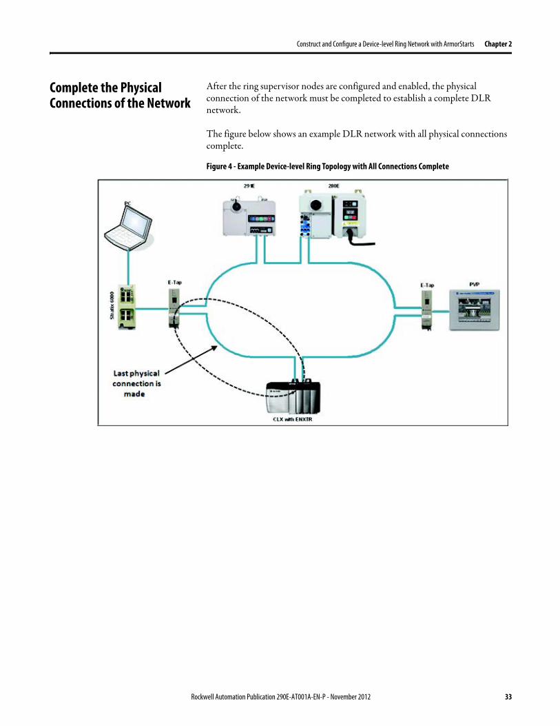
Construct and Configure a Device-level Ring Network with ArmorStarts Chapter 2
Complete the Physical Connections of the Network
After the ring supervisor nodes are configured and enabled the physical connection of the network must be completed to establish a complete DLR network
The figure below shows an example DLR network with all physical connections complete
Figure 4 - Example Device-level Ring Topology with All Connections Complete
Rockwell Automation Publication 290E-AT001A-EN-P - November 2012 33
Chapter 2 Construct and Configure a Device-level Ring Network with ArmorStarts
Verify Supervisor Configuration
The configuration and overall DLR network status can be verified in either RSLogix 5000 programming software or RSLinx Classic communication software
1 Access the supervisor nodersquos properties as shown previously in this chapter
2 Click the Network tab
3 Check the Network Topology and Network Status Fields
For a 1756-EN2TR module or the 1783-ETAP 1783-ETAP1F and 1783-ETAP2F tap the supervisor configuration can also be verified through the modulersquos diagnostic web pages For more information on monitoring diagnostics via an EtherNetIP modulersquos web pages see Monitor a DLR Network starting on page 37
34 Rockwell Automation Publication 290E-AT001A-EN-P - November 2012
Construct and Configure a Device-level Ring Network with ArmorStarts Chapter 2
IGMP Snooping This functionality is enabled by default in the 1783-ETAP 1783-ETAP1F and 1783-ETAP2F taps and is commonly used to manage multicast traffic on the network When in use this functionality allows the tap to multicast data to only those devices that need the data rather than to all devices connected to the network
For snooping to work there must be a device present that is running a querier Typically the device is a router or a switch such as the Stratix 6000 Stratix 8000 or Stratix 8300 managed switch
Once DHCP is enabled the switch could change the IP addresses on the ArmorStarts depending on network demand which could cause RSlogix5000 to loose communication with the device as connectivity is established via the AOP in the initial configuration
IGMP Querier This functionality is disabled by default The IGMP Querier functionality enables a 1783-ETAP 1783-ETAP1F or 1783-ETAP2F tap or switch such as a Stratix managed switch to send out a query to all devices on the network It determines what multicast addresses are of interest to a specific node or a group of nodes
The IGMP Querier functionality should be enabled for at least one node on the network The 1783-ETAP 1783-ETAP1F or 1783-ETAP2F tap managed switches and routers are examples of devices that support IGMP Querier functionality
IMPORTANT If DHCP for the Armostart is still required the Internet Group Management Protocol (IGMP) snooping on the E-tap must be disabled via the AOP
IMPORTANT If the IGMP Querier functionality is not enabled for at least one node on the network multicast traffic on the network may eventually create network performance issues
Rockwell Automation Publication 290E-AT001A-EN-P - November 2012 35
Chapter 2 Construct and Configure a Device-level Ring Network with ArmorStarts
However for all devices that are configured on the network with the IGMP Querier parameter enabled an IP address other than the factory default value must also be set for those devices If multiple devices on the network enable this functionality only the node with the lowest IP address becomes the active IGMP Querier node
IGMP Version
If the IGMP Querier is enabled a Querier Version must be selected The default version is Version 2
36 Rockwell Automation Publication 290E-AT001A-EN-P - November 2012
Chapter 3
Monitor a DLR Network
Introduction Use this chapter to learn how to monitor the DLR network
Methods to Monitor a DLR Network
Network diagnostic information can be retrieved from the ring supervisor-capable devices using the following
bull RSLogix 5000 programming software status pages
bull RSLinx communication software status pages
bull Device web pages
bull EtherNetIP Device Level Ring (DLR) network diagnostics faceplate
bull Programmatically through the use of a MSG instruction
RSLogix 5000 Programming Software Status Pages
RSLogix 5000 programming software version 1701 or later must be used and the appropriate AOPs installed to use the softwarersquos profile status pages
RSLinx Communication Software Status Pages
To monitor the network with this method the RSLinx communication software version 255 or later must be used
Topic Page
Methods to Monitor a DLR Network 37
Monitor Status Pages 39
Monitor ArmorStart Internal Web Server 44
Monitor via Faceplate Integration 45
Monitor Diagnostics via MSG Instructions 46
Rockwell Automation Publication 290E-AT001A-EN-P - November 2012 37
Chapter 3 Monitor a DLR Network
ArmorStart Internal Web Server
Rockwell Automation provides an internal embedded web server with each ArmorStart EtherNetIP The internal web server allows you to view information and configure the ArmorStart via a web browser The ArmorStart EtherNetIP can also be set up from the web server to send e-mail notifications The embedded web server is used to access configuration and status data It provides the user with the ability to view and modify the device configuration without having access to RSLogix 5000 Security in the form of an administrative password can be set The default login is Administrator There is no password set by default
EtherNetIP Device Level Ring (DLR) Network Diagnostics Faceplate
The diagnostics faceplate contains two major components
bull Logic code (encapsulated in an Add-On Instruction) that allows the controller to retrieve real-time DLR network status information
bull HMI faceplate graphics to allow the data to be visualized on an operator interface
Programmatically Through the Use of a MSG Instruction
For more information on how to monitor the DLR network via MSG Instructions see page 46
38 Rockwell Automation Publication 290E-AT001A-EN-P - November 2012
Monitor a DLR Network Chapter 3
Monitor Status Pages Both RSLogix 5000 programming software and RSLinx Classic communication software offer status pages that can be used to monitor the networkrsquos performance
RSLogix 5000 Programming Software Status Pages
Monitor the networkrsquos diagnostic information through the RSLogix 5000 programming software when the software is online
To monitor the network in RSLogix 5000 programming software follow these steps
1 Verify that the project is online
2 Access the active supervisor nodersquos propertiesa Right-click the modulersquos entry in the Controller Organizerb Click properties
Rockwell Automation Publication 290E-AT001A-EN-P - November 2012 39
Chapter 3 Monitor a DLR Network
3 Use the Network tab to monitor diagnostics
40 Rockwell Automation Publication 290E-AT001A-EN-P - November 2012
Monitor a DLR Network Chapter 3
RSLinx Communication Software
To monitor the network in RSLinx communication software follow these steps
1 Click RSWho to browse the network
2 Access the property pages for the active supervisor nodea Open the driver that shows the nodes on the DLR networkb Right-click the node that you want to monitor performancec Click on the choice that you need to access
Multiple choices appear
These options are shown in the following sections
Rockwell Automation Publication 290E-AT001A-EN-P - November 2012 41
Chapter 3 Monitor a DLR Network
Module Configuration
This series of tabs providesbull General informationbull Connection informationbull Module informationbull Internet protocolbull Port configurationbull Network information
The example below shows a ring fault between nodes at IP addresses 10888021 and MAC ID 00-00-BC-02-48-D5
42 Rockwell Automation Publication 290E-AT001A-EN-P - November 2012
Monitor a DLR Network Chapter 3
There are multiple fields used to monitor network diagnostics
Field Definition
Network Topology Possible values here can be Linear or Ring
Network Status Displays if the network is operating normally (Normal) or has experienced a fault (Ring Fault) as shown in the previous example screen
Active Ring Supervisor Displays the IP address or MAC address of the active ring supervisor
Active Supervisor Precedence For more information on this field see Active Ring Supervisor on page 11
Enable Ring Supervisor Configurable field that lets you to set the node as a ring supervisor
Ring Faults Detected Number of faults detected on the network since the last module power cycle or counter reset
Supervisor Status Displays whether this node is the active ring supervisor (Active) a back-up supervisor (Back-up) a ring node or part of a linear network
Last Active Node on Port 1 The last node the active ring supervisor can communicate with on Port 1 This value is an IP address or a MAC ID and remains latched until the Verify Fault Location button is clicked
Last Active Node on Port 2 The last node the active ring supervisor can communicate with on Port 2 This value is an IP address or a MAC ID and remains latched until the Verify Fault Location button is clicked
Status Displays whether a fault exists on the ring
IMPORTANT If the Network Topology field = Ring and the Network Status field = Normal the Last Active Node fields will display the last fault information even though it has been correctedTo clear the last fault information from these fields click Verify Fault Location You may see a message informing you that the supervisor is no longer in fault mode and the fields will be cleared
Rockwell Automation Publication 290E-AT001A-EN-P - November 2012 43
Chapter 3 Monitor a DLR Network
How to Access the ArmorStart EtherNetIP Internal Web Server
Open your preferred internet web browser and enter the IP address of the desired ArmorStart For this example 192168122 will be used
Use the links on the left-most navigation bar to see each available web page The screen below shows Ring Statistics for the ArmorStart 280E
44 Rockwell Automation Publication 290E-AT001A-EN-P - November 2012
Monitor a DLR Network Chapter 3
EtherNetIP Device Level Ring (DLR) Network Diagnostics Faceplate Overview
The EtherNetIP Device Level Ring (DLR) network diagnostics faceplate provides basic DLR network status information to the user to assist with monitoring and troubleshooting a DLR network
The diagnostics faceplate contains two major components
bull Logic code (encapsulated in an Add-On Instruction) that allows the controller to retrieve real-time DLR network status information
bull HMI faceplate graphics to allow the data to be visualized on an operator interface
The DLR diagnostics faceplate application can be downloaded from the Rockwell Automation Sample Code website at httpsamplecoderockwellautomationcom
Besides the individual Logix and View project components a demo application is also included with the downloaded file
Rockwell Automation Publication 290E-AT001A-EN-P - November 2012 45
Chapter 3 Monitor a DLR Network
Monitor Diagnostics via MSG Instructions
Network diagnostic information can also be obtained programmatically via MSG instructions in RSLogix 5000 programming software For example you can
bull Get all ring diagnostic informationbull Get a ring participant listbull Get the active supervisorbull Clear rapid ring faultsbull Verify a fault locationbull Reset a fault counterbull Enable and configure a ring supervisor
This information can be displayed on an HMI device or manipulated in the project code
Figure 5 - Example Use of MSG Instruction
This example describes how to retrieve diagnostic information from the DLR network Follow these steps
1 Enter a MSG instruction into the rung of logic
2 Configure the MSG instruction to retrieve ring diagnostic information service as shown in the following screen shots
IMPORTANT Make sure the tag created is sized appropriately to hold all of the data that you are reading or writing For more information see page 48
46 Rockwell Automation Publication 290E-AT001A-EN-P - November 2012
Monitor a DLR Network Chapter 3
3 Configure the MSG instructionrsquos communication path to point to the active supervisor node
The path on the following screen is one example path
IMPORTANT When using the Custom Get_Attributes_All (01) service pointing to an active supervisor node will retrieve all of the attributes listed in Retrieve All Diagnostic Information Attribute Description on page 50Pointing to a non-supervisor node will retrieve only the Network Topology and Network Status attribute informationPointing to backup supervisor node will retrieve the current active supervisorrsquos IP address
Rockwell Automation Publication 290E-AT001A-EN-P - November 2012 47
Chapter 3 Monitor a DLR Network
Use Specific Values on the Configuration Tab
Use the values on the Configuration tab of your MSG instruction to perform specific services Sample DLR network diagnostic application code for example Add-on Instruction or HMI faceplate graphics is available on the Rockwell Automation Sample Code Library For more information about the Rockwell Automation Sample Code Library see httpwwwrockwellautomationcomsolutionsintegratedarchitectureresources5html
➊ This request only works if there are fewer than 40 nodes on the network If there are more nodes than will fit in a single message an error will be returned➋ Use a Destination Length of 54 bytes if using firmware revision 3x or later for the 1756-EN2TR module or firmware revision 2x or later for the 1783-ETAP
1783-ETAP1F or 1783-ETAP2F taps
Request Description Message Type
Service Type
Service Code (HEX)
Class (HEX)
Instance Attribute (HEX)
Source Element
Source Length (Bytes)
Destination Destination Length (bytes)
Retrieve All Ring Diagnostic Information
Information for this request is listed in Retrieve All Ring Diagnostic Information on page 49
CIP Generic Custom 1 47 1 NA LeftBlank
0 Tag 50or54 ➋
Request Ring Participant List ➊
Information for this request is listed in Request the Ring Participant List on page 51
CIP Generic Get Attribute Single
e 47 1 9 NA NA Tag 10node
Get Active Supervisor
Obtain the IP address and MAC ID of the active supervisor on the DLR network
CIP Generic Get Attribute Single
e 47 1 a NA NA Tag 10
Acknowledge Rapid Ring Faults Condition
Request supervisor to resume normal operation after encountering a rapid ring fault condition
CIP Generic Custom 4c 47 1 NA NA NA NA
Verify a Fault Location
Request supervisor to update Last Active Node values
CIP Generic 4b 47 1 NA NA NA NA NA
Reset the Ring Fault Counter
Reset the number of ring faults detected on the DLR network
CIP Generic Set Attribute Single
10 47 1 5 Tag 2 NA NA
Enable and Configure a Ring Supervisor
Information for this request is listed in Enable and Configure a Ring Supervisor on page 52
CIP Generic Set Attribute Single
10 47 1 4 Tag 12 NA NA
48 Rockwell Automation Publication 290E-AT001A-EN-P - November 2012
Monitor a DLR Network Chapter 3
Retrieve All Ring Diagnostic Information
By performing the Retrieve All Ring Diagnostic Information request on an active supervisor the MSG instruction returns the following information
➊ RSLogix 5000 programming software may display the value in this field as negative numbers To better understand the value we recommend you view it in HEX format
Destination Tag Attribute Name Description Possible Values
SINT [0] Network Topology Current network topology mode 0 = Linear
1 = Ring
SINT [1] Network Status Current status of the network 0 = Normal
1 = Ring Fault
2 = Unexpected Loop Detected
3 = Partial Network Fault
4 = Rapid FaultRestore Cycle
SINT [2] Ring Supervisor Status Ring supervisor active status flag 0 = Node is functioning as a backup
1 = Node is functioning as the active ring supervisor
2 = Node is functioning as a normal ring node
3 = Node is operating in a non-DLR topology
4 = Node cannot support the currently operating ring parameters thatis Beacon Interval andor Beacon Timeout
Ring Supervisor Config Ring Supervisor configuration parameters
SINT [3] Ring Supervisor Enable Ring supervisor enable flag 0 = Node is configured as a normal ring node (default configuration)
1 = Node is configured as a ring supervisor
SINT [4] Ring Supervisor Precedence Precedence value of a ring supervisor ➊ Valid value range = 0hellip255
0 = Default value
SINT [5-8] Beacon Interval Duration of ring beacon interval Valid value range = 200 μshellip100 ms
Default = 400 μs
SINT [9-12] Beacon Timeout Duration of ring beacon timeout Value value range = 400 μshellip500 ms
Default value = 1960 μs
SINT [13-14] DLR VLAN ID Valid ID to use in ring protocol messages Valid value range = 0hellip4094
Default value = 0
SINT [15-16] Ring Faults Count Number of ring faults since power up ➊
Rockwell Automation Publication 290E-AT001A-EN-P - November 2012 49
Chapter 3 Monitor a DLR Network
Retrieve All Diagnostic Information Attribute Description
➊ This destination tag is available only with the 1756-EN2TR module firmware revision 3x or later 1783-ETAP 1783-ETAP1F and 1783-ETAP2F taps firmware revisions 2x or later If using the 1783-ETAP tap firmware revision 1x your program does not include this destination tag
➋ RSLogix 5000 programming software may display the value in this field as negative numbers To better understand the value we recommend you view it in HEX format
Destination Tag Attribute Name Description Possible Values
Last Active Node on Port 1 Last active node at the end of the chain through port 1 of the active ring supervisor during a ring fault
SINT [17-20] Device IP address ➋ Any valid IP address value
A value = 0 indicates no IP address has been configured for the device
SINT [21-26] Device MAC address ➋ Any valid Ethernet MAC address
Last Active Node on Port 2 Last active node at the end of the chain through port 2 of the active ring supervisor during a ring fault
SINT [27-30] Device IP address ➋ Any valid IP address value
A value = 0 indicates no IP address has been configured for the device
SINT [31-36] Device MAC address ➋ Any valid Ethernet MAC address
SINT [37-38] Ring Protocol Participants Count
Number of devices in the ring protocol participants list
Active Supervisor Address IP andor Ethernet MAC address of the active ring supervisor
SINT [39-42] Supervisor IP address Any valid IP address value
A value = 0 indicates no IP address has been configured for the device
SINT [43-48] Supervisor MAC address Any valid Ethernet MAC address
SINT [49] Active Supervisor Precedence
Precedence value of the active ring supervisor
SINT [50-53]➊ Capability Flags Alerts you that the device is capable of operating as a supervisor and beacon-based ring node
0x22
50 Rockwell Automation Publication 290E-AT001A-EN-P - November 2012
Monitor a DLR Network Chapter 3
Request the Ring Participant List
When requesting the Ring Participant List service on the DLR network the MSG instruction returns the following information
Request the Ring Participant List Attribute Description
➊ This attribute will return an array of the data shown one entry for each node The Ring Protocol Participants Count attribute determines the number entries
➋ This tag displays only IP addresses for ring participants that have been configured with one For example you may have a 1783-ETAP tap connected to the network that has not been assigned an IP address In that case no address is shown for the 1783-ETAP tap
➌ RSLogix 5000 programming software may display the value in this field as negative numbers To better understand the value we recommend you view it in HEX format
➍ Unlike destination tag SINT [0-3] where IP addresses are displayed only for ring participants configured with an IP address this tag displays MAC addresses for all ring participants because every ring participant has a MAC address
Destination Tag Attribute Name Description Possible Values
Ring Protocol Participants List ➊
List of devices participating in ring protocol
SINT [0-3] Device IP address ➋➌ Any valid IP address value
A value = 0 indicates no IP address has been configured for the device
SINT [4-9] Device MAC address ➌➍ Any valid Ethernet MAC address
Rockwell Automation Publication 290E-AT001A-EN-P - November 2012 51
Chapter 3 Monitor a DLR Network
Enable and Configure a Ring Supervisor
When performing the Enable and Configure a Ring Supervisor request on a supervisor-capable device configure the MSG instruction with the following information
Enable and Configure a Ring Supervisor Attribute Description
➊ RSLogix 5000 programming software may display the value in this field as negative numbers To better understand the value we recommend you view it in HEX format
Source Tag Attribute Name Description Possible Values
Ring Supervisor Config Ring Supervisor configuration parameters
SINT [0] Ring Supervisor Enable Ring supervisor enable flag 0 = Node is configured as a normal ring node (default configuration)1 = Node is configured as a ring supervisor
SINT [1] Ring Supervisor Precedence Precedence value of a ring supervisor ➊
Valid value range = 0hellip2550 = Default value
SINT [2-5] Beacon Interval Duration of ring beacon interval
Valid value range = 200 μshellip100 000 μsDefault = 400 μs
SINT [6-9] Beacon Timeout Duration of ring beacon timeout ➊
Value value range = 400 μshellip500 000 μsDefault value = 1960 μs
SINT [10-11] DLR VLAN ID Valid ID to use in ring protocol messages ➊
Valid value range = 0hellip4094Default value = 0
52 Rockwell Automation Publication 290E-AT001A-EN-P - November 2012
Chapter 4
Troubleshoot a DLR Network
Introduction Use this chapter to learn how to troubleshoot the DLR network
General Solutions for Linear or DLR Networks
Before attempting to correct specific faults on the linear or DLR network we recommend that you first take the following actions when a fault appears
bull For a DLR networkndash Verify that at least one node has been configured as a supervisor
on the network and that Network Topology = Ringndash Verify that all cables on the network are securely connected
to each devicendash Verify that all devices that require an IP address have one assigned
correctlyndash Check the Network Status field on the active supervisor nodersquos status
page to determine the fault typebull For a linear network
ndash Verify that none of the nodes are configured as a supervisor on the network and that Network Topology = LinearIf any nodes on a linear network are configured as a supervisor it may impact communication to other devices connected to the network
ndash Verify that all cables on the network are securely connected to each device
ndash Verify that all devices that require an IP address have one assigned correctly
If the fault is not cleared after completing the actions listed above use the tables in the rest of this chapter to troubleshoot issues specific to a DLR network or a linear network
Topic Page
General Solutions for the Linear or DLR Networks 53
Duplicate IP Address Detection 54
Specific Issues on the DLR Network 55
Network Recovery Performance 58
Device Port Debugging Mode 59
Rockwell Automation Publication 290E-AT001A-EN-P - November 2012 53
Chapter 4 Troubleshoot a DLR Network
Duplicate IP Address Detection
Some EtherNetIP communication modules support duplicate IP address detection The module verifies that its IP address does not match any other network devicersquos IP address when performing either of these tasks
bull Connect the module to an EtherNetIP network
bull Change the modulersquos IP address
If the modulersquos IP address matches that of another device on the network the modulersquos EtherNetIP port transitions to Conflict mode In Conflict mode these conditions exist
bull OK status indicator is blinking red
bull Network (NET) status indicator is solid red
bull On some EtherNetIP communication modules the module status display indicates the conflict
The display scrollsOK ltIP_address_of_this_modulegt Duplicate IP
ltMac_address_of_duplicate_node_detectedgt
For example OK 108860196 Duplicate IP - 0000BC0234B4
bull On some EtherNetIP communication modules the modulersquos diagnostic webpage displays information about duplicate IP address detection
For more information on which EtherNetIP communication modules support displaying duplicate IP address on their diagnostic webpage see the Technical Note titled Logix modules Duplicate IP address detection enhancement 118216 in the Technical Support Knowledgebase available at httpwwwrockwellautomationcomknowledgebase
54 Rockwell Automation Publication 290E-AT001A-EN-P - November 2012
Troubleshoot a DLR Network Chapter 4
Specific Issues on the DLR Network
Use the following table to troubleshoot possible specific issues on the DLR or linear network that are not solved by the actions described on the previous page
Issue Description Solution
Supervisor Reports a Ring Fault A link on the DLR network may be brokenbull intentionally for example because of adding or deleting nodes but not making all
physical connections to restore the setup of the network withwithout the nodebull unintentionally for example because a cable is broken or a device malfunctionsWhen this fault occurs the adjacent nodes to the faulted part of the network are displayed in the Ring Fault group and the Network Status field = Ring FaultThe screen shot below shows the Ring Fault section with IP addresses appearing for the last active nodes The faulted node is between nodes 108880115 and 108880208 If the IP address of either node is not available the software will display the nodersquos MAC ID
Once the fault is corrected the ring is automatically restored and the Network Status field returns to Normal
Determine where the fault condition exists and correct itClick the Refresh Communication link as needed to update the Ring Fault information to determine where the fault condition existsFinally DevicePort Debugging Mode functionality on the 1783-ETAP tap may be used to analyze a suspicious nodeFor more information refer to Device Port Debugging Mode on page 59
Rockwell Automation Publication 290E-AT001A-EN-P - November 2012 55
Chapter 4 Troubleshoot a DLR Network
Issue Description Solution
Rapid Ring Fault When a Rapid Ring Fault occurs the following events occurbull The active supervisor will block traffic on port 2 resulting in possible network
segmentation that is some nodes may become unreachablebull The Link 2 status indicator on the active supervisor is offbull As soon as the fault occurs for both RSLogix 5000 programming software and
RSLinx communication software the Status field = Rapid FaultRestore Cycles
Any of the following may cause a Rapid Ring Faultbull 5 intentional disconnectionsreconnections of a node from the network within 30
secondsbull A duplex mismatch between two connected devicesbull Electromagnetic noise on the networkbull Unstable physical connections such as intermittent connectorsGiven the nature of a Rapid Ring Fault the Last Active Node information may not be accurate when a Rapid Ring Fault condition is present
Multiple possible solutions existbull For the disconnections and reconnections issue no
solution is requiredClear the fault after reconnecting the device to the network permanentlybull For the duplex mismatch issue reconfigure the duplex
parameters to make sure they match between the devices
bull For the electromagnetic noise issue determine where the noise exists and eliminate it or use a protective shield in that location
bull For the unstable connections issue determine where they exist on the network and correct them
bull Check the media counters for all devices on the network The device with the highest media counter count is most likely causing the Rapid Ring Fault
bull Remove devices from the network one by one If the Rapid Ring Fault disappears after a device is removed that device is causing the fault
bull DevicePort Debugging Mode functionality on the 1783-ETAP tap may be used to analyze a suspicious node
For more information refer to Device Port Debugging Mode on page 59bull Finally the Beacon Interval or Timeout configuration
may not be appropriate for the networkHowever if these values need to be changed we recommend that you contact Rockwell Automation technical supportOnce the fault is fixed click Clear Fault
56 Rockwell Automation Publication 290E-AT001A-EN-P - November 2012
Troubleshoot a DLR Network Chapter 4
Issue Description Solution
Partial Fault Condition A partial network fault occurs when traffic is lost in only one direction on the network because a ring member is not forwarding beacons in both directions for example a component failureThe active ring supervisor detects a partial fault by monitoring the loss of Beacon frames on one port and the fault location appears in the Ring Fault section of the Network tab When a partial fault is detected the active ring supervisor blocks traffic on one port At this point the ring is segmented due to the partial fault condition The nodes adjacent to the faulted part of the network are displayed in the Ring Fault group with either IP addresses or MAC IDs for each node displayedWhen this fault occurs the Network Status field = Partial Fault ConditionOnce the fault is corrected it automatically clears and the Network Status field returns to Normal
Determine where the fault condition exists and correct itAdditionally the DevicePort Debugging Mode functionality also known as Port Mirroring on a 1783-ETAP 1783-ETAP1F or 1783-ETAP2F tap may be used to analyze a suspicious nodeFor more information refer to Device Port Debugging Mode on page 59
Media Counter Errors or Collisions
The media counters screen displays the number of physical layer errors or collisions The screen below indicates where to check for errors encountered Error levels are displayed depending on what caused the error For example an Alignment Error is displayed in the Alignment Error field
On a DLR network it is not uncommon to see low levels of media counter errors For example if the network breaks a low level of media counter errors appears With a low level of media counter errors the value typically does not continuously increase and often clearsA high level of media counter errors typically continues to increase and does not clear For example there is a mismatch of speed between two linked nodes a high level of media counter errors appears steadily increasing and not clearingTo access the RSLinx screen above browse the network right-click on the device select Module Properties and click the Port Diagnostics tab
Some example solutions includebull Check for a mismatch of speed andor duplex between
two linked nodesbull Verify that all cables on the network are securely
connected to each devicebull Check for electromagnetic noise on the network If you
find it eliminate it or use a protective shield in that location
Rockwell Automation Publication 290E-AT001A-EN-P - November 2012 57
Chapter 4 Troubleshoot a DLR Network
Network Recovery Performance
When measuring the networkrsquos performance with regard to dealing with fault conditions consider the network recovery time Network recovery is the time for all of the following to take place
1 The supervisor node recognizes that a fault exists on the network
2 The supervisor node reconfigures the network because of the fault
3 The supervisor node communicates to the network nodes that a fault condition exists
4 The network nodes reconfigure themselves because of the fault
With the default beacon interval value of 400 mS and beacon timeout value of 1960 mS the worst-case time for network recovery times are
bull 2890 mS for a copper DLR network This recovery time is based on 100 m copper segments between nodes on the network
bull 3140 mS for a fiber-optic DLR network This recovery time is based on 2 kM fiber-optic cable segments between nodes on the network
When considering the values listed above keep in mind
bull Recovery time may actually occur faster than the times listed
bull The recovery times listed above assume that your networkrsquos nodes are operating at 100 Mbps speed and full-duplex mode We recommend that your nodes generally operate in this mode for DLR networks
bull If other node conditions exist such as a node operating at 10 Mbps full-duplex or 10100 Mbps half-duplex the recovery times will vary from the times listed above
If this is the case for your application the beacon interval and beacon timeout will need to be changed We recommend that you first contact Rockwell Automation technical support if these parameters need to be changed
bull The value assumes that the majority of the traffic on your network is EtherNetIP traffic
58 Rockwell Automation Publication 290E-AT001A-EN-P - November 2012
Troubleshoot a DLR Network Chapter 4
Device Port Debugging Mode
This functionality is disabled by default Device Port Debugging mode which is similar to port mirroring can be used to monitor data received on the 1783-ETAP 1783-ETAP1F or 1783-ETAP2F taprsquos two network ports Monitor the data over the device port to a device such as a personal computer running a protocol analyzer application for advanced network debugging or analysis
When device port debugging is used on a 1783-ETAP the device connected to the 1783-ETAP taprsquos front port receives all of the data traversing the ring (both directions)
Device Port Debugging Example Network
When using the Device Port Debugging mode functionality insert the 1783-ETAP with the network analyzer connected to the device port It is inserted at the spot on the ring network where the node in question is located The graphic below shows a 1783-ETAP tap inserted in the network
IMPORTANT This functionality should be used only when troubleshooting the network and not in normal network operation
Rockwell Automation Publication 290E-AT001A-EN-P - November 2012 59
Chapter 4 Troubleshoot a DLR Network
Combined total network bandwidth of the traffic received on the two 1783-ETAP 1783-ETAP1F or 1783-ETAP2F taprsquos ports connected to the network should not exceed the taprsquos device port capacity The speed setting determines the device portrsquos capacity
Configure the device port on a 1783-ETAP 1783-ETAP1F or 1783-ETAP2F tap to either of two speed settings
bull 100 Mbps - default settingbull 10 Mbps
If the bandwidth exceeds the capacity of the taprsquos device port some frames from the ring will be dropped before reaching the device port These dropped frames do not impact the traffic on the rest of the DLR network
The device port setting determines how much network traffic the 1783-ETAP 1783-ETAP1F or 1783-ETAP2F tap can handle before dropping frames The circled section in the graphic below shows the Port Buffer Utilization of the Device Port In this example the value is zero because a ring fault exists on the network
60 Rockwell Automation Publication 290E-AT001A-EN-P - November 2012
Appendix A
Network Usage Guidelines and Recommendations
Consider the following guidelines and recommendations when using a DLR or linear network
GuidelineRecommendation Explanation
Use fewer than 50 nodes on a single DLR networkIf your application requires more than 50 nodes we recommend that the nodes are broken into separate but linked DLR networks
If you use more than 50 nodes on a single DLR networkbull Your network has a greater chance of multiple faults
occurring on the networkbull Network recovery times from faulted DLR network
are higher
Do not configure a supervisor on a linear network If your linear network includes non-DLR nodes and has a supervisor-enabled node on the network it may impact communication to non-DLR devices connected to the linear network
If you must connect a device that is running at 10 Mbps to a DLR or linear network do so through a 1783-ETAP 1783-ETAP1F or 1783-ETAP2F tap device port
The 1783-ETAP 1783-ETAP1F and 1783-ETAP2F taps can operate at 100 Mbps on the DLR network this is the optimal speed for a network If you connect a 10 Mbps device directly to the network instead of through a tap the linear or DLR network traffic slows to 10 MbpsAdditionally if the 10 Mbps device is connected to the network without a 1783-ETAP tap network recovery times are significantly impacted
Configure multiple supervisor nodes per ring If your DLR network only has one supervisor and the supervisor experiences a fault none of the other nodes become the active supervisor In this case the network becomes a linear network until the fault is corrected and the DLR network restoredAnother reason to configure multiple supervisor nodes is for replacing an active supervisor node with an out-of-box replacement the new device will not be enabled as a supervisor (by default) and there would still be no supervisor on the network
Rockwell Automation Publication 290E-AT001A-EN-P - November 2012 61
Appendix A Network Usage Guidelines and Recommendations
GuidelineRecommendation Explanation
Connect switches to a DLR network via 1783-ETAP 1783-ETAP1F or 1783-ETAP2F taps
If switches are connected to the DLR network without the use of a 1783-ETAP 1783-ETAP1F or 1783-ETAP2F tap the network may experience unpredictable behavior and network performance is unknown
Run all nodes on the DLR network at 100 Mbps and in Full-Duplex mode
These configuration values provide the best performance for your networkAdditionally we recommend that youbull Use auto-negotiate for all nodes on the DLR networkbull Do not use auto-negotiate on one node and then force
speed on the next node linked to it
In a linear network the number of nodes to use is application specific based on the considerations described in the next box
When determining the number of nodes to use on a linear network consider the followingbull There is a delay per node as information is transmitted
to each successive node used on the networkndash The typical delay on a linear network with 100 m
copper segments between nodes is 30 mSndash The typical delay on a linear network with 2 kM
fiber-optic segments between nodes is 40 mS
The greater the number of nodes on the network the longer the total time for information to be transmitted across the entire networkbull The single point of failure possibility is greater with
each additional connectionbull Troubleshooting the network may be more difficult
with a higher number of nodes
The total time for information to be transmitted across the entire network and its effect on how many nodes to use on a linear network is related to the Requested Packet Interval (RPI)Verify that the total time to transmit information from the first node to the last node on the network is less than the RPI Make sure the network is not loaded beyond 90 of capacity
62 Rockwell Automation Publication 290E-AT001A-EN-P - November 2012
Network Usage Guidelines and Recommendations Appendix A
GuidelineRecommendation Explanation
Do not physically close a DLR network without a supervisor configured on the network
A DLR network without a supervisor node results in a network stormIf you do close the DLR network without a supervisor configured break the ring and configure at least one supervisor before physically reconnecting the network
Use the default values for the followingbull Beacon Intervalbull Beacon Timeoutbull Ring Protocol VLAN ID
Changing the default values for the parameters Beacon Interval Beacon Timeout and Ring Protocol VLAN ID can result in unpredictable network behavior and negatively impacted network performanceThe default values are optimized for a network withbull 50 or fewer nodes are on the networkbull All nodes are operating at 100 Mbps and full-duplex
modebull At least 50 of the network traffic bandwidth being
EtherNetIP trafficIf you think the values of the Beacon Interval Beacon Timeout or Ring Protocol VLAN ID need to be changed for example if any node on ring is not operating at 100 Mbps and full-duplex mode we recommend that you first contact Rockwell Automation technical support
If DHCP for the ArmorStarts is still required you will need to disable Internet Group Management Protocol (IGMP) snooping on the E-tap via the AOP
IGMP Snooping is enabled by default in the 1783-ETAP 1783-ETAP1F and 1783-ETAP2F taps and is commonly used to manage multicast traffic on the network When in use this functionality allows the tap to multicast data to only those devices that need the data rather than to all devices connected to the networkOnce DHCP is enabled the switch could change the IP addresses on the ArmorStarts depending on network demand which could cause RSlogix5000 to loose communication with the device as connectivity is established via the AOP in the initial configuration
The IGMP Querier functionality should be enabled for at least one node on the network
This functionality is disabled by default The IGMP Querier functionality enables a 1783-ETAP 1783-ETAP1F or 1783-ETAP2F tap or switch such as a Stratix managed switch to send out a query to all devices on the network to determine what multicast addresses are of interest to a specific node or a group of nodesIf the IGMP Querier functionality is not enabled for at least one node on the network multicast traffic on the network may eventually create network performance issuesThe 1783-ETAP 1783-ETAP1F or 1783-ETAP2F taps managed switches and routers are examples of devices that support IGMP Querier functionality
Rockwell Automation Publication 290E-AT001A-EN-P - November 2012 63
Appendix A Network Usage Guidelines and Recommendations
Notes
64 Rockwell Automation Publication 290E-AT001A-EN-P - November 2012
Appendix B
Required Firmware Revisions
Required Firmware Revision for an Add-On Profile
➊ The ControlFLASH Firmware Upgrade software tcan be used o upgrade a 1756-EN2TR module from firmware revision 21 to 3x or later1x or later3x or later2x or later
➋ The ControlFLASH Firmware Upgrade software can be used to upgrade a 1783-ETAP tap from firmware revision 11 to 2x or later
To download new firmware go to httpwwwrockwellautomationcomsupportamericasindex_enhtml
If the firmware revision is upgraded on the module or tap the required AOP revision listed above must be used for that revision For example if the 1756-EN2TR module is upgraded to firmware revision 3x or later AOP revision 2x or later must be used in the RSLogix 5000 programming software
Additionally if the firmware revision is upgraded on the module or tap the required RSLinx communication software must also be used for that firmware revision For more information on which RSLinx software version is required for each firmware revision see page 66
For both the 1756-EN2TR module and 1783-ETAP tap make sure that the Major Revision configured on the General tab of the devicersquos RSLogix 5000 programming software configuration matches the major revision of the physical module
IMPORTANT To download an AOP go to httpsupportrockwellautomationcomcontrolflashLogixProfileraspDepending on the firmware revision of your product a specific AOP version must be used
Firmware Revision Add-On Profile Revision Cat No
21 ➊ 1x or later 1756-EN2TR
3x or later 2x or later
11 ➋ 1x or later 1783-ETAP
2x or later 2x or later
2x or later 2x or later 1783-ETAP1F
1783-ETAP2F
Rockwell Automation Publication 290E-AT001A-EN-P - November 2012 65
Appendix B Required Firmware Revisions
If the device configuration on the General tab does not match the physical module the programming software alerts you to this mismatch when attempting to configure the Internet Protocol Port Configuration and Network tabs for that device
Required Firmware Revision for RSLinx Communication Software
➊ The ControlFLASH Firmware Upgrade software can be used to upgrade a 1756-EN2TR module from firmware revision 21 to 3x or later1x or later3x or later255 or later3x or later256 or later
➋ The ControlFLASH Firmware Upgrade software can be used to upgrade a 1783-ETAP tap from firmware revision 11 to 2x or later
To download new firmware go to httpwwwrockwellautomationcomsupportamericasindex_enhtml
If the firmware revision is upgraded on the module or tap the required RSLinx communication software listed above must be used for that revision For example if the 1756-EN2TR module is upgraded to firmware revision 3x or later AOP revision 2x or later must be used in your RSLogix 5000 programming software
Additionally if the firmware revision is upgraded on the module or tap the required AOP revision must also be used for that firmware revision For more information on which AOP revision is required for each firmware revision see page 65
IMPORTANT Depending on the firmware revision of your product specific versions of RSLinx communication software must be used
Firmware Revision Required RSLinx Communication Software Version
Cat No
21 ➊ 255 or later 1756-EN2TR
3x or later 256 or later
11 ➋ 255 or later 1783-ETAP
2x or later 256 or later
2x or later 256 or later 1783-ETAP1F
1783-ETAP2F
66 Rockwell Automation Publication 290E-AT001A-EN-P - November 2012
Rockwell Otomasyon Ticaret AŞ Kar Plaza İş Merkezi E Blok Kat6 34752 İccedilerenkoumly İstanbul Tel +90 (216) 5698400
Rockwell Automation Publication 290E-AT001A-EN-P ndash November 2012 68 Copyright copy 2012 Rockwell Automation Inc All rights reserved Printed in the USA
Rockwell Automation Support
Rockwell Automation provides technical information on the Web to assist you in using its products At httpwwwrockwellautomationcomsupport you can find technical manuals a knowledge base of FAQs technical and application notes sample code and links to software service packs and a MySupport feature that you can customize to make thebest use of these tools
For an additional level of technical phone support for installation configuration and troubleshooting we offer TechConnectSM support programs For more information contact your local distributor or Rockwell Automation representative or visit httpwwwrockwellautomationcomsupport
Installation Assistance
If you experience a problem within the first 24 hours of installation review the information that is contained in this manualYou can contact Customer Support for initial help in getting your product up and running
New Product Satisfaction Return
Rockwell Automation tests all of its products to ensure that they are fully operational when shipped from the manufacturing facility However if your product is not functioning and needs to be returned follow these procedures
Documentation Feedback
Your comments will help us serve your documentation needs better If you have any suggestions on how to improve this document complete this form publication RA-DU002 available at httpwwwrockwellautomationcomliterature
United States or Canada 14406463434
Outside United States or Canada Use the Worldwide Locator at httpwwwrockwellautomationcomsupportamericasphone_enhtml or contact your local Rockwell Automation representative
United States Contact your distributor You must provide a Customer Support case number (call the phone number above to obtain one) to your distributor to complete the return process
Outside United States Please contact your local Rockwell Automation representative for the return procedure
- Important User Information
- General Precautions
- Software Requirements
- Additional Resources
- Rockwell Automation Support
- Installation Assistance
- New Product Satisfaction Return
- Table of Contents
- Chapter 1
-
- Device-Level Ring (DLR) Basics
-
- Introduction
- ArmorStart with EtherNetIP Overview
- What is a Device-level Ring (DLR) Network
- DLR Network Elements
-
- Supervisor Node
- Ring Node
-
- DLR Network Operation
- Number of Nodes on a DLR Network
- DLR Network Fault Management
-
- Network Reconfiguration after a Fault
-
- Chapter 2
-
- Construct and Configure a Device-level Ring Network with ArmorStarts
-
- Introduction
- Ethernet Capacity Tool
- Install Devices on a DLR Network
- ArmorStart Addressing Configuration
-
- Using the BootPDHCP Server
- Using the Rotary Network Address Switches
- Using the ArmorStart Internal Web Server
-
- Configure Supervisor Nodes on a DLR Network
-
- Configure a Ring Supervisor in RSLogix 5000 Programming Software
- Adding an Armorstart to RSLogix 5000
- Enable Ring Supervisor in RSLogix 5000 Programming Software
- Configure and Enable a Ring Supervisor in RSLinx Classic Communication Software
-
- Complete the Physical Connections of the Network
- Verify Supervisor Configuration
- IGMP Snooping
- IGMP Querier
-
- Chapter 3
-
- Monitor a DLR Network
-
- Introduction
- Methods to Monitor a DLR Network
-
- RSLogix 5000 Programming Software Status Pages
- RSLinx Communication Software Status Pages
- ArmorStart Internal Web Server
- EtherNetIP Device Level Ring (DLR) Network Diagnostics Faceplate
- Programmatically Through the Use of a MSG Instruction
-
- Monitor Status Pages
-
- RSLogix 5000 Programming Software Status Pages
- RSLinx Communication Software
-
- How to Access the ArmorStart EtherNetIP Internal Web Server
-
- EtherNetIP Device Level Ring (DLR) Network Diagnostics Faceplate Overview
-
- Monitor Diagnostics via MSG Instructions
-
- Use Specific Values on the Configuration Tab
- Retrieve All Ring Diagnostic Information
- Retrieve All Diagnostic Information Attribute Description
- Request the Ring Participant List
- Request the Ring Participant List Attribute Description
-
- Enable and Configure a Ring Supervisor
-
- Enable and Configure a Ring Supervisor Attribute Description
-
- Chapter 4
-
- Troubleshoot a DLR Network
-
- Introduction
- General Solutions for Linear or DLR Networks
- Duplicate IP Address Detection
- Specific Issues on the DLR Network
- Network Recovery Performance
- Device Port Debugging Mode
-
- Device Port Debugging Example Network
-
- Appendix A
-
- Network Usage Guidelines and Recommendations
-
- Notes
-
- Appendix B
-
- Required Firmware Revisions
-
- Required Firmware Revision for an Add-On Profile
- Required Firmware Revision for RSLinx Communication Software
-

Chapter 2 Construct and Configure a Device-level Ring Network with ArmorStarts
Verify Supervisor Configuration
The configuration and overall DLR network status can be verified in either RSLogix 5000 programming software or RSLinx Classic communication software
1 Access the supervisor nodersquos properties as shown previously in this chapter
2 Click the Network tab
3 Check the Network Topology and Network Status Fields
For a 1756-EN2TR module or the 1783-ETAP 1783-ETAP1F and 1783-ETAP2F tap the supervisor configuration can also be verified through the modulersquos diagnostic web pages For more information on monitoring diagnostics via an EtherNetIP modulersquos web pages see Monitor a DLR Network starting on page 37
34 Rockwell Automation Publication 290E-AT001A-EN-P - November 2012
Construct and Configure a Device-level Ring Network with ArmorStarts Chapter 2
IGMP Snooping This functionality is enabled by default in the 1783-ETAP 1783-ETAP1F and 1783-ETAP2F taps and is commonly used to manage multicast traffic on the network When in use this functionality allows the tap to multicast data to only those devices that need the data rather than to all devices connected to the network
For snooping to work there must be a device present that is running a querier Typically the device is a router or a switch such as the Stratix 6000 Stratix 8000 or Stratix 8300 managed switch
Once DHCP is enabled the switch could change the IP addresses on the ArmorStarts depending on network demand which could cause RSlogix5000 to loose communication with the device as connectivity is established via the AOP in the initial configuration
IGMP Querier This functionality is disabled by default The IGMP Querier functionality enables a 1783-ETAP 1783-ETAP1F or 1783-ETAP2F tap or switch such as a Stratix managed switch to send out a query to all devices on the network It determines what multicast addresses are of interest to a specific node or a group of nodes
The IGMP Querier functionality should be enabled for at least one node on the network The 1783-ETAP 1783-ETAP1F or 1783-ETAP2F tap managed switches and routers are examples of devices that support IGMP Querier functionality
IMPORTANT If DHCP for the Armostart is still required the Internet Group Management Protocol (IGMP) snooping on the E-tap must be disabled via the AOP
IMPORTANT If the IGMP Querier functionality is not enabled for at least one node on the network multicast traffic on the network may eventually create network performance issues
Rockwell Automation Publication 290E-AT001A-EN-P - November 2012 35
Chapter 2 Construct and Configure a Device-level Ring Network with ArmorStarts
However for all devices that are configured on the network with the IGMP Querier parameter enabled an IP address other than the factory default value must also be set for those devices If multiple devices on the network enable this functionality only the node with the lowest IP address becomes the active IGMP Querier node
IGMP Version
If the IGMP Querier is enabled a Querier Version must be selected The default version is Version 2
36 Rockwell Automation Publication 290E-AT001A-EN-P - November 2012
Chapter 3
Monitor a DLR Network
Introduction Use this chapter to learn how to monitor the DLR network
Methods to Monitor a DLR Network
Network diagnostic information can be retrieved from the ring supervisor-capable devices using the following
bull RSLogix 5000 programming software status pages
bull RSLinx communication software status pages
bull Device web pages
bull EtherNetIP Device Level Ring (DLR) network diagnostics faceplate
bull Programmatically through the use of a MSG instruction
RSLogix 5000 Programming Software Status Pages
RSLogix 5000 programming software version 1701 or later must be used and the appropriate AOPs installed to use the softwarersquos profile status pages
RSLinx Communication Software Status Pages
To monitor the network with this method the RSLinx communication software version 255 or later must be used
Topic Page
Methods to Monitor a DLR Network 37
Monitor Status Pages 39
Monitor ArmorStart Internal Web Server 44
Monitor via Faceplate Integration 45
Monitor Diagnostics via MSG Instructions 46
Rockwell Automation Publication 290E-AT001A-EN-P - November 2012 37
Chapter 3 Monitor a DLR Network
ArmorStart Internal Web Server
Rockwell Automation provides an internal embedded web server with each ArmorStart EtherNetIP The internal web server allows you to view information and configure the ArmorStart via a web browser The ArmorStart EtherNetIP can also be set up from the web server to send e-mail notifications The embedded web server is used to access configuration and status data It provides the user with the ability to view and modify the device configuration without having access to RSLogix 5000 Security in the form of an administrative password can be set The default login is Administrator There is no password set by default
EtherNetIP Device Level Ring (DLR) Network Diagnostics Faceplate
The diagnostics faceplate contains two major components
bull Logic code (encapsulated in an Add-On Instruction) that allows the controller to retrieve real-time DLR network status information
bull HMI faceplate graphics to allow the data to be visualized on an operator interface
Programmatically Through the Use of a MSG Instruction
For more information on how to monitor the DLR network via MSG Instructions see page 46
38 Rockwell Automation Publication 290E-AT001A-EN-P - November 2012
Monitor a DLR Network Chapter 3
Monitor Status Pages Both RSLogix 5000 programming software and RSLinx Classic communication software offer status pages that can be used to monitor the networkrsquos performance
RSLogix 5000 Programming Software Status Pages
Monitor the networkrsquos diagnostic information through the RSLogix 5000 programming software when the software is online
To monitor the network in RSLogix 5000 programming software follow these steps
1 Verify that the project is online
2 Access the active supervisor nodersquos propertiesa Right-click the modulersquos entry in the Controller Organizerb Click properties
Rockwell Automation Publication 290E-AT001A-EN-P - November 2012 39
Chapter 3 Monitor a DLR Network
3 Use the Network tab to monitor diagnostics
40 Rockwell Automation Publication 290E-AT001A-EN-P - November 2012
Monitor a DLR Network Chapter 3
RSLinx Communication Software
To monitor the network in RSLinx communication software follow these steps
1 Click RSWho to browse the network
2 Access the property pages for the active supervisor nodea Open the driver that shows the nodes on the DLR networkb Right-click the node that you want to monitor performancec Click on the choice that you need to access
Multiple choices appear
These options are shown in the following sections
Rockwell Automation Publication 290E-AT001A-EN-P - November 2012 41
Chapter 3 Monitor a DLR Network
Module Configuration
This series of tabs providesbull General informationbull Connection informationbull Module informationbull Internet protocolbull Port configurationbull Network information
The example below shows a ring fault between nodes at IP addresses 10888021 and MAC ID 00-00-BC-02-48-D5
42 Rockwell Automation Publication 290E-AT001A-EN-P - November 2012
Monitor a DLR Network Chapter 3
There are multiple fields used to monitor network diagnostics
Field Definition
Network Topology Possible values here can be Linear or Ring
Network Status Displays if the network is operating normally (Normal) or has experienced a fault (Ring Fault) as shown in the previous example screen
Active Ring Supervisor Displays the IP address or MAC address of the active ring supervisor
Active Supervisor Precedence For more information on this field see Active Ring Supervisor on page 11
Enable Ring Supervisor Configurable field that lets you to set the node as a ring supervisor
Ring Faults Detected Number of faults detected on the network since the last module power cycle or counter reset
Supervisor Status Displays whether this node is the active ring supervisor (Active) a back-up supervisor (Back-up) a ring node or part of a linear network
Last Active Node on Port 1 The last node the active ring supervisor can communicate with on Port 1 This value is an IP address or a MAC ID and remains latched until the Verify Fault Location button is clicked
Last Active Node on Port 2 The last node the active ring supervisor can communicate with on Port 2 This value is an IP address or a MAC ID and remains latched until the Verify Fault Location button is clicked
Status Displays whether a fault exists on the ring
IMPORTANT If the Network Topology field = Ring and the Network Status field = Normal the Last Active Node fields will display the last fault information even though it has been correctedTo clear the last fault information from these fields click Verify Fault Location You may see a message informing you that the supervisor is no longer in fault mode and the fields will be cleared
Rockwell Automation Publication 290E-AT001A-EN-P - November 2012 43
Chapter 3 Monitor a DLR Network
How to Access the ArmorStart EtherNetIP Internal Web Server
Open your preferred internet web browser and enter the IP address of the desired ArmorStart For this example 192168122 will be used
Use the links on the left-most navigation bar to see each available web page The screen below shows Ring Statistics for the ArmorStart 280E
44 Rockwell Automation Publication 290E-AT001A-EN-P - November 2012
Monitor a DLR Network Chapter 3
EtherNetIP Device Level Ring (DLR) Network Diagnostics Faceplate Overview
The EtherNetIP Device Level Ring (DLR) network diagnostics faceplate provides basic DLR network status information to the user to assist with monitoring and troubleshooting a DLR network
The diagnostics faceplate contains two major components
bull Logic code (encapsulated in an Add-On Instruction) that allows the controller to retrieve real-time DLR network status information
bull HMI faceplate graphics to allow the data to be visualized on an operator interface
The DLR diagnostics faceplate application can be downloaded from the Rockwell Automation Sample Code website at httpsamplecoderockwellautomationcom
Besides the individual Logix and View project components a demo application is also included with the downloaded file
Rockwell Automation Publication 290E-AT001A-EN-P - November 2012 45
Chapter 3 Monitor a DLR Network
Monitor Diagnostics via MSG Instructions
Network diagnostic information can also be obtained programmatically via MSG instructions in RSLogix 5000 programming software For example you can
bull Get all ring diagnostic informationbull Get a ring participant listbull Get the active supervisorbull Clear rapid ring faultsbull Verify a fault locationbull Reset a fault counterbull Enable and configure a ring supervisor
This information can be displayed on an HMI device or manipulated in the project code
Figure 5 - Example Use of MSG Instruction
This example describes how to retrieve diagnostic information from the DLR network Follow these steps
1 Enter a MSG instruction into the rung of logic
2 Configure the MSG instruction to retrieve ring diagnostic information service as shown in the following screen shots
IMPORTANT Make sure the tag created is sized appropriately to hold all of the data that you are reading or writing For more information see page 48
46 Rockwell Automation Publication 290E-AT001A-EN-P - November 2012
Monitor a DLR Network Chapter 3
3 Configure the MSG instructionrsquos communication path to point to the active supervisor node
The path on the following screen is one example path
IMPORTANT When using the Custom Get_Attributes_All (01) service pointing to an active supervisor node will retrieve all of the attributes listed in Retrieve All Diagnostic Information Attribute Description on page 50Pointing to a non-supervisor node will retrieve only the Network Topology and Network Status attribute informationPointing to backup supervisor node will retrieve the current active supervisorrsquos IP address
Rockwell Automation Publication 290E-AT001A-EN-P - November 2012 47
Chapter 3 Monitor a DLR Network
Use Specific Values on the Configuration Tab
Use the values on the Configuration tab of your MSG instruction to perform specific services Sample DLR network diagnostic application code for example Add-on Instruction or HMI faceplate graphics is available on the Rockwell Automation Sample Code Library For more information about the Rockwell Automation Sample Code Library see httpwwwrockwellautomationcomsolutionsintegratedarchitectureresources5html
➊ This request only works if there are fewer than 40 nodes on the network If there are more nodes than will fit in a single message an error will be returned➋ Use a Destination Length of 54 bytes if using firmware revision 3x or later for the 1756-EN2TR module or firmware revision 2x or later for the 1783-ETAP
1783-ETAP1F or 1783-ETAP2F taps
Request Description Message Type
Service Type
Service Code (HEX)
Class (HEX)
Instance Attribute (HEX)
Source Element
Source Length (Bytes)
Destination Destination Length (bytes)
Retrieve All Ring Diagnostic Information
Information for this request is listed in Retrieve All Ring Diagnostic Information on page 49
CIP Generic Custom 1 47 1 NA LeftBlank
0 Tag 50or54 ➋
Request Ring Participant List ➊
Information for this request is listed in Request the Ring Participant List on page 51
CIP Generic Get Attribute Single
e 47 1 9 NA NA Tag 10node
Get Active Supervisor
Obtain the IP address and MAC ID of the active supervisor on the DLR network
CIP Generic Get Attribute Single
e 47 1 a NA NA Tag 10
Acknowledge Rapid Ring Faults Condition
Request supervisor to resume normal operation after encountering a rapid ring fault condition
CIP Generic Custom 4c 47 1 NA NA NA NA
Verify a Fault Location
Request supervisor to update Last Active Node values
CIP Generic 4b 47 1 NA NA NA NA NA
Reset the Ring Fault Counter
Reset the number of ring faults detected on the DLR network
CIP Generic Set Attribute Single
10 47 1 5 Tag 2 NA NA
Enable and Configure a Ring Supervisor
Information for this request is listed in Enable and Configure a Ring Supervisor on page 52
CIP Generic Set Attribute Single
10 47 1 4 Tag 12 NA NA
48 Rockwell Automation Publication 290E-AT001A-EN-P - November 2012
Monitor a DLR Network Chapter 3
Retrieve All Ring Diagnostic Information
By performing the Retrieve All Ring Diagnostic Information request on an active supervisor the MSG instruction returns the following information
➊ RSLogix 5000 programming software may display the value in this field as negative numbers To better understand the value we recommend you view it in HEX format
Destination Tag Attribute Name Description Possible Values
SINT [0] Network Topology Current network topology mode 0 = Linear
1 = Ring
SINT [1] Network Status Current status of the network 0 = Normal
1 = Ring Fault
2 = Unexpected Loop Detected
3 = Partial Network Fault
4 = Rapid FaultRestore Cycle
SINT [2] Ring Supervisor Status Ring supervisor active status flag 0 = Node is functioning as a backup
1 = Node is functioning as the active ring supervisor
2 = Node is functioning as a normal ring node
3 = Node is operating in a non-DLR topology
4 = Node cannot support the currently operating ring parameters thatis Beacon Interval andor Beacon Timeout
Ring Supervisor Config Ring Supervisor configuration parameters
SINT [3] Ring Supervisor Enable Ring supervisor enable flag 0 = Node is configured as a normal ring node (default configuration)
1 = Node is configured as a ring supervisor
SINT [4] Ring Supervisor Precedence Precedence value of a ring supervisor ➊ Valid value range = 0hellip255
0 = Default value
SINT [5-8] Beacon Interval Duration of ring beacon interval Valid value range = 200 μshellip100 ms
Default = 400 μs
SINT [9-12] Beacon Timeout Duration of ring beacon timeout Value value range = 400 μshellip500 ms
Default value = 1960 μs
SINT [13-14] DLR VLAN ID Valid ID to use in ring protocol messages Valid value range = 0hellip4094
Default value = 0
SINT [15-16] Ring Faults Count Number of ring faults since power up ➊
Rockwell Automation Publication 290E-AT001A-EN-P - November 2012 49
Chapter 3 Monitor a DLR Network
Retrieve All Diagnostic Information Attribute Description
➊ This destination tag is available only with the 1756-EN2TR module firmware revision 3x or later 1783-ETAP 1783-ETAP1F and 1783-ETAP2F taps firmware revisions 2x or later If using the 1783-ETAP tap firmware revision 1x your program does not include this destination tag
➋ RSLogix 5000 programming software may display the value in this field as negative numbers To better understand the value we recommend you view it in HEX format
Destination Tag Attribute Name Description Possible Values
Last Active Node on Port 1 Last active node at the end of the chain through port 1 of the active ring supervisor during a ring fault
SINT [17-20] Device IP address ➋ Any valid IP address value
A value = 0 indicates no IP address has been configured for the device
SINT [21-26] Device MAC address ➋ Any valid Ethernet MAC address
Last Active Node on Port 2 Last active node at the end of the chain through port 2 of the active ring supervisor during a ring fault
SINT [27-30] Device IP address ➋ Any valid IP address value
A value = 0 indicates no IP address has been configured for the device
SINT [31-36] Device MAC address ➋ Any valid Ethernet MAC address
SINT [37-38] Ring Protocol Participants Count
Number of devices in the ring protocol participants list
Active Supervisor Address IP andor Ethernet MAC address of the active ring supervisor
SINT [39-42] Supervisor IP address Any valid IP address value
A value = 0 indicates no IP address has been configured for the device
SINT [43-48] Supervisor MAC address Any valid Ethernet MAC address
SINT [49] Active Supervisor Precedence
Precedence value of the active ring supervisor
SINT [50-53]➊ Capability Flags Alerts you that the device is capable of operating as a supervisor and beacon-based ring node
0x22
50 Rockwell Automation Publication 290E-AT001A-EN-P - November 2012
Monitor a DLR Network Chapter 3
Request the Ring Participant List
When requesting the Ring Participant List service on the DLR network the MSG instruction returns the following information
Request the Ring Participant List Attribute Description
➊ This attribute will return an array of the data shown one entry for each node The Ring Protocol Participants Count attribute determines the number entries
➋ This tag displays only IP addresses for ring participants that have been configured with one For example you may have a 1783-ETAP tap connected to the network that has not been assigned an IP address In that case no address is shown for the 1783-ETAP tap
➌ RSLogix 5000 programming software may display the value in this field as negative numbers To better understand the value we recommend you view it in HEX format
➍ Unlike destination tag SINT [0-3] where IP addresses are displayed only for ring participants configured with an IP address this tag displays MAC addresses for all ring participants because every ring participant has a MAC address
Destination Tag Attribute Name Description Possible Values
Ring Protocol Participants List ➊
List of devices participating in ring protocol
SINT [0-3] Device IP address ➋➌ Any valid IP address value
A value = 0 indicates no IP address has been configured for the device
SINT [4-9] Device MAC address ➌➍ Any valid Ethernet MAC address
Rockwell Automation Publication 290E-AT001A-EN-P - November 2012 51
Chapter 3 Monitor a DLR Network
Enable and Configure a Ring Supervisor
When performing the Enable and Configure a Ring Supervisor request on a supervisor-capable device configure the MSG instruction with the following information
Enable and Configure a Ring Supervisor Attribute Description
➊ RSLogix 5000 programming software may display the value in this field as negative numbers To better understand the value we recommend you view it in HEX format
Source Tag Attribute Name Description Possible Values
Ring Supervisor Config Ring Supervisor configuration parameters
SINT [0] Ring Supervisor Enable Ring supervisor enable flag 0 = Node is configured as a normal ring node (default configuration)1 = Node is configured as a ring supervisor
SINT [1] Ring Supervisor Precedence Precedence value of a ring supervisor ➊
Valid value range = 0hellip2550 = Default value
SINT [2-5] Beacon Interval Duration of ring beacon interval
Valid value range = 200 μshellip100 000 μsDefault = 400 μs
SINT [6-9] Beacon Timeout Duration of ring beacon timeout ➊
Value value range = 400 μshellip500 000 μsDefault value = 1960 μs
SINT [10-11] DLR VLAN ID Valid ID to use in ring protocol messages ➊
Valid value range = 0hellip4094Default value = 0
52 Rockwell Automation Publication 290E-AT001A-EN-P - November 2012
Chapter 4
Troubleshoot a DLR Network
Introduction Use this chapter to learn how to troubleshoot the DLR network
General Solutions for Linear or DLR Networks
Before attempting to correct specific faults on the linear or DLR network we recommend that you first take the following actions when a fault appears
bull For a DLR networkndash Verify that at least one node has been configured as a supervisor
on the network and that Network Topology = Ringndash Verify that all cables on the network are securely connected
to each devicendash Verify that all devices that require an IP address have one assigned
correctlyndash Check the Network Status field on the active supervisor nodersquos status
page to determine the fault typebull For a linear network
ndash Verify that none of the nodes are configured as a supervisor on the network and that Network Topology = LinearIf any nodes on a linear network are configured as a supervisor it may impact communication to other devices connected to the network
ndash Verify that all cables on the network are securely connected to each device
ndash Verify that all devices that require an IP address have one assigned correctly
If the fault is not cleared after completing the actions listed above use the tables in the rest of this chapter to troubleshoot issues specific to a DLR network or a linear network
Topic Page
General Solutions for the Linear or DLR Networks 53
Duplicate IP Address Detection 54
Specific Issues on the DLR Network 55
Network Recovery Performance 58
Device Port Debugging Mode 59
Rockwell Automation Publication 290E-AT001A-EN-P - November 2012 53
Chapter 4 Troubleshoot a DLR Network
Duplicate IP Address Detection
Some EtherNetIP communication modules support duplicate IP address detection The module verifies that its IP address does not match any other network devicersquos IP address when performing either of these tasks
bull Connect the module to an EtherNetIP network
bull Change the modulersquos IP address
If the modulersquos IP address matches that of another device on the network the modulersquos EtherNetIP port transitions to Conflict mode In Conflict mode these conditions exist
bull OK status indicator is blinking red
bull Network (NET) status indicator is solid red
bull On some EtherNetIP communication modules the module status display indicates the conflict
The display scrollsOK ltIP_address_of_this_modulegt Duplicate IP
ltMac_address_of_duplicate_node_detectedgt
For example OK 108860196 Duplicate IP - 0000BC0234B4
bull On some EtherNetIP communication modules the modulersquos diagnostic webpage displays information about duplicate IP address detection
For more information on which EtherNetIP communication modules support displaying duplicate IP address on their diagnostic webpage see the Technical Note titled Logix modules Duplicate IP address detection enhancement 118216 in the Technical Support Knowledgebase available at httpwwwrockwellautomationcomknowledgebase
54 Rockwell Automation Publication 290E-AT001A-EN-P - November 2012
Troubleshoot a DLR Network Chapter 4
Specific Issues on the DLR Network
Use the following table to troubleshoot possible specific issues on the DLR or linear network that are not solved by the actions described on the previous page
Issue Description Solution
Supervisor Reports a Ring Fault A link on the DLR network may be brokenbull intentionally for example because of adding or deleting nodes but not making all
physical connections to restore the setup of the network withwithout the nodebull unintentionally for example because a cable is broken or a device malfunctionsWhen this fault occurs the adjacent nodes to the faulted part of the network are displayed in the Ring Fault group and the Network Status field = Ring FaultThe screen shot below shows the Ring Fault section with IP addresses appearing for the last active nodes The faulted node is between nodes 108880115 and 108880208 If the IP address of either node is not available the software will display the nodersquos MAC ID
Once the fault is corrected the ring is automatically restored and the Network Status field returns to Normal
Determine where the fault condition exists and correct itClick the Refresh Communication link as needed to update the Ring Fault information to determine where the fault condition existsFinally DevicePort Debugging Mode functionality on the 1783-ETAP tap may be used to analyze a suspicious nodeFor more information refer to Device Port Debugging Mode on page 59
Rockwell Automation Publication 290E-AT001A-EN-P - November 2012 55
Chapter 4 Troubleshoot a DLR Network
Issue Description Solution
Rapid Ring Fault When a Rapid Ring Fault occurs the following events occurbull The active supervisor will block traffic on port 2 resulting in possible network
segmentation that is some nodes may become unreachablebull The Link 2 status indicator on the active supervisor is offbull As soon as the fault occurs for both RSLogix 5000 programming software and
RSLinx communication software the Status field = Rapid FaultRestore Cycles
Any of the following may cause a Rapid Ring Faultbull 5 intentional disconnectionsreconnections of a node from the network within 30
secondsbull A duplex mismatch between two connected devicesbull Electromagnetic noise on the networkbull Unstable physical connections such as intermittent connectorsGiven the nature of a Rapid Ring Fault the Last Active Node information may not be accurate when a Rapid Ring Fault condition is present
Multiple possible solutions existbull For the disconnections and reconnections issue no
solution is requiredClear the fault after reconnecting the device to the network permanentlybull For the duplex mismatch issue reconfigure the duplex
parameters to make sure they match between the devices
bull For the electromagnetic noise issue determine where the noise exists and eliminate it or use a protective shield in that location
bull For the unstable connections issue determine where they exist on the network and correct them
bull Check the media counters for all devices on the network The device with the highest media counter count is most likely causing the Rapid Ring Fault
bull Remove devices from the network one by one If the Rapid Ring Fault disappears after a device is removed that device is causing the fault
bull DevicePort Debugging Mode functionality on the 1783-ETAP tap may be used to analyze a suspicious node
For more information refer to Device Port Debugging Mode on page 59bull Finally the Beacon Interval or Timeout configuration
may not be appropriate for the networkHowever if these values need to be changed we recommend that you contact Rockwell Automation technical supportOnce the fault is fixed click Clear Fault
56 Rockwell Automation Publication 290E-AT001A-EN-P - November 2012
Troubleshoot a DLR Network Chapter 4
Issue Description Solution
Partial Fault Condition A partial network fault occurs when traffic is lost in only one direction on the network because a ring member is not forwarding beacons in both directions for example a component failureThe active ring supervisor detects a partial fault by monitoring the loss of Beacon frames on one port and the fault location appears in the Ring Fault section of the Network tab When a partial fault is detected the active ring supervisor blocks traffic on one port At this point the ring is segmented due to the partial fault condition The nodes adjacent to the faulted part of the network are displayed in the Ring Fault group with either IP addresses or MAC IDs for each node displayedWhen this fault occurs the Network Status field = Partial Fault ConditionOnce the fault is corrected it automatically clears and the Network Status field returns to Normal
Determine where the fault condition exists and correct itAdditionally the DevicePort Debugging Mode functionality also known as Port Mirroring on a 1783-ETAP 1783-ETAP1F or 1783-ETAP2F tap may be used to analyze a suspicious nodeFor more information refer to Device Port Debugging Mode on page 59
Media Counter Errors or Collisions
The media counters screen displays the number of physical layer errors or collisions The screen below indicates where to check for errors encountered Error levels are displayed depending on what caused the error For example an Alignment Error is displayed in the Alignment Error field
On a DLR network it is not uncommon to see low levels of media counter errors For example if the network breaks a low level of media counter errors appears With a low level of media counter errors the value typically does not continuously increase and often clearsA high level of media counter errors typically continues to increase and does not clear For example there is a mismatch of speed between two linked nodes a high level of media counter errors appears steadily increasing and not clearingTo access the RSLinx screen above browse the network right-click on the device select Module Properties and click the Port Diagnostics tab
Some example solutions includebull Check for a mismatch of speed andor duplex between
two linked nodesbull Verify that all cables on the network are securely
connected to each devicebull Check for electromagnetic noise on the network If you
find it eliminate it or use a protective shield in that location
Rockwell Automation Publication 290E-AT001A-EN-P - November 2012 57
Chapter 4 Troubleshoot a DLR Network
Network Recovery Performance
When measuring the networkrsquos performance with regard to dealing with fault conditions consider the network recovery time Network recovery is the time for all of the following to take place
1 The supervisor node recognizes that a fault exists on the network
2 The supervisor node reconfigures the network because of the fault
3 The supervisor node communicates to the network nodes that a fault condition exists
4 The network nodes reconfigure themselves because of the fault
With the default beacon interval value of 400 mS and beacon timeout value of 1960 mS the worst-case time for network recovery times are
bull 2890 mS for a copper DLR network This recovery time is based on 100 m copper segments between nodes on the network
bull 3140 mS for a fiber-optic DLR network This recovery time is based on 2 kM fiber-optic cable segments between nodes on the network
When considering the values listed above keep in mind
bull Recovery time may actually occur faster than the times listed
bull The recovery times listed above assume that your networkrsquos nodes are operating at 100 Mbps speed and full-duplex mode We recommend that your nodes generally operate in this mode for DLR networks
bull If other node conditions exist such as a node operating at 10 Mbps full-duplex or 10100 Mbps half-duplex the recovery times will vary from the times listed above
If this is the case for your application the beacon interval and beacon timeout will need to be changed We recommend that you first contact Rockwell Automation technical support if these parameters need to be changed
bull The value assumes that the majority of the traffic on your network is EtherNetIP traffic
58 Rockwell Automation Publication 290E-AT001A-EN-P - November 2012
Troubleshoot a DLR Network Chapter 4
Device Port Debugging Mode
This functionality is disabled by default Device Port Debugging mode which is similar to port mirroring can be used to monitor data received on the 1783-ETAP 1783-ETAP1F or 1783-ETAP2F taprsquos two network ports Monitor the data over the device port to a device such as a personal computer running a protocol analyzer application for advanced network debugging or analysis
When device port debugging is used on a 1783-ETAP the device connected to the 1783-ETAP taprsquos front port receives all of the data traversing the ring (both directions)
Device Port Debugging Example Network
When using the Device Port Debugging mode functionality insert the 1783-ETAP with the network analyzer connected to the device port It is inserted at the spot on the ring network where the node in question is located The graphic below shows a 1783-ETAP tap inserted in the network
IMPORTANT This functionality should be used only when troubleshooting the network and not in normal network operation
Rockwell Automation Publication 290E-AT001A-EN-P - November 2012 59
Chapter 4 Troubleshoot a DLR Network
Combined total network bandwidth of the traffic received on the two 1783-ETAP 1783-ETAP1F or 1783-ETAP2F taprsquos ports connected to the network should not exceed the taprsquos device port capacity The speed setting determines the device portrsquos capacity
Configure the device port on a 1783-ETAP 1783-ETAP1F or 1783-ETAP2F tap to either of two speed settings
bull 100 Mbps - default settingbull 10 Mbps
If the bandwidth exceeds the capacity of the taprsquos device port some frames from the ring will be dropped before reaching the device port These dropped frames do not impact the traffic on the rest of the DLR network
The device port setting determines how much network traffic the 1783-ETAP 1783-ETAP1F or 1783-ETAP2F tap can handle before dropping frames The circled section in the graphic below shows the Port Buffer Utilization of the Device Port In this example the value is zero because a ring fault exists on the network
60 Rockwell Automation Publication 290E-AT001A-EN-P - November 2012
Appendix A
Network Usage Guidelines and Recommendations
Consider the following guidelines and recommendations when using a DLR or linear network
GuidelineRecommendation Explanation
Use fewer than 50 nodes on a single DLR networkIf your application requires more than 50 nodes we recommend that the nodes are broken into separate but linked DLR networks
If you use more than 50 nodes on a single DLR networkbull Your network has a greater chance of multiple faults
occurring on the networkbull Network recovery times from faulted DLR network
are higher
Do not configure a supervisor on a linear network If your linear network includes non-DLR nodes and has a supervisor-enabled node on the network it may impact communication to non-DLR devices connected to the linear network
If you must connect a device that is running at 10 Mbps to a DLR or linear network do so through a 1783-ETAP 1783-ETAP1F or 1783-ETAP2F tap device port
The 1783-ETAP 1783-ETAP1F and 1783-ETAP2F taps can operate at 100 Mbps on the DLR network this is the optimal speed for a network If you connect a 10 Mbps device directly to the network instead of through a tap the linear or DLR network traffic slows to 10 MbpsAdditionally if the 10 Mbps device is connected to the network without a 1783-ETAP tap network recovery times are significantly impacted
Configure multiple supervisor nodes per ring If your DLR network only has one supervisor and the supervisor experiences a fault none of the other nodes become the active supervisor In this case the network becomes a linear network until the fault is corrected and the DLR network restoredAnother reason to configure multiple supervisor nodes is for replacing an active supervisor node with an out-of-box replacement the new device will not be enabled as a supervisor (by default) and there would still be no supervisor on the network
Rockwell Automation Publication 290E-AT001A-EN-P - November 2012 61
Appendix A Network Usage Guidelines and Recommendations
GuidelineRecommendation Explanation
Connect switches to a DLR network via 1783-ETAP 1783-ETAP1F or 1783-ETAP2F taps
If switches are connected to the DLR network without the use of a 1783-ETAP 1783-ETAP1F or 1783-ETAP2F tap the network may experience unpredictable behavior and network performance is unknown
Run all nodes on the DLR network at 100 Mbps and in Full-Duplex mode
These configuration values provide the best performance for your networkAdditionally we recommend that youbull Use auto-negotiate for all nodes on the DLR networkbull Do not use auto-negotiate on one node and then force
speed on the next node linked to it
In a linear network the number of nodes to use is application specific based on the considerations described in the next box
When determining the number of nodes to use on a linear network consider the followingbull There is a delay per node as information is transmitted
to each successive node used on the networkndash The typical delay on a linear network with 100 m
copper segments between nodes is 30 mSndash The typical delay on a linear network with 2 kM
fiber-optic segments between nodes is 40 mS
The greater the number of nodes on the network the longer the total time for information to be transmitted across the entire networkbull The single point of failure possibility is greater with
each additional connectionbull Troubleshooting the network may be more difficult
with a higher number of nodes
The total time for information to be transmitted across the entire network and its effect on how many nodes to use on a linear network is related to the Requested Packet Interval (RPI)Verify that the total time to transmit information from the first node to the last node on the network is less than the RPI Make sure the network is not loaded beyond 90 of capacity
62 Rockwell Automation Publication 290E-AT001A-EN-P - November 2012
Network Usage Guidelines and Recommendations Appendix A
GuidelineRecommendation Explanation
Do not physically close a DLR network without a supervisor configured on the network
A DLR network without a supervisor node results in a network stormIf you do close the DLR network without a supervisor configured break the ring and configure at least one supervisor before physically reconnecting the network
Use the default values for the followingbull Beacon Intervalbull Beacon Timeoutbull Ring Protocol VLAN ID
Changing the default values for the parameters Beacon Interval Beacon Timeout and Ring Protocol VLAN ID can result in unpredictable network behavior and negatively impacted network performanceThe default values are optimized for a network withbull 50 or fewer nodes are on the networkbull All nodes are operating at 100 Mbps and full-duplex
modebull At least 50 of the network traffic bandwidth being
EtherNetIP trafficIf you think the values of the Beacon Interval Beacon Timeout or Ring Protocol VLAN ID need to be changed for example if any node on ring is not operating at 100 Mbps and full-duplex mode we recommend that you first contact Rockwell Automation technical support
If DHCP for the ArmorStarts is still required you will need to disable Internet Group Management Protocol (IGMP) snooping on the E-tap via the AOP
IGMP Snooping is enabled by default in the 1783-ETAP 1783-ETAP1F and 1783-ETAP2F taps and is commonly used to manage multicast traffic on the network When in use this functionality allows the tap to multicast data to only those devices that need the data rather than to all devices connected to the networkOnce DHCP is enabled the switch could change the IP addresses on the ArmorStarts depending on network demand which could cause RSlogix5000 to loose communication with the device as connectivity is established via the AOP in the initial configuration
The IGMP Querier functionality should be enabled for at least one node on the network
This functionality is disabled by default The IGMP Querier functionality enables a 1783-ETAP 1783-ETAP1F or 1783-ETAP2F tap or switch such as a Stratix managed switch to send out a query to all devices on the network to determine what multicast addresses are of interest to a specific node or a group of nodesIf the IGMP Querier functionality is not enabled for at least one node on the network multicast traffic on the network may eventually create network performance issuesThe 1783-ETAP 1783-ETAP1F or 1783-ETAP2F taps managed switches and routers are examples of devices that support IGMP Querier functionality
Rockwell Automation Publication 290E-AT001A-EN-P - November 2012 63
Appendix A Network Usage Guidelines and Recommendations
Notes
64 Rockwell Automation Publication 290E-AT001A-EN-P - November 2012
Appendix B
Required Firmware Revisions
Required Firmware Revision for an Add-On Profile
➊ The ControlFLASH Firmware Upgrade software tcan be used o upgrade a 1756-EN2TR module from firmware revision 21 to 3x or later1x or later3x or later2x or later
➋ The ControlFLASH Firmware Upgrade software can be used to upgrade a 1783-ETAP tap from firmware revision 11 to 2x or later
To download new firmware go to httpwwwrockwellautomationcomsupportamericasindex_enhtml
If the firmware revision is upgraded on the module or tap the required AOP revision listed above must be used for that revision For example if the 1756-EN2TR module is upgraded to firmware revision 3x or later AOP revision 2x or later must be used in the RSLogix 5000 programming software
Additionally if the firmware revision is upgraded on the module or tap the required RSLinx communication software must also be used for that firmware revision For more information on which RSLinx software version is required for each firmware revision see page 66
For both the 1756-EN2TR module and 1783-ETAP tap make sure that the Major Revision configured on the General tab of the devicersquos RSLogix 5000 programming software configuration matches the major revision of the physical module
IMPORTANT To download an AOP go to httpsupportrockwellautomationcomcontrolflashLogixProfileraspDepending on the firmware revision of your product a specific AOP version must be used
Firmware Revision Add-On Profile Revision Cat No
21 ➊ 1x or later 1756-EN2TR
3x or later 2x or later
11 ➋ 1x or later 1783-ETAP
2x or later 2x or later
2x or later 2x or later 1783-ETAP1F
1783-ETAP2F
Rockwell Automation Publication 290E-AT001A-EN-P - November 2012 65
Appendix B Required Firmware Revisions
If the device configuration on the General tab does not match the physical module the programming software alerts you to this mismatch when attempting to configure the Internet Protocol Port Configuration and Network tabs for that device
Required Firmware Revision for RSLinx Communication Software
➊ The ControlFLASH Firmware Upgrade software can be used to upgrade a 1756-EN2TR module from firmware revision 21 to 3x or later1x or later3x or later255 or later3x or later256 or later
➋ The ControlFLASH Firmware Upgrade software can be used to upgrade a 1783-ETAP tap from firmware revision 11 to 2x or later
To download new firmware go to httpwwwrockwellautomationcomsupportamericasindex_enhtml
If the firmware revision is upgraded on the module or tap the required RSLinx communication software listed above must be used for that revision For example if the 1756-EN2TR module is upgraded to firmware revision 3x or later AOP revision 2x or later must be used in your RSLogix 5000 programming software
Additionally if the firmware revision is upgraded on the module or tap the required AOP revision must also be used for that firmware revision For more information on which AOP revision is required for each firmware revision see page 65
IMPORTANT Depending on the firmware revision of your product specific versions of RSLinx communication software must be used
Firmware Revision Required RSLinx Communication Software Version
Cat No
21 ➊ 255 or later 1756-EN2TR
3x or later 256 or later
11 ➋ 255 or later 1783-ETAP
2x or later 256 or later
2x or later 256 or later 1783-ETAP1F
1783-ETAP2F
66 Rockwell Automation Publication 290E-AT001A-EN-P - November 2012
Rockwell Otomasyon Ticaret AŞ Kar Plaza İş Merkezi E Blok Kat6 34752 İccedilerenkoumly İstanbul Tel +90 (216) 5698400
Rockwell Automation Publication 290E-AT001A-EN-P ndash November 2012 68 Copyright copy 2012 Rockwell Automation Inc All rights reserved Printed in the USA
Rockwell Automation Support
Rockwell Automation provides technical information on the Web to assist you in using its products At httpwwwrockwellautomationcomsupport you can find technical manuals a knowledge base of FAQs technical and application notes sample code and links to software service packs and a MySupport feature that you can customize to make thebest use of these tools
For an additional level of technical phone support for installation configuration and troubleshooting we offer TechConnectSM support programs For more information contact your local distributor or Rockwell Automation representative or visit httpwwwrockwellautomationcomsupport
Installation Assistance
If you experience a problem within the first 24 hours of installation review the information that is contained in this manualYou can contact Customer Support for initial help in getting your product up and running
New Product Satisfaction Return
Rockwell Automation tests all of its products to ensure that they are fully operational when shipped from the manufacturing facility However if your product is not functioning and needs to be returned follow these procedures
Documentation Feedback
Your comments will help us serve your documentation needs better If you have any suggestions on how to improve this document complete this form publication RA-DU002 available at httpwwwrockwellautomationcomliterature
United States or Canada 14406463434
Outside United States or Canada Use the Worldwide Locator at httpwwwrockwellautomationcomsupportamericasphone_enhtml or contact your local Rockwell Automation representative
United States Contact your distributor You must provide a Customer Support case number (call the phone number above to obtain one) to your distributor to complete the return process
Outside United States Please contact your local Rockwell Automation representative for the return procedure
- Important User Information
- General Precautions
- Software Requirements
- Additional Resources
- Rockwell Automation Support
- Installation Assistance
- New Product Satisfaction Return
- Table of Contents
- Chapter 1
-
- Device-Level Ring (DLR) Basics
-
- Introduction
- ArmorStart with EtherNetIP Overview
- What is a Device-level Ring (DLR) Network
- DLR Network Elements
-
- Supervisor Node
- Ring Node
-
- DLR Network Operation
- Number of Nodes on a DLR Network
- DLR Network Fault Management
-
- Network Reconfiguration after a Fault
-
- Chapter 2
-
- Construct and Configure a Device-level Ring Network with ArmorStarts
-
- Introduction
- Ethernet Capacity Tool
- Install Devices on a DLR Network
- ArmorStart Addressing Configuration
-
- Using the BootPDHCP Server
- Using the Rotary Network Address Switches
- Using the ArmorStart Internal Web Server
-
- Configure Supervisor Nodes on a DLR Network
-
- Configure a Ring Supervisor in RSLogix 5000 Programming Software
- Adding an Armorstart to RSLogix 5000
- Enable Ring Supervisor in RSLogix 5000 Programming Software
- Configure and Enable a Ring Supervisor in RSLinx Classic Communication Software
-
- Complete the Physical Connections of the Network
- Verify Supervisor Configuration
- IGMP Snooping
- IGMP Querier
-
- Chapter 3
-
- Monitor a DLR Network
-
- Introduction
- Methods to Monitor a DLR Network
-
- RSLogix 5000 Programming Software Status Pages
- RSLinx Communication Software Status Pages
- ArmorStart Internal Web Server
- EtherNetIP Device Level Ring (DLR) Network Diagnostics Faceplate
- Programmatically Through the Use of a MSG Instruction
-
- Monitor Status Pages
-
- RSLogix 5000 Programming Software Status Pages
- RSLinx Communication Software
-
- How to Access the ArmorStart EtherNetIP Internal Web Server
-
- EtherNetIP Device Level Ring (DLR) Network Diagnostics Faceplate Overview
-
- Monitor Diagnostics via MSG Instructions
-
- Use Specific Values on the Configuration Tab
- Retrieve All Ring Diagnostic Information
- Retrieve All Diagnostic Information Attribute Description
- Request the Ring Participant List
- Request the Ring Participant List Attribute Description
-
- Enable and Configure a Ring Supervisor
-
- Enable and Configure a Ring Supervisor Attribute Description
-
- Chapter 4
-
- Troubleshoot a DLR Network
-
- Introduction
- General Solutions for Linear or DLR Networks
- Duplicate IP Address Detection
- Specific Issues on the DLR Network
- Network Recovery Performance
- Device Port Debugging Mode
-
- Device Port Debugging Example Network
-
- Appendix A
-
- Network Usage Guidelines and Recommendations
-
- Notes
-
- Appendix B
-
- Required Firmware Revisions
-
- Required Firmware Revision for an Add-On Profile
- Required Firmware Revision for RSLinx Communication Software
-
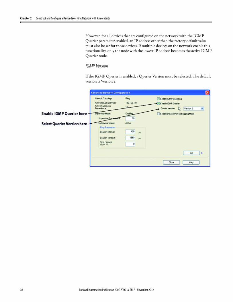
Chapter 3 Monitor a DLR Network
ArmorStart Internal Web Server
Rockwell Automation provides an internal embedded web server with each ArmorStart EtherNetIP The internal web server allows you to view information and configure the ArmorStart via a web browser The ArmorStart EtherNetIP can also be set up from the web server to send e-mail notifications The embedded web server is used to access configuration and status data It provides the user with the ability to view and modify the device configuration without having access to RSLogix 5000 Security in the form of an administrative password can be set The default login is Administrator There is no password set by default
EtherNetIP Device Level Ring (DLR) Network Diagnostics Faceplate
The diagnostics faceplate contains two major components
bull Logic code (encapsulated in an Add-On Instruction) that allows the controller to retrieve real-time DLR network status information
bull HMI faceplate graphics to allow the data to be visualized on an operator interface
Programmatically Through the Use of a MSG Instruction
For more information on how to monitor the DLR network via MSG Instructions see page 46
38 Rockwell Automation Publication 290E-AT001A-EN-P - November 2012
Monitor a DLR Network Chapter 3
Monitor Status Pages Both RSLogix 5000 programming software and RSLinx Classic communication software offer status pages that can be used to monitor the networkrsquos performance
RSLogix 5000 Programming Software Status Pages
Monitor the networkrsquos diagnostic information through the RSLogix 5000 programming software when the software is online
To monitor the network in RSLogix 5000 programming software follow these steps
1 Verify that the project is online
2 Access the active supervisor nodersquos propertiesa Right-click the modulersquos entry in the Controller Organizerb Click properties
Rockwell Automation Publication 290E-AT001A-EN-P - November 2012 39
Chapter 3 Monitor a DLR Network
3 Use the Network tab to monitor diagnostics
40 Rockwell Automation Publication 290E-AT001A-EN-P - November 2012
Monitor a DLR Network Chapter 3
RSLinx Communication Software
To monitor the network in RSLinx communication software follow these steps
1 Click RSWho to browse the network
2 Access the property pages for the active supervisor nodea Open the driver that shows the nodes on the DLR networkb Right-click the node that you want to monitor performancec Click on the choice that you need to access
Multiple choices appear
These options are shown in the following sections
Rockwell Automation Publication 290E-AT001A-EN-P - November 2012 41
Chapter 3 Monitor a DLR Network
Module Configuration
This series of tabs providesbull General informationbull Connection informationbull Module informationbull Internet protocolbull Port configurationbull Network information
The example below shows a ring fault between nodes at IP addresses 10888021 and MAC ID 00-00-BC-02-48-D5
42 Rockwell Automation Publication 290E-AT001A-EN-P - November 2012
Monitor a DLR Network Chapter 3
There are multiple fields used to monitor network diagnostics
Field Definition
Network Topology Possible values here can be Linear or Ring
Network Status Displays if the network is operating normally (Normal) or has experienced a fault (Ring Fault) as shown in the previous example screen
Active Ring Supervisor Displays the IP address or MAC address of the active ring supervisor
Active Supervisor Precedence For more information on this field see Active Ring Supervisor on page 11
Enable Ring Supervisor Configurable field that lets you to set the node as a ring supervisor
Ring Faults Detected Number of faults detected on the network since the last module power cycle or counter reset
Supervisor Status Displays whether this node is the active ring supervisor (Active) a back-up supervisor (Back-up) a ring node or part of a linear network
Last Active Node on Port 1 The last node the active ring supervisor can communicate with on Port 1 This value is an IP address or a MAC ID and remains latched until the Verify Fault Location button is clicked
Last Active Node on Port 2 The last node the active ring supervisor can communicate with on Port 2 This value is an IP address or a MAC ID and remains latched until the Verify Fault Location button is clicked
Status Displays whether a fault exists on the ring
IMPORTANT If the Network Topology field = Ring and the Network Status field = Normal the Last Active Node fields will display the last fault information even though it has been correctedTo clear the last fault information from these fields click Verify Fault Location You may see a message informing you that the supervisor is no longer in fault mode and the fields will be cleared
Rockwell Automation Publication 290E-AT001A-EN-P - November 2012 43
Chapter 3 Monitor a DLR Network
How to Access the ArmorStart EtherNetIP Internal Web Server
Open your preferred internet web browser and enter the IP address of the desired ArmorStart For this example 192168122 will be used
Use the links on the left-most navigation bar to see each available web page The screen below shows Ring Statistics for the ArmorStart 280E
44 Rockwell Automation Publication 290E-AT001A-EN-P - November 2012
Monitor a DLR Network Chapter 3
EtherNetIP Device Level Ring (DLR) Network Diagnostics Faceplate Overview
The EtherNetIP Device Level Ring (DLR) network diagnostics faceplate provides basic DLR network status information to the user to assist with monitoring and troubleshooting a DLR network
The diagnostics faceplate contains two major components
bull Logic code (encapsulated in an Add-On Instruction) that allows the controller to retrieve real-time DLR network status information
bull HMI faceplate graphics to allow the data to be visualized on an operator interface
The DLR diagnostics faceplate application can be downloaded from the Rockwell Automation Sample Code website at httpsamplecoderockwellautomationcom
Besides the individual Logix and View project components a demo application is also included with the downloaded file
Rockwell Automation Publication 290E-AT001A-EN-P - November 2012 45
Chapter 3 Monitor a DLR Network
Monitor Diagnostics via MSG Instructions
Network diagnostic information can also be obtained programmatically via MSG instructions in RSLogix 5000 programming software For example you can
bull Get all ring diagnostic informationbull Get a ring participant listbull Get the active supervisorbull Clear rapid ring faultsbull Verify a fault locationbull Reset a fault counterbull Enable and configure a ring supervisor
This information can be displayed on an HMI device or manipulated in the project code
Figure 5 - Example Use of MSG Instruction
This example describes how to retrieve diagnostic information from the DLR network Follow these steps
1 Enter a MSG instruction into the rung of logic
2 Configure the MSG instruction to retrieve ring diagnostic information service as shown in the following screen shots
IMPORTANT Make sure the tag created is sized appropriately to hold all of the data that you are reading or writing For more information see page 48
46 Rockwell Automation Publication 290E-AT001A-EN-P - November 2012
Monitor a DLR Network Chapter 3
3 Configure the MSG instructionrsquos communication path to point to the active supervisor node
The path on the following screen is one example path
IMPORTANT When using the Custom Get_Attributes_All (01) service pointing to an active supervisor node will retrieve all of the attributes listed in Retrieve All Diagnostic Information Attribute Description on page 50Pointing to a non-supervisor node will retrieve only the Network Topology and Network Status attribute informationPointing to backup supervisor node will retrieve the current active supervisorrsquos IP address
Rockwell Automation Publication 290E-AT001A-EN-P - November 2012 47
Chapter 3 Monitor a DLR Network
Use Specific Values on the Configuration Tab
Use the values on the Configuration tab of your MSG instruction to perform specific services Sample DLR network diagnostic application code for example Add-on Instruction or HMI faceplate graphics is available on the Rockwell Automation Sample Code Library For more information about the Rockwell Automation Sample Code Library see httpwwwrockwellautomationcomsolutionsintegratedarchitectureresources5html
➊ This request only works if there are fewer than 40 nodes on the network If there are more nodes than will fit in a single message an error will be returned➋ Use a Destination Length of 54 bytes if using firmware revision 3x or later for the 1756-EN2TR module or firmware revision 2x or later for the 1783-ETAP
1783-ETAP1F or 1783-ETAP2F taps
Request Description Message Type
Service Type
Service Code (HEX)
Class (HEX)
Instance Attribute (HEX)
Source Element
Source Length (Bytes)
Destination Destination Length (bytes)
Retrieve All Ring Diagnostic Information
Information for this request is listed in Retrieve All Ring Diagnostic Information on page 49
CIP Generic Custom 1 47 1 NA LeftBlank
0 Tag 50or54 ➋
Request Ring Participant List ➊
Information for this request is listed in Request the Ring Participant List on page 51
CIP Generic Get Attribute Single
e 47 1 9 NA NA Tag 10node
Get Active Supervisor
Obtain the IP address and MAC ID of the active supervisor on the DLR network
CIP Generic Get Attribute Single
e 47 1 a NA NA Tag 10
Acknowledge Rapid Ring Faults Condition
Request supervisor to resume normal operation after encountering a rapid ring fault condition
CIP Generic Custom 4c 47 1 NA NA NA NA
Verify a Fault Location
Request supervisor to update Last Active Node values
CIP Generic 4b 47 1 NA NA NA NA NA
Reset the Ring Fault Counter
Reset the number of ring faults detected on the DLR network
CIP Generic Set Attribute Single
10 47 1 5 Tag 2 NA NA
Enable and Configure a Ring Supervisor
Information for this request is listed in Enable and Configure a Ring Supervisor on page 52
CIP Generic Set Attribute Single
10 47 1 4 Tag 12 NA NA
48 Rockwell Automation Publication 290E-AT001A-EN-P - November 2012
Monitor a DLR Network Chapter 3
Retrieve All Ring Diagnostic Information
By performing the Retrieve All Ring Diagnostic Information request on an active supervisor the MSG instruction returns the following information
➊ RSLogix 5000 programming software may display the value in this field as negative numbers To better understand the value we recommend you view it in HEX format
Destination Tag Attribute Name Description Possible Values
SINT [0] Network Topology Current network topology mode 0 = Linear
1 = Ring
SINT [1] Network Status Current status of the network 0 = Normal
1 = Ring Fault
2 = Unexpected Loop Detected
3 = Partial Network Fault
4 = Rapid FaultRestore Cycle
SINT [2] Ring Supervisor Status Ring supervisor active status flag 0 = Node is functioning as a backup
1 = Node is functioning as the active ring supervisor
2 = Node is functioning as a normal ring node
3 = Node is operating in a non-DLR topology
4 = Node cannot support the currently operating ring parameters thatis Beacon Interval andor Beacon Timeout
Ring Supervisor Config Ring Supervisor configuration parameters
SINT [3] Ring Supervisor Enable Ring supervisor enable flag 0 = Node is configured as a normal ring node (default configuration)
1 = Node is configured as a ring supervisor
SINT [4] Ring Supervisor Precedence Precedence value of a ring supervisor ➊ Valid value range = 0hellip255
0 = Default value
SINT [5-8] Beacon Interval Duration of ring beacon interval Valid value range = 200 μshellip100 ms
Default = 400 μs
SINT [9-12] Beacon Timeout Duration of ring beacon timeout Value value range = 400 μshellip500 ms
Default value = 1960 μs
SINT [13-14] DLR VLAN ID Valid ID to use in ring protocol messages Valid value range = 0hellip4094
Default value = 0
SINT [15-16] Ring Faults Count Number of ring faults since power up ➊
Rockwell Automation Publication 290E-AT001A-EN-P - November 2012 49
Chapter 3 Monitor a DLR Network
Retrieve All Diagnostic Information Attribute Description
➊ This destination tag is available only with the 1756-EN2TR module firmware revision 3x or later 1783-ETAP 1783-ETAP1F and 1783-ETAP2F taps firmware revisions 2x or later If using the 1783-ETAP tap firmware revision 1x your program does not include this destination tag
➋ RSLogix 5000 programming software may display the value in this field as negative numbers To better understand the value we recommend you view it in HEX format
Destination Tag Attribute Name Description Possible Values
Last Active Node on Port 1 Last active node at the end of the chain through port 1 of the active ring supervisor during a ring fault
SINT [17-20] Device IP address ➋ Any valid IP address value
A value = 0 indicates no IP address has been configured for the device
SINT [21-26] Device MAC address ➋ Any valid Ethernet MAC address
Last Active Node on Port 2 Last active node at the end of the chain through port 2 of the active ring supervisor during a ring fault
SINT [27-30] Device IP address ➋ Any valid IP address value
A value = 0 indicates no IP address has been configured for the device
SINT [31-36] Device MAC address ➋ Any valid Ethernet MAC address
SINT [37-38] Ring Protocol Participants Count
Number of devices in the ring protocol participants list
Active Supervisor Address IP andor Ethernet MAC address of the active ring supervisor
SINT [39-42] Supervisor IP address Any valid IP address value
A value = 0 indicates no IP address has been configured for the device
SINT [43-48] Supervisor MAC address Any valid Ethernet MAC address
SINT [49] Active Supervisor Precedence
Precedence value of the active ring supervisor
SINT [50-53]➊ Capability Flags Alerts you that the device is capable of operating as a supervisor and beacon-based ring node
0x22
50 Rockwell Automation Publication 290E-AT001A-EN-P - November 2012
Monitor a DLR Network Chapter 3
Request the Ring Participant List
When requesting the Ring Participant List service on the DLR network the MSG instruction returns the following information
Request the Ring Participant List Attribute Description
➊ This attribute will return an array of the data shown one entry for each node The Ring Protocol Participants Count attribute determines the number entries
➋ This tag displays only IP addresses for ring participants that have been configured with one For example you may have a 1783-ETAP tap connected to the network that has not been assigned an IP address In that case no address is shown for the 1783-ETAP tap
➌ RSLogix 5000 programming software may display the value in this field as negative numbers To better understand the value we recommend you view it in HEX format
➍ Unlike destination tag SINT [0-3] where IP addresses are displayed only for ring participants configured with an IP address this tag displays MAC addresses for all ring participants because every ring participant has a MAC address
Destination Tag Attribute Name Description Possible Values
Ring Protocol Participants List ➊
List of devices participating in ring protocol
SINT [0-3] Device IP address ➋➌ Any valid IP address value
A value = 0 indicates no IP address has been configured for the device
SINT [4-9] Device MAC address ➌➍ Any valid Ethernet MAC address
Rockwell Automation Publication 290E-AT001A-EN-P - November 2012 51
Chapter 3 Monitor a DLR Network
Enable and Configure a Ring Supervisor
When performing the Enable and Configure a Ring Supervisor request on a supervisor-capable device configure the MSG instruction with the following information
Enable and Configure a Ring Supervisor Attribute Description
➊ RSLogix 5000 programming software may display the value in this field as negative numbers To better understand the value we recommend you view it in HEX format
Source Tag Attribute Name Description Possible Values
Ring Supervisor Config Ring Supervisor configuration parameters
SINT [0] Ring Supervisor Enable Ring supervisor enable flag 0 = Node is configured as a normal ring node (default configuration)1 = Node is configured as a ring supervisor
SINT [1] Ring Supervisor Precedence Precedence value of a ring supervisor ➊
Valid value range = 0hellip2550 = Default value
SINT [2-5] Beacon Interval Duration of ring beacon interval
Valid value range = 200 μshellip100 000 μsDefault = 400 μs
SINT [6-9] Beacon Timeout Duration of ring beacon timeout ➊
Value value range = 400 μshellip500 000 μsDefault value = 1960 μs
SINT [10-11] DLR VLAN ID Valid ID to use in ring protocol messages ➊
Valid value range = 0hellip4094Default value = 0
52 Rockwell Automation Publication 290E-AT001A-EN-P - November 2012
Chapter 4
Troubleshoot a DLR Network
Introduction Use this chapter to learn how to troubleshoot the DLR network
General Solutions for Linear or DLR Networks
Before attempting to correct specific faults on the linear or DLR network we recommend that you first take the following actions when a fault appears
bull For a DLR networkndash Verify that at least one node has been configured as a supervisor
on the network and that Network Topology = Ringndash Verify that all cables on the network are securely connected
to each devicendash Verify that all devices that require an IP address have one assigned
correctlyndash Check the Network Status field on the active supervisor nodersquos status
page to determine the fault typebull For a linear network
ndash Verify that none of the nodes are configured as a supervisor on the network and that Network Topology = LinearIf any nodes on a linear network are configured as a supervisor it may impact communication to other devices connected to the network
ndash Verify that all cables on the network are securely connected to each device
ndash Verify that all devices that require an IP address have one assigned correctly
If the fault is not cleared after completing the actions listed above use the tables in the rest of this chapter to troubleshoot issues specific to a DLR network or a linear network
Topic Page
General Solutions for the Linear or DLR Networks 53
Duplicate IP Address Detection 54
Specific Issues on the DLR Network 55
Network Recovery Performance 58
Device Port Debugging Mode 59
Rockwell Automation Publication 290E-AT001A-EN-P - November 2012 53
Chapter 4 Troubleshoot a DLR Network
Duplicate IP Address Detection
Some EtherNetIP communication modules support duplicate IP address detection The module verifies that its IP address does not match any other network devicersquos IP address when performing either of these tasks
bull Connect the module to an EtherNetIP network
bull Change the modulersquos IP address
If the modulersquos IP address matches that of another device on the network the modulersquos EtherNetIP port transitions to Conflict mode In Conflict mode these conditions exist
bull OK status indicator is blinking red
bull Network (NET) status indicator is solid red
bull On some EtherNetIP communication modules the module status display indicates the conflict
The display scrollsOK ltIP_address_of_this_modulegt Duplicate IP
ltMac_address_of_duplicate_node_detectedgt
For example OK 108860196 Duplicate IP - 0000BC0234B4
bull On some EtherNetIP communication modules the modulersquos diagnostic webpage displays information about duplicate IP address detection
For more information on which EtherNetIP communication modules support displaying duplicate IP address on their diagnostic webpage see the Technical Note titled Logix modules Duplicate IP address detection enhancement 118216 in the Technical Support Knowledgebase available at httpwwwrockwellautomationcomknowledgebase
54 Rockwell Automation Publication 290E-AT001A-EN-P - November 2012
Troubleshoot a DLR Network Chapter 4
Specific Issues on the DLR Network
Use the following table to troubleshoot possible specific issues on the DLR or linear network that are not solved by the actions described on the previous page
Issue Description Solution
Supervisor Reports a Ring Fault A link on the DLR network may be brokenbull intentionally for example because of adding or deleting nodes but not making all
physical connections to restore the setup of the network withwithout the nodebull unintentionally for example because a cable is broken or a device malfunctionsWhen this fault occurs the adjacent nodes to the faulted part of the network are displayed in the Ring Fault group and the Network Status field = Ring FaultThe screen shot below shows the Ring Fault section with IP addresses appearing for the last active nodes The faulted node is between nodes 108880115 and 108880208 If the IP address of either node is not available the software will display the nodersquos MAC ID
Once the fault is corrected the ring is automatically restored and the Network Status field returns to Normal
Determine where the fault condition exists and correct itClick the Refresh Communication link as needed to update the Ring Fault information to determine where the fault condition existsFinally DevicePort Debugging Mode functionality on the 1783-ETAP tap may be used to analyze a suspicious nodeFor more information refer to Device Port Debugging Mode on page 59
Rockwell Automation Publication 290E-AT001A-EN-P - November 2012 55
Chapter 4 Troubleshoot a DLR Network
Issue Description Solution
Rapid Ring Fault When a Rapid Ring Fault occurs the following events occurbull The active supervisor will block traffic on port 2 resulting in possible network
segmentation that is some nodes may become unreachablebull The Link 2 status indicator on the active supervisor is offbull As soon as the fault occurs for both RSLogix 5000 programming software and
RSLinx communication software the Status field = Rapid FaultRestore Cycles
Any of the following may cause a Rapid Ring Faultbull 5 intentional disconnectionsreconnections of a node from the network within 30
secondsbull A duplex mismatch between two connected devicesbull Electromagnetic noise on the networkbull Unstable physical connections such as intermittent connectorsGiven the nature of a Rapid Ring Fault the Last Active Node information may not be accurate when a Rapid Ring Fault condition is present
Multiple possible solutions existbull For the disconnections and reconnections issue no
solution is requiredClear the fault after reconnecting the device to the network permanentlybull For the duplex mismatch issue reconfigure the duplex
parameters to make sure they match between the devices
bull For the electromagnetic noise issue determine where the noise exists and eliminate it or use a protective shield in that location
bull For the unstable connections issue determine where they exist on the network and correct them
bull Check the media counters for all devices on the network The device with the highest media counter count is most likely causing the Rapid Ring Fault
bull Remove devices from the network one by one If the Rapid Ring Fault disappears after a device is removed that device is causing the fault
bull DevicePort Debugging Mode functionality on the 1783-ETAP tap may be used to analyze a suspicious node
For more information refer to Device Port Debugging Mode on page 59bull Finally the Beacon Interval or Timeout configuration
may not be appropriate for the networkHowever if these values need to be changed we recommend that you contact Rockwell Automation technical supportOnce the fault is fixed click Clear Fault
56 Rockwell Automation Publication 290E-AT001A-EN-P - November 2012
Troubleshoot a DLR Network Chapter 4
Issue Description Solution
Partial Fault Condition A partial network fault occurs when traffic is lost in only one direction on the network because a ring member is not forwarding beacons in both directions for example a component failureThe active ring supervisor detects a partial fault by monitoring the loss of Beacon frames on one port and the fault location appears in the Ring Fault section of the Network tab When a partial fault is detected the active ring supervisor blocks traffic on one port At this point the ring is segmented due to the partial fault condition The nodes adjacent to the faulted part of the network are displayed in the Ring Fault group with either IP addresses or MAC IDs for each node displayedWhen this fault occurs the Network Status field = Partial Fault ConditionOnce the fault is corrected it automatically clears and the Network Status field returns to Normal
Determine where the fault condition exists and correct itAdditionally the DevicePort Debugging Mode functionality also known as Port Mirroring on a 1783-ETAP 1783-ETAP1F or 1783-ETAP2F tap may be used to analyze a suspicious nodeFor more information refer to Device Port Debugging Mode on page 59
Media Counter Errors or Collisions
The media counters screen displays the number of physical layer errors or collisions The screen below indicates where to check for errors encountered Error levels are displayed depending on what caused the error For example an Alignment Error is displayed in the Alignment Error field
On a DLR network it is not uncommon to see low levels of media counter errors For example if the network breaks a low level of media counter errors appears With a low level of media counter errors the value typically does not continuously increase and often clearsA high level of media counter errors typically continues to increase and does not clear For example there is a mismatch of speed between two linked nodes a high level of media counter errors appears steadily increasing and not clearingTo access the RSLinx screen above browse the network right-click on the device select Module Properties and click the Port Diagnostics tab
Some example solutions includebull Check for a mismatch of speed andor duplex between
two linked nodesbull Verify that all cables on the network are securely
connected to each devicebull Check for electromagnetic noise on the network If you
find it eliminate it or use a protective shield in that location
Rockwell Automation Publication 290E-AT001A-EN-P - November 2012 57
Chapter 4 Troubleshoot a DLR Network
Network Recovery Performance
When measuring the networkrsquos performance with regard to dealing with fault conditions consider the network recovery time Network recovery is the time for all of the following to take place
1 The supervisor node recognizes that a fault exists on the network
2 The supervisor node reconfigures the network because of the fault
3 The supervisor node communicates to the network nodes that a fault condition exists
4 The network nodes reconfigure themselves because of the fault
With the default beacon interval value of 400 mS and beacon timeout value of 1960 mS the worst-case time for network recovery times are
bull 2890 mS for a copper DLR network This recovery time is based on 100 m copper segments between nodes on the network
bull 3140 mS for a fiber-optic DLR network This recovery time is based on 2 kM fiber-optic cable segments between nodes on the network
When considering the values listed above keep in mind
bull Recovery time may actually occur faster than the times listed
bull The recovery times listed above assume that your networkrsquos nodes are operating at 100 Mbps speed and full-duplex mode We recommend that your nodes generally operate in this mode for DLR networks
bull If other node conditions exist such as a node operating at 10 Mbps full-duplex or 10100 Mbps half-duplex the recovery times will vary from the times listed above
If this is the case for your application the beacon interval and beacon timeout will need to be changed We recommend that you first contact Rockwell Automation technical support if these parameters need to be changed
bull The value assumes that the majority of the traffic on your network is EtherNetIP traffic
58 Rockwell Automation Publication 290E-AT001A-EN-P - November 2012
Troubleshoot a DLR Network Chapter 4
Device Port Debugging Mode
This functionality is disabled by default Device Port Debugging mode which is similar to port mirroring can be used to monitor data received on the 1783-ETAP 1783-ETAP1F or 1783-ETAP2F taprsquos two network ports Monitor the data over the device port to a device such as a personal computer running a protocol analyzer application for advanced network debugging or analysis
When device port debugging is used on a 1783-ETAP the device connected to the 1783-ETAP taprsquos front port receives all of the data traversing the ring (both directions)
Device Port Debugging Example Network
When using the Device Port Debugging mode functionality insert the 1783-ETAP with the network analyzer connected to the device port It is inserted at the spot on the ring network where the node in question is located The graphic below shows a 1783-ETAP tap inserted in the network
IMPORTANT This functionality should be used only when troubleshooting the network and not in normal network operation
Rockwell Automation Publication 290E-AT001A-EN-P - November 2012 59
Chapter 4 Troubleshoot a DLR Network
Combined total network bandwidth of the traffic received on the two 1783-ETAP 1783-ETAP1F or 1783-ETAP2F taprsquos ports connected to the network should not exceed the taprsquos device port capacity The speed setting determines the device portrsquos capacity
Configure the device port on a 1783-ETAP 1783-ETAP1F or 1783-ETAP2F tap to either of two speed settings
bull 100 Mbps - default settingbull 10 Mbps
If the bandwidth exceeds the capacity of the taprsquos device port some frames from the ring will be dropped before reaching the device port These dropped frames do not impact the traffic on the rest of the DLR network
The device port setting determines how much network traffic the 1783-ETAP 1783-ETAP1F or 1783-ETAP2F tap can handle before dropping frames The circled section in the graphic below shows the Port Buffer Utilization of the Device Port In this example the value is zero because a ring fault exists on the network
60 Rockwell Automation Publication 290E-AT001A-EN-P - November 2012
Appendix A
Network Usage Guidelines and Recommendations
Consider the following guidelines and recommendations when using a DLR or linear network
GuidelineRecommendation Explanation
Use fewer than 50 nodes on a single DLR networkIf your application requires more than 50 nodes we recommend that the nodes are broken into separate but linked DLR networks
If you use more than 50 nodes on a single DLR networkbull Your network has a greater chance of multiple faults
occurring on the networkbull Network recovery times from faulted DLR network
are higher
Do not configure a supervisor on a linear network If your linear network includes non-DLR nodes and has a supervisor-enabled node on the network it may impact communication to non-DLR devices connected to the linear network
If you must connect a device that is running at 10 Mbps to a DLR or linear network do so through a 1783-ETAP 1783-ETAP1F or 1783-ETAP2F tap device port
The 1783-ETAP 1783-ETAP1F and 1783-ETAP2F taps can operate at 100 Mbps on the DLR network this is the optimal speed for a network If you connect a 10 Mbps device directly to the network instead of through a tap the linear or DLR network traffic slows to 10 MbpsAdditionally if the 10 Mbps device is connected to the network without a 1783-ETAP tap network recovery times are significantly impacted
Configure multiple supervisor nodes per ring If your DLR network only has one supervisor and the supervisor experiences a fault none of the other nodes become the active supervisor In this case the network becomes a linear network until the fault is corrected and the DLR network restoredAnother reason to configure multiple supervisor nodes is for replacing an active supervisor node with an out-of-box replacement the new device will not be enabled as a supervisor (by default) and there would still be no supervisor on the network
Rockwell Automation Publication 290E-AT001A-EN-P - November 2012 61
Appendix A Network Usage Guidelines and Recommendations
GuidelineRecommendation Explanation
Connect switches to a DLR network via 1783-ETAP 1783-ETAP1F or 1783-ETAP2F taps
If switches are connected to the DLR network without the use of a 1783-ETAP 1783-ETAP1F or 1783-ETAP2F tap the network may experience unpredictable behavior and network performance is unknown
Run all nodes on the DLR network at 100 Mbps and in Full-Duplex mode
These configuration values provide the best performance for your networkAdditionally we recommend that youbull Use auto-negotiate for all nodes on the DLR networkbull Do not use auto-negotiate on one node and then force
speed on the next node linked to it
In a linear network the number of nodes to use is application specific based on the considerations described in the next box
When determining the number of nodes to use on a linear network consider the followingbull There is a delay per node as information is transmitted
to each successive node used on the networkndash The typical delay on a linear network with 100 m
copper segments between nodes is 30 mSndash The typical delay on a linear network with 2 kM
fiber-optic segments between nodes is 40 mS
The greater the number of nodes on the network the longer the total time for information to be transmitted across the entire networkbull The single point of failure possibility is greater with
each additional connectionbull Troubleshooting the network may be more difficult
with a higher number of nodes
The total time for information to be transmitted across the entire network and its effect on how many nodes to use on a linear network is related to the Requested Packet Interval (RPI)Verify that the total time to transmit information from the first node to the last node on the network is less than the RPI Make sure the network is not loaded beyond 90 of capacity
62 Rockwell Automation Publication 290E-AT001A-EN-P - November 2012
Network Usage Guidelines and Recommendations Appendix A
GuidelineRecommendation Explanation
Do not physically close a DLR network without a supervisor configured on the network
A DLR network without a supervisor node results in a network stormIf you do close the DLR network without a supervisor configured break the ring and configure at least one supervisor before physically reconnecting the network
Use the default values for the followingbull Beacon Intervalbull Beacon Timeoutbull Ring Protocol VLAN ID
Changing the default values for the parameters Beacon Interval Beacon Timeout and Ring Protocol VLAN ID can result in unpredictable network behavior and negatively impacted network performanceThe default values are optimized for a network withbull 50 or fewer nodes are on the networkbull All nodes are operating at 100 Mbps and full-duplex
modebull At least 50 of the network traffic bandwidth being
EtherNetIP trafficIf you think the values of the Beacon Interval Beacon Timeout or Ring Protocol VLAN ID need to be changed for example if any node on ring is not operating at 100 Mbps and full-duplex mode we recommend that you first contact Rockwell Automation technical support
If DHCP for the ArmorStarts is still required you will need to disable Internet Group Management Protocol (IGMP) snooping on the E-tap via the AOP
IGMP Snooping is enabled by default in the 1783-ETAP 1783-ETAP1F and 1783-ETAP2F taps and is commonly used to manage multicast traffic on the network When in use this functionality allows the tap to multicast data to only those devices that need the data rather than to all devices connected to the networkOnce DHCP is enabled the switch could change the IP addresses on the ArmorStarts depending on network demand which could cause RSlogix5000 to loose communication with the device as connectivity is established via the AOP in the initial configuration
The IGMP Querier functionality should be enabled for at least one node on the network
This functionality is disabled by default The IGMP Querier functionality enables a 1783-ETAP 1783-ETAP1F or 1783-ETAP2F tap or switch such as a Stratix managed switch to send out a query to all devices on the network to determine what multicast addresses are of interest to a specific node or a group of nodesIf the IGMP Querier functionality is not enabled for at least one node on the network multicast traffic on the network may eventually create network performance issuesThe 1783-ETAP 1783-ETAP1F or 1783-ETAP2F taps managed switches and routers are examples of devices that support IGMP Querier functionality
Rockwell Automation Publication 290E-AT001A-EN-P - November 2012 63
Appendix A Network Usage Guidelines and Recommendations
Notes
64 Rockwell Automation Publication 290E-AT001A-EN-P - November 2012
Appendix B
Required Firmware Revisions
Required Firmware Revision for an Add-On Profile
➊ The ControlFLASH Firmware Upgrade software tcan be used o upgrade a 1756-EN2TR module from firmware revision 21 to 3x or later1x or later3x or later2x or later
➋ The ControlFLASH Firmware Upgrade software can be used to upgrade a 1783-ETAP tap from firmware revision 11 to 2x or later
To download new firmware go to httpwwwrockwellautomationcomsupportamericasindex_enhtml
If the firmware revision is upgraded on the module or tap the required AOP revision listed above must be used for that revision For example if the 1756-EN2TR module is upgraded to firmware revision 3x or later AOP revision 2x or later must be used in the RSLogix 5000 programming software
Additionally if the firmware revision is upgraded on the module or tap the required RSLinx communication software must also be used for that firmware revision For more information on which RSLinx software version is required for each firmware revision see page 66
For both the 1756-EN2TR module and 1783-ETAP tap make sure that the Major Revision configured on the General tab of the devicersquos RSLogix 5000 programming software configuration matches the major revision of the physical module
IMPORTANT To download an AOP go to httpsupportrockwellautomationcomcontrolflashLogixProfileraspDepending on the firmware revision of your product a specific AOP version must be used
Firmware Revision Add-On Profile Revision Cat No
21 ➊ 1x or later 1756-EN2TR
3x or later 2x or later
11 ➋ 1x or later 1783-ETAP
2x or later 2x or later
2x or later 2x or later 1783-ETAP1F
1783-ETAP2F
Rockwell Automation Publication 290E-AT001A-EN-P - November 2012 65
Appendix B Required Firmware Revisions
If the device configuration on the General tab does not match the physical module the programming software alerts you to this mismatch when attempting to configure the Internet Protocol Port Configuration and Network tabs for that device
Required Firmware Revision for RSLinx Communication Software
➊ The ControlFLASH Firmware Upgrade software can be used to upgrade a 1756-EN2TR module from firmware revision 21 to 3x or later1x or later3x or later255 or later3x or later256 or later
➋ The ControlFLASH Firmware Upgrade software can be used to upgrade a 1783-ETAP tap from firmware revision 11 to 2x or later
To download new firmware go to httpwwwrockwellautomationcomsupportamericasindex_enhtml
If the firmware revision is upgraded on the module or tap the required RSLinx communication software listed above must be used for that revision For example if the 1756-EN2TR module is upgraded to firmware revision 3x or later AOP revision 2x or later must be used in your RSLogix 5000 programming software
Additionally if the firmware revision is upgraded on the module or tap the required AOP revision must also be used for that firmware revision For more information on which AOP revision is required for each firmware revision see page 65
IMPORTANT Depending on the firmware revision of your product specific versions of RSLinx communication software must be used
Firmware Revision Required RSLinx Communication Software Version
Cat No
21 ➊ 255 or later 1756-EN2TR
3x or later 256 or later
11 ➋ 255 or later 1783-ETAP
2x or later 256 or later
2x or later 256 or later 1783-ETAP1F
1783-ETAP2F
66 Rockwell Automation Publication 290E-AT001A-EN-P - November 2012
Rockwell Otomasyon Ticaret AŞ Kar Plaza İş Merkezi E Blok Kat6 34752 İccedilerenkoumly İstanbul Tel +90 (216) 5698400
Rockwell Automation Publication 290E-AT001A-EN-P ndash November 2012 68 Copyright copy 2012 Rockwell Automation Inc All rights reserved Printed in the USA
Rockwell Automation Support
Rockwell Automation provides technical information on the Web to assist you in using its products At httpwwwrockwellautomationcomsupport you can find technical manuals a knowledge base of FAQs technical and application notes sample code and links to software service packs and a MySupport feature that you can customize to make thebest use of these tools
For an additional level of technical phone support for installation configuration and troubleshooting we offer TechConnectSM support programs For more information contact your local distributor or Rockwell Automation representative or visit httpwwwrockwellautomationcomsupport
Installation Assistance
If you experience a problem within the first 24 hours of installation review the information that is contained in this manualYou can contact Customer Support for initial help in getting your product up and running
New Product Satisfaction Return
Rockwell Automation tests all of its products to ensure that they are fully operational when shipped from the manufacturing facility However if your product is not functioning and needs to be returned follow these procedures
Documentation Feedback
Your comments will help us serve your documentation needs better If you have any suggestions on how to improve this document complete this form publication RA-DU002 available at httpwwwrockwellautomationcomliterature
United States or Canada 14406463434
Outside United States or Canada Use the Worldwide Locator at httpwwwrockwellautomationcomsupportamericasphone_enhtml or contact your local Rockwell Automation representative
United States Contact your distributor You must provide a Customer Support case number (call the phone number above to obtain one) to your distributor to complete the return process
Outside United States Please contact your local Rockwell Automation representative for the return procedure
- Important User Information
- General Precautions
- Software Requirements
- Additional Resources
- Rockwell Automation Support
- Installation Assistance
- New Product Satisfaction Return
- Table of Contents
- Chapter 1
-
- Device-Level Ring (DLR) Basics
-
- Introduction
- ArmorStart with EtherNetIP Overview
- What is a Device-level Ring (DLR) Network
- DLR Network Elements
-
- Supervisor Node
- Ring Node
-
- DLR Network Operation
- Number of Nodes on a DLR Network
- DLR Network Fault Management
-
- Network Reconfiguration after a Fault
-
- Chapter 2
-
- Construct and Configure a Device-level Ring Network with ArmorStarts
-
- Introduction
- Ethernet Capacity Tool
- Install Devices on a DLR Network
- ArmorStart Addressing Configuration
-
- Using the BootPDHCP Server
- Using the Rotary Network Address Switches
- Using the ArmorStart Internal Web Server
-
- Configure Supervisor Nodes on a DLR Network
-
- Configure a Ring Supervisor in RSLogix 5000 Programming Software
- Adding an Armorstart to RSLogix 5000
- Enable Ring Supervisor in RSLogix 5000 Programming Software
- Configure and Enable a Ring Supervisor in RSLinx Classic Communication Software
-
- Complete the Physical Connections of the Network
- Verify Supervisor Configuration
- IGMP Snooping
- IGMP Querier
-
- Chapter 3
-
- Monitor a DLR Network
-
- Introduction
- Methods to Monitor a DLR Network
-
- RSLogix 5000 Programming Software Status Pages
- RSLinx Communication Software Status Pages
- ArmorStart Internal Web Server
- EtherNetIP Device Level Ring (DLR) Network Diagnostics Faceplate
- Programmatically Through the Use of a MSG Instruction
-
- Monitor Status Pages
-
- RSLogix 5000 Programming Software Status Pages
- RSLinx Communication Software
-
- How to Access the ArmorStart EtherNetIP Internal Web Server
-
- EtherNetIP Device Level Ring (DLR) Network Diagnostics Faceplate Overview
-
- Monitor Diagnostics via MSG Instructions
-
- Use Specific Values on the Configuration Tab
- Retrieve All Ring Diagnostic Information
- Retrieve All Diagnostic Information Attribute Description
- Request the Ring Participant List
- Request the Ring Participant List Attribute Description
-
- Enable and Configure a Ring Supervisor
-
- Enable and Configure a Ring Supervisor Attribute Description
-
- Chapter 4
-
- Troubleshoot a DLR Network
-
- Introduction
- General Solutions for Linear or DLR Networks
- Duplicate IP Address Detection
- Specific Issues on the DLR Network
- Network Recovery Performance
- Device Port Debugging Mode
-
- Device Port Debugging Example Network
-
- Appendix A
-
- Network Usage Guidelines and Recommendations
-
- Notes
-
- Appendix B
-
- Required Firmware Revisions
-
- Required Firmware Revision for an Add-On Profile
- Required Firmware Revision for RSLinx Communication Software
-
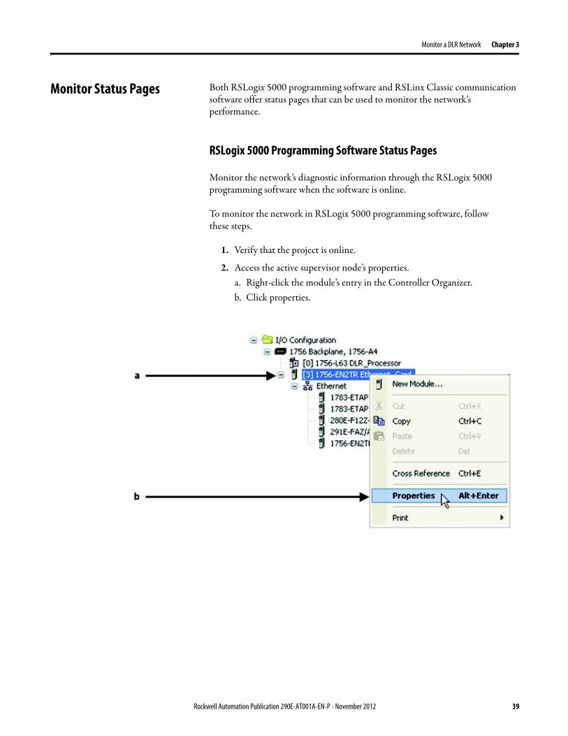
Monitor a DLR Network Chapter 3
Monitor Status Pages Both RSLogix 5000 programming software and RSLinx Classic communication software offer status pages that can be used to monitor the networkrsquos performance
RSLogix 5000 Programming Software Status Pages
Monitor the networkrsquos diagnostic information through the RSLogix 5000 programming software when the software is online
To monitor the network in RSLogix 5000 programming software follow these steps
1 Verify that the project is online
2 Access the active supervisor nodersquos propertiesa Right-click the modulersquos entry in the Controller Organizerb Click properties
Rockwell Automation Publication 290E-AT001A-EN-P - November 2012 39
Chapter 3 Monitor a DLR Network
3 Use the Network tab to monitor diagnostics
40 Rockwell Automation Publication 290E-AT001A-EN-P - November 2012
Monitor a DLR Network Chapter 3
RSLinx Communication Software
To monitor the network in RSLinx communication software follow these steps
1 Click RSWho to browse the network
2 Access the property pages for the active supervisor nodea Open the driver that shows the nodes on the DLR networkb Right-click the node that you want to monitor performancec Click on the choice that you need to access
Multiple choices appear
These options are shown in the following sections
Rockwell Automation Publication 290E-AT001A-EN-P - November 2012 41
Chapter 3 Monitor a DLR Network
Module Configuration
This series of tabs providesbull General informationbull Connection informationbull Module informationbull Internet protocolbull Port configurationbull Network information
The example below shows a ring fault between nodes at IP addresses 10888021 and MAC ID 00-00-BC-02-48-D5
42 Rockwell Automation Publication 290E-AT001A-EN-P - November 2012
Monitor a DLR Network Chapter 3
There are multiple fields used to monitor network diagnostics
Field Definition
Network Topology Possible values here can be Linear or Ring
Network Status Displays if the network is operating normally (Normal) or has experienced a fault (Ring Fault) as shown in the previous example screen
Active Ring Supervisor Displays the IP address or MAC address of the active ring supervisor
Active Supervisor Precedence For more information on this field see Active Ring Supervisor on page 11
Enable Ring Supervisor Configurable field that lets you to set the node as a ring supervisor
Ring Faults Detected Number of faults detected on the network since the last module power cycle or counter reset
Supervisor Status Displays whether this node is the active ring supervisor (Active) a back-up supervisor (Back-up) a ring node or part of a linear network
Last Active Node on Port 1 The last node the active ring supervisor can communicate with on Port 1 This value is an IP address or a MAC ID and remains latched until the Verify Fault Location button is clicked
Last Active Node on Port 2 The last node the active ring supervisor can communicate with on Port 2 This value is an IP address or a MAC ID and remains latched until the Verify Fault Location button is clicked
Status Displays whether a fault exists on the ring
IMPORTANT If the Network Topology field = Ring and the Network Status field = Normal the Last Active Node fields will display the last fault information even though it has been correctedTo clear the last fault information from these fields click Verify Fault Location You may see a message informing you that the supervisor is no longer in fault mode and the fields will be cleared
Rockwell Automation Publication 290E-AT001A-EN-P - November 2012 43
Chapter 3 Monitor a DLR Network
How to Access the ArmorStart EtherNetIP Internal Web Server
Open your preferred internet web browser and enter the IP address of the desired ArmorStart For this example 192168122 will be used
Use the links on the left-most navigation bar to see each available web page The screen below shows Ring Statistics for the ArmorStart 280E
44 Rockwell Automation Publication 290E-AT001A-EN-P - November 2012
Monitor a DLR Network Chapter 3
EtherNetIP Device Level Ring (DLR) Network Diagnostics Faceplate Overview
The EtherNetIP Device Level Ring (DLR) network diagnostics faceplate provides basic DLR network status information to the user to assist with monitoring and troubleshooting a DLR network
The diagnostics faceplate contains two major components
bull Logic code (encapsulated in an Add-On Instruction) that allows the controller to retrieve real-time DLR network status information
bull HMI faceplate graphics to allow the data to be visualized on an operator interface
The DLR diagnostics faceplate application can be downloaded from the Rockwell Automation Sample Code website at httpsamplecoderockwellautomationcom
Besides the individual Logix and View project components a demo application is also included with the downloaded file
Rockwell Automation Publication 290E-AT001A-EN-P - November 2012 45
Chapter 3 Monitor a DLR Network
Monitor Diagnostics via MSG Instructions
Network diagnostic information can also be obtained programmatically via MSG instructions in RSLogix 5000 programming software For example you can
bull Get all ring diagnostic informationbull Get a ring participant listbull Get the active supervisorbull Clear rapid ring faultsbull Verify a fault locationbull Reset a fault counterbull Enable and configure a ring supervisor
This information can be displayed on an HMI device or manipulated in the project code
Figure 5 - Example Use of MSG Instruction
This example describes how to retrieve diagnostic information from the DLR network Follow these steps
1 Enter a MSG instruction into the rung of logic
2 Configure the MSG instruction to retrieve ring diagnostic information service as shown in the following screen shots
IMPORTANT Make sure the tag created is sized appropriately to hold all of the data that you are reading or writing For more information see page 48
46 Rockwell Automation Publication 290E-AT001A-EN-P - November 2012
Monitor a DLR Network Chapter 3
3 Configure the MSG instructionrsquos communication path to point to the active supervisor node
The path on the following screen is one example path
IMPORTANT When using the Custom Get_Attributes_All (01) service pointing to an active supervisor node will retrieve all of the attributes listed in Retrieve All Diagnostic Information Attribute Description on page 50Pointing to a non-supervisor node will retrieve only the Network Topology and Network Status attribute informationPointing to backup supervisor node will retrieve the current active supervisorrsquos IP address
Rockwell Automation Publication 290E-AT001A-EN-P - November 2012 47
Chapter 3 Monitor a DLR Network
Use Specific Values on the Configuration Tab
Use the values on the Configuration tab of your MSG instruction to perform specific services Sample DLR network diagnostic application code for example Add-on Instruction or HMI faceplate graphics is available on the Rockwell Automation Sample Code Library For more information about the Rockwell Automation Sample Code Library see httpwwwrockwellautomationcomsolutionsintegratedarchitectureresources5html
➊ This request only works if there are fewer than 40 nodes on the network If there are more nodes than will fit in a single message an error will be returned➋ Use a Destination Length of 54 bytes if using firmware revision 3x or later for the 1756-EN2TR module or firmware revision 2x or later for the 1783-ETAP
1783-ETAP1F or 1783-ETAP2F taps
Request Description Message Type
Service Type
Service Code (HEX)
Class (HEX)
Instance Attribute (HEX)
Source Element
Source Length (Bytes)
Destination Destination Length (bytes)
Retrieve All Ring Diagnostic Information
Information for this request is listed in Retrieve All Ring Diagnostic Information on page 49
CIP Generic Custom 1 47 1 NA LeftBlank
0 Tag 50or54 ➋
Request Ring Participant List ➊
Information for this request is listed in Request the Ring Participant List on page 51
CIP Generic Get Attribute Single
e 47 1 9 NA NA Tag 10node
Get Active Supervisor
Obtain the IP address and MAC ID of the active supervisor on the DLR network
CIP Generic Get Attribute Single
e 47 1 a NA NA Tag 10
Acknowledge Rapid Ring Faults Condition
Request supervisor to resume normal operation after encountering a rapid ring fault condition
CIP Generic Custom 4c 47 1 NA NA NA NA
Verify a Fault Location
Request supervisor to update Last Active Node values
CIP Generic 4b 47 1 NA NA NA NA NA
Reset the Ring Fault Counter
Reset the number of ring faults detected on the DLR network
CIP Generic Set Attribute Single
10 47 1 5 Tag 2 NA NA
Enable and Configure a Ring Supervisor
Information for this request is listed in Enable and Configure a Ring Supervisor on page 52
CIP Generic Set Attribute Single
10 47 1 4 Tag 12 NA NA
48 Rockwell Automation Publication 290E-AT001A-EN-P - November 2012
Monitor a DLR Network Chapter 3
Retrieve All Ring Diagnostic Information
By performing the Retrieve All Ring Diagnostic Information request on an active supervisor the MSG instruction returns the following information
➊ RSLogix 5000 programming software may display the value in this field as negative numbers To better understand the value we recommend you view it in HEX format
Destination Tag Attribute Name Description Possible Values
SINT [0] Network Topology Current network topology mode 0 = Linear
1 = Ring
SINT [1] Network Status Current status of the network 0 = Normal
1 = Ring Fault
2 = Unexpected Loop Detected
3 = Partial Network Fault
4 = Rapid FaultRestore Cycle
SINT [2] Ring Supervisor Status Ring supervisor active status flag 0 = Node is functioning as a backup
1 = Node is functioning as the active ring supervisor
2 = Node is functioning as a normal ring node
3 = Node is operating in a non-DLR topology
4 = Node cannot support the currently operating ring parameters thatis Beacon Interval andor Beacon Timeout
Ring Supervisor Config Ring Supervisor configuration parameters
SINT [3] Ring Supervisor Enable Ring supervisor enable flag 0 = Node is configured as a normal ring node (default configuration)
1 = Node is configured as a ring supervisor
SINT [4] Ring Supervisor Precedence Precedence value of a ring supervisor ➊ Valid value range = 0hellip255
0 = Default value
SINT [5-8] Beacon Interval Duration of ring beacon interval Valid value range = 200 μshellip100 ms
Default = 400 μs
SINT [9-12] Beacon Timeout Duration of ring beacon timeout Value value range = 400 μshellip500 ms
Default value = 1960 μs
SINT [13-14] DLR VLAN ID Valid ID to use in ring protocol messages Valid value range = 0hellip4094
Default value = 0
SINT [15-16] Ring Faults Count Number of ring faults since power up ➊
Rockwell Automation Publication 290E-AT001A-EN-P - November 2012 49
Chapter 3 Monitor a DLR Network
Retrieve All Diagnostic Information Attribute Description
➊ This destination tag is available only with the 1756-EN2TR module firmware revision 3x or later 1783-ETAP 1783-ETAP1F and 1783-ETAP2F taps firmware revisions 2x or later If using the 1783-ETAP tap firmware revision 1x your program does not include this destination tag
➋ RSLogix 5000 programming software may display the value in this field as negative numbers To better understand the value we recommend you view it in HEX format
Destination Tag Attribute Name Description Possible Values
Last Active Node on Port 1 Last active node at the end of the chain through port 1 of the active ring supervisor during a ring fault
SINT [17-20] Device IP address ➋ Any valid IP address value
A value = 0 indicates no IP address has been configured for the device
SINT [21-26] Device MAC address ➋ Any valid Ethernet MAC address
Last Active Node on Port 2 Last active node at the end of the chain through port 2 of the active ring supervisor during a ring fault
SINT [27-30] Device IP address ➋ Any valid IP address value
A value = 0 indicates no IP address has been configured for the device
SINT [31-36] Device MAC address ➋ Any valid Ethernet MAC address
SINT [37-38] Ring Protocol Participants Count
Number of devices in the ring protocol participants list
Active Supervisor Address IP andor Ethernet MAC address of the active ring supervisor
SINT [39-42] Supervisor IP address Any valid IP address value
A value = 0 indicates no IP address has been configured for the device
SINT [43-48] Supervisor MAC address Any valid Ethernet MAC address
SINT [49] Active Supervisor Precedence
Precedence value of the active ring supervisor
SINT [50-53]➊ Capability Flags Alerts you that the device is capable of operating as a supervisor and beacon-based ring node
0x22
50 Rockwell Automation Publication 290E-AT001A-EN-P - November 2012
Monitor a DLR Network Chapter 3
Request the Ring Participant List
When requesting the Ring Participant List service on the DLR network the MSG instruction returns the following information
Request the Ring Participant List Attribute Description
➊ This attribute will return an array of the data shown one entry for each node The Ring Protocol Participants Count attribute determines the number entries
➋ This tag displays only IP addresses for ring participants that have been configured with one For example you may have a 1783-ETAP tap connected to the network that has not been assigned an IP address In that case no address is shown for the 1783-ETAP tap
➌ RSLogix 5000 programming software may display the value in this field as negative numbers To better understand the value we recommend you view it in HEX format
➍ Unlike destination tag SINT [0-3] where IP addresses are displayed only for ring participants configured with an IP address this tag displays MAC addresses for all ring participants because every ring participant has a MAC address
Destination Tag Attribute Name Description Possible Values
Ring Protocol Participants List ➊
List of devices participating in ring protocol
SINT [0-3] Device IP address ➋➌ Any valid IP address value
A value = 0 indicates no IP address has been configured for the device
SINT [4-9] Device MAC address ➌➍ Any valid Ethernet MAC address
Rockwell Automation Publication 290E-AT001A-EN-P - November 2012 51
Chapter 3 Monitor a DLR Network
Enable and Configure a Ring Supervisor
When performing the Enable and Configure a Ring Supervisor request on a supervisor-capable device configure the MSG instruction with the following information
Enable and Configure a Ring Supervisor Attribute Description
➊ RSLogix 5000 programming software may display the value in this field as negative numbers To better understand the value we recommend you view it in HEX format
Source Tag Attribute Name Description Possible Values
Ring Supervisor Config Ring Supervisor configuration parameters
SINT [0] Ring Supervisor Enable Ring supervisor enable flag 0 = Node is configured as a normal ring node (default configuration)1 = Node is configured as a ring supervisor
SINT [1] Ring Supervisor Precedence Precedence value of a ring supervisor ➊
Valid value range = 0hellip2550 = Default value
SINT [2-5] Beacon Interval Duration of ring beacon interval
Valid value range = 200 μshellip100 000 μsDefault = 400 μs
SINT [6-9] Beacon Timeout Duration of ring beacon timeout ➊
Value value range = 400 μshellip500 000 μsDefault value = 1960 μs
SINT [10-11] DLR VLAN ID Valid ID to use in ring protocol messages ➊
Valid value range = 0hellip4094Default value = 0
52 Rockwell Automation Publication 290E-AT001A-EN-P - November 2012
Chapter 4
Troubleshoot a DLR Network
Introduction Use this chapter to learn how to troubleshoot the DLR network
General Solutions for Linear or DLR Networks
Before attempting to correct specific faults on the linear or DLR network we recommend that you first take the following actions when a fault appears
bull For a DLR networkndash Verify that at least one node has been configured as a supervisor
on the network and that Network Topology = Ringndash Verify that all cables on the network are securely connected
to each devicendash Verify that all devices that require an IP address have one assigned
correctlyndash Check the Network Status field on the active supervisor nodersquos status
page to determine the fault typebull For a linear network
ndash Verify that none of the nodes are configured as a supervisor on the network and that Network Topology = LinearIf any nodes on a linear network are configured as a supervisor it may impact communication to other devices connected to the network
ndash Verify that all cables on the network are securely connected to each device
ndash Verify that all devices that require an IP address have one assigned correctly
If the fault is not cleared after completing the actions listed above use the tables in the rest of this chapter to troubleshoot issues specific to a DLR network or a linear network
Topic Page
General Solutions for the Linear or DLR Networks 53
Duplicate IP Address Detection 54
Specific Issues on the DLR Network 55
Network Recovery Performance 58
Device Port Debugging Mode 59
Rockwell Automation Publication 290E-AT001A-EN-P - November 2012 53
Chapter 4 Troubleshoot a DLR Network
Duplicate IP Address Detection
Some EtherNetIP communication modules support duplicate IP address detection The module verifies that its IP address does not match any other network devicersquos IP address when performing either of these tasks
bull Connect the module to an EtherNetIP network
bull Change the modulersquos IP address
If the modulersquos IP address matches that of another device on the network the modulersquos EtherNetIP port transitions to Conflict mode In Conflict mode these conditions exist
bull OK status indicator is blinking red
bull Network (NET) status indicator is solid red
bull On some EtherNetIP communication modules the module status display indicates the conflict
The display scrollsOK ltIP_address_of_this_modulegt Duplicate IP
ltMac_address_of_duplicate_node_detectedgt
For example OK 108860196 Duplicate IP - 0000BC0234B4
bull On some EtherNetIP communication modules the modulersquos diagnostic webpage displays information about duplicate IP address detection
For more information on which EtherNetIP communication modules support displaying duplicate IP address on their diagnostic webpage see the Technical Note titled Logix modules Duplicate IP address detection enhancement 118216 in the Technical Support Knowledgebase available at httpwwwrockwellautomationcomknowledgebase
54 Rockwell Automation Publication 290E-AT001A-EN-P - November 2012
Troubleshoot a DLR Network Chapter 4
Specific Issues on the DLR Network
Use the following table to troubleshoot possible specific issues on the DLR or linear network that are not solved by the actions described on the previous page
Issue Description Solution
Supervisor Reports a Ring Fault A link on the DLR network may be brokenbull intentionally for example because of adding or deleting nodes but not making all
physical connections to restore the setup of the network withwithout the nodebull unintentionally for example because a cable is broken or a device malfunctionsWhen this fault occurs the adjacent nodes to the faulted part of the network are displayed in the Ring Fault group and the Network Status field = Ring FaultThe screen shot below shows the Ring Fault section with IP addresses appearing for the last active nodes The faulted node is between nodes 108880115 and 108880208 If the IP address of either node is not available the software will display the nodersquos MAC ID
Once the fault is corrected the ring is automatically restored and the Network Status field returns to Normal
Determine where the fault condition exists and correct itClick the Refresh Communication link as needed to update the Ring Fault information to determine where the fault condition existsFinally DevicePort Debugging Mode functionality on the 1783-ETAP tap may be used to analyze a suspicious nodeFor more information refer to Device Port Debugging Mode on page 59
Rockwell Automation Publication 290E-AT001A-EN-P - November 2012 55
Chapter 4 Troubleshoot a DLR Network
Issue Description Solution
Rapid Ring Fault When a Rapid Ring Fault occurs the following events occurbull The active supervisor will block traffic on port 2 resulting in possible network
segmentation that is some nodes may become unreachablebull The Link 2 status indicator on the active supervisor is offbull As soon as the fault occurs for both RSLogix 5000 programming software and
RSLinx communication software the Status field = Rapid FaultRestore Cycles
Any of the following may cause a Rapid Ring Faultbull 5 intentional disconnectionsreconnections of a node from the network within 30
secondsbull A duplex mismatch between two connected devicesbull Electromagnetic noise on the networkbull Unstable physical connections such as intermittent connectorsGiven the nature of a Rapid Ring Fault the Last Active Node information may not be accurate when a Rapid Ring Fault condition is present
Multiple possible solutions existbull For the disconnections and reconnections issue no
solution is requiredClear the fault after reconnecting the device to the network permanentlybull For the duplex mismatch issue reconfigure the duplex
parameters to make sure they match between the devices
bull For the electromagnetic noise issue determine where the noise exists and eliminate it or use a protective shield in that location
bull For the unstable connections issue determine where they exist on the network and correct them
bull Check the media counters for all devices on the network The device with the highest media counter count is most likely causing the Rapid Ring Fault
bull Remove devices from the network one by one If the Rapid Ring Fault disappears after a device is removed that device is causing the fault
bull DevicePort Debugging Mode functionality on the 1783-ETAP tap may be used to analyze a suspicious node
For more information refer to Device Port Debugging Mode on page 59bull Finally the Beacon Interval or Timeout configuration
may not be appropriate for the networkHowever if these values need to be changed we recommend that you contact Rockwell Automation technical supportOnce the fault is fixed click Clear Fault
56 Rockwell Automation Publication 290E-AT001A-EN-P - November 2012
Troubleshoot a DLR Network Chapter 4
Issue Description Solution
Partial Fault Condition A partial network fault occurs when traffic is lost in only one direction on the network because a ring member is not forwarding beacons in both directions for example a component failureThe active ring supervisor detects a partial fault by monitoring the loss of Beacon frames on one port and the fault location appears in the Ring Fault section of the Network tab When a partial fault is detected the active ring supervisor blocks traffic on one port At this point the ring is segmented due to the partial fault condition The nodes adjacent to the faulted part of the network are displayed in the Ring Fault group with either IP addresses or MAC IDs for each node displayedWhen this fault occurs the Network Status field = Partial Fault ConditionOnce the fault is corrected it automatically clears and the Network Status field returns to Normal
Determine where the fault condition exists and correct itAdditionally the DevicePort Debugging Mode functionality also known as Port Mirroring on a 1783-ETAP 1783-ETAP1F or 1783-ETAP2F tap may be used to analyze a suspicious nodeFor more information refer to Device Port Debugging Mode on page 59
Media Counter Errors or Collisions
The media counters screen displays the number of physical layer errors or collisions The screen below indicates where to check for errors encountered Error levels are displayed depending on what caused the error For example an Alignment Error is displayed in the Alignment Error field
On a DLR network it is not uncommon to see low levels of media counter errors For example if the network breaks a low level of media counter errors appears With a low level of media counter errors the value typically does not continuously increase and often clearsA high level of media counter errors typically continues to increase and does not clear For example there is a mismatch of speed between two linked nodes a high level of media counter errors appears steadily increasing and not clearingTo access the RSLinx screen above browse the network right-click on the device select Module Properties and click the Port Diagnostics tab
Some example solutions includebull Check for a mismatch of speed andor duplex between
two linked nodesbull Verify that all cables on the network are securely
connected to each devicebull Check for electromagnetic noise on the network If you
find it eliminate it or use a protective shield in that location
Rockwell Automation Publication 290E-AT001A-EN-P - November 2012 57
Chapter 4 Troubleshoot a DLR Network
Network Recovery Performance
When measuring the networkrsquos performance with regard to dealing with fault conditions consider the network recovery time Network recovery is the time for all of the following to take place
1 The supervisor node recognizes that a fault exists on the network
2 The supervisor node reconfigures the network because of the fault
3 The supervisor node communicates to the network nodes that a fault condition exists
4 The network nodes reconfigure themselves because of the fault
With the default beacon interval value of 400 mS and beacon timeout value of 1960 mS the worst-case time for network recovery times are
bull 2890 mS for a copper DLR network This recovery time is based on 100 m copper segments between nodes on the network
bull 3140 mS for a fiber-optic DLR network This recovery time is based on 2 kM fiber-optic cable segments between nodes on the network
When considering the values listed above keep in mind
bull Recovery time may actually occur faster than the times listed
bull The recovery times listed above assume that your networkrsquos nodes are operating at 100 Mbps speed and full-duplex mode We recommend that your nodes generally operate in this mode for DLR networks
bull If other node conditions exist such as a node operating at 10 Mbps full-duplex or 10100 Mbps half-duplex the recovery times will vary from the times listed above
If this is the case for your application the beacon interval and beacon timeout will need to be changed We recommend that you first contact Rockwell Automation technical support if these parameters need to be changed
bull The value assumes that the majority of the traffic on your network is EtherNetIP traffic
58 Rockwell Automation Publication 290E-AT001A-EN-P - November 2012
Troubleshoot a DLR Network Chapter 4
Device Port Debugging Mode
This functionality is disabled by default Device Port Debugging mode which is similar to port mirroring can be used to monitor data received on the 1783-ETAP 1783-ETAP1F or 1783-ETAP2F taprsquos two network ports Monitor the data over the device port to a device such as a personal computer running a protocol analyzer application for advanced network debugging or analysis
When device port debugging is used on a 1783-ETAP the device connected to the 1783-ETAP taprsquos front port receives all of the data traversing the ring (both directions)
Device Port Debugging Example Network
When using the Device Port Debugging mode functionality insert the 1783-ETAP with the network analyzer connected to the device port It is inserted at the spot on the ring network where the node in question is located The graphic below shows a 1783-ETAP tap inserted in the network
IMPORTANT This functionality should be used only when troubleshooting the network and not in normal network operation
Rockwell Automation Publication 290E-AT001A-EN-P - November 2012 59
Chapter 4 Troubleshoot a DLR Network
Combined total network bandwidth of the traffic received on the two 1783-ETAP 1783-ETAP1F or 1783-ETAP2F taprsquos ports connected to the network should not exceed the taprsquos device port capacity The speed setting determines the device portrsquos capacity
Configure the device port on a 1783-ETAP 1783-ETAP1F or 1783-ETAP2F tap to either of two speed settings
bull 100 Mbps - default settingbull 10 Mbps
If the bandwidth exceeds the capacity of the taprsquos device port some frames from the ring will be dropped before reaching the device port These dropped frames do not impact the traffic on the rest of the DLR network
The device port setting determines how much network traffic the 1783-ETAP 1783-ETAP1F or 1783-ETAP2F tap can handle before dropping frames The circled section in the graphic below shows the Port Buffer Utilization of the Device Port In this example the value is zero because a ring fault exists on the network
60 Rockwell Automation Publication 290E-AT001A-EN-P - November 2012
Appendix A
Network Usage Guidelines and Recommendations
Consider the following guidelines and recommendations when using a DLR or linear network
GuidelineRecommendation Explanation
Use fewer than 50 nodes on a single DLR networkIf your application requires more than 50 nodes we recommend that the nodes are broken into separate but linked DLR networks
If you use more than 50 nodes on a single DLR networkbull Your network has a greater chance of multiple faults
occurring on the networkbull Network recovery times from faulted DLR network
are higher
Do not configure a supervisor on a linear network If your linear network includes non-DLR nodes and has a supervisor-enabled node on the network it may impact communication to non-DLR devices connected to the linear network
If you must connect a device that is running at 10 Mbps to a DLR or linear network do so through a 1783-ETAP 1783-ETAP1F or 1783-ETAP2F tap device port
The 1783-ETAP 1783-ETAP1F and 1783-ETAP2F taps can operate at 100 Mbps on the DLR network this is the optimal speed for a network If you connect a 10 Mbps device directly to the network instead of through a tap the linear or DLR network traffic slows to 10 MbpsAdditionally if the 10 Mbps device is connected to the network without a 1783-ETAP tap network recovery times are significantly impacted
Configure multiple supervisor nodes per ring If your DLR network only has one supervisor and the supervisor experiences a fault none of the other nodes become the active supervisor In this case the network becomes a linear network until the fault is corrected and the DLR network restoredAnother reason to configure multiple supervisor nodes is for replacing an active supervisor node with an out-of-box replacement the new device will not be enabled as a supervisor (by default) and there would still be no supervisor on the network
Rockwell Automation Publication 290E-AT001A-EN-P - November 2012 61
Appendix A Network Usage Guidelines and Recommendations
GuidelineRecommendation Explanation
Connect switches to a DLR network via 1783-ETAP 1783-ETAP1F or 1783-ETAP2F taps
If switches are connected to the DLR network without the use of a 1783-ETAP 1783-ETAP1F or 1783-ETAP2F tap the network may experience unpredictable behavior and network performance is unknown
Run all nodes on the DLR network at 100 Mbps and in Full-Duplex mode
These configuration values provide the best performance for your networkAdditionally we recommend that youbull Use auto-negotiate for all nodes on the DLR networkbull Do not use auto-negotiate on one node and then force
speed on the next node linked to it
In a linear network the number of nodes to use is application specific based on the considerations described in the next box
When determining the number of nodes to use on a linear network consider the followingbull There is a delay per node as information is transmitted
to each successive node used on the networkndash The typical delay on a linear network with 100 m
copper segments between nodes is 30 mSndash The typical delay on a linear network with 2 kM
fiber-optic segments between nodes is 40 mS
The greater the number of nodes on the network the longer the total time for information to be transmitted across the entire networkbull The single point of failure possibility is greater with
each additional connectionbull Troubleshooting the network may be more difficult
with a higher number of nodes
The total time for information to be transmitted across the entire network and its effect on how many nodes to use on a linear network is related to the Requested Packet Interval (RPI)Verify that the total time to transmit information from the first node to the last node on the network is less than the RPI Make sure the network is not loaded beyond 90 of capacity
62 Rockwell Automation Publication 290E-AT001A-EN-P - November 2012
Network Usage Guidelines and Recommendations Appendix A
GuidelineRecommendation Explanation
Do not physically close a DLR network without a supervisor configured on the network
A DLR network without a supervisor node results in a network stormIf you do close the DLR network without a supervisor configured break the ring and configure at least one supervisor before physically reconnecting the network
Use the default values for the followingbull Beacon Intervalbull Beacon Timeoutbull Ring Protocol VLAN ID
Changing the default values for the parameters Beacon Interval Beacon Timeout and Ring Protocol VLAN ID can result in unpredictable network behavior and negatively impacted network performanceThe default values are optimized for a network withbull 50 or fewer nodes are on the networkbull All nodes are operating at 100 Mbps and full-duplex
modebull At least 50 of the network traffic bandwidth being
EtherNetIP trafficIf you think the values of the Beacon Interval Beacon Timeout or Ring Protocol VLAN ID need to be changed for example if any node on ring is not operating at 100 Mbps and full-duplex mode we recommend that you first contact Rockwell Automation technical support
If DHCP for the ArmorStarts is still required you will need to disable Internet Group Management Protocol (IGMP) snooping on the E-tap via the AOP
IGMP Snooping is enabled by default in the 1783-ETAP 1783-ETAP1F and 1783-ETAP2F taps and is commonly used to manage multicast traffic on the network When in use this functionality allows the tap to multicast data to only those devices that need the data rather than to all devices connected to the networkOnce DHCP is enabled the switch could change the IP addresses on the ArmorStarts depending on network demand which could cause RSlogix5000 to loose communication with the device as connectivity is established via the AOP in the initial configuration
The IGMP Querier functionality should be enabled for at least one node on the network
This functionality is disabled by default The IGMP Querier functionality enables a 1783-ETAP 1783-ETAP1F or 1783-ETAP2F tap or switch such as a Stratix managed switch to send out a query to all devices on the network to determine what multicast addresses are of interest to a specific node or a group of nodesIf the IGMP Querier functionality is not enabled for at least one node on the network multicast traffic on the network may eventually create network performance issuesThe 1783-ETAP 1783-ETAP1F or 1783-ETAP2F taps managed switches and routers are examples of devices that support IGMP Querier functionality
Rockwell Automation Publication 290E-AT001A-EN-P - November 2012 63
Appendix A Network Usage Guidelines and Recommendations
Notes
64 Rockwell Automation Publication 290E-AT001A-EN-P - November 2012
Appendix B
Required Firmware Revisions
Required Firmware Revision for an Add-On Profile
➊ The ControlFLASH Firmware Upgrade software tcan be used o upgrade a 1756-EN2TR module from firmware revision 21 to 3x or later1x or later3x or later2x or later
➋ The ControlFLASH Firmware Upgrade software can be used to upgrade a 1783-ETAP tap from firmware revision 11 to 2x or later
To download new firmware go to httpwwwrockwellautomationcomsupportamericasindex_enhtml
If the firmware revision is upgraded on the module or tap the required AOP revision listed above must be used for that revision For example if the 1756-EN2TR module is upgraded to firmware revision 3x or later AOP revision 2x or later must be used in the RSLogix 5000 programming software
Additionally if the firmware revision is upgraded on the module or tap the required RSLinx communication software must also be used for that firmware revision For more information on which RSLinx software version is required for each firmware revision see page 66
For both the 1756-EN2TR module and 1783-ETAP tap make sure that the Major Revision configured on the General tab of the devicersquos RSLogix 5000 programming software configuration matches the major revision of the physical module
IMPORTANT To download an AOP go to httpsupportrockwellautomationcomcontrolflashLogixProfileraspDepending on the firmware revision of your product a specific AOP version must be used
Firmware Revision Add-On Profile Revision Cat No
21 ➊ 1x or later 1756-EN2TR
3x or later 2x or later
11 ➋ 1x or later 1783-ETAP
2x or later 2x or later
2x or later 2x or later 1783-ETAP1F
1783-ETAP2F
Rockwell Automation Publication 290E-AT001A-EN-P - November 2012 65
Appendix B Required Firmware Revisions
If the device configuration on the General tab does not match the physical module the programming software alerts you to this mismatch when attempting to configure the Internet Protocol Port Configuration and Network tabs for that device
Required Firmware Revision for RSLinx Communication Software
➊ The ControlFLASH Firmware Upgrade software can be used to upgrade a 1756-EN2TR module from firmware revision 21 to 3x or later1x or later3x or later255 or later3x or later256 or later
➋ The ControlFLASH Firmware Upgrade software can be used to upgrade a 1783-ETAP tap from firmware revision 11 to 2x or later
To download new firmware go to httpwwwrockwellautomationcomsupportamericasindex_enhtml
If the firmware revision is upgraded on the module or tap the required RSLinx communication software listed above must be used for that revision For example if the 1756-EN2TR module is upgraded to firmware revision 3x or later AOP revision 2x or later must be used in your RSLogix 5000 programming software
Additionally if the firmware revision is upgraded on the module or tap the required AOP revision must also be used for that firmware revision For more information on which AOP revision is required for each firmware revision see page 65
IMPORTANT Depending on the firmware revision of your product specific versions of RSLinx communication software must be used
Firmware Revision Required RSLinx Communication Software Version
Cat No
21 ➊ 255 or later 1756-EN2TR
3x or later 256 or later
11 ➋ 255 or later 1783-ETAP
2x or later 256 or later
2x or later 256 or later 1783-ETAP1F
1783-ETAP2F
66 Rockwell Automation Publication 290E-AT001A-EN-P - November 2012
Rockwell Otomasyon Ticaret AŞ Kar Plaza İş Merkezi E Blok Kat6 34752 İccedilerenkoumly İstanbul Tel +90 (216) 5698400
Rockwell Automation Publication 290E-AT001A-EN-P ndash November 2012 68 Copyright copy 2012 Rockwell Automation Inc All rights reserved Printed in the USA
Rockwell Automation Support
Rockwell Automation provides technical information on the Web to assist you in using its products At httpwwwrockwellautomationcomsupport you can find technical manuals a knowledge base of FAQs technical and application notes sample code and links to software service packs and a MySupport feature that you can customize to make thebest use of these tools
For an additional level of technical phone support for installation configuration and troubleshooting we offer TechConnectSM support programs For more information contact your local distributor or Rockwell Automation representative or visit httpwwwrockwellautomationcomsupport
Installation Assistance
If you experience a problem within the first 24 hours of installation review the information that is contained in this manualYou can contact Customer Support for initial help in getting your product up and running
New Product Satisfaction Return
Rockwell Automation tests all of its products to ensure that they are fully operational when shipped from the manufacturing facility However if your product is not functioning and needs to be returned follow these procedures
Documentation Feedback
Your comments will help us serve your documentation needs better If you have any suggestions on how to improve this document complete this form publication RA-DU002 available at httpwwwrockwellautomationcomliterature
United States or Canada 14406463434
Outside United States or Canada Use the Worldwide Locator at httpwwwrockwellautomationcomsupportamericasphone_enhtml or contact your local Rockwell Automation representative
United States Contact your distributor You must provide a Customer Support case number (call the phone number above to obtain one) to your distributor to complete the return process
Outside United States Please contact your local Rockwell Automation representative for the return procedure
- Important User Information
- General Precautions
- Software Requirements
- Additional Resources
- Rockwell Automation Support
- Installation Assistance
- New Product Satisfaction Return
- Table of Contents
- Chapter 1
-
- Device-Level Ring (DLR) Basics
-
- Introduction
- ArmorStart with EtherNetIP Overview
- What is a Device-level Ring (DLR) Network
- DLR Network Elements
-
- Supervisor Node
- Ring Node
-
- DLR Network Operation
- Number of Nodes on a DLR Network
- DLR Network Fault Management
-
- Network Reconfiguration after a Fault
-
- Chapter 2
-
- Construct and Configure a Device-level Ring Network with ArmorStarts
-
- Introduction
- Ethernet Capacity Tool
- Install Devices on a DLR Network
- ArmorStart Addressing Configuration
-
- Using the BootPDHCP Server
- Using the Rotary Network Address Switches
- Using the ArmorStart Internal Web Server
-
- Configure Supervisor Nodes on a DLR Network
-
- Configure a Ring Supervisor in RSLogix 5000 Programming Software
- Adding an Armorstart to RSLogix 5000
- Enable Ring Supervisor in RSLogix 5000 Programming Software
- Configure and Enable a Ring Supervisor in RSLinx Classic Communication Software
-
- Complete the Physical Connections of the Network
- Verify Supervisor Configuration
- IGMP Snooping
- IGMP Querier
-
- Chapter 3
-
- Monitor a DLR Network
-
- Introduction
- Methods to Monitor a DLR Network
-
- RSLogix 5000 Programming Software Status Pages
- RSLinx Communication Software Status Pages
- ArmorStart Internal Web Server
- EtherNetIP Device Level Ring (DLR) Network Diagnostics Faceplate
- Programmatically Through the Use of a MSG Instruction
-
- Monitor Status Pages
-
- RSLogix 5000 Programming Software Status Pages
- RSLinx Communication Software
-
- How to Access the ArmorStart EtherNetIP Internal Web Server
-
- EtherNetIP Device Level Ring (DLR) Network Diagnostics Faceplate Overview
-
- Monitor Diagnostics via MSG Instructions
-
- Use Specific Values on the Configuration Tab
- Retrieve All Ring Diagnostic Information
- Retrieve All Diagnostic Information Attribute Description
- Request the Ring Participant List
- Request the Ring Participant List Attribute Description
-
- Enable and Configure a Ring Supervisor
-
- Enable and Configure a Ring Supervisor Attribute Description
-
- Chapter 4
-
- Troubleshoot a DLR Network
-
- Introduction
- General Solutions for Linear or DLR Networks
- Duplicate IP Address Detection
- Specific Issues on the DLR Network
- Network Recovery Performance
- Device Port Debugging Mode
-
- Device Port Debugging Example Network
-
- Appendix A
-
- Network Usage Guidelines and Recommendations
-
- Notes
-
- Appendix B
-
- Required Firmware Revisions
-
- Required Firmware Revision for an Add-On Profile
- Required Firmware Revision for RSLinx Communication Software
-
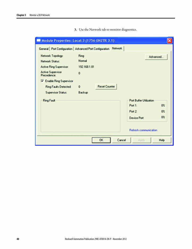
Chapter 3 Monitor a DLR Network
3 Use the Network tab to monitor diagnostics
40 Rockwell Automation Publication 290E-AT001A-EN-P - November 2012
Monitor a DLR Network Chapter 3
RSLinx Communication Software
To monitor the network in RSLinx communication software follow these steps
1 Click RSWho to browse the network
2 Access the property pages for the active supervisor nodea Open the driver that shows the nodes on the DLR networkb Right-click the node that you want to monitor performancec Click on the choice that you need to access
Multiple choices appear
These options are shown in the following sections
Rockwell Automation Publication 290E-AT001A-EN-P - November 2012 41
Chapter 3 Monitor a DLR Network
Module Configuration
This series of tabs providesbull General informationbull Connection informationbull Module informationbull Internet protocolbull Port configurationbull Network information
The example below shows a ring fault between nodes at IP addresses 10888021 and MAC ID 00-00-BC-02-48-D5
42 Rockwell Automation Publication 290E-AT001A-EN-P - November 2012
Monitor a DLR Network Chapter 3
There are multiple fields used to monitor network diagnostics
Field Definition
Network Topology Possible values here can be Linear or Ring
Network Status Displays if the network is operating normally (Normal) or has experienced a fault (Ring Fault) as shown in the previous example screen
Active Ring Supervisor Displays the IP address or MAC address of the active ring supervisor
Active Supervisor Precedence For more information on this field see Active Ring Supervisor on page 11
Enable Ring Supervisor Configurable field that lets you to set the node as a ring supervisor
Ring Faults Detected Number of faults detected on the network since the last module power cycle or counter reset
Supervisor Status Displays whether this node is the active ring supervisor (Active) a back-up supervisor (Back-up) a ring node or part of a linear network
Last Active Node on Port 1 The last node the active ring supervisor can communicate with on Port 1 This value is an IP address or a MAC ID and remains latched until the Verify Fault Location button is clicked
Last Active Node on Port 2 The last node the active ring supervisor can communicate with on Port 2 This value is an IP address or a MAC ID and remains latched until the Verify Fault Location button is clicked
Status Displays whether a fault exists on the ring
IMPORTANT If the Network Topology field = Ring and the Network Status field = Normal the Last Active Node fields will display the last fault information even though it has been correctedTo clear the last fault information from these fields click Verify Fault Location You may see a message informing you that the supervisor is no longer in fault mode and the fields will be cleared
Rockwell Automation Publication 290E-AT001A-EN-P - November 2012 43
Chapter 3 Monitor a DLR Network
How to Access the ArmorStart EtherNetIP Internal Web Server
Open your preferred internet web browser and enter the IP address of the desired ArmorStart For this example 192168122 will be used
Use the links on the left-most navigation bar to see each available web page The screen below shows Ring Statistics for the ArmorStart 280E
44 Rockwell Automation Publication 290E-AT001A-EN-P - November 2012
Monitor a DLR Network Chapter 3
EtherNetIP Device Level Ring (DLR) Network Diagnostics Faceplate Overview
The EtherNetIP Device Level Ring (DLR) network diagnostics faceplate provides basic DLR network status information to the user to assist with monitoring and troubleshooting a DLR network
The diagnostics faceplate contains two major components
bull Logic code (encapsulated in an Add-On Instruction) that allows the controller to retrieve real-time DLR network status information
bull HMI faceplate graphics to allow the data to be visualized on an operator interface
The DLR diagnostics faceplate application can be downloaded from the Rockwell Automation Sample Code website at httpsamplecoderockwellautomationcom
Besides the individual Logix and View project components a demo application is also included with the downloaded file
Rockwell Automation Publication 290E-AT001A-EN-P - November 2012 45
Chapter 3 Monitor a DLR Network
Monitor Diagnostics via MSG Instructions
Network diagnostic information can also be obtained programmatically via MSG instructions in RSLogix 5000 programming software For example you can
bull Get all ring diagnostic informationbull Get a ring participant listbull Get the active supervisorbull Clear rapid ring faultsbull Verify a fault locationbull Reset a fault counterbull Enable and configure a ring supervisor
This information can be displayed on an HMI device or manipulated in the project code
Figure 5 - Example Use of MSG Instruction
This example describes how to retrieve diagnostic information from the DLR network Follow these steps
1 Enter a MSG instruction into the rung of logic
2 Configure the MSG instruction to retrieve ring diagnostic information service as shown in the following screen shots
IMPORTANT Make sure the tag created is sized appropriately to hold all of the data that you are reading or writing For more information see page 48
46 Rockwell Automation Publication 290E-AT001A-EN-P - November 2012
Monitor a DLR Network Chapter 3
3 Configure the MSG instructionrsquos communication path to point to the active supervisor node
The path on the following screen is one example path
IMPORTANT When using the Custom Get_Attributes_All (01) service pointing to an active supervisor node will retrieve all of the attributes listed in Retrieve All Diagnostic Information Attribute Description on page 50Pointing to a non-supervisor node will retrieve only the Network Topology and Network Status attribute informationPointing to backup supervisor node will retrieve the current active supervisorrsquos IP address
Rockwell Automation Publication 290E-AT001A-EN-P - November 2012 47
Chapter 3 Monitor a DLR Network
Use Specific Values on the Configuration Tab
Use the values on the Configuration tab of your MSG instruction to perform specific services Sample DLR network diagnostic application code for example Add-on Instruction or HMI faceplate graphics is available on the Rockwell Automation Sample Code Library For more information about the Rockwell Automation Sample Code Library see httpwwwrockwellautomationcomsolutionsintegratedarchitectureresources5html
➊ This request only works if there are fewer than 40 nodes on the network If there are more nodes than will fit in a single message an error will be returned➋ Use a Destination Length of 54 bytes if using firmware revision 3x or later for the 1756-EN2TR module or firmware revision 2x or later for the 1783-ETAP
1783-ETAP1F or 1783-ETAP2F taps
Request Description Message Type
Service Type
Service Code (HEX)
Class (HEX)
Instance Attribute (HEX)
Source Element
Source Length (Bytes)
Destination Destination Length (bytes)
Retrieve All Ring Diagnostic Information
Information for this request is listed in Retrieve All Ring Diagnostic Information on page 49
CIP Generic Custom 1 47 1 NA LeftBlank
0 Tag 50or54 ➋
Request Ring Participant List ➊
Information for this request is listed in Request the Ring Participant List on page 51
CIP Generic Get Attribute Single
e 47 1 9 NA NA Tag 10node
Get Active Supervisor
Obtain the IP address and MAC ID of the active supervisor on the DLR network
CIP Generic Get Attribute Single
e 47 1 a NA NA Tag 10
Acknowledge Rapid Ring Faults Condition
Request supervisor to resume normal operation after encountering a rapid ring fault condition
CIP Generic Custom 4c 47 1 NA NA NA NA
Verify a Fault Location
Request supervisor to update Last Active Node values
CIP Generic 4b 47 1 NA NA NA NA NA
Reset the Ring Fault Counter
Reset the number of ring faults detected on the DLR network
CIP Generic Set Attribute Single
10 47 1 5 Tag 2 NA NA
Enable and Configure a Ring Supervisor
Information for this request is listed in Enable and Configure a Ring Supervisor on page 52
CIP Generic Set Attribute Single
10 47 1 4 Tag 12 NA NA
48 Rockwell Automation Publication 290E-AT001A-EN-P - November 2012
Monitor a DLR Network Chapter 3
Retrieve All Ring Diagnostic Information
By performing the Retrieve All Ring Diagnostic Information request on an active supervisor the MSG instruction returns the following information
➊ RSLogix 5000 programming software may display the value in this field as negative numbers To better understand the value we recommend you view it in HEX format
Destination Tag Attribute Name Description Possible Values
SINT [0] Network Topology Current network topology mode 0 = Linear
1 = Ring
SINT [1] Network Status Current status of the network 0 = Normal
1 = Ring Fault
2 = Unexpected Loop Detected
3 = Partial Network Fault
4 = Rapid FaultRestore Cycle
SINT [2] Ring Supervisor Status Ring supervisor active status flag 0 = Node is functioning as a backup
1 = Node is functioning as the active ring supervisor
2 = Node is functioning as a normal ring node
3 = Node is operating in a non-DLR topology
4 = Node cannot support the currently operating ring parameters thatis Beacon Interval andor Beacon Timeout
Ring Supervisor Config Ring Supervisor configuration parameters
SINT [3] Ring Supervisor Enable Ring supervisor enable flag 0 = Node is configured as a normal ring node (default configuration)
1 = Node is configured as a ring supervisor
SINT [4] Ring Supervisor Precedence Precedence value of a ring supervisor ➊ Valid value range = 0hellip255
0 = Default value
SINT [5-8] Beacon Interval Duration of ring beacon interval Valid value range = 200 μshellip100 ms
Default = 400 μs
SINT [9-12] Beacon Timeout Duration of ring beacon timeout Value value range = 400 μshellip500 ms
Default value = 1960 μs
SINT [13-14] DLR VLAN ID Valid ID to use in ring protocol messages Valid value range = 0hellip4094
Default value = 0
SINT [15-16] Ring Faults Count Number of ring faults since power up ➊
Rockwell Automation Publication 290E-AT001A-EN-P - November 2012 49
Chapter 3 Monitor a DLR Network
Retrieve All Diagnostic Information Attribute Description
➊ This destination tag is available only with the 1756-EN2TR module firmware revision 3x or later 1783-ETAP 1783-ETAP1F and 1783-ETAP2F taps firmware revisions 2x or later If using the 1783-ETAP tap firmware revision 1x your program does not include this destination tag
➋ RSLogix 5000 programming software may display the value in this field as negative numbers To better understand the value we recommend you view it in HEX format
Destination Tag Attribute Name Description Possible Values
Last Active Node on Port 1 Last active node at the end of the chain through port 1 of the active ring supervisor during a ring fault
SINT [17-20] Device IP address ➋ Any valid IP address value
A value = 0 indicates no IP address has been configured for the device
SINT [21-26] Device MAC address ➋ Any valid Ethernet MAC address
Last Active Node on Port 2 Last active node at the end of the chain through port 2 of the active ring supervisor during a ring fault
SINT [27-30] Device IP address ➋ Any valid IP address value
A value = 0 indicates no IP address has been configured for the device
SINT [31-36] Device MAC address ➋ Any valid Ethernet MAC address
SINT [37-38] Ring Protocol Participants Count
Number of devices in the ring protocol participants list
Active Supervisor Address IP andor Ethernet MAC address of the active ring supervisor
SINT [39-42] Supervisor IP address Any valid IP address value
A value = 0 indicates no IP address has been configured for the device
SINT [43-48] Supervisor MAC address Any valid Ethernet MAC address
SINT [49] Active Supervisor Precedence
Precedence value of the active ring supervisor
SINT [50-53]➊ Capability Flags Alerts you that the device is capable of operating as a supervisor and beacon-based ring node
0x22
50 Rockwell Automation Publication 290E-AT001A-EN-P - November 2012
Monitor a DLR Network Chapter 3
Request the Ring Participant List
When requesting the Ring Participant List service on the DLR network the MSG instruction returns the following information
Request the Ring Participant List Attribute Description
➊ This attribute will return an array of the data shown one entry for each node The Ring Protocol Participants Count attribute determines the number entries
➋ This tag displays only IP addresses for ring participants that have been configured with one For example you may have a 1783-ETAP tap connected to the network that has not been assigned an IP address In that case no address is shown for the 1783-ETAP tap
➌ RSLogix 5000 programming software may display the value in this field as negative numbers To better understand the value we recommend you view it in HEX format
➍ Unlike destination tag SINT [0-3] where IP addresses are displayed only for ring participants configured with an IP address this tag displays MAC addresses for all ring participants because every ring participant has a MAC address
Destination Tag Attribute Name Description Possible Values
Ring Protocol Participants List ➊
List of devices participating in ring protocol
SINT [0-3] Device IP address ➋➌ Any valid IP address value
A value = 0 indicates no IP address has been configured for the device
SINT [4-9] Device MAC address ➌➍ Any valid Ethernet MAC address
Rockwell Automation Publication 290E-AT001A-EN-P - November 2012 51
Chapter 3 Monitor a DLR Network
Enable and Configure a Ring Supervisor
When performing the Enable and Configure a Ring Supervisor request on a supervisor-capable device configure the MSG instruction with the following information
Enable and Configure a Ring Supervisor Attribute Description
➊ RSLogix 5000 programming software may display the value in this field as negative numbers To better understand the value we recommend you view it in HEX format
Source Tag Attribute Name Description Possible Values
Ring Supervisor Config Ring Supervisor configuration parameters
SINT [0] Ring Supervisor Enable Ring supervisor enable flag 0 = Node is configured as a normal ring node (default configuration)1 = Node is configured as a ring supervisor
SINT [1] Ring Supervisor Precedence Precedence value of a ring supervisor ➊
Valid value range = 0hellip2550 = Default value
SINT [2-5] Beacon Interval Duration of ring beacon interval
Valid value range = 200 μshellip100 000 μsDefault = 400 μs
SINT [6-9] Beacon Timeout Duration of ring beacon timeout ➊
Value value range = 400 μshellip500 000 μsDefault value = 1960 μs
SINT [10-11] DLR VLAN ID Valid ID to use in ring protocol messages ➊
Valid value range = 0hellip4094Default value = 0
52 Rockwell Automation Publication 290E-AT001A-EN-P - November 2012
Chapter 4
Troubleshoot a DLR Network
Introduction Use this chapter to learn how to troubleshoot the DLR network
General Solutions for Linear or DLR Networks
Before attempting to correct specific faults on the linear or DLR network we recommend that you first take the following actions when a fault appears
bull For a DLR networkndash Verify that at least one node has been configured as a supervisor
on the network and that Network Topology = Ringndash Verify that all cables on the network are securely connected
to each devicendash Verify that all devices that require an IP address have one assigned
correctlyndash Check the Network Status field on the active supervisor nodersquos status
page to determine the fault typebull For a linear network
ndash Verify that none of the nodes are configured as a supervisor on the network and that Network Topology = LinearIf any nodes on a linear network are configured as a supervisor it may impact communication to other devices connected to the network
ndash Verify that all cables on the network are securely connected to each device
ndash Verify that all devices that require an IP address have one assigned correctly
If the fault is not cleared after completing the actions listed above use the tables in the rest of this chapter to troubleshoot issues specific to a DLR network or a linear network
Topic Page
General Solutions for the Linear or DLR Networks 53
Duplicate IP Address Detection 54
Specific Issues on the DLR Network 55
Network Recovery Performance 58
Device Port Debugging Mode 59
Rockwell Automation Publication 290E-AT001A-EN-P - November 2012 53
Chapter 4 Troubleshoot a DLR Network
Duplicate IP Address Detection
Some EtherNetIP communication modules support duplicate IP address detection The module verifies that its IP address does not match any other network devicersquos IP address when performing either of these tasks
bull Connect the module to an EtherNetIP network
bull Change the modulersquos IP address
If the modulersquos IP address matches that of another device on the network the modulersquos EtherNetIP port transitions to Conflict mode In Conflict mode these conditions exist
bull OK status indicator is blinking red
bull Network (NET) status indicator is solid red
bull On some EtherNetIP communication modules the module status display indicates the conflict
The display scrollsOK ltIP_address_of_this_modulegt Duplicate IP
ltMac_address_of_duplicate_node_detectedgt
For example OK 108860196 Duplicate IP - 0000BC0234B4
bull On some EtherNetIP communication modules the modulersquos diagnostic webpage displays information about duplicate IP address detection
For more information on which EtherNetIP communication modules support displaying duplicate IP address on their diagnostic webpage see the Technical Note titled Logix modules Duplicate IP address detection enhancement 118216 in the Technical Support Knowledgebase available at httpwwwrockwellautomationcomknowledgebase
54 Rockwell Automation Publication 290E-AT001A-EN-P - November 2012
Troubleshoot a DLR Network Chapter 4
Specific Issues on the DLR Network
Use the following table to troubleshoot possible specific issues on the DLR or linear network that are not solved by the actions described on the previous page
Issue Description Solution
Supervisor Reports a Ring Fault A link on the DLR network may be brokenbull intentionally for example because of adding or deleting nodes but not making all
physical connections to restore the setup of the network withwithout the nodebull unintentionally for example because a cable is broken or a device malfunctionsWhen this fault occurs the adjacent nodes to the faulted part of the network are displayed in the Ring Fault group and the Network Status field = Ring FaultThe screen shot below shows the Ring Fault section with IP addresses appearing for the last active nodes The faulted node is between nodes 108880115 and 108880208 If the IP address of either node is not available the software will display the nodersquos MAC ID
Once the fault is corrected the ring is automatically restored and the Network Status field returns to Normal
Determine where the fault condition exists and correct itClick the Refresh Communication link as needed to update the Ring Fault information to determine where the fault condition existsFinally DevicePort Debugging Mode functionality on the 1783-ETAP tap may be used to analyze a suspicious nodeFor more information refer to Device Port Debugging Mode on page 59
Rockwell Automation Publication 290E-AT001A-EN-P - November 2012 55
Chapter 4 Troubleshoot a DLR Network
Issue Description Solution
Rapid Ring Fault When a Rapid Ring Fault occurs the following events occurbull The active supervisor will block traffic on port 2 resulting in possible network
segmentation that is some nodes may become unreachablebull The Link 2 status indicator on the active supervisor is offbull As soon as the fault occurs for both RSLogix 5000 programming software and
RSLinx communication software the Status field = Rapid FaultRestore Cycles
Any of the following may cause a Rapid Ring Faultbull 5 intentional disconnectionsreconnections of a node from the network within 30
secondsbull A duplex mismatch between two connected devicesbull Electromagnetic noise on the networkbull Unstable physical connections such as intermittent connectorsGiven the nature of a Rapid Ring Fault the Last Active Node information may not be accurate when a Rapid Ring Fault condition is present
Multiple possible solutions existbull For the disconnections and reconnections issue no
solution is requiredClear the fault after reconnecting the device to the network permanentlybull For the duplex mismatch issue reconfigure the duplex
parameters to make sure they match between the devices
bull For the electromagnetic noise issue determine where the noise exists and eliminate it or use a protective shield in that location
bull For the unstable connections issue determine where they exist on the network and correct them
bull Check the media counters for all devices on the network The device with the highest media counter count is most likely causing the Rapid Ring Fault
bull Remove devices from the network one by one If the Rapid Ring Fault disappears after a device is removed that device is causing the fault
bull DevicePort Debugging Mode functionality on the 1783-ETAP tap may be used to analyze a suspicious node
For more information refer to Device Port Debugging Mode on page 59bull Finally the Beacon Interval or Timeout configuration
may not be appropriate for the networkHowever if these values need to be changed we recommend that you contact Rockwell Automation technical supportOnce the fault is fixed click Clear Fault
56 Rockwell Automation Publication 290E-AT001A-EN-P - November 2012
Troubleshoot a DLR Network Chapter 4
Issue Description Solution
Partial Fault Condition A partial network fault occurs when traffic is lost in only one direction on the network because a ring member is not forwarding beacons in both directions for example a component failureThe active ring supervisor detects a partial fault by monitoring the loss of Beacon frames on one port and the fault location appears in the Ring Fault section of the Network tab When a partial fault is detected the active ring supervisor blocks traffic on one port At this point the ring is segmented due to the partial fault condition The nodes adjacent to the faulted part of the network are displayed in the Ring Fault group with either IP addresses or MAC IDs for each node displayedWhen this fault occurs the Network Status field = Partial Fault ConditionOnce the fault is corrected it automatically clears and the Network Status field returns to Normal
Determine where the fault condition exists and correct itAdditionally the DevicePort Debugging Mode functionality also known as Port Mirroring on a 1783-ETAP 1783-ETAP1F or 1783-ETAP2F tap may be used to analyze a suspicious nodeFor more information refer to Device Port Debugging Mode on page 59
Media Counter Errors or Collisions
The media counters screen displays the number of physical layer errors or collisions The screen below indicates where to check for errors encountered Error levels are displayed depending on what caused the error For example an Alignment Error is displayed in the Alignment Error field
On a DLR network it is not uncommon to see low levels of media counter errors For example if the network breaks a low level of media counter errors appears With a low level of media counter errors the value typically does not continuously increase and often clearsA high level of media counter errors typically continues to increase and does not clear For example there is a mismatch of speed between two linked nodes a high level of media counter errors appears steadily increasing and not clearingTo access the RSLinx screen above browse the network right-click on the device select Module Properties and click the Port Diagnostics tab
Some example solutions includebull Check for a mismatch of speed andor duplex between
two linked nodesbull Verify that all cables on the network are securely
connected to each devicebull Check for electromagnetic noise on the network If you
find it eliminate it or use a protective shield in that location
Rockwell Automation Publication 290E-AT001A-EN-P - November 2012 57
Chapter 4 Troubleshoot a DLR Network
Network Recovery Performance
When measuring the networkrsquos performance with regard to dealing with fault conditions consider the network recovery time Network recovery is the time for all of the following to take place
1 The supervisor node recognizes that a fault exists on the network
2 The supervisor node reconfigures the network because of the fault
3 The supervisor node communicates to the network nodes that a fault condition exists
4 The network nodes reconfigure themselves because of the fault
With the default beacon interval value of 400 mS and beacon timeout value of 1960 mS the worst-case time for network recovery times are
bull 2890 mS for a copper DLR network This recovery time is based on 100 m copper segments between nodes on the network
bull 3140 mS for a fiber-optic DLR network This recovery time is based on 2 kM fiber-optic cable segments between nodes on the network
When considering the values listed above keep in mind
bull Recovery time may actually occur faster than the times listed
bull The recovery times listed above assume that your networkrsquos nodes are operating at 100 Mbps speed and full-duplex mode We recommend that your nodes generally operate in this mode for DLR networks
bull If other node conditions exist such as a node operating at 10 Mbps full-duplex or 10100 Mbps half-duplex the recovery times will vary from the times listed above
If this is the case for your application the beacon interval and beacon timeout will need to be changed We recommend that you first contact Rockwell Automation technical support if these parameters need to be changed
bull The value assumes that the majority of the traffic on your network is EtherNetIP traffic
58 Rockwell Automation Publication 290E-AT001A-EN-P - November 2012
Troubleshoot a DLR Network Chapter 4
Device Port Debugging Mode
This functionality is disabled by default Device Port Debugging mode which is similar to port mirroring can be used to monitor data received on the 1783-ETAP 1783-ETAP1F or 1783-ETAP2F taprsquos two network ports Monitor the data over the device port to a device such as a personal computer running a protocol analyzer application for advanced network debugging or analysis
When device port debugging is used on a 1783-ETAP the device connected to the 1783-ETAP taprsquos front port receives all of the data traversing the ring (both directions)
Device Port Debugging Example Network
When using the Device Port Debugging mode functionality insert the 1783-ETAP with the network analyzer connected to the device port It is inserted at the spot on the ring network where the node in question is located The graphic below shows a 1783-ETAP tap inserted in the network
IMPORTANT This functionality should be used only when troubleshooting the network and not in normal network operation
Rockwell Automation Publication 290E-AT001A-EN-P - November 2012 59
Chapter 4 Troubleshoot a DLR Network
Combined total network bandwidth of the traffic received on the two 1783-ETAP 1783-ETAP1F or 1783-ETAP2F taprsquos ports connected to the network should not exceed the taprsquos device port capacity The speed setting determines the device portrsquos capacity
Configure the device port on a 1783-ETAP 1783-ETAP1F or 1783-ETAP2F tap to either of two speed settings
bull 100 Mbps - default settingbull 10 Mbps
If the bandwidth exceeds the capacity of the taprsquos device port some frames from the ring will be dropped before reaching the device port These dropped frames do not impact the traffic on the rest of the DLR network
The device port setting determines how much network traffic the 1783-ETAP 1783-ETAP1F or 1783-ETAP2F tap can handle before dropping frames The circled section in the graphic below shows the Port Buffer Utilization of the Device Port In this example the value is zero because a ring fault exists on the network
60 Rockwell Automation Publication 290E-AT001A-EN-P - November 2012
Appendix A
Network Usage Guidelines and Recommendations
Consider the following guidelines and recommendations when using a DLR or linear network
GuidelineRecommendation Explanation
Use fewer than 50 nodes on a single DLR networkIf your application requires more than 50 nodes we recommend that the nodes are broken into separate but linked DLR networks
If you use more than 50 nodes on a single DLR networkbull Your network has a greater chance of multiple faults
occurring on the networkbull Network recovery times from faulted DLR network
are higher
Do not configure a supervisor on a linear network If your linear network includes non-DLR nodes and has a supervisor-enabled node on the network it may impact communication to non-DLR devices connected to the linear network
If you must connect a device that is running at 10 Mbps to a DLR or linear network do so through a 1783-ETAP 1783-ETAP1F or 1783-ETAP2F tap device port
The 1783-ETAP 1783-ETAP1F and 1783-ETAP2F taps can operate at 100 Mbps on the DLR network this is the optimal speed for a network If you connect a 10 Mbps device directly to the network instead of through a tap the linear or DLR network traffic slows to 10 MbpsAdditionally if the 10 Mbps device is connected to the network without a 1783-ETAP tap network recovery times are significantly impacted
Configure multiple supervisor nodes per ring If your DLR network only has one supervisor and the supervisor experiences a fault none of the other nodes become the active supervisor In this case the network becomes a linear network until the fault is corrected and the DLR network restoredAnother reason to configure multiple supervisor nodes is for replacing an active supervisor node with an out-of-box replacement the new device will not be enabled as a supervisor (by default) and there would still be no supervisor on the network
Rockwell Automation Publication 290E-AT001A-EN-P - November 2012 61
Appendix A Network Usage Guidelines and Recommendations
GuidelineRecommendation Explanation
Connect switches to a DLR network via 1783-ETAP 1783-ETAP1F or 1783-ETAP2F taps
If switches are connected to the DLR network without the use of a 1783-ETAP 1783-ETAP1F or 1783-ETAP2F tap the network may experience unpredictable behavior and network performance is unknown
Run all nodes on the DLR network at 100 Mbps and in Full-Duplex mode
These configuration values provide the best performance for your networkAdditionally we recommend that youbull Use auto-negotiate for all nodes on the DLR networkbull Do not use auto-negotiate on one node and then force
speed on the next node linked to it
In a linear network the number of nodes to use is application specific based on the considerations described in the next box
When determining the number of nodes to use on a linear network consider the followingbull There is a delay per node as information is transmitted
to each successive node used on the networkndash The typical delay on a linear network with 100 m
copper segments between nodes is 30 mSndash The typical delay on a linear network with 2 kM
fiber-optic segments between nodes is 40 mS
The greater the number of nodes on the network the longer the total time for information to be transmitted across the entire networkbull The single point of failure possibility is greater with
each additional connectionbull Troubleshooting the network may be more difficult
with a higher number of nodes
The total time for information to be transmitted across the entire network and its effect on how many nodes to use on a linear network is related to the Requested Packet Interval (RPI)Verify that the total time to transmit information from the first node to the last node on the network is less than the RPI Make sure the network is not loaded beyond 90 of capacity
62 Rockwell Automation Publication 290E-AT001A-EN-P - November 2012
Network Usage Guidelines and Recommendations Appendix A
GuidelineRecommendation Explanation
Do not physically close a DLR network without a supervisor configured on the network
A DLR network without a supervisor node results in a network stormIf you do close the DLR network without a supervisor configured break the ring and configure at least one supervisor before physically reconnecting the network
Use the default values for the followingbull Beacon Intervalbull Beacon Timeoutbull Ring Protocol VLAN ID
Changing the default values for the parameters Beacon Interval Beacon Timeout and Ring Protocol VLAN ID can result in unpredictable network behavior and negatively impacted network performanceThe default values are optimized for a network withbull 50 or fewer nodes are on the networkbull All nodes are operating at 100 Mbps and full-duplex
modebull At least 50 of the network traffic bandwidth being
EtherNetIP trafficIf you think the values of the Beacon Interval Beacon Timeout or Ring Protocol VLAN ID need to be changed for example if any node on ring is not operating at 100 Mbps and full-duplex mode we recommend that you first contact Rockwell Automation technical support
If DHCP for the ArmorStarts is still required you will need to disable Internet Group Management Protocol (IGMP) snooping on the E-tap via the AOP
IGMP Snooping is enabled by default in the 1783-ETAP 1783-ETAP1F and 1783-ETAP2F taps and is commonly used to manage multicast traffic on the network When in use this functionality allows the tap to multicast data to only those devices that need the data rather than to all devices connected to the networkOnce DHCP is enabled the switch could change the IP addresses on the ArmorStarts depending on network demand which could cause RSlogix5000 to loose communication with the device as connectivity is established via the AOP in the initial configuration
The IGMP Querier functionality should be enabled for at least one node on the network
This functionality is disabled by default The IGMP Querier functionality enables a 1783-ETAP 1783-ETAP1F or 1783-ETAP2F tap or switch such as a Stratix managed switch to send out a query to all devices on the network to determine what multicast addresses are of interest to a specific node or a group of nodesIf the IGMP Querier functionality is not enabled for at least one node on the network multicast traffic on the network may eventually create network performance issuesThe 1783-ETAP 1783-ETAP1F or 1783-ETAP2F taps managed switches and routers are examples of devices that support IGMP Querier functionality
Rockwell Automation Publication 290E-AT001A-EN-P - November 2012 63
Appendix A Network Usage Guidelines and Recommendations
Notes
64 Rockwell Automation Publication 290E-AT001A-EN-P - November 2012
Appendix B
Required Firmware Revisions
Required Firmware Revision for an Add-On Profile
➊ The ControlFLASH Firmware Upgrade software tcan be used o upgrade a 1756-EN2TR module from firmware revision 21 to 3x or later1x or later3x or later2x or later
➋ The ControlFLASH Firmware Upgrade software can be used to upgrade a 1783-ETAP tap from firmware revision 11 to 2x or later
To download new firmware go to httpwwwrockwellautomationcomsupportamericasindex_enhtml
If the firmware revision is upgraded on the module or tap the required AOP revision listed above must be used for that revision For example if the 1756-EN2TR module is upgraded to firmware revision 3x or later AOP revision 2x or later must be used in the RSLogix 5000 programming software
Additionally if the firmware revision is upgraded on the module or tap the required RSLinx communication software must also be used for that firmware revision For more information on which RSLinx software version is required for each firmware revision see page 66
For both the 1756-EN2TR module and 1783-ETAP tap make sure that the Major Revision configured on the General tab of the devicersquos RSLogix 5000 programming software configuration matches the major revision of the physical module
IMPORTANT To download an AOP go to httpsupportrockwellautomationcomcontrolflashLogixProfileraspDepending on the firmware revision of your product a specific AOP version must be used
Firmware Revision Add-On Profile Revision Cat No
21 ➊ 1x or later 1756-EN2TR
3x or later 2x or later
11 ➋ 1x or later 1783-ETAP
2x or later 2x or later
2x or later 2x or later 1783-ETAP1F
1783-ETAP2F
Rockwell Automation Publication 290E-AT001A-EN-P - November 2012 65
Appendix B Required Firmware Revisions
If the device configuration on the General tab does not match the physical module the programming software alerts you to this mismatch when attempting to configure the Internet Protocol Port Configuration and Network tabs for that device
Required Firmware Revision for RSLinx Communication Software
➊ The ControlFLASH Firmware Upgrade software can be used to upgrade a 1756-EN2TR module from firmware revision 21 to 3x or later1x or later3x or later255 or later3x or later256 or later
➋ The ControlFLASH Firmware Upgrade software can be used to upgrade a 1783-ETAP tap from firmware revision 11 to 2x or later
To download new firmware go to httpwwwrockwellautomationcomsupportamericasindex_enhtml
If the firmware revision is upgraded on the module or tap the required RSLinx communication software listed above must be used for that revision For example if the 1756-EN2TR module is upgraded to firmware revision 3x or later AOP revision 2x or later must be used in your RSLogix 5000 programming software
Additionally if the firmware revision is upgraded on the module or tap the required AOP revision must also be used for that firmware revision For more information on which AOP revision is required for each firmware revision see page 65
IMPORTANT Depending on the firmware revision of your product specific versions of RSLinx communication software must be used
Firmware Revision Required RSLinx Communication Software Version
Cat No
21 ➊ 255 or later 1756-EN2TR
3x or later 256 or later
11 ➋ 255 or later 1783-ETAP
2x or later 256 or later
2x or later 256 or later 1783-ETAP1F
1783-ETAP2F
66 Rockwell Automation Publication 290E-AT001A-EN-P - November 2012
Rockwell Otomasyon Ticaret AŞ Kar Plaza İş Merkezi E Blok Kat6 34752 İccedilerenkoumly İstanbul Tel +90 (216) 5698400
Rockwell Automation Publication 290E-AT001A-EN-P ndash November 2012 68 Copyright copy 2012 Rockwell Automation Inc All rights reserved Printed in the USA
Rockwell Automation Support
Rockwell Automation provides technical information on the Web to assist you in using its products At httpwwwrockwellautomationcomsupport you can find technical manuals a knowledge base of FAQs technical and application notes sample code and links to software service packs and a MySupport feature that you can customize to make thebest use of these tools
For an additional level of technical phone support for installation configuration and troubleshooting we offer TechConnectSM support programs For more information contact your local distributor or Rockwell Automation representative or visit httpwwwrockwellautomationcomsupport
Installation Assistance
If you experience a problem within the first 24 hours of installation review the information that is contained in this manualYou can contact Customer Support for initial help in getting your product up and running
New Product Satisfaction Return
Rockwell Automation tests all of its products to ensure that they are fully operational when shipped from the manufacturing facility However if your product is not functioning and needs to be returned follow these procedures
Documentation Feedback
Your comments will help us serve your documentation needs better If you have any suggestions on how to improve this document complete this form publication RA-DU002 available at httpwwwrockwellautomationcomliterature
United States or Canada 14406463434
Outside United States or Canada Use the Worldwide Locator at httpwwwrockwellautomationcomsupportamericasphone_enhtml or contact your local Rockwell Automation representative
United States Contact your distributor You must provide a Customer Support case number (call the phone number above to obtain one) to your distributor to complete the return process
Outside United States Please contact your local Rockwell Automation representative for the return procedure
- Important User Information
- General Precautions
- Software Requirements
- Additional Resources
- Rockwell Automation Support
- Installation Assistance
- New Product Satisfaction Return
- Table of Contents
- Chapter 1
-
- Device-Level Ring (DLR) Basics
-
- Introduction
- ArmorStart with EtherNetIP Overview
- What is a Device-level Ring (DLR) Network
- DLR Network Elements
-
- Supervisor Node
- Ring Node
-
- DLR Network Operation
- Number of Nodes on a DLR Network
- DLR Network Fault Management
-
- Network Reconfiguration after a Fault
-
- Chapter 2
-
- Construct and Configure a Device-level Ring Network with ArmorStarts
-
- Introduction
- Ethernet Capacity Tool
- Install Devices on a DLR Network
- ArmorStart Addressing Configuration
-
- Using the BootPDHCP Server
- Using the Rotary Network Address Switches
- Using the ArmorStart Internal Web Server
-
- Configure Supervisor Nodes on a DLR Network
-
- Configure a Ring Supervisor in RSLogix 5000 Programming Software
- Adding an Armorstart to RSLogix 5000
- Enable Ring Supervisor in RSLogix 5000 Programming Software
- Configure and Enable a Ring Supervisor in RSLinx Classic Communication Software
-
- Complete the Physical Connections of the Network
- Verify Supervisor Configuration
- IGMP Snooping
- IGMP Querier
-
- Chapter 3
-
- Monitor a DLR Network
-
- Introduction
- Methods to Monitor a DLR Network
-
- RSLogix 5000 Programming Software Status Pages
- RSLinx Communication Software Status Pages
- ArmorStart Internal Web Server
- EtherNetIP Device Level Ring (DLR) Network Diagnostics Faceplate
- Programmatically Through the Use of a MSG Instruction
-
- Monitor Status Pages
-
- RSLogix 5000 Programming Software Status Pages
- RSLinx Communication Software
-
- How to Access the ArmorStart EtherNetIP Internal Web Server
-
- EtherNetIP Device Level Ring (DLR) Network Diagnostics Faceplate Overview
-
- Monitor Diagnostics via MSG Instructions
-
- Use Specific Values on the Configuration Tab
- Retrieve All Ring Diagnostic Information
- Retrieve All Diagnostic Information Attribute Description
- Request the Ring Participant List
- Request the Ring Participant List Attribute Description
-
- Enable and Configure a Ring Supervisor
-
- Enable and Configure a Ring Supervisor Attribute Description
-
- Chapter 4
-
- Troubleshoot a DLR Network
-
- Introduction
- General Solutions for Linear or DLR Networks
- Duplicate IP Address Detection
- Specific Issues on the DLR Network
- Network Recovery Performance
- Device Port Debugging Mode
-
- Device Port Debugging Example Network
-
- Appendix A
-
- Network Usage Guidelines and Recommendations
-
- Notes
-
- Appendix B
-
- Required Firmware Revisions
-
- Required Firmware Revision for an Add-On Profile
- Required Firmware Revision for RSLinx Communication Software
-

Monitor a DLR Network Chapter 3
RSLinx Communication Software
To monitor the network in RSLinx communication software follow these steps
1 Click RSWho to browse the network
2 Access the property pages for the active supervisor nodea Open the driver that shows the nodes on the DLR networkb Right-click the node that you want to monitor performancec Click on the choice that you need to access
Multiple choices appear
These options are shown in the following sections
Rockwell Automation Publication 290E-AT001A-EN-P - November 2012 41
Chapter 3 Monitor a DLR Network
Module Configuration
This series of tabs providesbull General informationbull Connection informationbull Module informationbull Internet protocolbull Port configurationbull Network information
The example below shows a ring fault between nodes at IP addresses 10888021 and MAC ID 00-00-BC-02-48-D5
42 Rockwell Automation Publication 290E-AT001A-EN-P - November 2012
Monitor a DLR Network Chapter 3
There are multiple fields used to monitor network diagnostics
Field Definition
Network Topology Possible values here can be Linear or Ring
Network Status Displays if the network is operating normally (Normal) or has experienced a fault (Ring Fault) as shown in the previous example screen
Active Ring Supervisor Displays the IP address or MAC address of the active ring supervisor
Active Supervisor Precedence For more information on this field see Active Ring Supervisor on page 11
Enable Ring Supervisor Configurable field that lets you to set the node as a ring supervisor
Ring Faults Detected Number of faults detected on the network since the last module power cycle or counter reset
Supervisor Status Displays whether this node is the active ring supervisor (Active) a back-up supervisor (Back-up) a ring node or part of a linear network
Last Active Node on Port 1 The last node the active ring supervisor can communicate with on Port 1 This value is an IP address or a MAC ID and remains latched until the Verify Fault Location button is clicked
Last Active Node on Port 2 The last node the active ring supervisor can communicate with on Port 2 This value is an IP address or a MAC ID and remains latched until the Verify Fault Location button is clicked
Status Displays whether a fault exists on the ring
IMPORTANT If the Network Topology field = Ring and the Network Status field = Normal the Last Active Node fields will display the last fault information even though it has been correctedTo clear the last fault information from these fields click Verify Fault Location You may see a message informing you that the supervisor is no longer in fault mode and the fields will be cleared
Rockwell Automation Publication 290E-AT001A-EN-P - November 2012 43
Chapter 3 Monitor a DLR Network
How to Access the ArmorStart EtherNetIP Internal Web Server
Open your preferred internet web browser and enter the IP address of the desired ArmorStart For this example 192168122 will be used
Use the links on the left-most navigation bar to see each available web page The screen below shows Ring Statistics for the ArmorStart 280E
44 Rockwell Automation Publication 290E-AT001A-EN-P - November 2012
Monitor a DLR Network Chapter 3
EtherNetIP Device Level Ring (DLR) Network Diagnostics Faceplate Overview
The EtherNetIP Device Level Ring (DLR) network diagnostics faceplate provides basic DLR network status information to the user to assist with monitoring and troubleshooting a DLR network
The diagnostics faceplate contains two major components
bull Logic code (encapsulated in an Add-On Instruction) that allows the controller to retrieve real-time DLR network status information
bull HMI faceplate graphics to allow the data to be visualized on an operator interface
The DLR diagnostics faceplate application can be downloaded from the Rockwell Automation Sample Code website at httpsamplecoderockwellautomationcom
Besides the individual Logix and View project components a demo application is also included with the downloaded file
Rockwell Automation Publication 290E-AT001A-EN-P - November 2012 45
Chapter 3 Monitor a DLR Network
Monitor Diagnostics via MSG Instructions
Network diagnostic information can also be obtained programmatically via MSG instructions in RSLogix 5000 programming software For example you can
bull Get all ring diagnostic informationbull Get a ring participant listbull Get the active supervisorbull Clear rapid ring faultsbull Verify a fault locationbull Reset a fault counterbull Enable and configure a ring supervisor
This information can be displayed on an HMI device or manipulated in the project code
Figure 5 - Example Use of MSG Instruction
This example describes how to retrieve diagnostic information from the DLR network Follow these steps
1 Enter a MSG instruction into the rung of logic
2 Configure the MSG instruction to retrieve ring diagnostic information service as shown in the following screen shots
IMPORTANT Make sure the tag created is sized appropriately to hold all of the data that you are reading or writing For more information see page 48
46 Rockwell Automation Publication 290E-AT001A-EN-P - November 2012
Monitor a DLR Network Chapter 3
3 Configure the MSG instructionrsquos communication path to point to the active supervisor node
The path on the following screen is one example path
IMPORTANT When using the Custom Get_Attributes_All (01) service pointing to an active supervisor node will retrieve all of the attributes listed in Retrieve All Diagnostic Information Attribute Description on page 50Pointing to a non-supervisor node will retrieve only the Network Topology and Network Status attribute informationPointing to backup supervisor node will retrieve the current active supervisorrsquos IP address
Rockwell Automation Publication 290E-AT001A-EN-P - November 2012 47
Chapter 3 Monitor a DLR Network
Use Specific Values on the Configuration Tab
Use the values on the Configuration tab of your MSG instruction to perform specific services Sample DLR network diagnostic application code for example Add-on Instruction or HMI faceplate graphics is available on the Rockwell Automation Sample Code Library For more information about the Rockwell Automation Sample Code Library see httpwwwrockwellautomationcomsolutionsintegratedarchitectureresources5html
➊ This request only works if there are fewer than 40 nodes on the network If there are more nodes than will fit in a single message an error will be returned➋ Use a Destination Length of 54 bytes if using firmware revision 3x or later for the 1756-EN2TR module or firmware revision 2x or later for the 1783-ETAP
1783-ETAP1F or 1783-ETAP2F taps
Request Description Message Type
Service Type
Service Code (HEX)
Class (HEX)
Instance Attribute (HEX)
Source Element
Source Length (Bytes)
Destination Destination Length (bytes)
Retrieve All Ring Diagnostic Information
Information for this request is listed in Retrieve All Ring Diagnostic Information on page 49
CIP Generic Custom 1 47 1 NA LeftBlank
0 Tag 50or54 ➋
Request Ring Participant List ➊
Information for this request is listed in Request the Ring Participant List on page 51
CIP Generic Get Attribute Single
e 47 1 9 NA NA Tag 10node
Get Active Supervisor
Obtain the IP address and MAC ID of the active supervisor on the DLR network
CIP Generic Get Attribute Single
e 47 1 a NA NA Tag 10
Acknowledge Rapid Ring Faults Condition
Request supervisor to resume normal operation after encountering a rapid ring fault condition
CIP Generic Custom 4c 47 1 NA NA NA NA
Verify a Fault Location
Request supervisor to update Last Active Node values
CIP Generic 4b 47 1 NA NA NA NA NA
Reset the Ring Fault Counter
Reset the number of ring faults detected on the DLR network
CIP Generic Set Attribute Single
10 47 1 5 Tag 2 NA NA
Enable and Configure a Ring Supervisor
Information for this request is listed in Enable and Configure a Ring Supervisor on page 52
CIP Generic Set Attribute Single
10 47 1 4 Tag 12 NA NA
48 Rockwell Automation Publication 290E-AT001A-EN-P - November 2012
Monitor a DLR Network Chapter 3
Retrieve All Ring Diagnostic Information
By performing the Retrieve All Ring Diagnostic Information request on an active supervisor the MSG instruction returns the following information
➊ RSLogix 5000 programming software may display the value in this field as negative numbers To better understand the value we recommend you view it in HEX format
Destination Tag Attribute Name Description Possible Values
SINT [0] Network Topology Current network topology mode 0 = Linear
1 = Ring
SINT [1] Network Status Current status of the network 0 = Normal
1 = Ring Fault
2 = Unexpected Loop Detected
3 = Partial Network Fault
4 = Rapid FaultRestore Cycle
SINT [2] Ring Supervisor Status Ring supervisor active status flag 0 = Node is functioning as a backup
1 = Node is functioning as the active ring supervisor
2 = Node is functioning as a normal ring node
3 = Node is operating in a non-DLR topology
4 = Node cannot support the currently operating ring parameters thatis Beacon Interval andor Beacon Timeout
Ring Supervisor Config Ring Supervisor configuration parameters
SINT [3] Ring Supervisor Enable Ring supervisor enable flag 0 = Node is configured as a normal ring node (default configuration)
1 = Node is configured as a ring supervisor
SINT [4] Ring Supervisor Precedence Precedence value of a ring supervisor ➊ Valid value range = 0hellip255
0 = Default value
SINT [5-8] Beacon Interval Duration of ring beacon interval Valid value range = 200 μshellip100 ms
Default = 400 μs
SINT [9-12] Beacon Timeout Duration of ring beacon timeout Value value range = 400 μshellip500 ms
Default value = 1960 μs
SINT [13-14] DLR VLAN ID Valid ID to use in ring protocol messages Valid value range = 0hellip4094
Default value = 0
SINT [15-16] Ring Faults Count Number of ring faults since power up ➊
Rockwell Automation Publication 290E-AT001A-EN-P - November 2012 49
Chapter 3 Monitor a DLR Network
Retrieve All Diagnostic Information Attribute Description
➊ This destination tag is available only with the 1756-EN2TR module firmware revision 3x or later 1783-ETAP 1783-ETAP1F and 1783-ETAP2F taps firmware revisions 2x or later If using the 1783-ETAP tap firmware revision 1x your program does not include this destination tag
➋ RSLogix 5000 programming software may display the value in this field as negative numbers To better understand the value we recommend you view it in HEX format
Destination Tag Attribute Name Description Possible Values
Last Active Node on Port 1 Last active node at the end of the chain through port 1 of the active ring supervisor during a ring fault
SINT [17-20] Device IP address ➋ Any valid IP address value
A value = 0 indicates no IP address has been configured for the device
SINT [21-26] Device MAC address ➋ Any valid Ethernet MAC address
Last Active Node on Port 2 Last active node at the end of the chain through port 2 of the active ring supervisor during a ring fault
SINT [27-30] Device IP address ➋ Any valid IP address value
A value = 0 indicates no IP address has been configured for the device
SINT [31-36] Device MAC address ➋ Any valid Ethernet MAC address
SINT [37-38] Ring Protocol Participants Count
Number of devices in the ring protocol participants list
Active Supervisor Address IP andor Ethernet MAC address of the active ring supervisor
SINT [39-42] Supervisor IP address Any valid IP address value
A value = 0 indicates no IP address has been configured for the device
SINT [43-48] Supervisor MAC address Any valid Ethernet MAC address
SINT [49] Active Supervisor Precedence
Precedence value of the active ring supervisor
SINT [50-53]➊ Capability Flags Alerts you that the device is capable of operating as a supervisor and beacon-based ring node
0x22
50 Rockwell Automation Publication 290E-AT001A-EN-P - November 2012
Monitor a DLR Network Chapter 3
Request the Ring Participant List
When requesting the Ring Participant List service on the DLR network the MSG instruction returns the following information
Request the Ring Participant List Attribute Description
➊ This attribute will return an array of the data shown one entry for each node The Ring Protocol Participants Count attribute determines the number entries
➋ This tag displays only IP addresses for ring participants that have been configured with one For example you may have a 1783-ETAP tap connected to the network that has not been assigned an IP address In that case no address is shown for the 1783-ETAP tap
➌ RSLogix 5000 programming software may display the value in this field as negative numbers To better understand the value we recommend you view it in HEX format
➍ Unlike destination tag SINT [0-3] where IP addresses are displayed only for ring participants configured with an IP address this tag displays MAC addresses for all ring participants because every ring participant has a MAC address
Destination Tag Attribute Name Description Possible Values
Ring Protocol Participants List ➊
List of devices participating in ring protocol
SINT [0-3] Device IP address ➋➌ Any valid IP address value
A value = 0 indicates no IP address has been configured for the device
SINT [4-9] Device MAC address ➌➍ Any valid Ethernet MAC address
Rockwell Automation Publication 290E-AT001A-EN-P - November 2012 51
Chapter 3 Monitor a DLR Network
Enable and Configure a Ring Supervisor
When performing the Enable and Configure a Ring Supervisor request on a supervisor-capable device configure the MSG instruction with the following information
Enable and Configure a Ring Supervisor Attribute Description
➊ RSLogix 5000 programming software may display the value in this field as negative numbers To better understand the value we recommend you view it in HEX format
Source Tag Attribute Name Description Possible Values
Ring Supervisor Config Ring Supervisor configuration parameters
SINT [0] Ring Supervisor Enable Ring supervisor enable flag 0 = Node is configured as a normal ring node (default configuration)1 = Node is configured as a ring supervisor
SINT [1] Ring Supervisor Precedence Precedence value of a ring supervisor ➊
Valid value range = 0hellip2550 = Default value
SINT [2-5] Beacon Interval Duration of ring beacon interval
Valid value range = 200 μshellip100 000 μsDefault = 400 μs
SINT [6-9] Beacon Timeout Duration of ring beacon timeout ➊
Value value range = 400 μshellip500 000 μsDefault value = 1960 μs
SINT [10-11] DLR VLAN ID Valid ID to use in ring protocol messages ➊
Valid value range = 0hellip4094Default value = 0
52 Rockwell Automation Publication 290E-AT001A-EN-P - November 2012
Chapter 4
Troubleshoot a DLR Network
Introduction Use this chapter to learn how to troubleshoot the DLR network
General Solutions for Linear or DLR Networks
Before attempting to correct specific faults on the linear or DLR network we recommend that you first take the following actions when a fault appears
bull For a DLR networkndash Verify that at least one node has been configured as a supervisor
on the network and that Network Topology = Ringndash Verify that all cables on the network are securely connected
to each devicendash Verify that all devices that require an IP address have one assigned
correctlyndash Check the Network Status field on the active supervisor nodersquos status
page to determine the fault typebull For a linear network
ndash Verify that none of the nodes are configured as a supervisor on the network and that Network Topology = LinearIf any nodes on a linear network are configured as a supervisor it may impact communication to other devices connected to the network
ndash Verify that all cables on the network are securely connected to each device
ndash Verify that all devices that require an IP address have one assigned correctly
If the fault is not cleared after completing the actions listed above use the tables in the rest of this chapter to troubleshoot issues specific to a DLR network or a linear network
Topic Page
General Solutions for the Linear or DLR Networks 53
Duplicate IP Address Detection 54
Specific Issues on the DLR Network 55
Network Recovery Performance 58
Device Port Debugging Mode 59
Rockwell Automation Publication 290E-AT001A-EN-P - November 2012 53
Chapter 4 Troubleshoot a DLR Network
Duplicate IP Address Detection
Some EtherNetIP communication modules support duplicate IP address detection The module verifies that its IP address does not match any other network devicersquos IP address when performing either of these tasks
bull Connect the module to an EtherNetIP network
bull Change the modulersquos IP address
If the modulersquos IP address matches that of another device on the network the modulersquos EtherNetIP port transitions to Conflict mode In Conflict mode these conditions exist
bull OK status indicator is blinking red
bull Network (NET) status indicator is solid red
bull On some EtherNetIP communication modules the module status display indicates the conflict
The display scrollsOK ltIP_address_of_this_modulegt Duplicate IP
ltMac_address_of_duplicate_node_detectedgt
For example OK 108860196 Duplicate IP - 0000BC0234B4
bull On some EtherNetIP communication modules the modulersquos diagnostic webpage displays information about duplicate IP address detection
For more information on which EtherNetIP communication modules support displaying duplicate IP address on their diagnostic webpage see the Technical Note titled Logix modules Duplicate IP address detection enhancement 118216 in the Technical Support Knowledgebase available at httpwwwrockwellautomationcomknowledgebase
54 Rockwell Automation Publication 290E-AT001A-EN-P - November 2012
Troubleshoot a DLR Network Chapter 4
Specific Issues on the DLR Network
Use the following table to troubleshoot possible specific issues on the DLR or linear network that are not solved by the actions described on the previous page
Issue Description Solution
Supervisor Reports a Ring Fault A link on the DLR network may be brokenbull intentionally for example because of adding or deleting nodes but not making all
physical connections to restore the setup of the network withwithout the nodebull unintentionally for example because a cable is broken or a device malfunctionsWhen this fault occurs the adjacent nodes to the faulted part of the network are displayed in the Ring Fault group and the Network Status field = Ring FaultThe screen shot below shows the Ring Fault section with IP addresses appearing for the last active nodes The faulted node is between nodes 108880115 and 108880208 If the IP address of either node is not available the software will display the nodersquos MAC ID
Once the fault is corrected the ring is automatically restored and the Network Status field returns to Normal
Determine where the fault condition exists and correct itClick the Refresh Communication link as needed to update the Ring Fault information to determine where the fault condition existsFinally DevicePort Debugging Mode functionality on the 1783-ETAP tap may be used to analyze a suspicious nodeFor more information refer to Device Port Debugging Mode on page 59
Rockwell Automation Publication 290E-AT001A-EN-P - November 2012 55
Chapter 4 Troubleshoot a DLR Network
Issue Description Solution
Rapid Ring Fault When a Rapid Ring Fault occurs the following events occurbull The active supervisor will block traffic on port 2 resulting in possible network
segmentation that is some nodes may become unreachablebull The Link 2 status indicator on the active supervisor is offbull As soon as the fault occurs for both RSLogix 5000 programming software and
RSLinx communication software the Status field = Rapid FaultRestore Cycles
Any of the following may cause a Rapid Ring Faultbull 5 intentional disconnectionsreconnections of a node from the network within 30
secondsbull A duplex mismatch between two connected devicesbull Electromagnetic noise on the networkbull Unstable physical connections such as intermittent connectorsGiven the nature of a Rapid Ring Fault the Last Active Node information may not be accurate when a Rapid Ring Fault condition is present
Multiple possible solutions existbull For the disconnections and reconnections issue no
solution is requiredClear the fault after reconnecting the device to the network permanentlybull For the duplex mismatch issue reconfigure the duplex
parameters to make sure they match between the devices
bull For the electromagnetic noise issue determine where the noise exists and eliminate it or use a protective shield in that location
bull For the unstable connections issue determine where they exist on the network and correct them
bull Check the media counters for all devices on the network The device with the highest media counter count is most likely causing the Rapid Ring Fault
bull Remove devices from the network one by one If the Rapid Ring Fault disappears after a device is removed that device is causing the fault
bull DevicePort Debugging Mode functionality on the 1783-ETAP tap may be used to analyze a suspicious node
For more information refer to Device Port Debugging Mode on page 59bull Finally the Beacon Interval or Timeout configuration
may not be appropriate for the networkHowever if these values need to be changed we recommend that you contact Rockwell Automation technical supportOnce the fault is fixed click Clear Fault
56 Rockwell Automation Publication 290E-AT001A-EN-P - November 2012
Troubleshoot a DLR Network Chapter 4
Issue Description Solution
Partial Fault Condition A partial network fault occurs when traffic is lost in only one direction on the network because a ring member is not forwarding beacons in both directions for example a component failureThe active ring supervisor detects a partial fault by monitoring the loss of Beacon frames on one port and the fault location appears in the Ring Fault section of the Network tab When a partial fault is detected the active ring supervisor blocks traffic on one port At this point the ring is segmented due to the partial fault condition The nodes adjacent to the faulted part of the network are displayed in the Ring Fault group with either IP addresses or MAC IDs for each node displayedWhen this fault occurs the Network Status field = Partial Fault ConditionOnce the fault is corrected it automatically clears and the Network Status field returns to Normal
Determine where the fault condition exists and correct itAdditionally the DevicePort Debugging Mode functionality also known as Port Mirroring on a 1783-ETAP 1783-ETAP1F or 1783-ETAP2F tap may be used to analyze a suspicious nodeFor more information refer to Device Port Debugging Mode on page 59
Media Counter Errors or Collisions
The media counters screen displays the number of physical layer errors or collisions The screen below indicates where to check for errors encountered Error levels are displayed depending on what caused the error For example an Alignment Error is displayed in the Alignment Error field
On a DLR network it is not uncommon to see low levels of media counter errors For example if the network breaks a low level of media counter errors appears With a low level of media counter errors the value typically does not continuously increase and often clearsA high level of media counter errors typically continues to increase and does not clear For example there is a mismatch of speed between two linked nodes a high level of media counter errors appears steadily increasing and not clearingTo access the RSLinx screen above browse the network right-click on the device select Module Properties and click the Port Diagnostics tab
Some example solutions includebull Check for a mismatch of speed andor duplex between
two linked nodesbull Verify that all cables on the network are securely
connected to each devicebull Check for electromagnetic noise on the network If you
find it eliminate it or use a protective shield in that location
Rockwell Automation Publication 290E-AT001A-EN-P - November 2012 57
Chapter 4 Troubleshoot a DLR Network
Network Recovery Performance
When measuring the networkrsquos performance with regard to dealing with fault conditions consider the network recovery time Network recovery is the time for all of the following to take place
1 The supervisor node recognizes that a fault exists on the network
2 The supervisor node reconfigures the network because of the fault
3 The supervisor node communicates to the network nodes that a fault condition exists
4 The network nodes reconfigure themselves because of the fault
With the default beacon interval value of 400 mS and beacon timeout value of 1960 mS the worst-case time for network recovery times are
bull 2890 mS for a copper DLR network This recovery time is based on 100 m copper segments between nodes on the network
bull 3140 mS for a fiber-optic DLR network This recovery time is based on 2 kM fiber-optic cable segments between nodes on the network
When considering the values listed above keep in mind
bull Recovery time may actually occur faster than the times listed
bull The recovery times listed above assume that your networkrsquos nodes are operating at 100 Mbps speed and full-duplex mode We recommend that your nodes generally operate in this mode for DLR networks
bull If other node conditions exist such as a node operating at 10 Mbps full-duplex or 10100 Mbps half-duplex the recovery times will vary from the times listed above
If this is the case for your application the beacon interval and beacon timeout will need to be changed We recommend that you first contact Rockwell Automation technical support if these parameters need to be changed
bull The value assumes that the majority of the traffic on your network is EtherNetIP traffic
58 Rockwell Automation Publication 290E-AT001A-EN-P - November 2012
Troubleshoot a DLR Network Chapter 4
Device Port Debugging Mode
This functionality is disabled by default Device Port Debugging mode which is similar to port mirroring can be used to monitor data received on the 1783-ETAP 1783-ETAP1F or 1783-ETAP2F taprsquos two network ports Monitor the data over the device port to a device such as a personal computer running a protocol analyzer application for advanced network debugging or analysis
When device port debugging is used on a 1783-ETAP the device connected to the 1783-ETAP taprsquos front port receives all of the data traversing the ring (both directions)
Device Port Debugging Example Network
When using the Device Port Debugging mode functionality insert the 1783-ETAP with the network analyzer connected to the device port It is inserted at the spot on the ring network where the node in question is located The graphic below shows a 1783-ETAP tap inserted in the network
IMPORTANT This functionality should be used only when troubleshooting the network and not in normal network operation
Rockwell Automation Publication 290E-AT001A-EN-P - November 2012 59
Chapter 4 Troubleshoot a DLR Network
Combined total network bandwidth of the traffic received on the two 1783-ETAP 1783-ETAP1F or 1783-ETAP2F taprsquos ports connected to the network should not exceed the taprsquos device port capacity The speed setting determines the device portrsquos capacity
Configure the device port on a 1783-ETAP 1783-ETAP1F or 1783-ETAP2F tap to either of two speed settings
bull 100 Mbps - default settingbull 10 Mbps
If the bandwidth exceeds the capacity of the taprsquos device port some frames from the ring will be dropped before reaching the device port These dropped frames do not impact the traffic on the rest of the DLR network
The device port setting determines how much network traffic the 1783-ETAP 1783-ETAP1F or 1783-ETAP2F tap can handle before dropping frames The circled section in the graphic below shows the Port Buffer Utilization of the Device Port In this example the value is zero because a ring fault exists on the network
60 Rockwell Automation Publication 290E-AT001A-EN-P - November 2012
Appendix A
Network Usage Guidelines and Recommendations
Consider the following guidelines and recommendations when using a DLR or linear network
GuidelineRecommendation Explanation
Use fewer than 50 nodes on a single DLR networkIf your application requires more than 50 nodes we recommend that the nodes are broken into separate but linked DLR networks
If you use more than 50 nodes on a single DLR networkbull Your network has a greater chance of multiple faults
occurring on the networkbull Network recovery times from faulted DLR network
are higher
Do not configure a supervisor on a linear network If your linear network includes non-DLR nodes and has a supervisor-enabled node on the network it may impact communication to non-DLR devices connected to the linear network
If you must connect a device that is running at 10 Mbps to a DLR or linear network do so through a 1783-ETAP 1783-ETAP1F or 1783-ETAP2F tap device port
The 1783-ETAP 1783-ETAP1F and 1783-ETAP2F taps can operate at 100 Mbps on the DLR network this is the optimal speed for a network If you connect a 10 Mbps device directly to the network instead of through a tap the linear or DLR network traffic slows to 10 MbpsAdditionally if the 10 Mbps device is connected to the network without a 1783-ETAP tap network recovery times are significantly impacted
Configure multiple supervisor nodes per ring If your DLR network only has one supervisor and the supervisor experiences a fault none of the other nodes become the active supervisor In this case the network becomes a linear network until the fault is corrected and the DLR network restoredAnother reason to configure multiple supervisor nodes is for replacing an active supervisor node with an out-of-box replacement the new device will not be enabled as a supervisor (by default) and there would still be no supervisor on the network
Rockwell Automation Publication 290E-AT001A-EN-P - November 2012 61
Appendix A Network Usage Guidelines and Recommendations
GuidelineRecommendation Explanation
Connect switches to a DLR network via 1783-ETAP 1783-ETAP1F or 1783-ETAP2F taps
If switches are connected to the DLR network without the use of a 1783-ETAP 1783-ETAP1F or 1783-ETAP2F tap the network may experience unpredictable behavior and network performance is unknown
Run all nodes on the DLR network at 100 Mbps and in Full-Duplex mode
These configuration values provide the best performance for your networkAdditionally we recommend that youbull Use auto-negotiate for all nodes on the DLR networkbull Do not use auto-negotiate on one node and then force
speed on the next node linked to it
In a linear network the number of nodes to use is application specific based on the considerations described in the next box
When determining the number of nodes to use on a linear network consider the followingbull There is a delay per node as information is transmitted
to each successive node used on the networkndash The typical delay on a linear network with 100 m
copper segments between nodes is 30 mSndash The typical delay on a linear network with 2 kM
fiber-optic segments between nodes is 40 mS
The greater the number of nodes on the network the longer the total time for information to be transmitted across the entire networkbull The single point of failure possibility is greater with
each additional connectionbull Troubleshooting the network may be more difficult
with a higher number of nodes
The total time for information to be transmitted across the entire network and its effect on how many nodes to use on a linear network is related to the Requested Packet Interval (RPI)Verify that the total time to transmit information from the first node to the last node on the network is less than the RPI Make sure the network is not loaded beyond 90 of capacity
62 Rockwell Automation Publication 290E-AT001A-EN-P - November 2012
Network Usage Guidelines and Recommendations Appendix A
GuidelineRecommendation Explanation
Do not physically close a DLR network without a supervisor configured on the network
A DLR network without a supervisor node results in a network stormIf you do close the DLR network without a supervisor configured break the ring and configure at least one supervisor before physically reconnecting the network
Use the default values for the followingbull Beacon Intervalbull Beacon Timeoutbull Ring Protocol VLAN ID
Changing the default values for the parameters Beacon Interval Beacon Timeout and Ring Protocol VLAN ID can result in unpredictable network behavior and negatively impacted network performanceThe default values are optimized for a network withbull 50 or fewer nodes are on the networkbull All nodes are operating at 100 Mbps and full-duplex
modebull At least 50 of the network traffic bandwidth being
EtherNetIP trafficIf you think the values of the Beacon Interval Beacon Timeout or Ring Protocol VLAN ID need to be changed for example if any node on ring is not operating at 100 Mbps and full-duplex mode we recommend that you first contact Rockwell Automation technical support
If DHCP for the ArmorStarts is still required you will need to disable Internet Group Management Protocol (IGMP) snooping on the E-tap via the AOP
IGMP Snooping is enabled by default in the 1783-ETAP 1783-ETAP1F and 1783-ETAP2F taps and is commonly used to manage multicast traffic on the network When in use this functionality allows the tap to multicast data to only those devices that need the data rather than to all devices connected to the networkOnce DHCP is enabled the switch could change the IP addresses on the ArmorStarts depending on network demand which could cause RSlogix5000 to loose communication with the device as connectivity is established via the AOP in the initial configuration
The IGMP Querier functionality should be enabled for at least one node on the network
This functionality is disabled by default The IGMP Querier functionality enables a 1783-ETAP 1783-ETAP1F or 1783-ETAP2F tap or switch such as a Stratix managed switch to send out a query to all devices on the network to determine what multicast addresses are of interest to a specific node or a group of nodesIf the IGMP Querier functionality is not enabled for at least one node on the network multicast traffic on the network may eventually create network performance issuesThe 1783-ETAP 1783-ETAP1F or 1783-ETAP2F taps managed switches and routers are examples of devices that support IGMP Querier functionality
Rockwell Automation Publication 290E-AT001A-EN-P - November 2012 63
Appendix A Network Usage Guidelines and Recommendations
Notes
64 Rockwell Automation Publication 290E-AT001A-EN-P - November 2012
Appendix B
Required Firmware Revisions
Required Firmware Revision for an Add-On Profile
➊ The ControlFLASH Firmware Upgrade software tcan be used o upgrade a 1756-EN2TR module from firmware revision 21 to 3x or later1x or later3x or later2x or later
➋ The ControlFLASH Firmware Upgrade software can be used to upgrade a 1783-ETAP tap from firmware revision 11 to 2x or later
To download new firmware go to httpwwwrockwellautomationcomsupportamericasindex_enhtml
If the firmware revision is upgraded on the module or tap the required AOP revision listed above must be used for that revision For example if the 1756-EN2TR module is upgraded to firmware revision 3x or later AOP revision 2x or later must be used in the RSLogix 5000 programming software
Additionally if the firmware revision is upgraded on the module or tap the required RSLinx communication software must also be used for that firmware revision For more information on which RSLinx software version is required for each firmware revision see page 66
For both the 1756-EN2TR module and 1783-ETAP tap make sure that the Major Revision configured on the General tab of the devicersquos RSLogix 5000 programming software configuration matches the major revision of the physical module
IMPORTANT To download an AOP go to httpsupportrockwellautomationcomcontrolflashLogixProfileraspDepending on the firmware revision of your product a specific AOP version must be used
Firmware Revision Add-On Profile Revision Cat No
21 ➊ 1x or later 1756-EN2TR
3x or later 2x or later
11 ➋ 1x or later 1783-ETAP
2x or later 2x or later
2x or later 2x or later 1783-ETAP1F
1783-ETAP2F
Rockwell Automation Publication 290E-AT001A-EN-P - November 2012 65
Appendix B Required Firmware Revisions
If the device configuration on the General tab does not match the physical module the programming software alerts you to this mismatch when attempting to configure the Internet Protocol Port Configuration and Network tabs for that device
Required Firmware Revision for RSLinx Communication Software
➊ The ControlFLASH Firmware Upgrade software can be used to upgrade a 1756-EN2TR module from firmware revision 21 to 3x or later1x or later3x or later255 or later3x or later256 or later
➋ The ControlFLASH Firmware Upgrade software can be used to upgrade a 1783-ETAP tap from firmware revision 11 to 2x or later
To download new firmware go to httpwwwrockwellautomationcomsupportamericasindex_enhtml
If the firmware revision is upgraded on the module or tap the required RSLinx communication software listed above must be used for that revision For example if the 1756-EN2TR module is upgraded to firmware revision 3x or later AOP revision 2x or later must be used in your RSLogix 5000 programming software
Additionally if the firmware revision is upgraded on the module or tap the required AOP revision must also be used for that firmware revision For more information on which AOP revision is required for each firmware revision see page 65
IMPORTANT Depending on the firmware revision of your product specific versions of RSLinx communication software must be used
Firmware Revision Required RSLinx Communication Software Version
Cat No
21 ➊ 255 or later 1756-EN2TR
3x or later 256 or later
11 ➋ 255 or later 1783-ETAP
2x or later 256 or later
2x or later 256 or later 1783-ETAP1F
1783-ETAP2F
66 Rockwell Automation Publication 290E-AT001A-EN-P - November 2012
Rockwell Otomasyon Ticaret AŞ Kar Plaza İş Merkezi E Blok Kat6 34752 İccedilerenkoumly İstanbul Tel +90 (216) 5698400
Rockwell Automation Publication 290E-AT001A-EN-P ndash November 2012 68 Copyright copy 2012 Rockwell Automation Inc All rights reserved Printed in the USA
Rockwell Automation Support
Rockwell Automation provides technical information on the Web to assist you in using its products At httpwwwrockwellautomationcomsupport you can find technical manuals a knowledge base of FAQs technical and application notes sample code and links to software service packs and a MySupport feature that you can customize to make thebest use of these tools
For an additional level of technical phone support for installation configuration and troubleshooting we offer TechConnectSM support programs For more information contact your local distributor or Rockwell Automation representative or visit httpwwwrockwellautomationcomsupport
Installation Assistance
If you experience a problem within the first 24 hours of installation review the information that is contained in this manualYou can contact Customer Support for initial help in getting your product up and running
New Product Satisfaction Return
Rockwell Automation tests all of its products to ensure that they are fully operational when shipped from the manufacturing facility However if your product is not functioning and needs to be returned follow these procedures
Documentation Feedback
Your comments will help us serve your documentation needs better If you have any suggestions on how to improve this document complete this form publication RA-DU002 available at httpwwwrockwellautomationcomliterature
United States or Canada 14406463434
Outside United States or Canada Use the Worldwide Locator at httpwwwrockwellautomationcomsupportamericasphone_enhtml or contact your local Rockwell Automation representative
United States Contact your distributor You must provide a Customer Support case number (call the phone number above to obtain one) to your distributor to complete the return process
Outside United States Please contact your local Rockwell Automation representative for the return procedure
- Important User Information
- General Precautions
- Software Requirements
- Additional Resources
- Rockwell Automation Support
- Installation Assistance
- New Product Satisfaction Return
- Table of Contents
- Chapter 1
-
- Device-Level Ring (DLR) Basics
-
- Introduction
- ArmorStart with EtherNetIP Overview
- What is a Device-level Ring (DLR) Network
- DLR Network Elements
-
- Supervisor Node
- Ring Node
-
- DLR Network Operation
- Number of Nodes on a DLR Network
- DLR Network Fault Management
-
- Network Reconfiguration after a Fault
-
- Chapter 2
-
- Construct and Configure a Device-level Ring Network with ArmorStarts
-
- Introduction
- Ethernet Capacity Tool
- Install Devices on a DLR Network
- ArmorStart Addressing Configuration
-
- Using the BootPDHCP Server
- Using the Rotary Network Address Switches
- Using the ArmorStart Internal Web Server
-
- Configure Supervisor Nodes on a DLR Network
-
- Configure a Ring Supervisor in RSLogix 5000 Programming Software
- Adding an Armorstart to RSLogix 5000
- Enable Ring Supervisor in RSLogix 5000 Programming Software
- Configure and Enable a Ring Supervisor in RSLinx Classic Communication Software
-
- Complete the Physical Connections of the Network
- Verify Supervisor Configuration
- IGMP Snooping
- IGMP Querier
-
- Chapter 3
-
- Monitor a DLR Network
-
- Introduction
- Methods to Monitor a DLR Network
-
- RSLogix 5000 Programming Software Status Pages
- RSLinx Communication Software Status Pages
- ArmorStart Internal Web Server
- EtherNetIP Device Level Ring (DLR) Network Diagnostics Faceplate
- Programmatically Through the Use of a MSG Instruction
-
- Monitor Status Pages
-
- RSLogix 5000 Programming Software Status Pages
- RSLinx Communication Software
-
- How to Access the ArmorStart EtherNetIP Internal Web Server
-
- EtherNetIP Device Level Ring (DLR) Network Diagnostics Faceplate Overview
-
- Monitor Diagnostics via MSG Instructions
-
- Use Specific Values on the Configuration Tab
- Retrieve All Ring Diagnostic Information
- Retrieve All Diagnostic Information Attribute Description
- Request the Ring Participant List
- Request the Ring Participant List Attribute Description
-
- Enable and Configure a Ring Supervisor
-
- Enable and Configure a Ring Supervisor Attribute Description
-
- Chapter 4
-
- Troubleshoot a DLR Network
-
- Introduction
- General Solutions for Linear or DLR Networks
- Duplicate IP Address Detection
- Specific Issues on the DLR Network
- Network Recovery Performance
- Device Port Debugging Mode
-
- Device Port Debugging Example Network
-
- Appendix A
-
- Network Usage Guidelines and Recommendations
-
- Notes
-
- Appendix B
-
- Required Firmware Revisions
-
- Required Firmware Revision for an Add-On Profile
- Required Firmware Revision for RSLinx Communication Software
-
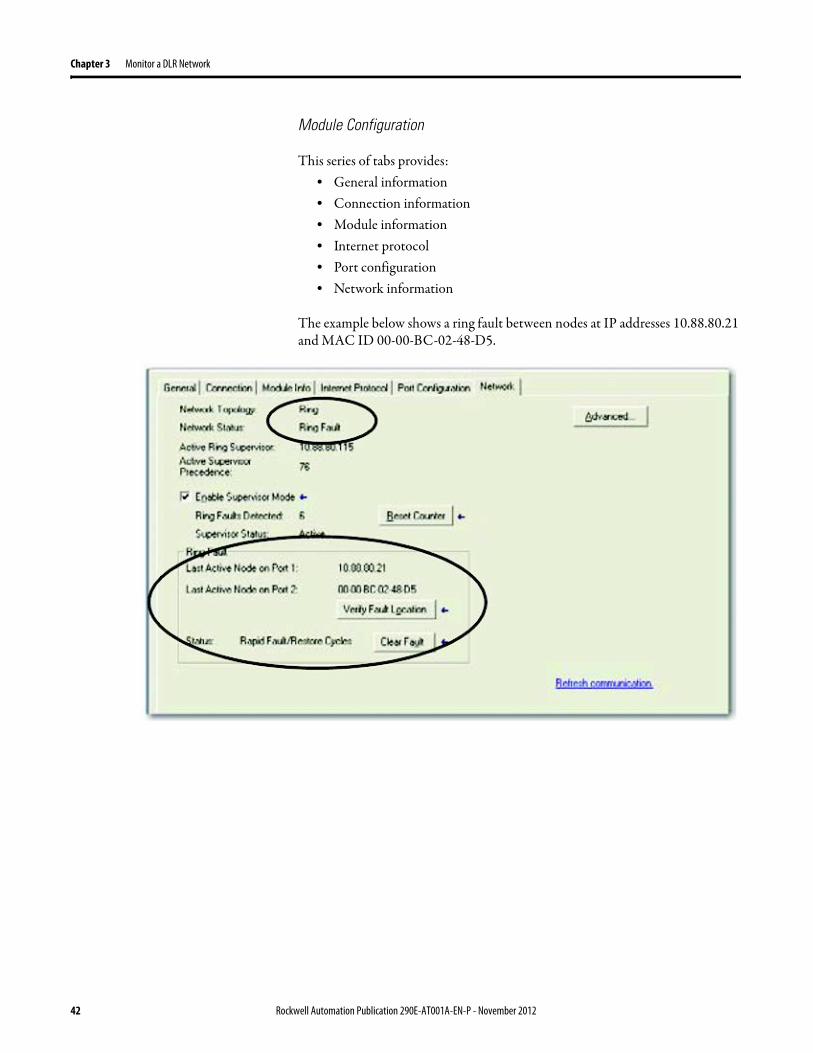
Chapter 3 Monitor a DLR Network
Module Configuration
This series of tabs providesbull General informationbull Connection informationbull Module informationbull Internet protocolbull Port configurationbull Network information
The example below shows a ring fault between nodes at IP addresses 10888021 and MAC ID 00-00-BC-02-48-D5
42 Rockwell Automation Publication 290E-AT001A-EN-P - November 2012
Monitor a DLR Network Chapter 3
There are multiple fields used to monitor network diagnostics
Field Definition
Network Topology Possible values here can be Linear or Ring
Network Status Displays if the network is operating normally (Normal) or has experienced a fault (Ring Fault) as shown in the previous example screen
Active Ring Supervisor Displays the IP address or MAC address of the active ring supervisor
Active Supervisor Precedence For more information on this field see Active Ring Supervisor on page 11
Enable Ring Supervisor Configurable field that lets you to set the node as a ring supervisor
Ring Faults Detected Number of faults detected on the network since the last module power cycle or counter reset
Supervisor Status Displays whether this node is the active ring supervisor (Active) a back-up supervisor (Back-up) a ring node or part of a linear network
Last Active Node on Port 1 The last node the active ring supervisor can communicate with on Port 1 This value is an IP address or a MAC ID and remains latched until the Verify Fault Location button is clicked
Last Active Node on Port 2 The last node the active ring supervisor can communicate with on Port 2 This value is an IP address or a MAC ID and remains latched until the Verify Fault Location button is clicked
Status Displays whether a fault exists on the ring
IMPORTANT If the Network Topology field = Ring and the Network Status field = Normal the Last Active Node fields will display the last fault information even though it has been correctedTo clear the last fault information from these fields click Verify Fault Location You may see a message informing you that the supervisor is no longer in fault mode and the fields will be cleared
Rockwell Automation Publication 290E-AT001A-EN-P - November 2012 43
Chapter 3 Monitor a DLR Network
How to Access the ArmorStart EtherNetIP Internal Web Server
Open your preferred internet web browser and enter the IP address of the desired ArmorStart For this example 192168122 will be used
Use the links on the left-most navigation bar to see each available web page The screen below shows Ring Statistics for the ArmorStart 280E
44 Rockwell Automation Publication 290E-AT001A-EN-P - November 2012
Monitor a DLR Network Chapter 3
EtherNetIP Device Level Ring (DLR) Network Diagnostics Faceplate Overview
The EtherNetIP Device Level Ring (DLR) network diagnostics faceplate provides basic DLR network status information to the user to assist with monitoring and troubleshooting a DLR network
The diagnostics faceplate contains two major components
bull Logic code (encapsulated in an Add-On Instruction) that allows the controller to retrieve real-time DLR network status information
bull HMI faceplate graphics to allow the data to be visualized on an operator interface
The DLR diagnostics faceplate application can be downloaded from the Rockwell Automation Sample Code website at httpsamplecoderockwellautomationcom
Besides the individual Logix and View project components a demo application is also included with the downloaded file
Rockwell Automation Publication 290E-AT001A-EN-P - November 2012 45
Chapter 3 Monitor a DLR Network
Monitor Diagnostics via MSG Instructions
Network diagnostic information can also be obtained programmatically via MSG instructions in RSLogix 5000 programming software For example you can
bull Get all ring diagnostic informationbull Get a ring participant listbull Get the active supervisorbull Clear rapid ring faultsbull Verify a fault locationbull Reset a fault counterbull Enable and configure a ring supervisor
This information can be displayed on an HMI device or manipulated in the project code
Figure 5 - Example Use of MSG Instruction
This example describes how to retrieve diagnostic information from the DLR network Follow these steps
1 Enter a MSG instruction into the rung of logic
2 Configure the MSG instruction to retrieve ring diagnostic information service as shown in the following screen shots
IMPORTANT Make sure the tag created is sized appropriately to hold all of the data that you are reading or writing For more information see page 48
46 Rockwell Automation Publication 290E-AT001A-EN-P - November 2012
Monitor a DLR Network Chapter 3
3 Configure the MSG instructionrsquos communication path to point to the active supervisor node
The path on the following screen is one example path
IMPORTANT When using the Custom Get_Attributes_All (01) service pointing to an active supervisor node will retrieve all of the attributes listed in Retrieve All Diagnostic Information Attribute Description on page 50Pointing to a non-supervisor node will retrieve only the Network Topology and Network Status attribute informationPointing to backup supervisor node will retrieve the current active supervisorrsquos IP address
Rockwell Automation Publication 290E-AT001A-EN-P - November 2012 47
Chapter 3 Monitor a DLR Network
Use Specific Values on the Configuration Tab
Use the values on the Configuration tab of your MSG instruction to perform specific services Sample DLR network diagnostic application code for example Add-on Instruction or HMI faceplate graphics is available on the Rockwell Automation Sample Code Library For more information about the Rockwell Automation Sample Code Library see httpwwwrockwellautomationcomsolutionsintegratedarchitectureresources5html
➊ This request only works if there are fewer than 40 nodes on the network If there are more nodes than will fit in a single message an error will be returned➋ Use a Destination Length of 54 bytes if using firmware revision 3x or later for the 1756-EN2TR module or firmware revision 2x or later for the 1783-ETAP
1783-ETAP1F or 1783-ETAP2F taps
Request Description Message Type
Service Type
Service Code (HEX)
Class (HEX)
Instance Attribute (HEX)
Source Element
Source Length (Bytes)
Destination Destination Length (bytes)
Retrieve All Ring Diagnostic Information
Information for this request is listed in Retrieve All Ring Diagnostic Information on page 49
CIP Generic Custom 1 47 1 NA LeftBlank
0 Tag 50or54 ➋
Request Ring Participant List ➊
Information for this request is listed in Request the Ring Participant List on page 51
CIP Generic Get Attribute Single
e 47 1 9 NA NA Tag 10node
Get Active Supervisor
Obtain the IP address and MAC ID of the active supervisor on the DLR network
CIP Generic Get Attribute Single
e 47 1 a NA NA Tag 10
Acknowledge Rapid Ring Faults Condition
Request supervisor to resume normal operation after encountering a rapid ring fault condition
CIP Generic Custom 4c 47 1 NA NA NA NA
Verify a Fault Location
Request supervisor to update Last Active Node values
CIP Generic 4b 47 1 NA NA NA NA NA
Reset the Ring Fault Counter
Reset the number of ring faults detected on the DLR network
CIP Generic Set Attribute Single
10 47 1 5 Tag 2 NA NA
Enable and Configure a Ring Supervisor
Information for this request is listed in Enable and Configure a Ring Supervisor on page 52
CIP Generic Set Attribute Single
10 47 1 4 Tag 12 NA NA
48 Rockwell Automation Publication 290E-AT001A-EN-P - November 2012
Monitor a DLR Network Chapter 3
Retrieve All Ring Diagnostic Information
By performing the Retrieve All Ring Diagnostic Information request on an active supervisor the MSG instruction returns the following information
➊ RSLogix 5000 programming software may display the value in this field as negative numbers To better understand the value we recommend you view it in HEX format
Destination Tag Attribute Name Description Possible Values
SINT [0] Network Topology Current network topology mode 0 = Linear
1 = Ring
SINT [1] Network Status Current status of the network 0 = Normal
1 = Ring Fault
2 = Unexpected Loop Detected
3 = Partial Network Fault
4 = Rapid FaultRestore Cycle
SINT [2] Ring Supervisor Status Ring supervisor active status flag 0 = Node is functioning as a backup
1 = Node is functioning as the active ring supervisor
2 = Node is functioning as a normal ring node
3 = Node is operating in a non-DLR topology
4 = Node cannot support the currently operating ring parameters thatis Beacon Interval andor Beacon Timeout
Ring Supervisor Config Ring Supervisor configuration parameters
SINT [3] Ring Supervisor Enable Ring supervisor enable flag 0 = Node is configured as a normal ring node (default configuration)
1 = Node is configured as a ring supervisor
SINT [4] Ring Supervisor Precedence Precedence value of a ring supervisor ➊ Valid value range = 0hellip255
0 = Default value
SINT [5-8] Beacon Interval Duration of ring beacon interval Valid value range = 200 μshellip100 ms
Default = 400 μs
SINT [9-12] Beacon Timeout Duration of ring beacon timeout Value value range = 400 μshellip500 ms
Default value = 1960 μs
SINT [13-14] DLR VLAN ID Valid ID to use in ring protocol messages Valid value range = 0hellip4094
Default value = 0
SINT [15-16] Ring Faults Count Number of ring faults since power up ➊
Rockwell Automation Publication 290E-AT001A-EN-P - November 2012 49
Chapter 3 Monitor a DLR Network
Retrieve All Diagnostic Information Attribute Description
➊ This destination tag is available only with the 1756-EN2TR module firmware revision 3x or later 1783-ETAP 1783-ETAP1F and 1783-ETAP2F taps firmware revisions 2x or later If using the 1783-ETAP tap firmware revision 1x your program does not include this destination tag
➋ RSLogix 5000 programming software may display the value in this field as negative numbers To better understand the value we recommend you view it in HEX format
Destination Tag Attribute Name Description Possible Values
Last Active Node on Port 1 Last active node at the end of the chain through port 1 of the active ring supervisor during a ring fault
SINT [17-20] Device IP address ➋ Any valid IP address value
A value = 0 indicates no IP address has been configured for the device
SINT [21-26] Device MAC address ➋ Any valid Ethernet MAC address
Last Active Node on Port 2 Last active node at the end of the chain through port 2 of the active ring supervisor during a ring fault
SINT [27-30] Device IP address ➋ Any valid IP address value
A value = 0 indicates no IP address has been configured for the device
SINT [31-36] Device MAC address ➋ Any valid Ethernet MAC address
SINT [37-38] Ring Protocol Participants Count
Number of devices in the ring protocol participants list
Active Supervisor Address IP andor Ethernet MAC address of the active ring supervisor
SINT [39-42] Supervisor IP address Any valid IP address value
A value = 0 indicates no IP address has been configured for the device
SINT [43-48] Supervisor MAC address Any valid Ethernet MAC address
SINT [49] Active Supervisor Precedence
Precedence value of the active ring supervisor
SINT [50-53]➊ Capability Flags Alerts you that the device is capable of operating as a supervisor and beacon-based ring node
0x22
50 Rockwell Automation Publication 290E-AT001A-EN-P - November 2012
Monitor a DLR Network Chapter 3
Request the Ring Participant List
When requesting the Ring Participant List service on the DLR network the MSG instruction returns the following information
Request the Ring Participant List Attribute Description
➊ This attribute will return an array of the data shown one entry for each node The Ring Protocol Participants Count attribute determines the number entries
➋ This tag displays only IP addresses for ring participants that have been configured with one For example you may have a 1783-ETAP tap connected to the network that has not been assigned an IP address In that case no address is shown for the 1783-ETAP tap
➌ RSLogix 5000 programming software may display the value in this field as negative numbers To better understand the value we recommend you view it in HEX format
➍ Unlike destination tag SINT [0-3] where IP addresses are displayed only for ring participants configured with an IP address this tag displays MAC addresses for all ring participants because every ring participant has a MAC address
Destination Tag Attribute Name Description Possible Values
Ring Protocol Participants List ➊
List of devices participating in ring protocol
SINT [0-3] Device IP address ➋➌ Any valid IP address value
A value = 0 indicates no IP address has been configured for the device
SINT [4-9] Device MAC address ➌➍ Any valid Ethernet MAC address
Rockwell Automation Publication 290E-AT001A-EN-P - November 2012 51
Chapter 3 Monitor a DLR Network
Enable and Configure a Ring Supervisor
When performing the Enable and Configure a Ring Supervisor request on a supervisor-capable device configure the MSG instruction with the following information
Enable and Configure a Ring Supervisor Attribute Description
➊ RSLogix 5000 programming software may display the value in this field as negative numbers To better understand the value we recommend you view it in HEX format
Source Tag Attribute Name Description Possible Values
Ring Supervisor Config Ring Supervisor configuration parameters
SINT [0] Ring Supervisor Enable Ring supervisor enable flag 0 = Node is configured as a normal ring node (default configuration)1 = Node is configured as a ring supervisor
SINT [1] Ring Supervisor Precedence Precedence value of a ring supervisor ➊
Valid value range = 0hellip2550 = Default value
SINT [2-5] Beacon Interval Duration of ring beacon interval
Valid value range = 200 μshellip100 000 μsDefault = 400 μs
SINT [6-9] Beacon Timeout Duration of ring beacon timeout ➊
Value value range = 400 μshellip500 000 μsDefault value = 1960 μs
SINT [10-11] DLR VLAN ID Valid ID to use in ring protocol messages ➊
Valid value range = 0hellip4094Default value = 0
52 Rockwell Automation Publication 290E-AT001A-EN-P - November 2012
Chapter 4
Troubleshoot a DLR Network
Introduction Use this chapter to learn how to troubleshoot the DLR network
General Solutions for Linear or DLR Networks
Before attempting to correct specific faults on the linear or DLR network we recommend that you first take the following actions when a fault appears
bull For a DLR networkndash Verify that at least one node has been configured as a supervisor
on the network and that Network Topology = Ringndash Verify that all cables on the network are securely connected
to each devicendash Verify that all devices that require an IP address have one assigned
correctlyndash Check the Network Status field on the active supervisor nodersquos status
page to determine the fault typebull For a linear network
ndash Verify that none of the nodes are configured as a supervisor on the network and that Network Topology = LinearIf any nodes on a linear network are configured as a supervisor it may impact communication to other devices connected to the network
ndash Verify that all cables on the network are securely connected to each device
ndash Verify that all devices that require an IP address have one assigned correctly
If the fault is not cleared after completing the actions listed above use the tables in the rest of this chapter to troubleshoot issues specific to a DLR network or a linear network
Topic Page
General Solutions for the Linear or DLR Networks 53
Duplicate IP Address Detection 54
Specific Issues on the DLR Network 55
Network Recovery Performance 58
Device Port Debugging Mode 59
Rockwell Automation Publication 290E-AT001A-EN-P - November 2012 53
Chapter 4 Troubleshoot a DLR Network
Duplicate IP Address Detection
Some EtherNetIP communication modules support duplicate IP address detection The module verifies that its IP address does not match any other network devicersquos IP address when performing either of these tasks
bull Connect the module to an EtherNetIP network
bull Change the modulersquos IP address
If the modulersquos IP address matches that of another device on the network the modulersquos EtherNetIP port transitions to Conflict mode In Conflict mode these conditions exist
bull OK status indicator is blinking red
bull Network (NET) status indicator is solid red
bull On some EtherNetIP communication modules the module status display indicates the conflict
The display scrollsOK ltIP_address_of_this_modulegt Duplicate IP
ltMac_address_of_duplicate_node_detectedgt
For example OK 108860196 Duplicate IP - 0000BC0234B4
bull On some EtherNetIP communication modules the modulersquos diagnostic webpage displays information about duplicate IP address detection
For more information on which EtherNetIP communication modules support displaying duplicate IP address on their diagnostic webpage see the Technical Note titled Logix modules Duplicate IP address detection enhancement 118216 in the Technical Support Knowledgebase available at httpwwwrockwellautomationcomknowledgebase
54 Rockwell Automation Publication 290E-AT001A-EN-P - November 2012
Troubleshoot a DLR Network Chapter 4
Specific Issues on the DLR Network
Use the following table to troubleshoot possible specific issues on the DLR or linear network that are not solved by the actions described on the previous page
Issue Description Solution
Supervisor Reports a Ring Fault A link on the DLR network may be brokenbull intentionally for example because of adding or deleting nodes but not making all
physical connections to restore the setup of the network withwithout the nodebull unintentionally for example because a cable is broken or a device malfunctionsWhen this fault occurs the adjacent nodes to the faulted part of the network are displayed in the Ring Fault group and the Network Status field = Ring FaultThe screen shot below shows the Ring Fault section with IP addresses appearing for the last active nodes The faulted node is between nodes 108880115 and 108880208 If the IP address of either node is not available the software will display the nodersquos MAC ID
Once the fault is corrected the ring is automatically restored and the Network Status field returns to Normal
Determine where the fault condition exists and correct itClick the Refresh Communication link as needed to update the Ring Fault information to determine where the fault condition existsFinally DevicePort Debugging Mode functionality on the 1783-ETAP tap may be used to analyze a suspicious nodeFor more information refer to Device Port Debugging Mode on page 59
Rockwell Automation Publication 290E-AT001A-EN-P - November 2012 55
Chapter 4 Troubleshoot a DLR Network
Issue Description Solution
Rapid Ring Fault When a Rapid Ring Fault occurs the following events occurbull The active supervisor will block traffic on port 2 resulting in possible network
segmentation that is some nodes may become unreachablebull The Link 2 status indicator on the active supervisor is offbull As soon as the fault occurs for both RSLogix 5000 programming software and
RSLinx communication software the Status field = Rapid FaultRestore Cycles
Any of the following may cause a Rapid Ring Faultbull 5 intentional disconnectionsreconnections of a node from the network within 30
secondsbull A duplex mismatch between two connected devicesbull Electromagnetic noise on the networkbull Unstable physical connections such as intermittent connectorsGiven the nature of a Rapid Ring Fault the Last Active Node information may not be accurate when a Rapid Ring Fault condition is present
Multiple possible solutions existbull For the disconnections and reconnections issue no
solution is requiredClear the fault after reconnecting the device to the network permanentlybull For the duplex mismatch issue reconfigure the duplex
parameters to make sure they match between the devices
bull For the electromagnetic noise issue determine where the noise exists and eliminate it or use a protective shield in that location
bull For the unstable connections issue determine where they exist on the network and correct them
bull Check the media counters for all devices on the network The device with the highest media counter count is most likely causing the Rapid Ring Fault
bull Remove devices from the network one by one If the Rapid Ring Fault disappears after a device is removed that device is causing the fault
bull DevicePort Debugging Mode functionality on the 1783-ETAP tap may be used to analyze a suspicious node
For more information refer to Device Port Debugging Mode on page 59bull Finally the Beacon Interval or Timeout configuration
may not be appropriate for the networkHowever if these values need to be changed we recommend that you contact Rockwell Automation technical supportOnce the fault is fixed click Clear Fault
56 Rockwell Automation Publication 290E-AT001A-EN-P - November 2012
Troubleshoot a DLR Network Chapter 4
Issue Description Solution
Partial Fault Condition A partial network fault occurs when traffic is lost in only one direction on the network because a ring member is not forwarding beacons in both directions for example a component failureThe active ring supervisor detects a partial fault by monitoring the loss of Beacon frames on one port and the fault location appears in the Ring Fault section of the Network tab When a partial fault is detected the active ring supervisor blocks traffic on one port At this point the ring is segmented due to the partial fault condition The nodes adjacent to the faulted part of the network are displayed in the Ring Fault group with either IP addresses or MAC IDs for each node displayedWhen this fault occurs the Network Status field = Partial Fault ConditionOnce the fault is corrected it automatically clears and the Network Status field returns to Normal
Determine where the fault condition exists and correct itAdditionally the DevicePort Debugging Mode functionality also known as Port Mirroring on a 1783-ETAP 1783-ETAP1F or 1783-ETAP2F tap may be used to analyze a suspicious nodeFor more information refer to Device Port Debugging Mode on page 59
Media Counter Errors or Collisions
The media counters screen displays the number of physical layer errors or collisions The screen below indicates where to check for errors encountered Error levels are displayed depending on what caused the error For example an Alignment Error is displayed in the Alignment Error field
On a DLR network it is not uncommon to see low levels of media counter errors For example if the network breaks a low level of media counter errors appears With a low level of media counter errors the value typically does not continuously increase and often clearsA high level of media counter errors typically continues to increase and does not clear For example there is a mismatch of speed between two linked nodes a high level of media counter errors appears steadily increasing and not clearingTo access the RSLinx screen above browse the network right-click on the device select Module Properties and click the Port Diagnostics tab
Some example solutions includebull Check for a mismatch of speed andor duplex between
two linked nodesbull Verify that all cables on the network are securely
connected to each devicebull Check for electromagnetic noise on the network If you
find it eliminate it or use a protective shield in that location
Rockwell Automation Publication 290E-AT001A-EN-P - November 2012 57
Chapter 4 Troubleshoot a DLR Network
Network Recovery Performance
When measuring the networkrsquos performance with regard to dealing with fault conditions consider the network recovery time Network recovery is the time for all of the following to take place
1 The supervisor node recognizes that a fault exists on the network
2 The supervisor node reconfigures the network because of the fault
3 The supervisor node communicates to the network nodes that a fault condition exists
4 The network nodes reconfigure themselves because of the fault
With the default beacon interval value of 400 mS and beacon timeout value of 1960 mS the worst-case time for network recovery times are
bull 2890 mS for a copper DLR network This recovery time is based on 100 m copper segments between nodes on the network
bull 3140 mS for a fiber-optic DLR network This recovery time is based on 2 kM fiber-optic cable segments between nodes on the network
When considering the values listed above keep in mind
bull Recovery time may actually occur faster than the times listed
bull The recovery times listed above assume that your networkrsquos nodes are operating at 100 Mbps speed and full-duplex mode We recommend that your nodes generally operate in this mode for DLR networks
bull If other node conditions exist such as a node operating at 10 Mbps full-duplex or 10100 Mbps half-duplex the recovery times will vary from the times listed above
If this is the case for your application the beacon interval and beacon timeout will need to be changed We recommend that you first contact Rockwell Automation technical support if these parameters need to be changed
bull The value assumes that the majority of the traffic on your network is EtherNetIP traffic
58 Rockwell Automation Publication 290E-AT001A-EN-P - November 2012
Troubleshoot a DLR Network Chapter 4
Device Port Debugging Mode
This functionality is disabled by default Device Port Debugging mode which is similar to port mirroring can be used to monitor data received on the 1783-ETAP 1783-ETAP1F or 1783-ETAP2F taprsquos two network ports Monitor the data over the device port to a device such as a personal computer running a protocol analyzer application for advanced network debugging or analysis
When device port debugging is used on a 1783-ETAP the device connected to the 1783-ETAP taprsquos front port receives all of the data traversing the ring (both directions)
Device Port Debugging Example Network
When using the Device Port Debugging mode functionality insert the 1783-ETAP with the network analyzer connected to the device port It is inserted at the spot on the ring network where the node in question is located The graphic below shows a 1783-ETAP tap inserted in the network
IMPORTANT This functionality should be used only when troubleshooting the network and not in normal network operation
Rockwell Automation Publication 290E-AT001A-EN-P - November 2012 59
Chapter 4 Troubleshoot a DLR Network
Combined total network bandwidth of the traffic received on the two 1783-ETAP 1783-ETAP1F or 1783-ETAP2F taprsquos ports connected to the network should not exceed the taprsquos device port capacity The speed setting determines the device portrsquos capacity
Configure the device port on a 1783-ETAP 1783-ETAP1F or 1783-ETAP2F tap to either of two speed settings
bull 100 Mbps - default settingbull 10 Mbps
If the bandwidth exceeds the capacity of the taprsquos device port some frames from the ring will be dropped before reaching the device port These dropped frames do not impact the traffic on the rest of the DLR network
The device port setting determines how much network traffic the 1783-ETAP 1783-ETAP1F or 1783-ETAP2F tap can handle before dropping frames The circled section in the graphic below shows the Port Buffer Utilization of the Device Port In this example the value is zero because a ring fault exists on the network
60 Rockwell Automation Publication 290E-AT001A-EN-P - November 2012
Appendix A
Network Usage Guidelines and Recommendations
Consider the following guidelines and recommendations when using a DLR or linear network
GuidelineRecommendation Explanation
Use fewer than 50 nodes on a single DLR networkIf your application requires more than 50 nodes we recommend that the nodes are broken into separate but linked DLR networks
If you use more than 50 nodes on a single DLR networkbull Your network has a greater chance of multiple faults
occurring on the networkbull Network recovery times from faulted DLR network
are higher
Do not configure a supervisor on a linear network If your linear network includes non-DLR nodes and has a supervisor-enabled node on the network it may impact communication to non-DLR devices connected to the linear network
If you must connect a device that is running at 10 Mbps to a DLR or linear network do so through a 1783-ETAP 1783-ETAP1F or 1783-ETAP2F tap device port
The 1783-ETAP 1783-ETAP1F and 1783-ETAP2F taps can operate at 100 Mbps on the DLR network this is the optimal speed for a network If you connect a 10 Mbps device directly to the network instead of through a tap the linear or DLR network traffic slows to 10 MbpsAdditionally if the 10 Mbps device is connected to the network without a 1783-ETAP tap network recovery times are significantly impacted
Configure multiple supervisor nodes per ring If your DLR network only has one supervisor and the supervisor experiences a fault none of the other nodes become the active supervisor In this case the network becomes a linear network until the fault is corrected and the DLR network restoredAnother reason to configure multiple supervisor nodes is for replacing an active supervisor node with an out-of-box replacement the new device will not be enabled as a supervisor (by default) and there would still be no supervisor on the network
Rockwell Automation Publication 290E-AT001A-EN-P - November 2012 61
Appendix A Network Usage Guidelines and Recommendations
GuidelineRecommendation Explanation
Connect switches to a DLR network via 1783-ETAP 1783-ETAP1F or 1783-ETAP2F taps
If switches are connected to the DLR network without the use of a 1783-ETAP 1783-ETAP1F or 1783-ETAP2F tap the network may experience unpredictable behavior and network performance is unknown
Run all nodes on the DLR network at 100 Mbps and in Full-Duplex mode
These configuration values provide the best performance for your networkAdditionally we recommend that youbull Use auto-negotiate for all nodes on the DLR networkbull Do not use auto-negotiate on one node and then force
speed on the next node linked to it
In a linear network the number of nodes to use is application specific based on the considerations described in the next box
When determining the number of nodes to use on a linear network consider the followingbull There is a delay per node as information is transmitted
to each successive node used on the networkndash The typical delay on a linear network with 100 m
copper segments between nodes is 30 mSndash The typical delay on a linear network with 2 kM
fiber-optic segments between nodes is 40 mS
The greater the number of nodes on the network the longer the total time for information to be transmitted across the entire networkbull The single point of failure possibility is greater with
each additional connectionbull Troubleshooting the network may be more difficult
with a higher number of nodes
The total time for information to be transmitted across the entire network and its effect on how many nodes to use on a linear network is related to the Requested Packet Interval (RPI)Verify that the total time to transmit information from the first node to the last node on the network is less than the RPI Make sure the network is not loaded beyond 90 of capacity
62 Rockwell Automation Publication 290E-AT001A-EN-P - November 2012
Network Usage Guidelines and Recommendations Appendix A
GuidelineRecommendation Explanation
Do not physically close a DLR network without a supervisor configured on the network
A DLR network without a supervisor node results in a network stormIf you do close the DLR network without a supervisor configured break the ring and configure at least one supervisor before physically reconnecting the network
Use the default values for the followingbull Beacon Intervalbull Beacon Timeoutbull Ring Protocol VLAN ID
Changing the default values for the parameters Beacon Interval Beacon Timeout and Ring Protocol VLAN ID can result in unpredictable network behavior and negatively impacted network performanceThe default values are optimized for a network withbull 50 or fewer nodes are on the networkbull All nodes are operating at 100 Mbps and full-duplex
modebull At least 50 of the network traffic bandwidth being
EtherNetIP trafficIf you think the values of the Beacon Interval Beacon Timeout or Ring Protocol VLAN ID need to be changed for example if any node on ring is not operating at 100 Mbps and full-duplex mode we recommend that you first contact Rockwell Automation technical support
If DHCP for the ArmorStarts is still required you will need to disable Internet Group Management Protocol (IGMP) snooping on the E-tap via the AOP
IGMP Snooping is enabled by default in the 1783-ETAP 1783-ETAP1F and 1783-ETAP2F taps and is commonly used to manage multicast traffic on the network When in use this functionality allows the tap to multicast data to only those devices that need the data rather than to all devices connected to the networkOnce DHCP is enabled the switch could change the IP addresses on the ArmorStarts depending on network demand which could cause RSlogix5000 to loose communication with the device as connectivity is established via the AOP in the initial configuration
The IGMP Querier functionality should be enabled for at least one node on the network
This functionality is disabled by default The IGMP Querier functionality enables a 1783-ETAP 1783-ETAP1F or 1783-ETAP2F tap or switch such as a Stratix managed switch to send out a query to all devices on the network to determine what multicast addresses are of interest to a specific node or a group of nodesIf the IGMP Querier functionality is not enabled for at least one node on the network multicast traffic on the network may eventually create network performance issuesThe 1783-ETAP 1783-ETAP1F or 1783-ETAP2F taps managed switches and routers are examples of devices that support IGMP Querier functionality
Rockwell Automation Publication 290E-AT001A-EN-P - November 2012 63
Appendix A Network Usage Guidelines and Recommendations
Notes
64 Rockwell Automation Publication 290E-AT001A-EN-P - November 2012
Appendix B
Required Firmware Revisions
Required Firmware Revision for an Add-On Profile
➊ The ControlFLASH Firmware Upgrade software tcan be used o upgrade a 1756-EN2TR module from firmware revision 21 to 3x or later1x or later3x or later2x or later
➋ The ControlFLASH Firmware Upgrade software can be used to upgrade a 1783-ETAP tap from firmware revision 11 to 2x or later
To download new firmware go to httpwwwrockwellautomationcomsupportamericasindex_enhtml
If the firmware revision is upgraded on the module or tap the required AOP revision listed above must be used for that revision For example if the 1756-EN2TR module is upgraded to firmware revision 3x or later AOP revision 2x or later must be used in the RSLogix 5000 programming software
Additionally if the firmware revision is upgraded on the module or tap the required RSLinx communication software must also be used for that firmware revision For more information on which RSLinx software version is required for each firmware revision see page 66
For both the 1756-EN2TR module and 1783-ETAP tap make sure that the Major Revision configured on the General tab of the devicersquos RSLogix 5000 programming software configuration matches the major revision of the physical module
IMPORTANT To download an AOP go to httpsupportrockwellautomationcomcontrolflashLogixProfileraspDepending on the firmware revision of your product a specific AOP version must be used
Firmware Revision Add-On Profile Revision Cat No
21 ➊ 1x or later 1756-EN2TR
3x or later 2x or later
11 ➋ 1x or later 1783-ETAP
2x or later 2x or later
2x or later 2x or later 1783-ETAP1F
1783-ETAP2F
Rockwell Automation Publication 290E-AT001A-EN-P - November 2012 65
Appendix B Required Firmware Revisions
If the device configuration on the General tab does not match the physical module the programming software alerts you to this mismatch when attempting to configure the Internet Protocol Port Configuration and Network tabs for that device
Required Firmware Revision for RSLinx Communication Software
➊ The ControlFLASH Firmware Upgrade software can be used to upgrade a 1756-EN2TR module from firmware revision 21 to 3x or later1x or later3x or later255 or later3x or later256 or later
➋ The ControlFLASH Firmware Upgrade software can be used to upgrade a 1783-ETAP tap from firmware revision 11 to 2x or later
To download new firmware go to httpwwwrockwellautomationcomsupportamericasindex_enhtml
If the firmware revision is upgraded on the module or tap the required RSLinx communication software listed above must be used for that revision For example if the 1756-EN2TR module is upgraded to firmware revision 3x or later AOP revision 2x or later must be used in your RSLogix 5000 programming software
Additionally if the firmware revision is upgraded on the module or tap the required AOP revision must also be used for that firmware revision For more information on which AOP revision is required for each firmware revision see page 65
IMPORTANT Depending on the firmware revision of your product specific versions of RSLinx communication software must be used
Firmware Revision Required RSLinx Communication Software Version
Cat No
21 ➊ 255 or later 1756-EN2TR
3x or later 256 or later
11 ➋ 255 or later 1783-ETAP
2x or later 256 or later
2x or later 256 or later 1783-ETAP1F
1783-ETAP2F
66 Rockwell Automation Publication 290E-AT001A-EN-P - November 2012
Rockwell Otomasyon Ticaret AŞ Kar Plaza İş Merkezi E Blok Kat6 34752 İccedilerenkoumly İstanbul Tel +90 (216) 5698400
Rockwell Automation Publication 290E-AT001A-EN-P ndash November 2012 68 Copyright copy 2012 Rockwell Automation Inc All rights reserved Printed in the USA
Rockwell Automation Support
Rockwell Automation provides technical information on the Web to assist you in using its products At httpwwwrockwellautomationcomsupport you can find technical manuals a knowledge base of FAQs technical and application notes sample code and links to software service packs and a MySupport feature that you can customize to make thebest use of these tools
For an additional level of technical phone support for installation configuration and troubleshooting we offer TechConnectSM support programs For more information contact your local distributor or Rockwell Automation representative or visit httpwwwrockwellautomationcomsupport
Installation Assistance
If you experience a problem within the first 24 hours of installation review the information that is contained in this manualYou can contact Customer Support for initial help in getting your product up and running
New Product Satisfaction Return
Rockwell Automation tests all of its products to ensure that they are fully operational when shipped from the manufacturing facility However if your product is not functioning and needs to be returned follow these procedures
Documentation Feedback
Your comments will help us serve your documentation needs better If you have any suggestions on how to improve this document complete this form publication RA-DU002 available at httpwwwrockwellautomationcomliterature
United States or Canada 14406463434
Outside United States or Canada Use the Worldwide Locator at httpwwwrockwellautomationcomsupportamericasphone_enhtml or contact your local Rockwell Automation representative
United States Contact your distributor You must provide a Customer Support case number (call the phone number above to obtain one) to your distributor to complete the return process
Outside United States Please contact your local Rockwell Automation representative for the return procedure
- Important User Information
- General Precautions
- Software Requirements
- Additional Resources
- Rockwell Automation Support
- Installation Assistance
- New Product Satisfaction Return
- Table of Contents
- Chapter 1
-
- Device-Level Ring (DLR) Basics
-
- Introduction
- ArmorStart with EtherNetIP Overview
- What is a Device-level Ring (DLR) Network
- DLR Network Elements
-
- Supervisor Node
- Ring Node
-
- DLR Network Operation
- Number of Nodes on a DLR Network
- DLR Network Fault Management
-
- Network Reconfiguration after a Fault
-
- Chapter 2
-
- Construct and Configure a Device-level Ring Network with ArmorStarts
-
- Introduction
- Ethernet Capacity Tool
- Install Devices on a DLR Network
- ArmorStart Addressing Configuration
-
- Using the BootPDHCP Server
- Using the Rotary Network Address Switches
- Using the ArmorStart Internal Web Server
-
- Configure Supervisor Nodes on a DLR Network
-
- Configure a Ring Supervisor in RSLogix 5000 Programming Software
- Adding an Armorstart to RSLogix 5000
- Enable Ring Supervisor in RSLogix 5000 Programming Software
- Configure and Enable a Ring Supervisor in RSLinx Classic Communication Software
-
- Complete the Physical Connections of the Network
- Verify Supervisor Configuration
- IGMP Snooping
- IGMP Querier
-
- Chapter 3
-
- Monitor a DLR Network
-
- Introduction
- Methods to Monitor a DLR Network
-
- RSLogix 5000 Programming Software Status Pages
- RSLinx Communication Software Status Pages
- ArmorStart Internal Web Server
- EtherNetIP Device Level Ring (DLR) Network Diagnostics Faceplate
- Programmatically Through the Use of a MSG Instruction
-
- Monitor Status Pages
-
- RSLogix 5000 Programming Software Status Pages
- RSLinx Communication Software
-
- How to Access the ArmorStart EtherNetIP Internal Web Server
-
- EtherNetIP Device Level Ring (DLR) Network Diagnostics Faceplate Overview
-
- Monitor Diagnostics via MSG Instructions
-
- Use Specific Values on the Configuration Tab
- Retrieve All Ring Diagnostic Information
- Retrieve All Diagnostic Information Attribute Description
- Request the Ring Participant List
- Request the Ring Participant List Attribute Description
-
- Enable and Configure a Ring Supervisor
-
- Enable and Configure a Ring Supervisor Attribute Description
-
- Chapter 4
-
- Troubleshoot a DLR Network
-
- Introduction
- General Solutions for Linear or DLR Networks
- Duplicate IP Address Detection
- Specific Issues on the DLR Network
- Network Recovery Performance
- Device Port Debugging Mode
-
- Device Port Debugging Example Network
-
- Appendix A
-
- Network Usage Guidelines and Recommendations
-
- Notes
-
- Appendix B
-
- Required Firmware Revisions
-
- Required Firmware Revision for an Add-On Profile
- Required Firmware Revision for RSLinx Communication Software
-

Monitor a DLR Network Chapter 3
There are multiple fields used to monitor network diagnostics
Field Definition
Network Topology Possible values here can be Linear or Ring
Network Status Displays if the network is operating normally (Normal) or has experienced a fault (Ring Fault) as shown in the previous example screen
Active Ring Supervisor Displays the IP address or MAC address of the active ring supervisor
Active Supervisor Precedence For more information on this field see Active Ring Supervisor on page 11
Enable Ring Supervisor Configurable field that lets you to set the node as a ring supervisor
Ring Faults Detected Number of faults detected on the network since the last module power cycle or counter reset
Supervisor Status Displays whether this node is the active ring supervisor (Active) a back-up supervisor (Back-up) a ring node or part of a linear network
Last Active Node on Port 1 The last node the active ring supervisor can communicate with on Port 1 This value is an IP address or a MAC ID and remains latched until the Verify Fault Location button is clicked
Last Active Node on Port 2 The last node the active ring supervisor can communicate with on Port 2 This value is an IP address or a MAC ID and remains latched until the Verify Fault Location button is clicked
Status Displays whether a fault exists on the ring
IMPORTANT If the Network Topology field = Ring and the Network Status field = Normal the Last Active Node fields will display the last fault information even though it has been correctedTo clear the last fault information from these fields click Verify Fault Location You may see a message informing you that the supervisor is no longer in fault mode and the fields will be cleared
Rockwell Automation Publication 290E-AT001A-EN-P - November 2012 43
Chapter 3 Monitor a DLR Network
How to Access the ArmorStart EtherNetIP Internal Web Server
Open your preferred internet web browser and enter the IP address of the desired ArmorStart For this example 192168122 will be used
Use the links on the left-most navigation bar to see each available web page The screen below shows Ring Statistics for the ArmorStart 280E
44 Rockwell Automation Publication 290E-AT001A-EN-P - November 2012
Monitor a DLR Network Chapter 3
EtherNetIP Device Level Ring (DLR) Network Diagnostics Faceplate Overview
The EtherNetIP Device Level Ring (DLR) network diagnostics faceplate provides basic DLR network status information to the user to assist with monitoring and troubleshooting a DLR network
The diagnostics faceplate contains two major components
bull Logic code (encapsulated in an Add-On Instruction) that allows the controller to retrieve real-time DLR network status information
bull HMI faceplate graphics to allow the data to be visualized on an operator interface
The DLR diagnostics faceplate application can be downloaded from the Rockwell Automation Sample Code website at httpsamplecoderockwellautomationcom
Besides the individual Logix and View project components a demo application is also included with the downloaded file
Rockwell Automation Publication 290E-AT001A-EN-P - November 2012 45
Chapter 3 Monitor a DLR Network
Monitor Diagnostics via MSG Instructions
Network diagnostic information can also be obtained programmatically via MSG instructions in RSLogix 5000 programming software For example you can
bull Get all ring diagnostic informationbull Get a ring participant listbull Get the active supervisorbull Clear rapid ring faultsbull Verify a fault locationbull Reset a fault counterbull Enable and configure a ring supervisor
This information can be displayed on an HMI device or manipulated in the project code
Figure 5 - Example Use of MSG Instruction
This example describes how to retrieve diagnostic information from the DLR network Follow these steps
1 Enter a MSG instruction into the rung of logic
2 Configure the MSG instruction to retrieve ring diagnostic information service as shown in the following screen shots
IMPORTANT Make sure the tag created is sized appropriately to hold all of the data that you are reading or writing For more information see page 48
46 Rockwell Automation Publication 290E-AT001A-EN-P - November 2012
Monitor a DLR Network Chapter 3
3 Configure the MSG instructionrsquos communication path to point to the active supervisor node
The path on the following screen is one example path
IMPORTANT When using the Custom Get_Attributes_All (01) service pointing to an active supervisor node will retrieve all of the attributes listed in Retrieve All Diagnostic Information Attribute Description on page 50Pointing to a non-supervisor node will retrieve only the Network Topology and Network Status attribute informationPointing to backup supervisor node will retrieve the current active supervisorrsquos IP address
Rockwell Automation Publication 290E-AT001A-EN-P - November 2012 47
Chapter 3 Monitor a DLR Network
Use Specific Values on the Configuration Tab
Use the values on the Configuration tab of your MSG instruction to perform specific services Sample DLR network diagnostic application code for example Add-on Instruction or HMI faceplate graphics is available on the Rockwell Automation Sample Code Library For more information about the Rockwell Automation Sample Code Library see httpwwwrockwellautomationcomsolutionsintegratedarchitectureresources5html
➊ This request only works if there are fewer than 40 nodes on the network If there are more nodes than will fit in a single message an error will be returned➋ Use a Destination Length of 54 bytes if using firmware revision 3x or later for the 1756-EN2TR module or firmware revision 2x or later for the 1783-ETAP
1783-ETAP1F or 1783-ETAP2F taps
Request Description Message Type
Service Type
Service Code (HEX)
Class (HEX)
Instance Attribute (HEX)
Source Element
Source Length (Bytes)
Destination Destination Length (bytes)
Retrieve All Ring Diagnostic Information
Information for this request is listed in Retrieve All Ring Diagnostic Information on page 49
CIP Generic Custom 1 47 1 NA LeftBlank
0 Tag 50or54 ➋
Request Ring Participant List ➊
Information for this request is listed in Request the Ring Participant List on page 51
CIP Generic Get Attribute Single
e 47 1 9 NA NA Tag 10node
Get Active Supervisor
Obtain the IP address and MAC ID of the active supervisor on the DLR network
CIP Generic Get Attribute Single
e 47 1 a NA NA Tag 10
Acknowledge Rapid Ring Faults Condition
Request supervisor to resume normal operation after encountering a rapid ring fault condition
CIP Generic Custom 4c 47 1 NA NA NA NA
Verify a Fault Location
Request supervisor to update Last Active Node values
CIP Generic 4b 47 1 NA NA NA NA NA
Reset the Ring Fault Counter
Reset the number of ring faults detected on the DLR network
CIP Generic Set Attribute Single
10 47 1 5 Tag 2 NA NA
Enable and Configure a Ring Supervisor
Information for this request is listed in Enable and Configure a Ring Supervisor on page 52
CIP Generic Set Attribute Single
10 47 1 4 Tag 12 NA NA
48 Rockwell Automation Publication 290E-AT001A-EN-P - November 2012
Monitor a DLR Network Chapter 3
Retrieve All Ring Diagnostic Information
By performing the Retrieve All Ring Diagnostic Information request on an active supervisor the MSG instruction returns the following information
➊ RSLogix 5000 programming software may display the value in this field as negative numbers To better understand the value we recommend you view it in HEX format
Destination Tag Attribute Name Description Possible Values
SINT [0] Network Topology Current network topology mode 0 = Linear
1 = Ring
SINT [1] Network Status Current status of the network 0 = Normal
1 = Ring Fault
2 = Unexpected Loop Detected
3 = Partial Network Fault
4 = Rapid FaultRestore Cycle
SINT [2] Ring Supervisor Status Ring supervisor active status flag 0 = Node is functioning as a backup
1 = Node is functioning as the active ring supervisor
2 = Node is functioning as a normal ring node
3 = Node is operating in a non-DLR topology
4 = Node cannot support the currently operating ring parameters thatis Beacon Interval andor Beacon Timeout
Ring Supervisor Config Ring Supervisor configuration parameters
SINT [3] Ring Supervisor Enable Ring supervisor enable flag 0 = Node is configured as a normal ring node (default configuration)
1 = Node is configured as a ring supervisor
SINT [4] Ring Supervisor Precedence Precedence value of a ring supervisor ➊ Valid value range = 0hellip255
0 = Default value
SINT [5-8] Beacon Interval Duration of ring beacon interval Valid value range = 200 μshellip100 ms
Default = 400 μs
SINT [9-12] Beacon Timeout Duration of ring beacon timeout Value value range = 400 μshellip500 ms
Default value = 1960 μs
SINT [13-14] DLR VLAN ID Valid ID to use in ring protocol messages Valid value range = 0hellip4094
Default value = 0
SINT [15-16] Ring Faults Count Number of ring faults since power up ➊
Rockwell Automation Publication 290E-AT001A-EN-P - November 2012 49
Chapter 3 Monitor a DLR Network
Retrieve All Diagnostic Information Attribute Description
➊ This destination tag is available only with the 1756-EN2TR module firmware revision 3x or later 1783-ETAP 1783-ETAP1F and 1783-ETAP2F taps firmware revisions 2x or later If using the 1783-ETAP tap firmware revision 1x your program does not include this destination tag
➋ RSLogix 5000 programming software may display the value in this field as negative numbers To better understand the value we recommend you view it in HEX format
Destination Tag Attribute Name Description Possible Values
Last Active Node on Port 1 Last active node at the end of the chain through port 1 of the active ring supervisor during a ring fault
SINT [17-20] Device IP address ➋ Any valid IP address value
A value = 0 indicates no IP address has been configured for the device
SINT [21-26] Device MAC address ➋ Any valid Ethernet MAC address
Last Active Node on Port 2 Last active node at the end of the chain through port 2 of the active ring supervisor during a ring fault
SINT [27-30] Device IP address ➋ Any valid IP address value
A value = 0 indicates no IP address has been configured for the device
SINT [31-36] Device MAC address ➋ Any valid Ethernet MAC address
SINT [37-38] Ring Protocol Participants Count
Number of devices in the ring protocol participants list
Active Supervisor Address IP andor Ethernet MAC address of the active ring supervisor
SINT [39-42] Supervisor IP address Any valid IP address value
A value = 0 indicates no IP address has been configured for the device
SINT [43-48] Supervisor MAC address Any valid Ethernet MAC address
SINT [49] Active Supervisor Precedence
Precedence value of the active ring supervisor
SINT [50-53]➊ Capability Flags Alerts you that the device is capable of operating as a supervisor and beacon-based ring node
0x22
50 Rockwell Automation Publication 290E-AT001A-EN-P - November 2012
Monitor a DLR Network Chapter 3
Request the Ring Participant List
When requesting the Ring Participant List service on the DLR network the MSG instruction returns the following information
Request the Ring Participant List Attribute Description
➊ This attribute will return an array of the data shown one entry for each node The Ring Protocol Participants Count attribute determines the number entries
➋ This tag displays only IP addresses for ring participants that have been configured with one For example you may have a 1783-ETAP tap connected to the network that has not been assigned an IP address In that case no address is shown for the 1783-ETAP tap
➌ RSLogix 5000 programming software may display the value in this field as negative numbers To better understand the value we recommend you view it in HEX format
➍ Unlike destination tag SINT [0-3] where IP addresses are displayed only for ring participants configured with an IP address this tag displays MAC addresses for all ring participants because every ring participant has a MAC address
Destination Tag Attribute Name Description Possible Values
Ring Protocol Participants List ➊
List of devices participating in ring protocol
SINT [0-3] Device IP address ➋➌ Any valid IP address value
A value = 0 indicates no IP address has been configured for the device
SINT [4-9] Device MAC address ➌➍ Any valid Ethernet MAC address
Rockwell Automation Publication 290E-AT001A-EN-P - November 2012 51
Chapter 3 Monitor a DLR Network
Enable and Configure a Ring Supervisor
When performing the Enable and Configure a Ring Supervisor request on a supervisor-capable device configure the MSG instruction with the following information
Enable and Configure a Ring Supervisor Attribute Description
➊ RSLogix 5000 programming software may display the value in this field as negative numbers To better understand the value we recommend you view it in HEX format
Source Tag Attribute Name Description Possible Values
Ring Supervisor Config Ring Supervisor configuration parameters
SINT [0] Ring Supervisor Enable Ring supervisor enable flag 0 = Node is configured as a normal ring node (default configuration)1 = Node is configured as a ring supervisor
SINT [1] Ring Supervisor Precedence Precedence value of a ring supervisor ➊
Valid value range = 0hellip2550 = Default value
SINT [2-5] Beacon Interval Duration of ring beacon interval
Valid value range = 200 μshellip100 000 μsDefault = 400 μs
SINT [6-9] Beacon Timeout Duration of ring beacon timeout ➊
Value value range = 400 μshellip500 000 μsDefault value = 1960 μs
SINT [10-11] DLR VLAN ID Valid ID to use in ring protocol messages ➊
Valid value range = 0hellip4094Default value = 0
52 Rockwell Automation Publication 290E-AT001A-EN-P - November 2012
Chapter 4
Troubleshoot a DLR Network
Introduction Use this chapter to learn how to troubleshoot the DLR network
General Solutions for Linear or DLR Networks
Before attempting to correct specific faults on the linear or DLR network we recommend that you first take the following actions when a fault appears
bull For a DLR networkndash Verify that at least one node has been configured as a supervisor
on the network and that Network Topology = Ringndash Verify that all cables on the network are securely connected
to each devicendash Verify that all devices that require an IP address have one assigned
correctlyndash Check the Network Status field on the active supervisor nodersquos status
page to determine the fault typebull For a linear network
ndash Verify that none of the nodes are configured as a supervisor on the network and that Network Topology = LinearIf any nodes on a linear network are configured as a supervisor it may impact communication to other devices connected to the network
ndash Verify that all cables on the network are securely connected to each device
ndash Verify that all devices that require an IP address have one assigned correctly
If the fault is not cleared after completing the actions listed above use the tables in the rest of this chapter to troubleshoot issues specific to a DLR network or a linear network
Topic Page
General Solutions for the Linear or DLR Networks 53
Duplicate IP Address Detection 54
Specific Issues on the DLR Network 55
Network Recovery Performance 58
Device Port Debugging Mode 59
Rockwell Automation Publication 290E-AT001A-EN-P - November 2012 53
Chapter 4 Troubleshoot a DLR Network
Duplicate IP Address Detection
Some EtherNetIP communication modules support duplicate IP address detection The module verifies that its IP address does not match any other network devicersquos IP address when performing either of these tasks
bull Connect the module to an EtherNetIP network
bull Change the modulersquos IP address
If the modulersquos IP address matches that of another device on the network the modulersquos EtherNetIP port transitions to Conflict mode In Conflict mode these conditions exist
bull OK status indicator is blinking red
bull Network (NET) status indicator is solid red
bull On some EtherNetIP communication modules the module status display indicates the conflict
The display scrollsOK ltIP_address_of_this_modulegt Duplicate IP
ltMac_address_of_duplicate_node_detectedgt
For example OK 108860196 Duplicate IP - 0000BC0234B4
bull On some EtherNetIP communication modules the modulersquos diagnostic webpage displays information about duplicate IP address detection
For more information on which EtherNetIP communication modules support displaying duplicate IP address on their diagnostic webpage see the Technical Note titled Logix modules Duplicate IP address detection enhancement 118216 in the Technical Support Knowledgebase available at httpwwwrockwellautomationcomknowledgebase
54 Rockwell Automation Publication 290E-AT001A-EN-P - November 2012
Troubleshoot a DLR Network Chapter 4
Specific Issues on the DLR Network
Use the following table to troubleshoot possible specific issues on the DLR or linear network that are not solved by the actions described on the previous page
Issue Description Solution
Supervisor Reports a Ring Fault A link on the DLR network may be brokenbull intentionally for example because of adding or deleting nodes but not making all
physical connections to restore the setup of the network withwithout the nodebull unintentionally for example because a cable is broken or a device malfunctionsWhen this fault occurs the adjacent nodes to the faulted part of the network are displayed in the Ring Fault group and the Network Status field = Ring FaultThe screen shot below shows the Ring Fault section with IP addresses appearing for the last active nodes The faulted node is between nodes 108880115 and 108880208 If the IP address of either node is not available the software will display the nodersquos MAC ID
Once the fault is corrected the ring is automatically restored and the Network Status field returns to Normal
Determine where the fault condition exists and correct itClick the Refresh Communication link as needed to update the Ring Fault information to determine where the fault condition existsFinally DevicePort Debugging Mode functionality on the 1783-ETAP tap may be used to analyze a suspicious nodeFor more information refer to Device Port Debugging Mode on page 59
Rockwell Automation Publication 290E-AT001A-EN-P - November 2012 55
Chapter 4 Troubleshoot a DLR Network
Issue Description Solution
Rapid Ring Fault When a Rapid Ring Fault occurs the following events occurbull The active supervisor will block traffic on port 2 resulting in possible network
segmentation that is some nodes may become unreachablebull The Link 2 status indicator on the active supervisor is offbull As soon as the fault occurs for both RSLogix 5000 programming software and
RSLinx communication software the Status field = Rapid FaultRestore Cycles
Any of the following may cause a Rapid Ring Faultbull 5 intentional disconnectionsreconnections of a node from the network within 30
secondsbull A duplex mismatch between two connected devicesbull Electromagnetic noise on the networkbull Unstable physical connections such as intermittent connectorsGiven the nature of a Rapid Ring Fault the Last Active Node information may not be accurate when a Rapid Ring Fault condition is present
Multiple possible solutions existbull For the disconnections and reconnections issue no
solution is requiredClear the fault after reconnecting the device to the network permanentlybull For the duplex mismatch issue reconfigure the duplex
parameters to make sure they match between the devices
bull For the electromagnetic noise issue determine where the noise exists and eliminate it or use a protective shield in that location
bull For the unstable connections issue determine where they exist on the network and correct them
bull Check the media counters for all devices on the network The device with the highest media counter count is most likely causing the Rapid Ring Fault
bull Remove devices from the network one by one If the Rapid Ring Fault disappears after a device is removed that device is causing the fault
bull DevicePort Debugging Mode functionality on the 1783-ETAP tap may be used to analyze a suspicious node
For more information refer to Device Port Debugging Mode on page 59bull Finally the Beacon Interval or Timeout configuration
may not be appropriate for the networkHowever if these values need to be changed we recommend that you contact Rockwell Automation technical supportOnce the fault is fixed click Clear Fault
56 Rockwell Automation Publication 290E-AT001A-EN-P - November 2012
Troubleshoot a DLR Network Chapter 4
Issue Description Solution
Partial Fault Condition A partial network fault occurs when traffic is lost in only one direction on the network because a ring member is not forwarding beacons in both directions for example a component failureThe active ring supervisor detects a partial fault by monitoring the loss of Beacon frames on one port and the fault location appears in the Ring Fault section of the Network tab When a partial fault is detected the active ring supervisor blocks traffic on one port At this point the ring is segmented due to the partial fault condition The nodes adjacent to the faulted part of the network are displayed in the Ring Fault group with either IP addresses or MAC IDs for each node displayedWhen this fault occurs the Network Status field = Partial Fault ConditionOnce the fault is corrected it automatically clears and the Network Status field returns to Normal
Determine where the fault condition exists and correct itAdditionally the DevicePort Debugging Mode functionality also known as Port Mirroring on a 1783-ETAP 1783-ETAP1F or 1783-ETAP2F tap may be used to analyze a suspicious nodeFor more information refer to Device Port Debugging Mode on page 59
Media Counter Errors or Collisions
The media counters screen displays the number of physical layer errors or collisions The screen below indicates where to check for errors encountered Error levels are displayed depending on what caused the error For example an Alignment Error is displayed in the Alignment Error field
On a DLR network it is not uncommon to see low levels of media counter errors For example if the network breaks a low level of media counter errors appears With a low level of media counter errors the value typically does not continuously increase and often clearsA high level of media counter errors typically continues to increase and does not clear For example there is a mismatch of speed between two linked nodes a high level of media counter errors appears steadily increasing and not clearingTo access the RSLinx screen above browse the network right-click on the device select Module Properties and click the Port Diagnostics tab
Some example solutions includebull Check for a mismatch of speed andor duplex between
two linked nodesbull Verify that all cables on the network are securely
connected to each devicebull Check for electromagnetic noise on the network If you
find it eliminate it or use a protective shield in that location
Rockwell Automation Publication 290E-AT001A-EN-P - November 2012 57
Chapter 4 Troubleshoot a DLR Network
Network Recovery Performance
When measuring the networkrsquos performance with regard to dealing with fault conditions consider the network recovery time Network recovery is the time for all of the following to take place
1 The supervisor node recognizes that a fault exists on the network
2 The supervisor node reconfigures the network because of the fault
3 The supervisor node communicates to the network nodes that a fault condition exists
4 The network nodes reconfigure themselves because of the fault
With the default beacon interval value of 400 mS and beacon timeout value of 1960 mS the worst-case time for network recovery times are
bull 2890 mS for a copper DLR network This recovery time is based on 100 m copper segments between nodes on the network
bull 3140 mS for a fiber-optic DLR network This recovery time is based on 2 kM fiber-optic cable segments between nodes on the network
When considering the values listed above keep in mind
bull Recovery time may actually occur faster than the times listed
bull The recovery times listed above assume that your networkrsquos nodes are operating at 100 Mbps speed and full-duplex mode We recommend that your nodes generally operate in this mode for DLR networks
bull If other node conditions exist such as a node operating at 10 Mbps full-duplex or 10100 Mbps half-duplex the recovery times will vary from the times listed above
If this is the case for your application the beacon interval and beacon timeout will need to be changed We recommend that you first contact Rockwell Automation technical support if these parameters need to be changed
bull The value assumes that the majority of the traffic on your network is EtherNetIP traffic
58 Rockwell Automation Publication 290E-AT001A-EN-P - November 2012
Troubleshoot a DLR Network Chapter 4
Device Port Debugging Mode
This functionality is disabled by default Device Port Debugging mode which is similar to port mirroring can be used to monitor data received on the 1783-ETAP 1783-ETAP1F or 1783-ETAP2F taprsquos two network ports Monitor the data over the device port to a device such as a personal computer running a protocol analyzer application for advanced network debugging or analysis
When device port debugging is used on a 1783-ETAP the device connected to the 1783-ETAP taprsquos front port receives all of the data traversing the ring (both directions)
Device Port Debugging Example Network
When using the Device Port Debugging mode functionality insert the 1783-ETAP with the network analyzer connected to the device port It is inserted at the spot on the ring network where the node in question is located The graphic below shows a 1783-ETAP tap inserted in the network
IMPORTANT This functionality should be used only when troubleshooting the network and not in normal network operation
Rockwell Automation Publication 290E-AT001A-EN-P - November 2012 59
Chapter 4 Troubleshoot a DLR Network
Combined total network bandwidth of the traffic received on the two 1783-ETAP 1783-ETAP1F or 1783-ETAP2F taprsquos ports connected to the network should not exceed the taprsquos device port capacity The speed setting determines the device portrsquos capacity
Configure the device port on a 1783-ETAP 1783-ETAP1F or 1783-ETAP2F tap to either of two speed settings
bull 100 Mbps - default settingbull 10 Mbps
If the bandwidth exceeds the capacity of the taprsquos device port some frames from the ring will be dropped before reaching the device port These dropped frames do not impact the traffic on the rest of the DLR network
The device port setting determines how much network traffic the 1783-ETAP 1783-ETAP1F or 1783-ETAP2F tap can handle before dropping frames The circled section in the graphic below shows the Port Buffer Utilization of the Device Port In this example the value is zero because a ring fault exists on the network
60 Rockwell Automation Publication 290E-AT001A-EN-P - November 2012
Appendix A
Network Usage Guidelines and Recommendations
Consider the following guidelines and recommendations when using a DLR or linear network
GuidelineRecommendation Explanation
Use fewer than 50 nodes on a single DLR networkIf your application requires more than 50 nodes we recommend that the nodes are broken into separate but linked DLR networks
If you use more than 50 nodes on a single DLR networkbull Your network has a greater chance of multiple faults
occurring on the networkbull Network recovery times from faulted DLR network
are higher
Do not configure a supervisor on a linear network If your linear network includes non-DLR nodes and has a supervisor-enabled node on the network it may impact communication to non-DLR devices connected to the linear network
If you must connect a device that is running at 10 Mbps to a DLR or linear network do so through a 1783-ETAP 1783-ETAP1F or 1783-ETAP2F tap device port
The 1783-ETAP 1783-ETAP1F and 1783-ETAP2F taps can operate at 100 Mbps on the DLR network this is the optimal speed for a network If you connect a 10 Mbps device directly to the network instead of through a tap the linear or DLR network traffic slows to 10 MbpsAdditionally if the 10 Mbps device is connected to the network without a 1783-ETAP tap network recovery times are significantly impacted
Configure multiple supervisor nodes per ring If your DLR network only has one supervisor and the supervisor experiences a fault none of the other nodes become the active supervisor In this case the network becomes a linear network until the fault is corrected and the DLR network restoredAnother reason to configure multiple supervisor nodes is for replacing an active supervisor node with an out-of-box replacement the new device will not be enabled as a supervisor (by default) and there would still be no supervisor on the network
Rockwell Automation Publication 290E-AT001A-EN-P - November 2012 61
Appendix A Network Usage Guidelines and Recommendations
GuidelineRecommendation Explanation
Connect switches to a DLR network via 1783-ETAP 1783-ETAP1F or 1783-ETAP2F taps
If switches are connected to the DLR network without the use of a 1783-ETAP 1783-ETAP1F or 1783-ETAP2F tap the network may experience unpredictable behavior and network performance is unknown
Run all nodes on the DLR network at 100 Mbps and in Full-Duplex mode
These configuration values provide the best performance for your networkAdditionally we recommend that youbull Use auto-negotiate for all nodes on the DLR networkbull Do not use auto-negotiate on one node and then force
speed on the next node linked to it
In a linear network the number of nodes to use is application specific based on the considerations described in the next box
When determining the number of nodes to use on a linear network consider the followingbull There is a delay per node as information is transmitted
to each successive node used on the networkndash The typical delay on a linear network with 100 m
copper segments between nodes is 30 mSndash The typical delay on a linear network with 2 kM
fiber-optic segments between nodes is 40 mS
The greater the number of nodes on the network the longer the total time for information to be transmitted across the entire networkbull The single point of failure possibility is greater with
each additional connectionbull Troubleshooting the network may be more difficult
with a higher number of nodes
The total time for information to be transmitted across the entire network and its effect on how many nodes to use on a linear network is related to the Requested Packet Interval (RPI)Verify that the total time to transmit information from the first node to the last node on the network is less than the RPI Make sure the network is not loaded beyond 90 of capacity
62 Rockwell Automation Publication 290E-AT001A-EN-P - November 2012
Network Usage Guidelines and Recommendations Appendix A
GuidelineRecommendation Explanation
Do not physically close a DLR network without a supervisor configured on the network
A DLR network without a supervisor node results in a network stormIf you do close the DLR network without a supervisor configured break the ring and configure at least one supervisor before physically reconnecting the network
Use the default values for the followingbull Beacon Intervalbull Beacon Timeoutbull Ring Protocol VLAN ID
Changing the default values for the parameters Beacon Interval Beacon Timeout and Ring Protocol VLAN ID can result in unpredictable network behavior and negatively impacted network performanceThe default values are optimized for a network withbull 50 or fewer nodes are on the networkbull All nodes are operating at 100 Mbps and full-duplex
modebull At least 50 of the network traffic bandwidth being
EtherNetIP trafficIf you think the values of the Beacon Interval Beacon Timeout or Ring Protocol VLAN ID need to be changed for example if any node on ring is not operating at 100 Mbps and full-duplex mode we recommend that you first contact Rockwell Automation technical support
If DHCP for the ArmorStarts is still required you will need to disable Internet Group Management Protocol (IGMP) snooping on the E-tap via the AOP
IGMP Snooping is enabled by default in the 1783-ETAP 1783-ETAP1F and 1783-ETAP2F taps and is commonly used to manage multicast traffic on the network When in use this functionality allows the tap to multicast data to only those devices that need the data rather than to all devices connected to the networkOnce DHCP is enabled the switch could change the IP addresses on the ArmorStarts depending on network demand which could cause RSlogix5000 to loose communication with the device as connectivity is established via the AOP in the initial configuration
The IGMP Querier functionality should be enabled for at least one node on the network
This functionality is disabled by default The IGMP Querier functionality enables a 1783-ETAP 1783-ETAP1F or 1783-ETAP2F tap or switch such as a Stratix managed switch to send out a query to all devices on the network to determine what multicast addresses are of interest to a specific node or a group of nodesIf the IGMP Querier functionality is not enabled for at least one node on the network multicast traffic on the network may eventually create network performance issuesThe 1783-ETAP 1783-ETAP1F or 1783-ETAP2F taps managed switches and routers are examples of devices that support IGMP Querier functionality
Rockwell Automation Publication 290E-AT001A-EN-P - November 2012 63
Appendix A Network Usage Guidelines and Recommendations
Notes
64 Rockwell Automation Publication 290E-AT001A-EN-P - November 2012
Appendix B
Required Firmware Revisions
Required Firmware Revision for an Add-On Profile
➊ The ControlFLASH Firmware Upgrade software tcan be used o upgrade a 1756-EN2TR module from firmware revision 21 to 3x or later1x or later3x or later2x or later
➋ The ControlFLASH Firmware Upgrade software can be used to upgrade a 1783-ETAP tap from firmware revision 11 to 2x or later
To download new firmware go to httpwwwrockwellautomationcomsupportamericasindex_enhtml
If the firmware revision is upgraded on the module or tap the required AOP revision listed above must be used for that revision For example if the 1756-EN2TR module is upgraded to firmware revision 3x or later AOP revision 2x or later must be used in the RSLogix 5000 programming software
Additionally if the firmware revision is upgraded on the module or tap the required RSLinx communication software must also be used for that firmware revision For more information on which RSLinx software version is required for each firmware revision see page 66
For both the 1756-EN2TR module and 1783-ETAP tap make sure that the Major Revision configured on the General tab of the devicersquos RSLogix 5000 programming software configuration matches the major revision of the physical module
IMPORTANT To download an AOP go to httpsupportrockwellautomationcomcontrolflashLogixProfileraspDepending on the firmware revision of your product a specific AOP version must be used
Firmware Revision Add-On Profile Revision Cat No
21 ➊ 1x or later 1756-EN2TR
3x or later 2x or later
11 ➋ 1x or later 1783-ETAP
2x or later 2x or later
2x or later 2x or later 1783-ETAP1F
1783-ETAP2F
Rockwell Automation Publication 290E-AT001A-EN-P - November 2012 65
Appendix B Required Firmware Revisions
If the device configuration on the General tab does not match the physical module the programming software alerts you to this mismatch when attempting to configure the Internet Protocol Port Configuration and Network tabs for that device
Required Firmware Revision for RSLinx Communication Software
➊ The ControlFLASH Firmware Upgrade software can be used to upgrade a 1756-EN2TR module from firmware revision 21 to 3x or later1x or later3x or later255 or later3x or later256 or later
➋ The ControlFLASH Firmware Upgrade software can be used to upgrade a 1783-ETAP tap from firmware revision 11 to 2x or later
To download new firmware go to httpwwwrockwellautomationcomsupportamericasindex_enhtml
If the firmware revision is upgraded on the module or tap the required RSLinx communication software listed above must be used for that revision For example if the 1756-EN2TR module is upgraded to firmware revision 3x or later AOP revision 2x or later must be used in your RSLogix 5000 programming software
Additionally if the firmware revision is upgraded on the module or tap the required AOP revision must also be used for that firmware revision For more information on which AOP revision is required for each firmware revision see page 65
IMPORTANT Depending on the firmware revision of your product specific versions of RSLinx communication software must be used
Firmware Revision Required RSLinx Communication Software Version
Cat No
21 ➊ 255 or later 1756-EN2TR
3x or later 256 or later
11 ➋ 255 or later 1783-ETAP
2x or later 256 or later
2x or later 256 or later 1783-ETAP1F
1783-ETAP2F
66 Rockwell Automation Publication 290E-AT001A-EN-P - November 2012
Rockwell Otomasyon Ticaret AŞ Kar Plaza İş Merkezi E Blok Kat6 34752 İccedilerenkoumly İstanbul Tel +90 (216) 5698400
Rockwell Automation Publication 290E-AT001A-EN-P ndash November 2012 68 Copyright copy 2012 Rockwell Automation Inc All rights reserved Printed in the USA
Rockwell Automation Support
Rockwell Automation provides technical information on the Web to assist you in using its products At httpwwwrockwellautomationcomsupport you can find technical manuals a knowledge base of FAQs technical and application notes sample code and links to software service packs and a MySupport feature that you can customize to make thebest use of these tools
For an additional level of technical phone support for installation configuration and troubleshooting we offer TechConnectSM support programs For more information contact your local distributor or Rockwell Automation representative or visit httpwwwrockwellautomationcomsupport
Installation Assistance
If you experience a problem within the first 24 hours of installation review the information that is contained in this manualYou can contact Customer Support for initial help in getting your product up and running
New Product Satisfaction Return
Rockwell Automation tests all of its products to ensure that they are fully operational when shipped from the manufacturing facility However if your product is not functioning and needs to be returned follow these procedures
Documentation Feedback
Your comments will help us serve your documentation needs better If you have any suggestions on how to improve this document complete this form publication RA-DU002 available at httpwwwrockwellautomationcomliterature
United States or Canada 14406463434
Outside United States or Canada Use the Worldwide Locator at httpwwwrockwellautomationcomsupportamericasphone_enhtml or contact your local Rockwell Automation representative
United States Contact your distributor You must provide a Customer Support case number (call the phone number above to obtain one) to your distributor to complete the return process
Outside United States Please contact your local Rockwell Automation representative for the return procedure
- Important User Information
- General Precautions
- Software Requirements
- Additional Resources
- Rockwell Automation Support
- Installation Assistance
- New Product Satisfaction Return
- Table of Contents
- Chapter 1
-
- Device-Level Ring (DLR) Basics
-
- Introduction
- ArmorStart with EtherNetIP Overview
- What is a Device-level Ring (DLR) Network
- DLR Network Elements
-
- Supervisor Node
- Ring Node
-
- DLR Network Operation
- Number of Nodes on a DLR Network
- DLR Network Fault Management
-
- Network Reconfiguration after a Fault
-
- Chapter 2
-
- Construct and Configure a Device-level Ring Network with ArmorStarts
-
- Introduction
- Ethernet Capacity Tool
- Install Devices on a DLR Network
- ArmorStart Addressing Configuration
-
- Using the BootPDHCP Server
- Using the Rotary Network Address Switches
- Using the ArmorStart Internal Web Server
-
- Configure Supervisor Nodes on a DLR Network
-
- Configure a Ring Supervisor in RSLogix 5000 Programming Software
- Adding an Armorstart to RSLogix 5000
- Enable Ring Supervisor in RSLogix 5000 Programming Software
- Configure and Enable a Ring Supervisor in RSLinx Classic Communication Software
-
- Complete the Physical Connections of the Network
- Verify Supervisor Configuration
- IGMP Snooping
- IGMP Querier
-
- Chapter 3
-
- Monitor a DLR Network
-
- Introduction
- Methods to Monitor a DLR Network
-
- RSLogix 5000 Programming Software Status Pages
- RSLinx Communication Software Status Pages
- ArmorStart Internal Web Server
- EtherNetIP Device Level Ring (DLR) Network Diagnostics Faceplate
- Programmatically Through the Use of a MSG Instruction
-
- Monitor Status Pages
-
- RSLogix 5000 Programming Software Status Pages
- RSLinx Communication Software
-
- How to Access the ArmorStart EtherNetIP Internal Web Server
-
- EtherNetIP Device Level Ring (DLR) Network Diagnostics Faceplate Overview
-
- Monitor Diagnostics via MSG Instructions
-
- Use Specific Values on the Configuration Tab
- Retrieve All Ring Diagnostic Information
- Retrieve All Diagnostic Information Attribute Description
- Request the Ring Participant List
- Request the Ring Participant List Attribute Description
-
- Enable and Configure a Ring Supervisor
-
- Enable and Configure a Ring Supervisor Attribute Description
-
- Chapter 4
-
- Troubleshoot a DLR Network
-
- Introduction
- General Solutions for Linear or DLR Networks
- Duplicate IP Address Detection
- Specific Issues on the DLR Network
- Network Recovery Performance
- Device Port Debugging Mode
-
- Device Port Debugging Example Network
-
- Appendix A
-
- Network Usage Guidelines and Recommendations
-
- Notes
-
- Appendix B
-
- Required Firmware Revisions
-
- Required Firmware Revision for an Add-On Profile
- Required Firmware Revision for RSLinx Communication Software
-

Chapter 3 Monitor a DLR Network
How to Access the ArmorStart EtherNetIP Internal Web Server
Open your preferred internet web browser and enter the IP address of the desired ArmorStart For this example 192168122 will be used
Use the links on the left-most navigation bar to see each available web page The screen below shows Ring Statistics for the ArmorStart 280E
44 Rockwell Automation Publication 290E-AT001A-EN-P - November 2012
Monitor a DLR Network Chapter 3
EtherNetIP Device Level Ring (DLR) Network Diagnostics Faceplate Overview
The EtherNetIP Device Level Ring (DLR) network diagnostics faceplate provides basic DLR network status information to the user to assist with monitoring and troubleshooting a DLR network
The diagnostics faceplate contains two major components
bull Logic code (encapsulated in an Add-On Instruction) that allows the controller to retrieve real-time DLR network status information
bull HMI faceplate graphics to allow the data to be visualized on an operator interface
The DLR diagnostics faceplate application can be downloaded from the Rockwell Automation Sample Code website at httpsamplecoderockwellautomationcom
Besides the individual Logix and View project components a demo application is also included with the downloaded file
Rockwell Automation Publication 290E-AT001A-EN-P - November 2012 45
Chapter 3 Monitor a DLR Network
Monitor Diagnostics via MSG Instructions
Network diagnostic information can also be obtained programmatically via MSG instructions in RSLogix 5000 programming software For example you can
bull Get all ring diagnostic informationbull Get a ring participant listbull Get the active supervisorbull Clear rapid ring faultsbull Verify a fault locationbull Reset a fault counterbull Enable and configure a ring supervisor
This information can be displayed on an HMI device or manipulated in the project code
Figure 5 - Example Use of MSG Instruction
This example describes how to retrieve diagnostic information from the DLR network Follow these steps
1 Enter a MSG instruction into the rung of logic
2 Configure the MSG instruction to retrieve ring diagnostic information service as shown in the following screen shots
IMPORTANT Make sure the tag created is sized appropriately to hold all of the data that you are reading or writing For more information see page 48
46 Rockwell Automation Publication 290E-AT001A-EN-P - November 2012
Monitor a DLR Network Chapter 3
3 Configure the MSG instructionrsquos communication path to point to the active supervisor node
The path on the following screen is one example path
IMPORTANT When using the Custom Get_Attributes_All (01) service pointing to an active supervisor node will retrieve all of the attributes listed in Retrieve All Diagnostic Information Attribute Description on page 50Pointing to a non-supervisor node will retrieve only the Network Topology and Network Status attribute informationPointing to backup supervisor node will retrieve the current active supervisorrsquos IP address
Rockwell Automation Publication 290E-AT001A-EN-P - November 2012 47
Chapter 3 Monitor a DLR Network
Use Specific Values on the Configuration Tab
Use the values on the Configuration tab of your MSG instruction to perform specific services Sample DLR network diagnostic application code for example Add-on Instruction or HMI faceplate graphics is available on the Rockwell Automation Sample Code Library For more information about the Rockwell Automation Sample Code Library see httpwwwrockwellautomationcomsolutionsintegratedarchitectureresources5html
➊ This request only works if there are fewer than 40 nodes on the network If there are more nodes than will fit in a single message an error will be returned➋ Use a Destination Length of 54 bytes if using firmware revision 3x or later for the 1756-EN2TR module or firmware revision 2x or later for the 1783-ETAP
1783-ETAP1F or 1783-ETAP2F taps
Request Description Message Type
Service Type
Service Code (HEX)
Class (HEX)
Instance Attribute (HEX)
Source Element
Source Length (Bytes)
Destination Destination Length (bytes)
Retrieve All Ring Diagnostic Information
Information for this request is listed in Retrieve All Ring Diagnostic Information on page 49
CIP Generic Custom 1 47 1 NA LeftBlank
0 Tag 50or54 ➋
Request Ring Participant List ➊
Information for this request is listed in Request the Ring Participant List on page 51
CIP Generic Get Attribute Single
e 47 1 9 NA NA Tag 10node
Get Active Supervisor
Obtain the IP address and MAC ID of the active supervisor on the DLR network
CIP Generic Get Attribute Single
e 47 1 a NA NA Tag 10
Acknowledge Rapid Ring Faults Condition
Request supervisor to resume normal operation after encountering a rapid ring fault condition
CIP Generic Custom 4c 47 1 NA NA NA NA
Verify a Fault Location
Request supervisor to update Last Active Node values
CIP Generic 4b 47 1 NA NA NA NA NA
Reset the Ring Fault Counter
Reset the number of ring faults detected on the DLR network
CIP Generic Set Attribute Single
10 47 1 5 Tag 2 NA NA
Enable and Configure a Ring Supervisor
Information for this request is listed in Enable and Configure a Ring Supervisor on page 52
CIP Generic Set Attribute Single
10 47 1 4 Tag 12 NA NA
48 Rockwell Automation Publication 290E-AT001A-EN-P - November 2012
Monitor a DLR Network Chapter 3
Retrieve All Ring Diagnostic Information
By performing the Retrieve All Ring Diagnostic Information request on an active supervisor the MSG instruction returns the following information
➊ RSLogix 5000 programming software may display the value in this field as negative numbers To better understand the value we recommend you view it in HEX format
Destination Tag Attribute Name Description Possible Values
SINT [0] Network Topology Current network topology mode 0 = Linear
1 = Ring
SINT [1] Network Status Current status of the network 0 = Normal
1 = Ring Fault
2 = Unexpected Loop Detected
3 = Partial Network Fault
4 = Rapid FaultRestore Cycle
SINT [2] Ring Supervisor Status Ring supervisor active status flag 0 = Node is functioning as a backup
1 = Node is functioning as the active ring supervisor
2 = Node is functioning as a normal ring node
3 = Node is operating in a non-DLR topology
4 = Node cannot support the currently operating ring parameters thatis Beacon Interval andor Beacon Timeout
Ring Supervisor Config Ring Supervisor configuration parameters
SINT [3] Ring Supervisor Enable Ring supervisor enable flag 0 = Node is configured as a normal ring node (default configuration)
1 = Node is configured as a ring supervisor
SINT [4] Ring Supervisor Precedence Precedence value of a ring supervisor ➊ Valid value range = 0hellip255
0 = Default value
SINT [5-8] Beacon Interval Duration of ring beacon interval Valid value range = 200 μshellip100 ms
Default = 400 μs
SINT [9-12] Beacon Timeout Duration of ring beacon timeout Value value range = 400 μshellip500 ms
Default value = 1960 μs
SINT [13-14] DLR VLAN ID Valid ID to use in ring protocol messages Valid value range = 0hellip4094
Default value = 0
SINT [15-16] Ring Faults Count Number of ring faults since power up ➊
Rockwell Automation Publication 290E-AT001A-EN-P - November 2012 49
Chapter 3 Monitor a DLR Network
Retrieve All Diagnostic Information Attribute Description
➊ This destination tag is available only with the 1756-EN2TR module firmware revision 3x or later 1783-ETAP 1783-ETAP1F and 1783-ETAP2F taps firmware revisions 2x or later If using the 1783-ETAP tap firmware revision 1x your program does not include this destination tag
➋ RSLogix 5000 programming software may display the value in this field as negative numbers To better understand the value we recommend you view it in HEX format
Destination Tag Attribute Name Description Possible Values
Last Active Node on Port 1 Last active node at the end of the chain through port 1 of the active ring supervisor during a ring fault
SINT [17-20] Device IP address ➋ Any valid IP address value
A value = 0 indicates no IP address has been configured for the device
SINT [21-26] Device MAC address ➋ Any valid Ethernet MAC address
Last Active Node on Port 2 Last active node at the end of the chain through port 2 of the active ring supervisor during a ring fault
SINT [27-30] Device IP address ➋ Any valid IP address value
A value = 0 indicates no IP address has been configured for the device
SINT [31-36] Device MAC address ➋ Any valid Ethernet MAC address
SINT [37-38] Ring Protocol Participants Count
Number of devices in the ring protocol participants list
Active Supervisor Address IP andor Ethernet MAC address of the active ring supervisor
SINT [39-42] Supervisor IP address Any valid IP address value
A value = 0 indicates no IP address has been configured for the device
SINT [43-48] Supervisor MAC address Any valid Ethernet MAC address
SINT [49] Active Supervisor Precedence
Precedence value of the active ring supervisor
SINT [50-53]➊ Capability Flags Alerts you that the device is capable of operating as a supervisor and beacon-based ring node
0x22
50 Rockwell Automation Publication 290E-AT001A-EN-P - November 2012
Monitor a DLR Network Chapter 3
Request the Ring Participant List
When requesting the Ring Participant List service on the DLR network the MSG instruction returns the following information
Request the Ring Participant List Attribute Description
➊ This attribute will return an array of the data shown one entry for each node The Ring Protocol Participants Count attribute determines the number entries
➋ This tag displays only IP addresses for ring participants that have been configured with one For example you may have a 1783-ETAP tap connected to the network that has not been assigned an IP address In that case no address is shown for the 1783-ETAP tap
➌ RSLogix 5000 programming software may display the value in this field as negative numbers To better understand the value we recommend you view it in HEX format
➍ Unlike destination tag SINT [0-3] where IP addresses are displayed only for ring participants configured with an IP address this tag displays MAC addresses for all ring participants because every ring participant has a MAC address
Destination Tag Attribute Name Description Possible Values
Ring Protocol Participants List ➊
List of devices participating in ring protocol
SINT [0-3] Device IP address ➋➌ Any valid IP address value
A value = 0 indicates no IP address has been configured for the device
SINT [4-9] Device MAC address ➌➍ Any valid Ethernet MAC address
Rockwell Automation Publication 290E-AT001A-EN-P - November 2012 51
Chapter 3 Monitor a DLR Network
Enable and Configure a Ring Supervisor
When performing the Enable and Configure a Ring Supervisor request on a supervisor-capable device configure the MSG instruction with the following information
Enable and Configure a Ring Supervisor Attribute Description
➊ RSLogix 5000 programming software may display the value in this field as negative numbers To better understand the value we recommend you view it in HEX format
Source Tag Attribute Name Description Possible Values
Ring Supervisor Config Ring Supervisor configuration parameters
SINT [0] Ring Supervisor Enable Ring supervisor enable flag 0 = Node is configured as a normal ring node (default configuration)1 = Node is configured as a ring supervisor
SINT [1] Ring Supervisor Precedence Precedence value of a ring supervisor ➊
Valid value range = 0hellip2550 = Default value
SINT [2-5] Beacon Interval Duration of ring beacon interval
Valid value range = 200 μshellip100 000 μsDefault = 400 μs
SINT [6-9] Beacon Timeout Duration of ring beacon timeout ➊
Value value range = 400 μshellip500 000 μsDefault value = 1960 μs
SINT [10-11] DLR VLAN ID Valid ID to use in ring protocol messages ➊
Valid value range = 0hellip4094Default value = 0
52 Rockwell Automation Publication 290E-AT001A-EN-P - November 2012
Chapter 4
Troubleshoot a DLR Network
Introduction Use this chapter to learn how to troubleshoot the DLR network
General Solutions for Linear or DLR Networks
Before attempting to correct specific faults on the linear or DLR network we recommend that you first take the following actions when a fault appears
bull For a DLR networkndash Verify that at least one node has been configured as a supervisor
on the network and that Network Topology = Ringndash Verify that all cables on the network are securely connected
to each devicendash Verify that all devices that require an IP address have one assigned
correctlyndash Check the Network Status field on the active supervisor nodersquos status
page to determine the fault typebull For a linear network
ndash Verify that none of the nodes are configured as a supervisor on the network and that Network Topology = LinearIf any nodes on a linear network are configured as a supervisor it may impact communication to other devices connected to the network
ndash Verify that all cables on the network are securely connected to each device
ndash Verify that all devices that require an IP address have one assigned correctly
If the fault is not cleared after completing the actions listed above use the tables in the rest of this chapter to troubleshoot issues specific to a DLR network or a linear network
Topic Page
General Solutions for the Linear or DLR Networks 53
Duplicate IP Address Detection 54
Specific Issues on the DLR Network 55
Network Recovery Performance 58
Device Port Debugging Mode 59
Rockwell Automation Publication 290E-AT001A-EN-P - November 2012 53
Chapter 4 Troubleshoot a DLR Network
Duplicate IP Address Detection
Some EtherNetIP communication modules support duplicate IP address detection The module verifies that its IP address does not match any other network devicersquos IP address when performing either of these tasks
bull Connect the module to an EtherNetIP network
bull Change the modulersquos IP address
If the modulersquos IP address matches that of another device on the network the modulersquos EtherNetIP port transitions to Conflict mode In Conflict mode these conditions exist
bull OK status indicator is blinking red
bull Network (NET) status indicator is solid red
bull On some EtherNetIP communication modules the module status display indicates the conflict
The display scrollsOK ltIP_address_of_this_modulegt Duplicate IP
ltMac_address_of_duplicate_node_detectedgt
For example OK 108860196 Duplicate IP - 0000BC0234B4
bull On some EtherNetIP communication modules the modulersquos diagnostic webpage displays information about duplicate IP address detection
For more information on which EtherNetIP communication modules support displaying duplicate IP address on their diagnostic webpage see the Technical Note titled Logix modules Duplicate IP address detection enhancement 118216 in the Technical Support Knowledgebase available at httpwwwrockwellautomationcomknowledgebase
54 Rockwell Automation Publication 290E-AT001A-EN-P - November 2012
Troubleshoot a DLR Network Chapter 4
Specific Issues on the DLR Network
Use the following table to troubleshoot possible specific issues on the DLR or linear network that are not solved by the actions described on the previous page
Issue Description Solution
Supervisor Reports a Ring Fault A link on the DLR network may be brokenbull intentionally for example because of adding or deleting nodes but not making all
physical connections to restore the setup of the network withwithout the nodebull unintentionally for example because a cable is broken or a device malfunctionsWhen this fault occurs the adjacent nodes to the faulted part of the network are displayed in the Ring Fault group and the Network Status field = Ring FaultThe screen shot below shows the Ring Fault section with IP addresses appearing for the last active nodes The faulted node is between nodes 108880115 and 108880208 If the IP address of either node is not available the software will display the nodersquos MAC ID
Once the fault is corrected the ring is automatically restored and the Network Status field returns to Normal
Determine where the fault condition exists and correct itClick the Refresh Communication link as needed to update the Ring Fault information to determine where the fault condition existsFinally DevicePort Debugging Mode functionality on the 1783-ETAP tap may be used to analyze a suspicious nodeFor more information refer to Device Port Debugging Mode on page 59
Rockwell Automation Publication 290E-AT001A-EN-P - November 2012 55
Chapter 4 Troubleshoot a DLR Network
Issue Description Solution
Rapid Ring Fault When a Rapid Ring Fault occurs the following events occurbull The active supervisor will block traffic on port 2 resulting in possible network
segmentation that is some nodes may become unreachablebull The Link 2 status indicator on the active supervisor is offbull As soon as the fault occurs for both RSLogix 5000 programming software and
RSLinx communication software the Status field = Rapid FaultRestore Cycles
Any of the following may cause a Rapid Ring Faultbull 5 intentional disconnectionsreconnections of a node from the network within 30
secondsbull A duplex mismatch between two connected devicesbull Electromagnetic noise on the networkbull Unstable physical connections such as intermittent connectorsGiven the nature of a Rapid Ring Fault the Last Active Node information may not be accurate when a Rapid Ring Fault condition is present
Multiple possible solutions existbull For the disconnections and reconnections issue no
solution is requiredClear the fault after reconnecting the device to the network permanentlybull For the duplex mismatch issue reconfigure the duplex
parameters to make sure they match between the devices
bull For the electromagnetic noise issue determine where the noise exists and eliminate it or use a protective shield in that location
bull For the unstable connections issue determine where they exist on the network and correct them
bull Check the media counters for all devices on the network The device with the highest media counter count is most likely causing the Rapid Ring Fault
bull Remove devices from the network one by one If the Rapid Ring Fault disappears after a device is removed that device is causing the fault
bull DevicePort Debugging Mode functionality on the 1783-ETAP tap may be used to analyze a suspicious node
For more information refer to Device Port Debugging Mode on page 59bull Finally the Beacon Interval or Timeout configuration
may not be appropriate for the networkHowever if these values need to be changed we recommend that you contact Rockwell Automation technical supportOnce the fault is fixed click Clear Fault
56 Rockwell Automation Publication 290E-AT001A-EN-P - November 2012
Troubleshoot a DLR Network Chapter 4
Issue Description Solution
Partial Fault Condition A partial network fault occurs when traffic is lost in only one direction on the network because a ring member is not forwarding beacons in both directions for example a component failureThe active ring supervisor detects a partial fault by monitoring the loss of Beacon frames on one port and the fault location appears in the Ring Fault section of the Network tab When a partial fault is detected the active ring supervisor blocks traffic on one port At this point the ring is segmented due to the partial fault condition The nodes adjacent to the faulted part of the network are displayed in the Ring Fault group with either IP addresses or MAC IDs for each node displayedWhen this fault occurs the Network Status field = Partial Fault ConditionOnce the fault is corrected it automatically clears and the Network Status field returns to Normal
Determine where the fault condition exists and correct itAdditionally the DevicePort Debugging Mode functionality also known as Port Mirroring on a 1783-ETAP 1783-ETAP1F or 1783-ETAP2F tap may be used to analyze a suspicious nodeFor more information refer to Device Port Debugging Mode on page 59
Media Counter Errors or Collisions
The media counters screen displays the number of physical layer errors or collisions The screen below indicates where to check for errors encountered Error levels are displayed depending on what caused the error For example an Alignment Error is displayed in the Alignment Error field
On a DLR network it is not uncommon to see low levels of media counter errors For example if the network breaks a low level of media counter errors appears With a low level of media counter errors the value typically does not continuously increase and often clearsA high level of media counter errors typically continues to increase and does not clear For example there is a mismatch of speed between two linked nodes a high level of media counter errors appears steadily increasing and not clearingTo access the RSLinx screen above browse the network right-click on the device select Module Properties and click the Port Diagnostics tab
Some example solutions includebull Check for a mismatch of speed andor duplex between
two linked nodesbull Verify that all cables on the network are securely
connected to each devicebull Check for electromagnetic noise on the network If you
find it eliminate it or use a protective shield in that location
Rockwell Automation Publication 290E-AT001A-EN-P - November 2012 57
Chapter 4 Troubleshoot a DLR Network
Network Recovery Performance
When measuring the networkrsquos performance with regard to dealing with fault conditions consider the network recovery time Network recovery is the time for all of the following to take place
1 The supervisor node recognizes that a fault exists on the network
2 The supervisor node reconfigures the network because of the fault
3 The supervisor node communicates to the network nodes that a fault condition exists
4 The network nodes reconfigure themselves because of the fault
With the default beacon interval value of 400 mS and beacon timeout value of 1960 mS the worst-case time for network recovery times are
bull 2890 mS for a copper DLR network This recovery time is based on 100 m copper segments between nodes on the network
bull 3140 mS for a fiber-optic DLR network This recovery time is based on 2 kM fiber-optic cable segments between nodes on the network
When considering the values listed above keep in mind
bull Recovery time may actually occur faster than the times listed
bull The recovery times listed above assume that your networkrsquos nodes are operating at 100 Mbps speed and full-duplex mode We recommend that your nodes generally operate in this mode for DLR networks
bull If other node conditions exist such as a node operating at 10 Mbps full-duplex or 10100 Mbps half-duplex the recovery times will vary from the times listed above
If this is the case for your application the beacon interval and beacon timeout will need to be changed We recommend that you first contact Rockwell Automation technical support if these parameters need to be changed
bull The value assumes that the majority of the traffic on your network is EtherNetIP traffic
58 Rockwell Automation Publication 290E-AT001A-EN-P - November 2012
Troubleshoot a DLR Network Chapter 4
Device Port Debugging Mode
This functionality is disabled by default Device Port Debugging mode which is similar to port mirroring can be used to monitor data received on the 1783-ETAP 1783-ETAP1F or 1783-ETAP2F taprsquos two network ports Monitor the data over the device port to a device such as a personal computer running a protocol analyzer application for advanced network debugging or analysis
When device port debugging is used on a 1783-ETAP the device connected to the 1783-ETAP taprsquos front port receives all of the data traversing the ring (both directions)
Device Port Debugging Example Network
When using the Device Port Debugging mode functionality insert the 1783-ETAP with the network analyzer connected to the device port It is inserted at the spot on the ring network where the node in question is located The graphic below shows a 1783-ETAP tap inserted in the network
IMPORTANT This functionality should be used only when troubleshooting the network and not in normal network operation
Rockwell Automation Publication 290E-AT001A-EN-P - November 2012 59
Chapter 4 Troubleshoot a DLR Network
Combined total network bandwidth of the traffic received on the two 1783-ETAP 1783-ETAP1F or 1783-ETAP2F taprsquos ports connected to the network should not exceed the taprsquos device port capacity The speed setting determines the device portrsquos capacity
Configure the device port on a 1783-ETAP 1783-ETAP1F or 1783-ETAP2F tap to either of two speed settings
bull 100 Mbps - default settingbull 10 Mbps
If the bandwidth exceeds the capacity of the taprsquos device port some frames from the ring will be dropped before reaching the device port These dropped frames do not impact the traffic on the rest of the DLR network
The device port setting determines how much network traffic the 1783-ETAP 1783-ETAP1F or 1783-ETAP2F tap can handle before dropping frames The circled section in the graphic below shows the Port Buffer Utilization of the Device Port In this example the value is zero because a ring fault exists on the network
60 Rockwell Automation Publication 290E-AT001A-EN-P - November 2012
Appendix A
Network Usage Guidelines and Recommendations
Consider the following guidelines and recommendations when using a DLR or linear network
GuidelineRecommendation Explanation
Use fewer than 50 nodes on a single DLR networkIf your application requires more than 50 nodes we recommend that the nodes are broken into separate but linked DLR networks
If you use more than 50 nodes on a single DLR networkbull Your network has a greater chance of multiple faults
occurring on the networkbull Network recovery times from faulted DLR network
are higher
Do not configure a supervisor on a linear network If your linear network includes non-DLR nodes and has a supervisor-enabled node on the network it may impact communication to non-DLR devices connected to the linear network
If you must connect a device that is running at 10 Mbps to a DLR or linear network do so through a 1783-ETAP 1783-ETAP1F or 1783-ETAP2F tap device port
The 1783-ETAP 1783-ETAP1F and 1783-ETAP2F taps can operate at 100 Mbps on the DLR network this is the optimal speed for a network If you connect a 10 Mbps device directly to the network instead of through a tap the linear or DLR network traffic slows to 10 MbpsAdditionally if the 10 Mbps device is connected to the network without a 1783-ETAP tap network recovery times are significantly impacted
Configure multiple supervisor nodes per ring If your DLR network only has one supervisor and the supervisor experiences a fault none of the other nodes become the active supervisor In this case the network becomes a linear network until the fault is corrected and the DLR network restoredAnother reason to configure multiple supervisor nodes is for replacing an active supervisor node with an out-of-box replacement the new device will not be enabled as a supervisor (by default) and there would still be no supervisor on the network
Rockwell Automation Publication 290E-AT001A-EN-P - November 2012 61
Appendix A Network Usage Guidelines and Recommendations
GuidelineRecommendation Explanation
Connect switches to a DLR network via 1783-ETAP 1783-ETAP1F or 1783-ETAP2F taps
If switches are connected to the DLR network without the use of a 1783-ETAP 1783-ETAP1F or 1783-ETAP2F tap the network may experience unpredictable behavior and network performance is unknown
Run all nodes on the DLR network at 100 Mbps and in Full-Duplex mode
These configuration values provide the best performance for your networkAdditionally we recommend that youbull Use auto-negotiate for all nodes on the DLR networkbull Do not use auto-negotiate on one node and then force
speed on the next node linked to it
In a linear network the number of nodes to use is application specific based on the considerations described in the next box
When determining the number of nodes to use on a linear network consider the followingbull There is a delay per node as information is transmitted
to each successive node used on the networkndash The typical delay on a linear network with 100 m
copper segments between nodes is 30 mSndash The typical delay on a linear network with 2 kM
fiber-optic segments between nodes is 40 mS
The greater the number of nodes on the network the longer the total time for information to be transmitted across the entire networkbull The single point of failure possibility is greater with
each additional connectionbull Troubleshooting the network may be more difficult
with a higher number of nodes
The total time for information to be transmitted across the entire network and its effect on how many nodes to use on a linear network is related to the Requested Packet Interval (RPI)Verify that the total time to transmit information from the first node to the last node on the network is less than the RPI Make sure the network is not loaded beyond 90 of capacity
62 Rockwell Automation Publication 290E-AT001A-EN-P - November 2012
Network Usage Guidelines and Recommendations Appendix A
GuidelineRecommendation Explanation
Do not physically close a DLR network without a supervisor configured on the network
A DLR network without a supervisor node results in a network stormIf you do close the DLR network without a supervisor configured break the ring and configure at least one supervisor before physically reconnecting the network
Use the default values for the followingbull Beacon Intervalbull Beacon Timeoutbull Ring Protocol VLAN ID
Changing the default values for the parameters Beacon Interval Beacon Timeout and Ring Protocol VLAN ID can result in unpredictable network behavior and negatively impacted network performanceThe default values are optimized for a network withbull 50 or fewer nodes are on the networkbull All nodes are operating at 100 Mbps and full-duplex
modebull At least 50 of the network traffic bandwidth being
EtherNetIP trafficIf you think the values of the Beacon Interval Beacon Timeout or Ring Protocol VLAN ID need to be changed for example if any node on ring is not operating at 100 Mbps and full-duplex mode we recommend that you first contact Rockwell Automation technical support
If DHCP for the ArmorStarts is still required you will need to disable Internet Group Management Protocol (IGMP) snooping on the E-tap via the AOP
IGMP Snooping is enabled by default in the 1783-ETAP 1783-ETAP1F and 1783-ETAP2F taps and is commonly used to manage multicast traffic on the network When in use this functionality allows the tap to multicast data to only those devices that need the data rather than to all devices connected to the networkOnce DHCP is enabled the switch could change the IP addresses on the ArmorStarts depending on network demand which could cause RSlogix5000 to loose communication with the device as connectivity is established via the AOP in the initial configuration
The IGMP Querier functionality should be enabled for at least one node on the network
This functionality is disabled by default The IGMP Querier functionality enables a 1783-ETAP 1783-ETAP1F or 1783-ETAP2F tap or switch such as a Stratix managed switch to send out a query to all devices on the network to determine what multicast addresses are of interest to a specific node or a group of nodesIf the IGMP Querier functionality is not enabled for at least one node on the network multicast traffic on the network may eventually create network performance issuesThe 1783-ETAP 1783-ETAP1F or 1783-ETAP2F taps managed switches and routers are examples of devices that support IGMP Querier functionality
Rockwell Automation Publication 290E-AT001A-EN-P - November 2012 63
Appendix A Network Usage Guidelines and Recommendations
Notes
64 Rockwell Automation Publication 290E-AT001A-EN-P - November 2012
Appendix B
Required Firmware Revisions
Required Firmware Revision for an Add-On Profile
➊ The ControlFLASH Firmware Upgrade software tcan be used o upgrade a 1756-EN2TR module from firmware revision 21 to 3x or later1x or later3x or later2x or later
➋ The ControlFLASH Firmware Upgrade software can be used to upgrade a 1783-ETAP tap from firmware revision 11 to 2x or later
To download new firmware go to httpwwwrockwellautomationcomsupportamericasindex_enhtml
If the firmware revision is upgraded on the module or tap the required AOP revision listed above must be used for that revision For example if the 1756-EN2TR module is upgraded to firmware revision 3x or later AOP revision 2x or later must be used in the RSLogix 5000 programming software
Additionally if the firmware revision is upgraded on the module or tap the required RSLinx communication software must also be used for that firmware revision For more information on which RSLinx software version is required for each firmware revision see page 66
For both the 1756-EN2TR module and 1783-ETAP tap make sure that the Major Revision configured on the General tab of the devicersquos RSLogix 5000 programming software configuration matches the major revision of the physical module
IMPORTANT To download an AOP go to httpsupportrockwellautomationcomcontrolflashLogixProfileraspDepending on the firmware revision of your product a specific AOP version must be used
Firmware Revision Add-On Profile Revision Cat No
21 ➊ 1x or later 1756-EN2TR
3x or later 2x or later
11 ➋ 1x or later 1783-ETAP
2x or later 2x or later
2x or later 2x or later 1783-ETAP1F
1783-ETAP2F
Rockwell Automation Publication 290E-AT001A-EN-P - November 2012 65
Appendix B Required Firmware Revisions
If the device configuration on the General tab does not match the physical module the programming software alerts you to this mismatch when attempting to configure the Internet Protocol Port Configuration and Network tabs for that device
Required Firmware Revision for RSLinx Communication Software
➊ The ControlFLASH Firmware Upgrade software can be used to upgrade a 1756-EN2TR module from firmware revision 21 to 3x or later1x or later3x or later255 or later3x or later256 or later
➋ The ControlFLASH Firmware Upgrade software can be used to upgrade a 1783-ETAP tap from firmware revision 11 to 2x or later
To download new firmware go to httpwwwrockwellautomationcomsupportamericasindex_enhtml
If the firmware revision is upgraded on the module or tap the required RSLinx communication software listed above must be used for that revision For example if the 1756-EN2TR module is upgraded to firmware revision 3x or later AOP revision 2x or later must be used in your RSLogix 5000 programming software
Additionally if the firmware revision is upgraded on the module or tap the required AOP revision must also be used for that firmware revision For more information on which AOP revision is required for each firmware revision see page 65
IMPORTANT Depending on the firmware revision of your product specific versions of RSLinx communication software must be used
Firmware Revision Required RSLinx Communication Software Version
Cat No
21 ➊ 255 or later 1756-EN2TR
3x or later 256 or later
11 ➋ 255 or later 1783-ETAP
2x or later 256 or later
2x or later 256 or later 1783-ETAP1F
1783-ETAP2F
66 Rockwell Automation Publication 290E-AT001A-EN-P - November 2012
Rockwell Otomasyon Ticaret AŞ Kar Plaza İş Merkezi E Blok Kat6 34752 İccedilerenkoumly İstanbul Tel +90 (216) 5698400
Rockwell Automation Publication 290E-AT001A-EN-P ndash November 2012 68 Copyright copy 2012 Rockwell Automation Inc All rights reserved Printed in the USA
Rockwell Automation Support
Rockwell Automation provides technical information on the Web to assist you in using its products At httpwwwrockwellautomationcomsupport you can find technical manuals a knowledge base of FAQs technical and application notes sample code and links to software service packs and a MySupport feature that you can customize to make thebest use of these tools
For an additional level of technical phone support for installation configuration and troubleshooting we offer TechConnectSM support programs For more information contact your local distributor or Rockwell Automation representative or visit httpwwwrockwellautomationcomsupport
Installation Assistance
If you experience a problem within the first 24 hours of installation review the information that is contained in this manualYou can contact Customer Support for initial help in getting your product up and running
New Product Satisfaction Return
Rockwell Automation tests all of its products to ensure that they are fully operational when shipped from the manufacturing facility However if your product is not functioning and needs to be returned follow these procedures
Documentation Feedback
Your comments will help us serve your documentation needs better If you have any suggestions on how to improve this document complete this form publication RA-DU002 available at httpwwwrockwellautomationcomliterature
United States or Canada 14406463434
Outside United States or Canada Use the Worldwide Locator at httpwwwrockwellautomationcomsupportamericasphone_enhtml or contact your local Rockwell Automation representative
United States Contact your distributor You must provide a Customer Support case number (call the phone number above to obtain one) to your distributor to complete the return process
Outside United States Please contact your local Rockwell Automation representative for the return procedure
- Important User Information
- General Precautions
- Software Requirements
- Additional Resources
- Rockwell Automation Support
- Installation Assistance
- New Product Satisfaction Return
- Table of Contents
- Chapter 1
-
- Device-Level Ring (DLR) Basics
-
- Introduction
- ArmorStart with EtherNetIP Overview
- What is a Device-level Ring (DLR) Network
- DLR Network Elements
-
- Supervisor Node
- Ring Node
-
- DLR Network Operation
- Number of Nodes on a DLR Network
- DLR Network Fault Management
-
- Network Reconfiguration after a Fault
-
- Chapter 2
-
- Construct and Configure a Device-level Ring Network with ArmorStarts
-
- Introduction
- Ethernet Capacity Tool
- Install Devices on a DLR Network
- ArmorStart Addressing Configuration
-
- Using the BootPDHCP Server
- Using the Rotary Network Address Switches
- Using the ArmorStart Internal Web Server
-
- Configure Supervisor Nodes on a DLR Network
-
- Configure a Ring Supervisor in RSLogix 5000 Programming Software
- Adding an Armorstart to RSLogix 5000
- Enable Ring Supervisor in RSLogix 5000 Programming Software
- Configure and Enable a Ring Supervisor in RSLinx Classic Communication Software
-
- Complete the Physical Connections of the Network
- Verify Supervisor Configuration
- IGMP Snooping
- IGMP Querier
-
- Chapter 3
-
- Monitor a DLR Network
-
- Introduction
- Methods to Monitor a DLR Network
-
- RSLogix 5000 Programming Software Status Pages
- RSLinx Communication Software Status Pages
- ArmorStart Internal Web Server
- EtherNetIP Device Level Ring (DLR) Network Diagnostics Faceplate
- Programmatically Through the Use of a MSG Instruction
-
- Monitor Status Pages
-
- RSLogix 5000 Programming Software Status Pages
- RSLinx Communication Software
-
- How to Access the ArmorStart EtherNetIP Internal Web Server
-
- EtherNetIP Device Level Ring (DLR) Network Diagnostics Faceplate Overview
-
- Monitor Diagnostics via MSG Instructions
-
- Use Specific Values on the Configuration Tab
- Retrieve All Ring Diagnostic Information
- Retrieve All Diagnostic Information Attribute Description
- Request the Ring Participant List
- Request the Ring Participant List Attribute Description
-
- Enable and Configure a Ring Supervisor
-
- Enable and Configure a Ring Supervisor Attribute Description
-
- Chapter 4
-
- Troubleshoot a DLR Network
-
- Introduction
- General Solutions for Linear or DLR Networks
- Duplicate IP Address Detection
- Specific Issues on the DLR Network
- Network Recovery Performance
- Device Port Debugging Mode
-
- Device Port Debugging Example Network
-
- Appendix A
-
- Network Usage Guidelines and Recommendations
-
- Notes
-
- Appendix B
-
- Required Firmware Revisions
-
- Required Firmware Revision for an Add-On Profile
- Required Firmware Revision for RSLinx Communication Software
-
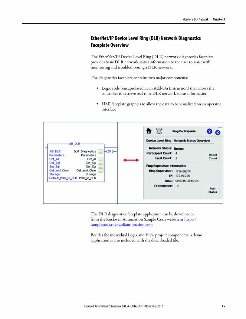
Monitor a DLR Network Chapter 3
EtherNetIP Device Level Ring (DLR) Network Diagnostics Faceplate Overview
The EtherNetIP Device Level Ring (DLR) network diagnostics faceplate provides basic DLR network status information to the user to assist with monitoring and troubleshooting a DLR network
The diagnostics faceplate contains two major components
bull Logic code (encapsulated in an Add-On Instruction) that allows the controller to retrieve real-time DLR network status information
bull HMI faceplate graphics to allow the data to be visualized on an operator interface
The DLR diagnostics faceplate application can be downloaded from the Rockwell Automation Sample Code website at httpsamplecoderockwellautomationcom
Besides the individual Logix and View project components a demo application is also included with the downloaded file
Rockwell Automation Publication 290E-AT001A-EN-P - November 2012 45
Chapter 3 Monitor a DLR Network
Monitor Diagnostics via MSG Instructions
Network diagnostic information can also be obtained programmatically via MSG instructions in RSLogix 5000 programming software For example you can
bull Get all ring diagnostic informationbull Get a ring participant listbull Get the active supervisorbull Clear rapid ring faultsbull Verify a fault locationbull Reset a fault counterbull Enable and configure a ring supervisor
This information can be displayed on an HMI device or manipulated in the project code
Figure 5 - Example Use of MSG Instruction
This example describes how to retrieve diagnostic information from the DLR network Follow these steps
1 Enter a MSG instruction into the rung of logic
2 Configure the MSG instruction to retrieve ring diagnostic information service as shown in the following screen shots
IMPORTANT Make sure the tag created is sized appropriately to hold all of the data that you are reading or writing For more information see page 48
46 Rockwell Automation Publication 290E-AT001A-EN-P - November 2012
Monitor a DLR Network Chapter 3
3 Configure the MSG instructionrsquos communication path to point to the active supervisor node
The path on the following screen is one example path
IMPORTANT When using the Custom Get_Attributes_All (01) service pointing to an active supervisor node will retrieve all of the attributes listed in Retrieve All Diagnostic Information Attribute Description on page 50Pointing to a non-supervisor node will retrieve only the Network Topology and Network Status attribute informationPointing to backup supervisor node will retrieve the current active supervisorrsquos IP address
Rockwell Automation Publication 290E-AT001A-EN-P - November 2012 47
Chapter 3 Monitor a DLR Network
Use Specific Values on the Configuration Tab
Use the values on the Configuration tab of your MSG instruction to perform specific services Sample DLR network diagnostic application code for example Add-on Instruction or HMI faceplate graphics is available on the Rockwell Automation Sample Code Library For more information about the Rockwell Automation Sample Code Library see httpwwwrockwellautomationcomsolutionsintegratedarchitectureresources5html
➊ This request only works if there are fewer than 40 nodes on the network If there are more nodes than will fit in a single message an error will be returned➋ Use a Destination Length of 54 bytes if using firmware revision 3x or later for the 1756-EN2TR module or firmware revision 2x or later for the 1783-ETAP
1783-ETAP1F or 1783-ETAP2F taps
Request Description Message Type
Service Type
Service Code (HEX)
Class (HEX)
Instance Attribute (HEX)
Source Element
Source Length (Bytes)
Destination Destination Length (bytes)
Retrieve All Ring Diagnostic Information
Information for this request is listed in Retrieve All Ring Diagnostic Information on page 49
CIP Generic Custom 1 47 1 NA LeftBlank
0 Tag 50or54 ➋
Request Ring Participant List ➊
Information for this request is listed in Request the Ring Participant List on page 51
CIP Generic Get Attribute Single
e 47 1 9 NA NA Tag 10node
Get Active Supervisor
Obtain the IP address and MAC ID of the active supervisor on the DLR network
CIP Generic Get Attribute Single
e 47 1 a NA NA Tag 10
Acknowledge Rapid Ring Faults Condition
Request supervisor to resume normal operation after encountering a rapid ring fault condition
CIP Generic Custom 4c 47 1 NA NA NA NA
Verify a Fault Location
Request supervisor to update Last Active Node values
CIP Generic 4b 47 1 NA NA NA NA NA
Reset the Ring Fault Counter
Reset the number of ring faults detected on the DLR network
CIP Generic Set Attribute Single
10 47 1 5 Tag 2 NA NA
Enable and Configure a Ring Supervisor
Information for this request is listed in Enable and Configure a Ring Supervisor on page 52
CIP Generic Set Attribute Single
10 47 1 4 Tag 12 NA NA
48 Rockwell Automation Publication 290E-AT001A-EN-P - November 2012
Monitor a DLR Network Chapter 3
Retrieve All Ring Diagnostic Information
By performing the Retrieve All Ring Diagnostic Information request on an active supervisor the MSG instruction returns the following information
➊ RSLogix 5000 programming software may display the value in this field as negative numbers To better understand the value we recommend you view it in HEX format
Destination Tag Attribute Name Description Possible Values
SINT [0] Network Topology Current network topology mode 0 = Linear
1 = Ring
SINT [1] Network Status Current status of the network 0 = Normal
1 = Ring Fault
2 = Unexpected Loop Detected
3 = Partial Network Fault
4 = Rapid FaultRestore Cycle
SINT [2] Ring Supervisor Status Ring supervisor active status flag 0 = Node is functioning as a backup
1 = Node is functioning as the active ring supervisor
2 = Node is functioning as a normal ring node
3 = Node is operating in a non-DLR topology
4 = Node cannot support the currently operating ring parameters thatis Beacon Interval andor Beacon Timeout
Ring Supervisor Config Ring Supervisor configuration parameters
SINT [3] Ring Supervisor Enable Ring supervisor enable flag 0 = Node is configured as a normal ring node (default configuration)
1 = Node is configured as a ring supervisor
SINT [4] Ring Supervisor Precedence Precedence value of a ring supervisor ➊ Valid value range = 0hellip255
0 = Default value
SINT [5-8] Beacon Interval Duration of ring beacon interval Valid value range = 200 μshellip100 ms
Default = 400 μs
SINT [9-12] Beacon Timeout Duration of ring beacon timeout Value value range = 400 μshellip500 ms
Default value = 1960 μs
SINT [13-14] DLR VLAN ID Valid ID to use in ring protocol messages Valid value range = 0hellip4094
Default value = 0
SINT [15-16] Ring Faults Count Number of ring faults since power up ➊
Rockwell Automation Publication 290E-AT001A-EN-P - November 2012 49
Chapter 3 Monitor a DLR Network
Retrieve All Diagnostic Information Attribute Description
➊ This destination tag is available only with the 1756-EN2TR module firmware revision 3x or later 1783-ETAP 1783-ETAP1F and 1783-ETAP2F taps firmware revisions 2x or later If using the 1783-ETAP tap firmware revision 1x your program does not include this destination tag
➋ RSLogix 5000 programming software may display the value in this field as negative numbers To better understand the value we recommend you view it in HEX format
Destination Tag Attribute Name Description Possible Values
Last Active Node on Port 1 Last active node at the end of the chain through port 1 of the active ring supervisor during a ring fault
SINT [17-20] Device IP address ➋ Any valid IP address value
A value = 0 indicates no IP address has been configured for the device
SINT [21-26] Device MAC address ➋ Any valid Ethernet MAC address
Last Active Node on Port 2 Last active node at the end of the chain through port 2 of the active ring supervisor during a ring fault
SINT [27-30] Device IP address ➋ Any valid IP address value
A value = 0 indicates no IP address has been configured for the device
SINT [31-36] Device MAC address ➋ Any valid Ethernet MAC address
SINT [37-38] Ring Protocol Participants Count
Number of devices in the ring protocol participants list
Active Supervisor Address IP andor Ethernet MAC address of the active ring supervisor
SINT [39-42] Supervisor IP address Any valid IP address value
A value = 0 indicates no IP address has been configured for the device
SINT [43-48] Supervisor MAC address Any valid Ethernet MAC address
SINT [49] Active Supervisor Precedence
Precedence value of the active ring supervisor
SINT [50-53]➊ Capability Flags Alerts you that the device is capable of operating as a supervisor and beacon-based ring node
0x22
50 Rockwell Automation Publication 290E-AT001A-EN-P - November 2012
Monitor a DLR Network Chapter 3
Request the Ring Participant List
When requesting the Ring Participant List service on the DLR network the MSG instruction returns the following information
Request the Ring Participant List Attribute Description
➊ This attribute will return an array of the data shown one entry for each node The Ring Protocol Participants Count attribute determines the number entries
➋ This tag displays only IP addresses for ring participants that have been configured with one For example you may have a 1783-ETAP tap connected to the network that has not been assigned an IP address In that case no address is shown for the 1783-ETAP tap
➌ RSLogix 5000 programming software may display the value in this field as negative numbers To better understand the value we recommend you view it in HEX format
➍ Unlike destination tag SINT [0-3] where IP addresses are displayed only for ring participants configured with an IP address this tag displays MAC addresses for all ring participants because every ring participant has a MAC address
Destination Tag Attribute Name Description Possible Values
Ring Protocol Participants List ➊
List of devices participating in ring protocol
SINT [0-3] Device IP address ➋➌ Any valid IP address value
A value = 0 indicates no IP address has been configured for the device
SINT [4-9] Device MAC address ➌➍ Any valid Ethernet MAC address
Rockwell Automation Publication 290E-AT001A-EN-P - November 2012 51
Chapter 3 Monitor a DLR Network
Enable and Configure a Ring Supervisor
When performing the Enable and Configure a Ring Supervisor request on a supervisor-capable device configure the MSG instruction with the following information
Enable and Configure a Ring Supervisor Attribute Description
➊ RSLogix 5000 programming software may display the value in this field as negative numbers To better understand the value we recommend you view it in HEX format
Source Tag Attribute Name Description Possible Values
Ring Supervisor Config Ring Supervisor configuration parameters
SINT [0] Ring Supervisor Enable Ring supervisor enable flag 0 = Node is configured as a normal ring node (default configuration)1 = Node is configured as a ring supervisor
SINT [1] Ring Supervisor Precedence Precedence value of a ring supervisor ➊
Valid value range = 0hellip2550 = Default value
SINT [2-5] Beacon Interval Duration of ring beacon interval
Valid value range = 200 μshellip100 000 μsDefault = 400 μs
SINT [6-9] Beacon Timeout Duration of ring beacon timeout ➊
Value value range = 400 μshellip500 000 μsDefault value = 1960 μs
SINT [10-11] DLR VLAN ID Valid ID to use in ring protocol messages ➊
Valid value range = 0hellip4094Default value = 0
52 Rockwell Automation Publication 290E-AT001A-EN-P - November 2012
Chapter 4
Troubleshoot a DLR Network
Introduction Use this chapter to learn how to troubleshoot the DLR network
General Solutions for Linear or DLR Networks
Before attempting to correct specific faults on the linear or DLR network we recommend that you first take the following actions when a fault appears
bull For a DLR networkndash Verify that at least one node has been configured as a supervisor
on the network and that Network Topology = Ringndash Verify that all cables on the network are securely connected
to each devicendash Verify that all devices that require an IP address have one assigned
correctlyndash Check the Network Status field on the active supervisor nodersquos status
page to determine the fault typebull For a linear network
ndash Verify that none of the nodes are configured as a supervisor on the network and that Network Topology = LinearIf any nodes on a linear network are configured as a supervisor it may impact communication to other devices connected to the network
ndash Verify that all cables on the network are securely connected to each device
ndash Verify that all devices that require an IP address have one assigned correctly
If the fault is not cleared after completing the actions listed above use the tables in the rest of this chapter to troubleshoot issues specific to a DLR network or a linear network
Topic Page
General Solutions for the Linear or DLR Networks 53
Duplicate IP Address Detection 54
Specific Issues on the DLR Network 55
Network Recovery Performance 58
Device Port Debugging Mode 59
Rockwell Automation Publication 290E-AT001A-EN-P - November 2012 53
Chapter 4 Troubleshoot a DLR Network
Duplicate IP Address Detection
Some EtherNetIP communication modules support duplicate IP address detection The module verifies that its IP address does not match any other network devicersquos IP address when performing either of these tasks
bull Connect the module to an EtherNetIP network
bull Change the modulersquos IP address
If the modulersquos IP address matches that of another device on the network the modulersquos EtherNetIP port transitions to Conflict mode In Conflict mode these conditions exist
bull OK status indicator is blinking red
bull Network (NET) status indicator is solid red
bull On some EtherNetIP communication modules the module status display indicates the conflict
The display scrollsOK ltIP_address_of_this_modulegt Duplicate IP
ltMac_address_of_duplicate_node_detectedgt
For example OK 108860196 Duplicate IP - 0000BC0234B4
bull On some EtherNetIP communication modules the modulersquos diagnostic webpage displays information about duplicate IP address detection
For more information on which EtherNetIP communication modules support displaying duplicate IP address on their diagnostic webpage see the Technical Note titled Logix modules Duplicate IP address detection enhancement 118216 in the Technical Support Knowledgebase available at httpwwwrockwellautomationcomknowledgebase
54 Rockwell Automation Publication 290E-AT001A-EN-P - November 2012
Troubleshoot a DLR Network Chapter 4
Specific Issues on the DLR Network
Use the following table to troubleshoot possible specific issues on the DLR or linear network that are not solved by the actions described on the previous page
Issue Description Solution
Supervisor Reports a Ring Fault A link on the DLR network may be brokenbull intentionally for example because of adding or deleting nodes but not making all
physical connections to restore the setup of the network withwithout the nodebull unintentionally for example because a cable is broken or a device malfunctionsWhen this fault occurs the adjacent nodes to the faulted part of the network are displayed in the Ring Fault group and the Network Status field = Ring FaultThe screen shot below shows the Ring Fault section with IP addresses appearing for the last active nodes The faulted node is between nodes 108880115 and 108880208 If the IP address of either node is not available the software will display the nodersquos MAC ID
Once the fault is corrected the ring is automatically restored and the Network Status field returns to Normal
Determine where the fault condition exists and correct itClick the Refresh Communication link as needed to update the Ring Fault information to determine where the fault condition existsFinally DevicePort Debugging Mode functionality on the 1783-ETAP tap may be used to analyze a suspicious nodeFor more information refer to Device Port Debugging Mode on page 59
Rockwell Automation Publication 290E-AT001A-EN-P - November 2012 55
Chapter 4 Troubleshoot a DLR Network
Issue Description Solution
Rapid Ring Fault When a Rapid Ring Fault occurs the following events occurbull The active supervisor will block traffic on port 2 resulting in possible network
segmentation that is some nodes may become unreachablebull The Link 2 status indicator on the active supervisor is offbull As soon as the fault occurs for both RSLogix 5000 programming software and
RSLinx communication software the Status field = Rapid FaultRestore Cycles
Any of the following may cause a Rapid Ring Faultbull 5 intentional disconnectionsreconnections of a node from the network within 30
secondsbull A duplex mismatch between two connected devicesbull Electromagnetic noise on the networkbull Unstable physical connections such as intermittent connectorsGiven the nature of a Rapid Ring Fault the Last Active Node information may not be accurate when a Rapid Ring Fault condition is present
Multiple possible solutions existbull For the disconnections and reconnections issue no
solution is requiredClear the fault after reconnecting the device to the network permanentlybull For the duplex mismatch issue reconfigure the duplex
parameters to make sure they match between the devices
bull For the electromagnetic noise issue determine where the noise exists and eliminate it or use a protective shield in that location
bull For the unstable connections issue determine where they exist on the network and correct them
bull Check the media counters for all devices on the network The device with the highest media counter count is most likely causing the Rapid Ring Fault
bull Remove devices from the network one by one If the Rapid Ring Fault disappears after a device is removed that device is causing the fault
bull DevicePort Debugging Mode functionality on the 1783-ETAP tap may be used to analyze a suspicious node
For more information refer to Device Port Debugging Mode on page 59bull Finally the Beacon Interval or Timeout configuration
may not be appropriate for the networkHowever if these values need to be changed we recommend that you contact Rockwell Automation technical supportOnce the fault is fixed click Clear Fault
56 Rockwell Automation Publication 290E-AT001A-EN-P - November 2012
Troubleshoot a DLR Network Chapter 4
Issue Description Solution
Partial Fault Condition A partial network fault occurs when traffic is lost in only one direction on the network because a ring member is not forwarding beacons in both directions for example a component failureThe active ring supervisor detects a partial fault by monitoring the loss of Beacon frames on one port and the fault location appears in the Ring Fault section of the Network tab When a partial fault is detected the active ring supervisor blocks traffic on one port At this point the ring is segmented due to the partial fault condition The nodes adjacent to the faulted part of the network are displayed in the Ring Fault group with either IP addresses or MAC IDs for each node displayedWhen this fault occurs the Network Status field = Partial Fault ConditionOnce the fault is corrected it automatically clears and the Network Status field returns to Normal
Determine where the fault condition exists and correct itAdditionally the DevicePort Debugging Mode functionality also known as Port Mirroring on a 1783-ETAP 1783-ETAP1F or 1783-ETAP2F tap may be used to analyze a suspicious nodeFor more information refer to Device Port Debugging Mode on page 59
Media Counter Errors or Collisions
The media counters screen displays the number of physical layer errors or collisions The screen below indicates where to check for errors encountered Error levels are displayed depending on what caused the error For example an Alignment Error is displayed in the Alignment Error field
On a DLR network it is not uncommon to see low levels of media counter errors For example if the network breaks a low level of media counter errors appears With a low level of media counter errors the value typically does not continuously increase and often clearsA high level of media counter errors typically continues to increase and does not clear For example there is a mismatch of speed between two linked nodes a high level of media counter errors appears steadily increasing and not clearingTo access the RSLinx screen above browse the network right-click on the device select Module Properties and click the Port Diagnostics tab
Some example solutions includebull Check for a mismatch of speed andor duplex between
two linked nodesbull Verify that all cables on the network are securely
connected to each devicebull Check for electromagnetic noise on the network If you
find it eliminate it or use a protective shield in that location
Rockwell Automation Publication 290E-AT001A-EN-P - November 2012 57
Chapter 4 Troubleshoot a DLR Network
Network Recovery Performance
When measuring the networkrsquos performance with regard to dealing with fault conditions consider the network recovery time Network recovery is the time for all of the following to take place
1 The supervisor node recognizes that a fault exists on the network
2 The supervisor node reconfigures the network because of the fault
3 The supervisor node communicates to the network nodes that a fault condition exists
4 The network nodes reconfigure themselves because of the fault
With the default beacon interval value of 400 mS and beacon timeout value of 1960 mS the worst-case time for network recovery times are
bull 2890 mS for a copper DLR network This recovery time is based on 100 m copper segments between nodes on the network
bull 3140 mS for a fiber-optic DLR network This recovery time is based on 2 kM fiber-optic cable segments between nodes on the network
When considering the values listed above keep in mind
bull Recovery time may actually occur faster than the times listed
bull The recovery times listed above assume that your networkrsquos nodes are operating at 100 Mbps speed and full-duplex mode We recommend that your nodes generally operate in this mode for DLR networks
bull If other node conditions exist such as a node operating at 10 Mbps full-duplex or 10100 Mbps half-duplex the recovery times will vary from the times listed above
If this is the case for your application the beacon interval and beacon timeout will need to be changed We recommend that you first contact Rockwell Automation technical support if these parameters need to be changed
bull The value assumes that the majority of the traffic on your network is EtherNetIP traffic
58 Rockwell Automation Publication 290E-AT001A-EN-P - November 2012
Troubleshoot a DLR Network Chapter 4
Device Port Debugging Mode
This functionality is disabled by default Device Port Debugging mode which is similar to port mirroring can be used to monitor data received on the 1783-ETAP 1783-ETAP1F or 1783-ETAP2F taprsquos two network ports Monitor the data over the device port to a device such as a personal computer running a protocol analyzer application for advanced network debugging or analysis
When device port debugging is used on a 1783-ETAP the device connected to the 1783-ETAP taprsquos front port receives all of the data traversing the ring (both directions)
Device Port Debugging Example Network
When using the Device Port Debugging mode functionality insert the 1783-ETAP with the network analyzer connected to the device port It is inserted at the spot on the ring network where the node in question is located The graphic below shows a 1783-ETAP tap inserted in the network
IMPORTANT This functionality should be used only when troubleshooting the network and not in normal network operation
Rockwell Automation Publication 290E-AT001A-EN-P - November 2012 59
Chapter 4 Troubleshoot a DLR Network
Combined total network bandwidth of the traffic received on the two 1783-ETAP 1783-ETAP1F or 1783-ETAP2F taprsquos ports connected to the network should not exceed the taprsquos device port capacity The speed setting determines the device portrsquos capacity
Configure the device port on a 1783-ETAP 1783-ETAP1F or 1783-ETAP2F tap to either of two speed settings
bull 100 Mbps - default settingbull 10 Mbps
If the bandwidth exceeds the capacity of the taprsquos device port some frames from the ring will be dropped before reaching the device port These dropped frames do not impact the traffic on the rest of the DLR network
The device port setting determines how much network traffic the 1783-ETAP 1783-ETAP1F or 1783-ETAP2F tap can handle before dropping frames The circled section in the graphic below shows the Port Buffer Utilization of the Device Port In this example the value is zero because a ring fault exists on the network
60 Rockwell Automation Publication 290E-AT001A-EN-P - November 2012
Appendix A
Network Usage Guidelines and Recommendations
Consider the following guidelines and recommendations when using a DLR or linear network
GuidelineRecommendation Explanation
Use fewer than 50 nodes on a single DLR networkIf your application requires more than 50 nodes we recommend that the nodes are broken into separate but linked DLR networks
If you use more than 50 nodes on a single DLR networkbull Your network has a greater chance of multiple faults
occurring on the networkbull Network recovery times from faulted DLR network
are higher
Do not configure a supervisor on a linear network If your linear network includes non-DLR nodes and has a supervisor-enabled node on the network it may impact communication to non-DLR devices connected to the linear network
If you must connect a device that is running at 10 Mbps to a DLR or linear network do so through a 1783-ETAP 1783-ETAP1F or 1783-ETAP2F tap device port
The 1783-ETAP 1783-ETAP1F and 1783-ETAP2F taps can operate at 100 Mbps on the DLR network this is the optimal speed for a network If you connect a 10 Mbps device directly to the network instead of through a tap the linear or DLR network traffic slows to 10 MbpsAdditionally if the 10 Mbps device is connected to the network without a 1783-ETAP tap network recovery times are significantly impacted
Configure multiple supervisor nodes per ring If your DLR network only has one supervisor and the supervisor experiences a fault none of the other nodes become the active supervisor In this case the network becomes a linear network until the fault is corrected and the DLR network restoredAnother reason to configure multiple supervisor nodes is for replacing an active supervisor node with an out-of-box replacement the new device will not be enabled as a supervisor (by default) and there would still be no supervisor on the network
Rockwell Automation Publication 290E-AT001A-EN-P - November 2012 61
Appendix A Network Usage Guidelines and Recommendations
GuidelineRecommendation Explanation
Connect switches to a DLR network via 1783-ETAP 1783-ETAP1F or 1783-ETAP2F taps
If switches are connected to the DLR network without the use of a 1783-ETAP 1783-ETAP1F or 1783-ETAP2F tap the network may experience unpredictable behavior and network performance is unknown
Run all nodes on the DLR network at 100 Mbps and in Full-Duplex mode
These configuration values provide the best performance for your networkAdditionally we recommend that youbull Use auto-negotiate for all nodes on the DLR networkbull Do not use auto-negotiate on one node and then force
speed on the next node linked to it
In a linear network the number of nodes to use is application specific based on the considerations described in the next box
When determining the number of nodes to use on a linear network consider the followingbull There is a delay per node as information is transmitted
to each successive node used on the networkndash The typical delay on a linear network with 100 m
copper segments between nodes is 30 mSndash The typical delay on a linear network with 2 kM
fiber-optic segments between nodes is 40 mS
The greater the number of nodes on the network the longer the total time for information to be transmitted across the entire networkbull The single point of failure possibility is greater with
each additional connectionbull Troubleshooting the network may be more difficult
with a higher number of nodes
The total time for information to be transmitted across the entire network and its effect on how many nodes to use on a linear network is related to the Requested Packet Interval (RPI)Verify that the total time to transmit information from the first node to the last node on the network is less than the RPI Make sure the network is not loaded beyond 90 of capacity
62 Rockwell Automation Publication 290E-AT001A-EN-P - November 2012
Network Usage Guidelines and Recommendations Appendix A
GuidelineRecommendation Explanation
Do not physically close a DLR network without a supervisor configured on the network
A DLR network without a supervisor node results in a network stormIf you do close the DLR network without a supervisor configured break the ring and configure at least one supervisor before physically reconnecting the network
Use the default values for the followingbull Beacon Intervalbull Beacon Timeoutbull Ring Protocol VLAN ID
Changing the default values for the parameters Beacon Interval Beacon Timeout and Ring Protocol VLAN ID can result in unpredictable network behavior and negatively impacted network performanceThe default values are optimized for a network withbull 50 or fewer nodes are on the networkbull All nodes are operating at 100 Mbps and full-duplex
modebull At least 50 of the network traffic bandwidth being
EtherNetIP trafficIf you think the values of the Beacon Interval Beacon Timeout or Ring Protocol VLAN ID need to be changed for example if any node on ring is not operating at 100 Mbps and full-duplex mode we recommend that you first contact Rockwell Automation technical support
If DHCP for the ArmorStarts is still required you will need to disable Internet Group Management Protocol (IGMP) snooping on the E-tap via the AOP
IGMP Snooping is enabled by default in the 1783-ETAP 1783-ETAP1F and 1783-ETAP2F taps and is commonly used to manage multicast traffic on the network When in use this functionality allows the tap to multicast data to only those devices that need the data rather than to all devices connected to the networkOnce DHCP is enabled the switch could change the IP addresses on the ArmorStarts depending on network demand which could cause RSlogix5000 to loose communication with the device as connectivity is established via the AOP in the initial configuration
The IGMP Querier functionality should be enabled for at least one node on the network
This functionality is disabled by default The IGMP Querier functionality enables a 1783-ETAP 1783-ETAP1F or 1783-ETAP2F tap or switch such as a Stratix managed switch to send out a query to all devices on the network to determine what multicast addresses are of interest to a specific node or a group of nodesIf the IGMP Querier functionality is not enabled for at least one node on the network multicast traffic on the network may eventually create network performance issuesThe 1783-ETAP 1783-ETAP1F or 1783-ETAP2F taps managed switches and routers are examples of devices that support IGMP Querier functionality
Rockwell Automation Publication 290E-AT001A-EN-P - November 2012 63
Appendix A Network Usage Guidelines and Recommendations
Notes
64 Rockwell Automation Publication 290E-AT001A-EN-P - November 2012
Appendix B
Required Firmware Revisions
Required Firmware Revision for an Add-On Profile
➊ The ControlFLASH Firmware Upgrade software tcan be used o upgrade a 1756-EN2TR module from firmware revision 21 to 3x or later1x or later3x or later2x or later
➋ The ControlFLASH Firmware Upgrade software can be used to upgrade a 1783-ETAP tap from firmware revision 11 to 2x or later
To download new firmware go to httpwwwrockwellautomationcomsupportamericasindex_enhtml
If the firmware revision is upgraded on the module or tap the required AOP revision listed above must be used for that revision For example if the 1756-EN2TR module is upgraded to firmware revision 3x or later AOP revision 2x or later must be used in the RSLogix 5000 programming software
Additionally if the firmware revision is upgraded on the module or tap the required RSLinx communication software must also be used for that firmware revision For more information on which RSLinx software version is required for each firmware revision see page 66
For both the 1756-EN2TR module and 1783-ETAP tap make sure that the Major Revision configured on the General tab of the devicersquos RSLogix 5000 programming software configuration matches the major revision of the physical module
IMPORTANT To download an AOP go to httpsupportrockwellautomationcomcontrolflashLogixProfileraspDepending on the firmware revision of your product a specific AOP version must be used
Firmware Revision Add-On Profile Revision Cat No
21 ➊ 1x or later 1756-EN2TR
3x or later 2x or later
11 ➋ 1x or later 1783-ETAP
2x or later 2x or later
2x or later 2x or later 1783-ETAP1F
1783-ETAP2F
Rockwell Automation Publication 290E-AT001A-EN-P - November 2012 65
Appendix B Required Firmware Revisions
If the device configuration on the General tab does not match the physical module the programming software alerts you to this mismatch when attempting to configure the Internet Protocol Port Configuration and Network tabs for that device
Required Firmware Revision for RSLinx Communication Software
➊ The ControlFLASH Firmware Upgrade software can be used to upgrade a 1756-EN2TR module from firmware revision 21 to 3x or later1x or later3x or later255 or later3x or later256 or later
➋ The ControlFLASH Firmware Upgrade software can be used to upgrade a 1783-ETAP tap from firmware revision 11 to 2x or later
To download new firmware go to httpwwwrockwellautomationcomsupportamericasindex_enhtml
If the firmware revision is upgraded on the module or tap the required RSLinx communication software listed above must be used for that revision For example if the 1756-EN2TR module is upgraded to firmware revision 3x or later AOP revision 2x or later must be used in your RSLogix 5000 programming software
Additionally if the firmware revision is upgraded on the module or tap the required AOP revision must also be used for that firmware revision For more information on which AOP revision is required for each firmware revision see page 65
IMPORTANT Depending on the firmware revision of your product specific versions of RSLinx communication software must be used
Firmware Revision Required RSLinx Communication Software Version
Cat No
21 ➊ 255 or later 1756-EN2TR
3x or later 256 or later
11 ➋ 255 or later 1783-ETAP
2x or later 256 or later
2x or later 256 or later 1783-ETAP1F
1783-ETAP2F
66 Rockwell Automation Publication 290E-AT001A-EN-P - November 2012
Rockwell Otomasyon Ticaret AŞ Kar Plaza İş Merkezi E Blok Kat6 34752 İccedilerenkoumly İstanbul Tel +90 (216) 5698400
Rockwell Automation Publication 290E-AT001A-EN-P ndash November 2012 68 Copyright copy 2012 Rockwell Automation Inc All rights reserved Printed in the USA
Rockwell Automation Support
Rockwell Automation provides technical information on the Web to assist you in using its products At httpwwwrockwellautomationcomsupport you can find technical manuals a knowledge base of FAQs technical and application notes sample code and links to software service packs and a MySupport feature that you can customize to make thebest use of these tools
For an additional level of technical phone support for installation configuration and troubleshooting we offer TechConnectSM support programs For more information contact your local distributor or Rockwell Automation representative or visit httpwwwrockwellautomationcomsupport
Installation Assistance
If you experience a problem within the first 24 hours of installation review the information that is contained in this manualYou can contact Customer Support for initial help in getting your product up and running
New Product Satisfaction Return
Rockwell Automation tests all of its products to ensure that they are fully operational when shipped from the manufacturing facility However if your product is not functioning and needs to be returned follow these procedures
Documentation Feedback
Your comments will help us serve your documentation needs better If you have any suggestions on how to improve this document complete this form publication RA-DU002 available at httpwwwrockwellautomationcomliterature
United States or Canada 14406463434
Outside United States or Canada Use the Worldwide Locator at httpwwwrockwellautomationcomsupportamericasphone_enhtml or contact your local Rockwell Automation representative
United States Contact your distributor You must provide a Customer Support case number (call the phone number above to obtain one) to your distributor to complete the return process
Outside United States Please contact your local Rockwell Automation representative for the return procedure
- Important User Information
- General Precautions
- Software Requirements
- Additional Resources
- Rockwell Automation Support
- Installation Assistance
- New Product Satisfaction Return
- Table of Contents
- Chapter 1
-
- Device-Level Ring (DLR) Basics
-
- Introduction
- ArmorStart with EtherNetIP Overview
- What is a Device-level Ring (DLR) Network
- DLR Network Elements
-
- Supervisor Node
- Ring Node
-
- DLR Network Operation
- Number of Nodes on a DLR Network
- DLR Network Fault Management
-
- Network Reconfiguration after a Fault
-
- Chapter 2
-
- Construct and Configure a Device-level Ring Network with ArmorStarts
-
- Introduction
- Ethernet Capacity Tool
- Install Devices on a DLR Network
- ArmorStart Addressing Configuration
-
- Using the BootPDHCP Server
- Using the Rotary Network Address Switches
- Using the ArmorStart Internal Web Server
-
- Configure Supervisor Nodes on a DLR Network
-
- Configure a Ring Supervisor in RSLogix 5000 Programming Software
- Adding an Armorstart to RSLogix 5000
- Enable Ring Supervisor in RSLogix 5000 Programming Software
- Configure and Enable a Ring Supervisor in RSLinx Classic Communication Software
-
- Complete the Physical Connections of the Network
- Verify Supervisor Configuration
- IGMP Snooping
- IGMP Querier
-
- Chapter 3
-
- Monitor a DLR Network
-
- Introduction
- Methods to Monitor a DLR Network
-
- RSLogix 5000 Programming Software Status Pages
- RSLinx Communication Software Status Pages
- ArmorStart Internal Web Server
- EtherNetIP Device Level Ring (DLR) Network Diagnostics Faceplate
- Programmatically Through the Use of a MSG Instruction
-
- Monitor Status Pages
-
- RSLogix 5000 Programming Software Status Pages
- RSLinx Communication Software
-
- How to Access the ArmorStart EtherNetIP Internal Web Server
-
- EtherNetIP Device Level Ring (DLR) Network Diagnostics Faceplate Overview
-
- Monitor Diagnostics via MSG Instructions
-
- Use Specific Values on the Configuration Tab
- Retrieve All Ring Diagnostic Information
- Retrieve All Diagnostic Information Attribute Description
- Request the Ring Participant List
- Request the Ring Participant List Attribute Description
-
- Enable and Configure a Ring Supervisor
-
- Enable and Configure a Ring Supervisor Attribute Description
-
- Chapter 4
-
- Troubleshoot a DLR Network
-
- Introduction
- General Solutions for Linear or DLR Networks
- Duplicate IP Address Detection
- Specific Issues on the DLR Network
- Network Recovery Performance
- Device Port Debugging Mode
-
- Device Port Debugging Example Network
-
- Appendix A
-
- Network Usage Guidelines and Recommendations
-
- Notes
-
- Appendix B
-
- Required Firmware Revisions
-
- Required Firmware Revision for an Add-On Profile
- Required Firmware Revision for RSLinx Communication Software
-
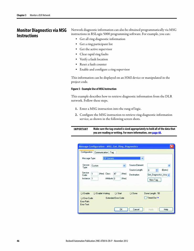
Chapter 3 Monitor a DLR Network
Monitor Diagnostics via MSG Instructions
Network diagnostic information can also be obtained programmatically via MSG instructions in RSLogix 5000 programming software For example you can
bull Get all ring diagnostic informationbull Get a ring participant listbull Get the active supervisorbull Clear rapid ring faultsbull Verify a fault locationbull Reset a fault counterbull Enable and configure a ring supervisor
This information can be displayed on an HMI device or manipulated in the project code
Figure 5 - Example Use of MSG Instruction
This example describes how to retrieve diagnostic information from the DLR network Follow these steps
1 Enter a MSG instruction into the rung of logic
2 Configure the MSG instruction to retrieve ring diagnostic information service as shown in the following screen shots
IMPORTANT Make sure the tag created is sized appropriately to hold all of the data that you are reading or writing For more information see page 48
46 Rockwell Automation Publication 290E-AT001A-EN-P - November 2012
Monitor a DLR Network Chapter 3
3 Configure the MSG instructionrsquos communication path to point to the active supervisor node
The path on the following screen is one example path
IMPORTANT When using the Custom Get_Attributes_All (01) service pointing to an active supervisor node will retrieve all of the attributes listed in Retrieve All Diagnostic Information Attribute Description on page 50Pointing to a non-supervisor node will retrieve only the Network Topology and Network Status attribute informationPointing to backup supervisor node will retrieve the current active supervisorrsquos IP address
Rockwell Automation Publication 290E-AT001A-EN-P - November 2012 47
Chapter 3 Monitor a DLR Network
Use Specific Values on the Configuration Tab
Use the values on the Configuration tab of your MSG instruction to perform specific services Sample DLR network diagnostic application code for example Add-on Instruction or HMI faceplate graphics is available on the Rockwell Automation Sample Code Library For more information about the Rockwell Automation Sample Code Library see httpwwwrockwellautomationcomsolutionsintegratedarchitectureresources5html
➊ This request only works if there are fewer than 40 nodes on the network If there are more nodes than will fit in a single message an error will be returned➋ Use a Destination Length of 54 bytes if using firmware revision 3x or later for the 1756-EN2TR module or firmware revision 2x or later for the 1783-ETAP
1783-ETAP1F or 1783-ETAP2F taps
Request Description Message Type
Service Type
Service Code (HEX)
Class (HEX)
Instance Attribute (HEX)
Source Element
Source Length (Bytes)
Destination Destination Length (bytes)
Retrieve All Ring Diagnostic Information
Information for this request is listed in Retrieve All Ring Diagnostic Information on page 49
CIP Generic Custom 1 47 1 NA LeftBlank
0 Tag 50or54 ➋
Request Ring Participant List ➊
Information for this request is listed in Request the Ring Participant List on page 51
CIP Generic Get Attribute Single
e 47 1 9 NA NA Tag 10node
Get Active Supervisor
Obtain the IP address and MAC ID of the active supervisor on the DLR network
CIP Generic Get Attribute Single
e 47 1 a NA NA Tag 10
Acknowledge Rapid Ring Faults Condition
Request supervisor to resume normal operation after encountering a rapid ring fault condition
CIP Generic Custom 4c 47 1 NA NA NA NA
Verify a Fault Location
Request supervisor to update Last Active Node values
CIP Generic 4b 47 1 NA NA NA NA NA
Reset the Ring Fault Counter
Reset the number of ring faults detected on the DLR network
CIP Generic Set Attribute Single
10 47 1 5 Tag 2 NA NA
Enable and Configure a Ring Supervisor
Information for this request is listed in Enable and Configure a Ring Supervisor on page 52
CIP Generic Set Attribute Single
10 47 1 4 Tag 12 NA NA
48 Rockwell Automation Publication 290E-AT001A-EN-P - November 2012
Monitor a DLR Network Chapter 3
Retrieve All Ring Diagnostic Information
By performing the Retrieve All Ring Diagnostic Information request on an active supervisor the MSG instruction returns the following information
➊ RSLogix 5000 programming software may display the value in this field as negative numbers To better understand the value we recommend you view it in HEX format
Destination Tag Attribute Name Description Possible Values
SINT [0] Network Topology Current network topology mode 0 = Linear
1 = Ring
SINT [1] Network Status Current status of the network 0 = Normal
1 = Ring Fault
2 = Unexpected Loop Detected
3 = Partial Network Fault
4 = Rapid FaultRestore Cycle
SINT [2] Ring Supervisor Status Ring supervisor active status flag 0 = Node is functioning as a backup
1 = Node is functioning as the active ring supervisor
2 = Node is functioning as a normal ring node
3 = Node is operating in a non-DLR topology
4 = Node cannot support the currently operating ring parameters thatis Beacon Interval andor Beacon Timeout
Ring Supervisor Config Ring Supervisor configuration parameters
SINT [3] Ring Supervisor Enable Ring supervisor enable flag 0 = Node is configured as a normal ring node (default configuration)
1 = Node is configured as a ring supervisor
SINT [4] Ring Supervisor Precedence Precedence value of a ring supervisor ➊ Valid value range = 0hellip255
0 = Default value
SINT [5-8] Beacon Interval Duration of ring beacon interval Valid value range = 200 μshellip100 ms
Default = 400 μs
SINT [9-12] Beacon Timeout Duration of ring beacon timeout Value value range = 400 μshellip500 ms
Default value = 1960 μs
SINT [13-14] DLR VLAN ID Valid ID to use in ring protocol messages Valid value range = 0hellip4094
Default value = 0
SINT [15-16] Ring Faults Count Number of ring faults since power up ➊
Rockwell Automation Publication 290E-AT001A-EN-P - November 2012 49
Chapter 3 Monitor a DLR Network
Retrieve All Diagnostic Information Attribute Description
➊ This destination tag is available only with the 1756-EN2TR module firmware revision 3x or later 1783-ETAP 1783-ETAP1F and 1783-ETAP2F taps firmware revisions 2x or later If using the 1783-ETAP tap firmware revision 1x your program does not include this destination tag
➋ RSLogix 5000 programming software may display the value in this field as negative numbers To better understand the value we recommend you view it in HEX format
Destination Tag Attribute Name Description Possible Values
Last Active Node on Port 1 Last active node at the end of the chain through port 1 of the active ring supervisor during a ring fault
SINT [17-20] Device IP address ➋ Any valid IP address value
A value = 0 indicates no IP address has been configured for the device
SINT [21-26] Device MAC address ➋ Any valid Ethernet MAC address
Last Active Node on Port 2 Last active node at the end of the chain through port 2 of the active ring supervisor during a ring fault
SINT [27-30] Device IP address ➋ Any valid IP address value
A value = 0 indicates no IP address has been configured for the device
SINT [31-36] Device MAC address ➋ Any valid Ethernet MAC address
SINT [37-38] Ring Protocol Participants Count
Number of devices in the ring protocol participants list
Active Supervisor Address IP andor Ethernet MAC address of the active ring supervisor
SINT [39-42] Supervisor IP address Any valid IP address value
A value = 0 indicates no IP address has been configured for the device
SINT [43-48] Supervisor MAC address Any valid Ethernet MAC address
SINT [49] Active Supervisor Precedence
Precedence value of the active ring supervisor
SINT [50-53]➊ Capability Flags Alerts you that the device is capable of operating as a supervisor and beacon-based ring node
0x22
50 Rockwell Automation Publication 290E-AT001A-EN-P - November 2012
Monitor a DLR Network Chapter 3
Request the Ring Participant List
When requesting the Ring Participant List service on the DLR network the MSG instruction returns the following information
Request the Ring Participant List Attribute Description
➊ This attribute will return an array of the data shown one entry for each node The Ring Protocol Participants Count attribute determines the number entries
➋ This tag displays only IP addresses for ring participants that have been configured with one For example you may have a 1783-ETAP tap connected to the network that has not been assigned an IP address In that case no address is shown for the 1783-ETAP tap
➌ RSLogix 5000 programming software may display the value in this field as negative numbers To better understand the value we recommend you view it in HEX format
➍ Unlike destination tag SINT [0-3] where IP addresses are displayed only for ring participants configured with an IP address this tag displays MAC addresses for all ring participants because every ring participant has a MAC address
Destination Tag Attribute Name Description Possible Values
Ring Protocol Participants List ➊
List of devices participating in ring protocol
SINT [0-3] Device IP address ➋➌ Any valid IP address value
A value = 0 indicates no IP address has been configured for the device
SINT [4-9] Device MAC address ➌➍ Any valid Ethernet MAC address
Rockwell Automation Publication 290E-AT001A-EN-P - November 2012 51
Chapter 3 Monitor a DLR Network
Enable and Configure a Ring Supervisor
When performing the Enable and Configure a Ring Supervisor request on a supervisor-capable device configure the MSG instruction with the following information
Enable and Configure a Ring Supervisor Attribute Description
➊ RSLogix 5000 programming software may display the value in this field as negative numbers To better understand the value we recommend you view it in HEX format
Source Tag Attribute Name Description Possible Values
Ring Supervisor Config Ring Supervisor configuration parameters
SINT [0] Ring Supervisor Enable Ring supervisor enable flag 0 = Node is configured as a normal ring node (default configuration)1 = Node is configured as a ring supervisor
SINT [1] Ring Supervisor Precedence Precedence value of a ring supervisor ➊
Valid value range = 0hellip2550 = Default value
SINT [2-5] Beacon Interval Duration of ring beacon interval
Valid value range = 200 μshellip100 000 μsDefault = 400 μs
SINT [6-9] Beacon Timeout Duration of ring beacon timeout ➊
Value value range = 400 μshellip500 000 μsDefault value = 1960 μs
SINT [10-11] DLR VLAN ID Valid ID to use in ring protocol messages ➊
Valid value range = 0hellip4094Default value = 0
52 Rockwell Automation Publication 290E-AT001A-EN-P - November 2012
Chapter 4
Troubleshoot a DLR Network
Introduction Use this chapter to learn how to troubleshoot the DLR network
General Solutions for Linear or DLR Networks
Before attempting to correct specific faults on the linear or DLR network we recommend that you first take the following actions when a fault appears
bull For a DLR networkndash Verify that at least one node has been configured as a supervisor
on the network and that Network Topology = Ringndash Verify that all cables on the network are securely connected
to each devicendash Verify that all devices that require an IP address have one assigned
correctlyndash Check the Network Status field on the active supervisor nodersquos status
page to determine the fault typebull For a linear network
ndash Verify that none of the nodes are configured as a supervisor on the network and that Network Topology = LinearIf any nodes on a linear network are configured as a supervisor it may impact communication to other devices connected to the network
ndash Verify that all cables on the network are securely connected to each device
ndash Verify that all devices that require an IP address have one assigned correctly
If the fault is not cleared after completing the actions listed above use the tables in the rest of this chapter to troubleshoot issues specific to a DLR network or a linear network
Topic Page
General Solutions for the Linear or DLR Networks 53
Duplicate IP Address Detection 54
Specific Issues on the DLR Network 55
Network Recovery Performance 58
Device Port Debugging Mode 59
Rockwell Automation Publication 290E-AT001A-EN-P - November 2012 53
Chapter 4 Troubleshoot a DLR Network
Duplicate IP Address Detection
Some EtherNetIP communication modules support duplicate IP address detection The module verifies that its IP address does not match any other network devicersquos IP address when performing either of these tasks
bull Connect the module to an EtherNetIP network
bull Change the modulersquos IP address
If the modulersquos IP address matches that of another device on the network the modulersquos EtherNetIP port transitions to Conflict mode In Conflict mode these conditions exist
bull OK status indicator is blinking red
bull Network (NET) status indicator is solid red
bull On some EtherNetIP communication modules the module status display indicates the conflict
The display scrollsOK ltIP_address_of_this_modulegt Duplicate IP
ltMac_address_of_duplicate_node_detectedgt
For example OK 108860196 Duplicate IP - 0000BC0234B4
bull On some EtherNetIP communication modules the modulersquos diagnostic webpage displays information about duplicate IP address detection
For more information on which EtherNetIP communication modules support displaying duplicate IP address on their diagnostic webpage see the Technical Note titled Logix modules Duplicate IP address detection enhancement 118216 in the Technical Support Knowledgebase available at httpwwwrockwellautomationcomknowledgebase
54 Rockwell Automation Publication 290E-AT001A-EN-P - November 2012
Troubleshoot a DLR Network Chapter 4
Specific Issues on the DLR Network
Use the following table to troubleshoot possible specific issues on the DLR or linear network that are not solved by the actions described on the previous page
Issue Description Solution
Supervisor Reports a Ring Fault A link on the DLR network may be brokenbull intentionally for example because of adding or deleting nodes but not making all
physical connections to restore the setup of the network withwithout the nodebull unintentionally for example because a cable is broken or a device malfunctionsWhen this fault occurs the adjacent nodes to the faulted part of the network are displayed in the Ring Fault group and the Network Status field = Ring FaultThe screen shot below shows the Ring Fault section with IP addresses appearing for the last active nodes The faulted node is between nodes 108880115 and 108880208 If the IP address of either node is not available the software will display the nodersquos MAC ID
Once the fault is corrected the ring is automatically restored and the Network Status field returns to Normal
Determine where the fault condition exists and correct itClick the Refresh Communication link as needed to update the Ring Fault information to determine where the fault condition existsFinally DevicePort Debugging Mode functionality on the 1783-ETAP tap may be used to analyze a suspicious nodeFor more information refer to Device Port Debugging Mode on page 59
Rockwell Automation Publication 290E-AT001A-EN-P - November 2012 55
Chapter 4 Troubleshoot a DLR Network
Issue Description Solution
Rapid Ring Fault When a Rapid Ring Fault occurs the following events occurbull The active supervisor will block traffic on port 2 resulting in possible network
segmentation that is some nodes may become unreachablebull The Link 2 status indicator on the active supervisor is offbull As soon as the fault occurs for both RSLogix 5000 programming software and
RSLinx communication software the Status field = Rapid FaultRestore Cycles
Any of the following may cause a Rapid Ring Faultbull 5 intentional disconnectionsreconnections of a node from the network within 30
secondsbull A duplex mismatch between two connected devicesbull Electromagnetic noise on the networkbull Unstable physical connections such as intermittent connectorsGiven the nature of a Rapid Ring Fault the Last Active Node information may not be accurate when a Rapid Ring Fault condition is present
Multiple possible solutions existbull For the disconnections and reconnections issue no
solution is requiredClear the fault after reconnecting the device to the network permanentlybull For the duplex mismatch issue reconfigure the duplex
parameters to make sure they match between the devices
bull For the electromagnetic noise issue determine where the noise exists and eliminate it or use a protective shield in that location
bull For the unstable connections issue determine where they exist on the network and correct them
bull Check the media counters for all devices on the network The device with the highest media counter count is most likely causing the Rapid Ring Fault
bull Remove devices from the network one by one If the Rapid Ring Fault disappears after a device is removed that device is causing the fault
bull DevicePort Debugging Mode functionality on the 1783-ETAP tap may be used to analyze a suspicious node
For more information refer to Device Port Debugging Mode on page 59bull Finally the Beacon Interval or Timeout configuration
may not be appropriate for the networkHowever if these values need to be changed we recommend that you contact Rockwell Automation technical supportOnce the fault is fixed click Clear Fault
56 Rockwell Automation Publication 290E-AT001A-EN-P - November 2012
Troubleshoot a DLR Network Chapter 4
Issue Description Solution
Partial Fault Condition A partial network fault occurs when traffic is lost in only one direction on the network because a ring member is not forwarding beacons in both directions for example a component failureThe active ring supervisor detects a partial fault by monitoring the loss of Beacon frames on one port and the fault location appears in the Ring Fault section of the Network tab When a partial fault is detected the active ring supervisor blocks traffic on one port At this point the ring is segmented due to the partial fault condition The nodes adjacent to the faulted part of the network are displayed in the Ring Fault group with either IP addresses or MAC IDs for each node displayedWhen this fault occurs the Network Status field = Partial Fault ConditionOnce the fault is corrected it automatically clears and the Network Status field returns to Normal
Determine where the fault condition exists and correct itAdditionally the DevicePort Debugging Mode functionality also known as Port Mirroring on a 1783-ETAP 1783-ETAP1F or 1783-ETAP2F tap may be used to analyze a suspicious nodeFor more information refer to Device Port Debugging Mode on page 59
Media Counter Errors or Collisions
The media counters screen displays the number of physical layer errors or collisions The screen below indicates where to check for errors encountered Error levels are displayed depending on what caused the error For example an Alignment Error is displayed in the Alignment Error field
On a DLR network it is not uncommon to see low levels of media counter errors For example if the network breaks a low level of media counter errors appears With a low level of media counter errors the value typically does not continuously increase and often clearsA high level of media counter errors typically continues to increase and does not clear For example there is a mismatch of speed between two linked nodes a high level of media counter errors appears steadily increasing and not clearingTo access the RSLinx screen above browse the network right-click on the device select Module Properties and click the Port Diagnostics tab
Some example solutions includebull Check for a mismatch of speed andor duplex between
two linked nodesbull Verify that all cables on the network are securely
connected to each devicebull Check for electromagnetic noise on the network If you
find it eliminate it or use a protective shield in that location
Rockwell Automation Publication 290E-AT001A-EN-P - November 2012 57
Chapter 4 Troubleshoot a DLR Network
Network Recovery Performance
When measuring the networkrsquos performance with regard to dealing with fault conditions consider the network recovery time Network recovery is the time for all of the following to take place
1 The supervisor node recognizes that a fault exists on the network
2 The supervisor node reconfigures the network because of the fault
3 The supervisor node communicates to the network nodes that a fault condition exists
4 The network nodes reconfigure themselves because of the fault
With the default beacon interval value of 400 mS and beacon timeout value of 1960 mS the worst-case time for network recovery times are
bull 2890 mS for a copper DLR network This recovery time is based on 100 m copper segments between nodes on the network
bull 3140 mS for a fiber-optic DLR network This recovery time is based on 2 kM fiber-optic cable segments between nodes on the network
When considering the values listed above keep in mind
bull Recovery time may actually occur faster than the times listed
bull The recovery times listed above assume that your networkrsquos nodes are operating at 100 Mbps speed and full-duplex mode We recommend that your nodes generally operate in this mode for DLR networks
bull If other node conditions exist such as a node operating at 10 Mbps full-duplex or 10100 Mbps half-duplex the recovery times will vary from the times listed above
If this is the case for your application the beacon interval and beacon timeout will need to be changed We recommend that you first contact Rockwell Automation technical support if these parameters need to be changed
bull The value assumes that the majority of the traffic on your network is EtherNetIP traffic
58 Rockwell Automation Publication 290E-AT001A-EN-P - November 2012
Troubleshoot a DLR Network Chapter 4
Device Port Debugging Mode
This functionality is disabled by default Device Port Debugging mode which is similar to port mirroring can be used to monitor data received on the 1783-ETAP 1783-ETAP1F or 1783-ETAP2F taprsquos two network ports Monitor the data over the device port to a device such as a personal computer running a protocol analyzer application for advanced network debugging or analysis
When device port debugging is used on a 1783-ETAP the device connected to the 1783-ETAP taprsquos front port receives all of the data traversing the ring (both directions)
Device Port Debugging Example Network
When using the Device Port Debugging mode functionality insert the 1783-ETAP with the network analyzer connected to the device port It is inserted at the spot on the ring network where the node in question is located The graphic below shows a 1783-ETAP tap inserted in the network
IMPORTANT This functionality should be used only when troubleshooting the network and not in normal network operation
Rockwell Automation Publication 290E-AT001A-EN-P - November 2012 59
Chapter 4 Troubleshoot a DLR Network
Combined total network bandwidth of the traffic received on the two 1783-ETAP 1783-ETAP1F or 1783-ETAP2F taprsquos ports connected to the network should not exceed the taprsquos device port capacity The speed setting determines the device portrsquos capacity
Configure the device port on a 1783-ETAP 1783-ETAP1F or 1783-ETAP2F tap to either of two speed settings
bull 100 Mbps - default settingbull 10 Mbps
If the bandwidth exceeds the capacity of the taprsquos device port some frames from the ring will be dropped before reaching the device port These dropped frames do not impact the traffic on the rest of the DLR network
The device port setting determines how much network traffic the 1783-ETAP 1783-ETAP1F or 1783-ETAP2F tap can handle before dropping frames The circled section in the graphic below shows the Port Buffer Utilization of the Device Port In this example the value is zero because a ring fault exists on the network
60 Rockwell Automation Publication 290E-AT001A-EN-P - November 2012
Appendix A
Network Usage Guidelines and Recommendations
Consider the following guidelines and recommendations when using a DLR or linear network
GuidelineRecommendation Explanation
Use fewer than 50 nodes on a single DLR networkIf your application requires more than 50 nodes we recommend that the nodes are broken into separate but linked DLR networks
If you use more than 50 nodes on a single DLR networkbull Your network has a greater chance of multiple faults
occurring on the networkbull Network recovery times from faulted DLR network
are higher
Do not configure a supervisor on a linear network If your linear network includes non-DLR nodes and has a supervisor-enabled node on the network it may impact communication to non-DLR devices connected to the linear network
If you must connect a device that is running at 10 Mbps to a DLR or linear network do so through a 1783-ETAP 1783-ETAP1F or 1783-ETAP2F tap device port
The 1783-ETAP 1783-ETAP1F and 1783-ETAP2F taps can operate at 100 Mbps on the DLR network this is the optimal speed for a network If you connect a 10 Mbps device directly to the network instead of through a tap the linear or DLR network traffic slows to 10 MbpsAdditionally if the 10 Mbps device is connected to the network without a 1783-ETAP tap network recovery times are significantly impacted
Configure multiple supervisor nodes per ring If your DLR network only has one supervisor and the supervisor experiences a fault none of the other nodes become the active supervisor In this case the network becomes a linear network until the fault is corrected and the DLR network restoredAnother reason to configure multiple supervisor nodes is for replacing an active supervisor node with an out-of-box replacement the new device will not be enabled as a supervisor (by default) and there would still be no supervisor on the network
Rockwell Automation Publication 290E-AT001A-EN-P - November 2012 61
Appendix A Network Usage Guidelines and Recommendations
GuidelineRecommendation Explanation
Connect switches to a DLR network via 1783-ETAP 1783-ETAP1F or 1783-ETAP2F taps
If switches are connected to the DLR network without the use of a 1783-ETAP 1783-ETAP1F or 1783-ETAP2F tap the network may experience unpredictable behavior and network performance is unknown
Run all nodes on the DLR network at 100 Mbps and in Full-Duplex mode
These configuration values provide the best performance for your networkAdditionally we recommend that youbull Use auto-negotiate for all nodes on the DLR networkbull Do not use auto-negotiate on one node and then force
speed on the next node linked to it
In a linear network the number of nodes to use is application specific based on the considerations described in the next box
When determining the number of nodes to use on a linear network consider the followingbull There is a delay per node as information is transmitted
to each successive node used on the networkndash The typical delay on a linear network with 100 m
copper segments between nodes is 30 mSndash The typical delay on a linear network with 2 kM
fiber-optic segments between nodes is 40 mS
The greater the number of nodes on the network the longer the total time for information to be transmitted across the entire networkbull The single point of failure possibility is greater with
each additional connectionbull Troubleshooting the network may be more difficult
with a higher number of nodes
The total time for information to be transmitted across the entire network and its effect on how many nodes to use on a linear network is related to the Requested Packet Interval (RPI)Verify that the total time to transmit information from the first node to the last node on the network is less than the RPI Make sure the network is not loaded beyond 90 of capacity
62 Rockwell Automation Publication 290E-AT001A-EN-P - November 2012
Network Usage Guidelines and Recommendations Appendix A
GuidelineRecommendation Explanation
Do not physically close a DLR network without a supervisor configured on the network
A DLR network without a supervisor node results in a network stormIf you do close the DLR network without a supervisor configured break the ring and configure at least one supervisor before physically reconnecting the network
Use the default values for the followingbull Beacon Intervalbull Beacon Timeoutbull Ring Protocol VLAN ID
Changing the default values for the parameters Beacon Interval Beacon Timeout and Ring Protocol VLAN ID can result in unpredictable network behavior and negatively impacted network performanceThe default values are optimized for a network withbull 50 or fewer nodes are on the networkbull All nodes are operating at 100 Mbps and full-duplex
modebull At least 50 of the network traffic bandwidth being
EtherNetIP trafficIf you think the values of the Beacon Interval Beacon Timeout or Ring Protocol VLAN ID need to be changed for example if any node on ring is not operating at 100 Mbps and full-duplex mode we recommend that you first contact Rockwell Automation technical support
If DHCP for the ArmorStarts is still required you will need to disable Internet Group Management Protocol (IGMP) snooping on the E-tap via the AOP
IGMP Snooping is enabled by default in the 1783-ETAP 1783-ETAP1F and 1783-ETAP2F taps and is commonly used to manage multicast traffic on the network When in use this functionality allows the tap to multicast data to only those devices that need the data rather than to all devices connected to the networkOnce DHCP is enabled the switch could change the IP addresses on the ArmorStarts depending on network demand which could cause RSlogix5000 to loose communication with the device as connectivity is established via the AOP in the initial configuration
The IGMP Querier functionality should be enabled for at least one node on the network
This functionality is disabled by default The IGMP Querier functionality enables a 1783-ETAP 1783-ETAP1F or 1783-ETAP2F tap or switch such as a Stratix managed switch to send out a query to all devices on the network to determine what multicast addresses are of interest to a specific node or a group of nodesIf the IGMP Querier functionality is not enabled for at least one node on the network multicast traffic on the network may eventually create network performance issuesThe 1783-ETAP 1783-ETAP1F or 1783-ETAP2F taps managed switches and routers are examples of devices that support IGMP Querier functionality
Rockwell Automation Publication 290E-AT001A-EN-P - November 2012 63
Appendix A Network Usage Guidelines and Recommendations
Notes
64 Rockwell Automation Publication 290E-AT001A-EN-P - November 2012
Appendix B
Required Firmware Revisions
Required Firmware Revision for an Add-On Profile
➊ The ControlFLASH Firmware Upgrade software tcan be used o upgrade a 1756-EN2TR module from firmware revision 21 to 3x or later1x or later3x or later2x or later
➋ The ControlFLASH Firmware Upgrade software can be used to upgrade a 1783-ETAP tap from firmware revision 11 to 2x or later
To download new firmware go to httpwwwrockwellautomationcomsupportamericasindex_enhtml
If the firmware revision is upgraded on the module or tap the required AOP revision listed above must be used for that revision For example if the 1756-EN2TR module is upgraded to firmware revision 3x or later AOP revision 2x or later must be used in the RSLogix 5000 programming software
Additionally if the firmware revision is upgraded on the module or tap the required RSLinx communication software must also be used for that firmware revision For more information on which RSLinx software version is required for each firmware revision see page 66
For both the 1756-EN2TR module and 1783-ETAP tap make sure that the Major Revision configured on the General tab of the devicersquos RSLogix 5000 programming software configuration matches the major revision of the physical module
IMPORTANT To download an AOP go to httpsupportrockwellautomationcomcontrolflashLogixProfileraspDepending on the firmware revision of your product a specific AOP version must be used
Firmware Revision Add-On Profile Revision Cat No
21 ➊ 1x or later 1756-EN2TR
3x or later 2x or later
11 ➋ 1x or later 1783-ETAP
2x or later 2x or later
2x or later 2x or later 1783-ETAP1F
1783-ETAP2F
Rockwell Automation Publication 290E-AT001A-EN-P - November 2012 65
Appendix B Required Firmware Revisions
If the device configuration on the General tab does not match the physical module the programming software alerts you to this mismatch when attempting to configure the Internet Protocol Port Configuration and Network tabs for that device
Required Firmware Revision for RSLinx Communication Software
➊ The ControlFLASH Firmware Upgrade software can be used to upgrade a 1756-EN2TR module from firmware revision 21 to 3x or later1x or later3x or later255 or later3x or later256 or later
➋ The ControlFLASH Firmware Upgrade software can be used to upgrade a 1783-ETAP tap from firmware revision 11 to 2x or later
To download new firmware go to httpwwwrockwellautomationcomsupportamericasindex_enhtml
If the firmware revision is upgraded on the module or tap the required RSLinx communication software listed above must be used for that revision For example if the 1756-EN2TR module is upgraded to firmware revision 3x or later AOP revision 2x or later must be used in your RSLogix 5000 programming software
Additionally if the firmware revision is upgraded on the module or tap the required AOP revision must also be used for that firmware revision For more information on which AOP revision is required for each firmware revision see page 65
IMPORTANT Depending on the firmware revision of your product specific versions of RSLinx communication software must be used
Firmware Revision Required RSLinx Communication Software Version
Cat No
21 ➊ 255 or later 1756-EN2TR
3x or later 256 or later
11 ➋ 255 or later 1783-ETAP
2x or later 256 or later
2x or later 256 or later 1783-ETAP1F
1783-ETAP2F
66 Rockwell Automation Publication 290E-AT001A-EN-P - November 2012
Rockwell Otomasyon Ticaret AŞ Kar Plaza İş Merkezi E Blok Kat6 34752 İccedilerenkoumly İstanbul Tel +90 (216) 5698400
Rockwell Automation Publication 290E-AT001A-EN-P ndash November 2012 68 Copyright copy 2012 Rockwell Automation Inc All rights reserved Printed in the USA
Rockwell Automation Support
Rockwell Automation provides technical information on the Web to assist you in using its products At httpwwwrockwellautomationcomsupport you can find technical manuals a knowledge base of FAQs technical and application notes sample code and links to software service packs and a MySupport feature that you can customize to make thebest use of these tools
For an additional level of technical phone support for installation configuration and troubleshooting we offer TechConnectSM support programs For more information contact your local distributor or Rockwell Automation representative or visit httpwwwrockwellautomationcomsupport
Installation Assistance
If you experience a problem within the first 24 hours of installation review the information that is contained in this manualYou can contact Customer Support for initial help in getting your product up and running
New Product Satisfaction Return
Rockwell Automation tests all of its products to ensure that they are fully operational when shipped from the manufacturing facility However if your product is not functioning and needs to be returned follow these procedures
Documentation Feedback
Your comments will help us serve your documentation needs better If you have any suggestions on how to improve this document complete this form publication RA-DU002 available at httpwwwrockwellautomationcomliterature
United States or Canada 14406463434
Outside United States or Canada Use the Worldwide Locator at httpwwwrockwellautomationcomsupportamericasphone_enhtml or contact your local Rockwell Automation representative
United States Contact your distributor You must provide a Customer Support case number (call the phone number above to obtain one) to your distributor to complete the return process
Outside United States Please contact your local Rockwell Automation representative for the return procedure
- Important User Information
- General Precautions
- Software Requirements
- Additional Resources
- Rockwell Automation Support
- Installation Assistance
- New Product Satisfaction Return
- Table of Contents
- Chapter 1
-
- Device-Level Ring (DLR) Basics
-
- Introduction
- ArmorStart with EtherNetIP Overview
- What is a Device-level Ring (DLR) Network
- DLR Network Elements
-
- Supervisor Node
- Ring Node
-
- DLR Network Operation
- Number of Nodes on a DLR Network
- DLR Network Fault Management
-
- Network Reconfiguration after a Fault
-
- Chapter 2
-
- Construct and Configure a Device-level Ring Network with ArmorStarts
-
- Introduction
- Ethernet Capacity Tool
- Install Devices on a DLR Network
- ArmorStart Addressing Configuration
-
- Using the BootPDHCP Server
- Using the Rotary Network Address Switches
- Using the ArmorStart Internal Web Server
-
- Configure Supervisor Nodes on a DLR Network
-
- Configure a Ring Supervisor in RSLogix 5000 Programming Software
- Adding an Armorstart to RSLogix 5000
- Enable Ring Supervisor in RSLogix 5000 Programming Software
- Configure and Enable a Ring Supervisor in RSLinx Classic Communication Software
-
- Complete the Physical Connections of the Network
- Verify Supervisor Configuration
- IGMP Snooping
- IGMP Querier
-
- Chapter 3
-
- Monitor a DLR Network
-
- Introduction
- Methods to Monitor a DLR Network
-
- RSLogix 5000 Programming Software Status Pages
- RSLinx Communication Software Status Pages
- ArmorStart Internal Web Server
- EtherNetIP Device Level Ring (DLR) Network Diagnostics Faceplate
- Programmatically Through the Use of a MSG Instruction
-
- Monitor Status Pages
-
- RSLogix 5000 Programming Software Status Pages
- RSLinx Communication Software
-
- How to Access the ArmorStart EtherNetIP Internal Web Server
-
- EtherNetIP Device Level Ring (DLR) Network Diagnostics Faceplate Overview
-
- Monitor Diagnostics via MSG Instructions
-
- Use Specific Values on the Configuration Tab
- Retrieve All Ring Diagnostic Information
- Retrieve All Diagnostic Information Attribute Description
- Request the Ring Participant List
- Request the Ring Participant List Attribute Description
-
- Enable and Configure a Ring Supervisor
-
- Enable and Configure a Ring Supervisor Attribute Description
-
- Chapter 4
-
- Troubleshoot a DLR Network
-
- Introduction
- General Solutions for Linear or DLR Networks
- Duplicate IP Address Detection
- Specific Issues on the DLR Network
- Network Recovery Performance
- Device Port Debugging Mode
-
- Device Port Debugging Example Network
-
- Appendix A
-
- Network Usage Guidelines and Recommendations
-
- Notes
-
- Appendix B
-
- Required Firmware Revisions
-
- Required Firmware Revision for an Add-On Profile
- Required Firmware Revision for RSLinx Communication Software
-

Monitor a DLR Network Chapter 3
3 Configure the MSG instructionrsquos communication path to point to the active supervisor node
The path on the following screen is one example path
IMPORTANT When using the Custom Get_Attributes_All (01) service pointing to an active supervisor node will retrieve all of the attributes listed in Retrieve All Diagnostic Information Attribute Description on page 50Pointing to a non-supervisor node will retrieve only the Network Topology and Network Status attribute informationPointing to backup supervisor node will retrieve the current active supervisorrsquos IP address
Rockwell Automation Publication 290E-AT001A-EN-P - November 2012 47
Chapter 3 Monitor a DLR Network
Use Specific Values on the Configuration Tab
Use the values on the Configuration tab of your MSG instruction to perform specific services Sample DLR network diagnostic application code for example Add-on Instruction or HMI faceplate graphics is available on the Rockwell Automation Sample Code Library For more information about the Rockwell Automation Sample Code Library see httpwwwrockwellautomationcomsolutionsintegratedarchitectureresources5html
➊ This request only works if there are fewer than 40 nodes on the network If there are more nodes than will fit in a single message an error will be returned➋ Use a Destination Length of 54 bytes if using firmware revision 3x or later for the 1756-EN2TR module or firmware revision 2x or later for the 1783-ETAP
1783-ETAP1F or 1783-ETAP2F taps
Request Description Message Type
Service Type
Service Code (HEX)
Class (HEX)
Instance Attribute (HEX)
Source Element
Source Length (Bytes)
Destination Destination Length (bytes)
Retrieve All Ring Diagnostic Information
Information for this request is listed in Retrieve All Ring Diagnostic Information on page 49
CIP Generic Custom 1 47 1 NA LeftBlank
0 Tag 50or54 ➋
Request Ring Participant List ➊
Information for this request is listed in Request the Ring Participant List on page 51
CIP Generic Get Attribute Single
e 47 1 9 NA NA Tag 10node
Get Active Supervisor
Obtain the IP address and MAC ID of the active supervisor on the DLR network
CIP Generic Get Attribute Single
e 47 1 a NA NA Tag 10
Acknowledge Rapid Ring Faults Condition
Request supervisor to resume normal operation after encountering a rapid ring fault condition
CIP Generic Custom 4c 47 1 NA NA NA NA
Verify a Fault Location
Request supervisor to update Last Active Node values
CIP Generic 4b 47 1 NA NA NA NA NA
Reset the Ring Fault Counter
Reset the number of ring faults detected on the DLR network
CIP Generic Set Attribute Single
10 47 1 5 Tag 2 NA NA
Enable and Configure a Ring Supervisor
Information for this request is listed in Enable and Configure a Ring Supervisor on page 52
CIP Generic Set Attribute Single
10 47 1 4 Tag 12 NA NA
48 Rockwell Automation Publication 290E-AT001A-EN-P - November 2012
Monitor a DLR Network Chapter 3
Retrieve All Ring Diagnostic Information
By performing the Retrieve All Ring Diagnostic Information request on an active supervisor the MSG instruction returns the following information
➊ RSLogix 5000 programming software may display the value in this field as negative numbers To better understand the value we recommend you view it in HEX format
Destination Tag Attribute Name Description Possible Values
SINT [0] Network Topology Current network topology mode 0 = Linear
1 = Ring
SINT [1] Network Status Current status of the network 0 = Normal
1 = Ring Fault
2 = Unexpected Loop Detected
3 = Partial Network Fault
4 = Rapid FaultRestore Cycle
SINT [2] Ring Supervisor Status Ring supervisor active status flag 0 = Node is functioning as a backup
1 = Node is functioning as the active ring supervisor
2 = Node is functioning as a normal ring node
3 = Node is operating in a non-DLR topology
4 = Node cannot support the currently operating ring parameters thatis Beacon Interval andor Beacon Timeout
Ring Supervisor Config Ring Supervisor configuration parameters
SINT [3] Ring Supervisor Enable Ring supervisor enable flag 0 = Node is configured as a normal ring node (default configuration)
1 = Node is configured as a ring supervisor
SINT [4] Ring Supervisor Precedence Precedence value of a ring supervisor ➊ Valid value range = 0hellip255
0 = Default value
SINT [5-8] Beacon Interval Duration of ring beacon interval Valid value range = 200 μshellip100 ms
Default = 400 μs
SINT [9-12] Beacon Timeout Duration of ring beacon timeout Value value range = 400 μshellip500 ms
Default value = 1960 μs
SINT [13-14] DLR VLAN ID Valid ID to use in ring protocol messages Valid value range = 0hellip4094
Default value = 0
SINT [15-16] Ring Faults Count Number of ring faults since power up ➊
Rockwell Automation Publication 290E-AT001A-EN-P - November 2012 49
Chapter 3 Monitor a DLR Network
Retrieve All Diagnostic Information Attribute Description
➊ This destination tag is available only with the 1756-EN2TR module firmware revision 3x or later 1783-ETAP 1783-ETAP1F and 1783-ETAP2F taps firmware revisions 2x or later If using the 1783-ETAP tap firmware revision 1x your program does not include this destination tag
➋ RSLogix 5000 programming software may display the value in this field as negative numbers To better understand the value we recommend you view it in HEX format
Destination Tag Attribute Name Description Possible Values
Last Active Node on Port 1 Last active node at the end of the chain through port 1 of the active ring supervisor during a ring fault
SINT [17-20] Device IP address ➋ Any valid IP address value
A value = 0 indicates no IP address has been configured for the device
SINT [21-26] Device MAC address ➋ Any valid Ethernet MAC address
Last Active Node on Port 2 Last active node at the end of the chain through port 2 of the active ring supervisor during a ring fault
SINT [27-30] Device IP address ➋ Any valid IP address value
A value = 0 indicates no IP address has been configured for the device
SINT [31-36] Device MAC address ➋ Any valid Ethernet MAC address
SINT [37-38] Ring Protocol Participants Count
Number of devices in the ring protocol participants list
Active Supervisor Address IP andor Ethernet MAC address of the active ring supervisor
SINT [39-42] Supervisor IP address Any valid IP address value
A value = 0 indicates no IP address has been configured for the device
SINT [43-48] Supervisor MAC address Any valid Ethernet MAC address
SINT [49] Active Supervisor Precedence
Precedence value of the active ring supervisor
SINT [50-53]➊ Capability Flags Alerts you that the device is capable of operating as a supervisor and beacon-based ring node
0x22
50 Rockwell Automation Publication 290E-AT001A-EN-P - November 2012
Monitor a DLR Network Chapter 3
Request the Ring Participant List
When requesting the Ring Participant List service on the DLR network the MSG instruction returns the following information
Request the Ring Participant List Attribute Description
➊ This attribute will return an array of the data shown one entry for each node The Ring Protocol Participants Count attribute determines the number entries
➋ This tag displays only IP addresses for ring participants that have been configured with one For example you may have a 1783-ETAP tap connected to the network that has not been assigned an IP address In that case no address is shown for the 1783-ETAP tap
➌ RSLogix 5000 programming software may display the value in this field as negative numbers To better understand the value we recommend you view it in HEX format
➍ Unlike destination tag SINT [0-3] where IP addresses are displayed only for ring participants configured with an IP address this tag displays MAC addresses for all ring participants because every ring participant has a MAC address
Destination Tag Attribute Name Description Possible Values
Ring Protocol Participants List ➊
List of devices participating in ring protocol
SINT [0-3] Device IP address ➋➌ Any valid IP address value
A value = 0 indicates no IP address has been configured for the device
SINT [4-9] Device MAC address ➌➍ Any valid Ethernet MAC address
Rockwell Automation Publication 290E-AT001A-EN-P - November 2012 51
Chapter 3 Monitor a DLR Network
Enable and Configure a Ring Supervisor
When performing the Enable and Configure a Ring Supervisor request on a supervisor-capable device configure the MSG instruction with the following information
Enable and Configure a Ring Supervisor Attribute Description
➊ RSLogix 5000 programming software may display the value in this field as negative numbers To better understand the value we recommend you view it in HEX format
Source Tag Attribute Name Description Possible Values
Ring Supervisor Config Ring Supervisor configuration parameters
SINT [0] Ring Supervisor Enable Ring supervisor enable flag 0 = Node is configured as a normal ring node (default configuration)1 = Node is configured as a ring supervisor
SINT [1] Ring Supervisor Precedence Precedence value of a ring supervisor ➊
Valid value range = 0hellip2550 = Default value
SINT [2-5] Beacon Interval Duration of ring beacon interval
Valid value range = 200 μshellip100 000 μsDefault = 400 μs
SINT [6-9] Beacon Timeout Duration of ring beacon timeout ➊
Value value range = 400 μshellip500 000 μsDefault value = 1960 μs
SINT [10-11] DLR VLAN ID Valid ID to use in ring protocol messages ➊
Valid value range = 0hellip4094Default value = 0
52 Rockwell Automation Publication 290E-AT001A-EN-P - November 2012
Chapter 4
Troubleshoot a DLR Network
Introduction Use this chapter to learn how to troubleshoot the DLR network
General Solutions for Linear or DLR Networks
Before attempting to correct specific faults on the linear or DLR network we recommend that you first take the following actions when a fault appears
bull For a DLR networkndash Verify that at least one node has been configured as a supervisor
on the network and that Network Topology = Ringndash Verify that all cables on the network are securely connected
to each devicendash Verify that all devices that require an IP address have one assigned
correctlyndash Check the Network Status field on the active supervisor nodersquos status
page to determine the fault typebull For a linear network
ndash Verify that none of the nodes are configured as a supervisor on the network and that Network Topology = LinearIf any nodes on a linear network are configured as a supervisor it may impact communication to other devices connected to the network
ndash Verify that all cables on the network are securely connected to each device
ndash Verify that all devices that require an IP address have one assigned correctly
If the fault is not cleared after completing the actions listed above use the tables in the rest of this chapter to troubleshoot issues specific to a DLR network or a linear network
Topic Page
General Solutions for the Linear or DLR Networks 53
Duplicate IP Address Detection 54
Specific Issues on the DLR Network 55
Network Recovery Performance 58
Device Port Debugging Mode 59
Rockwell Automation Publication 290E-AT001A-EN-P - November 2012 53
Chapter 4 Troubleshoot a DLR Network
Duplicate IP Address Detection
Some EtherNetIP communication modules support duplicate IP address detection The module verifies that its IP address does not match any other network devicersquos IP address when performing either of these tasks
bull Connect the module to an EtherNetIP network
bull Change the modulersquos IP address
If the modulersquos IP address matches that of another device on the network the modulersquos EtherNetIP port transitions to Conflict mode In Conflict mode these conditions exist
bull OK status indicator is blinking red
bull Network (NET) status indicator is solid red
bull On some EtherNetIP communication modules the module status display indicates the conflict
The display scrollsOK ltIP_address_of_this_modulegt Duplicate IP
ltMac_address_of_duplicate_node_detectedgt
For example OK 108860196 Duplicate IP - 0000BC0234B4
bull On some EtherNetIP communication modules the modulersquos diagnostic webpage displays information about duplicate IP address detection
For more information on which EtherNetIP communication modules support displaying duplicate IP address on their diagnostic webpage see the Technical Note titled Logix modules Duplicate IP address detection enhancement 118216 in the Technical Support Knowledgebase available at httpwwwrockwellautomationcomknowledgebase
54 Rockwell Automation Publication 290E-AT001A-EN-P - November 2012
Troubleshoot a DLR Network Chapter 4
Specific Issues on the DLR Network
Use the following table to troubleshoot possible specific issues on the DLR or linear network that are not solved by the actions described on the previous page
Issue Description Solution
Supervisor Reports a Ring Fault A link on the DLR network may be brokenbull intentionally for example because of adding or deleting nodes but not making all
physical connections to restore the setup of the network withwithout the nodebull unintentionally for example because a cable is broken or a device malfunctionsWhen this fault occurs the adjacent nodes to the faulted part of the network are displayed in the Ring Fault group and the Network Status field = Ring FaultThe screen shot below shows the Ring Fault section with IP addresses appearing for the last active nodes The faulted node is between nodes 108880115 and 108880208 If the IP address of either node is not available the software will display the nodersquos MAC ID
Once the fault is corrected the ring is automatically restored and the Network Status field returns to Normal
Determine where the fault condition exists and correct itClick the Refresh Communication link as needed to update the Ring Fault information to determine where the fault condition existsFinally DevicePort Debugging Mode functionality on the 1783-ETAP tap may be used to analyze a suspicious nodeFor more information refer to Device Port Debugging Mode on page 59
Rockwell Automation Publication 290E-AT001A-EN-P - November 2012 55
Chapter 4 Troubleshoot a DLR Network
Issue Description Solution
Rapid Ring Fault When a Rapid Ring Fault occurs the following events occurbull The active supervisor will block traffic on port 2 resulting in possible network
segmentation that is some nodes may become unreachablebull The Link 2 status indicator on the active supervisor is offbull As soon as the fault occurs for both RSLogix 5000 programming software and
RSLinx communication software the Status field = Rapid FaultRestore Cycles
Any of the following may cause a Rapid Ring Faultbull 5 intentional disconnectionsreconnections of a node from the network within 30
secondsbull A duplex mismatch between two connected devicesbull Electromagnetic noise on the networkbull Unstable physical connections such as intermittent connectorsGiven the nature of a Rapid Ring Fault the Last Active Node information may not be accurate when a Rapid Ring Fault condition is present
Multiple possible solutions existbull For the disconnections and reconnections issue no
solution is requiredClear the fault after reconnecting the device to the network permanentlybull For the duplex mismatch issue reconfigure the duplex
parameters to make sure they match between the devices
bull For the electromagnetic noise issue determine where the noise exists and eliminate it or use a protective shield in that location
bull For the unstable connections issue determine where they exist on the network and correct them
bull Check the media counters for all devices on the network The device with the highest media counter count is most likely causing the Rapid Ring Fault
bull Remove devices from the network one by one If the Rapid Ring Fault disappears after a device is removed that device is causing the fault
bull DevicePort Debugging Mode functionality on the 1783-ETAP tap may be used to analyze a suspicious node
For more information refer to Device Port Debugging Mode on page 59bull Finally the Beacon Interval or Timeout configuration
may not be appropriate for the networkHowever if these values need to be changed we recommend that you contact Rockwell Automation technical supportOnce the fault is fixed click Clear Fault
56 Rockwell Automation Publication 290E-AT001A-EN-P - November 2012
Troubleshoot a DLR Network Chapter 4
Issue Description Solution
Partial Fault Condition A partial network fault occurs when traffic is lost in only one direction on the network because a ring member is not forwarding beacons in both directions for example a component failureThe active ring supervisor detects a partial fault by monitoring the loss of Beacon frames on one port and the fault location appears in the Ring Fault section of the Network tab When a partial fault is detected the active ring supervisor blocks traffic on one port At this point the ring is segmented due to the partial fault condition The nodes adjacent to the faulted part of the network are displayed in the Ring Fault group with either IP addresses or MAC IDs for each node displayedWhen this fault occurs the Network Status field = Partial Fault ConditionOnce the fault is corrected it automatically clears and the Network Status field returns to Normal
Determine where the fault condition exists and correct itAdditionally the DevicePort Debugging Mode functionality also known as Port Mirroring on a 1783-ETAP 1783-ETAP1F or 1783-ETAP2F tap may be used to analyze a suspicious nodeFor more information refer to Device Port Debugging Mode on page 59
Media Counter Errors or Collisions
The media counters screen displays the number of physical layer errors or collisions The screen below indicates where to check for errors encountered Error levels are displayed depending on what caused the error For example an Alignment Error is displayed in the Alignment Error field
On a DLR network it is not uncommon to see low levels of media counter errors For example if the network breaks a low level of media counter errors appears With a low level of media counter errors the value typically does not continuously increase and often clearsA high level of media counter errors typically continues to increase and does not clear For example there is a mismatch of speed between two linked nodes a high level of media counter errors appears steadily increasing and not clearingTo access the RSLinx screen above browse the network right-click on the device select Module Properties and click the Port Diagnostics tab
Some example solutions includebull Check for a mismatch of speed andor duplex between
two linked nodesbull Verify that all cables on the network are securely
connected to each devicebull Check for electromagnetic noise on the network If you
find it eliminate it or use a protective shield in that location
Rockwell Automation Publication 290E-AT001A-EN-P - November 2012 57
Chapter 4 Troubleshoot a DLR Network
Network Recovery Performance
When measuring the networkrsquos performance with regard to dealing with fault conditions consider the network recovery time Network recovery is the time for all of the following to take place
1 The supervisor node recognizes that a fault exists on the network
2 The supervisor node reconfigures the network because of the fault
3 The supervisor node communicates to the network nodes that a fault condition exists
4 The network nodes reconfigure themselves because of the fault
With the default beacon interval value of 400 mS and beacon timeout value of 1960 mS the worst-case time for network recovery times are
bull 2890 mS for a copper DLR network This recovery time is based on 100 m copper segments between nodes on the network
bull 3140 mS for a fiber-optic DLR network This recovery time is based on 2 kM fiber-optic cable segments between nodes on the network
When considering the values listed above keep in mind
bull Recovery time may actually occur faster than the times listed
bull The recovery times listed above assume that your networkrsquos nodes are operating at 100 Mbps speed and full-duplex mode We recommend that your nodes generally operate in this mode for DLR networks
bull If other node conditions exist such as a node operating at 10 Mbps full-duplex or 10100 Mbps half-duplex the recovery times will vary from the times listed above
If this is the case for your application the beacon interval and beacon timeout will need to be changed We recommend that you first contact Rockwell Automation technical support if these parameters need to be changed
bull The value assumes that the majority of the traffic on your network is EtherNetIP traffic
58 Rockwell Automation Publication 290E-AT001A-EN-P - November 2012
Troubleshoot a DLR Network Chapter 4
Device Port Debugging Mode
This functionality is disabled by default Device Port Debugging mode which is similar to port mirroring can be used to monitor data received on the 1783-ETAP 1783-ETAP1F or 1783-ETAP2F taprsquos two network ports Monitor the data over the device port to a device such as a personal computer running a protocol analyzer application for advanced network debugging or analysis
When device port debugging is used on a 1783-ETAP the device connected to the 1783-ETAP taprsquos front port receives all of the data traversing the ring (both directions)
Device Port Debugging Example Network
When using the Device Port Debugging mode functionality insert the 1783-ETAP with the network analyzer connected to the device port It is inserted at the spot on the ring network where the node in question is located The graphic below shows a 1783-ETAP tap inserted in the network
IMPORTANT This functionality should be used only when troubleshooting the network and not in normal network operation
Rockwell Automation Publication 290E-AT001A-EN-P - November 2012 59
Chapter 4 Troubleshoot a DLR Network
Combined total network bandwidth of the traffic received on the two 1783-ETAP 1783-ETAP1F or 1783-ETAP2F taprsquos ports connected to the network should not exceed the taprsquos device port capacity The speed setting determines the device portrsquos capacity
Configure the device port on a 1783-ETAP 1783-ETAP1F or 1783-ETAP2F tap to either of two speed settings
bull 100 Mbps - default settingbull 10 Mbps
If the bandwidth exceeds the capacity of the taprsquos device port some frames from the ring will be dropped before reaching the device port These dropped frames do not impact the traffic on the rest of the DLR network
The device port setting determines how much network traffic the 1783-ETAP 1783-ETAP1F or 1783-ETAP2F tap can handle before dropping frames The circled section in the graphic below shows the Port Buffer Utilization of the Device Port In this example the value is zero because a ring fault exists on the network
60 Rockwell Automation Publication 290E-AT001A-EN-P - November 2012
Appendix A
Network Usage Guidelines and Recommendations
Consider the following guidelines and recommendations when using a DLR or linear network
GuidelineRecommendation Explanation
Use fewer than 50 nodes on a single DLR networkIf your application requires more than 50 nodes we recommend that the nodes are broken into separate but linked DLR networks
If you use more than 50 nodes on a single DLR networkbull Your network has a greater chance of multiple faults
occurring on the networkbull Network recovery times from faulted DLR network
are higher
Do not configure a supervisor on a linear network If your linear network includes non-DLR nodes and has a supervisor-enabled node on the network it may impact communication to non-DLR devices connected to the linear network
If you must connect a device that is running at 10 Mbps to a DLR or linear network do so through a 1783-ETAP 1783-ETAP1F or 1783-ETAP2F tap device port
The 1783-ETAP 1783-ETAP1F and 1783-ETAP2F taps can operate at 100 Mbps on the DLR network this is the optimal speed for a network If you connect a 10 Mbps device directly to the network instead of through a tap the linear or DLR network traffic slows to 10 MbpsAdditionally if the 10 Mbps device is connected to the network without a 1783-ETAP tap network recovery times are significantly impacted
Configure multiple supervisor nodes per ring If your DLR network only has one supervisor and the supervisor experiences a fault none of the other nodes become the active supervisor In this case the network becomes a linear network until the fault is corrected and the DLR network restoredAnother reason to configure multiple supervisor nodes is for replacing an active supervisor node with an out-of-box replacement the new device will not be enabled as a supervisor (by default) and there would still be no supervisor on the network
Rockwell Automation Publication 290E-AT001A-EN-P - November 2012 61
Appendix A Network Usage Guidelines and Recommendations
GuidelineRecommendation Explanation
Connect switches to a DLR network via 1783-ETAP 1783-ETAP1F or 1783-ETAP2F taps
If switches are connected to the DLR network without the use of a 1783-ETAP 1783-ETAP1F or 1783-ETAP2F tap the network may experience unpredictable behavior and network performance is unknown
Run all nodes on the DLR network at 100 Mbps and in Full-Duplex mode
These configuration values provide the best performance for your networkAdditionally we recommend that youbull Use auto-negotiate for all nodes on the DLR networkbull Do not use auto-negotiate on one node and then force
speed on the next node linked to it
In a linear network the number of nodes to use is application specific based on the considerations described in the next box
When determining the number of nodes to use on a linear network consider the followingbull There is a delay per node as information is transmitted
to each successive node used on the networkndash The typical delay on a linear network with 100 m
copper segments between nodes is 30 mSndash The typical delay on a linear network with 2 kM
fiber-optic segments between nodes is 40 mS
The greater the number of nodes on the network the longer the total time for information to be transmitted across the entire networkbull The single point of failure possibility is greater with
each additional connectionbull Troubleshooting the network may be more difficult
with a higher number of nodes
The total time for information to be transmitted across the entire network and its effect on how many nodes to use on a linear network is related to the Requested Packet Interval (RPI)Verify that the total time to transmit information from the first node to the last node on the network is less than the RPI Make sure the network is not loaded beyond 90 of capacity
62 Rockwell Automation Publication 290E-AT001A-EN-P - November 2012
Network Usage Guidelines and Recommendations Appendix A
GuidelineRecommendation Explanation
Do not physically close a DLR network without a supervisor configured on the network
A DLR network without a supervisor node results in a network stormIf you do close the DLR network without a supervisor configured break the ring and configure at least one supervisor before physically reconnecting the network
Use the default values for the followingbull Beacon Intervalbull Beacon Timeoutbull Ring Protocol VLAN ID
Changing the default values for the parameters Beacon Interval Beacon Timeout and Ring Protocol VLAN ID can result in unpredictable network behavior and negatively impacted network performanceThe default values are optimized for a network withbull 50 or fewer nodes are on the networkbull All nodes are operating at 100 Mbps and full-duplex
modebull At least 50 of the network traffic bandwidth being
EtherNetIP trafficIf you think the values of the Beacon Interval Beacon Timeout or Ring Protocol VLAN ID need to be changed for example if any node on ring is not operating at 100 Mbps and full-duplex mode we recommend that you first contact Rockwell Automation technical support
If DHCP for the ArmorStarts is still required you will need to disable Internet Group Management Protocol (IGMP) snooping on the E-tap via the AOP
IGMP Snooping is enabled by default in the 1783-ETAP 1783-ETAP1F and 1783-ETAP2F taps and is commonly used to manage multicast traffic on the network When in use this functionality allows the tap to multicast data to only those devices that need the data rather than to all devices connected to the networkOnce DHCP is enabled the switch could change the IP addresses on the ArmorStarts depending on network demand which could cause RSlogix5000 to loose communication with the device as connectivity is established via the AOP in the initial configuration
The IGMP Querier functionality should be enabled for at least one node on the network
This functionality is disabled by default The IGMP Querier functionality enables a 1783-ETAP 1783-ETAP1F or 1783-ETAP2F tap or switch such as a Stratix managed switch to send out a query to all devices on the network to determine what multicast addresses are of interest to a specific node or a group of nodesIf the IGMP Querier functionality is not enabled for at least one node on the network multicast traffic on the network may eventually create network performance issuesThe 1783-ETAP 1783-ETAP1F or 1783-ETAP2F taps managed switches and routers are examples of devices that support IGMP Querier functionality
Rockwell Automation Publication 290E-AT001A-EN-P - November 2012 63
Appendix A Network Usage Guidelines and Recommendations
Notes
64 Rockwell Automation Publication 290E-AT001A-EN-P - November 2012
Appendix B
Required Firmware Revisions
Required Firmware Revision for an Add-On Profile
➊ The ControlFLASH Firmware Upgrade software tcan be used o upgrade a 1756-EN2TR module from firmware revision 21 to 3x or later1x or later3x or later2x or later
➋ The ControlFLASH Firmware Upgrade software can be used to upgrade a 1783-ETAP tap from firmware revision 11 to 2x or later
To download new firmware go to httpwwwrockwellautomationcomsupportamericasindex_enhtml
If the firmware revision is upgraded on the module or tap the required AOP revision listed above must be used for that revision For example if the 1756-EN2TR module is upgraded to firmware revision 3x or later AOP revision 2x or later must be used in the RSLogix 5000 programming software
Additionally if the firmware revision is upgraded on the module or tap the required RSLinx communication software must also be used for that firmware revision For more information on which RSLinx software version is required for each firmware revision see page 66
For both the 1756-EN2TR module and 1783-ETAP tap make sure that the Major Revision configured on the General tab of the devicersquos RSLogix 5000 programming software configuration matches the major revision of the physical module
IMPORTANT To download an AOP go to httpsupportrockwellautomationcomcontrolflashLogixProfileraspDepending on the firmware revision of your product a specific AOP version must be used
Firmware Revision Add-On Profile Revision Cat No
21 ➊ 1x or later 1756-EN2TR
3x or later 2x or later
11 ➋ 1x or later 1783-ETAP
2x or later 2x or later
2x or later 2x or later 1783-ETAP1F
1783-ETAP2F
Rockwell Automation Publication 290E-AT001A-EN-P - November 2012 65
Appendix B Required Firmware Revisions
If the device configuration on the General tab does not match the physical module the programming software alerts you to this mismatch when attempting to configure the Internet Protocol Port Configuration and Network tabs for that device
Required Firmware Revision for RSLinx Communication Software
➊ The ControlFLASH Firmware Upgrade software can be used to upgrade a 1756-EN2TR module from firmware revision 21 to 3x or later1x or later3x or later255 or later3x or later256 or later
➋ The ControlFLASH Firmware Upgrade software can be used to upgrade a 1783-ETAP tap from firmware revision 11 to 2x or later
To download new firmware go to httpwwwrockwellautomationcomsupportamericasindex_enhtml
If the firmware revision is upgraded on the module or tap the required RSLinx communication software listed above must be used for that revision For example if the 1756-EN2TR module is upgraded to firmware revision 3x or later AOP revision 2x or later must be used in your RSLogix 5000 programming software
Additionally if the firmware revision is upgraded on the module or tap the required AOP revision must also be used for that firmware revision For more information on which AOP revision is required for each firmware revision see page 65
IMPORTANT Depending on the firmware revision of your product specific versions of RSLinx communication software must be used
Firmware Revision Required RSLinx Communication Software Version
Cat No
21 ➊ 255 or later 1756-EN2TR
3x or later 256 or later
11 ➋ 255 or later 1783-ETAP
2x or later 256 or later
2x or later 256 or later 1783-ETAP1F
1783-ETAP2F
66 Rockwell Automation Publication 290E-AT001A-EN-P - November 2012
Rockwell Otomasyon Ticaret AŞ Kar Plaza İş Merkezi E Blok Kat6 34752 İccedilerenkoumly İstanbul Tel +90 (216) 5698400
Rockwell Automation Publication 290E-AT001A-EN-P ndash November 2012 68 Copyright copy 2012 Rockwell Automation Inc All rights reserved Printed in the USA
Rockwell Automation Support
Rockwell Automation provides technical information on the Web to assist you in using its products At httpwwwrockwellautomationcomsupport you can find technical manuals a knowledge base of FAQs technical and application notes sample code and links to software service packs and a MySupport feature that you can customize to make thebest use of these tools
For an additional level of technical phone support for installation configuration and troubleshooting we offer TechConnectSM support programs For more information contact your local distributor or Rockwell Automation representative or visit httpwwwrockwellautomationcomsupport
Installation Assistance
If you experience a problem within the first 24 hours of installation review the information that is contained in this manualYou can contact Customer Support for initial help in getting your product up and running
New Product Satisfaction Return
Rockwell Automation tests all of its products to ensure that they are fully operational when shipped from the manufacturing facility However if your product is not functioning and needs to be returned follow these procedures
Documentation Feedback
Your comments will help us serve your documentation needs better If you have any suggestions on how to improve this document complete this form publication RA-DU002 available at httpwwwrockwellautomationcomliterature
United States or Canada 14406463434
Outside United States or Canada Use the Worldwide Locator at httpwwwrockwellautomationcomsupportamericasphone_enhtml or contact your local Rockwell Automation representative
United States Contact your distributor You must provide a Customer Support case number (call the phone number above to obtain one) to your distributor to complete the return process
Outside United States Please contact your local Rockwell Automation representative for the return procedure
- Important User Information
- General Precautions
- Software Requirements
- Additional Resources
- Rockwell Automation Support
- Installation Assistance
- New Product Satisfaction Return
- Table of Contents
- Chapter 1
-
- Device-Level Ring (DLR) Basics
-
- Introduction
- ArmorStart with EtherNetIP Overview
- What is a Device-level Ring (DLR) Network
- DLR Network Elements
-
- Supervisor Node
- Ring Node
-
- DLR Network Operation
- Number of Nodes on a DLR Network
- DLR Network Fault Management
-
- Network Reconfiguration after a Fault
-
- Chapter 2
-
- Construct and Configure a Device-level Ring Network with ArmorStarts
-
- Introduction
- Ethernet Capacity Tool
- Install Devices on a DLR Network
- ArmorStart Addressing Configuration
-
- Using the BootPDHCP Server
- Using the Rotary Network Address Switches
- Using the ArmorStart Internal Web Server
-
- Configure Supervisor Nodes on a DLR Network
-
- Configure a Ring Supervisor in RSLogix 5000 Programming Software
- Adding an Armorstart to RSLogix 5000
- Enable Ring Supervisor in RSLogix 5000 Programming Software
- Configure and Enable a Ring Supervisor in RSLinx Classic Communication Software
-
- Complete the Physical Connections of the Network
- Verify Supervisor Configuration
- IGMP Snooping
- IGMP Querier
-
- Chapter 3
-
- Monitor a DLR Network
-
- Introduction
- Methods to Monitor a DLR Network
-
- RSLogix 5000 Programming Software Status Pages
- RSLinx Communication Software Status Pages
- ArmorStart Internal Web Server
- EtherNetIP Device Level Ring (DLR) Network Diagnostics Faceplate
- Programmatically Through the Use of a MSG Instruction
-
- Monitor Status Pages
-
- RSLogix 5000 Programming Software Status Pages
- RSLinx Communication Software
-
- How to Access the ArmorStart EtherNetIP Internal Web Server
-
- EtherNetIP Device Level Ring (DLR) Network Diagnostics Faceplate Overview
-
- Monitor Diagnostics via MSG Instructions
-
- Use Specific Values on the Configuration Tab
- Retrieve All Ring Diagnostic Information
- Retrieve All Diagnostic Information Attribute Description
- Request the Ring Participant List
- Request the Ring Participant List Attribute Description
-
- Enable and Configure a Ring Supervisor
-
- Enable and Configure a Ring Supervisor Attribute Description
-
- Chapter 4
-
- Troubleshoot a DLR Network
-
- Introduction
- General Solutions for Linear or DLR Networks
- Duplicate IP Address Detection
- Specific Issues on the DLR Network
- Network Recovery Performance
- Device Port Debugging Mode
-
- Device Port Debugging Example Network
-
- Appendix A
-
- Network Usage Guidelines and Recommendations
-
- Notes
-
- Appendix B
-
- Required Firmware Revisions
-
- Required Firmware Revision for an Add-On Profile
- Required Firmware Revision for RSLinx Communication Software
-

Chapter 3 Monitor a DLR Network
Use Specific Values on the Configuration Tab
Use the values on the Configuration tab of your MSG instruction to perform specific services Sample DLR network diagnostic application code for example Add-on Instruction or HMI faceplate graphics is available on the Rockwell Automation Sample Code Library For more information about the Rockwell Automation Sample Code Library see httpwwwrockwellautomationcomsolutionsintegratedarchitectureresources5html
➊ This request only works if there are fewer than 40 nodes on the network If there are more nodes than will fit in a single message an error will be returned➋ Use a Destination Length of 54 bytes if using firmware revision 3x or later for the 1756-EN2TR module or firmware revision 2x or later for the 1783-ETAP
1783-ETAP1F or 1783-ETAP2F taps
Request Description Message Type
Service Type
Service Code (HEX)
Class (HEX)
Instance Attribute (HEX)
Source Element
Source Length (Bytes)
Destination Destination Length (bytes)
Retrieve All Ring Diagnostic Information
Information for this request is listed in Retrieve All Ring Diagnostic Information on page 49
CIP Generic Custom 1 47 1 NA LeftBlank
0 Tag 50or54 ➋
Request Ring Participant List ➊
Information for this request is listed in Request the Ring Participant List on page 51
CIP Generic Get Attribute Single
e 47 1 9 NA NA Tag 10node
Get Active Supervisor
Obtain the IP address and MAC ID of the active supervisor on the DLR network
CIP Generic Get Attribute Single
e 47 1 a NA NA Tag 10
Acknowledge Rapid Ring Faults Condition
Request supervisor to resume normal operation after encountering a rapid ring fault condition
CIP Generic Custom 4c 47 1 NA NA NA NA
Verify a Fault Location
Request supervisor to update Last Active Node values
CIP Generic 4b 47 1 NA NA NA NA NA
Reset the Ring Fault Counter
Reset the number of ring faults detected on the DLR network
CIP Generic Set Attribute Single
10 47 1 5 Tag 2 NA NA
Enable and Configure a Ring Supervisor
Information for this request is listed in Enable and Configure a Ring Supervisor on page 52
CIP Generic Set Attribute Single
10 47 1 4 Tag 12 NA NA
48 Rockwell Automation Publication 290E-AT001A-EN-P - November 2012
Monitor a DLR Network Chapter 3
Retrieve All Ring Diagnostic Information
By performing the Retrieve All Ring Diagnostic Information request on an active supervisor the MSG instruction returns the following information
➊ RSLogix 5000 programming software may display the value in this field as negative numbers To better understand the value we recommend you view it in HEX format
Destination Tag Attribute Name Description Possible Values
SINT [0] Network Topology Current network topology mode 0 = Linear
1 = Ring
SINT [1] Network Status Current status of the network 0 = Normal
1 = Ring Fault
2 = Unexpected Loop Detected
3 = Partial Network Fault
4 = Rapid FaultRestore Cycle
SINT [2] Ring Supervisor Status Ring supervisor active status flag 0 = Node is functioning as a backup
1 = Node is functioning as the active ring supervisor
2 = Node is functioning as a normal ring node
3 = Node is operating in a non-DLR topology
4 = Node cannot support the currently operating ring parameters thatis Beacon Interval andor Beacon Timeout
Ring Supervisor Config Ring Supervisor configuration parameters
SINT [3] Ring Supervisor Enable Ring supervisor enable flag 0 = Node is configured as a normal ring node (default configuration)
1 = Node is configured as a ring supervisor
SINT [4] Ring Supervisor Precedence Precedence value of a ring supervisor ➊ Valid value range = 0hellip255
0 = Default value
SINT [5-8] Beacon Interval Duration of ring beacon interval Valid value range = 200 μshellip100 ms
Default = 400 μs
SINT [9-12] Beacon Timeout Duration of ring beacon timeout Value value range = 400 μshellip500 ms
Default value = 1960 μs
SINT [13-14] DLR VLAN ID Valid ID to use in ring protocol messages Valid value range = 0hellip4094
Default value = 0
SINT [15-16] Ring Faults Count Number of ring faults since power up ➊
Rockwell Automation Publication 290E-AT001A-EN-P - November 2012 49
Chapter 3 Monitor a DLR Network
Retrieve All Diagnostic Information Attribute Description
➊ This destination tag is available only with the 1756-EN2TR module firmware revision 3x or later 1783-ETAP 1783-ETAP1F and 1783-ETAP2F taps firmware revisions 2x or later If using the 1783-ETAP tap firmware revision 1x your program does not include this destination tag
➋ RSLogix 5000 programming software may display the value in this field as negative numbers To better understand the value we recommend you view it in HEX format
Destination Tag Attribute Name Description Possible Values
Last Active Node on Port 1 Last active node at the end of the chain through port 1 of the active ring supervisor during a ring fault
SINT [17-20] Device IP address ➋ Any valid IP address value
A value = 0 indicates no IP address has been configured for the device
SINT [21-26] Device MAC address ➋ Any valid Ethernet MAC address
Last Active Node on Port 2 Last active node at the end of the chain through port 2 of the active ring supervisor during a ring fault
SINT [27-30] Device IP address ➋ Any valid IP address value
A value = 0 indicates no IP address has been configured for the device
SINT [31-36] Device MAC address ➋ Any valid Ethernet MAC address
SINT [37-38] Ring Protocol Participants Count
Number of devices in the ring protocol participants list
Active Supervisor Address IP andor Ethernet MAC address of the active ring supervisor
SINT [39-42] Supervisor IP address Any valid IP address value
A value = 0 indicates no IP address has been configured for the device
SINT [43-48] Supervisor MAC address Any valid Ethernet MAC address
SINT [49] Active Supervisor Precedence
Precedence value of the active ring supervisor
SINT [50-53]➊ Capability Flags Alerts you that the device is capable of operating as a supervisor and beacon-based ring node
0x22
50 Rockwell Automation Publication 290E-AT001A-EN-P - November 2012
Monitor a DLR Network Chapter 3
Request the Ring Participant List
When requesting the Ring Participant List service on the DLR network the MSG instruction returns the following information
Request the Ring Participant List Attribute Description
➊ This attribute will return an array of the data shown one entry for each node The Ring Protocol Participants Count attribute determines the number entries
➋ This tag displays only IP addresses for ring participants that have been configured with one For example you may have a 1783-ETAP tap connected to the network that has not been assigned an IP address In that case no address is shown for the 1783-ETAP tap
➌ RSLogix 5000 programming software may display the value in this field as negative numbers To better understand the value we recommend you view it in HEX format
➍ Unlike destination tag SINT [0-3] where IP addresses are displayed only for ring participants configured with an IP address this tag displays MAC addresses for all ring participants because every ring participant has a MAC address
Destination Tag Attribute Name Description Possible Values
Ring Protocol Participants List ➊
List of devices participating in ring protocol
SINT [0-3] Device IP address ➋➌ Any valid IP address value
A value = 0 indicates no IP address has been configured for the device
SINT [4-9] Device MAC address ➌➍ Any valid Ethernet MAC address
Rockwell Automation Publication 290E-AT001A-EN-P - November 2012 51
Chapter 3 Monitor a DLR Network
Enable and Configure a Ring Supervisor
When performing the Enable and Configure a Ring Supervisor request on a supervisor-capable device configure the MSG instruction with the following information
Enable and Configure a Ring Supervisor Attribute Description
➊ RSLogix 5000 programming software may display the value in this field as negative numbers To better understand the value we recommend you view it in HEX format
Source Tag Attribute Name Description Possible Values
Ring Supervisor Config Ring Supervisor configuration parameters
SINT [0] Ring Supervisor Enable Ring supervisor enable flag 0 = Node is configured as a normal ring node (default configuration)1 = Node is configured as a ring supervisor
SINT [1] Ring Supervisor Precedence Precedence value of a ring supervisor ➊
Valid value range = 0hellip2550 = Default value
SINT [2-5] Beacon Interval Duration of ring beacon interval
Valid value range = 200 μshellip100 000 μsDefault = 400 μs
SINT [6-9] Beacon Timeout Duration of ring beacon timeout ➊
Value value range = 400 μshellip500 000 μsDefault value = 1960 μs
SINT [10-11] DLR VLAN ID Valid ID to use in ring protocol messages ➊
Valid value range = 0hellip4094Default value = 0
52 Rockwell Automation Publication 290E-AT001A-EN-P - November 2012
Chapter 4
Troubleshoot a DLR Network
Introduction Use this chapter to learn how to troubleshoot the DLR network
General Solutions for Linear or DLR Networks
Before attempting to correct specific faults on the linear or DLR network we recommend that you first take the following actions when a fault appears
bull For a DLR networkndash Verify that at least one node has been configured as a supervisor
on the network and that Network Topology = Ringndash Verify that all cables on the network are securely connected
to each devicendash Verify that all devices that require an IP address have one assigned
correctlyndash Check the Network Status field on the active supervisor nodersquos status
page to determine the fault typebull For a linear network
ndash Verify that none of the nodes are configured as a supervisor on the network and that Network Topology = LinearIf any nodes on a linear network are configured as a supervisor it may impact communication to other devices connected to the network
ndash Verify that all cables on the network are securely connected to each device
ndash Verify that all devices that require an IP address have one assigned correctly
If the fault is not cleared after completing the actions listed above use the tables in the rest of this chapter to troubleshoot issues specific to a DLR network or a linear network
Topic Page
General Solutions for the Linear or DLR Networks 53
Duplicate IP Address Detection 54
Specific Issues on the DLR Network 55
Network Recovery Performance 58
Device Port Debugging Mode 59
Rockwell Automation Publication 290E-AT001A-EN-P - November 2012 53
Chapter 4 Troubleshoot a DLR Network
Duplicate IP Address Detection
Some EtherNetIP communication modules support duplicate IP address detection The module verifies that its IP address does not match any other network devicersquos IP address when performing either of these tasks
bull Connect the module to an EtherNetIP network
bull Change the modulersquos IP address
If the modulersquos IP address matches that of another device on the network the modulersquos EtherNetIP port transitions to Conflict mode In Conflict mode these conditions exist
bull OK status indicator is blinking red
bull Network (NET) status indicator is solid red
bull On some EtherNetIP communication modules the module status display indicates the conflict
The display scrollsOK ltIP_address_of_this_modulegt Duplicate IP
ltMac_address_of_duplicate_node_detectedgt
For example OK 108860196 Duplicate IP - 0000BC0234B4
bull On some EtherNetIP communication modules the modulersquos diagnostic webpage displays information about duplicate IP address detection
For more information on which EtherNetIP communication modules support displaying duplicate IP address on their diagnostic webpage see the Technical Note titled Logix modules Duplicate IP address detection enhancement 118216 in the Technical Support Knowledgebase available at httpwwwrockwellautomationcomknowledgebase
54 Rockwell Automation Publication 290E-AT001A-EN-P - November 2012
Troubleshoot a DLR Network Chapter 4
Specific Issues on the DLR Network
Use the following table to troubleshoot possible specific issues on the DLR or linear network that are not solved by the actions described on the previous page
Issue Description Solution
Supervisor Reports a Ring Fault A link on the DLR network may be brokenbull intentionally for example because of adding or deleting nodes but not making all
physical connections to restore the setup of the network withwithout the nodebull unintentionally for example because a cable is broken or a device malfunctionsWhen this fault occurs the adjacent nodes to the faulted part of the network are displayed in the Ring Fault group and the Network Status field = Ring FaultThe screen shot below shows the Ring Fault section with IP addresses appearing for the last active nodes The faulted node is between nodes 108880115 and 108880208 If the IP address of either node is not available the software will display the nodersquos MAC ID
Once the fault is corrected the ring is automatically restored and the Network Status field returns to Normal
Determine where the fault condition exists and correct itClick the Refresh Communication link as needed to update the Ring Fault information to determine where the fault condition existsFinally DevicePort Debugging Mode functionality on the 1783-ETAP tap may be used to analyze a suspicious nodeFor more information refer to Device Port Debugging Mode on page 59
Rockwell Automation Publication 290E-AT001A-EN-P - November 2012 55
Chapter 4 Troubleshoot a DLR Network
Issue Description Solution
Rapid Ring Fault When a Rapid Ring Fault occurs the following events occurbull The active supervisor will block traffic on port 2 resulting in possible network
segmentation that is some nodes may become unreachablebull The Link 2 status indicator on the active supervisor is offbull As soon as the fault occurs for both RSLogix 5000 programming software and
RSLinx communication software the Status field = Rapid FaultRestore Cycles
Any of the following may cause a Rapid Ring Faultbull 5 intentional disconnectionsreconnections of a node from the network within 30
secondsbull A duplex mismatch between two connected devicesbull Electromagnetic noise on the networkbull Unstable physical connections such as intermittent connectorsGiven the nature of a Rapid Ring Fault the Last Active Node information may not be accurate when a Rapid Ring Fault condition is present
Multiple possible solutions existbull For the disconnections and reconnections issue no
solution is requiredClear the fault after reconnecting the device to the network permanentlybull For the duplex mismatch issue reconfigure the duplex
parameters to make sure they match between the devices
bull For the electromagnetic noise issue determine where the noise exists and eliminate it or use a protective shield in that location
bull For the unstable connections issue determine where they exist on the network and correct them
bull Check the media counters for all devices on the network The device with the highest media counter count is most likely causing the Rapid Ring Fault
bull Remove devices from the network one by one If the Rapid Ring Fault disappears after a device is removed that device is causing the fault
bull DevicePort Debugging Mode functionality on the 1783-ETAP tap may be used to analyze a suspicious node
For more information refer to Device Port Debugging Mode on page 59bull Finally the Beacon Interval or Timeout configuration
may not be appropriate for the networkHowever if these values need to be changed we recommend that you contact Rockwell Automation technical supportOnce the fault is fixed click Clear Fault
56 Rockwell Automation Publication 290E-AT001A-EN-P - November 2012
Troubleshoot a DLR Network Chapter 4
Issue Description Solution
Partial Fault Condition A partial network fault occurs when traffic is lost in only one direction on the network because a ring member is not forwarding beacons in both directions for example a component failureThe active ring supervisor detects a partial fault by monitoring the loss of Beacon frames on one port and the fault location appears in the Ring Fault section of the Network tab When a partial fault is detected the active ring supervisor blocks traffic on one port At this point the ring is segmented due to the partial fault condition The nodes adjacent to the faulted part of the network are displayed in the Ring Fault group with either IP addresses or MAC IDs for each node displayedWhen this fault occurs the Network Status field = Partial Fault ConditionOnce the fault is corrected it automatically clears and the Network Status field returns to Normal
Determine where the fault condition exists and correct itAdditionally the DevicePort Debugging Mode functionality also known as Port Mirroring on a 1783-ETAP 1783-ETAP1F or 1783-ETAP2F tap may be used to analyze a suspicious nodeFor more information refer to Device Port Debugging Mode on page 59
Media Counter Errors or Collisions
The media counters screen displays the number of physical layer errors or collisions The screen below indicates where to check for errors encountered Error levels are displayed depending on what caused the error For example an Alignment Error is displayed in the Alignment Error field
On a DLR network it is not uncommon to see low levels of media counter errors For example if the network breaks a low level of media counter errors appears With a low level of media counter errors the value typically does not continuously increase and often clearsA high level of media counter errors typically continues to increase and does not clear For example there is a mismatch of speed between two linked nodes a high level of media counter errors appears steadily increasing and not clearingTo access the RSLinx screen above browse the network right-click on the device select Module Properties and click the Port Diagnostics tab
Some example solutions includebull Check for a mismatch of speed andor duplex between
two linked nodesbull Verify that all cables on the network are securely
connected to each devicebull Check for electromagnetic noise on the network If you
find it eliminate it or use a protective shield in that location
Rockwell Automation Publication 290E-AT001A-EN-P - November 2012 57
Chapter 4 Troubleshoot a DLR Network
Network Recovery Performance
When measuring the networkrsquos performance with regard to dealing with fault conditions consider the network recovery time Network recovery is the time for all of the following to take place
1 The supervisor node recognizes that a fault exists on the network
2 The supervisor node reconfigures the network because of the fault
3 The supervisor node communicates to the network nodes that a fault condition exists
4 The network nodes reconfigure themselves because of the fault
With the default beacon interval value of 400 mS and beacon timeout value of 1960 mS the worst-case time for network recovery times are
bull 2890 mS for a copper DLR network This recovery time is based on 100 m copper segments between nodes on the network
bull 3140 mS for a fiber-optic DLR network This recovery time is based on 2 kM fiber-optic cable segments between nodes on the network
When considering the values listed above keep in mind
bull Recovery time may actually occur faster than the times listed
bull The recovery times listed above assume that your networkrsquos nodes are operating at 100 Mbps speed and full-duplex mode We recommend that your nodes generally operate in this mode for DLR networks
bull If other node conditions exist such as a node operating at 10 Mbps full-duplex or 10100 Mbps half-duplex the recovery times will vary from the times listed above
If this is the case for your application the beacon interval and beacon timeout will need to be changed We recommend that you first contact Rockwell Automation technical support if these parameters need to be changed
bull The value assumes that the majority of the traffic on your network is EtherNetIP traffic
58 Rockwell Automation Publication 290E-AT001A-EN-P - November 2012
Troubleshoot a DLR Network Chapter 4
Device Port Debugging Mode
This functionality is disabled by default Device Port Debugging mode which is similar to port mirroring can be used to monitor data received on the 1783-ETAP 1783-ETAP1F or 1783-ETAP2F taprsquos two network ports Monitor the data over the device port to a device such as a personal computer running a protocol analyzer application for advanced network debugging or analysis
When device port debugging is used on a 1783-ETAP the device connected to the 1783-ETAP taprsquos front port receives all of the data traversing the ring (both directions)
Device Port Debugging Example Network
When using the Device Port Debugging mode functionality insert the 1783-ETAP with the network analyzer connected to the device port It is inserted at the spot on the ring network where the node in question is located The graphic below shows a 1783-ETAP tap inserted in the network
IMPORTANT This functionality should be used only when troubleshooting the network and not in normal network operation
Rockwell Automation Publication 290E-AT001A-EN-P - November 2012 59
Chapter 4 Troubleshoot a DLR Network
Combined total network bandwidth of the traffic received on the two 1783-ETAP 1783-ETAP1F or 1783-ETAP2F taprsquos ports connected to the network should not exceed the taprsquos device port capacity The speed setting determines the device portrsquos capacity
Configure the device port on a 1783-ETAP 1783-ETAP1F or 1783-ETAP2F tap to either of two speed settings
bull 100 Mbps - default settingbull 10 Mbps
If the bandwidth exceeds the capacity of the taprsquos device port some frames from the ring will be dropped before reaching the device port These dropped frames do not impact the traffic on the rest of the DLR network
The device port setting determines how much network traffic the 1783-ETAP 1783-ETAP1F or 1783-ETAP2F tap can handle before dropping frames The circled section in the graphic below shows the Port Buffer Utilization of the Device Port In this example the value is zero because a ring fault exists on the network
60 Rockwell Automation Publication 290E-AT001A-EN-P - November 2012
Appendix A
Network Usage Guidelines and Recommendations
Consider the following guidelines and recommendations when using a DLR or linear network
GuidelineRecommendation Explanation
Use fewer than 50 nodes on a single DLR networkIf your application requires more than 50 nodes we recommend that the nodes are broken into separate but linked DLR networks
If you use more than 50 nodes on a single DLR networkbull Your network has a greater chance of multiple faults
occurring on the networkbull Network recovery times from faulted DLR network
are higher
Do not configure a supervisor on a linear network If your linear network includes non-DLR nodes and has a supervisor-enabled node on the network it may impact communication to non-DLR devices connected to the linear network
If you must connect a device that is running at 10 Mbps to a DLR or linear network do so through a 1783-ETAP 1783-ETAP1F or 1783-ETAP2F tap device port
The 1783-ETAP 1783-ETAP1F and 1783-ETAP2F taps can operate at 100 Mbps on the DLR network this is the optimal speed for a network If you connect a 10 Mbps device directly to the network instead of through a tap the linear or DLR network traffic slows to 10 MbpsAdditionally if the 10 Mbps device is connected to the network without a 1783-ETAP tap network recovery times are significantly impacted
Configure multiple supervisor nodes per ring If your DLR network only has one supervisor and the supervisor experiences a fault none of the other nodes become the active supervisor In this case the network becomes a linear network until the fault is corrected and the DLR network restoredAnother reason to configure multiple supervisor nodes is for replacing an active supervisor node with an out-of-box replacement the new device will not be enabled as a supervisor (by default) and there would still be no supervisor on the network
Rockwell Automation Publication 290E-AT001A-EN-P - November 2012 61
Appendix A Network Usage Guidelines and Recommendations
GuidelineRecommendation Explanation
Connect switches to a DLR network via 1783-ETAP 1783-ETAP1F or 1783-ETAP2F taps
If switches are connected to the DLR network without the use of a 1783-ETAP 1783-ETAP1F or 1783-ETAP2F tap the network may experience unpredictable behavior and network performance is unknown
Run all nodes on the DLR network at 100 Mbps and in Full-Duplex mode
These configuration values provide the best performance for your networkAdditionally we recommend that youbull Use auto-negotiate for all nodes on the DLR networkbull Do not use auto-negotiate on one node and then force
speed on the next node linked to it
In a linear network the number of nodes to use is application specific based on the considerations described in the next box
When determining the number of nodes to use on a linear network consider the followingbull There is a delay per node as information is transmitted
to each successive node used on the networkndash The typical delay on a linear network with 100 m
copper segments between nodes is 30 mSndash The typical delay on a linear network with 2 kM
fiber-optic segments between nodes is 40 mS
The greater the number of nodes on the network the longer the total time for information to be transmitted across the entire networkbull The single point of failure possibility is greater with
each additional connectionbull Troubleshooting the network may be more difficult
with a higher number of nodes
The total time for information to be transmitted across the entire network and its effect on how many nodes to use on a linear network is related to the Requested Packet Interval (RPI)Verify that the total time to transmit information from the first node to the last node on the network is less than the RPI Make sure the network is not loaded beyond 90 of capacity
62 Rockwell Automation Publication 290E-AT001A-EN-P - November 2012
Network Usage Guidelines and Recommendations Appendix A
GuidelineRecommendation Explanation
Do not physically close a DLR network without a supervisor configured on the network
A DLR network without a supervisor node results in a network stormIf you do close the DLR network without a supervisor configured break the ring and configure at least one supervisor before physically reconnecting the network
Use the default values for the followingbull Beacon Intervalbull Beacon Timeoutbull Ring Protocol VLAN ID
Changing the default values for the parameters Beacon Interval Beacon Timeout and Ring Protocol VLAN ID can result in unpredictable network behavior and negatively impacted network performanceThe default values are optimized for a network withbull 50 or fewer nodes are on the networkbull All nodes are operating at 100 Mbps and full-duplex
modebull At least 50 of the network traffic bandwidth being
EtherNetIP trafficIf you think the values of the Beacon Interval Beacon Timeout or Ring Protocol VLAN ID need to be changed for example if any node on ring is not operating at 100 Mbps and full-duplex mode we recommend that you first contact Rockwell Automation technical support
If DHCP for the ArmorStarts is still required you will need to disable Internet Group Management Protocol (IGMP) snooping on the E-tap via the AOP
IGMP Snooping is enabled by default in the 1783-ETAP 1783-ETAP1F and 1783-ETAP2F taps and is commonly used to manage multicast traffic on the network When in use this functionality allows the tap to multicast data to only those devices that need the data rather than to all devices connected to the networkOnce DHCP is enabled the switch could change the IP addresses on the ArmorStarts depending on network demand which could cause RSlogix5000 to loose communication with the device as connectivity is established via the AOP in the initial configuration
The IGMP Querier functionality should be enabled for at least one node on the network
This functionality is disabled by default The IGMP Querier functionality enables a 1783-ETAP 1783-ETAP1F or 1783-ETAP2F tap or switch such as a Stratix managed switch to send out a query to all devices on the network to determine what multicast addresses are of interest to a specific node or a group of nodesIf the IGMP Querier functionality is not enabled for at least one node on the network multicast traffic on the network may eventually create network performance issuesThe 1783-ETAP 1783-ETAP1F or 1783-ETAP2F taps managed switches and routers are examples of devices that support IGMP Querier functionality
Rockwell Automation Publication 290E-AT001A-EN-P - November 2012 63
Appendix A Network Usage Guidelines and Recommendations
Notes
64 Rockwell Automation Publication 290E-AT001A-EN-P - November 2012
Appendix B
Required Firmware Revisions
Required Firmware Revision for an Add-On Profile
➊ The ControlFLASH Firmware Upgrade software tcan be used o upgrade a 1756-EN2TR module from firmware revision 21 to 3x or later1x or later3x or later2x or later
➋ The ControlFLASH Firmware Upgrade software can be used to upgrade a 1783-ETAP tap from firmware revision 11 to 2x or later
To download new firmware go to httpwwwrockwellautomationcomsupportamericasindex_enhtml
If the firmware revision is upgraded on the module or tap the required AOP revision listed above must be used for that revision For example if the 1756-EN2TR module is upgraded to firmware revision 3x or later AOP revision 2x or later must be used in the RSLogix 5000 programming software
Additionally if the firmware revision is upgraded on the module or tap the required RSLinx communication software must also be used for that firmware revision For more information on which RSLinx software version is required for each firmware revision see page 66
For both the 1756-EN2TR module and 1783-ETAP tap make sure that the Major Revision configured on the General tab of the devicersquos RSLogix 5000 programming software configuration matches the major revision of the physical module
IMPORTANT To download an AOP go to httpsupportrockwellautomationcomcontrolflashLogixProfileraspDepending on the firmware revision of your product a specific AOP version must be used
Firmware Revision Add-On Profile Revision Cat No
21 ➊ 1x or later 1756-EN2TR
3x or later 2x or later
11 ➋ 1x or later 1783-ETAP
2x or later 2x or later
2x or later 2x or later 1783-ETAP1F
1783-ETAP2F
Rockwell Automation Publication 290E-AT001A-EN-P - November 2012 65
Appendix B Required Firmware Revisions
If the device configuration on the General tab does not match the physical module the programming software alerts you to this mismatch when attempting to configure the Internet Protocol Port Configuration and Network tabs for that device
Required Firmware Revision for RSLinx Communication Software
➊ The ControlFLASH Firmware Upgrade software can be used to upgrade a 1756-EN2TR module from firmware revision 21 to 3x or later1x or later3x or later255 or later3x or later256 or later
➋ The ControlFLASH Firmware Upgrade software can be used to upgrade a 1783-ETAP tap from firmware revision 11 to 2x or later
To download new firmware go to httpwwwrockwellautomationcomsupportamericasindex_enhtml
If the firmware revision is upgraded on the module or tap the required RSLinx communication software listed above must be used for that revision For example if the 1756-EN2TR module is upgraded to firmware revision 3x or later AOP revision 2x or later must be used in your RSLogix 5000 programming software
Additionally if the firmware revision is upgraded on the module or tap the required AOP revision must also be used for that firmware revision For more information on which AOP revision is required for each firmware revision see page 65
IMPORTANT Depending on the firmware revision of your product specific versions of RSLinx communication software must be used
Firmware Revision Required RSLinx Communication Software Version
Cat No
21 ➊ 255 or later 1756-EN2TR
3x or later 256 or later
11 ➋ 255 or later 1783-ETAP
2x or later 256 or later
2x or later 256 or later 1783-ETAP1F
1783-ETAP2F
66 Rockwell Automation Publication 290E-AT001A-EN-P - November 2012
Rockwell Otomasyon Ticaret AŞ Kar Plaza İş Merkezi E Blok Kat6 34752 İccedilerenkoumly İstanbul Tel +90 (216) 5698400
Rockwell Automation Publication 290E-AT001A-EN-P ndash November 2012 68 Copyright copy 2012 Rockwell Automation Inc All rights reserved Printed in the USA
Rockwell Automation Support
Rockwell Automation provides technical information on the Web to assist you in using its products At httpwwwrockwellautomationcomsupport you can find technical manuals a knowledge base of FAQs technical and application notes sample code and links to software service packs and a MySupport feature that you can customize to make thebest use of these tools
For an additional level of technical phone support for installation configuration and troubleshooting we offer TechConnectSM support programs For more information contact your local distributor or Rockwell Automation representative or visit httpwwwrockwellautomationcomsupport
Installation Assistance
If you experience a problem within the first 24 hours of installation review the information that is contained in this manualYou can contact Customer Support for initial help in getting your product up and running
New Product Satisfaction Return
Rockwell Automation tests all of its products to ensure that they are fully operational when shipped from the manufacturing facility However if your product is not functioning and needs to be returned follow these procedures
Documentation Feedback
Your comments will help us serve your documentation needs better If you have any suggestions on how to improve this document complete this form publication RA-DU002 available at httpwwwrockwellautomationcomliterature
United States or Canada 14406463434
Outside United States or Canada Use the Worldwide Locator at httpwwwrockwellautomationcomsupportamericasphone_enhtml or contact your local Rockwell Automation representative
United States Contact your distributor You must provide a Customer Support case number (call the phone number above to obtain one) to your distributor to complete the return process
Outside United States Please contact your local Rockwell Automation representative for the return procedure
- Important User Information
- General Precautions
- Software Requirements
- Additional Resources
- Rockwell Automation Support
- Installation Assistance
- New Product Satisfaction Return
- Table of Contents
- Chapter 1
-
- Device-Level Ring (DLR) Basics
-
- Introduction
- ArmorStart with EtherNetIP Overview
- What is a Device-level Ring (DLR) Network
- DLR Network Elements
-
- Supervisor Node
- Ring Node
-
- DLR Network Operation
- Number of Nodes on a DLR Network
- DLR Network Fault Management
-
- Network Reconfiguration after a Fault
-
- Chapter 2
-
- Construct and Configure a Device-level Ring Network with ArmorStarts
-
- Introduction
- Ethernet Capacity Tool
- Install Devices on a DLR Network
- ArmorStart Addressing Configuration
-
- Using the BootPDHCP Server
- Using the Rotary Network Address Switches
- Using the ArmorStart Internal Web Server
-
- Configure Supervisor Nodes on a DLR Network
-
- Configure a Ring Supervisor in RSLogix 5000 Programming Software
- Adding an Armorstart to RSLogix 5000
- Enable Ring Supervisor in RSLogix 5000 Programming Software
- Configure and Enable a Ring Supervisor in RSLinx Classic Communication Software
-
- Complete the Physical Connections of the Network
- Verify Supervisor Configuration
- IGMP Snooping
- IGMP Querier
-
- Chapter 3
-
- Monitor a DLR Network
-
- Introduction
- Methods to Monitor a DLR Network
-
- RSLogix 5000 Programming Software Status Pages
- RSLinx Communication Software Status Pages
- ArmorStart Internal Web Server
- EtherNetIP Device Level Ring (DLR) Network Diagnostics Faceplate
- Programmatically Through the Use of a MSG Instruction
-
- Monitor Status Pages
-
- RSLogix 5000 Programming Software Status Pages
- RSLinx Communication Software
-
- How to Access the ArmorStart EtherNetIP Internal Web Server
-
- EtherNetIP Device Level Ring (DLR) Network Diagnostics Faceplate Overview
-
- Monitor Diagnostics via MSG Instructions
-
- Use Specific Values on the Configuration Tab
- Retrieve All Ring Diagnostic Information
- Retrieve All Diagnostic Information Attribute Description
- Request the Ring Participant List
- Request the Ring Participant List Attribute Description
-
- Enable and Configure a Ring Supervisor
-
- Enable and Configure a Ring Supervisor Attribute Description
-
- Chapter 4
-
- Troubleshoot a DLR Network
-
- Introduction
- General Solutions for Linear or DLR Networks
- Duplicate IP Address Detection
- Specific Issues on the DLR Network
- Network Recovery Performance
- Device Port Debugging Mode
-
- Device Port Debugging Example Network
-
- Appendix A
-
- Network Usage Guidelines and Recommendations
-
- Notes
-
- Appendix B
-
- Required Firmware Revisions
-
- Required Firmware Revision for an Add-On Profile
- Required Firmware Revision for RSLinx Communication Software
-
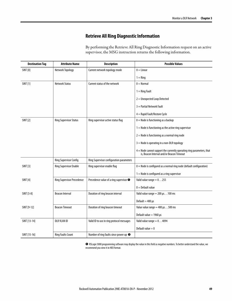
Monitor a DLR Network Chapter 3
Retrieve All Ring Diagnostic Information
By performing the Retrieve All Ring Diagnostic Information request on an active supervisor the MSG instruction returns the following information
➊ RSLogix 5000 programming software may display the value in this field as negative numbers To better understand the value we recommend you view it in HEX format
Destination Tag Attribute Name Description Possible Values
SINT [0] Network Topology Current network topology mode 0 = Linear
1 = Ring
SINT [1] Network Status Current status of the network 0 = Normal
1 = Ring Fault
2 = Unexpected Loop Detected
3 = Partial Network Fault
4 = Rapid FaultRestore Cycle
SINT [2] Ring Supervisor Status Ring supervisor active status flag 0 = Node is functioning as a backup
1 = Node is functioning as the active ring supervisor
2 = Node is functioning as a normal ring node
3 = Node is operating in a non-DLR topology
4 = Node cannot support the currently operating ring parameters thatis Beacon Interval andor Beacon Timeout
Ring Supervisor Config Ring Supervisor configuration parameters
SINT [3] Ring Supervisor Enable Ring supervisor enable flag 0 = Node is configured as a normal ring node (default configuration)
1 = Node is configured as a ring supervisor
SINT [4] Ring Supervisor Precedence Precedence value of a ring supervisor ➊ Valid value range = 0hellip255
0 = Default value
SINT [5-8] Beacon Interval Duration of ring beacon interval Valid value range = 200 μshellip100 ms
Default = 400 μs
SINT [9-12] Beacon Timeout Duration of ring beacon timeout Value value range = 400 μshellip500 ms
Default value = 1960 μs
SINT [13-14] DLR VLAN ID Valid ID to use in ring protocol messages Valid value range = 0hellip4094
Default value = 0
SINT [15-16] Ring Faults Count Number of ring faults since power up ➊
Rockwell Automation Publication 290E-AT001A-EN-P - November 2012 49
Chapter 3 Monitor a DLR Network
Retrieve All Diagnostic Information Attribute Description
➊ This destination tag is available only with the 1756-EN2TR module firmware revision 3x or later 1783-ETAP 1783-ETAP1F and 1783-ETAP2F taps firmware revisions 2x or later If using the 1783-ETAP tap firmware revision 1x your program does not include this destination tag
➋ RSLogix 5000 programming software may display the value in this field as negative numbers To better understand the value we recommend you view it in HEX format
Destination Tag Attribute Name Description Possible Values
Last Active Node on Port 1 Last active node at the end of the chain through port 1 of the active ring supervisor during a ring fault
SINT [17-20] Device IP address ➋ Any valid IP address value
A value = 0 indicates no IP address has been configured for the device
SINT [21-26] Device MAC address ➋ Any valid Ethernet MAC address
Last Active Node on Port 2 Last active node at the end of the chain through port 2 of the active ring supervisor during a ring fault
SINT [27-30] Device IP address ➋ Any valid IP address value
A value = 0 indicates no IP address has been configured for the device
SINT [31-36] Device MAC address ➋ Any valid Ethernet MAC address
SINT [37-38] Ring Protocol Participants Count
Number of devices in the ring protocol participants list
Active Supervisor Address IP andor Ethernet MAC address of the active ring supervisor
SINT [39-42] Supervisor IP address Any valid IP address value
A value = 0 indicates no IP address has been configured for the device
SINT [43-48] Supervisor MAC address Any valid Ethernet MAC address
SINT [49] Active Supervisor Precedence
Precedence value of the active ring supervisor
SINT [50-53]➊ Capability Flags Alerts you that the device is capable of operating as a supervisor and beacon-based ring node
0x22
50 Rockwell Automation Publication 290E-AT001A-EN-P - November 2012
Monitor a DLR Network Chapter 3
Request the Ring Participant List
When requesting the Ring Participant List service on the DLR network the MSG instruction returns the following information
Request the Ring Participant List Attribute Description
➊ This attribute will return an array of the data shown one entry for each node The Ring Protocol Participants Count attribute determines the number entries
➋ This tag displays only IP addresses for ring participants that have been configured with one For example you may have a 1783-ETAP tap connected to the network that has not been assigned an IP address In that case no address is shown for the 1783-ETAP tap
➌ RSLogix 5000 programming software may display the value in this field as negative numbers To better understand the value we recommend you view it in HEX format
➍ Unlike destination tag SINT [0-3] where IP addresses are displayed only for ring participants configured with an IP address this tag displays MAC addresses for all ring participants because every ring participant has a MAC address
Destination Tag Attribute Name Description Possible Values
Ring Protocol Participants List ➊
List of devices participating in ring protocol
SINT [0-3] Device IP address ➋➌ Any valid IP address value
A value = 0 indicates no IP address has been configured for the device
SINT [4-9] Device MAC address ➌➍ Any valid Ethernet MAC address
Rockwell Automation Publication 290E-AT001A-EN-P - November 2012 51
Chapter 3 Monitor a DLR Network
Enable and Configure a Ring Supervisor
When performing the Enable and Configure a Ring Supervisor request on a supervisor-capable device configure the MSG instruction with the following information
Enable and Configure a Ring Supervisor Attribute Description
➊ RSLogix 5000 programming software may display the value in this field as negative numbers To better understand the value we recommend you view it in HEX format
Source Tag Attribute Name Description Possible Values
Ring Supervisor Config Ring Supervisor configuration parameters
SINT [0] Ring Supervisor Enable Ring supervisor enable flag 0 = Node is configured as a normal ring node (default configuration)1 = Node is configured as a ring supervisor
SINT [1] Ring Supervisor Precedence Precedence value of a ring supervisor ➊
Valid value range = 0hellip2550 = Default value
SINT [2-5] Beacon Interval Duration of ring beacon interval
Valid value range = 200 μshellip100 000 μsDefault = 400 μs
SINT [6-9] Beacon Timeout Duration of ring beacon timeout ➊
Value value range = 400 μshellip500 000 μsDefault value = 1960 μs
SINT [10-11] DLR VLAN ID Valid ID to use in ring protocol messages ➊
Valid value range = 0hellip4094Default value = 0
52 Rockwell Automation Publication 290E-AT001A-EN-P - November 2012
Chapter 4
Troubleshoot a DLR Network
Introduction Use this chapter to learn how to troubleshoot the DLR network
General Solutions for Linear or DLR Networks
Before attempting to correct specific faults on the linear or DLR network we recommend that you first take the following actions when a fault appears
bull For a DLR networkndash Verify that at least one node has been configured as a supervisor
on the network and that Network Topology = Ringndash Verify that all cables on the network are securely connected
to each devicendash Verify that all devices that require an IP address have one assigned
correctlyndash Check the Network Status field on the active supervisor nodersquos status
page to determine the fault typebull For a linear network
ndash Verify that none of the nodes are configured as a supervisor on the network and that Network Topology = LinearIf any nodes on a linear network are configured as a supervisor it may impact communication to other devices connected to the network
ndash Verify that all cables on the network are securely connected to each device
ndash Verify that all devices that require an IP address have one assigned correctly
If the fault is not cleared after completing the actions listed above use the tables in the rest of this chapter to troubleshoot issues specific to a DLR network or a linear network
Topic Page
General Solutions for the Linear or DLR Networks 53
Duplicate IP Address Detection 54
Specific Issues on the DLR Network 55
Network Recovery Performance 58
Device Port Debugging Mode 59
Rockwell Automation Publication 290E-AT001A-EN-P - November 2012 53
Chapter 4 Troubleshoot a DLR Network
Duplicate IP Address Detection
Some EtherNetIP communication modules support duplicate IP address detection The module verifies that its IP address does not match any other network devicersquos IP address when performing either of these tasks
bull Connect the module to an EtherNetIP network
bull Change the modulersquos IP address
If the modulersquos IP address matches that of another device on the network the modulersquos EtherNetIP port transitions to Conflict mode In Conflict mode these conditions exist
bull OK status indicator is blinking red
bull Network (NET) status indicator is solid red
bull On some EtherNetIP communication modules the module status display indicates the conflict
The display scrollsOK ltIP_address_of_this_modulegt Duplicate IP
ltMac_address_of_duplicate_node_detectedgt
For example OK 108860196 Duplicate IP - 0000BC0234B4
bull On some EtherNetIP communication modules the modulersquos diagnostic webpage displays information about duplicate IP address detection
For more information on which EtherNetIP communication modules support displaying duplicate IP address on their diagnostic webpage see the Technical Note titled Logix modules Duplicate IP address detection enhancement 118216 in the Technical Support Knowledgebase available at httpwwwrockwellautomationcomknowledgebase
54 Rockwell Automation Publication 290E-AT001A-EN-P - November 2012
Troubleshoot a DLR Network Chapter 4
Specific Issues on the DLR Network
Use the following table to troubleshoot possible specific issues on the DLR or linear network that are not solved by the actions described on the previous page
Issue Description Solution
Supervisor Reports a Ring Fault A link on the DLR network may be brokenbull intentionally for example because of adding or deleting nodes but not making all
physical connections to restore the setup of the network withwithout the nodebull unintentionally for example because a cable is broken or a device malfunctionsWhen this fault occurs the adjacent nodes to the faulted part of the network are displayed in the Ring Fault group and the Network Status field = Ring FaultThe screen shot below shows the Ring Fault section with IP addresses appearing for the last active nodes The faulted node is between nodes 108880115 and 108880208 If the IP address of either node is not available the software will display the nodersquos MAC ID
Once the fault is corrected the ring is automatically restored and the Network Status field returns to Normal
Determine where the fault condition exists and correct itClick the Refresh Communication link as needed to update the Ring Fault information to determine where the fault condition existsFinally DevicePort Debugging Mode functionality on the 1783-ETAP tap may be used to analyze a suspicious nodeFor more information refer to Device Port Debugging Mode on page 59
Rockwell Automation Publication 290E-AT001A-EN-P - November 2012 55
Chapter 4 Troubleshoot a DLR Network
Issue Description Solution
Rapid Ring Fault When a Rapid Ring Fault occurs the following events occurbull The active supervisor will block traffic on port 2 resulting in possible network
segmentation that is some nodes may become unreachablebull The Link 2 status indicator on the active supervisor is offbull As soon as the fault occurs for both RSLogix 5000 programming software and
RSLinx communication software the Status field = Rapid FaultRestore Cycles
Any of the following may cause a Rapid Ring Faultbull 5 intentional disconnectionsreconnections of a node from the network within 30
secondsbull A duplex mismatch between two connected devicesbull Electromagnetic noise on the networkbull Unstable physical connections such as intermittent connectorsGiven the nature of a Rapid Ring Fault the Last Active Node information may not be accurate when a Rapid Ring Fault condition is present
Multiple possible solutions existbull For the disconnections and reconnections issue no
solution is requiredClear the fault after reconnecting the device to the network permanentlybull For the duplex mismatch issue reconfigure the duplex
parameters to make sure they match between the devices
bull For the electromagnetic noise issue determine where the noise exists and eliminate it or use a protective shield in that location
bull For the unstable connections issue determine where they exist on the network and correct them
bull Check the media counters for all devices on the network The device with the highest media counter count is most likely causing the Rapid Ring Fault
bull Remove devices from the network one by one If the Rapid Ring Fault disappears after a device is removed that device is causing the fault
bull DevicePort Debugging Mode functionality on the 1783-ETAP tap may be used to analyze a suspicious node
For more information refer to Device Port Debugging Mode on page 59bull Finally the Beacon Interval or Timeout configuration
may not be appropriate for the networkHowever if these values need to be changed we recommend that you contact Rockwell Automation technical supportOnce the fault is fixed click Clear Fault
56 Rockwell Automation Publication 290E-AT001A-EN-P - November 2012
Troubleshoot a DLR Network Chapter 4
Issue Description Solution
Partial Fault Condition A partial network fault occurs when traffic is lost in only one direction on the network because a ring member is not forwarding beacons in both directions for example a component failureThe active ring supervisor detects a partial fault by monitoring the loss of Beacon frames on one port and the fault location appears in the Ring Fault section of the Network tab When a partial fault is detected the active ring supervisor blocks traffic on one port At this point the ring is segmented due to the partial fault condition The nodes adjacent to the faulted part of the network are displayed in the Ring Fault group with either IP addresses or MAC IDs for each node displayedWhen this fault occurs the Network Status field = Partial Fault ConditionOnce the fault is corrected it automatically clears and the Network Status field returns to Normal
Determine where the fault condition exists and correct itAdditionally the DevicePort Debugging Mode functionality also known as Port Mirroring on a 1783-ETAP 1783-ETAP1F or 1783-ETAP2F tap may be used to analyze a suspicious nodeFor more information refer to Device Port Debugging Mode on page 59
Media Counter Errors or Collisions
The media counters screen displays the number of physical layer errors or collisions The screen below indicates where to check for errors encountered Error levels are displayed depending on what caused the error For example an Alignment Error is displayed in the Alignment Error field
On a DLR network it is not uncommon to see low levels of media counter errors For example if the network breaks a low level of media counter errors appears With a low level of media counter errors the value typically does not continuously increase and often clearsA high level of media counter errors typically continues to increase and does not clear For example there is a mismatch of speed between two linked nodes a high level of media counter errors appears steadily increasing and not clearingTo access the RSLinx screen above browse the network right-click on the device select Module Properties and click the Port Diagnostics tab
Some example solutions includebull Check for a mismatch of speed andor duplex between
two linked nodesbull Verify that all cables on the network are securely
connected to each devicebull Check for electromagnetic noise on the network If you
find it eliminate it or use a protective shield in that location
Rockwell Automation Publication 290E-AT001A-EN-P - November 2012 57
Chapter 4 Troubleshoot a DLR Network
Network Recovery Performance
When measuring the networkrsquos performance with regard to dealing with fault conditions consider the network recovery time Network recovery is the time for all of the following to take place
1 The supervisor node recognizes that a fault exists on the network
2 The supervisor node reconfigures the network because of the fault
3 The supervisor node communicates to the network nodes that a fault condition exists
4 The network nodes reconfigure themselves because of the fault
With the default beacon interval value of 400 mS and beacon timeout value of 1960 mS the worst-case time for network recovery times are
bull 2890 mS for a copper DLR network This recovery time is based on 100 m copper segments between nodes on the network
bull 3140 mS for a fiber-optic DLR network This recovery time is based on 2 kM fiber-optic cable segments between nodes on the network
When considering the values listed above keep in mind
bull Recovery time may actually occur faster than the times listed
bull The recovery times listed above assume that your networkrsquos nodes are operating at 100 Mbps speed and full-duplex mode We recommend that your nodes generally operate in this mode for DLR networks
bull If other node conditions exist such as a node operating at 10 Mbps full-duplex or 10100 Mbps half-duplex the recovery times will vary from the times listed above
If this is the case for your application the beacon interval and beacon timeout will need to be changed We recommend that you first contact Rockwell Automation technical support if these parameters need to be changed
bull The value assumes that the majority of the traffic on your network is EtherNetIP traffic
58 Rockwell Automation Publication 290E-AT001A-EN-P - November 2012
Troubleshoot a DLR Network Chapter 4
Device Port Debugging Mode
This functionality is disabled by default Device Port Debugging mode which is similar to port mirroring can be used to monitor data received on the 1783-ETAP 1783-ETAP1F or 1783-ETAP2F taprsquos two network ports Monitor the data over the device port to a device such as a personal computer running a protocol analyzer application for advanced network debugging or analysis
When device port debugging is used on a 1783-ETAP the device connected to the 1783-ETAP taprsquos front port receives all of the data traversing the ring (both directions)
Device Port Debugging Example Network
When using the Device Port Debugging mode functionality insert the 1783-ETAP with the network analyzer connected to the device port It is inserted at the spot on the ring network where the node in question is located The graphic below shows a 1783-ETAP tap inserted in the network
IMPORTANT This functionality should be used only when troubleshooting the network and not in normal network operation
Rockwell Automation Publication 290E-AT001A-EN-P - November 2012 59
Chapter 4 Troubleshoot a DLR Network
Combined total network bandwidth of the traffic received on the two 1783-ETAP 1783-ETAP1F or 1783-ETAP2F taprsquos ports connected to the network should not exceed the taprsquos device port capacity The speed setting determines the device portrsquos capacity
Configure the device port on a 1783-ETAP 1783-ETAP1F or 1783-ETAP2F tap to either of two speed settings
bull 100 Mbps - default settingbull 10 Mbps
If the bandwidth exceeds the capacity of the taprsquos device port some frames from the ring will be dropped before reaching the device port These dropped frames do not impact the traffic on the rest of the DLR network
The device port setting determines how much network traffic the 1783-ETAP 1783-ETAP1F or 1783-ETAP2F tap can handle before dropping frames The circled section in the graphic below shows the Port Buffer Utilization of the Device Port In this example the value is zero because a ring fault exists on the network
60 Rockwell Automation Publication 290E-AT001A-EN-P - November 2012
Appendix A
Network Usage Guidelines and Recommendations
Consider the following guidelines and recommendations when using a DLR or linear network
GuidelineRecommendation Explanation
Use fewer than 50 nodes on a single DLR networkIf your application requires more than 50 nodes we recommend that the nodes are broken into separate but linked DLR networks
If you use more than 50 nodes on a single DLR networkbull Your network has a greater chance of multiple faults
occurring on the networkbull Network recovery times from faulted DLR network
are higher
Do not configure a supervisor on a linear network If your linear network includes non-DLR nodes and has a supervisor-enabled node on the network it may impact communication to non-DLR devices connected to the linear network
If you must connect a device that is running at 10 Mbps to a DLR or linear network do so through a 1783-ETAP 1783-ETAP1F or 1783-ETAP2F tap device port
The 1783-ETAP 1783-ETAP1F and 1783-ETAP2F taps can operate at 100 Mbps on the DLR network this is the optimal speed for a network If you connect a 10 Mbps device directly to the network instead of through a tap the linear or DLR network traffic slows to 10 MbpsAdditionally if the 10 Mbps device is connected to the network without a 1783-ETAP tap network recovery times are significantly impacted
Configure multiple supervisor nodes per ring If your DLR network only has one supervisor and the supervisor experiences a fault none of the other nodes become the active supervisor In this case the network becomes a linear network until the fault is corrected and the DLR network restoredAnother reason to configure multiple supervisor nodes is for replacing an active supervisor node with an out-of-box replacement the new device will not be enabled as a supervisor (by default) and there would still be no supervisor on the network
Rockwell Automation Publication 290E-AT001A-EN-P - November 2012 61
Appendix A Network Usage Guidelines and Recommendations
GuidelineRecommendation Explanation
Connect switches to a DLR network via 1783-ETAP 1783-ETAP1F or 1783-ETAP2F taps
If switches are connected to the DLR network without the use of a 1783-ETAP 1783-ETAP1F or 1783-ETAP2F tap the network may experience unpredictable behavior and network performance is unknown
Run all nodes on the DLR network at 100 Mbps and in Full-Duplex mode
These configuration values provide the best performance for your networkAdditionally we recommend that youbull Use auto-negotiate for all nodes on the DLR networkbull Do not use auto-negotiate on one node and then force
speed on the next node linked to it
In a linear network the number of nodes to use is application specific based on the considerations described in the next box
When determining the number of nodes to use on a linear network consider the followingbull There is a delay per node as information is transmitted
to each successive node used on the networkndash The typical delay on a linear network with 100 m
copper segments between nodes is 30 mSndash The typical delay on a linear network with 2 kM
fiber-optic segments between nodes is 40 mS
The greater the number of nodes on the network the longer the total time for information to be transmitted across the entire networkbull The single point of failure possibility is greater with
each additional connectionbull Troubleshooting the network may be more difficult
with a higher number of nodes
The total time for information to be transmitted across the entire network and its effect on how many nodes to use on a linear network is related to the Requested Packet Interval (RPI)Verify that the total time to transmit information from the first node to the last node on the network is less than the RPI Make sure the network is not loaded beyond 90 of capacity
62 Rockwell Automation Publication 290E-AT001A-EN-P - November 2012
Network Usage Guidelines and Recommendations Appendix A
GuidelineRecommendation Explanation
Do not physically close a DLR network without a supervisor configured on the network
A DLR network without a supervisor node results in a network stormIf you do close the DLR network without a supervisor configured break the ring and configure at least one supervisor before physically reconnecting the network
Use the default values for the followingbull Beacon Intervalbull Beacon Timeoutbull Ring Protocol VLAN ID
Changing the default values for the parameters Beacon Interval Beacon Timeout and Ring Protocol VLAN ID can result in unpredictable network behavior and negatively impacted network performanceThe default values are optimized for a network withbull 50 or fewer nodes are on the networkbull All nodes are operating at 100 Mbps and full-duplex
modebull At least 50 of the network traffic bandwidth being
EtherNetIP trafficIf you think the values of the Beacon Interval Beacon Timeout or Ring Protocol VLAN ID need to be changed for example if any node on ring is not operating at 100 Mbps and full-duplex mode we recommend that you first contact Rockwell Automation technical support
If DHCP for the ArmorStarts is still required you will need to disable Internet Group Management Protocol (IGMP) snooping on the E-tap via the AOP
IGMP Snooping is enabled by default in the 1783-ETAP 1783-ETAP1F and 1783-ETAP2F taps and is commonly used to manage multicast traffic on the network When in use this functionality allows the tap to multicast data to only those devices that need the data rather than to all devices connected to the networkOnce DHCP is enabled the switch could change the IP addresses on the ArmorStarts depending on network demand which could cause RSlogix5000 to loose communication with the device as connectivity is established via the AOP in the initial configuration
The IGMP Querier functionality should be enabled for at least one node on the network
This functionality is disabled by default The IGMP Querier functionality enables a 1783-ETAP 1783-ETAP1F or 1783-ETAP2F tap or switch such as a Stratix managed switch to send out a query to all devices on the network to determine what multicast addresses are of interest to a specific node or a group of nodesIf the IGMP Querier functionality is not enabled for at least one node on the network multicast traffic on the network may eventually create network performance issuesThe 1783-ETAP 1783-ETAP1F or 1783-ETAP2F taps managed switches and routers are examples of devices that support IGMP Querier functionality
Rockwell Automation Publication 290E-AT001A-EN-P - November 2012 63
Appendix A Network Usage Guidelines and Recommendations
Notes
64 Rockwell Automation Publication 290E-AT001A-EN-P - November 2012
Appendix B
Required Firmware Revisions
Required Firmware Revision for an Add-On Profile
➊ The ControlFLASH Firmware Upgrade software tcan be used o upgrade a 1756-EN2TR module from firmware revision 21 to 3x or later1x or later3x or later2x or later
➋ The ControlFLASH Firmware Upgrade software can be used to upgrade a 1783-ETAP tap from firmware revision 11 to 2x or later
To download new firmware go to httpwwwrockwellautomationcomsupportamericasindex_enhtml
If the firmware revision is upgraded on the module or tap the required AOP revision listed above must be used for that revision For example if the 1756-EN2TR module is upgraded to firmware revision 3x or later AOP revision 2x or later must be used in the RSLogix 5000 programming software
Additionally if the firmware revision is upgraded on the module or tap the required RSLinx communication software must also be used for that firmware revision For more information on which RSLinx software version is required for each firmware revision see page 66
For both the 1756-EN2TR module and 1783-ETAP tap make sure that the Major Revision configured on the General tab of the devicersquos RSLogix 5000 programming software configuration matches the major revision of the physical module
IMPORTANT To download an AOP go to httpsupportrockwellautomationcomcontrolflashLogixProfileraspDepending on the firmware revision of your product a specific AOP version must be used
Firmware Revision Add-On Profile Revision Cat No
21 ➊ 1x or later 1756-EN2TR
3x or later 2x or later
11 ➋ 1x or later 1783-ETAP
2x or later 2x or later
2x or later 2x or later 1783-ETAP1F
1783-ETAP2F
Rockwell Automation Publication 290E-AT001A-EN-P - November 2012 65
Appendix B Required Firmware Revisions
If the device configuration on the General tab does not match the physical module the programming software alerts you to this mismatch when attempting to configure the Internet Protocol Port Configuration and Network tabs for that device
Required Firmware Revision for RSLinx Communication Software
➊ The ControlFLASH Firmware Upgrade software can be used to upgrade a 1756-EN2TR module from firmware revision 21 to 3x or later1x or later3x or later255 or later3x or later256 or later
➋ The ControlFLASH Firmware Upgrade software can be used to upgrade a 1783-ETAP tap from firmware revision 11 to 2x or later
To download new firmware go to httpwwwrockwellautomationcomsupportamericasindex_enhtml
If the firmware revision is upgraded on the module or tap the required RSLinx communication software listed above must be used for that revision For example if the 1756-EN2TR module is upgraded to firmware revision 3x or later AOP revision 2x or later must be used in your RSLogix 5000 programming software
Additionally if the firmware revision is upgraded on the module or tap the required AOP revision must also be used for that firmware revision For more information on which AOP revision is required for each firmware revision see page 65
IMPORTANT Depending on the firmware revision of your product specific versions of RSLinx communication software must be used
Firmware Revision Required RSLinx Communication Software Version
Cat No
21 ➊ 255 or later 1756-EN2TR
3x or later 256 or later
11 ➋ 255 or later 1783-ETAP
2x or later 256 or later
2x or later 256 or later 1783-ETAP1F
1783-ETAP2F
66 Rockwell Automation Publication 290E-AT001A-EN-P - November 2012
Rockwell Otomasyon Ticaret AŞ Kar Plaza İş Merkezi E Blok Kat6 34752 İccedilerenkoumly İstanbul Tel +90 (216) 5698400
Rockwell Automation Publication 290E-AT001A-EN-P ndash November 2012 68 Copyright copy 2012 Rockwell Automation Inc All rights reserved Printed in the USA
Rockwell Automation Support
Rockwell Automation provides technical information on the Web to assist you in using its products At httpwwwrockwellautomationcomsupport you can find technical manuals a knowledge base of FAQs technical and application notes sample code and links to software service packs and a MySupport feature that you can customize to make thebest use of these tools
For an additional level of technical phone support for installation configuration and troubleshooting we offer TechConnectSM support programs For more information contact your local distributor or Rockwell Automation representative or visit httpwwwrockwellautomationcomsupport
Installation Assistance
If you experience a problem within the first 24 hours of installation review the information that is contained in this manualYou can contact Customer Support for initial help in getting your product up and running
New Product Satisfaction Return
Rockwell Automation tests all of its products to ensure that they are fully operational when shipped from the manufacturing facility However if your product is not functioning and needs to be returned follow these procedures
Documentation Feedback
Your comments will help us serve your documentation needs better If you have any suggestions on how to improve this document complete this form publication RA-DU002 available at httpwwwrockwellautomationcomliterature
United States or Canada 14406463434
Outside United States or Canada Use the Worldwide Locator at httpwwwrockwellautomationcomsupportamericasphone_enhtml or contact your local Rockwell Automation representative
United States Contact your distributor You must provide a Customer Support case number (call the phone number above to obtain one) to your distributor to complete the return process
Outside United States Please contact your local Rockwell Automation representative for the return procedure
- Important User Information
- General Precautions
- Software Requirements
- Additional Resources
- Rockwell Automation Support
- Installation Assistance
- New Product Satisfaction Return
- Table of Contents
- Chapter 1
-
- Device-Level Ring (DLR) Basics
-
- Introduction
- ArmorStart with EtherNetIP Overview
- What is a Device-level Ring (DLR) Network
- DLR Network Elements
-
- Supervisor Node
- Ring Node
-
- DLR Network Operation
- Number of Nodes on a DLR Network
- DLR Network Fault Management
-
- Network Reconfiguration after a Fault
-
- Chapter 2
-
- Construct and Configure a Device-level Ring Network with ArmorStarts
-
- Introduction
- Ethernet Capacity Tool
- Install Devices on a DLR Network
- ArmorStart Addressing Configuration
-
- Using the BootPDHCP Server
- Using the Rotary Network Address Switches
- Using the ArmorStart Internal Web Server
-
- Configure Supervisor Nodes on a DLR Network
-
- Configure a Ring Supervisor in RSLogix 5000 Programming Software
- Adding an Armorstart to RSLogix 5000
- Enable Ring Supervisor in RSLogix 5000 Programming Software
- Configure and Enable a Ring Supervisor in RSLinx Classic Communication Software
-
- Complete the Physical Connections of the Network
- Verify Supervisor Configuration
- IGMP Snooping
- IGMP Querier
-
- Chapter 3
-
- Monitor a DLR Network
-
- Introduction
- Methods to Monitor a DLR Network
-
- RSLogix 5000 Programming Software Status Pages
- RSLinx Communication Software Status Pages
- ArmorStart Internal Web Server
- EtherNetIP Device Level Ring (DLR) Network Diagnostics Faceplate
- Programmatically Through the Use of a MSG Instruction
-
- Monitor Status Pages
-
- RSLogix 5000 Programming Software Status Pages
- RSLinx Communication Software
-
- How to Access the ArmorStart EtherNetIP Internal Web Server
-
- EtherNetIP Device Level Ring (DLR) Network Diagnostics Faceplate Overview
-
- Monitor Diagnostics via MSG Instructions
-
- Use Specific Values on the Configuration Tab
- Retrieve All Ring Diagnostic Information
- Retrieve All Diagnostic Information Attribute Description
- Request the Ring Participant List
- Request the Ring Participant List Attribute Description
-
- Enable and Configure a Ring Supervisor
-
- Enable and Configure a Ring Supervisor Attribute Description
-
- Chapter 4
-
- Troubleshoot a DLR Network
-
- Introduction
- General Solutions for Linear or DLR Networks
- Duplicate IP Address Detection
- Specific Issues on the DLR Network
- Network Recovery Performance
- Device Port Debugging Mode
-
- Device Port Debugging Example Network
-
- Appendix A
-
- Network Usage Guidelines and Recommendations
-
- Notes
-
- Appendix B
-
- Required Firmware Revisions
-
- Required Firmware Revision for an Add-On Profile
- Required Firmware Revision for RSLinx Communication Software
-
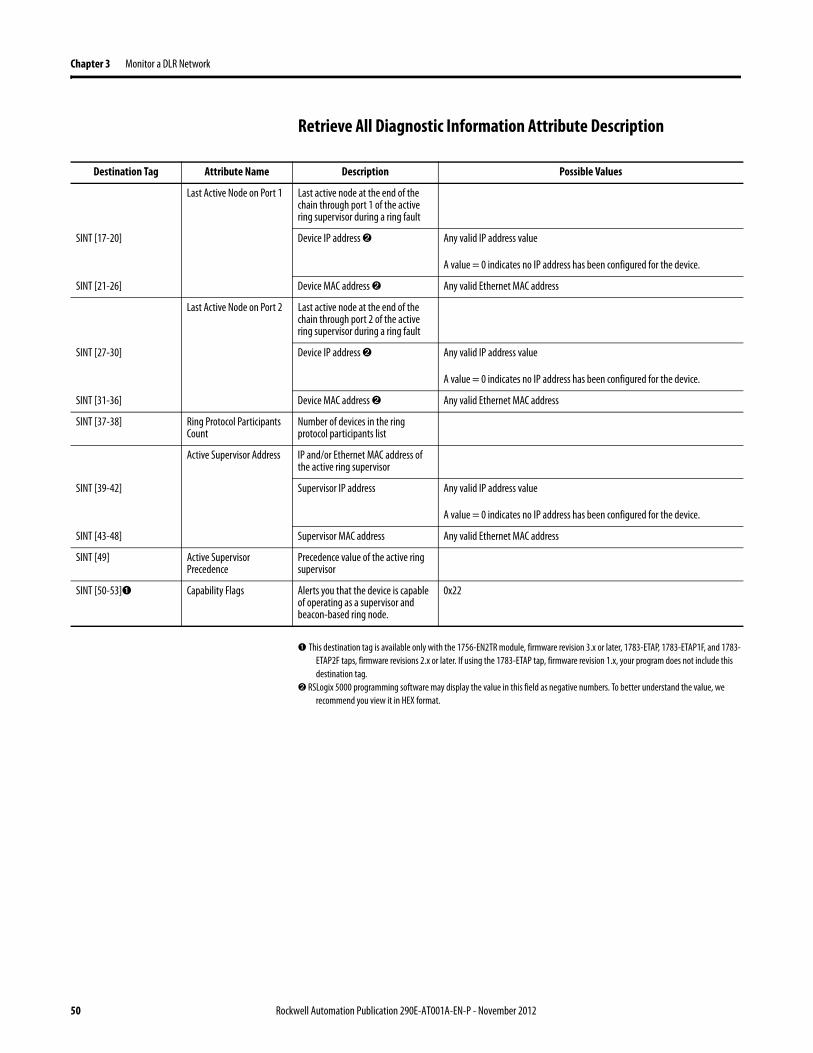
Chapter 3 Monitor a DLR Network
Retrieve All Diagnostic Information Attribute Description
➊ This destination tag is available only with the 1756-EN2TR module firmware revision 3x or later 1783-ETAP 1783-ETAP1F and 1783-ETAP2F taps firmware revisions 2x or later If using the 1783-ETAP tap firmware revision 1x your program does not include this destination tag
➋ RSLogix 5000 programming software may display the value in this field as negative numbers To better understand the value we recommend you view it in HEX format
Destination Tag Attribute Name Description Possible Values
Last Active Node on Port 1 Last active node at the end of the chain through port 1 of the active ring supervisor during a ring fault
SINT [17-20] Device IP address ➋ Any valid IP address value
A value = 0 indicates no IP address has been configured for the device
SINT [21-26] Device MAC address ➋ Any valid Ethernet MAC address
Last Active Node on Port 2 Last active node at the end of the chain through port 2 of the active ring supervisor during a ring fault
SINT [27-30] Device IP address ➋ Any valid IP address value
A value = 0 indicates no IP address has been configured for the device
SINT [31-36] Device MAC address ➋ Any valid Ethernet MAC address
SINT [37-38] Ring Protocol Participants Count
Number of devices in the ring protocol participants list
Active Supervisor Address IP andor Ethernet MAC address of the active ring supervisor
SINT [39-42] Supervisor IP address Any valid IP address value
A value = 0 indicates no IP address has been configured for the device
SINT [43-48] Supervisor MAC address Any valid Ethernet MAC address
SINT [49] Active Supervisor Precedence
Precedence value of the active ring supervisor
SINT [50-53]➊ Capability Flags Alerts you that the device is capable of operating as a supervisor and beacon-based ring node
0x22
50 Rockwell Automation Publication 290E-AT001A-EN-P - November 2012
Monitor a DLR Network Chapter 3
Request the Ring Participant List
When requesting the Ring Participant List service on the DLR network the MSG instruction returns the following information
Request the Ring Participant List Attribute Description
➊ This attribute will return an array of the data shown one entry for each node The Ring Protocol Participants Count attribute determines the number entries
➋ This tag displays only IP addresses for ring participants that have been configured with one For example you may have a 1783-ETAP tap connected to the network that has not been assigned an IP address In that case no address is shown for the 1783-ETAP tap
➌ RSLogix 5000 programming software may display the value in this field as negative numbers To better understand the value we recommend you view it in HEX format
➍ Unlike destination tag SINT [0-3] where IP addresses are displayed only for ring participants configured with an IP address this tag displays MAC addresses for all ring participants because every ring participant has a MAC address
Destination Tag Attribute Name Description Possible Values
Ring Protocol Participants List ➊
List of devices participating in ring protocol
SINT [0-3] Device IP address ➋➌ Any valid IP address value
A value = 0 indicates no IP address has been configured for the device
SINT [4-9] Device MAC address ➌➍ Any valid Ethernet MAC address
Rockwell Automation Publication 290E-AT001A-EN-P - November 2012 51
Chapter 3 Monitor a DLR Network
Enable and Configure a Ring Supervisor
When performing the Enable and Configure a Ring Supervisor request on a supervisor-capable device configure the MSG instruction with the following information
Enable and Configure a Ring Supervisor Attribute Description
➊ RSLogix 5000 programming software may display the value in this field as negative numbers To better understand the value we recommend you view it in HEX format
Source Tag Attribute Name Description Possible Values
Ring Supervisor Config Ring Supervisor configuration parameters
SINT [0] Ring Supervisor Enable Ring supervisor enable flag 0 = Node is configured as a normal ring node (default configuration)1 = Node is configured as a ring supervisor
SINT [1] Ring Supervisor Precedence Precedence value of a ring supervisor ➊
Valid value range = 0hellip2550 = Default value
SINT [2-5] Beacon Interval Duration of ring beacon interval
Valid value range = 200 μshellip100 000 μsDefault = 400 μs
SINT [6-9] Beacon Timeout Duration of ring beacon timeout ➊
Value value range = 400 μshellip500 000 μsDefault value = 1960 μs
SINT [10-11] DLR VLAN ID Valid ID to use in ring protocol messages ➊
Valid value range = 0hellip4094Default value = 0
52 Rockwell Automation Publication 290E-AT001A-EN-P - November 2012
Chapter 4
Troubleshoot a DLR Network
Introduction Use this chapter to learn how to troubleshoot the DLR network
General Solutions for Linear or DLR Networks
Before attempting to correct specific faults on the linear or DLR network we recommend that you first take the following actions when a fault appears
bull For a DLR networkndash Verify that at least one node has been configured as a supervisor
on the network and that Network Topology = Ringndash Verify that all cables on the network are securely connected
to each devicendash Verify that all devices that require an IP address have one assigned
correctlyndash Check the Network Status field on the active supervisor nodersquos status
page to determine the fault typebull For a linear network
ndash Verify that none of the nodes are configured as a supervisor on the network and that Network Topology = LinearIf any nodes on a linear network are configured as a supervisor it may impact communication to other devices connected to the network
ndash Verify that all cables on the network are securely connected to each device
ndash Verify that all devices that require an IP address have one assigned correctly
If the fault is not cleared after completing the actions listed above use the tables in the rest of this chapter to troubleshoot issues specific to a DLR network or a linear network
Topic Page
General Solutions for the Linear or DLR Networks 53
Duplicate IP Address Detection 54
Specific Issues on the DLR Network 55
Network Recovery Performance 58
Device Port Debugging Mode 59
Rockwell Automation Publication 290E-AT001A-EN-P - November 2012 53
Chapter 4 Troubleshoot a DLR Network
Duplicate IP Address Detection
Some EtherNetIP communication modules support duplicate IP address detection The module verifies that its IP address does not match any other network devicersquos IP address when performing either of these tasks
bull Connect the module to an EtherNetIP network
bull Change the modulersquos IP address
If the modulersquos IP address matches that of another device on the network the modulersquos EtherNetIP port transitions to Conflict mode In Conflict mode these conditions exist
bull OK status indicator is blinking red
bull Network (NET) status indicator is solid red
bull On some EtherNetIP communication modules the module status display indicates the conflict
The display scrollsOK ltIP_address_of_this_modulegt Duplicate IP
ltMac_address_of_duplicate_node_detectedgt
For example OK 108860196 Duplicate IP - 0000BC0234B4
bull On some EtherNetIP communication modules the modulersquos diagnostic webpage displays information about duplicate IP address detection
For more information on which EtherNetIP communication modules support displaying duplicate IP address on their diagnostic webpage see the Technical Note titled Logix modules Duplicate IP address detection enhancement 118216 in the Technical Support Knowledgebase available at httpwwwrockwellautomationcomknowledgebase
54 Rockwell Automation Publication 290E-AT001A-EN-P - November 2012
Troubleshoot a DLR Network Chapter 4
Specific Issues on the DLR Network
Use the following table to troubleshoot possible specific issues on the DLR or linear network that are not solved by the actions described on the previous page
Issue Description Solution
Supervisor Reports a Ring Fault A link on the DLR network may be brokenbull intentionally for example because of adding or deleting nodes but not making all
physical connections to restore the setup of the network withwithout the nodebull unintentionally for example because a cable is broken or a device malfunctionsWhen this fault occurs the adjacent nodes to the faulted part of the network are displayed in the Ring Fault group and the Network Status field = Ring FaultThe screen shot below shows the Ring Fault section with IP addresses appearing for the last active nodes The faulted node is between nodes 108880115 and 108880208 If the IP address of either node is not available the software will display the nodersquos MAC ID
Once the fault is corrected the ring is automatically restored and the Network Status field returns to Normal
Determine where the fault condition exists and correct itClick the Refresh Communication link as needed to update the Ring Fault information to determine where the fault condition existsFinally DevicePort Debugging Mode functionality on the 1783-ETAP tap may be used to analyze a suspicious nodeFor more information refer to Device Port Debugging Mode on page 59
Rockwell Automation Publication 290E-AT001A-EN-P - November 2012 55
Chapter 4 Troubleshoot a DLR Network
Issue Description Solution
Rapid Ring Fault When a Rapid Ring Fault occurs the following events occurbull The active supervisor will block traffic on port 2 resulting in possible network
segmentation that is some nodes may become unreachablebull The Link 2 status indicator on the active supervisor is offbull As soon as the fault occurs for both RSLogix 5000 programming software and
RSLinx communication software the Status field = Rapid FaultRestore Cycles
Any of the following may cause a Rapid Ring Faultbull 5 intentional disconnectionsreconnections of a node from the network within 30
secondsbull A duplex mismatch between two connected devicesbull Electromagnetic noise on the networkbull Unstable physical connections such as intermittent connectorsGiven the nature of a Rapid Ring Fault the Last Active Node information may not be accurate when a Rapid Ring Fault condition is present
Multiple possible solutions existbull For the disconnections and reconnections issue no
solution is requiredClear the fault after reconnecting the device to the network permanentlybull For the duplex mismatch issue reconfigure the duplex
parameters to make sure they match between the devices
bull For the electromagnetic noise issue determine where the noise exists and eliminate it or use a protective shield in that location
bull For the unstable connections issue determine where they exist on the network and correct them
bull Check the media counters for all devices on the network The device with the highest media counter count is most likely causing the Rapid Ring Fault
bull Remove devices from the network one by one If the Rapid Ring Fault disappears after a device is removed that device is causing the fault
bull DevicePort Debugging Mode functionality on the 1783-ETAP tap may be used to analyze a suspicious node
For more information refer to Device Port Debugging Mode on page 59bull Finally the Beacon Interval or Timeout configuration
may not be appropriate for the networkHowever if these values need to be changed we recommend that you contact Rockwell Automation technical supportOnce the fault is fixed click Clear Fault
56 Rockwell Automation Publication 290E-AT001A-EN-P - November 2012
Troubleshoot a DLR Network Chapter 4
Issue Description Solution
Partial Fault Condition A partial network fault occurs when traffic is lost in only one direction on the network because a ring member is not forwarding beacons in both directions for example a component failureThe active ring supervisor detects a partial fault by monitoring the loss of Beacon frames on one port and the fault location appears in the Ring Fault section of the Network tab When a partial fault is detected the active ring supervisor blocks traffic on one port At this point the ring is segmented due to the partial fault condition The nodes adjacent to the faulted part of the network are displayed in the Ring Fault group with either IP addresses or MAC IDs for each node displayedWhen this fault occurs the Network Status field = Partial Fault ConditionOnce the fault is corrected it automatically clears and the Network Status field returns to Normal
Determine where the fault condition exists and correct itAdditionally the DevicePort Debugging Mode functionality also known as Port Mirroring on a 1783-ETAP 1783-ETAP1F or 1783-ETAP2F tap may be used to analyze a suspicious nodeFor more information refer to Device Port Debugging Mode on page 59
Media Counter Errors or Collisions
The media counters screen displays the number of physical layer errors or collisions The screen below indicates where to check for errors encountered Error levels are displayed depending on what caused the error For example an Alignment Error is displayed in the Alignment Error field
On a DLR network it is not uncommon to see low levels of media counter errors For example if the network breaks a low level of media counter errors appears With a low level of media counter errors the value typically does not continuously increase and often clearsA high level of media counter errors typically continues to increase and does not clear For example there is a mismatch of speed between two linked nodes a high level of media counter errors appears steadily increasing and not clearingTo access the RSLinx screen above browse the network right-click on the device select Module Properties and click the Port Diagnostics tab
Some example solutions includebull Check for a mismatch of speed andor duplex between
two linked nodesbull Verify that all cables on the network are securely
connected to each devicebull Check for electromagnetic noise on the network If you
find it eliminate it or use a protective shield in that location
Rockwell Automation Publication 290E-AT001A-EN-P - November 2012 57
Chapter 4 Troubleshoot a DLR Network
Network Recovery Performance
When measuring the networkrsquos performance with regard to dealing with fault conditions consider the network recovery time Network recovery is the time for all of the following to take place
1 The supervisor node recognizes that a fault exists on the network
2 The supervisor node reconfigures the network because of the fault
3 The supervisor node communicates to the network nodes that a fault condition exists
4 The network nodes reconfigure themselves because of the fault
With the default beacon interval value of 400 mS and beacon timeout value of 1960 mS the worst-case time for network recovery times are
bull 2890 mS for a copper DLR network This recovery time is based on 100 m copper segments between nodes on the network
bull 3140 mS for a fiber-optic DLR network This recovery time is based on 2 kM fiber-optic cable segments between nodes on the network
When considering the values listed above keep in mind
bull Recovery time may actually occur faster than the times listed
bull The recovery times listed above assume that your networkrsquos nodes are operating at 100 Mbps speed and full-duplex mode We recommend that your nodes generally operate in this mode for DLR networks
bull If other node conditions exist such as a node operating at 10 Mbps full-duplex or 10100 Mbps half-duplex the recovery times will vary from the times listed above
If this is the case for your application the beacon interval and beacon timeout will need to be changed We recommend that you first contact Rockwell Automation technical support if these parameters need to be changed
bull The value assumes that the majority of the traffic on your network is EtherNetIP traffic
58 Rockwell Automation Publication 290E-AT001A-EN-P - November 2012
Troubleshoot a DLR Network Chapter 4
Device Port Debugging Mode
This functionality is disabled by default Device Port Debugging mode which is similar to port mirroring can be used to monitor data received on the 1783-ETAP 1783-ETAP1F or 1783-ETAP2F taprsquos two network ports Monitor the data over the device port to a device such as a personal computer running a protocol analyzer application for advanced network debugging or analysis
When device port debugging is used on a 1783-ETAP the device connected to the 1783-ETAP taprsquos front port receives all of the data traversing the ring (both directions)
Device Port Debugging Example Network
When using the Device Port Debugging mode functionality insert the 1783-ETAP with the network analyzer connected to the device port It is inserted at the spot on the ring network where the node in question is located The graphic below shows a 1783-ETAP tap inserted in the network
IMPORTANT This functionality should be used only when troubleshooting the network and not in normal network operation
Rockwell Automation Publication 290E-AT001A-EN-P - November 2012 59
Chapter 4 Troubleshoot a DLR Network
Combined total network bandwidth of the traffic received on the two 1783-ETAP 1783-ETAP1F or 1783-ETAP2F taprsquos ports connected to the network should not exceed the taprsquos device port capacity The speed setting determines the device portrsquos capacity
Configure the device port on a 1783-ETAP 1783-ETAP1F or 1783-ETAP2F tap to either of two speed settings
bull 100 Mbps - default settingbull 10 Mbps
If the bandwidth exceeds the capacity of the taprsquos device port some frames from the ring will be dropped before reaching the device port These dropped frames do not impact the traffic on the rest of the DLR network
The device port setting determines how much network traffic the 1783-ETAP 1783-ETAP1F or 1783-ETAP2F tap can handle before dropping frames The circled section in the graphic below shows the Port Buffer Utilization of the Device Port In this example the value is zero because a ring fault exists on the network
60 Rockwell Automation Publication 290E-AT001A-EN-P - November 2012
Appendix A
Network Usage Guidelines and Recommendations
Consider the following guidelines and recommendations when using a DLR or linear network
GuidelineRecommendation Explanation
Use fewer than 50 nodes on a single DLR networkIf your application requires more than 50 nodes we recommend that the nodes are broken into separate but linked DLR networks
If you use more than 50 nodes on a single DLR networkbull Your network has a greater chance of multiple faults
occurring on the networkbull Network recovery times from faulted DLR network
are higher
Do not configure a supervisor on a linear network If your linear network includes non-DLR nodes and has a supervisor-enabled node on the network it may impact communication to non-DLR devices connected to the linear network
If you must connect a device that is running at 10 Mbps to a DLR or linear network do so through a 1783-ETAP 1783-ETAP1F or 1783-ETAP2F tap device port
The 1783-ETAP 1783-ETAP1F and 1783-ETAP2F taps can operate at 100 Mbps on the DLR network this is the optimal speed for a network If you connect a 10 Mbps device directly to the network instead of through a tap the linear or DLR network traffic slows to 10 MbpsAdditionally if the 10 Mbps device is connected to the network without a 1783-ETAP tap network recovery times are significantly impacted
Configure multiple supervisor nodes per ring If your DLR network only has one supervisor and the supervisor experiences a fault none of the other nodes become the active supervisor In this case the network becomes a linear network until the fault is corrected and the DLR network restoredAnother reason to configure multiple supervisor nodes is for replacing an active supervisor node with an out-of-box replacement the new device will not be enabled as a supervisor (by default) and there would still be no supervisor on the network
Rockwell Automation Publication 290E-AT001A-EN-P - November 2012 61
Appendix A Network Usage Guidelines and Recommendations
GuidelineRecommendation Explanation
Connect switches to a DLR network via 1783-ETAP 1783-ETAP1F or 1783-ETAP2F taps
If switches are connected to the DLR network without the use of a 1783-ETAP 1783-ETAP1F or 1783-ETAP2F tap the network may experience unpredictable behavior and network performance is unknown
Run all nodes on the DLR network at 100 Mbps and in Full-Duplex mode
These configuration values provide the best performance for your networkAdditionally we recommend that youbull Use auto-negotiate for all nodes on the DLR networkbull Do not use auto-negotiate on one node and then force
speed on the next node linked to it
In a linear network the number of nodes to use is application specific based on the considerations described in the next box
When determining the number of nodes to use on a linear network consider the followingbull There is a delay per node as information is transmitted
to each successive node used on the networkndash The typical delay on a linear network with 100 m
copper segments between nodes is 30 mSndash The typical delay on a linear network with 2 kM
fiber-optic segments between nodes is 40 mS
The greater the number of nodes on the network the longer the total time for information to be transmitted across the entire networkbull The single point of failure possibility is greater with
each additional connectionbull Troubleshooting the network may be more difficult
with a higher number of nodes
The total time for information to be transmitted across the entire network and its effect on how many nodes to use on a linear network is related to the Requested Packet Interval (RPI)Verify that the total time to transmit information from the first node to the last node on the network is less than the RPI Make sure the network is not loaded beyond 90 of capacity
62 Rockwell Automation Publication 290E-AT001A-EN-P - November 2012
Network Usage Guidelines and Recommendations Appendix A
GuidelineRecommendation Explanation
Do not physically close a DLR network without a supervisor configured on the network
A DLR network without a supervisor node results in a network stormIf you do close the DLR network without a supervisor configured break the ring and configure at least one supervisor before physically reconnecting the network
Use the default values for the followingbull Beacon Intervalbull Beacon Timeoutbull Ring Protocol VLAN ID
Changing the default values for the parameters Beacon Interval Beacon Timeout and Ring Protocol VLAN ID can result in unpredictable network behavior and negatively impacted network performanceThe default values are optimized for a network withbull 50 or fewer nodes are on the networkbull All nodes are operating at 100 Mbps and full-duplex
modebull At least 50 of the network traffic bandwidth being
EtherNetIP trafficIf you think the values of the Beacon Interval Beacon Timeout or Ring Protocol VLAN ID need to be changed for example if any node on ring is not operating at 100 Mbps and full-duplex mode we recommend that you first contact Rockwell Automation technical support
If DHCP for the ArmorStarts is still required you will need to disable Internet Group Management Protocol (IGMP) snooping on the E-tap via the AOP
IGMP Snooping is enabled by default in the 1783-ETAP 1783-ETAP1F and 1783-ETAP2F taps and is commonly used to manage multicast traffic on the network When in use this functionality allows the tap to multicast data to only those devices that need the data rather than to all devices connected to the networkOnce DHCP is enabled the switch could change the IP addresses on the ArmorStarts depending on network demand which could cause RSlogix5000 to loose communication with the device as connectivity is established via the AOP in the initial configuration
The IGMP Querier functionality should be enabled for at least one node on the network
This functionality is disabled by default The IGMP Querier functionality enables a 1783-ETAP 1783-ETAP1F or 1783-ETAP2F tap or switch such as a Stratix managed switch to send out a query to all devices on the network to determine what multicast addresses are of interest to a specific node or a group of nodesIf the IGMP Querier functionality is not enabled for at least one node on the network multicast traffic on the network may eventually create network performance issuesThe 1783-ETAP 1783-ETAP1F or 1783-ETAP2F taps managed switches and routers are examples of devices that support IGMP Querier functionality
Rockwell Automation Publication 290E-AT001A-EN-P - November 2012 63
Appendix A Network Usage Guidelines and Recommendations
Notes
64 Rockwell Automation Publication 290E-AT001A-EN-P - November 2012
Appendix B
Required Firmware Revisions
Required Firmware Revision for an Add-On Profile
➊ The ControlFLASH Firmware Upgrade software tcan be used o upgrade a 1756-EN2TR module from firmware revision 21 to 3x or later1x or later3x or later2x or later
➋ The ControlFLASH Firmware Upgrade software can be used to upgrade a 1783-ETAP tap from firmware revision 11 to 2x or later
To download new firmware go to httpwwwrockwellautomationcomsupportamericasindex_enhtml
If the firmware revision is upgraded on the module or tap the required AOP revision listed above must be used for that revision For example if the 1756-EN2TR module is upgraded to firmware revision 3x or later AOP revision 2x or later must be used in the RSLogix 5000 programming software
Additionally if the firmware revision is upgraded on the module or tap the required RSLinx communication software must also be used for that firmware revision For more information on which RSLinx software version is required for each firmware revision see page 66
For both the 1756-EN2TR module and 1783-ETAP tap make sure that the Major Revision configured on the General tab of the devicersquos RSLogix 5000 programming software configuration matches the major revision of the physical module
IMPORTANT To download an AOP go to httpsupportrockwellautomationcomcontrolflashLogixProfileraspDepending on the firmware revision of your product a specific AOP version must be used
Firmware Revision Add-On Profile Revision Cat No
21 ➊ 1x or later 1756-EN2TR
3x or later 2x or later
11 ➋ 1x or later 1783-ETAP
2x or later 2x or later
2x or later 2x or later 1783-ETAP1F
1783-ETAP2F
Rockwell Automation Publication 290E-AT001A-EN-P - November 2012 65
Appendix B Required Firmware Revisions
If the device configuration on the General tab does not match the physical module the programming software alerts you to this mismatch when attempting to configure the Internet Protocol Port Configuration and Network tabs for that device
Required Firmware Revision for RSLinx Communication Software
➊ The ControlFLASH Firmware Upgrade software can be used to upgrade a 1756-EN2TR module from firmware revision 21 to 3x or later1x or later3x or later255 or later3x or later256 or later
➋ The ControlFLASH Firmware Upgrade software can be used to upgrade a 1783-ETAP tap from firmware revision 11 to 2x or later
To download new firmware go to httpwwwrockwellautomationcomsupportamericasindex_enhtml
If the firmware revision is upgraded on the module or tap the required RSLinx communication software listed above must be used for that revision For example if the 1756-EN2TR module is upgraded to firmware revision 3x or later AOP revision 2x or later must be used in your RSLogix 5000 programming software
Additionally if the firmware revision is upgraded on the module or tap the required AOP revision must also be used for that firmware revision For more information on which AOP revision is required for each firmware revision see page 65
IMPORTANT Depending on the firmware revision of your product specific versions of RSLinx communication software must be used
Firmware Revision Required RSLinx Communication Software Version
Cat No
21 ➊ 255 or later 1756-EN2TR
3x or later 256 or later
11 ➋ 255 or later 1783-ETAP
2x or later 256 or later
2x or later 256 or later 1783-ETAP1F
1783-ETAP2F
66 Rockwell Automation Publication 290E-AT001A-EN-P - November 2012
Rockwell Otomasyon Ticaret AŞ Kar Plaza İş Merkezi E Blok Kat6 34752 İccedilerenkoumly İstanbul Tel +90 (216) 5698400
Rockwell Automation Publication 290E-AT001A-EN-P ndash November 2012 68 Copyright copy 2012 Rockwell Automation Inc All rights reserved Printed in the USA
Rockwell Automation Support
Rockwell Automation provides technical information on the Web to assist you in using its products At httpwwwrockwellautomationcomsupport you can find technical manuals a knowledge base of FAQs technical and application notes sample code and links to software service packs and a MySupport feature that you can customize to make thebest use of these tools
For an additional level of technical phone support for installation configuration and troubleshooting we offer TechConnectSM support programs For more information contact your local distributor or Rockwell Automation representative or visit httpwwwrockwellautomationcomsupport
Installation Assistance
If you experience a problem within the first 24 hours of installation review the information that is contained in this manualYou can contact Customer Support for initial help in getting your product up and running
New Product Satisfaction Return
Rockwell Automation tests all of its products to ensure that they are fully operational when shipped from the manufacturing facility However if your product is not functioning and needs to be returned follow these procedures
Documentation Feedback
Your comments will help us serve your documentation needs better If you have any suggestions on how to improve this document complete this form publication RA-DU002 available at httpwwwrockwellautomationcomliterature
United States or Canada 14406463434
Outside United States or Canada Use the Worldwide Locator at httpwwwrockwellautomationcomsupportamericasphone_enhtml or contact your local Rockwell Automation representative
United States Contact your distributor You must provide a Customer Support case number (call the phone number above to obtain one) to your distributor to complete the return process
Outside United States Please contact your local Rockwell Automation representative for the return procedure
- Important User Information
- General Precautions
- Software Requirements
- Additional Resources
- Rockwell Automation Support
- Installation Assistance
- New Product Satisfaction Return
- Table of Contents
- Chapter 1
-
- Device-Level Ring (DLR) Basics
-
- Introduction
- ArmorStart with EtherNetIP Overview
- What is a Device-level Ring (DLR) Network
- DLR Network Elements
-
- Supervisor Node
- Ring Node
-
- DLR Network Operation
- Number of Nodes on a DLR Network
- DLR Network Fault Management
-
- Network Reconfiguration after a Fault
-
- Chapter 2
-
- Construct and Configure a Device-level Ring Network with ArmorStarts
-
- Introduction
- Ethernet Capacity Tool
- Install Devices on a DLR Network
- ArmorStart Addressing Configuration
-
- Using the BootPDHCP Server
- Using the Rotary Network Address Switches
- Using the ArmorStart Internal Web Server
-
- Configure Supervisor Nodes on a DLR Network
-
- Configure a Ring Supervisor in RSLogix 5000 Programming Software
- Adding an Armorstart to RSLogix 5000
- Enable Ring Supervisor in RSLogix 5000 Programming Software
- Configure and Enable a Ring Supervisor in RSLinx Classic Communication Software
-
- Complete the Physical Connections of the Network
- Verify Supervisor Configuration
- IGMP Snooping
- IGMP Querier
-
- Chapter 3
-
- Monitor a DLR Network
-
- Introduction
- Methods to Monitor a DLR Network
-
- RSLogix 5000 Programming Software Status Pages
- RSLinx Communication Software Status Pages
- ArmorStart Internal Web Server
- EtherNetIP Device Level Ring (DLR) Network Diagnostics Faceplate
- Programmatically Through the Use of a MSG Instruction
-
- Monitor Status Pages
-
- RSLogix 5000 Programming Software Status Pages
- RSLinx Communication Software
-
- How to Access the ArmorStart EtherNetIP Internal Web Server
-
- EtherNetIP Device Level Ring (DLR) Network Diagnostics Faceplate Overview
-
- Monitor Diagnostics via MSG Instructions
-
- Use Specific Values on the Configuration Tab
- Retrieve All Ring Diagnostic Information
- Retrieve All Diagnostic Information Attribute Description
- Request the Ring Participant List
- Request the Ring Participant List Attribute Description
-
- Enable and Configure a Ring Supervisor
-
- Enable and Configure a Ring Supervisor Attribute Description
-
- Chapter 4
-
- Troubleshoot a DLR Network
-
- Introduction
- General Solutions for Linear or DLR Networks
- Duplicate IP Address Detection
- Specific Issues on the DLR Network
- Network Recovery Performance
- Device Port Debugging Mode
-
- Device Port Debugging Example Network
-
- Appendix A
-
- Network Usage Guidelines and Recommendations
-
- Notes
-
- Appendix B
-
- Required Firmware Revisions
-
- Required Firmware Revision for an Add-On Profile
- Required Firmware Revision for RSLinx Communication Software
-
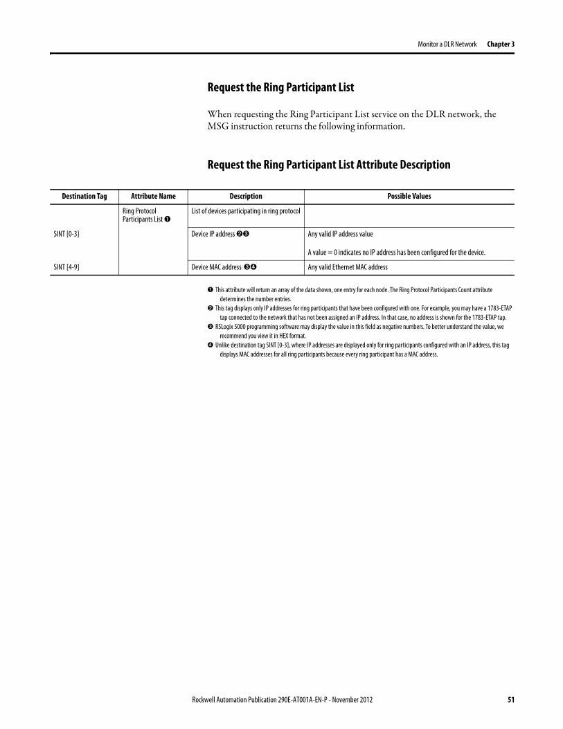

Chapter 4 Troubleshoot a DLR Network
Duplicate IP Address Detection
Some EtherNetIP communication modules support duplicate IP address detection The module verifies that its IP address does not match any other network devicersquos IP address when performing either of these tasks
bull Connect the module to an EtherNetIP network
bull Change the modulersquos IP address
If the modulersquos IP address matches that of another device on the network the modulersquos EtherNetIP port transitions to Conflict mode In Conflict mode these conditions exist
bull OK status indicator is blinking red
bull Network (NET) status indicator is solid red
bull On some EtherNetIP communication modules the module status display indicates the conflict
The display scrollsOK ltIP_address_of_this_modulegt Duplicate IP
ltMac_address_of_duplicate_node_detectedgt
For example OK 108860196 Duplicate IP - 0000BC0234B4
bull On some EtherNetIP communication modules the modulersquos diagnostic webpage displays information about duplicate IP address detection
For more information on which EtherNetIP communication modules support displaying duplicate IP address on their diagnostic webpage see the Technical Note titled Logix modules Duplicate IP address detection enhancement 118216 in the Technical Support Knowledgebase available at httpwwwrockwellautomationcomknowledgebase
54 Rockwell Automation Publication 290E-AT001A-EN-P - November 2012
Troubleshoot a DLR Network Chapter 4
Specific Issues on the DLR Network
Use the following table to troubleshoot possible specific issues on the DLR or linear network that are not solved by the actions described on the previous page
Issue Description Solution
Supervisor Reports a Ring Fault A link on the DLR network may be brokenbull intentionally for example because of adding or deleting nodes but not making all
physical connections to restore the setup of the network withwithout the nodebull unintentionally for example because a cable is broken or a device malfunctionsWhen this fault occurs the adjacent nodes to the faulted part of the network are displayed in the Ring Fault group and the Network Status field = Ring FaultThe screen shot below shows the Ring Fault section with IP addresses appearing for the last active nodes The faulted node is between nodes 108880115 and 108880208 If the IP address of either node is not available the software will display the nodersquos MAC ID
Once the fault is corrected the ring is automatically restored and the Network Status field returns to Normal
Determine where the fault condition exists and correct itClick the Refresh Communication link as needed to update the Ring Fault information to determine where the fault condition existsFinally DevicePort Debugging Mode functionality on the 1783-ETAP tap may be used to analyze a suspicious nodeFor more information refer to Device Port Debugging Mode on page 59
Rockwell Automation Publication 290E-AT001A-EN-P - November 2012 55
Chapter 4 Troubleshoot a DLR Network
Issue Description Solution
Rapid Ring Fault When a Rapid Ring Fault occurs the following events occurbull The active supervisor will block traffic on port 2 resulting in possible network
segmentation that is some nodes may become unreachablebull The Link 2 status indicator on the active supervisor is offbull As soon as the fault occurs for both RSLogix 5000 programming software and
RSLinx communication software the Status field = Rapid FaultRestore Cycles
Any of the following may cause a Rapid Ring Faultbull 5 intentional disconnectionsreconnections of a node from the network within 30
secondsbull A duplex mismatch between two connected devicesbull Electromagnetic noise on the networkbull Unstable physical connections such as intermittent connectorsGiven the nature of a Rapid Ring Fault the Last Active Node information may not be accurate when a Rapid Ring Fault condition is present
Multiple possible solutions existbull For the disconnections and reconnections issue no
solution is requiredClear the fault after reconnecting the device to the network permanentlybull For the duplex mismatch issue reconfigure the duplex
parameters to make sure they match between the devices
bull For the electromagnetic noise issue determine where the noise exists and eliminate it or use a protective shield in that location
bull For the unstable connections issue determine where they exist on the network and correct them
bull Check the media counters for all devices on the network The device with the highest media counter count is most likely causing the Rapid Ring Fault
bull Remove devices from the network one by one If the Rapid Ring Fault disappears after a device is removed that device is causing the fault
bull DevicePort Debugging Mode functionality on the 1783-ETAP tap may be used to analyze a suspicious node
For more information refer to Device Port Debugging Mode on page 59bull Finally the Beacon Interval or Timeout configuration
may not be appropriate for the networkHowever if these values need to be changed we recommend that you contact Rockwell Automation technical supportOnce the fault is fixed click Clear Fault
56 Rockwell Automation Publication 290E-AT001A-EN-P - November 2012
Troubleshoot a DLR Network Chapter 4
Issue Description Solution
Partial Fault Condition A partial network fault occurs when traffic is lost in only one direction on the network because a ring member is not forwarding beacons in both directions for example a component failureThe active ring supervisor detects a partial fault by monitoring the loss of Beacon frames on one port and the fault location appears in the Ring Fault section of the Network tab When a partial fault is detected the active ring supervisor blocks traffic on one port At this point the ring is segmented due to the partial fault condition The nodes adjacent to the faulted part of the network are displayed in the Ring Fault group with either IP addresses or MAC IDs for each node displayedWhen this fault occurs the Network Status field = Partial Fault ConditionOnce the fault is corrected it automatically clears and the Network Status field returns to Normal
Determine where the fault condition exists and correct itAdditionally the DevicePort Debugging Mode functionality also known as Port Mirroring on a 1783-ETAP 1783-ETAP1F or 1783-ETAP2F tap may be used to analyze a suspicious nodeFor more information refer to Device Port Debugging Mode on page 59
Media Counter Errors or Collisions
The media counters screen displays the number of physical layer errors or collisions The screen below indicates where to check for errors encountered Error levels are displayed depending on what caused the error For example an Alignment Error is displayed in the Alignment Error field
On a DLR network it is not uncommon to see low levels of media counter errors For example if the network breaks a low level of media counter errors appears With a low level of media counter errors the value typically does not continuously increase and often clearsA high level of media counter errors typically continues to increase and does not clear For example there is a mismatch of speed between two linked nodes a high level of media counter errors appears steadily increasing and not clearingTo access the RSLinx screen above browse the network right-click on the device select Module Properties and click the Port Diagnostics tab
Some example solutions includebull Check for a mismatch of speed andor duplex between
two linked nodesbull Verify that all cables on the network are securely
connected to each devicebull Check for electromagnetic noise on the network If you
find it eliminate it or use a protective shield in that location
Rockwell Automation Publication 290E-AT001A-EN-P - November 2012 57
Chapter 4 Troubleshoot a DLR Network
Network Recovery Performance
When measuring the networkrsquos performance with regard to dealing with fault conditions consider the network recovery time Network recovery is the time for all of the following to take place
1 The supervisor node recognizes that a fault exists on the network
2 The supervisor node reconfigures the network because of the fault
3 The supervisor node communicates to the network nodes that a fault condition exists
4 The network nodes reconfigure themselves because of the fault
With the default beacon interval value of 400 mS and beacon timeout value of 1960 mS the worst-case time for network recovery times are
bull 2890 mS for a copper DLR network This recovery time is based on 100 m copper segments between nodes on the network
bull 3140 mS for a fiber-optic DLR network This recovery time is based on 2 kM fiber-optic cable segments between nodes on the network
When considering the values listed above keep in mind
bull Recovery time may actually occur faster than the times listed
bull The recovery times listed above assume that your networkrsquos nodes are operating at 100 Mbps speed and full-duplex mode We recommend that your nodes generally operate in this mode for DLR networks
bull If other node conditions exist such as a node operating at 10 Mbps full-duplex or 10100 Mbps half-duplex the recovery times will vary from the times listed above
If this is the case for your application the beacon interval and beacon timeout will need to be changed We recommend that you first contact Rockwell Automation technical support if these parameters need to be changed
bull The value assumes that the majority of the traffic on your network is EtherNetIP traffic
58 Rockwell Automation Publication 290E-AT001A-EN-P - November 2012
Troubleshoot a DLR Network Chapter 4
Device Port Debugging Mode
This functionality is disabled by default Device Port Debugging mode which is similar to port mirroring can be used to monitor data received on the 1783-ETAP 1783-ETAP1F or 1783-ETAP2F taprsquos two network ports Monitor the data over the device port to a device such as a personal computer running a protocol analyzer application for advanced network debugging or analysis
When device port debugging is used on a 1783-ETAP the device connected to the 1783-ETAP taprsquos front port receives all of the data traversing the ring (both directions)
Device Port Debugging Example Network
When using the Device Port Debugging mode functionality insert the 1783-ETAP with the network analyzer connected to the device port It is inserted at the spot on the ring network where the node in question is located The graphic below shows a 1783-ETAP tap inserted in the network
IMPORTANT This functionality should be used only when troubleshooting the network and not in normal network operation
Rockwell Automation Publication 290E-AT001A-EN-P - November 2012 59
Chapter 4 Troubleshoot a DLR Network
Combined total network bandwidth of the traffic received on the two 1783-ETAP 1783-ETAP1F or 1783-ETAP2F taprsquos ports connected to the network should not exceed the taprsquos device port capacity The speed setting determines the device portrsquos capacity
Configure the device port on a 1783-ETAP 1783-ETAP1F or 1783-ETAP2F tap to either of two speed settings
bull 100 Mbps - default settingbull 10 Mbps
If the bandwidth exceeds the capacity of the taprsquos device port some frames from the ring will be dropped before reaching the device port These dropped frames do not impact the traffic on the rest of the DLR network
The device port setting determines how much network traffic the 1783-ETAP 1783-ETAP1F or 1783-ETAP2F tap can handle before dropping frames The circled section in the graphic below shows the Port Buffer Utilization of the Device Port In this example the value is zero because a ring fault exists on the network
60 Rockwell Automation Publication 290E-AT001A-EN-P - November 2012
Appendix A
Network Usage Guidelines and Recommendations
Consider the following guidelines and recommendations when using a DLR or linear network
GuidelineRecommendation Explanation
Use fewer than 50 nodes on a single DLR networkIf your application requires more than 50 nodes we recommend that the nodes are broken into separate but linked DLR networks
If you use more than 50 nodes on a single DLR networkbull Your network has a greater chance of multiple faults
occurring on the networkbull Network recovery times from faulted DLR network
are higher
Do not configure a supervisor on a linear network If your linear network includes non-DLR nodes and has a supervisor-enabled node on the network it may impact communication to non-DLR devices connected to the linear network
If you must connect a device that is running at 10 Mbps to a DLR or linear network do so through a 1783-ETAP 1783-ETAP1F or 1783-ETAP2F tap device port
The 1783-ETAP 1783-ETAP1F and 1783-ETAP2F taps can operate at 100 Mbps on the DLR network this is the optimal speed for a network If you connect a 10 Mbps device directly to the network instead of through a tap the linear or DLR network traffic slows to 10 MbpsAdditionally if the 10 Mbps device is connected to the network without a 1783-ETAP tap network recovery times are significantly impacted
Configure multiple supervisor nodes per ring If your DLR network only has one supervisor and the supervisor experiences a fault none of the other nodes become the active supervisor In this case the network becomes a linear network until the fault is corrected and the DLR network restoredAnother reason to configure multiple supervisor nodes is for replacing an active supervisor node with an out-of-box replacement the new device will not be enabled as a supervisor (by default) and there would still be no supervisor on the network
Rockwell Automation Publication 290E-AT001A-EN-P - November 2012 61
Appendix A Network Usage Guidelines and Recommendations
GuidelineRecommendation Explanation
Connect switches to a DLR network via 1783-ETAP 1783-ETAP1F or 1783-ETAP2F taps
If switches are connected to the DLR network without the use of a 1783-ETAP 1783-ETAP1F or 1783-ETAP2F tap the network may experience unpredictable behavior and network performance is unknown
Run all nodes on the DLR network at 100 Mbps and in Full-Duplex mode
These configuration values provide the best performance for your networkAdditionally we recommend that youbull Use auto-negotiate for all nodes on the DLR networkbull Do not use auto-negotiate on one node and then force
speed on the next node linked to it
In a linear network the number of nodes to use is application specific based on the considerations described in the next box
When determining the number of nodes to use on a linear network consider the followingbull There is a delay per node as information is transmitted
to each successive node used on the networkndash The typical delay on a linear network with 100 m
copper segments between nodes is 30 mSndash The typical delay on a linear network with 2 kM
fiber-optic segments between nodes is 40 mS
The greater the number of nodes on the network the longer the total time for information to be transmitted across the entire networkbull The single point of failure possibility is greater with
each additional connectionbull Troubleshooting the network may be more difficult
with a higher number of nodes
The total time for information to be transmitted across the entire network and its effect on how many nodes to use on a linear network is related to the Requested Packet Interval (RPI)Verify that the total time to transmit information from the first node to the last node on the network is less than the RPI Make sure the network is not loaded beyond 90 of capacity
62 Rockwell Automation Publication 290E-AT001A-EN-P - November 2012
Network Usage Guidelines and Recommendations Appendix A
GuidelineRecommendation Explanation
Do not physically close a DLR network without a supervisor configured on the network
A DLR network without a supervisor node results in a network stormIf you do close the DLR network without a supervisor configured break the ring and configure at least one supervisor before physically reconnecting the network
Use the default values for the followingbull Beacon Intervalbull Beacon Timeoutbull Ring Protocol VLAN ID
Changing the default values for the parameters Beacon Interval Beacon Timeout and Ring Protocol VLAN ID can result in unpredictable network behavior and negatively impacted network performanceThe default values are optimized for a network withbull 50 or fewer nodes are on the networkbull All nodes are operating at 100 Mbps and full-duplex
modebull At least 50 of the network traffic bandwidth being
EtherNetIP trafficIf you think the values of the Beacon Interval Beacon Timeout or Ring Protocol VLAN ID need to be changed for example if any node on ring is not operating at 100 Mbps and full-duplex mode we recommend that you first contact Rockwell Automation technical support
If DHCP for the ArmorStarts is still required you will need to disable Internet Group Management Protocol (IGMP) snooping on the E-tap via the AOP
IGMP Snooping is enabled by default in the 1783-ETAP 1783-ETAP1F and 1783-ETAP2F taps and is commonly used to manage multicast traffic on the network When in use this functionality allows the tap to multicast data to only those devices that need the data rather than to all devices connected to the networkOnce DHCP is enabled the switch could change the IP addresses on the ArmorStarts depending on network demand which could cause RSlogix5000 to loose communication with the device as connectivity is established via the AOP in the initial configuration
The IGMP Querier functionality should be enabled for at least one node on the network
This functionality is disabled by default The IGMP Querier functionality enables a 1783-ETAP 1783-ETAP1F or 1783-ETAP2F tap or switch such as a Stratix managed switch to send out a query to all devices on the network to determine what multicast addresses are of interest to a specific node or a group of nodesIf the IGMP Querier functionality is not enabled for at least one node on the network multicast traffic on the network may eventually create network performance issuesThe 1783-ETAP 1783-ETAP1F or 1783-ETAP2F taps managed switches and routers are examples of devices that support IGMP Querier functionality
Rockwell Automation Publication 290E-AT001A-EN-P - November 2012 63
Appendix A Network Usage Guidelines and Recommendations
Notes
64 Rockwell Automation Publication 290E-AT001A-EN-P - November 2012
Appendix B
Required Firmware Revisions
Required Firmware Revision for an Add-On Profile
➊ The ControlFLASH Firmware Upgrade software tcan be used o upgrade a 1756-EN2TR module from firmware revision 21 to 3x or later1x or later3x or later2x or later
➋ The ControlFLASH Firmware Upgrade software can be used to upgrade a 1783-ETAP tap from firmware revision 11 to 2x or later
To download new firmware go to httpwwwrockwellautomationcomsupportamericasindex_enhtml
If the firmware revision is upgraded on the module or tap the required AOP revision listed above must be used for that revision For example if the 1756-EN2TR module is upgraded to firmware revision 3x or later AOP revision 2x or later must be used in the RSLogix 5000 programming software
Additionally if the firmware revision is upgraded on the module or tap the required RSLinx communication software must also be used for that firmware revision For more information on which RSLinx software version is required for each firmware revision see page 66
For both the 1756-EN2TR module and 1783-ETAP tap make sure that the Major Revision configured on the General tab of the devicersquos RSLogix 5000 programming software configuration matches the major revision of the physical module
IMPORTANT To download an AOP go to httpsupportrockwellautomationcomcontrolflashLogixProfileraspDepending on the firmware revision of your product a specific AOP version must be used
Firmware Revision Add-On Profile Revision Cat No
21 ➊ 1x or later 1756-EN2TR
3x or later 2x or later
11 ➋ 1x or later 1783-ETAP
2x or later 2x or later
2x or later 2x or later 1783-ETAP1F
1783-ETAP2F
Rockwell Automation Publication 290E-AT001A-EN-P - November 2012 65
Appendix B Required Firmware Revisions
If the device configuration on the General tab does not match the physical module the programming software alerts you to this mismatch when attempting to configure the Internet Protocol Port Configuration and Network tabs for that device
Required Firmware Revision for RSLinx Communication Software
➊ The ControlFLASH Firmware Upgrade software can be used to upgrade a 1756-EN2TR module from firmware revision 21 to 3x or later1x or later3x or later255 or later3x or later256 or later
➋ The ControlFLASH Firmware Upgrade software can be used to upgrade a 1783-ETAP tap from firmware revision 11 to 2x or later
To download new firmware go to httpwwwrockwellautomationcomsupportamericasindex_enhtml
If the firmware revision is upgraded on the module or tap the required RSLinx communication software listed above must be used for that revision For example if the 1756-EN2TR module is upgraded to firmware revision 3x or later AOP revision 2x or later must be used in your RSLogix 5000 programming software
Additionally if the firmware revision is upgraded on the module or tap the required AOP revision must also be used for that firmware revision For more information on which AOP revision is required for each firmware revision see page 65
IMPORTANT Depending on the firmware revision of your product specific versions of RSLinx communication software must be used
Firmware Revision Required RSLinx Communication Software Version
Cat No
21 ➊ 255 or later 1756-EN2TR
3x or later 256 or later
11 ➋ 255 or later 1783-ETAP
2x or later 256 or later
2x or later 256 or later 1783-ETAP1F
1783-ETAP2F
66 Rockwell Automation Publication 290E-AT001A-EN-P - November 2012
Rockwell Otomasyon Ticaret AŞ Kar Plaza İş Merkezi E Blok Kat6 34752 İccedilerenkoumly İstanbul Tel +90 (216) 5698400
Rockwell Automation Publication 290E-AT001A-EN-P ndash November 2012 68 Copyright copy 2012 Rockwell Automation Inc All rights reserved Printed in the USA
Rockwell Automation Support
Rockwell Automation provides technical information on the Web to assist you in using its products At httpwwwrockwellautomationcomsupport you can find technical manuals a knowledge base of FAQs technical and application notes sample code and links to software service packs and a MySupport feature that you can customize to make thebest use of these tools
For an additional level of technical phone support for installation configuration and troubleshooting we offer TechConnectSM support programs For more information contact your local distributor or Rockwell Automation representative or visit httpwwwrockwellautomationcomsupport
Installation Assistance
If you experience a problem within the first 24 hours of installation review the information that is contained in this manualYou can contact Customer Support for initial help in getting your product up and running
New Product Satisfaction Return
Rockwell Automation tests all of its products to ensure that they are fully operational when shipped from the manufacturing facility However if your product is not functioning and needs to be returned follow these procedures
Documentation Feedback
Your comments will help us serve your documentation needs better If you have any suggestions on how to improve this document complete this form publication RA-DU002 available at httpwwwrockwellautomationcomliterature
United States or Canada 14406463434
Outside United States or Canada Use the Worldwide Locator at httpwwwrockwellautomationcomsupportamericasphone_enhtml or contact your local Rockwell Automation representative
United States Contact your distributor You must provide a Customer Support case number (call the phone number above to obtain one) to your distributor to complete the return process
Outside United States Please contact your local Rockwell Automation representative for the return procedure
- Important User Information
- General Precautions
- Software Requirements
- Additional Resources
- Rockwell Automation Support
- Installation Assistance
- New Product Satisfaction Return
- Table of Contents
- Chapter 1
-
- Device-Level Ring (DLR) Basics
-
- Introduction
- ArmorStart with EtherNetIP Overview
- What is a Device-level Ring (DLR) Network
- DLR Network Elements
-
- Supervisor Node
- Ring Node
-
- DLR Network Operation
- Number of Nodes on a DLR Network
- DLR Network Fault Management
-
- Network Reconfiguration after a Fault
-
- Chapter 2
-
- Construct and Configure a Device-level Ring Network with ArmorStarts
-
- Introduction
- Ethernet Capacity Tool
- Install Devices on a DLR Network
- ArmorStart Addressing Configuration
-
- Using the BootPDHCP Server
- Using the Rotary Network Address Switches
- Using the ArmorStart Internal Web Server
-
- Configure Supervisor Nodes on a DLR Network
-
- Configure a Ring Supervisor in RSLogix 5000 Programming Software
- Adding an Armorstart to RSLogix 5000
- Enable Ring Supervisor in RSLogix 5000 Programming Software
- Configure and Enable a Ring Supervisor in RSLinx Classic Communication Software
-
- Complete the Physical Connections of the Network
- Verify Supervisor Configuration
- IGMP Snooping
- IGMP Querier
-
- Chapter 3
-
- Monitor a DLR Network
-
- Introduction
- Methods to Monitor a DLR Network
-
- RSLogix 5000 Programming Software Status Pages
- RSLinx Communication Software Status Pages
- ArmorStart Internal Web Server
- EtherNetIP Device Level Ring (DLR) Network Diagnostics Faceplate
- Programmatically Through the Use of a MSG Instruction
-
- Monitor Status Pages
-
- RSLogix 5000 Programming Software Status Pages
- RSLinx Communication Software
-
- How to Access the ArmorStart EtherNetIP Internal Web Server
-
- EtherNetIP Device Level Ring (DLR) Network Diagnostics Faceplate Overview
-
- Monitor Diagnostics via MSG Instructions
-
- Use Specific Values on the Configuration Tab
- Retrieve All Ring Diagnostic Information
- Retrieve All Diagnostic Information Attribute Description
- Request the Ring Participant List
- Request the Ring Participant List Attribute Description
-
- Enable and Configure a Ring Supervisor
-
- Enable and Configure a Ring Supervisor Attribute Description
-
- Chapter 4
-
- Troubleshoot a DLR Network
-
- Introduction
- General Solutions for Linear or DLR Networks
- Duplicate IP Address Detection
- Specific Issues on the DLR Network
- Network Recovery Performance
- Device Port Debugging Mode
-
- Device Port Debugging Example Network
-
- Appendix A
-
- Network Usage Guidelines and Recommendations
-
- Notes
-
- Appendix B
-
- Required Firmware Revisions
-
- Required Firmware Revision for an Add-On Profile
- Required Firmware Revision for RSLinx Communication Software
-

Troubleshoot a DLR Network Chapter 4
Specific Issues on the DLR Network
Use the following table to troubleshoot possible specific issues on the DLR or linear network that are not solved by the actions described on the previous page
Issue Description Solution
Supervisor Reports a Ring Fault A link on the DLR network may be brokenbull intentionally for example because of adding or deleting nodes but not making all
physical connections to restore the setup of the network withwithout the nodebull unintentionally for example because a cable is broken or a device malfunctionsWhen this fault occurs the adjacent nodes to the faulted part of the network are displayed in the Ring Fault group and the Network Status field = Ring FaultThe screen shot below shows the Ring Fault section with IP addresses appearing for the last active nodes The faulted node is between nodes 108880115 and 108880208 If the IP address of either node is not available the software will display the nodersquos MAC ID
Once the fault is corrected the ring is automatically restored and the Network Status field returns to Normal
Determine where the fault condition exists and correct itClick the Refresh Communication link as needed to update the Ring Fault information to determine where the fault condition existsFinally DevicePort Debugging Mode functionality on the 1783-ETAP tap may be used to analyze a suspicious nodeFor more information refer to Device Port Debugging Mode on page 59
Rockwell Automation Publication 290E-AT001A-EN-P - November 2012 55
Chapter 4 Troubleshoot a DLR Network
Issue Description Solution
Rapid Ring Fault When a Rapid Ring Fault occurs the following events occurbull The active supervisor will block traffic on port 2 resulting in possible network
segmentation that is some nodes may become unreachablebull The Link 2 status indicator on the active supervisor is offbull As soon as the fault occurs for both RSLogix 5000 programming software and
RSLinx communication software the Status field = Rapid FaultRestore Cycles
Any of the following may cause a Rapid Ring Faultbull 5 intentional disconnectionsreconnections of a node from the network within 30
secondsbull A duplex mismatch between two connected devicesbull Electromagnetic noise on the networkbull Unstable physical connections such as intermittent connectorsGiven the nature of a Rapid Ring Fault the Last Active Node information may not be accurate when a Rapid Ring Fault condition is present
Multiple possible solutions existbull For the disconnections and reconnections issue no
solution is requiredClear the fault after reconnecting the device to the network permanentlybull For the duplex mismatch issue reconfigure the duplex
parameters to make sure they match between the devices
bull For the electromagnetic noise issue determine where the noise exists and eliminate it or use a protective shield in that location
bull For the unstable connections issue determine where they exist on the network and correct them
bull Check the media counters for all devices on the network The device with the highest media counter count is most likely causing the Rapid Ring Fault
bull Remove devices from the network one by one If the Rapid Ring Fault disappears after a device is removed that device is causing the fault
bull DevicePort Debugging Mode functionality on the 1783-ETAP tap may be used to analyze a suspicious node
For more information refer to Device Port Debugging Mode on page 59bull Finally the Beacon Interval or Timeout configuration
may not be appropriate for the networkHowever if these values need to be changed we recommend that you contact Rockwell Automation technical supportOnce the fault is fixed click Clear Fault
56 Rockwell Automation Publication 290E-AT001A-EN-P - November 2012
Troubleshoot a DLR Network Chapter 4
Issue Description Solution
Partial Fault Condition A partial network fault occurs when traffic is lost in only one direction on the network because a ring member is not forwarding beacons in both directions for example a component failureThe active ring supervisor detects a partial fault by monitoring the loss of Beacon frames on one port and the fault location appears in the Ring Fault section of the Network tab When a partial fault is detected the active ring supervisor blocks traffic on one port At this point the ring is segmented due to the partial fault condition The nodes adjacent to the faulted part of the network are displayed in the Ring Fault group with either IP addresses or MAC IDs for each node displayedWhen this fault occurs the Network Status field = Partial Fault ConditionOnce the fault is corrected it automatically clears and the Network Status field returns to Normal
Determine where the fault condition exists and correct itAdditionally the DevicePort Debugging Mode functionality also known as Port Mirroring on a 1783-ETAP 1783-ETAP1F or 1783-ETAP2F tap may be used to analyze a suspicious nodeFor more information refer to Device Port Debugging Mode on page 59
Media Counter Errors or Collisions
The media counters screen displays the number of physical layer errors or collisions The screen below indicates where to check for errors encountered Error levels are displayed depending on what caused the error For example an Alignment Error is displayed in the Alignment Error field
On a DLR network it is not uncommon to see low levels of media counter errors For example if the network breaks a low level of media counter errors appears With a low level of media counter errors the value typically does not continuously increase and often clearsA high level of media counter errors typically continues to increase and does not clear For example there is a mismatch of speed between two linked nodes a high level of media counter errors appears steadily increasing and not clearingTo access the RSLinx screen above browse the network right-click on the device select Module Properties and click the Port Diagnostics tab
Some example solutions includebull Check for a mismatch of speed andor duplex between
two linked nodesbull Verify that all cables on the network are securely
connected to each devicebull Check for electromagnetic noise on the network If you
find it eliminate it or use a protective shield in that location
Rockwell Automation Publication 290E-AT001A-EN-P - November 2012 57
Chapter 4 Troubleshoot a DLR Network
Network Recovery Performance
When measuring the networkrsquos performance with regard to dealing with fault conditions consider the network recovery time Network recovery is the time for all of the following to take place
1 The supervisor node recognizes that a fault exists on the network
2 The supervisor node reconfigures the network because of the fault
3 The supervisor node communicates to the network nodes that a fault condition exists
4 The network nodes reconfigure themselves because of the fault
With the default beacon interval value of 400 mS and beacon timeout value of 1960 mS the worst-case time for network recovery times are
bull 2890 mS for a copper DLR network This recovery time is based on 100 m copper segments between nodes on the network
bull 3140 mS for a fiber-optic DLR network This recovery time is based on 2 kM fiber-optic cable segments between nodes on the network
When considering the values listed above keep in mind
bull Recovery time may actually occur faster than the times listed
bull The recovery times listed above assume that your networkrsquos nodes are operating at 100 Mbps speed and full-duplex mode We recommend that your nodes generally operate in this mode for DLR networks
bull If other node conditions exist such as a node operating at 10 Mbps full-duplex or 10100 Mbps half-duplex the recovery times will vary from the times listed above
If this is the case for your application the beacon interval and beacon timeout will need to be changed We recommend that you first contact Rockwell Automation technical support if these parameters need to be changed
bull The value assumes that the majority of the traffic on your network is EtherNetIP traffic
58 Rockwell Automation Publication 290E-AT001A-EN-P - November 2012
Troubleshoot a DLR Network Chapter 4
Device Port Debugging Mode
This functionality is disabled by default Device Port Debugging mode which is similar to port mirroring can be used to monitor data received on the 1783-ETAP 1783-ETAP1F or 1783-ETAP2F taprsquos two network ports Monitor the data over the device port to a device such as a personal computer running a protocol analyzer application for advanced network debugging or analysis
When device port debugging is used on a 1783-ETAP the device connected to the 1783-ETAP taprsquos front port receives all of the data traversing the ring (both directions)
Device Port Debugging Example Network
When using the Device Port Debugging mode functionality insert the 1783-ETAP with the network analyzer connected to the device port It is inserted at the spot on the ring network where the node in question is located The graphic below shows a 1783-ETAP tap inserted in the network
IMPORTANT This functionality should be used only when troubleshooting the network and not in normal network operation
Rockwell Automation Publication 290E-AT001A-EN-P - November 2012 59
Chapter 4 Troubleshoot a DLR Network
Combined total network bandwidth of the traffic received on the two 1783-ETAP 1783-ETAP1F or 1783-ETAP2F taprsquos ports connected to the network should not exceed the taprsquos device port capacity The speed setting determines the device portrsquos capacity
Configure the device port on a 1783-ETAP 1783-ETAP1F or 1783-ETAP2F tap to either of two speed settings
bull 100 Mbps - default settingbull 10 Mbps
If the bandwidth exceeds the capacity of the taprsquos device port some frames from the ring will be dropped before reaching the device port These dropped frames do not impact the traffic on the rest of the DLR network
The device port setting determines how much network traffic the 1783-ETAP 1783-ETAP1F or 1783-ETAP2F tap can handle before dropping frames The circled section in the graphic below shows the Port Buffer Utilization of the Device Port In this example the value is zero because a ring fault exists on the network
60 Rockwell Automation Publication 290E-AT001A-EN-P - November 2012
Appendix A
Network Usage Guidelines and Recommendations
Consider the following guidelines and recommendations when using a DLR or linear network
GuidelineRecommendation Explanation
Use fewer than 50 nodes on a single DLR networkIf your application requires more than 50 nodes we recommend that the nodes are broken into separate but linked DLR networks
If you use more than 50 nodes on a single DLR networkbull Your network has a greater chance of multiple faults
occurring on the networkbull Network recovery times from faulted DLR network
are higher
Do not configure a supervisor on a linear network If your linear network includes non-DLR nodes and has a supervisor-enabled node on the network it may impact communication to non-DLR devices connected to the linear network
If you must connect a device that is running at 10 Mbps to a DLR or linear network do so through a 1783-ETAP 1783-ETAP1F or 1783-ETAP2F tap device port
The 1783-ETAP 1783-ETAP1F and 1783-ETAP2F taps can operate at 100 Mbps on the DLR network this is the optimal speed for a network If you connect a 10 Mbps device directly to the network instead of through a tap the linear or DLR network traffic slows to 10 MbpsAdditionally if the 10 Mbps device is connected to the network without a 1783-ETAP tap network recovery times are significantly impacted
Configure multiple supervisor nodes per ring If your DLR network only has one supervisor and the supervisor experiences a fault none of the other nodes become the active supervisor In this case the network becomes a linear network until the fault is corrected and the DLR network restoredAnother reason to configure multiple supervisor nodes is for replacing an active supervisor node with an out-of-box replacement the new device will not be enabled as a supervisor (by default) and there would still be no supervisor on the network
Rockwell Automation Publication 290E-AT001A-EN-P - November 2012 61
Appendix A Network Usage Guidelines and Recommendations
GuidelineRecommendation Explanation
Connect switches to a DLR network via 1783-ETAP 1783-ETAP1F or 1783-ETAP2F taps
If switches are connected to the DLR network without the use of a 1783-ETAP 1783-ETAP1F or 1783-ETAP2F tap the network may experience unpredictable behavior and network performance is unknown
Run all nodes on the DLR network at 100 Mbps and in Full-Duplex mode
These configuration values provide the best performance for your networkAdditionally we recommend that youbull Use auto-negotiate for all nodes on the DLR networkbull Do not use auto-negotiate on one node and then force
speed on the next node linked to it
In a linear network the number of nodes to use is application specific based on the considerations described in the next box
When determining the number of nodes to use on a linear network consider the followingbull There is a delay per node as information is transmitted
to each successive node used on the networkndash The typical delay on a linear network with 100 m
copper segments between nodes is 30 mSndash The typical delay on a linear network with 2 kM
fiber-optic segments between nodes is 40 mS
The greater the number of nodes on the network the longer the total time for information to be transmitted across the entire networkbull The single point of failure possibility is greater with
each additional connectionbull Troubleshooting the network may be more difficult
with a higher number of nodes
The total time for information to be transmitted across the entire network and its effect on how many nodes to use on a linear network is related to the Requested Packet Interval (RPI)Verify that the total time to transmit information from the first node to the last node on the network is less than the RPI Make sure the network is not loaded beyond 90 of capacity
62 Rockwell Automation Publication 290E-AT001A-EN-P - November 2012
Network Usage Guidelines and Recommendations Appendix A
GuidelineRecommendation Explanation
Do not physically close a DLR network without a supervisor configured on the network
A DLR network without a supervisor node results in a network stormIf you do close the DLR network without a supervisor configured break the ring and configure at least one supervisor before physically reconnecting the network
Use the default values for the followingbull Beacon Intervalbull Beacon Timeoutbull Ring Protocol VLAN ID
Changing the default values for the parameters Beacon Interval Beacon Timeout and Ring Protocol VLAN ID can result in unpredictable network behavior and negatively impacted network performanceThe default values are optimized for a network withbull 50 or fewer nodes are on the networkbull All nodes are operating at 100 Mbps and full-duplex
modebull At least 50 of the network traffic bandwidth being
EtherNetIP trafficIf you think the values of the Beacon Interval Beacon Timeout or Ring Protocol VLAN ID need to be changed for example if any node on ring is not operating at 100 Mbps and full-duplex mode we recommend that you first contact Rockwell Automation technical support
If DHCP for the ArmorStarts is still required you will need to disable Internet Group Management Protocol (IGMP) snooping on the E-tap via the AOP
IGMP Snooping is enabled by default in the 1783-ETAP 1783-ETAP1F and 1783-ETAP2F taps and is commonly used to manage multicast traffic on the network When in use this functionality allows the tap to multicast data to only those devices that need the data rather than to all devices connected to the networkOnce DHCP is enabled the switch could change the IP addresses on the ArmorStarts depending on network demand which could cause RSlogix5000 to loose communication with the device as connectivity is established via the AOP in the initial configuration
The IGMP Querier functionality should be enabled for at least one node on the network
This functionality is disabled by default The IGMP Querier functionality enables a 1783-ETAP 1783-ETAP1F or 1783-ETAP2F tap or switch such as a Stratix managed switch to send out a query to all devices on the network to determine what multicast addresses are of interest to a specific node or a group of nodesIf the IGMP Querier functionality is not enabled for at least one node on the network multicast traffic on the network may eventually create network performance issuesThe 1783-ETAP 1783-ETAP1F or 1783-ETAP2F taps managed switches and routers are examples of devices that support IGMP Querier functionality
Rockwell Automation Publication 290E-AT001A-EN-P - November 2012 63
Appendix A Network Usage Guidelines and Recommendations
Notes
64 Rockwell Automation Publication 290E-AT001A-EN-P - November 2012
Appendix B
Required Firmware Revisions
Required Firmware Revision for an Add-On Profile
➊ The ControlFLASH Firmware Upgrade software tcan be used o upgrade a 1756-EN2TR module from firmware revision 21 to 3x or later1x or later3x or later2x or later
➋ The ControlFLASH Firmware Upgrade software can be used to upgrade a 1783-ETAP tap from firmware revision 11 to 2x or later
To download new firmware go to httpwwwrockwellautomationcomsupportamericasindex_enhtml
If the firmware revision is upgraded on the module or tap the required AOP revision listed above must be used for that revision For example if the 1756-EN2TR module is upgraded to firmware revision 3x or later AOP revision 2x or later must be used in the RSLogix 5000 programming software
Additionally if the firmware revision is upgraded on the module or tap the required RSLinx communication software must also be used for that firmware revision For more information on which RSLinx software version is required for each firmware revision see page 66
For both the 1756-EN2TR module and 1783-ETAP tap make sure that the Major Revision configured on the General tab of the devicersquos RSLogix 5000 programming software configuration matches the major revision of the physical module
IMPORTANT To download an AOP go to httpsupportrockwellautomationcomcontrolflashLogixProfileraspDepending on the firmware revision of your product a specific AOP version must be used
Firmware Revision Add-On Profile Revision Cat No
21 ➊ 1x or later 1756-EN2TR
3x or later 2x or later
11 ➋ 1x or later 1783-ETAP
2x or later 2x or later
2x or later 2x or later 1783-ETAP1F
1783-ETAP2F
Rockwell Automation Publication 290E-AT001A-EN-P - November 2012 65
Appendix B Required Firmware Revisions
If the device configuration on the General tab does not match the physical module the programming software alerts you to this mismatch when attempting to configure the Internet Protocol Port Configuration and Network tabs for that device
Required Firmware Revision for RSLinx Communication Software
➊ The ControlFLASH Firmware Upgrade software can be used to upgrade a 1756-EN2TR module from firmware revision 21 to 3x or later1x or later3x or later255 or later3x or later256 or later
➋ The ControlFLASH Firmware Upgrade software can be used to upgrade a 1783-ETAP tap from firmware revision 11 to 2x or later
To download new firmware go to httpwwwrockwellautomationcomsupportamericasindex_enhtml
If the firmware revision is upgraded on the module or tap the required RSLinx communication software listed above must be used for that revision For example if the 1756-EN2TR module is upgraded to firmware revision 3x or later AOP revision 2x or later must be used in your RSLogix 5000 programming software
Additionally if the firmware revision is upgraded on the module or tap the required AOP revision must also be used for that firmware revision For more information on which AOP revision is required for each firmware revision see page 65
IMPORTANT Depending on the firmware revision of your product specific versions of RSLinx communication software must be used
Firmware Revision Required RSLinx Communication Software Version
Cat No
21 ➊ 255 or later 1756-EN2TR
3x or later 256 or later
11 ➋ 255 or later 1783-ETAP
2x or later 256 or later
2x or later 256 or later 1783-ETAP1F
1783-ETAP2F
66 Rockwell Automation Publication 290E-AT001A-EN-P - November 2012
Rockwell Otomasyon Ticaret AŞ Kar Plaza İş Merkezi E Blok Kat6 34752 İccedilerenkoumly İstanbul Tel +90 (216) 5698400
Rockwell Automation Publication 290E-AT001A-EN-P ndash November 2012 68 Copyright copy 2012 Rockwell Automation Inc All rights reserved Printed in the USA
Rockwell Automation Support
Rockwell Automation provides technical information on the Web to assist you in using its products At httpwwwrockwellautomationcomsupport you can find technical manuals a knowledge base of FAQs technical and application notes sample code and links to software service packs and a MySupport feature that you can customize to make thebest use of these tools
For an additional level of technical phone support for installation configuration and troubleshooting we offer TechConnectSM support programs For more information contact your local distributor or Rockwell Automation representative or visit httpwwwrockwellautomationcomsupport
Installation Assistance
If you experience a problem within the first 24 hours of installation review the information that is contained in this manualYou can contact Customer Support for initial help in getting your product up and running
New Product Satisfaction Return
Rockwell Automation tests all of its products to ensure that they are fully operational when shipped from the manufacturing facility However if your product is not functioning and needs to be returned follow these procedures
Documentation Feedback
Your comments will help us serve your documentation needs better If you have any suggestions on how to improve this document complete this form publication RA-DU002 available at httpwwwrockwellautomationcomliterature
United States or Canada 14406463434
Outside United States or Canada Use the Worldwide Locator at httpwwwrockwellautomationcomsupportamericasphone_enhtml or contact your local Rockwell Automation representative
United States Contact your distributor You must provide a Customer Support case number (call the phone number above to obtain one) to your distributor to complete the return process
Outside United States Please contact your local Rockwell Automation representative for the return procedure
- Important User Information
- General Precautions
- Software Requirements
- Additional Resources
- Rockwell Automation Support
- Installation Assistance
- New Product Satisfaction Return
- Table of Contents
- Chapter 1
-
- Device-Level Ring (DLR) Basics
-
- Introduction
- ArmorStart with EtherNetIP Overview
- What is a Device-level Ring (DLR) Network
- DLR Network Elements
-
- Supervisor Node
- Ring Node
-
- DLR Network Operation
- Number of Nodes on a DLR Network
- DLR Network Fault Management
-
- Network Reconfiguration after a Fault
-
- Chapter 2
-
- Construct and Configure a Device-level Ring Network with ArmorStarts
-
- Introduction
- Ethernet Capacity Tool
- Install Devices on a DLR Network
- ArmorStart Addressing Configuration
-
- Using the BootPDHCP Server
- Using the Rotary Network Address Switches
- Using the ArmorStart Internal Web Server
-
- Configure Supervisor Nodes on a DLR Network
-
- Configure a Ring Supervisor in RSLogix 5000 Programming Software
- Adding an Armorstart to RSLogix 5000
- Enable Ring Supervisor in RSLogix 5000 Programming Software
- Configure and Enable a Ring Supervisor in RSLinx Classic Communication Software
-
- Complete the Physical Connections of the Network
- Verify Supervisor Configuration
- IGMP Snooping
- IGMP Querier
-
- Chapter 3
-
- Monitor a DLR Network
-
- Introduction
- Methods to Monitor a DLR Network
-
- RSLogix 5000 Programming Software Status Pages
- RSLinx Communication Software Status Pages
- ArmorStart Internal Web Server
- EtherNetIP Device Level Ring (DLR) Network Diagnostics Faceplate
- Programmatically Through the Use of a MSG Instruction
-
- Monitor Status Pages
-
- RSLogix 5000 Programming Software Status Pages
- RSLinx Communication Software
-
- How to Access the ArmorStart EtherNetIP Internal Web Server
-
- EtherNetIP Device Level Ring (DLR) Network Diagnostics Faceplate Overview
-
- Monitor Diagnostics via MSG Instructions
-
- Use Specific Values on the Configuration Tab
- Retrieve All Ring Diagnostic Information
- Retrieve All Diagnostic Information Attribute Description
- Request the Ring Participant List
- Request the Ring Participant List Attribute Description
-
- Enable and Configure a Ring Supervisor
-
- Enable and Configure a Ring Supervisor Attribute Description
-
- Chapter 4
-
- Troubleshoot a DLR Network
-
- Introduction
- General Solutions for Linear or DLR Networks
- Duplicate IP Address Detection
- Specific Issues on the DLR Network
- Network Recovery Performance
- Device Port Debugging Mode
-
- Device Port Debugging Example Network
-
- Appendix A
-
- Network Usage Guidelines and Recommendations
-
- Notes
-
- Appendix B
-
- Required Firmware Revisions
-
- Required Firmware Revision for an Add-On Profile
- Required Firmware Revision for RSLinx Communication Software
-

Chapter 4 Troubleshoot a DLR Network
Issue Description Solution
Rapid Ring Fault When a Rapid Ring Fault occurs the following events occurbull The active supervisor will block traffic on port 2 resulting in possible network
segmentation that is some nodes may become unreachablebull The Link 2 status indicator on the active supervisor is offbull As soon as the fault occurs for both RSLogix 5000 programming software and
RSLinx communication software the Status field = Rapid FaultRestore Cycles
Any of the following may cause a Rapid Ring Faultbull 5 intentional disconnectionsreconnections of a node from the network within 30
secondsbull A duplex mismatch between two connected devicesbull Electromagnetic noise on the networkbull Unstable physical connections such as intermittent connectorsGiven the nature of a Rapid Ring Fault the Last Active Node information may not be accurate when a Rapid Ring Fault condition is present
Multiple possible solutions existbull For the disconnections and reconnections issue no
solution is requiredClear the fault after reconnecting the device to the network permanentlybull For the duplex mismatch issue reconfigure the duplex
parameters to make sure they match between the devices
bull For the electromagnetic noise issue determine where the noise exists and eliminate it or use a protective shield in that location
bull For the unstable connections issue determine where they exist on the network and correct them
bull Check the media counters for all devices on the network The device with the highest media counter count is most likely causing the Rapid Ring Fault
bull Remove devices from the network one by one If the Rapid Ring Fault disappears after a device is removed that device is causing the fault
bull DevicePort Debugging Mode functionality on the 1783-ETAP tap may be used to analyze a suspicious node
For more information refer to Device Port Debugging Mode on page 59bull Finally the Beacon Interval or Timeout configuration
may not be appropriate for the networkHowever if these values need to be changed we recommend that you contact Rockwell Automation technical supportOnce the fault is fixed click Clear Fault
56 Rockwell Automation Publication 290E-AT001A-EN-P - November 2012
Troubleshoot a DLR Network Chapter 4
Issue Description Solution
Partial Fault Condition A partial network fault occurs when traffic is lost in only one direction on the network because a ring member is not forwarding beacons in both directions for example a component failureThe active ring supervisor detects a partial fault by monitoring the loss of Beacon frames on one port and the fault location appears in the Ring Fault section of the Network tab When a partial fault is detected the active ring supervisor blocks traffic on one port At this point the ring is segmented due to the partial fault condition The nodes adjacent to the faulted part of the network are displayed in the Ring Fault group with either IP addresses or MAC IDs for each node displayedWhen this fault occurs the Network Status field = Partial Fault ConditionOnce the fault is corrected it automatically clears and the Network Status field returns to Normal
Determine where the fault condition exists and correct itAdditionally the DevicePort Debugging Mode functionality also known as Port Mirroring on a 1783-ETAP 1783-ETAP1F or 1783-ETAP2F tap may be used to analyze a suspicious nodeFor more information refer to Device Port Debugging Mode on page 59
Media Counter Errors or Collisions
The media counters screen displays the number of physical layer errors or collisions The screen below indicates where to check for errors encountered Error levels are displayed depending on what caused the error For example an Alignment Error is displayed in the Alignment Error field
On a DLR network it is not uncommon to see low levels of media counter errors For example if the network breaks a low level of media counter errors appears With a low level of media counter errors the value typically does not continuously increase and often clearsA high level of media counter errors typically continues to increase and does not clear For example there is a mismatch of speed between two linked nodes a high level of media counter errors appears steadily increasing and not clearingTo access the RSLinx screen above browse the network right-click on the device select Module Properties and click the Port Diagnostics tab
Some example solutions includebull Check for a mismatch of speed andor duplex between
two linked nodesbull Verify that all cables on the network are securely
connected to each devicebull Check for electromagnetic noise on the network If you
find it eliminate it or use a protective shield in that location
Rockwell Automation Publication 290E-AT001A-EN-P - November 2012 57
Chapter 4 Troubleshoot a DLR Network
Network Recovery Performance
When measuring the networkrsquos performance with regard to dealing with fault conditions consider the network recovery time Network recovery is the time for all of the following to take place
1 The supervisor node recognizes that a fault exists on the network
2 The supervisor node reconfigures the network because of the fault
3 The supervisor node communicates to the network nodes that a fault condition exists
4 The network nodes reconfigure themselves because of the fault
With the default beacon interval value of 400 mS and beacon timeout value of 1960 mS the worst-case time for network recovery times are
bull 2890 mS for a copper DLR network This recovery time is based on 100 m copper segments between nodes on the network
bull 3140 mS for a fiber-optic DLR network This recovery time is based on 2 kM fiber-optic cable segments between nodes on the network
When considering the values listed above keep in mind
bull Recovery time may actually occur faster than the times listed
bull The recovery times listed above assume that your networkrsquos nodes are operating at 100 Mbps speed and full-duplex mode We recommend that your nodes generally operate in this mode for DLR networks
bull If other node conditions exist such as a node operating at 10 Mbps full-duplex or 10100 Mbps half-duplex the recovery times will vary from the times listed above
If this is the case for your application the beacon interval and beacon timeout will need to be changed We recommend that you first contact Rockwell Automation technical support if these parameters need to be changed
bull The value assumes that the majority of the traffic on your network is EtherNetIP traffic
58 Rockwell Automation Publication 290E-AT001A-EN-P - November 2012
Troubleshoot a DLR Network Chapter 4
Device Port Debugging Mode
This functionality is disabled by default Device Port Debugging mode which is similar to port mirroring can be used to monitor data received on the 1783-ETAP 1783-ETAP1F or 1783-ETAP2F taprsquos two network ports Monitor the data over the device port to a device such as a personal computer running a protocol analyzer application for advanced network debugging or analysis
When device port debugging is used on a 1783-ETAP the device connected to the 1783-ETAP taprsquos front port receives all of the data traversing the ring (both directions)
Device Port Debugging Example Network
When using the Device Port Debugging mode functionality insert the 1783-ETAP with the network analyzer connected to the device port It is inserted at the spot on the ring network where the node in question is located The graphic below shows a 1783-ETAP tap inserted in the network
IMPORTANT This functionality should be used only when troubleshooting the network and not in normal network operation
Rockwell Automation Publication 290E-AT001A-EN-P - November 2012 59
Chapter 4 Troubleshoot a DLR Network
Combined total network bandwidth of the traffic received on the two 1783-ETAP 1783-ETAP1F or 1783-ETAP2F taprsquos ports connected to the network should not exceed the taprsquos device port capacity The speed setting determines the device portrsquos capacity
Configure the device port on a 1783-ETAP 1783-ETAP1F or 1783-ETAP2F tap to either of two speed settings
bull 100 Mbps - default settingbull 10 Mbps
If the bandwidth exceeds the capacity of the taprsquos device port some frames from the ring will be dropped before reaching the device port These dropped frames do not impact the traffic on the rest of the DLR network
The device port setting determines how much network traffic the 1783-ETAP 1783-ETAP1F or 1783-ETAP2F tap can handle before dropping frames The circled section in the graphic below shows the Port Buffer Utilization of the Device Port In this example the value is zero because a ring fault exists on the network
60 Rockwell Automation Publication 290E-AT001A-EN-P - November 2012
Appendix A
Network Usage Guidelines and Recommendations
Consider the following guidelines and recommendations when using a DLR or linear network
GuidelineRecommendation Explanation
Use fewer than 50 nodes on a single DLR networkIf your application requires more than 50 nodes we recommend that the nodes are broken into separate but linked DLR networks
If you use more than 50 nodes on a single DLR networkbull Your network has a greater chance of multiple faults
occurring on the networkbull Network recovery times from faulted DLR network
are higher
Do not configure a supervisor on a linear network If your linear network includes non-DLR nodes and has a supervisor-enabled node on the network it may impact communication to non-DLR devices connected to the linear network
If you must connect a device that is running at 10 Mbps to a DLR or linear network do so through a 1783-ETAP 1783-ETAP1F or 1783-ETAP2F tap device port
The 1783-ETAP 1783-ETAP1F and 1783-ETAP2F taps can operate at 100 Mbps on the DLR network this is the optimal speed for a network If you connect a 10 Mbps device directly to the network instead of through a tap the linear or DLR network traffic slows to 10 MbpsAdditionally if the 10 Mbps device is connected to the network without a 1783-ETAP tap network recovery times are significantly impacted
Configure multiple supervisor nodes per ring If your DLR network only has one supervisor and the supervisor experiences a fault none of the other nodes become the active supervisor In this case the network becomes a linear network until the fault is corrected and the DLR network restoredAnother reason to configure multiple supervisor nodes is for replacing an active supervisor node with an out-of-box replacement the new device will not be enabled as a supervisor (by default) and there would still be no supervisor on the network
Rockwell Automation Publication 290E-AT001A-EN-P - November 2012 61
Appendix A Network Usage Guidelines and Recommendations
GuidelineRecommendation Explanation
Connect switches to a DLR network via 1783-ETAP 1783-ETAP1F or 1783-ETAP2F taps
If switches are connected to the DLR network without the use of a 1783-ETAP 1783-ETAP1F or 1783-ETAP2F tap the network may experience unpredictable behavior and network performance is unknown
Run all nodes on the DLR network at 100 Mbps and in Full-Duplex mode
These configuration values provide the best performance for your networkAdditionally we recommend that youbull Use auto-negotiate for all nodes on the DLR networkbull Do not use auto-negotiate on one node and then force
speed on the next node linked to it
In a linear network the number of nodes to use is application specific based on the considerations described in the next box
When determining the number of nodes to use on a linear network consider the followingbull There is a delay per node as information is transmitted
to each successive node used on the networkndash The typical delay on a linear network with 100 m
copper segments between nodes is 30 mSndash The typical delay on a linear network with 2 kM
fiber-optic segments between nodes is 40 mS
The greater the number of nodes on the network the longer the total time for information to be transmitted across the entire networkbull The single point of failure possibility is greater with
each additional connectionbull Troubleshooting the network may be more difficult
with a higher number of nodes
The total time for information to be transmitted across the entire network and its effect on how many nodes to use on a linear network is related to the Requested Packet Interval (RPI)Verify that the total time to transmit information from the first node to the last node on the network is less than the RPI Make sure the network is not loaded beyond 90 of capacity
62 Rockwell Automation Publication 290E-AT001A-EN-P - November 2012
Network Usage Guidelines and Recommendations Appendix A
GuidelineRecommendation Explanation
Do not physically close a DLR network without a supervisor configured on the network
A DLR network without a supervisor node results in a network stormIf you do close the DLR network without a supervisor configured break the ring and configure at least one supervisor before physically reconnecting the network
Use the default values for the followingbull Beacon Intervalbull Beacon Timeoutbull Ring Protocol VLAN ID
Changing the default values for the parameters Beacon Interval Beacon Timeout and Ring Protocol VLAN ID can result in unpredictable network behavior and negatively impacted network performanceThe default values are optimized for a network withbull 50 or fewer nodes are on the networkbull All nodes are operating at 100 Mbps and full-duplex
modebull At least 50 of the network traffic bandwidth being
EtherNetIP trafficIf you think the values of the Beacon Interval Beacon Timeout or Ring Protocol VLAN ID need to be changed for example if any node on ring is not operating at 100 Mbps and full-duplex mode we recommend that you first contact Rockwell Automation technical support
If DHCP for the ArmorStarts is still required you will need to disable Internet Group Management Protocol (IGMP) snooping on the E-tap via the AOP
IGMP Snooping is enabled by default in the 1783-ETAP 1783-ETAP1F and 1783-ETAP2F taps and is commonly used to manage multicast traffic on the network When in use this functionality allows the tap to multicast data to only those devices that need the data rather than to all devices connected to the networkOnce DHCP is enabled the switch could change the IP addresses on the ArmorStarts depending on network demand which could cause RSlogix5000 to loose communication with the device as connectivity is established via the AOP in the initial configuration
The IGMP Querier functionality should be enabled for at least one node on the network
This functionality is disabled by default The IGMP Querier functionality enables a 1783-ETAP 1783-ETAP1F or 1783-ETAP2F tap or switch such as a Stratix managed switch to send out a query to all devices on the network to determine what multicast addresses are of interest to a specific node or a group of nodesIf the IGMP Querier functionality is not enabled for at least one node on the network multicast traffic on the network may eventually create network performance issuesThe 1783-ETAP 1783-ETAP1F or 1783-ETAP2F taps managed switches and routers are examples of devices that support IGMP Querier functionality
Rockwell Automation Publication 290E-AT001A-EN-P - November 2012 63
Appendix A Network Usage Guidelines and Recommendations
Notes
64 Rockwell Automation Publication 290E-AT001A-EN-P - November 2012
Appendix B
Required Firmware Revisions
Required Firmware Revision for an Add-On Profile
➊ The ControlFLASH Firmware Upgrade software tcan be used o upgrade a 1756-EN2TR module from firmware revision 21 to 3x or later1x or later3x or later2x or later
➋ The ControlFLASH Firmware Upgrade software can be used to upgrade a 1783-ETAP tap from firmware revision 11 to 2x or later
To download new firmware go to httpwwwrockwellautomationcomsupportamericasindex_enhtml
If the firmware revision is upgraded on the module or tap the required AOP revision listed above must be used for that revision For example if the 1756-EN2TR module is upgraded to firmware revision 3x or later AOP revision 2x or later must be used in the RSLogix 5000 programming software
Additionally if the firmware revision is upgraded on the module or tap the required RSLinx communication software must also be used for that firmware revision For more information on which RSLinx software version is required for each firmware revision see page 66
For both the 1756-EN2TR module and 1783-ETAP tap make sure that the Major Revision configured on the General tab of the devicersquos RSLogix 5000 programming software configuration matches the major revision of the physical module
IMPORTANT To download an AOP go to httpsupportrockwellautomationcomcontrolflashLogixProfileraspDepending on the firmware revision of your product a specific AOP version must be used
Firmware Revision Add-On Profile Revision Cat No
21 ➊ 1x or later 1756-EN2TR
3x or later 2x or later
11 ➋ 1x or later 1783-ETAP
2x or later 2x or later
2x or later 2x or later 1783-ETAP1F
1783-ETAP2F
Rockwell Automation Publication 290E-AT001A-EN-P - November 2012 65
Appendix B Required Firmware Revisions
If the device configuration on the General tab does not match the physical module the programming software alerts you to this mismatch when attempting to configure the Internet Protocol Port Configuration and Network tabs for that device
Required Firmware Revision for RSLinx Communication Software
➊ The ControlFLASH Firmware Upgrade software can be used to upgrade a 1756-EN2TR module from firmware revision 21 to 3x or later1x or later3x or later255 or later3x or later256 or later
➋ The ControlFLASH Firmware Upgrade software can be used to upgrade a 1783-ETAP tap from firmware revision 11 to 2x or later
To download new firmware go to httpwwwrockwellautomationcomsupportamericasindex_enhtml
If the firmware revision is upgraded on the module or tap the required RSLinx communication software listed above must be used for that revision For example if the 1756-EN2TR module is upgraded to firmware revision 3x or later AOP revision 2x or later must be used in your RSLogix 5000 programming software
Additionally if the firmware revision is upgraded on the module or tap the required AOP revision must also be used for that firmware revision For more information on which AOP revision is required for each firmware revision see page 65
IMPORTANT Depending on the firmware revision of your product specific versions of RSLinx communication software must be used
Firmware Revision Required RSLinx Communication Software Version
Cat No
21 ➊ 255 or later 1756-EN2TR
3x or later 256 or later
11 ➋ 255 or later 1783-ETAP
2x or later 256 or later
2x or later 256 or later 1783-ETAP1F
1783-ETAP2F
66 Rockwell Automation Publication 290E-AT001A-EN-P - November 2012
Rockwell Otomasyon Ticaret AŞ Kar Plaza İş Merkezi E Blok Kat6 34752 İccedilerenkoumly İstanbul Tel +90 (216) 5698400
Rockwell Automation Publication 290E-AT001A-EN-P ndash November 2012 68 Copyright copy 2012 Rockwell Automation Inc All rights reserved Printed in the USA
Rockwell Automation Support
Rockwell Automation provides technical information on the Web to assist you in using its products At httpwwwrockwellautomationcomsupport you can find technical manuals a knowledge base of FAQs technical and application notes sample code and links to software service packs and a MySupport feature that you can customize to make thebest use of these tools
For an additional level of technical phone support for installation configuration and troubleshooting we offer TechConnectSM support programs For more information contact your local distributor or Rockwell Automation representative or visit httpwwwrockwellautomationcomsupport
Installation Assistance
If you experience a problem within the first 24 hours of installation review the information that is contained in this manualYou can contact Customer Support for initial help in getting your product up and running
New Product Satisfaction Return
Rockwell Automation tests all of its products to ensure that they are fully operational when shipped from the manufacturing facility However if your product is not functioning and needs to be returned follow these procedures
Documentation Feedback
Your comments will help us serve your documentation needs better If you have any suggestions on how to improve this document complete this form publication RA-DU002 available at httpwwwrockwellautomationcomliterature
United States or Canada 14406463434
Outside United States or Canada Use the Worldwide Locator at httpwwwrockwellautomationcomsupportamericasphone_enhtml or contact your local Rockwell Automation representative
United States Contact your distributor You must provide a Customer Support case number (call the phone number above to obtain one) to your distributor to complete the return process
Outside United States Please contact your local Rockwell Automation representative for the return procedure
- Important User Information
- General Precautions
- Software Requirements
- Additional Resources
- Rockwell Automation Support
- Installation Assistance
- New Product Satisfaction Return
- Table of Contents
- Chapter 1
-
- Device-Level Ring (DLR) Basics
-
- Introduction
- ArmorStart with EtherNetIP Overview
- What is a Device-level Ring (DLR) Network
- DLR Network Elements
-
- Supervisor Node
- Ring Node
-
- DLR Network Operation
- Number of Nodes on a DLR Network
- DLR Network Fault Management
-
- Network Reconfiguration after a Fault
-
- Chapter 2
-
- Construct and Configure a Device-level Ring Network with ArmorStarts
-
- Introduction
- Ethernet Capacity Tool
- Install Devices on a DLR Network
- ArmorStart Addressing Configuration
-
- Using the BootPDHCP Server
- Using the Rotary Network Address Switches
- Using the ArmorStart Internal Web Server
-
- Configure Supervisor Nodes on a DLR Network
-
- Configure a Ring Supervisor in RSLogix 5000 Programming Software
- Adding an Armorstart to RSLogix 5000
- Enable Ring Supervisor in RSLogix 5000 Programming Software
- Configure and Enable a Ring Supervisor in RSLinx Classic Communication Software
-
- Complete the Physical Connections of the Network
- Verify Supervisor Configuration
- IGMP Snooping
- IGMP Querier
-
- Chapter 3
-
- Monitor a DLR Network
-
- Introduction
- Methods to Monitor a DLR Network
-
- RSLogix 5000 Programming Software Status Pages
- RSLinx Communication Software Status Pages
- ArmorStart Internal Web Server
- EtherNetIP Device Level Ring (DLR) Network Diagnostics Faceplate
- Programmatically Through the Use of a MSG Instruction
-
- Monitor Status Pages
-
- RSLogix 5000 Programming Software Status Pages
- RSLinx Communication Software
-
- How to Access the ArmorStart EtherNetIP Internal Web Server
-
- EtherNetIP Device Level Ring (DLR) Network Diagnostics Faceplate Overview
-
- Monitor Diagnostics via MSG Instructions
-
- Use Specific Values on the Configuration Tab
- Retrieve All Ring Diagnostic Information
- Retrieve All Diagnostic Information Attribute Description
- Request the Ring Participant List
- Request the Ring Participant List Attribute Description
-
- Enable and Configure a Ring Supervisor
-
- Enable and Configure a Ring Supervisor Attribute Description
-
- Chapter 4
-
- Troubleshoot a DLR Network
-
- Introduction
- General Solutions for Linear or DLR Networks
- Duplicate IP Address Detection
- Specific Issues on the DLR Network
- Network Recovery Performance
- Device Port Debugging Mode
-
- Device Port Debugging Example Network
-
- Appendix A
-
- Network Usage Guidelines and Recommendations
-
- Notes
-
- Appendix B
-
- Required Firmware Revisions
-
- Required Firmware Revision for an Add-On Profile
- Required Firmware Revision for RSLinx Communication Software
-
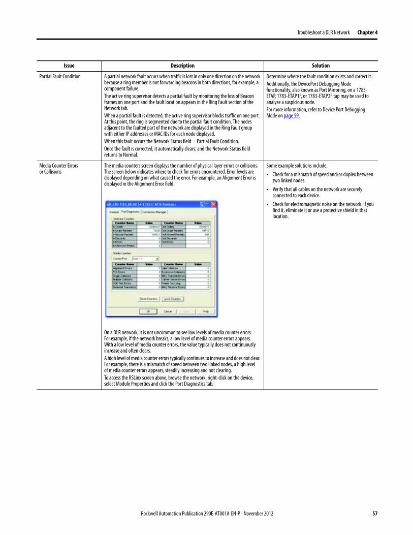
Troubleshoot a DLR Network Chapter 4
Issue Description Solution
Partial Fault Condition A partial network fault occurs when traffic is lost in only one direction on the network because a ring member is not forwarding beacons in both directions for example a component failureThe active ring supervisor detects a partial fault by monitoring the loss of Beacon frames on one port and the fault location appears in the Ring Fault section of the Network tab When a partial fault is detected the active ring supervisor blocks traffic on one port At this point the ring is segmented due to the partial fault condition The nodes adjacent to the faulted part of the network are displayed in the Ring Fault group with either IP addresses or MAC IDs for each node displayedWhen this fault occurs the Network Status field = Partial Fault ConditionOnce the fault is corrected it automatically clears and the Network Status field returns to Normal
Determine where the fault condition exists and correct itAdditionally the DevicePort Debugging Mode functionality also known as Port Mirroring on a 1783-ETAP 1783-ETAP1F or 1783-ETAP2F tap may be used to analyze a suspicious nodeFor more information refer to Device Port Debugging Mode on page 59
Media Counter Errors or Collisions
The media counters screen displays the number of physical layer errors or collisions The screen below indicates where to check for errors encountered Error levels are displayed depending on what caused the error For example an Alignment Error is displayed in the Alignment Error field
On a DLR network it is not uncommon to see low levels of media counter errors For example if the network breaks a low level of media counter errors appears With a low level of media counter errors the value typically does not continuously increase and often clearsA high level of media counter errors typically continues to increase and does not clear For example there is a mismatch of speed between two linked nodes a high level of media counter errors appears steadily increasing and not clearingTo access the RSLinx screen above browse the network right-click on the device select Module Properties and click the Port Diagnostics tab
Some example solutions includebull Check for a mismatch of speed andor duplex between
two linked nodesbull Verify that all cables on the network are securely
connected to each devicebull Check for electromagnetic noise on the network If you
find it eliminate it or use a protective shield in that location
Rockwell Automation Publication 290E-AT001A-EN-P - November 2012 57
Chapter 4 Troubleshoot a DLR Network
Network Recovery Performance
When measuring the networkrsquos performance with regard to dealing with fault conditions consider the network recovery time Network recovery is the time for all of the following to take place
1 The supervisor node recognizes that a fault exists on the network
2 The supervisor node reconfigures the network because of the fault
3 The supervisor node communicates to the network nodes that a fault condition exists
4 The network nodes reconfigure themselves because of the fault
With the default beacon interval value of 400 mS and beacon timeout value of 1960 mS the worst-case time for network recovery times are
bull 2890 mS for a copper DLR network This recovery time is based on 100 m copper segments between nodes on the network
bull 3140 mS for a fiber-optic DLR network This recovery time is based on 2 kM fiber-optic cable segments between nodes on the network
When considering the values listed above keep in mind
bull Recovery time may actually occur faster than the times listed
bull The recovery times listed above assume that your networkrsquos nodes are operating at 100 Mbps speed and full-duplex mode We recommend that your nodes generally operate in this mode for DLR networks
bull If other node conditions exist such as a node operating at 10 Mbps full-duplex or 10100 Mbps half-duplex the recovery times will vary from the times listed above
If this is the case for your application the beacon interval and beacon timeout will need to be changed We recommend that you first contact Rockwell Automation technical support if these parameters need to be changed
bull The value assumes that the majority of the traffic on your network is EtherNetIP traffic
58 Rockwell Automation Publication 290E-AT001A-EN-P - November 2012
Troubleshoot a DLR Network Chapter 4
Device Port Debugging Mode
This functionality is disabled by default Device Port Debugging mode which is similar to port mirroring can be used to monitor data received on the 1783-ETAP 1783-ETAP1F or 1783-ETAP2F taprsquos two network ports Monitor the data over the device port to a device such as a personal computer running a protocol analyzer application for advanced network debugging or analysis
When device port debugging is used on a 1783-ETAP the device connected to the 1783-ETAP taprsquos front port receives all of the data traversing the ring (both directions)
Device Port Debugging Example Network
When using the Device Port Debugging mode functionality insert the 1783-ETAP with the network analyzer connected to the device port It is inserted at the spot on the ring network where the node in question is located The graphic below shows a 1783-ETAP tap inserted in the network
IMPORTANT This functionality should be used only when troubleshooting the network and not in normal network operation
Rockwell Automation Publication 290E-AT001A-EN-P - November 2012 59
Chapter 4 Troubleshoot a DLR Network
Combined total network bandwidth of the traffic received on the two 1783-ETAP 1783-ETAP1F or 1783-ETAP2F taprsquos ports connected to the network should not exceed the taprsquos device port capacity The speed setting determines the device portrsquos capacity
Configure the device port on a 1783-ETAP 1783-ETAP1F or 1783-ETAP2F tap to either of two speed settings
bull 100 Mbps - default settingbull 10 Mbps
If the bandwidth exceeds the capacity of the taprsquos device port some frames from the ring will be dropped before reaching the device port These dropped frames do not impact the traffic on the rest of the DLR network
The device port setting determines how much network traffic the 1783-ETAP 1783-ETAP1F or 1783-ETAP2F tap can handle before dropping frames The circled section in the graphic below shows the Port Buffer Utilization of the Device Port In this example the value is zero because a ring fault exists on the network
60 Rockwell Automation Publication 290E-AT001A-EN-P - November 2012
Appendix A
Network Usage Guidelines and Recommendations
Consider the following guidelines and recommendations when using a DLR or linear network
GuidelineRecommendation Explanation
Use fewer than 50 nodes on a single DLR networkIf your application requires more than 50 nodes we recommend that the nodes are broken into separate but linked DLR networks
If you use more than 50 nodes on a single DLR networkbull Your network has a greater chance of multiple faults
occurring on the networkbull Network recovery times from faulted DLR network
are higher
Do not configure a supervisor on a linear network If your linear network includes non-DLR nodes and has a supervisor-enabled node on the network it may impact communication to non-DLR devices connected to the linear network
If you must connect a device that is running at 10 Mbps to a DLR or linear network do so through a 1783-ETAP 1783-ETAP1F or 1783-ETAP2F tap device port
The 1783-ETAP 1783-ETAP1F and 1783-ETAP2F taps can operate at 100 Mbps on the DLR network this is the optimal speed for a network If you connect a 10 Mbps device directly to the network instead of through a tap the linear or DLR network traffic slows to 10 MbpsAdditionally if the 10 Mbps device is connected to the network without a 1783-ETAP tap network recovery times are significantly impacted
Configure multiple supervisor nodes per ring If your DLR network only has one supervisor and the supervisor experiences a fault none of the other nodes become the active supervisor In this case the network becomes a linear network until the fault is corrected and the DLR network restoredAnother reason to configure multiple supervisor nodes is for replacing an active supervisor node with an out-of-box replacement the new device will not be enabled as a supervisor (by default) and there would still be no supervisor on the network
Rockwell Automation Publication 290E-AT001A-EN-P - November 2012 61
Appendix A Network Usage Guidelines and Recommendations
GuidelineRecommendation Explanation
Connect switches to a DLR network via 1783-ETAP 1783-ETAP1F or 1783-ETAP2F taps
If switches are connected to the DLR network without the use of a 1783-ETAP 1783-ETAP1F or 1783-ETAP2F tap the network may experience unpredictable behavior and network performance is unknown
Run all nodes on the DLR network at 100 Mbps and in Full-Duplex mode
These configuration values provide the best performance for your networkAdditionally we recommend that youbull Use auto-negotiate for all nodes on the DLR networkbull Do not use auto-negotiate on one node and then force
speed on the next node linked to it
In a linear network the number of nodes to use is application specific based on the considerations described in the next box
When determining the number of nodes to use on a linear network consider the followingbull There is a delay per node as information is transmitted
to each successive node used on the networkndash The typical delay on a linear network with 100 m
copper segments between nodes is 30 mSndash The typical delay on a linear network with 2 kM
fiber-optic segments between nodes is 40 mS
The greater the number of nodes on the network the longer the total time for information to be transmitted across the entire networkbull The single point of failure possibility is greater with
each additional connectionbull Troubleshooting the network may be more difficult
with a higher number of nodes
The total time for information to be transmitted across the entire network and its effect on how many nodes to use on a linear network is related to the Requested Packet Interval (RPI)Verify that the total time to transmit information from the first node to the last node on the network is less than the RPI Make sure the network is not loaded beyond 90 of capacity
62 Rockwell Automation Publication 290E-AT001A-EN-P - November 2012
Network Usage Guidelines and Recommendations Appendix A
GuidelineRecommendation Explanation
Do not physically close a DLR network without a supervisor configured on the network
A DLR network without a supervisor node results in a network stormIf you do close the DLR network without a supervisor configured break the ring and configure at least one supervisor before physically reconnecting the network
Use the default values for the followingbull Beacon Intervalbull Beacon Timeoutbull Ring Protocol VLAN ID
Changing the default values for the parameters Beacon Interval Beacon Timeout and Ring Protocol VLAN ID can result in unpredictable network behavior and negatively impacted network performanceThe default values are optimized for a network withbull 50 or fewer nodes are on the networkbull All nodes are operating at 100 Mbps and full-duplex
modebull At least 50 of the network traffic bandwidth being
EtherNetIP trafficIf you think the values of the Beacon Interval Beacon Timeout or Ring Protocol VLAN ID need to be changed for example if any node on ring is not operating at 100 Mbps and full-duplex mode we recommend that you first contact Rockwell Automation technical support
If DHCP for the ArmorStarts is still required you will need to disable Internet Group Management Protocol (IGMP) snooping on the E-tap via the AOP
IGMP Snooping is enabled by default in the 1783-ETAP 1783-ETAP1F and 1783-ETAP2F taps and is commonly used to manage multicast traffic on the network When in use this functionality allows the tap to multicast data to only those devices that need the data rather than to all devices connected to the networkOnce DHCP is enabled the switch could change the IP addresses on the ArmorStarts depending on network demand which could cause RSlogix5000 to loose communication with the device as connectivity is established via the AOP in the initial configuration
The IGMP Querier functionality should be enabled for at least one node on the network
This functionality is disabled by default The IGMP Querier functionality enables a 1783-ETAP 1783-ETAP1F or 1783-ETAP2F tap or switch such as a Stratix managed switch to send out a query to all devices on the network to determine what multicast addresses are of interest to a specific node or a group of nodesIf the IGMP Querier functionality is not enabled for at least one node on the network multicast traffic on the network may eventually create network performance issuesThe 1783-ETAP 1783-ETAP1F or 1783-ETAP2F taps managed switches and routers are examples of devices that support IGMP Querier functionality
Rockwell Automation Publication 290E-AT001A-EN-P - November 2012 63
Appendix A Network Usage Guidelines and Recommendations
Notes
64 Rockwell Automation Publication 290E-AT001A-EN-P - November 2012
Appendix B
Required Firmware Revisions
Required Firmware Revision for an Add-On Profile
➊ The ControlFLASH Firmware Upgrade software tcan be used o upgrade a 1756-EN2TR module from firmware revision 21 to 3x or later1x or later3x or later2x or later
➋ The ControlFLASH Firmware Upgrade software can be used to upgrade a 1783-ETAP tap from firmware revision 11 to 2x or later
To download new firmware go to httpwwwrockwellautomationcomsupportamericasindex_enhtml
If the firmware revision is upgraded on the module or tap the required AOP revision listed above must be used for that revision For example if the 1756-EN2TR module is upgraded to firmware revision 3x or later AOP revision 2x or later must be used in the RSLogix 5000 programming software
Additionally if the firmware revision is upgraded on the module or tap the required RSLinx communication software must also be used for that firmware revision For more information on which RSLinx software version is required for each firmware revision see page 66
For both the 1756-EN2TR module and 1783-ETAP tap make sure that the Major Revision configured on the General tab of the devicersquos RSLogix 5000 programming software configuration matches the major revision of the physical module
IMPORTANT To download an AOP go to httpsupportrockwellautomationcomcontrolflashLogixProfileraspDepending on the firmware revision of your product a specific AOP version must be used
Firmware Revision Add-On Profile Revision Cat No
21 ➊ 1x or later 1756-EN2TR
3x or later 2x or later
11 ➋ 1x or later 1783-ETAP
2x or later 2x or later
2x or later 2x or later 1783-ETAP1F
1783-ETAP2F
Rockwell Automation Publication 290E-AT001A-EN-P - November 2012 65
Appendix B Required Firmware Revisions
If the device configuration on the General tab does not match the physical module the programming software alerts you to this mismatch when attempting to configure the Internet Protocol Port Configuration and Network tabs for that device
Required Firmware Revision for RSLinx Communication Software
➊ The ControlFLASH Firmware Upgrade software can be used to upgrade a 1756-EN2TR module from firmware revision 21 to 3x or later1x or later3x or later255 or later3x or later256 or later
➋ The ControlFLASH Firmware Upgrade software can be used to upgrade a 1783-ETAP tap from firmware revision 11 to 2x or later
To download new firmware go to httpwwwrockwellautomationcomsupportamericasindex_enhtml
If the firmware revision is upgraded on the module or tap the required RSLinx communication software listed above must be used for that revision For example if the 1756-EN2TR module is upgraded to firmware revision 3x or later AOP revision 2x or later must be used in your RSLogix 5000 programming software
Additionally if the firmware revision is upgraded on the module or tap the required AOP revision must also be used for that firmware revision For more information on which AOP revision is required for each firmware revision see page 65
IMPORTANT Depending on the firmware revision of your product specific versions of RSLinx communication software must be used
Firmware Revision Required RSLinx Communication Software Version
Cat No
21 ➊ 255 or later 1756-EN2TR
3x or later 256 or later
11 ➋ 255 or later 1783-ETAP
2x or later 256 or later
2x or later 256 or later 1783-ETAP1F
1783-ETAP2F
66 Rockwell Automation Publication 290E-AT001A-EN-P - November 2012
Rockwell Otomasyon Ticaret AŞ Kar Plaza İş Merkezi E Blok Kat6 34752 İccedilerenkoumly İstanbul Tel +90 (216) 5698400
Rockwell Automation Publication 290E-AT001A-EN-P ndash November 2012 68 Copyright copy 2012 Rockwell Automation Inc All rights reserved Printed in the USA
Rockwell Automation Support
Rockwell Automation provides technical information on the Web to assist you in using its products At httpwwwrockwellautomationcomsupport you can find technical manuals a knowledge base of FAQs technical and application notes sample code and links to software service packs and a MySupport feature that you can customize to make thebest use of these tools
For an additional level of technical phone support for installation configuration and troubleshooting we offer TechConnectSM support programs For more information contact your local distributor or Rockwell Automation representative or visit httpwwwrockwellautomationcomsupport
Installation Assistance
If you experience a problem within the first 24 hours of installation review the information that is contained in this manualYou can contact Customer Support for initial help in getting your product up and running
New Product Satisfaction Return
Rockwell Automation tests all of its products to ensure that they are fully operational when shipped from the manufacturing facility However if your product is not functioning and needs to be returned follow these procedures
Documentation Feedback
Your comments will help us serve your documentation needs better If you have any suggestions on how to improve this document complete this form publication RA-DU002 available at httpwwwrockwellautomationcomliterature
United States or Canada 14406463434
Outside United States or Canada Use the Worldwide Locator at httpwwwrockwellautomationcomsupportamericasphone_enhtml or contact your local Rockwell Automation representative
United States Contact your distributor You must provide a Customer Support case number (call the phone number above to obtain one) to your distributor to complete the return process
Outside United States Please contact your local Rockwell Automation representative for the return procedure
- Important User Information
- General Precautions
- Software Requirements
- Additional Resources
- Rockwell Automation Support
- Installation Assistance
- New Product Satisfaction Return
- Table of Contents
- Chapter 1
-
- Device-Level Ring (DLR) Basics
-
- Introduction
- ArmorStart with EtherNetIP Overview
- What is a Device-level Ring (DLR) Network
- DLR Network Elements
-
- Supervisor Node
- Ring Node
-
- DLR Network Operation
- Number of Nodes on a DLR Network
- DLR Network Fault Management
-
- Network Reconfiguration after a Fault
-
- Chapter 2
-
- Construct and Configure a Device-level Ring Network with ArmorStarts
-
- Introduction
- Ethernet Capacity Tool
- Install Devices on a DLR Network
- ArmorStart Addressing Configuration
-
- Using the BootPDHCP Server
- Using the Rotary Network Address Switches
- Using the ArmorStart Internal Web Server
-
- Configure Supervisor Nodes on a DLR Network
-
- Configure a Ring Supervisor in RSLogix 5000 Programming Software
- Adding an Armorstart to RSLogix 5000
- Enable Ring Supervisor in RSLogix 5000 Programming Software
- Configure and Enable a Ring Supervisor in RSLinx Classic Communication Software
-
- Complete the Physical Connections of the Network
- Verify Supervisor Configuration
- IGMP Snooping
- IGMP Querier
-
- Chapter 3
-
- Monitor a DLR Network
-
- Introduction
- Methods to Monitor a DLR Network
-
- RSLogix 5000 Programming Software Status Pages
- RSLinx Communication Software Status Pages
- ArmorStart Internal Web Server
- EtherNetIP Device Level Ring (DLR) Network Diagnostics Faceplate
- Programmatically Through the Use of a MSG Instruction
-
- Monitor Status Pages
-
- RSLogix 5000 Programming Software Status Pages
- RSLinx Communication Software
-
- How to Access the ArmorStart EtherNetIP Internal Web Server
-
- EtherNetIP Device Level Ring (DLR) Network Diagnostics Faceplate Overview
-
- Monitor Diagnostics via MSG Instructions
-
- Use Specific Values on the Configuration Tab
- Retrieve All Ring Diagnostic Information
- Retrieve All Diagnostic Information Attribute Description
- Request the Ring Participant List
- Request the Ring Participant List Attribute Description
-
- Enable and Configure a Ring Supervisor
-
- Enable and Configure a Ring Supervisor Attribute Description
-
- Chapter 4
-
- Troubleshoot a DLR Network
-
- Introduction
- General Solutions for Linear or DLR Networks
- Duplicate IP Address Detection
- Specific Issues on the DLR Network
- Network Recovery Performance
- Device Port Debugging Mode
-
- Device Port Debugging Example Network
-
- Appendix A
-
- Network Usage Guidelines and Recommendations
-
- Notes
-
- Appendix B
-
- Required Firmware Revisions
-
- Required Firmware Revision for an Add-On Profile
- Required Firmware Revision for RSLinx Communication Software
-
Chapter 4 Troubleshoot a DLR Network
Network Recovery Performance
When measuring the networkrsquos performance with regard to dealing with fault conditions consider the network recovery time Network recovery is the time for all of the following to take place
1 The supervisor node recognizes that a fault exists on the network
2 The supervisor node reconfigures the network because of the fault
3 The supervisor node communicates to the network nodes that a fault condition exists
4 The network nodes reconfigure themselves because of the fault
With the default beacon interval value of 400 mS and beacon timeout value of 1960 mS the worst-case time for network recovery times are
bull 2890 mS for a copper DLR network This recovery time is based on 100 m copper segments between nodes on the network
bull 3140 mS for a fiber-optic DLR network This recovery time is based on 2 kM fiber-optic cable segments between nodes on the network
When considering the values listed above keep in mind
bull Recovery time may actually occur faster than the times listed
bull The recovery times listed above assume that your networkrsquos nodes are operating at 100 Mbps speed and full-duplex mode We recommend that your nodes generally operate in this mode for DLR networks
bull If other node conditions exist such as a node operating at 10 Mbps full-duplex or 10100 Mbps half-duplex the recovery times will vary from the times listed above
If this is the case for your application the beacon interval and beacon timeout will need to be changed We recommend that you first contact Rockwell Automation technical support if these parameters need to be changed
bull The value assumes that the majority of the traffic on your network is EtherNetIP traffic
58 Rockwell Automation Publication 290E-AT001A-EN-P - November 2012
Troubleshoot a DLR Network Chapter 4
Device Port Debugging Mode
This functionality is disabled by default Device Port Debugging mode which is similar to port mirroring can be used to monitor data received on the 1783-ETAP 1783-ETAP1F or 1783-ETAP2F taprsquos two network ports Monitor the data over the device port to a device such as a personal computer running a protocol analyzer application for advanced network debugging or analysis
When device port debugging is used on a 1783-ETAP the device connected to the 1783-ETAP taprsquos front port receives all of the data traversing the ring (both directions)
Device Port Debugging Example Network
When using the Device Port Debugging mode functionality insert the 1783-ETAP with the network analyzer connected to the device port It is inserted at the spot on the ring network where the node in question is located The graphic below shows a 1783-ETAP tap inserted in the network
IMPORTANT This functionality should be used only when troubleshooting the network and not in normal network operation
Rockwell Automation Publication 290E-AT001A-EN-P - November 2012 59
Chapter 4 Troubleshoot a DLR Network
Combined total network bandwidth of the traffic received on the two 1783-ETAP 1783-ETAP1F or 1783-ETAP2F taprsquos ports connected to the network should not exceed the taprsquos device port capacity The speed setting determines the device portrsquos capacity
Configure the device port on a 1783-ETAP 1783-ETAP1F or 1783-ETAP2F tap to either of two speed settings
bull 100 Mbps - default settingbull 10 Mbps
If the bandwidth exceeds the capacity of the taprsquos device port some frames from the ring will be dropped before reaching the device port These dropped frames do not impact the traffic on the rest of the DLR network
The device port setting determines how much network traffic the 1783-ETAP 1783-ETAP1F or 1783-ETAP2F tap can handle before dropping frames The circled section in the graphic below shows the Port Buffer Utilization of the Device Port In this example the value is zero because a ring fault exists on the network
60 Rockwell Automation Publication 290E-AT001A-EN-P - November 2012
Appendix A
Network Usage Guidelines and Recommendations
Consider the following guidelines and recommendations when using a DLR or linear network
GuidelineRecommendation Explanation
Use fewer than 50 nodes on a single DLR networkIf your application requires more than 50 nodes we recommend that the nodes are broken into separate but linked DLR networks
If you use more than 50 nodes on a single DLR networkbull Your network has a greater chance of multiple faults
occurring on the networkbull Network recovery times from faulted DLR network
are higher
Do not configure a supervisor on a linear network If your linear network includes non-DLR nodes and has a supervisor-enabled node on the network it may impact communication to non-DLR devices connected to the linear network
If you must connect a device that is running at 10 Mbps to a DLR or linear network do so through a 1783-ETAP 1783-ETAP1F or 1783-ETAP2F tap device port
The 1783-ETAP 1783-ETAP1F and 1783-ETAP2F taps can operate at 100 Mbps on the DLR network this is the optimal speed for a network If you connect a 10 Mbps device directly to the network instead of through a tap the linear or DLR network traffic slows to 10 MbpsAdditionally if the 10 Mbps device is connected to the network without a 1783-ETAP tap network recovery times are significantly impacted
Configure multiple supervisor nodes per ring If your DLR network only has one supervisor and the supervisor experiences a fault none of the other nodes become the active supervisor In this case the network becomes a linear network until the fault is corrected and the DLR network restoredAnother reason to configure multiple supervisor nodes is for replacing an active supervisor node with an out-of-box replacement the new device will not be enabled as a supervisor (by default) and there would still be no supervisor on the network
Rockwell Automation Publication 290E-AT001A-EN-P - November 2012 61
Appendix A Network Usage Guidelines and Recommendations
GuidelineRecommendation Explanation
Connect switches to a DLR network via 1783-ETAP 1783-ETAP1F or 1783-ETAP2F taps
If switches are connected to the DLR network without the use of a 1783-ETAP 1783-ETAP1F or 1783-ETAP2F tap the network may experience unpredictable behavior and network performance is unknown
Run all nodes on the DLR network at 100 Mbps and in Full-Duplex mode
These configuration values provide the best performance for your networkAdditionally we recommend that youbull Use auto-negotiate for all nodes on the DLR networkbull Do not use auto-negotiate on one node and then force
speed on the next node linked to it
In a linear network the number of nodes to use is application specific based on the considerations described in the next box
When determining the number of nodes to use on a linear network consider the followingbull There is a delay per node as information is transmitted
to each successive node used on the networkndash The typical delay on a linear network with 100 m
copper segments between nodes is 30 mSndash The typical delay on a linear network with 2 kM
fiber-optic segments between nodes is 40 mS
The greater the number of nodes on the network the longer the total time for information to be transmitted across the entire networkbull The single point of failure possibility is greater with
each additional connectionbull Troubleshooting the network may be more difficult
with a higher number of nodes
The total time for information to be transmitted across the entire network and its effect on how many nodes to use on a linear network is related to the Requested Packet Interval (RPI)Verify that the total time to transmit information from the first node to the last node on the network is less than the RPI Make sure the network is not loaded beyond 90 of capacity
62 Rockwell Automation Publication 290E-AT001A-EN-P - November 2012
Network Usage Guidelines and Recommendations Appendix A
GuidelineRecommendation Explanation
Do not physically close a DLR network without a supervisor configured on the network
A DLR network without a supervisor node results in a network stormIf you do close the DLR network without a supervisor configured break the ring and configure at least one supervisor before physically reconnecting the network
Use the default values for the followingbull Beacon Intervalbull Beacon Timeoutbull Ring Protocol VLAN ID
Changing the default values for the parameters Beacon Interval Beacon Timeout and Ring Protocol VLAN ID can result in unpredictable network behavior and negatively impacted network performanceThe default values are optimized for a network withbull 50 or fewer nodes are on the networkbull All nodes are operating at 100 Mbps and full-duplex
modebull At least 50 of the network traffic bandwidth being
EtherNetIP trafficIf you think the values of the Beacon Interval Beacon Timeout or Ring Protocol VLAN ID need to be changed for example if any node on ring is not operating at 100 Mbps and full-duplex mode we recommend that you first contact Rockwell Automation technical support
If DHCP for the ArmorStarts is still required you will need to disable Internet Group Management Protocol (IGMP) snooping on the E-tap via the AOP
IGMP Snooping is enabled by default in the 1783-ETAP 1783-ETAP1F and 1783-ETAP2F taps and is commonly used to manage multicast traffic on the network When in use this functionality allows the tap to multicast data to only those devices that need the data rather than to all devices connected to the networkOnce DHCP is enabled the switch could change the IP addresses on the ArmorStarts depending on network demand which could cause RSlogix5000 to loose communication with the device as connectivity is established via the AOP in the initial configuration
The IGMP Querier functionality should be enabled for at least one node on the network
This functionality is disabled by default The IGMP Querier functionality enables a 1783-ETAP 1783-ETAP1F or 1783-ETAP2F tap or switch such as a Stratix managed switch to send out a query to all devices on the network to determine what multicast addresses are of interest to a specific node or a group of nodesIf the IGMP Querier functionality is not enabled for at least one node on the network multicast traffic on the network may eventually create network performance issuesThe 1783-ETAP 1783-ETAP1F or 1783-ETAP2F taps managed switches and routers are examples of devices that support IGMP Querier functionality
Rockwell Automation Publication 290E-AT001A-EN-P - November 2012 63
Appendix A Network Usage Guidelines and Recommendations
Notes
64 Rockwell Automation Publication 290E-AT001A-EN-P - November 2012
Appendix B
Required Firmware Revisions
Required Firmware Revision for an Add-On Profile
➊ The ControlFLASH Firmware Upgrade software tcan be used o upgrade a 1756-EN2TR module from firmware revision 21 to 3x or later1x or later3x or later2x or later
➋ The ControlFLASH Firmware Upgrade software can be used to upgrade a 1783-ETAP tap from firmware revision 11 to 2x or later
To download new firmware go to httpwwwrockwellautomationcomsupportamericasindex_enhtml
If the firmware revision is upgraded on the module or tap the required AOP revision listed above must be used for that revision For example if the 1756-EN2TR module is upgraded to firmware revision 3x or later AOP revision 2x or later must be used in the RSLogix 5000 programming software
Additionally if the firmware revision is upgraded on the module or tap the required RSLinx communication software must also be used for that firmware revision For more information on which RSLinx software version is required for each firmware revision see page 66
For both the 1756-EN2TR module and 1783-ETAP tap make sure that the Major Revision configured on the General tab of the devicersquos RSLogix 5000 programming software configuration matches the major revision of the physical module
IMPORTANT To download an AOP go to httpsupportrockwellautomationcomcontrolflashLogixProfileraspDepending on the firmware revision of your product a specific AOP version must be used
Firmware Revision Add-On Profile Revision Cat No
21 ➊ 1x or later 1756-EN2TR
3x or later 2x or later
11 ➋ 1x or later 1783-ETAP
2x or later 2x or later
2x or later 2x or later 1783-ETAP1F
1783-ETAP2F
Rockwell Automation Publication 290E-AT001A-EN-P - November 2012 65
Appendix B Required Firmware Revisions
If the device configuration on the General tab does not match the physical module the programming software alerts you to this mismatch when attempting to configure the Internet Protocol Port Configuration and Network tabs for that device
Required Firmware Revision for RSLinx Communication Software
➊ The ControlFLASH Firmware Upgrade software can be used to upgrade a 1756-EN2TR module from firmware revision 21 to 3x or later1x or later3x or later255 or later3x or later256 or later
➋ The ControlFLASH Firmware Upgrade software can be used to upgrade a 1783-ETAP tap from firmware revision 11 to 2x or later
To download new firmware go to httpwwwrockwellautomationcomsupportamericasindex_enhtml
If the firmware revision is upgraded on the module or tap the required RSLinx communication software listed above must be used for that revision For example if the 1756-EN2TR module is upgraded to firmware revision 3x or later AOP revision 2x or later must be used in your RSLogix 5000 programming software
Additionally if the firmware revision is upgraded on the module or tap the required AOP revision must also be used for that firmware revision For more information on which AOP revision is required for each firmware revision see page 65
IMPORTANT Depending on the firmware revision of your product specific versions of RSLinx communication software must be used
Firmware Revision Required RSLinx Communication Software Version
Cat No
21 ➊ 255 or later 1756-EN2TR
3x or later 256 or later
11 ➋ 255 or later 1783-ETAP
2x or later 256 or later
2x or later 256 or later 1783-ETAP1F
1783-ETAP2F
66 Rockwell Automation Publication 290E-AT001A-EN-P - November 2012
Rockwell Otomasyon Ticaret AŞ Kar Plaza İş Merkezi E Blok Kat6 34752 İccedilerenkoumly İstanbul Tel +90 (216) 5698400
Rockwell Automation Publication 290E-AT001A-EN-P ndash November 2012 68 Copyright copy 2012 Rockwell Automation Inc All rights reserved Printed in the USA
Rockwell Automation Support
Rockwell Automation provides technical information on the Web to assist you in using its products At httpwwwrockwellautomationcomsupport you can find technical manuals a knowledge base of FAQs technical and application notes sample code and links to software service packs and a MySupport feature that you can customize to make thebest use of these tools
For an additional level of technical phone support for installation configuration and troubleshooting we offer TechConnectSM support programs For more information contact your local distributor or Rockwell Automation representative or visit httpwwwrockwellautomationcomsupport
Installation Assistance
If you experience a problem within the first 24 hours of installation review the information that is contained in this manualYou can contact Customer Support for initial help in getting your product up and running
New Product Satisfaction Return
Rockwell Automation tests all of its products to ensure that they are fully operational when shipped from the manufacturing facility However if your product is not functioning and needs to be returned follow these procedures
Documentation Feedback
Your comments will help us serve your documentation needs better If you have any suggestions on how to improve this document complete this form publication RA-DU002 available at httpwwwrockwellautomationcomliterature
United States or Canada 14406463434
Outside United States or Canada Use the Worldwide Locator at httpwwwrockwellautomationcomsupportamericasphone_enhtml or contact your local Rockwell Automation representative
United States Contact your distributor You must provide a Customer Support case number (call the phone number above to obtain one) to your distributor to complete the return process
Outside United States Please contact your local Rockwell Automation representative for the return procedure
- Important User Information
- General Precautions
- Software Requirements
- Additional Resources
- Rockwell Automation Support
- Installation Assistance
- New Product Satisfaction Return
- Table of Contents
- Chapter 1
-
- Device-Level Ring (DLR) Basics
-
- Introduction
- ArmorStart with EtherNetIP Overview
- What is a Device-level Ring (DLR) Network
- DLR Network Elements
-
- Supervisor Node
- Ring Node
-
- DLR Network Operation
- Number of Nodes on a DLR Network
- DLR Network Fault Management
-
- Network Reconfiguration after a Fault
-
- Chapter 2
-
- Construct and Configure a Device-level Ring Network with ArmorStarts
-
- Introduction
- Ethernet Capacity Tool
- Install Devices on a DLR Network
- ArmorStart Addressing Configuration
-
- Using the BootPDHCP Server
- Using the Rotary Network Address Switches
- Using the ArmorStart Internal Web Server
-
- Configure Supervisor Nodes on a DLR Network
-
- Configure a Ring Supervisor in RSLogix 5000 Programming Software
- Adding an Armorstart to RSLogix 5000
- Enable Ring Supervisor in RSLogix 5000 Programming Software
- Configure and Enable a Ring Supervisor in RSLinx Classic Communication Software
-
- Complete the Physical Connections of the Network
- Verify Supervisor Configuration
- IGMP Snooping
- IGMP Querier
-
- Chapter 3
-
- Monitor a DLR Network
-
- Introduction
- Methods to Monitor a DLR Network
-
- RSLogix 5000 Programming Software Status Pages
- RSLinx Communication Software Status Pages
- ArmorStart Internal Web Server
- EtherNetIP Device Level Ring (DLR) Network Diagnostics Faceplate
- Programmatically Through the Use of a MSG Instruction
-
- Monitor Status Pages
-
- RSLogix 5000 Programming Software Status Pages
- RSLinx Communication Software
-
- How to Access the ArmorStart EtherNetIP Internal Web Server
-
- EtherNetIP Device Level Ring (DLR) Network Diagnostics Faceplate Overview
-
- Monitor Diagnostics via MSG Instructions
-
- Use Specific Values on the Configuration Tab
- Retrieve All Ring Diagnostic Information
- Retrieve All Diagnostic Information Attribute Description
- Request the Ring Participant List
- Request the Ring Participant List Attribute Description
-
- Enable and Configure a Ring Supervisor
-
- Enable and Configure a Ring Supervisor Attribute Description
-
- Chapter 4
-
- Troubleshoot a DLR Network
-
- Introduction
- General Solutions for Linear or DLR Networks
- Duplicate IP Address Detection
- Specific Issues on the DLR Network
- Network Recovery Performance
- Device Port Debugging Mode
-
- Device Port Debugging Example Network
-
- Appendix A
-
- Network Usage Guidelines and Recommendations
-
- Notes
-
- Appendix B
-
- Required Firmware Revisions
-
- Required Firmware Revision for an Add-On Profile
- Required Firmware Revision for RSLinx Communication Software
-
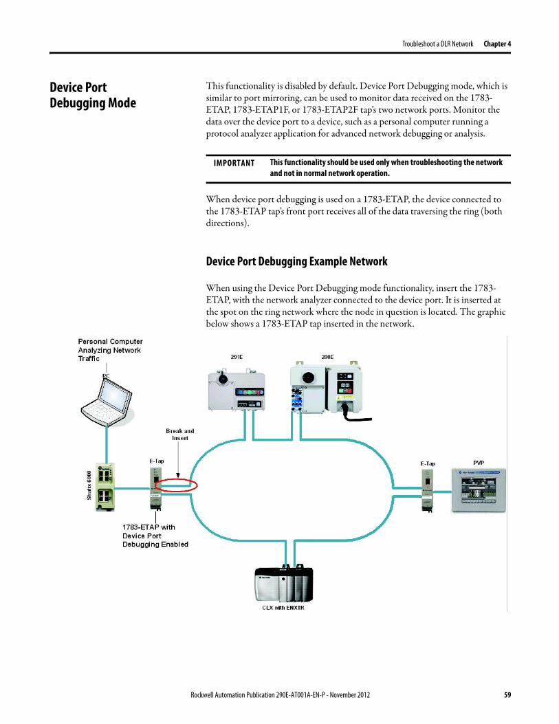
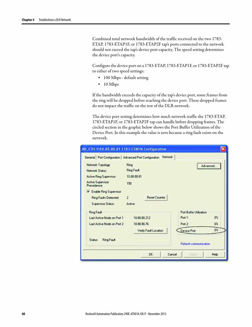
Appendix A Network Usage Guidelines and Recommendations
GuidelineRecommendation Explanation
Connect switches to a DLR network via 1783-ETAP 1783-ETAP1F or 1783-ETAP2F taps
If switches are connected to the DLR network without the use of a 1783-ETAP 1783-ETAP1F or 1783-ETAP2F tap the network may experience unpredictable behavior and network performance is unknown
Run all nodes on the DLR network at 100 Mbps and in Full-Duplex mode
These configuration values provide the best performance for your networkAdditionally we recommend that youbull Use auto-negotiate for all nodes on the DLR networkbull Do not use auto-negotiate on one node and then force
speed on the next node linked to it
In a linear network the number of nodes to use is application specific based on the considerations described in the next box
When determining the number of nodes to use on a linear network consider the followingbull There is a delay per node as information is transmitted
to each successive node used on the networkndash The typical delay on a linear network with 100 m
copper segments between nodes is 30 mSndash The typical delay on a linear network with 2 kM
fiber-optic segments between nodes is 40 mS
The greater the number of nodes on the network the longer the total time for information to be transmitted across the entire networkbull The single point of failure possibility is greater with
each additional connectionbull Troubleshooting the network may be more difficult
with a higher number of nodes
The total time for information to be transmitted across the entire network and its effect on how many nodes to use on a linear network is related to the Requested Packet Interval (RPI)Verify that the total time to transmit information from the first node to the last node on the network is less than the RPI Make sure the network is not loaded beyond 90 of capacity
62 Rockwell Automation Publication 290E-AT001A-EN-P - November 2012
Network Usage Guidelines and Recommendations Appendix A
GuidelineRecommendation Explanation
Do not physically close a DLR network without a supervisor configured on the network
A DLR network without a supervisor node results in a network stormIf you do close the DLR network without a supervisor configured break the ring and configure at least one supervisor before physically reconnecting the network
Use the default values for the followingbull Beacon Intervalbull Beacon Timeoutbull Ring Protocol VLAN ID
Changing the default values for the parameters Beacon Interval Beacon Timeout and Ring Protocol VLAN ID can result in unpredictable network behavior and negatively impacted network performanceThe default values are optimized for a network withbull 50 or fewer nodes are on the networkbull All nodes are operating at 100 Mbps and full-duplex
modebull At least 50 of the network traffic bandwidth being
EtherNetIP trafficIf you think the values of the Beacon Interval Beacon Timeout or Ring Protocol VLAN ID need to be changed for example if any node on ring is not operating at 100 Mbps and full-duplex mode we recommend that you first contact Rockwell Automation technical support
If DHCP for the ArmorStarts is still required you will need to disable Internet Group Management Protocol (IGMP) snooping on the E-tap via the AOP
IGMP Snooping is enabled by default in the 1783-ETAP 1783-ETAP1F and 1783-ETAP2F taps and is commonly used to manage multicast traffic on the network When in use this functionality allows the tap to multicast data to only those devices that need the data rather than to all devices connected to the networkOnce DHCP is enabled the switch could change the IP addresses on the ArmorStarts depending on network demand which could cause RSlogix5000 to loose communication with the device as connectivity is established via the AOP in the initial configuration
The IGMP Querier functionality should be enabled for at least one node on the network
This functionality is disabled by default The IGMP Querier functionality enables a 1783-ETAP 1783-ETAP1F or 1783-ETAP2F tap or switch such as a Stratix managed switch to send out a query to all devices on the network to determine what multicast addresses are of interest to a specific node or a group of nodesIf the IGMP Querier functionality is not enabled for at least one node on the network multicast traffic on the network may eventually create network performance issuesThe 1783-ETAP 1783-ETAP1F or 1783-ETAP2F taps managed switches and routers are examples of devices that support IGMP Querier functionality
Rockwell Automation Publication 290E-AT001A-EN-P - November 2012 63
Appendix A Network Usage Guidelines and Recommendations
Notes
64 Rockwell Automation Publication 290E-AT001A-EN-P - November 2012
Appendix B
Required Firmware Revisions
Required Firmware Revision for an Add-On Profile
➊ The ControlFLASH Firmware Upgrade software tcan be used o upgrade a 1756-EN2TR module from firmware revision 21 to 3x or later1x or later3x or later2x or later
➋ The ControlFLASH Firmware Upgrade software can be used to upgrade a 1783-ETAP tap from firmware revision 11 to 2x or later
To download new firmware go to httpwwwrockwellautomationcomsupportamericasindex_enhtml
If the firmware revision is upgraded on the module or tap the required AOP revision listed above must be used for that revision For example if the 1756-EN2TR module is upgraded to firmware revision 3x or later AOP revision 2x or later must be used in the RSLogix 5000 programming software
Additionally if the firmware revision is upgraded on the module or tap the required RSLinx communication software must also be used for that firmware revision For more information on which RSLinx software version is required for each firmware revision see page 66
For both the 1756-EN2TR module and 1783-ETAP tap make sure that the Major Revision configured on the General tab of the devicersquos RSLogix 5000 programming software configuration matches the major revision of the physical module
IMPORTANT To download an AOP go to httpsupportrockwellautomationcomcontrolflashLogixProfileraspDepending on the firmware revision of your product a specific AOP version must be used
Firmware Revision Add-On Profile Revision Cat No
21 ➊ 1x or later 1756-EN2TR
3x or later 2x or later
11 ➋ 1x or later 1783-ETAP
2x or later 2x or later
2x or later 2x or later 1783-ETAP1F
1783-ETAP2F
Rockwell Automation Publication 290E-AT001A-EN-P - November 2012 65
Appendix B Required Firmware Revisions
If the device configuration on the General tab does not match the physical module the programming software alerts you to this mismatch when attempting to configure the Internet Protocol Port Configuration and Network tabs for that device
Required Firmware Revision for RSLinx Communication Software
➊ The ControlFLASH Firmware Upgrade software can be used to upgrade a 1756-EN2TR module from firmware revision 21 to 3x or later1x or later3x or later255 or later3x or later256 or later
➋ The ControlFLASH Firmware Upgrade software can be used to upgrade a 1783-ETAP tap from firmware revision 11 to 2x or later
To download new firmware go to httpwwwrockwellautomationcomsupportamericasindex_enhtml
If the firmware revision is upgraded on the module or tap the required RSLinx communication software listed above must be used for that revision For example if the 1756-EN2TR module is upgraded to firmware revision 3x or later AOP revision 2x or later must be used in your RSLogix 5000 programming software
Additionally if the firmware revision is upgraded on the module or tap the required AOP revision must also be used for that firmware revision For more information on which AOP revision is required for each firmware revision see page 65
IMPORTANT Depending on the firmware revision of your product specific versions of RSLinx communication software must be used
Firmware Revision Required RSLinx Communication Software Version
Cat No
21 ➊ 255 or later 1756-EN2TR
3x or later 256 or later
11 ➋ 255 or later 1783-ETAP
2x or later 256 or later
2x or later 256 or later 1783-ETAP1F
1783-ETAP2F
66 Rockwell Automation Publication 290E-AT001A-EN-P - November 2012
Rockwell Otomasyon Ticaret AŞ Kar Plaza İş Merkezi E Blok Kat6 34752 İccedilerenkoumly İstanbul Tel +90 (216) 5698400
Rockwell Automation Publication 290E-AT001A-EN-P ndash November 2012 68 Copyright copy 2012 Rockwell Automation Inc All rights reserved Printed in the USA
Rockwell Automation Support
Rockwell Automation provides technical information on the Web to assist you in using its products At httpwwwrockwellautomationcomsupport you can find technical manuals a knowledge base of FAQs technical and application notes sample code and links to software service packs and a MySupport feature that you can customize to make thebest use of these tools
For an additional level of technical phone support for installation configuration and troubleshooting we offer TechConnectSM support programs For more information contact your local distributor or Rockwell Automation representative or visit httpwwwrockwellautomationcomsupport
Installation Assistance
If you experience a problem within the first 24 hours of installation review the information that is contained in this manualYou can contact Customer Support for initial help in getting your product up and running
New Product Satisfaction Return
Rockwell Automation tests all of its products to ensure that they are fully operational when shipped from the manufacturing facility However if your product is not functioning and needs to be returned follow these procedures
Documentation Feedback
Your comments will help us serve your documentation needs better If you have any suggestions on how to improve this document complete this form publication RA-DU002 available at httpwwwrockwellautomationcomliterature
United States or Canada 14406463434
Outside United States or Canada Use the Worldwide Locator at httpwwwrockwellautomationcomsupportamericasphone_enhtml or contact your local Rockwell Automation representative
United States Contact your distributor You must provide a Customer Support case number (call the phone number above to obtain one) to your distributor to complete the return process
Outside United States Please contact your local Rockwell Automation representative for the return procedure
- Important User Information
- General Precautions
- Software Requirements
- Additional Resources
- Rockwell Automation Support
- Installation Assistance
- New Product Satisfaction Return
- Table of Contents
- Chapter 1
-
- Device-Level Ring (DLR) Basics
-
- Introduction
- ArmorStart with EtherNetIP Overview
- What is a Device-level Ring (DLR) Network
- DLR Network Elements
-
- Supervisor Node
- Ring Node
-
- DLR Network Operation
- Number of Nodes on a DLR Network
- DLR Network Fault Management
-
- Network Reconfiguration after a Fault
-
- Chapter 2
-
- Construct and Configure a Device-level Ring Network with ArmorStarts
-
- Introduction
- Ethernet Capacity Tool
- Install Devices on a DLR Network
- ArmorStart Addressing Configuration
-
- Using the BootPDHCP Server
- Using the Rotary Network Address Switches
- Using the ArmorStart Internal Web Server
-
- Configure Supervisor Nodes on a DLR Network
-
- Configure a Ring Supervisor in RSLogix 5000 Programming Software
- Adding an Armorstart to RSLogix 5000
- Enable Ring Supervisor in RSLogix 5000 Programming Software
- Configure and Enable a Ring Supervisor in RSLinx Classic Communication Software
-
- Complete the Physical Connections of the Network
- Verify Supervisor Configuration
- IGMP Snooping
- IGMP Querier
-
- Chapter 3
-
- Monitor a DLR Network
-
- Introduction
- Methods to Monitor a DLR Network
-
- RSLogix 5000 Programming Software Status Pages
- RSLinx Communication Software Status Pages
- ArmorStart Internal Web Server
- EtherNetIP Device Level Ring (DLR) Network Diagnostics Faceplate
- Programmatically Through the Use of a MSG Instruction
-
- Monitor Status Pages
-
- RSLogix 5000 Programming Software Status Pages
- RSLinx Communication Software
-
- How to Access the ArmorStart EtherNetIP Internal Web Server
-
- EtherNetIP Device Level Ring (DLR) Network Diagnostics Faceplate Overview
-
- Monitor Diagnostics via MSG Instructions
-
- Use Specific Values on the Configuration Tab
- Retrieve All Ring Diagnostic Information
- Retrieve All Diagnostic Information Attribute Description
- Request the Ring Participant List
- Request the Ring Participant List Attribute Description
-
- Enable and Configure a Ring Supervisor
-
- Enable and Configure a Ring Supervisor Attribute Description
-
- Chapter 4
-
- Troubleshoot a DLR Network
-
- Introduction
- General Solutions for Linear or DLR Networks
- Duplicate IP Address Detection
- Specific Issues on the DLR Network
- Network Recovery Performance
- Device Port Debugging Mode
-
- Device Port Debugging Example Network
-
- Appendix A
-
- Network Usage Guidelines and Recommendations
-
- Notes
-
- Appendix B
-
- Required Firmware Revisions
-
- Required Firmware Revision for an Add-On Profile
- Required Firmware Revision for RSLinx Communication Software
-