armstrong flight research center - ntrs.nasa.gov · pdf filearmstrong flight research center...
TRANSCRIPT

Armstrong Flight Research Center
GROUND TO AIR FLOW VISUALIZATION
USING SOLAR CALCIUM-K LINE
BACKGROUND ORIENTED SCHLIEREN
Michael A. Hill and Edward A. Haering Jr.
NASA Armstrong Flight Research Center
Edwards, CA
https://ntrs.nasa.gov/search.jsp?R=20160007969 2018-05-04T04:21:35+00:00Z

Armstrong Flight Research Center
BACKGROUND
• Desire for a schlieren system for full scale aircraft in flight to visualize shockwaves generated by supersonic aircraft
• Sun based full scale in-flight schlieren systems– Schlieren for Aircraft in Flight (SAF)– NASA, Weinstein
1993
– Ground to Air Schlieren Photography System (GASPS) – Metrolaser Inc., NASA
• These systems use forms of streak photography to compile refractive distortions on the solar limb into a schlieren image
SAF
GASPS

Armstrong Flight Research Center
BACKGROUND ORIENTED SCHLIEREN USING CELESTIAL OBJECTS (BOSCO)
• Limitations of the solar limb method
– Flow features roughly orthogonal to the solar limb are not imaged
– Resolution of the system is tied to camera frame rate. Increasing the sensor size requires a proportional increase in frame rate. Hardware has an inverse relationship.
• Background Oriented Schlieren
– Can have x and y magnitudes for the full flow field. Schlieren images can be output along any “knife edge” direction.
– Possible to observe dynamic features
Armstrong Flight Research Center
BOSCO CONCEPT
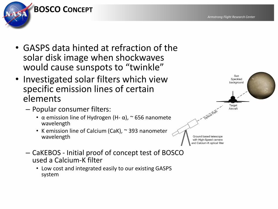
• GASPS data hinted at refraction of the solar disk image when shockwaves would cause sunspots to “twinkle”
• Investigated solar filters which view specific emission lines of certain elements– Popular consumer filters:
• α emission line of Hydrogen (H- α), ~ 656 nanometer wavelength
• K emission line of Calcium (CaK), ~ 393 nanometer wavelength
– CaKEBOS - Initial proof of concept test of BOSCO used a Calcium-K filter• Low cost and integrated easily to our existing GASPS
system

Armstrong Flight Research CenterCALCIUM-K ECLIPSE BACKGROUND ORIENTED SCHLIEREN
• The Calcium K filter only lets light through that is emitted by calcium ions in the sun’s chromosphere. Since these ions exist mainly in areas of strong magnetic fields, the sun’s surface has a granular appearance.
• These granulation cells act as the speckle background for the BOS technique

Armstrong Flight Research CenterCAKEBOS SYSTEM
Vixen Telescope
Lunt B1200
Calcium K filer
2X Focal Extender
(Barlow Lens)
Hispec High-Speed
digital camera
Imaging Laptop
12 Volt Battery
Camera Trigger
Ethernet
Meade Motorized
Mount
Mount Hand
Controller
• 80 mm f/7.5 refractor telescope• Calcium K filter: 393.4nm, 4 angstrom band pass• 2x Focal extender – Effective focal length: 1200mm• Fastec Hispec 2 camera
• 1280X1024• 506 Frames/sec• 400 µs integration time
• Manual solar tracking• Manually triggered at pilot’s “mark” call or visual eclipse

Armstrong Flight Research Center
CAKEBOS TEST OPERATIONS
• Aircraft waypoints were given in GPS coordinates and were calculated based on time of eclipse, ground position of the imager, and desired altitude of the aircraft.
• Waypoints were calculated on the order of 2 minutes.
• Course of the aircraft followed the sun direction across the sky, and flights occurred near the maximum solar elevation angle, to minimize the need for accurate waypoint timing.

Armstrong Flight Research CenterRAW DATA

Armstrong Flight Research CenterCAKEBOS ANALYSIS
• Initial image processing was done using cross correlation methods traditionally used for BOS
• Lack of discrete, high contrast speckles yielded poor correlation peaks
• Large interrogation windows reduced already limited resolution 50 averaged cross-correlation results

Armstrong Flight Research CenterCAKEBOS ANALYSIS
• Optical Flow
– Developed for computer vision applications in the 1970’s/80’s
– Uses the “brightness constancy criterion” – brightness is constant between 2 image pairs, differences in brightness correspond to motion
– Outputs “flow” vectors just as cross correlation does

Armstrong Flight Research Center
CAKEBOS ANALYSIS
• Image processing script was written utilizing the OpenCV package’s optical flow functions
– Horn and Schunck (HS) - Global Method, uses image derivatives. Minimizes global energy with smoothness parameter α.
– Lucas and Kanade (LK) – Local Method, uses image derivatives. Uses least squares about a local neighborhood to estimate motion
– Farnebäck (FB) - Local Method, estimates pixel neighborhood as a polynomial
𝜕𝐼
𝜕𝑥
𝛿𝑥
𝛿𝑡+𝜕𝐼
𝜕𝑦
𝛿𝑦
𝛿𝑡+𝜕𝐼
𝜕𝑡= 0
𝐸 = 𝜕𝐼
𝜕𝑥
𝛿𝑥
𝛿𝑡+𝜕𝐼
𝜕𝑦
𝛿𝑦
𝛿𝑡+𝜕𝐼
𝜕𝑡+∝2 ∆𝛿𝑥 2 + ∆𝛿𝑦 2 𝑑 𝑥𝑑𝑦
𝑓1 𝑥, 𝑦 = 𝑥, 𝑦 𝐴1𝑥𝑦 + 𝑏1
𝑇 𝑥𝑦 + 𝑐1
Brightness Constancy
H-S Global energy
FB Polynomial estimation

Armstrong Flight Research CenterCAKEBOS IMAGE PROCESSING
• The first 10 frames before the aircraft entered the field of view were used as reference backgrounds.
• Optical flow was performed on each frame with the aircraft in the field of view against the 10 background frames.
• The median pixel value of the 10 optical flow results were taken to get a single optical flow result for each frame with the aircraft in the field of view
• Each frame was shifted to a central point based on the aircraft trajectory.
• The final schlieren images were created by taking the median pixel values of all the shifted frames.
Optical flow result for a single frame with 10 reference
backgrounds

Armstrong Flight Research CenterCAKEBOS RESULTS – 70 AVERAGED IMAGES
X pixel displacement Y pixel displacement
H-S Pixel Displacement, X direction
-1
-0.8
-0.6
-0.4
-0.2
0
0.2
0.4
0.6
0.8
1Farnebäck Pixel Displacement, Y direction
-1
-0.8
-0.6
-0.4
-0.2
0
0.2
0.4
0.6
0.8
1

Armstrong Flight Research Center
CAKEBOS IMAGE PROCESSING – X DISPLACEMENT, 70 IMAGES
H-S L-K FB
L-K Pixel Displacement, X direction
-1
-0.8
-0.6
-0.4
-0.2
0
0.2
0.4
0.6
0.8
1H-S Pixel Displacement, X direction
-1
-0.8
-0.6
-0.4
-0.2
0
0.2
0.4
0.6
0.8
1
Farnebäck Pixel Displacement, X direction
-1
-0.8
-0.6
-0.4
-0.2
0
0.2
0.4
0.6
0.8
1Farnebäck Pixel Displacement, X direction
-1
-0.8
-0.6
-0.4
-0.2
0
0.2
0.4
0.6
0.8
1

Armstrong Flight Research CenterCAKEBOS IMAGE PROCESSING – Y DISPLACEMENT, 70 IMAGES
H-S L-K FB
Farnebäck Pixel Displacement, Y direction
-1
-0.8
-0.6
-0.4
-0.2
0
0.2
0.4
0.6
0.8
1
L-K Pixel Displacement, Y direction
-1
-0.8
-0.6
-0.4
-0.2
0
0.2
0.4
0.6
0.8
1
H-S Pixel Displacement, Y direction
-1
-0.8
-0.6
-0.4
-0.2
0
0.2
0.4
0.6
0.8
1Farnebäck Pixel Displacement, X direction
-1
-0.8
-0.6
-0.4
-0.2
0
0.2
0.4
0.6
0.8
1

Armstrong Flight Research CenterOPTICAL FLOW METHOD COMPARISON
Median value of 10 pixels in the Y’ axis was used to reduce noise in the plot

Armstrong Flight Research CenterBOSCO – APRIL 2016
• Success of CaKEBOS allowed for equipment upgrades
– Higher resolution Camera
• Photron WX-100: 2048 X 2048 pixels @ 1000 frames/sec
– Hydrogen alpha telescope
• More uniform texture distribution
• Speckle size is smaller and therefore better for BOS
• Higher contrast
H-α

Armstrong Flight Research CenterBOSCO SYSTEM (H-Α)
• 100 mm f/7 refractor telescope• H Alpha filter • 3x Focal extender – Effective focal length: 2100 mm• Photron WX-100
• 2048 X 2048 pixels• 1000 frames/sec• 333 µs integration time
• Manual solar tracking• Manually triggered at pilot’s “mark” call or visual eclipse
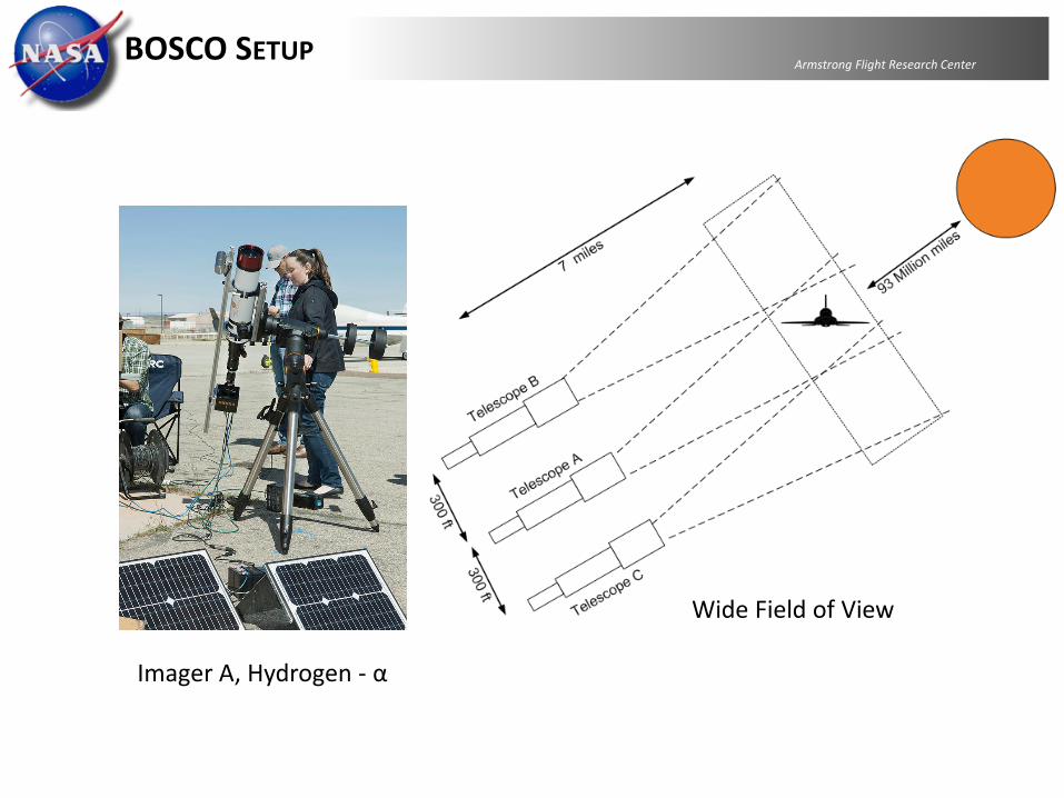
Armstrong Flight Research CenterBOSCO SETUP
Wide Field of View
Imager A, Hydrogen - α

Armstrong Flight Research Center
BOSCO DATA

Armstrong Flight Research Center
BOSCO RESULTS
Horizontal “knife edge”Vertical
“knife edge”

Armstrong Flight Research Center
BOSCO RESULTS
• Aircraft banked 600 for direct side view
3 Image Composite

Armstrong Flight Research CenterCONCLUDING REMARKS AND FUTURE WORK
• Solar chromosphere works well as a background for BOS
– Both Hydrogen – α line and Calcium-K line produced good results. • Initial results suggest H- α appears to be superior for BOS imaging
• For solar chromosphere BOS, optical flow algorithms produce much greater detail than current cross correlation methods
• Field of view can be increased with multiple camera array
• Method has pending patent• Future work
Airborne system for close-in imaging Would make possible low sun angle
imaging without being too far away• Non Aircraft imaging