army - fm90 7 - combined arms obstacle integration
TRANSCRIPT

FM 90-7 Combined Arms Obstacle Integration
HEADQUARTERS, DEPARTMENT OF THE ARMY DISTRIBUTION RESTRICTION: Approved for public release; distribution is unlimited.

FM 90-7 C1
Change 1 Headquarters Department of the Army Washington, DC, 10 April 2003
Combined Arms Obstacle Integration 1. Change FM 90-7, 29 September 1994, as follows:
Remove Old Pages Insert New Pages
B-3 and B-4 B-3 and B-4 2. A bar ( ) marks new or changed material. 3. File this transmittal sheet in front of the publication. DISTRIBUTION RESTRICTION: Approved for public release; distribution is unlimited. By Order of the Secretary of the Army: ERIC K. SHINSEKI General, United States Army Chief of Staff Official:
0307104 DISTRIBUTION: Active Army, Army National Guard, and US Army Reserve: To be distributed in accordance with the initial distribution number 115197, requirements for FM 90-7.
JOEL B. HUDSON Administrative Assistant to the
Secretary of the Army

FM 90-7
FIELD MANUALNo. 90-7
FM 90-7
HEADQUARTERSDEPARTMENT OF THE ARMY
Washington, DC, 29 September 1994
Combined ArmsObstacle Integration
Contents
i
FM 90-7
ii

FM 90-7
iii

FM 90-7
iv

FM 90-7
v

FM 90-7
vi
FM 90-7
vii

FM 90-7
viii
FM 90-7
Preface
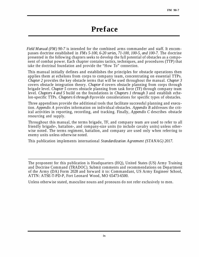
Field Manual (FM) 90-7 is intended for the combined arms commander and staff. It encom-passes doctrine established in FMs 5-100, 6-20 series, 71-100, 100-5, and 100-7. The doctrinepresented in the following chapters seeks to develop the full potential of obstacles as a compo-nent of combat power. Each chapter contains tactics, techniques, and procedures (TTP) thattake the doctrinal foundation and provide the “How To” connection.This manual initially defines and establishes the principles for obstacle operations thenapplies them at echelons from corps to company team, concentrating on essential TTPs.Chapter 2 provides the key obstacle terms that will be used throughout the manual. Chapter 3covers obstacle integration theory. Chapter 4 covers obstacle planning from corps throughbrigade level. Chapter 5 covers obstacle planning from task force (TF) through company teamlevel. Chapters 4 and 5 build on the foundations in Chapters 1 through 3 and establish eche-lon-specific TTPs. Chapters 6 through 8 provide considerations for specific types of obstacles.Three appendixes provide the additional tools that facilitate successful planning and execu-tion. Appendix A provides information on individual obstacles. Appendix B addresses the crit-ical activities in reporting, recording, and tracking. Finally, Appendix C describes obstacleresourcing and supply.Throughout this manual, the terms brigade, TF, and company team are used to refer to allfriendly brigade-, battalion-, and company-size units (to include cavalry units) unless other-wise noted. The terms regiment, battalion, and company are used only when referring toenemy units unless otherwise noted.This publication implements international Standardization Agreement (STANAG) 2017.
The proponent for this publication is Headquarters (HQ), United States (US) Army Trainingand Doctrine Command (TRADOC). Submit comments and recommendations on Departmentof the Army (DA) Form 2028 and forward it to: Commandant, US Army Engineer School,ATTN: ATSE-T-PD-P, Fort Leonard Wood, MO 65473-6500.Unless otherwise stated, masculine nouns and pronouns do not refer exclusively to men.
ix

FM 90-7
Chapter 1
Obstacles and theCombined Arms Team
Obstacles are any characteristics of the ter-rain that impede the mobility of a force.Some obstacles, such as mountains, rivers,railway embankments, and urban areas,exist before the onset of military operations.Military forces create other obstacles to sup-port their operations. Commanders usethese obstacles to support their scheme ofmaneuver. When integrated with maneuverand fires, obstacles can create a decisive bat-tlefield effect. Obstacle plans must matureas the commanders’ plans mature.
HISTORICAL USE OF OBSTACLES
History shows that obstacles rarely have asignificant effect on the enemy if units donot integrate them with friendly fires. Thefollowing historical vignette from World WarII is an example of obstacles that were notintegrated with fires.In February 1942, an engineer lieutenantwith two noncommissioned officers (NCOs)received orders to supervise the installation ofa minefield to support the defense of anAmerican infantry battalion near the Kasse-rine Pass in Tunisia. The lieutenant set offat 1930 hours with a truckload of mines, tolink up with one of the infantry battalion’s
companies. The company was to provide himwith a work detail to install the mines and,more importantly, provide the location of theminefield.At 2330 hours, he arrived at the infantry com-pany command post (CP), but no one at theCP could tell him the whereabouts of the workdetail. Nor could anyone tell him where theminefield should go or what role the mine-field was to play in the defense. The companyexecutive officer (XO) told the engineer to godown the road in the direction of the enemy.He assured the lieutenant that somewherealong the road he would meet someone whoundoubtedly was waiting for him.At 0130 hours, the lieutenant returned to theCP after searching along the road and find-ing no one. He insisted on speaking with theinfantry company commander who was sleep-ing. The infantry company commander toldthe lieutenant that he would provide himwith a forty-man detail, led by an infantrylieutenant who would show the engineerwhere to install the minefield.At 0330 hours, the infantry lieutenantshowed up with a twelve-man detail. Apolo-gizing for the small number of men, theinfantry lieutenant also told the engineer
Obstacles and the Combined Arms Team 1-1

FM 90-7
that he had no idea where the mines were togo. The engineer lieutenant moved out withthe detail to choose a site for the minefieldhimself. Unfortunately, he had never seen thesite in daylight and was unable to ensure thatthe obstacle was covered by fire (it was not).Additionally, the lieutenant had a small,untrained work crew, without the tools tobury the mines.When the first Germans arrived at the mine-field, they found mines hastily strewn acrossthe road, from a hill on one side to the roadembankment on the other (about 100 meters).Most mines were not even partially buried.German engineers quickly removed the minesfrom the road, and the German force contin-ued forward, unmolested by American fires.The minefield was virtually useless.Despite all of the problems that the lieuten-ant encountered, his efforts would not havebeen for nothing if the minefield had beenintegrated with fires. Small arms and artil-lery might have wreaked havoc on the dis-mounted German engineers, while a singleantitank (AT) weapon might have done thesame to the German tanks halted behind theminefield.The following historical vignette from theKorean War illustrates the possibilitieswhen a unit integrates fires and obstacles.In August of 1950, an American infantry regi-ment was defending along a stretch of theTaegu-Sangju Road known as the “BowlingAlley” in the Republic of Korea. The regimenthad artillery and a few tanks in support.The attacking North Koreans had the advan-tage of superior numbers of armored vehicles.However, as part of their defense, the Ameri-cans laid AT minefield close to their infantrypositions so that they could cover the mine-field with small-arms fire. They also prereg-istered artillery and mortar fires on theminefield.
When the North Koreans attacked, theywould invariably halt their tanks and send
dismounted infantry forward to breach theminefield. When the infantry reached theminefield, the Americans would open upwith machine-gun fire and pound the enemywith artillery and mortar fire. Simulta-neously, the American tanks and AT weaponswould start firing at the North Koreanarmored vehicles.In one night engagement, the Americansdestroyed eighteen North Korean tanks, fourself-propelled guns, and many trucks andpersonnel carriers, while taking only lightcasualties. Although the obstacles alone didnot defeat the enemy, friendly fires combinedwith the effects of the obstacles inflictedheavy losses on the enemy and halted theirattack.
CHARACTERISTICS OFOBSTACLES
Some obstacles, such as antitank ditches(ADs), wire, road craters (RCs), and manytypes of roadblocks, have virtually remainedthe same since World War II. They rely on aphysical object to impede vehicles or dis-mounted soldiers. Normally, they do notdamage or destroy equipment, nor do theyinjure or kill soldiers. One exception is abooby-trapped obstacle that, when it ismoved, triggers an explosive device; there-fore, these obstacles are passive in nature.Mine warfare, however, has changed signifi-cantly. Mines, with different fuze types andexplosive effects, are different from themines of the World War II era (whichrequired physical contact and relied on blasteffect). Today’s mines are triggered by pres-sure, seismic, magnetic, or other advancedfuzes. Mines that self-destruct (SD) atpreset times give commanders influenceover how long they remain an obstacle.The invention of programmable mines thatcan recognize and attack specific types ofvehicles within an area brings anotherdimension to the battlefield. Mine warfare
1-2 Obstacles and the Combined Arms Team

FM 90-7
technology continues to outpace counter-mine technology.Commanders at every echelon considerobstacles and their role in multiplying theeffects of combat power to integrate obsta-cles into all combined arms operations.Obstacles that are not properly integratedwith the scheme of maneuver are a hin-drance and may be detrimental to thefriendly scheme of maneuver by restrictingfuture maneuver options. They will inhibitmaneuver until they are breached orbypassed and ultimately cleared. The tech-nology used to create obstacles may continueto become more complex; however, the basicconcepts that affect the integration of obsta-cles into the commander’s plan will remainthe same.
DYNAMICS OF COMBAT POWERAND OBSTACLE INTEGRATION
Commanders combine four primary ele-ments (the dynamics of combat power asdescribed in FM 100-5) to create combatpower. They are—
Maneuver.Firepower.Protection.Leadership.
Obstacles, when properly planned and inte-grated into the scheme of maneuver, contrib-ute to combat power.
MANEUVERManeuver is the movement of combat forcesto gain positional advantage, usually todeliver—or threaten delivery of—direct andindirect fires. The effects of maneuver alsomay be achieved by allowing the enemy tomove into a disadvantageous position.Effective maneuver demands air and groundmobility, knowledge of the enemy and ter-rain, effective command and control (C2),
flexible plans, sound organizations, andlogistical support.Effective obstacle integration enhances theforce’s ability to gain, retain, or secure thepositional advantage. The commander andstaff use obstacle integration to develop anobstacle plan as they develop the maneuverplan. They use obstacle control to preserveand protect friendly maneuver and shapeenemy maneuver. They use obstacles to putthe enemy into a positional disadvantagerelative to the friendly force.
FIREPOWERFirepower provides the destructive force todefeat the enemy’s ability and will to fight.It facilitates maneuver by suppressing theenemy’s fires and disrupting the movementof his forces.Obstacle integration multiplies the effectsand capabilities of firepower. Obstacle inte-gration establishes a direct link betweenfires, fire-control measures, and obstacleeffects. The combination of firepower andobstacles causes the enemy to conform to thefriendly scheme of maneuver. Obstaclesmagnify the effects of firepower by—
Increasing target acquisition time.Creating target-rich environments.Creating vulnerabilities to exploit.
PROTECTIONProtection is the conservation of the fightingpotential of a force so that commanders canapply it at the decisive time and place. Pro-tection has the following components:
Maintaining operations security(OPSEC) and deception.Keeping soldiers healthy.Maintaining soldiers’ fighting moraleand safety.Avoiding fratricide.
Obstacles and the Combined Arms Team 1-3

FM 90-7
Friendly forces use OPSEC to deny theenemy information about friendly forceobstacles to inhibit the enemy’s breaching orbypassing efforts. They use phony obstaclesto deceive the enemy about locations ofactual obstacles and friendly positions.They use obstacles to prevent enemy entryinto friendly positions and installations tohelp protect soldiers from enemy assaults.Friendly forces record, report, and dissemi-nate obstacle information and take otheractions to protect soldiers from friendlyobstacle impacts. These impacts range frominjuries or damage to equipment, resultingfrom unexpected encounters with barbedwire obstacles, to fratricide caused by hittingmines installed by friendly units.
LEADERSHIPThe essential element of combat power iscompetent and confident leadership. Leader-ship provides purpose, direction, and moti-vation in combat. It is the leader whocombines the elements of combat power andbrings them to bear against the enemy. Thecompetent leader must know and under-stand soldiers and the tools of war to be suc-cessful in combat.Obstacle integration is a leader task. Obsta-cle integration ensures that obstacles havethe right priority and that units constructthem in the right place and at the right timeand cover them with fire. Successful obsta-cle integration allows leaders to—
Establish a clear link between forceallocation, direct-and indirect-fireplans, maneuver, and the obstacle plan.Ensure that weapons capabilities andobstacle effects are compatible.Provide obstacle control. nsure that obstacles are designed toachieve the desired effect.
Obstacle integration cuts across all func-tional areas of the combined arms force.Intelligence and obstacle integration providethe commander with the means to maximize
obstacle effects and affect both enemy andfriendly maneuver. The maneuver com-mander uses obstacles integrated with firesand maneuver to create vulnerabilities andensure the enemy’s defeat. Combat servicesupport (CSS) units anticipate and trans-port obstacle material to support the obsta-cle effort. Effective C2 provides the unity ofeffort that drives obstacle integrationthroughout all echelons of the force.
OTHER OBSTACLECONSIDERATIONS
The overriding consideration in planningobstacles is accomplishment of the mission;however, there are two considerations thatmay not be apparent in terms of the currentmilitary mission. They are—
Obstacle clearing at the cessation ofhostilities.Obstacle effects on noncombatants andtheir environment.
The Army’s keystone warfighting doctrine,FM 100-5, states that “even in war, thedesired strategic goal remains directed atconcluding hostilities on terms favorable tothe US and its allies and returning to peace-time as quickly as possible.” Once US forceshave accomplished their mission, obstaclesin the theater of operations (TO) must becleared. Many of these obstacles willinclude mines, booby traps, and unexplodedordnance (UXO) that pose a threat to per-sons attempting to clear the obstacles.
OBSTACLE CLEARINGObstacle-clearing operations continued foryears in Kuwait following the end of the1990-1991 Persian Gulf War, largely due toa lack of accurate minefield records by thedefending Iraqi forces. The minefield con-tinued to threaten civilians long after hostil-ities were concluded and caused numerouscasualties to military and civilian personnel.
1-4 Obstacles and the Combined Arms Team

.FM 90-7
Appendix B addresses the procedures thatthe Army uses to report, record, and trackobstacles of the friendly force and of theenemy. Accurate reporting, recording, andtracking not only will prevent fratricide butwill expedite clearing operations when peaceis restored.
EFFECTS ON NONCOMBATANTSCommanders also consider the effects ofobstacles on noncombatants and their envi-ronment. Obstacles frequently modify ter-rain through demolition, excavation, andother means. Some obstacle actions, such asdestroying levees, setting fires, felling treesin forested areas, or demolishing bridges,may have immediate impacts on noncomba-tants and often will have long-term effectson them and their environment.
Commanders minimize the effects of obsta-cles on noncombatants and the environmentif militarily possible. For example, if theenemy can be prevented from using a bridgeby means other than demolishing it,commanders choose the less damagingcourse of action (COA). Commanders avoidunnecessary destruction of farmland or for-ests or pollution of water sources when cre-ating obstacles. Care exercised bycommanders will alleviate long-term nega-tive effects on noncombatants and the envi-ronment.Obstacle integration occurs because of thedeliberate actions of commanders and staffs.The remainder of this manual focuses onproviding the doctrine and the TTP thatcommanders and staffs use to ensure thatobstacle integration is successful.
Obstacles and the Combined Arms Team 1-5

FM 90-7
Chapter 2
ObstacleFramework
This chapter provides a framework of termsand definitions that apply to obstacle plan-ning and integration. Precise use of theseterms creates a common language and pre-vents confusion during planning and execu-tion. The terms are presented in thefollowing general categories:
Obstacle classification.Obstacle intent.Obstacle protection.Obstacle C2.
OBSTACLE CLASSIFICATION
Obstacles are any physical characteristics ofthe terrain that impede the mobility of aforce. Obstacles fall into the following cate-gories (see Figure 2-1, page 2-2):
Existing obstacles.Reinforcing obstacles.
Although not a separate type of obstacle,units can use phony obstacles. Phony obsta-cles give the appearance of actual obstaclesbut require only minimal resources toemplace. They deceive the enemy by provid-ing the visual signature, or other signa-tures, of actual tactical or protectiveobstacles. Appendix A describes phonyobstacles.
EXISTING OBSTACLESExisting obstacles are obstacles that arepresent on the battlefield as inherentaspects of the terrain. The types of existingobstacles are—
Natural.Cultural.
Natural obstacles are terrain features, suchas rivers, forests, or mountains. Culturalobstacles are man-made terrain features,such as towns, canals, or railroad embank-ments.
REINFORCING OBSTACLESReinforcing obstacles are obstacles specifi-cally constructed, emplaced, or detonated bymilitary forces. The categories of reinforcingobstacles are—
Tactical.Protective.
Tactical Obstacles
The primary purposes of tactical obstaclesare to—
Attack the enemy maneuver.Multiply the effects and capabilities offirepower.
Obstacle Framework 2-1

FM 90-7
Tactical obstacles directly attack the tasks to a subordinate unit. Units plan, pre-enemy’s ability to move, mass, and reinforce.Commanders integrate these obstacles intothe force’s scheme of maneuver and direct-and indirect-fire plans to enhance the effectsof friendly fires. The types of tactical obsta-cles are clearly distinguished by the differ-ences in execution criteria. The three typesare—
Directed obstacles.Situational obstacles.Reserve obstacles.
Directed Obstacles. The higher com-mander directs these obstacles as specified
pare, and execute directed obstacles duringthe preparation of the battlefield. Most tacti-cal obstacles are directed obstacles, andmost directed obstacles are planned at TFlevel. Chapter 5 provides details on planningdirected obstacles in the context of TF obsta-cle planning, although the process is thesame at any level.Situational Obstacles. Situational obsta-cles are obstacles that units plan, andpossibly prepare, before beginning an opera-tion; however, they do not execute the obsta-cles unless specific criteria are met.Therefore, units may or may not execute
2-2 Obstacle Framework

FM 90-7
situational obstacles, depending on the situ-ation that develops during the battle. Theyare “be prepared” obstacles and provide thecommander flexibility for emplacing tacticalobstacles based on battlefield development.Chapter 7 provides specific considerationsfor planning situational obstacles.Reserve Obstacles. Reserve obstacles areobstacles for which the commander restrictsexecution authority. These are “on-order”obstacles. The commander usually specifiesthe unit responsible for emplacing, guard-ing, and executing the obstacle. Units nor-mally plan and prepare reserve obstaclesduring preparation of the battlefield. Theyexecute the obstacles only on command ofthe authorizing commander or based on spe-cific criteria that the commander identifies.Chapter 6 provides specific considerationsfor planning reserve obstacles.Tactical Obstacle Design. Units base tac-tical obstacle designs (width, depth, andcomposition) on the intended obstacle effectand formation of the attacker. They developtactical obstacle designs to achieve one offour obstacle effects—disrupt, turn, fix, orblock. Standard designs simplify obstacleresourcing, training, and effectiveness. SeeAppendix A for more information.
Protective Obstacles
Protective obstacles are a key component ofsurvivability operations. Like final protec-tion fires (FPF), protective obstacles providethe friendly force with close-in protection.The two types of protective obstacles are—
Hasty.Deliberate.
Hasty Protective Obstacles. These areprotective obstacles that are temporary innature. Soldiers can rapidly emplace andrecover or destroy them. Platoons andcompany teams employ hasty protectiveobstacles next to their positions to protect
the defending force from the enemy’s finalassault (see Figure 2-2). Base commandersand base cluster commanders may emplacehasty protective obstacles to protect againstall levels of threat in the rear area whensites are to be occupied temporarily.
Deliberate Protective Obstacles. Theseare protective obstacles that are more per-manent and that require more detailedplanning and usually more resources. Unitsemploy deliberate protective obstacles instrongpoints or at relatively fixed sites. Dur-ing operations other than war (OOTW),units emplace deliberate protective obsta-cles as part of their force protection plan.Units base the composition of protectiveobstacles on analysis of the situationaltemplate. They design protective obstacles
Obstacle Framework 2-3

FM 90-7
against the most severe and the most likelyclose combat threat. Emplacing unitsremove protective obstacles—or turn themover to relieving units—before departing thearea. A unit must report if it abandons pro-tective obstacles due to tactical necessity.Chapter 8 covers protective obstacles ingreater detail.
OBSTACLE INTENT
Obstacle intent is how the commanderwants to use tactical obstacles to support hisscheme of maneuver. Obstacle intent con-sists of the following components:
Target.Obstacle effect.Relative location.
TARGETThe target is the enemy force that the com-mander wants to affect with tactical obsta-cles. The commander usually identifies thetarget in terms of the size and type of enemyforce, the echelon, the avenue of approach(AA), or a combination of these things.
OBSTACLE EFFECTTactical obstacles and fires manipulate theenemy in a way that supports the com-mander’s intent and scheme of maneuver.The intended effect that the commanderwants the obstacles and fires to have on theenemy is called the obstacle effect. Theobstacle effect—
Drives integration.Focuses subordinates’ fires.Focuses obstacle effort.Multiplies the effects of firepower.
It is important to remember that obstacleeffects occur because of fires and obstacles,not just obstacles alone. All tactical obsta-cles produce one of the following obstacleeffects:
Disrupt.Turn.Fix.Block.
Disrupt Effect
The disrupt effect focuses fire planning andobstacle effort to cause the enemy to breakup its formation and tempo, interrupt itstimetable, commit breaching assets prema-turely, and piecemeal the attack. It alsohelps to deceive the enemy concerning thelocation of friendly defensive positions, toseparate combat echelons, or to separatecombat forces from their logistical support.Figure 2-3 depicts a disrupt effect on anattacking battalion. To achieve a disrupteffect, normally the obstacles must attackhalf the enemy’s AA. The obstacles shouldnot require extensive resources. Theyshould not be visible at long range butshould be easily detected as the enemynears them. Commanders normally use thedisrupt effect forward of engagement areas(EAs).
Turn Effect
The turn effect integrates fire planning andobstacle effort to divert an enemy formationoff one AA to an adjacent AA or into an EA.Its development requires well-definedmobility corridors (MCs) and AAs. Fig-ure 2-4, page 2-6, depicts a turn effect on anattacking battalion. To achieve this effect,the obstacles have a subtle orientation rela-tive to the enemy’s approach. The obsta-cles and fires allow bypasses in thedirection desired by the friendly scheme ofmaneuver. Obstacles at the start of the turnare visible and look more complex thanthose in the direction of the turn. Finally,the obstacles tie into impassable terrain atthe initial point of the turn. Commandersnormally use the turn effect on the flanks ofan EA.
2-4 Obstacle Framework

FM 90-7
Fix Effect
The fix effect focuses fire planning and obsta-cle effort to slow an attacker within a speci-fied area, normally an EA. Primary use ofthis effect is to give the friendly unit time toacquire, target, and destroy the attackingenemy with direct and indirect fires through-out the depth of an EA or AA. The fix effectmay generate the time necessary for thefriendly force to break contact and disengageas the enemy maneuvers into the area. Fig-ure 2-5, page 2-7, depicts a fix effect on anattacking battalion. To achieve the fix effect,
units array obstacles in depth to cause theenemy formation to react and breach repeat-edly. The obstacles must span the entirewidth of the AA, but they must not make theterrain impenetrable. The individual obsta-cles must look as if they could be easilybypassed or breached. A combination ofobstacles that are clearly visible and othersthat are unseen (such as buried mines andobstacles on the reverse slope) help to con-fuse the enemy once it encounters the obsta-cles. Commanders normally use the fixeffect inside the EA.
Obstacle Framework 2-5

FM 90-7
NOTE: The fix effect is differentfrom the maneuver action fix,which requires preventing the ene-my from moving any part of itsforce from a specific location. Care-ful use of the term “fix effect” willprevent confusion.
Block EffectThe block effect integrates fire planningand obstacle effort to stop an attacker alonga specific AA or prevent him from passingthrough an EA. Figure 2-6, page 2-8, depictsa block effect on an attacking battalion. To
achieve the block effect, units integrate com-plex obstacles with intense fires to defeatthe enemy’s breaching effort. Complexobstacles are obstacles that require morethan one breaching technique to breach theobstacle. Units array obstacles successivelyin a shallow area. When the enemy breachesone obstacle integrated with intense fires, itencounters another obstacle integratedwith intense fires. Obstacles must defeatthe enemy’s mounted and dismountedbreaching effort. They must span theentire width of the AA, allowing no bypass.Obstacles intended to stop the enemy alonga specific AA should be readily visible to
2-6 Obstacle Framework

FM 90-7
discourage the enemy. Obstacles used to pre-vent an enemy from passing through anEA should not be as visible so that theydo not discourage the enemy from enteringthe EA. The block effect is used in one oftwo instances. The first is to stop the enemyfrom using an AA and force it into anotheravenue that better supports the friendlyscheme of maneuver. The second is to stopthe enemy’s forward movement and assist inthe complete destruction of its force at thebase of the EA.
Obstacle Effect Graphics
Commanders depict obstacle effects graphi-cally. There is a separate graphic for eacheffect (see Figure 2-7, page 2-9). Command-ers use obstacle effect graphics to convey theeffect they want the obstacles to have on theenemy.
RELATIVE LOCATIONThe relative location is where the com-mander wants the obstacle effect to affect
Obstacle Framework 2-7

FM 90-7
the target. Wherever possible, commandersgive obstacle locations relative to maneuveror fire-control measures to integrate theeffects of obstacles with fires.
OBSTACLE PROTECTIONObstacle protection is protecting the integrityof obstacles. Both the emplacing unit (theunit that constructs the obstacle) and theowning unit (normally the company teamresponsible for siting the obstacle) play a rolein obstacle protection. The following activi-ties ensure obstacle protection:
Conducting counterreconnaissanceoperations.Targeting and destroying breachingequipment.Repairing breached obstacles.Using phony obstacles.
COUNTERRECONNAISSANCEEnemy reconnaissance operations beginwell ahead of any planned operation.Friendly forces conduct counterrecon-naissance to prevent the enemy from gath-ering information on friendly preparations.
2-8 Obstacle Framework

FM 90-7
FMs 71-2 and 71-3 discuss counterreconnais-sance operations in detail. The reconnais-sance and surveillance (R&S) plan includesobstacle protection as part of the counter-reconnaissance plan.Establishing obstacle responsibility is criticalto obstacle protection. Commanders mustenforce obstacle ownership. Company teamsuse patrols and constant observation toensure that the enemy does not conductreconnaissance of friendly obstacles. Thisnot only prevents the enemy from gain-ing detailed information but also preventsa small enemy force from covertly breach-ing the obstacle before its attack. Figure2-8, page 2-10, depicts one company team’s
actions in conducting a patrol. A listeningpost/observation post (LP/OP) that main-tains constant observation on the obsta-cle is also depicted. Other assets, such asground surveillance radars (GSRs) orremote sensors, can aid in detecting infil-trating enemy forces that are attemptingreconnaissance or a covert breach.
BREACHING ASSET DESTRUCTIONOnce the battle begins, early identificationand destruction of the enemy’s breach-ing equipment, along with C2 vehicles,ensure maximum effectiveness of obstacles.Destroying a tank with an attachedmine plow or roller reduces the enemy’s
Obstacle Framework 2-9

FM 90-7
breaching capability. This increases the timefor the friendly force to engage and destroyother combat vehicles. Units identify highpay-off targets (HPTs) in the enemy’s orderof battle and establish priority of engage-ment by friendly weapon systems.
OBSTACLE REPAIRAs part of obstacle protection, the com-mander must plan for obstacle-repair contin-gencies. Obstacle repair must occur in thefollowing instances:
When a patrol detects enemy covertbreach attempts in tactical obstacles.
Between enemy echelons or during alull in the battle.
Overmatching forces rely on quick repairmethods, such as using modular pack minesystems (MOPMS) or hand emplacing two tothree mines in the enemy’s breaching lane.Units must plan, resource, andobstacle-repair contingencies.
PHONY OBSTACLESPhony obstacles can support the
rehearse
completeobstacle protection plan. Examples includeminefield marking where no minefield exists
2-10 Obstacle Framework
FM 90-7
or shallow excavations and berms that looklike ADs. Phony obstacles serve to confuseenemy reconnaissance and breaching ele-ments concerning the location of actualobstacles.
OBSTACLE COMMANDAND CONTROL
Obstacle C2 focuses on—Obstacle-emplacement authority.Obstacle control.
OBSTACLE-EMPLACEMENTAUTHORITY
Obstacle-emplacement authorityauthority that a unit commander
is thehas to
emplace reinforcing obstacles. In a TO, the-ater commanders have the authority toemplace obstacles. In almost all cases, theydelegate the authority to corps commanderswho further delegate the authority to divi-sion commanders. Once this authority is
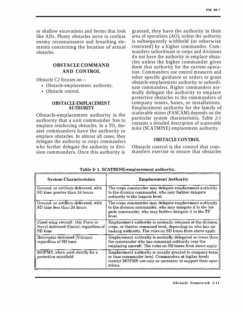
granted, they have the authority in theirarea of operations (AO), unless the authorityis subsequently withheld (or otherwiserestricted) by a higher commander. Com-manders subordinate to corps and divisionsdo not have the authority to emplace obsta-cles unless the higher commander givesthem that authority for the current opera-tion. Commanders use control measures andother specific guidance or orders to grantobstacle-emplacement authority to subordi-nate commanders. Higher commanders nor-mally delegate the authority to emplaceprotective obstacles to the commanders ofcompany teams, bases, or installations.Emplacement authority for the family ofscatterable mines (FASCAM) depends on theparticular system characteristics. Table 2-1contains a detailed description of scatterablemine (SCATMINE) emplacement authority.
OBSTACLE CONTROLObstacle control is the control that com-manders exercise to ensure that obstacles
Obstacle Framework 2-11

FM 90-7
support current and future operations. Obsta-cle control ensures that subordinate com-manders emplace obstacles to best supportthe higher commander’s scheme of maneuver.Obstacle control also ensures that subordi-nate commanders do not emplace obstaclesthat will interfere with future operations.Commanders maintain obstacle control by—
Focusing or withholding emplacementauthority.Restricting types or locations of obsta-cles.
Commanders use control measures, specificguidance, and orders to maintain obstaclecontrol.
Obstacle-Control MeasuresObstacle-control measures are specific controlmeasures that simplify granting obstacle-
emplacement authority and providing obsta-cle control. Table 2-2 summarizes some con-siderations for use of obstacle-controlmeasures. Figure 2-9 shows the obstacle-control- measure graphics. Chapter 3 coversthe use of obstacle-control measures to sup-port obstacle integration. Obstacle-controlmeasures are—
Zones.Belts.Groups.Restrictions.
Obstacle Zones. Obstacle zones are agraphic control measure that corps and divi-sion commanders use to grant obstacle-emplacement authority to brigades (includ-ing armored cavalry regiments (ACR) andother major subordinate units). Corpsand division commanders also use zones to
2-12 Obstacle Framework

FM 90-7
ensure that subordinates emplace obstaclesthat support the higher commander’sscheme of maneuver and that do notinterfere with future operations. Chapter 4covers the use of obstacle zones for obstacleplanning.
Corps and divisions plan obstacle zonesbased on brigade AOs. When defendingagainst an enemy of similar composition andcapability, they align brigades and zoneswith enemy division AAs as defined byregimental MCs. However, a light divisiondefending against a mechanized enemy mayplan obstacle zones based on enemy regimen-tal AAs as defined by battalion-size MCs. Inthe offense, zone planning is more flexible.Corps and divisions still align obstacle zoneswith areas for which brigades are responsi-ble. In any case, if the obstacle zone encom-passes the entire brigade sector, anothergraphic is unnecessary. Commanders maydesignate the entire sector as an obstaclezone, with the unit boundaries defining thegeographical limits of the zone.
Obstacle zones do not cross brigade bound-aries. Commanders assign zones to a singlesubordinate unit to ensure unity of effort,just as they would defensive sectors or battlepositions (BPs). This keeps tactical obstacleresponsibility along the same lines as con-trol of direct and indirect fires. This does notnormally create a vulnerability on theboundary between units since commandersbase both sectors and obstacle zones ondefined AAs.Adjacent brigades may rarely cover thesame AA, but obstacle zones still do notcross unit boundaries. Commanders giveadjacent brigades obstacle zones that meetalong their boundaries. To ensure unity ofobstacle effort, the commander designates acontact point for obstacle coordinationbetween the adjacent brigades. The divisioncommander also may assign more thanone zone to a unit. This technique is usefulwhen the commander wants to constraintactical obstacle employment to two or morespecific areas, leaving the remainder free fordivision maneuver.
Obstacle Framework 2-13

FM 90-7
Commanders can assign an obstacle intentto an obstacle zone, but they normally donot. Although the target (normally an enemydivision) and relative location (the area ofthe zone) are apparent, commanders nor-mally do not specify an obstacle effect fora zone. This allows the subordinate com-mander flexibility in using obstacles. Estab-lishing zone priorities helps identify thedivision obstacle main effort to subordinates.Obstacle zones also assist the corps or divi-sion staff to resource and plan obstacle logis-tics throughput to the brigades. Staffsresource obstacle zones by anticipating howthe brigades will use obstacles based ontheir assigned mission, intelligence prepara-tion of the battlefield (IPB), task organiza-tion, and division commander’s intent.Appendix C contains a detailed discussion ofobstacle resourcing and supply.Obstacle Belts. Obstacle belts are thegraphic control measure that brigade com-manders use to constrain tactical obsta-cle employment. They plan obstacle beltswithin assigned obstacle zones to grantobstacle-emplacement authority to theirmajor subordinate units. Obstacle belts alsofocus obstacles in support of the brigadescheme of maneuver and ensure that obsta-cles do not interfere with the maneuver ofany higher HQ Chapter 4 contains adetailed discussion of the use of obstaclebelts for obstacle planning.Brigade commanders use obstacle belts toattack the maneuver of enemy regiments (orenemy brigade-size units). They plan andallocate belts against regimental AAs basedon battalion MCs. This is consistent withbrigade planning, which allocates companiesagainst battalion MCs and task organizesTFs to defeat enemy regiments. As withobstacle zones, light units defending againstmechanized forces focus obstacle belts oneechelon down.For the same reasons as discussed in obsta-cle zones, obstacle belts do not cross unit
boundaries. A single unit is responsible for abelt; however, commanders may assignmore than one belt to a unit. TF command-ers cannot plan or emplace obstacles outsidebrigade-directed obstacle belts. Command-ers use the same techniques as for obstaclezones to ensure coordination along unitboundaries and may designate entire TFsectors as obstacle belts.Brigade commanders normally assign anobstacle intent to each obstacle belt. As withthe obstacle zone, the target and relativelocation are apparent. The addition of a spe-cific obstacle effect gives purpose and direc-tion to TF obstacle planning. When brigadecommanders assign an obstacle effect, theyensure that obstacles within the belt com-plement the brigade fire plan. The combina-tion of obstacle belts with specific effects isthe commander’s obstacle intent. It conveysthe effect that must be achieved by fires andobstacles (obstacle effect) against a specificenemy (target) within the defined belt (rela-tive location) to his TF commanders.
Obstacle belts refine the area authorized fortactical obstacles; however, they still giveTF commanders the latitude they need todevelop detailed obstacle plans based ondirect-fire planning. The brigade com-mander’s obstacle intent is descriptiverather than prescriptive. Assigning a spe-cific obstacle effect to a belt does not preventTF commanders from employing the fullrange of tactical obstacle effects within thebelt; however, the combined effect mustachieve the assigned intent of the belt.Obstacle belts are also critical tools inresourcing and planning obstacle logistics.There are two key components to logisticallysustaining the obstacle effort:
The commander and staff mustresource the belt with the material,manpower, and time required toemplace the obstacles to meet theintent.
2-14 Obstacle Framework
FM 90-7
The brigade must develop a plan forgetting the necessary resources to theright place, in the right amount, and insufficient time.
Obstacle belts help the staff to identifyrequirements and plan transportation.Appendix C contains a more detailed descrip-tion of belt resourcing and supply.
NOTE: The commander at corps, di-vision, or brigade level may autho-rize emplacement authority forcertain types of protective obsta-cles outside of obstacle zones orbelts. Normally, the commanderwill authorize company team andbase commanders to emplace pro-tective obstacles within 500 metersof their positions (mission, enemy,troops, terrain, and time available(METT-T) dependent). The com-mander usually limits the types ofobstacles that a unit may use forprotective obstacles that are out-side of obstacle-control measures(for example, allowing only wireand antipersonnel (AP) mines out-side of control measures for protec-tive obstacles and requiring thatminefield be fenced on all sides toprevent fratricide).
Obstacle Groups. Obstacle groups are oneor more individual obstacles grouped to pro-vide a specific obstacle effect. TFs use obsta-cle groups to ensure that company teamsemplace individual obstacles that supportthe TF scheme of maneuver. In rare cases,brigades, divisions, or even corps may useobstacle groups for specific tactical obstacles.Also, units integrate obstacle groups withdirect- and indirect-fire plans in detail.Obstacle groups usually attack the maneu-ver of enemy battalions. Normally, com-manders plan obstacle groups along enemybattalion AAs as defined by company MCs.They may plan a group along a company-sizeAA. This is especially true for friendly light
forces. Unlike obstacle zones or belts,obstacle groups are not areas but are rela-tive locations for actual obstacles. Com-manders normally show obstacle groupsusing the obstacle effect graphics. Whendetailed planning is possible (to includedetailed on-the-ground reconnaissance),commanders may show obstacle groupsusing individual obstacle graphics. Chapter5 contains a detailed discussion of the useof obstacle groups in obstacle planning.Commanders can plan obstacle groups with-in the limits of their obstacle-emplacementauthority. Corps and division commanderscan plan obstacle groups anywhere intheir AOs. Brigade and TF commanderscan plan them anywhere in their obstaclezones or belts, respectively. Because of therequirement for detailed integration withthe fire plan, very few obstacle groupsare planned above TF level. Unless solelyintegrated with indirect fires, obstaclegroups planned at corps, division, or bri-gade level ultimately are integrated withfire at the TF level. When given a belt withan assigned intent, the TF commander canuse any combination of group effects if thesum effect of all groups achieves the beltintent.Obstacle groups impose strict limitationson company team commanders to preservethe link between obstacle effects and thefire plan. The limitations are similar to thelimitations imposed by a BP. A group doesnot give the exact location of obstacles inthe group just as a BP does not show theexact location of each weapon in the com-pany team. The company team commanderand the emplacing unit leader, usually anengineer, coordinate these details directly.The company team commander and theengineer can adjust obstacles in the groupif the intent and link to the fire planremain intact. Company team commandersmake minor changes to obstacles and fire-control measures based on the reality of theterrain. For example, a commander may
Obstacle Framework 2-15

FM 90-7
move a fixing obstacle group and direct-firetarget reference points (TRPs) a few hun-dred meters to avoid having them maskedby rolling terrain. A major change to theobstacle-group location requires theapproval of the commander who ordered theobstacle group emplacement.Obstacle-ADgroup responsibility falls alongthe same lines as fire control. Normally,company team fire plans are relatively sim-ple, massing the company team’s fires on asingle AA at a time. Simplicity is essential inensuring that company team commanderscan focus their C2 on maximizing theeffects of the obstacle group. A TF shouldnot assign a company team more thantwo obstacle groups; however, it can effec-tively fight only one group at a time. Tomass fires on an obstacle group, more thanone company team will often cover a sin-gle obstacle group. In these cases, the com-mander who is responsible for establishingthe EA is also in charge of integrating theobstacle group. Normally, the TF com-mander or Operations and Training Officer(US Army) (S3) plays a significant role inbuilding and synchronizing an EA coveredby two or more companies.Obstacle groups, resource factors, and stan-dard individual obstacles are the basis of TFobstacle logistics planning. They enable thecommander and staff to allocate the neces-sary resources to each obstacle group, EA, orcompany team BP. These tools also enablethe staff to identify critical shortfalls, planthe flow of materials within the TF area, andschedule resupply, Appendix C addressesobstacle resourcing in detail.Obstacle Restrictions. Commanders at alllevels may use obstacle restrictions to pro-vide additional obstacle control. Command-ers may use obstacle restrictions to limit thespecific types of obstacles used (for example,no buried mines or no SCATMINEs). Theserestrictions ensure that subordinates donot use obstacles with characteristics
that impair future operations. It also allowscommanders to focus the use of limitedresources for the main effort by restrictingtheir use elsewhere. Commanders also mayuse restrictions to prevent subordinatesfrom emplacing obstacles in a certain area.This type of restriction may be shown graph-ically as an obstacle restricted area.Units also may indicate this type of restric-tion in the operation order (OPORD). Forexample, the order may state that there willbe no obstacles along a designated mainsupply route (MSR) or no demolition of acertain bridge. This type of restriction alsomay be implied. For example, a plannedcorps counterattack (CATK) axis implies tothe division that the axis is an obstaclerestricted area. Subordinate commandershave the right to be more restrictive thanthe higher commander; however, the subor-dinate commander cannot relax the highercommander’s restrictions.
Obstacle NumbersObstacle zones, belts, and groups are labeledwith alphanumeric designators. An obstaclenumber is a twelve-character designatorthat is given to each individual obstacle.The first four characters designate the HQthat ordered the obstacle zone. The nextthree characters are a letter for the obstaclezone, a number for the obstacle belt, andanother letter for the obstacle group. Thenext two characters are an abbreviation ofthe individual obstacle type. This is fol-lowed by a two-digit number indicating thenumber of the individual obstacle in thegroup. The last character is a status code.Appendix B contains a detailed explanationof the use of the alphanumeric designator inthe obstacle reporting and recording system.The terms and definitions used in this chap-ter lay the groundwork for understandingthe remainder of this manual. The followingchapters explain obstacle integration andplanning.
2-16 Obstacle Framework
FM 90-7
Chapter 3
Obstacle-IntegrationPrinciples
Obstacle integration is the process of ensur-ing that the obstacle effects support thescheme of maneuver. Obstacle integrationcuts across all functional areas and all eche-lons. An understanding of the basic princi-ples behind obstacle integration is essentialfor commanders and staffs at all levels.These principles are the cornerstone forobstacle planning discussed in Chapters 4and 5.Commanders and staffs consider the follow-ing to ensure that obstacles have the desiredimpact on the battle:
Intelligence.Obstacle intent.Fires and obstacle effects.Obstacles and operations in depth.Obstacle control.Echelons of obstacle planning.
INTELLIGENCE
Battlefield success depends largely on theability of the commander to see the battle-field. He identifies enemy vulnerabilitiesand how the enemy may use the existing ter-rain to gain an advantage. The maneuvercommander does this through the IPB
process (FM 34-130 covers the IPB processin detail). The IPB integrates enemy doc-trine with the terrain and weather, mission,and current battlefield situation. The IPBprocess helps the commander to—
Decide where to kill the enemy.Define the decisive point based on theterrain, enemy doctrine, and vulnera-bilities.
Key steps in the IPB process are to—Analyze the terrain.Determine enemy force size.Determine enemy vulnerability.
ANALYZE THE TERRAINStaffs conduct terrain analysis based on thefive military aspects of terrain: observationand fields of fire, cover and concealment,obstacles, key terrain, and avenues ofapproach (OCOKA). The obstacles inOCOKA are normally existing obstacles;however, reinforcing obstacles from previ-ous military operations may be present insome situations. The identification of MCsand AAs helps the commander to decidewhere the enemy can maneuver and to iden-tify any limitations on friendly maneuver.
Obstacle Integration Principles 3-1

FM 90-7
DETERMINE ENEMY FORCE SIZEThe next step is to determine the size of theenemy force that each AA can support. Theprimary reason for determining the size ofthe enemy force is to allocate friendly forces.An important consideration is to identifyany terrain that may cause the enemy tochange formation.
DETERMINE ENEMY VULNERABILITYIn the last step, the commander and staffconsider where the enemy is vulnerable.Attacking the enemy at the point of vulnera-bility with fires and obstacles can lead to adecisive victory. Also, obstacles should bedesigned against an enemy’s breaching vul-nerability. If some types of obstacles can beeasily breached by the enemy, using thoseobstacles to shape the battlefield may beineffective.
OBSTACLE INTENT
The commander decides how he wants to useobstacles to support his scheme of maneu-ver. He defines the end result that fires andobstacles must achieve. His obstacle intentprovides purpose and unity of effort to theobstacles emplaced by subordinates. At TFlevel and normally at brigade level, obstacleintent identifies the following:
Target.Obstacle effect.Relative location.
TARGETObstacles are a force-oriented combat multi-plier. Subordinates must understand thetarget of the obstacles so that they can prop-erly design and site obstacles.
OBSTACLE EFFECTSubordinates must know the commander’sdesired obstacle effect: disrupt, turn, fix, or
block. This provides a common expectationof the effect that the commander wantstheir fires and obstacles to have on enemymaneuver.
RELATIVE LOCATIONObstacle location is a vital component ofobstacle intent since it ties the obstacleeffect and target to the scheme of maneuver.Subordinates must understand the relativelocation of obstacles to ensure that thedesired effect occurs at the right place. Com-manders establish their obstacle intent con-current with organizing and developing thefire plan or scheme of maneuver. Each com-ponent of obstacle intent directly influencesthe fire plan or scheme of maneuver. Obsta-cle planning does not drive fire planning orthe scheme of maneuver. Subordinatesplan, adjust, and execute obstacles and fire-and maneuver-control measures to meet thecommander’s obstacle intent.Figure 3-1 illustrates the impact that obsta-cle intent can have on adjusting fire-controlmeasures at the TF level. The TF com-mander assigns Team A to occupy anddefend BP 10 oriented in EA Blue on TRPs01 and 02. The commander intends to usethe obstacles and fires in EA Blue to turn anenemy battalion to the south. To mass firesat the initial turning point, the TF com-mander adds TRP 03. The company teamcommander must first mass all firesbetween TRPs 01 and 03. Once the enemyforce begins turning, the commander willshift some or all fires between TRPs 02 and03.
FIRES AND OBSTACLE EFFECT
All leaders (from TF commander to squadleader) must understand how obstacles andfires mesh to achieve the obstacle effect.This enables them to maximize the effective-ness of available fires and obstacles, exploit
3-2 Obstacle Integration Principles

FM 90-7
the weaknesses they create in the enemy,and defeat the enemy attack. Fire controlrequires that named areas of interest (NAIs),targeted areas of interst (TAIs), and TRPssynchronize indirect fires with direct firesand obstacles.
FIRES AND DISRUPT EFFECTCommanders use the disrupt effect to causean enemy to—
Break up his formation and tempo.Interrupt his timetable.Commit breaching assets prematurely.Piecemeal his attack.
The disrupt effect also helps to deceive theenemy concerning the location of friendlydefensive positions, separate combat eche-lons, or separate combat forces from theirlogistical support. To accomplish the disrupteffect, the obstacles and fires must—
Cause the enemy to deploy early.Slow and disrupt part of the enemyforce.Allow part of the enemy force to ad-vance unimpeded.
Commanders use indirect fires and long-range direct fires to force the enemy tochange from a march formation to a prebattleor attack formation. Generally, indirect firesalone will not force an enemy to deployexcept when he is dismounted.Commanders plan suppression and neutral-ization indirect-fire targets (or groups) on the
obstacles in the disrupt obstacle group. Theyuse indirect fires with the obstacles to slowthe part of the enemy force that makes con-tact with the obstacles. Commanders alsouse every means available to disrupt enemyC2 throughout the enemy formation. Com-manders use electronic warfare (EW),smoke, and indirect fires to disrupt theenemy’s decision cycle and increase thedirect-fire window on the unimpeded part ofthe enemy force.Commanders use TRPs to mass direct firesagainst that part of the enemy formation notimpeded by obstacles and indirect fires.They do not execute those fires until theforce separates from its parent formation.They use direct-fire weapons that candeliver a lethal initial volley of fire. A quickvolley is critical if the enemy has good C2and can react quickly to the disruption of itsformation. Disengagement criteria are alsoa consideration in weapons selection. If com-manders plan a short engagement, theychoose a weapon system that can fire andmaneuver without becoming decisivelyengaged. If they expect a long engagement,they select a weapon system that can sus-tain rapid fire with sufficient survivabilityto support the engagement.Commanders plan fire-control measuresthat allow for the shift of direct or indirectfires to the enemy slowed by the obstacle orto the enemy bypassing the obstacle. Theyposition themselves to make an assessmentof the obstacle effect. If the enemy is rapidlybreaching the obstacles, they may shift
Obstacle Integration Principles 3-3

FM 90-7
direct fires against the enemy’s breachingassets. On the other hand, if too large a forcebypasses, commanders may shift all firesagainst the unimpeded enemy to inflict max-imum losses and then reposition friendlyforces to their subsequent positions.Figure 3-2 illustrates the integration of fireswith obstacles to achieve a disrupt effect. Inthis example, the TF commander assignsTeam D to defend BP 14 oriented in EA Redto disrupt the lead enemy battalion forwardof the TF EA. Team D will then reposition toa subsequent BP to help in the fight in theTF EA. Team D is a balanced company teamwith one armor platoon, one mechanizedinfantry platoon, and an armor company HQ.Fire-control measures include TRPs 03 and04 forward of the obstacle group and TRPs01 and 02 south of the obstacle group. TheTF commander orders the TF fire supportofficer (FSO) to plan artillery group AIB as asuppression mission to cover the disruptobstacle group. The FSO assigns the Team Dfire support team (FIST) the responsibilityfor execution of A1B.As the attacking enemy approaches theobstacle group, the company team com-mander orders the mechanized platoon toengage using the Bradley fighting vehicles’(BFV’s) tube-launched, optically tracked,wire-guided (TOW) missiles between TRPs03 and 04. The commander uses indirect
fires with the long-range TOW fires, whichcauses the enemy to button up and deployinto prebattle formation.The commander orders the company teamFIST to execute group A1B to coincide withthe enemy’s encounter with the obstacles inthe obstacle group. Group A1B includesdual-purpose improved conventional muni-tions (DPICM) and smoke. The combinationof fires, smoke, and obstacles slows thenorthern half of the enemy. As the enemyloses C2 over its formation, the southernhalf of the enemy separates from theremainder of the battalion and continuesforward.As the southern half of the enemy formationreaches the line defined by TRPs 01 and 02,the company team commander masses alldirect fires on the lead enemy vehicles. Thecompany team commander uses volley firesto destroy the southern half of the enemybattalion. He then shifts all direct fires tothe remainder of the enemy force, fires onevolley, and repositions to his subsequent BP.
FIRES AND TURN EFFECTCommanders use the turn effect to integratefires and obstacles to divert an enemy for-mation off one AA to an adjacent AA or intoan EA. To accomplish the turn effect, theobstacles and fires must—
Prevent the enemy from bypassing orbreaching at the start of the turn.Force the enemy to bypass in thedesired direction.Maintain pressure on the enemythroughout the turn and exploit itsexposed flank.
Commanders normally anchor turningobstacle groups to restrictive terrain or to astrongpoint. They plan fire-control measuresthat focus all available fires first at theanchor point. When the enemy hits theobstacle, the combination of fires, obstacles,
3-4 Obstacle Integration Principles

FM 90-7
terrain, and forces must seal any bypass atthe anchor point.Commanders plan an indirect-fire target orgroup to turn the enemy away from theanchor point. They focus enough direct-fireassets to deal with the size of the enemyforce expected at that point. For example, if acommander expects an enemy company atthe anchor point, he should allocate at least afriendly platoon to mass fires at that point. Ifthe enemy breaches the obstacle at theanchor point, the turning effect could be lost.This could unhinge the entire operation.The critical task in achieving the turn effectis to use obstacles and overwhelming fires toforce the enemy to move in the directiondesired by the friendly commander. As theengagement progresses, the friendly forcestops any attempt to breach the obstacle andmakes breaching assets priority targets.Direct-fire systems are the primary meansfor destroying enemy breaching equipment.Indirect fires can attack individual targets,but they may be less timely. Targeting all
obstacles in the obstacle group and register-ing TRPs during preparation will make indi-rect fires more responsive.Commanders develop a fire plan and fire-control measures that allow them to shiftfires as necessary to cover the turn effect.Both direct and indirect fires shift in unisonto attack and maintain pressure on theflank of the enemy force. Fires covering thelength of the turn effect are less focusedthan at the turn point. Company team com-manders give platoons sectors of firebetween TRPs. Commanders usually exe-cute indirect fires in groups instead of aim-ing at individual targets. Direct and indirectfires continue throughout the length anddepth of the turn effect. These fires simulta-neously exploit the vulnerability created bythe turn effect and protect the integrity ofthe obstacles:Figure 3-3 illustrates how a unit can inte-grate direct and indirect fires with obstaclesto achieve the turn effect. In this example,the TF commander assigns Team C the
Obstacle Integration Principles 3-5

FM 90-7
mission to defend BP 12 oriented in EAGreen to turn the enemy into the main TFEA to the south. Team C is a tank-heavycompany team with two armor platoons—amechanized infantry platoon and an armorcompany HQ. The company team com-mander positions one tank platoon each inBPs T1 and T2. He separates the mecha-nized platoon into a mounted element in BPB1 and a dismounted element in BP D1. Thecommander has tied the anchor point of theturning obstacles into restricted terrain andthe dismounted infantry position. Fire-con-trol measures include TRPs 01 and 02 tofocus fires on the turning point and TRPs 03and 04 to cover the length of the turn effect.The TF commander allocates artillery groupA1A as a destroy mission to cover the anchorpoint and group A1B as a neutralize groupto support the turn effect. He also allocatesone mortar FPF that the company teamcommander uses to protect the flank of BPD1. The company team commander gives thedismounted-element forward observer (FO)the primary responsibility for firing A1A andthe FPF. The company team FIST serves asbackup for A1A and is responsible for exe-cuting A1B.As the enemy approaches the anchor point ofthe turning obstacle group, the dismountedFO executes group A1A, which also triggersthe direct-fire engagement. The platoons inBPs T1 and B1 engage the enemy, orientingon TRPs 01 and 02. The dismounts in BP D1engage the enemy orienting on TRP 01, get-ting the short-range weapons of the dis-mounted infantry into the fight. Thedismounted FO can fire the mortar FPF tohelp destroy any dismounted attack on BPD1 or any dismounted breaching attempts atthe anchor point. The combination of massedfires, obstacles, and terrain seals allbypasses in the north and forces the enemyto begin bypassing to the south.The enemy begins bypassing as the result ofsmall-unit actions. Small-unit leaders andindividual vehicle commanders seek to avoid
destruction and continue the attack, bypass-ing to the south. When the lead enemy vehi-cles pass TRP 04, the company teamcommander shifts fires from BPs T2 and B1to the area between TRPs 02 and 03. First,the BFVs engage with TOWs only betweenTRPs 01 and 02. The change in orientationto cover the turn effect reduces the range offire, and the BFVs begin using all weaponsystems. Simultaneously, the tank platoonin BP T1 shifts its fires to the area betweenTRPs 02 and 03 but remains prepared toshift back to TRP 01. The dismounts in BPD1 continue to orient on TRP 01. The com-pany team FIST adjusts group A1B to sup-port the turn effect. All units maintain ahigh volume of fire to ensure that the enemybypasses the turn obstacle group to thesouth and into the main TF EA.
FIRES AND FIX EFFECTCommanders use the fix effect to focus fireplanning and obstacle effort to slow anattacker within a specified area, normallyan EA. The fix effect helps fires to defeat theenemy in detail or to gain the necessarytime for forces to reposition while inflictingmaximum casualties. To accomplish the fixeffect, the obstacles and fires must—
Cause the enemy to deploy into attackformation early.Allow the enemy to advance slowly intothe EA.Make the enemy fight in multipledirections once he is in the EA.
Commanders plan indirect fires forward ofthe obstacles to suppress or neutralize theenemy. They synchronize indirect fires withlong-range direct fires that cause the enemyto deploy out of a march or a prebattle for-mation. Ideally, units site obstacles at theenemy’s maximum-fire range but inside thefriendly effective fire range. If the enemy isin attack formation, this allows obstaclesand fires to attack the full frontage of theenemy.
3-6 Obstacle Integration Principles

FM 90-7
Initially, commanders orient fires on theenemy force as a whole. However, destroyingenemy breaching assets becomes increas-ingly important as the enemy continues toadvance into the EA. To maximize obstacleeffect and inflict maximum losses on theenemy, the fire plan requires an increase inthe intensity of fires as the enemy advances.Commanders plan successive TRPs, synchro-nized with obstacles closer to the BPs, whichtrigger engagement by additional weapons.They vary the intensity of fires through firecontrol to allow the enemy to continue aslowed advance. When the enemy fullycommits, friendly forces complete itsdestruction.Once the enemy commits in the EA, the fireplan forces the enemy to fight in as manydirections as possible. This serves to furtherslow its advance, disrupt its C2, reduceits mass, and provide interlocking fireswith flank shots on individual targets. Com-bining fires from multiple directions with therandom orientation of individual obstacles
further confuses the attacker. For directfires, commanders consider the use of TRPsand supplementary positions to reorientfires. They also consider the use of protec-tive obstacles to protect the force. The FSOand FISTs plan targets to hold the enemyin the EA and FPFs on critical MCs thatmay let the enemy threaten friendly posi-tions.Figure 3-4 illustrates some considerationsfor integrating fires and obstacles toachieve a fix effect. The TF commander hasarrayed two company teams oriented intoEA Black to destroy two enemy battalions.Team A, with two mechanized platoons andone tank platoon, occupies BP 21 orientedbetween TRPs 02 and 04. Team B has twotank platoons, one mechanized platoon, andone AT platoon and occupies BP 31 orientedbetween TRPs 01 and 02. The TF com-mander assigns Teams A and B subsequentpositions in BPs 22 and 32, respectively.The TF commander directs his FSO to plantwo artillery groups, A1A and A1B. Group
Obstacle Integration Principles 3-7

FM 90-7
A1A is a neutralize mission to help force theenemy to deploy into prebattle or attack for-mations. Group A1B is a destroy mission tosupport the enemy’s destruction in EABlack. The FSO assigns Team A’s FIST theresponsibility for A1A and A1B, with TeamB’s FIST providing backup. Team B isresponsible for establishing EA Black andsiting obstacles; however, they coordinate allTRP and obstacle locations with Team A.The TF commander plans to vary the inten-sity of fires in the EA through effective firecontrol. As the enemy approaches the EA,Team A’s FIST executes group A1A. Accord-ing to the TF execution matrix, this triggersthe long-range TOW fires from Team B’smechanized and AT platoons between TRPs01 and 02. The enemy begins deploying intoa prebattle formation and continues toadvance.As the enemy passes the line defined byTRPs 01 and 02, Team A’s commanderorders his mechanized platoons to beginengaging the enemy with TOWs oriented onTRP 02. The enemy begins deploying to anattack formation. As the lead enemy vehiclesapproach the line defined by TRPs 03 and04, Team A’s FIST executes group A1B. Thistriggers the fires of all weapons in both com-pany teams. Team A orients between TRPs02 and 04, and Team B orients betweenTRPs 03 and 04.In the example, the enemy encountersincreasing fires as it advances into the EA.The combined fires of both company teamsand the indirect fires from A1B do not attackthe enemy until it reaches TRPs 03 and 04.More importantly, the commander commitsTeam A’s fires when obstacles affect theenemy’s mobility the most. This kind of firecontrol requires a detailed execution matrixand detailed rehearsals by every leader.The TF commander can reposition the com-pany teams to BPs 22 and 32 to—
Confuse the enemy.
Maintain a standoff.Posture the force to disengage.
The TF commander allocates Team A onemortar FPF and Team B one artillery FPF.Each team commander places his FPF toprotect the flanks of his position. He mayalso use these targets to contain assaultingforces. Team A and B commanders also des-ignate supplementary positions within theirBPs to which they can shift forces to addressa threat to their flanks.
FIRES AND BLOCK EFFECTCommanders use the block-obstacle effect tointegrate fire planning and obstacle effort tostop an attacker along a specific AA or toprevent the enemy from advancing throughan EA. To accomplish the block effect, theobstacles and fires must—
Prevent the enemy from bypassing orbreaching the obstacles.Maximize available standoff.Stop the enemy’s forward movement.
Commanders consider obstacle protectionwhen planning fire-control measures. Thefirst mission of the overmatching force is tostop any bypassing or breaching attempt.They respond to any attempt to breach orbypass with a quick volley of direct and indi-rect fires. Blocking obstacles stop enemymaneuver and force the enemy to commitbreaching assets that friendly forces destroyby fire. Higher level commanders may allo-cate other forces to the task of completingthe enemy’s destruction, such as a joint airattack team (JAAT) or a ground CATK.To support survivability, commanders posi-tion forces to provide standoff so that theforce can survive. The EA must cover theentire AA. The maximum effective range ofthe overmatching weapons, minus standoff,limits the depth of the EA. The commanderpositions his forces so that he can massinterlocking fires across the entire AA. Thedefending force must be able to concentrate
3-8 Obstacle Integration Principles

FM 90-7
all available fires within the obstacle group.Commanders array weapon systems in depthbased on their maximum effective ranges.The success of the blocking effect is mea-sured by its impact on the enemy advance,not by enemy losses. The block effect requiresthe most resource intensive type of tacticalobstacle. Commanders only use it at criticalpoints on the battlefield. Normally, the mis-sion of forces overmatching a blocking obsta-cle effect is to defeat lead enemy units andcause the attacker to reconsider thedeployment of follow-on forces. Normally,commanders cannot expect a force over-matching a blocking group to both protect theobstacles and defeat the enemy.Figure 3-5 illustrates some considerations tointegrate fires and the block effect. The TFcommander has assigned Team A the mis-sion to defend BP 5 oriented into EA Gold tostop an enemy battalion from advancingalong this AA. Team A is an armor companyteam with two armor platoons and an AT
platoon. Team A’s commander positions onearmor platoon each in BPs 15 and 25 and theAT platoon in BP 35. The company teamcommander positions the BPs to allow eachweapon to engage about 1,000 meters beyondthe obstacles and still achieve acceptablestandoff. Fire-control measures include TRPs01 and 04 at the north and south ends of theobstacle group, TRP 02 forward of the obsta-cle group, and TRP 03 at the rear of theobstacle group. The TF commander ordersthe FSO to plan artillery group AID as adestroy mission on the obstacle group. Healso plans two linear targets along the reartrace of the obstacle group. Team A’s FIST isresponsible for executing all indirect targets.As the enemy vehicles enter EA Gold, theyare still in a march formation. As the leadenemy units pass the line defined by TRPs01 and 04, and the line defined by TRPs04 and 02, they hit the first obstacles inthe block-obstacle group. The company teamcommander initiates volley fires from all
Obstacle Integration Principles 3-9

FM 90-7
platoons. The tank platoons in BPs 15 and 25orient between TRPs 04 and 02 and betweenTRPs 01 and 04, respectively. The AT pla-toon orients between TRPs 01 and 02. Thetank platoons concentrate on TRPs 01 and 02to defeat any bypass attempts where theobstacles tie into the impassable terrain. Allforces concentrate on destroying any breach-ing assets as they move forward.
As the enemy continues to advance, somebreaching attempts are successful throughthe initial obstacles. The company team com-mander emplaced obstacles in depth andshifts fires from BP 15 to between TRPs 01and 03 and from BP 25 to between TRPs 03and 02. The company team FIST executesgroup AID to help in the destruction ofbreaching assets. The company team com-mander shifts the fires from BP 35 to concen-trate on breaching equipment.
Because of the depth and complexity of theobstacles, the high volume of fires destroyedmost of the enemy’s breaching assets. Thecompany team continues a high volume offire to defeat further breaching attemptsand to discourage the enemy from commit-ting follow-on forces along this AA.
OBSTACLES AND OPERATIONSIN DEPTH
Commanders use obstacles to support opera-tions in depth. Mission analysis drives theneed for and the types of obstacles; however,analyzing requirements throughout thedepth of the battlefield provides some ideaof how to use obstacles. Commanders consi-der three complementary elements whenplanning obstacles to support operations.They are—
Deep operations.Close operations.Rear operations.
DEEP OPERATIONSNormally, commanders use situationalobstacles to support deep operations. In theoffense, they use obstacles to help interdictenemy reinforcements or reserves. In thedefense and in the retrograde, they useobstacles to attack enemy follow-on forma-tions or subsequent echelons. Commandersuse these obstacles to support counterfireactivities against enemy indirect-fire units.They also use obstacles to attack enemyassets at fixed airfields or logistics sites.
CLOSE OPERATIONSDuring close operations, commanders usethe full range of tactical and protectiveobstacles. Offensive, defensive, or retrogradeoperations usually require different types ofobstacles.In the offense, commanders use situationalobstacles to support the defeat of defendingenemy forces. They attack enemy reserves orreinforcing units with these obstacles. Com-manders use them to prevent forces fromrepositioning or to fix part of a defendingenemy force while massing on the remainderof the force. They also use obstacles to pro-tect the flanks of friendly units, and theyplan obstacles on the objective to supporttheir transition to the defense. Reconnais-sance and security forces use situationalobstacles to help delay or defeat enemyCATKs. During movements to contact(MTCs), security forces use situationalobstacles to help fix enemy forces while thefriendly main body maneuvers into a posi-tion of advantage. Commanders ensurethat obstacles do not interfere with themaneuver of the reserve.In the defense, commanders integrate alltypes of obstacles to slow, canalize, anddefeat the enemy’s major units. In an areadefense, the commander uses protectiveobstacles to enhance survivability. He relies
3-10 Obstacle Integration Principles
FM 90-7
on directed and reserve obstacles focused onretaining key and decisive terrain. He mayuse situational obstacles to deal with unex-pected threats or to support economy-of-force efforts. For a mobile defense, the com-mander uses directed obstacles to create theconditions for destroying the enemy. He usessituational obstacles to support CATKs andreserve obstacles to maintain control overMCs. The commander tailors obstacles toensure the mobility of the force.Although obstacle use in the retrograde isvery similar to that in the defense, reserveobstacles are extremely important in the ret-rograde. Commanders focus on criticalpoints along high-speed AAs. The enemy isusually attempting to advance over the sameroutes that a unit is using for the retrograde.Commanders retain positive control overthese routes with reserve obstacles.In the defense or retrograde, security forcesuse different reinforcing obstacles dependingon the security force mission. Requirementsfor reinforcing obstacles increase from thescreen to guard and cover missions. Ascreening force uses directed and situationalobstacles to help harass and impede theenemy or to assist in its displacement. Aguard force uses all types of tactical obsta-cles to assist in the delay. It may use hastyprotective obstacles for protection againstthe enemy’s assault. A covering force notonly attacks, defends, and delays but alsodeceives the enemy regarding the location,size, and strength of forces in the main bat-tle area (MBA). The covering force employsobstacles to a greater extent than the guardforce. The number of obstacles must resem-ble the number in the MBA to support thedeception of the location of the MBA.
REAR OPERATIONSProtective obstacles are the primary rein-forcing obstacle employed in support of rear
operations. In the offense, most protectiveobstacles are hasty. In the defense, deliber-ate protective obstacles are common aroundstrongpoints and fixed sites. Units in BPsnormally use hasty protective obstacles. Inthe retrograde, units use deliberate protec-tive obstacles around fixed sites, but hastyprotective obstacles are most common. Unitsdesign protective obstacles specifically forthe anticipated threat. Protective-obstacleeffort is proportionate to the threat level. Asthe threat level increases, the protective-obstacle effort must increase. The force mayemploy tactical obstacles to counter anymajor threat to the rear operations.
OBSTACLE CONTROL
Obstacle control varies with echelon andMETT-T. The basic idea is to limit subordi-nates only as necessary to synchronize theirobstacle efforts with the commander’s intentand scheme of maneuver. A lack of obstaclecontrol can cause obstacles to interfere withthe higher commander’s scheme of maneu-ver. Too much obstacle control can cause alack of obstacles that support the refinedfire plans of subordinate commanders.To provide obstacle control, commandersfocus or withhold obstacle-emplacementauthority or restrict obstacles. They useobstacle-control measures, orders, or otherspecific guidance. Commanders and staffsconsider width, depth, and time when theyconduct obstacle-control planning. The fol-lowing concepts guide this planning:
Support current operations.Maximize subordinate flexibility.Facilitate future operations.
SUPPORT CURRENT OPERATIONSCommanders and staffs use obstacle controlto focus obstacle effort where it will clearlysupport the scheme of maneuver and com-mander’s intent. They also plan obstacle
Obstacle Integration Principles 3-11
FM 90-7
control to ensure that obstacles will notinterfere with current operations.
MAXIMIZE SUBORDINATE FLEXIBILITYCommanders normally give subordinatesflexibility to employ obstacles similar to theflexibility to conduct tactical missions. Forexample, defending in sector requires flexi-bility in obstacle employment. A com-mander will give subordinates maximumemplacement authority to support thedefender’s freedom to maneuver and decen-tralized fire planning. A commander willprobably focus obstacle-emplacementauthority for a unit defending from a BP.Defending from a BP requires more obstaclecontrol because the BP dictates thedefender’s position and orientation of fires.In the offense, commanders normally retaina higher degree of control due to limitedopportunities for obstacle emplacement andmore requirements for friendly mobility.Commanders frequently withhold emplace-ment authority or restrict the use of mostobstacles.
FACILITATE FUTURE OPERATIONSThe need for future mobility drives the needfor obstacle control to facilitate future opera-tions. A CATK axis and objective are exam-ples of future mobility needs. Anotherexample is a route for units that need toreposition forward as part of a higher com-mander’s plan. Commanders usually with-hold emplacement authority or userestrictions to ensure that obstacles do notinterfere with future maneuver; however,they may focus obstacle efforts to develop asituation that will support future opera-tions.Commanders can focus obstacle-emplace-ment authority using obstacle-control mea-sures. For example, a division commander
wants a brigade to defend well forward. Thecommander gives the brigade an obstaclezone that includes only the forward part ofits sector. The division commander thusensures that any obstacles the brigadeemplaces will support a defense forward inthe sector.Other specific guidance or orders provide ameans to focus obstacle-emplacementauthority. For example, a corps commandermay include in his OPORD instructions for adivision to concentrate obstacle effort alonga specific enemy AA. A second example is abrigade commander that wants a TF to forcethe enemy into an adjacent TF sector. Thebrigade commander gives the TF an obstaclebelt that encompasses most of the TF sector,but he assigns an intent (target, obstacleeffect, and relative location) to the belt. Thetarget helps to focus the type of obstacles thesubordinate will choose. The effect (here it isto turn the enemy into the adjacent TF sec-tor) helps focus the obstacle array. The rela-tive location, within the belt, still allows theTF commander maximum flexibility todevelop his own scheme of maneuver andobstacle plan.Commanders withhold obstacle-emplace-ment authority using control measures,orders, or other specific guidance. For exam-ple, a commander withholds authority byshaping obstacle-control measures so thatthey do not overlap the CATK axis andobjective, ensuring the freedom of the CATKforce.Obstacle restrictions are an important toolfor providing obstacle control. For example,a corps commander may designate a CATKaxis, through a division AO, as an obstaclerestricted area. A division commandermay restrict obstacles in objectives andplanned BPs within the division sector toSCATMINEs with a not later than (NLT)SD time.
3-12 Obstacle Integration Principles

FM 90-7
The commander considers the followingdimensions when planning obstacle control:
Width.Depth.Time.
Maneuver control measures can aid intailoring the width and depth of obstacle-control measures. Typical graphics that aidin focusing the width and depth of obstacle-control measures are—
Unit boundaries and phase lines (PLs).Battle handover lines (BHLs) and for-ward edges of the battle area (FEBAs).Lines of departure (LDs) and lines ofcontact (LCs).Fire-support coordination lines(FSCLs), no-fire areas (NFAs), andcoordinated fire lines (CFLS).Passage lanes and corridors.CATK axis and movement routes.Objectives, future BPs, and AAs.
Commanders also consider time when plan-ning obstacle control. For example, the useof an on-order obstacle zone gives the com-mander the ability to give a subordinateobstacle-emplacement authority only after acertain time or event. Also, the use of mineswith a SD time within a control measureallows a commander to limit the time thatobstacles affect an area.
ECHELONS OF OBSTACLEPLANNING
The nature of obstacle integration fromcorps to company team leads to an echelon-ment of obstacle planning. At each lowerlevel, commanders and staffs conduct moredetailed planning. At corps level, planningmainly consists of planning obstacle restric-tions, although the corps may plan reserve,situational, or directed obstacle groups. Atthe company-team level, planning consists ofthe detailed design and siting plans to
emplace and integrate the directed obstaclesin the TF obstacle groups.The echelonment of obstacle planningrequires that commanders at each level pro-vide subordinates with the right combina-tion of positive control and flexibility. Ateach level, obstacle planning builds on theobstacle plan from higher echelons. Withoutobstacle zones and belts, units must submita report of intention (see Appendix B) forevery obstacle. The report doubles as arequest when units initiate it at levels belowemplacement authority. Units do not submitthe report if the higher HQ grants emplace-ment authority. Commanders give theauthorization to install obstacles when theyestablish obstacle-control measures. As anexception, units do not submit reports ofintention for conventional obstacles that arepart of an operation plan (OPLAN) or gen-eral defense plan (GDP) if the authorizingcommander approves the plan.
CORPS-LEVEL PLANNINGCorps-level obstacle planning primarilycenters on obstacle control. The corps devel-ops obstacle restrictions to ensure that divi-sion obstacles do not interfere with thecorps’ scheme of maneuver and future oper-ations. The corps also provides obstacle-emplacement authority to ACRs and sepa-rate brigades using obstacle zones; however,they do not provide obstacle-emplacementauthority to divisions. Divisions alreadyhave the authority to emplace conventionalobstacles within their AOs. The corps plansreserve or situational obstacle groups onlyas they are necessary to support the corps’scheme of maneuver. In very rare instances,the corps may plan directed obstacle groups.Figure 3-6, page 3-14, shows a corps defend-ing with two divisions on line, an ACR as acovering force, and a separate brigade inreserve. The corps plans a zone in theACR covering force area to provide the ACR
Obstacle Integration Principles 3-13

FM 90-7
commander with obstacle-emplacementauthority and to focus the ACR obstacleeffort close to the forward line of own troops(FLOT). Because the corps commanderwants to allow the ACR commander flexibil-ity, he does not assign a specific obstacleeffect to the zone. To ensure that the corpsCATK is not hindered by obstacles, the com-mander designates in the OPORD that thecorps CATK axis is an obstacle restrictedarea, with no obstacles allowed.
DIVISION-LEVEL PLANNINGAt the division level, obstacle planning ismore directive than at corps level. Divisionsconcentrate on planning obstacle zones togive brigades and other major subunits(such as a cavalry squadron) obstacle-emplacement authority. Divisions also userestrictions with the obstacle zones to ensure
that brigade obstacles do not interfere withcorps- or division-level operations. Divisionsplan reserve and situational obstacle groupsto support the division’s and corps’ scheme ofmaneuver. Again, the planning of directedobstacle groups is rare.In Figure 3-7, the 52d Infantry Division (ID)(mechanized) of the defending corps con-ducts its defense with two brigades online and a brigade in reserve. The divisionplans a zone well forward in 3d Brigade’ssector and targeted at an enemy division AA.This constrains the brigade’s obstacle-emplacement authority and ensures that itsobstacles do not interfere with the corps’ ordivision’s CATK routes. Note that the divi-sion does not need to designate eitherCATK axis as an obstacle restricted area.No one who is subordinate to the divisionhas authority to emplace obstacles in these
3-14 Obstacle Integration Principles

FM 90-7
areas. In the north, the division designatesthe entire 1st Brigade sector as a zone, tar-geted at an enemy division; therefore, noadditional graphic is required. However, thedivision has designated a contact point onthe brigades’ boundaries and has directedthem to coordinate obstacles on the ground.
BRIGADE-LEVEL PLANNINGBrigade-level units conduct more detailedobstacle planning. Brigades plan obstaclebelts that give obstacle-emplacementauthority to TFs. Brigades also use obstaclerestrictions. Frequently, they plan situa-tional obstacle groups and reserve obstaclegroups. Directed obstacle group planning ismore common than at division level; how-ever, it is still rare.
Based on his analysis of METT-T, the 1stBrigade commander of the 52d ID decidesto defend as shown in Figure 3-8, page3-16. He has positioned TF 4-27 in a BP andhas assigned it responsibility for a blockobstacle belt to defeat a second echelonenemy regiment. TF 2-27 has responsibilityfor a fix obstacle belt in the north to destroyan enemy first echelon regiment. In thesouth, the commander assigns TF 1-93 aturn obstacle belt, positioned well forwardin the sector to prevent an enemy regimentfrom advancing along the boundary withthe 3d Brigade. Note that the commanderhas specified an effect for each belt. Also,the commander has designated a contactpoint between the two TFs to facilitateobstacle coordination.
Obstacle Integration Principles 3-15

FM 90-7
TASK-FORCE-LEVEL PLANNINGTFs conduct the majority of detailed obstacleplanning. They plan most obstacle groupsthat are executed at the company team level.Most of these obstacle groups are directedobstacles, but TFs can also plan reserve andsituational obstacles. TFs may use restric-tions, but normally do not because of the levelof detail of the TF obstacle plan.TF 1-93 plans to defend as shown in Fig-ure 3-9 and plans two obstacle groups to sup-port his defense. He assigns responsibility forthe turn obstacle group to Team A in BP A,but Team A must coordinate the siting of theobstacle with Team D in BP D. Team B in BPB is responsible for the block obstacle group.Note that the TF commander plans his obsta-cle groups to support his direct-fire plan andthe brigade commander’s intent to turn theenemy north.
COMPANY-TEAM-LEVEL PLANNINGAt the company team level, obstacle plan-ning focuses on the detailed design and sit-ing plans to execute the directed,situational, and reserve obstacle groupsplanned at higher levels.Figure 3-10 shows the obstacles Team Adesigned and sited to support the obstaclegroup intent. Note that the obstacles are indepth and tied into terrain. The companyteam designed and sited the obstacles onthe ground. The company team commanderintegrated the obstacles with direct andindirect fires to achieve the block effect.Obstacle planning is an inherent part ofthe tactical decision-making process.Chapters 4 and 5 provide the TTP necessaryfor commanders and staffs to conduct obsta-cle planning and provide information onhow to integrate obstacles.
3-16 Obstacle Integration Principles

FM 90-7
Obstacle Integration Principles 3-17

FM 90-7
Chapter 4
Obstacle Planning at Corps,Division, and Brigade Levels
Commanders and staffs consider the use ofobstacles when planning offensive, defensive,and retrograde operations. This chapterdescribes obstacle planning as it applies atcorps, division, and brigade levels. At theselevels, concentration is on granting obstacle-emplacement authority or providing obsta-cle control. At corps and division level, com-manders focus on developing obstacle zonesand restrictions. At the brigade level, com-manders focus on developing obstacle beltsand restrictions. At all three levels, com-manders may plan obstacle groups, but thisis rare.At each level, commanders include obstacleplanning in the decision-making process.This ensures that obstacle integration iseffective and that the obstacle plan is flexibleenough to allow changes during the plan-ning, preparation, and execution phases ofan operation. The following is a method forintegrating obstacle planning at corps, divi-sion, and brigade levels, using the decision-making doctrine in FM 101-5.
DECISION-MAKING PROCESSAND OBSTACLES
The decision-making process is as detailed oras simple as time permits. The commander
plays a key role in the process, with thestaff providing advice and informationrelated to their areas. Figure 4-1, page 4-2,shows the decision-making process withmajor considerations for obstacles at eachstep. These steps are—
Mission analysis.Course-of-action development (COA).COA analysis and comparison.Decision and execution.
Before beginning the decision-making pro-cess, the commander receives his mission ordeduces the mission based on an analysis ofthe current operation. The staff quicklyidentifies the type of operation, currentintelligence situation, and time available(estimate).
MISSION ANALYSISThe first step of the decision-making pro-cess involves the following activities:
Determine the facts and developassumptions.Analyze the mission of the higher HQand the commander’s intent.Analyze the relative combat power.Issue the commander’s guidance.
Obstacle Planning at Corps, Division, and Brigade Levels 4-1
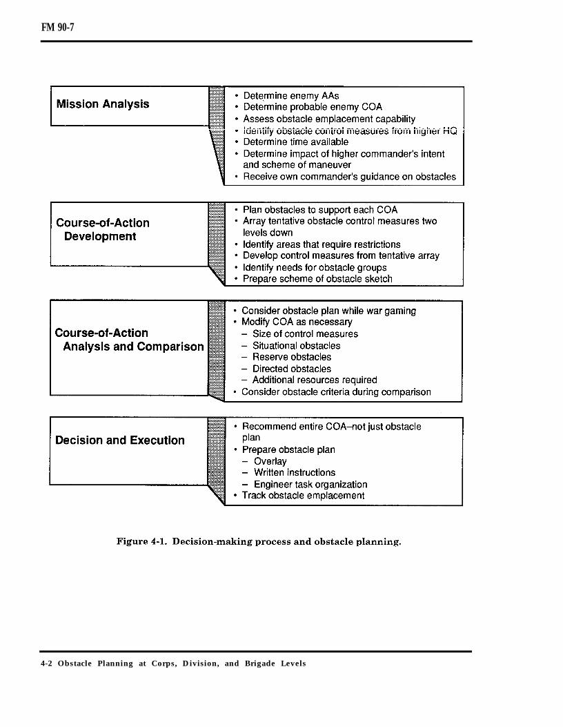
FM 90-7
4-2 Obstacle Planning at Corps, Division, and Brigade Levels

FM 90-7
Determine Facts and Develop AssumptionsThe commander relies on the staff to providethe facts and assumptions on which he canbase his mission analysis, restated mission,commander’s guidance, and COA develop-ment. The staff prepares or updates esti-mates to determine the facts andassumptions used in the decision-makingprocess. Table 4-1 lists some METT-T con-siderations for the staff when developing itsestimates. The staff uses these estimates asthe framework for developing facts andassumptions on obstacles.
Obstacle planning requires informationfrom the following estimates:
Intelligence.Logistics.Fire support.Engineer.
The staff may not prepare written esti-mates but uses the general format and thethought process involved at every level. Ateach lower level, the amount of detailrequired increases. For example, at corpslevel, logisticians address Class IV andClass V obstacle material in terms of short
Obstacle Planning at Corps, Division, and Brigade Levels 4-3

FM 90-7
tons. At brigade level, the staff must dealwith numbers of obstacle packages or mines.Intelligence Estimate. The entire staff hasinput into the intelligence estimate; how-ever, the Assistant Chief of Staff G2 (Intelli-gence)/Intelligence Officer (US Army) (S2)has general responsibility. A detaileddescription of this estimate can be foundin FMs 101-5, 34-1, and 34-10. The IPBincludes the intelligence informationrequired to integrate obstacles, such as—
AAs (friendly and enemy)Allocation of enemy combat power.Array of enemy forces two levels lower(location and formation).Enemy objectives, main effort, andoptions.NAIs/TAIs/decision points (DPs).Enemy vulnerabilities and enemy DPs.Enemy breaching capabilities.
Logistics Estimate. The logistics estimatehelps the staff determine the unit’s obstaclecapability. The resources available and thetransportation assets available to move theresources are both important. Normally,transportation assets are not dedicatedassets but are available only during a speci-fied time window. Therefore, the staff mustconsider where and when the unit will needthe resources. The following informationconcerning Class IV and Class V obstaclematerials is important for obstacle planning:
Type and quantity of material avail-able.Location of the material.Location where the material isrequired.Distance from current location to re-quired location.Transportation assets available tomove the material.Schedule for moving the material.
This information will help the staff deter-mine the feasibility of a COA based on
logistics. The engineer uses this informationin the engineer estimate.Fire-Support Estimate. The primary pur-pose of the fire-support estimate is to pro-vide information to integrate fires with thescheme of maneuver; however, the fire-support estimate also helps to integrateobstacles properly. The following informa-tion is useful for obstacle planning:
Total fire-support capability (such asbatteries, battalions, attack helicop-ters, or fixed-wing sorties).FASCAM capable assets (artillery orair-delivered).
Engineer Estimate. The staff engineerconducts an engineer estimate to providethe necessary engineer-related informationfor use in the decision-making process.Although there are several steps to the engi-neer estimate, the engineer uses the engi-neer battlefield assessment (EBA) for factsand assumptions. The EBA provides the fol-lowing information for obstacle planning:
Terrain analysis.Enemy engineer mission and mobility/survivability (M/S) capabilities.Friendly M/S capabilities.
The commander and staff use these esti-mates to complete the decision-making pro-cess.
Analyze Higher Headquarters’ Missionand Commander’s Intent
An analysis of the higher headquarters’ mis-sion and the commander’s intent identifiesinformation that may impact on the missionand which the staff uses in later steps of thedecision-making process. The staff findsthis information in the higher unit’s OPORDor OPLAN and in annexes that are included.Components of this analysis are—
Intent.AOs and deception.Tasks.
4-4 Obstacle Planning at Corps, Division, and Brigade Levels

FM 90-7
Limitations.Assets available.Risk.Time analysis.
Intent. The staff analyzes the higher com-mander’s intent to determine the purpose forobstacles and the desired end state for obsta-cles to support future operations. Even ifthe higher commander does not explicitlystate an intent for obstacles, the staff mustidentify information from his intent that willimpact on obstacle planning. For example,the commander’s intent states that the pur-pose of the current defense is to set the stagefor a major offensive operation. The staffmust consider the measures necessary toprevent obstacles from hindering that futureoffensive operation.AOs and Deception. The AO dictates thephysical limits of any obstacle use. The staffmust be aware of the requirements for thedeception plan of the higher HQ as it devel-ops an obstacle plan.Tasks. The staff determines the specifiedand implied tasks from its higher HQ thatimpact on obstacle planning.Specified tasks include—
Obstacle groups (directed, situational,or reserve) from higher HQ.Obstacle zones with specified effects(brigade).Obstacle restrictions.
Implied tasks include—Obstacle restrictions for attack/CATKaxis, BPs, objectives, and AAs.Obstacle-handover coordination duringa relief-in-place mission.Requirement to grant obstacle-emplacement authority and provideobstacle control to subordinates.
Limitations. The staff determines the limi-tations (things that cannot be done or thatmust be done) that will affect obstacle
employment. Limitations include the fol-lowing:
Must emplace obstacle groups fromhigher HQ.Must emplace obstacles to supportzones with specified effects (brigade).Cannot emplace obstacles outsideobstacle zones (brigade).Cannot emplace obstacles in areas thatviolate obstacle restrictions.Cannot use obstacles that violateobstacle restrictions.
Assets Available. To determine the assetsthat are available, the staff uses the variousstaff estimates and analyzes the task orga-nization of the higher HQ. Some assets thatmay affect obstacle planning include—
Intelligence assets that can supportobstacle execution.Assets (ground and air) for moving orhandling obstacle materials.Engineer units for tactical obstacleemplacement.Other units with manpower or equip-ment to support obstacle emplacement.Air or artillery assets with SCATMINEcapability.
Risks. The staff identifies any risks thatthe higher HQ is willing to accept to accom-plish a mission. One example is putting thepriority obstacle effort in a defense on themost likely enemy AA while planning situa-tional obstacles on the most dangerous AA.Another example is identifying where thehigher HQ is using economy-of-force mea-sures along a secondary AA. The staff mayplan for additional obstacles along that AAto help compensate for the smaller maneu-ver force allocated for the defense.Time Analysis. The staff determines thetime available and the decision cycle andreceives the time allocation from the com-mander. The staff should consider the 1/3 to2/3 rule; however, the staff must understandthat obstacles are usually time intensive. It
Obstacle Planning at Corps, Division, and Brigade Levels 4-5

FM 90-7
pushes known information to lower levelsearly so that units do not waste valuabletime. The staff also uses the time analysis tohelp determine total obstacle capability. Forexample, an engineer unit of a certain sizecan complete an approximate number ofobstacles in a specified time.The commander considers all of the informa-tion discussed previously when determiningthe essential tasks and a restated mission.However, obstacles by themselves are nor-mally not essential tasks or a part of therestated mission.
Analyze Relative Combat PowerThe staff analyzes relative combat power. Itnormally establishes a comparative base forfriendly and enemy units, computes the rela-tive combat power, and evaluates theresults. Obstacles, like many other factors(such as air power, terrain, or leadership),have an effect when integrated with fires,but the commander and staff subjectivelyassign a value for obstacles. They may haveto wait until they develop a COA before theycan assign a value for obstacles and thenrecompute the ratio of combat power.
Issue Commander’s GuidanceThe commander issues his concept andstates how he visualizes the conduct of thebattle. FM 101-5 covers this area in detail.The commander must articulate how he willintegrate obstacles to shape the battle andenhance the fire plan. He issues guidance onobstacle control, obstacle priority, anddesired effects. The level of specificity that acommander provides in his guidance isbased on the experience of the staff, the timeavailable, established habitual relation-ships, and standing operating procedures(SOPs). The commander should provide thefollowing guidance:
Location where friendly forces willmass fires to kill the enemy.Obstacle intent.
Authority to emplace different types ofobstacles and obstacle restrictions.Use of air or artillery assets (employ-ment of area denial artillery munition(ADAM) /remote antiarmor mine(RAAM) versus artillery on firing tar-gets of opportunity).Use of digging assets (survivability ver-sus countermobility).Use of maneuver forces in the obstacleeffort.Risk acceptance of M/S tasks.Obstacle turnover and lane closureinformation.Proposed CATK and other movementroutes.
COURSE-OF-ACTION DEVELOPMENTIn the next step of the planning process, thecommander and staff develop the maneuverCOA in broad terms. After they develop themaneuver COA, they develop a supportingobstacle plan, which is also in broad terms.The staff determines the details concerningobstacles during the analysis of the COA(war gaming) phase. The COA developmentconsists of the following steps:
Array initial forces.Develop a scheme of maneuver.Determine C2 means.Prepare COA statement and sketches.
Once the staff prepares the COA statementand sketch, it considers how to support theCOA with obstacles. The staff considersusing obstacles throughout the depth of thebattlefield. Table 4-2 and Table 4-3, page4-8, show some considerations for obstaclesin the offense and defense respectively.The staff tentatively sketches obstacle-control measures that support the unitstwo levels lower. When the staff arraysforces, it considers the terrain and enemy.When the staff determines the locationand size of the obstacle-control measures,
4-6 Obstacle Planning at Corps, Division, and Brigade Levels

FM 90-7
it considers the terrain, the enemy, the zones. The brigade staff draws obstacle beltsfriendly force array, and the scheme ofmaneuver. For example, when the corps isin the defense, it arrays brigades alongenemy division AAs. The corps staffsketches in tentative obstacle zones, consid-ering the terrain, targeting the enemy divi-sion, and supporting the arrayed brigadesand the corps’ scheme of maneuver. At thedivision level, the staff uses obstacle belts,while at the brigade level, it uses groups. Ateach level, the staff identifies those areaswhere mobility needs may require obstaclerestrictions. These tentative control mea-sures may also provide a starting point forresourcing obstacles (discussed in detail inAppendix C) and for developing the obstacleplan to support the COA.The staff uses the tentative obstacle-controlmeasures to develop obstacle-control mea-sures that support the COA. The corps staffdraws separate obstacle zones for ACRs orseparate brigades. It draws obstaclerestricted areas or identifies areas requiringobstacle restriction within the divisionareas. The division staff uses the tentativeobstacle belts to assist in drawing obstacle
based on the tentative groups. Both the divi-sion and brigades may draw obstaclerestricted areas or identify other restrictionsto support the scheme of maneuver. Zonesand belts must fall within the subordinateunit’s boundaries. The staff considers theobstacle-integration principle of obstacle-control when drawing the obstacle-controlmeasures.Other considerations may affect the obstacleplan. The staff also considers the use ofobstacles to support the reserve force. WithAssistant Chief of Staff, G3 (Operations andPlans) (G3)/S3 approval, the staff prepares ascheme-of-obstacles sketch that addresseshow obstacles support the maneuver COA.
COURSE-OF-ACTION ANALYSISStaff analysis identifies the best COA forrecommendation to the commander. Toanalyze the COAs, the staff uses wargaming techniques. They war-game theobstacle plan with the supported COA, notseparately. Considerations for the staff dur-ing war gaming are as follows:
Obstacle Planning at Corps, Division, and Brigade Levels 4-7

FM 90-7
Resources required for obstacle plan plans, information requirements, subordi-(see Appendix C). nate unit tasks, and additional require-Priorities, if requirements exceed capa- ments for combat support. Addedbilities. considerations at this point are—Obstacle plan that supports the COAand commander’s intent.Adequate restrictions to ensure freedomof maneuver for friendly forces duringcurrent and future operations.Plan that addresses all specified andimplied tasks.G2/S2 integration of enemy breachingcapability and reactions to obstacles.
If necessary, the staff modifies the COA fol-lowing war gaming. It also identifies branch
Changes to the size or location of con-trol measures, based on changes to thescheme of maneuver, boundaries, axisof advance, objectives, EAs, or theaddition of branches.Requirements for reserve obstacles(see Chapter 6 for specific consider-ations).Requirements for situational obstacles(see Chapter 7 for specific consider-ations).Requirements for directed obstacles.
4-8 Obstacle Planning at Corps, Division, and Brigade Levels

FM 90-7
Taskings to subunits to emplaceobstacles.Additional engineer units required fortactical obstacle emplacement.
After each COA is war-gamed, the staff com-pares the results to analyze the advantagesand disadvantages of a COA relative to theother plans. It compares each COA to theothers, using specific evaluation criteria thatit develops or that the commander directs.Relevant criteria that commanders and staffmay find useful in comparing COAs includethe following:
Which COA requires the least obstacleresource expenditure?Which COA has the least impact onlocal infrastructure by obstacles (suchas destroyed bridges)?Which COA causes the fewest hin-drances to future mobility due to obsta-cles?
DECISION AND EXECUTIONThe final step of the decision-making processis deciding on and executing a COA.
Recommendation and DecisionThe objective of the comparison is to make aunified recommendation to the commanderon the best COA. The staff may give greaterconsideration to a COA that requires a moredifficult obstacle plan if it looks like the bestselection based on other battlefield operat-ing system (BOS) perspectives. The staffinforms the commander where he mustaccept risk regarding obstacles or requestadditional assets to avoid that risk. The staffmust also be prepared to inform the com-mander where those assets may be obtainedand what influence he may have to exert toget them. Knowledge of the higher and adja-cent unit assets is important.The commander chooses the COA to adoptfor final planning. He may select a specific
COA, modify a COA, or combine parts ofseveral COAs. In any event, the commanderdecides and issues additional guidance tothe staff for developing the plan. The staffthen completes the plan and prepares theorder.
Plans and OrdersThe engineer normally prepares the obstacleplan, and the commander approves theplan or the order. The staff coordinates withand receives permission from the higher HQfor obstacles required outside an obstacle-control measure. It coordinates obstaclesplanned on flanks with adjacent units. Thestaff coordinates guidance on obstacles inthe rear area with the operations officer andcontrolling units. The staff also distributesthe obstacle plan to higher and subordinateunits.Obstacle plans at the corps, division, andbrigade levels normally contain the follow-ing:
Obstacle restrictions (either graphi-cally or clearly stated).Reserve obstacle groups (especially forpassage lanes) and execution criteriaand plans (see Chapter 6 for details).Situational obstacle groups (if any) andan execution matrix (see Chapter 7 fordetails).Engineer unit task organization.
At the corps level, the following is added tothe plan:
Obstacle zones for separate brigadesand ACRs (and intent, if specified).
See Figure 4-2, page 4-10, for an example ofa corps obstacle overlay.At the division level, the plan also includesthe following:
Obstacle zones for brigades (andintent, if specified).Guidance on the use and reporting ofprotective obstacles.
Obstacle Planning at Corps, Division, and Brigade Levels 4-9

FM 90-7
Engineer unit task organization. Execution and Supervision
See Figure 4-3 for an example of a division Units refine obstacle plans. They—obstacle overlay.
At the brigade level, the plan also includesthe following:
Obstacle belts for the TF (and intent, ifincluded).Guidance on the use and reporting ofprotective obstacles..Guidance on obstacle ownership andemplacement.
See Figure 4-4, page 4-12, for an example of abrigade obstacle overlay.
Continue to analyze incoming intelli-gence to ensure the validity of theobstacle plan in comparison to theexpected threat.Ensure that subunits report obstacle-control measures and obstacles as theydevelop and execute their plans (seeAppendix B).Shift assets, request additional assets,or modify the plan based on the obsta-cle effort completed and new or devel-oping requirements.Continue planning.
4-10 Obstacle Planning at Corps, Division, and Brigade Levels

FM 90-7
The following paragraphs contain a defen-sive scenario for obstacle planning at thedivision level. The process is the same at thecorps or brigade level.
DIVISION DEFENSIVE SCENARIO
This scenario illustrates the integration ofobstacles into the division decision-makingprocess in the defense. Note that this illus-tration highlights only certain aspects of thedecision-making process and focuses on asingle COA.
MISSION ANALYSISAs part of facts and assumptions, the staffdetermines the following concerning enemy
forces and the AAs in sector (see Figure4-5, page 4-13): The enemy has fiveregimental-size AAs in the division sector. Inthe north, two regimental AAs turn into adivision-size AA and then revert to three reg-imental AAs. In the south, there are threeregimental AAs that change into adivision-size AA.The staff has completed all other estimatesand gathered the information necessary forplanning. It has analyzed relative combatpower and determined that the ratios sup-port a defense. In addition, it has analyzedthe higher HQ commander’s mission andintent. In this case, there are no specificimpacts on division obstacle planning in thecorps’ plan. The staff incorporated the com-mander’s guidance into the plan.
Obstacle Planning at Corps, Division, and Brigade Levels 4-11

FM 90-7
COURSE-OF-ACTION DEVELOPMENTThe staff developed the following COA (seeFigure 4-6, page 4-14): The division defendsin sector to defeat two first-echelon motor-ized rifle divisions (MRDs) and a second ech-elon MRD. The division uses the divisioncavalry squadron to screen between PL Riverand PL Ocean and then conducts battle han-dover to two brigades defending on line. Thenorthern brigade will defeat an enemy divi-sion forward of PL Stream. The brigade willthen delay back to PL Lake, allowing enemypenetration into an apparent salient. Thesouthern brigade will defend forward of PLStream and allow penetration no greaterthan platoon size. The reserve brigade willCATK along Axis Copperhead into ObjectiveViper to destroy a second echelon MRD. Theaviation brigade will CATK along Axis Rat-tler into Objective Cobra, targeting the sec-ond echelon MRD’s C2 and CSS assets.
The staff sketches tentative obstacle belts(see Figure 4-7, page 4-15). It also draws inareas that require obstacle restrictions. Thefollowing paragraphs describe the decisionsthe staff made during this process.The staff anticipates that the cavalry squad-ron could employ three disrupting obstaclebelts to shape the battle. It groups these ten-tative belts into Obstacle Zone Alpha. Basedon the covering-force mission, the obstaclezone must allow maximum flexibility toemploy tactical obstacles. PL River (BHL)directly impacts on the obstacle zone’sdesign. The staff adjusts the rear of theobstacle zone forward of PL River to allowMBA forces to employ tactical obstacles tosupport the battle handover.The northern brigade defends in sectorbetween PL River and PL Lake. The staffconsiders the mobility requirements forthe reserve brigade’s mission forward of PL
4-12 Obstacle Planning at Corps, Division, and Brigade Levels

FM 90-7
Stream along Axis Copperhead and Objec-tive Viper. The staff anticipates that thebrigade could employ two fixing obstaclebelts forward of PL Stream, one on each AA.The staff also anticipates that the brigadewill require two blocking belts on the north-ern two AAs. Based on these consider-ations, and to keep the division’s CATK axisand objective restricted from obstacleemplacement, the staff plans two obstaclezones for the northern brigade.Obstacle Zone Bravo encompasses the BHL(PL River). This zone has two regimentalAAs. To give the brigade commander maxi-mum flexibility, the width of this obstaclezone covers the entire sector. The depth of
the zone provides for battle handover of thenorthern two regimental AAs. To facilitatethe division’s CATK, the commanderrestricts the depth of the obstacle zone toObjective Viper. These requirements dictatethe shape of Obstacle Zone Bravo.
Obstacle Zone Charlie is deep in the brigadesector. This zone has three regimental AAs.To give the brigade commander maximumflexibility, the zone width will cover from thenorthern boundary to Axis Copperhead.This covers two of the three AAs. The CATKforce will use the third AA. The forwardedge of the zone is in the vicinity of ObjectiveViper. The depth of the zone requires no
Obstacle Planning at Corps, Division, and Brigade Levels 4-13

FM 90-7
restriction; therefore, the brigade’s rearboundary dictates the zone’s depth.For the southern brigade, the staff uses thesame approach to develop the shape ofObstacle Zone Delta. To support the com-mander’s intent and show a strong defenseforward, the staff puts the zone’s rearboundary forward of PL Stream. This willcause a concentration of countermobilityeffort along the BHL to PL Stream.The staff must plan for the rearward pas-sage of the cavalry. It recommends to the G3that Lane Blue and Lane Red be restrictedfrom any obstacle emplacement. The bri-gades must coordinate directly with the divi-sion for reserve obstacle groups to closethese lanes, if required.Based on the obstacle plan to support theCOA, the staff determines the resourcesrequired to support the plan.
Note: The examples used to illus-trate obstacle resourcing above TFlevel in Appendix C relate directlyto this scenario.
COURSE-OF-ACTION ANALYSISThe staff analysis of the COA results insome modifications to the obstacle plan.They plan a “be-prepared” Obstacle ZoneGolf to support the division reserve’s CATKinto Objective Viper. Obstacle resources allo-cated to this zone will be for situationalobstacles to fix the enemy formations.The aviation brigade is conducting a sup-porting attack against the second echelondivision’s rear in Objective Cobra. Tacticalobstacles would aid the attack helicop-ters in their fight. The staff tailors ObstacleZones Echo and Foxtrot to support the fightin Objective Cobra and Python respectively.
4-14 Obstacle Planning at Corps, Division, and Brigade Levels

FM 90-7
ADAM and RAAM are available. ADAMand RAAM allocations will require coor-dination with the fire-support coordinator(FSCOORD).
DECISION AND EXECUTIONBased on their analysis, the staff recom-mended the COA in this scenario to the com-mander, and he approved. The staff preparesthe actual orders, to include the obstacle planand overlay Figure 4-8, page 4-16, showsthis division’s obstacle overlay. The staff alsofills in the details required for a completeplan. One detail that the staff addresses isguidance on protective obstacles.
The staff does not plan protective obstacles,but it does provide guidance on emplace-ment authority and allocates resources forprotective obstacles in the division rear. Inthis case, the division authorizes the bri-gades to delegate protective-obstacle-emplacement authority for all types of obsta-cles to company team level within obstaclezones. Outside obstacle zones, units only usewire obstacles for protective obstacles.
In the division rear, the division delegatesprotective-obstacle-emplacement authorityto the base cluster commanders. CSS assetsmust survive to provide sustainment to
Obstacle Planning at Corps, Division, and Brigade Levels 4-15

FM 90-7
combat units. Protective obstacles are impor-tant for ensuring survivability of CSS assetsin the rear. The staff determines that themajor rear area threat is from air-inserteddismounted enemy troops. Therefore, thestaff allocates wire and AP mines to the basecluster commanders.
OFFENSIVE OBSTACLE PLANNING
The following paragraphs provide specialconsiderations and some tools for planningobstacles to support offensive operations. Itis harder to plan obstacles to support offen-sive operations than to support defensiveoperations. In the offense, it is difficult todetermine where obstacles will support the
scheme of maneuver. In addition, most tacti-cal obstacles are situational. Therefore,obstacle planning must result in a plan thatis flexible enough to allow emplacementauthority and ensure obstacle control duringthe fluid offensive operation.
TYPES OF OFFENSIVE OPERATIONSThere are certain obstacle-planning consid-erations that are dependent on the type ofoffensive operation. One common consider-ation is that offensive operations normallyrely on situational obstacles due to the vari-ety of actions that may occur. The types ofoffensive operations are—
Movement to contact.
4-16 Obstacle Planning at Corps, Division, and Brigade Levels

FM 90-7
Attack.Exploitation.Pursuit.
Movement to ContactA unit conducts an MTC to develop the situ-ation or to gain or regain contact with theenemy. The primary consideration for an MTCis anticipating actions during movement andrequirements for maneuver and fire supportwhen the unit makes contact. A unit con-ducting an MTC normally organizes withforward, flank, and rear security elements;an advance guard; and a main body. Consid-erations for planning obstacles in support ofan MTC include using them to—
Fix the enemy while the main bodymaneuvers (forward security elementor advance guard).Assist in defeating enemy attacks(flank or rear security elements).Support a hasty defense.
AttackAttacks defeat, destroy, or neutralize theenemy. The same fundamentals apply to alltypes of attacks, including hasty, deliberate,spoiling, CATKs, and raids. Considerationsfor planning obstacles in support of attacksinclude using them to—
Attack reserves or CATK forces.Prevent defending forces from reposi-tioning.Support the protection of friendlyflanks during the attack.Support a hasty defense following theoffense.
ExploitationIn exploitation, the attacker maintainsoffensive pressure to extend the destructionof the defending force. Considerations forplanning obstacles in support of exploitationinclude using them to–
Prevent enemy withdrawal.Provide flank protection.Assist in cutting enemy lines of com-munication (LOC).
PursuitThe pursuit is the desired outcome of anattack or exploitation. The pursuit involvestotal destruction of a retreating enemy force.Commanders use air and ground assets tointercept, capture, or destroy the enemy.Considerations for obstacle planning in sup-port of pursuit include using them to—
Cut off enemy withdrawal routes.Allow the friendly force to fix anddestroy the enemy.
TECHNIQUES FOR OFFENSIVEOBSTACLE PLANNING
There are two techniques for planningobstacle zones and belts to support the dif-ferent types of offensive operations. Theyare to—
War-game.Use a grid system.
War GameWar-game to determine the most likelyareas where obstacles will support thescheme of maneuver, and then plan zones orbelts in those areas. If requirements foradditional obstacle-control measures arise,the staff quickly plans and disseminates theadditional control measures. It can use thistechnique in obstacle planning in support ofMTCs and attacks.Figure 4-9, page 4-18, shows an example ofobstacle zones developed to support anMTC. Obstacle Zone S supports the advanceguard as it fixes the lead of a moving enemyforce. As the advance guard assumes ahasty defense, the main body maneuvers toconduct a hasty attack against the flank of
Obstacle Planning at Corps, Division, and Brigade Levels 4-17
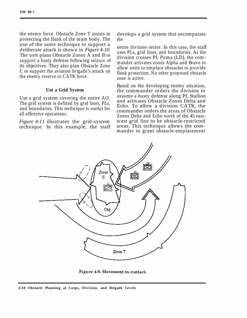
FM 90-7
the enemy force. Obstacle Zone T assists inprotecting the flank of the main body. Theuse of the same technique to support adeliberate attack is shown in Figure 4-10.The unit plans Obstacle Zones A and B tosupport a hasty defense following seizure ofits objectives. They also plan Obstacle ZoneC to support the aviation brigade’s attack onthe enemy reserve or CATK force.
Use a Grid System
Use a grid system covering the entire AO.The grid system is defined by grid lines, PLs,and boundaries. This technique is useful forall offensive operations.Figure 4-11 illustrates the grid-systemtechnique. In this example, the staff
develops a grid system that encompassesthe
entire division sector. In this case, the staffuses PLs, grid lines, and boundaries. As thedivision crosses PL Puma (LD), the com-mander activates zones Alpha and Bravo toallow units to emplace obstacles to provideflank protection. No other proposed obstaclezone is active.Based on the developing enemy situation,the commander orders the division toassume a hasty defense along PL Stallionand activates Obstacle Zones Delta andEcho. To allow a division CATK, thecommander orders the areas of ObstacleZones Delta and Echo north of the 45 east-west grid line to be obstacle-restrictedareas. This technique allows the com-mander to grant obstacle-emplacement
4-18 Obstacle Planning at Corps, Division, and Brigade Levels

FM 90-7
authority and provide obstacle control despite This chapter focused on obstacle planninga very fluid situation, using only one overlay. at the corps, division, and brigade levels.
The de-tail at these levels ensures the rightamount of obstacle control balanced with themaximum amount of flexibility for subordi-
Obstacle Planning at Corps, Division, and Brigade Levels 4-19

FM 90-7
Chapter 5
Obstacle Planning atTask-Force Level and Below
The goal of obstacle planning is to supportthe commander’s intent through optimumobstacle emplacement and integrationwith fires. The focus at the corps, division,and brigade levels is to grant obstacle-emplacement authority and provide obstaclecontrol. The focus at the TF level and belowis the actual integration of fires and obsta-cles. At the TF level, obstacle planning isvery directive and detailed and centers onobstacle groups. Below the TF level, obstacleplanning deals with the actual siting andemplacement of individual obstacles.
OBSTACLE PLANNING ATTASK-FORCE LEVEL
As with planning at higher levels, TF-levelobstacle planning is part of the decision-making process. The following paragraphsprovide techniques and considerations forobstacle planning integrated with the deci-sion-making process.
MISSION ANALYSIS
The key activities during mission analysisare to—
Determine the facts and developassumptions.
Analyze the higher HQ’s mission andthe commander’s intent.Analyze the relative combat power.Issue the commander’s guidance.
Determine Facts and DevelopAssumptions
Obstacle planning begins with intelligencefacts and assumptions, focused on the situa-tion template (SITEMP). The SITEMPincludes the modified combined obstacleoverlay (MCOO). The MCOO is the basicproduct of the battlefield area evaluation,terrain analysis, and weather analysis fromthe IPB. It includes the combined obstaclesoverlay, AA overlay (with MCs), friendlyoperational graphic, key terrain, and knownpotential enemy objectives. Since tacticalobstacles attack the enemy’s maneuver andreinforce the existing terrain, the MCOO isvital to obstacle planning. It helps ensurethat the obstacles correctly address theenemy AAs and MCs.The SITEMP depicts an estimate of how theenemy will attack in terms of the size andthe type of units and formations. TheSITEMP should identify the probablelocations where the enemy changes from a
Obstacle Planning at Task-Force Level and Below 5-1
FM 90-7
march formation to a prebattle formationand finally to an attack formation. Thisinformation helps select how and what partof the enemy formation obstacles will attackand the effect the obstacles will have on theenemy’s maneuver.The SITEMP also may depict the likelyroutes for enemy reconnaissance elements.This helps determine requirements for R&Spatrols that defeat enemy attempts to recon-noiter the obstacles and reduce their effec-tiveness before they attack.The engineer provides information on cur-rent and projected engineer task organiza-tion and the capabilities of engineerunits supporting the TF. In addition, he pro-vides facts concerning SCATMINE systemsthat are available and specific informationabout his engineer equipment or obstaclematerials that may not be known to theremainder of the staff,The FSO provides information on artillery-or aircraft-delivered SCATMINEs that areavailable. The Supply Officer (US Army)(S4) identifies the quantity and location ofobstacle material on hand, the transporta-tion assets available for moving obstaclematerial, and the maintenance status ofequipment that can contribute to the obsta-cle effort.
Analyze Relative Combat Power
The staff compares friendly and enemy com-bat power and identifies possible require-ments for obstacles to help offset enemyadvantages. The actual inclusion of obstaclesnormally occurs after COA development.
Analyze Higher Headquarters’ Missionand Commander’s Intent
The staff goes through each step of the anal-ysis and identifies information that willimpact on obstacle planning. The staff ana-lyzes the brigade commander’s intent to
determine how he wants to use obstacles tosupport his concept of the operation andachieve the desired end state. Normally, thebrigade commander will have given eachobstacle belt a specific effect; thus, the com-mander’s obstacle intent is clear. If the com-mander does not provide the specific effectsfor each obstacle belt, the staff must deter-mine his intent from the context of theorder.The TF must identify the tasks and limi-tations received from the brigade. Thesemight include obstacle belts with or withouta specified effect. They also includerestricted areas or restrictions on types ofobstacles. Also, the brigade may specifyobstacle groups (situational, reserve, ordirected).The available assets determine the totalobstacle capability in the TF. Availableassets include engineer units, SCATMINEsystems (artillery, air, or ground), infantryunits that can provide more manpower forobstacle emplacement, and trucks and util-ity aircraft for moving obstacle materials.Although not considered an asset, time is animportant resource that the staff must con-sider as it continues planning. Delays incompleting a plan can have a major negativeimpact on the obstacle effort.
Issue Commander’s Guidance
The commander’s initial planning guidanceon obstacles should be as specific as possi-ble. If the commander narrows the numberof COAs, or if some aspect of the differentCOAs remains unchanged, he may providespecific guidance on obstacles in certainareas. Any head start that the TF can get inemplacing obstacles is helpful.
COURSE-OF-ACTION DEVELOPMENT
After the staff develops a COA, the detailedobstacle planning begins. The staff focuses
5-2 Obstacle Planning at Task-Force Level and Below

FM 90-7
on three specifics when developing theobstacle plan to support the COA.
Fires analysis.Obstacle intent integration.Obstacle priorities.
Fires Analysis
Fires analysis starts with reviewing the TFcommander’s intent. The staff examines howit can use obstacles integrated with maneu-ver in the COA to achieve the commander’sintent.The staff uses the COA that it normallydepicts graphically on an overlay. Themaneuver graphics include maneuver andfire-control measures. Fire-control mea-sures indicate how and where combat forceswill mass, shift, and lift fires to destroy theenemy. The staff should draw planningrange fans for friendly weapon systems onthe overlay. Combined with the fire-controlmeasures, these range fans give the staff afeeling for where company teams can inte-grate obstacles with fires. Understandingthe maneuver and fire plans and the organi-zation of the EA are fundamental to inte-grating obstacles with fires.
Obstacle Intent Integration
Based on the TF commander’s intent andthe fires analysis, the staff determines loca-tions for directed obstacle groups. It startsby giving the obstacle groups a battlefieldplacement to support the maneuver plan.This location is for planning and is adjustedon the ground.Each directed obstacle group targets a spe-cific enemy element based on the SITEMP.The staff normally allocates groups againstenemy battalion-size MCs just as they allo-cate a company team to defeat an enemybattalion. Company team fire responsibility,therefore, drives the placement of obstaclegroups.
The staff decides which specific effect eachdirected obstacle group must achieve. Itplans obstacle groups to—
Disrupt the enemy.Turn the enemy into areas wherefriendly units can mass fires.Fix the enemy in the EA and enhancefires.Block the enemy along an AA.
The staff integrates these directed obstaclegroups (location, target, and specific effect(intent)) with the COA. It shows the obstaclegroups on the COA overlay using the obsta-cle effect graphics. The staff draws thegraphic to reflect the location of the obstaclegroup as accurately as possible.
Obstacle Priorities
The staff sets priorities for the directedobstacle groups that it placed on the COAoverlay. The staff aligns the obstacle grouppriorities to support the TF direct-fire maineffort. It numbers the obstacle effects graph-ics on the overlay starting with 1 and con-tinuing in sequence. These piorities help todetermine resource allocations and toensure that units emplace the obstacles thatare most critical to the overall plan first.
COURSE-OF-ACTION ANALYSIS
The staff conducts war gaming to determinewhich COA it should recommend to the com-mander. The staff should consider obstacleswithin the total context of the COA. How-ever, some specific considerations for thestaff during war gaming are—
Enemy reactions at obstacle groupsversus the desired obstacle effect.Enemy breaching capability that maymake one or more varieties of individ-ual obstacles preferable (see Appen-dix A).Obstacle locations that inhibit friendlymaneuver.
Obstacle Planning at Task-Force Level and Below 5-3

FM 90-7
Compatible obstacle effects and weaponsystem capabilities.Adequate fire-control measures to sup-port obstacle effect.
After war gaming, the staff adjusts the COAto include the obstacle plan. These adjust-ments may include the following:
Changes to locations of directed obsta-cle groups.Changes to the obstacle effect at a spe-cific location.Addition of situational obstacle groups(see Chapter 6 for specific consider-ations).Addition of reserve obstacle groups (seeChapter 7 for specific considerations).Identification of other mobility require-ments.
Mobility Requirements
staff identifies mobility requirements toThedetermine which obstacles need lanes orbypasses available for friendly forces. Lanesand bypasses are normally required for tac-tical repositioning, C2, and sustainmenttraffic. The staff identifies locations for lanesand bypasses based on tactical repositioningfrom the maneuver graphics, such as aroute, axis, or subsequent position. It alsoidentifies C2 mobility requirements, toinclude plans for rehearsals and physicalplacement of TRPs. Lastly, the staff identi-fies lanes and bypasses that are needed tosupport sustainment traffic. Considerationsare the MSRs into and through the TF area,the TF logistics release point (LRP), theroutes the company team takes from its posi-tion to the LRP, and the location of key TFlogistics nodes.
Obstacle Design and Resourcing
After comparing the COAs and determiningthe COA for recommendation to the com-mander, the staff can conduct more detailed
planning for the obstacle plan that supportsthat COA. Specifically, the staff can deter-mine the tentative design and resourcing forthe obstacle plan. Final design and resourc-ing occurs after the commander approvesthe COA and any final changes. In fact, finaldesign normally occurs at the company teamand emplacing unit level. Nevertheless, thestaff can develop a detailed concept that willrequire only minor modifications to supportthe final approved plan.
The staff begins by resourcing the groupsbased on the MC widths and the desiredeffect. It determines MC widths from theSITEMP. The total amount of linear obsta-cles required in a particular group is equalto the width of the MC multiplied by theresource factor for the obstacle effect,Appendix C explains resourcing in detail,The TF staff resources the obstacle groupsaccording to the obstacle group priorities.Once the staff resources the obstacle groups,the engineer plans the individual obstacles.
Use of standard obstacles supports resourceplanning and obstacle group design. Theplan for the individual obstacles, whichmake up a group, serves as a guide for theTF staff to adjust the resource allocation. Iftime is available for detailed reconnais-sance, the design of the group may providethe company teams the actual obstacledesign for each group. However, the designof the obstacle groups usually serves as aguide to company teams, and they conductthe actual design of the individual obstacleswith the emplacing unit leader.
DECISION AND EXECUTION
Once the commander selects a COA, thestaff completes the plan and publishes theorder. The staff makes final adjustments tothe plan and provides subordinate unitswith oral, written, and graphical informa-tion, with sufficient detail to allow the
5-4 Obstacle Planning at Task-Force Level and Below
FM 90-7
subordinates to conduct the operation. TheTF staff normally gives information concern-ing obstacles to subordinates using two tools.They are the—
Scheme-of-obstacles overlay.Obstacle-execution matrix.
Scheme-of-Obstacles Overlay
The scheme-of-obstacles overlay depicts thelocation of obstacle belts, brigade obstaclegroups (if any), and TF obstacle groups,within the TF sector. It also includes obstaclerestrictions from any higher level (the staffannotates restrictions that it cannot showgraphically). The overlay portrays obstaclegroups using an obstacle-effect graphic.These obstacle graphics define the generallocation and the effect to be achieved by indi-vidual obstacles.The obstacle overlay does not normallydepict individual obstacle locations. How-ever, the staff may depict individual obsta-cles if detailed reconnaissance has been doneand exact obstacle locations are identified.Alternately, the staff may include individualproposed obstacle graphics with the obstacle-effect graphic to guide the emplacing unitand the owning unit on the general configu-ration of the obstacle group. Commandersmust exercise caution if they use individualproposed obstacles on an overlay. They mustensure that inexperienced subordinates donot attempt to emplace obstacles exactly asdepicted on an overlay, instead of properlysiting the obstacle. The TF scenario that fol-lows includes an example of a TF obstacleoverlay.
Obstacle-Execution Matrix
The obstacle-execution matrix includes spe-cific instructions and detailed informationconcerning the obstacles on the scheme ofobstacle overlay. Normally, there is a sepa-rate execution matrix for each type oftactical obstacle. Chapters 6 and 7 describe
and provide examples of obstacle-executionmatrices for reserve and situational obsta-cles respectively Figure 5-1, page 5-6, is anexample of a directed obstacle-executionmatrix.As a minimum, a directed obstacle-execu-tion matrix should include the following:
Zone/belt/group designation andindividual obstacle numbers (seeAppendix B).Location (grid coordinates appropriateto the detail of the plan. This may be acenter of mass grid for the group, startand end points of the group trace, orgrid coordinates for individual obsta-cles, if known).Obstacle effect for the group.Priority for the group.Emplacing and owning unit.Location of any lanes and closureinstructions or reference to a reserve-obstacle matrix, if appropriate.Material or assets allocated for thegroup (possibly listed by number ofstandard obstacles. See Appendix A).Location of the obstacle materials (theClass IV and Class V point or othersite. See Appendix C).Any special instructions for eachgroup.
TASK-FORCE OBSTACLESCENARIO
The following scenario highlights some con-siderations for obstacle planning at the TFlevel. The TF commander has the mission todefend in sector to defeat an enemy regi-ment. Based on the TF mission, the com-mander directs the staff to develop theCOA depicted in Figure 5-2, page 5-7. Thescouts will screen forward. Teams A and Cand Company D defend from BPs A, C, andD, respectively, to mass fires in EA Tee.Team B defends along a secondary AA inthe south from BP B. On order, Team B
Obstacle Planning at Task-Force Level and Below 5-5

FM 90-7
5-6 Obstacle Planning at Task-Force Level and Below

FM 90-7
repositions to a subsequent BP to supportthe fight in EA Tee.The staff develops an obstacle plan to sup-port the COA. First, it analyzes the fire planto determine the areas where fires aremassed to destroy the enemy. The staffsketches in rough range fans based on theprobable weapon systems in each BP. Theseareas suggest locations where the staff canintegrate obstacles with fires (see Figure 5-3,page 5-8). The staff selects locations fordirected obstacle groups. It confines theobstacle group locations to obstacle belt A1,
which it identified during mission analysis.The staff uses obstacle-effect graphics toshow the relative location of the obstaclegroups and indicate the desired obstacleeffect. The obstacle groups target enemybattalion-size formations (see Figure 5-4,page 5-9). Finally, the TF staff sets prioritiesfor the obstacle groups based on theimportance of the obstacle group to the suc-cess of the COA. Figure 5-4 also shows thepriorities that support the commander’sdesire to stop the enemy in the south, force itto piecemeal into the EA, and destroy it inthe EA.
Obstacle Planning at Task-Force Level and Below 5-7

FM 90-7
The staff analyzes the COA and makesadjustments based on the analysis. Theseadjustments include the addition of asituational obstacle group to supportthe withdrawal of the scouts. The staff alsoidentifies mobility requirements. Theserequirements include lanes for passage ofthe TF scouts and marked bypasses in theEA to support EA rehearsals. Figure 5-5,page 5-10, shows the situational obstaclegroup and mobility requirements annotatedon the obstacle plan.The staff conducts obstacle design andresourcing for the obstacle plan. Obstacleresourcing to support an obstacle plan is dis-cussed in Appendix C. The design of obstaclegroups is discussed in Appendix A.
Following the commander’s decision toaccept the COA as it is, the staff finalizesthe obstacle plan. The final plan includes ascheme-of-obstacles overlay (see Figure5-6, page 5-11) and obstacle executionmatrices.
OBSTACLE PLANNING BELOWTASK-FORCE LEVEL
The following paragraphs outlines princi-ples for siting tactical obstacles to supportthe company team. The focal point is thecoordination that must occur between theemplacing unit leader (normally an engi-neer platoon leader) and the company teamcommander. This coordination is perhaps
5-8 Obstacle Planning at Task-Force Level and Below

FM 90-7
the most vital component of effective obsta-cle integration. It is at this level that unitsdirectly integrate obstacles with the effectsand capabilities of weapons and the fireplan. Once the coordination is complete, theemplacing unit physically sites the obstaclewith the company team.
COORDINATION WITH THE MANEUVERCOMMANDER
Effective coordination with the companyteam commander who is responsible for
the obstacle group is essential to making theobstacles a combat multiplier. The emplac-ing engineer is the company team com-mander’s team engineer for the mission. Theengineer and the company team commanderwork closely to ensure complete integrationof obstacles with the company team plan.The emplacing engineer and company teamcommander use a common set of informationwhen conducting coordination. The follow-ing tools or information will improve coordi-nation:
Obstacle Planning at Task-Force Level and Below 5-9

FM 90-7
SITEMP. During coordination, a checklist or frame-Commander’s intent. work is a useful tool for organizing thoughtsManeuver graphics and fire plan. and formulating questions. Table 5-1, page
5-12, provides a checklist of some consider-Obstacle execution matrix/matrices. ations for use during coordination betweenScheme-of-obstacle overlay. the emplacing engineer and the companyFire-support plan. team commander. These considerations are
CSS graphics.organized using the BOSs to provide a logi-cal framework.
5-10 Obstacle Planning at Task-Force Level and Below

FM 90-7
SITING THE OBSTACLE
The emplacing engineer and the companyteam commander site individual obstacles toachieve synchronization between the obsta-cle effect and fires. Both must devote suffi-cient time to the siting effort, since it representsthe final adjustments to obstacle locationand fire control before emplacement.To site individual obstacles, certain precon-ditions are necessary. First, the companyteam commander decides where he plans to
mass fires and marks the necessary fire-control measures on the ground. The loca-tion of these control measures must be clearsince they are the basis for obstacle siting.Second, the commander identifies tentativelocations for his key weapons within hisposition or sector. Finally, he and the engi-neer must both understand the intent of theobstacle group.
Obstacle siting concentrates on marking theobstacle group as a whole instead of each
Obstacle Planning at Task-Force Level and Below 5-11
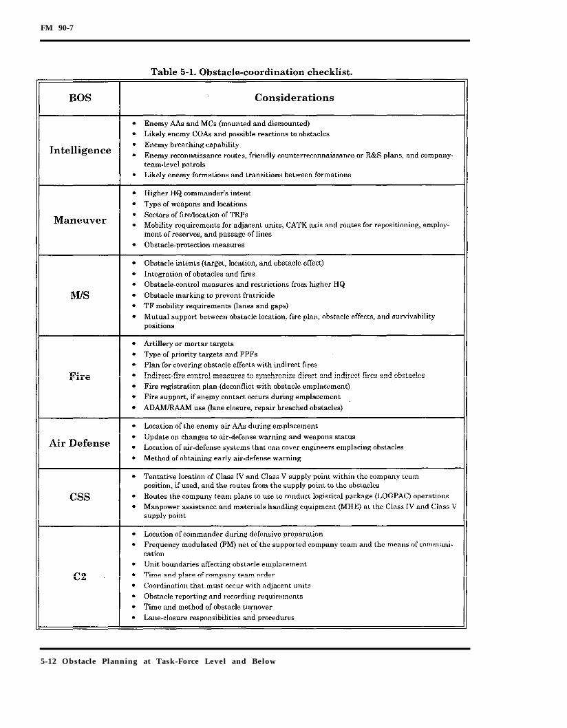
FM 90-7
5-12 Obstacle Planning at Task-Force Level and Below

FM 90-7
individual obstacle; however, in broken ter-rain, it may be easier to site individualobstacles. The company team commanderand emplacing engineer use vehicles or sol-diers from the company team, the engineerplatoon, or both to simulate the enemy forceand do the physical marking. The simulatedenemy forces move into the EA to the enemyside of the obstacle group. The engineer pla-toon leader and the company team com-mander collocate near the weapons coveringthe obstacle. As a technique, one or all of thetanks, Bradleys or other crew-served weap-ons may occupy their position and contributeto the siting process. All participants in thesiting process use a common FM net to com-municate during siting.The simulated enemy forces move into theEA simulating the enemy’s attack. Theydeploy into a formation of similar frontageas the expected enemy formation. Once theyare near the marked fire-control measures,they place markers at intervals as they drivethe trace of the obstacle group effect (or indi-vidual obstacles in broken terrain). Theyremain oriented on key fire-control mea-sures to ensure that the obstacle locationand effect are synchronized with fires. Dur-ing the process, each participant verifiesthat he can cover the obstacle, notes thelocation of fire-control measures and obsta-cles, and records the appropriate data onrange cards. As the platoon drives the obsta-cle trace, siting participants also identifydead space and requirements to refine thelocation of the obstacle group and fire-con-trol measures. The siting process also mayidentify the need for other fire-control mea-sures. Figure 5-7, page 5-15, illustrates howthe engineer and the company team com-mander work together to site a turn and afix obstacle group respectively.Once the company team marks the generallimits and orientation of the obstacle group,the engineers can begin marking individual
obstacles (if this has not already been done).To mark individual obstacles, the engineerplatoon uses the group markers as a guide.As shown in Figure 5-7, page 5-15, the groupmarkers may lend themselves well as thestart and end points of individual obstacles;however, this is not always the case. As theengineer platoon refines the group limitsinto the site of individual obstacles, the pla-toon can then begin the necessary site lay-out based on the method of obstacleemplacement.Siting is not the last thing done during prep-arations. The time and resources involved inemplacing tactical obstacles requires thatsiting begin concurrently with establishingthe defensive position. It is imperative thatthe unit sites the obstacles as soon as thecompany team commander establishes theEA and identifies tentative positions for keyweapons. It is not necessary that all weap-ons are in place and dug in before siting.Normally, well-marked fire-control mea-sures and one known position per maneuverplatoon (not dug in) are all that is requiredto effectively site the obstacles.
OBSTACLE TURNOVER AND TRANSFER
Once an obstacle group is completed, theemplacing unit conducts obstacle turnoverwith the owning unit. Occasionally, an own-ing unit will transfer responsibility for anobstacle to another unit. Obstacle turnoveror transfer ensures that the commander ofthe owning unit is familiar with the obstacleand understands its responsibilities con-cerning the obstacle. Considerations forobstacle turnover and transfer are as fol-lows:
Mutual identity check (normally onlyfor obstacle transfer).Briefing on local friendly and enemysituations.
Obstacle Planning at Task-Force Level and Below 5-13

FM 90-7
Description of the obstacle, to includelocation, type, marking, and composi-tion.
Conventional- mine fields (types ofmines, fuzing, and antihandlingdevices (AHDs)).Scatterable minefield (types ofmines, duration/SD time, and safetyzone).Other obstacles (booby traps andother hazards).
Information on lanes, to include num-ber, locations, marking, and closure plan
or information on the reserve obstacle(if applicable).Coordination completed or stillrequired with the FIST.Transfer of graphics and documenta-tion (minefield records, demolition tar-get folders, orders for the demolitionguard, or other written records).Guidance on obstacle protection mea-sures taken or required (counterrecon-naissance, targeting enemy breachers,obstacle repair, or phony obstacles).
5-14 Obstacle Planning at Task-Force Level and Below

FM 90-7
Obstacle Planning at Task-Force Level and Below 5-15

FM 90-7
Chapter 6
ReserveObstacles
This chapter implements STANAG 2017.
This chapter outlines the procedures to plan,prepare, and execute reserve obstaclegroups. Reserve obstacle groups are those forwhich the commander restricts executionauthority. These are "on-order" obstacles,The commander specifies the unit responsi-ble for obstacle emplacement, guarding, andexecution. Units normally plan and preparereserve obstacles during preparation of thebattlefield. Units execute them only on com-mand of the authorizing commander orbased on specific criteria that the com-mander identifies. The purpose of a reserveobstacle group is to retain control over themobility along an AA. Commanders usereserve obstacles when failure to maintaincontrol over the mobility along an AA willhave disastrous effects on the current battleor future operations.
EMPLOYMENT PRINCIPLES
Commanders carefully select and have theirstaffs plan reserve obstacles. Normally, thecommanders assign a maneuver unit as aguard element to protect the reserve obstacle
site. They also commit an engineer unit toprovide the technical expertise to ensurethat the obstacle is executed. Both themaneuver and engineer units that the com-mander dedicates to the reserve obstaclehave other potential missions. The com-mander must conclude that the reserveobstacle group is so critical that the loss ofunits to protect and execute the obstacleoutweighs the combat potential of thoseunits in other areas.The commander must clearly identify thecriteria for executing the obstacle. Reserveobstacles require detailed coordination andsynchronization to ensure success.Units normally install, but do not execute,reserve obstacles early in the preparationphase because they are a critical part of theplan. Units may use a reserve obstacle toclose a lane in a larger obstacle. Obstaclesused for rapid lane closure are often demoli-tion obstacles or mines; however, the type ofobstacle used is only limited by imaginationand ingenuity.
RESPONSIBILITIES
Key persons involved in the execution of areserve obstacle (see Figure 6-1, page 6-2)are the—
Reserve Obstacles 6-1

FM 90-7
Authorizing commander.Guard commander.Firing commander.
AUTHORIZING COMMANDER
The authorizing commander is the maneu-ver commander who determines the require-ment for a reserve obstacle. The authorizingcommander—
Establishes the criteria and proceduresfor executing the obstacle. Typically, hewithholds authority to execute until hegives the order, using specific codewords.
Selects the code words for the execu-tion of the obstacle.Establishes other specific criteria forexecuting the obstacle if he does notwithhold the execution authority. Hemay authorize the guard commanderto execute the target based on his owninitiative or based on other criteria.Determines the need for a separateguard force. If a small guard force canprotect the obstacle site, he maychoose to combine the duties of theguard force and the firing party. Inthis case, the guard commander andthe firing commander are the sameperson.
6-2 Reserve Obstacles

FM 90-7
Determines the need for a separate fir-ing party. If the reserve obstaclerequires an engineer technical experton site to ensure obstacle execution,then the firing party is separatefrom the guard force.
GUARD COMMANDER
The guard commander is the leader of theunit that protects the obstacle. He is acommissioned officer or an NCO. The guardcommander—
Ensures that the obstacle site is notcaptured by the enemy.Gives the firing commander the orderto execute the obstacle (based on thecriteria that the authorizing com-mander established).
FIRING COMMANDER
The firing commander is the leader of thefiring party and is an engineer NCO, unlessthe commander determines that there is noneed for an engineer technical expert on site.The firing commander—
Executes the obstacle when the guardcommander orders him to do so.Inspects and repairs the obstacle, asrequired.
The specific orders to the guard and firingcommanders are shown on the sampleSTANAG Form 2017 (see Figure 6-2,pages 6-4 and 6-5.
RESERVE-OBSTACLE PLANNINGCONSIDERATIONS
The staff plans reserve obstacles duringthe decision-making process. The followingparagraphs contain some considerations fordetermining the requirement for, and theplanning, preparation, and execution of,reserve obstacles.
The commander determines the require-ment for a reserve obstacle during theCOA analysis or possibly following the COAdevelopment. The commander may alsoreceive a requirement for a reserve obstaclefrom a higher commander as a specifiedtask. If so, the staff identifies the require-ment during the mission analysis.If the commander decides that he needs toretain control over mobility along an AA, hehas two options. He can—
Assign a specified task to a subordinateunit to maintain a lane.Use a reserve obstacle.
The commander must consider the effect ofthe premature loss of mobility along an AA.For example, if an ACR is withdrawingunder pressure through a division sector,premature loss of mobility along the AA mayslow or even stop the ACR's withdrawal.The corps commander may specifically taskthe division commander to ensure that theACR’s withdrawal lanes are clear until theACR has withdrawn. Thus he allows thedivision commander to determine the needfor reserve obstacles. The corps commandermay also decide to use reserve obstacles (seeFigure 6-3, page 6-6).
If the commander decides to use reserveobstacles, he again has two options. If spe-cific obstacle sites are obvious, such asbridges across a major river, the corps com-mander may designate those sites as corpsreserve obstacles. This will require detailedplanning by the corps staff and coordinationdown to the executing unit. If obstacle sitesare not obvious, the corps commander mayspecify that any obstacles along the with-drawal lanes are corps reserve targets. Thiswill require subordinate units to conductdetailed planning and then coordinatethrough operational and engineer channelswith the corps.
Reserve Obstacles 6-3

FM 90-7
6-4 Reserve Obstacles
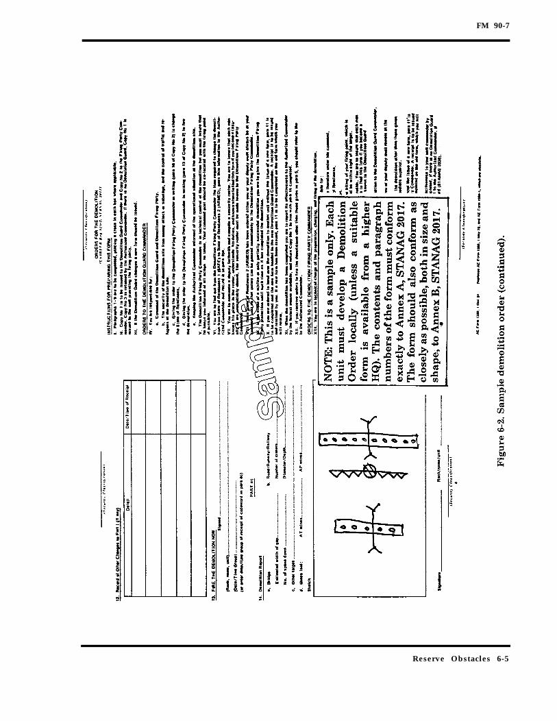
FM 90-7
Reserve Obstacles 6-5

FM 90-7
The need for reserve obstacles is not limitedto ensuring successful rearward passage offriendly units. The reserve obstacle may con-trol key terrain along a CATK axis that isalong the most dangerous enemy AA (seeFigure 6-4). Control of the key terrain (achoke point) along the CATK axis may becritical to success in the battle. The com-mander may reserve the obstacle controllingthe key terrain to retain his flexibility tocommit the CATK force along the axis andhave a means to close the AA if the enemyuses the most dangerous AA.
ADDITIONAL FACTS ANDASSUMPTIONS
Once the commander decides on the need fora reserve obstacle, the staff examines theSITEMP. It is used to determine the–
Size of the guard force required.Requirement to secure the obstacle,either by fire or occupation.Size of the obstacle required.Most effective type of obstacle.expected threat determines the sizeThe
of the guard force. The enemy and terrain
6-6 Reserve Obstacles

FM 90-7
situation dictate whether the guard forcemust secure the site by occupation orwhether they can do so from a distance byfire. The terrain that determines the size ofthe AA may determine the size of the obsta-cle. The enemy’s breaching capability maydetermine the most feasible obstacle. Forexample, if the enemy does not have organicassault bridging, then tank ditches and RCsmay be the best obstacle.
FIRES ANALYSIS
The staff analyzes the COA to determinethe—
Location of the obstacle relative to sub-ordinate units’ positions.Ability of the unit to cover the reserveobstacle group by fire following execu-tion.Most likely subordinate unit to assign tothe guard force mission.
The best spot for an obstacle may not be thebest spot to bring overwhelming combatpower to bear. When the unit uses thereserve obstacle to close a lane in a properlyplanned directed obstacle, the reserveobstacle is already integrated with fires.However, in some cases, a reserve obstacle
site is dictated by a higher commander orthe terrain. A reserve obstacle directed bythe higher HQ may require the subordinateunit to adjust its positions to cover theobstacle by fire. In some terrain, there maybe only a few sites where a commander canuse reserve obstacles to control mobilityalong an AA. This terrain is usually domi-nated by some type of existing obstacle (suchas a river, canal, or canyon). If the com-mander decides to use a reserve obstacle, herepositions forces to ensure that the obstacleis covered by fire.
OBSTACLE INTENT INTEGRATION
The staff places the reserve obstacle grouprelative to the terrain and friendly maneu-ver graphics to support the COA. Normally,the desired obstacle effect of a reserve obsta-cle is to block. Even if it is used to close alane in a directed fix obstacle group, thecommander uses the reserve obstacle toblock the AA, in this case the lane; however,the commander may use reserve obstacles toachieve any of the four obstacle effects. Thestaff indicates the location of reserve obsta-cles by using the obstacle effect graphics andannotating them as reserve obstacles.
Reserve Obstacles 6-7

FM 90-7
OBSTACLE PRIORITIES
Reserve obstacles are high-priority obsta-cles. Because a reserve obstacle is critical tothe plan, units must emplace reserve obsta-cles early in the preparation phase.
MOBILITY REQUIREMENTS
The commander’s decision to use reserveobstacles is based on—
Analysis of the COA.Detection of mobility requirements.
An additional consideration is the establish-ment of procedures for traffic control andlane marking. Figure 6-5 shows a possiblelane-marking system based on lane-markingguidance from FM 90-13-1.After the commander decides on a COA, thestaff can do the detailed planning for reserveobstacles. This detailed planning involvesdesigning and resourcing the reserve obs-tacle group.
OBSTACLE DESIGN AND RESOURCING
The staff determines—What obstacle assets are available.Which type of obstacle asset is best touse.
The staff must know the obstacle emplace-ment assets that are available. It finds thisinformation by reexamining the facts andassumptions for the mission. The stafflimits its consideration of availableassets to those that are quickly executed.Demolition obstacles, preconstructedobstacles (like the falling blocks used inKorea), and SCATMINEs are examples ofeasily executed obstacles. For smalllanes, hand-emplaced conventional minesmay be suitable. If the commander decidesto use SCATMINEs, the staff ensures thatthe asset directed to emplace the reserveobstacle is available for the mission at the
required time. The obstacle-emplacementunit is dedicated to the reserve obstacle,which makes it an "on-order" mission. Thestaff identifies potential situations whereSCATMINE assets may not be available andensures that the commander understandsany risk associated with their nonavailabil-ity.
DECISION AND EXECUTION
The staff prepares orders and providesmation on reserve obstacles on the SCIof-obstacles overlay, in a reserve-obstacle-execution matrix, and in a demolition orderfor the unit with the guard force mission.
SCHEME-OF-OBSTACLES OVERLAY
Reserve obstacles are included on thescheme-of-obstacles overlay. The staff usesthe obstacle effects graphics and, in manycases, the individual obstacle symbols (if thecommander intends to use a specific type ofindividual obstacle for the reserve obsta-cle). This provides the emplacing unit withclear guidance on what obstacle effect isdesired and what individual obstacles touse.
OBSTACLE-EXECUTION MATRIX
The obstacle-execution matrix for reserveobstacle groups is similar to the matrix fordirected obstacles (see Figure 6-6, page6-10). Typical information shown on thematrix includes—
Zone/belt/group designation and indi-vidual obstacle numbers.Location, effect, and priority of thegroup.Emplacing and owning units.Designation of the firing and guardcommanders.Emplacing asset and asset location.Any special instructions for each group.
6-8 Reserve Obstacles
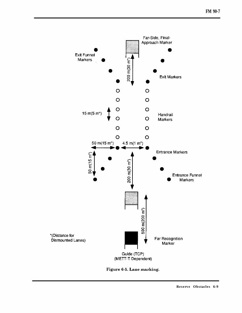
FM 90-7
Reserve Obstacles 6-9
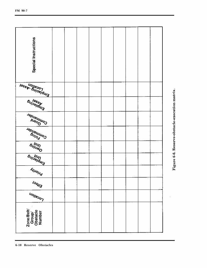
FM 90-7
6-10 Reserve Obstacles

FM 90-7
DEMOLITION ORDER
The demolition order, STANAG Form 2017,consists of a single sheet printed on bothsides. This order can be used for any obsta-cle, not just demolitions. Figure 6-2, pages6-4 and 6-5, includes an example of a com-pleted demolition order.The demolition order may include emergencyfiring orders (indicated on STANAG Form2017, items 5 and 6). The commander per-forms a risk assessment on the execution cri-teria. The commander has two options:withhold execution authority or grant execu-tion authority to the guard commanderbased on—
The possibility that the enemy is aboutto capture the obstacle.A NLT time being reached.Specific friendly action.Specific enemy action.
The combination of an enemy and afriendly action.
If the commander does not establish emer-gency firing orders, he takes the risk of theenemy destroying the guard unit and theobstacle not being executed. If he estab-lishes emergency firing orders, he takes therisk that the premature execution of theobstacle may hamper future operations.The commander makes a decision on execu-tion criteria and issues clear orders concern-ing the authority to execute the obstacle (seeFigure 6-7).
REHEARSALS
Once the order is published, the nextstep is to rehearse the execution of theobstacle. Reserve obstacles require detailedcoordination and execution. The focus ofthe rehearsal is to confirm the timing
Reserve Obstacles 6-11

FM 90-7
requirements. Units should conduct thisrehearsal as part of a larger rehearsal withminimal simulation. The following timingrequirements are considered during therehearsal (see Figure 6-8):
Time required for the guard commanderto notify the firing commander to exe-cute the target.Time required to execute the target.SCATMINE arming and duration time,if applicable.
The guard force and the firing party rehearsenotification procedures, using redundantcommunication procedures, such as wire andradio. They rehearse the time required toreceive notification and move to the firingpoint under all conditions.The firing commander and the guard com-mander calculate how long it will take toexecute the obstacle. The full rehearsalincludes rehearsal of the backup plan and
considerations for execution in reducedvisibility, such as smoke, darkness, or fog.Once these times are determined throughrehearsal, the firing commander informs theguard commander.Another time consideration is the armingand duration times. If SCATMINEs areused, the arming and duration times can bea significant factor. For example, it takestwo minutes for a MOPMS dispensed mineto arm. The duration on MOPMS is sixteenhours (assuming the mines are recycledthree times) from the time the mines arearmed; however, the mines begin to SD at80 percent of their expected life. It is impor-tant not to execute this and similar systemstoo late or too early.During the rehearsal, the guard commanderalso identifies the decision point for execut-ing the obstacle according to emergency fir-ing orders. Emergency firing orders may not
6-12 Reserve Obstacles

FM 90-7
require a physical DP but may require execu-tion of the obstacle based on enemy orfriendly actions that the guard commandercannot see. If so, the guard commander con-firms, with the authorizing commander,how he will get the information that drivesthe decision to execute the obstacle (such asa report from the TF scouts that the enemyhas reached a certain location).If execution depends on imminent enemycapture of the obstacle site, the guard com-mander makes assumptions about how muchcombat power he must have to retain controlof the site. He must also consider the timerequirements for execution that will affectthe DP. For example, he must determine atwhat point during the fight to retain controlthat he can order execution and still haveenough time for notification, execution, andarming.If execution is based on a certain size enemyforce reaching the obstacle site, the guardcommander uses the time required for obsta-cle execution and works backwards to locate
the DP to execute the obstacle. Ideally, thepoint should be clearly marked with a TRP.This spot may change based on visibilityconditions.If the reserve obstacle is also a lane, thecoordination required is similar to the coor-dination required to conduct a passage oflines. The guard commander must know thefollowing:
The number of vehicles to expect.The near and far recognition signals.The passage time.
Another important element to consider dur-ing the rehearsal is the commitment ofassets, especially if the assets have othermissions. For example, artillery assets mustbe available to fire a reserve ADAM/RAAMobstacle. During the rehearsal, the staff ver-ifies the availability of the asset and identi-fies additional situations where the assetmay not be available. It ensures that theexecuting unit understands the com-mander’s priorities.
Reserve Obstacles 6-13

FM 90-7
Chapter 7
SituationalObstacles
This chapter outlines the procedures todetermine the requirements for situationalobstacles and to plan, prepare, and executethem. Situational obstacles are obstaclesthat units plan, and possibly prepare, beforestarting an operation; however, they do notexecute them unless specific criteria are met.Unlike directed or reserve obstacles, a situa-tional obstacle may never be executed. Nor-mally, units plan several situationalobstacles that rely on the same assets foremplacement. This allows the commander toshift scarce assets to the location where heneeds them the most, based on the situation.
EMPLOYMENT PRINCIPLES
Commanders and staffs consider the follow-ing basic principles when planning, prepar-ing, and executing situational obstacles:
Identify the need.Plan for appropriate resources.Integrate the obstacle with friendlyfires.Plan the obstacle.Identify obstacle execution triggers.Withhold execution of the obstacle untilit is needed.
IDENTIFY THE NEED
The commander anticipates situations thatrequire him to modify the maneuver andfire plans to defeat the threat, and he con-siders the use of situational obstacles tosupport these modifications. He can use sit-uational obstacles as a combat multiplierfor branch plans or sequels since theyenable him to use economy-of-force mea-sures. The commander can use situationalobstacles to—
Attack an enemy vulnerability.Exploit success.Separate follow-on enemy forces.Provide flank protection.
PLAN FOR RESOURCES
Obstacle emplacement is normally resourceintensive. By their very nature, situationalobstacles must be able to be installedquickly but still achieve the desired obsta-cle effect. Units normally use SCATMINEsfor situational obstacles, but they may useany type of individual obstacle. Staffs con-sider that emplacing the obstacle mayrequire multiple assets. For example, usingair Volcano requires helicopter transport toemplace the obstacle, soldiers to load the
Situational Obstacles 7-1

FM 90-7
Volcano mine canisters, and enough canis-ters to achieve the desired effect on the tar-get.
INTEGRATE WITH FRIENDLY FIRES
Like any obstacle, units integrate situa-tional obstacles into the fire plan. Sinceobstacle execution depends on developmentof an expected situation, integrating theobstacles with fires is difficult. Commandersand staffs consider where they can employsituational obstacles and ensure that thecombination of fires and obstacles are suffi-cient to achieve the obstacle effect. Withoutfires, the obstacle may interfere with theenemy, but he can breach the obstacle atwill. For example, using SCATMINEs, with-out fires, to delay repairs to an enemy air-field will hinder the repairs; however, theenemy can identify and clear the mineswithout a major risk.
PLAN THE OBSTACLES
Situational obstacles are not used to attacktargets of opportunity. Commanders andstaffs identify them during the planning pro-cess. The time required to commit the assetand integrate the obstacle with fires nor-mally exceeds the window of opportunityagainst a target. Also, the use of obstacleemplacement assets (such as ADAM/RAAM)against targets of opportunity may waste avaluable obstacle asset that the commanderwill need later during the battle.
IDENTIFY EXECUTION TRIGGERS
Situational obstacles are triggered based onfriendly actions, enemy actions, or a combi-nation of both. For example, the commit-ment of the friendly reserve may trigger theexecution of situational obstacles to separateenemy forces. Another example of a situa-tional obstacle trigger is identification of theenemy attempting to reposition during a
DATK. Finally, the commitment of forcesalong an AA and enemy movement to attackan assailable flank is an example of a combi-nation of friendly and enemy actions thatcan trigger a situational obstacle (see Figure7-1).
WITHHOLD EXECUTION UNTIL NEEDED
The commander withholds execution of a sit-uational obstacle until the obstacle effect isrequired. Commanders and staffs considerthat the obstacle assets, once committed, areno longer available to support other mis-sions. They also consider that SCATMINEshave a SD time. Emplacing the obstacle tooearly may result in self-destruction of themines before the enemy arrives.
SITUATIONAL OBSTACLES IN THEDEFENSE
In the defense, the focus of situational obsta-cles is to help negate the attacker’s initialadvantage (see Figure 7-2, page 7-4). Somepossible uses of situational obstacles in thedefense are—
Reinforce or repair tactical obstaclesalready emplaced.Emplace obstacles where previouslythere were none.Defeat penetrations in the rear area.Protect the flanks of CATK forces.Separate attacking enemy echelons.Reinforce existing (natural or cultural)obstacles on AAs or MCs used by theenemy.Shape the battlefield for the deepbattle.
SITUATIONAL OBSTACLES IN THEOFFENSE
In the offense, the commander uses the flex-ibility of situational obstacles to help reducerisk, maintain the initiative, and preserve
7-2 Situational Obstacles

FM 90-7
Situational Obstacles 7-3

FM 90-7
freedom of action (see Figure 7-3). Some pos-sible uses for situational obstacles in theoffense are–
Interdict commitment of enemyreserves in conjunction with air inter-diction (AI), close air support (CAS), orJAATs.Assist ground forces (follow and sup-port) in defeating enemy CATKs threat-ening flanks or penetration.Obstruct enemy withdrawal or escaperoutes in conjunction with envelopingthe force.Isolate adjacent forces from influencingor reinforcing the main effort.Transition to a hasty defense to allowforce buildup or passage of fresh forces.
SITUATIONAL OBSTACLEPLANNING
The staff or the commander normally iden-tifies the need for a situational obstacleduring analysis of the COAs. However, thestaff gathers information or conducts ear-lier planning which impacts on situationalobstacle planning.
MISSION ANALYSIS
The staff gathers facts and developsassumptions during mission analysis. Aspart of the facts and assumptions, it—
Determines the unit’s capability to col-lect intelligence.Considers the friendly assets that theunit can use to emplace situationalobstacles.
7-4 Situational Obstacles

FM 90-7
Considers the assets from higher oradjacent HQ that may be available tosupport intelligence gathering or obsta-cle emplacement.Determines if there are any require-ments from higher HQ to plan a situa-tional obstacle.Determines if the higher HQ’s schemeof maneuver implies the need for a situ-ational obstacle.
COURSE-OF-ACTION DEVELOPMENT
As the staff develops the COA, it may makenote of specific actions, or areas, wheresituational obstacles can support the friendlyscheme of maneuver. However, it does the
actual obstacle planning in conjunctionwith the analysis of the COA.
COURSE-OF-ACTION ANALYSIS
The staff uses the event template and deci-sion support template (DST) to assist in sit-uational obstacle planning. The staffdevelops the event template and DST aspart of the analysis of the COAs.As the staff war-games a COA, it—
Develops an event template thatdepicts NAIs which allow the staff toconfirm or deny a particular enemyCOA based on identification of anenemy activity or lack of enemy activ-ity.
Situational Obstacles 7-5

FM 90-7
Uses the event template to identifyareas where fires and maneuver caninfluence the enemy and designatesthese areas as TAIs on the DST.Identifies DPs where the commandermust make a decision whether or not tocommit fires or forces to attack theenemy at the TAI.
Every TAI will not necessarily require, or bean appropriate location for, a situationalobstacle. In some cases, the time that ittakes the enemy to travel from an NAI to aTAI will be so short that triggering situa-tional obstacle emplacement based on enemy
action may be impossible. If the threat of nothaving an obstacle in the TAI is greatenough, the staff may decide to use afriendly action as the trigger for executingthe situational obstacle. The staff focusessituational obstacle planning on those TAIswhere obstacles can support friendly fireand maneuver (see Figure 7-4).
Fires Analysis
The staff analyzes weapon system rangesand effects to determine locations withinTAIs where it can integrate fires and
7-6 Situational Obstacles

FM 90-7
obstacles. The fire supporter, air liaisonofficer (ALO), and other special staff officersare involved in planning to ensure integra-tion of CAS or JMT missions, if applicable.
Obstacle Intent Integration
After determining where they can use obsta-cles within TAIs, the commander and staffnarrow planning even further by determin-ing the obstacle intent within the TAIs. ATAI is a location where friendly forces caninfluence the enemy. That enemy is the tar-get of the situational obstacle planned withinthe TAI. A general location for the obstacle isdetermined by the TAI and the range andeffects of friendly weapons and forces allo-cated to the TAI. The mission of the friendlyforce drives the specific obstacle effect andrefines the general obstacle location into alocation relative to the friendly force or theterrain.
Obstacle Priorities
The commander and staff prioritize the situ-ational obstacles. It is possible that they willdevelop several “be-prepared” missionsfor an obstacle emplacement asset. They usethe priorities to constrain the situational-obstacle plan based on actual availableassets. More importantly, they can use thesepriorities to assist in decision making duringexecution of the operation if two or more com-peting requirements for the same assetdevelop (see Figure 7-5, page 7-8).Normally, the commander and staff plan forthe same obstacle emplacement asset in sev-eral TAIs with the expectation that theenemy target will appear in only one. How-ever, the unit controlling the obstacleemplacement capability must understandwhich obstacle has priority, should the situa-tion call for the same asset in different loca-tions at the same time. The commander andstaff must ensure that the element with the
obstacle emplacement asset has sufficienttime to plan and rehearse each mission.
Mobility Requirements
The commander and staff consider theimpact of situational obstacles on friendlymobility. As a minimum, they should con-sider the impact on the following:
Overall scheme of maneuver of thehigher HQ.Branches or sequels in the higher HQ’splan.Specified or implied tasks for follow-onforces.Branches or sequels in their own plan.
The commander and his staff must ensuresynchronization, unity of effort, and supportto the overall plan. They must also considerany obstacle-control measures imposed bythe higher commander’s order. As with anytactical obstacle, situational-obstacleemployment is authorized only within thehigher commander’s obstacle-control mea-sures, unless the subordinate unit obtainsapproval to put obstacles outside of the con-trol measure.
Obstacle Design and Resourcing
To select the size and type of situationalobstacle required to best meet the com-mander’s intent, the staff analyzes the tar-get, the relative location, and the desiredeffect. It considers the following:
Size of obstacle required to meet theobstacle intent.Location of the obstacle.Accuracy of the emplacement asset.Trigger for obstacle execution and theDP.Time for the enemy to move from theNAI to the TAI.Time to commit the obstacle emplace-ment asset to the TAI.
Situational Obstacles 7-7

FM 90-7
Time for the asset to emplace the obsta-cle.Arming and SD time for SCATMINEs,if applicable.Time for allocated fires or force to coverthe TAI.Availability of the obstacle emplace-ment asset.C2 requirements, to include observa-tion of the NAI and reporting responsi-bilities.
The staff considers the feasibility ofusing obstacle assets based on the size and
location of the obstacle required and therequirement for accuracy in emplacing theobstacle. For example, locations far forwardof friendly positions or behind enemy posi-tions may eliminate the possibility of usingconventional obstacles or ground-emplacedSCATMINEs. The large size requirementsof an obstacle could eliminate the use ofADAM/RAAM. The accuracy required mayalso eliminate ADAM/RAAM or Gator fromconsideration.The trigger and time considerations reflectthe necessity of having the obstacleemplaced and armed before the enemy
7-8 Situational Obstacles
FM 90-7
arrives at the TAI. The commander must beable to—
Decide to emplace the obstacle.Move the asset to the TAI.Emplace the obstacle, to include ensur-ing that it is armed and has notreached its SD time.Ensure that the TAI is covered byfriendly fires before the enemy arrives.
The staff must select an obstacle design andemplacement asset that can meet the timerequirements.The availability of an emplacement asset isa major consideration. The staff identifiesother mission requirements that may com-pete for the same asset. For example, theartillery may not be able to fire ADAM/RAAM at the expected point in the battlebecause of other mission requirements.The staff also determines who will observethe event that triggers the situational-obstacle execution. The unit must clearlyidentify the observer and a backup observer.If situational obstacles are tasked to subor-dinate units, they must have the observationplatform to identify the target. The unitmust also identify clear and concise execu-tion criteria and ensure that communicationlinks are understood. Control proceduresshould be clearly established. For example,if the higher commander retains the obstacleat his level, the C2 needed to gain approvalat a later time should be clearly defined.The staff relies on the expertise of specialstaff officers, depending on the assetsneeded, to emplace the obstacle. The engi-neer may work closely with the ALO or airmission commander in planning the deliveryof air Volcano mines in the right configura-tion to achieve the desired effect. Whenplanning ADAM/RAAM use, the FSO andFSCOORD are involved to ensure that thebatteries are in position at the right placeand time with the right mix of ammunitionto emplace the minefield.
DECISION AND EXECUTIONThe staff provides subordinate units withinformation on the situational obstacle planin the scheme of obstacles overlay and thesituational obstacle execution matrix. Sub-unit instructions or the operational execu-tion matrix refer appropriate subunits to thesituational obstacle matrix.
Scheme-of-Obstacles Overlay
As with reserve obstacles, the staff uses theobstacle effect graphic and the specific indi-vidual obstacle symbols (because the com-mander normally intends to use a specifictype of individual obstacle). This ensuresthat the force attacking the enemy in theTAI and the unit emplacing the obstacleunderstand the intent of the obstacle.
Situational-Obstacle-Execution Matrix
The situational-obstacle-execution matrix issimilar to other obstacle-execution matrixes(see Figure 7-6, page 7-10). Information nor-mally shown on the matrix includes—
Zone/belt/group designation and indi-vidual obstacle numbers.Location (to include TAI designationand exact grid coordinates), effect, andpriority.Emplacing and owning unit.Trigger for the obstacle.NAI/DP for the obstacle.Emplacing asset and its source.Unit responsible for observing andreporting on the NAVDP.Any special instructions for each group.
RehearsalsOnce the order is published, the nextstep is to rehearse the execution of theobstacle. The focus of the rehearsal is toconfirm the timing requirements andensure that all persons involved in the
Situational Obstacles 7-9

FM 90-7
7-10 Situational Obstacles

FM 90-7
obstacle execution understand their respon-sibilities. The situational-obstacle rehearsalnormally is conducted as part of a largerrehearsal, although each situational obstacleis covered.There may be several different rehearsals atseveral different levels, For example, a TFand an artillery battalion rehearsal mightinclude the same ADAM/RAAM target. Anair Volcano minefield might be covered dur-ing a brigade rehearsal and the aviation unitrehearsal.The intent of the rehearsal is to synchronizethe execution of the obstacle. The unit veri-fies and refines the timing requirementsconsidered during obstacle design (seeFigure 7-7). First, if the trigger includes anenemy action, the unit determines thetime required for the enemy to move from
the NAI to the TAI. If possible, it does thisby actually moving subunits from the NAI tothe TAI at a doctrinal enemy movementrate. It modifies the movement rate basedon expected weather and light conditions.The unit may need to adjust the location ofthe observation platform that is observingthe NAI, based on the terrain or expectedweather or light conditions. The location ofthe NAI or DP may require marking with aTRP.Next, the unit verifies how long it will take tocommit the obstacle asset to the target loca-tion. This includes the time required to—
Report the trigger (enemy arrival atthe NAI or friendly action that servesas the trigger).Decide to execute.Order the execution.
Situational Obstacles 7-11

FM 90-7
Move the emplacing asset to a locationwhere it can begin emplacing.
The unit confirms the emplacement time ofthe obstacle. This may be determined by anactual physical rehearsal (such as how longit will take a ground Volcano system to drivethe obstacle trace or a similar piece of ter-rain). The unit may need to estimate theemplacement time, based on previous experi-ence or training, such as in the case of artil-lery-delivered ADAM/RAAM.If the unit uses SCATMINEs for the situa-tional obstacle, it figures arming time intothe total time required for emplacement. Forexample, it takes 45 minutes for a Flippermine to arm. Another time factor the unitconsiders is the duration of the effect. TheSD time for short duration ADAM/RAAM, forinstance, is four hours from the time themine is armed (the first mines will begin toSD after 3.2 hours). Consequently, it isimportant that the obstacle is not executedtoo early.Once the unit verifies the total time requiredfor the situational-obstacle execution, it com-pares this time with the time required forenemy movement from the NAI to the TAI. Ifthe time to execute exceeds the enemy move-ment time, the unit may need to modifythe emplacement plan. The unit may changethe design of the obstacle, such as reducingthe density of a scatterable minefield to
reduce emplacement time. The unit maychange the DP location by accepting riskand putting the DP farther out than the NAIand deciding to execute based on a probablerather than a confirmed enemy action. Theunit also can change emplacement assetnumbers or locations, such as increasing thenumber of firing batteries for ADAM/RAAMor positioning emplacing systems closer tothe obstacle location.The unit also compares the emplacementtime with the time required to integratefires and maneuver with the obstacle. Theunit ensures that the time requirementsallow it to synchronize the effects of theobstacle with fires on the enemy at the TAI.Another important element to consider dur-ing the rehearsal is the availability ofassets. The staff must ensure that the assetsnecessary to emplace the situational obsta-cle are available for the mission. During therehearsal, it is very important to determinethe availability of the asset and potentialsituations where the asset may not be avail-able. The priorities for all emplacing assetsmust be very clear.
Execution
Situational obstacles provide a tremendouscapability to the unit. The success of situa-tional obstacles depends on a good plan,rehearsed preparation, and disciplined exe-cution.
7-12 Situational Obstacles

FM 90-7
Chapter 8
ProtectiveObstacles
Protective obstacles are obstacles that com-manders use to protect soldiers, equipment,supplies, and facilities from enemy attacks orother threats. These other threats range fromenemy surveillance to the theft of suppliesand equipment by noncombatants. In tacticaloperations, protective obstacles providefriendly forces with close-in protection andhelp finish the enemy’s complete destruction.However, in OOTW, protective obstacles mayfocus primarily on preventing unauthorizedaccess to facilities and installations by civil-ians, rather than assisting in the destructionof an enemy force.
TYPES OF PROTECTIVEOBSTACLES
There are two types of protective obstacles.They are—
Hasty protective obstacles.Deliberate protective obstacles.
HASTY PROTECTIVE OBSTACLESThese protective obstacles are temporary innature. They are obstacles that soldiers canrapidly emplace and recover or destroy. Pla-toons and company teams employ hasty pro-tective obstacles next to their positions toprotect the defending force from the enemy’s
final assault. Base cluster and installationcommanders may emplace hasty protectiveobstacles to protect against all levels ofthreat when they occupy sites temporarilyor until they can plan and emplace deliber-ate protective obstacles.
DELIBERATE PROTECTIVE OBSTACLESThese are protective obstacles that aremore permanent and require more detailedplanning and usually a greater expenditureof resources. Units employ deliberate pro-tective obstacles in strongpoints or atrelatively fixed sites. During tactical opera-tions, company teams and platoonsmay emplace deliberate protectiveobstacles if they have considerable timeavailable. For example, forces that conductearly entry operations before the onsetof hostilities may have time to con-struct deliberate protective obstacles. Dur-ing OOTW, units emplace deliberateprotective obstacles as part of their forceprotection plan.
EMPLOYMENT GUIDELINES
There are basic guidelines that apply toprotective obstacles, some of which apply to
Protective Obstacles 8-1
FM 90-7
tactical obstacles as well. These guidelinesare—
Obstacles do not stand alone.The owning unit is normally theemplacing unit.Emplacement authority is not tied toobstacle-control measures.Planning occurs at the company-teamand base commander level.Planning includes resourcing that isseparate from tactical obstacles.Obstacles are reported, recorded, andtracked.
INTEGRATINGProtective obstacles do not provide protec-tion by themselves. In tactical operations,leaders integrate protective obstacles withdirect and indirect fires and observation. Aswith tactical obstacles, integration withfriendly fires is critical if the obstacle is to beeffective and destroy the enemy force.In OOTW, integrating fires and destroyingan enemy force may not be considered if theobstacles are to prevent noncombatants fromaccessing a facility or installation; however,the obstacles must remain under constantobservation. Leaders must also allocate suf-ficient force to protect the integrity of theobstacle, consistent with the rules of engage-ment for the operation.
EMPLACING UNITThe unit that occupies a position generallyemplaces its own protective obstacles. Engi-neers provide technical expertise and equip-ment, as required. Commanders focusengineer effort on tactical obstacles, butengineers may be responsible for installingprotective obstacles, especially for largeinstallations or compounds or in support of astrongpoint.
EMPLACING AUTHORITYUnlike tactical obstacles, the emplacementauthority for protective obstacles is not nor-mally tied to obstacle-control measures.Higher commanders authorize subordinatesto emplace protective obstacles outside ofobstacle zones, belts, or groups with mini-mal restrictions. Commanders may specifyin SOPs that subordinates can emplace pro-tective obstacles except as restricted in sub-sequent OPORDs.
PLANNING LEVELPlanning occurs at the company team andbase-cluster commander level. Companyteam commanders plan protective obstaclesto support their defensive positions. Thelack of a staff and limited time usuallyrequire that the company team commanderplan only hasty protective obstacles. Basecluster and installation commanders con-duct detailed planning for deliberate protec-tive obstacles around their sites.
RESOURCINGUnits plan resourcing separately for protec-tive and tactical obstacles. They plan for suf-ficient Class IV and Class V obstaclematerial to emplace the protective obstacles.They may transport and collocate thesematerials with those for tactical obstacles;however, the material allocation to subordi-nate units is planned separately from tacti-cal obstacles. Also, most units carry a basicload of Class IV and Class V materials spe-cifically for protective obstacles. This basicload is only enough for rudimentary hastyprotective obstacles. Staffs from corps to TFlevel plan to push obstacle material to sub-ordinate units so that the materials areavailable early during preparation of adefense.
8-2 Protective Obstacles

FM 90-7
REPORTING, RECORDING, AND TRACKINGUnits report, record, and track protectiveobstacles as described in Appendix B. Unliketactical obstacles, owning units recover pro-tective obstacles, or transfers them to arelieving unit, before leaving an area. Some-times, units may be forced to abandon protec-tive obstacles. Units report any of theseevents on a case-by-case basis.
PROTECTIVE-OBSTACLE PLANNING
Units develop protective-obstacle plans aspart of the decision-making process. Theymake detailed plans for protective obstaclesafter they have decided on a COA. At com-pany team level, for example, this includesselection of the location and orientation ofplatoon positions. For base cluster or instal-lation commanders, this might includeselecting base locations or fixed installationsites. (For clarity, all subunit positions, loca-tions, or sites are referred to as positions forthe remainder of this chapter.) The followingparagraphs contain a technique for planningprotective obstacles.
MISSION ANALYSISUnits determine their authority to emplaceprotective obstacles from the higher HQ’sOPORD. Units also determine if the higherHQ has placed any restrictions on the typesor locations of protective obstacles or if thehigher HQ’s scheme of maneuver implies theneed for restrictions on protective obstacles.
Units at every level conduct continuous IPBactivities during planning. Following selec-tion of a COA, units conduct detailed terrainanalysis of the area adjacent to planned oractual subunit locations. They also analyzethe threat to subunits. They figure out threatcapabilities, vulnerabilities, and potentialCOAs, focusing on the enemy’s close assault,if applicable. The analysis of the terrain and
enemy is very detailed because it focusesonly on the area and threat around subunitlocations.During protective-obstacle planning, unitsevaluate the area around their positions outto about 500 meters (METT-T dependent).Although they can conduct an initial evalua-tion by map, the unit must conduct physicalreconnaissance of the area. They incorporatethreat considerations during this evalua-tion. Some considerations are—
The likelihood of an assault against theposition.The type of enemy forces that can, andare most likely to, operate in the area.Mounted and dismounted AAs into orwithin the position.Templated methods and weapon sys-tems the enemy can employ for closeassault.Dead space and natural lines of driftfor an attacker.Possible assault positions or other posi-tions favoring the templated attacker.
Protective-Obstacle Bands
To evaluate the area close to a position forprotective obstacles, it is useful to segmentthe area into bands. Figure 8-1, page 8-4,shows a sample area divided into fourbands. METT-T drives the number anddimensions of each band.Band One. This band is farthest from theposition, normally 300 to 500 meters away.Primary threat considerations are heavyweapons, such as tank or infantry fightingvehicle (IFV) main guns, heavy or mediumhand-held AT weapons, and heavy machineguns. Another consideration is the locationof possible enemy assault positions.Band Two. This band is from beyond 30meters to 300 meters away. Primarythreat considerations are small arms;light, hand-held AT weapons; grenade
Protective Obstacles 8-3

FM 90-7
launchers; and possible assault positions fordismounted infiltrating forces. Other consid-erations include moving vehicle bombs ormoving vehicle assaults.Band Three. This band lays between BandTwo and the unit and defines the perimeterof the unit position. It extends from the indi-vidual equipment or personnel protectivepositions out to 30 meters. The primarythreat considerations are hand-thrown gre-nades or other explosive charges and small-arms fire.Band Four. Band Four is the area withinthe position, and its size depends on the size
of the position. The primary threat is anenemy force that has entered the position.
Protective-Obstacle CapabilitiesUnits must analyze their vulnerabilities andcapabilities. Some of the considerations forthis analysis include—
Type, quantity, and importance (to thecurrent or future mission) of friendlysubunits and systems.Capability of subunits to constructprotective obstacles (based on man-power, equipment, materials, or otherresources).
8-4 Protective Obstacles

FM 90-7
Vulnerability of subunits to the tem-plated enemy’s assault.Level of protective obstacle effortrequired for each subunit and system.
COURSE-OF-ACTIONDEVELOPMENT
As units develop a COA, they may makenote of areas, or subunits, where protectiveobstacles may be needed; however, they dothe actual obstacle planning after decidingon a COA.
COURSE-OF-ACTION ANALYSIS
As units analyze COAs, they may make noteof additional requirements for protectiveobstacles. They may identify likely areasduring war gaming.
DECISION AND EXECUTION
After selecting a COA, the unit refines it.Part of that refinement is planning protec-tive obstacles, focusing on the following:
Fires and observation.Obstacle integration.Obstacle priorities.Mobility requirements.Obstacle design and resourcing.Obstacle overlay.
FIRES AND OBSERVATION
Units analyze the areas within each band todetermine the locations where they can inte-grate obstacles with fires and observationagainst an assaulting enemy. Units considernot only direct-fire weapon systems but alsoindirect-fire systems and the use of com-mand-detonated mines. Units also considerall methods available for maintaining obser-vation, to include remote sensors. Especiallyin OOTW, this analysis may show that OP
locations must change to ensure constantobservation of the obstacles. Identification oflocations where they can integrate fires,observation, and obstacles helps units tofocus planning for obstacles. The units cansketch these areas on an overlay to aid infurther planning.
OBSTACLE INTEGRATION
Based on the identification of the locationswhere obstacles can be integrated with firesand observation, the unit can sketch in atrace of proposed obstacles in each location.These traces represent where the unit mayemplace obstacles in each band, withoutspecifying the types or actual location ofindividual obstacles.
OBSTACLE PRIORITIES
The unit assigns a priority for obstacles byband and annotates this on the planningoverlay. It considers the vulnerability ofsubunits and systems based on the type ofenemy expected. For example, a light infan-try company team expecting an assault by amounted enemy force would probably givefirst priority to protective obstacles inBand Two to help defeat a mounted assault.A unit involved in peacekeeping opera-tions in a position where the primarythreat is a semihostile group of unarmedcivilians would set a different priority. Itwould likely choose to construct obstacles inBand Three first to prevent the civiliansfrom making physical contact with the unit.Figure 8-2, page 8-6, shows an example of anoverlay annotated with the fires and obser-vation analysis, obstacle integration, andobstacle priorities.
MOBILITY REQUIREMENTS
The unit identifies mobility requirements.These requirements generally dictate that
Protective Obstacles 8-5
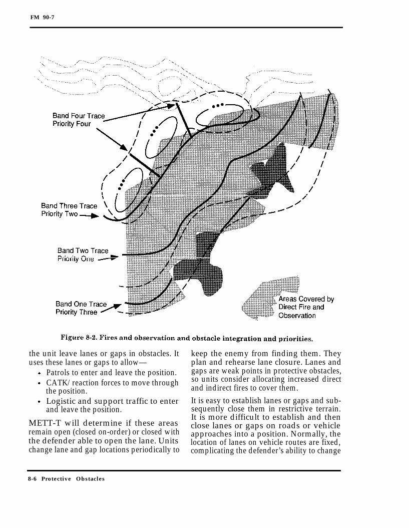
FM 90-7
the unit leave lanes or gaps in obstacles. It keep the enemy from finding them. Theyuses these lanes or gaps to allow— plan and rehearse lane closure. Lanes and
Patrols to enter and leave the position. gaps are weak points in protective obstacles,CATK/reaction forces to move through so units consider allocating increased directthe position. and indirect fires to cover them.
Logistic and support traffic to enter It is easy to establish lanes or gaps and sub-and leave the position. sequently close them in restrictive terrain.
It is more difficult to establish and thenMETT-T will determine if these areas close lanes or gaps on roads or vehicleremain open (closed on-order) or closed with approaches into a position. Normally, thethe defender able to open the lane. Units location of lanes on vehicle routes are fixed,change lane and gap locations periodically to complicating the defender’s ability to change
8-6 Protective Obstacles

FM 90-7
their location. When METT-T permits, unitsplan multiple vehicle lanes. Units then alter-nate the lanes that are open at any time.With the alternating opening and closing ofthese lanes, units can also change themethod and material used to close the lane.When units can establish only one lane, theydevelop redundant methods for closing thelane. Other obstacles can be built parallel tothe lane to contain any vehicles that pene-trate at the lane. Figure 8-3 shows the identi-fied mobility requirements annotated on theplanning overlay.
OBSTACLE DESIGN AND RESOURCINGUnits design and resource protective ob-stacles within each band to accomplish thefollowing:
Counter the templated threat.Enhance direct and indirect fires andobservation.Support the commander’s force protec-tion plan.
Ideally, units construct obstacles in allfour bands and tie the obstacles together to
Protective Obstacles 8-7

FM 90-7
ensure that there are no bypasses; realisti-cally, this is usually not possible.
Band One
Protective obstacles in Band One deny theenemy a position from which it can supportassaulting forces by fire. Units design pro-tective obstacles to defeat the expectedenemy. If the unit is a light infantry com-pany team, the greatest threat in Band Onemay be tank and IFV main gun fire. There-fore, the unit designs obstacles that can
help defeat this threat, such as AT mine-field in potential attack-by-fire positions. Ifthe unit is a tank company team, the great-est threat in Band One may be dismountedinfantry that are armed with medium ATweapons. The unit may design obstacles thatinclude AP mines and wire to defeat thisthreat.Tactical obstacles frequently tie into protec-tive obstacles in this band. Figure 8-4 showsan example of a turn obstacle group intowhich the unit ties protective obstacles.The protective obstacles at this point also
8-8 Protective Obstacles

FM 90-7
strengthen the anchor point of the turnobstacle group. This helps the defender tostop a mounted enemy from rapidly dis-mounting to breach or conduct an assault ofthe position.
Band Two
Band Two’s focus is to break up enemyassault formations and to deny anyattack-by-fire positions for the enemy’ssmall arms or light AT weapons. Like BandOne, Band Two obstacles may be tied intotactical obstacles. This commonly occurs inrestrictive terrain where the direct-fire EAsare usually small and the direct-fire engage-ments are close. Another example is the pro-tective obstacles around a block obstaclegroup. In this instance, the company teamcommander ensures that the tactical andprotective obstacles support each other.In Band Two, dismounted units use AT min-efield to help defeat mounted assaults intactical situations. In all situations, theymay use wire road blocks or other con-structed antivehicular obstacles to defeatmoving-vehicle threats, such as terroristvehicle bombs. Dismounted units may alsoincorporate AP minefield and wire obsta-cles to help break up enemy dismounted for-mations. Mounted units generally designBand Two obstacles to defeat enemy dis-mounted infiltration forces and, as in BandOne, to deny positions for dismounted forceswith light AT weapons.
Band Three
Protective-obstacle considerations withinBand Three focus on defeating dismountedthreats. Both mounted and dismountedunits use wire obstacles and possibly direc-tional and command-detonated AP mines.These obstacles help to prevent enemyforces and other threats from entering theunit’s position.
Band Four
Protective obstacles in Band Four help tobreak up the actual unit position and pre-vent the enemy from moving within theposition. Units can do this by putting protec-tive obstacles throughout the position, seg-menting it into irregular pieces. This causesthe attacker to breach repeatedly oncehe is on the position, enhancing thedefender’s ability to CATK, to maximizedefensive fires, to provide time to reorga-nize, or to conduct retrograde operations.Obstacles in Band Four usually are wire orother constructed AP and AT obstacles.Units normally do not use mines withintheir position because of the fratricide risk.Figure 8-5, page 8-10, shows an example of aprotective obstacle array around a companyteam.
Sources for Materials
Units emplacing protective obstacles rely onthree sources for protective obstacle materi-als. They are—
Unit basic load.Push packages.Requisitioned material.
Unit Basic Load. This source providesunits with a very limited capability for hastyprotective obstacles.Push Packages. A more important sourcefor hasty protective-obstacle materials ispush packages based on subunit capabili-ties. A technique is to develop packages,based on subunit types, as part of unit SOPsand to push those packages down to the sub-units as soon as it is apparent that the unitwill require protective obstacles.Requisitioned Material. Materials to sup-port deliberate protective obstacles are usu-ally requisitioned based on actualrequirements to complete the protectiveobstacles that the unit plans.
Protective Obstacles 8-9

FM 90-7
Other Design Considerations
Some additional considerations for protec-tive obstacle designs are as follows:
Employment in depth.Obstacle protection.
Employment in Depth. Protective obsta-cles do not seriously inhibit the enemy’sassault until they overload or exhaust hisbreaching capabilities. This requires obsta-cles employed in depth. It is difficult toconstruct a continuous array of protec-tive obstacles from Band One throughBand Four; however, units can construct
successive bands of obstacles, with eachfocused at a specific threat. This requiresthe enemy to continually deploy and regroupin an area of intensive fires until friendlyforces can destroy the enemy or force itswithdrawal.Obstacle Protection. Obstacle camouflagedepends on obstacle siting. Large protectiveobstacle systems are not easy to conceal bysiting alone. However, when units takeadvantage of the terrain and locate protec-tive obstacles in folds of the terrain, aroundblind curves in high speed AAs, or on the
8-10 Protective Obstacles

FM 90-7
reverse slope of a hill, they are less visible toan attacker. To aid in the camouflage of pro-tective obstacles from aerial observation,units avoid regular geometric layouts ofprotective-obstacle systems. Camouflageand deception can be enhanced with phonyobstacles used to confuse the attacker asto the exact location and extent of theprotective-obstacle system.
Continuous physical reconnaissance of pro-tective obstacles is extremely critical. Unitsmust keep protective obstacles under contin-uous observation at all times. In those areaswhere dead space exists, units use othermeans of early warning and monitoring, suchas flares, remote sensors, and GSRs. Thesemeasures ensure that an infiltrating forcecannot enter the area undetected.
PROTECTIVE-OBSTACLE OVERLAY
Units execute protective obstacles as theyprepare their defensive positions. Normally,the unit commander distributes an overlayto his subordinates that depicts the type andlocation of each protective obstacle. Thecommander allows subordinates the flexibil-ity to make minor changes to his plan.As units complete the obstacles, they reportand record the obstacles according to theprocedures in Appendix B and guidancefrom their higher HQ. Throughout the oper-ation, units maintain positive control overtheir protective obstacles to protect themfrom compromise by enemy forces. Moreimportantly, they assist other friendly unitsfrom straying into the protective obstacles,thus preventing fratricide.
Protective Obstacles 8-11

FM 90-7
Appendix A
IndividualObstacles
This appendix contains a description of thedifferent types of individual obstacles. Also,there is a discussion of individual obstacledesigns and how to develop individual obsta-cles. Lastly, this appendix describes thearray of individual obstacles to support theobstacle effects.
INDIVIDUAL OBSTACLE TYPES
Only the imagination and ingenuity of thesoldier who designs and emplaces them lim-its the nature and extent of reinforcing obsta-cles. The general types of individualobstacles are—
Demolition obstacles.Constructed obstacles.Land mines.Improvised obstacles.Complex obstacles.
In addition, there are phony obstacles, whichare not a type of individual obstacle but arerepresentations of actual obstacles that unitsuse to deceive the enemy.
DEMOLITION OBSTACLESUnits create demolition obstacles by the det-onation of explosives. There are many usesfor demolitions, but some examples are–
Destroying bridges.
Creating road craters.Creating abatis.
FM 5-250 covers demolitions and the effectsof demolitions in detail.
Bridges
The use of existing bridges is critical to themobility of a military force, especiallybridges spanning nonfordable rivers andstreams. Demolishing bridges forces theenemy to search for a suitable bypass(another bridge or ford site at a differentlocation) or expend mechanical assaultbridging assets to maintain its momentum.There is no standard planning factor for thedestruction of bridges as many variablesimpact on the materials and the manpowerrequired. See Chapter 4, FM 5-250, fordetails. The maneuver commander decideswhether to order a complete or a partialbridge demolition. The complete bridgedemolition leaves nothing of the old struc-ture, while the partial demolition saves thenear-side spans and abutments. The partialdemolition permits easier reconstruction ofthe bridge.
Road Craters
An RC is an effective obstacle on roads orother high-speed-movement routes, such as
Individual Obstacles A-1

FM 90-7
firebreaks. The RC forces the enemy to useearthmoving equipment, blade tanks, ormechanical bridging assets. Generally, thereare two types of RCs, hasty or deliberate.The planning factors and material require-ments for RCs are in Chapter 3, FM 5-250.See Figure A-1 for an example of the use ofan RC.
Abatis
Abatis are only effective if large enoughtrees are available to stop the enemy force.Abatis can be useful on roads and narrowmovement routes. Refer to Chapter 3,FM 5-250, for more information. See FigureA-2 for an example of the use of a stan-dard abatis.
CONSTRUCTED OBSTACLESUnits create constructed obstacles withmanpower or equipment and without theuse of explosives. Examples of constructedobstacles are–
Wire obstacles.Tetrahedrons and hedgehogs.Antitank ditches.
Wire Obstacles
Wire obstacles typically target the dis-mounted threat. Triple standard concertinais a common wire obstacle; however, thereare other types, such as double apron,tanglefoot, and general-purpose barbed-tape obstacles (GPBTOs). Double apron is
A-2 Individual Obstacles

FM 90-7
Individual Obstacles A-3

FM 90-7
manpower and material intensive andunits typically use it only for deliberate pro-tective obstacles. Tanglefoot works well intall grass or along a low-water line. TheGPBTO is an extremely effective wire obsta-cle, and soldiers can emplace it from a vehi-cle. Refer to Chapter 3, FM 5-34 for moreinformation. See Figure A-3 for an exampleof standard wire obstacles.
Tetrahedrons and Hedgehogs
Tetrahedrons and hedgehogs target themounted threat. Tetrahedrons are pyramidswith a triangular base and are normallyabout 1½ meters on each side. Engineersfabricate tetrahedrons from steel beams or
use concrete to create a massive tetrahe-dron. Engineers construct hedgehogs fromthree or four steel beams joined in the mid-dle to create something similar to a child’sgiant jack. Both of these obstacles are effec-tive in restrictive terrain. Units commonlyuse them in urban areas. Their ability tocompletely stop light vehicles makes themideal for use in protective obstacles aroundfixed sites in OOTW.
Antitank Ditches
Units can also use equipment to alterterrain to create constructed obstacles.For example, an AD is a constructedobstacle that is effective against all types of
A-4 Individual Obstacles

FM 90-7
vehicles. Like minefield, ADs are linearobstacles, but they require that the enemyuse a different breaching asset than itdoes for minefield. Additionally, mine-plow- and roller-equipped tanks cannotcross a breached AD as easily as a normaltank can. There are two basic ADdesigns, rectangular or triangular (seeFigure A-4).The AD supplements turn or block obstaclegroups. Units normally do not use ADs fordisrupt or fix obstacle groups because of thetime and equipment requirements. The com-mander must realize that the construction ofADs is time and equipment intensive. Typi-cally, there is a trade-off between diggingADs and digging survivability positions.
LAND MINES
Mines are explosive devices emplaced for theexpress purpose of killing, destroying, or
otherwise incapacitating enemy personneland equipment. Mines affect the enemy intwo ways. The first is the damage theyinflict on enemy personnel and equipment.Second, mines have a psychological impact.Units that detect mines, or witness themine effect on other parts of a formation,tend to slow down and seek bypasses toavoid the mine effects. The two general cat-egories of land mines are–
Conventional mines.Scatterable mines.
Conventional Mines
Conventional mines are hand-laid minesthat require manual arming. Conventionalmining is resource (time, labor, supply,and transportation) intensive. Part One,FM 20-32, covers conventional mines andmining in detail.
Individual Obstacles A-5

FM 90-7
Scatterable Mines
SCATMINEs are laid without regard to clas-sical pattern and are delivered by aircraft,helicopter, artillery, missile, or ground dis-penser. SCATMINEs provide the maneuvercommander a flexible, responsive, and lethalmine-laying capability to affect the enemy’sability to maneuver. All US SCATMINEshave a limited active life and self-destruct ata preset time. The duration of the active lifedepends on the type of mine and deliverysystem.
SCATMINEs are not an obstacle cure-all forinadequate tactical planning. Their userequires extensive coordination, integra-tion, and control. Indiscriminate use ofSCATMINEs causes a rapid depletion ofvaluable assets. More importantly, thepoorly planned use of SCATMINEs canimpede friendly movement and cause fratri-cide. For more detailed information onSCATMINEs and systems, refer to PartTwo, FM 20-32.
IMPROVISED OBSTACLESSoldiers and leaders design improvisedobstacles with imagination and ingenuitywhen using available materials and otherresources. Possible improvised obstaclesinclude the following:
Rubbled masonry buildings.Controlled fires.Flooded areas created by opening flood-gates or breaching levees.Damaged vehicle hulks used as road-blocks.
COMPLEX OBSTACLESUnits can create complex obstacles toimprove the effectiveness of obstacle groups.Complex obstacles are a combination ofdifferent types of individual obstacles.For example, an RC reinforced with AT
mines is a complex obstacle. The RCrequires that the enemy employ its mechan-ical bridging or blade-breaching assets,while the AT mines require that the enemyuse a mine-breaching asset. Together, theRCs and mines create a better obstacle. Thekey to creating effective complex obstacles isknowing the quantity and capability of theenemy’s breaching assets.A complex obstacle should affect low-densitybreaching equipment first; then it shouldaffect more common breaching equipment.For example, if the enemy has nine mineplows and three blade tanks, the unit canuse an AD and mines to force the enemy touse both breaching assets. This increasesthe time required to breach. Moreover, byputting the AD before the mines, the enemymust use its lowest density breaching equip-ment first. If friendly forces destroy theblade tanks, they reduce the probability ofthe enemy breaching the complex obstacle.Another example of complex obstacles isusing AP mines, triple standard concertina,tanglefoot, and AT mines. The wire andAP mines strip the enemy’s dismountedinfantry away from assaulting tanks. Thismakes both more vulnerable and enablesthe defending force to concentrate on onetype of threat. The AT mines preventarmored vehicles from dashing through thewire unimpeded.
PHONY OBSTACLESPhony obstacles play a key role in obstacleprotection by helping hide a unit’s actualobstacles from the enemy. They can alsohelp a unit compensate for shortages ofobstacle resources. A unit can mix actualobstacles with phony obstacles within anobstacle group. Naturally, this implies risk,and commanders must ensure that they con-sider the risk of using phony obstacles.Commanders must also ensure that theemplacing unit creates a phony obstacle
A-6 Individual Obstacles

FM 90-7
that will have the desired result on theenemy. An example is a shallow excavationcombined with a loose soil berm to simulatean AD. Another technique is to use mine-field markings where there are no mine-field. To be successful, this techniquenormally requires that the unit establish aprecedent. Highly visible minefield mark-ings in a disrupt obstacle group in forwardareas provide a visual cue to the enemy con-cerning minefield. Using the same mark-ings without minefield in a fix obstaclegroup may cause the enemy to assume thatthere is an actual minefield where noneexists.
INDIVIDUAL OBSTACLE DESIGNS
The remainder of this appendix providesguidelines for individual obstacles. Units useindividual obstacles as building blocks forobstacle groups. Standard obstacles allowrapid estimating for resourcing (time, man-power, equipment, and materials) that iscritical in making the force’s obstacle efforteffective, efficient, and timely. They allowunits to train on the installation of individ-ual obstacles as drills.
FMs 5-34, 5-102, and 20-32 provide detailson specific standard obstacles.These standard obstacles are not the onlytypes of obstacles that units should consider.Instead, units should consider modifyingstandard obstacles or creating their ownstandard obstacles based on METT-T andother resource availability. For example, thestandard minefield in FM 20-32 are focusedon a soviet-style tank and motorized infan-try threat. These minefield may not beappropriate for a mixed force of light infan-try and tanks.The following paragraphs provide somebasics for designing minefield based on thetype of threat.
ARMOR THREATUnits may need to design minefield forarmor threats other than soviet-style forces.The next few paragraphs describe some con-siderations for designing minefield basedon an enemy with armor companies of 12 to18 combat vehicles. These are minefieldthat a unit can use as building blocks forobstacle groups in mostly open terrain.
Width
An enemy armored company of 12 to 18 com-bat vehicles will have a probable frontage of500 meters when deployed. To affect theenemy, half the enemy company frontage(250 meters) should encounter the mine-field. An individual obstacle of 250 metersfrontage is an appropriate-size buildingblock.
Depth
Minefields must have enough depth to sup-port the obstacle effect based on the enemy’sbreaching capability. If the commanderwants a disrupt or fix effect, the minefieldshould require the enemy to expend at leastone breaching asset (for example, 100meters if the enemy has a mine-clearing linecharge (MICLIC)). For the turn-and-blockeffect, the depth should increase to force theenemy to expend more breaching assets. Foran enemy not equipped with line charges,the depth can decrease. If the enemy has nomechanical breaching assets, the depth candecrease even further.
Antitank Mines
The two options are track-width and full-width fuzed AT mines. Compared to the full-width fuzed mines, track-width fuzed mineshave a lower probability of encounter.Track-width fuzed mines require a den-sity of 1.0 per linear meter of front; how-ever, adding one row of full-width fuzedmines can reduce the resources required
Individual Obstacles A-7

FM 90-7
while increasing the probability of encounterfor the minefield. This results in one row offull-width fuzed mines and two rows oftrack-width fuzed mines.
Antipersonnel Mines
The minefield focuses on the mountedthreat, so if the enemy has mounted breach-ing assets, AP mines normally will not makemuch of a difference. However, if the enemylacks mechanical breaching assets, addingAP mines can help prevent dismountedbreaching.
Antihandling Devices
The emplacing unit determines the require-ment for AHDs based on the threat. Nor-mally, units use AHDs only if they expectcovert or other dismounted breachingattempts.
Irregular Outer Edges (IOEs)
The purpose of IOEs is to confuse the enemyabout the orientation of the minefield and toincrease the probability of an encounter.There may be cases where an IOE is desir-able, such as a fix or block effect. The IOEdoes not have to be part of the standardminefield.
LIGHT THREATDesigning standard minefield to achieve aspecific obstacle effect against a light force isa unique challenge. There are no strict doc-trinal frontages associated with an enemylight infantry company; however, a typicalmarch formation for a dismounted infantrycompany has a frontage of 40 to 200 meters.The following paragraphs describe consider-ations for designing standard minefield fora light threat.
Width
An enemy infantry company typically con-sists of three platoons. In march (column)
formation, it has a frontage of 40 to 200meters. Using 200 meters as the enemy’smaximum frontage, the standard minefieldmust target half of its frontage (100 meters).Camouflaging the mines and total patternaids tremendously in increasing the effec-tiveness of the disrupt and fix minefield.
Depth
A 45-meter depth complicates a light infan-try’s breaching attempt. A light forceemploys grapnel hooks, hand-placed explo-sives, bangalore torpedoes, and portableexplosive line charges. The 45-meter depthrequires multiple uses of those assets.
Antitank Mines
The minefield focuses on the dismountedthreat. Normally, AT mines are useful onlyif the enemy has vehicles.
Antipersonnel Mines
The M16A1 AP mine provides the best mixof lethality and density for the disrupt or fixminefield. The M18 Claymore mine isanother choice. The M14 AP can be used;however, it requires a much higher lineardensity.
Antihandling Devices
The emplacing unit determines the require-ment for AHDs based on the threat. At leastsome mines, especially those on the leadingedge of the minefield, should have AHDs.
Irregular Outer Edges
The IOE’s purpose is to confuse the enemyabout the orientation of the minefield and toincrease the enemy’s probability of encoun-ter. Use of the IOE is normal only in rela-tively open terrain.Leaders should not limit their view ofreinforcing obstacles only to minefield.
A-8 Individual Obstacles
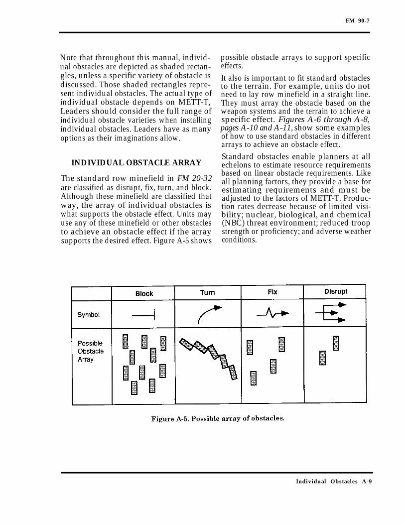
FM 90-7
Note that throughout this manual, individ-ual obstacles are depicted as shaded rectan-gles, unless a specific variety of obstacle isdiscussed. Those shaded rectangles repre-sent individual obstacles. The actual type ofindividual obstacle depends on METT-T,Leaders should consider the full range ofindividual obstacle varieties when installingindividual obstacles. Leaders have as manyoptions as their imaginations allow.
INDIVIDUAL OBSTACLE ARRAY
The standard row minefield in FM 20-32are classified as disrupt, fix, turn, and block.Although these minefield are classified thatway, the array of individual obstacles iswhat supports the obstacle effect. Units mayuse any of these minefield or other obstaclesto achieve an obstacle effect if the arraysupports the desired effect. Figure A-5 shows
possible obstacle arrays to support specificeffects.It also is important to fit standard obstaclesto the terrain. For example, units do notneed to lay row minefield in a straight line.They must array the obstacle based on theweapon systems and the terrain to achieve aspecific effect. Figures A-6 through A-8,pages A-10 and A-11, show some examplesof how to use standard obstacles in differentarrays to achieve an obstacle effect.Standard obstacles enable planners at allechelons to estimate resource requirementsbased on linear obstacle requirements. Likeall planning factors, they provide a base forestimating requirements and must beadjusted to the factors of METT-T. Produc-tion rates decrease because of limited visi-bility; nuclear, biological, and chemical(NBC) threat environment; reduced troopstrength or proficiency; and adverse weatherconditions.
Individual Obstacles A-9

FM 90-7
A-10 Individual Obstacles

FM 90-7
Individual Obstacles A-11

FM 90-7
Appendix B
Obstacle Numbering, Reporting,Recording, and Tracking
This appendix describes the obstacle num-bering system and the requirements forobstacle reporting and recording.
OBSTACLE NUMBERING
The obstacle numbering system shown inTable B-1, page B-2, consists of 11 alphanu-meric characters and an obstacle status sym-bol character. This number is compatiblewith the Tactical Engineer Command andControl System (TECCS) that augments theManeuver Control System (MCS). An obsta-cle number provides the following informa-tion concerning an individual obstacle:
HQ that established the obstacle zone inwhich the obstacle is located.Obstacle zone designation (if any).Obstacle belt designation within theobstacle zone (if any).Obstacle group designation within theobstacle belt.Individual obstacle type.Individual obstacle number.Obstacle status.
If units do not use obstacle zones and belts,or if the HQ directs obstacles outside anobstacle zone or belt, an asterisk is used inplace of the obstacle zone or belt designator.
The designation for the HQ is a letter fol-lowed by three numbers. For example, XVIICorps is shown as Z017; 23d Armored Divi-sion is shown as A023; and the 103d Air-borne Division is shown as I103.Obstacle zones are indicated by a single let-ter starting with “A” and continuing insequence. Obstacle Zone A in XVII Corps isdistinguished from Obstacle Zone A in 77thID by the HQ designation (Z017-A versus1077-A). The second obstacle zone in 77thID would be Obstacle Zone B (I077-B).Obstacle belts are indicated with a singledigit following the obstacle zone designatorstarting with “l” and continuing insequence. For example, the first obstaclebelt in Obstacle Zone C of the 5th CavalryDivision is shown as C005-C1.Obstacle groups are depicted by a single let-ter starting with “A” and continuing insequence. For example, the first obstaclegroup in Obstacle Belt 2 of Obstacle Zone Bin the 77th ID is I077-B2A.The individual obstacle type is expressed byone or two letters as shown in Table B-2,pages B-3 and B-4. For example, AD obsta-cles in I077-B2A are shown as I077-B2A-AD. Standard block minefield in the samegroup are shown as I077-B2A-MB.
Obstacle Numbering, Reporting, Recording, and Tracking B-1

FM 90-7
The individual obstacles in an obstacle groupare indicated by a two-digit number startingwith “01” and continuing in sequence. There-fore, the first block minefield in obstacle groupI077-B2A is I077-B2A-MB01. The secondblock minefield in the group is I077-B2A-MB02. If the obstacle group consists of a sin-gle obstacle, it is also shown as I077-B2A-MB01.If the corps or division orders the emplace-ment of an obstacle group outside an obstaclezone, then there is no obstacle zone or beltdesignator. Instead, units replace the obstaclezone and belt designators with asterisks (*).For example, if XVII Corps orders the demoli-tion of a bridge (abutment only) as a corpsreserve obstacle and this is the first suchobstacle, then the obstacle is indicated asZ017-**A-BA01. If the 1st Brigade, 77th ID,orders an ADAM/RAAM scatterable minefieldin Obstacle Zone B and outside all obstaclebelts, the designation is I077-B*A-SF01.
The obstacle status symbol is the last charac-ter of the obstacle number. The status sym-bol shows whether the obstacle is—
Planned (/)Being prepared (-).Prepared, but not executed (+).Executed or completed (x).
For example, if the first of the block mine-field discussed in the previous paragraph iscompleted, the obstacle number is I077-B2A-MB01X. If the corps reserve obstacle dis-cussed in the previous paragraph is pre-pared, the obstacle number is Z017-**A-BA01(+).Obstacle numbering for protective obstaclesmay require procedures that vary slightlyfrom those described. Units should reportprotective obstacles; however, identifying theindividual obstacles is difficult using theobstacle numbering guidelines without guid-ance from the higher HQ. A technique is for
B-2 Obstacle Numbering, Reporting, Recording, and Tracking

C1, FM 90-7
Obstacle Numbering, Reporting, Recording, and Tracking B-3
Table B-2. Obstacle type abbreviations.
M—Minefield/Munition Field W—Wire Obstacle
MB Block WA Double-apron
MC Chemical WC Concertina
MD Disrupt WF Tanglefoot
MF Fix WG General-purpose, barbed tape
MH Hasty protective WN Nonstandard
MN Nonstandard WR Roadblock
MO Point WT Triple-standard
MP Protective S—Scatterable Minefield/Munition Field
MQ Nuisance SB Gator
MS Standard-pattern SF ADAM and RAAM
MT Turn SM MOPMS
MU Dummy/decoy SV Volcano
A—Miscellaneous SW Scatterable mines (generic)
AB Abatis H—Hand-Emplaced Munitions
AC Chemical by explosives HC Claymore
AD AT ditch HH Hornet/WAM
AF Thermobaric or flame HO Other
AH Log hurdle HS SLAM
AL Log crib or log obstacle I—Improvised Explosive Devices
AM Movable obstacle (car, bus)
AN Expedient nonstandard obstacle ID Directional, special-purpose explosive
hazard
AP Post obstacle (hedgehog, tetrahedron)
AR RubbleIO Omnidirectional, special-purpose
explosive hazard
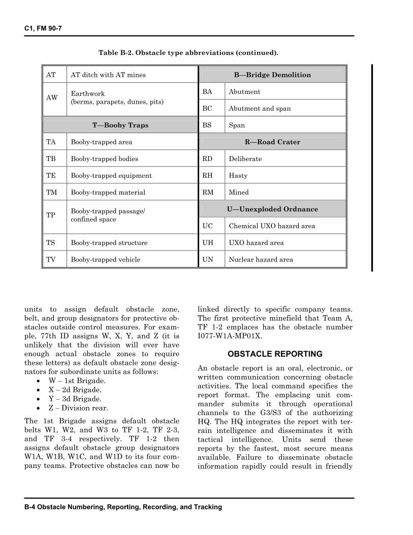
C1, FM 90-7
Table B-2. Obstacle type abbreviations (continued).
AT AT ditch with AT mines B—Bridge Demolition
BA AbutmentAW Earthwork
(berms, parapets, dunes, pits) BC Abutment and span
T—Booby Traps BS Span
TA Booby-trapped area R—Road Crater
TB Booby-trapped bodies RD Deliberate
TE Booby-trapped equipment RH Hasty
TM Booby-trapped material RM Mined
U—Unexploded Ordnance TP Booby-trapped passage/
confined space UC Chemical UXO hazard area
TS Booby-trapped structure UH UXO hazard area
TV Booby-trapped vehicle UN Nuclear hazard area
units to assign default obstacle zone, belt, and group designators for protective ob-stacles outside control measures. For exam- ple, 77th ID assigns W, X, Y, and Z (it isunlikely that the division will ever haveenough actual obstacle zones to requirethese letters) as default obstacle zone desig- nators for subordinate units as follows:
W 1st Brigade. X 2d Brigade. Y 3d Brigade. Z Division rear.
The 1st Brigade assigns default obstaclebelts W1, W2, and W3 to TF 1-2, TF 2-3, and TF 3-4 respectively. TF 1-2 then assigns default obstacle group designatorsW1A, W1B, W1C, and W1D to its four com-pany teams. Protective obstacles can now be
linked directly to specific company teams. The first protective minefield that Team A,TF 1-2 emplaces has the obstacle number I077-W1A-MP01X.
OBSTACLE REPORTING An obstacle report is an oral, electronic, orwritten communication concerning obstacleactivities. The local command specifies thereport format. The emplacing unit com- mander submits it through operationalchannels to the G3/S3 of the authorizing HQ. The HQ integrates the report with ter- rain intelligence and disseminates it with tactical intelligence. Units send thesereports by the fastest, most secure meansavailable. Failure to disseminate obstacle information rapidly could result in friendly
B-4 Obstacle Numbering, Reporting, Recording, and Tracking

FM 90-7
casualties. Figure B-1, page B-6, summa-rizes the obstacle report flow at the corpslevel and below.Units must submit the following reports forevery obstacle (with exceptions noted):
Report of intention.Report of initiation.Report of completion.
REPORT OF INTENTIONThe use of a report of intention depends onthe use of obstacle-control measures or anOPLAN.
Obstacle-Control Measures
If the higher HQ has designated obstacle-control measures, such as obstacle zones orbelts, units do not need to submit the reportof intention. The authorization to installobstacles is given when the higher HQestablishes the obstacle-control measure.Units must submit a report of intention forevery obstacle if the higher HQ did notestablish obstacle-control measures. Unitsmust submit a report of intention to notifytheir higher HQ before planning to emplacean obstacle.
Operation Plan
Conventional obstacles that are part of anOPLAN approved by the authorizing com-mander do not require a report of intentionbecause inclusion in an OPLAN implies anintention to emplace obstacles.The report of intention doubles as a requestwhen units initiate it at levels belowemplacement authority. The report includesthe following:
Tactical purpose of the obstacle.Estimated number and type of mines tobe emplaced.Location of obstacle.Proposed start and completion times.Type of obstacle.
Placement of mines (surface-laid orburied).Use of AHDs on mines, if applicable.Location and width of lanes and gapsand how they are marked.
REPORT OF INITIATIONA report of initiation is mandatory. Itinforms higher HQ that emplacement hasbegun and that the area is no longer safe forfriendly movement and maneuver. Thereport specifies the time that emplacementbegan and identifies the location and targetnumbers of obstacles. The scatterable minewarning (SCATMINWARN) notifies affectedunits that SCATMINEs will be emplaced.The SCATMINWARN report providesaffected units with the necessary warn-ing to plan and execute their operations.Units send the report before or immediatelyafter they have emplaced mines. FigureB-2, page B-7, shows a sample of theSCATMINWARN format.
REPORT OF COMPLETIONA report of completion is the report fromthe actual emplacing unit, through chan-nels, to at least corps level. It informs higherHQ that the obstacle is complete and func-tional. If required, units follow a report ofcompletion with completed DA Form 1355,DA Form 1355-1-R, or scatterable minefieldreport and record (see Figure B-3, page B-7).
ADDITIONAL REPORTSTwo additional reports that may be requiredat different times are—
Report of progress.Report of transfer.
Report of Progress
During the emplacing process, the com-mander may require periodic reports on thework completed.
Obstacle Numbering, Reporting, Recording, and Tracking B-5

FM 90-7
B-6 Obstacle Numbering, Reporting, Recording, and Tracking
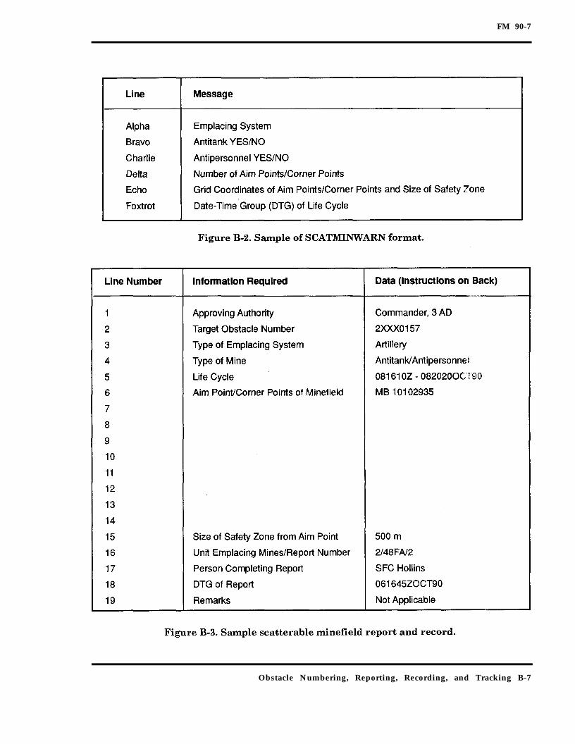
FM 90-7
Obstacle Numbering, Reporting, Recording, and Tracking B-7

FM 90-7
Report of Transfer
A commander transfers obstacle responsibil-ity to another commander with a report oftransfer. The relieving and relieved com-manders sign this report.
OBSTACLE RECORDING
Obstacle recording is an electronic or writ-ten communication describing the emplace-ment of the obstacle. Records are normallytechnical in nature, and there is very spe-cific guidance on the recording of mine-field. Units record tactical and deliberateprotective minefield using DA Form 1355.They record hasty protective minefield onDA Form 1355-1-R. Units use the scatter-able minefield report and record to reportand record scatterable minefield (seeFigure B-3, page B-7). The local commandspecifies how to record obstacles otherthan minefield.Obstacle records contain the following infor-mation, as a minimum:
Location of obstacle.Type of obstacle.Number and type of mines emplaced, ifapplicable.Placement of mines (surface-laid orburied), if applicable.Use of AHDs, if applicable.Location and width of lanes and gaps,if applicable.Description of any marking, if applica-ble.
The procedures for completing DA Form1355, DA Form 1355-1-B, or scatterableminefield report and record are in FM 20-32.
OBSTACLE TRACKING
Obstacle tracking consists of the followingcomponents:
Collation of obstacle completion reportsand other reports of identified obsta -cles, such as UXO and enemy obsta-cles.Dissemination of the collated informa-tion to friendly units that the obstaclesmay affect.Maintenance of the records that iden-tify obstacle locations for use in plan-ning future operations or in clearingobstacles after the end of hostilities.
The G3/S3 is responsible for tracking obsta-cles but is assisted by the engineer and firesupport staffs. Friendly force obstaclereports go upward through operational andengineer channels. Reports of enemy obsta-cles may arrive through a variety of chan-nels based on intelligence collection,maneuver contact, or other means. Nor-mally, the staff engineer collates thesereports and records and maintains the infor-mation on these obstacles.Eventually, detailed written reports andrecords, down to individual obstacles, flowthrough channels to the corps; however, forimmediate tracking, each level requires adifferent level of detail displayed graphi-cally. At corps level, immediate require-ments are graphics showing brigadeobstacle belts. The division tracks the loca-tions of obstacle groups graphically. The bri-gade plots the locations of individualobstacles on overlays. This provides enoughinformation for immediate planning con-cerns. If a corps or division staff attempts toplot individual obstacles, the end result isprobably an inaccurate overlay. As writtenreports and records arrive at corps level, thecorps begins to develop a data base forfuture planning and eventually for clearanceof all obstacles.Reports of friendly UXO normally come fromfire-support units or from Air Force or Navyaviation liaison officers. The fire-supportcell normally collates these reports andmaintains the record of these items.
B-8 Obstacle Numbering, Reporting, Recording, and Tracking
FM 90-7
The G3/S3 must decide how much of thisinformation to disseminate to subordinateunits. He also must decide what level ofdetail is necessary. Simple overlays depictingareas suspected of having large quantities ofUXO, and a brief description of the UXO andits hazards, may be useful to subordinatecommanders. They may choose to planmovements around those areas or ensure
that their subunits take appropriate precau-tions in those areas. Subordinate command-ers may require more detailed information ifthey must move through an area whereanother unit (or the enemy) previouslyemplaced tactical obstacles. In this case, thecommander may need an overlay or listingof all obstacles in the area with as muchdetail as is available.
Obstacle Numbering, Reporting, Recording, and Tracking B-9

FM 90-7
Appendix C
Obstacle Resourcing andSupply Operations
This appendix describes obstacle resourcingand supply from corps to emplacing unitlevel. First, it concentrates on how unitsplan to resource obstacles in terms of ClassIV and Class V obstacle materials, man-power, and equipment. Second, it describesthe flow of obstacle materials and offerssome techniques for ensuring efficient sup-ply operations.
OBSTACLE RESOURCING
At company team level, the emplacing unitand company team commander can easilyidentify the resources required for individ-ual obstacles. However, at TF level, theexact requirements are less clear. The exactrequirements become increasingly unclearat each higher level. The staff at each levelneeds a method for estimating obstacleresource requirements to make the neces-sary allocations to subordinate units. Thetwo techniques for estimating obstacleresource requirements are—
Requirement-based resourcing.Capability-based resourcing.
These techniques provide guidelines for req-uisitioning and moving resources.
REQUIREMENT-BASED RESOURCINGOne technique is to resource subordinateunits with obstacle materials and man-power based on anticipated requirements.These requirements are based on the tenta-tive control measures the staff used whiledeveloping the obstacle plan (see Chapter 4).The staff arrays obstacle-control measuresbased on the array of friendly forces two lev-els down. For example, the division staffdraws tentative obstacle belts to support thetentative array of TFs in the scheme ofmaneuver. The staff combines the obstaclebelts into obstacle zones and allocatesresources for the obstacle zones based on thetentative obstacle belts.The staff multiplies the width of the AA forthe tentative obstacle-control measure atthe lower level by the obstacle-effectresource factor (see Table C-1, page C-2).The resource factor used depends on theobstacle effect. The staff assumes an obsta-cle effect for the tentative obstacle-controlmeasures based on how it thinks the subor-dinate unit will fight the battle.This provides the linear obstacle effortrequired for the obstacle-control measure.Figure C-1, page C-2, shows the relationship
Obstacle Resourcing and Supply Operations C-1

FM 90-7
between the resource factor for each obstacleeffect, the AA width, the total linear obstacleeffort required, and a possible array of indi-vidual obstacles. The staff translates the lin-ear effort required for all the tentativeobstacle-control measures into resourcesrequired using standard planning factorsand obstacle packages. It sums the totalresources required for the tentative obstacle-control measures within each subordinate
unit’s area of operations. It then allocatesresources to the subordinate units based onthe resources required for the obstacles inits areas of operations.Figure C-2 shows the obstacle plan from thedivision scenario in Chapter 4 (to includethe tentative obstacle belts used to developthe plan). Table C-2, page C-4, shows anexample of the requirement-based resourc-ing technique based on that scenario.
C-2 Obstacle Resourcing and Supply Operations

FM 90-7
The division staff developed seven obstaclezones, A through G (column 1). It used tenta-tive obstacle belts (column 2) to develop theobstacle zones. The staff assumed an obstacleeffect (column 3) for each tentative obstaclebelt based on how it thought the brigade com-manders would fight the battle. It deter-mined the resource factor (column 4) basedon the assumed obstacle effect. It multipliedthe AA widths (column 5) by the resource fac-tor to determine the total linear obstacleeffort required (column 6) for each tentativeobstacle belt.The division used the standard row mine-field from FM 20-32 to determine resource
requirements (it could just as easily haveused other standard obstacles dependent onMETT-T). The staff divided the linearobstacle effort required by the frontage ofthe appropriate standard row minefield (col-umn 7) to determine the number of mine-field required (column 8). The staff thenmultiplies the number of minefieldrequired by the number of mines and pla-toon hours required for each minefield (col-umns 9 and 10 respectively). The staff totalsthe requirements for mines (column 11) andplatoon hours (column 12) for each obstaclezone.Using the zone totals (columns 13 and 14),the staff can now allocate platoons and
Obstacle Resourcing and Supply Operations C-3

FM 90-7
C-4 Obstacle Resourcing and Supply Operations

FM 90-7
mines to the brigades to meet the require-ments for each obstacle zone. The staff con-verts the platoon hours required intoplatoons required based on the actual timeavailable. It then task organizes engineerunits to the brigades to provide the necessarymanpower. The staff may consider othersources of manpower (units other than engi-neers) when allocating engineer units.
CAPABILITY-BASED RESOURCINGThe second technique for obstacle resourcingis to allocate obstacle materials based on thecapability of units to emplace obstacles.Units have the capability to emplace only acertain amount of obstacle material in agiven amount of time. For example, anengineer company can emplace a quantifi-able number of conventional mines in oneday.Capability-based resourcing is a good tech-nique to use when time is short. Early inthe plan development, the staff identifies the
main effort based on the concept of the oper-ation. Based on the main effort, the staffdevelops a preliminary task organization.This task organization drives obstacle mate-rial resourcing. Although the staff concernsitself primarily with the engineer task orga-nization, it does not ignore other units withobstacle emplacement capability.The advantage of this technique is the earlyidentification of obstacle material require-ments. Obstacles require a large amount ofmaterial and transportation assets to haulthe material. Engineer units have a limitedcapability for hauling obstacle material. Theearlier the staff identifies the haul require-ment, the easier coordination for haul assetsbecomes. This helps logistic plannerswho do not require great precision but cer-tainly welcome early identification ofrequirements.Figure C-3 illustrates the capability-basedresourcing technique. The scenario used is
Obstacle Resourcing and Supply Operations C-5

FM 90-7
the division defensive scenario fromChapter 4. The staff developed a task organi-zation for engineer units with one engineerbattalion each in support of 2d Brigade and1st Brigade. Both engineer battalions havean attached engineer company (from thethird engineer battalion) for a total of eightengineer platoons each. In addition, thecavalry squadron has an attached engineercompany (also from the third engineerbattalion) for a total of two engineer pla-toons. (Note that the third engineer battal-ion HQ is conducting planning andcoordination with 3d Brigade for the divisionCATK).To determine the obstacle resourcesrequired by each brigade, the division staffdetermined the obstacle emplacement capa-bility of the engineers in support of the bri-gades. The staff made several assumptionsconcerning obstacle emplacement capability.Based on the standard row minefield inFM 20-32 and minefield planning data inFM 5-34, the staff assumed that an engineerplatoon can emplace 100 mines per hour.The staff also assumed that the platoons canonly do ten hours of effective work per day(subtracting time for travel, maintenance,resupply, rest, and so forth).
The staff multiplied the effective hours perday by the number of mines per hour anddetermined that the platoons can use 1,000mines per day. The staff multiplied the num-ber of engineer platoons in support of eachbrigade by the number of mines per day.This figure was the number of mines perday that each brigade can reasonablyemplace given the engineer task organiza-tion.In the examples above, the staff only consid-ered the use of standard row minefield fromFM 20-32. The staff could have used a dif-ferent type of individual obstacle or a combi-nation of different types. If it used therequirement-based method, for example,
the staff could have substituted AD for partof the total linear obstacle effort required.For Obstacle Belt B1, the staff could haveused 1,000 meters of AD and 3,000 meters ofminefield instead of 4,000 meters of mine-field. This would have reduced the totalClass V and platoon hour requirement forObstacle Belt B1 but would have added arequirement for digging assets.Both of the resourcing techniques discussedabove can be used at any level for planningresources. At the TF level, the staff uses theactual groups that it has planned ratherthan tentative obstacle-control measures. Aswith any other process, the staff abbreviatesobstacle resourcing when time is short oradds detail if time allows. Whatever thetechnique used, staffs must make some rea-sonable assumptions when necessary. Theyalso must use information and planning fac-tors relevant to their organization.
OBSTACLE SUPPLY OPERATIONS
Obstacle material is Class IV or Class Vmaterial, which is requested and deliveredthrough the maneuver unit’s supply chan-nels. Obstacle material is a maneuver unitresponsibility. Figure C-4 and Figure C-5,page C-8, show the request flow and thesupply flow for Class IV and Class V, respec-tively, from corps to TF level.Class IV obstacle material requests originat-ing at or below TF level go to the TF S4. TheTF S4 sends supply requests to the forwardsupport battalion (FSB). Class IV supplyrequests at brigade level also go to the FSB.The FSB sends the requests to the divisionmateriel management center (DMMC). Sup-ply requests originating at division levelalso go to the DMMC. The DMMC sends therequest to the corps material managementcenter (CMMC). Corps-level requests also goto the CMMC.Issuing Class IV obstacle material usuallyinvolves large quantities of material. Corps
C-6 Obstacle Resourcing and Supply Operations

FM 90-7
support elements deliver Class IV materialdirectly to the emplacement sites usingcorps transportation assets.Units request Class V obstacle materialssomewhat differently. The TF S4 notifiesthe brigade S4 of Class V requirements. Thebrigade S4 notifies the division ammunitionofficer (DAO) in the DMMC who authorizesClass V issue by the ammunition transferpoint (ATP). The DAO sends requests forClass V to the CMMC.Class V obstacle material flows from thecorps storage area (CSA) to the ammu-nition storage points (ASP) to theammunition transfer points (ATP) or,more likely, straight to the ATP. Class Vobstacle material, unlike most ammunition,
is delivered to the user at the obstacleemplacement site.A supply request includes the quantity, therequired delivery time, the transportationresponsibilities, and a desired location. Thequantity includes the required quantity foreach type of obstacle. There may be severalDepartment of Defense identification codes(DODICs) and national stock numbers(NSNs) involved, depending on the types ofobstacles required. The required deliverytime is very important to ensure an earlystart on the preparation of the battlefield.Lack of material could adversely affect themission. The transportation responsibilitiesmust be clearly understood. MHE isrequired to ensure a rapid turnaround ofhaul assets.
Obstacle Resourcing and Supply Operations C-7
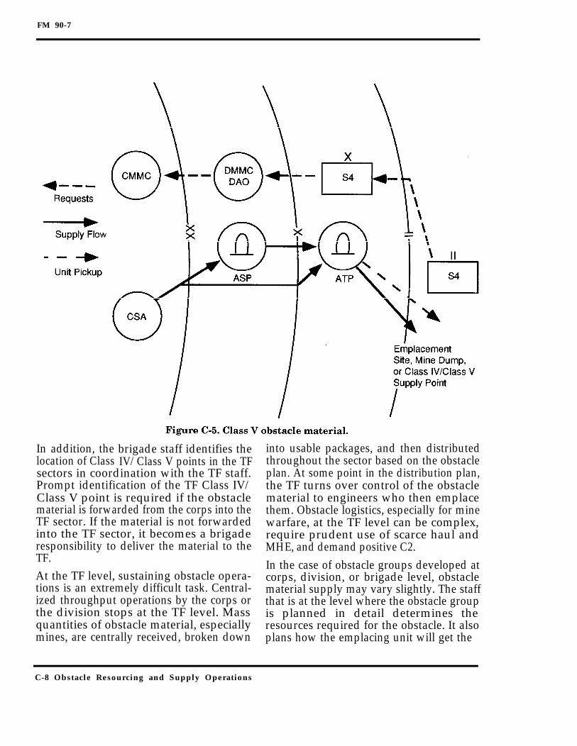
FM 90-7
In addition, thelocation of Class
brigade staff identifies theIV/Class V points in the TF
sectors in coordination with the TF staff.Prompt identification of the TF Class IV/Class V point is required if the obstaclematerial is forwarded from the corps into theTF sector. If the material is not forwardedinto the TF sector, it becomes a brigaderesponsibility to deliver the material to theTF.At the TF level, sustaining obstacle opera-tions is an extremely difficult task. Central-ized throughput operations by the corps orthe division stops at the TF level. Massquantities of obstacle material, especiallymines, are centrally received, broken down
into usable packages, and then distributedthroughout the sector based on the obstacleplan. At some point in the distribution plan,the TF turns over control of the obstaclematerial to engineers who then emplacethem. Obstacle logistics, especially for minewarfare, at the TF level can be complex,require prudent use of scarce haul andMHE, and demand positive C2.In the case of obstacle groups developed atcorps, division, or brigade level, obstaclematerial supply may vary slightly. The staffthat is at the level where the obstacle groupis planned in detail determines theresources required for the obstacle. It alsoplans how the emplacing unit will get the
C-8 Obstacle Resourcing and Supply Operations

FM 90-7
materials. For example, if the corps staffplans a reserve obstacle group, but thedetailed planning is done at TF level, the TFplans the resources for the obstacle group asit would any other obstacle group. However,if the corps staff plans the obstacle group indetail, it determines the resources required.In this case, the corps staff would also planfor delivery of the obstacle materials to theemplacing unit. Alternately, the corps staffcould direct the emplacing unit to pick up theobstacle materials from a location such asthe CSA.
OBSTACLE RESUPPLY NODESThere are two critical obstacle resupplynodes within the TF sector. Each of them hasa different function in the obstacle resupplyprocess if the material is not delivereddirectly to the emplacement site. They arethe—
Class IV/Class V supply point.Mine dump.
The relative location of the Class IV/Class Vsupply point and mine dumps are shown inFigure C-6.
Class IV/Class V Supply Point
The Class IV/Class V supply point is the cen-tral receiving point of obstacle material inthe TF sector. It is the point at which the TFreceives and transfers control of obstaclematerial pushed forward by higher levels.The supply point is established and operatedby the TF and is centrally located to supportall planned obstacles within the TF sector.Where the tactical obstacle plan allows, thesupply point should be located near the TFcombat trains to better facilitate C2 and theavailability of equipment.The main purpose of the Class IV/Class Vsupply-point operation is to receive obstaclematerials and then reconfigure them basedon the requirements for each obstacle group.
Obstacle Resourcing and Supply Operations C-9

FM 90-7
This requires that the supply point musthave a dedicated S4 representative to trackthe flow of obstacle material in and out ofthe supply point. The supply point shouldhave dedicated MHE to off-load the bulkquantities of obstacle material and reconfig-ure them into obstacle packages, if required.Obstacle materials are normally brokendown into obstacle packages if the materialsare not already delivered in combat config-ured loads. This may require a dedicatedengineer representative to ensure that theobstacle materials are configured properly.The most labor-intensive task at the ClassIV/Class V supply point is uncrating themines. This requires dedicated manpowerequipped with tools to break shipping bandsand uncrate the mines from their containers.Another important aspect of uncratingmines is tracking fuzes and booster charges.As the mines are uncrated, fuzes and boostercharges are separated; however, the samenumber and type of fuzes and boosters mustbe task organized with minefield packages.This requires strict supervision because mis-takes can quickly lead to confusion and awaste of emplacement time.Because of the assets involved in the ClassIV/Class V supply point, a TF is normallycapable of operating only one supply point atany given time. If the TF sector isextremely wide or deep, several supplypoints may be planned; however, only onecan be operated at a time, based on the com-mander’s priorities for obstacle emplace-ment.
Mine Dump
The mine dump is the most forward mineresupply node. It is the point at whichmines are task organized into mine strippackages and inspected, prepared, andloaded onto the emplacing vehicle. It isnot a permanent supply point. A mine dump
is not always used; it depends on themethod of minefield resupply. These tech-niques are discussed in more detail below.When used, one mine dump supports asingle obstacle group. It is activated ordeactivated upon initiation and comple-tion of emplacing the obstacle group. Minedump operations are primarily an engineercompany or platoon responsibility. However,it is a good technique to augment minedump operations with personnel from thecompany team overmatching the obstaclegroup being emplaced. The mine dump maybe located either in the vicinity of the com-pany team position or nearer to the obstaclegroup.There are three critical tasks that must beaccomplished at the mine dump.
As minefield packages are transportedto the mine dump, they are furthertask organized into strip packages,complete with the right number, type,and mix of fuzes and boosters. Forexample, if the platoon is emplacing astandard disrupt row minefield, minesare task organized into three packages.As the engineer platoon moves to themine dump to resupply, each emplac-ing vehicle loads a designated package.The mines are prepared for emplace-ment. They are not fuzed at the minedump. Preparation includes looseningand greasing fuze and booster wellsand checking to ensure proper func-tioning.The mines are loaded onto the emplac-ing vehicles or delivery system.
Transportation of mines from the Class IV/Class V supply point to the mine dump is asupported TF responsibility; however, it isusually shared between the engineer com-pany and the TF since neither one has thehaul capability to simultaneously service allactive mine dumps.
C-10 Obstacle Resourcing and Supply Operations

FM 90-7
OBSTACLE RESUPPLY RULESThe following rules govern obstacle materialresupply:
Uncrate mines at the Class IV/Class Vsupply point to preserve transportationassets going forward.Task organize obstacle material intotype packages at the Class IV/Class Vsupply points.Transport materials from the Class IV/Class V supply point to the mine dump(a shared engineer and maneuver unitresponsibility) when a mine dump isused.Inspect and prepare mines at the lastsupply node (Class IV/Class V supplypoint or mine dump) before loadingthem onto the emplacing vehicle or dis-pensing system.Set up Class IV/Class V supply pointsusing authorized ammunition proce-dures and distance requirements.
OBSTACLE SUPPLY LOCATIONSConsiderations for selecting a location forthe Class IV/Class V supply point and/ormine dump are—
Carrying capacity.Traffic circuit.Camouflage and cover.Defense.Time.Operators.
Carrying Capacity
The location of key supply nodes depends inpart on the type, amount, and availability ofhaul assets. The carrying capacity plays alarge role. In short, the more material avehicle can carry, the more turn-aroundtime you can afford. Table C-3, page C-12,provides the Class IV and Class V haulcapacity for various types of vehicles.
Traffic Circuit
Vehicles must be able to enter, load, unload,and exit without interfering with the load-ing and unloading of other vehicles.
Camouflage and Cover
Protection from observation and thermalimaging is desired. Protection from artilleryand air attack should be considered. Residuemust be removed.
Defense
The site must be organized for defenseagainst enemy patrols and saboteurs.
Time
Time factors to handle the obstaclematerial—to include all unloading, uncrat-ing, inspecting, and loading—must be con-sidered. Use of soldiers other than engineersto perform these functions can have a signif-icant impact on obstacle capability.
Operators
Leaders and soldiers must be specificallyallocated to operate mine dumps. They willprobably remain there until the task is com-plete. The supply node may have to be collo-cated with or be near a source of manpower.Table C-4, page C-12, provides general guid-ance on how much manpower is required tosustain mine resupply operations.
OBSTACLE MATERIAL RESUPPLYMETHODS
The methods for obstacle material resupplyare—
Supply point.Service station.Tailgate.
In each method, corps or division transportdelivers Class IV/Class V supplies forward
Obstacle Resourcing and Supply Operations C-11

FM 90-7
C-12 Obstacle Resourcing and Supply Operations
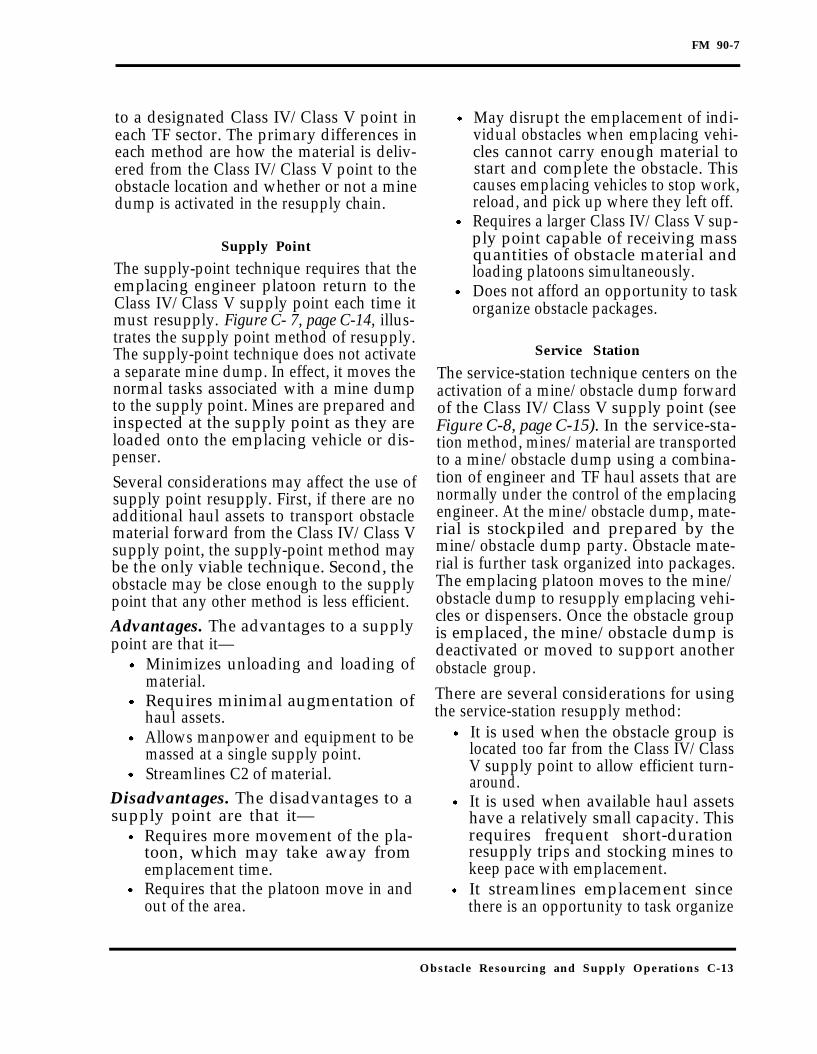
FM 90-7
to a designated Class IV/Class V point ineach TF sector. The primary differences ineach method are how the material is deliv-ered from the Class IV/Class V point to theobstacle location and whether or not a minedump is activated in the resupply chain.
Supply Point
The supply-point technique requires that theemplacing engineer platoon return to theClass IV/Class V supply point each time itmust resupply. Figure C- 7, page C-14, illus-trates the supply point method of resupply.The supply-point technique does not activatea separate mine dump. In effect, it moves thenormal tasks associated with a mine dumpto the supply point. Mines are prepared andinspected at the supply point as they areloaded onto the emplacing vehicle or dis-penser.Several considerations may affect the use ofsupply point resupply. First, if there are noadditional haul assets to transport obstaclematerial forward from the Class IV/Class Vsupply point, the supply-point method maybe the only viable technique. Second, theobstacle may be close enough to the supplypoint that any other method is less efficient.Advantages. The advantages to a supplypoint are that it—
Minimizes unloading and loading ofmaterial.Requires minimal augmentation ofhaul assets.Allows manpower and equipment to bemassed at a single supply point.Streamlines C2 of material.
Disadvantages. The disadvantages to asupply point are that it—
Requires more movement of the pla-toon, which may take away fromemplacement time.Requires that the platoon move in andout of the area.
May disrupt the emplacement of indi-vidual obstacles when emplacing vehi-cles cannot carry enough material tostart and complete the obstacle. Thiscauses emplacing vehicles to stop work,reload, and pick up where they left off.Requires a larger Class IV/Class V sup-ply point capable of receiving massquantities of obstacle material andloading platoons simultaneously.Does not afford an opportunity to taskorganize obstacle packages.
Service Station
The service-station technique centers on theactivation of a mine/obstacle dump forwardof the Class IV/Class V supply point (seeFigure C-8, page C-15). In the service-sta-tion method, mines/material are transportedto a mine/obstacle dump using a combina-tion of engineer and TF haul assets that arenormally under the control of the emplacingengineer. At the mine/obstacle dump, mate-rial is stockpiled and prepared by themine/obstacle dump party. Obstacle mate-rial is further task organized into packages.The emplacing platoon moves to the mine/obstacle dump to resupply emplacing vehi-cles or dispensers. Once the obstacle groupis emplaced, the mine/obstacle dump isdeactivated or moved to support anotherobstacle group.There are several considerations for usingthe service-station resupply method:
It is used when the obstacle group islocated too far from the Class IV/ClassV supply point to allow efficient turn-around.It is used when available haul assetshave a relatively small capacity. Thisrequires frequent short-durationresupply trips and stocking mines tokeep pace with emplacement.It streamlines emplacement sincethere is an opportunity to task organize
Obstacle Resourcing and Supply Operations C-13
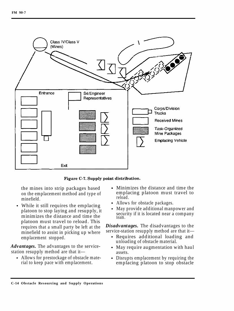
FM 90-7
the mines into strip packages based Minimizes the distance and time theon the emplacement method and type of emplacing platoon must travel tominefield. reload.
While it still requires the emplacing Allows for obstacle packages.May provide additional manpower andplatoon to stop laying and resupply, it
minimizes the distance and time the security if it is located near a companyteam.
platoon must travel to reload. Thisrequires that a small party be left at theminefield to assist in picking up whereemplacement stopped.
Advantages. The advantages to the service-station resupply method are that it—
Allows for prestockage of obstacle mate-rial to keep pace with emplacement.
Disadvantages. The disadvantages to theservice-station resupply method are that it—
Requires additional loading andunloading of obstacle material.May require augmentation with haulassets.Disrupts emplacement by requiring theemplacing platoon to stop obstacle
C-14 Obstacle Resourcing and Supply Operations

FM 90-7
Obstacle Resourcing and Supply Operations C-15

FM 90-7
emplacement, move to the supply point, Two overriding considerations drive thereload, and return to the minefield. decision to use the tailgate resupply method:
Tailgate
The tailgate resupply method transportsobstacle material directly from the ClassIV/Class V supply point to the emplacingplatoon on the site (see Figure C-9). Obstaclematerial is transported to the emplacingplatoon using both TF and engineer haulassets. At the obstacle site, obstaclematerial is loaded onto emplacing vehicles ordispensers. This action is performed byemplacing engineers rather than a separateparty.
If obstacle emplacement is being con-ducted during limited visibility, thetailgate method minimizes disruptionof emplacement and chance of fratri-cide as engineers move back into awork area after reloading.The tailgate method is used whenestablishing a hasty defense or whenthe situation is unclear and an attackcan happen at any time. Since obstaclematerial remains loaded until trans-ferred to the emplacing vehicle, thetailgate method enables engineers to
C-16 Obstacle Resourcing and Supply Operations

FM 90-7
quickly break contact without risking a Disadvantages. The disadvantages to theloss of obstacle material to the enemy. tailgate resupply method are that it—The tailgate resupply method is thepreferred method for light forces.
Advantages. The advantages to the tailgateresupply method are that it—
Minimizes loading and unloading ofobstacle material.Allows engineers to rapidly break con-tact, in the event of enemy attack, with-out losing obstacle material to theenemy.Minimizes the movement of platoons inand out of the obstacle (suitable for lim-ited visibility).
Requires augmentation by high capac-ity transportation assets capable of off-setting the loss in turn-around time ifthe vehicle has to wait on-station at theobstacle site.May result in inefficient use of haulassets.Complicates C2 in linking up obstacletransport assets with emplacing engi-neers as the engineers continueemplacement.Requires that task organizing of obsta-cle packages and loading occur concur-rently.
Obstacle Resourcing and Supply Operations C-17

FM 90-7
Glossary
#
AA
ACE
ACR
AD
AD
ADAM
AHD
AI
ALO
AO
AP
ASP
AT
ATTN
ATP
BFV
number
avenue of approach
armored combat earthmover
armored cavalry regiment
armored division
antitank ditch
area denial artillery munition – An artillery munition that containsantipersonnel scatterable mines.
antihandling device – A device designed to detonate a mine if the mineis disturbed.
air interdiction
air liaison officer
area of operation
antipersonnel
ammunition storage point
antitank
attention
ammunition transfer point
Bradley fighting vehicle
Glossary 1

FM 90-7
BHL
BOS
BP
C2
CAS
CATK
CEV
CFL
CMMC
co
COA
CP
CSA
CSS
cu
DA
DAO
DATK
DMMC
DODIC
battle handover line
battlefield operating system
battle position
command and control
close air support
counterattack
combat engineer vehicle
coordinated fire line
corps materiel management center
company
course of action
command post
corps storage area
combat service support
cubic
Department of the Army
division ammunition officer
deliberate attack
division materiel management center
Department of Defense identification code
2 Glossary
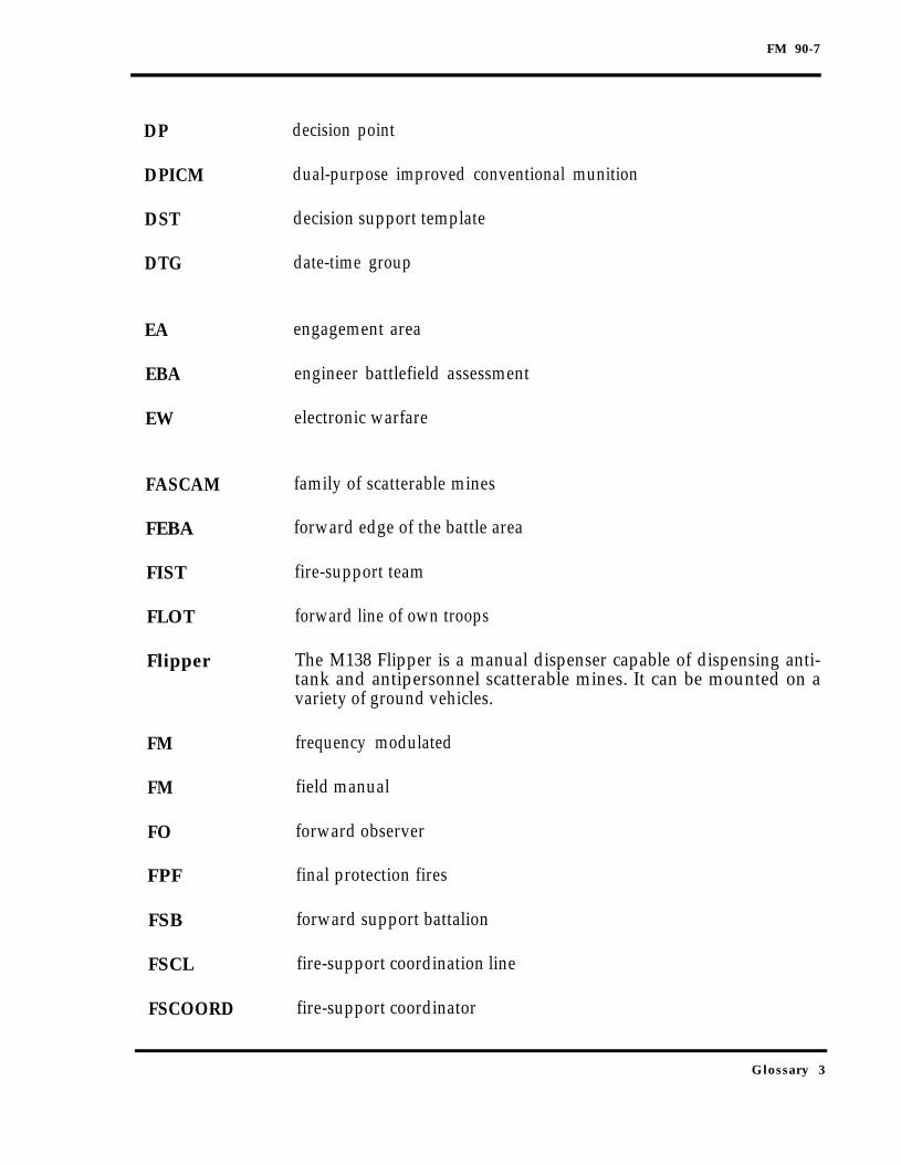
FM 90-7
DP decision point
DPICM dual-purpose improved conventional munition
DST decision support template
DTG date-time group
EA
EBA
EW
FASCAM
FEBA
FIST
FLOT
Flipper
engagement area
engineer battlefield assessment
electronic warfare
family of scatterable mines
forward edge of the battle area
fire-support team
forward line of own troops
The M138 Flipper is a manual dispenser capable of dispensing anti-tank and antipersonnel scatterable mines. It can be mounted on avariety of ground vehicles.
FM frequency modulated
FM field manual
FO forward observer
FPF final protection fires
FSB forward support battalion
FSCL fire-support coordination line
FSCOORD fire-support coordinator
Glossary 3

FM 90-7
FSO
ft
G2
G3
Gator
GDP
GEMSS
GPBTO
GSR
HATK
HMMWV
HQ
HPT
hr
ID
IFV
IOE
IPB
JAAT
fire-support officer
foot, feet
Assistant Chief of Staff, G2 (Intelligence)
Assistant Chief of Staff, G3 (Operations and Plans)
A scatterable mine system delivered by Air Force and Navy tacticalaircraft.
general defense plan
Ground-Emplaced, Mine-Scattering System
general-purpose barbed-tape obstacle
ground surveillance radar
hasty attack
high-mobility multipurpose wheeled vehicle
headquarters
high payoff target
hour(s)
infantry division
infantry fighting vehicle
irregular outer edge
intelligence preparation of the battlefield
joint air attack team
4 Glossary

FM 90-7
km
kph
lb
LC
LD
LOC
LOGPAC
LP
LRP
m
MBA
MC
MCOO
MCS
METT-T
MF
MHE
MICLIC
MO
MOPMS
kilometer(s)
kilometer(s) per hour
pound(s)
line of contact
line of departure
lines of communication
logistical package
listening post
logistics release point
meter(s)
main battle area
mobility corridor
modified combined obstacle overlay
Maneuver Control System
mission, enemy, troops, terrain, and time available
minefield
materials handling equipment
mine-clearing line charge
Missouri
Modular Pack Mine System – The M131 MOPMS is a man-portable,
Glossary 5

FM 90-7
MOUT
MRD
M/S
MSR
MTC
NA
NAI
NBC
NCO
NFA
NLT
NSN
obj
OCOKA
OOTW
OP
OPLAN
OPORD
suitcase-shaped, scatterable mine dispenser capable of emplacing 17antitank mines and 4 antipersonnel mines.
military operations on urbanized terrain
motorized rifle division
mobility/survivability
main supply route
movement to contact
not applicable
named area of interest
nuclear, biological, and chemical
noncommissioned officer
no-fire area
not later than
national stock number
objective
observation and fire, cover and concealment, obstacles, key terrain,and avenues of approach
operations other than war
observation post
operation plan
operation order
6 Glossary
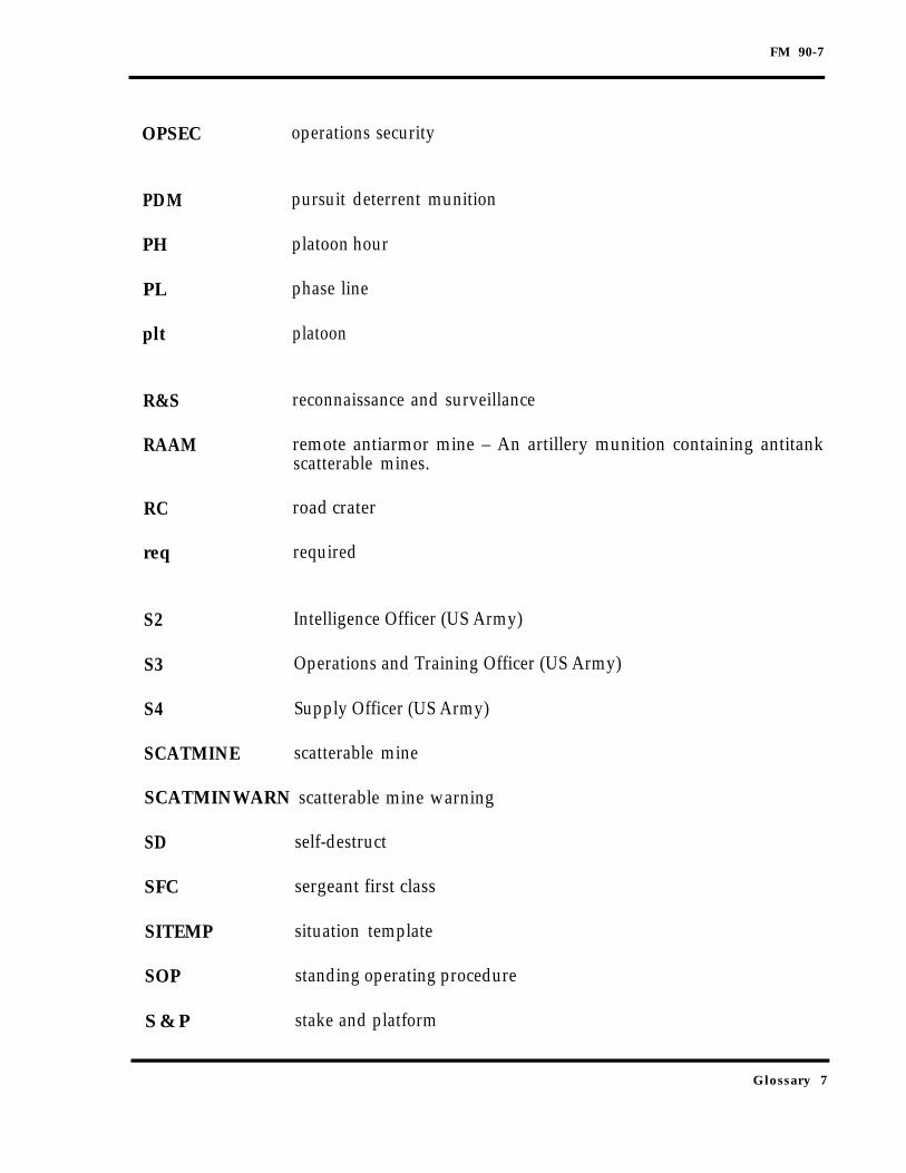
FM 90-7
OPSEC operations security
PDM pursuit deterrent munition
PH platoon hour
PL phase line
plt platoon
R&S reconnaissance and surveillance
RAAM remote antiarmor mine – An artillery munition containing antitankscatterable mines.
RC road crater
req required
S2 Intelligence Officer (US Army)
S3 Operations and Training Officer (US Army)
S4 Supply Officer (US Army)
SCATMINE scatterable mine
SCATMINWARN scatterable mine warning
SD self-destruct
SFC sergeant first class
SITEMP situation template
SOP standing operating procedure
S & P stake and platform
Glossary 7

FM 90-7
STANAG
TAI
TCP
TECCS
TF
TO
TOW
TRADOC
TRP
TTP
Standardization Agreement
targeted area of interest
traffic control post
Tactical Engineer Command and Control System
task force
theater of operation
tube-launched, optically-tracked, wire-guided antitank missiles
US Army Training and Doctrine Command
target reference point
tactics, techniques, and procedures
US United States
UXO unexploded ordnance
Volcano The multiple delivery mine system consisting of the M87 mine canis-ter, the M139 dispenser, and specific vehicle mounting kits. The sys-tem is capable of being dispensed from the air by a helicopter or fromthe ground from both tracked and wheeled vehicles. It includes bothAT and AP mines.
WAM
wt
XO
wide area mine – An antitank mine that detects and acquires targetsthen launches a submunition that attacks the top of the targets.
weight
executive officer
8 Glossary

FM 90-7
Object Symbols
Obstacle belts
Obstacle zone
Disrupt
Turn
Fix
Block
Generic obstacle
Glossary 9

FM 90-7
Prepared demolition state 2
Prepared bridge demolition state 2
Executed or fired demolition reinforcedantitank mines
with
Future or projected scatterable minefield
10 Glossary

FM 90-7
References
SOURCES USED
These are the sources quoted or paraphrased in this publication.
International Standardization Agreements (STANAG)
STANAG 2017. Orders to the Demolition Guard Commander and Demolition Firing PartyCommander (Non-Nuclear) Edition 3, 10 July 1981, amendment Edition 5, 29 April 1988.
STANAG 2366. Stopping Power of Land Minefield, 15 June 1993.
Army Publications
Field Manuals (FMs)FM 5–34. Engineer Field Data. 14 September 1987.FM 5–71–100. Division Engineer Combat Operations. 22 April 1993.FM 5-100. Engineer Combat Operations. 22 November 1988.FM 5–102. Countermobility. 14 March 1985.FM 5–114. Engineer Operations Short of War. 13 July 1992.FM 5–250. Explosives and Demolitions. 15 June 1992.FM 6-20. Fire Support in the AirLand Battle. 17 May 1988.FM 6-20-1. Tactics, Techniques, and Procedures for the Field Artillery Cannon Battalion.
29 November 1990.FM 6-20-2. Tactics, Techniques, and Procedures for Corps Artillery, Division Artillery, andField Artillery Brigade Headquarters. 7 January 1993.
FM 6-20-10. Tactics, Techniques, and Procedures for the Targeting Process. 29 March 1990.FM 6-20-20. Tactics, Techniques, and Procedures for Fire Support at Battalion, Task Force,
and Below. 27 December 1991.FM 6-20-30. Tactics, Techniques, and Procedures for Fire Support for Corps and Division
Operations. 18 October 1989.FM 6-20-40. Tactics, Techniques, and Procedures for Fire Support for Brigade Operations
(Heavy). 5 January 1990.FM 6-20-50. Tactics, Techniques, and Procedures for Fire Support for Brigade Operations(Light). 5 January 1990.
FM 20–32. Mine/Countermine Operation 30 September 1992.FM 34–1. Intelligence and Electronic Warfare Operations. 2 July 1987.FM 34–10. Division Intelligence and Electronic Warfare Operations. 25 November 1986.FM 34–130, Intelligence Reparation of the Battlefield. 23 May 1989.FM 71–2. The Tank and Mechanized Infantry Battalion Task Force, 27 September 1988.FM 71–3. Armored and Mechanized Infantry Brigade. 11 May 1988.
References 1

FM 90-7
FM 71-100. Division Operations. 16 June 1990.FM 90–13-1. Combined Arms Breaching Operations. 28 Feb 1991 (Change 1, May 1993).FM 100–5. Operations. 14 June 1993.FM 100-7. The Army in Theater Operations. To be published within 6 months.FM 101–5. Staff Organization and Operations. 25 May 1984.
DOCUMENTS NEEDED
These documents must be available to the intended users of this publication.
Department of the Army (DA) FormsDA Form 1355. Minefield Record. March 1987.DA Form 1355–1–R. Hasty Protective Minefield Record (LRA). July 1975.DA Form 2028, Recommended Changes to Publications and Blank Forms. February 1974.
2 References

FM 90-7
Index
Index 1

FM 90-7
2 Index
FM 90-7
Index 3
FM 90-7
4 Index

FM 90-7
Index 5
FM 90-7
6 Index

FM 90-7
Index 7

FM 90-7
8 Index

FM 90-729 SEPTEMBER 1994
By Order of the Secretary of the Army:
Official:
MILTON H. HAMILTONAdministrative Assistant to the
Secretary of the Army07239
GORDON R. SULLIVANGeneral, United States Army
Chief of Staff
DISTRIBUTION:
Active Army, USAR, and ARNG: To be distributed in accordance with DA Form12-11 E, requirements for FM 90-7, Combined Arms Obstacle Integration (Qty rqr.block no. 5197)
✩ U.S. GOVERNMENT PRINTING OFFICE: 1994 — 5 2 8 - 0 2 7 /2 0 0 2 7

PIN: 073038-001