army snowloads sno jax snow guards · in such areas the national snow load map in asce manual 7...
TRANSCRIPT

TI 809-523 August 1998
Technical Instructions
Commentary on Snow Loads
HeadquartersU.S. Army Corps of EngineersEngineering and Construction DivisionDirectorate of Military ProgramsWashington, DC 20314-1000

CEMP-E TI 809-523 August 1998
TECHNICAL INSTRUCTIONS
Commentary on Snow Loads
Any copyrighted material included in this document is identified at its point of use.Use of the copyrighted material apart from this document must have the permission of the copyright holder.
Approved for public release; distribution is unlimited.
Record of Changes (changes indicated \1\... /1/ )No. Date Location
_____________This Technical Instruction supersedes EI 01S001, dated 1 October 1997.(EI 01S001 text is included in this Technical Instruction and may carry EI 01S001 identification.)

CEMP-E TI 809-523 August 1998
FOREWORD
These technical instructions (TI) provide design and construction criteria and apply to all U.S.Army Corps of Engineers (USACE) commands having military construction responsibilities. TIwill be used for all Army projects and for projects executed for other military services or work forother customers where appropriate.
TI are living documents and will be periodically reviewed, updated, and made available to usersas part of the HQUSACE responsibility for technical criteria and policy for new militaryconstruction. CEMP-ET is responsible for administration of the TI system; technical content of TIis the responsibility of the HQUSACE element of the discipline involved. Recommendedchanges to TI, with rationale for the changes, should be sent to HQUSACE, ATTN: CEMP-ET,20 Massachusetts Ave., NW, Washington, DC 20314-1000.
TI are effective upon issuance. TI are distributed only in electronic media through theTECHINFO Internet site http://www.hnd.usace.army.mil/techinfo/index.htm and the ConstructionCriteria Base (CCB) system maintained by the National Institute of Building Sciences at Internetsite http://www.nibs.org/ccb/. Hard copies of these instructions produced by the user from theelectronic media should be checked against the current electronic version prior to use to assurethat the latest instructions are used.
FOR THE DIRECTOR OF MILITARY PROGRAMS.
KISUK CHEUNG, P.E.Chief, Engineering and Construction DivisionDirectorate of Military Programs

i
DEPARTMENT OF THE ARMY TI 809-52U.S. Army Corps of Engineers
CEMP-E Washington, DC 20314-1000
Technical InstructionsNo.TI 809-52 3 August 1998
COMMENTARY ON SNOW LOADS
Table of Contents
Page
Paragraph 1. Purpose and Scope............................................................................................ 1
2. Applicability ...................................................................................................... 1
3. References ...................................................................................................... 1
4. Building Configuration....................................................................................... 1
5. Unbalanced Loads............................................................................................. 2
6. Metal Buildings .................................................................................................. 2
7. Internally Drained Membrane Roofing Systems................................................... 2
8. Building Orientation............................................................................................ 2
9. Sliding Snow ...................................................................................................... 2
10. Icicles and Ice Dams........................................................................................... 3
11. Snow Guards..................................................................................................... 3
Figure Title
1 The peak snow load of this drift was 130 psf. The ground snow load thenwas 20 psf, and the snow load on the upper roof was 15 psf ......................................... 4
2 Snow drifts and their consequences.............................................................................. 53 Unbalanced snow loads on a saw-tooth roof.................................................................. 64 Orienting buildings with respect to the known direction of winter storm
winds can reduce actual drifting even though design loads do not change..................... 75 Snow sliding off a metal roof.......................................................................................... 86 Army van damaged by snow and ice that fell from a roof............................................... 9

CEMP-E TI 809-523 August 1998
ii
Table of contents (continued)
Figure TitlePage
7 The creep and glide of snow down a slippery roof can create dangerouscornices ......................................................................................................................10
8 Plumbing stack displaced by snow creeping down a slippery metal roof........................119 Tear in metal roofing caused by the plumbing stack displacement
shown in figure 8..........................................................................................................1210 Parapet capstone displaced by snow moving down the adjacent roof valley..................1311 Metal roof fascia torn by moving snow..........................................................................1412 Metal standing seams broken and displaced by snow moving down a valley.................1513 Plan view of a gable-roofed building showing some sliding snow issues.......................1614 Snow creep can create cornices that cause several problems......................................1715 Electrical service entrance cables should not be located below cold eaves...................1816 Scuppers are often not appropriate as primary drains for low slope roofs in
cold regions..................................................................................................................1917 Massive icings all along a metal roof over a warm attic.................................................2018 When a cold eave is not present, ice may form on building walls..................................2119 Removal of snow and ice is dangerous and often damages the roof.............................2220 Electric heaters can create tunnels which prevent ponds from
forming on roofs behind ice dams.................................................................................2321 Electric heaters zigzagged along the eaves of a residence to prevent
ponding of water behind ice dams.................................................................................2422 Fence type snow guards installed on a metal roof.........................................................2523 Plastic snow guards adhered to a metal roof.................................................................2624 Two rows of aluminum angle snow guards spaced well apart up a metal roof...............27

CEMP-E TI 809-523 August 1998
1
COMMENTARY ON SNOW LOADS
1. PURPOSE AND SCOPE. This document provides guidance for designing roofs subjectedto snow loads. The primary discipline addressed in structural, but this guidance also applies toarchitectural, mechanical, and electrical issues.
2. APPLICABILITY. These instructions are applicable to all USACE elements involved withthe design of buildings and other structures, including repairs and modifications as well as newconstruction.
3. REFERENCES.
a. Use the current edition of American Society of Civil Engineers (ASCE) Manual 7,“Minimum Design Loads for Buildings and Other Structures.” Copies are available from ASCE,1015 15th Street, N. W., Suite 600, Washington, D.C. 20005-2605. ASCE’s phone number is(202) 789-2200. Users of this document should not use the mandatory provisions of theStandard itself without becoming familiar with the Commentary on Snow Loads appended to theStandard. The Commentary explains the rationale behind the provisions and contains examplesthat illustrate their use.
b. Site-specific ground snow loads for military installations and other places of interest toDOD are tabulated in TI 809-XX, “Load Assumptions for Buildings.” That information is based ona detailed snow load case study at each place. Occasionally, the case study answer differs fromthe value on the national snow load map in ASCE Manual 7. When a difference exists, thetabulated value in TI 809-XX should be used. A copy of each case study is maintained at CEMP-ET. Snow loads for foreign locations are also tabulated in TI 809-XX. Caution is urged whenusing these foreign values since each is based on local experience only, not an extreme-valuestatistical analysis of recent meteorological data. Wherever possible, host country expertiseshould be sought and host country snow loads compared to those tabulated in TI 809-XX.
c. In some areas of the United States extreme local variations in snow loads precludemapping on a national scale. In such areas the national snow load map in ASCE Manual 7 doesnot present a ground snow load, but indicates that a snow load case study is needed. The dataand methodology used to conduct snow load case studies are presented in Cold RegionsResearch and Engineering Laboratory (CRREL) report “Snow Loads for the United States.” Additional snow load case studies are available through CEMP-ET.
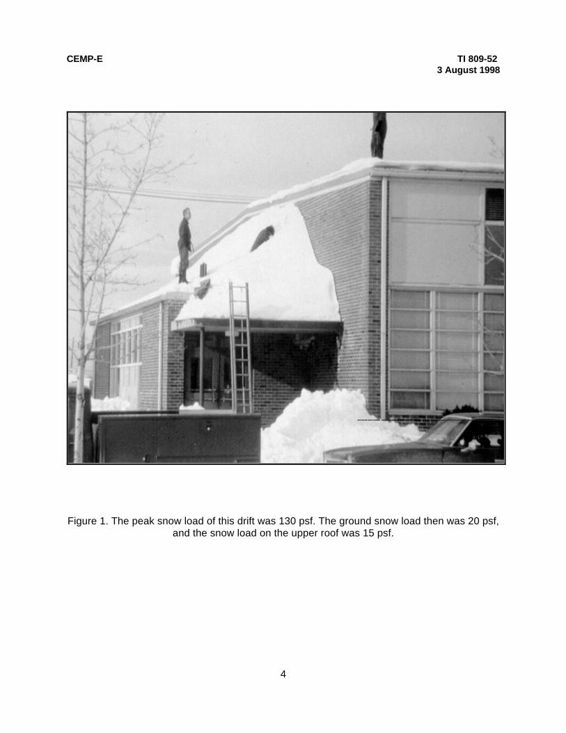
4. BUILDING CONFIGURAITON. The snow load provisions of ASCE Manual 7 indicate howdramatically the geometry of a building influences the snow loads on its roof. Problems can beavoided and more economical designs developed when snow load issues are considered by thedesign team as the show of the building evolves. Snow will drift into areas of “aerodynamicshade” (see figure 1). Figure 2 illustrates such places on the kinds of problems that areencountered.
5. UNBALANCED LOADS. Figure 3 shows a “saw-tooth roof” on which wind has moved snowfrom its upper portions into its valleys creating unbalanced snow loads. Such unbalanced snowloads are covered in ASCE Manual 7 for roofs with a slope of 15° or more. ASCE Manual 7 doesnot require consideration of unbalanced loads for lower slopes, but its Commentary warns that

CEMP-E TI 809-523 August 1998
2
such unbalanced loads are being observed on some large gable roofs with slopes less the 15°. That Commentary suggests that it may be appropriate to consider unbalanced loads for suchroofs with slopes down to 5° (about 1 in./ft.).
6. METAL BUILDINGS. Many metal buildings are built with low-slope gable roofs (single- ormultiple-gable). In cold regions for waterproofing reasons, it is appropriate to require a slope ofat least 1 inch/foot (about 5°) for metal roofing systems. Metal buildings are designed with littlestructural “fat.” Many have failed where an unbalanced snow load in one area caused purlins tofall, initiating progressive collapse. Unbalanced snow loads should be considered on all metalbuildings regardless of their slope.
7. INTERNALLY-DRAINED MEMBRANE ROOFING SYSTEMS. Such roofs usually haveslopes much less than 15° and, thus ASCE Manual 7 does not require unbalanced loads to beconsidered. There is always the possibility that some unbalanced loads may develop. To reducerisks associated with this possibility, the depth of such basins should be as small as possible. The easiest way to do this is to reduce roof slopes to 1/4 inch/foot. Dead flat roofs are a designmistake. A l/8 inch/foot design slope can result in as-built flat areas. There is no real evidencethat supports the contention that in cold regions a ½-inch/foot minimum slope should be used. Increasing the slope above ¼ inch/foot increases costs since higher walls are needed to accountfor the greater slope. Slopes of 1 inch/foot not only further increases the risk of unbalancedsnow loads, but these slopes can be more expensive due to the additional attachments neededto hold roofing components in place on such slopes.
8. BUILDING ORIENTATION. ASCE Manual 7 requires designers to assume that the highwinds which cause snow to drift could come from any direction. Nonetheless, information shouldbe sought from “locals” on drift orientation. Where such information indicates strong preferentialorientation of snow drifting, give thought to placing drift-prone features (e.g., loading dock roofseither upwind or alongside the building rather than at its downwind end. Design loads will notchange, but the amount of drifting may be reduced significantly. An example is shown in figure4. However, changing the orientation of buildings may not be possible. Sloping the roofs on theloading docks shown in figure 4 would reduce drift loads. However, that may introduce drainage,ice damming, and sliding snow problems.
9. SLIDING SNOW. The ability of slippery unobstructed roofs to shed snow loads by sliding canbe an advantage and a disadvantage. Loads on a roof can be reduced when snow slides off(figure 5), but loads will increase on any lower roofs onto which snow slides. If snow drops somedistance, large dynamic loads can be imposed on a lower roof or on an object located below(figure 6). Snow can creep and glide slowly down slippery surfaces (figure 7), even those withvery shallow slopes. The movement of snow can drag plumbing stacks (figure 8) and other roofpenetrations with it, damaging them and creating holes in the roof (figure 9). If snow slides fromroofs having gutters, they will probably be ripped off. Parapets and fascias can also be damaged(figures 10 and 11). Flow of snow down valleys can bend the standing seams of metal roofing(figure 12), reducing their strength and violating their waterproofing integrity. Several slidingsnow issues are illustrated in figure 13. Large curling snow cornices can be created at eaves(figure 7). Such cornices can be quite heavy, and they may curl around enough to damage wallsand windows. When they break off, piles of snow and ice are created on the ground. Thesepiles may deflect falling snow sideways towards walls, damaging them. Meltwater that drips ontothese piles can enter the building at the base of the wall if that base is not far above the finishedgrade outside. Figure 14 illustrates a number of these situations. Electrical service entrancecables located below eaves can be ripped loose by falling snow or damaged by the weight of icethat collects on them from roof meltwater (figure 15). Snow guards may be needed to hold snow

CEMP-E TI 809-523 August 1998
3
in place on slippery roofs. Internally drained membrane roofing systems with a slope of ¼incj/foot avoid these problems. Switching from internal drains to scuppers can lead toproblematic, dangerous icings (figure 16).
10. ICICLES AND ICE DAMS. Icicles and ice dams can form along the eaves of inadequatelyinsulated and ventilated roofs of heated buildings that drain to cold eaves (figure 17). Whereeaves are not present, such ice may form on the walls below (figure 18). Icings at eavesprevent snow load reductions by sliding until that ice warms up and either melts or breaks free. Falling ice is a hazard (figure 6). Icings at eaves can be avoided when attic ventilation systemsare able to keep the temperature of the roof from rising above about 30° F when the temperatureoutside is about 22° F. When it is warmer outside, icings usually do not grow and when it iscolder outside, less attic ventilation is needed. Equations for sizing attic ventilation systems arepresented in CRREL Miscellaneous Paper “Ventilating Attics to Minimize Icings at Eaves.” Theextra cost of adequately insulating and ventilating a roof to prevent icings is easy to justify sincethe water that ponds behind ice dams usually leaks into the building causing significantproblems. Efforts to remove icings with hammers, axes (figure 19), chain saws, and such usuallydamage the roof. On existing buildings, electrical heaters may be needed to keep tunnels meltedthrough small ice dams (figure 20). The tunnels prevent water from ponding on the roof andleaking into the building. Electric heaters are relatively easy to install along the eaves of a roofwith asphalt shingles (figure 21). Installing electric heaters on standing seam metal roofs is moredifficult. Guidelines are available in CRREL Miscellaneous Paper “Electric Heating Systems forCombating Icing Problems on Metal Roofs.” Essentially all new roofs should be designed so thatthey do not require electrical heaters.
11. SNOW GUARDS. Snow guards are objects used to hold snow on slippery roofs (figure 22). Many slate and metal roofs require snow guards to protect people and property. Snow guardsmay also be needed on barrel vaults and other such roofs with smooth membranes. Some snowguards are attached mechanically while others are adhered to the roof surface (figure 23). Design loads on snow guards should be based on the assumption that friction between the snowand the roof is zero. Multiple rows of snow guards spaced well apart up the roof (figure 24) arebetter at holding snow in place (i.e., avoiding the large dynamic loads created by sliding snow)than one row of last-resort snow guards placed near the eaves. A short snow guard on a longroof without other snow guards must be able to resist all the snow located within outward 45°angles up slope of its location. The loads at the ends of such a snow guard are about twice theaverage load on it. The design load on a snow guard should be less than half of any failure loadreported by its manufacturer. In high risk situations, (e.g., entrances and emergency exits ofschools) allowable loads on snow guards should be even lower. Design guidance, test, data,and performance standards on snow guards are limited so they should be used with caution.
CEMP-E TI 809-523 August 1998
4
Figure 1. The peak snow load of this drift was 130 psf. The ground snow load then was 20 psf,and the snow load on the upper roof was 15 psf.

CEMP-E TI 809-523 August 1998
5
Figure 2. Snow drifts and their consequences.

CEMP-E TI 809-523 August 1998
6
Figure 3. Unbalanced snow loads on a saw-tooth roof.

CEMP-E TI 809-523 August 1998
7
Figure 4. Orienting buildings with respect to the known direction of winter storm windscan reduce actual drifting even though design loads do not change.

CEMP-E TI 809-523 August 1998
8
Figure 5. Snow sliding off a metal roof.

CEMP-E TI 809-523 August 1998
9
Figure 6. Army van damaged by snow and ice that feel from a roof.

CEMP-E TI 809-523 August 1998
10
Figure 7. The creep and glide of snow down a slippery roof can createdangerous cornices.

CEMP-E TI 809-523 August 1998
11
Figure 8. Plumbing stack displaced by snow creeping down a slippery metal roof.

CEMP-E TI 809-523 August 1998
12
Figure 9. Tear in metal roofing caused by the plumbing stackdisplacement shown in figure 8.

CEMP-E TI 809-523 August 1998
13
Figure 10. Parapet capstone displaced by snow moving downthe adjacent roof valley.

CEMP-E TI 809-523 August 1998
14
Figure 11. Metal roof fascia torn by moving snow.

CEMP-E TI 809-523 August 1998
15
Figure 12. Metal standing seams broken and displaced bysnow moving down a valley.

CEMP-E TI 809-523 August 1998
16
Figure 13. Plan view of a gable-roofed building showing some sliding snow issues.

CEMP-E TI 809-523 August 1998
17
Figure 14. Snow creep can create cornices that cause several problems.

CEMP-E TI 809-523 August 1998
18
Figure 15. Electrical service entrance cables should not belocated below cold eaves.

CEMP-E TI 809-523 August 1998
19
Figure 16. Scuppers are often not appropriate as primary drains forlow slope roofs in cold regions.

CEMP-E TI 809-523 August 1998
20
Figure 17. Massive icings along a metal roof over a warm attic.

CEMP-E TI 809-523 August 1998
21
Figure 18. When a cold eave is not present, ice may form on building walls.

CEMP-E TI 809-523 August 1998
22
Figure 19. Removal of snow and ice is dangerous and oftendamages the roof.

CEMP-E TI 809-523 August 1998
23
Figure 20. Electric heaters can create tunnels which prevent pondsfrom forming on roofs behind ice dams.

CEMP-E TI 809-523 August 1998
24
Figure 21. Electric heaters zigzagged along the eaves of aresidence to prevent ponding of water behind ice dams.

CEMP-E TI 809-523 August 1998
25
Figure 22. Fence type snow guards installed on a metal roof.

CEMP-E TI 809-523 August 1998
26
Figure 23. Plastic snow guards adhered to a metal roof.

CEMP-E TI 809-523 August 1998
27
Figure 24. Two rows of aluminum angle snow guards spaced well apartup a metal roof.