army weapons systems 2011
TRANSCRIPT

7/29/2019 Army Weapons Systems 2011
http://slidepdf.com/reader/full/army-weapons-systems-2011 1/380

7/29/2019 Army Weapons Systems 2011
http://slidepdf.com/reader/full/army-weapons-systems-2011 2/380

7/29/2019 Army Weapons Systems 2011
http://slidepdf.com/reader/full/army-weapons-systems-2011 3/380
WEAPON SYSTEMS 2011
Dear Reader:
Malcolm R. O’Neill
Assistant Secretary of the Army
(Acquisition, Logistics and Technology)
and Army Acquisition Executive

7/29/2019 Army Weapons Systems 2011
http://slidepdf.com/reader/full/army-weapons-systems-2011 4/380
UNITED STATES ARMY
How to Use this Book ..................................................................................................... VI
Introduction ......................................................................................................1
Weapon Systems ............................................................................................13
2.75 Inch Rocket Systems (Hydra) ................................................................................14
Abrams Tank Upgrade (M1A2) ......................................................................................16
Advanced Field Artillery Tactical Data System (AFATDS) ...............................................18
Advanced Threat Infrared Countermeasure/Common Missile Warning
System (ATIRCM/CMWS) .............................................................................................20
Air Warrior (AW)............................................................................................................22
Air/Missile Defense Planning and Control System (AMDPCS) ........................................ 24
Airborne Reconnaissance Low (ARL) ............................................................................26 All Terrain Lifter Army System (ATLAS).........................................................................28
Armored Knight ...........................................................................................................30
Armored Security Vehicle (ASV) ....................................................................................32
Army Key Management System (AKMS) .......................................................................34
Artillery Ammunition .....................................................................................................36
Aviation Combined Arms Tactical Trainer (AVCATT) .......................................................38
Battle Command Sustainment Support System (BCS3).................................................40
Biometric Enabling Capability (BEC) ..............................................................................42
Black Hawk/UH-60 .......................................................................................................44
Bradley Fighting Vehicle Systems Upgrade ...................................................................46
Calibration Sets Equipment (CALSETS) .........................................................................48
Chemical Biological Medical Systems–Diagnostics .......................................................50
Chemical Biological Medical Systems–Prophylaxis .......................................................52
Chemical Biological Medical Systems/ Transformational Medical
Technologies–Therapeutics ..........................................................................................54
Chemical Biological Protective Shelter (CBPS) ..............................................................56
Chemical, Biological, Radiological, Nuclear Dismounted Reconnaissance Sets,
Kits, and Outfits (CBRN DR SKO) ..................................................................................58
Chemical Demilitarization ............................................................................................60
CH-47 Chinook .............................................................................................................62
Close Combat Tactical Trainer (CCTT) ...........................................................................64
Combat Service Support Communications (CSS Comms) .............................................66
Command Post Systems and Integration (CPS &I) .........................................................68
Common Hardware Systems (CHS)...............................................................................70
Common Remotely Operated Weapon Station (CROWS) ................................................72
Counter Defilade Target Engagement (CDTE) –XM25 ...................................................74
Countermine .................................................................................................................76
Counter-Rocket, Artillery and Mortar (C-RAM)..............................................................78Defense Enterprise Wideband SATCOM System ( DEWSS) .............................................80
Distributed Common Ground System–Army ( DCGS-A) ..................................................82
Distributed Learning System (DLS ) ...............................................................................84
Dry Support Bridge ( DSB) .............................................................................................86
Early Infantry Brigade Combat Team (E-IBCT) Capabilities IBCT Increment 1 ................88
Enhanced Medium Altitude Reconnaissance and Surveillance System (EMARSS) .........92
Excalibur (XM982) ........................................................................................................94
Family of Medium Tactical Vehicles (FMTV) ..................................................................96
Fixed Wing ....................................................................................................................98
Force Protection Systems ..........................................................................................100
Force Provider (FP) .....................................................................................................102
Force XXI Battle Command Brigade and Below (FBCB2) .............................................104
Forward Area Air Defense Command and Control (FAAD C2) ......................................106
Future Tank Main Gun Ammunition (FTMGA) ..............................................................108
General Fund Enterprise Business Systems (GFEBS) .................................................. 110
Global Combat Support System–Army (GCSS-Army) ...................................................112
Global Command and Control System–Army (GCCS-A) ...............................................114
Table of Contents
II

7/29/2019 Army Weapons Systems 2011
http://slidepdf.com/reader/full/army-weapons-systems-2011 5/380
WEAPON SYSTEMS 2011
Gray Eagle Extended Range Multipurpose (ERMP) Unmanned Aircraft System (UAS) .. 116
Ground Combat Vehicle ( GCV) ..................................................................................... 118Guardrail Common Sensor (GR/ CS) ........................................................................... 120
Guided Multiple Launch Rocket System (GMLRS) DPICM/Unitary/Alternative
Warhead (Tactical Rockets) ........................................................................................122
Heavy Expanded Mobility Tactical Truck (HEMTT)/
HEMTT Extended Service Program (ESP)....................................................................124
Heavy Loader ............................................................................................................. 126
Hellfire Family of Missiles ........................................................................................... 128
Helmet Mounted Night Vision Devices (HMNVD) .........................................................130
High Mobility Ar tillery Rocket System ( HIMARS) .........................................................132
High Mobility Engineer Excavator (HMEE) I and III .......................................................134High Mobility Multi-Purpose Wheeled Vehicle (HMMW V) Family of Vehicles ................136
Improved Environmental Control Units (IECU )..............................................................138
Improved Ribbon Bridge (IRB ) .....................................................................................140
Improved Target Acquisition System (ITAS) ................................................................. 142
Installation Protection Program (IPP)...........................................................................144
Instrumentable–Multiple Integrated Laser Engagement System (I-MILES) ..................146
Integrated Air and Missile Defense (IA MD) .................................................................148
Integrated Family of Test Equipment (I FTE) .................................................................150
Interceptor Body Armor............................................................................................... 152
Javelin ........................................................................................................................154Joint-Automatic Identification Technology (J-A IT) ....................................................... 156
Joint Air-to-Ground Missile (JAGM) ............................................................................. 158
Joint Bat tle Command–Platform (JBC-P) .................................................................... 160
Joint Biological Point Detection System (JBPDS ) ........................................................162
Joint Biological Standoff Detection System (JBSDS) ................................................... 164
Joint Biological Tactical Detection System (JBTDS) .................................................... 166
Joint Chem/Bio Coverall for Combat Vehicle Crewman (JC3) ......................................168
Joint Chemical Agent Detector (JCAD) ........................................................................170
Joint Chemical Biological Radiological Agent Water Monitor ( JCBRAWM) ....................172Joint Effects Model (JEM) ............................................................................................174
Joint Effects Targeting System (JETS) Target Location Designation System (TLDS) ... 176
Joint High Speed Vessel (JHSV) ..................................................................................178
Joint Land Attack Cruise Missile Defense Elevated Netted Sensor System (JLENS) ... 180
Joint Land Component Constructive Training Capability (JLCCTC) ..............................182
Joint Light Tactical Vehicle (JLTV) ............................................................................... 184
Joint Personnel Identification Version 2 (JPIv2) ...........................................................186
Joint Precision Airdrop System (JPADS)......................................................................188
Joint Service General Purpose Mask (JSGPM) ............................................................ 190
Joint Service Transportable Decontamination System (JSTDS)–Small Scale (SS) .......192Joint Tactical Ground S tations (JTAGS) .......................................................................194
Joint Tactical Radio System Airborne and Maritime/Fixed Station (JTRS AMF ) ...........196
Joint Tactical Radio System Ground Mobile Radios (JTRS GMR) .................................198
Joint Tactical Radio System Handheld, Manpack, and Small Form Fit (JTRS HMS) .....200
Joint Tactical Radio System Multifunctional Information
Distribution System (JTRS MIDS)................................................................................202
Joint Tactical Radio System, Network Enterprise Domain (JTRS NED) ........................204
Joint Warning and Reporting Network (JWARN) ..........................................................206
Kiowa Warrior .............................................................................................................208
Light Tactical Trailer (LTT) .......................................................................................... 210
Light Utility Helicopter (LUH )/UH-72A Lakota .............................................................. 212
XM806–Lightweight .50 cal Machine Gun .................................................................. 214
Lightweight 155mm Howitzer (LW155) .......................................................................216
Lightweight Laser Designator/Rangefinder (LLDR) AN /PED-1..................................... 218
Line Haul Tractor ........................................................................................................220
Load Handling System Compatible Water Tank Rack (Hippo) ......................................222
Longbow Apache (AH-64D) (LBA ) ..............................................................................224
II I
7/29/2019 Army Weapons Systems 2011
http://slidepdf.com/reader/full/army-weapons-systems-2011 6/380
UNITED STATES ARMY
Medical Communications for Combat Casualty Care (MC4) ........................................226
Medical Simulation Training Center (MSTC) ................................................................228Medium Caliber Ammunition (MCA) ............................................................................230
Medium Extended Air Defense System (MEADS) ........................................................232
Meteorological Measuring Set–Profiler (MMS-P) ........................................................234
Mine Protection Vehicle Family ( MPVF) .......................................................................236
Mine Resistant Ambush Protected Vehicles (MRAP) ....................................................238
Mobile Maintenance Equipment Systems ( MMES) ......................................................240
Modular Fuel System (MFS) .......................................................................................242
Mortar Systems ..........................................................................................................244
Mounted Soldier System (MSS) ..................................................................................246
Movement Tracking System (MTS) .............................................................................248Multiple Launch Rocket System (MLRS) M270A1 .......................................................250
NAVSTAR Global Positioning System (GPS) ................................................................252
Nett Warrior ( NW) ......................................................................................................254
Night Vision Thermal Systems–Thermal Weapon Sight (TWS) .....................................256
Non-Intrusive Inspection Systems ( NIIS) ....................................................................258
Nuclear Biological Chemical Reconnaissance Vehicle (NBCRV)
–Stryker Sensor Suite.................................................................................................260
One Semi-Automated Forces ( OneSAF) ......................................................................262
Paladin/Field Artillery Ammunition Supply Vehicle (FAASV) .........................................264
Palletized Load System (PLS) and PLS Extended Service Program (ESP ) ....................266
PATRIOT Advanced Capability–Three (PAC-3 ) ............................................................268
Precision Guidance Kit (PGK) ......................................................................................270
Prophet.......................................................................................................................272
Raven Small Unmanned Aircraft System (SUAS ) ........................................................ 274
Rough Terrain Container Handler (RTCH) ....................................................................276
Screening Obscuration Device (SOD)–Visual Restricted (Vr) .......................................278
Secure Mobile Anti-Jam Reliable Tactical–Terminal (SMART-T) ..................................280
Sentinel ......................................................................................................................282
Shadow Tactical Unmanned Aircraft System ( TUAS) ...................................................284Single Channel Ground and Airborne Radio System (SINCGARS) ................................286
Small Arms– Crew Served Weapons ...........................................................................288
Small Arms–Individual Weapons ................................................................................290
Small Caliber Ammunition ...........................................................................................292
Sniper Night Sight (SNS), AN/ PVS-10 .........................................................................294
Spider .........................................................................................................................296
Stryker Family of Vehicles ...........................................................................................298
Surface Launched Advanced Medium Range Air-to-Air Missile (SLAMRA AM).............300
Tactical Battle Command (TBC)/ Maneuver Control System (MCS) ..............................302
Tactical Electric Power (TEP) ......................................................................................304Tank Ammunition (TA) ................................................................................................306
Test Equipment Modernization ( TEMOD) .....................................................................308
Transportation Coordinators’ Automated Information for Movement
System II (TC-AIMS II) ................................................................................................310
Tube-Launched, Optically-Tracked, Wire-Guided ( TOW) Missiles ................................ 312
Unit Water Pod System ( Camel II) .............................................................................. 314
Warfighter Information Network–Tactical ( WIN-T) Increment 1 ...................................316
Warfighter Information Network–Tactical ( WIN-T) Increment 2 ...................................318
Warfighter Information Network–Tactical ( WIN-T) Increment 3 ...................................320
Weapons of Mass Destruction Elimination ..................................................................322
Science & Technology (S&T) ....................................................................... 324
S&T INVESTMENT—FUTURE FORCE TECHNOLOGY AREAS .......................................325
FORCE PROTECTION ..................................................................................................326
Kinetic Energy Active Protection System ................................................................326
Threat and Minefield Detection Payload for Shadow Tactical Unmanned
Aerial Vehicle .........................................................................................................326
Advanced Aircraft Survivability ...............................................................................327
Table of Contents
IV

7/29/2019 Army Weapons Systems 2011
http://slidepdf.com/reader/full/army-weapons-systems-2011 7/380
WEAPON SYSTEMS 2011
Detection for In-Road Threats ................................................................................327
Extended Area Protection & Survivability (EAPS) Integrated Demo .........................327INTELLIGENCE, SURVEILLANCE, RECONNAISSANCE .................................................328
Battlespace Terrain Reasoning Awareness—Bat tle Command ................................328
Target Location Designation System ......................................................................328
Advanced Common Sensor Payload ........................................................................328
IRON Symphony ......................................................................................................329
Flexible Display Technology for Soldiers and Vehicles ..............................................329
COMMAND, CONTROL, COMMUNICATIONS, AND COMPUTERS (C4)..........................330
Collaborative Battlespace Reasoning and Awareness .......................................... .......330
RF Adaptive Technologies Integrated with Communications and Location ...............330
LETHAL ITY .................................................................................................................331 Advanced Lasers and Unmanned Aerial System Payloads ......................................331
Applied Smaller, Lighter, Cheaper Munitions Components .......................................331
Scalable Technology for Adaptive Response ...........................................................331
MEDICAL ....................................................................................................................332
Psychological Resetting after Combat Deployment: Advanced Battlemind ..............332
Damage Control Resuscitation ...............................................................................332
Drug for the Treatment of Traumatic Brain Injury (TBI) ...........................................332
Prophylactic Drugs to Prevent Drug-Resistant Malaria ...........................................332
Alternative Dengue Fever Vaccine Strategy .............................................................333
Candidate Multivalent Vaccine Against HIV-1 ...........................................................333
UNMANNED SYSTEMS ...............................................................................................333
Safe Operations of Unmanned Systems for Reconnaissance in
Complex Environments ..........................................................................................333
SOLDIER SYSTEMS ....................................................................................................334
Soldier Planning Interfaces and Networked Electronics ...........................................334
High-Definition Cognition (HD-COG ) In Operational Environments ...........................334
LOGISTICS ..................................................................................................................335
Power for the Dismounted Soldier ..........................................................................335
Advanced Affordable Engine Technology .................................................................335Mobile Power ..........................................................................................................335
High Performance Lightweight Track ......................................................................335
BASIC RESEARCH ......................................................................................................336
S&T ROLE IN FORMAL ACQUISITION MILESTONES ....................................................338
SUMMARY .................................................................................................................338
Appendices .................................................................................................. 339
Army Combat Organizations .......................................................................................340
Glossary of Terms ....................................................................................................... 341
Systems by Contractors ..............................................................................................345Contractors by State ...................................................................................................357
Points of Contact ........................................................................................................361
V
7/29/2019 Army Weapons Systems 2011
http://slidepdf.com/reader/full/army-weapons-systems-2011 8/380
UNITED STATES ARMY
ACQUISITIONPHASE
INVESTMENT COMPONENT
WEAPON SYSTEMS 2011
Tube-Launched, Optically-Tracked,Wire-Guided (TOW) Missiles
Tube-Launched, Optically-Tracked,Wire-Guided (TOW) Missiles
Recapitalization
Modernization
Maintenance
T echnology Development Operations & SupportProduction & DeploymentEngineering & Manufacturing Development
FOREIGNMILITARY SALES
TheTOW weapon systemhas been sold to
morethan 43 allied nations overthelife of
thesystem.
CONTRACTORS
TOW 2B Aero andTOW BB
Prime:
Raytheon MissileSystems (Tucson,AZ)
ControlActuator, Shutter Actuator:
Moog (SaltLakeCity,UT)
Warheads:
AerojetGeneral ( Socorro,NM)
Gyroscope:
BAE Systems (Cheshire,CT)
Sensor (TOW 2B only):
Thales (Basingstoke,UK)
LaunchMotor:
ATK(Radford, VA)
FlightMotor:
ATK(Rocket Center,WV)
Machined/FabricatedPar ts:
Klune(Spanish Fork,UT)
MISSION
Provides long-range, heavy anti-tank and precision assault fire capabilities to
Army and Marine forces.
DESCRIPTION The Close Combat Missile System–
Heavy (CCMS-H) TOW (Tube-
Launched, Optically-Tracked, Wire-
Guided) isa heavy anti-tank/precision
assault weapon system, consisting of
ala uncher and amissi le. The missile
issix inches in diameter (encased, 8.6
inches) and 49incheslong. The gunner
definest he aim point by maintaining
the sight crossh airson t he target.
The launcher automatica lly steerst he
missile along the line-of-sight toward
the aim point via apair of control wires
or aone-way radio frequency (RF)
link, which linksthe launcher and the
missile.
TOW missilesa re employed on the
High Mobility Multipurpose Wheeled
Vehicle (HMMWV)-mounted Improved
Target Acquisition System (ITAS),
HMMWV-mounted M220A4launcher
(TOW 2), Stryker Anti-Tank Guided
Missile (ATGM) Vehicles, and Bradley
Fighting Vehicles(A2/A2ODS/A2OI F/
A3) within the In fantry, Stryker,
and Heavy Brigade Combat Teams,
respectively. TOW missilesare also
employedon the Marine HMMWV-
mountedI TAS, HMMWV-mounted
M220A4launcher (TOW 2), LAV-ATGM
Vehicle, and AH1W Cobraat tack
helicopter. TOW isalso employed by
allied nationson avariety ofground
and airborne platforms.
The TOW 2BAero is the most modern
and capable missile in the TOW family,
with an extended maximum ra nge to
4,500meters. The TOW 2BAero has
an advancedcounteractive protection
system capability anddefeatsall
current and projected threat armor
systems. The TOW 2BAero fliesover
the target (offset above t he gunner’s
aim point) anduses alaser profilometer
and magneticsensor to detect andfire
two downward-directed, explo sively-
formed penetrator warheadsinto the
target. The TOW 2B Aero’smissile
weight is49.8 pounds(enca sed, 65
pounds).
The TOW Bunker Buster iso ptimized
for performance against urban
structures, earthen bunkers, field
fortifications, and light-skinned armor
threats. The missile impact is at the
aim point. It has a6.25pound, 6-inch
diameter high-explosive, bulk-charge
warhead, and its missile weighs45.2
pounds. The TOW BBhasan impact
sensor (crush switch) located in the
main-charge ogive anda pyrotechnic
detonation delay to enhance warhead
effectiveness. The PBXN-109explosive
ishoused in a thickcasing for
maximum performance. The TOW BB
can produce a21- to 24-inch diameter
hole in an 8-inch thick, double-
reinforced concrete wall at arange of
65to 3,750meters.
SYSTEMINTERDEPENDENCIESM1121/1167HMMWV, Stryker ATGM,
ITAS
PROGRAMSTATUS•Current: TOW 2Band BBRF in
production
PROJECTEDACTIVITIES•F Y11–FY15: TOW MY
310 311
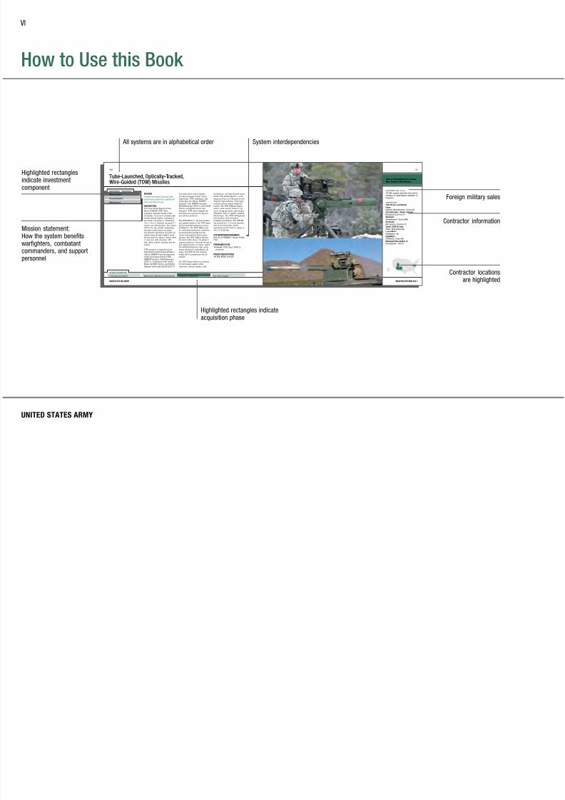
How to Use this Book
Highlighted rectanglesindicate investmentcomponent
UNITED STATES ARMY
VI
All systems are in alphabetical order
Highlighted rectangles indicateacquisition phase
Foreign military sales
Contractor information
Contractor locationsare highlighted
Mission statement:How the system benefitswarfighters, combatantcommanders, and supportpersonnel
System interdependencies

7/29/2019 Army Weapons Systems 2011
http://slidepdf.com/reader/full/army-weapons-systems-2011 9/380

7/29/2019 Army Weapons Systems 2011
http://slidepdf.com/reader/full/army-weapons-systems-2011 10/380
UNITED STATES ARMYUNITED STATES ARMY
7/29/2019 Army Weapons Systems 2011
http://slidepdf.com/reader/full/army-weapons-systems-2011 11/380
WEAPON SYSTEMS 2011
1
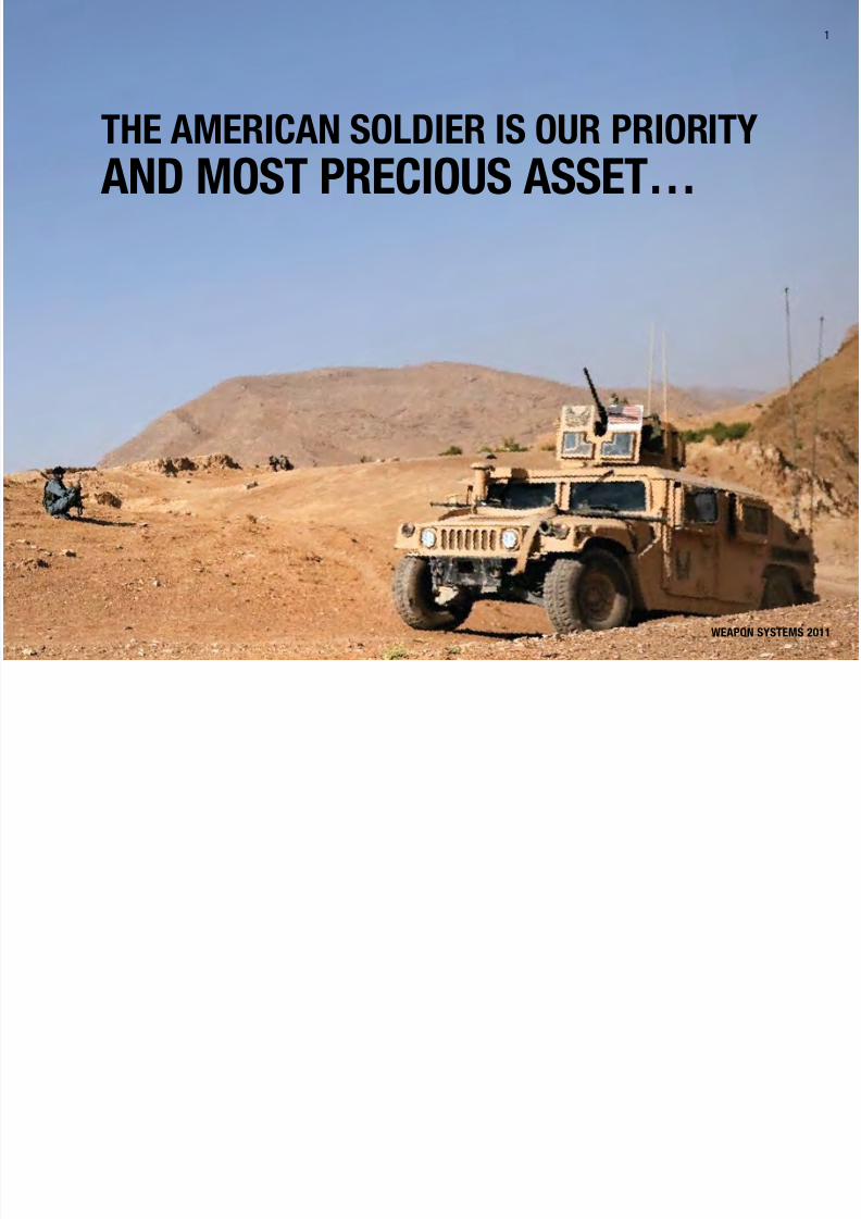
THE AMERICAN SOLDIER IS OUR PRIORITY
AND MOST PRECIOUS ASSET…

7/29/2019 Army Weapons Systems 2011
http://slidepdf.com/reader/full/army-weapons-systems-2011 12/380
UNITED STATES ARMY
2
UNITED STATES ARMY
2
MISSION
Provide our Soldiers a decisive
advantage in any mission by
developing, acquiring, fielding,
and sustaining the world’s best
equipment and services and
leveraging technologies and
capabilities to meet current andfuture Army needs.
VISION
A highly innovative organization
of dedicated professionals
transforming the Army with
integrated Acquisition, Logistics,
and Technology capabilities
to provide Soldiers a decisive
advantage and win ournation’s wars!
UNITED STATES ARMY
2

7/29/2019 Army Weapons Systems 2011
http://slidepdf.com/reader/full/army-weapons-systems-2011 13/380
WEAPON SYSTEMS 2011
3
WEAPON SYSTEMS 2011
3
We face a global secu rity env ironment character ized by
persistent conflict against enemies determined to disrupt
our Soldiers’ mission. Our goal is to do everything we
can to provide the best equipment deliver Soldiers to the
battlefield for a range of missions. They need the fire and
maneuver capabilities that al low them to communicate,
engage, and disengage. Our troops must continue to
operate with confidence in their equipment, operational
capabilities, communication, enhanced situational
awareness, and force protection. We want our Soldiers to
return from every operation and engagement.
Modernizing the Army wi ll help to counter rapidly
emerging threats that change the nature of battlefield
operations. This is accomplished by capturing lessons
learned from the range of combat to include close combat
and improved explosive devices (IEDs). The Army must
develop and field new capabilities or sustain, improve,
or divest current systems based on operational value,
capabilities shortfalls, and available resources. These
decisions are based on the principles identified in the
Army’s Modernization and Equipping Strategies a nd
are influenced by the results of detailed deliberations
with in the Army’s maturing Capabilit y Portfolio Rev iews
(CPRs). These, in turn, will be inuenced by the
requirement for Operational Adaptability contained in
the 2010 Army Operating Concept.
Decentralized operations are required within the context
of Mission Command. The complex and uncertain
strategic environment dictates the need for capabilities
and weapon systems that provide the essential qualities
of adaptability and versatility, to operate in cur rent and
future environments across the spectrum of conflict.
STRATEGIC CONTEXT
Lessons learned from the current operating environment
and a capability-based assessment highlight that some
current capabilities do not adequately counter the current
threats and lack the capabil ity needed to adequately
meet the operational requirements of future warfighting
concepts and threats.

7/29/2019 Army Weapons Systems 2011
http://slidepdf.com/reader/full/army-weapons-systems-2011 14/380
UNITED STATES ARMY
4
UNITED STATES ARMY
4
SOLDIERS ARE THE DECISIVE EDGE
ASA (ALT)’s focus is closely al igned with the Army
Modernization Strategy, which outlines a series of
key goals—such as the continued development of
new technologies engineered to provide Soldiers with
the decisive edge in battle. These technologies in
development span a range of new capability to include
robots, sensors, Unmanned Aircraft Systems ( UAS),
missiles and missile g uidance systems, emerging
combat platforms such as the Ground Combat Vehicle,
and key technologies such as the Army’s maturing
network, designed to connect Soldiers, sensors, and
multiple nodes to one another in real-time to improve
operational effectiveness across the full spectrum of
combat operations.
At the same t ime, the modern ization strategy places
a premium on finding affordable solutions, finding and
applying efficiencies designed to maximize the value
of dollars spent on development, and more rapidly
delivering greater technological capability w ithin an
increasingly constrained fiscal environment. To this end,
the Army is developing an Affordable Moderni zation
Strategy that seeks to develop needed systems with
a mind to budgetary responsibility. Part of this
involves synchronizing and integrating programs,
platforms, and systems in relation to one another from
a system-of-systems point of view in order to maximize
interoperability, reduce redundancy, and prioritize an
acquisition strategy which correctly organi zes and
develops technologies as interconnected systems.
The Assistant Secretary of the Army for Acquisition,
Logistics and Technology (ASA (ALT)) is deeply invested
in developing, delivering and sustaining the best weapons
technology available to assist Soldiers in executing the
myriad of operational requirements in a fluid and volatile
strategic environment. With the Soldier as the key focus,
ASA (ALT) seeks to equip Soldiers with the best in
cutting-edge technology and effectively manage up to 650
programs that are vita l to success in combat.
UNITED STATES ARMY
4

7/29/2019 Army Weapons Systems 2011
http://slidepdf.com/reader/full/army-weapons-systems-2011 15/380
WEAPON SYSTEMS 2011
5
• ASA (ALT) is working vigorously to implement
guidance from Defense Secretary Robert Gates,
which calls upon the serv ices to susta in current
force structure and needed modernization by
achieving two to three percent real growth. The
current and planned base defense budget has
steady but modest growth of one percent per year,necessitating innovative processes and doing more,
without more.
• To make up the difference and preclude reductions
in needed military capability, the difference of one
to two percent per year w ill be made up elsewhere
across the Department of Defense and the services.
The goal is to s ignificantly reduce excess overhead
costs and apply savings to force structure a nd
modernization.
• Part of this effort includes the application of LeanSix Sigma methodologies and Continuous Process
Improvement guidelines.
Part of th is modernization process—emphasizing this
system-of-systems engineering and va lidation of core-
required capabilities—hinges upon the results of the
Army’s Capability Portfolio Reviews (CPRs). These
CPRs have taken up a detailed examination of groups of
technologies and systems from a por tfolio perspect ive—
with a mind to perceiving how they relate to one another
and the full capability perspective of the operating force.
A key emphasis of the CPRs is to ident ify areas where
efficiencies can be increased and redundancies can be
eliminated. The reviews are grounded in the reality that
the defense budget wil l not increase nor be sustained at
the levels it has in recent years, therefore ushering in
an anticipated more constrained budget environment in
coming years.
The CPRs include Aviat ion, Network, Rad ios, Precision
Fires, Air and Missile Defense, Tactical Wheeled
Vehicles, Combat Vehicle Modernization, Soldier
Systems, Engineer Mobility/Countermobility, Intelligence
Surveillance Reconnaissance (ISR), Training
Ammunition, Software /Hardware, and Watercraft.
The CPRs are a lso aimed at informing the Army’soverarching investment strategy that seeks to effectively
manage taxpayer dollars with a mind to providing the
best technologies to our Soldiers while maintaining
affordability. For instance, the Precision Fires CPR
determined that the Army no longer has a need to develop
the Non-Line-of-Sight Launch System (NLOS-LS) because
it already has similar capabilities in its arsenal. As a
result of the CPR, the requirement for the NLOS-LS was
cancelled in an effort to remove redundancy while still
developing the best capabilities for Soldiers in combat.
The goal of the CPRs is to make the best use of
investment dollars and continue to serve Soldiers while
being responsible stewards of ta xpayer money and
constrained National resources.
5
WEAPON SYSTEMS 2011

7/29/2019 Army Weapons Systems 2011
http://slidepdf.com/reader/full/army-weapons-systems-2011 16/380
UNITED STATES ARMY
6
UNITED STATES ARMY
6
ENABLING ARMY MODERNIZATIONSO OUR SOLDIERS DOMINATE
TODAY AND TOMORROW
ASA (ALT) is developing technologies with a specific
mind to the ever-changing contingencies in today’s
combat environment. Soldiers are the decisive
edge in a wide range of potential conflict scenarios
ranging from peacekeeping and nation building to
fighting conventional, irregula r, or hybrid enemies.
Army Doctr ine cal ls upon the force to be prepared
for what is ca lled full-spectrum operations, meaning
they must be equipped for al l potential scenar ios to
include high-, medium-, and low-intensity conflict. The Army’s acquisition strateg y and weapons plat forms
seek to accommodate this operational reality and
prepare Soldiers to be adaptive to an entire range of
potential operations.
For this reason, acquisition processes need to be
synchronized with the requirements process to best
identify needs and capability gaps experienced by
Soldiers in battle today; ASA (ALT) will continue to
work closely with the Army’s Train ing and Doctr ine
Command (TRADOC) to ensure that the requirements
development process is deeply interwoven with weapons
systems modernization. There are times when systems
in development need to change, adjust, and tailor their
requirements to meet with cur rent capabilities and
urgent needs coming from combatant commanders in
theater. This process is one that requi res continuous
evaluation and reassessment throughout the weapons
system development process.
Also for this reason, the Army’s acquisit ion strategy is
designed to be tailorable to changing threats. The A rmy
seeks to train, develop and equip Soldiers who are able to
stay in front of an adaptive, fast-changing adversary. By
emphasizing the best design, delivery, and sustainment
of Army equipment, ASA (ALT) will remain focused on
harnessing scientific innovations in order to identify and
develop the most promising new technologies.
UNITED STATES ARMY
6

7/29/2019 Army Weapons Systems 2011
http://slidepdf.com/reader/full/army-weapons-systems-2011 17/380

7/29/2019 Army Weapons Systems 2011
http://slidepdf.com/reader/full/army-weapons-systems-2011 18/380
UNITED STATES ARMY
8
UNITED STATES ARMY
8
MRAP FORCE PROTECTION SAVING LIVES
Part of this equation involves continued investment in
proven technologies such as Mine Resistant Ambush
Protected (MRAP) vehicles. MRAPs are engineered with
a blast-debris deecting V-shaped hull and an armored
capsule to protect Soldiers from roadside bombs and IEDs.
The MRAPs, and the lighter weight, more mobile MRAP All Terrain Vehicles (M-ATV) have proven their ability to
save Soldiers’ lives in combat.
As a result of their performance in battle and proven value
to Soldiers, MRAPs will remain a vital part of the Army’s
Tactical Wheeled Vehicle eet for years to come. MRAPs
will be assigned to specic BCTs so that they are available
to perform key functions such as route clearance and
Soldier transportat ion when needed.
Also, MRAPs have been outfitted with NetworkIntegration Kits (NIK)—giving them the latest in Army
networking technology. Using software-programmable
radio such as JTRS and satellite technology such as
WIN-T, the networked MRAPs are able to share real-
time information such as sensor feeds from nearby
robots and UAS across the force while on the move.
This new capability—validated in technical field tests
and network exercises—connects units at the battalion
and company levels and below to one another and to
higher headquarters in real-time using the NIKs and
Force XXI Battle Command Brigade and Below (FBCB2)display screens.
MRAPs and other vehicles in the Army fleet will take
advantage of lighter weight armor composites as they
become available. The Army Research Laborator y
is testing combinations of materials which can out-
perform traditional steel at a much lighter weight;
these technologies will spin out into the force as they
become available.
THE NETWORK AS THE CENTERPIECEOF ARMY MODERNIZATION
The idea of the Army network is to connect multiple
echelons and be able to move information from thedismounted Soldier on the tactical edge, up to the
platoon and company level, and all the way up to
higher headquarters. The information t ravels through
a terrestria l network able to send voice, video, data,
and imagery through Joint Tactical Rad io Systems
(JTRS) softwa re programmable radios using high
bandwidth waveforms such as Soldier Radio Waveform
(SRW) and Wideband Networking Waveform (WN W).
Information sent and received by the terrestrial layer is
connected to Warfighter Information Network–Tactical
(WIN-T), a satellite network able to send informationover long distances using fixed nodes as well as vehicles
on-the-move.
The Army’s “network” can use the terrestrial layer in
addition to beyond line-of-sight satellite connections; the
line-of-sight radio connections can be extended through
use of an aerial tier which places Rifleman Radios on
aircraft such as UH-60 Black Hawks, AH-64 Apaches
and Shadow UAS. With the aerial tier, units do not have
to place a relay team on the top of a mountain ridge or
reposition a command post to ensure communication between ground units over extended distances.
For instance, the Army’s network will make it possible
for Soldiers in a vehicle on-the-move to view and sha re
real-time feeds from a nearby robot, ground sensor, or
UAS—instantaneously providing them combat-relevant
information and enabling them to share that information
with other units on the move, dismounted Soldiers, and
higher echelons of the force.

7/29/2019 Army Weapons Systems 2011
http://slidepdf.com/reader/full/army-weapons-systems-2011 19/380
WEAPON SYSTEMS 2011
9
“The Network is the
singularly most
important program
to the Army.”
GENERAL GEORGE W. CASEY, JR.
U.S. ARMY CHIEF OF STAFF
A prime example of the search for efficiencies within
major programs, the Department of Defense, Army, and
Marine Corps have succeeded in achieving a $2 billion
cost avoidance on the MRAP program by applying systems
engineering techniques and Lean Six Sigma practices
to the program. The thrust of the cost avoidance was
achieved through several key methodologies; MRAP
program managers streamlined and coordinated the
requirements process to better determine which vehicles
to upgrade and developed a database portal aimed at
sharing key information across the 25,000-strong fleet
of vehicles.
JLTV DEVELOPMENT: PERFORMANCE, PROTECTION,
AND PAYLOAD
The Joint Light Tactica l Vehicle, or JLTV, Technology
Development phase industry tea ms have built
government prototypes, engineering an unprecedented blend of mobility, payload capacit y, and survivabil ity—
building a light t actica l vehicle that w ill withstand
IED attacks, drive quickly through diverse terrain, and
transpor t beneath a CH-47 or CH-53 helicopter.
The Army-Marine Corps JLTV program will produce a
new fleet of tactical vehicles that can support a range of
mission sets. The Army is developing a family of JLTV
vehicles and companion trai lers that ca n be used in any
operational environment—low- to high-intensity conflict,
major combat operations, or hybrid warfare. Following aMilestone C decision in 2013, the Army plans to purchase
55,000 JLTVs and the Marines plan to buy 5,500. Full
production is slated for 2015.
Currently, there are three payload categories that cover
ten JLTV cong urations. Category A, the smal lest
category, will have a combat transport weight of 14,322
pounds and supports a 3,500-pound payload while
armored. Category B is somewhat larger, supporting a
4,500-pound payload while armored; Category C supports
a 5,100-pound payload while armored. The Category
C vehicles will a lso address shelter and ambulance
requirements. The entire JLTV fami ly is transportable by
tact ical assets (CH-47, CH-53, C-130), greatly reducing
the burden on strategic assets such as the limited
quantity of C-17 and C-5 aircraft.
Other requirements include building a vehicle that can
generate 30 kilowatts of exportable power, drive when
tires a re shot, accommodate sca lable armor solutions and
extra spall liner, and embedded diagnostics.

7/29/2019 Army Weapons Systems 2011
http://slidepdf.com/reader/full/army-weapons-systems-2011 20/380
UNITED STATES ARMY
1010
PAVING THE WAY FOR THE GROUND COMBAT VEHICLE
The Army plans to develop, design, bu ild, and deploy a
Ground Combat Vehicle Infantry Fighting Vehicle (IFV)
as a centerpiece of its combat vehicle modernization
strategy. The Army requires an IFV that can deliver a
squad to the bat tlefield in a full-spectrum environment
under armor. No single vehicle available today canprovide the necessary combination of capabilities
planned for the Ground Combat Vehicle. Plans for the
vehicle include development of a system that has abilities
equivalent to or surpassing the mobility of the Stryker
and the protection of an MRAP.
Based on lessons learned in over eight years of war, the
Army has confirmed that the existing fleets, including
the Bradley IFV, cannot provide the needed combinat ion
of space, weight and power, advanced force protection,
and mobility needed to prevail in 21st century full-spectrum environments.
The Ground Combat Vehicle will be able to maneuver in
urban environments, withstand IED attacks, and house
the state of-the-art in vehicle computing technology—a ll
while deliver ing a squad to the battlefield under the best
armor protection available.
The Army remains sharply focused on finding ways to
continually examine a nd improve the acquisition process
with a mind to increasing efficiency. This approach
includes a new, 120-day, Secretary of the Army-directed
Army Acquisition Rev iew, designed to take up and
evaluate the entire range of acquisition practices to
included funding, policy, processes, and major programs.
In addition, the Army is emphasizing Lean Six Sigma
business pract ices in many of its programs. These are
specific, business-proven methods aimed at finding way
to streamline product ivity and reduce overhead costs.
Applying these methods recently resulted in a $2 bil lion
cost avoidance on the MRAP program because program
managers found ways to consolidate and streamline
vehicle upgrade requi rements.
A system-of-systems approach is vital to these ongoing
efforts to transform business practices; the Army must
look at developing, managing, and acquiring technologies
in the most efficient way possible, an approach which
includes the need to understand the interdependencies
between systems. There must be an emphasis upon
maturing the capability to synchronize programs and
integrate schedules, deliveries, and other developmentsacross the acquisition process.
As a result of these a nd other practices, the acquisit ion
community remains acutely aware of its need to further
the transformat ion of its business efforts. These
initiatives help the Army transform as an institution and
ensure that the service provides the best value possible
for the taxpayer and the Soldier—who is at the very
center of these efforts.
TRANSFORMING ARMY ACQUISITIONAND BUSINESS PRACTICES
UNITED STATES ARMY
“If we are to preserve the Army that we have built so painstakingly
over the last eight years, we, the
civilians and military leadership of
the Department, must fundamentally
change the way we do business.”
GENERAL GEORGE W. CASEY, JR.
U.S. ARMY CHIEF OF STAFF

7/29/2019 Army Weapons Systems 2011
http://slidepdf.com/reader/full/army-weapons-systems-2011 21/380
WEAPON SYSTEMS 2011
11
ASA (ALT) recent ly embarked upon a revital ized
industry engagement program that brings leaders of
industry together with key Army decision-makers in an
effort to facilitate open and wor thwhile conversations;
both the Army and its industry partners stand to
benefit from such an arrangement that recognizes the
importance of proactive engagement. The rationale
behind such an approach is grounded in the effort
to min imize misundersta ndings and “eleventh hour”
reactions. This industry program is squarely aimed at
working to anticipate future developments, recognizing
and communicating industry trends, and identifying the
evolution of key technologies that are maturing to the
point where they can help Soldiers in combat.
ELIMINATING CHEMICAL WEAPONS
Achieving excellence in acquisition involves cont inuous
stewardship and superb ma nagement of highly sensitiveand visible programs for which ASA (ALT) has executive
agent authority, such as the Nation’s chemical weapons
disposal program.
The U.S. Army Chemical Materials Agency (CMA),
using acquisition processes as its baseline, works with
private industry, academia, and other interested policy
and environmental stakeholders to eliminate America’s
obsolete chemical weapons.
Overall, CMA has destroyed 78 percent of the nation’s
obsolete chemical weapons stockpile and a nticipates that
it will reach 90 percent destruction by 2012.
CMA also responds to discoveries of non-stockpile
chemical weapons and safely stores those weapons
until their disposal. Moreover, CMA partners with the
Federal Emergency Management Agency to prepare local
communities to deal with potential emergencies involving
those weapons.
COMMUNICATING AND COLLABORATING WITH
INDUSTRY
The Army must continue to foster, harness, and develop
its relationships with vita l industry partners as a way
to ensure the best possible development of new and
emerging systems. With this as an organiz ing principle,
ASA (ALT) has created a new industr y outreachengagement program squarely focused on furthering
partnerships with industry and facilitating constructive
dialogue designed to achieve the best results for Soldiers
in combat. Recognizing the importance of revitalizing
industry engagement, the A rmy continues to nurtu re
this outreach program, fostering and preserving
strong relationships between the Army and its vita l
industry partners.
Recognizing that there are often circumstances where
procurement sensitivities and ongoing competition maypreclude the occasion to dialogue with industry about
certain topics, there are nonetheless ample opportunities
for positive, proactive, and constructive engagement
with industry partners. While placing a premium upon
the importance of properly defi ning the parameters for
discussion with industry partners, ASA (ALT) seeks to
foster an environment of open dia logue.

7/29/2019 Army Weapons Systems 2011
http://slidepdf.com/reader/full/army-weapons-systems-2011 22/380

7/29/2019 Army Weapons Systems 2011
http://slidepdf.com/reader/full/army-weapons-systems-2011 23/380

7/29/2019 Army Weapons Systems 2011
http://slidepdf.com/reader/full/army-weapons-systems-2011 24/380

7/29/2019 Army Weapons Systems 2011
http://slidepdf.com/reader/full/army-weapons-systems-2011 25/380
WEAPON SYSTEMS 2011
2.75 Inch Rocket Systems (Hydra)
FOREIGN MILITARY SALES
Hydra 70: Colombia, Japan, Kuwait, the
Netherlands, Singapore, Thailand, and
United Arab Emirates
CONTRACTORS
Prime System:
General Dynamics (Burlington, VT)Grain:
Alliant Techsystems (Radford, VA)
Fin & Nozzle:
General Dynamics Ordnance and Tactical
Systems (Anniston, AL)Rocket Production:
General Dynamics Armament and
Technical Products (Camden, AR)
Warhead Fuzes:
Action Manufacturing (Philadelphia, PA)
Warhead Flechette:
Penn United (Cabot, PA)Fiber Containers:
Sonoco (Robesonia, PA)
Fastpack Refurbishment:
B&M Painting (Camden, AR)
15

7/29/2019 Army Weapons Systems 2011
http://slidepdf.com/reader/full/army-weapons-systems-2011 26/380
UNITED STATES ARMY
ACQUISITION PHASE
INVESTMENT COMPONENT
Abrams Tank Upgrade (M1A2)
Technology Development Operations & SupportProduction & DeploymentEngineering & Manufacturing Development
Recapitalization
Modernization
Maintenance
MISSION
Closes with and destroys enemy forces
on the integrated battlefield using
mobility, firepower, and shock effect with
lethality, survivability, and fightabilitynecessary to defeat advanced threats.
DESCRIPTION The Abrams tank upg rade includes
two power ful var iants, the M1A1 SA
(Situational Awareness) and the M1A2
SEP (System Enhancement Program)
version 2. The 1,500-horsepower AGT
turbine eng ine, the 120mm main gun,
and special armor make the Abrams
tank par ticula rly lethal aga inst heavyarmor forces.
M1A1 SA: Improvements include the
Gunners Primary Sight (GPS) with
improved thermal imaging capabilities of
the new Block I 2nd generation forward-
looking infrared (FLIR) technology.
Lethality improvements include the
Stabilized Commander’s Weapon
Station (SCWS) and ballistic solution
upgrades for the M829A3 kinetic and
the M1028 canister rounds. Common
Abrams modifications include Blue
Force Tracking (BFT), which is a digital
command and control system that gives
Army commanders across the battlefield
current information about their location
relative to friendly forces; and the Power
Train Improvement and IntegrationOptimization Program (TIGER engine and
improved transmission), which provides
more reliability, durability, and a single
standard for the vehicle’s power train.
Survivability improvements include frontal
armor and tur ret side armor upgrades.
M1A2 SEP v2: Upgrades include
improved survivability, automotive
power pack, computer systems, and
night vision capabilities. Lethalityimprovements include Common Remotely
Operated Weapon Station (CROWS)
and ballistic solution upgrades for the
M829A3 kinetic and the M1028 canister
rounds. The M1A2 SEP v2 has improved
microprocessors, color flat panel
displays, improved memory capacity,
better Soldier-machine interface, and a
new open operating system designed to
run the Common Operating Environment
(COE) software. Both the GPS and the
Commander’s Independent Thermal
Viewer (CITV) on the M1A2 SEP tank
include the improved thermal imaging
capabilities of the new Block I second-
generation FLIR technology. The M1A2
SEP has improved frontal and side armor
for enhanced crew survivability. The
M1A2 SEP is also equipped with battery based auxilia ry power, Total InteGrated
Engine Revitalization (TIGER), and an
upgraded transmission for improved
automotive reliability and durability.
SYSTEM INTERDEPENDENCIESNone
PROGRAM STATUS• Current: The 1st Caval ry Division ;
4th Infantr y Division; 3rd ArmoredCavalry Regiment, 1st Brigade;
1st Armored Division; Army
Prepositioned Stock 5 (Kuwait);
and the Army National Guard’s
Regional Training Institute and
Regional Training Site-Maintenance
are equipped with the Abrams M1A2
SEP v2; 1st Infantry Division and
3rd Infantry Division are equipped
with the Abrams M1A1 SA; Theater
Sustainment Stock (Kuwait) outfitted
with both M1A1SA and M1A2 SEP v2
tanks
• Current: Abrams production of
M1A1 SA and M1A2 SEP v2 tanks
continue for both the Active Army,
Army National Guard (ARNG) and the
Train ing and Doctrine Command
to meet the Army’s modularity goals by 2013
PROJECTED ACTIVITIES• FY11–12: 3rd Infantry Division,
4th and 2nd Brigades, 1st Armored
Division, 1st Brigade, 2nd Infantry
Division, and 116th Heavy Brigade
Combat Team, Idaho ARNG will be
fielded with the Abrams M1A2 SEP v2
tank; M1A1 SA fielding continues to
the 30th NC ARNG, 81st WA ARNG,155th MS ARNG, 11th ACR, and Army
Prepositioned Stock 4 (Korea)
• FY11–12: Continue M1A2 SEP v2
multi-year contract production
• FY11–12: Continue TIGER production
16

7/29/2019 Army Weapons Systems 2011
http://slidepdf.com/reader/full/army-weapons-systems-2011 27/380
WEAPON SYSTEMS 2011
Abrams Tank Upgrade (M1A2)
FOREIGN MILITARY SALES
M1A1: Australia (59), Egypt (1,005),
Iraq (140)
M1A2: Kuwait (218), Saudi Arabia (329)
CONTRACTORS
Prime:
General Dynamics Land Systems
(Sterling Heights, MI)
Engine:
Honeywell (Phoenix, AZ)Transmission:
Allison Transmission (Indianapolis, IN) Anniston Army Depot (Anniston, AL)
Combat weight (tons): M1A1 - 68.59; M1A2 SEP v1 - 68.57;
M1A2 SEP v2 - 69.29
Speed: 42 mph, 30 mph x-country
Main gun/rounds (basic load): M1 - 105mm/55 rounds;
M1A1 - 120mm/40 rounds; M1A2 - 120mm/42 rounds
Machine guns: .50 caliber 900 rounds, 7.62mm 11,400 rounds
17

7/29/2019 Army Weapons Systems 2011
http://slidepdf.com/reader/full/army-weapons-systems-2011 28/380

7/29/2019 Army Weapons Systems 2011
http://slidepdf.com/reader/full/army-weapons-systems-2011 29/380
WEAPON SYSTEMS 2011
Advanced Field Artillery Tactical
Data System (AFATDS)
FOREIGN MILITARY SALES
Bahrain, Egypt, Jordan, Portugal, Taiwan,
Turkey
CONTRACTORS
Software:
Raytheon (Fort Wayne, IN)
Hardware:
General Dynamics (Taunton, MA)
Raytheon (Fort Wayne, IN)
HIMARS Shelters:
Northrop Grumman (Carson, CA)
NET: VIATECH (Lawton, OK)Technical:
Computer Sciences Corp. (CSC)
(Eatontown, NJ)Fielding:
CACI (Eatontown, NJ)
IV&V:
Titan Systems (Lawton, OK)
19

7/29/2019 Army Weapons Systems 2011
http://slidepdf.com/reader/full/army-weapons-systems-2011 30/380
UNITED STATES ARMY
ACQUISITION PHASE
INVESTMENT COMPONENT
Advanced Threat Infrared Countermeasure/Common MissileWarning System (ATIRCM/CMWS)
Recapitalization
Modernization
Maintenance
MISSION
Detects missile launches/flights,
protects aircraft from Tier 1 infrared
(IR) guided missiles, and provides threat
awareness and IR countermeasures
using an airborne self-protection
system.
DESCRIPTION The Advanced Threat Infra red
Countermeasure/Common Missile Warning System (ATIRCM/CMWS)
integrates defensive infrared
countermeasures capabilities into
existing, current-generation aircraft to
engage and defeat multiple IR guided
missile threats simultaneously.
The U.S. Army operationa l require-
ments concept for IR countermeasure
systems is the Suite of Integrated
Infrared Countermeasures (SIIRCM).It mandates an integrated warning and
countermeasure system to enhance
aircraft survivability against infrared
guided threat missile systems. The
ATIRCM/CMWS Program forms the
core element of the SIIRCM concept.
ATIRCM/CMWS has a modula r
configuration consisting of an
integrated ultraviolet missile warning
system, an Infrared Laser Jammer, and
Improved Countermeasure Dispensers
(ICMDs). This conguration can vary
with aircraft and ty pe.
CMWS can function as a stand-alone
system with the capability to detect
missiles and provide audible and visual
warnings to pilots. When installed
with the Advanced IRCM Munitions
and ICMDs, it activates expendables todecoy/defeat infrared-guided missiles.
ATIRCM adds the Directed Energy
Laser Countermeasure Technology to
CMWS and is a key for Future Force
Army aircraft.
SYSTEM INTERDEPENDENCIESIn this Publication
CH-47F Chinook, Kiowa Warrior, Black
Hawk/UH-60
Other Major Interdependencies
AH-64A, AH-64D, C-12R/T/U, C-23,
C-26, Constant Hawk-A, Constant
Hawk-I, DHC-7, HH-60L, HH-60M,
MH-47E/G, MH-60K/L/M, RC-12/C-12,
RC-12K/N/P/Q, UC-35
PROGRAM STATUS• Current: All a ircraft deployed to
Operation Iraqi Freedom/Operation
Enduring Freedom equipped with
CMWS prior to deployment; OH-58D,
Kiowa Warrior is latest platform to
integrate CMWS
• Current: In process, next generation
Electronic Control Unit (ECU) and
Missile Warning Algorithms for all
aircraft
PROJECTED ACTIVITIES• Continue: ATIRCM Quick Reaction
Capability (QRC), the Army’s latest
Aircra ft Surv ivabilit y Equipment
(ASE) initiative to protect crews
and aircraft from advanced threat
Man-Portable Air Defense Systems
(MANPADS)
• Ongoing: Fielding to CH-47D/F
models
• 1QFY11:Next generation ECU (forCMWS) initial deliveries planned
Technology Development Operations & SupportProduction & DeploymentEngineering & Manufacturing Development
20

7/29/2019 Army Weapons Systems 2011
http://slidepdf.com/reader/full/army-weapons-systems-2011 31/380
WEAPON SYSTEMS 2011
Advanced Threat Infrared
Countermeasure/Common Missile
Warning System (ATIRCM/CMWS)
FOREIGN MILITARY SALES
United Kingdom
CONTRACTORS
ATIRCM/CMWS (Prime):
BAE Systems (Nashua, NH)
Logistics Support:
AEPCO (Huntsville, AL)Software Configuration Management
Support:
Science Applications International Corp.
(SAIC) (Huntsville, AL)
CMWS-GTRI E2E Data Analysis/SILDevelopment:
Georgia Tech Applied Research Corp.
(Atlanta, GA)
OH-58D Product Documentation Update:
Bell Helicopter Textron (Fort Worth, T X)
Test Support Data Analysis:
MacAulay-Brown, Inc. (Dayton, OH)UH-60A/L P31 Upgrade:
Rockwell Collins (Cedar Rapids, IA)
Engineering/Tech Production Support:
Computer Sciences Corp. (CSC)
(Huntsville, AL)OATS Phase 3:
David H. Pollock Consultants
(Eatontown, NJ)
21

7/29/2019 Army Weapons Systems 2011
http://slidepdf.com/reader/full/army-weapons-systems-2011 32/380
UNITED STATES ARMY
ACQUISITION PHASE
INVESTMENT COMPONENT
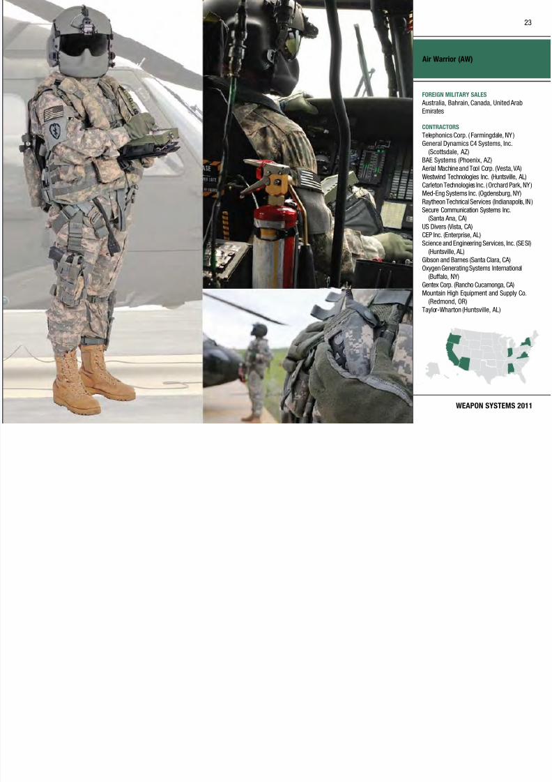
Air Warrior (AW)
Recapitalization
Modernization
Maintenance
Technology Development Operations & SupportProduction & DeploymentEngineering & Manufacturing Development
MISSION
Provides enhanced mission
effectiveness, leveraging clothing and
equipment to maximize aircrew member
survivability.
DESCRIPTION Air Warrior (AW) is a modular,
integrated, rapidly reconfigurable
combat aircrew ensemble that saves
lives and maximizes Army aircrew
mission performance. Previous aviationlife support equipment consisted
of a non-integrated assemblage of
protective and survival gear. AW
uses a systems approach to equipping
the aircrew and closes the capabil ity
gap between human and machine.
Fielded incrementally in blocks to
rapidly provide enhanced capabilities
to the warfighter, AW leverages and
integrates clothing and equipment,
such as the Army Aircrew Combat
Uniform and ballistic protection from
other Product Managers.
AW Block I provides :
• Survival Equipment Subsystem,
which integrates first a id, surv ival,
signaling, and communications
equipment with body armor and over-
water surv ival subsystems
• Microclimate Cooling System, which
increases effective mission duration
in heat-stress environments by more
than 350 percent
• Aircrew Integrated Helmet System,
a lighter helmet with increased headand hearing protection
AW Increment III :
• Electronic Data Manager (EDM), a
portable digita l-mission planning
device for over-the-horizon
messaging and enhanced situational
awareness capabilities through
connectivity to Blue Force Tracking,
Aviation
• Aircraft Wireless Intercom System
(AWIS) for secure cordless, hands-
free aircrew communications
• Survival Kit, Ready Access, Modular
(SKRAM) Go-Bag with integrated
hydration
• Portable Helicopter Oxygen Delivery
System, a Soldier-worn supplemental
breathing oxygen system for high-
altitude operations
• Communication Enhancement and
Protection System (CEPS) provides
helmet hear-through capabilit y
SYSTEM INTERDEPENDENCIESIn this Publication
Force XXI Battle Command Brigade
and Below (FBCB2), Black Hawk/UH-
60, Joint Battle Command–Platform
(JBC-P), Soldier Body Armor, CH-47F
Chinook, Army Key Management
System (AKMS), Kiowa Warrior, LightUtility Helicopter (LUH)/UH-72A
Lakota, Longbow Apache (AH-64D)
(LBA), Modernized UH-60 Black Hawk
Other Major Interdependencies
Fixed Wing
PROGRAM STATUS• FY09: Fielded Air Warrior
Increment III systems
• FY10: Fielding of the CEPS and
SKRAM
PROJECTED ACTIVITIES• FY11: Continue elding and reset
of Air Warrior to units prior to
deployment
22
7/29/2019 Army Weapons Systems 2011
http://slidepdf.com/reader/full/army-weapons-systems-2011 33/380

7/29/2019 Army Weapons Systems 2011
http://slidepdf.com/reader/full/army-weapons-systems-2011 34/380

7/29/2019 Army Weapons Systems 2011
http://slidepdf.com/reader/full/army-weapons-systems-2011 35/380

7/29/2019 Army Weapons Systems 2011
http://slidepdf.com/reader/full/army-weapons-systems-2011 36/380
UNITED STATES ARMY
ACQUISITION PHASE
INVESTMENT COMPONENT
Airborne Reconnaissance Low (ARL)
Technology Development Operations & SupportProduction & DeploymentEngineering & Manufacturing Development
Recapitalization
Modernization
Maintenance
MISSION
Provides tactical commanders with
a day/night, near all-weather, near
real-time airborne communications
intelligence/imagery intelligence
(COMINT/IMINT ) collection and
designated area surveillance system.
DESCRIPTION Airborne Reconnaissance Low (ARL)
is a self-deploying, multisensor, day/ night, all-weather reconnaissance,
intelligence system. It consists of a
modied DeHavilland DHC-7 xed-wing
aircraft equipped with COMINT/IMINT
and Ground Moving Target Indicator/
Synthetic Aperture Radar (GMTI/
SAR), and electro-optical (EO)/infrared
(IR) full-motion video capability. The
payloads are controlled and operated
via on-board open-architecture,
multifunction workstations. Intelligence
collected on the ARL can be analyzed,
recorded, and disseminated on the
aircraft workstations in real time
and stored on board for post-mission
processing. During multi-aircraft
missions, data can be shared between
cooperating aircraft via ultra high
frequency air-to-air data links allowing
multiplatform COMINT geolocation
operations. The ARL system includes a
variety of communications subsystems
to support near-real-time dissemination
of intelligence and dynamic retasking
of the aircraft. ARL provides real-time
down-link of MTI data to the Common
Ground Station (CGS) at the Brigade
Combat Team through echelon-above-
corps level. Eight aircraft are configured
as ARL–Multifunction (ARL-M),
equipped with a combination of IMINT,COMINT, and SAR/MTI payload and
demonstrated hyperspectral imager
applications and multi-intelligence
(multi-INT) data fusion capabilities.
Four mission workstations are on board
the aircraft and are remote-operator
capable. The Intelligence and Security
Command (INSCOM) operates all
ARL systems and currently supports
Southern Command (SOUTHCOM)
with one to four ARL-M aircraft,
United States Forces Korea (USFK)
with three ARL-M aircraft, and U.S.
Central Command (CENTCOM) with one
aircraft. Future sensor enhancements
are focused on upgrades to the COMINT,
IMINT, and radar payloads to support
emerging threats.
Capabilities include:
• Endurance/ceiling: 8 hours/20,000
feet
• Speed/gross weight: 231 knots/
47,000 pounds
• Range with max payload: greater
than 1,400 nautical miles
• Mission completion rate: greater
than 90 percent
ARL wil l continue to support current
operations until a future system isfielded.
SYSTEM INTERDEPENDENCIESNone
PROGRAM STATUS• 2QFY09: Phoenix Eye upgrade on
ARL-M1
• 2QFY10: Convert ARL C2 into
ARL-M7
• 3QFY10: Convert ARL C1 into
ARL-M8
PROJECTED ACTIVITIES• FY11: Continue imagery, radar,
COMINT, system interoperability,
and workstation architecture
upgrades
26

7/29/2019 Army Weapons Systems 2011
http://slidepdf.com/reader/full/army-weapons-systems-2011 37/380

7/29/2019 Army Weapons Systems 2011
http://slidepdf.com/reader/full/army-weapons-systems-2011 38/380
UNITED STATES ARMY
ACQUISITION PHASE
INVESTMENT COMPONENT
All Terrain Lifter Army System (ATLAS)
Technology Development Operations & SupportProduction & DeploymentEngineering & Manufacturing Development
Recapitalization
Modernization
Maintenance
MISSION
Provides a mobile, variable reach,
rough terrain forklift (RTFL) capable of
handling all classes of supplies.
DESCRIPTION The All Terrain Lifter Army System
(ATLAS) is a C-130 air-transportable,
10,000-pound-capacity, variable-reach,
RTFL. ATLAS supports units from
the transportat ion, quartermaster,
ordnance, missiles and munitions,engineer, aviation, and medical Army
units. ATLAS’s cross-country mobility
allows it to support the Brigade
Combat Teams and it is a critical asset
supporting an expeditionary Army.
ATLAS is a milit ary-unique vehicle:
commercial forklifts cannot meet
military requirements. It is capable
of lifting 4,000 pounds at a 21.5 feet
reach, 6,000 pounds at 15 feet, and
10,000 pounds at four feet. ATLAS is
equipped with two interchangeable
fork carriages: a 6,000-pound carriage
for stuffing and unstuffing standard
Army pa llets with 24-inch load centers
from 20-foot containers weighing up
to 6,000 pounds; and a 10,000-pound
carriage for handling loads weighing
up to 10,000 pounds at 48-inch load
center (Air Force 463L pallets).
ATLAS is a key component of
the Army’s Container Oriented
Distribution System. The ATLAS
II is an Environmental Protection
Agency Tier III-compliant ATLAS with
improved reliability, performance,
survivability, and transportability.
ATLAS I and ATLAS II systems areused to handle all classes of supply and
are essential to the deployment of a
continental U.S.-based Army and to the
sustainment of a deployed force.
Crew survivability is being addressed
in accordance with the Army’s Long
Term Armor Strateg y.
ATLAS Features
Length: 27.02 feet
Width: 8.35 feet (ATLAS II is four
inches narrower)
Height: 8.92 feet
Weight: 33,500 pounds
Power train: 165 horsepower Cummins
diesel engine; Funk 1723 PowerShift
(three-speed forward and reverse)
mechanical transmission
Cruising range: 10 hours of operation
before refueling
Road speed: 23 miles per hour
Force protection: Integrated armor
SYSTEM INTERDEPENDENCIESNone
PROGRAM STATUS• 2QFY07: ATLAS II contract award;
ongoing production and fielding of
ATLAS I
PROJECTED ACTIVITIES• Continue: Fielding to units
28

7/29/2019 Army Weapons Systems 2011
http://slidepdf.com/reader/full/army-weapons-systems-2011 39/380
30

7/29/2019 Army Weapons Systems 2011
http://slidepdf.com/reader/full/army-weapons-systems-2011 40/380
UNITED STATES ARMY
ACQUISITION PHASE
INVESTMENT COMPONENT
Armored Knight
Recapitalization
Modernization
Maintenance
Technology Development Operations & SupportProduction & DeploymentEngineering & Manufacturing Development
MISSION
Assists Heavy and Infantry Brigade
Combat Teams (HBCTs and IBCTs) in
performing terrain surveillance, target
acquisition and location, and fire
support for combat observation lasing
team missions.
DESCRIPTION The M1200 Armored Knight prov ides
precision strike capability by locatingand designating targets for both
ground- and air-delivered laser-guided
ordnance and conventional munitions.
It replaces the M707 Knight High
Mobility Multipurpose Wheeled
Vehicle (HMMWV) base a nd M981 re
support team vehicles used by combat
observation lasing teams (COLTs) in
both HBCTs and IBCTs. It operates
as an integral part of the brigade
reconnaissance element, providing
COLT and re support mission
planning and execution.
The Armored Kn ight is a M117
Armored Security Vehicle (ASV)
chassis/hull with add-on armor
fragmentation kits installed,
providing enhanced survivability and
maneuverability over the unarmored
M707. The system includes a full
360-degree armored cupola and
integrated Knight mission equipment
package.
The mission equipment package
includes: Fire Support Sensor System
(FS3) mounted sensor, Targeting
Station Control Panel, Mission
Processor Unit, Inertial Navigation
Unit, Defense Advanced GlobalPositioning System Receiver (DAGR),
Power Distribution Unit, Rugged Hand-
Held Computer Unit (RHC) Forward
Observer Software (FOS).
Other Armored Knight specifications:
Crew: Three COLT members
Combat loaded weight: Approximately
15 tons
Maximum speed: 63 miles per hour
Cruising range: 440 miles
Target location accuracy: less than
20 meters circular error probable
SYSTEM INTERDEPENDENCIESIn this Publication
Advanced Field Arti llery Tact ical Data
System (AFATDS), Armored Security
Vehicle (ASV), Force XXI Battle
Command Brigade and Below (FBCB2),
Lightweight Laser Designator/
Rangefinder (LLDR) AN/PED-1, Single
Channel Ground and Airborne Radio
System (SINCGARS)
Other Major Interdependencies
FS3, FOS
PROGRAM STATUS• FY10: Cumulative total of 239
vehicle systems produced out of 386 vehicle systems procured; Vehicle
systems elded to deploying HBCTs
and IBCTs
PROJECTED ACTIVITIES• 2QFY11–FY12: Procure and
produce additional 79 M1200 vehicle
systems; field to next deploying
units in HBCTs/IBCTs in Active
Component and Army National Guard
• FY12: Complete Design/Integration/
Validation of Target ing under Armor
Capability for M1200 Armored
Knight for increased survivability
30
31

7/29/2019 Army Weapons Systems 2011
http://slidepdf.com/reader/full/army-weapons-systems-2011 41/380
WEAPON SYSTEMS 2011
Armored Knight
FOREIGN MILITARY SALES
None
CONTRACTORS
M1117 ASV Hull :
Textron Marine & Land Systems
(New Orleans, LA)
Precision Targeting Systems
Production/Vehicle Integration:
DRS Sustainment Systems, Inc. (St. Louis,
MO; West Plains, MO)FS3 Sensor:
Raytheon (McKinney, TX)
Inertial Navigation Unit:
Honeywell (Clearwater, FL)
Common Display Unit:
DRS Tactical Systems (Melbourne, FL)
31
32

7/29/2019 Army Weapons Systems 2011
http://slidepdf.com/reader/full/army-weapons-systems-2011 42/380
UNITED STATES ARMY
ACQUISITION PHASE
INVESTMENT COMPONENT
Armored Security Vehicle (ASV)
Technology Development Operations & SupportProduction & DeploymentEngineering & Manufacturing Development
Recapitalization
Modernization
Maintenance
MISSION
Supports the military police missions
of rear-area security, law and order
operations, battlefield circulation, and
enemy prisoner-of-war operations
over the entire spectrum of war and in
operations other than war, and performs
convoy protection missions.
DESCRIPTION The M1117 Armored Secur ity Vehicle
(ASV) is an armored and turreted
all-wheel drive vehicle that supports
military police and convoy missions
and operations. The ASV provides
protection to the crew compartment,
gunner’s station, and the ammunition
storage area. The turret is fully
enclosed with an MK-19 40mm grenade
launcher gun, an M48 .50-caliber
machine gun, and a multi-salvo smokegrenade launcher. The ASV provides
ball istic, blast , and overhead protection
for its four-person crew. The ASV has a
payload of 3,360 pounds, 400-mile-plus
range, top speed of nearly 70 miles per
hour, and C-17 deployability.
SYSTEM INTERDEPENDENCIESNone
PROGRAM STATUS• Current: Continue elding to support
military police companies and
convoy protection units
PROJECTED ACTIVITIES• FY11: Produce approximately 150
vehicles; field approximately 250
vehicles; upgrade turret capabil ities
32

7/29/2019 Army Weapons Systems 2011
http://slidepdf.com/reader/full/army-weapons-systems-2011 43/380
34
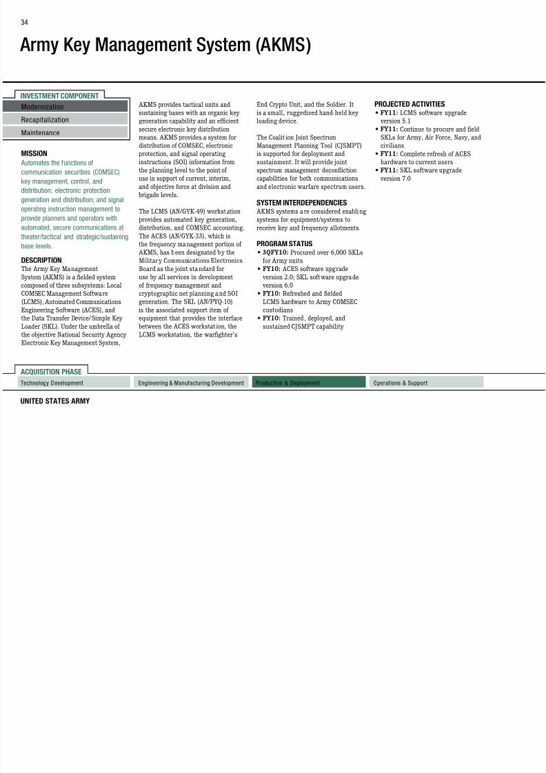
7/29/2019 Army Weapons Systems 2011
http://slidepdf.com/reader/full/army-weapons-systems-2011 44/380
UNITED STATES ARMY
ACQUISITION PHASE
INVESTMENT COMPONENT
Army Key Management System (AKMS)
Technology Development Operations & SupportProduction & DeploymentEngineering & Manufacturing Development
MISSION
Automates the functions of
communication securities (COMSEC)
key management, control, and
distribution; electronic protection
generation and distribution; and signal
operating instruction management to
provide planners and operators with
automated, secure communications at
theater/tactical and strategic/sustaining
base levels.
DESCRIPTION The Army Key Management
System (AKMS) is a fielded system
composed of three subsystems: Local
COMSEC Management Software
(LCMS), Automated Communications
Engineering Software (ACES), and
the Data Transfer Device/Simple Key
Loader (SKL). Under the umbrella of
the objective National Security Agency
Electronic Key Management System,
AKMS provides tactical units and
sustaining bases with an organic key
generation capability and an efficient
secure electronic key distribution
means. AKMS provides a system for
distribution of COMSEC, electronic
protection, and signal operating
instructions (SOI) information from
the planning level to the point of
use in support of current, interim,
and objective force at division and
brigade levels.
The LCMS (AN/GYK-49) workstation
provides automated key generation,
distribution, and COMSEC accounting.
The ACES (AN/GYK-33), which is
the frequency management portion of
AKMS, has been designated by the
Military Communications Electronics
Board as the joint standard for
use by all services in development
of frequency management and
cryptographic net planning and SOI
generation. The SKL (AN/PYQ-10)
is the associated support item of
equipment that provides the interface
between the ACES workstat ion, the
LCMS workstation, the warghter’s
End Crypto Unit, and the Soldier. It
is a small, ruggedized hand-held key
loading device.
The Coalit ion Joint Spectrum
Management Planning Tool (CJSMPT)
is supported for deployment and
sustainment. It will provide joint
spectrum management deconfliction
capabilities for both communications
and electronic warfare spectrum users.
SYSTEM INTERDEPENDENCIES AKMS systems are considered enabling
systems for equipment/systems to
receive key and frequency allotments.
PROGRAM STATUS• 3QFY10: Procured over 6,000 SKLs
for Army units
• FY10: ACES software upgrade
version 2.0; SKL software upgrade
version 6.0
• FY10: Refreshed and fielded
LCMS hardware to Army COMSEC
custodians
• FY10: Trained, deployed, and
sustained CJSMPT capability
PROJECTED ACTIVITIES• FY11: LCMS software upgrade
version 5.1
• FY11: Continue to procure and eld
SKLs for Army, Air Force, Navy, and
civilians
• FY11: Complete refresh of ACES
hardware to current users
• FY11: SKL software upgrade
version 7.0
Recapitalization
Modernization
Maintenance
34
35
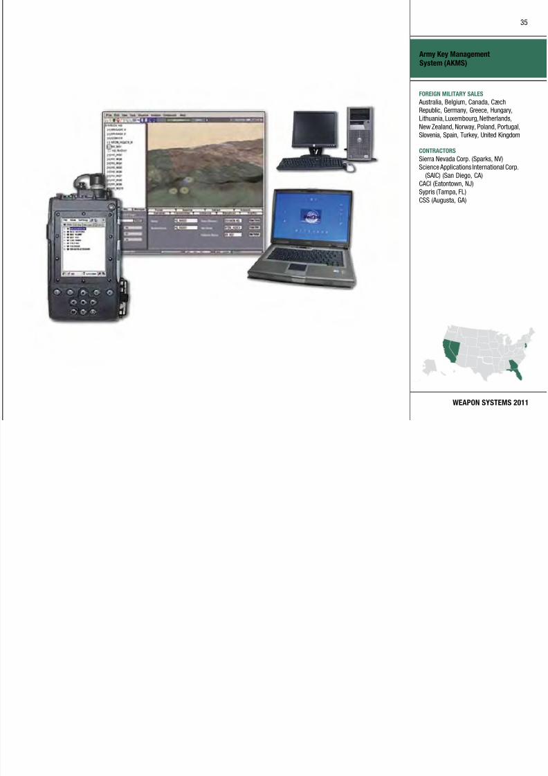
7/29/2019 Army Weapons Systems 2011
http://slidepdf.com/reader/full/army-weapons-systems-2011 45/380
WEAPON SYSTEMS 2011
Army Key Management
System (AKMS)
FOREIGN MILITARY SALES
Australia, Belgium, Canada, CzechRepublic, Germany, Greece, Hungary,
Lithuania, Luxembourg, Netherlands,
New Zealand, Norway, Poland, Portugal,
Slovenia, Spain, Turkey, United Kingdom
CONTRACTORS
Sierra Nevada Corp. (Sparks, NV)
Science Applications International Corp.
(SAIC) (San Diego, CA)
CACI (Eatontown, NJ)
Sypris (Tampa, FL)
CSS (Augusta, GA)
35
36

7/29/2019 Army Weapons Systems 2011
http://slidepdf.com/reader/full/army-weapons-systems-2011 46/380
UNITED STATES ARMY
ACQUISITION PHASE
INVESTMENT COMPONENT
Artillery Ammunition
Recapitalization
Modernization
Maintenance
Technology Development Operations & SupportProduction & DeploymentEngineering & Manufacturing Development
MISSION
Provides field artillery forces with
modernized munitions to destroy,
neutralize, or suppress the enemy by
cannon fire.
DESCRIPTION The Army’s ar tiller y ammunition
program includes 75mm (used for
ceremonies and simulated firing),
105mm, and 155mm projectiles
and their associated fuzes andpropelling charges.
Semi-fixed ammunition for short
and intermediate ranges, used in
105mm howitzers, is characterized
by adjusting the number of multiple
propelling charges. Semi-fixed
ammunition for long ranges contains
a single bag of propellant optimized
for obtaining high velocity and
is not adjustable. The primer is
an integral part of the cart ridge
case, and is located in the base. All
105mm cartridges are issued in a
fuzed or unfuzed configuration. Both
cartr idge configurations are packaged
with propel lant.
Separate-loading ammunition, used
in 155mm howitzers, has separately
issued projectiles, fuzes, propellant
charges, and primers. After installing
the appropr iate fuze on the projecti le,
the fuzed projectile is loaded into the
cannon along with the appropriate
amount of propellant charges and
a primer.
The art illery ammunit ion program
includes fuzes for cargo-carryingprojectiles, such as smoke,
illumination, dual-purpose improved
conventional munitions, and bursting
projectiles, such as high explosives.
This program also includes bag
propellant for the 105mm semi-fixed
cartr idges and modular artillery
charge system for 155mm howitzers.
SYSTEM INTERDEPENDENCIESNone
PROGRAM STATUS• 2QFY09: Completed type
classication of the 105mm M1064
Infrared (IR) Illumination cartridge
PROJECTED ACTIVITIES• 3QFY11: Complete full materiel
release of the 155mm M1066 IR
Illumination projectile
• 4QFY11: Complete full materiel
release of the 105mm M1130 pre-
formed fragmentation high-explosive
(HE) cartridge
• 4QFY11: Complete full materiel
release of the 155mm M1122 HE
training projecti le
36
37
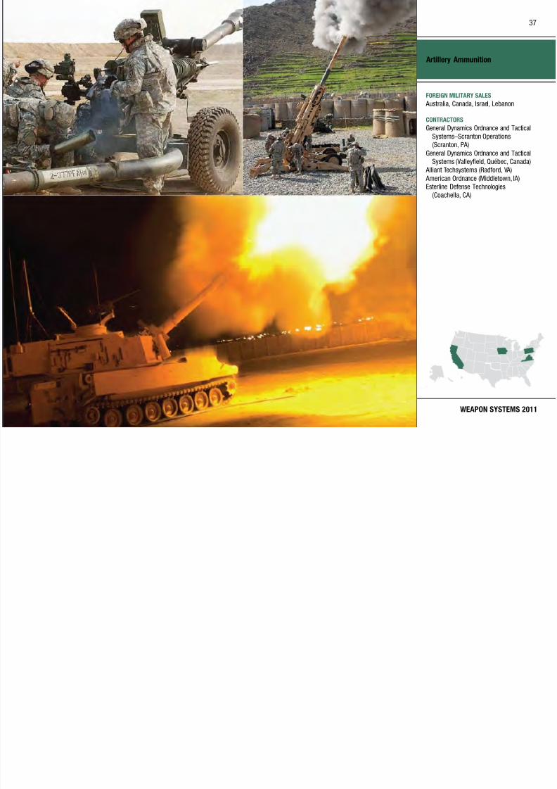
7/29/2019 Army Weapons Systems 2011
http://slidepdf.com/reader/full/army-weapons-systems-2011 47/380
WEAPON SYSTEMS 2011
Artillery Ammunition
FOREIGN MILITARY SALES
Australia, Canada, Israel, Lebanon
CONTRACTORS
General Dynamics Ordnance and Tactical
Systems–Scranton Operations
(Scranton, PA)
General Dynamics Ordnance and Tactical
Systems (Valleyfield, Québec, Canada)
Alliant Techsystems (Radford, VA)
American Ordnance (Middletown, IA)
Esterline Defense Technologies
(Coachella, CA)
37
38

7/29/2019 Army Weapons Systems 2011
http://slidepdf.com/reader/full/army-weapons-systems-2011 48/380
UNITED STATES ARMY
ACQUISITION PHASE
INVESTMENT COMPONENT
Aviation Combined Arms Tactical Trainer (AVCATT)
Technology Development Operations & SupportProduction & DeploymentEngineering & Manufacturing Development
MISSION
Provides a collective training system to
meet aviation training requirements and
to support institutional, organizational,
and sustainment training for Active and
Reserve Army aviation units worldwide
in combined arms training and
mission rehearsal.
DESCRIPTION The Aviation Combined Arms Tactical
Trainer (AVCATT) is a mobile,
transpor table, multi-station virtua l
simulation device designed to support
aviation unit collective and combined
arms training. AVCATT provides
manned modules reconfigurable to any
combination of attack, reconnaissance,
lift and/or cargo helicopters. There
are four role player stations for
batta lion/squadron staff, combined
arms elements, integrated threat
or friendly Semi-Automated Forces
(SAF). Exercise record/playback
with simultaneous AAR capabilit y is
provided. All 23 AVCATT suites have
been fielded. The suites a re continually
upgraded. The Non-Rated Crew
Member Manned Module (NCM3) and
SE Core/OneSAF Integration represent
the largest, current efforts.
The AVCATT single suite of equipment
consists of two mobile trailers that
house six reconfigurable, networked
simulators to support the Apache, Apache Longbow, Kiowa Warr ior,
Chinook, and Black Hawk. An after-
action review theater and a battle
master control station are also
provided as part of each suite.
AVCATT builds a nd sustains train ing
proficiency on mission-essential tasks
through crew and individua l training
by supporting aviation col lective
tasks, including armed reconnaissa nce
(area, zone, and route); deliberateattack; covering force operations;
downed aircrew recovery operations;
joint air at tack team; hasty at tack;
and air assault operations. The
system also has multiple correlated
visual databases to include Iraq
and Afghanistan.
AVCATT is ful ly mobile, capable of
using commercial and generator power,
and is transportable worldwide. The
system is interoperable via local area
network/wide area network with other
AVCATT suites and the Close Combat
Tactical Trainer.
SYSTEM INTERDEPENDENCIESIn this Publication
One Semi-Automated Force (OneSAF)
Other Major Interdependencies
AVCATT requires Synthetic
Environment Core (SE Core) to provide
terrain databases and v irtual models.
OneSAF will provide a common SAF
through SE Core in the future.
PROGRAM STATUS• 1QFY10: Fielding of 23 suites
completed; program has satisfied its
Basis of Issue Plan
• 2QFY10: Award of NCM3
development contract; NCM3 will
represent the “thi rd trailer” of
AVCATT
• 4QFY10: All 23 suites: Multimil lion
dollar upgrades complete; effort
provided technology refresh (new
image generators, head mounteddisplays, host and gate computers,
and communications system)
PROJECTED ACTIVITIES• 3QFY11: SE Core and OneSAF
integration complete; begin fielding
new software baseline with new
model/database/SAF capabilities
• 4QFY11: Field rst NCM3 to
Ft. Campbell, KY
• 1QFY12: Field second NCM3 to
Ft. Campbell, KY
Recapitalization
Modernization
Maintenance
38
39

7/29/2019 Army Weapons Systems 2011
http://slidepdf.com/reader/full/army-weapons-systems-2011 49/380
WEAPON SYSTEMS 2011
Aviation Combined Arms Tactical
Trainer (AVCATT)
AVCATT-A
2 Trailer Suite
Manned Simulator
Apache AH-64A Kiowa Warrior OH-58D
Manned Simulators
Chinook Ch-47D Black Hawk UH-60A/L
Apache Longbow AH-64D
FOREIGN MILITARY SALES
None
CONTRACTORS
AVCATT:
L-3 Communications (Arlington, TX)
NCM3:
Science Applications International Corp.
(SAIC) (Orlando, FL)
39
40

7/29/2019 Army Weapons Systems 2011
http://slidepdf.com/reader/full/army-weapons-systems-2011 50/380
UNITED STATES ARMY
ACQUISITION PHASE
INVESTMENT COMPONENT
Battle Command Sustainment Support System (BCS3)
Technology Development Operations & SupportProduction & DeploymentEngineering & Manufacturing Development
MISSION
Supports U.S. land forces with a logistic
decision-making capability that is
modular, tailorable, and scalable to
meet the full spectrum of battlefield
logistics command and control (C2) in
the battle command environment.
DESCRIPTION
The Battle Command Logistics
Command and Control (BCS3) system
is an integral par t of the Army Battle
Command System’s (ABCS) automation
logistical and data port ion of the
common operational picture (COP).
It is a precision tool designed for
logistical planning and execution thatprovides commanders with overarching
situational awareness critical in
making rapid, precise critical tactical,
operational, and strategic decisions in
a war environment.
BCS3’s core competencies are to
provide units, military personnel, and
commanders with the best warfighting
capability through the logistics
COP; commodity visibility; convoy
operations; reception, staging, onward
movement; and logistics reporting. The
BCS3 system is currently employed
at multiple echelons, and is utilized
to fuse susta inment, in-transit, and
force data reports for commanders in
a war environment. With its Microsoft Windows-ty pe COP, BCS3 can provide
a comprehensive real-time logistical
report that is modularly structured,
tai lorable, and scalable to meet the
full spectrum of battlefield logistics
C2 requirements.
BCS3 was developed by incorporating
innovative logistics technologies
and applications developed over the
last decade with today’s emerging
technologies used in support of U.S.land forces missions in Iraq and
Afghanistan. BCS3 is currently a ligned
with the Army’s Battle Command
Collapse Strategy intended to migrate
existing capability to Command Post
of the Future (CPOF), and web-enabled
Thin-Client Log C2 appl ications.
The system wil l continue to be uti lized
in training exercises, mission planning,
rehearsal, and execution. It can be
operated in unclassified and classified
environments. BCS3 also interfaces
with other Army, Joint Multinationa l
C2, and logistics business systems. In
effect, the system advances the goal to
increase capability for U.S. land forces
in Joint full-spectrum operations as laid
out in the Army’s Strategic Planning
Guidance.
SYSTEM INTERDEPENDENCIESIn this Publication
Movement Tracking System (MTS)
Other Major Interdependencies
LIW/LOGSA, ILAP, SARSS, SAMS(E),
SASS-MOD, PBUSE, EMILPO, RFID
PROGRAM STATUS• 1QFY10: Software fielding
BC08.10.02.03
• 2QFY10: Fielding to 167th Theater
Sustainment Command
• 3QFY10: Fielding to 135th
Sustainment Command
(Expeditionary)
PROJECTED ACTIVITIES• 3QFY11: Software delivery BC10.0.3
• 3QFY12: Software delivery BC10.0.4
Recapitalization
Modernization
Maintenance
0
41

7/29/2019 Army Weapons Systems 2011
http://slidepdf.com/reader/full/army-weapons-systems-2011 51/380
WEAPON SYSTEMS 2011
Battle Command Sustainment
Support System (BCS3)
FOREIGN MILITARY SALES
None
CONTRACTORS
Software Development/Engineering
Services:
Northrop Grumman (Carson, CA)
Field Support/Engineering Services:
Tapestry (San Diego, CA)
Program Support:
CACI (Chantilly, VA)Hardware:
Dell Computer Corporation
(Round Rock, TX)New Equipment Training:
Lockheed Martin (Tinton Falls, NJ)
42

7/29/2019 Army Weapons Systems 2011
http://slidepdf.com/reader/full/army-weapons-systems-2011 52/380
UNITED STATES ARMY
ACQUISITION PHASE
INVESTMENT COMPONENT
Recapitalization
Modernization
Maintenance
Technology Development Operations & SupportProduction & DeploymentEngineering & Manufacturing Development
MISSION
Serves as the Department of Defense
authoritative biometric repository
enabling identity superiority.
DESCRIPTIONBiometrics Enabling Capability (BEC)
(formerly the Biometric Enterprise
Core Capability [BECC]), using
an Enterprise System-of-Systems
architecture, will serve as DoD’s
biometric repository, enabling multi-modal matching, storing, and sharing
in support of identity superiority across
the depar tment.
SYSTEM INTERDEPENDENCIESIn this Publication
Joint Personnel Identificat ion version 2
(JPIv2)
Other Major Interdependencies
Automated Identity Ma nagement
System (AIMS), BiometricIdentification System for Access
(BISA), Detainee Reporting System
(DRS), Department of Homeland
Security IDENT, FBI Integrated
Automated Fingerprint Identication
System (IAFIS), Identity Dominance
System (IDS), Special Operations
Identity Dominance (SOID)
PROGRAM STATUS• 4QFY08: DoD Biometrics
Acquisition Decision Memorandum
(ADM) directs Milestone B no later
than FY10
• 1QFY09: Biometrics in support
of Identity Management Initial
Capabilities Document approved by Joint Requirements Oversight
Council
• 4QFY09: DoD Biometrics ADM
directs Analysis of Alternatives
(AoA) to be completed 2QFY10
• 3QFY10: DoD Biometrics ADM
approved name change from
Biometric Enterprise Core Capability
(BECC) to Biometric Enabling
Capability (BEC)
• 4QFY10: DoD Biometrics ADM
approved Biometric AoA finalreport; ADM also directed the
current operational Next Generation-
Automated Biometric Identification
System to a full deployment decision
(BEC Increment 0) in FY11
• 4QFY10: DoD Biometrics ADM
directs Milestone B for BEC
Increment 1 in FY12
PROJECTED ACTIVITIES• 1QFY11: NG-ABIS Capability
Production Document approved
• 2QFY11: Biometrics BEC Increment
1 Capability Development Document
approved
• 3QFY11: Full deployment decision
for BEC Increment 0• 3QFY12: Milestone B for BEC
Increment 1, i.e., permission to
enter system development and
demonstration
Biometric Enabling Capability (BEC)
43

7/29/2019 Army Weapons Systems 2011
http://slidepdf.com/reader/full/army-weapons-systems-2011 53/380
WEAPON SYSTEMS 2011
Biometric Enabling Capability (BEC)
FOREIGN MILITARY SALES
None
CONTRACTORS
Program Management Support
Services:
CACI (Arlington, VA)
The Research Associates (New York, NY)System Development and Integration:
To be determined pending Milestone B
44
7/29/2019 Army Weapons Systems 2011
http://slidepdf.com/reader/full/army-weapons-systems-2011 54/380
UNITED STATES ARMY
ACQUISITION PHASE
INVESTMENT COMPONENT
Black Hawk/UH-60
Recapitalization (UH-60 A-A/ L)
Modernization (UH-60M )
Maintenance
Technology Development Operations & SupportProduction & DeploymentEngineering & Manufacturing Development
MISSION
Provides air assault, general support,
aeromedical evacuation, command and
control, and special operations support
to combat, stability, and support
operations.
DESCRIPTION The Black Hawk (UH-60) is the Army’s
utility tact ical transport helicopter.
The versatile Black Hawk has
enhanced the overall mobility of the
Army due to dramatic improvements in
troop capacity and cargo li ft capability.
It will serve as the Army’s utility
helicopter in the Future Force.
There are multiple versions of the
UH-60 Black Hawk: the original UH-
60A; the UH-60L, which has greater
gross weight capability, higher cruise
speed, rate of climb, and external
load; and the UH-60M, which includes
the improved GE-701D engine and
provides greater cruising speed, rate
of climb, and internal load than the
UH-60A and L versions. During FY10
the Army decided to continue only with
developmental testing of the UH-60M
P3I Upgrade components, including
Common Avionics Architecture
System, fly-by-wire flight controls and
full authority digita l engine control
upgrade to the GE-701D Engine.
There are also dedicated MedicalEvacuation (MEDEVAC) versions
of the UH-60 Black Hawk: the HH-
60A, HH-60L and HH-60M each
include an integrated MEDEVAC
Mission Equipment Package (MEP)
kit, providing day/night and adverse
weather emergency evacuation
of casualties.
On the asymmetric battlefield, the
Black Hawk enables the commander
to get to the fight quicker and to mass effects throughout the
battlespace across the full spect rum
of conict. A single Black Hawk can
transpor t an entire 11-person, ful ly
equipped infantry squad faster than
predecessor systems and in most
weather condit ions. The Black Hawk
can reposition a 105mm howitzer, its
crew of six, and up to 30 rounds of
105mm ammunition in a single lift.
The aircraft’s crit ical components and
systems are armored or redundant,
and its airframe is designed to
crush progressively on impact, thus
protecting crew and passengers.
The UH-60M is a digital networked
platform with greater range and lift
to support maneuver Commanders
through air assault , general supportcommand and control, and aeromedical
evacuation. Full rate production for the
new-build UH-60M began in 2007 and
the UH-60M is currently employed in a
second combat rotation.
SYSTEM INTERDEPENDENCIESIn this Publication
Advanced Threat Infra red
Countermeasure/Common Missile
Warning System (ATIRCM/CMWS},
Air Warrior (AW), Joint Tactica l RadioSystem Multifunctional Information
Distribution System (JTRS MIDS)
Other Major Interdependencies
Blue Force Tracker (BFT)
PROGRAM STATUS• FY08: Multi-service/multi-year V II
contract award
• FY08: UH-60M rst unit equipped
• FY08: UH-60M P3I upgrade rst
flight
• Current: Production and fielding of
UH-60M and HH-60M aircraft
PROJECTED ACTIVITIES• Continue: Production and fielding of
UH-60M and HH-60M aircraft • FY12: Multi-service/multi-year V III
contract award
45

7/29/2019 Army Weapons Systems 2011
http://slidepdf.com/reader/full/army-weapons-systems-2011 55/380
WEAPON SYSTEMS 2011
Black Hawk/UH-60
UH-60A UH60L UH60MMAX GROSS WEIGHT (pounds): 20,250 22,000 22,000
CRUISE SPEED (knots): 149 150 152
RATE CLIMB (feet per minute): 814 1,315 1,646
ENGINES (2 each): GE-700 GE-701C GE-701D
EXTERNAL LOAD (pounds): 8,000 9,000 9,000
INTERNAL LOAD (troops/pounds): 11/2,640 11/2,640 11/3,190
CREW: two pilots, two crew chiefs
ARMAMENT: two 7.62mm machine guns
FOREIGN MILITARY SALES
UH-60M: Bahrain, Mexico, United Arab Emirates
UH-60L:
Brazil, Colombia, Egypt, Jordan, Saudi
Arabia, Thailand
CONTRACTORS
UH-60M:
Sikorsky (Stratford, CT)
701D Engine:
General Electric (Lynn, MA)
Multi-Function Displays:
Rockwell Collins (Cedar Rapids, IA)Flight Controls:
Hamilton Sundstrand (Windsor Locks, CT)
46
7/29/2019 Army Weapons Systems 2011
http://slidepdf.com/reader/full/army-weapons-systems-2011 56/380
UNITED STATES ARMY
ACQUISITION PHASE
INVESTMENT COMPONENT
Bradley Fighting Vehicle Systems Upgrade
Recapitalization
Modernization
Maintenance
Technology Development Operations & SupportProduction & DeploymentEngineering & Manufacturing Development
MISSION
Provides infantry and cavalry fighting
vehicles with digital command and
control capabilities, significantly
increased situational awareness,
enhanced lethality and survivability,
and improved sustainability and
supportability.
DESCRIPTION
The Bradley M2A3 Infantry/M3A3Cavalry Fighting Vehicle (IFV/CFV)
features two second-generation,
forward-looking infrared (FLIR)
sensors—one in the Improved Bradley
Acquisition Subsystem (IBAS), the
other in the Commander’s Independent
Viewer (CIV ). These systems prov ide
“hunter-killer ta rget handoff”
capability with ballistic fire control.
The Bradley A3 also has embedded
diagnostics and an Integrated Combat
Command and Control (IC3) digitalcommunications suite hosting a Force
XXI Bat tle Command Brigade-and-
Below (FBCB2) package with dig ital
maps, messages, and friend/foe
information. These systems provide
the vehicle with increased shared
battlefield s ituational awareness (SA).
The Bradley’s position nav igation with
GPS, inertial navigation, and enhanced
squad SA includes a squad leader
display integrated into vehicle digital
images and IC3.
SYSTEM INTERDEPENDENCIESIn this Publication
Force XXI Battle Command Brigade
and Below (FBCB2), Single Channel
Ground and Airborne Radio System
(SINCGARS)
Other Major Interdependencies
Army Battle Command System (A BCS),
Blue Force Tracker (BFT), FM Voice-
Advanced SINCGARS Improvement
Program (ASIP) Radio, Forward
Observer Systems (BFIST Only),
Ground Mobile Radio System (GMRS),
System of Systems Common Operating
Environment (SOSCOE)
PROGRAM STATUS• 1QFY10: Bradley A3 elded to 1st
Brigade, 4th Infantry Division; ODS
elded to 170th Separate Infantry
Brigade
• 2QFY10: Bradley A3 elded to 4th
Brigade, 1st Cavalry Division and
2nd Brigade, 4th Infantry Division;
ODS fielded to 1st Brigade, 1st
Infantry Division and 2nd Brigade,
1st Infantry Division
• 3QFY10: Bradley A3 elded to Army
Prepositioned Stock 5; 3rd Brigade,
1st Cavalry Division; 2nd Brigade,
1st Cavalry Division; ODS elded to
172nd Separate Infantry Brigade
• 4QFY10: Bradley A3 elded to
1st Brigade, 1st Cavalry Division;
ODS SA elded to 81st Washington
Army National Guard
PROJECTED ACTIVITIES• 2QFY11: Field Bradley A3 2nd
Brigade, 1st Armor Division and 3rd
Brigade, 3rd Infantry Division; Field
ODS SA 30th Heavy Brigade Combat
Team North Carol ina Army National
Guard
• 3QFY11: Field Bradley A3 2nd
Brigade, 3rd Infantry Division
• 4QFY11: Field Bradley A3 1st
Brigade, 2nd Infantry Division and3rd Brigade, 4th Infantry Division;
ODS fielded to TSS, Korea
47

7/29/2019 Army Weapons Systems 2011
http://slidepdf.com/reader/full/army-weapons-systems-2011 57/380
WEAPON SYSTEMS 2011
Bradley Fighting Vehicle Systems
Upgrade
SPEED:
RANGE:
PAYLOAD:
VEHICLE WEAPONS:M2/M3A3 MMBF REQUIRED/ACTUAL:
DEPLOYABLE AIRCRAFT:
40 mph
250 miles
6,000 pounds
25mm, TOW II, 7.62mm
400/681
C17, C5
FOREIGN MILITARY SALES
None
CONTRACTORS
Prime:
BAE Systems (York, PA; Santa Clara, CA)
DRS Technologies (Palm Bay, FL)
Raytheon (McKinney, TX)
L-3 Communications (Muskegon, MI)
Curtiss-Wright (Littleton, MA)
Elbit Systems of America (Fort Worth, TX)
48

7/29/2019 Army Weapons Systems 2011
http://slidepdf.com/reader/full/army-weapons-systems-2011 58/380
UNITED STATES ARMY
ACQUISITION PHASE
INVESTMENT COMPONENT
Calibration Sets Equipment (CALSETS)
Concept & Technology Development Operations & SupportSystem Development & DemonstrationConcept & Technology Development Production & DeploymentSystem Development & DemonstrationTechnology Development Engineering & Manufacturing Development
MISSION
Provides the capability to test, adjust,
synchronize, repair, and verify the
accuracy of Army test, measurement,
and diagnostic equipment across all
measurement parameters.
DESCRIPTIONCalibration Sets Equipment (CALSETS)
consists of fixed and tactical shelters
that house all instrumentation,
components, and power generation
equipment constituting a set. CALSETS
is capable of providing support to
maintenance units or area support from
brigade to multi-theater sustainment
operations. They are designed tocalibrate 90 percent of the Army’s test,
measurement and diagnostic equipment
workload with an objective of 98 percent.
The Calibration Sets Secondary Transfer
Standards are deployed worldwide and
are used to verify and transfer precision
accuracy to the current and future force.
CALSETS are designed to plug into Army
enterprise and battle networks, fully
supporting net-centric Joint operations
and communications. The shelters are
100 percent mobile, transportable in
operational configuration by surface
mode or aircraft (C-130, C-5, and C-17).
Secondary Transfer Standards Basic,
AN/GSM-286: This set consists of
baseline instruments and components
capable of supporting precisionmaintenance equipment in the physical,
dimensional, electrical, and electronic
parameters.
Secondary Transfer Standards
Augmented, AN/GSM-287: This set
consists of baseline instruments and
components with expanded capability
to support a wider variety of precision
maintenance equipment. It is capable
of supporting precision maintenance
equipment in the physical, dimensional,electrical, electronic, radiological,
electro-optical, and microwave frequency
parameters.
Secondary Transfer Standards,
AN/GSM-421: This cal ibration platform
consists of a M1152 High Mobility
Multipurpose Wheeled Vehicle with
a mounted shelter and integrated
10-kilowatt power generator. It is
equipped with a basic set of precision
maintenance calibration standards
designed to support up to 70 percent
of the Army’s high density precision
measurement equipment in forward
areas. This system is modular
and configurable to meet mission
requirements and can operate in a true
split-based mission posture. Designed forrapid deployment by surface or air, AN/
GSM-421 will not radiate or be disrupted
by electromagnetic interference.
Secondary Transfer Standards,
AN/GSM-705: This calibration platform
consists of a M1088A1 Medium Tactical
Vehicle Tractor with a 35-foot trailer
and integrated 15-kilowatt generator.
It contains the baseline and expanded-
issue instruments and components.
The platform applies a network-centricapproach to precision maintenance
support operations and data handling.
SYSTEM INTERDEPENDENCIESNone
PROGRAM STATUS• 2QFY09: Total-package fielding to
National Guard of CALSETS Secondary
Transfer Standards, AN/GSM-705
• Current: Sustainment of CALSETS
Secondary Transfer Standards Basic,
AN/GSM-286; Secondary Transfer
Standards Augmented, AN/GSM-287;
Secondary Transfer Standards, AN/
GSM-421 and AN/GSM-705
• Current: Production and fielding
of CALSETS Secondary TransferStandards, AN/GSM-705 (National
Guard)
• Current: System development and
demonstration of an up-armor capable
CALSETS Secondary Transfer
Standards, AN/GSM-421(v2)
PROJECTED ACTIVITIES• 2QFY11: AN/GSM-421(v2) limited
user test
• 3QFY11: Milestone C for AN/GSM-
421(v2)• 3QFY11: AN/GSM-421(v2) Full-rate
production decision
• 3QFY11: AN/GSM-421(v2) Production
contract awarded
• 3QFY12: AN/GSM-421(v2) First unit
equipped
Recapitalization
Modernization
Maintenance
49

7/29/2019 Army Weapons Systems 2011
http://slidepdf.com/reader/full/army-weapons-systems-2011 59/380
WEAPON SYSTEMS 2011
Calibration Sets Equipment
(CALSETS)
AN/GSM-421 AN/GSM-705
FOREIGN MILITARY SALES
Afghanistan, Egypt, Japan, Lithuania,Saudi Arabia, Taiwan, United Arab
Emirates
CONTRACTORS
Dynetics, Inc. (Huntsville, AL)
Agilent Technologies, Inc.
(Santa Clara, CA)
Science Applications International Corp.
(SAIC) (Huntsville, AL)
Fluke Corp. (Everett, WA)
50

7/29/2019 Army Weapons Systems 2011
http://slidepdf.com/reader/full/army-weapons-systems-2011 60/380
UNITED STATES ARMY
ACQUISITION PHASE
INVESTMENT COMPONENT
Chemical Biological Medical Systems–Diagnostics
Recapitalization
Modernization
Maintenance
Technology Development Operations & SupportProduction & DeploymentEngineering & Manufacturing Development
MISSIONProvides the warfighter with safe,
robust, and affordable medical
countermeasures against a broad
spectrum of chemical, biological,
radiological, and nuclear (CBRN) threats
and uses government and commercial
best practices to acquire Food and
Drug Administration (FDA)-approved
CBRN medical countermeasures and
diagnostics.
DESCRIPTION The Joint Biological Agent
Identification and Diagnostic
System (JBAIDS) is a reusable,
portable, modifiable biological
agent identification and diagnostic
system capable of rapid, reliable, and
simultaneous identification of multiple
biological agents and other pathogens
of operational concern. The ruggedized
and hardened system is configured tosupport deployed medical personnel
with the abi lity to identify specific
biological organisms from clinica l and
environmental sources and samples.
The JBAIDS anthrax, tula remia,
brucellosis, a nd plague detect ion
systems are FDA cleared for diagnostic
use. JBAIDS is operated throughout
the combat zone by medica l laborator y
personnel.
SYSTEM INTERDEPENDENCIESNone
PROGRAM STATUS• 2QFY09: National Guard fielding
complete (26 systems)
• 4QFY09: Emergency use
authorization for Swine Flu (H1N1)• 1QFY10: FDA clearance for Avian
Flu (H5N1) in vitro diagnostic (IVD)
kit
PROJECTED ACTIVITIES• 1QFY11: FDA clearance for typhus
IVD kit
• 4QFY11: Complete Navy elding (31
systems)
• 4QFY11: FDA clearance for Q-fever
IVD kit
51

7/29/2019 Army Weapons Systems 2011
http://slidepdf.com/reader/full/army-weapons-systems-2011 61/380
WEAPON SYSTEMS 2011
Chemical Biological Medical
Systems–Diagnostics
FOREIGN MILITARY SALES
None
CONTRACTORS
Idaho Technologies (Salt Lake City, UT)
52

7/29/2019 Army Weapons Systems 2011
http://slidepdf.com/reader/full/army-weapons-systems-2011 62/380
UNITED STATES ARMY
ACQUISITION PHASE
INVESTMENT COMPONENT
Chemical Biological Medical Systems–Prophylaxis
Recapitalization
Modernization
Maintenance
Concept & Technology Development Operations & SupportProduction & DeploymentEngineering & Manufacturing DevelopmentTechnology Development
MISSIONProvides the warfighter with safe,
robust, and affordable medical
countermeasures against a broad
spectrum of chemical, biological,
radiological, and nuclear (CBRN)
threats.
DESCRIPTIONChemical Biological Medical Systems–
Prophylaxis consists of the followingcomponents:
Anthrax Vaccine Absorbed (AVA):
The Anthrax Vaccine Absorbed is the
only Food and Drug Administration
(FDA)-licensed anthrax vaccine in the
United States that provides cutaneous,
gastrointestinal and aerosol infection
by batt lefield exposure to Bacillus
anthracis.
Recombinant Plague Vaccine (rF1V): The Recombinant Plag ue Vaccine is a
highly purified polypeptide produced
from non-sporeforming bacterial
cells transfected with a recombinant
vector from Yersinia pestis to prevent
pneumonic plague.
Recombinant Botulinum Toxin
Vaccine A/B (rBV A/ B):
The Recombinant Botu linum Bivalent
Vaccine is comprised of nontoxic
botulinum toxin heavy chain (Hc)
fragments of serotypes A and B
formulated with an a luminum
hydroxide adjuvant and delivered
intramuscularly prior to potential
exposure to botulinum toxins.
Bioscavenger II (BSCAV II): The Bioscavenger program fills
an urgent capability gap in the
warfighter’s defense against nerve
agents by development of a nerve agent
prophylactic by rendering protective
equipment, in theory, unnecessary.
Bioscavenger Increment II consists
of Protexia®, recombinant human
butyr ylcholinesterase produced in the
milk of transgenic goats and modified
with polyethylene glycol.
Smallpox Vaccine System (SVS):
The Smallpox Vaccine System
(SVS) Program provides both the
ACAM2000™ smallpox vaccine
and the Vaccinia Immune Globulin,
Intravenous (VIGIV) to vaccinate and
protect the warfighter from potentialexposure to smallpox. Both products
are FDA approved.
SYSTEM INTERDEPENDENCIESNone
PROGRAM STATUS• 1QFY09: Plague Vaccine Phase
2a clinical study complete; Plague
Vaccine manufacture scale-up and
validation init iated; rBV Phase 1bclinical study complete; rBV Phase 2
clinical study initiated
• 1QFY10: Bioscavenger Phase 1
clinical study complete; Bioscavenger
large-scale manufacturing, process
qualification, and validation begins
• 3QFY10: Plague Vaccine Phase 2b
clinical study begins
• 4QFY10: rBV Phase 2 clinical study
complete
• Current: Smallpox and AVA in
Sustainment
PROJECTED ACTIVITIES• 4QFY11: rBV A/B large-scale
manufacturing process validation
complete
• 2QFY13: rBV A/B Milestone C
decision
53

7/29/2019 Army Weapons Systems 2011
http://slidepdf.com/reader/full/army-weapons-systems-2011 63/380
WEAPON SYSTEMS 2011
Chemical Biological Medical
Systems–Prophylaxis
FOREIGN MILITARY SALES
Plague Vaccine:Canada, United Kingdom
CONTRACTORS
AVA:
Emergent BioSolutions (Bioport) ,
(Lansing, MI)rF1V:
DynPort Vaccine (Frederick, MD)
rBV A/B:
DynPort Vaccine (Frederick, MD)
BSCAV II:
PharmAthene (Annapolis, MD)SVS:
Acambis plc (Cambridge, MA)
Cangene, Corp. (Winnipeg, Manitoba,
Canada)
7/29/2019 Army Weapons Systems 2011
http://slidepdf.com/reader/full/army-weapons-systems-2011 64/380
55

7/29/2019 Army Weapons Systems 2011
http://slidepdf.com/reader/full/army-weapons-systems-2011 65/380
WEAPON SYSTEMS 2011
Chemical Biological Medical
Systems/Transformational Medical
Technologies–Therapeutics
FOREIGN MILITARY SALES
None
CONTRACTORS
AAS:
Meridian Medical Technologies
(Columbia, MD)
INATS:
Southwest Research Institute
(San Antonio, TX)
MRADC:
Osiris Therapeutics (Columbia, MD)
56

7/29/2019 Army Weapons Systems 2011
http://slidepdf.com/reader/full/army-weapons-systems-2011 66/380
UNITED STATES ARMY
ACQUISITION PHASE
INVESTMENT COMPONENT
Chemical Biological Protective Shelter (CBPS)
Recapitalization
Modernization
Maintenance
Technology Development Operations & SupportProduction & DeploymentEngineering & Manufacturing Development Production & Deployment
MISSIONEnables medical personnel to treat
casualties without the encumbrance
of individual protective clothing and
equipment in a highly mobile, easy-
to-use, and self-contained chemical-
biological (CB) hardened facility.
DESCRIPTION The Chemical Biologica l Protect ive
Shelter (CBPS) is a highly mobile,self-contained system designed to
replace the M51 Collective Protection
Shelter and the currently fielded un-
armored CBPS HMMWV variant. CBPS
consists of a Lightweight Multipurpose
Shelter (LMS) mounted on an armored
M1085A1 Medium Tactical Vehicle
(MTV) and a 400-square-foot, airbeam-
supported soft shelter. CBPS provides
a contamination-free, environmentally
controlled working area for medical
personnel to obtain relief from the need to wear CB protective clothing for 72
hours of operation.
All ancilla ry equipment required to provide protection, except the
generator, is mounted within the
shelter. Medical equipment and crew
gear are transported inside the LMS.
CBPS will be assigned to trauma
treatment teams/squads of maneuver
batta lions, medical companies
of forward and division support
batta lions, nondivisiona l medical
treatment teams/squads, divis ion andcorps medical companies, and forward
surgical teams.
SYSTEM INTERDEPENDENCIESIn this Publication
Family of Medium Tactical Vehicles
(FMTV), Single Channel Ground and
Airbor ne Radio System (SINCGARS),
Joint Chemical Agent Detector (JCAD)
Other Major Interdependencies
The shelter system is integ rated ontoan armored MTV.
PROGRAM STATUS• 2–4QFY10 First article testing
PROJECTED ACTIVITIES• 2QFY11: Follow-on test and
evaluation
• 3QFY11: Production and fielding
57
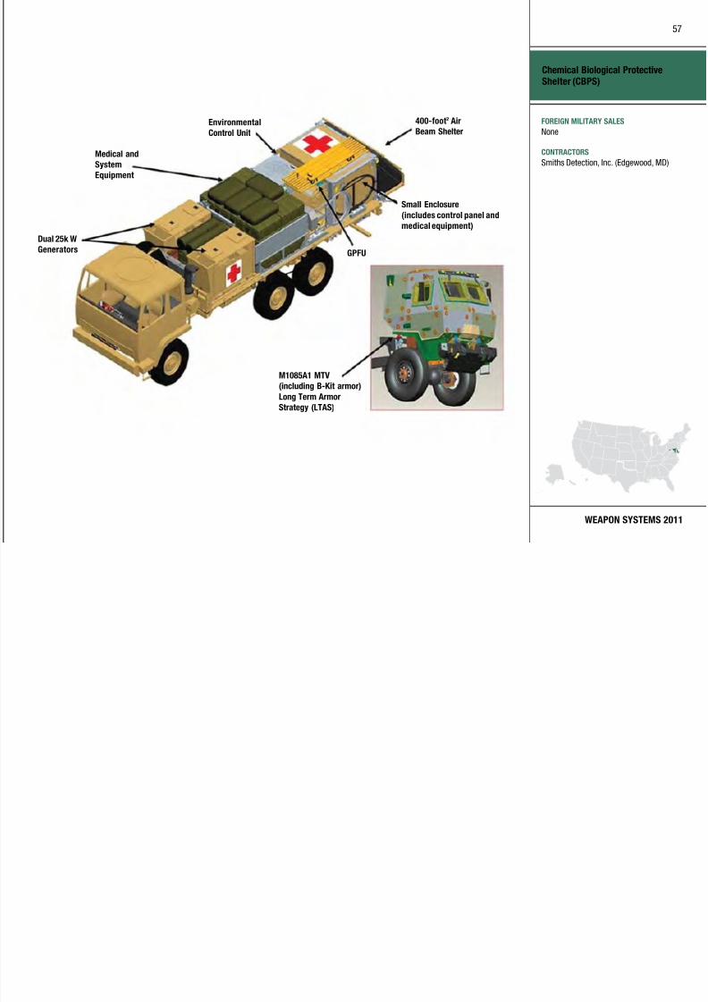
7/29/2019 Army Weapons Systems 2011
http://slidepdf.com/reader/full/army-weapons-systems-2011 67/380
WEAPON SYSTEMS 2011
Chemical Biological Protective
Shelter (CBPS)
Medical and
System
Equipment
Dual 25k W
Generators
Environmental
Control Unit
400-foot2 Air
Beam Shelter
Small Enclosure
(includes control panel and
medical equipment)
M1085A1 MTV
(including B-Kit armor)
Long Term Armor
Strategy (LTAS)
GPFU
FOREIGN MILITARY SALES
None
CONTRACTORS
Smiths Detection, Inc. (Edgewood, MD)
58

7/29/2019 Army Weapons Systems 2011
http://slidepdf.com/reader/full/army-weapons-systems-2011 68/380
UNITED STATES ARMY
ACQUISITION PHASE
INVESTMENT COMPONENT
Chemical, Biological, Radiological, Nuclear DismountedReconnaissance Sets, Kits, and Outfits (CBRN DR SKO)
Recapitalization
Modernization
Maintenance
Technology Development Operations & SupportProduction & DeploymentEngineering & Manufacturing Development
MISSIONProvides chemical, biological, radiological,
and nuclear (CBRN) reconnaissance in
confined spaces and terrain inaccessible
by traditional CBRN reconnaissance
mounted platforms/vehicles.
DESCRIPTION The Chemical, Biologica l, Radiological,
Nuclear (CBRN) Dismounted
Reconnaissance Sets, Kits, andOutfits (DR SKO) system consists
of commercial and government off-
the-shelf equipment that provides
personnel protection from CBRN
hazards, as well as detection,
identification, sample collection,
decontamination, marking, and hazard
reporting of CBRN threats. The system
is composed of handheld, man-portable
detectors that detect and identify
potential Weapons of Mass Destruction
(WMD) and/or WMD precursors anddetermine levels of protection required
to assess a sensit ive site. The system
supports dismounted reconnaissance,
surveillance, and CBRN site-
assessment missions to enable more
detailed CBRN information reports
for commanders. These site locations
may be enclosed or confined, and are therefore inaccessible by traditional
CBRN reconnaissance-mounted
platforms. CBRN site assessments help
planners determine if more thorough
analysis is required to mitigate risks
or gather intelligence on adversaries’
chemical warfare agents, biological
warfare agents, or toxic industr ial
material capabilities.
From 2008 to 2010, 27 DR SKO-like systems were fielded in support
of Joint Urgent Operational Needs
Statements (JUONS) to Central
Command and the services.
SYSTEM INTERDEPENDENCIESNone
PROGRAM STATUS• FY09: Approval to field to an
additional eight JUONS systems
to provide a total of 27 systems to
be fielded under urgent mater iel
releases
• FY09–10: Continue JUONS eldings
• FY10: Materiel development decision
approval
PROJECTED ACTIVITIES
• FY10–11: DR SKO Milestone Bdecision
• FY12: Milestone C, low-rate initial
production decision
59
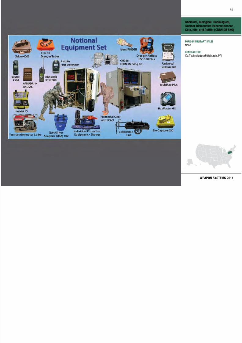
7/29/2019 Army Weapons Systems 2011
http://slidepdf.com/reader/full/army-weapons-systems-2011 69/380
WEAPON SYSTEMS 2011
Chemical, Biological, Radiological,
Nuclear Dismounted Reconnaissance
Sets, Kits, and Outfits (CBRN DR SKO)
FOREIGN MILITARY SALES
None
CONTRACTORS
ICx Technologies (Pit tsburgh, PA)
60

7/29/2019 Army Weapons Systems 2011
http://slidepdf.com/reader/full/army-weapons-systems-2011 70/380
UNITED STATES ARMY
ACQUISITION PHASE
INVESTMENT COMPONENT
Chemical Demilitarization
Recapitalization
Modernization
Maintenance
Technology Development Operations & SupportProduction & DeploymentEngineering & Manufacturing Development Production & Deployment
MISSIONEnhances national security by
eliminating U.S. chemical warfare
materiel (CWM) and supporting CWM
responses, while ensuring maximum
protection for the public, workers, and
the environment.
DESCRIPTION The Chemical Mater ials Agency (CMA)
mission is mandated by public lawand includes the design, construction,
systemization, operations, and closure
of chemical agent disposal facil ities
in Alabama, Arkansas, Indiana,
Maryland, Oregon, Utah, and the
Johnston Atoll in the South Pacific.
Demilitarization operations have been
completed in Indiana, Maryland, and
the Johnston Atoll. Stockpi le disposal
at locations in Colorado and Kentucky
is the responsibility of the Assembled
Chemical Weapons AlternativesProgram, which reports directly to the
Office of the Secretary of Defense.
CMA is also responsible for emergency
preparedness activities at the
chemical weapons storage depots
and assessment and destruction ofnon-stockpile and recovered chemical
warfare mater iel.
SYSTEM INTERDEPENDENCIESNone
PROGRAM STATUS• 4QFY09: Tooele Chemical Agent
Disposal Facility becomes fourth
chemical agent disposal facility
to achieve Star status in theOccupational Safety and Health
Administ ration’s Voluntary
Protection Program
• 1QFY10: CMA announced the
destruction of the two mi llionth
munition since entry into force of the
Chemical Weapons Convention
• 2QFY10: The Newport Chemical
Agent Disposal Faci lity Resource
Conservation and Recovery Act
permit is released, marking the
completion of the facility’s mission• 3QFY10: The Non-Stockpile
Chemical Material Project completed
destruction of all recovered chemical
warfa re materia l stored at Pine
Bluff, AR
• 4QFY10: CMA announced thedestruction of 75 percent of the
chemical agent stockpile since entry
into force of the Chemical Weapons
Convention
PROJECTED ACTIVITIES• 1QFY11: Complete nal agent
disposal campaign at Pine Bluff, AR
• 3QFY12: Complete nal agent
disposal campaign at Anniston, AL;
Tooele, UT; and Umatilla, OR
61

7/29/2019 Army Weapons Systems 2011
http://slidepdf.com/reader/full/army-weapons-systems-2011 71/380
WEAPON SYSTEMS 2011
Chemical Demilitarization
FOREIGN MILITARY SALES
None
CONTRACTORS
URS Corp. (Anniston, AL; Pine Bluff, AR;
Umatilla, OR; Tooele, UT)
62

7/29/2019 Army Weapons Systems 2011
http://slidepdf.com/reader/full/army-weapons-systems-2011 72/380
UNITED STATES ARMY
ACQUISITION PHASE
INVESTMENT COMPONENT
CH-47 Chinook
Recapitalization
Modernization
Maintenance
Technology Development Operations & SupportProduction & DeploymentEngineering & Manufacturing Development
MISSIONSupports a full spectrum of operations
including disaster relief, homeland
defense and security, and current
overseas contingency operations with a
Future Force system design.
DESCRIPTION The CH-47F is the Army’s only
heavy-lift ca rgo helicopter, supporting
combat operations and many other
critical operations other than war.
The CH-47F aircraft has a suite
of improved features such as an
upgraded digital cockpit featuring
the Common Avionics Architecture
System (CAAS), a new monolithic
airframe w ith vibration reduction and
the Digital Automatic F light Control
System (DAFCS) which provides
coupled (hands-off) controllability for
operations in adverse environments
(reduced visibility, brown out, high winds). The CH-47F’s common
cockpit enables multiservice dig ital
compatibility and interoperability
for improved situational awareness,
mission performance, and survivability,
as well as future growth potential. The
CH-47F has an empty weight of 24,578
pounds and a maximum gross weightof 50,000 pounds. The CH-47F can lift
intra-theater payloads up to 16,000
pounds in high/hot environments.
• Max gross weight: 50,000 pounds
• Max cruise speed: 160 knots
• Troop capacity: 36 (33 troops plus 3
crew members)
• Litter capacity: 24
• Sling-load capacity: 26,000 pounds
center hook, 17,000 pounds forward/
aft hook, 25,000 pounds tandem
• Minimum crew: 3 (pilot, copilot, and
flight engineer)
SYSTEM INTERDEPENDENCIESIn this Publication
Advanced Threat Infra red
Countermeasure/Common Missile
Warning System (ATIRCM/CMWS),
Air Warrior (AW)
Other Major Interdependencies ARC-231, BFT, CXP (APX-118), CXP
(APX-123), IDM, AMPS
PROGRAM STATUS• 2QFY07: Complete initia l
operational testing
• 4QFY07: First unit equipped
• 1QFY08: Multi-year procurement
contract award
PROJECTED ACTIVITIES• FY13: Multi-year II contract award
• 4QFY19: CH-47F elding complete
63

7/29/2019 Army Weapons Systems 2011
http://slidepdf.com/reader/full/army-weapons-systems-2011 73/380
WEAPON SYSTEMS 2011
CH-47 Chinook
FOREIGN MILITARY SALES
Australia
CONTRACTORS
Aircraft and Recap:
Boeing (Philadelphia, PA)
Engine:
Honeywell (Phoenix, AZ)Software:
Rockwell Collins (Cedar Rapids, IA)
Engine Controls:
Goodrich (Danbury, CT)
Cl C b T i l T i (CCTT)
64

7/29/2019 Army Weapons Systems 2011
http://slidepdf.com/reader/full/army-weapons-systems-2011 74/380
UNITED STATES ARMY
ACQUISITION PHASE
INVESTMENT COMPONENT
Close Combat Tactical Trainer (CCTT)
Recapitalization
Modernization
Maintenance
Technology Development Operations & SupportProduction & DeploymentEngineering & Manufacturing Development
MISSIONProvides collective training for infantry,
armor, mechanized infantry, cavalry
units, and their associated staffs,
using manned module simulators
within a virtual, synthetic environment,
to improve readiness, provide more
realistic collective training, and support
urgent training requirements.
DESCRIPTION The Close Combat Tactical Trainer
(CCTT) is a virtual, collective training
simulator that is fully interoperable with
the Aviation Combined Arms Tactical
Trainer (AVCATT). Crewed simulators,
such as the Abrams Main Battle Tank,
the Bradley Fighting Vehicle, the High
Mobility, Multipurpose Wheeled Vehicle
(HMMWV), the Heavy Expanded
Mobility Tactical Truck (HEMTT), and
the M113A3 Armored Personnel Carrier
offer sufficient fidelity for collectivemission training. Modular components
include the Recongurable Vehicle
Simulator/Recongurable Vehicle
Tactical Trainer (RVS/RVTT), which
simulates the HMMWV, the Armored
Security Vehicle (ASV), and the HEMTT.
An additional capability for CCTT
instructor/operators and training units is the Mobile Theater After Action Review
(MTAAR). In FY11, CCTT will add a
Dismounted Soldier (DS) capability,
which will consist of immersive,
individual Soldier simulators to train
both individual and collective tasks.
Soldiers use command and control
equipment to simulate the battle
direction of artillery, mortar, combat
engineers, and logistics units to support
the training mission. A Semi-Automated
Forces (SAF) workstation provides
supporting units (such as aviation and
air defense artillery) and all opposing
forces. All battlefield operating systems
are represented, ensuring an effective
simulation of a combat environment
that encompasses daylight, night, and
fog conditions. CCTT’s virtual terrain
databases cover 100 by 150 kilometers,
3.5 kilometers of active visual terrain,
and eight kilometers of extended rangefor M1A2 System Enhancement Program
tank and M2A3 Bradley Fighting
Vehicle. CCTT supports training of both
Active Army and Army National Guard
units at installations and posts in the
U.S., Europe, Korea, and Southwest Asia.
SYSTEM INTERDEPENDENCIESIn this Publication
One Semi-Automated Force (OneSAF)
will provide a common SAF through SE
Core in the future.
Other Major Interdependencies
CCTT requires Synthetic Environment
Core (SE Core) to provide terrain
databases and virtua l models.
PROGRAM STATUS• 1QFY10: Successfully fielded both
xed and mobile CCTT RVS/RVTT to
both CONUS and OCONUS locations
• 3QFY10: Successfully fielded an
Afghan istan v irtual terrain database
to the USAREUR CCTT faci lity
PROJECTED ACTIVITIES• 1QFY11: Production and fielding of
the RVTT to Ft. Sill, OK; Ft. Dix,
NJ; Ft. Lee, VA; Ft. Hood, TX; and
Ft. Campbell, KY • 2–3QFY11: Production and fielding
of the RVS/RVTT to Ft. Leonard
Wood, MO; Camp Shelby, MS;
Ft. Jackson, SC; and Camp Casey,
Korea
65
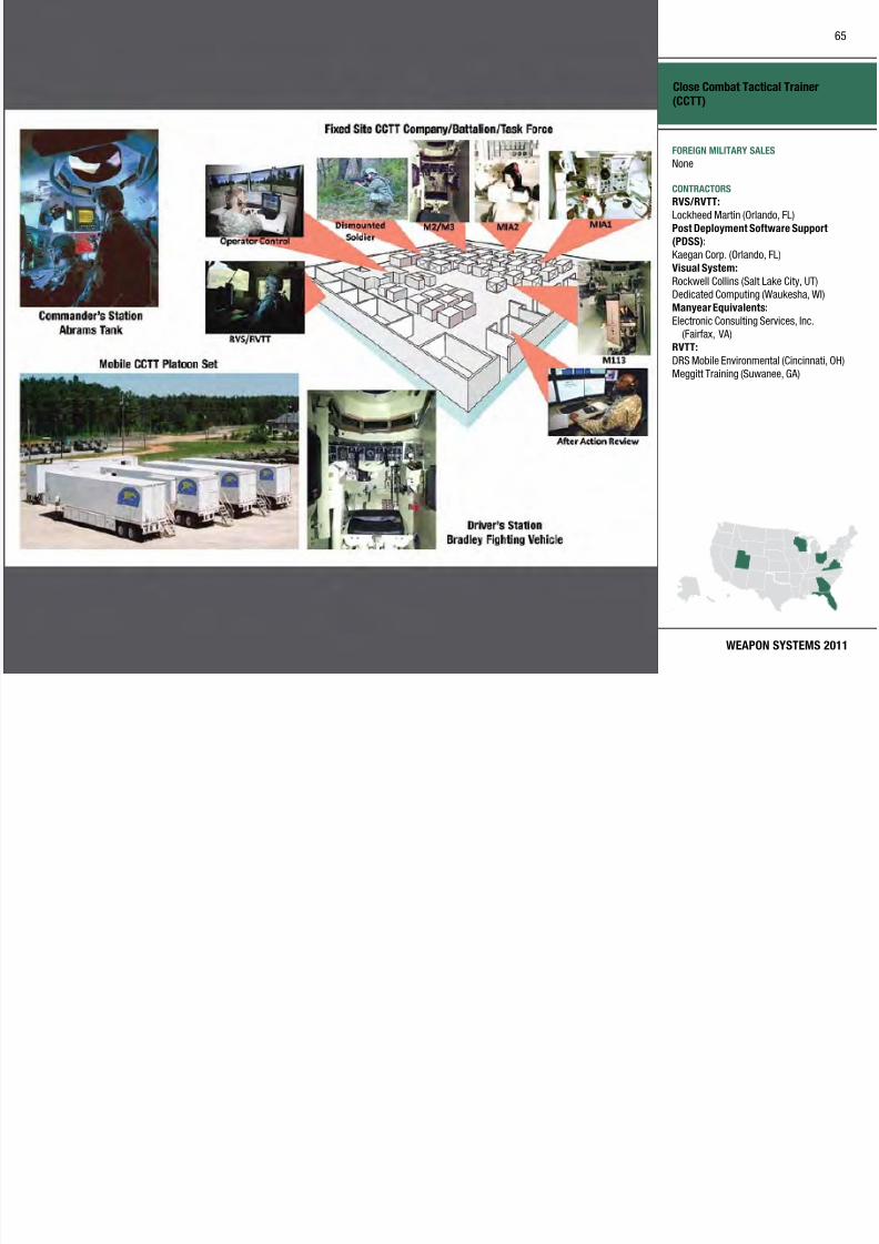
7/29/2019 Army Weapons Systems 2011
http://slidepdf.com/reader/full/army-weapons-systems-2011 75/380
WEAPON SYSTEMS 2011
Close Combat Tactical Trainer
(CCTT)
FOREIGN MILITARY SALES
None
CONTRACTORS
RVS/RVTT:
Lockheed Martin (Orlando, FL)
Post Deployment Software Support
(PDSS):
Kaegan Corp. (Orlando, FL)
Visual System:
Rockwell Collins (Salt Lake City, UT)
Dedicated Computing (Waukesha, WI)
Manyear Equivalents:
Electronic Consulting Services, Inc.(Fairfax, VA)
RVTT:
DRS Mobile Environmental (Cincinnati, OH)
Meggitt Training (Suwanee, GA)
C b t S i S t C i ti (CSS C )
66

7/29/2019 Army Weapons Systems 2011
http://slidepdf.com/reader/full/army-weapons-systems-2011 76/380
UNITED STATES ARMY
ACQUISITION PHASE
INVESTMENT COMPONENT
Combat Service Support Communications (CSS Comms)
Technology Development Operations & SupportProduction & DeploymentEngineering & Manufacturing Development
MISSION
Provides a worldwide commercial
satellite communications network,
engineering services, Integrated
Logistics Support, infrastructure,
and portable remote terminal unitsin support of Army Combat Service
Support (CSS) Logistics Management
Information Systems operating from
garrison or while deployed.
DESCRIPTIONCombat Service Support Communications
(CSS Comms) includes the Combat
Service Support Automated Information
Systems Interface (CAISI) and the
Combat Service Support SatelliteCommunications (CSS SATCOM) system.
CAISI allows current a nd emerging
battleeld CSS automation devices to
electronically exchange information via
tactical networks. CAISI also i nterfaces
with other battlefield and sustaini ng base
automated systems. CAISI provides unit
commanders and logistics managers aninterface device to support CSS doctrine
for full spectrum operations. This
capability supports a non-contiguous
concentration of users and the transfer
of real-time information in both fixed and
mobile operating environments. CAISI
allows deployed Soldiers to connect CSS
automation devices to a secure wireless
network and electronically exchange
information via tactical or commercial
communications.
CAISI employs a deployable wireless
LAN infrastructure linking Standard
Army Management In formation System
(STAMIS) computers in a seven
square-kilometer area. It is certified in
accordance with Federal I nformation
Processing Standards (FIPS) 140-2
Level 2-approved encryption for use with
sensitive information.
CSS SATCOM includes commercial off- the-shel f Ku-band auto-acquire satel lite
terminals, ca lled Combat Service Support
Very Small Aperture Termina ls (CSS
VSATs), repackaged in y-away transit
cases, along with a contractor-operated
fixed infrastructure of four primary and
three COOP telepor ts and high-speed
terrestria l links that prov ide a highlyeffective, easy-to-use, tra nsportable
SATCOM based solution to CSS nodes.
CSS SATCOM supports information
exchange up to the Sensitive Information
level, is rapidly deployable anywhere
in the world, and is fully integrated
into the Non-secure Internet Protocol
Router Network (NIPRNET) segment of
the Global In formation Gr id (GIG). CSS
SATCOM eliminates the often-dangerous
need for Soldiers to hand-deliver
requisitions via convoys in combat areas.
SYSTEM INTERDEPENDENCIESOther Major Interdependencies
CAISI, CSS SATCOM
PROGRAM STATUS• 4QFY09: CSS SATCOM supporting
2,400 systems on 16 networks with
expanded coverage to Central Africa
and the Pacific Rim
• 4QFY09: CSS SATCOM granted Authority to Operate (ATO) for two
years
• 4QFY09: Completed reset/overhaul
operations of 171 CSS SATCOM
systems from Operation Iraqi Freedom/
Operation Enduring Freedom
• 1QFY10–Current: Provided 24-hourresponse to deploying units (48 VSATs)
in support of the Haiti Operation
Unified Response earthquake efforts
• 3QFY10: Fielded 100 percent of CAISI
2.0 and CSS VSAT USAR elding
authorization, ARNG 100 percent CSS
VSAT elded
• 3QFY10: Trained and equipped Army
units with a total of 21,661 CAISI and
3,220 CSS VSATs to date
• 4QFY10: CAISI 2.0 eldings begin for
U.S. Army Europe (USAREUR) units
based in Germa ny
PROJECTED ACTIVITIES• 2QFY09–2QFY11: Continue to eld
CAISI and CSS VSAT systems and
train units in accordance w ith the
ARPL
• 2QFY09–2QFY11: Achieve pure fleet
CAISI 2.0 by replacing remaining
CAISI 1.1
• 1QFY11: Finalize CSS VSAT andCAISI Technical Manuals and
distribute with newly fielded systems
Recapitalization
Modernization
Maintenance
67

7/29/2019 Army Weapons Systems 2011
http://slidepdf.com/reader/full/army-weapons-systems-2011 77/380
WEAPON SYSTEMS 2011
Combat Service Support
Communications (CSS Comms)
FOREIGN MILITARY SALES
None
CONTRACTORS
Equipment:
Telos Corp. (Ashburn, VA)
LTI DataComm, Inc. (Reston, VA)
Juniper Networks (Herndon, VA)
L-3 Global Communications Solutions, Inc.
(Victor, NY)
Segovia Global IP Services (Herndon, VA)Project support/training:
Systems Technologies (Systek), Inc.
(West Long Branch, NJ)Tobyhanna Army Depot (Tobyhanna, PA)
Software Engineering Center–Belvoir
(SEC-B) (Ft. Belvoir, VA)
U.S. Army Information Systems
Engineering Command (USAISEC)
(Ft. Huachuca, AZ)
CACI (Eatontown, NJ; Arlington, VA)
DISA Satellite Transmission Services–
Global NETCOM (Ft. Huachuca, AZ)
C d P t S t d I t ti (CPS&I)
68

7/29/2019 Army Weapons Systems 2011
http://slidepdf.com/reader/full/army-weapons-systems-2011 78/380
UNITED STATES ARMY
ACQUISITION PHASE
INVESTMENT COMPONENT
MISSION
Provides commanders standardized and
mobile command posts with a tactical,
fully integrated, and digitized physical
infrastructure to execute Networked-
enabled Mission Command (NeMC) andachieve information dominance.
DESCRIPTION The Command Post Systems and
Integration (CPS&I) product
office provides commanders with
standardized, mobile, and fully
integrated command posts for the
modular expeditionary force, including
support for Future Force capabilities
and Joint and coalition forces. TheStandardized Integrated Command
Post System (SICPS)-based command
post is where commanders and their
staffs collaborate, plan, and execute
NeMC, maintain situational awareness
using the Common Operational Picture
(COP) and make decisions based on
available information. Per the SICPSCapabilities Production Document
(CPD), a family of Command Post
Platforms (CPP) with standardized
shelters, Command Center Systems
(CCS), Command Post Communications
Systems (CPCS) and Trailer-Mounted
Support Systems (TMSS), is currently
being fielded to the Army’s Active
Component, National Guard and Army
Reserve units.
SICPS provides the integrated NeMC
platform and infrastructure to al low
shared situational understanding of
the COP based on the var ious Army
and Joint command and control,
communications, and network systems
in the command post. Scalable and
modular, SICPS supports echelons
from battalion through Army Service
Component Command providing
tact ical flex ibilit y to support all
phases of operations. By integrating the tact ical Internet with cur rent and
future mission command capabilities,
command post operations are
revolutionized through a combination
of state-of-the-art data processing,
communications and information transpor t methods to achieve
information dominance.
SYSTEM INTERDEPENDENCIESIn this Publication
None
Other Major Interdependencies
Warfighter Information Network-
Tactical (WIN-T), Battle Command
Common Services (BCCS) Server,
Distributed Common Ground Systems
(DCGS), Mobile Electric Power (MEP),
Command Post of the Future (CPOF)
PROGRAM STATUS• 3QFY07–4QFY10: Completed SICPS
fielding and New Equipment Training
(NET) for 184 brigade level or
higher units
• 3QFY07–4QFY10: Continually
supported reset of all SICPS
equipped units returning fromOperation Enduring Freedom/
Operation Iraqi Freedom (OEF/OIF)
• 3QFY08: Initiated first delivery
order for Trailer Mounted Support
System (TMSS)
• 1QFY09: Completed CPP-Lightsystem requirements review/
preliminary design review
• 3QFY09: Conducted CPP-Light
critical design review
• 3QFY09: Supported Joint Users
Interoperability Communications
Exercise 2009 (JUICE 2009) to
evaluate emerging technologies in a
Joint operationa l environment
PROJECTED ACTIVITIES• 1–4QFY11: Continue SICPS elding
and NET to 33 brigade level, or
higher, units in accordance with Unit
Set Fielding schedule and support
Reset of units returning from OIF
and OEF
• 2QFY11: Conduct CPP-Light
developmental test
• 3QFY11: Conduct CPP-Light limited
user test
• 4QFY11: Field increased SICPS
capability to support the conversionof 1/1 AD HBCT to SBCT 8
• 1–4QFY12: Continue SICPS elding
and NET to 14 brigade level, or
higher, units in accordance with Unit
Set Fielding schedule and support
Reset of units returning from OIF
and OEF
Command Post Systems and Integration (CPS&I)
Recapitalization
Modernization
Maintenance
Technology Development Operations & SupportProduction & DeploymentEngineering & Manufacturing Development
69

7/29/2019 Army Weapons Systems 2011
http://slidepdf.com/reader/full/army-weapons-systems-2011 79/380
WEAPON SYSTEMS 2011
Command Post Systems and
Integration (CPS&I)
FOREIGN MILITARY SALES
None
CONTRACTORS
Command Post Platform/NET:
Northrop Grumman (Huntsville, AL)
SICPS:
SETA (Huntsville, AL)Materiel Fielding:
Tobyhanna Army Depot (Tobyhanna, PA)
Common Hardware Systems:
General Dynamics C4 Systems, Inc.
(Taunton, MA)
Common Hard are S stems (CHS)
70

7/29/2019 Army Weapons Systems 2011
http://slidepdf.com/reader/full/army-weapons-systems-2011 80/380
UNITED STATES ARMY
ACQUISITION PHASE
INVESTMENT COMPONENT
Common Hardware Systems (CHS)
Recapitalization
Modernization
Maintenance
Operations & SupportProduction & DeploymentEngineering & Manufacturing DevelopmentTechnology Development
MISSIONProvides state-of-the-art, fully qualified,
interoperable, compatible, deployable,
and survivable hardware for command,
control, and communications at all
echelons of command for the Army and
other DoD services.
DESCRIPTION The Common Hardware Systems
(CHS) program is the command
and control enabler for Army
Transformat ion, providing modularit y,
interoperability, and compatibility
to support implementation of net-
centricity. The CHS contract includes
a technology insertion capability to
continuously refresh the network-
centric architectural building blocks,
add new technology, and prevent
hardware obsolescence. New products
compliant with technology advances
such as Internet protocol version 6(IPv6) can be easily added to the
CHS offerings. CHS products include
a spectrum of computer processors
such as personal digital assistants
(PDAs), high-end tactical computers,
networking equipment, peripherals,
displays, installation kits, and
miscellaneous hardware needed forsystem integration. CHS products can
be procured in four versions: version 1
(non ruggedized), version 1+ (Moderate
ruggedization of v1), version 2
(ruggedized), and versions 3 (fully
rugged, MIL-SPEC Rugged Handheld
Unit).
CHS also provides worldwide repair,
maintenance, logistics, and technical
support through strategically
located contractor-operated regional
support centers (RSC) for tactical
military units and management of a
comprehensive five-year warranty.
CHS hardware version 1 includes
commercial workstations, peripherals,
and networking products. Version 1+
is Version 1 hardware that is modied
for better survivability in the field with
a minimal increase in cost. Version 2
includes ruggedized workstations,
peripherals, and networking products. Version 3 includes near-military
specification rugged handheld units.
SYSTEM INTERDEPENDENCIESNone
PROGRAM STATUS• 2QFY08: Completed high-altitude
electromagnetic pulse test
• 4QFY08: Tactical Switching
Requirement-3 (TSR-3) contract
signed
• 2QFY09–2QFY11: Continue CHS-3
hardware deliveries
• 2QFY09: (As Required) CHS
Operation Enduring Freedom/
Operation Iraqi Freedom repair
facilities
• 3QFY09: Joint User Interoperabi lity
Communications Exercise
• 4QFY09: Awarded Total Asset
Visibil ity contract
• 3QFY10: CHS-4 Solicitation released
to industry
PROJECTED ACTIVITIES• 2QFY11: CHS-4 contract award
• 2QFY16: CHS-5 contract award
71
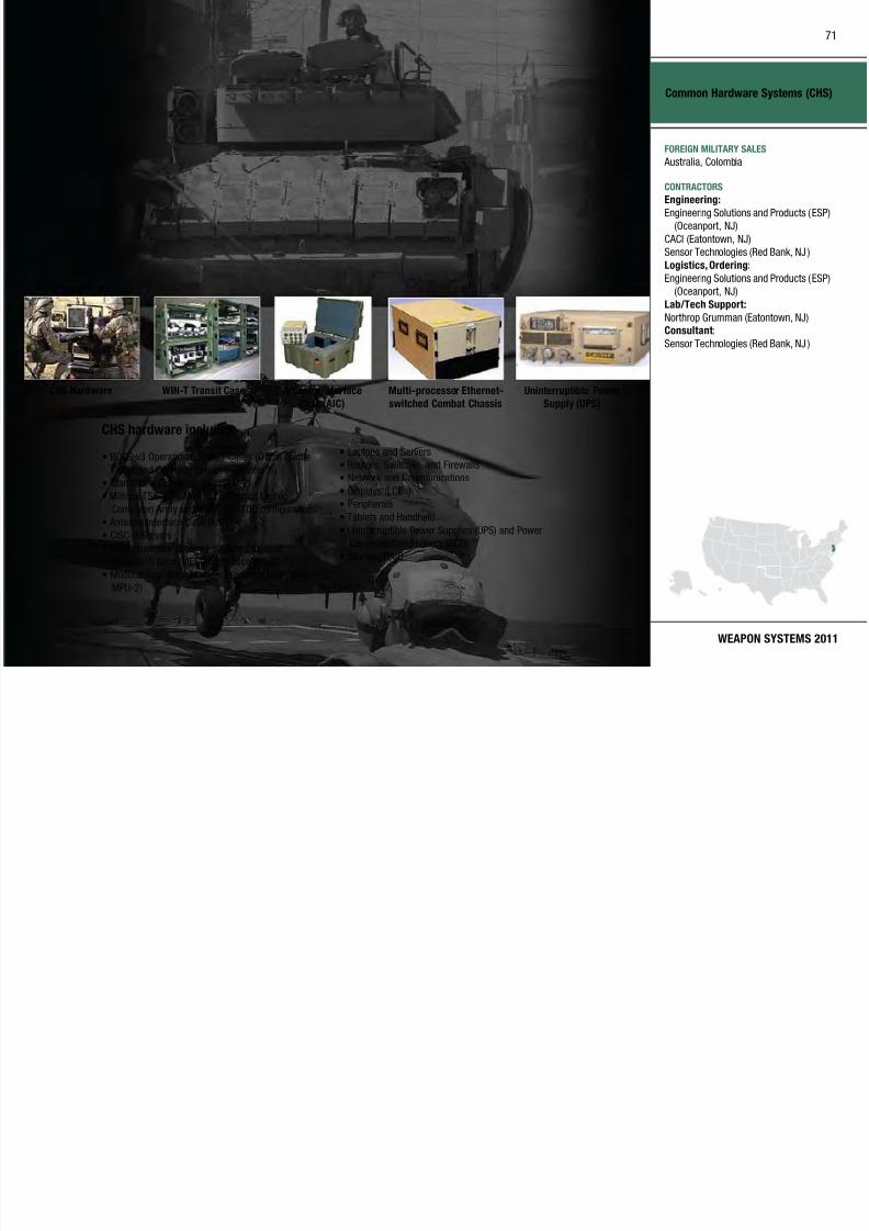
7/29/2019 Army Weapons Systems 2011
http://slidepdf.com/reader/full/army-weapons-systems-2011 81/380
WEAPON SYSTEMS 2011
Common Hardware Systems (CHS)
CHS hardware includes:
• BCCS v3 Operational Transit Cases (OTCs) (Battle
Command Common Services–version 3)• Standalone Computer Unit (SCU-2)
• Miltope TSC-v3-GM45 RLC ( Rugged Laptop
Computer) Army and USMC A FATDS configurations
• Antenna Interface Case (AIC)
• CISC-2 Servers
• Multi processor Ethernet-switched Combat
Chassis–5 Slice (MECC-5), 7 Slice (MECC-7)
• Modular Four-Slice Multiple Processor Unit (M4S
MPU-2)
• Laptops and Servers
• Routers, Switches, and Firewalls• Network and Communications
• Displays (LCDs)
• Peripherals
• Tablets and Handheld
• Uninterruptible Power Supplies (UPS) and Power
Converter/Conditioners (PCC)• Storage/RAID
CHS Hardware WIN-T Transit Cases Antenna Interface
Case (AIC)
Multi-processor Ethernet-
switched Combat Chassis
Uninterruptible Power
Supply (UPS)
FOREIGN MILITARY SALES
Australia, Colombia
CONTRACTORS
Engineering:
Engineering Solutions and Products (ESP)
(Oceanport, NJ)
CACI (Eatontown, NJ)
Sensor Technologies (Red Bank, NJ )
Logistics, Ordering:
Engineering Solutions and Products (ESP)
(Oceanport, NJ)
Lab/Tech Support:
Northrop Grumman (Eatontown, NJ)Consultant:
Sensor Technologies (Red Bank, NJ )
Common Remotely Operated Weapon Station (CROWS)
72

7/29/2019 Army Weapons Systems 2011
http://slidepdf.com/reader/full/army-weapons-systems-2011 82/380
UNITED STATES ARMY
ACQUISITION PHASE
INVESTMENT COMPONENT
Common Remotely Operated Weapon Station (CROWS)
Recapitalization
Modernization
Maintenance
Technology Development Operations & SupportProduction & DeploymentEngineering & Manufacturing Development
MISSIONEnables Soldiers to acquire and engage
targets while protected inside an
armored vehicle.
DESCRIPTION The Common Remotely Operated
Weapon Station (CROWS) is a
stabilized mount that contains a
sensor suite and fire-control software,
allowing on-the-move target acquisition
and first-burst target engagement.
Capable of target engagement under
day and night conditions, the CROWS
sensor suite includes a daytime video
camera, thermal camera, and laser
rangender. CROWS is designed to
mount on any tactical vehicle and
supports the MK19 Grenade Machine
Gun, .50 Caliber M2 Machine Gun,
M240B Machine Gun, and M249 Squad
Automatic Weapon.
CROWS also features programmable target reference points for multiple
locations, programmable sector
surveillance scanning, automatic
target ball istic lead, automat ic target
tracking, and programmable no-
fire zones.
Potential enhancements includeintegration of other weapons and
escalation-of-force systems.
SYSTEM INTERDEPENDENCIESIn this Publication
Small Arms–Crew Served Weapons,
Small Caliber Ammunition
Other Major Interdependencies
CROWS mounts the MK19, M2,
M240B, or M249 machine guns
PROGRAM STATUS• Current: Fielded over 2,000 CROWS
under urgent materiel release in
support of Operation Iraqi Freedom
and Operation Enduring Freedom
• Current: CROWS is integrated on
multiple types of platforms ranging
from the High Mobility Multipurpose
Wheeled Vehicle (HMMW V) to the
Abrams Tank
• Completed: Production verification testing and initia l operational test
and evaluation
PROJECTED ACTIVITIES• Continue: Fielding and sustainment
of CROWS on Mine Resistant
Ambush Protected (MRAP) vehicle,
MRAP All Terrain Vehicle (MATV),
and Remotely Controlled Vehicle
(RCV) platforms, in theaters of
operation under urgency
• 1–2QFY11: Type classification
planned
73

7/29/2019 Army Weapons Systems 2011
http://slidepdf.com/reader/full/army-weapons-systems-2011 83/380
WEAPON SYSTEMS 2011
Common Remotely Operated
Weapon Station (CROWS)
FOREIGN MILITARY SALES
None
CONTRACTORS
Kongsberg Defense & Aerospace
(Johnstown, PA)

7/29/2019 Army Weapons Systems 2011
http://slidepdf.com/reader/full/army-weapons-systems-2011 84/380

7/29/2019 Army Weapons Systems 2011
http://slidepdf.com/reader/full/army-weapons-systems-2011 85/380

7/29/2019 Army Weapons Systems 2011
http://slidepdf.com/reader/full/army-weapons-systems-2011 86/380
77

7/29/2019 Army Weapons Systems 2011
http://slidepdf.com/reader/full/army-weapons-systems-2011 87/380
WEAPON SYSTEMS 2011
Countermine
FOREIGN MILITARY SALES
IED Interrogation Arm:
Netherlands
VOSS:
Canada
CONTRACTORS
AN/PSS-14:
L-3 CyTerra Corp. (Waltham, MA;
Orlando, FL)
ASTAMIDS:
Northrop Grumman Integrated Systems
(Melbourne, FL)
GSTAMIDS:BAE Systems (Austin, TX)
VOSS:
Lockheed Martin Gyrocam Systems LLC
(Sarasota, FL)
IED Interrogation Arm:
FASCAN International (Baltimore, MD)HMDS:
NIITEK (Sterling, VA)
AMCS:
A/S Hydrema (Denmark)
Counter-Rocket Artillery and Mortar (C-RAM)
78
7/29/2019 Army Weapons Systems 2011
http://slidepdf.com/reader/full/army-weapons-systems-2011 88/380
UNITED STATES ARMY
ACQUISITION PHASE
INVESTMENT COMPONENT
Counter-Rocket, Artillery and Mortar (C-RAM)
Recapitalization
Modernization
Maintenance
Technology Development Operations & SupportProduction & DeploymentEngineering & Manufacturing Development
MISSIONIntegrates multiple Army- and DoD-
managed systems and commercial off-
the-shelf systems with a command and
control system to provide protection of
fixed and semi-fixed sites from rockets
and mortar rounds.
DESCRIPTION The Counter-Rocket, Ar tiller y, and
Mortar (C-RAM) system was developed
in response to a Multi-National Force-
Iraq Operational Needs Statement
(ONS) that was validated in September
2004. An innovative system-of-
systems approach was implemented
in which multiple DoD Program of
Record systems were integrated
with two commercial-of f-the-shelf
(COTS) items to provide seven C-RAM
functions: SENSE, WARN, RESPOND,
INTERCEPT, Command and Control
(C2), SHAPE, and PROTECT.
C-RAM component systems are:
Forward Area Air Defense Command
and Control (FAAD C2) system and
Air and Missile Defense Workstation
for C2; Lightweight Counter Mortar
Radar and Firender Radars for
SENSE; Landbased Phalanx WeaponSystem for INTERCEPT; and Wireless
Audio/ Visual Emergency System and a
wireless LAN for WARN. RESPONSE is
provided thru C-RAM integration with
Army/USMC battle command systems
and the USAF Tactical Automated
Security System.
Using this system-of-systems approach,
C-RAM completed development,
integration, and testing in April 2005,
meeting the requirements of the ONS.
The C-RAM systems was elded ve
months after initial funding and just
eight months after ONS validation.
In transition to a Program of Record,
the C-RAM WARN capabilit y will be
elded to all Army Brigade Combat
Teams as Increment 1 of the Indirect
Fire Protection Capability (IFPC).
SYSTEM INTERDEPENDENCIESIn this Publication
Advanced Field Arti llery Tact ical Data
System (AFATDS), FAAD C2, Sentinel
Other Major Interdependencies
Army and Marine Corps Batt le
Command Systems, Sentinel Radar
PROGRAM STATUS• 4QFY04: C-RAM ONS validated
• 2QFY05–3QFY05: C-RAM
Validation Test
• 2QFY05–1QFY08: C-RAM SENSE
and WARN fielded
• 3QFY05–2QFY07: C-RAM
INTERCEPT elded
• 4QFY10: Increment 1 CPD
validation
• Current: Sustainment
PROJECTED ACTIVITIES• 1QFY12: Increment 1 low-rate initial
production
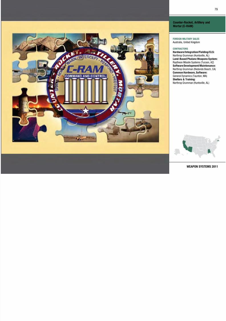
7/29/2019 Army Weapons Systems 2011
http://slidepdf.com/reader/full/army-weapons-systems-2011 89/380
Defense Enterprise Wideband SATCOM System (DEWSS)
80
7/29/2019 Army Weapons Systems 2011
http://slidepdf.com/reader/full/army-weapons-systems-2011 90/380
UNITED STATES ARMY
ACQUISITION PHASE
INVESTMENT COMPONENT
Defense Enterprise Wideband SATCOM System (DEWSS)
Technology Development Operations & SupportProduction & DeploymentEngineering & Manufacturing Development
MISSION
Provides combatant commanders,
deployed warfighters, and senior
leadership with secure, high-capacity
satellite connectivity enabling
reachback for voice, video, and datacommunications and transfer of
intelligence information.
DESCRIPTION The Defense Enterprise Wideba nd
SATCOM System (DEWSS) provides
strategic Army and DoD satellite
communications (SATCOM)
infrastructure, enabling National
and Senior Leader communications,
JCS-validated command, control,communications, and intelligence
(C3I) requirements, tactical reachback
to sustaining base for deployed
warfighters, and tra nsport for crit ical
intelligence information transfer to
deployed forces worldwide. DEWSS is
modernizing the enterprise satellite
terminals, baseband systems, andpayload and network control systems
required to support warfighter use of
the high-capacity Wideband Global
SATCOM (WGS) satellite constellation,
which DoD began launching in
October 2007. DEWSS capabilities
include super high frequency (SHF),
beyond-line-of-s ight communications;
tact ical reachback via DoD Teleport
and Standardized Tactical Entry
Point (STEP) sites; survivable
communications for critical nuclearcommand and control; and an anti-jam,
High-Altitude Electromagnetic Pulse
(HEMP) hardened, anti-scintillation
capability for key strategic forces.
SYSTEM INTERDEPENDENCIESNone
PROGRAM STATUS• 3QFY09: Modernization of
Enterprise Terminals (MET)contract awarded
• 3QFY09: 350 Enhanced Bandwidth
Efficient Modems (EBEM) fielded
worldwide, with Automatic Uplink
Power Control (AUPC)
• 3QFY09: KaSTARS completed four terminal installations (Landstuhl,
Germany; Camp Roberts, CA; and
two at Lago DiPatria, Italy)
• 3Q–4QFY09: KaSTARS support to
WGS-2 launch
• 4QFY09: Wideband Global SATCOM
KaSTARS terminal performance
certification awarded
• 4QFY09: DSCS Integrated
Management System (DIMS)
version 5.2 materiel release
• 4QFY09: Common NetworkPlanning Software (CNPS)
version 2.1 materiel release
• 1QFY10: MET Preliminary
Implementation Review (IPR)
• 2QFY10: Critical Implementation
Review (CIR)
• 2QFY10: Provide Internet protocol
capability to EBEM
• 2QFY10: USC-28 completed modem
refurbishment (Wahiawa, HI )
• 3QFY10: CNPS version 3.2 criticaldesign review
• 3QFY10: Replacement Patch and
Test Facility (RPTF) production
contract award
PROJECTED ACTIVITIES• Major Digital Communications
Satellite Subsystem (DCSS)
technology refresh/modernizat ion
to coincide with MET terminal
installations
• 1QFY11: Complete installation and
checkout of Wahiawa, HI starter kit
• 2QFY11: Wideband Power Control
Management System (WPCMS)
contract award
• 3QFY11: Worldwide EBEM fielding
complete• 4QFY11: Replacement PTF
production complete
• 1QFY12: MET first article test/
acceptance
Recapitalization
Modernization
Maintenance
81

7/29/2019 Army Weapons Systems 2011
http://slidepdf.com/reader/full/army-weapons-systems-2011 91/380
WEAPON SYSTEMS 2011
Defense Enterprise Wideband
SATCOM System (DEWSS)
FOREIGN MILITARY SALES
None
CONTRACTORS
Johns Hopkins University Applied Physics
Laboratory (Laurel, MD)
Northrop Grumman (Winter Park, FL)
ITT (Colorado Springs, CO)
Harris Corp. (Melbourne, FL)
Computer Sciences Corp. (CSC)
(Eatontown, NJ)

7/29/2019 Army Weapons Systems 2011
http://slidepdf.com/reader/full/army-weapons-systems-2011 92/380

7/29/2019 Army Weapons Systems 2011
http://slidepdf.com/reader/full/army-weapons-systems-2011 93/380
Distributed Learning System (DLS)
84

7/29/2019 Army Weapons Systems 2011
http://slidepdf.com/reader/full/army-weapons-systems-2011 94/380
UNITED STATES ARMY
ACQUISITION PHASE
INVESTMENT COMPONENT
Distributed Learning System (DLS)
Recapitalization
Modernization
Maintenance
Technology Development Operations & SupportProduction & DeploymentEngineering & Manufacturing Development Operations & Support
MISSION Acquires, deploys, and maintains a
worldwide, distributed learning system
to ensure Soldiers receive critical
training for mission success.
DESCRIPTION The Distributed Learning System
(DLS) provides a worldwide
information technology infrastructure
that innovat ively combines hardware,
software and telecommunications
resources with training facilitiesand web-based applications to
electronically deliver course content
for training of Soldiers and Department
of the Army (DA) Civilians anytime,
anywhere. DLS leverages technology to
increase training efficiencies, increase
individual and unit readiness, support
Soldiers’ career advancement and
improve their quality of life.
DLS provides to the user:• Access to Army e-Learning,
web-based t raining, consisting
of more than 5,400 commercial
business, information technology,
and 32 Rosetta Stone foreign
language courses
• Globally located Digital TrainingFacilities (DTFs) capable of
delivering multimedia courseware
for individual or group training via
computer or Video Tele-Training
(VTT)
• Enterprise management of the
DLS infrastructure, with customer
support for training applications.
• The Army Learning Management
System (ALMS), for web-based
delivery of multimedia training, and
streamlined, automated trainingmanagement functions
• Deployed Digital Tra ining Campuses
(DDTC) to deliver multimedia
courseware to deployed Soldiers
SYSTEM INTERDEPENDENCIESIn this Publication
General Fund Enterprise Business
Systems (GFEBS)
Other Major Interdependencies Army Knowledge Online is used for
identification and authorization and
to gain access to the ALMS. Student
training results a re transmitted v ia
the ALMS to the Army Train ing
Requirements and Resources System(ATRRS) as the system of record for
Army tra ining.
PROGRAM STATUS• 2QFY04–4QFY10: Sustained a
centrally managed global training
enterprise; electronically delivered
training in mil itar y occupational
specialties and self-development;
supported migration of courseware
to ALMS, began elding DDTC;
increased Army e-Learning andRosetta Stone (foreign language
training) enrollments
PROJECTED ACTIVITIES• 2QFY11: Upgrade ALMS to Saba 5.5
software
• 4QFY11: Complete elding of 14
DDTCs
• 1QFY11–4QFY21: Continue to
sustain all fielded DLS training
capabilities; continue to produce anddeploy a total of 50 DDTCs

7/29/2019 Army Weapons Systems 2011
http://slidepdf.com/reader/full/army-weapons-systems-2011 95/380

7/29/2019 Army Weapons Systems 2011
http://slidepdf.com/reader/full/army-weapons-systems-2011 96/380
87

7/29/2019 Army Weapons Systems 2011
http://slidepdf.com/reader/full/army-weapons-systems-2011 97/380
WEAPON SYSTEMS 2011
Dry Support Bridge (DSB)
FOREIGN MILITARY SALES
None
CONTRACTORS
Manufacturer:
Williams Fairey Engineering, Ltd.
(Stockport, United Kingdom)
PLS Chassis:
Oshkosh Corp. (Oshkosh, WI)
Logistics:
XMCO (Warren, MI)
Early Infantry Brigade Combat Team (E-IBCT)
88
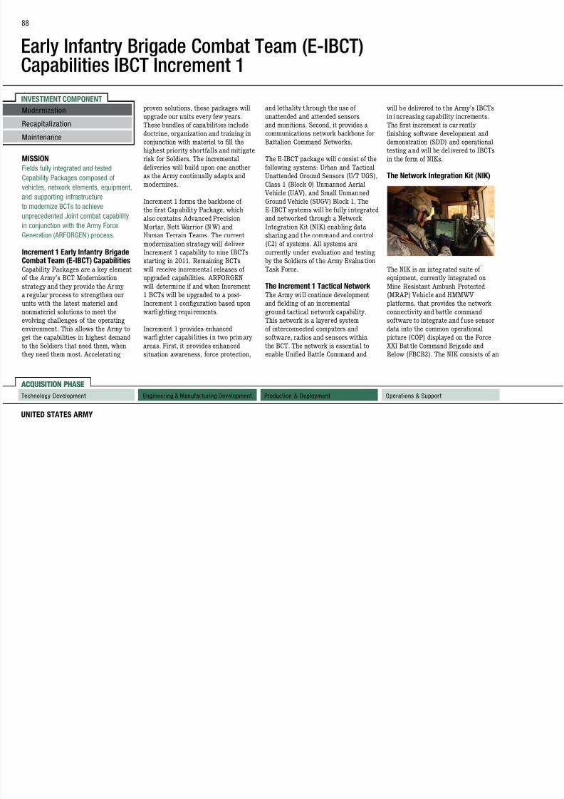
7/29/2019 Army Weapons Systems 2011
http://slidepdf.com/reader/full/army-weapons-systems-2011 98/380
UNITED STATES ARMY
ACQUISITION PHASE
INVESTMENT COMPONENT
Early Infantry Brigade Combat Team (E IBCT)Capabilities IBCT Increment 1
ACQUISITION PHASE
Technology Development Operations & SupportProduction & DeploymentEngineering & Manufacturing Development
MISSION
Fields fully integrated and tested
Capability Packages composed of
vehicles, network elements, equipment,
and supporting infrastructure
to modernize BCTs to achieveunprecedented Joint combat capability
in conjunction with the Army Force
Generation (ARFORGEN ) process.
Increment 1 Early Infantry BrigadeCombat Team (E-IBCT) CapabilitiesCapability Packages are a key element
of the Army’s BCT Modernization
strategy and they provide the Army
a regular process to strengthen our
units with the latest materiel andnonmateriel solutions to meet the
evolving challenges of the operating
environment. This allows the Army to
get the capabilities in highest demand
to the Soldiers that need them, when
they need them most. Accelerating
proven solutions, these packages willupgrade our units every few years.
These bundles of capabilit ies include
doctrine, organization and training in
conjunction with materiel to fill the
highest priority shortfalls and mitigate
risk for Soldiers. The incremental
deliveries will build upon one another
as the Army continually adapts and
modernizes.
Increment 1 forms the backbone of
the rst Capabilit y Package, whichalso contains Advanced Precision
Mortar, Nett Warrior (N W) and
Human Terrain Teams. The current
modernization strategy will deliver
Increment 1 capability to nine IBCTs
starting in 2011. Remaining BCTs
will receive incremental releases of
upgraded capabilities. ARFORGEN
will determine if and when Increment
1 BCTs will be upgraded to a post-
Increment 1 configuration based upon warfighting requirements.
Increment 1 provides enhanced
warfighter capabi lities in two primary
areas. First, it provides enhanced
situation awareness, force protection,
and lethality through the use ofunattended and attended sensors
and munitions. Second, it provides a
communications network backbone for
Battalion Command Networks.
The E-IBCT package will consist of the
following systems: Urban and Tactical
Unattended Ground Sensors (U/T UGS),
Class 1 (Block 0) Unmanned Aerial
Vehicle (UAV), and Small Unmanned
Ground Vehicle (SUGV) Block 1. The
E-IBCT systems will be fully i ntegratedand networked through a Network
Integration Kit (NIK) enabling data
sharing and the command and control
(C2) of systems. All systems are
currently under evaluation and testing
by the Soldiers of the Army Evaluation
Task Force.
The Increment 1 Tactical Network The Army wi ll continue development
and fielding of an incrementalground tactical network capability.
This network is a layered system
of interconnected computers and
software, radios and sensors within
the BCT. The network is essential to
enable Unied Battle Command and
will be delivered to the Army’s IBCTsin i ncreasing capability increments.
The first increment is cur rently
finishing software development and
demonstration (SDD) and operational
testing and will be del ivered to IBCTs
in the form of NIKs.
The Network Integration Kit (NIK)
The NIK is an integ rated suite of
equipment, currently integrated on
Mine Resistant Ambush Protected
(MRAP) Vehicle and HMMWV
platforms, that provides the networkconnectivity and battle command
software to integrate and fuse sensor
data into the common operational
picture (COP) displayed on the Force
XXI Bat tle Command Brigade and
Below (FBCB2). The NIK consists of an
Recapitalization
Modernization
Maintenance
89

7/29/2019 Army Weapons Systems 2011
http://slidepdf.com/reader/full/army-weapons-systems-2011 99/380
WEAPON SYSTEMS 2011
integrated computer system (ICS) that
hosts the Battle Command software
and the Systems of Systems Common
Operating Environment (SOSCOE)
software, along with a Joint TacticalRadio System Ground Mobile Radios
(JTRS GMR) to provide the interface to
the sensors and unma nned systems, as
well as voice and data communicat ions
with other veh icles and Soldiers.
Soldiers will be able to communicate
with the bat tal ion Tactical Operation
Center (TOC), by sending reports on
enemy sighting, activity and location
utilizing the NIK v ia the network,
allowing for near real-time tacticaldecisions.
Common Controller (CC) The Common Controller (CC) ser ves as
a single common networked controller
that connects Soldiers with many
different IBCT unmanned systems,
including the Class 1 Unmanned
Aircra ft System (UAS), the Armed
Robotic Vehicle–Assault–Light
(ARV-A-L), the Small Unmanned
Ground Vehicle (SUGV) and Urban
Unattended Ground Sensors (U-UGS).
The CC reduces the logistics footprint
on the battlefield and empowers the
Soldier with enhanced Intelligence,
Surveillance and Reconnaissance
(ISR) capability.
The Common Controller wil l
communicate via the network in Spiral
2/3/4, simplifying training, and will
perform selected training, logistics/
maintenance, medical and other Soldierfunctions.
XM156 Class I Block 0 UnmannedAerial Vehicle (UAV) The XM156 Class I Block 0 UAV is
a platoon level asset that provides
the dismounted Soldier w ith
Reconnaissance, Surveillance, and
Target Acquisit ion (RSTA) and laser
designation. Total system weight,
which includes the air vehicle, a control
device, and ground support equipment
is less than 51 pounds and is back-
packable in two custom Modular
Lightweight Load-Carrying Equipment
(MOLLE)-type carriers.
The Class I UAV provides imagery
data in order to recognize personnel
and provide ta rgeting information
to the BCT Modernization network
during day and night operations and
in adverse weather conditions from
as high as 1,000 feet above ground
level. The Army has incorporated an
expedited Class I into IBCT Increment
1 to provide additional ISR capability
to the Soldier start ing in 2011. The
Class I UAV Increment 1 capability will consist of a 25-pound vehicle with
a commercial-off-the-shelf (COTS)
electro-optical (EO) sensor and a COTS
infrared (IR) sensor and a gasoline-
based propuls ion system.
The air veh icle operates in open,
rolling, complex, and urban terrains
with a ver tical t ake-off a nd landing
capability. It is interoperable with
select ground and air platforms and
controlled by mounted or dismounted
Soldiers. The Class I uses autonomous
flight and navigation, but it will
interact with the network and the
Soldier to dynamically update routes
and target information. It provides
dedicated reconnaissance support and
early warning to the lowest echelons of
the BCT in environments not suited to
larger assets.
The Class I system provides a
hover and stare capability that is
not currently available in the ArmyUAV inventory for urban and route
surveillance. The Class I system
also fills known gaps that exist in
force operations, such as: Protect
Force in Counterinsurgency (COIN)
Operations, Soldier Protection in COIN
environment, Ability to Conduct Joint
Urban Operations, Enhanced ISR/
RSTA Capabilities, hover and stare
operations.
XM1216 Small Unmanned GroundVehicle (SUGV) The XM1216 SUGV is a lightweight,
Soldier portable UGV capable of
conducting Milita ry Operations in
Urban Terrain (MOUT), tunnels,
sewers, and caves. The SUGV
provides an unmanned capability for
those missions that are manpower
90
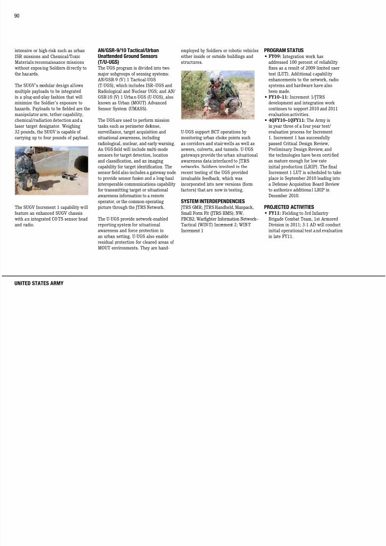
7/29/2019 Army Weapons Systems 2011
http://slidepdf.com/reader/full/army-weapons-systems-2011 100/380
UNITED STATES ARMY
intensive or high-risk such as urban
ISR missions and Chemical/Toxic
Materials reconnaissance missions
without exposing Soldiers di rectly to
the hazards.
The SUGV’s modular design al lows
multiple payloads to be integrated
in a plug-and-play fashion that will
minimize the Soldier’s exposure to
hazards. Payloads to be fielded are the
manipulator arm, tether capability,
chemical/radiation detection and a
laser target designator. Weighing
32 pounds, the SUGV is capable of
carrying up to four pounds of payload.
The SUGV Increment 1 capability will
feature an enhanced SUGV chassis
with an integrated COTS sensor head
and radio.
AN/GSR-9/10 Tactical/UrbanUnattended Ground Sensors(T/U-UGS) The UGS program is div ided into two
major subgroups of sensing systems: AN/GSR-9 (V ) 1 Tactical-UGS
(T-UGS), which includes ISR–UGS and
Radiological and Nuclear UGS; and AN/
GSR-10 (V) 1 Urban-UGS (U-UGS), also
known as Urban (MOUT) Advanced
Sensor System (UMASS).
The UGS are used to perform mission
tasks such as perimeter defense,
surveillance, target acquisition and
situational awareness, including
radiological, nuclear, and early warning. An UGS field will include multi-mode
sensors for target detection, location
and classification, and an imaging
capability for target identification. The
sensor field also includes a gateway node
to provide sensor fusion and a long-haul
interoperable communications capability
for transmitting target or situational
awareness information to a remote
operator, or the common operating
picture through the JTRS Network.
The U-UGS provide network-enabled
reporting system for situational
awareness and force protection in
an urban setting. U-UGS also enable
residual protection for cleared areas of
MOUT environments. They are hand-
employed by Soldiers or robotic vehicles
either inside or outside buildings and
structures.
U-UGS support BCT operations by
monitoring urban choke points such
as corridors and stairwells as well assewers, culverts, and tunnels. U-UGS
gateways provide the urban situational
awareness data interfaced to JTRS
networks. Soldiers involved in the
recent testing of the UGS provided
invaluable feedback, which was
incorporated into new versions (form
factors) that are now in testing.
SYSTEM INTERDEPENDENCIES JTRS GMR; JTRS Handheld, Manpack,
Small Form Fit (JTRS HMS); NW,
FBCB2; Warghter Information Network–
Tactical (WIN-T) Increment 2; WIN-T
Increment 1
PROGRAM STATUS• FY09: Integration work has
addressed 100 percent of reliability
fixes as a result of 2009 limited user
test (LUT). Additional capabil ityenhancements to the network, radio
systems and hardware have also
been made.
• FY10–11: Increment 1/JTRS
development and integration work
continues to support 2010 and 2011
evaluation activities.
• 4QFY10–1QFY11: The Army is
in year three of a four year test/
evaluation process for Increment
1. Increment 1 has successfully
passed Critical Design Review,Preliminary Design Review, and
the technologies have been certified
as mature enough for low-rate
initial production (LRIP). The final
Increment 1 LUT is scheduled to take
place in September 2010 leading into
a Defense Acquisition Board Review
to authorize additiona l LRIP in
December 2010.
PROJECTED ACTIVITIES• FY11: Fielding to 3rd Infantry
Brigade Combat Team, 1st Armored
Division in 2011; 3-1 AD will conduct
initial operational test and evaluation
in late FY11.

7/29/2019 Army Weapons Systems 2011
http://slidepdf.com/reader/full/army-weapons-systems-2011 101/380
Enhanced Medium Altitude Reconnaissance and Surveillance
92
7/29/2019 Army Weapons Systems 2011
http://slidepdf.com/reader/full/army-weapons-systems-2011 102/380
UNITED STATES ARMY
ACQUISITION PHASE
INVESTMENT COMPONENT
MISSIONProvides global, real-time, multi-
intelligence precision targeting
information to Joint land, maritime, and
air combat commanders across the full
spectrum of military operations.
DESCRIPTIONEnhanced Medium Altitude
Reconnaissance and Surveillance
System (EMARSS) is the Army’s
future force ai rborne intelligencecollection, processing, and targeting
support system. This manned multi-
INT Airborne Intelligence Surveillance
and Reconnaissance (AISR) system
provides a persistent capability to
detect, locate, classify/identify, and
track surface ta rgets in day /night, in
near-all-weather conditions, with a
high degree of timeliness and accuracy.
EMARSS aircraft will be located
within Aerial Exploitation Battalions
(AEB), which are assigned to the
U.S. Army Intelligence and Security
Command (INSCOM). The EMARSS
system will consist of commercial
derivative aircraft equipped with
electro-optic/infrared (EO/IR) full-
motion video (FMV) sensor, a COMINTcollection system, an aeria l precision
geolocation system, line-of-site (LOS)
tact ical and beyond-line-of-site (LOS/
BLOS) communications suites, two
operator workstations, and self-
protection suite integrated onto a
Beechcraft King Air 350ER platform.
EMARSS will operate as a single
platform in support of tactical
missions. Mission altitude and flight
tracks are chosen to optimize sensordata collection on the target a rea of
interest while avoiding known threats.
Flight tracks may be selected to strike
a balance among the capabilities
of multiple sensors, or to optimize
collection from individual sensors
based upon the da ily collect ion tasking
dictated by the tactical commander’s
priority intelligence requirements
(PIRs). EMARSS will provide efficient
response to Combat Forces’ ISR
task ing with centra lized processing,
exploitation, and dissemination
(PED) of ISR while simultaneously
transmitting cr itical FMV and
intelligence products to engaged
tact ical forces.
SYSTEM INTERDEPENDENCIESDistributed Common Ground System–
Army (DCGS-A)
PROGRAM STATUS• 1QFY10: Directed requirement
approved by the Headquarters
Department of the Army G-3/5/7
• 3QFY10: Release of the engineering
and manufacturing development
(EMD) request for proposal
• 4QFY10: EMD contract award
PROJECTED ACTIVITIES• 2–3QFY11: Joint Requirements
Oversight Council consideration of
the CPD
• FY11: EMD phase
System (EMARSS)
Recapitalization
Modernization
Maintenance
Technology Development Operations & SupportProduction & DeploymentEngineering & Manufacturing Development

7/29/2019 Army Weapons Systems 2011
http://slidepdf.com/reader/full/army-weapons-systems-2011 103/380

7/29/2019 Army Weapons Systems 2011
http://slidepdf.com/reader/full/army-weapons-systems-2011 104/380
95

7/29/2019 Army Weapons Systems 2011
http://slidepdf.com/reader/full/army-weapons-systems-2011 105/380
WEAPON SYSTEMS 2011
Excalibur (XM982)
FOREIGN MILITARY SALES
Australia, Canada, Sweden, United
Kingdom
CONTRACTORS
Excalibur Increment Ia:
Raytheon (Systems Integration)
(Tucson, AZ)
Atlantic Inertial Units (Plymouth, England)
BAE Systems Bofors Defense (teamed
with Raytheon) (Karlskoga, Sweden)
General Dynamics Ordnance and Tactical
Systems (Healdsburg, CA; Niceville, FL)
Increment Ib Phase 1 ( DesignMaturation):
Alliant Techsystems (Minneapolis, MN)
Raytheon (Tucson, AZ)

7/29/2019 Army Weapons Systems 2011
http://slidepdf.com/reader/full/army-weapons-systems-2011 106/380
Family of Medium Tactical Vehicles
97
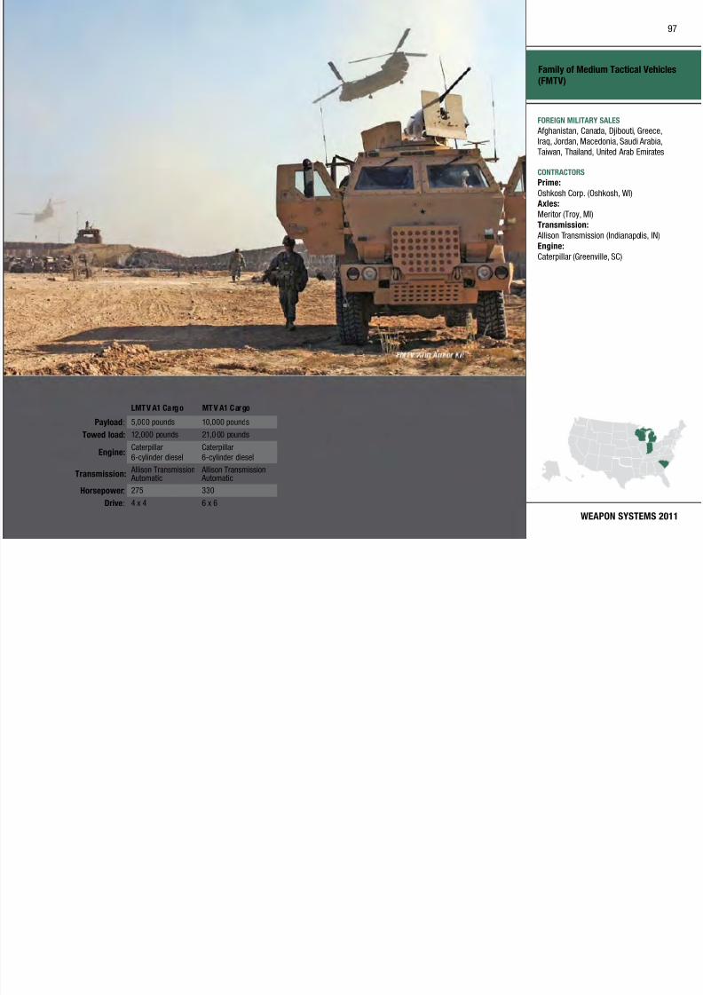
7/29/2019 Army Weapons Systems 2011
http://slidepdf.com/reader/full/army-weapons-systems-2011 107/380
WEAPON SYSTEMS 2011
Family of Medium Tactical Vehicles
(FMTV)
LMTV A1 Cargo MTV A1 Cargo
Payload: 5,000 pounds 10,000 pounds
Towed load: 12,000 pounds 21,0 00 pounds
Engine:Caterpillar
6-cylinder diesel
Caterpillar
6-cylinder diesel
Transmission: Allison Transmission Automatic
Allison Transmission Automatic
Horsepower: 275 330
Drive: 4 x 4 6 x 6
FOREIGN MILITARY SALES
Afghanistan, Canada, Djibouti, Greece,
Iraq, Jordan, Macedonia, Saudi Arabia,Taiwan, Thailand, United Arab Emirates
CONTRACTORS
Prime:
Oshkosh Corp. (Oshkosh, WI)Axles:
Meritor (Troy, MI)
Transmission:
Allison Transmission (Indianapolis, IN)
Engine:
Caterpillar (Greenville, SC)
Fixed Wing
98

7/29/2019 Army Weapons Systems 2011
http://slidepdf.com/reader/full/army-weapons-systems-2011 108/380
UNITED STATES ARMY
ACQUISITION PHASE
INVESTMENT COMPONENT
Technology Development Operations & SupportProduction & DeploymentEngineering & Manufacturing Development
Recapitalization
Modernization
Maintenance
MISSIONPerforms operational support and
focused logistics missions for the
Army, Joint serv ices, national agencies,
and multinational users in support of
intelligence and electronic warfare,
transporting key personnel, and
providing logistical support for battle
missions and homeland security.
DESCRIPTION
Army Fixed Wing aviation un itssupport their customers by enhancing
the lethal ity and survivabil ity on the
battlefield with intelligence and electronic
warfare assets. The Fixed Wing eet
provides timely movement of key
personnel to critical locations throughout
the theater of operations, transports
time-sensit ive and mission-cr itical supply
items and repair parts needed to continue
the warfight , and worldwide peacetime
contingencies and humanitarian relief
(Homeland Defense) support.
The Fixed Wing eet consists of eight
aircraft platforms and 256 aircraft t hat
allow the Army to perform day-to-day
operations in a more timely and cost-
efficient manner without reliance on
commercial transportation. Specialelectronic-mission aircraft provide
commanders with critical intelligence
and targeting i nformation, enhancing
lethality and survivability on the
battlefield.
All Army fixed-w ing aircraft are
commercial off-the-shelf products or are
developed from those products.
The fleet includes:
• C-12 Utility
• C-20/C-37 Long range transport • C-23 Cargo
• C-26 Utility
• EO-5 Airborne Reconnaissance Low
(ARL)
• RC-12 Guardrail Common Sensor (GR/
CS)
• UC-35 Utility
The EO-5 and RC-12 are classied as
special electronic mission aircraft and
provide real-time intelligence collection
in peace and war time environments.
The C-12, C-23, C-26, and UC-35 are
classified as operational support ai rcraft
and provide direct fixed-wing support
to warfighting combatant comma nders
worldwide. The C-20 and C-37 are
assigned to Andrews Air Force Base
and are classified as senior supportaircraft for the chief of staff and service
secretary.
SYSTEM INTERDEPENDENCIES Airbor ne Reconnaissa nce Low (ARL)
PROGRAM STATUS• C-12, RC-12, and UC-35 aircraft are
sustained using a Life Cycle Contractor
Support (LCCS) maintenance contract
• C-23 aircraft are sustained using
an LCCS ma intenance contract (M7 Aerospace)
• C-37 and UC-35 aircraft were purchased
with Congressional plus-up funding
• C-37, C-20, and C-26 aircraft are
sustained using Air Force LCCS
maintenance contracts (Gulfstream
and M7 Aerospace)
• EO-5 aircraft are sustained using an
LCCS maintenance contract (King
Aerospace)
PROJECTED ACTIVITIES• Acquire six C-12 replacement aircraft
for the Army Reserve
• Delivery of Golden Knights
replacement aircraf t
Fi d Wi
99

7/29/2019 Army Weapons Systems 2011
http://slidepdf.com/reader/full/army-weapons-systems-2011 109/380
WEAPON SYSTEMS 2011
Fixed Wing
FOREIGN MILITARY SALES
None
CONTRACTORS
Gulfstream (Savannah, GA)
King Aerospace (Addison, TX)
M7 Aerospace (San Antonio, TX)
Force Protection Systems
100

7/29/2019 Army Weapons Systems 2011
http://slidepdf.com/reader/full/army-weapons-systems-2011 110/380
UNITED STATES ARMY
ACQUISITION PHASE
INVESTMENT COMPONENT
RecapitalizationModernization
Maintenance
Technology Development Operations & SupportProduction & DeploymentEngineering & Manufacturing Development
MISSIONDetects, assesses, and responds
to unauthorized entry or attempted
intrusion into installations or facilities.
DESCRIPTIONForce Protection Systems consist of the
following components:
Automated Installation Entry (AIE)
is a software and hardware system
designed to read and compare vehicles
and personnel identification media. Theresults of the comparison are used to
permit or deny access to installation
in accordance with installation
commanders’ criteria. AIE will use
a database of personnel and vehicles
that have been authorized entr y onto
an Army installation and appropriate
entry lane hardware to permit/deny
access to the installation. The system
will validate the authenticit y of
credentials presented by a person with
data available from defense personnel
and vehicle registration databases.
AIE wi ll have the capabilit y to process
permanent personnel and enrolled
visitors, and to present a denial barrier
to restr ict unauthori zed personnel.
The system wil l also be capable of
adapting to immediate changes in threat conditions and apply rest rictive
entrance criteria consistent with the
force protection condition.
The Battleeld Anti-Intrusion
System (BAIS) is a compact, modular,
sensor-based warning system that
can be used as a tact ical stand-alone
system. The system consists of a
handheld monitor and three seismic/
acoustic sensors and provides coverage
across a platoon’s defensive front (450meters). It delivers early warning and
situational awareness information,
classifying detections as personnel,
vehicle, wheeled, or tracked intrusions.
The Lighting Kit, Motion Detector
(LKMD) is a simple, compact, modular,
sensor-based early-warning system
providing programmable responses of
illumination and sound. The LKMD
enhances unit awareness during all
types of operations and environments,
including those in urban terrain.
SYSTEM INTERDEPENDENCIESNone
PROGRAM STATUS• 4QFY10: BAIS contract award
• 4QFY10: LKMD procurement and
fielding
PROJECTED ACTIVITIES• FY02–13: BAIS procurement and
fielding
• FY06–11: LKMD operational testing
and procurement
Force Protection Systems
101

7/29/2019 Army Weapons Systems 2011
http://slidepdf.com/reader/full/army-weapons-systems-2011 111/380
WEAPON SYSTEMS 2011
Force Protection Systems
FOREIGN MILITARY SALES
None
CONTRACTORS
BAIS:
L-3 Communications (Camden, NJ)
LKMD:
EG&G (Albuquerque, NM)
Force Provider (FP)
102

7/29/2019 Army Weapons Systems 2011
http://slidepdf.com/reader/full/army-weapons-systems-2011 112/380
UNITED STATES ARMY
ACQUISITION PHASE
INVESTMENT COMPONENT
Technology Development Operations & SupportProduction & DeploymentEngineering & Manufacturing Development
RecapitalizationModernization
Maintenance
MISSION
Provides the Army, Joint U.S.
military, host nation, and coalition
forces personnel with a high-quality
deployable base camp to support the
expeditionary missions; develops,
integrates, acquires, fields, sustains,
and modernizes base camp support
systems to improve the warfighter’s
fighting capabilities, performance, and
quality of life.
DESCRIPTIONEach Force Provider (FP) is a high-
quality deployable base camp that
provides billeting, laundry, shower,
latrine, food service, shower water
reuse, and morale, welfare, and
recreation (MWR) kits to support
600 soldier camps. Additionally,
FP can be congured to support
150 base camps. FP includes 75
deployable triple container (TRICON)
systems, with eight latrine systems,
eight shower systems, four kitchen
systems, containerized batch laundry
systems, four TRICON refrigerated
containers, 26 60-kilowatt tactical
quiet generators, 26 modular personnel
tents (a ir supported), four 400,000
BTU water heaters, four improved fuel
distribution systems, two wastewater
evacuation tank/trailers, 26 mobile
electric power distribution replacement
systems, 56 environmental control
units, and eight air compressors that
are diesel-engine driven and operate
at 17 cubic feet per minute. FP is
prepositioned in Army Prepositioned
Stocks (APS) 1, 3, and 4 to support
combatant commanders’ requirements.
All system components weigh less
than 10,000 pounds, making FP highlymobile when prepacked for rapid
transpor t via a ir (C-130, C-141, C-5,
C-17), sea, road, or rail.
Additiona l operational add-on kits
include a cold-weather kit that allows
operation to -15 degrees Fahrenheit,
prime-power kit, large-scale electric
kitchen, and resource efficiency add-
ons to include a shower water reuse
system. New modules use an Airbeam
Shelter technology which reduces set
up time from days to hours.
SYSTEM INTERDEPENDENCIESOther Major Interdependencies
60-kilowatt Tactical Quiet Generator
PROGRAM STATUS• 2QFY10: Production initiated for
17 modules to replace deployed APS
assets
• 3QFY10: Deployment of two FP
600-man base camps configured
in 150-man subsets to support an
operational needs statement (ONS)
• 3QFY10: Integration of the Shower
Water Reuse System (SWRS) into FP
600-man base camps through urgent
materiel release to support ONS
PROJECTED ACTIVITIES• 1QFY11: Capabilities production
document approval supporting
improved capabilities
• 4QFY11: Integration of additional
resource efciency upgrades into FP
baseline
• 4QFY12: Projected completion of
delivery of FP production modules
to APS
Force Provider (FP)
103
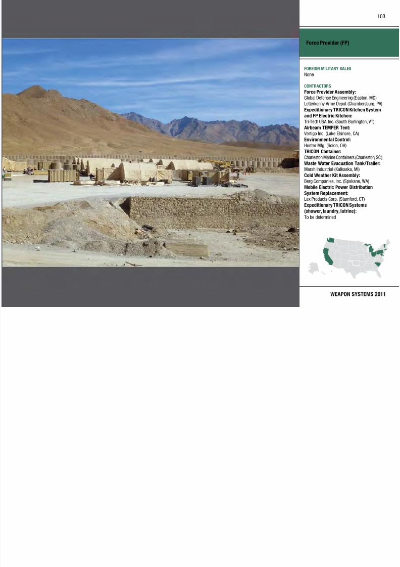
7/29/2019 Army Weapons Systems 2011
http://slidepdf.com/reader/full/army-weapons-systems-2011 113/380
WEAPON SYSTEMS 2011
Force Provider (FP)
FOREIGN MILITARY SALES
None
CONTRACTORS
Force Provider Assembly:
Global Defense Engineering (Easton, MD)
Letterkenny Army Depot (Chambersburg, PA)
Expeditionary TRICON Kitchen System
and FP Electric Kitchen:
Tri-Tech USA Inc. (South Burlington, VT)
Airbeam TEMPER Tent:
Vertigo Inc. (Lake Elsinore, CA)
Environmental Control:
Hunter Mfg. (Solon, OH)
TRICON Container:
Charleston Marine Containers (Charleston, SC)
Waste Water Evacuation Tank/Trailer:
Marsh Industrial (Kalkaska, MI)
Cold Weather Kit Assembly:
Berg Companies, Inc. (Spokane, WA)
Mobile Electric Power Distribution
System Replacement:
Lex Products Corp. (Stamford, CT)
Expeditionary TRICON Systems
(shower, laundry, latrine):
To be determined
Force XXI Battle Command Brigade and Below (FBCB2)
104

7/29/2019 Army Weapons Systems 2011
http://slidepdf.com/reader/full/army-weapons-systems-2011 114/380
UNITED STATES ARMY
ACQUISITION PHASE
INVESTMENT COMPONENT
RecapitalizationModernization
Maintenance
Technology Development Operations & SupportProduction & DeploymentEngineering & Manufacturing Development
MISSION
Provides integrated, on-the-move,
timely, relevant battle command
information to tactical combat leaders
and Soldiers from brigade to platform
and across platforms within the brigade
task force and other Joint forces.
DESCRIPTION The Force XXI Battle Command
Brigade and Below (FBCB2) forms
the principal dig ital command and
control system for the Army at
brigade levels and below. It provides
increased situational awareness (SA)
on the battlefield by automatically
disseminating throughout the network
timely fr iendly force locations, reported
enemy locations, and graphics to
visualize the commander’s intent and
scheme of maneuver.
FBCB2 is a key component of the Army
Battle Command System (ABCS).
Applique hardware and software
are integrated into the various
platforms at brigade-and-below, as
well as at appropr iate div ision and
corps slices necessary to support
brigade operations.
The system features platform
interconnections through two
communication systems: FBCB2–
Enhanced Position Location ReportingSystem (EPLRS), supported by the
tact ical Internet; and FBCB2–Blue
Force Tracking, supported by L-Band
satellite. The Joint Capabilities Release
(JCR) is the next software release and
addresses Joint requirements, database
simplification, Type 1 encryption, a
product line software approach, and
enables transition to the Blue Force
Tracking II (BFT II ) transceiver,
allowing a tenfold increase in data
throughput. FBCB2 is the pr imar y
platform-level digital Battle Command
(BC) for the Army and Marine Corps
at brigade-and-below, consisting of
computer hardware and software
integrated into tactical vehicles and
aircraft. The system distr ibutes SA
data and BC messages within/ between
platforms and command posts using
the Lower Tactica l Internet EPLRS
or L-Band satellite as its means of
communication.
SYSTEM INTERDEPENDENCIESIn this Publication
Advanced Field Ar tiller y Tactical Data
System (AFATDS), Battle Command
Sustainment Support System (BCS3),
Distributed Common Ground System– Army (DCGS-A), Movement Tracking
System (MTS), Nett Warrior (NW),
Warfighter In formation Network–
Tactical ( WIN-T) Increment 1,
WIN-T Increment 2, WIN-T Increment 3
Other Major Interdependencies
AMDWS, ASAS, BFT-AVN, DTSS,
CPOF, JTCW, JSTARS, MCS, JC2C
PROGRAM STATUS• Current: In production
PROJECTED ACTIVITIES• Current: Continue production
Force XXI Battle Command
105
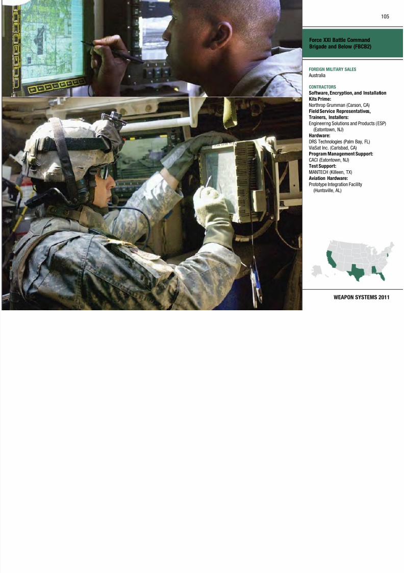
7/29/2019 Army Weapons Systems 2011
http://slidepdf.com/reader/full/army-weapons-systems-2011 115/380
WEAPON SYSTEMS 2011
Brigade and Below (FBCB2)
FOREIGN MILITARY SALES
Australia
CONTRACTORS
Software, Encryption, and Installation
Kits Prime:
Northrop Grumman (Carson, CA)
Field Service Representatives,
Trainers, Installers:
Engineering Solutions and Products (ESP)
(Eatontown, NJ)Hardware:
DRS Technologies (Palm Bay, FL)
ViaSat Inc. (Carlsbad, CA)Program Management Support:
CACI (Eatontown, NJ)
Test Support:
MANTECH (Killeen, TX)
Aviation Hardware:
Prototype Integration Facility
(Huntsville, AL)
Forward Area Air Defense Command and Control (FAAD C2)
106

7/29/2019 Army Weapons Systems 2011
http://slidepdf.com/reader/full/army-weapons-systems-2011 116/380
UNITED STATES ARMY
ACQUISITION PHASE
INVESTMENT COMPONENT
RecapitalizationModernization
Maintenance
Technology Development Operations & SupportProduction & DeploymentEngineering & Manufacturing Development
MISSION
Collects, processes, and disseminates
real-time target tracking and cuing
information to all short-range air
defense weapons and provides
command and control (C2) for the
Counter-Rocket, Mortar, and Artillery
(C-RAM) program.
DESCRIPTIONForward Area Air Defense Command
and Control (FAAD C2) softwareprovides critical C2, situational
awareness, and automated air track
information by integrating engagement
operations software for multiple
systems, including:
• Avenger
• Sentinel
• Army Battle Command System
(ABCS)
• C-RAM Program
FAAD C2 supports air defense and
C-RAM weapon systems engagement
operations by tracking friendly and
enemy aircraf t, cruise missiles,
unmanned aerial vehicles, mortar and
rocket rounds as identified by radar
systems, and by performing C2 for
Avenger and the C-RAM system.
FAAD C2 uses the following
communication systems:
• Enhanced Position Location
Reporting System (EPLRS)
• Multifunctional Information
Distribution System (MIDS)
• Single Channel Ground and Airborne
Radio System (SINCGARS)
FAAD C2 provides Joint C2
interoperability and horizontal
integration with all Army C2 and air
defense ar tillery system, including, but
not limited to:
• Surface Launched Advanced Medium
Range Air-to-Air Missile
• PATRIOT
• Avenger
• Theater High Altitude Area Defense
(THAAD)
• Airborne Warning and Control
System (AWACS)
• C-RAM
• ABCS
SYSTEM INTERDEPENDENCIESOther Major Interdependencies
Radar systems providing input
data such as Sentinel, Firender,
Lightweight Counter-Mortar Radar
(LCMR), a nd AWACS
PROGRAM STATUS• 3QFY10: BIOPs approved for
updated shelter systems
• 4QFY10: FAAD C2 version 5.4B full
materiel release
• 4QFY10: Complete elding of FAADSensor C2 nodes to ve division
headquarters
PROJECTED ACTIVITIES• 1QFY11: Complete FY10 reset effort
of 37 FAAD C2 shelter systems
• 2QFY11: Field nal Maneuver Air
and Missile Defense Battalion (1-188
Air Defense Ar tiller y)
• 3QFY11: Field FAAD C2 software
version 5.5A with 3D display
• 4QFY11: Continue elding of Sensor
C2 nodes to six additional division
headquarters
Forward Area Air Defense Command
d C t l (FAAD C2)
107

7/29/2019 Army Weapons Systems 2011
http://slidepdf.com/reader/full/army-weapons-systems-2011 117/380
WEAPON SYSTEMS 2011
and Control (FAAD C2)
FOREIGN MILITARY SALES
Egypt
CONTRACTORS
Software:
Northrop Grumman Space and Mission
Systems Corp. (Redondo Beach, CA)
Hardware:
Tobyhanna Army Depot (Scranton, PA)
PKMM (Las Vegas, NV)
SETA:
ITT–CAS, Inc. (Huntsville, AL)
CHS 3:
General Dynamics (Taunton, MA)
Future Tank Main Gun Ammunition (FTMGA)
108

7/29/2019 Army Weapons Systems 2011
http://slidepdf.com/reader/full/army-weapons-systems-2011 118/380
UNITED STATES ARMY
ACQUISITION PHASE
INVESTMENT COMPONENT
RecapitalizationModernization
Maintenance
Technology Development Operations & SupportProduction & DeploymentEngineering & Manufacturing Development
MISSION
Provides overwhelming lethality
overmatch to the heavy armor fleet.
DESCRIPTION The Future Tank Main Gun
Ammunition (F TMGA) suite consists
of two cartridges and will provide
enhanced lethality and increased
capability to the Heavy Brigade Combat
Team.
The next generation kinet ic energy(KE) cartridge, designated M829E4,
will use a n advanced penetrator to
defeat future heavy armor targets
equipped with explosive reactive
armor and act ive protection systems.
This wi ll increase survivabil ity of the
Abrams tank in the 0–4 kilometer
range.
The Advanced Multi-Purpose (AMP)
cartr idge will combine the capabilities
of a number of existing munitionsinto one cartridge. This cartridge
will ut ilize air bursting warhead and
multimode fuze technology to combine
those capabi lities and provide new
capability against dismounted infantry
at longer ranges. This cartr idge will
employ high-explosive, anti-personnel,
obstacle-reduction, and anti-helicopter
capabilities into one munition, thus
streamlining the logistical footprint
associated with deploying heavy forces.
This cartr idge wil l further enhance
survivability and lethalit y for Abrams
tanks in the 0–4 kilometer range.
SYSTEM INTERDEPENDENCIES The FTMGA suite must be compatible
with the Abra ms tank fleet through the
remainder of its service life.
PROGRAM STATUS• 4QFY09: Milestone B for M829E4
• FY10: M829E4 Engineering and
manufacturing development (EMD)
initiation
• FY10: Award of two competing EMD
contracts for M829E4
• Current: M829E4 TRL-6
demonstrated; AMP TRL-6
demonstrated
PROJECTED ACTIVITIES
• FY11: EMD downselect M829E4• FY12: Milestone B for AMP
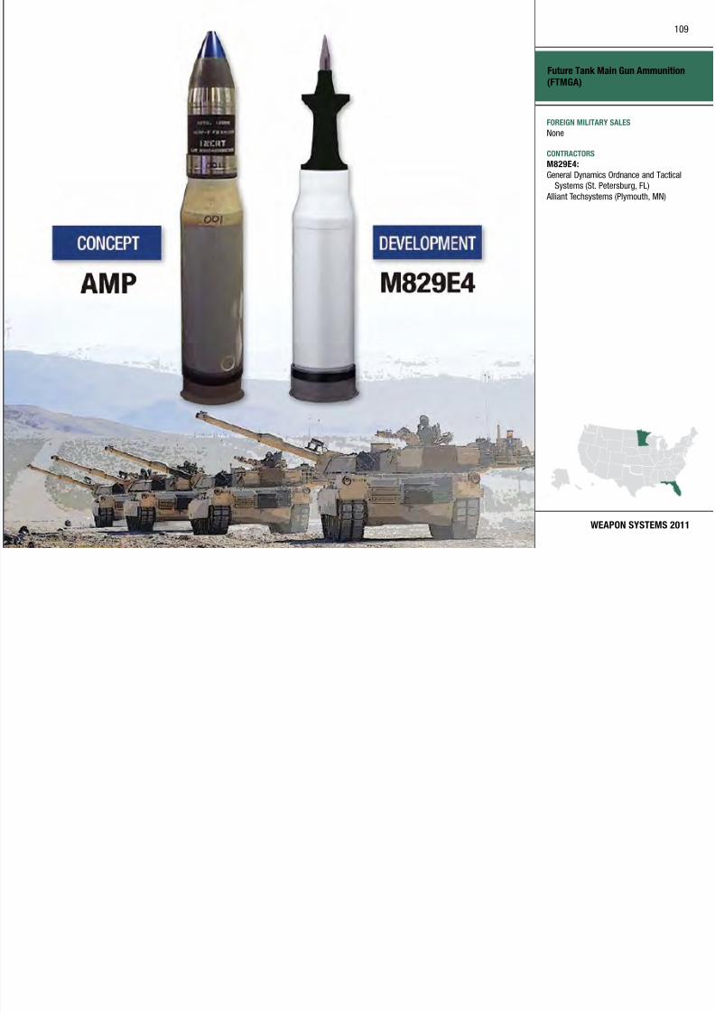
7/29/2019 Army Weapons Systems 2011
http://slidepdf.com/reader/full/army-weapons-systems-2011 119/380
General Fund Enterprise Business Systems (GFEBS)
110

7/29/2019 Army Weapons Systems 2011
http://slidepdf.com/reader/full/army-weapons-systems-2011 120/380
UNITED STATES ARMY
ACQUISITION PHASE
INVESTMENT COMPONENT
Technology Development Operations & SupportProduction & DeploymentEngineering & Manufacturing Development
RecapitalizationModernization
Maintenance
MISSION
Provides a new core financial
management capability that is
compliant with congressional mandates,
administers the Army’s General
Fund, and improves performance,
standardizes processes, and meets
future needs.
DESCRIPTION The Army wi ll implement a commercial
off-the-shelf Enterprise ResourcePlanning (ERP) system that meets
the requirements of the Chief
Financial Ofcers Act and the Federal
Financial Management Improvement
Act of 1996, and that is capable of
supporting the Department of Defense
with accurate, reliable, and timely
financial information. The General
Fund Enterprise Business Systems
(GFEBS) implementation involves
standardizing financial management,
accounting functions, real propertyinventory, and management across
the Army. As a result, A rmy financial
and real property professionals will
have access to timely, reliable, and
accurate information. GFEBS will also
improve cost management and control,
allow more time to perform financial
analysis, and facilit ate a more accurate
understanding of the value, location,
and characteristics of all property.
GFEBS will provide a comprehensive
system for many of the Army’s
financial and accounting functions
including general ledger, accounts
payable, revenue and accounts
receivable, cost management, financial
reporting, and real property inventory
and management. GFEBS will deploy
to an estimated 79,000 warghtersat more than 200 sites. Anticipated
benets to be rea lized a re $960 mil lion
between FY10 and Life Cycle FY22.
SYSTEM INTERDEPENDENCIESNone
PROGRAM STATUS• 2QFY08: Successful Milestone B
decision
• 3QFY08: Developmental testing for
release 1.2• 3QFY08: Begin build phase
of second production release
(release 1.3)
• 1QFY09: “Go-Live” of first
production release
• 1QFY09: Limited user test
• 2QFY09: “Go-Live” of release 1.3
• 2QFY09: Milestone C and move
to production and deployment/
operations and support phase
• 3QFY09: Full Army-wide
deployment of release 1.3
• 3QFY09: Successful Milestone C
decision
• 1QFY10: Successful release 1.4
“Go-Live”
• 1QFY10: Limited user testing of
release 1.4
• 2QFY10: Successful release 1.4“Go-Live” to Medical Command
• 2QFY10: Limited pre-deployment
authorization for Wave 2
• 3QFY10–4QFY10: Follow-on
operational test and evaluation
PROJECTED ACTIVITIES• Continue: Full deployment decision
approval
• 1QFY11: Deploy release 1.4.2
• 3QFY11: Release 1.4.3 and move
to full Army-wide deployment/ operations and support phase
General Fund Enterprise Business
Systems (GFEBS)
111

7/29/2019 Army Weapons Systems 2011
http://slidepdf.com/reader/full/army-weapons-systems-2011 121/380
WEAPON SYSTEMS 2011
Systems (GFEBS)
FOREIGN MILITARY SALES
None
CONTRACTORS
System Integrator:
Accenture (Reston, VA)
Program Management Support–
Acquisition:
Binary Group (Bethesda, MD)
Program Management Support
Services–Engineering:
iLuMinA Solutions (California, MD)
Global Combat Support System–Army (GCSS-Army)
112

7/29/2019 Army Weapons Systems 2011
http://slidepdf.com/reader/full/army-weapons-systems-2011 122/380
UNITED STATES ARMY
ACQUISITION PHASE
INVESTMENT COMPONENT
Technology Development Operations & SupportProduction & DeploymentEngineering & Manufacturing Development
RecapitalizationModernization
Maintenance
MISSION
Provides commanders and staffs with
a responsive and efficient automated
system that provides one coherent
source for accurate and timely tactical
logistics information to improve
situational awareness and facilitate the
decision-making cycle.
DESCRIPTIONGlobal Combat Support System–Army
(GCSS-Army) is one program with twocomponents. GCSS-Army Enterprise
Resource Planning (ERP) Solution
is an automation information system
that serves as the primary tactical
logistics enabler to support Army and
Joint Transformation for Sustainment
using an ERP system. The program
re-engineers current business processes
to achieve end-to-end logistics and
integration with applicable command
and control (C2)/Joint systems. The
second component, Army EnterpriseSystems Integration Program (AESIP),
formerly known as Product Lifecycle
Management Plus (PLM+), integrates
Army business functions by providing
a single source for enterprise hub
services, master data, and business
intelligence.
GCSS-Army uses commercial-off-the-
shelf (COTS) ERP software products
to support rapid force projection in
the batt lefield functiona l areas of
arming, fixing, fueling, sustaining and
tact ical logistics fina ncial processes.
The GCSS-Army solution replaces 11
logistics Standard Army Management
Information Systems (STAMIS) in tact ical units and wi ll establ ish an
interface/integration with applicable
C2 and Joint systems.
GCSS-Army (ERP Solution) is
the primary enabler for the Army
transformation vision of a techno-
logically advanced ERP that manages
the flow of logistics resources and
information to satisfy the Army’s
modernization requirements. AESIP
integrates Army business functions byproviding a single source for enterprise
hub services, business intelligence
and analyt ics, and centralized master
data management across the business
domain. GCSS-Army will meet the
warfighter’s need for responsive
support at the right place and time and
improve the commander’s situational
awareness with accurate and
responsive information.
SYSTEM INTERDEPENDENCIESGeneral Fund Enterprise Business
Systems (GFEBS)
PROGRAM STATUS• 4QFY08: Milestone B
• 1QFY09: Acquisition program
baseline signed• 4QFY10: Release 1.1 “Go-Live”
• 4QFY10: Developmental test and
evaluation; initial government test
PROJECTED ACTIVITIES• 2QFY11: Milestone C decision
• 4QFY11: Initial operational test and
evaluation
• 2QFY12: Full deployment decision
Global Combat Support System–
Army (GCSS-Army)
113

7/29/2019 Army Weapons Systems 2011
http://slidepdf.com/reader/full/army-weapons-systems-2011 123/380
WEAPON SYSTEMS 2011
Army (GCSS-Army)
FOREIGN MILITARY SALES
None
CONTRACTORS
Prime GCSS-Army:
Northrop Grumman Information Systems
(Richmond, VA)
Prime AESIP:
Computer Sciences Corp. (CSC)
(Falls Church, VA)
PMO Support:
LMI Consulting (McLean, VA)
MPRI, an L-3 Company (Alexandria, VA)
Capgemini (IV&V) (New York, NY)
Global Command and Control System–Army (GCCS-A)
114

7/29/2019 Army Weapons Systems 2011
http://slidepdf.com/reader/full/army-weapons-systems-2011 124/380
UNITED STATES ARMY
ACQUISITION PHASE
INVESTMENT COMPONENT
RecapitalizationModernization
Maintenance
Technology Development Operations & SupportProduction & DeploymentEngineering & Manufacturing Development
MISSION
Provides critical automated command
and control (C2) tools for combatant
commanders to enhance warfighter
capabilities throughout the spectrum
of conflict during Joint and combined
operations.
DESCRIPTION The Global Command and Control
System–Army (GCCS-A) is the Army’s
strategic and operational C2 system,
providing readiness, planning,
mobilization, and deployment capability
information for strategic commanders.
For theater commanders, GCCS-A
provides the following:
• Common operational picture andassociated friendly and enemy status
information
• Force-employment planning and
execution tools (receipt of forces,
intra-theater planning, readiness,
force tracking, onward movement,
and execution status)
• Overall interoperability with Joint,
coalition, and the tactical Army
Battle Command System (ABCS)
GCCS-A supports Army units from the
strategic commanders and regional
combatant commanders in theater,
down through the joint task forcecommander. As part of ABCS, GCCS-A
provides a seamless Army extension
from the Joint GCCS system to echelons
corps and below. Compatibility and
interoperability are achieved by
building the GCCS-A applications to
function on the common operating
environment and through interfaces
with other C2 systems within the Army
and other services. Force Readiness
and Force Projection are provided by
Defense Readiness Reporting System– Army (DRRS-A).
The common operating envi ronment
specifies a common system
infrastructure for all C2 systems in
accordance with the joint technical
architecture guidelines. These provide
a common support architecture and
modular software for use by the
services and agencies in developing
mission-specic solutions to their C2
requirements. The hardware platform
is based on commercial off-the-shelf
hardware. The system users are linked
via loca l area networks in client/
server configurations, operating at
Secret/High over the Secure Internet
Protocol Router Network for worldwide
communication.
SYSTEM INTERDEPENDENCIESIn this Publication
Advanced Field Arti llery Tact ical Data
System (AFATDS), Battle Command
Sustainment Support System (BCS3),
Tactical Battle Command (TBC)/
Maneuver Control System (MCS)
Other Major Interdependencies
ABCS, ASAS, CPOF, DRRS, DTSS,
GCCS-J, GSORTS, JOPES
PROGRAM STATUS• 3QFY08–1QFY09: Support Net-
Enabled Command Capability
(NECC) development of Army
capability modules with unique Army
requirements
• 3QFY08–4QFY10: Support
Operations Enduring Freedom and
Iraqi Freedom (OEF/OIF)
• 3QFY08–4QFY10: Release Defense
Readiness Reporting System–Army
(DRRS-A) Force Readiness Tool
(Phase 3) to the eld• 1–4QFY10: Support to the Joint
Command and Control (JC2)
Capability Analysis of A lternatives
(AoA)
PROJECTED ACTIVITIES• 1–4QFY11: Continue spiral
development in support of GCCS-A
Version 4.2.x and DRRS-A Phase 4
requirements
• 1–4QFY11: Continue directed
fieldings and required support forOEF/OIF
• 1–4QFY11: Continue support to the
JC2 AoA and eventual approved JC2
Way Forward
Global Command and Control
System–Army (GCCS-A)
115

7/29/2019 Army Weapons Systems 2011
http://slidepdf.com/reader/full/army-weapons-systems-2011 125/380
WEAPON SYSTEMS 2011
System Army (GCCS A)
FOREIGN MILITARY SALES
None
CONTRACTORS
Develop and Field Software:
Lockheed Martin (Springfield, VA;
Tinton Falls, NJ)
System Hardware:
GTSI (Chantilly, VA)
Systems Engineering and Support:
Accenture (Reston, VA)Field Support Reps:
Engineering Solutions and Products (ESP)
(Eatontown, NJ)
Systems Engineering and Integration:
Systems Technologies (Systek), Inc.
(West Long Branch, NJ)Program Support:
Booz Allen Hamilton (Eatontown, NJ)
Systems Integration and Testing:
General Dynamics (Fairfax, VA)
Gray Eagle Extended Range Multipurpose (ERMP)Unmanned Aircraft System (UAS)
116

7/29/2019 Army Weapons Systems 2011
http://slidepdf.com/reader/full/army-weapons-systems-2011 126/380
UNITED STATES ARMY
ACQUISITION PHASE
INVESTMENT COMPONENT
Unmanned Aircraft System (UAS)
RecapitalizationModernization
Maintenance
Technology Development Operations & SupportProduction & DeploymentEngineering & Manufacturing Development
MISSION
Provides combatant commanders
a real-time responsive capability to
conduct long-dwell, persistent stare,
wide-area reconnaissance, surveillance,
target acquisition, communications
relay, and attack missions.
DESCRIPTION The MQ-1C Gray Eagle Extended Range
Multipurpose Unmanned Aircraft
System (UAS) addresses the need fora long-endurance, armed, unmanned
aircraft system that offers greater
range, altitude, and payload flexibility.
The Gray Eagle UAS is powered by a
heavy fuel engine (HFE) for higher
performance, better fuel efficiency,
common fuel on the battlefield, and a
longer lifetime.
Its specifications include the following:
Length: 28 feet
Wingspan: 56 feet
Gross take-off weight: 3,200 pounds
(Growth to 3,600 pounds)
Maximum speed: 150 knots
Ceiling: 25,000 feet
Range: 1,200 nautical miles via
satellite communications (SATCOM)
Endurance: 30+ hours
The Gray Eagle UAS is fielded in
company sets, consisting of 12unmanned aircraft, si x One System
Ground Control Stations (OGCS), six
Ground Data Terminals (GDT), three
Portable Ground Control Stations
(PGCS), three Portable Ground Data
Terminals (PGDT), three Satellite
Ground Data Terminals (SGDT), an
Automated Take-off and Landing
System (ATLS), Light Medium
Tactical Vehicles (LMTV), and other
ground-support equipment, operated
and maintained by a company of 128Soldiers within the Combat Aviation
Brigade.
SYSTEM INTERDEPENDENCIESOther Major Interdependencies
PM–Robotic Unmanned Sensors
(PM-RUS) provides the electro-optical/
infrared (EO/IR) and SAR/GMTI
payloads, PM–Joint Attack Munition
Systems (PM-JAMS) provides Hellre
missiles, PM–Warfighter Information
Network–Terrestrial (PM-WIN-T)
provides communications relay payload
PROGRAM STATUS
• Current: Low-rate initial production
PROJECTED ACTIVITIES• 4QFY11: Initial operational test and
evaluation
• 2QFY12: Full-rate production
decision
Gray Eagle Extended Range
Multipurpose (ERMP) Unmanned
Aircraft System (UAS)
117

7/29/2019 Army Weapons Systems 2011
http://slidepdf.com/reader/full/army-weapons-systems-2011 127/380
WEAPON SYSTEMS 2011
Aircraft System (UAS)
FOREIGN MILITARY SALES
None
CONTRACTORS
Aircraft:
General Atomics, Aeronautical Systems
Inc. (San Diego, CA)
Ground Control Station:
AAI Corp. (Hunt Valley, MD)
Tactical Common Data Link:
L-3 Communications (Salt Lake City, UT )
Ground Combat Vehicle (GCV)
118

7/29/2019 Army Weapons Systems 2011
http://slidepdf.com/reader/full/army-weapons-systems-2011 128/380
UNITED STATES ARMY
ACQUISITION PHASE
INVESTMENT COMPONENT
RecapitalizationModernization
Maintenance
Technology Development Operations & SupportProduction & DeploymentEngineering & Manufacturing Development
MISSION
Provides the infantry squad with a
highly mobile, protected transport to
decisive locations on the battlefield.
DESCRIPTION The Ground Combat Vehicle (GCV) is
a critical element of the Army’s effort
to transform, replace, and improve
its Combat Vehicle eet. The GCV
Infantry Fighting Vehicle (IFV) will
provide force protection to deliver
a nine-man infantry squad in animprovised explosive device (IED)
threat env ironment. It wil l protect
occupants from IEDs, mines, and other
ball istic threats with scalable a rmor
that provides mission flexibility for
the commander.
GCV IFV will be designed with
sufficient power and space to host
the Army’s advanced network. The
IFV will feature an open architecture
to facil itate the integration ofcurrent and future communications,
computers, and surveillance and
reconnaissance systems.
The GCV IFV wi ll have enhanced
mobility to allow it to operate
effectively in a variety of complex
environments, including urban and
cross county terrain, while carrying a
full infantry squad plus crew of three.
The GCV IFV’s organ ic weapons will be
capable of providing both destructive
fires against a rmored vehicle threats
and direct fire support for the squad
during dismounted assaults. Flexible
capabilities can shape the operatingenvironment with effects that can vary
from a “shove” to a lethal overmatch.
SYSTEM INTERDEPENDENCIESNone
PROGRAM STATUS• FY10: Completed materiel
development decision; currently
proceeding to a Milestone A decision
for approval to enter into the
technology development phase
PROJECTED ACTIVITIES• Ongoing: The GCV IFV program wi ll
go through competitive development
as well as technology development
and engineering and manufacturing
development phases before enteringproduction; rst production of GCV
IFV is expected approximately seven
years f rom award of technology
development contracts
Ground Combat Vehicle (GCV)
119

7/29/2019 Army Weapons Systems 2011
http://slidepdf.com/reader/full/army-weapons-systems-2011 129/380
WEAPON SYSTEMS 2011
FOREIGN MILITARY SALES
To be determined
CONTRACTORS
To be determined

7/29/2019 Army Weapons Systems 2011
http://slidepdf.com/reader/full/army-weapons-systems-2011 130/380
Guardrail Common Sensor (GR/CS)
121

7/29/2019 Army Weapons Systems 2011
http://slidepdf.com/reader/full/army-weapons-systems-2011 131/380
WEAPON SYSTEMS 2011
FOREIGN MILITARY SALES
None
CONTRACTORS
System Integrator, ESA Subsystem, and
GGB Software/System Support:
Northrop Grumman (Sacramento, CA)
Data Links:
L-3 Communications (Salt Lake City, UT )
CHALS-C:
Lockheed Martin (Oswego, NY)X-MIDAS Software:
ZETA (Fairfax, VA)
HBC Subsystem:
ArgonST Radix (Mountain View, CA)
Guided Multiple Launch Rocket System (GMLRS)DPICM/Unitary/Alternative Warhead (Tactical Rockets)
122

7/29/2019 Army Weapons Systems 2011
http://slidepdf.com/reader/full/army-weapons-systems-2011 132/380
UNITED STATES ARMY
ACQUISITION PHASE
INVESTMENT COMPONENT
DPICM/Unitary/Alternative Warhead (Tactical Rockets)
Technology Development Operations & SupportProduction & DeploymentEngineering & Manufacturing Development
RecapitalizationModernization
Maintenance
MISSION
Provides a 24/7 persistent, responsive,
all-weather, rapidly-deployed, long-
range, surface-to-surface, area-and-
point precision strike capability.
DESCRIPTION The Guided Multiple Launch Rocket
System (GMLRS) is a major upgrade
to the M26 rocket, producing precise,
destructive, and shaping fires against
a variety of target sets. GMLRS is
employed with the M270A1 upgradedMultiple Launch Rocket System
(MLRS) tracked launcher and the
M142 High Mobility Artillery Rocket
System (HIMARS) wheeled launchers.
GMLRS munitions have greater
accuracy with a resulting higher
probability of kill, smaller logistics
footprint, and minimized collateral
damage.
There are two fielded var iants of the
GMLRS: the previously produceddual-purpose improved conventional
munitions (DPICM) variant designed to
service area targets; and the unitary
var iant with a single 200-pound
class high-explosive charge to
provide precision strike blast and
fragmentation effects with low
collateral damage. The developmentof a third var iant incorporating an
alternative warhead has been initiated.
The Alternat ive Warhead (AW) will be
compliant with the 2008 DoD Policy
on Cluster Munitions and Unintended
Harm to Civilians. The AW rocket
will service area target sets without
producing unexploded ordnance and is
scheduled to be elded in FY15.
The original GMLRS development wasan international cooperative program
with the United K ingdom, Germany,
France, and Italy. An urgent materiel
release version of the GMLRS Unitary
was produced and fielded in support
of U.S. Central Command (CENTCOM)
forces with over 1,600 rockets used in
operations through July 2010.
Rocket length: 3,937mm
Rocket diameter: 227mm
Rocket reliability: Threshold 92percent; objective 95 percent
Ballistic range(s): 15 to 70+
kilometers
SYSTEM INTERDEPENDENCIES
In this Publication Advanced Field Ar tiller y Tactical Data
System (AFATDS), HIMARS
Other Major Interdependencies
GPS, M270A1, Joint Systems, National
Systems
PROGRAM STATUS• 2Q–3QFY08: GMLRS Unitary initial
operational test
• 1QFY09: GMLRS AW CongurationSteering Board (CSB), Acquisition
Decision Memorandum (ADM)
approved for Technology
Development Initiation of the AW
• 1QFY09: GMLRS AW CSB ADM
halts new DPICM procurements
• 1QFY09: GMLRS Unitary full-rate
production decision
• 4QFY09: GMLRS AW Milestone A
• 4QFY10: GMLRS AW Warhead
Prototype Technical Demonstrations
PROJECTED ACTIVITIES• 4QFY11: GMLRS AW Milestone B
Guided Multiple Launch Rocket
System (GMLRS) DPICM/Unitary/
Alternative Warhead (Tactical
R k t )
123

7/29/2019 Army Weapons Systems 2011
http://slidepdf.com/reader/full/army-weapons-systems-2011 133/380
WEAPON SYSTEMS 2011
Rockets)
FOREIGN MILITARY SALES
Bahrain, Canada, France, Finland,
Germany, Japan, Jordan, Singapore,Thailand, United Arab Emirates,
United Kingdom
CONTRACTORS
Prime:
Lockheed Martin (Camden, AR;
Grand Prairie, TX)
Lockheed Martin Missiles and Fire Control
(Las Cruces, NM)
Guidance Set:
Honeywell (Clearwater, FL)
Rocket Motors: Aerojet (Camden, AR)
Technical System Support :
Systems, Studies, and Simulation
(Huntsville, AL)
Heavy Expanded Mobility Tactical Truck (HEMTT)/ HEMTT Extended Service Program (ESP)
124

7/29/2019 Army Weapons Systems 2011
http://slidepdf.com/reader/full/army-weapons-systems-2011 134/380
UNITED STATES ARMY
ACQUISITION PHASE
INVESTMENT COMPONENT
HEMTT Extended Service Program (ESP)
Technology Development Operations & SupportProduction & DeploymentEngineering & Manufacturing Development
Recapitalization
Modernization
Maintenance
MISSION
Supports combat units by performing
line and local haul, unit resupply,
helicopter and tactical vehicle refueling,
and related missions in a tactical
environment.
DESCRIPTION The Heavy Expanded Mobility Tactical
Truck (HEMTT) 10-ton, 8-wheel drive
is designed for cross-country military
missions up to 11 tons to transport
ammunition, petroleum, oils, and
lubricants. Variants include: M977,
M985, M978, M983, M984 and M1120.
The M977 is utilized for delivery of
general supplies, equipment, andammunition with an on-board crane
with 4,500 pounds load capacity. The
M985 cargo has an on-board crane with
5,400 pounds load capacity and is the
primary transporter for Multiple Launch
Rocket System (MLRS) ammunition.
The M978 tanker is a 2,500 gallon
fuel transporter for field refueling ofground vehicles and aircraft. The M984
wrecker includes a crane and winch
retrieval system and serves the primary
role of recovery and evacuation of heavy
wheel vehicles and combat systems.
The M983 Tractor is the prime mover
for the Patriot missile. The M983
Light Equipment Transporter (LET)
Tractor serves as the prime mover for
tactica l semitrailers in engineering
units to include the M870 seriesand Intermediate Stryker Recovery
System (ISRS) and Mine-Resistant,
Ambush-Protected (MRAP) vehicles.
The HEMTT Load Handling System
(LHS) provides NATO interoperability
with standard flatrack and mission
modules for delivery of general supplies,
equipment, and ammunition with
Palletized Load System (PLS) style
load handling systems. The system
is compatible with the PLS Trailer,
capable of a 26,000 pound payload.
The HEMTT A4 began elding in
December 2008. Enhancements include
a modern power train consisting of a
Caterpilla r C-15/500 horsepower Engine
and Allison Transmission (4500 SP/5-
speed automatic), anti-lock braking
system and traction control, air-ridesuspension, a J-1939 data-bus providing
an updated electrical system, climate
control, and a larger common cab.
HEMTT ESP, known as HEMTT
RECAP, is a recapitalization program
that converts high-mileage, older
version HEMTT trucks into the
current A4 production conguration.
Modernizing the fleet to one model
reduces logistic footprint andoperational and sustainment (O&S)
cost of maintaining old vehicles.
HEMTT has several congurations:
• M977: Cargo truck with l ight
materiel handling crane
• M985: Cargo truck with heavy
materiel handling crane
• M978: 2,500-gallon fuel tanker
• M984: Wrecker
• M983: Tractor
• M983 LET: LET fifth wheel verticalloading has 45K winch with gross
towing weight of 45.4 kilograms
• M1120: LHS transports palletized
materiel and International Standards
Organization (ISO) containers
SYSTEM INTERDEPENDENCIES
Other Major Interdependencies The M983 HEMTT LET Tractor paired
with the Fi fth Wheel Towing Device
and High Mobility Recovery Trailer
are designated ISRS and MRAP
recovery. Other vehicles that utilize the
HEMTT chassis are: M1142 Tactical
Fire Fighting Trucks, M1158 Heavy
Mobility Water Tender Truck, M1977
HEMTT Common Bridge Transporter
(CBT), Theatre High Altitude Area
Defense Missile System (THAAD),and the M985 GMT Guided Missile
Transport used in Patriot Battalions.
PROGRAM STATUS• 1QFY09: HEMTT A4 Family
of Vehicles was type classied
standard and full materiel released
(TC/MR)
PROJECTED ACTIVITIES• FY11: Distribute HEMTT A4s in
accordance with HeadquartersDepartment of the Army G8
distribution plan to next deployers to
Theater, Army National Guard, Army
Reserve, Homeland Defense, and
Army Prepositioned Stock
Heavy Expanded Mobility Tactical
Truck (HEMTT)/HEMTT Extended
Service Program (ESP)
125
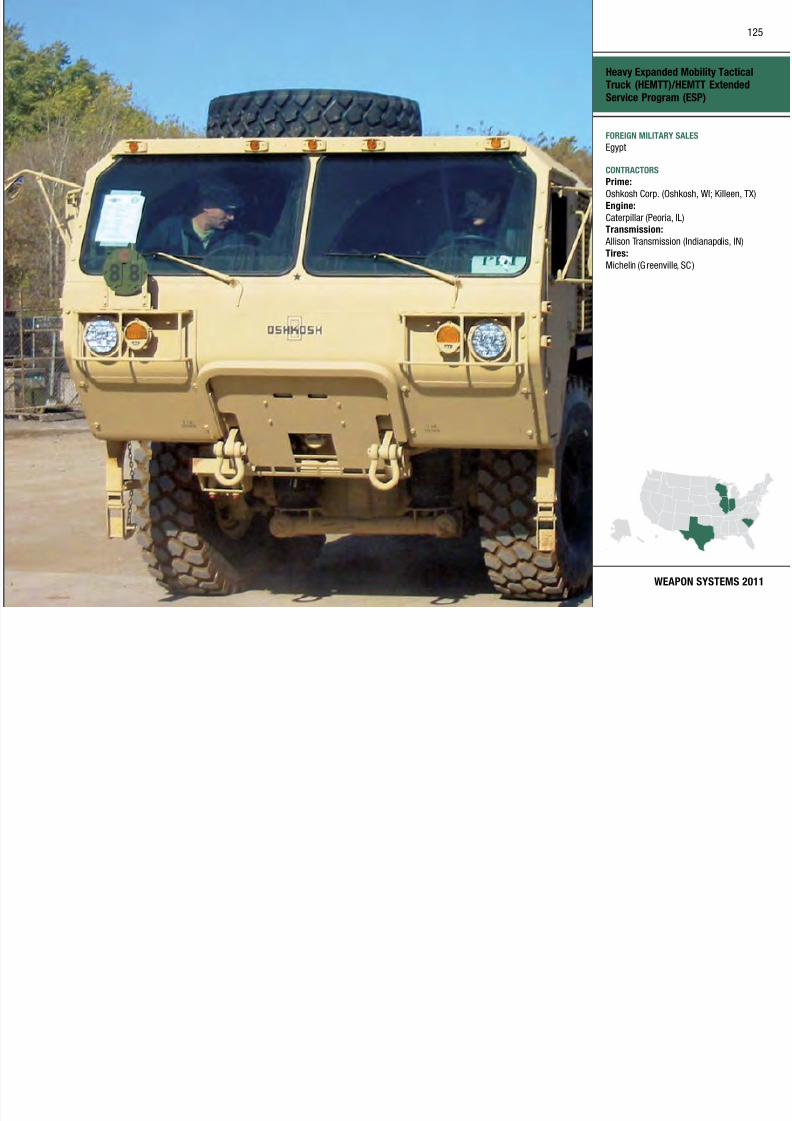
7/29/2019 Army Weapons Systems 2011
http://slidepdf.com/reader/full/army-weapons-systems-2011 135/380
WEAPON SYSTEMS 2011
g ( )
FOREIGN MILITARY SALES
Egypt
CONTRACTORS
Prime:
Oshkosh Corp. (Oshkosh, WI; Killeen, TX)
Engine:
Caterpillar (Peoria, IL)Transmission:
Allison Transmission (Indianapolis, IN)
Tires:
Michelin (Greenville, SC )

7/29/2019 Army Weapons Systems 2011
http://slidepdf.com/reader/full/army-weapons-systems-2011 136/380
Heavy Loader
127

7/29/2019 Army Weapons Systems 2011
http://slidepdf.com/reader/full/army-weapons-systems-2011 137/380
WEAPON SYSTEMS 2011
FOREIGN MILITARY SALES
None
CONTRACTORS
OEM:
Caterpillar Defense and Federal Products
(Peoria, IL)
Armor:
BAE Systems (Rockville, MD)
Logistics:
XMCO (Warren, MI)
Hellfire Family of Missiles
128

7/29/2019 Army Weapons Systems 2011
http://slidepdf.com/reader/full/army-weapons-systems-2011 138/380
UNITED STATES ARMY
ACQUISITION PHASE
INVESTMENT COMPONENT
Technology Development Operations & SupportProduction & DeploymentEngineering & Manufacturing Development
Recapitalization
Modernization
Maintenance
MISSION
Engages and defeats individual
moving or stationary advanced armor,
mechanized or vehicular targets, patrol
craft, buildings, or bunkers while
increasing aircraft survivability.
DESCRIPTION The AGM-114 Hellre Fami ly of
Missile includes the Hellre II and
Longbow Hellre missiles. Hellre
II is a precision strike, Semi-ActiveLaser (SAL) guided missile and is the
principal air-to-ground weapon for the
Army AH-64 Apache, OH-58 Kiowa
Warrior, Gray Eagle Extended Range
Multipurpose (ERMP) Unmanned
Aircra ft System (UAS), Special
Operations aircraft, Marine Corps
AH-1W Super Cobra and the Air Force’s
Predator/Reaper UAS.
The SAL Hellre II missi le is guided
by laser energy reflected off the target.It has three warhead variants: a
dual warhead, shaped charge high-
explosive anti-tank (HEAT) capability
for armored targets (AGM-114K); a
blast frag mentation warhead (BFWH)
for urban, patrol boat and other “soft”
targets (AGM-114M); and a metalaugmented charge (MAC) warhead
(AGM-114N) for urban structures,
bunkers, radar sites, communications
installations, and bridges. Beginning in
2012, a Hellre multi-purpose warhead
var iant (AGM-114R) will be ava ilable
to the warfighter that a llows select ion
of warhead effects corresponding to a
specic target type. The AGM-114R is
capable of being launched from Army
rotary wing and UAS platforms andprovides the pilot increased operational
flexibility.
The Longbow Hellre (AGM-114L)
is also a precision strike missile
using millimeter wave (MMW) radar
guidance instead of the Hellre I I’s
semi-active laser. It is the principal
anti-tank system for the AH-64D
Apache Longbow helicopter a nd
uses the same anti-armor warhead
as the Hellre II. The MMW seekerprovides beyond line-of-sight fire and
forget capability as well as the ability
to operate in adverse weather and
battlefield obscurants.
Diameter: 7 inches
Weight: 99.8–107 poundsLength: 64 inches
Maximum range:
Direct re: 7 kilometers
Indirect re: 8 kilometers
Minimum range: .5–1.5 kilometers
SYSTEM INTERDEPENDENCIESNone
PROGRAM STATUS• Current:
Laser Hellre II missilesare procured annually to replace
combat expenditures and war
reserve requirements
PROJECTED ACTIVITIESLaser Hellre
• Continue: In production
Longbow Hellre
• Continue: Sustainment activities
Hellfire Family of Missiles
129

7/29/2019 Army Weapons Systems 2011
http://slidepdf.com/reader/full/army-weapons-systems-2011 139/380
WEAPON SYSTEMS 2011
FOREIGN MILITARY SALES
Laser Hellfire:
Australia, Egypt, Greece, Israel, Kuwait,Netherlands, Saudi Arabia, Singapore,
Spain, TaiwanDirect commercial sale:
United Kingdom
Longbow Hellfire:
Israel, Japan, Kuwait, Singapore
Direct commercial sale:
United Kingdom
CONTRACTORS
Lockheed Martin (Troy, AL)
L-3 Communications (Chicago, IL) Alliant Techsystems (Rocket City, WV)
Moog Inc. (Salt Lake City, UT)Laser Hellfire Missile System, guidance
section, sensor group:
Hellfire LLC (Orlando, FL)Longbow Hellfire:
Longbow LLC (Orlando, FL)
Helmet Mounted Night Vision Devices (HMNVD)
130

7/29/2019 Army Weapons Systems 2011
http://slidepdf.com/reader/full/army-weapons-systems-2011 140/380
UNITED STATES ARMY
ACQUISITION PHASE
INVESTMENT COMPONENT
Technology Development Operations & SupportProduction & DeploymentEngineering & Manufacturing Development
MISSION
Enhances the warfighter’s visual
ability and situational awareness while
successfully engaging and executing
operations day or night, whether in
adverse weather or visually obscured
battlefield conditions.
DESCRIPTIONHelmet Mounted Night Vision Devices
(HMNVD) allow Soldiers to operate in
low-visibility conditions and retain use
of their hands. These devices include:
AN/PVS-14 Monocular Night Vis ion
Device (MNVD)
The AN/PVS-14 MNVD is a head- or
helmet-mounted passive device thatamplifies ambient light and very near
infrared (IR) energy to enable night
operations. The system is designed
for use in conjunction with rifle-
mounted aiming lights. The AN/
PVS-14 incorporates an IR illuminator
with a momentary and continuous-on
switching function. IR operation andlow-battery indicators are displayed
within the Soldier’s field of view. The
AN/PVS-14 has a lightweight, fully
adjustable militar y head strap that
allows for comfortable long-term use.
A wide range of opt ional accessories
includes high-magnification lenses and
a helmet-mounting bracket. The AN/
PVS-14 can be mounted to the M16
Rie/M4 Carbine receiver rail.
AN/AVS-6 Aviator’s Night Vision
Imaging System (ANVIS)
The AN/AVS-6 ANVIS is a third-
generation, helmet-mounted, direct-
view, image intensification device
that enables aviators to operate more
effectively and safely during low-light
and degraded battlefield conditions.
The low-light sensitiv ity represents
a 35 to 40 percent improvement over
the earl iest ANV IS. Additiona lly, the
gated power supply enables operationat significantly higher light levels than
any of the previous designs.
The AN/PSQ-20 Enhanced Night
Vision Goggle (EN VG) The AN/PSQ-20 ENVG gives Soldiers
new capabilities over existing
night vision and thermal devices by
incorporating image intensification and
long-wave infrared (thermal) sensors
into a single, helmet-mounted passive
device. The ENVG combines the visual
detail in low light conditions that
is provided by image intensification
with the thermal sensor’s abil ity to
see through fog, dust, and smoke that
obscure vision. This thermal capability
makes the ENVG, unlike earlier night
vision devices, useful dur ing the day
as well as at night. The ENVG allows
Soldiers to rapidly detect and engage
targets because it permits use of
existing rifle-mounted aiming lights.
Several engineering enhancements to
the ENVG improve its t a nd function.
For example, putting the battery pack
on the rear of the helmet provides better ba lance and increases comfort
as well as stability. The system is also
designed to work with existing ballistic
eye protection. In addition, the system
is now more compact and easier to
stow when not in use, which enhances
the Soldier’s mobility. Another benefit
of the ENVG is its compatibility with aiming lasers currently i n
use, allowing for a fully integrated
system of thermal, laser and image
intensification.
SYSTEM INTERDEPENDENCIESNone
PROGRAM STATUS• FY10: Fielded to units supporting
Operation Enduring Freedom and
Operation Iraqi Freedom
• FY10: Production and fielding
• FY10: Retrofit fielded units with the
objective lens (AN/AVS-6)
• FY10: New production contract with
multiple vendors (AN/PSQ-20)
PROJECTED ACTIVITIES• FY11: Production and fielding in
accordance with Headquarters
Department of the Army G8
priorities
Recapitalization
Modernization
Maintenance
Helmet Mounted Night
Vision Devices (HMNVD)
131

7/29/2019 Army Weapons Systems 2011
http://slidepdf.com/reader/full/army-weapons-systems-2011 141/380
WEAPON SYSTEMS 2011
FOREIGN MILITARY SALES
United Kingdom, Yemen
CONTRACTORS
AN/PVS-14:
ITT (Roanoke, VA)
L-3 Communications Electro-Optic
Systems (Tempe, AZ; Garland, TX)AN/AVS-6(V)3 ANVIS:
ITT (Roanoke, VA)
AN/PSQ-20:
ITT (Roanoke, VA)
The AN/PSQ-20 Enhanced Night
Vision Goggle (ENVG)
AN/PVS-14 Monocular Night
Vision Device (MNVD)
High Mobility Artillery Rocket System (HIMARS)
132
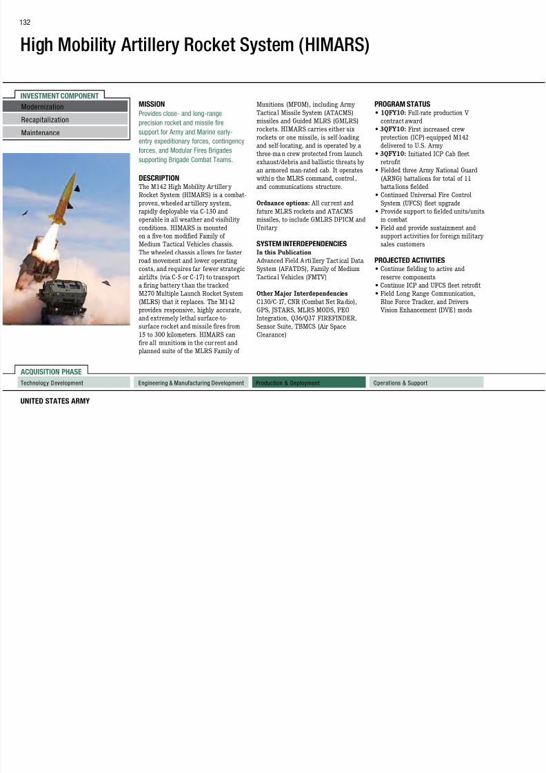
7/29/2019 Army Weapons Systems 2011
http://slidepdf.com/reader/full/army-weapons-systems-2011 142/380
UNITED STATES ARMY
ACQUISITION PHASE
INVESTMENT COMPONENT
Recapitalization
Modernization
Maintenance
Technology Development Operations & SupportProduction & DeploymentEngineering & Manufacturing Development
MISSION
Provides close- and long-rangeprecision rocket and missile fire
support for Army and Marine early-
entry expeditionary forces, contingency
forces, and Modular Fires Brigades
supporting Brigade Combat Teams.
DESCRIPTION The M142 High Mobility Artiller y
Rocket System (HIMARS) is a combat-
proven, wheeled ar tillery system,
rapidly deployable via C-130 and
operable in all weather and visibility
conditions. HIMARS is mounted
on a ve-ton modied Family of
Medium Tactical Vehicles chassis.
The wheeled chassis allows for faster
road movement and lower operating
costs, and requires far fewer strategic
airlifts (via C-5 or C-17) to transport
a firing battery than the tracked
M270 Multiple Launch Rocket System
(MLRS) that it replaces. The M142provides responsive, highly accurate,
and extremely lethal surface-to-
surface rocket and missile fires from
15 to 300 kilometers. HIMARS can
fire all munitions in the cur rent and
planned suite of the MLRS Family of
Munitions (MFOM), including Army
Tactical Missile System (ATACMS)missiles and Guided MLRS (GMLRS)
rockets. HIMARS carries either six
rockets or one missile, is self-loading
and self-locating, and is operated by a
three-ma n crew protected from launch
exhaust/debris and ballistic threats by
an armored man-rated cab. It operates
within the MLRS command, control ,
and communications structure.
Ordnance options: All cur rent and
future MLRS rockets and ATACMS
missiles, to include GMLRS DPICM and
Unitary
SYSTEM INTERDEPENDENCIESIn this Publication
Advanced Field Arti llery Tact ical Data
System (AFATDS), Family of Medium
Tactical Vehicles (FMTV)
Other Major Interdependencies
C130/C-17, CNR (Combat Net Radio),GPS, JSTARS, MLRS MODS, PEO
Integration, Q36/Q37 FIREFINDER,
Sensor Suite, TBMCS (Air Space
Clearance)
PROGRAM STATUS
• 1QFY10: Full-rate production Vcontract award
• 3QFY10: First increased crew
protection (ICP)-equipped M142
delivered to U.S. Army
• 3QFY10: Initiated ICP Cab eet
retrofit
• Fielded three Army National Guard
(ARNG) battalions for total of 11
batta lions fielded
• Continued Universal Fire Control
System (UFCS) eet upgrade
• Provide support to elded units/units
in combat
• Field and provide sustainment and
support activities for foreign military
sales customers
PROJECTED ACTIVITIES• Continue elding to active and
reserve components
• Continue ICP and UFCS eet retrot
• Field Long Range Communication,
Blue Force Tracker, and Drivers Vision Enhancement (DVE) mods
High Mobility Artillery Rocket
System (HIMARS)
133

7/29/2019 Army Weapons Systems 2011
http://slidepdf.com/reader/full/army-weapons-systems-2011 143/380
WEAPON SYSTEMS 2011
FOREIGN MILITARY SALES
Jordan, Singapore, United Arab Emirates
CONTRACTORS
Prime: Lockheed Martin
(Grand Prairie, TX; Camden, AR)Increased Crew Protection (ICP) Cab:
BAE Systems (Sealy, TX)
LIU, WIU, PSU: Harris Corp. (Melbourne, FL)
Chassis: BAE Systems (Sealy, TX)
PNU: L-3 Communications Space &
Navigation (Budd Lake, NJ)
Universal Gun Display Unit:
EFW (Fort Worth, TX)
Controller Assembly; Ball Screw:R&D Electronics (Brownsboro, AL)
Pump, Reservoir, Motor:
Eaton-Vickers (Jackson, MS)
ADU, Boom/Hydraulic Gear Box:
Smiths Industries (Whippany, NJ)
Metal Parts: Beacon Industries (Dallas, TX)
Hydraulic Lines:
Eaton Aeroquip (Jackson, MI)
Reloader Hoist: Breeze (Union, NJ)
Manifolds:
Real Time Labs (Boca Raton, FL)
Geared Bearing: Kaydon (Muskegon, MI)Fire Control System: Various vendors
EMPTY WEIGHT:MAX SPEED:
MAX CRUISING RANGE:
29,800 pounds100 kilometers per hour480 kilometers
High Mobility Engineer Excavator (HMEE) I and III
134

7/29/2019 Army Weapons Systems 2011
http://slidepdf.com/reader/full/army-weapons-systems-2011 144/380
UNITED STATES ARMY
ACQUISITION PHASE
INVESTMENT COMPONENT
Technology Development Operations & SupportProduction & DeploymentEngineering & Manufacturing Development
Recapitalization
Modernization
Maintenance
MISSION
Provides the Army with earthmovingvehicles that support self-deployability,
mobility, and speed to keep pace with
the Brigade Combat Teams (BCTs)
within the future engineer force.
DESCRIPTION The High Mobility Engineer
Excavator Type I (HMEE-I) is a non-
developmental, mi litary-unique vehicle
that wi ll be elded to the Army’s BCTs
and other selected engineer units. The
HMEE-I can travel up to 60 miles per
hour on primary roads and up to 25
miles per hour on secondary roads. The
high mobility of the HMEE-I provides
earthmoving machines capable of
maintaining pace with the Army’s
current combat systems. All HMEE-Is
will be capable of accept ing armor, are
C-130 transportable, and diesel driven.
HMEE-I will meet all Operational
Requirements Document requirementsand replaces Small Emplacement
Excavators (SEEs) in BCTs and
IHMEEs in Stryker BCTs.
The HMEE-III is a commercial-
based backhoe loader with mi litarymodifications that is intended for
units that are relatively stationary
and do not require the speed and
rapid deployability of the HMEE-I. Its
maximum speed is 25 miles per hour
on improved roads, and seven miles
per hour off-road. The HMEE-III is
used by Combat Support Brigades in
support of the Air/Ground Lines of
Communication (A/G LOC) force. Tasks
performed by the HMEE-III include
repair and improvement of roads, trails,
bridges, and airfields.
SYSTEM INTERDEPENDENCIESNone
PROGRAM STATUS
• All ballistics and vehicleperformance testing completed
• FY09: Type classification—standard
and full material release granted
PROJECTED ACTIVITIES• Fielding is ongoing
High Mobility Engineer Excavator
(HMEE) I and III
135

7/29/2019 Army Weapons Systems 2011
http://slidepdf.com/reader/full/army-weapons-systems-2011 145/380
WEAPON SYSTEMS 2011
FOREIGN MILITARY SALES
HMEE-I
New Zealand
CONTRACTORS
OEM:
JCB Inc. (Pooler, GA)
Armor:
ADSI (Hicksville, NY)
Logistics:
XMCO (Warren, MI)
High Mobility Multi-Purpose Wheeled Vehicle (HMMWV)Family of Vehicles
136

7/29/2019 Army Weapons Systems 2011
http://slidepdf.com/reader/full/army-weapons-systems-2011 146/380
UNITED STATES ARMY
ACQUISITION PHASE
INVESTMENT COMPONENT
Recapitalization
Modernization
Maintenance
Technology Development Operations & SupportProduction & DeploymentEngineering & Manufacturing Development
MISSION
Provides a light, tactical, wheeledvehicle for command and control, troop
transport, shelter carrier, ambulance,
towed-weapons prime mover, and
weapons platforms throughout all of the
battlefield or mission areas.
DESCRIPTION The High Mobility Multipurpose
Wheeled Vehicle (HMMW V) is a
lightweight, highly mobile, high
performance, diesel-powered, four-
wheel drive, a ir transportable and air
droppable family of tactical vehicles
that sat isfy Army, Marine Corps, Navy
and Air Force requirements. It can
be reconfigured as a troop car rier,
armament carr ier, shelter carr ier,
ambulance, tube-launched, optically
tracked, wire-guided (TOW) missile
carrier, and scout vehicle.
The HMMWV has incorporated technologica l upgrades; h igher
payload capacity; radial ti res; EPA
emissions updates; commercial
bucket seats; three-point seat belts
and other safety enhancements.
The HMMWV A2 congurat ion
incorporates a four-speed, electronic transmission, a 6.5-liter diesel engine,
and improvements in transportability.
It serves as a platform for other Army
systems such as the Ground-Based
Common Sensor. The heavy variant
has a payload of 4,870 pounds and is
the prime mover for the l ight howitzer
and heavier shelters. The expanded
capacity vehicle (ECV) armament
carrier has a payload capacity of 3,900
pounds, including crew and kits. The
ECV chassis serves as a platform for
mission payloads and for systems that
exceed 4,400 pounds and is used for
the M1114 Up-Armored HMMW V.
The Up-Armored HMMWV was
developed to provide increased ballistic
and blast protection, primarily for
military police, special operations,
and contingency force use. The current
production variants—M1151A1
Armament Carrier, the M1152A1(2-door variant) Troop/Cargo /Shelter
Carrier, the M1165A1 (4-door variant)
Command and Control Carrier and
the M1167 TOW Carrier—are bui lt on
an ECV chassis, providing additional
carry ing capacity for an integrated
armor package (A-Kit) and thecapability to accept add-on-armor kits
(B-Kits). The M1151A1 is currently
fielded with a gunner’s protection kit.
The HMMWV recapitalization program
reconfigures older base models to R1
vehicles with increased capabilit y,
reliability, and maintainability.
SYSTEM INTERDEPENDENCIESNumerous data interchange customers
use the HMMWV to mount shelters and
other systems. The M1101/1102 Light
Tactical Trailer is the designed tra iler
for this vehicle.
PROGRAM STATUS• Fielding of ECV HMMWVs to Army,
Marine Corps, Navy, Air Force, and
foreign military sa les customers
• Recapitalization of older model
HMMWVs
• Continued product improvement in
response to Army requirements
PROJECTED ACTIVITIES• Introduce upgraded components in
response to Army requirements
High Mobility Multi-Purpose
Wheeled Vehicle (HMMWV)
Family of Vehicles
137

7/29/2019 Army Weapons Systems 2011
http://slidepdf.com/reader/full/army-weapons-systems-2011 147/380
WEAPON SYSTEMS 2011
FOREIGN MILITARY SALES
Afghanistan, Argentina, Bahrain, Bolivia,
Chad, Colombia, Djibouti, Ecuador,Egypt, Ethiopia, Honduras, Israel, Kuwait,
Luxembourg, Mexico, Oman, Philippines,
Saudi Arabia, Sudan, Taiwan, Tanzania,
Tunisia, Uganda
CONTRACTORS
Prime: AM General (South Bend, IN)
Armored Doors: Demmer (Lansing, MI)Engine: GEP (Franklin, OH)
AC Units: Acme Radiator (Goshen, IN)
Stamping: Modineer Co. Inc. (Niles, MI)
Defiance (Defiance, OH)Transmission: GTP (Hillside, IL)
Underbody: ESA Mfg (Williamston, MI)Alternator: C.E. Niehoff & Co.
(Evanston, IL)
Seat Belt: Conax (St. Petersburg, FL)Aluminum Sheet: Kaiser Aluminum
(Chicago, IL)
Improved Environmental Control Units (IECU)
138

7/29/2019 Army Weapons Systems 2011
http://slidepdf.com/reader/full/army-weapons-systems-2011 148/380
UNITED STATES ARMY
ACQUISITION PHASE
INVESTMENT COMPONENTMISSION
Provides standardized environmentalcontrol capabilities to the Department
of Defense (DoD) in support of
national security.
DESCRIPTION The Improved Environmental Control
Units (IECU) program consists of four
standard sizes: 9,000 BTUH (British
thermal units per hour); 18,000 BTUH;
36,000 BTUH; and 60,000 BTUH; all
in five configurations. Once fielded,
these systems will prov ide critical
cooling to vita l command, control,
communications, computers, and
intelligence (C4I) and other military
electronic and support systems
equipment for the U.S. Army and the
wider DoD. The IECUs:
• Use R-410A refrigerant, a
commercial i ndustry standard
that is complia nt with al l current
environmental legislative
requirements• Increase reliability and decrease
weight and power consumption
compared to current military
standard systems
• Leverage current industry standards
while being ruggedized for militaryenvironments
• Are organically supportable
• Are fully operable up to +125
degrees Fahrenheit
• Provide quality cooling, heating, and
dehumidification for command posts;
command, control, communications,
computers, intelligence, surveillance,
and reconnaissance (C4ISR)
systems; weapon systems; and
other battlefield support equipment
while using a non-ozone-deplet ing
refrigerant
Additiona l improvements to the
warghter in theatre are the IECU’s
soft start and limited inrush current;
nuclear, biological, and chemical
compatible and electromagnetic
interference protected interface; fully
embedded diagnostics; automatic
safety controls; and remote control
capability for operations that requireusers to be out of the direct area.
SYSTEM INTERDEPENDENCIESNone
PROGRAM STATUS
• FY09–10: Low-rate initialproduction of 60,000 BTUH IECU
• FY09–10: Engineering and
manufacturing development (EMD)
Phase I for 9,000, 18,000, 36,000
BTUH family of IECUs
• 3QFY10: Receive full materiel
release and a full-rate production
decision for the 60,000 BTUH IECU
• 4QFY10: Competitively “downselect”
vendor and continue EMD Phase
II for 9,000, 18,000, 36,000 BTUH
family of IECUs
PROJECTED ACTIVITIES• FY10–11: EMD Phase II for 9,000,
18,000, 36,000 BTUH family of
IECUs
• FY10–11: Production and fielding of
60,000 BTUH IECU
Recapitalization
Modernization
Maintenance
Technology Development Operations & SupportProduction & DeploymentEngineering & Manufacturing Development
Improved Environmental Control
Units (IECU)
139

7/29/2019 Army Weapons Systems 2011
http://slidepdf.com/reader/full/army-weapons-systems-2011 149/380
WEAPON SYSTEMS 2011
FOREIGN MILITARY SALES
None
CONTRACTORS
9,000, 18,000, 36,000 BTUH IECU
Competitor (EMD Phase I):
Hunter Defense Technologies (Solon, OH )
9,000, 18,000, 36,000 BTUH IECU
Competitor (EMD Phase I):
Mainstream Engineering ( Rockledge, FL)
60,000 BTUH IECU:
DRS-ESI (Florence, KY)
Improved Ribbon Bridge (IRB)
140

7/29/2019 Army Weapons Systems 2011
http://slidepdf.com/reader/full/army-weapons-systems-2011 150/380
UNITED STATES ARMY
ACQUISITION PHASE
INVESTMENT COMPONENT
Recapitalization
Modernization
Maintenance
Technology Development Operations & SupportProduction & DeploymentEngineering & Manufacturing Development
MISSION
Improves mobility by providingcontinuous roadway or raft capable of
crossing military load classification 96
(wheeled)/80 (tracked) vehicles over
non-fordable wet gaps.
DESCRIPTION The Improved Ribbon Bridge (IRB)
Float Ribbon Bridge System is issued
to the Multi-Role Bridge Company
(MRBC). The U.S. Army Modied
Table of Organization and Equipment
(MTOE) authorizes MRBCs to consist
of: 42 IRB bridge bays (30 interior
bays and 12 ramp bays), 42 Bridge
Adapter Pal lets (BAP), 14 Bridge
Erection Boats (BEB), 14 Improved
Boat Cradles (IBC), and 56 Common
Bridge Transporters (CBT). These
assets collectively address Tactical
Float Ribbon Bridge “wet gap”
bridging. All components are required
to transport, launch, erect, andretrieve up to 210 meters of floating
bridge per company. The IRB can be
configured as either a continuous “full
closure” bridge or assembled and used
for rafting operations. The IRB has a
Military Load Capacity (MLC) of 105
wheeled/85 tracked (normal) and 110
wheeled/90 tracked (caut ion) vehicles. This MLC wi ll support the Joint force
commander’s ability to employ and
sustain forces worldwide. The IRB is
used to transport weapon systems,
troops, and supplies over water when
permanent bridges are not available.
Bridge capabilities are provided in
water currents moving at up to 10 feet
per second.
The bridge system allows two-way
trafc for HMMWV-width vehicles and
increased MLC at all water current
speeds over those of Standard Ribbon
Bridge. It is usable on increased bank
heights over 2.2 meters (7.2 feet)
and the improved folding/unfolding
mechanism avoids cable breakage.
Partially disassembled bays are C-130
transpor table, while a re externally
transpor table by CH-47 and CH-53.
SYSTEM INTERDEPENDENCIESOther Major Interdependencies
IRB operations rely and are
interdependent upon fully mission-
capable CBTs, BAPs, IBCs, and BEB
assets within a fully MTOE-equipped
MRBC.
PROGRAM STATUS
This system has been fielded since2002.
• 1QFY10: 2225th MR BC
• 3QFY10: 957th MRBC
• 3QFY10: 164th RTI
• 4QFY10: 1041st MRBC
PROJECTED ACTIVITIESFieldings are ongoing based on the
Army Requirements Priorit ization List .
• 1QFY11: 189th and 401st MRBCs
• 2QFY11: 132nd and 551st MRBCs
• 3QFY11: 35th EN TNB BDE
Improved Ribbon Bridge (IRB)
141

7/29/2019 Army Weapons Systems 2011
http://slidepdf.com/reader/full/army-weapons-systems-2011 151/380
WEAPON SYSTEMS 2011
FOREIGN MILITARY SALES
None
CONTRACTORS
General Dynamics European Land
Systems–Germany (GDELS-G)
(Kaiserslautern, Germany)
Logistic support:
AM General (AMG) (Livonia, MI)
CBT manufacturer:
Oshkosh Corp. (Oshkosh, WI)BEB manufacturer:
FBM Babcock Marine (Isle of Wight, United
Kingdom)
Improved Target Acquisition System (ITAS)
142

7/29/2019 Army Weapons Systems 2011
http://slidepdf.com/reader/full/army-weapons-systems-2011 152/380
UNITED STATES ARMY
ACQUISITION PHASE
INVESTMENT COMPONENT
Technology Development Operations & SupportProduction & DeploymentEngineering & Manufacturing Development
MISSION
Provides long-range sensor and
anti-armor/precision assault fire
capabilities, enabling the Soldier to
shape the battlefield by detecting and
engaging targets at long range with
tube-launched, optically tracked, wire-guided (TOW) missiles or directing the
employment of other weapon systems
to destroy those targets.
DESCRIPTION The Improved Target Acquis ition
System (ITAS) is a multipurpose
weapon system, used as a
reconnaissance, surveillance, and
target acquisit ion sensor. ITAS
provides long-range anti-armor/ precision assault fire capabilities to the
Army’s Infantry and Stryker Brigade
Combat Teams (BCTs) as well as to
the Marine Corps. ITAS is a major
product upgrade that greatly reduces
the number of components, minimizing
logistics support and equipmentrequirements. Built-in diagnostics and
improved interfaces enhance target
engagement performance.
ITAS’s second-generation forward-
looking infrared sensors double
the long-range surveillance of its
predecessor, the M220 TOW system.
It offers improved hit probability
with aided target tracking, improved
missile flight software algorithms,
and an elevation brake to minimize
launch transients. The ITAS includes
an integrated far target location
capability (day/night sight with laser
rangefinder), a position attitude
determination subsystem, a fire-control
subsystem, a lithium-ion battery power
source, and a modified traversing
unit. Soldiers can also detect and
engage long-range targets with TOW
missiles or, using the ITAS far-target
location (FTL) enhancement, directother res to destroy them. The FTL
enhancement consists of a position
attitude determination subsystem
(PADS) that provides the gunner with
his own Global Positioning System
(GPS) location and a 10-digit grid
location to his target through the useof differential GPS. With the PAQ-
4/PEQ-2 Laser Pointer, ITAS can
designate .50 caliber or MK-19 grenade
engagements. The ITAS can fire all
versions of the TOW family of missiles.
The TOW 2B Aero and the TOW
Bunker Buster have an extended
maximum range to 4,500 meters. The
TOW 2B Aero flies over the target
(off-set above the gunner’s aim point)
and uses a laser profilometer and
magnetic sensor to detect and fire two
downward-directed, explosively formed
penetrator warheads into the target.
TOW Bunker Buster, with its high-
explosive blast-fragmentation warhead,
is optimized for performance against
urban structures, ear then bunkers,
field fortifications, and light-skinned
armor threats. ITAS operates from the
High Mobility Multipurpose Wheeled
Vehicle (HMMWV), the dismount tripod platform, and Str yker anti-tank
guided missile (ATGM) vehicles.
SYSTEM INTERDEPENDENCIES
The ITAS system is integrated on the M1121/1167 HMMWV and the
Stryker ATGM. The ITAS system is the
guidance for the TOW missile.
PROGRAM STATUS• Current: ITAS has been fielded to
19 active and 10 reserve component
Infantry BCTs and seven Stryker
BCTs
• Current: The Marine Corps has
begun fielding the ITAS to infantry
and tank battal ions to replace all
Marine Corps M220A4 TOW 2
systems by 2012
PROJECTED ACTIVITIES• Continue: ITAS total package
fielding
• FY12: Complete Fielding
Recapitalization
Modernization
Maintenance
Improved Target Acquisition System
(ITAS)
143

7/29/2019 Army Weapons Systems 2011
http://slidepdf.com/reader/full/army-weapons-systems-2011 153/380
WEAPON SYSTEMS 2011
FOREIGN MILITARY SALES
NATO Maintenance and Supply Agency,
Canada
CONTRACTORS
Raytheon (McKinney, TX)
Training Devices:
Intercoastal Electronics (Mesa, AZ)
Installation Protection Program (IPP)
144
7/29/2019 Army Weapons Systems 2011
http://slidepdf.com/reader/full/army-weapons-systems-2011 154/380
UNITED STATES ARMY
ACQUISITION PHASE
INVESTMENT COMPONENT
Technology Development Operations & SupportProduction & DeploymentEngineering & Manufacturing Development
MISSION
Provides an effective chemical,
biological, radiological, and nuclear
(CBRN) protection, detection,
identification, and warning system for
military installations.
DESCRIPTION The Instal lation Protection Program
(IPP) will allow Department of Defense
installations to effectively protect
personnel and critical operations
against a CBRN event, to effectively
respond with trained and equipped
emergency personnel, and to ensure
installations can continue critical
operations during and a fter an attack.
IPP uses a tiered approach of
government and commercial off-
the-shelf capabili ties optimized for
an installat ion. The Baseline Tier
provides a foundation for installations
to maintain a standard level of
preparedness for a CBRN incident.
This tier consists of non-materielsolutions that address militar y-
civilian interoperability, system
architecture, policy, doctrine, training,
and administration. It includes Joint
training products, pla nning templates,
Mutual Aid Agreement templates, and
exercise templates and scenarios. The
IPP Portal (IP3) makes these solutions
available through Joint Knowledge
Online (JKO) and A rmy Knowledge
Online (AKO) at https://www.us.army.
mil/suite/page/449823 or through a
link on the Joint Acquisition CBRN
Knowledge System (JACKS) website at
https://jacks.jpeocbd.osd.mil.
Tier 1 focuses on enhancing an
installation’s existing emergency
responder capabilities and enables
an installation to prepare, respond,
and transfer the mission after a
CBRN attack. Tier 1 installations are
critical to the overall accomplishmentof the national military strategy or
installations that provide combat
service support. Tier 1 includes all
Baseline Tier capabilities and adds
individual protective equipment
for emergency responders and first
receivers; portable radiological
and chemical detection equipment;portable biological collectors with
analysis and identification laboratory
support; personal dosimeters; hazard
marking and controlling equipment;
medical countermeasures for first
responders/receivers; mass casualty
decontamination showers and tents;
mass casualty litters a nd support
equipment; mass notification systems;
an incident management system; and
new equipment training and field
exercise support.
Tier 2 applies to installations hosting
one-of-a-kind, critical strategic
missions or capabilities. The objective
of Tier 2 is to provide installations
with the capabilit y to prepare, react,
and continue critical missions or
capabilities without significant
interruption. The Tier 2 capability
package includes Baseline and Tier
1 capabilities plus fixed chemicaldetectors for warfare agents and toxic
industrial materials/chemicals; fixed
biological collectors with analysis
and identification laboratory support;
radiological monitoring equipment for
entry controllers; collective protection
for one of a kind strategic assets (up
to 3,000 square feet); a nd a decisionsupport system of software tools and
networked sensors.
SYSTEM INTERDEPENDENCIESNone
PROGRAM STATUS• 4QFY10: Complete 18 additional
installations
PROJECTED ACTIVITIES• 4QFY11: Complete 16 additional
installations
Recapitalization
Modernization
Maintenance
Installation Protection Program
(IPP)
145
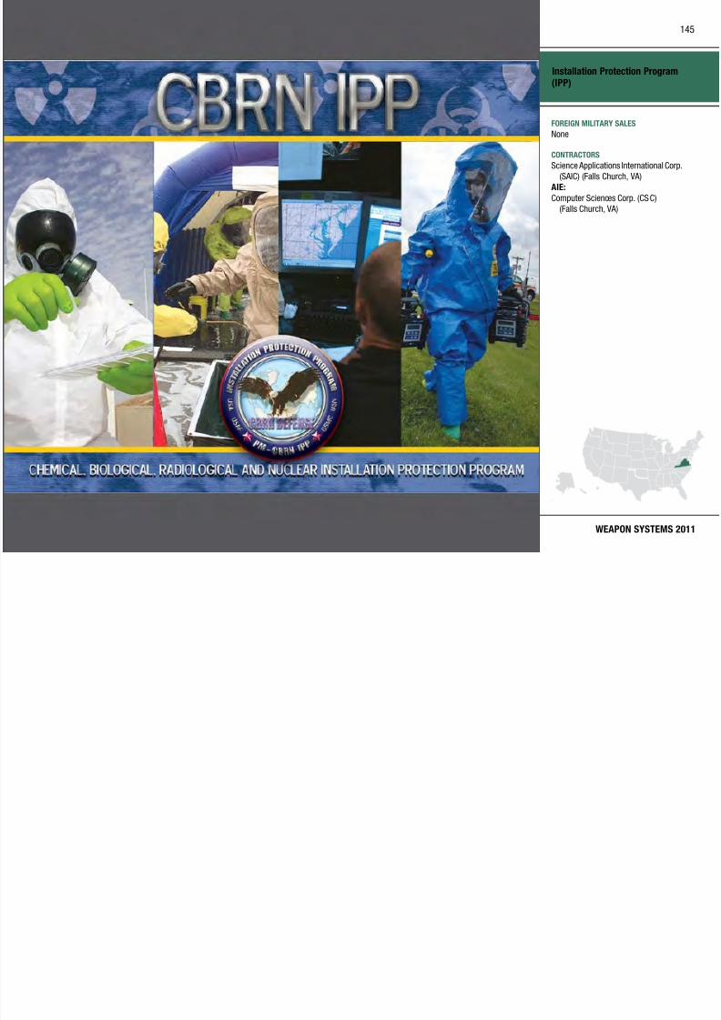
7/29/2019 Army Weapons Systems 2011
http://slidepdf.com/reader/full/army-weapons-systems-2011 155/380
WEAPON SYSTEMS 2011
FOREIGN MILITARY SALES
None
CONTRACTORS
Science Applications International Corp.
(SAIC) (Falls Church, VA)
AIE:
Computer Sciences Corp. (CSC)
(Falls Church, VA)
Instrumentable–Multiple Integrated Laser Engagement System(I-MILES)
146

7/29/2019 Army Weapons Systems 2011
http://slidepdf.com/reader/full/army-weapons-systems-2011 156/380
UNITED STATES ARMY
ACQUISITION PHASE
INVESTMENT COMPONENT
Technology Development Operations & SupportProduction & DeploymentEngineering & Manufacturing Development
MISSION
Provides force-on-force and force-
on-target collective training at
home stations and Combat Training
Centers (CTCs).
DESCRIPTION The Instrumentable–Multiple Integrated
Laser Engagement System (I-MILES)
is the Army’s primary live simulation
system and is composed of several
component systems. I-MILES products
include man-worn systems, combat
vehicle systems, target systems,
shoulder-launched systems, and
controller devices. The system operates
within a live, virtual, and constructive
integrated architecture that supports
Army and Joint exercises.
The I-MILES Combat Vehicle Tactical
Engagement Simulation System
(CV TESS) provides live training devices
for armored vehicles with fire control
systems including Bradley Fighting
Vehicles and Abrams Tanks. It interfaces
and communicates with CTCs and homestation instrumentation, providing
casualty and battlefield damage
assessments for after-action reporting.
I-MILES CV TESS provides real-time
casualty effects necessary for tactical
engagement training in direct fire
force-on-force and instrumented training
scenarios.
The I-MILES Individual Weapons
System (IWS) is a man-worn dismounted
system, providing event data that can
be downloaded for use in an after action
review and training assessment. The
IWS replaces Basic MILES IWS at home
stations and Maneuver CTCs Army-wide.
The Tactical Vehicle Systems (TVS)
encompasses the Wireless Independent
Target System (WITS) and replaces the
previously fielded Independent Target
System (ITS) and other Basic MILES
currently fielded on non-turret military vehicles. TVS/WITS designs include
Stryker variants, tactical wheeled
vehicle configurations, and a separate
configuration for tracked/oversized
vehicles such as the M113 and Mine
Resistant Ambush Protected vehicles.
The Shoulder Launched Munitions (SLM)
replaces Basic MILES and provides better training fidelity for blue forces’
AT4 weapons and threat weapons
using opposing force RPG7 visual
modifications.
The Universal/Micro Controller Devices
(UCD/MCD) are low-cost, lightweight
devices used by observer controllers and
maintenance personnel to initialize, set
up, troubleshoot, reload, reset, resurrect,
and manage participants during live
force-on-force train ing exercises. These
modular, self-contained devices interact
and provide administrative control of all
other MILES devices.
SYSTEM INTERDEPENDENCIESNone
PROGRAM STATUSIWS:
• Current: Fielded approximately
14,000 IWS kits to the National Training Center (NTC) and over
54,000 kits Army-wide
MXXI CVS:
• Current: Fielded over 400 systems to
the NTC and Joint Readiness Train ing
Center.
SLM:
• Current: Fielded over 1,000 SLM kits to NTC and over 5,400 kits Army-wide
UCD/MCD:
• Current: Fielded over 12,000 CD kits
Army-wide
TVS/ WITS:
• Current: Fielded approximately 2,000
WITS kits to var ious home stations
• 4QFY10: TVS cont ract award
PROJECTED ACTIVITIESIWS and SLM:
• FY11: Full and open competition for
recompete
UCD/MCD:
• FY11: Complete basis of issue
CV TESS:
• FY11: Full and open competition for
recompete
TVS/ WITS:
• FY11: TVS w ill complete testing and
start fielding; WITS will complete
fielding to outside continental United
States (U.S. Army, Europe, andKorea)
Recapitalization
Modernization
Maintenance
Instrumentable–Multiple Integrated
Laser Engagement System (I-MILES)
147

7/29/2019 Army Weapons Systems 2011
http://slidepdf.com/reader/full/army-weapons-systems-2011 157/380
WEAPON SYSTEMS 2011
FOREIGN MILITARY SALES
None
CONTRACTORS
IWS:
CUBIC Defense Sys. (San Diego, CA)
WITS:
Lockheed Martin (Orlando, FL)TVS:
CUBIC Defense Systems (San Diego, CA)
MXXI CVS:
Lockheed Martin (Orlando, FL)
SLM:
Lockheed Martin (Orlando, FL)
CV TESS:In competition
Integrated Air and Missile Defense (IAMD)
148

7/29/2019 Army Weapons Systems 2011
http://slidepdf.com/reader/full/army-weapons-systems-2011 158/380
UNITED STATES ARMY
ACQUISITION PHASE
INVESTMENT COMPONENT
MISSION
Provides the full combat potential of
an Integrated Air and Missile Defense
capability through a network-centric
“plug and fight” architecture at the
component level (e.g., launchers and
sensors) and a common command andcontrol (C2) system.
DESCRIPTION Army Integrated Air and Missi le
Defense (IAMD) will enable the
integration of modular components
(current and future AMD sensors,
weapons, and C2) with a common
C2 capability in a networked
and distributed “plug and fight”
architecture. This common C2,called the IA MD Battle Command
System (IBCS), will provide standard
configurations and capabilities at each
echelon. This allows Joint, interagency,
intergovernmental, and multinational
(JIIM) AMD forces to organize
based on mission, enemy, terrain and weather, troops and support avai lable,
time available, and civil considerations
(METT-TC). Shelters and vehicles may
be added to enable broader missions
and a wider span of control executed
at higher echelons. A network-
enabled “plug and fight” architecture
and common C2 system will enable
dynamic defense design and task
force reorganization, and provide the
capability for interdependent, network-
centric operations that link joint IAMDprotection to the supported force
scheme of operations and maneuver.
This Army IAMD system-of-systems
will enable extended range and non-
line-of-sight engagements across
the full spectrum of aerial threats,
providing fire control quality data
to the most appropr iate weapon to
successfully complete the mission.
Furthermore, it will mitigate thecoverage gaps and the single points of
failure that have plagued AMD defense
design in the past as well as reduce
manpower, enhance t raining, and
reduce operation and support costs.
SYSTEM INTERDEPENDENCIES
In this PublicationEarly Infantry Brigade Combat Team
(E-IBCT), Joint Land Attack Cruise
Missile Defense Elevated Netted Sensor
System (JLENS), Joint Tactical Ground
Stations (JTAGS), Surface Launched
Advanced Medium Range Air-to-Air
Missile (SLAMRAAM)
Other Major Interdependencies
ABCS, AEGIS, AWACS, BCS, BMDS,
CAC2S, C2BMC Planner, DD(X), E-2C,
Improved Sentinel, MEADS, Patriot, THAAD
PROGRAM STATUS• 4QFY07: Approval of two-contractor
competition strategy
• 1QFY08: Approval of acquisition
strategy
• 2QFY08: Request for proposal
released
• 4QFY08: IAMD Battle Command
System contract award• 1QFY10: Milestone B approval to
enter engineering and manufacturing
development
• 1QFY10: Down-select to single IBCS
development prime contractor
• 2QFY10: Award of A-Kit design and
development contract
PROJECTED ACTIVITIES• 4QFY11: IAMD Increment 2 critical
design review
• 1QFY12: Defense Acquisition Board
in process review
• 1QFY15: Milestone C
Recapitalization
Modernization
Maintenance
Technology Development Operations & SupportProduction & DeploymentEngineering & Manufacturing Development
Integrated Air and Missile Defense
(IAMD)
149

7/29/2019 Army Weapons Systems 2011
http://slidepdf.com/reader/full/army-weapons-systems-2011 159/380
WEAPON SYSTEMS 2011
FOREIGN MILITARY SALES
None
CONTRACTORS
IBCS Development:
Northrop Grumman (Huntsville, AL)
A-Kit Design and Development:
Raytheon (Andover, MA; Tewksbury, MA)SETA Support:
DMD (Huntsville, AL)
Integrated Family of Test Equipment (IFTE)
150

7/29/2019 Army Weapons Systems 2011
http://slidepdf.com/reader/full/army-weapons-systems-2011 160/380
UNITED STATES ARMY
ACQUISITION PHASE
INVESTMENT COMPONENT
Technology Development Operations & SupportProduction & DeploymentEngineering & Manufacturing Development
MISSION
Develops, acquires, fields, and sustains
automatic test equipment with the
capability to troubleshoot, isolate, and
diagnose faults, as well as verify the
operational status of the weapon system.
DESCRIPTION The Integrated Family of Test
Equipment (IFTE) consists of
interrelated, integrated, mobile,
tactical, and man-portable systems.
These rugged, compact, lightweight,
general-purpose systems enable
verification of the operationa l status
of weapon systems, as well as fault
isolation to the line-replaceable unit at
all maintenance levels, both on and off the weapon system plat form. IFTE is a
Early Infantry Brigade Combat Team
(E-IBCT) Associate Program.
Base Shop Test Facility–Version 3
(BSTF(V)3): The BSTF(V )3 is an off plat form
automatic test system which tests
electronic Line Replaceable Units
(LRU) and Shop Replaceable Units
(SRU) of ground and aviation systems.
Electro-Optics Test Facility (EOTF):
The EOTF tests the full range of Army
electro-optical systems, including
laser transmitters, receivers, spot
trackers, forward-looking infrared
systems, and television systems. It isfully mobile with V XI instrumentation,
touch-screen operator interface, and an
optical disk system for test program
software and electronic technical
manuals.
Next Generation Automatic Test
Station (NGATS):
The NGATS is the follow-on
reconfigurable, rapidly deployable,
expeditionary interoperable testerand screener that supports Joint
operations, reduces logistics footprint,
and replaces/consolidates obsolete,
unsupportable automatic test
equipment in the Army’s inventory.
Maintenance Support Device–
Version 3 (MSD-V3) : The latest generation MSD is a
lightweight, rugged, compact, man-
portable, general-purpose, at system
automatic tester that has a docking
station, detachable core tablet, and
swivel and touch screen capabilities. It
is used to verify the operational status
of aviation, automotive, electronic, and
missile weapon systems and to isolate
faulty components for immediate
repair or replacement. MSD-V3 hosts
Interactive Electronic TechnicalManuals and the Digital Logbook, is
used as a software uploader/verifier
to provide or restore mission software
to weapon systems, and supports
condition-based maintenance data
collection and reporting. MSD-V3
supports more than 50 weapon systems
and is used by more than 40 military
occupational specialties.
SYSTEM INTERDEPENDENCIESNone
PROGRAM STATUS
• 3QFY09: NGATS Milestone C• 3QFY09: NGATS Milestone C low-
rate initial production (LRIP)
• 4QFY09: MSD-V3 contract award
• 1QFY10: NGATS LRIP
• Current: MSD-V2 production and
fielding
• Current: EOTF operations and
support
PROJECTED ACTIVITIES• 1QFY11: MSD-V3 production and
fielding • 2QFY12: NGATS first unit equipped
Recapitalization
Modernization
Maintenance
Integrated Family of Test
Equipment (IFTE)
151

7/29/2019 Army Weapons Systems 2011
http://slidepdf.com/reader/full/army-weapons-systems-2011 161/380
WEAPON SYSTEMS 2011
Next Generation Automatic Test Station (NGATS)
Maintenance Support Device-
Version 3 (Type 1) with docking station
Maintenance Support Device-
Version 3 (Type 1) laptop only
FOREIGN MILITARY SALES
MSD:
Afghanistan, Australia, Bahrain, Chile,
Djibouti, Egypt, Ethiopia, Germany, Israel,
Iraq, Jordan, Korea, Kuwait, Lithuania,
Macedonia, Morocco, Netherlands, Oman,
Poland, Portugal, Saudi A rabia, Taiwan,
Turkey, United Arab Emirates, Uzbekistan,
Yemen
CONTRACTORS
MSD-V3:
Vision Technology Miltope Corp.
(Hope Hull, AL)
BSTF(V)3:Northrop Grumman (Rolling Meadows, IL)
EOTF:
Northrop Grumman (Rolling Meadows, IL)
NGATS:
Northrop Grumman (Rolling Meadows, IL)
DRS-TEM (Huntsville, AL)
Interceptor Body Armor
152

7/29/2019 Army Weapons Systems 2011
http://slidepdf.com/reader/full/army-weapons-systems-2011 162/380
UNITED STATES ARMY
ACQUISITION PHASE
INVESTMENT COMPONENT
Recapitalization
Modernization
Maintenance
Technology Development Operations & SupportProduction & DeploymentEngineering & Manufacturing Development
MISSION
Increases warfighter lethality andmobility by optimizing Soldier
protection while effectively managing
all lifecycle aspects of personal
protective equipment.
DESCRIPTIONInterceptor Body Armor (IBA) is
modular, multiple-threat body armor
with components consisting of an
Improved Outer Tactical Vest (IOTV);
two Enhanced Small Arms ProtectiveInserts (ESAPI); two Enhanced Side
Ballistic Inserts (ESBI); and Deltoid
Protectors (DP).
Eleven sizes of IOTVs and ve sizes
of ESAPI plates are being fielded. The
basic system weight (IOTV, ESAPI,
ESBI, size medium) is 31 pounds and
provides increased area coverage and
greater protection. The medium IOTV,
without plates, weighs 15 poundsand protects aga inst fragmentation
and 9mm rounds. The ESAPI plates
provide additional protection and
can withstand multiple small arms
hits. IBA includes attachable throat,
groin, and neck protectors. It also
has webbing attachment loops on thefront and back of the vest for attaching
pouches for the Modular Lightweight
Load-Carry ing Equipment (MOLLE).
DP provide additional protection from
fragmentary and 9mm projectiles to
the upper arm.
During Operation Iraqi Freedom
combat operations, the side areas not
covered by the ESAPI component of
the IBA were identified by combat
commanders and medical personnelas a vulnerability that needed to
be addressed. To meet this threat
and provide an increased level of
protection, the ESBI was developed.
Commanders have the exibility to
tai lor the IBA to meet the specific
mission needs or changing threat
conditions.
SYSTEM INTERDEPENDENCIES
None
PROGRAM STATUS• Current: In production and being
fielded
• 4QFY10: 402,400 IOTVs and
943,101 ESAPI sets elded
PROJECTED ACTIVITIES• Continue: Fielding
Interceptor Body Armor
153

7/29/2019 Army Weapons Systems 2011
http://slidepdf.com/reader/full/army-weapons-systems-2011 163/380
WEAPON SYSTEMS 2011
FOREIGN MILITARY SALES
None
CONTRACTORS
Armacel Armor (Camarillo, CA)
Ceradyne, Inc. (Costa Mesa, CA)
UNICOR Protective Materials Company
(Miami Lakes, FL)
BAE Systems (Phoenix, AZ)
ArmorWorks (Chandler, AZ)
KDH Defense Systems (Johnstown, PA)
MSA Armor and Equipment (St. Pauls, NC)
Point Blank Solutions
(Pompano Beach, FL)
The Protective Group (Miami Lakes, FL)
Javelin
154

7/29/2019 Army Weapons Systems 2011
http://slidepdf.com/reader/full/army-weapons-systems-2011 164/380
UNITED STATES ARMY
ACQUISITION PHASE
INVESTMENT COMPONENT
Recapitalization
Modernization
Maintenance
Technology Development Operations & SupportProduction & DeploymentEngineering & Manufacturing Development
MISSION
Provides the dismounted Soldier a man-portable, fire-and-forget system that
is highly lethal against targets ranging
from main battle tanks to fleeting
targets of opportunity found in current
threat environments facing the Army.
DESCRIPTION The Close Combat Missile System–
Medium (CCMS-M) Javelin is highly
effective against a variety of targets
at extended ranges under day/night, battlefield obscurants, adverse
weather, and multiple counter-measure
conditions. The system’s soft-launch
feature permits firing from enclosures
commonly found in complex urban
terrain. Javelin’s modular design
allows the system to evolve to meet
changing threats and requirements via
both software and hardware upgrades.
The system consists of a reusable
command launch unit (CLU) witha built-in-test (BIT), and a modular
missile encased in a disposable launch
tube assembly. The CLU provides
stand alone all weather and day/night
surveillance capability ideally suited
for infantry operations in Afghanistan.
The Javelin missi le and CLU together
weigh 48.8 pounds. The system alsoincludes training devices for t actical
training and classroom training.
Javelin’s fire-and-forget technology
allows the gunner to fire and
immediately take cover, to move
to another fight ing position, or to
reload. The Javelin provides enhanced
lethality through the use of a tandem
warhead that will defeat all known
armor threats. It is effective against
both stat ionary and moving targets. This system also provides defensive
capability against attacking/hovering
helicopters. The performance
improvements in current production
Javelin Block I CLUs are: increased
target identificat ion range, increased
surveillance time with new battery and
software management of the “on” time,
and external RS-170 interface for video
output. The performance improvements
in current production Javelin BlockI missiles are: increased probability
of hit/kill at 2,500 meters, improved
warhead lethalit y, and reduced time
of flight. In current conflicts the
CLU is being used as a stand-alone
surveillance and ta rget acquisition
asset. The Army is the lead for this
joint program with the Marine Corps. Javelin is a complementary system as
the lethal ity solution for the Armed
Robotic Vehicle–Assault (Light).
SYSTEM INTERDEPENDENCIESNone
PROGRAM STATUS• 3QFY07: Received full materiel
release on Block I CLU
• 4QFY08: Received full materiel
release on Block I missile• Current: Missile and CLU production
• Current: CLU total package elding
• Current: Javelin has been fielded to
more than 95 percent of active duty
units; fielding is underway to the
National Guard
PROJECTED ACTIVITIES• Continue: A Multipurpose Warhead
is planned to improve lethality
against irregular/soft targets• Continue: CLU production
• Continue: CLU total package
fielding
• Continue: Missile production
Javelin
155

7/29/2019 Army Weapons Systems 2011
http://slidepdf.com/reader/full/army-weapons-systems-2011 165/380
WEAPON SYSTEMS 2011
FOREIGN MILITARY SALES
Australia, Czech Republic, France, Ireland,
Jordan, Lithuania, New Zealand, Norway,
Oman, Taiwan, United Arab Emirates,
United Kingdom
CONTRACTORS
CLU: Raytheon Missile Systems (Tucson,
AZ); DRS Technologies (Dallas, TX);
Raytheon (McKinney, TX; Dallas, TX;
Garland, TX)GEU: Raytheon Missile Systems (Tucson,
AZ); Raytheon (McKinney, TX;
Dallas TX; Garland, TX)
ESAF/Seeker: Lockheed Martin(Orlando, FL; Ocala, FL)
FPA: DRS Technologies (Dallas, TX)Propulsion Unit: Aerojet (Camden, AR)
Missile Final Assembly: Lockheed
Martin (Troy, AL)FTT, EPBST: ECC International (Orlando, FL)
Batteries: Acme Electric (Tempe, AZ)
Precursor Whd: General Dynamics Ordnance
and Tactical Systems (Camden, AR)
Containers: Independent Pipe Products
(Grand Prairie, TX)
Test Support: Javelin Joint Venture(Huntsville, AL)
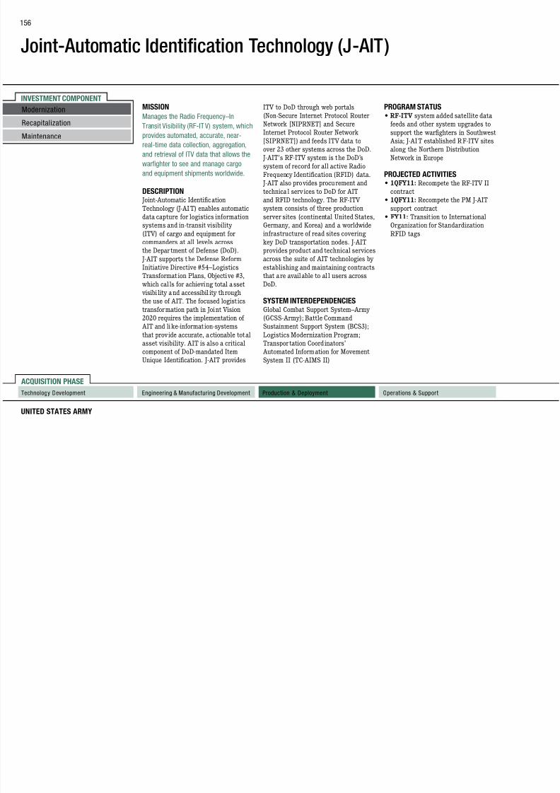
7/29/2019 Army Weapons Systems 2011
http://slidepdf.com/reader/full/army-weapons-systems-2011 166/380
Joint-Automatic Identification
Technology (J-AIT)
157
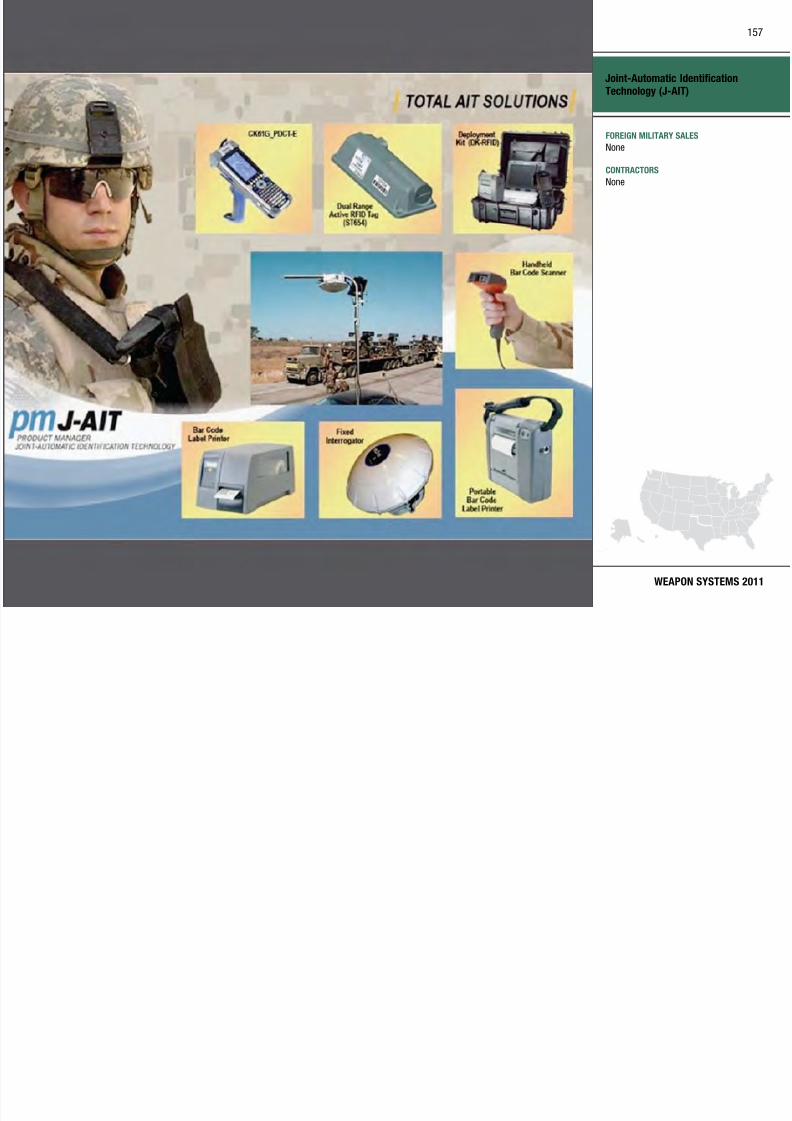
7/29/2019 Army Weapons Systems 2011
http://slidepdf.com/reader/full/army-weapons-systems-2011 167/380
WEAPON SYSTEMS 2011
FOREIGN MILITARY SALES
None
CONTRACTORS
None
Joint Air-to-Ground Missile (JAGM)
158

7/29/2019 Army Weapons Systems 2011
http://slidepdf.com/reader/full/army-weapons-systems-2011 168/380
UNITED STATES ARMY
ACQUISITION PHASE
INVESTMENT COMPONENT
Recapitalization
Modernization
Maintenance
Technology Development Operations & SupportProduction & DeploymentEngineering & Manufacturing Development
MISSION
Provides a single variant, precision-guided, air-to-ground weapon for use
by Joint service manned and unmanned
aircraft to destroy stationary and
moving high-value land and naval
targets.
DESCRIPTION The Joint Air-to-Ground Missile ( JAGM)
System is a precision guided munition
(PGM) for use on Joint rotary and fixed
wing platforms and unmanned aer ialsystems (UAS) to destroy high-value
stationary, moving, and relocatable
land and naval targets. JAGM is the
intended replacement for HELLFIRE,
air-launched TOW and Maverick
families of missiles.
JAGM will increase the warfighter’s
operational flexibility by effectively
engaging a variety of stationary and
mobile targets on the battlefield from
longer ranges, including advanced
heavy/light a rmored vehicles, bunkers,
buildings, patrol cra ft, command
and control vehicles, transporter/
erector (e.g., SCUD) launchers,
artillery systems, and radar/air
defense systems. The JAGM System
is a Joint program with the Army,Navy, and Marine Corps and includes
missiles, trainers, containers,
support equipment, and launchers.
Its multi-mode seeker will provide
robust capability in adverse weather,
day or night, and in an obscured/
countermeasured environment.
The warhead is desig ned for high
performance against both a rmored
and non-armored targets and the firing
platform is interoperable with the
command, control, communications,computer, intelligence, surveillance
and reconnaissance (C4ISR) network.
JAGM will be fielded to the Super
Hornet (F/A-18E/F), Apache (AH-
64D), and the Super Cobra (AH-1Z) in
2016. Follow-on eldings of JAGM on
the Seahawk (MH-60R) and the Sky
Warrior UAS are planned for 2017.
Diameter: 7 inches
Weight: 108 pounds
Length: 70 inches
Range: 500–16,000 meters for rotary
wing; 2,000 –28,000 meters for xed
wing
SYSTEM INTERDEPENDENCIES
Other Major InterdependenciesRotary-wing Launcher/Rack: M299;
Fixed-wing Launcher Rack: design to
be determined
PROGRAM STATUS• 4QFY08: Competitive technology
development contracts awarded
• 1QFY09: Integrated baseline review
• 4QFY09: System requirements
review
• 3QFY10: Preliminary design review
PROJECTED ACTIVITIES• 1QFY11: Milestone B
Joint Air-to-Ground Missile (JAGM)
159

7/29/2019 Army Weapons Systems 2011
http://slidepdf.com/reader/full/army-weapons-systems-2011 169/380
WEAPON SYSTEMS 2011
FOREIGN MILITARY SALES
None
CONTRACTORS
Prime: Raytheon (Tucson, AZ)
Lockheed Martin (Orlando, FL)
Launcher Integration: Boeing
(St. Louis, MO)Rocket Motor: Aerojet (Gainesville, VA)
Alliant Techsystems (Rocket Center, WV)
Ordnance & Tactical Systems: General
Dynamics (St. Petersburg, FL)
Warhead: GD-OTS (Niceville, FL)
Seeker: Lockheed Martin (Ocala, FL)
CAS: Moog Inc. (East Aurora, NY)Optical Assembly: Perkin Elmer (Ohio, OH)
CCAs Distribution: Avnet (Chandler, AZ)
TJM Electronic (Tempe, AZ )
F/W Plat Int: ATK (Woodland Hills, CA)
FPA: CMC Electronics (Mason, OH)Comp Midbody: GD-ATP (Lincoln, NE)
Final Assembly: Lockheed Martin
(Troy, AL)R/W Launcher: Marvin Engineering
(Inglewood, CA)
FM: Perkin Elmer (Ohio, OH)
Rocket Motor: Aerojet (Camden, AR)
Joint Battle Command–Platform (JBC-P)
160

7/29/2019 Army Weapons Systems 2011
http://slidepdf.com/reader/full/army-weapons-systems-2011 170/380
UNITED STATES ARMY
ACQUISITION PHASE
INVESTMENT COMPONENT
Recapitalization
Modernization
Maintenance
Technology Development Operations & SupportProduction & DeploymentEngineering & Manufacturing Development
MISSION
Provides accurate, on-the-move,digital command and control and
situational awareness to tactical leaders
at all echelons to the platform and
dismounted domains.
DESCRIPTION Joint Battle Comma nd–Platform
(JBC-P) is a foundation for achieving
information interoperability between
Joint warfighting elements on
current and future battlefields. As the next generation of Force XX I
Battle Command Brigade and Below
technology, it wil l be the principal
command and control system for
the Army and Marine Corps at the
brigade-and-below level, providing
users access to the tactical information
necessary to achieve information
dominance over the enemy. It consists
of computer hardware and software
integrated into tactical vehicles,
aircraft, and provided to dismounted
forces. JBC-P uses a product line
approach to software development
to save cost and promote a common
architecture. Components include a
core software module that provides
common functionality required of
all platforms and tailored softwaremodules with unique capabilities for
dismounted, vehicle, logistic, aviation,
and command post elements. JBC-P
software is designed for use over the
Blue Force Tracking II transceiver and
associated satellite networks, as well
as ground-based networks. Other key
enhancements include a redesigned,
intuitive user interface and faster
mapping software to quickly process
and display critical graphics. It will
be the primary provider and user ofdigital battle command and situational
awareness across the spectrum of
operations and wil l allow warfighters
to more effectively and consistently
communicate cr itical i nformation over
networks that connect the most distant
and remote locations.
SYSTEM INTERDEPENDENCIESIn this Publication
FBCB2, Joint Tactical Radio System
Handheld, Manpack, Small Form Fit
(JTRS HMS), Movement Tracking
System (MTS), Warfighter Information
Network–Tactical (WIN-T) Increment 1,
WIN-T Increment 2, WIN-T Increment
3, Advanced Field Artillery Tactical
Data System (AFATDS), Battle
Command Sustainment Support System(BCS3), Distributed Common Ground
System–Army (DCGS-A), Nett Warrior
(NW)
Other Major Interdependencies
AMDWS, ASAS, BFT-Avn, DTSS,
CPOF, JTCW, JSTARS MCS, JTRS, JC2C
PROGRAM STATUS• 4QFY09: Milestone B
• 4QFY10: Battlefield automation
appraisal
PROJECTED ACTIVITIES• Continue: JBC-P development and
testing
Joint Battle Command–Platform
(JBC-P)
161

7/29/2019 Army Weapons Systems 2011
http://slidepdf.com/reader/full/army-weapons-systems-2011 171/380
WEAPON SYSTEMS 2011
FOREIGN MILITARY SALES
None
CONTRACTORS
Program Support:
CACI (Eatontown, NJ)
Subject Matter Expert:
MITRE (Eatontown, NJ)Broad Area Announcement (BAA):
To be determined
Joint Biological Point Detection System (JBPDS)
162
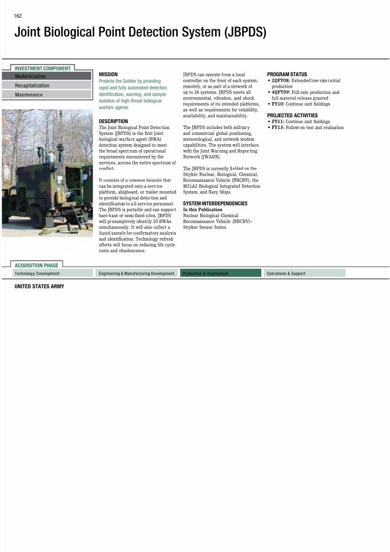
7/29/2019 Army Weapons Systems 2011
http://slidepdf.com/reader/full/army-weapons-systems-2011 172/380
UNITED STATES ARMY
ACQUISITION PHASE
INVESTMENT COMPONENT
Technology Development Operations & SupportProduction & DeploymentEngineering & Manufacturing Development
Recapitalization
Modernization
Maintenance
MISSION
Protects the Soldier by providingrapid and fully automated detection,
identification, warning, and sample
isolation of high-threat biological
warfare agents.
DESCRIPTION The Joint Biological Point Detection
System (JBPDS) is the first Joint
biological warfare agent (BWA)
detection system designed to meet
the broad spect rum of operat ionalrequirements encountered by the
services, across the entire spectrum of
conflict.
It consists of a common biosuite that
can be integrated onto a serv ice
platform, shipboard, or trailer mounted
to provide biological detec tion and
identification to a ll serv ice personnel.
The JBPDS is portable and can support
bare-base or semi-fixed s ites. JBPDS
will presumptively identi fy 10 BWAs
simultaneously. It will also collect a
liquid sample for confirmatory analysis
and identification. Technology refresh
efforts will focus on reducing life cycle
costs and obsolescence.
JBPDS can operate f rom a local
controller on the front of each system,remotely, or as part of a network of
up to 26 systems. JBPDS meets all
environmental, vibration, and shock
requirements of its intended platforms,
as well as requirements for reliability,
availability, and maintainability.
The JBPDS includes both mili tary
and commercial global positioning,
meteorological, and network modem
capabilities. The system will interface
with the Joint Warning and Repor tingNetwork (JWARN).
The JBPDS is currently fielded on the
Stryker Nuclear, Biological, Chemical,
Reconnaissance Vehicle (NBCRV), the
M31A2 Biological Integrated Detection
System, and Navy Ships.
SYSTEM INTERDEPENDENCIESIn this Publication
Nuclear Biological Chemical
Reconnaissance Vehicle (NBCRV)–
Stryker Sensor Suites
PROGRAM STATUS
• 2QFY08: Extended low-rate initialproduction
• 4QFY09: Full-rate production and
full materiel release granted
• FY10: Continue unit eldings
PROJECTED ACTIVITIES• FY11: Continue unit eldings
• FY13: Follow-on test and evaluation
Joint Biological Point Detection
System (JBPDS)
163

7/29/2019 Army Weapons Systems 2011
http://slidepdf.com/reader/full/army-weapons-systems-2011 173/380
WEAPON SYSTEMS 2011
FOREIGN MILITARY SALES
None
CONTRACTORS
General Dynamics Armament and
Technical Products (Charlotte, NC)
Joint Biological Standoff Detection System (JBSDS)
164

7/29/2019 Army Weapons Systems 2011
http://slidepdf.com/reader/full/army-weapons-systems-2011 174/380
UNITED STATES ARMY
ACQUISITION PHASE
INVESTMENT COMPONENT
Recapitalization
Modernization
Maintenance
Technology Development Operations & SupportProduction & DeploymentEngineering & Manufacturing Development
MISSION
Provides advanced, early-warning,standoff detection of biological warfare
agents (BWA) on a stationary platform
or fixed site, used in conjunction with
other biological point detectors for
advanced warning, reporting, and
protection.
DESCRIPTION The Joint Biological Sta ndoff Detection
System (JBSDS) will be the first
biological defense detect-to-warncapability to protect individual
warfighters.
The JBSDS Increment 1 provides
initial early warning capability against
biological warfare agent attack by
detecting aerosol clouds out to five
kilometers with infra red (IR) light
detection and ranging (LIDAR). JBSDS
Increment 1 operates at fixed sites or in
a stationary mode on mobile platforms.
JBSDS Increment 1 system wil l be used
for training to support Increment 2
concept of operations development.
JBSDS Increment 2 will provide 24/7
near-real-time biological warfare agent(BWA) detection and will network with
existing biological detection systems
to provide ea rly warn ing (detect-to-
warn) theater-wide to l imit the effects
of biological agent hazards against U.S.
forces at the tactical and operational
levels of war. JBSDS Increment 2 can
be employed in support of various
areas (e.g., fixed sites, air ports of
debarkation/sea ports of debarkation,
forward operating bases, amphibious
landing sites), on platforms, orstationary vehicles. JBSDS Increment
2 will pass detection information and
warnings through existing and planned
communications networks (e.g., Joint
Warning and Reporting Network).
Commanders may integrate JBSDS
Increment 2 outputs with information
from intelligence, meteorological,
radar, medical surveillance, local area
operations, and other available assets
to increase force protection, mit igate
the consequences of biological hazards,
and max imize combat effectiveness.
SYSTEM INTERDEPENDENCIES
Single Channel Ground and AirborneRadio System (SINCGARS),
Combat Service Support Automated
Information Systems Interface (CAISI)
PROGRAM STATUS• FY09: JBSDS Increment 2 materiel
development decision approved
• FY10: JBSDS Increment 1 systems
issued for training in support of
Increment 2 development
PROJECTED ACTIVITIES• FY11: JBSDS Increment 2 Milestone
A decision
• FY14: JBSDS Increment 2 Milestone
B decision
Joint Biological Standoff Detection
System (JBSDS)
O G S S
165

7/29/2019 Army Weapons Systems 2011
http://slidepdf.com/reader/full/army-weapons-systems-2011 175/380
WEAPON SYSTEMS 2011
FOREIGN MILITARY SALES
None
CONTRACTORS
Increment I:
Science and Engineering Services, Inc.
(SESI) (Columbia, MD)
Increment 2:
To be determined
Joint Biological Tactical Detection System (JBTDS)
166

7/29/2019 Army Weapons Systems 2011
http://slidepdf.com/reader/full/army-weapons-systems-2011 176/380
UNITED STATES ARMY
ACQUISITION PHASE
INVESTMENT COMPONENT
Recapitalization
Modernization
Maintenance
Technology Development Operations & SupportProduction & DeploymentEngineering & Manufacturing Development
MISSION
Provides a tactical, lightweight, battery-operated, biological warfare agent
(BWA) system capable of detecting,
warning, and presumptively identifying
and collecting samples for follow-on
confirmatory analysis.
DESCRIPTION The Joint Biological Tact ical Detection
Systems (JBTDS) will be a lightweight,
man-portable, battery-operated system
that detects, warns, and providespresumptive identification and sample
collection of BWA to provide near-real-
time detect ion of biological attacks
and hazards in the area of operation.
It will have a local alarm and be
networked to provide cooperative
capability with reduced probability of
false alarms. JBTDS will be employed
organically at the batta lion and lower
levels by non-chemical, biological,
radiological and nuclear personnel in
tact ical envi ronments across multiple
operational locations (e.g. forward
operating bases, operationally engaged
units, amphibious landing sites, air
base operat ions, etc).
JBTDS wil l ultimately support force
protection and maximize combateffectiveness by enhancing medical
response decision making. When
networked, JBTDS will augment
existing biological detection systems to
provide a theater-wide, seamless array
capable of detection and warning.
SYSTEM INTERDEPENDENCIESNone
PROGRAM STATUS
• FY09: Materiel development decisionapproved
• FY10: Development of Analysis of
Alternat ives
PROJECTED ACTIVITIES• FY11: JBTDS Milestone A decis ion
• FY12: JBTDS Milestone B decision
Joint Biological Tactical Detection
System (JBTDS)
FOREIGN MILITARY SALES
167
7/29/2019 Army Weapons Systems 2011
http://slidepdf.com/reader/full/army-weapons-systems-2011 177/380
WEAPON SYSTEMS 2011
FOREIGN MILITARY SALES
None
CONTRACTORS
To be determined
Joint Chem/Bio Coverall for Combat Vehicle Crewman (JC3)
168

7/29/2019 Army Weapons Systems 2011
http://slidepdf.com/reader/full/army-weapons-systems-2011 178/380
UNITED STATES ARMY
ACQUISITION PHASE
INVESTMENT COMPONENT
Recapitalization
Modernization
Maintenance
Technology Development Operations & SupportProduction & DeploymentEngineering & Manufacturing Development
MISSION
Provides the Combat Vehicle Crewman(CVC) with flame-resistant (FR ),
percutaneous protection against
chemical and biological (CB) agents,
radioactive particles, and toxic industrial
materials.
DESCRIPTION The Joint Chem/Bio Covera ll for
Combat Vehicle Crewman (JC3) is a
lightweight, one-piece, flame-resistant,
chemical, and biological protectivecoverall that resembles a standard
CVC coverall. The JC3 is intended to
be worn as a duty uniform; however,
it may be worn as an overgarment.
It will resist ignition and will
provide thermal protection to a llow
emergency egress. The JC3 will not be
degraded by exposure to petroleum,
oils, and lubricants present in the
operational environment. The JC3
will be compatible with current and
developmental protective masks and
mask accessories, headgear, gloves/
mittens, footwear, and other CVC
ancillary equipment (e.g., Spall vest).
SYSTEM INTERDEPENDENCIES
In this Publication Abrams Tank Upgrade (M1A2),
Bradley Fighting Vehicle Systems
Upgrade, Stryker Family of Vehicles
Other Major Interdependencies
Existing and co-developmental
protective masks, appropriate mask
accessories, protective headwear,
hand-wear, footwear, and Army and
Marine Corps a rmored vehicles
PROGRAM STATUS
• FY10: Continued production andfielding
• 1QFY10: First unit equipped
PROJECTED ACTIVITIES• FY11–16: Continue production and
fielding

7/29/2019 Army Weapons Systems 2011
http://slidepdf.com/reader/full/army-weapons-systems-2011 179/380
INVESTMENT COMPONENT
Joint Chemical Agent Detector (JCAD)
170

7/29/2019 Army Weapons Systems 2011
http://slidepdf.com/reader/full/army-weapons-systems-2011 180/380
UNITED STATES ARMY
ACQUISITION PHASE
INVESTMENT COMPONENT
Technology Development Operations & SupportProduction & DeploymentEngineering & Manufacturing Development
MISSION
Protects U.S. forces by detecting,identifying, alerting, and reporting the
presence of chemical warfare agent and
toxic industrial chemical vapor.
DESCRIPTION The Joint Chemical Agent Detector
(JCAD) is a pocket-size, rugged,
handheld detector that automatically
detects, identifies, and alarms to
chemical warfare agents and toxic
industrial chemical vapors.
The services can use the system on
mobile platforms, at fixed sites, and
on individuals designated to operate
in a chemical threat a rea. The system
can operate in a general chemical
warfare environment, and can
undergo conventional decontamination
procedures by the warfighter.
The Enhanced JCAD (M4E1 JCAD)
goes into production in FY11. The
M4E1 JCAD will reduce operation and
sustainment costs, has an improved
user interface, and is net-ready.
The JCAD replaces the Automatic
Chemical Agent Detector and Alarm
(ACADA or M22), M90, and M8A1
systems. The JCAD may replace the
Chemical Agent Monitor (CAM) and
Improved Chemical Agent Monitor
(ICAM).
Specific capabilities include:
• Instant feedback of hazard (mask
only or full Mission-Oriented
Protective Posture)
• Real-time detection of nerve, blister,
and blood agents• Stores up to 72 hours of detection
data
• The M4E1 will be net-ready through
implementation of the common
chemical, biological, radiological,
and nuclear standard interface
SYSTEM INTERDEPENDENCIESHigh Mobility Multipurpose Wheeled
Vehicle (HMMWV), Modular
Lightweight Load-carry ing Equipment
(MOLLE), M113, M2 (Bradley)
PROGRAM STATUS• 4QFY08: Full-rate production and
full materiel release; fielding of the
M4 JCAD to the Services
• FY10: Customer testing of M4E1
JCAD
PROJECTED ACTIVITIES• FY11: Continue elding M4 JCAD to
the serv ices
• FY11: Production verification
testing of M4E1 JCAD
• FY11: Production cut-in decision for
M4E1 JCAD
Recapitalization
Modernization
Maintenance
Joint Chemical Agent Detector
(JCAD)
FOREIGN MILITARY SALES
171

7/29/2019 Army Weapons Systems 2011
http://slidepdf.com/reader/full/army-weapons-systems-2011 181/380
WEAPON SYSTEMS 2011
FOREIGN MILITARY SALES
None
CONTRACTORSSmiths Detection, Inc. (Edgewood, MD)
INVESTMENT COMPONENT
Joint Chemical Biological Radiological Agent Water Monitor (JCBRAWM)
172

7/29/2019 Army Weapons Systems 2011
http://slidepdf.com/reader/full/army-weapons-systems-2011 182/380
UNITED STATES ARMY
ACQUISITION PHASE
INVESTMENT COMPONENT
Recapitalization
Modernization
Maintenance
Technology Development Operations & SupportProduction & DeploymentEngineering & Manufacturing Development
MISSION
Protects U.S. forces by detecting andidentifying the presence of biological
warfare agents and radiological
contaminants in water supplies.
DESCRIPTION The Joint Chemical Biologica l
Radiological Agent Water Monitor
(JCBRAWM) is a kit that provides a
waterborne biological and rad iological
agent detection capability. The
JCBRAWM kit is one-man portable
and detects two biological toxins andradiation (alpha and beta particles)
in drinking water. JCBRAWM
provides the ability to detect a nd
identify biological and radiological
contamination during three water-
monitoring missions: source site
selection/reconnaissance, treatment
verification, and quality assurance
of stored and distributed product
water. The system performs biological
detection and identification functions
with an immunoassay ticket and
radiological detection using the fielded
AN/PDR-77 (RADIAC) system and
accessory package.
JCBRAWM leverages commercial
technologies and fielded systems.
JCBRAWM supplements the currently
elded M272 water-testing kit.
The system is being fielded to the Army
and Navy.
SYSTEM INTERDEPENDENCIES AN/PDR-77
PROGRAM STATUS• FY09: Full-rate production; full
materiel release
• FY10: Fielding to the services
PROJECTED ACTIVITIES• FY11: Completion of elding
Joint Chemical Biological
Radiological Agent Water Monitor
(JCBRAWM)
FOREIGN MILITARY SALES
173

7/29/2019 Army Weapons Systems 2011
http://slidepdf.com/reader/full/army-weapons-systems-2011 183/380
WEAPON SYSTEMS 2011
FOREIGN MILITARY SALES
None
CONTRACTORS ANP Technologies (Newark, DE)
INVESTMENT COMPONENT
Joint Effects Model (JEM)
174

7/29/2019 Army Weapons Systems 2011
http://slidepdf.com/reader/full/army-weapons-systems-2011 184/380
UNITED STATES ARMY
ACQUISITION PHASE
INVESTMENT COMPONENT
Technology Development Operations & SupportProduction & DeploymentEngineering & Manufacturing Development
Recapitalization
Modernization
Maintenance
MISSION
Provides enhanced operational andtactical-level situational awareness of
the battlespace and provides real-time
hazard information during and after
an incident to influence and minimize
effects on current operations.
DESCRIPTION Joint Effects Model ( JEM) is an
Acquisition Categor y III software
program. It is the only accredited
DoD computer-based tactical andoperational hazard prediction
model capable of providing common
representation of chemical, biological,
radiological, nuclear (CBRN) and toxic
industrial chemicals/toxic industrial
material (TIC/TIM) hazard areas and
effects. It may be used in two variants:
as either a standalone system, or as a
resident application on host command,
control, communications, computers,
and intelligence (C4I) systems. It is
capable of modeling hazards in various
scenarios, including counterforce,
passive defense, accidents, incidents,
high-altitude releases, urban
environments, building interiors, and
human performance degradation.
JEM wil l follow an evolutionar y
acquisition approach. The JEM program
will deliver a ful l-capabi lity system
in three increments, each retaining
the functiona lity of the preceding
increment(s). JEM wi ll also support
planning to mitigate the effects of
weapons of mass destruction.
Chemical staff sections at the
batta lion, brigade, d ivision, corps
and echelons-above-corps levels,
as well as Special Forces chemical
recon detachments, will use JEM.Brigade, division, and corps-level
CBRN staff planners will also have a
reconnaissance version of JEM.
SYSTEM INTERDEPENDENCIESIn this Publication
Global Command and Control System–
Army (GCCS-A), Joint Warning and
Reporting Network (JWARN)
Other Major Interdependencies
Battle Command Common Services
(BCCS), Command Post of the Future
(CPOF), Maneuver Control System
(MCS)
PROGRAM STATUS• 3QFY10: JEM 1.0 full deployment
decision (GCCS-A, GCCS-J, C2PC,
JWARN)
• 4QFY10: JEM 1.0 production and
deployment
PROJECTED ACTIVITIES• FY11: Continue production and
deployment
• FY11-12: Continue JEM 2.0 software
development and testing
Joint Effects Model (JEM)
FOREIGN MILITARY SALES
175

7/29/2019 Army Weapons Systems 2011
http://slidepdf.com/reader/full/army-weapons-systems-2011 185/380
WEAPON SYSTEMS 2011
None
CONTRACTORSNorthrop Grumman Mission Systems
(San Diego, CA)
INVESTMENT COMPONENT
Joint Effects Targeting System (JETS)Target Location Designation System (TLDS)
176

7/29/2019 Army Weapons Systems 2011
http://slidepdf.com/reader/full/army-weapons-systems-2011 186/380
UNITED STATES ARMY
ACQUISITION PHASE
INVESTMENT COMPONENT
Recapitalization
Modernization
Maintenance
Technology Development Operations & SupportProduction & DeploymentEngineering & Manufacturing Development
MISSION
Provides significantly improvedcapability to precisely and accurately
engage targets in a variety of situations.
DESCRIPTION The Joint Effects Target ing System
(JETS) is a future system that will
answer the need for a very light weight,
highly accurate targeting system that
will a llow target engagements with
precision munitions (e.g., Joint Direct
Attack Munit ion [JDAM], Excalibur
and laser-guided weapons) and providecrucial digita l connectivity to request
and control indirect fires and close
air support from all Joint assets. The
JETS’ lighter weight wil l allow small
units supported by U.S. Air Force
Tactical A ir Control Par ties, Joint
Terminal At tack Controllers (JTACs),
and forward observers to have access
to precision ta rgeting even in rugged
mountainous terrain.
JETS will reduce fr iendly fire andcollateral damage by improving the
ability of Soldiers to differentiate
between enemy combatants and
non-combatants, and to accurately
and reliably locate targets while
communicating with Blue Force
tracking systems and overhead
surveillance assets to improve
situational awareness. JETS is
composed of two major increments:
the Target Location Designat ion
System (TLDS) and the Target Effects
Coordination System (TECS).
The TLDS will prov ide the dismounted
observer and JTAC with a common
enhanced lightweight hand-held
capability to rapidly acquire, accurately
locate, positively identify, and preciselydesignate targets. The TECS will
provide a networked, automated
communications capability to plan,
coordinate, and deliver fire support,
as well as provide terminal close air
support guidance.
SYSTEM INTERDEPENDENCIESU.S. Army Portable Forward Entry
Device, U.S. Air Force Tactical Air
Control Party-Close Air Support
System, U.S. Marine Corps StrikeLink,future TECS
PROGRAM STATUS• FY08: Analysis of alternatives
approved by Joint Studies Advisory
Group
• FY09: Request for information
released to support market research
• FY10: Materiel development decision
• FY10: Entered technology
development phase
PROJECTED ACTIVITIES• FY13: Enter engineering and
manufacturing development phase
• FY16: Initial operational capability
Joint Effects Targeting System
(JETS) Target Location Designation
System (TLDS)
FOREIGN MILITARY SALES
177

7/29/2019 Army Weapons Systems 2011
http://slidepdf.com/reader/full/army-weapons-systems-2011 187/380
WEAPON SYSTEMS 2011
None
CONTRACTORSTo Be Determined

7/29/2019 Army Weapons Systems 2011
http://slidepdf.com/reader/full/army-weapons-systems-2011 188/380
Joint High Speed Vessel (JHSV)
FOREIGN MILITARY SALES
179

7/29/2019 Army Weapons Systems 2011
http://slidepdf.com/reader/full/army-weapons-systems-2011 189/380
WEAPON SYSTEMS 2011
None
CONTRACTORSDetail Design and Construction:
Austal USA (Mobile, AL)
Electronic Systems:
General Dynamics Advanced Information
Systems (Fairfax, VA)
INVESTMENT COMPONENT
Joint Land Attack Cruise Missile Defense ElevatedNetted Sensor System (JLENS)
180

7/29/2019 Army Weapons Systems 2011
http://slidepdf.com/reader/full/army-weapons-systems-2011 190/380
UNITED STATES ARMY
ACQUISITION PHASE
Recapitalization
Modernization
Maintenance
Technology Development Operations & SupportProduction & DeploymentEngineering & Manufacturing Development
MISSION
Provides elevated, persistent, over-
the-horizon detection, tracking,
classification, and engagement data
of cruise missiles, aircraft, unmanned
aerial vehicles, tactical ballistic
missiles, large caliber rockets, and
surface-moving targets, enabling rapid
defensive engagement by air-directed,
surface-to-air, or air-to-air missile
systems.
DESCRIPTION The Joint Land Attack Cruise Missile
Defense Elevated Netted Sensor System
(JLENS) orbit comprises two systems:
a fire control radar system and a
wide-area surveillance radar system.
Each system has a 74-meter tetheredaerostat, a mobile mooring station,
radar, communications payload,
processing station, and associated
ground support equipment. The JLENS
mission is achieved by both the fire
control radar and the surveillance
radar systems operating as an “orbit;”
however, each system can operate
autonomously and contribute to the
JLENS mission.
JLENS uses its advanced sensor and
networking technologies to provide
360-degree wide-area surveillance
and tracking of cruise missiles and
other aircraft. Operating as a n orbit,
the survei llance radar generates
information that enables the firecontrol radar to readily search for,
detect, and track low-altitude cruise
missiles and other airborne threats.
Once the fire control radar develops
tracks, th is informat ion is provided
to tact ical data networks so other
network participants can assess threat
significance and assign systems to
counter the threat. The fire control
data supports extended engagement
ranges by other network participants
by providing high-quality track dataon targets that may be terrain-masked
from surface-based radar systems.
JLENS informat ion is distr ibuted
via the Joint service networks and
contributes to the development of a
single, integrated air picture.
JLENS also per forms as a multirole
platform, enabling extended range
communication and control linkages,
communications relay, battlefield
situational awareness, and can be
configured to detect and track surface
moving targets. JLENS can stay a loft
up to 30 days, providing 24-hour radar
coverage of the assigned areas. The
radar systems can be transported byaircraft, railway, ship, or roadway.
SYSTEM INTERDEPENDENCIESIn this Publication
Joint Tactical Radio System
Multifunctional Information
Distribution System (MIDS),
Medium Extended Air Defense
System (MEADS), Patriot Advanced
Capability–Three (PAC-3), Surface
Launched Advanced Medium Range
Air-to -Air Missi le (SLAMR AAM), Warfighter Information Network–
Tactical ( WIN-T) Increment 1, WIN-T
Increment 2, WIN-T Increment 3
Other Major Interdependencies
The JLENS System is dependent on
capabilities provided by CEC, MIDS,
Integrated Broadcast System (IBS).
The JLENS program is interdependent
with PAC-3, SLAMRAAM, MEADS,
and Navy Integrated Fire Control–
Counter Air (NIFC-CA).
PROGRAM STATUS• 2QFY08: Orbit preliminary design
review
• 1QFY09: Orbit critical design review
• 4QFY09: Platform first flight • 4QFY10: Orbit 1 system integration
begins
PROJECTED ACTIVITIES• 2QFY11: Orbit 1 integration
complete
• 1QFY12: Limited user test
• 2QFY12: NIFC-CA demonstration
• 2QFY12: Milestone C decision
• 3QFY13: Operational test
Joint Land Attack Cruise Missile
Defense Elevated Netted Sensor
System (JLENS)
FOREIGN MILITARY SALES
N
181

7/29/2019 Army Weapons Systems 2011
http://slidepdf.com/reader/full/army-weapons-systems-2011 191/380
WEAPON SYSTEMS 2011
None
CONTRACTORSRadar and Systems Engineering:
Raytheon (Andover, MA)
Surv. Radar:
Raytheon (El Segundo, CA)Platform:
TCOM (Columbia, MD; Elizabeth City, NC)
SETA Support:
SETA (Huntsville, AL)
Engineering and Technical Support:
E&TS Ktrs (Huntsville, AL)Software:
Raytheon Solipsys (Fulton, MD)Software Engineering:
Northrop Grumman (Huntsville, AL)
JLENS KPPs: Objective Threshold
Combat ID: Yes YesSIAP: 360° 100°
IFC: SLAMRA AM / PAC 3 / SM SLAMRA AM / PAC 3
Net-Ready: Meet all top-level IERs Meet critical top-level IERs
INVESTMENT COMPONENT
Joint Land Component Constructive Training Capability(JLCCTC)
182

7/29/2019 Army Weapons Systems 2011
http://slidepdf.com/reader/full/army-weapons-systems-2011 192/380
UNITED STATES ARMY
ACQUISITION PHASE
Technology Development Operations & SupportProduction & DeploymentEngineering & Manufacturing Development
MISSION
Provides unit commanders and their staffs
the capability to train in a simulation-based
environment with accurate representations
of land warfare operations.
DESCRIPTION
The Joint Land Component Constructive Training Capability (JLCCTC) is a
software modeling and simulation
capability that contributes to the Joint
training functional concept and the
Army training mission area by providing
appropriate levels of model and simulation
resolution and fidelity to support unit
collective and combined arms training.
JLCCTC provides multiple federations
configurable to any combination of models
and simulations. The training system
meets standards for net-centric operationsand key interface terrain databases to
support common operating environment
and will interoperate within a live, virtual,
and constructive integrated architecture.
The JLCCTC is composed of two separate
federations: JLCCTC–Multi-Resolution
Federation (MRF), and JLCCTC–Entity
Resolution Federation (ERF). The MRF is
a federated set of constructive simulat ion
software supported by commercial
software and commercial off-the-shelf
hardware that will support training of
commanders and their staffs in maneuver,
logistics, intelligence, air defense,
and artillery. The federate models are
connected by a combination of standard
High-Level Architecture, Run-Time
Infrastructure, Distributed InteractiveSimulation, custom interfaces, Master
Interface and Point-to-Point.
The JLCCTC-MRF is a Command Post
Exercise driver designed to tra in Army
commanders and their staffs at d ivision
through echelons-above -corps. It prov ides
a simulated operational environment
in which computer-generated forces
simulate and respond to the command
and control processes of the commanders
and staffs. The JLCCTC provides aninterface to Army Battle Command
System (ABCS) equipment, allowing
commanders and their staffs to train with
their “go-to -war” systems.
JLCCTC-ERF is a federation of
simulations, simulation command,
control, communications, computers,
and intelligence (C4I) interfaces, data
collection, and after action review tools.
It simulates the ABCS to facilitate battle
staff collective training by requiring staff
reaction to incoming digital information
while executing the commander’s tactica l
plan. Battle staffs of higher echelons
may also employ JLCCTC-ERF to achieve
specific training objectives.
SYSTEM INTERDEPENDENCIESNone
PROGRAM STATUS• 1QFY10: JLCCTC-MRF-W v5.5 U.S.
Army 2nd Infantry Division’s (2ID)
WARPATH and WFX exercises with
Korea
• 2QFY10: JLCCTC-MRF-W v5.5.1
accredited by CAC Commander
• 2QFY10: JLCCTC-ERF v5.2.1 elding
to Camp Dodge National Guard brigade
• 3QFY10: JLCCTC-MRF-W v5.5.2installed at BCTP, Ft. Leavenworth, KS
• 3QFY10: JLCCTC-ERF v5.2.1 elding to
Ft. Sill, Ft. Sam Houston, and ARCENT
• 1–4QFY10: JLCCTC-ERF v5.3 IT&E
• 3QFY10–4QFY10: JLCCTC-MRF-W
v6.0 development, integration, and test
events (IE #1 & IE #2)
• 4QFY10: JLCCTC ERF v5.3 VE/ORE
PROJECTED ACTIVITIES• 1QFY11: JLCCTC-ERF v5.3 elding to
Ft. Bragg and Ft. Indiantown Gap
• 1QFY11: JLCCTC-MRF-W v6.0
integration and test event (IE #3)
• 2QFY11: JLCCTC-MRF-W v6.0
integration and test event (IE #4)
• 2QFY11: JLCCTC-MRF-W v6.0
verification event and operationalreadiness event
• 2QFY11: JLCCTC-ERF v5.3 elding to
Camp Sagami and Schoeld Barracks
• 3QFY11: JLCCTC-ERF v5.3 elding to
Ft. Lewis and 7th ATC Grafenwoehr;
JLCCTC-MRF-W v6.0 35th ID exercise
with BCTP, Ft. Leavenworth, KS;
JLCCTC-MRF-W v6.0 elding to KBSC
• 4QFY11: JLCCTC-MRF-W v6.1
software release; JLCCTC-ERF v5.3
elding to KBSC
• 1QFY12: JLCCTC-MRF-W v6.1integration event in preparations for YS61
exercise; JLCCTC-MRF-W v6.1 U.S. Army
2nd Infantry Division’s (2ID) WARPATH
and WFX exercises with Korea
• 2QFY12: JLCCTC-MRF-W v6.1 YS61
Recapitalization
Modernization
Maintenance
Joint Land Component Constructive
Training Capability (JLCCTC)
FOREIGN MILITARY SALES
None
183
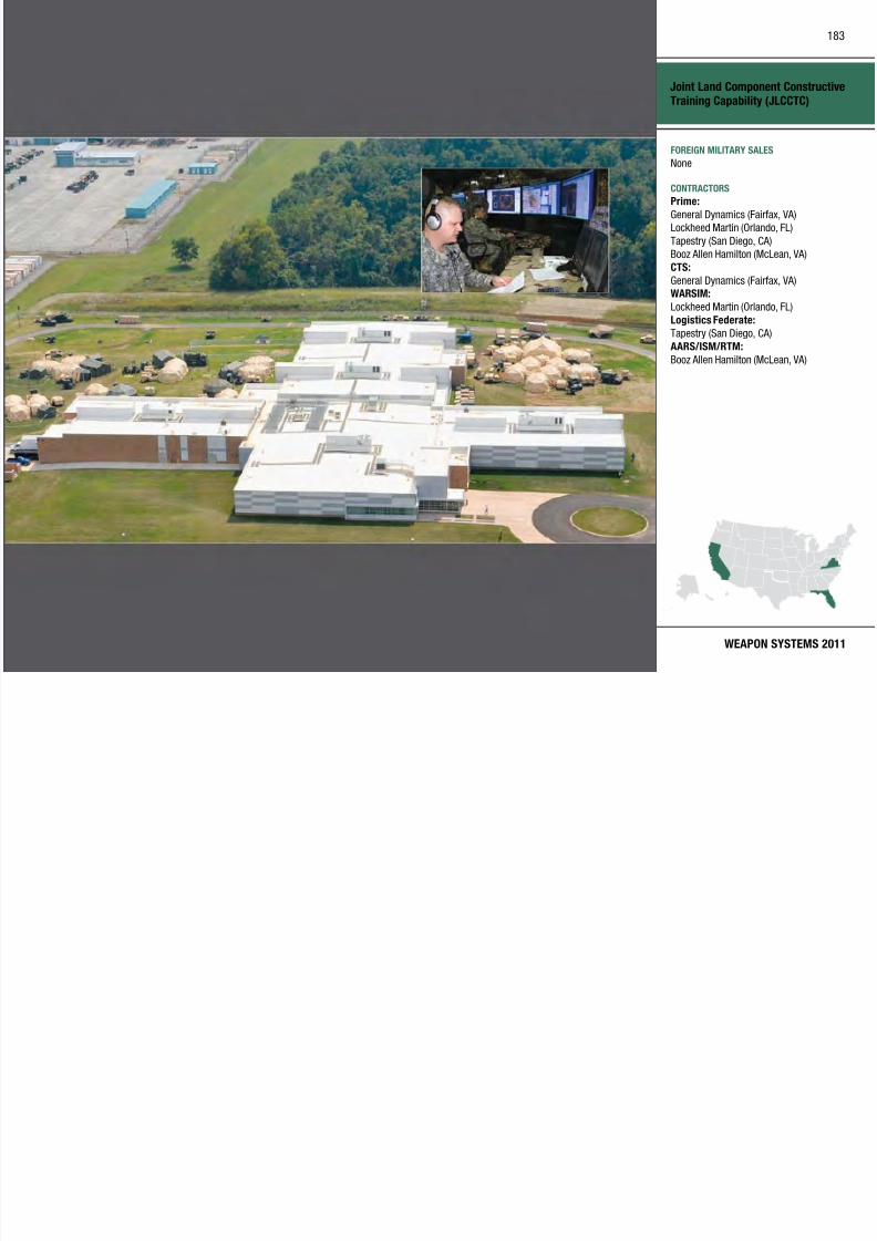
7/29/2019 Army Weapons Systems 2011
http://slidepdf.com/reader/full/army-weapons-systems-2011 193/380
WEAPON SYSTEMS 2011
None
CONTRACTORSPrime:
General Dynamics (Fairfax, VA)
Lockheed Martin (Orlando, FL)
Tapestry (San Diego, CA)
Booz Allen Hamilton (McLean, VA)
CTS:
General Dynamics (Fairfax, VA)WARSIM:
Lockheed Martin (Orlando, FL)
Logistics Federate:
Tapestry (San Diego, CA)
AARS/ISM/RTM:
Booz Allen Hamilton (McLean, VA)
INVESTMENT COMPONENT
Joint Light Tactical Vehicle (JLTV)
SS O OG S S
184

7/29/2019 Army Weapons Systems 2011
http://slidepdf.com/reader/full/army-weapons-systems-2011 194/380
UNITED STATES ARMY
ACQUISITION PHASE
Technology Development Operations & SupportProduction & DeploymentEngineering & Manufacturing Development
Recapitalization
Modernization
Maintenance
MISSION
Provides a family of vehicles, with
companion trailers, capable of
performing multiple mission roles that
will be designed to provide protected,
sustained, networked mobility for
personnel and payloads across the full
range of military operations.
DESCRIPTION The Joint Light Tactical Vehicle (JLTV)
Family of Vehicles (FoV) is a Joint
service and international program that will be capable of operat ing across a
broad spectrum of terrain and weather
conditions. The Joint services require
enhanced performance, exceeding the
existing High Mobility Multipurpose
Wheeled Vehicle, supporting the Joint
Functional Concepts of Battlespace
Awareness, Force Application,
and Focused Logistics. The JLTV
is transportable by a range of lift
assets, including rotary-wing aircraft,
to support operat ions across therange of militar y operations. Its
maneuverability enables operations
across the spectrum of terrain,
including urban areas, while providing
inherent and supplemental armor
against direct fire and improvised
explosive device threats.
Payloads: Category A–3,500 pounds,
Category B–4,500 pounds, Category
C–5,100 pounds
Transport abilit y: Internal–C-130,
External–CH-47/53, Sea–Height-
restricted decks
Protection: Scalable armor to provide
mission flexibility while protecting the
force.
Mobility: Maneuverability to enableoperations across the spectrum of
terra in, including urban areas.
Networking: Connectivity for improved
battlespace awareness and responsive,
well-integrated command and control
for embarked forces.
Sustainability: Reliable, maintainable,
maximum commonality across mission
role variants, onboard and exportable
power, and reduced fuel consumption.
The JLTV FoV balances the “Iron Triangle” of payload, protect ion, and
performance.
SYSTEM INTERDEPENDENCIESNone
PROGRAM STATUS• 1QFY09: Awarded three technology
development contracts
• 2QFY09: Start of work meetings
• 4QFY09: Preliminary design
reviews
• 1QFY10: Critical design review
• 3QFY10: Test readiness rev iew
• 3QFY10: Mid-point review with
milestone decision authority
PROJECTED ACTIVITIES• 3QFY11: Capability Development
Document approved• 4QFY11: Milestone B, enter
engineering and manufacturing
development (EMD)
• 1QFY12: Award two EMD contracts
Joint Light Tactical Vehicle (JLTV)
FOREIGN MILITARY SALES
None
185

7/29/2019 Army Weapons Systems 2011
http://slidepdf.com/reader/full/army-weapons-systems-2011 195/380
WEAPON SYSTEMS 2011
None
CONTRACTORSBAE Systems Land and Armaments
(Santa Clara, CA)
General Tactical Vehicle
(Sterling Heights, MI)
Lockheed Martin (Oswego, NY)
INVESTMENT COMPONENT
Joint Personnel Identification Version 2 (JPIv2)
MISSION SYSTEM INTERDEPENDENCIES PROGRAM STATUS
186
7/29/2019 Army Weapons Systems 2011
http://slidepdf.com/reader/full/army-weapons-systems-2011 196/380
UNITED STATES ARMY
ACQUISITION PHASE
Recapitalization
Modernization
Maintenance
Technology Development Operations & SupportProduction & DeploymentEngineering & Manufacturing Development
MISSION
Provides tactical biometrics collection
capability configurable for multiple
operational mission environments,
enabling identity superiority.
DESCRIPTION Joint Personnel Identificat ion version
2 (JPIv2) wil l collect, match, store,
and share biometrics (fingerprint/face/
iris) data and contextual information
from actual or potential adversar ies,
host-nation personnel, and third-
country nationals. This system wasformerly known as Biometric Family
of Capabilities for Full Spectrum
Operations (BFCFSO).
SYSTEM INTERDEPENDENCIESIn this Publication
Biometric Enabling Capability (BEC),
Distributed Common Ground System–
Army (DCGS-A)
Other Major Interdependencies
Identity Dominance System (IDS)
PROGRAM STATUS• 4QFY08: DoD Biometrics
Acquisition Decision Memorandum
(ADM) directs Milestone B no later
than F Y10
• 1QFY09: Biometrics in support
of Identity Management Initial
Capabilities document approved
by Joint Requirements Oversight
Council
• 4QFY09: DoD Biometrics ADM
directs the analysis of alternatives
to be completed 2QFY10
• 3QFY10: DoD Biometrics ADMapproved name change from
Biometric Family of Capabilities for
Full Spectrum Operations (BFCFSO)
to Joint Personnel Identification
Version 2 (JPIv2)
• 4QFY10: DoD Biometrics ADM
approves Biometric analysis of
alternatives final report and directs
Milestone B for JPIv2 in FY12
PROJECTED ACTIVITIES
• 2QFY11: JPIv2 1 Capabilit ydevelopment document approved
• 3QFY12: Milestone B, permission
to enter system development and
demonstration
Joint Personnel Identification
Version 2 (JPIv2)
FOREIGN MILITARY SALES
None
187

7/29/2019 Army Weapons Systems 2011
http://slidepdf.com/reader/full/army-weapons-systems-2011 197/380
WEAPON SYSTEMS 2011
None
CONTRACTORSProgram Management Support
Services:
CACI (Arlington, VA)
The Research Associates (New York, NY)System Development and Integration:
To be determined pending Milestone B
INVESTMENT COMPONENT
Joint Precision Airdrop System (JPADS)
MISSION f r 30 000 d a d a bj ti PROGRAM STATUS
188
7/29/2019 Army Weapons Systems 2011
http://slidepdf.com/reader/full/army-weapons-systems-2011 198/380
UNITED STATES ARMY
ACQUISITION PHASE
Recapitalization
Modernization
Maintenance
Technology Development Operations & SupportProduction & DeploymentEngineering & Manufacturing Development
MISSION
Provides the warfighter with precision
airdrop capability, ensuring an accurate
delivery of supplies to forward-
operating forces, reducing vehicular
convoys, and allowing aircraft to drop
cargo at safer altitudes and off-set
distances.
DESCRIPTION The Joint Precision Airdrop System
(JPADS) is a precision-guided airdrop
system that provides rapid, precise,high-altitude delivery capabilities that
do not rely on ground transportat ion.
The system ensures accurate and
timely delivery in support of operational
missions, while providing aircraft with
increased survivability.
JPADS integrates a parachute
decelerator, an autonomous guidance
unit, and a load container or pallet to
create a system that can accurately
deliver critical supplies with greatprecision along a predetermined glide
and flight path. The system is being
developed in two weight classes:
2,000 pounds and 10,000 pounds,
with potential future requirements
for 30,000 pounds, and an objective
system of 60,000 pounds. The guidance
system uses military global positioningsatellite data for precise navigation and
interfaces with a wirelessly updatable
mission planning module on board the
aircraft to receive real-time weather
data and compute multiple aerial
release points.
JPADS is being designed for aircraft
to drop cargo from altitudes of up to
24,500 feet mean sea level. It will
release cargo from a minimum off-set ofeight kilometers from the intended point
of impact, with an objective capability of
25 kilometers off-set. This off-set allows
aircraft to stay out of range of many
anti-aircraft systems. It also enables
aircraft to drop systems from a single
aerial release point and deliver them
to multiple or single locations, thus
reducing aircraft exposure time. Once
on the ground, the precise placement
of the loads greatly reduces the time
needed to recover the load as well asminimize exposure to ground forces.
SYSTEM INTERDEPENDENCIESNone
PROGRAM STATUS• 3QFY07–4QFY08: Testing for
2,000-pound variant completed• 1QFY08: Milestone B (permission
to enter system development and
demonstration phase) received for
10,000-pound variant
• 2QFY08: Testing began for
10,000-pound variant and currently
in developmental testing
• 3QFY09: Milestone C, Type
Classication-Standard, and full
materiel release approved for the
2,000-pound variant, with productioncontract
• 4QFY09: Fielding began for
2,000-pound variant and w ill
continue until FY12, assuming
projected funding remains
PROJECTED ACTIVITIES• 1QFY11: Complete testing of the
10,000-pound variant
• 4QFY11: Milestone C (full-rate
production and fielding decision)
for 10,000-pound variant withsubsequent award production
contract
• 1QFY12: Fielding begins for
10,000-pound variant
Joint Precision Airdrop System
(JPADS)
FOREIGN MILITARY SALES
None
189
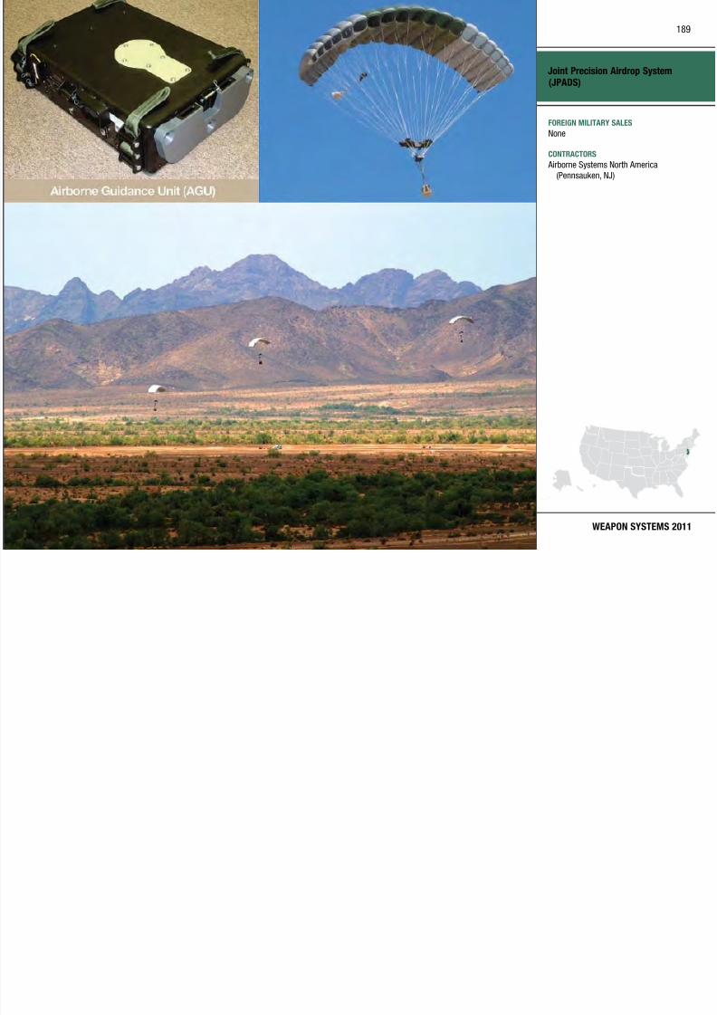
7/29/2019 Army Weapons Systems 2011
http://slidepdf.com/reader/full/army-weapons-systems-2011 199/380
WEAPON SYSTEMS 2011
None
CONTRACTORS Airborne Systems North America
(Pennsauken, NJ)
INVESTMENT COMPONENT
Joint Service General Purpose Mask (JSGPM)
M d i ti MISSION MCU 2/P series of protective masks for PROGRAM STATUS
190

7/29/2019 Army Weapons Systems 2011
http://slidepdf.com/reader/full/army-weapons-systems-2011 200/380
UNITED STATES ARMY
ACQUISITION PHASE
Recapitalization
Modernization
Maintenance
Technology Development Operations & SupportProduction & DeploymentEngineering & Manufacturing Development
MISSION
Enables warfighters’ survival in a
chemical, biological, radiological,
and nuclear (CBRN) environment by
providing chemical, biological, toxin,
radioactive particulate, and toxic
industrial material protection.
DESCRIPTION The Joint Service General Purpose
Mask (JSGPM) is a lightweight,
protective mask system incorporating
state-of-the-art technology to protectU.S. Joint forces from actual or
anticipated threats. The JSGPM
will provide above-the-neck, head-
eye-respiratory protection against
CBRN threats, including toxic
industrial chemicals (TIC). The mask
component designs will be optimized
to minimize their impact on the
wearer’s performance and to maximize
its ability to interface with current
and future service equipment and
protective clothing. The JSGPM masksystem replaces the M40/M42 series
of protective masks for the Army and
Marine Corps ground and combat
vehicle operations, as well as the
MCU-2/P series of protective masks for
Air Force and Navy shore-based a nd
shipboard applications.
SYSTEM INTERDEPENDENCIESIn this Publication
Joint Chem/Bio Covera ll for Combat
Vehicle Crewman (JC3)
Other Major Interdependencies
The JSGPM will inter face with
Joint serv ice vehicles, weapons,
communication systems, individual
clothing and protective equipment, andCBRN personal protective equipment
PROGRAM STATUS• FY10: Production and fielding
PROJECTED ACTIVITIES• FY11–16: Continue production and
fielding
Joint Service General Purpose Mask
(JSGPM)
FOREIGN MILITARY SALES
None
191

7/29/2019 Army Weapons Systems 2011
http://slidepdf.com/reader/full/army-weapons-systems-2011 201/380
WEAPON SYSTEMS 2011
CONTRACTORS Avon Protection Systems (Cadillac, MI)
INVESTMENT COMPONENT
Joint Service Transportable Decontamination System(JSTDS)–Small Scale (SS)
Modernization MISSION crew served weapons and aircraft PROGRAM STATUS
192
7/29/2019 Army Weapons Systems 2011
http://slidepdf.com/reader/full/army-weapons-systems-2011 202/380
UNITED STATES ARMY
ACQUISITION PHASE
Recapitalization
Modernization
Maintenance
Technology Development Operations & SupportProduction & DeploymentEngineering & Manufacturing Development
MISSION
Supports rapid and effective
decontamination of military equipment.
DESCRIPTION The Joint Service Transpor table
Decontamination System–Small Scale
(JSTDS-SS) will enable warfighters
to conduct thorough decontamination
of non-sensitive militar y materiel and
limited facility decontamination at
logistics bases, airfields (and critical
airfield assets), naval ships, ports,
key command and control centers,and other fixed facilities that have
been exposed to chemical, biological,
radiological, and nuclear (CBRN)
warfare agents /contamination and
toxic industr ial materials. The
system may also support other hazard
abatement missions as necessary.
The JSTDS-SS is supported with one
accessory kit and one water blivet per
system.
The JSTDS-SS is being developed usingan incremental approach. Increment
I provides improved capabilities over
current systems to decontaminate
tact ical and non-tactical vehicles,
ship exterior surfaces, aircraft,
crew served weapons, and aircraft
support equipment. Increment II
will focus on improving overarchingdecontamination processes, efficacy,
and system capabilities for operational
and thorough decontamination of non-
sensitive equipment.
SYSTEM INTERDEPENDENCIESOther Major Interdependencies
All individual protective equipment,
decontaminants, and detectors
PROGRAM STATUS• 3QFY10: Full-rate production
decision• 4QFY10: Production and fielding
PROJECTED ACTIVITIES• FY11–16: Continue production and
fielding
Joint Service Transportable
Decontamination System (JSTDS)–
Small Scale (SS)
FOREIGN MILITARY SALES
None
193

7/29/2019 Army Weapons Systems 2011
http://slidepdf.com/reader/full/army-weapons-systems-2011 203/380
WEAPON SYSTEMS 2011
CONTRACTORSDRS Technologies (Florence, KY )
INVESTMENT COMPONENT
Joint Tactical Ground Stations (JTAGS)
Modernization MISSION to warfighters in support of regional PROGRAM STATUS
194
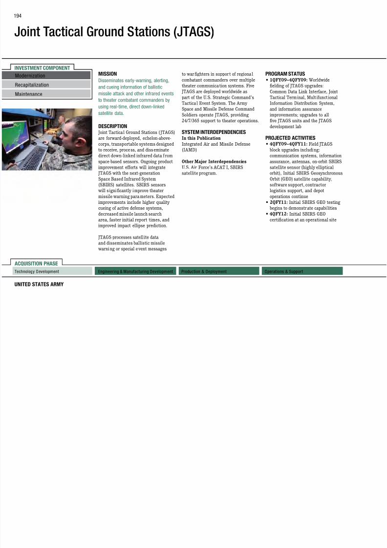
7/29/2019 Army Weapons Systems 2011
http://slidepdf.com/reader/full/army-weapons-systems-2011 204/380
UNITED STATES ARMY
ACQUISITION PHASE
Technology Development Operations & SupportProduction & DeploymentEngineering & Manufacturing Development
Recapitalization
Modernization
Maintenance
MISSION
Disseminates early-warning, alerting,
and cueing information of ballistic
missile attack and other infrared events
to theater combatant commanders by
using real-time, direct down-linked
satellite data.
DESCRIPTION Joint Tactical Ground Stations ( JTAGS)
are forward-deployed, echelon-above-
corps, transportable systems designed
to receive, process, and disseminatedirect down-linked infrared data f rom
space-based sensors. Ongoing product
improvement efforts will integrate
JTAGS with the next-generation
Space Based Infrared System
(SBIRS) satellites. SBIRS sensors
will s ignificantly improve theater
missile warning parameters. Expected
improvements include higher quality
cueing of active defense systems,
decreased missile launch search
area, faster initial report times, andimproved impact ellipse prediction.
JTAGS processes satell ite data
and disseminates ballistic missile
warning or special event messages
to warfighters in support of regional
combatant commanders over multiple
theater communication systems. Five JTAGS are deployed worldwide as
part of the U.S. Strategic Command’s
Tactical Event System. The Army
Space and Missile Defense Command
Soldiers operate JTAGS, providing
24/7/365 support to theater operations.
SYSTEM INTERDEPENDENCIESIn this Publication
Integrated Air and Missile Defense
(IAMD)
Other Major Interdependencies
U.S. Air Force’s ACAT I, SBIRS
satellite program.
PROGRAM STATUS• 1QFY09–4QFY09: Worldwide
fielding of JTAGS upgrades:Common Data Link Interface, Joint
Tactical Terminal, Mult ifunct ional
Information Distribution System,
and information assurance
improvements; upgrades to all
five JTAGS units and the JTAGS
development lab
PROJECTED ACTIVITIES• 4QFY09–4QFY11: Field JTAGS
block upgrades including:communication systems, information
assurance, antennas, on-orbit SBIRS
satellite sensor (highly elliptical
orbit), Initial SBIRS Geosynchronous
Orbit (GEO) satellite capability,
software support, contractor
logistics support, and depot
operations continue
• 2QFY11: Initial SBIRS GEO testing
begins to demonstrate capabi lities
• 4QFY12: Initial SBIRS GEO
certification at an operational site
Joint Tactical Ground Stations
(JTAGS)
FOREIGN MILITARY SALES
None
195

7/29/2019 Army Weapons Systems 2011
http://slidepdf.com/reader/full/army-weapons-systems-2011 205/380
WEAPON SYSTEMS 2011
CONTRACTORSDevelop, Deploy, Sustain (CLS):
Northrop Grumman Electronic Systems
(Colorado Springs, CO)
SETA support:
BAE Systems (Huntsville, AL)
INVESTMENT COMPONENT
Joint Tactical Radio System Airborne and Maritime/Fixed Station (JTRS AMF)
Modernization
Modernization MISSION simultaneous voice, data, and video PROJECTED ACTIVITIES
196

7/29/2019 Army Weapons Systems 2011
http://slidepdf.com/reader/full/army-weapons-systems-2011 206/380
UNITED STATES ARMY
ACQUISITION PHASE
Recapitalization
Modernization
Maintenance
Technology Development Operations & SupportProduction & DeploymentEngineering & Manufacturing Development
Recapitalization
Modernization
Maintenance
Provides scalable and modular
networked radio frequency-installed
communication capability to meet Joint
service requirements through two
Joint tactical radio sets with common
ancillary equipment for both radio form
factors and aircraft, as well as maritime
and shore sites.
DESCRIPTION The Joint Tactical Radio System
Airborne and Mari time/ FixedStation (JTRS AMF) will provide a
four-channel, full duplex, software-
defined radio integrated into a irborne,
shipboard, and fixed-station platforms,
enabling maritime and airborne
forces to communicate seamlessly
and with g reater efficiency through
implementation of five initial
waveforms (i.e., Ultra-High Frequency
Satellite Communications, Mobile User
Objective System, Wideband Network
Waveform, Soldier Radio Waveform,and Link 16) providing data, voice,
and networking capabilities. JTRS
AMF is software-reprogrammable,
multi-band/multi-mode capable, mobile
ad-hoc network capable, and provides
, ,
communications. The system is flexible
enough to provide point-to-point andnetted voice and data, whether it is
between Service Command Centers,
Shipboard Command Centers, Joint
Operations Centers or other functional
centers (e.g., intelligence, logistics).
AMF wil l assist U.S. Armed Forces
in the conduct of prompt, sustained,
and synchronized operations,
allowing warfighters the freedom to
achieve information dominance in alldomains—land, sea, air, and space.
SYSTEM INTERDEPENDENCIESIn this Publication
Joint Tactical Radio System Ground
Mobile Radios (JTRS GMR); Joint
Tactical Radio System Handheld,
Manpack, Small Form Fit (JTRS HMS);
Joint Tactical Radio System, Network
Enterprise Domain (JTRS NED)
Other Major InterdependenciesMultiple aircraf t, maritime, and fixed
site platforms
PROGRAM STATUS• 1QFY10: Critical design review
• 2QFY11: Delivery begins for
AMF Small A irborne engineeringdevelopment models (EDM)
• 1QFY12: Delivery begins for
M/F EDM
Joint Tactical Radio System
Airborne and Maritime/Fixed Station
(JTRS AMF)
FOREIGN MILITARY SALES
None
197

7/29/2019 Army Weapons Systems 2011
http://slidepdf.com/reader/full/army-weapons-systems-2011 207/380
WEAPON SYSTEMS 2011
CONTRACTORSPrime:
Lockheed Martin (San Diego, CA;
Alexandria, VA)
Subcontractors:
BAE Systems (Wayne, NJ)
Northrop Grumman (San Diego, CA)
General Dynamics C4 Systems, Inc.
(Scottsdale, AZ)
Raytheon (Fort Wayne, IN)
INVESTMENT COMPONENT
Joint Tactical Radio System Ground Mobile Radios (JTRS GMR)
Modernization MISSION use the frequency spectrum within PROGRAM STATUS
198

7/29/2019 Army Weapons Systems 2011
http://slidepdf.com/reader/full/army-weapons-systems-2011 208/380
UNITED STATES ARMY
ACQUISITION PHASE
Recapitalization
Modernization
Maintenance
Technology Development Operations & SupportProduction & DeploymentEngineering & Manufacturing Development
Develops, demonstrates, certifies,
fields, and sustains an affordable,
multi-channel networking radio
system that meets DoD ground vehicle
digitization and tactical communication
requirements.
DESCRIPTION Joint Tactical Radio System Ground
Mobile Radios (JTRS GMR) are a
key enabler of the DoD and Army
Transformat ion and wil l provide
critical communications capabilities
across the full spectrum of Joint
operations.
Through software reconfig uration,
JTRS GMR can emulate cur rent force
radios and operate new Internet
protocol-based networking waveforms
offering increased data throughput
utilizing self-forming, self-healing, and
managed communication networks.
The GMR route and retransmitfunctionality links various waveforms
in different frequency bands to form
one internetwork. GMR can scale
from one to four channels supporting
multiple security levels and effectively
the two megaher tz to two g igahert z
frequency range. The radios areSoftware Communications Architecture
compliant with increased bandwidth
through future waveforms. GMR are
interoperable with more than four
legacy radio systems and the JTRS
family of radios (HMS, JEM, and AMF).
SYSTEM INTERDEPENDENCIESIn this Publication
Joint Tactical Radio System Airborne
and Maritime/Fixed Station (JTRS
AMF); Joint Tact ical Radio System
Handheld, Manpack, Small Form
Fit (JTRS HMS); Single Channel
Ground and Airborne Radio System
(SINCGARS)
Other Major Interdependencies
Enhanced Position Locating Reporting
System (EPLRS), High Frequency
(HF), Network Enterprise Domain
(NED), Satellite Communications
(SATCOM), Soldier Radio Waveform(SRW), Ultra-High Frequency (UHF),
Wideband Networking Waveform
(WNW)
• 2QFY09: Engineering development
model (EDM) radio deliveries began; test readiness review
• 3QFY09: EDM production and
deliveries completed; production
qualification test began; security
verification tests began
• 3QFY10: System integration test
began; security verification test
concluded; production qualification
test concluded; NSA approval to
enter limited user test
PROJECTED ACTIVITIES• 1QFY11: Limited user test
• 2QFY11: Conclude Milestone C
decision approving entry into the
production and deployment phase
Joint Tactical Radio System Ground
Mobile Radios (JTRS GMR)
FOREIGN MILITARY SALES
None
199

7/29/2019 Army Weapons Systems 2011
http://slidepdf.com/reader/full/army-weapons-systems-2011 209/380
WEAPON SYSTEMS 2011
CONTRACTORSPrime:
Boeing (Huntington Beach, CA)
Hardware:
BAE Systems (Wayne, NJ)
Rockwell Collins (Cedar Rapids, IA)
Northrop Grumman (Carson, CA)
INVESTMENT COMPONENT
Joint Tactical Radio System Handheld, Manpack, andSmall Form Fit (JTRS HMS)
Modernization MISSION The Embedded Small Form Fit versions PROGRAM STATUS
200

7/29/2019 Army Weapons Systems 2011
http://slidepdf.com/reader/full/army-weapons-systems-2011 210/380
UNITED STATES ARMY
ACQUISITION PHASE
Technology Development Operations & SupportProduction & DeploymentEngineering & Manufacturing Development
Recapitalization
Maintenance
Provides the warfighter with a software
re-programmable, networkable multi-
mode system-of-systems capable of
simultaneous voice, data, and video
communications and meets the radio
requirements for Soldiers and small
platforms, such as missiles and ground
sensors.
DESCRIPTION The Joint Tactical Radio System
(JTRS) Handheld, Manpack, and
Small Form Fit (HMS) is a materiel
solution meeting the requirements of
the Office of the Assistant Secretar y
of Defense for Networks and
Information Integration/DoD Chief
Information Officer for a Software
Communications Architecture (SCA)
compliant hardware system hosting
SCA-compliant software waveforms
(applications). HMS is an Acquisition
Category ID program that encompasses
specific requirements to supportSpecial Operations Command, Army,
Marine Corps, Air Force, and Navy
communication needs.
of HMS will be used for Joint Service
Ground Sensor Networks, intelligentmunitions deployment and usage,
unmanned vehicles, and other platform
applications, including support for the
Early-Infantry Brigade Combat Team
and Ground Soldier System technical
performance and integration.
SYSTEM INTERDEPENDENCIESIn this Publication
Single Channel Ground and Airborne
Radio System (SINCGARS); Nett
Warrior (NW)
Other Major Interdependencies
SRW, HF, UHF SATCOM, MUOS, IMS;
UGS using SRW and various legacy WF
mixes
• 3QFY09: Phase 1 limited user test
(LUT)
PROJECTED ACTIVITIES• 3QFY11: Phase 2 LUT
• 1QFY12: Phase 2 Milestone C
decision
Joint Tactical Radio System
Handheld, Manpack, and Small
Form Fit (JTRS HMS)
FOREIGN MILITARY SALES
None
201

7/29/2019 Army Weapons Systems 2011
http://slidepdf.com/reader/full/army-weapons-systems-2011 211/380
WEAPON SYSTEMS 2011
CONTRACTORSMP, 2 CH HH, SFFs -A, -B, -K, AN/PRC-
154 (Rifleman Radio):
General Dynamics (Scottsdale, AZ)
2 CH HH, SFF-B, AN/PRC-154 (Rifleman
Radio):
Thales (Clarksburg, MD)
SFF-A, -D, -K:
BAE Systems (Wayne, NJ)
MP, SFF-D :
Rockwell Collins (Cedar Rapids, IA)PM Support:
Science Applications International Corp.(SAIC) (San Diego, CA)
INVESTMENT COMPONENT
Joint Tactical Radio System Multifunctional InformationDistribution System (JTRS MIDS)
Modernization Program includes the MIDS–Low
V l T i l (MIDS LVT) d th
MIDS-LVT, but also accommodates future
t h l i d biliti MIDS
• 1QFY10: Milestone Decision Authority
l f MIDS JTRS li it d
202

7/29/2019 Army Weapons Systems 2011
http://slidepdf.com/reader/full/army-weapons-systems-2011 212/380
UNITED STATES ARMY
ACQUISITION PHASE
Recapitalization
Maintenance
Technology Development Operations & SupportProduction & DeploymentEngineering & Manufacturing Development
MISSION
Provides real-time information and
situational awareness to the Joint and
coalition warfighter in the airborne,
ground, and maritime domains through
secure, scalable, modular, wireless,
and jam-resistant digital data and voice
communications.
DESCRIPTION The Joint Tactical Radio System
Multifunctional Information
Distribution System (JTRS MIDS) is
a secure, scalable, modular, wireless,
and jam-resistant digital information
system currently providing Tactical
Air Navigation (TACAN), Link-16,
and J-Voice to airborne, ground,
and maritime joint and coal ition warfighting platforms. MIDS provides
real-time and low-cost information
and situational awareness. The MIDS
Volume Termina l (MIDS-LVT) and the
MIDS JTRS Terminal.
MIDS-LVT is the foundation of the MIDS
international cooperative program with
Joint service participat ion. MIDS-LVT
provides interoperability with NATO
users, significantly increasing force
effectiveness and minimizing hostile
actions and f riend-on-friend engagements.
Three principal configurations of the
termina l are in production and use an
open-system, modular architecture. MIDS-
LVT(1) provides a Link-16 capability to
Navy and Air Force platforms, which were
previously unable to use the Joint Tactical
Information Distribution System (JTIDS)
due to space and weight limitations.
MIDS-LVT(2) is an Army variant of MIDS
that is a functional replacement for the
JTIDS Class 2M terminal. MIDS-LVT(3),
also referred to as MIDS Fighter Data
Link (FDL), is a reduced-function terminal
for the Air Force.
MIDS JTRS is a Software Defined Radio
(SDR) that is compliant with the JTRS
Software Communications Architecture
(SCA). MIDS JTRS maintains the Link-
16, J-Voice, and TACAN functional ity of
technologies and capabilities. MIDS
JTRS improvements over MIDS-LVTinclude Link-16 enhanced throughput
(ET), Link-16 frequency remapping (FR),
and programmable crypto. MIDS JTRS
accommodates incremental delivery of the
advanced JTRS waveforms through MIDS
JTRS platform capability packages, such
as the Joint Airborne Networking–Tactical
Edge (JAN-TE) capability.
SYSTEM INTERDEPENDENCIESIn this Publication
Joint Tactica l Radio System A irborne a nd
Maritime/Fixed Station (JTRS AMF);
Joint Tactica l Radio System, Network
Enterprise Domain (JTRS NED)
Other Major Interdependencies
Link-16, TACAN, JAN-TE Waveforms;
multiple Joint and coalition airborne,
ground, and maritime platforms
PROGRAM STATUS
• 1QFY10: MIDS Program Memorandumof Understanding Extension to 2021
signed between the U.S., France, Italy,
Germany, and Spain
approval of MIDS JTRS limited
production and elding of 41 terminalsfor USN (F/A-18E/F) and USAF
(JSTARs)
• 2QFY10: MIDS-LVT Lot 11 contract
award bringing total of MIDS-LVT
terminals on contract or delivered to
6,000+
• 2QFY10: MIDS JTRS receives National
Security Agency Type 1 cert ification
• 3QFY10: MIDS JTRS developmental
test complete
• 3QFY10: MIDS JTRS operational test
readiness review complete
• 4QFY10: MIDS JTRS initial operational
test and evaluation (IOT&E) conducted
PROJECTED ACTIVITIES• 1QFY11: MIDS JTRS IOT&E report
issued by commander, operational test
and evaluation force
• 2QFY11: MIDS JTRS IOT&E report
issued by director, operational test and
evaluation
• 2QFY11: MIDS JTRS initialoperational capability with the USN
F/A-18E/F Super Hornet
• 2QFY11: MIDS JTRS full production
and fielding decision
Joint Tactical Radio System
Multifunctional Information
Distribution System (JTRS MIDS)
FOREIGN MILITARY SALES
MIDS-LVT:
1 881terminals ( internationally)
203

7/29/2019 Army Weapons Systems 2011
http://slidepdf.com/reader/full/army-weapons-systems-2011 213/380
WEAPON SYSTEMS 2011MIDS Core Terminal MIDS-LVT
1,881 terminals ( internationally)
JTRS MIDS:None
CONTRACTORS
ViaSat Inc. (Carlsbad, CA)Data Link Solutions:
Rockwell Collins (Cedar Rapids, IA)
BAE Systems (Wayne, NJ)
EuroMIDS (Paris, France)
Thales (France)
Selex (Italy)
EADS (Germany)
Indra (Spain)
INVESTMENT COMPONENT
Joint Tactical Radio System, Network Enterprise Domain(JTRS NED)
waveforms (Wideband Networking
Waveform [WNW] Soldier Radio
edge. In addition, NED provides
network management and network
PROGRAM STATUS• FY10: Legacy WF/SRW nal
Modernization
204

7/29/2019 Army Weapons Systems 2011
http://slidepdf.com/reader/full/army-weapons-systems-2011 214/380
UNITED STATES ARMY
ACQUISITION PHASE
Technology Development Operations & SupportProduction & DeploymentEngineering & Manufacturing Development
MISSION
Develops portable, interoperable,
mobile ad-hoc networking waveforms/
applications, providing the combatant
commanders with the ability to
command, control, and communicate
with their forces via secure voice, video,
and data media forms during military
operations.
DESCRIPTION The Joint Tactical Radio System,
Network Enterprise Domain
(JTRS NED) is responsible for
the development, sustainment,
and enhancement of interoperable
networking and legacy software
waveforms. NED’s product line consists
of: 14 legacy waveforms (Bowman VHF, COBRA, EPLRS, Have Quick
II, HF SSB/ALE, HF 5066, Link 16,
SINCGARS, UHF DAMA SATCOM
181/182/183/184, UHF LOS, VHF
LOS); three mobile ad-hoc networking
Waveform [WNW], Soldier Radio
Waveform [SRW], and Mobile UserObjective System [MUOS]–Red Side
Processing); Network Enterprise
Services (NES) including the JTRS
WNW Network Manager (J WNM),
Soldier Radio Waveform Network
Manager (SRWNM), JTRS Enterprise
Network Manager (JENM), and
Enterprise Network Services (ENS).
JTRS NED manages the development
of Software Waveforms targeted to
operate on platforms such as the
Ground Mobile Radio (GMR), the
Handheld, Manpack, and Small Form
Fit (HMS) radios, the Airborne and
Maritime/Fixed Site (AMF) radios,
and the Multifunctional Information
Distribution System (MIDS) radios.
The JTRS NED software development
and sustainment efforts leverage
commercial technology and employ
open-system architecture to better
ensure interoperability and portabilityof each waveform. JTRS NED develops
networking waveforms to support
wireless networking with Global
Information Grid connectivity for
deployed warfighters at the tactical
network management and network
services software for the planning,execution, configuration, and
monitoring of the JTRS radios
and networks, including route
and retransmit services between
networking and legacy waveforms.
SYSTEM INTERDEPENDENCIESIn this Publication
JTRS GMR; JTRS AMF; JTRS MIDS;
JTRS HMS; Single Channel Ground and
Airborne Radio System (SINCGARS)
Other Major Interdependencies
Enhanced Position Location and
Reporting System (EPLRS), MUOS,
Link 16
• FY10: Legacy WF/SRW nal
qualication test (FQT) completed• 1QFY10: HF FQT completed
• 1QFY10: WNW FQT completed
• 1QFY10: SRW Delta FQT on HMS
completed
• 2QFY10 JWNM FQT completed
PROJECTED ACTIVITIES• 1QFY11: Complete ENS Phase 1
(SoftINC) FQT
• 1QFY11: Complete SRWNM FQT
• 2QFY11: Complete MUOS FQT
• 3QFY11: Complete ENS Phase 1
(TDC) FQT
• 4QFY11: Complete JENM Phase
2 FQT
• 4QFY12: Complete JENM Phase
3 FQT
Recapitalization
Maintenance
Joint Tactical Radio System,
Network Enterprise Domain
(JTRS NED)
FOREIGN MILITARY SALES
None
205

7/29/2019 Army Weapons Systems 2011
http://slidepdf.com/reader/full/army-weapons-systems-2011 215/380
WEAPON SYSTEMS 2011
CONTRACTORS
MUOS:
Lockheed Martin (Sunnyvale, CA)
SRW, SRWNM, ENS Phase 1 (SoftINC):
ITT (Fort Wayne, IN)PM Support:
SRA (Fairfax, VA)
JWNM, WNW, JENM:
Boeing (Huntington Beach, CA)
ENS Phase 1 (TDC):
Rockwell Collins (Cedar Rapids, IA)
INVESTMENT COMPONENT
Joint Warning and Reporting Network (JWARN)
Modernization MISSION
Accelerates the warfighter’s response
reports, Allied Tactical Publication
(ATP) 45 hazard plots and integrates
PROGRAM STATUS• 4QFY10: JWARN 1 0 full
206
7/29/2019 Army Weapons Systems 2011
http://slidepdf.com/reader/full/army-weapons-systems-2011 216/380
UNITED STATES ARMY
ACQUISITION PHASE
Technology Development Operations & SupportProduction & DeploymentEngineering & Manufacturing Development
Recapitalization
Maintenance
Accelerates the warfighter s response
to a chemical, biological, radiological,or nuclear (CBRN) attack by providing
Joint forces the capability to report,
analyze, and disseminate detection,
identification, location, and warning
information.
DESCRIPTION The Joint Warning and Reporting
Network (JWARN) is a computer-
based application that networks CBRN
sensors directly with Joint and service
command and control systems to
collect, analyze, identify, locate, and
report information on CBRN activity
and threats, and to disseminate
that information to decision-makers
throughout the command.
JWARN’s Mission Applicat ion Software
(JMAS) w ill be compatible and
integrated with Joint service command,
control, communications, computers,intelligence, and surveillance
reconnaissance (C4ISR) systems. It
will generate warn ing and dewar ning
information to affected forces via
nuclear, biological, and chemical (NBC)
(ATP)–45 hazard plots, and integrates
with the Joint Effects Model (JEM) to provide detailed ha zard prediction
plume overlays. JWARN automates the
recording and archiving of exposure
data for effective force protection.
It reduces the time from incident
observation to warning to within
two minutes, enhances war fighters’
situational awareness throughout the
area of operations, and supports battle
management tasks.
JWARN’s component interface device
connects to the sensors, and relays
warn ings to C4ISR systems v ia
advanced wired or wireless networks.
SYSTEM INTERDEPENDENCIESIn this Publication
Global Command and Control System–
Army (GCCS-A), Joint Effects Model
(JEM), Force XXI Battle Command
Brigade and Below (FBCB2)
Other Major Interdependencies
Battle Command Common Services
(BCCS), Command Post of the Future
(CPOF), Maneuver Control System
(MCS)
• 4QFY10: JWARN 1.0 full
deployment decision (GCCS-J,GCCS-A, C2PC, JEM)
• 4QFY10: Production and deployment
begins
• 4QFY10: JWARN 1.0 initial
operational capability
PROJECTED ACTIVITIES• FY11: Continue production and
deployment
• FY11: MCS/CPOF/BCCS and
FBCB2/JCR interoperability testing
• 1QFY11: JWARN 1.0 GCCS-M
operational testing
Joint Warning and Reporting
Network (JWARN)
FOREIGN MILITARY SALES
None
207

7/29/2019 Army Weapons Systems 2011
http://slidepdf.com/reader/full/army-weapons-systems-2011 217/380
WEAPON SYSTEMS 2011
CONTRACTORS
Northrop Grumman Information
Technology (Orlando, FL)
INVESTMENT COMPONENT
Kiowa Warrior
Modernization The Army is cur rently insta lling
modifications to address safety
• 3QFY10: Contract awarded
for Single Channel FADEC • 1QFY11: Kiowa Warrior CASUP
208

7/29/2019 Army Weapons Systems 2011
http://slidepdf.com/reader/full/army-weapons-systems-2011 218/380
UNITED STATES ARMY
ACQUISITION PHASE
RecapitalizationMaintenance
Technology Development Operations & SupportProduction & DeploymentEngineering & Manufacturing Development
MISSION
Performs aerial reconnaissance and
security in support of ground maneuver
forces.
DESCRIPTION The Kiowa Warr ior is a single-engine,
two-man, l ightly armed reconnaissance
helicopter with advanced visionics,
navigation, communication, weapons,
and cockpit integration systems. Its
mast-mounted sight houses a thermal
imaging system, low-light television,
and a laser rangefinder/designator
permitting target acquisition and
engagement at standoff ranges and
in adverse weather. The navigation
system can convey precise target
locations to other aircra ft or
artillery via its advanced digitalcommunications system. It provides
anti-armor and anti-personnel
capabilities at standoff ranges.
modifications to address safety,
obsolescence, and weight to keep theaircraft viable through its projected
retirement date of FY25. Additionally,
the Army has star ted an aircraft
replacement program to address Kiowa
Warrior losses.
SYSTEM INTERDEPENDENCIESIn this Publication
2.75 Inch Rocket Systems (Hydra),
Hellre Family of Missiles
Other Major Interdependencies
M3P .50 Caliber Machine Gun, various
communications, navigation, and
weapons systems
PROGRAM STATUS• FY10: Reset 53 aircraft re-deploying
from Operation Iraqi Freedom/
Operation Enduring Freedom
• FY10: Fielded 85 condition-based
maintenance sets
• 2QFY10: Inducted 6th CAT-Baircraft for restoration to flyable
status
• 2QFY10: Contract awarded for
engineering services
for Single Channel FADEC
enhancements• 3QFY10: Inducted 7th CAT-B
aircraft for restoration to flyable
status
• 3QFY10: Kiowa Warrior Cockpit and
Sensor Upgrade Program (CASUP)
system requirement review
• 3QFY10: Completed delivery of lot
12 Safety Enhancement Program
(SEP) aircraft (27 aircraft)
• 4QFY10: Contract awarded for
improved cabin heater
• 4QFY10: First induction for SEP lot
13 (30 aircraft)
• 4QFY10: Inducted 8th CAT-B
aircraft for restoration to flyable
status (one remains)
• 4QFY10: Begin fielding floor armor
PROJECTED ACTIVITIES• 1QFY11: Induct pilot aircraft
for Kiowa Warrior sustainment
maintenance program at Corpus
Christi Army Depot (CCAD)• 1QFY11: Begin fielding Level II
Manned Unmanned Teaming to first
squadron (first unit equipped)
1QFY11: Kiowa Warrior CASUP
Milestone B briefing• 2QFY11: First production
modications of AN/AAR-57
Common Missile Warning System-
equipped Kiowa Warrior a ircraft
• 2QFY11: Induct 9th CAT-B aircraft
for restoration to flyable status (last
aircraft)
• 2QFY11: Award production contract
for Kiowa Warrior cabins (used to
build war time replacement a ircraft)
• 3QFY11: Kiowa Warrior CASUP
critical design review
• 3QFY11: Begin structural
modifications on first Kiowa Warrior
CASUP test aircraft
• 3QFY11: Delivery of pilot Kiowa
Warrior cabin from Bell Helicopter;
induct into nal assembly at CCAD
• 4QFY11: Begin fielding single
channel FADEC safety improvements
• 4QFY11: Complete SEP lot 13;
program completion (last lot of 30
aircraft)
Kiowa Warrior
FOREIGN MILITARY SALES
Taiwan
209

7/29/2019 Army Weapons Systems 2011
http://slidepdf.com/reader/full/army-weapons-systems-2011 219/380
WEAPON SYSTEMS 2011
CONTRACTORS
Bell Helicopter Textron (Fort Worth, T X)
DRS Optronics, Inc. (Palm Bay, FL)
Rolls Royce Corp. (Indianapolis, IN)
Honeywell (Albuquerque, NM)
Elbit Systems of America (Fort Worth, TX)
INVESTMENT COMPONENT
Light Tactical Trailer (LTT)
Modernization MISSION
Increases the cargo carrying capability
SYSTEM INTERDEPENDENCIESHigh Mobility Multipurpose Wheeled
PROGRAM STATUS• Current: Continue elding to Army,
210
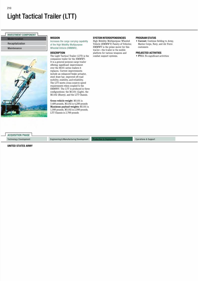
7/29/2019 Army Weapons Systems 2011
http://slidepdf.com/reader/full/army-weapons-systems-2011 220/380
UNITED STATES ARMY
ACQUISITION PHASE
RecapitalizationMaintenance
Technology Development Operations & SupportProduction & DeploymentEngineering & Manufacturing Development
Increases the cargo carrying capability
of the High Mobility MultipurposeWheeled Vehicle (HMMWV) .
DESCRIPTION The Light Tactical Trailer (LTT) is the
companion trailer for the HMMWV.
It is a general purpose cargo trailer
offering significant improvement
over the M101 series trailers it
replaces. Current improvements
include an enhanced brake actuator,
steel draw bar, improved off-road
mobility, stability, and reliability.
The LTT meets cross-country speed
requirements when coupled to the
HMMWV. The LTT is produced in three
configurations: the M1101 (Light), the
M1102 (Heavy), and the LTT Chassis.
Gross vehicle weight: M1101 is
3,400 pounds, M1102 is 4,200 pounds
Maximum payload weights: M1101 is
1,500 pounds, M1102 is 2,500 pounds,
LTT Chassis is 2,700 pounds
g ob ty u t pu pose W ee ed
Vehicle (HMMWV) Family of Vehicles;HMMWV is the prime mover for this
trai ler—the trailer is the mobile
platform for various weapons and
combat support systems.
Cu e t: Co t ue e d g to y,
Marine Corps, Navy, and Air Forcecustomers
PROJECTED ACTIVITIES• FY11: No significant activities
Light Tactical Trailer (LTT)
FOREIGN MILITARY SALES
Kenya, Afghanistan
CONTRACTORS
211

7/29/2019 Army Weapons Systems 2011
http://slidepdf.com/reader/full/army-weapons-systems-2011 221/380
WEAPON SYSTEMS 2011
CONTRACTORS
Silver Eagle Manufacturing Co. ( SEMCO)
(Portland, OR)
Schutt Industries (Clintonville, WI)
INVESTMENT COMPONENT
Light Utility Helicopter (LUH)/UH-72A Lakota
It has seating for two pilots and
up to five passengers or two NATO
In addition to the MEDEVAC and hoist
conguration, the UH-72A is also
PROGRAM STATUS• FY09: 128 aircraft on contract, with
Modernization
212
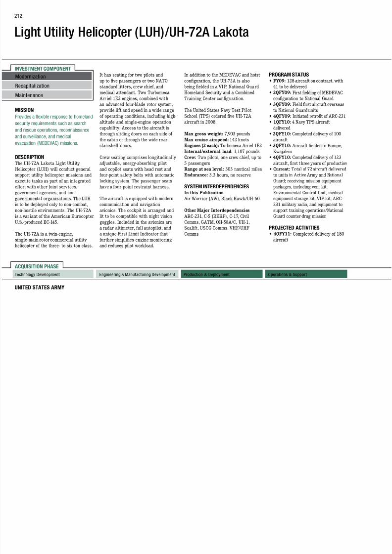
7/29/2019 Army Weapons Systems 2011
http://slidepdf.com/reader/full/army-weapons-systems-2011 222/380
UNITED STATES ARMY
ACQUISITION PHASE
Technology Development Operations & SupportProduction & DeploymentEngineering & Manufacturing Development
MISSION
Provides a flexible response to homeland
security requirements such as search
and rescue operations, reconnaissance
and surveillance, and medical
evacuation (MEDEVAC) missions.
DESCRIPTION The UH-72A Lakota Light Util ity
Helicopter (LUH) will conduct general
support utility helicopter missions and
execute tasks as part of an integrated
effort with other Joint serv ices,
government agencies, and non-
governmental organizations. The LUH
is to be deployed only to non-combat,
non-hostile environments. The UH-72A
is a var iant of the American Eurocopter
U.S.-produced EC-145.
The UH-72A is a twin-engine,
single-main-rotor commercial utility
helicopter of the three- to six-ton class.
p p g
standard litters, crew chief, andmedical attendant. Two Turbomeca
Arr iel 1E2 engines, combined with
an advanced four-blade rotor system,
provide lift and speed in a wide range
of operating conditions, including high-
altitude and single-engine operation
capability. Access to the aircraft is
through sl iding doors on each side of
the cabin or through the wide rear
clamshell doors.
Crew seating comprises longitudinally
adjustable, energy-absorbing pilot
and copilot seats with head rest and
four-point safety belts with automatic
locking system. The passenger seats
have a four-point restraint harness.
The aircraft is equipped with modern
communication and navigation
avionics. The cockpit is arranged and
lit to be compatible with night vision
goggles. Included in the avionics area radar altimeter, full autopilot, and
a unique First Limit Indicator that
further simplifies engine monitoring
and reduces pilot workload.
g
being elded in a VIP, National GuardHomeland Security and a Combined
Train ing Center conguration.
The United States Navy Test Pi lot
School (TPS) ordered ve UH-72A
aircraft in 2008.
Max gross weight: 7,903 pounds
Max cruise airspeed: 142 knots
Engines (2 each): Turbomeca Arriel 1E2
Internal/external load: 1,107 pounds
Crew: Two pilots, one crew chief, up to
5 passengers
Range at sea level: 303 nautical miles
Endurance: 3.3 hours, no reserve
SYSTEM INTERDEPENDENCIESIn this Publication
Air Warr ior (AW), Black Hawk/UH-60
Other Major Interdependencies
ARC-231, C-5 (RERP), C-17, Civil
Comms, GATM, OH-58A/C, UH-1,Sealift, USCG Comms, VHF/UHF
Comms
41 to be delivered• 2QFY09: First elding of MEDEVAC
configuration to National Guard
• 3QFY09: Field rst aircraft overseas
to National Guard units
• 4QFY09: Initiated retrot of ARC-231
• 1QFY10: 4 Navy TPS aircraft
delivered
• 2QFY10: Completed delivery of 100
aircraft
• 3QFY10: Aircraft fielded to Europe,
Kwajalein
• 4QFY10: Completed delivery of 123
aircraft, first three years of production
• Current: Total of 72 aircraft delivered
to units in Active Army and National
Guard; receiving mission equipment
packages, including vent kit,
Environmental Control Unit, medical
equipment storage kit, VIP kit, ARC-
231 military radio, and equipment to
support training operations/National
Guard counter-drug mission
PROJECTED ACTIVITIES• 4QFY11: Completed delivery of 180
aircraft
RecapitalizationMaintenance
Light Utility Helicopter (LUH)/UH-
72A Lakota
FOREIGN MILITARY SALES
None
CONTRACTORS
213

7/29/2019 Army Weapons Systems 2011
http://slidepdf.com/reader/full/army-weapons-systems-2011 223/380
WEAPON SYSTEMS 2011
CONTRACTORS
Airframe:
American Eurocopter (Columbus, MS;
Grand Prairie, TX)
CLS:
Helicopter Support, Inc. (Trumbull, CT)
American Eurocopter (Grand Prairie, TX)
Training:
American Eurocopter (Grand Prairie, TX)
CFSR:
American Eurocopter (Grand Prairie, TX)Program Management:
EADS North America (Huntsville, AL; Arlington, VA)
Helicopter Support, Inc. (Huntsville, AL;
Grand Prairie, TX)
INVESTMENT COMPONENT
XM806–Lightweight .50 cal Machine Gun
Modernization MISSION
Provides a lighter, more accurate
improved through a manual safety and
a quick change barrel that eliminates
PROGRAM STATUS• 4QFY08: Milestone B
214

7/29/2019 Army Weapons Systems 2011
http://slidepdf.com/reader/full/army-weapons-systems-2011 224/380
UNITED STATES ARMY
ACQUISITION PHASE
RecapitalizationMaintenance
Technology Development Operations & SupportProduction & DeploymentEngineering & Manufacturing Development
g
.50 caliber machine gun to reducewarfighter load, provide for more
rapid emplacement and displacement,
increase dismounted portability, and
reduce the strain on vehicle mounts.
DESCRIPTION The XM806 Lightweight .50 Ca liber
Machine Gun weighs approximately
one-half as much as a similarly
configured M2 and reduces the
recoil by at least 60 percent. This
lighter weight permits easy dismount
and ground transportability when
necessary, and the reduced recoil
permits the mounting of an optic for
greater lethality through increased
first-burst accuracy and control.
The XM806 can re all of the .50
caliber service ammunition in the
current inventory and is capable
of defeating personnel and lightlyarmored targets out to 2,000 meters.
It is designed to augment the M2
.50 caliber machine gun, but can
also be used to replace the M2 in
select operational locations. Safety is
the requirement for the operator toadjust headspace and timing.
The weapon is ideal for l ight infantry
and special operations forces, as
well as for vehicles demanding more
lethality but lighter weight.
SYSTEM INTERDEPENDENCIESNone
• 4QFY08: Initiated engineering andmanufacturing development phase
• 3QFY09: Completed three weapon
prototypes for engineering testing
• 3QFY09: Contract awarded to build
government-test assets
PROJECTED ACTIVITIES• 1QFY11: Development tests and
limited user tests
XM806–Lightweight .50 cal
Machine Gun
FOREIGN MILITARY SALES
None
CONTRACTORS
215

7/29/2019 Army Weapons Systems 2011
http://slidepdf.com/reader/full/army-weapons-systems-2011 225/380
WEAPON SYSTEMS 2011
CONTRACTORS
General Dynamics Armament and
Technical Products (Charlotte, NC)
INVESTMENT COMPONENT
Lightweight 155mm Howitzer (LW155)
Modernization MISSION
Provides direct, reinforcing, and general
Software upgrades incorporating the
Enhanced Portable Inductive Artillery
SYSTEM INTERDEPENDENCIESIn this Publication
216

7/29/2019 Army Weapons Systems 2011
http://slidepdf.com/reader/full/army-weapons-systems-2011 226/380
UNITED STATES ARMY
ACQUISITION PHASE
Technology Development Operations & SupportProduction & DeploymentEngineering & Manufacturing Development
RecapitalizationMaintenance
artillery fire support to maneuver forces.
DESCRIPTION The Lightweight 155mm Howitzer
(M777A2) will replace all M198
155mm howitzers in operation with the
Army and Marine Corps. The extensive
use of titanium in all its major
structures makes it 7,000 pounds
lighter than its predecessor, the M198,
with no sacr ifice in range, stabil ity,
accuracy, or durability, and it can be
dropped by parachute. The M777A2’sindependent suspension, smaller
footprint, and lower profile increase
strategic deployability and tactical
mobility. The system uses numerous
improvements to enhance reliability
and accuracy, and significantly
increase system survivability.
The M777A2 is jointly managed; the
Marine Corps led the development
of the howitzer and the Army led the development of Towed Arti llery
Digitization, the digital fire control
system for the M777A2.
Fuze Setter and the Excal ibur PlatformIntegration Kit hardware give the
M777A2 the capability to program and
fire the Excalibur precision-guided
munition.
Specications for the M777A2
Excalibur-compatible howitzer are:
Weight: 10,000 pounds
Emplace: Less than three minutes
Displace: Two to three minutes
Maximum range: 30 kilometer (rocket
assisted round)Rate-of-re: Four rounds per minute
maximum; two rounds per minute
sustained
Ground mobility: Family of Medium
Tactical Vehicles (FMTV), Medium
Tactical Vehicle Replacement, ve-ton
trucks
Air mobility: Two per C-130; six per C-17;
12 per C-5; CH-53D/E; CH-47D; MV-22
155mm compatibility: All fielded and
developmental NATO munitionsDigital and optical re control: Self-
locating and pointing; digital and voice
communications; self-contained power
supply
Advanced Field Ar tiller y TacticalData System (AFATDS); Ar tillery
Ammunition; Excalibur (XM982);
Family of Medium Tactical Vehicles
(FMTV); Precision Guidance Kit
(PGK); Single Channel Ground and
Airborne Radio System (SINCGARS)
Other Major Interdependencies
Army Software Blocking, Defense
Advanced Global Posit ioning System
Receiver
PROGRAM STATUS• 4QFY10: Full-rate production with a
total of 640 systems delivered to the
Army and Marine Corps (265/375
respectively)
PROJECTED ACTIVITIES• FY11: Continue full-rate production
and elding to Army, Marine Corps,
and National Guard units
• FY11: Continue Army ForceGeneration Reset and start depot
pilot overhaul
Lightweight 155mm Howitzer
(LW155)
FOREIGN MILITARY SALES
Australia and Canada
CONTRACTORS
217

7/29/2019 Army Weapons Systems 2011
http://slidepdf.com/reader/full/army-weapons-systems-2011 227/380
WEAPON SYSTEMS 2011
CONTRACTORS
Prime:
BAE Systems (Hattiesburg, MS; Barrow-
in-Furness, United Kingdom)
Cannon Assembly (GFE):
Watervliet Arsenal (Watervliet, NY)
Titanium Castings:
Precision CastParts Corp. (Portland, OR)Body:
Triumph Structures (Chatsworth, CA )
Castings:
Howmet Castings (Whitehall, MI)
INVESTMENT COMPONENT
Lightweight Laser Designator/Rangefinder (LLDR) AN/PED-1
Modernization MISSION
Provides the Soldier the ability to
more than 3 kilometers. During day
operations, targets can be recognized
PROGRAM STATUS• FY10: Fielded to units supporting
218
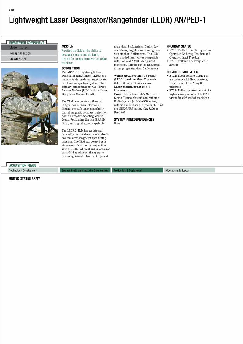
7/29/2019 Army Weapons Systems 2011
http://slidepdf.com/reader/full/army-weapons-systems-2011 228/380
UNITED STATES ARMY
ACQUISITION PHASE
RecapitalizationMaintenance
Technology Development Operations & SupportProduction & DeploymentEngineering & Manufacturing Development
accurately locate and designatetargets for engagement with precision
munitions.
DESCRIPTION The AN/PED-1 Lightweight Laser
Designator Rangefinder (LLDR) is a
man-portable, modular target locator
and laser designation system. The
primary components are the Target
Locator Module (TLM) and the Laser
Designator Module (LDM).
The TLM incorporates a thermal
imager, day camera, electronic
display, eye-safe laser rangefinder,
digital magnetic compass, Selective
Availabi lity/Anti-Spoofing Module
Global Positioning System (SAASM
GPS), and digital export capability.
The LLDR 2 TLM has an integra l
capability that enables the operator to
see the laser designator spot duringmissions. The TLM can be used as a
stand-alone device or in conjunction
with the LDM. At night and in obscured
battlefield conditions, the operator
can recognize vehicle-sized targets at
at more than 7 kilometers. The LDMemits coded laser pulses compatible
with DoD and NATO laser-g uided
munitions. Targets can be designated
at ranges greater than 5 kilometers.
Weight (total system): 35 pounds
(LLDR 1) and less than 30 pounds
(LLDR 2) for a 24-hour mission
Laser designator range: > 5
kilometers
Power: LLDR1 one BA-5699 or one
Single Channel Ground and AirborneRadio System (SINCGARS) battery
without use of laser designator; LLDR2
one SINCGARS battery (BA-5390 or
BA-5590)
SYSTEM INTERDEPENDENCIESNone
Operation Enduring Freedom andOperation Iraqi Freedom
• FY10: Follow-on delivery order
awards
PROJECTED ACTIVITIES• FY11: Begin fielding LLDR 2 in
accordance with Headquarters,
Department of the Army G8
priorities
• FY11: Follow-on procurement of a
high accuracy version of LLDR to
target for GPS guided munitions
Lightweight Laser Designator Range
Finder (LLDR) AN/PED-1
FOREIGN MILITARY SALES
None
CONTRACTORS
219

7/29/2019 Army Weapons Systems 2011
http://slidepdf.com/reader/full/army-weapons-systems-2011 229/380
WEAPON SYSTEMS 2011
Northrop Grumman Laser Systems
(Apopka, FL)
INVESTMENT COMPONENT
Line Haul Tractor
Modernization Brake system: Anti-lock brake system
(ABS)
Gross vehicle weight: 52,000 pounds
Fifth-wheel capacity: two-inch, 30,000
Corps units, primarily the construction
and combat support companies and
220

7/29/2019 Army Weapons Systems 2011
http://slidepdf.com/reader/full/army-weapons-systems-2011 230/380
UNITED STATES ARMY
ACQUISITION PHASE
Technology Development Operations & SupportProduction & DeploymentEngineering & Manufacturing Development
RecapitalizationMaintenance
MISSION
Supports combat service and support
units with transportation of bulk
petroleum products, containerized cargo,
general cargo, and bulk water.
DESCRIPTION The M915A5 Truck Tractor is a 6x4
semi-tractor used to perform the Line Haul
mission. The M915A5 is a block upgrade
of the M915A3 system, incorporating
enhanced suspension and power train
components. This block upgrade a llows the
M915A5 to readi ly accept armor packages
without reducing mission capability.
Gross vehicle weight rating: 120,000
pounds
Unarmored Gross vehicle weight:
26,500 pounds Armored Gross vehicle weight: 33,500
pounds
Fifth-wheel capacity: six-inch, 30,000
pounds
Diagnosis: Electronic
Towing speed: 65 miles per hour withfull payload
Engine: Detroit Diesel S60 (500 horse
power, 1650 pound-foot torque, DDEC IV
engine controller)
Transmission : Allison HD4500SP (six-
speed automatic)
The M915A5 truck is equipped with a
two-passenger cab and has an updated
power distribution module, upgraded wiring
harnesses, and a Roll Stability Control
system. Auxiliary power connections have
been added to supply emerging systems and
added command, control, communications,
computers, and intelligence communication
systems. A pair of 60-gallon fuel tanks
increase fuel capacity by 20 gallons to
extend driving range. The cab is ten inches
wider and extends 34 inches behind the
driver and passenger seats. The vehicle has
an improved ABS and an updated collision
warning system.
The M915A3 Line Haul Tractor is the
Army’s key line haul distribution platform.
It is a 6x4 tractor with a two-inch kingpin
and 105,000-pound gross combination
weight capacity.
poundsDiagnosis: Electronic
Brake system: ABS
Towing speed: 65 miles per hour with
full payload
Engine: Detroit Diesel S60 (430 horse
power, 1,450 pound-foot torque, DDEC IV
engine controller)
Transmission : Allison HD5460P (six-
speed automatic) with power take-off
The M916A3 Light Equipment Transport
(LET) is a 6x6 tractor with 68,000-pound
gross vehicle weight tractor with
3-1/2-inch, 40,000-pound capacity,
45,000-pound winch for recovery and
transport and compensator fifth wheel. It
has an electronic diesel engine, automatic
electronic transmission, ABS and is
capable of operating at speeds up to 60
miles per hour on flat terrain. This Non-
Developmental Item (NDI) vehicle is used
primarily to transport the M870 40-ton
low-bed semi-trailer.
The M917A2 and M917A2 Truck Chassis,
75,000 gross vehicle weight rating, 8x6
(for 20-ton dump truck), 12-cubic yard
dump truck vehicles are authorized in
the combat heavy battalions. It hasan electronic diesel engine, automatic
electronic transmission, ABS, and is
capable of operating at speeds up to 55
miles per hour on flat terrain.
SYSTEM INTERDEPENDENCIESIn this Publication
Joint Land Attack Cruise Missile Defense
Elevated Netted Sensor (JLENS)
Other Major Interdependencies
M872, 34-ton atbed semi-trailer;
M1062A1, 7,500-gallon semi-t railer;
M967/M969, 5,000-gallon semi-trailer
PROGRAM STATUS• FY10: Full production continues in
support of Army operations in the
United States and abroad
PROJECTED ACTIVITIES• 1QFY11: M915A5 type classification/
materiel release; production cut-in,ramp-up, and first unit equipping
Line Haul Tractor
FOREIGN MILITARY SALES
Afghanistan
CONTRACTORS
221

7/29/2019 Army Weapons Systems 2011
http://slidepdf.com/reader/full/army-weapons-systems-2011 231/380
WEAPON SYSTEMS 2011
Prime:
Daimler Trucks North America LLC /
Freightliner (Portland, OR ; Cleveland, NC)
Engine:
Detroit Diesel (Detroit, MI)
ABS Brakes:
Meritor (Troy, MI)Dump body:
Casteel Manufacturing (San Antonio, TX)
INVESTMENT COMPONENT
Load Handling System Compatible Water Tank Rack (Hippo)
Modernization MISSION
Enhances and expedites the delivery
The Hippo is ful ly functiona l, mounted
or dismounted, and is air t ransportable
PROGRAM STATUS• 2QFY07: Full materiel release
222

7/29/2019 Army Weapons Systems 2011
http://slidepdf.com/reader/full/army-weapons-systems-2011 232/380
UNITED STATES ARMY
ACQUISITION PHASE
RecapitalizationMaintenance
Technology Development Operations & SupportProduction & DeploymentEngineering & Manufacturing Development
of bulk potable water into the divisionand brigade areas, providing the Army
with the capability to receive, store,
and distribute potable water to units
deployed throughout the battlefield.
DESCRIPTION The Load Handling System (LHS)
Compatible Water Tank Rack (Hippo)
represents the latest in bulk water
distribution systems technology. It
replaces the 3,000 and 5,000 Semi- trai ler Mounted Fabric Tanks. The
Hippo consists of a 2,000-gallon
potable water tank in an International
Organization for Standardization
frame with a n integrated pump,
engine, alternator, fill ing stand, and
70-foot hose reel with bulk suction and
discharge hoses. It has the capacity to
pump 125 gallons of water per minute.
and ground transportable when full,partia lly full, or empty. It is Heavy
Expanded Mobility Tactical Truck
(HEMTT)-LHS, Palletized Load
System (PLS)- and PLS-Trailer-
compatible, and designed to operate
in cold weather environments and can
prevent water from freezing at -25
degrees Fahrenheit. The Hippo can be
moved, set up, and established rapidly
using minimal assets and personnel.
No site preparation by engineer
assets is required, and its modularconfiguration supports Expeditionary
Joint Forces Operations.
SYSTEM INTERDEPENDENCIESHEMTT-LHS, PLS, and PLS Trailer
• 1QFY08: Production and fielding• 4QFY08: Additional quantit ies
placed on contract
• FY09: Updated integrated electronic
technica l manuals
• FY10: Continue production and
fielding with 625 systems fielded as
of July 30, 2010
PROJECTED ACTIVITIES• FY11 and beyond: Continue
production and fielding

7/29/2019 Army Weapons Systems 2011
http://slidepdf.com/reader/full/army-weapons-systems-2011 233/380
INVESTMENT COMPONENT
Longbow Apache (AH-64D) (LBA)
Modernization Acquisit ion Designation Sight/Pilot Night
Vision Sensor (MTADS/PNVS) is a major
armed reconnaissance battalions, and
cavalry units as defined in the Ar my
SYSTEM INTERDEPENDENCIES2.75 Inch Rocket Systems (Hydra), Air
224
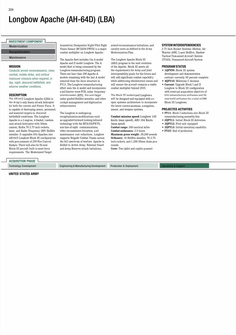
7/29/2019 Army Weapons Systems 2011
http://slidepdf.com/reader/full/army-weapons-systems-2011 234/380
UNITED STATES ARMY
ACQUISITION PHASE
Technology Development Operations & SupportProduction & DeploymentEngineering & Manufacturing Development
RecapitalizationMaintenance
MISSION
Conducts armed reconnaissance, close
combat, mobile strike, and vertical
maneuver missions when required, in
day, night, obscured battlefield, and
adverse weather conditions.
DESCRIPTION The AH-64 D Longbow Apache (LBA) is
the Army’s only heavy att ack helicopter
for both the current and Future Force. It
is capable of destroying armor, personnel,
and materiel targets in obscured
battlefield condi tions. The Longbow
Apache is a 2-engine, 4-bladed, tandem-
seat attack helicopter with 30mm
cannon, Hydra 70 2.75 inch rockets,
laser, and Radio Frequency (RF) Hellre
missiles. It upgrades 634 Apaches into AH-64D Longbow Block III congurat ion
with procurement of 259 Fire Control
Radars. There will also be 56 new
Block III aircraft built to meet force
requirements. The Modernized-Target
combat multiplier on Longbow Apache.
The Apache fleet includes the A model
Apache and D model Longbow. The A
model fleet is being consumed by the
Longbow remanufacturing program.
There are less t han 100 Apache A
models remaining with the last A model
removed from the force structure in
FY13. The Longbow remanufacturing
effort uses the A model and incorporates
a mil limeter-wave FCR, radar frequency
interferometer (RFI), re-and-forgetradar-guided Hellre missiles, and other
cockpit management and digitization
enhancements.
The Longbow is undergoing
recapitalization modifications such
as upgraded forward-looking infrared
technology w ith the MTA DS/PN VS,
non-line-of-sight communications,
video tra nsmission /reception, a nd
maintenance cost reductions. Longbowsupports Brigade Combat Teams across
the ful l spectrum of warfare. Apache is
fielded to Active Army, National Guard
and Army Reserve attack battalions,
Modernization Plan.
The Longbow Apache Block III
(AB3) program is the next evolution
of the Apache. Block III meets all
the requirements for Army and Joint
interoperability goals for the future and
will add significant combat capability
while addressing obsolescence issues and
will ensure the ai rcraf t remains a viable
combat multiplier beyond 2035.
The Block III modern ized Longbows will be designed and equ ipped with a n
open systems architecture to incorporate
the latest communications, navigation,
sensor, and weapon systems.
Combat mission speed: Longbow 145
knots (max speed); AB3 164 Knots
(max speed)
Combat range: 260 nautical miles
Combat endurance: 2.5 hours
Maximum gross weight: 20,260 poundsOrdnance: 16 Hellre missiles, 76 2.75-
inch rockets, and 1,200 30mm chain gu n
rounds
Crew: Two (pilot and copilot gunner)
Warrior (AW), L aser Hellre, Shadow Tactical Unmanned Ai rcraf t System
(TUAS), Unmanned Aircraft System
PROGRAM STATUS• 1QFY09: Block III system
development and demonstration
contract currently 50 percent complete
• 4QFY10: Milestone C decision
• Current: Upgrade Block I and II
Longbow to Block III configuration
with eventual acquisition object ive of
634 remanufacture airframes and 56new build airframes for a total of 690
Block III Longbows
PROJECTED ACTIVITIES• FY11: Block I inductions into Block III
remanufacturing assembly line
• 2QFY11: Initial Block III deliveries
• 3QFY12: First unit equipped
• 2QFY13: Initial operating capability
• FY25: End of production
Longbow Apache (AH-64D) (LBA)
FOREIGN MILITARY SALES
Egypt, Greece, Israel, Kuwait, Netherlands,
Saudi Arabia, Singapore, United Arab
Emirates
225

7/29/2019 Army Weapons Systems 2011
http://slidepdf.com/reader/full/army-weapons-systems-2011 235/380
WEAPON SYSTEMS 2011
Direct commercial sales: Greece, Japan,
United Kingdom
CONTRACTORS
Airframe: Boeing (Mesa, AZ)
MTADS: Lockheed Martin (Orlando, FL)
REU: Lockheed Martin (Orlando, FL)
Northrop Grumman (Linthicum, MD)
APU: Honeywell (Phoenix, AZ)
Technical: Aviation and Missile Solutions,
LLC (Huntsville, AL)
FCR: Longbow LLC (Orlando, FL)Radar: Northrop Grumman
(Linthicum, MD)
Logistics: AEPCO (Huntsville, AL)
TADS/PNVS: Lockheed Martin
(Goodyear, AZ)
Programmatics: DynCorp
(Fort Worth, TX)EGI: Honeywell (Clearwater, FL)
LRUs: Smiths (Clearwater, FL)
IPAS: Honeywell (Tempe, AZ )
INVESTMENT COMPONENT
Medical Communications for Combat Casualty Care (MC4)
R i li i
Modernization MISSION
Integrates, fields, and supports a
h i di l i f i
resuscitation information. The system
also provides units with automated tools
f ili i i ki di l
used, comprehensive information
management medical system on
h b l fi ld
226
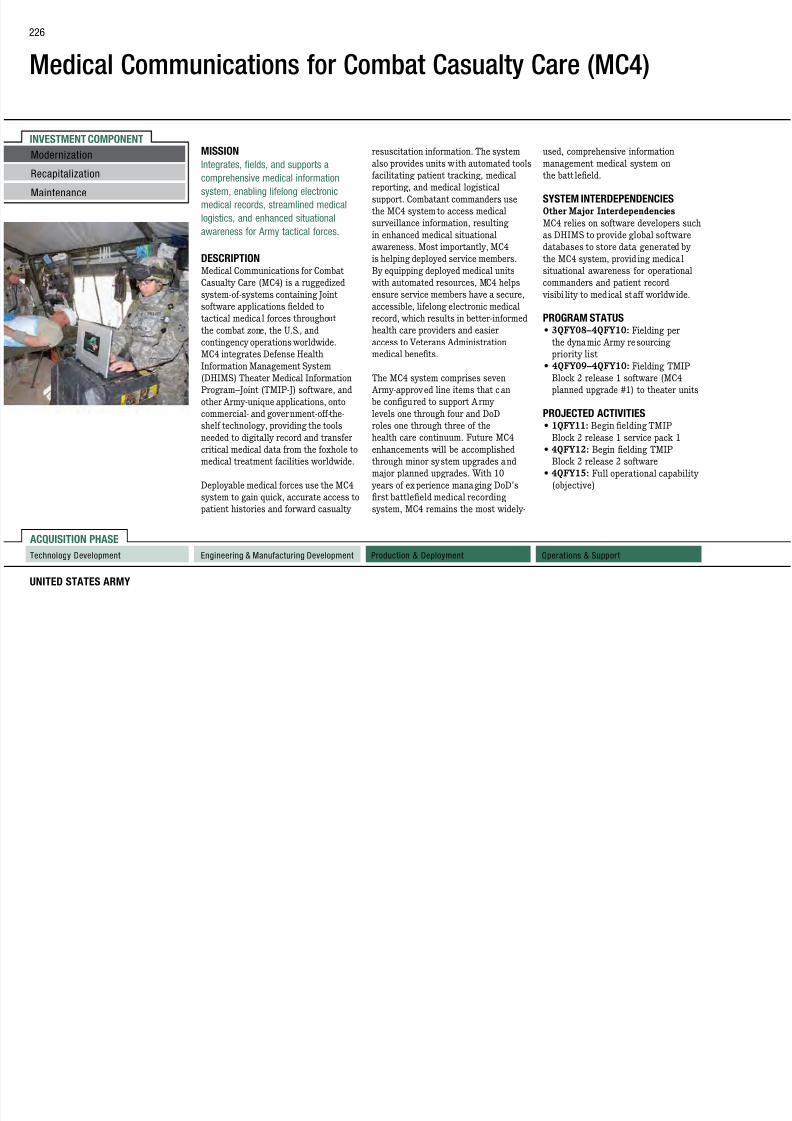
7/29/2019 Army Weapons Systems 2011
http://slidepdf.com/reader/full/army-weapons-systems-2011 236/380
UNITED STATES ARMY
ACQUISITION PHASE
Technology Development Operations & SupportProduction & DeploymentEngineering & Manufacturing Development
RecapitalizationMaintenance
comprehensive medical informationsystem, enabling lifelong electronic
medical records, streamlined medical
logistics, and enhanced situational
awareness for Army tactical forces.
DESCRIPTIONMedical Communications for Combat
Casualty Care (MC4) is a ruggedized
system-of-systems containing Joint
software applications fielded to
tactical medical forces throughout the combat zone, the U.S., and
contingency operations worldwide.
MC4 integrates Defense Health
Information Management System
(DHIMS) Theater Medical Information
Program–Joint (TMIP-J) software, and
other Army-unique applications, onto
commercial- and government-off-the-
shelf technology, providing the tools
needed to digitally record and transfer
critical medical data from the foxhole to
medical treatment facilities worldwide.
Deployable medical forces use the MC4
system to gain quick, accurate access to
patient histories and forward casualty
facilitating patient tracking, medicalreporting, and medical logistical
support. Combatant commanders use
the MC4 system to access medical
surveillance information, resulting
in enhanced medical situational
awareness. Most importantly, MC4
is helping deployed service members.
By equipping deployed medical units
with automated resources, MC4 helps
ensure service members have a secure,
accessible, lifelong electronic medical
record, which results in better-informedhealth care providers and easier
access to Veterans Administration
medical benefits.
The MC4 system comprises seven
Army-approved line items that can
be configured to support Army
levels one through four and DoD
roles one through three of the
health care continuum. Future MC4
enhancements will be accomplished
through minor system upgrades and
major planned upgrades. With 10
years of experience managing DoD’s
first battlefield medical recording
system, MC4 remains the most widely-
the batt lefield.
SYSTEM INTERDEPENDENCIESOther Major Interdependencies
MC4 relies on software developers such
as DHIMS to provide global software
databases to store data generated by
the MC4 system, provid ing medical
situational awareness for operational
commanders and patient record
visibi lity to medical staff worldwide.
PROGRAM STATUS• 3QFY08–4QFY10: Fielding per
the dynamic Army resourcing
priority list
• 4QFY09–4QFY10: Fielding TMIP
Block 2 release 1 software (MC4
planned upgrade #1) to theater units
PROJECTED ACTIVITIES• 1QFY11: Begin fielding TMIP
Block 2 release 1 service pack 1
• 4QFY12: Begin fielding TMIP
Block 2 release 2 software
• 4QFY15: Full operational capability
(objective)
Medical Communications for
Combat Casualty Care (MC4)
FOREIGN MILITARY SALES
None
CONTRACTORS
H d
227

7/29/2019 Army Weapons Systems 2011
http://slidepdf.com/reader/full/army-weapons-systems-2011 237/380
WEAPON SYSTEMS 2011
Hardware:Telos Corp. (Ashburn, VA)
Dell Federal Systems (Round Rock, TX)
System Engineering Support:
Johns Hopkins University Applied Physics
Laboratory (Laurel, MD)
System Integration Support:
L-3 Communications (Reston, VA)
Fielding, Training, and System
Administration Support :
General Dynamics (Fairfax, VA)

7/29/2019 Army Weapons Systems 2011
http://slidepdf.com/reader/full/army-weapons-systems-2011 238/380
Medical Simulation Training Center
(MSTC)
FOREIGN MILITARY SALES
None
CONTRACTORS
Medical Education Technologies
229

7/29/2019 Army Weapons Systems 2011
http://slidepdf.com/reader/full/army-weapons-systems-2011 239/380
WEAPON SYSTEMS 2011
Medical Education Technologies(Sarasota, FL)
Computer Sciences Corp. (CSC)
(Orlando, FL)
INVESTMENT COMPONENT
Medium Caliber Ammunition (MCA)
Recapitalization
Modernization MISSION
Provides overwhelming lethality in
medium caliber ammunition and
the M203 Grenade Launcher, M320
Grenade Launcher, and the MK19
Grenade Machine Gun
PROGRAM STATUS• Current: In production
230

7/29/2019 Army Weapons Systems 2011
http://slidepdf.com/reader/full/army-weapons-systems-2011 240/380
UNITED STATES ARMY
ACQUISITION PHASE
Technology Development Operations & SupportProduction & DeploymentEngineering & Manufacturing Development
RecapitalizationMaintenance
medium caliber ammunition andpoint- and area-target engagement via
medium handheld and crew-served
weapons.
DESCRIPTIONMedium caliber ammunition includes
20mm, 25mm, 30mm, and 40mm
armor-piercing, high-explosive,
smoke, illumination, training, and
antipersonnel cartr idges with the
capability to defeat light armor,materiel, and personnel targets. The
20mm cartridge is a multi-purpose
tracer with self destruct, used in the
Counter Rocket, Arti llery, and Mortar
(C-RAM) weapon system. The 25mm
target practice (TP), high explosive
incendiary and armor-piercing
cartr idges are red from the M242
Bushmaster Cannon for the Bradley
Fighting Vehicle. The 30mm TP and
high explosive-dual purpose (HEDP)
cartr idges are used in the Apache
helicopter’s M230 Chain Gun. A variety
of 40mm TP, HEDP, and specialty
cartr idges are designed for use in
Grenade Machine Gun.
SYSTEM INTERDEPENDENCIESOther Major Interdependencies
Medium caliber ammunition is
dependent upon the weapons platforms
currently in use.
PROJECTED ACTIVITIES• FY11: Multiple year family buys
for 25mm, 30mm, and 40mm
ammunition
Medium Caliber Ammunition (MCA)
FOREIGN MILITARY SALES
25mm:
Israel, Philippines
30mm:
Egypt Israel Japan Kuwait Netherlands
231

7/29/2019 Army Weapons Systems 2011
http://slidepdf.com/reader/full/army-weapons-systems-2011 241/380
WEAPON SYSTEMS 2011
Egypt, Israel, Japan, Kuwait, Netherlands,Serbia, Taiwan, United Arab Emirates
40mm:
Afghanistan, Canada, Greece, Israel,
Japan, Kenya, Philippines, Tunisia
CONTRACTORS
General Dynamics Ordnance and Tactical
Systems (Marion, IL; Red Lion, PA)
Alliant Techsystems (Radford, VA;
Rocket City, WV)
AMTEC Corp. (Janesville, WI;Camden, AR)
DSE (Balimoy) Corp. (Tampa, FL;
Gaffney, SC)
American Ordnance (Milan, TN;
Burlington, IA)
INVESTMENT COMPONENT
Medium Extended Air Defense System (MEADS)
entry operations. MEADS also has the
mobility to displace rapidly and protect
maneuver force assets during offensivei N d di ib d
and missile defense (AMD) TOC,
leveraging modular battle elements and
a distributed and open architecturef i li i h f
PROGRAM STATUS• 4QFY08–4QFY10: Incremental
critical design review phaseRecapitalization
Modernization
232

7/29/2019 Army Weapons Systems 2011
http://slidepdf.com/reader/full/army-weapons-systems-2011 242/380
UNITED STATES ARMY
ACQUISITION PHASE
Technology Development Operations & SupportProduction & DeploymentEngineering & Manufacturing Development
MISSION
Defends maneuver forces and critical
assets against the theater ballistic
missile, cruise missile, and air-breathing
threats in contingency and mature
theaters.
DESCRIPTION The Medium Extended Air Defense
System (MEADS) provides a robust,
360-degree defense using the PATRIOT
PAC-3 hit-to-kill missile segment
enhancement (MSE) against the full
spectrum of theater ball istic missiles,
anti-radiation missiles, cruise missiles,
unmanned aerial vehicles, tactical
air-to-surface missiles, and rotary-and
fixed-wing threats. MEADS will also
provide defense against multiple and
simultaneous attacks by short-range
ball istic missi les, low-radar cross-
section cruise missiles, and other
air-breathing threats. MEADS can be
immediately deployed by a ir for early
maneuver force assets during offensiveoperations. Netted, distributed, open
architecture, and modular components
are utilized in the MEADS to increase
survivability and flexibility of use in a
number of operational configurations.
The PAC-3 MSE improves upon the
current missile configuration ranges/
altitudes and improves performance
against maneuvering threats.
The MEADS weapon system will
use its netted and distributedarchitecture to ensure Joint and
allied interoperability, and to enable
a seamless interface to the next
generation of battle management
command, control, communications,
computers, and intelligence (BMC4I).
The system’s improved sensor
components and its ability to link other
airborne and ground-based sensors
facilitate the employment of its battle
elements.
The MEADS weapon system’s
objective battle management tactical
operations center (TOC) wi ll provide
the basis for the future common air
a distributed and open architecture to faci litate cont inuous exchange of
information to support a more effective
AMD system-of-systems.
SYSTEM INTERDEPENDENCIESIn this Publication
Integrated Air and Missile Defense
(IAMD), Joint Land Attack Cruise
Missile Defense Elevated Netted Sensor
System (JLENS), Joint Tactical Ground
Stations (JTAGS), PATRIOT Advanced
Capability–Three (PAC-3), SurfaceLaunched Advanced Medium Range
Air-To-Air Missi le (SLAMR AAM),
Warfighter Information Network–
Tactical (WIN-T) Increment 1, WIN-T
Increment 2, WIN-T Increment 3
Other Major Interdependencies
AEGIS, AWACS, DSP, E-2C, IAMD,
MSE, PEO Integration, RIVET-JOINT,
THAA D MDA–Sea Based Termina l,
BMDS, C-130J, C-17, CH-47F, JTRS
(WNW), Link 16
critical design review phase
PROJECTED ACTIVITIES• FY11: System program review
• 3QFY11: Prototype Multifunction
Fire Control Radar delivery to
testing
• 1QFY12: First MSE launch
Maintenance
Medium Extended Air Defense
System (MEADS)
FOREIGN MILITARY SALES
None
CONTRACTORS
D&D Contract:
233

7/29/2019 Army Weapons Systems 2011
http://slidepdf.com/reader/full/army-weapons-systems-2011 243/380
WEAPON SYSTEMS 2011
D&D Contract:MEADS, Intl. (Syracuse, NY; Orlando, FL;
Huntsville, AL)
Lockheed Martin (Grand Prairie, TX)PM/SYS:
Government (Statewide, AL)
MSE:
Lockheed Martin (Grand Prairie, TX)
Security/Exciter:
Lockheed Martin (Grand Prairie, TX)SETA:
Intuitive Research and Technology(Huntsville, AL)
INVESTMENT COMPONENT
Meteorological Measuring Set–Profiler (MMS-P)
Recapitalization
Modernization MISSION
Provides on-demand, real-time
meteorological data over an extended
targeting and termina l guida nce of
var ious munitions. Profiler transmits
this data to indi rect fire d irectiont f i d l i th fi i
SYSTEM INTERDEPENDENCIESOther Major Interdependencies
Navy Operational Global AtmosphericP di ti S t Gl b l B d t
234

7/29/2019 Army Weapons Systems 2011
http://slidepdf.com/reader/full/army-weapons-systems-2011 244/380
UNITED STATES ARMY
ACQUISITION PHASE
Maintenance
Technology Development Operations & SupportProduction & DeploymentEngineering & Manufacturing Development
meteorological data over an extendedbattlespace.
DESCRIPTION The AN/TMQ-52 Meteorological
Measuring Set–Profiler (MMS-P)
uses a suite of meteorological
sensors, meteorological data from
satellites, and an advanced mesoscale
atmospheric model to provide highly
accurate meteorological data for
indirect fire art illery forces. The
system uses common hardware,software, and operating systems and
is housed in a command post platform
shelter and transported on an M1152A
High Mobility Multipurpose Wheeled
Vehicle (HMMWV).
The mesoscale atmospheric model
receives large-scale atmospheric data
from the Air Force Weather Agency
and other meteorological sensors, and
produces a vertical profile of wind
speed and direction, temperature,
relative humidity, cloud base height,
type precipitat ion, and horizontal
visibi lity in the target area, a ll of
which are necessa ry for precise
this data to indi rect fire d irectioncenters for use in developing the firing
solution.
This new capabi lity i ncreases the
lethality of all field artillery platforms
such as the Multiple Launch Rocket
System, Paladin, and self-propelled
or towed howitzers by increasing the
probability of first-round hit, resulting
in significant ammunition cost savings
for the Army. The current Profiler
provides meteorological coverage throughout a 60-ki lometer radius,
while the follow-on Block III va riant
extends coverage up to 500 kilometers.
MMS-P replaces the Army’s current
Meteorological Measuring Set,
AN/TMQ-41. For the rst time,
Army field arti llery systems can
apply meteorological data along the
trajector y from the fir ing platform to
the target area .
Navy Operational Global AtmosphericPrediction System, Global Broadcast
System
PROGRAM STATUS• 1QFY05–Present: Completed
production of the Army Authorization
Objective of 108 systems, 96 of which
were fielded to Maneuver Brigade
Combat Teams, Fire Brigades, and
the training base
PROJECTED ACTIVITIES• 1QFY11–4QFY17: Complete
fielding of the system to Army
units; develop Profiler Block III
to reduce the system footprint
and leverage technology and
software advancements to achieve
improvements in accuracy
Meteorological Measuring
Set–Profiler (MMS-P)
FOREIGN MILITARY SALES
None
CONTRACTORS
Smiths Detection Inc (Edgewood MD)
235

7/29/2019 Army Weapons Systems 2011
http://slidepdf.com/reader/full/army-weapons-systems-2011 245/380
WEAPON SYSTEMS 2011
Smiths Detection, Inc. (Edgewood, MD)Pennsylvania State University
(University Park, PA)
INVESTMENT COMPONENT
Mine Protection Vehicle Family (MPVF)
Recapitalization
Modernization Future Engineer Force (FEF) clearance
companies in route and area clearance
operations, explosive hazards teamsin explosive hazards reconnaissance
The MPCV provides deployed
forces with an effective and reliable
blast-protected vehicle capable ofinterrogating and classifying suspected
PROJECTED ACTIVITIESMMPV:
• 4QFY11: Full materiel release/typeclassification standard and full rate
236

7/29/2019 Army Weapons Systems 2011
http://slidepdf.com/reader/full/army-weapons-systems-2011 246/380
UNITED STATES ARMY
ACQUISITION PHASE
Technology Development Operations & SupportProduction & DeploymentEngineering & Manufacturing Development
Maintenance
MISSION
Provides blast-protected platforms
capable of locating, interrogating,
and classifying suspected explosive
hazards, including improvised explosive
devices (IEDs) .
DESCRIPTION The Mine Protect ion Vehicle Family
(MPVF) consists of the Medium Mine
Protected Vehicle (MMPV), the Vehicle
Mounted Mine Detection (VMMD)
system, and the Mine Protected
Clearance Vehicle (MPCV). Each of
the systems in the MPVF has a blast-
deecting, V-shaped hull, and each
conducts specific missions.
The MMPV system is a blast-protected
command and control vehicle platform
that operates in explosive hazardous
environments and is adaptable to
a wide range of security and force
protection activities. It will support
operations, explosive hazards teamsin explosive hazards reconnaissance
operations, and explosive ordinance
disposal (EOD) companies in support
operations. The MMPV will also
support Chemical Biological Response
Teams and Prophet signals intel ligence
(SIGINT) systems.
The VMMD is a blast-protected,
vehicle-mounted mine-detection
and lane-proofing system capable
of finding and marking metallicexplosive hazards, including metallic-
encased IEDs and anti-tank mines
on unimproved roads. It consists of
two towing/mine detection “Husky”
vehicles, and a set of three mine
detonation trailers (MDTs). The Husky
detection platform detects, locates, and
marks suspected metallic explosive
hazards over a three-meters-wide
path. The Husky provides protection
against mine blasts under the wheels
and under the centerline, in addition to
ball istic protect ion of the operator cab.
The system is designed to be repairable
in the field after a mine blast.
blast protected vehicle capable ofinterrogating and classifying suspected
explosive hazards, including IEDs. The
MPCV has an articulating arm with a
digging/lif ting attachment and camera
to remotely interrogate a suspected
explosive hazard and allow the crew
to confirm, deny, and/or classify
the explosive hazard. It provides a
blast-protected platform to t ransport
Soldiers and allow them to dismount
to mark and/or neutral ize explosive
hazards.
SYSTEM INTERDEPENDENCIESNone
PROGRAM STATUS• 3QFY07: Milestone C, type
classification-generic, and low-rate
initial production (LRIP) for VMMD
• 1QFY08: Milestone C, t ype
classification-generic, and LRIP for
MMPV
• 1QFY08: Milestone C, t ype
classification-generic, and LRIP for
MPCV
4QFY11: Full materiel release/typeclassification standard and full-rate
production decision
• 1QFY12: First unit equipped
MPCV:
• 4QFY11: Full materiel release/type
classification standard and full-rate
production decision
• 1QFY12: First unit equipped
VMMD:
• 1QFY11: Full materiel release/type
classification standard and full-rate
production decision• 1QFY12: First unit equipped
Mine Protection Vehicle Family
(MPVF)
FOREIGN MILITARY SALES
MPCV:
United Kingdom
VMMD:
Canada
237

7/29/2019 Army Weapons Systems 2011
http://slidepdf.com/reader/full/army-weapons-systems-2011 247/380
WEAPON SYSTEMS 2011
Canada
CONTRACTORS
MMPV:
BAE Systems (York, PA)
MPCV:
Force Protection Industries, Inc.
(Ladson, SC)
VMMD:
Critical Solutions International, Inc.
(Dallas, TX)
INVESTMENT COMPONENT
Mine Resistant Ambush Protected Vehicles (MRAP)
Recapitalization
Modernization 60,000 pounds, with payloads ranging
from 1,000 to 18,000 pounds. Key
components (e.g., transmissions,
engines) vary between vehicles and
• MRA P All Terrain Vehicle
(M-ATV): Carr ies four Soldiers
plus a gunner. Supports small-unit
combat operations in complex and
• 1QFY08–2QFY09: Upgrading
vehicles to meet emerging threats,
enhance survivability, vehicle
mobility and improve automotive
238

7/29/2019 Army Weapons Systems 2011
http://slidepdf.com/reader/full/army-weapons-systems-2011 248/380
UNITED STATES ARMY
ACQUISITION PHASE
Maintenance
Technology Development Operations & SupportProduction & DeploymentEngineering & Manufacturing Development
MISSION
Provides tactical mobility for warfighters
with multimission platforms capable
of mitigating the effects of improvised
explosive devices (IEDs), underbody
mines, and small arms fire threats.
DESCRIPTION The Joint Mine Resistant Ambush
Protected (MRAP) Vehicle Program
(JMVP) is a multi-service program
currently supporting the Army, Navy,
Marine Corps, Air Force, and the U.S.
Special Operations Command. The
program procures, tests, i ntegrates,
fields, and supports highly survivable
vehicles that prov ide protection
from IEDs and other threats. These
four- to six-wheeled vehicles are
configured with government furnished
equipment to meet unique warfighting
requirements. Vehicle combat weights
(fully loaded without add-on armor)
range from approximately 34,000 to
engines) vary between vehicles and
manufacturers, but generally consist
of common commercial and mil itary
parts.
Four categories of vehicles support the
following missions:
• Category (CAT) I: Carries four to
six passengers. Designed to provide
increased mobility and reliability in
rough terrain.
• CAT II: Multimission operations(such as convoy lead, troop
transpor t, and ambulance). Carries
10 passengers.
• CAT III: Mine/IED clearance
operations and explosive ordnance
disposal (EOD); carries six
passengers, plus specialized
equipment to support EOD
operations; the Force Protection
Industries Buffalo is the only CAT III
variant. This is the largest MRAP
vehicle.
combat operations in complex and
highly restricted rura l, mountainous,
and urban terrains. The M-ATV
provides better overall mobility
characteristics than the original
CAT I, II, and III MRAP vehicles
yet reta ins the same sur vivabi lity
threshold.
SYSTEM INTERDEPENDENCIESOther Major Interdependencies
MRAP vehicles are equipped withmultiple GFE items, including
communications equipment, mine
and IED counter-measure equipment,
in addition to weapons and crew
protection systems.
PROGRAM STATUS• 3QFY07–1QFY11: Produce and field
MRAP vehicles to Army, Marine
Corps, Air Force, Navy, U.S. Special
Operations and foreign militar y sales
customers
mobility, and improve automotive
performance by incorporating
engineering changes in current
production, planned orders, and
fielded vehicles
• 2QFY08: Initiated capabilities
insertion program to provide
enhanced rocket-propelled grenade
protection, integration of remote
weapon system, increased vehicle
power and enhanced command,
control, communications, computers,and intelligence capability
PROJECTED ACTIVITIES• 1QFY11: Production and fielding of
MRAP vehicles complete based on
current requirements
• 2QFY11: Begin modernization of
MRAP vehicles returning from
theater in preparation for transition
to enduring force requirements
Mine Resistant Ambush Protected
Vehicles (MRAP)
FOREIGN MILITARY SALES
Canada, France, Italy, United Kingdom
CONTRACTORS
BAE Systems Land & Armaments, Ground
239

7/29/2019 Army Weapons Systems 2011
http://slidepdf.com/reader/full/army-weapons-systems-2011 249/380
WEAPON SYSTEMS 2011
y ,Systems Division (York, PA)
BAE-TVS (Sealy, TX)
Force Protection Industries, Inc.
(Ladson, SC)
General Dynamics Land Systems, Canada
(Ontario, Canada)
Navistar Defense (Warrenville, IL)
Oshkosh Corp. (Oshkosh, WI)
INVESTMENT COMPONENT
Mobile Maintenance Equipment Systems (MMES)
Recapitalization
Modernization
M i t
enclosure mounted on a M113/M1152
High Mobility Multi-Purpose Wheeled
Vehicle (HMMWV ).
Organization for Standardization 8x8x20
containers that can be mounted on a flat
rack or a trailer. The system contains an
electric power generator, Environmental
in the Army. Repairs may be performed in
all weather, climatic, and l ight conditions.
The SEW integrates commercial off-the-
shelf and NDI components in an enclosure
240
7/29/2019 Army Weapons Systems 2011
http://slidepdf.com/reader/full/army-weapons-systems-2011 250/380
UNITED STATES ARMY
ACQUISITION PHASE
Technology Development Operations & SupportProduction & DeploymentEngineering & Manufacturing Development
Maintenance
MISSION
Repairs battle-damaged combat systems
on site and up through the direct support
level in the forward battle area.
DESCRIPTION The Mobile Maintenance Equipment
System (MMES) employs a system-
of-systems approach to provide two-level maintenance capabilit y to
the warghter. Five interconnected
maintenance systems distributed
throughout the Ar my at multiple levels
and echelons provide a holistic repair
capability in all environments.
Shop Equipment Contact Maintenance
(SECM) is a rst responder providing
immediate field-level maintenance and
repair to battle-damaged g round support
and aviation equipment. The SECM
has industrial quality tools, light duty
cutting and welding equipment, and an
on-board compressor and power inverter.
The system consists of a fabricated
Forward Repair System (FRS) is a h igh-
mobility, forward maintenance and repair
system. The FRS places industrial-grade
power tools, diagnostic test equipment,
35 kW generator, and heavy li ft capability
in one package. The FRS is congured
with a 5.5 ton lift capacity with a 14 foot
radius crane capable of removing and
replacing major components on all models
of militar y vehicles. Mounted to a flat
rack, it is transported by Palletized LoadSystem (PLS) trucks in Heavy Brigades,
or by the Heavy Expanded Mobility
Tactical Truck Load Handling System
(HEMTT-LHS) in the Stryker Brigade
Combat Teams.
Standard Automotive Tool Set (SATS)
provides the warfighter a common
tool set with the capability to perform
field-level maintenance at all levels of
materiel system repairs. The SATS
includes a Base Tool Set and Field
Maintenance Modules (FMMs) that
allow the system to be ta ilored to support
heavy, medium, and light combat units.
SATS is transported by International
electric power generator, Environmental
Control Unit (ECU), Signal Entry Panel
(SEP), ergonomic storage of a complete
tool load of lifetime warranted industrial
quality tools. SATS has communication
capability that allows data and voice
connections for Global Combat Support
Systems–Army (GCSS-A). SATS is
transported (towed) by a tactical cargo
truck from the Family of Medium Tactical
Trucks (FMTV).
Hydraulic System Test and Repair
Unit (HSTRU MX3) is designed to
perform diagnostic testing and repair of
hydraulic systems. HSTRU is capable of
transporting and assembling hoses, tubes
and fitting components, and fabricating
industry standard hoses with crimping
technology. HSTRU is trailer mounted,
integrated, and transportable in a
standardi zed enclosure that is capable of
rapid deployment.
Shop Equipment Welding (SEW) provides
a full spectrum of welding capabilities,
and supports two-level maintenance
utilizing the only qual ied Welders (44B)
shelf and NDI components in an enclosure
mounted on an M103A3 Trailer.
SYSTEM INTERDEPENDENCIESNone
PROGRAM STATUS• Current–1QFY10: SEW production
and fielding
• Current: SECM production and
fielding
• Current: FRS production and elding • Current: SATS production and
fielding
• 3QFY10: SEW Reset program
established
PROJECTED ACTIVITIESProduction and Fielding
• 1QFY11: HSTRU rst unit equipped
• 2QFY11: FRS
• Ongoing: SECM
• Ongoing: SATS
• Ongoing: SEW Reset program
continues
Mobile Maintenance Equipment
Systems (MMES)
FOREIGN MILITARY SALES
None
CONTRACTORS
FRS and SECM:R k I l d A l (R k I l d IL)
241

7/29/2019 Army Weapons Systems 2011
http://slidepdf.com/reader/full/army-weapons-systems-2011 251/380
WEAPON SYSTEMS 2011
Rock Island Arsenal (Rock Island, IL)
Snap-on Industrial (Crystal Lake, IL)
SATS:
Kipper Tool Company (Gainesville, GA)
AAR Mobility Systems (Cadillac, MI)
MCT Industries, Inc. (Albuquerque, NM)HSTRU:
Mandus Group (Rock Island, IL)
INVESTMENT COMPONENT
Modular Fuel System (MFS)
Recapitalization
Modernization
Maintenance
MISSION
Provides the ability to rapidly establish
fuel distribution and storage capabilityat any location regardless of materiel
quickly set up, with the ability to
operate with minimal assets and
personnel.
PROGRAM STATUS• 3QFY08: PEO CS&CSS approved
MFS HEMTT/TRM interface
• 1QFY09: ASA (ALT) signed un-
242

7/29/2019 Army Weapons Systems 2011
http://slidepdf.com/reader/full/army-weapons-systems-2011 252/380
UNITED STATES ARMY
ACQUISITION PHASE
Technology Development Operations & SupportProduction & DeploymentEngineering & Manufacturing Development
Maintenance at any location regardless of materiel
handling equipment availability.
DESCRIPTION The Modular Fuel System (MFS),
formerly known as the Load Handling
System Modular Fuel Farm (LMFF),
is transported by the Heavy Expanded
Mobility Tactical Truck–Load Handling
System (HEMTT-LHS) and the
Palletized Load System. It is composed
of 14 tank rack modules (TRM) and two each of the pump and filtration
modules, commonly known as pump
rack modules (PRMs). Each TRM
is air-transportable with a baffled,
2,500-gallon-capacity fuel storage tank
and on-board storage compartments
for hoses, nozzles, fire extinguishers,
and grounding rods. MFS is compatible
with cur rent Army storage and
distribution systems and those of other
services and allied nations. The MFS’s
configuration can vary in size (total
capacity) based on the ty pe of force
supported and is rapidly employed,
The PRM includes a 600-gallon-per-
minute (GPM) diesel engine-driven
centrifugal pump, filter separator,
valves, fit tings, hoses, refueling
nozzles, and a 25 GPM electric pump
that allows fuel to be dispensed in
emergency situations. The PRM has
an evacuation capability that a llows
the hoses in the system to be purged
of fuel prior to recovery and is capable
of refueling both ground vehiclesand aircraft.
TRMs can be used for bu lk fuel
distribution in concert with HEMTT
Tankers. The HEMTT Tanker can
transfer fuel to and from the TRM and
can provide reta il operations. The TRM
doubles the HEMTT capacity. MFS is
capable of receiving, storing, filtering,
and issuing all kerosene based fuels.
SYSTEM INTERDEPENDENCIESOther Major Interdependencies
MFS TRM is interdependent with
HEMTT Palletized Load System (PLS)
and LHS for transportation
Q ( ) g
termination letter restoring the MFS
as an active program
• 2QFY09: Complete MFS-TRM
interface hardware
• 3QFY09: Complete MFS-TRM
interface logistics
• 1QFY10: MFS-TRM initial
operational test
PROJECTED ACTIVITIES
• 1QFY11: MFS-TRM full materielrelease, full-rate production, type
classification standard
• 1QFY11: MFS-TRM production
contract award
• 3QFY12: MFS-PRM full materiel
release, full-rate production,
type classification standard and
production contract award
Modular Fuel System (MFS)
FOREIGN MILITARY SALES
None
CONTRACTORS
DRS Sustainment Systems, Inc. (St. Louis,MO)
243

7/29/2019 Army Weapons Systems 2011
http://slidepdf.com/reader/full/army-weapons-systems-2011 253/380
WEAPON SYSTEMS 2011
MO)
E.D. Etnyre and Co. (Oregon, IL)
INVESTMENT COMPONENT
Mortar Systems
Recapitalization
Modernization
Maintenance
MISSION
Provides enhanced lethality, accuracy,
responsiveness, and crew survivabilitywhile reducing the logistics footprint
Lightweight variants of the M252 81mm
Mortar System and M224 60mm Mortar
System have been qualified and are
in production. Both systems provide
Other Major Interdependencies
M95/M96 MFCS-M and M150/M151
MFCS-D
244

7/29/2019 Army Weapons Systems 2011
http://slidepdf.com/reader/full/army-weapons-systems-2011 254/380
UNITED STATES ARMY
ACQUISITION PHASE
Technology Development Operations & SupportProduction & DeploymentEngineering & Manufacturing Development
Maintenance while reducing the logistics footprint.
DESCRIPTION The Morta r Fire Control System (MFCS) -
equipped mortar systems provide
organic, indirect fire support to t he
maneuver unit commander. Mortars are
employed in light and heavy forces, with
towed and tracked carr ier versions.
The Army uses three variants of 120mm
mortar systems, and all have beenqualified and are being equipped with
MFCS. All of t he mortar systems re
a full fam ily of ammunition including
high-explosive, infrared a nd visible light
illumination, smoke, and training. The
M120 120mm Towed Mortar System
is transported by the M1101 trailer
and is emplaced and displaced using
the M326 “quick stow” system. The
mounted variants are the M121 120mm
mortar, used on the M1064A3 Mortar
Carrier (M113 variant), and the 120mm
Recoiling Mortar System, used on the
M1129 Stryker Morta r Carr ier.
high-rate-of-fire capability and a re man-
portable.
The M95/M96 Mor tar Fi re Control
System–Mounted (MFCS-M), used
on the M1064A3 and M1129, and
the M150/M151 Mortar Fire Control
System–Dismounted (MFCS-D), used
with t he M120, combine a fire control
computer with a n inertial navigation
and pointing system, allowing crews tofire in u nder a minute, greatly improving
mortar lethalit y, accuracy and crew
survivability.
The M32 Lightweight Handheld Mortar
Ballistic Computer (LHMBC) has a
tact ical modem and embedded global
positioning system, allowing mortar
crews to send and receive digital call-
for-fire messages, calculate ballistic
solutions, and navigate.
SYSTEM INTERDEPENDENCIESIn this Publication
Advanced Field Arti llery Tact ical Data
System (AFATDS)
PROGRAM STATUS• 1QFY09–1QFY10: MFCS elded to two
Heavy Brigade Combat Teams (HBCTs)
and nine HBCTs reset
• 1QFY09–1QFY10: LHMBC elded
to seven Infantry BCTs, four Special
Forces groups, and 16 (IBCTs) reset
• 1QFY09–1QFY10: Mortar weapons
elded to numerous IBCT, HBCT,
Stryker BCT, and Special Forces groups
• 1QFY09–1QFY10: Continue productionand elding of 60mm, 81mm, and
120mm mortar systems
• 2QFY09–1QFY10: Production and
initial elding of M150/M151 MFCS-D
• 3QFY09: Full materiel release (FMR)
of MFCS-D
• 4QFY09: FMR of M326 “quick stow”
system
PROJECTED ACTIVITIES• 2QFY09–4QFY11: Complete initial
elding of MFCS-M
• 1QFY10–4QFY12: Continue elding of
M326 “quick stow” system
• 2QFY12: Complete production and
elding of M32 LHMBCs
Mortar Systems
FOREIGN MILITARY SALES
Afghanistan, Australia
CONTRACTORS
60mm and 81mm Mortar BipodProduction:
245

7/29/2019 Army Weapons Systems 2011
http://slidepdf.com/reader/full/army-weapons-systems-2011 255/380
WEAPON SYSTEMS 2011
Mortar
Range
(meters) Weight (pounds)
Rate of Fire
(rounds per minute) Crew Ammunition
M120/
M121
120mm
7240 319 16 for the
first minute
4 sustained
4 M121
carrier-mounted
5 M120 towed
High explosive (HE) (M934A1), white phosphorus
smoke (M929), illumination (visible light, M930 and
infrared [IR], M983), M933A1 (operational training),
and full-range practice (FRP) (M931)
M252
81mm
5935 90 30 first two minutes
15 sustained
3 HE (M821A2), red phosphorus smoke (M819),
illumination (visible light, M853A1 and IR, M816),
M889A2 (operational training), and FRP ( M879)
M224
60mm
3489 46.5
(conventional),
18.0 (handheld)
30 first four minutes
20 sustained
3 HE (M720A1), WP smoke (M722A1), illumination
(visible light, M721 and IR, M767), M768 (operational
training), and FRP (M769)
Production:
MaTech (Salisbury, MD)
60mm and 81mm Baseplate
Production:
AMT (Fairfield, NJ)
MFCS-D and MFCS-M production,
fielding, and installation:
Elbit Systems of America (Fort Worth, TX)
M32 LHMBC (R-PDA):
General Dynamics C4 Systems, Inc.
(Taunton, MA)
120mm, 81mm, and 60mm cannons,
120mm baseplates:
Watervliet Arsenal (Watervliet, NY)
INVESTMENT COMPONENT
Mounted Soldier System (MSS)
platform commanders and vehicle crew
members increased effectiveness on the
network-centric battlefield in areas of
command and control (C2), situational
Microclimate Cooling System
The Microclimate Cooling System
is integrated into the platform and
features a cooling vest worn by the
SYSTEM INTERDEPENDENCIESOther Major Interdependencies
Vehicle for power and C2
OG S S
Recapitalization
Modernization
Maintenance
246
7/29/2019 Army Weapons Systems 2011
http://slidepdf.com/reader/full/army-weapons-systems-2011 256/380
UNITED STATES ARMY
ACQUISITION PHASE
Technology Development Operations & SupportProduction & DeploymentEngineering & Manufacturing Development
MISSION
Enhances the survivability, situational
awareness, lethality, mobility, and
sustainability for all combat vehicle
crewmen and other Soldiers performing
mounted operations.
DESCRIPTION The Mounted Soldier System (MSS) is
an evolutionary program with identified
increments. Increment I provided the
Mounted Warrior Helmet-Mounted
Display and Increment II will augment
current and future capabilities under
the MSS Program. MSS will prov ide
the combat vehicle crew members
increased capabilities to conduct
offensive and defensive operations.
The MSS consists of a heads-up display,cordless communications, micro-
climatic cooling, and force protection
items. These subsystems will provide
awareness, communications, and force
protection. MSS also provides improved
integration and systems engineering
to enhance capabil ity synergy and
allow crewmen to better perform their
functions in the confined spaces of
combat vehicles.
Cordless Communications
Capabilities:
The Cordless Communicat ionsCapabilities provides increased safety
and mission performance to the
platform’s crew with the addition of a
wireless connection capabi lity to the
vehicle’s intercom and radios. It a llows
the crew to communicate by voice
over the platform’s intercom system
when mounted or dismounted with in
300 meters of their platform. The
system automatically detects when a
crewman becomes disconnected from
the intercom system and allows thedisconnected crewman to continue
to have voice communication with
the crew.
Soldier. This will reduce crewman heat
stress and provide increased comfort
during operations in hot environments.
Soldier Force Protection System
Capabilities:
Soldier safety is enhanced with the
Improved Combat Vehicle Crewman
Coverall, Flame Resistant Army
Combat Uniform (FRACU), Fire
Resistant Environmental Ensemble(FREE), ame-resistant and
moisture-wicking undergarments,
ball istic and laser eye protect ion,
and flame-resistant hand, face, a nd
foot protection. Soldier effectiveness
is improved with the ambidextrous
individual weapon holster, an
integrated CVC Helmet system, and a
lighter-weight, multilayer, improved
ball istic protection body armor system
PROGRAM STATUS• 3Q–4QFY06: DOTMLPF assessment
of Mounted Warrior conducted
• 3QFY07–3QFY08: Mounted Warrior
deployed with 4th Battalion, 9th
Infantry Regiment in Operation Iraqi
Freedom
• 1QFY08: Milestone B for MSS
• 2QFY09: MSS contracts awarded
PROJECTED ACTIVITIES• 4QFY10–3QFY11: Developmental
test, limited user test
• 4QFY11: MSS Milestone C
• 4QFY12: MSS full-rate production
begins
Maintenance
Mounted Soldier System (MSS)
FOREIGN MILITARY SALES
None
CONTRACTORS
Carleton Technologies Inc.(Orchard Park NY)
247

7/29/2019 Army Weapons Systems 2011
http://slidepdf.com/reader/full/army-weapons-systems-2011 257/380
WEAPON SYSTEMS 2011
(Orchard Park, NY)
Rockwell Collins (Carlsbad, CA)
Thales (Clarksburg, MD)
BAE Systems (Santa Clara, CA)
General Dynamics Land Systems (S terling
Heights, MI)
INVESTMENT COMPONENT
Movement Tracking System (MTS)
hardware, although the control station
uses a computer with a larger display
and faster processor. Communication
between the two is provided by a
i l t llit d th t
world. Objectively, al l common user
logistic transport vehicles, selected
combat support and combat service
support tactical wheeled vehicles,
d t ft ill b fitt d ith
the capabi lity to l ink ground level
operators conducting missions and
commanders/managers that plan,
direct, and control operations.
Recapitalization
Modernization
Maintenance
248

7/29/2019 Army Weapons Systems 2011
http://slidepdf.com/reader/full/army-weapons-systems-2011 258/380
UNITED STATES ARMY
ACQUISITION PHASE
Technology Development Operations & SupportProduction & DeploymentEngineering & Manufacturing Development
MISSION
Tracks the location of vehicles and
logistics assets, communicates with
vehicle operators, and redirects
missions on a worldwide, near real-time
basis during peacetime operations and
war.
DESCRIPTION The Movement Tracking System (MTS)
is a low-cost solution designed for the
Army and its vehicle operators for
tracking vehicles and communicat ing
while on and off the road. MTS is a
mobile satellite two-way messaging
system that is totally wireless, from
the MTS-equ ipped vehicles to the
control station. The mobile unit
configuration of the system is mounted
on a unit’s vehicles, while the controlstation configuration, in a fixed
location, monitors vehicle locations.
Both configurations use the same
basic communicat ions software and
commercial satellite vendor that
enables units to send and receive traffic
over the horizon, anyt ime, anywhere.
MTS worldwide satellite-based
communications coverage allows
the transportat ion coordinator to
communicate with the driver of any
truck, rega rdless of locat ion, without
having to put up antennas or involve
more Soldiers. MTS has been adapted to incorporate radio f requency
technology and an upgraded mi lita ry
global positioning system capability,
using multiple satellites. The system is
currently providing in-transit visibility
for near-real-time mission redirects
of combat service support vehicles
supporting the objective force on the
digitized battlefield.
MTS supports vehicle movement and
redirection based on fluid changes in battlefield tempo and enemy positions.
The system wi ll provide vehicles
and watercraft v isibility wherever
they may be deployed throughout the
and watercraft will be fitted with
MTS mobile units. MTS will provide
watercraf t transpor tation unit
commanders with the capabilit y to
track and communicate with assets
employed across the spectrum of
operations such as established ports,
logistics over-the-shore, intra-coastal,
inland waterways, and amphibious
operations.
When employed within the distr ibution
system, MTS will improve the
effectiveness and efficiency of limited-
distribution assets, provide the
ability to reroute supplies to higher
priority needs, enable the avoidance
of identified hazards, and inform
operators of unit location changes.
In addition, planned enhancements
of MTS (referred to as Block II
MTS enhancements) such as MTS’s
interface with embedded equipmentdiagnostic and prognostic systems, will
provide accurate data that will aid fleet
maintenance and improve availability
and overall service l ife. MTS provides
SYSTEM INTERDEPENDENCIESNone
PROGRAM STATUS• 4QFY08: Continued software
development for MTS–Enhanced
Software (ES)
• 1QFY09: Conducted testing of new
software upgrades
• 2QFY09: Develop MTS follow-onprocurement strategies
• 2QFY09: Begin testing MTS-ES
software
• 3QFY09: Continue testing MTS-ES
software
PROJECTED ACTIVITIES• 1QFY11: Field MTS-ES software
• 1QFY11: MTS follow-on procurement
• 1QFY12: Transition to Joint Battle
Command Platform
Maintenance
Movement Tracking System (MTS)
FOREIGN MILITARY SALES
None
CONTRACTORS
System integrator:COMTECH Mobile Datacom
249
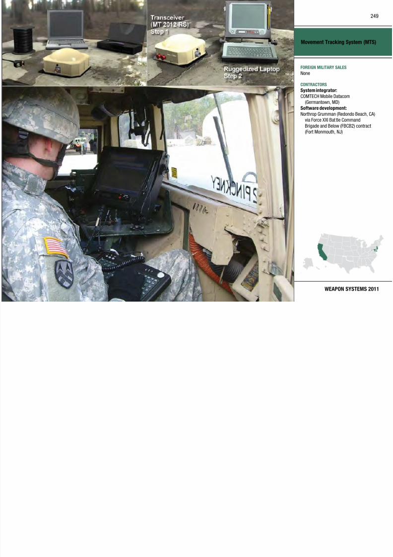
7/29/2019 Army Weapons Systems 2011
http://slidepdf.com/reader/full/army-weapons-systems-2011 259/380
WEAPON SYSTEMS 2011
COMTECH Mobile Datacom
(Germantown, MD)
Software development:
Northrop Grumman (Redondo Beach, CA)
via Force XXI Bat tle Command
Brigade and Below (FBCB2) contract
(Fort Monmouth, NJ)
INVESTMENT COMPONENT
Multiple Launch Rocket System (MLRS) M270A1
Recapitalization
Modernization
Maintenance
MISSION
Provides coalition ground forces with
highly lethal, responsive, and preciselong-range rocket and missile fires
the Bradley Fighting Vehicle). With
the IFCS, the M270A1 can re future
munitions and the ILMS reduces
system load and reload times. The
M270A1 id i hi hl
PROGRAM STATUS• 2QFY10: Completed eet
modernization with Auxiliary Power
Unit/Environmental Control Unit
d
250

7/29/2019 Army Weapons Systems 2011
http://slidepdf.com/reader/full/army-weapons-systems-2011 260/380
UNITED STATES ARMY
ACQUISITION PHASE
Technology Development Operations & SupportProduction & DeploymentEngineering & Manufacturing Development
that defeat point and area targets in
both urban/complex and open terrain
with minimal collateral damage, via
a highly mobile, responsive multiple
launch system.
DESCRIPTION The combat-proven Multiple Launch
Rocket System (MLRS) M270A1 is a
mechanized artillery weapon system that provides the combat commander
with round-the- clock, all-weather,
lethal, close- and long-range precision
rocket and missile fire support for
Joint forces, early-entry expedit ionary
forces, contingency forces, and modular
fire brigades supporting Brigade
Combat Teams.
The M270A1 is an upgraded version
of the M270 launcher. The program
entailed the concurrent incorporationof the Improved Fire Control System
(IFCS) and the Improved Launcher
Mechanical System (ILMS) on a
rebuilt M993 Carrier (derivative of
M270A1 provides responsive, highly
accurate and extremely lethal, surface-
to-surface, close- to long-range rocket
and missile fires from 15 kilometers to
a depth of 300 kilometers. It carries
and fires either two launch pods
containing six MLRS rockets each or
two Army Tactical Missiles, and is
capable of firing all current and future
MLRS family of rockets and missiles.
It operates with the same MLRScommand, control, and communications
structure and has the same size crew
as the M142 High Mobility Ar tillery
Rocket System (HIMARS).
SYSTEM INTERDEPENDENCIESIn this Publication
Advanced Field Arti llery Tact ical Data
System (AFATDS)
Other Major Interdependencies
M993 Bradley derivative chassis
upgrades
• 4QFY10: Completed M270A1
launcher overhaul pilot program
PROJECTED ACTIVITIES• Continue: Provide support to fielded
units/units in combat
• Continue: Provide sustainment and
support activities for MLRS strategic
partners and foreign military
sales customers• Continue: Field Driver Vision
Enhancement and Blue Force
Tracker Mods
• Continue: M270A1 launcher
overhaul program
Multiple Launch Rocket System
(MLRS) M270A1
FOREIGN MILITARY SALES
M270 and M270A1:
Bahrain, Denmark, Egypt, Finland, France,
Germany, Greece, Israel, Italy, Japan,
KoreaM270 and M270B1:
251

7/29/2019 Army Weapons Systems 2011
http://slidepdf.com/reader/full/army-weapons-systems-2011 261/380
WEAPON SYSTEMS 2011
Norway, Turkey, United Kingdom
CONTRACTORS
Prime and Launcher:
Lockheed Martin (Dallas, TX; Camden, AR)Chassis:
BAE Systems (York, PA)
Improved Weapons Interface Unit:
Harris Corp. (Melbourne, FL)
Position Navigation Unit:
L-3 Communications Space & Navigation(Budd Lake, NJ)
INVESTMENT COMPONENT
NAVSTAR Global Positioning System (GPS)
Recapitalization
Modernization
Maintenance
MISSION
Provides real-time position, velocity,
and timing data to tactical and strategicorganizations.
to date for a total of 250,000
DAGRs fielded. In addition, GPS
user equipment includes a Ground-
Based GPS Receiver Applications
Module (GB GRAM) Over 90 000
SYSTEM INTERDEPENDENCIESIn this Publication
PATRIOT Advanced Capability–Three
(PAC-3), Excalibur (XM982), Paladin/
Field Artillery Ammunition Support
252

7/29/2019 Army Weapons Systems 2011
http://slidepdf.com/reader/full/army-weapons-systems-2011 262/380
UNITED STATES ARMY
ACQUISITION PHASE
Technology Development Operations & SupportProduction & DeploymentEngineering & Manufacturing Development
DESCRIPTION The NAVSTAR Global Positioning
System (GPS) is a space-based,
Joint-serv ice navigat ion program led
by the Air Force, which distr ibutes
position, velocity, and timing data.
The GPS has three segments: a space
segment (nominally 24 satellites), a
ground control segment, and a user
equipment segment. User equipmentconsists of receivers configured
for handheld, ground, aircraft, and
watercraf t applicat ions. Military GPS
receivers use the Precise Positioning
Service (PPS) signal to ga in enhanced
accuracy and signa l protection not
available to commercial equipment.
GPS receivers in the Army today
are: the Precision Lightweight GPS
Receiver (PLGR), with more than
100,000 in handheld, installed, and
integrated applications; and theDefense Advanced GPS Receiver
(DAGR), with more than 183,000
as handheld receivers and 67,000
distributed for platform instal lations
Module (GB-GRAM). Over 90,000
GB-GRAMs have been procured and
provide embedded PPS capability to a
var iety of weapon systems. The Army
represents more than 80 percent of the
requirement for user equipment.
DAGR
Size: 6.37 x 3.4 x 1.56 inches
Weight: 1 pound; fits in a two-clip
carry ing case that attaches to load- bear ing equipment
Frequency: Dual (L1/L2)
Battery Life: 19 hours (4 AA
batter ies)
Security: Selective availability anti-
spoofing module
Satellites: All-in-v iew
GB-GRAM
Size: 0.6 x 2.45 x 3.4 inches
Weight: 3.5 ounces
Frequency: Dual (L1/L2)Security: Selective availability anti-
spoofing module
Satellites: All-in-view
Field Artillery Ammunition Support
Vehicle (FAASV)
Other Major Interdependencies
Blue Force Tracking, mobile ballistic
computers, laser rangefinders,
movement tracking systems, and
several unmanned aerial vehicle
systems
PROGRAM STATUS• 1QFY05–4QFY10: Continue DAGR
fieldings; continue demilitarization
and disposal of obsolete PLGR
PROJECTED ACTIVITIES• 1QFY11–4QFY17: Continue DAGR
eldings; DAGR 3.7 introduction;
GB-GRAM 3.7 introduction
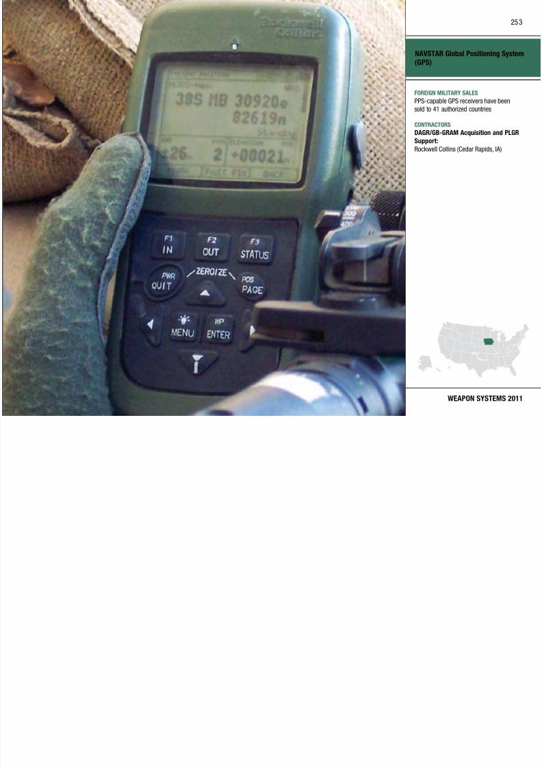
7/29/2019 Army Weapons Systems 2011
http://slidepdf.com/reader/full/army-weapons-systems-2011 263/380
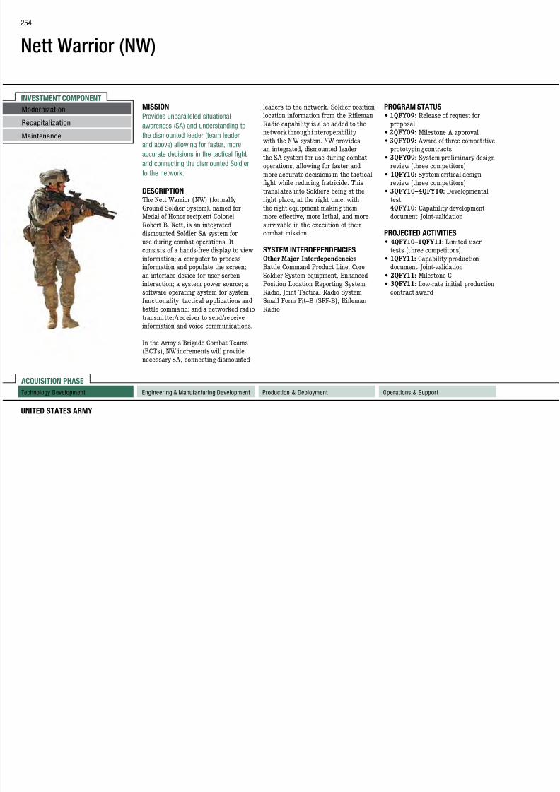
7/29/2019 Army Weapons Systems 2011
http://slidepdf.com/reader/full/army-weapons-systems-2011 264/380
Nett Warrior (NW)
FOREIGN MILITARY SALES
To be determined
CONTRACTORS
Refinement Systems:Rockwell Collins (Cedar Rapids, IA)
255

7/29/2019 Army Weapons Systems 2011
http://slidepdf.com/reader/full/army-weapons-systems-2011 265/380
WEAPON SYSTEMS 2011
Raytheon (McKinney, TX)
General Dynamics (Scottsdale, AZ)Support Services:
Engility (Billerica, MA)
NCI Information Systems (Reston, VA)
INVESTMENT COMPONENT
Night Vision Thermal Systems–Thermal Weapon Sight (TWS)
mountable to a weapon rail. They
operate to the maximum effective
range of the weapon.
The TWS fami ly comprises three
• Field of view: ≥6 degrees/18
degrees (narrow/wide)
• Operational time: 6.5 hours
• Power: six lithium AA batteries
PROGRAM STATUS• FY98: Type classification
• FY99: First unit equipped
• FY10: Fielded to units supportingOperation Enduring Freedom and
Recapitalization
Modernization
Maintenance
256

7/29/2019 Army Weapons Systems 2011
http://slidepdf.com/reader/full/army-weapons-systems-2011 266/380
UNITED STATES ARMY
ACQUISITION PHASE
MISSION
Enables the Soldier to detect and
engage targets, day or night, in all
weather and visibility-obscured
conditions.
DESCRIPTION The Thermal Weapon Sight (TWS)
family is a g roup of advanced infrareddevices for both in-line and stand-
alone use. Its technologies include
multi-band fused sensors and rapid
target acquisit ion capabil ities. The
AN/PAS-13 TWS gives Soldiers w ith
individual and crew served weapons
the capabi lity to see deep into the
battlefield, increase sur veilla nce and
target acquisit ion range, and penetrate
obscurants, day or night. The TWS
systems use uncooled, forward-looking
infrared technology and provide astandard video output for training,
image transfer, or remote viewing.
TWS systems are lightweight and
The TWS fami ly comprises three
variants, each of which is s ilent,
lightweight, compact, durable, and
battery-powered. They include:
AN/PAS-13(V)1 Light Weapon
Thermal Sight (LWTS) for the M16
and M4 series ries and carbines, as
well as the M136 Light Anti-Armor
Weapon
• Weight: 1.95 pounds• Magnication: 1.55x
• Field of view: ≥15 degrees
• Operational time: 5 hours
• Power: four lithium AA batteries
AN/PAS-13(V)2 Medium Weapon
Thermal Sight (MWTS) for the M249
Squad Automatic Weapon and M240B
series medium machine guns
• Weight: 2.9 pounds
• Magnication: 5x/1.66x (narrow/
wide)
AN/PAS-13(V)3 Heavy Weapon
Thermal Sight (HWTS) for the squad
leader’s weapon M16 and M4 series
ries and carbines, M24 and M107
sniper ries, and M2 HB and MK19
machine guns
• Weight: 3.9 pounds
• Magnication: 10x/3.3x (narrow/
wide)
• Field of view: ≥
3 degrees/9 degrees(narrow/wide)
• Operational time: 6.5 hours
• Power: six lithium AA batteries
SYSTEM INTERDEPENDENCIESNone
Operation Enduring Freedom and
Operation Iraqi Freedom
• FY10: Began 17 micron technology
validation testing; 17 micron
technology allows product ion of a
LWTS clip-on and reduces power and
weight in the MWTS and HWTS
PROJECTED ACTIVITIES• FY11: Continue to support and eld
in accordance with HeadquartersDepartment of the Army G8
guidance
• Continue: 17 micron validation
testing
Technology Development Operations & SupportProduction & DeploymentEngineering & Manufacturing Development
Night Vision Thermal Systems–
Thermal Weapon Sight (TWS)
FOREIGN MILITARY SALES
Deputy Assistant Secretary of the Army
Defense Exports and Cooperation (DASA
DE&C)
CONTRACTORS
BAE S t (L i t MA
257

7/29/2019 Army Weapons Systems 2011
http://slidepdf.com/reader/full/army-weapons-systems-2011 267/380
WEAPON SYSTEMS 2011
BAE Systems (Lexington, MA;
Manassas VA)
DRS Optronics (Dallas, TX; Melbourne, FL)
Raytheon (Dallas, TX; Goleta, CA;
McKinney, TX )
INVESTMENT COMPONENT
Non-Intrusive Inspection Systems (NIIS)
operator can “look into” places such as
false compartments that other systems
cannot see.
NIIS currently include a var iety of
use of the rail system eliminates
the requirement to ma intain a truck
platform and the presence of an
overhead art iculated arm that can be struck and damaged by vehicles
PROGRAM STATUS• 1QFY10: MMVACIS elding
• 4QFY10: ZBV procurement and
fielding
Recapitalization
Modernization
Maintenance
258

7/29/2019 Army Weapons Systems 2011
http://slidepdf.com/reader/full/army-weapons-systems-2011 268/380
UNITED STATES ARMY
ACQUISITION PHASE
Technology Development Operations & SupportProduction & DeploymentEngineering & Manufacturing Development
MISSION
Protects U.S. forces and critical
warfighting materiel by inspecting
cars, trucks, or cargo containers for
the presence of explosives, weapons,
drugs, or other contraband with nuclear
(gamma) and X-ray technology.
DESCRIPTION The Non-Intrusive Inspection Systems
(NIIS) program consists of commercial
off-the-shelf (COTS) products that
are employed within a layered force
protection system that includes
security personnel trained to maintain
situational awareness, aided by a range
of other products including military
working dogs, under-veh icle scanning
mirrors, and handheld or desktop trace
explosive detectors. The NIIS producea graphic image from which a tra ined
y y
products with differing characteristics
that are added to the Army
commander’s “tool box.” They include
mobile, rail-mounted but re-locatable,
and fixed-site characteristics. The
primary systems employed are
as follows:
The Mobile Vehicle and Cargo
Inspection System (MVACIS) is a truck-mounted system that ut ilizes
a nuclear source that can penetrate
approximately 6.5 inches of steel. It
can be employed in static locations or
moved rapidly between access control
points to provide protection where it is
most needed.
The Re-locatable Vehicle and Cargo
Inspection System (RVACIS) is a
rail-mounted system that util izes the
same nuclear source as the MVACIS.It operates on rails and is employed
in static locations or moved within
24 hours to locations where prepared
g y
being scanned.
The Militar ized Mobile VACIS
(MMVACIS) uses the same gamma
source as the other VACIS products
but is mounted on a High Mobility
Multipurpose Wheeled Vehicle.
MMVACIS provides a capability
that other NII systems do not—off-
installation external vehiclecheckpoints in remote locations.
The Z-Backscatter Van (ZBV) is
a van-mounted system that utilizes
backscatter X-ray technology. While
it can penetrate only approximately
one-quarter inch of steel, it can be
employed in static locations where
room is limited and scanning of ca rs,
larger vehicles, or containers with
smaller, less complex loads is expected.
SYSTEM INTERDEPENDENCIESNone
PROJECTED ACTIVITIES• 2QFY11: Final engineering change
proposal contract to be awarded
Non-Intrusive Inspection Systems
(NIIS)
FOREIGN MILITARY SALES
None
CONTRACTORS
American Science & Engineering, Inc.(Billerica, MA)
Rapiscan Systems (Torrance CA)
259
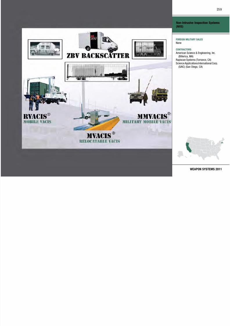
7/29/2019 Army Weapons Systems 2011
http://slidepdf.com/reader/full/army-weapons-systems-2011 269/380
WEAPON SYSTEMS 2011
Rapiscan Systems (Torrance, CA)
Science Applications International Corp.
(SAIC) (San Diego, CA)
INVESTMENT COMPONENT
Nuclear Biological Chemical Reconnaissance Vehicle(NBCRV)–Stryker Sensor Suite
Recapitalization
Modernization
Maintenance
MISSION
Performs nuclear, biological, and
chemical (NBC) reconnaissance; and
locates, identifies, marks, samples,
and reports NBC contamination on the
Detector, AN/UDR-13 Radiac Detector,
Joint Biological Point Detection
System (JBPDS), and at a distance,
through the use of the Joint ServiceLightweight Standoff Chemical Agent
PROGRAM STATUS• FY09–10: Additiona l low-rate initi al
production
• FY10: Initial operational test andevaluation
260

7/29/2019 Army Weapons Systems 2011
http://slidepdf.com/reader/full/army-weapons-systems-2011 270/380
UNITED STATES ARMY
ACQUISITION PHASE
Technology Development Operations & SupportProduction & DeploymentEngineering & Manufacturing Development
and reports NBC contamination on the
battlefield.
DESCRIPTION The Nuclear Biological Chemica l
Reconnaissance Vehicle (NBCRV)–
Stryker is the chemical, biological,
radiological, and nuclear (CBRN)
reconnaissance configuration of
the infantry carrier vehicle in theStryker Brigade Combat Teams,
Heavy Brigade Combat Teams, and
chemical companies.
The NBCRV-Stryker Sensor Suite
consists of a dedicated system of CBRN
detection, warning, and biological-
sampling equipment on a Stryker
vehicle (high speed, high mobil ity,
armored carrier). The NBCRV detects
chemical, radiological, and biological
contamination in its immediateenvironment through the Chemical
Biological Mass Spectrometer (CBMS),
Automatic Chemical Agent Detec tor
Alarm (ACADA), AN/VDR-2 Radiac
Detector (JSLSCAD). It automatically
integrates contamination information
from detectors with input from onboard
navigation and meteorological systems
and transmits digital NBC warning
messages through the vehicle’s
command and control equipment to
warn follow-on forces. NBCRV can
collect samples for follow-on analysis.
SYSTEM INTERDEPENDENCIESIn this Publication
Joint Biological Point Detection System
(JBPDS)
Other Major Interdependencies
ACADA, AN/U DR-13 Radiac Detector,
CBMS, Chemical Vapor Sampler System
(CVSS), JSLSCAD, Nuclear Biological
Chemical Sensor Processing Group
(NBCSPG)
PROJECTED ACTIVITIES• FY11: Full-rate production
Nuclear Biological Chemical
Reconnaissance Vehicle (NBCRV)–
Stryker Sensor Suite
FOREIGN MILITARY SALES
None
CONTRACTORS
Prime Vehicle:General Dynamics Land Systems
(Sterling Heights MI)
261

7/29/2019 Army Weapons Systems 2011
http://slidepdf.com/reader/full/army-weapons-systems-2011 271/380
WEAPON SYSTEMS 2011
(Sterling Heights, MI)
Sensor Software Integrator:
CACI Technologies (Manassas, VA)
INVESTMENT COMPONENTand Close Combat Tactical Trainer.
OneSAF will serve as the basis for
subsequent modernization activities
for simulators across the Army.OneSAF was designed to represent
training, exercise, and milita ry
operations. OneSAF is designed to meet
the construct ive training challenges
presented by transformation. Witha full range of warfighter functional
SYSTEM INTERDEPENDENCIESOther Major Interdependencies
OneSAF provides required
capabilities for SE Core; OneSAF isa complementary Tier I program of
One Semi-Automated Forces (OneSAF)
Recapitalization
Modernization
Maintenance
262

7/29/2019 Army Weapons Systems 2011
http://slidepdf.com/reader/full/army-weapons-systems-2011 272/380
UNITED STATES ARMY
ACQUISITION PHASE
MISSION
Provides simulation software that
supports constructive and virtual
training, computer-generated forces,
and mission rehearsal designed for
brigade-and-below, combat, and non-
combat operations.
DESCRIPTIONOne Semi-Automated Forces (OneSAF)
is a next generation, entity-level
simulation that supports both
computer-generated forces and Semi-
Automated Forces applicat ions. This
enables it to support a wide range of
Army br igade-and-below construct ive
simulations and vi rtual simulators.
OneSAF is currently being integrated
by the Synthet ic Environment Coreprogram as the replacement SAF
for virtual trainers such as Aviation
Combined Arms Tactical Trainer
the modular a nd Future Force and
provides entities, units, and behaviors
across the spectrum of military
operations in the contemporary
operating environment. OneSAF
has been crafted to be uniquely
capable of simulating aspects of the
contemporary operating environment
and its effects on simulated activities
and behaviors. OneSAF is unique inits ability to model unit behaviors
from fire team to company level for all
units—both combat and non-combat
operations. Intelligent, doctr inally
correct behaviors and improved
graphical user interfaces are provided
to increase the span of control for
workstation operators.
OneSAF represents a full range of
operations, systems, and control
processes in support of simulationapplications applied to advanced
concepts and requirements; research,
development, and acquisition; and
area representations, OneSAF
displays a high fidelity environmental
representation. OneSAF is a cross-
domain simulation suitable for
supporting tra ining, analysis, research,
experimentation, mission-planning,
and rehearsal activities. It provides
the latest physics-based modeling and
data, enhanced data collection, and
reporting capabilities.
Interoperability support is present
for industry standards such as
Distributed Interactive Simulation,
High Level Architecture, Military
Scenario Development Language, Joint
Consultation Command and Control
Information Exchange Data Model, and
Army Batt le Command System devices.
E-ICBT.
PROGRAM STATUS• 4QFY10: OneSAF version 4.0
released
• 4QFY10: OneSAF version 5.0
released
PROJECTED ACTIVITIES
• 2QFY11: Release OneSAF version 5.0 (Internat ional)
Technology Development Operations & SupportProduction & DeploymentEngineering & Manufacturing Development
One Semi-Automated Forces
(OneSAF)
FOREIGN MILITARY SALES
Australia, Bahrain, Canada, Czech
Republic, Egypt, Korea, New Zealand,
United Kingdom
CONTRACTORS
A&I, M&T, ERC:
263

7/29/2019 Army Weapons Systems 2011
http://slidepdf.com/reader/full/army-weapons-systems-2011 273/380
WEAPON SYSTEMS 2011
A&I, M&T, ERC:
Science Applications International Corp.
(SAIC) (Orlando, FL)
Integrated Environment:
Advanced Systems Technology
(Orlando, FL)
C4I Components:
Northrop Grumman Information Systems
(NGIS) (McLean, VA)
AAR/MSDE:
CAE USA (Tampa, FL)
INVESTMENT COMPONENT
Paladin/Field Artillery Ammunition Supply Vehicle (FAASV)
space, weight, and power concerns and
ensures long-term sustainment of the
fleet through 2050.
PIM uses state-of-the art components
t i th f ll i
• Non-line-of-sight cannon technology:
Common electric elevation/traverse
drives gun system and electric
rammer are included.
Oth PIM ifi ti i l d th
PROGRAM STATUS• FY10: Produced ve PIM Howitzer
and two FAASV prototype vehicles
PROJECTED ACTIVITIES1QFY11 2QFY12 B ild t PIM
Recapitalization
Modernization
Maintenance
264

7/29/2019 Army Weapons Systems 2011
http://slidepdf.com/reader/full/army-weapons-systems-2011 274/380
UNITED STATES ARMY
ACQUISITION PHASE
Technology Development Operations & SupportProduction & DeploymentEngineering & Manufacturing Development
MISSION
Provides the primary indirect fire
support for modular Heavy Brigade
Combat Teams and armored and
mechanized infantry divisions, as well
as an armored ammunition resupply
vehicle in support of the Paladin.
DESCRIPTION The M109A6 (Paladin) 155mm
Howitzer is the most technologically
advanced self-propelled cannon
system in the Army. The field artillery
ammunition supply vehicle (FAASV)
provides an armored ammunition
resupply vehicle in support of
the Palad in.
The Paladin Integrated Management
(PIM) program supports the fleetmanagement strategy for current
Paladins and FAASVs by providing
a low-risk and affordable life-cycle
solution that addresses obsolescence,
to improve the following:
• Survivability: “Shoot and scoot”
tactics; improved ba llist ic and
nuclear, biological, and chemical
protection on both the Howitzer and
FAASV.
• Responsive res: Capable of ring
within 45 seconds from a complete
stop with on-board communications,
remote travel lock, automatedcannon slew capability, and pivot
steer technology.
• Improved Survivability: New chassis
structure and armoring provisions
are built in.
• Extended range: 30 kilometers with
high-explosive (HE), Rocket-Assisted
Projectile (RAP) and Excalibur
Projectiles using M203 or M232/
M232A1 MACS propellant.
• Increased commonality and
reliability: Through Bradley commonpowertrain, track, and suspension
components.
Other PIM specifications include the
following:
Crew: Paladin, four; FAASV, ve
Combat loaded weight: Paladin, 37
tons; FAASV, 28 tons
Paladin on-board ammo: 39 rounds
FAASV on-board ammo: 95 rounds
Rates of re: 4 rounds per minute for
rst 3 minutes maximum; 1 round per
minute sustainedMaximum range: HE/RAP, 22/30
kilometers
Cruising range: Paladin, 180 miles;
FAASV, 180 miles
Fire Support Network: Paladin
Digital Fire Control System software
supports Fire Support Network
SYSTEM INTERDEPENDENCIES Advanced Field Ar tiller y Tactical
Data System (AFATDS), Ar tillery
Ammunition, Exca libur (XM982),Force XXI Battle Command Brigade
and Below (FBCB2), Precision
Guidance Kit (PGK)
• 1QFY11–2QFY12: Build two PIM
Howitzer and one FAASV prototype
vehicles
• 2QFY11–1QFY13: Developmental
testing
• 3QFY13: Milestone C
Paladin/Field Artillery Ammunition
Supply Vehicle (FAASV)
FOREIGN MILITARY SALES
None
CONTRACTORS
PIM Development:BAE Systems (York, PA)
PIM SW Support/FATB/Matrix Support:
265

7/29/2019 Army Weapons Systems 2011
http://slidepdf.com/reader/full/army-weapons-systems-2011 275/380
WEAPON SYSTEMS 2011
ppo ppo
Armaments R&D Center
(Picatinny Arsenal, NJ)
Program Management Support:
Tank-Automotive and Armaments
Command (TACOM) (Warren, MI)
Testing:
Yuma Proving Ground (Yuma, AZ)
Aberdeen Test Center (Aberdeen Proving
Ground, MD)
INVESTMENT COMPONENT
Palletized Load System (PLS) and PLS Extended ServiceProgram (ESP)
MISSION
Supports combat units by performing
cross-country movement of configured
loads of ammunition and other classes
of supply loaded on flat racks or in
the PLS trailer (M1076), container
handling unit for transporting 20-
foot ISO containers, the M3/M3A1
Container Roll-in/Out Platform, and the M1/M1077A1 at racks. The
PLS has the ability to operate with a
wheels, increased cor rosion protect ion,
enhanced electrical package, and
independent front suspension on
the A1.
SYSTEM INTERDEPENDENCIES
Recapitalization
Modernization
Maintenance
266
7/29/2019 Army Weapons Systems 2011
http://slidepdf.com/reader/full/army-weapons-systems-2011 276/380
UNITED STATES ARMY
ACQUISITION PHASE
Technology Development Operations & SupportProduction & DeploymentEngineering & Manufacturing Development
pp y
containers.
DESCRIPTION The Palletized Load System (PLS)
is a ten-wheel-drive (10x10), multi-
drive truck with 16.5 ton capacity
that provides the timely del ivery of
a high tonnage of ammunition, unit
equipment, International Organization
for Standardization (ISO) containers/
shelters, and all classes of supply to
using units and weapon systems as far
forward in the maneuver battalion area
as the tactica l situation allows. The
PLS consists of the PLS truck, PLS
trai ler (PLS-T), and demountable flat
racks. The PLS truck is a 10x10 prime
mover with an integral onboard load
handling system that provides self-
loading and unloading capability.
There are two PLS truck var iants, the
basic PLS truck (M1075) and the PLS
truck with materia l handling crane
(M1074). The system also includes
PLS has the ability to operate with a
degree of mobility commensurate with
the supported weapon systems, to
facilitate the fighting capabilities of the
supported systems and units.
The PLSA1 model is planned for
fielding in 2011. It will include:
independent front suspension, a
new C-15 engine, the Allison 4500
transmission, J-1939 data-bus, and
a cab that wil l be common with the
HEMTTA4 and is long-term armor
strategy compliant.
The PLS Extended Service
Program (ESP) is a recapitalization
program that converts high-mileage
PLS trucks to 0 miles/0 hours
and to the current A0 and future
A1 production configurations. The
trucks are disassembled and rebuilt with improved technology such as
an electronically controlled engine,
electronic transmission, air ride seats,
four-point seatbelts, bolt-together
SYSTEM INTERDEPENDENCIESNone
PROGRAM STATUS• Current: To date, fielded
approximately 5,500 PLS trucks and
9,081 PLS trailers
PROJECTED ACTIVITIES• FY11: PLSA1 type classification/
materiel release
• FY11: PLSA1 first unit equipped
Palletized Load System (PLS) and
PLS Extended Service Program
(ESP)
FOREIGN MILITARY SALES
Turkey, Israel, Jordan
CONTRACTORS
Prime:
Oshkosh Corp. (Oshkosh, WI)
Engine:
267
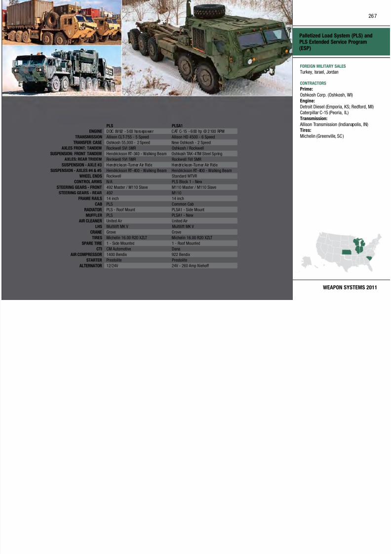
7/29/2019 Army Weapons Systems 2011
http://slidepdf.com/reader/full/army-weapons-systems-2011 277/380
WEAPON SYSTEMS 2011
PLS PLSA1
ENGINE DDC 8V92 - 500 horsepower CAT C-15 - 600 hp @ 2100 RPM
TRANSMISSION Allison CLT-755 - 5 Speed Allison HD 4500 - 6 Speed
TRANSFER CASE Oshkosh 55,000 - 2 Speed New Oshkosh - 2 Speed
AXLES FRONT: TANDEM Rockwell SVI 5MR Oshkosh / Rockwell
SUSPENSION: FRONT TANDEM Hendrickson RT-340 - Walking Beam Oshkosh TAK-4TM Steel Spring
AXLES: REAR TRIDEM Rockwell SVI 5MR Rockwell SVI 5MRSUSPENSION - AXLE #3 Hendrickson-Turner Air Ride Hendrickson-Turner Air Ride
SUSPENSION - AXLES #4 & #5 Hendrickson RT-400 - Walking Beam Hendrickson RT-400 - Walking Beam
WHEEL ENDS Rockwell Standard MTVR
CONTROL ARMS N/A PLS Block 1 - New
STEERING GEARS - FRONT 492 Master / M110 Slave M110 Master / M110 Slave
STEERING GEARS - REAR 492 M110
FRAME RAILS 14 inch 14 inch
CAB PLS Common Cab
RADIATOR PLS - Roof Mount PLSA1 - Side Mount
MUFFLER PLS PLSA1 - New
AIR CLEANER United Air United Air
LHS Multilift MK V Multilift MK VCRANE Grove Grove
TIRES Michelin 16.00 R20 XZLT Michelin 16.00 R20 XZLT
SPARE TIRE 1 - Side Mounted 1 - Roof Mounted
CTI CM Automotive Dana
AIR COMPRESSOR 1400 Bendix 922 Bendix
STARTER Prestolite Prestolite
ALTERNATOR 12/24V 24V - 260 Amp Niehoff
Detroit Diesel (Emporia, KS; Redford, MI)
Caterpillar C-15 (Peoria, IL)
Transmission:
Allison Transmission (Indianapolis, IN)Tires:
Michelin (Greenville, SC )
INVESTMENT COMPONENT
PATRIOT Advanced Capability–Three (PAC-3)
Recapitalization
Modernization
Maintenance
MISSION
Protects ground forces and critical
assets at all echelons from advanced
aircraft, cruise missiles, and tactical
ballistic missiles.
platform for PAC-2 or PAC-3 missiles,
which are sea led in can isters that
serve as shipping containers and
launch tubes.
The PAC 3 primary mission is to kill
SYSTEM INTERDEPENDENCIESIn this Publication
Air/Missile Defense Planning and
Control System (AMDPCS); Integrated Air and Missile Defense (IAMD);
Joint Land Attack Cruise Missile
268

7/29/2019 Army Weapons Systems 2011
http://slidepdf.com/reader/full/army-weapons-systems-2011 278/380
UNITED STATES ARMY
ACQUISITION PHASE
Technology Development Operations & SupportProduction & DeploymentEngineering & Manufacturing Development
DESCRIPTION The PATRIOT Advanced Capabili ty–
Three (PAC-3) program is an air-
defense, guided missile system with
long-range, medium- to high-altitude,
all-weather capabilities designed to
counter tactical ballistic missiles
(TBMs), cruise missiles, and advanced
aircraft. The combat element of the
PATRIOT missile system is the fire
unit, which consists of a phased array
radar set (RS), an engagement control
station (ECS), a battery command post,
an electric power plant, an antenna
mast group, a communications relay
group, and launching stations (LS)
with missiles.
The RS provides the tactica l functions
of airspace surveillance, target
detection, identification, classification, tracking, missile gu idance, and
engagement support. The ECS provides
command and control. Depending upon
configuration, the LS provides the
The PAC-3 primary mission is to kill
maneuvering and non-maneuvering
TBMs, and counter advanced cruise
missile and aircraft threats. The PAC-3
missile uses hit-to-kill technology for
greater lethality aga inst TBMs armed
with weapons of mass destruct ion.
The PAC-3 system upgrades have
provided improvements that increase
performance against evolving threats,
meet user requirements, and enhance
Joint interoperability. Patriot’s fast-
reaction capability, high firepower,
ability to track numerous targets
simultaneously, and ability to operate
in a severe electronic countermeasure
environment make it the Army’s
premier air defense system. The PAC-
3 Missile Segment Enhancement,
currently in development, is planned
to be used with the PAC-3 system and
will be the baseline interceptor for theMedium Extended Air Defense System,
which succeeds the PATRIOT system.
Joint Land Attack Cruise Missile
Defense Elevated Netted Sensor
System (JLENS); Joint Tactical Ground
Stations (JTAGS)
Other Major Interdependencies
ABMOC, AEGIS, AMDTF, AOC,
AWACS, CRC, HAWKEY E, IAMD, P/M
CAP, PEO Integration, RIVET-JOINT,
SHORAD, TACC, TAOC, THAAD
PROGRAM STATUS• 1QFY09: Post deployment build–6.5
(PDB-6.5) development, test, and
evaluation
PROJECTED ACTIVITIES• 3QFY07–1QFY11: Missile Segment
Enhancement (MSE) flight testing
• 3QFY12: PDB-7
• 4QFY14: MSE fielding begins
PATRIOT Advanced Capability–Three
(PAC-3)
FOREIGN MILITARY SALES
Germany, Japan, Netherlands, Taiwan,
United Arab Emirates
CONTRACTORSMissile Program Management Team:
Lockheed Martin (Dallas, TX)
269

7/29/2019 Army Weapons Systems 2011
http://slidepdf.com/reader/full/army-weapons-systems-2011 279/380
WEAPON SYSTEMS 2011
Seeker Program Management Team:
Boeing (Anaheim, CA)
Mods: Raytheon (Tewksbury, MA;
Long Beach, CA)Seeker Manufacturing/RFDL:
Lockheed Martin Missiles and Fire Control
(Chelmsford, MA)ELES: Lockheed Martin (Lufkin, TX)
System Integration:
Raytheon–El Paso (El Paso, TX)Raytheon (Huntsville, AL)
Raytheon–Norfolk (Norfolk, VA)
Raytheon–Burlington (Burlington, MA)Missile Assembly:
Lockheed Martin (Camden, AR)
Integration/GSE: Raytheon (Andover, MA)Seeker: Boeing (Huntsville, AL)
Seeker Assembly: Boeing (El Paso, TX)
SRM/ACM: Aerojet (Camden, AR)
INVESTMENT COMPONENT
Precision Guidance Kit (PGK)
Recapitalization
Modernization
Maintenance
MISSION
Improves the accuracy of existing
conventional artillery ammunition.
DESCRIPTIONThe Precision Guida nce Kit (PGK)
The PGK program is following an
incremental program approach.
Increment 1, the XM1156 PGK, will be
compatible with 155mm high explosive(HE) projectiles red from the M109A6
Paladin and M777A2 Joint Lightweight
PROGRAM STATUS• Current: Increment 1 program is
in engineering and manufacturing
development
PROJECTED ACTIVITIES
270
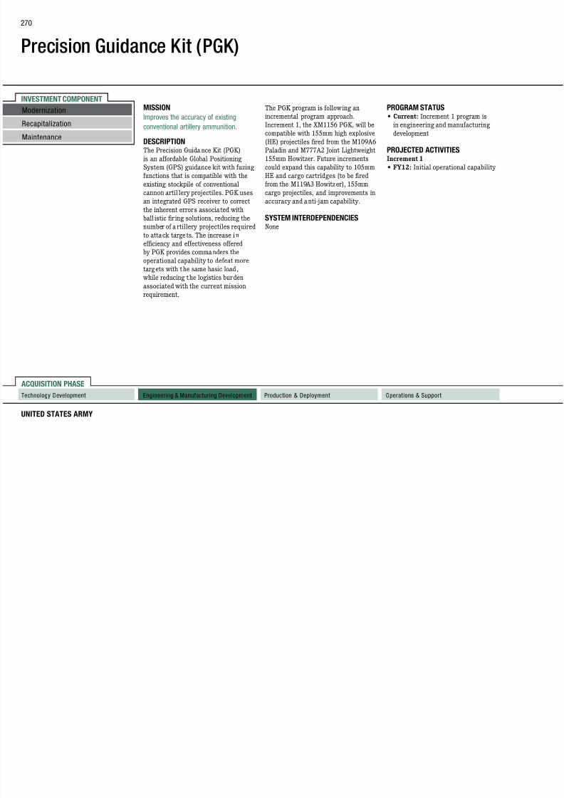
7/29/2019 Army Weapons Systems 2011
http://slidepdf.com/reader/full/army-weapons-systems-2011 280/380
UNITED STATES ARMY
ACQUISITION PHASE
Technology Development Operations & SupportProduction & DeploymentEngineering & Manufacturing Development
The Precision Guida nce Kit (PGK)
is an affordable Global Positioning
System (GPS) guidance kit with fuzing
functions that is compatible with the
existing stockpile of conventional
cannon artil lery projectiles. PGK uses
an integrated GPS receiver to correct
the inherent errors associated with
ball istic fir ing solutions, reducing the
number of a rtillery projectiles required
to attack targets. The increase in
efficiency and effectiveness offered
by PGK provides commanders the
operational capability to defeat more
targets with the same basic load,
while reducing the logistics burden
associated with the current mission
requirement.
Paladin and M777A2 Joint Lightweight
155mm Howitzer. Future increments
could expand this capability to 105mm
HE and cargo cartridges (to be red
from the M119A3 Howitzer), 155mm
cargo projectiles, and improvements in
accuracy and anti-jam capability.
SYSTEM INTERDEPENDENCIESNone
PROJECTED ACTIVITIESIncrement 1
• FY12: Initial operational capability
Precision Guidance Kit (PGK)
FOREIGN MILITARY SALES
None
CONTRACTORS
Increment 1Prime:
Alliant Techsystems (Plymouth, MN)
S b
271
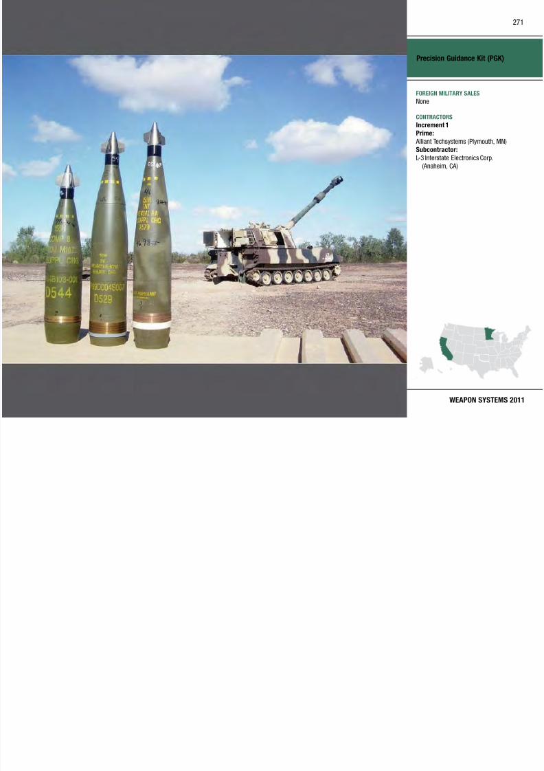
7/29/2019 Army Weapons Systems 2011
http://slidepdf.com/reader/full/army-weapons-systems-2011 281/380
WEAPON SYSTEMS 2011
Subcontractor:
L-3 Interstate Electronics Corp.
(Anaheim, CA)
INVESTMENT COMPONENT
Prophet
Recapitalization
Modernization
Maintenance
and identification of radio frequency
emitters. It is interoperable on the
Global Signals Intelligence Enterprise,
delivering collected data to commondatabases for access by the community.
Prophet’s tactical mobility allows
The Prophet Enhanced System will
provide increased capability over
existing Prophet ES 1 Systems. The
Prophet Enhanced System has beenaccelerated to provide upgraded
capability integrated on an XM1229
Other Major Interdependencies
Global Positioning System,
Trojan lightweight integrated
telecommunications equ ipment, tact ical rad io communications systems,
light tactical vehicles and assured
272
7/29/2019 Army Weapons Systems 2011
http://slidepdf.com/reader/full/army-weapons-systems-2011 282/380
UNITED STATES ARMY
ACQUISITION PHASE
Technology Development Operations & SupportProduction & DeploymentEngineering & Manufacturing Development
MISSION
Provides a near-real-time picture of
the battlespace through the use of
signals intelligence sensors offering the
capability to detect, identify, and locate
selected emitters.
DESCRIPTIONProphet is a 24-hour, al l weather,
near-real-time, ground-based tactical
signals intelligence/electronic warfare
capability organic to the Brigade
Combat Team (BCT), Stryker BCT,
Armored Cavalry Regiment, and
Battlefield Surveillance Brigade.
Prophet contains from two to four
Electronic Support 1/Enhanced
Systems, one to two controls, and
a TROJAN–Lightweight Integrated
Telecommunications Equipment(T-LITE) per control. It provides near-
real-time force protection, situational
awareness, and actionable intelligence
by reporting the location, tracking,
op e s ac ca o y a o s
supported units to easily reposition its
collection capability on the battlefield to
support evolving situations. Prophet can
be removed and used as a dismounted
capability for long-term operations.
Prophet Electronic Support 1 (ES 1)
System is integrated on an armored
M1165 High Mobility Multipurpose
Wheeled Vehicle (HMMWV). The
Prophet ES 1 System is being
fielded to active and reserve units
in support of Operation Enduring
Freedom/Operation Iraqi Freedom.
Some Prophet ES 1 Systems were
updated to include Wideband Beyond-
Line-of-Site (WBLOS) capabilities
based on the present PM Warfighter
Information Network–Tactical (WIN-T)
architecture. This capability allows
operation without the constraints ofline-of-sight communication, increasing
the system’s capability to operate
at extended distance and perform
distributed operations.
capa y eg a e o a 9
Medium Mine Protected Vehicle
to provide better crew protection,
and fielded to units in preparation
for deployment.
Prophet Control is integrated on an
armored M1165 HMMWV. Prophet
Control is the analytical node
that tasks the Prophet ES 1 and
Enhanced Systems for data collection
and reporting.
The Prophet Enhanced–RCON
system will be a “vehicle agnostic”/
modular system that will allow easy
vehicle integration, and will increase
the Prophet Enhanced System’s
capability to simultaneously perform
multiple missions.
SYSTEM INTERDEPENDENCIESIn this Publication
Distributed Communications Ground
System–Army (DCGS-A)
g ac ca e c es a ass e
mobility systems, WIN-T for WBLOS
PROGRAM STATUS• 2QFY10: Prophet Enhanced quick
reaction capability (QRC) rst-unit
equipped
• 2QFY10–4QFY10: Fielded Prophet
Enhanced QRC systems to Army
Transformation BCTs and Batt leeld
Surveillance Brigade
• 4QFY10: Prophet Enhanced–RCON
contract mod awarded
PROJECTED ACTIVITIES• 1Q–4QFY11: Continue Prophet ES 1
and Prophet Enhanced Systems
fieldings
• 1Q–4QFY11: Continue to deeld
Prophet Block I systems as Prophet
ES 1 and Prophet Enhanced Systems
are fielded• 2QFY11: Prophet Enhanced first
unit equipped
Prophet
FOREIGN MILITARY SALES
None
CONTRACTORS
Prophet Enhanced Sensor Production:General Dynamics (Scottsdale, AZ)
Prophet ES 1 Sensor and Control
P d ti
273

7/29/2019 Army Weapons Systems 2011
http://slidepdf.com/reader/full/army-weapons-systems-2011 283/380
WEAPON SYSTEMS 2011
Production:
L-3 Communications (San Diego, CA ;
Melbourne, FL)
INVESTMENT COMPONENT
Raven Small Unmanned Aircraft System (SUAS)
Recapitalization
Modernization
Maintenance
MISSION
Provides reconnaissance, surveillance,
target acquisition (RSTA), and force
protection for the battalion commander
and below during day/night operations.
loiter, and return home. In-flight
re-tasking and auto-loiter at sensor
payload point of interest are also
available. Raven incorporates secureglobal positioning system navigation.
The Raven system is comprised of
PROGRAM STATUS• Current: In production and
deployment
• Current: Operational in bothOperation Iraqi Freedom and
Operation Enduring Freedom
274

7/29/2019 Army Weapons Systems 2011
http://slidepdf.com/reader/full/army-weapons-systems-2011 284/380
UNITED STATES ARMY
ACQUISITION PHASE
Technology Development Operations & SupportProduction & DeploymentEngineering & Manufacturing Development
DESCRIPTION The RQ-11B Raven Small Unmanned
Aircra ft System (SUAS) is a hand-
launched, unmanned ai rcraft system
capable of 90 minutes of flight
time with an operationa l range of
approximately ten kilometers. Normal
operational altitude is 500 feet or
lower. The system, ai rcraft, and
ground control station are assembled
by operators in approximately five
minutes. The aircraft, which has
a wingspan of 4.5 feet, weighs 4.2
pounds. Day and night operations
are possible using interchangeable
modular payloads. Both color electro-
optical (EO) sensors and infrared (IR)
sensors are fielded with each system.
A hand controller displays live v ideo
and aircraft status. Mission planning
is performed on the hand controlleror ruggedized laptop running PFPS/
Falcon View ight planning software.
Aircra ft flight modes include fully
autonomous navigation, altitude hold,
y p
three a ir vehicles, a g round control
station (GCS), a remote video terminal
(identical to GCS), EO/IR payloads,
aircraft and GCS batteries, a eld
repair kit, and a spares package.
The digital data link incorporates
encryption, improves spectrum
management allowing more air vehicles
to be flown in an operational a rea, and
provides range extension via data relay
between two Raven aircraft.
The Raven is operated by t wo Soldiers
and has a rucksack-portable design. No
specific military occupational specialty
is required. Operator training is ten
days.
SYSTEM INTERDEPENDENCIESNone
p g
PROJECTED ACTIVITIES• FY11–12: Continue full-
rate production and product
improvements
Raven Small Unmanned Aircraft
System (SUAS)
FOREIGN MILITARY SALES
Estonia, Lebanon
CONTRACTORS
Aerovironment, Inc. (Simi Valley, CA)
Indigo System Corp. (Goleta, CA)
All American Racers, Inc. (Santa Ana, CA)
L 3 Communications (San Diego CA)
275

7/29/2019 Army Weapons Systems 2011
http://slidepdf.com/reader/full/army-weapons-systems-2011 285/380
WEAPON SYSTEMS 2011
L-3 Communications (San Diego, CA)
Bren-Tronics (Commack, NY)
INVESTMENT COMPONENT
Rough Terrain Container Handler (RTCH)
Recapitalization
Modernization
Maintenance
MISSION
Provides container handling and
materiel handling capability in cargo
transfer companies, transportation
companies, quartermaster units, and
ammunitions platoons
on hard-stand, over-sand terrain, and
cross-country, executing ammunition
handling and transportation
operations. The system is capable ofconducting operations in cold, basic,
and hot climates. Additionally, RTCH
PROGRAM STATUS• FY09: Contractor completed
transfer to cont inental United States
production
PROJECTED ACTIVITIES
276

7/29/2019 Army Weapons Systems 2011
http://slidepdf.com/reader/full/army-weapons-systems-2011 286/380
UNITED STATES ARMY
ACQUISITION PHASE
Technology Development Operations & SupportProduction & DeploymentEngineering & Manufacturing Development
ammunitions platoons.
DESCRIPTION The Rough Terrain Conta iner Handler
(RTCH) is a commercial, non-
developmental item acquired for cargo-
handling missions worldwide. The
vehicle lif ts, moves, and stacks both
20-foot and 40-foot American National
Standards Institute/International
Organization for Standardization
containers and shelters weighing up to
53,000 pounds.
Improvements to RTCH include
the capabi lity to transpor t by rai l,
highway, or water in less than 2 1/2
hours, reducing preparation time for
air transport (C5A and C17) from 16
hours to less than one hour; stacking
nine-foot, six-inch containers threehigh; achieving a forward speed of 23
miles per hour; and adding a full-range
extendable boom and flexible top
handler. RTCH will operate worldwide,
can ford up to 60 inches of sea water.
SYSTEM INTERDEPENDENCIESNone
• Continue: Production and fielding
Rough Terrain Container Handler
(RTCH)
FOREIGN MILITARY SALES
Australia, United Kingdom
CONTRACTORS
Kalmar Rough Terrain Center (KRTC) LLC
(Cibolo, TX)
277

7/29/2019 Army Weapons Systems 2011
http://slidepdf.com/reader/full/army-weapons-systems-2011 287/380
WEAPON SYSTEMS 2011
INVESTMENT COMPONENT
Screening Obscuration Device (SOD)–Visual Restricted (Vr)
Recapitalization
Modernization
Maintenance
MISSION
Provides the warfighter with the
ability to safely employ short-
duration obscuration in the visual
and near-infrared (IR) portions of the
electromagnetic spectrum screening
The SOD-Vr provides a less hazardous
alternative to current non-colored
smoke and incendiary hand g renades
because the fill is non-combustible andnon-burning.
SYSTEM INTERDEPENDENCIES
PROGRAM STATUS• FY09: Full-rate production; full
materiel release decision
• FY10: System redesign to includeenhanced safety (visual- and
tactical-recognition) features
278

7/29/2019 Army Weapons Systems 2011
http://slidepdf.com/reader/full/army-weapons-systems-2011 288/380
UNITED STATES ARMY
ACQUISITION PHASE
Technology Development Operations & SupportProduction & DeploymentEngineering & Manufacturing Development
electromagnetic spectrum, screening
dismounted maneuvers of the individual
Soldier or team on restricted and
complex terrain.
DESCRIPTION The M106 Screening Obscuration
Device–Visual Restricted (SOD-Vr)
provides the warfighter the capability
to rapidly employ small-area, short-
duration, screening obscuration effects
in the visual through near-IR spectrum
(0.4.–1.2 micron range) during full-
spectrum operations.
The SOD-Vr is designed for use
in restrictive terrain (i.e., urban
structures, subterranean locations,
and caves). The SOD-Vr degrades
proper operation and performance of
enemy battlefield weapon systems andenhances friendly capabilities.
SYSTEM INTERDEPENDENCIESNone PROJECTED ACTIVITIES
• FY11: Field systems to the
warfighter
Screening Obscuration Device
(SOD)–Visual Restricted (Vr)
FOREIGN MILITARY SALES
None
CONTRACTORS
Pine Bluff Arsenal (Pine Bluff, AR)
279
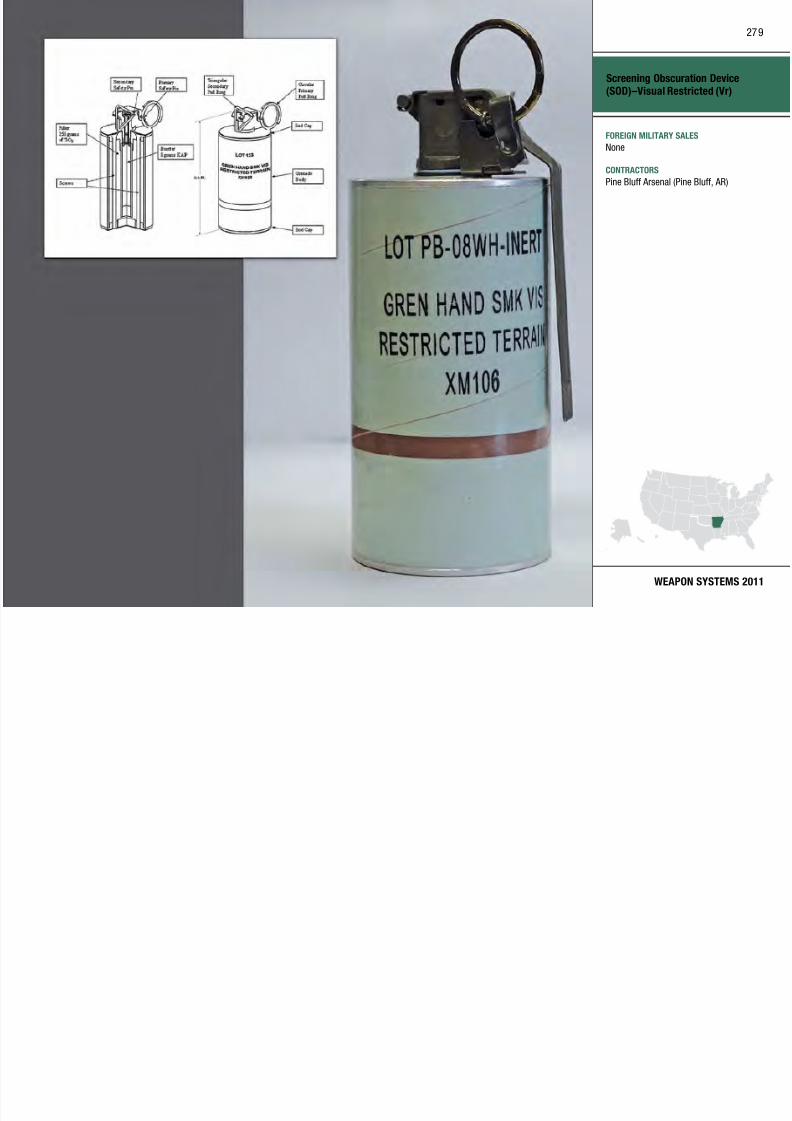
7/29/2019 Army Weapons Systems 2011
http://slidepdf.com/reader/full/army-weapons-systems-2011 289/380
WEAPON SYSTEMS 2011
INVESTMENT COMPONENT
Secure Mobile Anti-Jam Reliable Tactical–Terminal (SMART-T)
Recapitalization
Modernization
Maintenance
Recapitalization
Modernization
Maintenance
MISSION
Provides range extension to the
Army’s current and future tactical
communications networks.
DESCRIPTIONTh S M bil A t i J R li bl
SMART-T will include up-armoring
in compliance with recent changes
in Army policy for the deployment of
personnel carriers.
SMART-T processes data and voice
i ti t b th l d
PROGRAM STATUS• 2QFY07–4QFY10: Deployed up to
47 SMART-Ts in Southwest Asia;
received positive feedback• 3QFY08: Completed elding of 239
EHF SMART-Ts
2QFY09 C l t d A b t f
280
7/29/2019 Army Weapons Systems 2011
http://slidepdf.com/reader/full/army-weapons-systems-2011 290/380
UNITED STATES ARMY
ACQUISITION PHASE
Technology Development Operations & SupportProduction & DeploymentEngineering & Manufacturing Development Technology Development Operations & SupportProduction & DeploymentEngineering & Manufacturing Development
The Secure Mobile Ant i-Jam Reliable
Tactical–Terminal (SMART-T)
is a mobile military satellite
communication terminal mounted on a
standard High Mobility Multipurpose
Wheeled Vehicle. The SMART-T
extends the range of current and future
tact ical communications networks
through DoD Milstar communicat ion
satellites. With the SMART-T’s higher
power transmitter, it now provides
data rates up to 8.192 million bits
per second (Mbps). It provides the
Army with its only protected (ant i-
jam and ant i-scinti llation) w ideband
satellite communication capability
with new AEHF Transmission Securit y
(TRANSEC) algorithms. A production
contract was awarded to upgrade
SMART-T to support the Advanced
Extremely High Frequency (AEHF) waveform. The AEHF satel lite system
will d ramatically i ncrease the Army’s
end-to-end communications throughput
capability. The AEHF upgrade to the
communications at both low and
medium data rates. The terminal
provides worldwide, anti-jam, low
probability of intercept, secure voice,
and data capabilities for the Joint
warfighter. Its enhanced system
interfaces include base-band interface
changes, accommodating additional
data rates. SMART-T will be fielded at
the brigade and div ision levels.
SYSTEM INTERDEPENDENCIESOther Major Interdependencies
The SMART-T communicates with
Milstar milita ry communication
satellites, and is being upgraded
to communicate with AEHF
communication satellites.
• 2QFY09: Completed Army buyout of
AEHF SMART-T Upgrade K its
• 3QFY10: Awarded contract to
procure 39 complete AEHF SMART-Ts
PROJECTED ACTIVITIES• 1QFY11: Obtain conditional
materiel release for AEHF SMART-T
modification work order
• 2QFY11: Initiate AEHF SMART-T
fieldings to operational Army units
• 3QFY12: SMART-T will participate
in Air Force AEHF multi-service
operational test and evaluation
Secure Mobile Anti-Jam Reliable
Tactical–Terminal (SMART-T)
FOREIGN MILITARY SALES
None
CONTRACTORS
Production and Spares:
Raytheon (Largo, FL)
Engineering Support, Management:
Raytheon (Marlborough, MA)
281

7/29/2019 Army Weapons Systems 2011
http://slidepdf.com/reader/full/army-weapons-systems-2011 291/380
WEAPON SYSTEMS 2011
y ( g , )Circuit Cards:
Teledyne (Lewisburg, TN)
Filters:
Transtector (Hayden, ID)
Amplifier Assemblies:
Spectrum Microwave (Marlborough, MA)COMSEC:
L-3 Communications (Camden, NJ )
New Equipment Training/Fielding:EPS Corp. (Martinez, GA)
Satellite Simulator:
Lincoln Labs (Lexington, MA)Technical/Fielding Support :
Linquest Corp. (Colorado Springs, CO)
Admin/Tech:
JANUS Research (Eatontown, NJ)
Technical:
Booz Allen Hamilton (Eatontown, NJ)
INVESTMENT COMPONENT
Sentinel
Recapitalization
Modernization
Maintenance
MISSION
group mounted on a high-mobility
trai ler, the identificat ion friend-or-
foe system (IFF), and the FAAD C2
interface. The sensor is an advanced three-dimensional bat tleeld X-band
air defense phased-array radar with a
40 kilometer range
Sentinel modernization efforts
include enhanced target range and
classification upgrades to engage
non-line-of-sight targets; increaseddetection and acquisition range
of targets; enhanced situational
awareness; and classification of
PROGRAM STATUS• 4QFY10: Delivery and installation of
14 Improved Sentinel Kits on radars
PROJECTED ACTIVITIES• 2QFY11: Contract award for 62
Improved Sentinels
282

7/29/2019 Army Weapons Systems 2011
http://slidepdf.com/reader/full/army-weapons-systems-2011 292/380
UNITED STATES ARMY
ACQUISITION PHASE
Technology Development Operations & SupportProduction & DeploymentEngineering & Manufacturing Development
MISSION
Provides persistent surveillance and fire
control quality data through external
command and control platforms,
enabling protection against cruise
missiles, aircraft, unmanned aerial
vehicles, and rocket, artillery, and
mortar threats.
DESCRIPTIONSentinel is used with the Army’s
Forward Area Air Defense Command
and Control (FAAD C2) system and
provides key target data to Stinger-
based weapon systems and battlefield
commanders via FAAD C2 or
directly, using an Enhanced Position
Location Reporting System or the
Single Channel Ground and Airborne
Radio System.
Sentinel consists of the M1097A1
High Mobility Multipurpose Wheeled
Vehicle, the antenna transceiver
40-kilometer range.
Sentinel can operate day and night,
in adverse weather conditions,
and in battlefield environments of
dust, smoke, aerosols, and enemy
countermeasures. It provides
360-degree azimuth coverage for
acquisition and tracking of targets
(cruise missiles, unmanned aerial
vehicles, rota ry and fixed-wing
aircraft) moving at supersonic to
hovering speeds and at positions from
the map of the earth to the maximum
engagement altitude of short-range
air defense weapons. Sentinel detects
targets before they ca n engage, thus
improving air defense weapon reaction
time and a llowing engagement at
optimum ranges. Sentinel’s integrated
IFF system reduces the potential forengagement of friendly aircraf t.
awareness; and classification of
cruise missiles. The system provides
integrated air t racks with classification
and recognition of platforms that give
an integrated air and cruise missile
defense solution for the Air and Missile
Defense System of Systems Increment
1 architecture and subsequent
increments. Sentinel provides critical
air surveillance of the National Capital
Region and other areas as part of
ongoing homeland defense efforts, and
is a component of the counter rocket,
artil lery, and mortar batteries in the
area of responsibility.
SYSTEM INTERDEPENDENCIESFAAD C2, Surface Launched Advanced
Medium Range Air-to-Air Missile
(SLAMRAAM)
Improved Sentinels
• 2QFY11: Contract award for 156
AN/TPX-57 IFFs
• FY11–13: Installation/upgrade of
radars with 33 Improved Sentinel
Kits
Sentinel
FOREIGN MILITARY SALES
Egypt, Lithuania, Turkey
CONTRACTORS
Thales Raytheon Systems (Fullerton, CA;
El Paso, TX; Forest, MS; Largo, FL)
CAS, Inc. (Huntsville, AL)
283

7/29/2019 Army Weapons Systems 2011
http://slidepdf.com/reader/full/army-weapons-systems-2011 293/380
WEAPON SYSTEMS 2011
INVESTMENT COMPONENT
Shadow Tactical Unmanned Aircraft System (TUAS)
Recapitalization
Modernization
Maintenance
MISSION
Control Station (OSGCS) is the only
Joint-cert ied Ground Control Station
(GCS) in the Department of Defense.
The RQ-7B Shadow can be transported by six A ir Force C-130 aircraft. It is
currently operational in both the Army
and Marine Corps
vehicle (UAV) warrant ofcer, 12 Air
Vehicle Operators/Mission Payload
Operators, four electronic warfare
repair personnel, and three enginemechanics supporting launch and
recovery. The Maintenance Section
Multifunctional is manned by Soldiers
SYSTEM INTERDEPENDENCIESIn this Publication
HMMWV Family of Vehicles, Single
Channel Ground and Airborne RadioSystem (SINCGARS)
Other Major Interdependencies
284

7/29/2019 Army Weapons Systems 2011
http://slidepdf.com/reader/full/army-weapons-systems-2011 294/380
UNITED STATES ARMY
ACQUISITION PHASE
Technology Development Operations & SupportProduction & DeploymentEngineering & Manufacturing Development
MISSION
Provides reconnaissance, surveillance,
target acquisition, and force protection
for the Brigade Combat Team (BCT) in
near-real-time during day/night and
limited adverse weather conditions.
DESCRIPTION The RQ-7B Shadow Tactical Unmanned Aircra ft System (TUAS) has a
wingspan of 14 feet and a payload
capacity of approximately 60 pounds.
Gross takeoff weight exceeds 380
pounds and endurance is more than
five hours on-station at a distance of 50
kilometers. The system is compatible
with the Al l Source Analysis System,
Advanced Field Ar tiller y Tactical Data
System, Joint Surveillance Target
Attack Radar System Common GroundStation, Joint Technical Architecture–
Army, and the Defense Information
Infrastructure Common Operating
Environment. The One System Ground
and Marine Corps.
The RQ-7B Shadow congurat ion,
fielded in platoon sets, consists of:
• Four air vehicles with day/night
electro-optical/infrared (IR) with
laser designator and IR illuminator
payloads
• Two OSGCS on High Mobility
Multipurpose Wheeled Vehicles(HMMWV)
• Four One System Remote Video
Transceivers
• One hydraulic launcher
• Two ground data terminals
• Associated trucks, trailers, and
support equipment
Shadow systems are manned by
dedicated Unmanned Aircraft System
platoons of 22 soldiers and typically two contractors. Shadow platoons
are organic to the BCT. The Soldier
platoon consists of a platoon leader,
platoon sergeant, unmanned aerial
Multifunctional is manned by Soldiers
who also transport spares and provide
maintenance support. The Mobile
Maintenance Facility is manned by
contractor personnel located with the
Shadow platoon to provide logistics
support to include “off system support”
and “maintenance by repair.”
The Shadow also has a n earlyentry configuration of 15 Soldiers,
one GCS, the air vehicle transport
HMMWV, and the launcher trailer,
which can be transported in three
C-130s. All components can be slung
under a CH-47 or CH-53 helicopter
for transport.
Other Major Interdependencies
MEP803A 10kW
PROGRAM STATUS• Current: In production and
deployment; flown more than
535,000 hours in support of combat
operations in Operation Iraqi
Freedom and Operation Enduring
Freedom since achieving initialoperating capability
PROJECTED ACTIVITIES• FY11–12: Field remaining
production systems; procure and field
laser designator, Tactical Common
Data Link, and Universal Ground
Control Station retrots; develop
and field reliability and product
improvements
Shadow Tactical Unmanned Aircraft
System (TUAS)
FOREIGN MILITARY SALES
Australia
CONTRACTORS
Shadow System:
AAI Corp. (Textron Systems)
(Hunt Valley, MD)
TCDL:
285

7/29/2019 Army Weapons Systems 2011
http://slidepdf.com/reader/full/army-weapons-systems-2011 295/380
WEAPON SYSTEMS 2011
L-3 Communications (Salt Lake City, UT )
Shelter Integration:
CMI (Huntsville, AL)GDT:
Tecom (Chatsworth, CA )
Shelters:
General Dynamics (Marion, VA)
ACE II Flight:
Athena (Warrenton, VA)Mode IV IFF:
Raytheon (Baltimore, MD)
Amplifiers:
CTT (Santa Clara, CA)
INVESTMENT COMPONENT
Single Channel Ground and AirborneRadio System (SINCGARS)
Recapitalization
Modernization
Maintenance
MISSION
Provides Joint commanders with a
highly reliable, low-cost, secure, and
easily maintained Combat NET Radio(CNR) that has both voice and data
handling capability in support of tactical
weighs significantly less, while sti ll
maintaining all the functionalities of
the SIP for backward compatibil ity.
Enhancements include the Embedded
Global Positioning System (GPS)
Receiver (EGR) and the radio-based
will a llow the radios to continue to
provide secure communications to the
secret and top-secret level of security.
SYSTEM INTERDEPENDENCIESNone
286

7/29/2019 Army Weapons Systems 2011
http://slidepdf.com/reader/full/army-weapons-systems-2011 296/380
UNITED STATES ARMY
ACQUISITION PHASE
Technology Development Operations & SupportProduction & DeploymentEngineering & Manufacturing Development
command and control operations.
DESCRIPTION The Single Channel Ground and
Airborne Radio System (SINCGARS)
Advanced SINCGARS System
Improvement Program (ASIP) radio
is the DoD/Army multi-service fielded
solution for voice communication forplatoon level and above, operating
over the 30.000 to 87.975MHz
frequency range. This radio provides
the capabi lity of establishing two-
way communications (including
jam-resista nce) using the SINCGARS
waveform and provides multimode
voice and data communications
supporting ground, a ir-to-ground,
and ground-to-air line-of-sight
communications links. The ASIP radiois the newer version of the SINCGARS
radio. It is smaller than the SIP and
Receiver (EGR) and the radio based
combat identification/radio-based
situational awareness (RBCI/
RBSA) capability, which provides the
warfighter with enha nced situationa l
awareness and identification of friendly
forces in targeted areas. R BCI serves
as a gap filler for combat identification,
providing a n interrogation/responder
capability to satisfy the a ir-to-groundpositive identification of platforms
prior to release of weapons to
prevent fratricide. RBSA adds a radio
beaconing capabil ity for every ASIP-
equipped platform to enhance the Blue
Force situational awareness picture.
The Internet control ler enhancements
add improved addressing capabilities
in support of tactical Internet
enhancements being provided by Joint
Battle Command–Platform for Jointinteroperability. Crypto modernization
is a programmable communications
security capability for SINCGARS that
PROGRAM STATUS• 3QFY08–FY10: Continue to eld
in accordance with Headquarters
Department of the Army guidance to
support the Army Campaign Plan;
National Guard, Army Reserve, and
Active Army, Operation Enduring
Freedom requirements and urgent
Operational Needs Statement• 3QFY09: Competitive contract
award for procurement of SINCGARS
radios to meet approved acquisition
objective requirement in FY09
PROJECTED ACTIVITIES• FY11–4QFY13: Fielding of
SINCGARS to Army Overseas
Contingency Operation through FY13
Single Channel Ground and Airborne
Radio System (SINCGARS)
FOREIGN MILITARY SALES
Australia, Bahrain, Croatia, Egypt, Estonia,
Finland, Georgia, Greece, Hungary, Ireland,
Italy, Korea, Kuwait, Morocco, New
Zealand, Portugal, Saudi Arabia, SHAPE
Tech Center, Slovakia, Taiwan, Thailand,
Ukraine, Uzbekistan, Zimbabwe
287
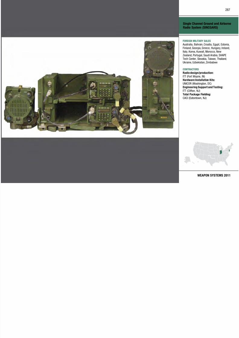
7/29/2019 Army Weapons Systems 2011
http://slidepdf.com/reader/full/army-weapons-systems-2011 297/380
WEAPON SYSTEMS 2011
CONTRACTORS
Radio design/production:
ITT (Fort Wayne, IN)Hardware Installation Kits:
UNICOR (Washington, DC)
Engineering Support and Testing:
ITT (Clifton, NJ)
Total Package Fielding:
CACI (Eatontown, NJ)
INVESTMENT COMPONENT
Small Arms–Crew Served Weapons
MISSION
The M240L short barrel var iant is
21.8 pounds, 5.4 pounds lighter than
the M240B.
The M249 Squad Automatic Weapon
(SAW) replaces the M16A1 Automatic
Rifle at the squad level, as well as
The M2E2 Quick Change Barrel
(QCB) Kit improves performance
and is easier and safer to use. Other
upgrades improve on the battle-provenM2 and can be retrofitted to existing
M2HB weapons.
• 3QFY09: Awarded letter contract for
initial production deliveries
• 1QFY10: Deliver first low-rate initial
production quantity of 50 weaponsM249:
• In production
• 2QFY09: Competitive IDIQ contract
Recapitalization
Modernization
Maintenance
288

7/29/2019 Army Weapons Systems 2011
http://slidepdf.com/reader/full/army-weapons-systems-2011 298/380
UNITED STATES ARMY
ACQUISITION PHASE
Technology Development Operations & SupportProduction & DeploymentEngineering & Manufacturing Development
Enables warfighters and small units to
engage targets with lethal fire to defeat
or deter adversaries.
DESCRIPTION The M240B 7.62mm Medium Machine
Gun has been reconfigured for ground
applications with buttstock, bipod, iron
sights, and forward-rail assemblies. TheM240B has a maximum effective range
of 1,800 meters, a cyclic rate of re of
650 rounds per minute, and a muzzle
velocity of 2,800 feet per second.
The M240L 7.62mm Medium
Machine Gun (Light) incorporates
titanium construct ion and alternative
manufacturing methods to achieve
significant weight savings. These
improvements reduce the Soldier’scombat load while allowing easier
handling and movement of the weapon.
q ,
some M60 multipurpose machine
guns in non-infantry units. The M249
delivers greater range and rates of fire
than the M16 or M4.
A collapsible buttstock improves
weapons control when fired in confined
spaces. A new short barrel allows
for improved egress and maneuver inclose quarter combat. An improved
bipod provides Soldiers with increased
reliability and weapon accuracy,
including on uneven terrain.
The M2 .50 Caliber Machine Gun is
highly effective against l ight armored
vehicles, low- and slow-fly ing aircraft ,
and small boats. The M2 provides
suppressive fire for offensive and
defensive purposes. It is capable ofsingle-shot (ground M2 Machine Gun)
and automatic fire.
The MK19 Grenade Machine Gun
supports the Soldier by delivering
heavy, accurate, and continuous
firepower against enemy personnel
and lightly armored vehicles. The
MK19 can be mounted on a tripod or
on multiple vehicle platforms and is
the prima ry suppressive weapon for
combat support and combat servicesupport units.
SYSTEM INTERDEPENDENCIESNone
PROGRAM STATUSM240B:
• In production
• Fielding ongoing
• 4QFY09: Competitive indenite
delivery/indenite quantity (IDIQ)contract awarded
M240L:
• 4QFY08: Type classification and
low-rate production
Q p Q
awarded
• 4QFY09: Awarded second deliver y
order on FY09 IDIQ contract
PROJECTED ACTIVITIESM240B:
• Continue: Production and fielding
M240L:
• FY11: Full materiel releaseM249:
• Continue: Production and fielding
• Continue: Participation in small
arms readiness evaluation team to
inspect, repair, renovate, or replace
M249 weapons for units deploying
overseas
MK19
• Continue: Production delivery under
new contract
• Continue: Fielding in support ofcurrent operations
Small Arms–Crew Served Weapons
FOREIGN MILITARY SALES
M240B Machine Gun:
Afghanistan, Jordan, Yemen
M249 SAW:
Afghanistan, Colombia, El SalvadorMK19 Grenade Machine Gun:
None
M2:
Af h i t J d
289

7/29/2019 Army Weapons Systems 2011
http://slidepdf.com/reader/full/army-weapons-systems-2011 299/380
WEAPON SYSTEMS 2011
Afghanistan, Jordan
CONTRACTORS
M249 SAW:
Fabrique National Manufacturing, LLC
(Columbia, SC)M240B Machine Gun:
Fabrique National Manufacturing, LLC
(Columbia, SC)MK19 Grenade Machine Gun:
General Dynamics Armament and
Technical Products (Saco, ME)
Alliant Techsystems (Mesa, AZ)
INVESTMENT COMPONENT
Small Arms–Individual Weapons
MISSION
thousand M14 EBRs were assembled
at TACOM Lifecycle Management
Command at Rock Island Arsenal in
response to Operational Need Statementsrequesting a longer range capability.
The upgraded weapons are currently in
service with select Army units.
be mounted on the shotgun. The bolt
handle is mountable on either side for
ambidextrous handling.
The MASS enables Soldiers to transition
between lethal and less-than-lethal fires
and adds the capability of a separate
• 1QFY09: Materiel release and full-
rate production decision
• 3QFY09: First unit equipped
M26 Modular Accessory ShotgunSystem:
• 4QFY09: Limited user test and
evaluation with MP units
Recapitalization
Modernization
Maintenance
290

7/29/2019 Army Weapons Systems 2011
http://slidepdf.com/reader/full/army-weapons-systems-2011 300/380
UNITED STATES ARMY
ACQUISITION PHASE
Technology Development Operations & SupportProduction & DeploymentEngineering & Manufacturing Development
Enables warfighters and small units to
engage targets with lethal fire to defeat
or deter adversaries.
DESCRIPTION The M4 Carbine replaces the M16 series
Ries in all Brigade Combat Teams,
Division Headquarters, and other
selected units. It is 1.4 pounds lighterand more portable than the M16 series of
ries. The M4 series of carbines can also
be mounted with the M203A2 Grenade
Launcher, M320 Grenade Launcher, or
M26 Modular Accessory Shotgun System
(MASS).
The M14 Enhanced Battle Rie (EBR)
has a new adjustable buttstock, cheek
rest and M4-style pistol grip, making
the rifle effective in both close quarterscombat and in the Squad Designated
Marksman role. The EBR can be
returned to its original configuration
with no permanent modications. Five
The M320 Grenade Launcher is the
replacement to all M203 series grenade
launchers on M16 Ries and M4
Carbines. A modular system, it attaches
under the barrel of the rifle or carbine
and can convert to a stand-alone weapon.
The M320 improves on current grenade
launchers with an integral day/nightsighting system and improved safety
features. It also has a side-loading
unrestricted breech that allows the
system to re longer 40mm low-velocity
projectiles (NATO standard and non-
standard).
The lightweight M26 12-Gauge MASS
attaches to the M4 Carbine and zeroes
to the host weapon. It is also designed
to operate as a stand-alone system, andcomes with a recoil-absorbing, collapsible
buttstock. The Picatinny rail mounted
on top allows accessory equipment to
shotgun without carrying a second
weapon. Additional features include a
box magazine, flip-up sights, and an
extendable stand-off device for door
breaching.
SYSTEM INTERDEPENDENCIESNone
PROGRAM STATUSM4 Carbine:
• Current: Delivery and fielding
M14 EBR:
• 3QFY09: Army Requirements and
Resourcing Board approved 5,000
systems
• 1QFY10: 1,200 additional systems
authorized
• 3QFY10: First 5,000 complete
(95 percent fielded)M320 Grenade Launcher Module:
• 1QFY09: Type classification-
standard decisions
• 2QFY10: Low-rate initial production
approved
• 4QFY10: First article testing
complete
PROJECTED ACTIVITIESM4 Carbine:
• Continue: M4 production, deliveries,
and fieldingM14 EBR:
• 4QFY11: Complete remaining 1,200
systems
• Continue: In sustainment
M320 Grenade Launcher Module:
• Continue: Production and fielding
• Continue: Reduce size and weight of
day/night sight
M26 Modular Accessory Shotgun
System:
• 4QFY10–2QFY11: Ramp up to fullrate production
• 2QFY11: Materiel release
• 3QFY11: First unit equipped

7/29/2019 Army Weapons Systems 2011
http://slidepdf.com/reader/full/army-weapons-systems-2011 301/380
INVESTMENT COMPONENT
Small Caliber Ammunition
Recapitalization
Modernization
Maintenance
MISSION
Provides warfighters with the highest
quality, most capable small caliber
ammunition for training and combat.
DESCRIPTIONSmall Caliber Ammunition consists
Three categories of Smal l Caliber
Ammunition are current ly in use.
War Reserve Ammo is modern
ammunition that supports individualand crew served weapons during
combat operations. Training Standard
Ammunition is dua l-purpose, and is
PROGRAM STATUS• Current: M855A1 Enhanced
Performance Round (M855
replacement program) in fullproduction
PROJECTED ACTIVITIES
292
7/29/2019 Army Weapons Systems 2011
http://slidepdf.com/reader/full/army-weapons-systems-2011 302/380
UNITED STATES ARMY
ACQUISITION PHASE
Technology Development Operations & SupportProduction & DeploymentEngineering & Manufacturing Development
of 5.56mm, 7.62mm, 9mm, 10- and
12-gauge, .22 Cal., .30 Cal., .50 Cal.,
and Grenade Rifle Entry Munition
(GREM). The 5.56mm cartridge is
used by the M16 Rie, M249 Squad
Automatic Weapon (SAW), and the
M4 Carbine. The 7.62mm cartridge
is used by the M240 Machine Gun,
and M60 Machine Gun, as well as the M24, M110 and M14 EBR Sniper
Rifles. The 9mm cartridge is fired
by the M9 Pistol. The M2 Machine
Gun and the M107 Sniper Rie use
.50 Cal. cartr idges. The remaining
Small Caliber Ammunition is used in a
var iety of pistols, r ifles and shotguns.
used to support training or operational
requirements. Training Unique
Ammunition is desig ned specifica lly for
use in training and is not for combat
use, i.e., blank, dummy, inert, and
short range tra ining ammunition.
SYSTEM INTERDEPENDENCIES
Small Arms–Crew Served Weapons,Small A rms–Individual Weapons
• FY11: Produce and deliver one
billion rounds (5.56mm, 7.62mm, and
0.50 Cal.)
• FY12: Complete Lake City Army
Ammunition Plant modernizat ion
program
Small Caliber Ammunition
FOREIGN MILITARY SALES
5.56mm, 7.62mm, .50 Caliber:
Afghanistan, Colombia, Czech Republic,
El Salvador, France, Hungary, India, Iraq,
Israel, Japan, Jordan, Kenya, Lebanon,
Philippines, Singapore, Thailand, Tunisia,
Yemen
CONTRACTORS
293

7/29/2019 Army Weapons Systems 2011
http://slidepdf.com/reader/full/army-weapons-systems-2011 303/380
WEAPON SYSTEMS 2011
CONTRACTORS
Alliant Techsystems (Independence, MO)
General Dynamics Ordnance and Tactical
Systems (St. Petersburg, FL)
Olin Corp. (East Alton, IL)
General Dynamics (Saint Marks, FL)
SNC Technologies (LeGardeur, Québec,
Canada)
INVESTMENT COMPONENT
Sniper Night Sight (SNS), AN/PVS-10
Recapitalization
Modernization
Maintenance
MISSION
Enables snipers to acquire and engage
targets during day and night operations.
DESCRIPTION
The AN/PVS-10 Sniper Night Sight
(SNS) is a lightweight, weapon-
d lf i d i
Weight: 4.9 pounds
Magnication: 8.5x
Range: Target recognition (night): 600
meters; target recognition (day): 800meters
Operational time: 24 hours (with one
battery set change)
T AA b i
PROGRAM STATUS• FY10: Fielded to snipers supporting
Operation Enduring Freedom and
Operation Iraqi Freedom
PROJECTED ACTIVITIES• FY11: Continue to eld in
d i h H d
294
7/29/2019 Army Weapons Systems 2011
http://slidepdf.com/reader/full/army-weapons-systems-2011 304/380
UNITED STATES ARMY
ACQUISITION PHASE
mounted, self-contained image-
intensified passive device designed
primarily for use by snipers for day
and night operations. It has a range of
600 meters at night, and 800 meters
during daylight. A day/night lever
enables the user to alternate between
day and night modes of operation. The
SNS employs a variable-gain imageintensifier that can be adjusted by the
user depending on the ambient light
levels. It includes a black-line reticle
for day use and can be illuminated for
night use when required.
An eyepiece diopter adjustment permits
use of the SNS without corrective
glasses. A rail mounting interface is
integrated into the base of the sight to
be quickly mounted to or dismounted
from the weapon.
Power: Two AA batteries
SYSTEM INTERDEPENDENCIESNone
accordance with Headquarters
Department of the Army guidance
Technology Development Operations & SupportProduction & DeploymentEngineering & Manufacturing Development
Sniper Night Sight (SNS),
AN/PVS-10
FOREIGN MILITARY SALES
Austria, Colombia, Kenya, Poland,
Thailand
CONTRACTORS
L-3 Communications Electro-Optical
Systems (Tempe, AZ; Garland, TX)
295

7/29/2019 Army Weapons Systems 2011
http://slidepdf.com/reader/full/army-weapons-systems-2011 305/380
WEAPON SYSTEMS 2011
INVESTMENT COMPONENT
Spider
Recapitalization
Modernization
Maintenance
MISSION
Provides the commander with a new
capability to shape the battlefield,
protect the force, and respond tochanging battlefield environments in a
graduated manner while minimizing risk
to friendly troops and non-combatants
The Spider system contains three
main components: the remote control
unit, residing within a computer
interface; the repeater, extending theremote control range; and a munition
control unit for sending and receiving
commands as well as activating the
iti S id b d
SYSTEM INTERDEPENDENCIESOther Major Interdependencies
Interface with Tactical Internet
through Force XXI Battle CommandBrigade-and-Below and obstacle
positioning through Global Positioning
System
296

7/29/2019 Army Weapons Systems 2011
http://slidepdf.com/reader/full/army-weapons-systems-2011 306/380
UNITED STATES ARMY
ACQUISITION PHASE
Technology Development Operations & SupportProduction & DeploymentEngineering & Manufacturing Development
to friendly troops and non combatants.
DESCRIPTION Anti-Personnel Landmine Alternatives
(APL/A) Track I (Spider) is a hand-
emplaced, remotely-controlled,
Man-in-the-Loop (MITL), anti-
personnel munition system. Spider
provides munition field effectiveness, but does so without residua l life-
threaten ing risks a fter hosti lities
end. The fielding of this system with
its sensors, communications, and
munitions changes the way Soldiers
operate in an otherwise unpredictable
battlefield. Each munition is control led
by a remotely stat ioned Soldier who
monitors its sensors, allowing for
more precise (non-lethal to lethal)
responses—a significant advancement
and advantage. The Spider Networked
Munitions System enables MITL to
detect, track, classify, count, and
destroy the enemy.
munitions. Spider can be used as a
force-protection-reinforcing obstacle
to delay, disrupt, and channel enemy
forces as well as restrict their use
of critical routes of terrain, thereby
reducing civil casualties and the
exposure of personnel to hostile fire.
It can also be integrated into a base
defense system, providing protection tosoldiers in forward operating bases and
combat outposts.
The system’s design allows for
safe, flexible, and rapid deployment,
reinforcement, and recovery as well
as safe passage of friendly forces.
Spider eliminates the possibility of an
unintended detonation through early
warn ing and select ive engagement of
enemy forces, and has a self-destruct
capability. Spider is designed for
storage, transport, rough handling,
and use in worldwide military
environments.
PROGRAM STATUS• 2QFY09: Fielding of urgent materiel
release hardware to Operation
Enduring Freedom
• 1QFY10: Award contract
modification to procure up to an
additional 70 systems
PROJECTED ACTIVITIES• 1QFY11: Materiel release/type
classification standard
• 1QFY11: Full-rate production
decision
• 3QFY11: Full-rate production
contract award
Spider
FOREIGN MILITARY SALES
None
CONTRACTORS
Prime:
Textron Defense Systems(Wilmington, MA)
Alliant Techsystems (Plymouth, MN)Subcontractors:
297

7/29/2019 Army Weapons Systems 2011
http://slidepdf.com/reader/full/army-weapons-systems-2011 307/380
WEAPON SYSTEMS 2011
Alliant Techsystems (Rocket Center, WV)
BAE Systems/Holston (Kingsport, TN)
American Ordnance (Milan, TN)
INVESTMENT COMPONENT
Stryker Family of Vehicles
Recapitalization
Modernization
Maintenance
MISSION
Enables the Army to immediately
Commanders Vehicle, Fire Support
Vehicle (FSV), Engineer Squad Vehicle,
Medical Evacuation Vehicle (MEV),
Anti-tank Guided Missile (ATGM) Vehicle, and the Nuclear Biological
Chemical Reconnaissance Vehicle
(NBCRV).
run-flat capability, and has a central
tire-inflation system. It also incorporates
a vehicle-height management system.
The Stryker program leverages non-
developmental items with common
subsystems and components to allow
rapid acquisition and fielding Stryker
• 1QFY10: Army announces plan to
convert two Heavy Brigade Combat
Teams (HBCTs) to SBCTs, increasing
total SBCTs to nine• 2QFY10: Acquisition Decision
Memorandum (ADM) clarifies the term
correction regarding MGS deficiencies
and authorizing continued use of
298
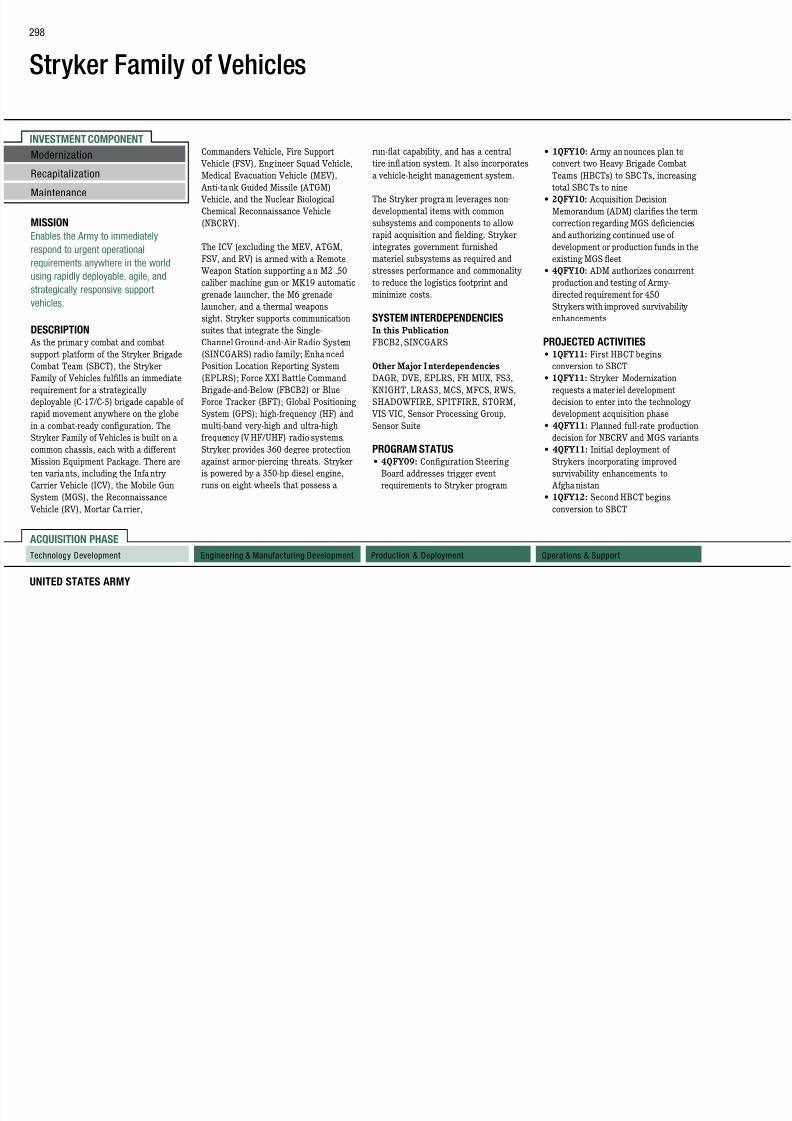
7/29/2019 Army Weapons Systems 2011
http://slidepdf.com/reader/full/army-weapons-systems-2011 308/380
UNITED STATES ARMY
ACQUISITION PHASE
Technology Development Operations & SupportProduction & DeploymentEngineering & Manufacturing Development
Enables the Army to immediately
respond to urgent operational
requirements anywhere in the world
using rapidly deployable, agile, and
strategically responsive support
vehicles.
DESCRIPTION As the primar y combat and combat
support platform of the Stryker Brigade
Combat Team (SBCT), the Stryker
Family of Vehicles fullls an immediate
requirement for a strategically
deployable (C-17/C-5) brigade capable of
rapid movement anywhere on the globe
in a combat-ready configuration. The
Stryker Family of Vehicles is built on a
common chassis, each with a different
Mission Equipment Package. There are
ten variants, including the Infantry
Carrier Vehicle (ICV), the Mobile Gun
System (MGS), the Reconnaissance
Vehicle (RV), Mortar Carrier,
The ICV (excluding the MEV, ATGM,
FSV, and RV) is armed with a Remote
Weapon Station supporting a n M2 .50
caliber machine gun or MK19 automatic
grenade launcher, the M6 grenade
launcher, and a thermal weapons
sight. Stryker supports communication
suites that integrate the Single-Channel Ground-and-Air Radio System
(SINCGARS) radio family; Enha nced
Position Location Reporting System
(EPLRS); Force XXI Battle Command
Brigade-and-Below (FBCB2) or Blue
Force Tracker (BFT); Global Positioning
System (GPS); high-frequency (HF) and
multi-band very-high and ultra-high
frequency (VHF/UHF) radio systems.
Stryker provides 360 degree protection
against armor-piercing threats. Stryker
is powered by a 350-hp diesel engine,
runs on eight wheels that possess a
rapid acquisition and fielding. Stryker
integrates government furnished
materiel subsystems as required and
stresses performance and commonality
to reduce the logistics footprint and
minimize costs.
SYSTEM INTERDEPENDENCIES
In this PublicationFBCB2, SINCGARS
Other Major Interdependencies
DAGR, DVE, EPLRS, FH MUX, FS3,
KNIGHT, LRAS3, MCS, MFCS, RWS,
SHADOWFIRE, SPITFIRE, STORM,
VIS VIC, Sensor Processing Group,
Sensor Suite
PROGRAM STATUS• 4QFY09: Conguration Steering
Board addresses trigger event
requirements to Stryker program
and authorizing continued use of
development or production funds in the
existing MGS fleet
• 4QFY10: ADM authorizes concurrent
production and testing of Army-
directed requirement for 450
Strykers with improved survivability
enhancements
PROJECTED ACTIVITIES• 1QFY11: First HBCT begins
conversion to SBCT
• 1QFY11: Stryker Modernization
requests a mater iel development
decision to enter into the technology
development acquisition phase
• 4QFY11: Planned full-rate production
decision for NBCRV and MGS variants
• 4QFY11: Initial deployment of
Strykers incorporating improved
survivability enhancements to
Afghanistan
• 1QFY12: Second HBCT begins
conversion to SBCT
Stryker Family of Vehicles
FOREIGN MILITARY SALES
None
CONTRACTORS
General Dynamics Land Systems
(Sterling Heights, MI)Manufacturing/Assembly:
General Dynamics Land Systems-Canada
(London, Ontario, Canada)
299

7/29/2019 Army Weapons Systems 2011
http://slidepdf.com/reader/full/army-weapons-systems-2011 309/380
WEAPON SYSTEMS 2011
Joint Systems Manufacturing Center
(JSMC) (Lima, OH)
General Dynamics Assembly Operations
(Anniston, AL)
Engineering:
General Dynamics (Sterling Heights, MI)
Kits:
Verhoff Machine (Continental, OH)Manifold/Alternator:
North American Controls (Shelby Twp, MI)
Sensors/CCA:
Raytheon (El Segundo, CA)
Fire System Assembly:
Kidde Dual Spectrum (Goleta, CA)
INVESTMENT COMPONENT
Surface Launched Advanced Medium Range Air-to-Air Missile(SLAMRAAM)
Recapitalization
Modernization
Maintenance
MISSION
Defeats aerial threats to the current
and future maneuver force and other
critical assets while supporting a varietyof missions at the tactical, operational,
and strategic levels of warfare.
other Joint and Army external sensors
when available. The SLAMRAAM
launcher, with remote capability, is
a mobile platform with multi-servicelaunch rails, launcher electronics,
on-board communication components,
and four to six AIM-120-C Advanced
Medium Range Air-to-Air Missiles
PROGRAM STATUS• 4QFY09: Army di rected
SLAMRAAM to be configured on a
more crew survivable platform• 2QFY10: Army decis ion to configure
SLAMRAAM on the Family of
Medium Tactical Vehicles
300

7/29/2019 Army Weapons Systems 2011
http://slidepdf.com/reader/full/army-weapons-systems-2011 310/380
UNITED STATES ARMY
ACQUISITION PHASE
Technology Development Operations & SupportProduction & DeploymentEngineering & Manufacturing Development
DESCRIPTION The Surface Launched Advanced
Medium Range Air-to-Air Missile
(SLAMRAAM) is a key component
of the Integrated Air and Missile
Defense (IAMD) Composite Battalion
and will replace the Avenger in the
Army’s Air a nd Missile Defense forces.SLAMRAAM is a lightweight, day-
or-night, adverse weather, non-line-
of-sight system for countering cruise
missiles and unmanned air vehicle
threats with engagement capabilities of
up to 18 kilometers.
The system is comprised of a n
Integrated Fire Control Station (IFCS)
for command and control, integrated
sensors, and missile launcher
platforms. While SLAMRAAM uses
Sentinel as its organic radar to provide
surveillance and fire control data, the
system will also receive data from
Medium Range Air to Air Missiles
(AMRAAMs). The SLAMRAAM
system is a critical component of a Joint
Cruise Missile Defense capability.
SYSTEM INTERDEPENDENCIESSLAMRAAM w ill provide engagement
operations interoperability by
participating on the Joint DataNetwork (JDN) (Link 16) Internal and
External communication. The IFCS
will manage engagement operations,
and the Advanced Sentinel radar
will be the init ial sensor. In addition,
SLAMRAAM will be supported by
the Joint Land Attack Cru ise Missile
Defense Elevated Netted Sensor
(JLENS) System.
PROJECTED ACTIVITIES• 2QFY11: Limited user testing
• 3QFY11: Milestone C decision for
low-rate initia l production (LRIP)
• 3QFY11: LRIP
Surface Launched Advanced
Medium Range Air-to-Air Missile
(SLAMRAAM)
FOREIGN MILITARY SALES
None
CONTRACTORS
Tech/Program Support:
SETA (Huntsville, AL)System Development/Integration
(FU/HIL/SIL):
Raytheon (Tewksbury, MA)
301

7/29/2019 Army Weapons Systems 2011
http://slidepdf.com/reader/full/army-weapons-systems-2011 311/380
WEAPON SYSTEMS 2011
INVESTMENT COMPONENT
Tactical Battle Command (TBC)/ManeuverControl System (MCS)
MISSION
Provides the tactical battle command
CPOF serves as the Army’s mission
critical command and control (C2)
system that provides collaborative and
situational awareness tools to supportdecision making, planning, rehearsal,
and execution management. CPOF will
serve as the foundation for the Battle
Command Collapse effort, which will
are also provided for asynchronous
collaboration managing business and
operational processes and leveraging
business intel ligence tools fordata analysis.
MCS version 6.4 is a mission-critical C2
system that allows commanders and
Joint Effects Model ( JEM), Joint
Tactical Radio System Ground Mobile
Radios (JTRS GMR), Joint Warning
and Reporting Network (JWARN)
Other Major Interdependencies
AMDWS, AMPS, ASAS, GCCS,
IMETS, JTCW/C2PC, NCES, TAIS,
Recapitalization
Modernization
Maintenance
302

7/29/2019 Army Weapons Systems 2011
http://slidepdf.com/reader/full/army-weapons-systems-2011 312/380
UNITED STATES ARMY
ACQUISITION PHASE
Technology Development Operations & SupportProduction & DeploymentEngineering & Manufacturing Development
Provides the tactical battle command
core environment and common services
baseline for executive decision-making
capabilities, maneuver functional and
battle staff tools, and enterprise services.
DESCRIPTION
Tactical Bat tle Command (TBC)/ Maneuver Control System (MCS) is
a suite of products and services that
includes the Command Post of the
Future (CPOF), Battle Command
Common Services (BCCS), Maneuver
Control System (MCS), Joint
Convergence effort with the United
States Marine Corps (USMC), tactical
SharePoint web portal, coalition
interoperability, and integration
of other Army Battle Command
Systems (ABCS).
Command Collapse effort, which will
unify Battle Command Capabilities
in one environment, allowing the
commander and users to access fires,
air, log, and maneuver capabilities
(information and functionality) through
one workstation and one interface.
BCCS provides the enablinginfrastructure for ABCS and Tactical
Battle Command and for migration
to Net-Centric Enterprise Services
environment. The Battle Command
Server provides interoperability
services, including the publish
and subscribe service and data
dissemination service. The server
also supports Joint convergence with
USMC by providing a data exchange
gateway that allows the direct
exchange of Common Operational
Picture (COP) data between the Joint
services. SharePoint portal services
system that allows commanders and
staffs to visuali ze the battle space and
synchronize the elements of combat
power. MCS includes battle staff tools
and maneuver functional capabilities,
including Chemical, Biological,
Radiological, and Nuclear tools, and
engineering tools for combat and
construction engineers.
SYSTEM INTERDEPENDENCIESIn this Publication
Advanced Field Arti llery Tact ical Data
System (AFATDS), Battle Command
Sustainment Support System (BCS3),
Distributed Common Ground System–
Army (DCGS-A), Early Infantry
Brigade Combat Team (E-IBCT)
Capabilities IBCT Increment I, Global
Command and Control System–Army
(GCCS-A), Force XXI Battle Command
Brigade and Below (FBCB2), Joint
Battle Command–Platform ( JBC-P),
IMETS, JTCW/C2PC, NCES, TAIS,
TBMCS, WIN-T
PROGRAM STATUS• 3QFY08: Joint Requirements
Oversight Council approves MCS
version 6.4 Capabilit ies Production
Document
• 1QFY09: Fielding decision(CPOF QR1)
• 3QFY10: Operational demonstration
of CPOF software with Personalized
Assistant that Learns technology
PROJECTED ACTIVITIES• 1QFY11: Quarterly release of CPOF
software version BC10.0.1
Tactical Battle Command (TBC)/
Maneuver Control System (MCS)
FOREIGN MILITARY SALES
None
CONTRACTORS
General Dynamics (Taunton, MA;
Scottsdale, AZ)CECOM Software Engineering Center (Fort
Monmouth, NJ)
Lockheed Martin (Tinton Falls, NJ)
CACI (Ch till VA)
303

7/29/2019 Army Weapons Systems 2011
http://slidepdf.com/reader/full/army-weapons-systems-2011 313/380
WEAPON SYSTEMS 2011
CACI (Chantilly, VA)
Sensor Technologies (Red Bank, NJ )
INVESTMENT COMPONENT
Tactical Electric Power (TEP)
MISSION
Provides standardized tactical electric
• Operate at rated loads in all military
environments
• Reduce infrared signature and noise
(less than 70 decibels at sevenmeters)
• Are survivable in chemical,
biological, a nd nuclear environments
• Meet power generation and
TQG, 30kW TQG, 60kW TQG, 100kW
TQG, 200kW TQG, and 840kW DPGDS;
of these, the 2kW MTG and 3kW TQG
are man-portable.
SYSTEM INTERDEPENDENCIESNone
• FY09–10: Production and fielding
ongoing for Power Distribution
Illumination System Electrical
(PDISE)
PROJECTED ACTIVITIES• 1QFY11: 3kW TQG rebuy contract
award
Recapitalization
Modernization
Maintenance
304

7/29/2019 Army Weapons Systems 2011
http://slidepdf.com/reader/full/army-weapons-systems-2011 314/380
UNITED STATES ARMY
ACQUISITION PHASE
Technology Development Operations & SupportProduction & DeploymentEngineering & Manufacturing Development
Provides standardized tactical electric
power to the Department of Defense in
support of national security.
DESCRIPTION The Tactical Electric Power (TEP)
program consists of small (2–3
kilowatt [kW]), medium (5–60kW),
and large (100–840kW) electricalpower generating systems, trailer-
mounted power units and power
plants, and electrical distribution
equipment that provide standardized
power management solutions to all
Department of Defense agencies and
numerous Allied nations. The Project
Manager–Mobile Electric Power
systems:
• Maximize fuel efciency
• Increase reliability (500–600
hours mean time between failure),
maintainability, and transportability
• Minimize weight and size while
meeting all user requirements
p g
conditioning standards in
accordance with military standards
(MIL-STD 1332)
• Provide quality electric power for
command posts; command, control,
communications, computers,
intelligence, surveillance, and
reconnaissance (C4ISR) systems; weapon systems; and other
battlefield suppor t equipment
TEP systems provide essential power
for Brigade Combat Team command
posts, air defense, aviation, field
artillery, force provider, and combat
support and service support systems.
The military-ruggedized commercia l
components use alternative and
renewable energy sources. The TEP
has a var iety of generator set sizes:
2kW Military Tactical Generator
(MTG), 3kW Tactical Quiet Generator
(TQG), 5kW TQG, 10kW TQG, 15kW
PROGRAM STATUS• FY08–09: Fielded the 15kW “B”
Model TQG
• FY08–09: Advanced Medium Mobile
Power Sources (AMMPS) (next
generation of medium TEP sources)
continued in Phase 2, system
demonstration• 2QFY09: First delivery of AMMPS
pre-production test models
• 3QFY09–1QFY10: AMMPS
developmental and operational
testing
• FY09–10: Production and fielding
ongoing for 2kW MTG, 3kW, 5kW,
10kW, 15kW, 30kW, 60kW, 100kW,
and 200kW TQG
• FY09–10: Continue assembly and
fielding of power units and power
plants (trailer-mounted generator
sets)
• 1QFY11: Large Advanced Mobile
Power Sources Milestone B
• 2QFY11: 2kW MTG rebuy contract
award
• 2QFY11: AMMPS Milestone C and
full-rate production contract
• FY10–11: Continue production and
elding of MTG and TQG generatorsets, power units, and power plants
• FY10–11: Continue production and
fielding of PDISE
Tactical Electric Power (TEP)
FOREIGN MILITARY SALES
TQGs have been purchased by 38
countries
CONTRACTORS
3kW, 5kW, 10kW, 15kW, 100kW, and200kW TQG:
DRS Fermont (Bridgeport, CT)30kW, 60kW TQG:
L 3 Westwood ( Tulsa OK )
305

7/29/2019 Army Weapons Systems 2011
http://slidepdf.com/reader/full/army-weapons-systems-2011 315/380
WEAPON SYSTEMS 2011
L-3 Westwood ( Tulsa, OK )
2 kW MTG:
Dewey Electronics (Oakland, NJ)
Deployable Power Generation and
Distribution System (DPGDS):
DRS Fermont (Bridgeport, CT)
Power Distribution Illumination System
Electrical (PDISE):
Fidelity Technologies Corp. (Reading, PA)
Trailers for Power Units and Power
Plants:
Schutt Industries (Clintonville, WI)
Advanced Medium Mobile Power
Sources 5–60kW:
Cummins Power Generation
(Minneapolis, MN)
INVESTMENT COMPONENT
Tank Ammunition (TA)
Recapitalization
Modernization
Maintenance
MISSION
Provides overwhelming lethality
overmatch in tank ammunition.
DESCRIPTION The current 120mm family of
tact ical tank ammunit ion consists
of fourth-generation kinetic
To support the Stryker force, the
105mm Mobile Gun System uses
M1040 canister cartridges. The M1040
canister cart ridge provides rapid,
lethal fire aga inst massed assaulting
infantry at close range, and is also
used in training. The M467A1 training
cartr idge, which is ballistically
PROGRAM STATUS• FY10: M829A3, M830, M830A1,
M1002 and M908, M1028, M1040,
M393A3, M467A1 are elded
PROJECTED ACTIVITIES• FY11: M865, M1002, and M1040 in
production
306

7/29/2019 Army Weapons Systems 2011
http://slidepdf.com/reader/full/army-weapons-systems-2011 316/380
UNITED STATES ARMY
ACQUISITION PHASE
Technology Development Operations & SupportProduction & DeploymentEngineering & Manufacturing Development
energy, multipurpose, and canister
ammunition. Kinetic Energy
ammunition lethality is optimized by
firing a maximum-weight sub-caliber
projectile at the greatest velocity
possible, defeating advanced threat
armor. The M829A3 kinetic energy
cartr idge provides armor-defeatcapability. Multipurpose ammunition
uses a high-explosive warhead to
provide blast, armor penetration, and
fragmentation effects. The shotgun
shell-like M1028 canister cartridge
provides the Abrams tank with
effective, rapid, lethal fire against
massed assaulting infantry, and is a lso
used in training. The 120mm family
has dedicated training cartridges in
production: M865, with its reduced
range, simulates sabot trajectory
to 2,500 meters; and M1002, which
simulates the M830A1 size, weight,
and nose switch.
matched to the M393A3 cartridge,
completed production in FY10.
SYSTEM INTERDEPENDENCIES The Abrams Main Battle Tank fires
120mm ammunition; the Stryker
Mobile Gun System fires 105mm
ammunition.
Tank Ammunition (TA)
FOREIGN MILITARY SALES
M831A1 and M865 :
Iraq
KE-WA1:
Kuwait
CONTRACTORS
M1002 and M865:
Alliant Techsystems (Plymouth, MN)
M1002 M865 and KEW:
307

7/29/2019 Army Weapons Systems 2011
http://slidepdf.com/reader/full/army-weapons-systems-2011 317/380
WEAPON SYSTEMS 2011
M1002, M865, and KEW:
General Dynamics Ordnance and Tactical
Systems (St. Petersburg, FL)
M1040:
L-3 Communications (Lancaster, PA)
INVESTMENT COMPONENT
Test Equipment Modernization (TEMOD)
Recapitalization
Modernization
Maintenance
MISSION
Improves readiness of Army weapon
Radar Test Set Identication Friend
or Foe Upgrade Kit and Radar Test
Set with Mode S enhanced and Mode
5 cryptography (TS-4530A/UPM) is
used to perform pre-flight checks on
aviation and missile transponders and
interrogators to alleviate potential
fratricide concerns. It is also required
Multimeter (AN/GSM-437) enables
quick, reliable troubleshooting
which positively a ffects operat ional
availability.
Radio Test Set (AN/PRM-36) will
be used to quickly and effectively
diagnose the SINCGARS, ARC-186,
Radio Test Set:
• 3QFY10: Issued letter request for bid
samples
PROJECTED ACTIVITIESIFF Radar Test Set Mode S
(Enhanced) Mode 5:
• 1QFY11: Low-rate initial production
308

7/29/2019 Army Weapons Systems 2011
http://slidepdf.com/reader/full/army-weapons-systems-2011 318/380
UNITED STATES ARMY
ACQUISITION PHASE
Technology Development Operations & SupportProduction & DeploymentEngineering & Manufacturing Development
systems; minimizes test, measurement,
and diagnostic equipment proliferation
and obsolescence; and reduces
operations/support costs.
DESCRIPTION
The Test Equipment Modernization(TEMOD) program procures general
purpose electronic test equipment
that is essential to the cont inuing
support of weapon systems required by
current/future forces. Acquisitions are
commercial items that have significant
impact on readiness, power projection,
safety, and training operations of the
United States Army, Army Reserve,
and National Guard. The TEMOD
program has procured 38 products
replacing over 334+ models.
to ensure al l Army plat forms are in
compliance with European and Federal
Aviation Administrat ion airspace
mandates.
Signal Generators, low frequency
(SG-1364/U) and high frequency (SG-
1366/U) are signal sources to testelectronic receivers and transmitters
of all types throughout the Army
and provide standards to compare
signals. They ensure that battlefield
commanders can communicate in
adverse conditions.
Telecommunication System Test Set
(TS-4544/U) measures and displays
var ious bit-data information as related
to digital t ransmission.
ARC-201, GRC-245, PRC-148, PRC-
150, and PSC-5 Radios at the Field
maintenance level.
SYSTEM INTERDEPENDENCIESNone
PROGRAM STATUSLow Frequency Signal Generator:
• 3QFY09: Product verification testing
(PVT)
• 2QFY09: Issued letter request for bid
samples
• 4QFY10: Full-rate production (FRP)
High Frequency Signal Generator:
• 4QFY10: Contract awarded
Telecommunication System Test Set:
• 3QFY10: Issued letter request for bid
samples
Multimeter:
• 4QFY10: Issued letter request for bid
samples
(LRIP)
• 2QFY11: PVT
• 3QFY11: FRP
High Frequency Signal Generator:
• 1QFY11: LRIP
• 2QFY11: PVT
• 1QFY12: FRP
Telecommunicat ion System TestSet:
• 4QFY11: Contract award
• 1QFY12: LRIP
• 3QFY12: PVT
• 2QFY13: FRP
Multimeter:
• 2QFY11: Contract award
• 3QFY11: LRIP
• 1QFY12: PVT
• 1QFY12: FRP
Radio Test Set:
• 2QFY11: Contract award
• 3QFY11: LRIP
• 4QFY11: PVT
• 3QFY12: FRP
Test Equipment Modernization
(TEMOD)
FOREIGN MILITARY SALES
IFF Radar Test Set Mode S
(Enhanced) Mode 5:
Azerbaijan, Greece, Hungary, Kuwait,
Netherlands, Norway, Portugal, Saudi
Arabia, Singapore, United Kingdom
CONTRACTORS
IFF Radar Test Set Mode S (Enhanced)
Mode 5:
309

7/29/2019 Army Weapons Systems 2011
http://slidepdf.com/reader/full/army-weapons-systems-2011 319/380
WEAPON SYSTEMS 2011
Mode 5:
Tel-Instrument Electronics Corp.
(Carlstadt, NJ)
Low Frequency Signal Generator:
Rohde & Schwarz (Columbia, MD)High Frequency Signal Generator:
To be determined
Telecommunication System Test Set:
To be determined
Multimeter:
To be determinedRadio Test Set:
To be determined
INVESTMENT COMPONENT
Transportation Coordinators’ Automated Information forMovement System II (TC-AIMS II)
Recapitalization
Modernization
Maintenance
MISSION
Facilitates movement, management,
and control of personnel, equipment,
and supplies from a home station toa theater of operations and back, and
provides in-theater support for onward
movement, sustainment planning
requirements and source in transit
SYSTEM INTERDEPENDENCIES Joint–Automatic Identi fication
Technology (J-AIT)
PROGRAM STATUS• 2QFY07–1QFY09: Continue Block 2
fielding
• 2QFY07–1QFY09: Completed
d l t f Bl k 3 hi h
PROJECTED ACTIVITIES• 1QFY11: TC-AIMS II reaches full
operational capabilit y
• 1QFY11: Complete elding Block 3
• 1QFY11: Complete AMR Phase I
fielding
• 1QFY11–1QFY12: Complete AMR
Phase II development
2QFY11 C l t T TN t t
310

7/29/2019 Army Weapons Systems 2011
http://slidepdf.com/reader/full/army-weapons-systems-2011 320/380
UNITED STATES ARMY
ACQUISITION PHASE
Technology Development Operations & SupportProduction & DeploymentEngineering & Manufacturing Development
requirements, and source in transit
visibility data.
DESCRIPTION The Transportation Coord inators’
Automated Information for Movement
System II (TC-AIMS II) is a service
migration system. Characteristicsinclude: source feeder system to Joint
Force Requirements Generation II,
Joint Planning and Execution System,
Global Transportation Network,
and Services’ command and control
systems; common user interface to
facilitate multi-service user training
and operations; commercial off-the-
shelf hardware/software architecture;
net-centric implementation with
breakaway cl ient-server and/or stand
alone/workgroup configurations;
incremental, block upgrade
developmental strategy.
development of Block 3, which
provided combatant commanders
a reception, staging, onward
movement, and integration
capability, directly supporting in-
theater transportat ion movement
activities
• 2QFY07–1QFY09: Successful test ofBlock 3, favorable milestone decision
to eld Block 3
• 2QFY07–1QFY09: Begin fielding of
Block 3
• 2QFY09–1QFY11: Complete elding
Block 2 and Block 3
• 2QFY09–2QFY10: Air Movement
Release (AMR) Phase I development
• 3QFY09: Completed TC-AIMS II
version 5 (Lindenhurst)
• 4QFY10: Complete TC-AIMS II
version 6 (Barstow)
• 2QFY11: Complete T TN prototype
• 4QFY11: Complete TOPS elding in
CENTCOM AOR (TLW Retirement)
• 4QFY12: Complete TC-AIMS II
version 7 (Wilton); provide Vista/
Windows 7 compatibi lity, data
checks/validations; publish CMP to
SIPRNET • 4QFY12: Complete AMR Phase II
fielding
• 3QFY13: Complete TC-AIMS II
version 8; Integrate with SLPC,
migrate reference data
Transportation Coordinators’
Automated Information for
Movement System II (TC-AIMS II)
FOREIGN MILITARY SALES
None
CONTRACTORS
Systems Integration:
Engineering Research and Development Command (Vicksburg, MS)
Future Research Corp. (Huntsville, AL)
Apptricity Corp. (Dallas, TX)
Program and Fielding/Training support:
311

7/29/2019 Army Weapons Systems 2011
http://slidepdf.com/reader/full/army-weapons-systems-2011 321/380
WEAPON SYSTEMS 2011
Program and Fielding/Training support:
L-3 Services, an MPRI Company
(Alexandria, VA)
INVESTMENT COMPONENT
Tube-Launched, Optically-Tracked,Wire-Guided (TOW) Missiles
Recapitalization
Modernization
Maintenance
MISSION
Provides long-range, heavy anti-tank
and precision assault fire capabilities to
Army and Marine forces.
DESCRIPTION The Close Combat Missile System–
Heavy (CCMS-H) TOW (Tube-
La h d O ti all Tra k d Wir
and Heavy Brigade Combat Teams,
respectively. TOW missiles are also
employed on the Marine HMMWV-
mounted ITAS, HMMWV-mounted
M220A4 launcher (TOW 2) , LAV-ATGM
Vehicle, and AH1W Cobra attack
helicopter. TOW is also employed by
allied nations on a variety of ground
a d airb r latf rm
threats. The missile impact is at the
aim point. It has a 6.25 pound, 6-inch
diameter high-explosive, bulk-charge
warhead, and its missile weighs 45.2
pounds. The TOW BB has an impact
sensor (crush switch) located in the
main-charge ogive and a pyrotechnic
detonation delay to enhance warhead
ff ti Th PBXN 109 l i
312

7/29/2019 Army Weapons Systems 2011
http://slidepdf.com/reader/full/army-weapons-systems-2011 322/380
UNITED STATES ARMY
ACQUISITION PHASE
Technology Development Operations & SupportProduction & DeploymentEngineering & Manufacturing Development
Launched, Optically-Tracked, Wire-
Guided) is a heavy anti-tank/precision
assault weapon system, consisting of
a launcher and a missile. The missile
is six inches in diameter (encased, 8.6
inches) and 49 inches long. The gunner
defines the aim point by maintaining
the sight cross ha irs on the ta rget. The launcher automatica lly steers the
missile along the line-of-sight toward
the aim point via a pa ir of control wires
or a one-way radio frequency (RF) link,
which links the launcher and missi le.
TOW missiles are employed on the
High Mobility Multipurpose Wheeled
Vehicle (HMMWV)-mounted Improved
Target Acquisit ion System (ITAS),
HMMWV-mounted M220A4 launcher
(TOW 2), Stryker Anti-Tank GuidedMissile (ATGM) Vehicles, and Bradley
Fighting Vehicles (A2/A2ODS/A2OIF/
A3) within the Infantry, Stryker,
and airborne platforms.
The TOW 2B Aero is the most modern
and capable missile in the TOW family,
with an ex tended maximum range to
4,500 meters. The TOW 2B Aero has
an advanced counteractive protection
system capability and defeats allcurrent and projected threat a rmor
systems. The TOW 2B Aero flies over
the target (offset above the gunner’s
aim point) and uses a laser profilometer
and magnetic sensor to detect and fire
two downward-directed, explosively-
formed penetrator warheads into the
target. The TOW 2B Aero’s missile
weight is 49.8 pounds (encased,
65 pounds).
The TOW Bunker Buster is optimizedfor performance against urban
structures, earthen bunkers, field
fortifications, and light-skinned armor
effectiveness. The PBXN-109 explosive
is housed in a thick casing for
maximum performance. The TOW BB
can produce a 21- to 24-inch diameter
hole in an 8-inch thick, double-
reinforced concrete wall at a range of
65 to 3,750 meters.
SYSTEM INTERDEPENDENCIESM1121/1167 HMM WV, Stryker ATGM,
ITAS
PROGRAM STATUS• Current: TOW 2B and BB RF in
production
PROJECTED ACTIVITIES• FY11–FY15: TOW MY
Tube-Launched, Optically-Tracked,
Wire-Guided (TOW) Missiles
FOREIGN MILITARY SALES
The TOW weapon system has been sold to
more than 43 allied nations over the life of
the system.
CONTRACTORSTOW 2B Aero and TOW BB
Prime:
Raytheon Missile Systems (Tucson, AZ)
Control Actuator, Shutter Actuator:
313
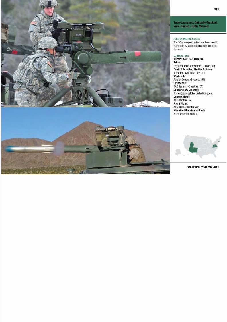
7/29/2019 Army Weapons Systems 2011
http://slidepdf.com/reader/full/army-weapons-systems-2011 323/380
WEAPON SYSTEMS 2011
,
Moog Inc. (Salt Lake City, UT)Warheads:
Aerojet General (Socorro, NM)
Gyroscope:
BAE Systems (Cheshire, CT)
Sensor (TOW 2B only):
Thales (Basingstoke, United Kingdom)Launch Motor:
ATK (Radford, VA)
Flight Motor:
ATK (Rocket Center, WV)
Machined/Fabricated Parts:
Klune (Spanish Fork, UT)
INVESTMENT COMPONENT
Unit Water Pod System (Camel II)
Recapitalization
Modernization
Maintenance
MISSION
Receives, stores, and dispenses potable
water to units at all echelons throughout
the battlefield.
DESCRIPTION The Unit Water Pod System (Camel II)
is the U.S. Army’s primary water
distribution system Camel II replaces
The Camel II is mounted on a
M1095 Trailer, allowing for better
transpor tabil ity on and off the road by
utilizing the Family of Medium Tactical
Vehicle Trucks. It holds a minimum
of 800 gallons of water and provides
a one-day supply of potable water for
drinking and other purposes. If the
unit has another source of drinking
PROGRAM STATUS• FY10: Contract awarded
PROJECTED ACTIVITIES• FY11: Deliver test units
• FY11: Conduct government testing
• FY12: Full materiel release; type
classification standard
• FY12: First unit equipped
314

7/29/2019 Army Weapons Systems 2011
http://slidepdf.com/reader/full/army-weapons-systems-2011 324/380
UNITED STATES ARMY
ACQUISITION PHASE
Technology Development Operations & SupportProduction & DeploymentEngineering & Manufacturing Development
distribution system. Camel II replaces
the M107, M149, and M1112 series
water trailers. It consists of an
800–900 gallon capacity bafed water
tank with integrated freeze protection
and all hoses and fittings necessary
to dispense water by gravi ty flow.
The acquisition strategy consists of two increments: Increment 1 is the
basic system with freeze protection ;
Increment 2 will provide modular
component(s) to give the Camel II
water chil ling, pumping, ci rculation,
and on-board power generation as add-
on capabilities.
unit has another source of drinking
water, such as bottled water, then
the Camel II can provide two days of
potable water for other purposes. It is
operational from -25 to +120 degrees
Fahrenheit. The system also contains
six fill ing positions for filli ng canteens
and five gallon water cans.
SYSTEM INTERDEPENDENCIESM1095 Medium Tactical Vehicle
Trai ler, Family of Medium Tactica l
Vehicle (FMTV) Trucks
• FY12: First unit equipped
Unit Water Pod System (Camel II)
FOREIGN MILITARY SALES
None
CONTRACTORS
To be determined
315

7/29/2019 Army Weapons Systems 2011
http://slidepdf.com/reader/full/army-weapons-systems-2011 325/380
WEAPON SYSTEMS 2011
INVESTMENT COMPONENT
Warfighter Information Network–Tactical (WIN-T) Increment 1
Recapitalization
Modernization
Maintenance
MISSION
Provides the warfighter seamless,
assured, mobile communications, along
with advanced network managementtools.
DESCRIPTION Warfighter Information Network–
Tactical ( WIN-T) Increment 1 is the
Capacity High Mobility Multipurpose
Wheeled Vehicle for roll-on/rol l-
off mobility.
Increment 1a upgrades the former Joint
Network Node satellite capability to
access the Ka-band defense Wideband
Global Satellite, reducing the reliance
on commercial Ku-band satellites
SYSTEM INTERDEPENDENCIESIn this Publication
Advanced Field Ar tiller y Tactical Data
System (AFATDS), Secure Mobile
Anti-Jam Reliable Tactical Terminal
(SMART-T), WIN-T Increment 2, WIN-T
Increment 3
Other Major Interdependencies
316

7/29/2019 Army Weapons Systems 2011
http://slidepdf.com/reader/full/army-weapons-systems-2011 326/380
UNITED STATES ARMY
ACQUISITION PHASE
Technology Development Operations & SupportProduction & DeploymentEngineering & Manufacturing Development
Tactical ( WIN T) Increment 1 is the
Army’s current and future tactica l
network, representing a generational
leap forward in al lowing widely
dispersed, highly maneuverable units
to communicate. Increment 1 is a
converged tactical communications
network providing voice, data, and video capabilit y to connect the
batta lion-level warfighter, allowing
greater flexibility of troop movement
and is scalable to meet the mission
commander’s requirements. It is
divided into two sub-increments
defined as Increment 1a, “extended
networking at-the-halt,” and Increment
1b, “enhanced networking-at-the-halt.”
Increment 1 is a rapidly deployable,
early entry system housed in a
Lightweight Multipurpose Shelter(LMS) and mounted on an Expanded
on commercial Ku band satellites.
WIN-T Increment 1b introduces the
Net Centric Waveform, a dynamic wave
form that optimizes bandwidth and
satellite utilization. It a lso introduces
a colorless core security architecture,
which meets Global InformationGrid Information Assurance security
compliance requirements and
incorporates industry standards for
network operations and intrusion
detection.
WIN-T Increment 1 is a Joint-
compatible communications package
that allows the war fighter to use
advanced networking capabilities,
interface to legacy systems, retain
interoperability with Current Forcesystems, and keep in step with future
increments of WIN-T.
Other Major Interdependencies
ACUS Mod, Army Battle Command
System, Command Post of the
Future, CPP, GPS, LOS (WARCOMS),
MBCOTM, MIL SATCOM, MSE, SICPS,
Teleport, THA AD, TOCS, TROPO
PROGRAM STATUS• 1QFY09: Increment 1a initial
operational test
• 2QFY09: Increment 1b limited user
test
• 4QFY09: Initial operational
capability
PROJECTED ACTIVITIES• 1QFY12: Increment 1b operational
test
Warfighter Information Network–
Tactical (WIN-T) Increment 1
FOREIGN MILITARY SALES
None
CONTRACTORS
Modem/Integration:
General Dynamics C4 Systems, Inc.(Taunton, MA)
Transportable Terminals:
General Dynamics SATCOM Technologies
(Duluth, GA)
317
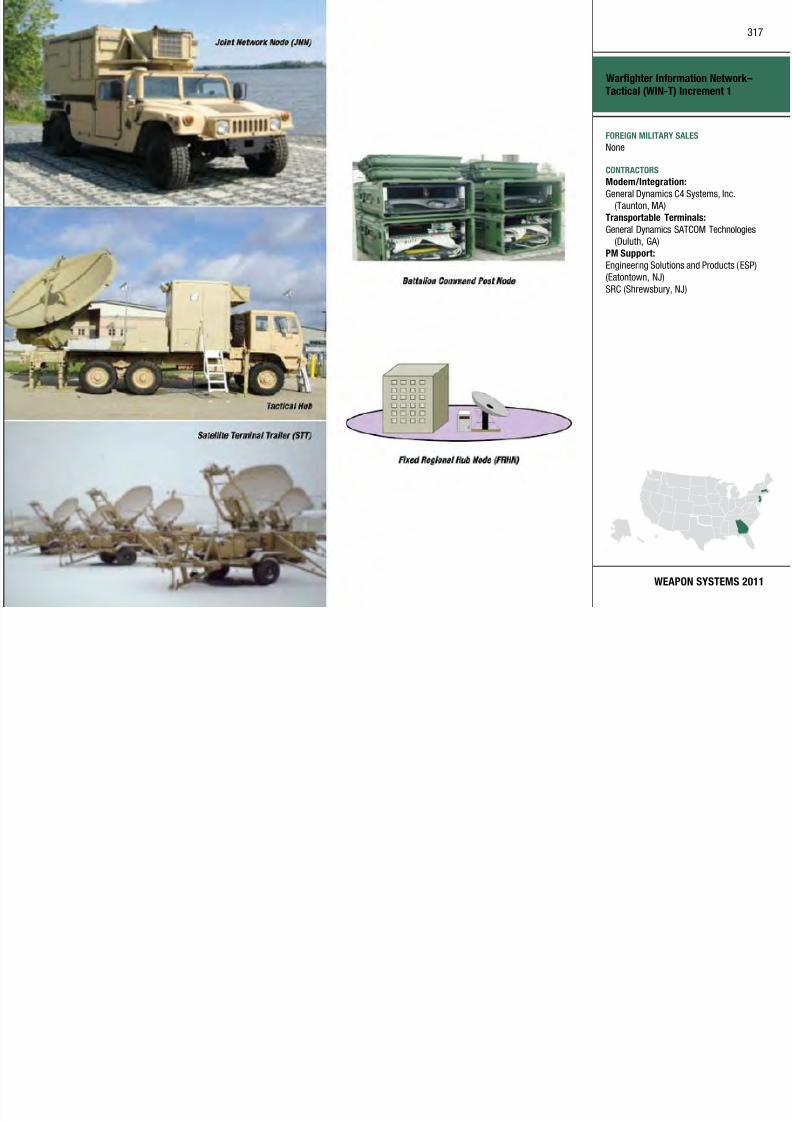
7/29/2019 Army Weapons Systems 2011
http://slidepdf.com/reader/full/army-weapons-systems-2011 327/380
WEAPON SYSTEMS 2011
PM Support:
Engineering Solutions and Products (ESP)
(Eatontown, NJ)
SRC (Shrewsbury, NJ)
INVESTMENT COMPONENT
Warfighter Information Network–Tactical (WIN-T) Increment 2
Recapitalization
Modernization
Maintenance
MISSION
Provides “initial networking on-
the-move” as a converged tactical
communications and transport layernetwork leveraging proven commercial
and government technology, enabling
Joint land forces to engage enemy
forces deeper and more effectively,
from division down to company. It
provides an accelerated delivery of
network operations capability that
allows management, prioritization,
and protection of information
while reducing organizational and
operational support.
Increment 2 network operations
Light Tactical Vehicle (JLTV); Joint
Tactical Radio System Ground Mobile
Radios (JTRS GMR); Joint Tactical
Radio System Handheld, Manpack,
Small Form Fit (JTRS HMS); Single
Channel Ground and Airborne Radio
System (SINCGARS); WIN-T Increment
1; WIN-T Increment 3
318

7/29/2019 Army Weapons Systems 2011
http://slidepdf.com/reader/full/army-weapons-systems-2011 328/380
UNITED STATES ARMY
ACQUISITION PHASE
Technology Development Operations & SupportProduction & DeploymentEngineering & Manufacturing Development
p y,
while incurring fewer losses.
DESCRIPTION Warfighter Information Network
Tactical ( WIN-T) Increment 2
accelerates delivery of a self-
forming, self-healing mobile networkinfrastructure via commercial off-the-
shelf and government off-the-shelf
technologies. Increment 2 leverages an
early release of the objective Highband
Networking Waveform running on
the Highband Networking Radio to
provide high throughput line-of-sight
communications and leverages an
early release of the objective Net
Centric Waveform on a ruggedized
R-MPM-1000 modem for on-the-move
(OTM) satellite communicationsenabling greater situational awareness
and command and control. Multiple
configuration items tailor capability
Increment 2 network operations
includes automated planning, on-
the-move node plann ing, automated-
link planning for currently fielded
systems, initial automated spectrum
management, initial quality of
service planning and monitoring, and
over-the-air network managementand configuration of WIN-T radios.
Additiona lly, Increment 2 network
operations automates the initial
Internet Protocol planning and routing
configurations.
Fielding is planned to 41 Brigade
Combat Teams and nine Divisions by
2017.
SYSTEM INTERDEPENDENCIES
Bradley Fighting Vehicle SystemsUpgrade; Distributed Common Ground
System–Army (DCGS-A); Integrated
Air and Missile Defense (IAMD); Joint
PROGRAM STATUS• 1QFY09: Developmental test
• 2QFY09: Limited user test
• 2QFY10: Milestone C, enter low-rate
initial production
PROJECTED ACTIVITIES• 1QFY11: Product qualification test
(Contractor)
• 2QFY11: Logistics demonstration
• 3QFY11: Product qualification test
(Government)
• 4QFY11: Force development test
• 1QFY12: Initial operational test
• 2QFY12: Full-rate production
decision review
• 2QFY12: Cold region test
• 3QFY12: First unit equipped
• 1QFY13: Initial operationalcapability
Warfighter Information Network–
Tactical (WIN-T) Increment 2
FOREIGN MILITARY SALES
None
CONTRACTORS
WIN-T System:
PrimeGeneral Dynamics (Taunton, MA)
Subcomponent
Lockheed Martin (Gaithersburg, MD)
Subcontractors
H i C (M lb FL)
319

7/29/2019 Army Weapons Systems 2011
http://slidepdf.com/reader/full/army-weapons-systems-2011 329/380
WEAPON SYSTEMS 2011
Harris Corp. (Melbourne, FL)
L-3 Communications (San Diego, CA)
General Dynamics (Richardson, TX)
INVESTMENT COMPONENT
Warfighter Information Network–Tactical (WIN-T) Increment 3
Recapitalization
Modernization
Maintenance
MISSION
Provides “full networking on-the-
move” as a mobile, multi-tiered,
tactical communications/transport layernetwork, enabling Joint land forces to
engage enemy forces effectively.
DESCRIPTION
support. WIN-T Increment 3 ensures
communications interoperability
with Joint, A llied, Coa lition, Current
Force, and commercial voice and data
networks. Using communications
payloads mounted on Unmanned Aerial
Systems, Increment 3 introduces
an air tier to increase network
reliability and robustness with
PROGRAM STATUS• 1QFY09: 30-Node Engineering
field test to demonstrate technology
maturity
PROJECTED ACTIVITIES• 2QFY12: Transmission subsystem
critical design review
• 3QFY13: Full critical design review
320
7/29/2019 Army Weapons Systems 2011
http://slidepdf.com/reader/full/army-weapons-systems-2011 330/380
UNITED STATES ARMY
ACQUISITION PHASE
Technology Development Operations & SupportProduction & DeploymentEngineering & Manufacturing Development
The Warfighter In formation Network–
Tactical ( WIN-T) Increment 3 enables
the full-objective mobile, t actica l
network distribution of command,
control, communications, computers,
intelligence, surveilla nce, and
reconnaissance information via voice,data, and rea l-time video. Building
on previous increments, Increment
3 provides more robust connectivity
and greater network access via
military specification radios, higher
bandwidth satellite communications
(SATCOM) and line-of-sight (LOS)
waveforms, an aer ial t ier (LOS
airborne relay), and integrated
network operations. It manages,
prioritizes, and protects information
through network operat ions (networkmanagement, quality of service and
information assurance) while reducing
organizational and operational
y
automatic routing between LOS and
SATCOM. This extends connectivity
and provides increased warfighter
mobility, providing constant mobile
communications.
SYSTEM INTERDEPENDENCIESBradley Fighting Vehicle Systems
Upgrade, Distributed Common Ground
System–Army (DCGS-A), Integrated
Air and Missile Defense (IAMD), Joint
Light Tactical Vehicle (JLTV), Joint
Tactical Radio System Ground Mobile
Radios (JTRS GMR), Joint Tactical
Radio System Handheld, Manpack,
Small Form Fit (JTRS HMS), Single
Channel Ground and Airborne Radio
System (SINCGARS), Stryker Family
of Vehicles, WIN-T Increment 2, WIN-TIncrement 1
Q g
• 4QFY13: Transmission subsystem
developmental test/limited user test
• 2QFY15: Milestone C
Warfighter Information Network–
Tactical (WIN-T) Increment 3
FOREIGN MILITARY SALES
None
CONTRACTORS
Prime:
General Dynamics (Taunton, MA;Sunrise, FL)
Subcomponent:
Lockheed Martin (Gaithersburg, MD)
Subcontractors:
Harris Corp (Melbourne FL)
321

7/29/2019 Army Weapons Systems 2011
http://slidepdf.com/reader/full/army-weapons-systems-2011 331/380
WEAPON SYSTEMS 2011
Harris Corp. (Melbourne, FL)
BAE Systems (Wayne, NJ)
L-3 Communications (San Diego, CA )
INVESTMENT COMPONENT
Weapons of Mass Destruction Elimination
Recapitalization
Modernization
Maintenance
MISSION
Provides a mobile laboratory that
enables weapons of mass destruction
(WMD) civil support teams to performon-site analysis of contaminants in
support of first responders.
DESCRIPTION
CST commanders. The UCS consists
of a combination of commercial and
existing government off-the-shelf
communications equipment (both
secure and non-secure data) to provide
the full ra nge of communications
necessary to support the CST mission.
It is the primary means of reach-back
communications for the ALS and acts
(heavy), the CALS has a modular
design that provides the necessary
array of analytica l, diagnostic, and
investigative capabilities tailored for
a specified mission or contingency
operation. The system also provides
voice and data communications to
enhance assessment of and response to
WMD events.
322

7/29/2019 Army Weapons Systems 2011
http://slidepdf.com/reader/full/army-weapons-systems-2011 332/380
UNITED STATES ARMY
ACQUISITION PHASE
Technology Development Operations & SupportProduction & DeploymentEngineering & Manufacturing Development
Analy tical Laboratory System (ALS)
Increment 1 is a mobile analytical
laboratory that provides the civil
support team (CST) capabilities
for detecting and identifying
chemical, biological, or radiological
contamination. ALS Increment 1is a system enhancement program
to replace the current Mobile ALS
and interim Dismounted Analyt ical
Platform. It provides advanced
technologies with enhanced sensit ivity
and selectivity in the detection and
identification of biological and chemical
warfa re agents and tox ic industrial
chemicals and materials.
The Unied Command Suite ( UCS)
vehicle is a self-contained, stand-alone,C-130 air mobile communications
platform that provides both voice and
data communications capabilities to
as a command and control hub to
deliver a common operational picture
for planning and fulfilli ng an incident
response. It provides:
• Digita l voice and data over satellite
network
• Secure Internet Protocol RouterNetwork (SIPRNET) and Non-Secure
(NIPRNET)
• Radio remote and intercom with
cross-banding
• Over-the-horizon communication
interoperable interface w ith state
emergency management and other
military units
The Common Analytical Laboratory
System (CALS) provides a common
CBRNE analytical capability acrossmultiple domain spaces. Developed
in both a mobile platform (light) as
well as a semi-fixed site platform
SYSTEM INTERDEPENDENCIESOther Major Interdependencies
UCS
PROGRAM STATUS
ALS-1:• 4QFY09: Full operational capability
20th SUPCOM Light Lab:
• 4QFY09: Full operational capability
PROJECTED ACTIVITIES20th SUPCOM Heavy Lab:
• 1QFY11: Full operational capability
20th SUPCOM Monitoring Suites:
• 4QFY11: Full operational capability
Weapons of Mass Destruction
Elimination
FOREIGN MILITARY SALES
None
CONTRACTORS
ALS:
Wolf Coach, Inc., an L-3 CommunicationsCompany (Auburn, MA)
UCS Vehicle:
Wolf Coach, Inc., an L-3 Communications
Company (Auburn, MA)
UCS Communications System
323

7/29/2019 Army Weapons Systems 2011
http://slidepdf.com/reader/full/army-weapons-systems-2011 333/380
WEAPON SYSTEMS 2011Heavy Lab (20th SUPCOM) Light Lab (20th SUPCOM)
UCS Communications System
Integrator:
Naval Air Warfare Center Aircraft Division
(Patuxent River, MD)20th SUPCOM Heavy Lab:
ECBC (Edgewood, MD)
324
Science & Technology The Army Science and Technology (S&T) strategy (F igure 1) supports the Army’s
goal to provide new technologies that enhance and modernize systems in the
Current Force and that enable new capabilities in the Future Force. This strategy
is effected through a portfolio with three t ypes of investments, each providing
different results in distinct timeframes.
The three types of S&T investment are far -term, funding basic research for
discovery and understanding of phenomena; mid-term, funding applied research
component demonstrations within a laboratory environment; and near-term,
funding advanced technology development system/sub-subsystem demonstrations
in relevant (non-laboratory) environments (Figure 2). The technology
demonstrations prove technology-enabled capabilities and concepts and their
military utility which, then inform the combat developments process and provide
the acquisit ion community with evidence of the technologies’ readiness to satisfy
system requirements. This portfolio also supports current overseas contingencyoperations in the following ways: (1) Soldiers benefit today from technologies that
emerged from past S&T investments; (2) we exploit transition opportunities by
accelerating mature technologies derived from ongoing S&T efforts; and (3) we
leverage the expertise of our scientists and engineers to develop solutions to

7/29/2019 Army Weapons Systems 2011
http://slidepdf.com/reader/full/army-weapons-systems-2011 334/380
Figure 1: Strategy—Develop and mature technology to enable the Future Force while seeking to enhance the
Current Force
unforeseen problems encountered during current operations such as the armor
applied to Mine-Resistant Ambush Protected (MRAP) combat vehicles for
enhanced protection from rocket propelled grenades (RPGs). The entire S&T
program is designed to be adaptable and responsive to the needs of the Army.
Figure 2: The S&T portfolio consists of three types of investments.
325
S&T INVESTMENT—FUTURE FORCE TECHNOLOGY AREAS
The diverse S&T portfolio is character ized in terms of Future Force Technology
Areas. The investments in these a reas are shown at right in a color depiction
(Figure 3) that approximates their proportionate dollar va lue in FY11 by
Technology Area.
Within these Technology Areas, the highest prior ity applied research and
advanced technology development efforts are designated by HeadquartersDepartment of the Army (HQDA) as Army Technology Objectives (ATOs). We do
not designate ATOs within the basic research area since these investments fund
sciences (discovery and understanding), not technology. The Army’s Training
and Doctrine Command/Army Capabilities Integration Center (TRADOC/ARCIC)
h h i h S& O d l d i l

7/29/2019 Army Weapons Systems 2011
http://slidepdf.com/reader/full/army-weapons-systems-2011 335/380
represents the warghter in the S&T ATO development process, and articulates
the warghter’s needs to the S&T community through the development, sta fng,
and coordination of the TRADOC “warghter outcomes.” ATOs are focused efforts
that develop specic S&T products desig ned to address warghter Outcomes
and meet agreed upon metrics. The goal of ATOs is to investigate and mature
technologies that provide new or improved capabil ities for acquisit ion programs.
This goal requires a close work ing relationsh ip with acquis ition programmanagers/program executive offices (PM/PEOs) to ensure that the ATO output
metrics are defined to be what the acquisition programs needs.
This S&T section of the U.S. Army Weapon Systems 2011 handbook is organized
by Future Force Technology Area. Selected ATOs are described with in most of
the Technology Areas. The complete portfolio of 89 ATOs is descr ibed in the 2010
Army Science and Technology Master Plan (distr ibution limited to government
and current government contractors).
Figure 3: The Future Force technology area color bands shown on the left are approximately proportional to
the financial investment within the Army’s requested FY11 S&T budget. The specific technologies funded in
these investment areas are aligned to the ten Comprehensive Warfighter Outcomes (CWO). The ten CWOs are
the consolidation of TRADOC’s Tier I warfighter outcomes. The warfighter outcomes articulate the warfighter
capability needs.
Short descriptions of Future Force Technology Areas:• Force Protection technologies enable Soldiers and platforms to avoid detection,
acquisition, hit, penetration, and kill. These technologies include advanced
armor, countermine, and counter improvised explosive devices (IEDs) detection
and neutralization, and counter rocket, artillery, and mortars (CRAM) a ircraft
survivability and active protection systems.
• Intelligence, Surveillance, and Reconnaissance (ISR) technologies enable
persistent and integrated situational awareness and understanding to provide
actionable intelligence that is specific to the needs of the Soldier across the
range of militar y operations.• Command, Control, Communications, and Computers (C4) technologies
provide capabilities for superior decision-making, including intelligent network
decision agents and antennas to link Soldiers and leaders into a seamless
battlefield network.
326
• Lethality technologies enhance the ability of Soldiers and platforms to provide
overmatch against threat capabilities and include nonlethal technologies
enabling tailorable lethality options.
• Medical technologies are developed to protec t Soldiers by diagnosing and
rendering initial treatment to combat casualties, preventing and treating
infectious diseases, enhancing clinical care and rehabilitative medicine, while
saving lives. They include technologies to enhance Soldier performance in
extremely challenging environments imposed by physical and psychological
demands on the battlefield, as well as extremes in topography and climate.• Unmanned Systems technologies enhance the effectiveness of unmanned air
and ground systems through improved perception, cooperative behaviors, and
increased autonomy.
• Soldier Systems technologies provide materiel solutions that protect, network,
t i d i S ldi d t i l l ti th t h h
FORCE PROTECTION
Kinetic Energy Active Protection System The Kinetic Energy Active Protection System ATO wi ll demonstrate the capabil ity
to defeat tank-fired kinetic energ y rounds. This program develops warhead and
interceptor designs and conducts robust component and interceptor testing.

7/29/2019 Army Weapons Systems 2011
http://slidepdf.com/reader/full/army-weapons-systems-2011 336/380
sustain, and equip Soldiers, and non-materiel solutions that enhance human
performance. Together these solutions enable Soldiers to adapt and dominate
against any threat.
• Logistics technologies enhance strategic response and reduce logistics
demand. Focus is on technologies that increase efciency of systems or
subsystems or sustainment processes that enable production of consumables
closer to the point of use, that conserve or reduce demand for consumables (suchas fuel and water), and that enhance the nation’s assurance of sufficient energy
for Army missions.
• Military Engineering and Environment technologies enhance deployabilit y
and sustainability. These technologies also enable sustainment of t raining and
testing range activities.
• Advanced Simulation technologies provide increasingly realistic training
and mission rehearsal environments to support battlefield operations, system
acquisition, and requirements development.
• Rotorcraft technologies enhance the performance and effect iveness of
current and future rotorcraft while seeking to reduce operational and
sustainment costs.
• Basic Research investments seek to develop new understanding to enablerevolutionary advances or parad igm shifts i n future operational capabilities.
Figure 4: Kinetic Energy Active Protection System
Threat and Minefield Detection Payload for Shadow Tactical UnmannedAerial Vehicle The Tactical Unmanned Aerial Vehicle (TUAV) ATO matures and demonstrates
a payload incorporating multi/hyper-spectral imaging sensors, adaptive spectral
detection, and change detection algorithms. The TUAV payload demonstrates
real-time detection of roadside threats, threat deployment activity, and minefieldsat realistic mission altitudes. It a lso provides an advanced reconnaissance,
surveillance, and target acquisition capability for detection of difficult t argets.
327
Advanced Aircraft Survivability The Advanced Ai rcraft Survivabilit y (AAS) ATO develops a nd demonstrates
an integrated, multi-spectral (ultra violet [UV], i nfrared [IR], acoustic), and
distributed aperture aircraf t survivability solution to simultaneously detect,
identify, and cue integrated counter-measures against currently operational
and emerging hostile fire and Man Portable Air Defense (MANPAD) technology
threats. Elements of this progra m include: improved missi le and smal l arms fire
detection sensors; a lightweight laser countermeasure for MANPAD missiles
and integrated visual laser dazzling of small a rms threats; lightweight beamdirectors; and closed-loop threat identification techniques.
Detection for In-Road Threats This ATO matures and demonstrates an advanced mine- and threat-detection
bilit t dd b d t f i d th t i l di th d l

7/29/2019 Army Weapons Systems 2011
http://slidepdf.com/reader/full/army-weapons-systems-2011 337/380
capability to address a broader spectrum of in-road threats—including those deeply
buried—at higher rates of advance for modular engineer platforms and the Early
Infantry Brigade Combat Team (E-IBCT). In order to meet current and Future Force
needs, this effort matures and then integrates ground-penetrating radar and metal-
detection technologies onto vehicles to detect the evolving underbelly threat on
primary and secondary roads. The technologies demonstrated include an optimized
metal detector, a downward-looking ground penetrating radar, signal processing,and algorithms optimized for both shallow and deep targets.
Extended Area Protection & Survivability (EAPS) Integrated Demo The Extended Area Protection and Survivability (EAPS) ATO is developing and
demonstrating critical technologies to provide the capability to defeat rockets,
artillery, and mortars (RA M) at extended ranges. The EAPS effort is developing
two missi le concepts and one gun concept to provide mobile, 360 -degree
hemispherical area protection to meet the objective Counter-RAM requirements.
This effort includes subsystems development of the technical fire control node
to process the decision logic for intercept, the track ing and fire control radar to
provide a precise location of the threat, the launch system, and the interceptors. The EAPS effort w ill demonstrate intercept of single RAM threats and multiple
simultaneous RAM threats. The system architecture is being developed to
integrate with the architecture being developed by Program Manager Counter-
Rocket, Artillery, and Mortar, Program Executive Ofce, Command, Control, and
Communications Tactical.
Figure 5: Extended Area Protection & Survivability (EAPS) Integrated Demo
328
INTELLIGENCE, SURVEILLANCE, RECONNAISSANCE
Battlespace Terrain Reasoning Awareness—Battle Command This ATO provides integrated bat tle command capabilit ies to create and utilize
actionable information from terrain, atmospheric, and weather effects on
systems, platforms, and Soldiers. This w ill enable agile, integrated ground and
air operations in all operational environments. An initial spiral of urban-based
technologies from the Network-Enabled Command and Control ATO program will
be incorporated, result ing in a net-centr ic, terrain reasoning service, embedded with battle command appl ications.
This effort is working with key transformat ional battle command programs and
TRADOC schools to (1) conduct controlled demonstrations to gain insight into
effectively integrating actionable terrain, atmospheric, and weather information
into battle command system-of-systems (SoS), sta ffs, processes, and functions;
(2) improve, extend, and mature terra in- and weather-based information
products and embedded applications within battle command SoS; (3) transition
capabilities to the Distributed Common Ground System–Army (DCGS-A), BCT,
and commercial joint mapping toolkit; and (4) support the development of a
geo-battle management language that extends the current model to includerepresentation of actionable terrain, weather, and atmospheric information.
Target Location Designation System This ATO demonstrates an improved, man-portable, target acqu isition and
laser designation system w ith reduced size weight and power This ATO

7/29/2019 Army Weapons Systems 2011
http://slidepdf.com/reader/full/army-weapons-systems-2011 338/380
Figure 6: Battlespace Terrain Reasoning Awareness—Battle Command
laser designation system w ith reduced size, weight, and power. This ATO
provides: (1) an improved mid-wave IR focal plane array; (2) a common
designator module using end-pumped, mono-block laser technology; a nd (3)
precision target location through an improved global positioning, gyroscope,
and magnetometer. The results of this effort will demonstrate to the warfighter
improvements in real-time target acquisition, precision target location, and
laser designation capabilities that increase combat effectiveness and lethality. The overa ll result wi ll be a n increased target acqu isition range that provides
greater standoff range and increased Soldier survivability, while the reduced
weight w ill achieve greater Sold ier mobil ity.
Advanced Common Sensor Payload The Advanced Common Sensor Payload ATO provides day /night wide-area
persistent imaging and enhanced reconnaissance, surveillance, and target
acquisition capabilit ies for insertion into the common sensor payload (CSP).
There will be two CSP var iants—one w ith a h igh-denition sensor and the
other with a dua l-color, third-generation, forward-looking radar. Both of
these systems wil l have t he following capabil ities : Step Stare Software t hat
provides persistent imag ing scan modes to improve resolution and Tiered DataProcessing that adds onboard modules for enhanced data exploitation and
compression to allow operation over existing ex tended-range and multipurpose
data l inks. The payoff will be a payload that provides persistent wide-area
activity monitoring and enhanced capabilities to include target search at ID
resolution, reduced operator workloads, and improved data exploitation.
329
IRON Symphony The IRON Symphony ATO defines and develops a next-generation Army Electronic
Warfare (EW) networking capabi lity, based on an integrated and distributed
EW framework, to enable the coordinated detection, geolocation, reporting, and
engagement of multiple diverse threat waveforms. Most current EW systems
are designed to mitigate a single threat waveform. Multiple threats force the
development of multiple systems, resulting in a rapid escalation of interoperability
and spectral de-confliction issues. The robust proliferation and simultaneous use
of modern communication threats, as well as the complexity of the threat signals themselves, have created an environment where the use of individua lized solutions
is no longer feasible.
Flexible Display Technology for Soldiers and VehiclesThis ATO develops flexible display technologies for affordable lightweight
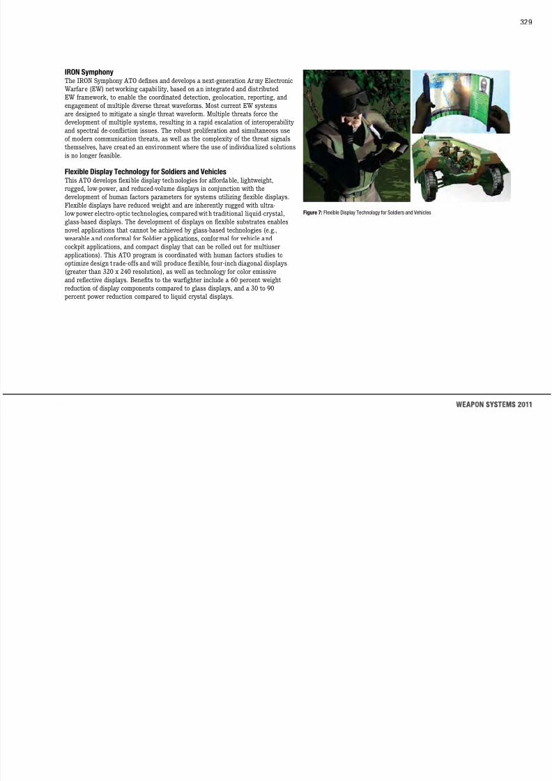
7/29/2019 Army Weapons Systems 2011
http://slidepdf.com/reader/full/army-weapons-systems-2011 339/380
This ATO develops flexible display technologies for affordable, lightweight,
rugged, low-power, and reduced-volume displays in conjunction with the
development of human factors parameters for systems utilizing flexible displays.
Flexible displays have reduced weight and are inherently rugged with ultra-
low power electro-optic technologies, compared with traditional liquid-crystal,
glass-based displays. The development of displays on flexible substrates enables
novel applications that cannot be achieved by glass-based technologies (e.g., wearable and conformal for Soldier applications, conformal for vehicle and
cockpit applications, and compact display that can be rolled out for multiuser
applications). This ATO program is coordinated with human factors studies to
optimize design t rade-offs and will produce flexible, four-inch diagonal displays
(greater than 320 x 240 resolution), as well as technology for color emissive
and reflective displays. Benefits to the warfighter include a 60 percent weight
reduction of display components compared to glass displays, and a 30 to 90
percent power reduction compared to liquid crystal displays.
Figure 7: Flexible Display Technology for Soldiers and Vehicles
330
COMMAND, CONTROL, COMMUNICATIONS,
AND COMPUTERS (C4)
Collaborative Battlespace Reasoning and Awareness The Collaborat ive Battlespace Reasoning and Awareness ATO develops and
demonstrates multiplatform, cross community applications and software services
that support the integrat ion and synchroni zation of intel ligence and operat ions
functions through the design, development, and implementation of information
interoperability, and through collaborative management and decision-support technologies. Th is ATO also develops and demonstrates systems that will improve
mission execution success by providing software to more tightly couple operations
and intelligence and to better facilitate collaboration. Research and development
is focused on mapping intelligence and geospatial information requirements to
military tasks This effort enables faster and higher quality decision cycles and

7/29/2019 Army Weapons Systems 2011
http://slidepdf.com/reader/full/army-weapons-systems-2011 340/380
military tasks. This effort enables faster and higher quality decision cycles and
increased battle command unification through collaboration and real-time sharing,
exploitation, and analysis of information to support the operational mission, tasks,
and desired effects.
RF Adaptive Technologies Integrated with Communications and Location
This ATO develops and demonstrates Radio Frequency (RF) dynamic spectrum technologies for tactical communications and improved position deter mination
in Global Positioning System (GPS)-degraded environments (Figure 8). The
ATO efforts include the development of a software module that enables spectrum
policy management for dynamic spectrum access-enabled radios, architecture
to integrate and enhance disrupt ion tolerant networking (DTN) in the tactical
environment, and a software module that improves position determination
based on net-assisted GPS and RF ranging technologies. This ATO bui lds upon
the Defense Advanced Research Projects Agency (DARPA) Wireless Network
After Next (WNA N) program to provide consistent dynamic spectrum policy
management using software implementation, ensure reliable message delivery in
a disruptive communications environment by enhancing and extending the DTN
technology into tact ical networks, mitigate multipath interference through RFranging, and improve GPS performance through net-assisted GPS technologies.
Figure 8: RF Adaptive Technologies Integrated with Communications and Location (RADICAL)
331
LETHALITY
Advanced Lasers and Unmanned Aerial System Payloads This ATO develops, integrates, and demonstrates a seven-pound advanced sensor
payload with laser rangefinding and laser designating capabilities to address the
reconnaissance, surveillance, and target acquisition mission requirements for the
BCT Class I unmanned aerial system (UAS). Under this ATO, new multifunction
lightweight lasers, optical receiver components, and electronics suitable for UAS
and other Soldier applications are developed. The new laser components will beintegrated with a compact, small-pixel, uncooled IR imaging sensor into a two-
axis pointing platform (gimbal) to enable an airborne organic laser designation
capability for the lower echelon warfighter. The advanced lasers and UAS sensor
payload will enable Soldiers to quickly see and characterize potential ta rgets as
well as nontarget objects that are in the open or in complex and urban terrain and

7/29/2019 Army Weapons Systems 2011
http://slidepdf.com/reader/full/army-weapons-systems-2011 341/380
well as nontarget objects that are in the open or in complex and urban terrain, and
support beyond-line-of-sight situational awareness, targeting, and engagement
with precis ion weapons. A paral lel Manufacturing Technology ef fort seeks to
develop an optimized manufacturing process for a universal, monoblock laser
designator module component that can be integrated into a wide variety of laser
applications.
Applied Smaller, Lighter, Cheaper Munitions Components Affordably reducing space, weight, a nd power at the component level remains
essential to increasing af fordable precision munition lethality for full spectrum
operations, particularly military operations on urban terra in (MOUT) (Figure 9).
This ATO focuses on developing increasingly smaller, lighter, cheaper components
and subsystems that enhance current system capabilities against asymmetric
threats and mature technologies for next-generation small precision munitions.
Primary investment areas include: nano/advanced composite structures and new
fabrication techniques to save weight while maintaining or enhancing structural
and thermal properties; miniaturi zed electronics to reduce size and weight, and
support increased processing demands for capability enhancements like image
stabilization; sensor/image processing for MOUT environments, including people tracking; and warhead safe and arm integration for precision letha lity against
expanded target sets in urban terrain. Major warfighter payoffs are enhanced
precision lethality and cost savings through common components.
Figure 9: Applied Smaller, Lighter, Cheaper Munitions Components
Scalable Technology for Adaptive Response The Scalable Technology for Adaptive Response (STAR) ATO matures and
demonstrates new energetic materials, fuzes, and warhead technologies designed
to provide selectable and sca lable effects against platforms and personnel. The
STAR ATO will demonstrate technologies for selectable lethal effects in large-,
medium-, and small-diameter munitions and missiles; as well as the development
of controlled lethal effects, multipurpose energetics and formulations, reactivematerials, and advanced fuzing and power technologies. The STAR ATO will
demonstrate scalable lethality within 250mm (Guided Multiple Launch Rocket
System), 155mm (Excalibur), and 30mm (M789/Mk238) munitions validating
improved weapon effectiveness and lethality and reduced collateral damage
and logistics.
332
MEDICAL
Psychological Resetting after Combat Deployment: Advanced Battlemind This ATO develops and va lidates an advanced un it-training program to reduce
combat-related psychological problems, including symptoms related to mild
traumatic brain injury (mTBI) and post-traumatic st ress disorder (PTSD) dur ing
the post-deployment resetting phase. The goal of this effort is to facil itate
recovery from psychological injuries related to combat, build individual and unit
resilience in preparation for subsequent deployments, reduce the incidence ofdebilitating symptomatic problems, and reduce risk-taking behaviors that have
the greatest impact on a Soldier’s mental hea lth, well-being, relationships, and
job performance. An in-depth, s ix-session tra ining package wil l be developed that
integrates state-of-the-art cognitive-behavioral approaches to traumatic stress,
while maintaining the focus on Soldier strengths unit cohesion leadership

7/29/2019 Army Weapons Systems 2011
http://slidepdf.com/reader/full/army-weapons-systems-2011 342/380
while maintaining the focus on Soldier strengths, unit cohesion, leadership
skills, and individual cognitive ski ll building. The package incorporates cognitive
education strategies shown to be effective in reducing symptoms from mTBI,
which often overlaps w ith PTSD. Fina lly, this ATO benchmarks key deployment-
related behavioral health reactions and develops and validates novel approaches
to assessing the psychological transit ion home following a combat deployment in
order to determine the effectiveness of the proposed early intervention.
Damage Control Resuscitation This ATO pursues the best combination and optimal use of alternatives to whole
blood (e.g., plasma, red blood cells, blood-clot ting agents) to prevent bleeding and
maintain oxygen delivery and nutrients to damaged tissue (Figure 10). These
products enhance survival of casualties after severe blood loss, which is the
leading cause of death to injured warfighters. Recent data from the battlefield
suggests that blood-clotting disorders and immune system activation, which
damages normal cellular metabolic processes, commonly occur in severely injured
patients. Therefore, a priority is to maintain blood-clotting capability and oxygen
and nutrient delivery to tissues by using the best resuscitation products that can
be administered at fa r forward deployed locations.
Figure 10: Damage Control Resuscitation
Drug for the Treatment of Traumatic Brain Injury (TBI) This ATO is testing a candidate drug to treat TBI to determine its safety and
effectiveness in 200 human subjects who have suffered TBI. TBI survivors often
have physical and cognitive impairment, memory loss, and mood and personality
disorders and currently no drugs exist to treat or reduce these brain-related
injuries. It is estimated that 15 to 25 percent of all injuries in recent conflicts are
to the head.
Prophylactic Drugs to Prevent Drug-Resistant Malaria This ATO develops candidate antimalari al preventive drugs and tests these
candidates in animals. Successful completion of this ATO will allow clinical
testing of ca ndidates in humans, potentially leading to a safe and ef fective
replacement antimalaria l preventive drug. The goals in developing these
candidate preventive drugs are to replace the cur rent drugs that are becoming
333
less effective due to the emergence of drug resistant malaria parasites, to reduce
or eliminate unwanted side effects that impact Soldiers’ use of the drugs, and to
allow for a less critical and more convenient dosing schedule for deployed Soldiers.
These new drugs will a lso increase operational readiness by ma intaining a
healthy force, as well as reducing the logistical and combat health support burden
associated with treatment in theater or after evacuation.
Alternative Dengue Fever Vaccine Strategy
This ATO develops a strategy for developing single vaccine that is effect iveagainst the four major types of Dengue. This strategy should demonstrate human
safety and provide initial data on the body’s immune response. The current
live-attenuated dengue virus vaccine in advanced development is suboptimal for
rapid deployment since it requires two doses at six month intervals. Successful
completion of this ATO will produce a vaccine strategy that will lead to a more
UNMANNED SYSTEMS
Safe Operations of Unmanned Systems for Reconnaissancein Complex Environments This ATO develops, integrates, and demonstrates robust robotic technologies
required for Future Modular Force unmanned systems (Figure 11). The ATO
advances the state of the art in perception and control technologies to permit
unmanned systems (UMS) to autonomously conduct missions in populated,
dynamic urban environments while adapting to changing conditions; developinitial tactical/mission behavior technologies to enable a group of heterogeneous
UMS to maneuver in collaboration with mounted and dismounted forces; optimize
soldier operation of UMS; and provide improved situational awareness for
enhanced survivability. Modeling and simulation will be used to develop, test,
and evaluate the unmanned systems technologies (e.g., tactical behaviors and

7/29/2019 Army Weapons Systems 2011
http://slidepdf.com/reader/full/army-weapons-systems-2011 343/380
completion of this ATO will produce a vaccine strategy that will lead to a more
rapid and complete protection from dengue infection.
Candidate Multivalent Vaccine Against HIV-1 This ATO seeks to evaluate novel Human Immunodeciency Vi rus (HI V-1)
vaccinat ion strategies using a modified v irus as the delivery vehicle of candidate
vaccines into the human body. The objective is to demonstrate that these vaccinesare safe for human subjects and capable of inducing an immune response which
protects against HIV-1.
and evaluate the unmanned systems technologies (e.g., tactical behaviors and
perception algorithms). Test bed platforms with software, appropriate mission
modules, and associated hardware developed under this program support
warfighter experiments in a milit ari ly significant envi ronment in conjunction
with TRA DOC.
Figure 11: Safe Operation of Unmanned Systems for Reconnaissance in Complex Environments
334
SOLDIER SYSTEMS
Soldier Planning Interfaces and Networked Electronics This ATO develops a government-owned, Soldier-borne electronic equipment
architecture that incorporates a National Security Agency-approved wireless
personal area network subsystem (Figure 12). The Soldier Planning Interfaces
and Networked Electronics (SPINE) ATO reduces the Soldier-borne footprint and
electronics system weight by 30 percent through the loss of wires and connectors.
The wireless network will be powered by a conformal battery current ly underdevelopment that increases power by 50 percent for a 24-hour period. Additionally,
the ATO utilizes emerging software services to enable Soldier connect ivity and
data exchange to current and future tactical radio networks and battle command
systems. Throughout this effort, capability demonstrations are conducted at the
C4ISR On The Move (OTM) test bed at Ft. Dix, NJ, to monitor progress.
High-Definition Cognition (HD-COG) In Operational Environments This ATO researches real-time understanding of brain funct ion in operational
environments to allow matching of Soldier capabilities and advanced technologies.
For example, vehicle crewstations could cue Soldiers based on how their brains
process what they see, hear, and feel. Such neuro-ergonomic designs can exploit
how the brain functions, providing tremendous Soldier performance improvements.
This program develops technologies to assess Soldier neuro-cognit ive processes
in operational environments, as well as techniques to use them for neuro-
ergonomic design. Technology development will focus on solutions to cognition, visual scanning, and platform control for mounted and dismounted operat ions.
Approximately three experiments will be per formed each year to look at ATO-
developed technologies in a motion-based simulation environment.

7/29/2019 Army Weapons Systems 2011
http://slidepdf.com/reader/full/army-weapons-systems-2011 344/380
C S O e o e (O ) test bed at t. , J, to o to p og ess.
Figure 12 : Soldier Planning Interfaces & Networked Electronics
335
LOGISTICS
Power for the Dismounted Soldier This ATO matures and demonstrates technologies to provide small, lightweight,
low-cost power sources. It demonstrates batteries that are ha lf the size and twice
the energy of C4ISR pr imar y batter ies (e.g., SINCGARS, Advanced SINCGARS
Improvement Program (ASIP); conformal rechargeable Soldier system batteries;
a Soldier-mission-extending hybrid fuel cell; and a JP8-powered Soldier-portable
power source for tactical battery recharg ing. The goals of the efforts includereduction in weight by 50 percent for Soldier power; extended mission times in
Soldier and sensor applications; reduction in resupply quantity, weight and costs;
and increased Soldier mobility, sustainability, survivability, and deployability by
providing higher-energy sources and recharging capability.
reduces fuel consumption through the use of advanced materials and combustion
controls; extends the battlefield mission through the use of transitional power
for unmanned ground vehicles/robotics, communications, and power electronic
controls; reduces logistics footprint (50 percent fuel savings/50 percent less
hardware) with Tri-Generation approaches; and enhances strategic mobility/
deployability without adversely impacting logistics costs, capability, or readiness.
High Performance Lightweight Track
This ATO provides two high-performance lightweight track system options for30–40 ton class vehicles: a Segmented Band Track and a Lightweight Metallic
Track. Future combat vehicles need lightweight track with acceptable
maintainability, durability, and survivability. The current lightweight track ATO
developed a 16.5-foot wide segmented band track for a 25-ton vehicle. Requirements
growth for the proposed Ground Combat Vehicle (GCV) has caused critical demand
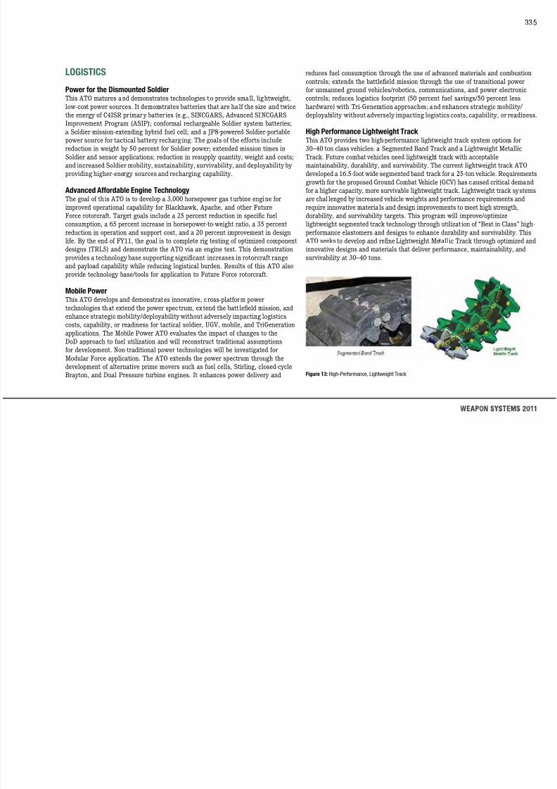
7/29/2019 Army Weapons Systems 2011
http://slidepdf.com/reader/full/army-weapons-systems-2011 345/380
Advanced Affordable Engine Technology The goal of th is ATO is to develop a 3,000 horsepower gas turbine engine for
improved operational capability for Blackhawk, Apache, and other Future
Force rotorcraft. Target goals include a 25 percent reduction in specic fuel
consumption, a 65 percent increase in horsepower-to-weight ratio, a 35 percent
reduction in operation and support cost, and a 20 percent improvement in design
life. By the end of FY11, the goal is to complete rig testing of optimized component
designs (TRL5) and demonstrate the ATO via an engine test. This demonstration
provides a technology base supporting significant increases in rotorcraft range
and payload capability while reducing logistical burden. Results of this ATO also
provide technology base/tools for application to Future Force rotorcraft.
Mobile Power This ATO develops and demonstrates innovative, cross-platform power
technologies that extend the power spec trum, extend the batt lefield mission, and
enhance strategic mobility/deployability without adversely impacting logistics
costs, capability, or readiness for tactical soldier, UGV, mobile, and TriGeneration
applications. The Mobile Power ATO evaluates the impact of changes to theDoD approach to fuel utilization and will reconstruct traditional assumptions
for development. Non-traditional power technologies will be investigated for
Modular Force application. The ATO extends the power spectrum through the
development of alternative prime movers such as fuel cells, Stirling, closed-cycle
Brayton, and Dual Pressure turbine engines. It enhances power delivery and
g p p ( )
for a higher capacity, more survivable lightweight track. Lightweight track systems
are chal lenged by increased vehicle weights and performance requirements and
require innovative materials and design improvements to meet high strength,
durability, and survivability targets. This program will improve/optimize
lightweight segmented track technology through utilizat ion of “Best in Class” high-
performance elastomers and designs to enhance durability and survivability. This
ATO seeks to develop and refine Lightweight Metall ic Track through optimized and
innovative designs and materials that deliver performance, maintainability, and
survivability at 30–40 tons.
Figure 13: High-Performance, Lightweight Track
336
BASIC RESEARCH 1 Autonomous Systems—Extending the operational effectiveness of Soldiers
through robot ic systems
A major military object ive is to total ly frustrate and defeat our adversar ies
across a wide spectrum of conflicts while dramatically increasing the
survivability of our Soldiers by keeping them out of harm’s way. Autonomous
systems of extraordinary capability can fulfill this objective; however, they must
be completely safe and secure while operating in highly complex operational
environments. Achieving such levels of capability will require significant
investments in highly sophisticated sense, response, and processing systemsapproaching that of biological systems; major advances in artificial intelligence;
the development of intelligent agents approaching human performance levels;
and advances in machine learning, swarming, and actuation and control.
2 Biotechnology—Leveraging four billion years of evolution

7/29/2019 Army Weapons Systems 2011
http://slidepdf.com/reader/full/army-weapons-systems-2011 346/380
Figure 14 : Basic Research Investments
Basic research investments are a critical hedge in acquiring new knowledge
in areas that hold great promise in advancing new and technically challenging
Army capabilit ies and concepts to enable revolutionary advances and paradigm-
shifting future operational capabilities. Areas of emerging interest and focus in
basic research are autonomous systems, biotechnology, immersive technology,
nanotechnology, network science, neuroscience, and quantum effects. Investment
in basic research within the Army provides insurance against an uncertain
future and guards against technological surprise. A nd if we are successful,
these investments will make it possible to conduct ever-more complex mil itar yoperations, with greater speed and precision, to devastate any adversary on
any battlefield. The following is a brief summary of the areas of investment, the
synergy among them, and some of the capabilities they may provide.
gy g g y
The increasing importance and demands for wide-area persistent surveillance
create significant challenges for sensor systems, real-time processing of vast
amounts of data, the real-time interpretation of information for decision-making,
and power and energy requirements to support such demanding systems. Through
four billion years of evolution, biological systems have engineered solutions
to some of these challenges. We seek to leverage research in these areas for
improving the performance of our Soldiers. Major investments in this area
through reverse engineering will lead to totally new sensing systems, new ways
for the rapid processing of data into information, the development of novel sense
and response systems, and biologically inspired power and energy solutions.
3 Immersive Technology—The path to virtual rea lity training
The evolving threat environment continues to put increasing demands on
the diversity and effectiveness of Soldier sk ills. To meet these demands,
superior training tools and methods are needed. Virtual worlds can provide
this capabilit y; however, we are cur rently at primitive stages in their
realization. With advances in computational processing and steady progress in
understanding the brain’s “software” comes the possibility of creating highlyrealistic vir tual tra ining environments inhabited by humanlike avatars. Such
environments will provide a paradigm shi ft in the way we provide training,
while achiev ing low-cost, safe, low-environmenta l impact, highly var iable
simulation environments for the future training of our Soldiers.
337
4 Nanotechnology—Dramatically changing our ability to manufacture new
material by design
The last centur y was dominated by advances in the physical sc iences
through the discovery of the atom, its structure and the laws that govern
its behavior. This century will be dominated by the complex world of biology
and nanoscience whose mysteries will be unraveled by our understanding
of systems of atoms and molecules. Nanotechnology is the manipulation of
matter on a near-atomic scale to produce new structures, materials, and
devices. Nanotechnology research makes it possible to explore the emerging biotech field and dra matically change our capabili ty in creat ing new materia ls
by design. This technology has the abil ity to tra nsform many industr ies in
discovering and creating new materials with properties that wi ll revolutionize
military technology and make Soldiers less vulnerable to the enemy and
to environmental threats. Research in nanosca le technologies is growing
6 Neuroscience—Understanding how the human brain works
Fundamental to the conduct of military operations is superior Soldier
performance. Understanding how the human brain works, i.e., determining the
brain’s “software,” is key to developing these capabi lities. When embedded in a
wide range of mi litary plat forms, this “software” will prov ide superior training
methods and human system interfaces that will be tuned to an individual’s
characteristics, thereby resulting in superior Soldier performance. Research in
this area wil l also dramatically advance our abi lity to prevent and treat those
suffering from various types of battlefield brain injury.
7 Quantum Ef fects—Overcoming the limitations of Moore’s Law
Increasing demands for information to support rapid and effective decision-
making on the battlefield require advanced sensor systems to collect relevant
data, as well as the means for processing it into actionable forms. Major

7/29/2019 Army Weapons Systems 2011
http://slidepdf.com/reader/full/army-weapons-systems-2011 347/380
rapidly worldwide. By 2015, the National Science Foundation estimates that
nanotechnology will have a one trillion dollar impact on the global economy and
employ two million workers, one million of whom may be in the United States.
5 Network Science—Managing complex military operations with greater
speed and precision
Networks tie together the following: highly distributed sensor systems for
reconnaissance and surveillance, information for decision-making, Soldiers, and
the execution of fast d istributed precision fires. Better-functioning networks
are essential to advancing our ability to conduct complex military operations
with greater speed and precision. However, our state of knowledge of these
networks is relatively primitive and, as such, significantly impairs our ability
to fully reali ze the potential that networks can provide on current and future
battlefields. A new multidisciplinary approach is being implemented that
combines communications, information, and the social/human component of
networks, and that changes the way we address the challenges associated with
optimizing the use of networks. Advances in network science will allow us to
predict and optimize network performance before we build them through thecreation of wholly new design tools.
advancements in processing power are required to cope with the demand to
process ever-larger amounts of data. Investments in this area will exploit the
massive parallelism of the quantum world to create computers that wil l dwarf
the capabi lities of the most powerful computers today, making them look
like pocket calculators. The development of such computational systems will
enable the embedding of high-performance computing in all military platforms,
including the Soldier’s uniform.
338
S&T ROLE IN FORMAL ACQUISITION MILESTONES
The Army S&T community role in acquisition involves not only technology
development and transition but also formal part icipation in milestone decisions
for acquisition programs of record. As the component S&T executive, the Deputy
Assistant Secretary of the Army (DASA) for Research and Technology (R&T) is
responsible for conducting technology readiness assessments (TRAs) at Milestone
B and C decision points for major defense acquisition programs (MDAPs). This
assessment has become even more important with recent statutory requirements for
the Milestone Decision Authority (MDA) to certify to Congress that the technologiesof an MDAP have been demonstrated to be at least at Technology Readiness Level
(TRL) 6 in a relevant environment prior to making a Milestone B decision. The TRA
serves as the gauge of this readiness for the MDA’s certification at both Army and
Office of the Secretar y of Defense levels. The TRA process is a collaborative effort
carr ied out among the program ofce, the S&T community, and (for acquisition
through the development of practical, intelligent, and operationally relevant
software tools aiding analysis and interpretation of battlefield intelligence. We are
key participants in an advanced Automotive Battery Initiative with over two billion
dollars committed to dual-use battery manufacturing through the Department
of Energy. We built the world’s rst precise, exible, ber-optic tool for CO2 laser
surgery using flexible optoelectronic fiber based technology now performing
over 175 life-saving weekly procedures. The Joint High Power Solid-State Laser
(JHPSSL) program demonstrated a laser with 105 kilowatts (kW) output—the
highest output recorded for a solid state laser, and a power threshold traditional ly
viewed as a proof of principle for “weapons grade” capable high-energy lasers. The Army Science Board completed a Quick Reaction study providing independent
recommendations for survivable manned ground vehicle designs to inform Army
leadership on alternatives for the cancelled Future Combat Systems manned ground
vehicle. The Army Science Board completed a Soldier suicide mitigation study to
develop and propose suicide mitigation actions and policy changes to reduce suicide

7/29/2019 Army Weapons Systems 2011
http://slidepdf.com/reader/full/army-weapons-systems-2011 348/380
category [ACAT] 1D programs) the Ofce of the Undersecretary of Defense (USD)
Acquisition Technology & Logistics (AT&L).
SUMMARY
Army research investments are targeted in areas fundamental to reali zing superior
land warfighting capabilities and discovering new knowledge from research in
areas highly relevant to the Army mission. These areas include research in network
science to better understand, predict performance, and design future networks;
neuroscience to better understand how the brain works so that we might improve
human-machine interfaces and Soldier performance; new materials science to better
protect our Soldiers and equipment; immersive virtual systems to improve our
training capability; and biotechnology/nanotechnology autonomous systems.
Army S&T has made signicant progress establishing persistent night surveillance
of large areas for real-time situational awareness and forensic backtracking of
suspect vehicles and personnel. Army S&T facilitated the rapid transition of technology solutions to both OIF and OEF, including protective armors for the
MRAP Expedient Armor Program and IED-detection devices such as the Husky-
mounted ground penetrating radar. We conducted nine independent readiness
reviews to assess technology maturity of systems transitioning through acquisition
milestones. We have advanced the computational understanding of the battlefield
rates among Soldiers.
In the coming years, the Army’s Science and Technology (S&T) community plans
to continue pursuing basic and applied research and technology development in
areas of force protection, C4ISR, medical, lethality, Soldiers, logistics, rotorcraft,
unmanned systems, and advanced simulation that will potentially allow the Army
to maintain superior land warfighting capabil ities. This strategy also retains
flexibility to develop solutions that are responsive to changing warfighter needs.
The technological sophistication required for 21st century operations constantly
increases with the broadening nature of threats and the greater availability of
technology to our adversaries. The goal of the Army’s ongoing research is to
provide high-payoff—the type that the private sector is not likely to sustain over
the long haul because there is no linkage to acquisition programs at the outset of
research. This high-risk research is essential if we are to achieve the technological
breakthroughs that result in dramatic performance improvements in the Army’s
systems. One such breakthrough in guidance and control technology led to the
Excalibur precision artillery munition that has virtually eliminated collateral
damage to noncombatants. Today’s Current Force has signicant technology-enabled advantages as a result of the Army’s past investments in S&T, particularly
in night vision, precision munitions, and individual Soldier protection. Scientists and
engineers continue to expand the limits of our understanding to provide technology
to our Soldiers in the systems they use to achieve transformational capabilities
required for decisive victories.
339
Appendices
Army Combat Organizations
Glossary of Terms
Systems by Contractors
Contractors by State
Points of Contact

7/29/2019 Army Weapons Systems 2011
http://slidepdf.com/reader/full/army-weapons-systems-2011 349/380
WEAPON SYSTEMS 2011
340
Army Combat Organizations
Army orga nizat ions are inherently built
around people and the tasks they must
perform. Major combat organizations
are composed of smaller forces, as
shown here.
Squad• Leader is a sergeant
• Smallest unit in Army organization
• Size varies depending on type:
Infantry (9 Soldiers), Armor (4
Soldiers), Engineer (10 Soldiers)
• Three or four squads make up aplatoon
Platoon• Leader is a lieutenant
• Size varies: Infantry (40 Soldiers),
Battalion• Leader is a lieutenant colonel
• Tactically and administratively self-
sufficient
• Armored Cavalry and Air Cavalry
equivalents are called squadrons
• Two or more combat battal ions makeup a brigade
Brigade• Leader is a colonel
• May be employed on independent or
To better confront current and future
threats, the Army is transforming its
force structure into Brigade Combat
Teams (BCTs). The goal is to prov ide
more flexible and self contained
forces with the capability of rapid
deployment and the ability to engagein the full spectrum of warfare without
sacrificing lethality and staying power
on the battleeld. These BCTs will be
organized as Infantry (IBCTs), Heavy
(HBCTs) and Stryker (SBCTs).

7/29/2019 Army Weapons Systems 2011
http://slidepdf.com/reader/full/army-weapons-systems-2011 350/380
UNITED STATES ARMY
Armor (4 tanks, 16 Soldiers)
• Three or four platoons make up a
company
Company• Leader is a captain
• Usually up to 220 Soldiers
• Artillery unit of this size is called a
battery
• Armored Cavalry or Air Cavalry unit
is called a troop
• Basic tactica l element of the
maneuver battalion or cava lry
squadron
• Normally ve companies make up a
batta lion
semi-independent operations
• Combat, combat support, or service
support elements may be attached to
perform specific missions
• Normally three combat brigades are
in a division
Division• Leader is a major general
• Fully structured division has own
brigade-size a rti llery, aviation,
engineer, combat support, and
service elements
• Two or more divisions make up a
corps commanded by a lieutenant
general
Acquisition Categories (ACAT) ACAT I programs are Milestone Decision Authorit y Programs (MDAPs [see also
Major Defense Acquisition Program]) or programs designated ACAT I by the
Milestone Decision Authority (MDA [see also Milestone Decision Authority]).
Dollar value: estimated by the Under Secretary of Defense (Acquisition and
Technology) (USD [A&T]) to require an eventual total expenditure for research,development, test and evaluation (RDT&E) of more than $365 million in scal
year (FY) 2000 constant dolla rs or, for procurement, of more than $2.190 bill ion
in FY 2000 constant dollars. ACAT I programs have two subcategories:
1. ACAT ID, for which the MDA is USD (A&T). The “D” refers to the Defense
A i iti B d (DAB) hi h d i th USD (A&T) t j d i i
AIS definit ion, design, development, deployment, operations and maintenance,
and incurred from the beginning of the Materiel Solution Analysis Phase through
sustainment for the estimated useful life of the system.
ACAT IA programs have two subcategories:
1. ACAT IAM, for which the MDA is the Chief Information Ofcer (CIO) of the DoD,
the ASD (C3I). The “M” refers to Major Automated Information System Review
Council (MAISRC). (Change 4, 5000.2-R)
2. ACAT IAC, for which the DoD CIO has delegated milestone decision authority to
the CAE or Component CIO. The “C” refers to Component.
ACAT II programs are defined as those acquisition programs that do not meet the
criteria for an ACAT I program, but do meet the criteria for a major system, or are
programs designated ACAT II by the MDA.
ACAT III d fi d th i iti th t d t t th
Glossary of Terms
341

7/29/2019 Army Weapons Systems 2011
http://slidepdf.com/reader/full/army-weapons-systems-2011 351/380
WEAPON SYSTEMS 2011
Acquisition Board (DAB), which advises the USD (A&T) at major decision
points.
2. ACAT IC, for which the MDA is the DoD Component Head or, if delegated, the
DoD Component Acquisition Executive (CAE). The “C” refers to Component. The
USD (A&T) designates programs as ACAT ID or ACAT IC.
ACAT IA programs are MAISs (see also Major Automated Information System
(MAIS) Acquisition Program), or programs designated by the Assistant Secretary
of Defense for Command, Control, Communications, and Intelligence (ASD [C3I])
to be ACAT IA.
Estimated to exceed: $32 million in FY 2000 constant dollars for all expenditures,
for all increments, regardless of the appropriation or fund source, directly related
to the AIS definition, design, development, and deployment, and incurred in any
single scal year; or $126 million in FY 2000 constant dollars for all expenditures,
for all increments, regardless of the appropriation or fund source, directly related
to the AIS definition, design, development, and deployment, and incurred from the beginning of the Mater iel Solution Analysis Phase through deployment at
all sites; or $378 million in FY 2000 constant dollars for all expenditures, for all
increments, regardless of the appropriation or fund source, directly related to the
ACAT III programs are defined as those acquisition programs that do not meet the
criteria for an ACAT I, an ACAT IA, or an ACAT II. The MDA is designated by the
CAE and shall be at the lowest appropriate level. This category includes less-than-
major AISs.
Acquisition Phase All the tasks and act ivities needed to bring a program to the next major milestone
occur during an acquisition phase. Phases provide a logical means of progressively
translating broad ly stated mission needs into well-defined system-specific
requirements and ultimately into operationally effective, suitable, and survivable
systems. The acquisition phases for the systems described in this handbook are
defined below:
Technology Development Phase
The purpose of this phase is to reduce technology r isk, determine and mature
the appropriate set of technologies to be integrated into a ful l system, and to
demonstrate critical technology elements on prototypes. Technology Development
is a continuous technology discovery and development process reflecting closecollaboration between the Science and Technology (S&T) community, the user,
and the system developer. It is an iterative process designed to assess the viability
of technologies while simultaneously refining user requirements. Entrance into
this phase depends on the completion of the Analysis of Alternatives (A0A), a
proposed materiel solution, and full funding for planned Technology Development
Phase activity.
Engineering and Manufactur ing Development (EMD) Phase
(Statutes applicable to the Systems Development and Demonstration phase shall
be applicable to the EMD phase.)
The purpose of the EMD phase is to develop a system or an increment of capability;
complete full system integration (technology risk reduction occurs during Technology
Development); develop an affordable and executable manufacturing process; ensure
operational supportability with par ticular attention to minimizing the logisticsfootprint; implement human systems integration (HSI); design for producibility;
ensure affordability; protect critical program information by implementing appropriate
techniques such as anti-tamper; and demonstrate system integration, interoperability,
safety, and utility. The Capability Development Document, Acquisition Strategy,
Systems Engineering Plan, and Test and Evaluation Master Plan (TEMP) shall
id thi ff t E t i t thi h d d t h l t it (i l di
(if Milestone C is full-rate production); an approved Initial Capabilities Document
(ICD) (if Milestone C is program initiation); an approved Capability Production
Document (CPD); a rened integrated architecture; acceptable interoperability;
acceptable operational supportability; and demonstration that the system is
affordable throughout the life cycle, fully funded, and properly phased for rapid
acquisition. The CPD reects the operational requirements, informed by EMD
results, and details the performance expected of the production system. If
Milestone C approves LRIP, a subsequent review and decision shall authorize full-
rate production.
Operations and Support Phase
The purpose of the Operations and Support phase is to execute a support program that meets mater iel readiness and operationa l support performance requirements,
and sustains the system in the most cost-effective manner over its total life
cycle. Planning for this phase shall begin prior to program initiation and sha ll
be documented in the Li fe-Cycle Susta inment Plan (LLSP). Operations and
Support has two major efforts: l ife-cycle sustainment and disposal. Entrance
i t th O ti d S t Ph d d ti th f ll i it i
342

7/29/2019 Army Weapons Systems 2011
http://slidepdf.com/reader/full/army-weapons-systems-2011 352/380
UNITED STATES ARMY
guide this effort. Entrance into this phase depends on technology maturity (including
software), approved requirements, and full funding. Unless some other factor is
overriding in its impact, the maturity of the technology shall determine the path to
be followed.
Production and Deployment Phase
The purpose of the Production and Deployment phase is to achieve an operational
capability that satisfies mission needs. Operational test a nd evaluation shall
determine the effectiveness and suitability of the system. The MDA shall make
the decision to commit DoD to production at Milestone C and sha ll document
the decision in an Acquisition Decision Memorandum. Milestone C authorizes
entry into low rate initial production (for MDAPs and major systems), into
production or procurement (for non-major systems that do not require LRIP) or
into limited deployment in support of operational testing for MAIS programs
or software-intensive systems with no production components. The tables in
Enclosure 4 identify the statutory and regulatory requirements that shall be
met at Milestone C. Entrance into this phase depends on the following criteria:
acceptable performance in developmental test and evaluation and operationalassessment (OSD OT&E oversight programs); mature software capability;
no significant manufacturing r isks; manufacturing processes under control
into the Operations and Support Phase depends on meeting the following criteria:
an approved CPD; an approved LCSP; and a successful Full-Rate Production
(FRP) Decision.
Acquisition Program A directed, funded effor t designed to prov ide a new, improved or continuing
weapons system or AIS capabili ty in response to a validated operationa l need.
Acquisition programs are divided into different categories that are established
to faci litate decentral ized decis ion-making, and execution and compliance with
statutory requirements.
Advanced Concept Technology Demonstrations (ACTDs) ACTDs are a means of demonstrat ing the use of emerging or mature technology
to address critical mil itary needs. ACTDs themselves are not acquisition
programs, although they are designed to provide a residual, usable capability
upon completion. I f the user determines that additional units are needed beyond
the residual capability and that these units can be funded, the additional buys
shall constitute an acquisition program with an acquisition category generallycommensurate with the dollar value and risk of the additional buy.
Automated Information System (AIS) A combination of computer hardware and software, data, or telecommunications,
that performs functions such as collecting, processing, transmitting, and displaying
information. Excluded are computer resources, both hardware and software, that are
physically part of, dedicated to, or essential in real time to the mission performance of
weapon systems.
Commercial and Non-Developmental ItemsMarket research and analysis shall be conducted to determine the availability
and suitability of existing commercial and non-developmental items prior to the
commencement of a development effort, during the development effort, and prior
to the preparation of any product description. For ACAT I and IA programs, whilefew commercial items meet requirements at a system level, numerous commercial
components, processes, and practices have application to DoD systems.
Demilitarization and Disposal At the end of its useful life, a system must be demilitarized and disposed of. During
d milita i ati a d di al th am ma a hall mat i l d t mi d
Live Fire Test and Evaluation (LFT&E)LFT&E must be conducted on a covered system, major munition program, missile
program, or product improvement to a covered system, major munition program,
or missile program before it can proceed beyond low-rate initial production. A
covered system is any vehicle, weapon platform, or conventional weapon system
that includes features designed to provide some degree of protection to users in
combat and that is an ACAT I or II program. Depending upon its intended use, a
commercial or non-developmental item may be a covered system, or a part of a
covered system. (Change 4, 5000.2-R) Systems requiring LFT&E may not proceed
beyond low-rate init ial product ion until realistic sur vivabi lity or lethalit y testing
is completed and the report required by statute is submitted to the prescribed
congressional committees.
Low-Rate Initial Production (LRIP) The objective of this activity is to produce the minimum quantity necessary to
provide production-configured or representative ar ticles for operational tests;
establish an initial production base for the system; and permit an orderly increase
i th d ti at f th t m ffi i t t l ad t f ll at d ti
34 3
7/29/2019 Army Weapons Systems 2011
http://slidepdf.com/reader/full/army-weapons-systems-2011 353/380
WEAPON SYSTEMS 2011
demilitarization and disposal, the program manager shall ensure materiel determined
to require demilitarization is controlled and shall ensure disposal is carried out in
a way that minimizes DoD’s liability due to environmental, safety, security, and
health issues.
Developmental Test and Evaluation (DT&E)DT&E shall identify potential operational and technological capabilities and
limitations of the alternative concepts and design options being pursued; support
the identification and description of design technical risks; and provide data and
analysis in support of the decision to certify the system ready for operational test
and evaluation.
Joint Program Management Any acquisition system, subsystem, component or technology program that involves
a strategy that includes funding by more than one DoD component during any phase
of a system’s life cycle shall be defined as a joint program. Joint programs shall be
consolidated and collocated at the location of the lead component’s program office, to
the maximum extent practicable.
in the production rate for the system, sufficient to lead to full-rate production upon
successful completion of operational testing.
Major Automated Information System (MAIS) Acquisition Program An AIS acquisit ion program that is (1) designated by ASD (C3I) as a MA IS, or
(2) estimated to require program costs in any single year in excess of $32 million
in FY 2000 constant dollars, total program costs in excess of $126 million in FY
2000 constant dollars, or total life-cycle costs in excess of $378 million in FY
2000 constant dollars. MAISs do not include highly sensitive classified programs.
Major Defense Acquisition Program (MDAP) An acquisit ion program that is not a highly sensit ive classified program (as
determined by the Secretary of Defense) and that is: (1) designated by the USD
(A&T) as an MDAP, or (2) estimated by the USD (A&T) to require an eventual
total expenditure for research, development, test and evaluation of more than
$365 million in FY 2000 constant dollars or, for procurement, of more than $2.190
billion in FY 2000 constant dollars.
Major Milestone A major milestone is the decision point that sepa rates the phases of a n acquisition
program. MDAP milestones include, for example, the decisions to authorize entry
into the engineering and manufacturing development phase or full rate production.
MAIS milestones may include, for example, the decision to begin program
definition and risk reduction.
Major SystemsDollar value: estimated by the DoD Component Head to require an eventual total
expenditure for RDT&E of more than $140 million in FY 2000 constant dollars, or
for procurement of more than $660 million in FY 2000 constant dollars.
Materiel Solution Analysis Phase The purpose of this phase is to assess potential mater iel solutions and to satisfy
the phase-specific entra nce criter ia for the next program milestone designated by
the MDA. Entrance into this phase depends upon an approved ICD resulting from
the ana lysis of current mission performance and an analysis of potentia l concepts
across the DoD components international systems from allies and cooperative
This act ivity shall a lso include the execution of operat ional support plans, to
include the transition from contractor to organic support, if appropriate. (Added
from 5000.2-R)
Operational Test and Evaluation (OT&E)OT&E shall be structured to determine the operational effectiveness and
suitability of a system under realistic conditions (e.g., combat) and to determine
if the operational performance requirements have been satisfied. The following
procedures are mandatory: threat or threat representative forces, targets, and
threat countermeasures, validated in coordination with Defense Intelligence
Agency (DIA), shall be used ; typical users shall operate and maintain the system
or item under conditions simulating combat stress and peacetime conditions; the independent operationa l test activities shall use product ion or production
representative articles for the dedicated phase of OT&E that supports the full-rate
production decision, or for ACAT IA or other acquisition programs, the deployment
decision; and the use of modeling and simulation shall be considered during test
planning. There are more mandatory procedures (nine total) in 5000.2-R.
344

7/29/2019 Army Weapons Systems 2011
http://slidepdf.com/reader/full/army-weapons-systems-2011 354/380
UNITED STATES ARMY
across the DoD components, international systems from allies, and cooperative
opportunities.
Milestone Decision Authority (MDA) The individual designated in accordance with criter ia establ ished by the USD
(A&T), or by the ASD (C3I) for AIS acquisition programs, to approve entry of an
acquisition program into the next phase.
Modifications Any modification that is of sufficient cost and complexity that it could itself qual ify
as an ACAT I or ACAT IA program shall be considered for management purposes
as a separate acquisition effort. Modications that do not cross the ACAT I or
IA threshold shall be considered part of the program being modified, unless
the program is no longer in production. In that case, the modification shall be
considered a separate acquisition effort. (Added from 5000.2-R)
Operational Support
The objectives of this activ ity are the execution of a support prog ram that meets the threshold values of all suppor t performance requirements and sustainment
of them in the most life-cycle cost-effective manner. A follow-on operational
testing program that assesses per formance and quality, compatibility, and
interoperability, and identifies deficiencies shall be conducted, as appropriate.
For additional information on acquisition terms, or terms not dened,
please refer to AR 70-1, Army Acquisition Policy, available on the
Internet at http://www.army.mil/usapa/epubs/pdf/r70_1.pdf ; or
DA PAM 70-3, Army Acquisition Procedures, available on the Internet at
http://www.dtic.mil/whs/directives/corres/pdf/500002p.pdf .
A/S Hydrema
Countermine
AAI Corp.
Gray Eagle Ex tended Range Multipurpose
(ERMP) Unmanned Aircraft System
(UAS)
AAI Corp. (Textron Systems)
Shadow Tactical Unmanned Aerial System
(TUAS)
AAR Mobility Systems
Acme Radiator
High Mobility Multi-Purpose Wheeled
Vehicle (HMMWV ) Family of Vehicles
Action Mfg
2.75 Inch Rocket Systems (Hydra)
ADSI
High Mobility Engineer Excavator (HMEE )
I and III
Advanced Systems Technology
One Semi-Automated Forces (OneSAF )
Aerojet General
Tube-Launched, Optically-Tracked, Wire-
Guided (TOW) Missiles
Agilent Technologies, Inc.
Calibration Sets Equipment (CALSETS)
Airborne Systems North America
Joint Precision Airdrop System (JPADS)
All American Racers, Inc.
Raven Small Unmanned Aircraft System(SUAS)
Alliant Techsystems
2.75 Inch Rocket Systems (Hydra)
Artillery Ammunition
Counter Defilade Target Engagement
AM General
High Mobility Multi-Purpose Wheeled
Vehicle (HMMWV ) Family of Vehicles
Improved Ribbon Bridge (IRB )
American Eurocopter
Light Utility Helicopter (LUH)/UH-72A
Lakota
American Ordnance
Artillery Ammunition
Medium Caliber Ammunition (MCA)Spider
American Science & Engineering, Inc.
Non-Intrusive Inspection Systems (NIIS)
AMT
Systems by Contractors
34 5

7/29/2019 Army Weapons Systems 2011
http://slidepdf.com/reader/full/army-weapons-systems-2011 355/380
WEAPON SYSTEMS 2011
Mobile Maintenance Equipment Systems
(MMES)
Aberdeen Test Center
Paladin/Field Artillery Ammunition Supply
Vehicle (FAASV)
Acambis plc
Chemical Biological Medical Systems–
Prophylaxis
Accenture
General Fund Enterprise Business Systems
(GFEBS)
Global Command and Control System–
Army (GCCS-A )
Acme ElectricJavelin
AEPCO
Advanced Threat Infrared
Countermeasure/Common Missile
Warning System (ATIRCM/CMWS)
Longbow Apache (AH-64D) (LBA)
Aerial Machine and Tool Corp.
Air Warrior (AW)
Aerovironment, Inc.
Raven Small Unmanned Aircraft System
(SUAS)
Aerojet
Guided Multiple Launch Rocket System
(GMLRS) DPICM/Unitary/Alternative
Warhead (Tactical Rockets)Javelin
Joint Air-to-Ground Missile (JAGM)
PATRIOT Advanced Capability–Three
(PAC-3)
Counter Defilade Target Engagement
(CDTE)–XM25
Excalibur (XM982)
Future Tank Main Gun Ammunition
(FTMGA)
Hellfire Family of Missiles
Joint Air-to-Ground Missile (JAGM)Medium Caliber Ammunition (MCA)
Precision Guidance Kit (PGK)
Small Caliber Ammunition
Spider
Tank Ammunition (TA)
Allison Transmission
Abrams Tank Upgrade (M1A1)
Family of Medium Tactical Vehicles
(FMTV)
Heavy Expanded Mobility Tactical Truck(HEMTT)/HEMTT Extended Service
Program (ESP)
Palletized Load System (PLS) and PLS
Extended Service Program (ESP)
AMT
Mortar Systems
AMTEC Corp.
Medium Caliber Ammunition (MCA)
Anniston Army Depot
Abrams Tank Upgrade (M1A1)
ANP Technologies
Joint Chemical Biological Radiological
Agent Water Monitor (JCBRAWM)
Apptricity Corp.
Transportation Coordinators’ Automated
Information for Movement System II
(TC-AIMS II)
ArgonST Radix
Guardrail Common Sensor (GR/CS)
Armacel Armor
Interceptor Body Armor
Armaments R&D Ctr
Paladin/Field Artillery Ammunition Supply
Vehicle (FAASV )
ArmorWorks
Interceptor Body Armor
Athena
Shadow Tactical Unmanned Aerial System
(TUAS)
Alliant Techsystems, Inc.Tube-Launched, Optically-Tracked, Wire-
Guided (TOW) Missiles
Atlantic Inertial Units
Excalibur (XM982)
BAE Systems
Advanced Threat Infrared
Countermeasure/Common Missile
Warning System (ATIRCM/CMWS)
Air Warrior (AW)
Airborne Reconnaissance Low (ARL)
Armored Security Vehicle (ASV)
Bradley Fighting Vehicle Systems Upgrade
Countermine
Heavy Loader
High Mobility Artillery Rocket System
(HIMARS)Interceptor Body Armor
Joint Tactical Ground Stations (JTAGS)
Joint Tactical Radio System Airborne and
Maritime/Fixed Station (JTRS AMF)
Joint Tactical Radio System Ground Mobile
Radios (JTRS GMR)
BAE Systems C4
Early Infantry Brigade Combat Team
(E-IBCT) Capabilities IBCT Increment 1
BAE Systems Bofors Defense (teamed
with Raytheon
Excalibur (XM982)
BAE Systems Land & Armaments
Joint Light Tactical Vehicle (JLTV)
BAE Systems Land & Armaments,Ground Systems Division
Mine Resistant Ambush Protected
Vehicles (MRAP)
BAE-TVS
Mine Resistant Ambush Protected
Early Infantry Brigade Combat Team
(E-IBCT) Capabilities IBCT Increment 1
Joint Air-to-Ground Missile (JAGM)
Joint Tactical Radio System Ground Mobile
Radios (JTRS GMR)
Joint Tactical Radio System, Network
Enterprise Domain (JTRS NED)
Longbow Apache (AH-64D) (LBA)
PATRIOT Advanced Capability–Three
(PAC-3)
Booz Allen HamiltonDistributed Common Ground System–
Army (DCGS-A )
Enhanced Medium Altitude
Reconnaissance and Surveillance
System (EMARSS)
Global Command and Control System–
346

7/29/2019 Army Weapons Systems 2011
http://slidepdf.com/reader/full/army-weapons-systems-2011 356/380
UNITED STATES ARMY
Austal USA
Joint High Speed Vessel (JHSV)
Aviation and Missile Solutions, LLC
Longbow Apache (AH-64D) (LBA)
Avnet
Joint Air-to-Ground Missile (JAGM)
Avon Protection Systems
Joint Service General Purpose Mask
(JSGPM)
Azimuth Inc.
Distributed Common Ground System–
Army (DCGS-A )
B&M Painting
2.75 Inch Rocket Systems (Hydra )
BAE Systems/Holston
Spider
Radios (JTRS GMR)
Joint Tactical Radio System Handheld,
Manpack, and Small Form Fit (JTRS
HMS)
Joint Tactical Radio System
Multifunctional Information Distribution
System (JTRS MIDS)Lightweight 155mm Howitzer (LW155)
Mine Protection Vehicle Family (MPVF)
Mounted Soldier System
Multiple Launch Rocket System (MLRS)
M270A1
Night Vision Thermal Systems–Thermal
Weapon Sight (TWS)
Paladin/Field Artillery Ammunition Supply
Vehicle (FAASV )
Tube-Launched, Optically-Tracked, Wire-
Guided (TOW) MissilesWarfighter Information Network–Tactical
(WIN-T) Increment 3
Mine Resistant Ambush Protected
Vehicles (MRAP)
Beacon Industries
High Mobility Artillery Rocket System
(HIMARS)
Bell Helicopter Textron
Advanced Threat Infrared
Countermeasure/Common Missile
Warning System (ATIRCM/CMWS)
Kiowa Warrior
Berg Companies, Inc.
Force Provider (FP)
Binary Group
General Fund Enterprise BusinessSystems (GFEBS)
Boeing
CH-47 Chinook
Global Command and Control System
Army (GCCS-A )
Joint Land Component Constructive
Training Capability (JLCCTC )
Secure Mobile Anti-Jam Reliable Tactical–
Terminal ( SMART-T)
Breeze
High Mobility Artillery Rocket System
(HIMARS)
Bren-Tronics
Raven Small Unmanned Aircraft System
(SUAS)
CACI
Advanced Field Artillery Tactical Data
System (AFATDS) Airborne Reconnaissance Low (ARL)
Army Key Management System (AKMS)
Battle Command Sustainment Support
System (BCS3)
Biometric Enabling Capability (BEC )
Combat Service Support Communications
(CSS Comms)
Common Hardware Systems (CHS)
Distributed Common Ground System–
Army (DCGS-A )
Enhanced Medium Altitude
Reconnaissance and Surveillance
System (EMARSS)
Force XXI Battle Command Brigade and
Below (FBCB2)
Joint Battle Command–Platform (JBC-P)
Joint Personnel Identification Version 2(JPIv2)
Single Channel Ground and Airborne Radio
System (SINCGARS)
Tactical Battle Command (TBC)/Maneuver
Control System (MCS)
CAS, Inc.
Enhanced Medium Altitude
Reconnaissance and Surveillance
System (EMARSS)
Sentinel
Casteel Manufacturing
Line Haul Tractor
Caterpillar
Family of Medium Tactical Vehicles
(FMTV)Heavy Expanded Mobility Tactical Truck
(HEMTT)/HEMTT Extended Service
Program (ESP)
Caterpillar C-15
Palletized Load System (PLS) and PLS
Chenega
Armored Security Vehicle (ASV)
CMC Electronics
Joint Air-to-Ground Missile (JAGM)
CMI
Shadow Tactical Unmanned Aerial System
(TUAS)
Colt’s Manufacturing Co.
Small Arms–Individual Weapons
Computer Sciences Corp. (CSC)
Advanced Field Artillery Tactical Data
System (AFATDS)
Advanced Threat Infrared
Countermeasure/CommonMissile
Cummins Mid-South LLC
Armored Security Vehicle (ASV)
Cummins Power Generation
Tactical Electric Power (TEP)
CSS
Army Key Management System (AKMS)
Curtiss-Wright
Bradley Fighting Vehicle Systems Upgrade
CTT
Shadow Tactical Unmanned Aerial System
(TUAS)
Daimler Truck, North America/
Freightliner
347

7/29/2019 Army Weapons Systems 2011
http://slidepdf.com/reader/full/army-weapons-systems-2011 357/380
WEAPON SYSTEMS 2011
CACI Technologies
Nuclear Biological Chemical
Reconnaissance Vehicle (NBCRV)–
Stryker Sensor Suite
CAE USAOne Semi-Automated Forces (OneSAF )
Cangene, Corp.
Chemical Biological Medical Systems–
Prophylaxis
Capgemini
Global Combat Support System–Army
(GCSS-Army)
Carleton Technologies Inc. Air Warrior (AW)
Mounted Soldier System
Palletized Load System (PLS) and PLS
Extended Service Program (ESP)
Caterpillar Defense and Federal
Products
Heavy Loader
CECOM Software Engineering Center
Tactical Battle Command (TBC)/Maneuver
Control System (MCS)
C.E. Niehoff & Co
High Mobility Multi-Purpose Wheeled
Vehicle (HMMWV ) Family of Vehicles
CEP Inc.
Air Warrior (AW)
Ceradyne, Inc.
Interceptor Body Armor
Charleston Marine Containers
Force Provider (FP)
Countermeasure/Common Missile
Warning System (ATIRCM/CMWS)
Defense Enterprise Wideband SATCOM
System (DEWSS)
Global Combat Support System–Army
(GCSS-Army)
Installation Protection Program (IPP)Medical Simulation Training Center
(MSTC)
COMTECH Mobile Datacom
Movement Tracking System (MTS )
Conax
High Mobility Multi-Purpose Wheeled
Vehicle (HMMWV ) Family of Vehicles
Critical Solutions International, Inc.Mine Protection Vehicle Family (MPVF)
CUBIC Defense Systems
Instrumentable–Multiple Integrated Laser
Engagement System (I-MILES)
Freightliner
Line Haul Tractor
David H. Pollock Consultants
Advanced Threat Infrared
Countermeasure/Common Missile
Warning System (ATIRCM/CMWS)
Dedicated Computing
Close Combat Tactical Trainer (CCTT)
Defiance
High Mobility Multi-Purpose Wheeled
Vehicle (HMMWV) Family of Vehicles
Dell Computer Corporation
Battle Command Sustainment Support
System (BCS3)
Dell Federal Systems
Medical Communications for Combat
Casualty Care (MC4)
Demmer
High Mobility Multi-Purpose Wheeled
Vehicle (HMMWV ) Family of Vehicles
Dewey Electronics
Tactical Electric Power (TEP)
Detroit Diesel
Line Haul Tractor
Palletized Load System (PLS) and PLS
Extended Service Program (ESP)
DISA Satellite Transmission Services-
Global NETCOM
Combat Service Support Communications
(CSS Comms)
DMD
DRS Sustainment Systems, Inc.
Armored Knight
Modular Fuel System (MFS)
DRS Tactical Systems
Armored Knight
DRS Technologies
Bradley Fighting Vehicle Systems Upgrade
Force XXI Battle Command Brigade and
Below (FBCB2)
JavelinJoint Service Transportable
Decontamination System (JSTDS)–
Small Scale (SS)
DSE (Balimoy) Corp.
Medium Caliber Ammunition (MCA)
EADS North America
Light Utility Helicopter (LUH)/UH-72A
Lakota)
Eaton-Vickers
High Mobility Artillery Rocket System
(HIMARS)
Eaton Aeroquip
High Mobility Artillery Rocket System
(HIMARS)
ECBC
Weapons of Mass Destruction Elimination
ECC International
Javelin
Engility
Nett Warrior (NW)
Engineering Research and
Development Command
Transportation Coordinators’ Automated
Information for Movement System II
(TC-AIMS II)
Engineering Solutions and Products
(ESP)
Common Hardware Systems (CHS)Force XXI Battle Command Brigade and
Below (FBCB2)
Global Command and Control System–
Army (GCCS-A )
Warfighter Information Network–Tactical
(WIN-T) Increment 1
348

7/29/2019 Army Weapons Systems 2011
http://slidepdf.com/reader/full/army-weapons-systems-2011 358/380
UNITED STATES ARMY
Integrated Air and Missile Defense (IAMD)
DRS-ESI
Improved Environmental Control Units
(IECU)
DRS Fermont
Tactical Electric Power (TEP)
DRS Mobile Environmental
Close Combat Tactical Trainer (CCTT)
DRS Optronics, Inc.
Kiowa Warrior
Night Vision Thermal Systems–Thermal
Weapon Sight (TWS)
DRS-TEM
Integrated Family of Test Equipment (IF TE)
( )
DynCorp
Longbow Apache (AH-64D) (LBA)
DynPort Vaccine
Chemical Biological Medical Systems–Prophylaxis
Dynetics, Inc.
Calibration Sets Equipment (CALSETS)
E&TS Ktrs
Joint Land Attack Cruise Missile Defense
Elevated Netted Sensor System (JLENS)
EADS
Joint Tactical Radio SystemMultifunctional Information Distribution
System (JTRS MIDS)
E.D. Etnyre and Co.
Modular Fuel System (MFS)
EFW
High Mobility Artillery Rocket System
(HIMARS)
EG&G
Force Protection Systems
Elbit Systems of America
Bradley Fighting Vehicle Systems Upgrade
Kiowa Warrior
Mortar Systems
Electronic Consulting Services, Inc.
Close Combat Tactical Trainer (CCTT)
Emergent BioSolutions
Chemical Biological Medical Systems–
Prophylaxis
( )
EPS Corp.
Secure Mobile Anti-Jam Reliable Tactical–
Terminal (SMART-T)
ESA Mfg.High Mobility Multi-Purpose Wheeled
Vehicle (HMMWV ) Family of Vehicles
Esterline Defense Technologies
Artillery Ammunition
EuroMIDS
Joint Tactical Radio System
Multifunctional Information Distribution
System (JTRS MIDS)
Fabrique National Manufacturing, LLC
Small Arms–Crew Served Weapons
FASCAN International
Countermine
FBM Babcock Marine
Improved Ribbon Bridge (IRB )
Fidelity Technologies Corp.
Tactical Electric Power (TEP)
Fluke Corp.
Calibration Sets Equipment (CALSETS)
Force Protection Industries, Inc.
Mine Protection Vehicle Family (MPVF)
Mine Resistant Ambush Protected Vehicles (MRA P)
Future Research Corp.
Transportation Coordinators’ Automated
Information for Movement System II
(TC-AIMS II)
Joint Tactical Radio System Handheld,
Manpack, and Small Form Fit
(JTRS HMS)
Medical Communications for Combat
Casualty Care (MC4)
Nett Warrior (NW)
Prophet
Shadow Tactical Unmanned Aerial System
(TUAS)
Small Caliber Ammunition
Stryker Family of Vehicles
Tactical Battle Command (TBC)/ManeuverControl System (MCS)
Warfighter Information Network–Tactical
(WIN-T) Increment 2
Warfighter Information Network–Tactical
(WIN-T) Increment 3
Early Infantry Brigade Combat Team
(E-IBCT) Capabilities IBCT Increment 1
Joint Tactical Radio System Airborne and
Maritime/Fixed Station (JTRS AMF)
Mortar Systems
Warfighter Information Network–Tactical
(WIN-T) Increment 1
General Dynamics European Land
Systems–Germany
Improved Ribbon Bridge (IRB )
General Dynamics Land Systems
Abrams Tank Upgrade (M1A1)
Mounted Soldier System
Nuclear Biological Chemical
Reconnaissance Vehicle (NBCRV)–
Stryker Sensor Suite
General Dynamics Ordnance and
Tactical Systems–Scranton Operations
Artillery Ammunition
General Dynamics SATCOM
Technologies
Warfighter Information Network–Tactical
(WIN-T) Increment 1
General Electric
Black Hawk/UH-60
General Tactical Vehicle
Joint Light Tactical Vehicle (JLTV)
Gentex Corp.
Air Warrior (AW)
Georgia Tech Applied Research Corp
349
7/29/2019 Army Weapons Systems 2011
http://slidepdf.com/reader/full/army-weapons-systems-2011 359/380
WEAPON SYSTEMS 2011
( )
General Atomics, Aeronautical
Systems Inc.
Gray Eagle Ex tended Range Multipurpose
(ERMP) Unmanned Aircraft System
(UAS)
General Dynamics
2.75 Inch Rocket Systems (Hydra)
Advanced Field Artillery Tactical Data
System (AFATDS)
Counter-Rocket, Artillery and Mortar
(C-RAM)
Distributed Common Ground System–
Army (DCGS-A )
Forward Area Air Defense Command and
Control (FAAD C2)Global Command and Control System–
Army (GCCS-A )
Joint Air-to-Ground Missile (JAGM)
Joint Land Component Constructive
Training Capability (JLCCTC )
General Dynamics Advanced
Information Systems
Joint High Speed Vessel (JHSV)
General Dynamics Armament and
Technical Products2.75 Inch Rocket Systems (Hydra)
Joint Air-to-Ground Missile (JAGM)
Joint Biological Point Detection System
(JBPDS)
XM806–Lightweight .50 cal Machine Gun
Small Arms–Crew Served Weapons
General Dynamics Assembly
Operations (GDAO)
Stryker Family of Vehicles
General Dynamics C4 Systems, Inc.
Air Warrior (AW)
Command Post Systems and Integration
(CPS&I)
y
Stryker Family of Vehicles
General Dynamics Land Systems,
Canada
Mine Resistant Ambush Protected
Vehicles (MRA P)Stryker Family of Vehicles
General Dynamics Ordnance and
Tactical Systems
2.75 Inch Rocket Systems (Hydra)
Artillery Ammunition
Excalibur (XM982)
Future Tank Main Gun Ammunition
(FTMGA)
Javelin
Joint Air-to-Ground Missile (JAGM)Medium Caliber Ammunition (MCA)
Small Caliber Ammunition
Tank Ammunition (TA)
g pp p
Advanced Threat Infrared
Countermeasure/Common Missile
Warning System (ATIRCM/CMWS)
GEPHigh Mobility Multi-Purpose Wheeled
Vehicle (HMMWV) Family of Vehicles
Gibson and Barnes
Air Warrior (AW)
Goodrich
CH-47 Chinook
Global Defense Engineering
Force Provider (FP)
Group Home Foundation, Inc.
Joint Chem/Bio Coverall for Combat
Vehicle Crewman (JC3)
GTP
High Mobility Multi-Purpose Wheeled
Vehicle (HMMWV ) Family of Vehicles
GTSI
Global Command and Control System–
Army (GCCS-A )
Gulfstream
Fixed Wing
Heckler and Koch GmbhCounter Defilade Target Engagement
(CDTE)–XM25
Heckler and Koch Defense Inc.
Small Arms–Individual Weapons
Honeywell
Abrams Tank Upgrade (M1A1)
Armored Knight
CH-47 Chinook
Early Infantry Brigade Combat Team
(E-IBCT) Capabilities IBCT Increment 1
Guided Multiple Launch Rocket System
(GMLRS) DPICM/Unitary/Alternative
Warhead (Tactical Rockets)
Kiowa Warrior
Longbow Apache (AH-64D) (LBA)
Howmet Castings
Lightweight 155mm Howitzer (LW155)
Hunter Defense Technologies
Improved Environmental Control Units
(IECU)
Independent Pipe Products
Javelin
Indigo System Corp.
Raven Small Unmanned Aircraft System
(SUAS)
Indra
Joint Tactical Radio System
Multifunctional Information Distribution
System (JTRS MIDS)
Intuitive Research and Technology
Medium Extended Air Defense System
(MEADS)
Intercoastal Electronics
Improved Target Acquisition System ( ITAS)
Javelin Joint Venture
Javelin
JCB Inc.
High Mobility Engineer Excavator (HMEE )
I and III
JLG Industries, Inc.
All Terrain Lifter Army System (ATLAS)
Johns Hopkins University Applied
Physics LaboratoryDefense Enterprise Wideband SATCOM
System (DEWSS)
Medical Communications for Combat
Casualty Care (MC4)
Joint Systems Manufacturing Center
350

7/29/2019 Army Weapons Systems 2011
http://slidepdf.com/reader/full/army-weapons-systems-2011 360/380
UNITED STATES ARMY
Hamilton Sundstrand
Black Hawk/UH-60
Harris Corp.
Defense Enterprise Wideband SATCOM
System (DEWSS)High Mobility Artillery Rocket System
(HIMARS)
Multiple Launch Rocket System (MLRS )
M270A1
Warfighter Information Network–Tactical
(WIN-T) Increment 2
Warfighter Information Network–Tactical
(WIN-T) Increment 3
Helicopter Support, Inc.
Light Utility Helicopter (LUH)/UH-72ALakota
Hellfire LLC
Hellfire Family of Missiles
Hunter Manufacturing
Force Provider (FP)
IBM
Distributed Learning System (DLS)Early Infantry Brigade Combat Team
(E-IBCT) Capabilities IBCT Increment 1
ICx Technologies
Chemical, Biological, Radiological, Nuclear
Dismounted Reconnaissance Sets, Kits,
and Outfits (CBRN DR CKO)
Idaho Technologies
Chemical Biological Medical Systems–
Diagnostics
iLuMinA Solutions
General Fund Enterprise Business
Systems (GFEBS)
iRobot
Early Infantry Brigade Combat Team
(E-IBCT ) Capabilities IBCT Increment 1
ITTDefense Enterprise Wideband SATCOM
System (DEWSS)
Helmet Mounted Night Vision Devices
(HMNVD)
Joint Tactical Radio System, Network
Enterprise Domain (JTRS NED)
Single Channel Ground and Airborne Radio
System (SINCGARS)
ITT–CAS, Inc.
Forward Area Air Defense Command andControl (FAAD C2)
JANUS Research
Secure Mobile Anti-Jam Reliable Tactical–
Terminal ( SMART-T)
(JSMC)
Stryker Family of Vehicles
Juniper Networks
Combat Service Support Communications
(CSS Comms)
Kaegan Corporation
Close Combat Tactical Trainer (CCTT )
Kaiser Aluminum
High Mobility Multi-Purpose Wheeled
Vehicle (HMMWV ) Family of Vehicles
Kalmar Rough Terrain Center (KRTC)
LLC
Rough Terrain Container Handler (RTCH )
Kaydon
High Mobility Artillery Rocket System
(HIMARS)
KDH Defense Systems
Interceptor Body Armor
Kidde Dual Spectrum
Stryker Family of Vehicles
King Aerospace
Fixed Wing
Kipper Tool Company
Mobile Maintenance Equipment Systems
(MMES)
Klune
Tube-Launched, Optically-Tracked, Wire-
Guided (TOW) Missiles
Kongsberg Defense & Aerospace
Warfighter Information Network–Tactical
(WIN-T) Increment 2
Warfighter Information Network–Tactical
(WIN-T) Increment 3
L-3 Communications/Brashear
Counter Defilade Target Engagement
(CDTE)–XM25
L-3 Communications Electro-Optic
Systems
Helmet Mounted Night Vision Devices(HMNVD)
Sniper Night Sight (SNS), AN/PVS-10
L-3 Communications Space &
Navigation
High Mobility Artillery Rocket System
Lapeer Industries Inc.
Armored Security Vehicle (ASV)
Letterkenny Army Depot
Force Provider (FP)
Lex Products Corp.
Force Provider (FP)
Lincoln Labs
Secure Mobile Anti-Jam Reliable Tactical–
Terminal ( SMART-T)
Linquest Corp
Secure Mobile Anti-Jam Reliable Tactical–
Terminal ( SMART-T)
Litton Advanced Systems
Guided Multiple Launch Rocket System
(GMLRS) DPICM/Unitary/Alternative
Warhead (Tactical Rockets)
Hellfire Family of Missiles
High Mobility Artillery Rocket System
(HIMARS)
Instrumentable–Multiple Integrated Laser
Engagement System (I-MILES)
Javelin
Joint Air-to-Ground Missile (JAGM)
Joint Land Component Constructive
Training Capability (JLCCTC )Joint Light Tactical Vehicle (JLTV)
Joint Tactical Radio System Airborne and
Maritime/Fixed Station (JTRS AMF)
Joint Tactical Radio System, Network
Enterprise Domain (JTRS NED)
Longbow Apache (AH-64D) (LBA)
351
7/29/2019 Army Weapons Systems 2011
http://slidepdf.com/reader/full/army-weapons-systems-2011 361/380
WEAPON SYSTEMS 2011
Common Remotely Operated Weapon
Station (CROWS)
L-3 Communications
Aviation Combined Arms Tactical Trainer
(AVCATT)Bradley Fighting Vehicle Systems Upgrade
Force Protection Systems
Gray Eagle Ex tended Range Multipurpose
(ERMP) Unmanned Aircraft System
(UAS)
Guardrail Common Sensor (GR/CS)
Hellfire Family of Missiles
Medical Communications for Combat
Casualty Care (MC4)
Prophet
Raven Small Unmanned Aircraft System(SUAS)
Secure Mobile Anti-Jam Reliable Tactical–
Terminal ( SMART-T)
Shadow Tactical Unmanned Aerial System
(TUAS)
Tank Ammunition (TA)
(HIMARS)
Multiple Launch Rocket System (MLRS )
M270A1
L-3 CyTerra Corp.
Countermine
L-3 Global Communications Solutions,
Inc.
Combat Service Support Communications
(CSS Comms)
L-3 Interstate Electronics Corp.
Precision Guidance Kit (PGK)
L-3 Services, an MPRI Company
Transportation Coordinators’ AutomatedInformation for Movement System II
(TC-AIMS II)
L-3 Westwood
Tactical Electric Power (TEP)
Airborne Reconnaissance Low (ARL)
LMI Consulting
Global Combat Support System–Army
(GCSS-Army)
Lockheed Martin
Airborne Reconnaissance Low (ARL)
Battle Command Sustainment Support
System (BCS3)
Close Combat Tactical Trainer (CCTT)
Distributed Common Ground System–
Army (DCGS-A )
Distributed Learning System (DLS)
Enhanced Medium Altitude
Reconnaissance and Surveillance
System (EMARSS)Global Command and Control System–
Army (GCCS-A )
Guardrail Common Sensor (GR/CS)
Medium Extended Air Defense System
(MEADS)
Multiple Launch Rocket System (MLRS )
M270A1
PATRIOT Advanced Capability–Three
(PAC-3)Tactical Battle Command (TBC)/Maneuver
Control System (MCS)
Warfighter Information Network–Tactical
(WIN-T) Increment 2
Warfighter Information Network–Tactical
(WIN-T) Increment 3
Lockheed Martin Gyrocam Systems
LLC
Countermine
Lockheed Martin Missiles and Fire
Control
Guided Multiple Launch Rocket System
(GMLRS) DPICM/Unitary/Alternative
Warhead (Tactical Rockets)
PATRIOT Advanced Capability–Three
(PAC-3)
Longbow LLC
Hellfire Family of Missiles
Longbow Apache (AH-64D) (LBA)
LTI DataComm, Inc.
Combat Service Support Communications
(CSS Comms)
M7 AerospaceFixed Wing
MacAulay-Brown, Inc.
Advanced Threat Infrared
Countermeasure/Common Missile
Warning System (ATIRCM/CMWS)
MCT Industries, Inc.
Mobile Maintenance Equipment Systems
(MMES)
MEADS, Intl.
Medium Extended Air Defense System
(MEADS)
Med-Eng Systems Inc.
Air Warrior (AW)
Medical Education TechnologiesMedical Simulation Training Center
(MSTC)
Meggitt Training
Close Combat Tactical Trainer (CCTT)
MITRE
Distributed Common Ground System–
Army (DCGS-A )
Enhanced Medium Altitude
Reconnaissance and Surveillance
System (EMARSS)
Joint Battle Command–Platform (JBC-P)
Modineer Co Inc.
High Mobility Multi-Purpose Wheeled
Vehicle (HMMWV) Family of Vehicles
Moog Inc.
Hellfire Family of Missiles
Joint Air-to-Ground Missile (JAGM)
Tube-Launched, Optically-Tracked, Wire-
Guided (TOW) Missiles
NCI Information Systems
Nett Warrior (NW)
NIITEK
Countermine
North American Controls
Stryker Family of Vehicles
Northrop Grumman
Advanced Field Artillery Tactical Data
System (AFATDS) Air/Missile Defense Planning and Control
System (AMDPCS)
Battle Command Sustainment Support
System (BCS3)
Command Post Systems and Integration
(CPS&I)
352

7/29/2019 Army Weapons Systems 2011
http://slidepdf.com/reader/full/army-weapons-systems-2011 362/380
UNITED STATES ARMY
Mainstream Engineering
Improved Environmental Control Units
(IECU)
Mandus GroupMobile Maintenance Equipment Systems
(MMES)
MANTECH
Force XXI Battle Command Brigade and
Below (FBCB2)
Marsh Industrial
Force Provider (FP)
Marvin EngrJoint Air-to-Ground Missile (JAGM)
MaTech
Mortar Systems
Meridian Medical Technologies
Chemical Biological Medical Systems/
Transformational Medical Technologies–
Therapeutics
MeritorFamily of Medium Tactical Vehicles
(FMTV)
Line Haul Tractor
Michelin
Heavy Expanded Mobility Tactical Truck
(HEMTT)/HEMTT Extended Service
Program (ESP)
Palletized Load System (PLS) and PLS
Extended Service Program (ESP)
Mil-Mar Century, Inc.
Load Handling System Compatible Water
Tank Rack (Hippo)
Mountain High Equipment and Supply
Co.
Air Warrior (AW)
MPRI, an L3 Company
Distributed Learning System (DLS)Global Combat Support System–Army
(GCSS-Army)
MSA Armor and Equipment
Interceptor Body Armor
N-Link Corp
Distributed Learning System (DLS)
Naval Air Warfare Center Aircraft
DivisionWeapons of Mass Destruction Elimination
Navistar Defense
Mine Resistant Ambush Protected
Vehicles (MRA P)
Common Hardware Systems (CHS)
Counter-Rocket, Artillery and Mortar
(C-RAM)
Defense Enterprise Wideband SATCOM
System (DEWSS)
Distributed Common Ground System– Army (DCGS-A )
Force XXI Battle Command Brigade and
Below (FBCB2)
Guardrail Common Sensor (GR/CS)
Integrated Air and Missile Defense (IAMD)
Integrated Family of Test Equipment (IFTE)
Joint Land Attack Cruise Missile Defense
Elevated Netted Sensor System (JLENS)
Joint Tactical Radio System Airborne and
Maritime/Fixed Station (JTRS AMF)
Joint Tactical Radio System Ground MobileRadios (JTRS GMR)
Longbow Apache (AH-64D) (LBA)
Movement Tracking System (MTS )
Northrop Grumman Electronic Systems
Joint Tactical Ground Stations (JTAGS)
Northrop Grumman Information
Systems
Global Combat Support System–Army
(GCSS-Army)
Northrop Grumman Integrated
Systems
Countermine
Northrop Grumman Information
Technology
Joint Warning and Reporting Network
(JWARN)
One Semi-Automated Forces (OneSAF )
Improved Ribbon Bridge (IRB )
Mine Resistant Ambush Protected
Vehicles (MRA P)
Palletized Load System (PLS) and PLS
Extended Service Program (ESP)
Osiris Therapeutics
Chemical Biological Medical Systems/
Transformational Medical Technologies–
Therapeutics
OverWatch SystemsDistributed Common Ground System–
Army (DCGS-A )
Early Infantry Brigade Combat Team
(E-IBCT) Capabilities IBCT Increment 1
Oxygen Generating Systems
PKMM
Forward Area A ir Defense Command and
Control (FAAD C2)
Point Blank Solutions
Interceptor Body Armor
Precision CastParts Corp.
Lightweight 155mm Howitzer (LW155)
Prototype Integration Facility
Force XXI Bat tle Command Brigade andBelow (FBCB2)
R&D Electronics
High Mobility Artillery Rocket System
(HIMARS)
Nett Warrior (NW)
Night Vision Thermal Systems–Thermal
Weapon Sight (TWS)
PATRIOT Advanced Capability–Three
(PAC-3)
Secure Mobile Anti-Jam Reliable Tactical–
Terminal ( SMART-T)
Shadow Tactical Unmanned Aerial System
(TUAS)
Stryker Family of Vehicles
Surface Launched Advanced Medium
Range Air-to-Air Missile (SLAMRAAM)
Raytheon Missile Systems
Counter-Rocket, Artillery and Mortar
(C-RAM)
Javelin
Tube-Launched, Optically-Tracked, Wire-
353

7/29/2019 Army Weapons Systems 2011
http://slidepdf.com/reader/full/army-weapons-systems-2011 363/380
WEAPON SYSTEMS 2011
Northrop Grumman Laser Systems
Lightweight Laser Designator Range
Finder (LLDR) AN/PED-1
Northrop Grumman Mission Systems
Joint Effects Model (JEM)
Northrop Grumman Space and Mission
Systems Corp.
Forward Area Air Defense Command and
Control (FAAD C2)
Olin Corp.
Small Caliber Ammunition
Oshkosh Corp.
Dry Support Bridge (DSB)Family of Medium Tactical Vehicles
(FMTV)
Heavy Expanded Mobility Tactical Truck
(HEMTT)/HEMTT Extended Service
Program (ESP)
International
Air Warrior (AW)
Penn United
2.75 Inch Rocket Systems (Hydra)
Pennsylvania State UniversityMeteorological Measuring Set–Profiler
(MMS-P)
Perkin Elmer
Joint Air-to-Ground Missile (JAGM)
PharmAthene
Chemical Biological Medical Systems–
Prophylaxis
Pine Bluff ArsenalScreening Obscuration Device (SOD)–
Visual Restricted (Vr)
Rapiscan Systems
Non-Intrusive Inspection Systems (NIIS)
Raytheon
Advanced Field Artillery Tactical Data
System (AFATDS) Armored Knight
Bradley Fighting Vehicle Systems Upgrade
Distributed Common Ground System–
Army (DCGS-A)
Early Infantry Brigade Combat Team
(E-IBCT) Capabilities IBCT Increment 1
Excalibur (XM982)
Improved Target Acquisition System ( ITAS)
Integrated Air and Missile Defense (IAMD)
JavelinJoint Air-to-Ground Missile (JAGM)
Joint Land Attack Cruise Missile Defense
Elevated Netted Sensor System (JLENS)
Joint Tactical Radio System Airborne and
Maritime/Fixed Station (JTRS AMF)
Guided (TOW) Missiles
Raytheon Solipsys
Joint Land Attack Cruise Missile Defense
Elevated Netted Sensor System (JLENS)
Raytheon Technical Services
Air Warrior (AW)
Real Time Labs
High Mobility Artillery Rocket System
(HIMARS)
Rock Island Arsenal
Mobile Maintenance Equipment Systems
(MMES)
Rockwell Collins
Advanced Threat Infrared
Countermeasure/Common Missile
Warning System (ATIRCM/CMWS)
Black Hawk/UH-60
CH-47 Chinook Close Combat Tactical Trainer (CCTT)
Joint Tactical Radio System Ground Mobile
Radios (JTRS GMR)
Joint Tactical Radio System Handheld,
Manpack, and Small Form Fit (JTRS
HMS)
Joint Tactical Radio System
Multifunctional Information Distribution
System (JTRS MIDS)
Joint Tactical Radio System, Network
Enterprise Domain (JTRS NED)Mounted Soldier System
NAVSTAR Global Positioning System (GPS)
Nett Warrior (NW)
Rohde & Schwarz
Test Equipment Modernization (TEMOD )
Enhanced Medium AltitudeReconnaissance and Surveillance
System (EMARSS)
Installation Protection Program (IPP)
Joint Tactical Radio System Handheld,
Manpack, and Small Form Fit (JTRS
HMS)
Non-Intrusive Inspection Systems (NIIS)
One Semi-Automated Forces (OneSAF )
Science and Engineering Services, Inc.
(SESI) Air Warrior (AW)
Joint Biological Standoff Detection System
(JBSDS)
Secure Communication Systems Inc.
Air Warrior (AW)
Joint Land Attack Cruise Missile DefenseElevated Netted Sensor System (JLENS)
Surface Launched Advanced Medium
Range Air-to-Air Missile (SLAMRAAM)
Sierra Nevada Corp.
Airborne Reconnaissance Low (ARL)
Army Key Management System (AKMS)
Sikorsky
Black Hawk/UH-60
Silver Eagle Manufacturing Company
(SEMCO)
Light Tactical Trailer ( LTT)
Simulation Training & Instrumentation
(STRICOM)
Ab T k U d (M1A1)
SNC Technologies
Small Caliber Ammunition
Software Engineering Center–Belvoir
(SEC-B)
Combat Service Support Communications
(CSS Comms)
Sonoco
2.75 Inch Rocket Systems (Hydra)
Southwest Research InstituteChemical Biological Medical Systems/
Transformational Medical Technologies–
Therapeutics
Spectrum Microwave
Secure Mobile Anti-Jam Reliable Tactical–
T i l ( SMART T)
354
7/29/2019 Army Weapons Systems 2011
http://slidepdf.com/reader/full/army-weapons-systems-2011 364/380
UNITED STATES ARMY
Rolls Royce Corp.
Kiowa Warrior
Rosetta Stone
Distributed Learning System (DLS)
Schutt Industries
Light Tactical Trailer (LTT )
Tactical Electric Power (TEP)
Science Applications International
Corp. (SAIC)
Advanced Threat Infrared
Countermeasure/Common Missile
Warning System (ATIRCM/CMWS)
Army Key Management System (AKMS)
Aviation Combined Arms Tactical Trainer
(AVCATT)
Calibration Sets Equipment (CALSETS)
Early Infantry Brigade Combat Team
(E-IBCT) Capabilities IBCT Increment 1
Segovia Global IP Services
Combat Service Support Communications
(CSS Comms)
SelexJoint Tactical Radio System
Multifunctional Information Distribution
System (JTRS MIDS)
Sensor Technologies
Common Hardware Systems (CHS)
Enhanced Medium Altitude
Reconnaissance and Surveillance
System (EMARSS)
Tactical Battle Command (TBC)/Maneuver
Control System (MCS)
SETA
Command Post Systems and Integration
(CPS&I)
Abrams Tank Upgrade (M1A1)
Skillsoft Corporation
Distributed Learning System (DLS)
SmithsLongbow Apache (AH-64D) (LBA)
Smiths Detection, Inc.
Chemical Biological Protective Shelter
(CBPS)
Joint Chemical Agent Detector (JCAD)
Meteorological Measuring Set– Profiler
(MMS-P)
Smiths Industries
High Mobility Artillery Rocket System
(HIMARS)
Snap-on Industrial
Mobile Maintenance Equipment Systems
(MMES)
Terminal ( SMART-T)
Sprint Communications Co.
Distributed Learning System (DLS)
SRAJoint Tactical Radio System, Network
Enterprise Domain (JTRS NED)
SRC
Warfighter Information Network–Tactical
(WIN-T) Increment 1
Sypris
Army Key Management System (AKMS)
Systems, Studies, and Simulation
Guided Multiple Launch Rocket System
(GMLRS) DPICM/Unitary/Alternative
Warhead (Tactical Rockets)
Systems Technologies (Systek), Inc.
Combat Service Support Communications
(CSS Comms)
Global Command and Control System–
Army (GCCS-A )
Tank-Automotive and Armaments
Command (TACOM)
Paladin/Field Artillery Ammunition Supply
Vehicle (FAASV)
Tapestry
Battle Command Sustainment Support
System (BCS3)
Joint Land Component Constructive
Training Capability (JLCCTC )
Taylor-Wharton
Telos Corp.
Combat Service Support Communications
(CSS Comms)
Medical Communications for Combat
Casualty Care (MC4)
Textron Defense Systems
Early Infantry Brigade Combat Team
(E-IBCT) Capabilities IBCT Increment 1
Spider
Textron Marine & Land Systems
Armored Knight
Armored Security Vehicle (ASV)
Thales
Joint Tactical Radio System Handheld,
Manpack and Small Form Fit (JTRS
Titan Systems
Advanced Field Artillery Tactical Data
System (AFATDS)
TJM Electronic
Joint Air-to-Ground Missile (JAGM)
Tobyhanna Army Depot
Combat Service Support Communications
(CSS Comms)
Command Post Systems and Integration
(CPS&I)Forward Area A ir Defense Command and
Control (FAAD C2)
Transtector
Secure Mobile Anti-Jam Reliable Tactical–
Terminal ( SMART-T)
United States Army Information
Systems Engineering Command
(USAISEC)
Combat Service Support Communications
(CSS Comms)
URS Corp.
Chemical Demilitarization
US Divers
Air Warrior (AW)
Verhoff Machine
Stryker Family of Vehicles
Vertigo Inc.
Force Provider (FP)
355

7/29/2019 Army Weapons Systems 2011
http://slidepdf.com/reader/full/army-weapons-systems-2011 365/380
WEAPON SYSTEMS 2011
Taylor Wharton
Air Warrior (AW)
TCOM
Joint Land Attack Cruise Missile Defense
Elevated Netted Sensor System (JLENS)
Tecom
Shadow Tactical Unmanned Aerial System
(TUAS)
Teledyne
Secure Mobile Anti-Jam Reliable Tactical–
Terminal ( SMART-T)
Telephonics Corp.
Air Warrior (AW)
Tel-Instrument Electronics Corp.
Test Equipment Modernization (TEMOD )
Manpack, and Small Form Fit (JTRS
HMS)
Joint Tactical Radio System Multifunctional
Information Distribution System (JTRS
MIDS)
Mounted Soldier SystemTube-Launched, Optically-Tracked, Wire-
Guided (TOW) Missiles
Thales Raytheon Systems
Sentinel
The Protective Group
Interceptor Body Armor
The Research Associates
Biometric Enabling Capability (BEC)
Joint Personnel Identification Version 2(JPIv2)
Terminal ( SMART T)
Tri-Tech USA Inc.
Force Provider (FP)
Triumph StructuresLightweight 155mm Howitzer (LW155)
Ultra, Inc.
Air/Missile Defense Planning and Control
System (AMDPCS)
UNICOR
Single Channel Ground and Airborne Radio
System (SINCGARS)
UNICOR Protective Materials Company
Interceptor Body Armor
Vertu Corp.
Small Arms–Individual Weapons
VIATECH
Advanced Field Artillery Tactical DataSystem (AFATDS)
ViaSat Inc.
Force XXI Bat tle Command Brigade and
Below (FBCB2)
Joint Tactical Radio System Multifunctional
Information Distribution System (JTRS
MIDS)
Vision Technology Miltope Corporation
Integrated Family of Test Equipment (IFTE)
Watervliet Arsenal
Lightweight 155mm Howitzer (LW155)
Mortar Systems
WESCAM Airborne Reconnaissance Low (ARL)
Westwind Technologies Inc.
Air Warrior (AW)
Williams Fairey Engineering, Ltd
Dry Support Bridge (DSB)
Wolf Coach, Inc., an L-3
Communications Company
Weapons of Mass Destruction Elimination
XMCO
Dry Support Bridge (DSB)
Heavy Loader
High Mobility Engineer Excavator (HMEE)
I and III
356

7/29/2019 Army Weapons Systems 2011
http://slidepdf.com/reader/full/army-weapons-systems-2011 366/380
UNITED STATES ARMY
Yuma Proving Ground
Paladin/Field Artillery Ammunition Supply
Vehicle (FAASV )
ZETAGuardrail Common Sensor (GR/CS)
357
Alabama
AEPCO
Anniston Army Depot
Austal USA
Aviation and Missile Solutions, LLC
BAE Systems
Boeing
CAS, Inc.CEP Inc.
CMI
Computer Sciences Corp. (CSC)
DISA Satellite Transmission Services-
Global NETCOM
DMD
Science and Engineering Services Inc.
(SESI)
SETA
Systems, Studies, and Simulation
Taylor-Wharton
URS Corp.
Vision Technology Miltope Corporation
Westwind Technologies Inc.
Arizona
Acme Electric
Alliant Techsystems
ArmorWorks
Avnet
B&M PaintingGeneral Dynamics Armament and
Technical Products
General Dynamics Ordnance and Tactical
Systems
Lockheed Martin
Pine Bluff Arsenal
URS Corp.
California
Aerovironment, Inc.
Agilent Technologies, Inc. All American Racers, Inc.
ArgonST Radix
Armacel Armor
Alliant Techsystems
BAE Systems
BAE Systems Land & Armaments
Boeing
RaytheonRockwell Collins
Science Applications International Corp.
(SAIC)
Secure Communication Systems Inc.
Tapestry
Tecom
Thales Raytheon Systems
Triumph Structures
US Divers
Vertigo Inc.
ViaSat Inc.
Colorado
ITT
Linquest Corp
Lockheed Martin
Northrop Grumman Electronic Systems
Contractors by State

7/29/2019 Army Weapons Systems 2011
http://slidepdf.com/reader/full/army-weapons-systems-2011 367/380
WEAPON SYSTEMS 2011
DRS-TEM
Dynetics, Inc.
EADS North America
E&TS Ktrs
Future Research Corp.General Dynamics Assembly Operations
General Dynamics Ordnance and Tactical
Systems
Government
Helicopter Support, Inc.
Intuitive Research and Technology
ITT-CAS, Inc.
Javelin Joint Venture
Lockheed Martin
MEADS, Intl.
Northrop Grumman
Prototype Integration FacilityR&D Electronics
Science Applications International Corp.
(SAIC)
BAE Systems
Boeing
DISA Satellite Transmission Services-
Global NETCOM
General DynamicsGeneral Dynamics C4 Systems, Inc.
Honeywell
Intercoastal Electronics
L-3 Communications Electro-Optic
Systems
Lockheed Martin
Raytheon
Raytheon Missile Systems
TJM Electronic
United States Army Information Systems
Engineering Command (USAISEC)
Yuma Proving Ground
Arkansas
Aerojet
AMTEC Corp.
Boeing
Ceradyne, Inc.
CTT
CUBIC Defense Sys.
Esterline Defense Technologies
General Atomics, Aeronautical SystemsInc.
General Dynamics Ordnance and Tactical
Systems
Gentex Corp.
Gibson and Barnes
Indigo System Corp.
Kidde Dual Spectrum
L-3 Communications
L-3 Interstate Electronics Corp.
Lockheed Martin
Marvin Engr
Northrop Grumman
Northrop Grumman Mission Systems
Northrop Grumman Space and Mission
Systems Corp.
Rapiscan Systems
Connecticut
BAE Systems
Colt’s Manufacturing Co.
DRS Fermont
GoodrichHamilton Sundstrand
Helicopter Support, Inc.
Lex Products Corp.
Sikorsky
Delaware
ANP Technologies
District of Columbia
UNICOR
Florida
Advanced Systems Technology
CAE USA
Chenega
Computer Sciences Corp. (CSC)
Conax
358
DRS Optronics, Inc.DRS Tactical Systems
DRS Technologies
DSE (Balimoy) Corp.
ECC International
General Dynamics
General Dynamics Ordnance and Tactical
Systems
Harris Corp.
Hellfire LLC
Honeywell
Kaegan CorporationL-3 Communications
L-3 CyTerra Corp.
Lockheed Martin
Lockheed Martin Gyrocam Systems LLC
Longbow LLC
Mainstream Engineering
MEADS Intl
EPS Corp.General Dynamics SATCOM
Georgia Tech Applied Research Corp.
Gulfstream
JCB Inc.
Kipper Tool Company
Meggitt Training
Idaho
Transtector
IllinoisBoeing
Caterpillar
Caterpillar C-15
Caterpillar Defense and Federal Products
C.E. Niehoff & Co.
E.D. Etnyre and Co.
General Dynamics Ordnance and Tactical
Iowa
American Ordnance
Rockwell Collins
Kansas
Detroit Diesel
Kentucky
DRS-ESI
DRS Technologies
LouisianaTextron Marine & Land Systems
Maine
General Dynamics Armament and
Technical Products
Group Home Foundation, Inc.
Maryland
PharmAtheneRaytheon
Raytheon Solipsys
Rohde & Schwarz
Science and Engineering Services, Inc.
(SESI)
Sierra Nevada Corp.
Smiths Detection, Inc.
TCOM
Thales
Massachusetts Acambis, Inc.
American Science & Engineering, Inc.
BAE Systems
Curtiss-Wright
Engility
General Dynamics
General Dynamics C4 Systems Inc

7/29/2019 Army Weapons Systems 2011
http://slidepdf.com/reader/full/army-weapons-systems-2011 368/380
UNITED STATES ARMY
MEADS, Intl.
Medical Education Technologies
Northrop Grumman
Northrop Grumman Information
Technology
Northrop Grumman Integrated SystemsNorthrop Grumman Laser Systems
Point Blank Solutions
Raytheon
Real Time Labs
Science Applications International Corp.
(SAIC)
Simulation Training & Instrumentation
(STRICOM)
Smiths
Sypris
Thales Raytheon Systems
The Protective Group
UNICOR Protective Materials Company
Georgia
CSS
General Dynamics Ordnance and Tactical
Systems
GTP
Kaiser A luminum
L-3 Communications
Mandus GroupNavistar Defense
Northrop Grumman
Olin Corp.
Rock Island Arsenal
Snap-on Industrial
Tank-Automotive and Armaments
Command (TACOM)
Indiana
Acme Radiator
Allison Transmission
AM General
ITT
Raytheon
Raytheon Technical Services
Rolls Royce Corp.
Maryland
AAI Corp.
Aberdeen Test Center
Binary Group
BAE Systems
COMTECH Mobile DatacomDynPort Vaccine
ECBC
FASCAN International
Global Defense Engineering
IBM
ICxTM Technologies, Inc.
iLuMinA Solutions
Johns Hopkins University Applied Physics
Laboratory
Litton Advanced Systems
Lockheed Martin
MaTech
Meridian Medical Technologies
Naval Air Warfare Center Aircraft Division
Northrop Grumman
Osiris Therapeutics
General Dynamics C4 Systems, Inc.
General Electric
iRobot
L-3 CyTerra Corp.
Lincoln Labs
Lockheed Martin Missiles and Fire ControlRaytheon
Spectrum Microwave
Textron Defense Systems
Wolf Coach, Inc., an L-3 Communications
Company
Michigan
AAR Mobility Systems
AM General
Avon Protection Systems
Demmer
Detroit Diesel
Eaton Aeroquip
Emergent BioSolutions
ESA Mfg.
General Dynamics
359
General Dynamics Land Systems
General Tactical Vehicle
Howmet Castings
Kaydon
L-3 Communications
Lapeer Industries Inc.
Marsh Industrial
Meritor
Modineer Co. Inc.
North American Controls
Tank-Automotive and Armaments
Command (TACOM)XMCO
Minnesota
Alliant Techsystems
Cummins Power Generation
General Dynamics C4 Systems, Inc.
New Hampshire
BAE Systems
Skillsoft Corporation
New Jersey
Airborne Systems North America
Armaments R&D Ctr
AMT
BAE Systems
BAE Systems C4
Booz Allen Hamilton
BreezeCACI
CECOM Software Engineering Center
Computer Sciences Corp. (CSC)
David H. Pollock Consultants
Dewey Electronics
Engineering Solutions and Products (ESP)
ITT
Bren-Tronics
Capgemini
Carleton Technologies Inc.
L-3 Global Communications Solutions, Inc.
Lockheed Martin
MEADS, Intl.
Med-Eng Systems Inc.
Moog Inc.
Oxygen Generating Systems International
Telephonics Corp.
The Research Associates
Watervliet ArsenalNorth Carolina
Daimler Truck, North America/Freightliner
General Dynamics Armament and
Technical Products
MSA Armor and Equipment
TCOM
Oregon
Daimler Truck, North America/Freightliner
Mountain High Equipment and Supply Co.
Silver Eagle Manufacturing Company
(SEMCO)
URS Corp.
Precision CastParts Corp.
Pennsylvania
Action Manufacturing
BAE Systems
BAE Systems Land & Armaments, Ground
Systems DivisionBoeing
Fidelity Technologies Corp.
General Dynamics Ordnance and Tactical
Systems - Scranton Operation
ICx Technologies
JLG Industries, Inc.
KDH Defense Systems

7/29/2019 Army Weapons Systems 2011
http://slidepdf.com/reader/full/army-weapons-systems-2011 369/380
WEAPON SYSTEMS 2011
Mississippi
American Eurocopter
BAE Systems
Eaton-Vickers
Engineering Research and DevelopmentCommand
Thales Raytheon Systems
Missouri
Alliant Techsystems
Boeing
DRS Sustainment Systems, Inc.
Nebraska
General Dynamics Armament and
Technical Products
Nevada
PKMM
Sierra Nevada Corp.
ITT
JANUS Research
L-3 Communications
L-3 Communications Space & Navigation
Lockheed Martin
MITRENorthrop Grumman
Sensor Technologies
Smiths Industries
SRC
Systems Technologies (Systek), Inc.
Tel-Instrument Electronics Corp.
New Mexico
Aerojet General
EG&G
HoneywellLockheed Martin Missiles and Fire Control
MCT Industries, Inc.
New York
ASDI
Ohio
CMC Electronics
Defiance
DRS Mobile Environmental
GEPHunter Defense Technologies
Hunter Manufacturing
Joint Systems Manufacturing Center
(JSMC)
MacAulay-Brown, Inc.
Mil-Mar Century, Inc.
Perkin Elmer
Precision CastParts Corp.
Verhoff Machine
OklahomaL-3 Westwood
Titan Systems
VIATECH
KDH Defense Systems
Kongsberg Defense & Aerospace
L-3 Communications
L-3 Communications/Brashear
Letterkenny Army Depot
Penn UnitedPennsylvania State University
Sonoco
Tobyhanna Army Depot
South Carolina
Caterpillar
Charleston Marine Containers
DSE (Balimoy) Corp.
Fabrique National Manufacturing, LLC
Force Protection Industries, Inc.
Michelin
Tennessee
American Ordnance
BAE/Holston
Cummins Mid-South LLC
Teledyne
360
Texas American Eurocopter
Apptricity Corp.
BAE Systems
BAE-TVS
Beacon Industries
Bell Helicopter, Textron
Boeing
Casteel Manufacturing
Critical Solutions International, Inc.
Dell Computer Corporation
Dell Federal SystemsDRS Optronics
DRS Technologies
DynCorp
EFW
Elbit Systems of America
Helicopter Support, Inc.
General Dynamics
Moog Inc.Rockwell Collins
URS Corp.
Vermont
General Dynamics
Tri-Tech USA Inc.
Virginia
Accenture
Aerial Machine and Tool Corp
Aerojet Alliant Techsystems
Athena
BAE Systems
Booz Allen Hamilton
CACI
Computer Sciences Corp. (CSC)
EADS North America
Rosetta StoneScience Applications International Corp.
(SAIC)
Segovia Global IP Services
Software Engineering Center–Belvoir
(SEC-B)
Sprint Communications Co, Gov Svs Div.
SRA
Telos Corp.
Vertu Corp.
ZETA
Washington
Berg Companies, Inc.
Fluke Corp.
N-Link Corp
West Virginia
Alliant Techsystems
England Atlantic Inertial Units
France
EuroMIDS
Thales
Germany
EADS
H&K Gmbh
General Dynamics European Land
Systems
Italy
Selex
Sweden
BAE Systems Bofors Defense (teamed
with Raytheon)

7/29/2019 Army Weapons Systems 2011
http://slidepdf.com/reader/full/army-weapons-systems-2011 370/380
UNITED STATES ARMY
General Dynamics
Independent Pipe Products
Kalmar Rough Terrain Center (KRTC) LLC
King Aerospace
L-3 Communications
L-3 Communications Electro-OpticSystems
Lockheed Martin
M7 Aerospace
MANTECH
Oshkosh Corp.
OverWatch Systems
Raytheon
Raytheon Missile Systems
Southwest Research Institute
Thales Raytheon Systems
Ultra, Inc.
Utah
Idaho Technologies
Klune
L-3 Communications
EADS North America
Electronic Consulting Services, Inc.
General Dynamics
General Dynamics Advanced Information
Systems
GTSIHeckler and Koch Defense Inc.
Helicopter Support, Inc.
IBM
ITT
Juniper Networks
L-3 Communications
L-3 Services, an MPRI Company
Lockheed Martin
LMI Consulting
LTI DataComm, Inc.
MPRI, an L-3 Company
NCI Information Systems
NIITEK
Northrop Grumman Information Systems
Northrop Grumman Information
Technology
Alliant Techsystems
Azimuth Inc.
Wisconsin
AMTEC Corp.
Dedicated ComputingOshkosh Corp.
Schutt Industries
INTERNATIONAL CONTRACTORS
Canada
Cangene, Corp.
General Dynamics Land Systems, Canada
General Dynamics Ordnance and Tactical
Systems
SNC Technologies
WESCAM
Denmark
A/S Hydrema
with Raytheon)
Spain
Indra
United KingdomBAE Systems
FBM Babcock Marine
Thales
Williams Fairey Engineering, Ltd
2.75 Inch Rocket Systems (Hydra)
JAMS Project Office
SFAE-MSL-JAMS
Redstone Arsenal, AL 35898-8000
Abrams Tank Upgrade (M1A2)
HBCT
SFAE-GCS-CS-A 6501 E. 11 Mile Rd.
Warren, MI 48397-5000
Advanced Field Artillery Tactical Data
System (AFATDS)
Product Director, Fire Support C ommand
All Terrain Lifter Army System (ATLAS)
Product Manager, Combat Engineer/ MHESFAE-CSS-FP-C6501 East 11 Mile rdMail Stop 401Warren, MI 48397-5000
Armored Knight
HBCTSFAE-GCS-HBCT6501 East 11 Mile Rd.Warren, MI 43897-5000
Armored Security Vehicle (ASV)
Battle Command Sustainment SupportSystem (BCS3)
PM Battle Command Sustainment
Support System (BCS3 )
SFAE-C3T-GC-BCS-3
10109 Gridley Rd.
Ft. Belvoir, VA 22060
Biometric Enabling Capability (BEC)
Project Manager PM DoD Biometrics
SFAE-PS-BI
Building 1445Ft. Belvoir, VA 22060-5526
Black Hawk/UH-60
PM Utility Helicopters
SFAE-AV-UH
Building 5308, 4th Floor
Redstone Arsenal AL 35898
Chemical Biological Medical Systems–Prophylaxis
JPM CBMS
64 Thomas Johnson Drive
Frederick, MD 21702
Chemical Biological Medical Systems /
Transformational Medical Technologies
–Therapeutics
JPM CBMS
64 Thomas Johnson Drive
Frederick, MD 21702
Chemical Biological Protective Shelter
(CBPS)
Joint Project Manager
Collective Protection
1333 Isaac Hull Ave SE
Washington Navy Yard
Points of Contact
361

7/29/2019 Army Weapons Systems 2011
http://slidepdf.com/reader/full/army-weapons-systems-2011 371/380
WEAPON SYSTEMS 2011
and Control
SFAE-C3T-BC-FSC2
Building 2525
Ft. Monmouth, NJ 07703-5404
Air Warrior (AW)
PM Air Warrior
SFAE-SDR-AW
6726 Odyssey Drive NW
Huntsville, AL 35806
Air/Missile Defense Planning and
Control System (AMDPCS)
C-RAM Program Office
SFAE-C3T-CR-AMD
Redstone Arsenal, AL 35898-5000
Airborne Reconnaissance Low (ARL)
PM Aerial Common Sensor
SFAE-IEWS-ACS
Building 800
Ft. Monmouth, NJ 07703
Armored Security Vehicle (ASV)
PM Armored Security VehicleSFAE-CSS-TV-A 6501 11 Mile Rd.Warren, MI 48397-5000
Army Key Management System (AKMS)
PD, COMSEC (Provisional)SFAE-C3T-COMSECFt. Monmouth, NJ 07703
Artillery Ammunition
PM Combat Ammunition SystemsSFAE-AMO-CASPicatinny Arsenal, NJ 07806
Aviation Combined Arms Tactical
Trainer (AVCATT)
Project Manager Combined ArmsTactical TrainersSFAE-STRI-PMCATT12350 Research ParkwayOrlando, FL 32826-3276
Redstone Arsenal, AL 35898
Bradley Fighting Vehicle Systems
Upgrade
Program Manager, Heavy Brigade
Combat TeamSFAE-GCS-CS
6501 East 11 Mile Rd.
Warren, MI 43897-5000
Calibration Sets Equipment (CALSETS)
Test, Measurement, and Diagnostic
Equipment
Product Director
Building 3651
Redstone Arsenal, AL 35898
Chemical Biological Medical Systems–
Diagnostics
JPM CBMS
64 Thomas Johnson Drive
Frederick, MD 21702
Washington Navy Yard
Washington, DC 20375-5150
Chemical, Biological, Radiological,
Nuclear Dismounted Reconnaissance
Sets, Kits, and Outfits (CBRN DR SKO)SFAE-CBD-NBC-R
5183 Blackhawk Rd.
Aberdeen Proving Ground , MD 21010
Chemical Demilitarization
Chemical Materials Agency
AMSCM-D
5183 Blackhawk Road
APG -EA, MD 21010-5 424
CH-47F Chinook
SFAE-AV-CH-ICH
Building 5678
Redstone Arsenal, AL 35898
Close Combat Tactical Trainer (CCTT)Project Manager Combined Arms
Tactical Trainers
SFAE-STRI-PMCATT
12350 Research Parkway
Orlando, FL 32826-3276
Combat Service Support
Communications (CSS Comms)
PM Defense Communications and Army
Transmission Systems
SFAE-PS-TS-DWT6700 Springfield Center Dr.
Suite E
Springfield, VA 22150
Command Post Systems and
Integration (CPS&I)
Project Manager Command Posts
Counter Defilade Target Engagement(CDTE)–XM25
PEO Soldier Weapons
SFAE-SDR-SW
PEO Soldier
Picatinny Arsenal, NJ 07806
Countermine
PM Countermine & EOD
SFAE-AMO-CCS
Ft. Belvoir, VA 22060-5 811
Counter-Rocket, Artillery and Mortar
(C-RAM)
C-RAM Program Office
SFAE-C3T-CR
Redstone Arsenal, AL 35898-5000
Defense Enterprise Wideband SATCOM
Dry Support Bridge (DSB)PM Bridging Systems
SFAE-CSS-FP-H MS 401
6501 East 11 Mile Rd.
Warren, MI 43897-5000
Early Infantry Brigade Combat Team
(E-IBCT) Capabilities IBCT Increment I
PM IBCT
SFAE-INT-CT
6501 E. 11 Mile
Warren, MI 48397
Enhanced Medium Altitude
Reconnaissance and Surveillance
System (EMARSS)
PM Aerial Common Sensor
SFAE-IEWS-ACS
Building 800
Fixed WingDA Systems Coordinator-Fixed Wing
ASA (ALT) Av iation-Intelligence &
Electronic Warfare
SAAL-SAI, Room 10023
2511 S. Jefferson Davis Highway
Arlington, VA 22202
Force Protection Systems
SFAE-CBD-Guardian
5109 Leesburg Pike
Falls Church, VA 22041
Force Provider (FP)
PM Force Sustainment Systems
SFAE-CSS-FP-F
Kansas Street
Natick, MA 01760-5057
362

7/29/2019 Army Weapons Systems 2011
http://slidepdf.com/reader/full/army-weapons-systems-2011 372/380
UNITED STATES ARMY
Project Manager Command Posts
SFAE-C3T-CP
Building 456
Ft. Monmouth, NJ 07703
Common Hardware Systems (CHS)Product Director Common Hardware
Systems (PD-CHS)
SFAE-C3T-CP-CHS
Building 457
Ft. Monmouth, NJ 07703
Common Remotely Operated Weapon
Station (CROWS)
PM Soldier Weapons
SFAE-SDR-SW
PEO Soldier
Picatinny Arsenal, NJ 07806
Defense Enterprise Wideband SATCOM
System (DEWSS)
PM Defense Communications and Army
Transmission Systems
Building 209
Ft. Monmouth, NJ 07703-5509
Distributed Common Ground System–
Army (DCGS-A)
PM Distributed Common Ground
System–Army (DCGS-A)
SFAE-IEW-DCG
Building 550
Saltzman Ave.
Ft. Monmouth, NJ 07703-5301
Distributed Learning System (DLS)
PD DLS
SFAE-PS-DL
11846 Rock Landing Dr.
Suite B
Newport News, VA 23606
Building 800
Ft. Monmouth, NJ 07703
Excalibur (XM982)
PM Combat Ammo Systems
SFAE-AMO-CAS-EXBuilding 172 Buffington Road
Picatinny Arsenal, NJ 07806-5000
Family of Medium Tactical Vehicles
(FMTV)
Product Manager - Medium Tactical
Vehicles
SFAE-CSS
6501 East 11 Mile Rd.
Warren, MI 43897-5000
Force XXI Battle Command Brigade and
Below (FBCB2)
PM FBCB2
SFAE-C3T-FBC
Building 2525Bay 1
Ft. Monmouth, NJ 07703-5408
Forward Area Air Defense Command
and Control (FAAD C2)
C-RAM Program Office
SFAE-C3T-CR
Redstone Arsenal, AL 35898-5000
Future Tank Main Gun Ammunition
(FTMGA)
PM Maneuver Ammunition Systems
SFAE-AMO-MAS
Picatinny Arsenal, NJ 07806
General Fund Enterprise BusinessSystems (GFEBS)
SFAE-PS-GF
5911 Kingstowne Village Parkway
Suite 600
Alexandria, VA 22315
Global Combat Support System–Army
(GCSS-Army)
Project Manager GCSS-Army
SFAE-PS-GC
3811 Corporate Rd Suite CPetersburg, VA 23805
Global Command and Control System–
Army (GCCS-A)
Product Manager, Strategic Battle
Command
SFAE-C3T-BC-SBC
Guardrail Common Sensor (GR/CS)PM Aerial Common Sensor
SFAE-IEWS-ACS
Building 800
Ft. Monmouth, NJ 07703
Guided Multiple Launch Rocket System
(GMLRS) DPICM/Unitary/Alternative
Warhead (Tactical Rockets)
Precision Fires Rocket and Missile
Systems
SFAE-MSLS-PFBLDG 5250 Martin Road
Redstone Arsenal, AL 35898
Heavy Expanded Mobility Tactical Truck
(HEMTT)/HEMTT Extended Service
Program (ESP)
PM Heavy Tactical Vehicles
Helmet Mounted Night Vision Devices(HMNVD)
PM Soldier Sensors and Lasers
SFAE-SDR-SSL
10170 Beach Road
Building 325
Ft. Belvoir, VA 22060
High Mobility Artillery Rocket System
(HIMARS)
Precision Fires Rocket and Missile
Systems Project OfficeSFAE-MSL-PF-FAL
Building 5250
Redstone Arsenal, AL 35898
High Mobility Engineer Excavator
(HMEE) I and III
Product Manager Combat Engineer/MHE
Improved Ribbon Bridge (IRB)PM Bridging Systems
(SFAE-CSS-FP-H) MS 401
6501 East 11 Mile Rd.
Warren, MI 43897
Improved Target Acquisition System
(ITAS)
PM Close Combat Weapon Systems
Project Office
SFAE-MSL-CWS-J
Redstone Arsenal, AL 35898
Installation Protection Program (IPP)
SFAE-CBD-Guardian
5109 Leesburg Pike
Falls Church, VA 22041
Instrumentable–Multiple Integrated
363
7/29/2019 Army Weapons Systems 2011
http://slidepdf.com/reader/full/army-weapons-systems-2011 373/380
WEAPON SYSTEMS 2011
SFAE C3T BC SBC
Building 2525
Ft. Monmouth, NJ 07703
Grey Eagle Extended Range Multiple
Purpose (ERMP) Unmanned AircraftSystem (UAS)
Project Manager Unmanned Aircraft
Systems (UAS)
SFAE-AV-UAS
5300 Martin Road
Redstone Arsenal, AL 35898-5000
Ground Combat Vehicle (GCV)
PM GCV
SFAE-GCS-GV
5500 Enterprise Dr.
Warren, MI 48043
PM Heavy Tactical Vehicles
SFAE-CSS-TV-H
Mail Stop 429
6501 East Eleven Mile Road
Warren, MI 48397-5000
Heavy Loader
PM for Combat Engineer Materiel
Handling Equipment
SFAE-CSS-FP-C
6501 East 11 Mile Road
Warren, MI 48397-5000
Hellfire Family of Missiles
JAMS Project Office
SFAE-MSLS-JAMS
Redstone Arsenal, AL 35898
Product Manager Combat Engineer/MHE
SFAE-CSS-FP-C
6501 East 11 Mile Rd
Warren, MI 48397-5000
High Mobility Multi-Purpose WheeledVehicle (HMMWV) Family of Vehicles
Product Manager Light Tactical Vehicles
SFAE-CSS-TV-L
6501 11 Mile Rd. MS 245
Warren, MI 43897
Improved Environmental Control Units
(IECU)
Project Manager Mobile Electric Power
SFAE-C3T-MEP-OPM
5850 Delafield Rd
Ft. Belvoir, VA 22060-5809
st u e tab e u t p e teg ated
Laser Engagement System (I-MILES)
Project Manager Training Devices
SFAE-STRI-PMTRADE
12350 Research Parkway
Orlando, FL 32826
Integrated Air and Missile Defense
(IAMD)
PEO Missiles and Space
SFAE-MSLS-IAMD
Program Executive Office Missiles
and Space Integrated Air and Missile
Defense Project Office
Building 5250
Redstone Arsenal, AL 35898-8000
Integrated Family of Test Equipment(IFTE)
Test, Measurement, and Diagnostic
Equipment
Product Director
Building 3651
Redstone Arsenal, AL 35898
Interceptor Body Armor
Product Manager Soldier Survivability
SFAE-SDR-EQ
10170 Beach RoadBuilding 325
Ft. Belvoir, VA 22060
Javelin
PM Close Combat Weapon Systems
Project Office
SFAE-MSL-CWS-J
Joint Battle Command–Platform(JBC-P)
Force XXI Battle Command
Brigade and Below
SFAE-C3T-FBC
Building 2525
Bay 1
Ft. Monmouth, NJ 07703-5408
Joint Biological Point Detection System
(JBPDS)
SFAE-CBD-NBC-D5183 Blackhawk Rd.
Aberdeen Proving Ground , MD 21010
Joint Biological Standoff Detection
System (JBSDS)
SFAE-CBD-NBC-D
5183 Blackhawk Rd.
Joint Effects Model (JEM)Joint Project Manager
Information System
4301 Pacific Highway
San Diego, CA 92110
Joint Effects Targeting System (JETS)
Target Location Designation System
(TLDS)
Project Manager Soldier Sensors and
Lasers
SFAE-SDR-SSL10170 Beach R oad, Building 325
Ft. Belvoir, VA 22060
Joint High Speed Vessel (JHSV)
Product Director Army Watercraft
Systems
SFAE-CSS-FP-W
Joint Light Tactical Vehicle (JLTV)PM Joint Light Tactical Vehicle (JLTV)
SFAE-CSS-JC-JL/MS 640
Building 301/2rd Floor
43087 Lake Street, NE
Harrison Twp, MI 48045-4941
Joint Personnel Identification Version
2 (JPIv2)
PM DoD Biometrics
SFAE-PS-BI
Building 1445Ft. Belvoir, VA 22060-5526
Joint Precision Airdrop System (JPADS)
PM Force Sustainment Systems
SFAE-CSS-FP-F
Kansas Street
Natick, MA 01760-5057
364

7/29/2019 Army Weapons Systems 2011
http://slidepdf.com/reader/full/army-weapons-systems-2011 374/380
UNITED STATES ARMY
Redstone Arsenal, AL 35898
Joint–Automatic Identification
Technology (J-AIT)
Product Manager, J-AITSFAE-PS-AI
8580 Cinder Bed Road
Newington, VA 22122
Joint Air-to-Ground Missile (JAGM)
Joint Air to Ground Missile Product
Office
SFAE-MSL-JAMS-M
5250 Martin Rd.
Redstone Arsenal, AL 35898
Aberdeen Proving Ground , MD 21010
Joint Chem/Bio Coverall for Combat
Vehicle Crewman (JC3)
Joint Project ManagerIndividual System
50 Tech Parkway
Stafford, VA 22556
Joint Chemical Agent Detector (JCAD)
SFAE-CBD-NBC-D
5183 Blackhawk Rd.
Aberdeen Proving Ground , MD 21010
Joint Chemical Biological Radiological
Agent Water Monitor (JCBRAWM)
SFAE-CBD-NBC-R
5183 Blackhawk Rd.
Aberdeen Proving Ground , MD 21010
6501 E. 11 Mile Road
Warren, MI 48397-5000
Joint Land Attack Cruise Missile
Defense Elevated Netted SensorSystem (JLENS)
PEO Missiles and Space
SFAE-MSLS-CMDS-JLN
P.O. Box 1500
Huntsville, AL 35807
Joint Land Component Constructive
Training Capability (JLCCTC)
Project Manager Constructive
Simulation
STRI-SFAE-PMCONSIM
12350 Research Parkway
Orlando, FL 32826
,
Joint Service General Purpose Mask
(JSGPM)
JPEO CBD
5203 Leesburg PikeSkyline #2, Suite 1609
Falls Church, VA 22041
Joint Service Transportable
Decontamination System (JSTDS)–
Small Scale (SS)
Joint Project Manager
Decontamination
50 Tech Parkway
Stafford, VA 22556
Joint Tactical Ground Stations (JTAGS)Lower Tier Project Office
SFAE-MSLS-LT
Lower Tier Project Office
P.O. Box 1500
Huntsville, AL 35807
Joint Tactical Radio System Airborne
and Maritime/Fixed Station (JTRS AMF)
Joint Program Executive Office (JPEO)
Joint Tactical Radio System (JTRS)
33000 Nixie Way Building 50Suite 339
San Diego, CA 92147-5110
Joint Tactical Radio System Ground
Mobile Radios (JTRS GMR)
Joint Program Executive Office (JPEO)
Joint Tactical Radio System (JTRS)
Joint Tactical Radio System, NetworkEnterprise Domain (JTRS NED)
Joint Program Executive Office (JPEO)
Joint Warning and Reporting Network
(JWARN)
Joint Project Manager
Information System
4301 Pacific Highway
San Diego, CA 92110
Kiowa WarriorSFAE-AV-ASH-KW
5681 Wood Road
Redstone Arsenal, AL 35898
Light Tactical Trailer (LTT)
Product Manager Light Tactical Vehicles
SFAE-CSS-TV-L
Lightweight 155mm Howitzer System(LW155)
JPMO-LW155SFAE-GCS-JLWBuilding 151Picatinny Arsenal, NJ 07806
Lightweight Laser Designator/
Rangefinder (LLDR) AN/PED-1
PM Soldier Sensors and LasersSoldier5901 Putnam Road
Ft. Belvoir, VA 22060
Line Haul Tractor
PM Heavy Tactical VehiclesSFAE-CSS-TV-HMail Stop 4296501 East Eleven Mile RoadWarren MI 48397 5000
Medical Simulation Training Center(MSTC)
Project Manager Combined Arms
Tactical Trainers
SFAE-STRI-PMCATT
12350 Research Parkway
Orlando, FL 32826-3276
Medium Caliber Ammunition (MCA)
PM Maneuver Ammunition Systems
SFAE-AMO-MAS
Picatinny Arsenal, NJ 07806
Medium Extended Air Defense System
(MEADS)
Project Manager, Lower Tier Project
Office
SFAE-MSLS-LT-CAP
PEO Missiles and Space
365

7/29/2019 Army Weapons Systems 2011
http://slidepdf.com/reader/full/army-weapons-systems-2011 375/380
WEAPON SYSTEMS 2011
y ( )
33000 Nixie Way Building 50
Suite 339
San Diego, CA 92147-5110
Joint Tactical Radio System Handheld,Manpack, and Small Form Fit
(JTRS HMS)
Joint Program Executive Office (JPEO)
Joint Tactical Radio System (JTRS)
33000 Nixie Way Building 50
Suite 339
San Diego, CA 92147-5110
Joint Tactical Radio System
Multifunctional Information Distribution
System (JTRS MIDS)
Joint Program Executive Office (JPEO)
Joint Tactical Radio System (JTRS)
33000 Nixie Way Building 50
Suite 339
San Diego, CA 92147-5110
6501 11 Mile Rd.
MS 245
Warren, MI 43897
Light Utility Helicopter (LUH)/ UH-72ALakota
LUH PM
PEO AVN-UH-LUH
Light Utility Helicopter (LUH)/UH-72A
Lakota, LUH PM
Huntsville, AL 35898-5000
XM806–Lightweight .50 cal Machine
Gun
PM Soldier Weapons
SFAE-SDR-SW
PEO Soldier
Picatinny Arsenal, NJ 07806
Warren, MI 48397-5000
Load Handling System Compatible
Water Tank Rack (Hippo)
PM Petroleum and Water SystemsSFAE-CSS-FP-P6501 East 11 Mile Rd.Mail Stop 111Warren, MI 43897
Longbow Apache (AH-64D) (LBA)
PM ApacheSFAE-AVBuilding 5681Redstone Arsenal, AL 35898
Medical Communications for Combat
Casualty Care (MC4)
PM Medical Communications for CombatCasualty Care (MC4)524 Palacky St.Ft. Detrick, MD 21702
p
P.O. Box 1500
Huntsville, AL 35807
Meteorological Measuring Set–Profiler
(MMS-P)Product Director for Target Identification
& Meteorological Sensors
SFAE-IEWS-NS-TIMS
Avenue o f Memor ies ( 563 )
Ft. Monmouth, NJ 07703
Mine Protection Vehicle Family (MPVF)
Product Manager Assured Mobility
Systems
SFAE-CSS-FP-AMS
6501 East 11 Mile Rd
Warren, MI 43897-5000
Mine Resistant Ambush ProtectedVehicles (MRAP)
JPO MRAP
SFAE-CSS-MR
6501 East 11 Mile Rd
Warren, MI 48397
Mobile Maintenance Equipment
Systems (MMES)
PM-SKOT
SFAE-CSS-JC-SK
Building 302, 2nd Floor
29661 George Avenue
Harrison Twp, MI 48045-4941
Modular Fuel System (MFS)
PM Petroleum and Water Systems
SFAE-CSS-FP-P
501 East 11 Mile Rd.
Multiple Launch Rocket System (MLRS)M270A1
Precision Fires Rocket and Miss ile
Systems Project Office
SFAE-MSL-PF-FAL
Building 5250
Redstone Arsenal, AL 35898
NAVSTAR Global Positioning System
(GPS)
PD GPS
SFAE-IEW&S-NS-GPS
328 Hopkins Road
Building 246
Aberdeen Proving Ground , MD 21005
Nett Warrior (NW)
SFAE-SDR-SWAR
10125 Kingman Rd
One Semi-Automated Force (OneSAF)Project Manager ConstructiveSimulationSFAE-STRI-PMCONSIM12350 Research ParkwayOrlando, FL 32826
Paladin/Field Artillery Ammunition
Supply Vehicle (FAASV)
HBCTSFAE-GCS-HBCT6501 East 11 Mile Rd.
Warren, MI 48397
Palletized Load System (PLS) and PLS
Extended Service Program (ESP)
PM Heavy Tactical VehiclesSFAE-CSS-TV-HMail Stop 4296501 East Eleven Mile Road
Raven Small Unmanned Aircraft System(SUAS)
Project Manager Unmanned Aircraft
Systems (UAS)
SFAE-AV-UAS-SU
5300 Martin Road
Redstone Arsenal, AL 35898-5000
Rough Terrain Container Handler
(RTCH)
Product Manager Combat Engineer/MHE
SFAE-CSS-FP-C
6501 East 11 Mile Rd
Mail Stop 401
Warren, MI 48397-5000
Screening Obscuration Device (SOD)–
Visual Restricted (Vr)
SFAE-CBD-NBC-R
366

7/29/2019 Army Weapons Systems 2011
http://slidepdf.com/reader/full/army-weapons-systems-2011 376/380
UNITED STATES ARMY
Mail Stop 111
Warren, MI 48397
Mortar Systems
PM Combat Ammunition SystemsSFAE-AMO-CAS-MS
Picatinny Arsenal, NJ 07806
Mounted Soldier System
PM Soldier Warrior
SFAE-SDR-SWAR
10125 Kingman Rd
Ft. Belvoir, VA 22060-5820
Movement Tracking System (MTS )
PM Logistics Information Systems
800 Lee Ave.
Building 5100
Ft. Lee, VA 23801
Building 317
Ft. Belvoir, VA 22060
Night Vision Thermal Systems–
Thermal Weapon Sight (TWS)PM Soldier Sensors and Lasers
Soldier
5901 Putnam Road
Ft. Belvoir, VA 22060
Non-Intrusive Inspection Systems (NIIS)
SFAE-CBD-Guardian
5109 Leesburg Pike
Falls Church, VA 22041
Nuclear Biological Chemical
Reconnaissance Vehicle (NBCRV)–
Stryker Sensor Suite
SFAE-CBD-NBC-R
5183 Blackhawk Rd.
Aberdeen Proving Ground , MD 21010
6501 East Eleven Mile RoadWarren, MI 48397-5000
PATRIOT Advanced Capability–Three
(PAC-3)
Project Manager, Lower Tier ProjectOfficeSFAE-MSLS-LTP.O. Box 1500Huntsville, AL 35807
Precision Guidance Kit (PGK)
PM Combat Ammunition SystemsSFAE-AMO-CASPicatinny Arsenal, NJ 07806
Prophet
PM PROPHETSFAE-IEW EWPBuilding 288Sherrill Ave.Monmouth, NJ 07703
5183 Blackhawk Rd.
Aberdeen Proving Ground , MD 21010
Secure Mobile Anti-Jam Reliable
Tactical–Terminal (SMART-T)PM WIN-T
SFAE-C3T-WIN-SATCOM
Building 910
Murphy Drive
Ft. Monmouth, NJ 07703
Sentinel
PEO Space and Missile Defense
SFAE-MSLS
Redstone Arsenal, AL 35898
Shadow Tactical Unmanned AircraftSystem (TUAS)
Project Manager Unmanned Aircraft
Systems (UAS)
SFAE-AV-UAS
5300 Martin Road
Redstone Arsenal, AL 35898-5000
Single Channel Ground and Airborne
Radio System (SINCGARS)
PM FBCB2
SFAE-C3T-FBC-TRC
Building 455 North
Ft. Monmouth, NJ 07703-5000
Small Arms–Crew Served Weapons
PM Soldier Weapons
SFAE-SDR-SW
PEO Soldier
SpiderPM Close Combat Systems
SFAE-AMO-CCS
Picatinny Arsenal, NJ 07806
Stryker Family of Vehicles
Project Manager–Stryker Brigade
Combat Team
SFAE-GCS-BCT MS 325
6501 East 11 Mile Rd.
Warren, MI 48397
Surface Launched Advanced Medium
Range Air-To-Air Missile (SLAMRAAM)
PEO Missile and Space
SFAE-MSLA-CMDS
Redstone Arsenal, AL 35898
Tactical Battle Command (TBC)/
Test Equipment Modernization (TEMOD)Test, Measurement, and Diagnostic
Equipment
Product Director
Building 3651
Redstone Arsenal, AL 35898
Transportation Coordinators’
Automated Information for Movement
System II (TC-AIMS II)
PD TIS
SFAE-PS-TC
200 Stovall St.
Suite 9S23
Alexandria, VA 22314
Tube-Launched, Optically-Tracked,
Wire-Guided (TOW) Missiles
PM Close Combat Weapon Systems
Warfighter Information Network–Tactical (WIN-T) Increment 2
Project Manager, WIN-Tactical
SFAE-C3T-WIN
Building E4510
Aberdeen Proving G round, MD 21010
Warfighter Information Network–
Tactical (WIN-T) Increment 3
Project Manager, WIN-Tactical
SFAE-C3T-WIN
Building E4510
Aberdeen Proving G round, MD 21010
Weapons of Mass Destruction
Elimination
SFAE-CBD-Guardian
5109 Leesburg Pike
Falls Church, VA 22041
367

7/29/2019 Army Weapons Systems 2011
http://slidepdf.com/reader/full/army-weapons-systems-2011 377/380
WEAPON SYSTEMS 2011
Picatinny Arsenal, NJ 07806
Small Arms–Individual Weapons
PM Soldier Weapons
SFAE-SDR-SWPEO Soldier
Picatinny Arsenal, NJ 07806
Small Caliber Ammunition
PM Maneuver Ammunition Systems
SFAE-AMO-MAS
Picatinny Arsenal, NJ 07806
Sniper Night Sight (SNS), AN/PVS-10
PM Soldier Weapons
SFAE-SDR-SW
PEO Soldier
Picatinny Arsenal, NJ 07806
Maneuver Control System (MCS)
Product Manager, Tactical Battle
Command
SFAE-C3T-BC-TBC
Building 2525Ft. Monmouth, NJ 07703
Tactical Electric Power (TEP)
Project Manager Mobile Electric Power
SFAE-C3T-MEP-OPM
5850 Delafield Road
Ft. Belvoir, VA 22060-5809
Tank Ammunition (TA)
PM Maneuver Ammunition Systems
SFAE-AMO-MAS
Picatinny Arsenal, NJ 07806
Project Office
SFAE-MSL-CWS-J
Redstone Arsenal, AL 35898
Unit Water Pod System (Camel II)PM Petroleum and Water Systems
SFAE-CSS-FP-P
6501 East 11 Mile Rd.
Mail Stop 111
Warren, MI 43897
Warfighter Information Network–
Tactical (WIN-T) Increment 1
Project Manager, WIN-Tactical
SFAE-C3T-WIN
Building 918
Murphy Drive
Ft. Monmouth, NJ 07703

7/29/2019 Army Weapons Systems 2011
http://slidepdf.com/reader/full/army-weapons-systems-2011 378/380

7/29/2019 Army Weapons Systems 2011
http://slidepdf.com/reader/full/army-weapons-systems-2011 379/380

7/29/2019 Army Weapons Systems 2011
http://slidepdf.com/reader/full/army-weapons-systems-2011 380/380