aryananda monica_studioair2014sm1
DESCRIPTION
Tutor:Chen CanHui Brief: LAGI CompetitionTRANSCRIPT

1
STUDIOAIR
MONICA ARYANANDA

2

A.1 Design Futuring
C R I T E R I A D E S I G N
B.1 Research Field
B.2 Case Study 1.0
B.3 Case Study 2.0
B.4 Technique: Development
D E TA I L E D D E S I G N
B.5 TechniqueL Prototypes
B.6 Technique: Proposal
B.7 Learning Objectives and Outcome
B.8 Appendix - Algorithmic Sketches
A.4 Conclusion
C.1 Design Concept
C.2 Tectonic Elements
C.3 Final Model
3
T A B L E O F C O N T E N T S
A.0 Introduction
C O N C E P T UA L I S AT I O N
A.2 Design Computation
A.3 Composition/Generation
A.5 Learning Outcomes
A.6 Appendix- Algorithmic Sketches

4
I N T R O D U C T I O N
My name is Monica Aryananda, a 3rd year bach-elor of environments student majoring in Archi-tecture. I am originally from Indonesia and have lived there all my life. With having a rich cultural background, i am hoping to someday incorpo-rate these cultures and architectural practices.
In my opinion, rather than a necessity, architec-ture is more about the way of life of an individual and community. Its purpose is mainly to accom-modate and protect however, I think a building without intent is not architecture but just shelter, to protect people from the external environment. Ar-chitecture is alluring because of the need to con-stantly problem solve and the exploration of ideas.
I don’t have any architectural background and is keen to learn more about how technology has influenced architecture greatly in the 21st centu-ry. This is aided by the availability of 3D model-ing and rendering. My past experience of digital modeling is only the use of basic software like Revit and Auto-cad, Rhino is fairly new to me however, after viewing the tutorials and the work of others, I’ve realized how powerful it can be.
Parametric design is a new concept I have yet to learn and found great interest in exploring it further.
The only past experience I have on 3d software is basic Rhino and Revitt, I find these 3d soft-wares very interesting as it enables us to explore forms not only through physical modeling but to try out different forms and shapes through the computer. There are many advantages mainly the freedom to control space and form in which we can alter, record, and edit very easily rather than drawing or making the real physical mode. I am very excited to learn grasshopper and how it can manipulate 3d forms giving it a set of rules that define the sequence of operation.
I took Virtual environments in first year and found it very difficult to use paneling tools and I strug-gled the whole semester and now that I am learn-ing grasshopper and Im hopping to make the best of this tool so it can help me in the future.

5
6
PA RT A . 1C O N C E P T U A L I S AT I O N

7
A . 1 . D E S I G N F U T U R I N G
Design Futuring is a practice
that creates and makes time for humans
by nullifying forms of action, goods,
systems and institutions that take time
away. (Lecture 2014) It is basically slow-
ing down the process and buying time for
future generation as the resource of the
world are now limited.
Accoring to Fry (2008), design futuring is
changing the way of thinking to become
more sustainable and to find a way to re-
generate resources and energy in a way
to slow down the process of using the
earth’s resources. This can be seen by
the two following precedents, it is basi-
cally using design as a tool to slow down

8
N at i o n a l S ta d i u m Ka o h s i u n gToyo Ito
This dragons shaped stadium by Toyo Ito is lo-
cated in Kaohsiung, Taiwan and it was designed
for sporting events, which can accommodate
around 55,000 people. Often building a stadium
would cost millions of dollars for construction,
engineering and operational costs. However, Ito
negates the energy used to power up the sta-
dium (3.300 lights) and the vision screens. As
suggested in Fry’s reading (2008), he stated that
the key of the future is to reduce time for future
generations and the key to design is by produc-
ing innovative solutions that could help reduce
energy consumption though excess use of ma-
terials, and efficient construction strategies.
In the case of the Dragon Stadium by Toyo Ito,
he approached the idea of Design futuring by
incorporating 8,844 solar panels into his design
to regenerate energy for the stadium; this will
create an advantage to reduce cost of the ener-
gy used in the building in a long term. This sta-
dium can operate at maximum efficientcy as the
panels generate 100% of its electricity from the
photovoltaic technology (GEN 2011).n and how
architects at present are redirecting to a more
sustainable approach rather than aesthetics.
According to Pham (2011), he has integrated
other green features such as permeable paving
and the extensive use of domestic materials. Ad-
ditionally as shown in Figure 2, Ito has also tack-
led the issue of labour, time and material cost ef-
ficiency of structure by using precast, continuous
structure for the external cladding of the stadium.
This refers back to Fry’s (2008) argument that
states how he carefully consider the material intel-
ligence to help slow down the rate of deterioratio
Figure 1:Toyo Ito, 2011, Taiwan, http://stat-
i c . g u i m . c o . u k / s y s - i m a g e s / G u a r d i a n / P i x / p i c -
tures/2010/4/6/1270553530138/Public-Architecture-
Now-002.jpg
Figure 2: Toyo Ito, 2011, Taiwan, http://bjlee2.files.word-
press.com/2010/10/lee_brian_assignment1b_img31.
jpg
Figure 3: Toyo Ito, 2011, Taiwan, http://
a d 0 0 9 c d n b . a r c h d a i l y . n e t / w p - c o n t e n t / u p l o a
ds/2009/05/1770308421_3522142791-7fe32f27a8-o-
528x316.jpg

9 Figure 1

10
Figure 2 This has opened up future possibilities by us-
ing materials such as solar panels as a part of
the design integration and not as a separate
entity like it was seen in the past. Regenera-
tion of energy has become one of the main fo-
cuses of architects in today’s world therefore,
bringing in such materials and finding ways to
reduce damage for the future. They are cur-
rently still used as how they are planned,
the stadium only takes up 6 minutes to light up
the whole place powered by the solar panel
(Pham 2011), which lights up 3,300 lighting in
the stadium. They have contributed the think-
ing that we are at the age where we should
preserve our environment in order to buy time
for the future, therefore, we should redirect our
thinking on using sustainable materials on inte-
grating efficiency in our everyday life (Fry 2008).
N at i o n a l S ta d i u m Ka o h s i u n gToyo Ito

11
Figure 3

12
Vo l vo Pav i l i o n , I ta l yLos Angeles’ Synthesis Design + Architecture
This portable pavilion is designed by LA office
Synthesis Design + Architecture for Volvo to estab-
lish Volvo’s new hybrid model V60 in Italy. In this
design the solar panels became the main material
and design feature/driver, not something placed
after the design but it is integrated as a part of the
design. The solar panel used in this design is a
total of 252 flexible photovoltaic (Like used in Toyo
Ito’s Kaohsiung Stadium) which is then attached to
the surface and the panels are placed in a way us-
ing computational design in a pattern to maximize
their sun intake taking the average sun’s position
in any location in Italy (SDA 2014). People are
now redirecting themselves towards sustainabil-
ity to slow down the rate of defuturing (Fry 2008)
Another interesting part of this project that makes
it Design futuring is that not only that the solar
panels the main design feature and driver but the
panels can also function in a way that the panels
receiving the least energy will automatically be
turned off, ensuring sustainability of energy and
power generation (SDA 2014). The panels then
charged the portable battery that charges the car.
Furthermore, this pavilion has expanded its poten-
tial by not only used to charge the cars it can also
be flat-packed to fit in the trunk of a car and can be
assemble in less than an hour which makes it por-
table and maximizes the sun rather then oil which
therefore helps create more time for the future.
Figure 1: SDA, 2013, http://synthesis-dna.com/pure-tension-volvo-v60-pavilion/
Figure 2: Italy. http://www.dezeen.com/2013/11/14/volvo-pure-tension-pavilion-charges-an-electric-car-by-synthesis-design-architecture/

13
Figure 1
Figure 2

14
PA RT A . 2D E S I G N C O M P U TAT I O N

15
A . 2 . D E S I G N C O M P U TAT I O N
Design Computation is the process of
using algorithms to generate faultless in-
novations. In this case, architects don’t
use visions and build according to what
design they want, but instead they study
the materials in the tangent with the use of
digital software such as grasshopper and
analyze it to determine the form of what
they are making. Integrating data and
computer from the very beginning of our
design process in relation to our design.
To sum it up, digital architecture aids the
emergence of certain distinctive geomet-
ric preferences and aesthetic affects. Be-
fore, the advance progress of materials
and fabrication design were among the
dominant contributions to the evolution of
digital architecture. However, at present,
biological influence and sustainability is
one of the main concepts used.
There is now an increase in the rela-
tionship between computer and archi-
tecture that enables digital architecture
to create a set of symbolic relation-
ships between formulation of design
process and developing technologies.
Fast progressing technology allows the
evolution of digital in architecture and
how computation allows designers to
derive forms from available data from
its surroundings and the environment.
Through generation and advance mate-
rial production in the world at present,
it creates a digital chain where humans
are bound to use this progress in order
to advance to the future. Parametric de-
sign allows new form of logic of digital
design thinking, it focuses on the logic
of associative and dependency relation-
ships. (Oxman, Rivka and Robert Ox-
man 2014)

16
C h h at ra p at i S h i va j i I nte r n at i o n a l A i r p o r tSkidmore, Owings & Merill
This concrete coffered canopy is covering
the new Mumbai Airport, India, which was re-
cently finished early this year. SOM has inte-
grated the national bird of India, which is the
peacock as the main concept of their design.
They then collect the constellation of colors of
the peacock feather that can be seen from fig-
ure 2 into data and thus creating a coffered can-
opy ceiling, which is 4 stories high (DBA 2014).
The reading by Oxman, Rivka and Robert Oxman
(2014) suggested that there is an increase in the
relationship between computer and architecture
and at present, digital architecture has enable set
of symbolic relationships between formulation of
design process and development. In this case,
computer aided design also provides efficiency in
time and algorithmic thinking has been widely used
to provide solution/design. SOM has an input of
these peacock feather and inspired by other series
of factors such as the sun’s lights and angles and
also keeping the idea of design futuring in mind.
Woodbury (2014) suggested that designers are
the ones that establishes and builds up the rela-
tionship of the components in the design in which
each part are independent and that it edit rela-
tionships by observing and selecting from results
produced. The airport has successfully used
computational tools to manipulate and establish
each component from the openings to the form
separately and how it works and goes together.
From figure 2 and 3 it can be seen that they care-
fully thought about the relationship of the columns
and how it transition outwards having bigger
opening outwards and smaller as it goes to the
column. It is mathematically possible to produce
this transition and design with only computational
tools, as it will take forever with freehand. Further-
more, as Brady (2014) suggested, SOM has been
famous to have computational designers working
in internal specialist group and that the computa-
tional designers are involved with the design pro-
cess.mal thermal performance and mitigate glare.
Figure 1:SOM, 2014, Mumbai, India, http://www.dezeen.com/2014/02/20/chhatrapati-shivaji-airport-ter-minal-mumbai-som/
Figure 2: SOM, 2014, Mumbai, India, http://www.arch-daily.com/477107/chhatrapati-shivaji-international-airport-terminal-2-som/52fd8fd4e8e44e1589000128_chhatrapati-shivaji-international-airport-terminal-2-som_column_diagram-png/
Figure 3: SOM, 2014, Mumbai, India, http://www.arch-daily.com/477107/chhatrapati-shivaji-international-airport-terminal-2-som/52fd901ae8e44e158900012a_chhatrapati-shivaji-international-airport-terminal-2-som_column_model-png/
17 Figure 1

18
Figure 2
C h h at ra p at i S h i va j i I nte r n at i o n a l A i r p o r tSkidmore, Owings & Merill

19
Figure 3

20
I C D / I T K E Re s e a rc h Pav i l i o n 2 0 1 2ICD/ITKE
The ICD/ITKE 2012 is a research pavilion is a ro-bot fabricated pavilion made up of carbon and glass fibre composites. The research is focused on material and morphological principles of arthro-pods skeleton as a solution for new composite construction paradigm in architecture. The main aim of the project was to transfer the fibrous morphology of the biological role model to fibre-reinforced composite materials, the anisotropy which will then be integrated into the computer based design simulation process leading to new possibilities. The design has to have elements of closed, digital information chain linking the mod-el to possible simulations, material testing and robotic fabrication control. The formation of ge-ometries and components simulations into com-putational models allowed the project to have comparative analysis of different iterations which is a big advantage of computational design.
The fabrication happens on site with robotic fabri-cation and a weather proofing environment with a 6-axis robot. The materials used are fibre which is then placed on a temporary steel frame. The in-tegration of biomimetic principles of the lobster cuticle and the logics of the newly developed robotic carbon and glass fibre filament winding the computational design process, enable a high level of structural performance in architecture.
Figure 1: University of Stutgart, 2012, http://icd.uni-stutt-
gart.de/?p=8807

21 Figure 1

22
PA RT A . 3C O M P O S I T I O N / G E N E R AT I O N

23
A . 3 . C O M P O S I T I O N / G E N E R AT I O N
Computation has definitely changed ar-
chitecture in a way that it allows architects
to widen their views and abilities to solve
highly complex problem. The reading by
Brady (2013) defines computation as the
processing of information and interactions
between components in a specific envi-
ronment, it influenced database, which
then provide the capacity to GENERATE
complex forms and order. The computer
then processes the information through a
model, which can be expressed as an al-
gorithm.
Computation and architects such as Grim-
shaw, Foster+ partners, and SOM has use
computation to generate and explore ar-
chitectural spaces and concepts though
algorithm and the relationship between
each different components (Brady 2013).
Compositional architecture is the practice
of composing a shape and having a vision
then using the computer to represent their
design that can also called as computer-
ization. However computation architecture
is when architects have sufficient under-
standing of algorithm concepts, when we
no longer need to discuss the digital as
something different, and computation as
the main method of design (Brady 2013).

24
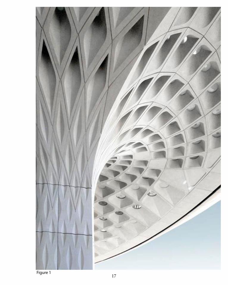
I T K E Re s e a rc h Pav i l i o n 2 0 1 1ICD/ ITKE
There has been a shift in architecture from com-
position to generation. Designers are now think-
ing of algorithm, which can be defined as set of
rules that define sequence of operation (Mod-
elab 2014). They use and come up with differ-
ent creative algorithms to generate forms that
would exceed their imagination and generate
unexpected result. Just like this example of the
2011 ITKE/ICD pavilion which researched the
biological principle of the sea urchin’s plate skel-
eton morphology (Sand Dollar) by using digital
based design and simulation accompanied by
a computer-based and controlled manufactur-
ing method for its construction (ICD/ITKE 2012).
The pavilion was built on the idea of effectively
extending the current bionic principles and relat-
ed performance to a range of different geometries
through the process of computation, the pavilion I
built with thin sheets of plywood of 6.5 mm (Arch-
daily 2012). The reading by Brady (2013)states that
when architects have sufficient understanding of
the algorithmic concepts, they would not discuss
digital as a separate entity but when computation
becomes the true method of design for architec-
ture. This statement applies directly to his pavilion,
as what they have come up with is just a set of data
of a sea urchin’s plate skeleton and had taken the
advantage of the computer to generate these ge-
ometries in relation to both the data and the site.
As seen in Figure 1, the properties used in their
design computational design processes are Het-
erogeneity (different cell sizes adaption to local
curvatures), Anisotropy (The direction of the struc-
ture, with computation the cells stretched and
orient themselves according to the construction
stresses) and lastly hierarchy (The pavilion is di-
vided into 2 hierarchy. The first one is when the
finger joints of the playwood are glued together
to form a cell, the second one is a screw con-
nection as seen in figure 3 allowing the assem-
bling and disassembling of the pavilion as seen
in figure 2). They have generated a form and has
explored the architectural possibilities through
writing and modifying algorithm that relates to the
relationship of different elements (Brady 2014).
Figure 1,2, 3 & 4 : ICD/ITKE, 2011, http://www.arch-
daily.com/200685/icditke-research-pavilion-icd-itke-
university-of-stuttgart/, 2014

25
Figure 1
Figure 2
26
Figure 3
I T K E Re s e a rc h Pav i l i o n 2 0 1 1ICD/ ITKE

27
Figure 4

28
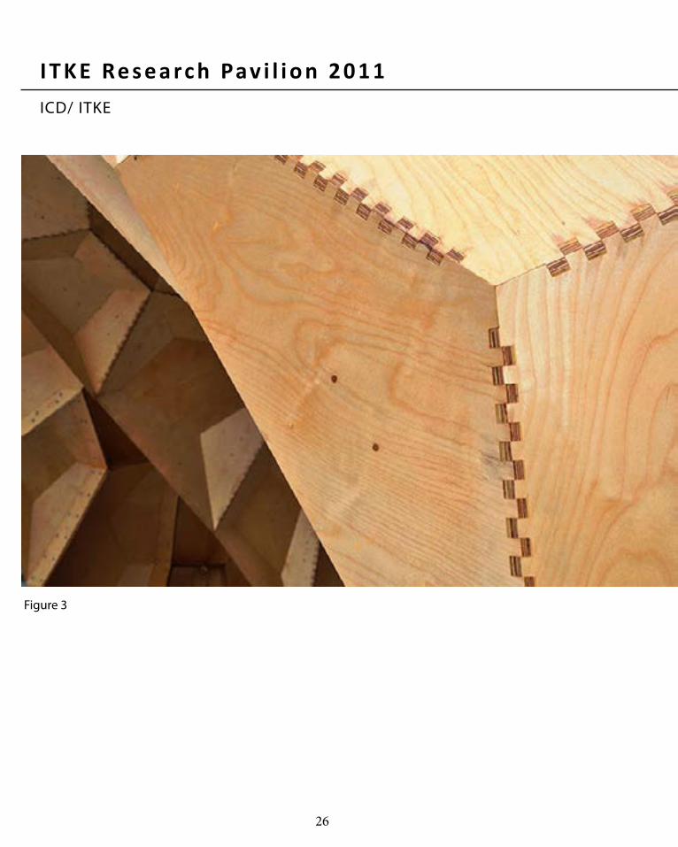
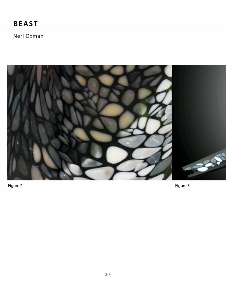
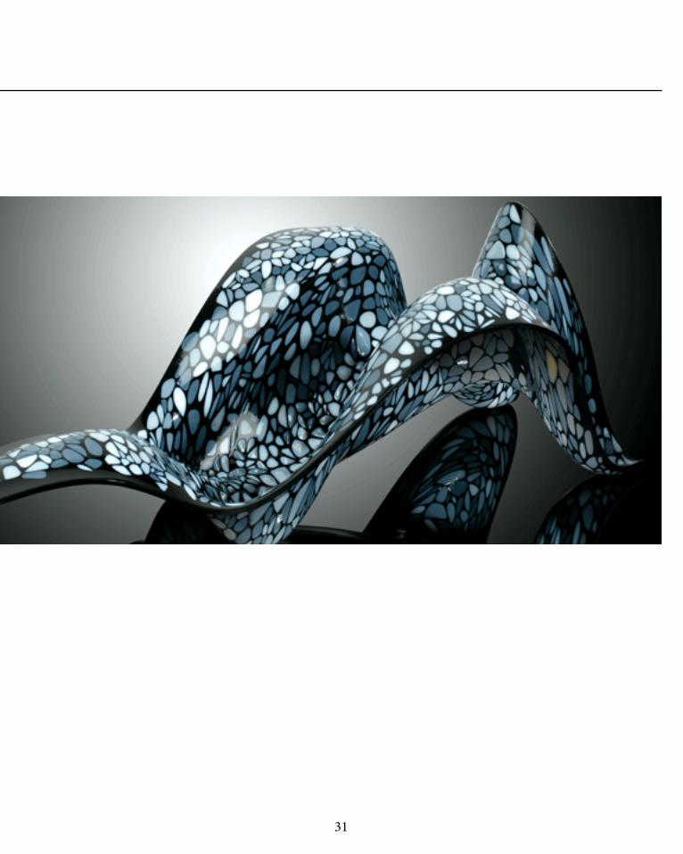
B EA STNeri Oxman
Neri Oxman is an architect/designer that is
currently an assistant professor of media and
arts at MIT media lab. Her job includes explor-
ing how digital design and fabrication technolo-
gies mediate between matter and environment
and how it changes the design and construc-
tion of objects, buildings and system (Elshout
2012). Just like other designers, she relies on
computation to adjust the material and form of
her objects; she suggests beginning from the
analysis of material properties and then generat-
ing a single, multi-functional form (Quirk 2012).
Beast is an organic-like structure formed by in-
corporating physical parameters with digital
form generation. The beast is a continuous sin-
gle surface, acting as both structure and aes-
thetics together, is locally modulated for both
structural support and corporeal aid. It adapts
and combines structural and environment per-
formance by adjusting and modifying its thick-
ness, pattern, flexibility, curvature and skin-
pressured area respectively (Oxman 2012).
Beast adjusts to every muscle in the us-
er’s body and responds itself like a living
organism, Oxman’s intent was about ma-
terial efficiency and actually customizing it ac-
cording to the user’s body load (Ortved 2011).
Figure 1: Beast, Neri Oxman, 2011, http://web.media.
mit.edu/~neri/site/projects/beast/beast.html
Figure 2: Beast, Neri Oxman, 2011, http://web.me-
dia.mit .edu/~neri/s ite/projects/beast/beast.html
Figure 3: Beast, Neri Oxman, 2011, http://www.mate-
rialconnexion.com/Home/Matter/MATTERMagazine/
PastIssues/MATTER63/MATTERInterviewNeriOxman/
tabid/699/Default.aspx
In this context, Oxman focuses on the material-
ity; the synthetic material she used on beast is a
heterogeneous material that is similar to the ma-
terials in biological systems (Ortved 2011). As
explained before, the material that can be seen
is more concentrated on areas which requires
more compression and density is low in areas
which is more tensile and requires less strength
(Ortved 2011). The shape and material den-
sity allocations are all based on computational
tools and digital fabrication, Oxman has proven
a point through her designs that designers can
be a mere source of algorithm thinking rules
to generate complex order form and structure.
29 Figure 1
30
Figure 2 Figure 3
B EA STNeri Oxman
31

32
PA RT A . 4C O N C L U S I O N

33
A . 4 C O N C L U S I O N
In Part A, Conceptualization, I have become
more aware of how computation is redefining the
practice of architecture. The main concept that
designers are noe focusing and redirecting on
is Design Futuring, It is how architects are chal-
lenged to be more sustainable and to slow down
the process of using resources to buy time for fu-
ture generations. We can achieve design futuring
by computation as it allows designers to extend
their abilities to deal with highly complex situation.
Designers are more less constraint than in the
past as highly complex forms, order and struc-
ture can be achieved just by a set of algorithm
or data. Some of the forms generated by digital
computation can provide inspirations for design-
ers as well as go beyond our expectations. ation
and using computation to generate the form. The
main idea of Part A is to built a form or structure
that can create time for humans as well as taking
the environment and data context into consider.
My intended design approach is regenerating ener-
gy to reduce the operational cost thus, being more
sustainable. It is so revise the data of the site and
design an installation that could create awareness
on how we need to redirect our focus from aesthet-
ics to sustainability. It is significant as mentioned
before that resources are scarcer and a redirecting
our design to provide time for the future is very im-
portant. The future generation can definitely ben-
efit from the design as more people are becoming
more aware of the situation and have to change.

34
PA RT A . 5L E A R N I N G O U T C O M E S

35
A . 5 L E A R N I N G O U T C O M E S
After a month of constant exercise of grass-
hopper with the help of readings and looking at
precedents, it has developed my interest in para-
metric and computational design. As mentioned
before in my introduction, I am not familiar at all
with Rhino and Grasshopper and was always
against it after my experience with them in virtu-
al environments during my first year. Thus, I was
always going for a more traditional approach of
things where we look at precedents, have a vision
of what we are going to design and then using the
computer only as a tool to computerize my design.
However, after doing all the tutorials and readings,
it has changed my view towards architecture, I
became more aware of where the future is going
and how important it is to engage with technology
not only to be more efficient but to actually gen-
erate form we could have never imagined which
really amazed me after doing the weekly videos
on grasshopper. I am now thinking more about
how I can design something inr elation to exist-
ing data, like how interesting would it be to de-
sign like Oxman, which is inspired by biological
systems, or SOM, and Grimshaw using computa-
tional tools to expand and develop their forms. I
could have done much better thinking about the
actual data than thinking about the sole aesthet-
ics and functions of the building and how the
form fits in space when the computer can actu-
ally generate the form for me. I am hopping to
expand my knowledge on parametric design
and computation for my future as an architect.

36
A . 6 A P P E N D I X
This was achieved by using orient that was in the tu-
torial and i have just experiemnted it further by us-
ing random points to stack the boxes .My idea was
to actually generate the form throught the data from
the site where i can calculate the sun energy and the
boxes will move accoringly in which at the highest
sunlight received, the boxes might be able to close up
to actually absorb the heat into regenerating energy
and during night time or on a cold day the boxes will
open to allow light and views to enter the building.

37
R E F E R E N C E S
Cifuentes, Fabian, 2012, In Progress Pulkovo airport/ Grimshaw Architects, URL: http://www.archdaily.com/307869/in-progress-pulkovo-airport-grimshaw-architects/
Den, Andrew .H, 2011, Interview with Neri Oxman, URL: http://www.materialconnexion.com/Home/Matter/MATTERMagazine/PastIssues/MATTER63/MATTERInterviewNeriOxman/tabid/699/Default.aspx
DesignBoom Architecture, 2014, SOM unites mumbai airport terminal with fractal roof canopy, URL: http://www.designboom.com/architecture/som-unites-mumbai-airport-termi-nal-with-fractal-roof-canopy-02-25-2014/
Dezeen, 2014, Grimshaw completes St petersburg airport with folded golden ceilings, URL: http://www.dezeen.com/2014/02/27/pulkovo-international-airport-terminal-by-grim-shaw/
Dezeen, 2014, SOM completes Mumbai airport terminal with coffered concrete canopy, URL: http://www.dezeen.com/2014/02/20/chhatrapati-shivaji-airport-terminal-mumbai-som/
Huang, Mary, 2014, Continuum Dress, http://www.rhymeandreasoncreative.com/portfolio/index.php
ICD/ITKE, 2012, ICD | ITKE Research Pavilion 2011 / ICD / ITKE University of Stuttgart, URL: http://www.archdaily.com/200685/icditke-research-pavilion-icd-itke-university-of-stuttgart/
Oxman, Neri, 2011, Beast, URL: http://web.media.mit.edu/~neri/site/projects/beast/beast.html
Pham, Diane, 2011, Dragon-Shaped Solar Stadium in Taiwan is 100% Powered by the Sun, URL: http://inhabitat.com/taiwans-solar-stadium-100-powered-by-the-sun/
38
R E F E R E N C E S
Fry, Tony (2008). Design Futuring: Sustainability, Ethics and New Practice (Oxford: Berg), pp. 1–16
Ferry, Robert & Elizabeth Monoian, ‘Design Guidelines’, Land Art Generator Initiative, Copenhagen, 2014. pp 1 - 10
Oxman, Rivka and Robert Oxman, eds (2014). Theories of the Digital in Architecture (Lon-don; New York: Routledge), pp. 1–10
Kalay, Yehuda E. (2004). Architecture’s New Media: Principles, Theories, and Methods of Computer-Aided Design (Cambridge, MA: MIT Press), pp. 5-25
Peters, Brady. (2013) ‘Computation Works: The Building of Algorithmic Thought’, Architec-tural Design, 83, 2, pp. 08-15
Definition of ‘Algorithm’ in Wilson, Robert A. and Frank C. Keil, eds (1999). The MIT Ency-clopedia of the Cognitive Sciences (London: MIT Press), pp. 11, 12
Woodbury, Robert F. (2014). ‘How Designers Use Parameters’, in Theories of the Digital in Architecture, ed. by Rivka Oxman and Robert Oxman (London; New York: Routledge), pp. 153–170

39

40
PA RT B . 1 R E S E A R C H F I E L D

41
B . 1 R E S E A R C H F I E L DS e c t i o n i n g
Sectioning is the process of form division and is com-
monly used to produce a complex design and geom-
etries. It is currently used in the world of computational
design and has evolved from a 2D orthographic projec-
tion to its 3d counterpart (Iwamoto 2009). Moreoever,
sectioning is also used as a method of taking differ-
ent ways of cross section which is commonly used in
airplanes and ship construction (Iwamoto 2009). Fur-
thermore, the technique which is widely used in sec-
tioning is cross-sectioning, contouring, horizontal and
vertical trimming. Thus, this material system has aid the
world of computational design by making it very effi-
cient and easy to produce form especially curved form.
In relation to our design concept, we have decid-
ed that sectioning is much more feasible than tes-
sellation (the material we first picked), as our con-
cept is related to the landscape and the curved
topography of the site in which by using section-
ing is more possible to produce and manipulate..
Tessellation has restrained our form making it very
hard to manipulate the form according to our con-
cept. Our team believed that we can explore our de-
sign concept with sectioning as it shows more po-
tential in making the design better and achievable.
However, there are also disadvantages related to sec-
tioning in relation to their fabrication, assembly and
form. Keeping in mind the research in part A- design fu-
turing, although sectioning allows us to achieve forms
which are hard to achieve with other materials, it has
issues with the fabrication materials needed to achieve
those forms. It may use more materials than needed with
other materials and it uses individual layer of sheets to
produce a form in which sometimes might not be nec-
essary. Iwamoto (2009) has expressed her concerns and
issues regarding these three factors in her case studied.

42
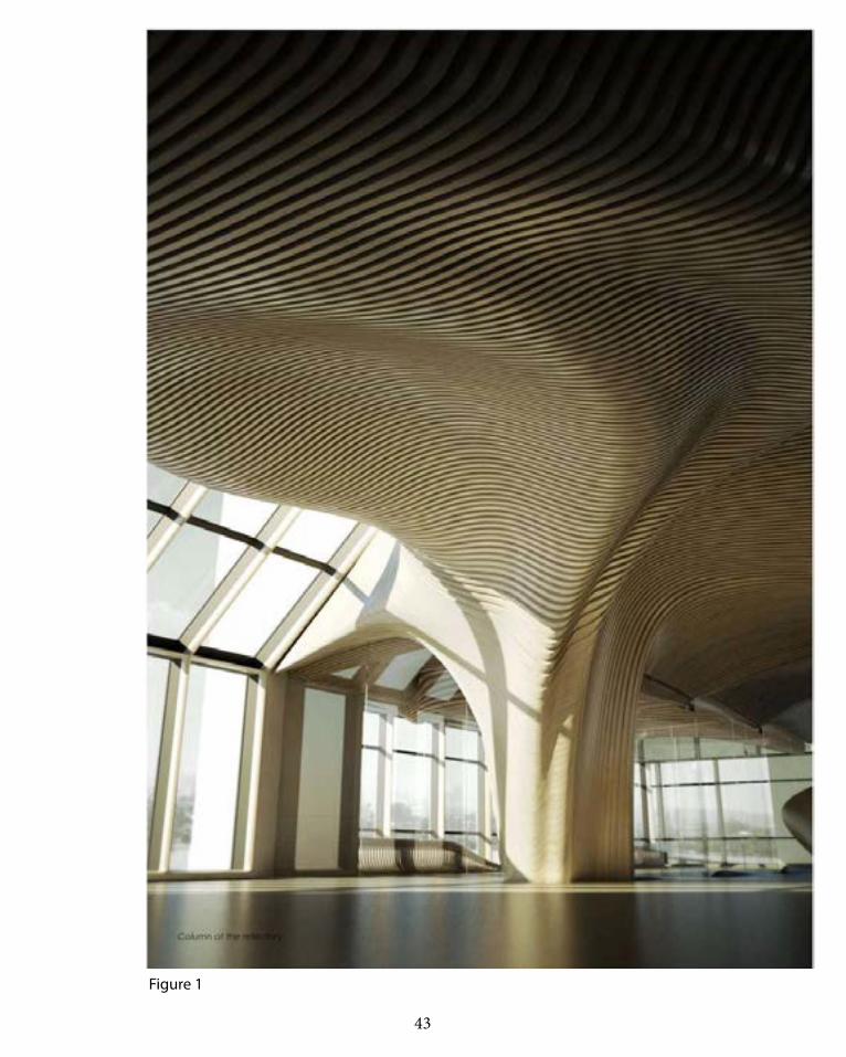
One main is an office renovation by dECOi archi-
tects located in Boston, USA. They have used a sec-
tioning method of vertical trimming to produce their
ceiling by using sustainable plywood to create aware-
ness of efficient building process. Not only do they
use sustainable plywood, they have incorporated a
computational logic of customized fabrication and
ready-made components which our team is trying to
achieve in our design. In relation to design futuring
in Part A, dECOi architects are aware of their environ-
ment and is suing a sustainable a carbon-absorbing
raw material (forested spruce), and is translated
and used efficiently into functional and refined ele-
ments with low-energy digital tooling (dECOI 2009).Figure 1,2 & 3: ONE Main, dECOi Architects, 2009, http://ar-
chitizer.com/projects/one-main/media/672278/
In figure 2, it can be seen then all the elements are
fabricated and is placed as stacking sectioning ele-
ments produced from a plywood sheet by incor-
porating ventilation grills, light pockets and door
handles. One of the advantages of this design that
makes it design futuring is also because not only
in its material usage, its assembly techniques also
shows lateindustrial protocols, which evident of ef-
ficient labour, material and logistic, digital fabrica-
tion allows this projects to be as economical as pos-
sible by offering a versatile digital tool (dECOi 2009).
O n e M a i ndECOi Architects
43
Figure 1

44
Figure 2 Figure 3
O n e M a i ndECOi Architects

45

46
Po l y m o r p h i c B e n c hColumbia GSAPP
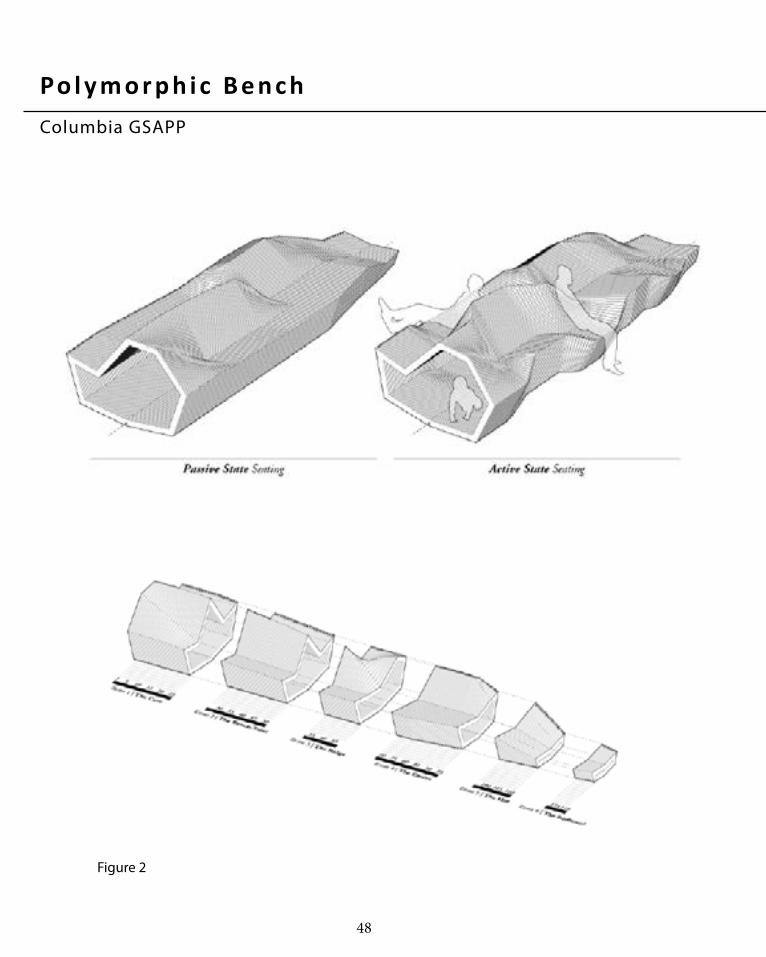
Polymorphic kinetic bench is a kinetic engineer-
ing solution by utilizing innovative design inspired
by the action of see-saw and the reverberating mo-
tion of a slinky to create a double sided bench, made
of 119 connected components which is placed on
an interactive board. This innovative bench is de-
signed and constructed by 10 GSAPP students, USA
(Chang 2012). What are most interesting about this
bench that fits our team’s design intent is the joints
and sectioning used. Section strips of the chair
used are connected with a rigid inventive pivot and
bolting system to keep the structure together pre-
venting it to move out of place, this allows only
the vertical sectioning to move on one part while
not allowing the other part of the bench to move.
In our design e are trying to achieve a dynamic mov-
ing landscape/pavilion, and movement is really nec-
essary to generate kinetic energy, which is why the
connection joints of this precedent really helped us
though about our own design. Furthermore, what al-
lows the structure to move is the strong elastic band
keeping them together, in figure 2 we are able to see
how the elastic band and the bolting integrated in the
design which involves an early thinking of the fabrica-
tion process with Rhino and Grasshopper. All togeth-
er this motion allows the installation to different types
of section, which interacts and engages with the user.
Figure 1,2 & 3: PolymorphicBench, GSAPP, USA, http://www.
jennchang.com/8.html

47
Figure 1
48
Figure 2
Po l y m o r p h i c B e n c hColumbia GSAPP

49
Figure 3

50
M AT E R I A L SYST E MSectioning
The reason why sectioning is suitable with our
design intent is because:
1. Sectioning does not restrict shapes. In comparison
to tesselation that requires the use of the same shape
repeated all over the form, sectioning’s compart-
ments follows the curvature of the form.
2. Sectioning does not create angular surface in com-
parison to tesselation. As shown on the figure on the
right, there are several methods of sectioning that
could be achieved, from waffling, horizontal of verti-
cal sectioning (Bang Restaurant), etc, which allows
the forms to be retained.
3. As shown in projects such as the Bang Restaurant
or Design weave, the connection in sectioning seems
to allow a more flexible joint that does not restrict
movement and also witholds its structural integrity.
4. With further iterations beginining in Case Study
1.0, it seems possible to achieve even more results
of sectioning methods, from varying basic shapes
to forms, as some examples have been shown in the
figure on the right.
5. Finally, with context to our design brief of energy
regeneration, there have been numerous research
on sectioning that have been done regarding how
to fabricate it efficiently, and these existing investi-
gations can come in good use when integrated to
the energy regeneration mechanism that has been
researched. (Part B.5-6 shows research on piezoelec-
tric generator).
Figure1:http://m1.behance.net/rendition/mod-
ules/27279945/disp/43f7a779780786933b7ac3b59b6ed
1e5.jpg

51
Figure 1

52
PA RT B . 2 C A S E S T U D Y 1 . 0

53
B . 2 C A S E S T U D Y 1 . 0
Part B.2 is the experimentation of the script
in order to test and explore the potential of sec-
tioning. This section will explore new iterations
to reach the potential and find the limit of the
material system. This section will explore differ-
ent ways of sectioning which includes section-
ing with lines, graph mapper, driftwood pattern,
and curves and how it sections different type
of geometries such as surface, solid, section
planes, density, and a mixture of both. In addi-
tion, this section will then extrapolate the four
most successful iterations and discuss its out-
come and why is it more successful than others.

54
SURFACE SOLIDSECTION PLANES
LINES
GRAPHMAPPER
DRIFTWOODPATTERN
SECTIONINGWITH CURVES
C A S E ST U DY 1 . 0 : I te rat i o n M at r i x

55
SECTION PLANES DENSITY
INCREASEDINPUT
HYBRIDS

56
LINES
GRAPHMAPPER
DRIFTWOODPATTERN
SECTIONINGWITH CURVES
C A S E ST U DY 1 . 0 : I te rat i o n M at r i x
HYBRIDSHYBRIDS

57
S E L E C T I O N C R E I T E R I A
Selection criteria:
1.A form and design that fits the LAGI brief
and the Copenhagen environment in rela-
tion to its topography and natural features
2.Can regenerate energy and sustain itself
3.Allowing the structure to move to provide
kinetic energy through the piezoelectric in
which the energy will then be converted to
electrical energy
4.Thinking about the fabrication and how it
can be feasible and assembled in real life
5.A design that is safe for children and adult
to interact in and engage with the structure

58
C A S E ST U DY 1 . 0 : S e l e c te d I te rat i o n s
Selection Criteria: Our team has decided to base the selection criteria on the feasibility of fabrication and on the form; we are going forward with the idea of
creating a dynamic landscape through sectioning which involves curves, movement and how the form can aid us in energy generation (kinetic energy).
This surface is sectioned from a curve from the
driftwood pattern, this is one of the most success-
ful iterations from the rest because I think this way
of sectioning provide flexibility in the shape we
want to produce, this does not restrict the form
and it creates a more dynamic form rather than
ordinary vertical sectioning. Furthermore, it does
not give a rigidity feeling to the form. We are aim-
ing to create a flexible dynamic landscape which
I think can be very well achieved with this form.
This form is one of the most successful vertical sec-
tioning as it shows that this way of sectioning can
create any shape and form given especially curved
form, it creates a sort of landscape feeling which
we can later integrate in our design. It also allow
different geometry variations and fits the crite-
ria in what we are trying to achieve. Furthermore
the advantage of sectioning is that it is easy to
construct as these are curves in the same planar.

59
C A S E ST U DY 1 . 0 : S e l e c te d I te rat i o n s
Selection Criteria: Our team has decided to base the selection criteria on the feasibility of fabrication and on the form; we are going forward with the idea of
creating a dynamic landscape through sectioning which involves curves, movement and how the form can aid us in energy generation (kinetic energy).
The additional input iterations creates an interest-
ing shape, but out of all, this form is the most in-
teresting and just the form itself is acting as a pa-
vilion sort of design, this can be integrated with
piezoelectric and will create a lit up pavilion. This
is the most successful iteration because it is pos-
sible to fabricate no matter how dynamic the shape
may be and creates rigid structure by adding the
section lines in x and y, not just in one direction.
This surface is sectioned from a curve from the drift-
wood pattern, this is one of the most successful it-
erations from the rest because I think this way of
sectioning provide flexibility in the shape we want
to produce, this does not restrict the form and it
creates a more dynamic form rather than ordinary
vertical sectioning. Furthermore, it allows the cre-
ation of dynamic forms with the piped section to
be part of the support structure itself. We are aim-
ing to create a flexible dynamic landscape which
I think can be very well achieved with this form.

60
In summary, with the appropriate mecha-nism and system, sectioning has great poten-tial to explore forms that would otherwise be difficult to fabricate and assemble with other systems for instance tesselation. Sectioning allows the form to be achieved with minimal angular edges thus allowing the overall form to have a curved finish. One of the biggest design potential is the low-energy fabrica-tion which will aid design futuring and the exploration of curved forms which can be further explored into mroe shapes. Although there may be issues concerning the efficiency of fabricating the components of a sectioned design and how to prototype an assembly that meets the design brief of allowing move-ment, with iterations and scripting explora-tion, a suitable system would tackle these issues.
D e s i g n Po te nt i a l

61

62
PA RT B . 3 C A S E S T U D Y 2 . 0
63
B . 3 C A S E S T U D Y 2 . 0
In relation to Part B.3, we have chosen Dunes-
cape as our selected project in which we are to
write a script to recreate the Dunescape to help
our future and final design. Dunescape was cho-
sen as it is the most related project to our de-
sign intent and idea; it explores the use of multi-
purpose spatial area in relation to structure and
aesthetics while rying to make our outcome as
similar as possible as the original in form. How-
ever the main difference is that since this is a
digital model, it was hard to imagine the rigid-
ity of the form therefore lacking certain struc-
tural members from the original dunescape.
64
D u n e s c a p eShop Architects
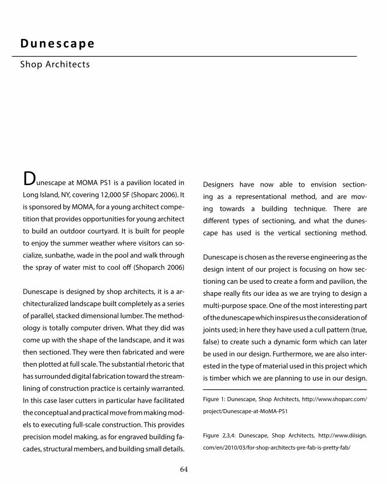
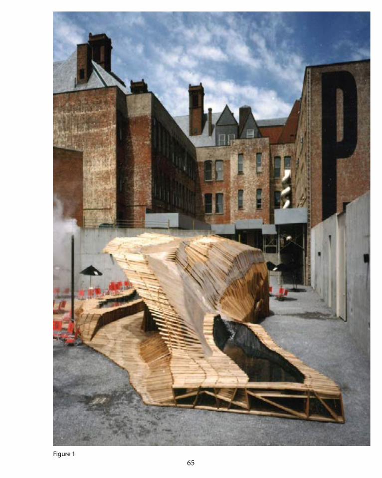
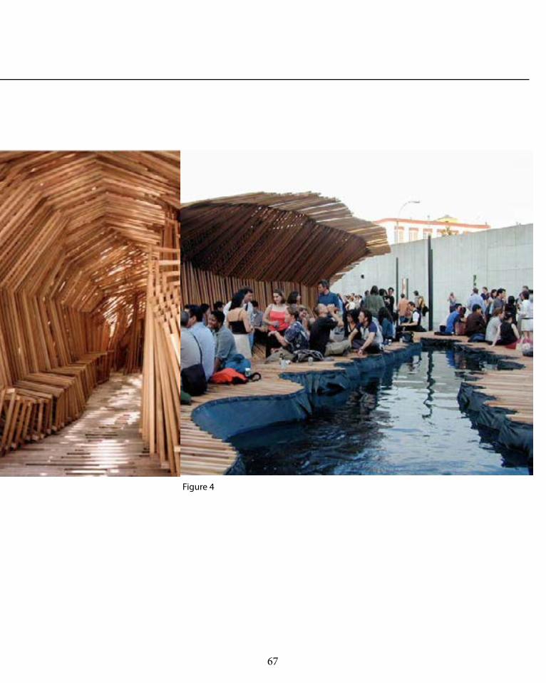
Dunescape at MOMA PS1 is a pavilion located in
Long Island, NY, covering 12,000 SF (Shoparc 2006). It
is sponsored by MOMA, for a young architect compe-
tition that provides opportunities for young architect
to build an outdoor courtyard. It is built for people
to enjoy the summer weather where visitors can so-
cialize, sunbathe, wade in the pool and walk through
the spray of water mist to cool off (Shoparch 2006)
Dunescape is designed by shop architects, it is a ar-
chitecturalized landscape built completely as a series
of parallel, stacked dimensional lumber. The method-
ology is totally computer driven. What they did was
come up with the shape of the landscape, and it was
then sectioned. They were then fabricated and were
then plotted at full scale. The substantial rhetoric that
has surrounded digital fabrication toward the stream-
lining of construction practice is certainly warranted.
In this case laser cutters in particular have facilitated
the conceptual and practical move from making mod-
els to executing full-scale construction. This provides
precision model making, as for engraved building fa-
cades, structural members, and building small details.
Figure 1: Dunescape, Shop Architects, http://www.shoparc.com/
project/Dunescape-at-MoMA-PS1
Figure 2,3,4: Dunescape, Shop Architects, http://www.diisign.
com/en/2010/03/for-shop-architects-pre-fab-is-pretty-fab/
Designers have now able to envision section-
ing as a representational method, and are mov-
ing towards a building technique. There are
different types of sectioning, and what the dunes-
cape has used is the vertical sectioning method.
Dunescape is chosen as the reverse engineering as the
design intent of our project is focusing on how sec-
tioning can be used to create a form and pavilion, the
shape really fits our idea as we are trying to design a
multi-purpose space. One of the most interesting part
of the dunescape which inspires us the consideration of
joints used; in here they have used a cull pattern (true,
false) to create such a dynamic form which can later
be used in our design. Furthermore, we are also inter-
ested in the type of material used in this project which
is timber which we are planning to use in our design.
65 Figure 1

66
Figure 2 Figure 3
D u n e s c a p eShop Architects
67
Figure 3 Figure 4

68
I
Creating a frame (ribs of the du-
nescape) for the design in Rhino.
Then orienting section spaces to
navigate the lines in later steps.
II.
Section Points are oriented into
the ribs in order to join the lines
in step III.
III.
Lines are joined by joining each
section points, depending on
how it should start and end.
D u n e s c a p eShop Architects

69
IV.
This diagram illustrates the fin-
ishing of the structure from th e
curves.
V.
Cull patterning allows the stack-
ing of the timber to create joints
without having to make angled
timber strips, allows strips to
always be straight so that it is
feasible to connect sideways.
VI.
Application of material property,
giving depth to the line to the
dimension of a real timber

70
The figure shows the script used
in creating the dunescape. Creat-
ing a frame (ribs of the dunes-
cape) for the design in Rhino.
Then orienting section spaces to
navigate the lines in later steps.
Section Points are oriented into
the ribs in order to join the lines
in step III.
Lines are joined by joining each
section points, depending on
how it should start and end. In
this case, it is line E to F.
Lines drawn for each necessary
points, this diagram shows all the
necessary lines joined together.
Cull Pattern (True-False) is used
in order to not make lines join
together straight, rather to create
spaces for fabrication.
Extrude the lines in X-Y to create
depth and extend it on the ends
in order to show joinings of the
dunescape.
Figure 1
D u n e s c a p eShop Architects

71

72
73

74
The outcome from the grasshopper digital dun-
escape has their differences and similarities to the
original Dunescape.
Similarities:
-Focuses on the joint detail such as the cull pattern-
ing (true, false) which then the timber extrusion are
extended to give emphasis on the details.
-The main use of curve to control the points in which
will control the whole form of the structure.
-Provides enclosed and open spaces for people to
socialize and interact.
-A multi-purpose spatial area.
-The team attempts to imitate the materiality of
the original dunescape which is timber in order to
achieve maximum similarity.
Differences:
-Lacking form similarity with the original dunescape
-The lack of structural members which is not that vis-
ible in the computer grasshopper.
-Lack of details such as curtain/pools and bathrooms
Finally, due to the lack of information regarding the
project and its dimension, we are unable to achieve
maximum accuracy regarding the dunescape project
with the reverse engineering.
D u n e s c a p eShop Architects

75

76
PA RT B . 4 T E C H N I Q U E D E V E L O P M E N T

77
B . 4 T E C H N I Q U E : D E V E L O P M E N T
In relation to Part B.3, we have chosen Dunes-
cape as our selected project in which we are to
write a script to recreate the Dunescape to help
our future and final design. Dunescape was cho-
sen as it is the most related project to our de-
sign intent and idea; it explores the use of multi-
purpose spatial area in relation to structure and
aesthetics while rying to make our outcome as
similar as possible as the original in form. How-
ever the main difference is that since this is a
digital model, it was hard to imagine the rigid-
ity of the form therefore lacking certain struc-
tural members from the original dunescape.

78
B . 4 Te c h n i q u e D e ve l o p m e ntDensity Variation

79
With density variation, the slider is controlled in order to produce several iterations displaying varying
forms in terms of the number of sectioning components. In the dunescape engineering, every sections need
to be joined to atleast one other, therefore if this variation is to be used, the designs with the bigger gaps need
to figure out a new connection method. A possible solution is to control the density in a way that the form
could achieve the same aesthetic intent such as the diagrams in the right while being achievable to construct.

80
B . 4 Te c h n i q u e D e ve l o p m e ntCull Patterning
81
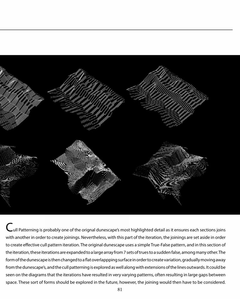
Cull Patterning is probably one of the orignal dunescape’s most highlighted detail as it ensures each sections joins
with another in order to create joinings. Nevertheless, with this part of the iteration, the joinings are set aside in order
to create effective cull pattern iteration. The original dunescape uses a simple True-False pattern, and in this section of
the iteration, these iterations are expanded to a large array from 7 sets of trues to a sudden false, among many other. The
form of the dunescape is then changed to a flat overlappping surface in order to create variation, gradually moving away
from the dunescape’s, and the cull patterning is explored as well along with extensions of the lines outwards. It could be
seen on the diagrams that the iterations have resulted in very varying patterns, often resulting in large gaps between
space. These sort of forms should be explored in the future, however, the joining would then have to be considered.

82
B . 4 Te c h n i q u e D e ve l o p m e ntSectioning with Curves
83
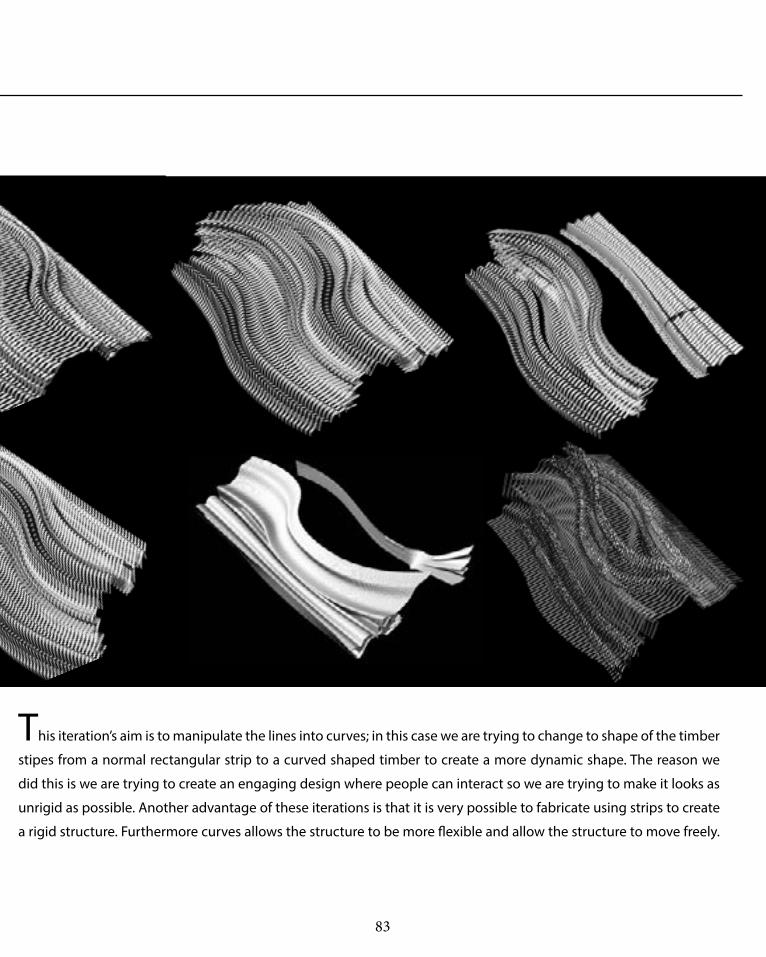
This iteration’s aim is to manipulate the lines into curves; in this case we are trying to change to shape of the timber
stipes from a normal rectangular strip to a curved shaped timber to create a more dynamic shape. The reason we
did this is we are trying to create an engaging design where people can interact so we are trying to make it looks as
unrigid as possible. Another advantage of these iterations is that it is very possible to fabricate using strips to create
a rigid structure. Furthermore curves allows the structure to be more flexible and allow the structure to move freely.

84
B . 4 Te c h n i q u e D e ve l o p m e ntSurface Patterning
85
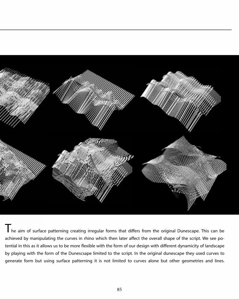
The aim of surface patterning creating irregular forms that differs from the original Dunescape. This can be
achieved by manipulating the curves in rhino which then later affect the overall shape of the script. We see po-
tential in this as it allows us to be more flexible with the form of our design with different dynamicity of landscape
by playing with the form of the Dunescsape limited to the script. In the original dunescape they used curves to
generate form but using surface patterning it is not limited to curves alone but other geometries and lines.

86
B . 4 Te c h n i q u e D e ve l o p m e ntHybrid

87
Lastly, the hybrid is the mix of the script in which we are trying to explore the limitation of the
form and how complex or what form can be derived by combining two types of iterations together.

88
T EC H N I Q U E : D e ve l o p m e nt
Selection Criteria: Our team has decided to base the selection criteria on the feasibility of fabrication and on the form; we are going forward with the idea of
creating a dynamic landscape through sectioning which involves curves, movement and how the form can aid us in energy generation (kinetic energy).
This hybrid of cull patterning and surface pattern-
ing is produce a very interesting form which cre-
ates this sort of pavilion, this is one of the most
successful as it fits our selection criteria. This form
allow the members to be connected with an elastic
band which then allows the form to start generat-
ing movement and energy. This form provides an
interesting form. However, since the curves are not
on the same planar they are not feasible to fabricate
This form is one of the most successful cull pattern-
ing as it shows that this way of sectioning can cre-
ate any shape and form given especially curved form
which will useful in our project, it creates a sort of
interesting wall pattern which can be integrated to
the landscape which can later be further developed.

89
T EC H N I Q U E : D e ve l o p m e nt
Selection Criteria: Our team has decided to base the selection criteria on the feasibility of fabrication and on the form; we are going forward with the idea of
creating a dynamic landscape through sectioning which involves curves, movement and how the form can aid us in energy generation (kinetic energy).
The density iteration can change the original Du-
nescape into a more natural and allow it to inter-
act with the environment by allowing more sun-
light and a space where people can go through
in and out. I personally like the shape of having
less timber structure, it might not be possible
with the structural and movement aspect of our
intent but further development can be made.
Manipulating the shape of the original Dunescape
with the manipulation of curves allows us to control
the form much more in which we can integrate with
the movement capabilities of the structure , this does
not restrict the form and it creates a more dynamic
form rather than ordinary vertical sectioning. Further-
more it does not give a rigidity feeling to the form.
We are aiming to create a flexible dynamic landscape
which I think can be very well achieved with this form.

90
91
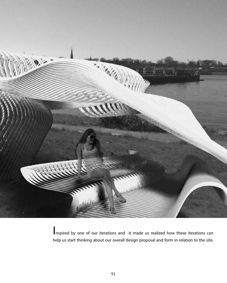
Inspired by one of our iterations and it made us realized how these iterations can
help us start thinking about our overall design proposal and form in relation to the site.

92
PA RT B . 5T E C H N I Q U E : P R O TO T Y P E S

93
This section explores the materialisation, joints
and structure in consideration with the fabrica-
tion and assembly of the model and how it re-
lates to our design intent (Movement, generates
energy and a dynamic form). The main material
used for the prototype is MDF as our intent and
idea relates more to the joints and structure. We
will be investigating different methods of joints
and orientations before proceeding to our final
design to gain experience on which will work
and which will fail. All the prototypes are digitally
fabricated using grasshopper and rhino which
is then sent to the fab-lab. The process is first to
align the layout of the sheet to be printed, then
to assemble them according to their order (giv-
ing number on the sheets) with different types
of jointing systems and secure them with glue.
B . 4 T E C H N I Q U E : D E V E L O P M E N T

94

95

96
P ro to t y p e : Tw i st i n g

97
The above prototype explores on the potential twisting component of our de-
sign intent. A part of our design idea is to design a landscape which can move in
relation to people’s body mass. The purpose of this is to make it possible for the
twisting structure to provide enough force for the piezoelectric to react and gener-
ate electricity. There is also another way for this to work by, is by attaching piezo-
electric patches (which will be explained later in technique: Proposal) in between
each sectioning component to provide friction when the structure twists and turn.

98
P ro to t y p e : J o i nt s

99
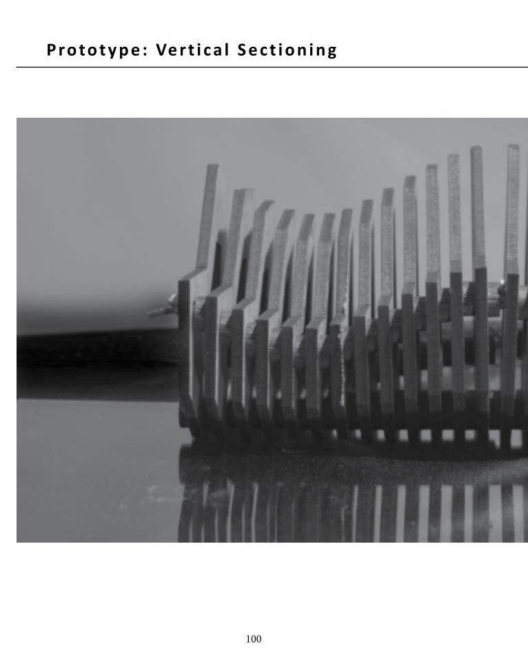
The above prototype focuses on the type of joints which allows twisting and bending
while providing a rigid structure. The jointing material used here is elastic band to allow
movement from the structure, in this experimentation process, it can be seen that having
a rigid bottom structure supported by elastic band side jointing is the most efficient and
feasible. The jointing system is mostly inspired by the GSAPP bench in which they make
use of a bolting at the bottom to secure the structure and the use of elastic band to allow
the structure to move.
In conclusion, Some of the prototypes do achieve our intended goal and some failed,
we tried different types like figure 3 to show the cull patterning however, the struc-
ture would not stand without the help of a support column in the middle which would
100
P ro to t y p e : Ve r t i c a l S e c t i o n i n g

101
102
C o n c l u s i o nPrototype
For example the rubber made the structure too
flexible allowing it to move freely and the struc-
ture lacks rigidity to be safe for humans to inter-
act with. The most ideal we found out is to have
a rigid bottom structure making it stays on one
position and having these elastic bands to cre-
ate a movement in order to provide kinetic energy.
We also tried experimenting with cull pattern-
ing to create the shape of the whole structure.
However, it failed due to the lack of structural
elements for the prototype. This will need fur-
ther development and experimentation in order
for it to work. However, we are planning to in-
tegrate both ideas of movement joints and cull
patterning in order to produce our final design.
In conclusion, the prototypes carried success and
failure in which further development can still be
made for all in order to make our final product.
What we focused on in these prototypes is the
ability of the joints and the rigidity of the struc-
ture in order to move forward to the designing
phase. We explored different types of joints mainly
the one we are inspired and sure that it can help
us move forward is the polymorphic joint; this is
because the design fit our design intent, allow-
ing the structure to move according to human
interaction. The three different types of joints we
tried to explore is with elastic band, rigid plastic
connection at the bottom and wire. Those three
proves to be a success and fits our design intent.
However, there are certain drawbacks in each.

103

104
PA RT B . 6T E C H N I Q U E P R O P O S A L

105
B . 6 T E C H N I Q U E P R O P O S A L
This section focuses on the techniques used to
further develop our idea and design intent. This
section further explores the type of energy the
design will be generating in specific the materi-
al the kinetic energy will be using. In addition, it
will discuss how this technique is applied to our
design to meet the design brief criteria by mak-
ing it as innovative and engaging as possible.
Our proposal will be focusing on the topography
and natural environment of the site and how it
affects our overall design with the integration of
kinetic energy and how it can engage the user
to make the design interactive and innovative.
Overall, our technique proposal is to use human
interaction to provide kinetic energy in which
the structure of our design will begin to twits
and turn activating the piezoelectric (sensitive
to even the smallest energy, however, the light
produce depends on how much energy is input-
ted) which will then be converted to light for the
pavilion in order to create awareness and edu-
cate the user on energy generation (going back
to the brief ). In relation to the LAGI brief, this
design has potential which can be further ex-
plored keeping in mind design futuring (Fry 2008)
and human engagement with the structure.

106
C o p e n h a ge nSite
Apart of our design intent is to create an inter-
active structure which is in relation to the natu-
ral surroundings of the site in which people can
distinguish our design as one with Copenhagen
itself. Our aim is to frame views to different areas
on the site while providing a journey for the user.
Our design will not only be aesthetic but edu-
cational at the same time in which awareness
of energy generation is created while engaged
with our design. Furthermore, at the end of the
journey, users will be able to spot the little mer-
maid which is across the site sort of as a reward
for the journey interaction with the structure.

107

108
K i n e t i c E n e rg yPiezoElectric
Rochelle salts, and other various solid (Gibilisco
2012). There are different ways we can incorporate
piezoelectric in our design. Firstly we can place a
whole area of piezo in which our structure will be
on and when the structure moves and provides
pressure to the ground, it will generate energy.
One of the disadvantages for this is that not the
whole area of piezo material is needed to generate
electricity therefore this proves to be insufficient.
Another ideal way that we thought about is to
insert these materials in between the sections in
joints in which even a little twist or stretch will gen-
erate energy through the piezo. Further develop-
ment with our real model is needed, but through
research it is very possible and efficient to use
this in our design which meets our design intent.
Piezoelectric can be known as the electric
charge that is accumulated in a certain solid in
response to a body mass or a mechanical stress
(Rouse 2012). The word itself meant electricity
which is resulting from pressure, it can come in
many different types and shapes, the most famous
and commonly used are patches and crystals
which our team is exploring further to incorpo-
rate it into our design. These different types have
the same mechanism in which it acquire charges
when it is compressed, twisted or even distorted
in order to generate energy. Piezoelectric is the
ability for certain materials to generate an alter-
nating current voltage when subjected to pres-
sure, vibrating or stress. The most common ma-
terial which is used for piezoelectric is ceramics,

109
http://www.youtube.com/watch?v=laSQ6yd7jaE
DIFFERENT TYPES OF PIEZOELECTRIC GENERATOR:
http://www.piezo.com/prodbm8dqmpict760.jpg

110
PA RT B . 7L E A R N I N G O B J E C T I V E S A N D O U T C O M E S

111
B . 7 L E A R N I N G O U T C O M E S
Part B has covered most aspect of the design,
which includes the design concept and intent
and why we have chosen our particular idea, ex-
ploring a material system in which we can fur-
ther explore and what we can achieve with sec-
tioning as a material system such as what are
the disadvantages and advantages of sectioning
keeping in mind its limitation and potential. Fur-
thermore, it has also explored different iterations
from the different types of sectioning on differ-
ent platform to the different iterations that can
be produced by testing our reverse engineer to
its potential. By choosing 4 of the best iterations,
I have learnt to start thinking about the design
and how can these iterations be helpful in our de-
sign intent in terms of form and structural joints.
In part A we were directed to explore the idea of
parametric design and design futuring and how
they have affected the world of design and how
computational design has aided in the production
of design. Whereas, in part B we were to think of the
design brief itself and how do we utilize what we
leant in part A into the integration of our design it-
self to create an innovative design. Part B also made
me appreciate the complexity of scripting and form
able to present and got some constructive criti-
cism in which we can further improve our design.
Some of the common feedbacks were:
-The main part that we have to consider is the fact
that we are focusing to much on the technical stuff
neglecting the main form and how it is related to
Copenhagen and the site itself.
-Another one is how our structure can be safe for
the users to interact as the ore structural joints and
members are needed
-Further exploration of joining would make it more
feasible for the structure to provide movement for
the kinetic energy
-How to integrate our piezoelectric into our design
-Lastly how can we produce the most efficient way
to construct and regenerate energy following the
LAGI Brief
In reference to our brief to create awareness of
energy regeneration, we have now had a better
idea on how we can move forward with our design.
Taking all that we have learnt in part B and critics
from our tutors and guest crits, it becomes clearer
on which areas we are lacking in and how can we
improve further. We can now conduct specific
research in order to achieve our design intent.
112
A . 6 A P P E N D I X
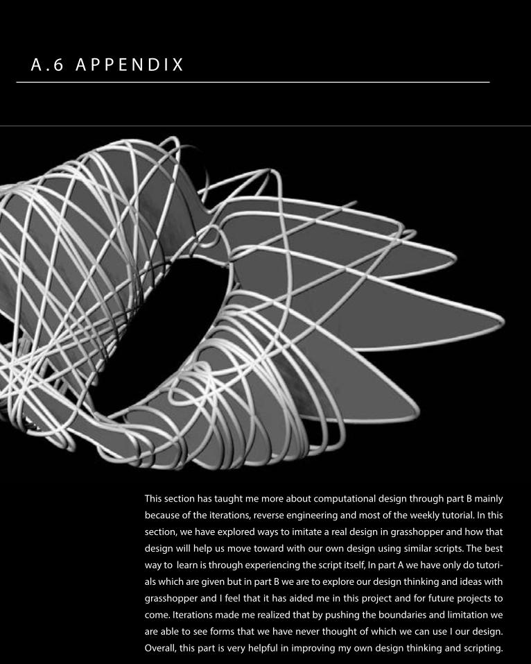
This section has taught me more about computational design through part B mainly
because of the iterations, reverse engineering and most of the weekly tutorial. In this
section, we have explored ways to imitate a real design in grasshopper and how that
design will help us move toward with our own design using similar scripts. The best
way to learn is through experiencing the script itself, In part A we have only do tutori-
als which are given but in part B we are to explore our design thinking and ideas with
grasshopper and I feel that it has aided me in this project and for future projects to
come. Iterations made me realized that by pushing the boundaries and limitation we
are able to see forms that we have never thought of which we can use I our design.
Overall, this part is very helpful in improving my own design thinking and scripting.

113
R E F E R E N C E S
Ferry, Robert & Elizabeth Monoian, ‘A Field Guide to Renewable Energy Technologies’’, Land Art Generator Initiative, Copenhagen, 2014. pp 1 - 71
Fry, Tony (2008). Design Futuring: Sustainability, Ethics and New Practice (Oxford: Berg), pp. 1–16
Dunescape, Shop Architects, http://www.shoparc.com/project/Dunescape-at-MoMA-PS1
Dunescape, Shop Architects, http://www.diisign.com/en/2010/03/for-shop-architects-pre-fab-is-pretty-fab/
Kolarevic, Branko and Kevin R. Klinger, eds (2008). Manufacturing Material Effects: Re-thinking Design and Making in Architecture (New York; London: Routledge), pp. 6–24
Oxman, Rivka and Robert Oxman, eds (2014). Theories of the Digital in Architecture (London; New York: Routledge), pp. 1–10
Margaret Rouse, 2012, http://whatis.techtarget.com/definition/piezoelectricity
Peters, Brady. (2013) ‘Realising the Architectural Intent: Computation at Herzog & De Meuron’. Architectural Design, 83, 2, pp. 56-61
Piezoelectric materials and pictures, 2012 http://www.piezo.com/prodbm8dqmpict760.jpg
Polymorphic Bench, GSAPP, USA, http://www.jennchang.com/8.html
Stan Giblisco, 2012, http://whatis.techtarget.com/definition/piezoelectricity

114
PA RT C . 1D E S I G N C O N C E P T

115
C . 1 D E S I G N C O N C E P T
Part C focuses on the development of idea and
the finalizing the design concept. All design options
are then finalized and the focus will shift to make our
design as realistic and innovative as possible. Fur-
thermore, this section will also demonstrate my un-
derstanding towards Sectioning (Material system)
and their potential/limitations, in addition to how
these parametric tools will assist me in my design.
This part will specify on the improvements and chang-
es made in regards to the mid-term presentation critic
and how our group has taken all the suggestions and
keeping them in mind while further developing our
project. It will then explore how our form has evolved
in relation to the site and the concept behind our de-
sign proposal explaining the workflow through dia-
grams. Lastly, this section will explain the construc-
tion process which includes the offsite and in-Situ.

116

117
D ES I G N CO N C E P TKinetiskape
such as fabrication and piezo in order to make our
installation sustainable. Our form is site derived;
we decided to make use of existing site qualities
such as the views, environment around the site
and place of interest at our site (views, entrance
and water taxi) to form the main curve of our sys-
tem. We then take the exploration of sectioning
systems in part B and chose one which suits our
design best, the vertical sectioning system best
suits our design concept because it gives maxi-
mum pressure to the piezo below which will lead
to more energy generation. Vertical sectioning
will also help us be material efficient as our form
can self-support. Another main concept we have
is allowing some parts of the installation to move
to make it more interactive and to generate more
energy at this point, and to do this we have de-
cided that vertical sectioning is the only sectioning
method which allows this movement to happen.
Therefore, combining these elements together we
have come up with the design to our installation.
According to the LAGI brief, we are to design
an installation which promotes awareness for en-
ergy generation in a large scale. The energy from
the design will have to be converted to electrical
energy with the potential of providing electricity
for houses and energy to sustain itself. Our group
has tackled this brief by first choosing kinetic
energy, we think it can be most the interactive
and attracts people to actually produce the en-
ergy themselves which will also create awareness.
We have come up with Kinetiskape, an interac-
tive dynamic landscape that can allow movement
at some parts which, uses kinetic energy placed
at the bottom of the installation in order to pro-
duce and store energy with every footstep taken
by users. This installation is designed to be very
engaging to help create awareness of energy
generation, in regards to our design; we have re-
ferred to Fry’s concept of design futuring to make
use of material system and technique proposal

118

119
F E E D BAC KS F RO M I N T E R I M P R ES E N TAT I O NDesign Improvement
We have discussed and kept in mind all of these
feedbacks and have thought of ways in which we
can improve our design:
1.The problem with the canopy is that it will be
able to cantilever with support joints at the bot-
tom
2.We made several options for the problem of the
distance between each section, the first option is
to use polyethylene between section to avoid in-
juries and the other option is to reduce the length
of the gap
3.Using attract and repel to produce our paramet-
ric form
4.Using actual site data to generate our form
There are several main arguments and sugges-
tion that came up during the mid-term presenta-
tion which we have to improve on further, which
are mainly:
1.The structural integrity of our form, especially in
the canopy
2.The distance between each sectioned compo-
nent to assure the safety of the visitors despite the
activities they do on site
3.Controlled degree of motion of the part where it
allows movement
4.Integrating a more parametric approach to our
design
5.A better controlled curve that will lead to the
generation of form

120
D ES I G N P RO P O SA L CO N C E P TFunction creates form
1-Platform 2-Canopy
A place to relax and sight-see the surround-ing view
Covering parts of the view to repel users and directing their attention away from un-wanted sceneries
1
2
2
2

121
2-Canopy 3-Dynamic Walking Structure
Covering parts of the view to repel users and directing their attention away from un-wanted sceneries
A part that moves when enagaged with users to create awareness of energy genera-tion
2
3
3
3
122
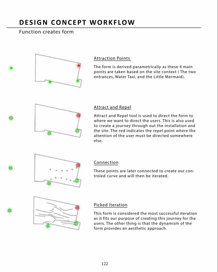
D ES I G N CO N C E P T WO R K F LOWFunction creates form
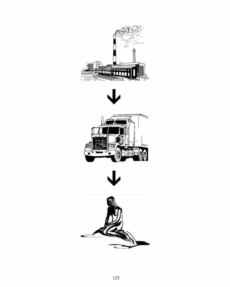
The form is derived parametrically as these 4 main points are taken based on the site context ( The two entrances, Water Taxi, and the Little Mermaid).
Attract and Repel tool is used to direct the form to where we want to direct the users. This is also used to create a journey through out the installation and the site. The red indicates the repel point where the attention of the user must be directed somewhere else.
These points are later connected to create our con-troled curve and will then be iterated.
This form is considered the most successful iteration as it fits our purpose of creating this journey for the users. The other thing is that the dynamism of the form provides an aesthetic approach.
Attraction Points
Attract and Repel
Connection
Picked Iteration

123

124
CO N ST R U C T I O N P RO C ES SPre Fabrication
The first step towards construction is the pre-
fabrication phase in the factory where the Pine
sheets timber is cut into pieces to form the sec-
tions. These sheets of timber is then transport-
ed to site, since no piece exceeds the standard
timber sheet not exceeding 300mm in lenght
it well be transported easily, some canopy
are customed and can be transported by wa-
ter/ship which can be then assembled in site.
At the same time of fabrication, the site can al-
ready be prepared for assembly, proccesses such
as excavation of site and preperation of concrete +
Piezo can already take place to not waste any time.
125

126
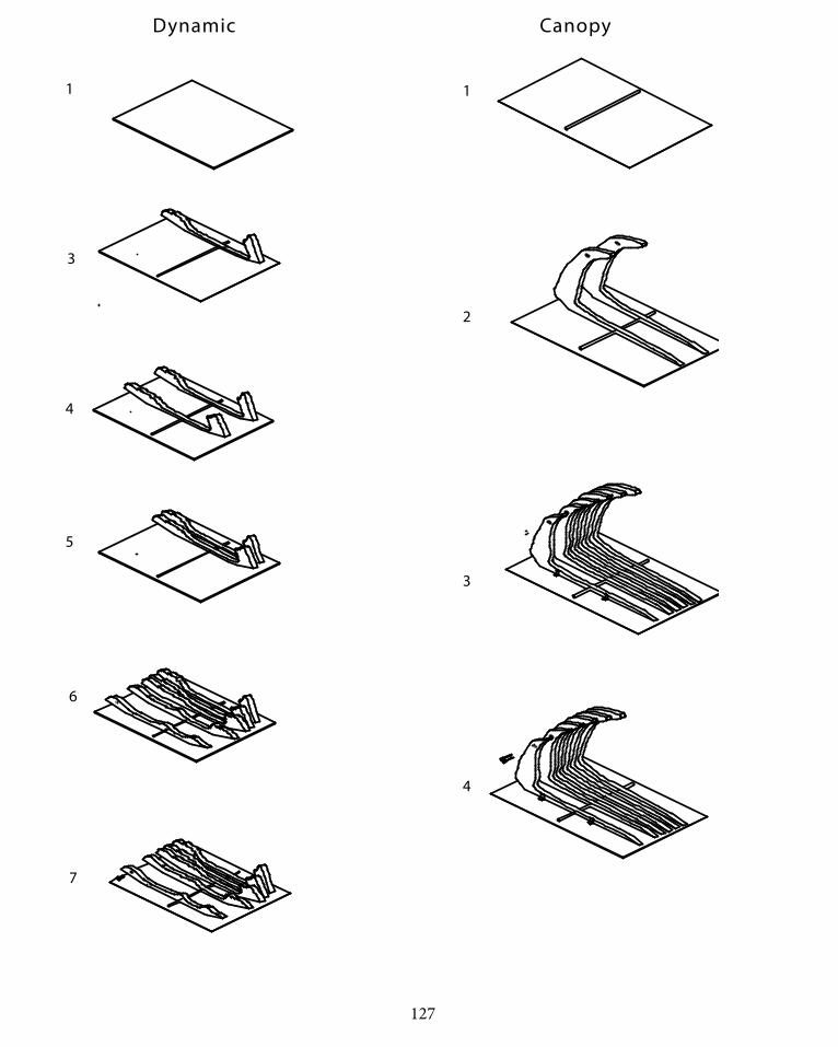
CO N ST R U C T I O N P RO C ES SIn-SITU
The on site construction follows the following
process:
- site excavation and site clearance
- Reinforced concrete laid on site, with Piezo in-
serted 5mm below concrete
- The plancement and bolting of the main struc-
tural rod on site
-Timber pieces are then arranged on sie and
bolted accordingly, the dynamic parts uses rubber
as their joining mechannism.
The steps are shown and potrayed in the diagrams
on the right.
127
CanopyDynamic
1
3
4
5
6
7
1
2
3
4
128
PA RT C . 2T E C TO N I C E L E M E N T S

129
C . 2 T E C T O N I C E L E M E N T S
Part C.2 revolves around the core construction
element of tge installation and the details which is
repeated across the design. By integrating proto-
types and detail drawing to show how the design
works and if the fabrication will be feasible. This
area will also explore the materials used and how
if it behaves as expected.
The tectonic elements and joints revolves around
our main concept and design criteria which
includes:
- Allowing flexible changes in our components from
dynamic to static and back to dynamic
- Allowing sections to give enough and stable pressure
to the ground to allow energy generation from the
Piezoelectric
- Structual integrity stability and safety for the users

130
CO R E CO N ST R U C T I O N E L E M E N TAssembly Process
1
2
3
STATIC DYNAMIC
HOLLOW CORE STEELCOATED PINE
TIMBER SHEET
STEEL BOLTS
REINFORCED CONCRETE SLAB
ELASTIC BAND
COATED PINE TIMBER SHEET
METAL PLATE & BOLTS
Steel Rod connection Henrich Rubber

131
STATICDYNAMIC STATIC
METAL PLATE & BOLTS
METAL PLATE & BOLTS
HOLLOW CORE STEEL
COATED PINE TIMBER SHEET COATED PINE
TIMBER SHEET
STEEL BOLTS
HOLLOW CORE STEEL
COATED PINE TIMBER SHEET
ELASTIC BAND
METAL PLATE & BOLTS
HOLLOW CORE STEEL
Our construction core element focuses on the joints between static and dynamic
elements and how the two works together. The diagrams above illutrate the compo-
nents needed in order for the two system to work cohesively together. The different be-
tween the two systems is that the section timber material on the static part is bolted to
the ground for stability and rigidity purposes, the dynamic parts have a different sys-
tem in which the base of the section timber is cut 30 degrees to allow a see-saw mo-
ement which allows user engagement and attraction. It is then connected together
with the static with the long rod and then is then bolted to the groun to avoid move-
ment which can cause the system to fail. The canopy works the same way as the static
which can be then connected to the dyamic component. The materials that would be
used is the Henrich rubber for the Dynamic which is a band for wood and Steel rod.

132
CO R E CO N ST R U C T I O N E L E M E N T PROTOTYPE from Kinetic to Light
Picture 1 Picture 2

133
Picture 2

134
PA RT C . 3F I N A L M O D E L

135
C . 3 . F I N A L M O D E L
Part C.3 is the fabrication and assembly of scaled
models and prototypes.

136
M O D E L M A K I N G P RO C ES S1:100 SCALED MODEL
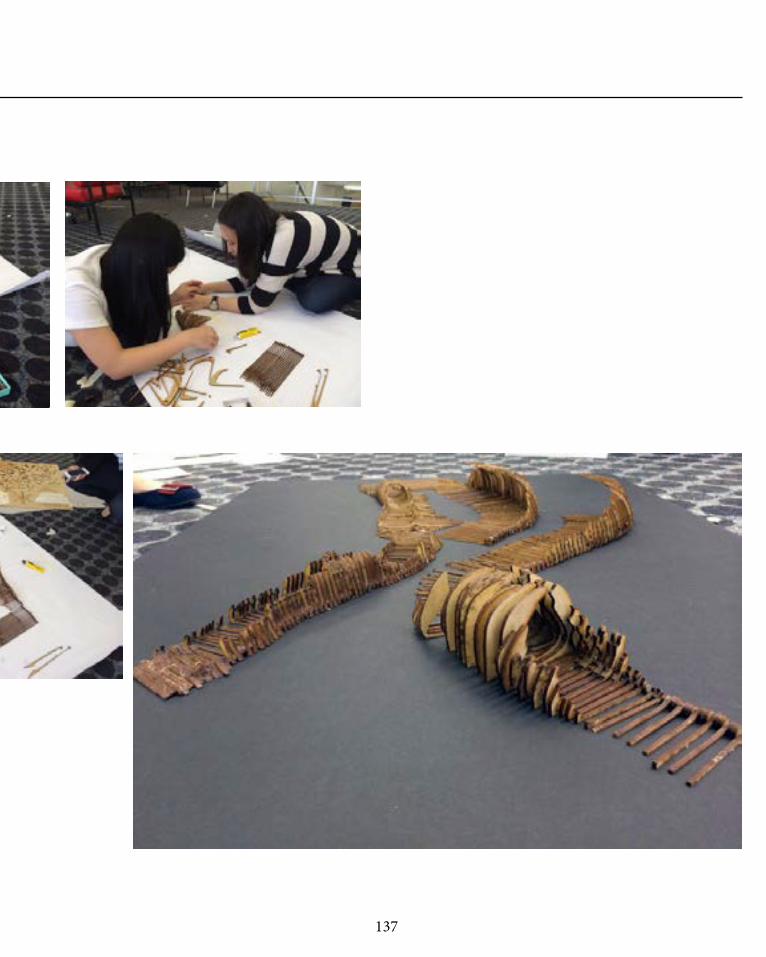
137
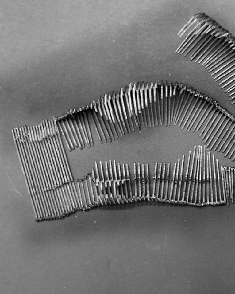
138

139

140

141

142

143

144

145

146

147

148
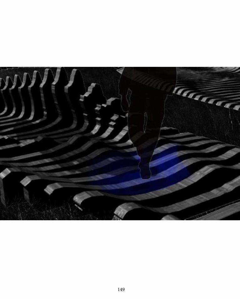
149

150
M O D E L M A K I N G P RO C ES SFabrication Template

151

152
PA RT C . 4A D D I T I O N A L L A G I B R I E F R E Q U I R E M E N T S

153
C . 4 L A G I B R I E F R E Q U I R E M E N T S
The Lagi brief was about creating awareness
through energy generation and how the design
can contribute to society and environment in en-
ergy generation and awareness. Our design was
developed by different ideas such as design fu-
turing and parametism. We have come up with
Kinetiskape, an interactive dynamic landscape
which can produce enough energy to self-sustain
and contribute to the environment. Kinetisk is a di-
rect translation from danish to english that means
kinetic, and in addition to that a landscape which
creates Kinetiskape. Our main idea is the engage-
ment of user with the site. Piezo is installed within
the concrete below the installation and everytime
a person engages or provides pressure to an area,
Light which is installed within each section will
light up to create awareness that through every-
day movement, enery can be saved and generted.
Thus the design of Kinetiskape.
Kinetiskape

154
M ate r i a l i t yPine Wood
Local Timber Used in Denmark: -Oak-Pine-Beech-Norway Spruce
Coated Pinesheet to reduce the rate of weathering, it is coated with intergrain wood oil (Natural and organic coat-ing); oil finish penetrates deep into the timber, preventing it from weathering.
-Pine Sheets are 30mm thick
Most forests in Denmark are pri-vately owned for generations, which is why timber is seen as a lega-cy and a heritage material (con-servation and production values).

155
OTHER MATERIALS:
Elastic Band Steel Rod
Bolts Concrete + Reinforcement

156
D e s i g n Te c h n o l o g y LED
LED: LIGHT EMITTING DIODES
Life Span (average) Watts used [= 60 Watt bulb] LED use less power (Watts) per unit of light emitted (lumens). This technology helps in reducing greenhouse gas emissions from power plants and lower electric bills
50,000 Hours 6-8 Watts
Kilo-Watts of Electricity Used 329 kWh/year Carbon Dioxide Emissions [30 bubls/year] Lower consumption, decreases CO2 emissions, sulfur dioxide, and high-level nuclear waste.
451 pounds/year
Durability Can Withstand jarring & Bumping Sensitivity to Humidity NO LUMENS WATTS 450 800 1,100 1,600 2,600 WATTS
4-5 6-8 9-13 16-20 25-30
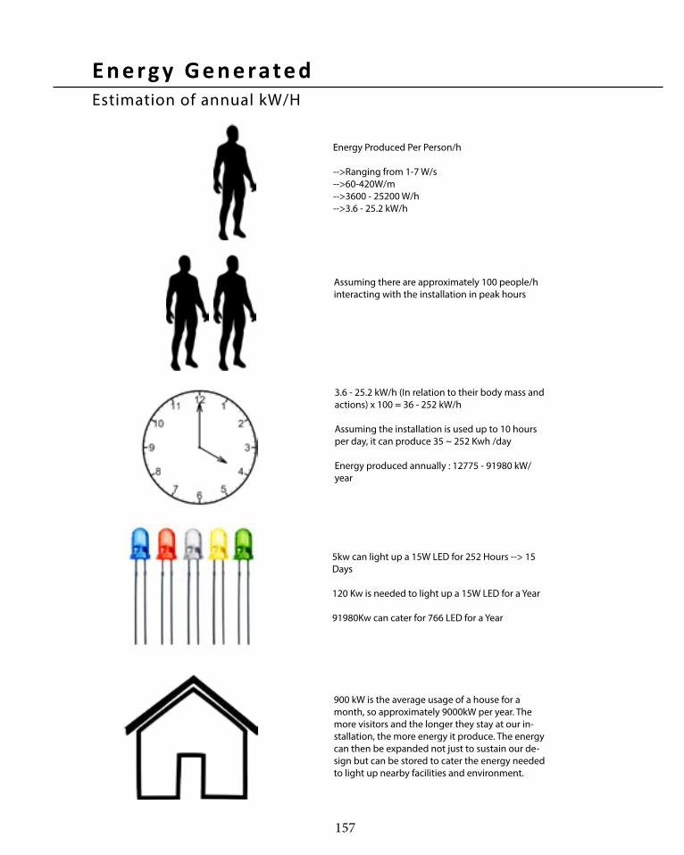
157
Energy Produced Per Person/h
-->Ranging from 1-7 W/s-->60-420W/m-->3600 - 25200 W/h-->3.6 - 25.2 kW/h
Assuming there are approximately 100 people/h interacting with the installation in peak hours
3.6 - 25.2 kW/h (In relation to their body mass and actions) x 100 = 36 - 252 kW/h
Assuming the installation is used up to 10 hours per day, it can produce 35 ~ 252 Kwh /day
Energy produced annually : 12775 - 91980 kW/year
5kw can light up a 15W LED for 252 Hours --> 15 Days
120 Kw is needed to light up a 15W LED for a Year
91980Kw can cater for 766 LED for a Year
900 kW is the average usage of a house for a month, so approximately 9000kW per year. The more visitors and the longer they stay at our in-stallation, the more energy it produce. The energy can then be expanded not just to sustain our de-sign but can be stored to cater the energy needed to light up nearby facilities and environment.
E n e rg y G e n e rate dEstimation of annual kW/H

158
E nv i ro n m e nta l I m p a c tPine Wood
Carbon Footprints
Low Embodied Energy
Recycling
Reduced Green House Emission
Less carbon footprints due to less green house emission, carbon is stored within the pine.
Total energyt o fabricate the timber uses less energy than other matrials such as concrete, solar panels etc.
Timber and and materials used is very easy to recycle
Green house is reduce as carbon is stored in the pine itself

159

160
PA RT C . 5L E A R N I N G O B J E C T I V E S
161
C . 5 L E A R N I N G O B J E C T I V E S
form which takes full advantage of its material sys-
tem. During my exploration of sectioning I have
noticed how it is more superior to other material
systems. Firstly Sectioning does not restrict shapes
in comparison to other material system, it allows
even the most dynamic shape to be make possible
to construct. Second, it does not necessarily create
an angular surface like tessellation which allows us
to design our form more freely etc. Lastly, with ex-
ploration in Part B and C we have noticed that it is
possible to achieve more dynamic results varying
from basic shapes to complex shapes.
During the final presentation one of the main com-
ments made by the crits are the face that we didn’t
make use of the total potential of sectioning as we
could have used different types of sectioning for
different functions which can take advantage of
the advantage of each type of sectioning. For ex-
ample for the canopy we could have used Cull pat-
terning (Same length of material and easy to fab-
ricate while saving material for fabrication due to
the template) for the canopy and not the vertical
sectioning. During the break after the final presen-
tation we have refined our design further to show
that we understood and made use of the material
system we explored.
Part.C by far has been the most difficult part to
overcome. This is because we have to develop our
prototype from part B to become more site specific
using parametric tools which take us most time to
figure out. The hardest part of this section is how
we have to think about the limitations and poten-
tial of our material system and how we have to de-
sign in a way that takes advantage of sectioning. In
this section I have learnt so much about sectioning
as a material system and as a construction tool. For
our design we have decided to use vertical section-
ing as it allows users to exert most pressure to the
Piezo which can create most energy rather than
other sectioning tools explored in part B which
is unfeasible to design with our concept. Part.C
has allowed me to explore parametric design to
a whole new level has allowed me to know more
about it advantages also disadvantages.
Before this studio I had no idea how valuable para-
metric design is, I have started to appreciate para-
metric and how it is generated. Designing keep the
idea of Design futuring and computational design
has made me appreciate how forms generated
by these ideas are not random but based on data
itself. I think this subject has pushed me to think
more about the environment and how the site
context can help me generate

162
F u r t h e r D e ve l o p m e nt
1. We have changed our method of creating form
to make it easier for construction. Now no matter
how dynamic the shape may be, it will only utilize
one type of timber which can be easily fabricated
which uses cull patterning similar to Dunescape.
As shown in Diagram 2, we can see how it con-
nects together and no matter how dynamic the
shape is it can be created with single strips of
timber connected together. This not only saves
material but also costs of transport to site.
2. The second is our fabrication template which
can be seen in Diagram 3. The difference in tech-
nique can affect greatly on the materials used
and wasted for this project. As seen, the refined
template doesn’t waste material whereas we wast-
ed more money on our first fabrication template
which supports fry’s design futuring (2008).
One of the main aspects that need to be im-
proved is the fact that we did not manipulate and
explore the full potential of different types of sec-
tioning and the feasible of construction and trans-
portation means. In our previous concept, the can-
opy was assembled as a single piece with vertical
sectioning without dividing it or cutting the piece
to smaller sections, not only can it save materials
but also easier construction. We have made pro-
totype in part B using the cull patterning method
and it failed as it wasn’t being able to support itself
(Diagram 1). We have developed our failed proto-
type into more separate pieces so it can support
itself. Therefore, for our refined design we have
taken advantage of our reverse engineering “Dun-
escape” methods of construction.
Cull Patterning
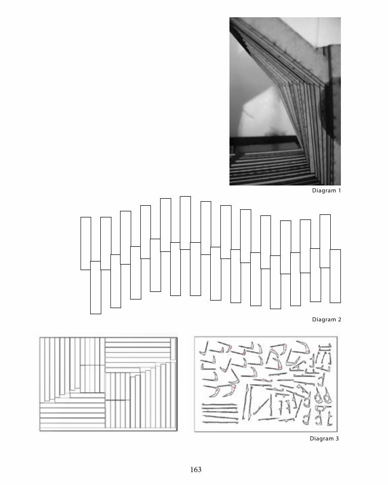
163
Diagram 1
Diagram 2
Diagram 3

164
F u r t h e r D e ve l o p m e ntAA Driftwood
The second change we made is how we manipu-
late sectioning to create and form space. One of
the feedbacks we got is how we did not take ad-
vantage of the sectioning types we did in part.B.
In this new refined case we used the driftwood
precedent type of sectioning where the sectioning
curve is the control curve that controls the whole
sectioning form.
In our first part we thought that AA driftwood
would not fit our design concept as it would be im-
possible to fabricate, but when we thought of how
these pieces can be made up with more than one
sections, we tried modifying and refining our form
which created a more dynamic space in the whole.
The diagram on the right shows the driftwood pat-
tern we explored in part B piped, for the purpose of
this design we have changed it to surfaces instead
of pipes.

165
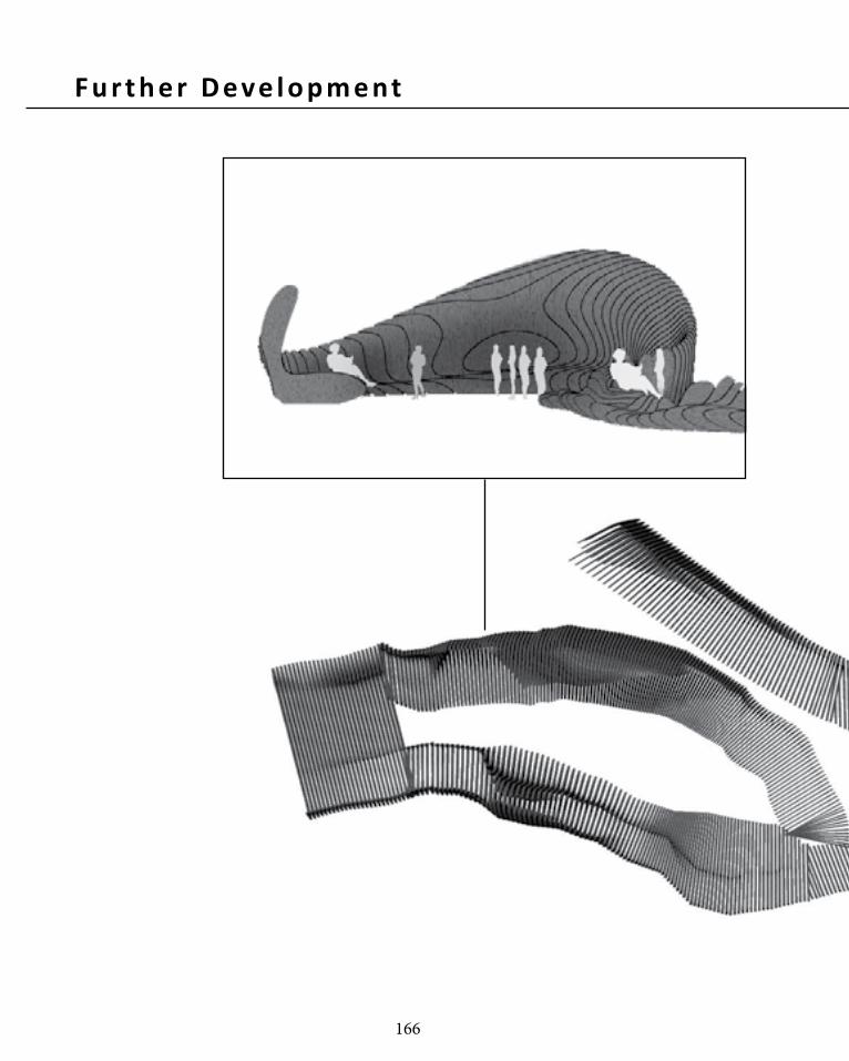
166
F u r t h e r D e ve l o p m e nt

167
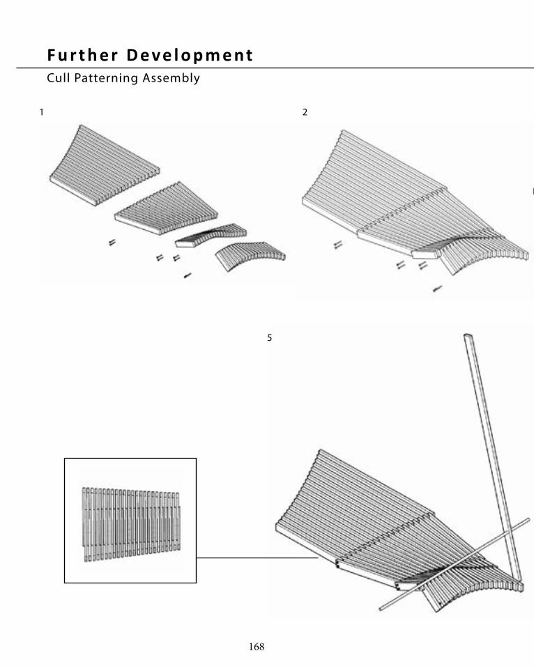
168
F u r t h e r D e ve l o p m e ntCull Patterning Assembly
1 2
5

169
3 4
6

170
F u r t h e r D e ve l o p m e ntCull Patterning

171

172
F u r t h e r D e ve l o p m e ntCull Patterning

173
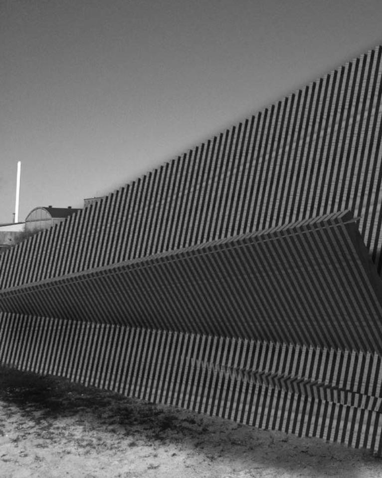
174

175

176
F u r t h e r D e ve l o p m e ntAA Driftwood Assembly
HOLLOW CORE STEEL
COATED PINE TIMBER SHEET
STEEL BOLTS
REINFORCED CONCRETE SLAB
METAL PLATE & BOLTS
COATED PINE TIMBER SHEET
ELASTIC BAND
METAL PLATE & BOLTS
STATIC DYNAMIC

177
HOLLOW CORE STEEL
COATED PINE TIMBER SHEET
REINFORCED CONCRETE SLAB
METAL PLATE & BOLTS
DYNAMIC

178
F u r t h e r D e ve l o p m e ntAA Driftwood Assembly

179

180

181
182
R E F E R E N C E S
Ferry, Robert & Elizabeth Monoian, ‘A Field Guide to Renewable Energy Technologies’’, Land Art Generator Initiative, Copenhagen, 2014. pp 1 - 71
Fry, Tony (2008). Design Futuring: Sustainability, Ethics and New Practice (Oxford: Berg), pp. 1–16
Dunescape, Shop Architects, http://www.shoparc.com/project/Dunescape-at-MoMA-PS1
Dunescape, Shop Architects, http://www.diisign.com/en/2010/03/for-shop-architects-pre-fab-is-pretty-fab/
Kolarevic, Branko and Kevin R. Klinger, eds (2008). Manufacturing Material Effects: Re-thinking Design and Making in Architecture (New York; London: Routledge), pp. 6–24
Oxman, Rivka and Robert Oxman, eds (2014). Theories of the Digital in Architecture (London; New York: Routledge), pp. 1–10
Margaret Rouse, 2012, http://whatis.techtarget.com/definition/piezoelectricity
Peters, Brady. (2013) ‘Realising the Architectural Intent: Computation at Herzog & De Meuron’. Architectural Design, 83, 2, pp. 56-61
Piezoelectric materials and pictures, 2012 http://www.piezo.com/prodbm8dqmpict760.jpg
Polymorphic Bench, GSAPP, USA, http://www.jennchang.com/8.html
Stan Giblisco, 2012, http://whatis.techtarget.com/definition/piezoelectricity

183