as 1345-1995 contents of pipes
TRANSCRIPT

AS 1345—1995
Australian Standard
Identification of the contents ofpipes, conduits and ducts
Acc
esse
d by
Clo
ugh
Eng
inee
ring
on 0
9 A
ug 2
001
This Australian Standard was prepared by Committee SF/16, Identification of Pipes.It was approved on behalf of the Council of Standards Australia on24 November 1994 and published on 5 March 1995.
The following interests are represented on Committee SF/16:
Australian Chamber of Commerce and Industry
Australian Gas Association
Australian Institute of Petroleum
Institute of Hospital Engineering, Australia
Public Works Department, N.S.W.
Society of Fire Protection Engineers
Water Board Sydney—Illawarra—Blue Mountains
Review of Australian Standards. To keep abreast of progress in industry, Australian Standards aresubject to periodic review and are kept up to date by the issue of amendments or new edit ions asnecessary. It is important therefore that Standards users ensure that they are in possession of the latestedit ion, and any amendments thereto.
Full details of all Australian Standards and related publications wil l be found in the Standards AustraliaCatalogue of Publications; this information is supplemented each month by the magazine ‘TheAustralian Standard’, which subscribing members receive, and which gives details of new publications,new edit ions and amendments, and of withdrawn Standards.
Suggestions for improvements to Australian Standards, addressed to the head office of StandardsAustralia, are welcomed. Noti fication of any inaccuracy or ambiguity found in an Australian Standardshould be made without delay in order that the matter may be investigated and appropriate action taken.
This Standard was issued in draft form for comment as DR 93250.
Acc
esse
d by
Clo
ugh
Eng
inee
ring
on 0
9 A
ug 2
001
AS 1345—1995
Australian Standard
Identification of the contents ofpipes, conduits and ducts
First published as AS (E)CA503 — 1942.Revised and redesignated AS CA21 — 1947.Second edition 1967.Revised and redesignated AS 1345— 1972.Second edition 1982.Third edition 1995.
PUBLISHED BY STANDARDS AUSTRALIA(STANDARDS ASSOCIATION OF AUSTRALIA)1 THE CRESCENT, HOMEBUSH, NSW 2140
ISBN 0 7262 9532 9
Acc
esse
d by
Clo
ugh
Eng
inee
ring
on 0
9 A
ug 2
001
AS 1345— 1995 2
PREFACE
This Standard was prepared by the Standards Australia Committee on Identification ofPipes, to supersede AS 1345—1982.
The basic colour scheme for pipe identification remains virtually the same as it was in the1982 edition, as does the design and use of pipe markers. The only significant differenceis the inclusion of a dark-blue supplementary colour to be used as an additional colourband around pipes carrying materials for human consumption.
A number of other changes have been made to the Standard with a view to making iteasier to understand and use by practitioners. For example, the tabulation of base coloursand their uses now includes a series of illustrative examples of where each colour should,and should not be used.
As regards the specification of colour, the Standard now provides both for a target colourfor matching colour-mixed surface finishes such as paints, and a colour tolerance whereready-made materials such as adhesive films or as-supplied pipe colour are to beconsidered.
In the Foreword to the 1982 edition it was noted that the colour system adopted in thatStandard was based on the International Standard ISO/R 508*. The Committee observedat that time that this International Standard had been approved by many ISO memberbodies and that it applied to shipping as well as land installations. Furthermore, therequirements of ISO/R 508 were considered to possess intrinsic merit in that the numberof colours were reduced to a minimum and the colours given were sufficiently distinctfrom one another to be separately identifiable when seen in isolation. Although ISO/R 508has since been withdrawn, action to issue a revision has started. It is likely, however, tobe some considerable time before a revised ISO Standard is available. It was thereforeconsidered inappropriate to delay the development of this edition of this Standard.
The term ‘informative’ has been used in this Standard to define the application of theappendix to which it applies. An ‘informative’ appendix is only for information andguidance.
* Identification colours for pipes conveying fluids in liquid or gaseous condition in land installations and onboard ships.
Copyright STANDARDS AUSTRALIA
Users of Standards are reminded that copyright subsists in all Standards Australia publications and software. Except where theCopyright Act allows and except where provided for below no publications or software produced by Standards Australia may bereproduced, stored in a retr ieval system in any form or transmitted by any means without prior permission in writ ing fromStandards Australia. Permission may be condit ional on an appropriate royalty payment. Requests for permission and informationon commercial software royalt ies should be directed to the head office of Standards Australia.
Standards Australia wil l permit up to 10 percent of the technical content pages of a Standard to be copied for useexclusively in-house by purchasers of the Standard without payment of a royalty or advice to Standards Australia.
Standards Australia wil l also permit the inclusion of its copyright material in computer software programs for no royaltypayment provided such programs are used exclusively in-house by the creators of the programs.
Care should be taken to ensure that material used is from the current edition of the Standard and that it is updated whenever theStandard is amended or revised. The number and date of the Standard should therefore be clearly identif ied.
The use of material in print form or in computer software programs to be used commercially, with or without payment, or incommercial contracts is subject to the payment of a royalty. This policy may be varied by Standards Australia at any time.
Acc
esse
d by
Clo
ugh
Eng
inee
ring
on 0
9 A
ug 2
001
3 AS 1345— 1995
CONTENTS
Page
FOREWORD . . . . . . . . . . . . . . . . . . . . . . . . . . . . . . . . . . . . . . . . . . . . . . . . . . . 4
1 SCOPE . . . . . . . . . . . . . . . . . . . . . . . . . . . . . . . . . . . . . . . . . . . . . . . . . . . . 52 APPLICATION . . . . . . . . . . . . . . . . . . . . . . . . . . . . . . . . . . . . . . . . . . . . . . 53 REFERENCED DOCUMENTS . . . . . . . . . . . . . . . . . . . . . . . . . . . . . . . . . . . 54 DEFINITIONS . . . . . . . . . . . . . . . . . . . . . . . . . . . . . . . . . . . . . . . . . . . . . . . 65 IDENTIFICATION SYSTEM . . . . . . . . . . . . . . . . . . . . . . . . . . . . . . . . . . . . 66 BASE IDENTIFICATION COLOUR . . . . . . . . . . . . . . . . . . . . . . . . . . . . . . . 67 PIPE MARKERS . . . . . . . . . . . . . . . . . . . . . . . . . . . . . . . . . . . . . . . . . . . . . 78 SUPPLEMENTARY COLOURS AND HAZARD IDENTIFICATION . . . . . . . . 119 LOCATION AND FORM OF IDENTIFICATION MARKINGS . . . . . . . . . . . . 11
10 JACKETED PIPES . . . . . . . . . . . . . . . . . . . . . . . . . . . . . . . . . . . . . . . . . . . . 1511 ADDITIONAL WARNING NOTICES . . . . . . . . . . . . . . . . . . . . . . . . . . . . . . 15
APPENDICESA METHODS OF IDENTIFICATION SPECIFIED IN OTHER
STANDARDS . . . . . . . . . . . . . . . . . . . . . . . . . . . . . . . . . . . . . . . . . . . . . . 16B CHROMATICITY DIAGRAM FOR IDENTIFICATION COLOURS
USED ON PIPES . . . . . . . . . . . . . . . . . . . . . . . . . . . . . . . . . . . . . . . . . . . 17C GUIDE TO SERVICES REQUIRING HAZARD IDENTIFICATION . . . . . . . 19
Acc
esse
d by
Clo
ugh
Eng
inee
ring
on 0
9 A
ug 2
001

AS 1345— 1995 4
FOREWORD
This Standard relies fundamentally on a single colour identification system. It is notpossible to provide for all situations in such a system. Furthermore, because colours maybe seen in isolation from one another, the absolute number of colours available is limitedand is considerably less than the ideal number of categories which might otherwise beprovided for pipe contents. For this reason, in selecting an appropriate colour, workersafety is one of the most important concerns. For example, the colour for acids and alkaliswould be applied only where a potential corrosive hazard existed, and not to highlydiluted acids or alkalis such as might be found in waste water or liquid foodstuff.
More detailed information on the contents of a pipe is provided, firstly, by the use of twospecial supplementary colours, yellow to indicate especially hazardous material and darkblue for materials for human consumption. The second means is by use of pipe markerswhich include words to describe the contents. Symbols for radioactive and biologicalhazards are also used.
The Standard sets out principles which should be considered in the planning of a schemefor identification of piping. Individual undertakings may find it necessary to depart fromthese principles in the application of markings in particular localities. However, thisshould only be done in extreme circumstances where adherence to the general principlescannot possibly be maintained and special care is taken to ensure that no colour is usedfor a purpose which conflicts with this Standard to the degree that either safety oroperational efficiency is compromised.
The principles of this Standard should be applied to the identification of buried and othernormally inaccessible services. However, it is recognized that such application maypresent difficulties and for this reason no normative requirements have been specified.
Acc
esse
d by
Clo
ugh
Eng
inee
ring
on 0
9 A
ug 2
001

5 AS 1345— 1995
STANDARDS AUSTRALIA
Australian Standard
Identification of the contents of pipes, conduits and ducts
1 SCOPE This Standard specifies means of identifying the contents of pipes, conduits,ducts and sheathing used to contain fluids, or for the distribution of electrical orcommunications services in land installations and on board ships, by the use of colours,words and symbols. It is not intended to apply to buried or normally inaccessible services.However, the general principles may be applied when considering those services.
NOTE: It is recognized that application of this Standard to buried services may presentdifficulties and for this reason only general guidance is offered.
2 APPLICATION It is recognized that in certain industries and applications there areconsistent and widely recognized colour coding systems in use other than that specified inthis Standard. Use of alternative systems is acceptable under this Standard in thefollowing circumstances:
(a) In installations normally inaccessible other than to operators and emergencyresponse personnel trained in the coding system in use; where different serviceswould otherwise have predominantly the same identification colour, andsupplementary or alternative identification is desirable for operational reasons butdoes not compromise safety.
(b) In areas in public view where use of the basic identification colour would not beaesthetically acceptable. In such cases all required colours and markers shall beplaced on the pipe as soon as it has disappeared from public view, e.g. through awall or bulkhead. If word descriptions are required on the service they may beplaced in a contrasting colour on the decorative colour in public view.
Appendix A lists known examples of alternative systems and the Standards in which theyare specified or described.
NOTE: Additional Standards may be included in future editions of this Standard. Enquiries inthis regard may be made to Standards Australia Head Office quoting Committee Number SF/16.
3 REFERENCED DOCUMENTS The following documents are referred to in thisStandard:
AS1169 Minimizing of combustion hazards arising from the medical use of flammable
anaesthetic agents
1596 LP gas—Storage and handling
1744 Forms of letters and numerals for road signs
2700 Colour standards for general purposes
2896 Medical gas systems—Installation and testing of non-flammable medical gaspipeline systems
3000 Electrical installations—Buildings, structures and premises (know as the SAAWiring Rules)
3500 National Plumbing and Drainage Code
COPYRIGHT
Acc
esse
d by
Clo
ugh
Eng
inee
ring
on 0
9 A
ug 2
001

AS 1345— 1995 6
Federal Office of Road SafetyAustralian Code for the Transport of Dangerous Goods by Road and Rail
Australian Institute of PetroleumCP5 Code of Practice for Pipeline Identification
4 DEFINITIONS For the purposes of this Standard, the definitions below apply.
4.1 Normally inaccessible—intimately contained within a mass of material or in aninaccessible duct or enclosure to which access cannot normally be gained. The termincludes services within a securely isolated enclosure to which entry is denied to all butauthorized personnel who have detailed knowledge of the contents of pipes within theenclosure.
4.2 Normative requirement—a requirement which it is necessary to meet if theStandard is to be implemented.
4.3 Pipe—a transport medium through which fluids flow or which contains electrical orcommunication circuits. The term includes conduits, ducts and sheathing when used forthis purpose.
4.4 Shall—indicates that a statement is mandatory.
4.5 Should—indicates a recommendation.
4.6 May—indicates the existence of an option.
5 IDENTIFICATION SYSTEM The system for pipe identification comprises thefollowing elements:
(a) The base identification colour—which is a single colour, selected in accordancewith Clause 6, and which may cover all or part of the pipe as set out in Clause 9. Itis required in all cases. The natural or as-manufactured colour of the pipe need notnecessarily comply with this Standard, except where a potentially hazardous conflictmight arise, e.g. the use of a green pipe to carry a corrosive substance.
(b) Pipe marker—which comprises one or more words on a label identifying either thecontents or the hazardous nature of the contents, or both, in accordance withClause 7. The words are placed on a background of the base identification colourwith an outer contrasting border. The pipe marker is a normative requirement onlyin certain conditions (see Clause 7).
(c) Supplementary colours—which comprise a band or panel of a different colour usedto indicate an additional attribute of the contents of the pipe, i.e. contents for humanconsumption or contents of a hazardous nature. Symbols for radiation and biologicalhazard, where relevant, are placed within the band or panel. Where required inaccordance with Clause 8, the use of supplementary colours is a normativerequirement.
6 BASE IDENTIFICATION COLOUR
6.1 General The objective of the base identification colour is to provide immediateinformation as to the contents of the pipe in broad terms. The relative hazard of apotential contents leak or spill to operations and maintenance workers, and moreparticularly, crews responding to emergency calls, will usually be the critical factor indetermining which colour is appropriate in a particular case.
NOTE: Further discussion on the objective of the base identification colour is given in theForeword.
Other colour codings which are provided largely for the convenience of operations andmaintenance workers are as follows (see also Table 1):
COPYRIGHT
Acc
esse
d by
Clo
ugh
Eng
inee
ring
on 0
9 A
ug 2
001

7 AS 1345— 1995
(a) Water—the distinction is made between pipes primarily carrying water, e.g. potable,mildly contaminated waste, cooling/heating, which will be green, and solutions ofother materials in water such as foodstuffs and organic waste, which in most caseswill be black.
(b) Air and other gases—the distinction is made between pipes carrying only air,e.g. compressed, vacuum, ventilation, which will be light blue, and all other gases,including pneumatic transport of particulate solids, which may be yellow-ochre orviolet.
(c) Fire services—these are coloured red even though they carry a material whichcould be classified elsewhere.
6.2 Application of colours The colours which shall be used as base identificationcolours for pipes (see Clause 5(a)) together with guidance on where each should be used,are shown in Table 1 and specified in Clause 6.3.
6.3 Colour specification The colours to be used for the purposes listed in Table 1shall be as specified in Table 2. Two forms of specification are given in the Table,as follows:
(a) Target colour This colour is shown in heavy type by name and reference numberin accordance withAS 2700, in the second and third column. It shall be used forcolour matching wherever a paint or other colour mixed surface finish is to be used.
(b) Colour with tolerance Where an in-built pipe colour or the colour of amanufactured film is to be considered as the pipe colour for the purposes of thisStandard, it shall be acceptable if it lies within the colour space and the luminancefactor limits specified in accordance with the CIE Chromaticity Coordinate systemin columns four to six of Table 2. These colour spaces are illustrated on the CIEChromaticity Chart at Appendix B, which also gives an abbreviated explanation ofthe CIE Chromaticity Coordinate System. The non-preferred colours in the secondcolumn of Table 2, in lighter type, fall within the corresponding colour space, andmay be used in lieu of the preferred colour when materials of those colours aresupplied.
7 PIPE MARKERS
7.1 General description Pipe markers comprise either a printed label which can beaffixed to a pipe or the equivalent colours and information signwritten directly onto thepipe or incorporated into the pipe at manufacture. Markers shall show the followinginformation:
(a) A word or words indicating the contents of the pipe and, if desired, some especiallyhazardous aspect of the pipe, e.g. high pressure, high voltage, toxic waste; or both.The words shall be in either white or black letters as shown in Figure 1.
(b) A background colour generally in the form of a rectangular colour identificationblock large enough to accommodate the words, such colour being the basicidentification colour from Table 1. See also the alternative form specified inClause 7.2.3 for small services.
(c) A contrasting border around the colour identification block as shown in Figure 1.The border colour should normally be white but may be yellow if a hazardidentification patch or band is to be used with the marker.
(d) A chevron within the border, if required, to indicate the direction of flow in a pipecarrying a liquid or gas.
A typical pipe marker is illustrated in Figure 1.
COPYRIGHT
Acc
esse
d by
Clo
ugh
Eng
inee
ring
on 0
9 A
ug 2
001

AS 1345— 1995 8
TABLE 1
PIPE IDENTIFICATION COLOURS AND THEIR USES
Colour name andbasic identification
Colour Applications (see Note 1) Exclusions (see Note 1)
Green— water
Drinking water (see Note 2)Waste waterCooling water, including seawaterHeating waterStorm waterHydraulic power supplyRecycled water
Sewage, and other dangerouslypolluted waste water
Silver-grey— steam
Live steamProcess steamExhaust steamSpace heating steam
Brown— oils, flammable andcombustible liquids
Fuel and lubricating oilsAnimal and vegetable oils for foodprocessing (see Note 2)Petrol, diesel and other light fractionfuelsOther flammable or combustible liquidsubstances
Liquefied gases under pressure
Yellow-ochre— gases
Fuel gasesProcess gasesLiquefied gases under pressurePneumatic transport of particulate solidsExhaust gases and fumesMedical gases (see Note 2)
AirHighly acid or alkaline gases
Violet— acids and alkalis
All corrosive liquids and gases
Light blue— air
Compressed airInstrument airVacuumVentilationPneumatic conveyor
Black— other liquids
Chemical mixtures in water or organicsolventLiquid foodstuffs (see Note 2)Sewage, organic wasteChemical and process wastes
Corrosive materialsFlammable or combustiblematerial
Red— fire services
Dedicated water, foam, other fireextinguishing supply lines
Electrical supplyCommunication circuits
Orange— electric power
Electricity supply circuits Extra-low voltage circuits
White— communications
Telephone and other communicationcircuitsExtra-low voltage supply
NOTES:1 The list of applications in the third column and exclusions in the fourth column may not be exhaustive.2 Services containing materials for human consumption have a supplementary colour (see Clause 8.1).
COPYRIGHT
Acc
esse
d by
Clo
ugh
Eng
inee
ring
on 0
9 A
ug 2
001
9 AS 1345— 1995
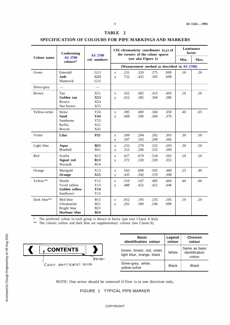
TABLE 2
SPECIFICATION OF COLOURS FOR PIPE MARKINGS AND MARKERS
Colour nameConforming
AS 2700colours*
AS 2700ref. numbers
CIE chromaticity coordinates (x,y) ofthe corners of the colour spaces
(see also Figure 1)
Luminancefactor
Min. Max.
(Measurement method as described inAS 2700)
Green EmeraldJadeShamrock
G13G21G23
xy
.231
.752.320.425
.275
.395.009.698
.10 .20
Silver-grey — —
Brown TanGolden tanBrownNut brown
X51X53X54X55
xy
.452
.412.482.385
.415
.360.403.380
.10 .20
Yellow-ochre StrawSandSandstoneRaffiaBiscuit
Y24Y44Y53X31X42
xy
.385
.408.400.390
.360
.360.350.370
.40 .65
Violet Lilac P23 xy
.309
.297.294.165
.262
.200.303.306
.30 .50
Light blue AquaBluebell
B25B41
xy
.255
.312.278.290
.232
.255.203.300
.30 .50
Red ScarletSignal redWaratah
R12R13R14
xy
.627
.372.670.330
.524
.330.502.353
.10 .20
Orange MarigoldOrange
X13X15
xy
.563
.435.608.392
.505
.370.480.398
.25 .40
Yellow** WattleVivid yellowGolden yellowSunflower
Y12Y13Y14Y15
xy
.510
.488.547.452
.485
.421.460.448
.40 .60
Dark blue** Mid blueUltramarineBright blueHarbour blue
B15B21B23B24
xy
.052
.262.195.300
.235
.246.105.098
.10 .20
* The preferred colour in each group is shown in heavy type (see Clause 6.3(a)).** The colours yellow and dark blue are supplementary colours (see Clause 8).
Basicidentification colour
Legendcolour
Chevroncolour
Green, brown, red, violet,light blue, orange, black
WhiteSame as basicidentification
colour
Silver-grey, white,yellow-ochre
Black Black
NOTE: One arrow should be removed if flow is in one direction only.
FIGURE 1 TYPICAL PIPE MARKER
COPYRIGHT
Acc
esse
d by
Clo
ugh
Eng
inee
ring
on 0
9 A
ug 2
001

AS 1345— 1995 10
7.2 Size
7.2.1 Letters Lettering on markers should be large enough to be readily read bypersons with normal eyesight at the maximum distance at which the marker needs to beread. Letters shall be as specified inAS 1744. Series C or D capitals are recommended.As a guide, under good visibility conditions, a letter height of at least 1 mm for each0.4 m of required reading distance should be provided. This may not be achievable onsmall services. In such cases the maximum practicable letter size shall be used. Except forsmall services (see Clause 7.2.3) the minimum letter height shall be as shown in Table 3.
7.2.2 Colour identification block Except for small services (see Clause 7.2.3), theheight of the background patch shall be at least one and a half times the letter heightrequired in Clause 7.2.1, or that given in Table 3, whichever is the greater.
TABLE 3
MINIMUM HEIGHT OF PIPE MARKERCOLOUR PATCHES AND LETTERS
millimetres
Size of service(outside diameteror depth of side)
Minimum height ofbackground patch
Minimum letter height
<4040 to 75
>75
See Clause 7.2.32550
1224
The length of the patch shall be either the length of the word or words plus 25 mm ateach end of the legend, or 375 mm, whichever is the greater.
7.2.3 Small services The basic identification colour for use on pipes of less than40 mm outside diameter shall be a continuous band around the circumference of the pipewith the word or words, where required, in not less than 4 mm upper-case letters placedlongitudinally along the pipe and repeated several times around the circumference so thatthey are visible from all viewing directions.
7.3 Application
7.3.1 Normative requirements Pipe markers shall be used in the followingcircumstances:
(a) Wherever hazard identification (see Clause 8.2) is required.
(b) Wherever there are several pipes side by side with the same base identificationcolour but different contents, and confusing one with another could have seriousconsequences.
(c) Where a pipe needs to be quickly identified in detail in an emergency.
(d) Wherever required by another Australian Standard or a legal requirement.
7.3.2 Requirements which are not normativeIn addition to the normative requirements,pipe markers may be used to identify in detail the contents of any pipe.
Wherever pipe markers are used on a pipe, all nearby pipes, in particular those with thesame base identification colour, should also have pipe markers.
7.4 Informative labelling When supplied, pipe markers shall be accompanied by thefollowing information, either stamped on or included in packaging, or printed on eachitem:
(a) The pipe size range for which the markers are suitable.
(b) The way the marker is intended to be placed on the pipe.
COPYRIGHT
Acc
esse
d by
Clo
ugh
Eng
inee
ring
on 0
9 A
ug 2
001

11 AS 1345— 1995
(c) Recommended locations along the pipe.
(d) Use of the chevron to indicate flow direction.
8 SUPPLEMENTARY COLOURS AND HAZARD IDENTIFICATION
8.1 Materials for human consumption Wherever it is considered that a hazardinvolving the contamination of materials for human consumption could arise, e.g. byreason of insufficiently well-identified pipes being adjacent to other pipes which mightcarry contaminants, the pipes carrying materials for human consumption shall in additionto the base colour be identified by a band of dark-blue colour at least 75 mm wide (smallservices excepted, see Clause 9.3), displayed in conjunction with the base colour band orpipe marker.
Services to which this requirement might apply would include—
(a) potable water;
(b) foodstuffs;
(c) other liquids for human consumption; and
(d) medical gases.
8.2 Hazard identification Wherever a special hazard to operators or maintenancepersonnel is present within a service, a yellow band or patch at least 75 mm wide (25 mmfor small services, see Clause 9.3) shall be displayed in conjunction with each pipemarker. The yellow band shall carry the additional markings illustrated in Figure 3,as follows:
(a) If contaminated with ionizing radiation, the radiation symbol shown in Figure 2(a).
(b) If contaminated with biologically hazardous material, the biological hazard symbolshown in Figure 2(b).
(c) In all other cases, alternate diagonal black and yellow stripes of equal width asshown in Figure 3.
NOTE: As a guide, an indication of the type and extent of hazards which could requirehazard identification is given in Appendix C.
9 LOCATION AND FORM OF IDENTIFICATION MARKINGS
9.1 General requirements Identification markings comprising either bands of baseidentification colour or pipe markers as required (see Clause 7.3) shall be located adjacentto all junctions, valves, service appliances, bulkheads, wall penetrations and the like, andat spacings not greater than 8 m along the service. An exception will be for uninterruptedlengths of external services, visible along their length, where the spacing of theidentification shall not exceed 50 m. Typical examples are shown in Figure 4.
Where pipe markers are a normative requirement under Clause 7.3.1 all identificationmarkings required under this Clause shall be pipe markers.
9.2 Form of marking Identification marking for other than small services (seeClause 9.3), shall be provided as specified elsewhere in this Standard, in one of thefollowing forms:
(a) The base identification colour applied to the full length of the service.
(b) The base identification colour in bands not less than 375 mm in length, located inaccordance with Clause 9.1.
(c) A pipe marker in accordance with Clause 7, located in accordance with Clause 9.1.
(d) A pipe marker with band of supplementary colour or hazard identification inaccordance with Clause 8.
(e) A combination of either Item (c) or Item (d) with Item (a).
COPYRIGHT
Acc
esse
d by
Clo
ugh
Eng
inee
ring
on 0
9 A
ug 2
001

AS 1345— 1995 12
FIGURE 2 SYMBOLS FOR IONIZING RADIATION AND RADIATION AND BIOLOGICAL HAZARD
COPYRIGHT
Acc
esse
d by
Clo
ugh
Eng
inee
ring
on 0
9 A
ug 2
001

13 AS 1345— 1995
FIGURE 3 EXAMPLES OF IDENTIFICATION MARKINGS ON HAZARDOUS SERVICES
9.3 Small services Services less than 40 mm in outside diameter shall haveidentification markers which may be reduced in size to not less than the following:
(a) Length of base colour band or pipe marker . . . 70 mm.
(b) Length of supplementary colour or hazard identification band or patch . . . 25 mm.
9.4 Multiple pipe installations Where several pipes are to be identified at the onelocation, care should be taken to ensure that all pipe markers are visible to an observerfrom one position, e.g. as illustrated in Figure 5.
COPYRIGHT
Acc
esse
d by
Clo
ugh
Eng
inee
ring
on 0
9 A
ug 2
001

AS 1345— 1995 14
DIMENSIONS IN MILLIMETRES
FIGURE 4 EXAMPLES OF THE APPLICATION OF MARKINGSNEAR VALVES, PIPE JUNCTIONS AND BULKHEADS
COPYRIGHT
Acc
esse
d by
Clo
ugh
Eng
inee
ring
on 0
9 A
ug 2
001

15 AS 1345— 1995
FIGURE 5 LOCATION OF PIPE MARKERS TO ENSURE VISIBILITY OF SEVERALMARKERS AT A SINGLE OBSERVER LOCATION
10 JACKETED PIPES Where a pipe carries two separate liquids or gases in coaxialpipes, the base colour shall be that of the more hazardous of the two contents, and twopipe markers placed side by side, with the words INNER and OUTER added to therespective contents descriptions, shall be used. The pipe marker for the less hazardousmaterial shall be coloured according to the code for that material.
11 ADDITIONAL WARNING NOTICES Where there is likely to be a safety hazardfor workers working on or dismantling a pipe, caused by factors other than the nature ofthe contents, e.g. cutting into pipe containing asbestos, or welding or flame cutting ofplastic pipe or rubber-lined pipe, a warning notice comprising a yellow background withblack letters of size and type as required by Clause 7.2.1, shall be provided.
COPYRIGHT
Acc
esse
d by
Clo
ugh
Eng
inee
ring
on 0
9 A
ug 2
001

AS 1345— 1995 16
APPENDIX A
METHODS OF IDENTIFICATION SPECIFIED IN OTHER STANDARDS
(Informative)
A1 SCOPE This Appendix is a list of known standards where reference is made toalternative methods of pipe identification.
A2 AUSTRALIAN STANDARDS
AS 1596—LP Gas—Storage and Handling—calls up AS 1345 for identification ofliquid and vapour lines in LPG installations. In addition, an appendix illustrates contentsmarkers which are recommended as supplementary identification for propane and butanepipelines.
AS 3000—SAA Wiring Rules —sets out the requirements for the colour marking ofinsulated and covered conductors under certain circumstances, including earthingconductors. The statutory or supply authority may also require that cable of differentcolours be used for identification purposes.
AS 1169—Minimizing of combustion hazards arising from the medical use offlammable anaesthetic agents—deals with the reduction of the risk of fire and explosionfrom the use of flammable medical agents, and the installation of medical gas supplysystems. Identification of the pipes used in such systems is also covered.
AS 2896—Medical gas systems —Installation and testing of non-flammable medicalgas pipeline systems—provides for alternative means of identifying pipes for thereticulation of medical gases in hospitals.
AS 3500—National Plumbing and Drainage Code—excludes single unit and certainsmall multiple-unit residential properties from the requirements ofAS 1345.
A3 INDUSTRY STANDARDS
AIP CP5—Code of Practice for Pipeline Identification—published by the AustralianInstitute of Petroleum. This Standard is widely used in the petroleum industry inpetroleum terminals and bulk plants.
Copies of CP5 are available from—
Australian Institute of Petroleum257 Collins StreetMELBOURNE VIC. 3000
COPYRIGHT
Acc
esse
d by
Clo
ugh
Eng
inee
ring
on 0
9 A
ug 2
001
17 AS 1345— 1995
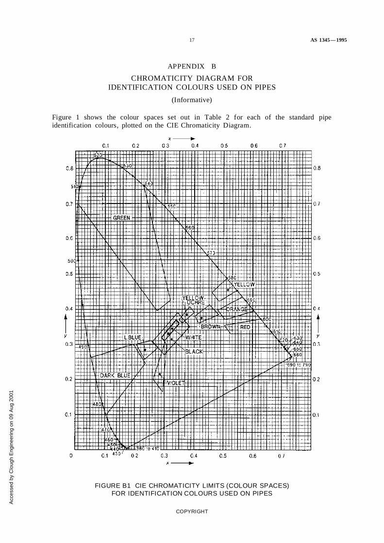
APPENDIX B
CHROMATICITY DIAGRAM FORIDENTIFICATION COLOURS USED ON PIPES
(Informative)
Figure 1 shows the colour spaces set out in Table 2 for each of the standard pipeidentification colours, plotted on the CIE Chromaticity Diagram.
FIGURE B1 CIE CHROMATICITY LIMITS (COLOUR SPACES)FOR IDENTIFICATION COLOURS USED ON PIPES
COPYRIGHT
Acc
esse
d by
Clo
ugh
Eng
inee
ring
on 0
9 A
ug 2
001

AS 1345— 1995 18
In simple terms, the CIE* colour chart has, around the periphery of the horseshoe, thepure colours of the spectrum stretching from wavelength 300 (violet) to 790 (red)nanometres. Colours on the line would be dense, fully saturated colours —actually ratherdifficult to achieve in practice, especially colours viewed by reflected light. (Colours donot exist outside the horseshoe.)
More practical colours exist as progressively desaturated or washed-out colours as theymove toward the centre of the diagram. The lightness or darkness of colours can changein two ways, first by the increase or decrease of luminance factor (pure white is 1.0, pureblack zero), and secondly by greater or lesser degree of saturation. Most lightening ordarkening is a combination of the two.
Changes in saturation will sometimes also result in changes in perceived colour, forexample brown is a desaturated form of yellow-orange (at low luminance factor levels),but in most cases will result in a pastel shade of the original, e.g. red to pink. It will benoted that most of theAS 2700colours are fairly well desaturated.
At the centre of the diagram is the absence of colour, i.e. white at high luminance factor,down through greys to black at zero luminance factor.
The system provides for an organized means of specifying colour tolerance. The colourspaces are adjusted to ensure that any colour lying in the space is generally perceived ashaving the named colour, whilst at the same time ensuring that there are large enoughgaps between the spaces to avoid confusing one colour with the next.
Automatic hand-held colorimeters which will give direct readings of colour coordinatesand luminance factor are available.
* Commission Internationale de l’Eclairage.
COPYRIGHT
Acc
esse
d by
Clo
ugh
Eng
inee
ring
on 0
9 A
ug 2
001
19 AS 1345— 1995
APPENDIX C
GUIDE TO SERVICES REQUIRING HAZARD IDENTIFICATION
(Informative)
C1 SCOPE This Appendix gives guidelines as to when a pipe service should beconsidered hazardous enough to require hazard identification.
C2 HAZARD TYPES AND DEGREES OF HAZARDS The following lists varioustypes of hazard associated with pipes, and suggests the degree of hazard at which hazardidentification should be considered (the class numbers in brackets refer to the relevantclasses of materials listed in the Australian Dangerous Goods Code which would fall intothe following categories):
(a) Corrosive hazard—materials that are likely to cause immediate burning of the skinon the hands and arms of an operator, if splashed or immersed (Class 8).
(b) Chemical poison—gaseous materials that are likely to cause immediate personalhazard if inhaled, or liquids which are poisonous if ingested in the small quantitieslikely to occur accidentally during maintenance or emergency operations. Thiscategory includes substances which can poison in the short term by absorptionthrough the skin (Classes 2.3, 6.2).
(c) Biological hazard—this category would be generally confined to materialscontaining virulent disease-causing organisms. Sewer pipes other than thoseassociated with hospitals and medical centres would not normally require hazardidentification unless there was a danger of polluting another service (Class 6.2).
(d) Radioactive hazard—materials emitting ionizing radiation in excess of 74becquerels per gram (Class 7).
(e) Temperature—unprotected pipes carrying material at temperatures above 60°C orbelow −10°C.
(f) Pressure—services carrying materials at elevated pressures, typically 0.5 Mpa forgases and 1.2 Mpa for liquids.
(g) Flammability —services carrying liquids, gases, or particulate solids which areflammable (Classes 2.1, 3, 4).
(h) Voltage—circuits carrying voltages in excess of 110 V (RMS).
COPYRIGHT
Acc
esse
d by
Clo
ugh
Eng
inee
ring
on 0
9 A
ug 2
001

A
cces
sed
by C
loug
h E
ngin
eerin
g on
09
Aug
200
1