as-i bus - steven engineering · “actuator-sensors interface as-i bus” document xdoc5011en...
TRANSCRIPT

Schneider Electric Brands
AS-i Bus
Class 8340
CONTENTS
Description PageGeneral Information . . . . . . . . . . . . . . . . . . . . . . . . . . . . . . . . . . . . . . . . . . . . . . . . . . 3TSXSAZ10 Master PLC Interface . . . . . . . . . . . . . . . . . . . . . . . . . . . . . . . . . . . . . . . . 9TSXSAY100 Master PLC Interface . . . . . . . . . . . . . . . . . . . . . . . . . . . . . . . . . . . . . . 12PLC Programming/Other Gateways . . . . . . . . . . . . . . . . . . . . . . . . . . . . . . . . . . . . . 14Repeater . . . . . . . . . . . . . . . . . . . . . . . . . . . . . . . . . . . . . . . . . . . . . . . . . . . . . . . . . . 16Addressing Terminal . . . . . . . . . . . . . . . . . . . . . . . . . . . . . . . . . . . . . . . . . . . . . . . . . 17Push Button Control Stations . . . . . . . . . . . . . . . . . . . . . . . . . . . . . . . . . . . . . . . . . . 1812-Button Keypads . . . . . . . . . . . . . . . . . . . . . . . . . . . . . . . . . . . . . . . . . . . . . . . . . . 20Inductive Proximity Sensors . . . . . . . . . . . . . . . . . . . . . . . . . . . . . . . . . . . . . . . . . . . 22Photoelectric Sensors . . . . . . . . . . . . . . . . . . . . . . . . . . . . . . . . . . . . . . . . . . . . . . . . 24Illuminated Indicator Banks. . . . . . . . . . . . . . . . . . . . . . . . . . . . . . . . . . . . . . . . . . . . 26Variable Drive Controllers for Asynchronous Motors . . . . . . . . . . . . . . . . . . . . . . . . 29XALSZ1 (Spider) and ZB2BZ Interface Boards . . . . . . . . . . . . . . . . . . . . . . . . . . . . 33TELEFAST® SB2 Intelligent Interfaces . . . . . . . . . . . . . . . . . . . . . . . . . . . . . . . . . . . 35Intelligent Splitter Modules . . . . . . . . . . . . . . . . . . . . . . . . . . . . . . . . . . . . . . . . . . . . 44Cabling and Connection Accessories . . . . . . . . . . . . . . . . . . . . . . . . . . . . . . . . . . . . 48Cable Splitter Modules . . . . . . . . . . . . . . . . . . . . . . . . . . . . . . . . . . . . . . . . . . . . . . . 50Extension Cables . . . . . . . . . . . . . . . . . . . . . . . . . . . . . . . . . . . . . . . . . . . . . . . . . . . 52Power Supply Module and Unit. . . . . . . . . . . . . . . . . . . . . . . . . . . . . . . . . . . . . . . . . 60Insulation Control Relay for AS-i Bus . . . . . . . . . . . . . . . . . . . . . . . . . . . . . . . . . . . . 62Product Index . . . . . . . . . . . . . . . . . . . . . . . . . . . . . . . . . . . . . . . . . . . . . . . . . . . . . . 66


AS-i BusGeneral Information
303/00 © 2000 Schneider Electric All Rights Reserved
AS-i (Actuator Sensor Interface) is a bus made up of sensors and actuators with a very short response time. AS-i is an open industry standard supported by the AS-i association. The leading manufacturers of sensors, actuators, programmable controllers and connection accessories are members of this association. AS-i has the advantage of not being a sole supplier network.
Connection to a higher level bus can be made through network gateways or by using a communication bus controller (programmable controller, etc.).
The AS-i intelligence is based on an ASIC (Application Specific Integrated Circuit), which can either be integrated directly into a sensor or actuator (known as an intelligent component), or in an interface module which can accept up to 8 standard (non-intelligent) sensors and actuators. It is the ASIC which manages all the communication functions of the sensor or actuator in order to supply information to the AS-i master regarding switching state, operational availability of the sensor, etc.
Advantages of the AS-i Bus
Cabling: Data is transmitted by a standard cable consisting of a pair of non-twisted unshielded #16 or #14 AWG (1.5 mm2 or 2.5 mm2) wires. The supply to the sensors and actuators is also provided by this cable. The cable is installed directly on the machine, without having to fit any special components (splitter blocks, etc.).
Installation: software tools, incorporated in PL7 products, make it possible to select bus components and to enter the parameters for these components by way of the automation system configuration.
Maintenance: all services offered on the interfaces and “in-rack” I/O programming are included in the PL7 tools, with screens for diagnostics, channel topology syntax, associated mnemonics, overriding of variables, debugging zone, etc.
Summary of Advantages:
• Reduction in cost and volume of cabling.
• Reduction in size of enclosures.
• Capability for expanding and adapting existing machines is simplified.
• Increased availability and adaptability of sub-assemblies.
NTERFACE
AS-i Master SupplyGround Fault Monitor
AS-i Universal Modules
AS-i Dedicated ModulesAS-i Dedicated Modules
AS-i Dedicated Products
AS
-i B
us
Aux
iliar
y 24
Vdc
sup
ply
Tools
IP 65 or 67 Machine
IP 20 Enclosure
AMS
9526VGG
ASI
ASIC

AS-i BusGeneral Information
© 2000 Schneider Electric All Rights Reserved4
03/00
Topology of the AS-i Bus
The topology of the AS-i bus is unrestricted. The lack of restrictions enables the most direct connections to be made between the bus and the various sensors and actuators in an installation. The maximum length of the AS-i bus is 328 feet (100 m) (including main runs and tap-off runs). Cable runs of up to 984 feet (300 m) are possible using repeaters (signal regenerators).
Connection of the AS-i cable is fast and is easily achieved by means of the IDCs (Insulation Displacement Connectors) on splitter boxes, T-connectors, or tap-offs, which pierce the cable insulation to make contact with the conductors. In the event of the IDCs being removed for circuit modifications, the cable insulation self-seals.
Master/Slave Bus
AS-i is a master/slave bus: all the slaves are managed by a single master. The master polls each of the slaves present on the bus, in turn, and waits for a reply. The cycle time is 5 ms maximum, for 31 digital slaves. Communications are always initiated by the bus master.
AS-i slaves are manufactured and have a configuration at delivery with the address 0. Prior to implementing for the first time, an address must be assigned to each slave using an addressing terminal. The dialog between the master and the slaves is achieved using a modulated carrier current utilizing an alternating pulse modulation (APM) technique. This is also known as Manchester coding. An error detection procedure provides excellent integrity of data transmission.
Point-to-point Line
RingTree
Splitter box: connection base + splitter module T-Connector

AS-i BusGeneral Information
503/00 © 2000 Schneider Electric All Rights Reserved
AS-i Masters
AS-i accepts different types of masters:
• The programmable controller master module incorporating an AS-i communication port, directly transfers the data, transparently, to the PLC application program. The Premium PLC supports 1 to 8 AS-i masters; the Micro PLC supports 1 AS-i master.
• The gateway master converts the AS-i bus from a simple communication node to a higher level bus. Gateways to higher level networks such as MODBUS Plus and Profibus DP are available from various third-party vendors.
M
M
M
M AS-i Bus Master
AS-i Bus
Other Bus
AS-i PortIntegrated into the PLC
Fipio/AS-i Gateway Master

AS-i BusGeneral Information
© 2000 Schneider Electric All Rights Reserved6
03/00
AS-i Slaves
An AS-i bus may be used with up to 31 slaves (each incorporating an ASIC) each consisting of 4 Input bits and 4 Output bits for cyclical exchange of information with the master, plus 4 parameter bits allowing extended functions (configuration, diagnostics, etc.). Each slave has its own address and a profile (defining the exchange of variables). Intelligent sensors and actuators (incorporating an ASIC) can be connected directly to the AS-i bus via passive splitter boxes or T-connectors.
Standard (non-intelligent) digital sensors or actuators are connected to the bus via intelligent splitter boxes or cabling interfaces. The maximum number of standard units that may be connected is 248.
Many applications involve a mixture of both intelligent and standard (non-intelligent) sensors/actuators.
1 Passive T-connector 3 Intelligent splitter box
2 Passive splitter box 4 Cabling interface
Each device connected on the AS-i bus is supplied via the AS-i cable from a special power supply unit (PSU).
The rating of this PSU must be suitable for the total consumption of the devices on the bus. The PSU may be located at any point of the bus.
Protocol Centralized master/slave
Dialog Type Cyclical polling
Refresh Time 5 ms for 31 slaves
Response Time Max. time defined for each slave
Connection Points 31 slaves
Number of Standard Products 248 maximum
Data 4 status bits, 4 command bits, and 4 parameter bits per slave
Maximum Length of Bus 328 ft (100 m), 984 ft (300 m) with repeater
Network Characteristics Supply and signal on the same cable
Physical Layer 2-core unscreened cable
“Actuator-Sensors Interface AS-i Bus” document XDOC5011EN contains basic information on the AS-i bus for electricians, automation engineers, and specifiers. This document explains the AS-i concept, recommendations for initial installation, and set-up.
1 2 3
4
AS-i Bus
31 Intelligent Components (Sensors or Actuators)Basic Functions + Extended Functions
248 Standard Components, MaximumBasic Functions

AS-i BusGeneral Information
703/00 © 2000 Schneider Electric All Rights Reserved
Example – Bus Supply Only
1 TSXSAZ10 AS-i bus master for TSX Micro PLC’s or
TSXSAY100 AS-i bus master for TSX Premium PLC
2 TSXSUPA0• or ABL6 Power supply unit for all sensors/actuators on the AS-i bus.
3 XZSDE1113 + XZSDP Passive splitter box allowing connection of two AS-i cables by IDCs.
4 XZSDE11•3 + XZSDA••D•• Intelligent splitter box, comprising a connection module + a splitter module, allowing the connection of standard sensors and actuators onto the AS-i bus (versions available: 2 I/2 O, 4 I, 4 O).
5 XZCG0•20 T-connectors allowing the connection (by IDC) of intelligent AS-i sensors and actuators to the AS-i bus.
6 ABE8•••S••0 TELEFAST SB2 intelligent interface allowing connection (by screw terminals) of standard sensors and actuators to the AS-i bus.
7 XS7C40AS101 or XS8C40AS101 Inductive proximity sensor, plug-in body, 5-position turret head
8 XUJ••••••AS Photo-electric detectors, type compact XUJ.
9 XALS200• Control station, with 2 pushbuttons, illuminated or not
10 XBLC5012•581 12-way keypads, tactile feedback type.
11 XZCB1•••1 Flat, unshielded, 2-core AS-i bus cable (yellow) with asymmetric profile, ensuring connection with the correct polarity.
12 XZCG0122 Tap-off for flat cable.
13 ATV58EU•••• Altivar 58 variable speed drives for asynchronous motors.
4
11
5
5
5
5
10
8
7
9
2
7 8 9
4 5 6
1 2 3
- 0 +
3
6
12
13
1

AS-i BusGeneral Information
© 2000 Schneider Electric All Rights Reserved8
03/00
Example – Bus Supply plus Auxiliary Power Supply
1 XZCB1•••1 Flat, unshielded, 2-core AS-i bus cable (yellow) with asymmetric profile, ensuring connection with the correct polarity.
2 XZCB1•••2 Flat, unshielded, 2-core cable (black) for separate 24 Vdc power supply, with asymmetric profile ensuring connection with the correct polarity.
3 XZSDE1113 + XZSDP Passive splitter box allowing connection of 2 yellow AS-i cables by means of IDCs.
4 XZSDE1143 + XZSDA22D12 Intelligent splitter box comprising a connection module + a splitter module, allowing connection of 2 standard sensors and 2 standard actuators onto the AS-i bus.
5 XZMA1 Repeater, for extending the line to increase the length of AS-i links by 328 ft (100 m) with 984 ft (300 m) max.
6 XZSDE1113 + XZSDA40D3 Intelligent splitter box comprising a connection module + a splitter module, allowing connection of 4 standard sensors onto the AS-i bus.
7 XZSDE1133 + XZSDP Passive splitter box allowing connection of 2 cables by IDCs.
8 XZCG012•D Tap-off, allowing connection (by IDC) to the AS-i bus; connection to the sensor or actuator by means of cable (2 x 0.34 mm2) with M12 straight connector.
9 XZCG0122 Tap-off, allowing connection (by IDC) to the AS-i bus; connection to the sensor or actuator by cable (2 x 0.34 mm2), bared at the device end for connection via terminals.
10 XZSDE2213 + XZSDP Passive splitter box allowing connection of a black AS-i cable and a round cable by means of screw terminals.
11 XZCG0120•C Tap-off allowing connection (by IDC) to the AS-i bus; connection to the sensor or actuator by cable (2 x 0.34 mm2) with M12 elbowed connector.
12 TSXSUPA0• or ABL6 Power supply unit, for all the sensors/actuators on the AS-i bus.
13 Master AS-i bus master. TSXSAZ10 for TSX Micro PLC. TSXSAY100 for TSX Premium PLC.
14 Power supply unit, TSXSUPA05 Separate 24 Vdc power supply unit, for supply to all sensors and actuators with heavier power requirements.
2 3
4
5
1
12
12
7
10
14
6
8 9
11
13
13

AS-i BusTSXSAZ10 Master PLC Interface
903/00 © 2000 Schneider Electric All Rights Reserved
MICRO AUTOMATION PLATFORM INTERFACE
Introduction
The TSXSAZ10 AS-i bus module enables the Micro PLC to act as the AS-i bus master. In this way up to 31 sensor/actuator type devices may be managed on the one AS-i bus. Up to 4 inputs and/or outputs can be connected to each device, giving a maximum of 248 I/O on one segment.
The AS-i bus consists of a master station (Micro PLC) and slave stations. The TSXSAZ10 module supports the AS-i M2 profile, interrogates the device connected on the AS-i bus in turn and stores the data (state of sensors/actuators, operational status of devices) in the PLC memory. Communication management on the AS-i bus is completely transparent with regard to the PLC application program.
An AS-i power supply must be used for powering the various components on the AS-i bus. Ideally this power supply unit (PSU) should be situated nearest to the stations with the largest current demands.
Description
The TSXSAZ10 AS-i bus master is a half-format module designed to slide into the basic configurations of TSX37-10/21/22 Micro PLCs, in position 4 (one TSXSAZ10 module per configuration) .
The front panel consists of:
1. An opening with a locating device for routing AS-i bus ribbon or round cable (to be connected to a terminal block inside the module).
2. Four indicator lamps:
— RUN: the module is active
— ERR: module fault or bus connection fault
— COM: AS-i bus communication is active
— AS-i: bus configuration error
3. A push button to transfer the AS-i bus display to the PLC front panel. When the TSXSAZ10 module is in position 4, the upper position 3 can only receive a TSXA•Z•••• analog or TSXCTZ••• counter
half-format module.
Sensors
Motor Starter TSXSupA02 Power Supply
XBL KeypadIntelligent SensorsXAL Control Station
AS-i Bus
XVA Indicator Bank Micro + TSXSAZ10
1
2
3
TSXSAZ10

AS-i BusTSXSAZ10 Master PLC Interface
© 2000 Schneider Electric All Rights Reserved10
03/00
Module Diagnostics
The Micro PLC centralized display block enables the display of the status of all the I/O channels, and the diagnostics for devices on the AS-i bus (present, missing, faulty, not conforming to the configuration):
1. Device number
2. Control push button for accessing the various operating modes of the display block
3. State of the 4 device inputs
4. State of the 4 device outputs
Refer to page 14 for detailed programming information.
Selection
AS-i Bus Module
Connections
TSXSAZ10 module
Description Protocol Number of I/O Catalog Number
AS-i bus master modulefor TSX37-10/21/22PLCs
AS-i 31 devices, 248 I/O maximum TSXSAZ10
BASE
1664
12840
13951
141062
151173
12840
13951
141062
151173
16641664
R I/O WRD
RUN
TER
I/O
ERR
> 1s.DIAG
BAT
DIAGEXT 2
12
139
146
15
12
13
14
12840
13
14
151173
12
13
141062 4
3
1
TSXSAZ10
+
-AS-i bus cable - flat cable with locating device or round cable(+ brown, - blue)
AS-i cable locking collar

AS-i BusTSXSAZ10 Master PLC Interface
1103/00 © 2000 Schneider Electric All Rights Reserved
Defined as the time between an AS-i input being triggered and an AS-i output (on the same slave) being energized, including the processing within the PLC program.
Specifications
Type of Module TSXSAZ10
Product Certifications AS-i No. 04601, NF C 63-850
AS-i Profile M2
Ambient Air Temperature Operation: +32 °F to +140 °F (0 °C to +60 °C), Storage: -13 °F to +158 °F (-25 °C to +70 °C)
Degree of Protection IP 20
Vibration Resistance Conforming to IEC 68-2-6, Fc tests.
Shock Resistance Conforming to IEC 68-2-27, EA tests.
Number of Connectable Slaves 31 AS-i slaves
Number of Inputs/Outputs 124 inputs and 124 outputs
Processing Times Depending on the scan time of the PLC “Master Task”
Execution Time 10 ms 30 ms 60 ms
Average Processing Time 22 ms 50 ms 80 ms
Maximum Processing Time 35 ms 75 ms 135 ms
Bus Connection By integral terminal within the module (interlock to maintain cable polarity)
Module Power Supply Supplied directly from the PLC (100–240 Vac, 24 Vdc)
Display Diagnostics By display panel integrated into the Micro PLC or via a suitable PC terminal using PL7 Micro/Junior software.
Compliance Standards UL Listed E194434 CCN NRAQCSA Certified LR58905 Class 2252 01

AS-i BusTSXSAY100 Master PLC Interface
© 2000 Schneider Electric All Rights Reserved12
03/00
PREMIUM AUTOMATION PLATFORM INTERFACE
Introduction
The TSXSAY100 master module for the AS-i bus enables the Premium PLC to act as the AS-i bus master. In this way, up to 31 sensor/actuator type devices may be managed on one AS-i bus. Up to 4 inputs and/or outputs can be connected to each device, giving a maximum of 248 I/O on one segment.
The AS-i bus consists of a master station (Premium PLC) and slave stations. The TSXSAY100 module, which supports the AS-i M2 profile, interrogates the devices connected on the AS-i bus and stores the data (status of sensors/actuators, operational status of devices) in the PLC memory. Communication management on the AS-i bus is completely transparent with regard to the PLC application program.
An AS-i power supply must be used for powering the various components on the bus. Ideally, this power supply unit (PSU) should be situated nearest to the components with the largest power demands.
Description
The TSXSAY100 AS-i bus master is a standard format module. It is designed to slide into any position on the Premium rack except those reserved for the processor and power supply.
The module features, on the front panel:
1. A display unit comprising 4 indicator lamps showing the module operating modes:
— RUN: module operating
— ERR: module fault
— COM: AS-i bus communication active
— I/O: AS-i bus I/O fault
2. A display unit comprising 32 indicator lamps for diagnostics of the AS-i bus and of each Slave connected to the bus.
3. Three indicator lamps specific to the module:
— AS-i: AS-i power supply fault
— Display Bus: display unit (2) is in Bus display
— Display I/O: display unit (2) is in Slave display (state of slave I/O)
4. Two push buttons used for local diagnostics of the AS-i bus.
5. One 3-way male SUB-D connector for connection to the AS-i bus (female connector supplied).
The maximum number of TSXSAY100 modules per PLC station depends on the type of processor installed. See “Selection” on page 13.
Sensors
AS-i bus
TSXSUPA02 Power Supply
Motor StarterXBL KeypadIntelligent Sensors
Premium + TSXSAY100XVA Indicator Bank
AS-i bus
XAL Control Station
12
3
4
5
TSXSAY100

AS-i BusTSXSAY100 Master PLC Interface
1303/00 © 2000 Schneider Electric All Rights Reserved
Module Diagnostics
The TSXSAY100 module display unit displays the status of all the I/O channels (Slave mode) and is used for diagnostics of devices on the AS-i bus (Bus mode):
Defined as the time between the appearance of an input, its processing by the PLC processor, and the activation of an output on the same slave device.
Selection
Description Protocol Number per PLC Number of I/O Catalog Number
AS-i bus master module for Premium PLCs
AS-i
2 for 51-104 for 57-208 for 57-308 for 57-40
31 devices or 248 I/O maximum
TSXSAY100
Specifications
Type of Module TSXSAY100
Product Certifications AS-i No. 18801, NF C 63-850
AS-i Profile M2
Ambient Air Temperature Operation: +32 °F to +140 °F (0 °C to +60 °C), Storage: -13 °F to +158 °F (-25 °C to +70 °C)
Degree of Protection IP 20
Vibration Resistance Conforming to IEC 68-2-6, Fc tests.
Shock Resistance Conforming to IEC 68-2-27, EA tests.
Number of Connectable Slaves 31 AS-i slaves
Number of Inputs/Outputs 124 inputs and 124 outputs
Processing Times Depending on the scan time of the PLC “Master Task”
Execution Time 10 ms 30 ms 60 ms
Average Processing Time 27 ms 33 ms 45 ms
Maximum Processing Time 37 ms 55 ms 80 ms
Bus Connection By 3-way SUB-D connector
Module Power Supply Power supply integrated on Premium PLC (100–240 Vac, 24 Vdc)
Diagnostics Via centralized display unit on Micro PLC or on TSXSAY100 module and the diagnostics function of PL7 Micro, PL7 Junior, and PL7 Pro software.
Compliance Standards UL Listed E194434 CCN NRAQCSA Certified LR58905 Class 2252 01
01
89
1617
2425
23
1011
1819
2627
67
1415
2223
3031
45
1213
2021
2829
Display Bus
Display I/O
01
89
1617
2425
23
1011
1819
2627
67
1415
2223
3031
45
1213
2021
2829
Display Bus
Display I/O
01
89
1617
2425
23
1011
1819
2627
67
1415
2223
3031
45
1213
2021
2829
Display Bus
Display I/O
Bus Mode
Displays image of the AS-i bus; each LED 1 to 31 corresponds to a Slave address on the bus.
Bus Mode
Displays image of the AS-i bus; each LED 1 to 31 corresponds to a Slave address on the bus.
Displays the address of the selected Slave.
Slave Mode (SLV)
Displays status of I/O bits of the selected Slave.
• ON
TSXSAY100
AS-i Cable Connections

AS-i BusPLC Programming/Other Gateways
© 2000 Schneider Electric All Rights Reserved14
03/00
Software Setup
The AS-i bus is configured using PL7 Micro/Junior/Pro software. The utilities available are based on the principle of simplicity:
• Management of profile tables, parameters, and data by the master (this management is transparent to the user).
• Topological I/O addressing: each AS-i slave declared on the bus is assigned a topological address on the bus by the user. This is transparent to the user.
• Each sensor/actuator on the AS-i bus is treated as an in-rack I/O by the Micro/Premium PLC.
AS-i Bus Configuration
All devices on the AS-i bus are configured implicitly using the following sequence of screens:
Declaration of the AS-i bus master module
• The TSXSAZ10 module is always inserted and declared in position no. 4 on TSX37-10 or TSX37-21/22 PLCs.
• The TSXSAY100 module is inserted into any position on TSX57, TPMX57, or TPCX57 PLCs (except the position reserved for processors and power supply).
Configuration of the AS-i slave devices
Using the configuration screen, it is possible to configure all the slave devices (1 to 31), i.e. all 248 I/O. Configuration for each device consists of defining, according to case:
• Groupe Schneider AS-i devices. The user selects the AS-i device catalog number from the various product families. This selection determines the AS-i profile and the parameters associated with the device.
• Third party AS-i devices. The user can use PL7 Micro/Junior software to manage a “customized” list of sensors/actuators of different brands. This list, specifying the AS-i profile and parameters, is compiled to meet the needs of the user.
The configuration screen is also used to:
• Associate a symbol with each AS-i input or output (up to 32 characters)
• Define the default position of the actuators for all devices (set to state 0 or maintained) should the Micro/Premium PLC stop.
Programming
After configuration, the I/O connected on the AS-i bus are processed by the application program in the same way as a PLC in-rack I/O, using either the address (e.g. I\4.0\16.2, input 2 of slave 16 of the AS-i bus) or the associated symbol (e.g. Start_conveyor).

AS-i BusPLC Programming/Other Gateways
1503/00 © 2000 Schneider Electric All Rights Reserved
Software Diagnostics
Diagnostics performed using the centralized display unit on the Micro PLC or using the centralized display unit on the TSX SAY 100 module of the Premium PLC can be completed using an FTX517 terminal or PC compatible with PL7 Micro/Junior/Pro software.
The terminal connected to the Micro/Premium PLC is used for operational diagnostics of the TSXSAZ10 and TSXSAY100 master modules, the AS-i bus and the slave devices on the AS-i bus.
Diagnostics are performed using a single screen divided into four sections providing information on:
1. Operational status of the TSXSAZ10 or TSXSAY100 module (RUN, ERR,I/O status).
2. Status of the AS-i channel connected to the module.
3. Faulty slave.
4. Data relating to any selected slave (profile, parameters, forcing).
In the event of an AS-i module or channel fault, a second screen can be accessed, which clearly shows the type of fault, which may be at internal or external level.
Network GatewaysThis is a partial listing of AS-i network gateway products. For up-to-date information, visit www.as-interface.com.
Network Example HostsProduct Name/Catalog Number
Vendor Phone Website
DeviceNet Allen-Bradley PLCs GWAS/DN Lumberg (804) 379-2012 www.lumbergusa.com
DeviceNet Allen-Bradley PLCs VAG-DN-K5 Pepperl+Fuchs (330) 425-3555 www.pepperl-fuchs.com
Interbus-SModicon PLCsSiemens PLCs
VAG-IBS-K1 Pepperl+Fuchs (330) 425-3555 www.pepperl-fuchs.com
Interbus-SModicon PLCsSiemens PLCs
IBS ST ASI DIO Phoenix Contact (800) 888-7388 www.phoenixcon.com
MODBUS Most PLCs VAG-MOD-KF-R4 Pepperl+Fuchs (330) 425-3555 www.pepperl-fuchs.com
Profibus DP Siemens PLCs GWAS/DP Lumberg (804) 379-2010 www.lumbergusa.com
Profibus DP Siemens PLCsVAG-PB-KF-R4VAG-PB-G4F-R4
Pepperl+Fuchs (330) 425-3555 www.pepperl-fuchs.com
Profibus FMS Siemens PLCs GWAS/DP-FMS Lumberg (804) 379-2011 www.lumbergusa.com
1
2
43

AS-i BusRepeater
© 2000 Schneider Electric All Rights Reserved16
03/00
Specifications
Approvals Pending
Ambient Air Temperature
Operation: +32 °F to +130 °F (0 °C to + 55 °C) Storage: -13 °F to +167 °F (-25 °C to + 75 °C)
Degree of Protection IP 67
Material Plastic
Connection To yellow AS-i cable
Power Supply By the AS-i cable
Current Consumption 45 mA per AS-i segment (90 mA total)
Operational Voltage Depending on AS-i specification (18.5 to 31.6 Vdc)
Insulation Electrical insulation between the segments
Indication One green LED per segment
Response Time 6 µs per message (12 µs per exchange)
The repeater allows an AS-i link to be extended by 328 feet (100 m). The maximum length of the bus becomes 984 feet (300 m). The repeater is connected directly to the flat AS-i cable by insulation displacement connectors (IDCs). There is electrical insulation between the segments.
Selection
Dimensions
XZMA1
Connections
Examples
Description Catalog Number
Repeater XZMA1
XZMA1
4.21
107
4.65
118
0.17 4.3
Ø0.
2Ø
5
0.18 4.6
Ø0.
39Ø
10
0.9123
1.333 1.54
39
0.287
0.8722 2.36
60
(2)
(1)
(3)
(1) LED(2) Master side(3) Extension side
Dual Dimensions: inchesmm
M P P
S S S S
328 ft100 m
328 ft100 m
P
S S S S
328 ft100 m
164 ft50 m
MP P
S S S S
164 ft50 m
328 ft100 m
M = MasterP = Power supplyS = Slaves

AS-i BusAddressing Terminal
1703/00 © 2000 Schneider Electric All Rights Reserved
The addressing terminal is used to set and change the addresses of AS-i slave devices. It is lightweight, hand-held, and powered by a rechargeable battery. A battery charger is included.
Selection
Specifications
Dimensions
XZMC11
Description Catalog Number
Addressing terminalBattery operated. Battery charger included.
For addressing intelligent modules, splitter boxes and AS-i slaves.
XZMC11US
Connection cable adaptorsCable length: 0.5 m (Spare parts)
For connecting addressing terminal XZMC11 to slaves fitted with socket (proximity sensors XS7/XS8, keypads, illuminated indicator banks, variable speed controllers ATV 58, interface modules LA9Z, and TELEFAST SB2, etc.)
XZMG12
For connecting addressing terminal XZMC11 to splitter boxes XZSCA••••• XZMG13
DocumentationReference manual “AS-i sensor/actuator bus” (in English)
XD0C5011EN
Ambient Air Temperature Operation: +32 °F to +130 °F (0 °C to + 55 °C) Storage: -4 °F to +131 °F (-20 °C to + 55 °C)
Degree of Protection IP 20
Power Supply By rechargeable batteries
Charge Time 14 hours
Operating Time 8 hours (fully charged batteries) or 250 read/writes
Display 13 mm LCD screen
Keypad 4 key membrane
Connection To AS-i slave: direct using M12 connector or by cable adaptor XZMG11 (see page 54)To splitter module: direct
Overload and Short-circuit Protection
Yes
Functions +1 address, -1 address, write address, read address
Error codes F1: overload, F2: connection not made, F3: slave fault, LOW BAT: recharge batteries
XZMC11
XZMG11
1.1830
3.1580
8.23
209
Dual Dimensions: inchesmm
AS-i BusPush Button Control Stations
© 2000 Schneider Electric All Rights Reserved18
03/00
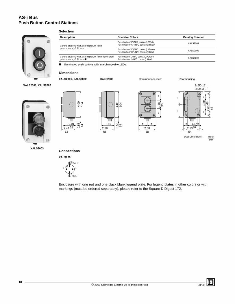
Selection
Illuminated push buttons with interchangeable LEDs.
Dimensions
XALS2001, XALS2002 XALS2003 Common face view Rear housing
Connections
XALS200
Enclosure with one red and one black blank legend plate. For legend plates in other colors or with markings (must be ordered separately), please refer to the Square D Digest 172.
Description Operator Colors Catalog Number
Control stations with 2 spring return flush push buttons, Ø 22 mm
Push button “I” (N/O contact): White Push button “O” (N/C contact): Black
XALS2001
Push button “I” (N/O contact): Green Push button “O” (N/C contact): Red
XALS2002
Control stations with 2 spring return flush illuminated push buttons, Ø 22 mm
Push button 1 (N/O contact): Green Push button 2 (N/C contact): Red
XALS2003
XALS2001, XALS2002
XALS2003
=
2.6868
=
==
1.18 30
= 2.1354
=
== 1.5740
=2.
68 68=
=1.
89 48=
2xØ0.172xØ4.3
==
51
2.6868
4.09
104
0.55 14
2.01512.44
62
4.09
104
0.55 14
Dual Dimensions: inchesmm
1
3
42
+
–
AS-i
AS-i

AS-i BusPush Button Control Stations
1903/00 © 2000 Schneider Electric All Rights Reserved
Environment
Electrical Specifications
Data Exchange Specifications
Product Certifications AS-i No. 06301
Ambient Air Temperature Operation: -13 °F to +158 °F (-25 °C to +70 °C), Storage: -40 °F to +158 °F (-40 °C to +70 °C)
Degree of Protection IP 65
Vibration Resistance 15 g (f = 40 to 500 Hz) conforming to IEC 68-2-6
Shock Resistance 70 g conforming to IEC 68-2-27 (push buttons)
Materials Polycarbonate enclosure, colored gray RAL 7035 and grey RAL 7021
Enclosure Flame Resistance NF C 20-455: 1760 °F (960 °C), UL 94: V0
Connection M12 connector
Power Supply From the AS-i bus
Current Consumption from Bus
< 40 mA (XALS2001 and XALS2002), < 80 mA (XALS2003)
Contact Blocks 1 N/C and 1 N/O, 24 V, 5 mA
LEDs of Illuminated Push Buttons
24 Vdc, 20 mA (XALS2003)
Short-circuit Protection Yes, for the LED indicators
Compliance Standards UL Listed E164353 CCN NKCR
AS-i Profile S3.F
Data Bits (Status)
Bit value 0 1
State D0 (I)Push button “I” unoperated(N/O contact open)
Push button “I” operated (N/O contact closed)
State D1 (I)Push button “O” operated(N/C contact open)
Push button “O” unoperated(N/C contact closed)
Data Bits (Commands)(only applicable toXALS2003)
Bit value 0 1
Command D2 (O) Green indicator off Green indicator illuminated
Command D3 (O) Red indicator off Red indicator illuminated
Parameter Bits Parameters P0 to P3 Not used

AS-i Bus12-Button Keypads
© 2000 Schneider Electric All Rights Reserved20
03/00
Selection
Dimensions
XBLC5012F581 Panel cutout and mounting holes
XBLC5012R581 Panel cutout and mounting holes
Connections
Rear view Mounting precautionWhen mounting the keypad on a metal support, the support must be grounded.
Description Mounting Method Catalog Number
12-button keypads Marked 0 to 9, +, - (1)
Flush mounting XBLC5012F581
Surface mounting XBLC5012R581
XBLC5012F581
XBLC5012R581
3.15 80
3.52
89.5
0.5714.5 1.16
29.5(1)
3.33
84.7
0.9223.32.58
65.6
7 8 94 5 61 2 3- 0 +
(3)
(2)
(1)
3.08
78.2
+0.
5
0
=
2.8372
=
3.58 911.97 50
==
Ø0.47 (1)
(4)
2.33 59.2
+0.5
0
+0.02 0
+0.
02
0
Ø12 (1)
(1) Connection by screw terminal plug-in block (1) Spacers, solder lugs and nuts included(2) Alternative mounting using M3 screws, length 0.5 inches (12 mm), not included(3) 0.06 inches (1.5 mm) nominal(4) Holes Ø0.13 inches (Ø3.2 mm) (2)
3.15 80
3.52
89.5
0.8922.5 (1)
3.84
97.5
1.1729.73.09
78.5
7 8 94 5 61 2 3- 0 +
(1) =
2.8773
=
2.4462 –0.5
–0.02
3.62 921.
97 50
==
3.19 81–
0.5
6xØ0.13+0.02
0
–0.
02
6xØ3.2+0.50
(1) Connection by screw terminal plug-in block (1) 0.55 inches (14 mm), maximumDual Dimensions: inches
mm
+ AS-i– AS-i

AS-i Bus12-Button Keypads
2103/00 © 2000 Schneider Electric All Rights Reserved
Specifications
These dust and damp protected compact keypads incorporate tactile feedback and are particularly suited to the majority of industrial applications.
The keypads are constructed using a single piece elastomer membrane, with the keys molded in, and the whole assembly is fixed to a mounting base plate (2 mounting methods: flush mounting or surface mounting).
The degree of protection with respect to the panel is provided by the compression of the elastomer membrane in the event of flush mounting or by a gasket in the event of surface mounting.
Environment
Electrical Specifications
Data Exchange Specifications
Product Certifications AS-i No. 08701
Ambient Air Temperature
Operation: +23 °F to +158 °F (-5 °C to +70 °C), Storage: -40 °F to +176 °F (-40 °C to +80 °C)
Degree of Protection IP 65
Key Colors Gray RAL 7032 and beige RAL 1019
Mechanical Life 3 million operating cycles
Key Travel 0.08 inch (2 mm)
Operating Force 2 N (7 ounces), with tactile feedback
Mounting Flush or surface mounting
Connection Screw terminal plug-in block, 1 x 16 AWG (1 x 1.5 mm2)
Power Supply From the AS-i bus
Current Consumption from bus < 80 mA
Compliance Standards UL Listed E164353 CCN NKCR
AS-i Profile S0.F
Data Bits (Status) Key No. pressed
0 1 2 3 4 5 6 7 8 9 - + None
Bit value
State D0 (I) 0 1 0 1 0 1 0 1 0 1 0 1 1
State D1 (I) 0 0 1 1 0 0 1 1 0 0 1 1 1
State D2 (I) 0 0 0 0 1 1 1 1 0 0 0 0 1
State D3 (I) 0 0 0 0 0 0 0 0 1 1 1 1 1
Hexadecimal 0 1 2 3 4 5 6 7 8 9 A B F
Parameter bits Parameters P0 to P3: not used

AS-i BusInductive Proximity Sensors
© 2000 Schneider Electric All Rights Reserved22
03/00
Terminal capacity: 2 x 16 AWG. Cable gland not included with sensor. Cable gland XSZPE13 to be ordered separately. Sr = Real sensing distance: sensing distance measured at rated supply voltage and at rated ambient temperature
(0.9 Sn - Sr - 1.1 Sn). Indication of detection of an object outside the correct operating zone of the sensor (see LED function table, page 23). Diagnostic function. Quick location of the sensor by its flashing yellow LED.
Sensors Flush Mountable in Metal Non Flush Mountable
Nominal sensing distance (Sn)
0.39 inches (10 mm) 0.59 inches (15 mm) 0.79 inches (20 mm)
SelectionCatalog Number XS1M30AS101 XS7C40AS101 XS8C40AS101
Specifications
Product Certifications AS-i No. 16901 AS-i No. 10001
Ambient Air Temperature
Operation: -13 °F to +158 °F (-25 °C to +70 °C) Storage: -40 °F to +185 °F (-40 °C to + 85 °C)
Degree of Protection IP 67
Shock Resistance 50 g, 11 ms conforming to IEC 68-2-27
Vibration Resistance 25 g at 55 Hz, amplitude ± 2 mm, f = 10 to 55 Hz, conforming to IEC 68-2-6
Materials Nickel plated brass PEI PEI
ConnectionPre-cabled with moulded M12 end connector. Cable length: 2.62 ft (0.8 m)
Screw terminals Screw terminals
Operating Zone 0.08 to 0.31 in (2 to 8 mm) 0.12 to 0.47 in (3 to 12 mm) 0.16 to 0.63 in (4 to 16 mm)
Repeat Accuracy 3% of Sr (2)
Differential Travel 1 to 15% of Sr 3 to 20% of Sr 3 to 20% of Sr
Delays First-up: ≤5 ms; response: ≤ 2 ms; recovery: ≤ 2 ms
Maximum Switching Frequency
150 Hz
Indicators Output: yellow LEDAlarm : red LED
Output: yellow LEDAlarm : red LED
Output: yellow LEDAlarm : red LED
Power Supply From the AS-i bus
Current Consumption from Bus
≤35 mA
Compliance Standards
UL Listed E164353 CCN NKCR
Data Exchange Specifications
AS-i Profile S1.1
Data Bits (Status) Bit value 0 1
State D0 (I) Signal “off” Signal “on”
State D1 (I) Alarm “on” (3) Alarm “off”
State D2 (I) Sensor out of service Sensor in service
Data Bits (Commands) Command D3 (O) Not used
Parameter Bits Bit value 0 1
Parameter P0 Not used
Parameter P1 Not used
Parameter P2 Not used
Parameter P3 Flash “on” Flash “off”

AS-i BusInductive Proximity Sensors
2303/00 © 2000 Schneider Electric All Rights Reserved
Dimensions
XS1 XS7, XS8
Setting-Up
Minimum Mounting Distances, inches (mm)XS1 XS7, XS8Side by side Face to face Side by side Face to face
Facing a metal object Mounted in a metal support Facing a metal object Mounted in a metal object
Connections, LED Function Table
The alarm is immediately triggered when an object is detected within the zone 0 to 0.2 Sn.
Correct detection when 0.2 Sn < S < 0.8 Sn. Delayed triggering. The alarm will be triggered if an object passes within the
zone 0.8 to 1.2 Sn and its time of passing exceeds 160 ms.
Object/sensor distance 0.2 Sn 0.8 Sn Sn 1.2 Sn
Output Bit D0 1 1 1 0 0
Yellow LED
Alarm Bit D1 0 1 0 0 1
Red LED
2.3660
2.0351.5
1.18 30
(1)
(4)
1.1830
2.36 60
2xØ0.21
1.5740
0.98 25
0.79 20
==
(1)(2)
1.5740
1.6141
4.61
117
0.9424
0.6316
(3)
1.57 40
2xØ5.3
(1) Cable, length 2.62 ft (0.8 m)
(1) Output or “flash” function LED(2) Alarm LED
(3) 1 tapped entry for No. 13 plastic cable gland(4) 2 elongated holes 0.21 x 0.28 in (5.3 x 7 mm)
Dual Dimensions: inchesmm
e1
e2e1 e2
e3
h
d
e3h
XS1 (1) e1 ≥ 20 e2 ≥120 e3 ≥ 30 d ≥30, h ≥0Mounting nut tightening torque: < 50 N m Flush mountable in metal. Non flush mountable in metal
XS7 e1 ≥ 40 e2 ≥ 120 e3 ≥ 45 h ≥ 0XS8 e1 ≥ 80 e2 ≥ 160 e3 ≥ 80 h ≥ 40
1
3
42
+
–
AS-i
AS-i
1234
+–
AS-iAS-i
AS-i BusPhotoelectric Sensors
© 2000 Schneider Electric All Rights Reserved24
03/00
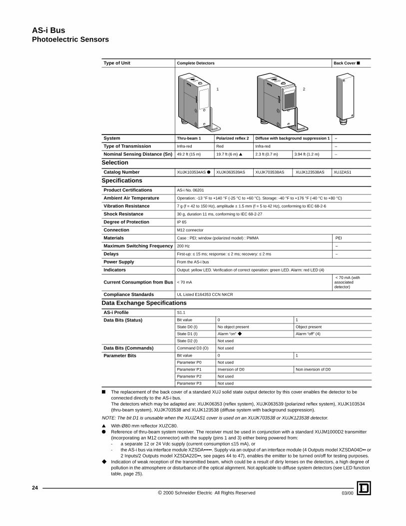
The replacement of the back cover of a standard XUJ solid state output detector by this cover enables the detector to be connected directly to the AS-i bus. The detectors which may be adapted are: XUJK06353 (reflex system), XUJK063539 (polarized reflex system), XUJK103534 (thru-beam system), XUJK703538 and XUJK123538 (diffuse system with background suppression).
NOTE: The bit D1 is unusable when the XUJZAS1 cover is used on an XUJK703538 or XUJK123538 detector.
With Ø80 mm reflector XUZC80. Reference of thru-beam system receiver. The receiver must be used in conjunction with a standard XUJM1000D2 transmitter
(incorporating an M12 connector) with the supply (pins 1 and 3) either being powered from:- a separate 12 or 24 Vdc supply (current consumption ≤15 mA), or- the AS-i bus via interface module XZSDA•••••. Supply via an output of an interface module (4 Outputs model XZSDA04D•• or
2 Inputs/2 Outputs model XZSDA22D••, see pages 44 to 47), enables the emitter to be turned on/off for testing purposes. Indication of weak reception of the transmitted beam, which could be a result of dirty lenses on the detectors, a high degree of
pollution in the atmosphere or disturbance of the optical alignment. Not applicable to diffuse system detectors (see LED function table, page 25).
Type of Unit Complete Detectors Back Cover
System Thru-beam 1 Polarized reflex 2 Diffuse with background suppression 1 –
Type of Transmission Infra-red Red Infra-red –
Nominal Sensing Distance (Sn) 49.2 ft (15 m) 19.7 ft (6 m) 2.3 ft (0.7 m) 3.94 ft (1.2 m) –
Selection
Catalog Number XUJK103534AS XUJK063539AS XUJK703538AS XUJK123538AS XUJZAS1
Specifications
Product Certifications AS-i No. 06201
Ambient Air Temperature Operation: -13 °F to +140 °F (-25 °C to +60 °C). Storage: -40 °F to +176 °F (-40 °C to +80 °C)
Vibration Resistance 7 g (f = 42 to 150 Hz), amplitude ± 1.5 mm (f = 5 to 42 Hz), conforming to IEC 68-2-6
Shock Resistance 30 g, duration 11 ms, conforming to IEC 68-2-27
Degree of Protection IP 65
Connection M12 connector
Materials Case : PEI; window (polarized model) : PMMA PEI
Maximum Switching Frequency 200 Hz –
Delays First-up: ≤ 15 ms; response: ≤ 2 ms; recovery: ≤ 2 ms –
Power Supply From the AS-i bus
Indicators Output: yellow LED. Verification of correct operation: green LED. Alarm: red LED (4)
Current Consumption from Bus < 70 mA < 70 mA (with associated detector)
Compliance Standards UL Listed E164353 CCN NKCR
Data Exchange Specifications
AS-i Profile S1.1
Data Bits (Status) Bit value 0 1
State D0 (I) No object present Object present
State D1 (I) Alarm “on” Alarm “off” (4)
State D2 (I) Not used
Data Bits (Commands) Command D3 (O) Not used
Parameter Bits Bit value 0 1
Parameter P0 Not used
Parameter P1 Inversion of D0 Non inversion of D0
Parameter P2 Not used
Parameter P3 Not used
1 2

AS-i BusPhotoelectric Sensors
2503/00 © 2000 Schneider Electric All Rights Reserved
DimensionsDetection CurvesThru-beam system Polarized reflex system Diffuse system (side approach recommended
Excess gain curves ambient temperature: +77 °F (+25 °C)Thru-beam system Polarized reflex system with XUZC80 reflector
Variation of usable sensing distances DimensionsXUJK703538AS (Diffuse system) XUJK••••••AS XUJZAS1Potentiometer at maximum Potentiometer at minimum
Connections LED function tableConnector Yellow LED illuminated for D0=1, green LED: verification of correct operation
Parameters Thru-beam and reflex systems Diffuse system
No object present in the beam Object present in the beam No object present in the beam Object present in the beam
P1 = 1 D0=0 D0=1 D0=0 D0=1
P1 = 0 D0=1 D0=0 D0=1 D0=0
Test output Verification of correct operationThru-beam and reflex systems Thru-beam and reflex systems
2 1
02
6
-6
-2
10
-10
0.05 m
0.16 ft
Sn 3.94 ft
Sn 2.3 ft
1.2 m0.7 m
2.3 ft 3.94 ft
Sn 0.7 m
Sn 1.2 m
26
-6
-2 ft
10
-10
Ø 0.79
59
Sn 49 ft
0Ø 20
Sn 15 m
m18
6
024
-6-4-2 26
Sn 20 ft
ft 8 m
Sn 6 m
∅ of beam
cm
∅ of beamcm
∅ of beamcm
With reflector XUZC80Object 20 x 20 cm (1 White 90% 2 Black 6%)
0.1 0.2 0.40.6
0.81
2 34
56
1015
500
100
50
10
5
1
D (m)20 D (m)0.1 0.2 0.4
0.60.8
12 3
45
910
403020
10
1
5
76
gain gain
1 m = 3.28 ft
0.80.05 0.6 0.7A
B
S (m) 1m = 3.28 ft
0.050.65
A
B
0.7 0.8 S (m)1 m = 3.28 ft
0.05 0.4 0.50.35
A
B
S (m)1 m = 3.28 ft
B
0.05 1.3A1.1
1.5 S (m)1 m = 3.28 ft
3.35 85
3.89
98.8
5
1.0727.2
0.51
13 (
4)
1.2832.6
2.46
62.5
0.05
1.35
1.18
30 (
5)
(1) (3)
2.4863
0.3910
0.3910
0.3910
0.39100.39
10 0.7920
(2)
0.67 17
1.18 30
0.102.6 (6)
2.6467
1.0727.2
3.35 85
0.35 9
0.7920
0.359
(1) LEDs(2) 1 elongated hole Ø0.17 x 0.55 in (Ø4.2 x 14 mm).(3) Sensitivity potentiometer.
A-B: Object reflection coefficient
Black 6% White 90%
Sensing range Non detection zone
Gray 18%
XUJK12358ASPotentiometer at maximum Potentiometer at minimum
(4) Receiver (R) and Transmitter (T) are reversed on diffuse system detectors with background suppression.
(5) Front mounting Ø0.16 in (Ø4 mm) screws and inserts supplied.(6) Applicable only to polarized reflex system detectors.
Dual Dimensions: inchesmm
123456
BUWHBN
BK
OG
XUJZAS1 backcover connections to associated detector
Orange
Black
Brown
White
Blue
1
3
42
+
–
AS-i
AS-i
t t10
0.81
1.2
+–
Signallevel
Green LEDRed LED
Optimum alignment
D1 = 0: alarm “on”D1 = 1: alarm “off”t = 160 ms
Red LED
Bit D1

AS-i BusIlluminated Indicator Banks
© 2000 Schneider Electric All Rights Reserved26
03/00
Illuminated indicator banks are visual or audible signalling units used mainly to indicate machine operation sequences and to check status from a distance. The illuminated units are visible throughout 360°. Examples: machine stop - start, no material, call technical staff, fault indication, etc.
Supplied as sub-assemblies for user assembly of up to 4 units (illuminated or audible). The column comprises:
• a base, incorporating terminal block, cable clamp, and support tube mountings,
• an AS-i adaptor unit,
• 1 to 4 colored lens units (green, red, orange, blue, clear, yellow) or audible signalling unit,
• a top cover, where necessary,
• optional accessories that include an anodized aluminium support tube, height 3.94 in (100 mm), 15.75 in (400 mm) or 31.5 in (800 mm) and support plate.
The units stack vertically and are each locked by a single screw. Electrical connections between each unit are made automatically during assembly.
Choice of panel mounting:
• either directly by the base using 2 screws, or
• using the support plate (4 mounting screws) and support tube.
Supply connections to the illuminated and audible units are brought out to terminals incorporated in the base unit.
The AS-i adaptor unit is connected to the bus using a plug-in terminal.
Bulb type for direct supply units: BA 15d base fitting incandescent, see page 27. When using with an AS-i adaptor unit, the maximum supply voltage for steady or flashing illuminated units must not exceed 48V.
NOTE: Illuminated indicator banks are supplied as sub-assemblies, for assembly by the user.
Each unit is packed individually and marked with its respective catalog number. Maximum number of units per bank: 4 illuminated units or 3 illuminated units + 1 audible unit (mounted immediately above the AS-i adaptor unit).
AS-i Adaptor Unit
Description Catalog Number
AS-i adaptor unit (the adaptor must be the lowest unit on the column) XVAS102
Illuminated Lens Units
Description Signal Supply Voltage Color Catalog Number
High intensity xenon “flash” lamp (Maximum of 1 unit per indicator bank, mounted at top)
With discharge circuit Integral tube
24 Vdc Green XVAC63C0241
Red XVAC64C0241
Orange XVAC65C0241
Blue XVAC66C0241
Clear XVAC67C0241
Illuminated lens units Steady light Bulb not included
12 to 48 Vac/dc Green XVAC33
Red XVAC34
Orange XVAC35
Blue XVAC36
Clear XVAC37
Yellow XVAC38
Flashing lightBulb not included
24 to 48 Vac Green XVAC43
Red XVAC44
Orange XVAC45
Blue XVAC46
Clear XVAC47
XVAC6•••••
XVA34
XVAC37
XVAS102
XVAC9•
XVAC21 XVAC07
+
XVA-C02
XVA-C01
XVA-C06
XVA-C12

AS-i BusIlluminated Indicator Banks
2703/00 © 2000 Schneider Electric All Rights Reserved
Audible Signalling UnitsDescription Signal Supply Voltage Catalog Number
Audible signalling units, 90 db at 3.28 ft (1 m)Continuous 12 to 48 Vdc XVAC911
Intermittent 12 to 48 Vdc XVAC921
Mounting UnitsDescription Catalog NumberBase unit + cover For bank without high intensity “flash” lamp XVAC21
Base unit only For bank with high intensity “flash” lamp XVAC07
Complementary mounting accessories for tube mounting
Tube only 3.94 in (100 mm) XVAC02
15.75 in (400 mm) XVAC03
31.5 in (800 mm) XVAC04
Tube/support mounting platePlastic XVAC01
Metal XVAC11
Side mounting bracket for tube/support mounting plate or base unit
Metal XVAC12
Sealing gaskets Dust and damp protecting For base unit XVAC05
For tube support XVAC06
Accessories and Spare PartsDescription Catalog NumberSet of sealing gaskets For IP 54 degree of protection of the indicator bank XVAC082
Bulbs, incandescentBA 15d base fitting(Sold in lots of 10)
For illuminated units 12 V - 5 W DL1BA012
24 V - 6.5 W DL1BL024
48 V - 6 W DL1BA048
Environment
Product Certifications AS-i No. 06401
Ambient Air Temperature Operation: +14 °F to +122 °F (-10 °C to +50 °C), Storage: -4 °F to +158 °F (-20 °C to +70 °C)
Degree of Protection IP 42 (mounted vertically, direct base mounting)
Vibration Resistance 5 g (f = 10 to 500 Hz) conforming to IEC 68-2-6
Shock Resistance 25 g, 11 ms conforming to IEC 68-2-27
Materials Unit housing: polycarbonate. Base and top cover: glass reinforced polyamide
Illuminated and Audible Signalling Unit Specifications
Rated Insulation Voltage Ui: 250 V conforming to IEC 947-1
Supply Voltage(for use with AS-i adaptor unit)
12 to 48 Vac or Vdc
Consumption Standard flashing light unit: 24 Vac: 250 mA
High intensity xenon flashing light unit: 24 Vdc: 350 mA maximum (720 mA at switch-on)
Audible unit: 12 to 48 Vdc: 10 to 50 mA
Rated Impulse Withstand Voltage U imp = 4 kV conforming to IEC 947-1
Bulb/Lamp type Illuminated units with steady or flashing circuit: BA 15d base fitting bulbs, minimum power: 5 W, maximum power: 7 W
Illuminated units with high intensity “flash” lamp (internal xenon tube): 13.6 cds (integrated luminosity) with clear lens
Audible Signalling Unit 90 db at 1 m, signal continuous or intermittent. Fundamental frequency : 3 kHz
Connection Screw and captive cable clamp terminals, capacity: 2 x 14 AWG (2 x 2.5 mm2)
AS-i Adaptor Unit Specifications
Power Supply From the AS-i bus
Current Consumption from Bus < 80 mA
Output Relay Type Relay contact 12 to 48 Vac or Vdc
Maximum current 1 A
No. of operating cycles 1 million
AS-i Profile S8.F
Data Bits Bit value 0 1
(Commands) Command D0 (O) Unit 1 “off” Unit 1 “on”
Command D1 (O) Unit 2 “off” Unit 2 “on”
Command D2 (O) Unit 3 “off” Unit 3 “on”
Command D3 (O) Unit 4 “off” Unit 4 “on”
Parameter Bits Parameters P0 to P3 Not used
Indicators Units 1 to 4: yellow LEDs. Supply: green LED
Compliance Standards UL Listed E164353 CCN NKCR

AS-i BusIlluminated Indicator Banks
© 2000 Schneider Electric All Rights Reserved28
03/00
DIMENSIONSIlluminated indicator bankswithout high intensity “flash” lamps with high intensity “flash” lamp (4)
Tube XVAC0• and support plate XVAC Panel cut-outFor direct mounting For tube mounting on support plate
Mounting, ConnectionsMounting the units Connections base ( viewed from above) AS-i adapter unit
Supply connections to illuminatedand audible signalling units
1.6542
b
Ø 2.68Ø 68
==
(1)
(3)
(4)
(5)
(2)
Number of illuminated or audible signalling units (3) b
1 6.26 in (159 mm)
2 8.31 in (211 mm)
3 10.35 in (263 mm)
4 12.4 in (315 mm)
(1) XVAC21
(2) XVAS102
(3) XVAC3 •, C4 • or C9 •
(4) LEDs
Number of illuminated or audible signalling units (3) b
0 9.17 in (233 mm)
1 11.22 in (285 mm)
2 13.27 in (337 mm)
3 15.31 in (389 mm)
(1) XVAC07
(2) XVAS102
(3) XVAC3 •, C4 • or C9 •
(4) XVAC6•••••
(5) LEDs
1.6542
b
Ø 2.68 68
(4)
==
(1)
(1)
(3)
(2)
Dual Dimensions: inchesmm
2.1354
4xØ5/M5
(1)
2.13 54
1.6542
2 x Ø4 or M4(1)
XVA C02 C03 C04
b2.48 in(63 mm)
14.29 in(363 mm)
30.04 in(763 mm)
(1) Tube, Ø0.98 in (Ø25 mm) (1) Ø0.98 in (Ø25 mm)
2.1354
b0.
63 16
Ø 2.68 68
==
(1)
Dual Dimensions: inchesmm
+ /
– / ASIBUS
D3
D2
D1
D0
– AS-iAS-i +
(1) (2)
(1) Supply to audible and illuminated units
(2) Supply to AS-i unit
Unit 4
Unit 3
Unit 2
Unit 1
XVAS102
Base XVAC21, C07

AS-i BusVariable Drive Controllers for Asynchronous Motors
2903/00 © 2000 Schneider Electric All Rights Reserved
ALTIVAR® 58 DRIVE CONTROLLER INTERFACE
Description
The TELEMECANIQUE® ALTIVAR 58 drive controller range is used to control asynchronous electrical motors with a power of 0.37 to 15 kW for 200/240 Vac single-phase and 200/240 Vac – 380/500 Vac3-phase power supply voltages.
Based on the concept of sensorless flux vector control, it can offer a range of high performance levels: wide range of speed, low duty torque, powerful acceleration and braking, adaptive tuning to motors and an energy saving function. The range is available in three versions, offering greater flexibility in installation and setup:
• Standard drive controller with heatsink (ATV58HU)
• Drive controller on a base plate (ATV58PU)
• Drive controller fitted in IP55 enclosure (ATV58EU)
Conforming to standards IEC, UL, and CSA, the ALTIVAR 58 drive controller range can be used for applications in the industrial and commercial sectors using simple or complex machines: mechanical handling machines, conveyors, lifts, packing and packaging machines, textile machines, timber machines, pumps, compressors, fans, air-conditioners, kneaders, etc.
Modularity of Communication Functions
ALTIVAR 58 drive controllers include a RS485 multidrop serial link (MODBUS RTU protocol) as standard and communication cards equipped with various protocols (Interbus-S, AS-i, MODBUS PLUS, Fipio, Uni-Telway, MODBUS) as options to meet the need for integration in remote architectures.
Description
ATV58HU••••
ATV58PU••••
ATV58EU••••
ATV
58H
U.ti
f
ATV
58P
U.ti
f
ATV
58E
U.t
if
Red LED: AS-i FaultGreen LED: AS-i Power
Removable terminals forconnection of AS-i bus
ATV
58P
arts
.eps

AS-i BusVariable Drive Controllers for Asynchronous Motors
© 2000 Schneider Electric All Rights Reserved30
03/00
ALTIVAR 58 Drive Controller Functions
Start-Stop Commands via the AS-i Bus
The AS-i bus communication card is used to perform the following commands:
• Forward operation
• Reverse operation
• Normal stop on deceleration ramp
• Fast stop
• DC injection stop
• Freewheel stop
• Reset faults (for drive controller reset)
Speed Commands via the AS-i Bus
One of the following operating modes can be selected:
• 2 directions with 4 preset speeds
• 1 direction with 7 preset speeds
• + fast/– fast
Selection is via the AS-i bus, using parameters P1 and P2.
Speed Commands via Analog Input
Inputs AI1 and AI2 can be used to receive a frequency setpoint.
The Start/Stop commands are sent via the AS-i bus.
Control via the AS-i Bus
Input bits (state) D2 and D3 can be assigned as and when required.
FunctionLocal Configuration on ATV58 Drive Controller (Terminal or PC)
Parameter Entry via AS-i Bus
D0 Fault/Ready – –
D1 Off/On – –
D2Sensor signal
Assignment of LI3 –
Local forcing –
D3
Sensor signalAssignment of LI4
Parameter P3
Local forcing
Frequency threshold reached
Assignment of R2
High speed reached
Frequency reference reached
Current threshold reached
Thermal threshold reached

AS-i BusVariable Drive Controllers for Asynchronous Motors
3103/00 © 2000 Schneider Electric All Rights Reserved
Connections Standard drive controller with heatsink, drive controller on a base plate
Drive controller fitted in IP55 enclosure
Communication Card
Description Connector For Drive Controllers Catalog Number
AS-i card Removable terminals ATV 58 all ratings VW3A58305
Cord
Description Length Catalog Number
Tap-off for one cable 6.56 ft (2 m) XZCG0122
XZCB01 flat cable for AS-i bus
XZCG0122 tap-off for one cable
XZCB1 flat cable for AS-i bus
XZCG0122 tap-off for one cable
Open cut-outs, fitted with plugsto allow the routing of cables equipped with connectors.

AS-i BusVariable Drive Controllers for Asynchronous Motors
© 2000 Schneider Electric All Rights Reserved32
03/00
Specifications
Product Certification AS-i Pending
Ambient Air TemperatureOperation +14 °F to +104 °F (-10 °C to +40 °C)
Storage -13 °F to +149 °F (-25 °C to +65 °C)
Compliance Standards UL Listed E164874 CCN NMMSCSA Certified LR96921 Class 3211 06
Electrical Specifications
Current Consumed On the AS-i bus 30 mA
Communication Specifications (parameter entry by default, factory setup)
Profile 7.D
Data Bits (Commands) Stop Forward operation Reverse operation Fault reset
D0 (Out) = 0 = 1 = 0 = 1
D1 (Out) = 0 = 0 = 1 = 1
Stop modes Frequency Specification
Normal FastDC injection braking
Freewheel LSP + AI SP2 SP3 HSP
D2 (Out) = 0 = 1 = 0 = 1 = 0 = 1 = 0 = 1 = 1
D3 (Out) = 0 = 0 = 1 = 1 = 0 = 0 = 1 = 1 = 1
Data Bits (Status) Value of bit = 0 Value of bit = 1
D0 (In) Fault Ready
D1 (In) Off On
D2 (In) Logic input LI3 off Logic input LI3 on
D3 (In) Logic output R2 off Logic output R2 on

AS-i BusXALSZ1 (Spider) and ZB2BZ Interface Boards
3303/00 © 2000 Schneider Electric All Rights Reserved
Adaptors for Control and Signalling Units
Green LED: DL1CJ0243, red LED: DL1CJ0244, yellow LED: DL1CJ0245
Dimensions
XALSZ1
ZB2BZS•H ZB2BZS•V
ConnectionsXALSZ1
ZB2BZS•• Connection example
DescriptionSignalling Mode of Illuminated Indicator
Mounting Position Catalog Number
Interface-2 inputs/2 outputsInputs for digital contactsOutputs for 24 Vdc LEDs DL1CJ024•
Steady - XALSZ1
Interface-4 inputs/4 outputs for printed circuitsInputs for digital contactsOutputs for indicators
SteadyVertical ZB2BZS2V
Horizontal ZB2BZS2H
Steady or flashing depending on parametering
Vertical ZB2BZS1V
Horizontal ZB2BZS1H
XA2BZ
1.5
38
0.5915
2.0552
5.91150
0.3910
5.91150
0.215.211.
6341
.50.9424
0.7519
Ø 0.174.2
Ø 0.174.2
0.338.33
0.338.37
0.102.54(1)
2.37 ± 0.00460.1 ± 0.1
54.8 ± 0.152.16 ± 0.01
(3) (2)0.28
7
60.1 ± 0.1
2.37 ± 0.004
1.333
Ø 0.174.2
1.2932.78
0.75
19
0.94 24
1.6341.5
54.8 ± 0.15
2.16 ± 0.01
0.338.37
Ø 0.17 4.2
0.338.33
0.12.54(1)
(3)
(2)
(1) 16 x Ø 1 mm pins on 2.54 mm pitch
(2) AS-i θ pin
(3) AS-i ⊕ pin
Dual Dimensions: inchesmm
BKBKGRGR
IN 2 IN 2 OUT 2 OUT 2
IN 1 IN 1
OUT 1 OUT 1
BKBKGRGR
– AS-iAS-i +Push button 2
Indicator 2 Indicator 1
Push button 1
A2
O1
0 V
O2
O3
O4
24 V
+ 24 V
0 V
I1 I2 I3 I4
Pro
g
AS-i +AS-i –
+ 2
4 V
0 V
O1 I1 O2 I2 O3 I3 O4 I4
+ 2
4 V
0 V
Pro
gN
CA
S-i +
AS
-i –
I1 I2 I3 I4 O1
O2
O3
O4 Inhibition

AS-i BusXALSZ1 (Spider) and ZB2BZ Interface Boards
© 2000 Schneider Electric All Rights Reserved34
03/00
Specifications for AS-i Adaptor, XALSZ1
Ambient Air Temperature Operation: -13 °F to +158 °F (-25 °C to + 70 °C)Storage: -40 °F to +158 °F (-40 °C to + 70 °C)
Degree of Protection IP 20
Connection By 2 wires, each 4 x 22 AWG (4 x 0.5 mm2)
Supply From the AS-i bus
Current Consumption from Bus < 80 mA
Inputs For 2 digital N/C or N/O contacts: 24 Vac, 5 mA
Outputs For 2 LED indicators: 24 Vdc, 20 mAWith short-circuit protection
Compliance Standards UL Recognized E164353 CCN NKCR2
AS-i Profile S3.F
Data Bits(Status)
Bit value 0 1
State D0 (I) Push button 1, contact open Push button 1, contact closed
State D1 (I) Push button 2, contact open Push button 2, contact closed
Data Bits(Commands)
Bit value 0 1
Command D2 (O) Indicator 1 off Indicator 1 on
Command D3 (O) Indicator 2 off Indicator 2 on
Parameter Bits Parameters P0 to P3 Not used
Specifications for AS-i Adaptors, ZB2BZS••
Product Certifications AS-i No. 16801
Ambient Air Temperature Operation: +14 °F to +131 °F (-10 °C to + 55 °C)Storage: -40 °F to +158 °F (-40 °C to + 70 °C)
Degree of Protection IP 20
Connection To printed circuit: 16-pin on 2.54 mm pitch
Power Supply From the AS-i bus
Current Consumption from Bus < 280 mA
Inputs For 4 digital N/C or N/O contacts: 24 Vac, 5 mA
OutputsFor 4 LED indicators: 24 Vdc, 1.2 W, 50 mA max. per outputWith overload and short-circuit protectionWatchdog: output = 0 after 30 ms of non polling of the slave by the master
Indication LED indicators for inputs, outputs, and supply
Compliance Standards UL Recognized E164353 CCN NKCR2
AS-i Profile ZB2BZS1•: S7.F; ZB2BZS2•: S7.0
Data Bits(Status)
Bit value 0 1
State D0 (I) Push button 1, contact open Push button 1, contact closed
State D1 (I) Push button 2, contact open Push button 2, contact closed
State D2 (I) Push button 3, contact open Push button 3, contact closed
State D3 (I) Push button 4, contact open Push button 4, contact closed
Data Bits(Commands)
Bit value 0 1
Command D0 (O) Indicator 1 off Indicator 1 on
Command D1 (O) Indicator 2 off Indicator 2 on
Command D2 (O) Indicator 3 off Indicator 3 on
Command D3 (O) Indicator 4 off Indicator 4 on
Parameter Bits for ZB2BZS1•
Bit value 0 1
Parameter P0 Indicator 1 on (flashing) Indicator 1 on (steady)
Parameter P1 Indicator 2 on (flashing) Indicator 2 on (steady)
Parameter P2 Indicator 3 on (flashing) Indicator 3 on (steady)
Parameter P3 Indicator 4 on (flashing) Indicator 4 on (steady)
Parameter Bitsfor ZB2BZS2•
Parameters P0 to P3 Not used

AS-i BusTELEFAST SB2 Intelligent Interfaces
3503/00 © 2000 Schneider Electric All Rights Reserved
Description
The TELEFAST® SB2 AS-i intelligent interfaces are based upon the TELEFAST 2 concept. They allow standard discrete sensor and actuator devices to be connected to the AS-i bus. They are available in 4 or 8 I/O versions. Their inputs, depending upon the model, may be isolated from the AS-i bus. Their outputs (either solid state or electromechanical relay) may be used to control actuators of 1 to 5 A.
Composition of the TELEFAST SB2 intelligent interfaces
ConfigurationsEight versions of TELEFAST SB2 intelligent interfaces are available as follows:
• 8-channel interfacesFour versions available, incorporating 4 inputs and 4 outputs.
ABE8S44SBB0— The inputs, isolated from the AS-i bus, are powered by an external 24 Vdc supply. They are protected by a current
limiter.— The solid state outputs, isolated from the AS-i bus, are powered by an external 24 Vdc supply. ABE8S44SBB1— The inputs are powered from the AS-i bus and protected by a current limiter.— The solid state outputs, isolated from the AS-i bus, are powered by an external 24 Vdc supply.ABE8R44SB11— The inputs are powered from the AS-i bus and protected by a current limiter.— The electromechanical relay outputs with 1 N/O contact, isolated from the AS-i bus, are powered by an external
5 to 125 Vdc or 5 to 250 Vac supply. ABE8R44SF10— The inputs, isolated from the AS-i bus, are powered by an external 110 Vac supply. — The electromechanical relay outputs with 1 N/O contact, isolated from the AS-i bus, are powered by an external
5 to 125 Vdc or 5 to 250 Vac supply. • 4-channel interfaces
Four versions are available, incorporating 4 inputs, 4 outputs or 2 inputs/2 outputs.ABE8S40SB00— Interface with 4 inputs powered by the AS-i bus and protected by a current limiter.ABE8R04S010— Interface with 4 electromechanical relay outputs with 1 N/O contact, isolated from the AS-i bus, and powered by
an external 5 to 125 Vdc or 5 to 250 Vac supply. ABE8S22SBB1Interface with 2 inputs and 2 outputs.— The inputs are powered from the AS-i bus and protected by a current limiter.— The solid state outputs, isolated from the AS-i bus, are powered by an external 24 Vdc supply.ABE8S22SBB2Interface with 2 inputs and 2 outputs.— The inputs are powered from the AS-i bus and protected by a current limiter.— The solid state outputs, isolated from the AS-i bus, are powered by an external 24 Vdc supply.
NOTE: The outputs have an inverse operation:- state 0 when they are controlled- state 1 when deactivated
In the case of a bus failure, the default position is state 1.
105108
104101
1
201301
204 205206
4Q1
Q4
8
9
7
6
10
1
234
5
All the TELEFAST SB2 interfaces share certain common functions and features, as shown below:
1. Module address connector2. "Normal"/"Addressing" mode selector switch3. LED (green) indicating correct connection to AS-i bus 4. LED (red) indicating an I/O fault5. LED (green) indicating presence of external power supply (only on
ABE8S22SBB• and ABE8S44SBB•)6. Removable screw terminals for I/O connection and external power
supply, if required7. Channel marking label8. LED showing I/O status9. Removable screw terminal block for connection to the AS-i bus10. Add-on terminal blocks (ABE7BV10 and ABE7BV20) for additional
common

AS-i BusTELEFAST SB2 Intelligent Interfaces
© 2000 Schneider Electric All Rights Reserved36
03/00
Dimensions
No.of
Channels
Function Voltage Polarity Distribution/
Operative Part
Output/ChannelCurrent
OutputDefaultPosition
Catalog NumberInput Output Input Output
44 – Bus – – – – ABE8S40SB00
–4 relays1 N.O.
–125 Vdc/250 Vac
Common for 4 channels or volt-free
5 A State 0 ABE8R04S010
22 solidstate
Bus 24 VdcCommon for 2 channels
2 AState 0 ABE8S22SBB1
State 1 ABE8S22SBB2
8 44 solidstate
24 Vdcext.
24 VdcCommon for 4 channels
1 A State 0 ABE8S44SBB0
Bus 24 VdcCommon for 4 channels
1 A State 0 ABE8S44SBB1
44 relays1 N.O.
Bus125 Vdc/250 Vac
Common for4 channelsor volt-free
5 A State 0 ABE8R44SB11
110 Vacext.
125 Vdc/250 Vac
Common for 4 channelsor volt-free
5 A State 0 ABE8R44SF10
Description SpecificationsSold inLots of
Catalog Number
Kit for mounting on solid plate – 10 ABE7ACC01
Additional snap-on terminal blocks10 shunted terminals 5 ABE7BV10
20 shunted terminals 5 ABE7BV20
Adhesive label holder For 6 characters 50 AR1SB3
Quick-blow fuses (HRC) 5 x 20, 250 V, UL 4 A 10 ABE7FU400
6.3 A 10 ABE7FU630
105108
104101
1
201301
204 205206
4Q1
Q4
ABE8S40SB00
105108
1041
201301
204 205206
4Q1
Q4
ABE8R44S••
AR1SB3
0.359
3.03 77
2.4462
1.38 35
0.5915
3.5490
2.44 62
3.03 77
5.12130
ABE8S4•••••ABE8S2•••••ABE8R04••••
ABE8R44S•••
Derate outputs to 0.75 A for 4 simultaneous outputs HRC: High Rupturing Capacity The outputs have an inverse operation: state 0 when they are controlled and state 1 when deactivated
Dual Dimensions: inchesmm

AS-i BusTELEFAST SB2 Intelligent Interfaces
3703/00 © 2000 Schneider Electric All Rights Reserved
Electrical Durability (in millions of operating cycles, according to IEC 947-5-1)
Electrical durability of electromechanical relays on the ABE8R44SB1, ABE8R44SF10, and ABE8R04S010 interfacesDC12 curves (1) DC13 curves (2)
AC12 curves (3) AC14 curves (4) AC15 curves (5)
(1) DC12: control of resistive loads and solid state loads optically isolated, I/R ≤ 1 ms.(2) DC13: control of electromagnets, L/R ≤ 2 x (Ue x Ie) in ms, Ue: rated operating voltage, Ie: rated operating current (with protective diode across load, DC12 curves
must be used with a coefficient of 0.9 applied to the number in millions of operating cycles).(3) AC12: control of resistive loads and solid state loads optically isolated, power factor (pf) ≥ 0.9.(4) AC14: control of small electromagnetic loads from electromagnets ≤72 VA, make: pf = 0.3, break: pf = 0.3.(5) AC15: control of electromagnetic loads from electromagnets > 72 VA, make: pf = 0.7, break: pf = 0.4.
General System EnvironmentProduct Certifications AS-i
Enclosure Rating Conforming to IEC 529 IP 2X
Shock Resistance Conforming to IEC 68-2-2711 ms (semi-sinusoidal)15 g (acceleration)
Vibration Resistance 5 to 13.2 Hz ± 1 mm13.2 to 100 Hz- 0.7 gn
Resistance to Electrostatic Discharges Conforming to IEC 1000-4-2 Level 3
Resistance to Radiated Fields Conforming to IEC 1000-4-3 Level 3
Resistance to Transients Conforming to IEC 1000-4-4 Level 3
Surge Withstand Conforming to IEC 1000-4-5 1 kV at 2 Ohms (differential mode), 2 kV at 12 Ohms (common mode)
Ambient Air TemperatureOperation, conforming to IEC 1131-2 -23 °F to +140 °F (-5 °C to +60 °C)
Storage, conforming to IEC 1131-2 -40 °F to +176 °F (-40 °C to +80 °C)
Insulation Voltage (for 1 minute) Terminals/fixing rails 2 kV
Installation Category Conforming to IEC 664 II
Degree of Pollution Conforming to IEC 664 2
Mounting Standard profilesOn backplate: 15 mm DIN rail or using ABEACC01On chassis: 15 mm and 7.5 mm DIN rails
Suitable Cable Sections
1 conductor 2 conductors
Flexible cable without cable end0.14 to 2.5 mm2
26 to 14 AWG––
Flexible cable with cable end0.14 to 1.5 mm2
26 to 16 AWG 0.14 to 0.75 mm2
26 to 18 AWG
Solid cable0.14 to 2.5 mm2
26 to 14 AWG0.14 to 1.5 mm2
26 to 16 AWG
Tightening Torque With 3.5 mm screwdriver 5.3 lb-in (0.6 N•m) 5.3 lb-in (0.6 N•m)
0 1.51 20.50.0
0.5
1.0
1.5
2.0
2.5
3.0
24V
48V
0.1 0.3 0.5 0.7 0.9 10.2 0.4 0.6 0.80.0
1.4
1.2
1.0
0.8
0.6
0.4
0.2
L/R = 10ms 24V
L/R = 60ms 24V
0 0.5 1.5 2.5 3.5 4.51.0 2.0 3.0 4.0 50.0
0.5
1.0
1.5
2.0
2.5
3.0
24V
48V
110V220V
0 0.2 0.6 1.0 1.4 1.80.4 0.8 1.2 1.6 20.0
0.5
1.0
1.5
2.0
2.5
24V48V
110V
220V
0.5 0.90.7 1.31.1 1.71.5 1.90.00.10.20.30.40.50.60.70.80.91.0
220V110V

AS-i BusTELEFAST SB2 Intelligent Interfaces
© 2000 Schneider Electric All Rights Reserved38
03/00
4-Channel Modules
See curves on page 37. Detailed operating descriptions are given in each installation guide. State of Di bit: state of corresponding input or output. Except for ABE8S22SBB2 where the state of the outputs is the inverse of bits D2 and D3.
Type of Interface ABE8S40SB00 ABE8R04S010 ABE8S22SBB1 ABE8S22SBB2
Function 4 inputs 4 outputs 2 inputs/2 solid state outputs
AS-i Certification No. 113 No. 112 No. 23601
Specifications at 140 °F (60 °C)
Inputs (sensor side) Supply voltage From the bus – From the bus
Supply current limit 200 mA – 200 mA
Current consumption per channel, at Un 10 mA – 10 mA
Guaranteed state 1 U > / I > 11 V/6 mA – 11 V/6 mA
Guaranteed state 0 U < / I < 5 V/2 mA – 5 V/2 mA
Conforming to IEC 1131-2 Type 2 – Type 2
Outputs (actuator side) Supply voltage conforming to IEC 947-5-1 – Ext.: 5 to 125 VdcExt.: 5 to 250 Vac
Ext.: 19.2 to 30 Vdc
Maximum volt drop at In – – 0.5 V
Thermal rating per channel – 5 A 1.4 A
Thermal rating for the common return – 6 A 3 A
Rated operating current conforming to IEC 947-5-1
– AC12: 5 AAC15: 1.5 A
DC12: 1.4 A DC13: 1 A
Mechanical life(in millions of operating cycles)
– 20 –
Minimum operating current – 10 mA (at 5 V) 2 mA
Maximum leakage current – – 0.3 mA
Overload protection – – Electronic
Overcurrent trip level – – 2 Types
Low level contact switching reliability (17 V/5 mA). Faults per 100 million operations
– 1 –
Other Specifications
Current Consumptionfrom the Bus
"No-load" < 35 mA < 25 mA < 35 mA
With all the channels "On" < 250 mA < 100 mA < 250 mA
Internal Fuse Protection – 6.3 A "quick-blow" THPC 4 A "quick-blow" FPC
Maximum Switching Frequency
100 Hz 10 Hz "no-load" 0.5 Hz at Ie
100 Hz at input < 0.5 Hz/li2 at output
Maximum Insulation Voltage
Conforming to IEC 947-1 Inputs/bus – – –
Outputs/bus – 300 V 300 V
Maximum Impulse Resistance
1.2/50 – 2.5 kV 2.5 kV at output
Compliance Standards UL Listed E164866 CCN NRAQCSA Certified LR89150 (164581-2500005985) Class 3211 07
Indicators Bus operational Green LED
Fault Red LED
External supply healthy – – Green LED
AS-i Profile S0.0 S8.0 S3.0 S3.F
Data Bits Bit value = 0 = 1 = 0 = 1 = 0 = 1 = 0 = 1
D0 Input 1 Output 1 Input 1 Input 1
0 1 0 1 0 1 0 1
D1 Input 2 Output 2 Input 2 Input 2
0 1 0 1 0 1 0 1
D2 Input 3 Output 3 Output 1 Output 1
0 1 0 1 0 1 1 0
D3 Input 4 Output 4 Output 2 Output 2
0 1 0 1 0 1 1 0
Parameter Bits P0 to P3 Not used
Output Default States Watchdog checks status of bus – State 0 8S22SBB1: state 0 8S22SBB2: state 1

AS-i BusTELEFAST SB2 Intelligent Interfaces
3903/00 © 2000 Schneider Electric All Rights Reserved
8-Channel Modules
Detailed operating descriptions are given in each installation guide. State of Di bit: state of corresponding input or output. Except for ABE8S22SBB2, where the state of the outputs is the inverse of bits D2 and D3.
Type of Interface ABE8S44SBB0 ABE8S44SBB1 ABE8R44SB11 ABE8R44SF10
Function 4 inputs/4 solidstate outputs
4 inputs/4 solidstate outputs
4 inputs/4 EMrelay outputs
4 inputs/4 EMrelay outputs
AS-i Certification No. 114 No. 179 No. 23501 No. 23401
Specifications at 140 °F (60 °C)
Inputs (sensor side) Supply voltage Ext.: 19.2 to 30 Vdc From the bus From the bus Ext.: 110 Vac
Supply current limit 250 mA 200 mA 150 mA –
Current consumption per channel, at Un 13 mA 10 mA 10 mA 17 mA
Guaranteed state 1 U > / I > 11 V/6 mA 74 V/10 mA
Guaranteed state 0 U < / I < 5 V/2 mA 20 V/4 mA
Conformity to IEC 1131-2 Type 2
Outputs (actuator side) Supply voltageconforming to IEC 947-5-1
Ext.: 19.2 to 30 Vdc Ext.: 19.2 to 30 Vdc
Ext.: 5 to 125 VdcExt.: 5 to 250 Vac
Maximum volt drop at In 0.5 V –
Thermal rating per channel 0.7 A 5 A
Thermal rating for the common return 2.8 A 2 A 6 A
Rated operating currentconforming to IEC 947-5-1
DC12: 0.7 ADC13: 0.5 A
AC12: 5 AAC15: 1.5 A
Mechanical life(in millions of operating cycles)
– 20
Minimum current 1 mA 10 mA (at 5 V)
Maximum leakage current 0.2 mA –
Overload protection Electronic –
Overcurrent trip level 1 Type –
Low level contact switching reliability (17 V/5 mA). Faults per 100 million operations
– 1
Other SpecificationsCurrent Consumptionfrom the Bus
"No-load" < 25 mA < 35 mA < 35 mA < 25 mA
With all the channels "On" < 35 mA < 250 mA < 300 mA < 100 mA
Internal Fuse Protection 4 A "quick-blow" FPC 6.3 A "quick-blow" THPC –
Maximum SwitchingFrequency
100 Hz at input, < 0.5 Hz/li2 at output 10 Hz "no-load", 0.5 Hz at Ie
Maximum Insulation Voltage
Conforming to IEC 947-1 Inputs/bus 300 V – – 300 V
Outputs/bus 300 V 300 V 300 V 300 V
Maximum Impulse Resistance
1.2/50 2.5 kV
Compliance Standards UL Listed E164866 CCN NRAQCSA Certified LR89150 (164581-2500005985) Class 3211 07
Indicators Bus operational Green LED
Fault Red LED
External supply healthy Green LED –
AS-i Profile S7.0
Data Bits Bit value = 0 = 1 = 0 = 1 = 0 = 1 = 0 = 1
D0 Input 1 Input 1 Input 1 Input 1
0 1 0 1 0 1 0 1
Output 1 Output 1 Output 1 Output 1
0 1 0 1 0 1 0 1
D1 Input 2 Input 2 Input 2 Input 2
0 1 0 1 0 1 0 1
Output 2 Output 2 Output 2 Output 2
0 1 0 1 0 1 0 1
D2 Input 3 Input 3 Input 3 Input 3
0 1 0 1 0 1 0 1
Output 3 Output 3 Output 3 Output 3
0 1 0 1 0 1 0 1
D3 Input 4 Input 4 Input 4 Input 4
0 1 0 1 0 1 0 1
Output 4 Output 4 Output 4 Output 4
0 1 0 1 0 1 0 1
Parameter Bit P0 to P3 Not used
Output Default States Watchdog checks status of bus State 0

AS-i BusTELEFAST SB2 Intelligent Interfaces
© 2000 Schneider Electric All Rights Reserved40
03/00
ABE8S40SB00 ABE8R04S010
ABE8S44SBB0 ABE8S44SBB1
ABE8S22SBB ABE8R44SF10
ABE8R44SB11
(1) Current limiter (see specifications on pages 38 and 39).(2) On inductive load where the energy is greater than the specified value (3) Jumpers supplied with the product
201
7 211
202
203
212
213
204
214
101
111
102
103
112
113
104
114
–+
I3I1 I4I2
–+
(1)
+ –
201
211
202
203
212
213
204
214
101
4321 111
102
103
112
113
104
114
Q1 Q2 Q3 Q4
–+
+/
+/
+/
–/
–/u2
u1
u1
–/
(3)
(2)
Bus
Channel 1 Channel 2
Channel 2Channel 1
Bus
201
202
203
205
204
206
207
208
7
101
102
103
105
104
106
107
108
4321
–
–
+
+
I3I1 I4I2
a 24 V
–+
Q1 Q2 Q3 Q4+
ABE-7BV10
(1)
(2)
201
205
204
208
7
101
105
104
108
4321
––
+I1 I4
–+
Q1 Q4
+
(1)
(2)
–
a 24 V
Bus
4 inputs 4 outputs4 outputs4 inputs
Bus
201
203
202
204
211
212
213
214
7
101
111
103
102
104
112
113
114
4321
––
+I1 I2–+
Q1 Q2
+
(1)
(2)(2)–+
201
211
2 204
205
4 215
206
216
207
217
208
218
111
1 101
114
3N
104
214
Q1 Q4
–+
+/
–/
+/
–/
u2
u1
u1 110 V
(3)
I1 I2 I3 I4
(2)(2)
Bus
4 inputs4 outputs2 outputs2 inputs
Bus
211
201
204
205
4
206
207
208
111
2 101
114
3 105
106
107
108
104
214
1
Q1 Q4
–+
+/ +/
–/–/
u2
u1
u1
–/
(3)
I1 I2 I3 I4
–
+(1)
+–
+
(2)(2)
4 inputs4 outputs
Bus

AS-i BusTELEFAST SB2 Intelligent Interfaces
4103/00 © 2000 Schneider Electric All Rights Reserved
Using TELEFAST® SB2 Intelligent Interfaces with Motor Starters
Recommended Wiring Diagrams
Data Exchange Specifications
AS-i Profile 7.0
Data Bits (Commands)
Bit value = 0 = 1
Command D0 (O) De-energize contactor 1 energize contactor 1
Command D1 (O) De-energize contactor 2 energize contactor 2
Command D2 (O) De-energize contactor 3 energize contactor 3
Command D3 (O) De-energize contactor 4 energize contactor 4
Data Bits (Status)
Bit value = 0 = 1
State D0 (I) Contactor 1 energized Contactor 1 de-energized
State D1 (I) Contactor 2 energized Contactor 2 de-energized
State D2 (I) Contactor 3 energized Contactor 3 de-energized
State D3 (I) Contactor 4 energized Contactor 4 de-energized
– KM2
– Q2
– KM3
– Q3
– KM4
– Q4– KM2 – KM3 – KM4
+ 24 V
AS-i +
0 V
+ 24 V
+–
AS-i –
0 V
I1Ι –
Ι +
24 V
AS-i +
AS-i –1 2 3 4 10
1
5 6 7 201
202
203
204
205
I2
102
I3
103
I4 O1
104
105
– KM1
ABE8S44SBB1
– KM1
– Q1
206
O2
106
207
O3
107
208
O4
108
– AU
– Q4
M4U WV
2/T
1
6/T
3
4/T
2
1/L1
5/L3
3/L2
– KM4
– Q3
M3
U WV
2/T
1
6/T
3
4/T
2
1/L1
5/L3
3/L2
– KM3
– Q2
M2
U WV
2/T
1
6/T
3
4/T
2
1/L1
5/L3
3/L2
– KM2
– Q1
M1
U WV
2/T
1
6/T
3
4/T
2
1/L1
5/L3
3/L2
– KM1
safety interlock
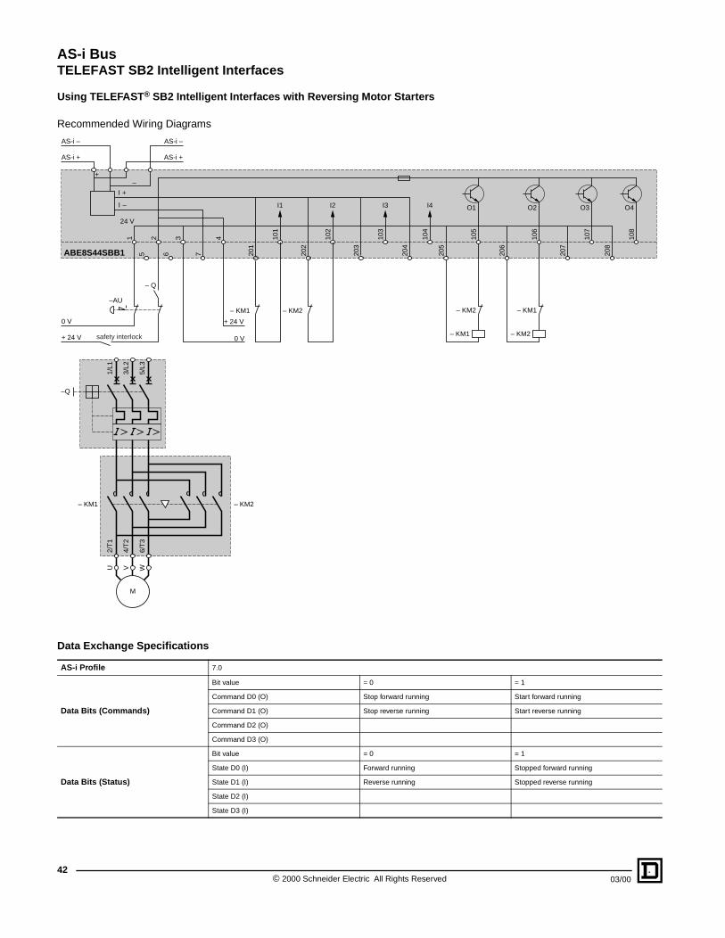
AS-i BusTELEFAST SB2 Intelligent Interfaces
© 2000 Schneider Electric All Rights Reserved42
03/00
Using TELEFAST® SB2 Intelligent Interfaces with Reversing Motor Starters
Recommended Wiring Diagrams
Data Exchange Specifications
AS-i Profile 7.0
Data Bits (Commands)
Bit value = 0 = 1
Command D0 (O) Stop forward running Start forward running
Command D1 (O) Stop reverse running Start reverse running
Command D2 (O)
Command D3 (O)
Data Bits (Status)
Bit value = 0 = 1
State D0 (I) Forward running Stopped forward running
State D1 (I) Reverse running Stopped reverse running
State D2 (I)
State D3 (I)
– KM2
+ 24 V
AS-i +
0 V
+ 24 V
+–
AS-i –
0 V
I1Ι –
Ι +
24 V
AS-i +
AS-i –
1 2 3 4 101
5 6 7 201
202
203
204
205
I2
102
I3
103
I4 O1
104
105
– KM1
– Q
ABE8S44SBB1
– KM1
– KM2
206
O2
106
– KM2
– KM1
207
O3
107
208
O4
108
–AU
–Q
M
U WV
2/T
1
6/T
3
4/T
2
1/L1
5/L3
3/L2
– KM1 – KM2
safety interlock

AS-i BusTELEFAST SB2 Intelligent Interfaces
4303/00 © 2000 Schneider Electric All Rights Reserved
Using TELEFAST® SB2 Intelligent Interfaces with Motor Starters
Associated Components
Only for ABS8••: 3 contactors can be interfaced with the ASBE8S44SBB1 module (maximum accumulative current for all output channels: 3.15 A)
Only for ABS8••: 3 contactors can be interfaced with the ASBE8S44SBB1 module (maximum accumulative current for all output channels: 3.15 A)
Standard Motor Starters
Rated Operational Power for Utilization Category AC-3
DOL Non-reversing Starters Reversing Starters Contactor
Consumption at 24 Vdc 400/415 Vac 220/230 Vac
Disconnect/Protector
Add-on Auxiliary
Block
Contactors KM1 to KM4
Disconnect/Protector
Add-on Auxiliary
Block
Reversing Contactors KM1 & KM2
Add-on Auxiliary
Block
kW kW Catalog No. Catalog No. Catalog No. Catalog No. Catalog No. Catalog No. Catalog No. mA
0.06 – GV2M02 GV2AE20 LP1K0601BD GV2M02 GV2AE20 LP2K0601BD LA1KN11 125
0.09 0.06 GV2M03 GV2AE20 LP1K0601BD GV2M03 GV2AE20 LP2K0601BD LA1KN11 125
0.12/0.18 – GV2M04 GV2AE20 LP1K0601BD GV2M04 GV2AE20 LP2K0601BD LA1KN11 125
0.25 0.09/0.12 GV2M05 GV2AE20 LP1K0601BD GV2M05 GV2AE20 LP2K0601BD LA1KN11 125
0.37/0.55 018/0.25 GV2M06 GV2AE20 LP1K0601BD GV2M06 GV2AE20 LP2K0601BD LA1KN11 125
0.75 0.37 GV2M07 GV2AE20 LP1K0601BD GV2M07 GV2AE20 LP2K0601BD LA1KN11 125
1.1/1.5 0.55/0.75 GV2M08 GV2AE20 LP1K0601BD GV2M08 GV2AE20 LP2K0601BD LA1KN11 125
2.2 1.1 GV2M10 GV2AE20 LP1K0601BD GV2M10 GV2AE20 LP2K0601BD LA1KN11 125
3/4 1.5 GV2M14 GV2AE20 LP1K0901BD GV2M14 GV2AE20 LP2K0901BD LA1KN11 125
5.5 2.2/3 GV2M16 GV2AE20 LP1D1201BD GV2M16 GV2AE20 LP2D1201BD LA1DN11 375
7.5 4 GV2M20 GV2AE20 LP1D1801BD GV2M20 GV2AE20 LP2D1801BD LA1DN11 375
9 – GV2M21 GV2AE20 LP1D2501BD GV2M21 GV2AE20 LP2D2501BD LA1DN11 460
11 5.5 GV2M22 GV2AE20 LP1D2501BD GV2M22 GV2AE20 LP2D2501BD LA1DN11 460
15 7.5/9 GV3M40 GV2AE20 LP1D3201BD GV3M40 GV2AE20 LP2D3201BD LA1DN11 460
18.5 – GV3M40 GV2AE20 LP1D3201BD GV3M40 GV2AE20 LP2D3201BD LA1DN11 460
22 11 GV3M63 GV2AE20 LP1D5001BD – – – – 920
30 15 GV3M63 GV2AE20 LP1D6501BD – – – – 920
37 18.5/22 GV7RE80 GV7AE11 LP1D8001BD – – – – 920
High-Performance Motor Starters
Rated Operational Power for Utilization Category AC-3
DOL Non-reversing Starters Reversing Starters Contactor
Consumption at 24 Vdc 400/415 Vac 220/230 Vac
Disconnect/Protector
Add-on Auxiliary
Block
Contactors KM1 to KM4
Disconnect/Protector
Add-on Auxiliary
Block
Reversing Contactors KM1 & KM2
Add-on Auxiliary
Block
kW kW Catalog No. Catalog No. Catalog No. Catalog No. Catalog No. Catalog No. Catalog No. mA
0.06 – GV2P02 GV2AE20 LP1D0901BD GV2P02 GV2AE20 LP2D0901BD LA1DN11 375
0.09 0.06 GV2P03 GV2AE20 LP1D0901BD GV2P03 GV2AE20 LP2D0901BD LA1DN11 375
0.12/0.18 – GV2P04 GV2AE20 LP1D0901BD GV2P04 GV2AE20 LP2D0901BD LA1DN11 375
0.25 0.09/0.12 GV2P05 GV2AE20 LP1D0901BD GV2P05 GV2AE20 LP2D0901BD LA1DN11 375
0.37/0.55 018/0.25 GV2P06 GV2AE20 LP1D0901BD GV2P06 GV2AE20 LP2D0901BD LA1DN11 375
0.75 0.37 GV2P07 GV2AE20 LP1D0901BD GV2P07 GV2AE20 LP2D0901BD LA1DN11 375
1.1/1.5 0.55/0.75 GV2P08 GV2AE20 LP1D1801BD GV2P08 GV2AE20 LP2D1801BD LA1DN11 375
2.2 1.1 GV2P10 GV2AE20 LP1D1801BD GV2P10 GV2AE20 LP2D1801BD LA1DN11 375
3/4 1.5 GV2P14 GV2AE20 LP1D1801BD GV2P14 GV2AE20 LP2D1801BD LA1DN11 375
5.5 2.2/3 GV2P16 GV2AE20 LP1D2501BD GV2P16 GV2AE20 LP2D2501BD LA1DN11 460
7.5 4 GV2P20 GV2AE20 LP1D2501BD GV2P20 GV2AE20 LP2D2501BD LA1DN11 460
9 – GV2P21 GV2AE20 LP1D2501BD GV2P21 GV2AE20 LP2D2501BD LA1DN11 460
11 5.5 GV2P22 GV2AE20 LP1D2501BD GV2P22 GV2AE20 LP2D2501BD LA1DN11 460
15 7.5/9 GV3M40 GV2AE20 LP1D8001BD GV3M40 GV2AE20 LP2D8001BD LA1DN11 920
18.5 – GV3M40 GV2AE20 LP1D8001BD GV3M40 GV2AE20 LP2D8001BD LA1DN11 920
22 11 GV3M63 GV2AE20 LP1D8001BD – – – – 920
30 15 GV3M63 GV2AE20 LP1D8001BD – – – – 920
37 18.5/22 GV7RE80 GV7AE11 LP1D8001BD – – – – 920
For convenience, the tables above provide references for IEC devices. The same connectivity can be done with NEMA starters and contactors. Consult the factory for additional information.

AS-i BusIntelligent Splitter Modules
44
Passive 4-way
Intelligent 4 Inputs
2 Inputs/2 Outputs
4 Outputs
Connection Bases
XZSDE1113 XZSDE1133
XZSDE2213XZSDE2323
XZSDE2213XZSDE2323
XZSDP40D1
XZSDA40D3
XZSDP40D1
XZSDA40D3
XZSDA22D32
XZSDA04D32
XZSDP40D1
XZSDA40D3
XZSDA22D32+XZSG10
XZSDA04D32+XZSG10
© 2000 Schneider Electric All Rights Reserved 03/00

AS-i BusIntelligent Splitter Modules
03/00 © 200
XZSDA22D32 XZSDA40D3
XZSDA04D32
XZSCA44D22
XZSCA44D21
XZSDE11•3 XZSDE2213
XZSG10XZSDP
XZLG102
Connection to outputs of low power relays, LEDs, valves, etc. Connection to inputs of digital contacts (push buttons, limit switches) and to solid-state outputs
of 2 or 3-wire type PNP sensors.
Two PG 11 cable glands (clamping capacity Ø6 to 10 mm) and 3 blanking plugs included with connection base. For twin-conductor cable for AS-i bus Ie ≤ 4 A.
4-Port Intelligent Splitter Modules for Connections to Actuators or Sensors
Description Sensor SupplySeparate Supply to the Actuators
Catalog Number
Splitter module2 inputs/2 solid-state outputs
Via XZSDE••••connection base,from the AS-i bus
Via XZSDE•••• connection base
XZSDA22D32
Splitter module4 inputs(200 mA max.)
Via XZSDE••••connection base,from the AS-i bus
– XZSDA40D3
Splitter module4 solid-state outputs
– Via XZSDE•••• connection base
XZSDA04D32
8-Port Splitter Modules
Description Connection Catalog Number
Splitter boxes4 inputs/4 solid-state outputs
To the AS-i bus and to the separate supply by IDC (Insulation Displacement Connectors) to yellow and black flat cables
XZSCA44D21
To the AS-i bus and to the separate supply by 5-pin male M12 connector
XZSCA44D22
Connection Bases
Description Cable ConnectionType and Number of Cables
Catalog Number
Connection bases for flat cable
By IDC
2 flat cables for AS-i bus (yellow) or 2 flat cables for separate supply (black) Ie ≤ 2 A
XZSDE1113
By IDC
2 flat cables:- 1 for AS-i bus (yellow)- 1 for separate supply(black) Ie ≤ 2 A
XZSDE1133
Connection base for round cable
To screw terminals Maximum clamping capacity: 2 x 16 AWG (2 x 1.5 mm2)
Unshielded XZSDE2213
Shielded XZSDE2323
Accessories for Connection Bases
DescriptionCable Type Suitable for Connection to Equipped Base
Catalog Number
Adaptor for provision of separate supply from the XZSDE2••• connection base
4-core cable(2 for the AS-i bus, 2 for the separate supply)
XZSG10
Cover for connection base XZSDP
Accessory for Splitter Modules
Description Catalog Number
Blanking plugfor M12 connectorDegree of protection IP 67
XZLG102
450 Schneider Electric All Rights Reserved

AS-i BusIntelligent Splitter Modules
Specifications
The power supplied to the module from the AS-i bus is short-circuit protected (maximum current: 100 mA). Total permissible current for the module: 2 A max.
Type2 inputs/2 outputs 4 inputs/4 outputs 4 inputs/4 outputs
XZSDA22D32 XZSCA44D21 XZSCA44D22
Environment
Product certifications AS-i No. 10201 AS-i No. 26201 AS-i No. 26201
Ambient Air Temperature Operation: -13 °F to +158 °F (-25 °C to +70 °C)Storage: -40 °F to +185 °F (-40 °C to +85 °C)
Degree of Protection IP 67
Materials PA6-GF-FR
ConnectionFrom the bus By connection base XZSDE•••• By insulation displacement connector By male, 5-pin, M12 connector
To the actuatorsor PNP sensors
By female, 4-pin, M12 connector
Electrical Specifications
Power Supply
Module From the AS-i bus From the AS-i bus (protected against reverse polarity)
Sensors 18 to 30 Vdc
Actuators
From separate 24 Vdc supply, -10% to +15%
From separate 24 Vdc supply, -10% to +15% (with protection against reverse polarity)
Via connection base Via AS-i black flat cable Via connector
Current Consumption from the Bus
≤ 200 mA ≤ 250 mA (output “On”)
PNP Inputs
Maximum current forthe 2 or 4 sensors
90 mA 200 mA
Input current - high ≥ 5 mA
Input current - low ≤ 1.5 mA
Input voltage - high > 10 Vdc
Input voltage - low < 5 Vdc
Outputs
Type Solid state 24 Vdc
Watchdog Default to state O (off) in the event of a communications failure
Maximum current 2 A DC12: 1.4 A; DC13: 2 A
Short-circuit protection Yes Yes plus protection against inductive over voltages
IndicatorsGreen LED Supply Supply plus verification of bus operation
Yellow LEDs Inputs/outputs
Data Exchange SpecificationsAS-i Profile S3.0 S7.0
Data Bits Status (I)and Commands (O)
Bit value = 0 = 1 = 0 = 1 = 0 = 1
D0 (I): Sensor 1 signal (I): Sensor 1 signal (I): Sensor 1 signal
Absent Present
Absent Present Absent Present
(O): Output 1 (O): Output 1
Off On Off On
D1 (I): Sensor 2 signal (I): Sensor 2 signal (I): Sensor 2 signal
Absent Present
Absent Present Absent Present
(O): Output 2 (O): Output 2
Off On Off On
D2 (O): Output 3 (I): Sensor 3 signal (I): Sensor 3 signal
Off On
Absent Present Absent Present
(O): Output 3 (O): Output 3
Off On Off On
D3 (O): Output 4 (I): Sensor 4 signal (I): Sensor 4 signal
Off On
Absent Present Absent Present
(O): Output 4 (O): Output 4
Off On Off On
Parameter Bits P0 to P3 Not used
© 2000 Schneider Electric All Rights Reserved46
03/00

AS-i BusIntelligent Splitter Modules
The power supplied to the module from the AS-i bus is short-circuit protected (maximum current: 100 mA). Total permissible current for the module: 2 A max.
Type4 inputs 4 outputs
XZSDA40D3 XZSDA04D32
Environment
Product Certifications AS-i No. 03602 AS-i No. 10301
Ambient Air Temperature Operation: -13 °F to +158 °F (-25 °C to +70 °C)Storage: -40 °F to +185 °F (-40 °C to +85 °C)
Degree of Protection IP 67
Materials PA6-GF-FR
ConnectionFrom the bus By connection base XZSDE••••
To the actuatorsor PNP sensors
By female, 4-pin, M12 connector
Electrical Specifications
Power Supply
Module From the AS-i bus
Sensors 18 to 30 Vdc -
Actuators- From separate 24 Vdc supply, -10% to +15%
- Via connection base
Current Consumption from the Bus
≤ 300 mA ≤ 50 mA
PNP Inputs
Maximum current forthe 2 or 4 sensors
200 mA-
Input current - high ≥ 5 mA -
Input current - low ≤ 1.5 mA -
Input voltage - high > 10 Vdc -
Input voltage - low < 5 Vdc -
Outputs
Type - Solid state 24 Vdc
Watchdog - Default to state O (off) in the event of a communications failure
Maximum current - 2 A
Short-circuit protection - Yes
IndicatorsGreen LED Supply
Yellow LEDs Inputs/outputs
Data Exchange SpecificationsAS-i Profile S0.0
Data Bits Status (I)and Commands (O)
Bit value = 0 = 1 = 0 = 1
D0 (I): Sensor 1 signal (O): Output 1
Absent Present Off On
D1 (I): Sensor 2signal (O): Output 2
Absent Present Off On
D2 (I): Sensor 3 signal (O): Output 3
Absent Present Off On
D3 (I): Sensor 4 signal (O): Output 4
Absent Present Off On
Parameter Bits P0 to P3 Not used
4703/00 © 2000 Schneider Electric All Rights Reserved

AS-i BusCabling and Connection Accessories
48
XZCG012
XZCG014XZCG014
XZCG0120
XZCG0220
XZSDP40D1
Passive Splitter Modules for Connections to AS-i Sensors or Actuators
Description Catalog Number
Splitter module, 4-way(2 A max. per way)
XZSDP40D1
Accessories for Connection of AS-i Flat Cable
Tap-Offs
Connection to flat cables by IDC (Insulation Displacement Connector).Ue - 40 V, Ie - 2 A.Degree of protection IP 40. Ambient air temperature: Operation: -13 °F to +158 °F (-25 °C to +70 °C), Storage: -40 °F to +185 °F (-40 °C to +85 °C)
DescriptionConnection to AS-i Sensor or Actuator
Cable Length Mounting Catalog Number
Tap-offs forconnection toa flat cable for AS-i bus (yellow)
By 5-pin femalestraight M12 remote connectorCable: 2 x 24 AWG (2 x 0.34 mm2)
1.97 ft (0.6 m) Screw XZCG01205D
3.28 ft (1 m) Screw XZCG0121D
By 5-pin femaleelbowed M12remote connectorCable: 2 x 24 AWG (2 x 0.34 mm2)
1.97 ft (0.6 m) Screw XZCG01205C
3.28 ft (1 m) Screw XZCG0121C
By cable with baredends for terminal blockCable: 2 x 24 AWG (2 x 0.34 mm2)Brown wire: AS-i Blue wire: AS-i
6.56 ft (2 m) Screw XZCG0122
Tap-offs forconnection totwo flat cables: - 1 for AS-i bus (yellow)- 1 for the separatesupply (black)
By 5-pin female straight M12 remote connectorCable: 4 x 24 AWG (4 x 0.34 mm2)
0.98 ft (0.3 m) Screw XZCG01403D
6.56 ft (2 m) Screw XZCG0142D
For 5-pin femaleelbowed M12remote connectorCable: 4 x 24 AWG (4 x 0.34 mm2)
0.98 ft (0.3 m) Screw XZCG01403C
6.56 ft (2 m) Screw XZCG0142C
By cable with baredends for terminal blockCable 4 x 24 AWG (4 x 0.34 mm2)Brown wire: AS-i Blue wire: AS-i White wire: 0 VBlack wire: + 24 V
6.56 ft (2 m) Screw XZCG0142
T connectors
Connection to flat cable by IDCUe ≤ 40 V, Ie ≤ 2 A.Degree of protection IP 67. Ambient air temperature: Operation: -13 °F to +158 °F (-25 °C to +70 °C), Storage: -40 °F to +185 °F (-40 °C to +85 °C)
DescriptionConnection to AS-iSensor or Actuator
Mounting Lugs Catalog Number
T connectors for connection to a flat cable for AS-i bus (yellow)
By 5-pin female M12 connectorWith XZCG0120
Without XZCG0220
© 2000 Schneider Electric All Rights Reserved 03/00

AS-i BusCabling and Connection Accessories
03/00
XZCB1••0•
XZCE40
Flat Cables and Accessories
The special profile of these 2-core flat cables eliminates the risk of polarity reversal when connecting.Connection to the cables are made by IDCs (see connection accessories).The sheath material self-seals the holes made by the IDC in the event of the connector being removed.Degree of protection IP 67. Ambient air temperature:- standard cable: Operation: -13 °F to +185 °F (-25 °C to +85 °C), Storage: -40 °F to +185 °F (-40 °C to +85 °C).- TPE (oil and vapor resistant cable): Operation with cable flexing: -22 °F to +221 °F (-30 °C to +105 °C)Non-flexing operation or storage: -40 °F to +221 °F (-40 °C to +105 °C)
Description Sheath Color Length Type of Cable Catalog Number
Flat cable 2 x 16AWG(2 x 1.5 mm2)Ue ≤ 48 V
Yellow (for bus)
65.6 ft (20 m)Standard XZCB10201
TPE XZCB10201H
164.0 ft (50 m)Standard XZCB10501
TPE XZCB10501H
328.1 ft (100 m)Standard XZCB11001
TPE XZCB11001H
Black (for separate 24 Vdc supply)
65.6 ft (20 m)Standard XZCB10202
TPE XZCB10202H
164.0 ft (50 m)Standard XZCB10502
TPE XZCB10502H
328.1 ft (100 m)Standard XZCB11002
TPE XZCB11002H
Description Catalog Number
Cable gland protective seal for use with flat cable and No. 11 cable gland (DIN PG11) XZCE40
49© 2000 Schneider Electric All Rights Reserved

AS-i BusCabling and Connection Accessories
DimensionsSplitter modules XZSDA•••, XZSDP40D1 Connection bases XZSDE11•3 Connection bases XZSDE2•••
Cover XZSDP Cables XZCB•••••
Splitter boxesXZSCA44D21 XZSCA44D22
1.0627
Ø0.37Ø9.5
1.46371.77
45
M12x1
2.34
59.5
3.15 80 1.38
(1)
35 (
1)Ø
0.21
Ø5.
3
Ø0.
37Ø
9.5 0.79
20
3.15 80
2.60 66
1.2231
1.77 (1)45 (2)
3.15 80
0.98 25
2.59 66
1.2231
0.7820
0.7920
1.77 (2)45 (2)
(4)
1.3033
(3)
1.38
(1)
35 (
1)Ø
0.21
Ø5.
3
Ø0.
37Ø
9.5
(1) Mounting on DIN rail.(2) When mounting side-by-side, allow 0.04 in
(1 mm) minimum between the modules.
(3) 4 holes for mounting PG11 cable gland or blanking plug.
(4) PG11 cable gland.
3.15 80
2.60 66
1.22311.77
45
0.513
0.16 4
0.143.6
0.020.5
0.102.5
0.3910
0.266.5
– +BNBU
Dual Dimensions: inchesmm
I-4 0-4
I-3 0-3
I-2 0-2
I-1 0-1
2.3660 1.42
36
1.3033 1.54
39
0.18 4.5
4.21
107
5.98
152
2.26
57.5
1.06 27
1.06 27
1.06 27
Ø0.20Ø5
2xØ0.18x72xØ4.5x7
1.0827.4
0.8020.4
0.9825
6.34
161
0.7118
M12x1
I-4 0-4
I-3 0-3
I-2 0-2
I-1 0-1
2.3660 1.42
36
1.3033 1.54
39
0.18 4.5
4.21
107
5.98
152
2.26
57.5
1.06 27
1.06 27
1.06 27
Ø0.20Ø5
2xØ0.18x72xØ4.5x7
© 2000 Schneider Electric All Rights Reserved50
03/00

AS-i BusCabling and Connection Accessories
DimensionsT-connectorsXZCG0120 XZCG0220
Tap-OffsXZCG012•• XZCG014••
ConnectionsM12 connectors on intelligent splitter modulesInputs XZSDA40D•, XZSDA22D•• Outputs XZSDA04D••Digital contact 3-wire sensor 2-wire sensor
M12 connectors on splitter boxes XZSCA44D2Inputs Outputs Connection to bus andDigital contact 3-wire sensor 2-wire sensor separate supply
XZSCA44D22
M12 connectors on T connectors XZCG0•20 M12 connectors on Connection basespassive splitter modules XZSDP40D1 tap-offs XZCG014•• XZSDE11•3 XZSDE2•••and tap-offs XZCG012••
1.9750
1.21
30.7
0.7920
0.59 15
1.18301.57
40
0.39 10
Ø0.18Ø4.5
(1)
1.1830
1.2
30.4
0.7920
0.59 15
(1)
(1) Connector adjustable to 2 positions through 90° (1) Connector adjustable to 2 positions through 90°
Dual Dimensions: inchesmm
0.43
10.8
(1) 1.333
0.4712 0.
092.
3
0.01 0.3
0.6
15.3
1.2431.51.63
41.5
0.6817.3
0.25
0.174.3
0.31 8
0.11
2.7
1.1429
0.25
0.174.3
0.11
2.7
0.83 21
0.31 8
1.8747.5
0.7118
0.5915
0.63 16
1.5439
(1)
(1) Cable length 1.97 ft (0.6 m), 3.28 ft (1 m), or 6.56 ft (2 m).Either with stripped ends for terminals (brown: AS-i (+), blue: AS-i (-)) or fitted with M12 connector.
(1) Cable length 0.98 ft (0.3 m) or 6.56 ft (2 m).Either with stripped ends for terminals (brown: AS-i (+), blue: AS-i (-), white: 0 V, black: + 24 V) or fitted with M12 connector
Dual Dimensions: inchesmm
1
4
2
3 –
+1
4
2
3 –
+1
4
2
3 –
+ 1
4
2
3– +
1
4
2
3 –
+
s
(1)
1
4
2
3 –
+
s
(1)
1
4
2
3– +
s
5(1)2
3
1
4a + 24 V
AS-i
AS-i –
+ 0 V
1
4
2
3 –
+
s
(1)
(1) Ground connected to splitter box assembly screws.
1
4
2
3
AS-i+0 V
AS-i – a + 24 V
AS-i
AS-i
–
+
Yellow or black cable
Yellow cable
1
4
AS-i2
3AS-i –
+
5103/00 © 2000 Schneider Electric All Rights Reserved

AS-i BusExtension Cables
52
Extension Cables
XZCR••••A•
XZCR••••E•
XZCR••••D•
XZCR••••C•
1
34
1
34
3 4
2 1
5
1 2
4 35
123
123
3 4
2 1
5
1 2
4 35
12345
12345
3 4
2 1
5
1 2
4 35
1234
1234
3 4
2 1
5
1 2
4 35
AS-i Sensors or Actuators
• Proximity sensors XS1• Photo-electric detectors XUJ• Control stations XAL
• Proximity sensors XS1• Photo-electric detectors XUJ• Control stations XAL
• Proximity sensors XS1• Photo-electric detectors XUJ• Control stations XAL
• Proximity sensors XS1• Photo-electric detectors XUJ• Control stations XAL• Enclosed starters LF1, LF2
Connections
© 2000 Schneider Electric All Rights Reserved 03/00

AS-i BusExtension Cables
03/00
Extension Cables
XZCR••••K•
XZCR••••H•
XZCR••••G•
XZCR••••E•
XZCR••••A•
XZCR••••F•
XZCR••••B•
125
12
5
3 4
2 1
5
1 2
4 35
1
45
345
3 4
2 1
5
1 2
4 35
1
34
1
34
3 4
2 1
5
1 2
4 35
123
123
3 4
2 1
5
1 2
4 35
1
34
1
34
1 2
4 3
54 2
3 1
1
45
1
34
3
1 2
s1 2
4 35
4
1
34
1
34
3 1
4
1 2
4 3
5
Standard Sensors
• Limit switches XCKJ•••D and XCM (4 or 5-pin)N.C. contact only.
• Limit switches XCKJ•••D and XCM (4 or 5-pin)N.O. contact only.
• Photo-electric detectors, 3-wire PNP, Osiris design 18, and Osiris design compact XUL.Operation: “light on” only.
• Photo-electric detectors, 3-wire PNP, XUB.- thru beam and reflex: operation: “light on” only- diffuse: operation: “dark on” only.
• Limit switches XS••••••D, type PNP 3-wire.N.O. output only.
• Photo-electric detectors, 3-wire PNP, XUB.- thru beam and reflex: operation: “light on” only- diffuse: operation: “dark on” only.
• Photo-electric detectors, 3-wire PNP, Osiris design compact XUJK.Operation: “light on” or “dark on”.
• Limit switches XS••••••D, 3-wire PNP.N.C. output only.
• Photo-electric detectors, PNP, Osiris design 8 XUA.Operation: “light on” or “dark on”.
• Limit switches XS••••••D, 3-wire PNP.N.O. or N.C. output.
• Photo-electric detectors, 3-wire PNP, Osiris design fiber XUD, Osiris design miniature XUML, and Osiris design forked XUVK.Operation: “light on” only.
• Electromechanical pressure or vacuum switches XML.N.O. contact only.
53© 2000 Schneider Electric All Rights Reserved

AS-i BusExtension Cables
Extension Cables with M12 Male/Female for Terminal Connections, 8 mm Diameter Female Connectors
Clip together, without locking. Degree of protection when correctly clipped together and with clamping ring correctly tightened, on screw versions.
DimensionsXZMG11 XZCR1501040G• XZCR1502040G•
ConnectionsXZMG11 XZCR1501040G•, XZCR1502040G•
Male Connector Type M12, 2-pin, straight M12, 3-pin, straight
Female Connector Type For terminal connections Ø 8 mm, 3-pin, straight Ø 8 mm, 3-pin, elbowed
Application See extension cable selection guide according to type of device to be connected to the AS-i bus, pages 52 and 53.
Selection
PvR Cable,Color Black
L = 1.64 ft(0.5 m)
XZMG11 – –
L = 3.28 ft(1 m)
– XZCR1501040G1 XZCR1502040G1
L = 6.56 ft(2 m)
– XZCR1501040G2 XZCR1502040G2
Specifications
Type of Connector Male: screw threaded. Female: clip ,
Degree of Protection IP 67 (male connector) IP 65
Ambient Air Temperature +14 °F to +122 °F (-10 °C to +50 °C) -31 °F to +176 °F (-35 °C to +80 °C)
Conductor Size 2 x 22 AWG (2 x 0.5 mm2) 3 x 24 AWG (3 x 0.34 mm2)
Cable Diameter 0.2 in (5 mm) 0.2 in (5 mm)
Nominal Voltage 12 to 48 Vdc 60 Vac, 75 Vdc
Nominal Current 3 A 4 A
Contact Resistance ≤ 5 mΩ ≤ 5 mΩ
M12x1
1.6341.5
19.69500
1.0226
0.43 11
Fitting forterminal
connection
M12x1
1.6341.5
1.1830
Ø0.
31Ø
8
L
L = 3.28 ft (1 m) or 6.56 ft (2 m)
1.6341.5
0.7920
Ø0.31Ø8
M12x10.24
6
0.63 16
L
L = 3.28 ft (1 m) or 6.56 ft (2 m)Dual Dimensions: inchesmm
21
34+ ––+
1
34
1
34
21
34
5 3 1
4
© 2000 Schneider Electric All Rights Reserved54
03/00

AS-i BusExtension Cables
Extension Cables with M12 Male Connector and M8 Female Connector
Degree of protection when clamping ring correctly tightened.
Dimensions
XZCR1509040H•, XZCR1509041J• XZCR1510040H•, XZCR1510041J•
Connections
XZCR1509040H•, XZCR1510040H• XZCR1509041J•, XZCR1510041J•
Male Connector Type M12, 3-pin, straight M12, 4-pin, straight
Female Connector Type M8, 3-pin, straight M8, 3-pin, elbowed M8, 4-pin, straight M8, 4-pin, elbowed
Application See extension cable selection guide according to type of device to be connected to the AS-i bus, pages 52 and 53.
Selection
PvR Cable, Color Black
L = 3.28 ft(1 m)
XZCR1509040H1 XZCR1510040H1 XZCR1509041J1 XZCR1510041J1
L = 6.56 ft(2 m)
XZCR1509040H2 XZCR1510040H2 XZCR1509041J2 XZCR1510041J2
Specifications
Type of Connector Male and female: screw threaded
Degree of Protection IP 67
Ambient Air Temperature -31 °F to +176 °F (-35 °C to +80 °C)
Conductor Size 3 x 24 AWG (3 x 0.34 mm2) 4 x 24 AWG (4 x 0.34 mm2)
Cable Diameter 0.2 in (5 mm) 0.2 in (5 mm)
Nominal Voltage 60 Vac, 75 Vdc
Nominal Current 4 A
Contact Resistance ≤ 5 mΩ
1.6341.5
L
M12x1
Ø0.
39Ø
10
M8x1
1.1830
1.6341.5
L
M12x1
0.65
16.5
0.246
0.7920
M8x1Ø0.39Ø10
L = 3.28 ft (1 m) or 6.56 ft (2 m) L = 3.28 ft (1 m) or 6.56 ft (2 m)Dual Dimensions: inches
mm
1
34
1
34
21
34
53 1
4 21234
1234
21
34
53 1
4 2
5503/00 © 2000 Schneider Electric All Rights Reserved

AS-i BusExtension Cables
Extension Cables with M12 Male Connector and M12 Female Connector
Degree of protection when clamping ring correctly tightened.
Dimensions
XZCR1511040A•, XZCR1511040E• XZCR1512040A•, XZCR1512040E•
Connections
XZCR1511040A•, XZCR1512040A• XZCR1511040E•. XZCR1512040E•
Male Connector Type M12, 3-pin, straight
Female Connector Type M12, 3-pin, straight M12, 3-pin, elbowed M12, 3-pin, straight M12, 3-pin, elbowed
Application See extension cable selection guide according to type of device to be connected to the AS-i bus, pages 52 and 53.
Selection
PvR Cable, Color Black
L = 3.28 ft(1 m)
XZCR1511040A1 XZCR1512040A1 XZCR1511040E1 XZCR1512040E1
L = 6.56 ft(2 m)
XZCR1511040A2 XZCR1512040A2 XZCR1511040E2 XZCR1512040E2
Specifications
Type of Connector Male and female: screw threaded
Degree of Protection IP 67
Ambient Air Temperature -31 °F to +176 °F (-35 °C to +80 °C)
Conductor Size 3 x 24 AWG (3 x 0.34 mm2)
Cable Diameter 0.2 in (5 mm)
Nominal Voltage 250 Vac, 300 Vdc
Nominal Current 4 A
Contact Resistance ≤ 5 mΩ
1.6341.5
L 1.6542
M12x1 M12x1
1.6341.5
L 1.2632
M12x1
M12x1 0.318
1.02 26
L = 3.28 ft (1 m) or 6.56 ft (2 m)L = 3.28 ft (1 m) or 6.56 ft (2 m)Dual Dimensions: inches
mm
1
34
1
34
21
34
5 512
43123
123
21
34
5 512
43
© 2000 Schneider Electric All Rights Reserved56
03/00

AS-i BusExtension Cables
Extension Cables with M12 Male Connector and M12 Female Connector
Degree of protection when clamping ring correctly tightened.
Dimensions
XZCR1511064D , XZCR1511041C•, XZCR1511062B• XZCR1512064D•, XZCR1512041C•, XZCR1512062B•
Connections
XZCR1511064D•, XZCR1512064D• XZCR1511041C•, XZCR1512041C• XZCR1511062B•, XZCR1512062B•
Male Connector Type M12, 5-pin, straight M12, 4-pin, straight M12, 3-pin, straight
Female Connector Type M12, 5-pin, straight M12, 5-pin, elbowed M12, 4-pin, straight M12, 4-pin, elbowed M12, 3-pin, straight M12, 3-pin, elbowed
Application See extension cable selection guide according to type of device to be connected to the AS-i bus, pages 52 and 53.
Selection
PvR Cable, Color Black
L = 3.28 ft(1 m)
XZCR1511064D1 XZCR1512064D1 XZCR1511041C1 XZCR1512041C1 XZCR1511062B1 XZCR1512062B1
L = 6.56 ft(2 m)
XZCR1511064D2 XZCR1512064D2 XZCR1511041C2 XZCR1512041C2 XZCR1511062B2 XZCR1512062B2
Specifications
Type of Connector Male and female: screw threaded
Degree of Protection IP 67
Ambient Air Temperature -31 °F to +176 °F (-35 °C to +80 °C)
Conductor Size 4 x 24 AWG (4 x 0.34 mm2) + 1 x 22 AWG (1 x 0.5 mm2)
4 x 24 AWG (4 x 0.34 mm2) 3 x 22 AWG (3 x 0.5 mm2)
Cable Diameter 0.23 in (5.8 mm) 0.2 in (5 mm) 0.2 in (5 mm)
Nominal Voltage 30 Vac, 36 Vdc 250 Vac, 300 Vdc 30 Vac, 36 Vdc
Nominal Current 4 A
Contact Resistance ≤ 5 mΩ
1.6341.5
L 1.6542
M12x1 M12x1
1.6341.5
L 1.2632
M12x1
M12x1 0.318
1.02 26
L = 3.28 ft (1 m) or 6.56 ft (2 m) L = 3.28 ft (1 m) or 6.56 ft (2 m)Dual Dimensions: inchesmm
12345
1234521
34
5 512
43 1234
1234
21
34
5 512
43 12
5
12
521
34
5 512
43
5703/00 © 2000 Schneider Electric All Rights Reserved

AS-i BusExtension Cables
Extension Cables with M12 Male Connector and M12 Female or DIN 43650 A Connectors
Degree of protection when clamping ring correctly tightened.
Dimensions
XZCR1511062F• XZCR1512062F• XZCR1523062K•
Connections
XZCR1511062F•, XZCR1512062F• XZCR1523062K•
Male Connector Type M12, 3-pin, straight
Female Connector Type M12, 3-pin, straight M12, 3-pin, elbowed DIN 43650 A, elbowed
Application See extension cable selection guide according to type of device to be connected to the AS-i bus, pages 52 and 53.
Selection
PvR Cable,Color Black
L = 3.28 ft(1 m)
XZCR1511062F1 XZCR1512062F1 XZCR1523062K1
L = 6.56 ft(2 m)
XZCR1511062F2 XZCR1512062F2 XZCR1523062K2
Specifications
Type of Connector Male and female: screw threaded
Degree of Protection IP 67
Ambient Air Temperature -31 °F to +176 °F (-35 °C to +80 °C)
Conductor Size 3 x 22 AWG (3 x 0.5 mm2)
Cable Diameter 0.2 in (5 mm)
Nominal Voltage 30 Vac, 36 Vdc
Nominal Current 4 A
Contact Resistance < 5 mΩ
L = 3.28 ft (1 m) or 6.56 ft (2 m)
1.6341.5
L 1.6542
M12x1 M12x1
1.6341.5
L 1.2632
M12x1
M12x1 0.318
1.02 26
1.6341.5
L 2.3660
30
M12x1
1.42 36
L = 3.28 ft (1 m) or 6.56 ft (2 m)L = 3.28 ft (1 m) or 6.56 ft (2 m) L = 3.28 ft (1 m) or 6.56 ft (2 m)
Dual Dimensions: inchesmm
1
45
34521
34
5 512
43 1
45
1
34
21
34
5
3
1
4
© 2000 Schneider Electric All Rights Reserved58
03/00

AS-i BusExtension Cables
M12 Male Connectors and Extension Cables, M12 Two-Way Splitter Boxes
To order a connector with a plastic clamping ring (entirely plastic encased connector) replace the second letter M in the selected reference with the letter P. For example: XZCC12MDM40B becomes XZCC12MDP40B.
Degree of protection when clamping ring correctly tightened and cable gland correctly seated.
Dimensions
XZCC12MDM40B XZCC12MCM40B XZCP1564L• XZLC1220C1
Connections
XZCC12M, •M40B XZCP1564L• XZLC1220C1
Male Connector Type M12, 4-pin, straight M12, 5-pin, straight
Application See extension cable selection guide according to type of device to be connected to the AS-i bus, pages 52 and 53.
Selection
Connection to Cable by Screw Terminal Connections
XZCC12MDM40B XZCC12MCM40B – –
PvR Cable, Color Black
L = 1.64 ft(0.5 m)
– – XZCP1564L05 –
L = 3.28 ft(1 m)
– – XZCP1564L1 –
L = 6.56 ft(2 m)
– – XZCP1564L2 –
2-Way Splitter (M12 Female Connectors, 5 Contacts)
– – – XZLC1220C1
Specifications
Type of Connector Male: screw threaded, metal clamping ring Male: screw threadedMale and female: screw threaded
Degree of Protection IP 67 IP 67 IP 67
Ambient Air Temperature -40 °F to +185 °F (-40 °C to +85 °C) -31 °F to +176 °F (-35 °C to +80 °C) +5 °F to +194 °F (-15 °C to +90 °C)
Conductor Size For terminal connections: 4 x 20 AWG (4 x 0.75 mm2), maximum 4 x 24 AWG (4 x 0.34 mm2) + 1 x 22 AWG (1 x 0.5 mm2)Cable diameter 0.23 in (5.8 mm)
–
Nominal Voltage 125 Vac, 150 Vdc 30 Vac, 36 Vdc 10 to 30 Vdc
Nominal Current 3 A 4 A 4 A per way: 4 A max
Contact Resistance ≤ 8 mΩ ≤ 5 mΩ ≤ 5 mΩ
Ø0.79Ø20
(1)
2.36 60
M12x1
Ø0.
78Ø
20
1.6141
(1)
1.46 37
0.81
20.5
0.9123
0.359
M12x1 M12x1
1.6341.5
L
1.3033
0.6717
0.7719.5
1.3835
1.0627
M12X1
M12X11.
57
40
Dual Dimensions: inchesmm
L = 3.28 ft (1 m) or 6.56 ft (2 m)
(1) 7 mm plastic cable gland (1) 7 mm plastic cable gland
21
34 3 4
2 1
5
1 2
4 35
3 4
2 1
5
WhiteBlack21
34
5
BK/WHBN
BK BU
Y/G
5903/00 © 2000 Schneider Electric All Rights Reserved
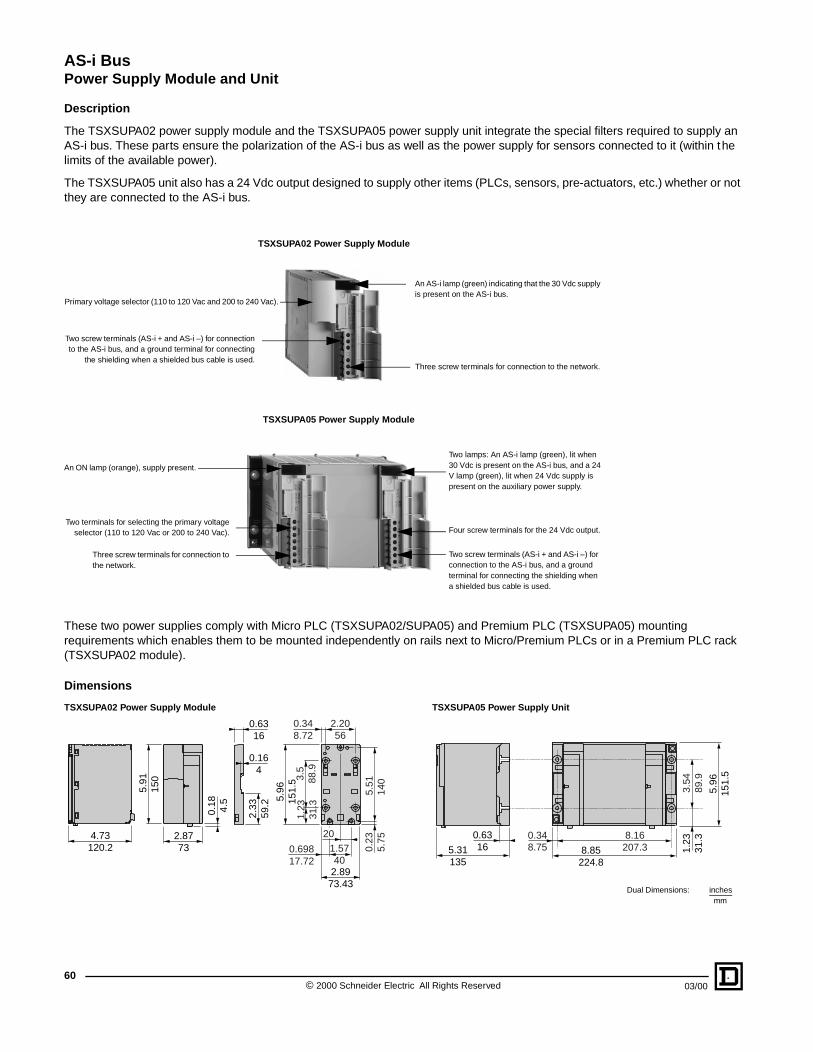
AS-i BusPower Supply Module and Unit
Description
The TSXSUPA02 power supply module and the TSXSUPA05 power supply unit integrate the special filters required to supply an AS-i bus. These parts ensure the polarization of the AS-i bus as well as the power supply for sensors connected to it (within the limits of the available power).
The TSXSUPA05 unit also has a 24 Vdc output designed to supply other items (PLCs, sensors, pre-actuators, etc.) whether or not they are connected to the AS-i bus.
These two power supplies comply with Micro PLC (TSXSUPA02/SUPA05) and Premium PLC (TSXSUPA05) mounting requirements which enables them to be mounted independently on rails next to Micro/Premium PLCs or in a Premium PLC rack (TSXSUPA02 module).
Dimensions
TSXSUPA02 Power Supply Module TSXSUPA05 Power Supply Unit
An AS-i lamp (green) indicating that the 30 Vdc supply is present on the AS-i bus.
Primary voltage selector (110 to 120 Vac and 200 to 240 Vac).
Two screw terminals (AS-i + and AS-i –) for connectionto the AS-i bus, and a ground terminal for connecting
the shielding when a shielded bus cable is used.Three screw terminals for connection to the network.
TSXSUPA02 Power Supply Module
TSXSUPA05 Power Supply Module
An ON lamp (orange), supply present.
Two lamps: An AS-i lamp (green), lit when 30 Vdc is present on the AS-i bus, and a 24 V lamp (green), lit when 24 Vdc supply is present on the auxiliary power supply.
Two screw terminals (AS-i + and AS-i –) for connection to the AS-i bus, and a ground terminal for connecting the shielding when a shielded bus cable is used.
Four screw terminals for the 24 Vdc output.
Three screw terminals for connection to the network.
Two terminals for selecting the primary voltageselector (110 to 120 Vac or 200 to 240 Vac).
5.96
151.
5
1.23
31.3
3.54
89.9
8.16207.3
0.348.75 8.85
224.8
0.63165.31
135
Dual Dimensions: inchesmm
4.73120.2
0.18 4.5
2.8773
5.91
150
0.6316
0.164
2.33
59.2
0.23
5.75
0.69817.72
1.5740
20
5.51
14
0
2.2056
2.8973.43
0.348.72
5.96
151.
5 3.5
88.9
1.23
31.3
© 2000 Schneider Electric All Rights Reserved60
03/00

AS-i BusPower Supply Module and Unit
03/00
TSXSUPA02
TSXSUPA05
Specifications
The TSXSUPA05 is a constant output maximum power. The power which is not used on one output is available on the other output. Output currents must respect the above curve.
Constant output maximum power supply unit, see above curve.
Type of Power Supply Module
TSXSUPA02 TSXSUPA05
Nominal Primary Voltage 100 to 120 Vac 200 to 240 Vac 100 to 120 Vac 200 to 240 Vac
Primary Voltage Range 85 to 132 Vac 170 to 264 Vac 85 to 132 Vac 170 to 264 Vac
Network Limit Frequency 47 to 63 47 to 63 47 to 63 47 to 63
Max. Immunity Time to Microbreaks
10 ms 10 ms 10 ms 10 ms
Secondary Nominal Voltages 30 V (AS-i bus) 30 V (AS-i bus) 24 V (process)
Voltage Limits 29.5 to 31.6 V 29.5 to 31.6 24 V ± 3%
Output Current 2.4 A at 140 °F (60 °C) (2.8 A peak) See output current curve at 140 °F (60 °C)
Output Power at Secondary 72 W at 140 °F (60 °C) See output current curve at 140 °F (60 °C)
TSXSUPA05 Output Currents
Rms Insulation Voltage Between Primary and Secondary
3500 Vrms
Withstand to Electric Fields 10 V/m
Safety Extra Low Voltage (SELV)
Yes
Interference Withstand Class FCC class A
Conformity to Standards
PLC IEC 1131-2
Vibrations IEC 68-2-6-Fc (2 g) IEC 68-2-6-Fc (1 g)
Shocks IEC 68-2-27 (15 g, 11 ms)
Temperature Storage -13 °F to +158 °F (-25 °C to +70 °C)
Operation +14 °F to +140 °F (-10 °C to +60 °C)
Compliance Standards UL Listed E194434 CCN NRAQCSA Certified LR58905 Class 2252 01
Selection
DescriptionCurrent at Secondary Voltages
Catalog Number30 Vac (AS-i bus) 24 Vdc
Module 100 to 120 Vac and 200 to 240 Vac, 50/60 Hz
2.4 A – TSXSUPA02
Unit 100 to 120 Vac and 200 to 240 Vac, 50/60 Hz
5 A 7 A TSXSUPA05
Ground fault detector for AS-i bus – – RM0PAS101
Connection accessories – – See pages 48 and 49.
1
1 2 3 4 5
234567
4.5
5.8
0
3
AS-i Bus Current, A (max)
Auxiliary Supply Current, A (max)
61© 2000 Schneider Electric All Rights Reserved

AS-i BusInsulation Control Relay for AS-i Bus
© 20062
105108
104101
1
201301
204 205206
4Q1
Q4
TEST RESET
OK
FAULT+
FAULT-
BUSBUS
1
23
4
6
7
7
5
Insulation control relay for AS-i bus:
1. Connections to the AS-i bus2. TEST button3. RESET button4. Relay state LED indicator5. I/O state indicators6. Removable power supply terminal7. Removable terminals
General
The RM0PAS101 insulation control relay detects and signals any ground fault on either of the 2 polarities of an AS-i bus cable. It takes into account any input/output ground faults of PNP intelligent splitter boxes (not isolated from the bus).
Used in conjunction with the impedance adaptor LA9RM401 on the supply, the RM0PAS101 insulation relay also detects faulty ground connections to the relay itself and/or to the AS-i supply.
Operating Principle
The RM0PAS101 insulation control relay is supplied directly from the AS-i bus. In the event of a fault, 1 of 2 output contacts allows breaking of the supply to the actuators while the other can be used to signal the fault to a PLC. In addition, the RM0PAS101 insulation control relay inhibits bus communication in the event of a fault, in order to activate the watchdog functions of the connected slaves.
Resetting, after rectification of fault and testing, can be performed by either using the buttons on the front left-hand side of the relay, or by applying a + 24 V signal to the inputs on the terminal block (control by PLC output).
• Operation with no fault present
On power-up of the AS-i bus, the insulation control relay measures the insulation resistance between each of the AS-i bus polarities (AS-i (+) and AS-i (–)) and the ground terminal, and compares it to a value on the order of 40 kΩ. If each resistance is higher than this value, the output relay energizes and the “OK” LED illuminates.
• Appearance of a fault
Should one or both of the resistances measured (R AS-i (+)/Ground and/or R AS-i (–)/Ground) fall below approximately 40 kΩ, or in the event of a fault in the ground connection to the RM0PAS101 insulation control relay:
— The data exchanges on the AS-i bus are inhibited which, in turn, triggers an alarm at the AS-i bus master within 5 ms.
— The output relay contacts open.
— The polarity on which the fault is detected is signalled by the illumination of one or two LEDs (FAULT + or/and FAULT –), located on the front left-hand side of the relay.
• Fault memory
The contacts remain open and the “Fault” LED stays on, even if the fault disappears, unless the supply to the AS-i (+) and AS-i (–) terminals is broken. If this occurs, the relay resets itself when the supply is restored, providing the fault has disappeared, and the output relay contacts re-close.
• Resetting
As soon as the fault is eliminated, the relay must be reset which, in turn, closes the output relay contacts and extinguishes the associated “Fault” LED. Two methods of resetting are possible:
— Locally, by pressing the RESET button.
— Remotely, by a change of state of the signal between terminals S1 and S2 (see function diagram on the next page) lasting more than 30 ms. This input must be permanently maintained at the high state when not being used for resetting.
0 Schneider Electric All Rights Reserved 03/00

AS-i BusInsulation Control Relay for AS-i Bus
03/00
• Test
The relay has a test feature to simulate faults. Each test sequence alternatively simulates an insulation fault on one of the two AS-i bus polarities. The relay must respond as if the fault was authentic and following each test, the relay must be reset as detailed above. Each subsequent test sequence checks the other polarity of the AS-i bus (see function diagram on next page).
Two methods of testing are possible:
• Locally, by pressing the TEST button.
• Remotely, by a change of state of the signal between terminals S3 and S4 lasting more than 30 ms.
Function Diagram
(1) (1) (1)
(3)
(1)
(2)(3)
(2)(3)
(2)(3)
(2)
(1) (1)
Relay off
Supply AS-i (+) AS-i (-)
AS-i (+)
AS-i (-)
LED/OKFAULT +FAULT -
Reset S1 S2
Test S3 S4Output relay
Contacts 15/1825/28
Relay on
Input at state 0 or contact openInput at state 1 or contact closed
LED offLED on
(1) 30 ms minimum
(2) 15 ms
(3) 20 ms
63© 2000 Schneider Electric All Rights Reserved

AS-i BusInsulation Control Relay for AS-i Bus
64
Selection
Dimensions
Recommended Wiring Schematic
Description Catalog Number
Insulation control relay for AS-i bus (supplied with an impedance adaptor) RM0PAS101
Impedance adaptor (replacement part) LA9RM401
2.99 76
2.2858 2.64
67
1.38 35
0.5915
3.5490
2.28 58
Dual Dimensions: inchesmm
S3
X1
X2
X3
X4
S1
15 25
S2
18 28
+ – + –
R <
0 V
0 V 0 VGND
24 Vdc
S4
To AS-i bus power supply/rest of bus
To AS-i bus master
Test(PLC output)
Remotereset
Reset(PLC output)
Fault(PLC input)
Emergency stop
Supply to actuatorsUse an interposing relay if thecurrent consumption of theactuators is greater than the breaking capacity of the internal relay(DC12: 5A/30V, DC13:1.5A/30V)
3 ohms
dc dc
RM0PAS101
AS-i (–)
AS-i (+)
Shd
1
32
(1)The insulation control relay impedance is the same as that of the network slave.
For correct operation, fit the impedance adaptor 1 directly on the AS-i bus supply 2, between terminals AS-i and Shd.
Connections to ground: both the bus power supply and the RM0PAS101 insulation relay must be reliably connected to ground (resistance < 3 Ω).
(1) Maximum distance between the insulation control relay and the AS-i bus master: 6.56 ft (2 m).Voltage at the RM0PAS101 insulation control relay must be between 29.5 and 31.6 Vdc.
1 Impedance adaptor LA9RM4012 Bus power supply3 AS-i bus master
© 2000 Schneider Electric All Rights Reserved 03/00

AS-i BusInsulation Control Relay for AS-i Bus
Specifications
Environment
Product Certification AS-i No. 16701
Conforming to Standards IEC 204, 1 and 2, EN 60204, 1 and 2
Degree of Protection Conforming to IEC 529(against direct contact)
IP2X
Resistance to Burning (Hot Wire Test) Conforming to IEC 695-2-1 1382 °F (750 °C): extinction < 30 s
Shock Resistance Conforming to IEC 68-2-27 11 ms (semi-sinusoidal), 15 gn
Vibration Resistance Conforming to IEC 68-2-6 10 to 150 Hz, 2 gn
Resistance to Electrostatic Discharges Conforming to IEC 1000-4-2 Level 3
Resistance to Radiated Fields Conforming to IEC 1000-4-3 Level 3
Resistance to Transients Conforming to IEC 1000-4-4 Level 3
Surge Withstand Conforming to IEC 1000-4-5 1.2/50–8/20 µs; Level 3
Ambient Air Temperature Operation 23 °F to 140 °F (-5 °C to +60 °C)
Insulation Voltage (for one minute) Terminals/fixing rail 2 kV
Installation Category Conforming to IEC 664 II
Degree of Pollution Conforming to IEC 654 2
Mounting Standard profilesOn backplate: 15 mm mounting rail or using ABE-ACC01
On chassis: 15 mm or 7.5 mm mounting rail
Suitable Cable Sections
Flexible cable without cable end
1 conductor 2 conductors
0.14 to 2.5 mm2 —
26 to 14 AWG —
Flexible cable with cable end0.09 to 1.5 mm2 0.09to 0.75 mm2
28 to 16 AWG 28 to 20 AWG
Solid cable0.14 to 4 mm2 0.2 to 2.5 mm2
26 to 12 AWG 24 to 14 AWG
Tightening Torque With 3.5 mm screwdriver 5.3 lb-in (0.6 N•m)
Measuring Input SpecificationsOperating Range 29.5 to 31.6 Vdc
Average Consumption at 30 V From bus 50 mA
Response TimeOpening of relay contacts < 20 ms
BUS communication interrupt < 5 ms
Detection ThresholdR AS-i (+) Ground < 10 kΩ
R AS-i (–) Ground < 10 kΩ
Output Relay Specifications and OperationNumber of Outputs 2 relays, each with 1 N/O contact
Output Relay State Energized on absence of fault when AS-i + AS-i – supplied
Rated Operating Voltage 50 Vdc
Conventional Thermal Current For U contact = 24 V DC 5 A
Rated Operating CurrentDC12 5 A
DC13 (U/R =10ms) 2 A
Operating Status Indication
FAULT +, upper red LED on Insulation fault, polarity AS-i +
FAULT –, lower red LED on Insulation fault, polarity AS-i –
OK, green LED on Supply to relay on and no fault present
Test, yellow LED on Test input at state 1
Reset, green LED on Reset input at state 1
R1 and R2, green LED on Output relays energized
Test Input and Reset Input Characteristics (supplied from external source, not bus)Consumption per Channel at Un Un = 24 Vdc 13 mA
State 1 Guaranteed U > or I > 11 V/5 mA
State 0 Guaranteed U < and I < 5 V/2 mA
Conformity Conforming to IEC 1131-2 Type II
Pending validation.
6503/00 © 2000 Schneider Electric All Rights Reserved

AS-i BusProduct Index by Description
DescriptionCatalog Number
Page No.
12 Button Keypad XBLC5012•••• 20
2 I+ 2 O Module for Operator Station XALSZ1 33
2 Push Buttons Operator Station XALS20•• 18
8-Port Splitter Box XZSCA••••• 45
Addressing Terminal XZMC11US 17
Addressing Terminal Cable XZMG11 17, 55
Addressing Terminal Cable to Non-Splitter Devices
XZMG12 17
Addressing Terminal Cable to Splitter Boxes XZMG13 17
Adhesive Label Holder AR1SB3 36
Altivar 58 AS-i Card VW3A58305 31
AS-i User Guide XD0C5011EN 17
Base for Round Shielded Cable XZSDE•••• 45
Base for Splitter Box XZSDE•••• 45
Blanking Plug XSZLD102 45
Cable XZCB••••• 52
Connector Adapter RJ 45/SUB-D 9 Pin Male XGVSZ0920
Cover for Base XZSDP 45
Covers XSZLD102 45
Drives Interface Card VW3A58305 31
Ground Leakage Relay RMOPAS101 64
Flat Cable XZCB••••• 49
I/O Card (4I + 4O) ZB2BZS•• 33
I/O Card for Operator Station XALSZ1 33
Impedance Adapter LA9RM401 64
Incandescent Bulb for XVA DL1B•••• 27
Inductive Proximity Sensor XS1M30AS101 22
Inductive Proximity Sensor XS7C40AS101 22
Inductive Proximity Sensor XS8C40AS101 22
Insulation Displacement Connectors (IDCs) XZCG••••• 48
Insulation Relay RMOPAS101 64
Intelligent Splitter Box XZSCA••••• 45
Interface Boards ZB2BZS•• 33
IP 20 Connectors XZCG••••• 48
DescriptionCatalog Number
Page No.
Jumper Cable XZCR15••••••• 52-58
Keypads XBLC5012•••• 20
M12, 5 pin, Straight, Extension Cable XZCP••••••• 59
Male Connector Plug XZCC12M••••• 59
Master for TSX Micro PLC TSXSAZ10 9
Master for TSX Premium PLC TSXSAY100 12
Mini-Style Connector Cable XZCR15••••••• 52-58
Passive Splitter Box XZLC1220C1 59
Passive Splitter, 4-Way XZSDP40D1 48
PG11 Seal for Flat Cable XZCE40 49
Photoelectric Sensors XUJK•••••AS 24
Power Supply for AS-i Bus TSXSUPA•• 61
Premium PLC Master TSXSAY100 12
Push Button Control Station XALS20•• 18
Quick Connector Cable XZCR15••••••• 52-58
Repeater XZMA1 16
RJ45/SUB-D 9 Pin Male Connector XGVSZ0920
Seal for Flat Cable XZCE40 49
Sensor Concentrator XZSCA••••• 45
Spider XALSZ1 33
Splitter Box XZSCA••••• 45
Splitter Box XZSDA••••• 45
Splitter Box XZLC1220C1 59
Splitter Box Base XZSDE•••• 45
Stack Lights XVA••••• 26
SUB-D 9 Pin Male Connector XGVSZ0920
Supply Adaptor for Round Cable Base XZSG10 45
Tap-Offs XZCG••••• 48
Telefast 2 Accessories ABE7••••• 36
Telefast 2 for AS-i ABE8••••• 36
TSX 37 Micro PLC User Manual TSXDM3713E
User Guide (AS-i Systems) XD0C5011EN 17
User Manual for TSX37 Micro TSXDM3713E
XUJ Sensor Interface XUJZAS1 24
© 2000 Schneider Electric All Rights Reserved66
03/00

AS-i BusProduct Index by Catalog Number
Catalog Number
Description Page No.
ABE7••••• TELEFAST 2 Accessories 36
ABE8••••• TELEFAST 2 for AS-i 36
AR1SB3 Adhesive Label Holder 36
DL1B•••• Incandescent Bulb for XVA 27
LA9RM401 Impedance Adapter 64
RMOPAS101 Ground Leakage Relay 64
TSXDM3713E TSX 37 Micro PLC User Manual
TSXSAY100 Master for TSX Premium PLC 12
TSXSAZ10 Master for TSX Micro PLC 9
TSXSUPA•• Power Supply for AS-i Bus 61
VW3A58305 Altivar 58 Drive Controller AS-i Card 31
XALS20•• 2 Push Buttons Operator Station 18
XALSZ1 2 I+ 2 O Module for Operator Station 33
XBLC5012•••• 12 Button Keypad 20
XD0C5011EN AS-i User Guide 17
XGVSZ0920 Connector Adapter RJ 45/SUB-D 9 Pin Male
XS1M30AS101 Inductive Proximity Sensor 22
XS7C40AS101 Inductive Proximity Sensor 22
XS8C40AS101 Inductive Proximity Sensor 22
XSZLD102 Blanking Plug 45
XUJK•••••AS Photoelectric Sensors 24
XUJZAS1 XUJ Sensor Interface 24
XVA••••• Stack Lights 26
XZCB••••• Flat Cable 49
XZCC12M••••• Male Connector Plug 59
XZCE40 PG11 Seal for Flat Cable 49
XZCG••••• Tap-Offs 48
XZCP••••••• M12, 5 pin, Straight, Extension Cable 59
XZCR15••••••• Jumper Cable 52-58
XZLC1220C1 Passive Splitter Box 59
XZMA1 Repeater 16
XZMC11US Addressing Terminal 17
XZMG11 Addressing Terminal Cable 17, 55
XZMG12Addressing Terminal Cable to Non-Splitter Devices
17
XZMG13 Addressing Terminal Cable to Splitter Boxes 17
XZSCA••••• Sensor Concentrator 45
XZSDA••••• Splitter Box 45
XZSDE•••• Splitter Box Base 45
XZSDP Cover for Base 45
XZSDP40D1 Passive Splitter, 4-Way 48
XZSG10 Supply Adaptor for Round Cable Base 45
ZB2BZS•• I/O Card (4I + 4O) 33
6703/00 © 2000 Schneider Electric All Rights Reserved

Square D Company8001 Highway 64 EastKnightdale, NC 27545 USA1-888-SquareD(1-888-778-2733)www.squared.com
Schneider Canada Inc.19 Waterman Avenue, M4B 1 Y2Toronto, Ontario
Catalog No. 8340CT0001 March 2000.D-Fax™ No. 4460, 4461, 4462
(416) 752-8020www.schneider.ca