as-interface cabling system ip 20 and ip 67 - … · 2 selection guide as-interface cabling system...
TRANSCRIPT
Catalogue August
04
AS-Interface cabling systemIP 20 and IP 67

1
Contents AS-Interface cabling systemIP 20 and IP 67
Selection guide . . . . . . . . . . . . . . . . . . . . . . . . . . . . . . . . . . . . . . . . pages 2 and 3
IP 20, AS-Interface V2.1Modular, for analogue inputsb Presentation . . . . . . . . . . . . . . . . . . . . . . . . . . . . . . . . . . . . . . . . . . . . . . . . page 4
b Characteristics. . . . . . . . . . . . . . . . . . . . . . . . . . . . . . . . . . . . . . . . . . . . . . . page 5
b References . . . . . . . . . . . . . . . . . . . . . . . . . . . . . . . . . . . . . . . . . . . . . . . . . page 6
b Dimensions, connections. . . . . . . . . . . . . . . . . . . . . . . . . . . . . . . . . . . . . . . page 7
IP 20, AS-Interface V2.1Modular, for discrete inputs/outputsb Presentation . . . . . . . . . . . . . . . . . . . . . . . . . . . . . . . . . . . . . . . . . . . . . . . . page 8
b Characteristics. . . . . . . . . . . . . . . . . . . . . . . . . . . . . . . . . . . . . . . . pages 9 and 10
b References, dimensions . . . . . . . . . . . . . . . . . . . . . . . . . . . . . . . . . . . . . . page 11
b Schemes, connections . . . . . . . . . . . . . . . . . . . . . . . . . . . . . . . . pages 12 and 13
IP 67 I/O, AS-Interface V2.1b Presentation, description . . . . . . . . . . . . . . . . . . . . . . . . . . . . . . . . . . . . . . page 14
b Setting-up . . . . . . . . . . . . . . . . . . . . . . . . . . . . . . . . . . . . . . . . . . pages 15 and 16
b Characteristics. . . . . . . . . . . . . . . . . . . . . . . . . . . . . . . . . . . . . . . pages 17 and 18
b References . . . . . . . . . . . . . . . . . . . . . . . . . . . . . . . . . . . . . . . . . . pages 19 to 21
b Dimensions . . . . . . . . . . . . . . . . . . . . . . . . . . . . . . . . . . . . . . . . . . . . . . . . page 22
b Schemes . . . . . . . . . . . . . . . . . . . . . . . . . . . . . . . . . . . . . . . . . . . . pages 23 to 25
b Connections. . . . . . . . . . . . . . . . . . . . . . . . . . . . . . . . . . . . . . . . . . . . . . . . page 26
b Selection . . . . . . . . . . . . . . . . . . . . . . . . . . . . . . . . . . . . . . . . . . . . . . . . . . page 27

2
Selection guide AS-Interface cabling system 1
Advantys, interfaces for generic productsIP 20 and IP 67
Description Analogue modular interfaces Discrete modular interfaces
Degree of protection IP 20
Functions Connection of 1 to 2 analogue sensors Connection of 1 to 8 discrete sensors/actuators
Connection of sensors/actuators By removable screw clamp connectors (optional spring terminal connectors)
Supply for the inputs and sensors Via the AS-Interface line Via the AS-Interface line or via c 24 V external power supply
Supply for the outputs – Via c 24 V external power supply
Connection to the AS-Interface and auxiliary supply By removable screw clamp connectors (optional IDC connectors)
AS-Interface version V2.1
Extended addressing No Yes
I/O configurations 2 inputs: 0/4…20 mA or 2 inputs 0…10 V 2 inputs/1 output, 4 inputs, 4 inputs/4 outputs, 4 inputs/3 outputs
Output type – Relay or triac 2 A,Transistor 0.5 A
Type ASI 20MApp ASI 20MTpp
Pages 5 11
3
1
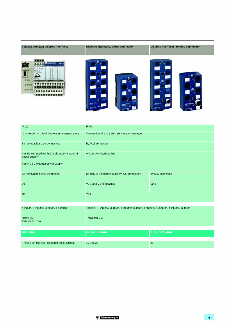
Telefast compact discrete interfaces Discrete interfaces, direct connection Discrete interfaces, remote connection
IP 20 IP 67
Connection of 1 to 8 discrete sensors/actuators Connection of 1 to 8 discrete sensors/actuators
By removable screw connectors By M12 connector
Via the AS-Interface line or via c 24 V external power supply
Via the AS-Interface line
Via c 24 V external power supply
By removable screw connectors Directly to the ribbon cable by IDC connectors By M12 connector
V1 V2.1 and V1 compatible V2.1
No Yes
4 inputs, 4 inputs/4 outputs, 4 outputs 4 inputs, 2 inputs/2 outputs, 4 inputs/4 outputs, 3 outputs, 4 outputs, 4 inputs/3 outputs
Relay 2A,Transistor 0.5 A
Transistor 2 A
ABE 8pp ASI 67FFPppp ASI 67FMPppp
“Please consult your Regional Sales Offices” 19 and 20 21

4
Presentation AS-Interface cabling system 1
Interfaces for generic productsIP 20, AS-Interface V2.1 Modular, for analogue inputs
ASI 20MA modular interfaces enable analogue output sensors (proximity, pressure, temperature sensors...) to be connected to the AS-Interface cabling system.Due to their particularly compact size, they are suitable for fitting in small-size enclosures as well as in larger, floor-standing enclosures.Inputs are of the current type (0-10 mA or 4-20 mA, depending on connection) or voltage type (0-10 V), and supply to the sensors is from the AS-Interface line.All connectors are of the removable type and are supplied with screw terminal block as standard. Quick connect terminal blocks are available as an accessory. A "Jack" connector on the front panel allows allows addressing of the product independently, or when installed.
Presentation
CompositionAS-Interface connection:
1 ASI 20MACC4 screw terminal block, fitted as standard.2 ASI 20MACC1 insulation displacement connector for chaining, to be ordered
separately.3 APE1 PAD21 self-stripping connector, to be ordered separately.
Sensor connection:
4 ASI 20MACC2 screw terminal block, fitted as standard.5 ASI 20MACC3 spring terminal connector, to be ordered separately.
Chaining The AS-Interface line can be chained
using an ASI 20MACC1 insulation displacement connector, to be ordered separately.
Description1 Removable screw terminal block for connection of the AS-Interface line. This
terminal block can be replaced by an APE 1PAD21 self-stripping block for connecting a single interface, or by an ASI 20MACC1 quick connect block for chaining several ASI 20MA interfaces.
2 Removable labels for marking the interface and the address, fitted as standard.3 Removable screw terminal block for connection of the inputs and of the power
supply for the sensors. This terminal block can be replaced by an ASI 20MACC3 quick connect terminal block.
4 Not used.5 Diagnostic LED.6 “Jack” connector for connection of an ASI TERACC2 cable for addressing and
diagnostic terminal type ASI TERV2 or XZ MC11.7 Fitting for clipping onto 35 mm symmetrical DIN rail.
1 2 3
5
4
109
481-
28-
M
1
5
2
7
3
4
6

5
Characteristics AS-Interface cabling system 1
Interfaces for generic productsIP 20, AS-Interface V2.1 Modular, for analogue inputs
EnvironmentProduct certifications UL, CSA (pending)
Operating temperature °C - 20…+ 60
Storage temperature °C - 40…+ 85Degree of protection Conforming to IEC/EN 60529 IP 20
Shock resistance Conforming to IEC/EN 60068-2-27 15 gn (for 11 ms)
Vibration resistance Hz 2…13.2 amplitude ± 1 mm, 13.2…100: 1 gnResistance to electrostatic discharge
Conforming to IEC/EN 61000-4-2 Level 3
Resistance to radiated fields Conforming to IEC/EN 61000-4-3 V/m 10
Resistance to transients Conforming to IEC/EN 61000-4-4 kV 2
Overvoltage category Conforming to IEC/EN 60664-1 IIDegree of pollution Conforming to IEC/EN 60664-1 2
AS-Interface characteristicsAS-Interface version V2.1
AS-Interface Profile (I/O code, ID code, ID1, ID2) (1) S7.3.F.D
Maximum number of addresses 31AS-Interface supply c V 26.5…31.6
Consumption on the AS-Interface line
No-load mA 60
Maximum mA 250Diagnostic signalling AS-Interface power ON Green LED
Fault (2) Red LED and fault bit
Parameter bit P0 Not usedP1 0: input 1 On, input 2 Off,
1: input 1 On, input 2 OnP2 1: fault bit On
P3 Not used
Mounting On 35 mm 5 rail (horizontal only)
Housing material Polycarbonate (UL94VO)Connection AS-Interface Removable terminal block
ASI 20MACC4: 0.2 to 2.5 mm2; ASI 20MACC1: 0.5 to 0.75 mm2; APE 1PAD2: 0.5 to 0.75 mm2
Sensors Removable terminal blockASI 20MACC2: max 1.5 mm2; ASI 20MACC3: 0.14 to 1.5 mm2
Analogue input characteristics (sensor side)Interface type ASI 20MA2VU ASI 20MA2VI
Inputs Voltage c V 0…10 –
Current c mA – 0…20 or 4…20Sensor input type Analogue
Supply to sensors V Via the AS-Interface line only
Input impedance Ω 20 000 250
Range of values decimal 0…10 000 0…20 000 or 4000…20 000Resolution bits 12
Refresh time ms < 50
(1) Bit ID1 can be modified by the user, in particular using the addressing terminal.(2) Fault LED:
off = if parameter bit 2 On, no fault,on steady = AS-Interface exchange fault,flashing = voltage > 10.5 V (VU), current < 1 mA or > 21 mA (VI).
6
References AS-Interface cabling system 1
Interfaces for generic productsIP 20, AS-Interface V2.1 Modular, for analogue inputs
(1) The inputs and sensor electronics are supplied from the AS-Interface line.(2) Connectors supplied with locating facility not activated; locating facility to be activated by
cutting off a lug.
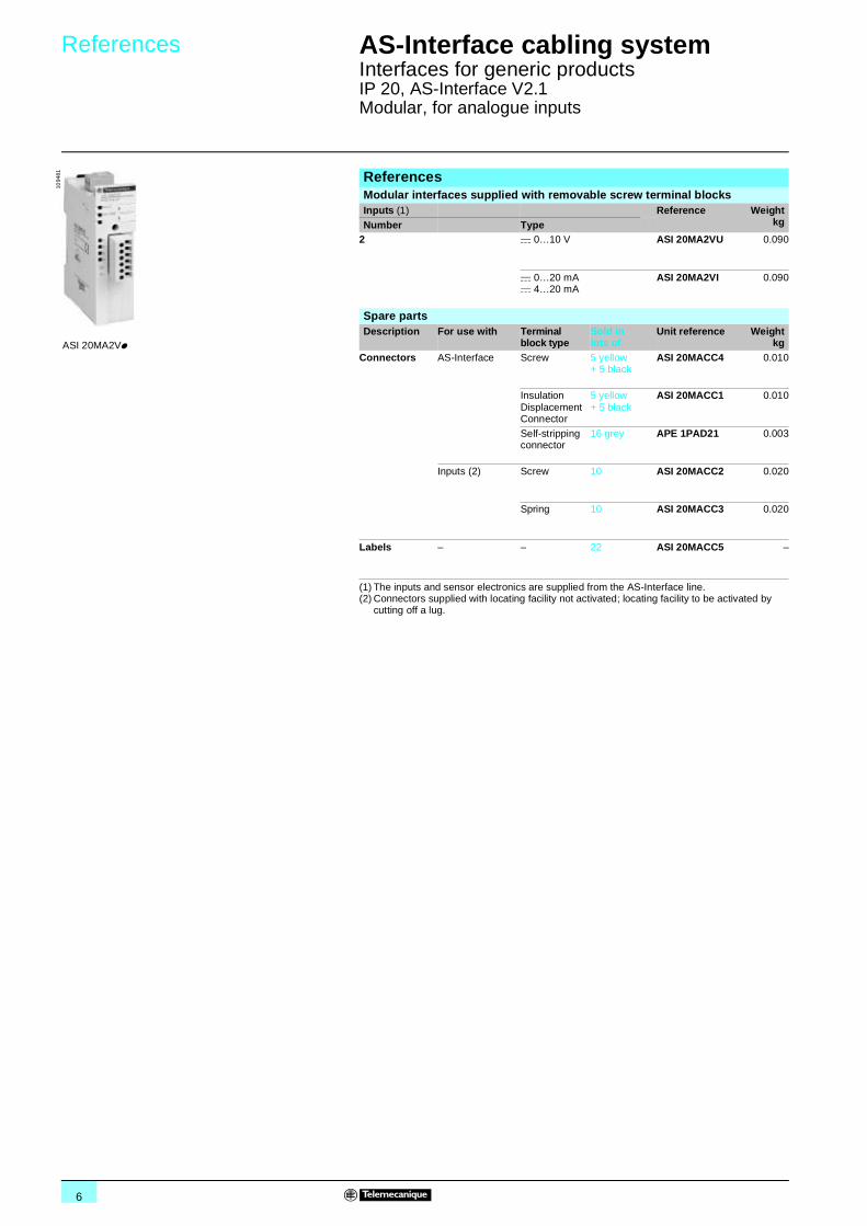
ReferencesModular interfaces supplied with removable screw terminal blocksInputs (1) Reference Weight
kgNumber Type2 c 0…10 V ASI 20MA2VU 0.090
c 0…20 mAc 4…20 mA
ASI 20MA2VI 0.090
Spare partsDescription For use with Terminal
block typeSold in lots of
Unit reference Weightkg
Connectors AS-Interface Screw 5 yellow + 5 black
ASI 20MACC4 0.010
Insulation Displacement Connector
5 yellow + 5 black
ASI 20MACC1 0.010
Self-stripping connector
16 grey APE 1PAD21 0.003
Inputs (2) Screw 10 ASI 20MACC2 0.020
Spring 10 ASI 20MACC3 0.020
Labels – – 22 ASI 20MACC5 –
ASI 20MA2Vp
1094
81
7
Dimensions,connections
AS-Interface cabling system 1
Interfaces for generic productsIP 20, AS-Interface V2.1 Modular, for analogue inputs
(1) Flashing.
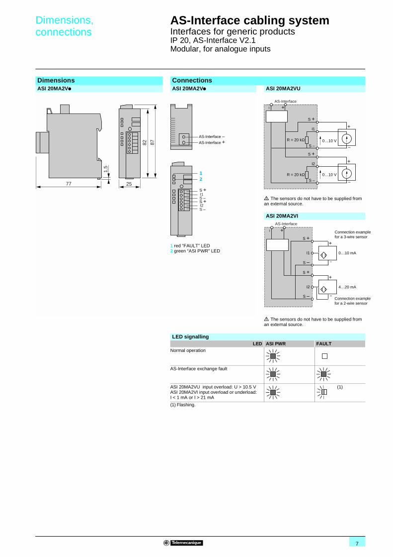
Dimensions ConnectionsASI 20MA2Vp ASI 20MA2Vp ASI 20MA2VU
1 red “FAULT” LED2 green “ASI PWR” LED
d The sensors do not have to be supplied from an external source.
ASI 20MA2VI
d The sensors do not have to be supplied from an external source.
LED signallingLED ASI PWR FAULT
Normal operation
AS-Interface exchange fault
ASI 20MA2VU input overload: U > 10.5 VASI 20MA2VI input overload or underload: I < 1 mA or I > 21 mA
(1)
77 25
82
1,5
87
S +
S +I1
12
S –
I2S –
AS-Interface
AS-Interface
+
I1
S +
R = 20 kΩ
R = 20 kΩ
S –0…10 V
S –
+
+
0…10 V
I2
S + +
AS-Interface
+
I1
S +
S –
0…10 mA
S –
+
+
4…20 mA
AS-Interface
I2
S +
Connection examplefor a 3-wire sensor
Connection example for a 2-wire sensor
8
Presentation AS-Interface cabling system 1
Interfaces for generic productsIP 20, AS-Interface V2.1 Modular, for discrete inputs/outputs
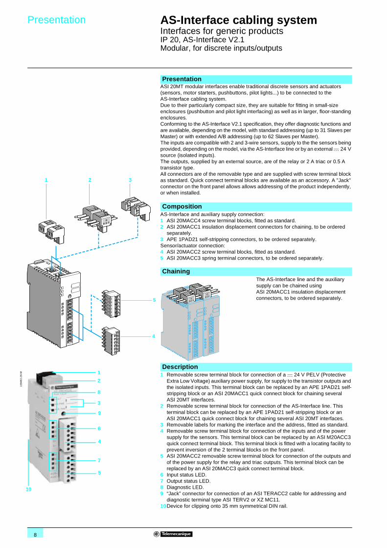
ASI 20MT modular interfaces enable traditional discrete sensors and actuators (sensors, motor starters, pushbuttons, pilot lights...) to be connected to the AS-Interface cabling system.Due to their particularly compact size, they are suitable for fitting in small-size enclosures (pushbutton and pilot light interfacing) as well as in larger, floor-standing enclosures.Conforming to the AS-Interface V2.1 specification, they offer diagnostic functions and are available, depending on the model, with standard addressing (up to 31 Slaves per Master) or with extended A/B addressing (up to 62 Slaves per Master).The inputs are compatible with 2 and 3-wire sensors, supply to the the sensors being provided, depending on the model, via the AS-Interface line or by an external c 24 V source (isolated inputs).The outputs, supplied by an external source, are of the relay or 2 A triac or 0.5 A transistor type.All connectors are of the removable type and are supplied with screw terminal block as standard. Quick connect terminal blocks are available as an accessory. A "Jack" connector on the front panel allows allows addressing of the product independently, or when installed.
Presentation
CompositionAS-Interface and auxiliary supply connection:1 ASI 20MACC4 screw terminal blocks, fitted as standard.2 ASI 20MACC1 insulation displacement connectors for chaining, to be ordered
separately.3 APE 1PAD21 self-stripping connectors, to be ordered separately.Sensor/actuator connection:4 ASI 20MACC2 screw terminal blocks, fitted as standard.5 ASI 20MACC3 spring terminal connectors, to be ordered separately.
Chaining The AS-Interface line and the auxiliary
supply can be chained using ASI 20MACC1 insulation displacement connectors, to be ordered separately.
Description1 Removable screw terminal block for connection of a c 24 V PELV (Protective
Extra Low Voltage) auxiliary power supply, for supply to the transistor outputs and the isolated inputs. This terminal block can be replaced by an APE 1PAD21 self-stripping block or an ASI 20MACC1 quick connect block for chaining several ASI 20MT interfaces.
2 Removable screw terminal block for connection of the AS-Interface line. This terminal block can be replaced by an APE 1PAD21 self-stripping block or an ASI 20MACC1 quick connect block for chaining several ASI 20MT interfaces.
3 Removable labels for marking the interface and the address, fitted as standard.4 Removable screw terminal block for connection of the inputs and of the power
supply for the sensors. This terminal block can be replaced by an ASI M20ACC3 quick connect terminal block. This terminal block is fitted with a locating facility to prevent inversion of the 2 terminal blocks on the front panel.
5 ASI 20MACC2 removable screw terminal block for connection of the outputs and of the power supply for the relay and triac outputs. This terminal block can be replaced by an ASI 20MACC3 quick connect terminal block.
6 Input status LED.7 Output status LED.8 Diagnostic LED.9 “Jack” connector for connection of an ASI TERACC2 cable for addressing and
diagnostic terminal type ASI TERV2 or XZ MC11.10Device for clipping onto 35 mm symmetrical DIN rail.
1 2 3
5
4
109
482-
28-
M
2
8
3
10
4
9
1
6
7
5
9
Characteristics AS-Interface cabling system 1
Interfaces for generic productsIP 20, AS-Interface V2.1 Modular, for discrete inputs/outputs
EnvironmentProduct certifications UL, CSA (pending)
Operating temperature °C - 20…+ 60
Storage temperature °C - 40…+ 85Degree of protection Conforming to IEC/EN 60529 IP 20
Shock resistance Conforming to IEC/EN 60068-2-27 15 gn (for 11 ms)
Vibration resistance Hz 2…13.2 amplitude ± 1 mm, 13.2…100: 1 gnResistance to electrostatic discharge
Conforming to IEC/EN 61000-4-2 Level 3
Resistance to radiated fields Conforming to IEC/EN 61000-4-3 V/m 10
Resistance to transients Conforming to IEC/EN 61000-4-4 kV 2
Dielectric test voltage between AS-Interface line and the outputs
Conforming to IEC/EN 60364-4-41 V 500 (transistor outputs), 3750 (relay and triac outputs)
Overvoltage category Conforming to IEC/EN 60664-1 II
Degree of pollution Conforming to IEC/EN 60664-1 2
AS-Interface characteristicsAS-Interface version V2.1AS-Interface supply c V 26.5…31.6
Diagnostic signalling AS-Interface power ON Green LED
Auxiliary supply ON Green LEDInput/output status Yellow LED
Fault (2) Red LED
N° of data bits/n° of inputs or outputs D0 Input 1 or output 1D1 Input 2 or output 2
D2 Input 3 or output 3
D3 Input 4 or output 4Value of input or output status data bit D0 to D3 0 = input or output OFF
1 = input or output ON
Output fallback if watchdog tripped Output state 0Parameter bit Not used
Mounting On 35 mm 5 rail (horizontal only)
Housing material Polycarbonate (UL94VO)Connection AS-Interface Removable terminal block
ASI 20MACC4: 0.2 to 2.5 mm2; ASI 20MACC1: 0.5 to 0.75 mm2; APE 1PAD21: 0.5 to 0.75 mm2
Sensors Removable terminal blockASI 20MACC2: max 1.5 mm2; ASI 20MACC3: 0.14 to 1.5 mm2
(1) Bit ID1 can be modified by the user, in particular using the addressing terminal.(2) Fault LED:
off = no fault,on steady = no data exchange on AS-Interface,flashing = peripheral fault.
10
Characteristics (continued) AS-Interface cabling system 1
Interfaces for generic productsIP 20, AS-Interface V2.1 Modular, for discrete inputs/outputs
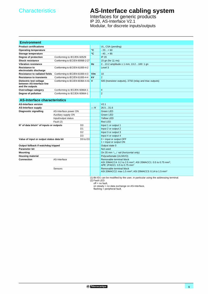
AS-Interface characteristics specific to I/O with standard addressingInterface type ASI 20MT4I4OR 20MT4I4OS 20MT4I4OSA
Maximum number of addresses for one master 31
Number of inputs 4 4 4 isolated (1)Number of outputs 4 x 2 A relay 4 x 0.5 A transistor
Supply to the sensors (inputs) Via the AS-Interface line max: 200 mA Via external PELV (2) power supply (AUX) max: 200 mA
Supply to the actuators (outputs) External a 250 V max, c 150 V max
Via external PELV (2) power supply (AUX)
Profile (I/O code, ID code, ID1, ID2) (3) S7.0.F.E
AS-Interface certification n° 52101 52301 52401Consumption on the AS-Interface line
No-load mA 15 15 15
Maximum (4) mA 110 50 20
AS-Interface characteristics specific to I/O with extended A/B addressingInterface type ASI 20MT4IE 20MT2I1OTE 20MT4I3ORE 20MT4I3OSE 20MT4I3OSAE
Maximum number of addresses for one master 62Number of inputs 4 2 4 4 4 isolated (1)
Number of outputs – 1 x 2 A triac 3 x 2 A relay 3 x 0.5 A transistor
Supply to the sensors (inputs) Via the AS-Interface linemax: 170 mA
Via the AS-Interface linemax: 170 mA
Via the AS-Interface linemax: 150 mA
Via external PELV (2) power supply (AUX) max: 200 mA
Supply to the actuators (outputs) – Externala 24…250 V
Externalmax: a 250 V
Via external PELV (2) power supply (AUX)
Profile (I/O code, ID code, ID1, ID2) (3) S0.A.7.0 S3.A.7.0 S7.A.7.0
AS-Interface certification n° 52501 53801 52201 52302 52401
Consumption on the AS-Interface line
No-load mA 15 15 15 15 15Maximum (4) mA 50 40 90 50 20
Input characteristics (sensor side)Interface type ASI 20MT4IE 20MT4I4OR
20MT4I3ORE20MT4I4OSA20MT4I3OSAE
20MT4I4OS20MT4I3OSE
20MT2I1OTE
Sensor type PNP 2 or 3-wire
State 1 guaranteed U > 11 V and I > 6 mA
State 0 guaranteed U < 5 V and I < 2 mAConformity of inputs Conforming to IEC 61131-2 Type 2
Output characteristics (sensor side)Interface type ASI 20MT4IE 20MT4I4OR
20MT4I3ORE20MT4I4OSA20MT4I3OSAE
20MT4I4OS20MT4I3OSE
20MT2I1OTE
Rated operational voltage (Ue)
Conforming to IEC 60947-5-1
a V – 250 – – 250c V – 150 19.2...30
PELV (2)19.2...30 PELV (2)
–
Maximum drop-out voltage at Ith V – – 0.3 0.3 3
Thermal current per channel (Ith/channel) A – 2 0.5 0.5 2
Thermal current per common A – 4 2 2 2Rated operational current (Ie)Conforming to IEC 60947-5-16 cycles/minute24…250 Va24…150 Vc
AC 12 A – 2 – – 2
DC 12 A – 0.5 0.5 0.5 –
AC 15 A – 0.5 – – –DC 13 A – 0.25 0.5 0.5 –
AC 14 A – 0.5 – – –
Minimum current mA – 10 0.5 0.5 8
Maximum leakage current mA – 0.5 at c 30 V –
Built-in overcurrent protection A – No Yes, electronic No
Mechanical lifein millions of operating cycles
– 20 – – –
Response time (5) Switching time from OFF to ON ms 1 10 1 1 10Switching time from ON to OFF ms 1 10 1 1 10
(1) AS-Interface line isolated inputs. These inputs have a potential common with the outputs.(2) Protective Extra Low Voltage c 19.2…30 V; the regulations relating to these installations are
defined in publication NF C 12-201 and in standard IEC 60364-4-41.(3) Bit ID1 can be modified by the user, in particular using the addressing terminal.(4) Consumption with all Inputs/Outputs On and sensor not energised.(5) Add the AS-Interface cycle time.

11
References,dimensions
AS-Interface cabling system 1
Interfaces for generic productsIP 20, AS-Interface V2.1 Modular, for discrete inputs/outputs
ReferencesModular interfaces supplied with removable screw terminal blocksType of addressing
Numberof inputs (1)
Number, type of outputs
Reference Weightkg
Standard 4 4 x z 250 V/2 A relay ASI 20MT4I4OR 0.090
4 x c 24 V/0.5 A transistor ASI 20MT4I4OS 0.090
4 isolated 4 x c 24 V/0.5 A transistor ASI 20MT4I4OSA 0.090
Extended A/B 4 – ASI 20MT4IE 0.090
2 1 x a 250 V/2 A triac ASI 20MT2I1OTE 0.090
4 3 x z 250 V/2 A relay ASI 20MT4I3ORE 0.090
3 x c 24 V/0.5 A transistor ASI 20MT4I3OSE 0.090
4 isolated 3 x c 24 V/0.5 A transistor ASI 20MT4I3OSAE 0.090
Spare partsDescription For use with Terminal
block typeSold in lots of
Unitreference
Weightkg
Connectors AS-Interface and auxiliary
Screw 5 yellow + 5 black
ASI 20MACC4 0.010
Insulation Displacement Connector
5 yellow + 5 black
ASI 20MACC1 0.010
Self-stripping connector
16 grey APE 1PAD21 0.240
Inputs/outputs (2)
Screw 10 ASI 20MACC2 0.020
Spring 10 ASI 20MACC3 0.020
Legends – – 22 ASI 20MACC5 –
(1) Unless marked "isolated", the inputs and sensor electronics are supplied from the AS-Interface line.
(2) Connectors supplied with locating facility not activated; locating facility to be activated by cutting off a lug.
DimensionsASI 20MTppp LED signalling
1 red “FAULT” LED 2 green “ASI PWR” LED3 green “AUX PWR” LED4 yellow LEDs: inputs/outputs
LED ASI PWR AUX PWR FAULTNormal operation
Output short-circuited (1)
No auxiliary supply(1)
AS-Interface exchange fault
LED Inputs/outputsON
OFF
(1) Flashing.
ASI 20MT4I4OR
109
483
ASI 20MT4IE
109
481
ASI 20MT4I3OSE
77 25
82
1,5
87
123
4
12
Schemes,connections
AS-Interface cabling system 1
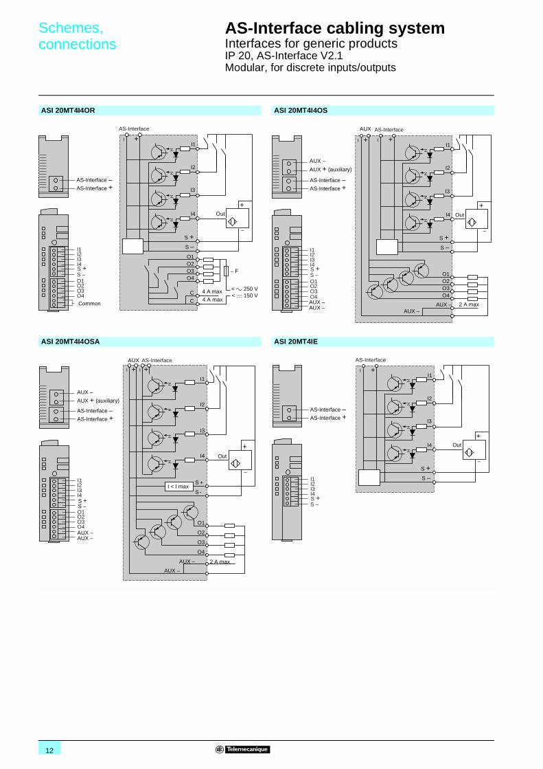
Interfaces for generic productsIP 20, AS-Interface V2.1 Modular, for discrete inputs/outputs
ASI 20MT4I4OR ASI 20MT4I4OS
ASI 20MT4I4OSA ASI 20MT4IE
– F
I1
I2
I3
I4
S +
+
S –
+
O1O2O3O4
< a 250 V< c 150 V
C
C
AS-Interface
AS-Interface
AS-Interface
+
S –
I2I1
I3I4S +
O2O1
O3O4Common
4 A max
Out
4 A max
S –
I2I1
I3I4S +
O2O1
O3O4
AS-Interface
AS-Interface
+
AUX –
AUX + (auxiliary)
AUX –AUX –
O1O2O3O4
AS-Interface
+ I1
I2
I3
I4
S +
+
S –
+
AUX
AUX –AUX –
2 A max
Out
I2I1
I3I4
O2O1
O3O4
AS-Interface
AS-Interface
+
AUX –
AUX + (auxiliary)
AUX –AUX –
I1
I2
I3
I4
+
+
O1
O2
O3
O4
AS-Interface
+
AUX
AUX –
AUX –
2 A max
Out
S +S –
S +
S -I < I max I2
I1
I3I4
S –S +
AS-Interface
AS-Interface
+
I1
I2
I3
I4
S +
+
S –
+
AS-Interface
Out

13
Schemes,connections (continued)
AS-Interface cabling system 1
Interfaces for generic productsIP 20, AS-Interface V2.1 Modular, for discrete inputs/outputs
ASI 20MT2I1OTE ASI 20MT4I3ORE
ASI 20MT4I3OSE ASI 20MT4I3OSAE
(1) Do not connect anything to this terminal. (1) Do not connect anything to this terminal.
S –
I2I1
S +
O1
AS-Interface
AS-Interface
+
– F– T2
– T1
+
O1
C
250 V
AS-Interface
I1
I2
S +S –
+
n.c.
n.c.
Out
n.c.n.c.
Common
max.
– F
I1
I2
I3
I4
S +
+
S –
+
O1O2O3
< a 250 V< c 150 V
C
C
AS-Interface
Out
n.c.
4 A max
AS-Interface
AS-Interface
+
S –
I2I1
I3I4S +
O2O1
O3n.c.Common
4 A max
O1O2O3
AS-Interface
+ I1
I2
I3
I4
S +
+
S –
+
X d (1)
Out
AUX –AUX –
2 A max
S –
I2I1
I3I4S +
O2O1
O3X (1)
AS-Interface
AS-Interface
+
AUX –AUX + (auxiliary)
AUX –AUX –
AUX
I1
I2
I3
I4
+
+
O1
O2
O3
AS-Interface
+
X d (1)
I2I1
I3I4
O2O1
O3X (1)
AS-Interface
AS-Interface
+
Out
AUX –
AUX –
2 A max
AUX –
AUX + (auxiliary)
AUX –AUX –
AUX
S +S –
I < I maxS +
S –

14
Presentation,description
AS-Interface cabling system 1
Advantys, interfaces for generic productsIP 67 I/O, AS-Interface V2.1
ASI 67F interfaces enable traditional sensors and actuators - in particular proximity sensors, photo-electric sensors and limit switches - to be connected to the AS-Interface cabling system.
Because of their IP 67 degree of protection, they can be mounted directly on the machine, as near as possible to the sensors and actuators.
Two types of housing are available:b A compact, 45 mm wide housing for 4-channel interfaces.b A flat, 60 mm wide housing for 8-channel interfaces.
The sensors and actuators are connected to the interface by M12 connectors. The AS-Interface line and any external power supply are connected in one of the following ways, depending on the model:b Directly to the ribbon cables via an Insulation Displacement Connector (IDC) (2 possible mounting positions).b By means of an M12 connector.
Conforming to the AS-Interface V2.1 specification, they offer diagnostic functions and are available, depending on the model, with standard addressing (up to 31 Slaves per master) or with extended addressing (up to 62 Slaves per master).
Specific "V1 compatible" versions allow replacement of previous XZS interfaces and use in association with V1 masters.
The inputs are compatible with 2 and 3-wire sensors and with the majority of models in the Osiris, Osiprox and Osiswitch sensor ranges, with or without alarm output.Supply to the sensors (200 mA max) is via the AS-Interface line.The outputs, supplied by an external source, are of the 2 A transistor type.
ASI 67F interfaces comprise:1 M12 connectors for connecting the sensors and actuators.2 Connector for yellow ribbon cable (AS-Interface line).3 Connector for black ribbon cable (auxiliary supply) - depending on model.4 M12 connectors for connecting the AS-Interface line and the auxiliary power
supply, also allowing connection for addressing via an ASI TERACC1F connection cable.
5 Holes for fixing screws.6 Fitting for clipping onto 35 mm symmetrical rail.7 Jack connector for connection of an ASI TERACC2 cable for terminal ASI TERV2
or XZ MC11.8 Diagnostic LED.9 I/O status LED.10Channel marker labels.11 Interface marker label.12 Interface to connection base fixing screws.
Presentation
Description
564
405-
19-
M
1 12
9
10
7
118
3
2
6
1 12
9
10
4
118
5
5
19
10
118
3
2
1 12
9
11
10
7
4
12
5
5
5644
06-2
4-M
564
408-
19-M
5644
07-2
4-M
12
12 12
128
5
Setting-up :pages 15 and 16
Characteristics :pages 17 and 18
References :pages 19 to 21
Dimensions :page 22
Schemes, connections :pages 23 to 26
15
Setting-up AS-Interface cabling system 1
Advantys, interfaces for generic productsIP 67 I/O, AS-Interface V2.1
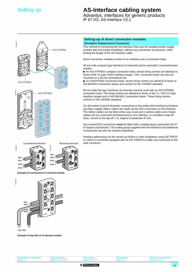
This method of connecting the AS-Interface lines and the auxiliary power supply enables fast and simple installation, without any connection accessories, while limiting the length of the AS-Interface cable.
Direct connection modules consist of an interface and a connection base.
45 mm wide compact type interfaces (4-channel) can be used with 2 connection base models:b An ASI 67FFB01 compact connection base, whose fixing centres are identical to those of the V1 type XZSD interface ranges. This connection base can also be mounted on a 35 mm symmetrical rail.b An ASI67FFB02 connection base, whose fixing centres are identical to those of ASI B4VM12 connection bases and conform to the CNOMO standard.
60 mm wide flat type interfaces (8-channel) must be used with an ASI 67FFB03 connection base. The fixing centres are identical to those of the V1, XZS CA type interface ranges and of ASI B8VM12 connection bases. These fixing centres conform to the CNOMO standard.
For all models (4 and 8-channel), connections to the yellow (AS-Interface) and black (auxiliary supply) ribbon cables are made via the IDC connectors on the interface. The ribbon cables can be fitted either way round and 2 yellow cables and 2 black cables can be connected simultaneously to one interface, to constitute a tap-off (max. current in the tap-off: 2 A, degree of protection IP 54).
Any unused M12 connectors must be fitted with a sealing plug to guarantee the IP 67 degree of protection. The sealing plugs supplied with the interfaces and additional components can also be ordered separately.
Interface addressing can be carried out before or after installation using ASI TERV2 or XZM C11 terminals equipped with an ASI TERACC2 cable and connected to the Jack connector.
Setting-up of direct connection modules (Insulation Displacement Connector)
ASI 67FFB02
ASI 67FFB01
DF
564
460
ASI 67FFB03
DF
5644
61
ASI –ASI +
TELEMEC
TELEMEC
T E L E M E C
T E L E M E C
CANIQUE
CANIQUE
AUX –AUX +
Example of tap-offs on 8-channel module
Tap-offs
DF
564
464
ASI +
AUX +
AUX –
ASI –T E L
E M EC
T E LE M E
C
T E L E M E C
T E LE M E
C AUX +
AUX –
ASI –
ASI +
CANIQUE
CANIQUE
CANIQUE
CANIQUE
Conventional direction Reversed direction
Example of connection to 4-channel module
DF
564
462
DF
564
463
Presentation, description :page 14
Characteristics :pages 17 and 18
References :pages 19 to 21
Dimensions :page 22
Schemes, connections :pages 23 to 26
16
Setting-up (continued) AS-Interface cabling system 1
Advantys, interfaces for generic productsIP 67 I/O, AS-Interface V2.1
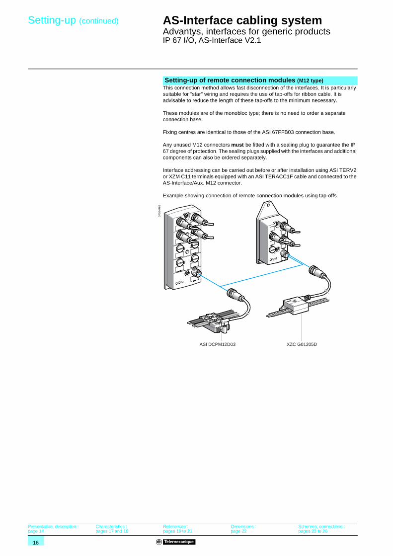
This connection method allows fast disconnection of the interfaces. It is particularly suitable for "star" wiring and requires the use of tap-offs for ribbon cable. It is advisable to reduce the length of these tap-offs to the minimum necessary.
These modules are of the monobloc type; there is no need to order a separate connection base.
Fixing centres are identical to those of the ASI 67FFB03 connection base.
Any unused M12 connectors must be fitted with a sealing plug to guarantee the IP 67 degree of protection. The sealing plugs supplied with the interfaces and additional components can also be ordered separately.
Interface addressing can be carried out before or after installation using ASI TERV2 or XZM C11 terminals equipped with an ASI TERACC1F cable and connected to the AS-Interface/Aux. M12 connector.
Example showing connection of remote connection modules using tap-offs.
Setting-up of remote connection modules (M12 type)
ASI DCPM12D03 XZC G01205D
CANIQUE
CANIQUE
DF
5644
65
Presentation, description :page 14
Characteristics :pages 17 and 18
References :pages 19 to 21
Dimensions :page 22
Schemes, connections :pages 23 to 26

17
Characteristics AS-Interface cabling system 1
Advantys, interfaces for generic productsIP 67 I/O, AS-Interface V2.1
(1) Add the consumption of the sensor supply to obtain the total max. consumption on the AS-Interface line.
(2) The status of the inputs is no longer communicated to the master.(3) All the outputs are off.
EnvironmentProduct certifications UL, CSA (GL pending)
Operating temperature To IEC/EN 60529 °C - 25…+ 70
Storage temperature °C - 40…+ 85Installation category To IEC 60664 II
Degree of protection To IEC 60529 IP 67 (IP 54 for use as tap-off or at line end)
Shock resistance To IEC 60068-2-27 gn 30 (for 11 ms)Vibration resistance To IEC/EN 60068-2-6 2…36 Hz: amplitude 1 mm, 36...150 Hz: 5 gn
To GL 2…13.2 Hz: ± 1mm, 13.2…100 Hz: 0.7 gn
Dielectric test voltageconforming to IEC/EN 60664-1
Inputs and outputs V 500 (for 1 minute)Inputs and auxiliary supply V 500 (for 1 minute)
Outputs and AS-Interface line kV 2 for 1 minute between the M12 connectors and earth
Auxiliary supply and AS-Interface line
V 500
Inputs and AS-Interface line No insulationOutputs and auxiliary supply No insulation
Resistance to electrostatic discharge To IEC/EN 61000-4-2 kV 8, level 3
Resistance to radiated fields To IEC/EN 61000-4-3 V/m 10, level 3Surge withstand To IEC/EN 61000-4-5 1 kV at 2 Ohms (differential mode), 2 kV at 12 Ohms (common mode)
Resistance to transients To IEC/EN 60100-4-4 kV 2, level 3
Degree of pollution To IEC/EN 60604-4-1 Level 3Flame resistance To IEC/EN 60695-2-11 At 750 °C, extinction < 30 s (hot wire test)
Mechanical resistance Product drop test m 1 (no damage)
Mounting 2 or 3 x M4 screwsOn 35 mm rail IEC/EN 60715 (for connection base ASI 67FFB01)
Tightening torque Fixing screws Nm 0.6Material of metal parts Stainless steel
Housing material PBT 30% GF Valox 553
AS-Interface characteristicsAS-Interface version V2.1
AS-Interface supply V 26.5…31.6Protection Against polarity inversion
Connection To the addressing terminal Jack connector (for ASI 67FFPppp)M12 connector (for ASI 67FMPppp)
Diagnostic signalling AS-Interface power ON Green LED
Auxiliary supply ON Green LEDFault Red LED
Input/output status Yellow LED
Characteristics of V1 compatible interfacesInterface type ASI 67FFP40A ASI 67FFP22A ASI 67FFP04A ASI 67FFP44A
AS-Interface max. consumption without sensor supply (1) 45 mA 32 mA 19 mA 49 mA
AS-Interface profile (I/O code, ID code, ID1, ID2) 00FF 30FF 80FF 70FF
AS-Interface certification n° 55001 n° 55101 n° 55201 n° 55301Maximum number of addresses 31
Number of data bits/number of I/OD0 I1 I1 O1 I1 / O1D1 I2 I2 O2 I2 / O2
D2 I3 O3 O3 I3 / O3
D3 I4 O4 O4 I4 / O4Input or output status data bit value
D0 to D3 0 = input On / output Off1 = input / output On
Output fallback Off in the absence of communication
Parameter bits Not used
Product status in the event of a peripheral fault
-Sensor supply overload (I > 200 mA).
Interface inhibited (2)
Overload on one output Interface not inhibited (3) Interface inhibited (2) (3)
Peripheral fault information –
Presentation, description :page 14
Setting-up :pages 15 and 16
References :pages 19 to 21
Dimensions :page 22
Schemes, connections :pages 23 to 26
18
Characteristics (continued) AS-Interface cabling system 1
Advantys, interfaces for generic productsIP 67 I/O, AS-Interface V2.1
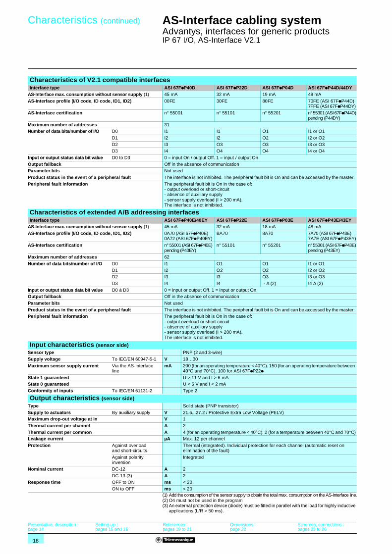
(1) Add the consumption of the sensor supply to obtain the total max. consumption on the AS-Interface line.(2) O4 must not be used in the program(3) An external protection device (diode) must be fitted in parallel with the load for highly inductive
applications (L/R > 50 ms).
Characteristics of V2.1 compatible interfacesInterface type ASI 67FpP40D ASI 67FpP22D ASI 67FpP04D ASI 67FpP44D/44DY
AS-Interface max. consumption without sensor supply (1) 45 mA 32 mA 19 mA 49 mA
AS-Interface profile (I/O code, ID code, ID1, ID2) 00FE 30FE 80FE 70FE (ASI 67FpP44D)7FFE (ASI 67FpP44DY)
AS-Interface certification n° 55001 n° 55101 n° 55201 n° 55301 (ASI 67FpP44D)pending (P44DY)
Maximum number of addresses 31Number of data bits/number of I/O D0 I1 I1 O1 I1 or O1
D1 I2 I2 O2 I2 or O2
D2 I3 O3 O3 I3 or O3D3 I4 O4 O4 I4 or O4
Input or output status data bit value D0 to D3 0 = input On / output Off. 1 = input / output On
Output fallback Off in the absence of communicationParameter bits Not used
Product status in the event of a peripheral fault The interface is not inhibited. The peripheral fault bit is On and can be accessed by the master.
Peripheral fault information The peripheral fault bit is On in the case of:- output overload or short-circuit- absence of auxiliary supply- sensor supply overload (I > 200 mA).The interface is not inhibited.
Characteristics of extended A/B addressing interfacesInterface type ASI 67FpP40E/40EY ASI 67FpP22E ASI 67FpP03E ASI 67FpP43E/43EY
AS-Interface max. consumption without sensor supply (1) 45 mA 32 mA 18 mA 48 mA
AS-Interface profile (I/O code, ID code, ID1, ID2) 0A70 (ASI 67FpP40E)0A72 (ASI 67FpP40EY)
BA70 8A70 7A70 (ASI 67FpP43E)7A7E (ASI 67FpP43EY)
AS-Interface certification n° 55001 (ASI 67FpP40E)pending (P40EY)
n° 55101 n° 55201 n° 55301 (ASI 67FpP43E)pending (P43EY)
Maximum number of addresses 62
Number of data bits/number of I/O D0 I1 O1 O1 I1 or O1
D1 I2 O2 O2 I2 or O2D2 I3 I3 O3 I3 or O3
D3 I4 I4 - ∆ (2) I4 ∆ (2)
Input or output status data bit value D0 à D3 0 = input or output Off. 1 = input or output OnOutput fallback Off in the absence of communication
Parameter bits Not used
Product status in the event of a peripheral fault The interface is not inhibited. The peripheral fault bit is On and can be accessed by the master. Peripheral fault information The peripheral fault bit is On in the case of:
- output overload or short-circuit- absence of auxiliary supply- sensor supply overload (I > 200 mA).The interface is not inhibited.
Input characteristics (sensor side)Sensor type PNP (2 and 3-wire)
Supply voltage To IEC/EN 60947-5-1 V 18…30
Maximum sensor supply current Via the AS-Interfaceline
mA 200 (for an operating temperature < 40°C). 150 (for an operating temperature between 40°C and 70°C). 100 for ASI 67FpP22p
State 1 guaranteed U > 11 V and I > 6 mAState 0 guaranteed U < 5 V and I < 2 mA
Conformity of inputs To IEC/EN 61131-2 Type 2
Output characteristics (sensor side)Type Solid state (PNP transistor)
Supply to actuators By auxiliary supply V 21.6...27.2 / Protective Extra Low Voltage (PELV)Maximum drop-out voltage at In V 1
Thermal current per channel A 2
Thermal current per common A 4 (for an operating temperature < 40°C). 2 (for a temperature between 40°C and 70°C)Leakage current µA Max. 12 per channel
Protection Against overload and short-circuits
Thermal (integrated). Individual protection for each channel (automatic reset on elimination of the fault)
Against polarity inversion
Integrated
Nominal current DC-12 A 2
DC-13 (3) A 2Response time OFF to ON ms < 20
ON to OFF ms < 20
Presentation, description :page 14
Setting-up :pages 15 and 16
References :pages 19 to 21
Dimensions :page 22
Schemes, connections :pages 23 to 26
19
References AS-Interface cabling system 1
Advantys, interfaces for generic productsIP 67 I/O, AS-Interface V2.1
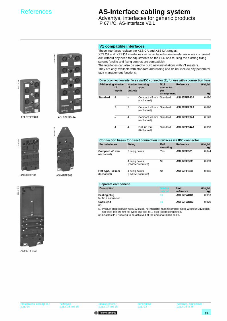
These interfaces replace the XZS CA and XZS DA ranges. XZS CA and XZS DA interfaces can be replaced when maintenance work is carried out, without any need for adjustments on the PLC and reusing the existing fixing screws (profile and fixing centres are compatible).The interfaces can also be used to build new installations with V1 masters.They are only available with standard addressing and do not include any peripheral fault management functions.
(1) Product supplied with two M12 plugs, not fitted (for 45 mm compact type), with four M12 plugs, not fitted (for 60 mm flat type) and one M12 plug (addressing) fitted.
(2) Enables IP 67 sealing to be achieved at the end of a ribbon cable.
V1 compatible interfaces
Direct connection interfaces via IDC connector (1), for use with a connection baseAddressing Number
of inputs
Number of outputs
Housingtype
M12 connector pin arrangement
Reference Weight
kgStandard 4 – Compact, 45 mm
(4-channel)Standard ASI 67FFP40A 0.090
2 2 Compact, 45 mm (4-channel)
Standard ASI 67FFP22A 0.090
– 4 Compact, 45 mm (4-channel)
Standard ASI 67FFP04A 0.120
4 4 Flat, 60 mm(8-channel)
Standard ASI 67FFP44A 0.090
Connection bases for direct connection interfaces via IDC connectorFor interfaces Fixing Rail
mountingReference Weight
kgCompact, 45 mm (4-channel)
2 fixing points Yes ASI 67FFB01 0.044
4 fixing points (CNOMO centres)
No ASI 67FFB02 0.039
Flat type, 60 mm(8-channel)
4 fixing points (CNOMO centres)
No ASI 67FFB03 0.066
Separate componentDescription Sold in
lots ofUnit reference
Weightkg
Sealing plugfor M12 connector
10 ASI 67FACC1 0.013
Cable end(2)
10 ASI 67FACC2 0.020
1211
11-1
9-M
ASI 67FFP40A
1211
05-2
4-M
ASI 67FFP44A
1211
08-1
7-M
ASI 67FFB02
1211
10-2
3-M
ASI 67FFB03
121
109-
17-M
ASI 67FFB01
Presentation, description :page 14
Setting-up :pages 15 and 16
Characteristics :pages 17 and 18
Dimensions :page 22
Schemes, connections :pages 23 to 26
20
References (continued) AS-Interface cabling system 1
Advantys, interfaces for generic productsIP 67 I/O, AS-Interface V2.1
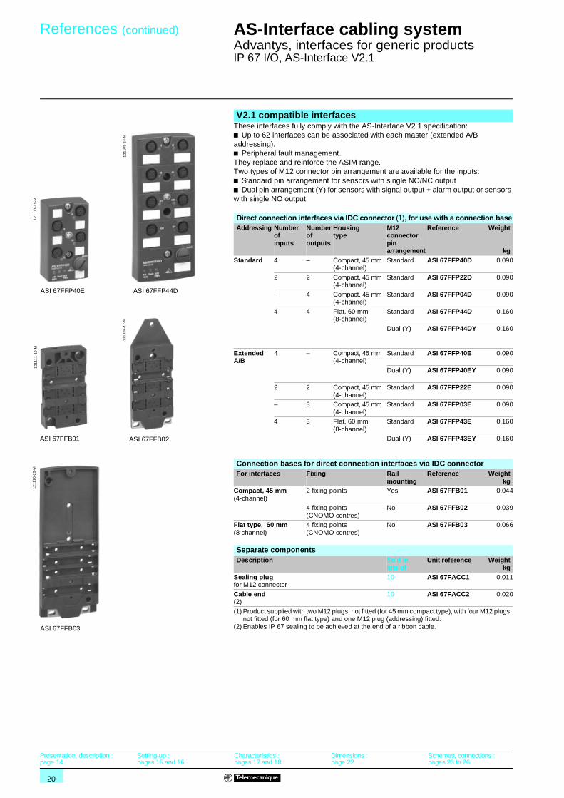
These interfaces fully comply with the AS-Interface V2.1 specification:b Up to 62 interfaces can be associated with each master (extended A/B addressing).b Peripheral fault management.They replace and reinforce the ASIM range.Two types of M12 connector pin arrangement are available for the inputs:b Standard pin arrangement for sensors with single NO/NC outputb Dual pin arrangement (Y) for sensors with signal output + alarm output or sensors with single NO output.
(1) Product supplied with two M12 plugs, not fitted (for 45 mm compact type), with four M12 plugs, not fitted (for 60 mm flat type) and one M12 plug (addressing) fitted.
(2) Enables IP 67 sealing to be achieved at the end of a ribbon cable.
V2.1 compatible interfaces
Direct connection interfaces via IDC connector (1), for use with a connection baseAddressing Number
of inputs
Number of outputs
Housing type
M12 connector pin arrangement
Reference Weight
kgStandard 4 – Compact, 45 mm
(4-channel)Standard ASI 67FFP40D 0.090
2 2 Compact, 45 mm (4-channel)
Standard ASI 67FFP22D 0.090
– 4 Compact, 45 mm (4-channel)
Standard ASI 67FFP04D 0.090
4 4 Flat, 60 mm(8-channel)
Standard ASI 67FFP44D 0.160
Dual (Y) ASI 67FFP44DY 0.160
Extended A/B
4 – Compact, 45 mm (4-channel)
Standard ASI 67FFP40E 0.090
Dual (Y) ASI 67FFP40EY 0.090
2 2 Compact, 45 mm (4-channel)
Standard ASI 67FFP22E 0.090
– 3 Compact, 45 mm (4-channel)
Standard ASI 67FFP03E 0.090
4 3 Flat, 60 mm(8-channel)
Standard ASI 67FFP43E 0.160
Dual (Y) ASI 67FFP43EY 0.160
Connection bases for direct connection interfaces via IDC connectorFor interfaces Fixing Rail
mountingReference Weight
kgCompact, 45 mm (4-channel)
2 fixing points Yes ASI 67FFB01 0.044
4 fixing points (CNOMO centres)
No ASI 67FFB02 0.039
Flat type, 60 mm(8 channel)
4 fixing points (CNOMO centres)
No ASI 67FFB03 0.066
Separate componentsDescription Sold in
lots ofUnit reference Weight
kgSealing plugfor M12 connector
10 ASI 67FACC1 0.011
Cable end(2)
10 ASI 67FACC2 0.020
ASI 67FFP44D
121
105-
24-
M
ASI 67FFP40E
121
111-
19-
M
ASI 67FFB02
121
108-
17-M
ASI 67FFB03
121
110
-23
-M
ASI 67FFB01
121
111-
19-M
Presentation, description :page 14
Setting-up :pages 15 and 16
Characteristics :pages 17 and 18
Dimensions :page 22
Schemes, connections :pages 23 to 26
21
References (continued) AS-Interface cabling system 1
Advantys, interfaces for generic productsIP 67 I/O, AS-Interface V2.1
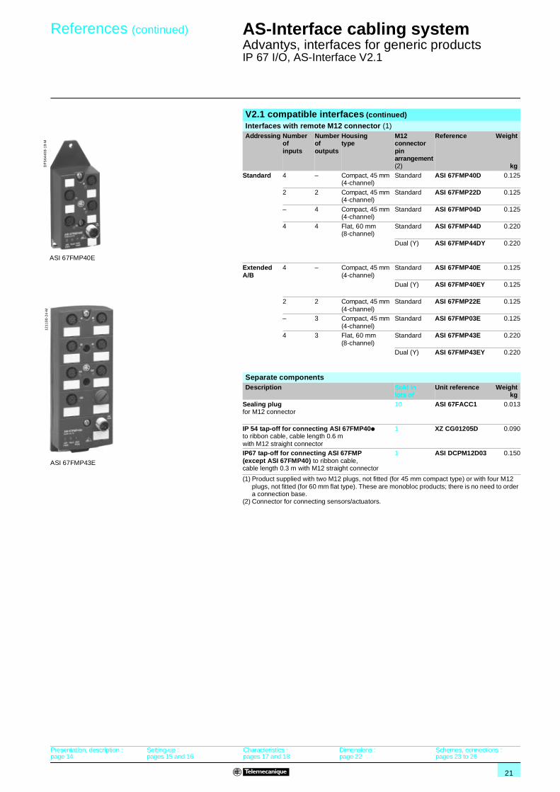
(1) Product supplied with two M12 plugs, not fitted (for 45 mm compact type) or with four M12 plugs, not fitted (for 60 mm flat type). These are monobloc products; there is no need to order a connection base.
(2) Connector for connecting sensors/actuators.
V2.1 compatible interfaces (continued)Interfaces with remote M12 connector (1)Addressing Number
of inputs
Number of outputs
Housing type
M12 connector pin arrangement(2)
Reference Weight
kgStandard 4 – Compact, 45 mm
(4-channel)Standard ASI 67FMP40D 0.125
2 2 Compact, 45 mm (4-channel)
Standard ASI 67FMP22D 0.125
– 4 Compact, 45 mm (4-channel)
Standard ASI 67FMP04D 0.125
4 4 Flat, 60 mm(8-channel)
Standard ASI 67FMP44D 0.220
Dual (Y) ASI 67FMP44DY 0.220
Extended A/B
4 – Compact, 45 mm (4-channel)
Standard ASI 67FMP40E 0.125
Dual (Y) ASI 67FMP40EY 0.125
2 2 Compact, 45 mm (4-channel)
Standard ASI 67FMP22E 0.125
– 3 Compact, 45 mm (4-channel)
Standard ASI 67FMP03E 0.125
4 3 Flat, 60 mm(8-channel)
Standard ASI 67FMP43E 0.220
Dual (Y) ASI 67FMP43EY 0.220
Separate componentsDescription Sold in
lots ofUnit reference Weight
kgSealing plugfor M12 connector
10 ASI 67FACC1 0.013
IP 54 tap-off for connecting ASI 67FMP40p to ribbon cable, cable length 0.6 m with M12 straight connector
1 XZ CG01205D 0.090
IP67 tap-off for connecting ASI 67FMP (except ASI 67FMP40) to ribbon cable, cable length 0.3 m with M12 straight connector
1 ASI DCPM12D03 0.150
121
100-
24-M
ASI 67FMP43E
ASI 67FMP40E
DF
564
408-
19-M
Presentation, description :page 14
Setting-up :pages 15 and 16
Characteristics :pages 17 and 18
Dimensions :page 22
Schemes, connections :pages 23 to 26
22
Dimensions AS-Interface cabling system 1
Advantys, interfaces for generic productsIP 67 I/O, AS-Interface V2.1
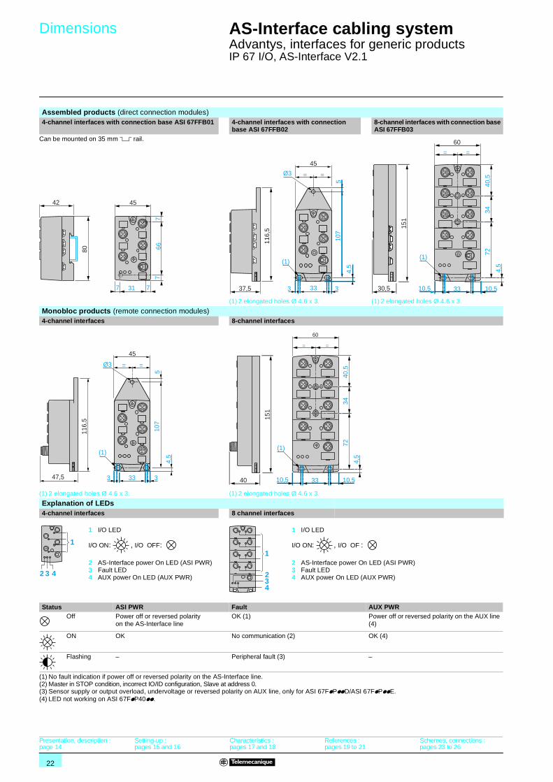
Assembled products (direct connection modules)4-channel interfaces with connection base ASI 67FFB01 4-channel interfaces with connection
base ASI 67FFB028-channel interfaces with connection base ASI 67FFB03
Can be mounted on 35 mm 5 rail.
(1) 2 elongated holes Ø 4.6 x 3. (1) 2 elongated holes Ø 4.6 x 3.
Monobloc products (remote connection modules)4-channel interfaces 8-channel interfaces
(1) 2 elongated holes Ø 4.6 x 3. (1) 2 elongated holes Ø 4.6 x 3.
Explanation of LEDs4-channel interfaces 8 channel interfaces
1 I/O LED
I/O ON: , I/O OFF:
2 AS-Interface power On LED (ASI PWR)3 Fault LED4 AUX power On LED (AUX PWR)
1 I/O LED
I/O ON: , I/O OF :
2 AS-Interface power On LED (ASI PWR)3 Fault LED4 AUX power On LED (AUX PWR)
Status ASI PWR Fault AUX PWROff Power off or reversed polarity
on the AS-Interface lineOK (1) Power off or reversed polarity on the AUX line
(4)
ON OK No communication (2) OK (4)
Flashing – Peripheral fault (3) –
(1) No fault indication if power off or reversed polarity on the AS-Interface line.(2) Master in STOP condition, incorrect IO/ID configuration, Slave at address 0.(3) Sensor supply or output overload, undervoltage or reversed polarity on AUX line, only for ASI 67FpPppD/ASI 67FpPppE.(4) LED not working on ASI 67FpP40pp.
4542
80
77
66
7 31 7
Ø3
3 3
45
= =
107
5
4,5
116,
5
3337,5
(1)
60
151
= =
10,5 10,53330,5
72
4,5
3440
,5
(1)
Ø3
45
= =
107
5
4,5
116,
5
47,5
(1)
3 333
151
40
60
= =
(1)
10,5 10,533
72
4,5
3440
,5
2 3 4
1
234
1
Presentation, description :page 14
Setting-up :pages 15 and 16
Characteristics :pages 17 and 18
References :pages 19 to 21
Schemes, connections :pages 23 to 26

23
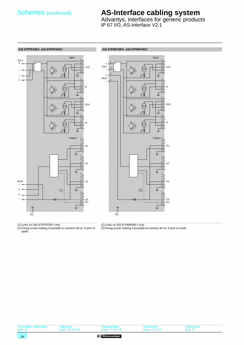
Schemes AS-Interface cabling system 1
Advantys, interfaces for generic productsIP 67 I/O, AS-Interface V2.1
ASI 67FFP40p ASI 67FFP22p ASI 67FFP03p, ASI 67FFP04p
(1) Links on ASI 67FFP04p only
ASI 67FMP22p ASI 67FMP03p, ASI 67FMP04p
(1) Links on ASI 67FMP04p onlyASI 67FFP40EY ASI 67FMP40p ASI 67FMP40EY
(2) Fixing screw making it possible to connect all no. 5 pins to earth.
+
–
–+
12345
AS-i+
–
1
1
1
2345
2345
2345
(2)
I1
I2
I3
I4
Input
+
–
–+
12345
AS-i+
–
1
1
1
2345
2345
2345
+
––
+
AUX
(2)
Input
Output
I1 or I3
I2 orI4
O1 orO3
O2 orO4
+
––+
12345
AS-i+
–
1
1
1
2345
2345
2345
+
––
+
AUX
(1)
O1
O2
O3
O4
(2)
(1)
Output
AS-i
AUX
12345
+
–
1
1
1
2345
2345
2345
1
3
4
2–
+–
+
(2)
Input
Output
I1 or I3
I2 or I4
O1 or O3
O2 or O4
AS-i
AUX
12345
1
1
1
2345
2345
2345
+
–
1
3
4
2
(1)(1)
–
+–
+
(2)
O1
O2
O3
O4
Output
+
––+
12345
AS-i+
–
1
1
1
2345
2345
2345
I1/I2
I2
I3/I4
I4
(2)
Input
AS-i
AUX
1
3
4
2
12345
+
–
1
1
1
2345
2345
2345
I1
I2
I3
I4
(2)
+
–
+
–
Input
AS-i
AUX
1
3
4
2
12345
+
–
1
1
1
2345
2345
2345
I1/I2
I2
I3/I4
I4
(2)
+
–
+
–
Input
Presentation, description :page 14
Setting-up :pages 15 and 16
Characteristics :pages 17 and 18
References :pages 19 to 21
Dimensions :page 22
24
Schemes (continued) AS-Interface cabling system 1
Advantys, interfaces for generic productsIP 67 I/O, AS-Interface V2.1
ASI 67FFP43EY, ASI 67FFP44DY ASI 67FMP43EY, ASI 67FMP44DY
(1) Links on ASI 67FFP43EY only(2) Fixing screw making it possible to connect all no. 5 pins to
earth.
(1) Links on ASI 67FMP43EY only(2) Fixing screw making it possible to connect all no. 5 pins to earth.
12345
1
1
1
2345
2345
2345
+
–
–
+
12345
AS-i
I1/I2
I2
I4
O1
O2
O3
O4
I3/I4
+
–
1
1
1
2345
2345
2345
–
–
+
+
AUX
(1)
(1)
(2)
Input
Output 12345
1
1
1
2345
2345
2345
12345
1
1
1
2345
2345
2345
AS-i
AUX
1
3
4
2
+
–
(1)
+
–
+
–
I1/I2
I2
I4
O1
O2
O3
O4
I3/I4
(1)
(2)
Input
Output
Presentation, description :page 14
Setting-up :pages 15 and 16
Characteristics :pages 17 and 18
References :pages 19 to 21
Dimensions :page 22
25
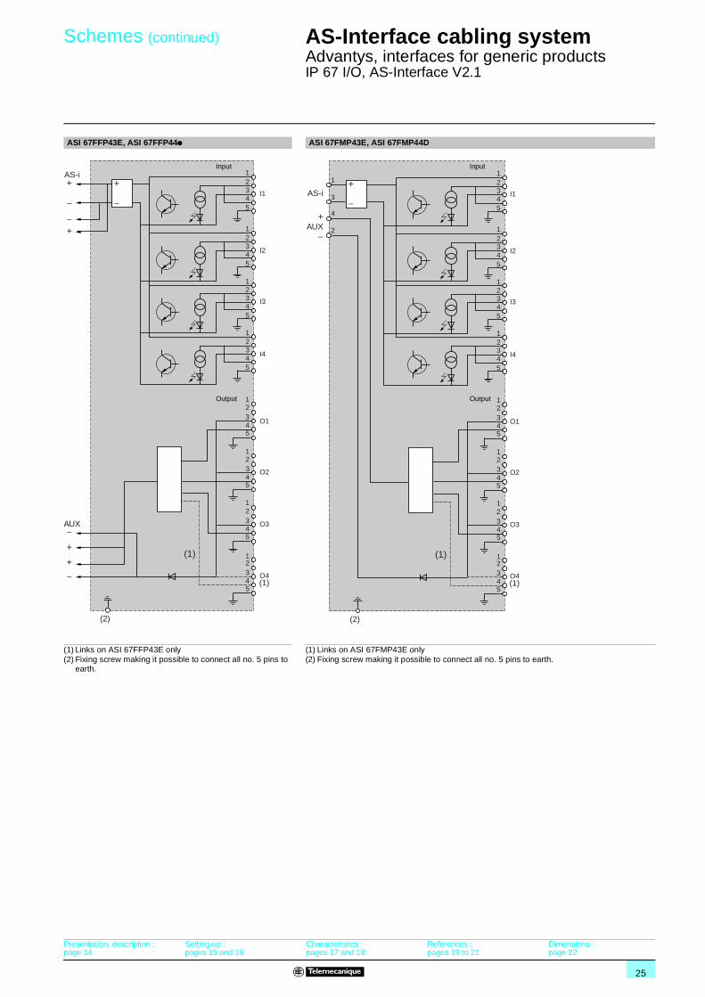
Schemes (continued) AS-Interface cabling system 1
Advantys, interfaces for generic productsIP 67 I/O, AS-Interface V2.1
ASI 67FFP43E, ASI 67FFP44p ASI 67FMP43E, ASI 67FMP44D
(1) Links on ASI 67FFP43E only(2) Fixing screw making it possible to connect all no. 5 pins to
earth.
(1) Links on ASI 67FMP43E only(2) Fixing screw making it possible to connect all no. 5 pins to earth.
12345
1
1
1
2345
2345
2345
+
–
–
+
12345
AS-i+
–
1
1
1
2345
2345
2345
–
–
+
+
AUX
(1)
I1
I2
I4
O1
O2
O3
O4
I3
(1)
(2)
Input
Output
AS-i
AUX
1
3
4
2
12345
1
1
1
2345
2345
2345
12345
+
–
1
1
1
2345
2345
2345
(1)
+
–
I1
I2
I4
O1
O2
O3
O4
I3
(1)
(2)
Input
Output
Presentation, description :page 14
Setting-up :pages 15 and 16
Characteristics :pages 17 and 18
References :pages 19 to 21
Dimensions :page 22

26
Connections AS-Interface cabling system 1
Advantys, interfaces for generic productsIP 67 I/O, AS-Interface V2.1
Connector locationsASI 67FFP44p/FMP44p ASI 67FFP44DY/FMP44DY ASI 67FFP43E/FMP43E ASI 67FFP43EY/FMP43EY
ASI 67FFP40pASI 67FMP40p
ASI 67FFP22A/22DASI 67FMP22A/22D
ASI 67FFP04pASI 67FMP04p
ASI 67FFP40EYASI 67FMP40EY
ASI 67FFP22EASI 67FMP22E
ASI 67FFP03EASI 67FMP03E
Pin arrangement of connectors for connecting sensors/actuators.ASI 67FpPppp ASI 67FpPpppY
Connector I1…I4 Connector O1…O4 Connector I1/I2
Connector I2
Connector I3/I4
Connector I4
Connector O1…O4
Pin arrangement of connectors AS-i AUX (ASI 67FMPppp)
Example of input connections. Example of output connectionsVolt-free contact or 2-wire sensor
3-wire sensor Sensor signal + alarm
Load
Example of connection of sensors with signal + alarm output to interfaces with dual pin arrangement
1 Do no use this connector2 Sensor with signal + alarm output
example: XU MOppp, XU KOppp, XU XOppp
I1 I2
I3 I4
O1 O2
O3 O4
I1/I2 I2
I4
O1 O2
O3 O4
I3/I4
I1 I2
I4I3
O1 O2
O3
I3/I4
I1/I2 I2
I4
O1 O2
O3
I1
I2
I 3
I4
I1
I2
O3
O4
O1
O2
O3
O4
I1/I2
I3/I4
I2
I4
I3
I4
O1
O2
O1
O2
O3
3 4
2 1
5
– I
I +
3 4
2 1
5
Com O
Not connected
Not connected
3 4
2 1
5
– I1
I2 +
3 4
2 1
5
–
+Not connected
3 4
2 1
5
– I3
I4 +
3 4
2 1
5
–
+Not connected
3 4
2 1
5
Com O
Not connected
Notconnected
1
4
1
43 –
+
Out
1
43
2
–
+
Alarm
Out
343 4
2 1AS-i +
AUX+AS-i –
–AUX
T E L E M E C
T E L E M E C
T E L E M E C
T E L E M E C
T E L E M E C
T E L E M E C
T E L E M E C
T E L E M E C
112
2 2
1 2
1
DF
564
422
Presentation, description :page 14
Setting-up :pages 15 and 16
Characteristics :pages 17 and 18
References :pages 19 to 21
Dimensions :page 22

27
Selection AS-Interface cabling system 1
Advantys, interfaces for generic productsIP 67 I/O, AS-Interface V2.1
The Advantys ASI 67F interface range can be used to fully replace the range of V1 and V2.1 interfaces with the following references: XZS ppp and ASI Mppp.
Replacement of older interfaces with the Advantys ASI 67F range during maintenance operations has the following advantages:b The old product fixings can be reused.b The installation can be restarted without having to adjust the PLC and without an addressing terminal (provided that the PLC is configured for automatic addressing and that the interfaces are replaced one by one).b Identical behaviour of old and new range interfaces in the event of a peripheral fault (sensor or output supply overload, absence of auxiliary voltage).
Note: old connection bases are not compatible with new interfaces and old interfaces are not compatible with new connection bases. Both the interface and connection base must be replaced in all cases.
Substitution tableOld range New rangeInterface Connection base Interface Connection base
ASI ME2I2O ASI B4VM12 ASI 67FFP22D ASI 67FFB02
ASI ME2I2OE ASI B4VM12 ASI 67FFP22E ASI 67FFB02ASI ME4I ASI B4VM12 ASI 67FFP40D ASI 67FFB02
ASI ME4I4O ASI B8VM12 ASI 67FFP44D ASI 67FFB03
ASI ME4IE ASI B4VM12 ASI 67FFP40E ASI 67FFB02ASI ME4O ASI B4VM12 ASI 67FFP04A ASI 67FFB02
XZS CA44D21 Integrated ASI 67FFP44A ASI 67FFB03
XZS DA04D32 XZS DE1133 ASI 67FFP04A ASI 67FFB01XZS DA22D32 XZS DE1133 ASI 67FFP22A ASI 67FFB01
XZS DA40D3 XZS DE1113 ASI 67FFP40A ASI 67FFB01
XZS DA40D3 XZS DE1133 ASI 67FFP40A ASI 67FFB01ASI DCPACC3 – ASI 67FACC1 –
XZL G102 – ASI 67FACC1 –

ART.803510 08 / 2004
DIA
3ED
2040
909E
N
Schneider Electric Industries S.A.S.
Head Office89, bd Franklin Roosevelt94504 Rueil-Malmaison CedexFRANCE
www.schneider-electric.comwww.telemecanique.com
Due to evolution of standards and equipment, the characteristics indicated in texts and images of thisdocument do not constitute a commitment on our part without confirmation.Design: Schneider ElectricPhotos: Schneider ElectricImpression:
The efficiency of Telemecanique branded solutionsUsed in combination, Telemecanique products provide quality solutions, meeting all your Automation & Control applications requirements.
A worldwide presence
Constantly availableb More than 5 000 points of sale in 130 countries.b You can be sure to find the range of products that are right for you and which complies fully with the standards in the country where they are used.
Technical assistance wherever you areb Our technicians are at your disposal to assist you in finding the optimum solution for your particular needs.b Schneider Electric provides you with all necessary technical assistance, throughout the world.
Networks & communication
Software tools
Motion control
Power supplies
Mounting systems
Interfaces & I/O
Operator dialog
Detection
AutomationMotor control
Simply Smart !