as - ky public service commission cases/2007-00155/kpc_assessment... · thermal overload problems...
TRANSCRIPT

Case Nuniber 2007-001 5.5 June 15,2007
Kentucky Public Service Coinmission P.O. Box 6 15 2 1 1 Sower Blvd. Franlcfoi-t, Kentucky 40602
Attention: Cliarles Bright
Dear Mr. Bright:
As you requested, I liave enclosed 10 bound copies of the assessnient of need for Kentucky Power Cornpaiiy's proposed Morgan Fork-Hays Branch 138 ItV traiisinission line. I also enclosed one loose copy for your coiiveiiieiice if you need to reproduce more copies.
Please let me know if there is ariytliirig else you need.
Sincerely,
JeAy E.' Mend1 President
Report on the Need for
Morgan Fork - Hays Branch 13 8 kV Transmission Line
In Floyd County, Kentucky
Proposed by Kentucky Power Company
Case Number 2007-00 155
Prepared by
Jerry E. Mend1
MSB Energy Associates, Inc.
June 18,2007

Table of Contents
Executive Summary ............................................................................................................ 1
Section I Characteristics Driving the Need for Transmission .......................................... 3
The Proposed Project ...................................................................................................... 3
Typical Motivations to Build Transmission Projects ...................................................... 3
Forecasts of Electricity Demands ................................................................................... 4
Baseline Growth .......................................................................................................... 4
Block Loads ................................................................................................................ 5
Starting vs Steady State Load ..................................................................................... 6
Economic Need ............................................................................................................... 7
The Electrical System in the Project Area ...................................................................... 8
Single Contingency Planning ...................................................................................... 9
KPC’s Transmission Planning Approach ....................................................................... 8
Radial Lines ................................................................................................................ 9
Thermal Overloads .................................................................................................... 10
Low Voltage .............................................................................................................. 10
Surnmary of Section I ................................................................................................... 11
Section I1 Transmission System Adequacy . Without Morgan Fork-Hays Branch Line 12
Without Maytown Compressor Load ............................................................................ 12
System Intact Analyses ............................................................................................. 12
Single Contingency Outage Analyses ....................................................................... 12
System Intact Analyses ............................................................................................. 13
Single Contingency Outage Analyses ....................................................................... 13
With Maytown Compressor Load at Steady State ........................................................ 13
With Maytown Compressor Load at Startup Conditions .............................................. 15
System Intact Analyses ............................................................................................. 15
Single Contingency Outage Analyses ....................................................................... 16
Discussion ..................................................................................................................... 16
Ability to Serve Future Loads ....................................................................................... 17
Surnmary of Section I1 .................................................................................................. 17
1

Section I11 Potential Solutions ......................................................................................... 19
Transmission solutions ................................................................................................. 19
Connecting the Maytown Compressor load at 46 kV ............................................... 19
Connecting the Maytown Compressor load at 69 kV ............................................... 20
Connecting the Maytown Compressor load at 138 kV ............................................. 22
Connecting the Maytown Compressor load at 13 8/76S 1tV ...................................... 23
Non-transmission solutions ........................................................................................... 23
Wheeling Power on Neighboring Systems ............................................................... 24
Redispatching ............................................................................................................ 24
Building Large Power Plants .................................................................................... 25
Load Management .................................................................................................... 25
Energy Efficiency ..................................................................................................... 27
Distributed Generation .............................................................................................. 27
Other Benefits ofthe Proposal ...................................................................................... 28
Summary of Section I11 ................................................................................................. 29
Section IV Conclusions ................................................................................................... 31
. .
.. 11

Executive Summary
On May 15,2007, Kentucky Power Company, (KPC) filed an application for a certificate
of public convenience and necessity for the construction of a 13 8 kV transmission line in
Floyd County, Kentucky. KPC proposes the Morgan Fork-Hays Branch project to meet
the load requirements of Kentucky-West Virginia Gas Company, which is converting
natural gas-fired pipeline compressor engines to electric motors and is substantially
expanding its compressor capability at its Maytown Compressor Station near Langley,
Kentucky. The customer requests service to begin in March 2008.
The proposed project taps the existing Beaver Creek-Betsy Lane 13 8 kV line at Morgan
Fork. The proposal is to construct a radial 138 kV transmission line approximately 8.3
miles to the Hays Branch Station near Langley. The customer requests taking power at
138 kV at Hays Branch.
Conclusions
1) Kentucky-West Virginia Gas Company intends to expand its compressor capacity and
convert its compressor engines to electric motors at the Maytown Compressor Station
near L,angley, Kentucky.
a) Operating electric motors at the Maytown Compressor Station will add 24 MW,
on average, to the electrical loads near Langley.
b) Starting the large electric motor at the Maytown Compressor Station will require
60 MW.
2) To serve the Maytown Compressor load, Kentucky Power Company will need to
upgrade its transmission and sub-transmission networks to resolve low voltage and
thermal overload problems, especially during compressor motor startup.
1

3) Providing service to the Maytown Compressor Station at 138 kV is reasonable.
a) At 46 l V , the Maytown compressor motors could not be started due to low
voltage.
b) TJpgrading the 46 kV system to 69 kV would be costly, could not be
accomplished in time to meet customer service requirements and may not be able
to maintain voltage levels during attempts to start the motors.
c) Tapping into the existing 13 8 kV line and serving the Maytown Compressor load
at 138 kV eliminates overload and low voltage problems and allows Kentucky
Power Company to provide reliable service to the project area.
d) Tapping into a nearby 765 kV line is costly and could not be accomplished in
time to meet customer service requirements.
4) Strategies to reliably serve load after the addition of the Maytown Compressor Station
without building transmission infrastructure are limited.
Wheeling across neighboring systems is not viable because adequate
interconnections to neighboring systems and to the Maytown Compressor load do
not exist.
There are no power plants that exist to be redispatched, or that could be built in
the project area to timely meet Maytown Compressor service requirements.
Load management and energy efficiency in the project area are not sufficient to
offset the 60 MW startup demand of the Maytown compressors.
Kentucky-West Virginia Gas Company could potentially reduce startup load by
replacing the two largest compressor motors with several smaller ones. Reducing
the startup load may make lower voltage transmission alternatives more viable.
2

Section I Characteristics Driving the Need for Transmission
The Proposed Project
Kentucky Power Company's (KPC) application states that the proposed Morgan Fork-
Hays Branch project is required to meet the load of a new customer near Langley,
Kentucky. Kentucky-West Virginia Gas Company is converting natural gas fired
pipeline compressor engines to electric motors and is substantially expanding its
compressor capability at its Maytown Compressor Station. The customer is adding a 24
MW average load to KPC's system. The load is at high load factor, anticipated to operate
24 hours per day 7 days per week. Moreover, KPC anticipates the peak load during
motor startup to be 60 MW.
The proposed project taps the existing Beaver Creek-Betsy Lane 138 kV line at Morgan
Fork and runs a radial 13 8 kV transmission line approximately 8.3 miles to the Hays
Branch Station near Langley. The customer requests taking power at 13 8 kV at Hays
Branch, and will own the 138 kV equipment on the customer side of the meter. The Hays
Branch Station is not a substation to provide electricity for KPC's other retail customers
at typical distribution voltages. Figure 1 is a map showing the location of the proposed
project.
KPC's application also lists some additional benefits of the 138 kV proposal, such as
allowing the future addition of a 138 kV loop to enhance supply reliability, providing
more flexibility in serving future local loads, and other benefits which will be considered
in more detail later in this report.
Typical Motivations to Build Transmission Projects
The need to build transmission lines is typically motivated by reliability concerns and/or
economic concerns. As loads grow and power plants are built, transmission system
improvements are needed in order to serve customers reliably - i.e., delivering the power
customers demand while operating the transmission system within normal loading and
3

voltage parameters. The transmission improvements are needed to ensure reliability of
service and the integrity of the bulk power supply system.
In other cases, the transmission system improvements are needed to provide access to
lower cost power supplies. Adequate generation may exist in the area where the power is
used, but it may be more costly than power generation from more distant sources. If
transmission system improvements are needed in order to be able to deliver the lower
cost power, the need is driven by economic considerations.
Frequently the need for transmission improvements is driven by both economic and
reliability considerations. The rest of Section I describes the purpose of KPC's proposed
Morgan Fork-Hays Branch transmission line and helps characterize the problem KPC is
proposing to solve with the Morgan Fork-Hays Branch proposal.
Appendix A is an overview of transmission systems.
Forecasts of Electricity Demands
Growth of electricity demands can occur as new customers are added or as new loads are
added by existing customers. As loads increase, the utility must secure new power
supplies and ensure adequate transmission paths between the power supplies and the
loads. In the project area, future electric demands are driven by baseline growth and
block loads.
Baseline Growth
Baseline growth refers to the relatively stable and steady growth of electrical demand that
occurs as a result of ongoing development. It is characterized by the additions of a mix
of residential, commercial and industrial loads driven by local population and economic
growth.
4

Baseline load growth in the project area is projected at less than 1 % per year (KPC
Response to Item No. 15). Total loads in the area served by the 46 kV lines' (See Figure
2) are about 80 MW without the new Maytown Compressor load. As such, baseline
growth in the area is less than 1 MW per year. Baseline growth is not the reason the
proposed transmission line is needed.
Block Loads
Block loads refer to large load increments added by single, large customers. These may
be factories, mines or, as in this case, a nattlsal gas compressor station. Block loads
represent step increases rather than continuous increases in load growth.
Kentucky-West Virginia Gas Company's Maytown Compressor is a 24 MW block load
increase. Figure 3 compares the baseline load forecast for the project area to the total
forecast including the Maytown Compressor block load. Figme 3 shows that the block
load increase is large relative to the baseline growth. The load with the Maytown
Compressor will in 2008 be equivalent to what the baseline load (without the Maytown
Compressor) would have been in 2034. Stated differently, the Maytown Compressor
block load addition is equivalent to over 25 years of baseline growth in the project area.
Information provided by KPC indicates that the project area is the located in an active
coal mining region. KPC serves coal mines in the area, and other mines may be opened
on relatively short notice. Coal mines could also add substantial block loads to the
electricity demands in the project area in the future. While potential future block loads at
currently unidentified potential future coal mines are not the reason for building the
proposed 13 8 kV line, they affect the robustness and longevity of the proposal and
alternatives.
This includes loads at substations at Kenwood, Prestonsburg, East Prestonsburg, Middle Creek, Allen, 1
Martin, Salisbury, McKinney, Garrett, Saltlick and Spring Fork
5

Starting vs Steady State Load
The impact of the Kentucky-West Virginia Gas Company Maytown Compressor load is
actually much more severe than described above. The steady state load is 24 MW to run
two 1 1,000-horsepower synchronous motors and three 3,000-horsepower induction
motors. According to the KPC response to item 3 1 , the starting load for the motors can
range from 5-10 times the steady state load. KPC assumed a 60 MW starting load, which
would be at the low end of the range of 55 MW to 110 MW KPC estimates for an 11,000-
horsepower motor.
There is a drawback to the customer having such large motors. In order to start, the
motor will draw high currents which will cause voltages to drop. This is not unlike the
lights in a household dimming momentarily when the vacuum cleaner is turned on. The
difference is that the 60 MW starting load can cause the voltages to drop so much that the
motor cannot start, and the issue is no longer one of momentary dimming. Instead there
would be compressor load that could not be served and/or low voltages over the entire
project area.
The 60 MW startup load assumes that the compressor motors would be started
sequentially. The situation would be exacerbated if one or more compressor motors were
started simultaneously. To put it into perspective relative to the baseline load growth, the
60 MW startup load is equivalent to 55 years of growth in baseline load at 1% per year.
From a transmission reliability perspective, the 24 MW steady state load is a large step
increase. However, even if the transmission network were capable of handling the steady
state load, it may not be capable of handling the startup load without substantial
modifications. This fact limits the alternatives available to serve the Maytown
Compressor loads.
6

Economic Need
As indicated earlier, two common motivations to build transmission lines are reliability
need and economic need. As described above, reliability need is a major factor in the
proposed Morgan Fork-Hays Branch transmission line, particularly the inability to
reliably serve a large block load with an even greater startup load.
Economic need refers to situations in which the transmission system is adequate to serve
load reliably, but is not adequate to allow full utilization of the lowest cost generation
resources. In these situations, building additional transmission would increase access to
lower cost power, resulting in economic savings to ratepayers.
The proposed project does not involve any economic need considerations - at least not in
the foreseeable future.
0 The proposed project does not enhance access to lower cost resources. Instead the
proposed project is a high voltage interconnection to a large new load.
The proposed project does not increase regional power transfers between KPC and
other utilities or power suppliers, nor does it complete a loop that would enhance
regional power transfers. Instead the proposed project is a radial transmission line to
a large customer load. It cannot provide power to KPC; it can only distribute power
from KPC.
0
In its application, KPC raised several benefits of its proposal that may occur at some
indeterminable time in the future. These include some reliability benefits, such as ability
to serve increased load growth. They also include benefits that may also have an
economic component, such as using the proposed line as a platform to upgrading KPC's
interconnection to East Kentucky Power Cooperative from 46 kV to 69 kV. These will
be addressed in more detail in Section 111, which discusses the pros and cons of potential
alternatives to the proposed line.
7

The Electrical System in the Project Area
The area of interest related to the proposed Morgan Fork-Hays Branch project is
generally defined by the 46 kV subtransmission facilities located between Beaver Creek
(north of Wheelwright) and Paintsville, and west of the existing Beaver Creek-Paintsville
138 kV line. Refer to Figure 2.
Loads in the project area are served from the 46 kV system. The 46 kV subtransmission
system in this area is supplied at Beaver Creek, Betsy Layne and Thelma (near
Paintsville) from KPC’s 138 kV transmission system. A 765 kV transmission line passes
through the project area, but is not electrically tapped or terminated at any of the local
substations. Some 69 kV transmission facilities are located east and south of the project
area, but they do not appear to generally contribute to the power supplies to the 46 kV
system.
The area around the Maytown Compressor is served from distribution lines supplied by
the 46 kV subtransmission lines. Placing a 24 MW steady state and 60 MW starting load
on the distribution lines would not be feasible. Even connecting it to the 46 kV system
would result in low voltage and overload conditions throughout the project area.
The question from an electrical perspective is how to get sufficient power to the
Maytown Compressor without low voltage and/or overload conditions on the 46 kV
subtransmission system serving the area.
KPC’s Transmission Planning Approach
KPC’s approach to transmission planning is similar to that used by other electric utilities
and will reasonably provide for reliable service. KPC models the transmission system
based on its physical parameters and assumptions about power plant output and load
levels. These power flow models calculate voltage levels and the amount of power
flowing through each component of the transmission system. To accurately represent the
transmission system, each transmission substation is individually modeled based on
8

individually forecasted substation loads. Service reliability is compromised when the
power flow runs indicate that there are serious overloads or low voltage problems, and
especially when voltage collapse can cause widespread blackouts.
M e n problems are indicated by the power flow runs, potential solutions must be
identified in order to ensure service reliability. Generally, electric utilities identify
solutions that improve the transmission infrastructure. Sometimes solutions involving
operating procedures (e.g., redispatching the power plants to alleviate line loading) can
be identified. While these may be acceptable as interim solutions, most utilities believe
that they are not permanent solutions and should not be considered a planned substitute
for appropriate infrastructure improvements.
Single Contingency Planning
Transmission components can fail. Single contingency planning means that the
transmission system is designed to operate without problems (overloads, low voltage)
even if any one element of the transmission system fails. KPC, like most electric utilities,
plans its transmission system to function even with the outage of any one transmission
line, transformer or other component. Power flow models generally run a system intact
case, and then remove one element at a time to test for transmission system performance
under single contingency outage conditions.
Radial Lines
Transmission systems are normally built with looped lines to provide multiple paths to
reliably serve load. Think of it as a square with the power source on one corner and the
load on another, and the sides of the square are the connecting transmission lines. If one
of the looped lines fails, power can flow to the load on the other one. Radial lines are not
looped. If the line fails, power does not reach the load and service is interrupted. The
proposed Morgan Fork-Hays Branch line is a radial line. If that line fails, the compressor
load at Hays Branch will not be served.
9

Thermal Overloads
Thermal overloads refer to a component exceeding its rating. Overloading the
component results in heat buildup and temperature increases. The heat is from the
electric power losses, caused by the passage of current against the resistance in the
conductor. The electric power losses increase as the square of the current flow, and are
more significant as the power level approaches the rated maximum.
Since heat from the conductor is harder to dissipate when the air temperature is higher,
thermal limits are often based on summer conditions. Utilities often use a summer
normal rating, which is not to be exceeded when all facilities are in service, for each
transformer and transmission line. They also often use a summer emergency rating,
which is not to be exceeded during the outage of any transmission component or
generating unit, for each transformer and transmission line.
KPC is a winter-peaking utility, and based its thermal overload ratings for its 46 kV lines
on maintaining a 203" F conductor temperature during the winter. As a comparison, East
Kentucky Power Cooperative uses summer normal and summer emergency ratings. KPC
uses only one rating for 46 kV lines in the project area because many of the 46 kV lines
have distribution underbuild, which means that higher temperatures could cause the 46
kV lines to sag enough that they would fail to maintain clearance requirements with the
underbuilt lines below.
Low Voltage
Low voltage conditions can cause customers' lights to dim, motors to stall, or sensitive
equipment to be damaged. KPC's low voltage criterion as applied in the power flow
studies conducted for the Morgan Fork-Hays Branch transmission proposal is that
voltages should not be less than 92% of nominal voltage. Some utilities use a 95%
system intact rating and a 90% contingency rating (with the latter being resolved to the
95% rating within 30 minutes). East Kentucky Power Cooperative, by comparison, uses
92.5% of nominal voltage as the low voltage threshold.
10

Summary of Section I
Regarding the assessment of reliability need for the proposed transmission line:
0 KPC forecasts baseline growth in system peak demand to be less than 1% per year
in the project area. Baseline growth is not a factor in the need for the proposed
transmission line.
KPC electricity demand in the project area is driven by large block loads, in this
case the 24 MW steady state load added by Kentucky-West Virginia Gas
Company's compressor load, which is equivalent to over 25 years of baseline
growth in the project area.
KPC expects the Kentucky-West Virginia Gas Company's compressor motor
starting load to be 60 MW.
Both the Kentucky-West Virginia Gas Company's compressor steady state and
starting loads are the prime drivers of the reliability need for the proposed line.
0
0
0
Regarding the assessment of economic need for the proposed transmission line:
0 Economic need is not a factor in the need for the proposed line for the foreseeable
future.
Regarding the transmission network:
The Maytown Compressor is in an area served from KPC's 46 kV
subtransmission system.
KPC's 46 kV system in the area of the Maytown Compressor load is at risk for
low voltage and overload.
0
11

Section II Transmission System Adequacy - Without Morgan
Fork-Hays Branch Line
Assessing the adequacy of KPC's transmission system without the proposed Morgan
Fork-Hays Branch transmission line is a key part of characterizing the nature of the
problem. This section defines the problem in terms of which transmission system
components become overloaded or experience low voltages and under what
circumstances. Identifying the problems that would occur in the absence of taking action
leads is an assessment of the need to take sume action, and is the focus of Section 11. In
Section 111, MSB provides an assessment of the alternatives and thus an assessment of the
need to take the speczjk action proposed by KPC (to build the Morgan Fork-Hays Branch
138 kV transmission line).
Without Maytown Compressor Load
With only baseline load growth, that is, without adding the Kentucky-West Virginia Gas
Company's Maytown Compressor load, the loads in the project area would be served by
the existing distribution system supplied by the 46 kV subtransmission system.
System Intact Analyses
In response to Item No. 35, KPC stated that the existing facilities are capable of sewing
the existing load without low voltage or thermal overload problems in the project area
under system intact conditions.
Single Contingency Outage Analyses
In response to Item No. 35, KPC stated that the existing facilities are capable of serving
the existing load without low voltage or thermal overload problems in the project area
under single contingency outage conditions.
12
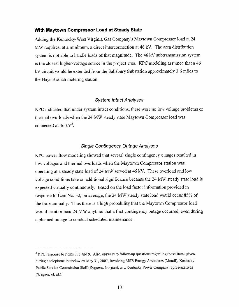
With Maytown Compressor Load at Steady State
Adding the Kentucky-West Virginia Gas Company's Maytown Compressor load at 24
MW requires, at a minimum, a direct interconnection at 46 kV. The area distribution
system is not able to handle loads of that magnitude. The 46 kV subtransmission system
is the closest higher-voltage source in the project area. KPC modeling assumed that a 46
kV circuit would be extended from the Salisbury Substation approximately 3.6 miles to
the Hays Branch metering station.
System Intact Analyses
KPC indicated that under system intact conditions, there were no low voltage problems or
thermal overloads when the 24 MW steady state Maytown Compressor load was
connected at 46 kV2.
Single Contingency Oufage Analyses
KPC power flow modeling showed that several single contingency outages resulted in
low voltages and thermal overloads when the Maytown Cornpressor station was
operating at a steady state load of 24 MW served at 46 kV. These overload and low
voltage conditions take on additional significance because the 24 MW steady state load is
expected virtually continuously. Based on the load factor information provided in
response to Item No. 32, on average, the 24 MW steady state load would occur 85% of
the time annually. Thus there is a high probability that the Maytown Compressor load
would be at or near 24 MW anytime that a first contingency outage occurred, even during
a planned outage to conduct scheduled maintenance.
KPC response to Items 7, 8 and 9. Also, answers to follow-up questions regarding those Items given
during a telephone interview on May 3 1,2007, involving MSB Energy Associates (Mendl), Kentucky
Public Service Commission Staff (Rogness, Garjian), and Kentucky Power Company representatives
(Wagner, et. al.)"
13
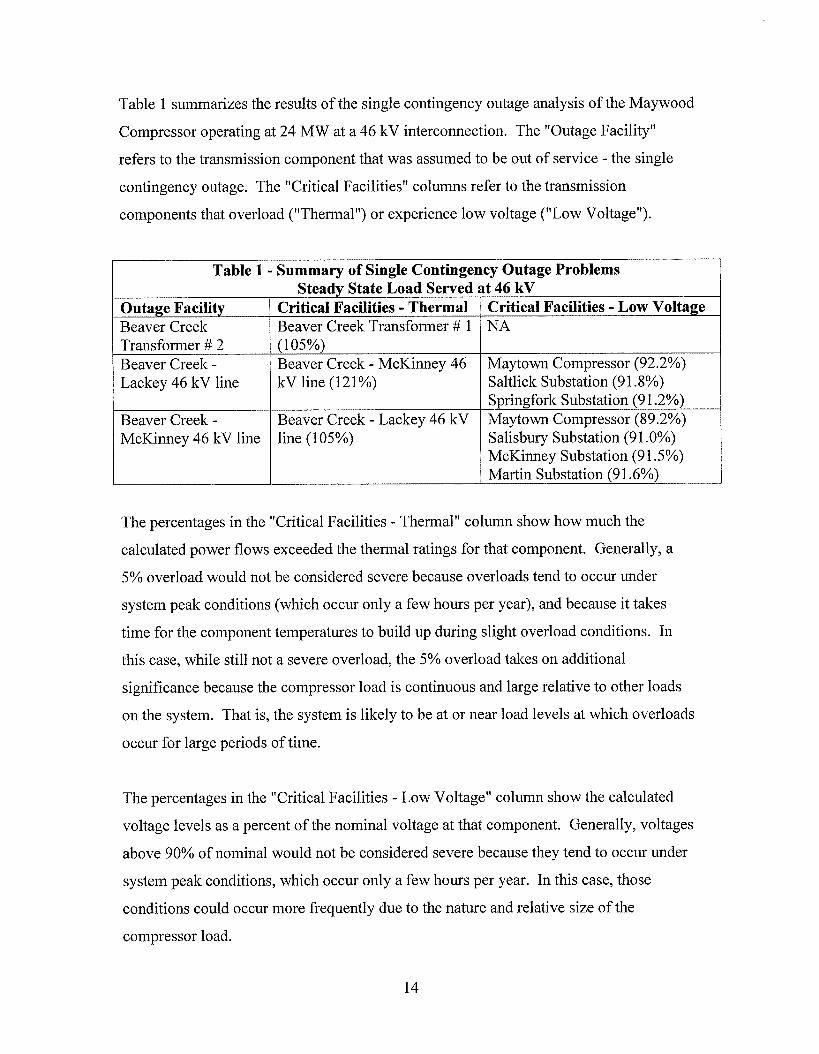
Table 1 summarizes the results of the single contingency outage analysis of the Maywood
Compressor operating at 24 MW at a 46 kV interconnection. The "Outage Facility"
refers to the transmission component that was assumed to be out of service - the single
contingency outage. The "Critical Facilities" columns refer to the transmission
components that overload (llThermalll) or experience low voltage ("Low Voltage").
Outage Facility Beaver Creek
Critical Facilities - Thermal Beaver Creek Transformer # 1
Critical Facilities - Low Voltage NA
Transformer # 2 Beaver Creek - Lackey 46 kV line
Beaver Creek -
(1 05%) Beaver Creek - McKinney 46 kV line (121%)
Beaver Creek - Lackey 46 kV
Maytown Compressor (92.2%) Saltlick Substation (91.8%) Springfork Substation (9 1.2%) Maytown Compressor (89.2%) Salisbury Substation (91 .O%) McKinney Substation (91 .5%) Martin Substation (9 1.6%)
McKinney 46 kV line
The percentages in the "Critical Facilities - Thermal" column show how much the
calculated power flows exceeded the thermal ratings for that component. Generally, a
5% overload would not be considered severe because overloads tend to occur under
system peak conditions (which occur only a few hours per year), and because it takes
time for the component temperatures to build up during slight overload conditions. In
this case, while still not a severe overload, the 5% overload takes on additional
significance because the compressor load is continuous and large relative to other loads
on the system. That is, the system is likely to be at or near load levels at which overloads
occur for large periods of time.
line (105%)
The percentages in the "Critical Facilities - Low Voltage" column show the calculated
voltage levels as a percent of the nominal voltage at that component. Generally, voltages
above 90% of nominal would not be considered severe because they tend to occur under
system peak conditions, which occur only a few hours per year. In this case, those
conditions could occur more frequently due to the nature and relative size of the
compressor load.
14

With Maytown Compressor Load at Startup Conditions
Adding the Kentucky-West Virginia Gas Company's Maytown Compressor load at 60
MW using a direct interconnection at 46 kV from the Salisbury Substation to the Hays
Branch metering station, exacerbates the steady state loading.
System Intact Analyses
KPC indicated that under system intact conditions, there were both low voltage problems
and thermal overloads when the 60 MW Maytown Compressor startup load was
connected at 46 kV". Attempting to draw 60 MW of startup power across the 46 kV
system depressed voltages on the 46 kV system throughout the entire project area.
Voltages at the Maytown Compressor dropped below 80%, which would be inadequate to
start the compressor motors. Thermal overloads would occur at the Beaver Creek
Transformer No. 1, the Allen - Martin 46 kV line and the Beaver Creek - McKinney 46
kV transmission line.
Table 2 summarizes the results of the system intact analysis of the Maywood Compressor
operating at 60 MW startup load at a 46 kV interconnection.
KPC response to Items 6,7 , 8 and 9.
1s

Table 2 - Summary of System Intact Problems Startun Load Served at 46 kV
Outage Facility None
Critical Facilities - Thermal
Beaver Creek Transformer # 1 (1 08%) Allen - Martin 46 kV line (129%) Beaver Creek - McKinney 46 kV line (1 34%)
Critical Facilities - Low Voltage
Maytown Compressor (79.3%) Saltlick Substation (91 3%) Springfork Substation (90.7%) Lackey Switching Station (92.3%) Salisbury Substation (84.9%) McKinney Substation (89.5%) Martin Substation (85.8%) Allen Substation (89.4%) Garrett Substation (91.6%) East Prestonsburg (89.2%) Prestonsburg (89.4%) Middlecreek Substation (9 1 .O%) Kenwood Substation (89.4%) Kenwood Tap (90.2%)
Single Contingency Outage Analyses
KPC either did not perform or did not provide power flow modeling that showed low
voltages and thermal overloads under single contingency outages resulted when the
Maytown Compressor station was operating at a startup load of 60 MW served at 46 kV.
It is clear that they would be substantially worse than the problems under system intact
conditions during motor startup. Because the system intact condition under startup
conditions already showed problems that needed to be addressed, conducting further
analysis of the single contingency outage conditions is unnecessary.
Discussion
The addition of the block load requires upgrades to the transmission and subtransmission
systems in order to be able to start the large motors. Due to the size of the motors and
large startup current draw, voltages drop to unacceptable levels throughout the 46 kV
system in the project area even under system intact conditions. If the voltages were
depressed momentarily but remained at levels high enough to start the large motors, the
transmission and subtransmission problems could probably be resolved through a number
16

of improvements to the lower voltage system. The fact that voltages become depressed
as extensively as they do during startup under system intact conditions means that the
new customer load cannot be served from the 46 kV system.
To expand on that point, if the motors could be started, the single contingency outages of
key facilities result in slight overloads that could probably be addressed by
reconductoring or rebuilding several 46 kV lines. Though there are some low voltage
problems, they are quite contained and relatively more manageable. However, that is
moot because the startup conditions are so severe that the motors cannot be started on the
46 kV system. Thus, higher voltage solutions must be considered, unless the size of the
starting load can be reduced.
Ability to Serve Future Loads
The relatively low growth in baseline demand is an advantage in that it does not add
much pressure to build extra capability to serve imminent load increases. The baseline
growth being so low does not greatly exacerbate the immediate problem, i.e., of
designing a transmission solution that is capable of starting the large Maytown
compressor motors.
On the other hand, the transmission solution should have sufficient robustness to
accommodate other large block loads that may occur from coal mining activity in the
area. Finding a transmission solution that barely solves the immediate problem of
connecting and serving the Maytown compressor load would provide little capacity to
serve future potential block loads, even if it may be able to absorb three, five, or even ten
years of baseline load growth.
Summary of Section I I
The problems with transmission and subtransmission in the Morgan Fork-Hays Branch
project area are local reliability-driven problems - driven by the addition of a large block
load with an even greater startup load.
17
0 There are no low voltage or thermal overload problems in the project area prior to
the addition of the Maytown Compressor load.
There are no low voltage or thermal overload problems in the project area when
the Maytown Cornpressor motors are operating at their steady state loads (24
MW) under system intact conditions.
Several relatively minor low voltage and thermal overload problems arise in the
project area when the Maytown Compressor motors are operating at their steady
state loads (24 MW) under single contingency outage conditions.
Severe low voltage and moderate overload conditions arise in the project area
when the large Maytown Compressor motors are being started (60 MW) from the
46 kV system even under system intact conditions.
The large motors at the Maytown Compressor cannot be started from the 46 kV
system.
0
0
0
18

Section 111 Potential Solutions
This section examines the potential solutions analyzed by KPC and also identifies other
possible solutions. Potential solutions would typically include transmission solutions as
well as non-transmission solutions.
Transmission solutions
Potential transmission solutions in this case are dictated by their ability to maintain
voltage levels during the large current draws when the large compressor motors are
starting.
Connecting the Maytown Compressor load at 46 kV
KPC Alternative: KPC analyzed the potential alternative of connecting in the Maytown
Compressor at 46 kV. This involved building a new 46 kV line from Salisbury
Substation to the Hays Branch metering station. This potential alternative is the reference
case set forth in Section I1 of this report. As indicated in Section I1 of this report, the 46
kV connection alternative has many deficiencies including low voltage and overload
problems during steady state operations under single contingency conditions and during
startup under system intact conditions. KPC's 46 kV alternative will not reliably serve
the load.
MSB Alternative: MSB noted that the problems occurring under single contingency
outage steady state conditions were quite manageable. Reconductoring the existing 46
kV lines to a larger conductor size would increase the current (and power) carrying
capability sufficiently to mitigate the calculated overloads. It appears that the Beaver
Creek - McKinney, Beaver Creek - L,ackey and Allen - Martin 46 kV lines are all
equipped with 336,400 kcmil ASCR conductors. Increasing them to 556,500 kcmil
ASCR conductors, the other size prevalent in the project area, would increase the power
carrying capability by about 35%, which would be sufficient to remove the expected
overloads. As shown in Table 1 , thermal overloads during first contingency outage
19

conditions and steady state operating loads were less than 121% of ratings.
Reconductoring would remove the overloads. Even under system intact startup
conditions, the thermal overloads are 134% of ratings or less, and thus reconductoring
would eliminate those overloads as well.
MSB does not consider this to be a viable alternative. The 46 kV approaches, according
to KPC power flow analyses, are simply unable to maintain voltage levels during the
motor startup. As long as startup loads are on the order of 60 MW, a higher voltage
solution will be needed to start the motors and serve the load.
In addition, KPC also noted that the structures supporting the 46 kV lines in the project
area are loaded to their weight-bearing capacity. That would mean that reconductoring
would also require replacing most of the support structures - in effect rebuilding the line.
KPC estimated that the cost to rebuild the 7.5 miles of the Beaver Creek-McKinney and
10 miles of the Beaver Creek-Lackey lines at 46 kV, together with the replacement of the
Beaver Creek Transformer, would cost approximately $13 m i l l i ~ n . ~ In addition, there
would be another approximately $2 million cost to build the 46 kV line from Salisbury to
the Maytown Compressor.
Thus a total of about $15 million would be required to upgrade the 46 kV system, in
comparison to KPC's estimated $1 5.4 million for its 138 kV proposal. But the 46 kV
approach would still be unable to maintain acceptable voltage levels during motor
startup, and would have more limited capability to address new block and baseline loads
in the project area. MSB does not consider the enhanced 46 kV alternative to be viable.
Connecting the Maytown Compressor load at 69 kV
KPC Alternative: In paragraph 18 of the application, KPC indicated that its proposed
138 kV solution provides a potential 69 kV source that could be used in any conversion
of the existing 46 kV system to 69 kV. MSB interpreted that to mean that KPC had some
Item No. 35 response by KPC.
20

long term plans to upgrade the 46 1V system to 69 kV as loads grew in the future. In
response to Items 16, 17 and 35, KPC clarified that the existing 46 kV system in the
project area was not designed to be upgraded to 69 kV and that doing a large scale
conversion would cost on the order of $120 million for lines and substation equipment
and would take five years to complete. This would be well beyond the March 2008 date
by which Kentucky-West Virginia Gas Company plans to start using electric motors for
compression. MSB agrees with KPC that large scale upgrading of the 46 kV system to
69 kV is not a viable alternative.
MSB Alternative: During the May 3 1 telephone interview following the responses to
Item Nos. 1-30, KPC provided clarification of its intent regarding the 69 kV conversion
in application paragraph 18. KPC indicated that it was currently interconnected with East
Kentucky Power Cooperative at the Falcon Substation at 46 kV, but was considering
upgrading the interconnection to 69 kV. Referring to Figure 2, that would entail
upgrading the Falcon-Middle Creek 46 kV line to 69 kV. KCP in its application was
suggesting that the proposed 138 kV line could ultimately be terminated with a 138 kV to
69 kV transformer at Hays Branch. That new 13 8/69 kV substation would be somehow
connected to the 69 kV Falcon-Middle Creek upgrade, thus completing the
interconnection with East Kentucky Power Cooperative at 69 ItV.
If KPC intends to complete a 69 kV interconnection to the west from Hays Branch to
Falcon, then the alternative of serving the Maytown Compressor load at 69 kV may be
more attractive. The cost to upgrade the interconnection may be expended anyway, so
there could be minimal incremental cost to serve the Maytown Compressor load.
However, there are several reasons this potential alternative is not reasonable. First,
connecting a large load over a long radial 69 kV line from the west is not likely to
provide the required level of reliability, and may, in fact, be electrically unworkable -
KPC did not perform power flow studies of any 69 kV alternatives.
Second, to be a useful interconnection between the utilities, the 69 kV cannot terminate at
Hays Branch but instead must tie into strong sources in KPC. To tie into the 69 kV
21

system, the Falcon-Hays Branch 69 kV line would have to be extended to Betsy Layne or
Beaver Creek, the two nearest locations of existing 69 kV lines. Either of those
extensions is longer than KPC's proposed line which taps the Beaver Creek-Betsy Layne
138 kV line near its midpoint.
An alternate means of tying the interconnection to strong sources in KPC, Falcon-Hays
Branch 69 1V could be terminated at a 13 8/69 kV substation at Hays Branch or at
Morgan Fork. The former would build the proposed line as 138 1V; the latter would
build it at 69 kV. If built at 13 8 kV, this is the same as KPC's proposal. If built at 69 kV,
it would increase losses, reduce flexibility and not fit in to a possible future 138 kV loop
also mentioned by KPC in paragraph 18 of the application.
MSB does not consider the 69 kV upgrade to be a viable alternative. It is not likely to
produce any significant electrical benefits, and is likely to take longer to fully implement.
In the meantime, it would either not serve the Maytown Compressor load as soon or as
reliably. Finally, it might ultimately end up with the same configuration that KPC is
contemplating with its proposal, only constructed in a different order.
Connecting the Maytown Compressor load at 138 kV
KPC Alternative: This is KPC's proposal. KPC's proposal resolves the low voltage and
overload conditions resulting from the addition of the Maytown Compressor load. KPC
evaluated a Northern, Central and Southern route. Each route connected the same
endpoints and is electrically indistinguishable from the other two. The proposed route is
the shortest, shares right of way with the 765 kV line, and is the least expensive. MSB
agrees with KPC that the proposed 138 kV line is a viable alternative.
MSB Alternative: MSB did not identify any other reasonable 138 kV sources. Tapping
the Beaver Creek - Betsy Layne 138 kV line is shorter and utilizes more corridor sharing
than other potential 138 kV sources.
22

Connecting the Maytown Compressor load at 138/765 kV
KPC Alternative: KPC identified this alternative in the application: to tap into the 765
kV line that the proposed line parallels for nearly half of its length, rather than to tap into
the Beaver Creek-Betsy Layne 13 8 1V line. The 765 kV tap would be transformed down
to 138 kV, and then extended from the tap substation to the Hays Rrancli metering
station. The advantage of this alternative is that there is not a redundant 13 8 kV line built
parallel to the 765 kV line to serve Maytown Compressor loads. It also creates a strong
138 kV source for a 138 kV loop that KPC could eventually build to improve reliability if
loads in the project area grow sufficiently. At present, KPC has no plans to build such a
138 kV loop, but indicates that one could be needed if block loads grow.
In responses to Itern No. 35, KPC identified three reasons that tapping into the 765 kV
line was not practical. First, it would require the construction of a 20-acre switching
station and substation to convert to 138 kV. Second, it would need 20 acres of flat land,
which is not readily available in the mountainous regions through which the 765 kV line
passes. Not only would the land be at a premium, it may require the construction of 765
kV lines to access it from the existing line. Third, the project could not be implemented
for about three years, much after the March 2008 date requested by the customer to begin
service.
MSR concurs with KPC that the 765 kV alternative is not practical due to cost and timing
concerns.
MSB Alternative: MSR did not consider any other 765 kV tap alternatives.
Non-transmission solutions
Potential non-transmission solutions in this case are dictated by the size of the block load,
and particularly the motor startup load. Non-transmission solutions would typically
include building new power plants in locations to alleviate transmission needs and
23
building distributed generation (smaller and more closely located to the load).
Redispatching existing generation may also be a viable non-transmission option to
eliminate overloads or low voltages. Non-transmission alternatives would also include
load management and energy efficiency programs to reduce usage on the customer side
of the meter. Customer owned generation on the customer side of the meter could also be
an effective tool to reduce transmission problems.
Wheeling Power on Neighboring Systems
Wheeling power on neighboring systems is not an alternative in this case. The new
Maytown Compressor load is located well within KPC service territory. The load is
currently not interconnected and some new construction must be done in order to connect
and serve the load. Thus, there is no viable wheeling alternative to serve the Maytown
compressor load in the near term.
Over the longer term, if KPC decides to upgrade the interconnection with East Kentucky
Power Cooperative at Falcon to 69 kV and then extends it to Hays Branch, that will
create a second path for power supplies from the west rather than fkom the east. The
western supply would involve some wheeling on the neighboring system. However, this
arrangement to the west would not normally be expected to move significant amounts of
power under system intact conditions. That is because stronger 138 kV sources are
located nearer to the Maytown Compressor load from the east, and these sources are
likely to dominate over more distant power supplies at 69 kV from the west. Thus, while
a second path may eventually exist that in theory could be used to wheel power across
neighboring systems to serve Maytown Compressor load, it is not likely to be a
significant flow path for power under system intact conditions.
Redispatching
Redispatching, or increasing generator output out of economic order at locations strategic
to maintaining transmission system integrity, is not an alternative in this case.
Redispatching alleviates loading on transmission lines by shaping where power sources
24
are and what paths power flows along from the sources to the loads. In this case, the
issue is connecting a large block load at the Maytown Compressor. There is no
generation in the vicinity of the Maytown Compressor load that would allow the motors
to start and the load to be served.
In addition, redispatching can be economic when the incremental cost of dispatching out
of economic order is less than the cost of building the transmission line. The high load
factor of the Maytown compressor would require dispatching out of economic order
many hours each year, which is likely to make redispatching very costly relative to
building the additional transmission lines.
Building Large Power Plants
The location of large power plants can and does affect the power flows and voltage
conditions on the transmission network. Normally, power plants are much more costly to
build than transmission, and it is generally not cost effective to consider building a large
power plant in order to avoid building a transmission line. However, if a power plant
needs to be built to meet power supply needs, the benefits to the transmission system
could influence the location of that power plant. In this case, constructing a large scale
power plant to serve the Maytown Compressor load is not applicable. First of all,
building a large scale power plant would require extensive interconnections of the plant
to the high voltage transmission network. Rather than building one transmission line into
the project area to serve a large block load there, KPC would have to build multiple high
voltage lines through the project area to deliver power from the plant to the transmission
system. Building multiple high voltage lines to connect a generator to avoid building one
high voltage line to connect a large load is not a practical option.
Load Management
Load management can in some instances control the peak loads sufficiently to defer or
avoid the need to build transmission or generation projects. Load management as used in
this report refers to direct load control methods and is aimed at shifting or shedding load
25
at the time of peak (or other critical times) through voluntary curtailment of customer
service or an interruption of a controlled appliance/process.
Interruptible tariffs are one form of load management that may be applicable to the
Kentucky-West Virginia Gas Company. The Gas Company has existing compressor
engines powered by natural gas. Initially, additional compression capacity will be added
using electric motors, and both the natural gas and electric motors will be run.
Eventually, the gas engines will be replaced by electric motors and retired. Having both
the gas and electric motors on site provides an opportunity to internipt part of the electric
load when the need arises while continuing the compression work with the gas engines.
KPC offered Kentucky-West Virginia Gas Company the opportunity to go onto
interruptible tariffs. The Gas Company declined because it did not consider its loads
interruptible and because KPC's loads peak in the winter when the Gas Company has its
highest loads and the greatest value of gas burned for compression. (Item Nos. 4 and 34)
Ultimately as it applies to this 138 kV transmission proposal, however, the problem is the
large 60 MW starting load. The 60 MW load cannot be interrupted because it is the
smallest amount of starting load associated with the large motor - if you want to start the
1 1,000-horsepower motor you will incur the 60 MW starting load. The transmission
network must be designed to supply that 60 MW starting load.
One possible strategy for shaping the customer's loads to reduce the starting load is to
select different motor sizes. For example, all else being equal, replacing each 1 1,000-
horsepower motor with two 5,500-horsepower motors would cut the starting load to 30
MW. Since there were no low voltage or overload problems for the system intact steady
state condition (24 MW) and relatively few problems for the first contingency outage
steady state condition, peak starting loads approaching 24 MW potentially could be
sustainable on the 46 kV system.
26

Of course it is the customer's choice as to the number and size of motors he/she installs.
And it is the utility's obligation to serve the loads that are demanded. Thus the utility and
the Commission cannot control the number and size of motors; they can only assure that
the customer pays a fair price for the MWs and MWHs consumed and that costs incurred
by the utility to serve that customer are reasonably allocated to that customer.
Energy Efficiency
Energy efficiency programs focus on appliances and processes that use less energy
whenever they are in use. As such, not only will they reduce overall electrical energy
consumed, they also will reduce the peak load to the extent they are on during time of
peak. Properly designed energy efficiency programs can be useful in reducing overall
growth of peak loads and energy requirements. In this case, because the baseline growth
is small relative to the block demand growth, energy efficiency opportunities in the
baseline growth will not materially affect the need for the proposed transmission line.
Again, that is because the need for the proposed line is driven so strongly by the starting
load imposed by the large motors.
To the extent that the improvement in the energy efficiency of the compressor motors
reduces the starting load of the motor, energy efficiency can help offset the problems
during startup. Again, that is the customer's choice. MSR did not conduct any analysis
of the efficiency of the compressor motors, and especially the large motors. However,
MSB assumes that motors that large with that high of load factors are designed and
selected by the Gas Company with energy efficiency in mind.
Distributed Genera tion
Distributed generation refers to small generators, typically 15 MW or less, located near to
the load. Distributed generation reduces the need for large power plants. Distributed
generation, being located nearer to the load, can reduce transmission losses and the need
for transmission system improvements. Distributed generation can be implemented as
customer owned and controlled (on customer side of meter reducing net load), utility
27

owned and controlled (on utility side of meter adding to the supply), or somewhere in
between (e.g., customer owned but utility co-controlled, etc).
In the context of the Morgan Fork-Hays Branch proposal, the electric motors are
replacing an existing distributed power source. In effect a distributed power resource is
being retired by the customer and replaced by an electric load that requires electric
system upgrades.
Other Benefits of the Proposal
KPC in paragraph 18 of the application asserted that the proposed 138 1V line "will
provide a platform to enable Kentucky Power to provide improved reliability for the
eastern Kentucky area transmission and distribution systems." KPC listed five benefits:
a) Reliability on KPC's 138 kV network will be improved with the installation of
two circuit breakers at Morgan Fork Station;
b) Additional capacity to serve additional load from Morgan Fork Station;
c) Potential 69 kV source that could be used in any conversion of the 46 kV system
to a 69 kV system;
d) Opportunity to locate a future station at the intersection of the Morgan Fork-Hays
Branch line and the Martin-Salisbury-McKinney 46 kV line; and
e) Opportunity for a future 138 kV loop from Thelma to Beaver Creek:
MSB has assessed each of these other benefits and agrees each of these points can have
bearing on the long-range transmission system configuration. However, because the
anticipated demand growth rates are quite low, there are no imnediate needs for or plans
implement points b) through e). None of these points rise to being determinative of
choices between alternatives, though each may be valuable under certain circiunstances.
In other words, while the five points of the platform are reasonable considerations to help
ensure sufficient flexibility to meet future conditions, they are not, in and of themselves,
significant drivers of the need for the proposed project.
28

Summary of Section 111
The large block load, and especially the large motor startup load, being added create
severe low voltage problems as identified in Section 11. This limits the types of
transmission alternatives that could be developed to primarily higher voltage alternatives.
KPC's obligation to serve the new load, coupled with its size, greatly limits the number of
non-transmission alternatives to the proposed project that could be viable.
KPC concluded that connecting the Maytown Compressor load at 46 kV was not
viable. MSR concurs.
MSB concluded that an enhanced connection at 46 kV, one including some rebuilding
of existing 46 kV lines, was not a viable means to serve the Maytown Compressor
load.
KPC concluded that large scale rebuilding of the 46 kV system to 69 kV is not a
viable means to serve the Maytown Compressor load. MSR concurs.
MSR concluded that upgrading a targeted 46 kV line 69 kV is not a viable means to
serve the Maytown Compressor load.
KPC concluded that the proposed 138 kV alternative is a viable means to serve the
Maytown Compressor load. MSB concurs.
KPC concluded that the proposed 765 kV tap to 138 kV alternative is not a viable
means to serve the Maytown. Compressor load. MSB concurs.
MSR concluded that wheeling power on neighboring systems was not a viable means
to serve the Maytown Compressor load.
MSR concluded that redispatching power plants to alleviate transmission system
problems was not a viable means to serve the Maytown Compressor load.
29

0 MSR concluded that building new utility-scale power plants to alleviate transmission
system problems was not a viable means to serve the Maytown Compressor load.
0 MSB concluded that implementing traditional load management programs to alleviate
transmission system problems was not a viable means to serve the Maytown
Compressor load.
0 MSR concluded that customer willingness to adjust the size and number of electric
motors driving the compressors could substantially reduce the startup load and thus
the seriousness of low voltage and overload problems. MSR cannot rule out the
possibility that startup loads could be affected enough that the Maytown Compressor
loads could be served fiom the 46 kV system.
MSB concluded that energy efficiency programs were not a viable means to serve the
Maytown Compressor load.
MSR concluded that distributed generation was not a viable means to serve the
Maytown Compressor load.
30

Section IV Conclusions
MSR concluded that:
Kentucky-West Virginia Gas Company intends to expand its compressor capacity and
convert its compressor engines to electric motors at the Maytown Compressor Station
near Langley, Kentucky.
a) Operating electric motors at the Maytown Compressor Station will add 24 MW,
on average, to the electrical loads near L,angley.
b) Starting the large electric motor at the Maytown Compressor Station will require
60 MW.
To serve the Maytown Compressor load, Kentucky Power Company will need to
upgrade its transmission and sub-transmission networks to resolve low voltage and
thermal overload problems, especially during compressor motor startup.
Providing service to the Maytown Compressor Station at 138 kV is reasonable.
a) At 46 kV, the Maytown compressor motors could not be started due to low
voltage.
b) Upgrading the 46 kV system to 69 kV would be costly, could not be
accomplished in time to meet customer service requirements and may not be able
to maintain voltage levels during attempts to start the motors.
c) Tapping into the existing 138 kV line and serving the Maytown Compressor load
at 138 kV eliminates overload and low voltage problems and allows Kentucky
Power Company to provide reliable service to the project area.
d) Tapping into a nearby 765 kV line is costly and could not be accomplished in
time to meet customer service requirements.
31

4) Strategies to reliably serve load after the addition of the Maytown Compressor Station
without building transmission infrastructure are limited.
Wheeling across neighboring systems is not viable because adequate
interconnections to neighboring systems and to the Maytown Compressor load do
not exist.
There are no power plants that exist to be redispatched, or that could be built in
the project area to timely meet Maytown Compressor service requirements.
Load management and energy efficiency in the project area are not sufficient to
offset the 60 MW startup demand of the Maytown compressors.
Kentucky-West Virginia Gas Company could potentially reduce startup load by
replacing the two largest compressor motors with several smaller ones. Reducing
the startup load may make lower voltage transmission alternatives more viable.
32

.. .
Figure 1


IMPACT OF MAYTOWN COMPRESSOR BLOCK LOAD ON PROJECT AREA BASELINE LOAD
1400 1
I 1000 ~; -- -- -- -
- - - Total Load Forecast -Baseline Load Forecast
Figure 3 is not a forecast of annual peak demands. Its purpose is to illustrate the effect of the Maytown Compressor block load relative to baseline load growth (assumed at 1 % per year). Kentucky Power Company forecasts growth in the project area at less than 1%.

Appendix A
Overview of Transmission Systems
Power plants generate electricity, often at points distant from the location that the
electricity is actually used. Power plants tend to be quite large, each often being capable
of serving hundreds of thousands of homes. Power must be transported from these large
power plants to the homes and businesses where it is used. Power is transmitted over
great distances by the high voltage transmission network to substations where it is
converted to lower voltages. Transmission lines normally operate at voltages between
69,000 volts (69 kV) and 765,000 volts (765 kV). These voltages are much too high to
be used in homes and most businesses. Transformers at substations convert transmission
voltages to successively lower voltages that ultimately supply the distribution lines that
fan out from distribution substations to deliver power to the customer. One final
transformer reduces the distribution voltage to voltages typically used by customers; e.g.,
most smaller businesses and residential customers typically use power at 220 volts.
Path of Least Resistance
Electricity flows from the source (power plant) to the sink (end user) in accordance with
the laws of physics. Power will flow most freely along the path of least resistance.
Transmission systems are interconnected and provide multiple paths for power to Row.
This complicates the analysis of transmission systems. Power will flow across multiple
parallel transmission paths as it moves from the power plant to the end user. It will also
come from multiple power plants. The transmission system can be viewed as a collector
of power fkom the various power plants on the system and as a supplier of power to the
various distribution substations connected to it. It is important to remember that power
will flow from multiple power plants to the point of end use along multiple parallel paths,
with the paths of lesser resistance taking more of the power flow, even if doing so will
overload a transmission facility. Power flow models simulate the operation of the
transmission network based on its physical parameters, the location and size of power
plants, the location and size of load, and the laws of physics.

Increasing Line Capacity
The maximum amount of power that can be carried by a transmission line depends on the
voltage and current that the line is designed for. At a given voltage, the larger the
conductors, the more power it can carry. If an existing line is running at h l l capacity, the
capacity can be increased by reconductoring the line, that is, to remove the old
conductors and replace them with larger conductors capable of handling higher current
flows. This assumes that the existing structures are able to support the additional weight
of the larger conductors. If not, reconductoring may require substantial rebuilding of the
line.
The other way to increase the amount of power a line can carry is to increase the voltage
at which it operates. Higher voltages require more insulation (larger insulators between
the towers and the conductors) and increased clearances (wider rights of way and taller
towers). For an existing line, upgrading the voltage may be difficult if clearance
requirements cannot be met; e.g., the line was built on small structures or through land
uses that do not allow widening the rights of way.
Losses occur in all transmission lines. The resistance of the conductor to current flowing
through it causes the conductor to heat up. These losses increase as the square of the
current flowing through the line, so that doubling the current quadruples the losses. For a
given conductor size, doubling the voltage (e.g., from 69 kV to 138 kV) will halve the
current for any given power level and result in one-fourth of the losses. All else equal,
the higher the voltage at which a transmission line operates, the more power it can carry
and the lower the losses.
