asbestos remediation plan for forested areas near libby, montana
TRANSCRIPT

Asbestos Remediation Plan for
Forested Areas near Libby, Montana
Developed for:
Lincoln County Port Authority
Libby, Montana
Final Report September 2012
Asbestos Remediation Plan for
Forested Areas near Libby, MT
Developed for:
Lincoln County Port Authority
Libby, Montana
Project Team:
Roy Anderson, Senior Consultant,
The Beck Group, Portland, Oregon
Greg Frame, Estimating Manager
Envirocon, Inc., Missoula, Montana
Craig Rawlings, Principal
Forest Business Network, Missoula, Montana
Project Reviewers:
Tony Ward, Assistant Professor
University of Montana, Missoula, Montana
Bob Rummer, Project Leader Forest Operations Research
U.S. Forest Service, Auburn, Alabama
Final Report
September 2012
Table of Contents
Page
CHAPTER 1 – EXECUTIVE SUMMARY ............................................................................... 1
1.1 Introduction .............................................................................................................. 1
1.2 The Operating Environment .................................................................................... 2
1.2.1 Landowners ........................................................................................................................ 2
1.2.2 Tree Biomass in OU3 ......................................................................................................... 3
1.2.3 Road System ...................................................................................................................... 4
1.2.4 Asbestos Levels ................................................................................................................. 4
1.3 The Remediation Plans ............................................................................................ 5
1.3.1 Standing Tree Remediation Plan ....................................................................................... 5
1.3.2 Forest Floor Duff Remediation Plan ................................................................................... 8
1.4 Recommendations ................................................................................................... 8
CHAPTER 2 – THE OPERATING ENVIRONMENT............................................................. 11
2.1.1 Existing Tree Vegetation .................................................................................................. 11
2.1.2 Road Density .................................................................................................................... 13
2.1.3 Topography ...................................................................................................................... 14
2.1.4 Asbestos Levels ............................................................................................................... 14
CHAPTER 3 – REMEDIATION PLANNING APPROACH ................................................... 19
CHAPTER 4 – STANDING TREE REMEDIATION PLAN.................................................... 20
4.1 Standing Tree Remediation Plan Objectives ........................................................ 20
4.2 Timber Harvesting Technology ............................................................................. 20
4.2.1 General Discussion of the Technologies Selected .......................................................... 21
Timber Felling ......................................................................................................... 22 4.2.1.1
Extraction ................................................................................................................ 25 4.2.1.2
Merchandising – Delimbing .................................................................................... 27 4.2.1.3
Truck Loading ......................................................................................................... 28 4.2.1.4
Hauling ................................................................................................................... 29 4.2.1.5
4.2.2 Equipment & Operating Modifications Needed for OU3 Plan Implementation ................ 30
General Approach .................................................................................................. 30 4.2.2.1
Equipment Modifications ........................................................................................ 32 4.2.2.2
Operator Modifications ........................................................................................... 32 4.2.2.3
Monitoring ............................................................................................................... 32 4.2.2.4

Table of Contents
CHAPTER 5 – FOREST DUFF REMEDIATION PLAN ........................................................ 33
5.1 Forest Duff Remediation Technology ................................................................... 33
5.1.1 Remediation of Northern Europe Forests ........................................................................ 33
5.1.2 Combination Industrial Vacuum System and Portable Conveyor .................................... 34
5.1.3 Beneficial Land Cover ...................................................................................................... 35
CHAPTER 6 – MATERIAL UTILIZATION ........................................................................... 36
6.1 General Utilization Concepts ................................................................................. 36
6.1.1 Establish a Permanent Utilization Structure .................................................................... 36
6.1.2 Site Control ...................................................................................................................... 37
6.2 Specific Products That Might Be Produced ......................................................... 37
6.2.1 Sawlogs ............................................................................................................................ 38
6.2.2 Pulp Chips ........................................................................................................................ 38
6.2.3 Hog Fuel ........................................................................................................................... 39
6.2.4 Logging Slash .................................................................................................................. 39
6.2.5 Firewood .......................................................................................................................... 40
6.3 Budgetary Capital Cost Estimates ........................................................................ 40
6.4 Estimated Required Staffing Levels ...................................................................... 41
THE BECK GROUP Page 1 Portland, OR
CHAPTER 1 – EXECUTIVE SUMMARY
1.1 INTRODUCTION
The forest surrounding the former W.R. Grace vermiculite mine near Libby, Montana
has been found to be contaminated with asbestos fibers. Since exposure to those
asbestos fibers can reasonably be expected to be a health risk for humans and since
wide spread exposure to humans could occur during a wildfire event, the Lincoln County
Port Authority (LCPA), in consultation with the U.S. Forest Service (USFS) and the
Montana Department of Natural Resources and Conservation (DNRC), seek a timber
harvesting technical plan for removing asbestos contaminated standing trees and forest
floor duff from the forests in an area identified by the United States Environmental
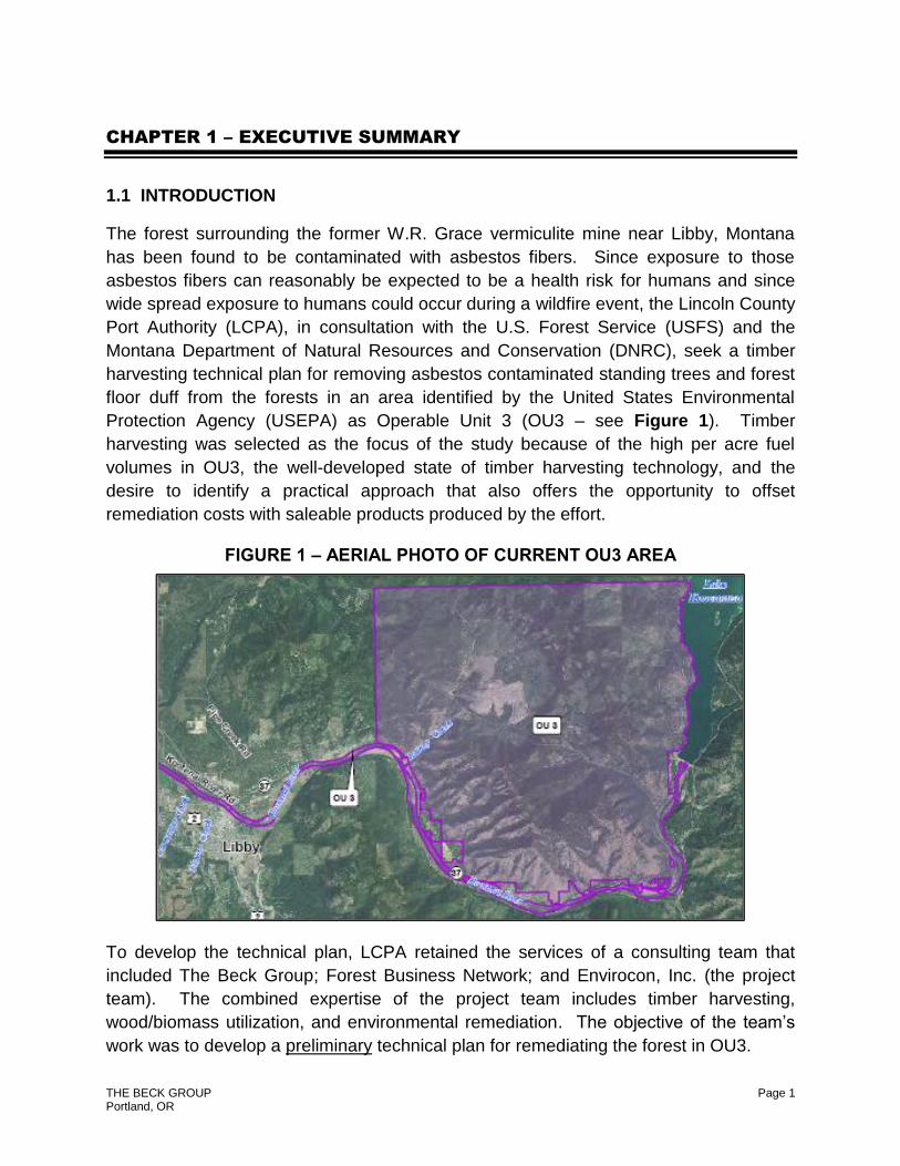
Protection Agency (USEPA) as Operable Unit 3 (OU3 – see Figure 1). Timber
harvesting was selected as the focus of the study because of the high per acre fuel
volumes in OU3, the well-developed state of timber harvesting technology, and the
desire to identify a practical approach that also offers the opportunity to offset
remediation costs with saleable products produced by the effort.
FIGURE 1 – AERIAL PHOTO OF CURRENT OU3 AREA
To develop the technical plan, LCPA retained the services of a consulting team that
included The Beck Group; Forest Business Network; and Envirocon, Inc. (the project
team). The combined expertise of the project team includes timber harvesting,
wood/biomass utilization, and environmental remediation. The objective of the team’s
work was to develop a preliminary technical plan for remediating the forest in OU3.

Chapter 1 – Executive Summary
THE BECK GROUP Page 2 Portland, OR
The OU3 area is part of the Libby Asbestos Superfund site that was established in
2002. It surrounds the former W.R. Grace vermiculite mine near Libby, Montana, and it
is approximately 35,000 acres in size. According to the USEPA, expansion of the OU3
perimeter is under consideration as further testing has shown asbestos contaminated
trees outside the current OU3 boundary. At this point, the extent of the potential
expansion is not known.
Implementation of the technical plan developed as part of this project is expected to
reduce the amount of biomass in OU3, which in turn would reduce the danger of wildfire
in OU3, which in turn would mitigate the risk of the asbestos currently contained in the
trees and forest floor duff from becoming airborne and spreading and contaminating a
much broader area during a wildfire event. Implementation of the plan is also expected
to allow the public to maintain some amount of access to OU3.
The following sections of the executive summary provide a description of the project
team’s plan, as well as a summary of the project team’s recommendations and
conclusions. The team appreciates the opportunity to assist on this important project.
1.2 THE OPERATING ENVIRONMENT
1.2.1 Landowners
At the current time OU3 is about 35,000 acres. The major landowners in OU3 include
the U.S. Forest Service, State of Montana, Plum Creek Timber Company, and Kootenai
Development Company (W.R. Grace). Table 1 shows the estimated acreage owned by
each.
TABLE 1 – ESTIMATED DISTRIBUTION OF
LANDOWNERSHIP IN LIBBY OU3 AREA
Landowner Estimated Acres
Owned
United States Forest Service 23,973
Plum Creek Timber Company 5,433
Kootenai Development Company (W.R. Grace) 3,629
Other Miscellaneous Private Owners 1,325
State of Montana 640
Total 35,000

Chapter 1 – Executive Summary
THE BECK GROUP Page 3 Portland, OR
1.2.2 Tree Biomass in OU3
No inventory of the trees in OU3 was completed as part of this study. However, based
on the US Forest Service’s FIA timber inventory database, for the area covered within a
20 mile radius of the mine site, there is estimated to be an average 611 trees per acre.
When this per acre average for the region is applied to the 35,000 acres of OU3, the
resulting estimate of total merchantable standing tree volume (for all trees greater than
5 inches in diameter at breast height) in OU3 is 65.4 million cubic feet, or 850,000 bone
dry tons, or about 425 million board feet. This translates to a per acre average volume
of about 1,900 cubic feet, 25 bone dry tons, or 12.4 thousand board feet.
About 270,000 bone dry tons (or about 44 percent) is estimated to be found in pulpwood
size trees (those less than 11 inches in diameter at breast height). About 455,000 bone
dry tons is estimated to be found in trees larger than 11 inches in diameter at breast
height. The balance of about 125,000 bone dry tons is estimated to be the bark of the
trees.
In addition to the “merchantable” volumes described in the preceding paragraph, there
is also biomass volume in the limbs and tops of the trees. During typical logging
operations, the limbs and tops (i.e., logging slash) are either left scattered across a
logging unit, or piled at a landing. For this project, an effort would be made to collect
and utilize all logging slash. The project team estimates that in OU3 there are 425,000
bone dry tons of limbs and tops.
Table 2 summarizes the volume of various materials estimated to be found in OU3.
TABLE 2 – ESTIMATED VOLUME OF BIOMASS IN OU3
Material
Type
Bone Dry
Tons
Sawlogs 455,000
Pulp Chips 270,000
Bark 125,000
Logging Slash 425,000
Total 1,275,000

Chapter 1 – Executive Summary
THE BECK GROUP Page 4 Portland, OR
1.2.3 Road System
The existing road system within OU3 is fairly well distributed, with the exception of the
southern portion of the area, which has relatively few roads. While the project team did
not inspect the existing road system within OU3 first hand, we did, however, view the
area from the perimeter and we viewed and analyzed aerial photos and topographic
maps of the area.
The project team estimates that the road density in OU3 is 1.75 (95 miles of forest road
per 54.7 square miles of land area in OU3). Importantly, for our recommendations
about how the biomass can be utilized, the mine site is centrally located within OU3 and
appears to be accessible from most points in OU3 without the need for log trucks to
travel on Highway 37.
Please note, however, that if OU3 is expanded, it may become necessary for log trucks
loaded with asbestos contaminated logs to travel on major public highways. The project
team has not investigated this possibility in detail, but log trailers have been developed
that have curtain sides1. Thus, it is possible that the logs can safely be transported on
major public roads so long as it is done using the enclosed log trailers. More research
on the feasibility and safety of material transport is needed if the area of OU3 is
expanded.
While the project team did not have an opportunity to tour the interior of OU3, it is
readily apparent from topographic maps of the region that the terrain within OU3 is very
challenging, especially in the western portion of the area. The steepness of the terrain
limits the choices of equipment available for timber harvesting operations, but it does
not prevent timber operations altogether. Specific equipment considerations are
discussed in greater detail in the body of the report.
1.2.4 Asbestos Levels
Asbestos levels on the trees in OU3 have been documented in several studies. For
example, the US EPA completed a study2 in which transects from 3 miles to nearly 10
miles long were run radially from the mine site. Tree bark samples were taken at
regular intervals along each transect. The results indicate that no fibers were detected
along some transects, while on others as many as 50 asbestos fibers were found per
1 See: Log-Chip Trailer Offers Flexibility accessed at http://www.forestnet.com/TWissues/Jan_feb_10/log_chip.php
2 Libby OU3 Phase I Sampling and Analysis Plan. USEPA. Completed 9/7/11.

Chapter 1 – Executive Summary
THE BECK GROUP Page 5 Portland, OR
sample. Another study3 completed by a University of Montana team in 2004 found trees
close to the mine site contained between 14 million and 260 million amphibole fibers per
square centimeter of bark surface area. Another study4 was completed by Tetra Tech
EM, Inc. for the Montana Department of Environmental Quality. That study was
completed on the Upper Flower Creek Timber Sale located south of Libby, Montana.
The site is owned by the State of Montana and managed by the Department of Natural
Resources and Conservation. The study found that Libby Amphibole fibers (asbestos)
concentrations ranged from no detection to nearly 283,000 structures per square
centimeter of tree bark. Samples were also taken from forest duff and were found to
range from no detection to 12 million structures per gram of dry weight of duff.
1.3 THE REMEDIATION PLANS
The project team organized its work into two distinct plans. The first is a remediation
plan for treating standing trees, and the second includes recommendations for treating
forest floor duff. Please note that for the standing tree remediation plan, the approach
taken was that identifying the silvicultural treatment (e.g., clearcut, seed-tree harvest,
shelterwood harvest, thinning, etc.) applied during timber harvesting was beyond the
scope of this study. Instead, each landowner within OU3 will have to determine for
themselves the most appropriate silvicultural prescription at the time of harvest.
1.3.1 Standing Tree Remediation Plan
With regard to the standing tree remediation plan for OU3, the project team
recommends at this time that a mechanized, whole-tree harvesting system be used to
carry out timber harvesting operations. More specifically, trees will be felled with a
tracked feller buncher, then brought to a landing with either a grapple skidder or cable
yarding system (depending on the terrain). Each tree will then be delimbed and topped
at the landing with either a stroke-boom delimber or a processor and be loaded onto
conventional log trucks with a tracked loader. The log trucks will transport the logs to
either a landfill, or to a utilization facility.
To control and contain the asbestos fibers on the trees during such timber harvesting
activities, a number of modifications to normal timber harvesting and transport
3 See: Amphibole Asbestos Fibers in Tree Bark – A Review of Findings for this Inhalational Exposure Source in Libby, Montana.
In: Journal of Occupational and Environmental Hygiene.
4 See: Final Data Report for DNRC Tree Bark ahnd Duff Smapling for the Upper Flower Creek Timber Sale, Task Order No. 93,
DEQ Contract 407026. Accessed at: http://www.epa.gov/region8/superfund/libby/OU3_FinalDataReport_TreeBark-
DuffSampling-UpperFlowerCreekTimberSaleAreaFeb-3-2012.pdf

Chapter 1 – Executive Summary
THE BECK GROUP Page 6 Portland, OR
procedures will be required. The following list provides a brief description of each
modification:
To mitigate the potential for the asbestos on trees to become airborne during
logging operations, it is recommended that timber harvesting activities in OU3 be
restricted to certain times of the year. The optimal time for mitigating asbestos
fiber release during timber harvesting is during the winter months when the
ground and trees are frozen. It is expected that the asbestos fibers during these
conditions will largely remain frozen to the bark and therefore will be less likely to
become airborne.
Since the extent of the remediation effort is very large and since there is concern
about the limited amount of time that freezing weather conditions will exist, the
project team also recommends testing timber harvesting operations during the
“shoulder seasons” of spring and fall. The testing would measure the extent of
asbestos fiber release at the timber harvesting site at times when air
temperatures are cooler, the relative humidity is higher, (i.e., during conditions
which are expected to be less likely to create airborne asbestos as a result of
timber harvesting). The USEPA conducted tests in OU3 during the late summer
of 2012, measuring the impact on air quality of timber harvesting operations. The
results of those tests were not available at the time of this study. However, those
results should be considered in assessing the timing of remediation efforts in
OU3.
To the extent possible, all timber harvesting equipment operators and log truck
drivers will work only from within the enclosed cab of their machines. The cab of
each machine will be equipped with positive air pressure HEPA filter systems.
This type of equipment is readily available.
To eliminate the possibility of recontamination, the sequence of remediation
efforts will be to first harvest trees in an area. After all trees scheduled for
harvest have been removed, the area will be reentered, and the forest floor duff
remediation plan will be completed.
A site safety and health plan (SSHP) will be developed for work that occurs in
contaminated areas. This SSHP will include all requirements for working within
contaminated areas of OU3.
For certain timber harvesting activities (i.e., cable yarding), workers will have to
work outside of an enclosed, air controlled cab environment. These activities will
include workers setting chokers on logs and hooking the logs to the
yarder/carriage. These workers will be working in the harvest unit, while other
workers will be working on the landing unhooking the logs from chokers. All of

Chapter 1 – Executive Summary
THE BECK GROUP Page 7 Portland, OR
these workers will wear personal protective equipment (PPE) during logging
operations, as defined in the SSHP. All procedures, as defined in the SSHP, will
be followed while working in contaminated areas of OU3.
To meet the activity based air quality standards that are expected to be
established as part of the OU3 timber harvesting remediation process,
engineering controls may be needed to be implemented. These controls may
include reduced work speed, application of water to key site areas, or application
of crusting agents to control dust.
A sampling and analysis plan (SAP) will be developed for use during the logging
activities to determine the levels of PPE and engineering controls that will be
required to be implemented to meet air emission standards.
Monitoring may indicate airborne asbestos levels during logging that are higher
than allowed limits. The project team recommends that the USFS, EPA and
other stakeholders negotiate an agreement for acceptable emission standards for
logging activities within OU3.
Given the limited amount of time available each year for operation and the
possibility that the equipment may need to operate at less than maximum
production rates, the remediating of OU3 will be a lengthy process. The project
team estimates it may take 10 years (or more) to complete the work. Therefore,
it is recommended that an implementation plan be developed, which prioritizes
the areas to be treated within OU3.
All biomass material (logs, limbs, tops, etc.) resulting from timber harvest
operations in OU3 can either be disposed (landfilled) at the mine site (or other
area) or processed in a permanent utilization structure that could be located
within OU3 at the former mine site. The permanent facility will have equipment
for unloading log trucks, and the primary operation within this permanent
utilization structure will be debarking the tree stems.
The resulting bark will either be used as boiler fuel (at a boiler location to be
determined) or landfilled at the mine site. The debarked stems will be cleaned
with water and tested for levels of asbestos fibers. At this point, the effectiveness
of debarking and water treatment in removing asbestos fibers is unknown.
Neither is there a known, cost-effective test for identifying asbestos levels on
debarked and water-cleaned stems. If/when such protocols are developed, the
cleaned stems that meet the specifications for maximum levels of asbestos can
then be certified by the landowner as being acceptable for sale to commercial
users. For example, the sawlogs could be sold to sawmills in the region. Also,
the smaller pulpwood size stems could be chipped into pulp chips on site or sold
Chapter 1 – Executive Summary
THE BECK GROUP Page 8 Portland, OR
as stems and chipped at a location of the buyer’s choosing. Similarly, hog fuel
(ground bark, limbs, tops, etc.) could be utilized by biomass boilers in the region.
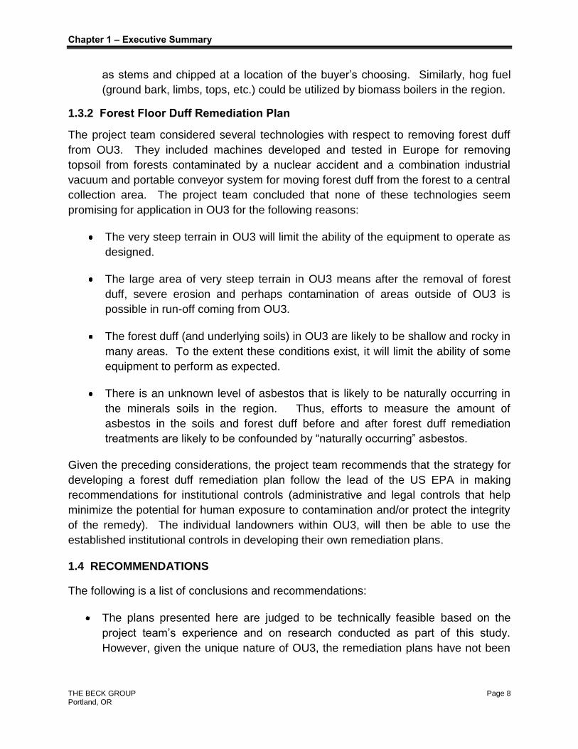
1.3.2 Forest Floor Duff Remediation Plan
The project team considered several technologies with respect to removing forest duff
from OU3. They included machines developed and tested in Europe for removing
topsoil from forests contaminated by a nuclear accident and a combination industrial
vacuum and portable conveyor system for moving forest duff from the forest to a central
collection area. The project team concluded that none of these technologies seem
promising for application in OU3 for the following reasons:
The very steep terrain in OU3 will limit the ability of the equipment to operate as
designed.
The large area of very steep terrain in OU3 means after the removal of forest
duff, severe erosion and perhaps contamination of areas outside of OU3 is
possible in run-off coming from OU3.
The forest duff (and underlying soils) in OU3 are likely to be shallow and rocky in
many areas. To the extent these conditions exist, it will limit the ability of some
equipment to perform as expected.
There is an unknown level of asbestos that is likely to be naturally occurring in
the minerals soils in the region. Thus, efforts to measure the amount of
asbestos in the soils and forest duff before and after forest duff remediation
treatments are likely to be confounded by “naturally occurring” asbestos.
Given the preceding considerations, the project team recommends that the strategy for
developing a forest duff remediation plan follow the lead of the US EPA in making
recommendations for institutional controls (administrative and legal controls that help
minimize the potential for human exposure to contamination and/or protect the integrity
of the remedy). The individual landowners within OU3, will then be able to use the
established institutional controls in developing their own remediation plans.
1.4 RECOMMENDATIONS
The following is a list of conclusions and recommendations:
The plans presented here are judged to be technically feasible based on the
project team’s experience and on research conducted as part of this study.
However, given the unique nature of OU3, the remediation plans have not been

Chapter 1 – Executive Summary
THE BECK GROUP Page 9 Portland, OR
proven in the field. Therefore, field testing is recommended to confirm the
feasibility of the remediation plans recommended in this report.
The tree inventory estimates for OU3 presented in this report are broad
estimates based on regional average per acre volumes. A more accurate
inventory of tree volume in OU3 is needed. Therefore, a silvicultural inventory
(timber, stand composition, fuel type, other vegetation, etc.) of OU3 is
recommended.
A detailed analysis of the existing road system in OU3 is needed. Key parts of
this analysis should include the ability of trucks to deliver materials from all parts
of OU3 using the existing forest road system rather than having to use Highway
37. Also, given the recommendation to haul stems from landings to the central
processing facility in lengths as long as possible, an assessment of the maximum
log length that can be transported on the existing road system using conventional
log trucks is needed.
A system for identifying the highest priority areas for treatment should be
developed. Potential criteria for selecting high priority areas are: 1) those found
to have the highest concentrations of asbestos fibers; 2) those already readily
accessible by existing roads; 3) those areas judged to have the greatest potential
for wildfire or where broad areas of trees have been killed by insects or disease.
Research and field level testing are needed to determine the effectiveness of
reducing the release of asbestos fibers by operating logging equipment under the
controls proposed in the remediation plan.
USEPA testing efforts up to this point have only determined that asbestos is
found on the bark on the main stem of the tree. While it stands to reason that the
fibers would also be found on other parts of the tree (e.g., limbs, tops, needles,
etc.) testing should be completed to confirm this assumption.
A program for providing the residents of the region with firewood from OU3
should be considered. This program would allow existing firewood contractors to
gather and provide firewood that is dry and certified to be free of asbestos fibers.
This effort is expected to eliminate what is believed to be a current and common
practice among residents of the area − going into the OU3 area, cutting firewood,
bringing it back to town, and burning it in their stoves, which potentially results in
recontamination of areas that have already been cleaned of asbestos.
More research is needed to determine whether it is preferable to install a boiler
and turbine generator within OU3 (e.g., at the former mine site), which would
allow utilization of biomass for hog fuel without the additional transport cost and

Chapter 1 – Executive Summary
THE BECK GROUP Page 10 Portland, OR
risk of contamination in areas outside OU3. Or would it be preferable to utilize
the hog fuel at an existing (or to be developed boiler) that would require the
transport and storage of asbestos contaminated biomass on roads and at a
location outside the borders of OU3?
More research is needed to determine the environmental impacts associated with
shipping asbestos contaminated logs, chips, barks, etc. in specially designed
covered trucks.
Testing is needed to determine the effectiveness of sprayed water in removing
asbestos fibers from debarked logs.
Testing and research are needed to identify procedures that can be employed to
quickly and accurately assess the presence of asbestos fibers on the surface of
materials (i.e., debarked logs).
Testing is needed to determine if the use of a water misting system on a landing
to encase tree stems in a sheath of ice is effective in controlling asbestos. If such
a system proves to be effective, additional testing should be conducted to
determine if it is feasible to use equipment similar to the snow making equipment
used at ski resorts to encase entire standing trees in a sheath of ice that will
serve as protection against the release of asbestos fibers during timber
harvesting operations.
THE BECK GROUP Page 11 Portland, OR
CHAPTER 2 – THE OPERATING ENVIRONMENT
The purpose of this section is to describe the physical features of the area surrounding
the mine site, including the terrain, road systems, and density of existing tree
vegetation. In addition, the levels of asbestos found during EPA testing in OU3 are
described.
2.1.1 Existing Tree Vegetation
For this study, no inventory of trees in OU3 was completed. Instead, the team used
data from the USFS Forest Inventory and Analysis (FIA) database to estimate average
tree densities by species and diameter class (on a per acre basis) in the forests in the
OU3 area. FIA data is based on permanent inventory plots that were established over
80 years ago. There is roughly 1 plot for every 6,000 acres of forest land in the United
States. Each plot is revisited about once every 10 years, at which time measurements
of tree growth, mortality, harvest, etc. are taken. The most recent measurements taken
in Montana were completed between 2003 and 2009.
Data from the FIA website was retrieved using the mine site as the center of a 20 mile
radius area. The specific information collected included the number of timberland
acres in that region, total number of trees, and total volume. That data was converted
to averages “per/acre”. The “per/acre” values were then applied to the 35,000 acres in
OU3.
It is important to note that this process is likely to overstate the number and
volume of trees in OU3 since it is based on the assumption that all of the acres in
OU3 are the same as the “average” of the broader region from which the FIA
sample was taken. In other words, it does not account for areas within OU3 that may
have been harvested recently and therefore do not reflect the “average” forest
conditions, or areas on the southern part of OU3 that have little tree vegetation because
they are located on south facing slopes. Completing a more accurate inventory of OU3
was beyond the scope of this project.
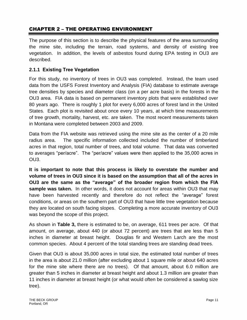
As shown in Table 3, there is estimated to be, on average, 611 trees per acre. Of that
amount, on average, about 440 (or about 72 percent) are trees that are less than 5
inches in diameter at breast height. Douglas fir and Western Larch are the most
common species. About 4 percent of the total standing trees are standing dead trees.
Given that OU3 is about 35,000 acres in total size, the estimated total number of trees
in the area is about 21.0 million (after excluding about 1 square mile or about 640 acres
for the mine site where there are no trees). Of that amount, about 6.0 million are
greater than 5 inches in diameter at breast height and about 1.3 million are greater than
11 inches in diameter at breast height (or what would often be considered a sawlog size
tree).

Chapter 2 – The Operating Environment
THE BECK GROUP Page 12 Portland, OR
TABLE 3 – ESTIMATED “AVERAGE” NUMBER OF STANDING TREES
PER ACRE IN OU3 BY SPECIES AND DIAMETER CLASS
Tree Diameter Class
Species
1.0 to 2.9
3.0 to 4.9
5.0 to 6.9
7.0 to 8.9
9.0 to
10.9
11.0 to
12.9
13.0 to
14.9
15.0 to
16.9
17.0 to
18.9
19.0 to
20.9
21.0 to
28.9 29+ Total
DF 92 53 24 15 10 6 5 3 2 1 1 1 213
PP 2 5 2 1 1 1 0 0 0 0 1 0 13
TF 48 7 10 7 4 3 2 1 0 0 0 0 81
HM 3 3 2 3 1 0 0 0 0 0 0 0 13
WP 0 0 0 1 0 0 0 0 0 0 0 0 1
ES 2 2 1 1 0 0 0 1 0 0 0 0 7
LP 10 18 10 5 4 3 2 2 1 0 0 0 54
WL 102 3 14 8 3 1 0 0 0 0 0 0 130
RC 77 12 4 1 1 0 0 0 0 0 0 0 96
Other 2 0 0 0 0 0 0 0 0 0 0 0 2
Total 338 102 67 43 24 15 9 6 3 2 2 1 611
NOTE: DF = Douglas fir; PP = Ponderosa Pine; TF = True firs; HM = Hemlock; WP = Western White Pine; ES = Engelmann Spruce; LP = Lodgepole Pine; WL = Western Larch; RC = Western Red Cedar; and Other = all other miscellaneous species
In terms of volume, rather than number of trees, Table 4 shows that there is an
estimated 65.4 million cubic feet of standing trees in OU3. Note that at the bottom of
the table, the cubic volumes have been converted into a total of roughly 850,000 bone
dry tons (BDT). The conversion is based on a factor of 26 bone dry pounds per cubic
foot. In addition, the cubic volume has been converted into board feet. When the
volume is expressed in board feet it is estimated to be about 425 million board feet
(MMBF) of standing trees in OU3. Please note that this estimate is based on a rough
conversion factor between cubic feet and board feet that does not account for different
conversion factors as tree size changes.
About 38 percent (317,000 bone dry tons) of the total volume is in pulpwood size trees
that are less than 11 inches in diameter at breast height. Note the 317,000 ton total
includes an estimated 47,000 bone dry tons of bark. Douglas fir and Western Larch
trees account for about 60 percent of the volume. Given that OU3 is about 35,000
acres in size, the estimated average per acre volume of standing trees is about 1,900
cubic feet, 25 bone dry tons, or 12.4 thousand board feet.
Chapter 2 – The Operating Environment
THE BECK GROUP Page 13 Portland, OR
TABLE 4 – ESTIMATED CUBIC FOOT VOLUME OF STANDING
TREES IN OU3 BY SPECIES AND DIAMETER CLASS (CUFT MILLIONS)
Tree Diameter Class
Species 5.0 to
6.9 7.0 to
8.9 9.0 to 10.9
11.0 to 12.9
13.0 to 14.9
15.0 to 16.9
17.0 to 18.9
19.0 to 20.9
21.0 to 28.9 29+ Total
DF 1.98 2.97 3.78 3.89 4.12 3.73 2.60 2.32 1.21 1.68 28.28
PP 0.12 0.15 0.42 0.34 0.14 0.26 0.53 0.25 1.79 0.00 3.99
TF 0.96 1.58 1.42 2.34 1.41 1.03 0.50 0.26 0.00 0.00 9.51
HM 0.17 0.61 0.43 0.08 0.04 0.00 0.00 0.00 0.00 0.00 1.33
WP 0.01 0.08 0.00 0.21 0.00 0.15 0.00 0.32 0.00 0.00 0.78
ES 0.08 0.30 0.15 0.26 0.47 1.07 0.32 0.44 1.26 0.00 4.36
WL 0.61 1.22 2.14 1.94 2.10 2.39 0.62 0.00 0.00 0.00 11.02
LP 1.29 1.64 1.04 0.26 0.00 0.00 0.00 0.00 0.00 0.00 4.23
RC 0.45 0.33 0.44 0.18 0.00 0.00 0.00 0.39 0.00 0.00 1.79
Other 0.00 0.00 0.00 0.06 0.00 0.00 0.00 0.00 0.00 0.00 0.06
Total CUFT 5.67 8.89 9.81 9.56 8.28 8.63 4.57 3.98 4.26 1.68 65.35
Total Converted to BDT 73,759 115,598 127,595 124,276 107,680 112,172 59,426 51,755 55,409 21,902 849,572
Total Converted to MMBF 37 58 64 62 54 56 30 26 28 11 425
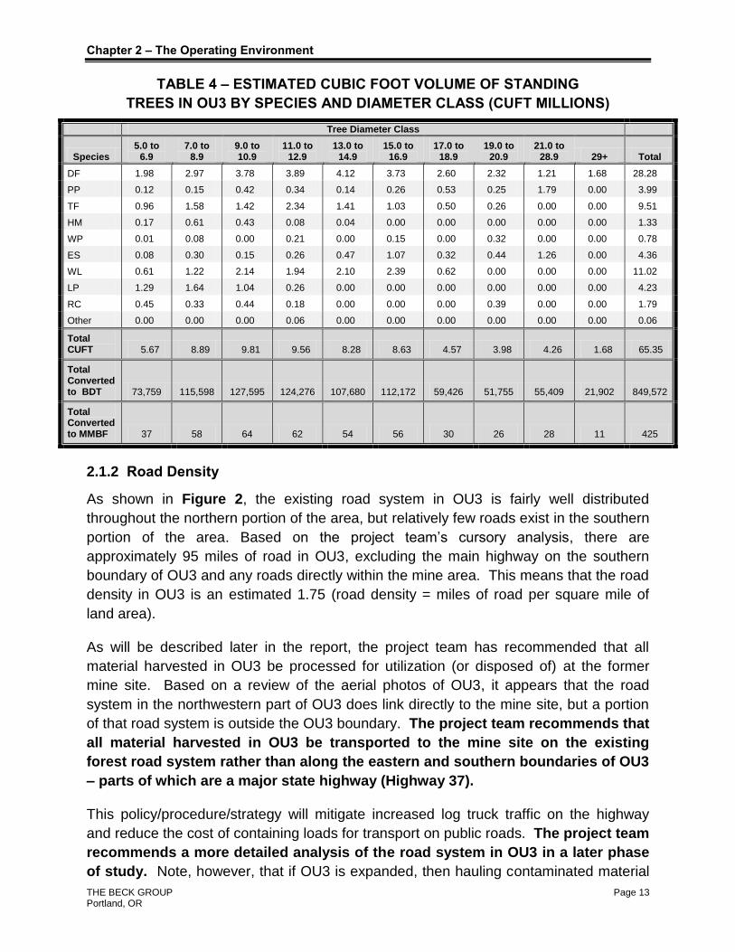
2.1.2 Road Density
As shown in Figure 2, the existing road system in OU3 is fairly well distributed
throughout the northern portion of the area, but relatively few roads exist in the southern
portion of the area. Based on the project team’s cursory analysis, there are
approximately 95 miles of road in OU3, excluding the main highway on the southern
boundary of OU3 and any roads directly within the mine area. This means that the road
density in OU3 is an estimated 1.75 (road density = miles of road per square mile of
land area).
As will be described later in the report, the project team has recommended that all
material harvested in OU3 be processed for utilization (or disposed of) at the former
mine site. Based on a review of the aerial photos of OU3, it appears that the road
system in the northwestern part of OU3 does link directly to the mine site, but a portion
of that road system is outside the OU3 boundary. The project team recommends that
all material harvested in OU3 be transported to the mine site on the existing
forest road system rather than along the eastern and southern boundaries of OU3
– parts of which are a major state highway (Highway 37).
This policy/procedure/strategy will mitigate increased log truck traffic on the highway
and reduce the cost of containing loads for transport on public roads. The project team
recommends a more detailed analysis of the road system in OU3 in a later phase
of study. Note, however, that if OU3 is expanded, then hauling contaminated material

Chapter 2 – The Operating Environment
THE BECK GROUP Page 14 Portland, OR
on major public roads may become necessary. More research is needed to determine
how effective specially designed log trucks with “curtain sides” to enclose the logs might
be in limiting the release of asbestos fibers during transport.
2.1.3 Topography
The project team was unable to visit and tour the OU3 area. However, a preliminary
analysis of the topography of the site (see Figure 3) shows that the terrain in OU3 is
very challenging, especially in the western portion of the area. Note that the areas
shaded in blue are those judged to be where the terrain is less challenging. As shown
in Figure 3, generally only the valley bottoms and mountain tops contain the gentler
sloped areas. The ability of logging equipment to operate on slopes is discussed in
greater detail in Chapter 4.
2.1.4 Asbestos Levels
In November 2004, a research team from the University of Montana collected samples
from standing trees at seven locations in the vicinity of the W.R. Grace mine site and
one from a control tree in Albany, NY. The results were published in a study5 and are
shown in Table 5, which indicates that the number of Amphibole fibers per square
centimeter of bark ranged from a low of zero for the control tree in New York and one
tree tested in Libby at the Asa Wood Elementary School to a high of 260 million fibers
per square centimeter of bark on a lodgepole pine tree near the former pump house at
the W.R. Grace mine site.
TABLE 5 – CONCENTRATIONS OF ASBESTOS FIBERS
IN TREES IN AND NEAR OU3
Sample Point Location Description Type of Tree
Amphibole Fibers/cm2 of
Bark
Location 1 - Sample 1A Near the former pump house at the W.R. Grace mine Lodgepole Pine 100 million
Location 1 – Sample 1B Near the former pump house at the W.R. Grace mine Lodgepole Pine 260 million
Location 1 – Sample 1D Near the former pump house at the W.R. Grace mine Larch 40 million
Location 2 Just outside the mine property along Raney Creek Road Lodgepole Pine 110 million
Location 3 – Sample 3B Near the mine access gate on Raney Creek Road Ponderosa Pine 14 million
Location 4 Albany, NY Pine None detected
Location 5 – Sample 11 Along railroad ~ 7 miles east of Libby, Montana Ponderosa Pine 5.8 million
Location 7 – Sample 18 Libby Middle School Track Douglas fir 0.25 million
Location 8 – Sample 23 Asa Wood Elementary School Larch None detected
5 Trees as Reservoirs for Amphibole Fibers in Libby, Montana. Tony J. Ward, et al. 2006. Science of the Total
Environment. August 15, 367(1): 460-5.

Chapter 2 – The Operating Environment
THE BECK GROUP Page 15 Portland, OR
In addition to the University of Montana study, the Montana Department of
Environmental Quality and the Montana Department of Natural Resources and
Conservation commissioned a study to measure the levels of asbestos contamination in
tree bark and forest duff in a timber sale area. The study was completed by Tetra Tech
EM, Inc. and was located in the Upper Flower Creek Timber Sale Area, which is located
south of Libby, Montana on land owned and managed by the State of Montana.
Samples were collected from 10 trees and 10 areas of forest duff in November 2011.
The results are shown in Table 6.
TABLE 6 – CONCENTRATIONS OF ASBESTOS FIBERS IN TREES AND FOREST
DUFF AS MEASURED AT A TIMBER SALE LOCATION
Sample Type Sample Number
Asbestos Fiber Count
Asbestos Concentration Unit of Measurement
Tree 1 8 226,298 structures/cm2
Tree 1 ND < DL structures/cm2
Tree 2 ND < DL structures/cm2
Tree 3 ND < DL structures/cm2
Tree 4 ND < DL structures/cm2
Tree 5 3 84,862 structures/cm2
Tree 6 3 73,793 structures/cm2
Tree 7 10 282,873 structures/cm2
Tree 7 5 141,436 structures/cm2
Tree 8 1 28,287 structures/cm2
Tree 9 ND < DL structures/cm2
Duff 1 ND < DL structures/gram of dry weight
Duff 2 2 5,700,000 structures/gram of dry weight
Duff 3 1 7,300,000 structures/gram of dry weight
Duff 4 ND < DL structures/gram of dry weight
Duff 4 ND < DL structures/gram of dry weight
Duff 5 ND < DL structures/gram of dry weight
Duff 6 ND < DL structures/gram of dry weight
Duff 7 ND < DL structures/gram of dry weight
Duff 9 ND < DL structures/gram of dry weight
Duff 8 ND < DL structures/gram of dry weight
Duff 9 3 12,000,000 structures/gram of dry weight
*DL refers to Detection Limit
Finally, the USEPA completed a study that measured the levels of asbestos in forest
soil, tree bark, and forest duff material along a number of transects extending radially
from the mine site. The results are shown in Table 6A

Chapter 2 – The Operating Environment
THE BECK GROUP Page 16 Portland, OR
TABLE 6A – ASBESTOS FIBER LEVELS - USEPA TESTING
Tree Bark Duff Material
Transect ID
Number of Structures
Surface Loading (M’s/cm2)
Number of Structures
Concentration (M’s/gram)
SL15-15 0 0 3 19
SL15-16 0 0 0 0
SL45-15 3 0.03 1 9
SL45-16 0 0 0 0
SL75-15 30 0.26 7 64
SL75-16 9 0.08 n/a n/a
SL135-15 13 0.12 8 61
SL135-16 19 0.18 2 18
SL195-15 50 0.53 4 35
SL195-16 3 0.03 1 10
SL315-15 2 0.02 0 0
SL315-16 5 0.04 3 18
Figure 1A shows the locations of each transect.
FIGURE 1A – LOCATION OF USEPA TREE BARK AND FOREST DUFF
MEASUREMENT TRANSECTS
(THE CENTER POINT IS THE FORMER MINE SITE)

Chapter 2 – The Operating Environment
THE BECK GROUP Page 17 Portland, OR
FIGURE 2 – IMAGE OF EXISTING ROAD SYSTEM IN OU3 AREA
(WHITE SHADED AREA = OU3; RED LINES = EXISTING ROADS)

Chapter 2 – The Operating Environment
THE BECK GROUP Page 18 Portland, OR
FIGURE 3 – TOPOGRAPHY IN OU3
(BLUE SHADED AREAS ARE WHERE THE SLOPE IS ESTIMATED TO BE LESS THAN 15 PERCENT TO 20 PERCENT)
Libby, Montana
W.R. Grace Mine Site Operational
Unit 3
THE BECK GROUP Page 19 Portland, OR
CHAPTER 3 – REMEDIATION PLANNING APPROACH
The project team has organized the remediation plan into two distinct planning efforts:
1. Standing Tree Remediation Plan – all activities associated with remediating
areas contaminated with standing trees containing asbestos fibers on the bark.
2. Forest Duff Remediation Plan – all activities associated with remediating the
forest floor (the organic duff layer).
Given the unique requirements of this remediation effort and the limited budget for this
phase of the project, the approach taken was to develop remediation plans based on a
combination of the project team’s experience and project specific research completed
during the course of the study. Thus, the plans presented here are being considered
“theoretical” because while the procedures and technologies recommended in this study
have been used in other applications, they have not – to our knowledge – been used for
the remediation of asbestos from standing trees and forest duff. In other words, the
procedures and technology recommendations made in this report have not yet been
tested and proven in the field for the specific purpose of asbestos remediation from
standing trees and forest duff. Therefore, throughout the report, the project team has
made recommendations about issues that, in the team’s judgment, need validation
based on field testing.

THE BECK GROUP Page 20 Portland, OR
CHAPTER 4 – STANDING TREE REMEDIATION PLAN
4.1 STANDING TREE REMEDIATION PLAN OBJECTIVES
The purposes of the standing tree remediation plan are to:
1. Develop a “remediation alternatives” list that identifies a number of possible
remediation approaches;
2. Analyze these alternatives to determine the best approach for this application,
(i.e., the one that captures and removes the most contamination);
3. Plan out the best approach for the remediation process in a step-by-step format ;
4. Describe any required modifications to processing equipment and processing
techniques to ensure worker safety and maximize containment of the asbestos
fibers;
5. Identify all other necessary best management and safe remediation practices.
The goals of this effort are that plan implementation will result in:
1. Reduction of fuels in the event of a wildfire in OU3;
2. Utilization (if possible) of contaminated material;
3. Continued public forest use of OU3 with minimal restrictions.
4.2 TIMBER HARVESTING TECHNOLOGY
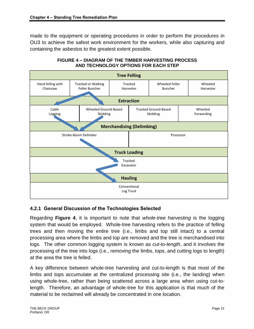
Figure 4 illustrates the processing steps (areas shaded in light green) involved in
harvesting and processing trees. Listed below each processing step area variety of the
technology option(s) that can be used to complete the processing step (the white
boxes). Each of the technology options shown at each step were considered as part of
this study. However, the blue arrows indicate the technology options judged to be best
suited for removal of the asbestos-impacted standing trees in OU3. Note that debarking
is generally not a common processing step in timber harvesting. It is included here
because removing the bark within the OU3 area reduces the probability of
contaminating other areas during transport.
Following Figure 4 is a general discussion section about the various technologies
selected for consideration. The next section describes the modifications needed to be
Chapter 4 – Standing Tree Remediation Plan
THE BECK GROUP Page 21 Portland, OR
made to the equipment or operating procedures in order to perform the procedures in
OU3 to achieve the safest work environment for the workers, while also capturing and
containing the asbestos to the greatest extent possible.
FIGURE 4 – DIAGRAM OF THE TIMBER HARVESTING PROCESS AND TECHNOLOGY OPTIONS FOR EACH STEP
4.2.1 General Discussion of the Technologies Selected
Regarding Figure 4, it is important to note that whole-tree harvesting is the logging
system that would be employed. Whole-tree harvesting refers to the practice of felling
trees and then moving the entire tree (i.e., limbs and top still intact) to a central
processing area where the limbs and top are removed and the tree is merchandised into
logs. The other common logging system is known as cut-to-length, and it involves the
processing of the tree into logs (i.e., removing the limbs, tops, and cutting logs to length)
at the area the tree is felled.
A key difference between whole-tree harvesting and cut-to-length is that most of the
limbs and tops accumulate at the centralized processing site (i.e., the landing) when
using whole-tree, rather than being scattered across a large area when using cut-to-
length. Therefore, an advantage of whole-tree for this application is that much of the
material to be reclaimed will already be concentrated in one location.
Wheeled Harvester
Tree Felling
Cable Logging
Extraction
Wheeled Ground-Based Skidding
Tracked Ground-Based Skidding
Wheeled Forwarding
Truck Loading
Tracked Excavator
Merchandising (Delimbing)
Processor Stroke-Boom Delimber
Hauling
Conventional Log Truck
Hand felling with Chainsaw
Tracked or Walking Feller Buncher
Tracked Harvester
Wheeled Feller Buncher
Chapter 4 – Standing Tree Remediation Plan
THE BECK GROUP Page 22 Portland, OR
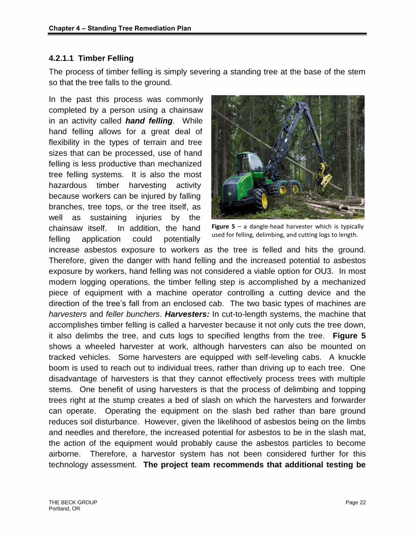
Figure 5 – a dangle-head harvester which is typically used for felling, delimbing, and cutting logs to length.
Timber Felling 4.2.1.1
The process of timber felling is simply severing a standing tree at the base of the stem
so that the tree falls to the ground.
In the past this process was commonly
completed by a person using a chainsaw
in an activity called hand felling. While
hand felling allows for a great deal of
flexibility in the types of terrain and tree
sizes that can be processed, use of hand
felling is less productive than mechanized
tree felling systems. It is also the most
hazardous timber harvesting activity
because workers can be injured by falling
branches, tree tops, or the tree itself, as
well as sustaining injuries by the
chainsaw itself. In addition, the hand
felling application could potentially
increase asbestos exposure to workers as the tree is felled and hits the ground.
Therefore, given the danger with hand felling and the increased potential to asbestos
exposure by workers, hand felling was not considered a viable option for OU3. In most
modern logging operations, the timber felling step is accomplished by a mechanized
piece of equipment with a machine operator controlling a cutting device and the
direction of the tree’s fall from an enclosed cab. The two basic types of machines are
harvesters and feller bunchers. Harvesters: In cut-to-length systems, the machine that
accomplishes timber felling is called a harvester because it not only cuts the tree down,
it also delimbs the tree, and cuts logs to specified lengths from the tree. Figure 5
shows a wheeled harvester at work, although harvesters can also be mounted on
tracked vehicles. Some harvesters are equipped with self-leveling cabs. A knuckle
boom is used to reach out to individual trees, rather than driving up to each tree. One
disadvantage of harvesters is that they cannot effectively process trees with multiple
stems. One benefit of using harvesters is that the process of delimbing and topping
trees right at the stump creates a bed of slash on which the harvesters and forwarder
can operate. Operating the equipment on the slash bed rather than bare ground
reduces soil disturbance. However, given the likelihood of asbestos being on the limbs
and needles and therefore, the increased potential for asbestos to be in the slash mat,
the action of the equipment would probably cause the asbestos particles to become
airborne. Therefore, a harvestor system has not been considered further for this
technology assessment. The project team recommends that additional testing be

Chapter 4 – Standing Tree Remediation Plan
THE BECK GROUP Page 23 Portland, OR
completed to determine definitively whether asbestos is also found on the limbs
and needles.
Feller Bunchers are the second type of commonly used mechanized tree felling
equipment. The key differences between harvesters and feller bunchers are that feller
bunchers are only used for cutting, holding, and placing stems on the ground.
Feller Bunchers are typically mounted on either wheeled vehicles or tracked vehicles
(see Figure 6). When mounted on tracked vehicles, feller bunchers often have
self-leveling cab capabilities to ensure that the machine can be safely operated on
steep slopes. Another advantage of tracks is that the weight of the machine is
distributed over a relatively large surface area, which means that ground pressure levels
are low, and therefore, the machines can operate on loose and wet soils while causing
little soil disturbance. In addition, when feller bunchers are mounted on tracked
vehicles, they typically have a swing-boom that reaches out to each tree rather than
driving the machine to each tree in order to fell it (see Figure 6).
Note from Figure 6 that feller bunchers have accumulator arms in which several stems
can be collected (i.e., a “bunch”). Wheeled feller bunchers can only be operated on
gentle terrain (less than 25% slopes). Tracked feller bunchers with self-leveling cabs
can operate on much steeper slopes (up to 50%) and therefore would be best suited to
the rugged terrain found in OU3.
Another advantage of feller bunchers for this application is that the machine can control
the direction and speed with which trees are felled. Therefore, since the operators will
probably be instructed to more carefully place the trees on the ground, they can operate
the equipment in such a way as to reduce the chances for the asbestos fibers to
become airborne. The project team recommends that a tracked feller buncher be
used to harvest trees in OU3.

Chapter 4 – Standing Tree Remediation Plan
THE BECK GROUP Page 24 Portland, OR
FIGURE 6 - SWING BOOM FELLER BUNCHER
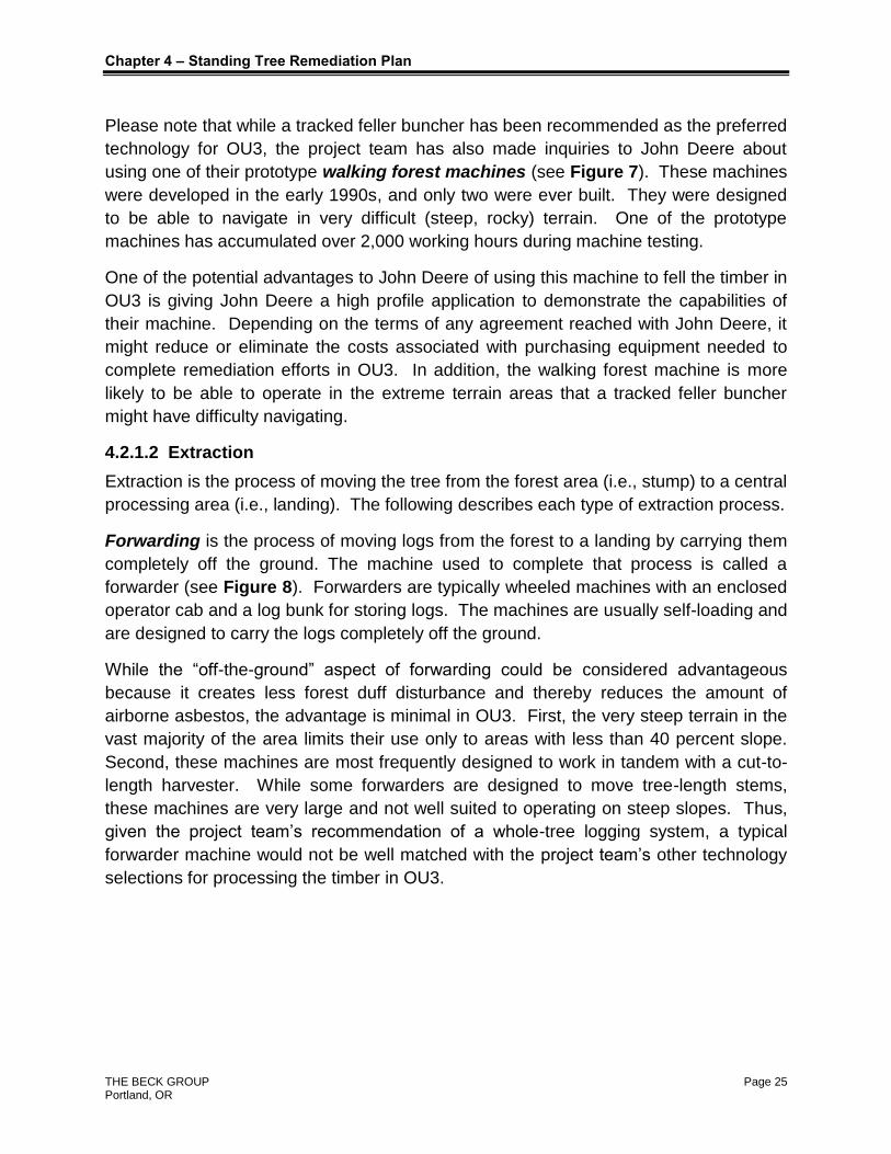
FIGURE 7
Figure 7 - John Deere Prototype Walking Forest Machine
Chapter 4 – Standing Tree Remediation Plan
THE BECK GROUP Page 25 Portland, OR
Please note that while a tracked feller buncher has been recommended as the preferred
technology for OU3, the project team has also made inquiries to John Deere about
using one of their prototype walking forest machines (see Figure 7). These machines
were developed in the early 1990s, and only two were ever built. They were designed
to be able to navigate in very difficult (steep, rocky) terrain. One of the prototype
machines has accumulated over 2,000 working hours during machine testing.
One of the potential advantages to John Deere of using this machine to fell the timber in
OU3 is giving John Deere a high profile application to demonstrate the capabilities of
their machine. Depending on the terms of any agreement reached with John Deere, it
might reduce or eliminate the costs associated with purchasing equipment needed to
complete remediation efforts in OU3. In addition, the walking forest machine is more
likely to be able to operate in the extreme terrain areas that a tracked feller buncher
might have difficulty navigating.
Extraction 4.2.1.2
Extraction is the process of moving the tree from the forest area (i.e., stump) to a central
processing area (i.e., landing). The following describes each type of extraction process.
Forwarding is the process of moving logs from the forest to a landing by carrying them
completely off the ground. The machine used to complete that process is called a
forwarder (see Figure 8). Forwarders are typically wheeled machines with an enclosed
operator cab and a log bunk for storing logs. The machines are usually self-loading and
are designed to carry the logs completely off the ground.
While the “off-the-ground” aspect of forwarding could be considered advantageous
because it creates less forest duff disturbance and thereby reduces the amount of
airborne asbestos, the advantage is minimal in OU3. First, the very steep terrain in the
vast majority of the area limits their use only to areas with less than 40 percent slope.
Second, these machines are most frequently designed to work in tandem with a cut-to-
length harvester. While some forwarders are designed to move tree-length stems,
these machines are very large and not well suited to operating on steep slopes. Thus,
given the project team’s recommendation of a whole-tree logging system, a typical
forwarder machine would not be well matched with the project team’s other technology
selections for processing the timber in OU3.

Chapter 4 – Standing Tree Remediation Plan
THE BECK GROUP Page 26 Portland, OR
FIGURE 8 – WHEELED FORWARDER
Skidding is the process of moving logs or whole trees from the forest to a landing by
dragging them on the ground. A skidder is the name of the machine used for skidding.
A number of machines can be used to skid logs, including cable, grapple, clam bunk,
and wheeled and tracked. Cable skidders are either wheeled or tracked. and they
include a winch and cable that must be attached to each log by an operator who would
have to be outside of the enclosed cab. Grapple skidders are generally a wheeled
machine with a set of bottom-opening grapples that are used to grab, assemble, and
hold a load of logs as they are skidded to a landing. The project team recommends
that to the extent allowed by the terrain in OU3, grapple skidders be used. The
primary reason for this technology selection is that the operator of the grapple skidder is
able to work from inside the enclosed cab of the machine and therefore, exposure to
airborne asbestos fibers is limited.
Cable Logging is the process of using a system of overhead cables, support
towers/trees, and winches to move whole-trees or logs from the forest to the landing.
Four common types of cable systems are the highlead, standing, running, and live
systems. All are commonly used in terrain that is too steep for the safe operation of
wheeled or tracked vehicles. Aside from the advantage of being able to operate on
nearly all terrain, another advantage of cable logging is that, under the right conditions,
a significant portion of the stems/logs are often held well above the ground, which
reduces disturbance of the forest duff.

Chapter 4 – Standing Tree Remediation Plan
THE BECK GROUP Page 27 Portland, OR
Figure 9 – Cable Yarding System
Figure 10 – Processor
For the sections of OU3 that are too
steep to safely operate wheeled or
tracked extraction equipment, the
project team recommends the use of
a cable logging system, see Figure 9.
Please note that the use of such a
system requires workers to hook the logs
to the cable system and to unhook the
logs at the landing. These workers
would not be in an enclosed cab. Thus,
additional personal protective equipment
(PPE) would be required for these
workers.
Merchandising – Delimbing 4.2.1.3
Merchandising is the process of removing the parts of the tree (e.g., limbs, tops, rot,
crook, sweep, etc.) so that the remaining pieces are logs (or pulpwood) that meets a
buyer’s specifications.
One piece of equipment
commonly used for
delimbing is a processor,
see Figure 10. It is typically
mounted on a knuckle-boom
and an excavator base. The
processor is designed to
remove tree limbs and to cut
logs to length, but it cannot
fell trees. A set of round
feed rolls are used to move
the log through a set of
delimbing knives. A bar saw
is also part of a processor,
and it is used to cut the log
to length after the limbs
have been removed. Most
heads are also equipped

Chapter 4 – Standing Tree Remediation Plan
THE BECK GROUP Page 28 Portland, OR
Figure 11 - Stroke Boom Delimber
with sensors for measuring the length and diameter of the log being processed.
Another piece of equipment
used for delimbing and
topping is a stroke boom
delimber, see Figure 11. It
is a tracked excavator with a
boom, two grapples, and a
saw mounted on it. The
front grapple will grab a
stem near the middle of it’s
length and place the butt of
the stem in the rear grapple.
The rear grapple then holds
the stem in place while the
stem is pulled through the
delimbing knives.
The project team has recommended the use of a stroke boom delimber because it
is generally a lower cost machine to operate. However, a processor is also
acceptable for use in the OU3 area. Please note that the project team recommends
that the stems be cut to the longest lengths possible. This practice will minimize
handling since fewer pieces will be produced.
Truck Loading 4.2.1.4
The purpose of log loaders is twofold: 1) For sorting logs into different groups based
on differences in size, quality, species, etc. and 2) for loading logs onto trucks, rail cars,
etc. so that they can be transported to their destination. Loaders are typically mounted
on either a wheeled base or a tracked machine. Wheeled machines of the “front-end”
loader type have the advantage of being fast and being able to handle large payloads in
a single “bite” of the grapple. However, they are not able to readily single out specific
logs for sorting, nor are they as stable as tracked machines. Therefore, wheeled
machines are not being recommended for this application since the landing areas are
likely to be relatively confined and could potentially have uneven terrain.
Tracked loaders (see Figure 12) are typically equipped with a knuckleboom that has
been specially designed for handling logs. It includes a grapple mounted to the end of
the boom that can grasp logs and fully rotate, which allows the operator to accurately
place logs on a truck. Most of these loaders also have a “heel” that allows for stable
handling of large and long length logs. The operator of the loader works within an

Chapter 4 – Standing Tree Remediation Plan
THE BECK GROUP Page 29 Portland, OR
enclosed cab. The project team recommends that a tracked based loader be used
in OU3.
FIGURE 12 - TRACKED LOG LOADER WITH ROTATING GRAPPLE AND HEEL
Hauling 4.2.1.5
After logs and pulpwood sized material have been merchandised and sorted into groups
on a landing, they are normally hauled to a conversion facility for further processing into
various products. A variety of tractor and trailer configurations are used, but for
the purposes of transporting logs and pulpwood size material for this application
a standard log truck and pole trailer configuration are recommended (see Figure
13). This arrangement will allow for transporting stems in tree length form or in long-log
segments. Note that depending on the weight limits for the roads or on the type of
roads common in OU3, different axle configurations maybe be needed or a stinger-
steered trailer may be required. The advantage of these changes would be increased
payload and the ability to better navigate roads with sharp turns. More investigation of
these issues is recommended in a later phase of study.

Chapter 4 – Standing Tree Remediation Plan
THE BECK GROUP Page 30 Portland, OR
FIGURE 13 – LOG TRUCK
4.2.2 Equipment & Operating Modifications Needed for OU3 Plan Implementation
This section describes the modifications to both normal equipment and normal
operating practices that will be required to operate within OU3.
General Approach 4.2.2.1
A normal procedure for remediating asbestos in, for example, buildings is to enclose the
entire area to be remediated within an atmospheric control structure so that asbestos
fibers that become airborne during remediation activities are captured within the
atmosphere controlled structure. However, the project team, after speaking with
numerous experts on topics including logging technology and asbestos remediation,
has concluded that a similar approach to harvesting trees in OU3 is not practical
because of the ruggedness of the terrain, the large land area to be treated, and the
height of the trees. All of these factors combine to make creating an atmosphere
controlled structure around tree felling, extraction, merchandising, loading, and hauling
activities highly impractical, if not impossible.
Therefore, the project team has focused on other methods for controlling and mitigating
the extent of asbestos released. These include:
1. Harvest Timing – All logging and hauling activities will be completed only during
periods of the year when: 1) the ground and trees are frozen (i.e., winter logging
only); or 2) when air temperatures are cool and relative humidity levels are high
enough to reduce dust. Of the two, timber harvesting during frozen conditions is
preferable. This precaution is expected to inhibit asbestos fibers from becoming
airborne during logging operations. However, testing is needed to determine the
extent of asbestos fiber release during timber harvesting operations under both
of these conditions.
Chapter 4 – Standing Tree Remediation Plan
THE BECK GROUP Page 31 Portland, OR
2. Dust Control – As is common in many asbestos remediation efforts, a water
mist will be applied to the tree stems, limbs, tops, and other logging slash on the
landing areas. During times of the year when the ambient air temperatures are
below freezing, the use of a water mist is expected to “freeze” or “encase” the
vast majority of the asbestos fibers in place and thereby inhibit the fibers from
becoming airborne during logging operations. It is the project team’s
understanding that the water needed for this procedure would be available from
existing wells within the OU3 mine site.
3. Expanded “Dust” Control – If testing of air conditions during timber harvesting
operations as recommended in point one show that asbestos fiber levels are too
high, the project team recommends experimentation with an expanded dust
control effort. The concept would be to use equipment similar to the snow
making equipment used at ski resorts to mist standing trees with water/ice
crystals prior to timber harvesting operations. It is expected that this misting
would encase the trees in a sheath of ice and thereby reduce the release of
asbestos fibers. Testing is needed to determine the feasibility of this concept as
well as to determine the amount of water needed.
4. Standing Tree Remediation First – The objective of this project is to identify a
plan for remediating both standing trees and forest floor duff in OU3. The project
team recommends that standing tree remediation always be completed in an
area before any work on forest floor duff remediation is undertaken. Harvesting
trees in an area where the forest floor duff has already been treated would only
recontaminate the area.
5. Maximum Operating Speeds – While all work will be conducted only during the
times of the year when the ground is frozen and therefore minimal levels of dust
are expected, machine and truck operators will still be required to move and
operate the machinery at a work pace that will minimize dust generation. This
reduces opportunities for asbestos to become airborne during harvesting
operations to acceptable levels established by regulators.
6. Long Term Plan – Given all of the following:
The already large size of the OU3 area (~35,000 acres),
The chance that OU3 may become larger,
The project team’s recommendation that equipment be operated with a preference for safety and mitigating asbestos fiber release rather than for maximizing production,

Chapter 4 – Standing Tree Remediation Plan
THE BECK GROUP Page 32 Portland, OR
The large amounts of biomass that will be generated as a result of implementing the plan,
Based on the preceding factors, the project team recommends that plans for
treating OU3 be considered on a long term basis – a minimum of 10 years and
most likely for as long as 10 years (or more) to treat the entire area.
Equipment Modifications 4.2.2.2
All equipment associated with timber felling, extraction, merchandising, truck loading,
and hauling (i.e., a tracked feller buncher, skidders, cable yarders, stroke boom
delimbers, log loader, and log trucks) will be modified so that each is equipped with a
positive air pressure system that will allow the operators to work in cabs without wearing
a respirator.
Operator Modifications 4.2.2.3
A site safety and health plan (SSHP) will be developed for all requirements to work
within the contaminated areas of OU3. The SSHP will likely include the use of
respirators while working outside of positive pressure controlled cabs.
The personnel working within contaminated areas of OU3 will be OSHA 40-hour trained
(Hazardous Waste Operations training as per 29 CFR 1910.120) and comply with all
requirements under this standard. All personnel will also be fully training in the standard
of the SSHP.
Monitoring 4.2.2.4
Procedures will be established for monitoring the release of asbestos fibers during
harvesting activities. These will include air monitoring to be conducted on the workers
and at the perimeter of the work area.
Monitoring may indicate airborne asbestos levels during logging that are higher
than currently allowed limits. The project team recommends that the USFS, EPA
and other stakeholders negotiate an agreement for acceptable air monitoring
requirements for logging activities within OU3.
A sampling and analysis plan (SAP) will be developed for use during the logging
activities to determine the required levels of PPE and engineering controls.

THE BECK GROUP Page 33 Portland, OR
CHAPTER 5 – FOREST DUFF REMEDIATION PLAN
Forest duff is the material found on the floor of forests that typically consists of items in
two layers. The upper layer generally includes things such as twigs, needles, leaves
and other forms of vegetation that are dead, but have not yet decomposed. The
second, lower layer includes partially to fully decomposed forest litter that rests on top of
the mineral soil. Duff sampling at 9 locations completed in November 2011 in the Upper
Flower Creek Timber Sale area indicated that asbestos concentrations in the duff
ranged from no detectable limits to 12 million structures per gram of dry duff weight.
While the area sampled is not within OU3, the results provide an indication of the
asbestos levels that might be expected within OU3.
It should be noted that to the knowledge of the project team, the extent of asbestos in
the two forest duff layers is not known. In other words, the distribution of asbestos in
the undecomposed duff layer relative to the more decomposed layer is not known. Nor
are the baseline levels of “naturally occurring” asbestos in the region known.
5.1 FOREST DUFF REMEDIATION TECHNOLOGY
The project team is not aware of any well-established technologies for removing forest
duff from forested areas. However, there has been some research aimed at developing
such technologies. The following sections summarize the findings from those efforts.
5.1.1 Remediation of Northern Europe Forests
In 2002 a study6 was completed the Nordic Nuclear Safety Research Group (a.k.a.
Nordisk Kemesikkerhedsforskning). The purpose of the study was to identify
technologies available for planning countermeasures in the event of a nuclear accident
that caused widespread contamination of forests and forest duff. With regard to forest
duff remediation, the study made recommendations that the top few centimeters of the
organic layer (i.e. the whole undecomposed layer and the top portion of the
decomposed layer) be removed during treatments. The recommendation for
accomplishing this task was the use of a tractor-powered machine that was in
development at FSL in Denmark, which is the Danish Forest and Landscape Research
Institute (www.eldis.org). The machine could reportedly harvest the organic forest floor
6 Tools for Forming Strategies for Remediation of Forests and Park Areas in Northern Europe after Radioactive Contamination:
Background and Techniques. 2002. Lynn Hubbard et al. Accessed at:
www.nks.org/scripts/getdocument.php?file=111010111119792

Chapter 5 -- Forest Duff Remediation Plan
THE BECK GROUP Page 34 Portland, OR
layer with first requiring the total removal of stumps and other vegetation. The project
team was not able to find further documentation of the equipment, but apparently it
consisted of a rotating device mounted to the front of a wheeled piece of equipment
such as a tractor or skidder. The rotating device scooped up the forest duff and fed it to
a storage bin mounted behind the tractor. The depth of the rotating brush in the duff
layer was controlled by a set of wheels.
Given the very steep terrain found in OU3, the project team does not believe the
technology recommended in the Nordic study would be viable. In addition, the Nordic
study recommended that the technique not be applied in areas that a prone to erosion.
Again, given the steep terrain in OU3, the project team has concluded that attempting to
remove the duff layer is not a preferred option because of the potential for significant
erosion.
Another option identified in the Nordic study was “deep plowing” of forest soils. The use
of large scale wheeled or tracked equipment with specially designed plows allows the
plowing and removal of soil up to 1 foot deep. While all standing trees need to be
removed to apply this technology, stumps do not need to be removed. The project team
considered this technology within the context of OU3, but concluded it was not likely to
be viable given the steep terrain in the region and soils that in many areas of OU3 are
likely to be too shallow and rocky.
5.1.2 Combination Industrial Vacuum System and Portable Conveyor
The project team also considered industrial vacuum systems as a way to remove forest
duff from OU3. Several industrial vacuum manufacturers exist including Vector in
Milwaukee, Wisconsin and Multi-Vac in Union Grove, Wisconsin. The concept
considered was that the industrial vacuums could be used in conjunction with portable
conveyors to gather and transport forest duff to a central collection point. More
specifically, an industrial vacuum system would be mounted on a wheeled or tracked
vehicle and would include a large collection bin. The vacuum would then move around
a contaminated site collecting forest duff. Periodically the vacuum would unload the
material from the collection bin onto a portable conveyor system which would transport
the material to a centralized collection point.
The project team is not aware of this concept ever having been demonstrated in actual
field use. However, portable industrial vacuum systems have been used successfully
and portable conveyor systems have been tested in the field. The two have not been
used in conjunction with each other. Regarding the portable conveyor systems, field
trials were completed in 2008, which tested the feasibility of using portable conveyors to
move slash from timber harvest units to a centralized landing area. The tests were
conducted in the Lake Tahoe area.

Chapter 5 -- Forest Duff Remediation Plan
THE BECK GROUP Page 35 Portland, OR
The results of the test are described in detail in a USFS research bulletin7 and in
abbreviated form here. Portable conveyors can be used in forest settings. They are
made up with a number of individual sections with each section being about 10 to 15
feet long. Such conveyors are available from several manufacturers and are being
used in construction, mining, and nursery industries for temporary material handling
tasks.
The conveyors tested in Lake Tahoe field tests were powered by hydraulics or electricity
and had the capacity to convey up to 20 tons of material per hour. They were set up in
a quarter acre timber harvest area and used to convey logging slash up a 17 degree
slope. The productivity of the conveying system ranged from 4 to 6 green tons per
hour. While the system worked in general a problem encountered was that many of the
slash pieces were too long or otherwise too big to fit on the conveyor with a good
likelihood of falling off.
In the context of OU3, the project team believes such a system might have a better
likelihood of being more effective because the material picked up by the industrial
vacuum system will be smaller in size and therefore less likely to fall off the conveyor.
However, given the low production rates observed in the trials and the much steeper
terrain in much of OU3, the technical and practical feasibility of such a system is
doubtful. A more detailed assessment of this possible technology is recommended in
later phases of study.
5.1.3 Beneficial Land Cover
A third option considered was the use of a beneficial land cover. This concept would
draw on the experience of a recent reclamation project near Aspen, Colorado8. In that
project, a mix of biochar and native grass seeds were applied to a barren slope that was
slowly eroding various toxins associated with mine tailings into Castle Creek at a
location just upstream from Aspen’s water treatment plant. The application of the
biochar and seed stabilized the soil in the slope and minimized erosion of soil into the
stream. In the Libby situation, the contamination is found in the forest duff rather than
the soil. Therefore, the utility of establishing a beneficial land cover is less clear.
Further investigation is recommended.
7 Tests of Biomass Removal Using Lightweight Portable Conveyors. June 2008. Bob Rummer, et al. Document
Number 0851-2809-MTDC.
8 From Barren to Beautiful at Aspen’s Hope Mine. September 10, 2011. Accessed at:
http://www.forestbusinessnetwork.com/7496/from-barren-to-beautiful-at-aspens-hope-mine/from-barren-to-
beautiful-at-aspens-hope-mine200/

THE BECK GROUP Page 36 Portland, OR
CHAPTER 6 – MATERIAL UTILIZATION
Given the vast amount of biomass material (about 850,000 bone dry tons) that is
estimated to be located within OU3, a substantial need exists to utilize the biomass so
that it does not accumulate at the site. This chapter describes the project team’s
preliminary plans for utilizing the various forms of biomass that will be generated. Each
form of biomass that can potentially be utilized is described. First, however, several
general concepts related to utilization are discussed.
6.1 GENERAL UTILIZATION CONCEPTS
6.1.1 Establish a Permanent Utilization Structure
The project team recommends that a permanent structure be established within OU3
(most likely at the mine site) that will allow for processing of logs, pulpwood, chips, etc.
in an atmosphere controlled environment and which has equipment installed that is
capable of cleaning the resulting products (logs, etc.) and which can test the products to
insure that they can be certified to meet acceptable levels of asbestos prior to leaving
the site.
The project team currently envisions a relatively large structure (e.g., 200’ x 200’) so
that a variety of processing steps could be accomplished within the structure. The
building would be designed so that various pieces of equipment could easily be “rolled
in and rolled out” as the needs for processing material change over time.
At a minimum, the equipment needed in the structure would include a debarking
operation that would allow for removal of the asbestos contaminated bark, resulting in a
“clean” debarked stem that could be utilized in a variety of ways. The project team
recommends that a ring debarker be installed for this purpose.
Ring debarkers are able to very precisely remove bark and leave wood fiber. Other
debarking technologies, such as chain flail debarkers and rotary drum debarkers, rely
on more of a “brute force” approach for removing bark, which allows for relatively little
control over the amount of bark/wood fiber removed. In addition, those technologies
create excessive dust, with less opportunity for particulate control. Ring debarkers, in
contrast, already commonly use dust control procedures such as a water mist and
vacuum systems.
As described by Mr. Mike Dickinson, Regional Sales Manager for Nicholson
Manufacturing, Ltd., which manufactures ring debarkers, the systems are typically
installed at about 8 foot elevation, which allows for a combination of gravity, vacuum

Chapter 6 -- Material Utilization
THE BECK GROUP Page 37 Portland, OR
pressure, and water mist to cause the bark and fine particles to drop into a system of
chutes, conveyors, and storage bins. Mr. Dickinson stated that 90 feet per minute is the
effective production rate for a ring debarker designed to handle the vast majority of the
trees in OU3 (a few trees over 35 inches in diameter would not be able to be
processed). The project team estimates that if all trees over 5 inches in diameter at
breast height were harvested and debarked, the debarker would have to run four
thousand hours per year for over 12 years to process all of the stems. The project team
also estimates that this would yield approximately 125,000 bone dry tons of bark.
The debarker and other equipment in the facility would be electrically powered.
According to Mr. Dickinson, the debarker and associated conveyors would require about
200 horsepower of electrical motors to operate. The debarker would need an infeed
conveyor at least as long as the longest stem that would be processed. At a minimum
this would be 40 feet, but could potentially be as long as 75 feet or more. The debarker
can be operated remotely using video cameras and control systems. This would help
reduce the potential for exposing operators to airborne asbestos.
In addition to the debarker, the permanent structure would need rolling stock (e.g., a
front end loader) for loading and unloading trucks, a stationary knuckleboom loader for
feeding logs to the debarker, and a cut-off saw for cutting stems to specified lengths.
Other, more specific, pieces of equipment that might be required are described in
Section 6.2, concerning specific products that might be produced
6.1.2 Site Control
Site control will be an overriding issue. In other words, the project team recommends
that none of the materials (logs, pulpwood, slash, chips, hog fuel, etc.) generated during
logging activities leave the OU3 area until: 1) after they have been certified to meet
specifications for acceptable asbestos levels; or 2) they are placed into specially
designed transport vehicles that mitigate the release of asbestos fibers during transport.
With respect to point 1, procedures for decontaminating products before allowing
them to be shipped out of OU3 will need to be developed. In addition, guidelines
for maximum allowable concentrations of asbestos fibers on the products will
have to be established.
6.2 SPECIFIC PRODUCTS THAT MIGHT BE PRODUCED
The following sections describe specific products that might be produced at the
permanent processing facility, as well as some of the specific support equipment that
would be needed.

Chapter 6 -- Material Utilization
THE BECK GROUP Page 38 Portland, OR
6.2.1 Sawlogs
Debarked sawlogs that have been certified to meet acceptable levels of asbestos could
be sold to nearby sawmills. Aside from the previously described debarker and
permanent utilization facility, the additional equipment needed for the production of
sawlogs is a cut-off saw for cutting the tree length stems into log lengths as specified by
the buyers of the logs, rolling stock for moving, sorting, and decking logs, and
miscellaneous conveyor systems.
To establish an order of magnitude estimate of what the logs in OU3 might be worth, the
project team used the current volume estimate and did not account for any growth of the
trees that would occur over the time the harvests are being conducted. Thus, there is
an estimated 266 million board feet of timber in sawlog size trees (> 11” in diameter at
breast height). According to RISI’s July 2012 delivered log price reporting service, the
average delivered log price for all species in the Inland Region is about $275 per
thousand board feet. Assuming that the average haul cost is $75 per thousand board
feet, it has been assumed that logs could be sold from the gate of the OU3 processing
facility for an average value of $200 per MBF. This translates into an estimated value of
$53.2 million at current log market values. Those revenues could be used to offset the
timber harvesting, road maintenance, administrative and other costs.
6.2.2 Pulp Chips
Another potential product that could be produced at the facility is pulp chips, which
could be used as a feedstock in the manufacture of paper or for the manufacture of
panel products such as Medium Density Fiberboard (MDF). The production of chips
would require that debarked logs be processed in either a stationary or portable chipper.
The chipper would either need to be coupled to the debarking system and cleaning
system so that small trees could be diverted from the saw log production line into the
chipper, or a loader would need to be used that could pluck the small stems from the
debarking and cleaning operation and divert them into the chipper. Adequate storage
space would be needed so that downtime at the chipper would not also slow down the
operation of the debarker.
To establish an order of magnitude estimate of what the pulp chips might be worth, the
project team used the same procedures for estimating the volume of the small trees as
were used in the preceding section for sawlogs (i.e., no adjustments were made for tree
growth). However, an allowance was made for 15 percent of the weight of the small
trees being bark and for 5 percent of the small trees being utilized as firewood. The
result is that there would be an estimated 250,000 bone dry tons of chips produced.
Chapter 6 -- Material Utilization
THE BECK GROUP Page 39 Portland, OR
Based on a survey of f.o.b. mill values for chips in the Inland Region completed by The
Beck Group at the end of 2011, the average value per bone dry ton was $100. For this
analysis, that value was discounted by 33 percent to a value of $67 per bone dry ton to
account for the OU3 region being further from a market than the mills that participated in
The Beck Group survey. The result is that the chips would have an estimated value of
$17.1 million at current market values. These revenues could be used to offset the
timber harvesting and other processing costs in OU3.
6.2.3 Hog Fuel
Technologies are proven and available for thermo-chemically destroying asbestos9.
Therefore, hog fuel is another product that could be produced at the permanent facility
and then utilized to produce steam and/or electricity. The location of such a user with
the appropriate technology for destroying asbestos has yet to be determined. However,
if such a user were found, the project team estimates that there would be approximately
125,000 bone dry tons of bark produced from the processing of saw logs and pulpwood
size trees. The bark could be sold as hog fuel. Assuming a delivered value of $35 per
bone dry ton, it is estimated that the bark would have a value of $4.375 million that
could be used to offset the costs of operating the debarker and transporting the bark to
the end user. An alternative to utilizing the bark as hog fuel would be to landfill the
material at a site to be determined within OU3.
6.2.4 Logging Slash
Like hog fuel, limbs and tops (logging slash) from the timber harvesting operations could
be processed in a portable horizontal grinder and subsequently used for hog fuel. The
current vision for this process would be to locate a horizontal grinder at the permanent
processing facility and to transport unground logging slash to the facility in for
processing into hog fuel. The limited budget for this project did not allow for more
detailed planning of how the limbs and tops can be transported.
Using a factor of 1 bone dry ton of logging slash produced for every thousand board feet
of timber produced, the project team estimates that approximately 425,000 bone dry
tons of logging slash would be produced. The analysis does not take into account any
growth of the trees that would occur over the life of the project. Assuming a delivered
value for this material of $35 per bone dry ton, it is estimated that the logging slash
would have a value of $14.9 million that could be used to offset the costs of collecting,
grinding, and transporting the material to the end user.
9 See: ARI Technologies, Inc. Thermochemical Conversion Technology (TCCT) at www.aritechnologies.com
Chapter 6 -- Material Utilization
THE BECK GROUP Page 40 Portland, OR
6.2.5 Firewood
The Libby area was a recent recipient of a grant from the federal government to
implement a wood stove changeout program. The objective of the program was to get
citizens to replace their older, inefficient wood burning stoves with newer, more efficient
wood burning stoves. Many Libby area residents took advantage of the program, but
the results have not been as successful as anticipated. Part of the problem is that many
residents continue to burn green or uncured wood. Another issue is that OU3 is
frequently the source of their firewood. As a result, concerns are arising that, after all of
the clean-up effort that has occurred in Libby, recontamination may be occurring
because some of its citizens are burning asbestos contaminated wood in their wood
stoves.
One potential solution to this issue is to develop a firewood program for the residents of
the region to use OU3 certified asbestos-free wood. No analysis has been completed
as part of this project, but the costs for such a program are anticipated to be small as
long as the material handling and processing structure are in place and producing
materials like saw logs and pulp chips. The expected benefits include helping residents
of the region reduce their heating bills, cleaning up the air quality in the area, and
reducing the spread of asbestos into areas that have already been cleaned up.
Assuming that 5 percent of the pulp logs were diverted from the production of chips into
firewood, the project team estimates that over 12,000 cords of firewood would be
produced during the life of the project. Further analysis is needed to determine the
costs of producing the firewood and whether that amount is consistent with the volumes
that are consumed in the region.
6.3 BUDGETARY CAPITAL COST ESTIMATES
Table 7 provides a budgetary level estimate of the capital cost for establishing a
utilization facility. Please note that given the limited budget for this project, the
estimates shown here are largely taken from costs associated with past projects and
little effort was given to verifying these costs as they might apply to the specifics of
establishing a utilization facility within OU3. Much more detailed research is needed to
more accurately estimate the capital cost associated with a utilization facility.

Chapter 6 -- Material Utilization
THE BECK GROUP Page 41 Portland, OR
TABLE 7 – BUDGETARY CAPITAL COST
ESTIMATE OU3 UTILIZATION FACILITY
Cost Item Description
Estimated Cost ($)
Building (200' x 200') 1,600,000
Rolling Stock (log loader and forklift) 350,000
Debarker and associated conveyors, decks, saws, etc. (used) 400,000
Portable horizontal grinder (new) 800,000
Total 3,150,000
6.4 ESTIMATED REQUIRED STAFFING LEVELS
Table 8 illustrates the estimated staffing levels for operating the permanent utilization
facility. With regard to timber harvesting operations, the staffing levels are estimated to
be no different than normal timber harvesting crews. Thus, a typical crew might consist
of 8 to 12 members depending on the type of logging equipment used.
TABLE 8 – ESTIMATED STAFFING REQUIREMENTS
AT PERMANENT UTILIZATION FACILITY
Staff Person
Number of
Staff Required Description
Supervisor 1 Oversee and manage utilization
facility operations
Project Safety
Coordinator
1 Ensure that safety protocols are in place and being
followed
Loader
Operator
1 Load/unload
trucks
Debarker
Operator
1 Operate
debarker
Log Clean Up
Operator
1 Operate system for cleaning debarked logs of
asbestos fibers
Test
Operator
1 Conduct tests to ensure debarked logs, chips, etc.
meet asbestos level specifications
Total 6