ascutney substation upgrade - velco 45... · ascutney substation upgrade project ... existing...
TRANSCRIPT

Ascutney Substation Upgrade
VIA MAIL
February 18, 2011
Chair
Town of Weathersfield Planning Commission
P.O. Box 550
Ascutney, VT 05030
Re: Ascutney Substation Upgrade
Certificate of Public Good – Section 248 Permit Process 45-Day Notice of Project Filing
This letter and enclosed information detail Vermont Electric Power Company’s (VELCO’s) Ascutney Substation Upgrade Project (“the Project”) - a proposed electrical substation that will help improve the reliability of the electric facilities serving central Vermont as well as New Hampshire’s transmission network. VELCO, Vermont Transco, LLC (collectively, “VELCO”) and Central Vermont Public Service (CVPS) anticipate petitioning the Vermont Public Service Board (“PSB”) in April 2011, for approval and issuance of a Certificate of Public Good to build a new substation southeast of the existing site as further described in Attachment A (Project Overview). The state permitting process requires VELCO to provide the Town of Weathersfield advanced notice at least 45 days prior to a formal filing with the PSB1. Attached to this letter, you will find an overview of the Project as well as the substation site and the transmission system interconnection layouts and a discussion regarding the expected impacts associated with this upgrade. As described below, VELCO will fully engage in public outreach discussions with the Town and other parties affected
1 The process is governed by Public Service Board Rule 5.400, which can be viewed on the Board's website at http://psb.vermont.gov/ .
by this project to share our infonnation and to collect insights and feedback. You will also be receiving a copy of our petition when it is filed with the PSB. We respectfully request that your comments be submitted by March 28, 2011 which is seven days prior to the anticipated April 4,
2011 filing date. Please note that you may make recommendations to the PSB within the 45 days
after the petition is filed.
For additional infonnation regarding the PSB process, including your right to participate in the proceeding, please refer to the "Guide to the Vennont Public Service Board's Section 248 Process" which can be found at http://psb.vennont.gov/ under the link "For Consumers and the Public" .
Before filing with the PSB, we would welcome the opportunity to discuss any questions or concerns you may have about the Project. We will provide notice of our Project to neighboring landowners and post infonnation on our website, http://www.velco.com under "Ascutney" in the "Projects" section. In addition, we anticipate scheduling a presentation of the Project in Weathersfield III
March describing the project in further detail which will include a question and answer session.
So that we may better address any questions or concerns you may have, please contact us before
March 28, 2011 . My contact infonnation follows:
Jose Sebastiao, 802-770-6495 or [email protected].
Thank you for your participation in this process.
Sincerely,
Jose Sebastiao, Project Manager Vennont Electric Power Company, Inc.
Enclosures:
• Attachment A - Project Overview
• Attachment B - Proposed Substation Viewshed Map
• Attachment C - Proposed Substation Layout & Transmission lines
• Attachment D - General Arrangement and Substation Elevations
• Attachment E - Glossary
Vermont Electric Power Company, Inc. 366 Pinnacle Ridge Rd, Rutland VT 05701
21Page

Attachment A – Project Overview
Vermont Electric Power Company, Inc. 1 | P a g e 366 Pinnacle Ridge Rd, Rutland VT 05701
VERMONT ELECTRIC POWER COMPANY
Ascutney Substation Project Overview
I. Introduction
Vermont Electric Power Company, Inc. and Vermont Transco LLC (VELCO) were formed when the local distribution utilities joined together to create the nation's first statewide "transmission only1
This overview describes the following:
" company in order to provide access to the St Lawrence hydro power and build and maintain the state’s high voltage transmission grid. VELCO owns and operates most of Vermont’s high voltage electric transmission network (essentially 115kV and above) interconnecting to the regional and national electric power supply system. VELCO’s network also provides electric supply to local distribution utilities such as Central Vermont Public Service (CVPS) in the Weathersfield service territory. The existing Ascutney substation directly connects to the sub-transmission network, providing service to CVPS and is also a key transmission asset interconnecting VELCO’s 115kV transmission network as further described in the project overview.
• Electric reliability problem associated with the current transmission network • Alternatives evaluated for this project • Project’s description • Project’s impacts • Anticipated project filing date with the Vermont Public Service Board (PSB) • Local and regional planning commissions’ rights to comment on the Project plans
A glossary of common electric terms is also attached for your reference. Additional information may be found on VELCO’s website at www.velco.com under the Projects tab, Ascutney Substation section.
1 Transmission refers to the part of the electric system that operates at high voltage and carries large amounts of electricity from generation plants to lower voltage distribution system supplying electricity to local areas. Typical transmission voltages in Vermont includes 450kV (kilovolt) direct current and 345kV, 115kV, 46kV or 34.5kV alternative current.

Attachment A – Project Overview
Vermont Electric Power Company, Inc. 2 | P a g e 366 Pinnacle Ridge Rd, Rutland VT 05701
II. Description of the Electric System Reliability Problem
Electric energy remains a cornerstone in the foundation of our local and state economies, our quality of life, and our communities. Households and local businesses use electricity to run communication networks and to operate facilities. Local industries and hospitals also rely on electricity to run lighting, heating, ventilation and air conditioning and to operate critical treatment facilities and equipment.
Although electric transmission facilities (power lines and substations) are responsible for only 8 to 10 percent of the average electric bill, they represent a much greater potential impact on the adequacy and reliability of the power system. If transmission facilities fail, large geographic areas can be affected, potentially resulting in interruptions to service and service quality or electric blackouts. Transmission utilities, such as VELCO, are required to design, operate and maintain a transmission network according to national and regional reliability standards. In addition, VELCO continuously assesses the adequacy of its system to ensure Vermont’s transmission network meets national and regional reliability criteria.
Originally built in 1958, VELCO’s existing Ascutney substation, located on Route 131 in Weathersfield, interconnects VELCO’s electric transmission network in central Vermont. The substation is connected to Webster, Bellows Falls and Slayton Hill substations to the East and VELCO’s Windsor and Coolidge (Cavendish) substations to the West, for a total of four key transmission lines. In this part of the system, VELCO’s transmission network provides service to Windsor county sub-transmission systems which include CVPS and Green Mountain Power’s (GMP) customers, and connects to the New England transmission network in New Hampshire. Failures of key transmission components would cause low voltage violations, voltage instability/collapse, or thermal overloads, which could result in extended outages for any of the areas served by the transmission system.
As outlined in VELCO’s 2009 Long-Range Plan, a lack of redundant transmission paths and the vulnerability of the current substation design result in system reliability problems, which under certain circumstances, may lead to loss of service and system outages. Planning studies by VELCO and ISO New England, Inc. (the operator of the New England bulk electric system), reveal that the existing Ascutney 115 kV substation does not meet current federally mandated reliability requirements. Specifically, the system cannot meet required reliability criteria because a bus fault (fault with a breaker failure to open), will result in system voltage violations and possible low voltage collapse (outage). These concerns can be addressed by constructing the substation using a redundant design. Examples are called a “ring bus”, or a “breaker-and-a-half” substation design.
Figure 1 - Area affected by the transmission deficiency
Attachment A – Project Overview
Vermont Electric Power Company, Inc. 3 | P a g e 366 Pinnacle Ridge Rd, Rutland VT 05701
Rebuilding the Ascutney substation from the existing radial bus design to a new “six-breaker” substation to connect the four 115kV lines serving central Vermont will correct current existing reliability criteria violations that result from having a design that can lead to outages from the failure of a single transmission element.
The Ascutney substation upgrade was identified in VELCO’s 2009 Long-Range Transmission Plan. Since the Long-Range Plan was issued, VELCO has continued to assess the area’s transmission need by conducting additional planning studies to select the best transmission solution. At this time, VELCO is proposing to install the breaker-and-a-half substation upgrade at a new Ascutney Substation site (situated approximately one mile southeast of the existing substation property on a developed parcel owned by Daniels Construction Company on Route 5 in Weathersfield), because the existing Ascutney substation parcel does not have sufficient space to accommodate these changes. Alternative sites were evaluated and the proposed site was chosen because of its lower environmental impact, as well as its proximity to the existing transmission lines that will interconnect with the new substation. Additionally, the new substation design and layout at the proposed site include the relocation of the existing 115kV/46kV transformer which connects to CVPS’ sub-transmission system, as well as provisions for the installation of a potential future VELCO transformer, as described in VELCO’s 2009 Long Range Plan. The existing CVPS 46 kV substation equipment used to serve CVPS’s area sub-transmission network will remain at the existing Ascutney substation. In addition, the study that ISO-NE, the regional system operator, is currently conducting to assess the needs of the Vermont and New Hampshire transmission systems suggests that there will likely be a need for transmission reinforcements in the Ascutney area that would require a more robust substation design in the near future.
III. Discussion on Alternatives Evaluated
VELCO and its experts have reviewed the need for this Project and have determined that the reconstruction of the substation is an effective way to address the reliability deficiencies. The proposed transmission solution was presented and the proposed plan application approved by ISO New England on November 22, 2010.
Alternatives to transmission upgrades, including energy efficiency and new generation, are currently under review in collaboration with the Vermont System Planning Committee (VSPC). The Committee and its associated planning process represent a new approach to addressing reliability issues in Vermont’s electric transmission system. The process is designed to facilitate full, fair and timely consideration of cost-effective non-transmission alternatives NTAs to new transmission projects. The Committee facilitates collaboration among utilities and increases transparency of the process, while involving the public in decisions about alternatives.
The members of the VSPC include: representatives from each Vermont electric distribution and transmission utility; and three public members representing residential, commercial and industrial consumers, and environmental protection, respectively. In addition, three non-voting members participate in the VSPC, including Vermont's Energy Efficiency Utility, the Sustainably Priced
Attachment A – Project Overview
Vermont Electric Power Company, Inc. 4 | P a g e 366 Pinnacle Ridge Rd, Rutland VT 05701
Energy Enterprise Development (SPEED) Facilitator, and the Vermont Department of Public Service. The VSPC structure and planning process was developed through a settlement negotiated in Docket 7081, the PSB’s investigation of least-cost integrated resource planning for VELCO.
An initial evaluation of the transmission system deficiency in the Ascutney area by the VSPC demonstrated that non-transmission alternatives were not viable to address the transmission system’s deficiency. Energy efficiency appeared to be insufficient to resolve the problem. Generation, however, including combustion turbines and distributed generation, may be technically viable, but are expected to be uneconomical based on the recent studies conducted by VELCO’s consultants and as the initial NTA’s screening indicated. In addition to higher costs, generation solutions also face potential feasibility issues such as air emission, noise, and traffic impacts associated with the construction and operation of a new generator.
In conclusion, based on current information, prudent planning indicates that VELCO should seek approval of the Ascutney Substation Upgrade at this time while including the final analysis of generation alternatives in filing for Project approval with the PSB. As requested by the VSPC, a refined NTA analysis is being finalized and will be presented to the committee early March, 2011.
IV. Description of the Substation Upgrade
The proposed Project includes rebuilding VELCO’s 115kV Ascutney substation southeast of the existing site and adjacent to the existing 115kV transmission lines it will interconnect to. The substation will include high voltage equipment and a control building enclosed in a fenced area as depicted in Attachment C. The substation will be approximately 2.7 acres. The substation design will be a “ring bus” configuration in accordance with ISO New England substation bus arrangement guidelines, including six 115kV breakers connected to the aluminum bus structure where four 115kV lines and the existing transformer will terminate. Some provisions will be made for the addition of a future 115kV to 46kV transformer interconnecting VELCO’s 115kV network to CVPS’s sub-transmission system. Provision will also be made for future 115kV - 25 MVAR capacitor banks which will connect to the substation aluminum bus structure as well. Construction is expected to take place in late winter of 2011 or early spring of 2012 with a targeted completion date of December 2012.
As part of this project, VELCO will also install new 115kV and 46kV line structures (poles) within an existing transmission corridor, in order to connect the new substation to the existing transmission lines and CVPS’s 46kV network. Preliminary project engineering shows the proposed alignments and substation’s location in Attachment C. VELCO owned components of the existing Ascutney substation will be decommissioned and the existing equipment retired as part of this project. Attachments D-1 and D-2 depict “Line of Sight Cross-Section” to the future substation as seen from various public viewpoints.

Attachment A – Project Overview
Vermont Electric Power Company, Inc. 5 | P a g e 366 Pinnacle Ridge Rd, Rutland VT 05701
V. Project’s Impact a. Aesthetics
Both the Vermont Natural Resources Board and the PSB utilize the so-called Quechee Lakes standard (set forth in the decision Quechee Lakes Corporation, #3EW0411-EB and #3O439- EB (1986)) to guide their aesthetics analysis. According to the Quechee Lakes standard, regulators must first determine whether a project will have an adverse impact on aesthetics and scenic and natural beauty. A project has an adverse impact if it is out of character with its surroundings. Specific factors that regulators use to make this evaluation include the nature of the project surroundings, the compatibility of the project design with those surroundings, the suitability of the project colors and materials with the immediate environment, the visibility of the project, and the impact of the project on open space. If regulators conclude that a project will have an adverse effect, the next step in the two-part test, is to determine whether the adverse effect of the project is “undue.” The adverse effect is considered undue when regulators find that any one of the following factors is affirmatively answered: (1) Does the project violate a clear, written community standard intended to preserve the aesthetics or scenic beauty of the area? (2) Have the applicants failed to take generally available mitigating steps which a reasonable person would take to improve the harmony of the project with its surroundings? (3) Does the project offend the sensibilities of the average person? Is it offensive or shocking because it is out of character with its surroundings or significantly diminishes the scenic qualities of the area? For transmission upgrades, the PSB’s aesthetic analysis, however, does not end with the results of the Quechee test. In addition, the PSB’s aesthetic assessment is “significantly informed by overall societal benefits of the project.” PSB Docket No. 6860, Order of 1/28/05 (footnotes omitted).
VELCO’s aesthetic consultant, T. J. Boyle Associates, LLC (TJB), a landscape architecture and planning firm, has reviewed the preliminary design plans and performed a visual analysis of the areas of the proposed Project upgrades. TJB has reported in their preliminary findings that Project upgrades will have limited visibility from surrounding public vantage points.
TJB’s preliminary analysis shows limited potential visibility to the proposed substation from Route 5, Interstate 91 and from the adjacent residential neighborhood along Tenney Hill Road. The analysis also found potential for visibility of line upgrades east of Interstate 91 from these locations. Attachment D, cross sections and accompanying location map, illustrate ‘Line of Sight’ from Route 5, the Connecticut River, Interstate 91 and Tenney Hill Road. Section A shows potential views from Route 5, northeast of the substation, along the existing access road to the site and represents potential views for a very limited portion of Route 5. Section B illustrates views along the transmission corridor from the Connecticut River and Route 5. The substation, shown in this section, will be offset from the ROW and will be screened by existing vegetation. The last section, Section C shows line of sight from Interstate 91 and from the adjacent residential neighborhood. Views of the substation from these locations will also be mostly screened by existing vegetation. Landscape mitigation plantings will be proposed to help screen views that are

Attachment A – Project Overview
Vermont Electric Power Company, Inc. 6 | P a g e 366 Pinnacle Ridge Rd, Rutland VT 05701
created to the substation and to also help screen visibility of the line upgrades. Due to the increased potential for visibility of line improvements, attention will also be given to the style and location of transmission line structures, and in particular the angle structures for the lines to access the new substation.
A detailed report with proposed landscaping mitigation measures will be included with the Petition to be filed this spring.
b. Noise
VELCO will conduct noise analysis to ensure that sound levels from operations of the new substation are at or below PSB acceptable levels. A complete engineering noise analysis will be provided as part of the Project filing with the PSB.
VI. Anticipated Project Filing Date with Vermont Public Service Board
A Petition is currently expected to be filed with the PSB seeking a Certificate of Public Good for the Project on April 4, 2011.
VII. Right of the Local and Regional Planning Commissions to Comment on the Project Plans
Vermont law section 248(f) of Title 30 gives municipal and regional planning commissions the right to receive this notice and make recommendations to the PSB and to the Applicant at least seven days prior to the planned filing of the Petition with the PSB. We request comments to be submitted by March 28, 2011 which is seven days prior to the anticipated April 4, 2011 filing date. You also have the right to make revised recommendations within 45 days after the date the Petition is filed with the PSB, if the Petition contains new or more detailed information that was not previously included in these plans.
For additional information regarding this process, including your planning commission’s right to participate in the PSB’s proceeding, please refer to the “Guide to the Vermont Public Service Board’s Section 248 Process” which can be found at http://www.state.vt.us/psb/ under the link “For Consumers and the Public.”
As the Project is still in the design phase, we will continue to have discussions and expect to receive feedback on this Project from various stakeholders. Please note that the PSB Petition, as well as other pertinent Project updates, will be posted on VELCO’s website at: http://www.velco.com/ under “Ascutney” in the “Projects” section. If you are interested in a presentation on this Project, or have comments or want to request further information, please contact Jose Sebastiao, the Project Manager for this Project, at 802-770-6495 or [email protected].
4136676.1
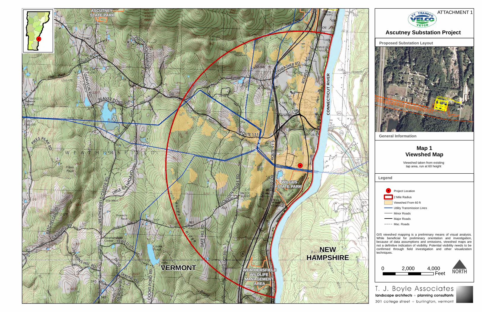
GIS viewshed mapping is a preliminary means of visual analysis.While beneficial for preliminary orientation and investigation,because of data assumptions and omissions, viewshed maps arenot a definitive indication of visibility. Potential visibility needs to beconfirmed through field investigation and other visualizationtechniques.
ROUTE
5
ROUTE
91 S
ROUTE 131
ROUTE
91 N
GULF RD
THRASHER RD
GOULDEN R
ID GE RD
GIRD L
OT RD
GRAVELIN RD
WEATH
ERSFIEL
D CENT
ER RD
CADY HILL RD
YEWELL LN
LITTLE CA NADA R
D
SKYLINE DR
TH 50
PERKIN S HILL RD
SOUTH MOUN TA IN RD
BEAVER PON D RD
DAKE
HILL R
D
COOK
S PON
D RD
MEAD
OW LN
PIKES PEAK RD
BATCH
ELDER
RD
4646
46
115
115
Map 1Viewshed Map
Legend
General Information
!.
!. Project Location2 Mile RadiusViewshed From 60 ftUtility Transmission LinesMinor RoadsMajor RoadsMsc. Roads
N
Ascutney Substation Project
0 4,0002,000Feet
Viewshed taken from existingtap area, run at 60 height
ATTACHMENT 1
Proposed Substation Layout
WEATHERSFIELDWILDLIFE
MANAGEMENT AREA
ASCUTNEY STATE PARK
WILGUSSTATE PARK
VERMONT
NEWHAMPSHIRE
CONN
ECTIC
UT R
IVER


Glossary of Electric System Terms
90/10 Load—An annual forecast of the state’s peak electric demand (load) where there is a 10‐percent
chance that the actual system peak load will exceed the forecasted value in any given year or, stated
another way, it is expected that on the average the forecast will be exceeded once every ten years.
affected utility—Affected utilities are those whose systems cause, contribute to or would experience an
impact from a reliability issue.
angle—Used to measure the synchronism between different alternating quantities, such as voltage or
current. It is often an important performance measure; it is measured in degrees.
baseload—A baseload power plant is an electric generation plant that is expected to operate in most
hours of the year.
blackout—A total loss of power over an area; usually caused by the failure of electrical equipment on
the power system.
breaker‐and‐a‐half—A substation design that offers advantages such as ensuring that the failure of any
one circuit breaker will not interrupt power for more than a brief time. The designs also allow parts of
the substation to be de‐energized for maintenance and repairs without causing a power interruption.
brownout—Abnormally low voltage that causes voltage‐sensitive equipment such as computers, motors
and certain types of lighting to have degraded or interrupted performance.
bus—Also referred to as a “node” or a “station” or a “substation.” A common connection point for two
or more electrical components, such as a transformer, a generator.
capability—The capacity of a piece of equipment to perform its intended function, such as carrying
current for a conductor or transformer, or interrupting current for a switch or breaker, or supplying
power for a generator. Certain pieces of equipment can have different capabilities based on certain
factors, such as ambient conditions (temperature, wind) and the amount of time the equipment is
expected to perform the intended function. Typically, a Normal rating or capability is nearly continuous,
and an Emergency capability is a higher capability utilized during infrequent events for a short duration,
typically twelve hours or less.
capacitor—A device that stores an electrical charge and is typically used to address low voltage issues
on a power system.
conductor—Part of a transmission or distribution line that actually carries the electricity; in other
words, the wire itself. The wire or conductor is just one part of a transmission line; other parts include
the poles and the insulators from which the conductor is hung. A conductor must have enough capacity
to carry the highest demand that it will experience, or it could overheat and fail.

contingency—An unplanned event creating an outage of a critical system component such as a
transmission line, transformer, or generator.
converge—Power flow programs use an iterative mathematical process to solve for, or converge to, the
solution of unknown system parameters, such as Voltage and Angle. When the mathematics do not
result in a solution, the iterative process has “failed to solve” or “failed to converge” to a solution. This
result is an indication of voltage collapse or loss of load.
Critical Energy Infrastructure Information (CEII)—Specific engineering, vulnerability, or detailed design
information about proposed or existing infrastructure (physical or virtual) that: (1) relates details about
the production, generation, transmission, or distribution of energy; (2) could be useful to a person
planning an attack on critical infrastructure; (3) is exempt from mandatory disclosure under the
Freedom of Information Act; and (4)gives strategic information beyond the location of the critical
infrastructure.
demand—The amount of electricity being used at any given moment by a single customer, or by a group
of customers. The total demand on a given system is the sum of all of the individual demands on that
system occurring at the same moment. The peak demand is the highest demand occurring within a given
span of time, usually a season or a year. The peak demand that a transmission or distribution system
must carry sets the minimum requirement for its capacity (see also the definition for energy).
demand‐side management (DSM)—A set of measures utilized to reduce energy consumption. Energy
conservation is one kind of DSM.
dispatch—As a verb: turning on or off, or setting the value or output of a generator, a capacitor bank,
reactor or transformer setting. As a noun: the state or status of these devices.
distribution—Distribution lines and distribution substations operate at lower voltage than the
transmission systems that feed them. They carry electricity from the transmission system to local
customers. When compared to transmission, distribution lines generally use shorter poles, have shorter
wire spans between poles and are usually found alongside streets and roads, or buried beneath them. A
typical distribution voltage would be 13.8‐kV.
distribution utility—A utility in the state of Vermont that is responsible for owning, operating, and
maintain the distribution part of the electric system within an area.
easement—A right to use another’s land for a specific purpose, such as to cross the land with
transmission lines.
failed to converge—See converge.
fault—The failure of a line, transformer, or other electrical component. Once such a component has
failed (due to overheating, short‐circuiting, physical breakage, or other trauma) it is automatically taken
out of operation by a circuit breaker that quickly turns the component off. Once it has been “tripped

off” it no longer poses a threat to human safety, but its loss may present a difficult burden to the
remaining system (see also the definition of redundant below).
forward capacity market—A marketplace operated by ISO‐NE using an auction system with a goal of
purchasing sufficient power capacity for reliable system operation for a future year at competitive prices
where all resources, both new and existing, can participate.
generation or generator—A device that converts mechanical power from an engine, a water wheel, a
windmill, or other source, into electrical power.
Inductor—See reactor.
kilowatt‐hour (kWh)—One thousand watt‐hours. A watt‐hour is a measure of the amount of electric
energy generated or consumed in a given period of time.
kilovolt (kV)—One thousand volts. Volts and kilovolts are measures of voltage. lead distribution utility ‐
A utility selected by the affected utilities to facilitate decision‐making and to lead the effort to conduct
the NTA analysis
lead distribution utility—A utility selected by the affected utilities to facilitate decision‐making and to
lead the effort to conduct NTA analysis.
load—see demand.
load shedding—Intentionally turning off power to a customer or group of customers, usually for
reliability reasons such as to avoid a blackout or equipment damage.
loss of load—See blackout
megawatt (MW)—One million watts. Watts and megawatts are measures of power. To put this in
perspective, the peak power demand for the New England region is approaching 30,000 MW or
30,000,000,000 (thirty billion) watts.
N‐0 or N‐1 or N‐1‐1—The term N minus zero (or one or two) refers to the failure of important
equipment. Although these terms sound complex, they are actually quite simple. “N” is the total number
of components that the system relies on to operate properly. The number subtracted from N is the
number of components that fail in a given scenario. Therefore, N‐0 means that no components have
failed and the system is in a normal condition. N‐1 means that only one component has failed. N‐1‐1
means that two components have failed, which is generally worse than having only one fail (see also the
definition of contingency above).
non‐transmission alternative (NTA)—The use of a non‐transmission solution such as local generation or
energy efficiency to solve a transmission reliability deficiency.
out of angle—See phase shifter.
per unit (pu)—The ratio of an actual or measured quantity to the base or reference value of the same
quantity. For example, a 0.9 pu voltage on a 100 kV system represents a 90 kV measurement of the
voltage.
phase shifter—Also referred to as a “phase shifting transformer” (PST) or “phase angle regulator”
(PAR). A transformer that adjusts the angle between two buses in order to change the amount of power
flowing between these buses. Some of these transformers are also able to adjust voltage. These
transformers have an angle capacity, which states the extent to which the tansformer can adjust the
angle between two buses. When the angle capacity is reached before the desired flow can be achieved,
it is stated that the transformer ran out of angle or that the angle capacity of the transformer is not
sufficiently large.
power—The amount of electricity that is consumed (demand) or supplied at any given time.
power factor—A measure of the amount of reactive power (by‐product of alternating current, i.e., AC)
in relation to the real power (component of power that can heat).
pool transmission facility or facilities (PTF)—Generally speaking, any transmission facility operating at
69 kV or higher and connected to other transmission lines or transmission systems is considered a PTF.
PTF falls under the authority of ISO New England and the construction of new PTF facilities is generally
funded through the ISO on a load ratio share basis among its member utilities.
reactive reinforcement—Also referred to as “reactive compensation.” The act of adding a capacitor
bank or shunt reactor to increase or reduce voltage.
reactor—A device that stores energy in the form of a magnetic field, and then uses this energy to induce
current. Typically used to address high voltage issues on a power system.
reliability deficiency—An existing or projected future violation, before or after a contingency, of the
applicable planning, design and/or operating criteria, with consideration given to the reliability and
availability of the individual system elements.
renewable power source—Any power source that does not run on a finite fuel which will eventually run
out, such as coal, oil, or natural gas. Renewable power sources include solar, wind and hydro generators,
because sunlight, wind and running water will not run out. Generators that burn replaceable fuels also
commonly qualify as renewable power sources. Examples include bio‐diesel generators that run on
crop‐derived fuels and wood‐burning generators.
right of way (ROW)—The long strip of property on which a transmission line is built. It may be owned by
the utility or it may be an easement.
ring bus—See breaker‐and‐a‐half, bus, substation.

sensitivity studies—A technique of analysis whereby different values of certain key variables such as the
permanent loss of a generation or transmission resource are tested to see how sensitive study results
are to possible change in assumptions.
shoulder load—A load level that is within some band width over and above 80% of the peak load level.
steady state—Refers to the period of time after all momentary network disturbances and automatic
equipment adjustments have ended.
substation—A substation is a fenced‐in area where several generators, transmission and/or distribution
lines come together and are connected by various other equipment for purposes of switching, metering,
or adjusting voltage by using transformers.
subtransmission—Subtransmission lines are power lines that typically operate at a voltage of 34,000 to
70,000 volts and are generally below 100 kV.
thermal—Refers to the heating effects of current flow. Often used in conjunction with capability,
impact, analysis.
transformer—A device that typically adjusts high‐voltage to a lower voltage. Different voltages are used
because higher voltages are better for moving power over a long distance, but lower voltages are better
for using electricity in machinery and appliances. Transformers are commonly described by the two (or
more) voltages that they connect, such as “115/13.8‐kV,” signifying a connection between 115‐kV and
13.8‐kV equipment or lines.
transmission—Transmission lines and transmission substations operate at high voltage and carry large
amounts of electricity from centralized generation plants to lower voltage distribution lines and
substations that supply local areas. Transmission lines use poles or structures, have long wire spans
between poles and usually traverse fairly straight paths across large distances. Typical transmission
voltages include 345‐kV and 115 kV and generally all are above 100 kV.
transmission system reinforcements—Transmission line or substation equipment added to existing
transmission infrastructure.
voltage—Voltage is much like water pressure in a system of pipes. If the pressure is too low, the pipes
cannot carry enough water to satisfy the needs of those connected to them. If the voltage is too low, the
electric system cannot carry enough electricity to satisfy the needs of those connected to it.
voltage collapse ‐A phenomenon whereby a series of events ultimately results in a blackout after a
certain amount of time ranging from seconds to minutes.
voltage instability—A phenomenon whereby system operators cannot maintain acceptable system
voltage given the tools at their disposal for a specific combination of load, generation and transmission.
Voltage collapse may ensue.