ashida numerical 3 phase tx. differential protection...
TRANSCRIPT

Ref.:ADR233A_V2 Issue: 01 27.01.08
Page 1 / 11
ASHIDA ELECTRONICS PVT LTD. ASHIDA HOUSE, Plot No. A-308, Road No. 21, Wagle Industrial Estate,Thane (W)-400 604. INDIA. E-mail: [email protected] Web: www.ashidaelectronics.com
Note: Due to our po l icy to upgrade our products constant ly , we reserve the r ight to supply products which may vary s l ight ly f rom that ind icated above.
Type: ADR233A(ADITYA–V2 Ser ies )
(Pre l iminary)
‚þ¹ªþ¸þ
ASHIDA Numerical 3 Phase Tx. Differential Protection Relay
L5
TRIP
L6
L7
ADR 233B_V2
PROTH.
FAULT 87
REF
BF
ERR
Ashida Numerical Directional 3O/C + 1E/F Protection RelayAshida Numerical 3 Phase Tx. Differential Protection Relay
L5
TRIP
L6
L7
L5
TRIP
L6
L7
ADR 233B_V2ADR 233A_V2
PROTH.
FAULT 87
REF
BF
ERRPROTH.
FAULT 87
REF
BF
ERR
Ashida Numerical Directional 3O/C + 1E/F Protection RelayAshida Numerical 3 Phase Tx. Differential Protection Relay Ashida Numerical Directional 3O/C + 1E/F Protection RelayAshida Numerical 3 Phase Tx. Differential Protection Relay
L5
TRIP
L6
L7
ADR 233B_V2
PROTH.
FAULT 87
REF
BF
ERR
Ashida Numerical Directional 3O/C + 1E/F Protection RelayAshida Numerical 3 Phase Tx. Differential Protection Relay
L5
TRIP
L6
L7
L5
TRIP
L6
L7
ADR 233B_V2ADR 233A_V2
PROTH.
FAULT 87
REF
BF
ERRPROTH.
FAULT 87
REF
BF
ERR
Ashida Numerical Directional 3O/C + 1E/F Protection RelayAshida Numerical 3 Phase Tx. Differential Protection Relay Ashida Numerical Directional 3O/C + 1E/F Protection RelayAshida Numerical 3 Phase Tx. Differential Protection Relay
Protection Features:
3Phase Tx. Differential Protection + REF
Programmable (Non- Volatile) Setting By
local keys as well as remote setting by
communication port
Latching of fault current value.
Operation base on fundamental frequency
value.
Harmonics restrain for Tx charging and CT
saturation condition.
Breaker Failure detection.
Cross harmonics restrain.
Programmable starting current.
Programmable Internal ICT( interposing CT)
ratio to match different transformer having
different vector groups
Programmable dual bias setting
Wide setting range 10-50% for bias in steps of
5%
Programmable 2nd HRM restrain 10% - 80%
Relay Design Features: Large 20x4 LCD display for Parameter and
setting display
Disturbance Recorder. Up 1 sec of actual
waveform of current along with logical and
physical status, are captured & saved in the
built-in memory with date time stamping, for
analyzing fault condition & fault location.
Fully communicable with IEC 60870-5-103 or
IEC61850 protocol
Very low burden on CT (less than 0.5VA)
Continuous monitoring of module’s internal
hardware and alarm generation in case of
failure of any critical components.
Facility to synchronised Relay time from
SCADA
5 Digital Output contacts for local alarm as
well as tele-signalling
5 Optically isolated digital status input for
monitoring of status and avoid used of
external relay logic
Ref.:ADR233A_V2 Issue: 01 27.01.08
Page 2 / 11
ASHIDA ELECTRONICS PVT LTD. ASHIDA HOUSE, Plot No. A-308, Road No. 21, Wagle Industrial Estate,Thane (W)-400 604. INDIA. E-mail: [email protected] Web: www.ashidaelectronics.com
Note: Due to our po l icy to upgrade our products constant ly , we reserve the r ight to supply products which may vary s l ight ly f rom that ind icated above.
Type: ADR233A(ADITYA–V2 Ser ies )
(Pre l iminary)
‚þ¹ªþ¸þ
ASHIDA Numerical 3 Phase Tx. Differential Protection Relay
100 nos of event memory, event such CB
close, Trip, digital status change, relay pkp
etc. All events are with date and time stamped
up to 1ms.
10 nos of Fault data stored with keypad
interface and time stamping.
Description:
ADR233A is second generation Numerical
Transformer differential Relay. It consist all the
necessary protection and monitoring functions
required for transformer, it consist of
1. High Speed Digital DSP Controller
2. Analog Measuring Module
3. Power supply Module
4. Digital Input output module.
The High speed Digital Signal Controller
continuously monitors line HV and LV current +
REF current. Along with different status input,
through CTs, and optical isolated status
connections. The high-speed micro-controller
samples these current signals through a A/D
converter. The Digital Signal performs powerful
Numerical Algorithms to find out RMS of
fundamental & harmonic contents of the current.
All measurement is tuned to fundamental
frequency i.e 50Hz, thus relay remain stable
during distorted waveform generated electronics
loco-motive. All these measure values are then
used for different protection function.. These
measured values are also displayed on large 20 x
4 LCD display for metering purpose. The DSC
also monitor different digital input through optical
isolator and control potential free contact for
control CB and generate ALARM and Tele-
signalling.
The power supply module is basically DC – DC
converted designed using modern PWM based
Switching mode technique to convert 110Vdc
station battery supply to the 12V and 24Vdc low
voltage supply for relay electronics and control
circuit. It also provides necessary isolation from
station battery. There are two type of power supply
modules are available 1) having range of 77Vdc –
250Vdc. Covering requirement of 110Vdc and
220Vdc station battery system 2) having range of
18Vdc to 52Vdc covering 24Vdc, 30Vdc, 48Vdc
station battery requirement.
The relay is having total 8 nos of dual LED of high
intensity for easy identification of type of fault for
easy user interface. LEDs L5, L6 and L7 and
Relay R1 to R5, digital status input and controlled
output are fully programmable via key pad
interface.
Main Functions The ADR233A are having following protection
functions.
1. Transformer differential protection.
2. REF protection.
3. Breaker Failure Detection.
4. Monitoring Functions.
Each of these functions are independently
programmable and can be enable or disable by
user depending upon requirement
Ref.:ADR233A_V2 Issue: 01 27.01.08
Page 3 / 11
ASHIDA ELECTRONICS PVT LTD. ASHIDA HOUSE, Plot No. A-308, Road No. 21, Wagle Industrial Estate,Thane (W)-400 604. INDIA. E-mail: [email protected] Web: www.ashidaelectronics.com
Note: Due to our po l icy to upgrade our products constant ly , we reserve the r ight to supply products which may vary s l ight ly f rom that ind icated above.
Type: ADR233A(ADITYA–V2 Ser ies )
(Pre l iminary)
‚þ¹ªþ¸þ
ASHIDA Numerical 3 Phase Tx. Differential Protection Relay
Differential Protection (87):
The ADR233A monitor HV and LV current of
power transformer through respective CT. The
sample current values are processed by power
fully DSP controller. It convert the these current
samples in to equivalent vectors and numbers of
parameter such as RMS values of IHV and ILV
and phases. IHV represent HV current and ILV
represent LV current. Normally to match HV and
LV CT ratio, phase shift between two winding due
to transformer vector group, ICTs (interposing
CTs) are needed. In ADR233A ICTs are software
selectable. There are two separate ICT ratio and
vector groups are provided, one for HV value and
another for LV value. After applying this corrective
factor, relay calculate operating and restring signal
from IHx and ILx (IH1 and IL1 is HV and LV
current after applying ICT correction factor. x
denote phase, 1 for R, 2 for Y and 3 for B). Base
on this and setting relay decide to operate or
restrain.
Operating Current Iox = IHx – ILx
Restraining Current
Ibx = (|IHx| +| ILx| ) / 2
Relay operate when Io is greater than pick-up current setting and
Iox > = S Ibx Where S = set bias. (Slope 1)
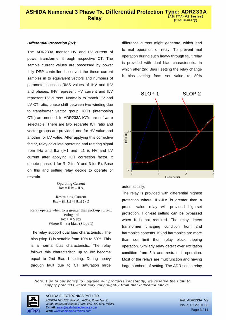
The relay support dual bias characteristic. The
bias (slop 1) is settable from 10% to 50% This
is a normal bias characteristic. The relay
follows this characteristic up to Ibx become
equal to 2nd Bias I setting. During heavy
through fault due to CT saturation large
difference current might generate, which lead
to mal operation of relay. To prevent mal
operation during such heavy through fault relay
is provided with dual bias characteristic. In
which after 2nd Bias I setting the relay change
it bias setting from set value to 80%
automatically.
The relay is provided with differential highest
protection where |IHx-ILx| is greater than a
preset value relay will provided high-set
protection. High-set setting can be bypassed
when it is not required. The relay detect
transformer charging condition from 2nd
harmonics contents. If 2nd harmonics are more
than set limit then relay block tripping
operation. Similarly relay detect over excitation
condition from 5th and restrain it operation.
Most of the relays are multifunction and having
large numbers of setting. The ADR series relay
SLOP 2SLOP 1 SLOP 2SLOP 1
Ref.:ADR233A_V2 Issue: 01 27.01.08
Page 4 / 11
ASHIDA ELECTRONICS PVT LTD. ASHIDA HOUSE, Plot No. A-308, Road No. 21, Wagle Industrial Estate,Thane (W)-400 604. INDIA. E-mail: [email protected] Web: www.ashidaelectronics.com
Note: Due to our po l icy to upgrade our products constant ly , we reserve the r ight to supply products which may vary s l ight ly f rom that ind icated above.
Type: ADR233A(ADITYA–V2 Ser ies )
(Pre l iminary)
‚þ¹ªþ¸þ
ASHIDA Numerical 3 Phase Tx. Differential Protection Relay
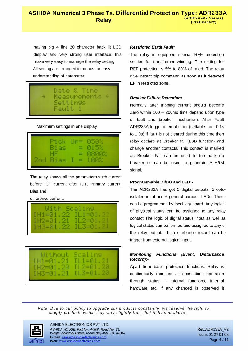
having big 4 line 20 character back lit LCD
display and very strong user interface, this
make very easy to manage the relay setting.
All setting are arranged in menus for easy
understanding of parameter
Maximum settings in one display
The relay shows all the parameters such current
before ICT current after ICT, Primary current,
Bias and
difference current.
Restricted Earth Fault:
The relay is equipped special REF protection
section for transformer winding. The setting for
REF protection is 5% to 80% of rated. The relay
give instant trip command as soon as it detected
EF in restricted zone.
Breaker Failure Detection:-
Normally after tripping current should become
Zero within 100 – 200ms time depend upon type
of fault and breaker mechanism. After Fault
ADR233A trigger internal timer (settable from 0.1s
to 1.0s) If fault is not cleared during this time then
relay declare as Breaker fail (LBB function) and
change another contacts. This contact is marked
as Breaker Fail can be used to trip back up
breaker or can be used to generate ALARM
signal.
Programmable DI/DO and LED:-
The ADR233A has got 5 digital outputs, 5 opto-
isolated input and 6 general purpose LEDs. These
can be programmed by local key board. Any logical
of physical status can be assigned to any relay
contact The logic of digital status input as well as
logical status can be formed and assigned to any of
the relay output. The disturbance record can be
trigger from external logical input.
Monitoring Functions (Event, Disturbance Record):-
Apart from basic protection functions. Relay is
continuously monitors all substations operation
through status, it internal functions, internal
hardware etc. if any changed is observed it

Ref.:ADR233A_V2 Issue: 01 27.01.08
Page 5 / 11
ASHIDA ELECTRONICS PVT LTD. ASHIDA HOUSE, Plot No. A-308, Road No. 21, Wagle Industrial Estate,Thane (W)-400 604. INDIA. E-mail: [email protected] Web: www.ashidaelectronics.com
Note: Due to our po l icy to upgrade our products constant ly , we reserve the r ight to supply products which may vary s l ight ly f rom that ind icated above.
Type: ADR233A(ADITYA–V2 Ser ies )
(Pre l iminary)
‚þ¹ªþ¸þ
ASHIDA Numerical 3 Phase Tx. Differential Protection Relay
marked as event. Such type of events is stored in
internal non-volatile memory along with time
stamped. Following some of the events. Relay
PKP, Relay Reset, CB Trip, CB close, Changed of
any digital status input, Relay setting changed etc.
Up to 100 such event can be stored and can be
download for detailed analysis. Apart from Event
record Relay also record actual waveform of
current along with all digital and logical status
during fault condition. Up to 10 such waveforms
can be recorded, the duration of disturbance
record is 1 sec. The disturbance record can be
trigger from physical status input as well as
from pick, trip operation of relay. This waveform
can be downloaded through communication port
for further analysis.
Relay Talk Software:
The general communication software is provided
to communicate with relay, known as Relay Talk.
By using this software data such as event log,
disturbance records etc can be down loaded and
can be further analysis. The disturbance record
data can be saved in standard COMTRADE
Format which is understandable by numbers of
relay testing units for play back.
Following as some of software clips
All The data can view at time

Ref.:ADR233A_V2 Issue: 01 27.01.08
Page 6 / 11
ASHIDA ELECTRONICS PVT LTD. ASHIDA HOUSE, Plot No. A-308, Road No. 21, Wagle Industrial Estate,Thane (W)-400 604. INDIA. E-mail: [email protected] Web: www.ashidaelectronics.com
Note: Due to our po l icy to upgrade our products constant ly , we reserve the r ight to supply products which may vary s l ight ly f rom that ind icated above.
Type: ADR233A(ADITYA–V2 Ser ies )
(Pre l iminary)
‚þ¹ªþ¸þ
ASHIDA Numerical 3 Phase Tx. Differential Protection Relay
Event list with real time
The waveform and logical and physical status latched by relay can be view and analysed
Data can be viewed as raw sine wave
or RMS value

Ref.:ADR233A_V2 Issue: 01 27.01.08
Page 7 / 11
ASHIDA ELECTRONICS PVT LTD. ASHIDA HOUSE, Plot No. A-308, Road No. 21, Wagle Industrial Estate,Thane (W)-400 604. INDIA. E-mail: [email protected] Web: www.ashidaelectronics.com
Note: Due to our po l icy to upgrade our products constant ly , we reserve the r ight to supply products which may vary s l ight ly f rom that ind icated above.
Type: ADR233A(ADITYA–V2 Ser ies )
(Pre l iminary)
‚þ¹ªþ¸þ
ASHIDA Numerical 3 Phase Tx. Differential Protection Relay

Ref.:ADR233A_V2 Issue: 01 27.01.08
Page 8 / 11
ASHIDA ELECTRONICS PVT LTD. ASHIDA HOUSE, Plot No. A-308, Road No. 21, Wagle Industrial Estate,Thane (W)-400 604. INDIA. E-mail: [email protected] Web: www.ashidaelectronics.com
Note: Due to our po l icy to upgrade our products constant ly , we reserve the r ight to supply products which may vary s l ight ly f rom that ind icated above.
Type: ADR233A(ADITYA–V2 Ser ies )
(Pre l iminary)
‚þ¹ªþ¸þ
ASHIDA Numerical 3 Phase Tx. Differential Protection Relay
While Order ing Specify the fol lowing Information for ADR233AA Relay
Order ing informat ion:
A D R 2 3 3 A - A M - X X X - X X - X - X - X X - X
Example ADR233A – AM-201-01-3-0-02-0 Type: ADR233A wi th s tandard set t ing IEC60870-5-103 com St . Back termina l layout Cabinet Type: CSE -150 H Termina l Removable Aux i l ia ry Supply: 77-250Vdc CT sec: 1 Amp. / 5 Amp selectable
AM XXX XX X Over current Earth Fault Relay
For Adity-V2 series start from 201. For V1 series refer respective document 201 01 Relay with standard Back Connection with IEC60870-5-
103 Communication CSE – H- 150 3
202 01 Relay with standard Back Connection with IEC61850 Communication
CSE – H- 150 3
D e f i n i t i o n o f M o d e l N o o f A d i t y a S e r i e s o f R e l a y s
A M X X X – X X – X – X – X X – X
Auxiliary Supply 01 = 18 – 52 V dc 06 = 110 V dc 02 = 77 – 250 V dc 07 = 220 V dc 03 = 24 V dc 04 = 30 V dc 05 = 48 V dc
Reserved for Future Use
PT Secondary 0 = NO PT 1 = 63.5 PT sec
CT Secondary 1 = 1 Amp. 2 = 5 Amp. 3 = 1 Amp. / 5 Amp. Selectable

Ref.:ADR233A_V2 Issue: 01 27.01.08
Page 9 / 11
ASHIDA ELECTRONICS PVT LTD. ASHIDA HOUSE, Plot No. A-308, Road No. 21, Wagle Industrial Estate,Thane (W)-400 604. INDIA. E-mail: [email protected] Web: www.ashidaelectronics.com
Note: Due to our po l icy to upgrade our products constant ly , we reserve the r ight to supply products which may vary s l ight ly f rom that ind icated above.
Type: ADR233A(ADITYA–V2 Ser ies )
(Pre l iminary)
‚þ¹ªþ¸þ
ASHIDA Numerical 3 Phase Tx. Differential Protection Relay
Technical Specifications:
General specifications Sr. No. Specification Particulars
I. Current Input : Suitable for CT secondary 5 Amp. or 1 Amp site selectable II. Aux. Supply : 77 - 250VDC. Or 18V – 52V to be specify
III. VA burden on CT : Less than 0.2VA IV. VA burden on Aux. : Less than 10 Watts V. Operating Temp. range : -10 deg. To + 65 deg.
VI. Continuous Current carrying capacity
: 2 x of rated
VII. Pick up : with in 1.1 times of set VIII. Reset Value : 95% to 90% of pick up.
IX. Output Contact : 2 for Trip : 1 for REF Trip : 1 for BF : 1 for PROTH. : 1 for RL OK : 5 for General Programmable
X. Contact Rating : Continuous: 5A : Make & carry for 0.5 sec : 30A : Make carry for 3 sec : 15A
XI. Opto Isolated input general programmable
: 2 + common Input : 5 -ve common
XII. Operating Time : Diff < 40ms at 2 times :REF < 25ms at 5 times
XIII. Thermal With stand for CT : 20 x of rated for 3.0 sec.
Differential Protection (87) : 87 OFF/ON : Operating Current (Io) 10% - 100% insteps of 1%
: Bias : 10 - 50%. In steps of 5% : 2nd Harm. Restrain : 10% to 80 % settable : High Set setting : 100% to 2000% in steps of 100%
: 2nd Bias I 100% -400% insteps of 50%
Vector group compensation for HV winding
: VH:- Yy0,Yy2,Yy4,Yy6,Yy8,Yy10,Yd1,Yd3,Yd5, Yd7,Yd9,Yd11,Ydy0 and Ydy6
XIV.
Vector group compensation for LV winding
: VL:- Yy0,Yy2,Yy4,Yy6,Yy8,Yy10,Yd1,Yd3,Yd5, Yd7,Yd9,Yd11,Ydy0 and Ydy6
REF section (Ie) :Ie> : OFF / ON XV. Ie :Ie> 5% - 80% insteps of 5%

Ref.:ADR233A_V2 Issue: 01 27.01.08
Page 10 / 11
ASHIDA ELECTRONICS PVT LTD. ASHIDA HOUSE, Plot No. A-308, Road No. 21, Wagle Industrial Estate,Thane (W)-400 604. INDIA. E-mail: [email protected] Web: www.ashidaelectronics.com
Note: Due to our po l icy to upgrade our products constant ly , we reserve the r ight to supply products which may vary s l ight ly f rom that ind icated above.
Type: ADR233A(ADITYA–V2 Ser ies )
(Pre l iminary)
‚þ¹ªþ¸þ
ASHIDA Numerical 3 Phase Tx. Differential Protection Relay
Breaker Fail (BF) :BF OFF/ON XVI. :BF delay : 0.1S – 1.0s
Operational Indicators (Flags) PROT.H /ERR : Green LED indicates Relay OK (Protection Healthy)
: In case of following condition led become Red 1. Problem in relay Hardware.
FAULT - 87 : Red LED indicates FAULT Hand Reset (HR) Type. REF : Red LED indicate REF Fault
XVII.
BF : Green LED indicate Breaker Fail (HR) Type L5 / L6 / L7 : Spare LED Programmable TRIP : Green LED indicates Output trip relay contact closer (SR) Type
: For Cabinet Type - MAC01302 XVIII. Drawing References : For Back Connections - ADV01301
: For Typical External connection - ADV01401 : For Draw-out Arrangement - MAC01303
Sr. No. Title Standard no. Electromagnetic Compatibility Type Test :
I. High Frequency test : IEC 60255-22-1, class – III : Frequency : 1MHz Damped Oscillatory : Longitudinal :5 KV (peak) : Duration: sec duration 2 sec. : Between input current Terminal
II. Electrostatic discharge Direct application
: IEC 60255-22-2 Class III and IEC 61000-4-2 class III. : Contact discharge: 6kV, : Air discharge: 8KV : Polarity: both +ve and –Ve polarities.
III. Indirect application : IEC-61000-4-2, Class-III
IV. Fast transient disturbance
: IEC 60255-22-4 and IEC 61000-4-4, class A : 1.2KV; 5/50ns; 5KHz burst duration = 15ms. : Repetition rate 300ms; Both polarities; Ri = 50Ω; duration 1 min.
V. Surge immunity test
: IEC 60255-22-5 / IEC 61000-4-6 class 4 : Differential Mode = 2kV : Common Mode = 4kV : 1.2/50uS , 5 surges of each polarity
VI. Power frequency immunity test : IEC-60255-22-7, Class-A
VII. Power frequency magnetic field test
: IEC-61000-4-8, Class-V
VIII. Radiated electromagnetic field disturbance
: IEC- 60255-22-3 : EN-61000-4-3 : Frequency 80MHz – 1GHz

Ref.:ADR233A_V2 Issue: 01 27.01.08
Page 11 / 11
ASHIDA ELECTRONICS PVT LTD. ASHIDA HOUSE, Plot No. A-308, Road No. 21, Wagle Industrial Estate,Thane (W)-400 604. INDIA. E-mail: [email protected] Web: www.ashidaelectronics.com
Note: Due to our po l icy to upgrade our products constant ly , we reserve the r ight to supply products which may vary s l ight ly f rom that ind icated above.
Type: ADR233A(ADITYA–V2 Ser ies )
(Pre l iminary)
‚þ¹ªþ¸þ
ASHIDA Numerical 3 Phase Tx. Differential Protection Relay
IX. Conducted Disturbance
induced by Radio Frequency field
: IEC 60255-22-6 / IEC 61000-4-6: 1996. : Freq. 150kHz – 80MHz, Amplitude 10 V, Modulation 80% AM @ 1
KHz X. AC Ripple in DC supply
Test : IEC 60255-11
XI. Radiated emission : IEC- 60255-25 Insulation tests:
XII. High Voltage Test
: IEC 60255-5. class – III : At 2.5kV 50Hz between all terminal connected together and
earth for 1 minutes XIII. Impulse Voltage Test
: IEC60255-5. class – III : Test voltage: 5KV (peak) 1.2 / 50us, : Energy :0.5 J, : Polarity : + ve and – Ve : Nos. of impulses : 3 positive and 3 negative impulse : Duration between Impulses : 5 sec.
Environmental tests: XIV. Cold test Storage test : IEC-60068-2-1 XV. Dry heat test : IEC-60068-2-2
XVI. Damp heat test, steady state : IEC-60068-2-3
XVII. Damp heat test, cyclic : IEC-60068-2-30 CE compliance XVIII. Immunity : IEC-60255-26 XIX. Emissive Test : IEC- 60255-26 XX. Low voltage directive : EN-50178
Mechanical tests
XXI. Vibration : IEC 60255-21-1 class 1 : Frequency Range = 10Hz – 150Hz , acceleration. = 1gn (9.8 m/s2) : Sweep rate 1 octave/min; 20 cycle in 3 orthogonal axis.
XXII. Shock and bump : IEC- 60255-21-2 XXIII. Seismic : IEC-60255-21-3 Revision Date Description
01 27 Jan 2008 Original specs


