ashrae 90 - allied commercial · all models are ashrae 90.1-2010 energy efficiency compliant and...
TRANSCRIPT
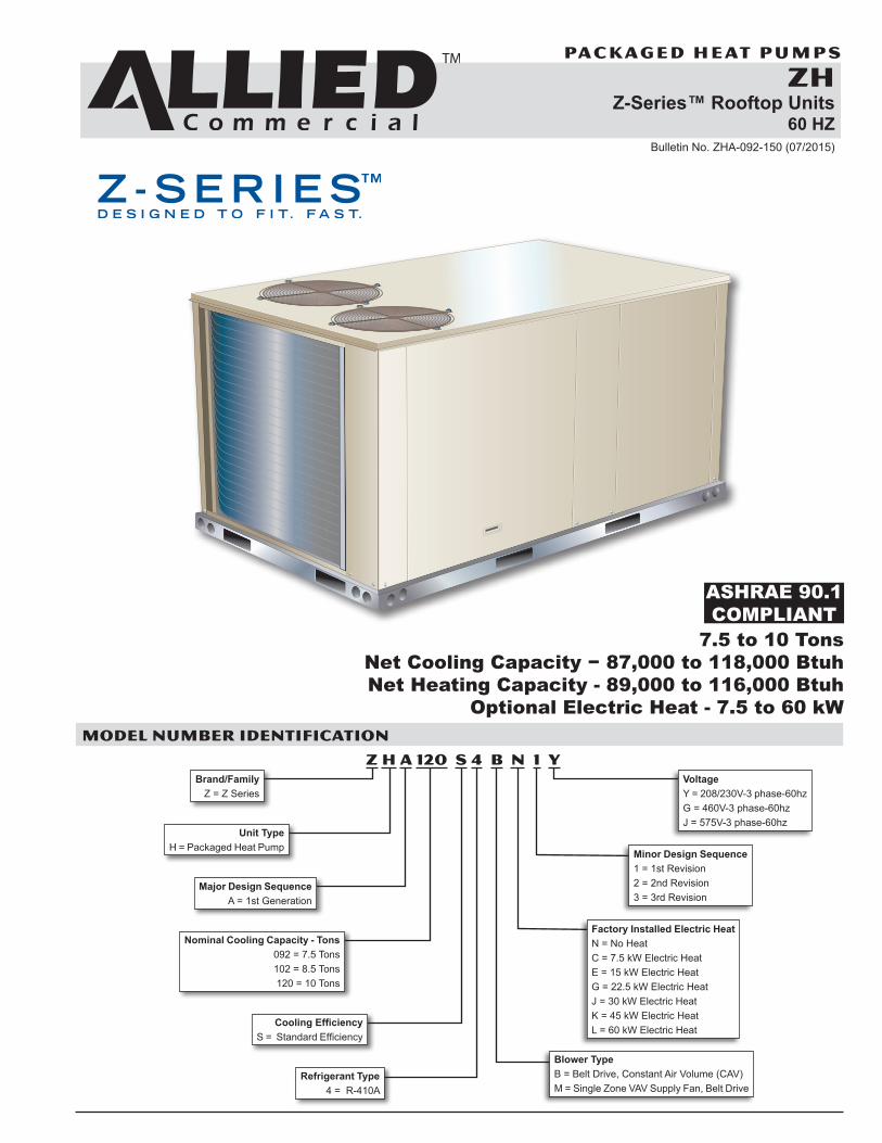
ZHZ-Series™ Rooftop Units
60 HZBulletin No. ZHA-092-150 (07/2015)
MODEL NUMBER IDENTIFICATION
ASHRAE 90.1COMPLIANT
Z H A 120 S 4 B N 1 YBrand/Family
Z = Z Series
Unit Type H = Packaged Heat Pump
Major Design Sequence A = 1st Generation
Nominal Cooling Capacity - Tons 092 = 7.5 Tons 102 = 8.5 Tons 120 = 10 Tons
Cooling Efficiency S = Standard Efficiency
Refrigerant Type 4 = R-410A
Factory Installed Electric Heat N = No Heat C = 7.5 kW Electric Heat E = 15 kW Electric Heat G = 22.5 kW Electric Heat J = 30 kW Electric Heat K = 45 kW Electric Heat L = 60 kW Electric Heat
Minor Design Sequence 1 = 1st Revision 2 = 2nd Revision 3 = 3rd Revision
Voltage Y = 208/230V-3 phase-60hz G = 460V-3 phase-60hz J = 575V-3 phase-60hz
Blower Type B = Belt Drive, Constant Air Volume (CAV) M = Single Zone VAV Supply Fan, Belt Drive
7.5 to 10 TonsNet Cooling Capacity − 87,000 to 118,000 BtuhNet Heating Capacity - 89,000 to 116,000 Btuh
Optional Electric Heat - 7.5 to 60 kW
ZH 7.5 TO 10 TON ROOFTOP UNITS
PA C KA G E D H E AT P U M P S
Z-Series™ Packaged Heat Pumps 7.5 to 10 Ton / Page 2
FEATURES AND BENEFITS
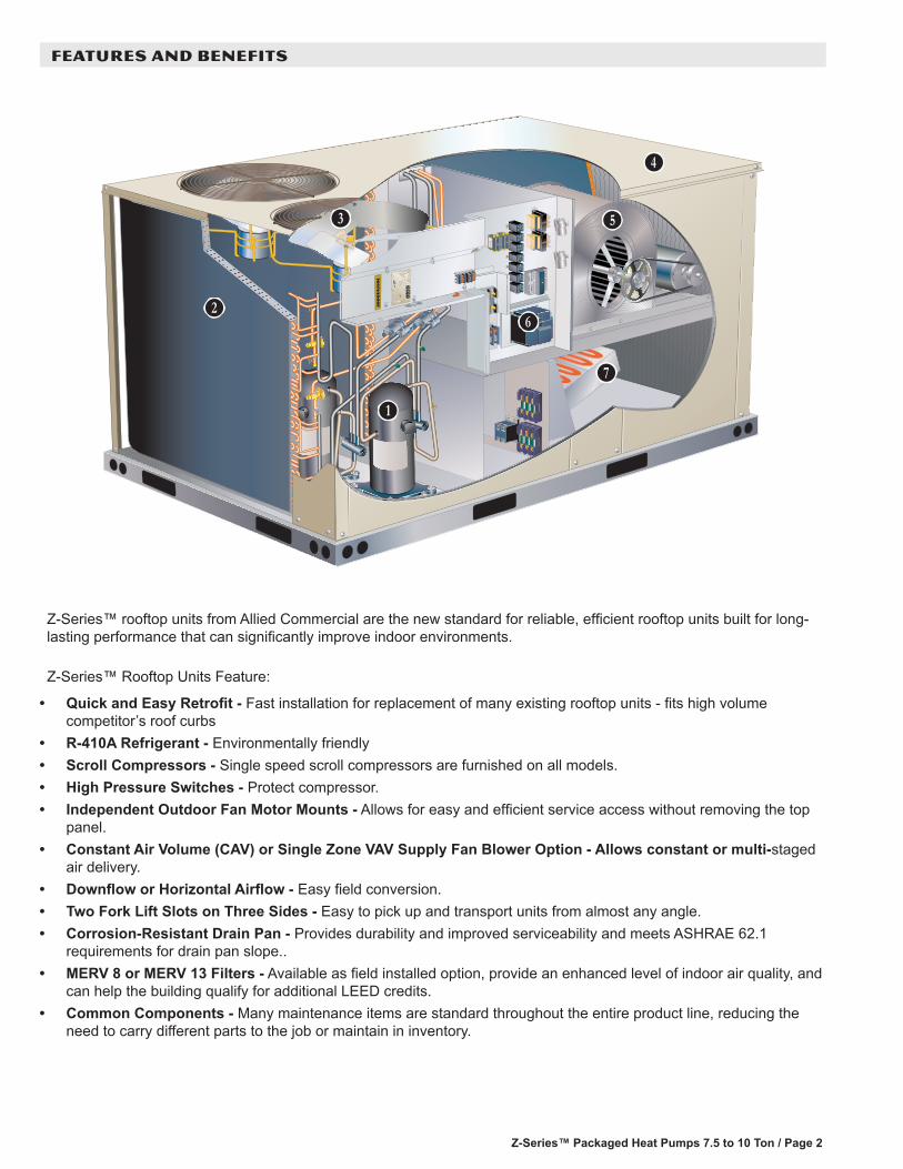
Z-Series™ rooftop units from Allied Commercial are the new standard for reliable, efficient rooftop units built for long-lasting performance that can significantly improve indoor environments. Z-Series™ Rooftop Units Feature:
• Quick and Easy Retrofit - Fast installation for replacement of many existing rooftop units - fits high volume competitor’s roof curbs
• R-410A Refrigerant - Environmentally friendly• Scroll Compressors - Single speed scroll compressors are furnished on all models.• High Pressure Switches - Protect compressor.• Independent Outdoor Fan Motor Mounts - Allows for easy and efficient service access without removing the top
panel.• Constant Air Volume (CAV) or Single Zone VAV Supply Fan Blower Option - Allows constant or multi-staged
air delivery. • Downflow or Horizontal Airflow - Easy field conversion.• Two Fork Lift Slots on Three Sides - Easy to pick up and transport units from almost any angle.• Corrosion-Resistant Drain Pan - Provides durability and improved serviceability and meets ASHRAE 62.1
requirements for drain pan slope..• MERV 8 or MERV 13 Filters - Available as field installed option, provide an enhanced level of indoor air quality, and
can help the building qualify for additional LEED credits.• Common Components - Many maintenance items are standard throughout the entire product line, reducing the
need to carry different parts to the job or maintain in inventory.
B
C
D
E
F
G
H
Z-Series™ Packaged Heat Pumps 7.5 to 12.5 Ton / Page 3
FEATURES AND BENEFITS
APPROVALSAHRI Certified to AHRI Standard 340/360-2007.ETL Intertek listed.Components bonded for grounding to meet safety standards for servicing required by UL, ULC and National and Canadian Electrical Codes.All models are ASHRAE 90.1-2010 energy efficiency compliant and meet or exceed requirements of Section 6.8.Models equipped with the Single Zone VAV Supply Fan option meet California Code of Regulations, Title 24 and ASHRAE 90.1-2010 Section 6.4.3.10 requirements for staged airflow.ISO 9001 Registered Manufacturing Quality System.
WARRANTYLimited five years on compressors.Limited five years on Optional High Performance Economizers.Limited one year all other covered components.
COOLING SYSTEMDesigned to maximize sensible and latent cooling performance at design conditions.System can operate from 30°F to 125°F without any additional controls.
R-410A RefrigerantNon-chlorine based, ozone friendly, R-410A.
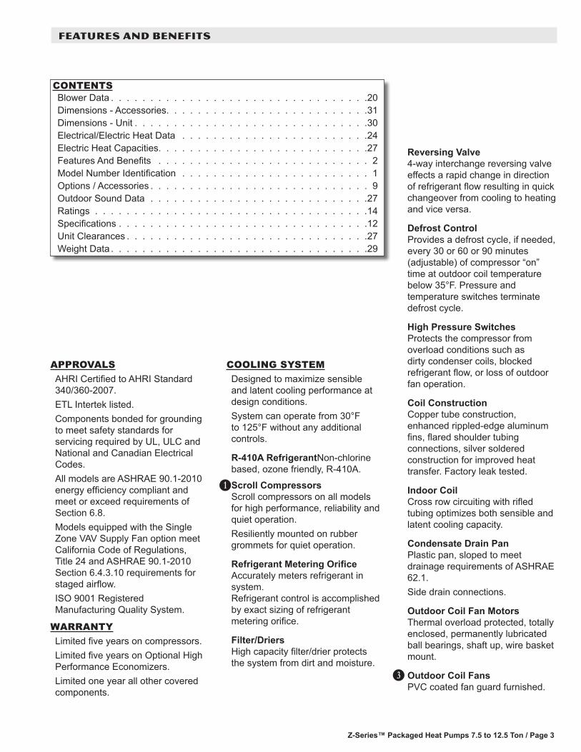
Scroll CompressorsScroll compressors on all models for high performance, reliability and quiet operation.Resiliently mounted on rubber grommets for quiet operation.
Refrigerant Metering Orifice Accurately meters refrigerant in system.Refrigerant control is accomplished by exact sizing of refrigerant metering orifice.
Filter/DriersHigh capacity filter/drier protects the system from dirt and moisture.
A
B
Reversing Valve4-way interchange reversing valve effects a rapid change in direction of refrigerant flow resulting in quick changeover from cooling to heating and vice versa.
Defrost ControlProvides a defrost cycle, if needed, every 30 or 60 or 90 minutes (adjustable) of compressor “on” time at outdoor coil temperature below 35°F. Pressure and temperature switches terminate defrost cycle.
High Pressure SwitchesProtects the compressor from overload conditions such as dirty condenser coils, blocked refrigerant flow, or loss of outdoor fan operation.
Coil ConstructionCopper tube construction, enhanced rippled-edge aluminum fins, flared shoulder tubing connections, silver soldered construction for improved heat transfer. Factory leak tested.
Indoor CoilCross row circuiting with rifled tubing optimizes both sensible and latent cooling capacity.
Condensate Drain PanPlastic pan, sloped to meet drainage requirements of ASHRAE 62.1.Side drain connections.
Outdoor Coil Fan MotorsThermal overload protected, totally enclosed, permanently lubricated ball bearings, shaft up, wire basket mount.
Outdoor Coil FansPVC coated fan guard furnished.
D
CONTENTSBlower Data . . . . . . . . . . . . . . . . . . . . . . . . . . . . . . . . .20Dimensions - Accessories. . . . . . . . . . . . . . . . . . . . . . . . . .31Dimensions - Unit . . . . . . . . . . . . . . . . . . . . . . . . . . . . . .30Electrical/Electric Heat Data . . . . . . . . . . . . . . . . . . . . . . . .24Electric Heat Capacities. . . . . . . . . . . . . . . . . . . . . . . . . . .27Features And Benefits . . . . . . . . . . . . . . . . . . . . . . . . . . . 2Model Number Identification . . . . . . . . . . . . . . . . . . . . . . . . 1Options / Accessories . . . . . . . . . . . . . . . . . . . . . . . . . . . . 9Outdoor Sound Data . . . . . . . . . . . . . . . . . . . . . . . . . . . .27Ratings . . . . . . . . . . . . . . . . . . . . . . . . . . . . . . . . . . .14Specifications . . . . . . . . . . . . . . . . . . . . . . . . . . . . . . . .12Unit Clearances . . . . . . . . . . . . . . . . . . . . . . . . . . . . . . .27Weight Data . . . . . . . . . . . . . . . . . . . . . . . . . . . . . . . . .29

Z-Series™ Packaged Heat Pumps 7.5 to 10 Ton / Page 4
COOLING SYSTEM (continued)
Required Selections
Cooling CapacitySpecify nominal cooling capacity of the unit.
Options/Accessories
Field InstalledCondensate Drain TrapAvailable in copper or PVC.
Drain Pan Overflow SwitchMonitors condensate level in drain pan, shuts down unit if drain becomes clogged.
Low Ambient KitCycles the outdoor fan while allowing compressor operation in the cooling cycle. This intermittent fan operation allows the system to operate without icing the indoor coil and losing capacity. Designed for use in ambient temperatures no lower than 0°F.
CABINETConstructionHeavy-gauge steel panels and full perimeter heavy-gauge galvanized steel base rail provides structural integrity for transportation, handling, and installation.Base rails have rigging holes.Three sides of the base rail have forklift slots.Raised edges around duct and power entry openings in the bottom of the unit provide additional protection against water entering the building.
Airflow ChoiceUnits are shipped in downflow (vertical) configuration, can be field converted to horizontal airflow.
Duct FlangesProvided for horizontal duct attachment.
Power EntryElectrical lines can be brought through the unit base or through horizontal access knock-outs.Optional Bottom Power Entry Kit is available.
Exterior PanelsConstructed of heavy-gauge, galvanized steel with a two-layer enamel paint finish.
InsulationAll panels adjacent to conditioned air are fully insulated with non-hygroscopic fiberglass insulation.
Access PanelsAccess panels are provided for the filter section, heating/blower section, and the compressor/controls section. Recessed handles allow easy access for servicing.
E
Options/Accessories
Factory InstalledCorrosion ProtectionA completely flexible immersed coating with an electrodeposited dry film process. (AST ElectroFin E-Coat) Meets Mil Spec MIL-P-53084, ASTM B117 Standard Method Salt Spray Testing.Indoor Corrosion Protection: - Coated coil Outdoor Corrosion Protection: - Coated coil
Field InstalledCombination Coil/Hail GuardsHeavy gauge steel frame painted to match cabinet with expanded metal mesh to protect the outdoor coil from damage.
FEATURES AND BENEFITS
Z-Series™ Packaged Heat Pumps 7.5 to 12.5 Ton / Page 5
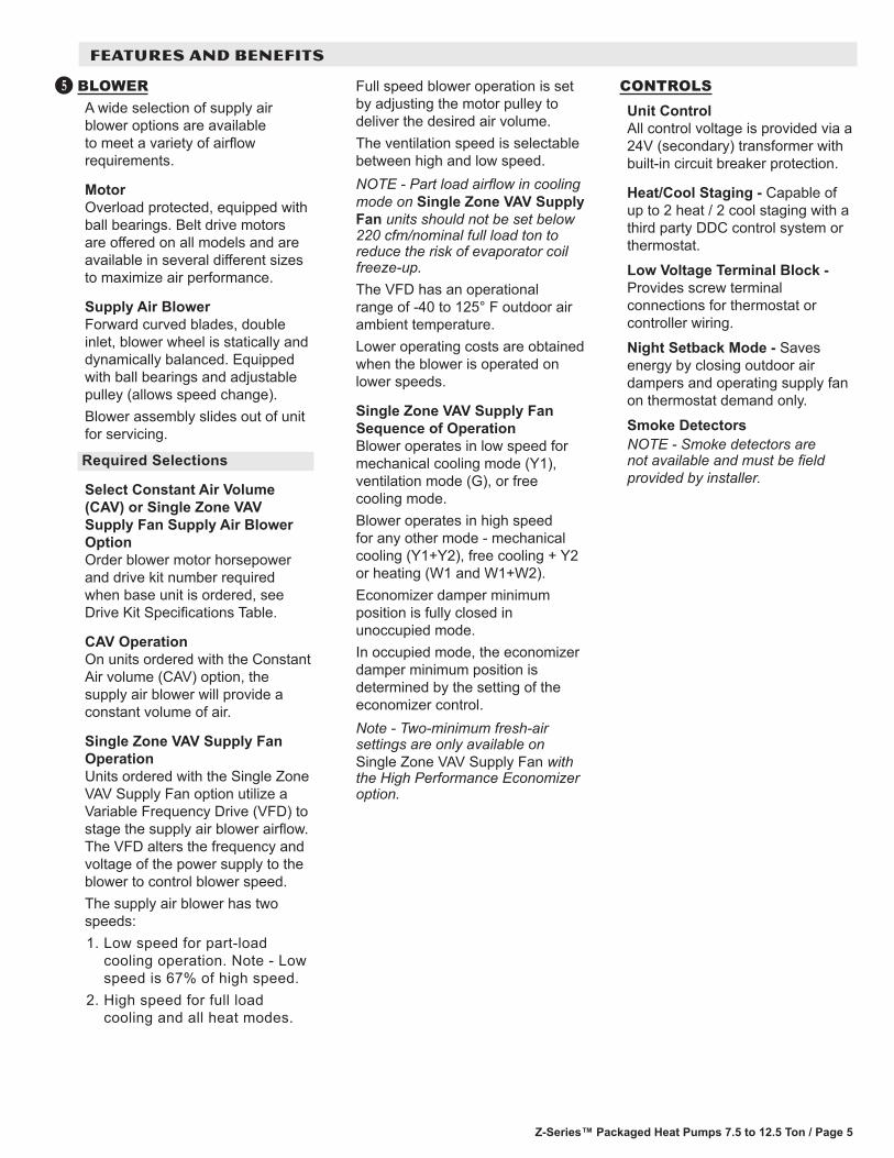
BLOWERA wide selection of supply air blower options are available to meet a variety of airflow requirements.
MotorOverload protected, equipped with ball bearings. Belt drive motors are offered on all models and are available in several different sizes to maximize air performance.
Supply Air BlowerForward curved blades, double inlet, blower wheel is statically and dynamically balanced. Equipped with ball bearings and adjustable pulley (allows speed change).Blower assembly slides out of unit for servicing.
Required Selections
Select Constant Air Volume (CAV) or Single Zone VAV Supply Fan Supply Air Blower OptionOrder blower motor horsepower and drive kit number required when base unit is ordered, see Drive Kit Specifications Table.
CAV OperationOn units ordered with the Constant Air volume (CAV) option, the supply air blower will provide a constant volume of air.
Single Zone VAV Supply Fan OperationUnits ordered with the Single Zone VAV Supply Fan option utilize a Variable Frequency Drive (VFD) to stage the supply air blower airflow. The VFD alters the frequency and voltage of the power supply to the blower to control blower speed.The supply air blower has two speeds:1. Low speed for part-load
cooling operation. Note - Low speed is 67% of high speed.
2. High speed for full load cooling and all heat modes.
F Full speed blower operation is set by adjusting the motor pulley to deliver the desired air volume.The ventilation speed is selectable between high and low speed.NOTE - Part load airflow in cooling mode on Single Zone VAV Supply Fan units should not be set below 220 cfm/nominal full load ton to reduce the risk of evaporator coil freeze-up.The VFD has an operational range of -40 to 125° F outdoor air ambient temperature. Lower operating costs are obtained when the blower is operated on lower speeds.
Single Zone VAV Supply Fan Sequence of OperationBlower operates in low speed for mechanical cooling mode (Y1), ventilation mode (G), or free cooling mode.Blower operates in high speed for any other mode - mechanical cooling (Y1+Y2), free cooling + Y2 or heating (W1 and W1+W2).Economizer damper minimum position is fully closed in unoccupied mode.In occupied mode, the economizer damper minimum position is determined by the setting of the economizer control.Note - Two-minimum fresh-air settings are only available on Single Zone VAV Supply Fan with the High Performance Economizer option.
CONTROLSUnit ControlAll control voltage is provided via a 24V (secondary) transformer with built-in circuit breaker protection.
Heat/Cool Staging - Capable of up to 2 heat / 2 cool staging with a third party DDC control system or thermostat.
Low Voltage Terminal Block - Provides screw terminal connections for thermostat or controller wiring.
Night Setback Mode - Saves energy by closing outdoor air dampers and operating supply fan on thermostat demand only.
Smoke DetectorsNOTE - Smoke detectors are not available and must be field provided by installer.
FEATURES AND BENEFITS
Z-Series™ Packaged Heat Pumps 7.5 to 10 Ton / Page 6
FEATURES AND BENEFITS
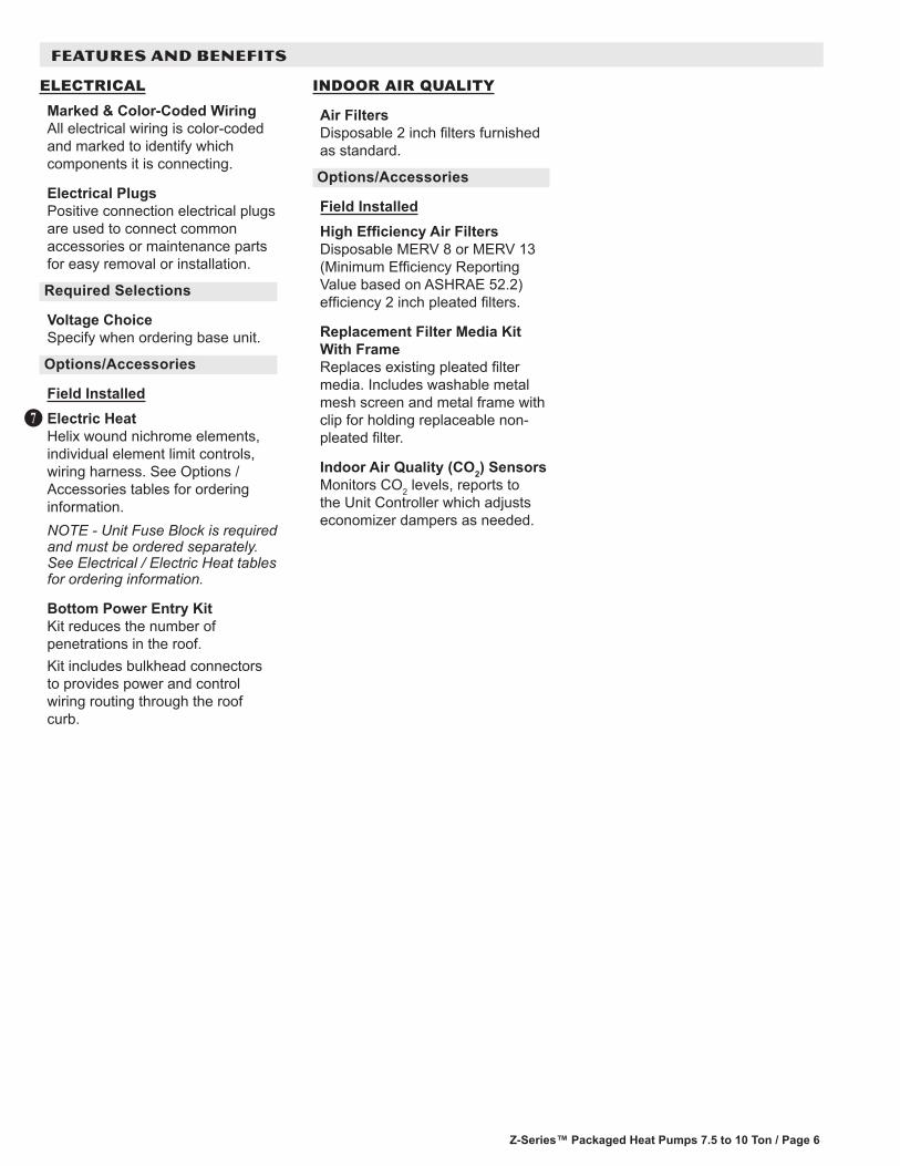
ELECTRICALMarked & Color-Coded WiringAll electrical wiring is color-coded and marked to identify which components it is connecting.
Electrical PlugsPositive connection electrical plugs are used to connect common accessories or maintenance parts for easy removal or installation.
Required Selections
Voltage ChoiceSpecify when ordering base unit.
Options/Accessories
Field InstalledElectric HeatHelix wound nichrome elements, individual element limit controls, wiring harness. See Options / Accessories tables for ordering information.NOTE - Unit Fuse Block is required and must be ordered separately. See Electrical / Electric Heat tables for ordering information.
Bottom Power Entry KitKit reduces the number of penetrations in the roof.Kit includes bulkhead connectors to provides power and control wiring routing through the roof curb.
H
INDOOR AIR QUALITY
Air FiltersDisposable 2 inch filters furnished as standard.
Options/Accessories
Field InstalledHigh Efficiency Air FiltersDisposable MERV 8 or MERV 13 (Minimum Efficiency Reporting Value based on ASHRAE 52.2) efficiency 2 inch pleated filters.
Replacement Filter Media Kit With FrameReplaces existing pleated filter media. Includes washable metal mesh screen and metal frame with clip for holding replaceable non-pleated filter.
Indoor Air Quality (CO2) SensorsMonitors CO2 levels, reports to the Unit Controller which adjusts economizer dampers as needed.

Z-Series™ Packaged Heat Pumps 7.5 to 12.5 Ton / Page 7
ECONOMIZER OPTIONS
Factory or Field InstalledNOTE - Downflow Economizer is factory or field installed. Horizontal Economizer is field installed only.
Economizer (Standard and High Performance Common Features)Downflow or Horizontal models with Barometric Relief Dampers and Hoods.Barometric Relief Dampers allow relief of excess air, aluminum blade dampers prevent blow back and outdoor air infiltration during off cycle, Exhaust hood with bird screen furnished.NOTE - Outdoor Air and Barometric Relief Exhaust Hoods are included when economizer is factory installed and are furnished with economizer when ordered for field installation.Occupied/Unoccupied mode with field furnished setback thermostat.Demand Control Ventilation (DCV) ready using optional CO2 sensors.Single temperature control is furnished with Economizer. Outdoor air temperature sensor enables economizer if the outdoor temperature is less than the setpoint of the control.
Standard Economizer Features (Not for Title 24)Parallel gear-driven action, return air and outdoor air dampers, plug-in connections to unit, nylon bearings, neoprene seals, 24-volt, fully-modulating spring return motor.
Standard Economizer Control ModuleThe Standard Economizer Control Module can be adjusted to operate based on outdoor air temperatures.
OPTIONS / ACCESSORIES
Economizer Controls:• Damper Minimum Position
- Can be set lower than traditional minimum air requirements resulting in cost savings.
• IAQ Sensor - Signals dampers to modulate and maintain 55°F when CO2 is higher than the CO2 setpoint.
• Demand Control Ventilation (DCV) LED - A steady green Demand Control Ventilation LED indicates the IAQ reading is higher than setpoint and requires more fresh air.
• Free Cool LED - A steady green LED indicates outdoor air is suitable for free cooling.
Free Cooling runs when outdoor air temperature is lower than the set temperature on the economizer control. NOTE: The Free Cooling default setting for outdoor air temperature sensor is 55°F.
High Performance Economizer Features Approved for California Title 24 building standards.ASHRAE 90.1-2010 compliant.Parallel gear-driven action, high torque 24-volt fully-modulating spring return damper motor, return air and outdoor air dampers, plug-in connections to unit, stainless steel bearings, enhanced neoprene blade edge seals and flexible stainless steel jamb seals to minimize air leakage.NOTE - High Performance Economizers are not approved for use with enthalpy controls in Title 24 applications.
High Performance Economizer Control ModuleModule provides inputs and outputs to control economizer based on parameter settings. Module automatically detects sensors by polling to determine which sensors are installed in system.
Module displays any alarm messages (fault detection and diagnostics) as an aid in troubleshooting.Non-volatile memory retains parameter settings in case of power failure.Keypad with four navigation buttons and LCD screen is furnished for setting economizer parameters.
• Menu Up/Exit button returns to the main menu.
• Arrow Up button moves to the previous or next parameter within the selected menu.
• Arrow Down button moves to the next parameter within the selected menu.
• Select (enter) button confirms parameter selection.
Main Menu Structure:• STATUS (economizer and
system operation status)• SETPOINTS (settings for
various setpoint parameters)• SYSTEM SETUP (settings/
information about the system)• ADVANCED SETUP (freeze
protection, CO2 settings, stage 3 delay and additional calibration settings)
• CHECKOUT (damper positions)• ALARMS (output signal that
can be configured for remote alarm monitoring)
NOTE - The free cooling setpoint for Title 24 applications must be set based on the Climate Zone where the system is installed. See Section 140.4 “Prescriptive Requirements for Space Conditioning Systems” of the California Energy Commission’s 2013 Building Energy Efficiency Standards.Refer to Installation Instructions for complete setup information and menu parameters available.

Z-Series™ Packaged Heat Pumps 7.5 to 10 Ton / Page 8
OPTIONS / ACCESSORIES
ECONOMIZER OPTIONS (continued)
Field InstalledSingle Enthalpy Temperature Control (Not for Title 24)Outdoor air enthalpy sensor enables economizer if the outdoor enthalpy is less than the setpoint of the control.
Differential Enthalpy Control (Not for Title 24)Order two Single Enthalpy Control Kits. One is field installed in the return air section, the other in the outdoor air section. Allows the economizer control board to select between outdoor air or return air, whichever has lower enthalpy.
EXHAUST OPTIONS
Field InstalledHorizontal Low Profile Barometric Relief DampersFor use when unit is configured for horizontal applications in a reduced space requiring an economizer.Allows relief of excess air.Aluminum blade dampers prevent blow back and outdoor air infiltration during off cycle.Field installed in return air duct.Exhaust hood with bird screen furnished.
Power Exhaust FanInstalls internal to unit for downflow applications only with economizer option. Provides exhaust air pressure relief. Interlocked to run when supply air blower is operating, fan runs when outdoor air dampers are 50% open (adjustable), motor is overload protected. Requires Economizer with Outdoor Air Hood and Barometric Relief Dampers. Fan is 20 in. diameter with 5 blades (K1PWRE10B) WITH 1/3 hp motor.
OUTDOOR AIR OPTIONS
Field InstalledOutdoor Air Damper - Downflow or Horizontal With Air HoodLinked mechanical dampers, 0 to 25% (fixed) outdoor air adjustable, installs in unit. Includes outdoor air hood.Automatic model features fully modulating spring return damper motor with plug-in connection.Manual model features a slide damper.Maximum mixed air temperature in cooling mode: 100°F.
ROOF CURBSHybrid Roof Curbs, DownflowNailer strip furnished, mates to unit, US National Roofing Contractors Approved, shipped knocked down.Roof curb can be assembled using interlocking tabs to fasten corners together. No tools required.Curb can also be fastened together with furnished hardware.Available in 8, 14, 18, and 24 inch heights.
CEILING DIFFUSERSCeiling Diffusers (Flush or Step-Down)Aluminum grilles, large center grille, insulated diffuser box with flanges, hanging rings furnished, interior transition (even air flow), internally sealed (prevents recirculation), adapts to T-bar ceiling grids or plaster ceilings.
Transitions (Supply and Return)NOTE - Ceiling Diffuser Transitions are not furnished and must be field fabricated.
Z-Series™ Packaged Heat Pumps 7.5 to 12.5 Ton / Page 9
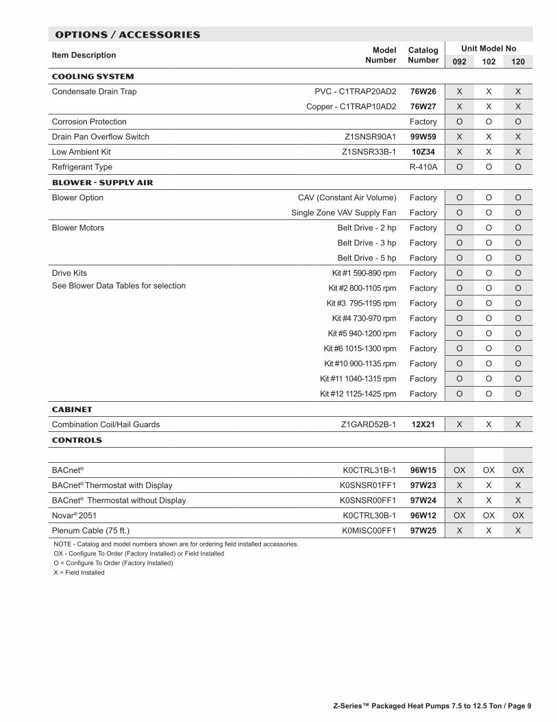
OPTIONS / ACCESSORIES
Item Description Model Number
Catalog Number
Unit Model No092 102 120
COOLING SYSTEM
Condensate Drain Trap PVC - C1TRAP20AD2 76W26 X X X
Copper - C1TRAP10AD2 76W27 X X X
Corrosion Protection Factory O O O
Drain Pan Overflow Switch Z1SNSR90A1 99W59 X X X
Low Ambient Kit Z1SNSR33B-1 10Z34 X X X
Refrigerant Type R-410A O O O
BLOWER - SUPPLY AIR
Blower Option CAV (Constant Air Volume) Factory O O O
Single Zone VAV Supply Fan Factory O O O
Blower Motors Belt Drive - 2 hp Factory O O O
Belt Drive - 3 hp Factory O O O
Belt Drive - 5 hp Factory O O O
Drive KitsSee Blower Data Tables for selection
Kit #1 590-890 rpm Factory O O O
Kit #2 800-1105 rpm Factory O O O
Kit #3 795-1195 rpm Factory O O O
Kit #4 730-970 rpm Factory O O O
Kit #5 940-1200 rpm Factory O O O
Kit #6 1015-1300 rpm Factory O O O
Kit #10 900-1135 rpm Factory O O O
Kit #11 1040-1315 rpm Factory O O O
Kit #12 1125-1425 rpm Factory O O O
CABINET
Combination Coil/Hail Guards Z1GARD52B-1 12X21 X X X
CONTROLS
BACnet® K0CTRL31B-1 96W15 OX OX OX
BACnet® Thermostat with Display K0SNSR01FF1 97W23 X X X
BACnet® Thermostat without Display K0SNSR00FF1 97W24 X X X
Novar® 2051 K0CTRL30B-1 96W12 OX OX OX
Plenum Cable (75 ft.) K0MISC00FF1 97W25 X X XNOTE - Catalog and model numbers shown are for ordering field installed accessories.OX - Configure To Order (Factory Installed) or Field InstalledO = Configure To Order (Factory Installed)X = Field Installed

Z-Series™ Packaged Heat Pumps 7.5 to 10 Ton / Page 10
OPTIONS / ACCESSORIES
Item Description Model Number
Catalog Number
Unit Model No092 102 120
INDOOR AIR QUALITY
Air Filters
High Efficiency Air Filters20 x 24 x 2 in. (Order 4 per unit)
MERV 8 - Z1FLTR15B-1 14C35 X X X
MERV 13 - Z1FLTR40B-1 14C36 X X X
Replacement Media Filter With Metal Mesh Frame (includes non-pleated filter media)
C1FLTR30B-1- Y3063 X X X
Indoor Air Quality (CO2) SensorsSensor - Wall-mount, off-white plastic cover with LCD display C0SNSR50AE1L 77N39 X X X
Sensor - Wall-mount, off-white plastic cover, no display C0SNSR52AE1L 87N53 X X X
Sensor - Black plastic case with LCD display, rated for plenum mounting
C0SNSR51AE1L 87N52 X X X
Sensor - Wall-mount, black plastic case, no display, rated for plenum mounting
C0MISC19AE1 87N54 X X X
CO2 Sensor Duct Mounting Kit - for downflow applications C0MISC19AE1- 85L43 X X X
Aspiration Box - for duct mounting non-plenum rated CO2 sensors (87N53 or 77N39)
C0MISC16AE1- 90N43 X X X
ELECTRICAL
Voltage 60 hz 208/230V - 3 phase Factory O O O
460V - 3 phase Factory O O O
575V - 3 phase Factory O O O
Bottom Power Entry Kit Z1PEKT01B-1 11H66 X X X
ELECTRIC HEAT
7.5 kW 208/230V-3ph - Z1EH0075B-1Y 10Y97 X X
460V-3ph - Z1EH0075B-1G 10Y98 X X
575V-3ph - Z1EH0075B-1J 10Y99 X X
15 kW 208/230V-3ph - Z1EH0150B-1Y 10Z01 X X X
460V-3ph - Z1EH0150B-1G 10Z03 X X X
575V-3ph - Z1EH0150B-1J 10Z04 X X X
22.5 kW 208/230V-3ph - Z1EH0225B-1Y 10Z05 X X X
460V-3ph - Z1EH0225B-1G 10Z06 X X X
575V-3ph - Z1EH0225B-1J 10Z07 X X X
30 kW 208/230V-3ph - Z1EH0300B-1Y 10Z08 X X X
460V-3ph - Z1EH0300B-1G 10Z09 X X X
575V-3ph - Z1EH0300B-1J 10Z10 X X X
45 kW 208/230V-3ph - Z1EH0450B-1Y 10Z11 X X X
460V-3ph - Z1EH0450B-1G 10Z12 X X X
575V-3ph - Z1EH0450B-1J 10Z13 X X X
60 kW 208/230V-3ph - Z1EH0600B-1Y 10Z14 X
460V-3ph - Z1EH0600B-1G 10Z15 X
575V-3ph - Z1EH0600B-1J 10Z16 X
ELECTRIC HEAT ACCESSORIES
Unit Fuse Block (required) - See Electrical/Electric Heat Tables for Selection X X XNOTE - Catalog and model numbers shown are for ordering field installed accessories.OX - Configure To Order (Factory Installed) or Field InstalledO = Configure To Order (Factory Installed)X = Field Installed

Z-Series™ Packaged Heat Pumps 7.5 to 12.5 Ton / Page 11
OPTIONS / ACCESSORIES
Item Description Model Number
Catalog Number
Unit Model No092 102 120
ECONOMIZER
Standard Economizer (Not for Title 24)Standard Downflow Economizer with Single Temperature Control - With Barometric Relief Dampers and Air Hoods
Z1ECON30B-1 10Z29 OX OX OX
Standard Horizontal Economizer with Single Temperature Control - With Barometric Relief Dampers and Air Hoods
Z1ECON16B-1 11G98 X X X
Standard Economizer Controls (Not for Title 24)Single Enthalpy Control C1SNSR64FF1 53W64 OX OX OXDifferential Enthalpy Control (order 2) C1SNSR64FF1 53W64 X X XHigh Performance Economizer (Approved for California Title 24 Building Standards)High Performance Downflow Economizer with Single Temperature Control - With Barometric Relief Dampers and Air Hoods
Z1ECON32B-1 12B44 OX OX OX
High Performance Horizontal Economizer with Single Temperature Control - With Barometric Relief Dampers and Air Hoods
Z1ECON33B-1 12B46 X X X
High Performance Economizer Controls (Not for Title 24)Single Enthalpy Control C1SNSR61FF1 11G21 X X XDifferential Enthalpy Control (order 2) C1SNSR61FF1 11G21 X X XHorizontal Low Profile Barometric Relief Dampers With Exhaust HoodHorizontal Low Profile Barometric Relief Dampers With Exhaust Hood LAGEDH03/15 53K04 X X X
OUTDOOR AIR
Outdoor Air DampersMotorized Dampers with outdoor air hood Z1DAMP20B-2 14G36 X X XManual Dampers with outdoor air hood Z1DAMP10B-2 14G37 X X X
POWER EXHAUST
Standard Static (Downflow) 208/230V-3ph - Z1PWRE10B-1Y 10Z70 X X X460V-3ph - Z1PWRE10B-1G 10Z71 X X X
Standard Static (Horizontal) 208/230V-3ph - Z1PWRE15A-1P 24E01 X X X460V-3ph - Z1PWRE15A-1G 28E01 X X X
575V Transformer Kit 575V-3ph - Z1TRFM20A-1J 59E02 X X XNOTE - Order 575V Transformer Kit with 208/230V Power Exhaust Fan for 575V applications. Order two kits for downflow models, order one kit for horizontal models.
ROOF CURBS
Hybrid Roof Curbs, Downflow8 in. height Z1CURB40B-1 10Z25 X X X14 in. height Z1CURB41B-1 10Z26 X X X
18 in. height Z1CURB42B-1 10Z27 X X X
24 in. height Z1CURB43B-1 10Z28 X X X
CEILING DIFFUSERS
Step-Down - Order one RTD11-95 29G04 X
RTD11-135 29G05 X X
Flush - Order one FD11-95 29G08 X
FD11-135 29G09 X X
NOTE - Ceiling Diffuser Transitions are not furnished and must be field fabricated.
NOTE - Catalog and model numbers shown are for ordering field installed accessories.OX - Configure To Order (Factory Installed) or Field InstalledO = Configure To Order (Factory Installed)X = Field Installed
Z-Series™ Packaged Heat Pumps 7.5 to 10 Ton / Page 12
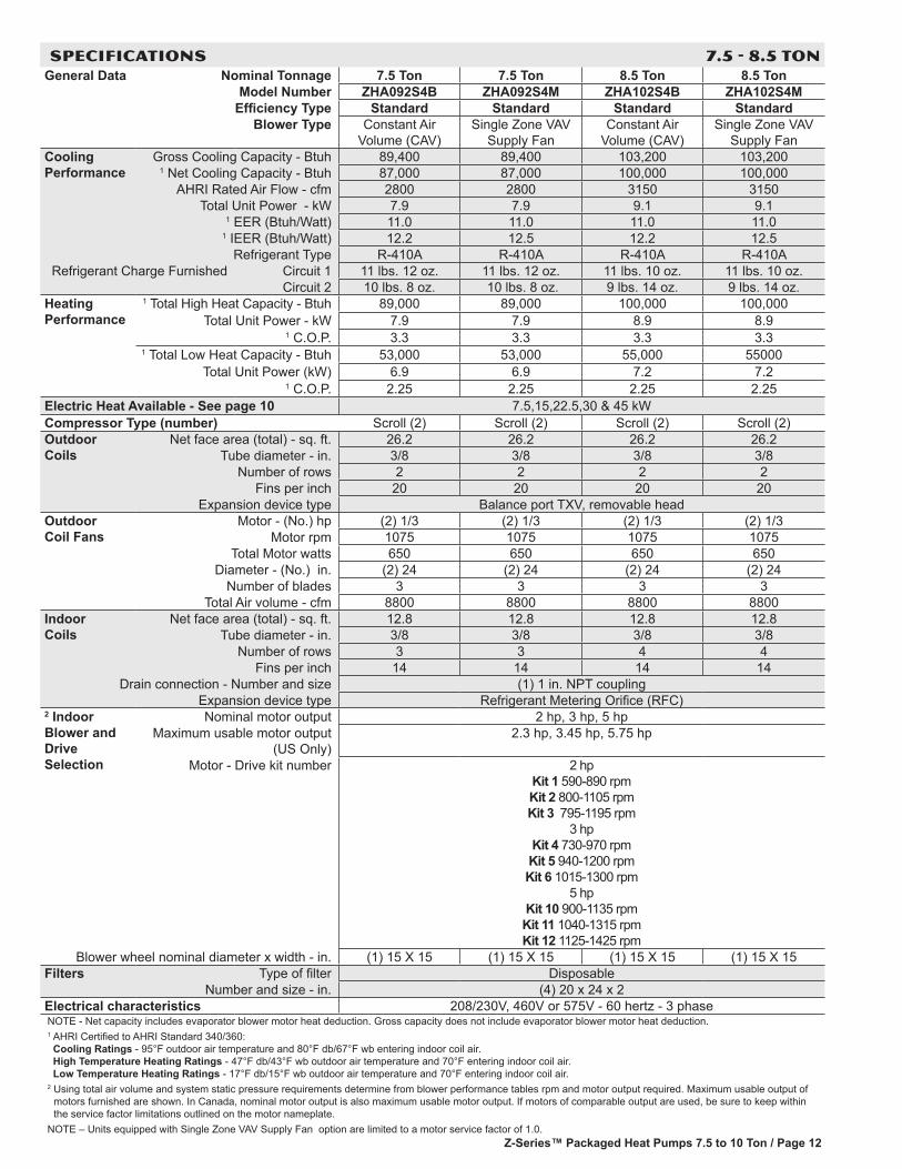
SPECIFICATIONS 7.5 - 8.5 TONGeneral Data Nominal Tonnage 7.5 Ton 7.5 Ton 8.5 Ton 8.5 Ton
Model Number ZHA092S4B ZHA092S4M ZHA102S4B ZHA102S4MEfficiency Type Standard Standard Standard Standard
Blower Type Constant Air Volume (CAV)
Single Zone VAV Supply Fan
Constant Air Volume (CAV)
Single Zone VAV Supply Fan
Cooling Performance
Gross Cooling Capacity - Btuh 89,400 89,400 103,200 103,2001 Net Cooling Capacity - Btuh 87,000 87,000 100,000 100,000
AHRI Rated Air Flow - cfm 2800 2800 3150 3150Total Unit Power - kW 7.9 7.9 9.1 9.1
1 EER (Btuh/Watt) 11.0 11.0 11.0 11.01 IEER (Btuh/Watt) 12.2 12.5 12.2 12.5
Refrigerant Type R-410A R-410A R-410A R-410ARefrigerant Charge Furnished Circuit 1 11 lbs. 12 oz. 11 lbs. 12 oz. 11 lbs. 10 oz. 11 lbs. 10 oz.
Circuit 2 10 lbs. 8 oz. 10 lbs. 8 oz. 9 lbs. 14 oz. 9 lbs. 14 oz.Heating Performance
1 Total High Heat Capacity - Btuh 89,000 89,000 100,000 100,000Total Unit Power - kW 7.9 7.9 8.9 8.9
1 C.O.P. 3.3 3.3 3.3 3.31 Total Low Heat Capacity - Btuh 53,000 53,000 55,000 55000
Total Unit Power (kW) 6.9 6.9 7.2 7.21 C.O.P. 2.25 2.25 2.25 2.25
Electric Heat Available - See page 10 7.5,15,22.5,30 & 45 kWCompressor Type (number) Scroll (2) Scroll (2) Scroll (2) Scroll (2)Outdoor Coils
Net face area (total) - sq. ft. 26.2 26.2 26.2 26.2Tube diameter - in. 3/8 3/8 3/8 3/8
Number of rows 2 2 2 2Fins per inch 20 20 20 20
Expansion device type Balance port TXV, removable headOutdoor Coil Fans
Motor - (No.) hp (2) 1/3 (2) 1/3 (2) 1/3 (2) 1/3Motor rpm 1075 1075 1075 1075
Total Motor watts 650 650 650 650Diameter - (No.) in. (2) 24 (2) 24 (2) 24 (2) 24
Number of blades 3 3 3 3Total Air volume - cfm 8800 8800 8800 8800
Indoor Coils
Net face area (total) - sq. ft. 12.8 12.8 12.8 12.8Tube diameter - in. 3/8 3/8 3/8 3/8
Number of rows 3 3 4 4Fins per inch 14 14 14 14
Drain connection - Number and size (1) 1 in. NPT couplingExpansion device type Refrigerant Metering Orifice (RFC)
2 Indoor Blower and Drive Selection
Nominal motor output 2 hp, 3 hp, 5 hpMaximum usable motor output
(US Only)2.3 hp, 3.45 hp, 5.75 hp
Motor - Drive kit number 2 hp Kit 1 590-890 rpm Kit 2 800-1105 rpm Kit 3 795-1195 rpm
3 hp Kit 4 730-970 rpm Kit 5 940-1200 rpm Kit 6 1015-1300 rpm
5 hp Kit 10 900-1135 rpm Kit 11 1040-1315 rpm Kit 12 1125-1425 rpm
Blower wheel nominal diameter x width - in. (1) 15 X 15 (1) 15 X 15 (1) 15 X 15 (1) 15 X 15Filters Type of filter Disposable
Number and size - in. (4) 20 x 24 x 2Electrical characteristics 208/230V, 460V or 575V - 60 hertz - 3 phaseNOTE - Net capacity includes evaporator blower motor heat deduction. Gross capacity does not include evaporator blower motor heat deduction.1 AHRI Certified to AHRI Standard 340/360: Cooling Ratings - 95°F outdoor air temperature and 80°F db/67°F wb entering indoor coil air. High Temperature Heating Ratings - 47°F db/43°F wb outdoor air temperature and 70°F entering indoor coil air. Low Temperature Heating Ratings - 17°F db/15°F wb outdoor air temperature and 70°F entering indoor coil air.
2 Using total air volume and system static pressure requirements determine from blower performance tables rpm and motor output required. Maximum usable output of motors furnished are shown. In Canada, nominal motor output is also maximum usable motor output. If motors of comparable output are used, be sure to keep within the service factor limitations outlined on the motor nameplate.
NOTE – Units equipped with Single Zone VAV Supply Fan option are limited to a motor service factor of 1.0.
Z-Series™ Packaged Heat Pumps 7.5 to 12.5 Ton / Page 13
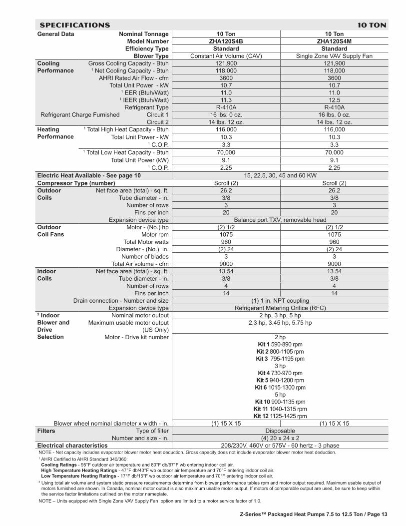
SPECIFICATIONS 10 TONGeneral Data Nominal Tonnage 10 Ton 10 Ton
Model Number ZHA120S4B ZHA120S4MEfficiency Type Standard Standard
Blower Type Constant Air Volume (CAV) Single Zone VAV Supply FanCooling Performance
Gross Cooling Capacity - Btuh 121,900 121,9001 Net Cooling Capacity - Btuh 118,000 118,000
AHRI Rated Air Flow - cfm 3600 3600Total Unit Power - kW 10.7 10.7
1 EER (Btuh/Watt) 11.0 11.01 IEER (Btuh/Watt) 11.3 12.5
Refrigerant Type R-410A R-410ARefrigerant Charge Furnished Circuit 1 16 lbs. 0 oz. 16 lbs. 0 oz.
Circuit 2 14 lbs. 12 oz. 14 lbs. 12 oz.Heating Performance
1 Total High Heat Capacity - Btuh 116,000 116,000Total Unit Power - kW 10.3 10.3
1 C.O.P. 3.3 3.31 Total Low Heat Capacity - Btuh 70,000 70,000
Total Unit Power (kW) 9.1 9.11 C.O.P. 2.25 2.25
Electric Heat Available - See page 10 15, 22.5, 30, 45 and 60 KWCompressor Type (number) Scroll (2) Scroll (2)Outdoor Coils
Net face area (total) - sq. ft. 26.2 26.2Tube diameter - in. 3/8 3/8
Number of rows 3 3Fins per inch 20 20
Expansion device type Balance port TXV, removable headOutdoor Coil Fans
Motor - (No.) hp (2) 1/2 (2) 1/2Motor rpm 1075 1075
Total Motor watts 960 960Diameter - (No.) in. (2) 24 (2) 24
Number of blades 3 3Total Air volume - cfm 9000 9000
Indoor Coils
Net face area (total) - sq. ft. 13.54 13.54Tube diameter - in. 3/8 3/8
Number of rows 4 4Fins per inch 14 14
Drain connection - Number and size (1) 1 in. NPT couplingExpansion device type Refrigerant Metering Orifice (RFC)
2 Indoor Blower and Drive Selection
Nominal motor output 2 hp, 3 hp, 5 hpMaximum usable motor output
(US Only)2.3 hp, 3.45 hp, 5.75 hp
Motor - Drive kit number 2 hp Kit 1 590-890 rpm Kit 2 800-1105 rpm Kit 3 795-1195 rpm
3 hp Kit 4 730-970 rpm Kit 5 940-1200 rpm Kit 6 1015-1300 rpm
5 hp Kit 10 900-1135 rpm Kit 11 1040-1315 rpm Kit 12 1125-1425 rpm
Blower wheel nominal diameter x width - in. (1) 15 X 15 (1) 15 X 15Filters Type of filter Disposable
Number and size - in. (4) 20 x 24 x 2Electrical characteristics 208/230V, 460V or 575V - 60 hertz - 3 phaseNOTE - Net capacity includes evaporator blower motor heat deduction. Gross capacity does not include evaporator blower motor heat deduction.1 AHRI Certified to AHRI Standard 340/360: Cooling Ratings - 95°F outdoor air temperature and 80°F db/67°F wb entering indoor coil air. High Temperature Heating Ratings - 47°F db/43°F wb outdoor air temperature and 70°F entering indoor coil air. Low Temperature Heating Ratings - 17°F db/15°F wb outdoor air temperature and 70°F entering indoor coil air.
2 Using total air volume and system static pressure requirements determine from blower performance tables rpm and motor output required. Maximum usable output of motors furnished are shown. In Canada, nominal motor output is also maximum usable motor output. If motors of comparable output are used, be sure to keep within the service factor limitations outlined on the motor nameplate.
NOTE – Units equipped with Single Zone VAV Supply Fan option are limited to a motor service factor of 1.0.
Z-Series™ Packaged Heat Pumps 7.5 to 10 Ton / Page 14
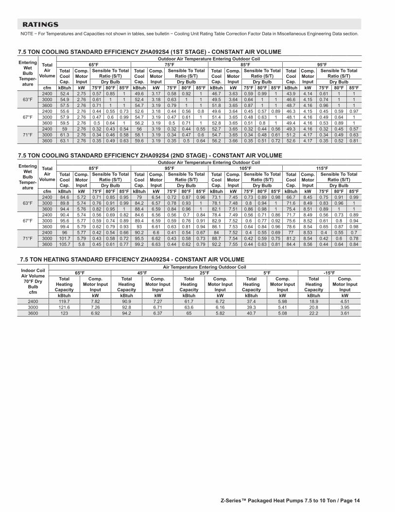
RATINGSNOTE − For Temperatures and Capacities not shown in tables, see bulletin − Cooling Unit Rating Table Correction Factor Data in Miscellaneous Engineering Data section.
7.5 TON COOLING STANDARD EFFICIENCY ZHA092S4 (1ST STAGE) - CONSTANT AIR VOLUME
Entering Wet Bulb
Temper-ature
Total Air
Volume
Outdoor Air Temperature Entering Outdoor Coil65°F 75°F 85°F 95°F
Total Cool Cap.
Comp. Motor Input
Sensible To Total Ratio (S/T)
Total Cool Cap.
Comp. Motor Input
Sensible To Total Ratio (S/T)
Total Cool Cap.
Comp. Motor Input
Sensible To Total Ratio (S/T)
Total Cool Cap.
Comp. Motor Input
Sensible To Total Ratio (S/T)
Dry Bulb Dry Bulb Dry Bulb Dry Bulbcfm kBtuh kW 75°F 80°F 85°F kBtuh kW 75°F 80°F 85°F kBtuh kW 75°F 80°F 85°F kBtuh kW 75°F 80°F 85°F
63°F2400 52.4 2.75 0.57 0.85 1 49.6 3.17 0.58 0.92 1 46.7 3.63 0.59 0.99 1 43.9 4.14 0.61 1 13000 54.9 2.76 0.61 1 1 52.4 3.18 0.63 1 1 49.5 3.64 0.64 1 1 46.6 4.15 0.74 1 13600 57.5 2.76 0.71 1 1 54.7 3.19 0.79 1 1 51.8 3.65 0.87 1 1 48.7 4.16 0.96 1 1
67°F2400 55.6 2.76 0.44 0.55 0.73 52.6 3.18 0.44 0.56 0.8 49.6 3.64 0.45 0.57 0.89 46.3 4.15 0.45 0.59 0.973000 57.9 2.76 0.47 0.6 0.99 54.7 3.19 0.47 0.61 1 51.4 3.65 0.48 0.63 1 48.1 4.16 0.49 0.64 13600 59.5 2.76 0.5 0.64 1 56.2 3.19 0.5 0.71 1 52.8 3.65 0.51 0.8 1 49.4 4.16 0.53 0.89 1
71°F2400 59 2.76 0.32 0.43 0.54 56 3.19 0.32 0.44 0.55 52.7 3.65 0.32 0.44 0.56 49.3 4.16 0.32 0.45 0.573000 61.3 2.76 0.34 0.46 0.58 58.1 3.19 0.34 0.47 0.6 54.7 3.65 0.34 0.48 0.61 51.2 4.17 0.34 0.49 0.633600 63.1 2.76 0.35 0.49 0.63 59.6 3.19 0.35 0.5 0.64 56.2 3.66 0.35 0.51 0.72 52.6 4.17 0.35 0.52 0.81
7.5 TON COOLING STANDARD EFFICIENCY ZHA092S4 (2ND STAGE) - CONSTANT AIR VOLUME
Entering Wet Bulb
Temper-ature
Total Air
Volume
Outdoor Air Temperature Entering Outdoor Coil85°F 95°F 105°F 115°F
Total Cool Cap.
Comp. Motor Input
Sensible To Total Ratio (S/T)
Total Cool Cap.
Comp. Motor Input
Sensible To Total Ratio (S/T)
Total Cool Cap.
Comp. Motor Input
Sensible To Total Ratio (S/T)
Total Cool Cap.
Comp. Motor Input
Sensible To Total Ratio (S/T)
Dry Bulb Dry Bulb Dry Bulb Dry Bulbcfm kBtuh kW 75°F 80°F 85°F kBtuh kW 75°F 80°F 85°F kBtuh kW 75°F 80°F 85°F kBtuh kW 75°F 80°F 85°F
63°F2400 84.6 5.72 0.71 0.85 0.95 79 6.54 0.72 0.87 0.96 73.1 7.45 0.73 0.89 0.98 66.7 8.45 0.75 0.91 0.993000 89.8 5.74 0.76 0.91 0.99 84.2 6.57 0.78 0.93 1 78.1 7.48 0.8 0.94 1 71.6 8.49 0.83 0.96 13600 94.4 5.76 0.82 0.95 1 88.4 6.59 0.84 0.96 1 82.1 7.51 0.86 0.98 1 75.4 8.51 0.89 1 1
67°F2400 90.4 5.74 0.56 0.69 0.82 84.6 6.56 0.56 0.7 0.84 78.4 7.49 0.56 0.71 0.86 71.7 8.49 0.56 0.73 0.893000 95.6 5.77 0.59 0.74 0.89 89.4 6.59 0.59 0.76 0.91 82.9 7.52 0.6 0.77 0.92 75.6 8.52 0.61 0.8 0.943600 99.4 5.79 0.62 0.79 0.93 93 6.61 0.63 0.81 0.94 86.1 7.53 0.64 0.84 0.96 78.6 8.54 0.65 0.87 0.98
71°F2400 96 5.77 0.42 0.54 0.66 90.2 6.6 0.41 0.54 0.67 84 7.52 0.4 0.55 0.69 77 8.53 0.4 0.55 0.73000 101.7 5.79 0.43 0.58 0.72 95.5 6.62 0.43 0.58 0.73 88.7 7.54 0.42 0.59 0.75 81.2 8.54 0.42 0.6 0.783600 105.7 5.8 0.45 0.61 0.77 99.2 6.63 0.44 0.62 0.79 92.2 7.55 0.44 0.63 0.81 84.4 8.56 0.44 0.64 0.84
7.5 TON HEATING STANDARD EFFICIENCY ZHA092S4 - CONSTANT AIR VOLUME
Indoor Coil Air Volume
70°F Dry Bulb cfm
Air Temperature Entering Outdoor Coil65°F 45°F 25°F 5°F -15°F
Total Heating Capacity
Comp. Motor Input
Input
Total Heating Capacity
Comp. Motor Input
Input
Total Heating Capacity
Comp. Motor Input
Input
Total Heating Capacity
Comp. Motor Input
Input
Total Heating Capacity
Comp. Motor Input
InputkBtuh kW kBtuh kW kBtuh kW kBtuh kW kBtuh kW
2400 119.7 7.82 90.9 7.27 61.7 6.72 37.4 5.98 18.9 4.513000 121.6 7.26 92.8 6.71 63.6 6.16 39.3 5.41 20.8 3.953600 123 6.92 94.2 6.37 65 5.82 40.7 5.08 22.2 3.61
Z-Series™ Packaged Heat Pumps 7.5 to 12.5 Ton / Page 15
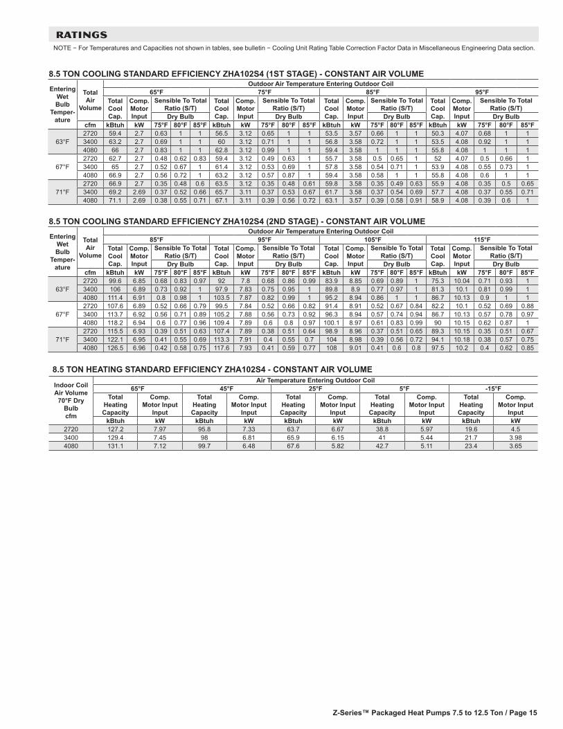
RATINGSNOTE − For Temperatures and Capacities not shown in tables, see bulletin − Cooling Unit Rating Table Correction Factor Data in Miscellaneous Engineering Data section.
8.5 TON COOLING STANDARD EFFICIENCY ZHA102S4 (1ST STAGE) - CONSTANT AIR VOLUME
Entering Wet Bulb
Temper-ature
Total Air
Volume
Outdoor Air Temperature Entering Outdoor Coil65°F 75°F 85°F 95°F
Total Cool Cap.
Comp. Motor Input
Sensible To Total Ratio (S/T)
Total Cool Cap.
Comp. Motor Input
Sensible To Total Ratio (S/T)
Total Cool Cap.
Comp. Motor Input
Sensible To Total Ratio (S/T)
Total Cool Cap.
Comp. Motor Input
Sensible To Total Ratio (S/T)
Dry Bulb Dry Bulb Dry Bulb Dry Bulbcfm kBtuh kW 75°F 80°F 85°F kBtuh kW 75°F 80°F 85°F kBtuh kW 75°F 80°F 85°F kBtuh kW 75°F 80°F 85°F
63°F2720 59.4 2.7 0.63 1 1 56.5 3.12 0.65 1 1 53.5 3.57 0.66 1 1 50.3 4.07 0.68 1 13400 63.2 2.7 0.69 1 1 60 3.12 0.71 1 1 56.8 3.58 0.72 1 1 53.5 4.08 0.92 1 14080 66 2.7 0.83 1 1 62.8 3.12 0.99 1 1 59.4 3.58 1 1 1 55.8 4.08 1 1 1
67°F2720 62.7 2.7 0.48 0.62 0.83 59.4 3.12 0.49 0.63 1 55.7 3.58 0.5 0.65 1 52 4.07 0.5 0.66 13400 65 2.7 0.52 0.67 1 61.4 3.12 0.53 0.69 1 57.8 3.58 0.54 0.71 1 53.9 4.08 0.55 0.73 14080 66.9 2.7 0.56 0.72 1 63.2 3.12 0.57 0.87 1 59.4 3.58 0.58 1 1 55.8 4.08 0.6 1 1
71°F2720 66.9 2.7 0.35 0.48 0.6 63.5 3.12 0.35 0.48 0.61 59.8 3.58 0.35 0.49 0.63 55.9 4.08 0.35 0.5 0.653400 69.2 2.69 0.37 0.52 0.66 65.7 3.11 0.37 0.53 0.67 61.7 3.58 0.37 0.54 0.69 57.7 4.08 0.37 0.55 0.714080 71.1 2.69 0.38 0.55 0.71 67.1 3.11 0.39 0.56 0.72 63.1 3.57 0.39 0.58 0.91 58.9 4.08 0.39 0.6 1
8.5 TON COOLING STANDARD EFFICIENCY ZHA102S4 (2ND STAGE) - CONSTANT AIR VOLUME
Entering Wet Bulb
Temper-ature
Total Air
Volume
Outdoor Air Temperature Entering Outdoor Coil85°F 95°F 105°F 115°F
Total Cool Cap.
Comp. Motor Input
Sensible To Total Ratio (S/T)
Total Cool Cap.
Comp. Motor Input
Sensible To Total Ratio (S/T)
Total Cool Cap.
Comp. Motor Input
Sensible To Total Ratio (S/T)
Total Cool Cap.
Comp. Motor Input
Sensible To Total Ratio (S/T)
Dry Bulb Dry Bulb Dry Bulb Dry Bulbcfm kBtuh kW 75°F 80°F 85°F kBtuh kW 75°F 80°F 85°F kBtuh kW 75°F 80°F 85°F kBtuh kW 75°F 80°F 85°F
63°F2720 99.6 6.85 0.68 0.83 0.97 92 7.8 0.68 0.86 0.99 83.9 8.85 0.69 0.89 1 75.3 10.04 0.71 0.93 13400 106 6.89 0.73 0.92 1 97.9 7.83 0.75 0.95 1 89.8 8.9 0.77 0.97 1 81.3 10.1 0.81 0.99 14080 111.4 6.91 0.8 0.98 1 103.5 7.87 0.82 0.99 1 95.2 8.94 0.86 1 1 86.7 10.13 0.9 1 1
67°F2720 107.6 6.89 0.52 0.66 0.79 99.5 7.84 0.52 0.66 0.82 91.4 8.91 0.52 0.67 0.84 82.2 10.1 0.52 0.69 0.883400 113.7 6.92 0.56 0.71 0.89 105.2 7.88 0.56 0.73 0.92 96.3 8.94 0.57 0.74 0.94 86.7 10.13 0.57 0.78 0.974080 118.2 6.94 0.6 0.77 0.96 109.4 7.89 0.6 0.8 0.97 100.1 8.97 0.61 0.83 0.99 90 10.15 0.62 0.87 1
71°F2720 115.5 6.93 0.39 0.51 0.63 107.4 7.89 0.38 0.51 0.64 98.9 8.96 0.37 0.51 0.65 89.3 10.15 0.35 0.51 0.673400 122.1 6.95 0.41 0.55 0.69 113.3 7.91 0.4 0.55 0.7 104 8.98 0.39 0.56 0.72 94.1 10.18 0.38 0.57 0.754080 126.5 6.96 0.42 0.58 0.75 117.6 7.93 0.41 0.59 0.77 108 9.01 0.41 0.6 0.8 97.5 10.2 0.4 0.62 0.85
8.5 TON HEATING STANDARD EFFICIENCY ZHA102S4 - CONSTANT AIR VOLUME
Indoor Coil Air Volume
70°F Dry Bulb cfm
Air Temperature Entering Outdoor Coil65°F 45°F 25°F 5°F -15°F
Total Heating Capacity
Comp. Motor Input
Input
Total Heating Capacity
Comp. Motor Input
Input
Total Heating Capacity
Comp. Motor Input
Input
Total Heating Capacity
Comp. Motor Input
Input
Total Heating Capacity
Comp. Motor Input
InputkBtuh kW kBtuh kW kBtuh kW kBtuh kW kBtuh kW
2720 127.2 7.97 95.8 7.33 63.7 6.67 38.8 5.97 19.6 4.53400 129.4 7.45 98 6.81 65.9 6.15 41 5.44 21.7 3.984080 131.1 7.12 99.7 6.48 67.6 5.82 42.7 5.11 23.4 3.65
Z-Series™ Packaged Heat Pumps 7.5 to 10 Ton / Page 16
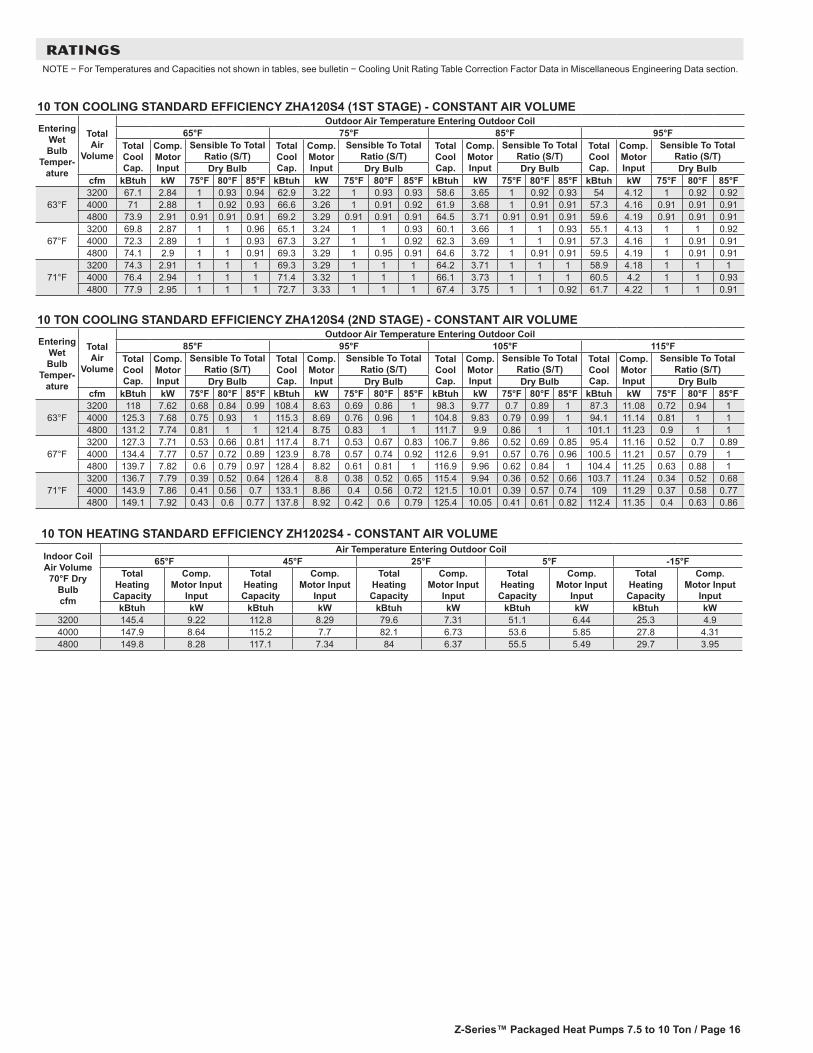
RATINGSNOTE − For Temperatures and Capacities not shown in tables, see bulletin − Cooling Unit Rating Table Correction Factor Data in Miscellaneous Engineering Data section.
10 TON COOLING STANDARD EFFICIENCY ZHA120S4 (1ST STAGE) - CONSTANT AIR VOLUME
Entering Wet Bulb
Temper-ature
Total Air
Volume
Outdoor Air Temperature Entering Outdoor Coil65°F 75°F 85°F 95°F
Total Cool Cap.
Comp. Motor Input
Sensible To Total Ratio (S/T)
Total Cool Cap.
Comp. Motor Input
Sensible To Total Ratio (S/T)
Total Cool Cap.
Comp. Motor Input
Sensible To Total Ratio (S/T)
Total Cool Cap.
Comp. Motor Input
Sensible To Total Ratio (S/T)
Dry Bulb Dry Bulb Dry Bulb Dry Bulbcfm kBtuh kW 75°F 80°F 85°F kBtuh kW 75°F 80°F 85°F kBtuh kW 75°F 80°F 85°F kBtuh kW 75°F 80°F 85°F
63°F3200 67.1 2.84 1 0.93 0.94 62.9 3.22 1 0.93 0.93 58.6 3.65 1 0.92 0.93 54 4.12 1 0.92 0.924000 71 2.88 1 0.92 0.93 66.6 3.26 1 0.91 0.92 61.9 3.68 1 0.91 0.91 57.3 4.16 0.91 0.91 0.914800 73.9 2.91 0.91 0.91 0.91 69.2 3.29 0.91 0.91 0.91 64.5 3.71 0.91 0.91 0.91 59.6 4.19 0.91 0.91 0.91
67°F3200 69.8 2.87 1 1 0.96 65.1 3.24 1 1 0.93 60.1 3.66 1 1 0.93 55.1 4.13 1 1 0.924000 72.3 2.89 1 1 0.93 67.3 3.27 1 1 0.92 62.3 3.69 1 1 0.91 57.3 4.16 1 0.91 0.914800 74.1 2.9 1 1 0.91 69.3 3.29 1 0.95 0.91 64.6 3.72 1 0.91 0.91 59.5 4.19 1 0.91 0.91
71°F3200 74.3 2.91 1 1 1 69.3 3.29 1 1 1 64.2 3.71 1 1 1 58.9 4.18 1 1 14000 76.4 2.94 1 1 1 71.4 3.32 1 1 1 66.1 3.73 1 1 1 60.5 4.2 1 1 0.934800 77.9 2.95 1 1 1 72.7 3.33 1 1 1 67.4 3.75 1 1 0.92 61.7 4.22 1 1 0.91
10 TON COOLING STANDARD EFFICIENCY ZHA120S4 (2ND STAGE) - CONSTANT AIR VOLUME
Entering Wet Bulb
Temper-ature
Total Air
Volume
Outdoor Air Temperature Entering Outdoor Coil85°F 95°F 105°F 115°F
Total Cool Cap.
Comp. Motor Input
Sensible To Total Ratio (S/T)
Total Cool Cap.
Comp. Motor Input
Sensible To Total Ratio (S/T)
Total Cool Cap.
Comp. Motor Input
Sensible To Total Ratio (S/T)
Total Cool Cap.
Comp. Motor Input
Sensible To Total Ratio (S/T)
Dry Bulb Dry Bulb Dry Bulb Dry Bulbcfm kBtuh kW 75°F 80°F 85°F kBtuh kW 75°F 80°F 85°F kBtuh kW 75°F 80°F 85°F kBtuh kW 75°F 80°F 85°F
63°F3200 118 7.62 0.68 0.84 0.99 108.4 8.63 0.69 0.86 1 98.3 9.77 0.7 0.89 1 87.3 11.08 0.72 0.94 14000 125.3 7.68 0.75 0.93 1 115.3 8.69 0.76 0.96 1 104.8 9.83 0.79 0.99 1 94.1 11.14 0.81 1 14800 131.2 7.74 0.81 1 1 121.4 8.75 0.83 1 1 111.7 9.9 0.86 1 1 101.1 11.23 0.9 1 1
67°F3200 127.3 7.71 0.53 0.66 0.81 117.4 8.71 0.53 0.67 0.83 106.7 9.86 0.52 0.69 0.85 95.4 11.16 0.52 0.7 0.894000 134.4 7.77 0.57 0.72 0.89 123.9 8.78 0.57 0.74 0.92 112.6 9.91 0.57 0.76 0.96 100.5 11.21 0.57 0.79 14800 139.7 7.82 0.6 0.79 0.97 128.4 8.82 0.61 0.81 1 116.9 9.96 0.62 0.84 1 104.4 11.25 0.63 0.88 1
71°F3200 136.7 7.79 0.39 0.52 0.64 126.4 8.8 0.38 0.52 0.65 115.4 9.94 0.36 0.52 0.66 103.7 11.24 0.34 0.52 0.684000 143.9 7.86 0.41 0.56 0.7 133.1 8.86 0.4 0.56 0.72 121.5 10.01 0.39 0.57 0.74 109 11.29 0.37 0.58 0.774800 149.1 7.92 0.43 0.6 0.77 137.8 8.92 0.42 0.6 0.79 125.4 10.05 0.41 0.61 0.82 112.4 11.35 0.4 0.63 0.86
10 TON HEATING STANDARD EFFICIENCY ZH1202S4 - CONSTANT AIR VOLUME
Indoor Coil Air Volume
70°F Dry Bulb cfm
Air Temperature Entering Outdoor Coil65°F 45°F 25°F 5°F -15°F
Total Heating Capacity
Comp. Motor Input
Input
Total Heating Capacity
Comp. Motor Input
Input
Total Heating Capacity
Comp. Motor Input
Input
Total Heating Capacity
Comp. Motor Input
Input
Total Heating Capacity
Comp. Motor Input
InputkBtuh kW kBtuh kW kBtuh kW kBtuh kW kBtuh kW
3200 145.4 9.22 112.8 8.29 79.6 7.31 51.1 6.44 25.3 4.94000 147.9 8.64 115.2 7.7 82.1 6.73 53.6 5.85 27.8 4.314800 149.8 8.28 117.1 7.34 84 6.37 55.5 5.49 29.7 3.95
Z-Series™ Packaged Heat Pumps 7.5 to 12.5 Ton / Page 17
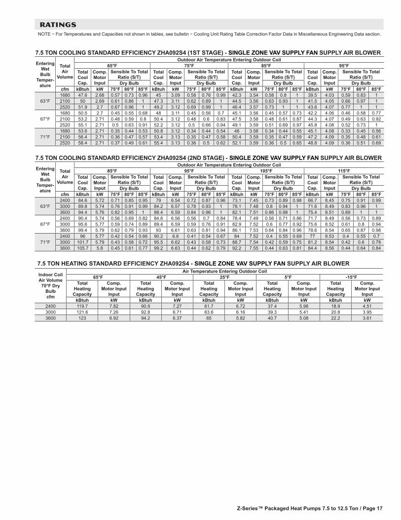
RATINGSNOTE − For Temperatures and Capacities not shown in tables, see bulletin − Cooling Unit Rating Table Correction Factor Data in Miscellaneous Engineering Data section.
7.5 TON COOLING STANDARD EFFICIENCY ZHA092S4 (1ST STAGE) - SINGLE ZONE VAV SUPPLY FAN SUPPLY AIR BLOWER
Entering Wet Bulb
Temper-ature
Total Air
Volume
Outdoor Air Temperature Entering Outdoor Coil65°F 75°F 85°F 95°F
Total Cool Cap.
Comp. Motor Input
Sensible To Total Ratio (S/T)
Total Cool Cap.
Comp. Motor Input
Sensible To Total Ratio (S/T)
Total Cool Cap.
Comp. Motor Input
Sensible To Total Ratio (S/T)
Total Cool Cap.
Comp. Motor Input
Sensible To Total Ratio (S/T)
Dry Bulb Dry Bulb Dry Bulb Dry Bulbcfm kBtuh kW 75°F 80°F 85°F kBtuh kW 75°F 80°F 85°F kBtuh kW 75°F 80°F 85°F kBtuh kW 75°F 80°F 85°F
63°F1680 47.6 2.68 0.57 0.73 0.96 45 3.09 0.58 0.76 0.99 42.3 3.54 0.58 0.8 1 39.5 4.03 0.59 0.83 12100 50 2.69 0.61 0.86 1 47.3 3.11 0.62 0.89 1 44.5 3.56 0.63 0.93 1 41.5 4.05 0.66 0.97 12520 51.9 2.7 0.67 0.96 1 49.2 3.12 0.69 0.99 1 46.4 3.57 0.73 1 1 43.6 4.07 0.77 1 1
67°F1680 50.5 2.7 0.45 0.55 0.68 48 3.11 0.45 0.56 0.7 45.1 3.56 0.45 0.57 0.73 42.2 4.06 0.46 0.58 0.772100 53.2 2.71 0.48 0.59 0.8 50.4 3.12 0.48 0.6 0.83 47.5 3.58 0.48 0.61 0.87 44.3 4.07 0.49 0.63 0.922520 55.1 2.71 0.5 0.63 0.91 52.2 3.12 0.5 0.66 0.94 49.1 3.59 0.51 0.69 0.97 45.8 4.08 0.52 0.73 1
71°F1680 53.6 2.71 0.35 0.44 0.53 50.8 3.12 0.34 0.44 0.54 48 3.58 0.34 0.44 0.55 45.1 4.08 0.33 0.45 0.562100 56.4 2.71 0.36 0.47 0.57 53.4 3.13 0.35 0.47 0.58 50.4 3.59 0.35 0.47 0.59 47.2 4.09 0.35 0.48 0.612520 58.4 2.71 0.37 0.49 0.61 55.4 3.13 0.36 0.5 0.62 52.1 3.59 0.36 0.5 0.65 48.8 4.09 0.36 0.51 0.69
7.5 TON COOLING STANDARD EFFICIENCY ZHA092S4 (2ND STAGE) - SINGLE ZONE VAV SUPPLY FAN SUPPLY AIR BLOWER
Entering Wet Bulb
Temper-ature
Total Air
Volume
Outdoor Air Temperature Entering Outdoor Coil85°F 95°F 105°F 115°F
Total Cool Cap.
Comp. Motor Input
Sensible To Total Ratio (S/T)
Total Cool Cap.
Comp. Motor Input
Sensible To Total Ratio (S/T)
Total Cool Cap.
Comp. Motor Input
Sensible To Total Ratio (S/T)
Total Cool Cap.
Comp. Motor Input
Sensible To Total Ratio (S/T)
Dry Bulb Dry Bulb Dry Bulb Dry Bulbcfm kBtuh kW 75°F 80°F 85°F kBtuh kW 75°F 80°F 85°F kBtuh kW 75°F 80°F 85°F kBtuh kW 75°F 80°F 85°F
63°F2400 84.6 5.72 0.71 0.85 0.95 79 6.54 0.72 0.87 0.96 73.1 7.45 0.73 0.89 0.98 66.7 8.45 0.75 0.91 0.993000 89.8 5.74 0.76 0.91 0.99 84.2 6.57 0.78 0.93 1 78.1 7.48 0.8 0.94 1 71.6 8.49 0.83 0.96 13600 94.4 5.76 0.82 0.95 1 88.4 6.59 0.84 0.96 1 82.1 7.51 0.86 0.98 1 75.4 8.51 0.89 1 1
67°F2400 90.4 5.74 0.56 0.69 0.82 84.6 6.56 0.56 0.7 0.84 78.4 7.49 0.56 0.71 0.86 71.7 8.49 0.56 0.73 0.893000 95.6 5.77 0.59 0.74 0.89 89.4 6.59 0.59 0.76 0.91 82.9 7.52 0.6 0.77 0.92 75.6 8.52 0.61 0.8 0.943600 99.4 5.79 0.62 0.79 0.93 93 6.61 0.63 0.81 0.94 86.1 7.53 0.64 0.84 0.96 78.6 8.54 0.65 0.87 0.98
71°F2400 96 5.77 0.42 0.54 0.66 90.2 6.6 0.41 0.54 0.67 84 7.52 0.4 0.55 0.69 77 8.53 0.4 0.55 0.73000 101.7 5.79 0.43 0.58 0.72 95.5 6.62 0.43 0.58 0.73 88.7 7.54 0.42 0.59 0.75 81.2 8.54 0.42 0.6 0.783600 105.7 5.8 0.45 0.61 0.77 99.2 6.63 0.44 0.62 0.79 92.2 7.55 0.44 0.63 0.81 84.4 8.56 0.44 0.64 0.84
7.5 TON HEATING STANDARD EFFICIENCY ZHA092S4 - SINGLE ZONE VAV SUPPLY FAN SUPPLY AIR BLOWER
Indoor Coil Air Volume
70°F Dry Bulb cfm
Air Temperature Entering Outdoor Coil65°F 45°F 25°F 5°F -15°F
Total Heating Capacity
Comp. Motor Input
Input
Total Heating Capacity
Comp. Motor Input
Input
Total Heating Capacity
Comp. Motor Input
Input
Total Heating Capacity
Comp. Motor Input
Input
Total Heating Capacity
Comp. Motor Input
InputkBtuh kW kBtuh kW kBtuh kW kBtuh kW kBtuh kW
2400 119.7 7.82 90.9 7.27 61.7 6.72 37.4 5.98 18.9 4.513000 121.6 7.26 92.8 6.71 63.6 6.16 39.3 5.41 20.8 3.953600 123 6.92 94.2 6.37 65 5.82 40.7 5.08 22.2 3.61
Z-Series™ Packaged Heat Pumps 7.5 to 10 Ton / Page 18
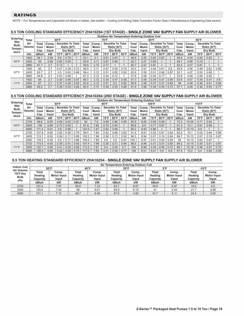
RATINGSNOTE − For Temperatures and Capacities not shown in tables, see bulletin − Cooling Unit Rating Table Correction Factor Data in Miscellaneous Engineering Data section.
8.5 TON COOLING STANDARD EFFICIENCY ZHA102S4 (1ST STAGE) - SINGLE ZONE VAV SUPPLY FAN SUPPLY AIR BLOWER
Entering Wet Bulb
Temper-ature
Total Air
Volume
Outdoor Air Temperature Entering Outdoor Coil65°F 75°F 85°F 95°F
Total Cool Cap.
Comp. Motor Input
Sensible To Total Ratio (S/T)
Total Cool Cap.
Comp. Motor Input
Sensible To Total Ratio (S/T)
Total Cool Cap.
Comp. Motor Input
Sensible To Total Ratio (S/T)
Total Cool Cap.
Comp. Motor Input
Sensible To Total Ratio (S/T)
Dry Bulb Dry Bulb Dry Bulb Dry Bulbcfm kBtuh kW 75°F 80°F 85°F kBtuh kW 75°F 80°F 85°F kBtuh kW 75°F 80°F 85°F kBtuh kW 75°F 80°F 85°F
63°F1920 56.1 2.69 0.6 0.79 1 53.1 3.1 0.61 0.83 1 49.9 3.55 0.62 0.87 1 46.6 4.04 0.64 0.93 12400 59 2.69 0.65 0.95 1 55.9 3.11 0.67 0.99 1 52.7 3.57 0.69 1 1 49.7 4.06 0.73 1 12880 61.7 2.7 0.73 1 1 58.8 3.12 0.77 1 1 55.7 3.57 0.81 1 1 52.4 4.07 0.87 1 1
67°F1920 60 2.7 0.47 0.59 0.72 56.9 3.11 0.47 0.59 0.75 53.5 3.57 0.48 0.61 0.8 49.9 4.06 0.48 0.62 0.852400 62.7 2.7 0.5 0.63 0.88 59.4 3.12 0.51 0.65 0.93 55.9 3.58 0.51 0.66 0.97 52.1 4.07 0.52 0.68 12880 64.8 2.7 0.53 0.69 1 61.3 3.12 0.54 0.72 1 57.6 3.58 0.55 0.77 1 53.8 4.08 0.56 0.82 1
71°F1920 64 2.7 0.35 0.46 0.57 60.7 3.12 0.35 0.47 0.58 57.3 3.58 0.35 0.47 0.59 53.6 4.07 0.34 0.47 0.62400 67 2.7 0.37 0.49 0.62 63.5 3.12 0.37 0.5 0.62 59.9 3.58 0.37 0.51 0.64 56 4.08 0.36 0.51 0.662880 69.2 2.7 0.38 0.53 0.66 65.5 3.12 0.38 0.53 0.68 61.6 3.58 0.38 0.54 0.72 57.7 4.08 0.38 0.55 0.77
8.5 TON COOLING STANDARD EFFICIENCY ZHA102S4 (2ND STAGE) - SINGLE ZONE VAV SUPPLY FAN SUPPLY AIR BLOWER
Entering Wet Bulb
Temper-ature
Total Air
Volume
Outdoor Air Temperature Entering Outdoor Coil85°F 95°F 105°F 115°F
Total Cool Cap.
Comp. Motor Input
Sensible To Total Ratio (S/T)
Total Cool Cap.
Comp. Motor Input
Sensible To Total Ratio (S/T)
Total Cool Cap.
Comp. Motor Input
Sensible To Total Ratio (S/T)
Total Cool Cap.
Comp. Motor Input
Sensible To Total Ratio (S/T)
Dry Bulb Dry Bulb Dry Bulb Dry Bulbcfm kBtuh kW 75°F 80°F 85°F kBtuh kW 75°F 80°F 85°F kBtuh kW 75°F 80°F 85°F kBtuh kW 75°F 80°F 85°F
63°F2720 99.6 6.85 0.68 0.83 0.97 92 7.8 0.68 0.86 0.99 83.9 8.85 0.69 0.89 1 75.3 10.04 0.71 0.93 13400 106 6.89 0.73 0.92 1 97.9 7.83 0.75 0.95 1 89.8 8.9 0.77 0.97 1 81.3 10.1 0.81 0.99 14080 111.4 6.91 0.8 0.98 1 103.5 7.87 0.82 0.99 1 95.2 8.94 0.86 1 1 86.7 10.13 0.9 1 1
67°F2720 107.6 6.89 0.52 0.66 0.79 99.5 7.84 0.52 0.66 0.82 91.4 8.91 0.52 0.67 0.84 82.2 10.1 0.52 0.69 0.883400 113.7 6.92 0.56 0.71 0.89 105.2 7.88 0.56 0.73 0.92 96.3 8.94 0.57 0.74 0.94 86.7 10.13 0.57 0.78 0.974080 118.2 6.94 0.6 0.77 0.96 109.4 7.89 0.6 0.8 0.97 100.1 8.97 0.61 0.83 0.99 90 10.15 0.62 0.87 1
71°F2720 115.5 6.93 0.39 0.51 0.63 107.4 7.89 0.38 0.51 0.64 98.9 8.96 0.37 0.51 0.65 89.3 10.15 0.35 0.51 0.673400 122.1 6.95 0.41 0.55 0.69 113.3 7.91 0.4 0.55 0.7 104 8.98 0.39 0.56 0.72 94.1 10.18 0.38 0.57 0.754080 126.5 6.96 0.42 0.58 0.75 117.6 7.93 0.41 0.59 0.77 108 9.01 0.41 0.6 0.8 97.5 10.2 0.4 0.62 0.85
8.5 TON HEATING STANDARD EFFICIENCY ZHA102S4 - SINGLE ZONE VAV SUPPLY FAN SUPPLY AIR BLOWER
Indoor Coil Air Volume
70°F Dry Bulb cfm
Air Temperature Entering Outdoor Coil65°F 45°F 25°F 5°F -15°F
Total Heating Capacity
Comp. Motor Input
Input
Total Heating Capacity
Comp. Motor Input
Input
Total Heating Capacity
Comp. Motor Input
Input
Total Heating Capacity
Comp. Motor Input
Input
Total Heating Capacity
Comp. Motor Input
InputkBtuh kW kBtuh kW kBtuh kW kBtuh kW kBtuh kW
2720 127.2 7.97 95.8 7.33 63.7 6.67 38.8 5.97 19.6 4.53400 129.4 7.45 98 6.81 65.9 6.15 41 5.44 21.7 3.984080 131.1 7.12 99.7 6.48 67.6 5.82 42.7 5.11 23.4 3.65

Z-Series™ Packaged Heat Pumps 7.5 to 12.5 Ton / Page 19
RATINGSNOTE − For Temperatures and Capacities not shown in tables, see bulletin − Cooling Unit Rating Table Correction Factor Data in Miscellaneous Engineering Data section.
10 TON COOLING STANDARD EFFICIENCY ZHA120S4 (1ST STAGE) - SINGLE ZONE VAV SUPPLY FAN SUPPLY AIR BLOWER
Entering Wet Bulb
Temper-ature
Total Air
Volume
Outdoor Air Temperature Entering Outdoor Coil65°F 75°F 85°F 95°F
Total Cool Cap.
Comp. Motor Input
Sensible To Total Ratio (S/T)
Total Cool Cap.
Comp. Motor Input
Sensible To Total Ratio (S/T)
Total Cool Cap.
Comp. Motor Input
Sensible To Total Ratio (S/T)
Total Cool Cap.
Comp. Motor Input
Sensible To Total Ratio (S/T)
Dry Bulb Dry Bulb Dry Bulb Dry Bulbcfm kBtuh kW 75°F 80°F 85°F kBtuh kW 75°F 80°F 85°F kBtuh kW 75°F 80°F 85°F kBtuh kW 75°F 80°F 85°F
63°F2240 61.6 2.77 0.62 0.82 1 57.3 3.14 0.62 0.87 1 52.9 3.56 0.64 0.94 1 48.4 4.03 0.65 1 12800 64.8 2.8 0.67 1 1 60.8 3.18 0.68 1 1 56.5 3.6 0.7 1 1 52.2 4.07 0.75 1 13360 68.2 2.83 0.75 1 1 63.9 3.21 0.8 1 1 59.5 3.63 0.87 1 1 54.9 4.1 0.95 1 1
67°F2240 65.8 2.81 0.48 0.6 0.74 61.3 3.19 0.48 0.61 0.8 56.7 3.6 0.48 0.62 0.86 51.8 4.07 0.48 0.63 0.942800 68.4 2.83 0.51 0.65 0.96 63.8 3.21 0.52 0.67 1 58.9 3.63 0.52 0.69 1 53.9 4.09 0.53 0.71 13360 70.4 2.86 0.55 0.71 1 65.7 3.23 0.55 0.76 1 60.8 3.65 0.56 0.82 1 55.6 4.11 0.57 0.91 1
71°F2240 70.1 2.85 0.36 0.47 0.58 65.5 3.23 0.35 0.47 0.59 60.8 3.65 0.34 0.47 0.6 55.7 4.11 0.33 0.48 0.622800 72.9 2.88 0.37 0.51 0.64 68.2 3.26 0.37 0.51 0.65 63.2 3.68 0.36 0.52 0.67 57.9 4.14 0.35 0.53 0.693360 74.8 2.9 0.39 0.54 0.69 70 3.28 0.38 0.55 0.71 64.8 3.69 0.38 0.56 0.78 59.5 4.16 0.37 0.57 0.86
10 TON COOLING STANDARD EFFICIENCY ZHA120S4 (2ND STAGE) - SINGLE ZONE VAV SUPPLY FAN SUPPLY AIR BLOWER
Entering Wet Bulb
Temper-ature
Total Air
Volume
Outdoor Air Temperature Entering Outdoor Coil85°F 95°F 105°F 115°F
Total Cool Cap.
Comp. Motor Input
Sensible To Total Ratio (S/T)
Total Cool Cap.
Comp. Motor Input
Sensible To Total Ratio (S/T)
Total Cool Cap.
Comp. Motor Input
Sensible To Total Ratio (S/T)
Total Cool Cap.
Comp. Motor Input
Sensible To Total Ratio (S/T)
Dry Bulb Dry Bulb Dry Bulb Dry Bulbcfm kBtuh kW 75°F 80°F 85°F kBtuh kW 75°F 80°F 85°F kBtuh kW 75°F 80°F 85°F kBtuh kW 75°F 80°F 85°F
63°F3200 118 7.62 0.68 0.84 0.99 108.4 8.63 0.69 0.86 1 98.3 9.77 0.7 0.89 1 87.3 11.08 0.72 0.94 14000 125.3 7.68 0.75 0.93 1 115.3 8.69 0.76 0.96 1 104.8 9.83 0.79 0.99 1 94.1 11.14 0.81 1 14800 131.2 7.74 0.81 1 1 121.4 8.75 0.83 1 1 111.7 9.9 0.86 1 1 101.1 11.23 0.9 1 1
67°F3200 127.3 7.71 0.53 0.66 0.81 117.4 8.71 0.53 0.67 0.83 106.7 9.86 0.52 0.69 0.85 95.4 11.16 0.52 0.7 0.894000 134.4 7.77 0.57 0.72 0.89 123.9 8.78 0.57 0.74 0.92 112.6 9.91 0.57 0.76 0.96 100.5 11.21 0.57 0.79 14800 139.7 7.82 0.6 0.79 0.97 128.4 8.82 0.61 0.81 1 116.9 9.96 0.62 0.84 1 104.4 11.25 0.63 0.88 1
71°F3200 136.7 7.79 0.39 0.52 0.64 126.4 8.8 0.38 0.52 0.65 115.4 9.94 0.36 0.52 0.66 103.7 11.24 0.34 0.52 0.684000 143.9 7.86 0.41 0.56 0.7 133.1 8.86 0.4 0.56 0.72 121.5 10.01 0.39 0.57 0.74 109 11.29 0.37 0.58 0.774800 149.1 7.92 0.43 0.6 0.77 137.8 8.92 0.42 0.6 0.79 125.4 10.05 0.41 0.61 0.82 112.4 11.35 0.4 0.63 0.86
10 TON HEATING STANDARD EFFICIENCY ZHA120S4 - SINGLE ZONE VAV SUPPLY FAN SUPPLY AIR BLOWER
Indoor Coil Air Volume
70°F Dry Bulb cfm
Air Temperature Entering Outdoor Coil65°F 45°F 25°F 5°F -15°F
Total Heating Capacity
Comp. Motor Input
Input
Total Heating Capacity
Comp. Motor Input
Input
Total Heating Capacity
Comp. Motor Input
Input
Total Heating Capacity
Comp. Motor Input
Input
Total Heating Capacity
Comp. Motor Input
InputkBtuh kW kBtuh kW kBtuh kW kBtuh kW kBtuh kW
3200 145.4 9.22 112.8 8.29 79.6 7.31 51.1 6.44 25.3 4.94000 147.9 8.64 115.2 7.7 82.1 6.73 53.6 5.85 27.8 4.314800 149.8 8.28 117.1 7.34 84 6.37 55.5 5.49 29.7 3.95

Z-Series™ Packaged Heat Pumps 7.5 to 10 Ton / Page 20
BLOWER DATA
092S STANDARD EFFICIENCY BELT DRIVE BLOWER − BASE UNITBLOWER TABLE INCLUDES RESISTANCE FOR BASE UNIT ONLY (NO HEAT SECTION) WITH DRY INDOOR COIL AND AIR FILTERS IN PLACE. FOR ALL UNITS ADD:1 − Wet indoor coil air resistance of selected unit.2 − Any factory installed options air resistance (heat section, economizer, etc.)3 − Any field installed accessories air resistance (duct resistance, diffuser, etc.)Then determine from blower table blower motor output required.See page 22 for blower motors and drives.See page 22 for wet coil and option/accessory air resistance data.MINIMUM AIR VOLUME REQUIRED FOR USE WITH OPTIONAL ELECTRIC HEAT (Maximum Static Pressure - 2.0 in. w.g.):7.5 kW, 15 kW, 22.5 kW - 2065 cfm30 kW - 2250 cfm45 kW - 3000 cfm
Total Air
Volume cfm
Total Static Pressure − in. w.g.
0.2 0.4 0.6 0.8 1.0 1.2 1.4 1.6 1.8 2.0 2.2 2.4 2.6
RPM BHP RPM BHP RPM BHP RPM BHP RPM BHP RPM BHP RPM BHP RPM BHP RPM BHP RPM BHP RPM BHP RPM BHP RPM BHP
1750 494 0.11 562 0.34 632 0.56 702 0.74 771 0.85 838 0.96 902 1.07 961 1.19 - - - - - - - - - - - - - - - - - - - - - - - - - - - - - -
2000 514 0.26 581 0.49 650 0.70 719 0.87 786 0.98 852 1.09 915 1.20 972 1.32 1026 1.47 1076 1.65 - - - - - - - - - - - - - - - - - -
2250 533 0.41 599 0.62 667 0.82 735 0.99 802 1.10 866 1.21 928 1.33 984 1.46 1037 1.63 1085 1.81 1132 2.01 1178 2.21 1226 2.43
2500 553 0.55 619 0.76 685 0.95 753 1.10 818 1.22 881 1.34 942 1.47 997 1.62 1048 1.80 1096 1.99 1142 2.20 1188 2.41 1237 2.64
2750 573 0.70 638 0.90 705 1.08 771 1.22 835 1.35 897 1.49 957 1.63 1011 1.80 1061 1.99 1108 2.19 1154 2.41 1200 2.63 1249 2.87
3000 594 0.85 659 1.05 725 1.22 791 1.36 853 1.50 915 1.65 973 1.81 1026 1.99 1075 2.20 1121 2.42 1167 2.64 1213 2.87 1262 3.12
3250 617 1.01 682 1.20 747 1.37 812 1.52 873 1.67 934 1.83 990 2.01 1042 2.21 1089 2.43 1135 2.66 1181 2.90 1228 3.13 1277 3.38
3500 640 1.17 706 1.36 771 1.53 834 1.70 895 1.86 954 2.03 1008 2.23 1058 2.46 1105 2.69 1150 2.93 1196 3.17 1243 3.41 1293 3.65
3750 665 1.34 731 1.54 796 1.72 857 1.89 917 2.07 975 2.26 1027 2.48 1076 2.72 1121 2.97 1166 3.22 1212 3.46 1261 3.71 1311 3.96
4000 692 1.54 758 1.75 822 1.93 882 2.11 940 2.30 996 2.51 1047 2.76 1094 3.02 1139 3.27 1184 3.52 1230 3.77 1280 4.03 1330 4.29
4250 722 1.76 787 1.97 849 2.15 908 2.35 965 2.56 1018 2.79 1067 3.06 1113 3.33 1157 3.59 1202 3.85 1250 4.11 1300 4.38 1352 4.65
Z-Series™ Packaged Heat Pumps 7.5 to 12.5 Ton / Page 21
BLOWER DATA
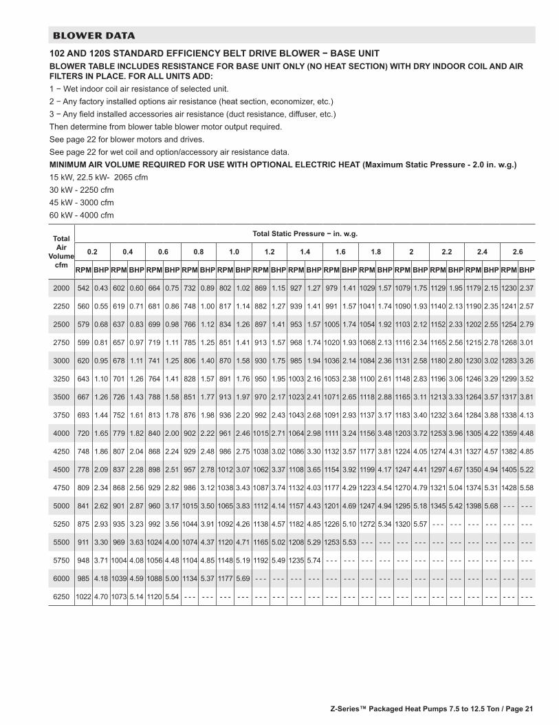
102 AND 120S STANDARD EFFICIENCY BELT DRIVE BLOWER − BASE UNITBLOWER TABLE INCLUDES RESISTANCE FOR BASE UNIT ONLY (NO HEAT SECTION) WITH DRY INDOOR COIL AND AIR FILTERS IN PLACE. FOR ALL UNITS ADD:1 − Wet indoor coil air resistance of selected unit.2 − Any factory installed options air resistance (heat section, economizer, etc.)3 − Any field installed accessories air resistance (duct resistance, diffuser, etc.)Then determine from blower table blower motor output required.See page 22 for blower motors and drives.See page 22 for wet coil and option/accessory air resistance data.MINIMUM AIR VOLUME REQUIRED FOR USE WITH OPTIONAL ELECTRIC HEAT (Maximum Static Pressure - 2.0 in. w.g.)15 kW, 22.5 kW- 2065 cfm30 kW - 2250 cfm45 kW - 3000 cfm60 kW - 4000 cfm
Total Air
Volume cfm
Total Static Pressure − in. w.g.
0.2 0.4 0.6 0.8 1.0 1.2 1.4 1.6 1.8 2 2.2 2.4 2.6
RPM BHP RPM BHP RPM BHP RPM BHP RPM BHP RPM BHP RPM BHP RPM BHP RPM BHP RPM BHP RPM BHP RPM BHP RPM BHP
2000 542 0.43 602 0.60 664 0.75 732 0.89 802 1.02 869 1.15 927 1.27 979 1.41 1029 1.57 1079 1.75 1129 1.95 1179 2.15 1230 2.37
2250 560 0.55 619 0.71 681 0.86 748 1.00 817 1.14 882 1.27 939 1.41 991 1.57 1041 1.74 1090 1.93 1140 2.13 1190 2.35 1241 2.57
2500 579 0.68 637 0.83 699 0.98 766 1.12 834 1.26 897 1.41 953 1.57 1005 1.74 1054 1.92 1103 2.12 1152 2.33 1202 2.55 1254 2.79
2750 599 0.81 657 0.97 719 1.11 785 1.25 851 1.41 913 1.57 968 1.74 1020 1.93 1068 2.13 1116 2.34 1165 2.56 1215 2.78 1268 3.01
3000 620 0.95 678 1.11 741 1.25 806 1.40 870 1.58 930 1.75 985 1.94 1036 2.14 1084 2.36 1131 2.58 1180 2.80 1230 3.02 1283 3.26
3250 643 1.10 701 1.26 764 1.41 828 1.57 891 1.76 950 1.95 1003 2.16 1053 2.38 1100 2.61 1148 2.83 1196 3.06 1246 3.29 1299 3.52
3500 667 1.26 726 1.43 788 1.58 851 1.77 913 1.97 970 2.17 1023 2.41 1071 2.65 1118 2.88 1165 3.11 1213 3.33 1264 3.57 1317 3.81
3750 693 1.44 752 1.61 813 1.78 876 1.98 936 2.20 992 2.43 1043 2.68 1091 2.93 1137 3.17 1183 3.40 1232 3.64 1284 3.88 1338 4.13
4000 720 1.65 779 1.82 840 2.00 902 2.22 961 2.46 1015 2.71 1064 2.98 1111 3.24 1156 3.48 1203 3.72 1253 3.96 1305 4.22 1359 4.48
4250 748 1.86 807 2.04 868 2.24 929 2.48 986 2.75 1038 3.02 1086 3.30 1132 3.57 1177 3.81 1224 4.05 1274 4.31 1327 4.57 1382 4.85
4500 778 2.09 837 2.28 898 2.51 957 2.78 1012 3.07 1062 3.37 1108 3.65 1154 3.92 1199 4.17 1247 4.41 1297 4.67 1350 4.94 1405 5.22
4750 809 2.34 868 2.56 929 2.82 986 3.12 1038 3.43 1087 3.74 1132 4.03 1177 4.29 1223 4.54 1270 4.79 1321 5.04 1374 5.31 1428 5.58
5000 841 2.62 901 2.87 960 3.17 1015 3.50 1065 3.83 1112 4.14 1157 4.43 1201 4.69 1247 4.94 1295 5.18 1345 5.42 1398 5.68 - - - - - -
5250 875 2.93 935 3.23 992 3.56 1044 3.91 1092 4.26 1138 4.57 1182 4.85 1226 5.10 1272 5.34 1320 5.57 - - - - - - - - - - - - - - - - - -
5500 911 3.30 969 3.63 1024 4.00 1074 4.37 1120 4.71 1165 5.02 1208 5.29 1253 5.53 - - - - - - - - - - - - - - - - - - - - - - - - - - - - - -
5750 948 3.71 1004 4.08 1056 4.48 1104 4.85 1148 5.19 1192 5.49 1235 5.74 - - - - - - - - - - - - - - - - - - - - - - - - - - - - - - - - - - - -
6000 985 4.18 1039 4.59 1088 5.00 1134 5.37 1177 5.69 - - - - - - - - - - - - - - - - - - - - - - - - - - - - - - - - - - - - - - - - - - - - - - - -
6250 1022 4.70 1073 5.14 1120 5.54 - - - - - - - - - - - - - - - - - - - - - - - - - - - - - - - - - - - - - - - - - - - - - - - - - - - - - - - - - - - -
Z-Series™ Packaged Heat Pumps 7.5 to 10 Ton / Page 22
BLOWER DATA
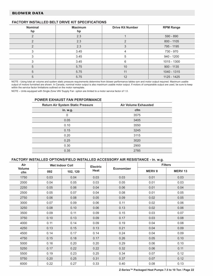
FACTORY INSTALLED BELT DRIVE KIT SPECIFICATIONSNominal
hpMaximum
hpDrive Kit Number RPM Range
2 2.3 1 590 - 8902 2.3 2 800 - 11052 2.3 3 795 - 11953 3.45 4 730 - 9703 3.45 5 940 - 12003 3.45 6 1015 - 13005 5.75 10 900 - 11355 5.75 11 1040 - 13155 5.75 12 1125 - 1425
NOTE - Using total air volume and system static pressure requirements determine from blower performance tables rpm and motor output required. Maximum usable output of motors furnished are shown. In Canada, nominal motor output is also maximum usable motor output. If motors of comparable output are used, be sure to keep within the service factor limitations outlined on the motor nameplate.NOTE – Units equipped with Single Zone VAV Supply Fan option are limited to a motor service factor of 1.0.
POWER EXHAUST FAN PERFORMANCE Return Air System Static Pressure Air Volume Exhausted
in. w.g. cfm 0 3575
0.05 34050.10 35500.15 32450.20 31150.25 30200.30 29000.35 2785
FACTORY INSTALLED OPTIONS/FIELD INSTALLED ACCESSORY AIR RESISTANCE - in. w.g.Air
Volume cfm
Wet Indoor Coil Electric Heat Economizer
Filters
MERV 8 MERV 13092 102, 120
1750 0.03 0.04 0.03 0.03 0.01 0.032000 0.04 0.05 0.03 0.05 0.01 0.032250 0.05 0.06 0.04 0.06 0.01 0.042500 0.05 0.07 0.04 0.08 0.01 0.052750 0.06 0.08 0.05 0.09 0.02 0.053000 0.07 0.09 0.06 0.11 0.02 0.063250 0.08 0.10 0.06 0.13 0.02 0.063500 0.09 0.11 0.09 0.15 0.03 0.073750 0.10 0.13 0.09 0.17 0.03 0.084000 0.11 0.14 0.09 0.19 0.04 0.084250 0.13 0.15 0.13 0.21 0.04 0.094500 0.14 0.17 0.14 0.24 0.04 0.094750 0.15 0.18 0.17 0.26 0.05 0.105000 0.16 0.20 0.20 0.29 0.06 0.105250 0.17 0.22 0.22 0.32 0.06 0.115500 0.19 0.23 0.25 0.34 0.07 0.125750 0.20 0.25 0.31 0.37 0.07 0.126000 0.22 0.27 0.33 0.40 0.08 0.13

Z-Series™ Packaged Heat Pumps 7.5 to 12.5 Ton / Page 23
BLOWER DATA
CEILING DIFFUSERS AIR RESISTANCE - in. w.g.RTD11 Step-Down Diffuser
FD11 Flush DiffuserUnit Size Air Volume
cfm 2 Ends Open 1 Side, 2 Ends Open
All Ends & Sides Open
092 Models
2400 0.21 0.18 0.15 0.142600 0.24 0.21 0.18 0.172800 0.27 0.24 0.21 0.203000 0.32 0.29 0.25 0.253200 0.41 0.37 0.32 0.313400 0.50 0.45 0.39 0.373600 0.61 0.54 0.48 0.443800 0.73 0.63 0.57 0.51
102 & 120 Models
3600 0.36 0.28 0.23 0.153800 0.40 0.32 0.26 0.184000 0.44 0.36 0.29 0.214200 0.49 0.40 0.33 0.244400 0.54 0.44 0.37 0.274600 0.60 0.49 0.42 0.314800 0.65 0.53 0.46 0.355000 0.69 0.58 0.50 0.395200 0.75 0.62 0.54 0.43
CEILING DIFFUSER AIR THROW DATA
Model No.Air Volume
1 Effective Throw RangeRTD11 Step-Down FD11 Flush
cfm ft. ft.
092 Models
2600 24 - 29 19 - 242800 25 - 30 20 - 283000 27 - 33 21 - 293200 28 - 35 22 - 293400 30 - 37 22 - 30
102, 120 Models
3600 25 - 33 22 - 293800 27 - 35 22 - 304000 29- 37 24 - 334200 32 - 40 26 - 354400 34 - 42 28 - 37
1 Throw is the horizontal or vertical distance an air stream travels on leaving the outlet or diffuser before the maximum velocity is reduced to 50 ft. per minute. Four sides open.
Z-Series™ Packaged Heat Pumps 7.5 to 10 Ton / Page 24
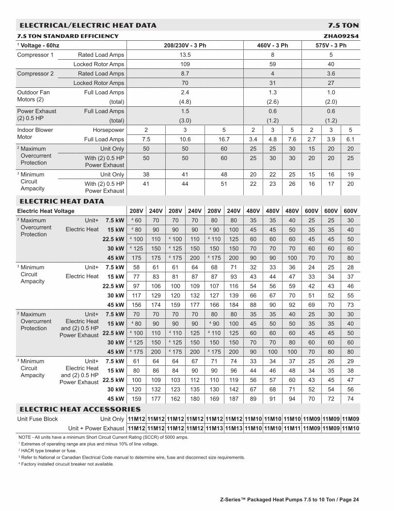
ELECTRICAL/ELECTRIC HEAT DATA 7.5 TON
7.5 TON STANDARD EFFICIENCY ZHa092S41 Voltage - 60hz 208/230V - 3 Ph 460V - 3 Ph 575V - 3 PhCompressor 1 Rated Load Amps 13.5 8 5
Locked Rotor Amps 109 59 40Compressor 2 Rated Load Amps 8.7 4 3.6
Locked Rotor Amps 70 31 27Outdoor Fan Motors (2)
Full Load Amps 2.4 1.3 1.0(total) (4.8) (2.6) (2.0)
Power Exhaust (2) 0.5 HP
Full Load Amps 1.5 0.6 0.6(total) (3.0) (1.2) (1.2)
Indoor Blower Motor
Horsepower 2 3 5 2 3 5 2 3 5Full Load Amps 7.5 10.6 16.7 3.4 4.8 7.6 2.7 3.9 6.1
2 Maximum Overcurrent Protection
Unit Only 50 50 60 25 25 30 15 20 20With (2) 0.5 HP Power Exhaust
50 50 60 25 30 30 20 20 25
3 Minimum Circuit Ampacity
Unit Only 38 41 48 20 22 25 15 16 19With (2) 0.5 HP Power Exhaust
41 44 51 22 23 26 16 17 20
ELECTRIC HEAT DATAElectric Heat Voltage 208V 240V 208V 240V 208V 240V 480V 480V 480V 600V 600V 600V2 Maximum
Overcurrent Protection
Unit+Electric Heat
7.5 kW 4 60 70 70 70 80 80 35 35 40 25 25 3015 kW 4 80 90 90 90 4 90 100 45 45 50 35 35 40
22.5 kW 4 100 110 4 100 110 4 110 125 60 60 60 45 45 5030 kW 4 125 150 4 125 150 150 150 70 70 70 60 60 6045 kW 175 175 4 175 200 4 175 200 90 90 100 70 70 80
3 Minimum Circuit Ampacity
Unit+Electric Heat
7.5 kW 58 61 61 64 68 71 32 33 36 24 25 2815 kW 77 83 81 87 87 93 43 44 47 33 34 37
22.5 kW 97 106 100 109 107 116 54 56 59 42 43 4630 kW 117 129 120 132 127 139 66 67 70 51 52 5545 kW 156 174 159 177 166 184 88 90 92 69 70 73
2 Maximum Overcurrent Protection
Unit+ Electric Heat
and (2) 0.5 HP Power Exhaust
7.5 kW 70 70 70 70 80 80 35 35 40 25 30 3015 kW 4 80 90 90 90 4 90 100 45 50 50 35 35 40
22.5 kW 4 100 110 4 110 125 4 110 125 60 60 60 45 45 5030 kW 4 125 150 4 125 150 150 150 70 70 80 60 60 6045 kW 4 175 200 4 175 200 4 175 200 90 100 100 70 80 80
3 Minimum Circuit Ampacity
Unit+ Electric Heat
and (2) 0.5 HP Power Exhaust
7.5 kW 61 64 64 67 71 74 33 34 37 25 26 2915 kW 80 86 84 90 90 96 44 46 48 34 35 38
22.5 kW 100 109 103 112 110 119 56 57 60 43 45 4730 kW 120 132 123 135 130 142 67 68 71 52 54 5645 kW 159 177 162 180 169 187 89 91 94 70 72 74
ELECTRIC HEAT ACCESSORIESUnit Fuse Block Unit Only 11M12 11M12 11M12 11M12 11M12 11M12 11M10 11M10 11M10 11M09 11M09 11M09
Unit + Power Exhaust 11M12 11M12 11M12 11M12 11M13 11M13 11M10 11M10 11M11 11M09 11M09 11M10NOTE - All units have a minimum Short Circuit Current Rating (SCCR) of 5000 amps.1 Extremes of operating range are plus and minus 10% of line voltage.2 HACR type breaker or fuse.3 Refer to National or Canadian Electrical Code manual to determine wire, fuse and disconnect size requirements.4 Factory installed cirucuit breaker not available.
Z-Series™ Packaged Heat Pumps 7.5 to 12.5 Ton / Page 25
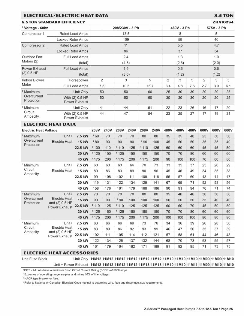
ELECTRICAL/ELECTRIC HEAT DATA 8.5 TON
8.5 TON STANDARD EFFICIENCY ZHa102S41 Voltage - 60hz 208/230V - 3 Ph 460V - 3 Ph 575V - 3 PhCompressor 1 Rated Load Amps 13.5 8 5
Locked Rotor Amps 109 59 40Compressor 2 Rated Load Amps 11 5.5 4.7
Locked Rotor Amps 86 37 34Outdoor Fan Motors (2)
Full Load Amps 2.4 1.3 1.0(total) (4.8) (2.6) (2.0)
Power Exhaust (2) 0.5 HP
Full Load Amps 1.5 0.6 0.6(total) (3.0) (1.2) (1.2)
Indoor Blower Motor
Horsepower 2 3 5 2 3 5 2 3 5Full Load Amps 7.5 10.5 16.7 3.4 4.8 7.6 2.7 3.9 6.1
2 Maximum Overcurrent Protection
Unit Only 50 50 60 25 30 30 20 20 25With (2) 0.5 HP Power Exhaust
50 50 60 30 30 30 20 20 25
3 Minimum Circuit Ampacity
Unit Only 41 44 51 22 23 26 16 17 20With (2) 0.5 HP Power Exhaust
44 47 54 23 25 27 17 19 21
ELECTRIC HEAT DATAElectric Heat Voltage 208V 240V 208V 240V 208V 240V 480V 480V 480V 600V 600V 600V2 Maximum
Overcurrent Protection
Unit+Electric Heat
7.5 kW 4 60 70 70 70 80 80 35 35 40 25 30 3015 kW 4 80 90 90 90 4 90 100 45 50 50 35 35 40
22.5 kW 4 100 110 4 110 125 4 110 125 60 60 60 45 45 5030 kW 4 125 150 4 125 150 150 150 70 70 80 60 60 6045 kW 4 175 200 4 175 200 4 175 200 90 100 100 70 80 80
3 Minimum Circuit Ampacity
Unit+Electric Heat
7.5 kW 60 63 63 66 70 73 33 35 37 25 26 2915 kW 80 86 83 89 90 96 45 46 49 34 35 38
22.5 kW 99 108 102 111 109 118 56 57 60 43 44 4730 kW 119 131 122 134 129 141 67 69 71 52 53 5645 kW 158 176 161 179 168 186 90 91 94 70 71 74
2 Maximum Overcurrent Protection
Unit+ Electric Heat
and (2) 0.5 HP Power Exhaust
7.5 kW 70 70 70 70 80 80 35 40 40 30 30 3015 kW 90 90 4 90 100 100 100 50 50 50 35 40 40
22.5 kW 4 110 125 4 110 125 125 125 60 60 70 45 50 5030 kW 4 125 150 4 125 150 150 150 70 70 80 60 60 6045 kW 4 175 200 4 175 200 4 175 200 100 100 100 80 80 80
3 Minimum Circuit Ampacity
Unit+ Electric Heat
and (2) 0.5 HP Power Exhaust
7.5 kW 63 66 66 69 73 76 34 36 39 26 28 3015 kW 83 89 86 92 93 99 46 47 50 35 37 39
22.5 kW 102 111 105 114 112 121 57 58 61 44 46 4830 kW 122 134 125 137 132 144 68 70 73 53 55 5745 kW 161 179 164 182 171 189 91 92 95 71 73 75
ELECTRIC HEAT ACCESSORIESUnit Fuse Block Unit Only 11M12 11M12 11M12 11M12 11M12 11M12 11M10 11M10 11M10 11M09 11M09 11M10
Unit + Power Exhaust 11M12 11M12 11M12 11M12 11M13 11M13 11M10 11M10 11M11 11M09 11M10 11M10NOTE - All units have a minimum Short Circuit Current Rating (SCCR) of 5000 amps.1 Extremes of operating range are plus and minus 10% of line voltage.2 HACR type breaker or fuse.3 Refer to National or Canadian Electrical Code manual to determine wire, fuse and disconnect size requirements.

Z-Series™ Packaged Heat Pumps 7.5 to 10 Ton / Page 26
ELECTRICAL/ELECTRIC HEAT DATA 10 TON
10 TON STANDARD EFFICIENCY ZHa120S41 Voltage - 60hz 208/230V - 3 Ph 460V - 3 Ph 575V - 3 PhCompressor 1 Rated Load Amps 15.6 7.8 5.8
Locked Rotor Amps 110 52 38.9Compressor 2 Rated Load Amps 15.6 7.8 5.8
Locked Rotor Amps 110 52 38.9Outdoor Fan Motors (2)
Full Load Amps 3.0 1.5 1.2(total) (6.0) (3.0) (2.4)
Power Exhaust (2) 0.5 HP
Full Load Amps 1.5 0.6 0.6(total) (3.0) (1.2) (1.2)
Indoor Blower Motor
Horsepower 2 3 5 2 3 5 2 3 5Full Load Amps 7.5 10.6 16.7 3.4 4.8 7.6 2.7 3.9 6.1
2 Maximum Overcurrent Protection
Unit Only 60 60 70 30 30 35 20 25 25With (2) 0.5 HP Power Exhaust
60 70 70 30 30 35 25 25 25
3 Minimum Circuit Ampacity
Unit Only 49 52 59 24 26 29 19 20 22With (2) 0.5 HP Power Exhaust
52 55 62 26 27 30 20 21 23
ELECTRIC HEAT DATAElectric Heat Voltage 208V 240V 208V 240V 208V 240V 480V 480V 480V 600V 600V 600V2 Maximum
Overcurrent Protection
Unit+Electric Heat
15 kW 4 90 100 100 100 4 100 110 50 50 60 40 40 4022.5 kW 4 110 125 125 125 4 125 150 60 60 70 50 50 50
30 kW 150 150 150 150 150 150 70 80 80 60 60 6045 kW 4 175 200 4 175 200 200 200 100 100 100 80 80 8060 kW 4 175 200 200 200 4 200 225 100 100 110 80 80 80
3 Minimum Circuit Ampacity
Unit+Electric Heat
15 kW 88 94 91 97 98 104 47 48 51 37 38 4022.5 kW 108 117 111 120 117 126 58 60 62 46 47 49
30 kW 127 139 130 142 137 149 70 71 74 55 56 5845 kW 166 184 169 188 176 194 92 94 96 73 74 7660 kW 174 193 177 197 184 203 97 98 101 76 78 80
2 Maximum Overcurrent Protection
Unit+ Electric Heat
and (2) 0.5 HP Power Exhaust
15 kW 100 100 100 100 110 110 50 50 60 40 40 4522.5 kW 125 125 125 125 4 125 150 60 70 70 50 50 50
30 kW 150 150 150 150 4 150 175 80 80 80 60 60 6045 kW 4 175 200 4 175 200 200 200 100 100 100 80 80 8060 kW 200 200 200 200 4 200 225 100 100 110 80 80 90
3 Minimum Circuit Ampacity
Unit+ Electric Heat
and (2) 0.5 HP Power Exhaust
15 kW 91 97 94 100 101 107 48 50 52 38 39 4122.5 kW 111 120 114 123 120 129 59 61 64 47 48 50
30 kW 130 142 133 145 140 152 71 72 75 56 57 5945 kW 169 187 172 191 179 197 93 95 98 74 75 7760 kW 177 196 180 200 187 206 98 99 102 78 79 81
ELECTRIC HEAT ACCESSORIESUnit Fuse Block Unit Only 11M12 11M12 11M12 11M12 11M12 11M12 11M10 11M10 11M11 11M09 11M09 11M10
Unit + Power Exhaust 11M12 11M12 11M12 11M12 11M13 11M13 11M11 11M11 11M11 11M09 11M10 11M10NOTE - All units have a minimum Short Circuit Current Rating (SCCR) of 5000 amps.1 Extremes of operating range are plus and minus 10% of line voltage.2 HACR type breaker or fuse.3 Refer to National or Canadian Electrical Code manual to determine wire, fuse and disconnect size requirements.
Z-Series™ Packaged Heat Pumps 7.5 to 12.5 Ton / Page 27
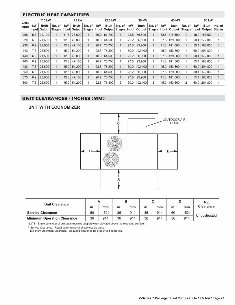
1 Unit ClearanceA B C D Top
Clearancein. mm in. mm in. mm in. mmService Clearance 60 1524 36 914 36 914 60 1524
UnobstructedMinimum Operation Clearance 36 914 36 914 36 914 36 914NOTE - Entire perimeter of unit base requires support when elevated above the mounting surface.1 Service Clearance - Required for removal of serviceable parts. Minimum Operation Clearance - Required clearance for proper unit operation.
UNIT CLEARANCES - INCHES (MM)
ELECTRIC HEAT CAPACITIES
Volts Input
7.5 kW 15 kW 22.5 kW 30 kW 45 kW 60 kWkW
Input Btuh
Output No. of Stages
kW Input
Btuh Output
No. of Stages
kW Input
Btuh Output
No. of Stages
kW Input
Btuh Output
No. of Stages
kW Input
Btuh Output
No. of Stages
kW Input
Btuh Output
No. of Stages
208 5.6 19,100 1 11.3 38,600 1 16.9 57,700 1 22.5 76,800 1 33.8 115,300 1 45.0 153,600 1
220 6.3 21,500 1 12.6 43,000 1 18.9 64,500 1 25.2 86,000 1 37.8 129,000 1 50.4 172,000 1
230 6.9 23,600 1 13.8 47,100 1 20.7 70,700 1 27.5 93,900 1 41.3 141,000 1 55.1 188,000 1
240 7.5 25,600 1 15.0 51,200 1 22.5 76,800 1 30.0 102,400 1 45.0 153,600 1 60.0 204,800 1
440 6.9 21,500 1 12.6 43,000 1 18.9 64,500 1 25.2 86,000 1 37.8 129,000 1 50.4 172,000 1
460 6.9 23,600 1 13.8 47,100 1 20.7 70,700 1 27.5 93,900 1 41.3 141,000 1 55.1 188,000 1
480 7.5 25,600 1 15.0 51,200 1 22.5 76,800 1 30.0 102,400 1 45.0 153,600 1 60.0 204,800 1
550 6.3 21,500 1 12.6 43,000 1 18.9 64,500 1 25.2 86,000 1 37.8 129,000 1 50.4 172,000 1
575 6.9 23,600 1 13.8 47,100 1 20.7 70,700 1 27.5 93,900 1 41.3 141,000 1 55.1 188,000 1
600 7.5 25,600 1 15.0 51,200 1 22.5 76,800 2 30.0 102,400 2 45.0 153,600 2 60.0 204,800 1
BD
C
A
OUTDOOR AIRHOOD
UNIT WITH ECONOMIZER
Z-Series™ Packaged Heat Pumps 7.5 to 10 Ton / Page 28
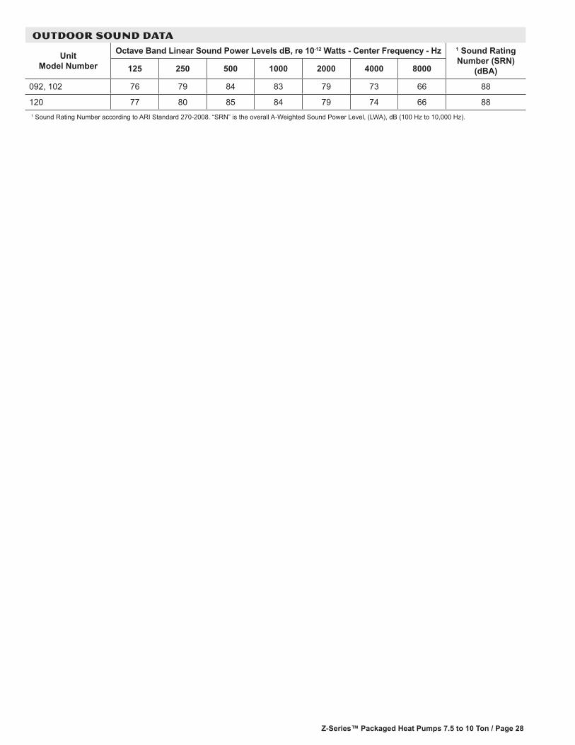
OUTDOOR SOUND DATA
Unit Model Number
Octave Band Linear Sound Power Levels dB, re 10-12 Watts - Center Frequency - Hz 1 Sound Rating Number (SRN)
(dBA)125 250 500 1000 2000 4000 8000
092, 102 76 79 84 83 79 73 66 88
120 77 80 85 84 79 74 66 881 Sound Rating Number according to ARI Standard 270-2008. “SRN” is the overall A-Weighted Sound Power Level, (LWA), dB (100 Hz to 10,000 Hz).
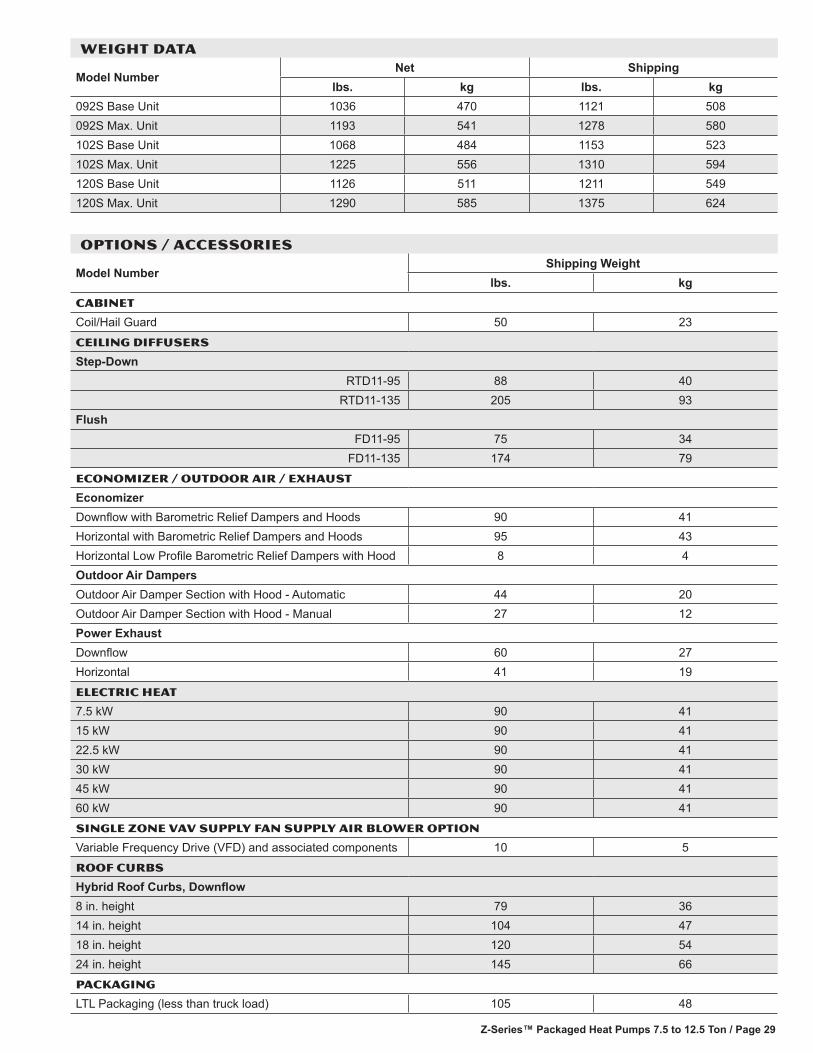
Z-Series™ Packaged Heat Pumps 7.5 to 12.5 Ton / Page 29
OPTIONS / ACCESSORIES
Model NumberShipping Weight
lbs. kgCABINET
Coil/Hail Guard 50 23
CEILING DIFFUSERS
Step-DownRTD11-95 88 40
RTD11-135 205 93Flush
FD11-95 75 34FD11-135 174 79
ECONOMIZER / OUTDOOR AIR / EXHAUST
EconomizerDownflow with Barometric Relief Dampers and Hoods 90 41Horizontal with Barometric Relief Dampers and Hoods 95 43Horizontal Low Profile Barometric Relief Dampers with Hood 8 4Outdoor Air DampersOutdoor Air Damper Section with Hood - Automatic 44 20Outdoor Air Damper Section with Hood - Manual 27 12Power ExhaustDownflow 60 27Horizontal 41 19
ELECTRIC HEAT
7.5 kW 90 4115 kW 90 4122.5 kW 90 4130 kW 90 4145 kW 90 4160 kW 90 41
Single Zone VAV Supply Fan SUPPLY AIR BLOWER OPTION
Variable Frequency Drive (VFD) and associated components 10 5
ROOF CURBS
Hybrid Roof Curbs, Downflow8 in. height 79 3614 in. height 104 4718 in. height 120 5424 in. height 145 66
PACKAGING
LTL Packaging (less than truck load) 105 48
WEIGHT DATA
Model NumberNet Shipping
lbs. kg lbs. kg092S Base Unit 1036 470 1121 508092S Max. Unit 1193 541 1278 580102S Base Unit 1068 484 1153 523102S Max. Unit 1225 556 1310 594120S Base Unit 1126 511 1211 549120S Max. Unit 1290 585 1375 624
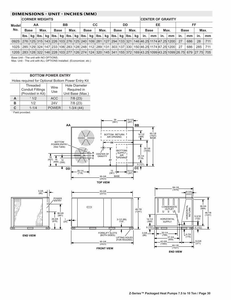
Z-Series™ Packaged Heat Pumps 7.5 to 10 Ton / Page 30
DIMENSIONS - UNIT - INCHES (MM)
Model No.
CORNER WEIGHTS CENTER OF GRAVITYAA BB CC DD EE FF
Base Max. Base Max. Base Max. Base Max. Base Max. Base Max.lbs. kg lbs. kg lbs. kg lbs. kg lbs. kg lbs. kg lbs. kg lbs. kg in. mm in. mm in. mm in. mm
092S 276 125 315 143 226 103 276 125 240 109 281 127 294 133 321 146 46.25 1174 47.25 1200 27 686 28 711102S 285 129 324 147 233 106 283 128 248 112 289 131 303 137 330 150 46.25 1174 47.25 1200 27 686 285 711120S 283 128 322 146 228 103 277 126 274 124 320 145 341 155 372 169 43.25 1099 43.25 1099 26.75 679 27.75 705Base Unit - The unit with NO OPTIONS. Max. Unit - The unit with ALL OPTIONS Installed. (Economizer, etc.)
END VIEWFRONT VIEW
LIFTING HOLES(FOR RIGGING)
POWERENTRY
1(25)
FORKLIFT SLOTS(BOTH SIDES)
HO
RIZ
ON
TAL
RE
TUR
N
HORIZONTALSUPPLY
CENTER OFGRAVITY
TOP VIEW
BOTTOM RETURNAIR OPENING
AA
DD
EE
FF
BB
CC
BOTTOMSUPPLY
AIROPENING
BASE
BOTTOMPOWER ENTRY
(See Table)
5 (127)
28-1/4(718)
58-1/8(1476)
6 (152)
BA
C18(457) 14
(356)16
(406)
39(991)
28-1/4(718)
39-3/8(1000)
14-1/2(368)
60-1/8(1527)BASE
95-3/8(2423)
10-1/2(267)
15(381)
10-1/2(267)
93-3/8(2372)
48-7/8(1241)
3-1/2 (89)TYP.
95-3/8(2423)
26-5/8(676)
38-5/8(981)
3-3/8(86)
3-3/8(86)
30-1/4(768)
37-3/4(959)
42-5/8(1083)
14-5/8(371)
14-1/2(368)
6 (152)
38-3/4(984)
5-3/16(132)
48-7/8(1241)
6-7/8(175)
60-1/8(1527)
8-3/4(222)
CONDENSATEOUTLET
END VIEW
BOTTOM POWER ENTRYHoles required for Optional Bottom Power Entry Kit
Threaded Conduit Fittings (Provided in Kit)
Wire Use
Hole Diameter Required in
Unit Base (Max.)A 1 1/2 ACC 7/8 (23)B 1/2 24V 7/8 (23)C 1-1/4 POWER 1-3/4 (44)
1 Field provided.

Z-Series™ Packaged Heat Pumps 7.5 to 12.5 Ton / Page 31
DIMENSIONS - ACCESSORIES - INCHES (MM)
31(787)
OUTDOOR AIR HOOD DETAIL FOR OPTIONAL DOWNFLOW ECONOMIZER(Downflow Applications)
OUTDOOR AIR DAMPER HOOD DETAIL FOR OPTIONAL MANUAL OR MOTORIZED OUTDOOR AIR DAMPERS(Downflow or Horizontal Applications)
OUTDOOR AIRDAMPER HOOD
OPTIONALOUTDOOR
AIR DAMPERSAND PANEL
END VIEW
16-1/2(419)
OPTIONAL OUTDOORAIR HOOD
(Furnished with Economizer)
END VIEW
18-1/4(464)
3/4(19)
25(635)
42-1/2(1080)
22(559)
13-1/2(343)
25(635)
OUTDOOR AIRDAMPER HOOD
(Furnished) 16-1/2(419)
26(660)
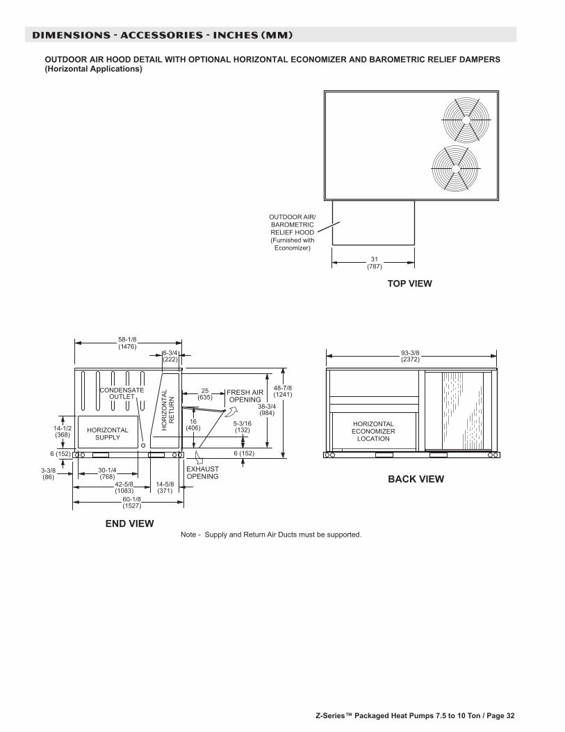
Z-Series™ Packaged Heat Pumps 7.5 to 10 Ton / Page 32
DIMENSIONS - ACCESSORIES - INCHES (MM)
BACK VIEW
TOP VIEW
OUTDOOR AIR HOOD DETAIL WITH OPTIONAL HORIZONTAL ECONOMIZER AND BAROMETRIC RELIEF DAMPERS(Horizontal Applications)
31(787)
END VIEW
EXHAUSTOPENING
Note - Supply and Return Air Ducts must be supported.
HORIZONTALECONOMIZER
LOCATION
93-3/8(2372)
25(635)
16(406)
6 (152)
3-3/8(86)
14-1/2(368)
30-1/4(768)
HO
RIZ
ON
TAL
RE
TUR
N
HORIZONTALSUPPLY
58-1/8(1476)
8-3/4(222)
42-5/8(1083)
14-5/8(371)
60-1/8(1527)
6 (152)
5-3/16(132)
38-3/4(984)
48-7/8(1241)CONDENSATE
OUTLET FRESH AIROPENING
OUTDOOR AIR/BAROMETRICRELIEF HOOD(Furnished with
Economizer)
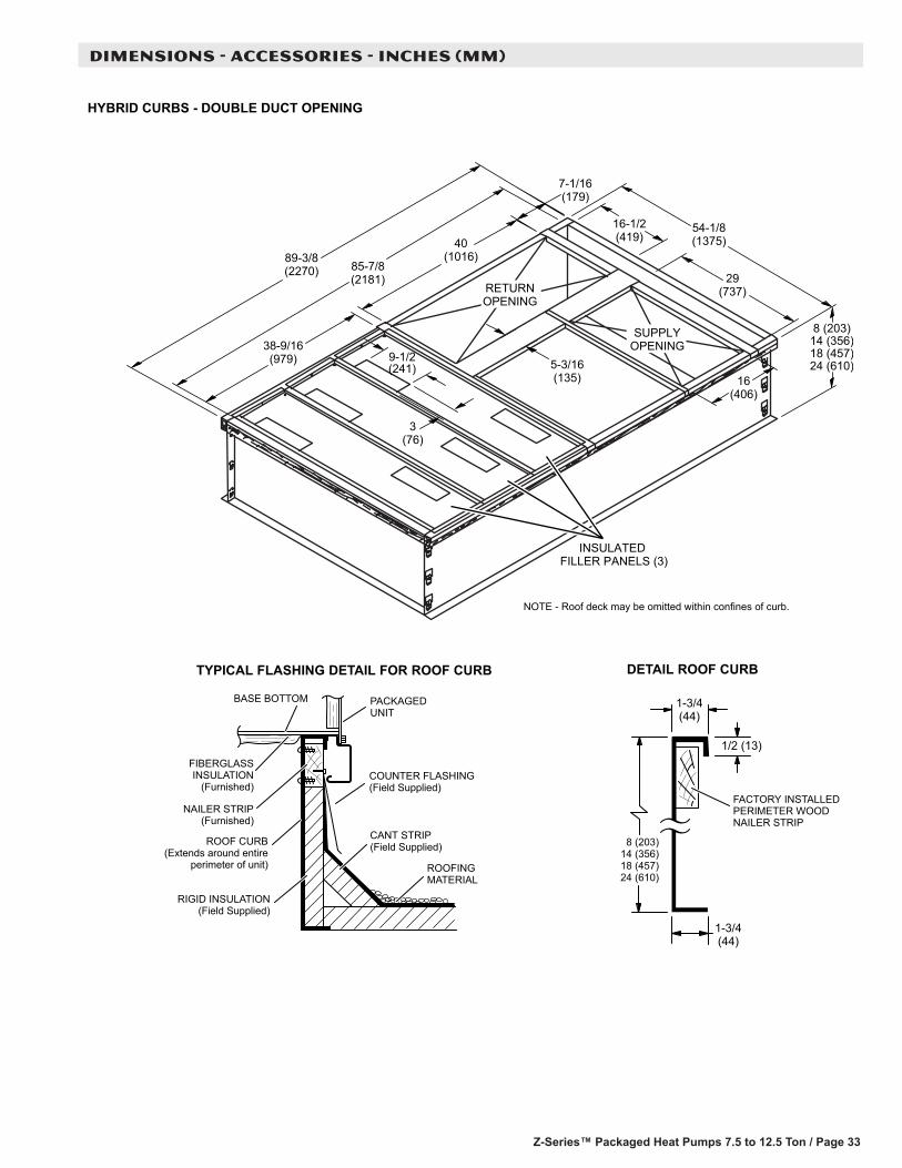
Z-Series™ Packaged Heat Pumps 7.5 to 12.5 Ton / Page 33
DIMENSIONS - ACCESSORIES - INCHES (MM)
RETURNOPENING
NOTE - Roof deck may be omitted within confines of curb.
INSULATED FILLER PANELS (3)
SUPPLYOPENING
TYPICAL FLASHING DETAIL FOR ROOF CURB
ROOF CURB(Extends around entire
perimeter of unit)
FIBERGLASSINSULATION
(Furnished)COUNTER FLASHING(Field Supplied)
BASE BOTTOM
RIGID INSULATION(Field Supplied)
ROOFINGMATERIAL
CANT STRIP(Field Supplied)
PACKAGEDUNIT
NAILER STRIP(Furnished)
DETAIL ROOF CURB
FACTORY INSTALLEDPERIMETER WOODNAILER STRIP
HYBRID CURBS - DOUBLE DUCT OPENING
8 (203)14 (356)18 (457)24 (610)
89-3/8(2270) 85-7/8
(2181)
40(1016)
38-9/16(979)
7-1/16(179)
9-1/2(241)
3(76)
5-3/16(135)
16-1/2(419)
54-1/8(1375)
29(737)
16(406)
1-3/4(44)
1/2 (13)
1-3/4(44)
8 (203)14 (356)18 (457)24 (610)
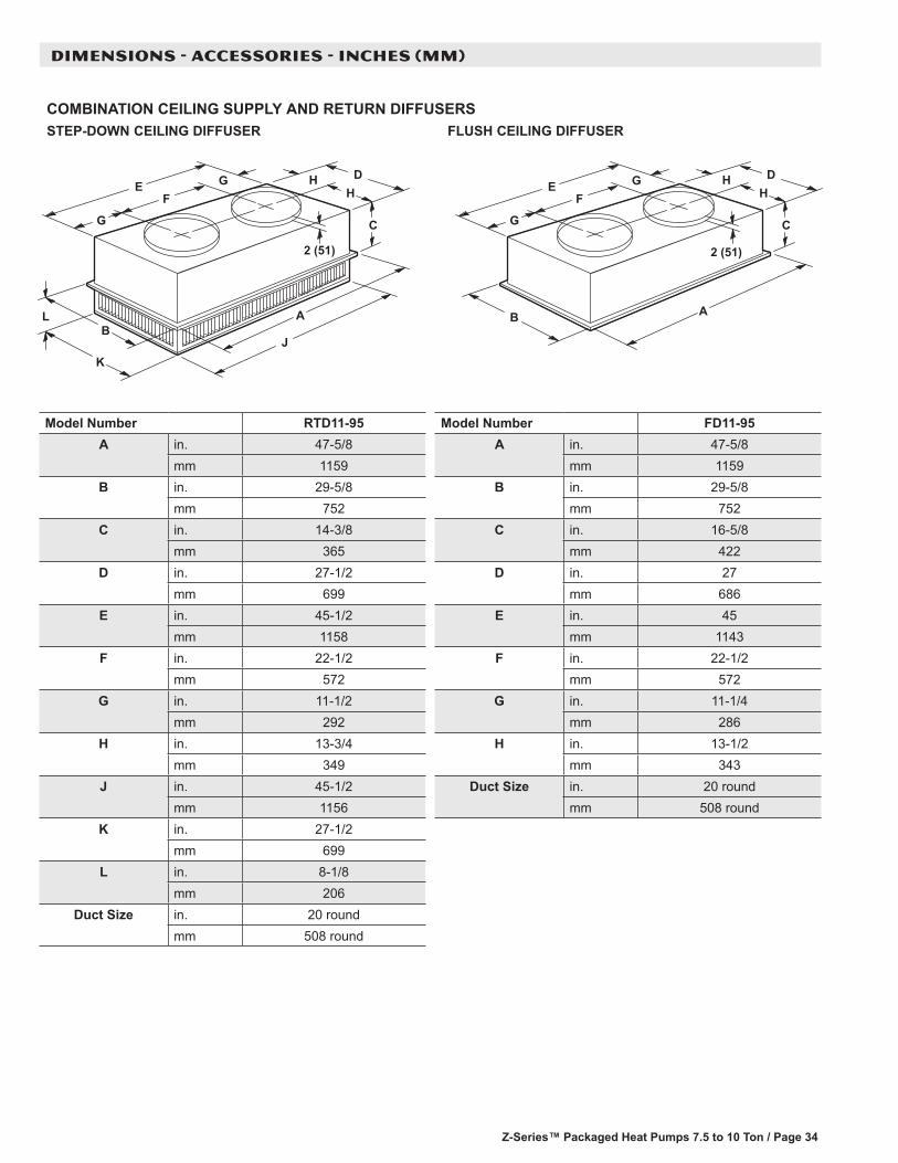
Z-Series™ Packaged Heat Pumps 7.5 to 10 Ton / Page 34
DIMENSIONS - ACCESSORIES - INCHES (MM)
COMBINATION CEILING SUPPLY AND RETURN DIFFUSERSSTEP-DOWN CEILING DIFFUSER FLUSH CEILING DIFFUSER
L A
J
C
HH
DG
G
FE
B
K
2 (51)
A
C
HH
DG
G
FE
B
2 (51)
Model Number RTD11-95A in. 47-5/8
mm 1159B in. 29-5/8
mm 752C in. 14-3/8
mm 365D in. 27-1/2
mm 699E in. 45-1/2
mm 1158F in. 22-1/2
mm 572G in. 11-1/2
mm 292H in. 13-3/4
mm 349J in. 45-1/2
mm 1156K in. 27-1/2
mm 699L in. 8-1/8
mm 206Duct Size in. 20 round
mm 508 round
Model Number FD11-95A in. 47-5/8
mm 1159B in. 29-5/8
mm 752C in. 16-5/8
mm 422D in. 27
mm 686E in. 45
mm 1143F in. 22-1/2
mm 572G in. 11-1/4
mm 286H in. 13-1/2
mm 343Duct Size in. 20 round
mm 508 round
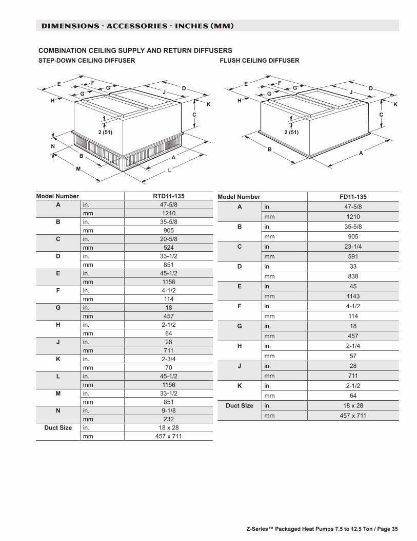
Z-Series™ Packaged Heat Pumps 7.5 to 12.5 Ton / Page 35
COMBINATION CEILING SUPPLY AND RETURN DIFFUSERSRESUFFID GNILIEC HSULFRESUFFID GNILIEC NWOD-PETS
L
A
C
HJG
FE
B
M
N
K
DG
2 (51)
A
C
HJG
FE
B
K
DG
2 (51)
DIMENSIONS - ACCESSORIES - INCHES (MM)
Model Number RTD11-135A in. 47-5/8
mm 1210B in. 35-5/8
mm 905C in. 20-5/8
mm 524D in. 33-1/2
mm 851E in. 45-1/2
mm 1156F in. 4-1/2
mm 114G in. 18
mm 457H in. 2-1/2
mm 64J in. 28
mm 711K in. 2-3/4
mm 70L in. 45-1/2
mm 1156M in. 33-1/2
mm 851N in. 9-1/8
mm 232Duct Size in. 18 x 28
mm 457 x 711
Model Number FD11-135A in. 47-5/8
mm 1210B in. 35-5/8
mm 905C in. 23-1/4
mm 591D in. 33
mm 838E in. 45
mm 1143F in. 4-1/2
mm 114G in. 18
mm 457H in. 2-1/4
mm 57J in. 28
mm 711K in. 2-1/2
mm 64Duct Size in. 18 x 28
mm 457 x 711

REVISIONS
REVISIONS
Section Description
Options/AccessoriesUpdated model and catalog numbers for both Motorized and Manual Options for Outdoor Air Dampers With Outdoor Air Hood. Shipping weights updated for Outdoor Air Dampers With Outdoor Air Hood.
NOTE - Due to Allied Commercial ongoing commitment to quality, Specifications, Ratings and Dimensions subject to change without notice and without incurring liability. Improper installation, adjustment, alteration, service or maintenance can cause property damage or personal injury. Installation and service must be performed by a qualified installer and servicing agency.
©2015 Allied Air Enterprises LLC, a Lennox International Inc. Company
Visit us at www.allied-commercial.com
For the latest technical information, visit us at www.allied-commercial.com
Contact us at 1-800-448-5872