ashrae providing care for mob jb
TRANSCRIPT

2 ASHRAE Jou rna l ash rae .o rg December 2005
Providing Care for Medical Offi ce BuildingBy Jeff Blaevoet, P.E., Member ASHRAE
About the Author
Jeff Blaevoet, P.E., is principal at Guttmann and Blaevoet Consulting Engineers in San Francisco. Blaevoet received a 2005 ASHRAE Technology Award for this project.
Thermally powered VAV diffusers historically have been used in Thermally powered VAV diffusers historically have been used in Tretrofi ts to provide additional zoning for existing systems. The Tretrofi ts to provide additional zoning for existing systems. The TKaiser Geary Medical Offi ce Building in San Francisco is the fi rst sig-
nifi cant new building in the United States to use thermally powered
VAV diffusers as the basis of design. An improved direct digital control
(DDC) approach for reheat control was developed, and a prototype
tested at the factory before construction commenced. This project demonstrates why medical
offi ce buildings particularly can benefi t from this HVAC system type. Other build-ing types where fully enclosed offi ces are needed, such as attorney offi ces, are also well suited for this system given.
As the number of reheat coils is greatly reduced, heating hot water distribution is also a fraction of a VAV/reheat box sys-tem, which has cost benefi ts and reduced liability of water leaks above the ceiling.
Ductwork distribution is greatly simpli-fi ed, and the extent of powered controls also is much less.
Where operable windows are provided, a possibility exists of a window being left open, which would affect the thermostat of a VAV box, causing discomfort for the occupants in the other rooms served by that box. With self-contained thermally powered VAV diffusers, the master DDC zone controllers are much fewer, reduc-
ing the chances of this happening. If it did, the VAV diffusers would compen-sate. For these reasons, as well as the sate. For these reasons, as well as the improved comfort and energy effi ciency improved comfort and energy effi ciency afforded, thermally powered VAV diffus-afforded, thermally powered VAV diffus-ers also have a much broader application ers also have a much broader application potential.
Project OverviewProject OverviewThe Kaiser Geary Medical Office The Kaiser Geary Medical Office
Building is a high-rise building con-Building is a high-rise building con-structed in 2000. The $60 million build-structed in 2000. The $60 million build-ing is eight stories with an atrium and fi ve ing is eight stories with an atrium and fi ve additional fl oors of underground parking. additional fl oors of underground parking. Each fl oor has an area of 32,800 ftEach fl oor has an area of 32,800 ft2 (3047 m2) and the building has a total fl oor area ) and the building has a total fl oor area of 261,600 ftof 261,600 ft2 (24 303 m (24 303 m2) The facility contains a cafeteria, a large data/telecom room, doctor’s offi ces, nurse’s stations, a full pharmacy, exam rooms, waiting areas, a cancer center, neurology, ortho-
Reprinting this proof for distribution or posting on web sites is not permitted. Authors may request permission to reprint or post on their web site once the fi nal version has been published. A reprint permission form may be found at www.ashrae.org.
December 2005 ASHRAE Jou rna l 3
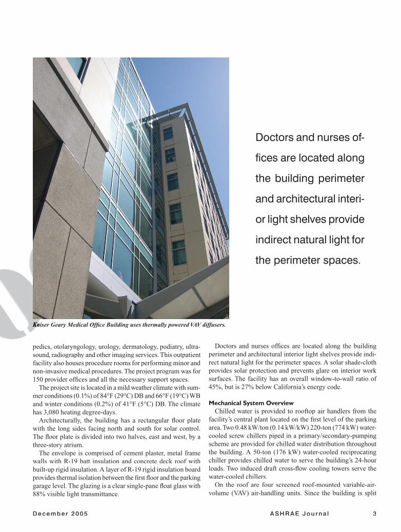
Doctors and nurses of-
fi ces are located along
the building perimeter
and architectural interi-
or light shelves provide
indirect natural light for
the perimeter spaces.
pedics, otolaryngology, urology, dermatology, podiatry, ultra-sound, radiography and other imaging services. This outpatient facility also houses procedure rooms for performing minor and non-invasive medical procedures. The project program was for 150 provider offi ces and all the necessary support spaces.
The project site is located in a mild weather climate with sum-mer conditions (0.1%) of 84°F (29°C) DB and 66°F (19°C) WB and winter conditions (0.2%) of 41°F (5°C) DB. The climate has 3,080 heating degree-days.
Architecturally, the building has a rectangular fl oor plate with the long sides facing north and south for solar control. The fl oor plate is divided into two halves, east and west, by a three-story atrium.
The envelope is comprised of cement plaster, metal frame walls with R-19 batt insulation and concrete deck roof with built-up rigid insulation. A layer of R-19 rigid insulation board provides thermal isolation between the fi rst fl oor and the parking garage level. The glazing is a clear single-pane fl oat glass with 88% visible light transmittance.
Doctors and nurses offi ces are located along the building perimeter and architectural interior light shelves provide indi-rect natural light for the perimeter spaces. A solar shade-cloth provides solar protection and prevents glare on interior work surfaces. The facility has an overall window-to-wall ratio of 45%, but is 27% below California’s energy code.
Mechanical System OverviewChilled water is provided to rooftop air handlers from the
facility’s central plant located on the fi rst level of the parking area. Two 0.48 kW/ton (0.14 kW/kW) 220-ton (774 kW) water-cooled screw chillers piped in a primary/secondary-pumping scheme are provided for chilled water distribution throughout the building. A 50-ton (176 kW) water-cooled reciprocating chiller provides chilled water to serve the building’s 24-hour loads. Two induced draft cross-fl ow cooling towers serve the water-cooled chillers.
On the roof are four screened roof-mounted variable-air-volume (VAV) air-handling units. Since the building is split
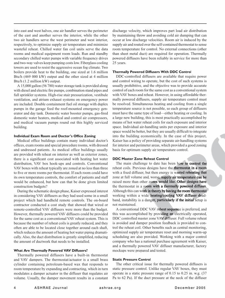
Kaiser Geary Medical Offi ce Building uses thermally powered VAV diffusers.Kaiser Geary Medical Offi ce Building uses thermally powered VAV diffusers.
4 ASHRAE Jou rna l ash rae .o rg December 2005
into east and west halves, one air handler serves the perimeter of the east and another serves the interior, while the other two air handlers serve the west perimeter and west interior, respectively, to optimize supply air temperature and minimize wasteful reheat. Chilled water fan coil units serve the data rooms and medical equipment room loads. Run and standby secondary chilled water pumps with variable frequency drives and two-way valves keep pumping costs low. Fiberglass cooling towers are used to resist the aggressive ocean fog climate. Two boilers provide heat to the building, one sized at 1.6 million Btu/h (469 000 kW) output and the other sized at 4 million Btu/h (1.2 million kW) output.
A 15,000 gallon (56 780) water storage tank is provided along with diesel and electric fi re pumps, combination stand pipes and full sprinkler systems. High-rise stair pressurization, vestibule ventilation, and atrium exhaust systems on emergency power are included. Double containment fuel oil storage with duplex pumps in the garage feed the roof-mounted emergency gen-erator and day tank. Domestic water booster pumps, gas-fi red domestic water heaters, medical and control air compressors, and medical vacuum pumps round out this highly serviced building.
Individual Exam Room and Doctor’s Offi ce ZoningMedical offi ce buildings contain many individual doctor’s
offi ces, exam rooms and special procedure rooms, with dressed and undressed patients. As medical offi ce buildings usually are provided with reheat on interior as well as exterior zones, there is a signifi cant cost associated with heating hot water distribution, VAV box hook-ups and controls. Conventional VAV boxes with reheat typically are zoned at no less than three to fi ve or more rooms per thermostat. If each room could have its own temperature controls, the comfort of patients and staff would be enhanced, but how can that be done given limited construction budgets?
During the schematic design phase, Kaiser expressed interest in considering VAV diffusers as they had used some in a small project which had handheld remote controls. The on-board contractor conducted a cost study that showed that wired or remote-controlled VAV diffusers were more than the budget. However, thermally powered VAV diffusers could be provided for the same cost as a conventional VAV reheat system. This is because the number of reheat coils is greatly reduced, and they often are able to be located close together around each shaft, which reduces the amount of heating hot water piping dramati-cally. Also, the duct distribution is greatly simplifi ed, reducing the amount of ductwork that needs to be installed.
What Are Thermally Powered VAV Diffusers?Thermally powered diffusers have a built-in thermostat
and VAV dampers. The thermostat/actuator is a small brass cylinder containing petroleum-based wax that responds to room temperature by expanding and contracting, which in turn modulates a damper actuator in the diffuser that regulates air volume. Usually, the damper movement results in a constant
discharge velocity, which improves part load air distribution by maintaining throw and avoiding cold air dumping that can occur at low discharge velocities. Room air is induced by the supply air and routed over the self-contained thermostat to sense room temperature for control. No external connections (other than sheet metal duct) are required for operation. Thermally powered diffusers have been reliably in service for more than 25 years.
Thermally Powered Diffusers With DDC ControlDDC-controlled diffusers are available that require power
and control wiring to operate, but the cost of such systems is usually prohibitive, and the objective was to provide accurate control of each room for the same cost as a conventional system with VAV boxes and reheat. However, in using affordable ther-mally powered diffusers, supply air temperature control must be resolved. Simultaneous heating and cooling from a single temperature source is not possible, so each group of diffusers must have the same type of load—either heating or cooling. In a large new building, this is most practically accomplished by means of hot water reheat coils for each exposure and interior space. Individual air-handling units per exposure and interior space would be better, but they are usually diffi cult to integrate into the building economically. In the case of this project, Kaiser has a policy of providing separate air-handling systems for interior and perimeter areas, which provided a good zoning basis for optimum supply air temperature control.
DDC Master Zone Reheat ControlThe main challenge to date has been how to control the The main challenge to date has been how to control the
reheat coils. Previous designs have the thermostat in a room reheat coils. Previous designs have the thermostat in a room with a fi xed diffuser, but then energy is wasted reheating that with a fi xed diffuser, but then energy is wasted reheating that zone at full volume and, worse, supply air temperature can be zone at full volume and, worse, supply air temperature can be raised more than other zones would like. Other designs have raised more than other zones would like. Other designs have the thermostat in a room with a thermally powered diffuser. the thermostat in a room with a thermally powered diffuser. Although this can work in theory by having the room thermostat Although this can work in theory by having the room thermostat working within a wide heating/cooling VAV diffuser dead-working within a wide heating/cooling VAV diffuser dead-band, instability is a danger, particularly if the initial setup is band, instability is a danger, particularly if the initial setup is not maintained.
A conventional DDC VAV reheat sequence is preferred, and A conventional DDC VAV reheat sequence is preferred, and this was accomplished by providing an electrically operated, this was accomplished by providing an electrically operated, DDC controlled master zone VAV diffuser. Full volume reheat DDC controlled master zone VAV diffuser. Full volume reheat is avoided and damper position feedback is provided to con-trol the reheat coil. Other benefi ts such as central monitoring, optimized supply air temperature reset and morning warm-up scheduling are also provided. Working with a major control company who has a national purchase agreement with Kaiser, and a thermally powered VAV diffuser manufacturer, factory mockups were prepared and tested.
Static Pressure ControlThe other critical issue for thermally powered diffusers is
static pressure control. Unlike regular VAV boxes, they must operate in a static pressure range of 0.15 to 0.25 in. w.g. (37 Pa to 62 Pa). If the duct pressure at the neck of the diffuser

December 2005 ASHRAE Jou rna l 5
is below that range, less than the rated cfm will be delivered. Above 0.25 in. w.g. (62 Pa), the diffuser will be noisy. In a large system, there may be multiple static pressure control dampers downstream of the reheat coils. Avoiding VAV boxes, and designing low pressure, low velocity ductwork also has a benefi cial effect on fan energy use. The four air-handling units serving the building, have a combined power to airfl ow ratio of 0.58 W/cfm (1.23 W per L/s), which is 53% less than the ratio of 1.25 W/cfm (2.65 W per L/s) for VAV systems allowed by California’s energy code.
Implementation and CommissioningFollowing the successful mockup and testing of the master
zone DDC with the control and diffuser manufacturers, con-zone DDC with the control and diffuser manufacturers, con-struction, test and balancing, and commissioning proceeded struction, test and balancing, and commissioning proceeded smoothly. Balancing VAV diffusers is accomplished by unhook-smoothly. Balancing VAV diffusers is accomplished by unhook-ing the tension spring that connects the thermostat/actuator ing the tension spring that connects the thermostat/actuator and the blades (so the blades are full open constant volume) and the blades (so the blades are full open constant volume) setting the static pressure controls to the correct range, and setting the static pressure controls to the correct range, and adjusting the duct-mounted balancing dampers for design cfm adjusting the duct-mounted balancing dampers for design cfm at the diffuser. at the diffuser.
Operating experienceOperating experienceFeedback from facilities staff at the medical offi ce building Feedback from facilities staff at the medical offi ce building
is that the system had few startup problems and has performed is that the system had few startup problems and has performed very well since coming into operation. The main problem was very well since coming into operation. The main problem was the failure to reconnect some of the actuator mechanisms after the failure to reconnect some of the actuator mechanisms after initial balancing had occurred. In the four years of building initial balancing had occurred. In the four years of building operation, no malfunctions of the VAV diffusers have occurred operation, no malfunctions of the VAV diffusers have occurred and the system has been easy to maintain. Most importantly, and the system has been easy to maintain. Most importantly, complaints from building occupants have been signifi cantly complaints from building occupants have been signifi cantly lower than other similar facilities without individual room control. Service calls were quickly resolved by adjusting the diffuser setpoint.
Energy Performance and Environmental ImpactThe project design minimizes building energy consumption,
which was projected to be 27% below California’s energy code, thereby reducing the environmental impact of electricity generation. The DOE-2 energy model showed that the build-ing design resulted in a savings of 1,859,430 kWh/year over a standard building designed to comply with California’s energy code. Approximately 1.33 lbs (0.6 kg) of CO2 are produced for each kWh of electricity generated. The 1,859,430 kWh reduc-tion in energy use corresponds to the elimination of more than 2,473,040 lbs/year (1.1 million kg/year) of the greenhouse gas CO2.
ConclusionThe use of thermally powered VAV diffusers should be ap-
plied to new construction as well as retrofi t HVAC systems (which has been the main market for the product to date). As they typically are used for retrofi tting problem systems, and they cannot solve inherent problems with existing systems, only provide additional zoning—they perhaps have not been
fully appreciated. This approach offers improved comfort through individual
room temperature control, better air distribution at part load, simplifi ed duct distribution, and greatly scaled back reheat pip-ing with reduced leakage, and associated mold growth potential above ceilings. They enhance use with operable windows, have simple, robust controls, lower energy use, and offer easy com-missioning and maintenance.
These benefi ts have not been well publicized, and few new buildings using this technology have been designed to date. Thermally powered VAV diffusers appear to be greatly un-derestimated, and should be much more widely used in new construction.