asi module
DESCRIPTION
ASI ModuleTRANSCRIPT

3.2.4 The Application Layer 1. 3.2.4.1 AS-i master calls 2. 3.2.4.2 Data convention 3. 3.2.4.3 Function sequence in the slave 4. 3.2.4.4 Function sequence in the master 5. 3.2.4.5 Device profiles 6. 3.2.4.6 The Combined Transactions 3.2.4 The Application Layer 3.2.4.1 AS-i master calls
Fig. 3.15 summarizes the stipulated AS-Interface master calls to a standard slave. The following section describes them and the response of the slave in detail.
Fig. 3.15: Overview of the master calls to a standard slave [1] Read I/O configuration The call „Read I/O configuration“ allows the master to read the set I/O configuration of a slave. This is sent in the slave response to this call and is used together with the calls “Read ID code” for unambiguous identification of a slave. The I/O configuration refers to the data ports on Interface 1 of the slave and is defined as shown in Fig. 3.16. Here IN means a process input, and OUT a process output, I/O a bi-directional behavior of the port and TRI a tri-state output with no function. The latter state is assumed if during the reset no unambiguous I/O configuration can be determined from the slave’s own data memory due to a read error.

Fig. 3.16: I/O configurations
Wherever an output OUT (and no bi-directional behavior) is defined, this means that the corresponding information bit is undefined in the Slave response. Likewise the information bit from the master call remains without meaning, even though it is sent, where an input IN is defined. Unneeded information can thus be hidden with this I/O configuration. At the same time the I/O configuration together with the ID codes for identifying Slaves is employed. These refer to the slave profile. The I/O configuration is 4 bits long, is determined by the manufacturer and is stored in the slave, where it cannot be changed.
Read ID-Code The command calls „Read ID code“ apply to the identification code of the slave. This together with the I/O configuration is used for unique identification of a slave.
The ID code of a slave consists of three parts:
The actual ID-Code This is used to identify various types of slaves. The ID code “A” for example means that the slave works in “extended addressing mode” and interprets master calls differently at times. The ID code “B” indicates a “Safety at Work” slave, which is designed for sending safety-related signals. The ID code is 4 bits long, is determined by the manufacturer and is stored in the slave, where it cannot be changed.
Extended ID-Code 1 This part of the ID code can be modified by the user. It can be used for identifying slaves which from the manufacturer’s point of view are identical but which from the user’s perspective are different. One could for example assign motor starters having an adjustable overcurrent limit with different ID Code 1 values, so that they cannot be confused when replacing a unit in the system. For the standard slave this code is 4 bits long, and for a slave with extended addressing mode 3 bits long.
Extended ID-Code 2 This part of the ID code is used for extending the identification possibilities of AS-I slaves. Like the actual ID code it is 4 bits long, is determined by the manufacturer and is stored in the slave, where it cannot be changed.
Together with the I/O configuration the ID codes refer to a device profile (see Section 3.2.4.5). This contains specifications for the meanings of the data and parameter bits which are expected by or sent by the slave, specifications regarding the behavior of the slave as well as any additional definitions which support the interchangeability of slaves from different manufacturers but having the same function. The extended ID code is not implemented for slaves conforming to Specification 2. In the case of these slaves the master expands the missing codes to FHex.

Data call The master call „data call“ („Data Exchange“, see [1]) is the most important and frequently used AS-Interface call. It is used to cyclically send the bit pattern for the data outputs on Interface 1 of the slave accessed by address and then to read the input level and send it back in the slave response.
The data ports can be used in various ways: as outputs to the process, which can be set and cleared by the call, and/or as inputs from the process whose state, initiated by the call, is read in. Determinant here is the slave profile, which is defined by the I/O configuration and the ID codes.
If the data ports are configured as outputs, the last sent value is stored in the slave until it is overwritten by a new value or reset by a Reset. slaves can also be equipped with a watchdog function which resets the outputs when communication with the master is interrupted for longer than 40ms. After a reset, such as would be caused by turning on the supply voltage, the slave does not send replies to the data call until it has first received a valid parameter call.
A data call to address 00Hex is not possible, as this would be interpreted by the slave as an addressing call.
Parameter call The master call „parameter call“ is used to send the bit pattern acyclic for the parameter outputs on Interface 1 and then to read the input levels and send them back in the slave response. This parameter port can be used to remotely control certain functions in the slave, such as activating a time function, changing the switching distance of the sensor or, in the case of a multi-sensor system, changing from one measuring process to a different one. The last sent value is stored in the slave until it is overwritten by a new value or reset by a Reset. Reading the information in on the parameter ports can be used to send simple diagnostics information.
After a reset the parameter ports are set to a defined state. They are set only after a “parameter call” has been received without error. Only then are “data call” messages properly exchanged.
A standard slave has 4 bits of parameter data available, or 3 bits for a slave in extended addressing mode. A parameter call to address 00Hex is not possible, as this would be interpreted by the slave as an addressing call. .
Addressing call This command allows the master to permanently set the address of the slave which previously had Address 00Hex to a new value.
The slave first acknowledges errorless receipt of the command with the reply 6Hex and can then be accessed under the new address. At the same time the slave starts internally storing the new address in a non-volatile memory. This procedure can take up to 500ms, and may not be interrupted by a power interruption or a reset command.
The addressing unit uses this call to give the slave a new address over the AS-Interface line. The master can also use this call to assist in replacement of defective slaves.
Reset Slave The command „Reset AS-i-slave“ can be used to reset a slave to its base state. It has the same effect as does the Reset after applying power or the reset on the Reset input of Interface 1. The slave acknowledges errorless receipt of this command with the reply 6Hex . The reset procedure may take a maximum of 2ms.
Clear operating address The command „clear operating address“ is used for temporary deleting of the slave operating address and is needed in connection with the address assignment, since the „addressing call“ can only be carried out by a slave having operating address 00Hex. If for example a slave which used to have address 15Hex needs to be reprogrammed to the new address 09Hex, this can only be done using the following command sequence:
„Clear operating address“ and „Addressing call“ (09Hex).
The slave acknowledges errorless receipt of „clear operating address“ with the reply 0Hex and is then accessible under the new address 00Hex . Clearing the operating addressing by means of this command is not permanent; if after executing this command you need to reload the originally non-volatile stored address, you can do this using the “Reset AS-i-slave” command.
Read status The command call „Read status“ can be used to read out the status register of the contacted slave. Its contents are sent in the slave response to this call. The slave’s status register contains three flags having the following meanings:

Flag meaning S0 „Address volatile“
This flag is set when the internal slave routine for permanent storing of the slave address is running. S1 „Peripheral error“
This flag is set when the slave has detected an error in its peripheral. This many indicate for example an overload of the sensor supply voltage. S3 „Non-volatile memory read error“
This flag is set when an error occurs during a reset while reading the non-volatile memory.
Flag S2 is not yet used and is reserved for future expansions. Simultaneous with the reply to the call, an address comparison is performed by querying the non-volatile memory. If the address in the address register is not equal to that in the non-volatile memory, Flag S0 is set. The information from the status register can be used by the master for diagnostic purposes. Version 2.0 slaves do not support the „Peripheral error“ flag. When the master is communicating with a slave having extended ID-Code 2=FHex, it does not evaluate Flag S1.
Broadcast Command calls containing 15Hex are defined as “Broadcast? Calls. They may not be replied to by the slaves. To this extent they are untypical for normal AS-i data exchange. At the present time only the broadcast command “Reset” is defined. Additional broadcast commands will be implemented in future versions of the specification. Version 2.0 slaves do not support the broadcast function.
Fig. 3.17 provides an overview of the master calls. This applies to a salve with extended addressing mode:
Fig. 3.17: Overview of the master calls to a salve with extended addressing mode
From Fig. 3.17 it can be seen that an information bit is used in numerous calls as a „Select Bit“ for distinguishing between the A-Slave and the B-Slave. The definition of the select bit is selected such that the A-Slave behaves just like the standard slave. This enables you to operated “new” slaves in AS-i networks even when they are connected to “old” masters.

3.2.4.2 Data convention In addition to the message format already described, the data convention shown in Fig. 3.18 is stipulated for AS-Interface [1]. From the point of view of the host system or Interface 3, a value of 0 for a data bit means that the sensor, the actuator or the slave function is „turned off“ or „inactive“; a value of 1 means „turned on“ or „active“.
Fig. 3.18: Convention for data transmission
Since this convention does not apply in Interface 2 in the same way, the master must invert the data bits for data outputs (and only there!). It must also be noted that this definition does not apply to parameter input and output. Since parameters are internal system data, the master does not invert them.
3.2.4.3 Function sequence in the slave The states which the sequence control in the slave can assume and the possible transitions between the them are shown in Fig. 3.19. After a RESET the AS-Interface slave goes through the „INITIALIZE“ state. Here it carries out the following functions:
• Resetting the outputs, the internal registers and flags • Loading the address, the I/O configuration and the ID codes from the non-volatile memory, • Changing to the „ASYNCHRONOUS“ state.
Fig. 3.19: Main state diagram for the sequence controller in the slave
If the sequence controller detects an error in reading the non-volatile memory, it sets Flag S3 in the status register. This may occur for example if while carrying out the addressing call there is a voltage dropout so that the save procedure in the non-volatile memory cannot be finished.
In the ”SYNCHRONOUS“ state the slave reads the data stream arriving on the line and waits for a pause. In the “RECEIVE” state a data telegram is read beginning with the next start bit and the check described in Section 3.2.3.3 is performed. If the reception is faulty, the slave reverts to “ASYNCHRONOUS” state, where it waits for the next pause; if no errors are detected during the check, it goes over to the “DECODE” state.
In the “DECODE“ state first the address comparison is performed. Only if the addresses agree is the command analyzed, carried out and a reply generated where appropriate. This is returned to the master in the “SEND” state.
Since communication with the non-volatile memory can take considerable time (up to 500ms depending on the call

and IC version), it runs in the background. It does not disturb data traffic between the master and slave, but the master must take the execution times into consideration. After initializing, the slave does carry out all commands, but does not immediately reply to data calls. Only after a valid parameter call has been received is data exchange enabled. This behavior is intended to ensure that the slave is in the desired operating state before data are output.
3.2.4.4 Function sequence in the master
Fig. 3.20: Main status diagram (simplified) of the master
In normal operation, after conclusion of the detection and activation phase (which is described in greater detail in Section 3.4.7), cyclical communication takes place between the master and all connected slaves. Such a cycle consists of the data exchange phase, the (optional) management phase and the inclusion phase. The two data exchange phases illustrated in Fig. 3.20 differ from each other only when A- and B-slaves exist in the network under one address. In the data exchange phase the master queries all the activated slaves one after the other with a data call; the states from the output data image are sent to the slave and the input signals which are contained in the slave response are stored in the input data image. If the transmission level reports an error, the call is repeated in up to three successive cycles. If the third attempt also fails, it is assumed that the corresponding slave is absent or defective. The slave is then removed from all master lists and the input data image is set to zero. This error handling spread out over several cycles is necessary because given these short telegrams a noise burst with extremely high amplitude can interfere with several cycles.
The repetition of the calls also ensures reliable operation under these conditions. Individual noise pulses or interference such as is typically encountered in industrial environments are caught by the immediate repetition already on the transmission level without having a noticeable effect on the time response.
After the data exchange phase is finished, one can transition if needed to the management phase. In the management phase “acyclic” telegrams are sent. Exactly one master call can be performed per cycle, with the data necessary for carrying out the functions of the sequence control level (e.g. setting parameters or changing an operating address) can be sent, in part distributed over several cycles. If there is no job, the cycle moves on to the inclusion phase and no telegram is sent. The following jobs can be executed during the management phase:
Setting parameter values Reading a slave status Reading the I/O configuration Reading the three ID codes Writing the extended ID Code 1 Resetting the operating address of a slave to 0 Assigning a new operating address to Slave 0 Resetting a slave Carrying out a broadcast
After the management phase is finished the inclusion phase is entered, in which at the end of each cycle newly arriving stations are searched for. During each inclusion phase a search is made for exactly one slave using the “Read status” call. This call is performed from the transmission level without repetition in case of error, since a transmission error at this point is not time-critical. The peripheral error information of the slaves is collected for activated slaves in the inclusion phase. This has the advantage that no lengthening of the cycle is required. On the other hand, the querying of all peripheral error information takes several cycles. Already activated slaves also get the

“Read ID-Code” call, so that any passive devices connected later in the network (e.g. diagnostic devices) can identify the slaves.
If a slave which is already activated replies or if there is no slave reply, the next slave is searched for in the next activation phase. If a slave which was previously unknown replies, the complete identification of the slave is determined in the next inclusion phases. Then in the following inclusion phase the slave is activated depending on the selected operating mode. Activation is accomplished by writing the parameters from the parameter field.
An inclusion or re-inclusion of a slave therefore extends over several inclusion phases. The procedure, which here is divided over several cycles with one telegram per cycle, is the same as that used to search for and activate slaves in startup mode.
If you were to view the sequence of an AS-i cycle described here with an oscilloscope connected to the AS-i line, the screen would look as illustrated in Fig. 3.21.
Fig. 3.21: AS-i cycle
3.2.4.5 Device profiles In accordance with IEC61915-1 (Draft [21]) a device profile consists of data and parameters which can be exchanged with a device as well as the status diagram, which provides information about the behavior of the device on the communication network. Device profiles are independent of the characteristic of the field bus system being used. In the case of AS-Interface these device profiles are called “slave profiles” (in contrast to “master profiles”, see Section 3.4.9). A slave profile specifies the following properties of a slave uniquely and bindingly:
• Which data bits carry information and what this information means • Whether parameters are used and, if yes, what they mean • Whether the peripheral error bit may be evaluated • How the slave behaves
An example of a typical status diagram for a simple slave is shown in Fig. 3.22. In the case of a slave which for example communicates digital data distributed over several cycles, the status diagram is of course more complex. But this is information which has meaning only for the master and slave developer; the user does not have to be concerned about these processes. The unique assignment of a slave to a profile is given by the combination of the I/O configuration, ID code and extended ID Code 2.

Fig. 3.22: Status diagram of a slave according to a device profile
The profile also specifies the following in many cases: • which logic levels are defined for the inputs and outputs of the slave module, • which time delays need to be taken into account for in- and /or output signals, and • which pin configurations need to be observed and what the labeling of the module has to look like
Fig. 3.23: Pin assignments for M12 connections on AS-i slaves (here: female)
Fig. 3.23 shows the pin assignments provided for in the profiles for the most commonly used M12 connector method. These specifications are – as much as possible – compatible with the standards for the connected products (e.g. IEC60947-5-2 [16]). These additional specifications support the interoperability between products made by different manufacturers. In order to not inhibit advances or the offering of specialized modules with too narrowly defined profile definitions, the „free profile“ with ID code FHex is provided. Here essential parts of the device profile definition may be defined between the manufacturer and user.
The overview in Fig. 3.24 shows which profiles are currently available. Additional profiles are permanently being reviewed and approved by the technical commission of the AS-International Association.
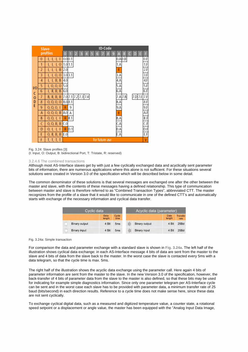
Fig. 3.24: Slave profiles [3] (I: Input, O: Output, B: bidirectional Port, T: Tristate, R: reserved)
3.2.4.6 The combined transactions Although most AS-Interface slaves get by with just a few cyclically exchanged data and acyclically sent parameter bits of information, there are numerous applications where this alone is not sufficient. For these situations several solutions were created in Version 3.0 of the specification which will be described below in some detail.
The common denominator of these solutions is that several messages are exchanged one after the other between the master and slave, with the contents of these messages having a defined relationship. This type of communication between master and slave is therefore referred to as “Combined Transaction Types”, abbreviated CTT. The master recognizes from the profile of a slave that it would like to communicate in one of the defined CTT’s and automatically starts with exchange of the necessary information and cyclical data transfer.
Fig. 3.24a: Simple transaction
For comparison the data and parameter exchange with a standard slave is shown in Fig. 3.24a. The left half of the illustration shows cyclical data exchange: in each AS-Interface message 4 bits of data are sent from the master to the slave and 4 bits of data from the slave back to the master. In the worst case the slave is contacted every 5ms with a data telegram, so that the cycle time is max. 5ms. The right half of the illustration shows the acyclic data exchange using the parameter call. Here again 4 bits of parameter information are sent from the master to the slave. In the new Version 3.0 of the specification, however, the back-transfer of 4 bits of parameter data from the slave to the master is also defined, so that these bits may be used for indicating for example simple diagnostics information. Since only one parameter telegram per AS-Interface cycle can be sent and in the worst case each slave has to be provided with parameter data, a minimum transfer rate of 25 baud (bits/second) in each direction results. Reference to a cycle time does not make sense here, since these data are not sent cyclically.
To exchange cyclical digital data, such as a measured and digitized temperature value, a counter state, a rotational speed setpoint or a displacement or angle value, the master has been equipped with the "Analog Input Data Image,

AIDI" and the "Analog Output Data Image, AODI", each having a capacity of 124 words (see Fig. 3.36).
For the acyclic data, which are typically diagnostic data, parameter data or data which identify the slave in detail, the masters have a data channel which is constructed similar to the familiar parameter channel. It allows data packets with lengths up to 32 bytes to be exchanged with the slave.
In the meantime 5 different possibilities for byte-by-byte data communication between the master and slave have been specified by AS-International. These are described in greater detail in the following. The data amounts shown in the illustrations are net data, and the cycle times the maximum times which may occur in the worst case. The prerequisite for using these transaction types is having a master which supports them.
CTT1 Combined Transaction Type 1 (CTT1) is intended for simple and complex sensors or actuators such as temperature, pressure or flow transmitters, displacement and angle measurement systems, scanners, speed-controlled motors, analog process valves, displays with up to 8 characters or similar field devices. The slave can only be operated in standard addressing mode. It is not possible to change the transfer direction for the cyclical data on the fly.
Whereas slaves having Profile S-7.3 can only receive or send cyclical data and parameterizing is only possible using the 4-bit parameters (Fig. 3.24c), Profile S-7.4 offers expanded possibilities for communication. Here you can switch to the parameter channel to query the ID data and diagnostic data for the slave and exchange parameter data records (Fig. 3.24d). The ID data contain among other things the Vendor ID and the Device ID in code. Furthermore the operating mode of the slave (analog mode, transparent mode, 4-bit mode) is transmitted.
In analog mode the available number range of -32768 (8000Hex) to 32767 (7FFFHex) is generally divided into five ranges (Fig. 3.24b shows this using the example of a 4..20mA signal):
Fig. 3.24b: Error, warning and working ranges of an analog sensor having a 4..20mA signal
1. Error range "wire break" The measured value is invalid, the overflow bit is set 2. Underrange The measured value is valid, but has a greater measuring uncertainty because it
is outside the nominal range 3. Working range The measured value is acquired at the specified accuracy 4. Overrange The measured value is valid, but has a greater measuring uncertainty because it
is outside the nominal range 5. Error range „short circuit" The measured value is invalid, the overflow bit is set The exact limits of the nominal and over-/underflow ranges as well as the error ranges are defined in the vendor’s data sheet. The default value, which is substituted in the receiver for example when communication is interrupted, is 7FFFHex. In transparent mode16 bits of data can be transmitted in any desired format. There is no over- or underflow state of the measured value, and the corresponding bit is not set. The default value, which is substituted in the receiver for example when communication is interrupted, is 0000Hex.
In 4-bit mode the slave behaves like a standard slave, cyclically exchanging 4 bits of data in both directions. Here the CTT1 is used only for identifying the slave, for detailed diagnostics, and for parameterizing.

Fig. 3.24c: CTT1 (Profile S-7.3) for simple sensors or actuators
The worst-case times and data transfer rates shown in Figs. 3.24c and 3.24d can be halved resp. doubled through optimal use of the possibilities of the AS-Interface, namely when the slave sends back its response to the master call in the same message and does not allow an entire cycle to elapse.
It should be noted that switching between cyclical data communication and parameter communication can take a certain time (several 100ms) and that during acyclic data exchange no cyclical data can be sent.
CTT2 Combined Transaction Type 2 (CTT2) is intended for simple and complex field devices such as temperature regulators, displays with more than 8 characters, speed controlled motors with actual value feedback, analog process valves with position feedback or similar field devices in which digital data need to be sent in both directions (Fig. 3.24e). CTT2 can also serve as an alternative to a HART interface to a field device, albeit with some minor limitations. The slave can be operated in standard addressing mode but not in extended addressing mode. Data exchange is full-duplex, i.e. both binary data as well as digital input and output data can be sent at the same time. No special switching of the data transfer direction is required.

Fig. 3.24d: CTT1 (Profile S-7.4) parameterizable sensors or actuators
This transaction type allows use of "Combi Field Devices“. This includes devices that have both binary and digital input and output capability. The binary inputs and outputs can be used for example for rapid display of an over or under limit violation, and the simultaneously available digital transmission of the precise measured value can be used for diagnostics and maintenance purposes.
The parameter channel can be used in this transaction type as well to transmit the ID data for the slave including Vendor ID, Product ID and operating mode. Comprehensive diagnostics and parameter data records can also be exchanged. If acyclic digital data are exchanged, the cyclical digital data traffic is interrupted for the duration of the transmission, whereas the cyclical transmission of the binary data remains unaffected.
The data formats used are the same as for CTT1.
The worst-case times and data transfer rates shown in Figs. 3.24e can be halved resp. doubled through optimal use of the possibilities of the AS-Interface, namely when the slave sends back its response to the master call in the same message and does not allow an entire cycle to elapse.
In order to handle the resulting variety of parameters, work is currently underway to incorporate AS-Interface into the FDT standard. This will result in an OEM-neutral platform which can be used to conveniently set parameters and process remote diagnostics and maintenance.

Fig. 3.24e: CTT2 for Combi Field Devices (not shown here: S-B.A.E)
CTT3 Combined Transaction Type 3 (CTT3) is intended for binary sensors, actuators and field devices including keypads with signal light feedback, valve terminals, status indicator columns and similar devices where binary data need to be transmitted in both directions. Simple analog sensors or actuators can also be operated using CTT3 if the resolution of 8 bits is sufficient. The slave is operated in extended addressing mode (Fig. 3.24f).
Profile S-7.A.7 makes the output data bit „lost“ due to the extended addressability available again. This is however at the expense of response time, which for this transaction type can be up to max. 40ms.
The worst-case times and data transfer rates shown in Figs. 3.24f can be halved resp. doubled through optimal use of the possibilities of the AS-Interface, namely when the slave sends back its response to the master call in the same message and does not allow an entire cycle to elapse.
If one were to equip an AS-Interface network with 62 slaves having Profile S-7.A.A, a total of 496 binary inputs and 496 binary outputs would be available, i.e. nearly 1000 I/O’s in all.

Fig. 3.24f: CTT3 for keypads, valve terminals and similar devices
Fig. 3.24g: CTT4 for single- or dual-channel analog sensors
CTT4 Combined Transaction Type 4 (CTT4) is intended for simple analog sensors such as temperature, pressure or flow transmitters and similar devices in which digital data only need to be transmitted from the slave to the master. The slave is operated in extended addressing mode (Fig. 3.24g).
This transmission type is an extension of CTT1.
CTT5 Combined Transaction Type 5 (CTT5) is optimized for fast data transmission. It can be used for fast sensors such as angle encoders, actuators and field devices which are for example components in dynamic digital control loops. 8 bits, 12 bits or 16 bits of data can be sent full-duplex in 5ms (Fig. 3.24h). This is organized as follows using several slave addresses: The lowest address of 2, 3 or 4 successive addresses is the physical address of the slave. This slave uses the next higher addresses for widening its data channel. In this way a digital value of up to 16-bit resolution can be

sent in full in a single AS-Interface cycle. The “shadow addresses” may not of course be assigned to other slaves. The slave occupies 2, 3 or 4 standard addresses.
The output value is provided in the output data image of the slave with the lowest address, and the input value in the corresponding field of the analog input data image. The fields of the “shadow slaves” remain empty.
In the case of slaves that use this transaction type it must be noted that the mechanisms for automatic addressing do not work in the same way as for other slaves. It may therefore be necessary for the user to take other measures if he is using slaves with CTT5.
Fig. 3.24h: CTT5 for fast analog sensors, actuators and field devices
Communication with safe slaves is also part of “Combined Transaction Types”. Here however communication takes place not primarily between the master and the slave, but rather between the salve and the safety monitor. This is covered in detail in Section 4 of this book.
In summary, there are now various complementary methods available for simply exchanging analog data, parameter data, ID data and detailed diagnostic data over AS-Interface. The task of the product developer is to select the most appropriate procedure for the task at hand from among the variety of possibilities. For the user this means new types of communication are available that are as simple to use as one has come to expect from AS-Interface. “Click and Go” is now here for the analog world as well.