asli ceiling diffusers set
DESCRIPTION
CatalogueTRANSCRIPT
Ceiling Diffusers
Supply Air Grilles
Return Air Grilles
Louvers
Jet Diffusers
Floor Diffusers
Dampers
Damper Actuators
VAV Terminal Units
Flexible Air Duct
Silencer
CEILING DIFFUSERS CONTENTS
• DA Directional Ceiling Diffuser
• DG Double Deflection Ceiling Diffuser
• DP Plate Type Ceiling Diffuser
• DJ Modular Core Directional Diffuser
• CA Round Diffuser
• CA-A-C Round Diffuser
• CAC Ceiling Diffuser
• CAC 2 Ceiling Diffuser
• CP Plate Type Round Diffuser
• PD & PDC Perforated Face Diffuser
• SW-2T Swirl Diffuser
• SW-3T Curve-blade Swirl Diffuser
• SLLS Linear Ceiling Diffuser
• LTD Light Troffer Diffuser
• Ceiling Diffusers Accessories
CONTENTS
All stated specifications are updated at the printing date and subject to change without notice or obligation. The actual product might differ from pictures shown.
CEILING DIFFUSERS
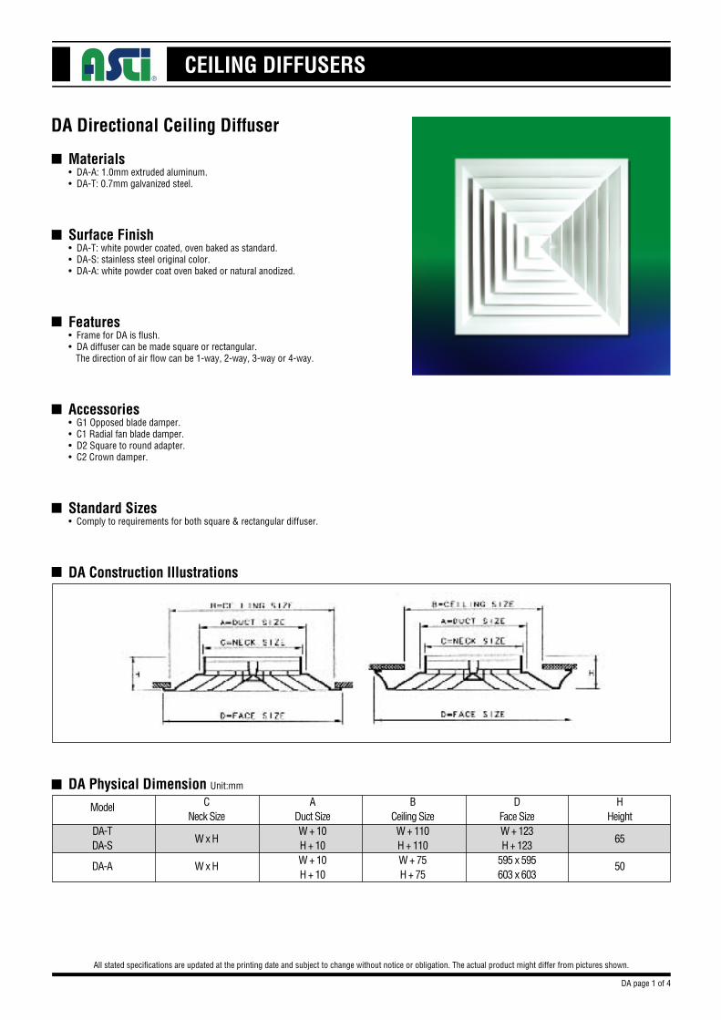
Materials• DA-A: 1.0mm extruded aluminum.• DA-T: 0.7mm galvanized steel.
Surface Finish• DA-T: white powder coated, oven baked as standard.• DA-S: stainless steel original color.• DA-A: white powder coat oven baked or natural anodized.
Features• Frame for DA is flush.• DA diffuser can be made square or rectangular. The direction of air flow can be 1-way, 2-way, 3-way or 4-way.
Accessories• G1 Opposed blade damper.• C1 Radial fan blade damper.• D2 Square to round adapter.• C2 Crown damper.
Standard Sizes• Comply to requirements for both square & rectangular diffuser.
DA Construction Illustrations
DA Directional Ceiling Diffuser
All stated specifications are updated at the printing date and subject to change without notice or obligation. The actual product might differ from pictures shown.
n
n
n
n
n
n
n
DA Physical Dimension Unit:mm
DA-TDA-S
CNeck Size
ADuct SizeW + 10H + 10W + 10H + 10
BCeiling SizeW + 110H + 110W + 75H + 75
DFace SizeW + 123H + 123
595 x 595603 x 603
HHeight
W x H
DA-A
Model
W x H
65
50
DA page 1 of 4
CEILING DIFFUSERS
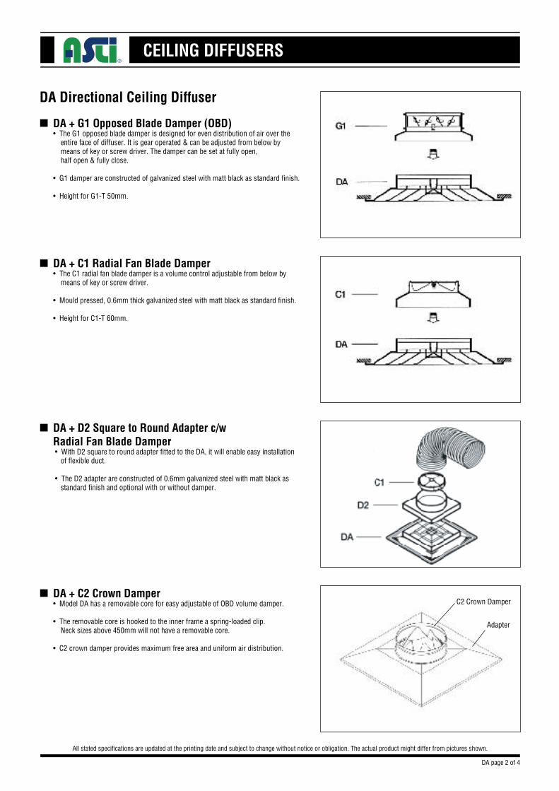
DA + G1 Opposed Blade Damper (OBD)• The G1 opposed blade damper is designed for even distribution of air over the entire face of diffuser. It is gear operated & can be adjusted from below by means of key or screw driver. The damper can be set at fully open, half open & fully close.
• G1 damper are constructed of galvanized steel with matt black as standard finish.
• Height for G1-T 50mm.
DA Directional Ceiling Diffuser
All stated specifications are updated at the printing date and subject to change without notice or obligation. The actual product might differ from pictures shown.
n
DA + C1 Radial Fan Blade Damper• The C1 radial fan blade damper is a volume control adjustable from below by means of key or screw driver.
• Mould pressed, 0.6mm thick galvanized steel with matt black as standard finish.
• Height for C1-T 60mm.
n
DA + D2 Square to Round Adapter c/w
Radial Fan Blade Damper • With D2 square to round adapter fitted to the DA, it will enable easy installation of flexible duct.
• The D2 adapter are constructed of 0.6mm galvanized steel with matt black as standard finish and optional with or without damper.
n
DA + C2 Crown Damper• Model DA has a removable core for easy adjustable of OBD volume damper.
• The removable core is hooked to the inner frame a spring-loaded clip. Neck sizes above 450mm will not have a removable core.
• C2 crown damper provides maximum free area and uniform air distribution.
n
DA page 2 of 4
C2 Crown Damper
Adapter
CEILING DIFFUSERS
DA Directional Ceiling Diffuser
All stated specifications are updated at the printing date and subject to change without notice or obligation. The actual product might differ from pictures shown.
n DA Product Specification Unit:mm
Model CodeDA-T
DA-S
DA-A
Materials0.7 SPGC Steel
0.5 Stainless SteelSUS. 304
Extruded Aluminium A6063
Surface FinishWhite Powder Coat,
Oven Baked
Original Colour
White Powder Coat,Oven Baked or Natural Anodized
Standard Sizes150 X 150200 X 200250 X 250300 X 300350 X 350400 X 400450 X 450500 X 500550 X 550600 X 600
Accessories
G1 OpposedBlade Damper
D2 Square toRound Damper
C1 Radial Fan Blade
C2 Crown Damper
Order Key
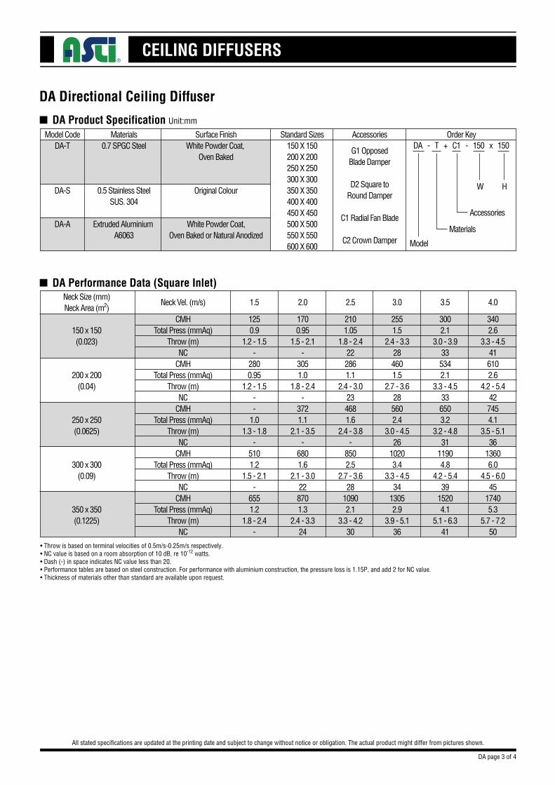
n DA Performance Data (Square Inlet)
DA - T + C1 - 150 x 150
Model
Materials
Accessories
W H
Neck Size (mm)Neck Area (m2)
150 x 150(0.023)
200 x 200(0.04)
250 x 250(0.0625)
300 x 300(0.09)
350 x 350(0.1225)
CMHTotal Press (mmAq)
Throw (m)NC
CMHTotal Press (mmAq)
Throw (m)NC
CMHTotal Press (mmAq)
Throw (m)NC
CMHTotal Press (mmAq)
Throw (m)NC
CMHTotal Press (mmAq)
Throw (m)NC
Neck Vel. (m/s)
1700.95
1.5 - 2.1-
3051.0
1.8 - 2.4-
3721.1
2.1 - 3.5-
6801.6
2.1 - 3.0228701.3
2.4 - 3.324
2.0
3002.1
3.0 - 3.9335342.1
3.3 - 4.5336503.2
3.2 - 4.831
11904.8
4.2 - 5.439
15204.1
5.1 - 6.341
3.5
2101.05
1.8 - 2.4222861.1
2.4 - 3.0234681.6
2.4 - 3.8-
8502.5
2.7 - 3.628
10902.1
3.3 - 4.230
2.5
2551.5
2.4 - 3.3284601.5
2.7 - 3.6285602.4
3.0 - 4.526
10203.4
3.3 - 4.534
13052.9
3.9 - 5.136
3.0
3402.6
3.3 - 4.5416102.6
4.2 - 5.4427454.1
3.5 - 5.136
13606.0
4.5 - 6.045
17405.3
5.7 - 7.250
4.0
1250.9
1.2 - 1.5-
2800.95
1.2 - 1.5--
1.01.3 - 1.8
-5101.2
1.5 - 2.1-
6551.2
1.8 - 2.4-
1.5
• Throw is based on terminal velocities of 0.5m/s-0.25m/s respectively.•NC value is based on a room absorption of 10 dB, re 10-12 watts.•Dash (-) in space indicates NC value less than 20.•Performance tables are based on steel construction. For performance with aluminium construction, the pressure loss is 1.15P, and add 2 for NC value.• Thickness of materials other than standard are available upon request.
DA page 3 of 4
CEILING DIFFUSERS
DA Directional Ceiling Diffuser
All stated specifications are updated at the printing date and subject to change without notice or obligation. The actual product might differ from pictures shown.
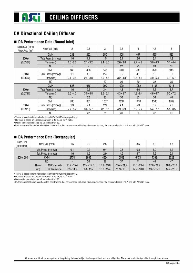
n DA Performance Data (Round Inlet)Neck Size (mm)Neck Area (m2)
200 ø(0.0324)
250 ø(0.0507)
300 ø(0.0731)
350 ø(0.0979)
CMHTotal Press (mmAq)
Throw (m)NC
CMHTotal Press (mmAq)
Throw (m)NC
CMHTotal Press (mmAq)
Throw (m)NC
CMHTotal Press (mmAq)
Throw (m)NC
Neck Vel. (m/s)
3501.5
2.4 - 3.5-
5482.4
3.0 - 4.5227903.4
3.6 - 5.426
10572.9
42 - 6.225
3
5253.4
3.0 - 4.3288205.3
4.0 - 5.432
11857.6
4.6 - 6.736
15856.7
5.4 - 7.737
4.5
4082.1
2.6 - 3.8226403.2
3.2 - 4.8269204.8
4.3 - 5.730
12344.1
4.9 - 6.931
3.5
4672.6
2.7 - 4.2257304.1
3.5 - 5.130
10526.0
4.3 - 6.433
14105.3
5.2 - 7.234
4
5834.2
3.1 - 4.4319136.5
4.1 - 5.735
13158.7
5.2 - 7.240
17627.9
5.5 - 8.541
5
2921.1
2.1 - 3.2-
4561.6
2.4 - 3.8-
6582.5
3.0 - 4.8228812.1
3.6 - 5.722
2.5
2331.0
1.5 - 2.6-
3651.1
2.1 - 3.5-
5261.6
2.5 - 4.2-
7051.3
2.7 - 5.2-
2
• Throw is based on terminal velocities of 0.5m/s-0.25m/s respectively.•NC value is based on a room absorption of 10 dB, re 10-12 watts.•Dash (-) in space indicates NC value less than 20.•Performance tables are based on steel construction. For performance with aluminium construction, the pressure loss is 1.15P, and add 2 for NC value.
n DA Performance Data (Rectangular)Face Size
(mm x mm)
1200 x 600
Vel. Press. (mmAq)Tot. Press. (mmAq)
CMHNC
Throw(m)
1200mm side600mm side
Neck Vel. (m/s)
0.42.9
462432
13.9 - 19.810.7 - 15.4
2.5
1.07.5
739844
17.6 - 24.913.7 - 19.3
4.0
0.54.2
554837
15.4 - 21.711.9 - 16.8
3.0
0.85.7
647341
16.6 - 23.412.7 - 18.0
3.5
1.29.4
832247
18.8 - 26.314.4 - 20.5
4.5
0.21.9
369926
12.4 - 17.69.8 - 13.7
2.0
0.11.0
2774-
10.7 - 15.47.3 - 11.9
1.5
• Throw is based on terminal velocities of 0.5m/s-0.25m/s respectively.•NC value is based on a room absorption of 10 dB, re 10-12 watts.•Dash (-) in space indicates NC value less than 20.•Performance tables are based on steel construction. For performance with aluminium construction, the pressure loss is 1.15P, and add 2 for NC value.
DA page 4 of 4
CEILING DIFFUSERS
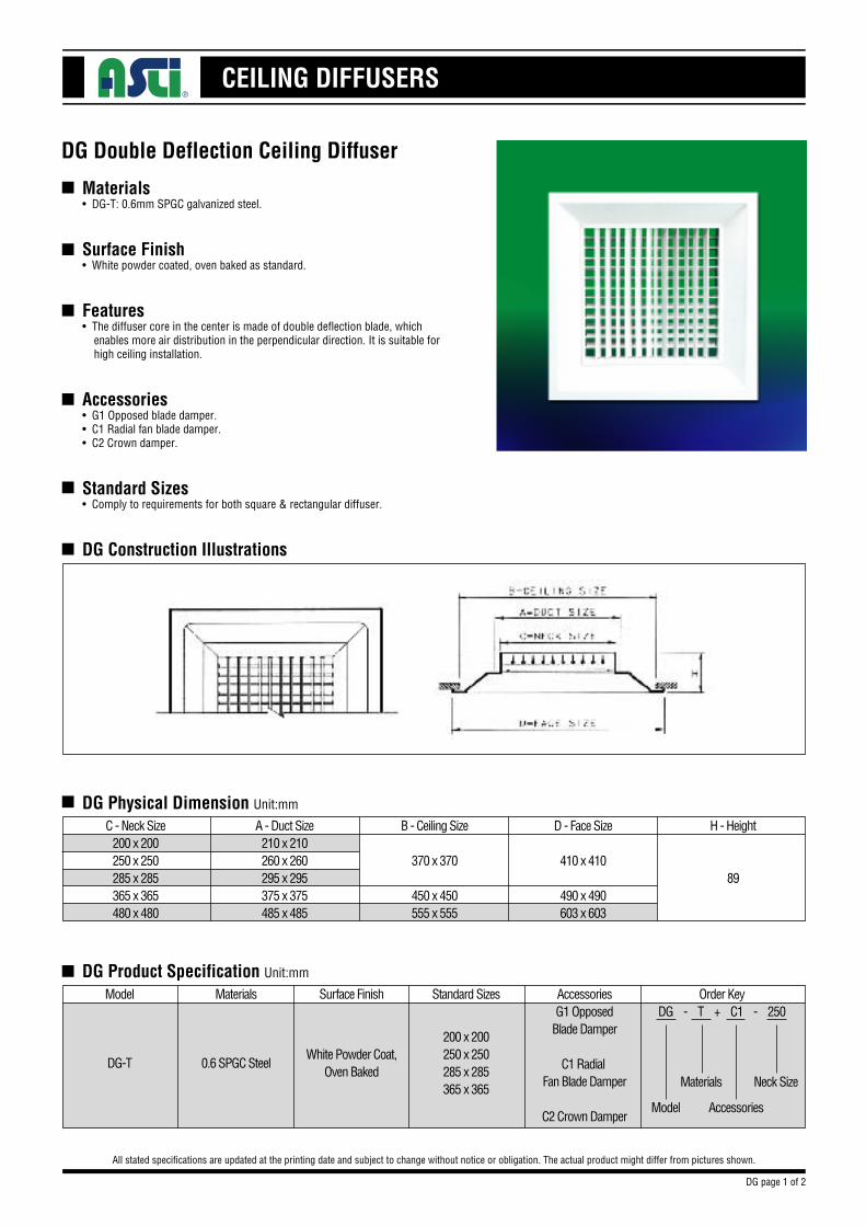
Materials• DG-T: 0.6mm SPGC galvanized steel.
Surface Finish• White powder coated, oven baked as standard.
Features• The diffuser core in the center is made of double deflection blade, which enables more air distribution in the perpendicular direction. It is suitable for high ceiling installation.
Accessories• G1 Opposed blade damper.• C1 Radial fan blade damper.• C2 Crown damper.
Standard Sizes• Comply to requirements for both square & rectangular diffuser.
DG Construction Illustrations
DG Double Deflection Ceiling Diffuser
All stated specifications are updated at the printing date and subject to change without notice or obligation. The actual product might differ from pictures shown.
n
n
n
n
n
n
n
DG Physical Dimension Unit:mm
C - Neck Size200 x 200250 x 250285 x 285365 x 365480 x 480
A - Duct Size210 x 210260 x 260295 x 295375 x 375485 x 485
B - Ceiling Size
370 x 370
450 x 450555 x 555
D - Face Size
410 x 410
490 x 490603 x 603
H - Height
89
n DG Product Specification Unit:mm
Model Materials Surface Finish Standard Sizes
200 x 200250 x 250285 x 285365 x 365
White Powder Coat,Oven Baked
0.6 SPGC SteelDG-T
AccessoriesG1 Opposed
Blade Damper
C1 Radial Fan Blade Damper
C2 Crown Damper
Order KeyDG - T + C1 - 250
Model
Materials
Accessories
Neck Size
DG page 1 of 2
CEILING DIFFUSERS
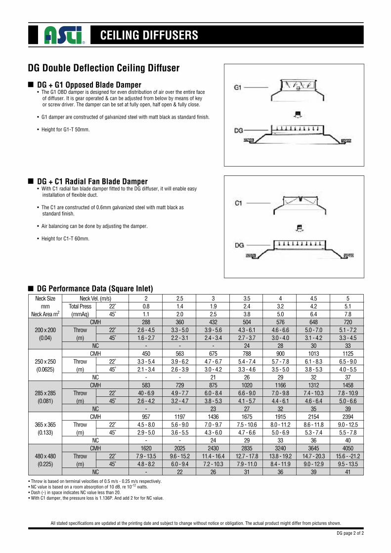
DG + G1 Opposed Blade Damper• The G1 OBD damper is designed for even distribution of air over the entire face of diffuser. It is gear operated & can be adjusted from below by means of key or screw driver. The damper can be set at fully open, half open & fully close.
• G1 damper are constructed of galvanized steel with matt black as standard finish.
• Height for G1-T 50mm.
DG Double Deflection Ceiling Diffuser
All stated specifications are updated at the printing date and subject to change without notice or obligation. The actual product might differ from pictures shown.
n
DG + C1 Radial Fan Blade Damper• With C1 radial fan blade damper fitted to the DG diffuser, it will enable easy installation of flexible duct.
• The C1 are constructed of 0.6mm galvanized steel with matt black as standard finish.
• Air balancing can be done by adjusting the damper.
• Height for C1-T 60mm.
n
n DG Performance Data (Square Inlet)Neck Size
mmNeck Area m2
200 x 200(0.04)
250 x 250(0.0625)
285 x 285(0.081)
365 x 365(0.133)
480 x 480(0.225)
Neck Vel. (m/s)
CMH
NCCMH
NCCMH
NCCMH
NCCMH
NC
Total Press(mmAq)
Throw(m)
Throw(m)
Throw(m)
Throw(m)
Throw(m)
31.92.5432
3.9 - 5.62.4 - 3.4
-675
4.7 - 6.73.0 - 4.2
21875
6.0 - 8.43.8 - 5.3
231436
7.0 - 9.74.3 - 6.0
242430
11.4 - 16.47.2 - 10.3
26
4.54.26.4648
5.0 - 7.03.1 - 4.2
301013
6.1 - 8.33.8 - 5.3
321312
7.4 - 10.34.6 - 6.4
352154
8.6 - 11.85.3 - 7.4
363645
14.7 - 20.39.0 - 12.9
39
3.52.43.8504
4.3 - 6.12.7 - 3.7
24788
5.4 - 7.43.3 - 4.6
261020
6.6 - 9.04.1 - 5.7
271675
7.5 - 10.64.7 - 6.6
292835
12.7 - 17.87.9 - 11.0
31
43.25.0576
4.6 - 6.63.0 - 4.0
28900
5.7 - 7.83.5 - 5.0
291166
7.0 - 9.84.4 - 6.1
321915
8.0 - 11.25.0 - 6.9
333240
13.8 - 19.28.4 - 11.9
36
55.17.8720
5.1 - 7.23.3 - 4.5
331125
6.5 - 9.04.0 - 5.5
371458
7.8 - 10.95.0 - 6.6
392394
9.0 - 12.55.5 - 7.8
404050
15.6 - -21.29.5 - 13.5
41
2.51.42.0360
3.3 - 5.02.2 - 3.1
-563
3.9 - 6.22.6 - 3.9
-729
4.9 - 7.73.2 - 4.7
-1197
5.6 - 9.03.6 - 5.5
-2025
9.6 - 15.26.0 - 9.4
22
20.81.1288
2.6 - 4.51.6 - 2.7
-450
3.3 - 5.42.1 - 3.4
-583
40 - 6.92.6 - 4.2
-957
4.5 - 8.02.9 - 5.0
-1620
7.9 - 13.54.8 - 8.2
-
22˚45˚
22˚45˚
22˚45˚
22˚45˚
22˚45˚
22˚45˚
•Throw is based on terminal velocities of 0.5 m/s - 0.25 m/s respectively.•NC value is based on a room absorption of 10 dB, re 10-12 watts.•Dash (-) in space indicates NC value less than 20.•With C1 damper, the pressure loss is 1.136P. And add 2 for for NC value.
DG page 2 of 2
CEILING DIFFUSERS
DJ Modular Core Directional Diffuser
■
■
■
■
■
■
All stated specifications are updated at the printing date and subject to change without notice or obligation. The actual product might differ from pictures shown.
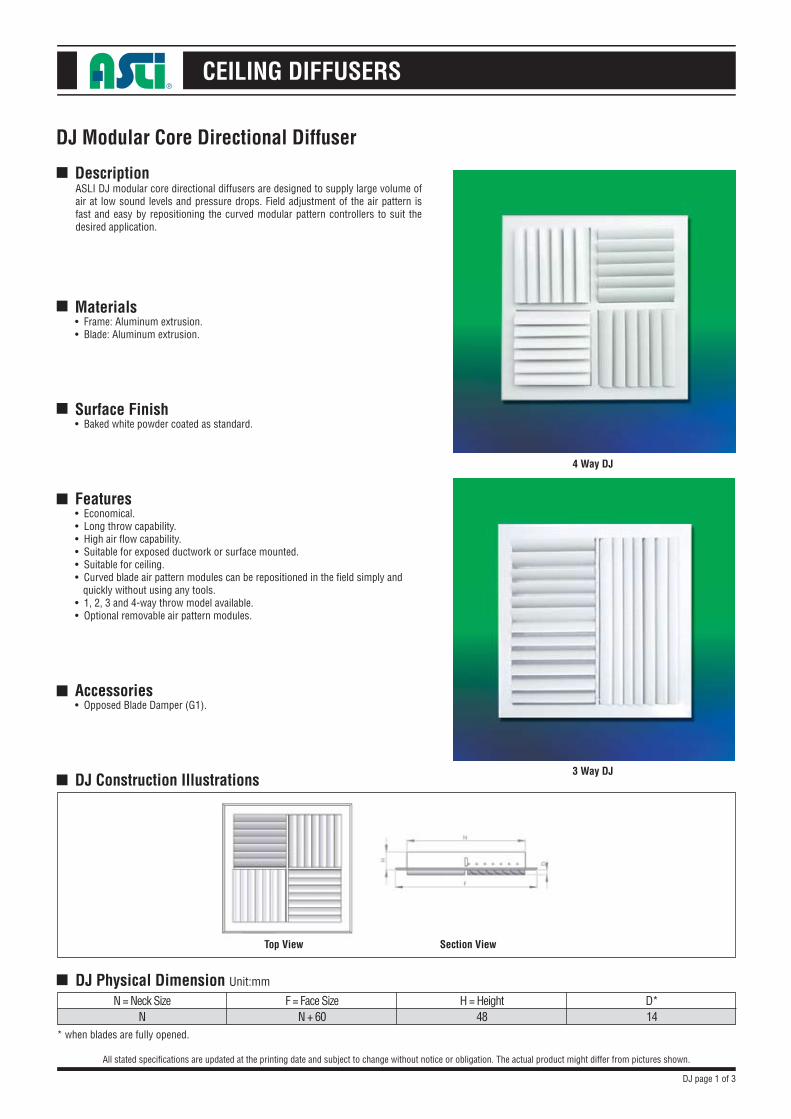
Description
Materials• Frame: Aluminum extrusion.• Blade: Aluminum extrusion.
Surface Finish• Baked white powder coated as standard.
Features• Economical.• Long throw capability.• High air flow capability.• Suitable for exposed ductwork or surface mounted.• Suitable for ceiling. • Curved blade air pattern modules can be repositioned in the field simply and quickly without using any tools.• 1, 2, 3 and 4-way throw model available.• Optional removable air pattern modules.
Accessories• Opposed Blade Damper (G1).
DJ Construction Illustrations
ASLI DJ modular core directional diffusers are designed to supply large volume of air at low sound levels and pressure drops. Field adjustment of the air pattern is fast and easy by repositioning the curved modular pattern controllers to suit the desired application.
* when blades are fully opened.
Top View
4 Way DJ
3 Way DJ
Section View
DJ page 1 of 3
■ DJ Physical Dimension Unit:mm
N = Neck SizeN
F = Face SizeN + 60
H = Height48
D*14
CEILING DIFFUSERS
DJ Modular Core Directional Diffuser
All stated specifications are updated at the printing date and subject to change without notice or obligation. The actual product might differ from pictures shown.
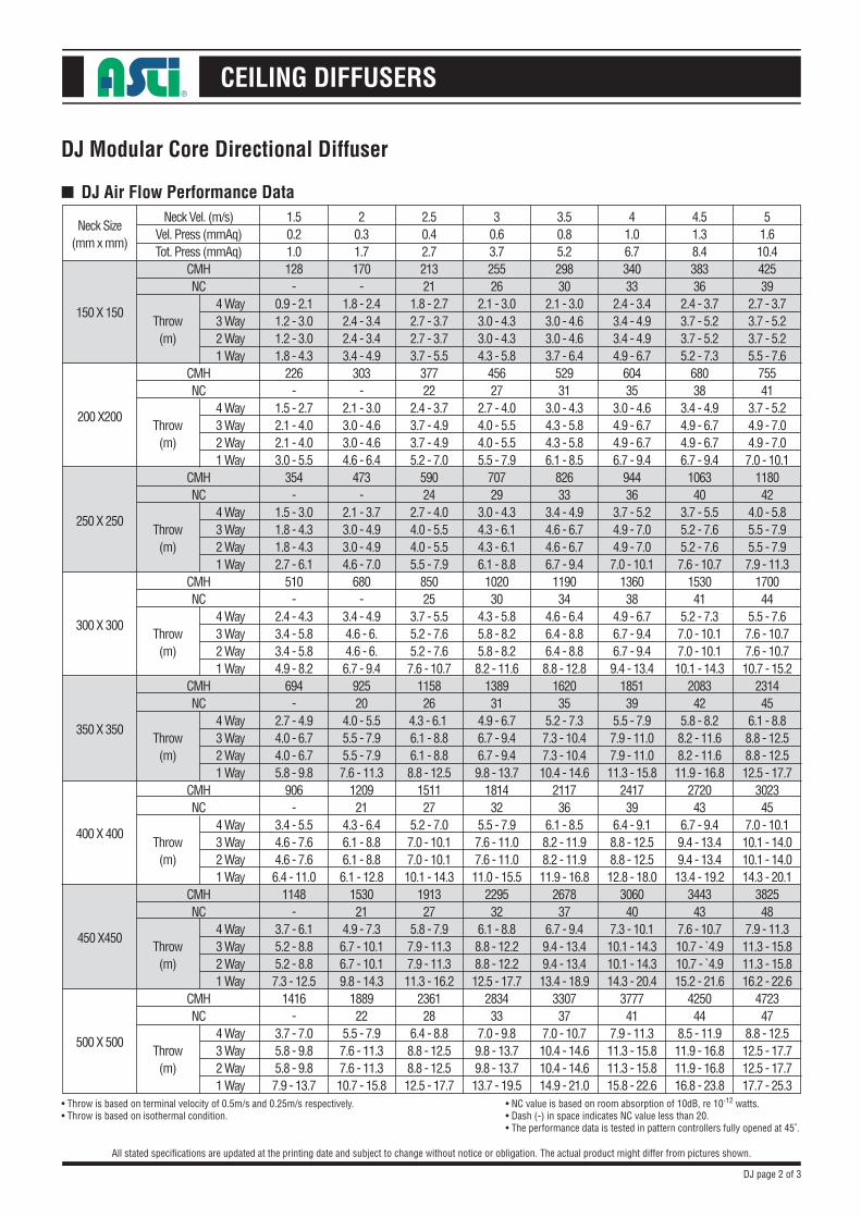
■ DJ Air Flow Performance Data
Neck Size(mm x mm)
150 X 150
200 X200
250 X 250
300 X 300
350 X 350
400 X 400
450 X450
500 X 500
Neck Vel. (m/s)Vel. Press (mmAq)Tot. Press (mmAq)
CMHNC
CMHNC
CMHNC
CMHNC
CMHNC
CMHNC
CMHNC
CMHNC
Throw(m)
Throw(m)
Throw(m)
Throw(m)
Throw(m)
Throw(m)
Throw(m)
Throw(m)
1.50.21.0128
-0.9 - 2.11.2 - 3.01.2 - 3.01.8 - 4.3
226-
1.5 - 2.72.1 - 4.02.1 - 4.03.0 - 5.5
354-
1.5 - 3.01.8 - 4.31.8 - 4.32.7 - 6.1
510-
2.4 - 4.33.4 - 5.83.4 - 5.84.9 - 8.2
694-
2.7 - 4.94.0 - 6.74.0 - 6.75.8 - 9.8
906-
3.4 - 5.54.6 - 7.64.6 - 7.66.4 - 11.0
1148-
3.7 - 6.15.2 - 8.85.2 - 8.87.3 - 12.5
1416-
3.7 - 7.05.8 - 9.85.8 - 9.87.9 - 13.7
4 Way3 Way2 Way1 Way
4 Way3 Way2 Way1 Way
4 Way3 Way2 Way1 Way
4 Way3 Way2 Way1 Way
4 Way3 Way2 Way1 Way
4 Way3 Way2 Way1 Way
4 Way3 Way2 Way1 Way
4 Way3 Way2 Way1 Way
DJ page 2 of 3
20.31.7170
-1.8 - 2.42.4 - 3.42.4 - 3.43.4 - 4.9
303-
2.1 - 3.03.0 - 4.63.0 - 4.64.6 - 6.4
473-
2.1 - 3.73.0 - 4.93.0 - 4.94.6 - 7.0
680-
3.4 - 4.94.6 - 6.4.6 - 6.6.7 - 9.4
92520
4.0 - 5.55.5 - 7.95.5 - 7.97.6 - 11.3
120921
4.3 - 6.46.1 - 8.86.1 - 8.86.1 - 12.8
153021
4.9 - 7.36.7 - 10.16.7 - 10.19.8 - 14.3
188922
5.5 - 7.97.6 - 11.37.6 - 11.310.7 - 15.8
2.50.42.721321
1.8 - 2.72.7 - 3.72.7 - 3.73.7 - 5.5
37722
2.4 - 3.73.7 - 4.93.7 - 4.95.2 - 7.0
59024
2.7 - 4.04.0 - 5.54.0 - 5.55.5 - 7.9
85025
3.7 - 5.55.2 - 7.65.2 - 7.67.6 - 10.7
115826
4.3 - 6.1 6.1 - 8.86.1 - 8.88.8 - 12.5
151127
5.2 - 7.07.0 - 10.17.0 - 10.110.1 - 14.3
191327
5.8 - 7.97.9 - 11.37.9 - 11.311.3 - 16.2
236128
6.4 - 8.88.8 - 12.58.8 - 12.512.5 - 17.7
30.63.725526
2.1 - 3.03.0 - 4.33.0 - 4.34.3 - 5.8
45627
2.7 - 4.04.0 - 5.54.0 - 5.55.5 - 7.9
70729
3.0 - 4.34.3 - 6.14.3 - 6.16.1 - 8.8
102030
4.3 - 5.85.8 - 8.25.8 - 8.28.2 - 11.6
138931
4.9 - 6.76.7 - 9.46.7 - 9.49.8 - 13.7
181432
5.5 - 7.97.6 - 11.07.6 - 11.011.0 - 15.5
229532
6.1 - 8.88.8 - 12.28.8 - 12.212.5 - 17.7
283433
7.0 - 9.89.8 - 13.79.8 - 13.713.7 - 19.5
3.50.85.229830
2.1 - 3.03.0 - 4.63.0 - 4.63.7 - 6.4
52931
3.0 - 4.34.3 - 5.84.3 - 5.86.1 - 8.5
82633
3.4 - 4.94.6 - 6.74.6 - 6.76.7 - 9.4
119034
4.6 - 6.46.4 - 8.86.4 - 8.88.8 - 12.8
162035
5.2 - 7.37.3 - 10.47.3 - 10.410.4 - 14.6
211736
6.1 - 8.58.2 - 11.98.2 - 11.911.9 - 16.8
267837
6.7 - 9.49.4 - 13.49.4 - 13.413.4 - 18.9
330737
7.0 - 10.710.4 - 14.610.4 - 14.614.9 - 21.0
41.06.734033
2.4 - 3.43.4 - 4.93.4 - 4.94.9 - 6.7
60435
3.0 - 4.64.9 - 6.74.9 - 6.76.7 - 9.4
94436
3.7 - 5.24.9 - 7.04.9 - 7.07.0 - 10.1
136038
4.9 - 6.76.7 - 9.46.7 - 9.49.4 - 13.4
185139
5.5 - 7.97.9 - 11.07.9 - 11.011.3 - 15.8
241739
6.4 - 9.18.8 - 12.58.8 - 12.512.8 - 18.0
306040
7.3 - 10.110.1 - 14.310.1 - 14.314.3 - 20.4
377741
7.9 - 11.311.3 - 15.811.3 - 15.815.8 - 22.6
4.51.38.438336
2.4 - 3.73.7 - 5.23.7 - 5.25.2 - 7.3
68038
3.4 - 4.94.9 - 6.74.9 - 6.76.7 - 9.4
106340
3.7 - 5.55.2 - 7.65.2 - 7.67.6 - 10.7
153041
5.2 - 7.37.0 - 10.17.0 - 10.110.1 - 14.3
208342
5.8 - 8.28.2 - 11.68.2 - 11.611.9 - 16.8
272043
6.7 - 9.49.4 - 13.49.4 - 13.413.4 - 19.2
344343
7.6 - 10.710.7 - ̀ 4.910.7 - ̀ 4.915.2 - 21.6
425044
8.5 - 11.911.9 - 16.811.9 - 16.816.8 - 23.8
51.610.442539
2.7 - 3.73.7 - 5.23.7 - 5.25.5 - 7.6
75541
3.7 - 5.24.9 - 7.04.9 - 7.07.0 - 10.1
118042
4.0 - 5.85.5 - 7.95.5 - 7.97.9 - 11.3
170044
5.5 - 7.67.6 - 10.77.6 - 10.710.7 - 15.2
231445
6.1 - 8.88.8 - 12.58.8 - 12.512.5 - 17.7
302345
7.0 - 10.110.1 - 14.010.1 - 14.014.3 - 20.1
382548
7.9 - 11.311.3 - 15.811.3 - 15.816.2 - 22.6
472347
8.8 - 12.512.5 - 17.712.5 - 17.717.7 - 25.3
• Throw is based on terminal velocity of 0.5m/s and 0.25m/s respectively.• Throw is based on isothermal condition.
• NC value is based on room absorption of 10dB, re 10-12 watts.• Dash (-) in space indicates NC value less than 20.• The performance data is tested in pattern controllers fully opened at 45˚.
CEILING DIFFUSERS
DJ Modular Core Directional Diffuser
All stated specifications are updated at the printing date and subject to change without notice or obligation. The actual product might differ from pictures shown.
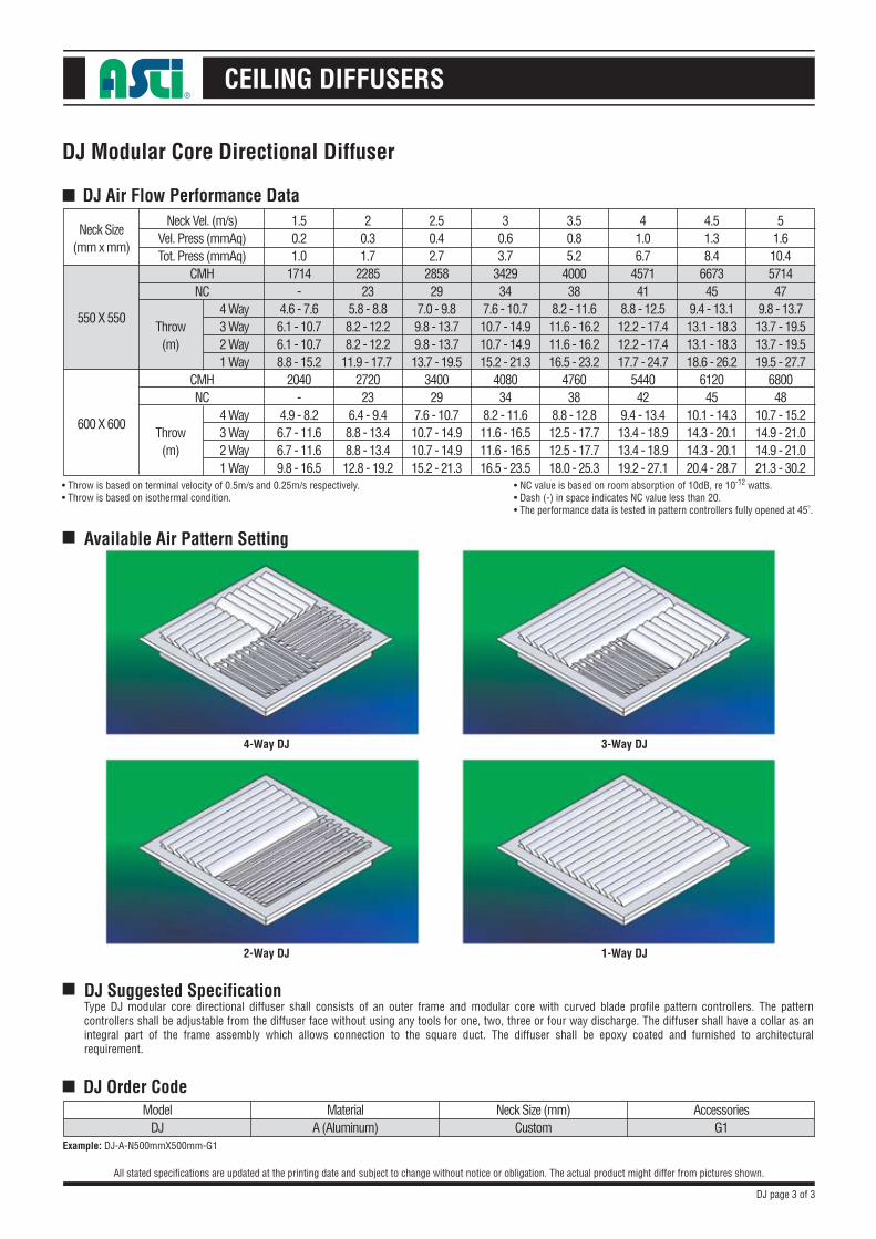
■ DJ Air Flow Performance Data
Neck Size(mm x mm)
550 X 550
600 X 600
Neck Vel. (m/s)Vel. Press (mmAq)Tot. Press (mmAq)
CMHNC
CMHNC
Throw(m)
Throw(m)
1.50.21.0
1714-
4.6 - 7.66.1 - 10.76.1 - 10.78.8 - 15.2
2040-
4.9 - 8.26.7 - 11.66.7 - 11.69.8 - 16.5
4 Way3 Way2 Way1 Way
4 Way3 Way2 Way1 Way
DJ page 3 of 3
20.31.7
228523
5.8 - 8.88.2 - 12.28.2 - 12.2
11.9 - 17.7 272023
6.4 - 9.48.8 - 13.48.8 - 13.412.8 - 19.2
2.50.42.7
285829
7.0 - 9.89.8 - 13.79.8 - 13.713.7 - 19.5
340029
7.6 - 10.710.7 - 14.910.7 - 14.915.2 - 21.3
30.63.7
342934
7.6 - 10.710.7 - 14.910.7 - 14.915.2 - 21.3
408034
8.2 - 11.611.6 - 16.511.6 - 16.516.5 - 23.5
3.50.85.2
400038
8.2 - 11.611.6 - 16.211.6 - 16.216.5 - 23.2
476038
8.8 - 12.812.5 - 17.712.5 - 17.718.0 - 25.3
41.06.7
457141
8.8 - 12.512.2 - 17.412.2 - 17.417.7 - 24.7
544042
9.4 - 13.413.4 - 18.913.4 - 18.919.2 - 27.1
4.51.38.4
667345
9.4 - 13.113.1 - 18.313.1 - 18.318.6 - 26.2
612045
10.1 - 14.314.3 - 20.114.3 - 20.120.4 - 28.7
51.610.4571447
9.8 - 13.713.7 - 19.513.7 - 19.519.5 - 27.7
680048
10.7 - 15.214.9 - 21.014.9 - 21.021.3 - 30.2
• Throw is based on terminal velocity of 0.5m/s and 0.25m/s respectively.• Throw is based on isothermal condition.
• NC value is based on room absorption of 10dB, re 10-12 watts.• Dash (-) in space indicates NC value less than 20.• The performance data is tested in pattern controllers fully opened at 45˚.
■
■
DJ Order CodeModel
DJExample: DJ-A-N500mmX500mm-G1
DJ Suggested SpecificationType DJ modular core directional diffuser shall consists of an outer frame and modular core with curved blade profile pattern controllers. The pattern controllers shall be adjustable from the diffuser face without using any tools for one, two, three or four way discharge. The diffuser shall have a collar as an integral part of the frame assembly which allows connection to the square duct. The diffuser shall be epoxy coated and furnished to architectural requirement.
■ Available Air Pattern Setting
MaterialA (Aluminum)
Neck Size (mm)Custom
AccessoriesG1
4-Way DJ 3-Way DJ
2-Way DJ 1-Way DJ
CEILING DIFFUSERS
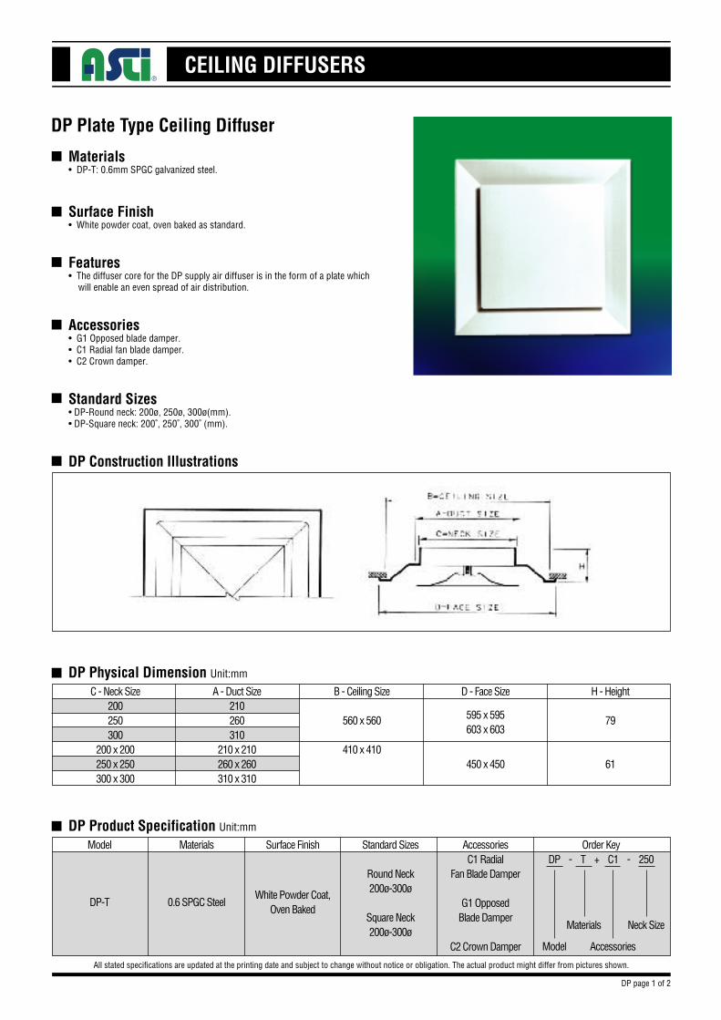
Materials• DP-T: 0.6mm SPGC galvanized steel.
Surface Finish• White powder coat, oven baked as standard.
Features• The diffuser core for the DP supply air diffuser is in the form of a plate which will enable an even spread of air distribution.
Accessories• G1 Opposed blade damper.• C1 Radial fan blade damper.• C2 Crown damper.
Standard Sizes• DP-Round neck: 200ø, 250ø, 300ø(mm).• DP-Square neck: 200˚, 250˚, 300˚ (mm).
DP Construction Illustrations
DP Plate Type Ceiling Diffuser
All stated specifications are updated at the printing date and subject to change without notice or obligation. The actual product might differ from pictures shown.
n
n
n
n
n
n
n
DP Physical Dimension Unit:mm
C - Neck Size200250300
200 x 200250 x 250300 x 300
A - Duct Size210260310
210 x 210260 x 260310 x 310
B - Ceiling Size
560 x 560
410 x 410
595 x 595603 x 603
D - Face Size
450 x 450
H - Height
79
61
n DP Product Specification Unit:mm
Model Materials Surface Finish
White Powder Coat,Oven Baked
0.6 SPGC SteelDP-T
AccessoriesC1 Radial
Fan Blade Damper
G1 OpposedBlade Damper
C2 Crown Damper
Standard Sizes
Round Neck200ø-300ø
Square Neck200ø-300ø
Order KeyDP - T + C1 - 250
Model
Materials
Accessories
Neck Size
DP page 1 of 2
CEILING DIFFUSERS
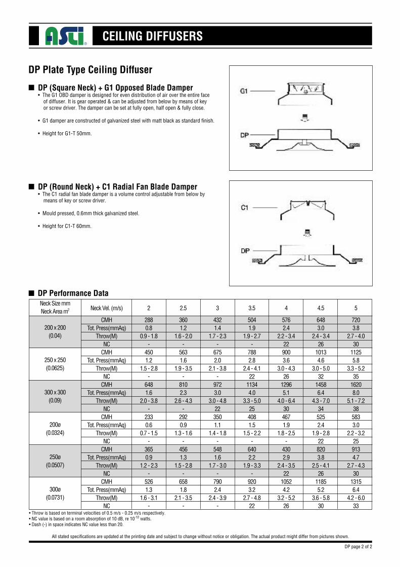
DP (Square Neck) + G1 Opposed Blade Damper• The G1 OBD damper is designed for even distribution of air over the entire face of diffuser. It is gear operated & can be adjusted from below by means of key or screw driver. The damper can be set at fully open, half open & fully close.
• G1 damper are constructed of galvanized steel with matt black as standard finish.
• Height for G1-T 50mm.
DP Plate Type Ceiling Diffuser
All stated specifications are updated at the printing date and subject to change without notice or obligation. The actual product might differ from pictures shown.
n
DP (Round Neck) + C1 Radial Fan Blade Damper• The C1 radial fan blade damper is a volume control adjustable from below by means of key or screw driver.
• Mould pressed, 0.6mm thick galvanized steel.
• Height for C1-T 60mm.
n
n DP Performance DataNeck Size mmNeck Area m2
200 x 200(0.04)
250 x 250(0.0625)
300 x 300(0.09)
200ø(0.0324)
250ø(0.0507)
300ø(0.0731)
CMHTot. Press(mmAq)
Throw(M)NC
CMHTot. Press(mmAq)
Throw(M)NC
CMHTot. Press(mmAq)
Throw(M)NC
CMHTot. Press(mmAq)
Throw(M)NC
CMHTot. Press(mmAq)
Throw(M)NC
CMHTot. Press(mmAq)
Throw(M)NC
Neck Vel. (m/s)
4321.4
1.7 - 2.3-
6752.0
2.1 - 3.8-
9723.0
3.0 - 4.8223501.1
1.4 - 1.8-
5481.6
1.7 - 3.0-
7902.4
2.4 - 3.9-
3
6483.0
2.4 - 3.426
10134.6
3.0 - 5.032
14586.4
4.3 - 7.0345252.4
1.9 - 2.8228203.8
2.5 - 4.126
11855.2
3.6 - 5.830
4.5
5041.9
1.9 - 2.7-
7882.8
2.4 - 4.122
11344.0
3.3 - 5.0254081.5
1.5 - 2.2-
6402.2
1.9 - 3.3-
9203.2
2.7 - 4.822
3.5
5762.4
2.2 - 3.4229003.6
3.0 - 4.326
12965.1
4.0 - 6.4304671.9
1.8 - 2.5-
4302.9
2.4 - 3.522
10524.2
3.2 - 5.226
4
7203.8
2.7 - 4.030
11255.8
3.3 - 5.235
16208.0
5.1 - 7.2385833.0
2.2 - 3.2259134.7
2.7 - 4.330
13156.4
4.2 - 6.033
5
3601.2
1.6 - 2.0-
5631.6
1.9 - 3.5-
8102.3
2.6 - 4.3-
2920.9
1.3 - 1.6-
4561.3
1.5 - 2.8-
6581.8
2.1 - 3.5-
2.5
2880.8
0.9 - 1.8-
4501.2
1.5 - 2.8-
6481.6
2.0 - 3.8-
2330.6
0.7 - 1.5-
3650.9
1.2 - 2.3-
5261.3
1.6 - 3.1-
2
•Throw is based on terminal velocities of 0.5 m/s - 0.25 m/s respectively.•NC value is based on a room absorption of 10 dB, re 10-12 watts.•Dash (-) in space indicates NC value less than 20.
DP page 2 of 2
CEILING DIFFUSERS
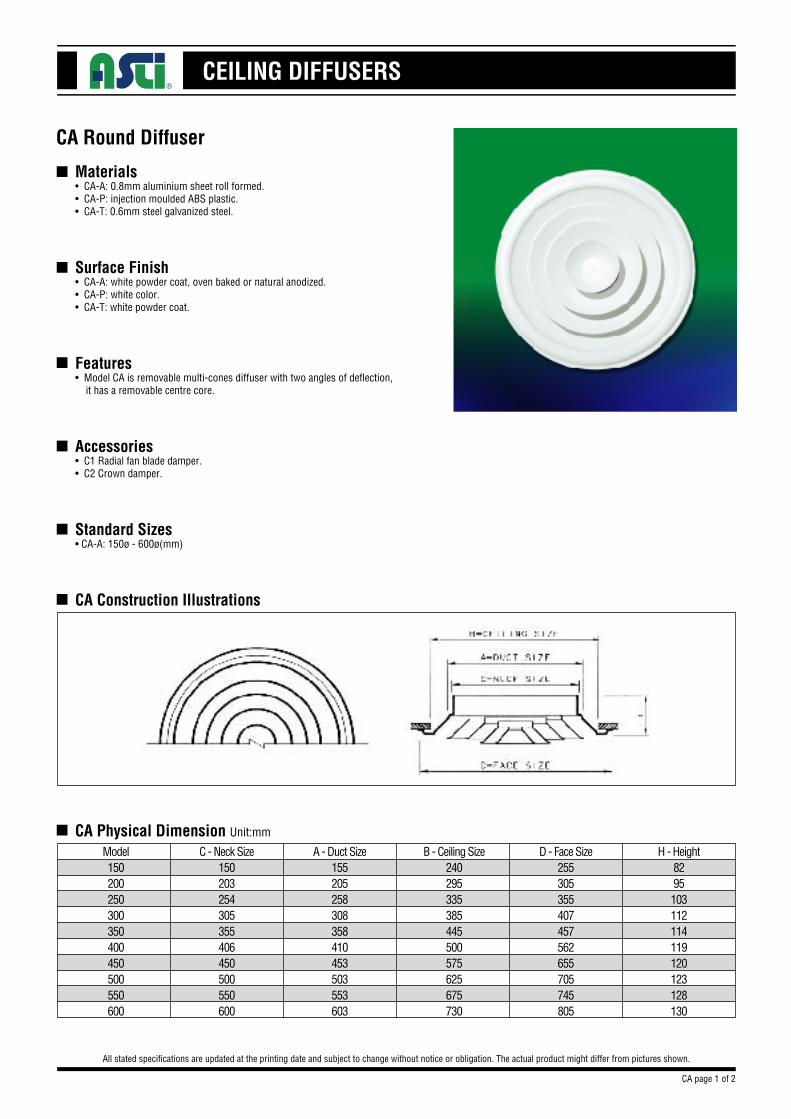
Materials• CA-A: 0.8mm aluminium sheet roll formed.• CA-P: injection moulded ABS plastic.• CA-T: 0.6mm steel galvanized steel.
Surface Finish• CA-A: white powder coat, oven baked or natural anodized.• CA-P: white color.• CA-T: white powder coat.
Features• Model CA is removable multi-cones diffuser with two angles of deflection, it has a removable centre core.
Accessories• C1 Radial fan blade damper.• C2 Crown damper.
Standard Sizes• CA-A: 150ø - 600ø(mm)
CA Construction Illustrations
CA Round Diffuser
All stated specifications are updated at the printing date and subject to change without notice or obligation. The actual product might differ from pictures shown.
n
n
n
n
n
n
n
CA Physical Dimension Unit:mm
Model150200250300350400450500550600
C - Neck Size150203254305355406450500550600
A - Duct Size155205258308358410453503553603
B - Ceiling Size240295335385445500575625675730
D - Face Size255305355407457562655705745805
H - Height8295103112114119120123128130
CA page 1 of 2
CEILING DIFFUSERS
CA Round Diffuser
All stated specifications are updated at the printing date and subject to change without notice or obligation. The actual product might differ from pictures shown.
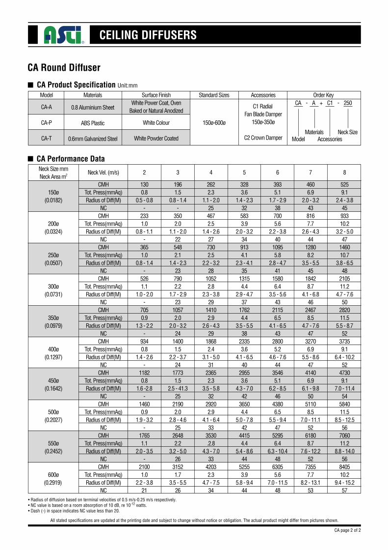
n CA Performance DataNeck Size mmNeck Area m2
150ø(0.0182)
200ø(0.0324)
250ø(0.0507)
300ø(0.0731)
350ø(0.0979)
400ø(0.1297)
450ø(0.1642)
500ø(0.2027)
550ø(0.2452)
600ø(0.2919)
CMHTot. Press(mmAq)Radius of Diff(M)
NCCMH
Tot. Press(mmAq)Radius of Diff(M)
NCCMH
Tot. Press(mmAq)Radius of Diff(M)
NCCMH
Tot. Press(mmAq)Radius of Diff(M)
NCCMH
Tot. Press(mmAq)Radius of Diff(M)
NCCMH
Tot. Press(mmAq)Radius of Diff(M)
NCCMH
Tot. Press(mmAq)Radius of Diff(M)
NCCMH
Tot. Press(mmAq)Radius of Diff(M)
NCCMH
Tot. Press(mmAq)Radius of Diff(M)
NCCMH
Tot. Press(mmAq)Radius of Diff(M)
NC
Neck Vel. (m/s)
2622.3
1.1 - 2.0254672.5
1.4 - 2.6277302.5
2.2 - 3.228
10522.8
2.3 - 3.829
14102.9
2.6 - 4.329
18682.4
3.1 - 5.031
23652.3
3.5 - 5.832
29202.9
4.1 - 6.433
3530.2.8
4.3 - 7.033
42032.3
4.7 - 7.534
4
4606.9
2.0 - 3.2438167.7
2.6 - 4.344
12808.2
3.5 - 5.545
18428.7
4.1 - 6.846
24678.5
4.7 - 7.647
32706.9
5.5 - 8.647
41406.9
6.1 - 9.850
51108.5
7.0 - 11.152
61808.7
7.6 - 12.252
73557.7
8.2 - 13.153
7
3283.6
1.4 - 2.3325833.9
2.0 - 3.2349134.1
2.3 - 4.135
13154.4
2.9 - 4.737
17624.4
3.5 - 5.538
23353.6
4.1 - 6.540
29553.6
4.3 - 7.042
36504.4
5.0 - 7.842
44154.4
5.4 - 8.644
52553.9
5.8 - 9.444
5
3935.1
1.7 - 2.9387005.6
2.2 - 3.840
10955.8
2.8 - 4.741
15806.4
3.5 - 5.643
21156.5
4.1 - 6.543
28005.2
4.6 - 7.644
35465.1
6.2 - 8.546
43806.5
5.5 - 9.447
52956.4
6.3 - 10.448
63055.6
7.0 - 11.548
6
5259.1
2.4 - 3.84593310.2
3.2 - 5.047
146010.7
3.8 - 6.548
210511.2
4.7 - 7.650
282011.5
5.5 - 8.752
37359.1
6.4 - 10.252
47309.1
7.0 - 11.454
584011.5
8.5 - 12.556
706011.2
8.8 - 14.056
840510.2
9.4 - 15.257
8
1961.5
0.8 - 1.4-
3502.0
1.1 - 2.0225482.1
1.4 - 2.3237902.2
1.7 - 2.923
10572.0
2.0 - 3.224
14001.5
2.2 - 3.724
17731.5
2.5 - 41.325
21902.0
2.8 - 4.625
26482.2
3.2 - 5.026
31521.7
3.5 - 5.526
3
1300.8
0.5 - 0.8-
2331.0
0.8 - 1.1-
3651.0
0.8 - 1.4-
5261.1
1.0 - 2.0-
7050.9
1.3 - 2.2-
9340.8
1.4 - 2.6-
11820.8
1.6 -2.8-
14600.9
1.9 - 3.2-
17651.1
2.0 - 3.5-
21001.0
2.2 - 3.821
2
•Radius of diffusion based on terminal velocities of 0.5 m/s-0.25 m/s respectively.•NC value is based on a room absorption of 10 dB, re 10-12 watts.•Dash (-) in space indicates NC value less than 20.
CA page 2 of 2
n CA Product Specification Unit:mm
Model
CA-A
CA-P
CA-T
Materials
0.8 Aluminium Sheet
ABS Plastic
0.6mm Galvanized Steel
Surface FinishWhite Power Coat, Oven
Baked or Natural Anodized
White Colour
White Powder Coated
Accessories
C1 Radial Fan Blade Damper
150ø-350ø
C2 Crown Damper
Standard Sizes
150ø-600ø
Order KeyCA - A + C1 - 250
ModelMaterials
AccessoriesNeck Size
CEILING DIFFUSERS
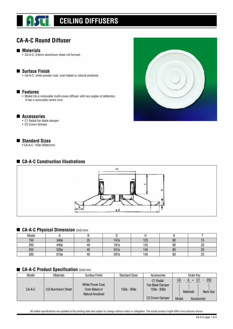
Materials• CA-A-C: 0.8mm aluminium sheet roll formed.
Surface Finish• CA-A-C: white powder coat, oven baked or natural anodized.
Features• Model CA is removable multi-cones diffuser with two angles of deflection, it has a removable centre core.
Accessories• C1 Radial fan blade damper.• C2 Crown damper.
Standard Sizes• CA-A-C: 150ø-300ø(mm)
CA-A-C Construction Illustrations
CA-A-C Round Diffuser
All stated specifications are updated at the printing date and subject to change without notice or obligation. The actual product might differ from pictures shown.
n
n
n
n
n
n
n
CA-A-C Physical Dimension Unit:mm
Model150200250300
A340ø440ø520ø610ø
B35404045
D147ø197ø247ø297ø
H125135145145
K80808080
T15202023
n CA-A-C Product Specification Unit:mm
Model
CA-A-C
Materials
0.8 Aluminium Sheet
Surface Finish
White Power Coat,Oven Baked or
Natural Anodized
Accessories
C1 Radial Fan Blade Damper
150ø - 300ø
C2 Crown Damper
Standard Sizes
150ø - 300ø
Order KeyCA - A + C1 - 250
Model
Materials
Accessories
Neck Size
CA-A-C page 1 of 2
CEILING DIFFUSERS
CA-A-C Round Diffuser
All stated specifications are updated at the printing date and subject to change without notice or obligation. The actual product might differ from pictures shown.
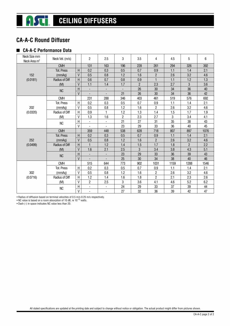
n CA-A-C Performance DataNeck Size mm Neck Area m2
152(0.0181)
202(0.0320)
252(0.0499)
302(0.0716)
CMHTot. Press(mmAq)
Radius of Diff(M)
CMHTot. Press(mmAq)
Radius of Diff(M)
CMHTot. Press(mmAq)
Radius of Diff(M)
CMHTot. Press(mmAq)
Radius of Diff(M)
1310.20.50.61.1--
2310.20.50.91.3--
3590.20.51
1.6--
5150.20.51.22--
HVHVHV
HVHVHV
HVHVHV
HVHVHV
•Radius of diffusion based on terminal velocities of 0.5 m/s-0.25 m/s respectively.•NC value is based on a room absorption of 10 dB, re 10-12 watts.•Dash (-) in space indicates NC value less than 20.
1630.30.80.71.4--
2880.30.81
1.6--
4480.30.81.22.1--
6440.30.81.42.5--
2610.921
2.330304610.92
1.42.731337180.92
1.73.43334
10310.922
4.13336
1960.51.20.81.7-
213460.51.21.2221235380.51.21.42.523257730.51.21.632427
2280.71.60.9226264030.71.61.32.327296280.71.61.5329309020.71.61.83.62932
2941.12.61.12.734345191.12.61.5335368071.12.61.83.83638
11591.12.62.14.63739
3922.14.61.33.640426922.14.61.94.14345
10762.14.62.25.14346
15462.14.62.66.24447
3261.43.21.2336365761.43.21.73.438408971.43.22
4.33940
12881.43.22.35.23942
NC
NC
NC
NC
CA-A-C page 2 of 2
Neck Vel. (m/s) 3 4.53.5 4 5 62.52
CEILING DIFFUSERS
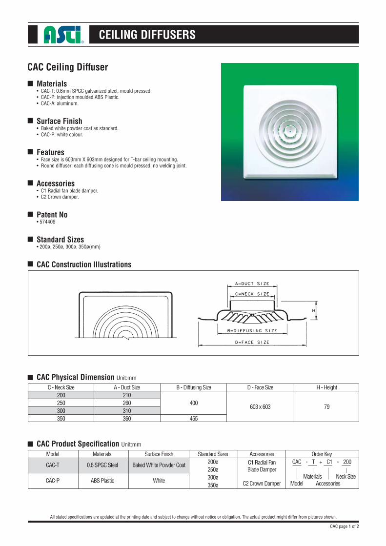
Materials• CAC-T: 0.6mm SPGC galvanized steel, mould pressed.• CAC-P: injection moulded ABS Plastic.• CAC-A: aluminum.
Surface Finish• Baked white powder coat as standard.• CAC-P: white colour.
Features• Face size is 603mm X 603mm designed for T-bar ceiling mounting.• Round diffuser: each diffusing cone is mould pressed, no welding joint.
Accessories• C1 Radial fan blade damper.• C2 Crown damper.
Patent No• 574406
Standard Sizes• 200ø, 250ø, 300ø, 350ø(mm)
CAC Construction Illustrations
CAC Ceiling Diffuser
All stated specifications are updated at the printing date and subject to change without notice or obligation. The actual product might differ from pictures shown.
■
■
■
■
■
■
■
■
CAC Physical Dimension Unit:mm
C - Neck Size200250300350
A - Duct Size210260310360
B - Diffusing Size
400
455
D - Face Size H - Height
■ CAC Product Specification Unit:mm
Model Materials Surface Finish
CAC-T
CAC-P
0.6 SPGC Steel
ABS Plastic
Baked White Powder Coat
White
AccessoriesC1 Radial FanBlade Damper
C2 Crown Damper
Standard Sizes200ø250ø300ø350ø
Order KeyCAC - T + C1 - 200
ModelMaterials
AccessoriesNeck Size
603 x 603 79
CAC page 1 of 2
CEILING DIFFUSERS
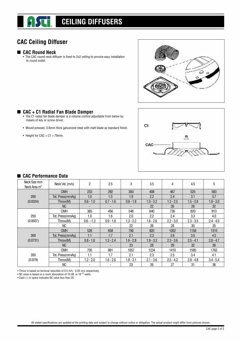
CAC Round Neck • The CAC round neck diffuser is fixed to 2x2 ceiling to provice easy installation to round outlet.
CAC Ceiling Diffuser
All stated specifications are updated at the printing date and subject to change without notice or obligation. The actual product might differ from pictures shown.
n
CAC + C1 Radial Fan Blade Damper• The C1 radial fan blade damper is a volume control adjustable from below by means of key or screw driver.
• Mould pressed, 0.6mm thick galvanized steel with matt blade as standard finish.
• Height for CAC + C1 = 79mm.
n
n CAC Performance DataNeck Size mmNeck Area m2
200(0.0324)
250(0.0507)
300(0.0731)
350(0.979)
CMHTot. Press(mmAq)
Throw(M)NC
CMHTot. Press(mmAq)
Throw(M)NC
CMHTot. Press(mmAq)
Throw(M)NC
CMHTot. Press(mmAq)
Throw(M)NC
3501.9
0.8 - 1.8-
5482.0
1.3 - 2.2227902.1
1.6 - 2.823
10572.1
1.8 - 3.123
5253.1
1.5 - 2.8288203.3
2.3 - 3.530
11583.5
2.5 - 4.132
15853.4
2.8 - 4.831
4082.2
1.0 - 2.2226402.2
1.6 - 2.6269202.3
1.9 - 3.328
12342.3
2.1 - 3.626
4672.4
1.2 - 2.5267302.4
2.2 - 3.028
10522.6
2.3 - 3.629
14102.5
2.5 - 4.227
5833.7
1.8 - 3.0329134.0
2.4 - 4.035
13154.2
2.8 - 4.736
17624.1
3.4 - 5.436
2921.5
0.7 - 1.6-
4561.6
0.9 - 1.8-
6581.7
1.3 - 2.4-
8811.7
1.6 - 2.6-
2331.0
0.6 - 1.0-
3651.0
0.6 - -1.3-
5261.1
0.8 - 1.8-
7051.1
1.2 - 2.0-
•Throw is based on terminal velocities of 0.5 m/s - 0.25 m/s respectively.•NC value is based on a room absorption of 10 dB, re 10-12 watts.•Dash (-) in space indicates NC value less than 20.
CAC page 2 of 2
Neck Vel. (m/s) 3 4.53.5 4 52.52
CEILING DIFFUSERS
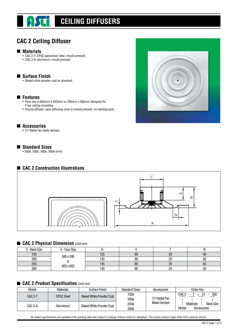
Materials• CAC 2-T: SPGC galvanized steel, mould pressed.• CAC 2-A: aluminum, mould pressed.
Surface Finish• Baked white powder coat as standard.
Features• Face size is 603mm X 603mm or 595mm x 595mm designed for T-bar ceiling mounting.• Round diffuser: each diffusing cone is mould pressed, no welding joint.
Accessories• C1 Radial fan blade damper.
Standard Sizes• 200ø, 250ø, 300ø, 350ø (mm)
CAC 2 Construction Illustrations
CAC 2 Ceiling Diffuser
All stated specifications are updated at the printing date and subject to change without notice or obligation. The actual product might differ from pictures shown.
■
■
■
■
■
■
■
CAC 2 Physical Dimension Unit:mm
C - Neck Size150200250300
■ CAC 2 Product Specification Unit:mm
Model Materials Surface Finish
CAC 2-T
CAC 2-A
SPGC Steel
Aluminium
Baked White Powder Coat
Baked White Powder Coat
Accessories
C1 Radial FanBlade Damper
Standard Sizes150ø200ø250ø300ø
Order KeyCAC 2 - T + C1 - 200
ModelMaterials
AccessoriesNeck Size
CAC 2 page 1 of 2
A - Face Size
595 x 595or
603 x 603
H125135145145
E80808080
T20202020
N40404040
CEILING DIFFUSERS
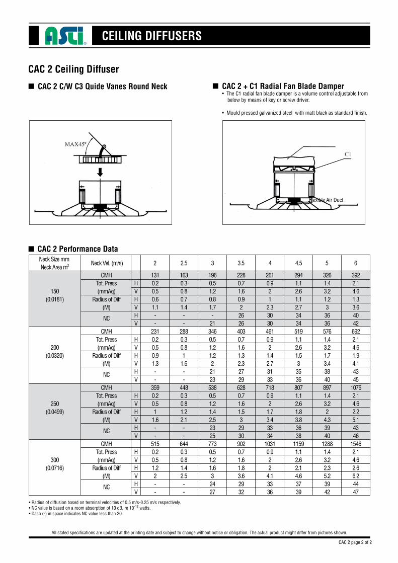
CAC 2 C/W C3 Quide Vanes Round Neck
CAC 2 Ceiling Diffuser
All stated specifications are updated at the printing date and subject to change without notice or obligation. The actual product might differ from pictures shown.
■ CAC 2 + C1 Radial Fan Blade Damper• The C1 radial fan blade damper is a volume control adjustable from below by means of key or screw driver.
• Mould pressed galvanized steel with matt black as standard finish.
■
■ CAC 2 Performance Data
CAC 2 page 2 of 2
Flexible Air Duct
Neck Size mm Neck Area m2
150(0.0181)
200(0.0320)
250(0.0499)
300(0.0716)
CMHTot. Press(mmAq)
Radius of Diff(M)
CMHTot. Press(mmAq)
Radius of Diff(M)
CMHTot. Press(mmAq)
Radius of Diff(M)
CMHTot. Press(mmAq)
Radius of Diff(M)
1310.20.50.61.1--
2310.20.50.91.3--
3590.20.51
1.6--
5150.20.51.22--
HVHVHV
HVHVHV
HVHVHV
HVHVHV
• Radius of diffusion based on terminal velocities of 0.5 m/s-0.25 m/s respectively.• NC value is based on a room absorption of 10 dB, re 10-12 watts.• Dash (-) in space indicates NC value less than 20.
1630.30.80.71.4--
2880.30.81
1.6--
4480.30.81.22.1--
6440.30.81.42.5--
2610.921
2.330304610.92
1.42.731337180.92
1.73.43334
10310.922
4.13336
1960.51.20.81.7-
213460.51.21.2221235380.51.21.42.523257730.51.21.632427
2280.71.60.9226264030.71.61.32.327296280.71.61.5329309020.71.61.83.62932
2941.12.61.12.734345191.12.61.5335368071.12.61.83.83638
11591.12.62.14.63739
3922.14.61.33.640426922.14.61.94.14345
10762.14.62.25.14346
15462.14.62.66.24447
3261.43.21.2336365761.43.21.73.438408971.43.22
4.33940
12881.43.22.35.23942
NC
NC
NC
NC
Neck Vel. (m/s) 3 4.53.5 4 5 62.52
BC
ED
H
CEILING DIFFUSERS
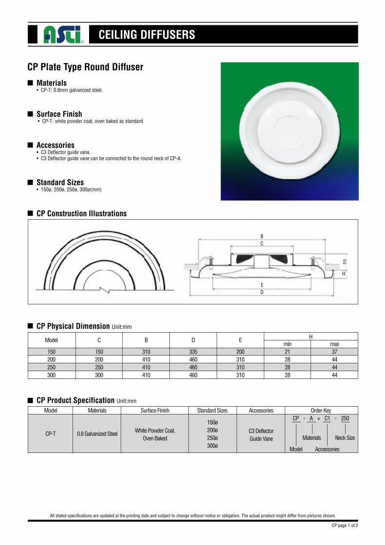
Materials• CP-T: 0.8mm galvanized steel.
Surface Finish • CP-T: white powder coat, oven baked as standard.
Accessories• C3 Deflector guide vane.• C3 Deflector guide vane can be connected to the round neck of CP-A.
Standard Sizes• 150ø, 200ø, 250ø, 300ø(mm)
CP Construction Illustrations
CP Plate Type Round Diffuser
All stated specifications are updated at the printing date and subject to change without notice or obligation. The actual product might differ from pictures shown.
n
n
n
n
n
n
CP Physical Dimension Unit:mm
max37444444
n CP Product Specification Unit:mm
Model
CP-T
Materials
0.8 Galvanized Steel
Surface Finish
White Powder Coat,Oven Baked
Accessories
C3 DeflectorGuide Vane
Standard Sizes
150ø200ø250ø300ø
Order KeyCP - A + C1 - 250
Model
Materials
Accessories
Neck Size
CP page 1 of 2
min21282828
H
200310310310
335460460460
310410410410
EDB
150200250300
C
150200250300
Model
CEILING DIFFUSERS
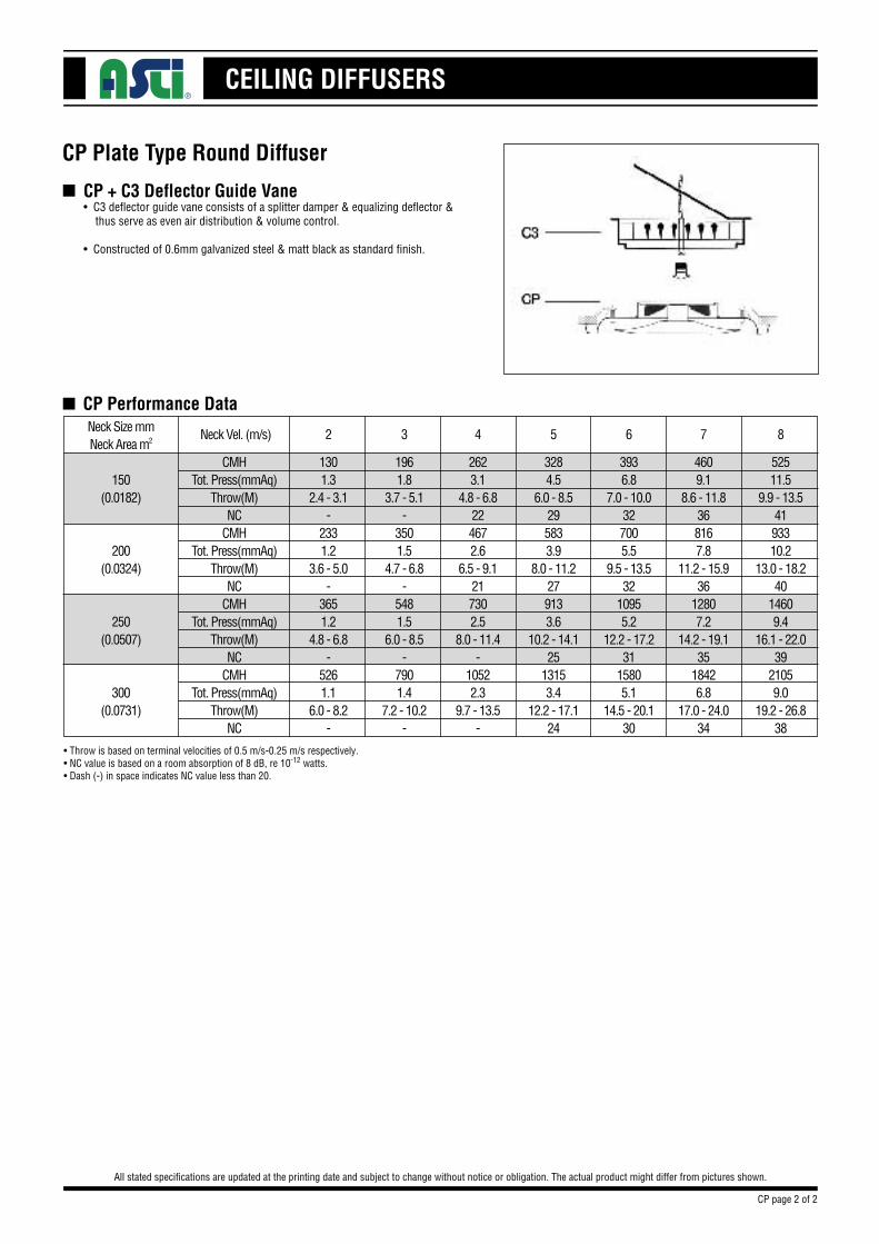
CP + C3 Deflector Guide Vane• C3 deflector guide vane consists of a splitter damper & equalizing deflector & thus serve as even air distribution & volume control.
• Constructed of 0.6mm galvanized steel & matt black as standard finish.
CP Plate Type Round Diffuser
All stated specifications are updated at the printing date and subject to change without notice or obligation. The actual product might differ from pictures shown.
n
n CP Performance DataNeck Size mmNeck Area m2
150(0.0182)
200(0.0324)
250(0.0507)
300(0.0731)
CMHTot. Press(mmAq)
Throw(M)NC
CMHTot. Press(mmAq)
Throw(M)NC
CMHTot. Press(mmAq)
Throw(M)NC
CMHTot. Press(mmAq)
Throw(M)NC
2623.1
4.8 - 6.8224672.6
6.5 - 9.1217302.5
8.0 - 11.4-
10522.3
9.7 - 13.5-
4609.1
8.6 - 11.8368167.8
11.2 - 15.936
12807.2
14.2 - 19.135
18426.8
17.0 - 24.034
3284.5
6.0 - 8.5295833.9
8.0 - 11.2279133.6
10.2 - 14.125
13153.4
12.2 - 17.124
3936.8
7.0 - 10.0327005.5
9.5 - 13.532
10955.2
12.2 - 17.231
15805.1
14.5 - 20.130
52511.5
9.9 - 13.54193310.2
13.0 - 18.240
14609.4
16.1 - 22.039
21059.0
19.2 - 26.838
1961.8
3.7 - 5.1-
3501.5
4.7 - 6.8-
5481.5
6.0 - 8.5-
7901.4
7.2 - 10.2-
1301.3
2.4 - 3.1-
2331.2
3.6 - 5.0-
3651.2
4.8 - 6.8-
5261.1
6.0 - 8.2-
•Throw is based on terminal velocities of 0.5 m/s-0.25 m/s respectively.•NC value is based on a room absorption of 8 dB, re 10-12 watts.•Dash (-) in space indicates NC value less than 20.
Neck Vel. (m/s) 4 75 6 832
CP page 2 of 2
CEILING DIFFUSERS
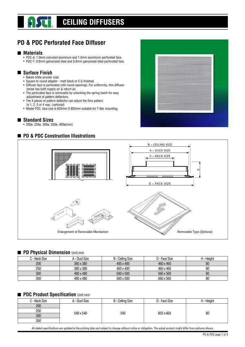
Materials• PDC-A: 1.0mm extruded aluminum and 1.0mm aluminum perforated face.• PDC-T: 0.8mm galvanized steel and 0.8mm galvanized steel perforated face.
Surface Finish• Baked white powder coat.• Square to round adapter - matt black or E.G finished.• Diffuser face is perforated with round openings. For uniformity, this diffuser series has both supply air & return air. • The perforated face is removable by unlocking the spring hatch for easy adjustment of pattern deflectors.• The 4 pieces of pattern deflector can adjust the flow pattern to 1, 2, 3 or 4 way. (optional)• Model PDC, face size is 603mm X 603mm suitable for T-Bar mounting.
Standard Sizes• 200ø, 250ø, 300ø, 350ø, 400ø(mm)
PD & PDC Construction Illustrations
PD & PDC Perforated Face Diffuser
All stated specifications are updated at the printing date and subject to change without notice or obligation. The actual product might differ from pictures shown.
n
n
n
n
n
PD Physical Dimension Unit:mm
C - Neck Size200250300350
A - Duct Size380 x 380380 x 380480 x 480480 x 480
B - Ceiling Size400 x 400400 x 400500 x 500500 x 500
D - Face Size460 x 460460 x 460560 x 560560 x 560
H - Height80808080
C - Neck Size200250300350
A - Duct Size B - Ceiling Size D - Face Size H - Height
540 x 540 545 603 x 603 80
n PDC Product Specification Unit:mm
PD & PDC page 1 of 3
Enlargement of Removable Mechanism Removable Type (Optional)
CEILING DIFFUSERS
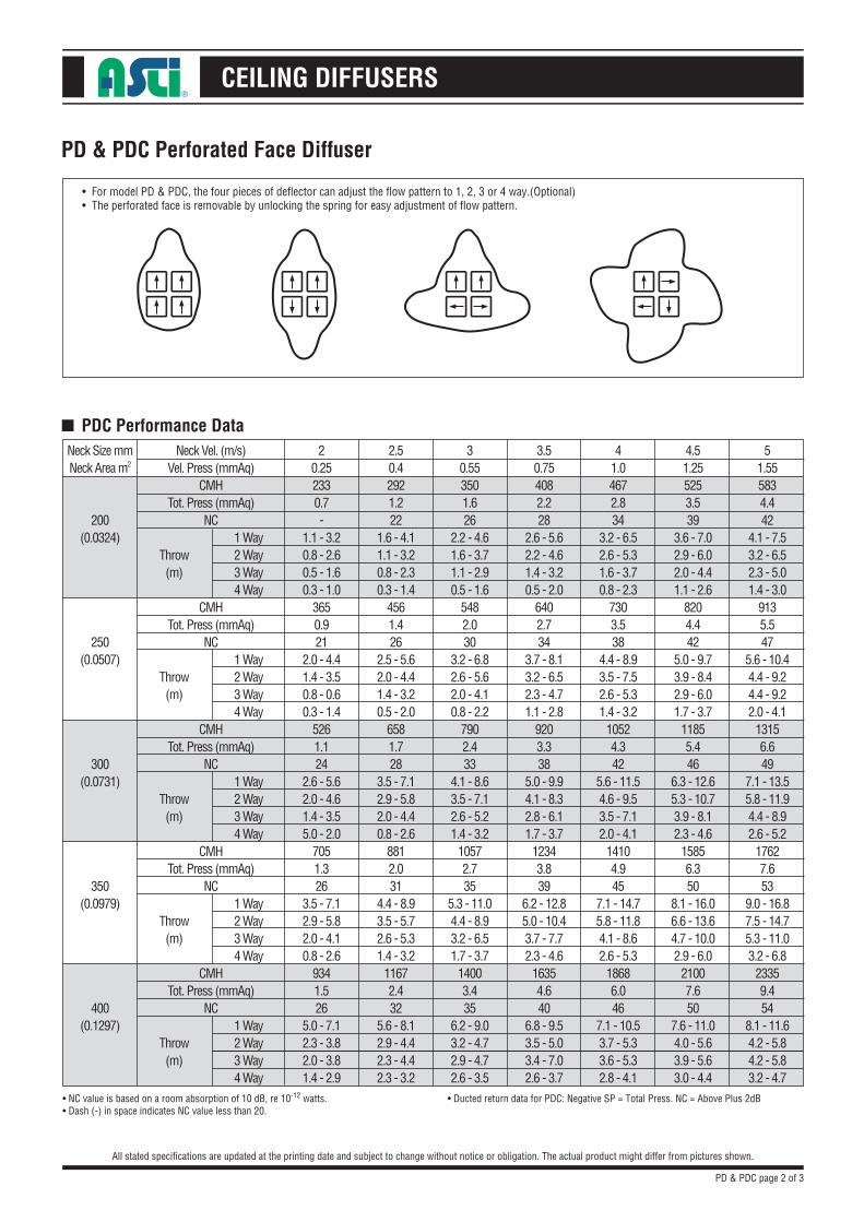
• For model PD & PDC, the four pieces of deflector can adjust the flow pattern to 1, 2, 3 or 4 way.(Optional)• The perforated face is removable by unlocking the spring for easy adjustment of flow pattern.
PD & PDC Perforated Face Diffuser
All stated specifications are updated at the printing date and subject to change without notice or obligation. The actual product might differ from pictures shown.
n PDC Performance DataNeck Size mmNeck Area m2
200(0.0324)
250(0.0507)
300(0.0731)
350(0.0979)
400(0.1297)
Neck Vel. (m/s)Vel. Press (mmAq)
CMHTot. Press (mmAq)
NC
CMHTot. Press (mmAq)
NC
CMHTot. Press (mmAq)
NC
CMHTot. Press (mmAq)
NC
CMHTot. Press (mmAq)
NC
Throw(m)
Throw(m)
Throw(m)
Throw(m)
Throw(m)
30.553501.626
2.2 - 4.61.6 - 3.71.1 - 2.90.5 - 1.6
5482.030
3.2 - 6.82.6 - 5.62.0 - 4.10.8 - 2.2
7902.433
4.1 - 8.63.5 - 7.12.6 - 5.21.4 - 3.2
10572.735
5.3 - 11.04.4 - 8.93.2 - 6.51.7 - 3.7
14003.435
6.2 - 9.03.2 - 4.72.9 - 4.72.6 - 3.5
4.51.255253.539
3.6 - 7.02.9 - 6.02.0 - 4.41.1 - 2.6
8204.442
5.0 - 9.73.9 - 8.42.9 - 6.01.7 - 3.7
11855.446
6.3 - 12.65.3 - 10.73.9 - 8.12.3 - 4.6
15856.350
8.1 - 16.06.6 - 13.64.7 - 10.02.9 - 6.0
21007.650
7.6 - 11.04.0 - 5.63.9 - 5.63.0 - 4.4
3.50.754082.228
2.6 - 5.62.2 - 4.61.4 - 3.20.5 - 2.0
6402.734
3.7 - 8.13.2 - 6.52.3 - 4.71.1 - 2.8
9203.338
5.0 - 9.94.1 - 8.32.8 - 6.11.7 - 3.7
12343.839
6.2 - 12.85.0 - 10.43.7 - 7.72.3 - 4.6
16354.640
6.8 - 9.53.5 - 5.03.4 - 7.02.6 - 3.7
41.04672.834
3.2 - 6.52.6 - 5.31.6 - 3.70.8 - 2.3
7303.538
4.4 - 8.93.5 - 7.52.6 - 5.31.4 - 3.2
10524.342
5.6 - 11.54.6 - 9.53.5 - 7.12.0 - 4.1
14104.945
7.1 - 14.75.8 - 11.84.1 - 8.62.6 - 5.3
18686.046
7.1 - 10.53.7 - 5.33.6 - 5.32.8 - 4.1
51.555834.442
4.1 - 7.53.2 - 6.52.3 - 5.01.4 - 3.0
9135.547
5.6 - 10.44.4 - 9.24.4 - 9.22.0 - 4.1
13156.649
7.1 - 13.55.8 - 11.94.4 - 8.92.6 - 5.2
17627.653
9.0 - 16.87.5 - 14.75.3 - 11.03.2 - 6.8
23359.454
8.1 - 11.64.2 - 5.84.2 - 5.83.2 - 4.7
2.50.42921.222
1.6 - 4.11.1 - 3.20.8 - 2.30.3 - 1.4
4561.426
2.5 - 5.62.0 - 4.41.4 - 3.20.5 - 2.0
6581.728
3.5 - 7.12.9 - 5.82.0 - 4.40.8 - 2.6
8812.031
4.4 - 8.93.5 - 5.72.6 - 5.31.4 - 3.2
11672.432
5.6 - 8.12.9 - 4.42.3 - 4.42.3 - 3.2
20.252330.7-
1.1 - 3.20.8 - 2.60.5 - 1.60.3 - 1.0
3650.921
2.0 - 4.41.4 - 3.50.8 - 0.60.3 - 1.4
5261.124
2.6 - 5.62.0 - 4.61.4 - 3.55.0 - 2.0
7051.326
3.5 - 7.12.9 - 5.82.0 - 4.10.8 - 2.6
9341.526
5.0 - 7.12.3 - 3.82.0 - 3.81.4 - 2.9
1 Way2 Way3 Way4 Way
1 Way2 Way3 Way4 Way
1 Way2 Way3 Way4 Way
1 Way2 Way3 Way4 Way
1 Way2 Way3 Way4 Way
•NC value is based on a room absorption of 10 dB, re 10-12 watts.•Dash (-) in space indicates NC value less than 20.
•Ducted return data for PDC: Negative SP = Total Press. NC = Above Plus 2dB
PD & PDC page 2 of 3
CEILING DIFFUSERS
PD & PDC Perforated Face Diffuser
All stated specifications are updated at the printing date and subject to change without notice or obligation. The actual product might differ from pictures shown.
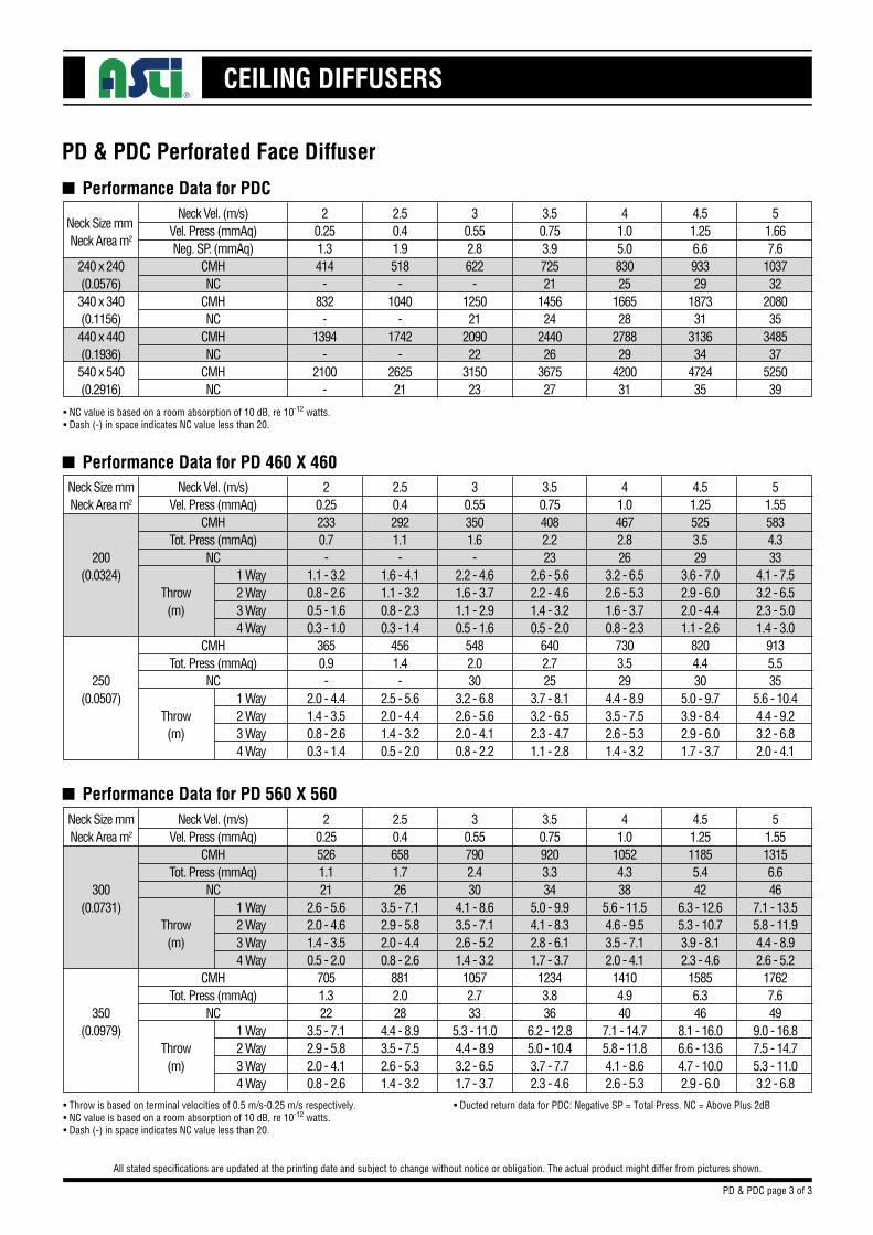
n Performance Data for PDC
240 x 240(0.0576)340 x 340(0.1156)440 x 440(0.1936)540 x 540(0.2916)
Neck Size mm Neck Area m2
Neck Vel. (m/s)Vel. Press (mmAq)Neg. SP. (mmAq)
CMHNC
CMHNC
CMHNC
CMHNC
30.552.8622
-125021
209022
315023
4.51.256.693329
187331
313634
472435
3.50.753.972521
145624
244026
367527
41.05.083025
166528
278829
420031
51.667.6
103732
208035
348537
525039
2.50.41.9518
-1040
-1742
-262521
20.251.3414
-832
-1394
-2100
-
•NC value is based on a room absorption of 10 dB, re 10-12 watts.•Dash (-) in space indicates NC value less than 20.
•Throw is based on terminal velocities of 0.5 m/s-0.25 m/s respectively.•NC value is based on a room absorption of 10 dB, re 10-12 watts.•Dash (-) in space indicates NC value less than 20.
•Ducted return data for PDC: Negative SP = Total Press. NC = Above Plus 2dB
n Performance Data for PD 460 X 460Neck Size mmNeck Area m2
200(0.0324)
250(0.0507)
Neck Vel. (m/s)Vel. Press (mmAq)
CMHTot. Press (mmAq)
NC
CMHTot. Press (mmAq)
NC
Throw(m)
Throw(m)
30.553501.6-
2.2 - 4.61.6 - 3.71.1 - 2.90.5 - 1.6
5482.030
3.2 - 6.82.6 - 5.62.0 - 4.10.8 - 2.2
4.51.255253.529
3.6 - 7.02.9 - 6.02.0 - 4.41.1 - 2.6
8204.430
5.0 - 9.73.9 - 8.42.9 - 6.01.7 - 3.7
3.50.754082.223
2.6 - 5.62.2 - 4.61.4 - 3.20.5 - 2.0
6402.725
3.7 - 8.13.2 - 6.52.3 - 4.71.1 - 2.8
41.04672.826
3.2 - 6.52.6 - 5.31.6 - 3.70.8 - 2.3
7303.529
4.4 - 8.93.5 - 7.52.6 - 5.31.4 - 3.2
51.555834.333
4.1 - 7.53.2 - 6.52.3 - 5.01.4 - 3.0
9135.535
5.6 - 10.44.4 - 9.23.2 - 6.82.0 - 4.1
2.50.42921.1-
1.6 - 4.11.1 - 3.20.8 - 2.30.3 - 1.4
4561.4-
2.5 - 5.62.0 - 4.41.4 - 3.20.5 - 2.0
20.252330.7-
1.1 - 3.20.8 - 2.60.5 - 1.60.3 - 1.0
3650.9-
2.0 - 4.41.4 - 3.50.8 - 2.60.3 - 1.4
1 Way2 Way3 Way4 Way
1 Way2 Way3 Way4 Way
n Performance Data for PD 560 X 560Neck Size mmNeck Area m2
300(0.0731)
350(0.0979)
Neck Vel. (m/s)Vel. Press (mmAq)
CMHTot. Press (mmAq)
NC
CMHTot. Press (mmAq)
NC
Throw(m)
Throw(m)
30.557902.430
4.1 - 8.63.5 - 7.12.6 - 5.21.4 - 3.2
10572.733
5.3 - 11.04.4 - 8.93.2 - 6.51.7 - 3.7
4.51.2511855.442
6.3 - 12.65.3 - 10.73.9 - 8.12.3 - 4.6
15856.346
8.1 - 16.06.6 - 13.64.7 - 10.02.9 - 6.0
3.50.759203.334
5.0 - 9.94.1 - 8.32.8 - 6.11.7 - 3.7
12343.836
6.2 - 12.85.0 - 10.43.7 - 7.72.3 - 4.6
41.0
10524.338
5.6 - 11.54.6 - 9.53.5 - 7.12.0 - 4.1
14104.940
7.1 - 14.75.8 - 11.84.1 - 8.62.6 - 5.3
51.5513156.646
7.1 - 13.55.8 - 11.94.4 - 8.92.6 - 5.2
17627.649
9.0 - 16.87.5 - 14.75.3 - 11.03.2 - 6.8
2.50.46581.726
3.5 - 7.12.9 - 5.82.0 - 4.40.8 - 2.6
8812.028
4.4 - 8.93.5 - 7.52.6 - 5.31.4 - 3.2
20.255261.121
2.6 - 5.62.0 - 4.61.4 - 3.50.5 - 2.0
7051.322
3.5 - 7.12.9 - 5.82.0 - 4.10.8 - 2.6
1 Way2 Way3 Way4 Way
1 Way2 Way3 Way4 Way
PD & PDC page 3 of 3
CEILING DIFFUSERS
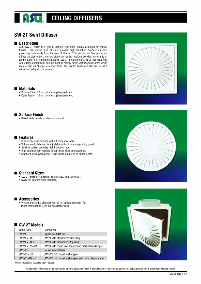
Description
Materials• Diffuser Face: 1.0mm thickness galvanized steel.• Outer Frame: 1.0mm thickness galvanized steel.
Surface Finish• Baked white powder coated as standard.
Features• Diffuser face can be open without using any tools.• Volume control damper is adjustable without removing ceiling panel.• Swirl air pattern provides high induction ratio.• High coanda effect reduces direct-throw of air on occupants.• Standard sizes available for T-bar ceiling on metric or imperial size.
Standard Sizes• SW-2T: 595mm X 595mm, 603mmX603mm (face size).• SWR-2T: 565mm outer diameter.
Accessories• Plenum box, radial blade damper (C1) , perforated sheet (PS), round inlet adapter (D2), crown damper (C2).
SW-2T Models
SW-2T Swirl Diffuser
All stated specifications are updated at the printing date and subject to change without notice or obligation. The actual product might differ from pictures shown.
n
n
n
n
n
n
n
Model CodeSW-2TSW-2T + PB-SSW-2T + PB-TSW-2T + D2 + C1SWR-2TSWR-2T+ D2SWR-2T+D2+C1
DescriptionSquare swirl diffuserSW-2T with plenum box side entrySW-2T with plenum box top entrySW-2T with round inlet adapter and radial blade damperRound swirl diffuserSWR-2T with round inlet adapterSWR-2T with round inlet adapter and radial blade damper
ASLI SW-2T series is a type of diffuser with fixed radially arranged air control blades. This unique type of slots provide high induction “vortex” air flow projecting horizontally from the face of diffuser. This swirling air flow produce a diffuse air distribution, with no stationary air jet resulting excellent uniformity of temperature in air conditioned space. SW-2T is suitable in area of high heat load where large quantities of cool air must be rapidly mixed with room air; areas which require high air change in a short time. The SW-2T series can also be use as a return and exhaust type device.
•Other models are available upon request
SW-2T page 1 of 4
CEILING DIFFUSERS
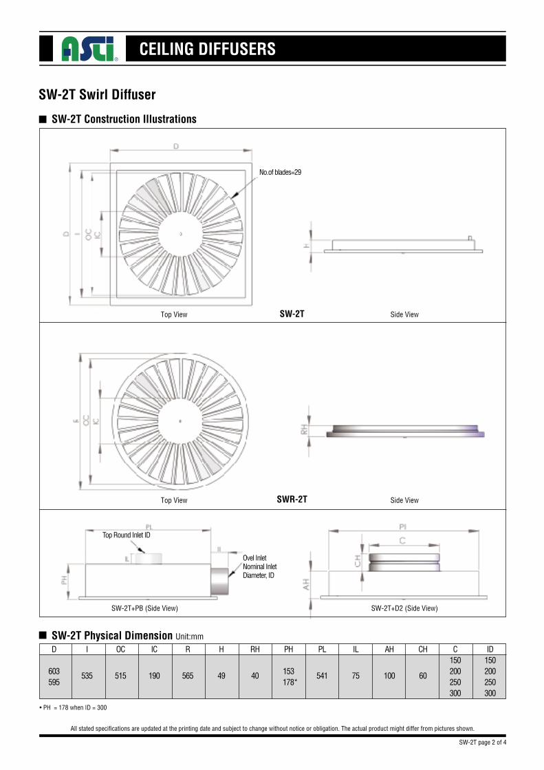
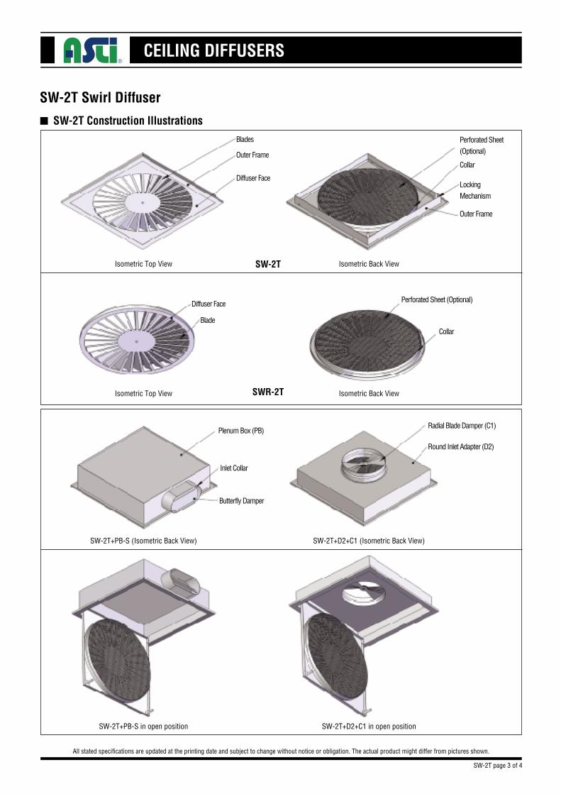
SW-2T Construction Illustrations
SW-2T Swirl Diffuser
All stated specifications are updated at the printing date and subject to change without notice or obligation. The actual product might differ from pictures shown.
n
n
SW-2T Physical Dimension Unit:mm
C150200250300
CHAHILPLPH
153 178*
RHHRICOCI
60100755414049565190515535
D
603595
ID150200250300
• PH = 178 when ID = 300
Top View SW-2T
SWR-2T
Side View
Top View Side View
SW-2T+PB (Side View) SW-2T+D2 (Side View)
No.of blades=29
Ovel InletNominal InletDiameter, ID
Top Round Inlet ID
SW-2T page 2 of 4
CEILING DIFFUSERS
SW-2T Construction Illustrations
SW-2T Swirl Diffuser
All stated specifications are updated at the printing date and subject to change without notice or obligation. The actual product might differ from pictures shown.
n
Isometric Top View Isometric Back View
Isometric Top View Isometric Back View
SW-2T+PB-S (Isometric Back View) SW-2T+D2+C1 (Isometric Back View)
SW-2T+PB-S in open position SW-2T+D2+C1 in open position
SW-2T
SWR-2T
Perforated Sheet (Optional)
Perforated Sheet (Optional)
Blades
Outer Frame
Diffuser Face
Diffuser Face
Blade
Plenum Box (PB)Radial Blade Damper (C1)
Round Inlet Adapter (D2)
Inlet Collar
Butterfly Damper
Collar
Collar
LockingMechanism
Outer Frame
SW-2T page 3 of 4
CEILING DIFFUSERS
SW-2T Swirl Diffuser
All stated specifications are updated at the printing date and subject to change without notice or obligation. The actual product might differ from pictures shown.
n SW-2T Order Code
n
Tot. PressNC
Throw
C1X 1.2+ 2
X 0.9
PBX 1.2+ 2
X 0.85
ModelSW-2T
SWR-2T
CasingPlenum Box (PB)
Adapter (D2)
AccessoriesRadial Blade Damper (C1)
Perforated Sheet (PS)
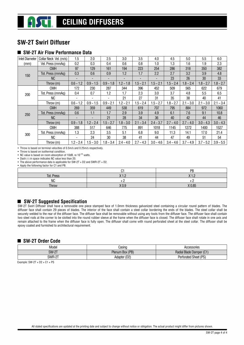
• Throw is based on terminal velocities of 0.5m/s and 0.25m/s respectively.• Throw is based on isothermal condition.• NC value is based on room absorption of 10dB, re 10-12 watts.• Dash (-) in space indicates NC value less than 20.• The above performance data is applicable for SW-2T + D2 and SWR-2T + D2.• Apply the following factor for C1 and PB.
n SW-2T Air Flow Performance DataInlet Diameter
(mm)
150
200
250
300
1.50.2970.3-
0.6 ~ 1.21720.4-
0.6 ~ 1.22690.6-
0.9 ~ 1.83881.3-
1.2 ~ 2.4
2.00.31290.6-
0.9 ~ 1.52300.7-
0.9 ~ 1.53591.1-
1.2 ~ 2.45172.324
1.5 ~ 3.0
2.50.41610.9-
0.9 ~ 1.82871.2-
0.9 ~ 2.14491.721
1.5 ~ 2.76463.530
1.8 ~ 3.4
3.00.61941.2-
1.2 ~ 1.83441.721
1.2 ~ 2.15382.928
1.8 ~ 3.07755.138
2.4 ~ 4.0
3.50.82231.7-
1.5 ~ 2.13962.327
1.5 ~ 2.46193.934
2.1 ~ 3.48916.841
2.7 ~ 4.3
4.01.02542.2-
1.5 ~ 2.14523.031
1.5 ~ 2.77074.936
2.4 ~ 3.710189.044
3.0 ~ 4.6
4.51.32862.723
1.5 ~ 2.45093.735
1.8 ~ 2.77956.140
2.7 ~ 4.0114511.347
3.4 ~ 4.6
5.01.63183.226
1.8 ~ 2.45654.838
2.1 ~ 3.08847.642
2.7 ~ 4.0127214.149
3.7 ~ 4.9
5.51.93503.930
1.8 ~ 2.76225.540
2.1 ~ 3.09729.144
3.0 ~ 4.3140017.051
3.7 ~ 5.2
6.02.33824.833
1.8 ~ 2.76796.541
2.1 ~ 3.4106010.846
3.0 ~ 4.3152721.454
3.9 ~ 5.5
Collar Neck Vel. (m/s)Vel. Press (mmAq)
CMHTot. Press (mmAq)
NCThrow (m)
CMHTot. Press (mmAq)
NCThrow (m)
CMHTot. Press (mmAq)
NCThrow (m)
CMHTot. Press (mmAq)
NCThrow (m)
SW-2T Suggested SpecificationSW-2T Swirl Diffuser shall have a removable one piece stamped face of 1.0mm thickness galvanized steel containing a circular round pattern of blades. The diffuser face shall contain 29 pieces of blades. The interior of the face shall contain a steel collar bordering the ends of the blades. The steel collar shall be securely welded to the rear of the diffuser face. The diffuser face shall be removable without using any tools from the diffuser face. The diffuser face shall contain two steel rods at the corner to be slotted into the round rubber sleeve at the frame when the diffuser face is closed. The diffuser face shall rotate in one axis and remain attached to the frame when the diffuser face is fully open. The diffuser shall come with round perforated sheet at the steel collar. The diffuser shall be epoxy coated and furnished to architectural requirement.
Example: SW-2T + D2 + C1 + PS
SW-2T page 4 of 4
CEILING DIFFUSERS
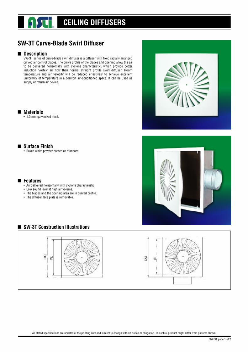
Description
Materials• 1.0 mm galvanized steel.
Surface Finish• Baked white powder coated as standard.
Features• Air delivered horizontally with cyclone characteristic.• Low sound level at high air volume.• The blades and the opening area are in curved profile.• The diffuser face plate is removable.
SW-3T Construction Illustrations
SW-3T Curve-Blade Swirl Diffuser
All stated specifications are updated at the printing date and subject to change without notice or obligation. The actual product might differ from pictures shown.
n
n
n
n
nSW-3T series of curve-blade swirl diffuser is a diffuser with fixed radially arranged curved air control blades. The curve profile of the blades and opening allow the air to be delivered horizontally with cyclone characteristic, which provide better induction "vortex" air flow than normal straight profile swirl diffuser. Room temperature and air velocity will be reduced effectively to achieve excellent uniformity of temperature in a comfort air-conditioned space. It can be used as supply or return air device.
SW-3T page 1 of 2
CEILING DIFFUSERS
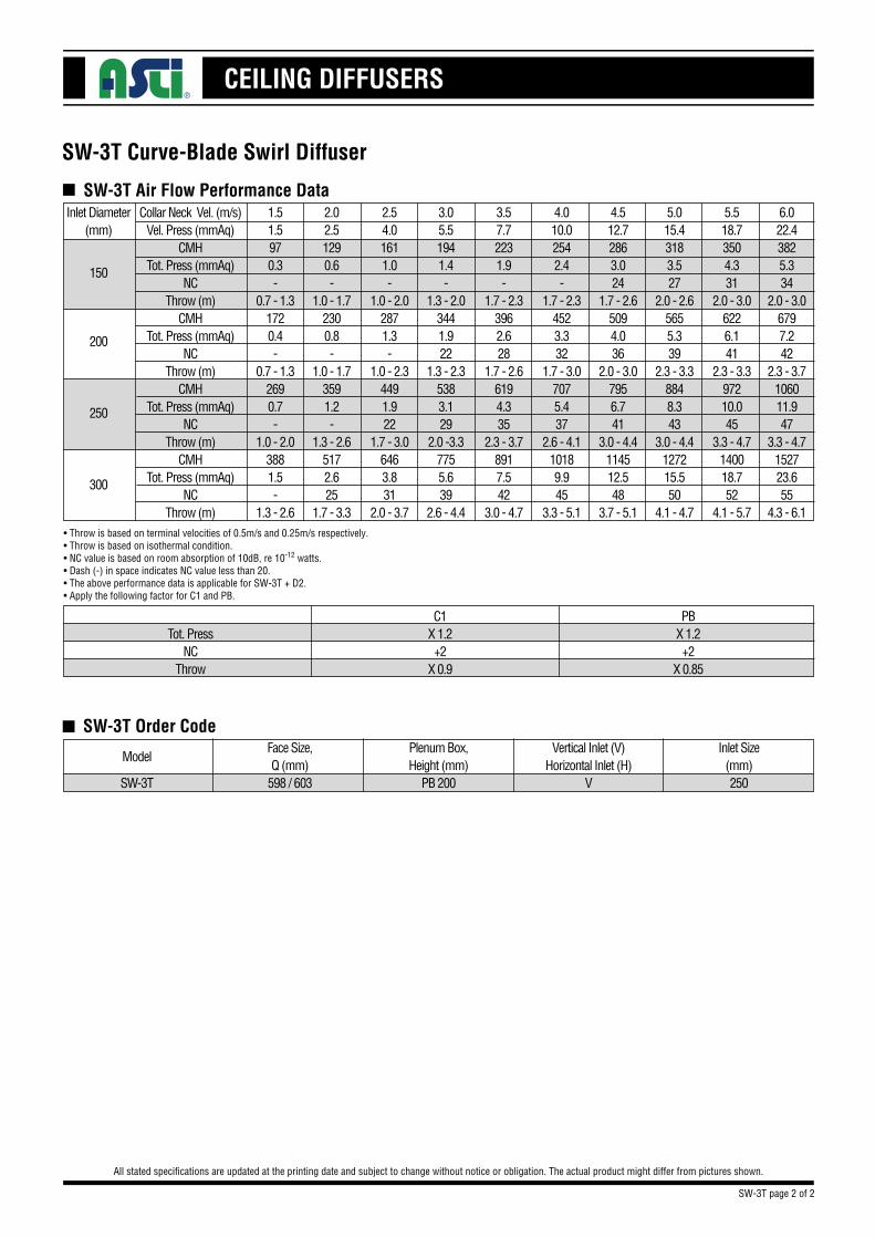
SW-3T Order Code
SW-3T Curve-Blade Swirl Diffuser
All stated specifications are updated at the printing date and subject to change without notice or obligation. The actual product might differ from pictures shown.
n
SW-3T
ModelFace Size,Q (mm)
598 / 603
Plenum Box,Height (mm)
PB 200
Vertical Inlet (V)Horizontal Inlet (H)
V
Inlet Size(mm)250
SW-3T page 2 of 2
Tot. PressNC
Throw
C1X 1.2+2
X 0.9
PBX 1.2+2
X 0.85
• Throw is based on terminal velocities of 0.5m/s and 0.25m/s respectively.• Throw is based on isothermal condition.• NC value is based on room absorption of 10dB, re 10-12 watts.• Dash (-) in space indicates NC value less than 20.• The above performance data is applicable for SW-3T + D2.• Apply the following factor for C1 and PB.
n SW-3T Air Flow Performance DataInlet Diameter
(mm)
150
200
250
300
1.51.5970.3-
0.7 - 1.31720.4-
0.7 - 1.32690.7-
1.0 - 2.03881.5-
1.3 - 2.6
2.02.51290.6-
1.0 - 1.72300.8-
1.0 - 1.73591.2-
1.3 - 2.65172.625
1.7 - 3.3
2.54.01611.0-
1.0 - 2.02871.3-
1.0 - 2.34491.922
1.7 - 3.06463.831
2.0 - 3.7
3.05.51941.4-
1.3 - 2.03441.922
1.3 - 2.35383.129
2.0 -3.37755.639
2.6 - 4.4
3.57.72231.9-
1.7 - 2.33962.628
1.7 - 2.66194.335
2.3 - 3.78917.542
3.0 - 4.7
4.010.02542.4-
1.7 - 2.34523.332
1.7 - 3.07075.437
2.6 - 4.110189.945
3.3 - 5.1
4.512.72863.024
1.7 - 2.65094.036
2.0 - 3.07956.741
3.0 - 4.4114512.548
3.7 - 5.1
5.015.43183.527
2.0 - 2.65655.339
2.3 - 3.38848.343
3.0 - 4.4127215.550
4.1 - 4.7
5.518.73504.331
2.0 - 3.06226.141
2.3 - 3.397210.045
3.3 - 4.7140018.752
4.1 - 5.7
6.022.43825.334
2.0 - 3.06797.242
2.3 - 3.7106011.947
3.3 - 4.7152723.655
4.3 - 6.1
Collar Neck Vel. (m/s)Vel. Press (mmAq)
CMHTot. Press (mmAq)
NCThrow (m)
CMHTot. Press (mmAq)
NCThrow (m)
CMHTot. Press (mmAq)
NCThrow (m)
CMHTot. Press (mmAq)
NCThrow (m)
CEILING DIFFUSERS
SLLS Linear Ceiling Diffuser
n
n
n
n
n
All stated specifications are updated at the printing date and subject to change without notice or obligation. The actual product might differ from pictures shown.
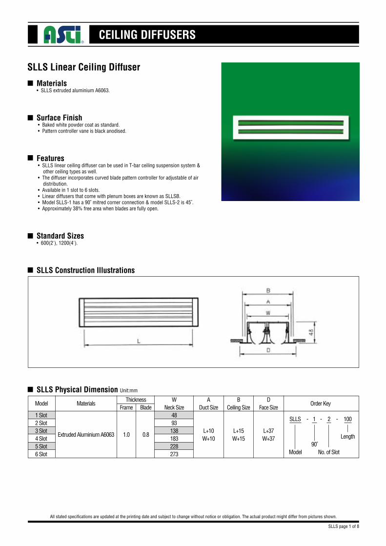
Materials• SLLS extruded aluminium A6063.
Surface Finish • Baked white powder coat as standard. • Pattern controller vane is black anodised.
Features • SLLS linear ceiling diffuser can be used in T-bar ceiling suspension system & other ceiling types as well. • The diffuser incorporates curved blade pattern controller for adjustable of air distribution. • Available in 1 slot to 6 slots. • Linear diffusers that come with plenum boxes are known as SLLSB. • Model SLLS-1 has a 90˚ mitred corner connection & model SLLS-2 is 45˚. • Approximately 38% free area when blades are fully open.
Standard Sizes• 600(2'), 1200(4').
SLLS Construction Illustrations
n SLLS Physical Dimension Unit:mm
Thickness WNeck Size
4893138183228273
1 Slot2 Slot3 Slot4 Slot5 Slot6 Slot
DFace Size
L+37W+37
Frame BladeOrder Key
SLLS - 1 - 2 - 100
Model90˚
No. of Slot
Length
Materials
Extruded Aluminium A6063
Model
1.0 0.8
BCeiling Size
L+15W+15
ADuct Size
L+10W+10
SLLS page 1 of 8
CEILING DIFFUSERS
SLLS Linear Ceiling Diffuser
n
All stated specifications are updated at the printing date and subject to change without notice or obligation. The actual product might differ from pictures shown.
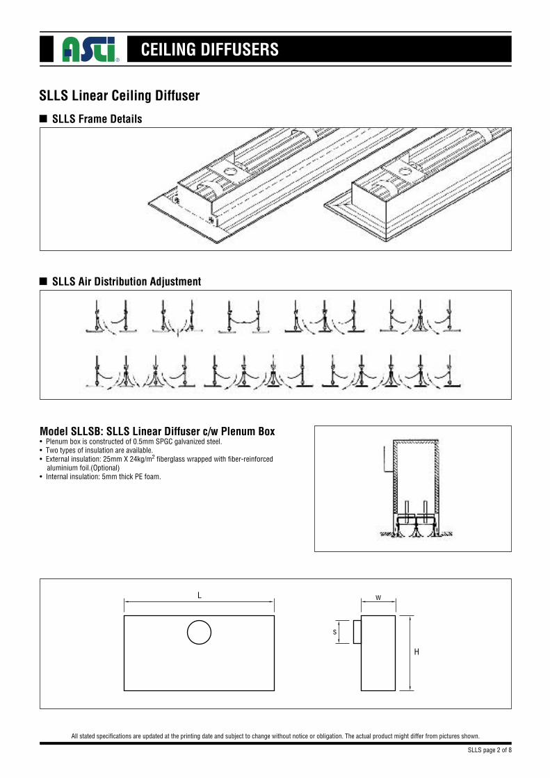
SLLS Frame Details
n SLLS Air Distribution Adjustment
L
s
w
H
Model SLLSB: SLLS Linear Diffuser c/w Plenum Box• Plenum box is constructed of 0.5mm SPGC galvanized steel.• Two types of insulation are available.• External insulation: 25mm X 24kg/m2 fiberglass wrapped with fiber-reinforced aluminium foil.(Optional)• Internal insulation: 5mm thick PE foam.
SLLS page 2 of 8
CEILING DIFFUSERS
SLLS Linear Ceiling Diffuser
All stated specifications are updated at the printing date and subject to change without notice or obligation. The actual product might differ from pictures shown.
■ SLLS Physical Dimension Unit:mm
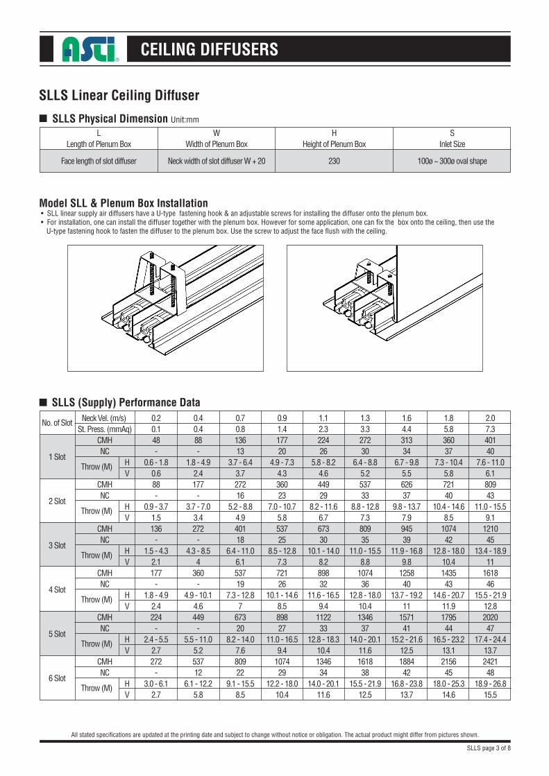
LLength of Plenum Box
Face length of slot diffuser
WWidth of Plenum Box
Neck width of slot diffuser W + 20 230 100ø ~ 300ø oval shape
HHeight of Plenum Box
SInlet Size
Model SLL & Plenum Box Installation • SLL linear supply air diffusers have a U-type fastening hook & an adjustable screws for installing the diffuser onto the plenum box. • For installation, one can install the diffuser together with the plenum box. However for some application, one can fix the box onto the ceiling, then use the U-type fastening hook to fasten the diffuser to the plenum box. Use the screw to adjust the face flush with the ceiling.
■ SLLS (Supply) Performance Data
No. of Slot
1 Slot
2 Slot
3 Slot
4 Slot
5 Slot
6 Slot
Neck Vel. (m/s) St. Press. (mmAq)
CMH NC
CMH NC
CMH NC
CMH NC
CMH NC
CMH NC
HV
HV
HV
HV
HV
HV
Throw (M)
Throw (M)
Throw (M)
Throw (M)
Throw (M)
Throw (M)
1.12.322426
5.8 - 8.24.644929
8.2 - 11.66.767330
10.1 - 14.08.289832
11.6 - 16.59.4
112233
12.8 - 18.310.4134634
14.0 - 20.111.6
1.85.836037
7.3 - 10.45.872140
10.4 - 14.68.5
107442
12.8 - 18.010.4143543
14.6 - 20.711.9179544
16.5 - 23.213.1215645
18.0 - 25.314.6
1.33.327230
6.4 - 8.85.253733
8.8 - 12.87.380935
11.0 - 15.58.8
107436
12.8 - 18.010.4134637
14.0 - 20.111.6161838
15.5 - 21.912.5
1.64.431334
6.7 - 9.85.562637
9.8 - 13.77.994539
11.9 - 16.89.8
125840
13.7 - 19.211
157141
15.2 - 21.612.5188442
16.8 - 23.813.7
2.07.340140
7.6 - 11.06.180943
11.0 - 15.59.1
121045
13.4 - 18.911
161846
15.5 - 21.912.8202047
17.4 - 24.413.7242148
18.9 - 26.815.5
0.91.417720
4.9 - 7.34.336023
7.0 - 10.75.853725
8.5 - 12.87.372126
10.1 - 14.68.589827
11.0 - 16.59.4
107429
12.2 - 18.010.4
0.70.813613
3.7 - 6.43.727216
5.2 - 8.84.940118
6.4 - 11.06.153719
7.3 - 12.87
67320
8.2 - 14.07.680922
9.1 - 15.58.5
0.40.488-
1.8 - 4.92.4177
-3.7 - 7.0
3.4272
-4.3 - 8.5
4360
-4.9 - 10.1
4.6449
-5.5 - 11.0
5.253712
6.1 - 12.25.8
0.20.148-
0.6 - 1.80.688-
0.9 - 3.71.5136
-1.5 - 4.3
2.1177
-1.8 - 4.9
2.4224
-2.4 - 5.5
2.7272
-3.0 - 6.1
2.7
SLLS page 3 of 8
CEILING DIFFUSERS
SLLS Linear Ceiling Diffuser
All stated specifications are updated at the printing date and subject to change without notice or obligation. The actual product might differ from pictures shown.
n SLLS (Return) Performance Data2.83402468027
102029
136030
170028
204029
7.254537
108540
163042
217543
272041
326442
4.14052981531
122534
163035
204033
244834
5.54753395036
142538
190539
238037
285638
11.568043
136046
204048
272049
340047
408048
1.8270
-5452281524
108524
136022
163223
1.0200
-405
-610
-815
-1020
-1224
-
0.5135
-270
-405
-545
-680
-1224
-
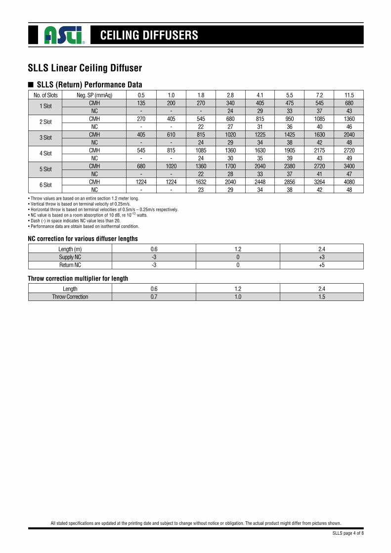
Neg. SP (mmAq)CMHNC
CMHNC
CMHNC
CMHNC
CMHNC
CMHNC
No. of Slots
1 Slot
2 Slot
3 Slot
4 Slot
5 Slot
6 Slot
NC correction for various diffuser lengths
2.4+3+5
• Throw values are based on an entire section 1.2 meter long.• Vertical throw is based on terminal velocity of 0.25m/s.• Horizontal throw is based on terminal velocities of 0.5m/s – 0.25m/s respectively.• NC value is based on a room absorption of 10 dB, re 10-12 watts.• Dash (-) in space indicates NC value less than 20.• Performance data are obtain based on isothermal condition.
1.200
0.6-3-3
Length (m)Supply NCReturn NC
Throw correction multiplier for length
2.41.5
1.21.0
0.60.7
LengthThrow Correction
SLLS page 4 of 8
CEILING DIFFUSERS
SLLS Linear Ceiling Diffuser
All stated specifications are updated at the printing date and subject to change without notice or obligation. The actual product might differ from pictures shown.
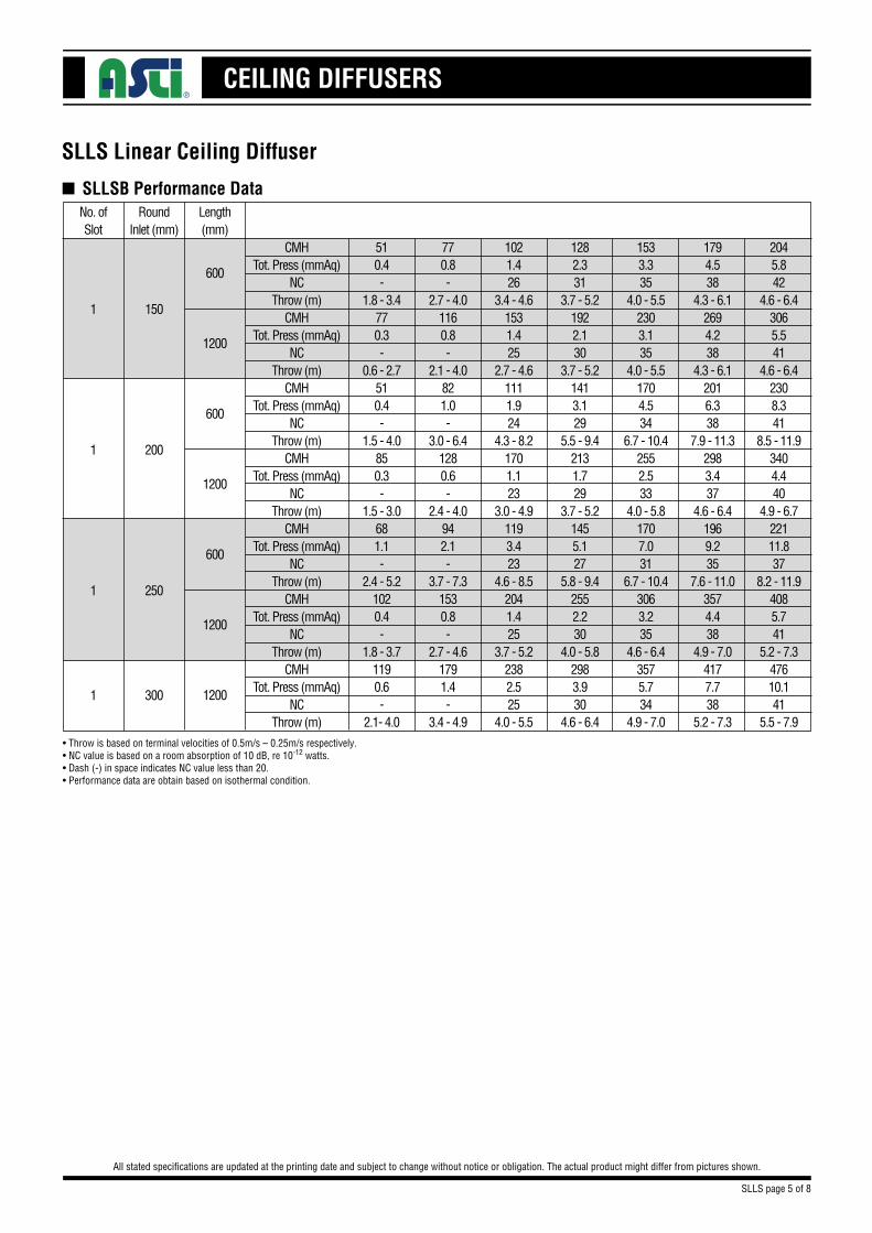
n SLLSB Performance Data
1021.426
3.4 - 4.61531.425
2.7 - 4.61111.924
4.3 - 8.21701.123
3.0 - 4.91193.423
4.6 - 8.52041.425
3.7 - 5.22382.525
4.0 - 5.5
1794.538
4.3 - 6.12694.238
4.3 - 6.12016.338
7.9 - 11.32983.437
4.6 - 6.41969.235
7.6 - 11.03574.438
4.9 - 7.04177.738
5.2 - 7.3
1282.331
3.7 - 5.21922.130
3.7 - 5.21413.129
5.5 - 9.42131.729
3.7 - 5.21455.127
5.8 - 9.42552.230
4.0 - 5.82983.930
4.6 - 6.4
1533.335
4.0 - 5.52303.135
4.0 - 5.51704.534
6.7 - 10.42552.533
4.0 - 5.81707.031
6.7 - 10.43063.235
4.6 - 6.43575.734
4.9 - 7.0
2045.842
4.6 - 6.43065.541
4.6 - 6.42308.341
8.5 - 11.93404.440
4.9 - 6.722111.837
8.2 - 11.94085.741
5.2 - 7.347610.141
5.5 - 7.9
770.8-
2.7 - 4.01160.8-
2.1 - 4.0821.0-
3.0 - 6.41280.6-
2.4 - 4.0942.1-
3.7 - 7.31530.8-
2.7 - 4.61791.4-
3.4 - 4.9
510.4-
1.8 - 3.4770.3-
0.6 - 2.7510.4-
1.5 - 4.0850.3-
1.5 - 3.0681.1-
2.4 - 5.21020.4-
1.8 - 3.71190.6-
2.1- 4.0
Length(mm)
600
1200
600
1200
600
1200
1200
RoundInlet (mm)
No. ofSlot
150
200
250
1
1
1
3001
CMHTot. Press (mmAq)
NCThrow (m)
CMHTot. Press (mmAq)
NCThrow (m)
CMHTot. Press (mmAq)
NCThrow (m)
CMHTot. Press (mmAq)
NCThrow (m)
CMHTot. Press (mmAq)
NCThrow (m)
CMHTot. Press (mmAq)
NCThrow (m)
CMHTot. Press (mmAq)
NCThrow (m)
SLLS page 5 of 8
• Throw is based on terminal velocities of 0.5m/s – 0.25m/s respectively.• NC value is based on a room absorption of 10 dB, re 10-12 watts.• Dash (-) in space indicates NC value less than 20.• Performance data are obtain based on isothermal condition.

CEILING DIFFUSERS
SLLS Linear Ceiling Diffuser
All stated specifications are updated at the printing date and subject to change without notice or obligation. The actual product might differ from pictures shown.
n SLLSB Performance Data
1451.224
4.0 - 7.92302.024
3.0 - 5.51701.123
4.6 - 9.42721.424
3.7 - 6.12041.425
5.5 - 11.33231.425
4.3 - 6.43741.325
4.9 - 7.0
2603.937
7.0 - 12.83965.937
5.2 - 7.32983.437
8.2 - 13.74513.936
8.5 - 7.63574.438
9.8 - 14.95534.038
6.1 - 8.54593.637
6.4 - 9.1
1842.029
5.2 - 10.12863.029
3.7 - 6.12131.729
5. 8 - 11.63322.129
4.3 - 6.72552.230
7.0 - 12.84002.130
5.2 - 6.44591.929
5.5 - 7.9
2212.834
6.1 - 11.93404.333
4.6 - 6.72552.533
7.0 - 12.83912.933
5.2 - 7.33063.235
8.5 - 14.04762.934
5.5 - 7.95442.733
6.1 - 8.5
2985.241
8.2 - 13.74517.640
5.5 - 7.63404.440
9.4 - 14.65104.939
5.8 - 8.24085.741
11.3 - 16.26295.241
6.4 - 9.17144.640
7.0 - 9.8
1070.7-
2.1 - 5.81751.1-
2.1 - 4.61280.6-
3.0 - 7.02130.9-
2.7 - 5.21530.8-
4.3 - 8.52470.8-
3.4 - 5.82890.8-
3.7 - 6.1
680.3-
0.9 - 3.71190.5-
0.9 - 3.0850.3-
1.5 - 4.61530.5-
1.5 - 4.01020.4-
2.1 - 5.51700.4-
2.1 - 4.62040.4-
2.7 - 5.2
Length(mm)
600
1200
600
1200
600
1200
1200
RoundInlet (mm)
No. ofSlot
150
200
250
2
2
2
3002
CMHTot. Press (mmAq)
NCThrow (m)
CMHTot. Press (mmAq)
NCThrow (m)
CMHTot. Press (mmAq)
NCThrow (m)
CMHTot. Press (mmAq)
NCThrow (m)
CMHTot. Press (mmAq)
NCThrow (m)
CMHTot. Press (mmAq)
NCThrow (m)
CMHTot. Press (mmAq)
NCThrow (m)
SLLS page 6 of 8
• Throw is based on terminal velocities of 0.5m/s – 0.25m/s respectively.• NC value is based on a room absorption of 10 dB, re 10-12 watts.• Dash (-) in space indicates NC value less than 20.• Performance data are obtain based on isothermal condition.
CEILING DIFFUSERS
SLLS Linear Ceiling Diffuser
All stated specifications are updated at the printing date and subject to change without notice or obligation. The actual product might differ from pictures shown.
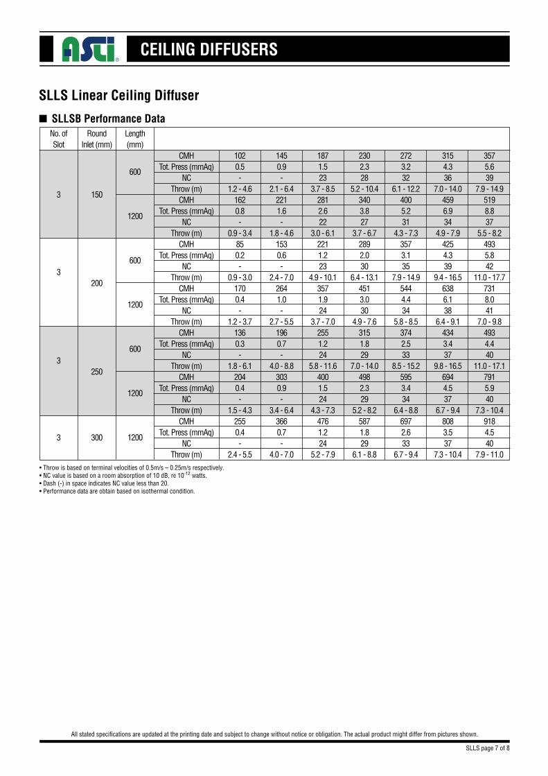
n SLLSB Performance Data
1871.523
3.7 - 8.52812.622
3.0 - 6.12211.223
4.9 - 10.13571.924
3.7 - 7.02551.224
5.8 - 11.64001.524
4.3 - 7.34761.224
5.2 - 7.9
3154.336
7.0 - 14.04596.934
4.9 - 7.94254.339
9.4 - 16.56386.138
6.4 - 9.14343.437
9.8 - 16.56944.537
6.7 - 9.48083.537
7.3 - 10.4
2302.328
5.2 - 10.43403.827
3.7 - 6.72892.030
6.4 - 13.14513.030
4.9 - 7.63151.829
7.0 - 14.04982.329
5.2 - 8.25871.829
6.1 - 8.8
2723.232
6.1 - 12.24005.231
4.3 - 7.33573.135
7.9 - 14.95444.434
5.8 - 8.53742.533
8.5 - 15.25953.434
6.4 - 8.86972.633
6.7 - 9.4
3575.639
7.9 - 14.95198.837
5.5 - 8.24935.842
11.0 - 17.77318.041
7.0 - 9.84934.440
11.0 - 17.17915.940
7.3 - 10.49184.540
7.9 - 11.0
1450.9-
2.1 - 6.42211.6-
1.8 - 4.61530.6-
2.4 - 7.02641.0-
2.7 - 5.51960.7-
4.0 - 8.83030.9-
3.4 - 6.43660.7-
4.0 - 7.0
1020.5-
1.2 - 4.61620.8-
0.9 - 3.4850.2-
0.9 - 3.01700.4-
1.2 - 3.71360.3-
1.8 - 6.12040.4-
1.5 - 4.32550.4-
2.4 - 5.5
Length(mm)
600
1200
600
1200
600
1200
1200
RoundInlet (mm)
No. ofSlot
150
200
250
3
3
3
3003
CMHTot. Press (mmAq)
NCThrow (m)
CMHTot. Press (mmAq)
NCThrow (m)
CMHTot. Press (mmAq)
NCThrow (m)
CMHTot. Press (mmAq)
NCThrow (m)
CMHTot. Press (mmAq)
NCThrow (m)
CMHTot. Press (mmAq)
NCThrow (m)
CMHTot. Press (mmAq)
NCThrow (m)
SLLS page 7 of 8
• Throw is based on terminal velocities of 0.5m/s – 0.25m/s respectively.• NC value is based on a room absorption of 10 dB, re 10-12 watts.• Dash (-) in space indicates NC value less than 20.• Performance data are obtain based on isothermal condition.

CEILING DIFFUSERS
SLLS Linear Ceiling Diffuser
All stated specifications are updated at the printing date and subject to change without notice or obligation. The actual product might differ from pictures shown.
n SLLSB Performance Data
2301.924
3.7 ~ 8.93573.924
3.1 ~ 6.82551.222
4.6 ~ 10.24422.725
4.0 ~ 7.73151.325
4.6 ~ 8.04931.925
4.6 ~ 8.05781.324
5.2 ~ 8.9
3965.937
7.7 ~ 15.760010.936
5.6 ~ 8.94854.538
9.6 ~ 17.67487.437
7.1 ~ 10.25323.737
7.4 ~ 10.58255.537
7.4 ~ 10.59613.836
8.0 ~ 11.4
2863.129
5.6 ~ 11.14395.829
4.0 ~ 7.73322.029
6.5 ~ 13.05444.030
4.9 ~ 8.63881.930
5.6 ~ 8.96043.030
5.6 ~ 8.97062.029
6.5 ~ 9.9
3404.433
6.8 ~ 13.65198.233
4.9 ~ 8.34083.234
8.0 ~ 16.06465.534
6.2 ~ 9.34592.834
6.8 ~ 9.97144.134
6.8 ~ 9.98332.933
7.4 ~ 10.5
4517.740
8.9 ~ 17.068014.039
6.5 ~ 9.65615.941
11.1 ~ 19.18509.740
7.7 ~ 10.86044.840
8.0 ~ 11.19357.040
8.0 ~ 11.110884.839
8.6 ~ 12.0
1751.1-
2.2 ~ 6.82772.3-
1.9 ~ 5.21790.6-
2.2 ~ 7.13401.5-
2.8 ~ 6.52430.7-
3.7 ~ 7.13831.1-
3.7 ~ 7.14510.8-
4.3 ~ 7.7
1190.5-
0.9 ~ 4.01961.1-
0.9 ~ 3.71020.2-
0.6 ~ 2.82380.7-
1.5 ~ 4.31700.4-
1.9 ~ 4.92720.6-
1.9 ~ 4.93230.4-
2.5 ~ 6.2
Length(mm)
600
1200
600
1200
600
1200
1200
RoundInlet (mm)
No. ofSlot
150
200
250
4
4
4
3004
CMHTot. Press (mmAq)
NCThrow (m)
CMHTot. Press (mmAq)
NCThrow (m)
CMHTot. Press (mmAq)
NCThrow (m)
CMHTot. Press (mmAq)
NCThrow (m)
CMHTot. Press (mmAq)
NCThrow (m)
CMHTot. Press (mmAq)
NCThrow (m)
CMHTot. Press (mmAq)
NCThrow (m)
SLLS page 8 of 8
• Throw is based on terminal velocities of 0.5m/s – 0.25m/s respectively.• NC value is based on a room absorption of 10 dB, re 10-12 watts.• Dash (-) in space indicates NC value less than 20.• Performance data are obtain based on isothermal condition.
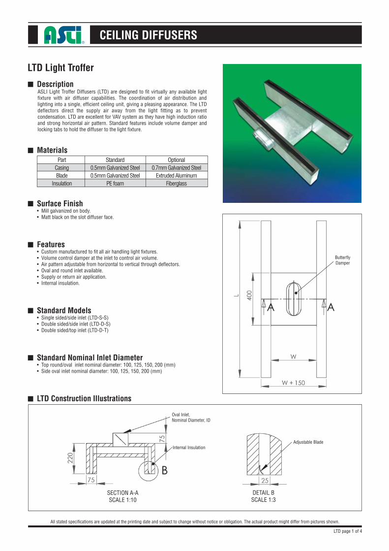
CEILING DIFFUSERS
Description
Materials
Surface Finish• Mill galvanized on body.• Matt black on the slot diffuser face.
Features• Custom manufactured to fit all air handling light fixtures.• Volume control damper at the inlet to control air volume.• Air pattern adjustable from horizontal to vertical through deflectors.• Oval and round inlet available.• Supply or return air application.• Internal insulation.
Standard Models• Single sided/side inlet (LTD-S-S)• Double sided/side inlet (LTD-D-S)• Double sided/top inlet (LTD-D-T)
Standard Nominal Inlet Diameter• Top round/oval inlet nominal diameter: 100, 125, 150, 200 (mm)• Side oval inlet nominal diameter: 100, 125, 150, 200 (mm)
LTD Construction Illustrations
LTD Light Troffer
All stated specifications are updated at the printing date and subject to change without notice or obligation. The actual product might differ from pictures shown.
■
■
■
■
■
■
■
Optional0.7mm Galvanized Steel
Extruded AluminumFiberglass
Standard0.5mm Galvanized Steel0.5mm Galvanized Steel
PE foam
PartCasingBlade
Insulation
ASLI Light Troffer Diffusers (LTD) are designed to fit virtually any available light fixture with air diffuser capabilities. The coordination of air distribution and lighting into a single, efficient ceiling unit, giving a pleasing appearance. The LTD deflectors direct the supply air away from the light fitting as to prevent condensation. LTD are excellent for VAV system as they have high induction ratio and strong horizontal air pattern. Standard features include volume damper and locking tabs to hold the diffuser to the light fixture.
ButterflyDamper
Adjustable Blade
Oval Inlet,Nominal Diameter, ID
Internal Insulation
SECTION A-ASCALE 1:10
DETAIL BSCALE 1:3
LTD page 1 of 4
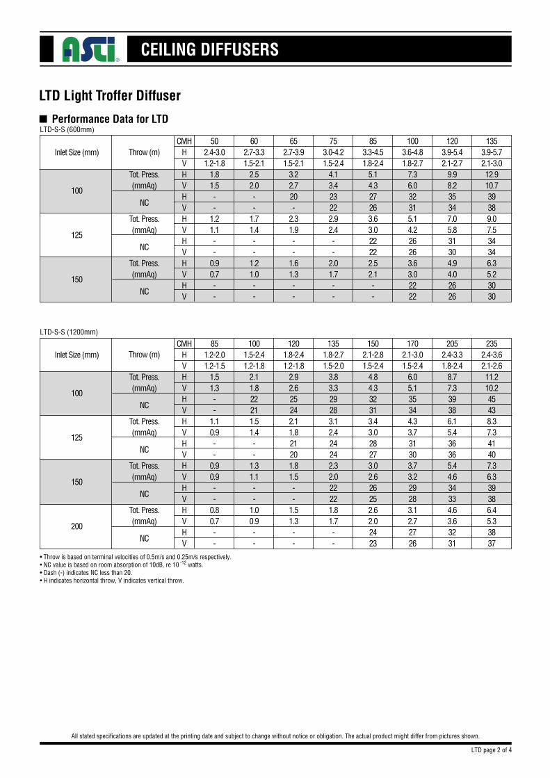
CEILING DIFFUSERS
LTD Light Troffer Diffuser
All stated specifications are updated at the printing date and subject to change without notice or obligation. The actual product might differ from pictures shown.
n Performance Data for LTD
Inlet Size (mm)50
2.4-3.01.2-1.8
1.81.5--
1.21.1--
0.90.7--
CMHHVHVHVHVHVHVHV
•Throw is based on terminal velocities of 0.5m/s and 0.25m/s respectively.•NC value is based on room absorption of 10dB, re 10 -12 watts.•Dash (-) indicates NC less than 20.•H indicates horizontal throw, V indicates vertical throw.
602.7-3.31.5-2.1
2.52.0--
1.71.4--
1.21.0--
853.3-4.51.8-2.4
5.14.327263.63.022222.52.1--
652.7-3.91.5-2.1
3.22.720-
2.31.9--
1.61.3--
753.0-4.21.5-2.4
4.13.423222.92.4--
2.01.7--
1003.6-4.81.8-2.7
7.36.032315.14.226263.63.02222
1353.9-5.72.1-3.012.910.739389.07.534346.35.23030
1203.9-5.42.1-2.7
9.98.235347.05.831304.94.02626
NC
NC
NC
Throw (m)
100
125
150
LTD-S-S (1200mm)
LTD-S-S (600mm)
Inlet Size (mm)
Tot. Press.(mmAq)
Tot. Press.(mmAq)
Tot. Press.(mmAq)
Tot. Press.(mmAq)
851.2-2.01.2-1.5
1.51.3--
1.10.9--
0.90.9--
0.80.7--
CMHHVHVHVHVHVHVHVHVHV
1001.5-2.41.2-1.8
2.11.822211.51.4--
1.31.1--
1.00.9--
1502.1-2.81.5-2.4
4.84.332313.43.028273.02.626252.62.02423
1201.8-2.41.2-1.8
2.92.625242.11.821201.81.5--
1.51.3--
1351.8-2.71.5-2.0
3.83.329283.12.424242.32.022221.81.7--
1702.1-3.01.5-2.4
6.05.135344.33.731303.73.229283.12.72726
2352.4-3.62.1-2.611.210.245438.37.341407.36.339386.45.33837
2052.4-3.31.8-2.4
8.77.339386.15.436365.44.634334.63.63231
NC
NC
NC
NC
Throw (m)
100
125
150
200
LTD page 2 of 4
Tot. Press.(mmAq)
Tot. Press.(mmAq)
Tot. Press.(mmAq)
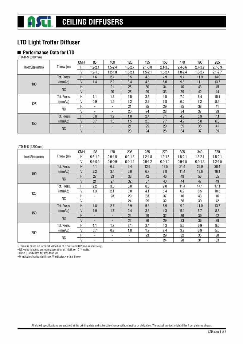
CEILING DIFFUSERS
LTD Light Troffer Diffuser
All stated specifications are updated at the printing date and subject to change without notice or obligation. The actual product might differ from pictures shown.
n Performance Data for LTD
Inlet Size (mm)
Tot. Press.(mmAq)
Tot. Press.(mmAq)
Tot. Press.(mmAq)
851.2-2.11.2-1.5
1.61.4--
1.10.9--
0.80.7--
CMHHVHVHVHVHVHVHV
•Throw is based on terminal velocities of 0.5m/s and 0.25m/s respectively.•NC value is based on room absorption of 10dB, re 10 -12 watts.•Dash (-) indicates NC less than 20.•H indicates horizontal throw, V indicates vertical throw.
1001.5-2.41.2-1.8
2.42.221201.81.5--
1.21.0--
1502.1-3.31.5-2.4
7.96.034334.53.829283.12.72928
1201.8-2.71.5-2.1
3.53.426252.52.221201.81.52120
1352.1-3.01.5-2.1
4.84.630293.52.925242.42.02524
1702.4-3.61.8-2.4
9.79.340397.06.035344.94.23534
2052.7-3.92.1-2.714.013.74544
10.18.541397.16.04139
1902.7-3.91.8-2.711.911.143428.47.238375.95.03837
NC
NC
NC
Throw (m)
100
125
150
LTD-D-S (1200mm)
LTD-D-S (600mm)
Inlet Size (mm)
Tot. Press.(mmAq)
Tot. Press.(mmAq)
Tot. Press.(mmAq)
Tot. Press.(mmAq)
1350.6-1.20.6-0.9
4.12.227212.21.3--
1.81.0--
1.10.7--
CMHHVHVHVHVHVHVHVHVHV
1700.9-1.50.6-0.9
6.53.433273.52.123
2.71.7--
1.70.9--
2701.2-1.80.9-1.216.58.846409.05.437326.94.332294.32.42924
2050.9-1.50.9-1.2
9.45.038325.03.029243.92.424223.11.8--
2351.2-1.80.9-1.212.66.742378.84.133295.33.329263.41.923-
3051.5-2.10.9-1.521.411.44944
11.46.940369.05.436335.63.23228
3701.5-2.11.2-1.530.416.15549
17.110.54642
13.78.342398.65.03833
3401.5-2.10.9-1.525.913.65347
14.18.54339
11.06.739366.93.93531
NC
NC
NC
NC
Throw (m)
100
125
150
200
LTD page 3 of 4
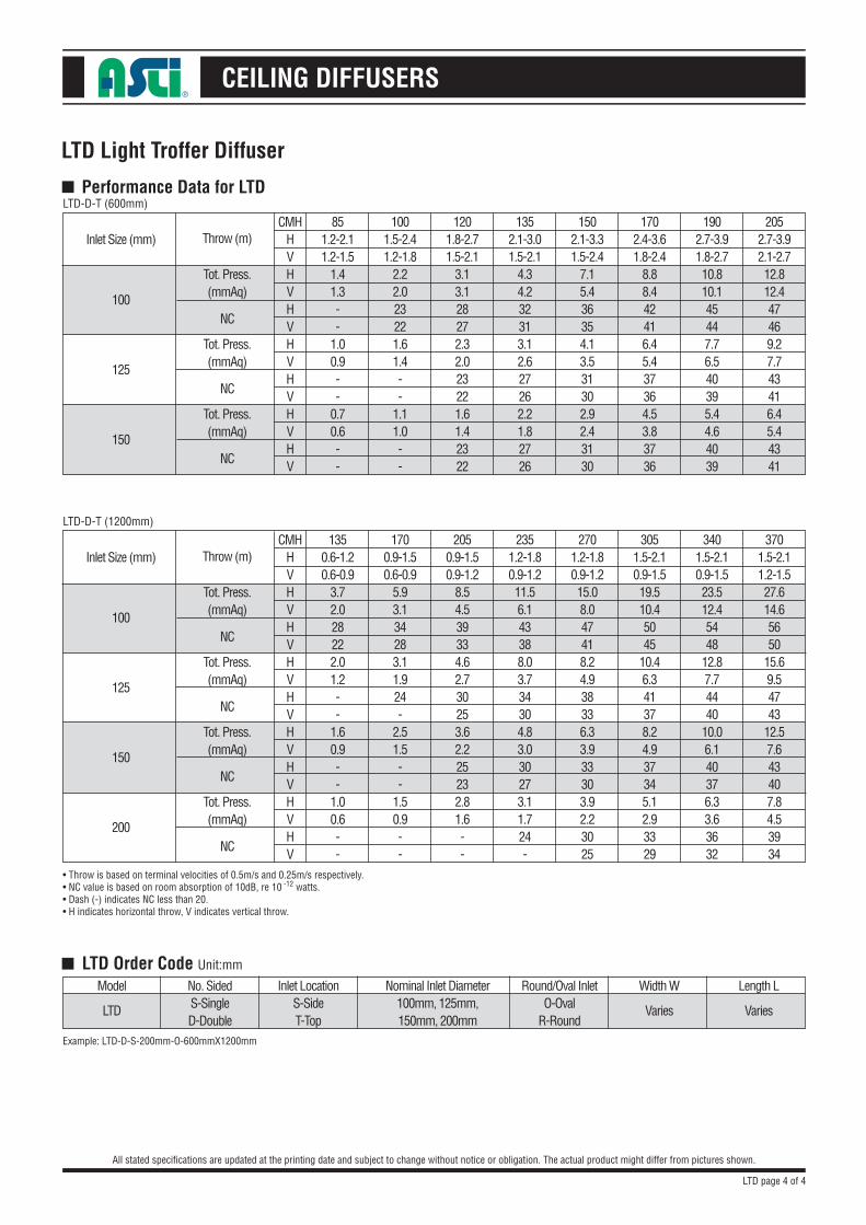
CEILING DIFFUSERS
LTD Light Troffer Diffuser
All stated specifications are updated at the printing date and subject to change without notice or obligation. The actual product might differ from pictures shown.
■ Performance Data for LTD
Inlet Size (mm)
Tot. Press.(mmAq)
Tot. Press.(mmAq)
Tot. Press.(mmAq)
851.2-2.11.2-1.5
1.41.3--
1.00.9--
0.70.6--
CMHHVHVHVHVHVHVHV
• Throw is based on terminal velocities of 0.5m/s and 0.25m/s respectively.• NC value is based on room absorption of 10dB, re 10 -12 watts.• Dash (-) indicates NC less than 20.• H indicates horizontal throw, V indicates vertical throw.
Example: LTD-D-S-200mm-O-600mmX1200mm
1001.5-2.41.2-1.8
2.22.023221.61.4--
1.11.0--
1502.1-3.31.5-2.4
7.15.436354.13.531302.92.43130
1201.8-2.71.5-2.1
3.13.128272.32.023221.61.42322
1352.1-3.01.5-2.1
4.34.232313.12.627262.21.82726
1702.4-3.61.8-2.4
8.88.442416.45.437364.53.83736
2052.7-3.92.1-2.712.812.447469.27.743416.45.44341
1902.7-3.91.8-2.710.810.145447.76.540395.44.64039
NC
NC
NC
Throw (m)
100
125
150
LTD-D-T (1200mm)
LTD-D-T (600mm)
Inlet Size (mm)
Tot. Press.(mmAq)
Tot. Press.(mmAq)
Tot. Press.(mmAq)
Tot. Press.(mmAq)
1350.6-1.20.6-0.9
3.72.028222.01.2--
1.60.9--
1.00.6--
CMHHVHVHVHVHVHVHVHVHV
1700.9-1.50.6-0.9
5.93.134283.11.924-
2.51.5--
1.50.9--
2701.2-1.80.9-1.215.08.047418.24.938336.33.933303.92.23025
2050.9-1.50.9-1.2
8.54.539334.62.730253.62.225232.81.6--
2351.2-1.80.9-1.211.56.143388.03.734304.83.030273.11.724-
3051.5-2.10.9-1.519.510.45045
10.46.341378.24.937345.12.93329
3701.5-2.11.2-1.527.614.65650
15.69.54743
12.57.643407.84.53934
3401.5-2.10.9-1.523.512.45448
12.87.74440
10.06.140376.33.63632
NC
NC
NC
NC
Throw (m)
100
125
150
200
■ LTD Order Code Unit:mm
Model
LTD
Nominal Inlet Diameter100mm, 125mm,150mm, 200mm
No. SidedS-SingleD-Double
Round/Oval InletO-Oval
R-Round
Width W Length L
Varies Varies
Inlet LocationS-SideT-Top
LTD page 4 of 4
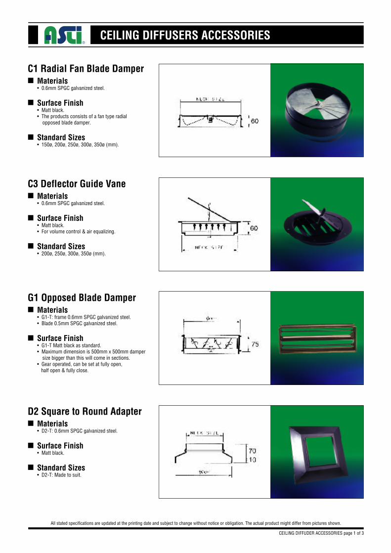
CEILING DIFFUSERS ACCESSORIES
Materials• 0.6mm SPGC galvanized steel.
Surface Finish• Matt black.• The products consists of a fan type radial opposed blade damper.
Standard Sizes• 150ø, 200ø, 250ø, 300ø, 350ø (mm).
C1 Radial Fan Blade Damper
All stated specifications are updated at the printing date and subject to change without notice or obligation. The actual product might differ from pictures shown.
n
n
n
Materials• 0.6mm SPGC galvanized steel.
Surface Finish• Matt black.• For volume control & air equalizing.
Standard Sizes• 200ø, 250ø, 300ø, 350ø (mm).
C3 Deflector Guide Vanen
n
n
Materials• G1-T: frame 0.6mm SPGC galvanized steel.• Blade 0.5mm SPGC galvanized steel.
Surface Finish• G1-T Matt black as standard.• Maximum dimension is 500mm x 500mm damper size bigger than this will come in sections.• Gear operated, can be set at fully open, half open & fully close.
G1 Opposed Blade Dampern
n
CEILING DIFFUDER ACCESSORIES page 1 of 3
Materials• D2-T: 0.6mm SPGC galvanized steel.
Surface Finish• Matt black.
Standard Sizes• D2-T: Made to suit.
D2 Square to Round Adaptern
n
n
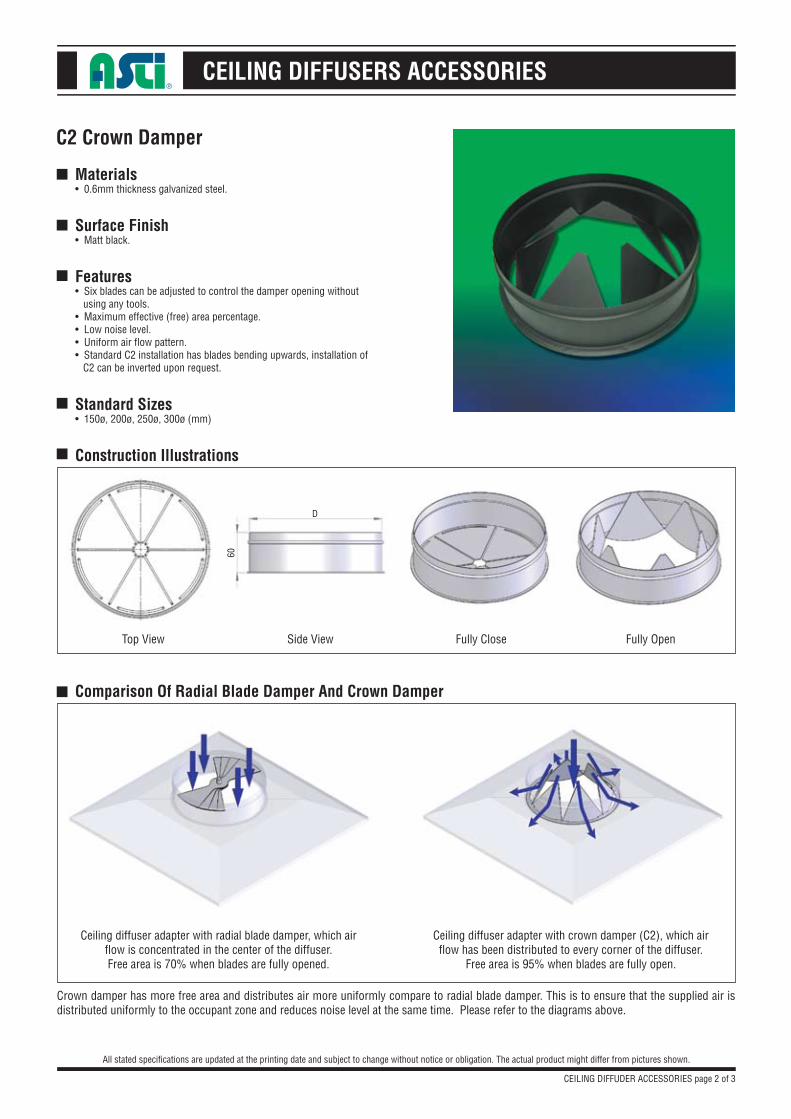
CEILING DIFFUSERS ACCESSORIES
Materials• 0.6mm thickness galvanized steel.
Surface Finish• Matt black.
Features• Six blades can be adjusted to control the damper opening without using any tools.• Maximum effective (free) area percentage.• Low noise level.• Uniform air flow pattern.• Standard C2 installation has blades bending upwards, installation of C2 can be inverted upon request.
Standard Sizes• 150ø, 200ø, 250ø, 300ø (mm)
Construction Illustrations
C2 Crown Damper
All stated specifications are updated at the printing date and subject to change without notice or obligation. The actual product might differ from pictures shown.
■
■
■
■
■
■
Comparison Of Radial Blade Damper And Crown Damper
CEILING DIFFUDER ACCESSORIES page 2 of 3
Top View Side View Fully Close Fully Open
Ceiling diffuser adapter with radial blade damper, which air flow is concentrated in the center of the diffuser.Free area is 70% when blades are fully opened.
Ceiling diffuser adapter with crown damper (C2), which air flow has been distributed to every corner of the diffuser.
Free area is 95% when blades are fully open.
Crown damper has more free area and distributes air more uniformly compare to radial blade damper. This is to ensure that the supplied air is distributed uniformly to the occupant zone and reduces noise level at the same time. Please refer to the diagrams above.
D
60
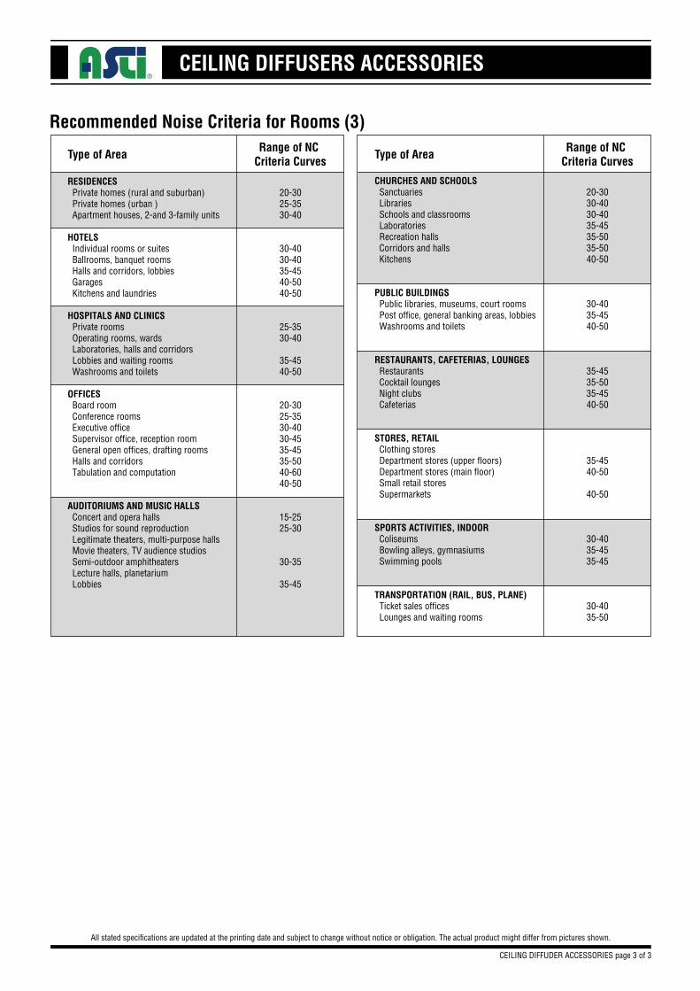
CEILING DIFFUSERS ACCESSORIES
Recommended Noise Criteria for Rooms (3)
All stated specifications are updated at the printing date and subject to change without notice or obligation. The actual product might differ from pictures shown.
CEILING DIFFUDER ACCESSORIES page 3 of 3
Type of AreaRange of NC
Criteria Curves
RESIDENCES Private homes (rural and suburban) 20-30 Private homes (urban ) 25-35 Apartment houses, 2-and 3-family units 30-40
HOTELS Individual rooms or suites 30-40 Ballrooms, banquet rooms 30-40 Halls and corridors, lobbies 35-45 Garages 40-50 Kitchens and laundries 40-50
HOSPITALS AND CLINICS Private rooms 25-35 Operating rooms, wards 30-40 Laboratories, halls and corridors Lobbies and waiting rooms 35-45 Washrooms and toilets 40-50
OFFICES Board room 20-30 Conference rooms 25-35 Executive office 30-40 Supervisor office, reception room 30-45 General open offices, drafting rooms 35-45 Halls and corridors 35-50 Tabulation and computation 40-60 40-50
AUDITORIUMS AND MUSIC HALLS Concert and opera halls 15-25 Studios for sound reproduction 25-30 Legitimate theaters, multi-purpose halls Movie theaters, TV audience studios Semi-outdoor amphitheaters 30-35 Lecture halls, planetarium Lobbies 35-45
Type of AreaRange of NC
Criteria Curves
CHURCHES AND SCHOOLS Sanctuaries 20-30 Libraries 30-40 Schools and classrooms 30-40 Laboratories 35-45 Recreation halls 35-50 Corridors and halls 35-50 Kitchens 40-50
PUBLIC BUILDINGS Public libraries, museums, court rooms 30-40 Post office, general banking areas, lobbies 35-45 Washrooms and toilets 40-50
RESTAURANTS, CAFETERIAS, LOUNGES Restaurants 35-45 Cocktail lounges 35-50 Night clubs 35-45 Cafeterias 40-50
STORES, RETAIL Clothing stores Department stores (upper floors) 35-45 Department stores (main floor) 40-50 Small retail stores Supermarkets 40-50
SPORTS ACTIVITIES, INDOOR Coliseums 30-40 Bowling alleys, gymnasiums 35-45 Swimming pools 35-45
TRANSPORTATION (RAIL, BUS, PLANE) Ticket sales offices 30-40 Lounges and waiting rooms 35-50