asme b18.3-2003 socket cap, shoulder, and set screws, hex and spline keys (inch series)
TRANSCRIPT
A N A M E R I C A N N A T I O N A L S T A N D A R D
Socket Cap, Shoulder, and Set Screws, Hex and Spline Keys (Inch Series)
ASME B18.3-2003(Revision of ASME B18.3-1998)
ASME B18.3-2003(Revision of ASME B18.3-1998)
Socket Cap,Shoulder, andSet Screws, Hexand Spline Keys(Inch Series)
A N A M E R I C A N N A T I O N A L S T A N D A R D
Three Park Avenue • New York, NY 10016
Date of Issuance: April 29, 2005
The 2003 edition of this Standard is being issued with an automatic addenda subscription service.The use of addenda allows revisions made in response to public review comments or committeeactions to be published as necessary. This Standard will be revised when the Society approves theissuance of a new edition.
ASME issues written replies to inquiries concerning interpretations of technical aspects of thisStandard. Interpretations are published on the ASME Web site under the Committee Pages athttp://www.asme.org/codes/ as they are issued.
ASME is the registered trademark of The American Society of Mechanical Engineers.
This code or standard was developed under procedures accredited as meeting the criteria for American NationalStandards. The Standards Committee that approved the code or standard was balanced to assure that individuals fromcompetent and concerned interests have had an opportunity to participate. The proposed code or standard was madeavailable for public review and comment that provides an opportunity for additional public input from industry, academia,regulatory agencies, and the public-at-large.
ASME does not “approve,” “rate,” or “endorse” any item, construction, proprietary device, or activity.ASME does not take any position with respect to the validity of any patent rights asserted in connection with any
items mentioned in this document, and does not undertake to insure anyone utilizing a standard against liability forinfringement of any applicable letters patent, nor assume any such liability. Users of a code or standard are expresslyadvised that determination of the validity of any such patent rights, and the risk of infringement of such rights, isentirely their own responsibility.
Participation by federal agency representative(s) or person(s) affiliated with industry is not to be interpreted asgovernment or industry endorsement of this code or standard.
ASME accepts responsibility for only those interpretations of this document issued in accordance with the establishedASME procedures and policies, which precludes the issuance of interpretations by individuals.
No part of this document may be reproduced in any form,in an electronic retrieval system or otherwise,
without the prior written permission of the publisher.
The American Society of Mechanical EngineersThree Park Avenue, New York, NY 10016-5990
Copyright © 2005 byTHE AMERICAN SOCIETY OF MECHANICAL ENGINEERS
All rights reservedPrinted in U.S.A.
CONTENTS
Foreword . . . . . . . . . . . . . . . . . . . . . . . . . . . . . . . . . . . . . . . . . . . . . . . . . . . . . . . . . . . . . . . . . . . . . . . . . . . . . . ivCommittee Roster . . . . . . . . . . . . . . . . . . . . . . . . . . . . . . . . . . . . . . . . . . . . . . . . . . . . . . . . . . . . . . . . . . . . . viCorrespondence With the B18 Committee . . . . . . . . . . . . . . . . . . . . . . . . . . . . . . . . . . . . . . . . . . . . . . vii
1 Introductory Notes . . . . . . . . . . . . . . . . . . . . . . . . . . . . . . . . . . . . . . . . . . . . . . . . . . . . . . . . . . . . . . 1
2 General Data . . . . . . . . . . . . . . . . . . . . . . . . . . . . . . . . . . . . . . . . . . . . . . . . . . . . . . . . . . . . . . . . . . . . 2
Figure1 Optional Types of Cup Points . . . . . . . . . . . . . . . . . . . . . . . . . . . . . . . . . . . . . . . . . . . . . . . . . . . 40
Tables1A Dimensions of Hexagon and Spline Socket Head Cap Screws . . . . . . . . . . . . . . . . . . . . 31B-1 Dimensions of Under Head Fillets for Socket Head Cap Screws Threaded
to the Head . . . . . . . . . . . . . . . . . . . . . . . . . . . . . . . . . . . . . . . . . . . . . . . . . . . . . . . . . . . . . . . . . . 61B-2 Dimensions of Under Head Fillets for Socket Head Cap Screws With an
Unthreaded Length of Body Diameter . . . . . . . . . . . . . . . . . . . . . . . . . . . . . . . . . . . . . . . . 71C Body and Grip Lengths for Socket Head Cap Screws . . . . . . . . . . . . . . . . . . . . . . . . . . . . 81D Lengths Beyond Sizes in Table 1C . . . . . . . . . . . . . . . . . . . . . . . . . . . . . . . . . . . . . . . . . . . . . . . 111E Shank Straightness for Socket Head Cap Screws . . . . . . . . . . . . . . . . . . . . . . . . . . . . . . . . . 121F Dimensions of Drilled Hexagon Socket Head Cap Screws . . . . . . . . . . . . . . . . . . . . . . . . 141G Dimensions of Low Head Hexagon Socket Cap Screws . . . . . . . . . . . . . . . . . . . . . . . . . . 162A Dimensions of Hexagon and Spline Socket Flat Countersunk Head
Cap Screws . . . . . . . . . . . . . . . . . . . . . . . . . . . . . . . . . . . . . . . . . . . . . . . . . . . . . . . . . . . . . . . . . . 182B Body and Grip Lengths for Socket Flat Countersunk Head Cap Screws . . . . . . . . . . 212C Lengths Beyond Sizes in Table 2B . . . . . . . . . . . . . . . . . . . . . . . . . . . . . . . . . . . . . . . . . . . . . . . 243 Dimensions of Hexagon and Spline Socket Button Head Cap Screws . . . . . . . . . . . . . 254 Dimensions of Hexagon Socket Head Shoulder Screws . . . . . . . . . . . . . . . . . . . . . . . . . . 285A Dimensions of Hexagon and Spline Socket Set Screws . . . . . . . . . . . . . . . . . . . . . . . . . . . 325B Hexagon Key Engagements for Short Length Set Screws . . . . . . . . . . . . . . . . . . . . . . . . . 375C Dimensions of Optional Cup Points . . . . . . . . . . . . . . . . . . . . . . . . . . . . . . . . . . . . . . . . . . . . . 396 Dimensions of Hexagon Sockets . . . . . . . . . . . . . . . . . . . . . . . . . . . . . . . . . . . . . . . . . . . . . . . . 417 Dimensions of Spline Sockets . . . . . . . . . . . . . . . . . . . . . . . . . . . . . . . . . . . . . . . . . . . . . . . . . . . 428 Dimensions of Hexagon Keys and Bits . . . . . . . . . . . . . . . . . . . . . . . . . . . . . . . . . . . . . . . . . . 439 Dimensions of Spline Keys and Bits . . . . . . . . . . . . . . . . . . . . . . . . . . . . . . . . . . . . . . . . . . . . . 45
Mandatory AppendicesI Gages and Gaging for Hexagon and Spline Sockets . . . . . . . . . . . . . . . . . . . . . . . . . . . . . . 47II Protrusion Gaging of Flat Countersunk Heads . . . . . . . . . . . . . . . . . . . . . . . . . . . . . . . . . . . 50III Straightness Gage and Gaging . . . . . . . . . . . . . . . . . . . . . . . . . . . . . . . . . . . . . . . . . . . . . . . . . . 51
Nonmandatory AppendicesA Drill and Counterbore Sizes for Socket Head Cap Screws . . . . . . . . . . . . . . . . . . . . . . . . 52B Applicability of Keys and Bits to Various Socket Screw Types and Sizes . . . . . . . . . . 54C Formulas for Dimensions . . . . . . . . . . . . . . . . . . . . . . . . . . . . . . . . . . . . . . . . . . . . . . . . . . . . . . . 56D Hexagon and Spline Socket Head Cap Screws (1936 Series) . . . . . . . . . . . . . . . . . . . . . . 58
iii
FOREWORD
American National Standards Committee B18 for thestandardization of bolts, screws, nuts, rivets, and similarfasteners was organized in March 1922 as Sectional Com-mittee B18 under the aegis of the American EngineeringStandards Committee (later the American StandardsAssociation, then the United States of America Stan-dards Institute and, as of October 6, 1969, the AmericanNational Standards Institute) with the Society of Auto-motive Engineers and the American Society of Mechani-cal Engineers as joint sponsors.
Subcommittee No. 91 on Socket Head Cap and SetScrews was organized in April 1929 and completed itsfirst report in November 1931. Seven successive draftswere issued during which the content of the proposalwas considerably extended and refined, and in March1933 copies were distributed to industry for criticismand comment. The suggestions received were carefullyreviewed, and in April 1935 the proposal was presentedto the members of Sectional Committee B18 for letterballot vote. Following the acceptance by the two sponsororganizations, it was designated an American Standard(ASA B18.3) in February 1936 by the American Stan-dards Association.
For the purpose of keeping the work of the Subcom-mittee in line with the developments in industry, theCommittee prepared a supplement to the standard inthe form of a table covering the dimensions of hexagonaland fluted socket head shoulder screws (stripper bolts)optional, which received approval of the American Stan-dards Association in April 1944 and was designatedASA B18.3a.
In March 1945, the Subcommittee submitted certainfundamental changes and additions to the Standard,and the Sectional Committee recommended issuance ofa completely revised standard. Following approval ofthe Sectional Committee, the revised document wasapproved by the sponsor organizations and the Ameri-can Standards Association and designated an AmericanStandard in April 1947.
In accordance with ASA procedure, a review of thestandard was undertaken in 1950 and certain additionalchanges were recommended by the Subcommittee. Capscrew sizes No. 0 and 1 and set screw sizes No. 0, 1, 2,3, and 4 were added to satisfy increasing demand fromvarious industries. Material, hardness, and thread fitwere included to provide a more complete standard. Adraft dated November 1951 was distributed to industry
1 As of April 1, 1966, Subcommittee 9 was redesignated as Sub-committee 3.
iv
for criticism and comment. A further revision, datedNovember 1953, was presented to Sectional CommitteeB18 for letter ballot vote. Following approval of the Sec-tional Committee and sponsors, the proposal was sub-mitted to the American Standards Association. It wasapproved and designated an American Standard onAugust 26, 1954.
Shortly after the 1954 standard was issued, work wasinitiated on the development of standards covering flatcountersunk head cap screws, button head cap screws,and cap screws up to 4 in. in diameter. As these proposalsevolved with comments received from various indus-tries, it became evident that a major revision wasrequired, particularly in regard to insufficient bearingsurface under the head on some sizes as well as increasedsocket sizes to permit higher set-up torque. The resultingproposed revision was presented to Sectional Commit-tee B18 for letter ballot vote. Following approval of theSectional Committee and sponsors, the proposal wassubmitted to the American Standards Association. Itwas approved and designated an American Standardon December 21, 1961.
Continued surveillance of the 1961 standard by theSubcommittee indicated by 1966 that a complete revi-sion of the document was necessary to provide recogni-tion of technical improvements in materials andmanufacturing methods. Work over the next 2 yearsculminated in a March 1968 draft proposal incorporatingrevisions in the following areas:
(a) more clearly defined materials for all products(b) application of Unified radius root threads to all
cap screws(c) refinements to underhead fillets(d) extension of size coverage for flat countersunk
head cap screws to include 7⁄8 in. through 11⁄2 in. diame-ters, and tabulation of body and grip lengths for sizes0 in. through 1 in.
(e) increased key engagements in socket set screwsand implementation of minimum hexagon key engage-ment in short length set screws
(f) addition of width across corner dimensions forhexagon keys and bits
(g) the inclusion of appendices covering drill andcounterbore sizes for socket head cap screws (1960Series), and gages and gaging for spline sockets.
Following acceptance of this draft by the Subcommit-tee, it was approved by letter ballot of USA Standards
Committee B18 and the sponsor organizations, and sub-mitted to the United States of America Standards Insti-tute. It was approved and designated a USA Standardon September 19, 1969.
A periodic review of the standard, undertaken bySubcommittee 3 in 1973, resulted in agreement that thedocument be revised to reflect clarification of theunderhead fillet on socket head cap screws, add cover-age on drilled socket head cap screws, lengthen thethread undercut on socket head shoulder screws, andextend the coverage on the latter to include the 11⁄2 in.,13⁄4 in., and 2 in. sizes. A proposal incorporating thesechanges together with numerous editorial correctionswas prepared and, subsequent to Subcommittee accept-ance, approved by letter ballot to American NationalStandards Committee B18. Following approval by thesponsor organizations, the proposal was submitted tothe American National Standards Institute and desig-nated an American National Standard on November1, 1976.
A periodic review of the standard, undertaken by theSubcommittee in 1980, resulted in agreement that thedocument be revised
(a) to clarify the notes on screw point chamfers(b) in socket tolerances for large sockets and in coun-
terbore sizes to reflect standard tooling(c) to reference the ASTM document A 574 for the
appropriate mechanical and chemical requirementsA proposal containing these changes, as well as many
editorial corrections, was prepared for and balloted byletter ballot to the ASME Committee B18. Followingapproval by the sponsor organization, the proposal wassubmitted to the American National Standards Instituteand designated an American National Standard on Janu-ary 4, 1982.
A periodic review of the standard, undertaken bythe Committee in 1985, resulted in agreement that thedocument be revised to clarify the dimensions withrespect to plated products, and to incorporate by refer-ence the new ASTM documents for the appropriatemechanical, chemical, and testing requirements for the
v
button head, flat countersunk head, and set screw prod-ucts. A proposal containing these changes, as well aseditorial corrections, was prepared and balloted by letterballot to ASME Committee B18. Following approval byASME, the proposal was submitted to the AmericanNational Standards Institute and designated an Ameri-can National Standard on August 7, 1986.
A periodic review of this Standard was undertakenby the Committee in 1990. Based on this review, it wasdetermined that the document needed significant revi-sions to clarify and update the Standard. These revisionswould need to address the technical changes in manu-facturing methods and changes in the standards com-munity. To accomplish this objective, established qualitystandards were recognized and integrated into the Stan-dard. In addition, designated characteristics for eachproduct and product identification were established andgaging techniques for countersunk screws were added.These changes were balloted and approved by the ASMEB18 Committee. The proposal was submitted to theAmerican National Standards Institute and designatedan American National Standard on January 14, 1998.
A periodic review of this Standard was again under-taken by the Committee in 2000. It was determined thatthere were many technical printing errors that had tobe revised. Inspection definitions were added to clarifybearing surface, runout, and straightness for variousproducts. The radius under the head for socket headscrews was clarified by the addition of drawings show-ing the radius on thread to the head socket screws, andalso showing the radius on socket screws with anunthreaded shoulder. The protrusion gage dimensionswere changed on flat head socket cap screws. The threadrequirements for short length socket set screws werealso changed. A standard was also developed for lowhead socket cap screws. These changes were ballotedand approved by the ASME B18 Committee. The pro-posal was submitted to the American National Stan-dards Institute and designated as an American NationalStandard on July 8, 2003.
ASME B18 STANDARDS COMMITTEEStandardization of Bolts, Nuts, Rivets, Screws,
Washers, and Similar Fasteners(The following is the roster of the Committee at the time of approval of this Standard.)
OFFICERS
D. A. Clever, ChairR. D. Strong, Vice ChairS. W. Vass, Vice ChairA. Guzman, Secretary
COMMITTEE PERSONNEL
J. Altman, Rotor Clip Co.J. H. Slass, Alternate, Rotor Clip Co.J. B. Belford, Lawson Products, Inc.R. M. Byrne, Trade Association Management, Inc.D. A. Clever, Deere & Co.A. P. Cockman, Ford Motor Co.T. Collier, Cam-Tech Industries, Inc.R. L. Crane, The American Society of Mechanical EngineersA. C. Dicola, Wrought Washer Manufacturing, Inc.B. A. Dusina, Federal Screw WorksD. S. George, Ford Motor Co.D. L. Drobnich, Alternate, Ford Motor Co.J. Greenslade, Greenslade and Co.J. Grey, Fastener Consulting Services, Inc.B. Hasiuk, Defense Supply CenterA. Herskovitz, ConsultantJ. Hubbard, Rockford Fastener, Inc.J. F. Koehl, Spirol International Corp.W. H. Kopke, ITW Shakeproof Assembly Co.
SUBCOMMITTEE 3 — SOCKET HEAD, CAP, AND SET SCREWS (B18)
R. Kerr, Chair, Kerr Lakeside Inc.R. L. Crane, Secretary, The American Society of Mechanical
EngineersJ. Buda, SPS TechT. Collier, Cam-Tech Industries, Inc.J. Foote, Trade Association Management, Inc.J. Greenslade, Greenslade & Co.J. Grey, Fastener Consulting Services, Inc.A. Herskovitz, ConsultantM. W. Holubecki, Electric Boat Corp.J. Hubbard, Rockford Fastener, Inc.
vi
M. Levison, Alternate, ITW Shakeproof Assembly Co.J. G. Langenstein, ConsultantD. Liesche, Defense Supply CenterL. L. Lord, Caterpillar, Inc.W. J. Lutkus, Heil Coil EmhartA. D. McCrindle, Canadian Fasteners InstituteK. E. McCullough, ConsultantR. B. Meade, Textron Fastening SystemsM. D. Prasad, General Motors Corp.S. Savoji, ITW MedalistW. Schevey, BGM Fastener Co., Inc.R. D. Strong, General Motors Corp.R. Torres, NFDAS. W. Vass, Lake Erie Screw Corp.C. B. Wackrow, MNP Corp.R. G. Weber, Fairfield UniversityW. K. Wilcox, ConsultantC. J. Wilson, Industrial Fasteners InstituteR. B. Wright, Wright Tool Co.J. G. Zeratsky, National Rivet and Manufacturing Co.
M. Keller, Para CADH. Lo, Defense Supply CenterL. Lord, Caterpillar, Inc.R. B. Meade, Textron Fastening SystemsL. Schroeder, Kansas Department of TransportationG. Simpson, Semblex Corp.R. Strong, GM Vehicle Engineering CenterJ. Tyler, Holo-KromeC. B. Wackrow, MNP Corp.P. Werner, Safety Socket Screw Corp.W. Wilcox, ConsultantC. J. Wilson, Industrial Fasteners Institute
CORRESPONDENCE WITH THE B18 COMMITTEE
General. ASME Standards are developed and maintained with the intent to represent theconsensus of concerned interests. As such, users of this Standard may interact with the Committeeby requesting interpretations, proposing revisions, and attending Committee meetings. Corre-spondence should be addressed to:
Secretary, B18 Standards CommitteeThe American Society of Mechanical EngineersThree Park AvenueNew York, NY 10016-5990
Proposing Revisions. Revisions are made periodically to the Standard to incorporate changesthat appear necessary or desirable, as demonstrated by the experience gained from the applicationof the Standard. Approved revisions will be published periodically.
The Committee welcomes proposals for revisions to this Standard. Such proposals should beas specific as possible, citing the paragraph number(s), the proposed wording, and a detaileddescription of the reasons for the proposal, including any pertinent documentation.
Interpretations. Upon request, the B18 Committee will render an interpretation of any require-ment of the Standard. Interpretations can only be rendered in response to a written request sentto the Secretary of the B18 Standards Committee.
The request for interpretation should be clear and unambiguous. It is further recommendedthat the inquirer submit his/her request in the following format:
Subject: Cite the applicable paragraph number(s) and the topic of the inquiry.Edition: Cite the applicable edition of the Standard for which the interpretation is
being requested.Question: Phrase the question as a request for an interpretation of a specific requirement
suitable for general understanding and use, not as a request for an approvalof a proprietary design or situation. The inquirer may also include any plansor drawings, which are necessary to explain the question; however, theyshould not contain proprietary names or information.
Requests that are not in this format may be rewritten in the appropriate format by the Committeeprior to being answered, which may inadvertently change the intent of the original request.
ASME procedures provide for reconsideration of any interpretation when or if additionalinformation that might affect an interpretation is available. Further, persons aggrieved by aninterpretation may appeal to the cognizant ASME Committee or Subcommittee. ASME does not“approve,” “certify,” “rate,” or “endorse” any item, construction, proprietary device, or activity.
Attending Committee Meetings. The B18 Standards Committee regularly holds meetings, whichare open to the public. Persons wishing to attend any meeting should contact the Secretary ofthe B18 Standards Committee.
vii

viii
ASME B18.3-2003
SOCKET CAP, SHOULDER, AND SET SCREWS,HEX AND SPLINE KEYS (INCH SERIES)
1 INTRODUCTORY NOTES1.1 Scope
1.1.1 This Standard covers complete general anddimensional data for various types of hexagon andspline (fluted) socket cap screws, shoulder screws, setscrews, and hexagon and spline keys recognized as anAmerican National Standard. Also, included are appen-dices that provide specifications for hexagon and splinesocket gages and gaging, tables showing applicabilityof keys and bits to various socket screws types and sizes,drill and counterbore sizes for socket head cap screws,and formulas on which dimensional data are based.However, where questions arise concerning acceptanceof product, the dimensions in the tables shall governover recalculation by formula.
1.1.2 The inclusion of dimensional data in this Stan-dard is not intended to imply that all of the productsdescribed are stock production sizes. Consumers shouldconsult with manufacturers concerning lists of stock pro-duction sizes.
1.2 Socket Cap ScrewsThe head types covered by this Standard are specified
in paras. 1.2.1 through 1.2.5.
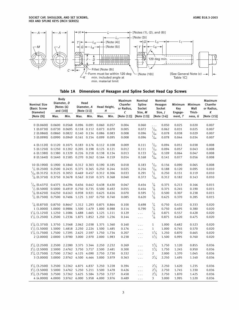
1.2.1 Socket Head Cap Screws. The socket head shallhave a flat chamfered top surface with smooth orknurled cylindrical sides and a flat bearing surface. Spec-ifications are given in Tables 1A through 1F. Both hexa-gon and spline socket types are included.
Dimensions for drilled holes and counterbores areincluded in Table A-1 of Nonmandatory Appendix A.
1.2.2 Drilled Hexagon Socket Head Cap Screws. Speci-fications for hexagon socket head cap screws havingtwo, four, and six holes drilled in the head for lock wireapplication are given in Table 1F.
1.2.3 Socket Flat Countersunk Head Cap Screws. Theflat countersunk head shall have a flat top surface anda conical bearing surface with included angle of approxi-mately 82 deg. Specifications are given in Tables 2A,2B, and 2C. Both hexagon and spline socket types areincluded.
1.2.4 Socket Button Head Cap Screws. The buttonhead shall have a low rounded top surface with a largeflat bearing surface. Specifications are given in Table 3.Both hexagon and spline socket types are included.
1
1.2.5 Socket Low Head Cap Screws. These are similarto socket head cap screws, except they have reducedhead height and a smaller socket size. They are designedto be used in applications where height clearance is aproblem. Specifications are given in Table 1G. Splinesocket types are excluded.
1.3 Socket Head Shoulder Screws
The socket head shoulder screw is a hexagon sockethead screw having a cylindrical shoulder under thehead. Specifications are given in Table 4.
1.4 Socket Set Screws
The socket set screw is a screw threaded the entirelength except for its length of point. The point isdesigned to bear on a mating part. The common pointstyles are cup, flat, oval, cone, and half dog. Specifica-tions for set screws are shown in Tables 5A through 5Cfor both hexagon and spline socket types.
1.5 Keys and Bits for Driving Socket Screws
The tools for driving socket screws are hexagon orspline keys and bits, the specifications for which appearin Tables 8 and 9, respectively.
1.6 Dimensions
All dimensions in this Standard are given in inchesunless stated otherwise.
All dimensions apply prior to coating unless statedotherwise.
1.7 Finish
Because of the high hardness of these products, it isrecommended that they not be electroplated.
1.8 Identification MarkingProducts described in paras. 1.2.1 through 1.2.4 and
1.3 with diameters larger than #10 must be marked withthe identification of the source manufacturer or privatelabel distributor accepting the responsibility for confor-mance to this Standard. Marking size, type, and locationof marks are at manufacturer’s option. Products shallnot be marked on bearing surface.
1.9 OptionsOptions, where specified, shall be at the discretion of
the manufacturer unless agreed upon otherwise by themanufacturer and purchaser.
ASME B18.3-2003 SOCKET CAP, SHOULDER, AND SET SCREWS,HEX AND SPLINE KEYS (INCH SERIES)
1.10 Responsibility for Modifications
The manufacturer shall not be held responsible formalfunctions of product due to plating or other modifi-cations, when such plating or modification is not accom-plished under his control or direction.
1.11 Terminology
For definitions of terms relating to fasteners or tocomponent features thereof used in this Standard, referto ASME B18.12, Glossary of Terms for Mechanical Fas-teners.
1.12 Referenced Standards
The following is a list of publications referenced in thisStandard. Unless otherwise specified, the most recentstandard available shall be used.
ASME B1.1, Unified Inch Screw Threads (UN and UNRThread Form)
ASME B1.3M, Screw Thread Gaging Systems for Dimen-sional Acceptability — Inch and Metric Screw Threads(UN, UNR, UNJ, M, and MJ)
ANSI B18.12, Glossary of Terms for Mechanical Fas-teners
ASME B18.18.1M, Inspection and Quality Assurance forGeneral Purpose Fasteners
ASME B18.18.2M, Inspection and Quality Assurance forHigh Volume Machine Assembly Fasteners
ASME B18.18.3M, Inspection and Quality Assurance forSpecial Purpose Fasteners
ASME B18.18.4M, Fasteners Produced from a Single MillHeat With In-Process Control and Lot Traceability
ASME B18.24.1, Part Identifying Number (PIN) CodeSystem Standard for B18 Externally ThreadedProducts
ASME B46.1, Surface TextureASME B47.1, Gage BlanksASME Y14.5M, Engineering Drawing and Related Docu-
mentation Practices, Dimensioning and TolerancingASME Y14.6, Engineering Drawing and Related Docu-
mentation Practices, Screw Thread RepresentationPublisher: The American Society of Mechanical Engi-
neers (ASME), Three Park Avenue, New York, NY10016-5990; Order Department: 22 Law Drive, Box2300, Fairfield, NJ 07007-2300
ASTM A 574, Standard Specification for Alloy SteelSocket-Head Cap Screws
ASTM F 835, Standard Specification for Alloy SteelSocket Button and Flat Countersunk Head Cap Screws
ASTM F 837, Standard Specification for Stainless SteelSocket-Head Cap Screws
ASTM F 879, Standard Specification for Stainless SteelSocket Button and Flat Countersunk Head Cap Screws
ASTM F 880, Standard Specification for Stainless SteelSocket Set Screws
ASTM F 912, Standard Specification for Alloy SteelSocket Set Screws
2
Publisher: The American Society for Testing and Materi-als (ASTM), 100 Barr Harbor Drive, West Consho-hocken, PA 19428-2959
2 GENERAL DATA
2.1 Sockets
In accordance with the provisions set forth in the notesto the respective dimensional tables, screws shall havehexagon or spline sockets as designated by the pur-chaser.
Gages and gaging procedures are included in Manda-tory Appendix I. For coated products, use GO gagesidentical in design and tolerances to those shown inMandatory Appendix I, except having minimum dimen-sions equal to minimum sizes of keys and bits shownin Tables 8 and 9, respectively. Due to possible buildupof the socket, coated products may not accept a standardhex or spline key.
2.1.1 Hexagon Sockets. Hexagon sockets shall con-form with the specifications given in Table 6.
2.1.2 Spline Sockets. Spline sockets shall conformwith the specifications given in Table 7.
2.2 Threads
Threads on all screw products covered by this Stan-dard shall be in accordance with ASME B1.1 for theseries and class specified in the notes to the respectiveproduct dimensional tables.
Acceptability of screw threads shall be based on Sys-tem 22, ASME B1.1, except where otherwise specifiedin Note (14) of Table 5A.
2.3 Quality Assurance
Products will be furnished in accordance with ASMEB18.18.1M, with the thread acceptability to InspectionLevel C, unless otherwise specified.
2.4 Dimensional Characteristics
Products shall conform to the dimensions indicatedin the respective tables. The designated characteristicsdefined within the notes of each product table shallbe inspected in accordance with ASME B18.18.2M. Fornondesignated dimensional characteristics, the provi-sions of ASME B18.18.1M shall apply. Should a nondes-ignated dimension be determined to have a variance, itshall be deemed conforming to this Standard if the user,who is the installer, accepts the variance based on fit,form, and function considerations. Where verifiable in-process inspection is used in accordance with ASMEB18.18.3M or ASME B18.18.4M, the final inspection levelsample sizes of those respective standards shall apply.
SOCKET CAP, SHOULDER, AND SET SCREWS, ASME B18.3-2003HEX AND SPLINE KEYS (INCH SERIES)
A
LGTG
C
TLB
F
K
LTLG LT
LB
G
LHA
M J
D
Fillet [Note (9)]
[Note (10)]
[Note (3)]
[Note (4)][Note (5)]
[Notes (1), (2), and (8)]
[See General Note (c) Table 1C]
120 deg min.
Form must be within 120 degmin. included angle atmin. material limit
Table 1A Dimensions of Hexagon and Spline Socket Head Cap Screws
Body Maximum Nominal Nominal MaximumDiameter, D HeadNominal Size Chamfer Spline Hexagon Minimum Minimum Chamfer[Notes (6) Diameter, A Head Height,(Basic Screw or Radius, Socket Socket Key Wall or Radius,and (10)] [Note (11)] HDiameter) C Size, M Size, J Engage- Thick- K
[Note (9)] Max. Min. Max. Min. Max. Min. [Note (12)] [Note (13)] [Note (14)] ment, T ness, G [Note (15)]
0 (0.0600) 0.0600 0.0568 0.096 0.091 0.060 0.057 0.004 0.060 . . . 0.050 0.025 0.020 0.0071 (0.0730) 0.0730 0.0695 0.118 0.112 0.073 0.070 0.005 0.072 1⁄16 0.062 0.031 0.025 0.0072 (0.0860) 0.0860 0.0822 0.140 0.134 0.086 0.083 0.008 0.096 5⁄64 0.078 0.038 0.029 0.0073 (0.0990) 0.0990 0.0949 0.161 0.154 0.099 0.095 0.008 0.096 5⁄64 0.078 0.044 0.034 0.007
4 (0.1120) 0.1120 0.1075 0.183 0.176 0.112 0.108 0.009 0.111 3⁄32 0.094 0.051 0.038 0.0085 (0.1250) 0.1250 0.1202 0.205 0.198 0.125 0.121 0.012 0.111 3⁄32 0.094 0.057 0.043 0.0086 (0.1380) 0.1380 0.1329 0.226 0.218 0.138 0.134 0.013 0.133 7⁄64 0.109 0.064 0.047 0.0088 (0.1640) 0.1640 0.1585 0.270 0.262 0.164 0.159 0.014 0.168 9⁄64 0.141 0.077 0.056 0.008
10 (0.1900) 0.1900 0.1840 0.312 0.303 0.190 0.185 0.018 0.183 5⁄32 0.156 0.090 0.065 0.0081⁄4 (0.2500) 0.2500 0.2435 0.375 0.365 0.250 0.244 0.025 0.216 3⁄16 0.188 0.120 0.095 0.010
5⁄16 (0.3125) 0.3125 0.3053 0.469 0.457 0.312 0.306 0.033 0.291 1⁄4 0.250 0.151 0.119 0.0103⁄8 (0.3750) 0.3750 0.3678 0.562 0.550 0.375 0.368 0.040 0.372 5⁄16 0.312 0.182 0.143 0.010
7⁄16 (0.4375) 0.4375 0.4294 0.656 0.642 0.438 0.430 0.047 0.454 3⁄8 0.375 0.213 0.166 0.0151⁄2 (0.5000) 0.5000 0.4919 0.750 0.735 0.500 0.492 0.055 0.454 3⁄8 0.375 0.245 0.190 0.0155⁄8 (0.6250) 0.6250 0.6163 0.938 0.921 0.625 0.616 0.070 0.595 1⁄2 0.500 0.307 0.238 0.0153⁄4 (0.7500) 0.7500 0.7406 1.125 1.107 0.750 0.740 0.085 0.620 5⁄8 0.625 0.370 0.285 0.015
7⁄8 (0.8750) 0.8750 0.8647 1.312 1.293 0.875 0.864 0.100 0.698 3⁄4 0.750 0.432 0.333 0.0201 (1.0000) 1.0000 0.9886 1.500 1.479 1.000 0.988 0.114 0.790 3⁄4 0.750 0.495 0.380 0.020
11⁄8 (1.1250) 1.1250 1.1086 1.688 1.665 1.125 1.111 0.129 . . . 7⁄8 0.875 0.557 0.428 0.02011⁄4 (1.2500) 1.2500 1.2336 1.875 1.852 1.250 1.236 0.144 . . . 7⁄8 0.875 0.620 0.475 0.020
13⁄8 (1.3750) 1.3750 1.3568 2.062 2.038 1.375 1.360 0.160 . . . 1 1.000 0.682 0.523 0.02011⁄2 (1.5000) 1.5000 1.4818 2.250 2.224 1.500 1.485 0.176 . . . 1 1.000 0.745 0.570 0.02013⁄4 (1.7500) 1.7500 1.7295 2.625 2.597 1.750 1.734 0.207 . . . 11⁄4 1.250 0.870 0.665 0.020
2 (2.0000) 2.0000 1.9780 3.000 2.970 2.000 1.983 0.238 . . . 11⁄2 1.500 0.995 0.760 0.020
21⁄4 (2.2500) 2.2500 2.2280 3.375 3.344 2.250 2.232 0.269 . . . 13⁄4 1.750 1.120 0.855 0.03621⁄2 (2.5000) 2.5000 2.4762 3.750 3.717 2.500 2.481 0.300 . . . 13⁄4 1.750 1.245 0.950 0.03623⁄4 (2.7500) 2.7500 2.7262 4.125 4.090 2.750 2.730 0.332 . . . 2 2.000 1.370 1.045 0.036
3 (3.0000) 3.0000 2.9762 4.500 4.464 3.000 3.979 0.363 . . . 21⁄4 2.250 1.495 1.140 0.036
31⁄4 (3.2500) 3.2500 3.2262 4.875 4.837 3.250 3.228 0.394 . . . 21⁄4 2.250 1.620 1.235 0.03631⁄2 (3.5000) 3.5000 3.4762 5.250 5.211 3.500 3.478 0.426 . . . 23⁄4 2.750 1.745 1.330 0.03633⁄4 (3.7500) 3.7500 3.7262 5.625 5.584 3.750 3.727 0.458 . . . 23⁄4 2.750 1.870 1.425 0.036
4 (4.0000) 4.0000 3.9762 6.000 5.958 4.000 3.976 0.489 . . . 3 3.000 1.995 1.520 0.036
3
ASME B18.3-2003 SOCKET CAP, SHOULDER, AND SET SCREWS,HEX AND SPLINE KEYS (INCH SERIES)
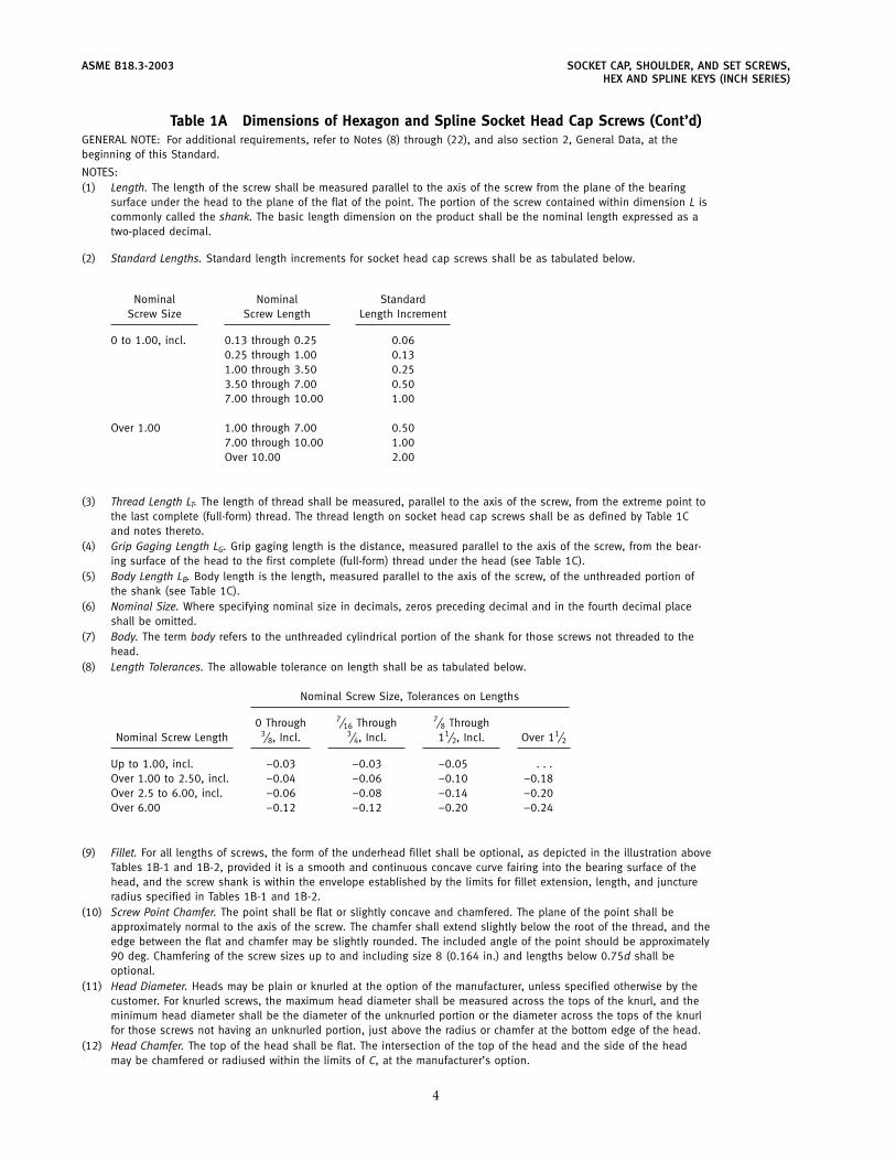
Table 1A Dimensions of Hexagon and Spline Socket Head Cap Screws (Cont’d)GENERAL NOTE: For additional requirements, refer to Notes (8) through (22), and also section 2, General Data, at thebeginning of this Standard.
NOTES:(1) Length. The length of the screw shall be measured parallel to the axis of the screw from the plane of the bearing
surface under the head to the plane of the flat of the point. The portion of the screw contained within dimension L iscommonly called the shank. The basic length dimension on the product shall be the nominal length expressed as atwo-placed decimal.
(2) Standard Lengths. Standard length increments for socket head cap screws shall be as tabulated below.
Nominal Nominal StandardScrew Size Screw Length Length Increment
0 to 1.00, incl. 0.13 through 0.25 0.060.25 through 1.00 0.131.00 through 3.50 0.253.50 through 7.00 0.507.00 through 10.00 1.00
Over 1.00 1.00 through 7.00 0.507.00 through 10.00 1.00Over 10.00 2.00
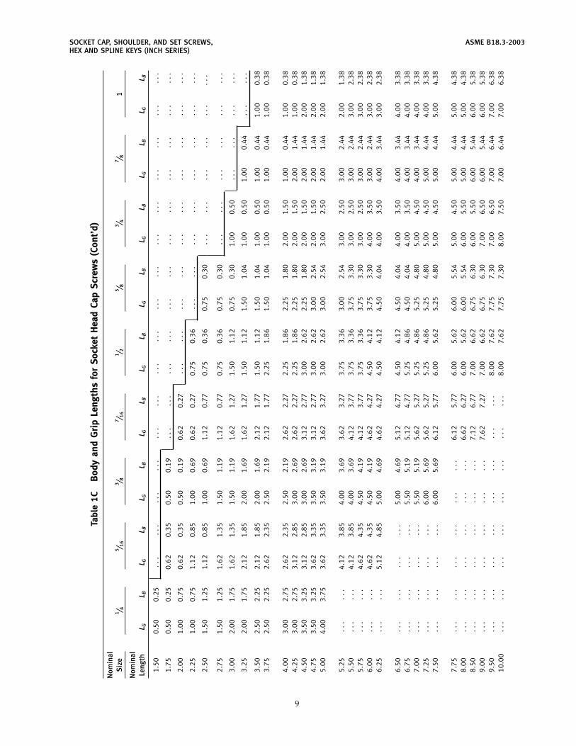
(3) Thread Length LT. The length of thread shall be measured, parallel to the axis of the screw, from the extreme point tothe last complete (full-form) thread. The thread length on socket head cap screws shall be as defined by Table 1Cand notes thereto.
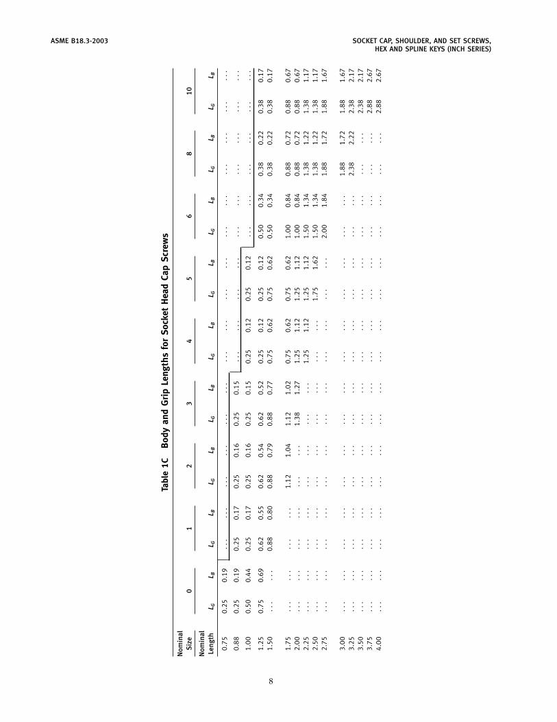
(4) Grip Gaging Length LG. Grip gaging length is the distance, measured parallel to the axis of the screw, from the bear-ing surface of the head to the first complete (full-form) thread under the head (see Table 1C).
(5) Body Length LB. Body length is the length, measured parallel to the axis of the screw, of the unthreaded portion ofthe shank (see Table 1C).
(6) Nominal Size. Where specifying nominal size in decimals, zeros preceding decimal and in the fourth decimal placeshall be omitted.
(7) Body. The term body refers to the unthreaded cylindrical portion of the shank for those screws not threaded to thehead.
(8) Length Tolerances. The allowable tolerance on length shall be as tabulated below.
Nominal Screw Size, Tolerances on Lengths
0 Through 7⁄16 Through 7⁄8 ThroughNominal Screw Length 3⁄8, Incl. 3⁄4, Incl. 11⁄2, Incl. Over 11⁄2
Up to 1.00, incl. −0.03 −0.03 −0.05 . . .Over 1.00 to 2.50, incl. −0.04 −0.06 −0.10 −0.18Over 2.5 to 6.00, incl. −0.06 −0.08 −0.14 −0.20Over 6.00 −0.12 −0.12 −0.20 −0.24
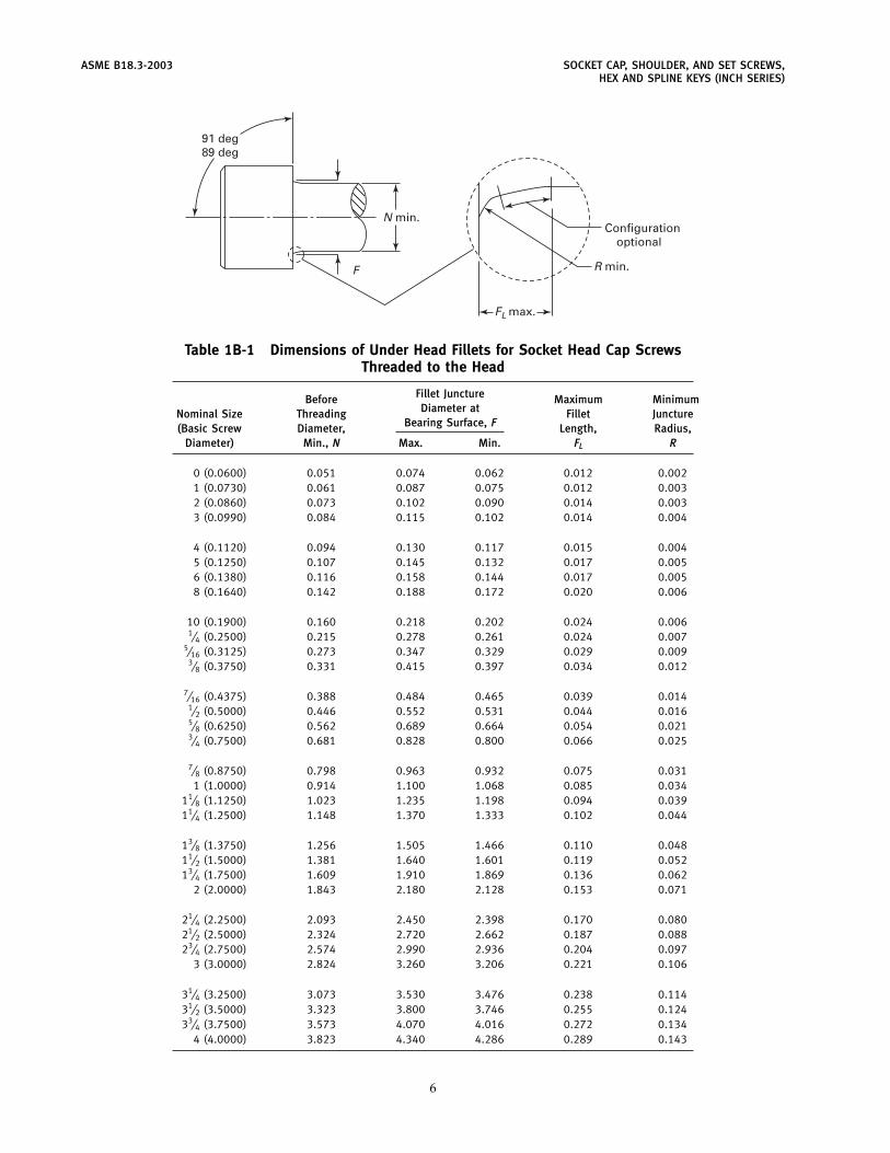
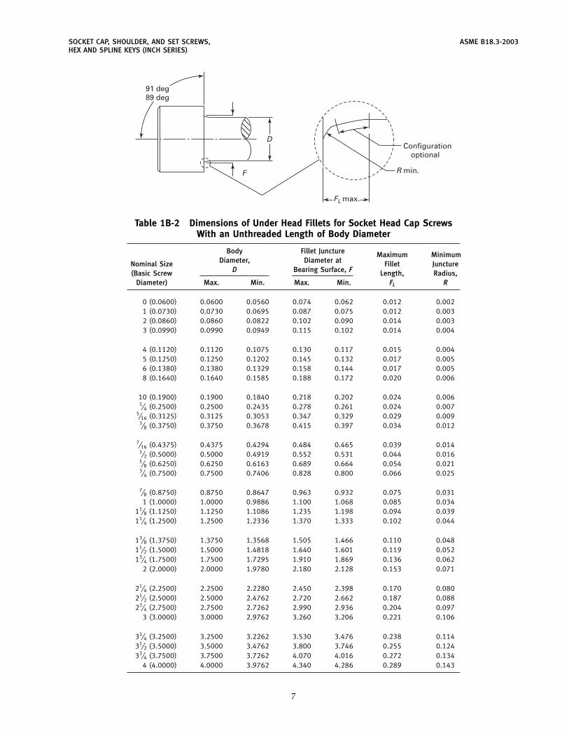
(9) Fillet. For all lengths of screws, the form of the underhead fillet shall be optional, as depicted in the illustration aboveTables 1B-1 and 1B-2, provided it is a smooth and continuous concave curve fairing into the bearing surface of thehead, and the screw shank is within the envelope established by the limits for fillet extension, length, and junctureradius specified in Tables 1B-1 and 1B-2.
(10) Screw Point Chamfer. The point shall be flat or slightly concave and chamfered. The plane of the point shall beapproximately normal to the axis of the screw. The chamfer shall extend slightly below the root of the thread, and theedge between the flat and chamfer may be slightly rounded. The included angle of the point should be approximately90 deg. Chamfering of the screw sizes up to and including size 8 (0.164 in.) and lengths below 0.75d shall beoptional.
(11) Head Diameter. Heads may be plain or knurled at the option of the manufacturer, unless specified otherwise by thecustomer. For knurled screws, the maximum head diameter shall be measured across the tops of the knurl, and theminimum head diameter shall be the diameter of the unknurled portion or the diameter across the tops of the knurlfor those screws not having an unknurled portion, just above the radius or chamfer at the bottom edge of the head.
(12) Head Chamfer. The top of the head shall be flat. The intersection of the top of the head and the side of the headmay be chamfered or radiused within the limits of C, at the manufacturer’s option.
4
SOCKET CAP, SHOULDER, AND SET SCREWS, ASME B18.3-2003HEX AND SPLINE KEYS (INCH SERIES)
Table 1A Dimensions of Hexagon and Spline Socket Head Cap Screws (Cont’d)(13) See Table 7 for spline socket dimensions and Mandatory Appendix I for gaging of spline sockets.(14) See Table 6 for hexagon socket dimensions and Mandatory Appendix I for gaging of hexagon sockets.(15) Edge of Head. The edge between the bearing surface and the side of the head may be broken (rounded or
chamfered), but the radius or chamfer measured along the bearing surface shall not exceed the values listed for K.(16) Bearing Surface. The plane of the bearing surface shall be perpendicular to the axis of the shank, within a maximum
deviation of 1 deg, obtained by holding the screw on the body or major thread diameter within 1 diameter of thebearing surface of the head, but beyond the maximum length of the fillet, FL, and inspecting on an opticalcomparator, or comparable inspection equipment, rotating the axis of the shank 360 deg.
(17) Runout(a) The runout of the head with the axis of the shank shall be within 2% of the maximum basic screw diameter
dimension, D, or 0.006 in., whichever is greater.Runout for (a) above is defined as the full indicator movement (FIM) obtained by holding the screw on the body or
major screw thread diameter within 1 diameter of the bearing surface of the head, but beyond the maximum lengthof the fillet, FL, rotating 360 deg and indicating on the outside diameter of the head.
(b) The runout of the socket with the axis of the shank of the screw shall be within 3% of the maximum screwdiameter, D, or 0.005 in., whichever is greater for nominal sizes through 1⁄2 in. diameter and 6% for nominal sizesabove 1⁄2 in. diameter.
Runout for (b) above is defined as the full indicator movement (FIM) obtained by holding the screw on the body ormajor screw thread diameter within 1 diameter of the bearing surface of the head, but beyond the maximum lengthof the fillet, FL, rotating 360 deg, indicating on each of six hexagon flats.
(c) The conformance of screws to shank straightness or camber limitations set forth as De in Table 1E, shall bechecked by the use of the procedures and typical gage illustrated in Mandatory Appendix III.
(18) Threads. Threads shall be Unified external threads with radius root: Class 3A UNRC and UNRF Series for screw sizes 0(0.060 in.) through 1 in.; Class 2A UNRC and UNRF Series for sizes over 1 in. to 11⁄2 in., inclusive; and Class 2A UNRSeries for sizes larger than 11⁄2 in.
For plated or unplated screws, acceptability shall be based upon System 22, ASME B1.3M.Class 3A does not provide a plating allowance. When plated products are required, it is recommended that they be
procured from the manufacturer (see para. 1.10, Introductory Notes).(19) Material
(a) Steel, Alloy. Cap screws shall be fabricated from an alloy steel and shall conform in all respects to ASTM A 574.(b) Steel, Corrosion-Resistant. Cap screws shall be fabricated from a corrosion-resistant steel and shall conform in
all respects to ASTM F 837.(20) Surface Roughness. For alloy steel screws of sizes up to and incuding 5⁄8 in., and nominal lengths equal to or less
than 8 times the basic screw diameter, the surface roughness of the screws shall not exceed 63 �in. (arithmeticalaverage) on the fillet and head bearing surfaces, nor exceed 32 �in. (arithmetical average) on the threads.
For larger sizes, longer lengths, and corrosion-resistant steel screws, the surface roughness of the screws shall notexceed 125 �in. (arithmetical average) on the body [see Note (10)], fillet [see Note (7)], and head bearing surfaces.
Normally, it shall be sufficient to ascertain that these surfaces on screws have the equivalent of a smoothmachined finish by visual comparison with known surface standards. However, where it is practical and deemed nec-essary to measure these surfaces with commercially available equipment, roughness measurements shall be taken axi-ally on the body and fillet surfaces, and circumferentially on the bearing surface. (See ASME B46.1, Surface Texture.)
(21) Drawings. On socket screw drawings, when the distance from the bearing surface of the head to the threading isdimensioned, regardless of type of thread representation (see ASME Y14.6 for description of schematic and simplifiedthread representation), the dimension should be noted to indicate whether body length or grip length is required.
(22) Dimensional Conformance. Socket Head Cap Screws shall have the following designated characteristics inspected toASME B18.18.2M to Inspection Level C: threads, head diameter, socket size (gaged), length, and fillet transitiondiameter.
(23) Designation. To promote uniformity and understanding in communications relating to products conforming to thisStandard, it is recommended that Hexagon and Spline Socket Head Cap Screws be designated in accordance with thefollowing data, preferably in the sequence shown:
(a) product name(b) designation of the standard(c) nominal size (number, fractional or decimal equivalent)(d) thread pitch(e) nominal length (fractional or decimal equivalent)(f) material(g) protective finish, if required
EXAMPLES:Hexagon Socket Head Cap Screws, ASME B18.3, 6-32 � 3⁄4, Alloy SteelSpline Socket Head Cap Screws, ASME B18.3, 0.138-32 � 0.750, Alloy Steel, Zinc Plated. (For plated products, see
para. 1.7, Introductory Notes.)For the recommended B18 part identifying numbering system (PIN), see ASME B18.24.1.
5
ASME B18.3-2003 SOCKET CAP, SHOULDER, AND SET SCREWS,HEX AND SPLINE KEYS (INCH SERIES)
FL max.
R min.
N min.
F
Configurationoptional
91 deg89 deg
Table 1B-1 Dimensions of Under Head Fillets for Socket Head Cap ScrewsThreaded to the Head
Fillet JunctureBefore Maximum MinimumDiameter atNominal Size Threading Fillet Juncture
Bearing Surface, F(Basic Screw Diameter, Length, Radius,Diameter) Min., N Max. Min. FL R
0 (0.0600) 0.051 0.074 0.062 0.012 0.0021 (0.0730) 0.061 0.087 0.075 0.012 0.0032 (0.0860) 0.073 0.102 0.090 0.014 0.0033 (0.0990) 0.084 0.115 0.102 0.014 0.004
4 (0.1120) 0.094 0.130 0.117 0.015 0.0045 (0.1250) 0.107 0.145 0.132 0.017 0.0056 (0.1380) 0.116 0.158 0.144 0.017 0.0058 (0.1640) 0.142 0.188 0.172 0.020 0.006
10 (0.1900) 0.160 0.218 0.202 0.024 0.0061⁄4 (0.2500) 0.215 0.278 0.261 0.024 0.007
5⁄16 (0.3125) 0.273 0.347 0.329 0.029 0.0093⁄8 (0.3750) 0.331 0.415 0.397 0.034 0.012
7⁄16 (0.4375) 0.388 0.484 0.465 0.039 0.0141⁄2 (0.5000) 0.446 0.552 0.531 0.044 0.0165⁄8 (0.6250) 0.562 0.689 0.664 0.054 0.0213⁄4 (0.7500) 0.681 0.828 0.800 0.066 0.025
7⁄8 (0.8750) 0.798 0.963 0.932 0.075 0.0311 (1.0000) 0.914 1.100 1.068 0.085 0.034
11⁄8 (1.1250) 1.023 1.235 1.198 0.094 0.03911⁄4 (1.2500) 1.148 1.370 1.333 0.102 0.044
13⁄8 (1.3750) 1.256 1.505 1.466 0.110 0.04811⁄2 (1.5000) 1.381 1.640 1.601 0.119 0.05213⁄4 (1.7500) 1.609 1.910 1.869 0.136 0.062
2 (2.0000) 1.843 2.180 2.128 0.153 0.071
21⁄4 (2.2500) 2.093 2.450 2.398 0.170 0.08021⁄2 (2.5000) 2.324 2.720 2.662 0.187 0.08823⁄4 (2.7500) 2.574 2.990 2.936 0.204 0.097
3 (3.0000) 2.824 3.260 3.206 0.221 0.106
31⁄4 (3.2500) 3.073 3.530 3.476 0.238 0.11431⁄2 (3.5000) 3.323 3.800 3.746 0.255 0.12433⁄4 (3.7500) 3.573 4.070 4.016 0.272 0.134
4 (4.0000) 3.823 4.340 4.286 0.289 0.143
6
SOCKET CAP, SHOULDER, AND SET SCREWS, ASME B18.3-2003HEX AND SPLINE KEYS (INCH SERIES)
FL max.
R min.
D
F
Configurationoptional
91 deg89 deg
Table 1B-2 Dimensions of Under Head Fillets for Socket Head Cap ScrewsWith an Unthreaded Length of Body Diameter
Body Fillet Juncture Maximum MinimumDiameter, Diameter atNominal Size Fillet Juncture
D Bearing Surface, F(Basic Screw Length, Radius,Diameter) Max. Min. Max. Min. FL R
0 (0.0600) 0.0600 0.0560 0.074 0.062 0.012 0.0021 (0.0730) 0.0730 0.0695 0.087 0.075 0.012 0.0032 (0.0860) 0.0860 0.0822 0.102 0.090 0.014 0.0033 (0.0990) 0.0990 0.0949 0.115 0.102 0.014 0.004
4 (0.1120) 0.1120 0.1075 0.130 0.117 0.015 0.0045 (0.1250) 0.1250 0.1202 0.145 0.132 0.017 0.0056 (0.1380) 0.1380 0.1329 0.158 0.144 0.017 0.0058 (0.1640) 0.1640 0.1585 0.188 0.172 0.020 0.006
10 (0.1900) 0.1900 0.1840 0.218 0.202 0.024 0.0061⁄4 (0.2500) 0.2500 0.2435 0.278 0.261 0.024 0.007
5⁄16 (0.3125) 0.3125 0.3053 0.347 0.329 0.029 0.0093⁄8 (0.3750) 0.3750 0.3678 0.415 0.397 0.034 0.012
7⁄16 (0.4375) 0.4375 0.4294 0.484 0.465 0.039 0.0141⁄2 (0.5000) 0.5000 0.4919 0.552 0.531 0.044 0.0165⁄8 (0.6250) 0.6250 0.6163 0.689 0.664 0.054 0.0213⁄4 (0.7500) 0.7500 0.7406 0.828 0.800 0.066 0.025
7⁄8 (0.8750) 0.8750 0.8647 0.963 0.932 0.075 0.0311 (1.0000) 1.0000 0.9886 1.100 1.068 0.085 0.034
11⁄8 (1.1250) 1.1250 1.1086 1.235 1.198 0.094 0.03911⁄4 (1.2500) 1.2500 1.2336 1.370 1.333 0.102 0.044
13⁄8 (1.3750) 1.3750 1.3568 1.505 1.466 0.110 0.04811⁄2 (1.5000) 1.5000 1.4818 1.640 1.601 0.119 0.05213⁄4 (1.7500) 1.7500 1.7295 1.910 1.869 0.136 0.062
2 (2.0000) 2.0000 1.9780 2.180 2.128 0.153 0.071
21⁄4 (2.2500) 2.2500 2.2280 2.450 2.398 0.170 0.08021⁄2 (2.5000) 2.5000 2.4762 2.720 2.662 0.187 0.08823⁄4 (2.7500) 2.7500 2.7262 2.990 2.936 0.204 0.097
3 (3.0000) 3.0000 2.9762 3.260 3.206 0.221 0.106
31⁄4 (3.2500) 3.2500 3.2262 3.530 3.476 0.238 0.11431⁄2 (3.5000) 3.5000 3.4762 3.800 3.746 0.255 0.12433⁄4 (3.7500) 3.7500 3.7262 4.070 4.016 0.272 0.134
4 (4.0000) 4.0000 3.9762 4.340 4.286 0.289 0.143
7
ASME B18.3-2003 SOCKET CAP, SHOULDER, AND SET SCREWS,HEX AND SPLINE KEYS (INCH SERIES)
Tabl
e1C
Bod
yan
dG
rip
Leng
ths
for
Soc
ket
Hea
dCa
pS
crew
s
Nom
inal
Siz
e0
12
34
56
810
Nom
inal
Leng
thL G
L BL G
L BL G
L BL G
L BL G
L BL G
L BL G
L BL G
L BL G
L B
0.75
0.25
0.19
...
...
...
...
...
...
...
...
...
...
...
...
...
...
...
...
0.88
0.25
0.19
0.25
0.17
0.25
0.16
0.25
0.15
...
...
...
...
...
...
...
...
...
...
1.00
0.50
0.44
0.25
0.17
0.25
0.16
0.25
0.15
0.25
0.12
0.25
0.12
...
...
...
...
...
...
1.25
0.75
0.69
0.62
0.55
0.62
0.54
0.62
0.52
0.25
0.12
0.25
0.12
0.50
0.34
0.38
0.22
0.38
0.17
1.50
...
...
0.88
0.80
0.88
0.79
0.88
0.77
0.75
0.62
0.75
0.62
0.50
0.34
0.38
0.22
0.38
0.17
1.75
...
...
...
...
1.12
1.04
1.12
1.02
0.75
0.62
0.75
0.62
1.00
0.84
0.88
0.72
0.88
0.67
2.00
...
...
...
...
...
...
1.38
1.27
1.25
1.12
1.25
1.12
1.00
0.84
0.88
0.72
0.88
0.67
2.25
...
...
...
...
...
...
...
...
1.25
1.12
1.25
1.12
1.50
1.34
1.38
1.22
1.38
1.17
2.50
...
...
...
...
...
...
...
...
...
...
1.75
1.62
1.50
1.34
1.38
1.22
1.38
1.17
2.75
...
...
...
...
...
...
...
...
...
...
...
...
2.00
1.84
1.88
1.72
1.88
1.67
3.00
...
...
...
...
...
...
...
...
...
...
...
...
...
...
1.88
1.72
1.88
1.67
3.25
...
...
...
...
...
...
...
...
...
...
...
...
...
...
2.38
2.22
2.38
2.17
3.50
...
...
...
...
...
...
...
...
...
...
...
...
...
...
...
...
2.38
2.17
3.75
...
...
...
...
...
...
...
...
...
...
...
...
...
...
...
...
2.88
2.67
4.00
...
...
...
...
...
...
...
...
...
...
...
...
...
...
...
...
2.88
2.67
8
SOCKET CAP, SHOULDER, AND SET SCREWS, ASME B18.3-2003HEX AND SPLINE KEYS (INCH SERIES)
Tabl
e1C
Bod
yan
dG
rip
Leng
ths
for
Soc
ket
Hea
dCa
pS
crew
s(C
ont’
d)
Nom
inal
Siz
e1 ⁄ 4
5 ⁄ 16
3 ⁄ 87 ⁄ 1
61 ⁄ 2
5 ⁄ 83 ⁄ 4
7 ⁄ 81
Nom
inal
Leng
thL G
L BL G
L BL G
L BL G
L BL G
L BL G
L BL G
L BL G
L BL G
L B
1.50
0.50
0.25
...
...
...
...
...
...
...
...
...
...
...
...
...
...
...
...
1.75
0.50
0.25
0.62
0.35
0.50
0.19
...
...
...
...
...
...
...
...
...
...
...
...
2.00
1.00
0.75
0.62
0.35
0.50
0.19
0.62
0.27
...
...
...
...
...
...
...
...
...
...
2.25
1.00
0.75
1.12
0.85
1.00
0.69
0.62
0.27
0.75
0.36
...
...
...
...
...
...
...
...
2.50
1.50
1.25
1.12
0.85
1.00
0.69
1.12
0.77
0.75
0.36
0.75
0.30
...
...
...
...
...
...
2.75
1.50
1.25
1.62
1.35
1.50
1.19
1.12
0.77
0.75
0.36
0.75
0.30
...
...
...
...
...
...
3.00
2.00
1.75
1.62
1.35
1.50
1.19
1.62
1.27
1.50
1.12
0.75
0.30
1.00
0.50
...
...
...
...
3.25
2.00
1.75
2.12
1.85
2.00
1.69
1.62
1.27
1.50
1.12
1.50
1.04
1.00
0.50
1.00
0.44
...
...
3.50
2.50
2.25
2.12
1.85
2.00
1.69
2.12
1.77
1.50
1.12
1.50
1.04
1.00
0.50
1.00
0.44
1.00
0.38
3.75
2.50
2.25
2.62
2.35
2.50
2.19
2.12
1.77
2.25
1.86
1.50
1.04
1.00
0.50
1.00
0.44
1.00
0.38
4.00
3.00
2.75
2.62
2.35
2.50
2.19
2.62
2.27
2.25
1.86
2.25
1.80
2.00
1.50
1.00
0.44
1.00
0.38
4.25
3.00
2.75
3.12
2.85
3.00
2.69
2.62
2.27
2.25
1.86
2.25
1.80
2.00
1.50
2.00
1.44
1.00
0.38
4.50
3.50
3.25
3.12
2.85
3.00
2.69
3.12
2.77
3.00
2.62
2.25
1.80
2.00
1.50
2.00
1.44
2.00
1.38
4.75
3.50
3.25
3.62
3.35
3.50
3.19
3.12
2.77
3.00
2.62
3.00
2.54
2.00
1.50
2.00
1.44
2.00
1.38
5.00
4.00
3.75
3.62
3.35
3.50
3.19
3.62
3.27
3.00
2.62
3.00
2.54
3.00
2.50
2.00
1.44
2.00
1.38
5.25
...
...
4.12
3.85
4.00
3.69
3.62
3.27
3.75
3.36
3.00
2.54
3.00
2.50
3.00
2.44
2.00
1.38
5.50
...
...
4.12
3.85
4.00
3.69
4.12
3.77
3.75
3.36
3.75
3.30
3.00
2.50
3.00
2.44
3.00
2.38
5.75
...
...
4.62
4.35
4.50
4.19
4.12
3.77
3.75
3.36
3.75
3.30
3.00
2.50
3.00
2.44
3.00
2.38
6.00
...
...
4.62
4.35
4.50
4.19
4.62
4.27
4.50
4.12
3.75
3.30
4.00
3.50
3.00
2.44
3.00
2.38
6.25
...
...
5.12
4.85
5.00
4.69
4.62
4.27
4.50
4.12
4.50
4.04
4.00
3.50
4.00
3.44
3.00
2.38
6.50
...
...
...
...
5.00
4.69
5.12
4.77
4.50
4.12
4.50
4.04
4.00
3.50
4.00
3.44
4.00
3.38
6.75
...
...
...
...
5.50
5.19
5.12
4.77
5.25
4.86
4.50
4.04
4.00
3.50
4.00
3.44
4.00
3.38
7.00
...
...
...
...
5.50
5.19
5.62
5.27
5.25
4.86
5.25
4.80
5.00
4.50
4.00
3.44
4.00
3.38
7.25
...
...
...
...
6.00
5.69
5.62
5.27
5.25
4.86
5.25
4.80
5.00
4.50
5.00
4.44
4.00
3.38
7.50
...
...
...
...
6.00
5.69
6.12
5.77
6.00
5.62
5.25
4.80
5.00
4.50
5.00
4.44
5.00
4.38
7.75
...
...
...
...
...
...
6.12
5.77
6.00
5.62
6.00
5.54
5.00
4.50
5.00
4.44
5.00
4.38
8.00
...
...
...
...
...
...
6.62
6.27
6.00
5.62
6.00
5.54
6.00
5.50
5.00
4.44
5.00
4.38
8.50
...
...
...
...
...
...
7.12
6.77
7.00
6.62
6.75
6.30
6.00
5.50
6.00
5.44
6.00
5.38
9.00
...
...
...
...
...
...
7.62
7.27
7.00
6.62
6.75
6.30
7.00
6.50
6.00
5.44
6.00
5.38
9.50
...
...
...
...
...
...
...
...
8.00
7.62
7.75
7.30
7.00
6.50
7.00
6.44
7.00
6.38
10.0
0..
...
...
...
...
...
...
...
.8.
007.
627.
757.
308.
007.
507.
006.
447.
006.
38
9
ASME B18.3-2003 SOCKET CAP, SHOULDER, AND SET SCREWS,HEX AND SPLINE KEYS (INCH SERIES)
Tabl
e1C
Bod
yan
dG
rip
Leng
ths
for
Soc
ket
Hea
dCa
pS
crew
s(C
ont’
d)
Nom
inal
Siz
e1 ⁄ 4
5 ⁄ 16
3 ⁄ 87 ⁄ 1
61 ⁄ 2
5 ⁄ 83 ⁄ 4
7 ⁄ 81
Nom
inal
Leng
thL G
L BL G
L BL G
L BL G
L BL G
L BL G
L BL G
L BL G
L BL G
L B
11.0
0..
...
...
...
...
...
...
...
...
...
.9.
258.
809.
008.
508.
007.
448.
007.
3812
.00
...
...
...
...
...
...
...
...
...
...
10.2
59.
8010
.00
9.50
9.00
8.44
9.00
8.38
13.0
0..
...
...
...
...
...
...
...
...
...
...
...
.11
.00
10.5
010
.00
9.44
10.0
09.
3814
.00
...
...
...
...
...
...
...
...
...
...
...
...
12.0
011
.50
11.0
010
.44
11.0
010
.38
15.0
0..
...
...
...
...
...
...
...
...
...
...
...
.13
.00
12.5
012
.00
11.4
412
.00
11.3
8
16.0
0..
...
...
...
...
...
...
...
...
...
...
...
...
...
.13
.00
12.4
413
.00
12.3
817
.00
...
...
...
...
...
...
...
...
...
...
...
...
...
...
14.0
013
.44
14.0
013
.38
18.0
0..
...
...
...
...
...
...
...
...
...
...
...
...
...
.15
.00
14.4
415
.00
14.3
819
.00
...
...
...
...
...
...
...
...
...
...
...
...
...
...
...
...
16.0
015
.38
20.0
0..
...
...
...
...
...
...
...
...
...
...
...
...
...
...
...
.17
.00
16.3
8
GEN
ERA
LN
OTE
S:
(a)
The
tabu
late
dL G
valu
esar
em
axim
uman
dre
pres
ent
the
min
imum
desi
gngr
iple
ngth
ofth
esc
rew
.Th
eysh
all
bem
ea-
sure
dfr
omth
ebe
arin
gsu
rfac
eof
the
head
toth
efa
ceof
aG
Oth
read
ring
gage
,ha
ving
the
thre
adco
unte
rsin
kan
d/or
coun
terb
ore
rem
oved
,w
hich
has
been
asse
mbl
edby
hand
asfa
ras
the
thre
adw
illpe
rmit
.Th
eta
bula
ted
L Bva
lues
are
min
imum
and
repr
esen
tth
em
inim
umbo
dyle
ngth
ofth
esc
rew
.Th
eyar
eeq
ual
toL G
min
us5
tim
esth
epi
tch
ofth
eU
NRC
thre
adfo
rth
ere
spec
tive
scre
wsi
ze.
(b)
Scr
ews
havi
ngno
min
alle
ngth
sfa
lling
betw
een
thos
efo
rw
hich
L Gan
dL B
valu
esar
eta
bula
ted
inth
isTa
ble
shal
lha
veL G
and
L Bdi
men
sion
sco
nfor
min
gw
ith
thos
eof
the
next
shor
ter
tabu
late
dno
min
alle
ngth
for
the
resp
ecti
vesc
rew
size
.Fo
rex
ampl
e:fo
ra
1 ⁄ 4in
.si
zesc
rew
,1.
88in
.lo
ng,
L Gp
0.50
in.
and
L Bp
0.25
in.
(c)
For
scre
ws
ofno
min
alle
ngth
sab
ove
the
heav
ybo
ldlin
ein
this
Tabl
e,th
eco
mpl
ete
(ful
l-for
m)
thre
ads,
mea
sure
dw
ith
ath
read
ring
gage
havi
ngth
eth
read
cham
fer
and/
orc o
unte
rbor
ere
mov
ed,
shal
lex
tend
tow
ithi
ntw
opi
tche
s(t
hre a
ds)
ofth
ehe
adfo
rsi
zes
0(0
.060
in.)
thro
ugh
5 ⁄ 8in
.,in
clus
ive;
and
shal
lex
tend
ascl
ose
toth
ehe
adas
ispr
acti
cabl
efo
rsi
zes
larg
erth
an5 ⁄ 8
in.
Scr
ews
over
1in
.in
diam
eter
and
ofle
ngth
ssh
orte
rth
anth
em
inim
umth
read
leng
thL T
plus
5ti
mes
the
pitc
hof
the
UN
RCth
read
for
the
resp
ecti
vesc
rew
size
shal
lha
veco
mpl
ete
(ful
l-for
m)
thre
ads
exte
ndin
gas
clos
eto
the
head
aspr
acti
cabl
e.S
ee(d
)be
low
for
L Tva
lues
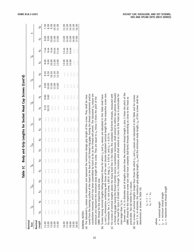
.(d
)Fo
rsc
rew
sof
nom
inal
leng
ths
long
erth
anth
ose
for
whi
chL G
and
L Bva
lues
are
tabu
late
din
this
Tabl
ean
dfo
rsc
rew
sov
er1
in.
indi
amet
er,
the
max
imum
grip
gagi
ngle
ngth
,L G
,an
dth
em
inim
umbo
dyle
ngth
,L B
,of
the
scre
ws
shal
lbe
dete
rmin
edas
show
nin
Tabl
e1D
:
L Gp
L−
L TL B
pL
−L T
T
whe
reL
pno
min
alle
ngth
L Tp
min
imum
thre
adle
ngth
L TTp
max
imum
tota
lth
read
leng
th
10
SOCKET CAP, SHOULDER, AND SET SCREWS, ASME B18.3-2003HEX AND SPLINE KEYS (INCH SERIES)
LTT
LTLG
LB
L
Table 1D Lengths Beyond Sizes in Table 1C
Nominal Size Minimum Maximum Total(Basic Screw Thread Length, Thread Length,
Diameter) LT LTT
0 (0.0600) 0.50 0.621 (0.0730) 0.62 0.772 (0.0860) 0.62 0.803 (0.0990) 0.62 0.83
4 (0.1120) 0.75 0.995 (0.1250) 0.75 1.006 (0.1380) 0.75 1.058 (0.1640) 0.88 1.19
10 (0.1900) 0.88 1.271⁄4 (0.2500) 1.00 1.50
5⁄16 (0.3125) 1.12 1.713⁄8 (0.3750) 1.25 1.94
7⁄16 (0.4375) 1.38 2.171⁄2 (0.5000) 1.50 2.385⁄8 (0.6250) 1.75 2.823⁄4 (0.7500) 2.00 3.25
7⁄8 (0.8750) 2.25 3.691 (1.0000) 2.50 4.12
11⁄8 (1.1250) 2.81 4.6511⁄4 (1.2500) 3.12 5.09
13⁄8 (1.3750) 3.44 5.6511⁄2 (1.5000) 3.75 6.0813⁄4 (1.7500) 4.38 7.13
2 (2.0000) 5.00 8.11
21⁄4 (2.2500) 5.62 8.9921⁄2 (2.5000) 6.25 10.0023⁄4 (2.7500) 6.88 10.87
3 (3.0000) 7.50 11.75
31⁄4 (3.2500) 8.12 12.6331⁄2 (3.5000) 8.75 13.5033⁄4 (3.7500) 9.38 14.37
4 (4.0000) 10.00 15.25
11
ASME B18.3-2003 SOCKET CAP, SHOULDER, AND SET SCREWS,HEX AND SPLINE KEYS (INCH SERIES)
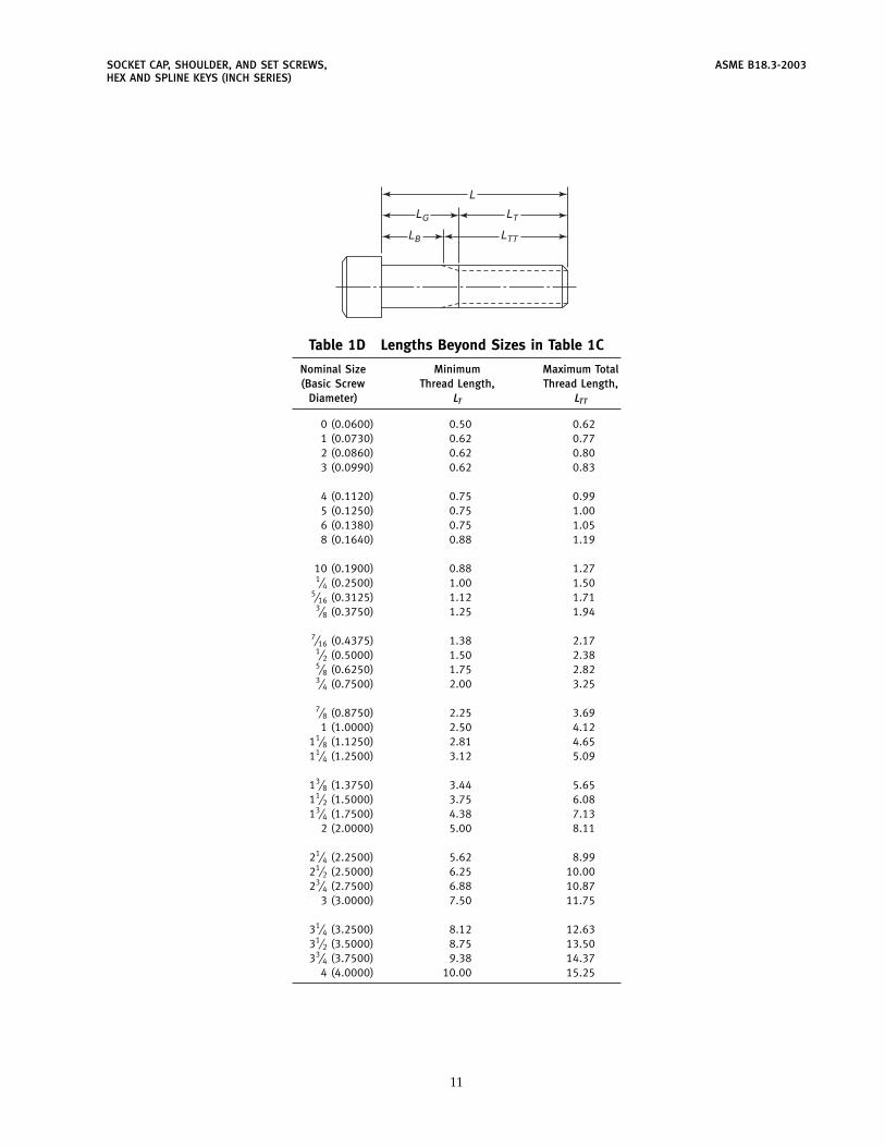
Table 1E Shank Straightness for Socket Head Cap Screws
Nominal Size, De Diameter [Note (1)]
Nominal Length 0 1 2 3 4 5 6 8 10
Over 0 to 0.25, incl. 0.063 0.076 . . . . . . . . . . . . . . . . . . . . .Over 0.25 to 0.50, incl. 0.065 0.078 . . . . . . . . . . . . . . . . . . . . .Over 0.50 to 0.75, incl. 0.068 0.080 . . . . . . . . . . . . . . . . . . . . .Over 0.75 to 1, incl. 0.070 0.082 . . . . . . . . . . . . . . . . . . . . .Over 1 to 1.50, incl. . . . 0.087 . . . . . . . . . . . . . . . . . . . . .
Over 0 to 0.50, incl. . . . . . . 0.090 0.103 0.116 . . . . . . . . . . . .Over 0.50 to 1, incl. . . . . . . 0.095 0.107 0.120 . . . . . . . . . . . .Over 1 to 1.50, incl. . . . . . . 0.099 0.111 0.123 . . . . . . . . . . . .Over 1.50 to 2, incl. . . . . . . 0.103 0.115 0.127 . . . . . . . . . . . .Over 2 to 2.50, incl. . . . . . . . . . . . . 0.131 . . . . . . . . . . . .
Over 0 to 0.75, incl. . . . . . . . . . . . . . . . 0.130 0.143 0.168 . . .Over 0.75 to 1.50, incl. . . . . . . . . . . . . . . . 0.136 0.148 0.173 . . .Over 1.50 to 2.25, incl. . . . . . . . . . . . . . . . 0.140 0.153 0.178 . . .Over 2.25 to 3, incl. . . . . . . . . . . . . . . . 0.146 0.158 0.183 . . .Over 3 to 4, incl. . . . . . . . . . . . . . . . 0.150 0.163 0.189 . . .
Over 0 to 1, incl. . . . . . . . . . . . . . . . . . . . . . . . . 0.196Over 1 to 2, incl. . . . . . . . . . . . . . . . . . . . . . . . . 0.201Over 2 to 3, incl. . . . . . . . . . . . . . . . . . . . . . . . . 0.207Over 3 to 4, incl. . . . . . . . . . . . . . . . . . . . . . . . . 0.213Over 4 to 6, incl. . . . . . . . . . . . . . . . . . . . . . . . . 0.215
Nominal Size, De Diameter [Note (1)]
Nominal Length 1⁄45⁄16
3⁄87⁄16
1⁄25⁄8
3⁄47⁄8 1
Over 0 to 1, incl. 0.255 0.317 0.379 0.441 . . . . . . . . . . . . . . .Over 1 to 2, incl. 0.260 0.322 0.383 0.445 . . . . . . . . . . . . . . .Over 2 to 3, incl. 0.265 0.326 0.387 0.449 . . . . . . . . . . . . . . .Over 3 to 4, incl. 0.270 0.331 0.391 0.453 . . . . . . . . . . . . . . .Over 4 to 6, incl. 0.275 0.337 0.400 0.462 . . . . . . . . . . . . . . .
Over 0 to 2, incl. . . . . . . . . . . . . 0.507 0.631 0.756 0.880 1.005Over 2 to 4, incl. . . . . . . . . . . . . 0.514 0.638 0.762 0.886 1.010Over 4 to 6, incl. . . . . . . . . . . . . 0.521 0.644 0.767 0.891 1.015Over 6 to 8, incl. . . . . . . . . . . . . 0.525 0.650 0.773 0.897 1.020Over 8 to 10, incl. . . . . . . . . . . . . . . . . . . 0.775 0.900 1.025
12
SOCKET CAP, SHOULDER, AND SET SCREWS, ASME B18.3-2003HEX AND SPLINE KEYS (INCH SERIES)
Table 1E Shank Straightness for Socket Head Cap Screws (Cont’d)
Nominal Size, De Diameter [Note (1)]
Nominal Length 11⁄8 11⁄4 13⁄8 11⁄2 13⁄4 2 21⁄4
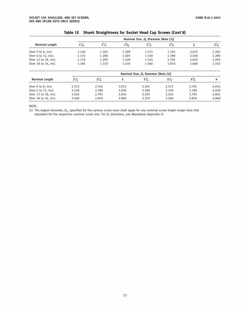
Over 0 to 6, incl. 1.140 1.265 1.390 1.515 1.765 2.015 2.265Over 6 to 12, incl. 1.155 1.280 1.405 1.530 1.780 2.030 2.280Over 12 to 18, incl. 1.170 1.295 1.420 1.545 1.795 2.045 2.295Over 18 to 24, incl. 1.185 1.310 1.435 1.560 1.810 2.060 2.310
Nominal Size, De Diameter [Note (1)]
Nominal Length 21⁄2 23⁄4 3 31⁄4 31⁄2 33⁄4 4
Over 0 to 6, incl. 2.515 2.765 3.015 3.265 3.515 3.765 4.015Over 6 to 12, incl. 2.530 2.780 3.030 3.280 3.530 3.780 4.030Over 12 to 18, incl. 2.545 2.795 3.045 3.295 3.545 3.795 4.045Over 18 to 24, incl. 2.560 2.810 3.060 3.310 3.560 3.810 4.060
NOTE:(1) The largest diameter, De, specified for the various screw sizes shall apply for any nominal screw length longer than that
tabulated for the respective nominal screw size. For De diameters, see Mandatory Appendix III.
13
ASME B18.3-2003 SOCKET CAP, SHOULDER, AND SET SCREWS,HEX AND SPLINE KEYS (INCH SERIES)
V
U
W6 Holes4 Holes2 Holes
60 deg nom.
60 deg nom.
60 degnom.
60 degnom.
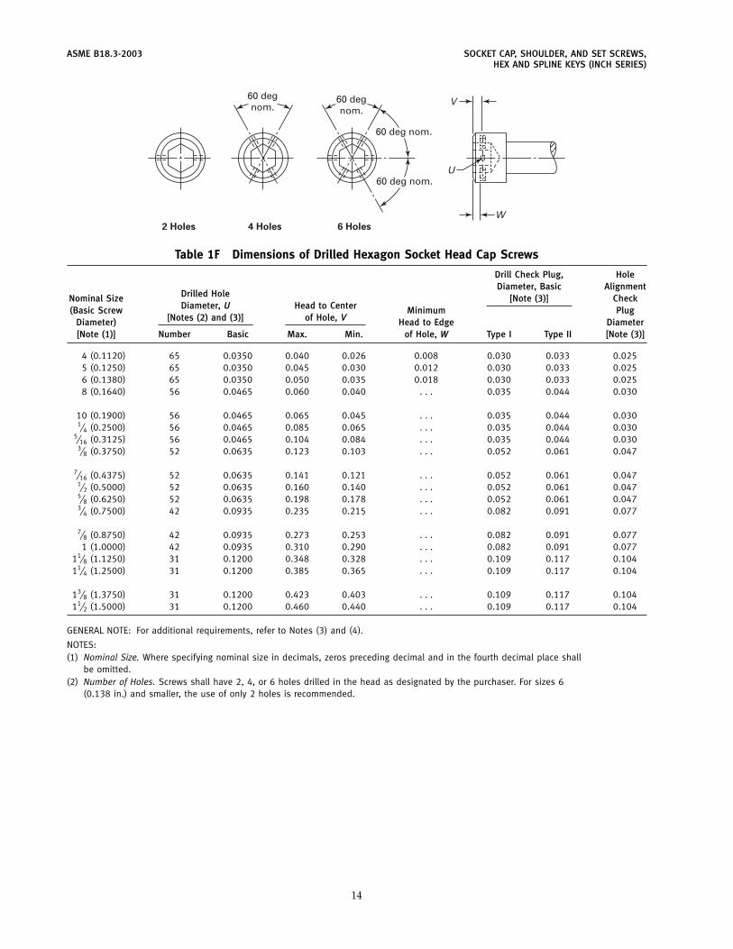
Table 1F Dimensions of Drilled Hexagon Socket Head Cap Screws
Drill Check Plug, HoleDiameter, Basic Alignment
Drilled HoleNominal Size [Note (3)] CheckDiameter, U Head to Center(Basic Screw Minimum Plug
[Notes (2) and (3)] of Hole, VDiameter) Head to Edge Diameter[Note (1)] Number Basic Max. Min. of Hole, W Type I Type II [Note (3)]
4 (0.1120) 65 0.0350 0.040 0.026 0.008 0.030 0.033 0.0255 (0.1250) 65 0.0350 0.045 0.030 0.012 0.030 0.033 0.0256 (0.1380) 65 0.0350 0.050 0.035 0.018 0.030 0.033 0.0258 (0.1640) 56 0.0465 0.060 0.040 . . . 0.035 0.044 0.030
10 (0.1900) 56 0.0465 0.065 0.045 . . . 0.035 0.044 0.0301⁄4 (0.2500) 56 0.0465 0.085 0.065 . . . 0.035 0.044 0.030
5⁄16 (0.3125) 56 0.0465 0.104 0.084 . . . 0.035 0.044 0.0303⁄8 (0.3750) 52 0.0635 0.123 0.103 . . . 0.052 0.061 0.047
7⁄16 (0.4375) 52 0.0635 0.141 0.121 . . . 0.052 0.061 0.0471⁄2 (0.5000) 52 0.0635 0.160 0.140 . . . 0.052 0.061 0.0475⁄8 (0.6250) 52 0.0635 0.198 0.178 . . . 0.052 0.061 0.0473⁄4 (0.7500) 42 0.0935 0.235 0.215 . . . 0.082 0.091 0.077
7⁄8 (0.8750) 42 0.0935 0.273 0.253 . . . 0.082 0.091 0.0771 (1.0000) 42 0.0935 0.310 0.290 . . . 0.082 0.091 0.077
11⁄8 (1.1250) 31 0.1200 0.348 0.328 . . . 0.109 0.117 0.10411⁄4 (1.2500) 31 0.1200 0.385 0.365 . . . 0.109 0.117 0.104
13⁄8 (1.3750) 31 0.1200 0.423 0.403 . . . 0.109 0.117 0.10411⁄2 (1.5000) 31 0.1200 0.460 0.440 . . . 0.109 0.117 0.104
GENERAL NOTE: For additional requirements, refer to Notes (3) and (4).
NOTES:(1) Nominal Size. Where specifying nominal size in decimals, zeros preceding decimal and in the fourth decimal place shall
be omitted.(2) Number of Holes. Screws shall have 2, 4, or 6 holes drilled in the head as designated by the purchaser. For sizes 6
(0.138 in.) and smaller, the use of only 2 holes is recommended.
14
SOCKET CAP, SHOULDER, AND SET SCREWS, ASME B18.3-2003HEX AND SPLINE KEYS (INCH SERIES)
Table 1F Dimensions of Drilled Hexagon Socket Head Cap Screws (Cont’d)(3) Holes. Hole size and location from the top of the head shall conform to the specifications given in this Table. For sizes
8 (0.164 in.) and larger, the drilled hole shall lie within the flats of the hexagon socket and not break through thesocket corners. Positioning of holes on opposite sides of the socket shall be such that the hole alignment check plugwill pass completely through the head on all screw sizes.
For commercial-quality screws, the edge of the holes on the outside of the head may be chamfered or broken. Theedge of the holes within the socket may contain burrs to the extent that the socket will accept a key having the stan-dard minimum width across the flats (see Table 8) and the holes must allow the Type I drill check plug to pass fromthe outside of the head into the socket.
For aircraft-quality screws, the edge of the holes on the outside of the head shall be chamfered and there shall beno burr chips or slivers that might become dislodged during usage. The socket shall accept a key having the standardmaximum width across the flats (see Table 8) and the hole must allow the Type II drill check plug to pass from the out-side of the head into the socket.
Chamfer on the edge of the holes, whether provided optionally or as requried, shall be subject to visual inspectiononly.
(4) Screws. Drilled hexagon socket head cap screws shall conform to the respective dimensions and requirements set forthin Table 1A and the notes thereto, except for the holes in the head as specified in this Table and Notes (2) and (3).
(5) Designation. To promote uniformity and understanding in communications relating to products conforming to this Stan-dard, it is recommended that Drilled Hexagon Socket Head Cap Screws be designated in accordance with the followingdata, preferably in the sequence shown:
(a) product name, including number of holes(b) designation of the standard(c) nominal size (number, fractional or decimal equivalent)(d) thread pitch(e) nominal length (fractional or decimal equivalent)(f) material(g) protective finish, if required
EXAMPLES:Drilled (2 holes) Hexagon Socket Head Cap Screws, ASME B18.3, 6-32 � 3⁄4 , Alloy SteelDrilled (6 holes) Hexagon Socket Head Cap Screws, ASME B18.3, 0.375-16 � 1.250, Alloy Steel, Zinc Plated. (For
plated products, see para. 1.7, Introductory Notes.)
For the recommended B18 part identifying numbering system (PIN), see ASME B18.24.1.
15
ASME B18.3-2003 SOCKET CAP, SHOULDER, AND SET SCREWS,HEX AND SPLINE KEYS (INCH SERIES)
A
JF
KL
H
D
C
T
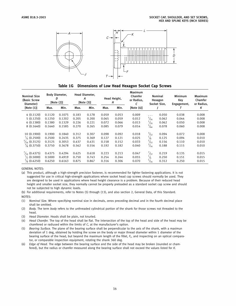
Table 1G Dimensions of Low Head Hexagon Socket Cap Screws
MaximumBody Diameter, Head Diameter,Nominal Size Chamfer Nominal Minimum Maximum
D A Head Height,(Basic Screw or Radius, Hexagon Key Chamfer[Note (2)] [Note (3)] HDiameter) C Socket Size, Engagement, or Radius,
[Note (1)] Max. Min. Max. Min. Max. Min. [Note (4)] J T K
4 (0.1120) 0.1120 0.1075 0.183 0.178 0.059 0.053 0.009 . . . 0.050 0.038 0.0085 (0.1250) 0.1250 0.1202 0.205 0.200 0.065 0.059 0.012 1⁄16 0.062 0.044 0.0086 (0.1380) 0.1380 0.1329 0.226 0.221 0.072 0.066 0.013 1⁄16 0.062 0.050 0.0088 (0.1640) 0.1640 0.1585 0.270 0.265 0.085 0.079 0.014 5⁄64 0.078 0.060 0.008
10 (0.1900) 0.1900 0.1840 0.312 0.307 0.098 0.092 0.018 3⁄32 0.094 0.072 0.0081⁄4 (0.2500) 0.2500 0.2435 0.375 0.369 0.127 0.121 0.025 1⁄8 0.125 0.094 0.010
5⁄16 (0.3125) 0.3125 0.3053 0.437 0.431 0.158 0.152 0.033 5⁄32 0.156 0.110 0.0103⁄8 (0.3750) 0.3750 0.3678 0.562 0.556 0.192 0.182 0.040 3⁄16 0.188 0.115 0.010
7⁄16 (0.4375) 0.4375 0.4294 0.625 0.618 0.223 0.213 0.047 7⁄32 0.219 0.135 0.0151⁄2 (0.5000) 0.5000 0.4919 0.750 0.743 0.254 0.244 0.055 1⁄4 0.250 0.151 0.0155⁄8 (0.6250) 0.6250 0.6163 0.875 0.867 0.316 0.306 0.070 5⁄16 0.312 0.250 0.015
GENERAL NOTES:(a) This product, although a high-strength precision fastener, is recommended for lighter fastening applications. It is not
suggested for use in critical high-strength applications where socket head cap screws should normally be used. Theyare designed to be used in applications where head height clearance is a problem. Because of their reduced headheight and smaller socket size, they normally cannot be properly preloaded as a standard socket cap screw and shouldnot be subjected to high dynamic loads.
(b) For additional requirements, refer to Notes (5) through (13), and also section 2, General Data, of this Standard.
NOTES:(1) Nominal Size. Where specifying nominal size in decimals, zeros preceding decimal and in the fourth decimal place
shall be omitted.(2) Body. The term body refers to the unthreaded cylindrical portion of the shank for those screws not threaded to the
head.(3) Head Diameter. Heads shall be plain, not knurled.(4) Head Chamfer. The top of the head shall be flat. The intersection of the top of the head and side of the head may be
chamfered or radiused within the limits of C, at the manufacturer’s option.(5) Bearing Surface. The plane of the bearing surface shall be perpendicular to the axis of the shank, with a maximun
deviation of 1 deg, obtained by holding the screw on the body or major thread diameter within 1 diameter of thebearing surface of the head, but beyond the maximum length of the fillet, FL, and inspecting on an optical compara-tor, or comparable inspection equipment, rotating the shank 360 deg.
(6) Edge of Head. The edge between the bearing surface and the side of the head may be broken (rounded or cham-fered), but the radius or chamfer measured along the bearing surface shall not exceed the values listed for K.
16
SOCKET CAP, SHOULDER, AND SET SCREWS, ASME B18.3-2003HEX AND SPLINE KEYS (INCH SERIES)
Table 1G Dimensions of Low Head Hexagon Socket Cap Screws (Cont’d)
(7) Runout(a) The runout of the head with the axis of the shank shall be within 2% of the maximum basic screw diameter
dimension, D, or 0.006 in., whichever is greater.Runout for (a) above is defined as the full indicator movement (FIM) obtained by holding the screw on the body or
major screw thread diameter within 1 diameter of the bearing surface of the head, but beyond the maximum lengthof the fillet, FL, rotating 360 deg and indicating on the outside diameter of the head.
(b) The runout of the socket with the axis of the shank of the screw shall be within 3% of the maximum screwdiameter, D, or 0.005 in., whichever is greater for sizes through 1⁄2 in. diameter and 6% for sizes above 1⁄2 in.diameter.
Runout for (b) above is defined as the full indicator movement (FIM) obtained by holding the screw on the body ormajor screw thread diameter within 1 diameter of the bearing surface of the head, but beyond the maximum lengthof the fillet, FL, rotating 360 deg, indicating on each of the six hexagon flats.
(c) The conformance of screws to shank straightness or camber limitations set forth as De in Table 1E shall bechecked by the use of the procedures and typical gage illustrated in Mandatory Appendix III.
(8) Fillet. For all lengths of screws, the form of the underhead fillet shall be optional, as depicted in the illustration aboveTables 1B-1 and 1B-2, provided it is a smooth and continuous concave curve fairing into the bearing surface of thehead, and the screw shank is within the envelope established by the limits for fillet extension, length, and junctureradius specified in Tables 1B-1 and 1B-2.
(NOTE: Tables 1B-1 and 1B-2 are found in the Socket Head Cap Screws information.)
(9) Length. The length of the screw shall be measured parallel to the axis of the screw from the plane of the bearing sur-face under the head to the plane of the flat of the point. The portion of the screw contained within dimension L iscommonly called the shank. The basic length dimension on the product shall be the nominal length expressed as atwo-placed decimal.
(10) Standard Lengths and Sizes (Alloy Steel). Most manufacturers consider the following diameters as standard stockitems:
(a) #8-32 up to 1 in. long
(b) #10-24 up to 1 in. long
(c) #10-32 up to 1 in. long
(d) 1⁄4-20 up to 1 in. long
(e) 5⁄16-18 up to 11⁄2 in. long
(f) 3⁄8-16 up to 11⁄2 in. long
(g) 1⁄2-13 up to 11⁄2 in. longAll of the above sizes are threaded to the head. For the exact size needed, consult with the supplier.
(11) All other characteristics are the same as Notes (3) through (6), (8), (13), (14), and (18) through (23) of Table 1A forsocket head cap screws.
[EXCEPTIONS: Since these are not full-size socket screw products, the requirements of paras. 7.2 and 7.3 of ASTMA574 as specified in Note (19) of Table 1A will not apply. Since these are not ordinarily made in spline sockets, Note(13) of Table 1A will not apply. Since these are not ordinarily made in Stainless Steel, Note (19)(b) of Table 1A willnot apply.]
(12) The minimum tensile requirements for Alloy Steel Low Head Socket Cap Screws are the same as for Alloy Steel SocketButton Cap Screws, for the same length and diameter, as per ASTM F 835.
(13) Designation. To promote uniformity and understanding in communications relating to products conforming to thisStandard, it is recommended that Hexagon Low Head Socket Cap Screws be designated in accordance with the follow-ing data, preferably in the sequence shown:
(a) product name
(b) designation of the standard
(c) nominal size (number, fractional or decimal equivalent)
(d) thread pitch
(e) nominal length (fractional or decimal equivalent)
(f) material
(g) protective finish, if required
EXAMPLES:Hexagon Low Head Socket Cap Screws, ASME 818.3, 8-32 � 3⁄4 , Alloy SteelHexagon Low Head Socket Cap Screws, ASME B18.3, 0.164-32 � 0.750, Alloy Steel, Zinc Plated. (For plated prod-
ucts, see para. 1.7, Introductory Notes.)
For the recommended B18 part identifying numbering system (PIN), see ASME B18.24.1.
17
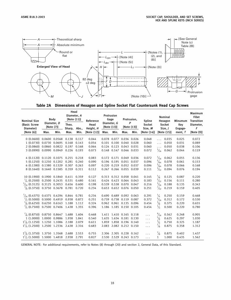
ASME B18.3-2003 SOCKET CAP, SHOULDER, AND SET SCREWS,HEX AND SPLINE KEYS (INCH SERIES)
A
L
H
T
LGH
LT
LBH
F
G
PD
A
M J
Enlarged View of Head
Theoretical sharp
Absolute minimum
[Note (4)]
[Note (5)]
[Notes (1),(2), and(8)]
[See GeneralNote (c)
Table 2B]
[Note (3)]
Protrusion gage
82 deg±2 deg
[Note (10)]
Round orflat
Table 2A Dimensions of Hexagon and Spline Socket Flat Countersunk Head Cap Screws
Head MaximumDiameter, A Protrusion Nominal Fillet
Body [Note (11)] Gage Protrusion,Nominal Size Reference Spline Hexagon Minumum TransitionDiameter, D Diameter, G P(Basic Screw Theo. Head Socket Socket Key Diameter,
[Note (7)] [Note (13)] [Note (13)]Diameter) Sharp, Abs., Height, H Size, M Size, J Engage- F[Note (6)] Max. Min. Max. Min. [Note (12)] Max. Min. Max. Min. [Note (14)] [Note (15)] ment, T [Note (9)]
0 (0.0600) 0.0600 0.0568 0.138 0.117 0.044 0.078 0.077 0.036 0.026 0.048 . . . 0.035 0.025 0.0721 (0.0730) 0.0730 0.0695 0.168 0.143 0.054 0.101 0.100 0.040 0.028 0.060 . . . 0.050 0.031 0.0892 (0.0860) 0.0860 0.0822 0.197 0.168 0.064 0.124 0.123 0.043 0.031 0.060 . . . 0.050 0.038 0.1063 (0.0990) 0.0990 0.0949 0.226 0.193 0.073 0.148 0.147 0.046 0.033 0.072 1⁄16 0.062 0.044 0.119
4 (0.1120) 0.1120 0.1075 0.255 0.218 0.083 0.172 0.171 0.049 0.036 0.072 1⁄16 0.062 0.055 0.1365 (0.1250) 0.1250 0.1202 0.281 0.240 0.090 0.196 0.195 0.051 0.037 0.096 5⁄64 0.078 0.061 0.1536 (0.1380) 0.1380 0.1329 0.307 0.263 0.097 0.220 0.219 0.052 0.037 0.096 5⁄64 0.078 0.066 0.1688 (0.1640) 0.1640 0.1585 0.359 0.311 0.112 0.267 0.266 0.055 0.039 0.111 3⁄32 0.094 0.076 0.194
10 (0.1900) 0.1900 0.1840 0.411 0.359 0.127 0.313 0.312 0.058 0.041 0.145 1⁄8 0.125 0.087 0.2201⁄4 (0.2500) 0.2500 0.2435 0.531 0.480 0.161 0.424 0.423 0.064 0.043 0.183 5⁄32 0.156 0.111 0.280
5⁄16 (0.3125) 0.3125 0.3053 0.656 0.600 0.198 0.539 0.538 0.070 0.047 0.216 3⁄16 0.188 0.135 0.3433⁄8 (0.3750) 0.3750 0.3678 0.781 0.720 0.234 0.653 0.652 0.076 0.050 0.251 7⁄32 0.219 0.159 0.405
7⁄16 (0.4375) 0.4375 0.4294 0.844 0.781 0.234 0.690 0.689 0.092 0.063 0.291 1⁄4 0.250 0.159 0.4681⁄2 (0.5000) 0.5000 0.4919 0.938 0.872 0.251 0.739 0.738 0.119 0.087 0.372 5⁄16 0.312 0.172 0.5305⁄8 (0.6250) 0.6250 0.6163 1.188 1.112 0.324 0.962 0.961 0.135 0.096 0.454 3⁄8 0.375 0.220 0.6553⁄4 (0.7500) 0.7500 0.7406 1.438 1.355 0.396 1.186 1.185 0.150 0.105 0.454 1⁄2 0.500 0.220 0.780
7⁄8 (0.8750) 0.8750 0.8647 1.688 1.604 0.468 1.411 1.410 0.165 0.118 . . . 9⁄16 0.562 0.248 0.9051 (1.0000) 1.0000 0.9886 1.938 1.841 0.540 1.635 1.634 0.181 0.130 . . . 5⁄8 0.625 0.297 1.030
11⁄8 (1.1250) 1.1250 1.1086 2.188 2.079 0.611 1.859 1.858 0.196 0.140 . . . 3⁄4 0.750 0.325 1.18711⁄4 (1.2500) 1.2500 1.2336 2.438 2.316 0.683 2.083 2.082 0.212 0.150 . . . 7⁄8 0.875 0.358 1.312
13⁄8 (1.3750) 1.3750 1.3568 2.688 2.553 0.755 2.306 2.305 0.228 0.162 . . . 7⁄8 0.875 0.402 1.43711⁄2 (1.5000) 1.5000 1.4818 2.938 2.791 0.827 2.530 2.529 0.243 0.173 . . . 1 1.000 0.435 1.562
GENERAL NOTE: For additional requirements, refer to Notes (8) through (20) and section 2, General Data, of this Standard.
18
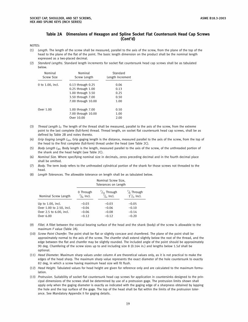
SOCKET CAP, SHOULDER, AND SET SCREWS, ASME B18.3-2003HEX AND SPLINE KEYS (INCH SERIES)
Table 2A Dimensions of Hexagon and Spline Socket Flat Countersunk Head Cap Screws(Cont’d)
NOTES:
(1) Length. The length of the screw shall be measured, parallel to the axis of the screw, from the plane of the top of thehead to the plane of the flat of the point. The basic length dimension on the product shall be the nominal lengthexpressed as a two-placed decimal.
(2) Standard Lengths. Standard length increments for socket flat countersunk head cap screws shall be as tabulatedbelow.
Nominal Nominal StandardScrew Size Screw Length Length Increment
0 to 1.00, incl. 0.13 through 0.25 0.060.25 through 1.00 0.131.00 through 3.50 0.253.50 through 7.00 0.507.00 through 10.00 1.00
Over 1.00 1.00 through 7.00 0.507.00 through 10.00 1.00Over 10.00 2.00
(3) Thread Length LT. The length of the thread shall be measured, parallel to the axis of the screw, from the extremepoint to the last complete (full-form) thread. Thread length, on socket flat countersunk head cap screws, shall be asdefined by Table 2B and notes thereto.
(4) Grip Gaging Length LGH. Grip gaging length is the distance, measured parallel to the axis of the screw, from the top ofthe head to the first complete (full-form) thread under the head (see Table 2C).
(5) Body Length LBH. Body length is the length, measured parallel to the axis of the screw, of the unthreaded portion ofthe shank and the head height (see Table 2C).
(6) Nominal Size. Where specifying nominal size in decimals, zeros preceding decimal and in the fourth decimal placeshall be omitted.
(7) Body. The term body refers to the unthreaded cylindrical portion of the shank for those screws not threaded to thehead.
(8) Length Tolerances. The allowable tolerance on length shall be as tabulated below.
Nominal Screw Size,Tolerances on Length
0 Through 7⁄16 Through 7⁄8 ThroughNominal Screw Length 3⁄8, Incl. 3⁄4, Incl. 11⁄2, Incl.
Up to 1.00, incl. −0.03 −0.03 −0.05Over 1.00 to 2.50, incl. −0.04 −0.06 −0.10Over 2.5 to 6.00, incl. −0.06 −0.08 −0.14Over 6.00 −0.12 −0.12 −0.20
(9) Fillet. A fillet between the conical bearing surface of the head and the shank (body) of the screw is allowable to themaximum F value (Table 2A).
(10) Screw Point Chamfer. The point shall be flat or slightly concave and chamfered. The plane of the point shall beapproximately normal to the axis of the screw. The chamfer shall extend slightly below the root of the thread, and theedge between the flat and chamfer may be slightly rounded. The included angle of the point should be approximately90 deg. Chamfering of the screw sizes up to and including size 8 (0.164 in.) and lengths below 1.5d shall beoptional.
(11) Head Diameter. Maximum sharp values under column A are theoretical values only, as it is not practical to make theedges of the head sharp. The maximum sharp value represents the exact diameter of the hole countersunk to exactly82 deg, in which a screw having maximum head size will fit flush.
(12) Head Height. Tabulated values for head height are given for reference only and are calculated to the maximum formu-lation.
(13) Protrusion. Suitability of socket flat countersunk head cap screws for application in countersinks designed to the prin-cipal dimensions of the screws shall be determined by use of a protrusion gage. The protrusion limits shown shallapply only when the gaging diameter is exactly as indicated with the gaging edge of a sharpness obtained by lappingthe hole and the top surface of the gage. The top of the head shall be flat within the limits of the protrusion toler-ance. See Mandatory Appendix II for gaging details.
19
ASME B18.3-2003 SOCKET CAP, SHOULDER, AND SET SCREWS,HEX AND SPLINE KEYS (INCH SERIES)
Table 2A Dimensions of Hexagon and Spline Socket Flat Countersunk Head Cap Screws(Cont’d)
(14) See Table 7 for spline socket dimensions and Mandatory Appendix I for gaging of spline sockets.(15) See Table 6 for hexagon socket dimensions and Mandatory Appendix I for gaging of hexagon sockets.(16) Bearing Surface. The runout of the conical bearing surface shall be within 1 deg obtained by holding the screw on the
body or major screw thread diameter within 1 diameter of the bearing surface of the head, but beyond the maximumlength of the fillet, F, rotating 360 deg and inspecting on an optical comparator, or comparable inspection equipment.
(17) Runout(a) The runout of the socket with the axis of the shank of the screw shall be within 3% of the maximum screw
diameter, D, or 0.005 in., whichever is greater for nominal sizes through 1⁄2 in. diameter and 6% for nominal sizesabove 1⁄2 in. diameter.
Runout for (a) above is defined as the full indicator movement (FIM) obtained by holding the screw on the body ormajor thread diameter within 1 diameter of the bearing surface of the head, but beyond the maximum length of thefillet, F, rotating 360 deg, indicating on each of the six hexagon flats.
(b) The conformance of screws to shank straightness or camber limitations shall be as set forth as De in Table 1E(Socket Head Cap Screws), and shall be checked by the use of the procedures and typical gage illustrated in Manda-tory Appendix III.
(18) Threads. Threads shall be Unified external threads with radius root: Class 3A UNRC and UNRF Series for sizes 0(0.060 in.) through 1 in.; Class 2A UNRC and UNRF Series for sizes over 1 in. to 11⁄2 in., inclusive.
Acceptability shall be based on System 22, ASME B1.3M.Class 3A does not provide a plating allowance. When plated products are required, it is recommended that they be
procured from the manufacturer (see para. 1.10, Introductory Notes).(19) Material
(a) Steel, Alloy. Flat countersunk head cap screws shall be fabricated from an alloy steel and shall conform in allrespects to ASTM F 835.
(b) Steel, Corrosion-Resistant. Flat countersunk head cap screws shall be fabricated from austenitic corrosion-resi-tant steel and shall conform in all respects to ASTM F 879.
(20) Dimensional Conformance. Flat Countersunk Socket Head Cap Screws shall have the following designated characteris-tics inspected to ASME B18.18.2M to Inspection Level C: threads, protrusion /flushness, socket size (gaged), andlength.
(21) Designation. To promote uniformity and understanding in communications relating to products conforming to thisStandard, it is recommended that Hexagon and Spline Flat Countersunk Socket Head Cap Screws be designated inaccordance with the following data, preferably in the sequence shown:
(a) product name(b) designation of the standard(c) nominal size (number, fractional or decimal equivalent)(d) thread pitch(e) nominal length (fractional or decimal equivalent)(f) material(g) protective finish, if required
EXAMPLES:Hexagon Socket Flat Countersunk Head Cap Screws, ASME B18.3, 1⁄4-28 � 13⁄4 , Alloy SteelHexagon Socket Flat Countersunk Head Cap Screws, ASME B18.3, 0.250-28 � 1.750, Corrosion-Resistant SteelHexagon Socket Flat Countersunk Head Cap Screws, ASME B18.3, 6-32 � 0.500, Alloy Steel, Zinc Plated. (For
plated products, see para. 1.7, Introductory Notes.)
For the recommended B18 part identifying numbering system (PIN), see ASME B18.24.1.
20
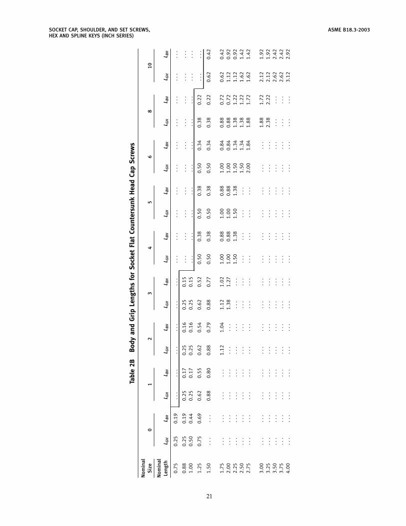
SOCKET CAP, SHOULDER, AND SET SCREWS, ASME B18.3-2003HEX AND SPLINE KEYS (INCH SERIES)
Tabl
e2B
Bod
yan
dG
rip
Leng
ths
for
Sock
etFl
atCo
unte
rsun
kH
ead
Cap
Scr
ews
Nom
inal
Siz
e0
12
34
56
810
Nom
inal
Leng
thL G
HL B
HL G
HL B
HL G
HL B
HL G
HL B
HL G
HL B
HL G
HL B
HL G
HL B
HL G
HL B
HL G
HL B
H
0.75
0.25
0.19
...
...
...
...
...
...
...
...
...
...
...
...
...
...
...
...
0.88
0.25
0.19
0.25
0.17
0.25
0.16
0.25
0.15
...
...
...
...
...
...
...
...
...
...
1.00
0.50
0.44
0.25
0.17
0.25
0.16
0.25
0.15
...
...
...
...
...
...
...
...
...
...
1.25
0.75
0.69
0.62
0.55
0.62
0.54
0.62
0.52
0.50
0.38
0.50
0.38
0.50
0.34
0.38
0.22
...
...
1.50
...
...
0.88
0.80
0.88
0.79
0.88
0.77
0.50
0.38
0.50
0.38
0.50
0.34
0.38
0.22
0.62
0.42
1.75
...
...
...
...
1.12
1.04
1.12
1.02
1.00
0.88
1.00
0.88
1.00
0.84
0.88
0.72
0.62
0.42
2.00
...
...
...
...
...
...
1.38
1.27
1.00
0.88
1.00
0.88
1.00
0.84
0.88
0.72
1.12
0.92
2.25
...
...
...
...
...
...
...
...
1.50
1.38
1.50
1.38
1.50
1.34
1.38
1.22
1.12
0.92
2.50
...
...
...
...
...
...
...
...
...
...
...
...
1.50
1.34
1.38
1.22
1.62
1.42
2.75
...
...
...
...
...
...
...
...
...
...
...
...
2.00
1.84
1.88
1.72
1.62
1.42
3.00
...
...
...
...
...
...
...
...
...
...
...
...
...
...
1.88
1.72
2.12
1.92
3.25
...
...
...
...
...
...
...
...
...
...
...
...
...
...
2.38
2.22
2.12
1.92
3.50
...
...
...
...
...
...
...
...
...
...
...
...
...
...
...
...
2.62
2.42
3.75
...
...
...
...
...
...
...
...
...
...
...
...
...
...
...
...
2.62
2.42
4.00
...
...
...
...
...
...
...
...
...
...
...
...
...
...
...
...
3.12
2.92
21
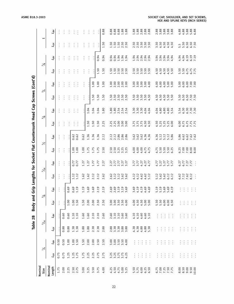
ASME B18.3-2003 SOCKET CAP, SHOULDER, AND SET SCREWS,HEX AND SPLINE KEYS (INCH SERIES)
Tabl
e2B
Bod
yan
dG
rip
Leng
ths
for
Sock
etFl
atCo
unte
rsun
kH
ead
Cap
Scr
ews
(Con
t’d)
Nom
inal
Siz
e1 ⁄ 4
5 ⁄ 16
3 ⁄ 87 ⁄ 1
61 ⁄ 2
5 ⁄ 83 ⁄ 4
7 ⁄ 81
Nom
inal
Leng
thL G
HL B
HL G
HL B
HL G
HL B
HL G
HL B
HL G
HL B
HL G
HL B
HL G
HL B
HL G
HL B
HL G
HL B
H
1.75
0.75
0.50
...
...
...
...
...
...
...
...
...
...
...
...
...
...
...
...
2.00
0.75
0.50
0.88
0.60
...
...
...
...
...
...
...
...
...
...
...
...
...
...
2.25
1.25
1.00
0.88
0.60
1.00
0.69
...
...
...
...
...
...
...
...
...
...
...
...
2.50
1.25
1.00
1.38
1.10
1.00
0.69
1.12
0.77
1.00
0.62
...
...
...
...
...
...
...
...
2.75
1.75
1.50
1.38
1.10
1.50
1.19
1.12
0.77
1.00
0.62
...
...
...
...
...
...
...
...
3.00
1.75
1.50
1.88
1.60
1.50
1.19
1.62
1.27
1.00
0.62
...
...
...
...
...
...
...
...
3.25
2.25
2.00
1.88
1.60
2.00
1.69
1.62
1.27
1.75
1.36
1.50
1.04
...
...
...
...
...
...
3.50
2.25
2.00
2.38
2.10
2.00
1.69
2.12
1.77
1.75
1.36
1.50
1.04
1.50
1.00
...
...
...
...
3.75
2.75
2.50
2.38
2.10
2.50
2.19
2.12
1.77
1.75
1.36
1.50
1.04
1.50
1.00
1.50
0.94
...
...
4.00
2.75
2.50
2.88
2.60
2.50
2.19
2.62
2.27
2.50
2.12
2.25
1.80
1.50
1.00
1.50
0.94
1.50
0.88
4.25
3.25
3.00
2.88
2.60
3.00
2.69
2.62
2.27
2.50
2.12
2.25
1.80
1.50
1.00
1.50
0.94
1.50
0.88
4.50
3.25
3.00
3.38
3.10
3.00
2.69
3.12
2.77
2.50
2.12
2.25
1.80
2.50
2.00
1.50
0.94
1.50
0.88
4.75
3.75
3.50
3.38
3.10
3.50
3.19
3.12
2.77
3.25
2.86
3.00
2.54
2.50
2.00
2.50
1.94
1.50
0.88
5.00
3.75
3.50
3.88
3.60
3.50
3.19
3.62
3.27
3.25
2.86
3.00
2.54
2.50
2.00
2.50
1.94
2.50
1.88
5.25
4.25
4.00
3.88
3.60
4.00
3.69
3.62
3.27
3.25
2.86
3.00
2.54
2.50
2.00
2.50
1.94
2.50
1.88
5.50
...
...
4.38
4.10
4.00
3.69
4.12
3.77
4.00
3.62
3.75
3.30
3.50
3.00
2.50
1.94
2.50
1.88
5.75
...
...
4.38
4.10
4.50
4.19
4.12
3.77
4.00
3.62
3.75
3.30
3.50
3.00
3.50
2.94
2.50
1.88
6.00
...
...
4.88
4.60
4.50
4.19
4.62
4.27
4.00
3.62
3.75
3.30
3.50
3.00
3.50
2.94
3.50
2.88
6.25
...
...
4.88
4.60
5.00
4.69
4.62
4.27
4.75
4.36
4.50
4.04
3.50
3.00
3.50
2.94
3.50
2.88
6.50
...
...
5.38
5.10
5.00
4.69
5.12
4.77
4.75
4.36
4.50
4.04
4.50
4.00
3.50
2.94
3.50
2.88
6.75
...
...
...
...
5.50
5.19
5.12
4.77
4.75
4.36
4.50
4.04
4.50
4.00
4.50
3.94
3.50
2.88
7.00
...
...
...
...
5.50
5.19
5.62
5.27
5.50
5.12
5.25
4.80
4.50
4.00
4.50
3.94
4.50
3.88
7.25
...
...
...
...
6.00
5.69
5.62
5.27
5.50
5.12
5.25
4.80
4.50
4.00
4.50
3.94
4.50
3.88
7.50
...
...
...
...
6.00
5.69
6.12
5.77
5.50
5.12
5.25
4.80
5.50
5.00
4.50
3.94
4.50
3.88
7.75
...
...
...
...
6.50
6.19
6.12
5.77
6.25
5.86
6.00
5.54
5.50
5.00
5.50
4.94
4.50
3.88
8.00
...
...
...
...
...
...
6.62
6.27
6.25
5.86
6.00
5.54
5.50
5.00
5.50
4.94
5.5
4.88
8.50
...
...
...
...
...
...
7.12
6.77
7.00
6.62
6.75
6.30
6.50
6.00
5.50
4.94
5.50
4.88
9.00
...
...
...
...
...
...
7.62
7.27
7.00
6.62
6.75
6.30
6.50
6.00
6.75
6.19
6.50
5.88
9.50
...
...
...
...
...
...
8.12
7.77
8.00
7.62
7.75
7.30
7.50
7.00
6.75
6.19
6.50
5.88
10.0
0..
...
...
...
...
...
...
...
.8.
007.
627.
757.
307.
507.
007.
757.
197.
506.
88
22
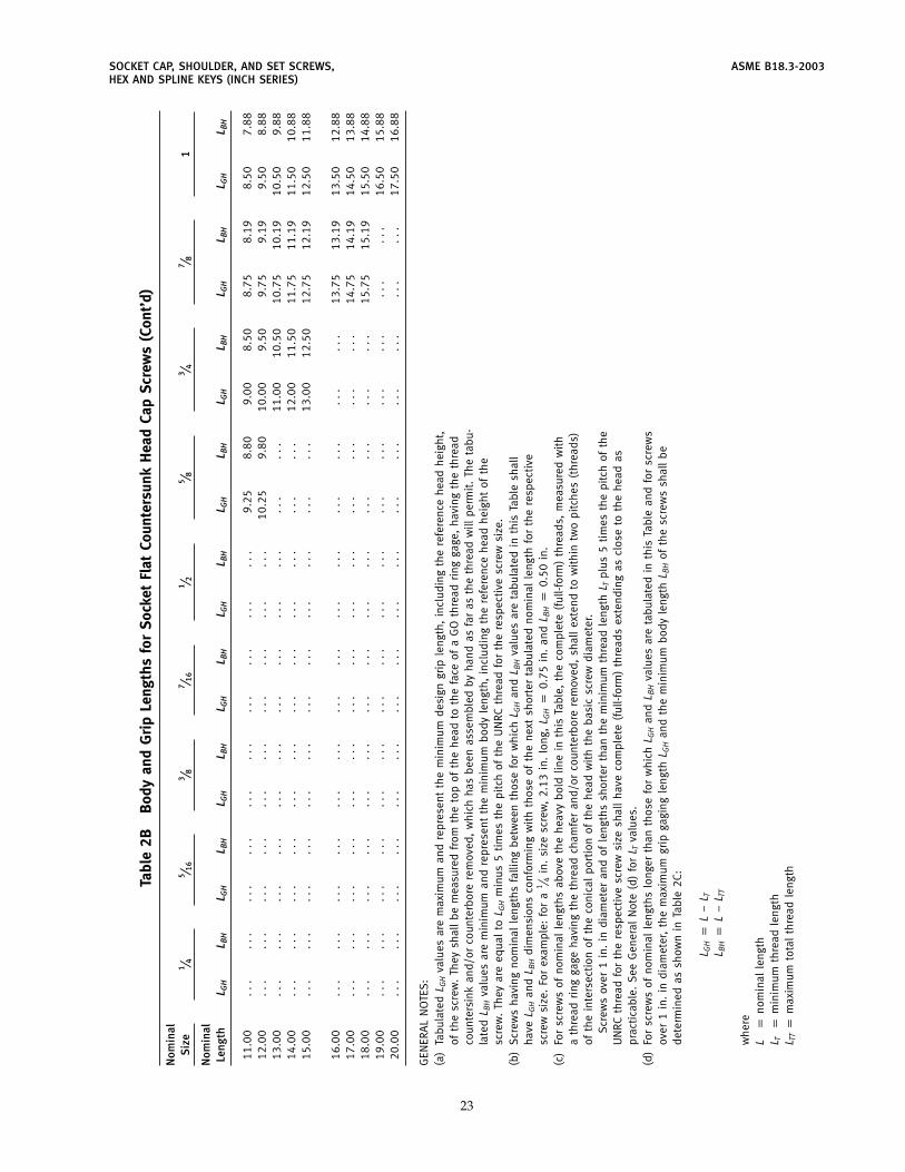
SOCKET CAP, SHOULDER, AND SET SCREWS, ASME B18.3-2003HEX AND SPLINE KEYS (INCH SERIES)
Tabl
e2B
Bod
yan
dG
rip
Leng
ths
for
Soc
ket
Flat
Coun
ters
unk
Hea
dCa
pS
crew
s(C
ont’
d)
Nom
inal
Siz
e1 ⁄ 4
5 ⁄ 16
3 ⁄ 87 ⁄ 1
61 ⁄ 2
5 ⁄ 83 ⁄ 4
7 ⁄ 81
Nom
inal
Leng
thL G
HL B
HL G
HL B
HL G
HL B
HL G
HL B
HL G
HL B
HL G
HL B
HL G
HL B
HL G
HL B
HL G
HL B
H
11.0
0..
...
...
...
...
...
...
...
...
...
.9.
258.
809.
008.
508.
758.
198.
507.
8812
.00
...
...
...
...
...
...
...
...
...
...
10.2
59.
8010
.00
9.50
9.75
9.19
9.50
8.88
13.0
0..
...
...
...
...
...
...
...
...
...
...
...
.11
.00
10.5
010
.75
10.1
910
.50
9.88
14.0
0..
...
...
...
...
...
...
...
...
...
...
...
.12
.00
11.5
011
.75
11.1
911
.50
10.8
815
.00
...
...
...
...
...
...
...
...
...
...
...
...
13.0
012
.50
12.7
512
.19
12.5
011
.88
16.0
0..
...
...
...
...
...
...
...
...
...
...
...
...
...
.13
.75
13.1
913
.50
12.8
817
.00
...
...
...
...
...
...
...
...
...
...
...
...
...
...
14.7
514
.19
14.5
013
.88
18.0
0..
...
...
...
...
...
...
...
...
...
...
...
...
...
.15
.75
15.1
915
.50
14.8
819
.00
...
...
...
...
...
...
...
...
...
...
...
...
...
...
...
...
16.5
015
.88
20.0
0..
...
...
...
...
...
...
...
...
...
...
...
...
...
...
...
.17
.50
16.8
8
GEN
ERA
LN
OTE
S:
(a)
Tabu
late
dL G
Hva
lues
are
max
imum
and
repr
esen
tth
em
inim
umde
sign
grip
leng
th,
incl
udin
gth
ere
fere
nce
head
heig
ht,
ofth
esc
rew
.Th
eysh
all
bem
easu
red
from
the
top
ofth
ehe
adto
the
face
ofa
GO
thre
adri
ngga
ge,
havi
ngth
eth
read
coun
ters
ink
and/
orco
unte
rbor
ere
mov
ed,
whi
chha
sbe
enas
sem
bled
byha
ndas
far
asth
eth
read
will
perm
it.
The
tabu
-la
ted
L BH
valu
esar
em
inim
uman
dre
pres
ent
the
min
imum
body
leng
th,
incl
udin
gth
ere
fere
nce
head
heig
htof
the
scre
w.
They
are
equa
lto
L GH
min
us5
tim
esth
epi
tch
ofth
eU
NRC
thre
adfo
rth
ere
spec
tive
scre
wsi
ze.
(b)
Scr
ews
havi
ngno
min
alle
ngth
sfa
lling
betw
een
thos
efo
rw
hich
L GH
and
L BH
valu
esar
eta
bula
ted
inth
isTa
ble
shal
lha
veL G
Han
dL B
Hdi
men
sion
sco
nfor
min
gw
ith
thos
eof
the
next
shor
ter
tabu
late
dno
min
alle
ngth
for
the
resp
ecti
vesc
rew
size
.Fo
rex
ampl
e:fo
ra
1 ⁄ 4in
.si
zesc
rew
,2.
13in
.lo
ng,
L GH
p0.
75in
.an
dL B
Hp
0.50
in.
(c)
For
scre
ws
ofno
min
alle
ngth
sab
ove
the
heav
ybo
ldlin
ein
this
Tabl
e,th
eco
mpl
ete
(ful
l-for
m)
thre
ads,
mea
sure
dw
ith
ath
read
ring
gage
havi
ngth
eth
read
cham
fer
and/
orco
u nte
rbor
ere
mov
ed,
shal
lex
tend
tow
ithi
ntw
opi
tche
s(t
hrea
ds)
ofth
ein
ters
ecti
onof
the
coni
cal
port
ion
ofth
ehe
adw
ith
the
basi
csc
rew
diam
eter
.S
crew
sov
er1
in.
indi
amet
eran
dof
leng
ths
shor
ter
than
the
min
imum
thre
adle
ngth
L Tpl
us5
tim
esth
epi
tch
ofth
eU
NRC
thre
adfo
rth
ere
spec
tive
scre
wsi
zesh
all
have
com
plet
e(f
ull-f
orm
)th
read
sex
tend
ing
ascl
ose
toth
ehe
adas
prac
tica
ble.
See
Gen
eral
Not
e(d
)fo
rL T
valu
es.
(d)
For
scre
ws
ofno
min
alle
ngth
slo
nger
than
thos
efo
rw
hich
L GH
and
L BH
valu
esar
eta
bula
ted
inth
isTa
ble
and
for
scre
ws
over
1in
.in
diam
eter
,th
em
axim
umgr
ipga
ging
leng
thL G
Han
dth
em
inim
umbo
dyle
ngth
L BH
ofth
esc
rew
ssh
all
bede
term
ined
assh
own
inTa
ble
2C:
L GH
pL
−L T
L BH
pL
−L T
T
whe
reL
pno
min
alle
ngth
L Tp
min
imum
thre
adle
ngth
L TTp
max
imum
tota
lth
read
leng
th
23
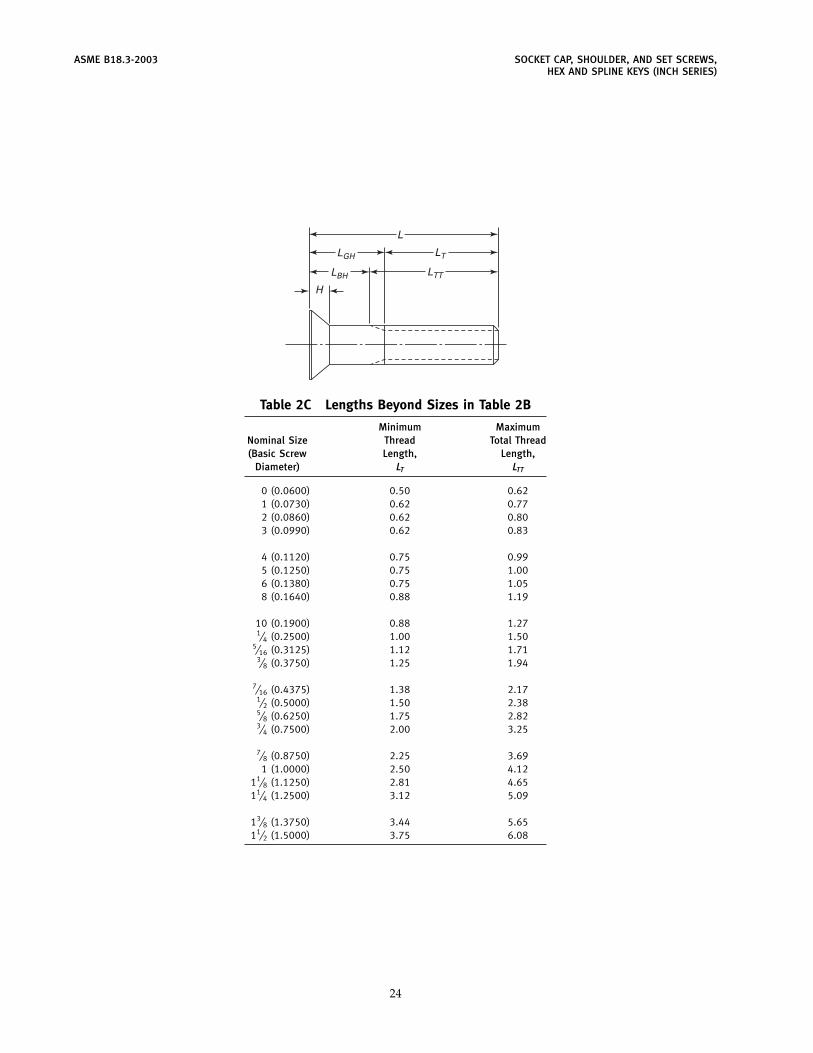
ASME B18.3-2003 SOCKET CAP, SHOULDER, AND SET SCREWS,HEX AND SPLINE KEYS (INCH SERIES)
LTT
LTLGH
LBH
H
L
Table 2C Lengths Beyond Sizes in Table 2B
Minimum MaximumNominal Size Thread Total Thread(Basic Screw Length, Length,
Diameter) LT LTT
0 (0.0600) 0.50 0.621 (0.0730) 0.62 0.772 (0.0860) 0.62 0.803 (0.0990) 0.62 0.83
4 (0.1120) 0.75 0.995 (0.1250) 0.75 1.006 (0.1380) 0.75 1.058 (0.1640) 0.88 1.19
10 (0.1900) 0.88 1.271⁄4 (0.2500) 1.00 1.50
5⁄16 (0.3125) 1.12 1.713⁄8 (0.3750) 1.25 1.94
7⁄16 (0.4375) 1.38 2.171⁄2 (0.5000) 1.50 2.385⁄8 (0.6250) 1.75 2.823⁄4 (0.7500) 2.00 3.25
7⁄8 (0.8750) 2.25 3.691 (1.0000) 2.50 4.12
11⁄8 (1.1250) 2.81 4.6511⁄4 (1.2500) 3.12 5.09
13⁄8 (1.3750) 3.44 5.6511⁄2 (1.5000) 3.75 6.08
24
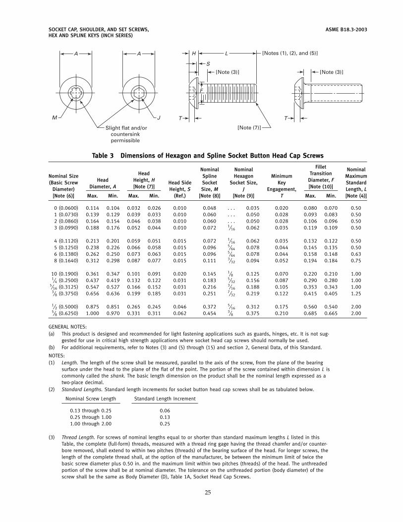
SOCKET CAP, SHOULDER, AND SET SCREWS, ASME B18.3-2003HEX AND SPLINE KEYS (INCH SERIES)
L
S
F
T
H
M
A
J
[Note (3)]
[Note (7)]
[Notes (1), (2), and (5)]
[Note (3)]
Slight flat and/orcountersinkpermissible
A
T
Table 3 Dimensions of Hexagon and Spline Socket Button Head Cap Screws
FilletNominal Nominal NominalHead TransitionNominal Size Spline Hexagon Minimum Maximum
Head Height, H Diameter, F(Basic Screw Head Side Socket Socket Size, Key StandardDiameter, A [Note (7)] [Note (10)]Diameter) Height, S Size, M J Engagement, Length, L
[Note (6)] Max. Min. Max. Min. (Ref.) [Note (8)] [Note (9)] T Max. Min. [Note (4)]
0 (0.0600) 0.114 0.104 0.032 0.026 0.010 0.048 . . . 0.035 0.020 0.080 0.070 0.501 (0.0730) 0.139 0.129 0.039 0.033 0.010 0.060 . . . 0.050 0.028 0.093 0.083 0.502 (0.0860) 0.164 0.154 0.046 0.038 0.010 0.060 . . . 0.050 0.028 0.106 0.096 0.503 (0.0990) 0.188 0.176 0.052 0.044 0.010 0.072 1⁄16 0.062 0.035 0.119 0.109 0.50
4 (0.1120) 0.213 0.201 0.059 0.051 0.015 0.072 1⁄16 0.062 0.035 0.132 0.122 0.505 (0.1250) 0.238 0.226 0.066 0.058 0.015 0.096 5⁄64 0.078 0.044 0.145 0.135 0.506 (0.1380) 0.262 0.250 0.073 0.063 0.015 0.096 5⁄64 0.078 0.044 0.158 0.148 0.638 (0.1640) 0.312 0.298 0.087 0.077 0.015 0.111 3⁄32 0.094 0.052 0.194 0.184 0.75
10 (0.1900) 0.361 0.347 0.101 0.091 0.020 0.145 1⁄8 0.125 0.070 0.220 0.210 1.001⁄4 (0.2500) 0.437 0.419 0.132 0.122 0.031 0.183 5⁄32 0.156 0.087 0.290 0.280 1.00
5⁄16 (0.3125) 0.547 0.527 0.166 0.152 0.031 0.216 3⁄16 0.188 0.105 0.353 0.343 1.003⁄8 (0.3750) 0.656 0.636 0.199 0.185 0.031 0.251 7⁄32 0.219 0.122 0.415 0.405 1.25
1⁄2 (0.5000) 0.875 0.851 0.265 0.245 0.046 0.372 5⁄16 0.312 0.175 0.560 0.540 2.005⁄8 (0.6250) 1.000 0.970 0.331 0.311 0.062 0.454 3⁄8 0.375 0.210 0.685 0.665 2.00
GENERAL NOTES:(a) This product is designed and recommended for light fastening applications such as guards, hinges, etc. It is not sug-
gested for use in critical high strength applications where socket head cap screws should normally be used.(b) For additional requirements, refer to Notes (3) and (5) through (15) and section 2, General Data, of this Standard.
NOTES:(1) Length. The length of the screw shall be measured, parallel to the axis of the screw, from the plane of the bearing
surface under the head to the plane of the flat of the point. The portion of the screw contained within dimension L iscommonly called the shank. The basic length dimension on the product shall be the nominal length expressed as atwo-place decimal.
(2) Standard Lengths. Standard length increments for socket button head cap screws shall be as tabulated below.
Nominal Screw Length Standard Length Increment
0.13 through 0.25 0.060.25 through 1.00 0.131.00 through 2.00 0.25
(3) Thread Length. For screws of nominal lengths equal to or shorter than standard maximum lengths L listed in thisTable, the complete (full-form) threads, measured with a thread ring gage having the thread chamfer and/or counter-bore removed, shall extend to within two pitches (threads) of the bearing surface of the head. For longer screws, thelength of the complete thread shall, at the option of the manufacturer, be between the minimum limit of twice thebasic screw diameter plus 0.50 in. and the maximum limit within two pitches (threads) of the head. The unthreadedportion of the screw shall be at nominal diameter. The tolerance on the unthreaded portion (body diameter) of thescrew shall be the same as Body Diameter (D), Table 1A, Socket Head Cap Screws.
25
ASME B18.3-2003 SOCKET CAP, SHOULDER, AND SET SCREWS,HEX AND SPLINE KEYS (INCH SERIES)
Table 3 Dimensions of Hexagon and Spline Socket Button Head Cap Screws (Cont’d)
(4) Nominal Size. Where specifying nominal size in decimals, zeros preceding decimal and in the fourth decimal placeshall be omitted.
(5) Length Tolerances. Allowable tolerance on length shall be as tabulated below.
Nominal Screw Size,Tolerances on Length
0 Through 1⁄2 ThroughNominal Screw Length 3⁄8, Incl. 5⁄8, Incl.
Up to 1.00, incl. −0.03 −0.03Over 1.00 to 2.00, incl. −0.04 −0.06Over 2.00 −0.04 0.06
(6) Fillet. The form of the fillet shall be optional, provided it flairs into the bearing surface between the minimum andmaximum diameter F. The fillet shall be a smooth and continuous curve having a bearing surface juncture radius notless than that tabulated below.
Nominal Minimum Nominal MinimumScrew Size Juncture Radius Screw Size Juncture Radius
0 0.002 10 0.0061 0.003 1⁄4 0.0072 0.003 5⁄16 0.0093 0.004 3⁄8 0.012
4 0.004 1⁄2 0.0165 0.005 5⁄8 0.0216 0.0058 0.006
(7) Screw Point Chamfer. The point shall be flat or slightly concave and chamfered. The plane of the point shall beapproximately normal to the axis of the screw. The chamfer shall extend slightly below the root of the thread, and theedge between flat and chamfer may be slightly rounded. The included angle of the point should be approximately 90deg. Chamfering of screw sizes up to and including size 8 (0.164 in.) and lengths below 0.75d shall be optional.
(8) Head Height. Tabulated head heights represent metal-to-metal measurements; that is, the truncation of the roundedsurface caused by the socket is not considered part of the head height.
(9) See Table 7 for spline socket dimensions and Mandatory Appendix I for gaging of spline sockets.
(10) See Table 6 for hexagon socket dimensions and Mandatory Appendix I for gaging of hexagon sockets.
(11) Bearing Surface. The plane of the bearing surface shall be perpendicular to the axis of the shank within 2 degobtained by holding the screw on the body or major thread diameter within 1 diameter of the bearing surface of thehead, but beyond the maximum length of the fillet, F, rotating 360 deg, and inspecting on an optical comparator, orcomparable inspection equipment.
(12) Runout
(a) The runout of the head with the axis of the shank shall be within 3% of the maximum basic screw diameterdimension, D, or 0.008 in., whichever is greater.
Runout for (a) above is defined as the full indicator movement (FIM) obtained by holding the screw on the body ormajor thread diameter next to the head, but beyond the maximum length of the fillet, F, rotating the screw 360 deg,with the indicator riding on the outer surface of the head on the rounded portion, adjacent to, but not on the extremeperiphery of, the head.
(b) The runout of the socket with the axis of the shank of the screw shall be within 3% of the maximum screwdiameter, D, or 0.005 in., whichever is greater for nominal sizes through 1⁄2 in. diameter and 6% for nominal sizesabove 1⁄2 in. diameter.
Runout for (b) above is defined as the full indicator movement (FIM) obtained by holding the screw on the body ormajor screw thread diameter within 1 diameter of the bearing surface of the head, but beyond the maximum lengthof the fillet, F, rotating 360 deg, indicating on each of the hexagon flats.
(13) Threads. Threads shall be Unified external threads with radius root: Class 3A UNRC and UNRF Series.Acceptability shall be based on System 22, ASME B1.3M.Class 3A does not provide a plating allowance. When plated products are required, it is recommended that they be
procured from the manufacturer (see para. 1.10, Introductory Notes).
26
SOCKET CAP, SHOULDER, AND SET SCREWS, ASME B18.3-2003HEX AND SPLINE KEYS (INCH SERIES)
Table 3 Dimensions of Hexagon and Spline Socket Button Head Cap Screws (Cont’d)(14) Material
(a) Steel, Alloy. Button head cap screws shall be fabricated from an alloy steel and shall conform in all respects toASTM F 835.
(b) Steel, Corrosion-Resistant. Button head cap screws shall be fabricated from austenitic corrosion-resistant steeland shall conform in all respects to ASTM F 879.
(15) Dimensional Conformance. Socket Button Head Cap Screws shall have the following designated characteristicsinspected to ASME B18.18.2M to Inspection Level C: threads, head diameter, socket size (gaged), length, and fillettransition diameter.
(16) Designation. To promote uniformity and understanding in communications relating to products conforming to thisStandard, it is recommended that Hexagon and Spline Socket Button Head Cap Screws be designated in accordancewith the following data, preferably in the sequence shown:
(a) product name(b) designation of the standard(c) nominal size (number, fractional or decimal equivalent)(d) thread pitch(e) nominal length (fractional or decimal equivalent)(f) material(g) protective finish, if required
EXAMPLES:Hexagon Socket Button Head Cap Screws, ASME B18.3, 10-32 � 3⁄4 , Alloy SteelHexagon Socket Button Head Cap Screws, ASME B18.3, 0.190-32 � 0.750, Alloy Steel, Zinc Plated. (For plated
products, see para. 1.7, Introductory Notes.)
For the recommended B18 part identifying numbering system (PIN), see ASME B18.24.1.
27
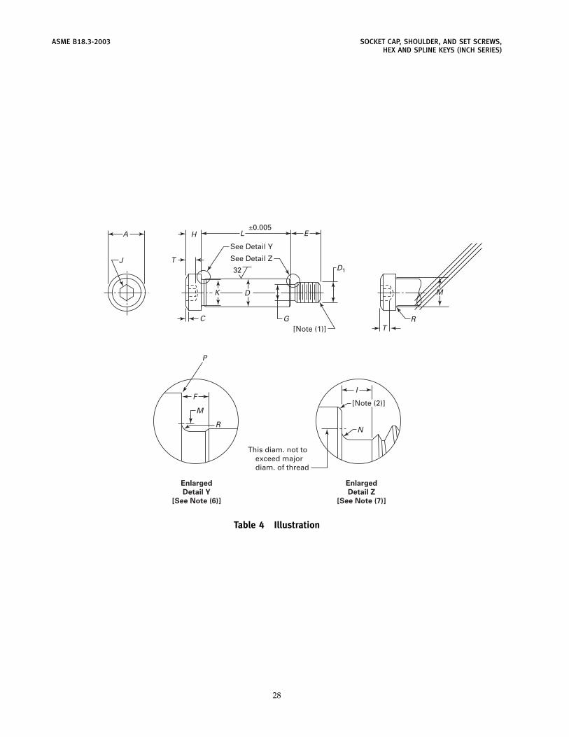
ASME B18.3-2003 SOCKET CAP, SHOULDER, AND SET SCREWS,HEX AND SPLINE KEYS (INCH SERIES)
A
J
L E
G
DK
H
T
C
D1
[Note (1)]
See Detail Y
±0.005
See Detail Z
32
TR
M
FI
N
P
M
R
This diam. not toexceed majordiam. of thread
[Note (2)]
Enlarged
Detail Y
[See Note (6)]
Enlarged
Detail Z
[See Note (7)]
Table 4 Illustration
28
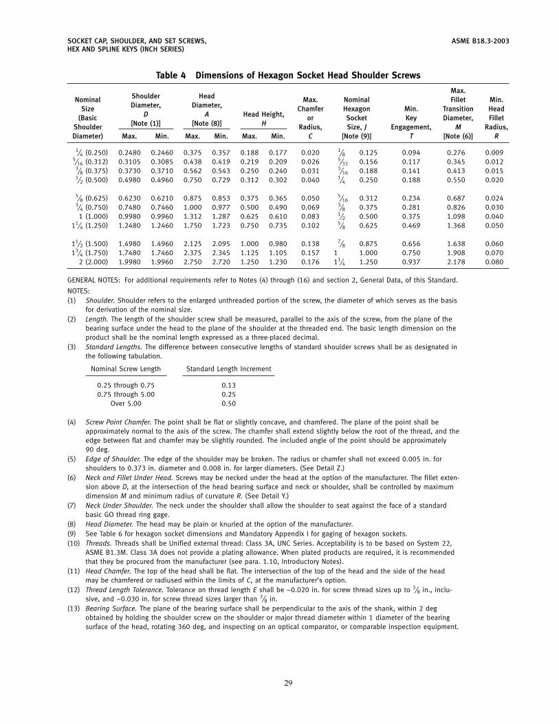
SOCKET CAP, SHOULDER, AND SET SCREWS, ASME B18.3-2003HEX AND SPLINE KEYS (INCH SERIES)
Table 4 Dimensions of Hexagon Socket Head Shoulder Screws
Max.Shoulder HeadNominal Max. Nominal Fillet Min.Diameter, Diameter,Size Chamfer Hexagon Min. Transition Head
D A Head Height,(Basic or Socket Key Diameter, Fillet[Note (1)] [Note (8)] HShoulder Radius, Size, J Engagement, M Radius,
Diameter) Max. Min. Max. Min. Max. Min. C [Note (9)] T [Note (6)] R
1⁄4 (0.250) 0.2480 0.2460 0.375 0.357 0.188 0.177 0.020 1⁄8 0.125 0.094 0.276 0.0095⁄16 (0.312) 0.3105 0.3085 0.438 0.419 0.219 0.209 0.026 5⁄32 0.156 0.117 0.345 0.012
3⁄8 (0.375) 0.3730 0.3710 0.562 0.543 0.250 0.240 0.031 3⁄16 0.188 0.141 0.413 0.0151⁄2 (0.500) 0.4980 0.4960 0.750 0.729 0.312 0.302 0.040 1⁄4 0.250 0.188 0.550 0.020
5⁄8 (0.625) 0.6230 0.6210 0.875 0.853 0.375 0.365 0.050 5⁄16 0.312 0.234 0.687 0.0243⁄4 (0.750) 0.7480 0.7460 1.000 0.977 0.500 0.490 0.069 3⁄8 0.375 0.281 0.826 0.0301 (1.000) 0.9980 0.9960 1.312 1.287 0.625 0.610 0.083 1⁄2 0.500 0.375 1.098 0.040
11⁄4 (1.250) 1.2480 1.2460 1.750 1.723 0.750 0.735 0.102 5⁄8 0.625 0.469 1.368 0.050
11⁄2 (1.500) 1.4980 1.4960 2.125 2.095 1.000 0.980 0.138 7⁄8 0.875 0.656 1.638 0.06013⁄4 (1.750) 1.7480 1.7460 2.375 2.345 1.125 1.105 0.157 1 1.000 0.750 1.908 0.070
2 (2.000) 1.9980 1.9960 2.750 2.720 1.250 1.230 0.176 11⁄4 1.250 0.937 2.178 0.080
GENERAL NOTES: For additional requirements refer to Notes (4) through (16) and section 2, General Data, of this Standard.
NOTES:(1) Shoulder. Shoulder refers to the enlarged unthreaded portion of the screw, the diameter of which serves as the basis
for derivation of the nominal size.(2) Length. The length of the shoulder screw shall be measured, parallel to the axis of the screw, from the plane of the
bearing surface under the head to the plane of the shoulder at the threaded end. The basic length dimension on theproduct shall be the nominal length expressed as a three-placed decimal.
(3) Standard Lengths. The difference between consecutive lengths of standard shoulder screws shall be as designated inthe following tabulation.
Nominal Screw Length Standard Length Increment
0.25 through 0.75 0.130.75 through 5.00 0.25
Over 5.00 0.50
(4) Screw Point Chamfer. The point shall be flat or slightly concave, and chamfered. The plane of the point shall beapproximately normal to the axis of the screw. The chamfer shall extend slightly below the root of the thread, and theedge between flat and chamfer may be slightly rounded. The included angle of the point should be approximately90 deg.
(5) Edge of Shoulder. The edge of the shoulder may be broken. The radius or chamfer shall not exceed 0.005 in. forshoulders to 0.373 in. diameter and 0.008 in. for larger diameters. (See Detail Z.)
(6) Neck and Fillet Under Head. Screws may be necked under the head at the option of the manufacturer. The fillet exten-sion above D, at the intersection of the head bearing surface and neck or shoulder, shall be controlled by maximumdimension M and minimum radius of curvature R. (See Detail Y.)
(7) Neck Under Shoulder. The neck under the shoulder shall allow the shoulder to seat against the face of a standardbasic GO thread ring gage.
(8) Head Diameter. The head may be plain or knurled at the option of the manufacturer.(9) See Table 6 for hexagon socket dimensions and Mandatory Appendix I for gaging of hexagon sockets.(10) Threads. Threads shall be Unified external thread: Class 3A, UNC Series. Acceptability is to be based on System 22,
ASME B1.3M. Class 3A does not provide a plating allowance. When plated products are required, it is recommendedthat they be procured from the manufacturer (see para. 1.10, Introductory Notes).
(11) Head Chamfer. The top of the head shall be flat. The intersection of the top of the head and the side of the headmay be chamfered or radiused within the limits of C, at the manufacturer’s option.
(12) Thread Length Tolerance. Tolerance on thread length E shall be −0.020 in. for screw thread sizes up to 3⁄8 in., inclu-sive, and −0.030 in. for screw thread sizes larger than 3⁄8 in.
(13) Bearing Surface. The plane of the bearing surface shall be perpendicular to the axis of the shank, within 2 degobtained by holding the shoulder screw on the shoulder or major thread diameter within 1 diameter of the bearingsurface of the head, rotating 360 deg, and inspecting on an optical comparator, or comparable inspection equipment.
29
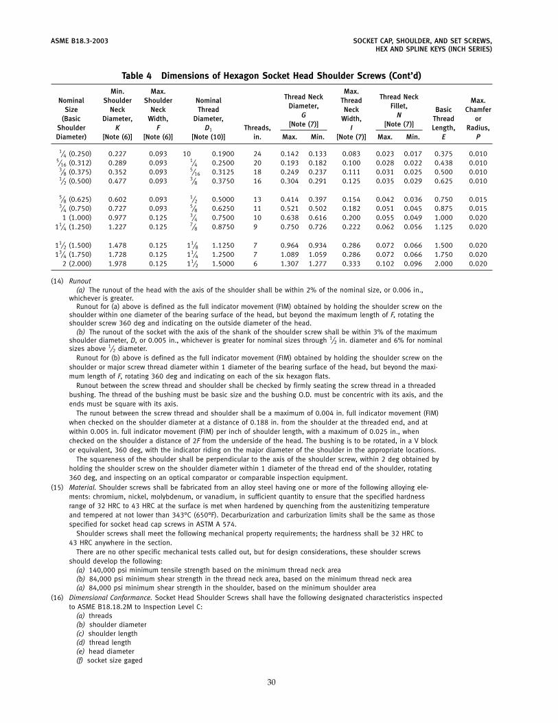
ASME B18.3-2003 SOCKET CAP, SHOULDER, AND SET SCREWS,HEX AND SPLINE KEYS (INCH SERIES)
Table 4 Dimensions of Hexagon Socket Head Shoulder Screws (Cont’d)
Min. Max. Max.Thread Neck Thread NeckNominal Shoulder Shoulder Nominal Thread Max.
Diameter, Fillet,Size Neck Neck Thread Neck Basic ChamferG N(Basic Diameter, Width, Diameter, Width, Thread or
[Note (7)] [Note (7)]Shoulder K F D1 Threads, I Length, Radius,Diameter) [Note (6)] [Note (6)] [Note (10)] in. Max. Min. [Note (7)] Max. Min. E P
1⁄4 (0.250) 0.227 0.093 10 0.1900 24 0.142 0.133 0.083 0.023 0.017 0.375 0.0105⁄16 (0.312) 0.289 0.093 1⁄4 0.2500 20 0.193 0.182 0.100 0.028 0.022 0.438 0.010
3⁄8 (0.375) 0.352 0.093 5⁄16 0.3125 18 0.249 0.237 0.111 0.031 0.025 0.500 0.0101⁄2 (0.500) 0.477 0.093 3⁄8 0.3750 16 0.304 0.291 0.125 0.035 0.029 0.625 0.010
5⁄8 (0.625) 0.602 0.093 1⁄2 0.5000 13 0.414 0.397 0.154 0.042 0.036 0.750 0.0153⁄4 (0.750) 0.727 0.093 5⁄8 0.6250 11 0.521 0.502 0.182 0.051 0.045 0.875 0.0151 (1.000) 0.977 0.125 3⁄4 0.7500 10 0.638 0.616 0.200 0.055 0.049 1.000 0.020
11⁄4 (1.250) 1.227 0.125 7⁄8 0.8750 9 0.750 0.726 0.222 0.062 0.056 1.125 0.020
11⁄2 (1.500) 1.478 0.125 11⁄8 1.1250 7 0.964 0.934 0.286 0.072 0.066 1.500 0.02013⁄4 (1.750) 1.728 0.125 11⁄4 1.2500 7 1.089 1.059 0.286 0.072 0.066 1.750 0.020
2 (2.000) 1.978 0.125 11⁄2 1.5000 6 1.307 1.277 0.333 0.102 0.096 2.000 0.020
(14) Runout(a) The runout of the head with the axis of the shoulder shall be within 2% of the nominal size, or 0.006 in.,
whichever is greater.Runout for (a) above is defined as the full indicator movement (FIM) obtained by holding the shoulder screw on the
shoulder within one diameter of the bearing surface of the head, but beyond the maximum length of F, rotating theshoulder screw 360 deg and indicating on the outside diameter of the head.
(b) The runout of the socket with the axis of the shank of the shoulder screw shall be within 3% of the maximumshoulder diameter, D, or 0.005 in., whichever is greater for nominal sizes through 1⁄2 in. diameter and 6% for nominalsizes above 1⁄2 diameter.
Runout for (b) above is defined as the full indicator movement (FIM) obtained by holding the shoulder screw on theshoulder or major screw thread diameter within 1 diameter of the bearing surface of the head, but beyond the maxi-mum length of F, rotating 360 deg and indicating on each of the six hexagon flats.
Runout between the screw thread and shoulder shall be checked by firmly seating the screw thread in a threadedbushing. The thread of the bushing must be basic size and the bushing O.D. must be concentric with its axis, and theends must be square with its axis.
The runout between the screw thread and shoulder shall be a maximum of 0.004 in. full indicator movement (FIM)when checked on the shoulder diameter at a distance of 0.188 in. from the shoulder at the threaded end, and atwithin 0.005 in. full indicator movement (FIM) per inch of shoulder length, with a maximum of 0.025 in., whenchecked on the shoulder a distance of 2F from the underside of the head. The bushing is to be rotated, in a V blockor equivalent, 360 deg, with the indicator riding on the major diameter of the shoulder in the appropriate locations.
The squareness of the shoulder shall be perpendicular to the axis of the shoulder screw, within 2 deg obtained byholding the shoulder screw on the shoulder diameter within 1 diameter of the thread end of the shoulder, rotating360 deg, and inspecting on an optical comparator or comparable inspection equipment.
(15) Material. Shoulder screws shall be fabricated from an alloy steel having one or more of the following alloying ele-ments: chromium, nickel, molybdenum, or vanadium, in sufficient quantity to ensure that the specified hardnessrange of 32 HRC to 43 HRC at the surface is met when hardened by quenching from the austenitizing temperatureand tempered at not lower than 343°C (650°F). Decarburization and carburization limits shall be the same as thosespecified for socket head cap screws in ASTM A 574.
Shoulder screws shall meet the following mechanical property requirements; the hardness shall be 32 HRC to43 HRC anywhere in the section.
There are no other specific mechanical tests called out, but for design considerations, these shoulder screwsshould develop the following:
(a) 140,000 psi minimum tensile strength based on the minimum thread neck area(b) 84,000 psi minimum shear strength in the thread neck area, based on the minimum thread neck area(a) 84,000 psi minimum shear strength in the shoulder, based on the minimum shoulder area
(16) Dimensional Conformance. Socket Head Shoulder Screws shall have the following designated characteristics inspectedto ASME B18.18.2M to Inspection Level C:
(a) threads(b) shoulder diameter(c) shoulder length(d) thread length(e) head diameter(f) socket size gaged
30
SOCKET CAP, SHOULDER, AND SET SCREWS, ASME B18.3-2003HEX AND SPLINE KEYS (INCH SERIES)
Table 4 Dimensions of Hexagon Socket Head Shoulder Screws (Cont’d)(17) Designation. To promote uniformity and understanding in communications relating to products conforming to this
Standard, it is recommended that Hexagon Socket Head Shoulder Screws be designated in accordance with the follow-ing data, preferably in the sequence shown:
(a) product name.(b) designation of the standard.(c) nominal size (number, fractional or decimal equivalent).(d) nominal length (fractional or decimal equivalent).(e) material.(f) protective finish, if required. (For plated products, see para. 1.7, Introductory Notes.)EXAMPLES:Hexagon Socket Head Shoulder Screws, ASME B18.3, 1⁄4 � 11⁄4 , Alloy SteelHexagon Socket Head Shoulder Screws, ASME B18.3, 0.250 � 1.250, Alloy Steel, Phosphate Coated
For the recommended B18 part identifying numbering system (PIN), see ASME B18.24.1.
31
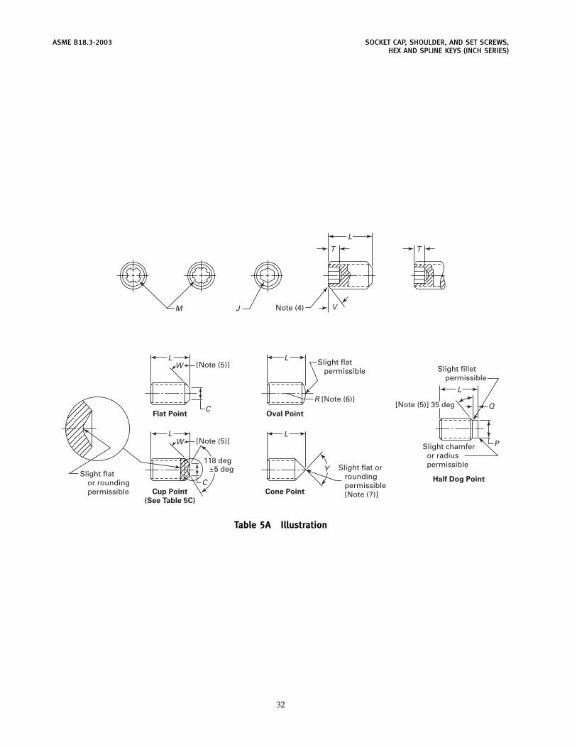
ASME B18.3-2003 SOCKET CAP, SHOULDER, AND SET SCREWS,HEX AND SPLINE KEYS (INCH SERIES)
M J V
T
L
Note (4)
T
L
C
W [Note (5)]
Slight flator roundingpermissible
Flat Point
Cup Point
(See Table 5C)
Oval Point
Half Dog Point
Cone Point
L
L
Q
PL
W [Note (5)]
118 deg±5 deg
R [Note (6)][Note (5)] 35 deg
Slight flat or rounding permissible [Note (7)]
Slight chamfer or radius permissible
Slight filletpermissible
Slight flat permissible
C
L
Y
Table 5A Illustration
32
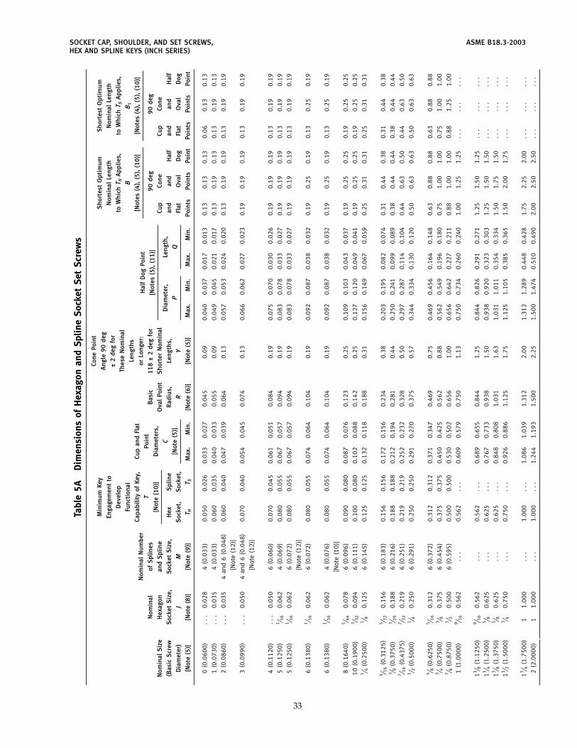
SOCKET CAP, SHOULDER, AND SET SCREWS, ASME B18.3-2003HEX AND SPLINE KEYS (INCH SERIES)
Tabl
e5A
Dim
ensi
ons
ofH
exag
onan
dSp
line
Soc
ket
Set
Scr
ews
Cone
Poin
tM
inim
umKe
yS
hort
est
Opt
imum
Sho
rtes
tO
ptim
umA
ngle
90de
gEn
gage
men
tto
Nom
inal
Leng
thN
omin
alLe
ngth
±2
deg
for
Dev
elop
toW
hich
T HA
pplie
s,to
Whi
chT S
App
lies,
Thes
eN
omin
alFu
ncti
onal
BB
1Le
ngth
sCa
pabi
lity
ofKe
y,Cu
pan
dFl
at[N
otes
(4),
(5),
(10)
][N
otes
(4),
(5),
(10)
]N
omin
alN
umbe
ror
Long
er:
Hal
fD
ogPo
int
TPo
int
Nom
inal
ofS
plin
esB
asic
118
±2
deg
for
90de
g90
deg
[Not
es(5
),(1
1)]
[Not
e(1
0)]
Dia
met
ers,
Nom
inal
Siz
eH
exag
onan
dS
plin
eO
val
Poin
tS
hort
erN
omin
alCu
pCo
neCu
pCo
neC
Dia
met
er,
Leng
th,
(Bas
icS
crew
Soc
ket
Siz
e,S
ocke
tS
ize,
Hex
Spl
ine
Rad
ius,
Leng
ths,
and
and
Hal
fan
dan
dH
alf
[Not
e(5
)]P
QD
iam
eter
)J
MS
ocke
t,S
ocke
t,R
YFl
atO
val
Dog
Flat
Ova
lD
og
[Not
e(5
)][N
ote
(8)]
[Not
e(9
)]T H
T SM
ax.
Min
.[N
ote
(6)]
[Not
e(5
)]M
ax.
Min
.M
ax.
Min
.Po
ints
Poin
tsPo
int
Poin
tsPo
ints
Poin
t
0(0
.060
0)..
.0.
028
4(0
.033
)0.
050
0.02
60.
033
0.02
70.
045
0.09
0.04
00.
037
0.01
70.
013
0.13
0.13
0.13
0.06
0.13
0.13
1(0
.073
0)..
.0.
035
4(0
.033
)0.
060
0.03
50.
040
0.03
30.
055
0.09
0.04
90.
045
0.02
10.
017
0.13
0.19
0.13
0.13
0.19
0.13
2(0
.086
0)..
.0.
035
4an
d6
(0.0
48)
0.06
00.
040
0.04
70.
039
0.06
40.
130.
057
0.05
30.
024
0.02
00.
130.
190.
190.
130.
190.
19
[Not
e(1
2)]
3(0
.099
0)..
.0.
050
4an
d6
(0.0
48)
0.07
00.
040
0.05
40.
045
0.07
40.
130.
066
0.06
20.
027
0.02
30.
190.
190.
190.
130.
190.
19
[Not
e(1
2)]
4(0
.112
0)..
.0.
050
6(0
.060
)0.
070
0.04
50.
061
0.05
10.
084
0.19
0.07
50.
070
0.03
00.
026
0.19
0.19
0.19
0.13
0.19
0.19
5(0
.125
0)1 ⁄ 1
60.
062
4(0
.069
)0.
080
0.05
50.
067
0.05
70.
094
0.19
0.08
30.
078
0.03
30.
027
0.19
0.19
0.19
0.13
0.19
0.19
5(0
.125
0)1 ⁄ 1
60.
062
6(0
.072
)0.
080
0.05
50.
067
0.05
70.
094
0.19
0.08
30.
078
0.03
30.
027
0.19
0.19
0.19
0.13
0.19
0.19
[Not
e(1
2)]
6(0
.138
0)1 ⁄ 1
60.
062
6(0
.072
)0.
080
0.05
50.
074
0.06
40.
104
0.19
0.09
20.
087
0.03
80.
032
0.19
0.25
0.19
0.13
0.25
0.19
6(0
.138
0)1 ⁄ 1
60.
062
4(0
.076
)0.
080
0.05
50.
074
0.06
40.
104
0.19
0.09
20.
087
0.03
80.
032
0.19
0.25
0.19
0.13
0.25
0.19
[Not
e(1
0)]
8(0
.164
0)5 ⁄ 6
40.
078
6(0
.096
)0.
090
0.08
00.
087
0.07
60.
123
0.25
0.10
90.
103
0.04
30.
037
0.19
0.25
0.25
0.19
0.25
0.25
10(0
.190
0)3 ⁄ 3
20.
094
6(0
.111
)0.
100
0.08
00.
102
0.08
80.
142
0.25
0.12
70.
120
0.04
90.
041
0.19
0.25
0.25
0.19
0.25
0.25
1 ⁄ 4(0
.250
0)1 ⁄ 8
0.12
56
(0.1
45)
0.12
50.
125
0.13
20.
118
0.18
80.
310.
156
0.14
90.
067
0.05
90.
250.
310.
310.
250.
310.
31
5 ⁄ 16
(0.3
125)
5 ⁄ 32
0.15
66
(0.1
83)
0.15
60.
156
0.17
20.
156
0.23
40.
380.
203
0.19
50.
082
0.07
40.
310.
440.
380.
310.
440.
383 ⁄ 8
(0.3
750)
3 ⁄ 16
0.18
86
(0.2
16)
0.18
80.
188
0.21
20.
194
0.28
10.
440.
250
0.24
10.
099
0.08
90.
380.
440.
440.
380.
440.
447 ⁄ 1
6(0
.437
5)7 ⁄ 3
20.
219
6(0
.251
)0.
219
0.21
90.
252
0.23
20.
328
0.50
0.29
70.
287
0.11
40.
104
0.44
0.63
0.50
0.44
0.63
0.50
1 ⁄ 2(0
.500
0)1 ⁄ 4
0.25
06
(0.2
91)
0.25
00.
250
0.29
10.
270
0.37
50.
570.
344
0.33
40.
130
0.12
00.
500.
630.
630.
500.
630.
63
5 ⁄ 8(0
.625
0)5 ⁄ 1
60.
312
6(0
.372
)0.
312
0.31
20.
371
0.34
70.
469
0.75
0.46
90.
456
0.16
40.
148
0.63
0.88
0.88
0.63
0.88
0.88
3 ⁄ 4(0
.750
0)3 ⁄ 8
0.37
56
(0.4
54)
0.37
50.
375
0.45
00.
425
0.56
20.
880.
562
0.54
90.
196
0.18
00.
751.
001.
000.
751.
001.
007 ⁄ 8
(0.8
750)
1 ⁄ 20.
500
6(0
.595
)0.
500
0.50
00.
530
0.50
20.
656
1.00
0.65
60.
642
0.22
70.
211
0.88
1.00
1.00
0.88
1.25
1.00
1(1
.000
0)9 ⁄ 1
60.
562
...
0.56
2..
.0.
609
0.57
90.
750
1.13
0.75
00.
734
0.26
00.
240
1.00
1.25
1.25
...
...
...
11 ⁄ 8(1
.125
0)9 ⁄ 1
60.
562
...
0.56
2..
.0.
689
0.65
50.
844
1.25
0.84
40.
826
0.29
10.
271
1.25
1.50
1.25
...
...
...
11 ⁄ 4(1
.250
0)5 ⁄ 8
0.62
5..
.0.
625
...
0.76
70.
733
0.93
81.
500.
938
0.92
00.
323
0.30
31.
251.
501.
50..
...
...
.
13 ⁄ 8(1
.375
0)5 ⁄ 8
0.62
5..
.0.
625
...
0.84
80.
808
1.03
11.
631.
031
1.01
10.
354
0.33
41.
501.
751.
50..
...
...
.
11 ⁄ 2(1
.500
0)3 ⁄ 4
0.75
0..
.0.
750
...
0.92
60.
886
1.12
51.
751.
125
1.10
50.
385
0.36
51.
502.
001.
75..
...
...
.
13 ⁄ 4(1
.750
0)1
1.00
0..
.1.
000
...
1.08
61.
039
1.31
22.
001.
312
1.28
90.
448
0.42
81.
752.
252.
00..
...
...
.
2(2
.000
0)1
1.00
0..
.1.
000
...
1.24
41.
193
1.50
02.
251.
500
1.47
40.
510
0.49
02.
002.
502.
50..
...
...
.
33
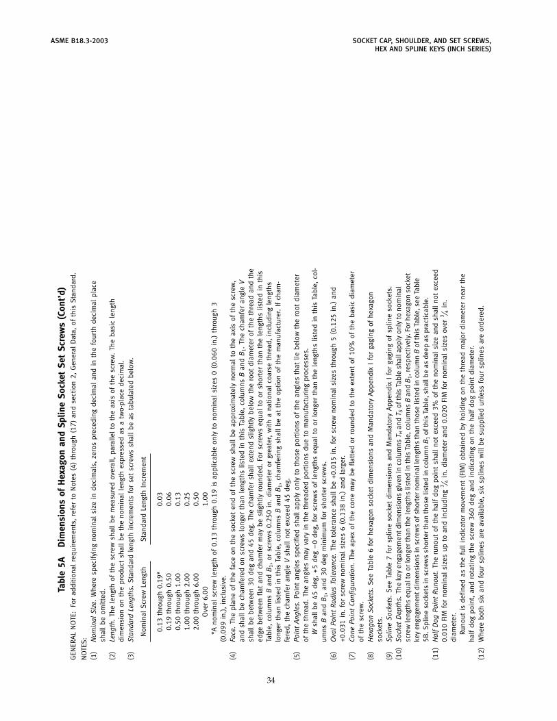
ASME B18.3-2003 SOCKET CAP, SHOULDER, AND SET SCREWS,HEX AND SPLINE KEYS (INCH SERIES)
Tabl
e5A
Dim
ensi
ons
ofH
exag
onan
dSp
line
Soc
ket
Set
Scr
ews
(Con
t’d)
GEN
ERA
LN
OTE
:Fo
rad
diti
onal
requ
irem
ents
,re
fer
toN
otes
(4)
thro
ugh
(17)
and
sect
ion
2,G
ener
alD
ata,
ofth
isS
tand
ard.
NO
TES
:(1
)N
omin
alSi
ze.
Whe
resp
ecif
ying
nom
inal
size
inde
cim
als,
zero
spr
eced
ing
deci
mal
and
inth
efo
urth
deci
mal
plac
esh
all
beom
itte
d.(2
)Le
ngth
.Th
ele
ngth
ofth
esc
rew
shal
lbe
mea
sure
dov
eral
l,pa
ralle
lto
the
axis
ofth
esc
rew
.Th
eba
sic
leng
thdi
men
sion
onth
epr
oduc
tsh
all
beth
eno
min
alle
ngth
expr
esse
das
atw
o-pl
ace
deci
mal
.(3
)St
anda
rdLe
ngth
s.S
tand
ard
leng
thin
crem
ents
for
set
scre
ws
shal
lbe
asta
bula
ted
belo
w.
Nom
inal
Scr
ewLe
ngth
Sta
ndar
dLe
ngth
Incr
emen
t
0.13
thro
ugh
0.19
*0.
030.
19th
roug
h0.
500.
060.
50th
roug
h1.
000.
131.
00th
roug
h2.
000.
252.
00th
roug
h6.
000.
50O
ver
6.00
1.00
*Ano
min
alsc
rew
leng
thof
0.13
thro
ugh
0.19
isap
plic
able
only
tono
min
alsi
zes
0(0
.060
in.)
thro
ugh
3(0
.099
in.)
,in
clus
ive.
(4)
Face
.Th
epl
ane
ofth
efa
ceon
the
sock
eten
dof
the
scre
wsh
all
beap
prox
imat
ely
norm
alto
the
axis
ofth
esc
rew
,an
dsh
all
bech
amfe
red
onsc
rew
slo
nger
than
leng
ths
liste
din
this
Tabl
e,co
lum
nsB
and
B1.
The
cham
fer
angl
eV
shal
lbe
betw
een
30de
gan
d45
deg.
The
cham
fer
shal
lex
tend
slig
htly
belo
wth
ero
otdi
amet
erof
the
thre
adan
dth
eed
gebe
twee
nfla
tan
dch
amfe
rm
aybe
slig
htly
roun
ded.
For
scre
ws
equa
lto
orsh
orte
rth
anth
ele
ngth
slis
ted
inth
isTa
ble,
colu
mns
Ban
dB
1,or
scre
ws
0.25
0in
.di
amet
eror
grea
ter,
wit
ha
nati
onal
coar
seth
read
,in
clud
ing
leng
ths
long
erth
anlis
ted
inth
isTa
ble,
colu
mns
Ban
dB
1,ch
amfe
ring
shal
lbe
atth
eop
tion
ofth
em
anuf
actu
rer .
Ifch
am-
fere
d,th
ech
amfe
ran
gle
Vsh
all
not
exce
ed45
deg.
(5)
Poin
tAn
gles
.Po
int
angl
essp
ecifi
edsh
all
appl
yon
lyto
thos
epo
rtio
n sof
the
angl
esth
atlie
belo
wth
ero
otdi
amet
erof
the
thre
ad.
The
angl
esm
ayva
ryin
the
thre
aded
port
ion s
due
tom
anuf
actu
ring
proc
esse
s.W
shal
lbe
45de
g,+5
deg
−0
deg,
for
scre
ws
ofle
ngth
seq
ual
toor
long
erth
anth
ele
ngth
slis
ted
inth
isTa
ble,
c ol-
umns
Ban
dB
1,an
d30
deg
min
imum
for
shor
ter
scre
ws.
(6)
Ova
lPo
int
Radi
usTo
lera
nce.
The
tole
ranc
esh
all
be+0
.015
in.
for
scre
wno
min
alsi
zes
thro
ugh
5(0
.125
in.)
and
+0.0
31in
.fo
rsc
rew
nom
inal
size
s6
(0.1
38in
.)an
dla
rger
.(7
)Co
nePo
int
Conf
igur
atio
n.Th
eap
exof
the
cone
may
befla
tted
orro
unde
dto
the
exte
ntof
10%
ofth
eba
sic
diam
eter
ofth
esc
rew
.(8
)H
exag
onSo
cket
s.S
eeTa
ble
6fo
rhe
xago
nso
cket
dim
ensi
ons
and
Man
dato
r yA
ppen
dix
Ifo
rga
ging
ofhe
xago
nso
cket
s.(9
)Sp
line
Sock
ets.
See
Tabl
e7
for
splin
eso
cket
dim
ensi
ons
and
Man
dato
r yA
ppen
dix
Ifo
rga
ging
ofsp
line
sock
ets.
(10)
Sock
etD
epth
s.Th
eke
yen
gage
men
tdim
ensi
ons
give
nin
colu
mns
T Han
dT S
ofth
isTa
ble
shal
lapp
lyon
lyto
nom
inal
scre
wle
ngth
seq
ualt
oor
long
erth
anth
ele
ngth
slis
ted
inth
isTa
ble,
colu
mns
Ban
dB
1,re
spec
tive
ly.F
orhe
xago
nso
cket
key
enga
gem
entd
imen
sion
sin
scre
ws
ofsh
orte
rnom
inal
leng
ths
than
thos
elis
ted
inco
lum
nB
ofth
isTa
ble,
see
Tabl
e5B
.Spl
ine
sock
ets
insc
rew
ssh
orte
rtha
nth
ose
liste
din
colu
mn
B1
ofth
isTa
ble,
shal
lbe
asde
epas
prac
tica
ble.
(11)
Hal
fD
ogPo
int
Runo
ut.
The
runo
utof
the
half
dog
poin
tsh
all
not
exce
ed3%
ofth
eno
min
alsi
zean
dsh
all
not
exce
ed0.
010
FIM
for
nom
inal
size
sup
toan
din
clud
ing
3 ⁄ 4in
.di
amet
eran
d0.
020
FIM
for
nom
inal
size
sov
er3 ⁄ 4
in.
diam
eter
.Ru
nout
isde
fined
asth
efu
llin
dica
tor
mov
emen
t(F
IM)
obta
ined
byho
ldin
gon
the
thre
adm
ajor
diam
eter
near
the
half
dog
poin
t,an
dro
tati
ngth
esc
rew
360
deg
and
indi
cati
ngon
the
half
dog
poin
tdi
amet
er.
(12)
Whe
rebo
thsi
xan
dfo
ursp
lines
are
avai
labl
e,si
xsp
lines
will
besu
pplie
dun
less
four
splin
esar
eor
dere
d.
34
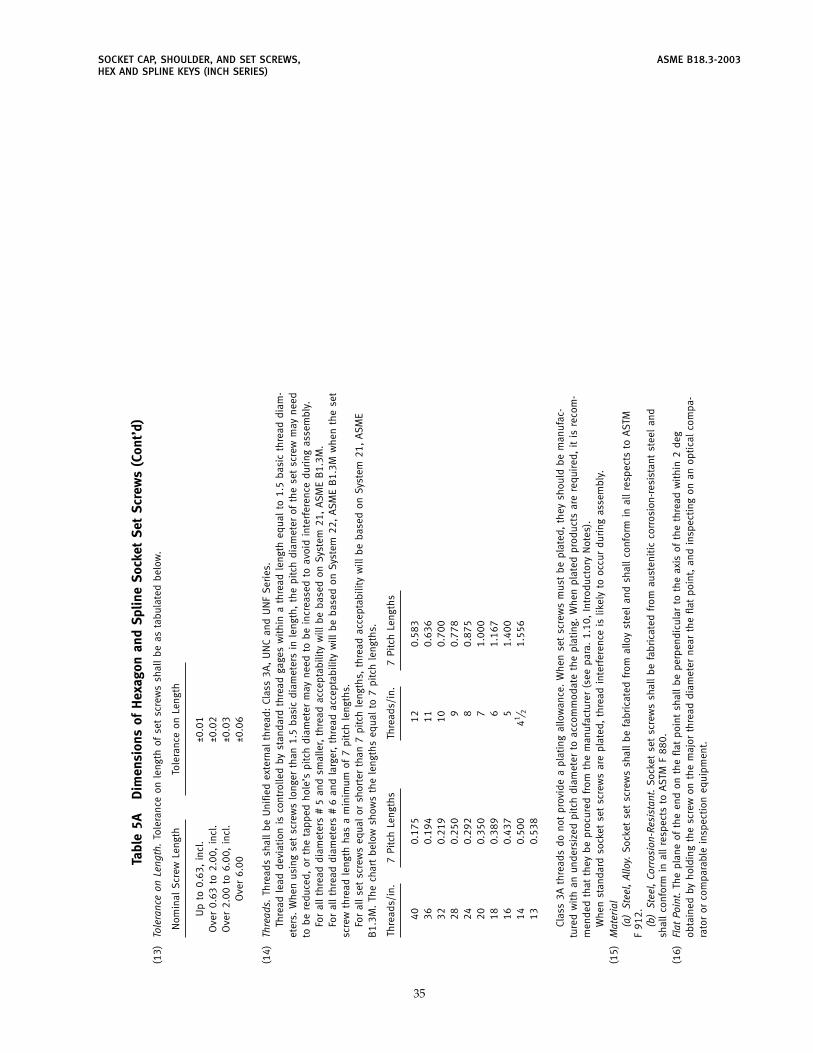
SOCKET CAP, SHOULDER, AND SET SCREWS, ASME B18.3-2003HEX AND SPLINE KEYS (INCH SERIES)
Tabl
e5A
Dim
ensi
ons
ofH
exag
onan
dSp
line
Soc
ket
Set
Scr
ews
(Con
t’d)
(13)
Tole
ranc
eon
Leng
th.
Tole
ranc
eon
leng
thof
set
scre
ws
shal
lbe
asta
bula
ted
belo
w.
Nom
inal
Scr
ewLe
ngth
Tole
ranc
eon
Leng
th
Up
to0.
63,
incl
.±0
.01
Ove
r0.
63to
2.00
,in
cl.
±0.0
2O
ver
2.00
to6.
00,
incl
.±0
.03
Ove
r6.
00±0
.06
(14)
Thre
ads.
Thre
ads
shal
lbe
Uni
fied
exte
rnal
thre
ad:
Clas
s3A
,U
NC
and
UN
FS
erie
s.Th
read
lead
devi
atio
nis
cont
rolle
dby
stan
dard
thre
adga
ges
wit
hin
ath
read
leng
theq
ual
to1.
5ba
sic
thre
addi
am-
eter
s.W
hen
usin
gse
tsc
rew
slo
nger
than
1.5
basi
cdi
amet
ers
inle
ngth
,th
epi
tch
diam
eter
ofth
ese
tsc
rew
may
need
tobe
redu
ced,
orth
eta
pped
hole
’spi
tch
diam
eter
may
need
tobe
incr
ease
dto
avoi
din
terf
eren
cedu
ring
asse
mbl
y.Fo
ral
lth
read
diam
eter
s#
5an
dsm
alle
r,th
read
acce
ptab
ility
will
beba
sed
onSy
stem
21,
ASM
EB
1.3M
.Fo
ral
lth
read
diam
eter
s#
6an
dla
rger
,th
read
acce
ptab
ility
will
beba
sed
onSy
stem
22,
ASM
EB
1.3M
whe
nth
ese
tsc
rew
thre
adle
ngth
has
am
inim
umof
7pi
tch
leng
ths.
For
all
set
scre
ws
equa
lor
shor
ter
than
7pi
tch
leng
ths,
thre
adac
cept
abili
tyw
illbe
base
don
Syst
em21
,A
SME
B1.
3M.
The
char
tbe
low
show
sth
ele
ngth
seq
ual
to7
pitc
hle
ngth
s.
Thre
ads/
in.
7Pi
tch
Leng
ths
Thre
ads/
in.
7Pi
tch
Leng
ths
400.
175
120.
583
360.
194
110.
636
320.
219
100.
700
280.
250
90.
778
240.
292
80.
875
200.
350
71.
000
180.
389
61.
167
160.
437
51.
400
140.
500
41 ⁄ 21.
556
130.
538
Clas
s3A
thre
ads
dono
tpr
ovid
ea
plat
ing
allo
wan
ce.
Whe
nse
tsc
rew
sm
ust
bepl
ated
,th
eysh
ould
bem
anuf
ac-
ture
dw
ith
anun
ders
ized
pitc
hdi
amet
erto
acco
mm
odat
eth
epl
atin
g.W
hen
plat
edpr
oduc
tsar
ere
quir
ed,
itis
reco
m-
men
ded
that
they
bepr
ocur
edfr
omth
em
anuf
actu
rer
(see
para
.1.
10,
Intr
oduc
tory
Not
es).
Whe
nst
anda
rdso
cket
set
scre
ws
are
plat
ed,
thre
adin
ter f
eren
ceis
likel
yto
occu
rdu
ring
asse
mbl
y.(1
5)M
ater
ial
(a)
Stee
l,Al
loy.
Soc
ket
set
scre
ws
shal
lbe
fabr
icat
edfr
omal
loy
stee
lan
dsh
all
conf
orm
inal
lre
spec
tsto
AST
MF
912.
(b)
Stee
l,Co
rros
ion-
Resi
stan
t.S
ocke
tse
tsc
rew
ssh
all
befa
bric
ated
from
aust
enit
icco
rros
ion-
resi
stan
tst
eel
and
shal
lco
nfor
min
all
resp
ects
toA
STM
F88
0.(1
6)Fl
atPo
int.
The
plan
eof
the
end
onth
efla
tpo
int
shal
lbe
perp
endi
cula
rto
the
axis
ofth
eth
read
wit
hin
2de
gob
tain
edby
hold
ing
the
scre
won
the
maj
orth
read
diam
eter
near
the
flat
poin
t,an
din
spec
ting
onan
opti
cal
com
pa-
rato
ror
com
para
ble
insp
ecti
oneq
uipm
ent.
35
ASME B18.3-2003 SOCKET CAP, SHOULDER, AND SET SCREWS,HEX AND SPLINE KEYS (INCH SERIES)
Tabl
e5A
Dim
ensi
ons
ofH
exag
onan
dSp
line
Soc
ket
Set
Scr
ews
(Con
t’d)
(17)
Dim
ensi
onal
Conf
orm
ance
.S
ocke
tse
tsc
rew
ssh
all
have
the
follo
win
gde
sign
ated
char
acte
risti
csin
spec
ted
toA
SME
B18
.18.
2Mto
Insp
ecti
onLe
vel
C:(a
)th
read
s(b
)m
inim
umke
yen
gage
men
t(c
)so
cket
size
(gag
ed)
(d)
leng
th(1
8)D
esig
natio
n.To
prom
ote
unifo
rmit
yan
dun
ders
tand
ing
inco
mm
unic
atio
nsre
lati
ngto
prod
ucts
conf
orm
ing
toth
isS
tand
ard,
itis
reco
mm
ende
dth
atH
exag
onan
dS
plin
eS
ocke
tS
etS
crew
sbe
desi
gnat
edin
acco
rdan
cew
ith
the
follo
w-
ing
data
,pr
efer
ably
inth
ese
quen
cesh
own:
(a)
prod
uct
nam
ean
dpo
int
styl
e(b
)de
sign
atio
nof
the
stan
dard
(c)
nom
inal
size
(num
ber,
frac
tion
alor
deci
mal
equi
vale
nt)
(d)
thre
adpi
tch
(e)
nom
inal
leng
th(f
ract
iona
lor
deci
mal
equi
vale
nt)
(f)
mat
eria
l(g
)pr
otec
tive
finis
h,if
requ
ired
EXA
MPL
ES:
Hex
agon
Soc
ket
Set
Scr
ew,
Cup
Poin
t,A
SME
B18
.3,
1 ⁄ 4-2
0�
1 ⁄ 4,
Allo
yS
teel
Spl
ine
Soc
ket
Set
Scr
ew,
Flat
Poin
t,A
SME
B18
.3,
0.11
2-40
�0.
125,
Allo
yS
teel
,Zi
ncPl
ated
.(F
orpl
ated
prod
ucts
,se
epa
ra.
1.7,
Intr
oduc
tory
Not
es.)
Hex
agon
Soc
ket
Set
Scr
ew,
Cup
Poin
t,A
SME
B18
.3,
6-32
�0.
250,
Corr
osio
n-Re
sist
ant
Ste
el
For
the
reco
mm
ende
dB
18pa
rtid
enti
fyin
gnu
mbe
ring
syst
em(P
IN),
see
ASM
EB
18.2
4.1.
36
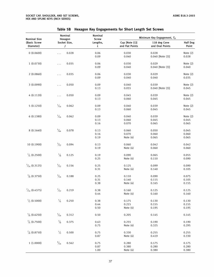
SOCKET CAP, SHOULDER, AND SET SCREWS, ASME B18.3-2003HEX AND SPLINE KEYS (INCH SERIES)
Table 5B Hexagon Key Engagements for Short Length Set Screws
Nominal NominalMinimum Key Engagement, THNominal Size Hexagon Screw
(Basic Screw Socket Size, Lengths, Cup [Note (1)] 118 deg Cone Half DogDiameter) J L and Flat Points and Oval Points Point
0 (0.0600) . . . 0.028 0.06 0.030 0.028 Note (2)0.09 0.040 0.040 [Note (3)] 0.028
1 (0.0730) . . . 0.035 0.06 0.030 0.029 Note (2)0.09 0.040 0.040 [Note (3)] 0.040
2 (0.0860) . . . 0.035 0.06 0.030 0.029 Note (2)0.09 0.040 0.040 0.035
3 (0.0990) . . . 0.050 0.09 0.040 0.039 Note (2)0.13 0.055 0.040 [Note (3)] 0.045
4 (0.1120) . . . 0.050 0.09 0.045 0.039 Note (2)0.13 0.060 0.045 0.045
5 (0.1250) 1⁄16 0.062 0.09 0.040 0.039 Note (2)0.13 0.060 0.045 0.045
6 (0.1380) 1⁄16 0.062 0.09 0.040 0.039 Note (2)0.13 0.060 0.045 0.0450.16 0.070 0.065 0.065
8 (0.1640) 5⁄64 0.078 0.13 0.060 0.050 0.0450.16 0.070 0.060 0.0600.19 Note (4) 0.065 0.065
10 (0.1900) 3⁄32 0.094 0.13 0.060 0.042 0.0420.19 Note (4) 0.060 0.060
1⁄4 (0.2500) 1⁄8 0.125 0.19 0.090 0.065 0.0550.25 Note (4) 0.110 0.090
5⁄16 (0.3125) 5⁄32 0.156 0.25 0.125 0.099 0.0900.31 Note (4) 0.140 0.105
3⁄8 (0.3750) 3⁄16 0.188 0.25 0.110 0.090 0.0750.31 0.140 0.115 0.1050.38 Note (4) 0.165 0.155
7⁄16 (0.4375) 7⁄32 0.219 0.38 0.160 0.125 0.1250.44 Note (4) 0.160 0.160
1⁄2 (0.5000) 1⁄4 0.250 0.38 0.175 0.130 0.1300.44 0.215 0.155 0.1550.50 Note (4) 0.195 0.195
5⁄8 (0.6250) 5⁄16 0.312 0.50 0.205 0.145 0.145
3⁄4 (0.7500) 3⁄8 0.375 0.63 0.255 0.190 0.1900.75 Note (4) 0.325 0.295
7⁄8 (0.8750) 1⁄2 0.500 0.75 0.330 0.255 0.2550.87 Note (4) 0.419 0.330
1 (1.0000) 9⁄16 0.562 0.75 0.280 0.175 0.1750.87 0.380 0.280 0.2801.00 Note (4) 0.380 0.380
37

ASME B18.3-2003 SOCKET CAP, SHOULDER, AND SET SCREWS,HEX AND SPLINE KEYS (INCH SERIES)
Table 5B Hexagon Key Engagements for Short Length Set Screws (Cont’d)GENERAL NOTES:(a) CAUTION: The use of short-length set screws listed in this Table can result in failure of the socket, key, or mating
threads during tightening because key engagement and thread length are less than optimum. Therefore, it is stronglyrecommended that screws of lengths equal to or greater than the lengths specified in columns B and B1 of Table 5A beused wherever possible.
(b) See Table 5A, and the illustrations and notes thereto, for additional dimensions and specifications.
NOTES:(1) Cup angle may be 118 deg or 130 deg, +5 deg, depending upon screw length and manufacturing process.(2) These sizes are impractical to manufacture because of point configuration and short length.(3) Cone point angle for these lengths shall be 90 deg; see column Y of Table 5A.(4) These screws are covered in Table 5A.
38
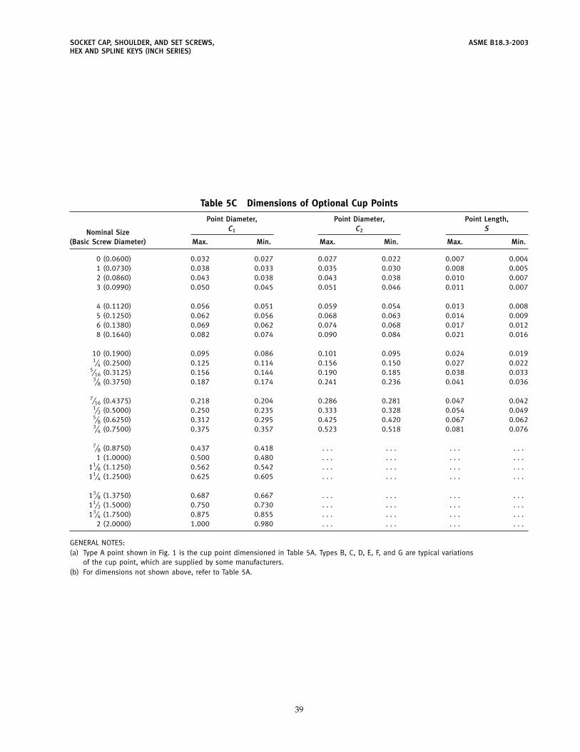
SOCKET CAP, SHOULDER, AND SET SCREWS, ASME B18.3-2003HEX AND SPLINE KEYS (INCH SERIES)
Table 5C Dimensions of Optional Cup Points
Point Diameter, Point Diameter, Point Length,C1 C2 SNominal Size
(Basic Screw Diameter) Max. Min. Max. Min. Max. Min.
0 (0.0600) 0.032 0.027 0.027 0.022 0.007 0.0041 (0.0730) 0.038 0.033 0.035 0.030 0.008 0.0052 (0.0860) 0.043 0.038 0.043 0.038 0.010 0.0073 (0.0990) 0.050 0.045 0.051 0.046 0.011 0.007
4 (0.1120) 0.056 0.051 0.059 0.054 0.013 0.0085 (0.1250) 0.062 0.056 0.068 0.063 0.014 0.0096 (0.1380) 0.069 0.062 0.074 0.068 0.017 0.0128 (0.1640) 0.082 0.074 0.090 0.084 0.021 0.016
10 (0.1900) 0.095 0.086 0.101 0.095 0.024 0.0191⁄4 (0.2500) 0.125 0.114 0.156 0.150 0.027 0.022
5⁄16 (0.3125) 0.156 0.144 0.190 0.185 0.038 0.0333⁄8 (0.3750) 0.187 0.174 0.241 0.236 0.041 0.036
7⁄16 (0.4375) 0.218 0.204 0.286 0.281 0.047 0.0421⁄2 (0.5000) 0.250 0.235 0.333 0.328 0.054 0.0495⁄8 (0.6250) 0.312 0.295 0.425 0.420 0.067 0.0623⁄4 (0.7500) 0.375 0.357 0.523 0.518 0.081 0.076
7⁄8 (0.8750) 0.437 0.418 . . . . . . . . . . . .1 (1.0000) 0.500 0.480 . . . . . . . . . . . .
11⁄8 (1.1250) 0.562 0.542 . . . . . . . . . . . .11⁄4 (1.2500) 0.625 0.605 . . . . . . . . . . . .
13⁄8 (1.3750) 0.687 0.667 . . . . . . . . . . . .11⁄2 (1.5000) 0.750 0.730 . . . . . . . . . . . .13⁄4 (1.7500) 0.875 0.855 . . . . . . . . . . . .
2 (2.0000) 1.000 0.980 . . . . . . . . . . . .
GENERAL NOTES:(a) Type A point shown in Fig. 1 is the cup point dimensioned in Table 5A. Types B, C, D, E, F, and G are typical variations
of the cup point, which are supplied by some manufacturers.(b) For dimensions not shown above, refer to Table 5A.
39
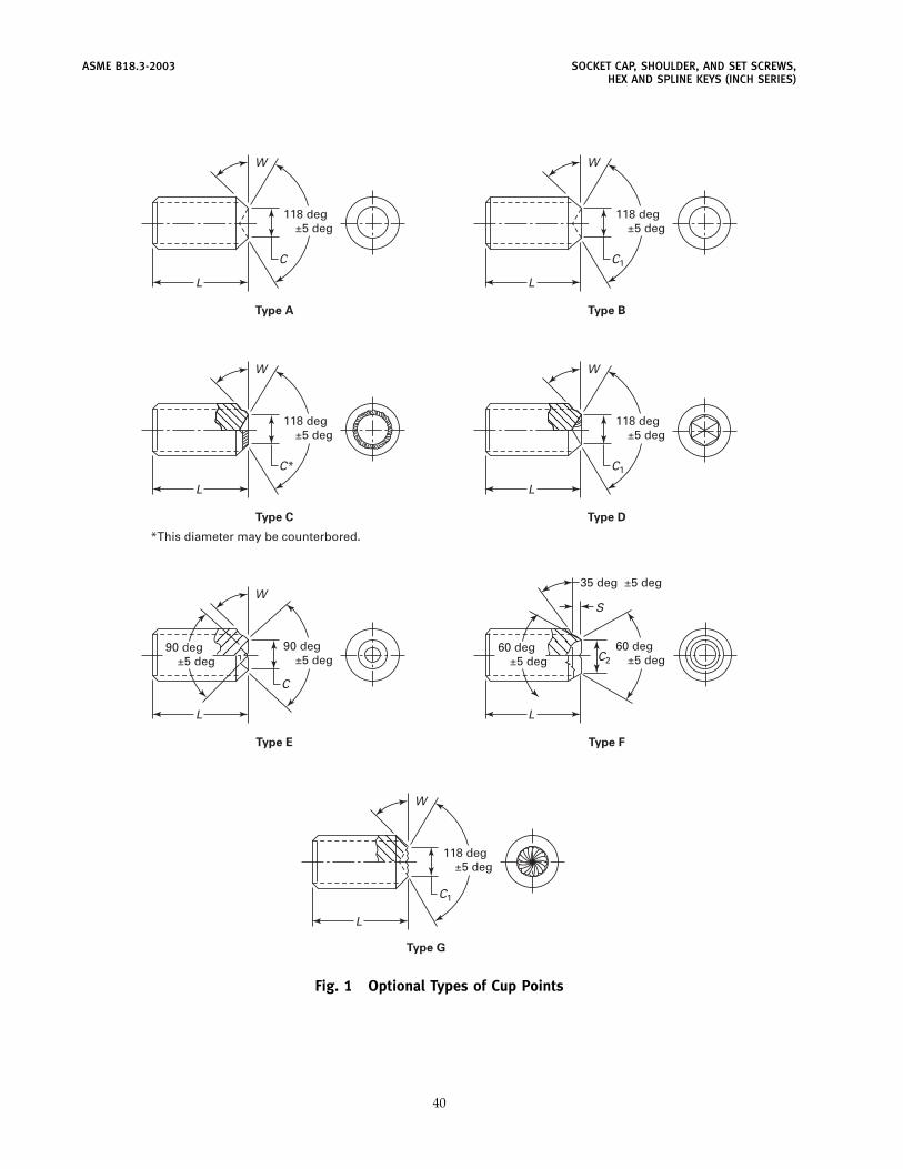
ASME B18.3-2003 SOCKET CAP, SHOULDER, AND SET SCREWS,HEX AND SPLINE KEYS (INCH SERIES)
Type A
L
118 deg±5 deg
W
C
Type B
L
118 deg±5 deg
W
C1
Type C
L
118 deg±5 deg
*This diameter may be counterbored.
W
C*
Type E
L
90 deg±5 deg
90 deg±5 deg
W
C
Type D
L
118 deg±5 deg
W
C1
Type F
L
60 deg±5 deg
60 deg±5 deg
35 deg ±5 deg
C2
S
Type G
L
118 deg±5 deg
W
C1
Fig. 1 Optional Types of Cup Points
40
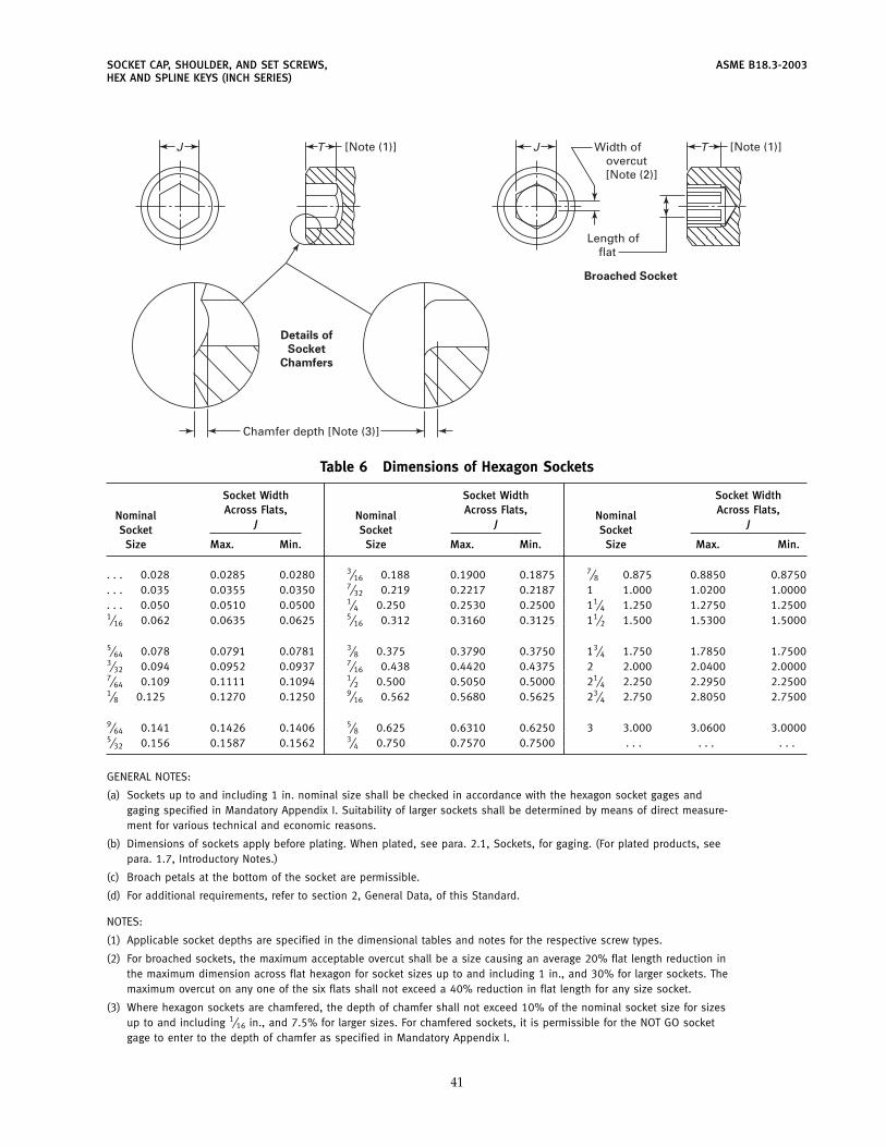
SOCKET CAP, SHOULDER, AND SET SCREWS, ASME B18.3-2003HEX AND SPLINE KEYS (INCH SERIES)
J
Chamfer depth [Note (3)]
Length offlat
Width ofovercut[Note (2)]
Details of
Socket
Chamfers
Broached Socket
JT [Note (1)] T [Note (1)]
Table 6 Dimensions of Hexagon Sockets
Socket Width Socket Width Socket WidthAcross Flats, Across Flats, Across Flats,Nominal Nominal Nominal
J J JSocket Socket SocketSize Max. Min. Size Max. Min. Size Max. Min.
. . . 0.028 0.0285 0.0280 3⁄16 0.188 0.1900 0.1875 7⁄8 0.875 0.8850 0.8750
. . . 0.035 0.0355 0.0350 7⁄32 0.219 0.2217 0.2187 1 1.000 1.0200 1.0000
. . . 0.050 0.0510 0.0500 1⁄4 0.250 0.2530 0.2500 11⁄4 1.250 1.2750 1.25001⁄16 0.062 0.0635 0.0625 5⁄16 0.312 0.3160 0.3125 11⁄2 1.500 1.5300 1.5000
5⁄64 0.078 0.0791 0.0781 3⁄8 0.375 0.3790 0.3750 13⁄4 1.750 1.7850 1.75003⁄32 0.094 0.0952 0.0937 7⁄16 0.438 0.4420 0.4375 2 2.000 2.0400 2.00007⁄64 0.109 0.1111 0.1094 1⁄2 0.500 0.5050 0.5000 21⁄4 2.250 2.2950 2.25001⁄8 0.125 0.1270 0.1250 9⁄16 0.562 0.5680 0.5625 23⁄4 2.750 2.8050 2.7500
9⁄64 0.141 0.1426 0.1406 5⁄8 0.625 0.6310 0.6250 3 3.000 3.0600 3.00005⁄32 0.156 0.1587 0.1562 3⁄4 0.750 0.7570 0.7500 . . . . . . . . .
GENERAL NOTES:
(a) Sockets up to and including 1 in. nominal size shall be checked in accordance with the hexagon socket gages andgaging specified in Mandatory Appendix I. Suitability of larger sockets shall be determined by means of direct measure-ment for various technical and economic reasons.
(b) Dimensions of sockets apply before plating. When plated, see para. 2.1, Sockets, for gaging. (For plated products, seepara. 1.7, Introductory Notes.)
(c) Broach petals at the bottom of the socket are permissible.
(d) For additional requirements, refer to section 2, General Data, of this Standard.
NOTES:
(1) Applicable socket depths are specified in the dimensional tables and notes for the respective screw types.
(2) For broached sockets, the maximum acceptable overcut shall be a size causing an average 20% flat length reduction inthe maximum dimension across flat hexagon for socket sizes up to and including 1 in., and 30% for larger sockets. Themaximum overcut on any one of the six flats shall not exceed a 40% reduction in flat length for any size socket.
(3) Where hexagon sockets are chamfered, the depth of chamfer shall not exceed 10% of the nominal socket size for sizesup to and including 1⁄16 in., and 7.5% for larger sizes. For chamfered sockets, it is permissible for the NOT GO socketgage to enter to the depth of chamfer as specified in Mandatory Appendix I.
41
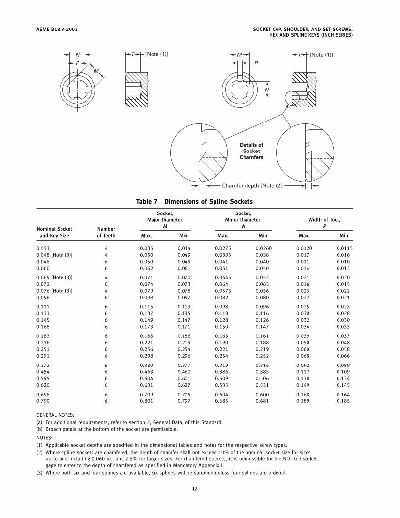
ASME B18.3-2003 SOCKET CAP, SHOULDER, AND SET SCREWS,HEX AND SPLINE KEYS (INCH SERIES)
TN
MP
[Note (1)] [Note (1)]
Chamfer depth [Note (2)]
Details of
Socket
Chamfers
M
P
N
T
Table 7 Dimensions of Spline Sockets
Socket, Socket,Major Diameter, Minor Diameter, Width of Tool,
M N PNominal Socket Numberand Key Size of Teeth Max. Min. Max. Min. Max. Min.
0.033 4 0.035 0.034 0.0275 0.0260 0.0120 0.01150.048 [Note (3)] 4 0.050 0.049 0.0395 0.038 0.017 0.0160.048 6 0.050 0.049 0.041 0.040 0.011 0.0100.060 6 0.062 0.061 0.051 0.050 0.014 0.013
0.069 [Note (3)] 4 0.071 0.070 0.0545 0.053 0.021 0.0200.072 6 0.074 0.073 0.064 0.063 0.016 0.0150.076 [Note (3)] 4 0.079 0.078 0.0575 0.056 0.023 0.0220.096 6 0.098 0.097 0.082 0.080 0.022 0.021
0.111 6 0.115 0.113 0.098 0.096 0.025 0.0230.133 6 0.137 0.135 0.118 0.116 0.030 0.0280.145 6 0.149 0.147 0.128 0.126 0.032 0.0300.168 6 0.173 0.171 0.150 0.147 0.036 0.033
0.183 6 0.188 0.186 0.163 0.161 0.039 0.0370.216 6 0.221 0.219 0.190 0.188 0.050 0.0480.251 6 0.256 0.254 0.221 0.219 0.060 0.0580.291 6 0.298 0.296 0.254 0.252 0.068 0.066
0.372 6 0.380 0.377 0.319 0.316 0.092 0.0890.454 6 0.463 0.460 0.386 0.383 0.112 0.1090.595 6 0.604 0.601 0.509 0.506 0.138 0.1340.620 6 0.631 0.627 0.535 0.531 0.149 0.145
0.698 6 0.709 0.705 0.604 0.600 0.168 0.1640.790 6 0.801 0.797 0.685 0.681 0.189 0.185
GENERAL NOTES:(a) For additional requirements, refer to section 2, General Data, of this Standard.(b) Broach petals at the bottom of the socket are permissible.
NOTES:(1) Applicable socket depths are specified in the dimensional tables and notes for the respective screw types.(2) Where spline sockets are chamfered, the depth of chamfer shall not exceed 10% of the nominal socket size for sizes
up to and including 0.060 in., and 7.5% for larger sizes. For chamfered sockets, it is permissible for the NOT GO socketgage to enter to the depth of chamfered as specified in Mandatory Appendix I.
(3) Where both six and four splines are available, six splines will be supplied unless four splines are ordered.
42
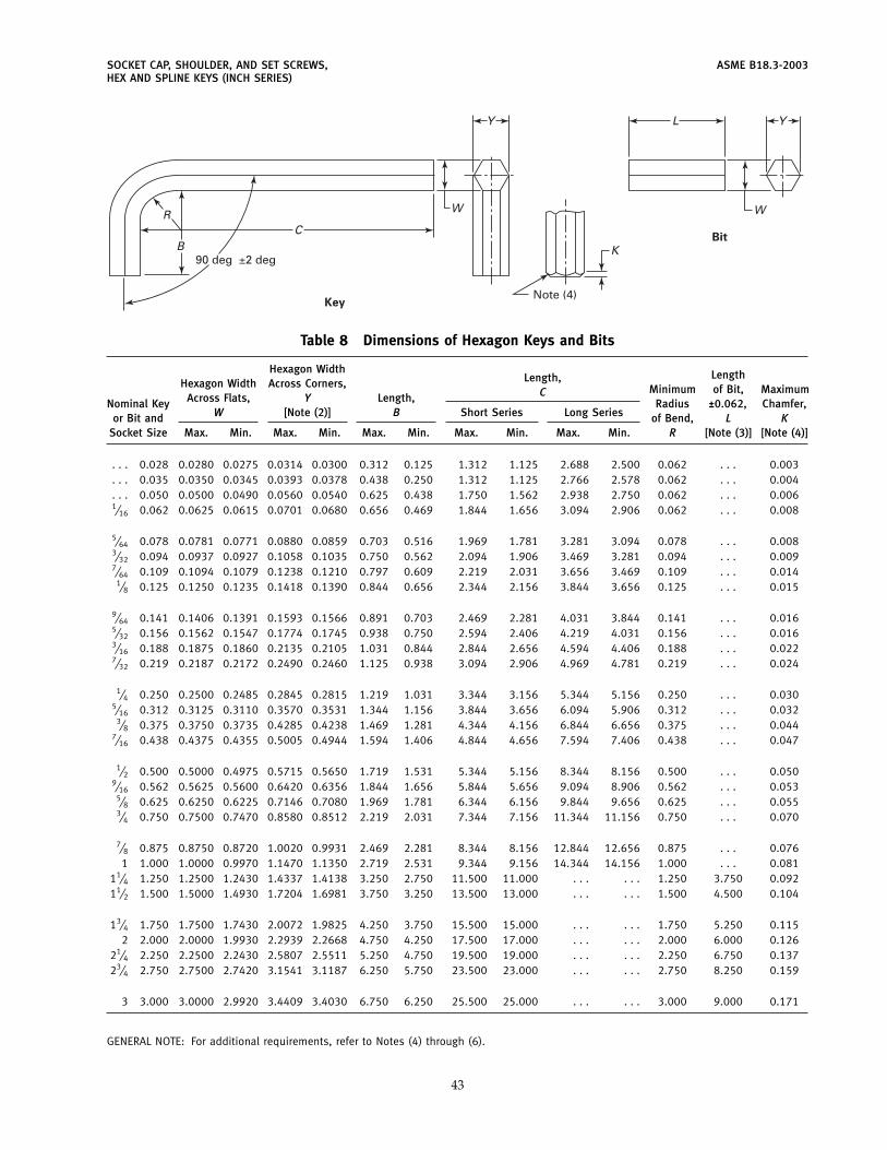
SOCKET CAP, SHOULDER, AND SET SCREWS, ASME B18.3-2003HEX AND SPLINE KEYS (INCH SERIES)
Key
Bit
Y
W
K
W
YL
C
90 deg ±2 deg
Note (4)
B
R
Table 8 Dimensions of Hexagon Keys and Bits
Hexagon Width LengthLength,Hexagon Width Across Corners, Minimum of Bit, MaximumCAcross Flats, Y Length,Nominal Key Radius ±0.062, Chamfer,W [Note (2)] B Short Series Long Seriesor Bit and of Bend, L K
Socket Size Max. Min. Max. Min. Max. Min. Max. Min. Max. Min. R [Note (3)] [Note (4)]
. . . 0.028 0.0280 0.0275 0.0314 0.0300 0.312 0.125 1.312 1.125 2.688 2.500 0.062 . . . 0.003
. . . 0.035 0.0350 0.0345 0.0393 0.0378 0.438 0.250 1.312 1.125 2.766 2.578 0.062 . . . 0.004
. . . 0.050 0.0500 0.0490 0.0560 0.0540 0.625 0.438 1.750 1.562 2.938 2.750 0.062 . . . 0.0061⁄16 0.062 0.0625 0.0615 0.0701 0.0680 0.656 0.469 1.844 1.656 3.094 2.906 0.062 . . . 0.008
5⁄64 0.078 0.0781 0.0771 0.0880 0.0859 0.703 0.516 1.969 1.781 3.281 3.094 0.078 . . . 0.0083⁄32 0.094 0.0937 0.0927 0.1058 0.1035 0.750 0.562 2.094 1.906 3.469 3.281 0.094 . . . 0.0097⁄64 0.109 0.1094 0.1079 0.1238 0.1210 0.797 0.609 2.219 2.031 3.656 3.469 0.109 . . . 0.014
1⁄8 0.125 0.1250 0.1235 0.1418 0.1390 0.844 0.656 2.344 2.156 3.844 3.656 0.125 . . . 0.015
9⁄64 0.141 0.1406 0.1391 0.1593 0.1566 0.891 0.703 2.469 2.281 4.031 3.844 0.141 . . . 0.0165⁄32 0.156 0.1562 0.1547 0.1774 0.1745 0.938 0.750 2.594 2.406 4.219 4.031 0.156 . . . 0.0163⁄16 0.188 0.1875 0.1860 0.2135 0.2105 1.031 0.844 2.844 2.656 4.594 4.406 0.188 . . . 0.0227⁄32 0.219 0.2187 0.2172 0.2490 0.2460 1.125 0.938 3.094 2.906 4.969 4.781 0.219 . . . 0.024
1⁄4 0.250 0.2500 0.2485 0.2845 0.2815 1.219 1.031 3.344 3.156 5.344 5.156 0.250 . . . 0.0305⁄16 0.312 0.3125 0.3110 0.3570 0.3531 1.344 1.156 3.844 3.656 6.094 5.906 0.312 . . . 0.032
3⁄8 0.375 0.3750 0.3735 0.4285 0.4238 1.469 1.281 4.344 4.156 6.844 6.656 0.375 . . . 0.0447⁄16 0.438 0.4375 0.4355 0.5005 0.4944 1.594 1.406 4.844 4.656 7.594 7.406 0.438 . . . 0.047
1⁄2 0.500 0.5000 0.4975 0.5715 0.5650 1.719 1.531 5.344 5.156 8.344 8.156 0.500 . . . 0.0509⁄16 0.562 0.5625 0.5600 0.6420 0.6356 1.844 1.656 5.844 5.656 9.094 8.906 0.562 . . . 0.053
5⁄8 0.625 0.6250 0.6225 0.7146 0.7080 1.969 1.781 6.344 6.156 9.844 9.656 0.625 . . . 0.0553⁄4 0.750 0.7500 0.7470 0.8580 0.8512 2.219 2.031 7.344 7.156 11.344 11.156 0.750 . . . 0.070
7⁄8 0.875 0.8750 0.8720 1.0020 0.9931 2.469 2.281 8.344 8.156 12.844 12.656 0.875 . . . 0.0761 1.000 1.0000 0.9970 1.1470 1.1350 2.719 2.531 9.344 9.156 14.344 14.156 1.000 . . . 0.081
11⁄4 1.250 1.2500 1.2430 1.4337 1.4138 3.250 2.750 11.500 11.000 . . . . . . 1.250 3.750 0.09211⁄2 1.500 1.5000 1.4930 1.7204 1.6981 3.750 3.250 13.500 13.000 . . . . . . 1.500 4.500 0.104
13⁄4 1.750 1.7500 1.7430 2.0072 1.9825 4.250 3.750 15.500 15.000 . . . . . . 1.750 5.250 0.1152 2.000 2.0000 1.9930 2.2939 2.2668 4.750 4.250 17.500 17.000 . . . . . . 2.000 6.000 0.126
21⁄4 2.250 2.2500 2.2430 2.5807 2.5511 5.250 4.750 19.500 19.000 . . . . . . 2.250 6.750 0.13723⁄4 2.750 2.7500 2.7420 3.1541 3.1187 6.250 5.750 23.500 23.000 . . . . . . 2.750 8.250 0.159
3 3.000 3.0000 2.9920 3.4409 3.4030 6.750 6.250 25.500 25.000 . . . . . . 3.000 9.000 0.171
GENERAL NOTE: For additional requirements, refer to Notes (4) through (6).
43
ASME B18.3-2003 SOCKET CAP, SHOULDER, AND SET SCREWS,HEX AND SPLINE KEYS (INCH SERIES)
Table 8 Dimensions of Hexagon Keys and Bits (Cont’d)NOTES:(1) Hexagon Keys are furnished as Short Arm Series or Long Arm Series.(2) Any truncation or rounding of hexagon corners within the specified across-corner dimensions shall be evident on all
corners.(3) For nominal socket sizes above 1 in., it is recommended that bits be used in conjunction with standard hexagon
wrenches or power drives. When the application makes the use of keys necessary, the keys should conform to thedimensions listed. Bits 1 in. and smaller are available, but the lengths have not been standardized.
(4) Each end shall be square with the axis of each arm within 4 deg and edges may be sharp or chamfered at the optionof the manufacturer. The chamfer shall not exceed the values listed.
(5) Material (Steel Alloy). Hexagon keys and bits shall be fabricated from an alloy steel having two or more of the followingalloying elements: chromium, nickel, molybdenum, or vanadium, in sufficient quantity to ensure that the specifiedminimum hardness of 48 HRC at the surface for nominal sizes up to and including 3⁄8 in., and 45 HRC for nominal sizesover 3⁄8 in., is met when hexagon keys and bits are hardened by quenching from the austenitizing temperature andtempered.
(6) For plated hexagon keys and bits, all dimensions are before plating. Because of the high hardness of these products, itis recommended that they not be electroplated.
(7) For applicability of keys and bits to various socket screw types and sizes, see Nonmandatory Appendix B, Table B-1.(8) Designation. To promote uniformity and understanding in communications relating to products conforming to this
Standard, it is recommended that Hexagon Keys or Bits be designated in accordance with the following data, preferablyin the sequence shown:
(a) product name(b) designation of the standard(c) nominal key or bit size(d) series(e) protective finish, if required
EXAMPLES:Hexagon Key, ASME B18.3, 1⁄8 Short Arm SeriesHexagon Key, ASME B18.3, 1⁄8 Long Arm Series, Nickel Plated. [See Note (6).]Hexagon Key Bit, ASME B18.3, 11⁄2 Hex
44
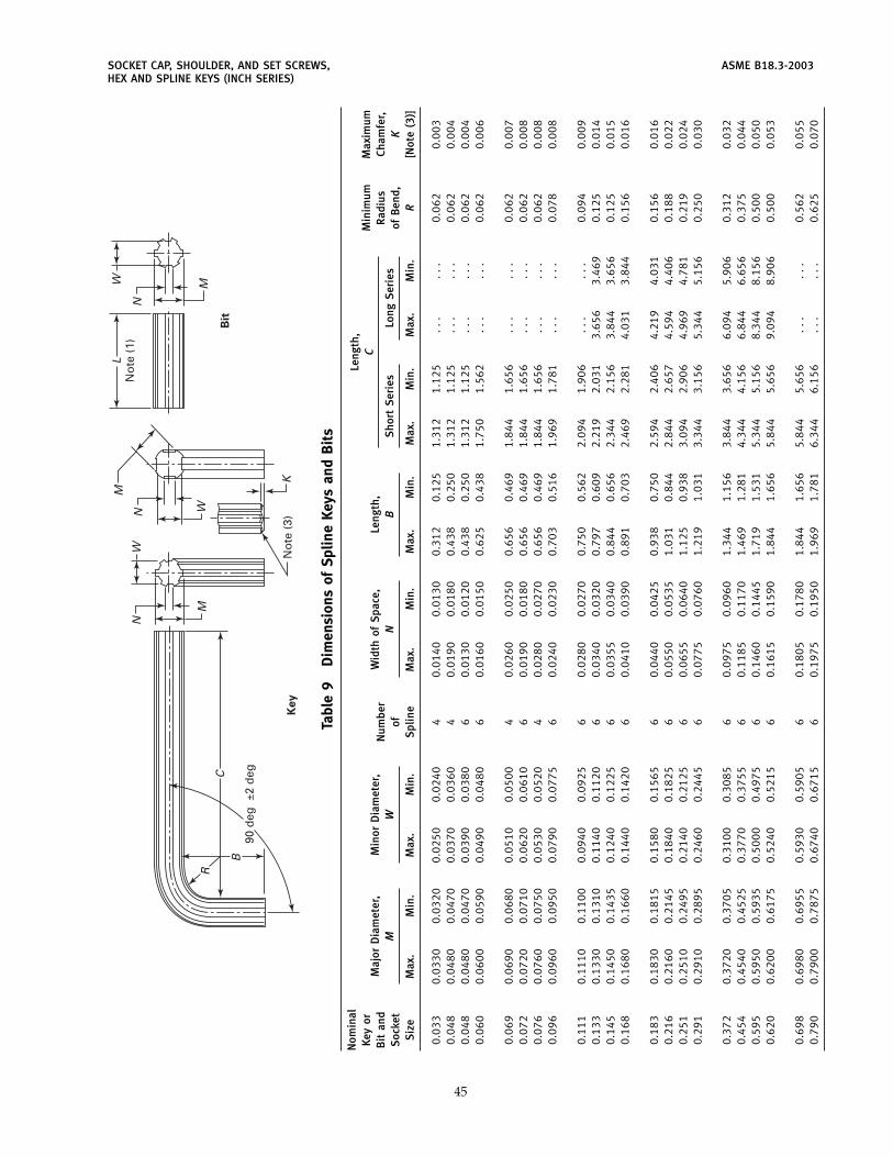
SOCKET CAP, SHOULDER, AND SET SCREWS, ASME B18.3-2003HEX AND SPLINE KEYS (INCH SERIES)
Key
Bit
W
M
N
MWL
No
te (
1)N
N
M
K
C
90 d
eg ±
2 d
eg
No
te (
3)
B
RW
Tabl
e9
Dim
ensi
ons
ofSp
line
Keys
and
Bit
s
Nom
inal
Leng
th,
Key
orM
inim
umM
axim
umC
Maj
orD
iam
eter
,M
inor
Dia
met
er,
Wid
thof
Spa
ce,
Leng
th,
Bit
and
Num
ber
Rad
ius
Cham
fer,
MW
NB
Sho
rtS
erie
sLo
ngS
erie
sS
ocke
tof
ofB
end,
KS
ize
Max
.M
in.
Max
.M
in.
Spl
ine
Max
.M
in.
Max
.M
in.
Max
.M
in.
Max
.M
in.
R[N
ote
(3)]
0.03
30.
0330
0.03
200.
0250
0.02
404
0.01
400.
0130
0.31
20.
125
1.31
21.
125
...
...
0.06
20.
003
0.04
80.
0480
0.04
700.
0370
0.03
604
0.01
900.
0180
0.43
80.
250
1.31
21.
125
...
...
0.06
20.
004
0.04
80.
0480
0.04
700.
0390
0.03
806
0.01
300.
0120
0.43
80.
250
1.31
21.
125
...
...
0.06
20.
004
0.06
00.
0600
0.05
900.
0490
0.04
806
0.01
600.
0150
0.62
50.
438
1.75
01.
562
...
...
0.06
20.
006
0.06
90.
0690
0.06
800.
0510
0.05
004
0.02
600.
0250
0.65
60.
469
1.84
41.
656
...
...
0.06
20.
007
0.07
20.
0720
0.07
100.
0620
0.06
106
0.01
900.
0180
0.65
60.
469
1.84
41.
656
...
...
0.06
20.
008
0.07
60.
0760
0.07
500.
0530
0.05
204
0.02
800.
0270
0.65
60.
469
1.84
41.
656
...
...
0.06
20.
008
0.09
60.
0960
0.09
500.
0790
0.07
756
0.02
400.
0230
0.70
30.
516
1.96
91.
781
...
...
0.07
80.
008
0.11
10.
1110
0.11
000.
0940
0.09
256
0.02
800.
0270
0.75
00.
562
2.09
41.
906
...
...
0.09
40.
009
0.13
30.
1330
0.13
100.
1140
0.11
206
0.03
400.
0320
0.79
70.
609
2.21
92.
031
3.65
63.
469
0.12
50.
014
0.14
50.
1450
0.14
350.
1240
0.12
256
0.03
550.
0340
0.84
40.
656
2.34
42.
156
3.84
43.
656
0.12
50.
015
0.16
80.
1680
0.16
600.
1440
0.14
206
0.04
100.
0390
0.89
10.
703
2.46
92.
281
4.03
13.
844
0.15
60.
016
0.18
30.
1830
0.18
150.
1580
0.15
656
0.04
400.
0425
0.93
80.
750
2.59
42.
406
4.21
94.
031
0.15
60.
016
0.21
60.
2160
0.21
450.
1840
0.18
256
0.05
500.
0535
1.03
10.
844
2.84
42.
657
4.59
44.
406
0.18
80.
022
0.25
10.
2510
0.24
950.
2140
0.21
256
0.06
550.
0640
1.12
50.
938
3.09
42.
906
4.96
94.
781
0.21
90.
024
0.29
10.
2910
0.28
950.
2460
0.24
456
0.07
750.
0760
1.21
91.
031
3.34
43.
156
5.34
45.
156
0.25
00.
030
0.37
20.
3720
0.37
050.
3100
0.30
856
0.09
750.
0960
1.34
41.
156
3.84
43.
656
6.09
45.
906
0.31
20.
032
0.45
40.
4540
0.45
250.
3770
0.37
556
0.11
850.
1170
1.46
91.
281
4.34
44.
156
6.84
46.
656
0.37
50.
044
0.59
50.
5950
0.59
350.
5000
0.49
756
0.14
600.
1445
1.71
91.
531
5.34
45.
156
8.34
48.
156
0.50
00.
050
0.62
00.
6200
0.61
750.
5240
0.52
156
0.16
150.
1590
1.84
41.
656
5.84
45.
656
9.09
48.
906
0.50
00.
053
0.69
80.
6980
0.69
550.
5930
0.59
056
0.18
050.
1780
1.84
41.
656
5.84
45.
656
...
...
0.56
20.
055
0.79
00.
7900
0.78
750.
6740
0.67
156
0.19
750.
1950
1.96
91.
781
6.34
46.
156
...
...
0.62
50.
070
45
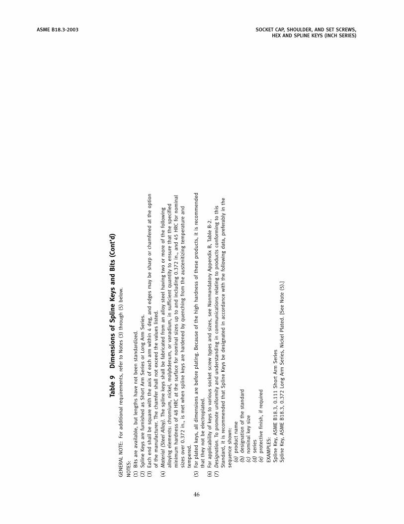
ASME B18.3-2003 SOCKET CAP, SHOULDER, AND SET SCREWS,HEX AND SPLINE KEYS (INCH SERIES)
Tabl
e9
Dim
ensi
ons
ofSp
line
Keys
and
Bit
s(C
ont’
d)G
ENER
AL
NO
TE:
For
add
itio
nal
requ
irem
ents
,re
fer
toN
otes
(3)
thro
ugh
(5)
bel
ow.
NO
TES
:(1
)B
its
are
avai
labl
e,b
utle
ngth
sha
veno
tb
een
stan
dar
diz
ed.
(2)
Spl
ine
Keys
are
furn
ishe
das
Sho
rtA
rmS
erie
sor
Long
Arm
Ser
ies.
(3)
Each
end
shal
lb
esq
uare
wit
hth
eax
isof
each
arm
wit
hin
4d
eg,
and
edge
sm
ayb
esh
arp
orch
amfe
red
atth
eop
tion
ofth
em
anuf
actu
rer.
The
cham
fer
shal
lno
tex
ceed
the
valu
eslis
ted
.(4
)M
ater
ial
(Ste
elAl
loy)
.Th
esp
line
keys
shal
lb
efa
bri
cate
dfr
oman
allo
yst
eel
havi
ngtw
oor
mor
eof
the
follo
win
gal
loyi
ngel
emen
ts:
chro
miu
m,
nick
el,
mol
ybd
enum
,or
vana
diu
m,
insu
ffic
ient
quan
tity
toen
sure
that
the
spec
ified
min
imum
hard
ness
of48
HRC
atth
esu
rfac
efo
rno
min
alsi
zes
upto
and
incl
udin
g0.
372
in.,
and
45H
RCfo
rno
min
alsi
zes
over
0.37
2in
.,is
met
whe
nsp
line
keys
are
hard
ened
byqu
ench
ing
from
the
aust
enit
izin
gte
mpe
ratu
rean
dte
mpe
red
.(5
)Fo
rpl
ated
keys
,al
ld
imen
sion
sar
eb
efor
epl
atin
g.B
ecau
seof
the
high
hard
ness
ofth
ese
prod
ucts
,it
isre
com
men
ded
that
they
not
be
elec
trop
late
d.
(6)
For
appl
icab
ility
ofke
ysto
vari
ous
sock
etsc
rew
type
san
dsi
zes,
see
Non
man
dat
ory
App
end
ixB
,Ta
ble
B-2
.(7
)D
esig
natio
n.To
prom
ote
unifo
rmit
yan
dun
der
stan
din
gin
com
mun
icat
ions
rela
ting
topr
oduc
tsco
nfor
min
gto
this
Sta
ndar
d,
itis
reco
mm
end
edth
atS
plin
eKe
ysb
ed
esig
nate
din
acco
rdan
cew
ith
the
follo
win
gd
ata,
pref
erab
lyin
the
sequ
ence
show
n:(a
)pr
oduc
tna
me
(b)
des
igna
tion
ofth
est
and
ard
(c)
nom
inal
key
size
(d)
seri
es(e
)pr
otec
tive
finis
h,if
requ
ired
EXA
MPL
ES:
Spl
ine
Key,
ASM
EB
18.3
,0.
111
Sho
rtA
rmS
erie
sS
plin
eKe
y,A
SME
B18
.3,
0.37
2Lo
ngA
rmS
erie
s,N
icke
lPl
ated
.[S
eeN
ote
(5).
]
46
ASME B18.3-2003
MANDATORY APPENDIX IGAGES AND GAGING FOR HEXAGON AND SPLINE SOCKETS
I-1 GENERAL
The gages specified herein are intended for use indetermining the acceptability of sockets up to andincluding the 1 in. nominal hexagon socket size andthe 0.790 in. nominal spline socket size. Suitability ofhexagon sockets of nominal sizes larger than 1 in. shallbe determined by direct measurement for various techni-cal and economic reasons. For dimensions of gages forsockets and spline sockets, see Tables I-1 and I-2.
I-2 GAGING OF HEXAGON SOCKETS
Hexagon sockets in screws shall allow the GO memberof the gage to enter freely to the minimum key engage-ment depths specified in the dimensional tables for therespective screw types.
For hexagon sockets that are not chamfered, the NOTGO gage member shall not enter any of the three across-flat dimensions of the socket for nominal socket sizesof 1⁄8 in. and larger, and the hexagonal NOT GO gagemember shall not enter the socket for nominal socketsizes smaller than 1⁄8 in.
For chamfered hexagon sockets, the NOT GO gagemember shall be permitted to enter only to a depthequivalent to 10% of the nominal socket size for nominalsocket sizes up to and including 1⁄16 in., and to 7.5% ofthe nominal socket sizes for larger sockets.
47
I-3 GAGING OF SPLINE SOCKETS
Spline sockets in screws shall allow the GO member ofthe gage to enter freely to the minimum key engagementdepths specified in the dimensional tables for the respec-tive screw types.
For spline sockets that are not chamfered, the NOTGO gage member shall not enter the socket.
For chamfered spline sockets, the NOT GO gage mem-ber shall be permitted to enter only to a depth equivalentto 10% of the nominal socket size for nominal socketsizes up to and including 0.060 in., and to 7.5% of thenominal socket size for larger sockets.
I-4 GAGES
Gages shall be made from any grade of steel, through-hardened and tempered to 60 HRC minimum.
The form of hexagonal and spline gage members shallbe within the tolerance zone specified. See ASMEY14.5M, Engineering Drawing and Related Documenta-tion Practices, Dimensioning and Tolerancing.
The surface roughness on hexagon and spline flatsshall be 8 �in. (arithmetical average) maximum. SeeASME B46.1, Surface Texture.
The gage handles shall conform to ASME B47.1, GageBlanks.
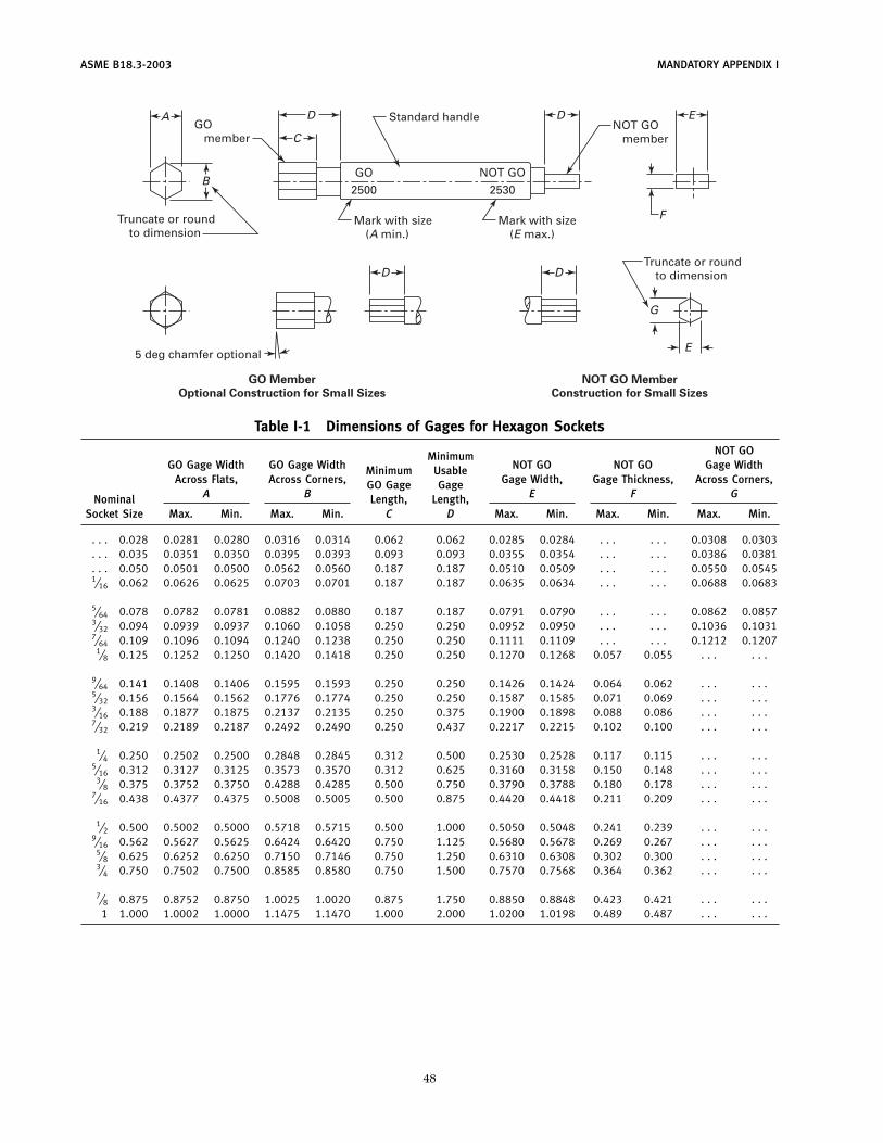
ASME B18.3-2003 MANDATORY APPENDIX I
NOT GO Member
Construction for Small Sizes
GO Member
Optional Construction for Small Sizes
A
B
D
D D
G
E
D E
F
CGO member
GO
2500
NOT GO
2530
Truncate or roundto dimension
5 deg chamfer optional
Mark with size(A min.)
Mark with size(E max.)
NOT GO member
Truncate or roundto dimension
Standard handle
Table I-1 Dimensions of Gages for Hexagon Sockets
NOT GOMinimumGO Gage Width GO Gage Width NOT GO NOT GO Gage WidthMinimum Usable
Across Flats, Across Corners, Gage Width, Gage Thickness, Across Corners,GO Gage GageA B E F GNominal Length, Length,
Socket Size Max. Min. Max. Min. C D Max. Min. Max. Min. Max. Min.
. . . 0.028 0.0281 0.0280 0.0316 0.0314 0.062 0.062 0.0285 0.0284 . . . . . . 0.0308 0.0303
. . . 0.035 0.0351 0.0350 0.0395 0.0393 0.093 0.093 0.0355 0.0354 . . . . . . 0.0386 0.0381
. . . 0.050 0.0501 0.0500 0.0562 0.0560 0.187 0.187 0.0510 0.0509 . . . . . . 0.0550 0.05451⁄16 0.062 0.0626 0.0625 0.0703 0.0701 0.187 0.187 0.0635 0.0634 . . . . . . 0.0688 0.0683
5⁄64 0.078 0.0782 0.0781 0.0882 0.0880 0.187 0.187 0.0791 0.0790 . . . . . . 0.0862 0.08573⁄32 0.094 0.0939 0.0937 0.1060 0.1058 0.250 0.250 0.0952 0.0950 . . . . . . 0.1036 0.10317⁄64 0.109 0.1096 0.1094 0.1240 0.1238 0.250 0.250 0.1111 0.1109 . . . . . . 0.1212 0.1207
1⁄8 0.125 0.1252 0.1250 0.1420 0.1418 0.250 0.250 0.1270 0.1268 0.057 0.055 . . . . . .
9⁄64 0.141 0.1408 0.1406 0.1595 0.1593 0.250 0.250 0.1426 0.1424 0.064 0.062 . . . . . .5⁄32 0.156 0.1564 0.1562 0.1776 0.1774 0.250 0.250 0.1587 0.1585 0.071 0.069 . . . . . .3⁄16 0.188 0.1877 0.1875 0.2137 0.2135 0.250 0.375 0.1900 0.1898 0.088 0.086 . . . . . .7⁄32 0.219 0.2189 0.2187 0.2492 0.2490 0.250 0.437 0.2217 0.2215 0.102 0.100 . . . . . .
1⁄4 0.250 0.2502 0.2500 0.2848 0.2845 0.312 0.500 0.2530 0.2528 0.117 0.115 . . . . . .5⁄16 0.312 0.3127 0.3125 0.3573 0.3570 0.312 0.625 0.3160 0.3158 0.150 0.148 . . . . . .
3⁄8 0.375 0.3752 0.3750 0.4288 0.4285 0.500 0.750 0.3790 0.3788 0.180 0.178 . . . . . .7⁄16 0.438 0.4377 0.4375 0.5008 0.5005 0.500 0.875 0.4420 0.4418 0.211 0.209 . . . . . .
1⁄2 0.500 0.5002 0.5000 0.5718 0.5715 0.500 1.000 0.5050 0.5048 0.241 0.239 . . . . . .9⁄16 0.562 0.5627 0.5625 0.6424 0.6420 0.750 1.125 0.5680 0.5678 0.269 0.267 . . . . . .
5⁄8 0.625 0.6252 0.6250 0.7150 0.7146 0.750 1.250 0.6310 0.6308 0.302 0.300 . . . . . .3⁄4 0.750 0.7502 0.7500 0.8585 0.8580 0.750 1.500 0.7570 0.7568 0.364 0.362 . . . . . .
7⁄8 0.875 0.8752 0.8750 1.0025 1.0020 0.875 1.750 0.8850 0.8848 0.423 0.421 . . . . . .1 1.000 1.0002 1.0000 1.1475 1.1470 1.000 2.000 1.0200 1.0198 0.489 0.487 . . . . . .
48
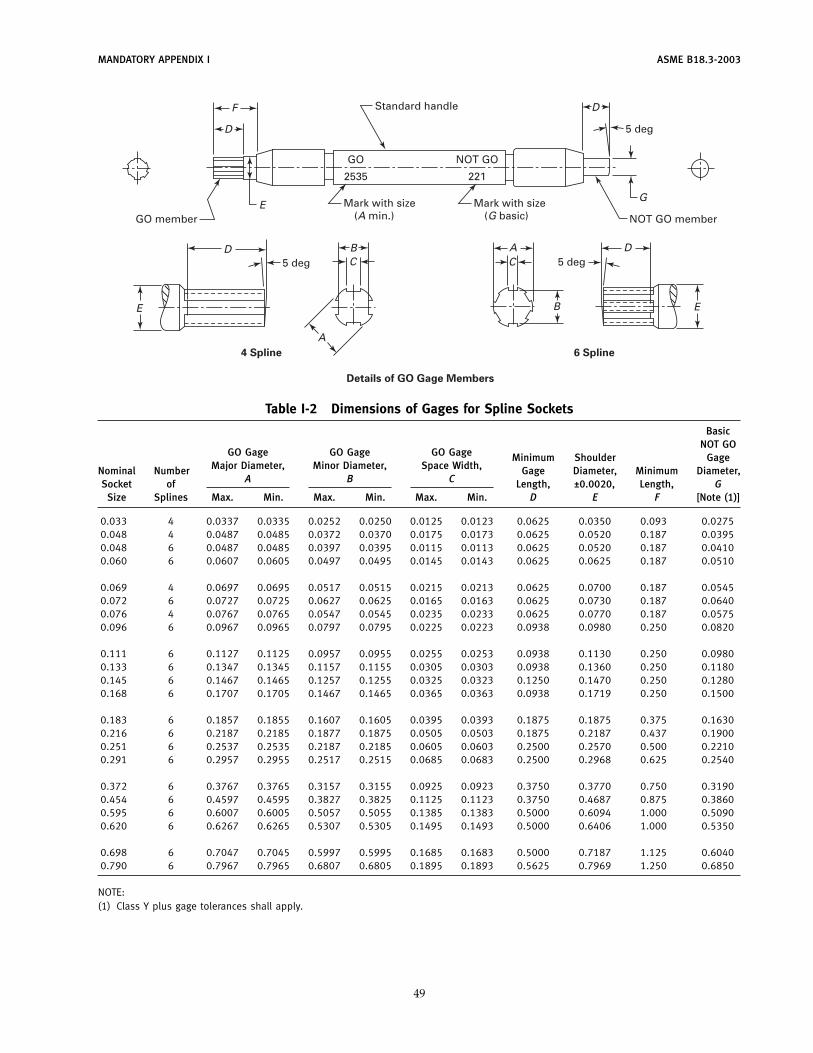
MANDATORY APPENDIX I ASME B18.3-2003
Details of GO Gage Members
4 Spline 6 Spline
D
D
E
F
B
D
G
AC
B
C
A
Mark with size(A min.)
Standard handle
5 deg
5 deg
GO
2535
NOT GO
NOT GO member
221
5 deg
GO memberMark with size
(G basic)
D
EE
Table I-2 Dimensions of Gages for Spline Sockets
BasicNOT GO
GO Gage GO Gage GO Gage Minimum Shoulder GageMajor Diameter, Minor Diameter, Space Width,Nominal Number Gage Diameter, Minimum Diameter,
A B CSocket of Length, ±0.0020, Length, GSize Splines Max. Min. Max. Min. Max. Min. D E F [Note (1)]
0.033 4 0.0337 0.0335 0.0252 0.0250 0.0125 0.0123 0.0625 0.0350 0.093 0.02750.048 4 0.0487 0.0485 0.0372 0.0370 0.0175 0.0173 0.0625 0.0520 0.187 0.03950.048 6 0.0487 0.0485 0.0397 0.0395 0.0115 0.0113 0.0625 0.0520 0.187 0.04100.060 6 0.0607 0.0605 0.0497 0.0495 0.0145 0.0143 0.0625 0.0625 0.187 0.0510
0.069 4 0.0697 0.0695 0.0517 0.0515 0.0215 0.0213 0.0625 0.0700 0.187 0.05450.072 6 0.0727 0.0725 0.0627 0.0625 0.0165 0.0163 0.0625 0.0730 0.187 0.06400.076 4 0.0767 0.0765 0.0547 0.0545 0.0235 0.0233 0.0625 0.0770 0.187 0.05750.096 6 0.0967 0.0965 0.0797 0.0795 0.0225 0.0223 0.0938 0.0980 0.250 0.0820
0.111 6 0.1127 0.1125 0.0957 0.0955 0.0255 0.0253 0.0938 0.1130 0.250 0.09800.133 6 0.1347 0.1345 0.1157 0.1155 0.0305 0.0303 0.0938 0.1360 0.250 0.11800.145 6 0.1467 0.1465 0.1257 0.1255 0.0325 0.0323 0.1250 0.1470 0.250 0.12800.168 6 0.1707 0.1705 0.1467 0.1465 0.0365 0.0363 0.0938 0.1719 0.250 0.1500
0.183 6 0.1857 0.1855 0.1607 0.1605 0.0395 0.0393 0.1875 0.1875 0.375 0.16300.216 6 0.2187 0.2185 0.1877 0.1875 0.0505 0.0503 0.1875 0.2187 0.437 0.19000.251 6 0.2537 0.2535 0.2187 0.2185 0.0605 0.0603 0.2500 0.2570 0.500 0.22100.291 6 0.2957 0.2955 0.2517 0.2515 0.0685 0.0683 0.2500 0.2968 0.625 0.2540
0.372 6 0.3767 0.3765 0.3157 0.3155 0.0925 0.0923 0.3750 0.3770 0.750 0.31900.454 6 0.4597 0.4595 0.3827 0.3825 0.1125 0.1123 0.3750 0.4687 0.875 0.38600.595 6 0.6007 0.6005 0.5057 0.5055 0.1385 0.1383 0.5000 0.6094 1.000 0.50900.620 6 0.6267 0.6265 0.5307 0.5305 0.1495 0.1493 0.5000 0.6406 1.000 0.5350
0.698 6 0.7047 0.7045 0.5997 0.5995 0.1685 0.1683 0.5000 0.7187 1.125 0.60400.790 6 0.7967 0.7965 0.6807 0.6805 0.1895 0.1893 0.5625 0.7969 1.250 0.6850
NOTE:(1) Class Y plus gage tolerances shall apply.
49
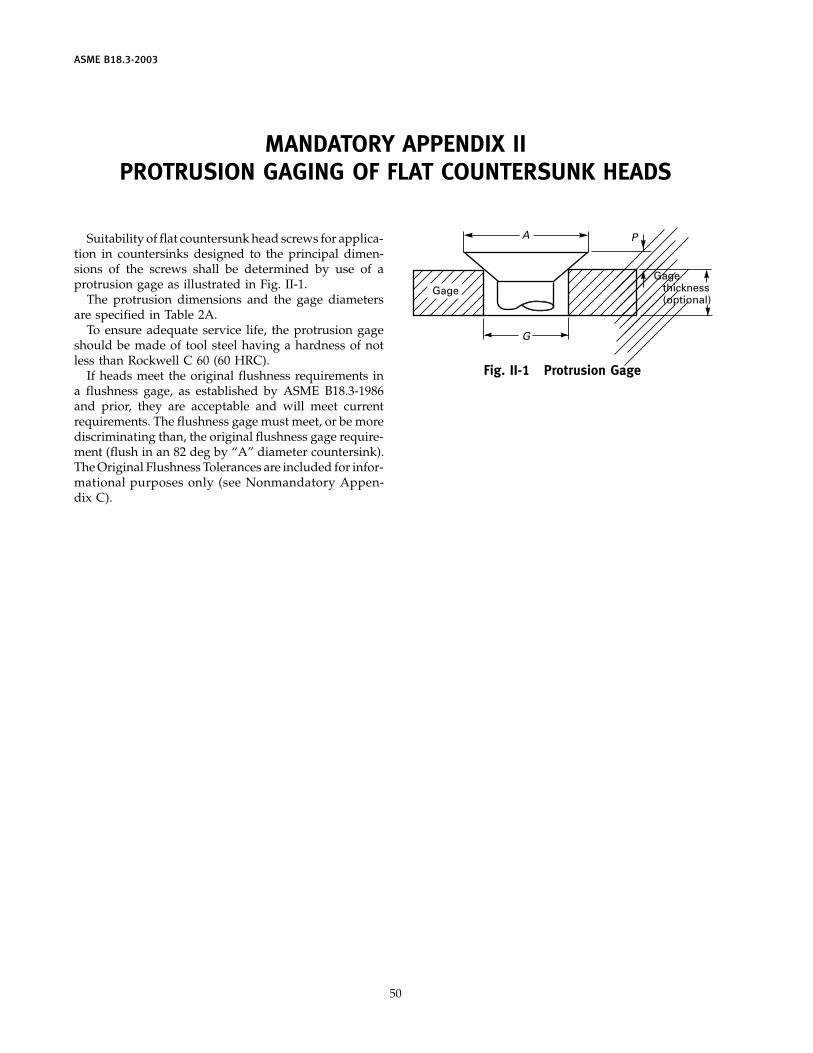
ASME B18.3-2003
MANDATORY APPENDIX IIPROTRUSION GAGING OF FLAT COUNTERSUNK HEADS
Suitability of flat countersunk head screws for applica-tion in countersinks designed to the principal dimen-sions of the screws shall be determined by use of aprotrusion gage as illustrated in Fig. II-1.
The protrusion dimensions and the gage diametersare specified in Table 2A.
To ensure adequate service life, the protrusion gageshould be made of tool steel having a hardness of notless than Rockwell C 60 (60 HRC).
If heads meet the original flushness requirements ina flushness gage, as established by ASME B18.3-1986and prior, they are acceptable and will meet currentrequirements. The flushness gage must meet, or be morediscriminating than, the original flushness gage require-ment (flush in an 82 deg by “A” diameter countersink).The Original Flushness Tolerances are included for infor-mational purposes only (see Nonmandatory Appen-dix C).
50
Gage thickness(optional)
A
G
P
Gage
Fig. II-1 Protrusion Gage
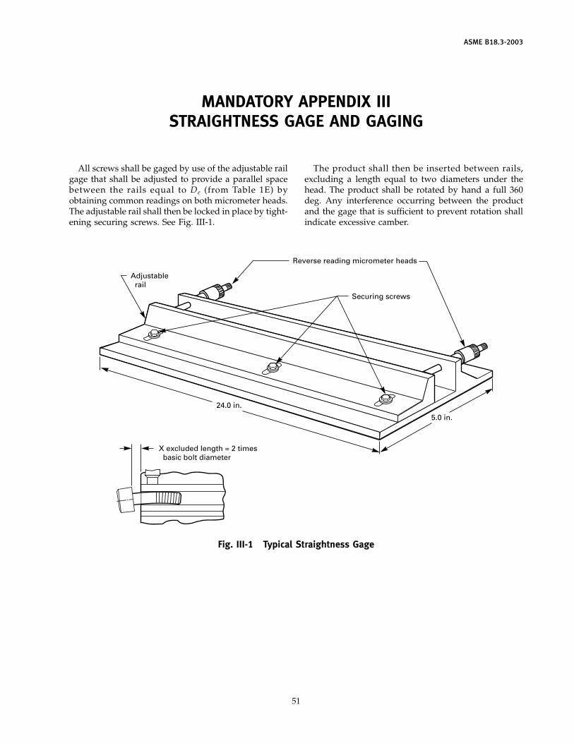
ASME B18.3-2003
MANDATORY APPENDIX IIISTRAIGHTNESS GAGE AND GAGING
All screws shall be gaged by use of the adjustable railgage that shall be adjusted to provide a parallel spacebetween the rails equal to De (from Table 1E) byobtaining common readings on both micrometer heads.The adjustable rail shall then be locked in place by tight-ening securing screws. See Fig. III-1.
Securing screws
5.0 in.
24.0 in.
X excluded length = 2 times basic bolt diameter
Reverse reading micrometer heads
Adjustable rail
Fig. III-1 Typical Straightness Gage
51
The product shall then be inserted between rails,excluding a length equal to two diameters under thehead. The product shall be rotated by hand a full 360deg. Any interference occurring between the productand the gage that is sufficient to prevent rotation shallindicate excessive camber.
ASME B18.3-2003
NONMANDATORY APPENDIX ADRILL AND COUNTERBORE SIZES FOR SOCKET HEAD CAP
SCREWS
Table A-1 appears on the following page.
52
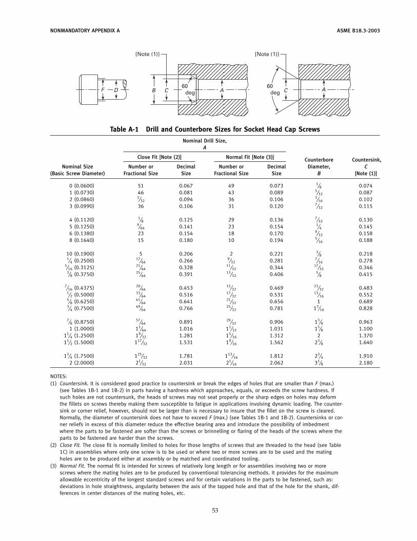
NONMANDATORY APPENDIX A ASME B18.3-2003
D C ABF
[Note (1)] [Note (1)]
60deg
60deg C A
Table A-1 Drill and Counterbore Sizes for Socket Head Cap Screws
Nominal Drill Size,A
Close Fit [Note (2)] Normal Fit [Note (3)] Counterbore Countersink,Nominal Size Number or Decimal Number or Decimal Diameter, C
(Basic Screw Diameter) Fractional Size Size Fractional Size Size B [Note (1)]
0 (0.0600) 51 0.067 49 0.073 1⁄8 0.0741 (0.0730) 46 0.081 43 0.089 5⁄32 0.0872 (0.0860) 3⁄32 0.094 36 0.106 3⁄16 0.1023 (0.0990) 36 0.106 31 0.120 7⁄32 0.115
4 (0.1120) 1⁄8 0.125 29 0.136 7⁄32 0.1305 (0.1250) 9⁄64 0.141 23 0.154 1⁄4 0.1456 (0.1380) 23 0.154 18 0.170 9⁄32 0.1588 (0.1640) 15 0.180 10 0.194 5⁄16 0.188
10 (0.1900) 5 0.206 2 0.221 3⁄8 0.2181⁄4 (0.2500) 17⁄64 0.266 9⁄32 0.281 7⁄16 0.278
5⁄16 (0.3125) 21⁄64 0.328 11⁄32 0.344 17⁄32 0.3463⁄8 (0.3750) 25⁄64 0.391 13⁄32 0.406 5⁄8 0.415
7⁄16 (0.4375) 29⁄64 0.453 15⁄32 0.469 23⁄32 0.4831⁄2 (0.5000) 33⁄64 0.516 17⁄32 0.531 13⁄16 0.5525⁄8 (0.6250) 41⁄64 0.641 21⁄32 0.656 1 0.6893⁄4 (0.7500) 49⁄64 0.766 25⁄32 0.781 13⁄16 0.828
7⁄8 (0.8750) 57⁄64 0.891 29⁄32 0.906 13⁄8 0.9631 (1.0000) 11⁄64 1.016 11⁄32 1.031 15⁄8 1.100
11⁄4 (1.2500) 19⁄32 1.281 15⁄16 1.312 2 1.37011⁄2 (1.5000) 117⁄32 1.531 19⁄16 1.562 23⁄8 1.640
13⁄4 (1.7500) 125⁄32 1.781 113⁄16 1.812 23⁄4 1.9102 (2.0000) 21⁄32 2.031 21⁄16 2.062 31⁄8 2.180
NOTES:(1) Countersink. It is considered good practice to countersink or break the edges of holes that are smaller than F (max.)
(see Tables 1B-1 and 1B-2) in parts having a hardness which approaches, equals, or exceeds the screw hardness. Ifsuch holes are not countersunk, the heads of screws may not seat properly or the sharp edges on holes may deformthe fillets on screws thereby making them susceptible to fatigue in applications involving dynamic loading. The counter-sink or corner relief, however, should not be larger than is necessary to insure that the fillet on the screw is cleared.Normally, the diameter of countersink does not have to exceed F (max.) (see Tables 1B-1 and 1B-2). Countersinks or cor-ner reliefs in excess of this diameter reduce the effective bearing area and introduce the possibility of imbedmentwhere the parts to be fastened are softer than the screws or brinnelling or flaring of the heads of the screws where theparts to be fastened are harder than the screws.
(2) Close Fit. The close fit is normally limited to holes for those lengths of screws that are threaded to the head (see Table1C) in assemblies where only one screw is to be used or where two or more screws are to be used and the matingholes are to be produced either at assembly or by matched and coordinated tooling.
(3) Normal Fit. The normal fit is intended for screws of relatively long length or for assemblies involving two or morescrews where the mating holes are to be produced by conventional tolerancing methods. It provides for the maximumallowable eccentricity of the longest standard screws and for certain variations in the parts to be fastened, such as:deviations in hole straightness, angularity between the axis of the tapped hole and that of the hole for the shank, dif-ferences in center distances of the mating holes, etc.
53
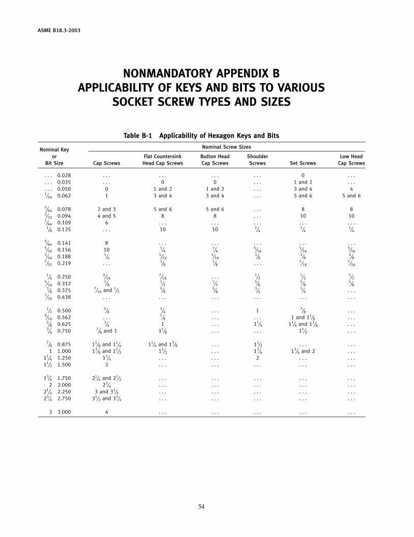
ASME B18.3-2003
NONMANDATORY APPENDIX BAPPLICABILITY OF KEYS AND BITS TO VARIOUS
SOCKET SCREW TYPES AND SIZES
Table B-1 Applicability of Hexagon Keys and Bits
Nominal Screw SizesNominal Keyor Flat Countersink Button Head Shoulder Low Head
Bit Size Cap Screws Head Cap Screws Cap Screws Screws Set Screws Cap Screws
. . . 0.028 . . . . . . . . . . . . 0 . . .
. . . 0.035 . . . 0 0 . . . 1 and 2 . . .
. . . 0.050 0 1 and 2 1 and 2 . . . 3 and 4 41⁄16 0.062 1 3 and 4 3 and 4 . . . 5 and 6 5 and 6
5⁄64 0.078 2 and 3 5 and 6 5 and 6 . . . 8 83⁄32 0.094 4 and 5 8 8 . . . 10 107⁄64 0.109 6 . . . . . . . . . . . . . . .
1⁄8 0.125 . . . 10 10 1⁄41⁄4
1⁄4
9⁄64 0.141 8 . . . . . . . . . . . . . . .5⁄32 0.156 10 1⁄4
1⁄45⁄16
5⁄165⁄16
3⁄16 0.188 1⁄45⁄16
5⁄163⁄8
3⁄83⁄8
7⁄32 0.219 . . . 3⁄83⁄8 . . . 7⁄16
7⁄16
1⁄4 0.250 5⁄167⁄16 . . . 1⁄2
1⁄21⁄2
5⁄16 0.312 3⁄81⁄2
1⁄25⁄8
5⁄85⁄8
3⁄8 0.375 7⁄16 and 1⁄25⁄8
5⁄83⁄4
3⁄4 . . .7⁄16 0.438 . . . . . . . . . . . . . . . . . .
1⁄2 0.500 5⁄83⁄4 . . . 1 7⁄8 . . .
9⁄16 0.562 . . . 7⁄8 . . . . . . 1 and 11⁄8 . . .5⁄8 0.625 3⁄4 1 . . . 11⁄4 11⁄4 and 13⁄8 . . .3⁄4 0.750 7⁄8 and 1 11⁄8 . . . . . . 11⁄2 . . .
7⁄8 0.875 11⁄8 and 11⁄4 11⁄4 and 13⁄8 . . . 11⁄2 . . . . . .1 1.000 13⁄8 and 11⁄2 11⁄2 . . . 13⁄4 13⁄4 and 2 . . .
11⁄4 1.250 13⁄4 . . . . . . 2 . . . . . .11⁄2 1.500 2 . . . . . . . . . . . . . . .
13⁄4 1.750 21⁄4 and 21⁄2 . . . . . . . . . . . . . . .2 2.000 23⁄4 . . . . . . . . . . . . . . .
21⁄4 2.250 3 and 31⁄4 . . . . . . . . . . . . . . .23⁄4 2.750 31⁄2 and 33⁄4 . . . . . . . . . . . . . . .
3 3.000 4 . . . . . . . . . . . . . . .
54
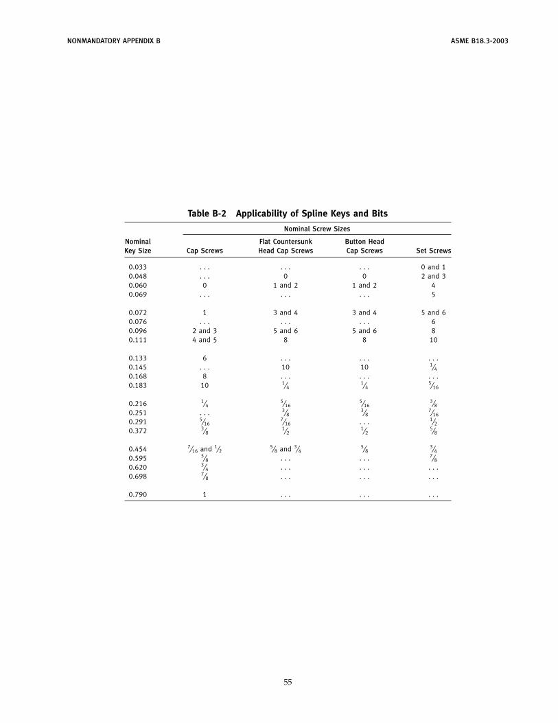
NONMANDATORY APPENDIX B ASME B18.3-2003
Table B-2 Applicability of Spline Keys and Bits
Nominal Screw Sizes
Nominal Flat Countersunk Button HeadKey Size Cap Screws Head Cap Screws Cap Screws Set Screws
0.033 . . . . . . . . . 0 and 10.048 . . . 0 0 2 and 30.060 0 1 and 2 1 and 2 40.069 . . . . . . . . . 5
0.072 1 3 and 4 3 and 4 5 and 60.076 . . . . . . . . . 60.096 2 and 3 5 and 6 5 and 6 80.111 4 and 5 8 8 10
0.133 6 . . . . . . . . .0.145 . . . 10 10 1⁄40.168 8 . . . . . . . . .0.183 10 1⁄4
1⁄45⁄16
0.216 1⁄45⁄16
5⁄163⁄8
0.251 . . . 3⁄83⁄8
7⁄16
0.291 5⁄167⁄16 . . . 1⁄2
0.372 3⁄81⁄2
1⁄25⁄8
0.454 7⁄16 and 1⁄25⁄8 and 3⁄4
5⁄83⁄4
0.595 5⁄8 . . . . . . 7⁄80.620 3⁄4 . . . . . . . . .0.698 7⁄8 . . . . . . . . .
0.790 1 . . . . . . . . .
55
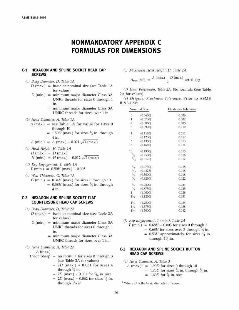
ASME B18.3-2003
NONMANDATORY APPENDIX CFORMULAS FOR DIMENSIONS
C-1 HEXAGON AND SPLINE SOCKET HEAD CAPSCREWS
(a) Body Diameter, D, Table 1AD (max.) p basic or nominal size (see Table 1A
for values)D (min.) p minimum major diameter Class 3A
UNRF threads for sizes 0 through 1in.
p minimum major diameter Class 3AUNRC threads for sizes over 1 in.
(b) Head Diameter, A, Table 1AA (max.) p see Table 1A for value for sizes 0
through 10p 1.50D (max.) for sizes 1⁄4 in. through
4 in.A (min.) p A (max.) − 0.021 �D (max.)
(c) Head Height, H, Table 1AH (max.) p D (max.)H (min.) p H (max.) − 0.012 �D (max.)
(d) Key Engagement, T, Table 1AT (min.) p 0.50H (max.) − 0.005
(e) Wall Thickness, G, Table 1AG (min.) p 0.34H (max.) for sizes 0 through 10
p 0.38H (max.) for sizes 1⁄4 in. through4 in.
C-2 HEXAGON AND SPLINE SOCKET FLATCOUNTERSUNK HEAD CAP SCREWS
(a) Body Diameter, D, Table 2AD (max.) p basic or nominal size (see Table 2A
for values)D (min.) p minimum major diameter Class 3A
UNRF threads for sizes 0 through 1in.
p minimum major diameter Class 3AUNRC threads for sizes over 1 in.
(b) Head Diameter, A, Table 2AA (max.)
Theor. Sharp p no formula for sizes 0 through 3(see Table 2A for values)
p 2D (max.) + 0.031 for sizes 4through 3⁄8 in.
p 2D (max.) − 0.031 for 7⁄16 in. sizep 2D (max.) − 0.062 for sizes 1⁄2 in.
through 11⁄2 in.
56
(c) Maximum Head Height, H, Table 2A
Hmax (ref.) pA (max.) − D (max.)
2cot 41 deg
(d) Head Protrusion, Table 2A. No formula (See Table2A for values).
(e) Original Flushness Tolerance. Prior to ASMEB18.3-1998:
Nominal Size Flushness Tolerance
0 (0.0600) 0.0061 (0.0730) 0.0072 (0.0860) 0.0083 (0.0990) 0.010
4 (0.1120) 0.0115 (0.1250) 0.0126 (0.1380) 0.0138 (0.1640) 0.014
10 (0.1900) 0.0151⁄4 (0.2500) 0.0165⁄16 (0.3125) 0.017
3⁄8 (0.3750) 0.0187⁄16 (0.4375) 0.0181⁄2 (0.5000) 0.0185⁄8 (0.6250) 0.022
3⁄4 (0.7500) 0.0247⁄8 (0.8750) 0.025
1 (1.0000) 0.02811⁄8 (1.1250) 0.031
11⁄4 (1.2500) 0.03513⁄8 (1.3750) 0.03811⁄2 (1.5000) 0.042
(f) Key Engagement, T (min.), Table 2AT (min.) p 0.68H − 0.005 for sizes 0 through 3
p 0.68H for sizes over 3 through 5⁄8 in.p 0.53H approximately for sizes 3⁄4 in.
through 11⁄2 in.
C-3 HEXAGON AND SPLINE SOCKET BUTTONHEAD CAP SCREWS
(a) Head Diameter, A, Table 3A (max.)1 p 1.90D for sizes 0 through 10
p 1.75D for sizes 1⁄4 in. through 1⁄2 in.p 1.60D for 5⁄8 in. size
1 Where D is the basic diameter of screw.
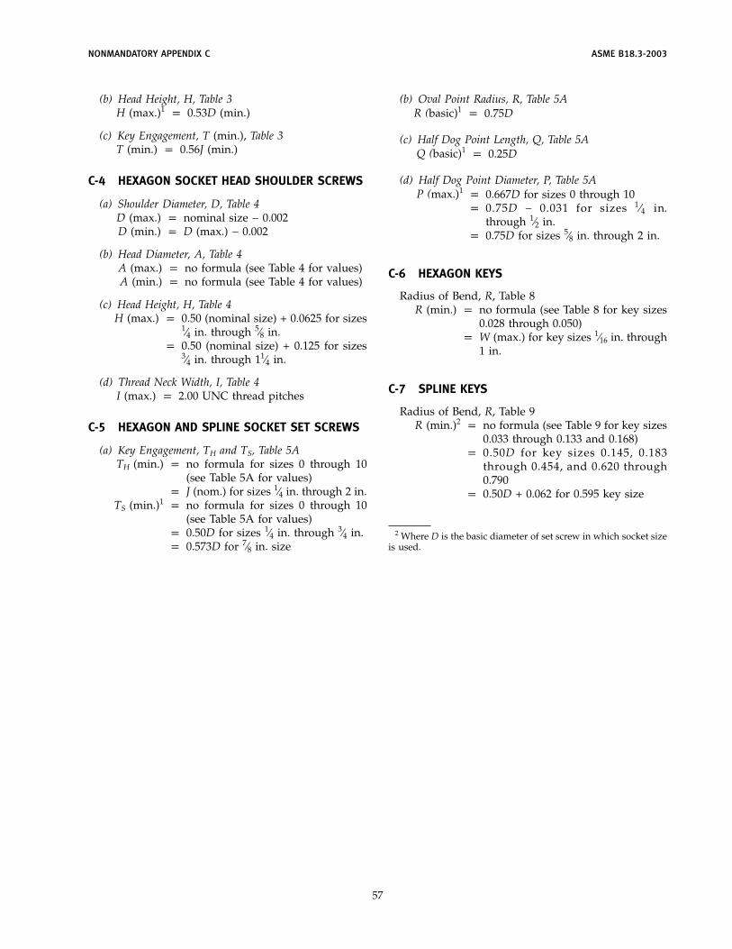
NONMANDATORY APPENDIX C ASME B18.3-2003
(b) Head Height, H, Table 3H (max.)1 p 0.53D (min.)
(c) Key Engagement, T (min.), Table 3T (min.) p 0.56J (min.)
C-4 HEXAGON SOCKET HEAD SHOULDER SCREWS
(a) Shoulder Diameter, D, Table 4D (max.) p nominal size − 0.002D (min.) p D (max.) − 0.002
(b) Head Diameter, A, Table 4A (max.) p no formula (see Table 4 for values)A (min.) p no formula (see Table 4 for values)
(c) Head Height, H, Table 4H (max.) p 0.50 (nominal size) + 0.0625 for sizes
1⁄4 in. through 5⁄8 in.p 0.50 (nominal size) + 0.125 for sizes
3⁄4 in. through 11⁄4 in.
(d) Thread Neck Width, I, Table 4I (max.) p 2.00 UNC thread pitches
C-5 HEXAGON AND SPLINE SOCKET SET SCREWS
(a) Key Engagement, TH and TS, Table 5ATH (min.) p no formula for sizes 0 through 10
(see Table 5A for values)p J (nom.) for sizes 1⁄4 in. through 2 in.
TS (min.)1 p no formula for sizes 0 through 10(see Table 5A for values)
p 0.50D for sizes 1⁄4 in. through 3⁄4 in.p 0.573D for 7⁄8 in. size
57
(b) Oval Point Radius, R, Table 5AR (basic)1 p 0.75D
(c) Half Dog Point Length, Q, Table 5AQ (basic)1 p 0.25D
(d) Half Dog Point Diameter, P, Table 5AP (max.)1 p 0.667D for sizes 0 through 10
p 0.75D − 0.031 for sizes 1⁄4 in.through 1⁄2 in.
p 0.75D for sizes 5⁄8 in. through 2 in.
C-6 HEXAGON KEYS
Radius of Bend, R, Table 8R (min.) p no formula (see Table 8 for key sizes
0.028 through 0.050)p W (max.) for key sizes 1⁄16 in. through
1 in.
C-7 SPLINE KEYS
Radius of Bend, R, Table 9R (min.)2 p no formula (see Table 9 for key sizes
0.033 through 0.133 and 0.168)p 0.50D for key sizes 0.145, 0.183
through 0.454, and 0.620 through0.790
p 0.50D + 0.062 for 0.595 key size
2 Where D is the basic diameter of set screw in which socket sizeis used.
ASME B18.3-2003
NONMANDATORY APPENDIX DHEXAGON AND SPLINE SOCKET HEAD CAP SCREWS
(1936 SERIES)
Prior to 1961, the 1936 Series of socket head capscrews were recognized as standard. The 1936 Seriesscrews are no longer stocked by screw manufacturersand are now available only on special order. The majordifferences between the 1936 Series screws and thepresent standard screws (1960 Series) are that, for somesizes, the 1936 Series had smaller head diameters and/or socket sizes and/or different thread lengths. Users
58
desiring additional information on the 1936 Seriesshould refer to Appendix IV of ASA B18.3-1961, orshould consult socket screw manufacturers.
In the event of an order, unless otherwise specified,the manufacturer may use the thread length and lengthtolerances for 1960 Series style Socket Cap Screws on1936 Series style Socket Cap Screws.
AMERICAN NATIONAL STANDARDS FOR BOLTS, NUTS, RIVETS, SCREWS,WASHERS, AND SIMILAR FASTENERS
Small Solid Rivets . . . . . . . . . . . . . . . . . . . . . . . . . . . . . . . . . . . . . . . . . . . . . . . . . . . . . . . . . . . . . . . . . . . . . . . . . . . . . . . . . . B18.1.1-1972 (R2001)Large Rivets . . . . . . . . . . . . . . . . . . . . . . . . . . . . . . . . . . . . . . . . . . . . . . . . . . . . . . . . . . . . . . . . . . . . . . . . . . . . . . . . . . . . . . . B18.1.2-1972 (R2001)Metric Small Solid Rivets . . . . . . . . . . . . . . . . . . . . . . . . . . . . . . . . . . . . . . . . . . . . . . . . . . . . . . . . . . . . . . . . . . . . . . . . . . .B18.1.3M-1983 (R2001)Square and Hex Bolts and Screws (Inch Series) . . . . . . . . . . . . . . . . . . . . . . . . . . . . . . . . . . . . . . . . . . . . . . . . . . . . . . . . . . . . . . . . . B18.2.1-1996Square and Hex Nuts (Inch Series) . . . . . . . . . . . . . . . . . . . . . . . . . . . . . . . . . . . . . . . . . . . . . . . . . . . . . . . . . . . . . . . . . . . . B18.2.2-1987 (R1999)Metric Hex Cap Screws . . . . . . . . . . . . . . . . . . . . . . . . . . . . . . . . . . . . . . . . . . . . . . . . . . . . . . . . . . . . . . . . . . . . . . . . . . . . . . . . . . B18.2.3.1M-1999Metric Formed Hex Screws . . . . . . . . . . . . . . . . . . . . . . . . . . . . . . . . . . . . . . . . . . . . . . . . . . . . . . . . . . . . . . . . . . . . . . . . B18.2.3.2M-1979 (R1995)Metric Heavy Hex Screws . . . . . . . . . . . . . . . . . . . . . . . . . . . . . . . . . . . . . . . . . . . . . . . . . . . . . . . . . . . . . . . . . . . . . . . . . B18.2.3.3M-1979 (R2001)Metric Hex Flange Screws . . . . . . . . . . . . . . . . . . . . . . . . . . . . . . . . . . . . . . . . . . . . . . . . . . . . . . . . . . . . . . . . . . . . . . . . . . . . . . . . B18.2.3.4M-2001Metric Hex Bolts . . . . . . . . . . . . . . . . . . . . . . . . . . . . . . . . . . . . . . . . . . . . . . . . . . . . . . . . . . . . . . . . . . . . . . . . . . . . . . . . B18.2.3.5M-1979 (R2001)Metric Heavy Hex Bolts . . . . . . . . . . . . . . . . . . . . . . . . . . . . . . . . . . . . . . . . . . . . . . . . . . . . . . . . . . . . . . . . . . . . . . . . . . . B18.2.3.6M-1979 (R2001)Metric Heavy Hex Structural Bolts . . . . . . . . . . . . . . . . . . . . . . . . . . . . . . . . . . . . . . . . . . . . . . . . . . . . . . . . . . . . . . . . . . B18.2.3.7M-1979 (R2001)Metric Hex Lag Screws . . . . . . . . . . . . . . . . . . . . . . . . . . . . . . . . . . . . . . . . . . . . . . . . . . . . . . . . . . . . . . . . . . . . . . . . . . . B18.2.3.8M-1981 (R1999)Metric Heavy Hex Flange Screws . . . . . . . . . . . . . . . . . . . . . . . . . . . . . . . . . . . . . . . . . . . . . . . . . . . . . . . . . . . . . . . . . . . . . . . . . . B18.2.3.9M-2001Square Head Bolts (Metric Series) . . . . . . . . . . . . . . . . . . . . . . . . . . . . . . . . . . . . . . . . . . . . . . . . . . . . . . . . . . . . . . . . . B18.2.3.10M-1996 (R2003)Metric Hex Nuts, Style 1 . . . . . . . . . . . . . . . . . . . . . . . . . . . . . . . . . . . . . . . . . . . . . . . . . . . . . . . . . . . . . . . . . . . . . . . . . . . . . . . . . B18.2.4.1M-2002Metric Hex Nuts, Style 2 . . . . . . . . . . . . . . . . . . . . . . . . . . . . . . . . . . . . . . . . . . . . . . . . . . . . . . . . . . . . . . . . . . . . . . . . . . B18.2.4.2M-1979 (R1995)Metric Slotted Hex Nuts . . . . . . . . . . . . . . . . . . . . . . . . . . . . . . . . . . . . . . . . . . . . . . . . . . . . . . . . . . . . . . . . . . . . . . . . . . B18.2.4.3M-1979 (R2001)Metric Hex Flange Nuts . . . . . . . . . . . . . . . . . . . . . . . . . . . . . . . . . . . . . . . . . . . . . . . . . . . . . . . . . . . . . . . . . . . . . . . . . . . B18.2.4.4M-1982 (R1999)Metric Hex Jam Nuts . . . . . . . . . . . . . . . . . . . . . . . . . . . . . . . . . . . . . . . . . . . . . . . . . . . . . . . . . . . . . . . . . . . . . . . . . . . . . B18.2.4.5M-1979 (R2003)Metric Heavy Hex Nuts . . . . . . . . . . . . . . . . . . . . . . . . . . . . . . . . . . . . . . . . . . . . . . . . . . . . . . . . . . . . . . . . . . . . . . . . . . . B18.2.4.6M-1979 (R2003)Fasteners for Use in Structural Applications . . . . . . . . . . . . . . . . . . . . . . . . . . . . . . . . . . . . . . . . . . . . . . . . . . . . . . . . . . . . . B18.2.6-1996 (R2004)Metric 12-Spline Flange Screws . . . . . . . . . . . . . . . . . . . . . . . . . . . . . . . . . . . . . . . . . . . . . . . . . . . . . . . . . . . . . . . . . . . . . . . . . . . B18.2.7.1M-2002Clearance Holes for Bolt Screws and Studs. . . . . . . . . . . . . . . . . . . . . . . . . . . . . . . . . . . . . . . . . . . . . . . . . . . . . . . . . . . . . . . . . . . . . B18.2.8-1999Socket Cap, Shoulder, and Set Screws, Hex and Spline Keys (Inch Series) . . . . . . . . . . . . . . . . . . . . . . . . . . . . . . . . . . . . . . . . . . . . . B18.3-2003Socket Head Cap Screws (Metric Series) . . . . . . . . . . . . . . . . . . . . . . . . . . . . . . . . . . . . . . . . . . . . . . . . . . . . . . . . . . . . . . .B18.3.1M-1986 (R2002)Metric Series Hexagon Keys and Bits. . . . . . . . . . . . . . . . . . . . . . . . . . . . . . . . . . . . . . . . . . . . . . . . . . . . . . . . . . . . . . . . . .B18.3.2M-1979 (R2003)Hexagon Socket Head Shoulder Screws (Metric Series) . . . . . . . . . . . . . . . . . . . . . . . . . . . . . . . . . . . . . . . . . . . . . . . . . . .B18.3.3M-1986 (R2002)Hexagon Socket Button Head Cap Screws (Metric Series) . . . . . . . . . . . . . . . . . . . . . . . . . . . . . . . . . . . . . . . . . . . . . . . . .B18.3.4M-1986 (R2002)Hexagon Socket Flat Countersunk Head Cap Screws (Metric Series) . . . . . . . . . . . . . . . . . . . . . . . . . . . . . . . . . . . . . . . . .B18.3.5M-1986 (R2002)Metric Series Socket Set Screws . . . . . . . . . . . . . . . . . . . . . . . . . . . . . . . . . . . . . . . . . . . . . . . . . . . . . . . . . . . . . . . . . . . . .B18.3.6M-1986 (R2002)Round Head Bolts (Inch Series) . . . . . . . . . . . . . . . . . . . . . . . . . . . . . . . . . . . . . . . . . . . . . . . . . . . . . . . . . . . . . . . . . . . . . . . . .B18.5-1990 (R2003)Metric Round Head Short Square Neck Bolts . . . . . . . . . . . . . . . . . . . . . . . . . . . . . . . . . . . . . . . . . . . . . . . . . . . . . . . . . B18.5.2.1M-1996 (R2003)Metric Round Head Square Neck Bolts . . . . . . . . . . . . . . . . . . . . . . . . . . . . . . . . . . . . . . . . . . . . . . . . . . . . . . . . . . . . . . B18.5.2.2M-1982 (R2000)Round Head Square Neck Bolts With Large Head (Metric Series) . . . . . . . . . . . . . . . . . . . . . . . . . . . . . . . . . . . . . . . . . B18.5.2.3M-1990 (R2003)Wood Screws (Inch Series) . . . . . . . . . . . . . . . . . . . . . . . . . . . . . . . . . . . . . . . . . . . . . . . . . . . . . . . . . . . . . . . . . . . . . . . . . . . B18.6.1-1981 (R1997)Slotted Head Cap Screws, Square Head Set Screws, and Slotted Headless Set Screws . . . . . . . . . . . . . . . . . . . . . . . . . . . . . . . . . B18.6.2-1998Machine Screws and Machine Screw Nuts . . . . . . . . . . . . . . . . . . . . . . . . . . . . . . . . . . . . . . . . . . . . . . . . . . . . . . . . . . . . . . . . . . . . . B18.6.3-2003Thread Forming and Thread Cutting Tapping Screws and
Metallic Drive Screws (Inch Series) . . . . . . . . . . . . . . . . . . . . . . . . . . . . . . . . . . . . . . . . . . . . . . . . . . . . . . . . . . . . . . . . . . . . . . . . . B18.6.4-1998Metric Thread-Forming and Thread-Cutting Tapping Screws . . . . . . . . . . . . . . . . . . . . . . . . . . . . . . . . . . . . . . . . . . . . . . . . . . . . . . . B18.6.5M-2000Metric Machine Screws . . . . . . . . . . . . . . . . . . . . . . . . . . . . . . . . . . . . . . . . . . . . . . . . . . . . . . . . . . . . . . . . . . . . . . . . . . . . . . . . . . . . B18.6.7M-1999General Purpose Semi-Tubular Rivets, Full Tubular Rivets, Split Rivets and Rivet Caps . . . . . . . . . . . . . . . . . . . . . . . . . . . . .B18.7-1972 (R2001)Metric General Purpose Semi-Tubular Rivets . . . . . . . . . . . . . . . . . . . . . . . . . . . . . . . . . . . . . . . . . . . . . . . . . . . . . . . . . . . .B18.7.1M-1984 (R2000)Clevis Pins and Cotter Pins (Inch Series) . . . . . . . . . . . . . . . . . . . . . . . . . . . . . . . . . . . . . . . . . . . . . . . . . . . . . . . . . . . . . . . . B18.8.1-1994 (R2000)Taper Pins, Dowel Pins, Straight Pins, Grooved Pins, and Spring Pins (Inch Series) . . . . . . . . . . . . . . . . . . . . . . . . . . . . . . . . . . . . B18.8.2-1995Spring Pins: Coiled Type, Spring Pins: Slotted, Machine Dowel Pins: Hardened Ground,
and Grooved Pins (Metric Series) . . . . . . . . . . . . . . . . . . . . . . . . . . . . . . . . . . . . . . . . . . . . . . . . . . . . . . . . . . . . . . . . . . . . . . . .B18.8.100M-2000Cotter Pins, Headless Clevis Pins, and Headed Clevis Pins . . . . . . . . . . . . . . . . . . . . . . . . . . . . . . . . . . . . . . . . . . . . . . . . . . . . .B18.8.200M-2000Plow Bolts (Inch Series) . . . . . . . . . . . . . . . . . . . . . . . . . . . . . . . . . . . . . . . . . . . . . . . . . . . . . . . . . . . . . . . . . . . . . . . . . . . . . . .B18.9-1996 (R2003)Track Bolts and Nuts . . . . . . . . . . . . . . . . . . . . . . . . . . . . . . . . . . . . . . . . . . . . . . . . . . . . . . . . . . . . . . . . . . . . . . . . . . . . . . . . .B18.10-1982 (R2000)Miniature Screws . . . . . . . . . . . . . . . . . . . . . . . . . . . . . . . . . . . . . . . . . . . . . . . . . . . . . . . . . . . . . . . . . . . . . . . . . . . . . . . . . . . .B18.11-1961 (R2000)Glossary of Terms for Mechanical Fasteners . . . . . . . . . . . . . . . . . . . . . . . . . . . . . . . . . . . . . . . . . . . . . . . . . . . . . . . . . . . . . . . . . . . . . B18.12-2001Screw and Washer Assemblies — Sems (Inch Series). . . . . . . . . . . . . . . . . . . . . . . . . . . . . . . . . . . . . . . . . . . . . . . . . . . . . . .B18.13-1996 (R2003)Screw and Washer Assemblies: Sems (Metric Series) . . . . . . . . . . . . . . . . . . . . . . . . . . . . . . . . . . . . . . . . . . . . . . . . . . B18.13.1M-1998 (R2003)Forged Eyebolts . . . . . . . . . . . . . . . . . . . . . . . . . . . . . . . . . . . . . . . . . . . . . . . . . . . . . . . . . . . . . . . . . . . . . . . . . . . . . . . . . . . . .B18.15-1985 (R2003)
Metric Lifting Eyes . . . . . . . . . . . . . . . . . . . . . . . . . . . . . . . . . . . . . . . . . . . . . . . . . . . . . . . . . . . . . . . . . . . . . . . . . . . . . . . . . B18.15M-1998 (R2004)Prevailing-Torque Type Steel Metric Hex Nuts and Hex Flange Nuts . . . . . . . . . . . . . . . . . . . . . . . . . . . . . . . . . . . . . . . . . . . . . . . . B18.16M-2004Mechanical and Performance Requirements for Prevailing-Torque Type
Steel Metric Hex Nuts and Hex Flange Nuts . . . . . . . . . . . . . . . . . . . . . . . . . . . . . . . . . . . . . . . . . . . . . . . . . . . . . . . . B18.16.1M-1979 (R2001)Torque-Tension Test Requirements for Prevailing-Torque Type
Steel Metric Hex Nuts and Hex Flange Nuts . . . . . . . . . . . . . . . . . . . . . . . . . . . . . . . . . . . . . . . . . . . . . . . . . . . . . . . . B18.16.2M-1979 (R2001)Dimensional Requirements for Prevailing-Torque Type Steel
Metric Hex Nuts and Hex Flange Nuts . . . . . . . . . . . . . . . . . . . . . . . . . . . . . . . . . . . . . . . . . . . . . . . . . . . . . . . . . . . . . . . . . . . . .B18.16.3M-1998Inspection and Quality Assurance for General Purpose Fasteners . . . . . . . . . . . . . . . . . . . . . . . . . . . . . . . . . . . . . . . . . B18.18.1M-1987 (R1999)Inspection and Quality Assurance for High-Volume Machine Assembly Fasteners . . . . . . . . . . . . . . . . . . . . . . . . . . . . B18.18.2M-1987 (R1999)Inspection and Quality Assurance for Special Purpose Fasteners . . . . . . . . . . . . . . . . . . . . . . . . . . . . . . . . . . . . . . . . . B18.18.3M-1987 (R1999)Inspection and Quality Assurance for Fasteners for Highly Specialized
Engineered Applications . . . . . . . . . . . . . . . . . . . . . . . . . . . . . . . . . . . . . . . . . . . . . . . . . . . . . . . . . . . . . . . . . . . . . . . . B18.18.4M-1987 (R1999)Inspection and Quality Assurance Plan Requiring In-Process Inspection and Controls. . . . . . . . . . . . . . . . . . . . . . . . . B18.18.5M-1998 (R2003)Quality Assurance Plan for Fasteners Produced in a Third Party Accreditation System . . . . . . . . . . . . . . . . . . . . . . . . B18.18.6M-1998 (R2003)Quality Assurance Plan for Fasteners Produced in a Customer Approved Control Plan . . . . . . . . . . . . . . . . . . . . . . . . B18.18.7M-1998 (R2003)Lock Washers (Inch Series) . . . . . . . . . . . . . . . . . . . . . . . . . . . . . . . . . . . . . . . . . . . . . . . . . . . . . . . . . . . . . . . . . . . . . . . . . . . . . . . . . B18.21.1-1999Lock Washers (Metric Series) . . . . . . . . . . . . . . . . . . . . . . . . . . . . . . . . . . . . . . . . . . . . . . . . . . . . . . . . . . . . . . . . . . . . . . . . . . . . . .B18.21.2M-1999Metric Plain Washers. . . . . . . . . . . . . . . . . . . . . . . . . . . . . . . . . . . . . . . . . . . . . . . . . . . . . . . . . . . . . . . . . . . . . . . . . . . . . . . B18.22M-1981 (R2000)Plain Washers . . . . . . . . . . . . . . . . . . . . . . . . . . . . . . . . . . . . . . . . . . . . . . . . . . . . . . . . . . . . . . . . . . . . . . . . . . . . . . . . . . . . B18.22.1-1965 (R2003)Part Identifying Number (PIN) Code System Standard for B18 Externally
Threaded Products. . . . . . . . . . . . . . . . . . . . . . . . . . . . . . . . . . . . . . . . . . . . . . . . . . . . . . . . . . . . . . . . . . . . . . . . . . . . . . . . . . . . . . B18.24.1-1996Part Identifying Number (PIN) Code System Standard for B18 Internally
Threaded Products. . . . . . . . . . . . . . . . . . . . . . . . . . . . . . . . . . . . . . . . . . . . . . . . . . . . . . . . . . . . . . . . . . . . . . . . . . . . . . . B18.24.2-1998 (R2003)Part Identifying Number (PIN) Code System Standard for B18 Nonthreaded Products. . . . . . . . . . . . . . . . . . . . . . . . . . . B18.24.3-1998 (R2003)Square and Rectangular Keys and Keyways. . . . . . . . . . . . . . . . . . . . . . . . . . . . . . . . . . . . . . . . . . . . . . . . . . . . . . . . . . . B18.25.1M-1996 (R2003)Woodruff Keys and Keyways . . . . . . . . . . . . . . . . . . . . . . . . . . . . . . . . . . . . . . . . . . . . . . . . . . . . . . . . . . . . . . . . . . . . . . . B18.25.2M-1996 (R2003)Square and Rectangular Keys and Keyways: Width Tolerances and
Deviations Greater Than Basic Size . . . . . . . . . . . . . . . . . . . . . . . . . . . . . . . . . . . . . . . . . . . . . . . . . . . . . . . . . . . . . . . B18.25.3M-1998 (R2003)Tapered and Reduced Cross Section Retaining Rings (Inch Series) . . . . . . . . . . . . . . . . . . . . . . . . . . . . . . . . . . . . . . . . . . . . . . . . . . . B18.27-1998Helical Coil Screw Thread Inserts (Inch Series) — Free Running and Screw Locking. . . . . . . . . . . . . . . . . . . . . . . . . . . . . B18.29.1-1993 (R2002)Open-End Blind Rivets With Break Mandrels (Metric Series) . . . . . . . . . . . . . . . . . . . . . . . . . . . . . . . . . . . . . . . . . . . . . . . . . . . . .B18.30.1M-2000
The ASME Publications Catalog shows a complete list of all the Standards published by the Society. For a complimentary catalog, or the latestinformation about our publications, call 1-800-THE-ASME (1-800-843-2763).
ASME B18.3-2003
M00703