aspenplus user models v8
DESCRIPTION
AspenPlus ExamplesTRANSCRIPT

User Models
Aspen Plus

Version Number: V8.0December 2012
Copyright (c) 1981-2012 by Aspen Technology, Inc. All rights reserved.
Aspen Plus, aspenONE, the aspen leaf logo and Plantelligence and Enterprise Optimization are trademarks orregistered trademarks of Aspen Technology, Inc., Burlington, MA.
All other brand and product names are trademarks or registered trademarks of their respective companies.
This document is intended as a guide to using AspenTech's software. This documentation contains AspenTechproprietary and confidential information and may not be disclosed, used, or copied without the prior consent ofAspenTech or as set forth in the applicable license agreement. Users are solely responsible for the proper use ofthe software and the application of the results obtained.
Although AspenTech has tested the software and reviewed the documentation, the sole warranty for the softwaremay be found in the applicable license agreement between AspenTech and the user. ASPENTECH MAKES NOWARRANTY OR REPRESENTATION, EITHER EXPRESSED OR IMPLIED, WITH RESPECT TO THIS DOCUMENTATION,ITS QUALITY, PERFORMANCE, MERCHANTABILITY, OR FITNESS FOR A PARTICULAR PURPOSE.
Aspen Technology, Inc.200 Wheeler RoadBurlington, MA 01803-5501USAPhone: (1) (781) 221-6400Toll Free: (1) (888) 996-7100URL: http://www.aspentech.com

Contents iii
Contents
Who Should Read this Guide ...................................................................................1
Introducing Aspen Plus ...........................................................................................3
Related Documentation.....................................................................................4Technical Support ............................................................................................5
1 Writing and Using User Models............................................................................7
Fortran User Models .........................................................................................8Moving to the Intel Fortran Compiler ........................................................9Configuring Aspen Plus for Your Fortran Compiler.......................................9Compiler-Compatible Write Statements................................................... 10Writing Fortran User Models .................................................................. 11Dynamic Linking Overview .................................................................... 12Compiling Fortran User Models............................................................... 13Supplying Fortran User Models to Aspen Plus............................................ 13Creating Fortran Shared Libraries Using Asplink ....................................... 14Writing DLOPT Files .............................................................................. 14Specifying DLOPT Files for Aspen Plus Runs ............................................. 15Modifying Asplink ................................................................................. 16Using the IMSL Library with Aspen Plus................................................... 17
2 Calling the Flash Utility .....................................................................................21
Flash Utility FLSH_FLASH ................................................................................ 21NBOPST .............................................................................................. 24Flash Types ......................................................................................... 24RETN .................................................................................................. 24IRETN................................................................................................. 25
Flash Results Stored in COMMON ..................................................................... 25
3 Calling Physical Property Monitors ....................................................................27
Calling Sequences for Thermodynamic Property Monitors .................................... 28Calling Sequences for Transport Property Monitors ............................................. 30Calling Sequences for Nonconventional Property Monitors ................................... 31Calling Sequences for Thermodynamic and Transport Property Monitors withDerivatives.................................................................................................... 31Argument Descriptions for Physical Property Monitors ......................................... 31
IDX .................................................................................................... 34IDXNC ................................................................................................ 34Y, X, X1, X2, Z, CS............................................................................... 34CAT .................................................................................................... 35NBOPST .............................................................................................. 35KDIAG ................................................................................................ 35

iv Contents
Calculation Codes................................................................................. 35Phases................................................................................................ 36CALPRP Results.................................................................................... 36Derivatives.......................................................................................... 36
Calling Sequences for PROP-SET Property Monitors ............................................ 37Argument Descriptions for PROP-SET Property Monitors ...................................... 38
PROPS ................................................................................................ 39PHASES .............................................................................................. 39KWDBS............................................................................................... 39XPCLV................................................................................................. 40KULAB ................................................................................................ 40CALUPP Results.................................................................................... 40
Example of Calling CALUPP Multiple Times to Retrieve Multiple Properties.............. 41
4 Calling Utility Subroutines.................................................................................45
Packing Utilities ............................................................................................. 47Aspen Plus Error Handler................................................................................. 48Report Header Utility ...................................................................................... 49
ISECT ................................................................................................. 50Terminal File Writer Utility............................................................................... 51Utilities to Determine Component Index............................................................ 52
Component Index Example.................................................................... 53CAS Number Utility......................................................................................... 53Component Attribute Information Utilities ......................................................... 54Component Attribute Calculation Utilities........................................................... 57Polymer Property Utilities ................................................................................ 59Polymer Type Utilities ..................................................................................... 63Polymer Component Fraction Utilities................................................................ 65General Stream Handling Utilities ..................................................................... 66Plex Offset Utility ........................................................................................... 69Ambient Pressure Utility.................................................................................. 70Break Utility .................................................................................................. 71License Name Utility ....................................................................................... 71The Fortran WRITE Statement ......................................................................... 71
5 User Unit Operation Models...............................................................................75
User and User2 Fortran Models ........................................................................ 75Stream Structure and Calculation Sequence ............................................ 78NBOPST .............................................................................................. 78Size.................................................................................................... 79Integer and Real Parameters ................................................................. 79Local Work Arrays ................................................................................ 80Simulation Control Guidelines ................................................................ 80History File.......................................................................................... 81Terminal File........................................................................................ 82Report File .......................................................................................... 82Control Panel ....................................................................................... 82
Incorporating Excel Worksheets into User2........................................................ 82Extending the User2 Concept................................................................. 83Excel File Name ................................................................................... 83Fortran Routine.................................................................................... 83The Excel Template .............................................................................. 83

Contents v
Tables................................................................................................. 84The Helper Functions ............................................................................ 85The Hook Functions .............................................................................. 88The Sample Workbook .......................................................................... 89Creating or Converting Your Own Excel Models ........................................ 90Converting an Existing Excel Model......................................................... 91Customizing the Fortran Code................................................................ 92
Accessing User2 Parameters ............................................................................ 96Accessing parameters by position........................................................... 96Accessing parameters by name.............................................................. 97Other Helper Functions ......................................................................... 99
User3 Fortran Models.................................................................................... 100Stream Structure and Calculation Sequence .......................................... 103NBOPST ............................................................................................ 104USER3 Data Classifications .................................................................. 104Size.................................................................................................. 105Variable Types and Mapping Concepts .................................................. 106Scaling and Units Conversion in USER3................................................. 108K Codes ............................................................................................ 108Sparsity Example ............................................................................... 110Creating a USER3 Model...................................................................... 111Additional User3 Subroutines ............................................................... 113Physical Property Call Primitives........................................................... 120Low-Level Physical Property Subroutines............................................... 123Other Useful USER3 Utilities ................................................................ 125
Component Object Models (COM) ................................................................... 126
6 User Physical Property Models ........................................................................127
User Models for Conventional Properties.......................................................... 128Principal User Model Subroutines for Conventional Properties............................. 132
IDX .................................................................................................. 138Partial Component Index Vectors ......................................................... 138X, Y, Z .............................................................................................. 138Real and Integer Work Areas ............................................................... 138KOP.................................................................................................. 139KDIAG .............................................................................................. 139Calculation Codes............................................................................... 139Range of Applicability ......................................................................... 140Units of Measurement ......................................................................... 140Global Physical Property Constants ....................................................... 140User K-Value ..................................................................................... 140Electrolyte Calculations ....................................................................... 141
Model-Specific Parameters for Conventional Properties ..................................... 141Universal Constant Names and Definitions............................................. 141Naming Model-Specific Parameters....................................................... 142Multiple Data Sets .............................................................................. 142
Parameter Retrieval...................................................................................... 143User Models for Nonconventional Properties..................................................... 145Using Component Attributes .......................................................................... 145Principal User Model Subroutines for Nonconventional Properties........................ 146
IDXNC .............................................................................................. 147Real and Integer Work Areas ............................................................... 147

vi Contents
KOP.................................................................................................. 147KDIAG .............................................................................................. 148Range of Applicability ......................................................................... 148
Model-Specific Parameters for Nonconventional Properties ................................ 148Naming Model-Specific Parameters....................................................... 149
Accessing Component Attributes .................................................................... 149
7 User Properties for Property Sets....................................................................151
Subroutine to Define a User Property.............................................................. 151IDX .................................................................................................. 153NBOPST, KDIAG, and KPDIAG.............................................................. 153Phase Codes ...................................................................................... 153
Passing Phase Fraction and Composition Information........................................ 153Component Order Independence.................................................................... 154
8 User Stream Report.........................................................................................155
Stream Report Subroutine............................................................................. 155Stream Classes .................................................................................. 156PRPVAL............................................................................................. 156NRPT ................................................................................................ 157Component IDs.................................................................................. 157
9 User Blending Subroutines for Petroleum Properties ......................................159
Petroleum Blending Subroutine ...................................................................... 159IDX .................................................................................................. 160
10 User Subroutines for Sizing and Costing........................................................161
Sizing Model Subroutine................................................................................ 161Integer and Real Parameters ............................................................... 162ICSIZ ............................................................................................... 162IRSLT ............................................................................................... 162
Costing Model Subroutine.............................................................................. 163
11 User Kinetics Subroutines .............................................................................165
Kinetics Subroutine for USER Reaction Type .................................................... 166Integer and Real Parameters ............................................................... 169NBOPST ............................................................................................ 169Local Work Arrays .............................................................................. 169Calling Model Type ............................................................................. 170STOIC............................................................................................... 170Reaction Rates................................................................................... 170Component Attributes and Substream PSD............................................ 171User Variables ................................................................................... 171Component Fluxes in RPlug ................................................................. 172COMMON RPLG_RPLUGI...................................................................... 172COMMON RPLG_RPLUGR ..................................................................... 173COMMON RBTC_RBATI........................................................................ 173COMMON RBTC_RBATR....................................................................... 173COMMON RCST_RCSTRI...................................................................... 174COMMON RXN_RCSTRR ...................................................................... 174

Contents vii
COMMON PRSR_PRESRI...................................................................... 174COMMON PRSR_PRESRR ..................................................................... 175COMMON RXN_DISTI.......................................................................... 175COMMON RXN_DISTR ......................................................................... 175COMMON RXN_RPROPS ...................................................................... 176
User Kinetics Subroutine for REAC-DIST Reaction Type..................................... 176NBOPST ............................................................................................ 178STOIC............................................................................................... 178
12 User Pressure Drop and Holdup Subroutines for RPlug .................................179
RPlug Pressure Drop Subroutine..................................................................... 180RPlug Holdup Subroutine............................................................................... 182
NBOPST ............................................................................................ 183Integer and Real Parameters ............................................................... 183Pressure............................................................................................ 183Local Work Arrays .............................................................................. 184User Variables (Pressure Drop Subroutine only) ..................................... 184COMMON RPLG_RPLUGI...................................................................... 184COMMON RPLG_RPLUGR ..................................................................... 185
13 User Heat Transfer Subroutine for RPlug.......................................................187
RPlug Heat Transfer Subroutine ..................................................................... 188NBOPST ............................................................................................ 190Integer and Real Parameters ............................................................... 190Local Work Arrays .............................................................................. 190User Variables ................................................................................... 190COMMON RPLG_RPLUGI...................................................................... 190COMMON RPLG_RPLUGR ..................................................................... 191Heat Flux Terms................................................................................. 192
14 User Heat Transfer Subroutine for RBatch.....................................................193
RBatch Heat Transfer Subroutine ................................................................... 194Stream Structure ............................................................................... 195NBOPST ............................................................................................ 195Integer and Real Parameters ............................................................... 195Local Work Arrays .............................................................................. 195User Variables ................................................................................... 195
15 User Subroutines for RYield ..........................................................................197
RYield User Subroutines ................................................................................ 198NBOPST ............................................................................................ 200Integer and Real Parameters ............................................................... 200Local Work Arrays .............................................................................. 200
16 User KLL Subroutines ....................................................................................201
User KLL Subroutine ..................................................................................... 202IDX .................................................................................................. 203X1, X2 .............................................................................................. 203NBOPST, KDIAG................................................................................. 203Component Sequence Number ............................................................. 203

viii Contents
Integer and Real Parameters ............................................................... 203
17 User Subroutines for Pipes and HeatX...........................................................205
User Pressure Drop Subroutine ...................................................................... 206User Liquid Holdup Subroutine ....................................................................... 208User Diameter Subroutine ............................................................................. 209
Integer and Real Parameters ............................................................... 211NBOPST ............................................................................................ 211Local Work Arrays .............................................................................. 211KFLASH............................................................................................. 211
18 User Heat Transfer Subroutine for HeatX ......................................................213
HeatX Heat Transfer Subroutine..................................................................... 213NBOPST ............................................................................................ 215Integer and Real Parameters ............................................................... 215Local Work Arrays .............................................................................. 215Equipment Specification Arrays ............................................................ 215
19 User LMTD Correction Factor Subroutine for HeatX .......................................219
HeatX LMTD Correction Factor Subroutine ....................................................... 220NBOPST ............................................................................................ 221Integer and Real Parameters ............................................................... 221Local Work Arrays .............................................................................. 221Equipment Specification Arrays ............................................................ 222
20 User Subroutines for Rate-Based Distillation.................................................223
Rate-Based Binary Mass Transfer Coefficient Subroutine ................................... 224Integer and Real Parameters ............................................................... 226
Rate-Based Heat Transfer Coefficient Subroutine ............................................. 229Integer and Real Parameters ............................................................... 230
Rate-Based Interfacial Area Subroutine........................................................... 232Integer and Real Parameters ............................................................... 234
Rate-Based Holdup Subroutine....................................................................... 236Integer and Real Parameters ............................................................... 237Packing Parameters ............................................................................ 240Packing Type Specification .................................................................. 241Packing Vendor Specification ............................................................... 241Packing Material Specification .............................................................. 242Packing Size Specification ................................................................... 242
21 User Tray and Packing Subroutines ...............................................................243
User Tray Sizing/Rating Subroutine ................................................................ 244RTPAR .............................................................................................. 246RTRSLT............................................................................................. 246
User Packing Sizing/Rating Subroutine............................................................ 247Integer and Real Parameters ............................................................... 248
22 User Performance Curves Subroutine for Compr/MCompr.............................249
Performance Curve Subroutine ...................................................................... 250Integer and Real Parameters ............................................................... 251

Contents ix
Local Work Arrays .............................................................................. 251
23 User Solubility Subroutine for Crystallizer.....................................................253
Crystallizer Solubility Subroutine.................................................................... 253IDX .................................................................................................. 255Integer and Real Parameters ............................................................... 255Local Work Arrays .............................................................................. 255
24 User Performance Curves Subroutine for Pump.............................................257
Pump Performance Curve Subroutine.............................................................. 257Integer and Real Parameters ............................................................... 258Local Work Arrays .............................................................................. 259
25 User Subroutines for Petroleum Property Methods........................................261
26 COM Unit Operation Interfaces......................................................................269
Components and Interfaces ........................................................................... 270Unit Interfaces............................................................................................. 273
ICapeUnit Interface Methods ............................................................... 273ICapeUtilities Interface Method ............................................................ 276
Port Interfaces............................................................................................. 279ICapeUnitPort Interface Methods.......................................................... 279
Parameter Interfaces .................................................................................... 282ICapeParameter................................................................................. 282ICapeParameterSpec .......................................................................... 285ICapeRealParameterSpec Interface Methods.......................................... 286ICapeIntegerParameterSpec Interface Methods...................................... 288ICapeOptionParameterSpec Interface Methods....................................... 290
Collection Interfaces ..................................................................................... 292ICapeCollection Interface Methods........................................................ 292
ICapeIdentification Interface Methods............................................................. 293ComponentDescription........................................................................ 294ComponentName ............................................................................... 294
Aspen Plus Interfaces ................................................................................... 294IATCapeXDiagnostic Interface Methods ................................................. 295IATCapeXRealParameterSpec............................................................... 296
Installation of COM Unit Operations ................................................................ 300Distributing COM Models to Users................................................................... 301Adding Compiled COM Models to the Aspen Plus Model Palette........................... 301Version Compatibility for Visual Basic COM Models ........................................... 302Uninstalling COM Models ............................................................................... 302
27 CAPE-OPEN COM Thermodynamic Interfaces.................................................303
Material Templates ....................................................................................... 306Material Objects ........................................................................................... 307
ICapeThermoMaterialObject Interface Methods ...................................... 307Physical Property System .............................................................................. 315
ICapeThermoSystem Interface Methods ................................................ 316Property Package ......................................................................................... 317
Importing and Exporting ..................................................................... 317ICapeThermoPropertyPackage Interface Methods ................................... 318

x Contents
Registration of CAPE-OPEN Components ......................................................... 323
28 COM Interface for Updating Oil Characterizations and Petroleum Properties 325
IAssayUpdate Interface Methods .................................................................... 326Modifying Petroleum Properties During a Simulation ............................... 326Recalculate Characterization Parameters ............................................... 329Additional IAssayUpdate Interface Methods ........................................... 331
A Common Blocks and Accessing Component Data.............................................337
Aspen Plus Common Blocks ........................................................................... 338COMMON DMS_ERROUT...................................................................... 338COMMON DMS_FLSCOM...................................................................... 338COMMON DMS_NCOMP ....................................................................... 339COMMON DMS_PLEX .......................................................................... 339COMMON PPUTL_PPGLOB.................................................................... 340COMMON DMS_RGLOB........................................................................ 341COMMON DMS_RPTGLB ...................................................................... 341COMMON DMS_STWKWK .................................................................... 342COMMON SHS_STWORK ..................................................................... 342COMMON PPEXEC_USER ..................................................................... 344
Accessing Component Data Using the Plex ...................................................... 345FRMULA ............................................................................................ 345IDSCC .............................................................................................. 346IDSNCC ............................................................................................ 346IDXNCC ............................................................................................ 347Paramname....................................................................................... 347Using IPOFF3..................................................................................... 348
Accessing Component Data using PPUTL_GETPARAM ........................................ 349
B User Subroutine Templates and Examples.......................................................351
C Stream Structure.............................................................................................353
Substream MIXED ........................................................................................ 354Substream CISOLID ..................................................................................... 354Substream NC ............................................................................................. 355Determining Particle Size Distribution Length................................................... 356

Who Should Read this Guide 1
Who Should Read this Guide
This manual is intended for the Aspen Plus user who wants to create customFortran subroutines and CAPE-OPEN models to extend the modelingcapabilities of Aspen Plus. Programming experience with Fortran, C++, orVisual Basic is recommended.

2 Who Should Read this Guide

Introducing Aspen Plus 3
Introducing Aspen Plus
This volume of the Aspen Plus Reference Manuals, User Models, describes howto write an Aspen Plus user model when the built-in models provided byAspen Plus do not meet your needs. For example, you can write a user modelfor a complete unit operation model, a complete physical property model, asizing and costing model, special stream properties or stream reports, or toadd calculations to built-in Aspen Plus unit operation models.
An Aspen Plus user model consists of one or more Fortran subroutines.Experienced Aspen Plus users with a knowledge of Fortran programming finduser models a very powerful tool for customizing process models.
A CAPE-OPEN user model consists of a collection of routines implementingone or more interfaces defined by the CAPE-OPEN standard. See chapters 26-28 for more information about these subroutines.

4 Introducing Aspen Plus
Related DocumentationTitle Content
Aspen Plus Getting Started Building andRunning a Process Model
Tutorials covering basic use ofAspen Plus. A prerequisite for theother Getting Started guides
Aspen Plus Getting Started ModelingProcesses with Solids
Tutorials covering the Aspen plusfeatures designed to handle solids
Aspen Plus Getting Started ModelingProcesses with Electrolytes
Tutorials covering the Aspen plusfeatures designed to handleelectrolytes
Aspen Plus Getting Started Using Equation-Oriented Modeling
Tutorials covering the use ofequation-oriented models in AspenPlus
Aspen Plus Getting Started Customizing UnitOperation Models
Tutorials covering the developmentof custom unit operation models inAspen Plus
Aspen Plus System Management ReferenceManual
Information about customizing filesprovided with Aspen Plus
Aspen Plus Summary File Toolkit ReferenceManual
Information about the Summary FileToolkit, a library designed to readAspen Plus summary files.
Aspen Plus Input Language Guide ReferenceManual
Syntax and keyword meanings forthe Aspen Plus input language, andaccessible variables.
OOMF Script Language Reference Manual Syntax and command meanings forthe OOMF Script language
APrSystem Physical Property Methods andPhysical Property Models Reference Manuals
Information about property methodsand property models
Aspen Plus Application Examples A suite of examples illustratingcapabilities of Aspen Plus
Aspen Engineering Suite Installation Manual Instructions for installing Aspen Plusand other Aspen Engineering Suiteproducts

Introducing Aspen Plus 5
Technical SupportAspenTech customers with a valid license and software maintenanceagreement can register to access the online AspenTech Support Center at:
http://support.aspentech.com
This Web support site allows you to:
Access current product documentation
Search for tech tips, solutions and frequently asked questions (FAQs)
Search for and download application examples
Search for and download service packs and product updates
Submit and track technical issues
Send suggestions
Report product defects
Review lists of known deficiencies and defects
Registered users can also subscribe to our Technical Support e-Bulletins.These e-Bulletins are used to alert users to important technical supportinformation such as:
Technical advisories
Product updates and releases
Customer support is also available by phone, fax, and email. The most up-to-date contact information is available at the AspenTech Support Center athttp://support.aspentech.com.

6 Introducing Aspen Plus

1 Writing and Using User Models 7
1 Writing and Using UserModels
Aspen Plus provides several methods for creating customized models:
Method Reference
Fortran See Fortran User Models in this chapter.
Excel See Chapter 5 for Excel unit operation models.See the chapter "Calculator Blocks and In-line Fortran" inthe Aspen Plus User Guide for Excel Calculator blocks.
COM Models based on theCAPE-OPEN standard
See Chapter 26.
Aspen Custom Modeler See ACM documentation.

8 1 Writing and Using User Models
Fortran User ModelsThis section describes how to write and compile Fortran user models, and howto specify the location of the Fortran user models to use during Aspen Plusruns.
An Aspen Plus Fortran user model consists of one or more subroutines thatyou write yourself to extend the capabilities of Aspen Plus. You can write sixkinds of Fortran user models for use in Aspen Plus:
User unit operation models.
User physical property models for calculating the various major,subordinate, and intermediate physical properties.
User models for sizing and costing.
User models for special stream properties.
User stream reports.
User models for performing various types of calculations within Aspen Plusunit operation models.
Examples of calculations that Fortran user models perform within Aspen Plusunit operation models include:
Reaction rates.
Heat transfer rates/coefficients.
Pressure drop.
Liquid-liquid distribution coefficients.
Fortran user models can call:
Aspen Plus utility routines to perform flash and physical propertycalculations.
The Aspen Plus error handler to report errors in calculations.
Chapters 2 through 4 in this manual describe the Aspen Plus subroutines thatFortran user models can call. All chapters in this manual describe the properargument list you need to declare in your subroutines to interface your usermodel to Aspen Plus. The Argument List Descriptions describe the inputand/or output variables to the subroutines.
Throughout this chapter, the term “shared library” will be used in place of theplatform-specific term “DLL” (Windows).

1 Writing and Using User Models 9
Moving to the Intel Fortran CompilerAspen Plus V8.0 is based on the Intel Fortran compiler XE 2011 (version 12)and Microsoft Visual Studio 2010. This is a change from version V7.3 andearlier versions of Aspen Plus, which used Intel Fortran compiler 9.1 instead,and versions 2004.1 and earlier, which used the no-longer-available CompaqVisual Fortran.
It is possible to continue using Compaq Visual Fortran with Aspen Plus, withcertain limitations. See the following section for information on how toconfigure Aspen Plus to use this compiler, and the text immediately below fordetails on these limitations.
If you used the Compaq Visual Fortran compiler previously, please be awareof the following issues in upgrading Aspen Plus and/or the Intel Fortrancompiler:
Object files (.OBJ) and static libraries are not compatible between Compaqand Intel compilers. If you move to the Intel compiler you will need torecompile any object files from their source code using the new compiler.
Use DLLs (dynamic or export libraries) for maximum compatibilitybetween code compiled with different compilers.
READs and WRITEs to Fortran I/O units opened by code compiled by adifferent compiler will not work. Aspen Plus opens its pre-defined units(such as the history file and the control panel) using the Intel compiler, soany code compiled by the Compaq compiler will no longer be able to writeto these units. See Compiler-Compatible Write Statements, below.
The symbolic debugger will only work if Aspen Plus and the user Fortrancode are compiled with the same version of the compiler.
Note: The above issues may apply if you are using Intel Fortran version 11 orearlier, but the READ and WRITE statements will work in this case.
Configuring Aspen Plus for Your FortranCompilerThe Intel Fortran compiler depends on an external package, such as MicrosoftVisual Studio, to provide some capabilities, such as linking. As a result, thereare multiple configurations possible on user machines even with the sameversion of Intel Fortran.
Microsoft's free development tool, Visual C++ Express Edition (2005 or later),includes a linker which will work. The Microsoft Platform SDK is not requiredfor Aspen Plus usage. Installing the latest service pack is recommended.
Information about Visual C++ Express Edition and service packs can be foundat http://msdn.microsoft.com/vstudio/express/downloads/default.aspx
If you have trouble downloading the product using the web installation, trythe manual installation of Express Editions fromhttp://msdn.microsoft.com/vstudio/express/support/install/

10 1 Writing and Using User Models
Aspen Plus provides a utility to allow you to specify the combination ofcompiler and linker you want to use. This utility sets certain environmentvariables so that the scripts mentioned in this manual and Aspen Plus will usethe tools you specify to compile and link Fortran. The utility runs after yourreboot when you first install Aspen Plus. If you need to run it at any othertime, you can find it under the Start menu under Programs | AspenTech |Process Modeling <version> | Aspen Plus | Select Compiler for AspenPlus.
The utility will present a list of options for different compiler configurationsyou might be using. In addition, there is a User option which allows you toset the environment variables yourself. Below this, it displays the currentcompiler settings, which come from three sources:
HKEY_CURRENT_USER, registry settings for the currently logged-in user
HKEY_LOCAL_MACHINE, registry settings that apply to all users who havenot specified user settings
A value from the Aspen Plus installation that is used if nothing else hasbeen specified.
The utility then allows you to set the options for HKEY_CURRENT_USER andHKEY_LOCAL_MACHINE. Note that you must be an administrator on thecomputer to set options for HKEY_LOCAL_MACHINE.
If Aspen Plus or an Aspen Plus Simulation Engine window is running when youset these options, your changes may not be applied in the already-runningprograms. Close them and restart to ensure your new settings are used.
The settings specified by this utility are version-specific and will only affectthe version of Aspen Plus under which you ran the utility.
Note: In addition to these settings, users on non-English versions of Windowshave reported the need to set the language in Microsoft Visual Studio toEnglish instead of Use Windows default.
Custom Compiler Settings
If you choose the User option in the utility, you will need to set the INCLUDE,LIB, PATH, and USE_COMPAQ_FORTRAN environment variables yourself. Thecommands in the configuration file listed below illustrate how these should beset.
The list of compiler options displayed by the utility and the actions taken foreach can be found in the Compilers.cfg file in the Engine\Xeq folder of theAPrSystem installation. You can add additional configurations to this file, ifdesired, and the utility will display them as additional options.
Compiler-Compatible Write StatementsWRITE statements writing to Fortran unit numbers for files opened by AspenPlus will not work correctly if the user Fortran is compiled by a differentcompiler than Aspen Plus. (You may find the output from these statements infiles named fort.## where ## is the unit number.) Instead, you should usethe Aspen Plus function DMS_WRTALN to write to these files.

1 Writing and Using User Models 11
1 Include the following (beginning in column 1):
#include "ppexec_user.cmn"
2 Define character string for the buffer. For example, to write a two-linemessage:
CHARACTER*256 BUFFER(2)
3 Write the two-line message to the buffer:
2000 FORMAT ("LINE 1",/,"LINE 2")WRITE (BUFFER, 2000)
4 Call DMS_WRTALN to write to the history file one line at a time:
CALL DMS_WRTALN(USER_NHSTRY,BUFFER(1))CALL DMS_WRTALN(USER_NHSTRY,BUFFER(2))
Note: Use USER_NRPT rather than USER_NHSTRY to write to the report file.
Example of Writing to History File Using DifferentCompilers
SUBROUTINE USR002...IMPLICIT REAL*8 (A-H, O-Z)
#include "ppexec_user.cmn"
DIMENSION ID(2)CHARACTER*256 BUFFER(3)...
CC WRITE MULTIPLE LINES TO HISTORY FILEC2000 FORMAT ('FLASH OF STREAM', 2A4, 'FAILED',/,
+ 'CHECK INPUT SPECIFICATIONS')WRITE (BUFFER, 2000) ID(1), ID(2)CALL DMS_WRTALN(USER_NHSTRY, BUFFER(1))CALL DMS_WRTALN(USER_NHSTRY, BUFFER(2))...RETURNEND
Writing Fortran User ModelsUser models written in Fortran should follow these rules and conventions:
Filenames: Files may be given any name, but should end with a .f fileextension. If you choose to use the .for extension, do not use namesbeginning with an underscore (such as _abc123.for), because Aspen Plusmay overwrite these files with files containing non-interpretable inline Fortranfrom models such as Calculator blocks. If you are calling the Aspen Plus

12 1 Writing and Using User Models
engine directly, do not use the name runid.for where runid is the Run ID ofany of your simulations, because this name will be used for the non-interpretable inline Fortran file in these cases.
Subroutine Names: The names of the physical properties and ADA/PCSuser models are dictated by Aspen Plus and should be used as documented inthis manual. The names of all other Fortran user models should contain nomore than six characters.
Double Precision: All real variables must be declared as double precision(REAL*8). Include the following statement in your user subroutines:
IMPLICIT REAL*8 (A-H, O-Z)
Aspen Plus Common Blocks: Aspen Plus common blocks are defined ininclude files. To reference any Aspen Plus common block variables, includethe appropriate include file using the C preprocessor syntax. For example, toinclude common PPEXEC_USER, use the following statement, beginning incolumn 1:
#include “ppexec_user.cmn”
The user subroutine should not modify the value of any Aspen Plus commonblock variables.
Dummy Dimensions: If the Subroutine Argument List Descriptions in thismanual show (1) as the Dimension, you should declare that variable as anarray with a dummy dimension of 1.
Fortran Extensions: You can use any Fortran extensions supported by yoursystem’s compiler, with the exception that subroutine names must not exceedsix characters. However, the use of Fortran extensions may make it moredifficult to port your user subroutines to other platforms.
Units: All variables in the argument list are in SI units, unless the variabledescription states otherwise.
Dynamic Linking OverviewAspen Plus dynamically loads and executes Fortran user models during therun. This feature avoids the need to link special versions of the simulationengine.
Before beginning a run that references Fortran user models, you must:
Write the user models.
Compile the user models using the aspcomp procedure.
Link the user models into a Fortran shared library using the asplinkprocedure (optional).
Supply the object files or shared library to the Aspen Plus system.
During a run, Aspen Plus determines the symbol names of all Fortran usermodels needed for the run. It then resolves (i.e., finds function pointers to)the user models as follows:
Loads and resolves symbols from any shared libraries specified via theDLOPT file (see below).

1 Writing and Using User Models 13
Looks for additional system-wide customized DLLs in the Engine\Inhousedirectory of the APrSystem installation.
If any symbols remain unresolved, invokes asplink in a subprocess to linka new run-specific Fortran shared library from the object module filessupplied by the user, then loads and resolves symbols from this newshared library.
If any symbols remain unresolved, terminates with an error message.
During the dynamic linking process, Aspen Plus writes messages to the filerunid.ld. This file contains information on objects used in the build and anymessages the linker generates and can be used to diagnose any dynamiclinking problems.
After resolving all symbols, Aspen Plus invokes the Fortran user models at theappropriate points in the run via a special interface routine namedDMS_DOCALL. DMS_DOCALL is passed the function pointer to the user modelof interest, along with all necessary arguments. In turn, it invokes the usermodel itself, passing it the arguments.
Compiling Fortran User ModelsYou must compile all Fortran user models before beginning an Aspen Plus run.In order to insure consistent compiler options, use the aspcomp procedurefor compiling. In an Aspen Plus Simulation Engine window (available inStart | Programs | AspenTech | Process Modeling <version> | AspenPlus), type:
aspcomp *.f [dbg]
The brackets [] indicate that the parameter dbg is optional. Do not type thebrackets. Use dbg if you plan to debug these routines.
Supplying Fortran User Models to AspenPlusThe simplest method of supplying Fortran user models to Aspen Plus is byputting the user model’s object module files (the results of the aspcompcommand) in the run directory. By default, whenever Aspen Plus spawns asubprocess to link a run-specific Fortran shared library it includes all objectmodule files from the run directory.
Alternatively, you can write a Dynamic Linking Options (DLOPT) file thatspecifies the objects to use when creating the run-specific Fortran sharedlibrary. The DLOPT file can also specify shared libraries created by theasplink procedure for use when resolving user model symbols instead of, orin addition to, linking a run-specific shared library.

14 1 Writing and Using User Models
Creating Fortran Shared Libraries UsingAsplinkYou can use the asplink command to create your own Fortran sharedlibraries containing the object files needed for Fortran user models. This is agood choice when you make many runs without changing your user models.By creating your own shared libraries, you can often avoid the need forAspen Plus to link a run-specific user model shared library for each run. In anAspen Plus Simulation Engine window (available in Start | Programs |AspenTech | Process Modeling <version> | Aspen Plus), type:
ASPLINK [DLOPT dloptfile] [genexe] libname
Where:
[] Indicates that the contents are optional; do not type thebrackets.
dloptfile = Name a DLOPT file.
libname = Name of the Fortran shared library to create. If libname endswith .exe or the genexe parameter is included, asplink buildsan EXE instead of a DLL.
Linker messages are written to a file named libname.ld.
By default asplink includes all of the object module files present in the rundirectory. This behavior can be modified by specifying a DLOPT file toasplink.
The file extension given to the Fortran shared library filename depends on theplatform. If you do not specify a file extension in the libname parameter toasplink, the correct file extension will be attached automatically.
The Fortran shared library file extension for all Windows platforms is .DLL.
Writing DLOPT FilesDynamic Linking Options (DLOPT) files can be used to alter the linking ofFortran shared libraries. DLOPT files can be specified to:
asplink when creating Fortran shared libraries before an Aspen Plus run.
Aspen Plus when making a run.
DLOPT files can contain:
DLOPT commands.
File specifications referring to object module files, object module libraries(archives), or Fortran shared libraries.
Rules for Writing DLOPT Files
Observe these rules when writing DLOPT files:
Only one DLOPT command or file specification per line.

1 Writing and Using User Models 15
File specifications may contain an asterisk (*) as a wildcard for matching alist of files, for example, *.obj.
File specifications may contain environment variables and UNC paths.
Do not enclose file specifications in quotation marks (" ").
Comments may be used anywhere, begin with # or !, and terminate atthe end of the line.
DLOPT Commands
The following DLOPT command is recognized:
Command Platform Meaning
:no_local All platforms Do not use any object module files from the localdirectory in the link
Example: DLOPT File
! This is an example DLOPT file:no_local ! Do not include object module
! files from run directoryD:\USEROBJS\*.OBJ ! Include all object module files from
! D:\USEROBJS directory%USRLIB%\XYZ.LIB ! Include object module library XYZ.LIB
! from the directory pointed to by the! USRLIB environment variable
\\SERVER\SHARE\*.DLL ! Use the shared libraries in the! \\SERVER\SHARE directory! when resolving user model symbols
%APRSYS%\Inhouse\*.dll ! Search the system-level Inhouse! directory for DLLs.
Note: If no DLOPT file is specified for the run, Aspen Plus<version>\Engine\xeq\aspfiles.def and APrSystem<version>\Engine\xeq\aprsysfiles.def are searched for a DLOPT filespecification. A default DLOPT file can be specified in one of these folders,perhaps to reference a system-level set of libraries as in the Inhouse line ofthe example above.
Specifying DLOPT Files for Aspen Plus RunsOnce a DLOPT file has been written, you can specify it for use during anAspen Plus run in several ways:
When you are running the Aspen Plus simulation engine from commandline, you can specify the DLOPT file on the command line:
aspen input runid /dlopt=dloptfile
Where:
input = Input file name
runid = Run id
dloptfile = Name of the DLOPT file

16 1 Writing and Using User Models
When you are running Aspen Plus from the user interface, specify theDLOPT file in the Run Settings dialog box. From the Developer tab ofthe ribbon, click Options. On the Engine Files sheet of the dialog box,specify the DLOPT file in the Linker Options field.
When running either from command line or from the user interface, youcan specify a DLOPT file in the defaults file. Add the following line to yourdefaults file:
DLOPT: dloptfile
Where:
dloptfile = Name of the DLOPT file (which may include the ${ASPTOP}variable to refer to the Aspen Plus Engine folder, as in${ASPTOP}\xeq\DefaultDlopt.opt)
You can use this method using a defaults file in your own directory. Thiswill cause the named DLOPT file to be used for all runs, unless one of thepreceding methods is used to override it.
Note: If you do override the file for a specific run, the default DLOPT fileis not used at all. If you override the file but want to also include optionsfrom the default file, you will have to copy them into your DLOPT filespecific to that run.
A system administrator can use the above method to configure all users toinclude the same set of object files in their runs. The Aspen Plus systemdefaults file, aspfiles.def, is located in the XEQ subdirectory of theAspen Plus simulation engine, and the APrSystem defaults fileaprsysfiles.def is located in the XEQ subdirectory of the APrSystemengine directory. See The Aspen Plus Run Definition File in Chapter 2of the Aspen Plus System Management Guide for more information aboutthis file.
Modifying AsplinkIf you need to include any additional Aspen Plus system DLLs in all yourasplink runs, you can do so by modifying asplink.prl in theAPrSystem <version>\Engine\xeq directory. To do so, find this section inasplink.prl:
@ap_dlls = ( "atdms", "zemath", "zesqp", "zereport", "ppmon","pputil", "ppupp", "zeftools", "zevaraccu", "ppflash", "ppexec","zeshs", "pprxn", "ppbase", "ppeos", "zeuosutl", "zestreamu","zeitutl", "pppces", "ppstub", "zeusrutl", "pptgs", "atdms2","aphier" );
Modify it by adding the additional routines you need, such as ppgamma in thisexample:
@ap_dlls = ( "atdms", "zemath", "zesqp", "zereport", "ppmon","pputil", "ppupp", "zeftools", "zevaraccu", "ppflash", "ppexec","zeshs", "pprxn", "ppbase", "ppeos", "zeuosutl", "zestreamu","zeitutl", "pppces", "ppstub", "zeusrutl", "pptgs", "atdms2","aphier", "ppgamma");

1 Writing and Using User Models 17
Using the IMSL Library with Aspen PlusSome versions of the Intel Fortran come with the VNI/IMSL library. Thestandard Aspen Plus compiler configuration does not support the use of IMSLlibrary.
In order to use IMSL in Aspen Plus runs, you need to make changes asdescribed here. Note that because of frequent compiler/library changes, youmay have to follow the spirit of the steps described here (replace directorypaths as appropriate, etc.).
AspenTech thanks our customer Kunle Ogunde from DuPont for sharing someof the information here.
Modify Compilers.cfg to Include IMSL-RelatedInformation
Aspen Plus uses the information in Compilers.cfg to set up the compilerenvironment for compilation and linking for many C/C++/Fortran compilercombinations.
Note: Edit Compilers.cfg with a text editor (like NotePad) not a wordprocessor (like Word). Be sure not to introduce any extra line breaks orspaces.
To use the IMSL library, you need to:
1 Locate Compilers.cfg and make a backup. The file is located inC:\Program Files\AspenTech\AprSystem <version>\Engine\Xeq
2 Find the appropriate compiler section in Compilers.cfg and make thechanges.
3 Alter FNL_DIR if you are using any IMSL library other than version 6.
4 Close and reopen any Aspen Plus Simulation Engine windows.
The changes required are shown in red in the following example whichassumes you are using the IVF10_VS9 configuration.
Begin IVF10_VS9 "Intel Fortran 10.x and Microsoft Visual Studio 2008"IFDir=HKEY_LOCAL_MACHINE("SOFTWARE\Intel\Compilers\Fortran\10#.###\IA32\ProductDir")VSDir=HKEY_LOCAL_MACHINE("SOFTWARE\Microsoft\VisualStudio\9.0\InstallDir")\..\..SDKDir=HKEY_LOCAL_MACHINE("SOFTWARE\Microsoft\Microsoft SDKs\Windows\CurrentInstallFolder")INCLUDE=$(IFDir)\Include;$(VSDir)\vc\atlmfc\include;$(VSDir)\vc\include;$(SDKDir)\includeLIB=$(IFDir)\lib;$(VSDir)\vc\atlmfc\lib;$(VSDir)\vc\lib;$(SDKDir)\libPATH=$(IFDir)\bin;$(VSDir)\Common7\IDE;$(VSDir)\vc\bin;$(VSDir)\Common7\Tools;$(SDKDir)\bin;$(PATH)## Start of IMSL changes - non MPIFNL_DIR=C:\Program Files\VNI\imsl\fnl600INCLUDE=$(FNL_DIR)\IA32\INCLUDE\dll;$(INCLUDE)LIB=$(FNL_DIR)\IA32\LIB;$(LIB)PATH=$(FNL_DIR)\IA32\LIB;$(PATH)# End of IMSL changes - non MPI#USE_COMPAQ_FORTRAN=IFDir=VSDir=SDKDir=End

18 1 Writing and Using User Models
Another version of the IMSL library installs in a folder named CTT6.0 and hasa different folder structure. This version needs changes to this section ofCompilers.cfg like the following:
FNL_DIR=C:\Program Files\VNI\CTT6.0INCLUDE=$(FNL_DIR)\include\IA32;$(INCLUDE)LIB=$(FNL_DIR)\lib\IA32;$(LIB)PATH=$(FNL_DIR)\lib\IA32;$(PATH)
Modify Fortran Code that Interfaces with IMSL
The AspenPlus compilation script, aspcomp.bat, uses the following compileroptions:
/iface:cvf /MD /Qsave
The /iface:cvf option specifies the Compaq-Fortran-compatible callingconvention.
When you mix object (.obj or .lib) files created using different callingconventions, you must tell the compiler to use the right calling conventions.This is done by adding "CDEC$ ATTRIBUTES" directives in the Fortran code.
Here is an example of how to properly specify the calling convention whendealing with IMSL routines. This routine itself is compiled with aspcomp.bat.
SUBROUTINE MYSUB(N, X, ...)IMPLICIT NONE
cc Tells the compiler that the IMSL routine DNEQNF we want toc call is compiled with default calling conventionccDEC$ ATTRIBUTES DEFAULT :: DNEQNF
cc Tells the compiler that the EXTERNAL EQNS to be calledc by IMSL is compiled with default calling conventionccDEC$ ATTRIBUTES DEFAULT :: EQNS
INTEGER NREAL*8 X(N), ....EXTERNAL EQNS
......cc Calling IMSL DNEQNF routine and pass our EQNS callbackc routine as EXTERNALc
CALL DNEQNF(EQNS, ERREL, N, ITMAX, XGUESS, X, FNORM)
......
RETURNEND
SUBROUTINE EQNS (X, F, N)

1 Writing and Using User Models 19
IMPLICIT NONEcc Tells the compiler to compile EQNS with default callingc convention because it will be called by IMSL. Note thatC the routine that passes EQNS as EXTERNAL to IMSL routineC also need the same declaration.ccDEC$ ATTRIBUTES DEFAULT :: EQNS
INTEGER NREAL*8 X(N), F(N)
.......
RETURNEND
In the example above:
If you forget to declare DNEQNF, you will getmissing routine _DNEQNF@28in the linker output (.ld) file, or in general _ROUTINE@nn where ROUTINEis the IMSL routine missing a declaration and nn is 4 times the number ofarguments.
If you forget to declare EQNS (in TWO places), you won't get a linker errorbut the program will crash when it runs.
Add IMSL Libraries to the Dlopt File for Linking
To use user routines that use the IMSL library in Aspen Plus, or to use asplinkto build a DLL that uses the IMSL library, you need to specify IMSL libraries ina dlopt file.
We don't have Intel Fortran with IMSL library and the IMSL document alsolacks the information for using IMSL with other products. Our customer KunleOgunde from DuPont kindly provided us the following information.
For simple situations, try adding the following lines in the dlopt file:
%FNL_DIR%\IA32\lib\imsl.lib%FNL_DIR%\IA32\lib\IMSLBLAS.LIB%FNL_DIR%\IA32\lib\IMSLS_ERR.LIB%FNL_DIR%\IA32\lib\libguide40.lib/NODEFAULTLIB:libcmt.lib
If the short list is insufficient, try the following list:
%FNL_DIR%\IA32\lib\imsl.lib%FNL_DIR%\IA32\lib\IMSLSUPERLU.LIB%FNL_DIR%\IA32\lib\IMSLSCALAR.LIB%FNL_DIR%\IA32\lib\IMSLBLAS.LIB%FNL_DIR%\IA32\lib\IMSLS_ERR.LIB%FNL_DIR%\IA32\lib\IMSLMPISTUB.LIB%FNL_DIR%\IA32\lib\MKL_IA32.lib%FNL_DIR%\IA32\lib\imslp_err.lib%FNL_DIR%\IA32\lib\imslsparsestub.lib%FNL_DIR%\IA32\lib\libguide40.lib%FNL_DIR%\IA32\lib\mkl_blacs_mpich2.lib%FNL_DIR%\IA32\lib\mkl_c.lib

20 1 Writing and Using User Models
%FNL_DIR%\IA32\lib\mkl_scalapack.lib/NODEFAULTLIB:libcmt.lib
You many have to do some experiments if you are still getting missing IMSLroutines in the linker output (.ld) file.
When using the version of IMSL which installs in the CTT6.0 folder, the folderstructure is different, and all these lines need lib\IA32 rather thanIA32\lib.
Notes on using asplink.bat to build a DLL that uses theIMSL library
Type "asplink help" for asplink syntax.
The option to specify a dlopt file with asplink is dlopt=dlopt_file (Note: Not/dlopt=...).
Typical commands to build MyDll.lib/.dll from myfile1.f and myfile2.f withadditional libraries specified in MyDll.opt are as follows
aspcomp myfile1.faspcomp myfile2.fasplink dlopt=MyDll.opt MyDlldel myfile1.objdel myfile2.obj
These commands should be executed from an Aspen Plus Simulation EngineWindow.
Be sure to delete loose .obj files because loose .obj files are automaticallylinked into runid.dll.
If you use object files that call IMSL libraries in an Aspen Plus simulation,then you need to include IMSL libraries in the dlopt file for the Aspen Plussimulation.
If you build MyDll.dll/.lib in advance, and use this prebuilt DLL in your AspenPlus simulation, then you do not need to include IMSL libraries in the dlopt filefor the Aspen Plus simulation, but you do need to include MyDll.lib in thisdlopt file.

2 Calling the Flash Utility 21
2 Calling the Flash Utility
FLSH_FLASH is the Aspen Plus subroutine for all types of flash calculations. Auser model can call FLSH_FLASH to perform the following types of flashcalculations:
One-, two-, and three-phase flashes.
Free-water calculations.
Flashes with solid substreams.
FLSH_FLASH performs these functions:
Packs the component vector in each substream.
Identifies flash types and provides initial guesses.
Calls flash process routines.
Calls physical property monitors to compute stream properties.
Stores results in the stream vector.
Stores detailed results in COMMON /SHS_STWORK/, COMMON/DMS_STWKWK/, and COMMON /DMS_PLEX/. See Flash Results Stored inCOMMON, this chapter. See Appendix A for information on how to includethe required common blocks in your code.
After calling FLSH_FLASH, you should check integer function FLSH_FLSTAT todetermine the convergence status of the flash.
Flash Utility FLSH_FLASH
Calling Sequence for FLSH_FLASH
CALL FLSH_FLASH (SVEC, NSUBS, IDXSUB,ITYPE, NBOPST, KODE,NPKODE, KPHASE, MAXIT, TOL, SPEC1, SPEC2, GUESS, LMSG, LPMSG,JRES, KRESLT, RETN, IRETN, LCFLAG)

22 2 Calling the Flash Utility
Argument List Descriptions for FLSH_FLASH
Variable I/O† Type Dimension Description
SVEC I/O REAL*8 (1) Stream vector (see Appendix C)
NSUBS I INTEGER — Number of substreams in stream vector
IDXSUB I INTEGER NSUBS Location of substreams in stream vector
ITYPE I INTEGER NSUBS Substream type vector1=MIXED2=CISOLID3=NC
NBOPST I INTEGER 6 Physical property option set array (seeNBOPST)
KODE I INTEGER — Flash option code (see Flash Types)1=PQ2=TP3=PV4=TQ5=TVIf NPKODE=1, 1=PQ, 2=TP
NPKODE I INTEGER — Maximum number of phases in the mixedsubstream1=one-phase (phase specified in KPHASE)2=two-phase (vapor-liquid)3=three-phase (vapor-liquid-liquid)11=one-phase with free water (liquid-water)12=two-phase with free water (vapor-liquid-water)
KPHASE I INTEGER — Phase when NPKODE=11=vapor2=liquid3=solid
MAXIT I INTEGER — Maximum number of iterations. IfMAXIT=USER_IUMISS, FLSH_FLASH uses isthe Maximum Iterations, specified on theSetup | Calculation Options | FlashConvergence sheet. USER_IUMISS is inCOMMON/PPEXEC_USER/.
TOL I REAL*8 — Convergence tolerance If TOL=USER_RUMISS,FLSH_FLASH uses the Error Tolerance specifiedon the Setup | Calculation Options | FlashConvergence sheet. USER_RUMISS is inCOMMON/PPEXEC_USER/.
SPEC1 I REAL*8 — First specified variable (see Flash Types)If KODE=1, SPEC1=P (N/m2). (P0 = pressuredrop)If KODE=2, SPEC1=T (K)If KODE=3, SPEC1=P (N/m2). (P0 = pressuredrop)If KODE=4, SPEC1=T (K)If KODE=5, SPEC1=T (K)

2 Calling the Flash Utility 23
Variable I/O† Type Dimension Description
SPEC2 I REAL*8 — Second specified variable (see Flash Types)If KODE=1, SPEC2=Q (watt)If KODE=2, SPEC2=P (N/m2). (P 0 = pressuredrop)If KODE=3, SPEC2=V. (vapor/feed molar ratio)If KODE=4, SPEC2=Q (watt)If KODE=5, SPEC2=V
GUESS I REAL*8 — Initial guess (ignored if JRES=2)If KODE=1, GUESS=TIf KODE=2, no guess requiredIf KODE=3, GUESS=TIf KODE=4, GUESS=PIf KODE=5, GUESS=PIf GUESS=RMISS, FLSH_FLASH determines theinitial guess. USER_RUMISS is inCOMMON/PPEXEC_USER/.
LMSG I INTEGER — Local diagnostic message level
LPMSG I INTEGER — Local physical property diagnostic level
JRES I INTEGER — Simulation restart flag0,1=Do not use retention2=Use retention
KRESLT I INTEGER — Result calculation flag0=Do not calculate results1=Calculate results-1=Calculate T only (for KODE=1)
RETN I/O REAL*8 (1) Real retention vector (see RETN)
IRETN I/O INTEGER (1) Integer retention vector (see IRETN)
LCFLAG O INTEGER — Local convergence flag. Pass this toFLSH_FLSTAT to determine convergencestatus.
†I = Input to subroutine, O = Output from subroutine
Calling Sequence for FLSH_FLSTAT
INTEGER FLSH_FLSTAT...ISTAT = FLSH_FLSTAT (MODE, LCFLAG)
Argument List Descriptions for FLSH_FLSTAT
Variable I/R† Type Dimension Description
MODE I INTEGER — Specify 0 for this argument. Other values areused internally by Aspen Plus to check forspecific types of errors.
LCFLAG I INTEGER — Value of LCFLAG returned by FLSH_FLASH
ISTAT R INTEGER — 0 = No error
1 = Error
2 = Warning(s), but no error
†I = Input to function, R = Value returned by function

24 2 Calling the Flash Utility
Calling Sequence for PPUTL_GOPSET
SUBROUTINE PPUTL_GOPSET (NBOPST, NAME)
Argument List Descriptions for PPUTL_GOPSET
Variable I/O† Type Dimensions Description
NBOPST O INTEGER 6 Global property methods array
NAME O INTEGER 2 Global property method name
†I = Input to subroutine, O = Output from subroutine
NBOPSTNormally NBOPST is provided by Aspen Plus as input to the main user modelsubroutine. If for some reason this is not available, NBOPST for the globalproperty method may be obtained using PPMON_GOPSET.
Flash TypesSome common flash types are shown in the following table:
Type KODE SPEC1 SPEC2
Bubble point 3 (PV) or 5 (TV) P or T 0
Dew point 3 (PV) or 5 (TV) P or T 1
Adiabatic 1 (PQ) or 4 (TQ) P or T 0
Isothermal 2 (TP) T P
Specifications for the flash are taken from a combination of values in SVEC,SPEC1, and SPEC2. The component flows and total flow are always used, andthe following table shows the additional specifications:
KODE SPEC1 SPEC2 Additional specifications
1 (PQ) P Q P in SVEC(NCOMP_NCC + 3) if SPEC1 0,H in SVEC(NCOMP_NCC + 4)
2 (TP) T P P in SVEC(NCOMP_NCC + 3) if SPEC2 0
3 (PV) P V P in SVEC(NCOMP_NCC + 3) if SPEC1 0
4 (TQ) T Q H in SVEC(NCOMP_NCC + 4)
5 (TV) T V none
Indices in SVEC are for the MIXED substream. For the CISOLID substream,add NCOMP_NCC + 9 + NCOMP_NVACC. For the NC substream, addNCOMP_NNCC + 9 + NCOMP_NVACC plus an additional NCOMP_NCC + 9 + nif there is a CISOLID substream. See appendix C for details.
RETNFor nonelectrolyte flashes, the current length of RETN is 6*NCC+31. (Thislength may be changed in the future.) For electrolyte flashes, this length is afunction of the number of chemistry reactions. The variable NRETN inCOMMON/SHS_STWORK/ contains the actual length needed (see Appendix

2 Calling the Flash Utility 25
A). The real work area for FLSH_FLASH starts at B (STWKWK_LRSTW+1) inCOMMON /DMS_PLEX/. This area also contains work space of the correct sizefor FLSH_FLASH real retention, pointed to by STWORK_MRETN. Thus, theuser model can pass B (STWKWK_LRSTW+STWORK_MRETN) to FLSH_FLASHfor RETN. If you do this:
You must set JRES to 0 to turn off restart.
Retention values are not saved.
IRETNThe current length of IRETN is 2*NCC+24. (This length may be changed inthe future.) The integer work area for FLSH_FLASH starts at IB(STWKWK_LISTW+1) in COMMON /DMS_PLEX/. This area also contains workspace of the correct size for FLSH_FLASH integer retention, pointed to bySTWORK_MIRETN. Thus, the user model can pass IB(STWKWK_LISTW+STWORK_MIRETN) to FLSH_FLASH for IRETN. If you dothis:
You must set JRES to 0 to turn off restart.
Retention values are not saved.
Flash Results Stored inCOMMONCOMMON /DMS_STWKWK/ provides these scalar results from FLSH_FLASH:
Variable Name Description
STWKWK_TCALC Temperature (K)
STWKWK_PCALC Pressure (N/m2)
STWKWK_VCALC Vapor fraction (molar)
STWKWK_QCALC Heat duty (watt)
STWKWK_BETA Liquid 1/total liquid (molar ratio)
STWKWK_NCPMOO Number of packed components in the MIXED substream
STWKWK_NCPCSO Number of packed components among all CISOLID substreams
STWKWK_NCPNCO Number of packed components among all NC substreams
COMMON /DMS_PLEX/ contains equilibrium compositions in packed form (seeAppendix A). These compositions use offsets in:
COMMON /SHS_STWORK/ (see Appendix A).
COMMON /DMS_STWKWK/ (offsets STWKWK_LISTW andSTWKWK_LRSTW).

26 2 Calling the Flash Utility
Phase LengthIDX VectorMole or Mass Fraction Vector
Overall MIXEDsubstream
STWKWK_NCPMOO IDX vector: IB (STWKWK_LISTW+ STWORK_MIM)Mole Fraction vector: B (STWKWK_LRSTW+STWORK_MF)
Liquid STWKWK_NCPMOO IDX vector: IB (STWKWK_LISTW+ STWORK_MIM)Mole Fraction vector: B (STWKWK_LRSTW+ STWORK_MX)
1st liquid STWKWK_NCPMOO IDX vector: IB (STWKWK_LISTW+ STWORK_MIM)Mole Fraction vector: B (STWKWK_LRSTW+ STWORK_MX1)
2nd liquid STWKWK_NCPMOO IDX vector: IB (STWKWK_LISTW+ STWORK_MIM)Mole Fraction vector: B (STWKWK_LRSTW+ STWORK_MX2)
Vapor STWKWK_NCPMOO IDX vector: IB (STWKWK_LISTW+ STWORK_MIM)Mole Fraction vector: B (STWKWK_LRSTW+ STWORK_MY)
Conventionalsolids
STWKWK_NCPCSO IDX vector: IB (STWKWK_LISTW+ STWORK_MIC)Mole Fraction vector: B (STWKWK_LRSTW+ STWORK_MCS)
Nonconventionalsolids
STWKWK_NCPNCO IDX vector: IB (STWKWK_LISTW+ STWORK_MIN)Mass Fraction vector: B (STWKWK_LRSTW+ STWORK_MNC)
FLSH_FLASH packs all CISOLID and NC type substreams into conventionaland nonconventional solids arrays, respectively.

3 Calling Physical Property Monitors 27
3 Calling Physical PropertyMonitors
You can use Aspen Plus monitor routines, such as PPMON_LMTHMY for liquidmixture thermodynamic properties, to access the Aspen Plus physicalproperty system. Pass the following information to a monitor through themonitor's argument list:
State variables (temperature, pressure, and composition).
Calculation codes indicating the required properties.
Physical property option set pointers.
The composition vector must be in packed form (see Packing Utilities, Chapter4). A monitor controls calculations of the required properties, using themethods, models, data sets, and model options identified by the option set(property method) pointers. The monitor then returns the properties to thecalling program through the argument list.
Aspen Plus provides several thermodynamic phase monitors that cansimultaneously control the calculation of:
Fugacity coefficients.
Enthalpies.
Entropies.
Free energies.
Molar volumes.
Aspen Plus also provides special monitors with abbreviated argument lists forindividual properties, such as PPMON_ENTHL for liquid mixture enthalpy.When possible, the phase monitors avoid redundant calculations, such aswhen an equation of state is used to calculate several properties of a givenmixture. Use phase monitors when appropriate to increase computationalefficiency. Avoid calling several individual property monitors.
Aspen Plus can also calculate property derivatives analytically. The calculatedderivatives include derivatives with respect to temperature (T), pressure (P),mole number (n), and mole fraction (x). Aspen Plus provides a generalproperty monitor PPMON_CALPRP for calculation of thermodynamic andtransport properties and their derivatives.
This chapter lists the monitors available for thermodynamic, transport, andnonconventional properties, along with their argument lists.

28 3 Calling Physical Property Monitors
Calling Sequences forThermodynamic PropertyMonitors
Pure Component Thermodynamic Phase Monitors (Vapor)
CALL PPMON_VTHRM (T, P, N, IDX, NBOPST, KDIAG, KBASE,KPHI, KH, KS, KG, KV, PHI, H, S, G, V,DPHI, DH, DS, DG, DV, KER)
Pure Component Thermodynamic Phase Monitors (Liquid)
CALL PPMON_LTHRM (T, P, N, IDX, NBOPST, KDIAG, KBASE,KPHI, KH, KS, KG, KV, PHI, H, S, G, V,DPHI, DH, DS, DG, DV, KER)
Pure Component Thermodynamic Phase Monitors (Solid)
CALL PPMON_STHRM (T, P, N, IDX, NBOPST, KDIAG, KBASE,KPHI, KH, KS, KG, KV, PHI, H, S, G, V,DPHI, DH, DS, DG, DV, KER)
Mixture Thermodynamic Phase Monitors (Vapor)
CALL PPMON_VMTHRM (T, P, Y, N, IDX, NBOPST, KDIAG, KBASE,KPHI, KH, KS, KG, KV, PHI, HMX, SMX, GMX,VMX, DPHI, DHMX, DSMX, DGMX, DVMX, KER)
Mixture Thermodynamic Phase Monitors (Liquid)
CALL PPMON_LMTHMY (T, P, X, Y, N, IDX, NBOPST, KDIAG,KBASE, KPHI, KH, KS, KG, KV, PHI, HMX,SMX, GMX, VMX, DPHI, DHMX, DSMX, DGMX,DVMX, KER)
Mixture Thermodynamic Phase Monitors (Solid)
CALL PPMON_SMTHRM (T, P, CS, N, IDX, NBOPST, KDIAG, KBASE,KPHI, KH, KS, KG, KV, PHI, HMX, SMX, GMX,VMX, DPHI, DHMX, DSMX, DGMX, DVMX, KER)
Equilibrium Ratio (K-Value) (Vapor-Liquid)
CALL PPMON_KVL (T, P, X, Y, N, IDX, NBOPST, KDIAG, KK, K,DK, KER)
Equilibrium Ratio (K-Value) (Liquid-Liquid)
CALL PPMON_KLL (T, P, X1, X2, N, IDX, NBOPST, KDIAG,KK, K, DK, KER)

3 Calling Physical Property Monitors 29
Mixture Enthalpy (Vapor)
CALL PPMON_ENTHV (T, P, Y, N, IDX, NBOPST, KDIAG, KBASE, KH,HMX, HMX, KER)
Mixture Enthalpy (Liquid)
CALL PPMON_ENTHL (T, P, X, N, IDX, NBOPST, KDIAG, KBASE, KH,HMX, DHMX, KER)
Mixture Enthalpy (Solid)
CALL PPMON_ENTHS (T, P, CS, N, IDX, NBOPST, KDIAG, KBASE, KH,HMX, DHMX, KER)
Mixture Molar Volume (Vapor)
CALL PPMON_VOLV (T, P, Y, N, IDX, NBOPST, KDIAG, KV,VMX, DVMX, KER)
Mixture Molar Volume (Liquid)
CALL PPMON_VOLL (T, P, X, N, IDX, NBOPST, KDIAG, KV,VMX, DVMX, KER)
Mixture Molar Volume (Solid)
CALL PPMON_VOLS (T, P, CS, N, IDX, NBOPST, KDIAG, KV,VMX, DVMX, KER)
Mixture Fugacity Coefficient (Vapor)
CALL PPMON_FUGV (T, P, Y, N, IDX, NBOPST, KDIAG, KPHI,PHI, DPHI, KER)
Mixture Fugacity Coefficient (Liquid)
CALL PPMON_FUGLY (T, P, X, Y, N, IDX, NBOPST, KDIAG,KPHI, PHI, DPHI, KER)
Mixture Fugacity Coefficient (Solid)
CALL PPMON_FUGS (T, P, CS, N, IDX, NBOPST, KDIAG, KPHI, PHI,DPHI, KER)
Ideal Gas
CALL PPBASE_IDLGAS (T, Y, N, IDX, KDIAG, KBASE, KHI, KSI,KGI, KH, KS, KG, H, S, G, DH, DS, DG,HMX, SMX, GMX, DHMX, DSMX, DGMX, KER)

30 3 Calling Physical Property Monitors
Calling Sequences for TransportProperty Monitors
Mixture Viscosity (Vapor)
CALL PPMON_VISCV (T, P, Y, N, IDX, NBOPST, KDIAG, VISC,KER)
Mixture Viscosity (Liquid)
CALL PPMON_VISCL (T, P, X, N, IDX, NBOPST, KDIAG, VISC,KER)
Mixture Thermal Conductivity (Vapor)
CALL PPMON_TCONV (T, P, Y, N, IDX, NBOPST, KDIAG, TCON,KER)
Mixture Thermal Conductivity (Liquid)
CALL PPMON_TCONL (T, P, X, N, IDX, NBOPST, KDIAG, TCON,KER)
Mixture Thermal Conductivity (Solid)
CALL PPMON_TCONS (T, P, CS, N, IDX, NBOPST, KDIAG, TCON, KER)
Mixture Diffusion Coefficient (Vapor)
CALL PPMON_DIFCOV (T, P, Y, N, IDX, NBOPST, KDIAG, DIFCO, KER)
Mixture Diffusion Coefficient (Liquid)
CALL PPMON_DIFCOL (T, P, X, N, IDX, NBOPST, KDIAG, DIFCO, KER)
Binary Diffusion Coefficient (Vapor)
CALL PPMON_DFCOBV (T, P, Y, N, IDX, NBOPST, KDIAG, BINCO, KER)
Binary Diffusion Coefficient (Liquid)
CALL PPMON_DFCOBL (T, P, X, N, IDX, NBOPST, KDIAG, BINCO, KER)
Mixture Surface Tension
CALL PPMON_SRFTNY (T, P, X, Y, N, IDX, NBOPST, KDIAG, SRFTEN,KER)

3 Calling Physical Property Monitors 31
Calling Sequences forNonconventional PropertyMonitors
Nonconventional Enthalpy Monitor
CALL PPNCS_ENTHAL (IDXNC, CAT, T, P, KDIAG, KNC, HNC,DHNC, KER)
Nonconventional Density Monitor
CALL PPNCS_DENSTY (IDXNC, CAT, T, P, KDIAG, KNC, DNC,DDNC, KER)
Calling Sequences forThermodynamic and TransportProperty Monitors withDerivatives
General Property Monitor
CALL PPMON_CALPRP (T, P, Z, NX, N, IDX, NBOPST, KDIAG,KBASE, PROPS, NPROP, PHASES, NPHASE,RESULT, NRESULT, IRESULT, KERR)
Note: To avoid excessive memory usage in simulations with manycomponents, you may not request both dx (mole fraction) and dn (molenumber) derivatives in a single call to PPMON_CALPRP.
Argument Descriptions forPhysical Property Monitors
Argument List Descriptions for Physical Property Monitors
Variable I/O†Type DimensionDescription
T I REAL*8 — Temperature (K)
P I REAL*8 — Pressure (N/m2)
NX I INTEGER — Number of phases in the composition vector Z
N I INTEGER — Number of components present
IDX I INTEGER N Component index vector (see IDX)

32 3 Calling Physical Property Monitors
Variable I/O†Type DimensionDescription
IDXNC I INTEGER — Nonconventional component index (seeIDXNC)
Y I REAL*8 N Vapor mole fraction vector (see Y, X, X1, X2,Z, CS)
X I REAL*8 N Liquid mole fraction vector (see Y, X, X1, X2,Z, CS)
Z I REAL*8 N*NX Mole fraction matrix for all phases forPPMON_CALPRP (see Y, X, X1, X2, Z, CS)
X1 I REAL*8 N Liquid 1 mole fraction vector (see Y, X, X1,X2, Z, CS)
X2 I REAL*8 N Liquid 2 mole fraction vector (see Y, X, X1,X2, Z, CS)
CS I REAL*8 N Conventional solid mole fraction vector (seeY, X, X1, X2, CS)
CAT I REAL*8 (1) Component attribute vector (see CAT)
NBOPST I INTEGER 6 Physical property option set vector (seeNBOPST)
KDIAG I INTEGER — Diagnostic level code (see KDIAG)
KBASE I INTEGER — Thermodynamic function base code.KBASE=0, Pure components in ideal gas stateat 298.15 K; KBASE=1, elements in theirstandard states at 298.15 K.
KK I INTEGER — K-value calculation code (see CalculationCodes)
KPHI I INTEGER — Fugacity coefficient calculation code (seeCalculation Codes)
KH I INTEGER — Enthalpy calculation code (see CalculationCodes)
KS I INTEGER — Entropy calculation code (see CalculationCodes)
KG I INTEGER — Gibbs energy calculation code (see CalculationCodes)
KV I INTEGER — Molar volume calculation code (seeCalculation Codes)
KHI I INTEGER — Pure component ideal gas enthalpy calculationcode (see Calculation Codes)
KSI I INTEGER — Pure component ideal gas entropy calculationcode (see Calculation Codes)
KGI I INTEGER — Pure component ideal gas Gibbs energycalculation code (see Calculation Codes)
KNC I INTEGER — Nonconventional property calculation code(see Calculation Codes)
PROPS I CHARACTER NPROP Vector of properties. Properties are calculatedfor all phases. (see Derivatives)
NPROP I INTEGER — Number of properties in PROPS
PHASES I CHARACTER NPHASE Vector of phases for which properties are tobe calculated (see Phases)
NPHASE I INTEGER — Number of phases in PHASES (see Phases)

3 Calling Physical Property Monitors 33
Variable I/O†Type DimensionDescription
RESULT O REAL*8 * Calculated properties. (see CALPRP Results)
NRESULT I/O INTEGER — Number of elements in RESULT. (see CALPRPResults)
IRESULT O INTEGER NPROP*NPHASE
Index into RESULT for each property in eachphase. (see CALPRP Results)
PHI O REAL*8 N Vector of fugacity coefficients of purecomponents or of components in a mixture
DPHI O REAL*8 N Vector of partial derivatives with respect totemperature of fugacity coefficients of purecomponents or of components in a mixture(K-1)
K O REAL*8 N Vector of equilibrium ratios (K-values) ofcomponents in coexisting phases
DK O REAL*8 N Vector of partial derivatives of equilibriumratios (K-values) of components in coexistingphases with respect to temperature
H O REAL*8 N Vector of pure component enthalpies(J/kgmole)
DH O REAL*8 N Vector of partial derivatives of purecomponent enthalpies with respect totemperature (J/kgmole-K)
HMX O REAL*8 — Mixture enthalpy (J/kgmole)
DHMX O REAL*8 — Partial derivative of mixture enthalpy withrespect to temperature (J/kgmole-K)
S O REAL*8 N Vector of pure component entropies(J/kgmole-K)
DS O REAL*8 N Vector of partial derivatives of purecomponent entropies with respect totemperature (J/kgmole-K2)
SMX O REAL*8 — Mixture entropy (J/kgmole-K)
DSMX O REAL*8 — Partial derivative of mixture entropy withrespect to temperature (J/kgmole-K2)
G O REAL*8 N Vector of pure component Gibbs energies(J/kgmole)
DG O REAL*8 N Vector of partial derivatives of purecomponent Gibbs energies with respect totemperature (J/kgmole-K)
GMX O REAL*8 — Mixture Gibbs energy (J/kgmole)
DGMX O REAL*8 — Partial derivative of mixture Gibbs energywith r with respect to temperature (J/kgmole-K)
V O REAL*8 N Vector of pure component molar volumes(m3/kgmole)
DV O REAL*8 N Vector of partial derivatives of purecomponent molar volumes with respect totemperature (m3/kgmole-K)
VMX O REAL*8 — Mixture molar volume (m3/kgmole)
DVMX O REAL*8 — Partial derivative of mixture molar volumewith respect to temperature (m3/kgmole-K)

34 3 Calling Physical Property Monitors
Variable I/O†Type DimensionDescription
VISC O REAL*8 — Mixture viscosity (N-s/m2)
TCON O REAL*8 — Mixture thermal conductivity (J/sec-m-K)
DIFCO O REAL*8 N Vector of diffusion coefficients of componentsin a mixture (m2/sec)
BINCO O REAL*8 N*N Matrix of binary diffusion coefficients ofcomponents (m2/sec).BINCO(I,J)=BINCO(J,I).
SRFTEN O REAL*8 — Mixture surface tension (N/m)
HNC O REAL*8 — Enthalpy of a nonconventional component(J/kg)
DHNC O REAL*8 — Partial derivative of the enthalpy of anonconventional component with respect totemperature (J/kg-K)
DNC O REAL*8 — Density of a nonconventional component(m3/kg)
DDNC O REAL*8 — Partial derivative of the density of anonconventional component with respect totemperature (m3/kg-K)
KER O INTEGER — Error return code ( 0 if an error or warningcondition occurred in any physical propertymodel; = 0 otherwise)
KERR O INTEGER — Error flag for CALPRP. (see CALPRP Results)†I = Input to subroutine, O = Output from subroutine
IDXIDX is a vector containing component sequence numbers of the conventionalcomponents actually present in the order that they appear on theComponents Specifications Selection sheet. For example, if only the first andthird conventional components are present, N=2 and IDX=(1,3). You can usethe utility routine SHS_CPACK to pack a stream and produce an IDX vector.(See Chapter 4 for a description of SHS_CPACK.)
IDXNCIDXNC is the index of the single nonconventional component for whichcalculations are to be performed. IDXNC is the sequence number of thecomponent within the complete set of attributed components, bothconventional and nonconventional, in the simulation.
The order for the set of attributed components is the order on theComponents Specifications Selection sheet.
Y, X, X1, X2, Z, CSY, X, X1, X2, and CS are packed mole fraction vectors of length N. Theycontain the mole fractions of the components that are present and are to beincluded in the calculations. The corresponding IDX vector defines the orderof components. For example, if N=2 and IDX=(1,3), Y(2) is the vapor mole

3 Calling Physical Property Monitors 35
fraction of the component listed third on the Components SpecificationsSelection sheet, excluding any nonconventional components.
For PPMON_CALPRP, Z is a packed mole fraction matrix of dimension N byNX. The first N elements correspond to phase 1, the next N to phase 2, andso on. The identity of each phase (e.g. liquid or vapor) is determined by thePHASES specification.
CATCAT is the vector of component attribute values for the complete set ofattributed nonconventional components in the simulation. For a givennonconventional component, the index IDXNC and additional indicesdescribed in Chapter 6 provide sufficient information for a monitor to retrieveattribute values from the CAT vector.
NBOPSTNormally NBOPST is provided by Aspen Plus as input to the main user modelsubroutine. If for some reason this is not available, NBOPST for the globalproperty method may be obtained using PPMON_GOPSET.
Calling Sequence for PPUTL_GOPSET
SUBROUTINE PPUTL_GOPSET (NBOPST, NAME)
Argument List Descriptions for PPUTL_GOPSET
Variable I/O† Type Dimensions Description
NBOPST O INTEGER 6 Global property methods array
NAME O INTEGER 2 Global property method name
†I = Input to subroutine, O = Output from subroutine
KDIAGKDIAG controls the printing of error, warning, and diagnostic information inthe history file. KDIAG values correspond to the values for message levelsdescribed in the help for the message level fields on the Setup |Specifications | Diagnostics sheet or the Block Options | Diagnosticssheet of a unit operation model. If KDIAG=N, all messages at level N andbelow are printed.
Calculation CodesCalculation codes can have four values:0 = Do not calculate property or its temperature derivative1 = Calculate the property only2 = Calculate the temperature derivative of the property only3 = Calculate the property and its temperature derivative

36 3 Calling Physical Property Monitors
The monitors do not change values of argument list quantities that will not becalculated.
PhasesValid phase specifiers for PPMON_CALPRP are:
V= VaporL= LiquidS= Solid
NPHASE is generally the same as NX.
CALPRP ResultsThe results are arranged in this order:
All properties for phase 1.
All properties for phase 2.
…
All properties for phase NPHASE.
NRESULT should be set to the length of the RESULT vector provided. IfNRESULT is 0, no calculations are performed and NRESULT is set to the actualsize required; user should allocate required storage and call thePPMON_CALPRP property monitor again. If NRESULT is insufficient, results aretruncated and an error code of –3 is returned.
IRESULT provides indices into RESULT for each property in each phase.IRESULT allows you to easily retrieve the desired property in each phase.
KERR error codes for PPMON_CALPRP are:
0 No error.–1 Error in parsing property specifications.–2 Invalid phase specification.–3 Insufficient size for result vector.–4 Insufficient size of mole fraction vector.
DerivativesTo specify the derivative of a property, append one of the following suffixes tothe property name in PROPS:
.DT for derivative with respect to temperature
.DP for derivative with respect to pressure
.DN for derivative with respect to mole number
.DX for derivative with respect to mole fraction
For example, to calculate the temperature derivative of mixture enthalpy,specify HMX.DT in PROPS.
To avoid excessive memory usage in simulations with many components, youmay not request both DX (mole fraction) and DN (mole number) derivativesin a single call to PPMON_CALPRP.

3 Calling Physical Property Monitors 37
Calling Sequences for PROP-SET Property Monitors
General PROP-SET Property Monitor (CALUPP)
CALL UPP_CALUPP (T, P, X, N, IDX, NBOPST, IAS, PROPS, PHASES,KWDBS, XPCLV, KULAB, NL2C, KL2C, NATOMS,KATOMS, NPKODE, RESULT, KERR)
This monitor is used to calculate the prop-set properties listed in Chapter 4 ofthe Physical Property Data Reference Manual.
Note: CALUPP cannot be used for properties based on flow rate. Forproperties like VLSTDMX which can be returned in either flow-based units orunits per mole or mass, set KULAB to the appropriate mole or mass units andmultiply the result from CALUPP by the flow rate to get the desired value.
PROP-SET Property Monitor (CALUP1)
CALL UPP_CALUP1 (PROPS, LDT, LDP, LDN, KERR)
This utility can be used to query the dependency of the given property ontemperature, pressure and composition.
PROP-SET Property Monitor (CALUP2)
CALL UPP_CALUP2 (IDPSET, NPROP, PROPS, NTEMP, TEMP, NPRES,PRES, NPHASE, PHASES, NCOMP, IDCOMP, NBASIS,KWDBS, NUNIT, KULAB, NLVPCT, XPCLV, NL2C,KL2C, KERR)
This utility can be used to query the property names, phase, basis, unit, andother qualifiers for the given Prop-Set ID.
PROP-SET Property Monitor (CALUP3)
CALL UPP_CALUP3 (T, P, X, N, IDX, NBOPST, IAS, PROPS, LP,LDT, LDP, LDN, PHASES, KWDBS, XPCLV, KULAB,NL2C, KL2C, NATOMS, KATOMS, NPKODE, RESULT,RESUDT, RESUDP, RESUDN, KERR)
This monitor is used to calculate the property and derivatives of the prop-setproperties listed in Property Sets in Physical Property Data in online help.This monitor is similar to CALUPP.

38 3 Calling Physical Property Monitors
Argument Descriptions forPROP-SET Property Monitors
Argument List Descriptions for PROP-SET PropertyMonitors
Variable I/O†
Type Dimension Description
T I REAL*8 — Temperature (K)
P I REAL*8 — Pressure (Pa)
X I REAL*8 N Composition vector
N I INTEGER — Number of components
IDX I INTEGER N Vector of component index
NBOPST I INTEGER 6 Physical property option set vector
IAS I INTEGER — ID of entry ASSAY for petroleum properties
PROPS I/O INTEGER (2,*) Matrix of property which is calculated (seePROPS)
PHASES I/O INTEGER * Vector of index of phase for which property tobe calculated (see PHASES)
KWDBS I/O INTEGER * Vector of basis index (see KWDBS)
XPCLV I/O REAL *8 * Vector of Liquid volume percent % (see XPCLV)
KULAB I/O INTEGER (4,*) Matrix of unit output of result (see KULAB)
KL2C I/O INTEGER NL2C Vector of key component index of the secondliquid phase
NL2C I/O INTEGER — Number of component index in KL2C
NATOMS I INTEGER — Number of atom entries in KATOMS
KATOMS I INTEGER NATOMS Vector of atom entries
LP I LOGICAL — .TRUE. : Property required.
FALSE. : No calculation
LDT I/O LOGICAL — .TRUE. : DT required.
.FALSE. : No calculation
LDP I/O LOGICAL — .TRUE. : DP required.
.FALSE. : No calculation
LDN I/O LOGICAL — .TRUE. : DN required.
.FALSE. : No calculation
NPROP O INTEGER — Number of properties
NPHASE O INTEGER — Number of phases
NBASIS O INTEGER — Number of basis
NUNIT O INTEGER — Number of units
NLVPCT O INTEGER — Number of liquid volume %
NCOMP O INTEGER — Number of properties
IDCOMP O INTEGER NCOMP Vector of ID of components
NTEMP O INTEGER — Number of temperature points
TEMP O REAL*8 NTEMP Vector of temperature
NPRES O INTEGER — Number of pressure points

3 Calling Physical Property Monitors 39
Variable I/O†
Type Dimension Description
PRES O REAL*8 NPRES Vector of pressure
RESULT O REAL*8 * Calculated property (see CALUPP results)
RESUDT O REAL*8 * Calculated DT (see CALUPP results)
RESUDP O REAL*8 * Calculated DP (see CALUPP results)
RESUDN O REAL*8 * Calculated DN (see CALUPP results)
KERR O INTEGER — Error flag for CALUPP (see KERR)†I = Input to subroutine, O = Output from subroutine
PROPSPROPS is an integer vector containing the name of the requested prop-setproperty. Valid property names are listed in Property Sets in PhysicalProperty Data in online help. In addition to these, names of user properties(defined on the Customize | User Properties form in the Propertiesenvironment) can also be used with CALUPP.
For example, to request pure-component heat capacity CP:
INTEGER PROPS(2)DATA PROPS /4HCP ,4H /
PHASESPHASES is the index of the phase qualifier (see Property Sets in PhysicalProperty Data in online help).
1 V (vapor)2 L (liquid phase)3 S (solid phase)4 L1 (first liquid phase)5 T (total mixture for mixed substream)6 L2 (second liquid phase)
For example, to request a property for the vapor phase:
INTEGER PHASESDATA PHASES / 1 /
KWDBSKWDBS is the index of the WET/DRY basis qualifier (Default is WET)
1 WET (to include water in the calculation)2 DRY (to exclude water from the calculation)
For example, to specify DRY basis for a property calculation:
INTEGER KWDBSDATA KWDBS / 2 /

40 3 Calling Physical Property Monitors
XPCLVXPCLV is the liquid volume percent (0-100), which is used only for TBPT,D86T, D1160T, VACT, D86T-API5, TBPTWT, D86TWT, D1160TWT, VACTWT,D86TWT-API, D2887T, D86TCK, D86TWTCK. For other properties, set XPCLVto RGLOB_RMISS (from COMMON/DMS_RGLOB/).
KULABKULAB is an integer vector containing the UNITS qualifier for the calculatedproperty (result). For default, OUT-UNITS is to be used.
For example, to request mixture enthalpy in Btu/hr:
INTEGER KULAB(4)DATA KULAB /4HBTU /,4HHR ,4H ,4H /
To use the default, OUT-UNITS, set KULAB = 0 or blank:
INTEGER KULAB(4)DATA KULAB / 4H ,4H ,4H ,4H /
To specify a units set, such as SI, for the results, set KULAB to the units setname:
INTEGER KULAB(4)DATA KULAB / 4HSI ,4H ,4H ,4H /
Note: CALUPP cannot be used for properties based on flow rate. Forproperties like VLSTDMX which can be returned in either flow-based units orunits per mole or mass, set KULAB to the appropriate mole or mass units andmultiply the result from CALUPP by the flow rate to get the desired value.
CALUPP ResultsCALUPP can only handle one property for one phase, one basis, one liquidvolume percent and one unit label in the same call. If you need severalproperties for multiple phases, basis and so on, you must make multiple callsto the property monitor.
You must define (dimension) the length of the result vectors (RESULT,RESUDT, RESUDP and RESUDN) to be of sufficient size. For mixtureproperties, RESULT has length 1. For pure component and partial properties,RESULT has length N. Temperature and pressure derivative require the samestorage area as the property itself. Mole number derivative requires storagearea equal to N times the area required for the property.
KERR
Error codes for UPP_CALUPP are:
0 No error; the property is to be calculated0 Error in processing property set; no calculation1 Error for creating prop-set2 No property requested3 Dry basis is invalid because no water in the component list4 No component in composition vector

3 Calling Physical Property Monitors 41
5 Liquid volume percent value is outside>6 Flash failure
Example of Calling CALUPPMultiple Times to RetrieveMultiple Properties
SUBROUTINE SAMPLE (T, P, X, N, IDX, NBOPST, CPV, CPL,+ CPVMX, CPLMX, HV, HL, HVMX, HLMX)
CC Sample calculations of 2 properties for both pure componentsC and mixture for 2 phases (vapor and liquid).CC CALUPP can only handle one property and one phase per call, soC it must be called 4 times, 1 for each combination of propertyC and phase. This example collects the data for these calls inC arrays and passes the appropriate parts for each call.CC T, P, X, N, IDX, and NBOPST are supplied through argumentsC in this subroutine. NBOPST is provided as input to most userC subroutines. See IDX and NBOPST in this chapter forC assistance in determining these values.CC T -- temperatureC P -- pressureC X -- component vectorC N -- number of componentsC IDX -- component index vectorC NBOPST -- option set vectorC
IMPLICIT NONE
INTEGER NBOPST(6), N, IDX(N)REAL*8 T, P, X(N), CPV(N), CPL(N), CPVMX, CPLMX, HV(N),
+ HL(N),HVMX, HLMXCC Set qualified propertiesC NPROP -- number of qualified propertiesC PROPS(2,NPROP) -- names of qualified propertiesCC Note: To retrieve both pure and mixture properties, theC number of properties is two for each property. For example,C heat capacity is CP for pure component, CPMX for mixture. SoC for this case the number of properties (NPROP) is four:C CP, CPMX, H, HMX.C
INTEGER NPROPPARAMETER (NPROP = 4)INTEGER PROPS(2,NPROP)DATA PROPS /4HCP ,4H ,4HCPMX,4H , 4HH ,4H ,4HHMX ,4H /
CC Set qualified phases

42 3 Calling Physical Property Monitors
C NPHASE -- number of qualified phasesC For each property:C PHASES(NPHASE,NPROP) -- index of qualified phases for eachC phase of each propertyC 1: vaporC 2: liquidC 3: solidC 4: liquid 2C 5: totalC 6: liquid 1C
INTEGER NPHASEPARAMETER (NPHASE = 2)INTEGER PHASES(NPHASE,NPROP)DATA PHASES / 1, 2, 1, 2, 1, 2, 1, 2 /
CC Set qualified wet/dry basisC KWDBS(NPROP) -- index of basis for each propertyC 1 : wetC 2 : dryC Note: For all pure component properties,C electrolyte properties (Phys. Prop. Data table 4.4), andC nonconventional properties (Phys. Prop. Data table 4.8),C wet/dry basis is not valid. Set KWDBS = 0 in these cases.C For other properties, if this is not specifiedc (that is, if KWDBS = 0), then wet is the default.c In this case, KWDBS = 0 for pure component properties (CP, H)c KWDBS = 1 for mixrure properties (CPMX, HMX)C
INTEGER KWDBS(NPROP)DATA KWDBS / 0, 1, 0, 1 /
CC Set qualified liquid volume percentC XPCLV -- values of liquid volume %C Note: Most properties don't need liquid volume percent.C For them, set XPCLV = RMISS (1D35)C For the following properties, liquid volume percent must beC supplied.C TBPT, D86T, D1160T, VACT, D86T-API5, TBPTWT,C D86TWT, D1160TWT, VACTWT, D86TWT-API, D2887T,C D86TCK, D86TWTCKC In this case, for all properties XPCLV is not valid, soC set all XPCLV = RMISS (1D35).C If you needed different percent for different properties youC would create an array as for other parameters above.C
REAL*8 XPCLVDATA XPCLV / 1D35 /
CCC Set qualified units output of the resultC KULAB(4,NPROP) -- units output for each propertyC Note: If this is not specified, the default is the in-unitsC specified in Aspen Plus or Aspen PropertiesC
INTEGER KULAB(4,NPROP)DATA KULAB / 4HJ/KM, 4HOL-K,4H , 4H ,

3 Calling Physical Property Monitors 43
+ 4H , 4H ,4H , 4H ,+ 4HJ/KM, 4HOL ,4H , 4H ,+ 4H , 4H ,4H , 4H /
CC Set L2-compsC NL2C -- Number of L2-compsC KL2C(NL2C) -- IDs of L2-compsC For this case there are no L2-comps required, so set NL2C = 0C If you needed different L2-comps for different properties youC would create an array as for other parameters above.C
INTEGER NL2CINTEGER KL2CDATA NL2C / 0 /DATA KL2C / 0 /
CC Set atoms entriesC NATOMS -- number of atoms entriesC KATOMS(NATOMS) -- atom vector entriesC For this case there are no properties requiring atoms entries,C so set NATOMS = 0C If you needed different atoms for different properties youC would create an array as for other parameters above.C
INTEGER NATOMSINTEGER KATOMSDATA NATOMS / 0 /DATA KATOMS / 0 /
CC Set number of phases for flashC NPKODE -- number of phases for flashC 1: 1-phaseC 2: 2-phasesC 3: 3-phasesC Note: If this is not specified (NPKODE = 0), a 2-phase flash isC performed.C If you needed different numbers of phases for differentC properties you would create an array as for other parametersC above.C
INTEGER NPKODEDATA NPKODE / 0 /
CC Set result vectorC RESULT(?) -- returned values of propertiesC Note: You must set the maximum length of the result so that itC is large enough.C * For most mixture properties, result has length = 1C * For pure-component or partial properties, length = NC * For a petroleum property curve, length = 2*NPOINTC 1 to NPOINT --> liq. vol. % for each pointC NPOINT+1 to 2*NPOINT --> petroleum propertyC
REAL*8 RESULT(N)CC Set order number of entry assay for calculations of petroleumC properties

44 3 Calling Physical Property Monitors
C IAS > 0 for petroleum property calculationsC IAS = 0 for othersC In this case, no petroleum property is requested. Set IAS = 0.C If you needed different assay numbers for different propertiesC you would create an array as for other parameters above.C
INTEGER IASDATA IAS / 0 /
CC Set local variablesC
INTEGER KERR, I, II, J, JJ, K, KKC
KERR = 0CC Calculate each property for each phaseC Note how corresponding elements of each array are passed toC CALUPP for each call for a particular property and phase.C
DO 10 I = 1, NPROPDO 20 J = 1, NPHASE
CALL UPP_CALUPP(T, P, X, N, IDX, NBOPST, IAS,1 PROPS(1,I), PHASES(J,I), KWDBS(I), XPCLV,2 KULAB(1,I), NL2C, KL2C, NATOMS, KATOMS, NPKODE,3 RESULT, KERR)
IF (KERR .NE. 0) GO TO 20CC Copy results into appropriate vectorsC
IF (I.EQ.2 .OR. I.EQ.4) THENIF (J .EQ. 1) THEN
IF (I .EQ. 2) CPVMX = RESULT(1)IF (I .EQ. 4) HVMX = RESULT(1)GO TO 20
END IFIF (J .EQ. 2) THEN
IF (I .EQ. 2) CPLMX = RESULT(1)IF (I .EQ. 4) HLMX = RESULT(1)GO TO 20
END IFEND IFDO 30 K = 1, N
IF (I.EQ.1 .AND. J.EQ.1) CPV(K) = RESULT(K)IF (I.EQ.1 .AND. J.EQ.2) CPL(K) = RESULT(K)IF (I.EQ.3 .AND. J.EQ.1) HV(K) = RESULT(K)IF (I.EQ.3 .AND. J.EQ.2) HL(K) = RESULT(K)
30 CONTINUE20 CONTINUE10 CONTINUE
RETURNEND

4 Calling Utility Subroutines 45
4 Calling Utility Subroutines
User subroutines can call Aspen Plus utility subroutines for specific tasks. Thischapter describes the following Aspen Plus utilities:
Packing Utilities
Utility Use
SHS_CPACK Packs a conventional substream vector before calling a physicalproperty monitor
SHS_NCPACK Packs a nonconventional substream vector before calling a physicalproperty monitor
SHS_SCPACK Packs lists of conventional component flow rates from severalphases into an output array which contains mole fractions ofcomponents that are present in at least one of the phases
Error Handling Utilities
Utility Use
DMS_IRRCHK andDMS_ERRPRT
Issues error and information messages during user subroutinecalculations
Utilities for Writing Messages
Utility Use
ZREP_RPTHDR Paginates when writing to the report file
DMS_WRTTRM Writes messages to the Control Panel or Terminal File
Component Identification Utilities
Utility Use
DMS_KFORM orDMS_KFORMC
Determines the sequence number (IDX) of a conventionalcomponent from its alias
DMS_KCCID orDMS_KCCIDC
Determines the sequence number (IDX) of a conventionalcomponent from its ID
DMS_KNCID orDMS_KNCIDC
Determines the sequence number (IDX) of a nonconventionalcomponent from its ID
PPUTL_IDXCS2 Determines CAS number for a given component alias or vice versa

46 4 Calling Utility Subroutines
Component Attribute Information Utilities
Utility Use
SHS_CAELID Find a component attribute element ID given the attribute ID andthe element number
SHS_CAID Find a component attribute ID given the component sequencenumber, the attribute type number, and the substream structure
SHS_LCAOFF Find the offset of a component attribute from the beginning of thesubstream given the structure of the substream, the componentsequence number and the attribute type number
SHS_LCATT Find the offset of a component attribute from the substream giventhe structure of the substream, attributed component sequencenumber and the attribute ID
SHS_NCAVAR Find the number of elements in a component attribute given theattribute type index, the component index, and the substream type
Component Attribute Calculation Utilities
Utility Use
SHS_CAMIX Mix the attributes from two inlet streams into an outlet stream
SHS_CASPLT Calculate the attribute values in a product stream produced bysplitting a given feed stream
SHS_CASPSS Calculate the attribute values in a product substream produced bysplitting a given feed substream
SHS_CAUPDT Calculate class zero polymer component attribute values in aproduct stream based on class 2 component attributes.
Polymer Property Utilities
Utility Use
POLY_GETCRY Get the crystallinity of a list of components
POLY_GETDPN Get the number average degree of polymerization
POLY_GETMWN Calculate the true molecular weight of a polymer from the degree ofpolymerization and the average segment molecular weight
POLY_GETMWW Get the weight-average molecular weight vector for polymercomponents, or the component molecular weight for standardcomponents
POLY_GETPDI Get the polydispersity index for polymer components. For standardcomponents, parameter POLPDI is returned.
POLY_GETSMF Get the segment mole fractions for a polymer or oligomercomponent
POLY_GETSWF Get the segment weight (mass) fractions for a polymer or oligomercomponent
Polymer Type Utilities
Utility Use
PPUTL_ISCAT Determine whether a component is a catalyst
PPUTL_ISINI Determine whether a component is an ionic initiator
SHS_ISOLIG Determine whether a component is an oligomer

4 Calling Utility Subroutines 47
Utility Use
SHS_ISPOLY Determine whether a component is a polymer
PPUTL_ISSEG Determine whether a component is a segment
Polymer Component Fraction Utilities
Utility Use
POLY_XATOWT Get true weight fractions for all of the components present
POLY_XATOXT Get true mole fractions for all of the components present
General Stream Handling Utilities
Utility Use
SHS_IPTYPE Get the substream type number from the stream class descriptorbead
SHS_LPHASE Find the offset of a substream from the beginning of a streamstructure
SHS_NPHASE Find the number of substreams from the stream class descriptorbead
SHS_NSVAR Find the number of stream variables
SHS_SSCOPY Copy substream information from one stream to another
Plex Offset Utility
Utility Use
DMS_IFCMN orDMS_IFCMNC
Determines DMS_PLEX offsets for component data areas
Other Utilities
Utility Use
UU_GETP_AMB Obtain the ambient pressure
DMS_IAPCBR Check whether break key has been pressed
PPUTL_CHKCOMPNAME Obtain company name from license
Packing UtilitiesPacking sets up a mole fraction vector for the components actually present,eliminating zero flow components. SHS_CPACK is a utility routine for packingconventional component flows, given a conventional substream (type MIXEDor CISOLID).
SHS_NCPACK is a utility routine for packing nonconventional componentflows, given a nonconventional substream (type NC).
SHS_SCPACK packs flows when the vectors for individual phases are known.

48 4 Calling Utility Subroutines
Calling Sequence for SHS_CPACK
CALL SHS_CPACK (SUBSTR, NCP, IDX, X, FLOW)
Calling Sequence for SHS_NCPACK
CALL SHS_NCPACK (SUBSTR, NCP, IDX, X, FLOW)
Calling Sequence for SHS_SCPACK
SUBROUTINE SHS_SCPACK (NPHASE, LPHASE, NCP, IDX, XV, FLOWV)
Argument List Descriptions for Packing Utilities
Variable I/O† Type Dimension Description
SUBSTR I REAL*8 (1) Vector of component flows
NPHASE I INTEGER --- Number of phases to be packed
LPHASE I INTEGER NPHASE Vector of phase plex addresses
NCP O INTEGER — Number of components actually present
IDX O INTEGER NCP Component index vector
X O REAL*8 NCP Packed mole fraction vector forSHS_CPACK; mass fraction vector forSHS_NCPACK
XV O REAL NCP,NPHASE
Mole fraction array of componentsactually present
FLOW O REAL*8 — Total substream flow (kgmole/s forSHS_CPACK; kg/s for SHS_NCPACK)
FLOWV O REAL NPHASE Vector of phase flow rates†I = Input to subroutine, O = Output from subroutine
Aspen Plus Error HandlerThe Aspen Plus Error Handler consists of two subprograms:
Function DMS_IRRCHK.
Subroutine DMS_ERRPRT.
User-written subroutines should call DMS_ERRPRT when they find an error toreport. Make sure your subroutine performs these steps:
1 Call function DMS_IRRCHK to determine if the message should be printed.DMS_IRRCHK determines this based upon the error severity, diagnosticlevel, and number of errors that have already been printed.
2 If DMS_IRRCHK=1, write a message using Fortran internal WRITEstatements into the message buffer in COMMON / DMS_ERROUT / (seeThe Fortran WRITE Statement, this chapter.).
3 If DMS_IRRCHK=1, call DMS_ERRPRT to print the message.
Note: This WRITE statement will not work when using the Compaq VisualFortran compiler. See Moving to the Intel Fortran Compiler, chapter 1.

4 Calling Utility Subroutines 49
Calling Sequence for Error Handler
INTEGER DMS_IRRCHK...IPRT=DMS_IRRCHK (IPROG, ISEV, ICODE, LDIAG, LTERM, IESCAL,
IPHYS,NHEAD)CALL DMS_ERRPRT (NLINES)
Argument List Descriptions for Error Handler
Variable I/O† Type Dimension Description
IPRT O INTEGER — Print flag, IPRT=0, don't print messageIPRT=1, print message
IPROG I INTEGER 2 Calling subroutine name (two integerwords, 4 characters in first, twocharacters in second)
ISEV I INTEGER — Error severityIf ISEV=-1, system errorIf ISEV=0, terminal errorIf ISEV=1, severe errorIf ISEV=2, errorIf ISEV=3, warningIf ISEV>4, information
ICODE I INTEGER — Error number; must have fewer thanfive digits and be unique within callingsubroutine
LDIAG I INTEGER — Diagnostic level
LTERM I INTEGER — Terminal diagnostic level. Notimplemented; setLTERM=USER_IUMISS fromCOMMON/PPEXEC_USER
IESCAL I INTEGER — Error escalation level. Notimplemented; set IESCAL= 0
IPHYS I INTEGER — If IPHYS=1, calling subroutine is aphysical property routineIf IPHYS=0, calling subroutine is not aphysical property routine
NHEAD I INTEGER — Amount of header information printed IfNHEAD=0, no headerIf NHEAD=1, cursory headerIf NHEAD=2, normal header
NLINES I INTEGER — Number of lines to print†I = Input to subroutine, O = Output from subroutine
Report Header UtilityThe Aspen Plus report file is designed for pages with a fixed number of lines,specified on the Setup | Report Options | General sheet. SubroutineZREP_RPTHDR handles pagination, page header information, and table ofcontents entries. A user-written subroutine or a Fortran block that will

50 4 Calling Utility Subroutines
execute during the report pass should call ZREP_RPTHDR before it writes tothe Aspen Plus report file.
Calling Sequence for ZREP_RPTHDR
CALL ZREP_RPTHDR (LINES, IPAGE, ISECT, ISUB)
Argument List Descriptions for ZREP_RPTHDR
Variable I/O† Type Dimension Description
LINES I INTEGER — Number of lines to be printed
IPAGE I INTEGER — IPAGE=0, ZREP_RPTHDR places outputon current page if there is enoughroom. Otherwise, ZREP_RPTHDR placesoutput on a new page.
ISECT I INTEGER — Report section number for table ofcontents and header (See ISECT)
ISUB I INTEGER 10 Integer array containing the reportsubsection heading for the table ofcontents. ZREP_RPTHDR makes a newtable of contents entry whenever it iscalled with a new ISUB. COMMON/DMS_RPTGLB/ contains an array of thecorrect length which can be passed toZREP_RPTHDR (see Appendix A). Forcertain applications, such as the USERand USER2 unit operation models,Aspen Plus initializes ISUB in COMMON/DMS_RPTGLB/ and the user routineneed not change it.
†I = Input to subroutine, O = Output from subroutine
ISECTISECT can take the following values:
1 Flowsheet section2 Physical property section3 Unit operation block section4 Stream section5 Cost block section6 Economic evaluation section7 Data regression section8 Physical property tables section9 Sensitivity block section10 ADA/PCS section11 Utility section12 Input section13 Property constant estimation section14 Balance block section

4 Calling Utility Subroutines 51
Terminal File Writer UtilityIf you want to write to the Terminal File (when running Aspen Plus fromcommand line without the Windows user interface) or to the Control Panel(when running Aspen Plus from the Windows user interface) follow thesesteps:
1 Include the following (beginning in column 1):
#include “dms_maxwrt.cmn”
2 Use a Fortran internal write to MAXWRT_MAXBUF and then callDMS_WRTTRM, with the number of lines to be written as the argument.
Calling Sequence for Terminal File Writer
CALL DMS_WRTTRM (NLINES)
Argument List Descriptions for Terminal File Writer
Variable I/O† Type Dimension Description
NLINES I INTEGER — Number of lines to print
†I = Input to subroutine, O = Output from subroutine
Example: User Subroutine Writing to the Terminal
SUBROUTINE USR001...IMPLICIT REAL*8 (A-H, O-Z)
#include “dms_maxwrt.cmn”
DIMENSION ID(2)...
CC NOW WRITE TO THE TERMINALC1000 FORMAT ('FLASH OF STREAM', 2A4, 'FAILED')
WRITE (MAXWRT_MAXBUF, 1000) ID(1), ID(2)CALL DMS_WRTTRM(1)...RETURNEND

52 4 Calling Utility Subroutines
Utilities to DetermineComponent IndexIt is sometimes useful to determine the sequence number of a conventional ornonconventional component among all the conventional or nonconventionalcomponents you entered on the Components | Specifications | Selectionsheet. All physical property data arrays, the stream vectors, and certain othercomponent arrays are packed in component list order. The data for allcomponents are stored in contiguous arrays, from 1 to NCOMP_NCC forconventional, and from 1 to NCOMP_NNCC for nonconventional components(see COMMON DMS_NCOMP, Appendix A). Also see Appendix C for adescription of the structure of the stream vector.
To locate a specific component in such arrays:
Call For a If you know its
DMS_KFORM or DMS_KFORMC Conventional component Alias
DMS_KCCID or DMS_KCCIDC Conventional component ID
DMS_KNCID or DMS_KNCIDC Nonconventional component ID
Use the versions with names ending in C if you specify the alias as aCHARACTER variable.
Calling Sequence for DMS_KFORM
INTEGER DMS_KFORM...K = DMS_KFORM (NAME)
Calling Sequence for DMS_KFORMC
INTEGER DMS_KFORMC...K = DMS_KFORMC (CNAME)
Calling Sequence for DMS_KCCID
INTEGER DMS_KCCID...K = DMS_KCCID (IDC)
Calling Sequence for DMS_KCCIDC
INTEGER DMS_KCCIDC...K = DMS_KCCIDC (CIDC)
Calling Sequence for DMS_KNCID
INTEGER DMS_KNCID...K = DMS_KNCID (IDNC)

4 Calling Utility Subroutines 53
Calling Sequence for DMS_KNCIDC
INTEGER DMS_KNCIDC...K = DMS_KNCIDC (CIDNC)
Argument List Descriptions for Component Index Utilities
Variable I/O† Type Dimension Description
NAME I INTEGER 3 Component alias as 3 integer words
CNAME I CHARACTER*12 — Component alias as a character string
IDC I INTEGER 2 Conventional component ID as twointeger words
CIDC I CHARACTER*8 — Conventional component ID as acharacter string
IDNC I INTEGER 2 Nonconventional component ID as twointeger words
CIDNC I CHARACTER*8 — Nonconventional component ID as acharacter string
K O INTEGER — Component indexIf = 0, the component has not beendeclared on the Components |Specifications | Selection sheet
†I = Input to subroutine, O = Output from subroutine
Component Index ExampleIn a User unit operation model (see Chapter 5), the packed stream vectors forthe attached streams are supplied as arguments to the Fortran model. In thisexample, we are interested in the amount of water in the MIXED substream ofthe first material inlet stream (SIN1):
...INTEGER DMS_KFORMCINTEGER IWATERREAL*8 WATERIWATER=DMS_KFORMC('H2O')IF (IWATER.NE.0) THEN
WATER=SIN1(IWATER)ELSE
WATER=0.0ENDIF...
CAS Number UtilityIf you know only the CAS registry number for a component and you want itscomponent alias, or you know only the alias and want CAS number, use thisutility to find the other identifier.

54 4 Calling Utility Subroutines
Calling Sequence for PPUTL_IDXCS2
CALL PPUTL_IDXCS2 (IALIAS, ICAS, ITYPE, IOK)
Argument List Descriptions for CAS Number Utility
Variable I/O† Type Dimension Description
IALIAS I/O INTEGER 3 Component alias as 3 integer words
ICAS I/O INTEGER 4 CAS number (string encoded as 4integer words)
ITYPE I INTEGER - If 1, find ICAS for given IALIAS.
If 2, find IALIAS for given ICAS.
IOK O INTEGER - If 0, no match was found.
If 1, match was found and valuereturned.
†I = Input to subroutine, O = Output from subroutine
Component AttributeInformation UtilitiesThese utilities are useful for handling stream data with component attributes,as commonly encountered with nonconventional components and polymers.
Utility Use
SHS_CAELID Find a component attribute element ID given the attribute ID andthe element number
SHS_CAID Find a component attribute ID given the component sequencenumber, the attribute type number, and the substream structure
SHS_LCAOFF Find the offset of a component attribute from the beginning of thesubstream given the structure of the substream, the componentsequence number and the attribute type number
SHS_LCATT Find the offset of a component attribute from the substream giventhe structure of the substream, attributed component sequencenumber and the attribute ID
SHS_NCAVAR Find the number of elements in a component attribute given theattribute type index, the component index, and the substream type
Calling Sequence for SHS_CAELID
SUBROUTINE SHS_CAELID ( IDCAT, IELEM, IDCAEL )
Argument List Descriptions for SHS_CAELID
Variable I/O Type Dimension Description
IDCAT I INTEGER 2 Comp attr. ID in two integer words
IELEM I INTEGER --- Comp attr. element no.
IDCAEL O INTEGER 2 Comp attr. element ID in two integerwords

4 Calling Utility Subroutines 55
Example of Calling SHS_CAELID in User Routine
INTEGER IDCAT(2), IELEM, IDCAEL(2)DATA IDCAT / 'DPN ',' ' /IELEM=1...CALL SHS_CAELID ( IDCAT, IELEM, IDCAEL )
Calling Sequence for SHS_CAID
SUBROUTINE SHS_CAID ( ISSCNC, NCSEQ, J, IDCAT )
Argument List Descriptions for SHS_CAID
Variable I/O Type Dimension Description
ISSCNC I INTEGER --- Flag: 1 = conventional substream
2 = nonconventional substream
NCSEQ I INTEGER --- Attributed component sequence number
J I INTEGER --- Comp attr. type no.
IDCAT O INTEGER 2 Comp attr. ID in two integer words
Example of Calling SHS_CAID in User Routine
INTEGER ISSCNC, NCSEQ, J, IDCAT(2)ISSCNC=1 !'Conventional substream'J=1...CALL SHS_CAID ( ISSCNC, NCSEQ, J, IDCAT )
Calling Sequence for SHS_LCAOFF
FUNCTION SHS_LCAOFF (ISSCNC, NCSEQ, J)
Argument List Descriptions for SHS_LCAOFF
Variable I/O Type Dimension Description
ISSCNC I INTEGER --- Flag:
1 = Conventional substream
2 = non conventional substream
NCSEQ I INTEGER --- Attributed component sequence number
J I INTEGER --- Comp. attribute type no.
LCAOFF O INTEGER --- Attribute offset from substream
Example of Calling SHS_LCAOFF in User Routine
INTEGER ISSCNC, NCSEQ, J, SHS_LCAOFFISSCNC=1 !'Conventional substream'NCSEQ=2 !'Second attributed component'

56 4 Calling Utility Subroutines
J=1 !'First component attribute inthe list for this component'
.
.
.N = SHS_LCAOFF (ISSCNC, NCSEQ, J)
Calling Sequence for SHS_LCATT
FUNCTION SHS_LCATT (ISSCNC, NCSEQ, IDCATT)
Argument List Descriptions for SHS_LCATT
Variable I/O Type Dimension Description
ISSCNC I INTEGER --- Flag:
1 = conventional substream
2 = non conventional substream
NCSEQ I INTEGER --- Attributed component sequence number
IDCATT I INTEGER 2 Component attribute ID in two integerwords
LCATT O INTEGER --- Attribute offset
Example of Calling SHS_LCATT in User Routine
INTEGER ISSCNC, NCSEQ, IAID(2), SHS_LCATTDATA IAD / 'DPN ', / ' ' /ISSCNC=1NCSEQ=1...N = SHS_LCATT (ISSCNC, NCSEQ, IAID)
Calling Sequence for SHS_NCAVAR
FUNCTION SHS_NCAVAR (ISSCNC, NCSEQ, J)
Argument List Descriptions for SHS_NCAVAR
Variable I/O Type Dimension Description
ISSCNC I INTEGER --- Flag:
1 = conventional substream
2 = non conventional substream
NCSEQ I INTEGER --- Attributed component sequence number
J I INTEGER --- Comp attribute type no.
NCAVAR O INTEGER --- Attribute length
Example of Calling SHS_NCAVAR in User Routine
INTEGER ISSCNC, NCSEQ, J, SHS_NCAVARISSCNC=1 !'Conventional substream'NCSEQ=1

4 Calling Utility Subroutines 57
J=1...N = SHS_NCAVAR (ISSCNC, NCSEQ, J)
Component AttributeCalculation UtilitiesThese utilities perform the calculations Aspen Plus would perform whenhandling component attributes for nonconventional and polymer components.
Utility Use
SHS_CAMIX Mix the attributes from two inlet streams into an outlet stream
SHS_CASPLT Calculate the attribute values in a product stream produced bysplitting a given feed stream
SHS_CASPSS Calculate the attribute values in a product substream produced bysplitting a given feed substream
SHS_CAUPDT Calculate class zero polymer component attribute values in aproduct stream based on class 2 component attributes.
Calling Sequence for SHS_CAMIX
SUBROUTINE SHS_CAMIX ( IP, SS1, SS2, SSO )
Argument List Descriptions for SHS_CAMIX
Variable I/O Type Dimension Description
IP I INTEGER --- Substream type1 or 2 = conventional3 = nonconventional
SS1 I REAL*8 1 1st input substream
SS2 I REAL*8 1 2nd input substream
SSO O REAL*8 1 Output substream
Example of Calling SHS_CAMIX in User Routine
INTEGER IPREAL*8 SS1(1), SS2(1), SS0(1)IP=1 !'Conventional substream'...CALL SHS_CAMIX ( IP, SS1, SS2, SSO )
Calling Sequence for SHS_CASPLT
SUBROUTINE SHS_CASPLT ( FEED, PROD, NSUBS, IDXSUB, ITYPE )

58 4 Calling Utility Subroutines
Argument List Descriptions for SHS_CASPLT
Variable I/O Type Dimension Description
FEED I REAL*8 (1) Combined feed stream
PROD O REAL*8 (1) Given outlet stream
NSUBS I INTEGER --- Number of substreams
ITYPE I INTEGER NSUB Substream type vector
IDXSUB I INTEGER NSUB Substream index vector
Example of Calling SHS_CASPLT in User Routine
INTEGER NSUBS, ITYPE(1), IDXSUB(1)REAL*8 FEED(1), PROD(1)IDXSUB(1)=1 !'First substream'ITYPE(1)=1 !'Conventional'...CALL SHS_CASPLT ( FEED, PROD, NSUBS, IDXSUB, ITYPE )
Calling Sequence for SHS_CASPSS
SUBROUTINE SHS_CASPSS ( FEED, PROD, ITYPE )
Argument List Descriptions for SHS_CASPSS
Variable I/O Type Dimension Description
FEED I REAL*8 (1) Feed substream
PROD O REAL*8 (1) Outlet substream
ITYPE I INTEGER NSUB Substream type
Example of Calling SHS_CASPSS in User Routine
INTEGER ITYPE(1)REAL*8 FEED(1), PROD(1)ITYPE(1)=1 !'Conventional'...CALL SHS_CASPSS ( FEED, PROD, ITYPE )
Calling Sequence for SHS_CAUPDT
SUBROUTINE SHS_CAUPDT ( STREAM, NSUBS, IDXSUB, IPHASE )
Argument List Descriptions for SHS_CAUPDT
Variable I/O Type Dimension Description
STREAM I REAL*8 (1) Stream vector
NSUBS I INTEGER --- Number of substreams
IDXSUB I INTEGER NSUBS Substream index vector

4 Calling Utility Subroutines 59
Variable I/O Type Dimension Description
IPHASE I INTEGER NSUBS Substream type vector
1= MIXED
2= CISOLID
3= NCSOLID
Example of Calling SHS_CAUPDT in User Routine
INTEGER NSUBS, IDXSUB(1), IPHASE(1)REAL*8 STREAM(1)IPHASE(1)=1 !'First phase'...CALL SHS_CAUPDT ( STREAM, NSUBS, IDXSUB, IPHASE )
Polymer Property UtilitiesThese utilities calculate specific polymer properties.
Polymer Property Utilities
Utility Use
POLY_GETCRY Get the crystallinity of a list of components
POLY_GETDPN Get the number average degree of polymerization
POLY_GETMWN Calculate the true molecular weight of a polymer from the degree ofpolymerization and the average segment molecular weight
POLY_GETMWW Get the weight-average molecular weight vector for polymercomponents, or the component molecular weight for standardcomponents
POLY_GETPDI Get the polydispersity index for polymer components. For standardcomponents, parameter POLPDI is returned.
POLY_GETSMF Get the segment mole fractions for a polymer or oligomercomponent
POLY_GETSWF Get the segment weight (mass) fractions for a polymer or oligomercomponent
Calling Sequence for POLY_GETCRY
SUBROUTINE POLY_GETCRY ( NCNC, NCP, IDX, CRY )
Argument List Descriptions for POLY_GETCRY
Variable I/O Type Dimension Description
NCNC I INTEGER --- 1 = conventional substream
2 = non-conventional substream
NCP I INTEGER --- Number of components
IDX I INTEGER NCP Component index vector

60 4 Calling Utility Subroutines
Variable I/O Type Dimension Description
CRY O INTEGER NCP Crystalline fraction
Example of Calling POLY_GETCRY in User Routine
INTEGER NCNC, NCP, IDXP, CRY(1)NCNC=1 !'Conventional substream'NCP=1IDXP=2 !'Polymer is 2nd component'...CALL POLY_GETCRY( NCNC, NCP, IDX, CRY )
Calling Sequence for POLY_GETDPN
SUBROUTINE POLY_GETDPN ( NCNC, NCP, IDX, DPN )
Argument List Descriptions for POLY_GETDPN
Variable I/O Type Dimension Description
NCNC I INTEGER --- 1 = conventional substream
2 = non-conventional substream
NCP I INTEGER --- Number of components
IDX I INTEGER NCP Component index vector
DPN O REAL*8 NCP Degree of polymerization
Example of Calling POLY_GETDPN in User Routine
INTEGER NCNC, NCP, IDXPREAL*8 DPNNCNC=1 !'Conventional substream'NCP=1IDXP=2 !'Polymer is 2nd component'...CALL POLY_GETDPN( NCNC, NCP, IDX, DPN )
Calling Sequence for POLY_GETMWN
SUBROUTINE POLY_GETMWN ( NCNC, NCP, IDX, XMWTRU )
Argument List Descriptions for POLY_GETMWN
Variable I/O Type Dimension Description
NCNC I INTEGER --- 1 = conventional substream
2 = non-conventional substream
NCP I INTEGER --- Number of components
IDX I INTEGER NCP Component index vector
XMWTRU O REAL*8 NCP True number average molecular weight

4 Calling Utility Subroutines 61
Example of Calling POLY_GETMWN in User Routine
INTEGER NCNC, NCP, IDXPREAL*8 XMWTRU(1)NCNC=1 !'Conventional substream'NCP=1IDXP=2 !'Polymer is 2nd component'...CALL POLY_GETMWN( NCNC, NCP, IDX, XMWTRU )
Calling Sequence for POLY_GETMWW
SUBROUTINE POLY_GETMWW ( NCNC, NCP, IDX, MWW )
Argument List Descriptions for POLY_GETMWW
Variable I/O Type Dimension Description
NCNC I INTEGER --- 1 = conventional substream
2 = non-conventional substream
NCP I INTEGER --- Number of components present
IDX I INTEGER NCP Component index vector
MWW O REAL*8 NCP Weight-average molecular weight
Example of Calling POLY_GETMWW in User Routine
REAL*8 MWWINTEGER NCNC, NCP, IDXINCNC=1 !'Conventional substream'NCP=1 !'Only one component (polymer)'IDXI=2 !'Polymer is 2nd component'...CALL POLY_GETMWW( NCNC, NCP, IDXI, MWW )
Calling Sequence for POLY_GETPDI
SUBROUTINE POLY_GETPDI ( NCNC, NCP, IDX, MWW )
Argument List Descriptions for POLY_GETPDI
Variable I/O Type Dimension Description
NCNC I INTEGER --- 1 = conventional substream
2 = non-conventional substream
NCP I INTEGER --- Number of components present
IDX I INTEGER NCP Component index vector
PDI O REAL*8 NCP Polydispersity index

62 4 Calling Utility Subroutines
Example of Calling POLY_GETPDI in User Routine
INTEGER NCNC, NCP, IDXIREAL*8 PDINCNC=1 !'Conventional substream'NCP=1 !'Only one component (polymer)'IDXI=2 !'Polymer is 2nd component'...CALL POLY_GETPDI( NCNC, NCP, IDXI, PDI )
Calling Sequence for POLY_GETSMF
SUBROUTINE POLY_GETSMF ( NCNC, IDX, SMFRAC )
Argument List Descriptions for POLY_GETSMF
Variable I/O Type Dimension Description
NCNC I INTEGER --- 1 = conventional substream
2 = non-conventional substream
IDX I INTEGER --- Component index
SMFRAC O REAL*8 NCOMP_NSEG Segment mole fractions
The number of segments is retrieved from common DMS_NCOMP. TheSMFRAC variable must be dimensioned to NCOMP_NSEG or larger.
Example of Calling POLY_GETSMF in User Routine
INTEGER NCNC, NCP, IDXIREAL*8 SMFRAC(10) ! dimension must be > NsegNCNC=1 !'Conventional substream'IDXI=2 !'Polymer is 2nd component'...CALL POLY_GETSMF( NCNC, IDXI, SMFRAC)
Calling Sequence for POLY_GETSWF
SUBROUTINE POLY_GETSWF ( NCNC, IDX, SMFRAC )
Argument List Descriptions for POLY_GETSWF
Variable I/O Type Dimension Description
NCNC I INTEGER --- 1 = conventional substream
2 = non-conventional substream
IDX I INTEGER --- Component index
SWFRAC O REAL*8 NCOMP_NSEG Segment mole fractions
The number of segments is retrieved from common DMS_NCOMP. TheSWFRAC variable must be dimensioned to NCOMP_NSEG or larger.

4 Calling Utility Subroutines 63
Example of Calling POLY_GETSWF in User Routine
INTEGER NCNC, NCP, IDXIREAL*8 SWFRAC(10) ! dimension must be > NsegNCNC=1 !'Conventional substream'IDXI=2 !'Polymer is 2nd component'...CALL POLY_GETSWF( NCNC, IDXI, SWFRAC)
Polymer Type UtilitiesThese utilities determine the type of a component for polymer componenttypes.
Utility Use
PPUTL_ISCAT Determine whether a component is a catalyst
PPUTL_ISINI Determine whether a component is an ionic initiator
SHS_ISOLIG Determine whether a component is an oligomer
SHS_ISPOLY Determine whether a component is a polymer
PPUTL_ISSEG Determine whether a component is a segment
Calling Sequence for PPUTL_ISCAT
FUNCTION PPUTL_ISCAT ( ICOMP )
Argument List Descriptions for PPUTL_ISCAT
Variable I/O Type Dimension Description
ICOMP I INTEGER --- Component index
ISCAT O LOGICAL --- True for catalysts
Example of Calling PPUTL_ISCAT in User Routine
INTEGER ICOMPLOGICAL PPUTL_ISCATICOMP=2 !...If ( PPUTL_ISCAT( ICOMP ) ) then...
Calling Sequence for PPUTL_ISINI
FUNCTION PPUTL_ISINI ( ICOMP )
Argument List Descriptions for PPUTL_ISINI
Variable I/O Type Dimension Description
ICOMP I INTEGER --- Component index

64 4 Calling Utility Subroutines
Variable I/O Type Dimension Description
ISINI O LOGICAL --- True for initiators
Example of Calling PPUTL_ISINI in User Routine
INTEGER ICOMPLOGICAL PPUTL_ISINIICOMP=2 !...If ( PPUTL_ISINI( ICOMP ) ) then...
Calling Sequence for SHS_ISOLIG
FUNCTION SHS_ISOLIG ( ICOMP )
Argument List Descriptions for SHS_ISOLIG
Variable I/O Type Dimension Description
ICOMP I INTEGER --- Component index
ISOLIG O LOGICAL --- True for oligomers
Example of Calling SHS_ISOLIG in User Routine
INTEGER ICOMPLOGICAL SHS_ISOLIGICOMP=3 !...If ( SHS_ISOLIG( ICOMP ) ) then...
Calling Sequence for SHS_ISPOLY
FUNCTION SHS_ISPOLY ( ICOMP )
Argument List Descriptions for SHS_ISPOLY
Variable I/O Type Dimension Description
ICOMP I INTEGER --- Component index
ISPOLY O LOGICAL --- True for polymers
Example of Calling SHS_ISPOLY in User Routine
INTEGER ICOMPLOGICAL SHS_ISPOLYICOMP=2 !...If ( ISPOLY( ICOMP ) ) then...

4 Calling Utility Subroutines 65
Calling Sequence for PPUTL_ISSEG
FUNCTION PPUTL_ISSEG ( ICOMP )
Argument List Descriptions for PPUTL_ISSEG
Variable I/O Type Dimension Description
ICOMP I INTEGER --- Component index
ISSEG O LOGICAL --- True for segments
Example of Calling PPUTL_ISSEG in User Routine
INTEGER ICOMPLOGICAL PPUTL_ISSEGICOMP=5 !...If ( PPUTL_ISSEG( ICOMP ) ) then...
Polymer Component FractionUtilitiesUse these routines to convert apparent mole fraction vectors to other types offractions.
Utility Use
POLY_XATOWT Get true weight fractions for all of the components present
POLY_XATOXT Get true mole fractions for all of the components present
Calling Sequence for POLY_XATOWT
SUBROUTINE POLY_XATOWT ( X, NCP, IDX, WT )
Argument List Descriptions for POLY_XATOWT
Variable I/O Type Dimension Description
X I REAL*8 NCP Apparent mole fraction vector
NCP I INTEGER --- Number of components present
IDX I INTEGER NCP Component index vector
WT O REAL*8 NCP True weight fraction vector
Example of Calling POLY_XATOWT in User Routine
C Dimension of WT can be set high enoughC to avoid overwriting;C Alternatively, the proper work space canC be assigned to theC array WT (preferred method)C

66 4 Calling Utility Subroutines
REAL*8 WT(10)...CALL POLY_XATOWT (X, NCP, IDX, WT)
Calling Sequence for POLY_XATOXT
SUBROUTINE POLY_XATOXT ( NCP, IDX, XMW, X, XTRUE )
Argument List Descriptions for POLY_XATOXT
Variable I/O Type Dimension Description
NCP I INTEGER --- Number of components present
IDX I INTEGER NCP Component index vector
XMW I REAL*8 NCC Molecular weight vector
NCC I INTEGER --- Number of components listed
X I REAL*8 NCP Apparent mole fraction vector
XTRUE O REAL*8 NCP True mole fraction vector
Example of Calling POLY_XATOXT in User Routine
C Dimension of XTRUE can be set highC enough to avoid overwriting;C Alternatively, the proper work spaceC can be assigned to theC array XTRUE (preferred method)C
REAL*8 XTRUE(10)...CALL POLY_XATOXT (NCP, IDX, XMW, X, XTRUE)
General Stream HandlingUtilitiesThese utilities operate on stream class descriptor beads available in modelssuch as User2.
Utility Use
SHS_IPTYPE Get the substream type number from the stream class descriptorbead
SHS_LOCPSD Locate PSD information in a substream and locate size intervals
SHS_LPHASE Find the offset of a substream from the beginning of a streamstructure
SHS_NPHASE Find the number of substreams from the stream class descriptorbead
SHS_NSVAR Find the number of stream variables

4 Calling Utility Subroutines 67
Utility Use
SHS_SSCOPY Copy substream information from one stream to another
Calling Sequence for SHS_IPTYPE
FUNCTION SHS_IPTYPE (LD, I)
Argument List Descriptions for SHS_IPTYPE
Variable I/O Type Dimension Description
LD I INTEGER --- Address of stream class descriptor bead
I I INTEGER --- Substream number
Example of Calling SHS_IPTYPE in User Routine
INTEGER I, SHS_IPTYPEINTEGER LD !'Available in user models such as USER2'I=1 !'Substream 1'...N = SHS_IPTYPE (LD, I)
Calling Sequence for SHS_LOCPSD
SUBROUTINE SHS_LOCPSD(LD, J, LPSD, NSI, LSLIM)
Argument List Descriptions for SHS_LOCPSD
Variable I/O Type Dimension Description
LD I INTEGER --- Address of stream class descriptor bead
J I INTEGER --- Substream index number (See StreamStructure)
LPSD O INTEGER --- Offset of substream I in the streamstructure
NSI O INTEGER --- Number of size intervals
LSLIM O INTEGER --- Location of size intervals in the plex
Example of Calling SHS_LOCPSD in User Routine
INTEGER IINTEGER LD !'Available in user models such as USER2'REAL*8 SIN1 !'Material stream, as in USER'
#include "dms_plex.cmn"equivalence(ib(1),b(1))
#include "ppexec_user.cmn"C See Appendix A for information about the common blocksC included above; ppexec_user is included here only to accessC the report file unit number, but dms_plex and the equivalenceC statement are required to access the size intervals in theC plex.

68 4 Calling Utility Subroutines
.
.
.call SHS_LOCPSD(LD, 2, LPSD, NSI, LSLIM)do i=1, nsi+1
write(USER_NRPT,*) 'i, slim(i) ', i, b(lslim+i-1)enddodo i=1, nsi
write(USER_NRPT,*) 'i, frac(i) ', i, sin1(lpsd+i-1)enddo
Calling Sequence for SHS_LPHASE
FUNCTION SHS_LPHASE (LD, I)
Argument List Descriptions for SHS_LPHASE
Variable I/O Type Dimension Description
LD I INTEGER --- Address of stream class descriptor bead
LPHASE O INTEGER --- Offset of substream I in the streamstructure
I I INTEGER --- Substream number
Example of Calling SHS_LPHASE in User Routine
INTEGER I, SHS_LPHASEINTEGER LD !'Available in user models such as USER2'I=1...N = SHS_LPHASE (LD, I)
Calling Sequence for SHS_NPHASE
FUNCTION SHS_NPHASE (LD)
Argument List Descriptions for SHS_NPHASE
Variable I/O Type Dimension Description
LD I INTEGER --- Address of stream
NPHASE O INTEGER --- No. of substreams
Example of Calling SHS_NPHASE in User Routine
INTEGER SHS_NPHASEINTEGER LD !'Available in user models such as USER2'...N = SHS_NPHASE (LD)

4 Calling Utility Subroutines 69
Calling Sequence for SHS_NSVAR
FUNCTION SHS_NSVAR (LD)
Argument List Descriptions for SHS_NSVAR
Variable I/O Type Dimension Description
LD I INTEGER --- Address of stream class descriptor bead
NSVAR O INTEGER --- Length of stream variable
Example of Calling SHS_NSVAR in User Routine
INTEGER SHS_NSVARINTEGER LD !'Available in user models such as USER2'...N = SHS_NSVAR (LD)
Calling Sequence for SHS_SSCOPY
SUBROUTINE SHS_SSCOPY( LD, S1, S2, IDX, I)
Argument List Descriptions for SHS_SSCOPY
Variable I/O Type Dimension Description
LD I INTEGER --- Locator of descriptor bead
S1 I REAL*8 (1) Stream vector to copy from
S2 O REAL*8 (1) Stream vector to copy into
IDX I INTEGER --- Location of substream within streamvector
I I INTEGER --- Substream number
Example of Calling SHS_SSCOPY in User Routine
INTEGER LD !'Available in user models such as USER2'INTEGER IDX(1), IREAL*8 S(1), S2(1)I=1 !'Substream 1'...CALL SHS_SSCOPY( LD, S1, S2, IDX, I)
Plex Offset UtilityThe integer functions DMS_IFCMN and DMS_IFCMNC determine the offset forcomponent data areas in the labeled common DMS_PLEX. This commoncontains the Plex, the main memory area where all the data for a simulationis stored in a flexible way. The Plex contains data areas sized to hold the

70 4 Calling Utility Subroutines
amount of data in the simulation. Each data area has a specific name andlength. For example, for molecular weights the name is MW and the length isNCOMP_NCC. (See Appendix A for a list of data areas.)
Calling Sequence for DMS_IFCMN
INTEGER DMS_IFCMN...IOFF = DMS_IFCMN (NAME)
Calling Sequence for DMS_IFCMNC
INTEGER DMS_IFCMNCCHARACTER*8 CNAME...IOFF = DMS_IFCMNC(CNAME)
Argument List Descriptions for DMS_PLEX Offset Utility
Variable I/O† Type Dimension Description
NAME I INTEGER 2 Component data name as 2 integerwords
CNAME I CHARACTER*8 — Component data name as a characterstring
IOFF O INTEGER — Integer or real DMS_PLEX offset. Realdata starts at B(IOFF+1). Integer datastarts at IB(IOFF+1).
†I = Input to subroutine, O = Output from subroutine
Ambient Pressure UtilityWhen a gauge pressure is used, it is sometimes useful to know the ambientpressure. The ambient pressure can be specified on Setup SpecificationsGlobal sheet. UU_GETP_AMB is a utility routine to obtain the ambientpressure in SI units.
Calling Sequence for UU_GETP_AMB
CALL UU_GETP_AMB (PAMB)
Argument List Descriptions for UU_GETP_AMB Utility
Variable I/O† Type Dimension Description
PAMB O REAL - Ambient pressure
†I = Input to subroutine, O = Output from subroutine

4 Calling Utility Subroutines 71
Break UtilityIf you write a long, complex model, you may want the ability to stop themodel by hitting the break key. Put the following code in your model at eachpoint where you want it to check whether break has been pressed:
Calling Sequence for DMS_IAPCBR
INTEGER DMS_IAPCBR, IDUM, IRESIDUM = 0IRES = DMS_IAPCBR(IDUM)
If IRES comes back with value 0, the break key has NOT been hit. If thevalue is 1, the break key HAS been hit.
License Name UtilityUse this function to obtain the company name string from the AspenTechlicense in use. You can use this utility to create and distribute user modelswhich are locked to a particular company.
Calling Sequence for PPUTL_CHKCOMPNAME
CALL PPUTL_CHKCOMPNAME (IOK, IDCOMP)
Argument List Descriptions for PPUTL_CHKCOMPNAMEUtility
Variable I/O† Type Dimension Description
IOK O INTEGER - Status. 1 on success.
IDCOMP O INTEGER 9 Elements 1-8 are the company name.Element 9 is an encrypted checksumand should be ignored.
†I = Input to subroutine, O = Output from subroutine
Example of Calling PPUTL_CHKCOMPNAME in User Routine
INTEGER IDCOMP(9), IOK...CALL PPUTL_CHKCOMPNAME(IOK, IDCOMP)WRITE(NNN,999) (IDCOMP(II),II=1,8)
999 FORMAT(6X, 'THIS IS LICENSED COMPANY NAME: ', 8A4)
The Fortran WRITE StatementThe Fortran internal WRITE statement is the same as other WRITE statementsexcept that in the internal WRITE statement the integer variable containing

72 4 Calling Utility Subroutines
the unit number is replaced by a variable which has been declared aCHARACTER*80 array. Each array element contains space for 80 charactersand is considered one record. (Thus, error messages must have fewer than80 characters per line.) You must give an array name—not an element of anarray—or continuation lines will not be accepted. For example, suppose youenter WRITE(IERW(1), 10). A slash in the FORMAT will cause an error,because it would cause continuation past the end of the array element. If youenter WRITE(IERW, 10), no error occurs until the entire array is filled. This iswhy a separate array is equivalenced to each row in the error messagecommon, COMMON /DMS_ERROUT/ (see Appendix A).
To write an error message with several WRITE statements (one for lines oneand two, and another for lines three through five):
This WRITE statement Should write to
First IERW1
Second IERW3
Note: This WRITE statement will not work when using the Compaq VisualFortran compiler. See Moving to the Intel Fortran Compiler, chapter 1.
When you replace the unit number (integer variable) with a character arrayname, Aspen Plus treats each element in the array as a single output record.
Example: User Subroutine Writing an Error Message
SUBROUTINE USR001..IMPLICIT REAL * 8 (A-H,O-Z)
C#include “dms_errout.cmn”#include “ppexec_user.cmn”
.
.
.INTEGER DMS_IRRCHKDIMENSION IPROG(2)DATA IPROG /4HUSR0, 4H01 /CHARACTER*80 IERW1(10), IERW2(9)CHARACTER*80 IERW3(8), IERW4(7), IERW5(6), IERW6(5)CHARACTER*80 IERW7(4), IERW8(3), IERW9(2), IERW10EQUIVALENCE (ERROUT_IEROUT(1),IERW1),(ERROUT_IEROUT(2)
+ ,IERW2), (ERROUT_IEROUT(3),IERW3),(ERROUT_IEROUT(4)+ ,IERW4), (ERROUT_IEROUT(5),IERW5),(ERROUT_IEROUT(6)+ ,IERW6), (ERROUT_IEROUT(7),IERW7),(ERROUT_IEROUT(8)+ ,IERW8), (ERROUT_IEROUT(9),IERW9),(ERROUT_IEROUT(10)+ ,IERW10)...
CC ERROR ENCOUNTEREDC
IF (DMS_IRRCHK(IPROG, 1, 1, KDIAG, USER_IUMISS, 0, 0, 2)1 .NE. 0) THEN
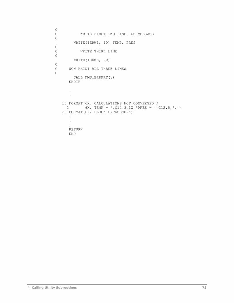
4 Calling Utility Subroutines 73
CC WRITE FIRST TWO LINES OF MESSAGEC
WRITE(IERW1, 10) TEMP, PRESCC WRITE THIRD LINEC
WRITE(IERW3, 20)CC NOW PRINT ALL THREE LINESC
CALL DMS_ERRPRT(3)ENDIF...
10 FORMAT(6X,'CALCULATIONS NOT CONVERGED'/1 6X,'TEMP = ',G12.5,1X,'PRES = ',G12.5,'.')
20 FORMAT(6X,'BLOCK BYPASSED.')...RETURNEND

74 4 Calling Utility Subroutines

5 User Unit Operation Models 75
5 User Unit OperationModels
This chapter describes the methods for creating custom unit operation modelsin Aspen Plus:
Fortran models with User and User2.
Excel models accessed through User2.
Fortran models with User3.
User and User2 Fortran ModelsThe unit operation models User and User2 allow you to interface your ownunit operation model with Aspen Plus by supplying a subroutine and enteringits name in the Model or Report field on the User or User2 Input Specificationssheet. To use your own equation-oriented models, see User3 Fortran Modelson page 100.
The only differences in the argument lists for User and User2 are:
User can have up to four inlet and four outlet material streams, oneinformation inlet stream, and one information outlet stream.
User2 has no limit on the number of inlet or outlet streams.
Calling Sequence for User
SUBROUTINE subrname† (NSIN, NINFI, SIN1, SIN2, SIN3, SIN4,SINFI, NSOUT, NINFO, SOUT1, SOUT2,SOUT3, SOUT4, SINFO, NSUBS, IDXSUB,ITYPE, NINT, INT, NREAL, REAL, IDS,NPO, NBOPST, NIWORK, IWORK, NWORK,WORK, NSIZE, SIZE, INTSIZ, LD)
†Subroutine name you entered on the User Input Specifications sheet.

76 5 User Unit Operation Models
Argument List Descriptions for User
Variable I/O† Type Dimension Description
NSIN I INTEGER — Number of inlet streams (both material andinformation)
NINFI I INTEGER — Number of inlet information streams
SIN1 I/O REAL*8 (1) First inlet material stream (see StreamStructure and Calculation Sequence)
SIN2 I/O REAL*8 (1) Second inlet material stream (see StreamStructure and Calculation Sequence)
SIN3 I/O REAL*8 (1) Third inlet material stream (see StreamStructure and Calculation Sequence)
SIN4 I/O REAL*8 (1) Fourth inlet material stream (see StreamStructure and Calculation Sequence)
SINFI I/O REAL*8 — Inlet information stream (see StreamStructure and Calculation Sequence)
NSOUT I INTEGER — Number of outlet streams (both material andinformation)
NINFO I INTEGER — Number of outlet information streams
SOUT1 O REAL*8 (1) First outlet material stream (see StreamStructure and Calculation Sequence)
SOUT2 O REAL*8 (1) Second outlet material stream (see StreamStructure and Calculation Sequence)
SOUT3 O REAL*8 (1) Third outlet material stream (see StreamStructure and Calculation Sequence)
SOUT4 O REAL*8 (1) Fourth outlet material stream (see StreamStructure and Calculation Sequence)
SINFO O REAL*8 — Outlet information stream (see StreamStructure and Calculation Sequence)
NSUBS I INTEGER — Number of substreams in material streams
IDXSUB I INTEGER NSUBS Location of substreams in stream vector
ITYPE I INTEGER NSUBS Substream type vector (1-MIXED, 2-CISOLID,3-NC)
NINT I INTEGER — Number of integer parameters (see Integerand Real Parameters)
INT I/O INTEGER NINT Vector of integer parameters (see Integer andReal Parameters)
NREAL I INTEGER — Number of real parameters (see Integer andReal Parameters)
REAL I/O REAL*8 NREAL Vector of real parameters (see Integer andReal Parameters)
IDS I INTEGER 2, 13 Block IDs:(*,1) - Block ID(*,2) - User model subroutine name(*,3) - User report subroutine name(*,4) to (*,8) - inlet stream IDs(*,9) to (*,13) - outlet stream IDs
NPO I INTEGER — Number of property option sets (always 2)
NBOPST I INTEGER 6, NPO Property option set array (see NBOPST)

5 User Unit Operation Models 77
Variable I/O† Type Dimension Description
NIWORK I INTEGER — Length of integer work vector (see Local WorkArrays)
IWORK W INTEGER NIWORK Integer work vector (see Local Work Arrays)
NWORK I INTEGER — Length of real work vector (see Local WorkArrays)
WORK W REAL*8 NWORK Real work vector (see Local Work Arrays)
NSIZE I INTEGER — Length of size results vector
SIZE O REAL*8 NSIZE Real sizing results (see Size)
INTSIZ O INTEGER NSIZE Integer size parameters (see Size)
LD I INTEGER — Plex location of the material stream classdescriptor bead
†I = Input to subroutine, O = Output from subroutine, W = Workspace
Calling Sequence for User2
SUBROUTINE subrname† (NMATI, SIN, NINFI, SINFI, NMATO, SOUT,NINFO, SINFO, IDSMI, IDSII, IDSMO, IDSIO,NTOT, NSUBS, IDXSUB, ITYPE, NINT, INT,NREAL, REAL, IDS, NPO, NBOPST, NIWORK,IWORK, NWORK, WORK, NSIZE, SIZE, INTSIZ,LD)
†Subroutine name you entered on the User2 Input Specifications sheet.
Argument List Descriptions for User2
Variable I/O† Type Dimension Description
NMATI I INTEGER — Number of inlet material streams
SIN I/O REAL*8 NTOT,NMATI
Array of inlet material streams (see StreamStructure and Calculation Sequence)
NINFI I INTEGER — Number of inlet information streams
SINFI I/O REAL*8 NINFI Vector of inlet information streams (seeStream Structure and Calculation Sequence)
NMATO I INTEGER — Number of outlet material streams
SOUT O REAL*8 NTOT,NMATO
Array of outlet material streams
NINFO I INTEGER — Number of outlet information streams
SINFO O REAL*8 NINFO Vector of outlet information streams (seeStream Structure and Calculation Sequence)
IDSMI I INTEGER 2, NMATI IDs of inlet material streams
IDSII I INTEGER 2, NINFI IDs of inlet information streams
IDSMO I INTEGER 2, NMATO IDs of outlet material streams
IDSIO I INTEGER 2, NINFO IDs of outlet information streams
NTOT I INTEGER — Length of material streams
NSUBS I INTEGER — Number of substreams in material streams
IDXSUB I INTEGER NSUBS Location of substreams in stream vector
ITYPE I INTEGER NSUBS Substream type vector (1-MIXED, 2-CISOLID,3-NC)

78 5 User Unit Operation Models
Variable I/O† Type Dimension Description
NINT I INTEGER — Number of integer parameters (see Integerand Real Parameters)
INT I/O INTEGER NINT Vector of integer parameters (see Integer andReal Parameters)
NREAL I INTEGER — Number of real parameters (see Integer andReal Parameters)
REAL I/O REAL*8 NREAL Vector of real parameters (see Integer andReal Parameters)
IDS I INTEGER 2, 3 Block IDs:(*,1) - Block ID(*, 2) - User model subroutine name(*, 3) - User report subroutine name
NPO I INTEGER — Number of property option sets (always 2)
NBOPST I INTEGER 6, NPO Property option set array (see NBOPST)
NIWORK I INTEGER — Length of integer work vector (see Local WorkArrays)
IWORK W INTEGER NIWORK Integer work vector (see Local Work Arrays)
NWORK I INTEGER — Length of real work vector (see Local WorkArrays)
WORK W REAL*8 NWORK Real work vector (see Local Work Arrays)
NSIZE I INTEGER — Length of size results vector
SIZE O REAL*8 NSIZE Real sizing results (see Size)
INTSIZ O INTEGER NSIZE Integer size parameters (see Size)
LD I INTEGER — Plex location of the stream class descriptorbead
†I = Input to subroutine, O = Output from subroutine, W = Workspace
Stream Structure and Calculation SequenceThe stream structure for material streams is described in Appendix C. Forinformation streams, the stream vector consists of a single value. All streamdata are in SI units.
In normal sequential modular calculations, the block calculates (fills in) theoutlet streams based on the inlet streams and specifications you made for theblock. However, sometimes it is useful for a block to modify its feedstream(s), such as when the feed stream has no source block because it is afeed to the process. To handle these cases, the user subroutine may changeits inlet stream.
The list of inlet streams for User2 blocks includes streams referenced on theStreams sheet, in addition to streams connected on the flowsheet.
NBOPSTWhen calling FLSH_FLASH or a property monitor, NBOPST should be passed ifproperty calculations are to be performed using the first (or only) option set.NBOPST(1,2) should be passed if property calculations are to be performedusing the second option set.

5 User Unit Operation Models 79
SizeThe size array SIZE should be filled in with the results from simulationcalculations if sizing and costing calculations are performed. The values thatare stored depend on the cost model. The values can be stored in any order.For each element in SIZE, the corresponding element in INTSIZ should befilled out with the correct result code. The result codes are:
10 Inlet pressure (N/m2)
11 Outlet pressure (N/m2)
12 Inlet temperature (K)
13 Outlet temperature (K)
14 Inlet vapor volumetric flow (m3/s)
15 Outlet vapor volumetric flow (m3/s)
16 Outlet liquid volumetric flow (m3/s)
17 Vapor density (kg/m3)
18 Liquid density (kg/m3)
19 Heat duty (watt)
50 Area (m2)
51 Isentropic or polytropic efficiency
52 Cp/Cv
53 Mechanical efficiency
54 Compressor type (1=polytropic centrifugal; 2=polytropic positivedisplacement; 3=isentropic)
55 Horsepower (watt)
92 Surface tension (N/m)
93 Liquid viscosity (N-s/m2)
94 Relative volatility
95 Diffusivity (m2/s)
Integer and Real ParametersYou can use integer and real retention parameters by specifying the numberon the User | Input | Specifications sheet or the User2 | Input | UserArrays sheet. You can initialize these parameters by assigning values on thesame sheet. The default values are USER_RUMISS for real parameters, andUSER_IUMISS for integer parameters. Aspen Plus retains these parametersfrom one call to the next. The variables USER_IUMISS and USER_RUMISS arelocated in labeled common PPEXEC_USER (see Appendix A).

80 5 User Unit Operation Models
Local Work ArraysYou can use local work arrays by specifying the array length on the User orUser2 | Input | Specifications sheet. Aspen Plus does not retain thesearrays from one call to the next.
Simulation Control GuidelinesAn Aspen Plus unit operation model calculates outlet stream values, and realand integer array results, from inlet stream values and from real and integerarray inputs, in order to produce History file and Report file output.
Follow these guidelines to implement the simulation options in a user unitoperation model:
1 If USER_NGBAL of COMMON /PPEXEC_USER/ is 1, the energy balanceswitch is on; and if USER_IPASS of COMMON /PPEXEC_USER/ is 1, themodel is being called on a simulation pass and should calculate:
o Outlet stream component flows
o Total flow
o Molecular weight
o Pressure
o Enthalpy (specific mass enthalpy in Aspen Plus streams)
o Retention variables in the integer and real arrays
2 If USER_NGBAL of COMMON /PPEXEC_USER/ is 1, the energy balanceswitch is on; and if USER_IPASS of COMMON /PPEXEC_USER/ is 2, themodel is being called on a results pass and should fill in values of theoutlet streams and of the integer and real arrays that are not calculatedduring a simulation pass. The values that were calculated during asimulation pass should not be changed.
3 If USER_NGBAL of COMMON /PPEXEC_USER/ is 1, the energy balanceswitch is on; and if USER_IPASS of COMMON /PPEXEC_USER/ is 3, thenthe model is being called on a simulation and results pass and shouldcalculate everything in both guidelines 1 and 2 above.
4 A sizing flag is stored in USER_ISIZE of COMMON /PPEXEC_USER/. Whenthe value of USER_ISIZE is:0 - Skip sizing calculations1 - Do sizing calculations
5 USER_NGBAL, USER_IPASS and USER_ISIZE are set by the system beforeeach User or User2 block call. Their values depend on the simulationoptions you specified on the Setup | Calculation Options |Calculations sheet, or on the User or User2 | Block Options |Simulation Options sheet. USER_IPASS also depends on the progressthrough the simulation, results, and report passes. A USER_IPASS of 4 isthe report pass.
6 The restart flag is stored in USER_IRESTR of COMMON /PPEXEC_USER/.USER_IRESTR indicates whether initialization calculations are to beperformed or whether the model should simply restart using retentioninformation. The initial value of the restart flag depends on the option youspecified on the Setup | Calculation Options | Calculations sheet, or

5 User Unit Operation Models 81
on the User BlockOptions SimulationOptions (or User or User2 | BlockOptions | Simulation Options) sheet.
7 When the value of USER_IRESTR is:0 - Initialization calculations should be performed.1 - Initialization calculations should be performed. If the modelcalculations proceed satisfactorily, retention information should be storedand USER_IRESTR should be set to 2.2 - Initialization should be bypassed, and the model should restartiterations using retention information. Retention information should beupdated. If for any reason you consider the new retention informationunreliable and do not want to use it to restart calculations, resetUSER_IRESTR to 1.
8 The simulation options discussed above eliminate unnecessary processcalculations. However, since they complicate model coding, in many casesyou can ignore them. For example:
o If a model always calculates outlet stream enthalpy, you can ignorethe energy balance switch USER_NGBAL.
o If all results are calculated every time the model is called, you canignore the USER_IPASS distinctions.
o If a model cannot restart from retention information, you can ignorethe restart flag, USER_IRESTR.
o If a model does not do sizing calculations, you can ignore USER_ISIZE.
9 Unit operation models also set the convergence flag, USER_ICONVG, ofCOMMON /PPEXEC_USER/. If the model calculations have completednormally (converged), USER_ICONVG should be set to 0. If the modelcalculations have failed, USER_ICONVG should be set to a negativenumber. The value of the negative number should indicate the type orcause of failure so that an appropriate message is written during thereport pass.
10 The following values of USER_ICONVG are reserved for Aspen Plus systemuse and should not be used by the User or User2 model:
o -1
o -2
o -9995
o -9996
o -9997
o -9998
o -9999
o -USER_IUMISS
History FileThe History File contains intermediate output during unit operation modelexecution. History File output consists of errors, warnings, and diagnostics.You can control the amount of History File output by setting a message levelon the Setup | Specifications | Diagnostics sheet and the User or User2| Block Options | Diagnostics sheet. Each level includes the messageswritten at all lower levels. The message level for a User or User2 block is

82 5 User Unit Operation Models
stored in USER_LMSG of COMMON /PPEXEC_USER/. The Fortran unit numberfor the History File is stored in USER_NHSTRY of COMMON /PPEXEC_USER/.
Note: WRITEs to this file will not work when using the Compaq Visual Fortrancompiler. See Moving to the Intel Fortran Compiler, chapter 1.
At all diagnostic levels of 4 or above, Aspen Plus writes a message to theHistory File when the unit block begins execution. The user model then writesthe errors, warnings, and diagnostics.
Diagnostics should begin in column seven or beyond. Units are assumed to beSI. If they are not SI, unit labels should accompany numerical values.
Errors and warnings have a standard format (see Aspen Plus Error Handler,Chapter 4).
Terminal FileIf you want to write to the terminal or the Control Panel, use the Terminal FileWriter utility DMS_WRTTRM (see Chapter 4).
Report FileThe Report file Fortran unit number is stored in USER_NRPT of COMMON/PPEXEC_USER/ (see Appendix A; and Report Header Utility, Chapter 4).
Note: WRITEs to this file will not work when using the Compaq Visual Fortrancompiler. See Moving to the Intel Fortran Compiler, chapter 1.
Control PanelAspen Plus displays on the Control Panel runtime information and any errorsor warnings that occur during calculations. The Control Panel replaces theTerminal File for output purposes. Use the utility DMS_WRTTRM to write tothe Control Panel (see Chapter 4).
You cannot use the Control Panel to read from the Terminal File. In this case,you will need to run Aspen Plus without the Windows user interface. TheFortran file number for the terminal is stored in USER_NTRMNL ofCOMMON/PPEXEC_USER/ (see Appendix A).
Incorporating ExcelWorksheets into User2If you are one of the many engineers who use Excel models, you may wantto:
Combine Excel models with the Aspen Plus system.
Supply input data and additional operating parameters to your Excelmodel through the Aspen Plus graphical user interface, and then retrieveresults.

5 User Unit Operation Models 83
This section explains how to run Excel models as part of an Aspen Plussimulation, without having to convert the Excel model into a Fortran library.This section assumes you are familiar with the Aspen Plus User2 model,described earlier in this chapter.
Extending the User2 ConceptThere are four steps in extending the User2 model to incorporate Excelmodels:
1 Place a User2 block.
2 Connect any streams.
3 Specify the name of the Excel workbook file that represents the unitoperation model for the block.
4 Enter the operating parameters, by filling out the real and integerparameters arrays.
When Aspen Plus solves the block, it loads the Excel file, writes theappropriate input data, tells the workbook to calculate, and then reads backthe output data. The integer and real parameter arrays are treated as bothinput and output.
Excel File NameThe file name for the Excel model is limited to 64 characters. All characters inthe file name must be alpha or numeric, a hyphen (-), or an underscore;spaces are not allowed. The file name should be the full path to the file. The.xls format from Excel 2003 should be used, not the .xlsx, .xlsm, or .xlsbformats from later versions. For example:
e:\mymodels\myflash.xls
Fortran RoutineIn addition to the file name, you may optionally enter the name of the Fortranroutine to call when solving the User2 block. If you don't enter a Fortranroutine, then a default routine will be used.
In the default routine, all the inlet stream data (component flows, streamtotal flow, temperature, pressure, mass-specific enthalpy, molar vaporfraction, molar liquid fraction, mass-specific entropy, mass density andmolecular weight for the stream) are initially copied to a single array. Thenthe appropriate APIs are called, to write and read from the Excel workbook.The outlet stream data is copied into the outlet stream array for Aspen Plus tocontinue the simulation. All the stream data that is transferred betweenAspen Plus and Excel must be in SI units (kmole/sec, K, Pascal ).
The Excel TemplateTo be compatible with the Aspen Plus User2 extension, the workbookrepresenting a model must follow certain guidelines. These guidelines arecalled the Excel Template.

84 5 User Unit Operation Models
The template, userxltemplate.xls, is located in the user directory of theAspen Plus engine installation.
To begin creating an Excel model, copy the template.
TablesIn the Excel template, data is divided into four distinct tables. Each table is onits own sheet. The sheet and the corresponding table have the same name.
The Aspen_Input table supplies the stream input information, whichincludes:
Flow for each component in the stream (MIXED substream).
Temperature, pressure and total flow for the stream (MIXED substream).
Mass-specific enthalpy, molar vapor fraction, molar liquid fraction, mass-specific entropy, mass density and molecular weight for the stream(MIXED substream).
The columns for the table are for inlet stream IDs. The rows display thecomponent IDs followed by total mole flow, temperature, pressure, mass-specific enthalpy, molar vapor fraction, molar liquid fraction, mass-specificentropy, mass density and molecular weight for the respective stream (MIXEDsubstream). Whenever there is no other column or row heading available, thesystem automatically uses the column or row number as the heading.
In the sample workbook called dryer.xls, the Aspen_Input sheet looks like:
INPUT 2 H2O-COAL
AIR 0.0043 0
H2O 0 0.002182
COAL 0 0.001818
TOTFLOW 0.0043 0.004
TEMP 478 300
PRES 101325 101325
ENTHALPY 181423 -3479200
VAP FRAC 1 0
LIQ FRAC 0 1
ENTROPY 475.7966 11366.47
DENSITY 0.7381 725.183
MOLE WT 28.95091 48.87867
The Aspen_RealParams table shows the array of real parameters asentered on the User2 input form in Aspen Plus. Whenever there is no othercolumn or row heading available, the system automatically uses the columnor row number as the heading:
REALPARAMS 1
1 0.1
2 0.3
The Aspen_IntParams table shows the array of integer parameters asentered on the User2 input form. Whenever there is no other column or row

5 User Unit Operation Models 85
heading available, the system automatically uses the column or row numberas the heading:
INTPARAMS 1
1 1
The Aspen_Output table shows the output data for each stream. The typesof data correspond to those in the Aspen_Input table. The columns for thetable are for outlet stream IDs. Rows display the component IDs followed bytotal mole flow, temperature, pressure, mass-specific enthalpy, molar vaporfraction, molar liquid fraction, mass-specific entropy, mass density andmolecular weight for the respective stream (MIXED substream):
OUTPUT AIROUT PRODUCT
AIR 0.0043 0
H2O 0.00086 0.001322
COAL 0 0.001818
TOTFLOW 0.00516 0.00314
TEMP 478 300
PRES 101325 101325
ENTHALPY 0 0
VAP FRAC 0 0
LIQ FRAC 0 0
ENTROPY 0 0
DENSITY 0 0
MOLE WT 0 0
Other tables may appear if you have solid substreams in streams connectedto this model, such as Aspen_Input_NC and Aspen_Output_NC for an NCsubstream. These are similar in form to the ones shown above, but havesubstream and component attributes added at the end of the list.
The data in each table is given a named range, with the same name as itssheet. By naming the ranges, models can be written by referring to theseranges, rather than using explicit cell references. This technique allows formore readable formulas and macros, and is more robust and flexible underchange. For example, in the dryer Sheet1, the input pressure for the secondstream is referred to using the range name Aspen_Input in the followingformula, which uses the helper function ahgetvalue (see next section):
=ahgetvalue(Aspen_Input,"PRES",2)
The Helper FunctionsTo facilitate extracting data from the tables, a set of helper functions issupplied. All the functions are prefixed with "ah", which stands for AspenHelper. These functions are designed to be used both from within formulas incells, and from within VBA functions and subroutines. The functions are asfollows:
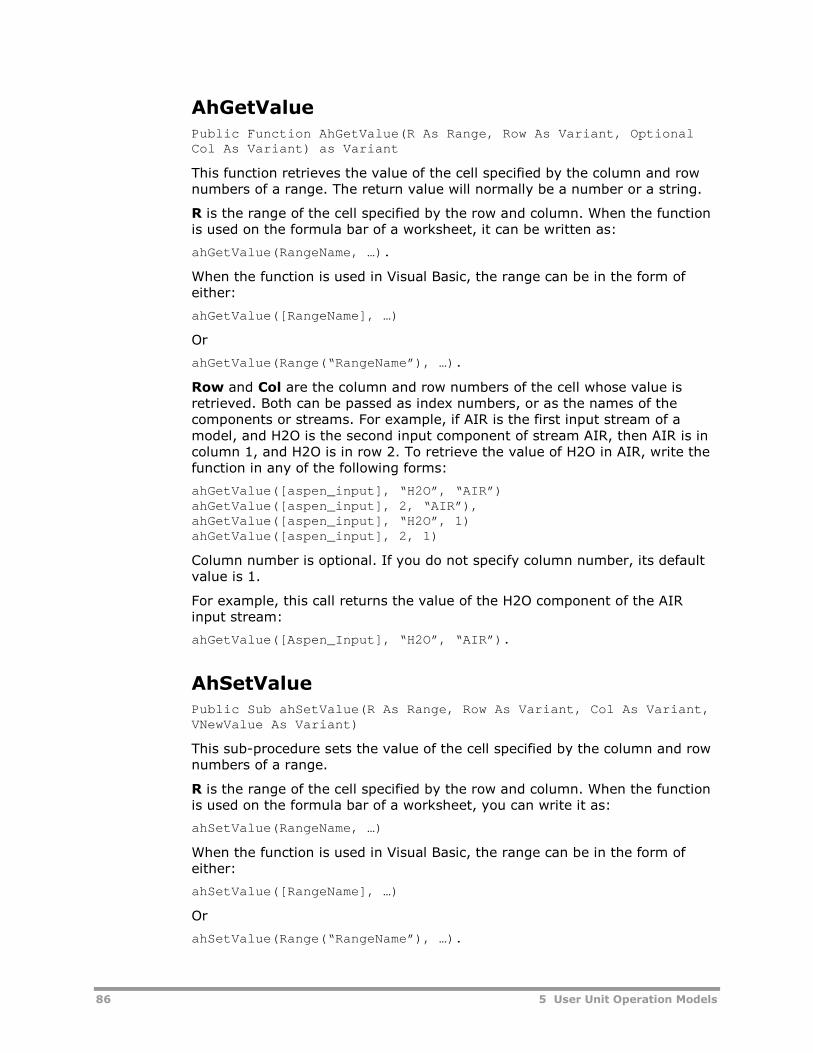
86 5 User Unit Operation Models
AhGetValue
Public Function AhGetValue(R As Range, Row As Variant, OptionalCol As Variant) as Variant
This function retrieves the value of the cell specified by the column and rownumbers of a range. The return value will normally be a number or a string.
R is the range of the cell specified by the row and column. When the functionis used on the formula bar of a worksheet, it can be written as:
ahGetValue(RangeName, …).
When the function is used in Visual Basic, the range can be in the form ofeither:
ahGetValue([RangeName], …)
Or
ahGetValue(Range(“RangeName”), …).
Row and Col are the column and row numbers of the cell whose value isretrieved. Both can be passed as index numbers, or as the names of thecomponents or streams. For example, if AIR is the first input stream of amodel, and H2O is the second input component of stream AIR, then AIR is incolumn 1, and H2O is in row 2. To retrieve the value of H2O in AIR, write thefunction in any of the following forms:
ahGetValue([aspen_input], “H2O”, “AIR”)ahGetValue([aspen_input], 2, “AIR”),ahGetValue([aspen_input], “H2O”, 1)ahGetValue([aspen_input], 2, 1)
Column number is optional. If you do not specify column number, its defaultvalue is 1.
For example, this call returns the value of the H2O component of the AIRinput stream:
ahGetValue([Aspen_Input], “H2O”, “AIR”).
AhSetValuePublic Sub ahSetValue(R As Range, Row As Variant, Col As Variant,VNewValue As Variant)
This sub-procedure sets the value of the cell specified by the column and rownumbers of a range.
R is the range of the cell specified by the row and column. When the functionis used on the formula bar of a worksheet, you can write it as:
ahSetValue(RangeName, …)
When the function is used in Visual Basic, the range can be in the form ofeither:
ahSetValue([RangeName], …)
Or
ahSetValue(Range(“RangeName”), …).

5 User Unit Operation Models 87
Row and Col are the column and row numbers of the cell whose value is set.Both can be passed as index numbers, or the names of the components orstreams. For example, if AIR is the first input stream of a model, and H2O isthe second input component of stream AIR, then AIR is in column 1, and H2Ois in row 2. To set the value of H2O in AIR, write the function in any of thefollowing forms:
ahSetValue([Aspen_Output], “H2O”, “AIR”, …)ahSetValue([Aspen_Output], 2, “AIR”, …)ahSetValue([Aspen_Output], “H2O”, 1, …)ahGetValue([Aspen_Output], 2, 1, …).
VNewValue is the value to be set; it can be number, string, or other datatypes. For example, this call sets the value of H2O of the input stream AIR to0.004:
ahSetValue([Aspen_Output], “H2O”, “AIR”, 0.004)
AhNumCompsPublic Function ahNumComps(R As Range) As Integer
This function calculates the number of components of a model.
R is the range that includes all the streams and components of a model.When the function is used on the formula bar of a worksheet, you can write isas:
AhNumComps(RangeName)
When the function is used in Visual Basic, the range can be in either of thefollowing two forms:
AhNumComps ([RangeName])AhNumComps(Range(“RangeName”))
For example, this call returns the number of input components:
ahNumComps([Aspen_Input])
AhNumStreams
Public Function ahNumStreams(R As Range) As Integer
This function calculates the number of streams of a model.
R is the range that includes all the streams and components of a model.When the function is used on the formula bar of a worksheet, you can write itas:
ahNumStreams (RangeName)
When the function is used in Visual Basic, the range can be in either of thesetwo forms:
ahNumStreams ([RangeName])ahNumStreams (Range(“RangeName”)).
For example, this call returns the number of input streams:
ahNumStreams ([Aspen_Input])

88 5 User Unit Operation Models
AhNumParams
Public Function ahNumParams(R As Range) As Integer
This function returns the number of integer or real parameters in a model.
R is the range that represents the parameters of a model, usuallyAspen_RealParams or Aspen_IntParams. When the function is used on theformula bar of a worksheet, you can write it as:
ahNumParams(RangeName)
When the function is used in Visual Basic, the range can be in either of thesetwo forms:
ahNumParams ([RangeName])ahNumParams(Range(“RangeName”))
For example, this call returns the number of real parameters:
ahNumParams([Aspen_RealParams])
The Hook FunctionsWhen calling some of the User2 routines, Aspen Plus calls pre-defined macrosin the Excel file. These Excel macros are called the hook functions. They allowthe modeler to customize and extend the basic sequence in running an Excelmodel.
When the Aspen Plus engine processes a User2 Excel block, it calls thefollowing APIs from the User2 interface file:
StartIteration(fileName, blockID)WriteTable("Input". ...)WriteTable("IntParams". ...)WriteTable("RealParams". ...)WriteTable("Output". ...)CalculateData()ReadTable("IntParams". ...)ReadTable("RealParams". ...)ReadTable("Output". ...)EndIteration
When the entire simulation run has completed, Aspen Plus callsEndRun(runID).
Function AspenStartIteration(blockId As String)As String
This function is called at the start of each iteration of the Excel model, beforethe model gets calculated. A global variable, g_blockId, is assigned to thecurrent block ID, so that it can be used in AspenEndIteration or in othermethods.

5 User Unit Operation Models 89
Function AspenEndIteration() As String
This function is called at the end of each iteration of the model, after themodel has been calculated. If you want to save the last table of data to auniquely named sheet, this is the place to do it. The Excel templates contain afunction called CopySheetForBlock. This function takes a sheet name (such asOutput or Input) and a block ID. The template makes a call to:
CopySheetForBlock "Output", g_blockId
This call copies whatever values are currently on the Aspen_Output sheetonto a newly created sheet called Aspen_Output_B1ockId, where BlockId isthe ID of the block that is ending its iteration. The g_blockId gets savedduring the call to AspenStartIteration.
Function AspenCalculate() As String
This function is called to solve the model for the given inputs, after writing outall the input data. By default it calls only Calculate. If you are writing VBAcode to solve your model, call it from here.
Function AspenEndRun(runId As String) As String
This function is called when the Aspen Plus engine is quitting, after all blockshave been processed. The run ID is passed from the engine. You may want touse the run ID as part of the file name, if saving the sheet at the end of arun.
Error Handling
Each of the hook functions returns a string. If the string is empty, thatindicates success. A non-empty string indicates failure; the value of the stringis passed back to the engine, and then to the user. For example, ifAspenCalculate() returns the string “Pressure exceeds maximum,” thisinformation will be passed back to the user and an error status will bedisplayed.
The Sample WorkbookA sample workbook called: dryer95.xls or dryer.xls is located in the userdirectory of the Aspen Plus engine installation. This workbook is an exampleof a model designed for a specific set of components and streams. Itsimulates a model that removes water from a slurry stream, based on anevaporation rate derived from the mole fraction of the input and output airstreams. These mole fractions are passed to the model via the realparameters array, which is written out to the Aspen_RealParams sheet.
In this sample you will see five sheets of interest: Aspen_Input,Aspen_Output, Aspen_Real Params and Sheet1. There are named ranges foreach of the Aspen sheets. The cell containing the evaporation rate is namedEvapRate. EvapRate is defined on Sheet1 as follows:

90 5 User Unit Operation Models
ahgetvalue(Aspen_Input,"TOTFLOW",1) *(ahgetvalue(Aspen_RealParams,2) - ahgetvalue(Aspen_RealParams,1))
EvapRate is then referred to on the Aspen_Output sheet to calculate thewater flow for the air and slurry streams. The rest of the values are just takenfrom the input sheet, via the ahGetValue method. Because this model iswritten exclusively for the given set of streams and components, cell formulascan be placed directly in the Aspen_Output range.
When a new simulation is run, the input data and real parameter data will beoverwritten with new values from the input file passed to the Aspen Plusengine. The output sheet will not be overwritten, because cells that containformulas are never overwritten.
At the end of each solving iteration, the output values will be read back intothe engine. The last output values will be saved to a sheet, based on thename of the block. At the end the entire workbook is saved via a call toThisWorkbook.Save, made from the hook function AspenEndRun.
A sample function called testVBACalculate produces the same output tabledata as the formulas, but does so from VBA code. It makes extensive use ofthe ahSetValue() method.
Creating or Converting Your Own ExcelModelsStart by copying the template, userxltemplate.xls, located in the userdirectory of the Aspen Plus engine installation.
Decide whether you are going to write a generic or specific model, asexplained later in this chapter.
To create sample data, you may need to extend one of the sample namedranges: Aspen_Input, Aspen_Ouput, or one of the parameter ranges. Use theInsert/Name/Define dialog to modify the current range. Then enterappropriate sample stream and component names in place of the S1, S2,…and C1, C2 that are supplied. You can test your model as you develop it, byrunning the AspenCalculate macro or just recalculating your workbook. Onceyour model is fully tested from within Excel, then you can begin testing itfrom Aspen Plus.
Converting Existing Formulas
In your spreadsheet where you refer to the temperature of an inlet streamcalled AIR, substitute the ahGetValue(Aspen_Input,"TEMP","AIR"). Dolikewise for your other input. You can place your output formulas directly ontothe Aspen_Output sheet when writing a specific model. By using the helpermethods, you will be making your formulas more readable and more robustas you make modifications to the model.

5 User Unit Operation Models 91
Writing Models for a Specific Set of Componentsand Streams
When you are writing a model that is always going to be used with the sameset of components and streams, you can embed formulas into yourworksheet, and refer to streams and components by name, making yourmodel much easier to read. For example, to get the water flow of the air inputstream you can write:
ahGetValue(Aspen_Input, “H2O”, “AIR”)
When data is written to the spreadsheet, cells that contain formulas are neveroverwritten. All cells that don't contain formulas are cleared before new datais written.
Writing Generic Models in Excel
A generic model, like the built-in Aspen Plus unit operation models, doesn'tmake assumptions about the stream composition, the number of streams, ortheir names. The best way to create such a model in Excel is to use the Aspenhelper functions to determine the numbers of streams and components, anditerate through them. You can then write your calculation routines in theAspen hook method AspenCalculate(), or call your methods from there.Included in the Excel template are some test and sample code in ahtest(),which show how to call the various “ahGet" methods. The following codesnippet loops through all the component flows of all the input streams:
For i = 1 To ahNumStreams([Aspen_Input])For j = 1 To ahNumComps([Aspen_Input])
testSheet.Cells(rowNum+j,i+1).Value=ahGetValue([Aspen_Input], j, i)
Next jNext i
Converting an Existing Excel ModelThe procedure for converting an Excel model is:
1 Copy to the working directory the Aspen Excel template userxltemplate.xlsfrom the user directory of the Aspen Plus engine installation. Copy thetemplate to a file that represents your model; for example, mymodel.xls.
2 For the user Excel sheets that have formulas associated with the cells,copy Sheet1 of the user Excel sheet for the model you are converting tothe Aspen Excel template (also called Sheet1).
3 Start up the Aspen Plus user interface, apwn.exe. Place a User2 block andmake the appropriate stream connections.
4 Complete the input specifications, including the User2 input form (Excelfile name and Fortran interface file). Specify the Aspen Excel templatename (for example, mymodel.xls) on the User2 input form.
5 Run the simulation.
6 Bring up mymodel.xls.
7 Aspen_Input and Aspen_Output sheets will contain the appropriate streamand component IDs for the simulation you are modeling.

92 5 User Unit Operation Models
8 Go to Sheet1 of mymodel.xls. Use the helper functions to retrieveappropriate values from the Aspen_Input sheet. Identify the INT and REALparameters that need to be entered from Aspen Plus, and any results thatneed to come back into Aspen Plus. Use helper functions to retrieve theINT and REAL values from the Aspen_IntParams sheet and theAspen_RealParams sheet.
9 Go to the Aspen_Output sheet of the Aspen Excel template. Retrieve thestream results from Sheet1. For example, if you want to retrieve the valuein cell c12 on Sheet1, you can type in: =Sheet1!C12
10 If you have any results to be stored in INT or REAL arrays, go to theAspen_IntParams and Aspen_RealParams sheets. Retrieve those valuesfrom Sheet1 as described in Step 8.
You are now ready to run the simulation.
Customizing the Fortran CodeThe default file userxls.f is supplied with the product. It allows you access to acommonly used subset of model data. To extend the amount of data that getsplaced into tables in Excel, you can modify this Fortran file, and make use ofthe same TableDataWrapper API functions. The API is implemented in theTableDataWrapper.dll. All the API methods take a return code as their firstargument. This return code will be 0 on success, and non-zero on failure.Details about the error can be retrieved by calling GetLastTableDataErr().
StartIteration()
Description
When you start Iteration for a block, the unique block name of the block forwhich the calculations are to be done is retrieved, along with the file name ofthe Excel workbook that represents the model.
For each iteration of a block, a hook called AspenStartIteration(blockId) willbe called in the Excel workbook, giving you a chance to extend the model.
Syntax
void StartIteration(FORINT* retCode, HOLLSTR filename, FORINTfilenameLen, HOLLSTR blockid, FORINT blockidLen)
Arguments
filename Name of the Excel file that represents this model. Will normallycome from the User2 input form.
filenameLen Number of characters in the filename string.
blockid The unique block name of the block being calculated.
blockidLen The number of characters in the block name string.

5 User Unit Operation Models 93
WriteTable()
Description
For each set of data, such as parameters containing INT and REAL, or aStream table containing a table of components and Streams, the following arepassed as input parameters:
Number of items in the row and col.
Row and col headers.
You need one WriteTable call for each set of data. Create new Excel sheets foreach table of data, if they don’t already exist. Assign the tag "Aspen_" , pre-pended to the table name. For example, for a table called Input the sheetname would be Aspen_Input.
Use a separate worksheet for each set or table of data. The four tables usedin the supplied usrxls.f are Input, Output, RealParams and IntParams. Theseare the main working sheets, where the input data is written, calculations (ifany) occur, and the resulting data is held.
Before data is written, the whole range is cleared, except for those cells thatcontain formulas.
The data is written starting from the top left corner of the sheet. As a block ofdata is being filled into the sheet, the data corresponding to those cells thatneed a blank are indicated by one of the following:
This constant Represents
IMISS Integer missing value
RMISS Real missing value
Syntax
void WriteTable (FORINT* retCode, HOLLSTR tableName, FORINT*tableNameLen, FORINT* numrows, HOLLSTR rowheaders, FORINT*rowheaderLen, FORINT* numcols, HOLLSTR colheaders, FORINT*colheaderLen, FORINT* dataType, void* data, FORINT* dataLength);
ArgumentstableName The name of the overall table or range, input, params, output.
tableNameLen The number of characters in the tablename string.
numrows The number of rows in the table.
rowheaders An array of strings representing the headers for each row. Allthe strings must be of the same length. Either the array mustbe numrows big, or the rowheaderLen must be 0.
rowheaderLen The number of characters in the each string of the rowheadersarray. If this number is 0, then the row names for the table willbe automatically generated as 1, 2, 3, ... up to numrows.
numcols,colheaders,colheaderLen
See the preceding description of numrows, rowheaders, androwheaderLen.
dataType Indicates what type of data is being passed in the data array. 0means integer, 1 means real, and 2 means string.

94 5 User Unit Operation Models
data The actual data to be written into the body of the table. It isread column by column, and must be as large as numrows *numcols.
dataLength If the dataType is string, then the dataLength holds the numberof characters in the fixed len strings in data.
CalculateData
Description
Calls a hook function in the Excel workbook called AspenCalculate to performthe calculations. Users can call their own VBA calculation macros fromAspenCalculate.
Syntax
void CalculateData(FORINT*retCode)
ReadTable
Description
Read the results data and other blocks of input data that were subject tochange during calculation. For each table of data to be read, such asparameters containing INT and REAL, the details such as the number of itemsin the rows and cols are passed in as input parameters.
Syntax
void ReadTable(FORINT* retCode, HOLLSTR tableName, FORINT*tableNameLen, FORINT* numrows, FORINT* numcols, FORINT* dataType,void* data, FORINT*dataLength);
ArgumentstableName The name of the overall table or range, input, params, output.
tableNameLen The number of characters in the tablename string.
numrows The number of rows in the table.
numcols The number of columns in the table.
dataType Indicates what type of data is being passed in the data array. 0means integer, 1 means real, and 2 means string.
data The actual data to be read from the body of the table. It is readcolumn by column, and must be as large as numrows *numcols.
dataLength If the dataType is string, then the dataLength holds the numberof characters in the fixed Len strings in data.

5 User Unit Operation Models 95
EndIteration
Description
Ends the iteration for a block. Calls a hook function called AspenEndIteration.This hook allows the modeler to do things like copying the table data of theActive block to the block's specific table sheet. For example, the Input sheetof the block B1 could be copied to Aspen_Input_B1 sheet. During this processonly the values in the sheet, and not the formulas and the name ranges, arecopied.
Syntax
void EndIteration(FORINT* retCode)
GetLastTableDataErr
Description
Gets the last error, if any, from any of the API calls.
Syntax
void GetLastTableDataErr(FORINT* retCode, FORINT*errNumber,HOLLSTR description, FORINT*descriptionLen, FORINT*descriptionLineWrapLen, HOLLSTR source, FORINT* sourceLen)
ArgumentserrNumber The error number of the last error. It may be an
automation error, an Excel error, or a table wrap error.
description The error description as a string.
descriptionLen On the way in, this parameter holds the maximumnumber of characters that can be stored in thedescription string. When returning, it holds the actualnumber of characters written in the description string.
descriptionLineWrapLen If this parameter is non-zero, the description string willbe formatted so that it breaks cleanly at linesdescriptionLineWrapLen long, padding the lines withspaces.
source The name of the application that is the source of theerror.
sourceLen The maximum number of characters that can be writtento the source string.

96 5 User Unit Operation Models
Accessing User2 ParametersThe following subroutines and functions can be called from a User2 Fortransubroutine to access the real, integer, and character parameter arraysspecified on the User2 Setup User Arrays sheet, and the names of the Excelinterface file and additional user subroutines specified on the User2 SetupSubroutine sheet. There are 3 ways to get or set the values of theseparameters:
1 Access the values directly from the INT and REAL arrays (for example,INT(5)).
2 Use the helper functions that access the parameters by position.
3 Use the helper functions that access the parameters by name and index,using the names on the User2 | Setup | Configured Variables sheet.See Getting Started Customizing Unit Operation Models, Chapter 4, tolearn how to use the Configured Variables sheet.
Accessing parameters by positionThis group of subroutines (USRUTL_NUMSTR through USRUTL_GETEXCEL)can be called from User2 without using the names in the user configurationsubroutine. They give the user access to integer, real, and characterparameter arrays. Access to the arrays is by position, not by name.
SUBROUTINE USRUTL_NUMSTR (NUMSTR)
Sets NUMSTR to the number of character string parameters.
SUBROUTINE USRUTL_GETHSTR (ISTRNO, IBUFF, IBUFLEN, IACTLEN)
Retrieves character parameter number ISTRNO as a Hollerith array in IBUFF.Sets IACTLEN to the actual length of the string, in characters. The user mustset IBUFLEN to the length of the integer array IBUFF before calling thissubroutine.
SUBROUTINE USRUTL_GETCSTR (ISTRNO, CSTR, CSTRLEN, IACTLEN)
Retrieves character parameter number ISTRNO as a character array in CSTR.Sets IACTLEN to the actual length of the string, in characters. If the user setsCSTRLEN to zero before calling this routine, then the only action is to setIACTLEN. If CSTRLEN is greater than zero, then CSTR is filled and IACTLEN isset to the number of characters in CSTR.
SUBROUTINE USRUTL_SETHSTR (ISTRNO, IBUFF, ICLEN)
Sets character parameter number ISTRNO from the first ICLEN characters ofHollerith array IBUFF.
SUBROUTINE USRUTL_SETCSTR (ISTRNO, CSTR, ICLEN)
Sets character parameter number ISTRNO from the first ICLEN characters ofcharacter array CSTR.

5 User Unit Operation Models 97
SUBROUTINE USRUTL_NUMINTS (NUMINTS)
Retrieves the length of the integer parameter array as NUMINTS.
SUBROUTINE USRUTL_GETINT (INTNO, IVAL)
Sets IVAL to the value of integer parameter number INTNO.
SUBROUTINE USRUTL_SETINT (INTNO, IVAL)
Sets value number INTNO in the integer parameter array to value IVAL.
SUBROUTINE USRUTL_NUMREALS (NUMREALS)
Retrieves the length of the real parameter array.
SUBROUTINE USRUTL_GETREAL (IREALNO, RVAL)
Sets RVAL to the value of real parameter number IREALNO.
SUBROUTINE USRUTL_SETREAL (IREALNO, RVAL)
Sets value number IREALNO in the real parameter array to value RVAL.
Argument List Descriptions for Position-Access HelperFunctions
Variable I/O Type Dimension Description
NUMSTR O INTEGER Number of character strings
ISTRNO I INTEGER 1-based string index
IBUFF I/O INTEGER IBUFLEN,when output
Hollerith string as array of integers, 4chars/word
IBUFLEN I INTEGER Length of IBUFF
ICLEN I INTEGER Number of characters (not words) tocopy
IACTLEN O INTEGER Number of characters in retrieved string
CSTR I/O CHARACTER CSTRLEN,when output
Character string
CSTRLEN I INTEGER Length of CSTR. If 0, only set IACTLEN.
NUMINTS O INTEGER Number of integer values entered
INTNO I INTEGER 1-based integer index
IVAL I/O INTEGER Integer value
NUMREALSO INTEGER Number of real values entered
IREALNO I INTEGER 1-based real index
RVAL I/O REAL*8 Real value
Accessing parameters by nameThe following group of functions allows the user to set and get the valuesfrom the integer, real, and character arrays by name. The value of VNAMEshould be set to the name of a variable in the user configuration subroutine.The INDEX array is always 1-based.
The User2 | Setup | Configured Variables sheet allows the user to setvalues in the integer, real, and character arrays using the names specified in

98 5 User Unit Operation Models
the configuration library. The values are actually the values in those arrays onthe User2 | Setup | User Arrays sheet. When a value is set on the UserArrays sheet, the corresponding value is updated on the ConfiguredVariables sheet, and vice versa. See Getting Started Customizing UnitOperation Models, Chapter 4, to learn how to use the Configured Variablessheet.
INTEGER FUNCTION USRUTL_GETVAR (VNAME, INDEX)
The returned value is the 1-based location in the integer or real array of theinteger, real, or character variable with name VNAME and 1-based indicesspecified by array INDEX (a scalar value may be entered for scalar and one-dimensional variables). Character variables are stored in the integerparameter array in Hollerith format (4 characters per integer word).
INTEGER FUNCTION USRUTL_GET_REAL_PARAM (VNAME, INDEX, RVAL)
Sets RVAL to the value of the real parameter with name VNAME and indicesas specified in INDEX. Returns GLOBAL_IMISS on any error, 0 otherwise.
INTEGER FUNCTION USRUTL_GET_INT_PARAM (VNAME, INDEX, IVAL)
Sets IVAL to the value of the integer parameter with name VNAME and indicesas specified in INDEX. Returns GLOBAL_IMISS on any error, 0 otherwise.
INTEGER FUNCTION USRUTL_GET_CHAR_PARAM (VNAME, INDEX, CHARSTR,IACTLEN)
Fills the character array CHARSTR with the value of the character parameterspecified by VNAME and INDEX. Sets IACTLEN to the actual length of thestring, in characters. Returns GLOBAL_IMISS on any error, 0 otherwise.
INTEGER FUNCTION USRUTL_GET_HCHAR_PARAM (VNAME, INDEX, ICHARHOL,ICHLEN, IACTLEN)
Fills the integer array ICHARHOL with the Hollerith representation (4characters per integer) of the character parameter specified by VNAME andINDEX. Sets IACTLEN to the actual length of the string, in characters. Theuser must set ICHLEN to the length of the integer array ICHARHOL. ReturnsGLOBAL_IMISS on any error, 0 otherwise.
INTEGER FUNCTION USRUTL_SET_REAL_PARAM (VNAME, INDEX, RVAL)
Sets the value of the real parameter with name VNAME and indices asspecified in INDEX to value RVAL. Returns GLOBAL_IMISS on any error, 0otherwise.
INTEGER FUNCTION USRUTL_SET_INT_PARAM (VNAME, INDEX, IVAL)
Sets the value of the integer parameter with name VNAME and indices asspecified in INDEX to value IVAL. Returns GLOBAL_IMISS on any error, 0otherwise.
INTEGER FUNCTION USRUTL_SET_CHAR_PARAM (VNAME, INDEX, CHARSTR)
Sets the character parameter specified by VNAME and INDEX to the characterstring CHARSTR. Returns GLOBAL_IMISS on any error, 0 otherwise.
INTEGER FUNCTION USRUTL_SET_HCHAR_PARAM (VNAME, INDEX, ICHARHOL,ICLEN)

5 User Unit Operation Models 99
Sets the character parameter specified by VNAME and INDEX to the Hollerithstring ICHARHOL. User should set ICLEN to the number of characters to copy.Returns GLOBAL_IMISS on any error, 0 otherwise.
Argument List Descriptions for Name-Access HelperFunctions
Variable I/O Type Dimension Description
VNAME I CHARACTER *(*) Name of var to find
INDEX I INTEGER varies Array of indices, 1-based
RVAL I/O REAL*8 Real value
IVAL I/O INTEGER Integer value
CHARSTR I/O CHARACTER IACTLEN, when output Character string
IACTLEN O INTEGER Number of characters inCHARSTR
ICHARHOL I/O INTEGER ICHLEN, when output Hollerith array
ICHLEN I INTEGER Length of ICHARHOL (integerwords)
ICLEN I INTEGER Number of characters to store
Other Helper FunctionsThese subroutines give access to the Excel file name and the user subroutinesnamed on the USER-MODELS sentence, and allow the user to convertbetween Hollerith strings and character strings. Each of the subroutines isdescribed below.
SUBROUTINE USRUTL_HTOCHAR (IARRAY, IARRAYLEN, LOC, CHARSTR)
Converts the Hollerith character string at location LOC in the array IARRAYinto a character string variable stored in CHARSTR. The user should setIARRAYLEN to the length of IARRAY.
SUBROUTINE USRUTL_CHARTOH (CHARSTR, ICHARHOL, ICHLEN)
Converts character string CHARSTR to a Hollerith string and stores it inICHARHOL. The user should set ICHLEN to the length of ICHARHOL.
SUBROUTINE USRUTL_GETEXCEL (INAME, NAMELEN)
Retrieves the name of the Excel spreadsheet as a Hollerith string in INAME.Sets NAMELEN to the number of characters in the Excel spreadsheet name.INAME should be an integer array of length at least 40.
Use INAME as an input argument for the StartIteration function called by theExcel interface user model subroutine (see Customizing the Fortran Code, inthis chapter).
SUBROUTINE USRUTL_NUMSUBS (NUMSUBS)
Retrieves the number of user subroutines entered on the USER-MODELSsentence.
SUBROUTINE USRUTL_GETSUB (ISUBNO, IFNCPTR)

100 5 User Unit Operation Models
Sets IFNCPTR to be a pointer to user subroutine number ISUBNO, accordingto the order the subroutines are specified in the USER-MODELS sentence.
After calling this function, you would call your user subroutine usingDMS_DOCALL as follows:
CALL DMS_DOCALL (IFNCPTR, ARG1, ARG2, ARG3, ..., ARG80)
Where ARG1, ..., ARG80 are the eighty arguments to be passed to your usersubroutine. If your subroutine uses fewer arguments (ten, in the followingexample), use a dummy local integer variable (IDUM, in the example) foreach additional argument up to ARG80:
CALL DMS_DOCALL (IFNCPTR, ARG1, ARG2, ARG3, ARG4, ARG5, ARG6,ARG7, ARG8, ARG9, ARG10, IDUM, IDUM, ..., IDUM)
Calling your user subroutine through DMS_DOCALL gives you the flexibility ofchanging the called subroutine without needing to modify the callingsubroutine, provided the called subroutines take the same arguments. Forinstance, if your model has two alternate methods for calculating a particularproperty, you could create a subroutine which implements each method, thenswitch between methods by changing the subroutine specified to User2.
Argument List Descriptions for Other Helper Functions
Variable I/O Type Dimension Description
IARRAY I INTEGER IARRAYLEN Hollerith array
IARRAYLEN
I INTEGER Length of IARRAY
LOC I INTEGER Location in IARRAY to start converting
CHARSTR I/O CHARACTER *(*) Character string
ICHARHOL O INTEGER ICHLEN Hollerith array
ICHLEN I INTEGER Length of ICHARHOL (integer words)
INAME O INTEGER at least 40 Buffer, length at least 40 words, forspreadsheet name, as a Hollerith array
NAMELEN O INTEGER Actual number of characters in spreadsheetname
NUMSUBS O INTEGER Number of user subroutines
ISUBNO I INTEGER 1-based subroutine index
IFNCPTR I/O INTEGER Subroutine pointer
User3 Fortran ModelsThe unit operation model User3 allows you to interface your own equation-oriented Fortran models with Aspen Plus. A User3 model consists of a numberof different procedures which are initiated by calls to the main modelsubroutine with different values for the argument K. Commonly, the mainmodel subroutine is just a driver which calls other subroutines as needed toperform the steps required. The report can be generated by the samesubroutine, or by a separate routine using the same argument list.

5 User Unit Operation Models 101
All declarations for the User3 model subroutine can be found in the fileu3args.inc which is located in the commons directory of the Aspen Plussimulation engine installation. The initial arguments, up to INTSIZE, areidentical to the arguments of User2.
Calling Sequence for User3
SUBROUTINE USRxxx†(NMATI, SIN, NINFI, SINFI, NMATO, SOUT, NINFO,SINFO, IDSMI, IDSII, IDSMO, IDSIO, NTOT, NSUBS,IDXSUB, ITYPE, NINT, INT, NREAL, REAL, IDS,NPO, NBOPST, NIWORK, IWORK, NWORK, WORK, NSIZE,SIZE, INTSIZE, LDMAT, NWDIR, IWDIR, MODEL1,MODEL2, MODEL3,K, NDE, NAE, NY, NIV, NAV, Y,YMIN, YMAX, YSCALE, YSBND, YSTAT, F, FSCALE,FSTAT, NZ, ISTOR, JSTOR, BJ, X, XEND, NONNEG,NLAB, LABX, LABY, LABF, KDIAG, NPOINT, XVAL,YVAL, NREPV, IREPV, IFAIL, ISTOP, KSTOP,IRESET, KERROR)
†Subroutine name you entered on the User3 | Input | Specificationssheet. Must begin with USR and have a name no longer than 6 characters.
Argument List Descriptions for User3
Variable I/O† Type Dimension Description
NMATI I INTEGER — Number of inlet material streams
SIN I/O REAL*8 NTOT,NMATI
Array of inlet material streams (seeStream Structure and CalculationSequence)
NINFI I INTEGER — Number of inlet information streams
SINFI I/O REAL*8 NINFI Vector of inlet information streams(see Stream Structure and CalculationSequence)
NMATO I INTEGER — Number of outlet material streams
SOUT O REAL*8 NTOT, NMATO Array of outlet material streams
NINFO I INTEGER — Number of outlet information streams
SINFO O REAL*8 NINFO Vector of outlet information streams(see Stream Structure and CalculationSequence)
IDSMI I INTEGER 2, NMATI IDs of inlet material streams asHollerith strings
IDSII I INTEGER 2, NINFI IDs of inlet information streams asHollerith strings
IDSMO I INTEGER 2, NMATO IDs of outlet material streams asHollerith strings
IDSIO I INTEGER 2, NINFO IDs of outlet information streams asHollerith strings
NTOT I INTEGER — Length of material streams
NSUBS I INTEGER — Number of substreams in materialstreams
IDXSUB I INTEGER NSUBS Location of substreams in streamvector

102 5 User Unit Operation Models
Variable I/O† Type Dimension Description
ITYPE I INTEGER NSUBS Substream type vector (1-MIXED, 2-CISOLID, 3-NC)
NINT I INTEGER — Number of integer parameters (seeModel Parameters)
INT I/O INTEGER NINT Vector of integer parameters (seeModel Parameters)
NREAL I INTEGER — Number of real parameters (see ModelParameters)
REAL I/O REAL*8 NREAL Vector of real parameters (see ModelParameters)
IDS I INTEGER 2, 3 Block IDs as Hollerith strings:(*,1) - Block ID(*, 2) - User model subroutine name(*, 3) - User report subroutine name
NPO I INTEGER — Number of property option sets(always 2)
NIWORK I INTEGER — Length of integer work vector (seeLocal Work Arrays)
IWORK W INTEGER NIWORK Integer work vector (see Local WorkArrays)
NWORK I INTEGER — Length of real work vector (see LocalWork Arrays)
WORK W REAL*8 NWORK Real work vector (see Local WorkArrays)
NSIZE I INTEGER — Length of size results vector
SIZE O REAL*8 NSIZE Real sizing results (see Size)
INTSIZ O INTEGER NSIZE Integer size parameters (see Size)
LDMAT I INTEGER — Plex location of the material streamdescriptor bead
NWDIR I INTEGER — Length of work directory (see LocalWork Arrays)
IWDIR W REAL*8 NWDIR Work directory (see Local Work Arrays)
MODEL1 I INTEGER — MODEL1 through MODEL3 are externalsubroutine names supplied on theUser3 setup form (as Hollerith strings).
MODEL2 I INTEGER —
MODEL3 I INTEGER —
K I INTEGER — Type of action expected (see K Codes)
NDE I/O INTEGER — Number of differential equations
NAE I/O INTEGER — Number of algebraic equations
NY I/O INTEGER — Number of variables
NAV I/O INTEGER — Number of additional variables
Y I/O REAL*8 NDE+NY+NIV+NAV Variable array
YMIN I/O REAL*8 NDE+NY+NIV+NAV Variable lower bound array
YMAX I/O REAL*8 NDE+NY+NIV+NAV Variable upper bound array
YSCALE I/O REAL*8 NDE+NY+NIV+NAV Variable scaling array
YSBND I/O REAL*8 NDE+NY+NIV+NAV Variable step bound array
YSTAT O INTEGER NDE+NY+NIV+NAV Variable status array

5 User Unit Operation Models 103
Variable I/O† Type Dimension Description
F O REAL*8 NDE+NAE+NIV Function residual array
FSCALE I/O REAL*8 NDE+NAE+NIV Function residual scaling factor array
FSTAT O INTEGER NDE+NAE+NIV Function status array
NZ I/O INTEGER — Number of Jacobian non-zero elements
ISTOR I/O INTEGER NZ Row (functions) indices of Jacobiannon-zeroes (see Sparsity Example)
JSTOR I/O INTEGER NZ Column (variable) indices of Jacobiannon-zeroes (see Sparsity Example)
BJ O REAL*8 NZ Jacobian value array
X I/O REAL*8 — DAE Integration variable
XEND O REAL*8 — Limit of DAE integration variable
NONNEG O INTEGER NDE+NY+NIV+NAV Non-negative flag
NLAB I/O INTEGER — Length of names
LABX I/O INTEGER NLAB, * Integration variable name array
LABY I/O INTEGER NLAB,NDE+NY+NIV+NAV
Variable name array
LABF I/O INTEGER NLAB,NDE+NAE+NIV
Function names array
KDIAG I INTEGER — History output level (SIM-LEVEL)
NPOINT I INTEGER — Number of points for history tabulation
XVAL I REAL*8 NPOINT Array of integration values attabulation points
YVAL I REAL*8 NDE+NY+NIV+NAV,NPOINT
Array of variable values at tabulationpoints
NREPV — INTEGER — Not used
IREPV — INTEGER NREPV Not used
IFAIL O INTEGER — Model evaluation failure flag (1 =cannot evaluate functions)
ISTOP I INTEGER — Index for variable which reached a stopcriterion (DAE)
KSTOP I INTEGER — Stop reason code (DAE) (1 = maxvalue reached, –1 = min valuereached)
IRESET O INTEGER — Reset flag (1 = partial reset, 2 = totalreset, 3 = total reset for new problem)
KERROR O INTEGER — Error flag (1 = input checking error,negative = integrator error)
†I = Input to subroutine, O = Output from subroutine, W = Workspace
Stream Structure and Calculation SequenceThe stream structure for material streams is described in Appendix C. Forinformation streams, the stream vector consists of a single value. All streamdata are in SI units.
In normal sequential modular calculations, the block calculates (fills in) theoutlet streams based on the inlet streams and specifications you made for the

104 5 User Unit Operation Models
block. However, sometimes it is useful for a block to modify its feedstream(s), such as when the feed stream has no source block because it is afeed to the process. To handle these cases, the user subroutine may changeits inlet stream.
NBOPSTWhen calling FLSH_FLASH or a property monitor, NBOPST should be passed ifproperty calculations are to be performed using the first (or only) option set.NBOPST(1,2) should be passed if property calculations are to be performedusing the second option set.
USER3 Data ClassificationsA USER3 model handles several types of data: control information, modelparameter data, open model variables, and local work arrays.
USER3 Control Information
Control information is defined by the USER3 system and passed between theUSER3 executive and the user-written subroutines. This includes variouscontrol flags and system parameters which the user-written model isexpected to either interpret or set. An example is the K flag, which indicatesthe type of information the USER3 executive expects from the user-writtenmodel on any given call.
Model Parameters
Parameters are those values which do not change during a run, thus they arenot model variables. Model parameters are read from either the REAL or theINT array. An example of an integer parameter is the number of stages in atower or the number of product streams leaving the block. Examples of realparameters are values of regression coefficients. Integer parameters may beused to dimension arrays, determine the number of equations necessary, orpoint to array locations, while real parameters are typically used as constantsin equations.
To use these parameters, specify the number of them on the User3 InputUser Arrays sheet. You can initialize these parameters by assigning values onthe same sheet. The default values are USER_RUMISS for real parameters,and USER_IUMISS for integer parameters. Aspen Plus retains theseparameters from one call to the next. The variables USER_IUMISS andUSER_RUMISS are located in labeled common PPEXEC_USER (seeAppendix A).
USER3 Variable Data Structures
Each variable has several attributes, such as value, upper bound, lowerbound, step bounds, status, scaling factor and name. All model variablevalues associated with a given block (including the attached stream variables)are stored in the Y array. Other variable attributes are stored in similarly

5 User Unit Operation Models 105
dimensioned arrays, such as YMAX, YMIN, YSBND, YSTAT, YSCALE, and LABYcorresponding to the attributes listed above.
Variable values can appear in several contexts within USER3. The first iswithin the Plex, which is the Aspen Plus linked list data structure. Within thePlex, stream variables are stored in stream beads (a bead is an area ofcontiguous memory locations) and USER3 block variables are kept in the Yarray corresponding to the Y keyword input sentence. REAL and INT arrayparameters for a given block are stored in an assigned portion of the Plex. Asecond context might be as a local name, facilitating the writing of easilyunderstood equations with meaningful variable names. A third context is theglobal vector which is passed between the model and the internal or externalsolver. These contexts are given the shorthand designations P for Plex, V forLocal and X for Global. In many cases it is necessary to transfer values fromone context to another, as in Plex to Global (PTX) or Plex to Local (PTV) andLocal to Global (VTX) during initialization.
The Y variable vector is passed to the USER3 model via the calling argumentlist. On input, depending on the value of the USER_IRESTR flag in COMMON/PPEXEC_USER/, the Y vector may either be the initial Y array set in thekeyword input file (USER_IRESTR=1), or a persistent Y vector which containsthe latest updated Y values (USER_IRESTR=2). On output, the Y vectorcontains the values of all variables associated the block.
The model writer is responsible for providing the local names for the blockvariables generated by the USER3 model. The fully qualified name is formedby prepending the block id and the string '.BLK' to the name. The names ofthe stream variables are automatically provided by the stream utilities whichgenerate the stream variables.
Local Work Arrays
You can use local work arrays by specifying the array lengths on the User3Input Specifications sheet. Aspen Plus does not retain these arrays from onecall to the next.
SizeThe size array SIZE should be filled in with the results from simulationcalculations if sizing and costing calculations are performed. The values thatare stored depend on the cost model. The values can be stored in any order.For each element in SIZE, the corresponding element in INTSIZ should befilled out with the correct result code. The result codes are:
10 Inlet pressure (N/m2)
11 Outlet pressure (N/m2)
12 Inlet temperature (K)
13 Outlet temperature (K)
14 Inlet vapor volumetric flow (m3/s)
15 Outlet vapor volumetric flow (m3/s)
16 Outlet liquid volumetric flow (m3/s)

106 5 User Unit Operation Models
17 Vapor density (kg/m3)
18 Liquid density (kg/m3)
19 Heat duty (watt)
50 Area (m2)
51 Isentropic or polytropic efficiency
52 Cp/Cv
53 Mechanical efficiency
54 Compressor type (1=polytropic centrifugal; 2=polytropic positivedisplacement; 3=isentropic)
55 Horsepower (watt)
92 Surface tension (N/m)
93 Liquid viscosity (N-s/m2)
94 Relative volatility
95 Diffusivity (m2/s)
Variable Types and Mapping ConceptsUSER3 models work primarily with two types of open variables: streamvariables and block variables. Mole flow based material stream variables are:
blkid.strid.STR.compid.FLOW Component Molar Flows
blkid.strid.STR.FLOW Total Molar Flow
blkid.strid.STR.ENTH Enthalpy
blkid.strid.STR.PRES Pressure
Information stream variables are:
blkid.strid.STR.HEAT Heat stream
blkid.strid.STR.WORK Work stream
Block variables have names of the form:
blkid.BLK.lclid
Stream variables may be created by calling stream utilities or directly by themodel. Block variables are created by the model or by open physical propertycalls.
Variables may be accessed for residual and Jacobian computation in severalways. The preferred method is to write the equations using the Y array andindices to designate the variable locations. For example:
F(1) = Y(KPO(1)) - Y(KPI(1)) - Y(KDELP)
An alternate method is to write the equations in terms of local variable namesand explicitly map the values between the global Y array and the local names.For example:
POUT = Y(KPO(1))

5 User Unit Operation Models 107
PIN = Y(KPI(1))DELTAP = Y(KDELP)F(1) = POUT - PIN - DELTAP
In the preferred method, the Y array locations are mapped symbolically bythe VMP routine. This allows all operations on Y and Y attribute arrays to bedefined in terms of symbolic indices which do not change when their Ylocation changes. For example:
VMP routine fragment:
N = N +1KQBYN = NN = N + 1KQACT = NN = N + 1KSPEED = N
RES routine fragment:
M = M + 1F(M) = Y(KSPEED) * Y(KQBYN) - Y(KQACT)
Note that creating a new variable changes only the VMP routine, since thesymbolic pointer names for existing variables do not change when thenumerical index changes. Thus, existing residuals in the RES routine remainunchanged.
Stream variables are mapped by the U3SVMP routine as follows:
KFI(1..NMATI, 1..NCF) Component flows of each inlet material stream
KFTI(1..NMATI) Total flow of each inlet material stream
KHI(1..NMATI) Molar enthalpy of each inlet material stream
KPI(1..NMATI) Pressure of each inlet material stream
KFINFI(1..NINFI) Energy flow of each inlet information stream
KFO(1..NMATI, 1..NCF) Component flows of each outlet material stream
KFTO(1..NMATI) Total flow of each outlet material stream
KHO(1..NMATI) Molar enthalpy of each outlet material stream
KPO(1..NMATI) Pressure of each outlet material stream
KFINFO(1..NINFO) Energy flow of each outlet information stream
Block variables are mapped by a user-written routine USRxxx_VMP. Byconvention, mapping indices begin with the letter 'K'. Arrays of block variablemapping indices must be locally dimensioned. For example:
INTEGER*4 MXCF, MXSOUTPARAMETER (MXCF = 50, MXSOUT = 20)INTEGER*4 KDELP, KALPHA(MXSOUT, MXCF)
To reduce the lengths of internal model argument lists, a model-specificinclude file is created with a common block to hold the block and streamvariable mapping indices. This include file is typically called USRxxx_vmp.INCand is included in the USER3 model main subroutine and all modelsubroutines which access variables or attributes. For example, an insert filecalled 'usrtoa_vmp.inc' might consist of:
integer*4 mxmati, mxmato, maxinf, mxcfparameter (mxmati=1, mxmato=1, maxinf=1, mxcf=50)integer*4 kfti, kfi, khi, kpi, kfinfi, kfto, kfo, kho, kpo,

108 5 User Unit Operation Models
kfinfoINTEGER*4 KTEMP, KCP, KMOLV, KMW, KQACTcommon /usrtoa_vmp/ kfti(mxmati), kfi(mxcf,mxmati), khi(mxmati),
& kpi(mxmati), kfinfi(maxinf), kfto(mxmato), kfo(mxcf,mxmato),& kho(mxmato), kpo(mxmato), kfinfo(maxinf),& KTEMP, KCP, KMOLV, KMW, KQACT
Template USER3 model-specific include files are distributed with Aspen Plus inthe Engine\Custom directory.
Scaling and Units Conversion in USER3Aspen Plus uses group scaling factors for enthalpies, flows, temperatures, K-values, and pressures. These are accessed by calling the utility U3GSCL. Themodel writer should provide a scaling factor for each variable and functionand place these in arrays YSCALE and FSCALE. By default those scaling valueswhich are not provided by the user are assigned a value of 1.
In order to have consistency across connection equations within Aspen Plus,all stream variables should be scaled by the appropriate group scaling factors.Any block variables for which a group scaling factor exists should also bescaled by that value.
Currently a USER3 model must be internally consistent with SI units. Themodel calculations may use any set of units as long as all data are convertedfrom SI upon entering the model and to SI upon exiting the model. Two unitsconversion functions are provided: IU_UU2SI(VALUE, NROW, UNITS) andIU_SI2UU(VALUE, NROW, UNITS), where VALUE is the real value to beconverted, NROW is the unit group, and UNITS is a valid Aspen Plus unitname from the units of measure table in Aspen Plus Input Language, Chapter3. NROW is generally unnecessary except to distinguish temperature (22)from temperature change (31).
Variables passed to the model via the SPECS or Y sentences are notconverted or modified in any way. Thus, it is up to the model writer to specifythe units sense of input for the model user. All Aspen Plus USER3 librarymodels expect input in SI units. The VARIABLES sentence will convert valuesfrom the stated uom to SI units.
K CodesThe USER3 model returns variable, equation, and Jacobian array dimensions;names the variables and equations; provides a cold or warm initialization;returns residual or Jacobian values; writes to the history or report files; ortransfers variable values back into the Plex storage structure depending onthe value of flag K passed to the model. Each type of request is detailed insubsequent paragraphs. The values of K and corresponding actions are:
K Action
0 Cold initialization
1 Compute residual values
6 Presolve
7 Solver termination: Store solution in the Plex

5 User Unit Operation Models 109
K Action
9 Compute Jacobian values
10 Warm initialization
13 Return array dimensions
14 Return variable names
15 Return model fixed/free status changes
101 Write to report file
Array Dimensions (K=13)
At this call the model returns the total number of variables (NY), the totalnumber of equations (NAE) and the total number of nonzero Jacobianelements (NZ). If the model processes material and/or information streamsand you want to use the standard material and energy balances, there arestream utility calls which return dimensions for the stream variables andequations. The model must then add the values required for its blockvariables, equations and nonzeroes to those from the stream utilities beforereturning.
Variable and Function Names (K=14)
This call requests the model to return the list of variable names in the arrayLABY and function names in the array LABF. The variable names areprocessed by the USER3 interface routine in order to match the indices to thenames given in the SPECS, VARIABLES or FUNCTIONS sentence. Both sets ofnames are passed to the solver and used for reporting purposes.
Variable Fixed/Free Status (K=15)
This call allows the model to change the variable fixed/free status. This maybe useful under certain circumstances, although in most cases no action isnecessary at this call.
Cold Initialization (K=0)
At this step the model performs several functions. It copies the data from thePlex to Local and/or Global variables. Data from the Plex consists of materialand information streams, initial or persistent Y variables and values entered inthe REAL and INT array for the block being modeled. Local variables are thosewith convenient local names for use in writing the model equations, whileglobal variables are those passed in the Y variable vector as used by theinternal or external solver. During this operation you can initialize anyvariables whose values are not given or unavailable, for example those whichthe user does not initialize in the user interface and which therefore appear asthe value RMISS. Variable and equation scaling factors and variable upper,lower and step bounds should be determined and loaded into the YSCALE,FSCALE, YMAX, YMIN, and YSBND vectors respectively. The sparsity patternfor the Jacobian matrix is loaded into the ISTOR and JSTOR arrays for the rowand column indices for each nonzero element.

110 5 User Unit Operation Models
Warm Initialization (K=10)
This generally includes a small subset of the cold initialization activities. Theprimary purpose of this call is to give the model an opportunity to take actionbefore solution starts, for example, to read a local data file or set up non-retained run-time pointers.
Presolve (K=6)
At this call the model can make a final presolve error check or perform anydesired presolve actions.
Return Residual Values (K=1)
At this call, the solver passes in the current values of the variables and theuser model is responsible for returning values for each residual equation.
Return Jacobian Values (K=9)
At this call the current values of the variables are passed in by the solver andthe user model is responsible for returning values for each Jacobian element.
Write to the Report File (K=101)
During this call, which occurs after flowsheet solution, the model writesresults to the report file. The FORTRAN logical unit number for the report fileis given by the value of USER_NRPT from the PPEXEC_USER common block.Note that USER3 provides information for all streams connected to USER3blocks, therefore the model writer need only print non-stream informationand perhaps selected stream variables in the block section of the report file.
Solver Termination: Copy Values into the Plex(K=7)
At this call, the model copies all values from Global or Local to Plex. Bydefault, USER3 creates an equation bead to provide persistent storage of theequation-oriented data, for example the Y and F arrays, Y and F attributearrays, and Jacobian pattern and value arrays. Typically, at this message themodel needs only to call U3SPTX to store stream values into the Aspen Plusstream bead.
Sparsity ExampleA simple model to estimate pressure drop across a unit consists of 5 variablesand 2 equations:
f(1) = DELTAP – PRES_PARAM * MASS_FLOW^2 = 0f(2) = PRES_IN – PRES_OUT – DELTAP = 0
Assume the variables are ordered and named as:

5 User Unit Operation Models 111
y(1) = DELTAPy(2) = PRES_INy(3) = PRES_OUTy(4) = PRES_PARAMy(5) = MASS_FLOW
and the functions are named as:
f(1) = ESTIMATE_DELTAPf(2) = DELTAP_DEFINITION
The sparsity pattern (rows=equations; columns=variables) is:
1 2 3 4 5
1 x x x
2 x x x
The Jacobian matrix of first partial derivatives is:
df(1)/dy(1) = 1df(1)/dy(4) = –MASS_FLOW^2df(1)/dy(5) = –2 * PRES_PARAM * MASS_FLOWdf(2)/dy(1) = –1df(2)/dy(2) = 1df(2)/dy(3) = –1
This information would be returned by the model as follows:
On the array dimensions (K=13) call:Set NZ = 6.
On the cold initialization (K=0) call:Set ISTOR = 1, 1, 1, 2, 2, 2.Set JSTOR = 1, 4, 5, 1, 2, 3.
On the return Jacobian values (K=9) call:Set BJ = 1, –MASS_FLOW^2, –2 * PRES_PARAM * MASS_FLOW, –1, 1, –1(using the current values of MASS_FLOW and PRES_PARAM).
To solve the system in the square case, 3 variables must be specified. Onevalid specification is to fix PRES_IN, PRES_OUT, and MASS_FLOW to computePRES_PARAM and DELTAP. Another is to fix PRES_IN, MASS_FLOW, andPRES_PARAM to compute DELTAP and PRES_OUT.
Creating a USER3 ModelThe standard methodology for writing a USER3 model may be summarizedas:
1 Develop the model on paper.
2 Design the INT and REAL arrays.
3 Decide which stream utilities and open physical property calls apply.
4 Determine initialization procedure.
5 Fill in the template model main subroutine.
6 Create the model mapping include file.
7 Design the output format.

112 5 User Unit Operation Models
8 Fill in the template subroutines.
9 Compile, debug and test on Aspen Plus side.
Step 1: Develop the Model on Paper Write out variable names.
Write out equations in residual format.
Name the equations.
Write out the sparsity pattern.
Write out Jacobian values.
Step 2: Design the INT and REAL Arrays The standard INT convention is to have:
INT(1) = NDHEL (Number of Directory Header Elements - 3)INT(2) = NINTP (Number of Integer Parameters)INT(3) = NREALP (Number of Real Parameters)INT(4) = IMODE (Sequential Mode Flag)
Determine necessary integer parameters and their order in the INT array.
Decide if additional INT storage is necessary for model internal use.
Set length of INT array, NINT.
Determine necessary real parameters and their order in the REAL array.
Decide if additional REAL storage is necessary for model internal use.
Set length of REAL array, NREAL.
Step 3: Decide Which Stream Utilities & OpenPhysical Property Calls Apply Determine whether overall energy balance, overall material balance, or
component balances are required.
Determine which, if any, open physical property calls are necessary.
Step 4: Determine Initialization Procedure All uninitialized variables should be given reasonable values.
Initialization can be simply to provide default values or to performsequential computations based on information given by the user.
Step 5: Fill in the Template Model MainSubroutine Modify template calls to reflect the name of the model and its subroutines.
Modify stream utility and physical property calls as appropriate.
Customize main subroutine as required.

5 User Unit Operation Models 113
Step 6: Create Model Mapping Include File Determine maximum dimensions for number of streams and components.
Dimension local arrays.
Declare stream and block variables and place into COMMON/USRxxx_VMP/.
Step 7: Design the Output Format Decide what block report should look like.
Decide if additional information (beyond what is printed by the USER3executive) is necessary.
Step 8: Fill in Template Subroutines Rename each template subroutine.
Include the block include file.
For each subroutine, insert block specific code.
Customize open physical property wrapper subroutines for the specificblock.
Write the block specific report routine.
Write the block specific initialization routine.
Step 9: Compile, Debug, Test in Aspen Plus Compile: ASPCOMP USRxxx.FOR in an Aspen Plus Simulation Engine
window.
Run Aspen Plus.
Use interactive kernel or calls to debugging utility subroutine to debugproblems.
Run several versions of the test problem with different specifications,input values, etc.
Additional User3 SubroutinesUSER3 consists of a number of distinct collections of subroutines. Theseinclude the software which provides the interface to the Aspen Plus routinesand data structures, the internal and external solvers, the utilities directlyavailable to the model writer for manipulating data, character strings, processand information streams, and the user-written model subroutines themselves.The calling argument list and functional description of the USER3 model-writing utilities are given below.
The main USER3 subroutine must begin with USR and have 6 or fewercharacters and is represented in the names below as USRxxx. All other user-written subroutines must begin with the letters USR, but have no restrictionon name length. Those utilities which are generic to all USER3 models arenamed U3xxxx and those which manipulate stream variables and functionsare named U3Sxxx. For a USER3 model processing material and/orinformation streams the following routines are typically needed:

114 5 User Unit Operation Models
USRxxx - Main model subroutine.
U3SVMP - Maps stream variable locations (index in Global variablevector).
USRxxx_VMP - Maps block variable locations (index in Global variablevector).
K = 13 (Return Dimensions):
U3HDR - Reads the INT array header.
USRxxx_IP - Reads integer parameters from INT array.
USRxxx_RP - Reads real parameters from REAL array.
USRxxx_CHK - Checks data input from block paragraph.
U3_MSTRM_NCF - Computes the number of components in a materialstream (full slate).
U3_MSTRM_NZC - Computes actual number of non-zero components in amaterial stream.
U3SNY - Returns the number of stream variables.
U3SNF - Returns the number of stream residuals.
U3SNNZ – Returns the number of stream non-zero Jacobian elements.
USRxxx_DIM - Returns the number of block variables, residuals, andJacobian elements.
K = 14 (Return Names):
U3SVL - Assigns names to the stream variables.
U3SEL - Assigns names to the stream functions.
USRxxx_NAM - Assigns names to the block variables and functions.
U3DNAM - Assigns default names to other vars. & eqns.
K = 0 (Cold Initialization):
U3GSCL - Computes group scaling factors.
U3SCPY - Initializes outlet stream vector.
U3SPTX - Copies stream variables from Plex -> Global.
USRxxx_PTX – Assigns attributes to Global block variables.
USRxxx_INI – Custom closed-form initialization.
U3VPPT – Put variable physical type.
U3SETF - Packs stream equations into Global vector.
USRxxx_ETF - Packs block equations into Global vector.
U3SPAT - Generates sparsity pattern for stream equations.
USRxxx_PAT - Generates sparsity pattern (and nz) for Jacobian of blockequations.
K = 10 (Warm Initialization):
No default routines.

5 User Unit Operation Models 115
K = 6 (Presolve):
No default routines.
K = 1 (Residual Evaluation):
U3SRES - Evaluates stream equation residuals.
USRxxx_RES - Evaluates block equation residuals.
K = 9 (Jacobian Evaluation):
U3SJAC - Evaluates stream equation Jacobian elements.
USRxxx_JAC - Evaluates block equation Jacobian elements.
K = 7 (Call After Solver Termination):
U3SXTP - Copies stream variables from Global -> Plex.
USRxxx_XTP - Copies block variables from Global -> Plex.
K = 101 (Write to Report):
USRxxx_RPT - Writes to the Report file.
If open physical property calls are used, they are typically collected into a setof wrapper calls with parallel functionality to the stream and block variablecalls. A set of template physical property call wrappers, illustrating how eachtype of open physical property call is used, is included in the Aspen Plus<version>\Engine\User folder as file PPTEMP.FOR.
These user-written physical property call wrapper routines are typicallynamed:
USRxxx_PP_DIM - Count additional variables, functions and nonzeroescreated by open calls.
USRxxx_PP_NAM - Name the additional variables and functions created bythe open calls.
USRxxx_PP_PAT - Provide sparsity pattern for Jacobian rows added by theopen calls.
USRxxx_PP_ETF - Scale the functions generated by the open calls.
USRxxx_PP_RES - Return residual values of the open call functions.
USRxxx_PP_JAC - Return the Jacobian values for the elements added bythe open calls.
In general, the open calls only create variables which are internal to that call.For example, temperature, pressure, or component flow variables used inenthalpy, molar volume, or heat capacity calls are not created, since thoseare typical stream or block variables. In some cases, notably the Open Two-Phase Flash Interface (O2FI), many variables are created automatically (forexample K-values) and many others may be created by either the user or theO2FI call at the user’s discretion (for example, temperature or duty may ormay not already exist as block variables).
The stream utilities, block routines and open physical property call wrappersnormally have the same extension, but where different the stream utilityroutine name endings are given in parentheses.
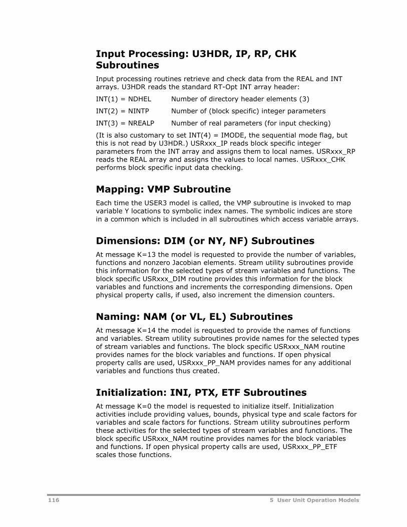
116 5 User Unit Operation Models
Input Processing: U3HDR, IP, RP, CHKSubroutines
Input processing routines retrieve and check data from the REAL and INTarrays. U3HDR reads the standard RT-Opt INT array header:
INT(1) = NDHEL Number of directory header elements (3)
INT(2) = NINTP Number of (block specific) integer parameters
INT(3) = NREALP Number of real parameters (for input checking)
(It is also customary to set INT(4) = IMODE, the sequential mode flag, butthis is not read by U3HDR.) USRxxx_IP reads block specific integerparameters from the INT array and assigns them to local names. USRxxx_RPreads the REAL array and assigns the values to local names. USRxxx_CHKperforms block specific input data checking.
Mapping: VMP Subroutine
Each time the USER3 model is called, the VMP subroutine is invoked to mapvariable Y locations to symbolic index names. The symbolic indices are storein a common which is included in all subroutines which access variable arrays.
Dimensions: DIM (or NY, NF) Subroutines
At message K=13 the model is requested to provide the number of variables,functions and nonzero Jacobian elements. Stream utility subroutines providethis information for the selected types of stream variables and functions. Theblock specific USRxxx_DIM routine provides this information for the blockvariables and functions and increments the corresponding dimensions. Openphysical property calls, if used, also increment the dimension counters.
Naming: NAM (or VL, EL) Subroutines
At message K=14 the model is requested to provide the names of functionsand variables. Stream utility subroutines provide names for the selected typesof stream variables and functions. The block specific USRxxx_NAM routineprovides names for the block variables and functions. If open physicalproperty calls are used, USRxxx_PP_NAM provides names for any additionalvariables and functions thus created.
Initialization: INI, PTX, ETF Subroutines
At message K=0 the model is requested to initialize itself. Initializationactivities include providing values, bounds, physical type and scale factors forvariables and scale factors for functions. Stream utility subroutines performthese activities for the selected types of stream variables and functions. Theblock specific USRxxx_NAM routine provides names for the block variablesand functions. If open physical property calls are used, USRxxx_PP_ETFscales those functions.

5 User Unit Operation Models 117
Pattern: PAT Subroutine
At message K=0 the model is requested to provide the Jacobian pattern.Stream utility subroutines perform these activities for the selected types ofstream functions. The block specific USRxxx_PAT routine provides pattern andnz dimension for the block functions. If open physical property calls are used,USRxxx_PP_PAT provides the sparsity pattern and nz for those functions.
Function Evaluation: RES Subroutine
At message K=1 the model is requested to return its function residual values.Stream utility subroutines do this for the selected types of stream functions.The block specific USRxxx_RES routine returns values of the block functions.When open physical property calls are used, USRxxx_PP_RES returns theirfunction values.
Output: RPT Subroutine
At message K=101 the model is called to write to the Report file. Blockspecific routine USRxxx_RPT is prepared to create customized output. Thissubroutine can access the FORTRAN logical unit number for the Report filefrom COMMON /PPEXEC_USER/. This subroutine can call several Aspen Plususer interface output utilities.
Closure: XTP Subroutine
At message K=7 the model is called upon solution or termination. The USER3model can call stream utility routines to copy stream values into the AspenPlus stream arrays. The model can also take other block specific actions asnecessary.
Jacobian Evaluation: JAC Subroutine
At message K=9 the model is called to evaluate the Jacobian. Stream utilitysubroutines do this for the selected types of stream functions. The blockspecific USRxxx_JAC routine returns block Jacobian values. If open physicalproperty calls are used, USRxxx_PP_JAC returns their Jacobian values. If thenumeric layer is used the model will not be called with this message level.
USER3 Stream Utilities
Stream utilities (U3Sxxx) create standard RT-Opt stream variables (mole flowbasis) for each material and information stream present and writes standardmaterial and energy balances. The stream functions are:
Overall energy balance.
Overall material balance.
Component material balances.
Other stream utilities are available for writing only subsets of these functions,such as energy balance only, overall material balance only, or balances on asubset of the components.

118 5 User Unit Operation Models
For variables, the U3Sxxx routines are:
NY Number of variables.
VL Variable names.
VMP Variable mapping.
PTX Variable and attribute initialization.
For the full set of material and energy balance functions and their attributes,the U3Sxxx routines are:
NF Number of functions.
NZ Number of nonzero Jacobian elements.
RES Function residual evaluation.
PAT Jacobian sparsity pattern.
JAC Jacobian evaluation.
EL Function names.
ETF Function scaling factors.
Subroutine U3SCPY copies one Aspen Plus stream array into another, typicallyto aid in initialization of outlet streams. Subroutine U3SPTX copies values ofall Aspen Plus streams associated with the block into the appropriate streamvariables and also initializes the stream variable attributes (scales andbounds). Subroutine U3SXTP copies values of all stream variables into theproper Aspen Plus streams and performs a flash calculation to fill in otherstream properties.
The USER3 stream utilities work internally with stream descriptors, whichcontain information about the stream name, location, and number ofcomponents. The USER3 model must call U3SDESC or U3SDESC1 to initializethe stream descriptors if stream utilities are used. U3SDESC1 supports theuse of a non-zero component group, while U3SDESC does not. If U3SDESC1is used, the user-specified non-zero component list may be obtained withsubroutine U3GIDX_BLK Parameters for sizing the stream descriptors aredeclared and stored in include files 'U3MSTRM.INC' and 'U3ISTRM.INC'.
Material Balance Only Routines
If the USER3 model requires no energy balance or a custom energy balance,stream utilities which only write the material balance functions may be called.These routines work with overall and component material balances and havenames of the form U3_MBAL_xxx, where xxx represents the standard USER3subroutine nomenclature:
NF Number of functions.
NZ Number of nonzero Jacobian elements.
RES Function residual evaluation.
PAT Jacobian sparsity pattern.
JAC Jacobian evaluation.
NAM Function names.
SCL Function scaling factors.
The material balance stream utilities can write functions on selectedcomponents only - for example, inerts in a reacting system. The number of
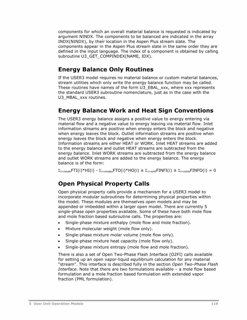
5 User Unit Operation Models 119
components for which an overall material balance is requested is indicated byargument NINDX. The components to be balanced are indicated in the arrayINDX(NINDX), by their location in the Aspen Plus stream slate. Thecomponents appear in the Aspen Plus stream slate in the same order they aredefined in the input language. The index of a component is obtained by callingsubroutine U3_GET_COMPINDEX(NAME, IDX).
Energy Balance Only Routines
If the USER3 model requires no material balance or custom material balances,stream utilities which only write the energy balance function may be called.These routines have names of the form U3_EBAL_xxx, where xxx representsthe standard USER3 subroutine nomenclature, just as in the case with theU3_MBAL_xxx routines.
Energy Balance Work and Heat Sign Conventions
The USER3 energy balance assigns a positive value to energy entering viamaterial flow and a negative value to energy leaving via material flow. Inletinformation streams are positive when energy enters the block and negativewhen energy leaves the block. Outlet information streams are positive whenenergy leaves the block and negative when energy enters the block.Information streams are either HEAT or WORK. Inlet HEAT streams are addedto the energy balance and outlet HEAT streams are subtracted from theenergy balance. Inlet WORK streams are subtracted from the energy balanceand outlet WORK streams are added to the energy balance. The energybalance is of the form:
i=nmatiFTI(i)*HI(i) - i=nmatoFTO(i)*HO(i) ± i=ninfiFINFI(i) ± i=ninfoFINFO(i) = 0
Open Physical Property Calls
Open physical property calls provide a mechanism for a USER3 model toincorporate modular subroutines for determining physical properties withinthe model. These modules are themselves open models and may beappended or imbedded within a larger open model. There are currently 5single-phase open properties available. Some of these have both mole flowand mole fraction based subroutine calls. The properties are:
Single-phase mixture enthalpy (mole flow and mole fraction).
Mixture molecular weight (mole flow only).
Single-phase mixture molar volume (mole flow only).
Single-phase mixture heat capacity (mole flow only).
Single-phase mixture entropy (mole flow and mole fraction).
There is also a set of Open Two-Phase Flash Interface (O2FI) calls availablefor setting up an open vapor-liquid equilibrium calculation for any material“stream”. This interface is described fully in the section Open Two-Phase FlashInterface. Note that there are two formulations available – a mole flow basedformulation and a mole fraction based formulation with extended vaporfraction (PML formulation).

120 5 User Unit Operation Models
It is convenient to wrap the physical property calls for a specific block into aset of subroutines named USRxxx_PP_xxx, where xxx represents:
DIM Number of functions and variables.
RES Function residual evaluation.
PAT Jacobian sparsity pattern.
JAC Jacobian evaluation.
NAM Function and variable names.
ETF Function scaling factors.
Once the wrappers have been written for a particular block, they are called inthe same section of code as the corresponding stream and block functions. Atemplate set of wrapper routines is distributed as file PPTEMP.FOR and iseasily customized for a particular block.
Differences Between Open & Closed PhysicalProperty Calls
All USER2 closed physical property calls are available within USER3, but onlya subset of these calls have been converted to open subroutine modules.Closed property calls return the value of the property when given the properinputs, while open physical property calls perform all functions required of anopen model, including:
Creating and naming any additional variables.
Writing a function or functions for the property in residual format.
Providing Jacobian sparsity pattern and values.
Each single-phase open property call creates no new variables and one newfunction. The calls for mole flow streams can be made either through the SETroutine for the property (by setting the ICFLAG variable for the desiredoperation), or by individually calling the lower level routines for dimensions,names, sparsity, residuals and Jacobian. The mole fraction stream utilitiesmust be called via the low-level routines since no SET routines exist for those.Note that the mole fraction based calls use the same name subroutine as themole flow calls, since the name of the open function is the same in each case.
The names and argument list for the high-level SET routines are given first,followed by the description of the argument variables. The low-levelsubroutines use subsets of the SET arguments. Their names and argumentlists follow the variable descriptions.
Physical Property Call Primitives
Single phase heat capacity
SUBROUTINE RTO_CPSET (NCP,KPH,NBOPST,IDX,FLOW,PRES,TEMP,CP,1 JXFLOW,JXPRES,JXTE,JXCP,TOLER,FSCALE,2 PSCALE,TSCALE,LODIAG,NLAB,ICFLAG,IRNDX,3 JXNDX,NZNDX,ZFLOW,ICNAME,XNAME,RNAME,4 IRSTOR,JXSTOR,RESID,DRESDX)

5 User Unit Operation Models 121
Single phase enthalpy
SUBROUTINE RTO_ENSET (NCP,KPH,NBOPST,IDX,FLOW,PRES,TEMP,ENTH,1 JXFLOW,JXPRES,JXTEMP,JXENTH,TOLER,FSCALE,2 PSCALE,LODIAG,NLAB,ICFLAG,IRNDX,JXNDX,3 NZNDX,ZFLOW,ICNAME,XNAME,RNAME,IRSTOR,4 JXSTOR,RESID,DRESDX)
Average molecular weight
SUBROUTINE RTO_MWSET (NCP,IDX,FLOW,AMW,JXFLOW,JXAMW,NLAB,1 ICFLAG,IRNDX,JXNDX,NZNDX,ZFLOW,ICNAME,2 XNAME,RNAME,IRSTOR,JXSTOR,RESID,DRESDX)
Single phase molar volume
SUBROUTINE RTO_VMSET (NCP,KPH,NBOPST,IDX,FLOW,PRES,TEMP,VM,1 JXFLOW,JXPRES,JXTEMP,JXVM,TOLER,FSCALE,2 PSCALE,LODIAG,NLAB,ICFLAG,IRNDX,JXNDX,3 NZNDX,ZFLOW,ICNAME,XNAME,RNAME,IRSTOR,4 JXSTOR,RESID,DRESDX)
Single phase entropy
SUBROUTINE RTO_SMSET (NCP,KPH,NBOPST,IDX,FLOW,PRES,TEMP,ENTR,1 JXFLOW,JXPRES,JXTEMP,JXENTR,TOLER,FSCALE,2 PSCALE,LODIAG,NLAB,ICFLAG,IRNDX,JXNDX,3 NZNDX,ZFLOW,ICNAME,XNAME,RNAME,IRSTOR,4 JXSTOR,RESID,DRESDX)
Argument List for Physical Property Call Primitives
Variable ICFLAGs Type Dimension Description
NCP I: 0, 1, 2,3, 4
I 1 Number of packed components.
KPH I: 1, 3, 4 I 1 Phase code. 1 - Vapor. 2 - Liquid.
NBOPST I: 3, 4 I 6 Physical property option set.
IDX I: 1, 3, 4 I NCP Non-zero component index.
FLOW I: 3 ,4 R NCP Component flows.
PRES I: 3, 4 R 1 Pressure.
TEMP I: 3, 4 R 1 Temperature.
CP I: 3, 4 R 1 Single phase heat capacity variable.
ENTH I: 3, 4 R 1 Single phase enthalpy variable.
AMW I: 3, 4 R 1 Average molecular weight variable.
VM I: 3, 4 R 1 Single phase molar volume variable.
ENTR I: 3, 4 R 1 Single phase entropy variable.
JXFLOW I: 2 I 1 Variable vector component flowsindex.
JXPRES I: 2 I 1 Variable vector pressure index.
JXTEMP I: 2 I 1 Variable vector temperature index.
JXCP I: 2 I 1 Variable vector heat capacity index.

122 5 User Unit Operation Models
Variable ICFLAGs Type Dimension Description
JXENTH I: 2 I 1 Variable vector enthalpy index.
JXAMW I: 2 I 1 Variable vector molecular weightindex.
JXVM I: 2 I 1 Variable vector molar volume index.
JXENTR I:2 I 1 Variable vector entropy index.
TOLER I: 4 R 1 Residual convergence tolerance.
FSCALE I: 4 R 1 Flow scale.
PSCALE I: 4 R 1 Pressure scale.
TSCALE I: 4 R 1 Temperature scale.
LODIAG I: 3, 4 I 1 Physical property diagnostic level.
NLAB I: 1 I 1 Length of variable or residual names.
ICFLAG I: 0, 1, 2,3, 4
I 1 Calculation flag.0 - Return dimensions.1 - Return variable and equationnames.2 - Return jacobian sparsity.3 - Return function residual.4 - Return jacobian matrix.
IRNDX I/O: 0, 1,2, 3, 4
I 1 Residual vector index, incremented byNEQN; NEQN = 1 for RTO_CPSET,RTO_ENSET, RTO_MWSET,RTO_VMSETInput - (1st local residual index)) - 1Output - Last local residual index
JXNDX I/O: 0, 1,2, 3, 4
I 1 Variable vector index, incremented byNVAR; NVAR = 0 for RTO_CPSET,RTO_ENSET, RTO_MWSET,RTO_VMSETInput - No. of variables beforeaddition of RTO_MWSET internalvariables.Output - No. of variables afteraddition of RTO_MWSET internalvariables.
NZNDX I/O: 0, 1,2, 3, 4
I 1 Jacobian nonzero index, incrementedby NNZ; NNZ = NCP + 1 forRTO_MWSET, and NNZ = NCP + 3 forRTO_CPSET, RTO_ENSET,RTO_VMSETInput - (1st local nonzero index) - 1Output - Last local nonzero index.
ZFLOW I/O: 3, 4 R NCP Component mole fractions.1
Input - default composition for totalflow below zero tolerance.Output - Composition used forproperty calculation
ICNAME O: 1 I (2,NCP) Component names.
XNAME O: 1 R (3,NVAR) Variable names.
RNAME O: 1 R (3,NEQN) Function residual name.
IRSTOR O: 2 I NNZ Row index of jacobian.

5 User Unit Operation Models 123
Variable ICFLAGs Type Dimension Description
JXSTOR O: 2 I NNZ Column index of jacobian.
RESID O: 3 R NEQN Function residual value.
DRESDX O: 4 R NNZ Jacobian matrix of residual wrtvariables.
Notes:
1 ZFLOW should be set to the default value of the composition for which theenthalpy should be returned for total flow rates below the minimum flowtolerance. Upon return from the called routine, ZFLOW will contain thecomposition at which the returned value of the property was calculated.Thus, if the user wishes to use the composition of the previous propertycall as the default zero flow composition, no adjustment to ZFLOW isnecessary between calls.
2 The USER3 model main subroutine should include the following commonblock and statements in order to provide the block name to the physicalproperty calls:
#include "rxn_iblkiddo i=1,2
iblkid_idblk(i) = ids(i,1)enddo
Low-Level Physical Property Subroutines
Heat capacity
Subroutine rto_cpdim (ncp, irndx, jxndx, nzndx)Subroutine rto_cpjac (ncp, kph, nbopst, idx, flow, pres, temp,
cp, lodiag, delta, fscale, pscale,tscale, irndx, jxndx, nzndx, zflow,dresdx)
Subroutine rto_cpnam (ncp, kph, idx, nlab, irndx, jxndx,nzndx, icname, xname, rname)
Subroutine rto_cpres (ncp, kph, nbopst, idx, flow, pres,temp, cp, lodiag, irndx, jxndx, nzndx,zflow, resid)
subroutine rto_cpspr (ncp, jxflow, jxpres, jxtemp, jxcp,irndx, jxndx, nzndx, irstor, jxstor)
Enthalpy (mole flow basis):
subroutine rto_endim (ncp, irndx, jxndx, nzndx)subroutine rto_enjac (ncp, kph, nbopst, idx, flow, pres,
temp, enth, lodiag, delta, fscale,pscale, irndx, jxndx, nzndx, zflow,dresdx)
subroutine rto_ennam (ncp, kph, idx, nlab, irndx, jxndx,nzndx, icname, xname, rname)
subroutine rto_enres (ncp, kph, nbopst, idx, flow, pres,temp, enth, lodiag, irndx, jxndx,nzndx, zflow, resid)

124 5 User Unit Operation Models
subroutine rto_enspr (ncp, jxflow, jxpres, jxtemp, jxenth,irndx, jxndx, nzndx, irstor, jxstor)
Enthalpy (mole fraction basis):
subroutine rto_encdim (ncp, irndx, jxndx, nzndx)subroutine rto_encjac (ncp, kph, nbopst, idx, flow, pres,
temp, enth, lodiag, delta, fscale,pscale, irndx, jxndx, nzndx, zflow,dresdx)
subroutine rto_ennam (ncp, kph, idx, nlab, irndx, jxndx,nzndx, icname, xname, rname)
subroutine rto_encres (ncp, kph, nbopst, idx, flow, pres,temp, enth, lodiag, irndx, jxndx,nzndx, zflow, resid)
subroutine rto_encspr (ncp, jxcomp, jxpres, jxtemp, jxenth,irndx, jxndx, nzndx, irstor, jxstor)
Molecular Weight:
subroutine rto_mwdim (ncp, irndx, jxndx, nzndx)subroutine rto_mwjac (ncp, idx, flow, amw, irndx, jxndx,
nzndx, zflow, dresdx)subroutine rto_mwnam (ncp, idx, nlab, irndx, jxndx, nzndx,
icname, xname, rname)subroutine rto_mwres (ncp, idx, flow, amw, irndx, jxndx,
nzndx, zflow, resid)subroutine rto_mwspr (ncp, jxflow, jxamw, irndx, jxndx,
nzndx, irstor, jxstor)
Molar Volume:
subroutine rto_vmdim (ncp, irndx, jxndx, nzndx)subroutine rto_vmjac (ncp, kph, nbopst, idx, flow, pres,
temp, vm, lodiag, delta, fscale,pscale, irndx, jxndx, nzndx, zflow,dresdx)
subroutine rto_vmnam (ncp, kph, idx, nlab, irndx, jxndx,nzndx, icname, xname, rname)
subroutine rto_vmres (ncp, kph, nbopst, idx, flow, pres,temp, vm, lodiag, irndx, jxndx, nzndx,zflow, resid)
subroutine rto_vmspr (ncp, jxflow, jxpres, jxtemp, jxvm,irndx, jxndx, nzndx, irstor, jxstor)
Entropy (mole flow basis):
subroutine rto_smdim (ncp, irndx, jxndx, nzndx)subroutine rto_smjac (ncp, kph, nbopst, idx, flow, pres,
temp, entr, lodiag, delta, fscale,pscale, irndx, jxndx, nzndx, zflow,dresdx)
subroutine rto_smnam (ncp, kph, idx, nlab, irndx, jxndx,nzndx, icname, xname, rname)

5 User Unit Operation Models 125
subroutine rto_smres (ncp, kph, nbopst, idx, flow, pres,temp, entr, lodiag, irndx, jxndx,nzndx, zflow, resid)
subroutine rto_smspr (ncp, jxflow, jxpres, jxtemp, jxentr,irndx, jxndx, nzndx, irstor, jxstor)
Entropy (mole fraction basis):
subroutine rto_smcdim (ncp, irndx, jxndx, nzndx)subroutine rto_smcjac (ncp, kph, nbopst, idx, flow, pres,
temp, entr, lodiag, delta, fscale,pscale, irndx, jxndx, nzndx, zflow,dresdx)
subroutine rto_smnam (ncp, kph, idx, nlab, irndx, jxndx,nzndx, icname, xname, rname)
subroutine rto_smcres (ncp, kph, nbopst, idx, flow, pres,temp, entr, lodiag, irndx, jxndx,nzndx, zflow, resid)
subroutine rto_smcspr (ncp, jxcomp, jxpres, jxtemp, jxentr,irndx, jxndx, nzndx, irstor, jxstor)
Other Useful USER3 UtilitiesUSER3 provides several naming and string manipulation utilities, including:
U3DNAM Provides default names for unnamed variables and equations.
U3VNAM Provides a fully qualified name for a block variable.
U3ENAM Provides a fully qualified name for a block equation.
U3PKCR Removes embedded blank characters from a string.
U3CLST Initializes a string to blanks.
USER3 also provides a number of variable attribute manipulation utilities,such as:
U3FXV Sets status of a variable to fixed.
U3UFXV Sets status of a variable to free.
U3VFXD Inquire as to a variable's fixed/free status.
U3VGPT Get the physical type of a variable.
U3VPPT Put the physical type of a variable.
U3INCR Set function status to included.
U3UNCR Set function status to unincluded.
U3RINC Inquire as to a function's included/unincluded status.
Since the YSTAT and FSTAT arrays have several pieces of informationoverlayed into each integer location, it is recommended that all statusmanipulation within the model be done with these utilities rather than bydirectly working with FSTAT and YSTAT.

126 5 User Unit Operation Models
Component Object Models(COM)Aspen Plus has the ability to directly call Component Object Models (COM) toperform unit operation calculations. See Chapter 26, COM Unit OperationInterfaces, beginning on page 269, for detailed information.

6 User Physical Property Models 127
6 User Physical PropertyModels
The Aspen Plus user physical property models allow you to provide models forcalculating various major, subordinate, and intermediate physical properties.Aspen Plus allows user models for both conventional and nonconventionalproperties. You can invoke the user physical property models by selecting theuser models for properties on the Methods | Selected Methods | Modelssheet, or by selecting the user models for nonconventional properties on theMethods | NC-Props form. Each user physical property model has a built-inmodel name, principal subroutine name, and model-specific parameternames.

128 6 User Physical Property Models
User Models for ConventionalPropertiesThis section lists the conventional properties calculated by user models.Definitions of the properties, the associated model names, principalsubroutine names, and model-specific parameter names are also listed. Thefollowing sections explain how to introduce a user conventional propertymodel in a simulation, and how to prepare the necessary principal subroutinesfor calculating the desired physical properties.
For each physical property, the associated built-in user model name, principalsubroutine name, and parameter information are listed in the following table.
CalculatedProperty
ModelName
PrincipalSubroutineName
ParameterName
NumberofElements
ParameterType Definition
† ESUSR ESU ESUAESUB
51
UnaryBinary
Equation of state formixtures
† ESUSR0 ESU0 ESUA 5 Unary Equation of state for purecomponents
† ESUSR2 ESU2 ESU2AESU2B
51
UnaryBinary
Equation of state formixtures with full analyticalderivatives
† ESUSR20 ESU20 ESU2A 5 Unary Equation of state for purecomponents with fullanalytical derivatives
GAMMA†† GMUSR GMU GMUAGMUB
32
UnaryBinary
Liquid phase activitycoefficient
GAMMA†† GMELCUSR GMELCU GMELUAGMELUB
32
UnaryBinary
Liquid phase electrolytesystem activity coefficient
KVL†† KVLUSR KVLU — — — K-value (see K-Value)
HV HV0USR HV0U HV0UA 5 Unary Pure component vapormolar enthalpy
DHV DHV0USR DHV0U DHV0UA 5 Unary Pure component vapormolar enthalpy departure
HVMX HV2USR HV2U HV2UA 5 Unary Mixture vapor molarenthalpy
HVMX HV2USR2 HV2U2 HV2U2A 5 Unary Mixture vapor molarenthalpy†††
DHVMX DHV2USR DHV2U DHV2UA 5 Unary Mixture vapor molarenthalpy departure
HL HL0USR HL0U HL0UA 5 Unary Pure component liquidmolar enthalpy
DHL DHL0USR DHL0U DHL0UA 5 Unary Pure component liquidmolar enthalpy departure
HLMX HL2USR HL2U HL2UA 5 Unary Mixture liquid molarenthalpy
HLMX HL2USR2 HL2U2 HL2U2A 5 Unary Mixture liquid molarenthalpy†††
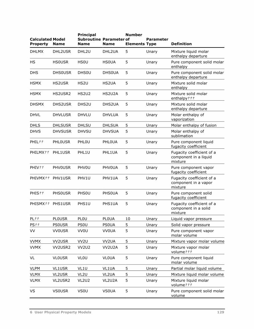
6 User Physical Property Models 129
CalculatedProperty
ModelName
PrincipalSubroutineName
ParameterName
NumberofElements
ParameterType Definition
DHLMX DHL2USR DHL2U DHL2UA 5 Unary Mixture liquid molarenthalpy departure
HS HS0USR HS0U HS0UA 5 Unary Pure component solid molarenthalpy
DHS DHS0USR DHS0U DHS0UA 5 Unary Pure component solid molarenthalpy departure
HSMX HS2USR HS2U HS2UA 5 Unary Mixture solid molarenthalpy
HSMX HS2USR2 HS2U2 HS2U2A 5 Unary Mixture solid molarenthalpy†††
DHSMX DHS2USR DHS2U DHS2UA 5 Unary Mixture solid molarenthalpy departure
DHVL DHVLUSR DHVLU DHVLUA 5 Unary Molar enthalpy ofvaporization
DHLS DHLSUSR DHLSU DHLSUA 5 Unary Molar enthalpy of fusion
DHVS DHVSUSR DHVSU DHVSUA 5 Unary Molar enthalpy ofsublimation
PHIL†† PHL0USR PHL0U PHL0UA 5 Unary Pure component liquidfugacity coefficient
PHILMX†† PHL1USR PHL1U PHL1UA 5 Unary Fugacity coefficient of acomponent in a liquidmixture
PHIV†† PHV0USR PHV0U PHV0UA 5 Unary Pure component vaporfugacity coefficient
PHIVMX†† PHV1USR PHV1U PHV1UA 5 Unary Fugacity coefficient of acomponent in a vapormixture
PHIS†† PHS0USR PHS0U PHS0UA 5 Unary Pure component solidfugacity coefficient
PHISMX†† PHS1USR PHS1U PHS1UA 5 Unary Fugacity coefficient of acomponent in a solidmixture
PL†† PL0USR PL0U PL0UA 10 Unary Liquid vapor pressure
PS†† PS0USR PS0U PS0UA 5 Unary Solid vapor pressure
VV VV0USR VV0U VV0UA 5 Unary Pure component vapormolar volume
VVMX VV2USR VV2U VV2UA 5 Unary Mixture vapor molar volume
VVMX VV2USR2 VV2U2 VV2U2A 5 Unary Mixture vapor molarvolume†††
VL VL0USR VL0U VL0UA 5 Unary Pure component liquidmolar volume
VLPM VL1USR VL1U VL1UA 5 Unary Partial molar liquid volume
VLMX VL2USR VL2U VL2UA 5 Unary Mixture liquid molar volume
VLMX VL2USR2 VL2U2 VL2U2A 5 Unary Mixture liquid molarvolume†††
VS VS0USR VS0U VS0UA 5 Unary Pure component solid molarvolume

130 6 User Physical Property Models
CalculatedProperty
ModelName
PrincipalSubroutineName
ParameterName
NumberofElements
ParameterType Definition
VSMX VS2USR VS2U VS2UA 5 Unary Mixture solid molar volume
VSMX VS2USR2 VS2U2 VS2U2A 5 Unary Mixture solid molarvolume†††
MUV MUV0USR MUV0U MUV0UA 5 Unary Pure component vaporviscosity
MUVMX MUV2USR MUV2U MUV2UA 5 Unary Mixture vapor viscosity
MUVMX MUV2USR2 MUV2U2 MUV2U2A 5 Unary Mixture vapor viscosity†††
MUL MUL0USR MUL0U MUL0UA 5 Unary Pure component liquidviscosity
MULMX MUL2USR MUL2U MUL2UA 5 Unary Mixture liquid viscosity
MULMX MUL2USR2 MUL2U2 MUL2U2A 5 Unary Mixture liquid viscosity†††
KV KV0USR KV0U KV0UA 5 Unary Pure component vaporthermal conductivity
KVMX KV2USR KV2U KV2UA 5 Unary Mixture vapor thermalconductivity
KVMX KV2USR2 KV2U2 KV2U2A 5 Unary Mixture vapor thermalconductivity†††
KL KL0USR KL0U KL0UA 5 Unary Pure component liquidthermal conductivity
KLMX KL2USR KL2U KL2UA 5 Unary Mixture liquid thermalconductivity
KLMX KL2USR2 KL2U2 KL2U2A 5 Unary Mixture liquid thermalconductivity†††
KS KS0USR KS0U KS0UA 5 Unary Pure component solidthermal conductivity
KSMX KS2USR KS2U KS2UA 5 Unary Mixture solid thermalconductivity
KSMX KS2USR2 KS2U2 KS2U2A 5 Unary Mixture solid thermalconductivity†††
DV DV0USR DV0U DV0UA 5 Unary Binary diffusion coefficientsof vapor
DL DL0USR DL0U DL0UA 5 Unary Binary diffusion coefficientsof liquid
DVMX DV1USR DV1U DV1UA 5 Unary Diffusion coefficient of acomponent in a vapormixture
DLMX DL1USR DL1U DL1UA 5 Unary Diffusion coefficient of acomponent in a liquidmixture
SIGL SIG0USR SIG0U SIG0UA 5 Unary Pure component surfacetension
SIGLMX SIG2USR SIG2U SIG2UA 5 Unary Mixture surface tension
SIGLMX SIG2USR2 SIG2U2 SIG2U2A 5 Unary Mixture surface tension†††
GLMX GL2USR GL2U GL2UA 5 Unary Mixture liquid molar Gibbsfree energy

6 User Physical Property Models 131
CalculatedProperty
ModelName
PrincipalSubroutineName
ParameterName
NumberofElements
ParameterType Definition
GLMX GL2USR2 GL2U2 GL2U2A 5 Unary Mixture liquid molar Gibbsfree energy†††
GVMX GV2USR GV2U GV2UA 5 Unary Mixture vapor molar Gibbsfree energy
GVMX GV2USR2 GV2U2 GV2U2A 5 Unary Mixture vapor molar Gibbsfree energy†††
GSMX GS2USR GS2U GS2UA 5 Unary Mixture solid molar Gibbsfree energy
GSMX GS2USR2 GS2U2 GS2U2A 5 Unary Mixture solid molar Gibbsfree energy†††
DSSMX DSS2USR DSS2U DSS2UA 5 Unary Mixture solid molar entropydeparture
DSLMX DSL2USR DSL2U DSL2UA 5 Unary Mixture liquid molarentropy departure
DSVMX DSV2USR DSV2U DSV2UA 5 Unary Mixture vapor molarentropy departure
DGSMX DGS2USR DGS2U DGS2UA 5 Unary Mixture solid molar Gibbsfree energy departure
DGLMX DGL2USR DGL2U DGL2UA 5 Unary Mixture liquid molar Gibbsfree energy departure
DGVMX DGV2USR DGV2U DGV2UA 5 Unary Mixture vapor molar Gibbsfree energy departure
DGS DGS0USR DGS0U DGS0UA 5 Unary Pure component solid molarGibbs free energy departure
GS GS0USR GS0U GS0UA 5 Unary Pure component solid molarGibbs free energy
DGL DGL0USR DGL0U DGL0UA 5 Unary Pure component liquidmolar Gibbs free energydeparture
GL GL0USR GL0U GL0UA 5 Unary Pure component liquidmolar Gibbs free energy
DGV DGV0USR DGV0U DGV0UA 5 Unary Pure component vapormolar Gibbs free energydeparture
GV GV0USR GV0U GV0UA 5 Unary Pure component vapormolar Gibbs free energy
†ESUSR and ESUSR0 are the model names for user equation-of-state models. All ofthe built-in equation-of-state models are capable of calculating and returning fugacitycoefficients, enthalpy, entropy, and Gibbs free energy departures, and molar volumesfor mixtures or pure components in the vapor or liquid phases. While this is notrequired of a user equation-of-state model, you should include those properties thatwill actually be required when the model is called by a physical property monitor.
††The quantity calculated and returned should be the natural logarithm of theproperty.
†††These mixture property models are intended for users to develop special mixingrules to calculate mixture properties from the constituent pure component propertiescalculated by a specified route.

132 6 User Physical Property Models
Principal User ModelSubroutines for ConventionalPropertiesFor each user model, you must provide a principal subroutine that calculatesand returns the desired physical properties. Since the principal subroutinesare called directly by the appropriate physical property monitors, they have afixed name and argument list structure. The principal subroutine can call anyadditional subroutine. There is no restriction on the argument lists and thenumber of these additional subroutines.
Calling Sequence for Pure Component Properties
SUBROUTINE subrname (T, PI, N, IDX, IRW, IIW, KCALC, KOP,NDS, KDIAG, QI, DQI, KER)
Principal subroutine names: HV0U, DHV0U, HL0U, DHL0U, HS0U, DHS0U,PHL0U, PHV0U, PHS0U, PL0U, PS0U, VV0U, VL0U, VS0U, MUV0U, MUL0U,KV0U, KL0U, KS0U, SIG0U, DHLSU, DHVSU, DHVLU, DGS0U, GS0U, DGL0U,GL0U, DGV0U, GV0U
Calling Sequence for Properties of Components in aMixture
SUBROUTINE subrname (T, P, Z, N, IDX, IRW, IIW, KCALC,KOP, NDS, KDIAG, QIMX, DQIMX, KER)
Principal subroutine names: PHL1U, PHV1U, PHS1U, VL1U, DV1U, DL1U
Calling Sequence for User Activity Coefficient Model
SUBROUTINE GMU (T, P, Z, N, IDX, IRW, IIW, KCALC,KOP, NDS, KDIAG, QIMX, DQIMX, KER,NSUB, NSUP, IDXSUB, IDXSUP, GAMSC,DGAMSC)
Calling Sequence for User Electrolyte Activity CoefficientModel
SUBROUTINE GMUELC (T, P, X, N, NSUB, NSUP, NCAT, NANI,IDX, IDXM, IDXSUB, IDXSUP, IDXCAT,IDXANI, IRW, IIW, KCALC, NDS, KDIAG,GAMA, GAMSC, DGAMA, DGAMSC, KER, KOP)
(See Electrolyte Calculations)
Calling Sequence for Properties of a Mixture
SUBROUTINE subrname (T, P, Z, N, IDX, IRW, IIW, KCALC,KOP, NDS, KDIAG, QMX, DQMX, KER)

6 User Physical Property Models 133
Principal subroutine names: HV2U, DHV2U, HL2U, DHL2U, HS2U, DHS2U,VV2U, VL2U, VS2U, MUV2U, MUL2U, KV2U, KL2U, KS2U, SIG2U, GL2U, GV2U,GS2U, DSS2U, DSL2U, DSV2U, DGS2U, DGL2U, DGV2U
Calling Sequence for Properties of a Mixture That Dependson Pure Component Properties and User Mixing Rule
SUBROUTINE subrname (T, P, Z, N, IDX, XMW, SG, VLSTD,PARAM, QI, DQI, DPQI, KSW, KOP, NDS,KDIAG, QMX, DQMX, DPQMX, KER)
Principal subroutine names: HV2U2, HL2U2, HS2U2, VV2U2, VL2U2,VS2U2, MUV2U2, MUL2U2, KV2U2, KL2U2, KS2U2, SIG2U2, GL2U2, GV2U2,GS2U2
Thermodynamic and transport properties of mixtures are generally a non-linear function of the constituent pure component properties. The abovemodels and subroutines allow users to provide their own mixing rules tocalculate these properties from pure component properties that are computedusing a specified route.
Calling Sequence for User EOS Subroutine (ESU)
SUBROUTINE ESU (T, P, Z, N, IDX, IRW, IIW, KVL, KPHI,KH, KS, KG, KV, NDS, KDIAG, PHIMX,DHMX, DSMX, DGMX, VMX, DPHIMX, DDHMX,DDSMX, DDGMX, DVMX, KER, KOP)
Calling Sequence for User Pure Component EOSSubroutine (ESU0)
SUBROUTINE ESU0 (T, PI, N, IDX, IRW, IIW, KVL, KPHI,KH, KS, KG, KV, NDS, KDIAG, PHI, DH,DS, DG, V, DPHI, DDH, DDS, DDG, DV,KER, KOP)
Calling Sequence for User EOS Subroutine with FullAnalytical Derivatives (ESU2)
SUBROUTINE ESU2 (T, P, Z, N, IDX, RW, IW, KVL, NDS,KDIAG, KPHI, KH, KS, KG, KV, PHIMX,DPHIMXDT, DPHIMXDP, DPHIMXDN, DPHIMXDX,DHMX, DDHMXDT, DDHMXDP, DDHMXDN, DDHMXDX,DSMX, DDSMXDT, DDSMXDP, DDSMXDN, DDSMXDX,DGMX, DDSMXDT, DDGMXDP, DDGMXDN, DDGMXDX,VMX, DVMXDT, DVMXDP, DVMXDN, DVMXDX,KER, KOP)
Calling Sequence for User Pure Component EOSSubroutine with Full Analytical Derivatives (ESU20)
SUBROUTINE ESU20 (T, P, N, IDX, RW, IW, KVL, NDS,KDIAG, KER, KPHI, KH, KS, KG, KV, PHI,DPHIDT, DPHIDP, DH, DDHDT, DDHDP, DS,

134 6 User Physical Property Models
DDSDT, DDSDP, DG, DDGDT, DDGDP, V, DVDT,DVDP, KOP)
Calling Sequence for User K-Value Subroutine (KVLU)
SUBROUTINE KVLU (T, P, X, Y, N, IDX, IRW, IIW, KCALC,KOP, NDS, KDIAG, XK, DXK, KER)
Argument Descriptions: Conventional PropertySubroutines
Variable I/O† Type Dimension Description
T I REAL*8 — Temperature (K)
P I REAL*8 — Pressure (N/m2)
PI I REAL*8 N Vector of pressures for pure componentproperties (either system pressure or vaporpressure) at which the calculations should beperformed (N/m2)
Z I REAL*8 N Component mole fraction vector (see X, Y,Z)
X I REAL*8 N Liquid mole fraction vector (see X, Y, Z)
Y I REAL*8 N Vapor mole fraction vector (see X, Y, Z)
N I INTEGER — Number of components present
IDX I INTEGER N Component index vector (see IDX)
NSUB I INTEGER — Number of subcritical components within IDX
NSUP I INTEGER — Number of supercritical components withinIDX
NCAT I INTEGER — Number of cations within IDX
NANI I INTEGER — Number of anions within IDX
IDXSUB I INTEGER NSUB Subcritical component index vector (seePartial Component Index Vectors)
IDXSUP I INTEGER NSUP Supercritical component index vector (seePartial Component Index Vectors)
IDXM I INTEGER NSUB+NSUP Molecular component index vector (seePartial Component Index Vectors)
IDXCAT I INTEGER NCAT Cation component index vector (see PartialComponent Index Vectors)
IDXANI I INTEGER NANI Anion component index vector (see PartialComponent Index Vectors)
IRW I INTEGER — Offset for real work array (see Real andInteger Work Areas)
IIW I INTEGER — Offset for integer work array (see Real andInteger Work Areas)
RW I/O REAL*8 see note Real Work Area (see Real and Integer WorkAreas)
IW I/O INTEGER see note Integer Work Area (see Real and IntegerWork Areas)

6 User Physical Property Models 135
Variable I/O† Type Dimension Description
KCALC I INTEGER — Calculation code:KCALC=1, Calculate property onlyKCALC=2, Calculate temperature derivativeof property onlyKCALC=3, Calculate property andtemperature derivative.
KSW I INTEGER 3 Calculation code for user mixing rules. Foreach element, 0 = Do not calculate, 1 =Calculate:
KSW(1): The property itself
KSW(2): Temperature derivative of property
KSW(3): Pressure derivative of property
XMW I REAL*8 NCC †† Molecular weight vector
SG I REAL*8 NCC †† Specific gravity vector
VLSTD I REAL*8 NCC †† Standard liquid volume vector (m3/kgmole)
PARAM I REAL*8 5*NCC †† Vector of user mixing rule model parameter,such as HL2U2A parameter for HL2U2model.
KOP I INTEGER 10 Integer vector containing up to 10 modeloption codes (see KOP)
NDS I INTEGER — Data set number of the model-specificparameters (see Parameter Retrieval, thischapter, for explanation of how to use thisnumber to retrieve the correct set ofparameters.)
KDIAG I INTEGER — Diagnostic level code for the control ofwarning and error messages. (see KDIAG)
KVL I INTEGER — Vapor - liquid flag:KVL=1, vapor. KVL=2, liquid
KPHI I INTEGER see note Calculation code for fugacity coefficients (seeCalculation Codes)
KH I INTEGER see note Calculation code for the enthalpy departure(see Calculation Codes)
KS I INTEGER see note Calculation code for the entropy departure(see Calculation Codes)
KG I INTEGER see note Calculation code for the Gibbs energydeparture (see Calculation Codes)
KV I INTEGER see note Calculation code for the molar volume (seeCalculation Codes)
QI I/O REAL*8 N Vector of pure component properties.For user mixing rules, this is an inputvariable; for all other models it is an outputvariable.
DQI I/O REAL*8 N Vector of temperature derivatives of purecomponent properties.For user mixing rules, this is an inputvariable; for all other models it is an outputvariable.
DPQI I REAL*8 N Vector of pressure derivatives of purecomponent properties for user mixing rules

136 6 User Physical Property Models
Variable I/O† Type Dimension Description
QIMX O REAL*8 N Vector of properties of components in amixture
DQIMX O REAL*8 N Vector of temperature derivatives ofproperties of components in a mixture
QMX O REAL*8 — Mixture property
DQMX O REAL*8 — Temperature derivative of a mixtureproperty
DPQMX O REAL*8 — Pressure derivative of a mixture property
GAMSC O REAL*8 NSUB, NSUP Natural logarithm of the activity coefficientsof supercritical components at infinitedilution in subcritical components
DGAMSC O REAL*8 NSUB, NSUP Temperature derivative of GAMSC
GAMA O REAL*8 N Natural logarithm of the activity coefficientsof all components; for ionic species, this isthe natural logarithm of the unsymmetricactivity coefficient (see ElectrolyteCalculations)
DGAMA O REAL*8 N Temperature derivative of GAMA (seeElectrolyte Calculations)
PHI O REAL*8 N Vector of logarithms for fugacity coefficientsof pure components
DPHI O REAL*8 N Vector of temperature derivatives of PHI
DPHIDT O REAL*8 N Vector of temperature derivatives of PHI
DPHIDP O REAL*8 N Vector of pressure derivatives of PHI
PHIMX O REAL*8 N Vector of logarithms for fugacity coefficientsof components in a mixture
DPHIMX O REAL*8 N Vector of temperature derivative of PHIMX
DPHIMXDT O REAL*8 N Vector of temperature derivative of PHIMX
DPHIMXDP O REAL*8 N Vector of pressure derivative of PHIMX
DPHIMXDN O REAL*8 N,N Vector of molar flow derivative of PHIMXDPHIMXDN(i,j) = dPHIMX(i)/dN(j)
DPHIMXDX O REAL*8 N,N Vector of composition derivative of PHIMXDPHIMXDX(i,j) = dPHIMX(i)/dX(j)
DH O REAL*8 N Vector of pure component enthalpydepartures (J/kgmole)
DDH O REAL*8 N Vector of temperature derivatives of DH(J/kgmole-K)
DDHDT O REAL*8 N Vector of temperature derivatives of DH
DDHDP O REAL*8 N Vector of pressure derivatives of DH
DHMX O REAL*8 — Enthalpy departure of a mixture (J/kgmole)
DDHMX O REAL*8 — Temperature derivative of DHMX (J/kgmole-K)
DDHMXDT O REAL*8 — Temperature derivative of DHMX
DDHMXDP O REAL*8 — Pressure derivative of DHMX
DDHMXDN O REAL*8 N Vector of molar flow derivative of DHMX
DDHMXDX O REAL*8 N Vector of composition derivative of DHMX
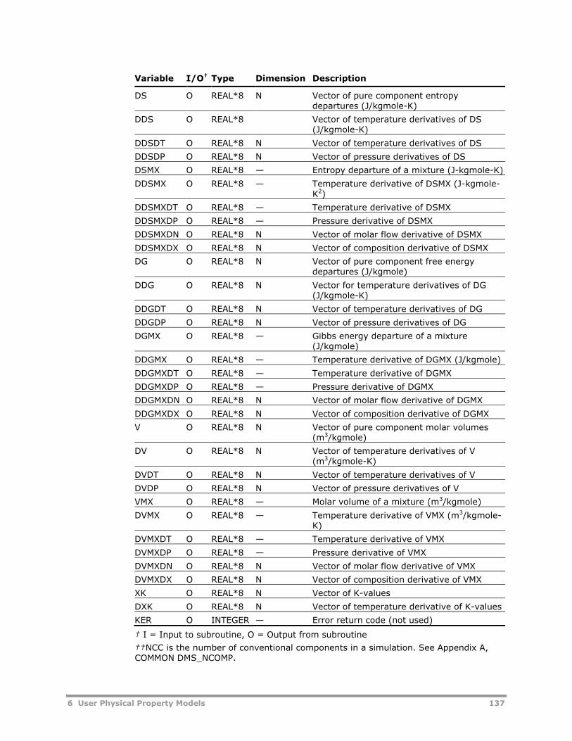
6 User Physical Property Models 137
Variable I/O† Type Dimension Description
DS O REAL*8 N Vector of pure component entropydepartures (J/kgmole-K)
DDS O REAL*8 Vector of temperature derivatives of DS(J/kgmole-K)
DDSDT O REAL*8 N Vector of temperature derivatives of DS
DDSDP O REAL*8 N Vector of pressure derivatives of DS
DSMX O REAL*8 — Entropy departure of a mixture (J-kgmole-K)
DDSMX O REAL*8 — Temperature derivative of DSMX (J-kgmole-K2)
DDSMXDT O REAL*8 — Temperature derivative of DSMX
DDSMXDP O REAL*8 — Pressure derivative of DSMX
DDSMXDN O REAL*8 N Vector of molar flow derivative of DSMX
DDSMXDX O REAL*8 N Vector of composition derivative of DSMX
DG O REAL*8 N Vector of pure component free energydepartures (J/kgmole)
DDG O REAL*8 N Vector for temperature derivatives of DG(J/kgmole-K)
DDGDT O REAL*8 N Vector of temperature derivatives of DG
DDGDP O REAL*8 N Vector of pressure derivatives of DG
DGMX O REAL*8 — Gibbs energy departure of a mixture(J/kgmole)
DDGMX O REAL*8 — Temperature derivative of DGMX (J/kgmole)
DDGMXDT O REAL*8 — Temperature derivative of DGMX
DDGMXDP O REAL*8 — Pressure derivative of DGMX
DDGMXDN O REAL*8 N Vector of molar flow derivative of DGMX
DDGMXDX O REAL*8 N Vector of composition derivative of DGMX
V O REAL*8 N Vector of pure component molar volumes(m3/kgmole)
DV O REAL*8 N Vector of temperature derivatives of V(m3/kgmole-K)
DVDT O REAL*8 N Vector of temperature derivatives of V
DVDP O REAL*8 N Vector of pressure derivatives of V
VMX O REAL*8 — Molar volume of a mixture (m3/kgmole)
DVMX O REAL*8 — Temperature derivative of VMX (m3/kgmole-K)
DVMXDT O REAL*8 — Temperature derivative of VMX
DVMXDP O REAL*8 — Pressure derivative of VMX
DVMXDN O REAL*8 N Vector of molar flow derivative of VMX
DVMXDX O REAL*8 N Vector of composition derivative of VMX
XK O REAL*8 N Vector of K-values
DXK O REAL*8 N Vector of temperature derivative of K-values
KER O INTEGER — Error return code (not used)
† I = Input to subroutine, O = Output from subroutine
††NCC is the number of conventional components in a simulation. See Appendix A,COMMON DMS_NCOMP.

138 6 User Physical Property Models
IDXIDX is a vector containing component numbers of the conventionalcomponents actually present in the order that they appear on theComponents | Specifications | Selection sheet. For example, if only thefirst and third conventional components are present, then N=2 andIDX=(1,3). For component properties, output vectors should be filled in foronly the components actually present.
Partial Component Index VectorsIDXSUB and IDXSUP are vectors containing the locations within IDX that pointto subcritical or supercritical components, respectively. For example, if thefirst component in IDX is subcritical, and the second is supercritical:
IDXSUB(1) = 1IDXSUP(1) = 2
To get the index K of the component in the order it appears on theComponents | Specification | Selection sheet:
KSUB = IDX(IDXSUB(1))KSUP = IDX(IDXSUP(1))
You declare supercritical components on the Components | Henry Compsform.
IDXM is a vector of all molecular (non-ionic) components and includes all ofthe components in IDXSUB and IDXSUP. IDXCAT and IDXANI are vectors ofthe cation and anion components, respectively. These vectors are used in thesame manner as IDXSUB and IDXSUP.
X, Y, ZX, Y, and Z are packed mole fraction vectors of length N containing the molefractions of the components that are present and are to be included in thecalculations. The order of components is defined by the corresponding IDXvector. For example, if N=2 and IDX=(1,3), Y(2) is the vapor mole fraction ofthe conventional component listed third on the Components |Specifications | Selection sheet.
Real and Integer Work AreasTo access the real and integer work areas reserved for a user physicalproperty model using IRW and IIW:
1 Include labeled commons DMS_PPWORK and DMS_IPWORK. Includedirectives begin in column 1.
#include “dms_ppwork.cmn”#include “dms_ipwork.cmn”
2 Include labeled common DMS_PLEX. Include directives begin in column 1.
#include “dms_plex.cmn”
3 Add the following declarations:

6 User Physical Property Models 139
REAL*8 B(1)EQUIVALENCE (B(1), IB(1))
The first element of the real work area that the user model can use is:
B(PPWORK_LPPWK + IRW + 1)
The length of this area is:
10 + 4 * NCOMP_NCC + NCOMP_NCC * NCOMP_NCC
where NCOMP_NCC is the total number of conventional components declaredin the simulation (see Appendix A, COMMON DMS_NCOMP).
The first element of the integer work area that the user model can use is:
IB(IPWORK_LIPWK + IIW + 1)
The length of this area is 20 elements. Both the integer and real work areasare local to the user subroutine, and their contents are not saved/retainedfrom one call to the next.
Some subroutines use work area arguments RW and IW instead, directlyproviding the variables for these work areas.
KOPYou can use the 10-element option code vector, KOP, to provide additionalcalculational flexibility within your user model. For example, multiplecorrelations within the same user model may be handled by branching todifferent segments of a subroutine, or to different subroutines, depending onthe option codes. Option codes default to zero for all user models. To assignspecific integer values to the option codes, go to the Methods | SpecifiedMethods | Models sheet of the property method of interest. Select the userproperty model that you want to modify the option codes, and click theOption Codes button.
KDIAGYou can use KDIAG to control the printing of error, warning, and diagnosticinformation in the History File. The values for KDIAG correspond to the valuesfor message levels described in the Help screens for Physical Properties onthe Setup | Specifications | Diagnostics sheet or the Block Options |Diagnostics sheet of a unit operation model. If KDIAG=N, all messages atlevel N and below will be printed.
Calculation CodesThe calculation code KCALC (and KPHI, KH, KS, KG, KV in ESU and ESU0) canhave four values:
0 = Do not calculate the property or its temperature derivative1 = Calculate the property only2 = Calculate the temperature derivative of the property only3 = Calculate the property and its temperature derivative

140 6 User Physical Property Models
The calculation code KSW of user mixing rules has three elements. KPHI, KH,KS, KG, KV have three elements in ESU20 and six elements in ESU2 with the4th currently unused. The elements are used to indicate whether to calculatethese properties:
Element 1: The property itselfElement 2: The temperature derivative of propertyElement 3: The pressure derivative of propertyElement 5: The molar flow derivative of propertyElement 6: The composition derivative of property
For each element, the value 0 means do not calculate; value 1 (or otherwisegreater than zero) means calculate.
Range of ApplicabilityA user model should test for the range of applicability of the model, andprovide a reasonable extrapolation beyond the range. A warning messageshould be written to the History File. Frequently, the reasonable extrapolationcan be a linear extrapolation with a slope equal to that of the correlation at ornear the appropriate bound. When the correlation bounds are violated orwhen any other condition occurs that may make the results questionable, anerror or warning message should be written to the History File. (See Chapter4, Aspen Plus Error Handler.)
Units of MeasurementAll quantities passed to a principal subroutine through its argument list andthrough the universal constant labeled commons are in SI units. Model-specific parameters may be in any units. All calculated properties returnedthrough the argument list must be in SI.
Global Physical Property ConstantsThe universal gas constant and the ideal gas reference pressure andtemperature are available in SI units in COMMON /PPUTL_PPGLOB/ (seeAppendix A).
User K-ValueAspen Plus treats the user K-value as if it were a liquid fugacity coefficientmodel. To invoke the user K-value model for K-value calculations, you mustmodify your current property method using the Methods | SpecifiedMethods | Routes sheet. On this sheet, select
KVLUSR as the Route ID for the property PHILMX.
PHIVMX00 as the Route ID for the property PHIVMX.

6 User Physical Property Models 141
Electrolyte CalculationsElectrolyte user models should always calculate properties on a true-component basis for all species. If apparent component calculations arerequested, the Aspen Physical Property System will make the necessaryconversions of the data returned by the user model.
Model-Specific Parameters forConventional PropertiesIn general, a user model may require as input model-specific parameters anduniversal constants such as critical temperature. The universal constantspresently defined in Aspen Plus are listed in this section. You can access anyof these universal constants by
Including the labeled common DMS_PLEX in the model.
Determining the offset of the parameter into the PLEX by calling theutility DMS_IFCMN (or DMS_IFCMNC). (See Chapter 4.)
Each user model has a built-in model-specific unary parameter and, in somecases, a built-in model-specific binary parameter as well (see the User Modelsfor Conventional Properties table, this chapter). These parameters are storedin the labeled common DMS_PLEX, and can be accessed by first determiningtheir offset in the PLEX.
In user mixing rules there are 4 unary parameters as arguments in theprincipal user model subroutines:
XMW (molecular weight)
SG (specific gravity)
VLSTD (standard liquid volume)
PARAM (built-in model-specific parameter)
If additional model-specific parameters are required, you can introduce themby assigning names to them on the Customize | User Parameters form.These parameters will be stored in the labeled common DMS_PLEX, and canbe accessed by first determining their offset in the PLEX.
If parameters required by a user model are already known to Aspen Plusbecause of their association with built-in Aspen Plus models, but are notrequired by any models invoked by the user, you must include theseparameters on the Customize | User Parameters form.
All binary user model parameters default to zero, and all unary parametersdefault to RGLOB_RMISS (from COMMON/DMS_RGLOB/). You can entervalues of the universal constants and model-specific parameters on theMethods | Parameters forms.
Universal Constant Names and DefinitionsName Definition
MW Molecular weight (kg/kgmole)

142 6 User Physical Property Models
Name Definition
TC Critical temperature (K)
PC Critical pressure (N/m2)
VC Critical volume (m3/kgmole)
OMEGA Pitzer acentric factor
DHFORM Standard heat of formation of ideal gas at 298.15 K (J/kgmole)
DGFORM Standard free energy of formation of ideal gas at 298.15 K (J/kgmole)
TB Normal boiling point (K)
VB Liquid molar volume at TB (m3/kgmole)
TFP Normal freezing point (K)
DELTA Solubility parameter at 298.15 K (J/ m3) 1/2
MUP Dipole moment (J * m3) 1/2
RGYR Radius of gyration (m)
CHI Stiel polar factor
CHARGE Ionic charge number (positive for cations, negative for anions, zero formolecular species)
Naming Model-Specific ParametersChoose the name of the additional model-specific parameters to avoid conflictwith the built-in Aspen Plus names. We recommend using the names that arelisted in the User Models for Conventional Properties table, this chapter, withthe last character changed to B, C, and so on.
Multiple Data SetsYou can define multiple data sets for the model-specific parameters—boththose built-in and those defined on the Customize | User Parameters form.
For built-in parameters that allow multiple data sets, use the Methods |Selected Methods | Models sheet to specify the data set number (greaterthan 1) for the model and its parameters.
For user-defined parameters, you must:
Use the Customize | User Parameters form to define the parameterand the maximum number of data sets allowed.
Use the Methods | Selected Methods | Models sheet to specify theuser model and the data set number (greater than 1) for the model andits parameters.
Example: Accessing Critical Temperature
The user model requires critical temperature. In the user subroutine, include:
#include “dms_plex.cmn”INTEGER DMS_IFCMNCINTEGER LTC..

6 User Physical Property Models 143
.LTC=DMS_IFCMNC('TC')
The TC values start at B(LTC +1)
Example: Accessing a 2-element Binary Parameter
For the liquid phase activity coefficient model, GMUSR, use both the 3-element unary parameter GMUA and the 2-element binary parameter GMUB.In the user subroutine, include:
#include “dms_plex.cmn”INTEGER DMS_IFCMNCINTEGER LGMUA, LGMUBREAL*8 B(1)EQUIVALENCE (B(1), IB(1))...LGMUA=DMS_IFCMNC('GMUA')LGMUB=DMS_IFCMNC('GMUB')
The parameter values start at B(LGMUA + 1) and B(LGMUB + 1)
Example: Accessing a 3-element Binary Parameter
Same as example for 2-element binary parameter; however, the user modelrequires an additional 3-element binary parameter with a maximum of 2 datasets. Specify on the Customize | User Parameters form:
Parameter Name: GMUC
Parameter Type: Binary Parameters
No. of Elements: 3
Maximum Data Sets: 2
In the user subroutine, include:
#include “dms_plex.cmn”INTEGER DMS_IFCMNCINTEGER LGMUCREAL*8 B(1)EQUIVALENCE (B(1), IB(1))...LGMUC=DMS_IFCMNC('GMUC')
The parameter values start at B(LGMUC + 1)
Parameter RetrievalSince parameter areas are not packed, Aspen Plus can retrieve parametervalues for the subset of N components included in the calculation using theindex vector IDX. To determine the PLEX location K of the IELth element of

144 6 User Physical Property Models
the NDSth data set of the unary parameter GMUA (which has 3 elements) forthe Ith component in the packed IDX array:
INTEGER DMS_IFCMNC...NEL = 3LGMUA = DMS_IFCMNC('GMUA')LNDS = LGMUA+NEL*NCOMP_NCC*(NDS-1)LI= LNDS+NEL*(IDX(I)-1)K = LI+IEL
Variable name Description
NEL Number of elements for GMUA
LGMUA PLEX Offset of GMUA
LNDS PLEX offset of the NDSth data set for GMUA
LI PLEX offset of the Ith component within the NDSth data set forGMUA
K PLEX location of the IELth element of GMUA for the Ith componentwithin the NDSth data set for GMUA
NCOMP_NCC Number of conventional components in the simulation, stored inlabeled common /DMS_NCOMP/ (see Appendix A)
To determine the PLEX location K of the IELth element of the NDSth data setof the binary parameter GMUB for the component pair (i, j):
INTEGER DMS_IFCMNC...NEL = 2LGMUB = DMS_IFCMNC('GMUB')LNDS = LGMUB+NEL*NCOMP_NCC*NCOMP_NCC*(NDS-1)LIJ = LNDS+NEL*NCOMP_NCC*(IDX(J) -1)+NEL*(IDX(I)-1)K = LIJ+IEL
Variable name Description
NEL Number of elements for GMUB
LGMUB PLEX offset of GMUB
LNDS PLEX offset of the NDSth data set for GMUB
LIJ PLEX offset of GMUB for the (i, j) binary
K PLEX location of the IELth element of GMUB for the (i, j) binary
NCOMP_NCC Number of conventional components in the simulation, stored inlabeled common /DMS_NCOMP/ (see Appendix A)

6 User Physical Property Models 145
User Models forNonconventional PropertiesAspen Plus provides two user models for calculating nonconventionalproperties, one for enthalpy and the other for density. Their built-in modelnames, properties, subroutine names, and parameter names are listed below.
You can use the Methods | NC-Props form to introduce a nonconventionaluser model in a simulation.
Nonconventional models calculate the property of a single nonconventionalcomponent on each call rather than for a set of components of a mixture.Therefore you must assign a model for each required property of eachcomponent. You can also specify model option codes.
User Models for Nonconventional Properties
Model-Specific Parameters
Property Model Name Principal Sub. Name Name Elements Type
ENTHALPY ENTHLUSR ENTHLU ENTUA 5 Unary
DENSITY DNSTYUSR DNSTYU DNSUA 5 Unary
Using Component AttributesA nonconventional component is characterized in terms of its componentattributes. You can combine any number of component attribute types, eachof which may have several elements, to characterize a component.
A user nonconventional model may use any of the built-in componentattribute types, as well as any of a set of five user attribute types:
CAUSR1, CAUSR2, CAUSR3, CAUSR4, CAUSR5
Each of these types has up to 10 user-defined elements. A user model mayassume any definitions of these attributes. The only restriction is that theattributes should represent intensive rather than extensive quantities.
You can define components as nonconventional (Type=Nonconventional) onthe Components | Specifications | Selection sheet.
Component Attributes and Offset Array Names
Component Attribute Offset Array Name
PROXANAL PRXANL
ULTANAL ULTANL
SULFANAL SLFANL
GENANAL GENANL
CAUSR1 CAUSR1
CAUSR2 CAUSR2

146 6 User Physical Property Models
Component Attribute Offset Array Name
CAUSR3 CAUSR3
CAUSR4 CAUSR4
CAUSR5 CAUSR5
Principal User ModelSubroutines forNonconventional PropertiesFor each user model, you must provide a principal subroutine (see UserModels for Nonconventional Properties), that calculates and returns thedesired physical properties. Since the principal subroutines are called directlyby the appropriate physical property monitors, they have a fixed name andargument list structure. The principal subroutine can call any additionalsubroutine. There is no restriction on the argument lists of these additionalsubroutines.
Calling Sequence for Nonconventional Properties
SUBROUTINE ENTHLU (T, P, CAT, IDXNC, IRW, IIW, KCALC, KOP, NDS,KDIAG, Q, DQ, KER)
SUBROUTINE DNSTYU (T, P, CAT, IDXNC, IRW, IIW, KCALC, KOP, NDS,KDIAG, Q, DQ, KER)
Argument Descriptions: Nonconventional Prop.Subroutines
Variable I/O† Type Dimension Description
T I REAL*8 — Temperature (K)
P I REAL*8 — Pressure (N/m2)
CAT I REAL*8 (1) Nonconventional component attribute vector(see Accessing Component Attributes)
IDXNC I INTEGER — Nonconventional component index (seeIDXNC and Accessing Component Attributes)
IRW I INTEGER — Offset for real work array (see Real andInteger Work Areas)
IIW I INTEGER — Offset for integer work array (see Real andInteger Work Areas)
KCALC I INTEGER — Calculation code:KCALC = 1, Calculate property onlyKCALC = 2, Calculate temperature derivativeof property onlyKCALC = 3, Calculate property andtemperature derivative
KOP I INTEGER 10 Integer vector containing up to 10 modeloption codes (see KOP)

6 User Physical Property Models 147
Variable I/O† Type Dimension Description
NDS I INTEGER — Data set number of the model-specificparameters (see Parameter Retrieval)
KDIAG I INTEGER — Diagnostic level code for the control ofwarning and error messages (see KDIAG)
Q O REAL*8 — Property of a single attributed component
DQ O REAL*8 — Temperature derivative of the property of asingle attributed component
KER O INTEGER — Error return code (not used)
† I = Input to subroutine, O = Output from subroutine
IDXNCIDXNC is the index of the single nonconventional component for whichcalculations are to be performed. It is the sequence number of the componentwithin the complete set of attributed components, both conventional andnonconventional, in the simulation.
Real and Integer Work AreasTo access the real and integer work areas reserved for a user physicalproperty model:
1 Include labeled commons DMS_PPWORK and DMS_IPWORK. Includedirectives begin in column 1.
#include “dms_ppwork.cmn”#include “dms_ipwork.cmn”
2 Include labeled common DMS_PLEX. Include directives begin in column 1.
#include “dms_plex.cmn”
3 Add the following declarations:
REAL*8 B(1)EQUIVALENCE (B(1), IB(1))
The first element of the real work area that the user model can use is:
B(PPWORK_LPPWK + IRW + 1)
The length of this area is 20 elements.
The first element of the integer work area that the user model can use is:
IB(IPWORK_LIPWK + IIW + 1)
The length of this area is 20 elements. Both the integer and real work areasare local to the user subroutine, and their contents are not saved/retainedfrom one call to the next.
KOPYou can use the 10-element option code vector, KOP, to provide additionalcalculational flexibility within the model. For example, multiple correlationswithin the same user model may be handled by branching to different

148 6 User Physical Property Models
segments of a subroutine, or to different subroutines, depending on theoption codes. You can assign specific integer values to the option codes onthe Methods | NC-Props form. Option codes default to zero for all usermodels.
KDIAGYou can use KDIAG to control the printing of error, warning, and diagnosticinformation in the History File. The values for KDIAG correspond to the valuesfor message levels described in the Help screens for Physical Properties onthe Setup | Specifications | Diagnostics sheet or the Block Options |Diagnostics sheet of a unit operation model. If KDIAG=N, all messages atlevel N and below will be printed.
Range of ApplicabilityA user model should test for the range of applicability of the model, andprovide a reasonable extrapolation beyond the range. A warning messageshould be written to the History File. Frequently, the reasonable extrapolationcan be a linear extrapolation with a slope equal to that of the correlation at ornear the appropriate bound. When the correlation bounds are violated orwhen any other condition occurs that may make the results questionable, anerror or warning message should be written to the History File (see Chapter4, Aspen Plus Error Handler).
Model-Specific Parameters forNonconventional PropertiesEach user model for nonconventional properties has a built-in model-specificunary parameter. The names of these parameters are listed in this section.You can access these parameters by:
Including the labeled common DMS_PLEX in the model.
Determining the offset of the parameter into the PLEX by calling the utilityDMS_IFCMN (or DMS_IFCMNC) (see Chapter 4).
If additional model-specific parameters are required, you can introduce themby assigning names to them on the Customize | User Parameters form.These parameters are stored in the labeled common DMS_PLEX, and can beaccessed by first determining the offset in the PLEX.
If parameters required by a user model are already known to Aspen Plusbecause of their association with built-in Aspen Plus models, but are notrequired by any models invoked by the user, you must include theseparameters on the Customize | User Parameters form.
All binary user model parameters default to zero, and all unary parametersdefault to RGLOB_RMISS (from COMMON/DMS_RGLOB/). You can entervalues of the model-specific parameters on the Methods | Parametersforms.

6 User Physical Property Models 149
Naming Model-Specific ParametersThe name of the additional model-specific parameters should be chosencarefully to avoid conflict.
Accessing ComponentAttributesAspen Plus passes the nonconventional component attribute vector, CAT, tothe user principal subroutine through its argument list. CAT stores the valuesof the component attributes for the complete set of attributed componentsfor each stream, both conventional and nonconventional. You can retrieve aparticular element of an attribute from the CAT vector using an index storedin the plex. The plex location is determined from the component index IDXNCand another plex offset of the attribute. Use the utility DMS_IFCMN orDMS_IFCMNC to obtain the offset. See the example below.
Example: Accessing Component Attributes
Retrieve the IELth element of the attribute CAUSR3 and assign it to scalarvariable CATI. The following Fortran statements are used:
#include “dms_plex.cmn”DIMENSION CAT(1)INTEGER DMS_IFCMNC...LCAU3 = DMS_IFCMNC ('CAUSR3')I = IEL + IB(LCAU3 + IDXNC)CATI = CAT(I)
To retrieve values of model-specific parameters from the labeled common,DMS_PLEX, IDXNC index is again used. For example, the IELth element of thefive-element parameter ENTUA can be obtained as follows:
#include “dms_plex.cmn”INTEGER DMS_IFCMNCREAL*8 B(1)EQUIVALENCE (B(1), IB(1))...LENTUA = DMS_IFCMNC('ENTUA')K = LENTUA + 5 * (IDXNC - 1)ENTUAI = B(K + IEL)

150 6 User Physical Property Models

7 User Properties for Property Sets 151
7 User Properties forProperty Sets
You can define user properties for a Property Set by supplying the Fortransubroutines to calculate the property values. First, you define the property onthe Customize | User Properties | Specifications sheet. Then you canreference the property on the Prop-Set | Properties sheet just as youreference built-in Aspen Plus properties.
Subroutine to Define a UserProperty
Calling Sequence for User Properties
SUBROUTINE subrname†
(T, P, FV, FL, BETA, N, IDX, FLOW, Y, X,X1, X2, Z, NBOPST, KDIAG, KPDIAG, XPCTLV,IPHASE, NAME, PRPVAL, SF, S, ISUBS, CAT,FLOWS, NSUBS, IDXSUB, ITYPE)
† Subroutine name you entered on the Customize | User Properties |Specifications sheet.
Argument Descriptions for User Properties
Variable I/O† Type Dimension Description
T I REAL*8 — Temperature (K)
P I REAL*8 — Pressure (N/m2)
FV I REAL*8 — Molar vapor fraction
FL I REAL*8 — Molar liquid fraction
BETA I REAL*8 — Moles liquid 1/moles total liquid
N I INTEGER — Number of components present (see IDX)
IDX I INTEGER N Component index vector for Y, X, X1, X2,and Z (and PRPVAL for componentproperties) (see IDX)
FLOW I REAL*8 — Total molar flow (kgmole/s) (see IDX)

152 7 User Properties for Property Sets
Variable I/O† Type Dimension Description
Y I REAL*8 N Mole fraction vector for vapor phase (seeIDX)
X I REAL*8 N Mole fraction vector for liquid phase (seeIDX)
X1 I REAL*8 N Mole fraction vector for liquid phase 1 (seeIDX)
X2 I REAL*8 N Mole fraction vector for liquid phase 2 (seeIDX)
Z I REAL*8 N Total (all phases combined) mole fractionvector (see IDX)
NBOPST I INTEGER 6 Physical Property option set vector (seeNBOPST, KDIAG, and KPDIAG)
KDIAG I INTEGER — Simulation diagnostic level (Simulation levelset globally on Setup | Specifications |Diagnostics sheet) (see NBOPST, KDIAG,and KPDIAG)
KPDIAG I INTEGER — Property diagnostic level (Physical Propertiesset globally on Setup | Specifications |Diagnostics sheet) (see NBOPST, KDIAG,and KPDIAG)
XPCTLV I REAL*8 — Distillation curve liquid volume percent
IPHASE I INTEGER — Phase for which calculations are requested(Phase on Prop-Set | Qualifiers sheet)(see Phase Codes)1 = vapor, 2 = liquid, 3 = solid4 = second liquid, 5 = total (all phasescombined), 6 = first liquid
NAME I INTEGER 2 Property name stored as 2 integer words
PRPVAL O REAL*8 — or (N) For mixture properties: one property valueFor pure component or partial properties:vector (of length N) of component propertyvalues (see IDX)
SF I REAL*8 — Solid fraction (1.0-FV-FL)
S I REAL*8 N Mole or mass fraction vector for solid phase(mole for substreams of type CISOLID, massfor substreams of type NC)
ISUBS I INTEGER 4 Substream for which calculations arerequested(1)= Substream type (1-MIXED, 2-CISOLID,3-NC)(2)= Substream number(3) and (4)= Substream ID stored as 2integers (Substream on the Properties Prop-Sets Qualifiers sheet)If ISUBS(1)=0, calculations are requested forthe total stream (Substream=ALL on theProp-Set | Qualifiers sheet)
CAT I REAL*8 (1) Component attribute vector
FLOWS I REAL*8 (1) Stream vector (see Appendix C)
NSUBS I INTEGER — Number of substreams in FLOWS
IDXSUB I INTEGER NSUBS Location of substreams within FLOWS vector

7 User Properties for Property Sets 153
Variable I/O† Type Dimension Description
ITYPE I INTEGER NSUBS Substream type vector for FLOWS (1-MIXED,2-CISOLID, 3-NC)
† I = Input to subroutine, O = Output from subroutine
IDXIDX is a vector containing component sequence numbers of the conventionalcomponents actually present in the order that they appear on theComponents | Specifications | Selection sheet. For example, if only thefirst and third conventional components are present, then N=2 andIDX=(1,3).
The mole fraction vectors Y, X, X1, X2, and Z contain mole fractions only forcomponents in the stream. In the above example X(2) would be the liquidmole fraction for the component listed third on the Components |Specifications | Selection sheet. For component properties, fill in PRPVALonly for the components actually present.
NBOPST, KDIAG, and KPDIAGYour subroutine should use the variables NBOPST, KDIAG and KPDIAG only ifit calls Aspen Plus physical property monitors or utility routines (seeChapter 3). These variables should be passed to the Aspen Plus subroutine.
Phase CodesAspen Plus calls the user subroutine for each phase you listed on the Prop-Set | Qualifiers sheet, provided that phase exists in the stream. The usersubroutine must check for valid phase codes.
Passing Phase Fraction andComposition InformationThe phase fraction and composition information that Aspen Plus passesdepends on the phase you specified on the Phase field of the Prop-Set |Qualifiers sheet (IPHASE), and the stream flash option you specified on theProperties Advanced UserProperties Specifications sheet. If Do Not Flash isselected, Aspen Plus passes only the Z vector.
If Always Flash or Do Not Flash for Total Phase Stream Properties is selected,then:
When IPHASE = Aspen Plus passes these arguments
1 Y
2 BETA, X, X1, X2
4 X2
5, Always Flash FV, FL, BETA, Y, X, X1, X2

154 7 User Properties for Property Sets
When IPHASE = Aspen Plus passes these arguments
5, Do Not Flash for Total Phase StreamProperties
Z
6 X1
Component OrderIndependenceIn some cases, you might want to create a user Property Set subroutine thatis independent of the order in which you specified components on theComponents | Specifications | Selection sheet. You can use thecomponent alias and call the utility DMS_KFORM or DMS_KFORMC for thispurpose (see Chapter 4).
For a component Then
In an Aspen Plusdatabank
Use the component's databank alias
Not in a databank Use the User-Defined Component Wizard from theComponents | Specifications | Selection sheet to enter thecomponent alias

8 User Stream Report 155
8 User Stream Report
The Aspen Plus stream report interface allows you to access any or all of thestreams in the simulation for writing user-defined stream reports or forinterfacing to downstream programs.
Enter the user subroutine name on the Setup | Report Options | Streamsheet. Click on the Supplementary Stream button to create a Supplementalstream report. On the Supplemental Stream Report dialog box, click theSubroutine Button to specify the subroutine name.
Stream Report Subroutine
Calling Sequence for Stream Report Subroutine
SUBROUTINE subrname†
(STVEC, NSTRM, NTOT, IDSTRM, IDBSOR,IDBSNK, IHEAD, LHEAD, ISUPNO, NOSAT, ISCTYP, NPTOT, IHEADS,PRPVAL, XTREF, XPREF, XPCLV, NSUBS, IDXSUB, ITYPE, LD)
† Subroutine name you entered on the Supplemental Stream ReportSubroutine dialog box.
Argument List Descriptions for Stream Report Subroutine
Variable I/O† Type Dimension Description
STVEC I REAL*8 NTOT, NSTRM Stream vectors (see Stream Classes)
NSTRM I INTEGER — Number of streams
NTOT I INTEGER — Number of stream variables
IDSTRM I INTEGER 2, NSTRM Stream IDs
IDBSOR I INTEGER 2, NSTRM Source block ID for each stream
IDBSNK I INTEGER 2, NSTRM Sink block ID for each stream
IHEAD I INTEGER LHEAD Heading entered on the SupplementalStream Report Subroutine dialog box.
LHEAD I INTEGER — Length of IHEAD
ISUPNO I INTEGER — Supplementary stream report number(Supplementary Report Number onthe Supplemental Stream Reportdialog box)

156 8 User Stream Report
Variable I/O† Type Dimension Description
NOSAT I INTEGER — Number of stream attributes (0 formaterial streams; 1 for heat and workstreams)
ISCTYP I INTEGER — Stream class type (1-material, 2-heat, 3-work)
NPTOT I INTEGER — Number of properties (see PRPVAL)
IHEADS I INTEGER 2, 6, NPTOT Property headingsRow 1: NameRow 2: PhaseRow 3: ComponentRow 4: (Wet/Dry) or substream id ('wet'is not printed)Row 5: UnitsRow 6: More Units
PRPVAL I REAL*8 NPTOT,NSTRM
Property values (see PRPVAL)
XTREF I REAL*8 NPTOT Reference temperatures (K)
XPREF I REAL*8 NPTOT Reference pressures (N/m2)
XPCLV I REAL*8 NPTOT Liquid volume percents
NSUBS I INTEGER — Number of substreams in stream vector
IDXSUB I INTEGER NSUBS Location of substreams in stream vector
ITYPE I INTEGER NSUBS Substream types (1-MIXED, 2-CISOLID,3-NC)
LD I INTEGER — Plex location of stream class bead
† I = Input to subroutine, O = Output from subroutine
Stream ClassesAspen Plus calls the user subroutine once for each stream class. You canspecify the streams that are passed to the user subroutine on theSupplemental Stream Report Include Streams dialog box (click theInclude Streams button on the Supplemental Stream Report dialog box).
The stream structure for material streams is described in Appendix C. Forinformation streams, the stream vector consists of a single value.
PRPVALThe PRPVAL array contains all of the properties in all of the Property setslisted on the Supplemental Stream Report Property Sets dialog box (clickthe Property Sets button on the Supplemental Stream Report dialogbox). For each property in each Property set, if there are any qualifiers, thearray will contain values for all valid combinations of qualifiers. Qualifiers arespecified on the Prop-Set | Qualifiers sheet. The qualifiers are varied in thefollowing order, from fastest to slowest: Components, Phase, Temperature,Pressure, % Distilled, Units, and Water Basis. You can use the IHEADS arrayto locate values in the PRPVAL array. Use multiple Property sets to arrangethe order of the values. Units for PRPVAL are the user's output units or theunits in the UNITS qualifier.

8 User Stream Report 157
NRPTThe Fortran unit number for the Aspen Plus report file is variable USER_NRPTin COMMON /PPEXEC_USER/ (see Appendix A.) When writing to theAspen Plus report file, subroutine ZREP_RPTHDR should be called beforewriting to ensure correct pagination (see Report Header Utility, Chapter 4.)
Component IDsComponent IDs are stored in COMMON /DMS_PLEX/ in the IDSCC area forconventional components and in COMMON /DMS_PLEX/ in the IDSNCC areafor nonconventional components (see Appendix A).

158 8 User Stream Report
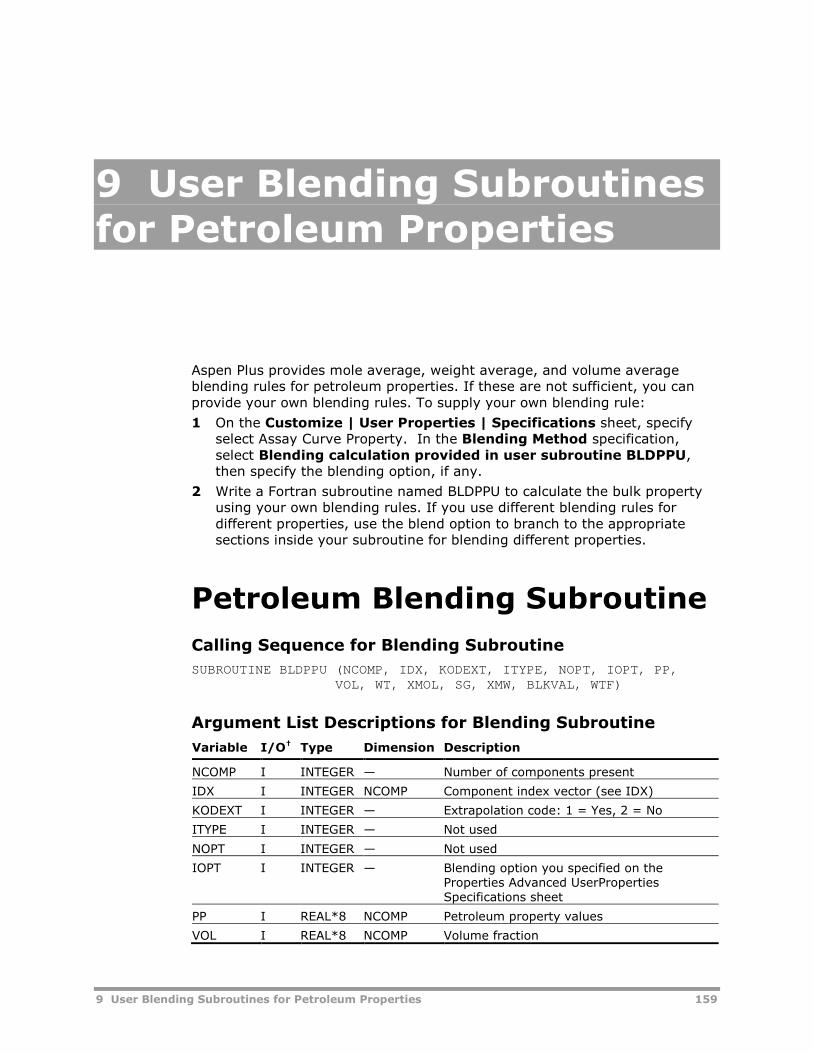
9 User Blending Subroutines for Petroleum Properties 159
9 User Blending Subroutinesfor Petroleum Properties
Aspen Plus provides mole average, weight average, and volume averageblending rules for petroleum properties. If these are not sufficient, you canprovide your own blending rules. To supply your own blending rule:
1 On the Customize | User Properties | Specifications sheet, specifyselect Assay Curve Property. In the Blending Method specification,select Blending calculation provided in user subroutine BLDPPU,then specify the blending option, if any.
2 Write a Fortran subroutine named BLDPPU to calculate the bulk propertyusing your own blending rules. If you use different blending rules fordifferent properties, use the blend option to branch to the appropriatesections inside your subroutine for blending different properties.
Petroleum Blending Subroutine
Calling Sequence for Blending Subroutine
SUBROUTINE BLDPPU (NCOMP, IDX, KODEXT, ITYPE, NOPT, IOPT, PP,VOL, WT, XMOL, SG, XMW, BLKVAL, WTF)
Argument List Descriptions for Blending Subroutine
Variable I/O† Type Dimension Description
NCOMP I INTEGER — Number of components present
IDX I INTEGER NCOMP Component index vector (see IDX)
KODEXT I INTEGER — Extrapolation code: 1 = Yes, 2 = No
ITYPE I INTEGER — Not used
NOPT I INTEGER — Not used
IOPT I INTEGER — Blending option you specified on theProperties Advanced UserPropertiesSpecifications sheet
PP I REAL*8 NCOMP Petroleum property values
VOL I REAL*8 NCOMP Volume fraction

160 9 User Blending Subroutines for Petroleum Properties
Variable I/O† Type Dimension Description
WT I REAL*8 NCOMP Weight fraction
XMOL I REAL*8 NCOMP Mole fraction
SG I REAL*8 NCOMP Specific gravity
XMW I REAL*8 NCOMP Molecular weight
BLKVAL O REAL*8 — Petroleum property bulk value
WTF I REAL*8 NCOMP Not used
† I = Input to subroutine, O = Output from subroutine
IDXIDX is a vector containing component sequence numbers of the conventionalcomponents actually present in the order that they appear on theComponents | Specifications | Selection sheet. For example, if only thefirst and third conventional components are present, then NCOMP=2 andIDX=(1,3).

10 User Subroutines for Sizing and Costing 161
10 User Subroutines forSizing and Costing
The user unit operation model User2 can call Fortran subroutines that yousupply to do sizing and costing calculations.
Sizing Model Subroutine
Calling Sequence for Sizing Model Subroutine
SUBROUTINE subrname†
(KMODE, NEQP, NINT, INT, NREAL, REAL,NIST, ICSIZ, RCSIZ, NRSLT, IRSLT, RSLT)
† Subroutine name you entered.
Argument List Descriptions for Sizing Model Subroutine
Variable I/O† Type Dimension Description
KMODE I INTEGER — Costing mode flag= 1: Uses user written costing model= 2: Uses user correlation
NEQP I/O INTEGER — Number of pieces of equipment. Aspen Plussets this value to the integer missing valueUSER_IUMISS (from COMMON/PPEXEC_USER/) if you do not specify. If itis not set, it should be calculated by thesizing model.
NINT I INTEGER — Number of integer parameters (see Integerand Real Parameters)
INT I INTEGER NINT Vector of integer parameters (see Integerand Real Parameters)
NREAL I INTEGER — Number of real parameters (see Integer andReal Parameters)
REAL I REAL*8 NREAL Vector of real parameters (see Integer andReal Parameters)
NIST I INTEGER — Number of values retrieved from flowsheetreference

162 10 User Subroutines for Sizing and Costing
Variable I/O† Type Dimension Description
ICSIZ I INTEGER NIST Array of reference codes. See ICSIZ.
RCSIZ I REAL*8 NIST Array of flowsheet reference values. Thisarray parallels the ICSIZ array, so anelement of RCSIZ contains the value for thecode in the same element of ICSIZ.
NRSLT I INTEGER — Number of size results you specified
IRSLT I INTEGER NRSLT Array of size-result codes. See IRSLT.
RSLT O REAL*8 NRSLT Array of size results you entered. This arrayparallels the RSLT array, identifying resultsof the types specified in IRSLT.
† I = Input to subroutine, O = Output from subroutine
Integer and Real ParametersYou can use integer and real retention parameters by specifying the numberof values. You can initialize these parameters by assigning values. The defaultvalues are USER_RUMISS for real parameters and USER_IUMISS for integerparameters. Aspen Plus retains these parameters from one call to the next.The variables USER_IUMISS and USER_RUMISS are located in labeledcommon PPEXEC_USER (see Appendix A).
ICSIZThe following values in array ICSIZ correspond to the specifications listed onthe User2 reference form:
10 PIN
11 POUT
11 PRES
12 TIN
13 TOUT
13 TEMP
14 VAP-FLOW-IN
15 VAP-FLOW-OUT
15 VAP-FLOW
16 LIQ-FLOW
17 VAP-DENSITY
18 LIQ-DENSITY
19 DUTY
50 AREA
51 PREF
52 HC-RATIO
53 MEFF
54 COMPR-TYPE
55 HP
56 ZIN
57 ZOUT
90 NFEEDS
91 NSTAGE
92 SURF-TEN
93 VISCOSITY
94 REL-VOL
95 LIQ-DIFF
IRSLTThe following integer values in array IRSLT correspond to the results codesentered in RSLT:
1 PRES
2 TEMP
3 VAP-FLOW
4 LIQ-FLOW
5 DUTY
6 AREA
7 HP
8 HEAD
9 WEIGHT
10 DIAM
11 TT-LENGTH
12 THICKNESS
13 VOL-FLOW
14 FLOW-PARAM
15 VOLUME
16 CAPACITY
17 NTRAY

10 User Subroutines for Sizing and Costing 163
Costing Model Subroutine
Calling Sequence for Costing Model Subroutine
SUBROUTINE subrname†
(KMODE, NEQP, FMCN, CSTAJ, NIST, ICSIZ,RCSIZ, NRSLT, IRSLT, RSLT, TBCOST, TCOST
† Subroutine name you entered.
Argument List for Costing Model Subroutine
Variable I/O† Type Dimension Description
KMODE I INTEGER — Costing mode flag.= 1: Uses user written costing model= 2: Uses user correlation
NEQP I INTEGER — Number of pieces of equipment
FMCN I/O REAL*8 — Material of construction factor. May bespecified or calculated by the model.
CSTAJ I REAL*8 — Costing adjustment factor you specified
NIST I INTEGER — Number of values retrieved from flowsheetreference
ICSIZ I INTEGER NIST Array of reference data codes. See sizingmodel argument list description fordescription of values.
RCSIZ I REAL*8 NIST Array of values retrieved from flowsheetreference.
NRSLT I INTEGER — Number of user specified size results
IRSLT I INTEGER NRSLT Array of user specified size-results codes.See sizing model argument list descriptionfor description of values.
RSLT I REAL*8 NRSLT Array of user specified size-results
TBCOST O REAL*8 — Total calculated base cost per piece ofequipment
TCOST O REAL*8 — Total calculated adjusted cost per piece ofequipment. (TCOST = TBCOST * CSTAJ *FMCN)
† I = Input to subroutine, O = Output from subroutine

164 10 User Subroutines for Sizing and Costing

11 User Kinetics Subroutines 165
11 User Kinetics Subroutines
You can supply a kinetics subroutine to calculate reaction rates for thefollowing models.
Model Name Description
RPlug Kinetic reactor model
RBatch Kinetic reactor model
RCSTR Kinetic reactor model
RadFrac Staged separation model
Pres-Relief Pressure relief system
For RadFrac, you can supply the user kinetics subroutine in either USERreaction type or REAC-DIST reaction type.
For descriptions of the kinetics and other subroutines for reactions of typeSegment-based, Step-growth, or Free-radical, see the chapters of AspenPolymers User Guide, Volume 1 devoted to these models. For the Gel Effectsubroutine for Emulsion reactions, see the Gel Effect section in the chapter forFree-Radical reactions.

166 11 User Kinetics Subroutines
Kinetics Subroutine for USERReaction TypeYou can use this user kinetics subroutine for the reactor unit operation models(RPlug, RBatch, RCSTR), the staged separation model (RadFrac), and thePressure Relief system (Pres-Relief).
For the reactor models and the pressure relief system, the kinetics subroutinecalculates the rate of generation for each component in each substream. Ifsolids participate in the reactions, the kinetics subroutine also accounts forchanges in the outlet stream particle size distribution, and in the componentattribute values. For example, if coal is treated as a single non-conventionalcomponent, its attributes, as represented by its ultimate and proximateanalysis, must change at a rate consistent with the reactions.
For RadFrac, the kinetics subroutine calculates the rate of generation for eachcomponent on a given stage. It should also calculate the individual reactionrates in each phase if you use this routine for rate-based calculations.
On the Reactions Reactions form select the USER type to specify the reactionstoichiometry and the associated user-supplied kinetics subroutine name.
In addition to the parameters passed to your subroutine through theargument list, there are common blocks you can use to access parametersspecific to a unit operation model.
Calling Sequence for User Kinetics Subroutine, Type USER
SUBROUTINE subrname†
(SOUT, NSUBS, IDXSUB, ITYPE, NINT, INT,NREAL, REAL, IDS, NPO, NBOPST, NIWORK,IWORK, NWORK, WORK, NC, NR, STOIC, RATES,FLUXM, FLUXS, XCURR, NTCAT, RATCAT,NTSSAT, RATSSA, KCALL, KFAIL, KFLASH,NCOMP, IDX, Y, X, X1, X2, NRALL, RATALL,NUSERV, USERV, NINTR, INTR, NREALR,REALR, NIWR, IWR, NWR, WR, NRL, RATEL,NRV, RATEV)
† Subroutine name you entered on the Reactions | Subroutine sheet.
Argument List for User Kinetics Subroutine, Type USER
Variable I/O/W† Type Dimension Description
SOUT I REAL*8 1 Stream vector (see Appendix C)
NSUBS I INTEGER — Number of substreams in stream vector
IDXSUB I INTEGER NSUBS Location of substreams in stream vector
ITYPE I INTEGER NSUBS Substream type vector(1 = MIXED2 = CISOLID3 = NC)

11 User Kinetics Subroutines 167
Variable I/O/W† Type Dimension Description
NINT I INTEGER — Number of integer parameters,from unitoperation block User Subroutine form(see Integer and Real Parameters)
INT I/O INTEGER NINT Vector of integer parameters, from unitoperation block User Subroutine form(see Integer and Real Parameters)
NREAL I INTEGER — Number of real parameters, from unitoperation block User Subroutine form(see Integer and Real Parameters)
REAL I/O REAL*8 NREAL Vector of real parameters, from unitoperation block User Subroutine form(see Integer and Real Parameters)
IDS I INTEGER 2,4 (*,1) - Block ID as Hollerith string
(*,2)-(*,3) - Used by Aspen Plus
(1,4) - Type of the unit operation block(see Calling Model Type)
NPO I INTEGER — Number of property option sets
NBOPST I INTEGER 6, NPO Property option set array (see NBOPST)
NIWORK I INTEGER — Length of integer work vector, from unitoperation block User Subroutine form(see Local Work Arrays)
IWORK W INTEGER NIWORK Integer work vector, from unit operationblock User Subroutine form (see LocalWork Arrays)
NWORK I INTEGER — Length of real work vector, from unitoperation block User Subroutine form(see Local Work Arrays)
WORK W REAL*8 NWORK Real work vector, from unit operationblock User Subroutine form (see LocalWork Arrays)
NC I INTEGER — Total number of components defined onthe Components | Specifications |Selection sheet
NR I INTEGER — Number of User kinetic reactions
STOIC I REAL*8 NC, NSUBS,NR
Array of stoichiometric coefficients (seeSTOIC)
RATES O REAL*8 (1) Component reaction rates from Userkinetic reactions (see Reaction Rates)
FLUXM O REAL*8 (1) Component fluxes, mixed-solid (seeComponent Fluxes in RPlug)
FLUXS O REAL*8 (1) Component fluxes, solid-mixed (RPlug)(see Component Fluxes in RPlug)
XCURR I REAL*8 — RPlug: Current reactor location(m)RBatch, Pres-Relief: Current time(s)RCSTR: Current iteration numberRadFrac: Current stage number
NTCAT I INTEGER — Dimension of RATCAT
RATCAT O REAL*8 NTCAT Rates of component attributes(see Component Attributes and SubstreamPSD)

168 11 User Kinetics Subroutines
Variable I/O/W† Type Dimension Description
NTSSAT I INTEGER — Dimension of RATSSA
RATSSA O REAL*8 NTSSAT Rates of substream PSD weight fractions(RCSTR, RPlug)(see Component Attributes and SubstreamPSD)
KCALL I INTEGER — Call code (RPlug, RBatch, RCSTR, Pres-Relief)0 = First call and calculate rates1 = Calculate rates11 = Output point. Print to history file12 = Final call before exiting13 = Report pass. Print to report file
KFAIL O INTEGER — Fail Code (RPlug, RBatch, RCSTR, Pres-Relief)0 = Continue calculations1 = Model is failing for current conditions99 = Stop calculations
KFLASH I INTEGER — Stream flash flag (RPlug, RBatch, RCSTR,Pres-Relief)0 = Stream has not been flashed1 = Stream has been flashed
NCOMP I INTEGER — Number of components present
IDX I INTEGER NCOMP Component sequence numbers
Y I REAL*8 NCOMP Vapor mole fractions
X I REAL*8 NCOMP Liquid mole fractions
X1 I REAL*8 NCOMP Liquid 1 mole fractions
X2 I REAL*8 NCOMP Liquid 2 mole fractions
NRALL I INTEGER — Total number of kinetic Powerlaw andLHHW reactions in the block (RPlug,RBatch, RCSTR, Pres-Relief)
RATALL I REAL*8 NRALL Individual reaction rates of kineticPowerlaw and LHHW reactions (RPlug,RBatch, RCSTR, Pres-Relief) (see ReactionRates)
NUSERV I INTEGER — Number of user variables (RPlug, RBatch)(from User Subroutine | User Variablessheet)
USERV I/O REAL*8 NUSERV Vector of user variables (RPlug, RBatch)(from User Subroutine | User Variablessheet; see User Variables)
NINTR I INTEGER — Number of integer parameters (fromReactions | Subroutine sheet) (seeInteger and Real Parameters)
INTR I/O INTEGER NINTR Vector of integer parameters(from Reactions | Subroutine sheet)(see Integer and Real Parameters)
NREALR I INTEGER — Number of real parameters(from Reactions | Subroutine sheet)(see Integer and Real Parameters)

11 User Kinetics Subroutines 169
Variable I/O/W† Type Dimension Description
REALR I/O REAL*8 NREALR Vector of real parameters(from Reactions | Subroutine sheet)(see Integer and Real Parameters)
NIWR I INTEGER — Length of integer work array(from Reactions | Subroutine sheet)(see Local Work Arrays)
IWR W INTEGER NIWR Integer work array(from Reactions | Subroutine sheet)(see Local Work Arrays)
NWR I INTEGER — Length of real work array(from Reactions | Subroutine sheet)(see Local Work Arrays)
WR W REAL*8 NWR Real work array(from Reactions | Subroutine sheet)(see Local Work Arrays)
NRL I INTEGER — Number of liquid phase user kineticreactions (RadFrac)
RATEL O REAL*8 NRL Individual reaction rates in the liquidphase (kgmole/s) (for Rate-BasedDistillation)
NRV I INTEGER — Number of vapor phase user kineticreactions (RadFrac)
RATEV O REAL*8 NRV Individual reaction rates in the vaporphase (kgmole/s) (for Rate-BasedDistillation)
† I = Input to subroutine, O = Output from subroutine, W = Workspace
Integer and Real ParametersYou can use two sets of integer and real retention parameters:
Parameters specific to the unit operation block (on the User Subroutineform).
Parameters specific to the set of reactions (on the Reactions |Subroutine sheet).
You can initialize these parameters by assigning values on the same sheet.The default values are USER_RUMISS for real parameters and USER_IUMISSfor integer parameters. Aspen Plus retains these parameters from one call tothe next. The variables USER_IUMISS and USER_RUMISS are located inlabeled common PPEXEC_USER (see Appendix A).
NBOPSTWhen calling FLSH_FLASH or a property monitor, NBOPST should be passed.
Local Work ArraysYou can use local work arrays by specifying the array length on the:
User Subroutine form for the unit operation block.

170 11 User Kinetics Subroutines
Reactions | Subroutine sheet.
Aspen Plus does not retain these arrays from one call to the next.
Calling Model TypeThe meanings of some arguments to the user kinetics subroutine depend onthe type of unit operation model which called it. Element IDS(1,4) specifiesthis model type as a Hollerith string. The possible values are:
IDS(1,4) Value Calling Model Type
RBAT RBatch
RCST RCSTR
RPLU RPlug
PRES Pres-Relief
RADF RadFrac
Example:
INTEGER MODELS(5)DATA MODELS /4HRBAT,4HRCST,4HRPLU,4HPRES,4HRADF/
C ...IF (IDS(1,4) .EQ. MODELS(1)) THEN
C Code for RBatch hereELSE IF (IDS(1,4) .EQ. MODELS(2)) THEN
C Code for RCSTR hereC ...
STOICFor RadFrac, the STOIC array is sorted such that the coefficients for the liquidphase reactions appear after all the vapor-phase reactions. The sort resultsdo not depend on the order in which you entered the reactions on theReactions | Subroutine sheet.
Reaction RatesThe component reaction rates must be calculated for each component. Theseare rates of change and should be negative for a component that is consumedand positive for a component that is generated. When there are multiplesubstreams, the structure of the RATES vector is the concatenation of therates for all components in the first substream, rates for all components inthe second substream, etc. Substream structure is discussed in Appendix C.
The units of the reaction rates are:
For RBatch, RCSTR, and Pres-Relief.Conventional components: (kgmole/m3-s) (m3) = kgmole/sNonconventional components: (kg/m3-s) (m3) = kg/s(rates per unit volume are multiplied by the volume occupied by thereacting phase)

11 User Kinetics Subroutines 171
For Rplug.Conventional components: (kgmole/m3-s) (m2) = kgmole/m-sNonconventional components: (kg/m3-s) (m2) = kg/m-s(rates per unit volume are multiplied by the cross-sectional area coveredby the reacting phase)
For RadFrac.Conventional components: (kgmole/s)
Component Attributes and Substream PSDIf solids participate in reactions, you need to account for changes incomponent attribute values and particle size distribution (PSD) of asubstream. You can do one of the following:
Update the attribute and PSD values in the stream vector SOUT in theuser kinetics routine each time it gets called.
Supply rates of change for the attributes and PSD weight fractions, inunits of attribute/s and 1/s, respectively. In this case the reactor willconverge on the attributes and PSD and will update the stream vectorwith their converged/current values each time it calls the user kineticssubroutine. To initiate this calculation for component attributes and/orPSD, use the User Subroutine | Kinetics sheet for RPlug and RBatchand use the Setup | PSD and Setup | Component Attr sheets forRCSTR. The structure of the component attribute rates vector (RATCAT)is: rates for all attributed components in the first substream, then thesecond substream, and so on. The structure for PSD rates vector(RATSSA) is rates for all PSD weight fractions in the first substream, thenthe second substream and so on.
User VariablesUser variables provide a convenient method to access intermediate variablescalculated within user subroutines.
As an example, consider a user kinetics routine that calculates rates for thefollowing reactions:
1 A + B C
2 B + 2D E
3 B F
The subroutine returns the net reaction rates for components A through F inthe RATES vector. However, for diagnostic purposes, it may be moreconvenient to view the rates of individual reactions 1 through 3. These typesof intermediate calculations can be loaded into the USERV array.
The user variables are identified with user-specified labels. These labels arespecified on the reactor model (RBATCH or RPLUG) User Subroutine | UserVariables sheet.
The user variable results are tabulated in the reactor model’s Profiles | UserVariables sheet. User variables can also be tabulated in the simulationhistory file by setting the Simulation level higher than 5 on the BlockOptions | Diagnostics sheet.

172 11 User Kinetics Subroutines
Aspen Plus does not perform unit conversion on the user variables. Uservariables can be stored by any and all of the user subroutines called by areactor model.
Component Fluxes in RPlugFLUXM and FLUXS are used to take into account the effect of mass exchangeon the substream enthalpy balance in RPlug when multiple substreams existin your simulation and you have specified that the substream temperaturesmay be different (on the RPlug | Setup | Specifications sheet).
Reactions can occur within each substream and can use reactants from, oradd products to, any substream. Each reaction must be assigned to a specificsubstream so that the temperature used to determine the reaction rate is thetemperature of that substream, and the reaction heat effect is absorbed bythat substream.
Both FLUXM and FLUXS give the flux (molar flow rate per unit volume) ofcomponents between substreams due to reactions specified for anothersubstream, but with a different sign and a different basis for the volume:
FLUXM is the flux, at mixed substream temperature, from mixedsubstream to solid substream.
FLUXS is the flux, at solid substream temperature, from solid substreamto mixed substream.
The structure and units of both FLUXM and FLUXS are identical to those of theRATES vector.
COMMON RPLG_RPLUGICOMMON block RPLG_RPLUGI contains integer configuration parameters forthe RPlug block. To use RPLG_RPLUGI, include the following directive (incolumn 1) of your subroutine:
#include “rplg_rplugi.cmn”
The following table describes the variables in RPLG_RPLUGI.
Variable Type Description
RPLUGI_IRPLUG INTEGER RPlug reactor type (from the RPlug Setup Specificationssheet; see below for explanation of values
RPLUGI_NTUBE INTEGER Number of reactor tubes
Values of RPLUGI_IRPLUG have the following meanings:
1 = Reactor with Specified Temperature2 = Adiabatic Reactor3 = Reactor with Co-current Coolant4 = Reactor with Counter-current Coolant5 = Adiabatic Reactor (with substreams at different temperatures)6 = Reactor with Co-current Coolant (with substreams at differenttemperatures)7 = Reactor with Counter-current Coolant (with substreams at differenttemperatures)8 = Reactor with Constant Coolant Temperature

11 User Kinetics Subroutines 173
9 = Reactor with Constant Coolant Temperature (with substreams at differenttemperatures)
COMMON RPLG_RPLUGRCOMMON block RPLG_RPLUGR contains real configuration parameters for theRPlug block. To use RPLG_RPLUGR, include the following directive (in column1) of your subroutine:
#include “rplg_rplugr.cmn”
The following table describes the variables in RPLG_RPLUGR.
Variable Type Description
RPLUGR_UXLONG REAL*8 Reactor length (m)
RPLUGR_UDIAM REAL*8 Reactor (or tube) diameter (m)
RPLUGR_AXPOS REAL*8 Current axial position (m)
RPLUGR_TCOOL REAL*8 Coolant temperature (from Setup | Specificationssheet) (K)
RPLUGR_CATWT REAL*8 Total catalyst mass (kg)
RPLUGR_CAT_RHO REAL*8 Catalyst mass density (kg/m3)
RPLUGR_BED_VOID REAL*8 Reactor bed void fraction (unitless)
COMMON RBTC_RBATICOMMON block RBTC_RBATI contains integer configuration parameters forthe RBatch block. To use RBTC_RBATI, include the following directive (incolumn 1) of your subroutine:
#include “rbtc_rbati.cmn”
The following table describes the variables in RBTC_RBATI.
Variable Type Description
RBATI_IRBAT INTEGER RBatch reactor type (from RBatch | Setup |Specification sheet)1 = Constant Temperature2 = Temperature Profile3 = Constant Heat Duty4 = Constant Coolant Temperature5 = Heat Duty Profile6 = Heat Transfer User Subroutine
COMMON RBTC_RBATRCOMMON block RBTC_RBATR contains real configuration parameters for theRBatch block. To use RBTC_RBATR, include the following directive (in column1) of your subroutine:
#include “rbtc_rbatr.cmn”
The following table describes the variables in RBTC_RBATR.
Variable Type Description

174 11 User Kinetics Subroutines
RBATR_VOLRB REAL*8 RBatch reactor volume (m3)
COMMON RCST_RCSTRICOMMON block RCST_RCSTRI contains integer configuration parameters forthe RCSTR block. To use RCST_RCSTRI, include the following directive (incolumn 1) of your subroutine:
#include “rcst_rcstri.cmn”
The following table describes the variables in RCST_RCSTRI.
Variable Type Description
RCSTRI_IRCSTR INTEGER RCSTR reactor type: 1 = Temperature specified,2 = Heat duty specified
COMMON RXN_RCSTRRCOMMON block RXN_RCSTRR contains real configuration parameters for theRCSTR block. To use RXN_RCSTRR, include the following directive (in column1) of your subroutine:
#include “rxn_rcstrr.cmn”
The following table describes the variables in RXN_RCSTRR.
Variable Type Description
RCSTRR_VOLRC REAL*8 RCSTR reactor volume
RCSTRR_VFRRC REAL*8 RCSTR volume fraction of phase specified for holdup(Setup Specifications sheet)
RCSTRR_CATWT REAL*8 Total catalyst mass (kg)
RCSTRR_CAT_RHO REAL*8 Catalyst mass density (kg/m3)
RCSTRR_BED_VOI REAL*8 Bed voidage (unitless)
COMMON PRSR_PRESRICOMMON block PRSR_PRESRI contains integer configuration parameters forthe Pres-Relief block. To use PRSR_PRESRI, include the following directive (incolumn 1) of your subroutine:
#include “prsr_presri.cmn”
The following table describes the variables in PRSR_PRESRI.
Variable Type Description
PRESRI_ISCNAR INTEGER Pressure relief scenario (from FlowsheetingOptionsPres-Relief Setup sheet)1 = Dynamic run with vessel engulfed by fire2 = Dynamic run with specified heat flux into vessel6 = Steady state flow rating of relief system7 = Steady state flow rating of relief valve

11 User Kinetics Subroutines 175
COMMON PRSR_PRESRRCOMMON block PRSR_PRESRR contains real configuration parameters for thePres-Relief block. To use PRSR_PRESRR, include the following directive (incolumn 1) of your subroutine:
#include “prsr_presrr.cmn”
The following table describes the variables in PRSR_PRESRR.
Variable Type Description
PRESRR_VOLPR REAL*8 Vessel volume (m3)
COMMON RXN_DISTICOMMON block RXN_DISTI contains integer configuration parameters forreactive distillation calculations. To use RXN_DISTI, include the followingdirective (in column 1) of your subroutine:
#include “rxn_disti.cmn”
The following table describes the variables in RXN_DISTI.
Variable Type Description
DISTI_IHLBAS INTEGER Basis for liquid holdup specification1 = Volume2 = Mass3 = Mole
DISTI_IHVBAS INTEGER Basis for vapor holdup specification1 = Volume2 = Mass3 = Mole
COMMON RXN_DISTRCOMMON block RXN_DISTR contains real configuration parameters forreactive distillation calculations. To use RXN_DISTR, include the followingdirective (in column 1) of your subroutine:
#include “rxn_distr.cmn”
The following table describes the variables in RXN_DISTR.
Variable Type Description
DISTR_TIMLIQ REAL*8 Liquid residence time in stage or segment
DISTR_TIMVAP REAL*8 Vapor residence time in stage or segment
DISTR_HLDLIQ REAL*8 Liquid holdup in stage or segment (units depend onDISTI_IHLBAS, see below)
DISTR_HLDVAP REAL*8 Vapor holdup in stage or segment (units depend onDISTI_IHVBAS, see below)
DISTI_IHLBAS Units for DISTR_HLDLIQ and DISTR_HLDVAP1 m3
2 kg3 kgmole

176 11 User Kinetics Subroutines
COMMON RXN_RPROPSCOMMON block RXN_RPROPS contains real property values, such astemperature and pressure, for the reaction calculations. To use RXN_RPROPS,include the following directive (in column 1) of your subroutine:
#include “rxn_rprops.cmn”
The following table describes the variables in RXN_RPROPS.
Variable Type Description
RPROPS_UTEMP REAL*8 Reactor/stage temperature (K)
RPROPS_UPRES REAL*8 Reactor/stage pressure (N/m2)
RPROPS_UVFRAC REAL*8 Molar vapor fraction in the reactor/stage
RPROPS_UBETA REAL*8 Liquid 1/Total liquid molar ratio in the reactor/stage
RPROPS_UVVAP REAL*8 For RBatch and RCSTR: Volume occupied by the vaporphase in the reactor (m3)For RPlug: Cross-sectional area covered by the vaporphase in the reactor (m2)For RadFrac: Vapor volume holdup in the stage
†(m3)
RPROPS_UVLIQ REAL*8 For RBatch and RCSTR: Volume occupied by the liquidphase in the reactor (m3)For RPlug: Cross-sectional area covered by the liquid phasein the reactor (m2)For RadFrac: Liquid volume holdup in the stage
†(m3)
RPROPS_UVLIQS REAL*8 For RBatch and RCSTR: Volume occupied by the liquid andsolid phases in the reactor (m3)For RPlug: Cross-sectional area covered by the liquid andsolid phases in the reactor (m2)
† Use only if you have specified the holdup for the stage on a volume basis.
User Kinetics Subroutine forREAC-DIST Reaction TypeYou can use this user kinetics subroutine for the staged separation modelRadFrac. The user kinetics subroutine calculates the generation rate (molesper unit time) for each component on a given stage. Use the Reactions formand select the REAC-DIST type to specify the reaction chemistry and theassociated user-supplied kinetics subroutine name.
If your routine is used for rate-based calculations, it should use TLIQ andTVAP (rather than T) as the temperatures for each phase. It also mustcalculate the individual rates of each reaction in each phase.

11 User Kinetics Subroutines 177
Calling Sequence: User Kinetics Subroutine, Type REAC-DIST
SUBROUTINE subrname† (N, NCOMP, NR, NRL, NRV, T, TLIQ, TVAP,P, PHFRAC, F, X, Y, IDX, NBOPST, KDIAG,STOIC, IHLBAS, HLDLIQ, TIMLIQ, IHVBAS,HLDVAP, TIMVAP, NINT, INT, NREAL, REAL,RATES, RATEL, RATEV, NINTB, INTB, NREALB,REALB, NIWORK, IWORK, NWORK, WORK)
† Subroutine name you entered on the Reactions | Subroutine sheet.
Argument List: User Kinetics Subroutine, Type REAC-DIST
Variable I/O† Type Dimension Description
N I INTEGER — Stage number
NCOMP I INTEGER — Number of components present
NR I INTEGER — Total number of kinetic reactions
NRL I INTEGER 3 NRL (1) - Number of overall liquid reactionsNRL (2) - Number of liquid1 reactionsNRL (3) - Number of liquid2 reactions
NRV I INTEGER — Number of vapor phase kinetic reactions
T I REAL*8 — Stage temperature (K)
TLIQ I REAL*8 — Liquid temperature on stage (K)
TVAP I REAL*8 — Vapor temperature on stage (K)
P I REAL*8 — Stage pressure (N/m2)
PHFRAC I REAL*8 3 Phase fraction(1) Vapor fraction(2) Liquid1 fraction (RadFrac, 3-phase)(3) Liquid2 fraction (RadFrac, 3-phase)
F I REAL*8 — Total flow on stage or segment (Vapor +Liquid) (kgmole/s)
Y I REAL*8 NCOMP Vapor mole fraction
IDX I INTEGER NCOMP Component sequence number
NBOPST I INTEGER 6 Property option set (see NBOPST)
KDIAG I INTEGER — Local diagnostic level
STOIC I REAL*8 NCOMP, NR Reaction stoichiometry (see STOIC)
IHLBAS I INTEGER — Basis for liquid holdup specification1: volume, 2: mass, 3: mole
HLDLIQ I REAL*8 — Liquid holdupIHLBAS Units1 m3
2 kg3 kmol
TIMLIQ I REAL*8 — Liquid residence time (s)
IHVBAS I INTEGER — Basis for vapor holdup specification1: volume, 2: mass, 3: mole
†I = Input to subroutine, O = Output from subroutine, W = Workspace
Continued

178 11 User Kinetics Subroutines
Variable I/O† Type Dimension Description
HLDVAP I REAL*8 — Vapor holdupIHVBAS Units1 m3
2 kg3 kmol
TIMVAP I REAL*8 — Vapor residence time (s)
NINT I INTEGER — Number of integer parameters(from Reactions | Subroutine sheet)
INT I/O INTEGER NINT Vector of integer parameters(from Reactions | Subroutine sheet)
NREAL I INTEGER — Number of real parameters(from Reactions | Subroutine sheet)
REAL I/O INTEGER NREAL Vector of real parameters(from Reactions | Subroutine sheet)
RATES O REAL*8 NCOMP Component reaction rates (kgmole/s)
RATEL O REAL*8 NRL Individual reaction rates in the liquid phase(kgmole/s) (for Rate-Based Distillation)
RATEV O REAL*8 NRV Individual reaction rates in the vapor phase(kgmole/s) (for Rate-Based Distillation)
NINTB I INTEGER — Number of integer parameters(from unit operation block User Subroutineform)
INTB I/O INTEGER NINTB Vector of integer parameters (from unitoperation block User Subroutine form)
NREALB I INTEGER — Number of real parameters (from unitoperation block User Subroutine form)
REALB I/O INTEGER NREALB Vector of real parameters (from unitoperation block User Subroutine form)
NIWORK I INTEGER — Length of integer work vector (from unitoperation block User Subroutine form)
IWORK W INTEGER NIWORK Integer work vector
NWORK I INTEGER — Length of real work vector (from unitoperation block User Subroutine form)
WORK W INTEGER NWORK Real work vector
†I = Input to subroutine, O = Output from subroutine, W = Workspace
NBOPSTWhen calling FLSH_FLASH or a physical property monitor, NBOPST should bepassed.
STOICSTOIC is sorted such that the coefficients for liquid phase reactions appearafter all vapor reactions regardless of the order in which you entered thereactions on the Reactions | Subroutine sheet.

12 User Pressure Drop and Holdup Subroutines for RPlug 179
12 User Pressure Drop andHoldup Subroutines for RPlug
You can supply a user pressure drop subroutine for the unit operation modelRPlug. The user pressure drop subroutine calculates the stream pressure orpressure drop for both the process and coolant streams at any point along thereactor. You can specify the user subroutine on the RPlug | UserSubroutine | Pressure Drop sheet.
You can supply a user holdup subroutine for the unit operation model RPlug.The user holdup subroutine calculates the reactor holdup at any point alongthe reactor. You can specify the user subroutine on the RPlug | UserSubroutine | Holdup sheet.

180 12 User Pressure Drop and Holdup Subroutines for RPlug
RPlug Pressure DropSubroutine
Calling Sequence for RPlug Pressure Drop Subroutine
SUBROUTINE subrname†
(SIN, SOUT, SINC, SOUTC, NSUBS, IDXSUB,ITYPE, NINT, INT, NREAL, REAL, IDS, NPO,NBOPST, NIWORK, IWORK, NWORK, WORK,PRESP, PRESC, Z, XLONG, DIAM, ANGLE,ELEV,ROUGH, AFRAC, NTUBE, VOID, DPART,SPHER, NUSERV, USERV )
† Subroutine name you entered on the RPlug | User Subroutine |Pressure Drop sheet.
Argument List for RPlug Pressure Drop Subroutine
Variable I/O/W†
Type Dimension Description
SIN I REAL*8 (1) Inlet process stream vector (see AppendixC)
SOUT I/O REAL*8 (1) Process stream vector at current reactorlocation Z (see Appendix C)
SINC I REAL*8 (1) Inlet coolant stream vector (see AppendixC)
SOUTC I/O REAL*8 (1) Coolant stream vector at current reactorlocation Z (see Appendix C)
NSUBS I INTEGER — Number of substreams in stream vector
IDXSUB I INTEGER NSUBS Location of substreams in stream vector
ITYPE I INTEGER NSUBS Substream type vector (1-MIXED,2-CISOLID, 3-NC)
NINT I INTEGER — Number of integer parameters (see Integerand Real Parameters)
INT I/O INTEGER NINT Vector of integer parameters (see Integerand Real Parameters)
NREAL I INTEGER — Number of real parameters (see Integer andReal Parameters)
REAL I/O REAL*8 NREAL Vector of real parameters (see Integer andReal Parameters)
IDS I INTEGER 2, 13 Block IDs(*,1) - Block ID(*, 2) to (*, 5) - Used by Aspen Plus(*, 6) - User pressure drop subroutinename(*, 7) - User heat transfer subroutine name(*, 8) - User holdup subroutine name
NPO I INTEGER — Number of property option sets (always 2)
NBOPST I INTEGER 6, NPO Property option set array (see NBOPST)

12 User Pressure Drop and Holdup Subroutines for RPlug 181
Variable I/O/W†
Type Dimension Description
NIWORK I INTEGER — Length of integer work vector (see LocalWork Arrays)
IWORK W INTEGER NIWORK Integer work vector
NWORK I INTEGER — Length of real work vector (see Local WorkArrays)
WORK W REAL*8 NWORK Real work vector
PRESP O REAL*8 — Process stream pressure (N/m2) or pressuredrop (dP/dZ) (N/m2/m) (see Pressure)
PRESC O REAL*8 — Coolant stream pressure (N/m2) or pressuredrop (dP/dZ) (N/m2/m) (see Pressure)
Z I REAL*8 — Current reactor location (m)
XLONG I REAL*8 — Reactor Length, specified on the RPlug |Setup | Configuration sheet (m)
DIAM I REAL*8 — Reactor (or tube) diameter, specified on theRPlug | Setup | Specification sheet (m)
ANGLE I REAL*8 — Angle of inclination (radians) from theRPlug | Setup | Configuration sheet
ELEV I REAL*8 — Elevation change from feed to discharge(m) from the RPlug | Setup |Configuration sheet
ROUGH I REAL*8 — Roughness (m) from the RPlug | Setup |Pressure sheet
AFRAC I REAL*8 — Fraction of cross-sectional area occupied bythe condensed phases
NTUBE I REAL*8 — Number of tubes from the RPlug | Setup |Configuration sheet
VOID I REAL*8 — Void fraction from the RPlug | Setup |Catalyst sheet
DPART I REAL*8 — Particle diameter from the RPlug | Setup |Catalyst sheet (m)
SPHER I REAL*8 — Particle sphericity from the RPlug | Setup| Catalyst sheet
NUSERV I INTEGER — Number of user variables from the RPlug |User Subroutine | User Variables sheet
USERV I/O REAL*8 NUSERV Vector of user variables from the RPlug |User Subroutine | User Variables sheet(See User Variables)
† I = Input to subroutine, O = Output from subroutine, W = Workspace

182 12 User Pressure Drop and Holdup Subroutines for RPlug
RPlug Holdup Subroutine
Calling Sequence for RPlug Holdup Subroutine
SUBROUTINE subrname†
(SOUT, NSUBS, IDXSUB, ITYPE, NINT,INT, NREAL, REAL, IDS, NPO,NBOPST, NIWORK, IWORK, NWORK, WORK,XLONG, DIAM, VOID, THETA, Z, LAMBDA,SIGMA, VISL, VISV, DENL, DENV,VELMIX, KFLASH, HOLDUP)
† Subroutine name you entered on the RPlug | User Subroutine | Holdupsheet.
Argument List for RPlug Holdup Subroutine
Variable I/O/W†
Type Dimension Description
SOUT I/O REAL*8 (1) Process stream vector at current reactorlocation Z (see Appendix C)
NSUBS I INTEGER — Number of substreams in stream vector
IDXSUB I INTEGER NSUBS Location of substreams in stream vector
ITYPE I INTEGER NSUBS Substream type vector (1: MIXED, 2:CISOLID, 3: NC)
NINT I INTEGER — Number of integer parameters (see Integerand Real Parameters)
INT I/O INTEGER NINT Vector of integer parameters (see Integerand Real Parameters)
NREAL I INTEGER — Number of real parameters (see Integer andReal Parameters)
REAL I/O REAL*8 NREAL Vector of real parameters (see Integer andReal Parameters)
IDS I INTEGER 2, 13 Block IDs(*, 1) - Block ID(*, 2) to (*, 5) - Used by Aspen Plus(*, 6) - User pressure drop subroutine name(*, 7) - User heat transfer subroutine name(*, 8) - User holdup subroutine name
NPO I INTEGER — Number of property option sets (always 2)
NBOPST I INTEGER 6, NPO Property option set array (see NBOPST)
NIWORK I INTEGER — Length of integer work vector (see LocalWork Arrays)
IWORK W INTEGER NIWORK Integer work vector
NWORK I INTEGER — Length of real work vector (see Local WorkArrays)
WORK W REAL*8 NWORK Real work vector
XLONG I REAL*8 — Reactor Length, specified on the RPlug |Setup | Configuration sheet (m)
DIAM I REAL*8 — Reactor (or tube) diameter, specified on theRPlug | Setup | Specification sheet (m)

12 User Pressure Drop and Holdup Subroutines for RPlug 183
Variable I/O/W†
Type Dimension Description
VOID I REAL*8 — Void fraction from the RPlug | Setup |Catalyst sheet
THETA I REAL*8 — Angle of pipe/tube from the horizontal (rad)
Z I REAL*8 — Current reactor location (m)
LAMBDA I REAL*8 — No slip liquid volume fraction (-)
SIGMA I REAL*8 — Liquid surface tension (N/m)
VISL I REAL*8 — Liquid viscosity (N-s/m2)
VISG I REAL*8 — Gas viscosity (N-s/m2)
DENL I REAL*8 — Liquid density (kg/m3)
DENG I REAL*8 — Gas density (kg/m3)
VELMIX I REAL*8 — Mixture velocity (m/s)
KFLASH I INTEGER — Stream flash flag:KFLASH = 0, stream has not been flashedKFLASH = 1, stream has been flashedAlways set to 1 for RPlug
HOLDUP O REAL*8 — Calculated volumetric liquid holdup fraction,liquid volume/total volume
† I = Input to subroutine, O = Output from subroutine, W = Workspace
NBOPSTWhen calling FLSH_FLASH or a property monitor, NBOPST should be passedfor the process stream; NBOPST(1, 2) should be passed for the coolantstream.
Integer and Real ParametersYou can use integer and real retention parameters by specifying the numberon the RPlug | User Subroutine | Pressure Drop sheet (pressure dropsubroutine) or the RPlug | User Subroutine | Holdup sheet (holdupsubroutine). You can initialize these parameters by assigning values on thesame sheet. The default values are USER_RUMISS for real parameters andUSER_IUMISS for integer parameters. Aspen Plus retains these parametersfrom one call to the next. The variables USER_IUMISS and USER_RUMISS arelocated in labeled common PPEXEC_USER (see Appendix A).
PressureFor Calculation Option on the RPlug | User Subroutine | Pressure Dropsheet, select:
Calculate Pressure if the user subroutine calculates pressure.
Calculate Pressure Drop if the user subroutine calculates the rate ofchange of pressure with respect to reactor length.
Your subroutine should then return either the pressure or the differentialpressure drop (dP/dz) for PRESP and PRESC.

184 12 User Pressure Drop and Holdup Subroutines for RPlug
Local Work ArraysYou can use local work arrays by specifying the array length on the RPlug |User Subroutine | Pressure Drop sheet (pressure drop subroutine) or theRPlug | User Subroutine | Holdup sheet (holdup subroutine). Aspen Plusdoes not retain these arrays from one call to the next.
User Variables (Pressure Drop Subroutineonly)User variables provide a convenient method to access intermediate variablescalculated within user subroutines. For example, a user pressure dropsubroutine may calculate the process fluid Reynolds number in order tocalculate the pressure drop. This intermediate variable can be stored in theUSERV array by the pressure drop subroutine.
User variables are identified with user-specified labels. These labels arespecified on the User Subroutine | User Variables sheet. The Units labelis used for convenience; Aspen Plus does not perform unit conversion on theuser variables.
User variable profiles are tabulated in the reactor model’s Profiles | UserVariables sheet.
User variables can also be tabulated in the simulation history file by settingthe Simulation level higher than 5 on the Block Options | Diagnosticssheet.
COMMON RPLG_RPLUGICOMMON block RPLG_RPLUGI contains integer configuration parameters forthe RPlug block. To use RPLG_RPLUGI, include the following directive (incolumn 1) of your subroutine:
#include “rplg_rplugi.cmn”
The following table describes the variables in RPLG_RPLUGI.
Variable Type Description
RPLUGI_IRPLUG INTEGER RPlug reactor type
RPLUGI_NTUBE INTEGER Number of reactor tubes
Reactor types:
1 = Reactor with Specified Temperature2 = Adiabatic Reactor3 = Reactor with Co-current Coolant4 = Reactor with Counter-current Coolant5 = Adiabatic Reactor (with substreams at different temperatures)6 = Reactor with Co-current Coolant (with substreams at different
temperatures)7 = Reactor with Counter-current Coolant (with substreams at different
temperatures)

12 User Pressure Drop and Holdup Subroutines for RPlug 185
8 = Reactor with Constant Coolant Temperature9 = Reactor with Constant Coolant Temperature (with substreams at
different temperatures)
COMMON RPLG_RPLUGRCOMMON block RPLG_RPLUGR contains real configuration parameters for theRPlug block. To use RPLG_RPLUGR, include the following directive (in column1) of your subroutine:
#include “rplg_rplugr.cmn”
The following table describes the variables in RPLG_RPLUGR.
Variable Type Description
RPLUGR_UXLONG REAL*8 Reactor length (m)
RPLUGR_UDIAM REAL*8 Reactor (or tube) diameter (m)
RPLUGR_AXPOS REAL*8 Current axial position (m)
RPLUGR_TCOOL REAL*8 Coolant temperature (from Setup | Specificationssheet) (K)
RPLUGR_CATWT REAL*8 Total catalyst mass (kg)
RPLUGR_CAT_RHO REAL*8 Catalyst mass density (kg/m3)
RPLUGR_BED_VOID REAL*8 Reactor bed void fraction (unitless)

186 12 User Pressure Drop and Holdup Subroutines for RPlug

13 User Heat Transfer Subroutine for RPlug 187
13 User Heat TransferSubroutine for RPlug
You can supply a heat transfer rate subroutine for the unit operation modelRPlug. The user heat transfer subroutine calculates the heat transfer rates perunit reactor wall area at any point along the reactor.
You can specify the user heat transfer subroutine on the RPlug | UserSubroutine | Heat Transfer sheet.

188 13 User Heat Transfer Subroutine for RPlug
RPlug Heat Transfer Subroutine
Calling Sequence for RPlug Heat Transfer Subroutine
SUBROUTINE subrname†
(SIN, SOUT, SINC, SOUTC, NSUBS, IDXSUB,ITYPE, NINTQ, INTQ, NREALQ, REALQ, IDS,NPO, NBOPST, NIWQ, IWORKQ, NWQ, WORKQ,QTCP, QTCA, QTCS, QTPA, Z, XLONG, DIAM,ANGLE, ELEV, ROUGH, AFRAC, NTUBE, VOID,DPART, SPHER, NUSERV, USERV)
† Subroutine name entered on the RPlug | User Subroutine | HeatTransfer sheet.
Argument List for RPlug Heat Transfer Subroutine
Variable I/O† Type DimensionDescription
SIN I REAL*8 (1) Inlet process stream vector (see Appendix C)
SOUT I/O REAL*8 (1) Process stream vector at current reactorlocation Z (see Appendix C)
SINC I REAL*8 (1) Inlet coolant stream vector (see Appendix C)
SOUTC I/O REAL*8 (1) Coolant stream vector at current reactorlocation Z (see Appendix C)
NSUBS I INTEGER — Number of substreams in stream vector
IDXSUB I INTEGER NSUBS Location of substreams in stream vector
ITYPE I INTEGER NSUBS Substream type vector(1-MIXED, 2-CISOLID, 3-NC)
NINTQ I INTEGER — Number of integer parameters (see Integerand Real Parameters)
INTQ I/O INTEGER NINTQ Vector of integer parameters (see Integer andReal Parameters)
NREALQ I INTEGER — Number of real parameters (see Integer andReal Parameters)
REALQ I/O REAL*8 NREALQ Vector of real parameters (see Integer andReal Parameters)
IDS I INTEGER 2, 13 Block IDs(*,1) - Block ID(*, 2) to (*, 5) - Used by Aspen Plus(*, 6) - User pressure drop subroutine name(*, 7) - User heat transfer subroutine name(*, 8) - User holdup subroutine name
NPO I INTEGER — Number of property option sets (always 2)
NBOPST I INTEGER 6, NPO Property option set array (see NBOPST)
NIWQ I INTEGER — Length of integer work vector (see Local WorkArrays)
IWORKQ W INTEGER NIWQ Integer work vector
NWQ I INTEGER — Length of real work vector (see Local WorkArrays)

13 User Heat Transfer Subroutine for RPlug 189
WORKQ W REAL*8 NWQ Real work vector
QTCP O REAL*8 — Heat transfer flux from coolant stream toprocess stream (W/m2)
QTCA
(QTCM)††
O REAL*8 — (1) Heat transfer flux from coolant stream toambient environment (W/m2)
††
(2) Heat transfer flux from coolant stream tomixed substream of process stream (W/m2)
††
QTCS††
O REAL*8 — (1) Not used††
(2) Heat transfer flux from coolant stream tosolid substreams of process stream (W/m2)
††
QTPA
(QTSM)††
O REAL*8 — (1) Heat transfer flux from the processstream to the ambient environment (W/m2)
††
(2) Heat transfer flux from the solidsubstream to the mixed substream of theprocess stream (W/m2)
††
Z I REAL*8 — Current reactor location (m)
XLONG I REAL*8 — Length of reactor you specified on the RPlug| Setup | Configuration sheet (m)
DIAM I REAL*8 — Diameter of reactor you specified on theRPlug | Setup | Configuration sheet (m)
ANGLE I REAL*8 — Angle of inclination (radians) from the RPlug| Setup | Configuration sheet
ELEV I REAL*8 — Elevation change from feed to discharge (m)from the RPlug | Setup | Configurationsheet
ROUGH I REAL*8 — Roughness (m) from the RPlug | Setup |Pressure sheet
AFRAC I REAL*8 — Fraction of cross-sectional area occupied bythe condensed phases
NTUBE I REAL*8 — Number of tubes from the RPlug | Setup |Configuration sheet
VOID I REAL*8 — Void fraction from the RPlug | Setup |Catalyst sheet
DPART I REAL*8 — Particle diameter from the RPlug | Setup |Catalyst sheet (m)
SPHER I REAL*8 — Particle sphericity from the RPlug | Setup |Catalyst sheet
NUSERV I INTEGER — Number of user variables from the RPlug |User Subroutine | User Variables sheet
USERV I/O REAL*8 NUSERV Vector of user variables from the RPlug |User Subroutine | User Variables sheet
† I = Input to subroutine, O = Output from subroutine, W = Workspace
†† Option (1) is always used when the process stream does not include solidsubstreams.Option (2) is only used when the process stream includes solid substreams and theRPlug block is configured to allow the solid and mixed substreams to be at differenttemperatures. See Heat Flux Terms, page 191.

190 13 User Heat Transfer Subroutine for RPlug
NBOPSTWhen calling FLSH_FLASH or a property monitor, NBOPST should be passedfor the process stream; NBOPST(1, 2) should be passed for the coolantstream.
Integer and Real ParametersYou can use integer and real retention parameters by specifying the numberon the RPlug | User Subroutine | Heat Transfer sheet. You can initializethese parameters by assigning values on the same sheet. Default values areUSER_RUMISS for real parameters and USER_IUMISS for integer parameters.Aspen Plus retains these parameters from one call to the next. The variablesUSER_IUMISS and USER_RUMISS are located in labeled commonPPEXEC_USER (see Appendix A).
Local Work ArraysYou can use local work arrays by specifying the array length on the RPlug |User Subroutine | Pressure Drop sheet. Aspen Plus does not retain thesearrays from one call to the next.
User VariablesUser variables provide a convenient method to access intermediate variablescalculated within user subroutines. For example, a user heat transfersubroutine may calculate values for the Reynolds and Prandtl numbers inorder to calculate the overall heat transfer rates in the reactor.
User variables are identified with user-specified labels. These labels arespecified on the User Subroutine | User Variables sheet. The Units labelis used for convenience; Aspen Plus does not perform unit conversion on theuser variables.
User variable profiles are tabulated in the reactor model’s Profiles | UserVariables sheet.
User variables can also be tabulated in the simulation history file by settingthe Simulation level higher than five on the Block Options | Diagnosticssheet.
COMMON RPLG_RPLUGICOMMON block RPLG_RPLUGI contains integer configuration parameters forthe RPlug block. To use RPLG_RPLUGI, include the following directive (incolumn 1) of your subroutine:
#include “rplg_rplugi.cmn”

13 User Heat Transfer Subroutine for RPlug 191
The following table describes the variables in RPLG_RPLUGI.
Variable Type Description
RPLUGI_IRPLUG INTEGER RPlug reactor type
RPLUGI_NTUBE INTEGER Number of reactor tubes
Reactor types:
1 = Reactor with Specified Temperature2 = Adiabatic Reactor3 = Reactor with Co-current Coolant4 = Reactor with Counter-current Coolant5 = Adiabatic Reactor (with substreams at different temperatures)6 = Reactor with Co-current Coolant (with substreams at different
temperatures)7 = Reactor with Counter-current Coolant (with substreams at different
temperatures)8 = Reactor with Constant Coolant Temperature9 = Reactor with Constant Coolant Temperature (with substreams at
different temperatures)
COMMON RPLG_RPLUGRCOMMON block RPLG_RPLUGR contains real configuration parameters for theRPlug block. To use RPLG_RPLUGR, include the following directive (in column1) of your subroutine:
#include “rplg_rplugr.cmn”
The following table describes the variables in RPLG_RPLUGR.
Variable Type Description
RPLUGR_UXLONG REAL*8 Reactor length (m)
RPLUGR_UDIAM REAL*8 Reactor (or tube) diameter (m)
RPLUGR_AXPOS REAL*8 Current axial position (m)
RPLUGR_TCOOL REAL*8 Coolant temperature (from Setup | Specificationssheet) (K)
RPLUGR_CATWT REAL*8 Total catalyst mass (kg)
RPLUGR_CAT_RHO REAL*8 Catalyst mass density (kg/m3)
RPLUGR_BED_VOID REAL*8 Reactor bed void fraction (unitless)

192 13 User Heat Transfer Subroutine for RPlug
Heat Flux TermsThe heat transfer model returns the net heat flux per unit wall area. The wallarea can be calculated from the number of tubes (RPLUGI_NTUBE), the tubelength (RPLUGR_UXLONG), and tube diameter (RPLUGR_UDIAM). The RPLUGmodel does not consider tube thickness.
In most cases, the heat transfer subroutine should calculate three heat fluxterms:
QTCP Heat flux from the coolant stream to the process stream
QTCA Heat flux from the coolant stream to the environment (heat loss)
QTPA Heat flux from the process stream to the environment (heat loss)
The heat flux terms are all set to zero before the heat transfer routine iscalled. If these values need to be retained between calls they should be savedin the WORKQ vector.
When multiple substreams are present in RPlug, the Setup Specificationssheet displays the option to allow the solid and mixed substreams to be atdifferent temperatures. When this option is chosen, the option number storedin RPLUGI_IRPLUG is 5, 6, 7, or 9, and the definitions of some of thearguments above are changed:
QTCP Heat flux from the coolant stream to the process stream
QTCA (QTCM) Heat flux from the coolant stream to the mixed substream
QTCS Heat flux from the coolant stream to the solid substream of the processstream
QTPA (QTSM) Heat flux from the solid substream of the process stream to the mixedsubstream
14 User Heat Transfer Subroutine for RBatch 193
14 User Heat TransferSubroutine for RBatch
You can supply a user subroutine for the unit operation model RBatch tocalculate heat transfer rates. The user heat transfer subroutine calculates theinstantaneous heat duty transferred to or from the reactor contents byconvective and radiant heat transfer via a cooling jacket or a serpentine.
To supply a user heat transfer subroutine for RBatch, select Heat TransferUser Subroutine for the Reactor Operations specification on the RBatch |Setup | Specifications sheet, and then specify the subroutine name on theRBatch | User Subroutine | Heat Transfer sheet.

194 14 User Heat Transfer Subroutine for RBatch
RBatch Heat TransferSubroutine
Calling Sequence for RBatch Heat Transfer Subroutine
SUBROUTINE subrname†
(SOUT, NSUBS, IDXSUB, ITYPE, NINT, INT,NREAL, REAL, IDS, NPO, NBOPST, NIWORK,IWORK, NWORK, WORK, TIME, DUTY, NUSERV,USERV)
† Subroutine name you entered on the RBatch | User Subroutine | HeatTransfer sheet.
Argument List for RBatch Heat Transfer Subroutine
Variable I/O/W† Type Dimension Description
SOUT I/O REAL*8 (1) Stream vector for reactor contents atcurrent time (see Stream Structure)
NSUBS I INTEGER — Number of substreams in stream vector
IDXSUB I INTEGER NSUBS Location of substreams in stream vector
ITYPE I INTEGER NSUBS Substream type vector: 1=MIXED,2=CISOLID, 3=NC
NINT I INTEGER — Number of integer parameters (seeInteger and Real Parameters)
INT I/O INTEGER NINT Vector of integer parameters (seeInteger and Real Parameters)
NREAL I INTEGER — Number of real parameters (see Integerand Real Parameters)
REAL I/O REAL*8 NREAL Vector of real parameters (see Integerand Real Parameters)
IDS I INTEGER 2, 13 Block Ids(*, 1) - Block ID(*, 2) to (*, 5) - Used by Aspen Plus(*, 6) - Heat transfer subroutine name
NPO I INTEGER — Number of property option sets (always1)
NBOPST I INTEGER 6, NPO Property option set array (see NBOPST)
NIWORK I INTEGER — Length of integer work vector (see LocalWork Arrays)
IWORK W INTEGER NIWORK Integer work vector
NWORK I INTEGER — Length of real work vector (see LocalWork Arrays)
WORK W REAL*8 NWORK Real work vector
TIME I REAL*8 — Current time (sec)
DUTY O REAL*8 — Heat transfer rate at current time(positive for heating, negative forcooling) (watt)

14 User Heat Transfer Subroutine for RBatch 195
Variable I/O/W† Type Dimension Description
NUSERV I INTEGER - Number of user variables from theRBatch | User Subroutine | UserVariables sheet
USERV I/O REAL*8 NUSERV Vector of user variables from the RBatch| User Subroutine | User Variablessheet
† I = Input to subroutine, O = Output from subroutine, W = Workspace
Stream StructureThe stream structure for material streams is described in Appendix C. Thestream vector for the reactor contents represents the actual molar or massamounts of the components in the reactor (all phases), not their flow rates.
NBOPSTNBOPST is used when calling FLSH_FLASH or a property monitor.
Integer and Real ParametersYou can use integer and real retention parameters by specifying the numberon the RBatch | User Subroutine | Heat Transfer sheet. You can initializethese parameters by assigning values on the same sheet. The default valuesare USER_RUMISS for real parameters and USER_IUMISS for integerparameters. Aspen Plus retains these parameters from one call to the next.The variables USER_IUMISS and USER_RUMISS are located in labeledcommon PPEXEC_USER (see Appendix A).
Local Work ArraysYou can use local work arrays by specifying the array length on the RBatch |User Subroutine | Heat Transfer sheet. Aspen Plus does not retain thesearrays from one call to the next.
User VariablesUser variables provide a convenient method to access intermediate variablescalculated within user subroutines. For example, a user heat transfersubroutine may calculate values for the Reynolds and Prandtl numbers inorder to calculate the overall heat transfer rates in the reactor.
User variables are identified with user-specified labels. These labels arespecified on the User Subroutine | User Variables sheet. The Units labelis used for convenience; Aspen Plus does not perform unit conversion on theuser variables.
User variable profiles are tabulated in the RBatch | Profiles | UserVariables sheet.

196 14 User Heat Transfer Subroutine for RBatch
User variables can also be tabulated in the simulation history file by settingthe Simulation level higher than 5 on the Block Options | Diagnosticssheet.
15 User Subroutines for RYield 197
15 User Subroutines forRYield
You can supply user subroutines for the unit operation model RYield. A yieldsubroutine calculates the yields and component flows for each component ineach substream, while a petroleum characterization subroutine re-characterizes the pre-defined assay or blend fed to the block. In either case,the results of the subroutine are used to fill the outlet stream of the RYieldblock.
The yield subroutine can also change the particle size distribution (PSD) andcomponent attributes for the outlet stream. For example, if coal isdevolatilized, its analysis, as represented in Aspen Plus by componentattributes such as ultimate and proximate analysis, must change.
Use the RYield | User Subroutine | Yield sheet to specify a user yieldsubroutine. Use the RYield | Assay Analysis | Subroutine sheet to specifya user petroleum characterization subroutine.

198 15 User Subroutines for RYield
RYield User Subroutines
Calling Sequence for RYield Yield Subroutine
SUBROUTINE subrname†
(SIN, SOUT, NSUBS, IDXSUB, ITYPE, NINT,INT, NREAL, REAL, IDS, NPO, NBOPST,NIWORK, IWORK, NWORK, WORK)
† Subroutine name you entered on the RYield | User Subroutine | Yieldsheet.
Argument List Descriptions for RYield Yield Subroutine
Variable I/O/W†
Type Dimension Description
SIN I REAL*8 (1) Inlet stream (see Appendix C)
SOUT O REAL*8 (1) Outlet stream (see Appendix C)
NSUBS I INTEGER — Number of substreams in stream vector
IDXSUB I INTEGER NSUBS Location of substreams in stream vector
ITYPE I INTEGER NSUBS Substream type vector(1-MIXED, 2-CISOLID, 3-NC)
NINT I INTEGER — Number of integer parameters (seeInteger and Real Parameters)
INT I/O INTEGER NINT Vector of integer parameters (seeInteger and Real Parameters)
NREAL I INTEGER — Number of real parameters (see Integerand Real Parameters)
REAL I/O REAL*8 NREAL Vector of real parameters (see Integerand Real Parameters)
IDS I INTEGER 2, 13 Block Ids(*, 1) - Block ID(*, 2) to (*, 4) - Used by Aspen Plus(*, 5) - Yield subroutine name
NPO I INTEGER — Number of property option sets (always1)
NBOPST I INTEGER 6, NPO Property option set array (see NBOPST)
NIWORK I INTEGER — Length of integer work vector (see LocalWork Arrays)
IWORK W INTEGER NIWORK Integer work vector (see Local WorkArrays)
NWORK I INTEGER — Length of real work vector (see LocalWork Arrays)
WORK W REAL*8 NWORK Real work vector (see Local Work Arrays)
† I = Input to subroutine, O = Output from subroutine, W = Workspace

15 User Subroutines for RYield 199
Calling Sequence for RYield Petroleum CharacterizationSubroutine
SUBROUTINE subrname†
(SID, NTBPPT, TBPPCT, TBP, NGRPT,GRBULK, GRTEMP, GRVAL, NMWPT, MWBULK,MWTEMP, MWVAL, NPCURV, NPPT, PRNAME,PRTEMP, PRVAL, NVCURV, NVPT, VISBT,VISTEM, VISVAL, NTBMAX, NGRMAX,NMWMAX, NPMAX, NPCMAX, NVCMAX, NIWORK,IWORK, NWORK, WORK)
† Subroutine name you entered on the RYield | Assay Analysis |Subroutine sheet.
Argument List Descriptions for RYield PetroleumCharacterization Subroutine
Variable I/O/W†
Type Dimension Description
SID I INTEGER — Outlet stream name for petroleumcharacterization
NTBPPT I/O INTEGER — Number of data points in TBP curve
TBPPCT O REAL*8 NTBMAX Percent distilled in TBP curve
TBP O REAL*8 NTBMAX Temperature in TBP curve
NGRPT I/O INTEGER — Number of data points in gravity curve
GRBULK O REAL*8 — Bulk gravity value
GRTEMP O REAL*8 NGRMAX Distillation temperature in gravity curve
GRVAL O REAL*8 NGRMAX Gravity value in gravity curve
NMWPT I/O INTEGER — Number of data points in gravity curve
MWBULK O REAL*8 — Bulk molecular weight value
MWTEMP O REAL*8 NMWMAX Distillation temperature in molecular weightcurve
MWVAL O REAL*8 NMWMAX Molecular weight value in molecular weightcurve
NPCURV I/O INTEGER — Number of petroleum property curves,excluding viscosity curves
NPPT O INTEGER NPCMAX Number of data points of petroleumproperty curves
PRNAME O INTEGER 2, NPCMAX Petroleum property names
PRTEMP O REAL*8 NPMAX,NPCMAX
Distillation temperature in petroleumproperty curves
PRVAL O REAL*8 NPMAX,NPCMAX
Property value in petroleum property curves
NVCURV I/O INTEGER — Number of viscosity curves
NVPT O INTEGER NVCMAX Number of data points of viscosity curves
VISBT O REAL*8 NVCMAX Reference temperature
VISTEM O REAL*8 NPMAX,NVCMAX
Distillation temperature in viscosity curves
VISVAL O REAL*8 NPMAX,NVCMAX
Viscosity value in viscosity curves

200 15 User Subroutines for RYield
NTBMAX I INTEGER — Maximum number of data points allowed forTBP curve
NGRMAX I INTEGER — Maximum number of data points allowed forgravity curve
NMWMAX I INTEGER — Maximum number of data points allowed formolecular weight curve
NPMAX I INTEGER — Maximum number of data points allowed forproperty curves, including viscosity curves
NPCMAX I INTEGER — Maximum number of property curvesallowed for a stream, excluding viscositycurves
NVCMAX I INTEGER — Maximum number of viscosity curvesallowed for a stream
NIWORK I INTEGER — Length of integer work vector (see LocalWork Arrays)
IWORK W INTEGER NIWORK Integer work vector (see Local Work Arrays)
NWORK I INTEGER — Length of real work vector (see Local WorkArrays)
WORK W REAL*8 NWORK Real work vector (see Local Work Arrays)
† I = Input to subroutine, O = Output from subroutine, W = Workspace
NBOPSTWhen calling FLSH_FLASH or a property monitor, NBOPST should be passedto the yield subroutine.
Integer and Real ParametersYou can use integer and real retention parameters by specifying the numberon the RYield | User Subroutine | Yield sheet. You can initialize theseparameters by assigning values on the same sheet. The default values areUSER_RUMISS for real parameters and USER_IUMISS for integer parameters.Aspen Plus retains these parameters from one call to the next. The variablesUSER_IUMISS and USER_RUMISS are located in labeled commonPPEXEC_USER (see Appendix A).
Local Work ArraysYou can use local work arrays by specifying the array length on the RYield |User Subroutine | Yield sheet. Aspen Plus does not retain these arraysfrom one call to the next.

16 User KLL Subroutines 201
16 User KLL Subroutines
You can supply a user subroutine to calculate liquid-liquid equilibrium K-values (distribution coefficients) for the unit operation models Extract,RadFrac, and Decanter. User KLL subroutines are useful when you have anempirical correlation for the distribution coefficients. This table lists the sheetswhere you specify the KLL subroutine name:
Unit operation model Sheet
Decanter Decanter | Properties | KLL Subroutine
Extract Extract | Properties | KLL Subroutine
RadFrac RadFrac | User Subroutines | KLL
The liquid-liquid equilibrium K-value of component i, Ki, is defined such thatat equilibrium:
Ii
IIiIII
ix
xxxPTK ),,,(
Where:
T = Temperature
P = Pressure
Ix = Mole fraction vector for liquid phase 1
xII = Mole fraction vector for liquid phase 2
xiII = Mole fraction of component i in liquid phase 2
xiI = Mole fraction of component i in liquid phase 1
The user subroutine calculates Ki for each component given values for T, P,
xI
and xII
.

202 16 User KLL Subroutines
User KLL Subroutine
Calling Sequence for User KLL Subroutines
SUBROUTINE subrname†
(T, P, X1, X2, N, IDX, NBOPST, KDIAG,KBASE, RK, RDUM, KER, NINT, INT,NREAL, REAL, ISTAGE, IBASIS)
†Subroutine name you entered on a sheet listed on page 201.
Argument List Descriptions for User KLL Subroutines
Variable I/O† Type Dimension Description
T I REAL*8 — Temperature (K)
P I REAL*8 — Pressure (N/m2)
X1 I REAL*8 N Mole fraction vector for liquid phase 1 (see X1,X2)
X2 I REAL*8 N Mole fraction vector for liquid phase 2 (see X1,X2)
N I INTEGER — Number of components present (see IDX)
IDX I INTEGER N Component index vector for X1, X2, and RK(see IDX)
NBOPST I INTEGER 6 Physical property option set vector (seeNBOPST, KDIAG)
KDIAG I INTEGER — Property diagnostic level (see NBOPST, KDIAG)
KBASE I INTEGER — Thermodynamic function base code: 0, purecomponents in ideal gas state at 298.15K; 1,elements in their standard states at 298.15K
RK O REAL*8 N Vector of Liquid-Liquid K-values (see X1, X2)
RDUM — — — Not used
KER O INTEGER — Error return code:0 if an error or warning condition occurred=0 otherwise
NINT I INTEGER — Number of integer parameters (see Integerand Real Parameters)
INT I/O INTEGER NINT Vector of integer parameters (see Integer andReal Parameters)
NREAL I INTEGER — Number of real parameters (see Integer andReal Parameters)
REAL I/O REAL*8 NREAL Vector of real parameters (see Integer andReal Parameters)
ISTAGE I INTEGER — Stage Number (only for RadFrac, Extract)
IBASIS O INTEGER — Basis for the calculated K-values:0 = Mole; 1 = Mass; 2 = Standard Volume
† I = Input to subroutine, O = Output from subroutine

16 User KLL Subroutines 203
IDXIDX is a vector containing component sequence numbers of the conventionalcomponents actually present in the order that they appear on theComponents Specification Selection sheet. For example, if only the first andthird conventional components are present, N=2 and IDX=(1,3). RK shouldbe filled in only for the components actually present.
X1, X2X1 and X2 are packed mole fraction vectors of length N containing the molefractions of the components that are present and are to be included in thecalculations. The order of the components is defined by the IDX vectors. Forexample, if N=2 and IDX=(1,3), X1(2) is the liquid 1 mole fraction of theconventional component listed third on the Components SpecificationsSelection sheet.
NBOPST, KDIAGYour subroutine should use the variables NBOPST and KDIAG only ifAspen Plus physical property monitors are called in the user subroutine.These variables should be passed to the Aspen Plus subroutine. For moreinformation about using monitors, see Chapter 3.
Component Sequence NumberIt is sometimes desirable to make a user KLL subroutine independent of theorder in which components are entered on the Components SpecificationsSelection sheet. Use the utility DMS_KFORM or DMS_KFORMC (see Chapter 4)to find the sequence number of a component in the set of conventionalcomponents you entered on the Components Specifications Selection sheet.
Integer and Real ParametersYou can use integer and real retention parameters by specifying the numberon a sheet listed on page 16-1. You can initialize these parameters byassigning values on the same sheet. The default values are USER_RUMISS forreal parameters and USER_IUMISS for integer parameters. Aspen Plus retainsthese parameters from one call to the next. The variables USER_IUMISS andUSER_RUMISS are located in labeled common PPEXEC_USER (seeAppendix A).

204 16 User KLL Subroutines

17 User Subroutines for Pipes and HeatX 205
17 User Subroutines forPipes and HeatX
This chapter describes the user pressure drop and liquid holdup subroutinesfor Pipeline, Pipe, and HeatX, and the user diameter subroutine for Pipe.
To supply a user pressure drop and liquid holdup subroutine for Pipeline orPipe:
Select User Subroutine for Downhill, Inclined, Horizontal, andVertical on the Pipeline | Setup | Methods sheet or Pipe | Advanced| Methods sheet.
Specify the subroutine names on the Pipeline or Pipe | UserSubroutine | Pressure Drop and Liquid Holdup sheets.
To supply a user pressure drop and liquid holdup subroutine for the tube sideof a shell-and-tube HeatX:
Select User Subroutine for Pressure Drop Correlation or LiquidHoldup Correlation on the HeatX | Setup | Pressure Drop sheet.
Specify the subroutine names on the HeatX | User Subroutine |Pressure Drop sheet or the HeatX | User Subroutine | Liquid Holdupsheet.
You can supply either or both of the pressure drop and liquid holdupsubroutines.
If you supply both subroutines, Aspen Plus will call the liquid holdupsubroutine first.
To specify a user diameter subroutine for Pipe:
Select Compute using user subroutine for Diameter on the Pipe |Setup | Pipe Parameters sheet.
Specify the subroutine name on the Pipe | User Subroutine | Diametersheet.

206 17 User Subroutines for Pipes and HeatX
User Pressure Drop Subroutine
Calling Sequence for User Pressure Drop Subroutine
SUBROUTINE subrname†
(SOUT, NSUBS, IDXSUB, ITYPE, NINT, INT,NREAL, REAL, IDS, NPO, NBOPST, NIWORK,IWORK, NWORK, WORK, XLEN, DIAM, THETA,RELRUF, Z, XLFR, XL2FR, SIGMA, VISL,VISG, DENL, DENG, VELMIX, VELSON, VELSG,VELSL, KFLASH, IREGIM, HOLDUP, DPFRIC,DPEL, DPACC, DPTOT)
†Subroutine name you entered on the User Subroutine | Pressure Drop
sheet.
Argument List Descriptions, User Pressure DropSubroutine
Variable I/O/W† Type DimensionDescription
SOUT I REAL*8 (1) Stream vector (see Appendix C)
NSUBS I INTEGER — Number of substreams in stream vector
IDXSUB I INTEGER NSUBS Location of substreams in stream vector
ITYPE I INTEGER NSUBS Substream type vector (1-MIXED, 2-CISOLID, 3-NC)
NINT I INTEGER — Number of integer parameters (see Integerand Real Parameters)
INT I INTEGER NINT Vector of integer parameters (see Integerand Real Parameters)
NREAL I INTEGER — Number of real parameters (see Integer andReal Parameters)
REAL I REAL*8 NREAL Vector of real parameters (see Integer andReal Parameters)
IDS I INTEGER 2, 13 Block ID and subroutine names:(*,1) - Block ID(*,2) to (*,4) - Used by Aspen Plus(*,5) - User holdup subroutine name(*,6) - User pressure drop subroutine name(*,7) - User heat transfer coefficientsubroutine name (HeatX)(*,8) - User LMTD correction subroutinename (HeatX)
NPO I INTEGER — Number of property option sets (always 2)
NBOPST I INTEGER 6, NPO Property option set array (see NBOPST)
NIWORK I INTEGER — Length of integer work vector (see LocalWork Arrays)
IWORK W INTEGER NIWORK Integer work vector (see Local Work Arrays)
NWORK I INTEGER — Length of real work vector (see Local WorkArrays)
WORK W REAL*8 NIWORK Real work vector (see Local Work Arrays)

17 User Subroutines for Pipes and HeatX 207
Variable I/O/W† Type DimensionDescription
XLEN I REAL*8 — Pipe/tube length (m)
DIAM I REAL*8 — Pipe/tube diameter (m)
THETA I REAL*8 — Angle of pipe/tube from the horizontal (rad)
RELRUF I REAL*8 — Pipe/tube relative roughness (absoluteroughness/DIAM) (dimensionless)
Z I REAL*8 — Current pipe/tube location (m)
XLFR I REAL*8 — Volumetric ratio of the liquid phase to total(all phases combined)
XL2FR I REAL*8 — Volumetric ratio of the second liquid phase tothe combined liquid phase
SIGMA I REAL*8 — Liquid surface tension (N/m)
VISL I REAL*8 — Liquid viscosity (N-s/m2)
VISG I REAL*8 — Gas viscosity (N-s/m2)
DENL I REAL*8 — Liquid density (kg/m3)
DENG I REAL*8 — Gas density (kg/m3)
VELMIX I REAL*8 — Mixture velocity (m/s)
VELSON I REAL*8 Velocity of sound (m/s)
VELSG I REAL*8 — Superficial gas velocity (m/s)
VELSL I REAL*8 — Superficial liquid velocity (m/s)
KFLASH I INTEGER — Stream flash flag:KFLASH = 0, stream has not been flashed(possible for Pipeline and Pipe only)KFLASH = 1, stream has been flashed (seeKFLASH)
IREGIM I INTEGER — Flow regime, taken from the list below:
1-Segregated2-Distributed3-Stratified4-Slug
5-Mist6-Bubble7-Intermittent8-Transition
9-Annular10-Liquid11-Vapor12-Undefined
13-Heading14-Wave15-Disp. Bubb
HOLDUP I REAL*8 — Calculated volumetric liquid holdup fraction,as: liquid volume/total volume
DPFRIC O REAL*8 — Length derivative of frictional pressure drop(N/m2/m)
DPEL I/O REAL*8 — Length derivative of elevational pressuredrop (N/m2/m)
DPACC I/O REAL*8 — Length derivative of accelerational pressuredrop (N/m2/m)
DPTOT O REAL*8 — Length derivative of total pressure drop(N/m2/m). Initialized to USER_RUMISS,located in COMMON/PPEXEC_USER/ (seeAppendix A ). If not set by the usersubroutine, DPTOT is calculated as the sumof DPFRIC, DPEL, and DPACC.
† I = Input to subroutine, O = Output from subroutine, W = Workspace

208 17 User Subroutines for Pipes and HeatX
User Liquid Holdup Subroutine
Calling Sequence for User Liquid Holdup Subroutine
SUBROUTINE subrname†
(SOUT, NSUBS, IDXSUB, ITYPE, NINT, INT,NREAL, REAL, IDS, NPO, NBOPST, NIWORK,IWORK, NWORK, WORK, XLEN, DIAM, THETA,RELRUF, Z, XLFR, XL2FR, SIGMA, VISL,VISG, DENL, DENG, VELMIX, VELSON, VELSG,VELSL, KFLASH, IREGIM, HOLDUP)
†Subroutine name you entered on the User Subroutine | Liquid Holdup
sheet.
Argument List Descriptions, User Liquid HoldupSubroutine
Variable I/O† Type Dimension Description
SOUT I REAL*8 (1) Stream vector
NSUBS I INTEGER — Number of substreams
IDXSUB I INTEGER NSUBS Location of substreams in stream vector
ITYPE I INTEGER NSUBS Substream type vector (1-MIXED, 2-CISOLID,3-NC)
NINT I INTEGER — Number of integer parameters (see Integerand Real Parameters)
INT I INTEGER NINT Vector of integer parameters (see Integer andReal Parameters)
NREAL I INTEGER — Number of real parameters (see Integer andReal Parameters)
REAL I REAL*8 NREAL Vector of real parameters (see Integer andReal Parameters)
IDS I INTEGER 2, 13 Block Ids:(I, 1) - Block ID(I, 2) to (I, 4) - Used by Aspen Plus(I, 5) - User holdup subroutine name(I, 6) - User pressure drop subroutine name
NPO I INTEGER — Number of property option sets (always 2)
NBOPST I INTEGER 6, NPO Property option set array
NIWORK I INTEGER — Length of integer work vector (see Local WorkArrays)
IWORK W INTEGER NIWORK Integer work vector (see Local Work Arrays)
NWORK I INTEGER — Length of real work vector (see Local WorkArrays)
WORK W REAL*8 NIWORK Real work vector (see Local Work Arrays)
XLEN I REAL*8 — Pipe/tube length (m)
DIAM I REAL*8 — Pipe/tube diameter (m)
THETA I REAL*8 — Angle of pipe/tube from the horizontal (rad)

17 User Subroutines for Pipes and HeatX 209
Variable I/O† Type Dimension Description
RELRUF I REAL*8 — Pipe/tube relative roughness. Absoluteroughness/DIAM. Dimensionless.
Z I REAL*8 — Current pipe/tube location (m)
XLFR I REAL*8 — Volumetric ratio of the liquid phase to total (allphases combined)
XL2FR I REAL*8 — Volumetric ratio of the second liquid phase tothe combined liquid phase
SIGMA I REAL*8 — Liquid surface tension (N/m)
VISL I REAL*8 — Liquid viscosity (N-s/m2)
VISG I REAL*8 — Gas viscosity (N-s/m2)
DENL I REAL*8 — Liquid density (kg/m3)
DENG I REAL*8 — Gas density (kg/m3)
VELMIX I REAL*8 — Mixture velocity (m/s)
VELSON I REAL*8 — Velocity of sound (m/s)
VELSG I REAL*8 — Superficial gas velocity (m/s)
VELSL I REAL*8 — Superficial liquid velocity (m/s)
KFLASH I INTEGER — Stream flash flag:KFLASH = 0, stream has not been flashed(possible for Pipeline and Pipe only)KFLASH = 1, stream has been flashed (seeKFLASH)
IREGIM O INTEGER — Flow regime, taken from the list below:
1-Segregated2-Distributed3-Stratified4-Slug
5-Mist6-Bubble7-Intermittent8-Transition
9-Annular10-Liquid11-Vapor12-Undefined
13-Heading14-Wave15-Disp. Bubb
HOLDUP O REAL*8 — Calculated volumetric liquid holdup fraction,liquid volume/total volume
† I = Input to subroutine, O = Output from subroutine, W = Workspace
User Diameter Subroutine
Calling Sequence for User Diameter Subroutine
SUBROUTINE subrname†
(SOUT, NSUBS, IDXSUB, ITYPE, NINT,INT, NREAL, REAL, IDS, NPO,NBOPST, NIWORK, IWORK, NWORK, WORK,DIAM, DIAMN, ABSRUF, XLFR, XL2FR,SIGMA, VISL, VISG, DENL, DENG,KFLASH, IERR)
†Subroutine name you entered on the User Subroutine | Diameter sheet.
Argument List Descriptions, User Diameter Subroutine
Variable I/O/W† Type Dimension Description
SOUT I REAL*8 (1) Stream vector (see Appendix C)

210 17 User Subroutines for Pipes and HeatX
Variable I/O/W† Type Dimension Description
NSUBS I INTEGER — Number of substreams in stream vector
IDXSUB I INTEGER NSUBS Location of substreams in stream vector
ITYPE I INTEGER NSUBS Substream type vector (1-MIXED, 2-CISOLID, 3-NC)
NINT I INTEGER — Number of integer parameters (see Integerand Real Parameters)
INT I INTEGER NINT Vector of integer parameters (see Integerand Real Parameters)
NREAL I INTEGER — Number of real parameters (see Integer andReal Parameters)
REAL I REAL*8 NREAL Vector of real parameters (see Integer andReal Parameters)
IDS I INTEGER 2, 13 Blocks IDs:(*,1) - Block ID(*,2) to (*,4) - Used by Aspen Plus(*,5) - User holdup subroutine name(*,6) - User pressure drop subroutine name
NPO I INTEGER — Number of property option sets
NBOPST I INTEGER 6, NPO Property option set array (see NBOPST)
NIWORK I INTEGER — Length of integer work vector (see LocalWork Arrays)
IWORK W INTEGER NIWORK Integer work vector (see Local Work Arrays)
NWORK I INTEGER — Length of real work vector (see Local WorkArrays)
WORK W REAL*8 NIWORK Real work vector (see Local Work Arrays)
DIAM O REAL*8 — Pipe inner diameter (m)
DIAMN O REAL*8 — Nominal pipe diameter (m)
ABSRUF I REAL*8 — Pipe absolute roughness (m)
SIGMA I REAL*8 — Liquid surface tension (N/m)
XLFR I REAL*8 — Volumetric ratio of the liquid phase to total(all phases combined)
XL2FR I REAL*8 — Volumetric ratio of the second liquid phase tothe combined liquid phase
VISL I REAL*8 — Liquid viscosity (N-s/m2)
VISG I REAL*8 — Gas viscosity (N-s/m2)
DENL I REAL*8 — Liquid density (kg/m3)
DENG I REAL*8 — Gas density (kg/m3)
KFLASH I INTEGER — Stream flash flag:KFLASH = 0, stream has not been flashedKFLASH = 1, stream has been flashed (seeKFLASH)
IERR O INTEGER — Error flag (printed in report)
† I = Input to subroutine, O = Output from subroutine, W = Workspace

17 User Subroutines for Pipes and HeatX 211
Integer and Real ParametersYou can use integer and real retention parameters by specifying the numberon the sheet where you specify the subroutine name. You can initialize theseparameters by assigning values on the same sheet. The default values areUSER_RUMISS for real parameters and USER_IUMISS for integer parameters.Aspen Plus retains these parameters from one call to the next. The variablesUSER_IUMISS and USER_RUMISS are located in labeled commonPPEXEC_USER (see Appendix A).
NBOPSTWhen calling FLSH_FLASH or a property monitor, NBOPST should be passed.
Local Work ArraysYou can use local work arrays by specifying the array length on the sheetwhere you specify the subroutine name. Aspen Plus does not retain thesearrays from one call to the next.
KFLASHPipeline and Pipe can either use a property table or perform stream flasheswhile integrating down the length of the pipe (specify Interpolate fromProperty Grid on the Pipe | Advanced | Calculation Options sheet or thePipeline | Setup | Configuration sheet). If Do Flash at Each Step isselected, then KFLASH will be set to 1, and SOUT will be updated at thecurrent pipe location. If Interpolate from Property Grid is selected, thenKFLASH will be set to zero and the temperature, pressure, enthalpy, vaporand liquid fractions, and density values will be updated by interpolating withinthe property table. The entropy values will not be updated.
KFLASH will always be set to 1 for HeatX.

212 17 User Subroutines for Pipes and HeatX

18 User Heat Transfer Subroutine for HeatX 213
18 User Heat TransferSubroutine for HeatX
You can supply a user subroutine for the unit operation model HeatX tocalculate heat transfer coefficients.
To supply a user heat transfer subroutine for HeatX, select User Subroutinefor Calculation Method on the HeatX | Setup | U Methods sheet andspecify the subroutine name on the HeatX | User Subroutines | HeatTransfer sheet.
HeatX Heat Transfer Subroutine
Calling Sequence for HeatX Heat Transfer Subroutine
SUBROUTINE subrname†
(SIN, SOUT, TIN, TOUT, NSUBS, IDXSUB,TYPE, NINT, INT, NREAL, REAL, NIDS, IDS,NPO, NBOPST, NIWORK, IWORK, NWORK, WORK,IEQSP, REQSP, ITUBE, RTUBE, ISEGB, RSEGB,IRODB, RRODB, RFINS, ISSTR, ICALC, UCALC)
†Subroutine name you entered on the HeatX | User Subroutines | Heat
Transfer sheet.
Argument List Descriptions for HeatX Heat Transfer
Variable I/O† Type Dimension Description
SIN I REAL*8 (1) Inlet shell stream
SOUT I REAL*8 (1) Outlet shell stream
TIN I REAL*8 (1) Inlet tube stream
TOUT I REAL*8 (1) Outlet tube stream
NSUBS I INTEGER — Number of substreams
IDXSUB I INTEGER NSUBS Location of substreams in stream vector
ITYPE I INTEGER NSUBS Substream type vector: 1=MIXED,2=CISOLID, 3=NC
NINT I INTEGER — Number of integer parameters (see Integerand Real Parameters)

214 18 User Heat Transfer Subroutine for HeatX
Variable I/O† Type Dimension Description
INT I INTEGER NINT Vector of integer parameters (see Integer andReal Parameters)
NREAL I INTEGER — Number of real parameters (see Integer andReal Parameters)
REAL I REAL*8 NREAL Vector of real parameters (see Integer andReal Parameters)
NIDS I INTEGER — Dimension for IDS
IDS I INTEGER 2, NIDS Block ID and subroutine names:(*,1) - Block ID(*,2) to (*,4) - Used by Aspen Plus(*,5) - User holdup subroutine name(*,6) - User pressure drop subroutine name(*,7) - User heat transfer coefficientsubroutine name(*,8) - User LMTD correction subroutine name
NPO I INTEGER — Number of property option sets (=2)
NBOPST I INTEGER 6, 2 Property option sets(*,1) - Shell stream(*,2) - Tube stream(See NBOPST)
NIWORK I INTEGER — Length of integer work vector (see Local WorkArrays)
IWORK I INTEGER NIWORK Integer work vector
NWORK I INTEGER — Length of real work vector (see Local WorkArrays)
WORK I REAL*8 NWORK Real work vector
IEQSP I INTEGER 9 Integer array of equipment specs (seeEquipment Specification Arrays)
REQSP I REAL*8 2 Real array of equipment spec data (seeEquipment Specification Arrays)
ITUBE I INTEGER 5 Integer array of tube bank data (seeEquipment Specification Arrays)
RTUBE I REAL*8 5 Real array of tube bank data (see EquipmentSpecification Arrays)
ISEGB I INTEGER 3 Integer array of segmental baffle shell data(see Equipment Specification Arrays)
RSEGB I REAL*8 17 Real array of segmental baffle shell data (seeEquipment Specification Arrays)
IRODB I INTEGER (1) Integer array of rod baffle shell data (seeEquipment Specification Arrays)
RRODB I REAL*8 11 Real array of rod baffle shell data (seeEquipment Specification Arrays)
RFINS I REAL*8 7 Real array of low-fin data (see EquipmentSpecification Arrays)
ISSTR I INTEGER — Shell stream flag= 0 Shell stream is hot= 1 Shell stream is cold

18 User Heat Transfer Subroutine for HeatX 215
Variable I/O† Type Dimension Description
ICALC I INTEGER — Heat transfer coefficient calculation flag(specified on User Subroutines HeatTransfersheet)= 0 Overall coefficient= 1 Local coefficient
UCALC O REAL*8 — Calculated heat transfer coefficient (W/m2 K)
† I = Input to subroutine, O = Output from subroutine
NBOPSTNBOPST is used when calling FLSH_FLASH or a property monitor.
Integer and Real ParametersYou can use integer and real retention parameters by specifying the numberon the HeatX User Subroutines HeatTransfer sheet. You can initialize theseparameters by assigning values on the same sheet. The default values areUSER_RUMISS for real parameters and USER_IUMISS for integer parameters.Aspen Plus retains these parameters from one call to the next. The variablesUSER_IUMISS and USER_RUMISS are located in labeled commonPPEXEC_USER (see Appendix A).
Local Work ArraysYou can use local work arrays by specifying the array length on the HeatXUser Subroutines HeatTransfer sheet. Aspen Plus does not retain these arraysfrom one call to the next.
Equipment Specification ArraysThe following table explains the usage of the equipment specification arrays.
Equipment Specification Arrays Usage
Array Entry Form Description
IEQSP 1 Setup | Specifications Flow direction= 0 Counter-current= 1 Co-current= 2 Crossflow
2 (future use)
3 (future use)
4 (future use)
5 Geometry | Shell Number of tube passes

216 18 User Heat Transfer Subroutine for HeatX
Array Entry Form Description
6 Geometry | Shell TEMA shell type= 0 TEMA E shell= 1 TEMA F shell= 2 TEMA G shell= 3 TEMA H shell= 4 TEMA J shell= 5 TEMA X shell
7 Geometry | Baffles Baffle type= 0 No baffles= 1 Segmental baffles= 2 Rod baffles
8 Geometry | Shell Exchanger Orientation= 0 Horizontal= 1 Vertical
9 Geometry | Shell Direction of tubeside flow= 0 Up flow= 1 Down flow
REQSP 1 Geometry | Shell Inside shell diameter (m)
2 Geometry | Shell Shell to bundle clearance (m)
TUBE 1 Geometry | Tubes Total number of tubes
2 (calculated) Number of tube rows
3 Geometry | Tubes Tube type= 0 Bare tubes= 1 Low-finned tubes
4 Geometry | Tubes Tube layout pattern= 0 Triangle (30)= 1 Rotated square (45)= 1 Rotated triangle (60)= 2 Square (90)
5 Geometry | Tubes Tube material
6 Geometry | Tubes Nominal size (diameter)= 0 1/4"= 1 3/8"= 2 1/2"= 3 5/8"= 4 3/4"= 5 7/8"= 6 1"= 7 1-1/4"= 8 1-1/2"= 9 2"= 10 2-1/2"
7 Geometry | Tubes Birmingham wire gauge
RTUBE 1 Geometry | Tubes Tube length (m)
2 Geometry | Tubes Tube inner diameter (m)
3 Geometry | Tubes Tube outer diameter (m)
4 Geometry | Tubes Tube thickness (m)
5 Geometry | Tubes Tube pitch (m)
6 Geometry | Tubes Tube thermal conductivity (watts/m-K)
ISEGB 1 Geometry | Baffles Number of segmental baffles

18 User Heat Transfer Subroutine for HeatX 217
Array Entry Form Description
2 Geometry | Shell Number of sealing strip pairs
3 Geometry | Shell Tubes in window= 0 Yes= 1 No
RSEGB 1 Geometry | Baffles Baffle cut
2 Geometry | Baffles Shell to baffle clearance (m)
3 Geometry | Baffles Tube to baffle clearance (m)
4 Geometry | Baffles Baffle spacing (m)
5 Geometry | Baffles Tubesheet to first baffle spacing (m)
6 Geometry | Baffles Last baffle to tubesheet spacing (m)
7 (calculated) Net crossflow area of one baffle window (m2)
8 (calculated) Hydraulic diameter of baffle window (m)
9 (calculated) Fraction of tubes in crossflow between baffletips
10 (calculated) Number of tube rows crossed in one bafflewindow
11 (calculated) Number of tube rows crossed between baffletips
12 (calculated) Total number of tube rows crossed
13 (calculated) Crossflow area near shell centerline (m2)
14 (calculated) Bypass area ratio
15 (calculated) Sealing strip ratio
16 (calculated) Total leakage area ratio
17 (calculated) Shell to baffle leakage ratio
IRODB 1 Geometry | Baffles Number of rod baffles
RRODB 1 Geometry | Baffles Rod baffle spacing (m)
2 Geometry | Baffles Rod Baffle inside diameter of ring (m)
3 Geometry | Baffles Rod Baffle outside diameter of ring (m)
4 Geometry | Baffles Rod Baffle support rod diameter (m)
5 Geometry | Baffles Rod Baffle total length of support rods per baffle(m)
6 (calculated) Parallel flow area (m2)
7 (calculated) Leakage flow area (m2)
8 (calculated) Leakage to shell parameter
9 (calculated) Baffle flow area (m2)
10 (calculated) Hydraulic diameter (m)
11 (calculated) Parallel flow characteristic diameter (m)
FINS 1 Geometry | Tube Fins Ratio of finned area to inside tube area
2 Geometry | Tube Fins Fin efficiency
3 Geometry | Tube Fins Root diameter of finned tube (m)
4 Geometry | Tube Fins Number of fins per unit length (1/m)
5 Geometry | Tube Fins Fin thickness (m)
6 Geometry | Tube Fins Fin height (m)
7 (calculated) Finned tube effective diameter (m)

218 18 User Heat Transfer Subroutine for HeatX

19 User LMTD Correction Factor Subroutine for HeatX 219
19 User LMTD CorrectionFactor Subroutine for HeatX
You can supply a user subroutine for the unit operation model HeatX tocalculate a log mean temperature difference correction factor.
To supply a user LMTD correction factor subroutine for HeatX, select User-Subr for LMTD Correction Method on the HeatX | Setup | Specificationssheet, and specify the subroutine name on the HeatX | User Subroutines |LMTD sheet.

220 19 User LMTD Correction Factor Subroutine for HeatX
HeatX LMTD Correction FactorSubroutine
Calling Sequence: HeatX LMTD Correction Factor
SUBROUTINE subrname†
(SIN, SOUT, TIN, TOUT, NSUBS, IDXSUB,ITYPE, NINT, INT, NREAL, REAL, NIDS, IDS,NPO, NBOPST, NIWORK, IWORK, NWORK, WORK,IEQSP, ICFLW, UAVG, AREA, FMTD)
†Subroutine name you entered on the HeatX | User Subroutines | LMTD
sheet.
Argument List for HeatX LMTD Correction Factor
Variable I/O† Type Dimension Description
SIN I REAL*8 (1) Inlet shell stream
SOUT I REAL*8 (1) Outlet shell stream
TIN I REAL*8 (1) Inlet tube stream
TOUT I REAL*8 (1) Outlet tube stream
NSUBS I INTEGER — Number of substreams
IDXSUB I INTEGER NSUBS Location of substreams in stream vector
ITYPE I INTEGER NSUBS Substream type vector: 1=MIXED,2=CISOLID, 3=NC
NINT I INTEGER — Number of integer parameters (see Integerand Real Parameters)
INT I INTEGER NINT Vector of integer parameters (see Integer andReal Parameters)
NREAL I INTEGER — Number of real parameters (see Integer andReal Parameters)
REAL I REAL*8 NREAL Vector of real parameters (see Integer andReal Parameters)
NIDS I INTEGER — Dimension for IDS
IDS I INTEGER 2, NIDS Blocks IDs:(*,1) - Block ID(*,2) to (*,4) - Used by Aspen Plus(*,5) - User holdup subroutine name(*,6) - User pressure drop subroutine name(*,7) - User heat transfer coefficientsubroutine name(*,8) - User LMTD correction subroutine name
NPO I INTEGER — Number of property option sets (=2)
NBOPST I INTEGER 6, 2 Property option sets(*,1) - Shell stream(*,2) - Tube stream(See NBOPST)
NIWORK I INTEGER — Length of integer work vector (see Local WorkArrays)

19 User LMTD Correction Factor Subroutine for HeatX 221
IWORK I INTEGER NIWORK Integer work vector
NWORK I INTEGER — Length of real work vector (see Local WorkArrays)
WORK I REAL*8 NWORK Real work vector
IEQSP I INTEGER 9 Integer array of equipment specs (seeEquipment Specification Arrays)
ICFLW I INTEGER 6 Integer array of crossflow data (see EquipmentSpecification Arrays)
UAVG I REAL*8 — Average heat transfer coefficient (W/m2K)
AREA I REAL*8 — Heat transfer area (m2)
FMTD O REAL*8 — LMTD correction factor
† I = Input to subroutine, O = Output from subroutine
NBOPSTNBOPST is used when calling FLSH_FLASH or a property monitor.
Integer and Real ParametersYou can use integer and real retention parameters by specifying the numberon the HeatX | User Subroutines | LMTD sheet. You can initialize theseparameters by assigning values on the same sheet. The default values areUSER_RUMISS for real parameters and USER_IUMISS for integer parameters.Aspen Plus retains these parameters from one call to the next. The variablesUSER_IUMISS and USER_RUMISS are located in labeled commonPPEXEC_USER (see Appendix A).
Local Work ArraysYou can use local work arrays by specifying the array length on the HeatXUser Subroutines LMTD sheet. Aspen Plus does not retain these arrays fromone call to the next.

222 19 User LMTD Correction Factor Subroutine for HeatX
Equipment Specification ArraysThe following table explains the usage of the equipment specification arrays:
Array Entry Sheet Description
IEQSP 1 Setup |Specifications
Flow direction= 0 Counter-current= 1 Co-current= 2 Crossflow
2 (Future use)
3 (Future use)
4 (Future use)
5 Geometry | Shell Number of tube passes
6 Geometry | Shell TEMA shell type= 0 TEMA E shell= 1 TEMA F shell= 2 TEMA G shell= 3 TEMA H shell= 4 TEMA J shell= 5 TEMA X shell
7 Geometry | Baffles Baffle type= 0 No baffles= 1 Segmental baffles= 2 Rod baffles
8 Geometry | Shell Exchanger Orientation= 0 Horizontal= 1 Vertical
9 Geometry | Shell Direction of tubeside flow= 0 Up flow= 1 Down flow
ICFLW 1 (Future use)
2 (Future use)
3 Geometry | Shell Crossflow tubeside mixing = 0 Unmixed= 1 Between passes= 2 Throughout
4 (Future use)
5 Geometry | Shell Crossflow shellside mixing = 0 Unmixed= 1 Between passes= 2 Throughout
6 (Future use)

20 User Subroutines for Rate-Based Distillation 223
20 User Subroutines forRate-Based Distillation
The Aspen Rate-Based Distillation1 feature in RadFrac can use Fortransubroutines you supply to calculate:
Binary mass transfer coefficients for vapor and liquid phases
Heat transfer coefficients for vapor and liquid phases
Interfacial area
Holdup for liquid and vapor phases
This chapter provides argument lists and values you need for usersubroutines that perform all of these calculations. Use these sheets to specifythe subroutines in Aspen Plus:
To calculate Use sheet
Binary mass transfer coefficients RadFrac | User Transfer Subroutines | MassTransfer
Heat transfer coefficients RadFrac | User Transfer Subroutines | HeatTransfer
Interfacial area RadFrac | User Transfer Subroutines | InterfacialArea
Liquid and vapor holdup RadFrac | User Transfer Subroutines | Holdup
RadFrac can also use subroutines to calculate KLL, tray or packingsizing/rating calculations, and reaction kinetics. These capabilities are notlimited to rate-based mode. See chapters 11, 16, and 21 for details on thesesubroutines.
Rate-Based Distillation expects you to provide values for both vapor andliquid phases whenever you supply Fortran subroutines for:
Binary mass transfer coefficients.
Heat transfer coefficients.
Interfacial area.
Holdup.
1 Aspen Rate-Based Distillation requires a separate license, and can be used only by customerswho have licensed it through a specific license agreement with Aspen Technology, Inc.

224 20 User Subroutines for Rate-Based Distillation
Rate-Based Binary MassTransfer Coefficient Subroutine
Calling Sequence for Binary Mass Transfer Coefficients
SUBROUTINE usrmtrfc†(KSTG, NCOMPS, IDX, NBOPST, KPDIAG, XCOMPB,FRATEL, YCOMPB, FRATEV, PRESS, TLIQ, TVAP,AVMWLI, AVMWVA, VISCML, DENMXL, SIGMAL,VISCMV, DENMXV, AREAIF, PREK, EXPKD, COLTYP,USRCOR, TWRARA, COLDIA, HTPACK, PACSIZ,SPAREA, CSIGMA, PFACT, PKPRMS, VOIDFR,IPAKAR, IPTYPE, IVENDR, IPMAT, IPSIZE,WEIRHT, DCAREA, ARAACT, FLOPTH, NPASS,WEIRL, IFMETH, SYSFAC, HOLEAR, ITTYPE,TRASPC, PITCH, IPHASE, NINT, INT, NREAL,REAL)
†Subroutine name you entered on the RadFrac | User Transfer
Subroutines | Mass Transfer sheet.
Argument List for Binary Mass Transfer Coefficients
Variable I/O† Type Dimension Description and Range
KSTG I INTEGER — Stage number
NCOMPS I INTEGER — Number of components
IDX I INTEGER NCOMPS Component index vector
NBOPST I INTEGER 6 Physical property option set vector
KPDIAG I INTEGER — Physical property diagnostic code
XCOMPB I REAL*8 NCOMPS Bulk liquid mole fraction
FRATEL I REAL*8 — Flow of liquid (kgmole/s)
YCOMPB I REAL*8 NCOMPS Bulk vapor mole fraction
FRATEV I REAL*8 — Flow of vapor (kgmole/s)
PRESS I REAL*8 — Pressure (N/m2)
TLIQ I REAL*8 — Liquid temperature (K)
TVAP I REAL*8 — Vapor temperature (K)
AVMWLI I REAL*8 — Average molecular weight of liquid mixture(kg/kgmole)
AVMWVA I REAL*8 — Average molecular weight of vapor mixture(kg/kgmole)
VISCML I REAL*8 — Viscosity of liquid (N-s/m2)
DENMXL I REAL*8 — Density of liquid mixture (kgmole/m3)
SIGMAL I REAL*8 — Surface tension of liquid (N/m)
VISCMV I REAL*8 — Viscosity of vapor (N-s/m2)
DENMXV I REAL*8 — Density of vapor mixture (kgmole/m3)

20 User Subroutines for Rate-Based Distillation 225
Variable I/O† Type Dimension Description and Range
AREAIF I REAL*8 — Interfacial areaWhen COLTYP = 1, AREAIF has units m2/m3
of packing volumeWhen COLTYP = 2, AREAIF has units m2/m2
of active tray area
PREK††
O REAL*8 — Mass transfer coefficient factor. See note.
EXPKD††
O REAL*8 — Mass transfer coefficient exponent. See note.
COLTYP I INTEGER — Type of column: 1 = Packed, 2 = Tray
USRCOR I INTEGER — Choice of user correlation
TWRARA I REAL*8 — Cross-sectional area of tower (m2)
COLDIA I REAL*8 — Column diameter (m)
HTPACK I REAL*8 — Height of packing in the section (m)
PACSIZ I REAL*8 — Size of packing (m)
SPAREA I REAL*8 — Specific surface area of packing (m2/m3)
CSIGMA I REAL*8 — Critical surface tension of packing material(N/m)
PFACT I REAL*8 — Packing factor (1/m)
PKPRMS I INTEGER 20 Packing parameters (see Packing Parameters)
VOIDFR I INTEGER — Void fraction of packing
IPAKAR I INTEGER — Packing arrangement: 1 = Random, 2 =Structured
IPTYPE I INTEGER — Packing Type (See Packing Type Specification)
IVENDR I INTEGER — Packing vendor code (See Packing VendorSpecification)
IPMAT I INTEGER — Packing material code (See Packing MaterialSpecification)
IPSIZE I INTEGER — Packing size code (See Packing SizeSpecification)
WEIRHT I REAL*8 — Height of exit weir (m)
DCAREA I REAL*8 — Area of downcomer (m2)
ARAACT I REAL*8 — Active area available on tray (m2)
FLOPTH I REAL*8 — Flowpath length (m)
NPASS I INTEGER — Number of tray passes
WEIRL I REAL*8 — Length of exit weir (m)
IFMETH I INTEGER — Flooding calculation method, required forsieve tray
SYSFAC I REAL*8 — System factor, required for sieve tray
HOLEAR I REAL*8 — Ratio of total hole area to active area,required for sieve tray
ITTYPE I INTEGER — Tray type: 1 = bubble cap, 2 = sieve, 3 =Glitsch Ballast, 4 = Koch Flexitray, 5 =Nutter Float Valve
TRASPC I REAL*8 — Tray spacing (m)
PITCH I REAL*8 — Sieve hole pitch (m), required for sieve trays
IPHASE I INTEGER — IPHASE: 0 = Liquid, 1 = Vapor

226 20 User Subroutines for Rate-Based Distillation
Variable I/O† Type Dimension Description and Range
NINT I INTEGER — Number of integer parameters (see Integerand Real Parameters)
INT I INTEGER NINT Vector of integer parameters (see Integer andReal Parameters)
NREAL I INTEGER — Number of real parameters (see Integer andReal Parameters)
REAL I REAL*8 NREAL Vector of real parameters (see Integer andReal Parameters)
† I = Input to subroutine, O = Output from subroutine
††EXPKDYDIFFUSIVITPREKBINMTP , where BINMTP is the binary mass
transfer coefficients with molar density and interfacial area included, in the units ofkgmole/s
Integer and Real ParametersYou can use integer and real retention parameters by specifying the numberon the RadFrac | User Transfer Subroutines | Mass Transfer sheet. Youcan initialize these parameters by assigning values on the same sheet. Thedefault values are USER_RUMISS for real parameters and USER_IUMISS forinteger parameters. Aspen Plus retains these parameters from one call to thenext. The variables USER_IUMISS and USER_RUMISS are located in labeledcommon PPEXEC_USER (see Appendix A).
Example: Binary Mass Transfer Coefficients Routine
You can use the following code as a template to create your own subroutine.In addition, Aspen Plus provides the template for this user subroutine online(see Appendix B).
IMPLICIT NONEINTEGER KSTG, NCOMPS, IDX(NCOMPS), NBOPST(6), KPDIAG,
+ COLTYP, USRCOR, IPAKAR, IPTYPE, NPASS, IFMETH,+ ITTYPE, NINT, INT(NINT), IPHASE, NREALREAL*8 XCOMPB(NCOMPS), FRATEL, YCOMPB(NCOMPS), FRATEV,
+ PRESS, TLIQ, TVAP, AVMWLI, AVMWVA, VISCML, DENMXL,+ SIGMAL, VISCMV, DENMXV, AREAIF, PREK, EXPKD,+ TWRARA, COLDIA, HTPACK, PACSIZ, SPAREA, CSIGMA,+ PFACT, PKPRMS(20), VOIDFR, WEIRHT, DCAREA, ARAACT,+ FLOPTH, WEIRL, SYSFAC, HOLEAR, TRASPC, PITCH,+ REAL(NREAL)
C Declare local variables used in the user correlationsC
REAL*8 RS_BennettHLREAL*8 RS_BennettAREAL*8 RS_BennettCREAL*8 ScLB, ScVB, rhoLms, rhoVms, ReLPrm,
+ dTemp, uL, uV, Fs, QL,+ C, alphae, hL, ShLB, ReV
CC Instead of computing BINMTP from diffusivity as in RATEFRACC compute PREK and EXPKD for Rate-Based DistillationC

20 User Subroutines for Rate-Based Distillation 227
IF (COLTYP .EQ. 1) THENCC**** PACKED COLUMNC
IF (USRCOR .EQ. 1) THENC user subroutine example for packed column: Onda 68CC Onda, K., Takeuchi, H. and Okumoto, Y., "Mass TransferC Coefficients between Gas and Liquid Phases in PackedC Columns", J. Chem. Eng. Jap., 1, (1968) P56C
IF (IPHASE.EQ.0) THENCC Liquid phaseC
rhoLms = DENMXL * AVMWLIuL = FRATEL / TWRARA / DENMXLReLPrm = rhoLms * uL / VISCML / AREAIFdTemp = (rhoLms/9.81D0/VISCML)**(0.33333333D0)dTemp = 0.0051D0 * (ReLPrm**(0.66666667D0))
+ *((SPAREA*PACSIZ)**(0.4D0)) / dTempCC CONVERT K FROM M/S TO KMOL/S
dTemp = dTemp * TWRARA * HTPACK * AREAIF * DENMXLCC COMPOSITION INDEPENDENT PART OF SCHMIDT NUMBER
ScLB = VISCML / rhoLmsC
PREK = dTemp / DSQRT(ScLB)EXPKD = 0.5D0
CELSE
CC Vapor phaseC
rhoVms = DENMXV * AVMWVAuV = FRATEV / TWRARA / DENMXVReV = rhoVms * uV / VISCMV / SPAREAdTemp = SPAREA*PACSIZdTemp = dTemp * dTemp
IF (PACSIZ .GE. 0.015D0) THENdTemp = 5.23D0 / dTemp
ELSEdTemp = 2.0D0 / dTemp
END IFdTemp = dTemp * (ReV**(0.7D0)) * SPAREA
CC CONVERT K FROM M/S TO KMOL/S
dTemp = dTemp * TWRARA * HTPACK * AREAIF * DENMXVCC COMPOSITION INDEPENDENT PART OF SCHMIDT NUMBER
ScVB = VISCMV / rhoVmsC
PREK = dTemp * ScVB ** 0.33333333D0EXPKD = 0.66666667D0
END IFC END OF IF (IPHASE)
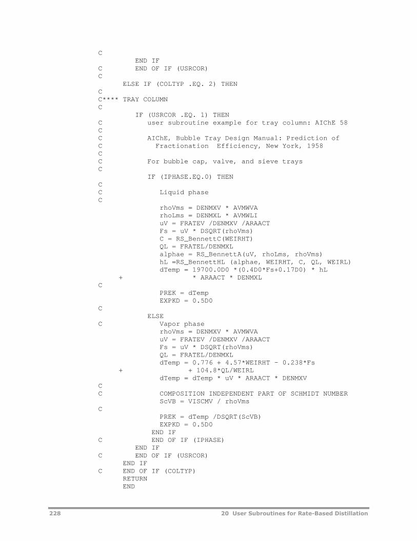
228 20 User Subroutines for Rate-Based Distillation
CEND IF
C END OF IF (USRCOR)C
ELSE IF (COLTYP .EQ. 2) THENCC**** TRAY COLUMNC
IF (USRCOR .EQ. 1) THENC user subroutine example for tray column: AIChE 58CC AIChE, Bubble Tray Design Manual: Prediction ofC Fractionation Efficiency, New York, 1958CC For bubble cap, valve, and sieve traysC
IF (IPHASE.EQ.0) THENCC Liquid phaseC
rhoVms = DENMXV * AVMWVArhoLms = DENMXL * AVMWLIuV = FRATEV /DENMXV /ARAACTFs = uV * DSQRT(rhoVms)C = RS_BennettC(WEIRHT)QL = FRATEL/DENMXLalphae = RS_BennettA(uV, rhoLms, rhoVms)hL =RS_BennettHL (alphae, WEIRHT, C, QL, WEIRL)dTemp = 19700.0D0 *(0.4D0*Fs+0.17D0) * hL
+ * ARAACT * DENMXLC
PREK = dTempEXPKD = 0.5D0
CELSE
C Vapor phaserhoVms = DENMXV * AVMWVAuV = FRATEV /DENMXV /ARAACTFs = uV * DSQRT(rhoVms)QL = FRATEL/DENMXLdTemp = 0.776 + 4.57*WEIRHT - 0.238*Fs
+ + 104.8*QL/WEIRLdTemp = dTemp * uV * ARAACT * DENMXV
CC COMPOSITION INDEPENDENT PART OF SCHMIDT NUMBER
ScVB = VISCMV / rhoVmsC
PREK = dTemp /DSQRT(ScVB)EXPKD = 0.5D0
END IFC END OF IF (IPHASE)
END IFC END OF IF (USRCOR)
END IFC END OF IF (COLTYP)
RETURNEND

20 User Subroutines for Rate-Based Distillation 229
Rate-Based Heat TransferCoefficient Subroutine
Calling Sequence for Heat Transfer Coefficients
SUBROUTINE usrhtrfc†(KSTG, NCOMPS, IDX, NBOPST, KPDIAG, XCOMPB,
FRATEL, YCOMPB, FRATEV, PRESS, TLIQ, TVAP,AVMWP, VISCMP, DENMXP, CPMIXP, THRMCP, PREH,EXPHK, EXPHD, COLTYP, USRCOR, COLDIA, IPAKAR,IPTYPE, IVENDR, IPMAT, IPSIZE, ITTYPE, IPHASE,NINT, INT, NREAL, REAL)
†Subroutine name you entered on the RadFrac | User Transfer
Subroutines | Heat Transfer sheet.
Argument List for Heat Transfer Coefficients
Variable I/O† Type Dimension Description and Range
KSTG I INTEGER — Stage number
NCOMPS I INTEGER — Number of components
IDX I INTEGER NCOMPS Component index vector
NBOPST I INTEGER 6 Physical property option set vector
KPDIAG I INTEGER — Physical property diagnostic code
XCOMPB I REAL*8 NCOMPS Bulk liquid mole fraction
FRATEL I REAL*8 — Flow of liquid (kgmole/s)
YCOMPB I REAL*8 NCOMPS Bulk vapor mole fraction
FRATEV I REAL*8 — Flow of vapor (kgmole/s)
PRESS I REAL*8 — Pressure (N/m2)
TLIQ I REAL*8 — Liquid temperature (K)
TVAP I REAL*8 — Vapor temperature (K)
AVMWP I REAL*8 — Average molecular weight of the mixture(kg/kgmole)
VISCMP I REAL*8 — Viscosity of mixture (N-s/m2)
DENMXP I REAL*8 — Mixture density (kgmole/m3)
CPMIXP I REAL*8 — Mixture heat capacity (J/kgmole/K)
THRMCP I REAL*8 — Mixture thermal conductivity (watt/m-K)
PREH†† O REAL*8 — Heat transfer coefficient factor (see note)
EXPHK†† O REAL*8 — Heat transfer coefficient exponent (see note)
EXPHD†† O REAL*8 — Heat transfer coefficient exponent (see note)
COLTYP I INTEGER — Type of column: 1 = Packed, 2 = Tray
USRCOR I INTEGER — Choice of user correlation
COLDIA I REAL*8 — Column diameter (m)
IPAKAR I INTEGER — Packing arrangement: 1 = Random, 2 =Structured
IPTYPE I INTEGER — Packing Type (see Packing Type Specification)

230 20 User Subroutines for Rate-Based Distillation
Variable I/O† Type Dimension Description and Range
IVENDR I INTEGER — Packing vendor code (See Packing VendorSpecification)
IPMAT I INTEGER — Packing material code (See Packing MaterialSpecification)
IPSIZE I INTEGER — Packing size code (See Packing SizeSpecification)
ITTYPE I INTEGER — Tray type: 1 = bubble cap, 2 = sieve, 3 =Glitsch Ballast, 4 = Koch Flexitray, 5 = NutterFloat Valve
IPHASE I INTEGER — Phase: 0 = Liquid, 1 = Vapor
NINT I INTEGER — Number of integer parameters (see Integerand Real Parameters)
INT I INTEGER NINT Vector of integer parameters (see Integer andReal Parameters)
NREAL I INTEGER — Number of real parameters (see Integer andReal Parameters)
REAL I REAL*8 NREAL Vector of real parameters (see Integer andReal Parameters)
† I = Input to subroutine, O = Output from subroutine
††EXPHDEXPHK YDIFFUSIVITBINMTPPREHHTCOEF , where HTCOEF is
the heat transfer coefficient with interfacial area included, in the units of J/sec-K
Integer and Real ParametersYou can use integer and real retention parameters by specifying the numberon the RadFrac | User Transfer Subroutines | Heat Transfer sheet. Youcan initialize these parameters by assigning values on the same sheet. Thedefault values are USER_RUMISS for real parameters and USER_IUMISS forinteger parameters. Aspen Plus retains these parameters from one call to thenext. The variables USER_IUMISS and USER_RUMISS are located in labeledcommon PPEXEC_USER (see Appendix A).

20 User Subroutines for Rate-Based Distillation 231
Example: Heat Transfer Coefficients Routine
You can use the following code as a template to create your own subroutine.In addition, Aspen Plus provides the template for this user subroutine online(see Appendix B).
IMPLICIT NONEINTEGER KSTG, NCOMPS, IDX(NCOMPS), NBOPST(6), KPDIAG,
+ COLTYP, USRCOR, IPAKAR, IPTYPE, ITTYPE, IPHASE,+ NINT, INT(NINT), NREALREAL*8 XCOMPB(NCOMPS), FRATEL, YCOMPB(NCOMPS), FRATEV,
+ PRESS, TLIQ, TVAP, AVMWP, VISCMP, DENMXP, CPMIXP,+ THRMCP, PREH, EXPHK, EXPHD, COLDIA, REAL(NREAL)
C Declare local variables used in the user correlationsC
REAL*8 ScOvPrBCC Instead of computing HTCOEF for RATEFRACC We will compute PREH, EXPHK, and EXPHD forC Rate-Based DistillationC
IF (USRCOR .EQ. 1) THENC user subroutine example: Chilton-Colburn analogyC
IF (IPHASE.EQ.0) THENCC Liquid phaseC
ScOvPrB = THRMCP/(CPMIXP * DENMXP)C
PREH = CPMIXP * (ScOvPrB ** 0.666666667D0)EXPHK = 1.0D0EXPHD = -0.666666667D0
ELSECC Vapor phaseC
ScOvPrB = THRMCP/(CPMIXP * DENMXP)C
PREH = CPMIXP * (ScOvPrB ** 0.666666667D0)EXPHK = 1.0D0EXPHD = -0.666666667D0
END IFC END OF IF (IPHASE)C
END IFC END OF IF (USRCOR)C
RETURNEND

232 20 User Subroutines for Rate-Based Distillation
Rate-Based Interfacial AreaSubroutine
Calling Sequence for Interfacial Area
SUBROUTINE usrintfa†(KSTG, NCOMPS, IDX, NBOPST, KPDIAG, XCOMPB,
FRATEL, YCOMPB, FRATEV, PRESS, TLIQ, TVAP,AVMWLI, AVMWVA, VISCML, DENMXL, SIGMAL, VISCMV,DENMXV, AREAIF, COLTYP, USRCOR, TWRARA, COLDIA,HTPACK, PACSIZ, SPAREA, CSIGMA, PFACT, PKPRMS,VOIDFR, IPAKAR, IPTYPE, IVENDR, IPMAT, IPSIZE,WEIRHT, DCAREA, ARAACT, FLOPTH, NPASS, WEIRL,IFMETH, SYSFAC, HOLEAR, ITTYPE, TRASPC, PITCH,NINT, INT, NREAL, REAL)
†Subroutine name you entered on the RadFrac | User Transfer
Subroutines | Interfacial Area sheet.
Argument List for Interfacial Area
Variable I/O† Type Dimension Description and Range
KSTG I INTEGER — Stage number
NCOMPS I INTEGER — Number of components
IDX I INTEGER NCOMPS Component index vector
NBOPST I INTEGER 6 Physical property option set vector
KPDIAG I INTEGER — Physical property diagnostic code
XCOMPB I REAL*8 NCOMPS Bulk liquid mole fraction
FRATEL I REAL*8 — Flow of liquid (kgmole/s)
YCOMPB I REAL*8 NCOMPS Bulk vapor mole fraction
FRATEV I REAL*8 — Flow of vapor (kgmole/s)
PRESS I REAL*8 — Pressure (N/m2)
TLIQ I REAL*8 — Liquid temperature (K)
TVAP I REAL*8 — Vapor temperature (K)
AVMWLI I REAL*8 — Average molecular weight of liquid mixture(kg/kgmole)
AVMWVA I REAL*8 — Average molecular weight of vapor mixture(kg/kgmole)
VISCML I REAL*8 — Viscosity of liquid mixture (N-s/m2)
DENMXL I REAL*8 — Density of liquid mixture (kgmole/m3)
SIGMAL I REAL*8 — Surface tension of liquid (N/m)
VISCMV I REAL*8 — Viscosity of vapor mixture (N-s/m2)
DENMXV I REAL*8 — Density of vapor mixture (kgmole/m3)
AREAIF O REAL*8 — Interfacial area. Units depend on COLTYP:When COLTYP = 1, m2/m3 of packing volumeWhen COLTYP = 2, m2/m2 of active tray area
COLTYP I INTEGER — Type of column: 1 = Packed, 2 = Tray
USRCOR I INTEGER — Choice of user correlation

20 User Subroutines for Rate-Based Distillation 233
Variable I/O† Type Dimension Description and Range
TWRARA I REAL*8 — Cross-sectional area of tower (m2)
COLDIA I REAL*8 — Column diameter (m)
HTPACK I REAL*8 — Height of packing in section (m)
PACSIZ I REAL*8 — Size of packing (m)
SPAREA I REAL*8 — Specific surface area of packing (m2/m3)
CSIGMA I REAL*8 — Critical surface tension of packing material(N/m)
PFACT I REAL*8 — Packing factor (1/m)
PKPRMS I INTEGER 20 Packing parameters (See Packing Parameters)
VOIDFR I INTEGER — Void fraction of packing (m3/m3)
IPAKAR I INTEGER — Packing arrangement: 1 = Random, 2 =Structured
IPTYPE I INTEGER — Packing Type (See Packing Type Specification)
IVENDR I INTEGER — Packing vendor code (See Packing VendorSpecification)
IPMAT I INTEGER — Packing material code (See Packing MaterialSpecification)
IPSIZE I INTEGER — Packing size code (See Packing SizeSpecification)
WEIRHT I REAL*8 — Height of exit weir (m)
DCAREA I REAL*8 — Area of downcomer (m2)
ARAACT I REAL*8 — Active area available on tray (m2)
FLOPTH I REAL*8 — Flowpath length (m)
NPASS I INTEGER — Number of tray passes
WEIRL I REAL*8 — Length of exit weir (m)
IFMETH I INTEGER — Flooding calculation method, required for sievetrays
SYSFAC I REAL*8 — System factor, required for sieve trays
HOLEAR I REAL*8 — Ratio of total hole area to active area, requiredfor sieve tray
ITTYPE I INTEGER — Tray type: 1 = bubble cap, 2 = sieve, 3 =Glitsch Ballast, 4 = Koch Flexitray, 5 = NutterFloat Valve
TRASPC I REAL*8 — Tray spacing (m)
PITCH I REAL*8 — Sieve hole pitch (m), required for sieve trays
NINT I INTEGER — Number of integer parameters (see Integerand Real Parameters)
INT I INTEGER NINT Vector of integer parameters (see Integer andReal Parameters)
NREAL I INTEGER — Number of real parameters (see Integer andReal Parameters)
REAL I REAL*8 NREAL Vector of real parameters (see Integer andReal Parameters)
† I = Input to subroutine, O = Output from subroutine

234 20 User Subroutines for Rate-Based Distillation
Integer and Real ParametersYou can use integer and real retention parameters by specifying the numberon the RadFrac | User Transfer Subroutines | Interfacial Area sheet. You caninitialize these parameters by assigning values on the same sheet. The defaultvalues are USER_RUMISS for real parameters and USER_IUMISS for integerparameters. Aspen Plus retains these parameters from one call to the next.The variables USER_IUMISS and USER_RUMISS are located in labeledcommon PPEXEC_USER (see Appendix A).
Example: Interfacial Area Routine
You can use the following code as a template to create you own subroutine.In addition, Aspen Plus provides the template for this user subroutine online(see Appendix B).
IMPLICIT NONEINTEGER KSTG, NCOMPS, IDX(NCOMPS), NBOPST(6), KPDIAG,
+ COLTYP, USRCOR, IPAKAR, IPTYPE, NPASS, IFMETH,+ ITTYPE, NINT, INT(NINT), NREALREAL*8 XCOMPB(NCOMPS), FRATEL, YCOMPB(NCOMPS), FRATEV,
+ PRESS, TLIQ, TVAP, AVMWLI, AVMWVA, VISCML, DENMXL,+ SIGMAL, VISCMV, DENMXV, AREAIF, TWRARA, COLDIA,+ HTPACK, PACSIZ, SPAREA, CSIGMA, PFACT, PKPRMS(20),+ VOIDFR, WEIRHT, DCAREA, ARAACT, FLOPTH, WEIRL,+ SYSFAC, HOLEAR, TRASPC, PITCH, REAL(NREAL)
C Declare local variables used in the user correlationsC
REAL*8 WeL, dTemp, uV, rhoVms,+ uL, rhoLms, ReL, FrL, uL2,+ ReV, d, Wprime
CC Compute specific interface area as described aboveC Check COLTYP/USRCOR if providing multiple area correlationsC
IF (COLTYP .EQ. 1) THENCC**** PACKED COLUMNC
IF (USRCOR .EQ. 1) THENC user subroutine example for packed column: Onda 68CC Onda, K., Takeuchi, H. and Okumoto, Y., "MassTransferC Coefficients between Gas and Liquid Phases inPackedC Columns", J. Chem. Eng. Jap., 1, (1968) p. 56C
rhoLms = DENMXL * AVMWLIuL = FRATEL / TWRARA / DENMXLuL2 = uL * uLReL = rhoLms * uL / VISCML / SPAREAFrL = SPAREA * uL2 / 9.81D0
C WHERE 9.81D0 IS GRAVITY CONSTANT IN M/S^2WeL = rhoLms * uL2 / SIGMAL / SPAREAdTemp = -1.45D0*((CSIGMA/SIGMAL)**0.75D0)

20 User Subroutines for Rate-Based Distillation 235
+ *(ReL**0.1D0)*(FrL**(-0.05D0))+ *(WeL**0.2D0)
dTemp = 1.D0 - DEXP(dTemp)
AREAIF = SPAREA*dTempEND IF
C END OF IF (USRCOR)C
ELSE IF (COLTYP .EQ. 2) THENCC**** TRAY COLUMNC
IF (USRCOR .EQ. 1) THENC user subroutine example for tray column: Scheffe-Weiland 87CC Scheffe, R.D. and Weiland, R.H., "Mass TransferC Characteristics of Valve Trays." Ind. Eng. Chem. Res.C 26, (1987) p. 228CC The original paper only mentioned valve tray.C It is also used for bubble-cap tray and sieve tray.CC CHARACTERISTIC LENGTH IS ALWAYS 1 METER.
d = 1.0D0rhoLms = DENMXL * AVMWLIrhoVms = DENMXV * AVMWVAuL = FRATEL / TWRARA / DENMXLuV = FRATEV / TWRARA / DENMXVReL = rhoLms * uL * d / VISCMLReV = rhoVms * uV * d / VISCMVWprime = WEIRHT / dAREAIF = 0.27D0 * ReV**0.375D0 * ReL**0.247D0AREAIF = AREAIF * Wprime**0.515
END IFC END OF IF (USRCOR)C
END IFC END OF IF (COLTYP)C
RETURNEND

236 20 User Subroutines for Rate-Based Distillation
Rate-Based Holdup Subroutine
Calling Sequence for Holdup Subroutine
SUBROUTINE usrhldup†(KSTG, FRATEL, FRATEV, AVMWLI, AVMWVA, VISCML,
DENMXL, SIGMAL, VISCMV, DENMXV, LHLDUP, VHLDUP,VSPACE, COLTYP, USRCOR, TWRARA, COLDIA, HTPACK,PACSIZ, SPAREA, CSIGMA, PFACT, PKPRMS, VOIDFR,PLHOLD, PVHOLD, IPAKAR, IPTYPE, IVENDR, IPMAT,IPSIZE, WEIRHT, DCAREA, ARAACT, FLOPTH, NPASS,WEIRL, IFMETH, SYSFAC, HOLEAR, ITTYPE, TRASPC,PITCH, NINT, INT, NREAL, REAL)
†Subroutine name you entered on the RadFrac | User Transfer
Subroutines | Holdup sheet.
Argument List for Holdup Subroutine
Variable I/O† Type DimensionDescription and Range
KSTG I INTEGER — Stage number
FRATEL I REAL*8 — Flow of liquid (kgmole/s)
FRATEV I REAL*8 — Flow of vapor (kgmole/s)
AVMWLI I REAL*8 — Average molecular weight of liquid mixture(kg/kgmole)
AVMWVA I REAL*8 — Average molecular weight of vapor mixture(kg/kgmole)
VISCML I REAL*8 — Viscosity of liquid (N-s/m2)
DENMXL I REAL*8 — Density of liquid mixture (kgmole/ m3)
SIGMAL I REAL*8 — Surface tension of liquid (N/m)
VISCMV I REAL*8 — Viscosity of vapor mixture (N-s/m2)
DENMXV I REAL*8 — Density of vapor mixture (kgmole/m3)
LHLDUP O REAL*8 — Liquid stage holdup (m3)
VHLDUP O REAL*8 — Vapor stage holdup (m3)
VSPACE O REAL*8 — Vapor space holdup (m3)
COLTYP I INTEGER — Type of column: 1 = Packed, 2 = Tray
USRCOR I INTEGER — Choice of user correlation
TWRARA I REAL*8 — Cross-sectional area of tower (m2)
COLDIA I REAL*8 — Column diameter (m)
HTPACK I REAL*8 — Height of packing in the section (m)
PACSIZ I REAL*8 — Size of packing (m)
SPAREA I REAL*8 — Specific surface area of packing (m2/m3)
CSIGMA I REAL*8 — Critical surface tension of packing material(N/m)
PFACT I REAL*8 — Packing factor (1/m)
PKPRMS I INTEGER 20 Packing parameters (See Packing Parameters)
VOIDFR I INTEGER — Void fraction of packing (m3/m3)

20 User Subroutines for Rate-Based Distillation 237
Variable I/O† Type DimensionDescription and Range
PLHOLD I REAL*8 — User specified % free volume for liquid holdup
PVHOLD I REAL*8 — User specified % free volume for vapor holdup
IPAKAR I INTEGER — Packing arrangement: 1 = Random, 2 =Structured
IPTYPE I INTEGER — Packing Type (see Packing Type Specification)
IVENDR I INTEGER — Packing vendor code (See Packing VendorSpecification)
IPMAT I INTEGER — Packing material code (See Packing MaterialSpecification)
IPSIZE I INTEGER — Packing size code (See Packing SizeSpecification)
WEIRHT I REAL*8 — Height of exit weir (m)
DCAREA I REAL*8 — Area of downcomer (m2)
ARAACT I REAL*8 — Active area available on tray (m2)
FLOPTH I REAL*8 — Flowpath length (m)
NPASS I INTEGER — Number of tray passes
WEIRL I REAL*8 — Length of exit weir (m)
IFMETH I INTEGER — Flooding calculation method, required for sievetrays
SYSFAC I REAL*8 — System factor, required for sieve trays
HOLEAR I REAL*8 — Ratio of total hole area to active area, requiredfor sieve tray
ITTYPE I INTEGER — Tray type: 1 = bubble cap, 2 = sieve, 3 =Glitsch Ballast, 4 = Koch Flexitray, 5 = NutterFloat Valve
TRASPC I REAL*8 — Tray spacing (m)
PITCH I REAL*8 — Sieve hole pitch (m), required for sieve trays
NINT I INTEGER — Number of integer parameters (see Integerand Real Parameters)
INT I INTEGER NINT Vector of integer parameters (see Integer andReal Parameters)
NREAL I INTEGER — Number of real parameters (see Integer andReal Parameters)
REAL I REAL*8 NREAL Vector of real parameters (see Integer andReal Parameters)
† I = Input to subroutine, O = Output from subroutine
Integer and Real ParametersYou can use integer and real retention parameters by specifying the numberon the RadFrac | User Transfer Subroutines | Holdup sheet. You can initializethese parameters by assigning values on the same sheet. The default valuesare USER_RUMISS for real parameters and USER_IUMISS for integerparameters. Aspen Plus retains these parameters from one call to the next.The variables USER_IUMISS and USER_RUMISS are located in labeledcommon PPEXEC_USER (see Appendix A).

238 20 User Subroutines for Rate-Based Distillation
Example: Holdup Subroutine
You can use the following code as a template to create your own subroutine.In addition, Aspen Plus provides the template for this user subroutine online(see Appendix B).
IMPLICIT NONEINTEGER KSTG, COLTYP, USRCOR, IPAKAR, IPTYPE, NPASS,
1 IFMETH, ITTYPE, NINT, INT(NINT), NREALREAL*8 FRATEL, FRATEV, AVMWLI, AVMWVA, VISCML, DENMXL,
1 SIGMAL, VISCMV, DENMXV, LHLDUP, VHLDUP, VSPACE,2 TWRARA,COLDIA, HTPACK, PACSIZ, SPAREA, CSIGMA,3 PFACT,PKPRMS(20), VOIDFR, PLHOLD, PVHOLD, WEIRHT,4 DCAREA,ARAACT, FLOPTH, WEIRL, SYSFAC, HOLEAR,5 TRASPC, PITCH, REAL(NREAL)
CC Define local variablesC
INTEGER ITER, KHTERR, KDPERRC Variables used in the Stichlmair 89 correlation
REAL*8 DEQ, UL, UV, REV, C1, C2, C3,+ DP, DPDRY, DPWET, FRL, HT, HT0, AUX, F, D,+ C_S, GRAV, FF, HTETA
CC Variables used in the Bennett 83 correlation
REAL*8 RS_BennettA, RS_BennettC, RS_BennettHLREAL*8 FREVOL, US, RHOV, RHOL, ALPHAE, C_B, QL, HL, HF,
+ VOID, PLH, PVHDATA GRAV /9.806599D0/
CIF (COLTYP .EQ. 1) THEN
CC PACKED COLUMNC
VSPACE = 0.0D0IF (USRCOR .EQ. 1) THEN
C user subroutine example for packed column: Stichlmair 89CC Stichlmair, J., Bravo, J.L. and Fair, J.R., "General ModelC for Prediction of Pressure Drop and Capacity ofC Countercurrent Gas/Liquid Packed Columns", Gas Sep.C Purif., 3, (1989), P19C
DEQ = 6D0*(1D0 - VOIDFR)/SPAREARHOL = AVMWLI*DENMXLRHOV = AVMWVA*DENMXV
CC *** CALCULATE FRICTION FACTOR ***C
UV = FRATEV/DENMXV/TWRARAREV = DEQ*UV*RHOV/VISCMVC1 = PKPRMS(1)C2 = PKPRMS(2)C3 = PKPRMS(3)FF = C1/REV + C2/DSQRT(REV) + C3IF (FF .EQ. 0D0) FF = 10D0C_S = (-C1/REV - C2/2D0/DSQRT(REV))/FF

20 User Subroutines for Rate-Based Distillation 239
CC *** CALCULATE DRY PRESSURE DROP ***C
DPDRY = 0.75D0*FF*(1D0 - VOIDFR)/VOIDFR**4.65D01 *RHOV*UV*UV/DEQ/RHOL/GRAV
CC *** CALCULATE LIQUID HOLDUP BELOW THE LOADING POINT ***C
UL = FRATEL/DENMXL/TWRARAFRL = UL*UL*SPAREA/GRAV/VOIDFR**4.65D0HT0 = .555D0*FRL**(0.33333333D0)
CC *** SET INITIAL ESTIMATE OF WET PRESSURE DROP ***C
DP = DPDRYITER = 0
CC *** CALCULATE WET PRESSURE DROP USING NEWTON'S METHOD ***C
101 KHTERR = 0HT = HT0*(1D0 + 20D0*DP*DP)HTETA = HT/VOIDFRIF (HTETA .GE. 1D0) THEN
KHTERR = 1ELSE
AUX = ((1D0 -VOIDFR*(1D0 -HTETA))/(1D0 -VOIDFR))1 **((2D0 +C_S)/3D0)
F = DP/DPDRY -AUX/(1D0 -HTETA)**4.65D0D = 1D0/DPDRY -40D0*HT0*DP*AUX/(1D0 -HTETA)**
1 4.65D0*(4.65/(VOIDFR -HT) +2 (2D0+C_S)/3D0/(1D0 -VOIDFR +HT))
END IFC END OF IF (HTETA...CC *** CHECK IF LIQUID OCCUPIES THE WHOLE PACKING VOIDAGE ***C
IF (KHTERR .EQ. 1) THENHT = DMAX1(VOIDFR, HT0)DPWET = DSQRT((HT/HT0 - 1D0)/20D0)GOTO 301
END IFC END OF IF (KHTERR...CC *** GET NEW ESTIMATE ***C
DPWET = DP - F/DCC *** CHECK FOR CONVERGENCE ***C
IF (DABS(DPWET - DP)/DP .GT. 1D-12) THENIF (DPWET .GT. 0.3D0) DPWET = 0.3D0IF (DPWET .LT. 0.0D0) DPWET = 0.01D0ITER = ITER + 1IF (ITER .GT. 30) THEN
KDPERR = 5GOTO 201
END IF
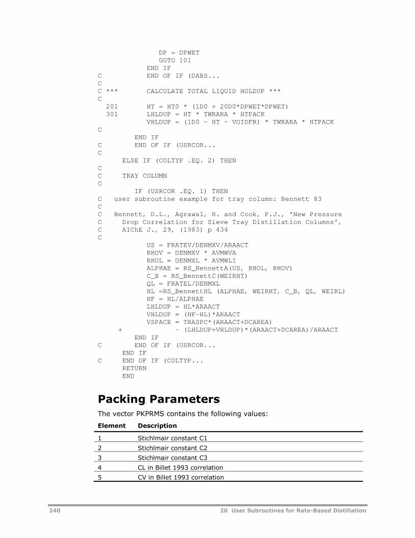
240 20 User Subroutines for Rate-Based Distillation
DP = DPWETGOTO 101
END IFC END OF IF (DABS...CC *** CALCULATE TOTAL LIQUID HOLDUP ***C
201 HT = HT0 * (1D0 + 20D0*DPWET*DPWET)301 LHLDUP = HT * TWRARA * HTPACK
VHLDUP = (1D0 - HT - VOIDFR) * TWRARA * HTPACKC
END IFC END OF IF (USRCOR...C
ELSE IF (COLTYP .EQ. 2) THENCC TRAY COLUMNC
IF (USRCOR .EQ. 1) THENC user subroutine example for tray column: Bennett 83CC Bennett, D.L., Agrawal, R. and Cook, P.J., "New PressureC Drop Correlation for Sieve Tray Distillation Columns",C AIChE J., 29, (1983) p 434C
US = FRATEV/DENMXV/ARAACTRHOV = DENMXV * AVMWVARHOL = DENMXL * AVMWLIALPHAE = RS_BennettA(US, RHOL, RHOV)C_B = RS_BennettC(WEIRHT)QL = FRATEL/DENMXLHL =RS_BennettHL (ALPHAE, WEIRHT, C_B, QL, WEIRL)HF = HL/ALPHAELHLDUP = HL*ARAACTVHLDUP = (HF-HL)*ARAACTVSPACE = TRASPC*(ARAACT+DCAREA)
+ - (LHLDUP+VHLDUP)*(ARAACT+DCAREA)/ARAACTEND IF
C END OF IF (USRCOR...END IF
C END OF IF (COLTYP...RETURNEND
Packing ParametersThe vector PKPRMS contains the following values:
Element Description
1 Stichlmair constant C1
2 Stichlmair constant C2
3 Stichlmair constant C3
4 CL in Billet 1993 correlation
5 CV in Billet 1993 correlation

20 User Subroutines for Rate-Based Distillation 241
Element Description
6 B in Bravo-Rocha-Fair 1985 correlation
7 S in Bravo-Rocha-Fair 1985 correlation
8 H in Bravo-Rocha-Fair 1985 correlation
9 Fse in Bravo-Rocha-Fair 1992 correlation
10 CE in Bravo-Rocha-Fair 1992 correlation
11 in Bravo-Rocha-Fair 1992 correlation
See the reference for RadFrac in the online help for detailed descriptions ofthese correlations and parameters.
Packing Type SpecificationThe following list provides the packing type specification for the variableIPTYPE.
Random Packings Structured Packings
1 = Berl saddle2 = Cascade mini-ring (CMR)3 = Coil Pack4 = Dixon Packing5 = Heli Pack6 = Helix7 = Hy-Pak8 = I-ball packing9 = Intalox metal tower packing (IMTP)10 = Intalox saddle11 = Super-Intalox saddle12 = Leschig ring13 = McMahon packing14 = Mesh ring packing15 = Pall ring16 = Raschig ring17 = Sigma packing18 = Intalox Snowflake plastic packing19 = Koch Flexiring single-tab slottedring20 = Koch HCKP multi-tab slotted ring21 = Koch Fleximax22 = Koch Flexisaddle23 = Raschig Ralu-ring24 = Raschig Ralu-flow25 = Raschig Super-Ring26 = Raschig Torus-Saddle27 = Raschig Super-Torus-Saddle
100 = Glitsch Grid200 = Glitsch Goodloe501 = Mellapak 125X502 = Mellapak 125Y503 = Mellapak 250X504 = Mellapak 250Y505 = Mellapak 350X506 = Mellapak 350Y507 = Mellapak 500X508 = Mellapak 500Y509 = Sulzer BX511 = Sulzer CY512 = Kerapak513 = Mellapak 170Y607 = Norton Intalox structured packing(ISP)701 = Koch Flexipac702 = Koch Flexeramic703 = Koch Flexigrid801 = Raschig Ralu-pak802 = Raschig Super-Pak803 = Crossflgrd
If the packing type is not specified, IPTYPE = USER_IUMISS.
Packing Vendor SpecificationThe following list provides the packing type specification for the variableIVENDR.

242 20 User Subroutines for Rate-Based Distillation
3 = MTL4 = NORTON
6 = GENERIC7 = KOCH
8 = SULZER9 = RASCHIG
If the packing vendor is not specified, IVENDR = USER_IUMISS.
Packing Material SpecificationThe following list provides the packing type specification for the variableIPMAT.
1 = PLASTIC2 = METAL3 = CERAMIC
4 = CARBON5 = METAL-326 = METAL-16
7 = STANDARD8 = STEEL9 = POLYPROPYLENE
If the packing material is not specified, IPMAT = USER_IUMISS.
Packing Size SpecificationThe following list provides the packing type specification for the variableIPSIZE.
101 = 1.5-MM102 = 2-MM103 = 2.5-MM104 = 3-MM105 = 4-MM106 = 5-MM107 = 6-MM 0.25"108 = 10-MM 0.375"109 = 13-MM 0.5"110 = 15-MM 0.6"111 = 16-MM 0.625"112 = 19-MM 0.75"113 = 20-MM 0.875"114 = 25-MM 1"115 = 30-MM 1.25"116 = 35-MM 1.375"117 = 38-MM 1.5"118 = 40-MM 1.6"119 = 50-MM 2"120 = 75-MM 3"121 = 90-MM 3.5"122 = 100-MM 4"123 = 45-MM 1.8"124 = 60-MM 2.36"127 = 80-MM128 = 125-MM201 = NO-0A202 = NO-0P203 = NO-0204 = NO-0.5A
205 = NO-0.5P206 = NO-0.5207 = NO-1A208 = NO-1P209 = NO-1X210 = NO-1211 = NO-1.5P212 = NO-2A213 = NO-2P214 = NO-2X215 = NO-2216 = NO-3A217 = NO-3P218 = NO-3219 = NO-4P220 = NO-4221 = NO-5P222 = NO-5223 = NO-7224 = NO-0.3225 = NO-0.7226 = NO-1.5301 – II401 = 200402 = 300403 = 400404 = 700405 = 28406 = 48407 = 88408 = 25
409 = 50501 = STYLE-2502 = STYLE-3601 = 1X602 = 1Y603 = 1.4Y604 = 1.6Y605 = 2X606 = 2Y607 = 2.5Y608 = 3X609 = 3Y610 = 4Y611 = 125X612 = 125Y613 = 250X614 = 250Y615 = 350X616 = 350Y617 = 500X618 = 500Y619 = 170Y627 = 250YC701 = 1T702 = 2T703 = 3T704 = 4T705 = 5T
If the packing size is not specified, IPSIZE = USER_IUMISS.

21 User Tray and Packing Subroutines 243
21 User Tray and PackingSubroutines
You can supply your own tray sizing or packing subroutine for sizing andrating calculations for RadFrac, MultiFrac, and PetroFrac.
For trays, enter the subroutine name on the following sheet:
For Use this sheet
RadFrac RadFrac | User Subroutines | Tray Sizing/Rating
MultiFrac MultiFrac | User Subroutines | Tray Sizing/Rating
PetroFrac PetroFrac | User Subroutines | Tray Sizing/Rating
For packing, enter the subroutine name on the following sheet:
For Use this sheet
RadFrac RadFrac | User Subroutines | Pack Sizing/Rating
MultiFrac MultiFrac | User Subroutines | Pack Sizing/Rating
PetroFrac PetroFrac | User Subroutines | Pack Sizing/Rating

244 21 User Tray and Packing Subroutines
User Tray Sizing/RatingSubroutine
Calling Sequence for User Tray Subroutine
SUBROUTINE subrname†
(MODE, N, FLM, FVMTO, FLV, FVVTO, RHOL,RHOVTO, SIGMA, FP, QR, SYSFAC, NPASS, TS,FA, DIAM, SZPAR, RTPAR, NINT, INT, NREAL,REAL, SZRSLT, RTRSLT, P, XMWL, XMWVTO,XMUL, XMUVTO, FFAC, FFR, ITTYPE)
†Subroutine name you entered on the User Subroutines | Tray
Sizing/Rating sheet.
Argument List Descriptions for User Tray Subroutine
Variable I/O† Type Dimension Description and Range
MODE I INTEGER — Calculation mode: 1 = Sizing, 2 = Rating
N I INTEGER — Stage number
FLM I REAL*8 — Mass liquid flow from the stage (kg/s)
FVMTO I REAL*8 — Mass vapor flow to the stage (kg/s)
FLV I REAL*8 — Volumetric liquid flow from the stage (m3/s)
FVVTO I REAL*8 — Volumetric vapor flow to the stage (m3/s)
RHOL I REAL*8 — Mass density of liquid from the stage (kg/m3)
RHOVTO I REAL*8 — Mass density of vapor to the stage (kg/m3)
SIGMA I REAL*8 — Surface tension of liquid from the stage (N/m)
FP I REAL*8 — Flow parameter
QR I REAL*8 — Reduced vapor throughput (m3/s)
SYSFAC I REAL*8 — System foaming factor
NPASS I INTEGER — Number of passes
TS I REAL*8 — Tray spacing (m)
FA I/O REAL*8 — Percentage approach to floodingInput for sizing, Output for rating
DIAM I/O REAL*8 — Column diameter (m)Input for rating, Output for sizing
SZPAR I REAL*8 3 Sizing input parameters:SZPAR (1) - minimum allowed downcomerarea/tray areaSZPAR (2) - percent slot or hole area/activeareaSZPAR (3) - minimum column diameter (m)
RTPAR I REAL*8 60 Rating input parameters (see RTPAR)
NINT I INTEGER — Number of integer parameters (see Integerand Real Parameters)
INT I/O INTEGER NINT Vector of integer parameters (see Integer andReal Parameters)

21 User Tray and Packing Subroutines 245
Variable I/O† Type Dimension Description and Range
NREAL I INTEGER — Number of real parameters (see Integer andReal Parameters)
REAL I/O REAL*8 NREAL Vector of real parameters (see Integer andReal Parameters)
SZRSLT O REAL*8 4 Sizing results:SZRSLT (1) - Weir length (m)SZRSLT (2) - Downcomer velocity (m/s)SZRSLT (3) - Downcomer area per panel (m2)SZRSLT (4) - Active area (m2)
RTRSLT O REAL*8 20 Rating results (see RTRSLT)
P I REAL*8 — Stage pressure (N/m2)
XMWL I REAL*8 — Average molecular weight of liquid from thestage
XMWVTO I REAL*8 — Average molecular weight of vapor to thestage
XMULll I REAL*8 — Viscosity of liquid from stage (N-s/m2)
XMUVTO I REAL*8 — Viscosity of vapor to the stage (N-s/m2)
FFAC I REAL*8 — F factor (for rating only) (m/s (kg/m3) ½)
FFR I REAL*8 — Reduced F factor (m3/s (kg/m3) ½)
ITTYPE I INTEGER — Type of tray1 = bubble-cap2 - sieve
† I = Input to subroutine, O = Output from subroutine

246 21 User Tray and Packing Subroutines
RTPARThe array of rating input parameters contains these values in its 60 elements:
RTPAR (1) - Weir height (m), panel ARTPAR (2) - Weir height (m), panel BRTPAR (3) - Weir height (m), panel CRTPAR (4) - Weir height (m), panel DRTPAR (5) - Weir length (m), panel ARTPAR (6) - Weir length (m), panel BRTPAR (7) - Weir length (m), panel CRTPAR (8) - Weir length (m), panel DRTPAR (9) - Top downcomer width (m), panel ARTPAR (10) - Top downcomer width (m), panel BRTPAR (11) - Top downcomer width (m), panel CRTPAR (12) - Top downcomer width (m), panel DRTPAR (13) - Bottom downcomer width (m), panel ARTPAR (14) - Bottom downcomer width (m), panel BRTPAR (15) - Bottom downcomer width (m), panel CRTPAR (16) - Bottom downcomer width (m), panel DRTPAR (17) - Top downcomer area (m2), panel ARTPAR (18) - Top downcomer area (m2), panel BRTPAR (19) - Top downcomer area (m2), panel CRTPAR (20) - Top downcomer area (m2), panel DRTPAR (21) - Bottom downcomer area (m2), panel ARTPAR (22) - Bottom downcomer area (m2), panel BRTPAR (23) - Bottom downcomer area (m2), panel CRTPAR (24) - Bottom downcomer area (m2), panel DRTPAR (25) - Downcomer clearance (m), panel ARTPAR (26) - Downcomer clearance (m), panel BRTPAR (27) - Downcomer clearance (m), panel CRTPAR (28) - Downcomer clearance (m), panel DRTPAR (29) - Downcomer height (m), panel ARTPAR (30) - Downcomer height (m), panel B
RTPAR (31) - Downcomer height (m), panel CRTPAR (32) - Downcomer height (m), panel DRTPAR (33) - Flow path length (m), panel ARTPAR (34) - Flow path length (m), panel BRTPAR (35) - Flow path length (m), panel CRTPAR (36) - Flow path length (m), panel DRTPAR (37) - Flow path width (m), panel ARTPAR (38) - Flow path width (m), panel BRTPAR (39) - Flow path width (m), panel CRTPAR (40) - Flow path width (m), panel DRTPAR (41) - Active area (m2), panel ARTPAR (42) - Active area (m2), panel BRTPAR (43) - Active area (m2), panel CRTPAR (44) - Active area (m2), panel DRTPAR (45) - Number of caps, panel ARTPAR (46) - Number of caps, panel BRTPAR (47) - Number of caps, panel CRTPAR (48) - Number of caps, panel DRTPAR (49) - Number of rows, panel ARTPAR (50) - Number of rows, panel BRTPAR (51) - Number of rows, panel CRTPAR (52) - Number of rows, panel DRTPAR (53) - Downcomer-to-wall (m)RTPAR (54) - Hole diameter (m)RTPAR (55) - Hole area/active areaRTPAR (56) - Deck thickness (m)RTPAR (57) - Cap diameter (m)RTPAR (58) - Cap space (m)RTPAR (59) - Skirt height (m)RTPAR (60) - Efficiency
RTRSLTThe rating results array contains these parameters:
RTRSLT (1) - Pressure drop (mm - liq), panel ARTRSLT (2) - Pressure drop (mm - liq), panel BRTRSLT (3) - Pressure drop (mm - liq), panel CRTRSLT (4) - Pressure drop (mm - liq), panel DRTRSLT (5) - Downcomer velocity (gpm/ft2), panel ARTRSLT (6) - Downcomer velocity (gpm/ft2), panel BRTRSLT (7) - Downcomer velocity (gpm/ft2), panel CRTRSLT (8) - Downcomer velocity (gpm/ft2), panel DRTRSLT (9) - Downcomer backup (mm), panel ARTRSLT (10) - Downcomer backup (mm), panel BRTRSLT (11) - Downcomer backup (mm), panel CRTRSLT (12) - Downcomer backup (mm), panel D
RTRSLT (13) - Downcomer backup/tray spacing,panel ARTRSLT (14) - Downcomer backup/tray spacing,panel BRTRSLT (15) - Downcomer backup/tray spacing,panel CRTRSLT (16) - Downcomer backup/tray spacing,panel DRTRSLT (17) - Weir loading (gpm/ft), panel ARTRSLT (18) - Weir loading (gpm/ft), panel BRTRSLT (19) - Weir loading (gpm/ft), panel CRTRSLT (20) - Weir loading (gpm/ft), panel D

21 User Tray and Packing Subroutines 247
User Packing Sizing/RatingSubroutine
Calling Sequence for User Packing Subroutine
SUBROUTINE subrname†
(MODE, N, P, FLM, FVMTO, FLV, FVVTO,XMWL, XMWVTO, RHOL, RHOVTO, XMUL,XMUVTO, SIGMA, FP, QR, FFAC, FFR,SYSFAC, IPTYPE, IPSIZE, IPMAT, PACKFC,VOID, SURFA, STICH, HETP, FA, DIAM,NINT, INT, NREAL, REAL, DPSTG, HTSTG)
†Subroutine name you entered on the User Subroutines | Pack
Sizing/Rating sheet.
Argument List Descriptions for User Packing Subroutine
Variable I/O†
Type Dimension Description and Range
MODE I INTEGER — Calculation mode: 1 = Sizing, 2 = Rating
N I INTEGER — Stage number
P I REAL*8 — Stage pressure (N/m2)
FLM I REAL*8 — Mass liquid flow from the stage (kg/s)
FVMTO I REAL*8 — Mass vapor flow to the stage (kg/s)
FLV I REAL*8 — Volumetric liquid flow from the stage (m3/s)
FVVTO I REAL*8 — Volumetric vapor flow to the stage (m3/s)
XMWL I REAL*8 — Average molecular weight of liquid from thestage
XMWVTO I REAL*8 — Average molecular weight of vapor to thestage
RHOL I REAL*8 — Mass density of liquid from the stage (kg/m3)
RHOVTO I REAL*8 — Mass density of vapor to the stage (kg/m3)
XMUL I REAL*8 — Viscosity of liquid from the stage (N-s/m2)
XMUVTO I REAL*8 — Viscosity of vapor to the stage (N-s/m2)
SIGMA I REAL*8 — Surface tension of liquid from the stage (N/m)
FP I REAL*8 — Flow parameter
QR I REAL*8 — Reduced vapor throughput (m3s)
FFAC I REAL*8 — F factor (for rating only) (m/s (kg/m3) ½)
FFR I REAL*8 — Reduced F factor (m/s (kg/m3) ½)
SYSFAC I REAL*8 — System foaming factor
IPTYPE I INTEGER — Packing type
IPSIZE I INTEGER — Packing size
IPMAT I INTEGER — Packing material
PACKFC I REAL*8 — Packing factor (1/m)
VOID I REAL*8 — Packing void fraction
SURFA I REAL*8 — Packing surface area (m2/m3)
STICH I REAL*8 3 Stichlmair constants

248 21 User Tray and Packing Subroutines
Variable I/O†
Type Dimension Description and Range
HETP I/O REAL*8 — Height equivalent to a theoretical plate (m)
FA I/O REAL*8 — Fractional approach to floodingInput for sizing, Output for rating
DIAM I/O REAL*8 — Column diameter (m)Input for sizing, Output for rating
NINT I INTEGER — Number of integer parameters (see Integerand Real Parameters)
INT I/O INTEGER NINT Vector of integer parameters (see Integer andReal Parameters)
NREAL I REAL*8 — Number of real parameters (see Integer andReal Parameters)
REAL I/O REAL*8 NREAL Vector of real parameters (see Integer andReal Parameters)
DPTSG O REAL*8 — Pressure drop per stage (N/m2)
HTSTG O REAL*8 — Fractional liquid holdup
† I = Input to subroutine, O = Output from subroutine
Integer and Real ParametersYou can use integer and real retention parameters by specifying the numberon one of the sheets listed on page 243. You can initialize these parametersby assigning values on the same sheet. The default values are USER_RUMISSfor real parameters and USER_IUMISS for integer parameters. Aspen Plusretains these parameters from one call to the next. The variablesUSER_IUMISS and USER_RUMISS are located in labeled commonPPEXEC_USER (see Appendix A).

22 User Performance Curves Subroutine for Compr/MCompr 249
22 User Performance CurvesSubroutine forCompr/MCompr
This chapter describes the user performance curves subroutine for Compr andMCompr.
To supply a user performance curves subroutine for Compr, select UserSubroutine for Curve Format on the Compr | Performance Curves |Curve Setup sheet. On the Compr | User Subroutine | Specificationsheet, choose the type of user curves and specify the user subroutine name.
To supply a user performance curves subroutine for MCompr, select UserSubroutine for Curve Format on the MCompr | Performance Curves |Curve Setup sheet. On the MCompr | User Subroutine | Specificationsheet, choose the type of user curves and specify the user subroutine name.
The user subroutine calculates one of the following:
Head.
Head coefficient.
Power.
Discharge pressure.
Pressure ratio.
Pressure change.
In addition, you can also calculate efficiency in the user subroutine.

250 22 User Performance Curves Subroutine for Compr/MCompr
Performance Curve Subroutine
Calling Sequence for User Performance Curves Subroutine
SUBROUTINE subrname†
(S1, NSUBS, IDXSUB, ITYPE, NBOPST, NINT,INT, NREAL, REAL, NIWORK, IWORK, NWORK,WORK, IEXTOP, ISTAGE, IWHEEL, DIAMIM,ACTSPD, SONCVI, IUSRCT, VALD1U, VALD2U,ABVSRG, BELSWL, IRETFL)
†Subroutine name you entered on the Compr or MCompr | User
Subroutine | Specification sheet.
Argument List for User Performance Curves Subroutine
Variable I/O†
Type Dimension Description and Range
S1 I REAL*8 (1) Stream vector after initial flash (has alreadyaccounted for pressure losses at suctionnozzle)
NSUBS I INTEGER — Number of substreams
IDXSUB I INTEGER NSUBS Substream index vector
ITYPE I INTEGER NSUBS Substream type vector: 1=MIXED,2=CISOLID, 3=NC
NBOPST I INTEGER 6 Property option set
NINT I INTEGER — Number of integer parameters (see Integerand Real Parameters)
INT I INTEGER NINT Vector of integer parameters (see Integer andReal Parameters)
NREAL I INTEGER — Number of real parameters (see Integer andReal Parameters)
REAL I REAL*8 NREAL Vector of real parameters (see Integer andReal Parameters)
NIWORK I INTEGER — Length of user integer work array (see LocalWork Arrays)
IWORK I INTEGER NIWORK User integer work array (see Local WorkArrays)
NWORK I INTEGER — Length of user real work array (see Local WorkArrays)
WORK I REAL*8 NWORK User real work area (see Local Work Arrays)
IEXTOP I INTEGER — Extrapolation option= 1, extrapolate beyond surge and stonewall= 0, do not extrapolate
ACTSPD I REAL*8 — Actual operating shaft speed (1/sec)
ISTAGE I INTEGER — Stage number (= 1 for Compr)
IWHEEL I INTEGER — Wheel number (= 1 for Compr)
DIAMIM I REAL*8 — Impeller diameter (m)
SONCVI I REAL*8 — Sonic velocity of process fluid at suctionconditions (after any suction pressure losses)

22 User Performance Curves Subroutine for Compr/MCompr 251
Variable I/O†
Type Dimension Description and Range
IUSRCT I INTEGER — Type of dependent variable (specified on theUser Subroutine | Specification sheet)0=none 4=discharge pressure1=head 5=pressure ratio2=head coefficient 6=pressure change3=power
VALD1U O REAL*8 — Calculated value of dependent variable (in SIunits)
VALD2U O REAL*8 — Calculated value of efficiency
ABVSRG O REAL*8 — Percentage above surge point100 * (actual suction volumetric flowrate -suction volumetric flowrate at surge) / suctionvolumetric flowrate at surge
BELSWL O REAL*8 — Percentage below stonewall point100 * (suction volumetric flowrate at stonewall- actual suction volumetric flowrate) / suctionvolumetric flowrate at stonewall
IRETFL O INTEGER — Return flag= 0, all fine> 0, error= -1, value below surge= -2, value above stonewall
† I = Input to subroutine, O = Output from subroutine
Integer and Real ParametersYou can use integer and real retention parameters by specifying the numberon the Compr or MCompr | User Subroutine | Specification sheet. Youcan initialize these parameters by assigning values on the same sheet. Thedefault values are USER_RUMISS for real parameters and USER_IUMISS forinteger parameters. Aspen Plus retains these parameters from one call to thenext. The variables USER_IUMISS and USER_RUMISS are located in labeledcommon PPEXEC_USER (see Appendix A).
Local Work ArraysYou can use local work arrays by specifying the array length on the Compr orMCompr | User Subroutine | Specification sheet. Aspen Plus does notretain these arrays from one call to the next.

252 22 User Performance Curves Subroutine for Compr/MCompr

23 User Solubility Subroutine for Crystallizer 253
23 User SolubilitySubroutine for Crystallizer
You can supply a user solubility subroutine for the unit operation modelCrystallizer.
The user solubility subroutine provides the saturation concentration to beused in determining crystal product flow rate in the model. The solubilitysubroutine can also be used to calculate crystal product flow rate, whichreplaces the model calculation.
To provide a user solubility subroutine for Crystallizer, select UserSubroutine for Saturation Calculation Method on the Crystallizer |Setup | Specifications sheet and specify the subroutine name on theCrystallizer | Advanced | User Subroutine sheet.
Crystallizer SolubilitySubroutine
Calling Sequence for Crystallizer Subroutine
SUBROUTINE subrname†
(SOUTC, IPROD, ITYCON, NC, IDX, TEMP,CONCEN, XMW, CSMIN, QLSOLN, FLSOLN,QLSOLV, FLSOLV, FLSOLU, PRODIN, SLRYIN,VENT, RHOL, RHOLL, FRHYD, NINTS, INTS,NREALS, REALS, NIWKS, IWORKS, NWKS,WORKS, CSAT, PROD, NSUB, IDXSUB, STOIC,NTOT, SVENT, NCP, NCPNC, IDCRY)
†Subroutine name you entered on the Crystallizer | Advanced | User
Subroutine sheet.
Argument List Descriptions for Crystallizer Subroutine
Variable I/O†
Type Dimension Description and Range
SOUTC I REAL*8 — Stream vector (see Appendix C)

254 23 User Solubility Subroutine for Crystallizer
Variable I/O†
Type Dimension Description and Range
IPROD O INTEGER — Flag for calculating crystallizer yield0 = calculated by model1 = calculated in this routine
ITYCON O INTEGER — Type of concentration0 = kg/m3 of solution (or solvent)1 = kg/kg of solution (or solvent)
NC I INTEGER — Total number of components present(conventional and non-conventional)
IDX I INTEGER NCP Component index vector (see IDX)
TEMP I REAL*8 — Temperature (K)
CONCEN I REAL*8 NC Concentrations (kg/m3 or kg/kg, based onvalue of ITYCON)
XMW I REAL*8 NC Molecular weight
CSMIN I REAL*8 — Concentration of limiting component (kg/m3 orkg/kg)
QLSOLN I REAL*8 — Volume flow rate of solution (m3/s)
FLSOLN I REAL*8 — Mass flow rate of solution (kg/s)
QLSOLV I REAL*8 — Volume flow rate of solvent (m3/s)
FLSOLV I REAL*8 — Mass flow rate of solvent (kg/s)
FLSOLU I REAL*8 — Mass flow rate of solute (kg/s)
PRODIN I REAL*8 — Mass flow rate of crystal entering Crystallizer(kg/s)
SLRYIN I REAL*8 — Mass flow rate of slurry entering Crystallizer(kg/s)
VENT I REAL*8 — Vent mass flow rate (kg/s)
RHOL I REAL*8 — Density of solution (kg/m3)
RHOLL I REAL*8 — Density of solvent (kg/m3)
FRHYD I REAL*8 — Mass fraction of hydrated solvent
NINTS I INTEGER — Number of integer parameters (see Integerand Real Parameters)
INTS I INTEGER NINTS Vector of integer parameters (see Integer andReal Parameters)
NREALS I INTEGER — Number of Real Parameters (see Integer andReal Parameters)
REALS I REAL*8 NREALS Vector of Real Parameters (see Integer andReal Parameters)
NIWKS I INTEGER — Length of integer work vector (see Local WorkArrays)
IWORKS I INTEGER NIWKS Integer work vector (see Local Work Arrays)
NWKS I INTEGER — Length of real work vector (see Local WorkArrays)
WORKS I REAL*8 NWKS Real work vector (see Local Work Arrays)
CSAT O REAL*8 — Saturation concentration (kg/m3 or kg/kg,based on value of ITYCON)
PROD O REAL*8 — Crystal product flow rate (kg/s)
NSUB I INTEGER — Number of substreams
IDXSUB I INTEGER NSUB Substream index vector

23 User Solubility Subroutine for Crystallizer 255
Variable I/O†
Type Dimension Description and Range
STOIC I REAL*8 NSUB, NC, 1 Stoichiometric coefficients for crystallizationkinetics
NTOT I INTEGER — Length of a stream vector
SVENT I REAL*8 NTOT Stream vector of vent flow
NCP I INTEGER — Number of components present incrystallization kinetics (conventional and non-conventional)
NCPNC I INTEGER — Number of non-conventional componentspresent
IDCRY I INTEGER — Component index number (see IDX) of thecrystal product
† I = Input to subroutine, O = Output from subroutine
IDXIDX is a vector of length NCP containing component sequence numbers of thecomponents present in the crystallization kinetics.
The values of IDX are component index numbers, where the components arenumbered in the order they appear on the Components | Specification |Selection sheet, except that all conventional components are numbered firstin the order shown, followed by non-conventional components present in theCrystallizer model, in the order shown.
For example, if NC = 6, and only the third and sixth components on theComponents form are non-conventional (and present in the Crystallizer) andthe rest are conventional components, then NCPNC = 2. The componentnumbers (in the order the components are listed on the Components form)are 1, 2, 5, 3, 4, 6. If the first, third, and fifth components on theComponents form are involved in crystallization kinetics, then NCP = 3 andIDX = (1,4,5).
Integer and Real ParametersYou can use integer and real retention parameters by specifying the numberon the Crystallizer | Advanced | User Subroutine sheet. You can initializethese parameters by assigning values on the same sheet. The default valuesare USER_RUMISS for real parameters and USER_IUMISS for integerparameters. Aspen Plus retains these parameters from one call to the next.The variables USER_IUMISS and USER_RUMISS are located in labeledcommon PPEXEC_USER (see Appendix A).
Local Work ArraysYou can use local work arrays by specifying the array length on theCrystallizer | Advanced | User Subroutine sheet. Aspen Plus does notretain these arrays from one call to the next.

256 23 User Solubility Subroutine for Crystallizer

24 User Performance Curves Subroutine for Pump 257
24 User Performance CurvesSubroutine for Pump
This chapter describes the user performance curves subroutine for Pump.
To supply a user performance curves subroutine for Pump, select UserSubroutine for Curve Format on the Pump | Performance Curves |Curve Setup sheet. On the Pump | User Subroutine | Specificationsheet, choose the type of user curves and specify the user subroutine name.
The user subroutine calculates one of the following:
Head.
Head coefficient.
Power.
Discharge pressure.
Pressure ratio.
Pressure change.
In addition, you can also calculate efficiency and required net positive suctionhead (NPSHR) in the user subroutine.
Pump Performance CurveSubroutine
Calling Sequence for User Performance Curves Subroutine
SUBROUTINE subrname†
(S1, NSUBS, IDXSUB, ITYPE, NBOPST, NINT,INT, NREAL, REAL, NIWORK, IWORK, NWORK,WORK, DIAMIM, VFLIN, ACTSPD, SUSPSP,IUSRCT, VALD1U, VALD2U, VALD3U)
†Subroutine name you entered on the Pump | User Subroutine |
Specification sheet.

258 24 User Performance Curves Subroutine for Pump
Argument List for User Performance Curves Subroutine
Variable I/O†
Type DimensionDescription and Range
S1 I REAL*8 (1) Stream vector after initial flash (has alreadyaccounted for pressure losses at suction nozzle)(see Appendix C)
NSUBS I INTEGER — Number of substreams
IDXSUB I INTEGER NSUBS Substream index vector
ITYPE I INTEGER NSUBS Substream type vector: 1,=MIXED, 2=CISOLID,3=NC
NBOPST I INTEGER 6 Property option set
NINT I INTEGER — Number of integer parameters (see Integer andReal Parameters)
INT I INTEGER NINT Vector of integer parameters (see Integer andReal Parameters)
NREAL I INTEGER — Number of real parameters (see Integer and RealParameters)
REAL I REAL*8 NREAL Vector of real parameters (see Integer and RealParameters)
NIWORK I INTEGER — Length of user integer work array (see LocalWork Arrays)
IWORK I INTEGER NIWORK User integer work array (see Local Work Arrays)
NWORK I INTEGER — Length of user real work array (see Local WorkArrays)
WORK I REAL*8 NWORK User real work area (see Local Work Arrays)
DIAMIM I REAL*8 — Impeller diameter (m)
VFLIN I REAL *8 — Volumetric flow rate at the suction condition(m3/s)
ACTSPD I REAL*8 — Actual operating shaft speed (1/sec)
SUSPSP I REAL*8 — Suction specific speed (units depend on speedunits selected on Pump | Setup | CalculationOptions sheet)
IUSRCT I INTEGER — Type of dependent variable (specified on the UserSubroutine Specification sheet)0=none 4=discharge pressure1=head 5=pressure ratio2=head coefficient 6=pressure change3=power
VALD1U O REAL*8 — Calculated value of the dependent variable (in SIunits)
VALD2U O REAL*8 — Calculated value of efficiency
VALD3U O REAL*8 — Calculated value of NPSHR (m)
† I = Input to subroutine, O = Output from subroutine
Integer and Real ParametersYou can use integer and real retention parameters by specifying the numberon the Pump | User Subroutine | Specification sheet. You can initializethese parameters by assigning values on the same sheet. The default values

24 User Performance Curves Subroutine for Pump 259
are USER_RUMISS for real parameters and USER_IUMISS for integerparameters. Aspen Plus retains these parameters from one call to the next.The variables USER_IUMISS and USER_RUMISS are located in labeledcommon PPEXEC_USER (see Appendix A).
Local Work ArraysYou can use local work arrays by specifying the array length on the Pump |User Subroutine | Specification sheet. Aspen Plus does not retain thesearrays from one call to the next.

260 24 User Performance Curves Subroutine for Pump

25 User Subroutines for Petroleum Property Methods 261
25 User Subroutines forPetroleum Property Methods
Aspen Plus provides several correlations for basic properties, thermodynamicproperties, and equation of state parameters for petroleum characterization.If these are not sufficient, you can provide your own correlation.
To provide your own correlation:
1 Write a Fortran subroutine to calculate the property or parameter usingyour correlations. The subroutine name must be the same as the name ofthe user routine you will select in step 2.
2 Go to the Components | Petro Characterization | Property Methods| Basic sheet. Specify a base property method. For the properties orparameters for which you want to supply your own correlation, select theUser routine option.
The following pages list the calling arguments to the subroutines.

262 25 User Subroutines for Petroleum Property Methods
Calling Sequence for Boiling Point Subroutine
SUBROUTINE PCABPU (XMW, SG, ABP)
Argument List Descriptions for Boiling Point Subroutine
Variable I/O† Type Dimension Description
XMW I REAL*8 — Molecular weight
SG I REAL*8 — Specific gravity
ABP O REAL*8 — Average boiling point
† I = Input to subroutine, O = Output from subroutine
Calling Sequence for Benedict-Webb-Rubin ParameterSubroutine
SUBROUTINE PCBWRU (ABP, API, SG, XMW, BWRGMA, TCBWR, VCBWR)
Argument List Descriptions for BWR ParameterSubroutine
Variable I/O† Type Dimension Description
ABP I REAL*8 — Average boiling point
API I REAL*8 — API gravity
SG I REAL*8 — Specific gravity
XMW I REAL*8 — Molecular weight
BWRGMA O REAL*8 — BWR orientation parameter
TCBWR O REAL*8 — BWR critical temperature
VCBWR O REAL*8 — BWR critical volume
† I = Input to subroutine , O = Output from subroutine
Calling Sequence for Ideal Gas Heat Capacity Subroutine
SUBROUTINE PCCPGU (ABP, API, SG, XMW, TC, PC, CPIG)
Argument List Descriptions for Ideal Gas Heat CapacitySubroutine
Variable I/O† Type Dimension Description
ABP I REAL*8 — Average boiling point
API I REAL*8 — API gravity
SG I REAL*8 — Specific gravity
XMW I REAL*8 — Molecular weight
TC I REAL*8 — Critical temperature
PC I REAL*8 — Critical pressure
CPIG O REAL*8 11 Ideal gas heat capacity coefficients
† I = Input to subroutine, O = Output from subroutine

25 User Subroutines for Petroleum Property Methods 263
Calling Sequence for Gibbs Free Energy of FormationSubroutine
SUBROUTINE PCDGFU (ABP, API, SG, XMW, DGFORM)
Argument List Descriptions for Gibbs Free Energy ofFormation Subroutine
Variable I/O† Type Dimension Description
ABP I REAL*8 — Average boiling point
API I REAL*8 — API gravity
SG I REAL*8 — Specific gravity
XMW I REAL*8 — Molecular weight
DGFORM O REAL*8 — Gibbs free energy of formation
† I = Input to subroutine, O = Output from subroutine
Calling Sequence for Heat of Formation Subroutine
SUBROUTINE PCDHFU (ABP, API, SG, XMW, DHFORM)
Argument List Descriptions for Heat of FormationSubroutine
Variable I/O† Type Dimension Description
ABP I REAL*8 — Average boiling point
API I REAL*8 — API gravity
SG I REAL*8 — Specific gravity
XMW I REAL*8 — Molecular weight
DHFORM O REAL*8 — Heat of formation
† I = Input to subroutine, O = Output from subroutine
Calling Sequence for Enthalpy of Vaporization Subroutine
SUBROUTINE PCDHVU (ABP, API, SG, XMW, TC, PC, DHVLB)
Argument List Descriptions for Enthalpy of VaporizationSubroutine
Variable I/O† Type Dimension Description
ABP I REAL*8 — Average boiling point
API I REAL*8 — API gravity
SG I REAL*8 — Specific gravity
XMW I REAL*8 — Molecular weight
TC I REAL*8 — Critical temperature
PC I REAL*8 — Critical pressure
DHVLB O REAL*8 — Heat of vaporization
† I = Input to subroutine, O = Output from subroutine

264 25 User Subroutines for Petroleum Property Methods
Calling Sequence for Hydrocarbon Solubility Subroutine
SUBROUTINE PCHSLU (ABP, API, SG, XMW, HCSOL)
Argument List Descriptions for Viscosity Subroutine
Variable I/O† Type Dimension Description
ABP I REAL*8 — Average boiling point
API I REAL*8 — API gravity
SG I REAL*8 — Specific gravity
XMW I REAL*8 — Molecular weight
HCSOL O REAL*8 5 Hydrocarbon solubility parameters.
The first three elements are A, B, and C inln(x) = A + B/T + C ln Tand the last two elements are lower andupper temperature limits, as described inHydrocarbon Solubility in online help.
† I = Input to subroutine, O = Output from subroutine
Calling Sequence for Viscosity Subroutine
SUBROUTINE PCMULU (ABP, API, SG, XMW, TC, TEMP, VISC)
Argument List Descriptions for Viscosity Subroutine
Variable I/O† Type Dimension Description
ABP I REAL*8 — Average boiling point
API I REAL*8 — API gravity
SG I REAL*8 — Specific gravity
TC I REAL*8 — Critical temperature
TEMP I REAL*8 — Temperature
VISC O REAL*8 — Viscosity
† I = Input to subroutine, O = Output from subroutine
Calling Sequence for Molecular Weight Subroutine
SUBROUTINE PCMWU (ABP, SG, XMW)
Argument List Descriptions for Molecular WeightSubroutine
Variable I/O† Type Dimension Description
ABP I REAL*8 — Average boiling point
SG I REAL*8 — Specific gravity
XMW O REAL*8 — Molecular weight
† I = Input to subroutine, O = Output from subroutine

25 User Subroutines for Petroleum Property Methods 265
Calling Sequence for Acentric Factor Subroutine
SUBROUTINE PCOMGU (TC, PC, PLXANT, ABP, SG, XMW, OMEGA)
Argument List Descriptions for Acentric Factor Subroutine
Variable I/O† Type Dimension Description
TC I REAL*8 — Critical temperature
PC I REAL*8 — Critical pressure
PLXANT I REAL*8 9 Extended Antoine vapor pressureparameters
ABP I REAL*8 — Average boiling point
SG I REAL*8 — Specific gravity
OMEGA O REAL*8 — Acentric Factor
† I = Input to subroutine, O = Output from subroutine
Calling Sequence for Critical Pressure Subroutine
SUBROUTINE PCPCU (ABP, API, SG, XMW, PC)
Argument List Descriptions for Critical PressureSubroutine
Variable I/O† Type Dimension Description
ABP I REAL*8 — Average boiling point
API I REAL*8 — API gravity
SG I REAL*8 — Specific gravity
XMW I REAL*8 — Molecular weight
PC O REAL*8 — Critical pressure
† I = Input to subroutine, O = Output from subroutine
Calling Sequence for Vapor Pressure Subroutine
SUBROUTINE PCPLU (ABP, API, SG, XMW, TC, PC, VPT, VPRES)
Argument List Descriptions for Vapor Pressure Subroutine
Variable I/O† Type Dimension Description
ABP I REAL*8 — Average boiling point
API I REAL*8 — API gravity
SG I REAL*8 — Specific gravity
XMW I REAL*8 — Molecular weight
TC I REAL*8 — Critical temperature
PC I REAL*8 — Critical pressure
VPT I REAL*8 — Vapor pressure temperature
VPRES O REAL*8 — Vapor pressure
† I = Input to subroutine, O = Output from subroutine

266 25 User Subroutines for Petroleum Property Methods
Calling Sequence for RKS Interaction ParametersSubroutine
SUBROUTINE PCRKIU (ABP, API, SG, XMW, DELTA, BPVAL, LH2S, LCO2,LN2)
Argument List Descriptions for RKS InteractionParameters Subroutine
Variable I/O† Type Dimension Description
ABP I REAL*8 — Average boiling point
API I REAL*8 — API gravity
SG I REAL*8 — Specific gravity
XMW I REAL*8 — Molecular weight
DELTA I REAL*8 — Solubility parameter
BPVAL O REAL*8 3 RKS binary parameters
LH2S I LOGICAL — H2S present flag
LCO2 I LOGICAL — CO2 present flag
LN2 I LOGICAL — N2 present flag
† I = Input to subroutine, O = Output from subroutine
Calling Sequence for Specific Gravity Subroutine
SUBROUTINE PCSGU (ABP, API, SG, XMW)
Argument List Descriptions for Specific Gravity Subroutine
Variable I/O† Type Dimension Description
ABP I REAL*8 — Average boiling point
API I REAL*8 — API gravity
SG O REAL*8 — Specific gravity
XMW I REAL*8 — Molecular weight
† I = Input to subroutine, O = Output from subroutine

25 User Subroutines for Petroleum Property Methods 267
Calling Sequence for Critical Temperature Subroutine
SUBROUTINE PCTCU (ABP, API, SG, XMW, TC)
Argument List Descriptions for Critical TemperatureSubroutine
Variable I/O† Type Dimension Description
ABP I REAL*8 — Average boiling point
API I REAL*8 — API gravity
SG I REAL*8 — Specific gravity
XMW I REAL*8 — Molecular weight
TC O REAL*8 — Critical temperature
† I = Input to subroutine, O = Output from subroutine
Calling Sequence for Critical Volume Subroutine
SUBROUTINE PCVCU (ABP, SG, XMW, OMEGA, TC, PC, VC)
Argument List Descriptions for Critical Volume Subroutine
Variable I/O† Type Dimension Description
ABP I REAL*8 — Average boiling point
API I REAL*8 — API gravity
SG I REAL*8 — Specific gravity
XMW I REAL*8 — Molecular weight
OMEGA I REAL*8 — Acentric factor
TC I REAL*8 — Critical temperature
PC I REAL*8 — Critical pressure
VC O REAL*8 — Critical volume
† I = Input to subroutine, O = Output from subroutine

268 25 User Subroutines for Petroleum Property Methods
Calling Sequence for Liquid Molar Volume Subroutine
SUBROUTINE PCVOLU (ABP, API, SG, XMW, TC, PC, VC, ZC, TR, VOL)
Argument List Descriptions for Liquid Molar VolumeSubroutine
Variable I/O† Type Dimension Description
ABP I REAL*8 — Average boiling point
API I REAL*8 — API gravity
SG I REAL*8 — Specific gravity
XMW I REAL*8 — Molecular weight
TC I REAL*8 — Critical temperature
PC I REAL*8 — Critical pressure
VC I REAL*8 — Critical volume
ZC I REAL*8 — Critical compressibility
TR I REAL*8 — Reduced temperature
VOL O REAL*8 — Liquid molar volume
† I = Input to subroutine, O = Output from subroutine
Calling Sequence for Water Solubility Subroutines
SUBROUTINE PCWSLU (ABP, API, SG, XMW, TC, WSOLCC)SUBROUTINE PCWSLU2 (ABP, API, SG, XMW, TC, WSOLCC, NWS, W, IDIM)
Argument List Descriptions for Water SolubilitySubroutines
Variable I/O† Type Dimension Description
ABP I REAL*8 — Average boiling point (K)
API I REAL*8 — API gravity
SG I REAL*8 — Specific gravity
XMW I REAL*8 — Molecular weight
TC I REAL*8 — Critical temperature (K)
WSOLCC O REAL*8 5 Water solubility correlation parameters
NWS I INTEGER — Number of user-entered water solubilitydata points
W I REAL*8 IDIM Work space that can be used forintermediate calculation results, if needed
IDIM I INTEGER — Dimension for work space W. You shouldnot write beyond the available work space.
† I = Input to subroutine, O = Output from subroutine

26 COM Unit Operation Interfaces 269
26 COM Unit OperationInterfaces
This chapter describes the Component Object Model (COM) interfaces used todevelop new Aspen Plus custom unit operations. Aspen Plus supports new unitoperation models developed using the following languages:
Visual Basic
C++
C#
J++
Aspen Plus supports version 1.0 of the CAPE-OPEN interface specification.Visit the CAPE-OPEN Laboratories Network web site www.Co-LaN.org fortechnical documentation describing the standards.
Users interested in writing CAPE-OPEN unit operation models should apply formembership in the CAPE-OPEN Laboratories Network. Individual membershipis free and provides access to source code for example models.
The CAPE-OPEN interfaces allow the development of new unit operationmodels for use with any simulator that supports the CAPE-OPEN COMinterface standard. The standard covers both Corba and COM technologies.Aspen Plus provides support for part of the COM specification.
There are two ways to create the model:
Use an example model as a template.
Start from scratch.
To write a new model from scratch create a new Visual Basic (or otherlanguage) project and then add a reference to the CAPE-OPEN Type Librarycorresponding to the version of the standard you want to use. You add thereference to the type library using the References command on the Projectmenu. This type library contains the definitions of all CAPE-OPEN interfacesdefined in the selected version of the standard. In the rest of this chapter wewill refer to the interfaces from version 1.0 of the standard.
Your model will run in both Sequential Modular and Equation Oriented modeswithin Aspen Plus, but in Equation-oriented mode it will run under the AspenPlus perturbation layer. CAPE-OPEN interfaces for equation-oriented modelsare not supported.

270 26 COM Unit Operation Interfaces
Summary of the differences between 0.93 and 1.0 versions of the CAPE-OPENstandards that affect the implementation of CAPE-OPEN Unit Operations:
CAPE-OPEN 1.0 introduces a new interface called ICapeUtilities. This is ageneral interface that may be implemented by any CAPE-OPENComponent. The Initialize, Edit, Terminate, SimulationContext andParameters methods from the 0.93 version of the ICapeUnit interfacehave been moved to ICapeUtilities in version 1.0. As a consequence of thischange the ICapeUnitEdit interface is removed altogether.
The ICapeUnitCollection interface has been renamed ICapeCollection andis now a general interface intended for use with any type of collection.
In the ECapeBadArgument interface the type of the “position” argument ischanged from CapeLong to CapeShort for consistency with the writtenspecification.
The Simulation Context interfaces are defined. In particular the newICapeDiagnostic interface allows a CAPE-OPEN component to generateoutput messages. Aspen Plus displays these messages in the Control Panelor the history file.
Components and InterfacesThe following table summarizes the components and associated CAPE-OPEN,Aspen Plus, and Microsoft COM interfaces required for Sequential Modularsimulation:
Component CAPE-OPEN Interfaces Aspen Plus Interfaces Microsoft Interfaces
Aspen PlusSimulator
ICapeDiagnostic IAssayUpdateIATCapeXDiagnostic
Unit(s) ICapeUnitICapeIdentificationICapeUtilities
IPersistStorageIPersistStreamIPersistStreamInitIUnknownIDispatch
Port(s) ICapeUnitPortICapeIdentification
IUnknownIDispatch
Parameter(s) ICapeParameterICapeParameterSpecICapeRealParameterSpecICapeIntegerParameterSpecICapeOptionParameterSpecICapeIdentification
IATCapeXRealParameterSpec IUnknownIDispatch
Collection(s) ICapeCollectionICapeIdentification
IUnknownIDispatch

26 COM Unit Operation Interfaces 271
The following diagram displays the relationship between these componentsand the interfaces that each supports:
S
Unit Operation
ICapeUnitIUnknown ICapeIdentificationIDispatch ICapeUtilities
ICapeCollection
PortCollectionIUnknown ParameterCollection
IDispatch
IUnknown
ICapeUnitPort ICapeParameter
ParameterPortIUnknown
IDispatch
IUnknown
ICapeCollection
ICapeIdentificationICapeIdentification
This chapter also describes the Aspen Plus interfaces that extend the CAPE-OPEN standard. CAPE-OPEN version 1.0 defines the ICapeDiagnostic,ICapeCOSEUtilities, and ICapeMaterialTemplateSystem interfaces throughwhich a simulator can provide services to a CAPE-OPEN component. AspenPlus provides the following interfaces which extend these services. Note thatthe IATCapeXDiagnostic interface functionality is now available through the

272 26 COM Unit Operation Interfaces
ICapeDiagnostic interface and that ICapeDiagnostic should be used inpreference to IATCapeXDiagnostic. Support for IATCapeXDiagnostic isretained for backwards compatibility.
Interface Description
IAssayUpdate Provides access to simulation assay data. See Chapter28.
IATCapeXRealParameterSpec Allows the unit of measurement for a parameter to bedefined. See page 296.
IATCapeXDiagnostic Allows a CAPE-OPEN unit operation to write text to theAspen Plus history file and control panel window. Seepage 295.
Note: Remember that these interfaces are specific to Aspen Plus. A COMmodel which relies on either the IAssayUpdate or the IATCapeXDiagnostic
interface will only run in Aspen Plus.
The 1.0 version of the CAPE-OPEN standard requires that COM unit operationsimplement support for the standard IPersist mechanism used by otherMicrosoft COM components for persistence. Aspen Plus implements supportfor this mechanism and consequently, it expects a COM unit operation toimplement one of the standard Microsoft persistence interfacesIPersistStorage, IPersistStream, or IPersistStreamInit. If a COM unit
operation does not implement one of these interfaces, it will still run, butAspen Plus assumes that it does not need to save its data.
Based on the programming language, the following is required:
Programming Language Required Action
Visual Basic No action is required – the interfaces are automaticallyimplemented.
C++ Write at least one of the interfaces according to Microsoftstandards.
Aspen Plus includes a type library, AspenCapeX, which contains the definitions
of all of the Aspen Plus-specific interfaces and enumerations described in thischapter. This type library is found in the Engine\xeq directory of the
APrSystem installation. In addition, Aspen Plus installs the CAPE-OPEN typelibraries for all three versions of the standard that are supported. These typelibraries contain all the CAPE-OPEN interface and enumeration definitions. Thelibraries installed are:
C:\Program Files\Common Files\CAPE-OPEN\CAPE-OPENv1-0-0.tlbC:\Program Files\Common Files\CAPE-OPEN\CAPE-OPENv0-9-3.tlbC:\Program Files\Common Files\CAPE-OPEN\CAPE-OPENv0-9-0.tlb

26 COM Unit Operation Interfaces 273
Unit InterfacesUnit interfaces include the following:
Interface Name Description
ICapeUnit Defines functions related to creating, deleting, and calculating aunit operation.
ICapeUtilities Defines methods common to all CAPE-OPEN components –creation, deletion, editing and access to parameters
ICapeIdentification Defines access functions for name and description. (See page293.)
ICapeUnit Interface MethodsICapeUnit consists of the following methods:
Method Name Description
Calculate Performs the unit operation model calculation.
ValStatus Returns a flag indicating whether the unit is valid, invalid, or needsvalidating.
Ports Returns an interface to a collection containing the unit's ports.
Validate Returns a flag indicating whether the unit's data is valid.
Calculate
CAPE-OPEN Description
Calculate performs the unit operation model calculation, including progress
monitoring and interruption checks (as required) using the simulation context.
Interface Name ICapeUnit
Method Name Calculate (no arguments)
Returns CapeError

274 26 COM Unit Operation Interfaces
Implementation Details
For Aspen Plus, the Calculate method is expected to perform a flash
calculation on the material objects associated with all the material outlet portsof the unit. See CAPE-OPEN COM Thermodynamic Interfaces, Chapter 27, fordetails of methods supported by the material object interfaces.
The Aspen Plus simulation context interfaces IAssayUpdate and
IATCapeXDiagnostic do not allow progress monitoring or interrupt checking.
A unit operation can write to the Model Manager Control Panel window to giveinformation about progress if necessary, using methods from theIATCapeXDiagnostic interface.
If Calculate returns an error code:
The CAPE-OPEN error interfaces associated with the error are queried foran explanation of the error which is written to the history file.
The Aspen Plus outlet streams connected to the unit are not updated withdata from the material objects associated with the unit’s outlet ports.
ValStatus
CAPE-OPEN Description
ValStatus returns a flag of type CapeValidationStatus indicating whether the
unit is valid, invalid, or needs validating. The possible values of the flag are:
CAPE_VALID
CAPE_INVALID
CAPE_NOT_VALIDATED
Calling the Validate method is expected to set the unit’s status to either
CAPE_VALID or CAPE_INVALID, depending on whether the validation testssucceed or fail. Making a change to the unit operation, such as setting aparameter value, or connecting a stream to a port is expected to set theunit’s status to CAPE_NOT_VALIDATED.
Dirty returns a flag indicating whether the unit has been modified since it
was last saved. This flag is used to determine whether the unit's Save or
Validate methods need to be called.
Interface Name ICapeUnit
Method Name ValStatus
Returns CapeError

26 COM Unit Operation Interfaces 275
Argument(s)
Name I/O* Type/Dimension Description
Status O CapeValidationStatus CAPE_VALID if the unit is valid
CAPE_INVALID if the unit has failed validation
CAPE_NOT_VALIDATED if the unit has beenupdated since it was last validated.
Implementation Details
This method is not used by Aspen Plus. Persistence for COM models runningin Aspen Plus is based on the standard IPersistStorage mechanism.
Ports
CAPE-OPEN Description
Ports returns an ICapeCollection interface that provides access to the
unit’s list of ports. Each element accessed through the returned interfacemust support the ICapeUnitPort interface.
Note: The ICapeCollection interface methods are described later in this
chapter.
Interface Name ICapeUnit
Method Name Ports
Returns CapeError
Argument(s)
Name I/O* Type/Dimension Description
PortsInterfaceO CapeInterface The interface of the collection containing thelist of unit ports.
Validate
CAPE-OPEN Description
Validate returns a flag to indicate whether the unit is valid. This method
should verify unit data, port data, and parameter values.
Interface Name ICapeUnit
Method Name Validate
Returns CapeError
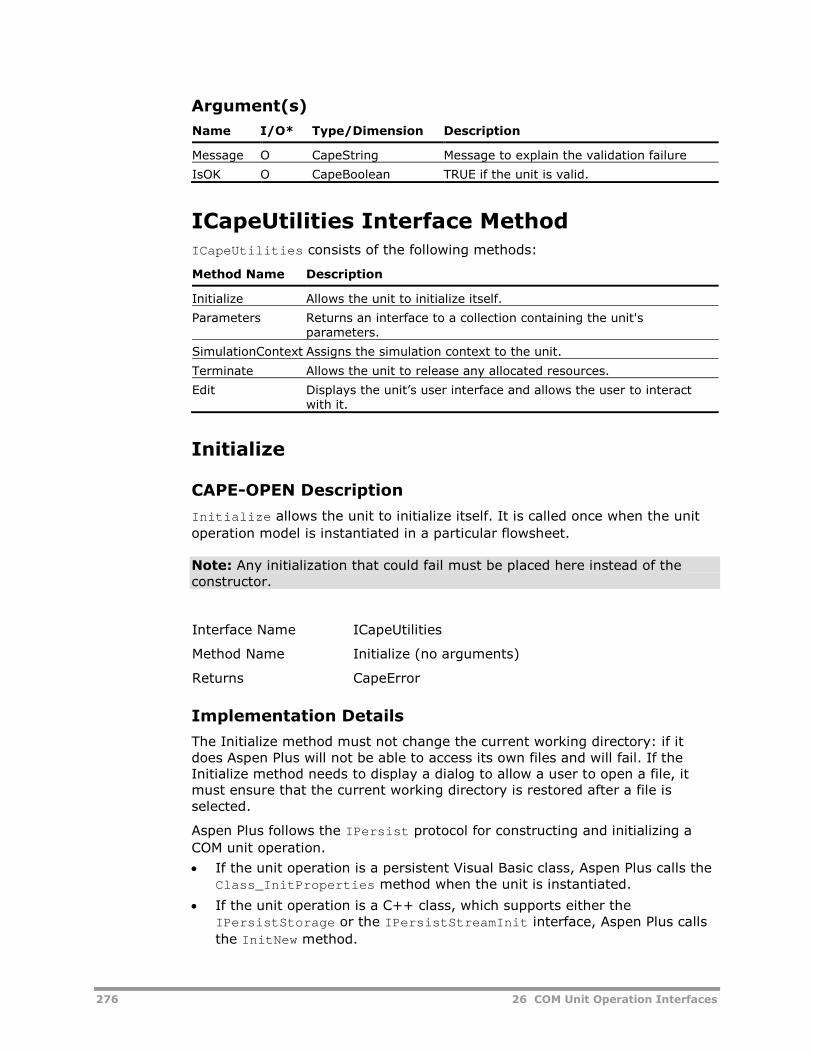
276 26 COM Unit Operation Interfaces
Argument(s)
Name I/O* Type/Dimension Description
Message O CapeString Message to explain the validation failure
IsOK O CapeBoolean TRUE if the unit is valid.
ICapeUtilities Interface MethodICapeUtilities consists of the following methods:
Method Name Description
Initialize Allows the unit to initialize itself.
Parameters Returns an interface to a collection containing the unit'sparameters.
SimulationContext Assigns the simulation context to the unit.
Terminate Allows the unit to release any allocated resources.
Edit Displays the unit’s user interface and allows the user to interactwith it.
Initialize
CAPE-OPEN Description
Initialize allows the unit to initialize itself. It is called once when the unit
operation model is instantiated in a particular flowsheet.
Note: Any initialization that could fail must be placed here instead of theconstructor.
Interface Name ICapeUtilities
Method Name Initialize (no arguments)
Returns CapeError
Implementation Details
The Initialize method must not change the current working directory: if itdoes Aspen Plus will not be able to access its own files and will fail. If theInitialize method needs to display a dialog to allow a user to open a file, itmust ensure that the current working directory is restored after a file isselected.
Aspen Plus follows the IPersist protocol for constructing and initializing a
COM unit operation.
If the unit operation is a persistent Visual Basic class, Aspen Plus calls theClass_InitProperties method when the unit is instantiated.
If the unit operation is a C++ class, which supports either theIPersistStorage or the IPersistStreamInit interface, Aspen Plus calls
the InitNew method.

26 COM Unit Operation Interfaces 277
Parameters
CAPE-OPEN Description
Parameters returns an ICapeCollection interface that provides access to
the unit’s list of parameters. Each element accessed through the returnedinterface must support the ICapeParameter interface.
Note: The ICapeCollection interface methods are described later in this
chapter.
Note: Aspen Plus expects that CAPE-OPEN unit operations do not haveparameters whose names are the same except for capital/lower-case letters.
Interface Name ICapeUtilities
Method Name Parameters
Returns CapeError
Argument(s)
Name I/O* Type/Dimension Description
PublicParams O CapeInterface The interface of the collection containing thelist of unit parameters.
SimulationContext
CAPE-OPEN Description
SimulationContext assigns the simulation context to the unit.
Interface Name ICapeUtilities
Method Name SimulationContext
Returns CapeError
Argument(s)
Name I/O*Type/Dimension Description
SimulationContext I CapeInterface The context of the simulator (progress,thermo, numeric).
Implementation Details
When Aspen Plus calls SimulationContext it passes an IDispatch interface
to the unit. The unit can then query the IDispatch interface for the
ICapeDiagnostic, IAssayUpdate, or IATCapeXDiagnostic interface.

278 26 COM Unit Operation Interfaces
IAssayUpdate provides access to Aspen Plus assay data. The
ICapeDiagnostic and IATCapeXDiagnostic interfaces both allow messages
to be written to the history file and control panel, and allows errors to beraised. The ICapeDiagnostic interface should be used in preference to the
IATCapeXDiagnostic interface, which is supported for backwards
compatibility only.
Aspen Plus does not implement support for the ICapeMaterialTemplateSystemand ICapeCOSEUtilities interfaces.
Terminate
CAPE-OPEN Description
Terminate releases any resources allocated by the unit. It verifies if the data
has been saved and returns an error if not.
Interface Name ICapeUtilities
Method Name Terminate
Returns CapeError
Argument(s)
Name I/O* Type/Dimension Description
Message I/O CapeString Message describing any error occurring duringTerminate.
IsOK O CapeBoolean Flag indicating whether termination succeeded orfailed.
Implementation Details
Aspen Plus calls Terminate when a unit is deleted or a simulation is closed.
The Terminate method is called immediately before one of the following:
If the unit operation is a Visual Basic class, Aspen Plus calls theClass_Terminate() method when the unit is deleted or when a
simulation is closed.
If the unit operation is a C++ class, the class destructor is called when theunit is deleted or when the simulation is closed.
Edit
CAPE-OPEN Description
Edit displays the unit’s user interface and allows the user to interact with it.
If no user interface is available, it returns an error.
Interface Name ICapeUtilities

26 COM Unit Operation Interfaces 279
Method Name Edit
Returns CapeError
Argument(s)
Name I/O* Type/Dimension Description
Message I/O CapeString Message describing any error occurring duringedit.
IsOK O CapeBoolean Flag indicating whether editing succeeded orfailed.
Implementation Details
The Edit method must not change the current working directory: if it doesAspen Plus will not be able to access its own files and will fail. If the Editmethod needs to display a dialog to allow a user to open a file, it must ensurethat the current working directory is restored after a file is selected.
Port InterfacesPort interfaces include the following:
Interface Name Description
ICapeUnitPort Defines functions to access the properties of a port.
ICapeIdentification Defines access functions for name and description. (See page 0-293.)
ICapeUnitPort Interface MethodsICapeUnitPort consists of the following methods:
Method Name Description
Connect Connects a stream to a port.
ConnectedObject Returns the material, energy, or information object connected tothe port using the Connect method.
Direction Returns the direction in which objects or information connected tothe port are expected to flow.
Disconnect Disconnects the port from the connected stream.
PortType Returns the type of the port.
Connect
CAPE-OPEN Description
Connect connects a stream to a port. The port validates the type of the object
being passed.
Interface Name ICapeUnitPort

280 26 COM Unit Operation Interfaces
Method Name Connect
Returns CapeError
Argument(s)
Name I/O* Type/Dimension Description
ObjectToConnect I CapeInterface The object that is to be connected to theport.
Message I/O CapeString Message describing any error occurringduring connect.
IsOK O CapeBoolean Flag indicating whether connectionsucceeded or failed.
Implementation Details
Aspen Plus creates a material object when it connects a stream to a port thatbelongs to a CAPE-OPEN unit. It then calls the port’s Connect method passing
in the material object's IDispatch interface. Aspen Plus gives the new
material object the same name as stream that was connected to the port.
Material objects are described in CAPE-OPEN COM Thermodynamic Interfaces,Chapter 27.
ConnectedObject
CAPE-OPEN Description
ConnectedObject returns the material, energy, or information object
connected to the port using the Connect method.
Interface Name ICapeUnitPort
Method Name ConnectedObject
Returns CapeError
Argument(s)
Name I/O* Type/Dimension Description
ConnectedObject O CapeInterface The object that is connected to the port.
Direction
CAPE-OPEN Description
Direction returns the direction in which objects or information connected to
the port are expected to flow. The returned value must be one of theconstants defined in the CapePortDirection enumeration, that is, one of
CapeInput, CapeOutput, or CapeInputOutput.

26 COM Unit Operation Interfaces 281
Interface Name ICapeUnitPort
Method Name Direction
Returns CapeError
Argument(s)
Name I/O* Type/Dimension Description
PortDirection O CapePortDirection The direction of the port.
Disconnect
CAPE-OPEN Description
Disconnect disconnects the port from the connected stream.
Interface Name ICapeUnitPort
Method Name Disconnect
Returns CapeError
Argument(s)
Name I/O* Type/Dimension Description
Message I/O CapeString Message describing any error occurring duringdisconnect.
IsOK O CapeBoolean Flag indicating whether disconnection succeededor failed.
Implementation Details
Aspen Plus calls Disconnect when a stream is disconnected from a port that
belongs to a CAPE-OPEN unit.
PortType
CAPE-OPEN Description
PortType returns the type of the port. The returned value must be one of the
constants defined in the CapePortType enumeration, that is, one of
CapeMaterial, CapeEnergy, CapeInformation, or CapeAny.
Interface Name ICapeUnitPort
Method Name PortType
Returns CapeError

282 26 COM Unit Operation Interfaces
Argument(s)
Name I/O* Type/Dimension Description
PortType O CapePortType The type of the port.
Parameter InterfacesParameter interfaces include the following:
Interface Name Description
ICapeParameter Provides functions to access the properties of aparameter.
ICapeParameterSpec Provides functions to access properties of a parameterspecification that are independent of the type of theparameter value.
ICapeRealParameterSpec Provides functions to access the properties of aspecification for a real value.
ICapeIntegerParameterSpec Provides functions to access the properties of aspecification for an integer value.
ICapeOptionParameterSpec Provides functions to access the properties of aspecification for an option value. An option value isone of a set of fixed strings. For example, an optionparameter might only allow the values “Yes” and “No”.
ICapeIdentification Defines access functions for name and description.(See page 0-293.)
ICapeParameterICapeParameter consists of the following methods:
Method Name Description
ValStatus Returns a flag indicating whether the parameter is valid, invalid, orneeds validating.
Specification Returns/assigns the specification of the parameter.
Validate Checks whether the value of the parameter is valid in specificationterms and in any other terms that are specified.
Value Returns/assigns the value of the parameter.
ValueSource Returns/assigns the source of the value for the parameter.
ValStatus
CAPE-OPEN Description
ValStatus returns a flag of type CapeValidationStatus indicating whether the
parameter is valid, invalid, or needs validating. The possible values of the flagare:
CAPE_VALID
CAPE_INVALID

26 COM Unit Operation Interfaces 283
CAPE_NOT_VALIDATED
Calling the Validate method is expected to set the parameter’s status to eitherCAPE_VALID or CAPE_INVALID, depending on whether the validation testssucceed or fail. Making a change to the parameter value is expected to setthe its status to CAPE_NOT_VALIDATED.
Interface Name ICapeParameter
Method Name ValStatus
Returns CapeError
Argument(s)
Name I/O* Type/Dimension Description
Status O CapeValidationStatus CAPE_VALID if the unit is valid
CAPE_INVALID if the unit has failed validation
CAPE_NOT_VALIDATED if the unit has beenupdated since it was last validated.
Specification
CAPE-OPEN Description
Specification returns/assigns the specification of the parameter. The [get]
method returns the specification as an interface to the correct specificationtype.
Note: If the specification type does not match, an error occurs (invalidargument).
Interface Name ICapeParameter
Method Name Specification
Returns CapeError
Argument(s)
Name I/O* Type/Dimension Description
Spec I/O CapeInterface The specification interface of this parameter.
Validate
CAPE-OPEN Description
Validate ensures that the value of the parameter is valid in specification
terms and in any other terms that are specified.

284 26 COM Unit Operation Interfaces
Interface Name ICapeParameter
Method Name Validate (no arguments)
Returns CapeError
Value
CAPE-OPEN Description
Value returns/assigns the value of the parameter.
If this value is not passed as a CapeVariant, an error occurs (invalid
argument).
Interface Name ICapeParameter
Method Name Value
Returns CapeError
Argument(s)
Name I/O* Type/Dimension Description
Value I/O CapeVariant The value of the parameter.
ValueSource
CAPE-OPEN Description
ValueSource returns/assigns the source of the value for the parameter. This
value can be:
The user.
An estimation.
A calculated value.
Interface Name ICapeParameter
Method Name ValueSource
Returns CapeError
Argument(s)
Name I/O* Type/Dimension Description
ValueSource I/O CapeLong The source of the value of the parameter.
Implementation Details
This method is not used by Aspen Plus.

26 COM Unit Operation Interfaces 285
ICapeParameterSpecICapeParameterSpec consists of the following methods:
Method Name Description
Type Returns or assigns the type of the parameter specification.
Mode Returns or assigns the access mode for the parameter.
Dimensionality Returns or assigns the dimensionality for the parameter’s value.
Type
CAPE-OPEN Description
Type returns or assigns the type of the parameter value. The parameter typecan be one of CapeRealParam or CapeIntParam.
Interface Name ICapeParameterSpec
Method Name Type
Returns CapeError
Argument(s)
Name I/O* Type/Dimension Description
ParamType I/O CapeParamType The type of the parameter value.
Mode
CAPE-OPEN Description
Mode returns or assigns the access mode for a parameter value. The accessmode can be one of CapeRead, CapeWrite, or CapeReadWrite.
Interface Name ICapeParameterSpec
Method Name Mode
Returns CapeError
Argument(s)
Name I/O* Type/Dimension Description
Mode I/O CapeParamMode The access mode for the parameter value.

286 26 COM Unit Operation Interfaces
Implementation Details
The Aspen Plus data browser uses this method to fill in the Read Only field inthe grid used to display parameter values. If Mode is set to CapeRead then the
value for the parameter cannot be updated.
Dimensionality
CAPE-OPEN Description
Dimensionality returns or assigns the dimensionality of the parameter value.The dimensionality is represented as an array of values, one for each of thefundamental physical dimensions. The CAPE-OPEN standard leaves the exactspecification of this representation open.
Interface Name ICapeParameterSpec
Method Name Dimensionality
Returns CapeError
Argument(s)
Name I/O* Type/Dimension Description
Dimensions I/O CapeVariant The dimensionality of the parameter value.
Implementation Details
Aspen Plus does not use this method. Instead a parameter can implement theIATCapeXRealParameterSpec interface which can be used to define the
display unit for a parameter value.
ICapeRealParameterSpec InterfaceMethodsICapeRealParameterSpec consists of the following methods:
Method Name Description
DefaultValue Returns/assigns the default value of the specified real valuedparameter.
LowerBound Returns/assigns the lower bound of the specified real valuedparameter.
UpperBound Returns/assigns the upper bound of the specified real valuedparameter.
Validate Validates a real value against its specification.

26 COM Unit Operation Interfaces 287
DefaultValue
CAPE-OPEN Description
DefaultValue returns/assigns the default value of the specified real valued
parameter.
Interface Name ICapeRealParameterSpec
Method Name DefaultValue
Returns CapeError
Argument(s)
Name I/O* Type/Dimension Description
DefaultValue I/O CapeDouble The default value of the real valuedparameter.
LowerBound
CAPE-OPEN Description
LowerBound returns/assigns the lower bound of the specified real valued
parameter.
Interface Name ICapeRealParameterSpec
Method Name LowerBound
Returns CapeError
Argument(s)
Name I/O* Type/Dimension Description
LBound I/O CapeDouble The lower bound of the real valuedparameter.
UpperBound
CAPE-OPEN Description
UpperBound returns/assigns the upper bound of the specified real valued
parameter.
Interface Name ICapeRealParameterSpec
Method Name UpperBound
Returns CapeError

288 26 COM Unit Operation Interfaces
Argument(s)
Name I/O* Type/Dimension Description
UBound I/O CapeDouble The upper bound of the real valuedparameter.
Validate
CAPE-OPEN Description
Validate validates a real value against its specification. It returns a flag
indicating the success or failure of the validation together with a string thatcan be used to provide information about the validation.
Interface Name ICapeRealParameterSpec
Method Name Validate
Returns CapeError
Argument(s)
Name I/O* Type/Dimension Description
Value I CapeDouble The value of the parameter to validate.
Message O CapeString The message conveying information regardingthe validation.
IsOK O CapeBoolean A flag to indicate success or failure.
ICapeIntegerParameterSpec InterfaceMethodsICapeIntegerParameterSpec consists of the following methods:
Method Name Description
DefaultValue Returns/assigns the default value of the specified integer valuedparameter.
LowerBound Returns/assigns the lower bound of the specified integer valuedparameter.
UpperBound Returns/assigns the upper bound of the specified integer valuedparameter.
Validate Validates an integer value against its specification.

26 COM Unit Operation Interfaces 289
DefaultValue
CAPE-OPEN Description
DefaultValue returns/assigns the default value of the specified integer
valued parameter.
Interface Name ICapeIntegerParameterSpec
Method Name DefaultValue
Returns CapeError
Argument(s)
Name I/O* Type/Dimension Description
DefaultValue I/O CapeLong The default value of the integer valuedparameter.
LowerBound
CAPE-OPEN Description
LowerBound returns/assigns the lower bound of the specified integer valued
parameter.
Interface Name ICapeIntegerParameterSpec
Method Name LowerBound
Returns CapeError
Argument(s)
Name I/O* Type/Dimension Description
LBound I/O CapeLong The lower bound of the integer valued parameter.
UpperBound
CAPE-OPEN Description
UpperBound returns/assigns the upper bound of the specified integer valued
parameter.
Interface Name ICapeIntegerParameterSpec
Method Name UpperBound
Returns CapeError

290 26 COM Unit Operation Interfaces
Argument(s)
Name I/O* Type/Dimension Description
UBound I/O CapeLong The upper bound of the integer valuedparameter.
Validate
CAPE-OPEN Description
Validate validates an integer value against its specification. It returns a flag
to indicate the success or failure of the validation together with string thatcan be used to provide information about the validation.
Interface Name ICapeIntegerParameterSpec
Method Name Validate
Returns CapeError
Argument(s)
Name I/O* Type/Dimension Description
Value I CapeLong The value of the parameter being validated.
Message O CapeString The message conveying information regardingthe validation.
IsOK O CapeBoolean Flag indicating whether validation succeeded orfailed.
ICapeOptionParameterSpec InterfaceMethodsICapeOptionParameterSpec consists of the following methods:
Method Name Description
DefaultValue Returns/assigns the default value of the specified option-valuedparameter.
OptionList Returns the valid options for this parameter as an array of strings.
RestrictedToList Returns a boolean value to indicate whether values for theparameter are restricted to the specified options or not.
Validate Validates an option value against its specification.
DefaultValue
CAPE-OPEN Description
DefaultValue returns/assigns the default value of the specified option-valued
parameter.

26 COM Unit Operation Interfaces 291
Interface Name ICapeOptionParameterSpec
Method Name DefaultValue
Returns CapeError
Argument(s)
Name I/O* Type/Dimension Description
DefaultValue O CapeString The default value of the option-valuedparameter.
OptionList
CAPE-OPEN Description
OptionList returns the list of valid options for the parameter as an array of
strings.
Interface Name ICapeOptionParameterSpec
Method Name OptionList
Returns CapeError
Argument(s)
Name I/O* Type/Dimension Description
OptionNames O CapeArrayString The valid options for the parameter.
RestrictedToList
CAPE-OPEN Description
RestrictedToList returns a boolean value to indicate whether the value of
the parameter must be one of the option values, or whether other values maybe assigned.
Interface Name ICapeOptionParameterSpec
Method Name RestrictedToList
Returns CapeError
Argument(s)
Name I/O* Type/Dimension Description
Restricted O CapeBoolean Returns TRUE if the parameter value must beone of the values returned by OptionList.
Returns FALSE if other values are allowed.

292 26 COM Unit Operation Interfaces
Validate
CAPE-OPEN Description
Validate validates an option value against its specification. It returns a flag
to indicate the success or failure of the validation together with string thatcan be used to provide information about the validation.
Interface Name ICapeOptionParameterSpec
Method Name Validate
Returns CapeError
Argument(s)
Name I/O* Type/Dimension Description
Value I CapeString The value of the parameter being validated.
Message O CapeString The message conveying information regardingthe validation.
IsOK O CapeBoolean Flag indicating whether validation succeeded orfailed.
Collection InterfacesCollection interfaces include the following:
Interface Name Description
ICapeCollection Provides functions to access the elements of a collection.
ICapeIdentification Defines access functions for name and description. (See page 0-293.)
ICapeCollection Interface MethodsICapeCollection consists of the following methods:
Method Name Description
Count Returns the number of objects in the collection.
Item Returns an element from the port’s collection or the collection ofunit parameters.
Count
CAPE-OPEN Description
Count returns the number of objects in the collection.

26 COM Unit Operation Interfaces 293
Interface Name ICapeCollection
Method Name Count
Returns CapeError
Argument(s)
Name I/O* Type/Dimension Description
ItemsCount O CapeLong Number of items in the collection.
Item
CAPE-OPEN Description
Item returns an element from a collection. Pass either a name or position in
the collection to identify the required element.
Interface Name ICapeCollection
Method Name Item
Returns CapeError
Argument(s)
Name I/O* Type/Dimension Description
Id I CapeVariant Identifier for the requested item:
Name of item
Position in collection
Item O CapeInterface The requested element.
ICapeIdentification InterfaceMethodsThe ICapeIdentification interface is used for all the CAPE-OPEN COM
components (including unit, port, parameter, and collection). Note that thisinterface does not belong to the UNIT System of interfaces, but to the overallCAPE-OPEN System.
ICapeIdentification consists of the following methods:
Method Name Description
ComponentDescriptionReturns/assigns the description of the component.
ComponentName Returns/assigns the name of the component.

294 26 COM Unit Operation Interfaces
ComponentDescription
CAPE-OPEN Description
ComponentDescription returns/assigns the description of the component.
Interface Name ICapeIdentification
Method Name ComponentDescription
Returns CapeError
Argument(s)
Name I/O* Type/Dimension Description
Desc I/O CapeString The description of the component.
ComponentName
CAPE-OPEN Description
ComponentName returns/assigns the name of the component.
Interface Name ICapeIdentification
Method Name ComponentName
Returns CapeError
Argument(s)
Name I/O* Type/Dimension Description
Name I/O CapeString The name of the component.
Aspen Plus InterfacesAspen Plus interfaces include the following:
Interface Name Description
IAssayUpdate Provides access to simulation assay data. See COMInterface for Updating Oil Characterizations andPetroleum Properties, Chapter 28.
IATCapeXDiagnostic Allows a CAPE-OPEN unit operation to write text to theAspen Plus history file and control panel window.
IATCapeXRealParameterSpec Defines the unit of measurement to use when displayingthe value of a parameter in the Data Browser.

26 COM Unit Operation Interfaces 295
IATCapeXDiagnostic Interface MethodsAspen Plus provides IATCapeXDiagnostic as an extension to the CAPE-OPEN
standard. The interface is passed to the unit when Aspen Plus callsSimulationContext. Use this interface to write diagnostic messages to Aspen
Plus.
IATCapeXDiagnostic consists of the following methods:
Method Name Description
SendMsgToHistory Writes text to the history file.
SendMsgToTerminal Writes text to the control panel window.
RaiseError Signals an error to Aspen Plus.
SendMsgToHistory
Description
SendMsgToHistory writes text to the Aspen Plus history file.
Interface Name IATCapeXDiagnostic
Method Name SendMsgToHistory
Returns CapeError
Argument(s)
Name I/O* Type/Dimension Description
Message I CapeString The text being written to the history file.
SendMsgToTerminal
Description
SendMsgToTerminal writes text to the Aspen Plus control panel window.
Interface Name IATCapeXDiagnostic
Method Name SendMsgToTerminal
Returns CapeError
Argument(s)
Name I/O* Type/Dimension Description
Message I CapeString The text being written to the terminal.

296 26 COM Unit Operation Interfaces
RaiseError
Description
RaiseError signals errors and warnings to Aspen Plus. Use this method if
something goes wrong during the Calculate code.
Note: An error with severity ErrorSeverityTerminal terminates the Aspen
Plus simulation.
Interface Name IATCapeXDiagnostic
Method Name RaiseError
Returns CapeError
Argument(s)
Name I/O* Type/Dimension Description
Severity I ErrorSeverity, one of:
ErrorSeverityTerminal
ErrorSeveritySevere
ErrorSeverityError
ErrorSeverityWarning
The severity of the error.
Context I CapeString A string which identifies the unit.
Message I CapeString The text being written to the history file.
IATCapeXRealParameterSpecIATCapeXRealParameterSpec consists of the following method:
Method Name Description
DisplayUnits Defines the display unit for the parameter.
DisplayUnits
Description
DisplayUnits defines the unit of measurement symbol for a parameter.
Note: The symbol must be one of the uppercase strings recognized by AspenPlus to ensure that it can perform unit of measurement conversions on theparameter value. The system converts the parameter's value from SI units fordisplay in the data browser and converts updated values back into SI.
Interface Name IATCapeXRealParameterSpec
Method Name DisplayUnits
Returns CapeError

26 COM Unit Operation Interfaces 297
Argument(s)
Name I/O* Type/Dimension Description
UOMString O CapeString A string of uppercase characters containingthe unit of measurement symbol used byAspen Plus to display the value of theparameter.
Implementation Details
Aspen Plus stores all values in SI units internally. It converts values from SIunits to display units when they are displayed, and it converts values fromdisplay units to SI units when they are changed. UseIATCapeXRealParameterSpec to perform the same conversions on the unit
operation’s parameters.
Using this interface means that the upper bound, lower bound and value of aparameter are all in SI units. This makes these values consistent with thevalues returned from material objects. The exception is for mole-based unitswhere Aspen Plus uses kmol for consistency with the standard mass unit kg,but the standard SI unit is the mole and CAPE-OPEN uses moles. Mole-basedvalues must be converted appropriately when going between Aspen Plus andCAPE-OPEN data.
The following table lists the valid units of measurement symbols:
Physical Type Valid Units of Measurement
ANGLE Rad, Deg
AREA Sqm, sqft
AREA-PRICE $/sqm, $/sqft
AREA-USAGE sqm/sec, sqft/hr, sqm/hr
BOND-WORK-IN j/kg, kwhr/ton
CHROM-VEL m/sec, ft/sec, cm/hr
COMPOSITION mol-fr
CONTENTS fraction, percent
CURRENT amp, mamp
DENSITY kg/cum, lb/cuft, gm/cc
DIFFUSIVITY sqm/sec, sqft/hr, sqcm/sec
DIMENSIONLES unitless
DIPOLEMOMENT (j*cum)**.5, (btu*cuft)**.5, debye
ELEC-POWER watt, kw
ELEC-PRICE $/j, $/kwhr
ENERGY j, btu, cal
ENERGY-PRICE $/j, $/btu, $/cal
ENTHALPY j/kmol, btu/lbmol, cal/mol
ENTHALPY-CYC watt/cycle, btu/cycle, cal/cycle
ENTHALPY-FLO watt, btu/hr, cal/sec
ENTHALPY-OPR watt/cycle, btu/op-hr, cal/op-sec
ENTROPY j/kmol-k, btu/lbmol-r, cal/mol-k
F-FACTOR (kg-cum)**.5/se, (lb-cuft)**.5/hr, (gm-l)**.5/min

298 26 COM Unit Operation Interfaces
Physical Type Valid Units of Measurement
FILTER-RESIS 1/meter, 1/ft
FISCAL $
FLOW kg/sec, lb/hr, kg./hr
FLUX cum/sqm-sec, cuft/sqft-sec, l/sqm-sec
FORCE newton, lbf, dyne
FREQUENCY hz, rpm
HEAD j/kg, ft-lbf/lb, m-kgf/kg
HEAT j, btu, cal
HEAT-FLUX watt/m, btu/hr-ft, cal/sec-m
HEAT-TRANS-C watt/sqm-k, btu/hr-sqft-r, cal/sec-sqcm-k
INVERSE-AREA 1/sqm, 1/sqft
INVERSE-HT-C sqm-k/watt, hr-sqft-r/btu, sec-sqcm-k/cal
INVERSE-LENG 1/m, 1/ft, 1/cm
INVERSE-PRES sqm/n, 1/psi, 1/atm
INVERSE-TEMP 1/k, 1/r
INVERSE-TIME 1/sec, 1/hr
ITEM-PRICE $/item
LENGTH meter, ft
LN-INV-TIME ln(1/sec), ln(1/hr)
MASS kg, lb
MASS-CONC kg/cum, lb/cuft, gm/l
MASS-CYCL kg/cycle, lb/cycle
MASS-DENSITY kg/cum, lb/cuft, gm/cc
MASS-ENTHALP j/kg, btu/lb, cal/gm
MASS-ENTROPY j/kg-k, btu/lb-r, cal/gm-k
MASS-FLOW kg/sec, lb/hr, kg/hr
MASS-FLUX kg/sqm-s, lb/sqft-hr, kg/sqm-hr
MASS-HEAT-CA j/kg-k, btu/lb-r, cal/gm-k
MASS-OPER kg/op-sec, lb/op-hr, kg/op-hr
MASS-PER-LEN kg/m, lb/ft, kg/m
MASS-TRANS-C kg/s-swm-kg/c, lb/hr-sqf-lb/c, gm/s-sqcm-gm/cc
MASS-VOLUME cum/kg, cuft/lb, cc/kg
MOL-FLOW-LEN kmol/sec-m, lbmol/hr-ft, kmol/hr-m
MOLE-CONC kmol/cum, lbmol/cuft, mol/cc
MOLE-CYCL kmol/cycle, lbmol/cycle
MOLE-DENSITY kmol/cum, lbmol/cuft, mol/cc
MOLE-ENTHALP j/kmol, btu/lbmol, cal/mol
MOLE-ENTROPY j/kmol-k, btu/lbmol-r, cal/mol-k
MOLE-FLOW kmol/sec, lbmol/hr, kmol/hr
MOLE-HEAT-CA j/kmol-k, btu/lbmol-r, cal/mol-k
MOLE-OPER kmol/op-sec, lbmol/op-hr, kmol/op-hr
MOLE-VOLUME cum/kmol, cuft/lbmol, cc/mol
MOLES kmol, lbmol

26 COM Unit Operation Interfaces 299
Physical Type Valid Units of Measurement
MOM-INERTIA kg/sqm, lb-sqft
NUM-CON-RATE no/cum-sec, no/cuft-sec, no/l-sec
NUM-CONC no/cum, no/cuft, no/l
PACK-FACTOR 1/m, 1/ft
PDROP n/aqm, psi, atm
PDROP-PER-HT n/cum, in-water/ft, mm-water/m
POP-DENSITY no/m/cum, no/ft/cuft, no/m/l
POWER watt, hp, kw
POWER-VOLUME watt/cum, hp/cuft, kw/l
PRESSURE n/sqm, psi, atm
RHO-VSQRD kg/m-sqsec, lb/ft-sqsec, kg/m-sqsec
SOLUPARAM (j/cum)**.5, (BTU/Cuft)**.5, (Cal/cc)**.5
SOLUTE-PERM sqm/m-s, sqft/ft-hr, sqm/m-hr
SOLVENT-PERM kg/sqm-s-pa, lb/sqft-hr-atm, KG/SQM-HR-ATM
SOUND-LEVEL DECIBELS
SPEC-FLT-RES meter/kg, ft/lb, meter/kg
SPECIFICAREA sqm/cum, sqft/cuft, sqcm/cc
SURFACE-TENS n/m, dyne/cm
TEMP-VOLUME CUM-K/KMOL, CUFT-R/LBMOL, CC-K/MOL
TEMPERATURE k, f
THERMAL-COND watt/m-k, btu-ft/hr-sqft, kcal-m/hr-sqm-k
TIME sec, hr
UA j/sec-k, btu/hr-r, cal/sec-k
UNIT-PRICE $/kg, $/lb
VELOCITY m/sec, ft/sec
VFLOW-LENGTH sqm/sec, gpm/ft, sqcm/sec
VFLOW-RPM cum/sec/rpm, cuft/hr/rpm, l/min/rpm
VISCOSITY n-sec/sqm, cp
VOL-ENTHALPY j/cum, btu/cuft, cal/cc
VOL-HEAT-CAP j/cum-k, btu/cuft-r, cal/cc-k
VOLTAGE volt, kvolt
VOLUME cum, cuft, l
VOLUME-CYCL cum/cycle, cuft/cycle, l/cycle
VOLUME-FLOW cum/sec, cuft/hr, l/min
VOLUME-OPER cum/op-sec, cuft/op-hr, l/op-min
VOLUME-PRICE $/cum, $/cuft, $/l
VOLUME-USAGE cum/sec, cuft/hr, l/hr
WATER-RATE kg/j, lb/hp-hr, kg/kw-hr
WORK j, hp-hr, kw-hr

300 26 COM Unit Operation Interfaces
Installation of COM UnitOperationsMicrosoft COM supports component categories so that applications can easilyidentify classes that implement specific interfaces. Aspen Plus identifies CAPE-OPEN compliant COM unit operations by searching the registry for classes inthe CAPE-OPEN unit operation category. The identifier (CATID) for thiscategory is:
678c09a5-7d66-11d2-a67d-00105a42887f
Note: The Aspen Plus installation will automatically register the Category idsrequired by CAPE-OPEN if it is necessary.
The mechanism for registering a COM unit operation in the CAPE-OPEN unitoperation category depends on whether the unit is implemented in C++ orVisual Basic.
For a C++ class:
Write the DLLRegisterServer method so that it adds the CAPE-OPEN unit
operation CATID to the list of implemented categories for the class. Use theregsvr32 utility to register the DLL built by the C++ compiler.
For a Visual Basic class:
If you use the Visual Basic Unit Operation Wizard it will create an installpackage for your Unit Operation that will create the correct registry entries.In this case no further action is required.
If you do not use the Wizard then Visual Basic will register the classautomatically when it builds the DLL, but it does not add the CAPE-OPEN unitoperation category to the registry. This entry has to be added separately.There are two ways to do this:
Use the regsvr32 utility to register the DLL built by Visual Basic.
Create a .reg file containing the necessary entries.
Creating a .reg file
Copy CapeDescription.reg from your C:\Program Files\CommonFiles\AspenTech Shared\CAPE-OPEN Example Models directory (where C:represents the Windows installation drive) to the directory containing yourVisual Basic project. Then edit this file and make changes appropriate for yourUnit Operation. Finally, build your Visual Basic project and then double-clickon your copy of the .reg file in Windows Explorer to add the entries to theregistry.
26 COM Unit Operation Interfaces 301
Distributing COM Models toUsersIf you are using the Unit Operation Wizard you can give the install packagethat it creates to other users so that they can install the Unit Operation onother machines. The Wizard provides documentation describing how to dothis.
To distribute and install a unit operation that doesn’t have an installationpackage onto another user's machine, register the DLL file using the regsvr32utility described previously.
1 Copy the DLL to a directory on the target machine, and log into themachine.
2 Run the regsvr32 utility on the DLL.
Adding Compiled COM Modelsto the Aspen Plus Model PaletteUse a COM unit operation in Aspen Plus by selecting it from the CAPE-OPENtab within the Model Palette and dragging it into the Process Flowsheetwindow.
To display the CAPE-OPEN tab in the Model Palette:
1 Start Aspen Plus.
2 From the Developer tab of the ribbon, click Manage Libraries.
3 In the Manage Libraries dialog box, check the Is In Use box next toCAPE-OPEN and click OK.
Aspen Plus displays a new tab called CAPE-OPEN on the Model Palettealong with the other the built-in Model Palette tabs.
Note: If the tab is not visible, click at the bottom of the screen until thetab appears.
Important: To define icons for COM models or to categorize them usingdifferent tabs, first create a user model library. Once the new library iscreated, copy COM models into the new library and modify the icons and tabsas necessary. See Chapter 16 of the Aspen Plus User Guide for moreinformation.
302 26 COM Unit Operation Interfaces
Version Compatibility for VisualBasic COM ModelsEvery COM unit operation has a unique class identifier (CLSID). Aspen Plusstores this identifier in .appdf, .bkp, and .inp files as part of persisting a COMunit operation. For Visual Basic COM unit operations, the Visual Basic compilerassigns this identifier and changes it with each build of the unit operation. ForC++ classes, the class identifier only changes when the model developerchanges it.
The effect of changing the class identifier is that Aspen Plus cannot load filescontaining the previous class identifier. Text files can be corrected using atext editor but .appdf binary files cannot be corrected.
To prevent this problem, Visual Basic 6 uses the Version Compatibility optionto fix the class identifier for a class.
Important: Always set this option to Project Compatibility for COM unitoperations. This allows Visual Basic to use the class identifier from theprevious version of the DLL built by the project.
To set this option in Visual Basic:
1 From the Project menu, select Properties.
2 From the Project Properties dialog, select the Component tab.
3 Select Project Compatibility from the list of compatibility options.
Note: This option is only available after the DLL file has been built for the firsttime.
Uninstalling COM ModelsIf your Unit Operation has an installation package use Add/RemovePrograms from the Windows Control Panel to remove it from a machine.
Remove a COM unit operation that doesn’t have an installation package fromyour machine by deleting its registry entries using the regsvr32 utility from
Microsoft.
1 Open a command prompt window.
2 Change the working directory to the directory where the DLL is located.
For example: cd \My Projects\Membrane
3 Execute the command:
Regsvr32 VBMembraneDLL /u
This command removes the entries associated with all the classes inVBMembraneDLL from the registry.
Note: Once a COM unit operation is uninstalled, Aspen Plus cannot loadassociated simulations.

27 CAPE-OPEN COM Thermodynamic Interfaces 303
27 CAPE-OPEN COMThermodynamic Interfaces
This chapter describes CAPE-OPEN COM interfaces and the methods availablefor thermophysical properties and phase equilibrium calculations. Theseinterfaces follow the standards defined in the Physical Properties interfaceModel and Specification document defined by CAPE-OPEN.
Aspen Plus now supports version 1.0 of the CAPE-OPEN standard. This versionis very similar to the version 0.93 supported in Aspen Plus 11.1.
The benefits of using these open standard Thermodynamic interfaces are
Unit operation model can use any physical property systems that areCAPE-OPEN compliant, without having to customize the model for eachproperty system.
Property model developer needs to develop the model using the interfacesonly once. The model can then be used with any physical property systemthat is CAPE-OPEN compliant, without having to customize the model foreach property system. This allows property specialists in the academia orindustry to focus on model development work rather than on writinginterfaces.
The following table summarizes the components associated with the CAPE-OPEN COM Thermodynamic interfaces:
Interface Associated Component
ICapeThermoMaterialTemplate Material Template
ICapeThermoMaterialObject Material Object
ICapeThermoSystem Physical Property System
ICapeThermoPropertyPackage Property Package
ICapeThermoCalculationRoutine Thermophysicial Property Calculation Routines
ICapeThermoEquilibriumServer Equilibrium Server (for flash calculations)
All CAPE-OPEN Thermodynamic interface methods are invoked via thematerial object, which is an instance of the material template. The physicalproperty system owns the property package, which is responsible for theactual calculations of thermophysical properties and phase equilibrium. Allcalculations are usually performed by the native property system, however

304 27 CAPE-OPEN COM Thermodynamic Interfaces
CAPE-OPEN allows the use of external property calculation routines andequilibrium server in a particular property package.
The following diagram displays the relationship between the CAPE-OPENSimulation Executive (COSE), the unit operation models, and the variouscomponents previously defined.
This diagram displays the interfaces supported by each of the components.The associations, represented by the lines from the components to theinterfaces, are also detailed. The way these associations are implemented is
Unit System
ICapeThermoMaterialObject
SimulationExec
(COSE)
ThermoSystem

27 CAPE-OPEN COM Thermodynamic Interfaces 305
not dictated by CAPE-OPEN, but is proprietary to the component/simulationvendor.
The CAPE-OPEN compliant Simulation Executive (COSE):
Maintains interface implementations of the material template and materialobject.
Provides functionality for defining the material template.
Delegates the material object to the appropriate Thermodynamic Systemand property package interfaces.
The following diagram summarizes CAPE-OPEN Thermodynamic interfaces:
ICapeThermoSystem
GetPropertyPackages()ResolvePropertyPackage()
ICapeThermoPropertyPackage
ICapeThermoEquilibriumServer
ICapeThermoMaterialObject
CalcProp()ComponentIds()PhaseIds()GetProp()SetProp()GetIndependentVar()SetIndependentVar()PropCheck()AvailableProps()RemoveResults()ValidityCheck()GetComponentConstant()GetUniversalConstant()GetPropList()GetNumComponents()CreateMaterialObject()Duplicate()
CreateMaterialObject()
SetProp()
ClassFactory
ICapeThermoMaterialTemplate
CalcProp()CalcEquilibrium()GetPhaseList()GetComponentList()PropCheck()ValidityCheck()GetUniversalConstant()GetComponentConstant()GetPropList()
ICapeThermoCalculationRoutine
PropCheck()ValidityCheck()CalcProp()PropList()
CalcEquilibrium()ValidityCheck()PropCheck()

306 27 CAPE-OPEN COM Thermodynamic Interfaces
Material TemplatesMaterial templates define the characterization of a material. A materialtemplate is a set of services, usually provided by the COSE, required for theproperty package to work in coordination with unit operations and otherpieces of the simulation.
Material templates provide unified interfaces for the following functions:
1 Association between a material object and a property package. Theactive material template within the flowsheet provides the connectionmechanism between any material object and the active property packagewithin that part of the flowsheet.
2 Delegation of functions. The material template handles the delegationof interface methods from the material object to the property package.The delegation uses the association between a material object and aproperty package. For example, in a PH flash calculation, the propertypackage itself implements the code, but the material object interfaceprovides the CalcEquilibrium method, which is then delegated to the
property package.
3 Component mapping. Different property packages active in differentsections of the flowsheet may use different naming conventions forcomponents. The material template implements the required componentmapping.
4 Material object factory. The material template implements themechanism to create a material object.
5 Component subsetting. The material template provides mechanismsused to implement further configuration of a property package to eitherreduce the number of components, or to modify the number of activephases.
The material template definition consists of:
o A Component List
o A Phase Assumption
o Reference to CAPE-OPEN property package
o List of custom attributes for pseudo-components
Note: The implementation of Material Templates is internal to Aspen Plus andis not directly accessible to CAPE-OPEN components.

27 CAPE-OPEN COM Thermodynamic Interfaces 307
Material ObjectsMaterial objects define an instance of a material and are created frommaterial templates.
A material object is an instance of the material template and is a CAPE-OPENstandard view of the proprietary streams present in Aspen Plus. The materialobject is a persistent entity that provides the data source necessary for theproperty package to perform its calculations, and provides a place to storeresults.
A material object is associated with each connected port on a CAPE-OPEN UnitOperation to store data characterizing the stream conditions at each port andto provide the unit operation with a way to request physical property andflash calculations.
The property package uses data specified in the material object (e.g.,temperature, pressure, and component molar flow rates) to calculate therequired properties.
ICapeThermoMaterialObject InterfaceMethodsThe ICapeThermoMaterialObject interface consists of the following methods:
Method Name Description
AvailableProps Gets a list of calculated properties.
CalcEquilibrium Delegates flash calculations to the associated ThermodynamicSystem.
CalcProp Performs all property calculations and delegates the calculations tothe associated Thermodynamic System.
CreateMaterialObject Creates a material object from the parent material template of thecurrent material object.
Duplicate Creates a duplicate of the current material object.
GetComponentConstant Retrieves component constants from the property package.
GetIndependentVar Returns the independent variables of a material object.
GetNumComponents Returns the number of components in a material object.
GetProp Retrieves the calculation results from the material object.
GetPropList Returns a list of properties supported by the property package andcorresponding CO calculation routines.
GetUniversalConstant Retrieves universal constants from the property package.
ICapeThermoMaterialObject Returns the list of components Ids of a given material object.
PhaseIds Returns the list of phases supported by the material object.
PropCheck Verifies that given properties can be calculated.
RemoveResults Removes all or specified property results in the material object.
SetIndependentVar Sets the independent variable for a given material object.
SetProp Sets the property values of the material object.
ValidityCheck Checks the validity of the calculation.

308 27 CAPE-OPEN COM Thermodynamic Interfaces
AvailableProps
Description
AvailableProps gets a list of calculated properties.
Interface Name ICapeThermoMaterialObject
Method Name AvailableProps
Returns CapeError
Argument(s)
Name I/O* Type/Dimension Description
*props O CapeArrayString Properties for which results are available.
CalcEquilibrium
Description
CalcEquilibrium delegates flash calculations to the associated
Thermodynamic System.
Interface Name ICapeThermoMaterialObject
Method Name CalcEquilibrium
Returns CapeError
Argument(s)
Name I/O* Type/Dimension Description
flashType I CapeString Flash calculation type.
props I CapeVariant (StringArray)
Properties to be calculated at equilibrium.NULL for no properties.
CalcProp
Description
CalcProp performs all property calculations and delegates the calculations to
the associated Thermodynamic System.
Interface Name ICapeThermoMaterialObject
Method Name CalcProp
Returns CapeError

27 CAPE-OPEN COM Thermodynamic Interfaces 309
Argument(s)
Name I/O* Type/Dimension Description
props I CapeVariant (StringArray)
The List of Properties to be calculated.
phases I CapeVariant (StringArray)
List of phases for which the properties are tobe calculated.
calcType I CapeString Type of calculation: Mixture Property or PureComponent Property. For partial property,such as fugacity coefficients of components ina mixture, use “Mixture” CalcType. For purecomponent fugacity coefficients, use “Pure”CalcType.
CreateMaterialObject
Description
CreateMaterialObject creates a material object from the parent material
template of the current material object.
Interface Name ICapeThermoMaterialObject
Method Name CreateMaterialObject
Returns CapeError
Argument(s)
Name I/O* Type/Dimension Description
materialObject O *ICapeInterface The created/initialized material object.
Duplicate
Description
Duplicate creates a duplicate of the current material object.
Interface Name ICapeThermoMaterialObject
Method Name Duplicate
Returns CapeError
Argument(s)
Name I/O* Type/Dimension Description
clone O *ICapeInterface The created/initialized material object.

310 27 CAPE-OPEN COM Thermodynamic Interfaces
GetComponentConstant
Description
GetComponentConstant retrieves component constants from the property
package.
Interface Name ICapeThermoMaterialObject
Method Name GetComponentConstant
Returns CapeError
Argument(s)
Name I/O* Type/Dimension Description
props I CapeVariant (StringArray)
List of component constants.
compIds I CapeVariant (StringArray)
List of component IDs for which constantsare to be retrieved. NULL for all componentsin the material object.
*propvals O CapeArrayDouble Component Constant values returned fromthe property package for all the componentsin the material object.
GetIndependentVar
Description
GetIndependentVar returns the independent variables of a material object.
Interface Name ICapeThermoMaterialObject
Method Name GetIndependentVar
Returns CapeError
Argument(s)
Name I/O* Type/Dimension Description
indVars I CapeVariant (StringArray)
Independent variables to be set (see namesfor state variables for list of valid variables).
*values O CapeArrayDouble Values of independent variables.
GetNumComponents
Description
GetNumComponents returns the number of components in a material object.

27 CAPE-OPEN COM Thermodynamic Interfaces 311
Interface Name ICapeThermoMaterialObject
Method Name GetNumComponents
Returns CapeError
Argument(s)
Name I/O* Type/Dimension Description
*num O CapeLong Number of components in the material object.
GetProp
Description
GetProp retrieves the calculation results from the material object.
Interface Name ICapeThermoMaterialObject
Method Name GetProp
Returns CapeError
Argument(s)
Name I/O* Type/Dimension Description
property I CapeString The Property for which results arerequested from the material object.
phase I CapeString The qualified phase for the results.
compIds I CapeVariant (StringArray)
The qualified components for the results.NULL to specify all components in thematerial object. For mixture property suchas liquid enthalpy, this qualifier is notrequired. Use NULL as placeholder.
calcType I CapeString The qualified type of calculation for theresults. Valid calculation types include:
Pure
Mixture
basis I CapeString Qualifies the basis of the result (i.e., mass/mole). Default is mole. Use NULL fordefault or as place holder for property forwhich basis does not apply.
*results O CapeArrayDouble Results vector containing property valuesin SI units arranged by the definedqualifiers.
Note: GetProp returns mole-based quantities in mole units rather than kmolas Aspen Plus does. Mole is the standard SI unit but Aspen Plus uses kmol forconsistency with the standard mass unit kg.

312 27 CAPE-OPEN COM Thermodynamic Interfaces
GetPropList
Description
GetPropList returns a list of properties supported by the property package
and corresponding CO calculation routines.
Interface Name ICapeThermoMaterialObject
Method Name GetPropList
Returns CapeError
Argument(s)
Name I/O* Type/Dimension Description
*props O CapeArrayString String list of all supported properties of theproperty package.
GetUniversalConstant
Description
GetUniversalConstant retrieves universal constants from the property
package.
Interface Name ICapeThermoMaterialObject
Method Name GetUniversalConstant
Returns CapeError
Argument(s)
Name I/O* Type/Dimension Description
props I CapeVariant (StringArray)
List of universal constants to be retrieved.
*propvals O CapeArrayDouble Values of universal constants.
ICapeThermoMaterialObject
Description
ICapeThermoMaterialObject returns the list of components Ids of a given
material object.
Interface Name ICapeThermoMaterialObject
Method Name ICapeThermoMaterialObject
Returns CapeError

27 CAPE-OPEN COM Thermodynamic Interfaces 313
Argument(s)
Name I/O* Type/Dimension Description
*compIds O CapeVariant (String Array) Component IDs.
PhaseIds
Description
PhaseIds returns the list of phases supported by the material object.
Interface Name ICapeThermoMaterialObject
Method Name PhaseIds
Returns CapeError
Argument(s)
Name I/O* Type/Dimension Description
*phaseIds O CapeVariant (String Array) List of phases
PropCheck
Description
PropCheck verifies that given properties can be calculated.
Interface Name ICapeThermoMaterialObject
Method Name PropCheck
Returns CapeError
Argument(s)
Name I/O* Type/Dimension Description
props I CapeVariant (StringArray)
Properties to check.
*valid O CapeArrayBoolean Returns Boolean List associated to list ofproperties to be checked.

314 27 CAPE-OPEN COM Thermodynamic Interfaces
RemoveResults
Description
RemoveResults removes all or specified property results in the material
object.
Interface Name ICapeThermoMaterialObject
Method Name RemoveResults
Returns CapeError
Argument(s)
Name I/O* Type/Dimension Description
props I CapeVariant (StringArray)
Properties to be removed. NULL to removeall properties.
SetIndependentVar
Description
SetIndependentVar sets the independent variable for a given material object.
Interface Name ICapeThermoMaterialObject
Method Name SetIndependentVar
Returns CapeError
Argument(s)
Name I/O* Type/Dimension Description
indVars I CapeVariant (StringArray)
Independent variables to be set (seenames for state variables for list of validvariables)
values I CapeVariant (DoubleArray)
Values of independent variables.
SetProp
Description
SetProp sets the property values of the material object.
Interface Name ICapeThermoMaterialObject
Method Name SetProp
Returns CapeError

27 CAPE-OPEN COM Thermodynamic Interfaces 315
Argument(s)
Name I/O* Type/Dimension Description
property I CapeString The property for which the values need tobe set.
phase I CapeString Phase, if applicable. Use NULL for aplaceholder.
compIds I CapeVariant (StringArray)
Components for which values are to be set.NULL to specify all components in thematerial object. For mixture property suchas liquid enthalpy, this qualifier is notrequired. Use NULL as placeholder.
calcType I CapeString The calculation type. Valid calculation typesinclude:
Pure
Mixture
basis I CapeString Qualifies the basis (mole / mass).
values I CapeVariant (DoubleArray)
Values to set for the property.
ValidityCheck
Description
ValidityCheck checks the validity of the calculation.
Interface Name ICapeThermoMaterialObject
Method Name ValidityCheck
Returns CapeError
Argument(s)
Name I/O* Type/Dimension Description
props I CapeVariant (StringArray)
The properties for which reliability ischecked.
*rellist O CapeArrayThermoReliability
Returns the reliability scale of thecalculation.
Physical Property SystemThe property system owns the property packages, and the system of interestmust be registered. The Aspen Plus physical property system is registered asAtCOProperties.COPropertySystem.n where n is the internal version numberof Aspen Plus. This number may be seen as "(n.x.y)" (where x and y areother numbers that should be ignored) after the usual version number in theAbout box.

316 27 CAPE-OPEN COM Thermodynamic Interfaces
ICapeThermoSystem Interface MethodsThe ICapeThermoSystem interface consists of the following methods:
Method Name Description
GetPropertyPackages Returns StringArray of property package names supported
by the system.
ResolvePropertyPackage Resolves referenced property packages to a propertypackage interface.
GetPropertyPackages
Description
GetPropertyPackages returns StringArray of property package names
supported by the Thermodynamic System.
Interface Name ICapeThermoSystem
Method Name GetPropertyPackages
Returns CapeError
Argument(s)
Name I/O* Type/DimensionDescription
*propertyPackageList O CapeArrayString The returned set of supportedproperty packages.
ResolvePropertyPackage
Description
ResolvePropertyPackage resolves referenced property package to a property
package interface.
Interface Name ICapeThermoSystem
Method Name ResolvePropertyPackage
Returns CapeError
Argument(s)
Name I/O* Type/Dimension Description
propertyPackage I CapeString The property package to be resolved.
*propPackObject O CapeInterface The property package interface.

27 CAPE-OPEN COM Thermodynamic Interfaces 317
Property PackageThe property package performs requested property calculations, and containsall necessary property information, such as:
Components.
Property methods.
Property data.
The calculation methods.
The property package uses data in the material object to calculate theproperties requested in the interface method. The calculated properties arethen stored in the material object.
Importing and ExportingAspen Plus can prepare, export, and import CAPE-OPEN compliant propertypackages compatible with other applications.
Importing a Property Package
A CAPE-OPEN compliant property package from another application can beimported and used in Aspen Plus to calculate physical properties instead ofthe native physical property methods.
To import a property package:
1 From the Tools menu, select Import CAPE-OPEN Property Package. TheAvailable Property Packages dialog box appears.
2 Expand the property system tree to display all the available propertypackages owned by a given property system.
3 Select the property package being imported.
4 Click OK. The property method from the foreign property package isnamed CP-# (where # is a number) in the Properties | CAPE-OPENPackages folder. You can rename these packages if desired.
Note: If there are component conflicts, Aspen Plus prompts you to reconcilethe conflict before continuing.
Details of imported packages will be displayed within the CAPE-OPENPackages folder under Customize in the navigation pane. For packages notproduced by Aspen Plus or Aspen Properties, you can choose to override theflash calculation from the package with the Aspen Properties flash. You canalso specify defaults for the property method, Henry components, etc. usedfor any capabilities the CAPE-OPEN property package does not supply. (Forpackages produced by Aspen Plus or Aspen Properties, these fields aredimmed. Such packages always include all capabilities used in the AspenPhysical Property System.)
To use an imported Property Package in a simulation select the correspondingProperty Method where appropriate. For example to use a CAPE-OPEN

318 27 CAPE-OPEN COM Thermodynamic Interfaces
Property Package globally select the corresponding Property Method on theGlobal sheet of the Methods | Specifications form. To use a CAPE-OPENProperty Package for a particular property analysis, select the correspondingmethod on the Properties sheet of the Input form for the analysis. Notethat when you do so, the Henry Components, Free-Water method, etc. aredimmed; the ones in the package (or the defaults specified on the CAPE-OPEN Packages form for this package, if the package is missing anycapabilities) are used when the method from the CAPE-OPEN package isselected.
Exporting a Property Package
Use Aspen Plus to prepare a CAPE-OPEN compliant property package for usewith other applications, such as another process simulator or an in-houseprogram.
To export a property package:
1 Select the components, property methods, and provide all the necessaryproperty data and parameters.
2 From the File menu, select Export | CAPE-OPEN Package. TheAspenTech CAPE-OPEN Property Package Manager window appears.
3 Update the description of the package as required, then click Save andRegister.
4 Choose a filename and location for the CAPE-OPEN property package file.
5 A message appears telling you the package was successfully registered.Click OK to return to Aspen Plus.
ICapeThermoPropertyPackage InterfaceMethodsThe ICapeThermoPropertyPackage interface consists of the following
methods:
Method Name Description
GetPropertyPackages Returns StringArray of property package names supported
by the system.
ResolvePropertyPackage Resolves referenced property packages to a property packageinterface.
CalcEquilibrium
Description
CalcEquilibrium calculates and flash calculation requests.
Interface Name ICapeThermoPropertyPackage
Method Name CalcEquilibrium
Returns CapeError

27 CAPE-OPEN COM Thermodynamic Interfaces 319
Argument(s)
Name I/O* Type/Dimension Description
*materialObjectI CapeInterface The MaterialObject
flashType I CapeString Flash calculation type.
props I CapeVariant (StringArray)
Properties to be calculated atequilibrium. NULL for no properties.
CalcProp
Description
CalcProp performs all calculations, and is implemented by the associated
Thermodynamic System.
Note: This method is further defined in the descriptions of the CAPE-OPENCalling Pattern and the User Guide Section.
Interface Name ICapeThermoPropertyPackage
Method Name CalcProp
Returns CapeError
Argument(s)
Name I/O* Type/Dimension Description
*materialObjectI CapeInterface The material object for the calculation.
props I CapeVariant (StringArray)
The list of properties to be calculated.
phases I CapeVariant (StringArray)
List of phases for which the propertiesare to be calculated.
calcType I CapeString Type of calculation: Mixture propertyor pure component property. Forpartial property, such as fugacitycoefficients of components in amixture, use “Mixture” CalcType. Forpure component fugacity coefficients,use “Pure” CalcType.
GetComponentConstant
Description
GetComponentConstant returns the values of the component constants on the
material object.
Interface Name ICapeThermoPropertyPackage
Method Name GetComponentConstant
Returns CapeError

320 27 CAPE-OPEN COM Thermodynamic Interfaces
Argument(s)
Name I/O* Type/Dimension Description
*materialObjectI CapeInterface The material object.
props I CapeVariant (StringArray)
The list of properties.
*propvals O CapeArrayDouble Component constant values.
GetComponentList
Description
GetComponentList returns the list of components of a given property
package.
Interface Name ICapeThermoPropertyPackage
Method Name GetComponentList
Returns CapeError
Argument(s)
Name I/O* Type/Dimension Description
*compsIds O CapeVariant (String Array) List of component IDs.
*formulae O CapeVariant (String Array) List of component aliases.
*name O CapeVariant (String Array) List of component names.
*boilTemps O CapeVariant (Double Array) List of boiling point temperatures.
*molwt O CapeVariant (Double Array) List of molecular weight.
*casno O CapeVariant (String Array) List of CAS number.
GetPhaseList
Description
GetPhaseList provides the list of the supported phases.
Interface Name ICapeThermoPropertyPackage
Method Name GetPhaseList
Returns CapeError
Argument(s)
Name I/O* Type/Dimension Description
*phases O CapeArrayString The list of phases supported by the propertypackage.

27 CAPE-OPEN COM Thermodynamic Interfaces 321
GetPropList
Description
GetPropList returns a list of Thermodynamic System supported properties.
Interface Name ICapeThermoPropertyPackage
Method Name GetPropList
Returns CapeError
Argument(s)
Name I/O* Type/Dimension Description
*props O CapeArrayString String list of all supported properties.
GetUniversalConstant
Description
GetUniversalConstant returns the values of the universal constants.
Interface Name ICapeThermoPropertyPackage
Method Name GetUniversalConstant
Returns CapeError
Argument(s)
Name I/O* Type/Dimension Description
*materialObjectI CapeInterface The material object.
props I CapeVariant (StringArray)
List of requested universal constants.
*propvals O CapeArrayDouble Values of universal constants.
PropCheck
Description
PropCheck verifies that properties can be calculated.
Interface Name ICapeThermoPropertyPackage
Method Name PropCheck
Returns CapeError

322 27 CAPE-OPEN COM Thermodynamic Interfaces
Argument(s)
Name I/O* Type/Dimension Description
*materialObjectI CapeInterface The material object for thecalculations.
props I CapeVariant (StringArray)
List of properties to check.
*valid O CapeArrayBoolean The array of booleans for eachproperty.
ValidityCheck
Description
ValidityCheck checks the validity of the calculation.
Interface Name ICapeThermoPropertyPackage
Method Name ValidityCheck
Returns CapeError
Argument(s)
Name I/O* Type/Dimension Description
*materialObjectI CapeInterface The material object for thecalculations.
Props I CapeVariant (StringArray)
The list of properties to check.
*rellist O CapeArrayThermoReliability
The properties for which reliability ischecked.

27 CAPE-OPEN COM Thermodynamic Interfaces 323
Registration of CAPE-OPENComponentsThe CAPE-OPEN components are registered using the MS Windows registrycategories. The following table displays the GUIDs of all CAPE-OPENcomponents related to the Thermodynamic interfaces.
Category ID (CATID) Number
CapeThermoSystem 678c09a3-7d66-11d2-a67d-00105a42887f
CapeThermoPropertyPackage 678c09a4-7d66-11d2-a67d-00105a42887f
CapeThermoEquilibriumServer 678c09a6-7d66-11d2-a67d-00105a42887f
Interface ID (IID) Number
ICapeThermoCalculationRoutine 678c0991-7d66-11d2-a67d-00105a42887f
ICapeThermoReliability 678c0992-7d66-11d2-a67d-00105a42887f
ICapeThermoMaterialTemplate 678c0993-7d66-11d2-a67d-00105a42887f
ICapeThermoMaterialObject 678c0994-7d66-11d2-a67d-00105a42887f
ICapeThermoSystem 678c0995-7d66-11d2-a67d-00105a42887f
ICapeThermoPropertyPackage 678c0996-7d66-11d2-a67d-00105a42887f
ICapeThermoEquilibriumServer 678c0997-7d66-11d2-a67d-00105a42887f

324 27 CAPE-OPEN COM Thermodynamic Interfaces

28 COM Interface for Updating Oil Characterizations and Petroleum Properties 325
28 COM Interface forUpdating OilCharacterizations andPetroleum Properties
This chapter describes Component Object Model (COM) interfaces, and themethods available for updating pseudocomponent characterizationparameters and petroleum properties during the simulation.
Note: The IAssayUpdate COM interface is the only interface used to update
oil characterizations and properties.
Aspen Plus includes an example COM Model that uses the interface defined inthis chapter. Refer to this example for the source code.

326 28 COM Interface for Updating Oil Characterizations and Petroleum Properties
IAssayUpdate InterfaceMethodsThe following table summarizes the main methods available for the COMinterface IAssayUpdate:
Method Descriptions
UpdateParameters Recalculates characterization parameters for pseudocomponents.
SetPetroPropValuesSets value for a Petro-Prop in a given stream.
CopyAssayData Copies assay data from one material stream to another materialstream.
Note: There are some additional methods described further in this chapter.
The remainder of this chapter describes how to use the COM interfacemethods.
Modifying Petroleum Properties During aSimulationAspen Plus allows petroleum properties to change for the same set ofpseudocomponents from stream to stream. This feature allows the simulationto track stream property changes without introducing additional components.
Consider the following example:
Refining ReactorInlet Outlet
Both the inlet stream and outlet stream of the block have the same set ofpseudocomponents. The sulfur content (S), a petroleum property of eachcomponent, is different in the two streams.

28 COM Interface for Updating Oil Characterizations and Petroleum Properties 327
CopyAssayData
Description
Use to initialize the petroleum property data structure for the outlet streamand to copy the petroleum property information from the inlet stream to theoutlet stream.
If the user model does not change the pseudocomponent petroleum propertyof the outlet, call this interface method for the outlet to propagate thepetroleum property information from the inlet to the outlet.
Interface Name IAssayUpdate
Method Name CopyAssayData
Returns Success/failure flag
Argument(s)
Name I/O* Type/Dimension Description
CopyFlag I CopyOption Option to use when copying.
CopyCannotChange = 1: OutletStreamIdreferences the same petroleum propertydata structure as the InletStreamId. Thepetroleum property value can not bemodified. This is sufficient if the user modeldoes not change the pseudocomponentpetroleum properties.
CopyCanChange = 2: the OutletStreamIdhas its own petroleum property datastructure. Initially, this new data structurewill have an exact copy of the petroleumproperty data as the InletStreamId. The usercan modify the petroleum properties.
InletStreamId I BSTR Id of the inlet stream from which thepetroleum property data are copied into theoutlet.
NumInletStreams I Short Total number of inlet streams to the block.
InletStreamIds I Pointer toSAFEARRAY(BSTR)
Ids of all inlet streams.
OutletStreamId I BSTR Id of the outlet stream for which thepetroleum property data structure is to besetup.
FlowIn I Double Total flow rate of the inlet stream referencedby InletStreamId.

328 28 COM Interface for Updating Oil Characterizations and Petroleum Properties
Name I/O* Type/Dimension Description
MissingValuesDefaultOption I Short Defaulting option when petroleum propertyin the inlet stream have missing value; usedfor CopyOption = CopyCanChange.
When MissingValuesDefaultOption is 0,petroleum properties are copied from inlet tooutlet without modifications, includingmissing values.
When MissingValuesDefaultOption is greaterthen 0, components with component indexgreater than or equal toMissingValuesDefaultOption will defaultmissing petroleum property to the firstavailable value.
SetPetroPropValues
Description
SetPetroPropValues selectively changes pseudocomponent petroleum
property values for one or more pseudocomponents.
Interface Name IAssayUpdate
Method Name SetPetroPropValues
Returns Success/failure flag
Argument(s)
Name I/O*Type/Dimension Description
OutletStreamId I BSTR The outlet stream Id associated with thepetroleum property values beingchanged.
PropName I BSTR The petroleum property nameassociated with the pseudocomponentvalues being changed (e.g., SULFUR).
NumComponents I Short The pseudocomponent(s) number(s)associated with the properties beingchanged.
ComponentIndex I Pointer toSAFEARRAY(long)
Indices of pseudocomponents. Can beobtained using the GetComponentIndexmethod.
PetroPropValues I Pointer toSAFEARRAY(double)
New values of the changed petroleumproperty.
Temperature I Double Reference temperature of the data. Usedfor viscosity or kinematic viscosity.
Unit I BSTR The units of the reference temperature(one of K, C, R, or F).

28 COM Interface for Updating Oil Characterizations and Petroleum Properties 329
Recalculate Characterization ParametersPseudocomponent characterization parameters (e.g., critical temperature,critical pressure, ideal gas heat capacity parameters, vapor pressureExtended-Antoine constants, liquid viscosity parameters, etc.) are not subjectto change during the simulation.
If a parameter such as the pseudocomponent molecular weight changesduring a simulation, a material imbalance may occur.
Conversely, in modeling petroleum refining reactor units, boiling point andgravity data of the reactor outlet stream are calculated during the simulation.The pseudocomponent characterization parameters must then be re-computed based on these calculations.
Consider the following example:
Refining ReactorInlet Outlet
The simulation contains 2 sets of pseudocomponents:
(A1 … A4)
(B1 … B4)
The inlet stream contains flows for the “A” set and the outlet stream containsflows for the “B” set. The property constants of the “B” set have to be re-computed during the simulation, based on the boiling point and gravity valuespredicted for the outlet stream by the reactor model.

330 28 COM Interface for Updating Oil Characterizations and Petroleum Properties
UpdateParameters
Description
UpdateParameters updates the pseudocomponent properties during the
simulation.
Interface Name IAssayUpdate
Method Name UpdateParameters
Returns Success/failure flag
Argument(s)
Name I/O* Type/Dimension Description
NumPseudoComponents I short Number of pseudocomponents.
ComponentIndex I Pointer toSAFEARRAY(long)
Component indices ofpseudocomponents.
Note: Do not usepseudocomponents that appearin any flowsheet inlet stream witha non-zero flow.
PseudoCompDefiningParamValues I Pointer toSAFEARRAY(double)
Values of parameters used torecalculate the characterizationparameters: TB, API, SG, and MW.
The length of the array is4*NumPseudoComponents. The firstfour elements store TB, API, SG, andMW of the pseudocomponentcorresponding toComponentIndex[0]; and the next
four elements store TB, API, SG, andMW of the pseudocomponentcorresponding toComponentIndex[1], and so on.
ReportFlag I ReportOption Report flag. Currently not active.
Note: Pseudocomponents can appear in a flowsheet inlet stream asthemselves, in assay form, or in a blend. If an assay or blend has a non-zeroflow in a flowsheet inlet stream, then all associated pseudocomponents areconsidered as appearing in the flowsheet inlet stream with a non-zero flow. InAspen Plus, pseudocomponents are generated based on specifications of aPC-CALC paragraph. All assays and blends in a PC-CALC paragraph share thesame set of pseudocomponents. If no PC-CALC paragraph is specified in aflowsheet, then all assays and blends in the flowsheet share one (and onlyone) set of pseudocomponents.

28 COM Interface for Updating Oil Characterizations and Petroleum Properties 331
Additional IAssayUpdate Interface MethodsThe following table summarizes additional methods available for the COMinterface IAssayUpdate:
Method Descriptions
GetAssayCount Returns number of user-entered assays and blends.
GetAssayId Returns an Assay/Blend Id, given index.
GetComponentCount Returns the number of light-end components andpseudocomponents.
GetComponentIndex Returns component indices for all light-end components andpseudocomponents associated with the assay.
GetParameters Returns parameters for pseudocomponents.
GetPetroPropValues Returns values of petroleum properties in a given stream.
GetPropertyCount Returns number of user-entered petroleum properties.
GetPropertyName Returns petroleum property Id, given petroleum property index.
GetAssayCount
Description
GetAssayCount returns the number of assays and blends defined in a
simulation.
Interface Name IAssayUpdate
Method Name GetAssayCount
Returns Success/failure flag
Argument(s)
Name I/O* Type/Dimension Description
Count O Pointer to Int Number of assays and blends.
GetAssayId
Description
GetAssayId returns the assay/blend Id given the index.
Interface Name IAssayUpdate
Method Name GetAssayId
Returns Success/failure flag

332 28 COM Interface for Updating Oil Characterizations and Petroleum Properties
Argument(s)
Name I/O* Type/Dimension Description
Index I Int Assay/blend index.
AssayId O Pointer to BSTR Assay/blend Id.
GetComponentCount
Description
GetComponentCount returns the number of light-end components and
pseudocomponents that exist in an assay/blend.
Interface Name IAssayUpdate
Method Name GetComponentCount
Returns Success/failure flag
Argument(s)
Name I/O* Type/Dimension Description
AssayId I BSTR The assay/blend Id.
NumLightEndComponents
O Pointer to short The number of light end componentsin the assay/blend.
NumPseudoComponents
O Pointer to short The number of pseudocomponents inthe assay/blend.
GetComponentIndex
Description
GetComponentIndex returns pseudocomponent indices given an assay/blend
Id. This is necessary when a user defines the inlet stream and outlet streamin terms of 2 assays/blends, rather than in terms of the individualpseudocomponents. In this scenario, the pseudocomponent indices are notknown a priori.
Interface Name IAssayUpdate
Method Name GetComponentIndex
Returns Success/failure flag

28 COM Interface for Updating Oil Characterizations and Petroleum Properties 333
Argument(s)
Name I/O* Type/Dimension Description
AssayId I/O Pointer to BSTR The assay/blend Id.
NumLightEndComponents I/O Pointer to short The number of light end components in theassay/blend.
NumPseudoComponents I/O Pointer to short Number of pseudocomponents in theassay/blend.
LightEndComponentIndex I/O Pointer toSAFEARRAY(long)
Component indices of the light endcomponents.
PseudoComponentIndex I/O Pointer toSAFEARRAY(long)
Component indices of thepseudocomponents.
GetParameters
Description
GetParameters returns characterization parameters for the components.
Interface Name IAssayUpdate
Method Name GetParameters
Returns Success/failure flag
Argument(s)
Name I/O* Type/Dimension Description
ParaName I/O BSTR The parameter name.
NumPseudoComponents I Short The number ofpseudocomponents.
PseudoComponentIndex I/O Pointer to SAFEARRAY(long)
Component indices of thepseudocomponents.
PseudoComponentParamValues I/O Pointer to SAFEARRAY(double)
The pseudocomponent parametervalues.
GetPetroPropValues
Description
GetPetroPropValues returns values of a petroleum property defined for a
given stream.
Interface Name IAssayUpdate
Method Name GetPetroPropValues
Returns Success/failure flag

334 28 COM Interface for Updating Oil Characterizations and Petroleum Properties
Argument(s)
Name I/O* Type/Dimension Description
OutletStreamId I BSTR The outlet stream Id.
PropName I BSTR The petroleum property name (e.g.,SULFUR).
NumComponentIndex I Short The number of pseudocomponent(s).
ComponentIndex I Pointer toSAFEARRAY (long)
Indices of pseudocomponents. Thiscan be obtained using theGetComponentIndex method.
PetroPropValues O Pointer toSAFEARRAY(double)
The values of the petroleumproperty.
Temperature I Double The reference temperature of theproperty. Used for viscosity orkinematic viscosity.
Unit I BSTR The units of the referencetemperature (one of K, C, R, or F).
GetPropertyCount
Description
GetPropertyCount returns the number of petroleum properties defined in a
simulation.
Interface Name IAssayUpdate
Method Name GetPropertyCount
Returns Success/failure flag
Argument(s)
Name I/O* Type/Dimension Description
Count O Pointer to Int Number of petroleum properties.
GetPropertyName
Description
GetPropertyName returns the name of the petroleum property given the
index.
Interface Name IAssayUpdate
Method Name GetPropertyName
Returns Success/failure flag

28 COM Interface for Updating Oil Characterizations and Petroleum Properties 335
Argument(s)
Name I/O* Type/Dimension Description
Index I Int Petroleum property index.
Name O Pointer to BSTR Petroleum property name.

336 28 COM Interface for Updating Oil Characterizations and Petroleum Properties

A Common Blocks and Accessing Component Data 337
A Common Blocks andAccessing Component Data
The first section of this appendix contains descriptions of the Aspen PlusFortran common blocks that you can use in user subroutines. The secondsection contains information on how to access certain component data areasin DMS_PLEX.

338 A Common Blocks and Accessing Component Data
Aspen Plus Common BlocksThe user routine should not change any of the variables in the commons,except for COMMON /DMS_PLEX/.
This section describes the following common blocks:
Common Block Description
DMS_ERROUT Error message buffer
DMS_FLSCOM Flash error common
DMS_NCOMP Number of components
DMS_PLEX The Plex
PPUTL_PPGLOB Physical property global variables
DMS_RGLOB Real global variables
DMS_RPTGLB Report writer global variables
DMS_STWKWK Stream flash work space
SHS_STWORK Stream flash work space offsets
PPEXEC_USER Control flags and other variables for user-written subroutines
COMMON DMS_ERROUTDMS_ERROUT contains character variables for error messages (see Chapter4, Aspen Plus Error Handler). To use DMS_ERROUT, include the followingdirective (in column 1) in your subroutine:
#include "dms_errout.cmn"
The following table describes the variables in DMS_ERROUT.
Variable Type Description
ERROUT_IEROUT CHARACTER*80 Character array of length 10 used to store errormessages.See Chapter 4, Aspen Plus Error Handler.
COMMON DMS_FLSCOMDMS_FLSCOM contains error return codes from lower level flash routines, tobe checked by higher level flash routines. To use DMS_FLSCOM, include thefollowing directive (in column 1) in your subroutine:
#include "dms_flscom.cmn"
The following table describes the variables in DMS_FLSCOM.
Variables Description
FLSCOM_IFLERR Return code being passed up from lower level routines:0 = all OK1 = error encountered

A Common Blocks and Accessing Component Data 339
COMMON DMS_NCOMPDMS_NCOMP contains numbers of components of various classifications andlengths of component-related stream segments. To use DMS_NCOMP, includethe following directive (in column 1) in your subroutine:
#include "dms_ncomp.cmn"
The following table describes the variables in DMS_NCOMP.
Variable Description
NCOMP_NCC Number of conventional components defined by user + componentsgenerated by ADA
NCOMP_NNCC Number of nonconventional components
NCOMP_NC Total number of components = NCOMP_NCC + NCOMP_NNCC
NCOMP_NAC Number of attributed components
NCOMP_NACC Number of attributed conventional components
NCOMP_NVCP Number of conventional substream variables without attributes(NCOMP_NCC+9)
NCOMP_NVNCP Number of nonconventional substream variables without attributes(NCOMP_NNCC+9)
NCOMP_NVACC Length of the component attribute set for all attributed conventionalcomponents
NCOMP_NVANCC Length of the component attribute set for all nonconventionalcomponents
NCOMP_NASSAY Number of assays
NCOMP_NCCASS Number of conventional components defined by user plus number ofassays = NCOMP_NCC + NCOMP_NASSAY
NCOMP_IDXWAT Component index number for waterNote: This indicates the first component with alias H2O if there ismore than one. Use other functions to search the component list ifyou require compatibility with specifying multiple components withthe same alias.
NCOMP_NG Number of UNIFAC groups
NCOMP_NM Number of molecular species
NCOMP_NAION Number of anions
NCOMP_NCION Number of cations
NCOMP_NPOLY Number of polymer components (Aspen Polymers)
NCOMP_NSEG Number of segment components (Aspen Polymers)
NCOMP_NOLIG Number of oligomer components (Aspen Polymers)
NCOMP_NSITE Number of sites (Aspen Polymers)
NCOMP_NCAT Number of Ziegler-Natta catalyst components (Aspen Polymers)
NCOMP_NINIT Number of ionic polymerization initiator components (AspenPolymers)
COMMON DMS_PLEXDMS_PLEX contains the lengthy in-core storage area for the Plex. The Plex isthe main memory area where all the data for a simulation is stored, in a

340 A Common Blocks and Accessing Component Data
flexible way. The Plex consists of data areas sized to hold the amount of datain the simulation. See Accessing Component Data Using the Plex, later in thischapter, for more information.
The Plex consists of integer and real arrays equivalenced to each other. Thelength depends on problem size and can change (grow) during programexecution.
To use DMS_PLEX, include the following directive (in column 1) in yoursubroutine:
#include "dms_plex.cmn"
Add the following declarations to your subroutine:
REAL*8 B(1)EQUIVALENCE (B(1), IB(1))
The following table describes the variables in DMS_PLEX.
Variable Description
B Real Plex area
IB Integer Plex area
COMMON PPUTL_PPGLOBPhysical property global common used by all simulation program propertyroutines for easy reference. To use PPUTL_PPGLOB, include the followingdirective (in column 1) in your subroutine:
#include "pputl_ppglob.cmn"
The following table describes the variables in PPUTL_PPGLOB.
Variable Description
PPGLOB_PREF Reference pressure (101,325 N/m2)
PPGLOB_TREF Reference temperature (298.15 K)
PPGLOB_RGAS Gas law constant (8,314.33 J/kgmole-K)
PPGLOB_BOLTZ Boltzmann constant (1.38048x10⁻²³ J/K)

A Common Blocks and Accessing Component Data 341
COMMON DMS_RGLOBDMS_RGLOB contains real global specifications. To use DMS_RGLOB, includethe following directive (in column 1) in your subroutine:
#include "dms_rglob.cmn"
The following table describes the variables in DMS_RGLOB.
Variable Description
RGLOB_RMISS Missing code for real numbers, 1D35
RGLOB_RMIN Smallest nonzero magnitude for a real number, 1D-15
RGLOB_ABSMIN Smallest allowed absolute tolerance, 1D-8
RGLOB_SCLMIN Smallest allowed scale factor, 1D-10 (not currently used)
RGLOB_XMIN Smallest mole fraction considered nonzero, 1D-15
RGLOB_HSCALE Scale factor for enthalpy, 1D8
RGLOB_RELMIN Smallest allowed relative tolerance, 1D-10 (not currently used)
RGLOB_SCLDEF Default scale factor, 1D8 (currently used for pressure)
RGLOB_TMAX Time control parameter - maximum time in simulation allowed
RGLOB_TNOW Time control parameter - current time in simulation
RGLOB_TUPPER Upper limit for temperature (from Setup SimulationOptionsFlashConvergence sheet)
RGLOB_TLOWER Lower limit for temperature (from Setup SimulationOptionsFlashConvergence sheet)
RGLOB_PUPPER Upper limit for pressure (from Setup SimulationOptionsFlashConvergence sheet)
RGLOB_PLOWER Lower limit for pressure (from Setup SimulationOptionsFlashConvergence sheet)
COMMON DMS_RPTGLBDMS_RPTGLB contains report writer flags and space for subsection headings.To use DMS_RPTGLB, include the following directive (in column 1) in yoursubroutine:
#include "dms_rptglb.cmn"
The following table describes the variables in DMS_RPTGLB.
Variable Description
RPTGLB_IREPFL Report pass flag 0 - not report pass; 1 - report pass
RPTGLB_ISUB(10) Subsection heading set by Report Writer routines and passed toroutine RPTHDR
RPTGLB_IRGSUM Summary file flag. 0 = no summary file requested; 1=summaryfile requested

342 A Common Blocks and Accessing Component Data
COMMON DMS_STWKWKDMS_STWKWK is the stream flash work area common. This is a workcommon designed for stream flash calculations. It is always used along withCOMMON SHS_STWORK. COMMON SHS_STWORK sets the dimension andoffset of various work areas in the COMMON DMS_STWKWK.
To use DMS_STWKWK, include the following directive (in column 1) in yoursubroutine:
#include "dms_stwkwk.cmn"
The following table describes the variables in DMS_STWKWK.
Variable Description
STWKWK_LRSTW Offset into the real work area in the Plex. B(STWKWK_LRSTW+1)is the first position in the Plex
STWKWK_LISTW Offset into the integer work area in the Plex.IB(STWKWK_LISTW+1) is the first position in the Plex
STWKWK_NCPMOO Number of packed components in MIXED substream
STWKWK_NCPCSO Number of packed components in all CISOLID substreamscombined
STWKWK_NCPNCO Number of packed components in all NC substreams combined
STWKWK_NTRIAL Number of iterations
STWKWK_TCALC Outlet temperature (K)
STWKWK_PCALC Outlet pressure (N/m2)
STWKWK_VCALC Outlet molar vapor fraction
STWKWK_QCALC Heat duty (watt)
STWKWK_BETA Molar ratio of liquid 1 to total liquid
COMMON SHS_STWORKSHS_STWORK is the stream flash work offset COMMON. This commoncontains indexes and dimension for the stream flash work COMMONDMS_STWKWK. To use SHS_STWORK, include the following directive (incolumn 1) in your subroutine:
#include "shs_stwork.cmn"

A Common Blocks and Accessing Component Data 343
The following table describes the variables in SHS_STWORK.
Variable Description
STWORK_NRETN Dimension of retention real vector
STWORK_NIRETN Dimension of retention integer vector
STWORK_MF Offset to overall MIXED substream (feed) mole fraction vectorMole fraction vector begins at B(STWKWK_LRSTW + STWORK_MF)Allocated length is NCOMP_NCC
STWORK_MX Offset to overall liquid mole fraction vectorMole fraction vector begins at B (STWKWK_LRSTW + STWORK_MX)Allocated length is NCOMP_NCC
STWORK_MX1 Offset to liquid 1 mole fraction vectorMole fraction vector begins at B (STWKWK_LRSTW + STWORK_MX1)Allocated length is NCOMP_NCC
STWORK_MX2 Offset to liquid 2 mole fraction vectorMole fraction vector begins at B (STWKWK_LRSTW + STWORK_MX2)Allocated length is NCOMP_NCC
STWORK_MY Offset to vapor mole fraction vectorMole fraction vector begins at B (STWKWK_LRSTW + STWORK_MY)Allocated length is NCOMP_NCC
STWORK_MCS Offset to conventional solid mole fraction vectorMole fraction vector begins at B (STWKWK_LRSTW + STWORK_MCS)Allocated length is NCOMP_NCC
STWORK_MNC Offset to nonconventional solid mass fraction vectorMole fraction vector begins at B (STWKWK_LRSTW + STWORK_MNC)Allocated length is NCOMP_NNCC
STWORK_MRETN Offset to retention real vectorRetention vector begins at B(STWKWK_LRSTW + STWORK_MRETN)Length is STWORK_NRETN
STWORK_MIM Offset to IDX vector for MIXED substreamIDX vector begins at IB(STWKWK_LISTW+ STWORK_MIM)Allocated length is NCOMP_NCC
STWORK_MIC Offset to IDX vector for conventional solidsIDX vector begins at IB(STWKWK_LISTW + STWORK_MIC)Allocated length is NCOMP_NCC
STWORK_MIN Offset to IDX vector for nonconventional solidsIDX vector begins at IB (STWKWK_LISTW + STWORK_MIN)Allocated length is NCOMP_NNCC
STWORK_MIRETN Offset to retention integer vectorRetention vector begins at B(STWKWK_LITW + STWORK_MIRETN)Length is STWORK_NIRETN
STWORK_HV Vapor enthalpy (J/kgmole)
STWORK_HL Liquid enthalpy (J/kgmole)
STWORK_HL1 Liquid 1 enthalpy (J/kgmole)
STWORK_HL2 Liquid 2 enthalpy (J/kgmole)
STWORK_SV Vapor entropy (J/kgmole-K)
STWORK_SL Liquid entropy (J/kgmole-K)
STWORK_SL1 Liquid 1 entropy (J/kgmole-K)
STWORK_SL2 Liquid 2 entropy (J/kgmole-K)
STWORK_VV Vapor volume (m3/kgmole)

344 A Common Blocks and Accessing Component Data
Variable Description
STWORK_VL Liquid volume (m3/kgmole)
STWORK_VL1 Liquid 1 volume (m3/kgmole)
STWORK_VL2 Liquid 2 volume (m3/kgmole)
STWORK_XMWV Vapor molecular weight
STWORK_XMWL Liquid molecular weight
STWORK_XMWL1 Liquid 1 molecular weight
STWORK_XMWL2 Liquid 2 molecular weight
STWORK_HCS CISOLID enthalpy (J/kgmole)
STWORK_HNCS NC enthalpy (J/kg)
STWORK_SSALT Calculated output salt entropy (J/kgmole-K)
STWORK_VSALT Calculated output salt volume (m3/kgmole)
STWORK_HSALT Calculated output salt enthalpy (J/kgmole)
STWORK_FSALT Mole ratio of total salt to total salt-free feed
STWORK_RATIO Mole ratio of product versus reactant
COMMON PPEXEC_USERPPEXEC_USER conveniently stores run time control flags. To usePPEXEC_USER, include the following directive (in column 1) in yoursubroutine:
#include "ppexec_user.cmn"
The following table describes the variables in PPEXEC_USER.
Variable Description
USER_RUMISS Real missing code
USER_IUMISS Integer missing code
USER_NGBAL Local energy balance flag:0 = OFF1 = ON
USER_IPASS Calculation control flag (for User and User2 only):1 = Perform simulation calculations only2 = Perform results calculations only3 = Perform simulation and results calculations4 = Write report
USER_IRESTR Local restart flag:0 = Initialization calculations should be performed1 = Initialization calculations should be performed if model calculations are
successful then USER_IRESTR should be set to 2, otherwise left at 12 = Initialization should be bypassed. If model calculations are successful leave
at 2, otherwise reset to 1.
USER_ICONVG Local convergence flag (for User and User2 only):0 = Calculations completed normally- I = Calculations failed. I indicates the reason
USER_LMSG Local diagnostic flag
USER_LPMSG Local physical property diagnostic flag

A Common Blocks and Accessing Component Data 345
Variable Description
USER_NHSTRY History file Fortran unit number
USER_NRPT Report file Fortran unit number
USER_NTRMNL Terminal file Fortran unit number
USER_ISIZE Sizing calculation flag (for User and User2 only)0 = No sizing calculations (default)1= Do sizing calculations
USER_BALMAS Whether Aspen Plus should perform a mass balance check on completion of user unitoperation model and report warnings on mass balance errors0 = Perform mass balance check (default)-1 = Do not perform mass balance check
Accessing Component DataUsing the PlexAll the data for conventional and nonconventional components are stored inthe labeled common DMS_PLEX. Each type of data occupies a contiguous areawithin the Plex. These areas are of variable lengths depending on the amountof data within the simulation. To use the Plex, the user will need to know:
The name of the area.
The offset of the area into the Plex.
The structure of that area (one- or two-dimensional; and if two-dimensional, the leading dimension).
You can easily obtain the offset into the Plex by using the utility DMS_IFCMNC(see Chapter 4). The data for two-dimensional areas are stored in columns.
This section describes the following component data areas:
Data Area Description
FRMULA Conventional component alias
IDSCC Conventional component IDs
IDSNCC Nonconventional component IDs
IDXNCC Nonconventional attributed component indexes
paramname Any physical property parameter
Using IPOFF3 Some calculated or intermediate properties
FRMULAFRMULA is the conventional component alias stored as three integer words foreach conventional component (equivalent to 12 characters). Its length is3*NCOMP_NCC.

346 A Common Blocks and Accessing Component Data
Example: Printing the Alias of the Ith Component to theHistory File
#include “dms_plex.cmn”#include “ppexec_user.cmn”
INTEGER DMS_IFCMNC...LFRMUL = DMS_IFCMNC('FRMULA')LI = LFRMUL + 3*(I-1)WRITE (USER_NHSTRY, '(6X, A, 3A4)') 'ALIAS = ',
* (IB(LI+J), J=1,3)
Note: This WRITE statement will not work when using the Compaq VisualFortran compiler. See Moving to the Intel Fortran Compiler, chapter 1.
IDSCCIDSCC is the conventional component IDs stored as two integer words foreach conventional component (equivalent to 8 characters). Its length is2*NCOMP_NCC.
Example: Printing the ID of the Ith ConventionalComponent to the History File
#include “dms_plex.cmn”#include “ppexec_user.cmn”
INTEGER DMS_IFCMNC...LIDSCC = DMS_IFCMNC('IDSCC')LI = LIDSCC + 2*(I-1)WRITE (USER_NHSTRY, '(6X, A, 2A4)') 'COMPONENT = ',
* (IB(LI+J), J=1,2)
Note: This WRITE statement will not work when using the Compaq VisualFortran compiler. See Moving to the Intel Fortran Compiler, chapter 1.
IDSNCCIDSNCC is the nonconventional component IDs stored as two integer wordsfor each nonconventional component (equivalent to 8 characters). Its lengthis 2*NCOMP_NNCC.
Example: Printing the ID of the Ith NonconventionalComponent to the History File
#include “dms_plex.cmn”#include “ppexec_user.cmn”
INTEGER DMS_IFCMNC.

A Common Blocks and Accessing Component Data 347
.
.LIDSNC = DMS_IFCMNC('IDSNCC')LI = LIDSNC + 2*(I-1)WRITE (USER_NHSTRY, '(6X, A, 2A4)') 'COMPONENT = ',
* (IB(LI+J), J=1,2)
Note: This WRITE statement will not work when using the Compaq VisualFortran compiler. See Moving to the Intel Fortran Compiler, chapter 1.
IDXNCCIDXNCC stores the pointer into the component attribute array (CAT) for thebeginning of the attributes for each attributed nonconventional component.Its length is NCOMP_NAC – NCOMP_NACC (equal to NCOMP_NNCC if allnonconventional components are attributed).
Example: Storing the First CAT Location for the Attributesof the Nonconventional Component ASH into the VariableLASH
#include “dms_plex.cmn”INTEGER DMS_KNCIDC, DMS_IFCMNC...KASH = DMS_KNCIDC('ASH')LIDXNC = DMS_IFCMNC('IDXNCC')LASH = IB(LIDXNC+KASH)
ParamnameParamname is the physical property parameter data for the indicatedparameter name.
If unary, its length is nel*ncomp
If binary, its length is nel*ncomp*ncomp
Where:
nel = Number of elements per parameter
ncomp = Number of conventional or nonconventional components(NCOMP_NCC or NCOMP_NNCC)
Example: Locating Physical Property Data for the IthConventional Component
#include “dms_plex.cmn”DIMENSION B(1)EQUIVALENCE (B(1), IB(1))INTEGER DMS_IFCMNC
DIMENSION PLXANT (9)

348 A Common Blocks and Accessing Component Data
C**C** LOCATE PLEX OFFSETSC**
LMW = DMS_IFCMNC('MW')LTC = DMS_IFCMNC('TC')LPC = DMS_IFCMNC('PC')LCHRG = DMS_IFCMNC('CHARGE')LPL = DMS_IFCMNC('PLXANT')
C**C** LOCATE OFFSETS FOR COMPONENT IC**
LMWI = LMW+ILTCI = LTC+ILPCI = LPC+ILCHRGI = LCHRG+ILPLI = LPL+9*(I-1)
C**C** ACCESS PROPERTY DATA FROM THE PLEXC**
XMW = B(LMWI)TC = B(LTCI)PC = B(LPCI)CHARGE = B(LCHRGI)DO J = 1, 9PLXANT(J) = B(LPL+J)END DO
Using IPOFF3Users familiar with the Aspen Plus system have been able to directly accesssome calculated or intermediate properties from the plex using the labeledcommon IPOFF3_IPOFF3. For example, they might access activity coefficientwith the following code:
INTEGER GAM, LGAMA, IREAL*8 GAMMA1
GAM(I) = LGAMA + ILGAMA = IPOFF3_IPOFF3(24)
C ln(gamma) of the first component in the mixtureGAMMA1 = B(GAM(1))
In version 2006, a project to reduce memory usage by Aspen Plus hasresulted in a major change to the way these calculated properties are stored.As a result, labeled common IPOFF3_IPOFF3 can no longer be used in thisway. Instead, use the DMS_ALIPOFF3 function to determine the offset, asillustrated by the following code:
C Include a new labelled common#include "dms_lclist.cmn"
C Declare the variablesINTEGER DMS_ALIPOFF3, FN, PROP1, LPROP1, I, PROP2, LPROP2REAL*8 GAMMA1, XTRUE
C Define the function FN

A Common Blocks and Accessing Component Data 349
C Use this function to find the correct offset for mostC real-valued properties. Not used for XTRUE and integerC properties
FN(I) = I + LCLIST_LBLCLIST
C Get the plex offsetsC 24 is the property index for ln(gamma)C 76 is the property index for xtrue
LPROP1 = DMS_ALIPOFF3(24)LPROP2 = DMS_ALIPOFF3(76)
C Define function PROP1C PROP1(I) can be used as GAM(I) was used before.
PROP1(I) = FN(LPROP1) + I
C Access the property from the Plex B()C ln(gamma) of the first component in the mixture
GAMMA1 = B(PROP1(1))
C Define function PROP2C Use this form for XTRUE and all integer-valued properties
PROP2(I) = LPROP2 + I
C Access the property from the Plex B()C xtrue of the first component in the mixture
XTRUE = B(PROP2(1))
Accessing Component Datausing PPUTL_GETPARAMIt is also possible to access component characterization parameters with asubroutine without using the commons required to access the Plex.PPUTL_GETPARAM handles scalar parameters such as TB, TC, PC;temperature-dependent parameters such as PLXANT; binary parameters suchas RKSKIJ and NRTL; and Unifac group and group binary parameters.
Calling Sequence for PPUTL_GETPARAM
SUBROUTINE PPUTL_GETPARAM (NAME, NCOMP, IDX, VALUE, NELEM,NDIM, IERROR)
Argument List Descriptions for PPUTL_GETPARAM
Variable I/O† Type Dimension Description
NAME I INTEGER 2 Parameter name
NCOMP I INTEGER — Number of components or groups
IDX I INTEGER NCOMP Component index vector, non-conventionalcomponent index vector, or Unifac groupindex vector
VALUE O REAL*8 * Parameter values (See note.)
NELEM O INTEGER — Number of elements

350 A Common Blocks and Accessing Component Data
NDIM O INTEGER — Parameter type:1 = Unary, conventional components2 = Binary, conventional components3 = Unary, non-conventional components4 = Binary, non-conventional components5 = Unifac group6 = Unifac group binary
IERROR O INTEGER — 0 = No error1 = Parameter not available
† I = Input to subroutine, O = Output from subroutine
Note: VALUE must be dimensioned adequately by the calling program.
Parameter Type Size Parameter Stack
Unary scalar NCOMP 1 to NCOMP
Unary T-dependent
NELEM * NCOMP Element 1 to NELEM for component 1, thenall elements for component 2, etc.
Binary scalar NCOMP * NCOMP K(I,J) with I,J indexed as I + NCOMP * (J-1)
Binary vector NELEM * NCOMP *NCOMP
K(1,I,J) with I,J pair indexed as for binaryscalars, then K(2,I,J), etc.
To avoid complex indexing, it is recommended that the calling programdimensions VALUE as VALUE(NELEM,NCOMP) for unary T-dependentparameters, VALUE(NCOMP,NCOMP) for binary scalar parameters, andVALUE(NELEM,NCOMP,NCOMP) for binary vectors.

B User Subroutine Templates and Examples 351
B User Subroutine Templatesand Examples
When you start writing a new user subroutine you can use any of thetemplates or examples that are provided online. The directories in whichthese files are located are shown below. Please read the README.TXT filefirst, for a brief description of all the files provided in each directory.
C:\Program Files\AspenTech\Aspen Plus <version>\Engine\UserC:\Program Files\AspenTech\APrSystem <version>\Engine\User
Substitute the installation drive and directory for C:\Program Files\AspenTechif you did not install the Aspen Plus Simulation Engine or the APrSystem inthe default directory.

352 B User Subroutine Templates and Examples

C Stream Structure 353
C Stream Structure
The stream vector is a concatenation of the substream vectors of allsubstreams that make up the stream. Each stream belongs to a stream class,which defines the number and order of its substreams. For built-in streamclasses, the order in which substreams appear in the stream vector is theorder in which the substreams are listed in the following table:
Stream ClassNumber ofSubstreams† Substream Type(s)† Substream ID(s)
SubstreamPSD ID
CONVEN 1 MIXED MIXED —
MIXCISLD 2 MIXEDCISOLID
MIXEDCISOLID
—
MIXNC 2 MIXEDNC
MIXEDNC
——
MIXCINC 3 MIXEDCISOLIDNC
MIXEDCISOLIDNC
———
MIXCIPSD 2 MIXEDCISOLID
MIXEDCIPSD
—PSD
MCINCPSD 3 MIXEDCISOLIDNC
MIXEDCISOLIDNCPSD
—PSDPSD
† The arguments NSUBS, IDXSUB, and ITYPE contain the stream class data structureinformation, and are defined in all user model subroutines dealing with streamvectors.
For user-defined stream classes, the order is that in which you listed them onthe Define Stream Class dialog box (from the Setup | Stream Class form).
The structure of each individual substream type is described in the followingsections.

354 C Stream Structure
Substream MIXEDArray Index Description
1, . . . , NCOMP_NCC Component mole flows (kgmole/sec)
NCOMP_NCC + 1 Total mole flow (kgmole/sec)
NCOMP_NCC + 2 Temperature (K)
NCOMP_NCC + 3 Pressure (N/m2)
NCOMP_NCC + 4 Mass enthalpy (J/kg)
NCOMP_NCC + 5 Molar vapor fraction
NCOMP_NCC + 6 Molar liquid fraction
NCOMP_NCC + 7 Mass entropy (J/kg-K)
NCOMP_NCC + 8 Mass density (kg/m3)
NCOMP_NCC + 9 Molecular weight (kg/kgmole)
NCOMP_NCC + 10, . . .,NCOMP_NCC + 9 +NCOMP_NVACC
Component attributes
NCOMP_NCC is the number of conventional components entered on theComponents | Specifications | Selection sheet and NCOMP_NVACC is thetotal length of the component attribute array for conventional components(see Appendix A, DMS_NCOMP). The order of the component mole flows isthe same as the order of the components on the Components |Specifications | Selection sheet. All values are in the SI units indicated.
The component attributes appear in the MIXED substream mainly for polymersimulations. They appear in the same order as described for Substream NC,below.
Substream CISOLIDThe layout of a substream vector for a substream of type CISOLID is shownbelow. The layout is the same as for a MIXED substream, except that if thesubstream has a PSD, an array of values for the PSD is appended to thevector. NCOMP_NCC is the number of conventional components. Space for allof the conventional components is reserved in both the MIXED and theCISOLID type substream. The component order is the same as on theComponents | Specifications | Selection sheet. All values are in the SIunits indicated. For substreams of type CISOLID, vapor and liquid fractionshave the value 0.0.
Array Index Description
1, . . . , NCOMP_NCC Conventional component mole flows (kgmole/sec)
NCOMP_NCC + 1 Total mole flow (kg-mole/sec)
NCOMP_NCC + 2 Temperature (K)
NCOMP_NCC + 3 Pressure (N/m2)
NCOMP_NCC + 4 Mass enthalpy (J/kg)

C Stream Structure 355
Array Index Description
NCOMP_NCC + 5 Molar vapor fraction (0.0)
NCOMP_NCC + 6 Molar liquid fraction (0.0)
NCOMP_NCC + 7 Mass entropy (J/kg-K)
NCOMP_NCC + 8 Mass density (kg/m3)
NCOMP_NCC + 9 Molecular weight (kg/kgmole)
NCOMP_NCC + 10
NCOMP_NCC + 9 + n
frac1
.
. PSD values (if a PSD is defined for the substream) †
.fracn
† n is the number of intervals in the particle size distribution.
Substream NCThe layout of a substream vector for a substream of type NC is shown below.In addition to the component flows and the stream conditions, the vectorcontains component attributes and, if the substream has a PSD, an array ofvalues for the PSD. NCOMP_NNCC is the number of nonconventionalcomponents, and NCOMP_NVANCC is the total length of the componentattribute array for nonconventional components. (see Appendix A,DMS_NCOMP).
The component order for the component flows is the same as on theComponents | Specifications | Selection sheet. Component attributes foreach component appear in the order specified on the Components | Attr-Comps | Selection sheet or the Methods | NC Props | Property Methodssheet for that component. On the NC Props form, this order depends on themethods chosen for calculating nonconventional component properties.
All values are in the SI units indicated. n is the number of intervals in theparticle size distribution. ncat is the number of elements of each componentattribute. For substreams of type NC, the molecular weight is set to 1 bydefinition.
Array Index Description
1, . . . , NCOMP_NNCCComponent mass flows (kg/s)
NCOMP_NNCC + 1 Total mass flow (kg/s)
NCOMP_NNCC + 2 Temperature (K)
NCOMP_NNCC + 3 Pressure (N/m2)
NCOMP_NNCC + 4 Mass enthalpy (J/kg)
NCOMP_NNCC + 5 Vapor fraction (0.0)
NCOMP_NNCC + 6 Liquid fraction (0.0)
NCOMP_NNCC + 7 Mass entropy (J/kg-K)
NCOMP_NNCC + 8 Mass density (kg/m3)
NCOMP_NNCC + 9 1.0

356 C Stream Structure
Array Index Description
NCOMP_NNCC + 10,. . ., NCOMP_NNCC +9 + NCOMP_NVANCC value1
.
.
.
valuencat1
}Values for component attribute 1 ofcomponent 1 †
value1
.
.
.
valuencat2}Values for component attribute 2 of
component 1 †
. . .
value1
.
.
.
valuencat1}Values for component attribute 1 of
component 2 †
. . .
NCOMP_NNCC + 10+ NCOMP_NVANCC,. . .,NCOMP_NNCC + 9+ NCOMP_NVANCC+ n
frac1
.
.
.
fracn}PSD values (if a PSD is defined for the
substream) ††
† ncat1 is the number of elements of the first component attribute.ncat2 is the number of elements of the second component attribute.
†† n is the number of intervals in the particle size distribution.
Determining Particle SizeDistribution LengthUse SHS_LOCPSD to determine the number of size intervals in the particlesize distribution for any substream, given the stream vector and the streamclass descriptor bead LD. In User3 LD is provided as LDMAT. See GeneralStream Handling Utilities in Chapter 4.