assembling mobile logger by yourself - short manual
TRANSCRIPT
shortmanual_assemblingmobileloggerversion3.docx
Copyright(2018‐2019). Prof YEUNG Yau Yuen Page | 1
Assembling Mobile Logger by Yourself - Short Manual
(Version 3 - Full manual available at http://has.eduhk.hk/seslogger/)
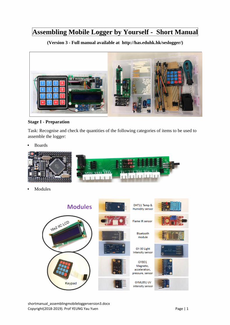
Stage I - Preparation
Task: Recognise and check the quantities of the following categories of items to be used to assemble the logger:
• Boards
• Modules
shortmanual_assemblingmobileloggerversion3.docx
Copyright(2018‐2019). Prof YEUNG Yau Yuen Page | 2
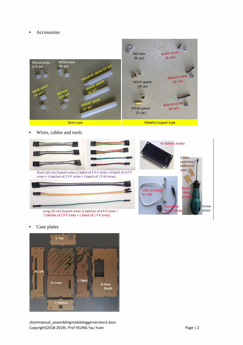
• Accessories
• Wires, cables and tools
• Case plates

shortmanual_assemblingmobileloggerversion3.docx
Copyright(2018‐2019). Prof YEUNG Yau Yuen Page | 3
Stage 2 – Assemble the mobile logger
Task: Follow the subsequent steps one-by-one to assemble your own mobile logger:
1. Peel off backing paper of all the six case plates
2. Fix the parts (Arduino M.B., PCB, battery holder) on the Base case plate
3. Connect wires to pins in PCB and Arduino MB according to the following specification table. Need to mark down the color of the connecting wires.
Ports/Pins on PCB
PCB Color of wire@
Arduino MB
Usage
Connecting IIC port
GND GND Provide electrical power to PCB
VCC 5V
SDA D20 (SDA) Data transmission from IIC sensors
SCL D21 (SCL)
Bluetooth Rx D14(Tx3) Data communication for Bluetooth Tx D15(Rx3)
Connecting 3-pin inputs/outputs sockets
A1 A1 Data transmission from analog sensors (including DHT11 sensor, IR flame sensor, various types of gas sensor, pH sensor, turbidity sensor, O2 sensor, CO2 sensor)
A2 A2
A3 A3
A4 A4
A5 A5
Connecting 4-pin sockets
6A #use two jumpers and no wires
SDA (PCB) Data transmission from IIC sensors, e.g. IR thermometer
6B SDA (PCB)
7A D18(Tx1) Data transmission from UART or serial sensors, e.g. IR CO2 sensor, sound level sensor and PM2.5 sensor
7B D19(Rx1)
8A D16 (Tx2)
8B D17(Rx2)
9V input power Vin Vin Input 9V electrical power to
Arduino MB GND GND
@Use abbreviation like: R=Red, G=Green, B=Blue, Br=Brown, O=Orange, Y=Yellow, W=White, Gy=Grey and Bk=Black
# SDA and SCL respectively of PCB (not Arduino MB and use two jumpers)
4. Fix the parts (LCD module, keypad, and three sensor modules) on the Front plate
shortmanual_assemblingmobileloggerversion3.docx
Copyright(2018‐2019). Prof YEUNG Yau Yuen Page | 4
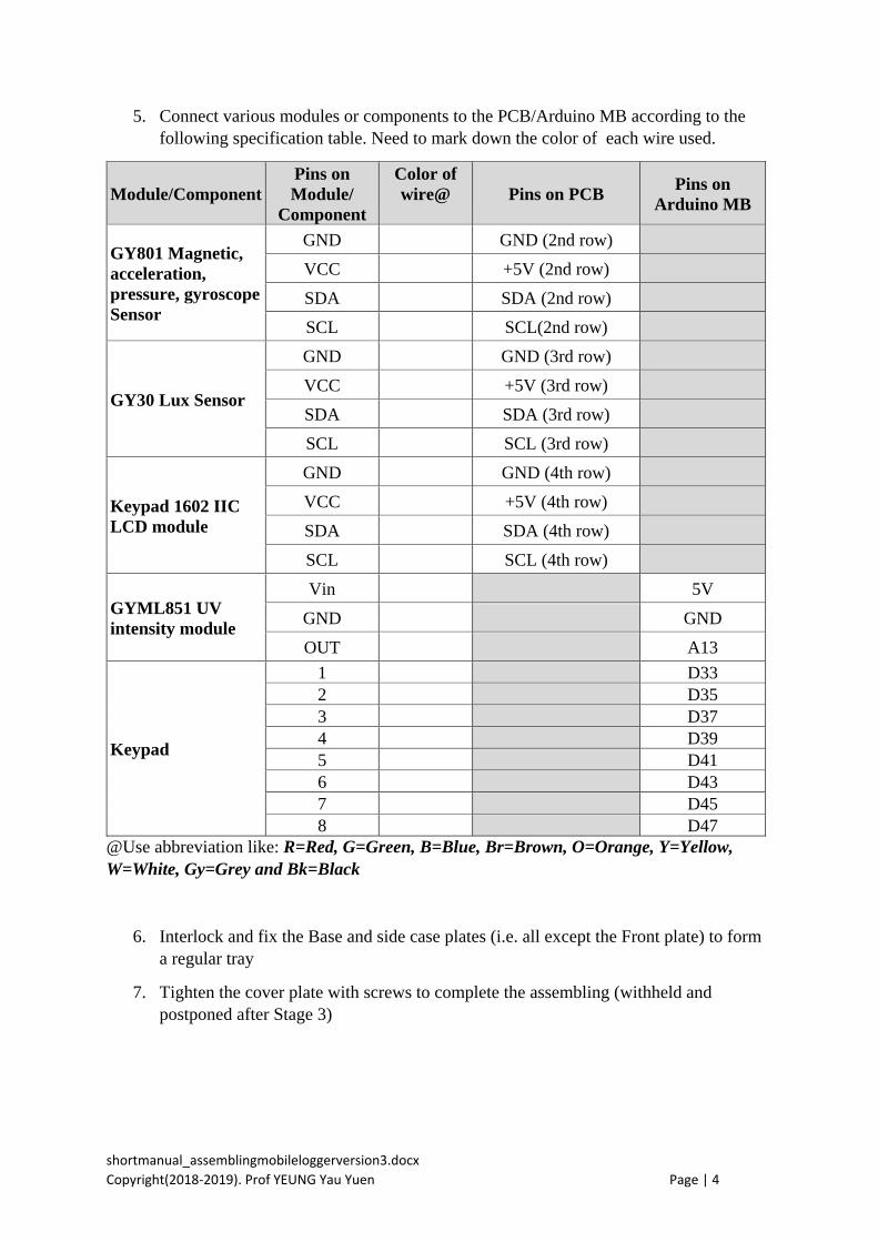
5. Connect various modules or components to the PCB/Arduino MB according to the following specification table. Need to mark down the color of each wire used.
Module/ComponentPins on Module/
Component
Color of wire@ Pins on PCB
Pins on Arduino MB
GY801 Magnetic, acceleration, pressure, gyroscope Sensor
GND GND (2nd row)
VCC +5V (2nd row)
SDA SDA (2nd row)
SCL SCL(2nd row)
GY30 Lux Sensor
GND GND (3rd row)
VCC +5V (3rd row)
SDA SDA (3rd row)
SCL SCL (3rd row)
Keypad 1602 IIC LCD module
GND GND (4th row)
VCC +5V (4th row)
SDA SDA (4th row)
SCL SCL (4th row)
GYML851 UV intensity module
Vin 5V
GND GND
OUT A13
Keypad
1 D33 2 D35 3 D37 4 D39 5 D41 6 D43 7 D45 8 D47
@Use abbreviation like: R=Red, G=Green, B=Blue, Br=Brown, O=Orange, Y=Yellow, W=White, Gy=Grey and Bk=Black
6. Interlock and fix the Base and side case plates (i.e. all except the Front plate) to form a regular tray
7. Tighten the cover plate with screws to complete the assembling (withheld and postponed after Stage 3)

shortmanual_assemblingmobileloggerversion3.docx
Copyright(2018‐2019). Prof YEUNG Yau Yuen Page | 5
Stage 3 - Simple testing and usage of the mobile logger
Test 1:
1. Insert a 9V battery into the battery holder inside the bottom side of the mobile logger. Put the Front plate onto its position and fix it temporarily with two rubber bands.
2. Power on the mobile logger (switch located at the bottom side).
3. You will see the message “Welcome to EdUHK” and then other message like BT:MML13 etc.
Likely bugs and solution:
a) If there is no light from the LCD and Arduino MB, check (i) battery, (ii) 9V battery connector at the end of the PCB, (iii) wires for Vin and GND pins in the POWER part of the Arduino MB and the corresponding pins of the PCB.
b) If the Arduino MB has light but the LCD shows no light, check (i) 5V and GND pins in the POWER part of the Arduino MB and the corresponding pins of the PCB; (ii) wires to the LCD.
c) If the LCD shows light but no visible characters shown, (i) press # in the keypad, (ii) switch off and on the power, (iii) use a screw driver to adjust its brightness and contrast by turning the cross in the blue cube by 45-90 degrees clockwise.
Test 2:
1. Insert an external Temperature & Humidity (DHT11) sensor into a 3-pin cable (VCCRed wire, GNDBlack wire, DATAGreen wire) and then plug the cable into the slot #1 (lower left side) of the mobile logger.
2. Press 1 in the keypad and you will get the temperature in oC and humidity in %. The number in the LHS of the LCD is the time (in seconds) that your mobile logger has been powered on.
3. Press button 2 of the keypad and you will get the local air pressure in hPa and temperature from the internal GY801 sensor.
4. Press button 3 of the keypad and you will get the light intensity in lux from the internal GY-30 sensor (at the central position with a hole). Cover the sensor with your finger and press 3 again. What will you get?
5. Insert a flame IR sensor into another 3-pin cable (A0Green wire, GBlack wire and +Red wire) and then plug the cable into the slot#2 of the mobile logger.
6. Press 4 in the keypad and you will get the flame IR level.

shortmanual_assemblingmobileloggerversion3.docx
Copyright(2018‐2019). Prof YEUNG Yau Yuen Page | 6
Likely bugs and solutions:
If any of the above sensors are not functioning properly, check (i) the corresponding cables connected to the sensors and (ii) keypad cable.
Test 3 (Bluetooth connection):
1. Press * on the keypad and it will show the Bluetooth name (e.g. BT:MML13). 2. Open the SESLogger7 app in your tablet (or smartphone). If you have your own Android
device, you may download and install it from the website indicated below. 3. Click the “Search BT Device” button once (and another time if necessary). 4. If a list of Bluetooth devices are shown, select the name for your mobile logger. . The PIN
is XYXY for Bluetooth name MMLXY. 5. If successfully connected, you will get another screen shown. 6. Click “D5:UV Intensity” in the pull-up menu located at the lower left corner of the app,
you will get the UV intensity after a while.
Likely bugs and solutions:
If the Bluetooth connection fails for a few times, check (i) if the Bluetooth module has been inserted into its proper place, (ii) wire connection between the Rx and Tx pins of the PCB and D14 and D15 of the Arduino MB.
Completion and Future Work
If no more bugs found, you may tighten the Front plate of the mobile logger by using four long M3X10 screws.
You may write your own Arduino programmes (or sketches) to use different sensors or functions of the mobile logger.
Updated information (including the operating system and app as free for download) is available at:
http://has.eduhk.hk/seslogger/
Welcome to send feedback or comments by email to [email protected]