assembly and modular table power system installation instructions
TRANSCRIPT
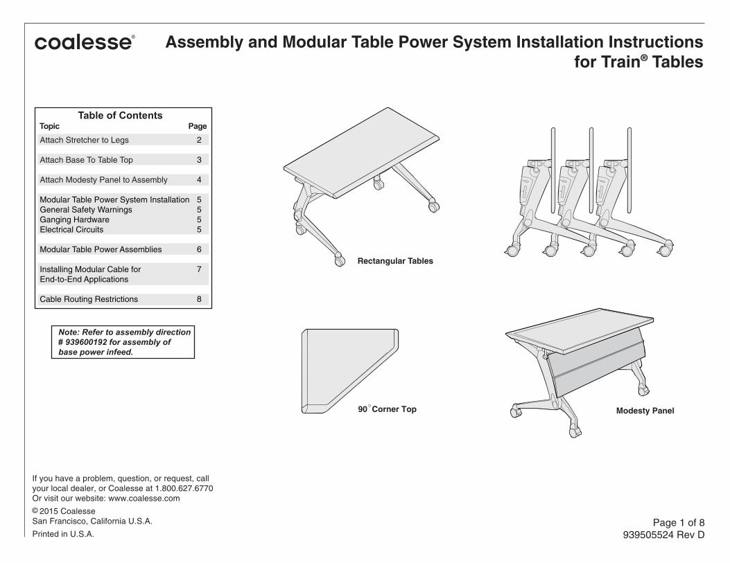
Assembly and Modular Table Power System Installation Instructionsfor Train® Tables
If you have a problem, question, or request, callyour local dealer, or Coalesse at 1.800.627.6770Or visit our website: www.coalesse.com© 2015 Coalesse San Francisco, California U.S.A.
Printed in U.S.A.Page 1 of 8
939505524 Rev D
Rectangular Tables
90 Corner Top Modesty Panel
Note: Refer to assembly direction # 939600192 for assembly of base power infeed.
Table of ContentsTopic PageAttach Stretcher to Legs
Attach Base To Table Top
Attach Modesty Panel to Assembly
Modular Table Power System InstallationGeneral Safety WarningsGanging HardwareElectrical Circuits
Modular Table Power Assemblies
Installing Modular Cable for End-to-End Applications
Cable Routing Restrictions
2
3
4
5 5 5 5
6
7
8

Page 2 of 8939505524 Rev D
SHIPPED COMPONENTS:(1) Table top(2) Legs(1) Stretcher
HARDWARE:Stretcher Hardware:(4) #730574 Allen Head Screws, 3/8-16 x 1”(2) #811679 Stretcher Joint Backer Plate(4) #732353 Lock Washers
Table Top Mounting Hardware:(8) #A730461 Flathead Phillips woodscrews, #10x7/8”, black
TOOLS REQUIRED:Electric Drill with 6” extension and:• #2 Phillips bit• T-27 Torx bit• 7/32” Allen wrench bit(NOTE: Hand tools may be substituted for the electric drill bits if necessary) WARNING: Protect top surface from scratches while attaching base feet.
BACKER PLATE
LOCK WASHERS
ALLEN HEAD SCREWS
Attach Stretcher To Legs
1. Unwrap the stretcher from package.
2. Attach the stretcher to each legcasting.The Backer Plate (#811679) is installed on the outside of the casting as shown.The stretcher is attached to each leg casting with (2) Allen Head screws(#730574) and two lock washers.
STRETCHER
TIP: Place a shim under carpet to allow a finger hold when assembled unit is ready to upright.
Page 3 of 8939505524 Rev D
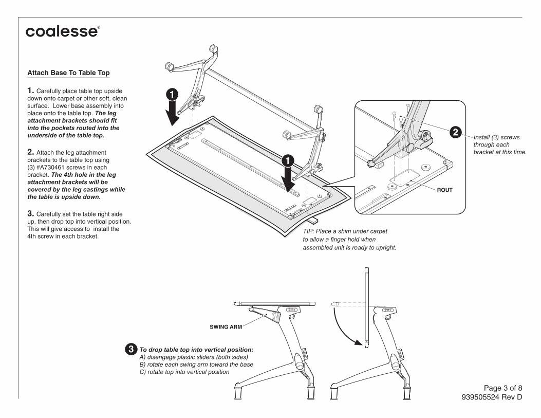
Attach Base To Table Top
1. Carefully place table top upsidedown onto carpet or other soft, clean surface. Lower base assembly intoplace onto the table top. The legattachment brackets should fitinto the pockets routed into theunderside of the table top.
2. Attach the leg attachmentbrackets to the table top using(3) #A730461 screws in eachbracket. The 4th hole in the legattachment brackets will becovered by the leg castings whilethe table is upside down.
3. Carefully set the table right sideup, then drop top into vertical position.This will give access to install the 4th screw in each bracket.
ROUT
1
1
Install (3) screwsthrough eachbracket at this time.
2
To drop table top into vertical position:A) disengage plastic sliders (both sides)B) rotate each swing arm toward the baseC) rotate top into vertical position
3
SWING ARM

Page 4 of 8939505524 Rev D
Attach Modesty Panel To Assembly
Note: To attach the modesty panel,Train table top must be flipped up.
1.
2.
3.
4.
Attach bracket,facing outward,to inside of leg.
Brackets are identified with “L”or “R”. Attach the left-handbracket, “L”, LOOSELY to theleg on the user’s left with (2)torx head screws. Attach theright-hand bracket, “R”,LOOSELY to the leg on theuser’s right with (2) torx head screws.
DO NOT OPEN THE MODESTY PANEL DOOR FOR 24 HOURS. For full cure the door should not be opened for 24 hours.
Align top of brackets with top of modesty panel.Also, adjust brackets on each side for the latchlock tape surface to fully contact the modesty panel.
Attach modesty panel to table by slipping the clips over the stretcher.
With upper modesty panel door open, peel off theprotective backing of the latchlock tape to expose the adhesive. Close the modesty panel door and firmly press the door, adhering the latchlock tape on each bracket to the door.
SHIPPED COMPONENTS(1) modesty panel(1) hardware package
HARDWARE PACKAGE(4) (73053705) torx head screws, 1/4-20 x 1/2” (1) (811772R) right-hand bracket, R (1) (811772L) left-hand bracket, L (1) latchlock tape on each bracket
TOOLS REQUIRED(1) electric drill or rachet with T-27 torx bit
R
LATCHLOCKTAPE 1
BRACKET
MODESTY PANEL
RHBRACKET
LHBRACKET
FLIPPEDTOP
STRETCHER
CLIPS
Page 5 of 8939505524 Rev D
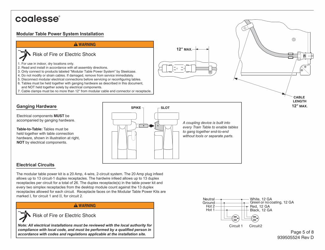
12" MAX.
Circuit 1 Circuit 2
Green or no coating, 12 GANeutralGround
Hot 2Hot 1
White, 12 GA
Red, 12 GABlack, 12 GA
Electrical components MUST be accompanied by ganging hardware.
Table-to-Table: Tables must beheld together with table connectionhardware, shown in illustration at right,NOT by electrical components.
SPIKE SLOT
A coupling device is built into every Train Table to enable tables to gang together end-to-endwithout tools or separate parts.
CABLE LENGTH
12" MAX.
Electrical Circuits The modular table power kit is a 20 Amp, 4-wire, 2-circuit system. The 20 Amp plug infeed allows up to 13 circuit-1 duplex receptacles. The hardwire infeed allows up to 13 duplex receptacles per circuit for a total of 26. The duplex receptacle(s) in the table power kit and every two simplex receptacles from the desktop module count against the 13 duplex receptacles allowed for each circuit. Receptacle faces on the Modular Table Power Kits are marked I, for circuit 1 and II, for circuit 2.
Ganging Hardware
Note: All electrical installations must be reviewed with the local authority for compliance with local code, and must be performed by a qualified person in accordance with codes and regulations applicable at the installation site.
WARNING
Risk of Fire or Electric Shock
WARNING
Risk of Fire or Electric Shock
1. For use in indoor, dry locations only.2. Read and install in accordance with all assembly directions.3. Only connect to products labeled "Modular Table Power System" by Steelcase.4. Do not modify or strain cables. If damaged, remove from service immediately.5. Disconnect modular electrical connections before servicing or reconfiguring tables.6. Tables must be held together with ganging hardware as described in this document, and NOT held together solely by electrical components.7. Cable clamps must be no more than 12" from modular cable end connector or receptacle.
Modular Table Power System Installation
Page 6 of 8939505524 Rev D
Modular Table Power Assemblies
Single ReceptacleSHIPPED COMPONENTS:- 1 cable assembly- 1 hardware kit
HARDWARE:- 1 receptacle bracket- 4 conduit clamps- 2 conduit snap-clips- 8 #10 phillips head screws - black
TOOLS REQUIRED: #2 phillips head driver #2 phillips head driver
Double ReceptacleSHIPPED COMPONENTS:- 1 cable assembly- 1 hardware kit
HARDWARE:- 2 receptacle brackets- 5 conduit clamps- 2 conduit snap-clips-11 #10 phillips head screws - black
TOOLS REQUIRED:
Table WidthTable Depth24"30"
48"
60"54"
60"
72"66"
72"
84"78"
Cable Assembly Length
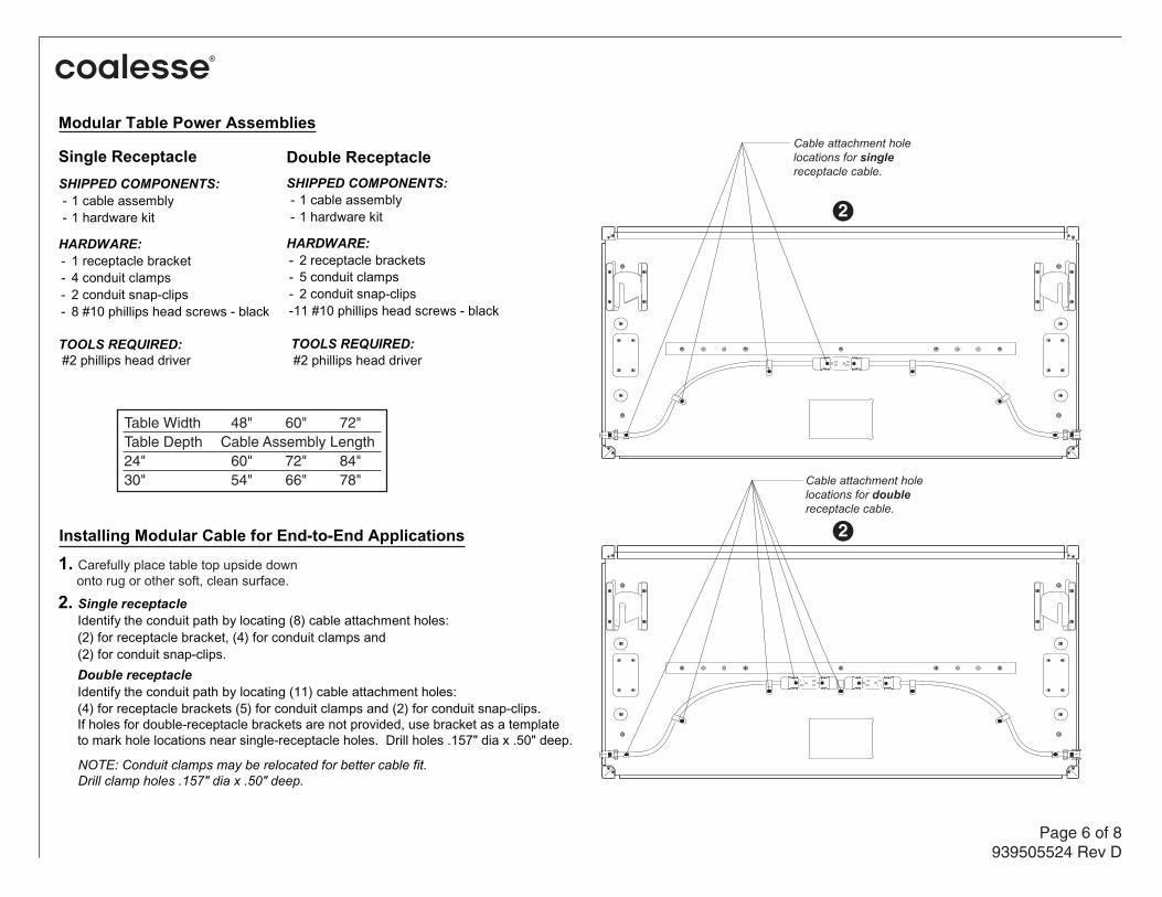
Installing Modular Cable for End-to-End Applications1. Carefully place table top upside down onto rug or other soft, clean surface.
2. Single receptacle Identify the conduit path by locating (8) cable attachment holes:(2) for receptacle bracket, (4) for conduit clamps and(2) for conduit snap-clips.Double receptacleIdentify the conduit path by locating (11) cable attachment holes: (4) for receptacle brackets (5) for conduit clamps and (2) for conduit snap-clips.If holes for double-receptacle brackets are not provided, use bracket as a templateto mark hole locations near single-receptacle holes. Drill holes .157" dia x .50" deep.
NOTE: Conduit clamps may be relocated for better cable fit.Drill clamp holes .157" dia x .50" deep.
2
Cable attachment holelocations for singlereceptacle cable.
Cable attachment holelocations for doublereceptacle cable.
2

Page 7 of 8939505524 Rev D
Installing Modular Cable for End-to-End Applications (continued)
9. Carefully flip tables upright into use position.
3. Fasten receptacle bracket(s).
4. Fasten conduit snap-clips.
5. Loosely fasten conduit clamps.
6. Determine direction of power and orient male and female ends of cable assembly as required. Align ends flush with table edges and snap into clips. Note: Infeed has a female connector.
7. Snap receptacle(s) into receptacle bracket(s).
8. Tighten conduit clamps.
WARNING
Risk of Fire or Electric Shock
10. Make ganging connections between adjoining tables. - Lack of mechanical connection may lead to cable damage.
11. Connect modular connectors. - Match like colors only. (Green-to-Green, Red-to-Red, Black-to-Black and White-to-White). Push connectors together until both latches engage.
11
Male end of ModularTable Power Cable
Female end of ModularTable Power Cable
GREEN
BLACKWHITE
REDGREEN
BLACK
WHITERED
Note: Latches fully engaged.
Note: Orient colors on both connectors to match.
CABLE CONNECTOR
CONDUIT SNAP-CLIP
CONDUIT CLAMP
RECEPTACLE BRACKET
5
6
3
4
RECEPTACLE
7
8

Page 8 of 8939505524 Rev D
Cable Routing Restrictions In order for the flip-top mechanism to work properly,the mechanism area - handle, swing arm, top pivotand bumpers - must be free of any obstructions.When routing power cables, follow the recommendedconduit path described on page 6, and avoid theshaded areas in the illustration shown on this page.
Flip-Top mechanism must move freely in shaded areas shown. Do not route cables in these areas.