assembly, inst allation, and removal of contacts and modules ohm user manual.pdf · assembly, inst...
TRANSCRIPT

Assembly, InstAllAtIon, And RemovAl of ContACts And modulesFOR 50 Ohm COAXIAL CONTACTS AND mODULES
tAble of Contents
seCtIon 1 RECEIvER CONTACT ASSEmbLy INSTRUCTIONS
seCtIon 2 ITA CONTACT ASSEmbLy INSTRUCTIONS
seCtIon 3 CONTACT INSTALLATION AND REmOvAL
seCtIon 4 mODULE INSTALLATION AND REmOvAL
seCtIon 5 CROSS REFERENCE TAbLES
seCtIon 6 pRODUCT pERFORmANCE SpECIFICATIONS
6/16/2017
Please note that any printed or downloaded User Manuals or Procedure Sheets may not reflect the most current revisions. The information contained in these materials is subject to change.
For the most current information available, visit www.vpc.com.
50 Ohm COAXIAL CONTACTS AND mODULES USER’S mANUAL: SECTION 1 vIRgInIA pAnel CoRpoRAtIon 50 Ohm COAXIAL CONTACTS AND mODULES USER’S mANUAL: SECTION 1 vIRgInIA pAnel CoRpoRAtIon
6/16/20171-1 For the most current information available, visit www.vpc.com.
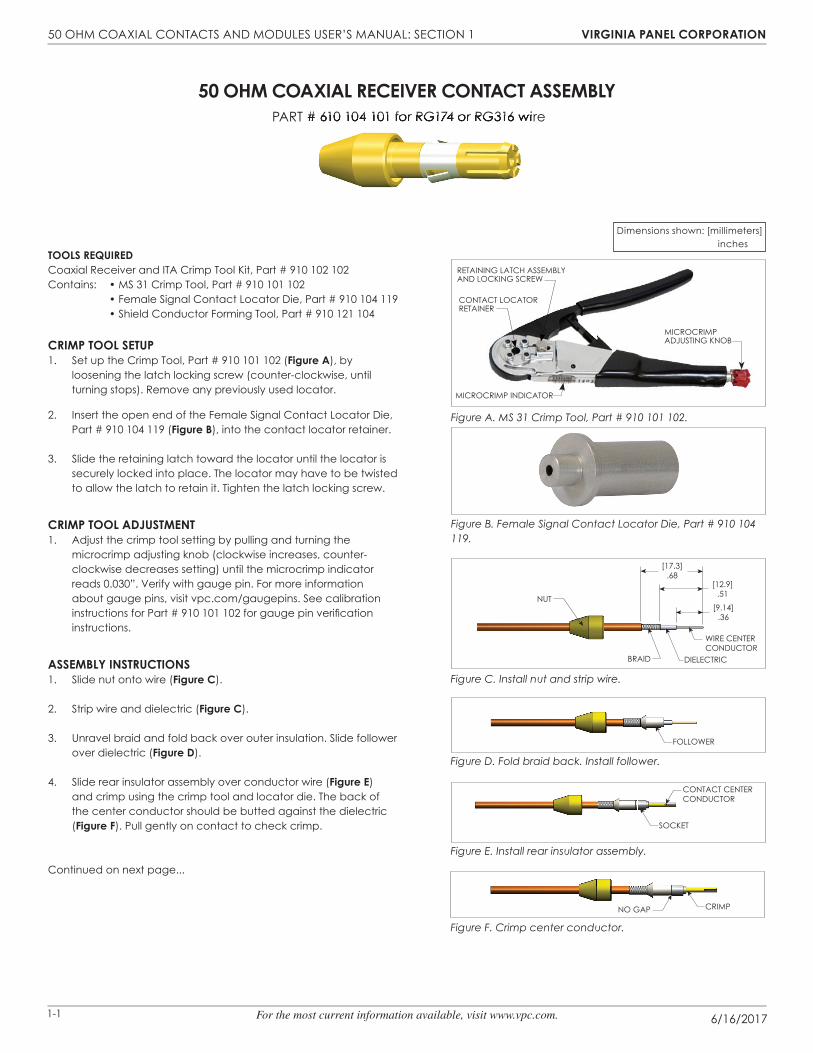
50 ohm CoAxIAl ReCeIveR ContACt Assembly pART # 610 104 101 for RG174 or RG316 wire
tools ReQuIRedCoaxial Receiver and ITA Crimp Tool Kit, part # 910 102 102Contains: • MS 31 Crimp Tool, Part # 910 101 102 • Female Signal Contact Locator Die, Part # 910 104 119 • Shield Conductor Forming Tool, Part # 910 121 104
CRImp tool setup1. Set up the Crimp Tool, Part # 910 101 102 (figure A), by
loosening the latch locking screw (counter-clockwise, until turning stops). Remove any previously used locator.
2. Insert the open end of the Female Signal Contact Locator Die, Part # 910 104 119 (figure b), into the contact locator retainer.
3. Slide the retaining latch toward the locator until the locator is securely locked into place. The locator may have to be twisted to allow the latch to retain it. Tighten the latch locking screw.
CRImp tool AdJustment1. Adjust the crimp tool setting by pulling and turning the
microcrimp adjusting knob (clockwise increases, counter-clockwise decreases setting) until the microcrimp indicator reads 0.030”. Verify with gauge pin. For more information about gauge pins, visit vpc.com/gaugepins. See calibration instructions for Part # 910 101 102 for gauge pin verifi cation instructions.
Assembly InstRuCtIons1. Slide nut onto wire (figure C).
2. Strip wire and dielectric (figure C).
3. Unravel braid and fold back over outer insulation. Slide follower over dielectric (figure d).
4. Slide rear insulator assembly over conductor wire (figure e) and crimp using the crimp tool and locator die. The back of the center conductor should be butted against the dielectric (figure f). Pull gently on contact to check crimp.
Continued on next page...
.369.14
.6817.3
.5112.9
NUT
BRAID DIELECTRIC
WIRE CENTER WCONDUCTOR
FOLLOWER
SOCKET
CONTACT CENTERCONDUCTOR
CRIMPNO GAP
Figure C. Install nut and strip wire.
Figure F. Crimp center conductor.
Figure E. Install rear insulator assembly.
Figure D. Fold braid back. Install follower.
Dimensions shown: [millimeters] inches
pART # 610 104 101 for RG174 or RG316 wire
Figure B. Female Signal Contact Locator Die, Part # 910 104 119.
Figure A. MS 31 Crimp Tool, Part # 910 101 102.
mICROCRImp ADJUSTING KNOb
mICROCRImp INDICATOR
RETAINING LATCh ASSEmbLy AND LOCKING SCREW
CONTACT LOCATOR RETAINER
NUT
[17.3].68
[12.9].51
[9.14].36
WIRE CENTER CONDUCTOR
DIELECTRICbRAID
FOLLOWER
SOCKET
CONTACT CENTER CONDUCTOR
CRImpNO GAp
50 Ohm COAXIAL CONTACTS AND mODULES USER’S mANUAL: SECTION 1 vIRgInIA pAnel CoRpoRAtIon 50 Ohm COAXIAL CONTACTS AND mODULES USER’S mANUAL: SECTION 1 vIRgInIA pAnel CoRpoRAtIon
6/16/20171-2 For the most current information available, visit www.vpc.com.
SHIELD CONDUCTOR
.28 MINIMUM7.11
Figure H. Install shield conductor.
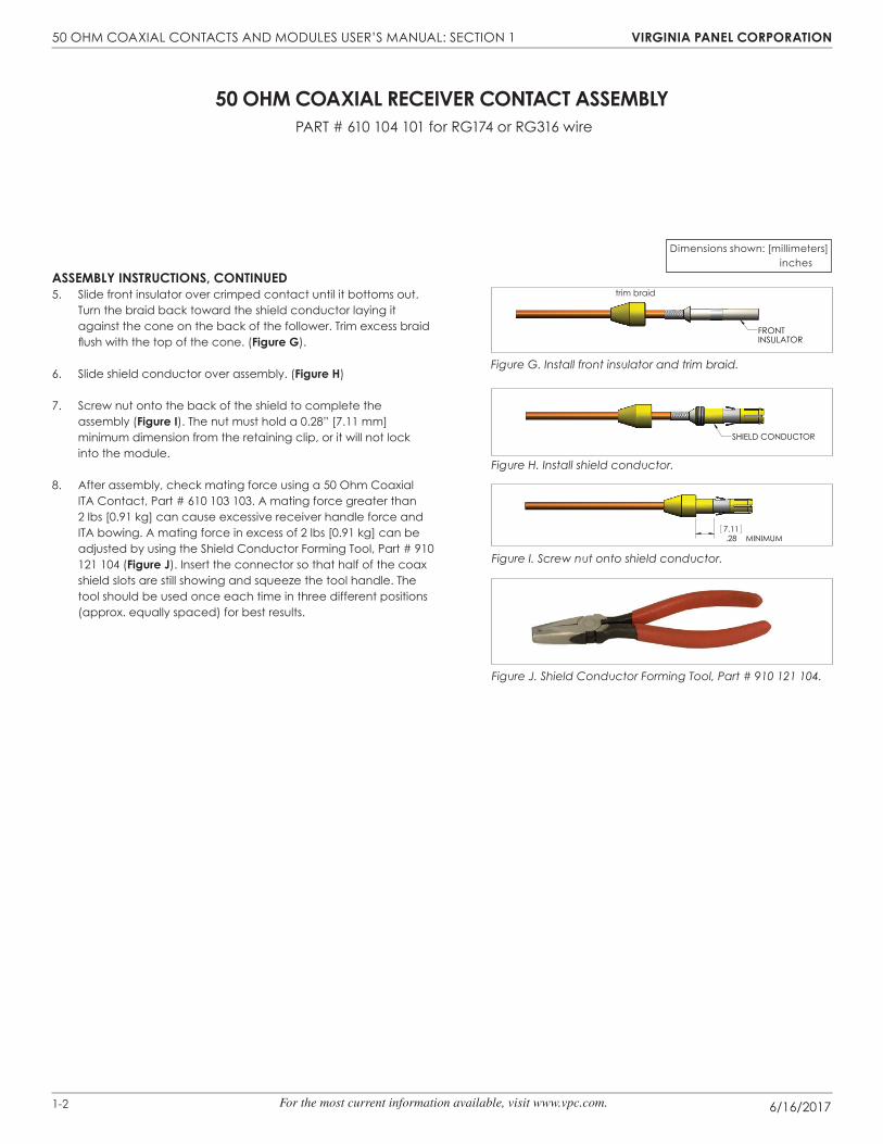
50 ohm CoAxIAl ReCeIveR ContACt Assembly pART # 610 104 101 for RG174 or RG316 wire
Dimensions shown: [millimeters] inches
Assembly InstRuCtIons, ContInued5. Slide front insulator over crimped contact until it bottoms out.
Turn the braid back toward the shield conductor laying it against the cone on the back of the follower. Trim excess braid flush with the top of the cone. (figure g).
6. Slide shield conductor over assembly. (figure h)
7. Screw nut onto the back of the shield to complete the assembly (figure I). The nut must hold a 0.28” [7.11 mm] minimum dimension from the retaining clip, or it will not lock into the module.
8. After assembly, check mating force using a 50 Ohm Coaxial ITA Contact, Part # 610 103 103. A mating force greater than 2 lbs [0.91 kg] can cause excessive receiver handle force and ITA bowing. A mating force in excess of 2 lbs [0.91 kg] can be adjusted by using the Shield Conductor Forming Tool, Part # 910 121 104 (figure J). Insert the connector so that half of the coax shield slots are still showing and squeeze the tool handle. The tool should be used once each time in three different positions (approx. equally spaced) for best results.
Figure J. Shield Conductor Forming Tool, Part # 910 121 104.
Figure I. Screw nut onto shield conductor.
FRONT INSULATOR
Figure G. Install front insulator and trim braid.
trim braid
50 Ohm COAXIAL CONTACTS AND mODULES USER’S mANUAL: SECTION 1 vIRgInIA pAnel CoRpoRAtIon 50 Ohm COAXIAL CONTACTS AND mODULES USER’S mANUAL: SECTION 1 vIRgInIA pAnel CoRpoRAtIon
6/16/20171-3 For the most current information available, visit www.vpc.com.
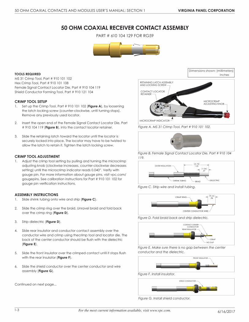
50 ohm CoAxIAl ReCeIveR ContACt Assembly
pART # 610 104 129 FOR RG59
tools ReQuIRedmS 31 Crimp Tool, part # 910 101 102hex Crimp Tool, part # 910 101 108Female Signal Contact Locator Die, Part # 910 104 119Shield Conductor Forming Tool, Part # 910 121 104
CRImp tool setup1. Set up the Crimp Tool, Part # 910 101 102 (figure A), by loosening
the latch locking screw (counter-clockwise, until turning stops). Remove any previously used locator.
2. Insert the open end of the Female Signal Contact Locator Die, Part # 910 104 119 (figure b), into the contact locator retainer.
3. Slide the retaining latch toward the locator until the locator is securely locked into place. The locator may have to be twisted to allow the latch to retain it. Tighten the latch locking screw.
CRImp tool AdJustment1. Adjust the crimp tool setting by pulling and turning the microcrimp
adjusting knob (clockwise increases, counter-clockwise decreases setting) until the microcrimp indicator reads 0.040”. Verify with gauge pin. For more information about gauge pins, visit vpc.com/gaugepins. See calibration instructions for Part # 910 101 102 for gauge pin verifi cation instructions.
Assembly InstRuCtIons1. Slide shrink tubing onto wire and strip (figure C).
2. Slide the crimp ring over the braid. Unravel braid and fold back over the crimp ring (figure d).
3. Strip dielectric (figure d).
4. Slide rear insulator and conductor contact assembly over the conductor wire and crimp using thecrimp tool and locator die. The back of the center conductor should be fl ush with the dielectric (figure e).
5. Slide the front insulator over the crimped contact until it stops fl ush with the rear insulator (figure f).
6. Slide the shield conductor over the center conductor and wire assembly (figure g).
Continued on next page...
Figure C. Strip wire and install tubing.
Figure G. Install shield conductor.
Figure F. Install insulator.
Figure E. Make sure there is no gap between the center conductor and the dielectric.
Figure D. Fold braid back and strip dielectric.
1.2531.75
.4711.94
DIELECTRICBRAIDSHRINK TUBING
OUTER INSULATION
.369.14CRIMP RING
CENTER CONDUCTOR WIRE
CONTACT CENTERCONDUCTOR
REAR INSULATOR
NO GAP
CRIMP
FRONT INSULATOR
SHIELD CONDUCTOR
Dimensions shown: [millimeters] inches
Figure B. Female Signal Contact Locator Die, Part # 910 104 119.
Figure A. MS 31 Crimp Tool, Part # 910 101 102.
mICROCRImp ADJUSTING KNOb
mICROCRImp INDICATOR
RETAINING LATCh ASSEmbLy AND LOCKING SCREW
CONTACT LOCATOR RETAINER

50 Ohm COAXIAL CONTACTS AND mODULES USER’S mANUAL: SECTION 1 vIRgInIA pAnel CoRpoRAtIon 50 Ohm COAXIAL CONTACTS AND mODULES USER’S mANUAL: SECTION 1 vIRgInIA pAnel CoRpoRAtIon
6/16/20171-4 For the most current information available, visit www.vpc.com.
Figure K. Install shrink tubing.
Figure J. Crimp contact.
.28MINIMUM
7.21
CRIMP POSITION"A"
CRIMP POSITION"C"
SHRINK TUBING
50 ohm CoAxIAl ReCeIveR ContACt Assembly
pART # 610 104 129 FOR RG59
Assembly InstRuCtIons, ContInued7. Turn the braid back toward the shield conductor laying it
on top of the threaded portion of the shield conductor. No strands of the braid should extend beyond the threaded portion (figure h). Trim braid if necessary.
8. Slide the crimp ring into position over the braid and crimp in two places using Hex Crimp Tool, Part # 910 101 108, in Hex position C for the smaller portion of the crimp ring and position A for the larger portion of the crimp ring. The crimp ring must hold 0.28” [7.11 mm] minimum dimension from the retaining clip or it will not lock into the module (figure J).
9. Slide the shrink tubing over the exposed braid and the “C” position crimp and shrink (figure K).
10. After assembly, check the mating force using a 50 Ohm Coaxial ITA contact, Part # 610 103 132. A mating force greater than 2 lbs [0.91 kg] can cause excess receiver handle force and ITA bowing. If the mating force is greater than 2 lbs [0.91 kg] adjust the shield conductor using the Shield Conductor Forming Tool, Part # 910 121 104 (figure l). Insert the contact so that half of the coax shield slots are still showing and squeeze the tool handle. The tool should be used once each time in three different positions (approx. equally spaced) for best results.
Dimensions shown: [millimeters] inches
Figure L. Shield Conductor Forming Tool, Part # 910 121 104.
Figure H. Fold braid back over shield conductor.
BRAID OVERSHIELD CONDUCTOR TRIM BRAID
50 Ohm COAXIAL CONTACTS AND mODULES USER’S mANUAL: SECTION 1 vIRgInIA pAnel CoRpoRAtIon 50 Ohm COAXIAL CONTACTS AND mODULES USER’S mANUAL: SECTION 1 vIRgInIA pAnel CoRpoRAtIon
6/16/20171-5 For the most current information available, visit www.vpc.com.
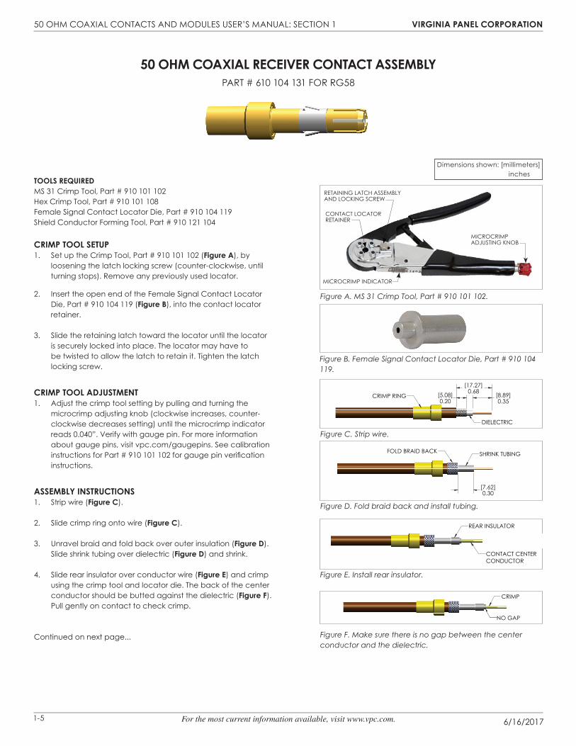
50 ohm CoAxIAl ReCeIveR ContACt AssemblypART # 610 104 131 FOR RG58
tools ReQuIRedmS 31 Crimp Tool, part # 910 101 102hex Crimp Tool, part # 910 101 108Female Signal Contact Locator Die, Part # 910 104 119Shield Conductor Forming Tool, Part # 910 121 104
CRImp tool setup1. Set up the Crimp Tool, Part # 910 101 102 (figure A), by
loosening the latch locking screw (counter-clockwise, until turning stops). Remove any previously used locator.
2. Insert the open end of the Female Signal Contact Locator Die, Part # 910 104 119 (figure b), into the contact locator retainer.
3. Slide the retaining latch toward the locator until the locator is securely locked into place. The locator may have to be twisted to allow the latch to retain it. Tighten the latch locking screw.
CRImp tool AdJustment1. Adjust the crimp tool setting by pulling and turning the
microcrimp adjusting knob (clockwise increases, counter-clockwise decreases setting) until the microcrimp indicator reads 0.040”. Verify with gauge pin. For more information about gauge pins, visit vpc.com/gaugepins. See calibration instructions for Part # 910 101 102 for gauge pin verifi cation instructions.
Assembly InstRuCtIons1. Strip wire (figure C).
2. Slide crimp ring onto wire (figure C).
3. Unravel braid and fold back over outer insulation (figure d). Slide shrink tubing over dielectric (figure d) and shrink.
4. Slide rear insulator over conductor wire (figure e) and crimp using the crimp tool and locator die. The back of the center conductor should be butted against the dielectric (figure f). Pull gently on contact to check crimp.
Continued on next page...
Figure C. Strip wire.
Figure F. Make sure there is no gap between the center conductor and the dielectric.
Figure E. Install rear insulator.
Figure D. Fold braid back and install tubing.
[8.89]0.35
[5.08]0.20
[17.27]0.68
CRIMP RING
DIELECTRIC
[7.62]0.30
SHRINK TUBINGFOLD BRAID BACK
REAR INSULATOR
CONTACT CENTER CONDUCTOR
CRIMP
NO GAP
Dimensions shown: [millimeters] inches
Figure B. Female Signal Contact Locator Die, Part # 910 104 119.
Figure A. MS 31 Crimp Tool, Part # 910 101 102.
mICROCRImp ADJUSTING KNOb
mICROCRImp INDICATOR
RETAINING LATCh ASSEmbLy AND LOCKING SCREW
CONTACT LOCATOR RETAINER
50 Ohm COAXIAL CONTACTS AND mODULES USER’S mANUAL: SECTION 1 vIRgInIA pAnel CoRpoRAtIon 50 Ohm COAXIAL CONTACTS AND mODULES USER’S mANUAL: SECTION 1 vIRgInIA pAnel CoRpoRAtIon
6/16/20171-6 For the most current information available, visit www.vpc.com.
Figure J. Fold braid over shield conductor.
Figure H. Install shield conductor.
Figure K. Crimp contact.
SHIELD CONDUCTOR
FOLD SHIELD OVER THREADS
TRIM BRAID
CRIMP POSITION "A"
CRIMP POSITION "B"
[7.11]0.28 MINIMUM
50 ohm CoAxIAl ReCeIveR ContACt AssemblypART # 610 104 131 FOR RG58
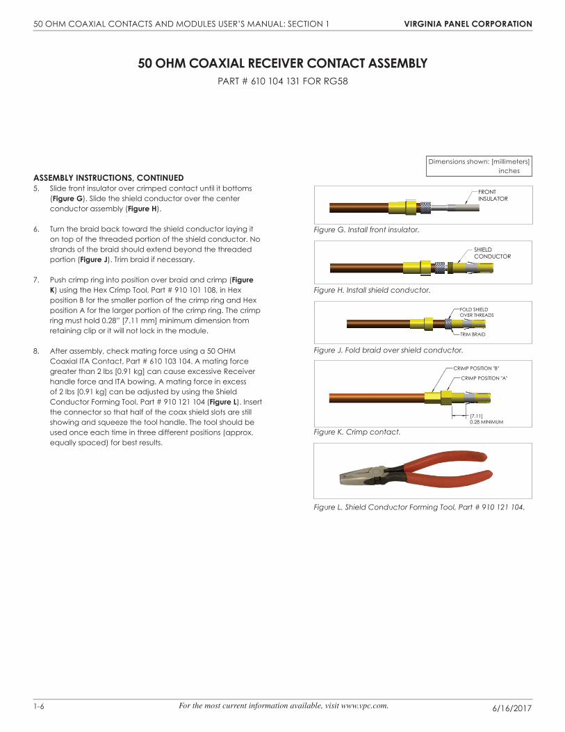
Assembly InstRuCtIons, ContInued5. Slide front insulator over crimped contact until it bottoms
(figure g). Slide the shield conductor over the center conductor assembly (figure h).
6. Turn the braid back toward the shield conductor laying it on top of the threaded portion of the shield conductor. No strands of the braid should extend beyond the threaded portion (figure J). Trim braid if necessary.
7. Push crimp ring into position over braid and crimp (figure K) using the Hex Crimp Tool, Part # 910 101 108, in Hex position B for the smaller portion of the crimp ring and Hex position A for the larger portion of the crimp ring. The crimp ring must hold 0.28” [7.11 mm] minimum dimension from retaining clip or it will not lock in the module.
8. After assembly, check mating force using a 50 OHM Coaxial ITA Contact, Part # 610 103 104. A mating force greater than 2 lbs [0.91 kg] can cause excessive Receiver handle force and ITA bowing. A mating force in excess of 2 lbs [0.91 kg] can be adjusted by using the Shield Conductor Forming Tool, Part # 910 121 104 (figure l). Insert the connector so that half of the coax shield slots are still showing and squeeze the tool handle. The tool should be used once each time in three different positions (approx. equally spaced) for best results.
Dimensions shown: [millimeters] inches
Figure L. Shield Conductor Forming Tool, Part # 910 121 104.
Figure G. Install front insulator.
FRONT INSULATOR

50 Ohm COAXIAL CONTACTS AND mODULES USER’S mANUAL: SECTION 2 vIRgInIA pAnel CoRpoRAtIon
6/16/20172-1 For the most current information available, visit www.vpc.com.
50 Ohm COAXIAL CONTACTS AND mODULES USER’S mANUAL: SECTION 1 vIRgInIA pAnel CoRpoRAtIon 50 Ohm COAXIAL CONTACTS AND mODULES USER’S mANUAL: SECTION 1 vIRgInIA pAnel CoRpoRAtIon
50 ohm CoAxIAl ItA ContACt AssemblypART # 610 103 103 FOR RG174 OR RG316
tools ReQuIRedCoaxial 50 Ohm Receiver and ITA Crimp Tool Kit, part # 910 102 102Contains: • MS 31 Crimp Tool, Part # 910 101 102 • Male Signal Contact Locator Die, Part # 910 104 117 • Insulator Insertion Tool, Part # 910 113 101 • Hex Crimp Tool, Part # 910 101 104
CRImp tool setup1. Set up the Crimp Tool, Part # 910 101 102 (figure A), by loosening
the latch locking screw (counter-clockwise, until turning stops). Remove any previously used locator.
2. Insert the open end of the Male Signal Contact Locator Die, Part # 910 104 117 (figure b), into the contact locator retainer.
3. Slide the retaining latch toward the locator until the locator is securely locked into place. The locator may have to be twisted to allow the latch to retain it. Tighten the latch locking screw.
CRImp tool AdJustment1. Adjust the crimp tool setting by pulling and turning the
microcrimp adjusting knob (clockwise increases, counter-clockwise decreases setting) until the microcrimp indicator reads 0.030”. Verify with gauge pin. For more information about gauge pins, visit vpc.com/gaugepins. See calibration instructions for Part # 910 101 102 for gauge pin verifi cation instructions.
Assembly InstRuCtIons1. Slide crimp ring and shield conductor onto wire (figure C).
2. Strip wire (figure C).
3. Unravel braid and fold back over outer insulation (figure d).
4. Slide rear insulator over dielectric until it stops against the braid (figure d).
5. Slide the front insulator with contact center conductor over the center conductor wire (figure e) and crimp using the crimp tool and locator die.
6. Slide rear insulator forward pressing it on front insulator until parts are fi rmly together (figure f).
7. Fold braid back toward the contact center conductor (figure f).
Continued on next page...
Figure C. Install crimp ring and shield conductor.
Figure F. Make sure there is no gap between the rear and front insulator.
Figure E. Install front insulator with signal contact.
Figure D. Fold braid back and install rear insulator.
4.06.16
6.86.27
17.53.69
SHIELD CONDUCTORCRIMP RING
DIELECTRIC
REAR INSULATORBRAID
FRONT INSULATOR
CONTACT CENTERCONDUCTOR
CRIMP
NO GAPBRAID
Dimensions shown: [millimeters] inches
Figure A. MS 31 Crimp Tool, Part # 910 101 102.
Figure B. Male Signal Contact Locator Die, Part # 910 104 117.
2
mICROCRImp ADJUSTING KNOb
mICROCRImp INDICATOR
RETAINING LATCh ASSEmbLy AND LOCKING SCREW
CONTACT LOCATOR RETAINER

50 Ohm COAXIAL CONTACTS AND mODULES USER’S mANUAL: SECTION 2 vIRgInIA pAnel CoRpoRAtIon
6/16/20172-2 For the most current information available, visit www.vpc.com.
Figure K. Crimp contact.
Figure L. Hex Crimp Tool, Part # 910 101 104.
CRIMP POSITION "A"CRIMP POSITION "C"
50 ohm CoAxIAl ItA ContACt AssemblypART # 610 103 103 FOR RG174 OR RG316
Assembly InstRuCtIons, ContInued8. Slide the shield conductor forward over the braid far enough
that the braid can be pulled out from under the shield conductor.
9. Using the Insulator Insertion Tool, Part # 910 113 101 (figure g), press the insulator into the shield conductor until Surface “A” of the tool touches Surface “B” of the shield conductor (figure h).
10. Fold the braid over the shield conductor (figure J).
11. Slide the crimp ring into position over the braid and crimp in two places (figure K) using Hex Crimp Tool, Part # 910 101 104 (figure l). Position A should be used for the larger portion of the crimp ring and Position C should be used for the smaller portion of the crimp ring.
Dimensions shown: [millimeters] inches
Figure G. Insulator Insertion Tool, Part # 910 113 101.
Figure J. Fold braid back over shield conductor.
Figure H. Insulator insertion.
SURFACE "A"
INSULATOR INSERTION TOOLSURFACE "B"
50 Ohm COAXIAL CONTACTS AND mODULES USER’S mANUAL: SECTION 2 vIRgInIA pAnel CoRpoRAtIon
6/16/20172-3 For the most current information available, visit www.vpc.com.
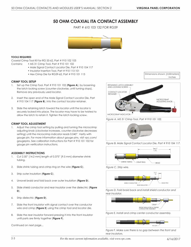
tools ReQuIRedCoaxial Crimp Tool Kit for RG 55-62, part # 910 102 103Contains: • MS 31 Crimp Tool, Part # 910 101 102 • Male Signal Contact Locator Die, Part # 910 104 117 • Insulator Insertion Tool, Part # 910 113 101 • Hex Crimp Die for RG59-62, Part # 910 101 113
CRImp tool setup1. Set up the Crimp Tool, Part # 910 101 102 (figure A), by loosening
the latch locking screw (counter-clockwise, until turning stops). Remove any previously used locator.
2. Insert the open end of the Male Signal Contact Locator Die, Part # 910 104 117 (figure b), into the contact locator retainer.
3. Slide the retaining latch toward the locator until the locator is securely locked into place. The locator may have to be twisted to allow the latch to retain it. Tighten the latch locking screw.
CRImp tool AdJustment1. Adjust the crimp tool setting by pulling and turning the microcrimp
adjusting knob (clockwise increases, counter-clockwise decreases setting) until the microcrimp indicator reads 0.040”. Verify with gauge pin. For more information about gauge pins, visit vpc.com/gaugepins. See calibration instructions for Part # 910 101 102 for gauge pin verifi cation instructions.
Assembly InstRuCtIons1. Cut 2.50” [14.2 mm] length of 0.375” [9.5 mm] diameter shrink
tubing.
2. Slide shrink tubing and crimp ring on the wire (figure C).
3. Strip outer insulation (figure C).
4. Unravel braid and fold back over outer insulation (figure d).
5. Slide shield conductor and rear insulator over the dielectric (figure d).
6. Strip dielectric (figure d).
7. Slide the front insulator with signal contact over the conductor wire and crimp (figure e) using the crimp tool and locator die.
8. Slide the rear insulator forward pressing it into the front insulator until parts are fi rmly together (figure f).
Continued on next page...
50 ohm CoAxIAl ItA ContACt AssemblypART # 610 103 132 FOR RG59
Figure C. Strip wire.
Figure F. Make sure there is no gap between the front and rear insulators.
Figure E. Install and crimp center conductor assembly.
Figure D. Fold braid back and install shield conductor and rear insulator.
1.7544.5
SHRINK TUBING CRIMP RING BRAID
.164.1
SHIELD CONDUCTORREAR INSULATOR
DIELECTRIC
CRIMP
FRONT INSULATOR & CENTERCONDUCTOR ASSEMBLY
NO GAP
Dimensions shown: [millimeters] inches
Figure A. MS 31 Crimp Tool, Part # 910 101 102.
Figure B. Male Signal Contact Locator Die, Part # 910 104 117.
mICROCRImp ADJUSTING KNOb
mICROCRImp INDICATOR
RETAINING LATCh ASSEmbLy AND LOCKING SCREW
CONTACT LOCATOR RETAINER

50 Ohm COAXIAL CONTACTS AND mODULES USER’S mANUAL: SECTION 2 vIRgInIA pAnel CoRpoRAtIon
6/16/20172-4 For the most current information available, visit www.vpc.com.
Figure L. Crimp contact.
Figure J. Fold braid over shield conductor.
Figure H. Insulator insertion.
Figure M. Install shrink tubing.
SURFACE "A"
SURFACE "B"
INSULATOR INSERTION TOOL
FOLD BRAID OVERSHIELD CONDUCTOR
CRIMP POSITION"A"
SHRINK TUBING
Figure G. Insulator Insertion Tool, Part # 910 113 101.
Assembly InstRuCtIons, ContInued9. Using the Insulator Insertion Tool, Part # 910 113 101 (figure g),
press the insulator into the shield conductor until Surface “A” of the tool touches Surface “B” of the shield conductor (figure h).
10. Turn braid over the back of the shield conductor (figure J). Trim the braid so that at least 0.10” [2.54 mm] of the first step of the shield conductor is covered.
11. Slide the crimp ring into position over the braid and crimp using Hex Crimp Die, Part # 910 101 113 (figure K) in Hex position “A” (figure l).
12. Slide the shrink tubing over the exposed braid and crimp ring and shrink (figure m).
50 ohm CoAxIAl ItA ContACt AssemblypART # 610 103 132 FOR RG59
Dimensions shown: [millimeters] inches
Figure K. Hex Crimp Die, Part # 910 101 113.

50 Ohm COAXIAL CONTACTS AND mODULES USER’S mANUAL: SECTION 2 vIRgInIA pAnel CoRpoRAtIon
6/16/20172-5 For the most current information available, visit www.vpc.com.
50 ohm CoAxIAl ItA ContACt AssemblypART # 610 103 104 FOR RG58
tools ReQuIRedCoaxial Crimp Tool Kit for RG55-62, part # 910 102 103Contains: • MS 31 Crimp Tool, Part # 910 101 102 • Male Signal Contact Locator Die, Part # 910 104 117 • Insulator Insertion Tool, Part # 910 113 101 • Hex Crimp Tool, Part # 910 101 104
CRImp tool setup1. Set up the Crimp Tool, Part # 910 101 102 (figure A), by loosening
the latch locking screw (counter-clockwise, until turning stops). Remove any previously used locator.
2. Insert the open end of the Male Signal Contact Locator Die, Part # 910 104 117 (figure b), into the contact locator retainer.
3. Slide the retaining latch toward the locator until the locator is securely locked into place. The locator may have to be twisted to allow the latch to retain it. Tighten the latch locking screw.
CRImp tool AdJustment1. Adjust the crimp tool setting by pulling and turning the microcrimp
adjusting knob (clockwise increases, counter-clockwise decreases setting) until the microcrimp indicator reads 0.040”. Verify with gauge pin. For more information about gauge pins, visit vpc.com/gaugepins. See calibration instructions for Part # 910 101 102 for gauge pin verifi cation instructions.
Assembly InstRuCtIons1. Strip wire (figure C).
2. Slide tubing and crimp ring on wire (figure C).
3. Unravel braid and fold back over crimp ring (figure d).
4. Strip dielectric (figure d).
5. Slide shield conductor and rear insulator over the dielectric (figure e).
6. Slide front insulator with contact center conductor over the conductor wire (figure f) and crimp using the crimp tool and locator die.
7. Slide rear insulator forward pressing it on front insulator until parts are fi rmly together (figure g).
Continued on next page...
Figure C. Strip wire and install tubing.
Figure G. Make sure there is no gap between the front and rear insulator.
Figure E. Install shield conductor and rear insulator.
Figure D. Fold braid back and strip dielectric.
2.0050.8SHRINK TUBING
SHIELD BRAIDCRIMP RING
.164.1
SHIELD BRAIDDIELECTRIC
SHIELD CONDUCTOR
REAR INSULATOR
NO GAP
Dimensions shown: [millimeters] inches
Figure F. Install front insulator with contact center conductor.
Figure A. MS 31 Crimp Tool, Part # 910 101 102.
Figure B. Male Signal Contact Locator Die, Part # 910 104 117.
mICROCRImp ADJUSTING KNOb
mICROCRImp INDICATOR
RETAINING LATCh ASSEmbLy AND LOCKING SCREW
CONTACT LOCATOR RETAINER

50 Ohm COAXIAL CONTACTS AND mODULES USER’S mANUAL: SECTION 2 vIRgInIA pAnel CoRpoRAtIon
6/16/20172-6 For the most current information available, visit www.vpc.com.
Figure J. Insulator insertion.
INSULATOR INSERTION TOOL
SURFACE "A"
SURFACE "B"
CRIMP POSITIONS "A" AND "B"
Figure M. Crimp contact.
Figure K. Fold braid back over shield conductor.
50 ohm CoAxIAl ItA ContACt AssemblypART # 610 103 104 FOR RG58
Assembly InstRuCtIons, ContInued8. Using the Insulator Insertion Tool, Part # 910 113 101 (figure h),
press the insulator into the shield conductor until Surface “A” of the tool touches Surface “B” of the shield conductor (figure J).
9. Fold braid back over the shield conductor (figure K). Trim braid so that a minimum of 0.10” [2.54 mm] covers the first step of the shield conductor.
10. Slide the crimp ring into position over braid and crimp using Hex Crimp Tool, Part # 910 101 104 (figure l) in position “A” for the first crimp, rotate the hex 180° and crimp in the same position using position “B” (figure m).
11. Slide the shrink tubing over the exposed braid and crimp ring and shrink (figure n).
Dimensions shown: [millimeters] inches
SHRINK TUBING
Figure N. Install shrink tubing.
Figure L. Hex Crimp Tool, Part # 910 101 104.
Figure H. Insulator Insertion Tool, Part # 910 113 101.
50 Ohm COAXIAL CONTACTS AND mODULES USER’S mANUAL: SECTION 3 vIRgInIA pAnel CoRpoRAtIon
6/16/20173-1 For the most current information available, visit www.vpc.com.
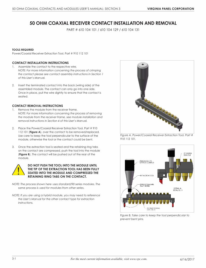
tools ReQuIRedpower/Coaxial Receiver Extraction Tool, part # 910 112 101
ContACt InstAllAtIon InstRuCtIons 1. Assemble the contact to the respective wire. NOTE: For more information concerning the process of crimping
the contact please see contact assembly instructions in Section 1 of this User’s Manual.
2. Insert the terminated contact into the back (wiring side) of the assembled module. The contact can only go into one side. Once in place, pull the wire slightly to ensure that the contact is seated.
ContACt RemovAl InstRuCtIons1. Remove the module from the receiver frame.
NOTE: For more information concerning the process of removing the module from the receiver frame, see module installation and removal instructions in Section 4 of this User’s Manual.
2. Place the Power/Coaxial Receiver Extraction Tool, Part # 910 112 101 (figure A), over the contact to be removed/replaced. Use care to keep the tool perpendicular to the surface of the module, otherwise the tool or the contact could be bent.
3. Once the extraction tool is seated and the retaining ring tabs on the contact are compressed, push the tool into the module (figure b). The contact will be pushed out of the rear of the module.
do not push the tool Into the module untIl the tIp of the extRACtIon tool hAs been fully seAted Into the module And CompRessed the RetAInIng RIng tAbs on the ContACt.
NOTE: The process shown here uses standard/90 series modules. The same process is used for modules from other series.
NOTE: If you are using a hybrid module, you may need to reference the User’s Manual for the other contact type for extraction instructions.
50 ohm CoAxIAl ReCeIveR ContACt InstAllAtIon And RemovAlpART # 610 104 101 / 610 104 129 / 610 104 131
Figure A. Power/Coaxial Receiver Extraction Tool, Part # 910 112 101.
Figure B. Take care to keep the tool perpendicular to prevent bent pins.
50 Ohm COAXIAL CONTACTS AND mODULES USER’S mANUAL: SECTION 3 vIRgInIA pAnel CoRpoRAtIon
6/16/20173-2 For the most current information available, visit www.vpc.com.
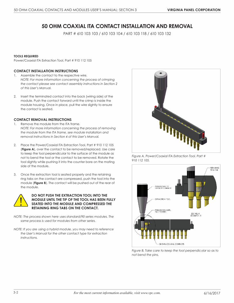
tools ReQuIRedpower/Coaxial ITA Extraction Tool, part # 910 112 105
ContACt InstAllAtIon InstRuCtIons1. Assemble the contact to the respective wire. NOTE: For more information concerning the process of crimping
the contact please see contact assembly instructions in Section 2 of this User’s Manual.
2. Insert the terminated contact into the back (wiring side) of the module. Push the contact forward until the crimp is inside the module housing. Once in place, pull the wire slightly to ensure the contact is seated.
ContACt RemovAl InstRuCtIons1. Remove the module from the ITA frame.
NOTE: For more information concerning the process of removing the module from the ITA frame, see module installation and removal instructions in Section 4 of this User’s Manual.
2. Place the Power/Coaxial ITA Extraction Tool, Part # 910 112 105 (figure A), over the contact to be removed/replaced. Use care to keep the tool perpendicular to the surface of the module as not to bend the tool or the contact to be removed. Rotate the tool slightly while pushing it into the counter bore on the mating side of the module.
3. Once the extraction tool is seated properly and the retaining ring tabs on the contact are compressed, push the tool into the module (figure b). The contact will be pushed out of the rear of the module.
do not push the extRACtIon tool Into the module untIl the tIp of the tool hAs been fully seAted Into the module And CompRessed the RetAInIng RIng tAbs on the ContACt.
NOTE: The process shown here uses standard/90 series modules. The same process is used for modules from other series.
NOTE: If you are using a hybrid module, you may need to reference the User’s Manual for the other contact type for extraction instructions.
50 ohm CoAxIAl ItA ContACt InstAllAtIon And RemovAlpART # 610 103 103 / 610 103 104 / 610 103 118 / 610 103 132
Figure B. Take care to keep the tool perpendicular so as to not bend the pins.
Figure A. Power/Coaxial ITA Extraction Tool, Part # 910 112 105.
50 Ohm COAXIAL CONTACTS AND mODULES USER’S mANUAL: SECTION 4 vIRgInIA pAnel CoRpoRAtIon
6/16/20174-1 For the most current information available, visit www.vpc.com.
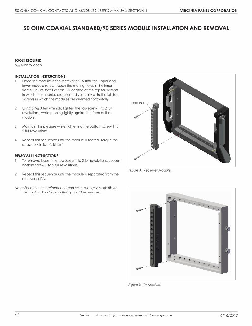
tools ReQuIRed3/32 Allen Wrench
InstAllAtIon InstRuCtIons1. Place the module in the receiver or ITA until the upper and
lower module screws touch the mating holes in the inner frame. Ensure that Position 1 is located at the top for systems in which the modules are oriented vertically or to the left for systems in which the modules are oriented horizontally.
2. Using a 3/32 Allen wrench, tighten the top screw 1 to 2 full revolutions, while pushing lightly against the face of the module.
3. Maintain this pressure while tightening the bottom screw 1 to 2 full revolutions.
4. Repeat this sequence until the module is seated. Torque the screw to 4 in-lbs [0.45 Nm].
RemovAl InstRuCtIons1. To remove, loosen the top screw 1 to 2 full revolutions. Loosen
bottom screw 1 to 2 full revolutions.
2. Repeat this sequence until the module is separated from the receiver or ITA.
Note: For optimum performance and system longevity, distribute the contact load evenly throughout the module.
50 ohm CoAxIAl stAndARd/90 seRIes module InstAllAtIon And RemovAl
Figure A. Receiver Module.
POSITION 1
Figure B. ITA Module.
50 Ohm COAXIAL CONTACTS AND mODULES USER’S mANUAL: SECTION 5 vIRgInIA pAnel CoRpoRAtIon
6/16/20175-1 For the most current information available, visit www.vpc.com.
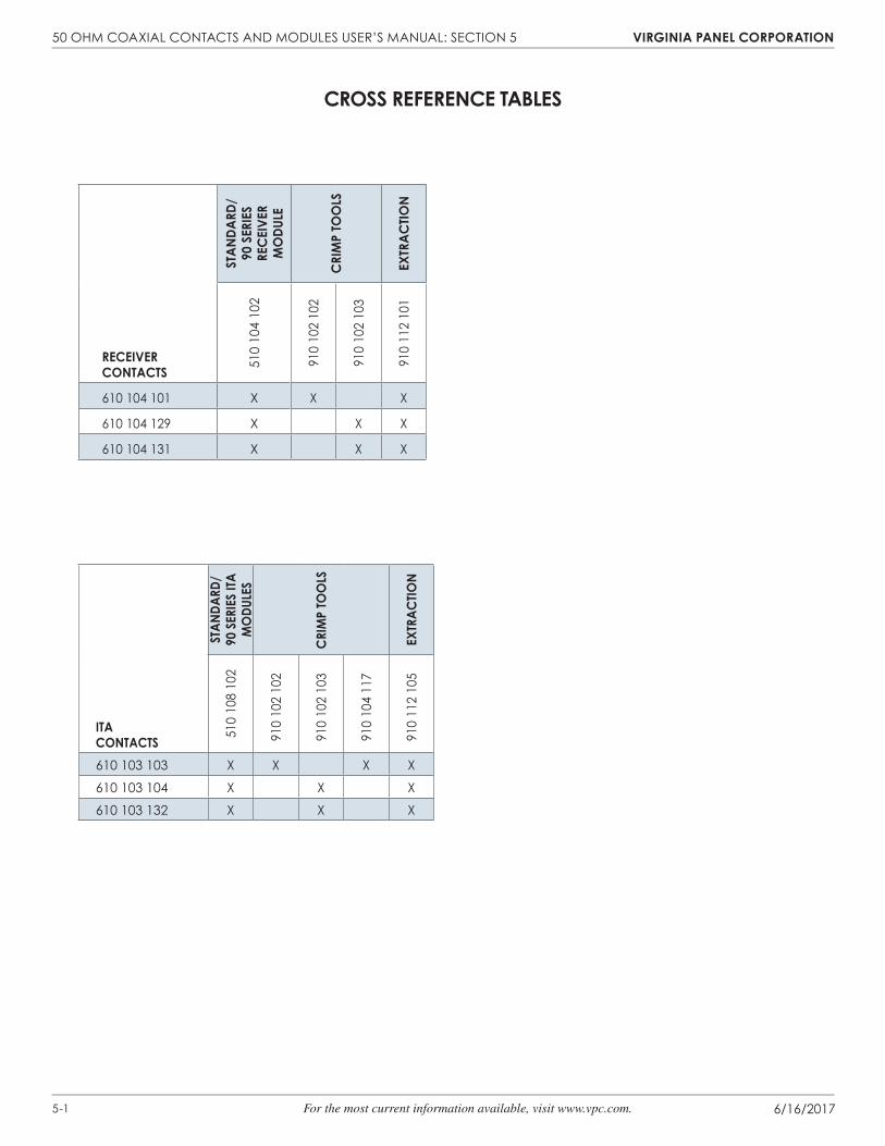
ReCeIveR ContACts
stAn
dARd
/ 90
seR
Ies
ReC
eIve
R m
odu
le
CRI
mp
too
ls
extR
ACtIo
n
510
104
102
910
102
102
910
102
103
910
112
101
610 104 101 X X X
610 104 129 X X X
610 104 131 X X X
CRoss RefeRenCe tAbles
ItA ContACts
stAn
dARd
/ 90
seR
Ies
ItA
mo
dule
s
CRI
mp
too
ls
extR
ACtIo
n
510
108
102
910
102
102
910
102
103
910
104
117
910
112
105
610 103 103 X X X X
610 103 104 X X X
610 103 132 X X X
50 Ohm COAXIAL CONTACTS AND mODULES USER’S mANUAL: SECTION 6 vIRgInIA pAnel CoRpoRAtIon
6/16/20176-1 For the most current information available, visit www.vpc.com.
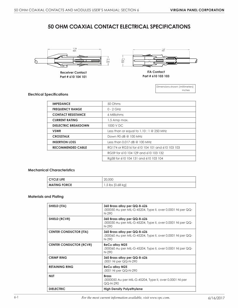
50 ohm CoAxIAl ContACt eleCtRICAl speCIfICAtIons
Receiver Contactpart # 610 104 101
ItA Contactpart # 610 103 103
Electrical Specifications
ImpedAnCe 50 Ohms
fReQuenCy RAnge 0 - 2 GHz
ContACt ResIstAnCe 6 Milliohms
CuRRent RAtIng 1.5 Amp max.
dIeleCtRIC bReAKdoWn 1000 v DC
vsWR Less than or equal to 1.10 : 1 @ 250 MHz
CRosstAlK Down 90 dB @ 100 MHz
InseRtIon loss Less than 0.017 dB @ 100 MHz
ReCommended CAble RG174 or RG316 for 610 104 101 and 610 103 103
RG59 for 610 104 129 and 610 103 132
Rg58 for 610 104 131 and 610 103 104
Mechanical Characteristics
CyCle lIfe 20,000
mAtIng foRCe 1.5 lbs [0.68 kg]
Materials and Plating
shIeld (ItA) 360 Brass alloy per QQ-B-626.000050 Au per MIL-G-45204, Type II, over 0.0001 Ni per QQ-N-290
shIeld (RCvR) 360 Brass alloy per QQ-B-626.000030 Au per MIL-G-45204, Type II, over 0.0001 Ni per QQ-N-290
CenteR ConduCtoR (ItA) 360 Brass alloy per QQ-B-626.000060 Au per MIL-G-45204, Type II, over 0.0001 Ni per QQ-N-290
CenteR ConduCtoR (RCvR) BeCu alloy M25.000060 Au per MIL-G-45204, Type II, over 0.0001 Ni per QQ-N-290
CRImp RIng 360 Brass alloy per QQ-B-626.0001 Ni per QQ-N-290
RetAInIng RIng BeCu alloy M25.0001 Ni per QQ-N-290
nut Brass.0000050 Au per MIL-G-45204, Type II, over 0.0001 Ni per QQ-N-290
dIeleCtRIC High Density Polyethylene
.2−3DIA.REF.
1.42REF.
1.24REF.
.211DIA
Dimensions shown: [millimeters] inches

50 Ohm COAXIAL CONTACTS AND mODULES USER’S mANUAL: SECTION 6 vIRgInIA pAnel CoRpoRAtIon
6/16/20176-2 For the most current information available, visit www.vpc.com.
50 ohm CoAxIAl ContACt eleCtRICAl speCIfICAtIons
VSWR
mARKeR fReQuenCy InseRtIon loss
1 100 MHz 1.042
2 150 MHz 1.051
3 200 MHz 1.066
4 250 MHz 1.091
50 Ohm Coaxial Plots for 610 103 103 with 610 104 101Typical Mated Pair Using RG174