assembly instructions - · pdf fileassembly instructions tzid-c & tzid-c200 ......
TRANSCRIPT
ASSEMBLY INSTRUCTIONSTZID-C & TZID-C200For LINEAR ACTUATOR types:
Copes-Vulcan Type 700Fisher Type 657/667
PN25068
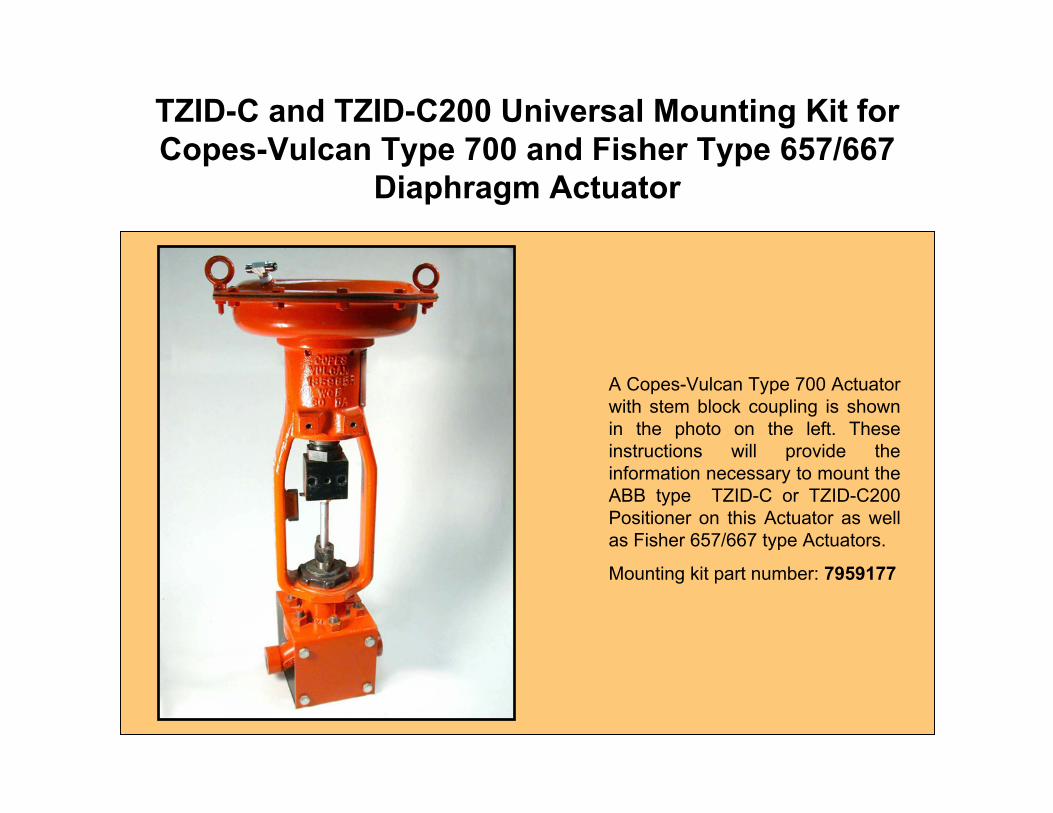
TZID-C and TZID-C200 Universal Mounting Kit for Copes-Vulcan Type 700 and Fisher Type 657/667
Diaphragm Actuator
A Copes-Vulcan Type 700 Actuator with stem block coupling is shown in the photo on the left. These instructions will provide the information necessary to mount the ABB type TZID-C or TZID-C200 Positioner on this Actuator as well as Fisher 657/667 type Actuators.
Mounting kit part number: 7959177
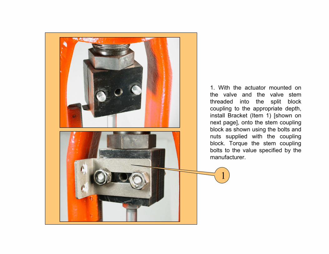
1. With the actuator mounted on the valve and the valve stem threaded into the split block coupling to the appropriate depth, install Bracket (Item 1) [shown on next page], onto the stem coupling block as shown using the bolts and nuts supplied with the coupling block. Torque the stem coupling bolts to the value specified by the manufacturer.
1

2. Locate Items 2 through 8 which get mounted to the Bracket (Item 1). The mounting of Item 1 is shown on the previous page.
3. Follow the procedures on the following page to mount all of the items pictured to the Bracket (Item 1), as shown on the next page.
1
24
6
7
8
35
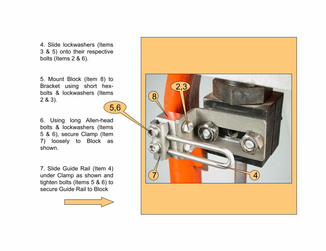
4. Slide lockwashers (Items 3 & 5) onto their respective bolts (Items 2 & 6).
5. Mount Block (Item 8) to Bracket using short hex-bolts & lockwashers (Items 2 & 3).
6. Using long Allen-head bolts & lockwashers (Items 5 & 6), secure Clamp (Item 7) loosely to Block as shown.
7. Slide Guide Rail (Item 4) under Clamp as shown and tighten bolts (Items 5 & 6) to secure Guide Rail to Block
2,3
47
85,6
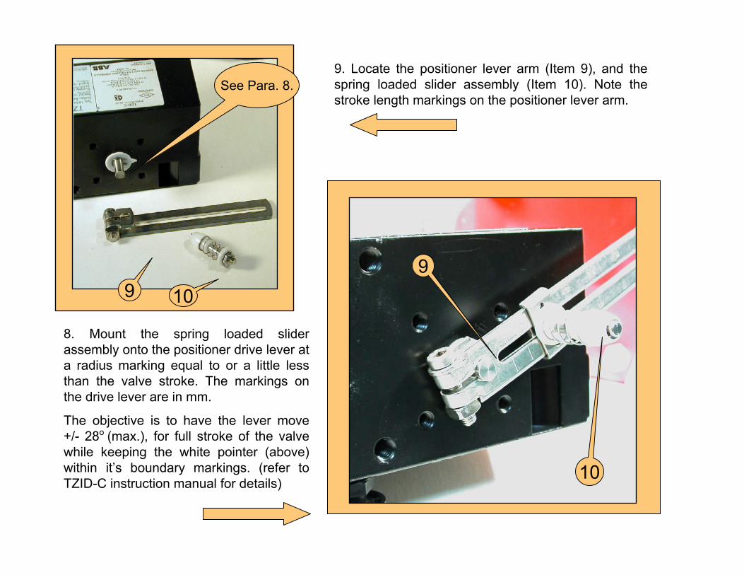
9. Locate the positioner lever arm (Item 9), and the spring loaded slider assembly (Item 10). Note the stroke length markings on the positioner lever arm.
9 10
8. Mount the spring loaded slider assembly onto the positioner drive lever at a radius marking equal to or a little less than the valve stroke. The markings on the drive lever are in mm.
The objective is to have the lever move +/- 28o (max.), for full stroke of the valve while keeping the white pointer (above) within it’s boundary markings. (refer to TZID-C instruction manual for details)
See Para. 8.
10
9
18
11,12,13
15,16,17
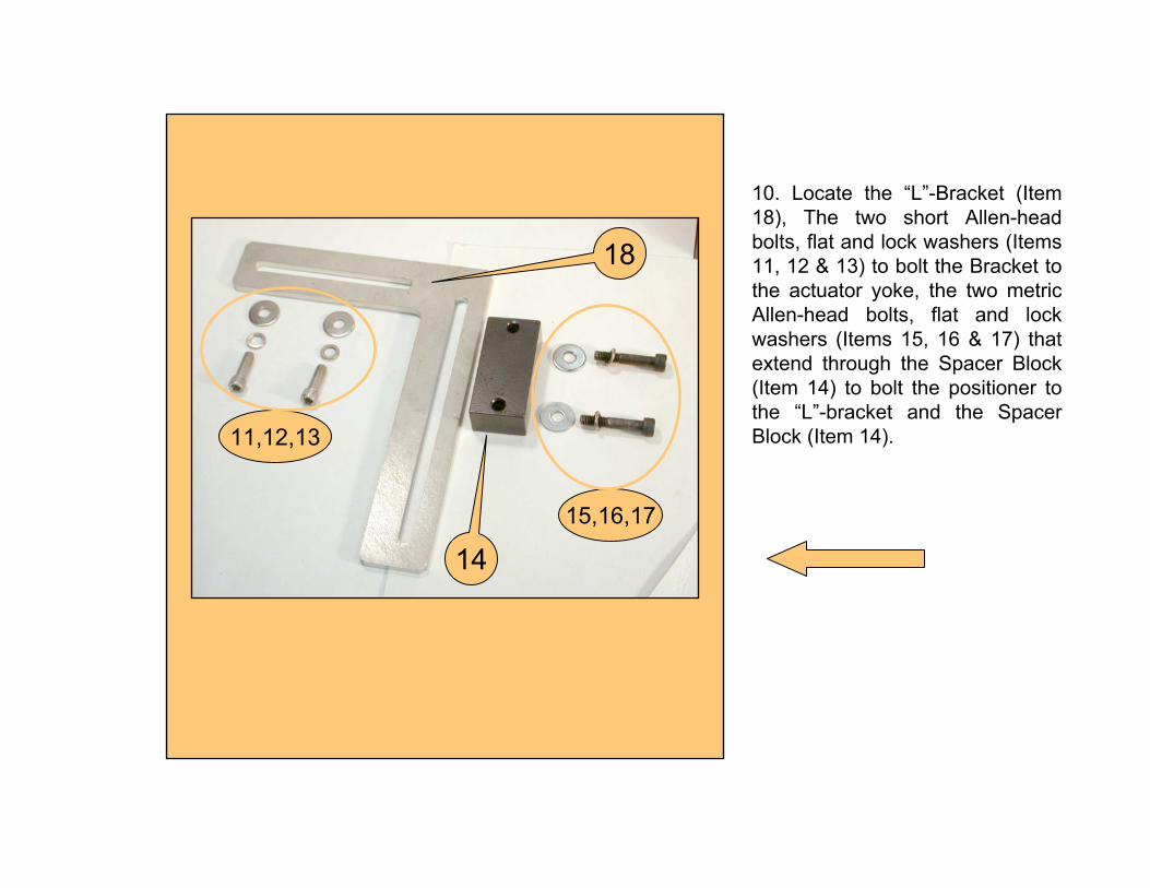
10. Locate the “L”-Bracket (Item 18), The two short Allen-head bolts, flat and lock washers (Items 11, 12 & 13) to bolt the Bracket to the actuator yoke, the two metric Allen-head bolts, flat and lock washers (Items 15, 16 & 17) that extend through the Spacer Block (Item 14) to bolt the positioner to the “L”-bracket and the Spacer Block (Item 14).
14
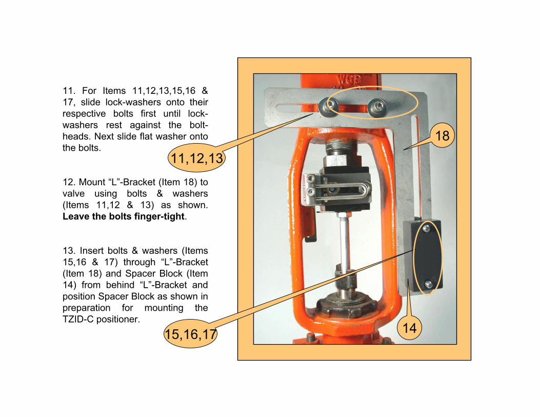
11. For Items 11,12,13,15,16 & 17, slide lock-washers onto their respective bolts first until lock-washers rest against the bolt-heads. Next slide flat washer onto the bolts.
12. Mount “L”-Bracket (Item 18) to valve using bolts & washers (Items 11,12 & 13) as shown. Leave the bolts finger-tight.
13. Insert bolts & washers (Items 15,16 & 17) through “L”-Bracket (Item 18) and Spacer Block (Item 14) from behind “L”-Bracket and position Spacer Block as shown in preparation for mounting the TZID-C positioner.
1811,12,13
1415,16,17
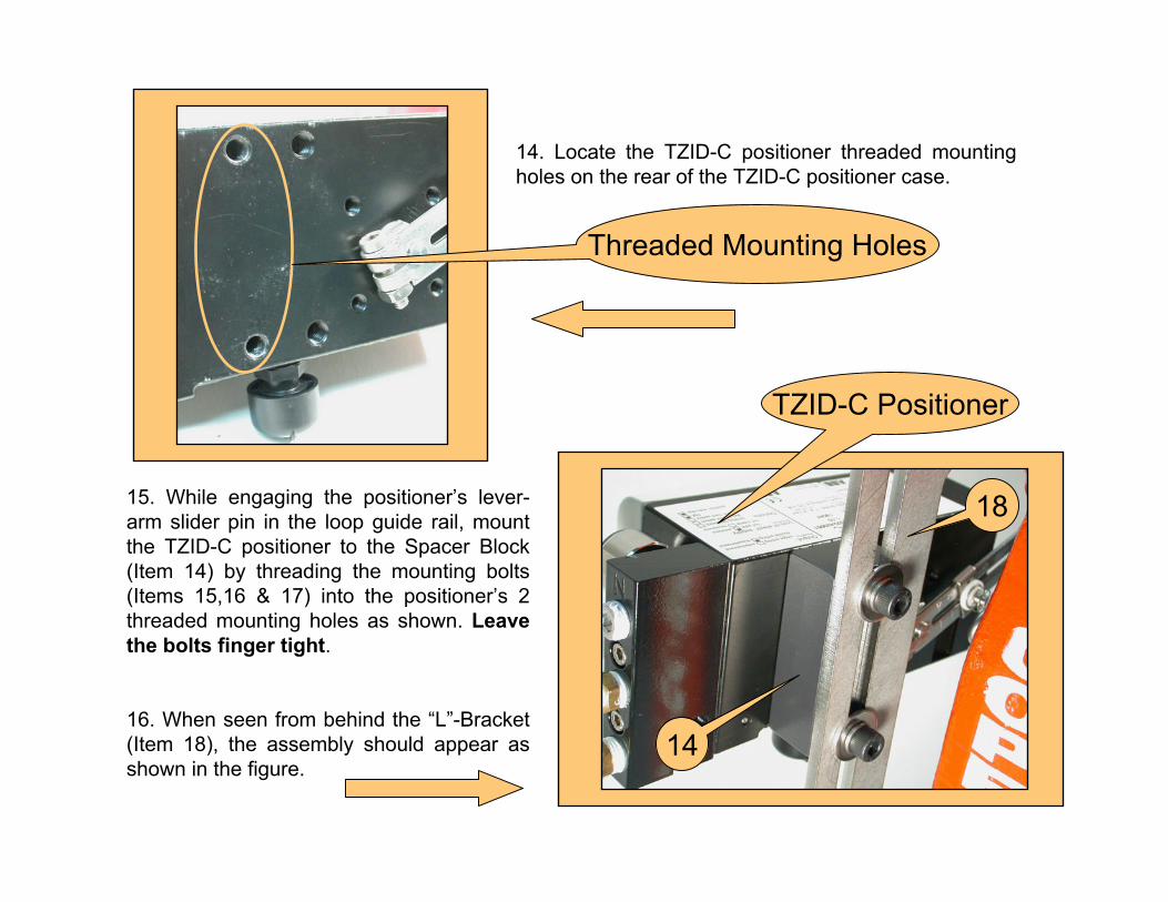
15. While engaging the positioner’s lever-arm slider pin in the loop guide rail, mount the TZID-C positioner to the Spacer Block (Item 14) by threading the mounting bolts (Items 15,16 & 17) into the positioner’s 2 threaded mounting holes as shown. Leave the bolts finger tight.
16. When seen from behind the “L”-Bracket (Item 18), the assembly should appear as shown in the figure.
14. Locate the TZID-C positioner threaded mounting holes on the rear of the TZID-C positioner case.
Threaded Mounting Holes
14
TZID-C Positioner
18
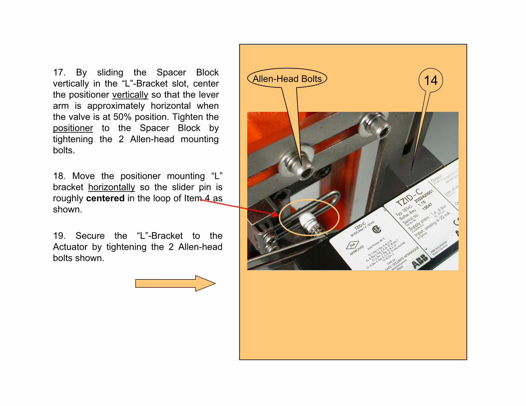
17. By sliding the Spacer Block vertically in the “L”-Bracket slot, center the positioner vertically so that the lever arm is approximately horizontal when the valve is at 50% position. Tighten the positioner to the Spacer Block by tightening the 2 Allen-head mounting bolts.
18. Move the positioner mounting “L” bracket horizontally so the slider pin is roughly centered in the loop of Item 4 as shown.
19. Secure the “L”-Bracket to the Actuator by tightening the 2 Allen-head bolts shown.
Allen-Head Bolts 14
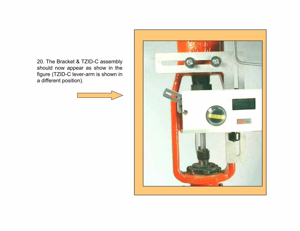
20. The Bracket & TZID-C assembly should now appear as show in the figure (TZID-C lever-arm is shown in a different position).
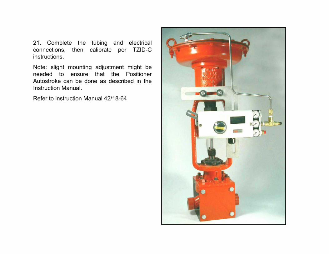
21. Complete the tubing and electrical connections, then calibrate per TZID-C instructions.
Note: slight mounting adjustment might be needed to ensure that the Positioner Autostroke can be done as described in the Instruction Manual.
Refer to instruction Manual 42/18-64

ABB Automation Products GmbHIndustriestr. 28D-65760 Eschborn GermanyTel: +49 (0) 6196 800 0Fax: +49 (0) 6196 800 1849
The Company's policy is one of continuous product improvement and the right is reserved to modify the information contained herein without notice.
© 2002 ABB Inc. Printed in USA
ABB Inc.125 East County Line RoadWarminster, PA 18974 USATel. 215-674-6000FAX: 215-674-7183
ABB Instrumentation LtdHoward Road, St. NeotsCambs. England, PE19 3EUTel. +44 (0) 1480-475-321FAX: +44 (0) 1480-217-948
ABB Instrumentation S.p.AVia Sempione 24320016 Pero (Milano) ItalyTel: +39 (02) 33928 1Fax: +39 (02) 33928 240
PN25
068