assembly instructions - horizon · pdf fileassembly instructions voyager e specifications ......
TRANSCRIPT

ASSEMBLY INSTRUCTIONSASSEMBLY INSTRUCTIONS
VOYAGER E SPECIFICATIONSOverall Length . . . . . . . . . . . . . . . . . . . . . . . . . . . . . . . . . . 33"Overall Height . . . . . . . . . . . . . . . . . . . . . . . . . . . . . . . . 121/4"Main Rotor Diameter . . . . . . . . . . . . . . . . . . . . . . . . . . . 385/8"Tail Rotor Diameter . . . . . . . . . . . . . . . . . . . . . . . . . . . . . . . 7"Gear Ratio . . . . . . . . . . . . . . . . . . . . . . . . . . . . . 23.33:1:1.5Speed Controller . . . . . . . NEA-300H High Frequency (included)Motor . . . . . . . . . . . . . . . . . . . . . . . . . . NHM-540ST (included)Battery . . . . . . . . . . . . . . . 8.4V 2000mAh NiCad (not Included)Weight . . . . . . . . . . . . . . . . . . . . . . . . . . . . . . 52.2 oz– 55.7 oz
(weight will vary based on the servos used)
The JR Voyager E is the first electric helicopter to utilize theJR 120-CCPM swashplate control system. This new systemfeatures a lower parts count and also reduces weight forincreased precision and improve performance. The Voyager’slightweight, yet highly rigid frame design enables theVoyager E to fly with power and control authority neverbefore seen in an electric helicopter.
* Gyro not Included.
2
Introduction . . . . . . . . . . . . . . . . . . . . . . . . . . . . . . . . . . . . . 3Voyager E Features . . . . . . . . . . . . . . . . . . . . . . . . . . . . . . . 4Additional Items Required to Complete the Voyager E . . . 4–5Hardware Identification . . . . . . . . . . . . . . . . . . . . . . . . . . . . 6Anatomy of the Voyager E . . . . . . . . . . . . . . . . . . . . . . . . . . 71-1 Preassembled Main Frame Components . . . . . . . . 81-2 Body Mount Attachment . . . . . . . . . . . . . . . . . . . . 81-A Mini Servo Mounting Plate Installation . . . . . . . . . 91-3 Landing Gear Assembly . . . . . . . . . . . . . . . . . . 101-4 Landing Gear Attachment . . . . . . . . . . . . . . . . . 102-1 Main Drive Gear Assembly Installation . . . . . . . 112-2 Swashplate and Washout Assembly Installation . . . 112-3 Rotor Head Installation . . . . . . . . . . . . . . . . . . . 122-4 Flybar Paddle Installation . . . . . . . . . . . . . . . . . . 122-5 Flybar Adjustment . . . . . . . . . . . . . . . . . . . . . . . 132-6 Control Rod Installation . . . . . . . . . . . . . . . . . . 132-7 Motor Installation . . . . . . . . . . . . . . . . . . . . . . . 143-1 Tail Gear Case Assembly . . . . . . . . . . . . . . . . . . 153-2 Tail Output Shaft/Pitch Slider Installation . . . . . . 153-3 Tail Rotor Assembly Installation . . . . . . . . . . . . . 163-4 Tail Pitch Control Lever Installation . . . . . . . . . . 163-5 Tail Boom Assembly Installation . . . . . . . . . . . . 173-6 Tail Rotor Blade Installation . . . . . . . . . . . . . . . 183-7 Vertical/Horizontal Fin Installation . . . . . . . . . . . 18Servo Installation and Linkage Suggestions . . . . . . . . . . . . 194-1 Aileron/Elevator Servo Installation (Standard Servo) . . 194-2 Pitch/Rudder Servo Installation (Standard Servo) . . . 194-A Aileron/Elevator Servo Installation (Mini Servo) . 204-B Pitch/Rudder Servo Installation (Mini Servo) . . . . 204-3 Tail Pitch Control Rod Assembly . . . . . . . . . . . . 214-4 Tail Control Rod Installation . . . . . . . . . . . . . . . . 214-5 Receiver/Gyro/Speed Controller Installationn . . . 22Understanding Swashplate Control Systems . . . . . . . . . . . 23How JR 120 CCPM Works . . . . . . . . . . . . . . . . . . . . . . . . 24CCPM Software Activation and Initial Adjustment . . . . . 25–30Important CCPM Programming Dos and Don'ts . . . . . . 31–32Speed Controller Setup . . . . . . . . . . . . . . . . . . . . . . . . . . . 33
5-1 Servo Arm Preparation and Installation . . . . . . . . 345-2 CCPM Servo Centering with the Sub-Trim Function . . 355-3 CCPM Linkage Connection . . . . . . . . . . . . . . . . . 365-4 Checking the Swashplate for Level . . . . . . . . . . . 375-5 Pitch-to-Aileron Mixing Adjustment with Travel Adjust . . 385-6 Pitch-to-Elevator Mixing Adjustment with Travel Adjust . 395-7 Tail Rotor Linkage Connection/Adjustment . . . . . 406-1 Trimming the Body/Canopy . . . . . . . . . . . . . . . . 416-2 Canopy Attachment . . . . . . . . . . . . . . . . . . . . . . 416-3 Body Mounting/Decel attachment . . . . . . . . . . . . 426-4 Body Attachment/Final Trimming . . . . . . . . . . . . 42Decal Placement . . . . . . . . . . . . . . . . . . . . . . . . . . . . . . . . 436-5 Main Rotor Blade Balancing . . . . . . . . . . . . . . . . 446-6 Main Rotor Blade Attachment . . . . . . . . . . . . . . 44Motor Connection/Battery Installation . . . . . . . . . . . . . . . . 45Final Servo Adjustment and Radio Setup . . . . . . . . . . . 46–48Radio System Operation/Helicopter Control Movements . . 49–50Final Preflight Check . . . . . . . . . . . . . . . . . . . . . . . . . . . . . 51General Maintenance . . . . . . . . . . . . . . . . . . . . . . . . . . . . . 52Preassembled Components . . . . . . . . . . . . . . . . . . . . . 53–54XP652 Heli Data Sheet Voyager E CCPM Initial Setup . . . . .55X-3810 Heli Data Sheet Voyager E CCPM Initial Setup . . . . 5610X Heli Data Sheet Voyager E CCPM Initial Setup . . . . 57–58Body Set/Landing Gear/Servo Plate Assembly Parts . . . . . . 59Main Rotor Head/Swashplate/Washout Unit/Main Gear
Assembly Parts . . . . . . . . . . . . . . . . . . . . . . . . . . . . . . 60Tail Rotor Assembly Parts . . . . . . . . . . . . . . . . . . . . . . . . . 61Main Frame/Motor/Intermediate Gear Assembly Parts . . . . 62Motor/Miscellaneous Assembly Parts . . . . . . . . . . . . . . . . 63Voyager Parts Listing . . . . . . . . . . . . . . . . . . . . . . . . . 64–70
INDEX
Section Description Page Section Description Page
3
INTRODUCTION
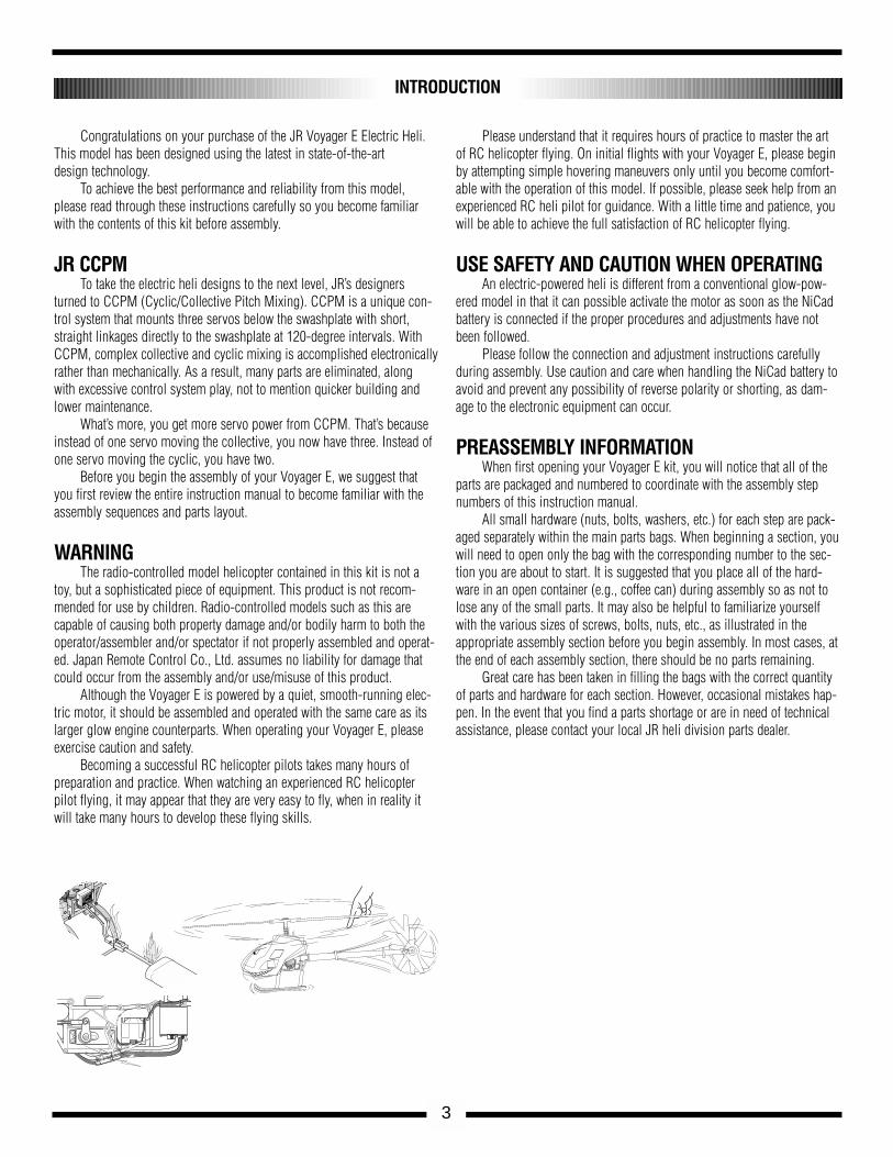
Congratulations on your purchase of the JR Voyager E Electric Heli. This model has been designed using the latest in state-of-the-art design technology.
To achieve the best performance and reliability from this model,please read through these instructions carefully so you become familiarwith the contents of this kit before assembly.
JR CCPMTo take the electric heli designs to the next level, JR’s designers
turned to CCPM (Cyclic/Collective Pitch Mixing). CCPM is a unique con-trol system that mounts three servos below the swashplate with short,straight linkages directly to the swashplate at 120-degree intervals. WithCCPM, complex collective and cyclic mixing is accomplished electronicallyrather than mechanically. As a result, many parts are eliminated, along with excessive control system play, not to mention quicker building andlower maintenance.
What’s more, you get more servo power from CCPM. That’s becauseinstead of one servo moving the collective, you now have three. Instead ofone servo moving the cyclic, you have two.
Before you begin the assembly of your Voyager E, we suggest thatyou first review the entire instruction manual to become familiar with theassembly sequences and parts layout.
WARNINGThe radio-controlled model helicopter contained in this kit is not a
toy, but a sophisticated piece of equipment. This product is not recom-mended for use by children. Radio-controlled models such as this arecapable of causing both property damage and/or bodily harm to both theoperator/assembler and/or spectator if not properly assembled and operat-ed. Japan Remote Control Co., Ltd. assumes no liability for damage thatcould occur from the assembly and/or use/misuse of this product.
Although the Voyager E is powered by a quiet, smooth-running elec-tric motor, it should be assembled and operated with the same care as its larger glow engine counterparts. When operating your Voyager E, pleaseexercise caution and safety.
Becoming a successful RC helicopter pilots takes many hours ofpreparation and practice. When watching an experienced RC helicopterpilot flying, it may appear that they are very easy to fly, when in reality itwill take many hours to develop these flying skills.
Please understand that it requires hours of practice to master the artof RC helicopter flying. On initial flights with your Voyager E, please beginby attempting simple hovering maneuvers only until you become comfort-able with the operation of this model. If possible, please seek help from anexperienced RC heli pilot for guidance. With a little time and patience, youwill be able to achieve the full satisfaction of RC helicopter flying.
USE SAFETY AND CAUTION WHEN OPERATINGAn electric-powered heli is different from a conventional glow-pow-
ered model in that it can possible activate the motor as soon as the NiCadbattery is connected if the proper procedures and adjustments have notbeen followed.
Please follow the connection and adjustment instructions carefullyduring assembly. Use caution and care when handling the NiCad battery toavoid and prevent any possibility of reverse polarity or shorting, as dam-age to the electronic equipment can occur.
PREASSEMBLY INFORMATIONWhen first opening your Voyager E kit, you will notice that all of the
parts are packaged and numbered to coordinate with the assembly stepnumbers of this instruction manual.
All small hardware (nuts, bolts, washers, etc.) for each step are pack-aged separately within the main parts bags. When beginning a section, youwill need to open only the bag with the corresponding number to the sec-tion you are about to start. It is suggested that you place all of the hard-ware in an open container (e.g., coffee can) during assembly so as not tolose any of the small parts. It may also be helpful to familiarize yourselfwith the various sizes of screws, bolts, nuts, etc., as illustrated in theappropriate assembly section before you begin assembly. In most cases, atthe end of each assembly section, there should be no parts remaining.
Great care has been taken in filling the bags with the correct quantityof parts and hardware for each section. However, occasional mistakes hap-pen. In the event that you find a parts shortage or are in need of technicalassistance, please contact your local JR heli division parts dealer.
FETHIGHT FREQUENCY
SPEED CONTROLLER
8.4V
NEA-300H
JRREMORE
CONTROL
MADE IN JAPAN
4
ADDITIONAL ITEMS REQUIRED TO COMPLETE THE JR VOYAGER E
VOYAGER E FEATURES
CCPM (Cyclic/Collective Pitch Mixing):More Accurate: Control system play is greatly reduced.Simpler: Fewer links to setup and maintain.More Powerful: Collective has three times the servo power,
cyclic has double.
Heavy-Duty Frame DesignProvides excellent durability.
Belt-Driven Tail Rotor DesignProvides easy adjustment and low maintenance.
Precision Ball Bearings at All Critical LocationsProvide low wear, high precision, and reduced maintenance.
Straight Blade Axle Rotor Head DesignProvides high responsiveness and solid blade tracking. Reduces
potential boom strikes.
Low Drag Flybar PaddlesProvide quick, yet smooth, cyclic response at all flight speeds.Heavy-Duty Tail BoomProvides increased structural rigidity and improved tail rotor precision.
Prefinished Main Rotor BladesProvide easy assembly with excellent flight characteristics.
Superior Parts Fit and FinishMake assembly trouble-free and enjoyable.
Powerful NHM-540ST MotorProvides excellent power for agile flying.
High Quality NEA-300H Speed ControllerOffers smooth throttle response and efficient current flow.
Durable Polyethylene Canopy w/DecalsReduces assembly time and eliminates the need for paintings.
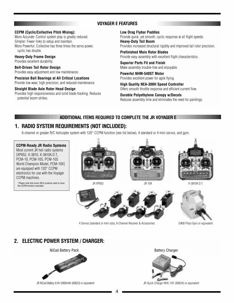
CCPM-Ready JR Radio SystemsMost current JR heli radio systems[XP652, X-3810, X-3810A.D.T., PCM-10, PCM-10S, PCM-10SWorld Champion Model, PCM-10X]are equipped with 120° CCPM electronics for use with the VoyagerCCPM machines.
*Please note that some 3810 systems need to havethe CCPM function activated.
G400 Piezo Gyro or equivalent4 Servos (standard or mini size), 6-Channel Receiver & Accessories
JR XP652 JR 10X
2. ELECTRIC POWER SYSTEM / CHARGER:
NiCad Battery Pack Battery Charger
JR Quick Charger NHC-101 (60624) or equivalentJR NiCad Battery 8.4V-2000mAh (60623) or equivalent
1. RADIO SYSTEM REQUIREMENTS (NOT INCLUDED):6-channel or greater R/C helicopter system with 120° CCPM function (see list below), 4 standard or 4 mini servos, and gyro.
X-3810A.D.T.
5
Double-Sided ServoMounting Tape
Nylon Wire Ties tosecure radio wires
Super Horn (3 pcs) w/Screws
(or equivalent)
Whip Antenna (optional)
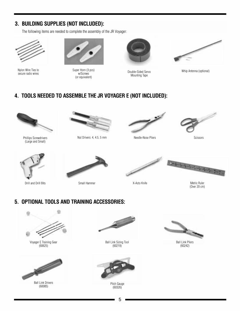
3. BUILDING SUPPLIES (NOT INCLUDED):The following items are needed to complete the assembly of the JR Voyager:
Needle-Nose Pliers
Drill and Drill Bits
Ball Link Pliers(60242)
Ball Link Sizing Tool(60219)
Small Hammer X-Acto Knife Metric Ruler(Over 20 cm)
ScissorsPhillips Screwdrivers(Large and Small)
Nut Drivers: 4, 4.5, 5 mm
4. TOOLS NEEDED TO ASSEMBLE THE JR VOYAGER E (NOT INCLUDED):
5. OPTIONAL TOOLS AND TRAINING ACCESSORIES:
Pitch Gauge(60326)
Ball Link Drivers(60085)
Voyager E Training Gear(60625)
6
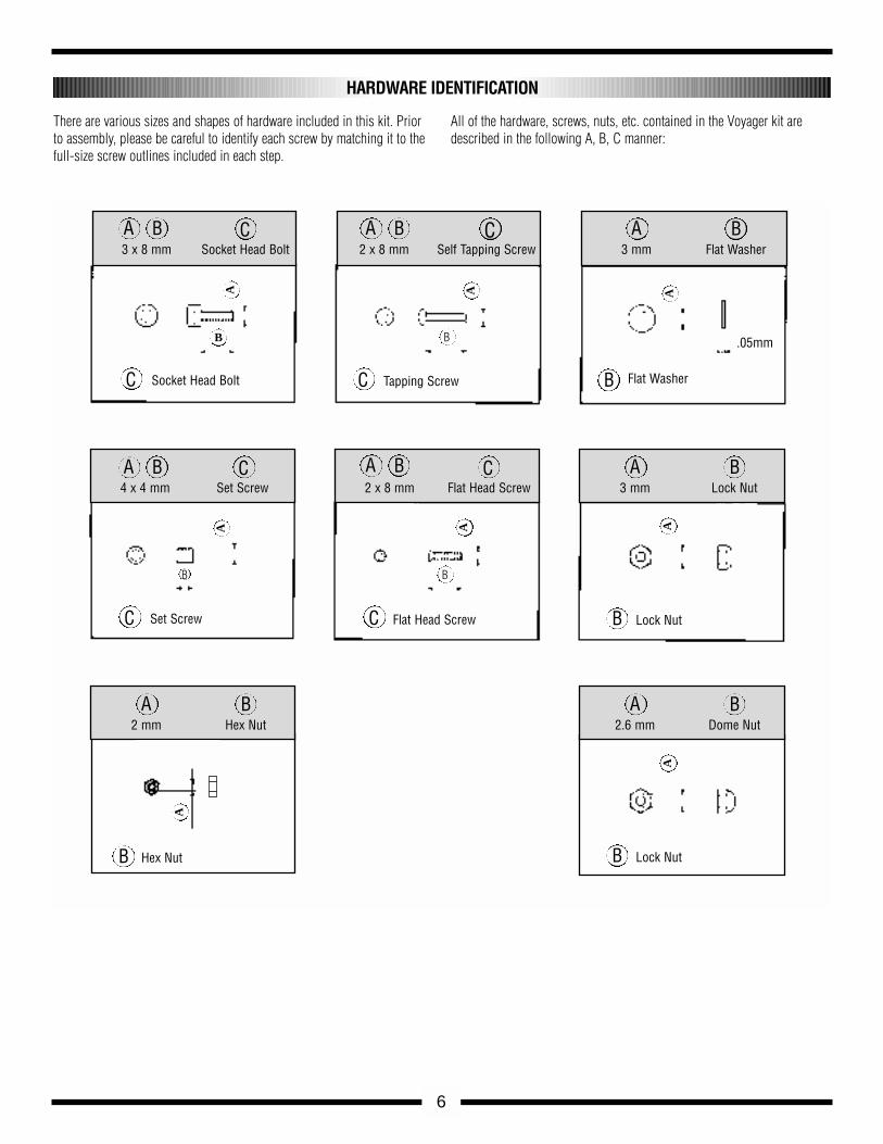
There are various sizes and shapes of hardware included in this kit. Priorto assembly, please be careful to identify each screw by matching it to thefull-size screw outlines included in each step.
All of the hardware, screws, nuts, etc. contained in the Voyager kit aredescribed in the following A, B, C manner:
HARDWARE IDENTIFICATION
Socket Head Bolt Tapping Screw Flat Washer
.05mm
Flat Head Screw Lock Nut
C C
CA
B
A A
B
B
C3 x 8 mm Socket Head Bolt
Set ScrewC
A
B
C
CA A
2 x 8 mm Flat Head Screw
2 x 8 mm Self Tapping ScrewA B
B
3 mm Flat Washer
A B
B
3 mm Lock Nut
Hex Nut
A B
B
2 mm Hex Nut
C4 x 4 mm Set Screw
A B A B
A B A B
Lock Nut
A
A B
B
2.6 mm Dome Nut
A
FETHIGHT FREQUENCY
SPEED CONTROLLER
8.4V
NEA-300H
JRREMORECONTROL
MADE IN JAPAN
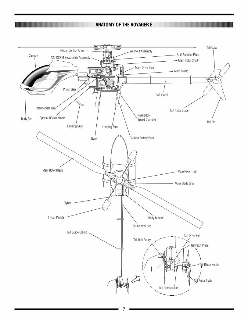
CanopyFlybar Control Arms Washout Assembly
Anti-Rotation Plate
Main Rotor Shaft
Main Drive GearMain Frame
Tail Case
Tail Fin
Tail Rotor Blade
Tail Boom
NEH-300HSpeed Conroller
NiCad Battery Pack
Landing Strut
Gyro
Landing Skid
Special RS540 Motor
Intermediate Gear
Body Set
Main Rotor Blade Main Rotor Hub
Main Blade Grip
Flybar
Flybar Paddle
Tail Guide Clamp
Body Mount
Tail Control Rod
Tail Belt PulleyTail Drive Belt
Tail Pitch Plate
Tail Blade Holder
Tail Rotor Blade
Tail Output Shaft
Pinion Gear
120 CCPM Swashplate Assembly
7
ANATOMY OF THE VOYAGER E
1-1
1-2
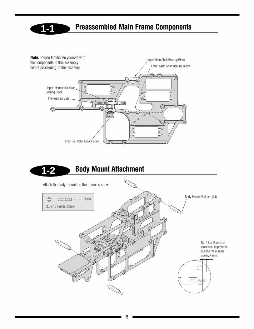
Upper Main Shaft Bearing Block
Lower Main Shaft Bearing Block
Front Tail Rotor Drive Pulley
Upper Intermediate Gear Bearing Block
Intermediate Gear
Body Mount 25.5 mm (x4)
The 2.6 x 15 mm set screw should protrude past the main frameside by 4 mm.
2.6 x 15 mm Set Screw
............ 4 pcs
Attach the body mounts to the frame as shown
8
Preassembled Main Frame Components
Body Mount Attachment
Attach the body mounts to the frame as shown.
Note: Please familiarize yourself withthe components in this assemblybefore proceeding to the next step.
1-A
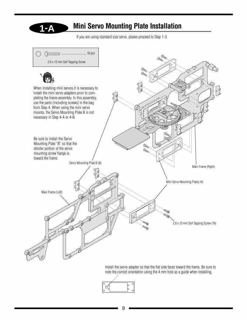
Servo Mounting Plate B (8)Main Frame (Right)
Mini Servo Mounting Plates (4)
2.6 x 12 mm Self Tapping Screw (16)
Main Frame (Left)
................................. 16 pcs
2.6 x 12 mm Self Tapping Screw
9
Mini Servo Mounting Plate Installation
When installing mini servos,it is necessary toinstall the mini servo adapters prior to com-pleting the frame assembly. In this assembly,use the parts (including screws) in the bagfrom Step 4. When using the mini servomounts, the Servo Mounting Plate B is notnecessary in Step 4-A or 4-B.
Install the servo adapter so that the flat side faces toward the frame. Be sure tonote the correct orientation using the 4 mm hole as a guide when installing.
Be sure to install the ServoMounting Plate “B” so that theshorter portion of the servomounting screw flange istoward the frame.
If you are using standard size servo, please proceed to Step 1-3.
1-3
1-4
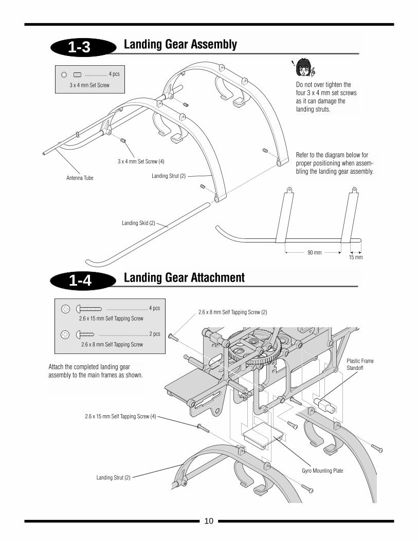
90 mm15 mm
Landing Strut (2)
Landing Skid (2)
Antenna Tube
3 x 4 mm Set Screw (4)
.................. 4 pcs
3 x 4 mm Set Screw
2.6 x 8 mm Self Tapping Screw (2)
2.6 x 15 mm Self Tapping Screw (4)
Landing Strut (2)Gyro Mounting Plate
Plastic Frame Standoff
................................. 4 pcs
2.6 x 15 mm Self Tapping Screw
....................................... 2 pcs
2.6 x 8 mm Self Tapping Screw
10
Landing Gear Assembly
Landing Gear Attachment
Do not over tighten thefour 3 x 4 mm set screwsas it can damage thelanding struts.
Refer to the diagram below forproper positioning when assem-bling the landing gear assembly.
Attach the completed landing gearassembly to the main frames as shown.
2-1
2-2
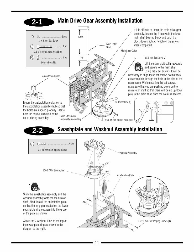
Short
Long
Main Rotor Shaft
Main Shaft Collar
3 x 3 mm Set Screw (2)
Autorotation Collar
Main Drive Gear/Autorotation Assembly 2.6 x 15 mm Socket Head Bolt
................................. 2 pcs
............... 1 pc
................................... 1 pc
3 x 3 mm Set Screw
2.6 x 15 mm Socket Head Bolt
2.6 mm Lock Nut
Washout Assembly
Anti-Rotation Plate
120 CCPM Swashplate
2.6 x 8 mm Self Tapping Screws (4)
.................................... 4 pcs
2.6 x 8 mm Self Tapping Screw
Use Threadlock (2)
11
Main Drive Gear Assembly Installation
Swashplate and Washout Assembly Installation
Mount the autorotation collar on tothe autorotation assembly hub so thatthe holes are aligned properly. Pleasenote the correct direction of the collar during assembly.
If it is difficult to insert the main drive gearassembly, loosen the 4 screws in the lowermain shaft bearing block and push theblock down slightly. Retighten the screwswhen completed.
Lift the main shaft collar upwardsand secure to the main shaftusing the 2 set screws. It will be
necessary to align these set screws so that theyare accessible through the hole in the side of themain frame. While securing the set screws,make sure that you are pushing down on themain rotor shaft so that there will be no up/downplay in the main shaft once the collar is secured.
Slide the swashplate assembly and thewashout assembly onto the main rotorshaft. Next, install the antirotation plateso that the long pin located on the lowerswashplate ring engages into the groveof the plate as shown.
Attach the 2 washout links to the top ofthe swashplate ring as shown in the diagram to the right.
2-3
2-4
JR PROPO
JR PROPO
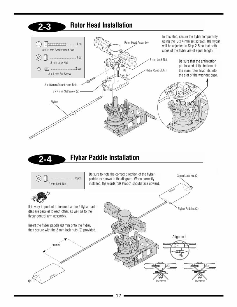
Rotor Head Assembly
3 mm Lock Nut
Flybar Control Arm
3 x 18 mm Socket Head Bolt
3 x 4 mm Set Screw (2)
Flybar
........... 1 pc
.................................... 1 pc
................................. 2 pcs
3 x 18 mm Socket Head Bolt
3 mm Lock Nut
3 x 4 mm Set Screw
.................................. 2 pcs
3 mm Lock Nut
3 mm Lock Nut (2)
Flybar Paddles (2)
IncorrectIncorrect
80 mm
JR Propo
JR Propo
12
Rotor Head Installation
Flybar Paddle Installation
In this step, secure the flybar temporarilyusing the 3 x 4 mm set screws. The flybarwill be adjusted in Step 2-5 so that bothsides of the flybar are of equal length.
Be sure that the antirotationpin located at the bottom ofthe main rotor head fits intothe slot of the washout base.
It is very important to insure that the 2 flybar pad-dles are parallel to each other, as well as to theflybar control arm assembly.
Insert the flybar paddle 80 mm onto the flybar,then secure with the 3 mm lock nuts (2) provided.
Be sure to note the correct direction of the flybarpaddle as shown in the diagram. When correctlyinstalled, the words “JR Propo” should face upward.
Alignment
A B
2-5
2-6
A B
C
B
C
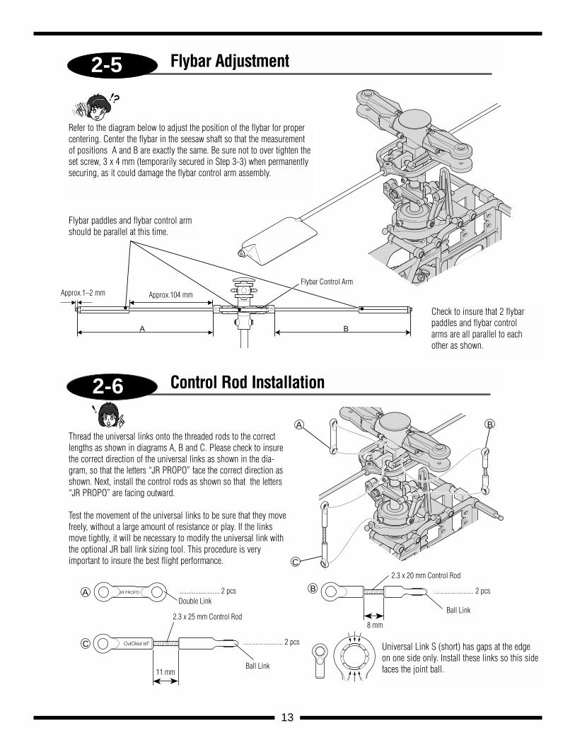
A JR PROPO
JR PROPO
Flybar Control Arm
2.3 x 20 mm Control Rod
Ball Link
Ball Link
2.3 x 25 mm Control Rod
11 mm
Double Link....................... 2 pcs
....................... 2 pcs
....................... 2 pcs
13
Refer to the diagram below to adjust the position of the flybar for propercentering. Center the flybar in the seesaw shaft so that the measurementof positions A and B are exactly the same. Be sure not to over tighten theset screw, 3 x 4 mm (temporarily secured in Step 3-3) when permanentlysecuring, as it could damage the flybar control arm assembly.
Flybar Adjustment
Control Rod Installation
Check to insure that 2 flybarpaddles and flybar controlarms are all parallel to eachother as shown.
Flybar paddles and flybar control armshould be parallel at this time.
Thread the universal links onto the threaded rods to the correctlengths as shown in diagrams A, B and C. Please check to insurethe correct direction of the universal links as shown in the dia-gram, so that the letters “JR PROPO” face the correct direction asshown. Next, install the control rods as shown so that the letters“JR PROPO” are facing outward.
Test the movement of the universal links to be sure that they movefreely, without a large amount of resistance or play. If the linksmove tightly, it will be necessary to modify the universal link withthe optional JR ball link sizing tool. This procedure is very important to insure the best flight performance.
Universal Link S (short) has gaps at the edgeon one side only. Install these links so this sidefaces the joint ball.
Approx.1–2 mm Approx.104 mm
8 mm
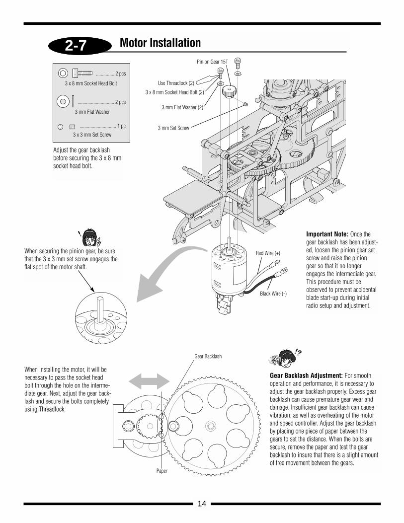
2-7
............... 2 pcs
3 x 8 mm Socket Head Bolt Use Threadlock (2)
.............................. 2 pcs
3 mm Flat Washer
.............................. 1 pc
3 x 3 mm Set Screw
Pinion Gear 15T
3 x 8 mm Socket Head Bolt (2)
3 mm Flat Washer (2)
3 mm Set Screw
Gear Backlash
Paper
Red Wire (+)
Black Wire (-)
14
When securing the pinion gear, be surethat the 3 x 3 mm set screw engages theflat spot of the motor shaft.
Motor Installation
When installing the motor, it will benecessary to pass the socket headbolt through the hole on the interme-diate gear. Next, adjust the gear back-lash and secure the bolts completelyusing Threadlock.
Adjust the gear backlashbefore securing the 3 x 8 mmsocket head bolt.
Gear Backlash Adjustment: For smoothoperation and performance, it is necessary toadjust the gear backlash properly. Excess gearbacklash can cause premature gear wear anddamage. Insufficient gear backlash can causevibration, as well as overheating of the motorand speed controller. Adjust the gear backlashby placing one piece of paper between thegears to set the distance. When the bolts aresecure, remove the paper and test the gearbacklash to insure that there is a slight amountof free movement between the gears.
Important Note: Once thegear backlash has been adjust-ed, loosen the pinion gear setscrew and raise the piniongear so that it no longerengages the intermediate gear.This procedure must beobserved to prevent accidentalblade start-up during initialradio setup and adjustment.
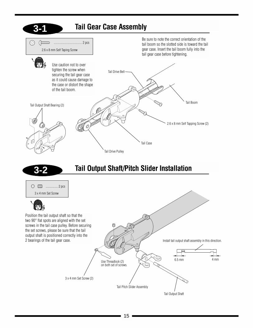
3-1
3-2
..................................... 2 pcs
2.6 x 8 mm Self Taping Screw
Tail Boom
2.6 x 8 mm Self Tapping Screw (2)
Tail Case
Tail Drive Pulley
Tail Drive Belt
Tail Output Shaft Bearing (2)
................ 2 pcs
3 x 4 mm Set Screw
3 x 4 mm Set Screw (2)
Use Threadlock (2) on both set of screws.
Tail Pitch Slider Assembly
Tail Output Shaft
Install tail output shaft assembly in this direction.
6.5 mm 4 mm
15
Tail Gear Case Assembly
Tail Output Shaft/Pitch Slider Installation
Use caution not to overtighten the screw whensecuring the tail gear caseas it could cause damage tothe case or distort the shapeof the tail boom.
Be sure to note the correct orientation of thetail boom so the slotted side is toward the tailgear case. Insert the tail boom fully into thetail gear case before tightening.
Position the tail output shaft so that the two 90° flat spots are aligned with the setscrews in the tail case pulley. Before securingthe set screws, please be sure that the tailoutput shaft is positioned correctly into the 2 bearings of the tail gear case.
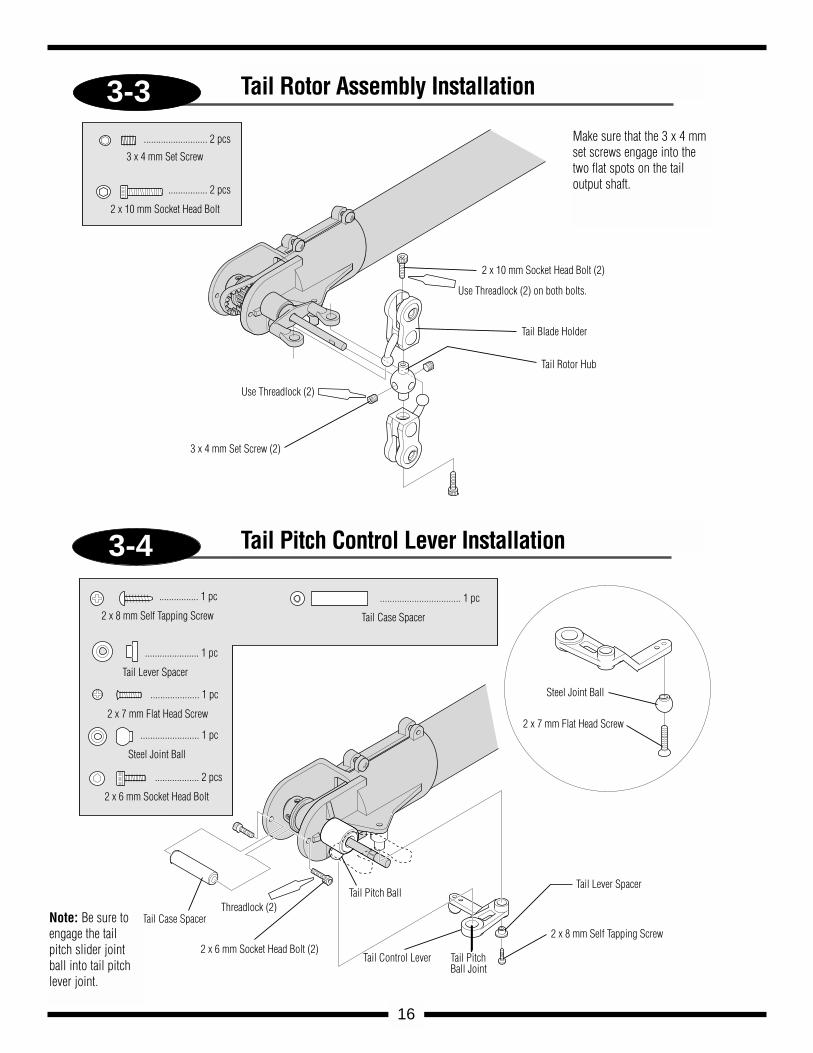
3-3
3-4
.......................... 2 pcs
3 x 4 mm Set Screw
................ 2 pcs
2 x 10 mm Socket Head Bolt
Use Threadlock (2)
3 x 4 mm Set Screw (2)
2 x 10 mm Socket Head Bolt (2)
Use Threadlock (2) on both bolts.
Tail Blade Holder
Tail Rotor Hub
................ 1 pc
2 x 8 mm Self Tapping Screw
...................... 1 pc
Tail Lever Spacer
.................... 1 pc
2 x 7 mm Flat Head Screw
........................ 1 pc
Steel Joint Ball
.................. 2 pcs
2 x 6 mm Socket Head Bolt
................................. 1 pc
Tail Case Spacer
Tail Case Spacer
2 x 6 mm Socket Head Bolt (2)Tail Control Lever
Tail Lever Spacer
2 x 8 mm Self Tapping Screw
2 x 7 mm Flat Head Screw
Steel Joint Ball
Tail Pitch Ball
Tail Pitch Ball Joint
Threadlock (2)
16
Tail Rotor Assembly Installation
Tail Pitch Control Lever Installation
Make sure that the 3 x 4 mmset screws engage into thetwo flat spots on the tail output shaft.
Note: Be sure toengage the tailpitch slider jointball into tail pitchlever joint.
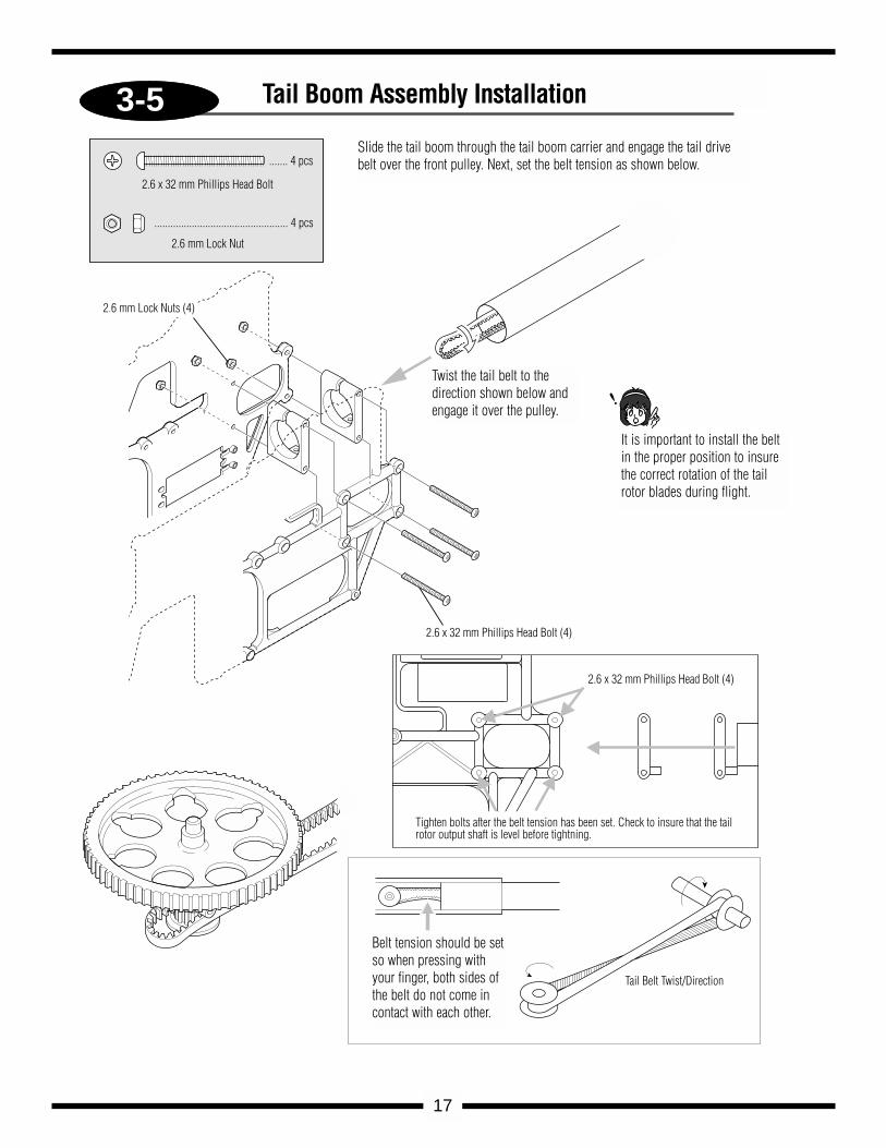
3-5
....... 4 pcs
2.6 x 32 mm Phillips Head Bolt
.................................................. 4 pcs
2.6 mm Lock Nut
2.6 mm Lock Nuts (4)
2.6 x 32 mm Phillips Head Bolt (4)
2.6 x 32 mm Phillips Head Bolt (4)
Tighten bolts after the belt tension has been set. Check to insure that the tail rotor output shaft is level before tightning.
Tail Belt Twist/Direction
17
Tail Boom Assembly Installation
Slide the tail boom through the tail boom carrier and engage the tail drivebelt over the front pulley. Next, set the belt tension as shown below.
Twist the tail belt to thedirection shown below andengage it over the pulley.
It is important to install the beltin the proper position to insurethe correct rotation of the tailrotor blades during flight.
Belt tension should be setso when pressing withyour finger, both sides ofthe belt do not come incontact with each other.
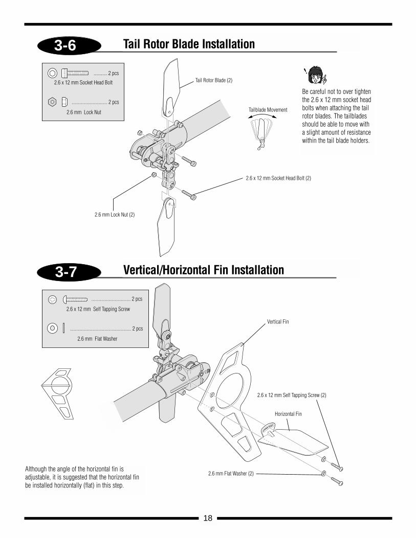
3-6
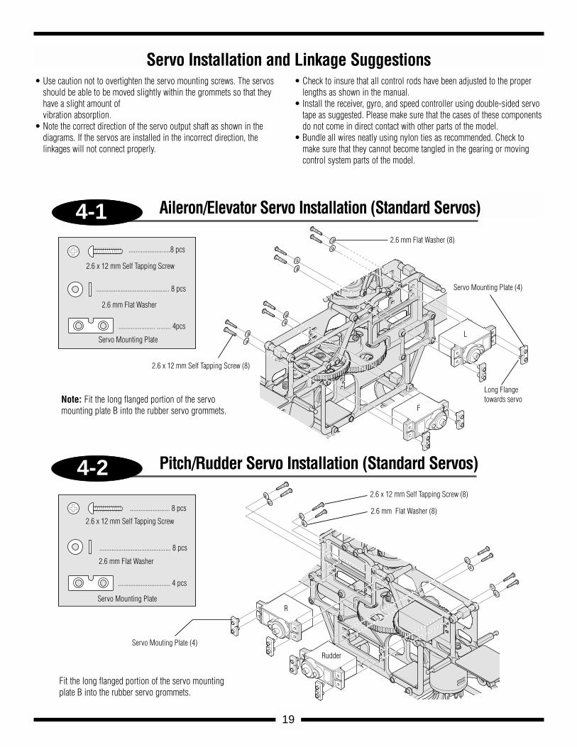
3-7
........... 2 pcs
2.6 x 12 mm Socket Head Bolt
............................. 2 pcs
2.6 mm Lock Nut
2.6 mm Lock Nut (2)
Tail Rotor Blade (2)
Tailblade Movement
2.6 x 12 mm Socket Head Bolt (2)
................................ 2 pcs
2.6 x 12 mm Self Tapping Screw
.................................................. 2 pcs
2.6 mm Flat Washer
Vertical Fin
Horizontal Fin
2.6 x 12 mm Self Tapping Screw (2)
2.6 mm Flat Washer (2)
18
Tail Rotor Blade Installation
Vertical/Horizontal Fin Installation
Be careful not to over tightenthe 2.6 x 12 mm socket headbolts when attaching the tailrotor blades. The tailbladesshould be able to move witha slight amount of resistancewithin the tail blade holders.
Although the angle of the horizontal fin isadjustable, it is suggested that the horizontal finbe installed horizontally (flat) in this step.
4-1
4-2
........................8 pcs
2.6 x 12 mm Self Tapping Screw
.......................................... 8 pcs
2.6 mm Flat Washer
..................... ........ 4pcs
Servo Mounting Plate
2.6 mm Flat Washer (8)
Servo Mounting Plate (4)
Long Flangetowards servo
2.6 x 12 mm Self Tapping Screw (8)
....................... 8 pcs
2.6 x 12 mm Self Tapping Screw
......................................... 8 pcs
2.6 mm Flat Washer
.............................. 4 pcs
Servo Mounting Plate
Servo Mouting Plate (4)
2.6 x 12 mm Self Tapping Screw (8)
2.6 mm Flat Washer (8)
L
F
R
Rudder
19
Aileron/Elevator Servo Installation (Standard Servos)
Pitch/Rudder Servo Installation (Standard Servos)
Servo Installation and Linkage Suggestions • Use caution not to overtighten the servo mounting screws. The servos
should be able to be moved slightly within the grommets so that theyhave a slight amount of vibration absorption.
• Note the correct direction of the servo output shaft as shown in the diagrams. If the servos are installed in the incorrect direction, the linkages will not connect properly.
• Check to insure that all control rods have been adjusted to the properlengths as shown in the manual.
• Install the receiver, gyro, and speed controller using double-sided servotape as suggested. Please make sure that the cases of these componentsdo not come in direct contact with other parts of the model.
• Bundle all wires neatly using nylon ties as recommended. Check tomake sure that they cannot become tangled in the gearing or movingcontrol system parts of the model.
Note: Fit the long flanged portion of the servomounting plate B into the rubber servo grommets.
Fit the long flanged portion of the servo mountingplate B into the rubber servo grommets.
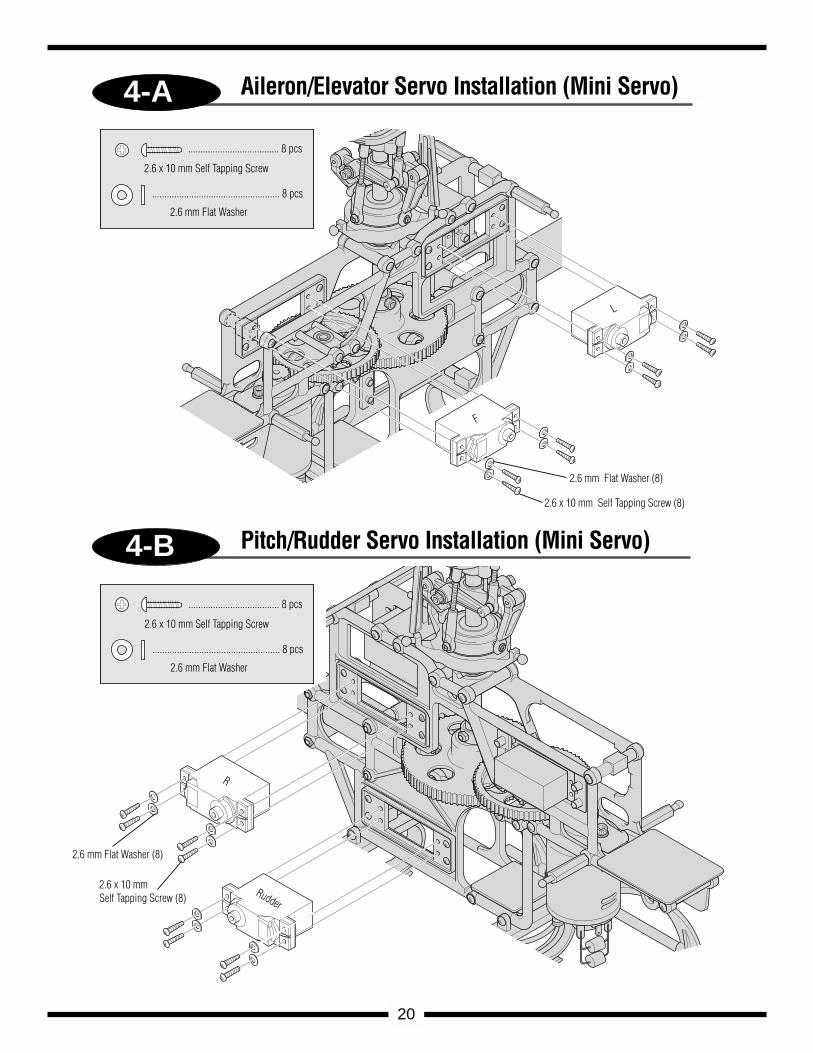
4-A
4-B
..................................... 8 pcs
2.6 x 10 mm Self Tapping Screw
.................................................... 8 pcs
2.6 mm Flat Washer
..................................... 8 pcs
2.6 x 10 mm Self Tapping Screw
.................................................... 8 pcs
2.6 mm Flat Washer
2.6 mm Flat Washer (8)
F
L
2.6 x 10 mm Self Tapping Screw (8)
2.6 x 10 mm Self Tapping Screw (8)
2.6 mm Flat Washer (8)
R
Rudder
20
Aileron/Elevator Servo Installation (Mini Servo)
Pitch/Rudder Servo Installation (Mini Servo)
JR PROPO
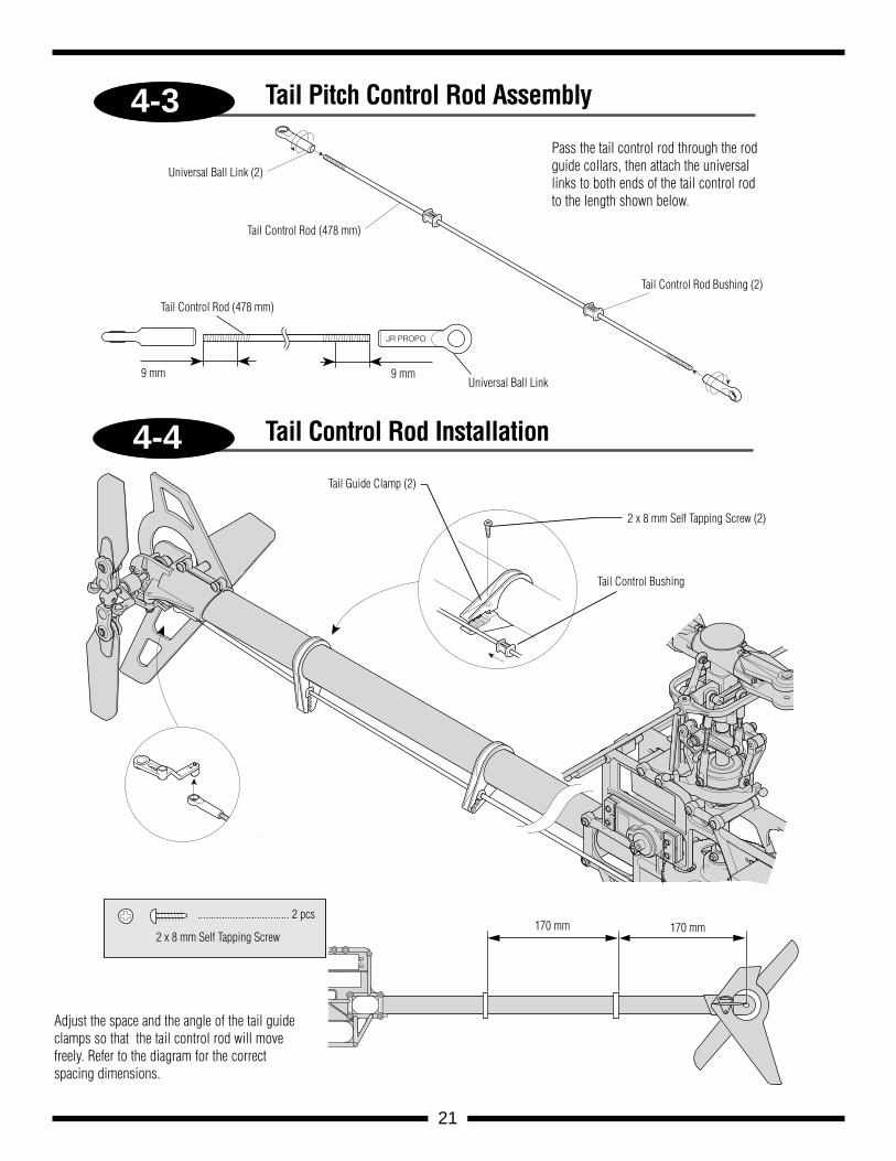
4-3
4-4
Universal Ball Link (2)
Tail Control Rod (478 mm)
Tail Control Rod Bushing (2)
Universal Ball Link9 mm9 mm
Tail Control Rod (478 mm)
Tail Guide Clamp (2)
2 x 8 mm Self Tapping Screw (2)
Tail Control Bushing
.................................. 2 pcs
2 x 8 mm Self Tapping Screw170 mm 170 mm
21
Tail Pitch Control Rod Assembly
Tail Control Rod Installation
Pass the tail control rod through the rodguide collars, then attach the universallinks to both ends of the tail control rodto the length shown below.
Adjust the space and the angle of the tail guideclamps so that the tail control rod will movefreely. Refer to the diagram for the correctspacing dimensions.
4-5
FET
HIGHT FREQUENCY
SPEED CONTROLLER
8.4V
NEA-300H
JR REMORECONTROL
MADE IN JAPAN
Receiver
Double-Sided Servo Mounting Tape
NEA-300H Speed Controller
Servo Mounting Tape
Gyro
Servo Mounting Tape
NiCad Battery Pack
Servos wires secured using nylon ties
Double-Sided Tape
Speed Controller Switch
R600JR
22
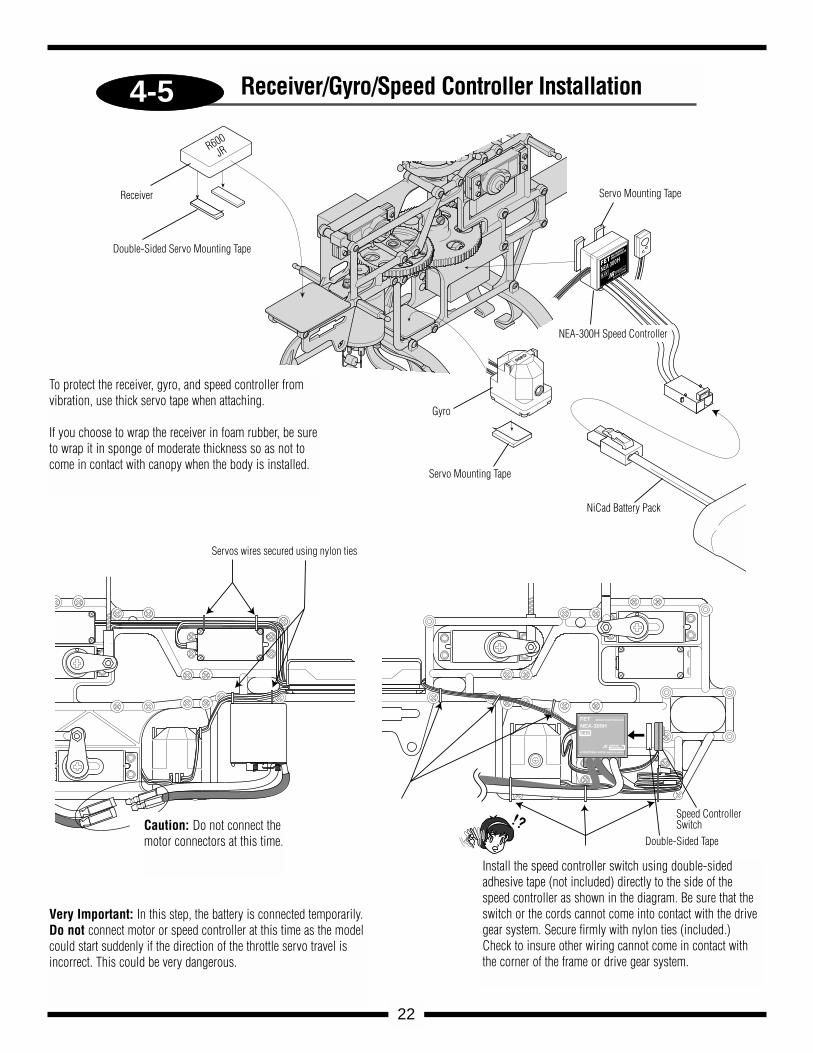
Receiver/Gyro/Speed Controller Installation
To protect the receiver, gyro, and speed controller fromvibration, use thick servo tape when attaching.
If you choose to wrap the receiver in foam rubber, be sureto wrap it in sponge of moderate thickness so as not tocome in contact with canopy when the body is installed.
Very Important: In this step, the battery is connected temporarily.Do not connect motor or speed controller at this time as the modelcould start suddenly if the direction of the throttle servo travel isincorrect. This could be very dangerous.
Caution: Do not connect themotor connectors at this time.
Install the speed controller switch using double-sidedadhesive tape (not included) directly to the side of thespeed controller as shown in the diagram. Be sure that theswitch or the cords cannot come into contact with the drivegear system. Secure firmly with nylon ties (included.)Check to insure other wiring cannot come in contact withthe corner of the frame or drive gear system.
120 3-SERVO CCPM SWASHPLATE MIXING
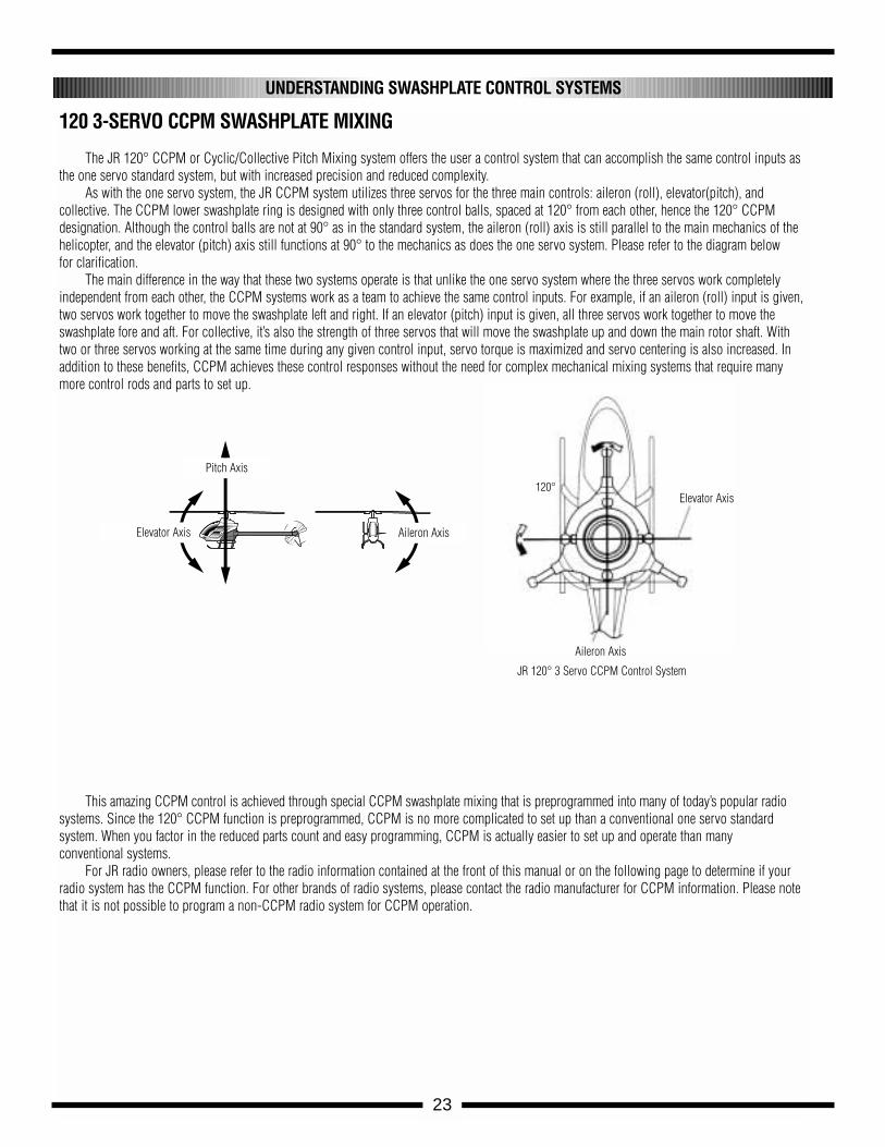
The JR 120° CCPM or Cyclic/Collective Pitch Mixing system offers the user a control system that can accomplish the same control inputs asthe one servo standard system, but with increased precision and reduced complexity.
As with the one servo system, the JR CCPM system utilizes three servos for the three main controls: aileron (roll), elevator(pitch), and collective. The CCPM lower swashplate ring is designed with only three control balls, spaced at 120° from each other, hence the 120° CCPM designation. Although the control balls are not at 90° as in the standard system, the aileron (roll) axis is still parallel to the main mechanics of thehelicopter, and the elevator (pitch) axis still functions at 90° to the mechanics as does the one servo system. Please refer to the diagram below for clarification.
The main difference in the way that these two systems operate is that unlike the one servo system where the three servos work completelyindependent from each other, the CCPM systems work as a team to achieve the same control inputs. For example, if an aileron (roll) input is given,two servos work together to move the swashplate left and right. If an elevator (pitch) input is given, all three servos work together to move theswashplate fore and aft. For collective, it’s also the strength of three servos that will move the swashplate up and down the main rotor shaft. Withtwo or three servos working at the same time during any given control input, servo torque is maximized and servo centering is also increased. Inaddition to these benefits, CCPM achieves these control responses without the need for complex mechanical mixing systems that require manymore control rods and parts to set up.
This amazing CCPM control is achieved through special CCPM swashplate mixing that is preprogrammed into many of today’s popular radiosystems. Since the 120° CCPM function is preprogrammed, CCPM is no more complicated to set up than a conventional one servo standard system. When you factor in the reduced parts count and easy programming, CCPM is actually easier to set up and operate than many conventional systems.
For JR radio owners, please refer to the radio information contained at the front of this manual or on the following page to determine if yourradio system has the CCPM function. For other brands of radio systems, please contact the radio manufacturer for CCPM information. Please notethat it is not possible to program a non-CCPM radio system for CCPM operation.
UNDERSTANDING SWASHPLATE CONTROL SYSTEMS
Elevator Axis120°
JR 120° 3 Servo CCPM Control System
Aileron Axis
23
Pitch Axis
Elevator Axis Aileron Axis
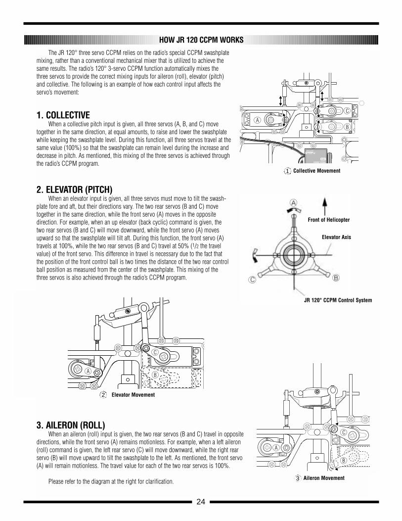
The JR 120° three servo CCPM relies on the radio’s special CCPM swashplatemixing, rather than a conventional mechanical mixer that is utilized to achieve thesame results. The radio’s 120° 3-servo CCPM function automatically mixes thethree servos to provide the correct mixing inputs for aileron (roll), elevator (pitch)and collective. The following is an example of how each control input affects theservo’s movement:
1. COLLECTIVEWhen a collective pitch input is given, all three servos (A, B, and C) move
together in the same direction, at equal amounts, to raise and lower the swashplatewhile keeping the swashplate level. During this function, all three servos travel at thesame value (100%) so that the swashplate can remain level during the increase anddecrease in pitch. As mentioned, this mixing of the three servos is achieved throughthe radio’s CCPM program.
2. ELEVATOR (PITCH)When an elevator input is given, all three servos must move to tilt the swash-
plate fore and aft, but their directions vary. The two rear servos (B and C) movetogether in the same direction, while the front servo (A) moves in the oppositedirection. For example, when an up elevator (back cyclic) command is given, thetwo rear servos (B and C) will move downward, while the front servo (A) movesupward so that the swashplate will tilt aft. During this function, the front servo (A)travels at 100%, while the two rear servos (B and C) travel at 50% (1/2 the travelvalue) of the front servo. This difference in travel is necessary due to the fact thatthe position of the front control ball is two times the distance of the two rear controlball position as measured from the center of the swashplate. This mixing of thethree servos is also achieved through the radio’s CCPM program.
3. AILERON (ROLL) When an aileron (roll) input is given, the two rear servos (B and C) travel in opposite
directions, while the front servo (A) remains motionless. For example, when a left aileron(roll) command is given, the left rear servo (C) will move downward, while the right rearservo (B) will move upward to tilt the swashplate to the left. As mentioned, the front servo(A) will remain motionless. The travel value for each of the two rear servos is 100%.
Please refer to the diagram at the right for clarification.
HOW JR 120 CCPM WORKS
24
8.4V
NEA-300H
JRREMORECONTROL
MADE IN JAPAN
AB
C
AB
C
A
B
C
Front of Helicopter
Elevator Axis
JR 120° CCPM Control System
Collective Movement
Elevator Movement2
1
Aileron Movement3
CCPM SOFTWARE ACTIVATION AND INITIAL ADJUSTMENT
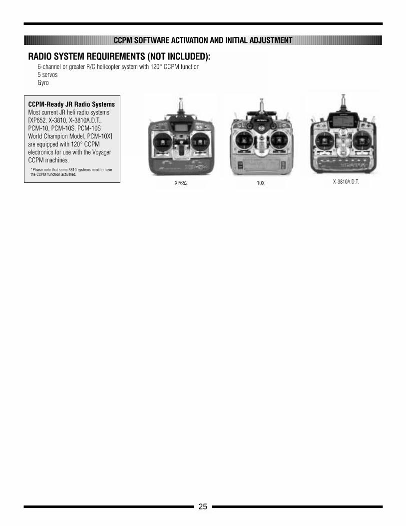
RADIO SYSTEM REQUIREMENTS (NOT INCLUDED):6-channel or greater R/C helicopter system with 120° CCPM function5 servos Gyro
XP652 10X X-3810A.D.T.
25
CCPM-Ready JR Radio SystemsMost current JR heli radio systems[XP652, X-3810, X-3810A.D.T., PCM-10, PCM-10S, PCM-10SWorld Champion Model, PCM-10X]are equipped with 120° CCPM electronics for use with the VoyagerCCPM machines.
*Please note that some 3810 systems need to havethe CCPM function activated.
26
The following activation and setup procedure should be used for all JR XP652 systems. Please note that the XF622 and XP642 6 channel systems donot have the required CCPM software.
Prior to activating the CCPM function, it is first suggested that the data reset function be performed to reset the desired model number to be usedback to the factory default settings.
Caution: Prior to performing the data reset function, it will be necessary to select the desired model number to be used.
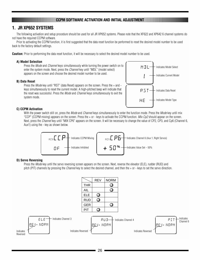
A) Model SelectionPress the Mode and Channel keys simultaneously while turning the power switch on toenter the system mode. Next, press the Channel key until “MDL” (model select)appears on the screen and choose the desired model number to be used.
B) Data ResetPress the Mode key until “RST” (data Reset) appears on the screen. Press the + and -keys simultaneously to reset the current model. A high-pitched beep will indicate thatthe reset was successful. Press the Mode and Channel keys simultaneously to exit thesystem mode.
C) CCPM ActivationWith the power switch still on, press the Mode and Channel keys simultaneously to enter the function mode. Press the Mode key until mix“CCP” (CCPM mixing) appears on the screen. Press the + or - keys to activate the CCPM function. Mix Cp2 should appear on the screen.Next, press the Channel key until “MIX CP6” appears on the screen. It will be necessary to change the value of CP2, CP3, and Cp6 (Channel 6,Aux1) using the - key as shown below.
D) Servo ReversingPress the Mode key until the servo reversing screen appears on the screen. Next, reverse the elevator (ELE), rudder (RUD) and pitch (PIT) channels by pressing the Channel key to select the desired channel, and then the + or - keys to set the servo direction.
CCPM SOFTWARE ACTIVATION AND INITIAL ADJUSTMENT
1. JR XP652 SYSTEMS
mdl
1
Indicates Model Select
Indicates Current Model
rst
he
Indicates Data Reset
Indicates Model Type
mixCCP
of
Indicates CCPM Mixing
Indicates Inhibited
ele
rev.norm
rud
rev.norm
pit
rev.norm
mixCP6
+ 50%
Indicates Channel 6 (Aux 1, Right Servos)
Indicates Value Set – 50%
Indicates Channel 3
IndicatesReversed
Indicates Channel 4
Indicates Reversed
IndicatesChannel 6
Indicates Reversed
REV NORM
THR
AIL
ELE
RUD
GER
PIT
27
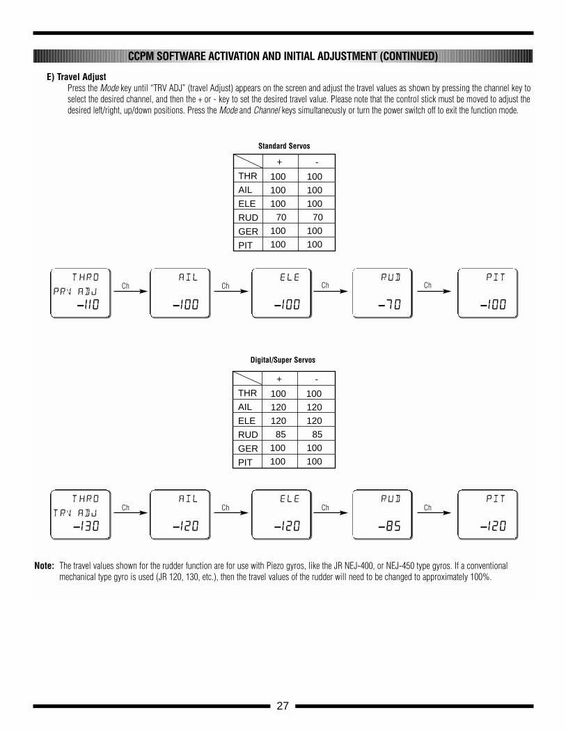
E) Travel AdjustPress the Mode key until “TRV ADJ” (travel Adjust) appears on the screen and adjust the travel values as shown by pressing the channel key toselect the desired channel, and then the + or - key to set the desired travel value. Please note that the control stick must be moved to adjust thedesired left/right, up/down positions. Press the Mode and Channel keys simultaneously or turn the power switch off to exit the function mode.
Note: The travel values shown for the rudder function are for use with Piezo gyros, like the JR NEJ-400, or NEJ-450 type gyros. If a conventionalmechanical type gyro is used (JR 120, 130, etc.), then the travel values of the rudder will need to be changed to approximately 100%.
CCPM SOFTWARE ACTIVATION AND INITIAL ADJUSTMENT (CONTINUED)
thro
trv adj
-130
ail
-120
ele
-120
rud
-85
pit
-120
thro
prv adj
-110
ail
-100
ele
-100
rud
-70
pit
-100
Ch
Ch
Ch
Ch
Ch
Ch
Ch
Ch
Standard Servos
+ -
THR
AIL
ELE
RUD
GER
PIT
100 100
100 100
100 100
70 70
100 100
100 100
Digital/Super Servos
+ -
THR
AIL
ELE
RUD
GER
PIT
100 100
120 120
120 120
85 85
100 100
100 100
28
The following activation and setup procedure should be used for all JR X-3810 and X-3810A.D.T. systems.
Note: Some early X-3810 systems will require the activation of the CCPM software. It’s easy to identify if your system has the CCPM function acti-vated by identifying if the “SWASH TYP” function appears in the system mode as shown in Section A below. Please refer to Section A toaccess the system mode.
Prior to activating the CCPM function, it is first suggested that the data reset function be performed to reset the desired model number to beused back to the factory default settings.
Caution: Prior to performing the data reset function, it will be necessary to select the desired model number to be used.
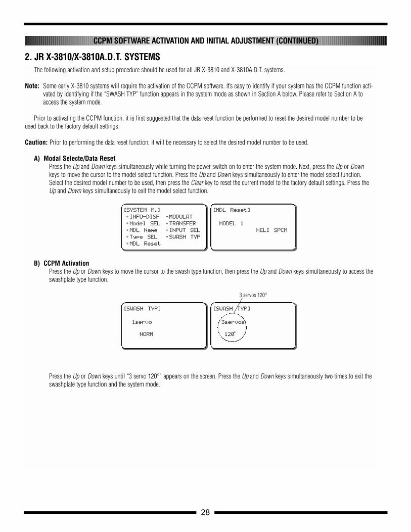
A) Modal Selecte/Data ResetPress the Up and Down keys simultaneously while turning the power switch on to enter the system mode. Next, press the Up or Downkeys to move the cursor to the model select function. Press the Up and Down keys simultaneously to enter the model select function.Select the desired model number to be used, then press the Clear key to reset the current model to the factory default settings. Press theUp and Down keys simultaneously to exit the model select function.
B) CCPM ActivationPress the Up or Down keys to move the cursor to the swash type function, then press the Up and Down keys simultaneously to access theswashplate type function.
Press the Up or Down keys until “3 servo 120°” appears on the screen. Press the Up and Down keys simultaneously two times to exit theswashplate type function and the system mode.
CCPM SOFTWARE ACTIVATION AND INITIAL ADJUSTMENT (CONTINUED)
2. JR X-3810/X-3810A.D.T. SYSTEMS
[SYSTEM M.]
• INFO-DISP
• Model SEL
• MDL Name
• Type SEL
• MDL Reset
• MODULAT
• TRANSFER
• INPUT SEL
• SWASH TYP
[MDL Reset]
MODEL 1
HELI SPCM
[SWASH TYP]
1servo
NORM
[SWASH TYP]
3servos
120•
3 servos 120°
29
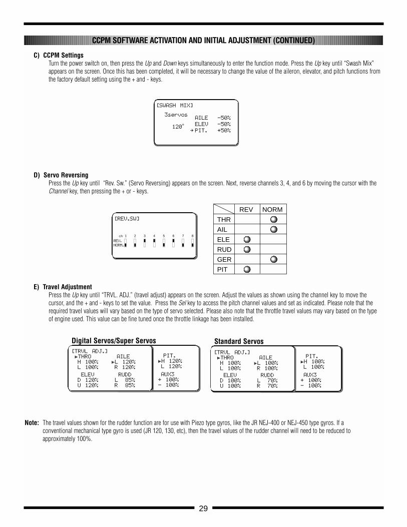
C) CCPM SettingsTurn the power switch on, then press the Up and Down keys simultaneously to enter the function mode. Press the Up key until “Swash Mix”appears on the screen. Once this has been completed, it will be necessary to change the value of the aileron, elevator, and pitch functions fromthe factory default setting using the + and - keys.
D) Servo ReversingPress the Up key until “Rev. Sw.” (Servo Reversing) appears on the screen. Next, reverse channels 3, 4, and 6 by moving the cursor with theChannel key, then pressing the + or - keys.
E) Travel AdjustmentPress the Up key until “TRVL. ADJ.” (travel adjust) appears on the screen. Adjust the values as shown using the channel key to move the cursor, and the + and - keys to set the value. Press the Sel key to access the pitch channel values and set as indicated. Please note that therequired travel values will vary based on the type of servo selected. Please also note that the throttle travel values may vary based on the typeof engine used. This value can be fine tuned once the throttle linkage has been installed.
Note: The travel values shown for the rudder function are for use with Piezo type gyros, like the JR NEJ-400 or NEJ-450 type gyros. If aconventional mechanical type gyro is used (JR 120, 130, etc), then the travel values of the rudder channel will need to be reduced to approximately 100%.
CCPM SOFTWARE ACTIVATION AND INITIAL ADJUSTMENT (CONTINUED)
PIT.
£H 100%
L 100%
AUX3
+ 100%
- 100%
[TRVL ADJ.]
£THRO
H 100%
L 100%
AILE
£L 100%
R 100%
ELEV
D 100%
U 100%
RUDD
£L 70%
R 70%
[SWASH MIX]
3servos
120•
AILE -50%
ELEV -50%
∞ PIT. +50%
PIT.
£H 120%
L 120%
AUX3
+ 100%
- 100%
[TRVL ADJ.]
£THRO
H 100%
L 100%
AILE
£L 120%
R 120%
ELEV
D 120%
U 120%
RUDD
£L 85%
R 85%
Digital Servos/Super Servos Standard Servos
REV NORM
THR
AIL
ELE
RUD
GER
PIT
[REV.SW]
1 2 3 4 5 6 7 8ch
REV.
NORM.
30
The following activation and setup procedure should be used for all JR PCM10, 10S, 10SX, 10SxII, and 10X systems.
Prior to activating the CCPM function, it is first suggested that a data reset function be performed to reset the desired model number to be used backto the factory default settings.
Caution: Prior to performing the data reset function, it will be necessary to select the desired model number to be used. Access the model select func-tion (code 84) and select the desired model to be used.
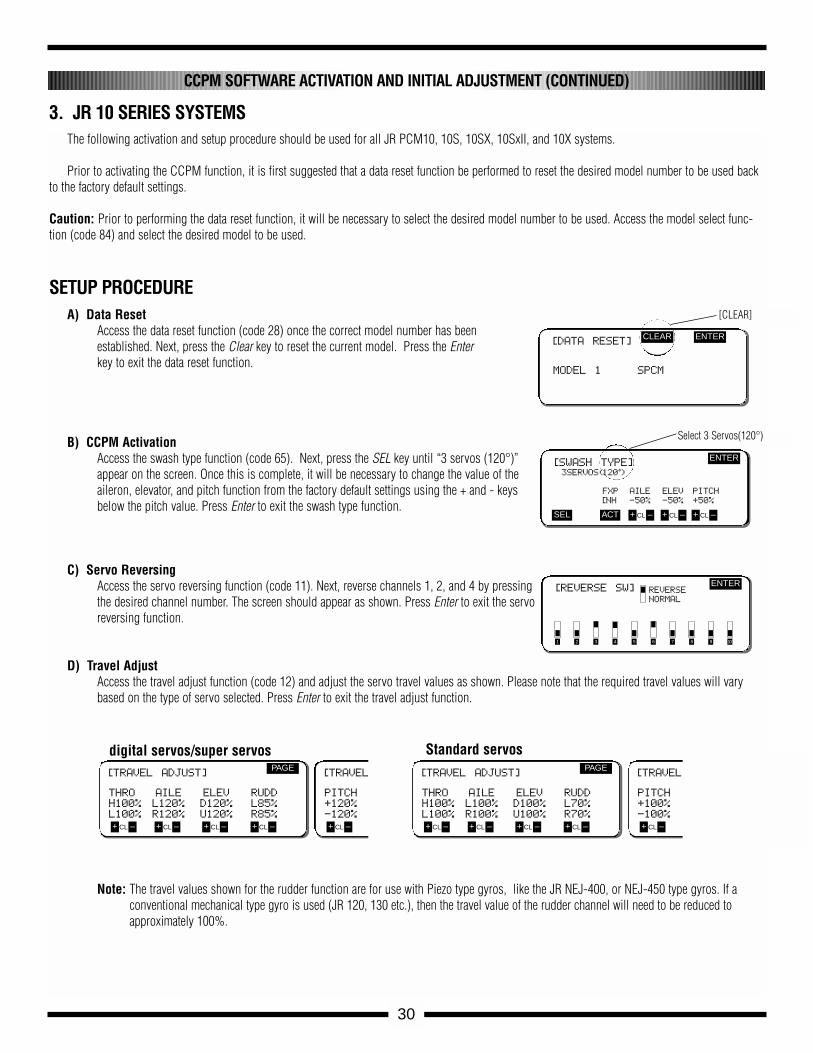
A) Data ResetAccess the data reset function (code 28) once the correct model number has beenestablished. Next, press the Clear key to reset the current model. Press the Enterkey to exit the data reset function.
B) CCPM ActivationAccess the swash type function (code 65). Next, press the SEL key until “3 servos (120°)”appear on the screen. Once this is complete, it will be necessary to change the value of theaileron, elevator, and pitch function from the factory default settings using the + and - keysbelow the pitch value. Press Enter to exit the swash type function.
C) Servo ReversingAccess the servo reversing function (code 11). Next, reverse channels 1, 2, and 4 by pressingthe desired channel number. The screen should appear as shown. Press Enter to exit the servoreversing function.
D) Travel AdjustAccess the travel adjust function (code 12) and adjust the servo travel values as shown. Please note that the required travel values will varybased on the type of servo selected. Press Enter to exit the travel adjust function.
Note: The travel values shown for the rudder function are for use with Piezo type gyros, like the JR NEJ-400, or NEJ-450 type gyros. If a conventional mechanical type gyro is used (JR 120, 130 etc.), then the travel value of the rudder channel will need to be reduced toapproximately 100%.
CCPM SOFTWARE ACTIVATION AND INITIAL ADJUSTMENT (CONTINUED)
3. JR 10 SERIES SYSTEMS
SETUP PROCEDURE
[DATA RESET]
MODEL 1 SPCM
CLEAR ENTER
[SWASH TYPE]3SERVOS(120•)
FXP AILE ELEV PITCH
[NH -50% -50% +50%
ENTER
SEL ACT + –CL + –CL + –CL
[REVERSE SW] REVERSE
NORMAL
ENTER
1 2 3 4 5 6 7 8 9 10
[TRAVEL ADJUST]
THRO AILE ELEV RUDD
H100% L120% D120% L85%
L100% R120% U120% R85%
PAGE
+ –CL + –CL + –CL + –CL
[TRAVELADJUST]
PITCH
+120%
-120%
+ –CL + –CL
[TRAVEL ADJUST]
THRO AILE ELEV RUDD
H100% L100% D100% L70%
L100% R100% U100% R70%
PAGE
+ –CL + –CL + –CL + –CL
[TRAVEL ADJUST]
PITCH
+100%
-100%
+ –CL + –CL + –CL
[CLEAR]
Select 3 Servos(120°)
digital servos/super servos Standard servos
31
IMPORTANT CCPM PROGRAMMING DOS AND DON’TS
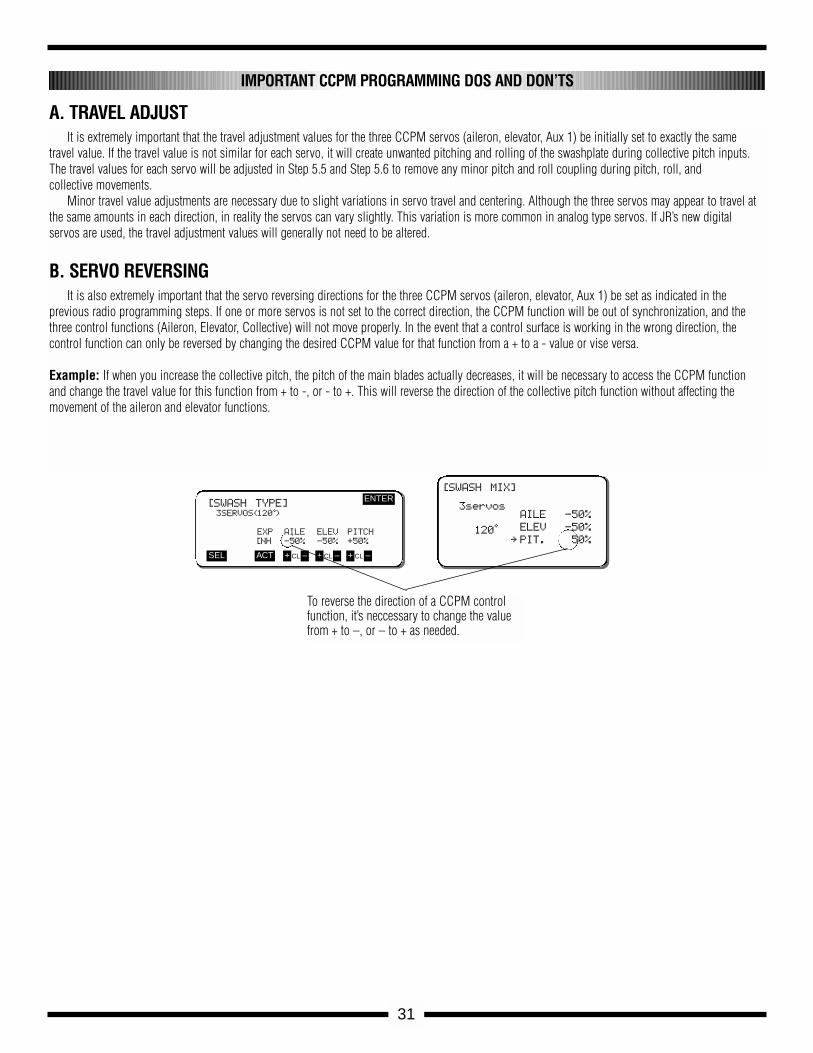
It is extremely important that the travel adjustment values for the three CCPM servos (aileron, elevator, Aux 1) be initially set to exactly the same travel value. If the travel value is not similar for each servo, it will create unwanted pitching and rolling of the swashplate during collective pitch inputs.The travel values for each servo will be adjusted in Step 5.5 and Step 5.6 to remove any minor pitch and roll coupling during pitch, roll, and collective movements.
Minor travel value adjustments are necessary due to slight variations in servo travel and centering. Although the three servos may appear to travel atthe same amounts in each direction, in reality the servos can vary slightly. This variation is more common in analog type servos. If JR’s new digital servos are used, the travel adjustment values will generally not need to be altered.
A. TRAVEL ADJUST
It is also extremely important that the servo reversing directions for the three CCPM servos (aileron, elevator, Aux 1) be set as indicated in the previous radio programming steps. If one or more servos is not set to the correct direction, the CCPM function will be out of synchronization, and thethree control functions (Aileron, Elevator, Collective) will not move properly. In the event that a control surface is working in the wrong direction, the control function can only be reversed by changing the desired CCPM value for that function from a + to a - value or vise versa.
Example: If when you increase the collective pitch, the pitch of the main blades actually decreases, it will be necessary to access the CCPM functionand change the travel value for this function from + to -, or - to +. This will reverse the direction of the collective pitch function without affecting themovement of the aileron and elevator functions.
B. SERVO REVERSING
[SWASH TYPE]3SERVOS(120•)
EXP AILE ELEV PITCH
[NH -50% -50% +50%
ENTER
SEL ACT + –CL + –CL + –CL
To reverse the direction of a CCPM controlfunction, it’s neccessary to change the valuefrom + to –, or – to + as needed.
[SWASH MIX]
3servos
120•
AILE -50%
ELEV -50%
∞ PIT. 50%
5-1
32
(Right)
(Front)
(Left)
NEA-300HSpeed Controller
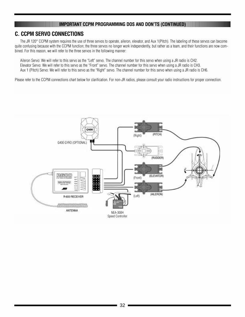
The JR 120° CCPM system requires the use of three servos to operate, aileron, elevator, and Aux 1(Pitch). The labeling of these servos can becomequite confusing because with the CCPM function; the three servos no longer work independently, but rather as a team, and their functions are now com-bined. For this reason, we will refer to the three servos in the following manner:
Aileron Servo: We will refer to this servo as the “Left” servo. The channel number for this servo when using a JR radio is CH2.Elevator Servo: We will refer to this servo as the “Front” servo. The channel number for this servo when using a JR radio is CH3.Aux 1 (Pitch) Servo: We will refer to this servo as the “Right” servo. The channel number for this servo when using a JR radio is CH6.
Please refer to the CCPM connections chart below for clarification. For non-JR radios, please consult your radio instructions for proper connection.
C. CCPM SERVO CONNECTIONS
IMPORTANT CCPM PROGRAMMING DOS AND DON’TS (CONTINUED)
G400 GYRO (OPTIONAL)
G400
33
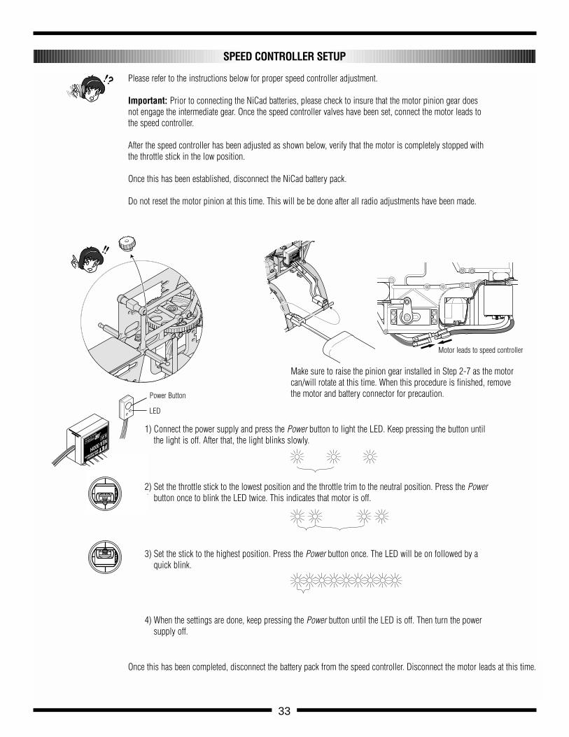
1) Connect the power supply and press the Power button to light the LED. Keep pressing the button untilthe light is off. After that, the light blinks slowly.
Make sure to raise the pinion gear installed in Step 2-7 as the motorcan/will rotate at this time. When this procedure is finished, removethe motor and battery connector for precaution.
Please refer to the instructions below for proper speed controller adjustment.
Important: Prior to connecting the NiCad batteries, please check to insure that the motor pinion gear doesnot engage the intermediate gear. Once the speed controller valves have been set, connect the motor leads tothe speed controller.
After the speed controller has been adjusted as shown below, verify that the motor is completely stopped withthe throttle stick in the low position.
Once this has been established, disconnect the NiCad battery pack.
Do not reset the motor pinion at this time. This will be be done after all radio adjustments have been made.
2) Set the throttle stick to the lowest position and the throttle trim to the neutral position. Press the Powerbutton once to blink the LED twice. This indicates that motor is off.
3) Set the stick to the highest position. Press the Power button once. The LED will be on followed by aquick blink.
4) When the settings are done, keep pressing the Power button until the LED is off. Then turn the powersupply off.
SPEED CONTROLLER SETUP
Power Button
LED
Once this has been completed, disconnect the battery pack from the speed controller. Disconnect the motor leads at this time.
Motor leads to speed controller
5-1
34
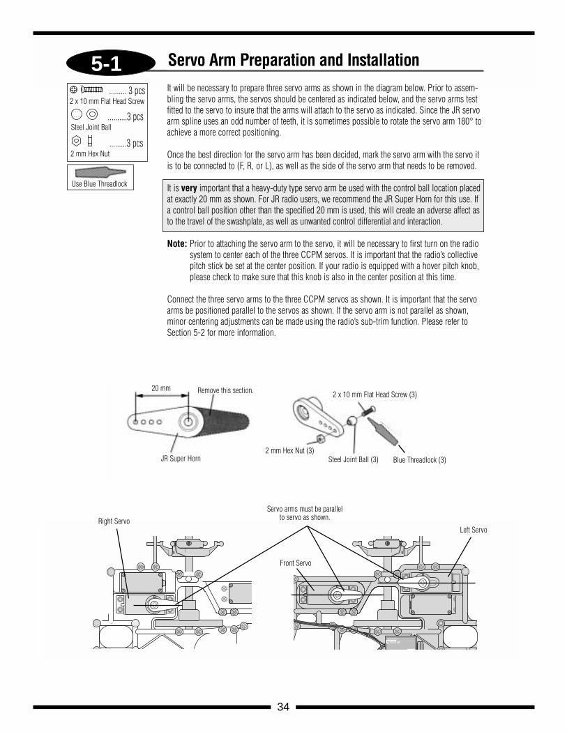
Servo Arm Preparation and Installation
......... 3 pcs2 x 10 mm Flat Head Screw
..........3 pcsSteel Joint Ball
.........3 pcs2 mm Hex Nut
It will be necessary to prepare three servo arms as shown in the diagram below. Prior to assem-bling the servo arms, the servos should be centered as indicated below, and the servo arms testfitted to the servo to insure that the arms will attach to the servo as indicated. Since the JR servoarm spline uses an odd number of teeth, it is sometimes possible to rotate the servo arm 180° toachieve a more correct positioning.
Once the best direction for the servo arm has been decided, mark the servo arm with the servo itis to be connected to (F, R, or L), as well as the side of the servo arm that needs to be removed.
It is very important that a heavy-duty type servo arm be used with the control ball location placedat exactly 20 mm as shown. For JR radio users, we recommend the JR Super Horn for this use. Ifa control ball position other than the specified 20 mm is used, this will create an adverse affect asto the travel of the swashplate, as well as unwanted control differential and interaction.
Note: Prior to attaching the servo arm to the servo, it will be necessary to first turn on the radiosystem to center each of the three CCPM servos. It is important that the radio’s collectivepitch stick be set at the center position. If your radio is equipped with a hover pitch knob,please check to make sure that this knob is also in the center position at this time.
Connect the three servo arms to the three CCPM servos as shown. It is important that the servoarms be positioned parallel to the servos as shown. If the servo arm is not parallel as shown,minor centering adjustments can be made using the radio’s sub-trim function. Please refer toSection 5-2 for more information.
Use Blue Threadlock
Steel Joint Ball (3)2 mm Hex Nut (3)
2 x 10 mm Flat Head Screw (3)Remove this section.
JR Super Horn
20 mm
Blue Threadlock (3)
8.4V
JRREMORECONTROL
MADE IN JAPAN
Right Servo
Servo arms must be parallelto servo as shown.
Front Servo
Left Servo
5-2
35
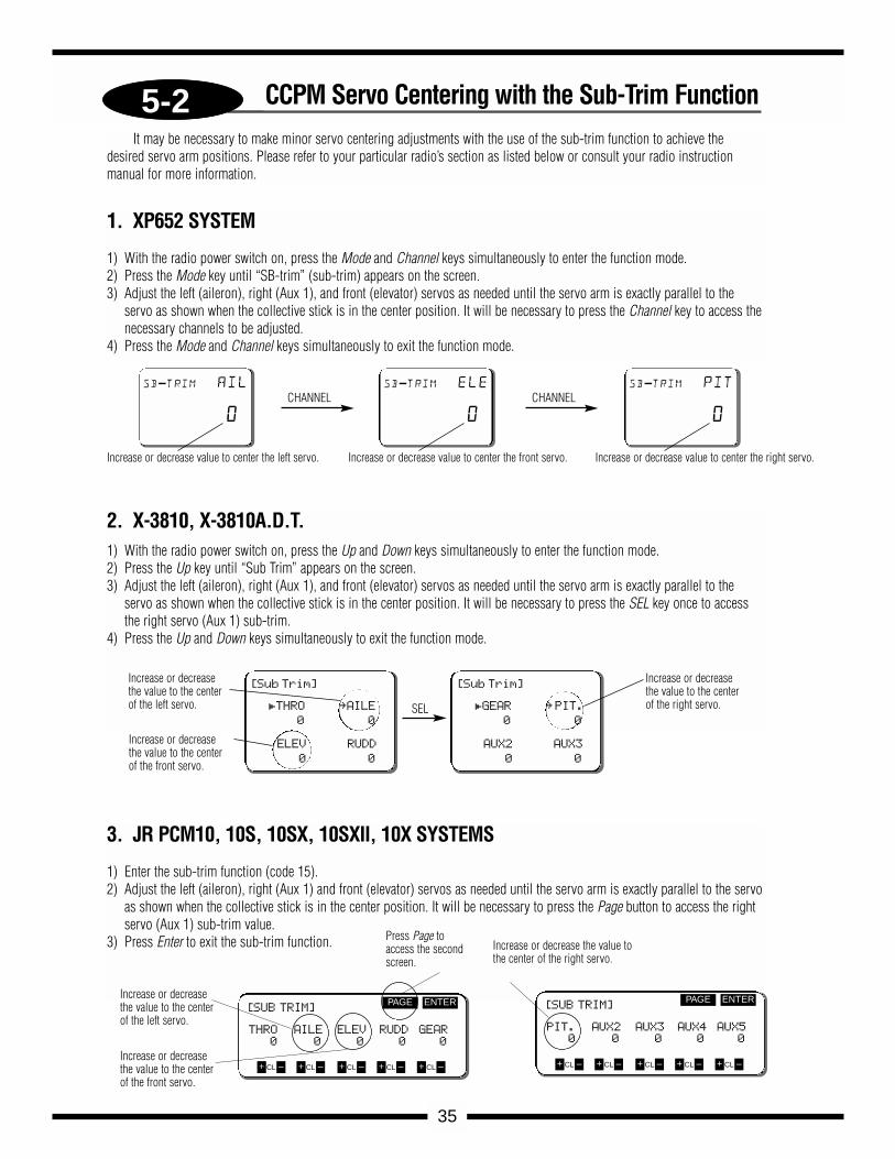
CCPM Servo Centering with the Sub-Trim Function
1. XP652 SYSTEM
1) With the radio power switch on, press the Mode and Channel keys simultaneously to enter the function mode.2) Press the Mode key until “SB-trim” (sub-trim) appears on the screen.3) Adjust the left (aileron), right (Aux 1), and front (elevator) servos as needed until the servo arm is exactly parallel to the
servo as shown when the collective stick is in the center position. It will be necessary to press the Channel key to access thenecessary channels to be adjusted.
4) Press the Mode and Channel keys simultaneously to exit the function mode.
CHANNEL CHANNELsb-trim ail
0
Increase or decrease value to center the left servo.
sb-trim ele
0
Increase or decrease value to center the front servo.
sb-trim pit
0
Increase or decrease value to center the right servo.
2. X-3810, X-3810A.D.T. 1) With the radio power switch on, press the Up and Down keys simultaneously to enter the function mode.2) Press the Up key until “Sub Trim” appears on the screen.3) Adjust the left (aileron), right (Aux 1), and front (elevator) servos as needed until the servo arm is exactly parallel to the
servo as shown when the collective stick is in the center position. It will be necessary to press the SEL key once to accessthe right servo (Aux 1) sub-trim.
4) Press the Up and Down keys simultaneously to exit the function mode.
[Sub Trim]
£THRO ∞AILE
0 0
ELEV RUDD
0 0
[Sub Trim]
£GEAR ∞PIT.
0 0
AUX2 AUX3
0 0
Increase or decreasethe value to the centerof the front servo.
Increase or decreasethe value to the centerof the right servo.
Increase or decreasethe value to the centerof the left servo. SEL
3. JR PCM10, 10S, 10SX, 10SXII, 10X SYSTEMS
1) Enter the sub-trim function (code 15).2) Adjust the left (aileron), right (Aux 1) and front (elevator) servos as needed until the servo arm is exactly parallel to the servo
as shown when the collective stick is in the center position. It will be necessary to press the Page button to access the rightservo (Aux 1) sub-trim value.
3) Press Enter to exit the sub-trim function.
[SUB TRIM]
THRO AILE ELEV RUDD GEAR
0 0 0 0 0
ENTERPAGE
+ –CL + –CL + –CL + –CL + –CL
Press Page toaccess the secondscreen.
Increase or decreasethe value to the centerof the left servo.
Increase or decreasethe value to the centerof the front servo.
[SUB TRIM]
PIT. AUX2 AUX3 AUX4 AUX5
0 0 0 0 0
ENTERPAGE
+ –CL + –CL + –CL + –CL + –CL
Increase or decrease the value tothe center of the right servo.
It may be necessary to make minor servo centering adjustments with the use of the sub-trim function to achieve thedesired servo arm positions. Please refer to your particular radio’s section as listed below or consult your radio instructionmanual for more information.
C
JR PROPO
c
A
JR PROPO
JR PROPO
B
B
A
5-3
36
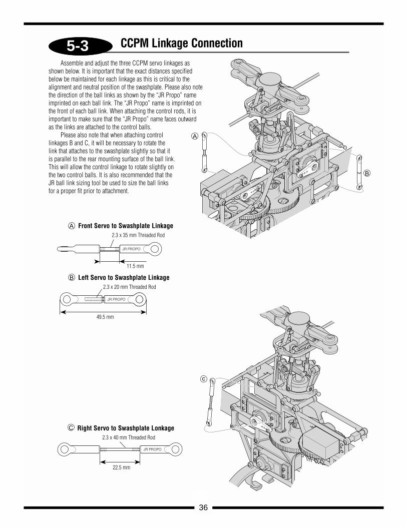
CCPM Linkage ConnectionAssemble and adjust the three CCPM servo linkages as
shown below. It is important that the exact distances specifiedbelow be maintained for each linkage as this is critical to thealignment and neutral position of the swashplate. Please also notethe direction of the ball links as shown by the “JR Propo” nameimprinted on each ball link. The “JR Propo” name is imprinted onthe front of each ball link. When attaching the control rods, it isimportant to make sure that the “JR Propo” name faces outwardas the links are attached to the control balls.
Please also note that when attaching controllinkages B and C, it will be necessary to rotate thelink that attaches to the swashplate slightly so that itis parallel to the rear mounting surface of the ball link.This will allow the control linkage to rotate slightly onthe two control balls. It is also recommended that theJR ball link sizing tool be used to size the ball linksfor a proper fit prior to attachment.
Front Servo to Swashplate Linkage2.3 x 35 mm Threaded Rod
Left Servo to Swashplate Linkage2.3 x 20 mm Threaded Rod
11.5 mm
49.5 mm
Right Servo to Swashplate Lonkage2.3 x 40 mm Threaded Rod
22.5 mm
5-4
37
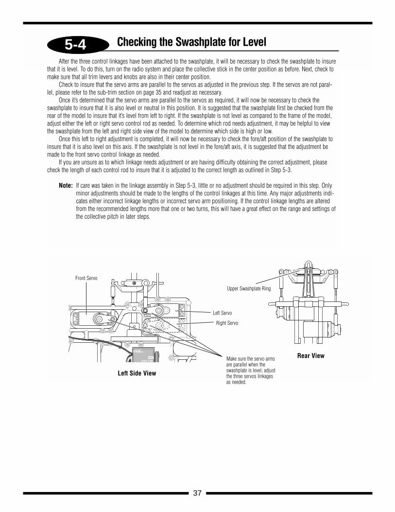
Checking the Swashplate for LevelAfter the three control linkages have been attached to the swashplate, it will be necessary to check the swashplate to insure
that it is level. To do this, turn on the radio system and place the collective stick in the center position as before. Next, check tomake sure that all trim levers and knobs are also in their center position.
Check to insure that the servo arms are parallel to the servos as adjusted in the previous step. If the servos are not paral-lel, please refer to the sub-trim section on page 35 and readjust as necessary.
Once it’s determined that the servo arms are parallel to the servos as required, it will now be necessary to check theswashplate to insure that it is also level or neutral in this position. It is suggested that the swashplate first be checked from therear of the model to insure that it’s level from left to right. If the swashplate is not level as compared to the frame of the model,adjust either the left or right servo control rod as needed. To determine which rod needs adjustment, it may be helpful to viewthe swashplate from the left and right side view of the model to determine which side is high or low.
Once this left to right adjustment is completed, it will now be necessary to check the fore/aft position of the swashplate toinsure that it is also level on this axis. If the swashplate is not level in the fore/aft axis, it is suggested that the adjustment bemade to the front servo control linkage as needed.
If you are unsure as to which linkage needs adjustment or are having difficulty obtaining the correct adjustment, pleasecheck the length of each control rod to insure that it is adjusted to the correct length as outlined in Step 5-3.
Note: If care was taken in the linkage assembly in Step 5-3, little or no adjustment should be required in this step. Onlyminor adjustments should be made to the lengths of the control linkages at this time. Any major adjustments indi-cates either incorrect linkage lengths or incorrect servo arm positioning. If the control linkage lengths are alteredfrom the recommended lengths more that one or two turns, this will have a great effect on the range and settings ofthe collective pitch in later steps.
8.4V
NEA-300H
JRREMORECONTROL
MADE IN JAPAN
Make sure the servo armsare parallel when theswashplate is level; adjustthe three servos linkagesas needed.
Front Servo
Upper Swashplate Ring
Left Servo
Right Servo
Left Side View
Rear View
5-5
38
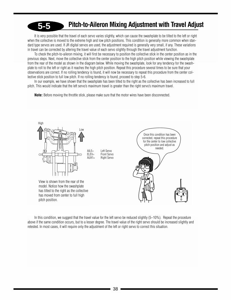
It is very possible that the travel of each servo varies slightly, which can cause the swashplate to be tilted to the left or rightwhen the collective is moved to the extreme high and low pitch positions. This condition is generally more common when stan-dard type servos are used. If JR digital servos are used, the adjustment required is generally very small, if any. These variationsin travel can be corrected by altering the travel value of each servo slightly through the travel adjustment function.
To check the pitch-to-aileron mixing, it will first be necessary to position the collective stick in the center position as in theprevious steps. Next, move the collective stick from the center position to the high pitch position while viewing the swashplatefrom the rear of the model as shown in the diagram below. While moving the swashplate, look for any tendency for the swash-plate to roll to the left or right as it reaches the high pitch position. Repeat this procedure several times to be sure that yourobservations are correct. If no rolling tendency is found, it will now be necessary to repeat this procedure from the center col-lective stick position to full low pitch. If no rolling tendency is found, proceed to step 5-6.
In our example, we have shown that the swashplate has been tilted to the right as the collective has been increased to fullpitch. This would indicate that the left servo’s maximum travel is greater than the right servo’s maximum travel.
Note: Before moving the throttle stick, please make sure that the motor wires have been disconnected.
In this condition, we suggest that the travel value for the left servo be reduced slightly (5–10%). Repeat the procedureabove if the same condition occurs, but to a lesser degree. The travel value of the right servo should be increased slightly andretested. In most cases, it will require only the adjustment of the left or right servo to correct this situation.
View is shown from the rear of themodel. Notice how the swashplatehas tilted to the right as the collectivehas moved from center to full highpitch position.
High
Low
Once this condition has been corrected, repeat this procedurefor the center to low collectivepitch position and adjust as
needed. AILE= Left ServoELEV= Front ServoAUX1= Right Servo
Pitch-to-Aileron Mixing Adjustment with Travel Adjust
5-6
39
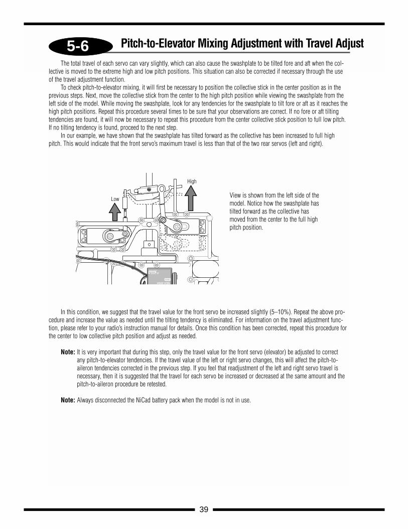
The total travel of each servo can vary slightly, which can also cause the swashplate to be tilted fore and aft when the col-lective is moved to the extreme high and low pitch positions. This situation can also be corrected if necessary through the useof the travel adjustment function.
To check pitch-to-elevator mixing, it will first be necessary to position the collective stick in the center position as in theprevious steps. Next, move the collective stick from the center to the high pitch position while viewing the swashplate from theleft side of the model. While moving the swashplate, look for any tendencies for the swashplate to tilt fore or aft as it reaches thehigh pitch positions. Repeat this procedure several times to be sure that your observations are correct. If no fore or aft tiltingtendencies are found, it will now be necessary to repeat this procedure from the center collective stick position to full low pitch.If no tilting tendency is found, proceed to the next step.
In our example, we have shown that the swashplate has tilted forward as the collective has been increased to full highpitch. This would indicate that the front servo’s maximum travel is less than that of the two rear servos (left and right).
In this condition, we suggest that the travel value for the front servo be increased slightly (5–10%). Repeat the above pro-cedure and increase the value as needed until the tilting tendency is eliminated. For information on the travel adjustment func-tion, please refer to your radio’s instruction manual for details. Once this condition has been corrected, repeat this procedure forthe center to low collective pitch position and adjust as needed.
Note: It is very important that during this step, only the travel value for the front servo (elevator) be adjusted to correctany pitch-to-elevator tendencies. If the travel value of the left or right servo changes, this will affect the pitch-to-aileron tendencies corrected in the previous step. If you feel that readjustment of the left and right servo travel isnecessary, then it is suggested that the travel for each servo be increased or decreased at the same amount and thepitch-to-aileron procedure be retested.
Note: Always disconnected the NiCad battery pack when the model is not in use.
View is shown from the left side of themodel. Notice how the swashplate hastilted forward as the collective hasmoved from the center to the full highpitch position.
Pitch-to-Elevator Mixing Adjustment with Travel Adjust
8.4V
NEA-300H
JRREMORECONTROL
MADE IN JAPAN
High
Low
5-7
90°
90°
2 x 7 mm Flat Head Screw (1)
Servo Arm
2 mm Hex Nut (1)
Steel Jointball (1)12
.5 m
m
............... 1 pc2 x 7 mm Flat Head Screw
................... 1 pc
Steel Jointball
........................ 1 pc2 mm Hex Nut
40
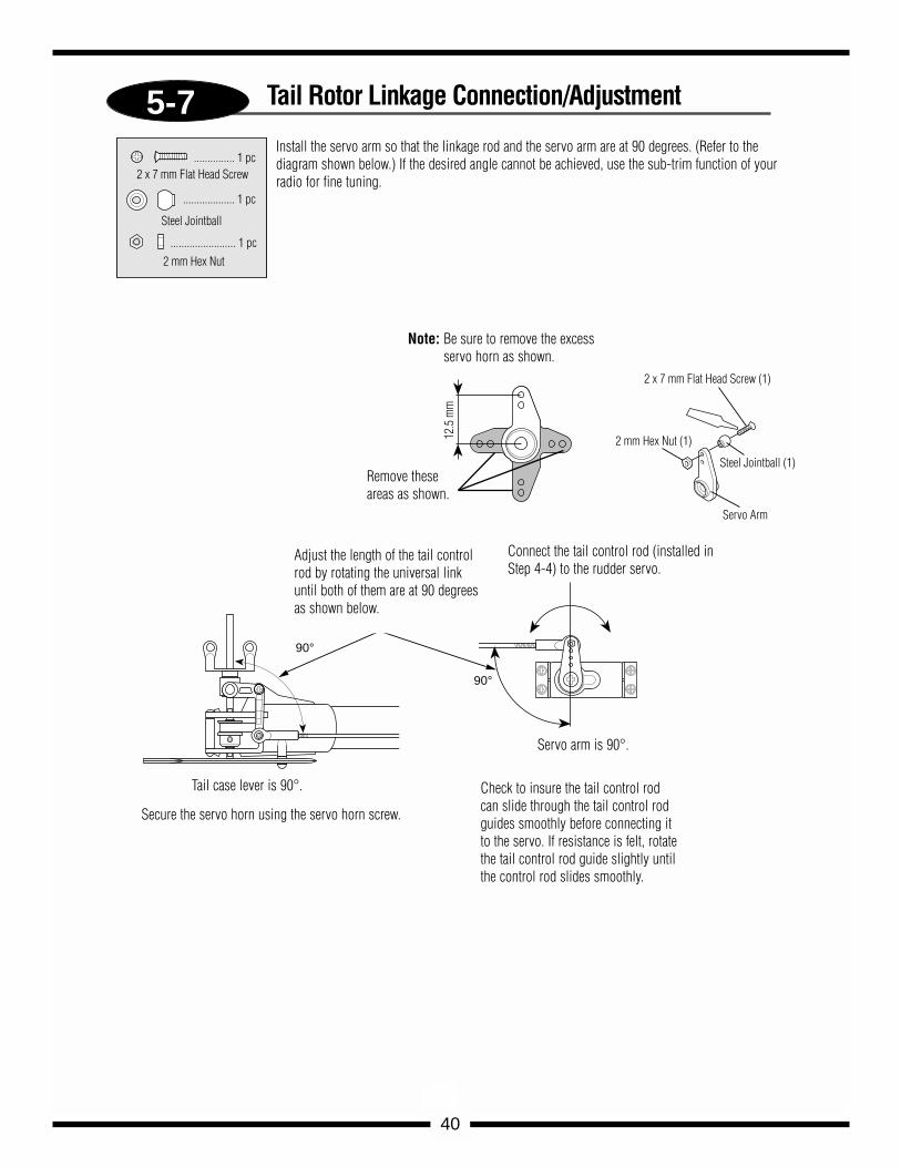
Tail Rotor Linkage Connection/Adjustment
Install the servo arm so that the linkage rod and the servo arm are at 90 degrees. (Refer to thediagram shown below.) If the desired angle cannot be achieved, use the sub-trim function of yourradio for fine tuning.
Adjust the length of the tail controlrod by rotating the universal linkuntil both of them are at 90 degreesas shown below.
Tail case lever is 90°.
Secure the servo horn using the servo horn screw.
Servo arm is 90°.
Connect the tail control rod (installed inStep 4-4) to the rudder servo.
Check to insure the tail control rodcan slide through the tail control rodguides smoothly before connecting itto the servo. If resistance is felt, rotatethe tail control rod guide slightly untilthe control rod slides smoothly.
Note: Be sure to remove the excessservo horn as shown.
Remove theseareas as shown.
6-1
6-2
41
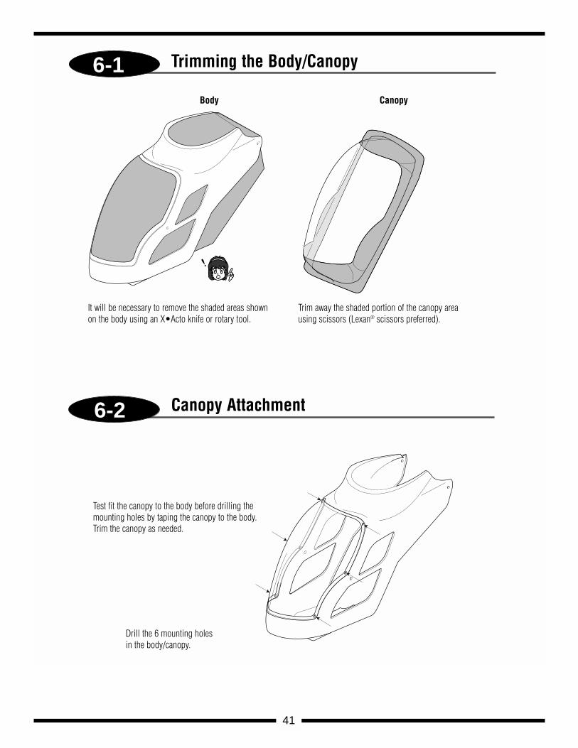
Trimming the Body/Canopy
Body Canopy
It will be necessary to remove the shaded areas shownon the body using an X•Acto knife or rotary tool.
Trim away the shaded portion of the canopy areausing scissors (Lexan® scissors preferred).
Canopy Attachment
Test fit the canopy to the body before drilling themounting holes by taping the canopy to the body.Trim the canopy as needed.
Drill the 6 mounting holesin the body/canopy.
6-3
6-4
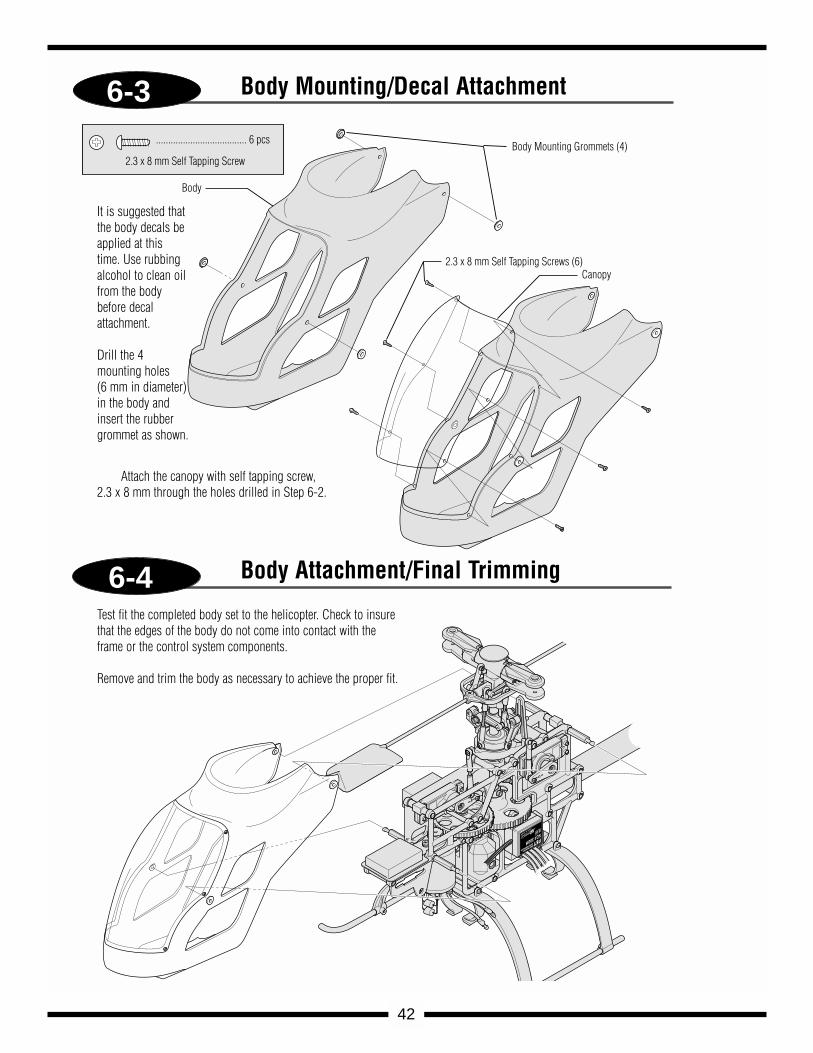
..................................... 6 pcs
2.3 x 8 mm Self Tapping Screw Body Mounting Grommets (4)
2.3 x 8 mm Self Tapping Screws (6)
Body
Canopy
42
Body Mounting/Decal Attachment
Body Attachment/Final Trimming
It is suggested thatthe body decals beapplied at thistime. Use rubbingalcohol to clean oilfrom the bodybefore decal attachment.
Drill the 4 mounting holes (6 mm in diameter) in the body and insert the rubber grommet as shown.
Attach the canopy with self tapping screw, 2.3 x 8 mm through the holes drilled in Step 6-2.
Test fit the completed body set to the helicopter. Check to insurethat the edges of the body do not come into contact with theframe or the control system components.
Remove and trim the body as necessary to achieve the proper fit.
43
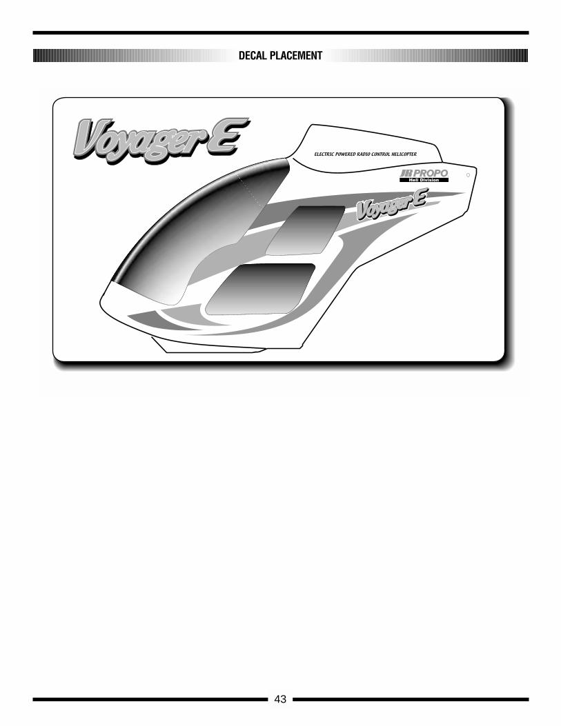
DECAL PLACEMENT
6-5
6-6
Main Rotor Blades
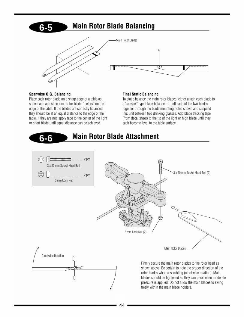
3 x 20 mm Socket Head Bolt (2)
3 mm Lock Nut (2)
Main Rotor Blades
3 x 20 mm Socket Head Bolt
3 mm Lock Nut
.............. 2 pcs
.......................................... 2 pcs
Clockwise Rotation
44
Firmly secure the main rotor blades to the rotor head asshown above. Be certain to note the proper direction of therotor blades when assembling (clockwise rotation). Mainblades should be tightened so they can pivot when moderatepressure is applied. Do not allow the main blades to swingfreely within the main blade holders.
Spanwise C.G. BalancingPlace each rotor blade on a sharp edge of a table asshown and adjust so each rotor blade “teeters” on theedge of the table. If the blades are correctly balanced,they should be at an equal distance to the edge of thetable. If they are not, apply tape to the center of the lightor short blade until equal distance can be achieved.
Final Static BalancingTo static balance the main rotor blades, either attach each blade toa “seesaw” type blade balancer or bolt each of the two bladestogether through the blade mounting holes shown and suspendthis unit between two drinking glasses. Add blade tracking tape(from decal sheet) to the tip of the light or high blade until theyeach become level to the table surface.
Main Rotor Blade Balancing
Main Rotor Blade Attachment
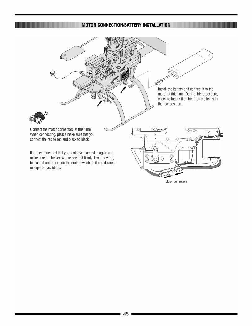
Motor Connectors
45
Install the battery and connect it to themotor at this time. During this procedure,check to insure that the throttle stick is inthe low position.
Connect the motor connectors at this time.When connecting, please make sure that youconnect the red to red and black to black.
It is recommended that you look over each step again andmake sure all the screws are secured firmly. From now on,be careful not to turn on the motor switch as it could causeunexpected accidents.
MOTOR CONNECTION/BATTERY INSTALLATION
Now that the radio system is completely installed into the helicopter, it isnecessary to check and adjust the following:
1. SERVO DIRECTION (SERVO REVERSING)Check to insure that all servos have been set to the correct directionas shown on page 24.
2. DUAL RATESIt is suggested that for initial flights the dual rate function values beset as follows:
0 Position (low rate): 60%1 Position (high rate): 100%
3. EXPONENTIAL SETTINGSIt is suggested that the exponential rate settings remain in the 0 valueposition until the initial test flights. After initial flights, adjust theexponential values to achieve the desired control feel.
4. SUB-TRIM SETTINGSIt is suggested that the correct neutral settings be achieved withoutthe use of the sub-trim feature. If sub-trim is used for final flightadjustments, it is suggested that the sub-trim values not exceed 10. Ifthe sub-trim values are greater, readjust the control linkages and resetthe sub-trims to 0.
5. PITCH/THROTTLE CURVE ADJUSTMENTIt is very important that the throttle and pitch curves are adjustedproperly to achieve the best performance from your helicopter. Whenproperly adjusted, the main rotor rpm should remain consistentthroughout all maneuvers and throttle stick positions. A constant rpmwill also help to improve the effectiveness and accuracy of the tailrotor and gyro systems.
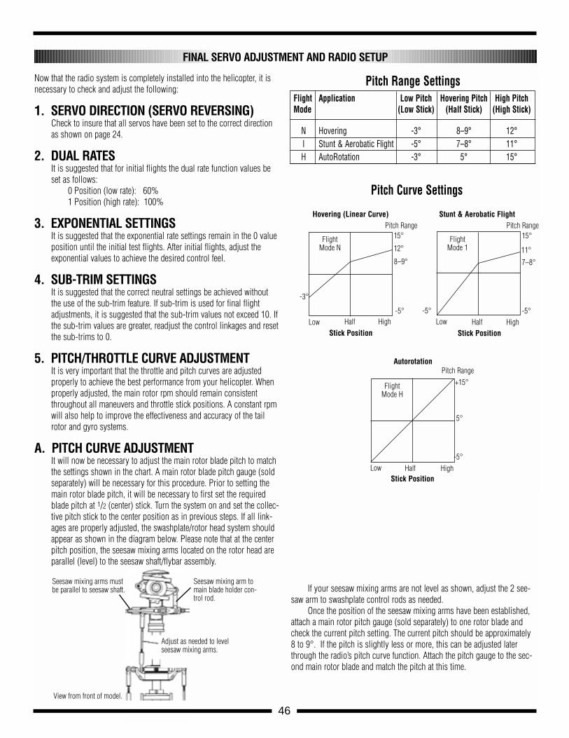
A. PITCH CURVE ADJUSTMENTIt will now be necessary to adjust the main rotor blade pitch to matchthe settings shown in the chart. A main rotor blade pitch gauge (soldseparately) will be necessary for this procedure. Prior to setting themain rotor blade pitch, it will be necessary to first set the requiredblade pitch at 1/2 (center) stick. Turn the system on and set the collec-tive pitch stick to the center position as in previous steps. If all link-ages are properly adjusted, the swashplate/rotor head system shouldappear as shown in the diagram below. Please note that at the centerpitch position, the seesaw mixing arms located on the rotor head areparallel (level) to the seesaw shaft/flybar assembly.
If your seesaw mixing arms are not level as shown, adjust the 2 see-saw arm to swashplate control rods as needed.
Once the position of the seesaw mixing arms have been established,attach a main rotor pitch gauge (sold separately) to one rotor blade andcheck the current pitch setting. The current pitch should be approximately8 to 9°. If the pitch is slightly less or more, this can be adjusted laterthrough the radio’s pitch curve function. Attach the pitch gauge to the sec-ond main rotor blade and match the pitch at this time.
FINAL SERVO ADJUSTMENT AND RADIO SETUP
+15°
5°
-5°
15°
11°
-5°
7–8°
15°
12°
8–9°
-5° -5°
-3°
Hovering (Linear Curve)
Flight Mode N
Flight Mode 1
Flight Mode H
Stick Position Stick PositionLow Half High Low Half High
Stick PositionLow Half High
Stunt & Aerobatic Flight
Autorotation
Flight Application Low Pitch Hovering Pitch High PitchMode (Low Stick) (Half Stick) (High Stick)
N Hovering -3° 8–9° 12°I Stunt & Aerobatic Flight -5° 7–8° 11°H AutoRotation -3° 5° 15°
Pitch Range Settings
Pitch Curve Settings
Pitch Range Pitch Range
Pitch Range
Seesaw mixing arms mustbe parallel to seesaw shaft.
Seesaw mixing arm tomain blade holder con-trol rod.
Adjust as needed to levelseesaw mixing arms.
View from front of model.
46
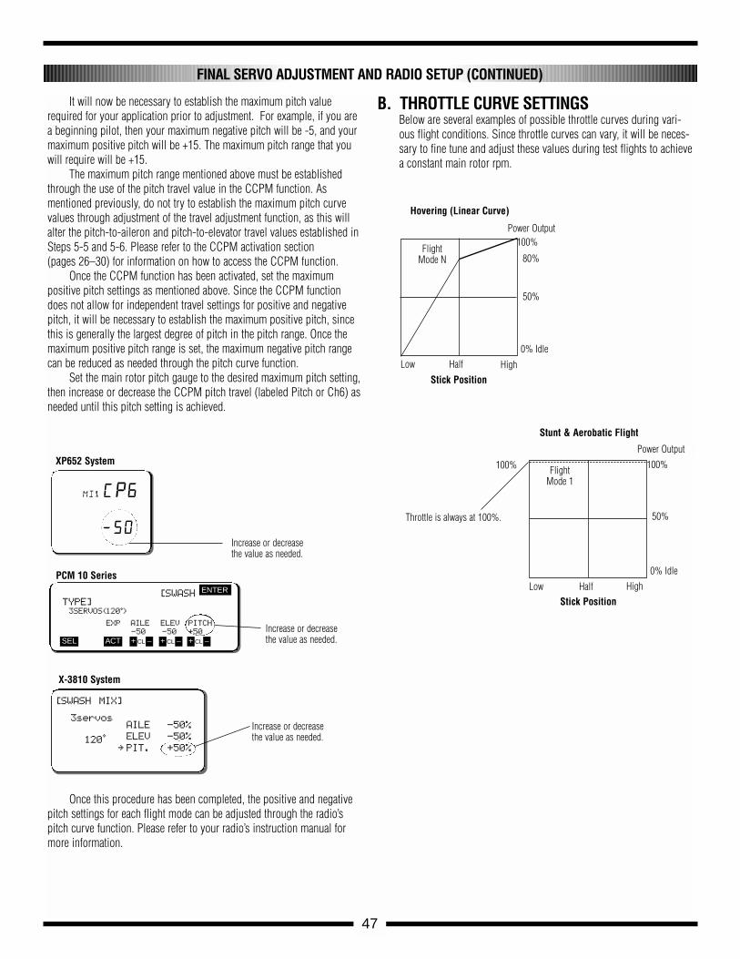
It will now be necessary to establish the maximum pitch valuerequired for your application prior to adjustment. For example, if you area beginning pilot, then your maximum negative pitch will be -5, and yourmaximum positive pitch will be +15. The maximum pitch range that youwill require will be +15.
The maximum pitch range mentioned above must be establishedthrough the use of the pitch travel value in the CCPM function. As mentioned previously, do not try to establish the maximum pitch curvevalues through adjustment of the travel adjustment function, as this willalter the pitch-to-aileron and pitch-to-elevator travel values established in Steps 5-5 and 5-6. Please refer to the CCPM activation section (pages 26–30) for information on how to access the CCPM function.
Once the CCPM function has been activated, set the maximum positive pitch settings as mentioned above. Since the CCPM functiondoes not allow for independent travel settings for positive and negativepitch, it will be necessary to establish the maximum positive pitch, sincethis is generally the largest degree of pitch in the pitch range. Once themaximum positive pitch range is set, the maximum negative pitch rangecan be reduced as needed through the pitch curve function.
Set the main rotor pitch gauge to the desired maximum pitch setting,then increase or decrease the CCPM pitch travel (labeled Pitch or Ch6) asneeded until this pitch setting is achieved.
Once this procedure has been completed, the positive and negativepitch settings for each flight mode can be adjusted through the radio’spitch curve function. Please refer to your radio’s instruction manual formore information.
B. THROTTLE CURVE SETTINGSBelow are several examples of possible throttle curves during vari-ous flight conditions. Since throttle curves can vary, it will be neces-sary to fine tune and adjust these values during test flights to achievea constant main rotor rpm.
FINAL SERVO ADJUSTMENT AND RADIO SETUP (CONTINUED)
[SWASHTYPE]3SERVOS(120•)
EXP AILE ELEV PITCH
-50 -50 +50
ENTER
SEL ACT + –CL + –CL + –CL
Increase or decreasethe value as needed.
Increase or decreasethe value as needed.
Increase or decreasethe value as needed.
[SWASH MIX]
3servos
120•
X-3810 System
PCM 10 Series
XP652 System
AILE -50%
ELEV -50%
∞ PIT. +50%
mixCP6
—50
100%
50%
100%
0% Idle
Power Output
Hovering (Linear Curve)
Stick PositionLow Half High
Flight Mode N
100%
50%
0% Idle
Power Output
Stunt & Aerobatic Flight
Stick PositionLow Half High
Flight Mode 1
47
80%
Throttle is always at 100%.
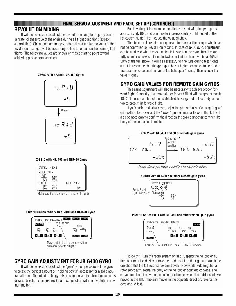
REVOLUTION MIXINGIt will be necessary to adjust the revolution mixing to properly com-
pensate for the torque of the engine during all flight conditions (exceptautorotation). Since there are many variables that can alter the value of therevolution mixing, it will be necessary to fine tune this function during testflights. The following values are shown only as a starting point towardachieving proper compensation:
GYRO GAIN ADJUSTMENT FOR JR G400 GYROIt will be necessary to adjust the “gain” or compensation of the gyro
to create the correct amount of “holding power” necessary for a solid neu-tral tail rotor. The intent of the gyro is to compensate for abrupt movementsor wind direction changes, working in conjunction with the revolution mix-ing function.
For hovering, it is recommended that you start with the gyro gain atapproximately 80°, and continue to increase slightly until the tail of thehelicopter “hunts,” then reduce the value slightly.
This function is used to compensate for the reaction torque which cannot be controlled by Revolution Mixing. In case of G400 gyro, adjustmentcan be achieved with the volume knob located on the gyro. Turn the knobfully counter clockwise, then clockwise so that the knob will be at 40% to50% of the full stroke. It will be necessary to fine tune during test flightsand it is recommended the gyro gain be set higher for more stable rudder.Increase the value until the tail of the helicopter “hunts,” then reduce thevales slightly.
GYRO GAIN VALVES FOR REMOTE GAIN GYROSThis same adjustment will also be necessary to achieve proper for-
ward flight. Generally, the gyro gain for forward flight will be approximately10–20% less than that of the established hover gain due to aerodynamicforces present in forward flight.
If you’re using a dual rate gyro, adjust the gain so that you’re using “higher”gain setting for hover and the “lower” gain setting for forward flight. It willalso be necessary to confirm the direction the gyro compensates when thebody of the helicopter is rotated.
To do this, turn the radio system on and suspend the helicopter bythe main rotor head. Next, move the rudder stick to the right and watch thedirection that the tail rotor servo arm travels. Now while watching the tailrotor servo arm, rotate the body of the helicopter counterclockwise. Theservo arm should move in the same direction as when the rudder stick wasmoved to the left. If the arm moves in the opposite direction, reverse thegyro and re-test.
48
[ATS REVO-MIX]DIR-RIGHT
-POS-
UP DN P HOV ZERO
5% 5% 0% 50 0
ENTERPAGE
STORE STORE
SEL
NORM
+ –CL + –CL + –CL
Make certain that the compensationdirection is set to “Right.”
PCM 10 Series radio with NEJ400 and NEJ450 Gyros
[GYROS SENS ADJ]
AUX3 0: 1: 2:
∞ 80% 60% 50%
ENTER
SEL+ –CL + –CL + –CL
Press SEL to select AUX3 or AUTO GAIN Function
Please refer to your radio’s instructions for more information.
PCM 10 Series radio with NEJ450 and other remote gain gyros
[ATS. MIX]
REVO.MixNORM∞Up R5%DN R5%
STNT ACC.MixUp R3%Dn R3% 0%
X-3810 with NEJ400 and NEJ450 Gyros
mix rvu
+5
mixrvD
+5
XP652 with NEJ400, NEJ450 Gyros
XP652 with NEJ450 and other remote gain gyros
gertrv. adj.
-60%
Channel
Make sure that the direction is set to R (right)
[GYRO SENS]
RUDD D/R
£Rate: ∞0: 80%1: 60%
X-3810 with NEJ450 and other remote gain gyros
Changeswitch position
Set to RuddD/R Switch
FINAL SERVO ADJUSTMENT AND RADIO SET UP (CONTINUED)
gertrv. adj.
+80%
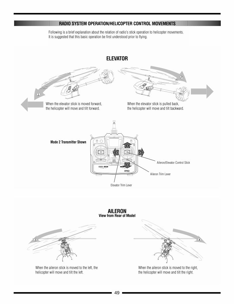
49
RADIO SYSTEM OPERATION/HELICOPTER CONTROL MOVEMENTS
Following is a brief explanation about the relation of radio's stick operation to helicopter movements. It is suggested that this basic operation be first understood prior to flying.
FETHIGHT FREQUENCY
SPEED CONTROLLER
8.4VNEA-300H
JRREMORE
CONTROL
MADE IN JAPAN
1
2
FETHIGHT FREQUENCYSPEED CONTROLLER
8.4V
NEA-300H
JRREMORE CONTROL MADE IN JAPAN
MULTIDATADISPLAY
VOLTAGEINDICATOR
MODE C H
ON
ENT
+ -CLR
XP652
1
3 4
2
3 4
When the elevator stick is moved forward,the helicopter will move and tilt forward.
When the elevator stick is pulled back, the helicopter will move and tilt backward.
ELEVATOR
Aileron/Elevator Control Stick
Aileron Trim Lever
Elevator Trim Lever
Mode 2 Transmitter Shown
When the aileron stick is moved to the left, thehelicopter will move and tilt the left.
When the aileron stick is moved to the right,the helicopter will move and tilt the right.
AILERONView from Rear of Model
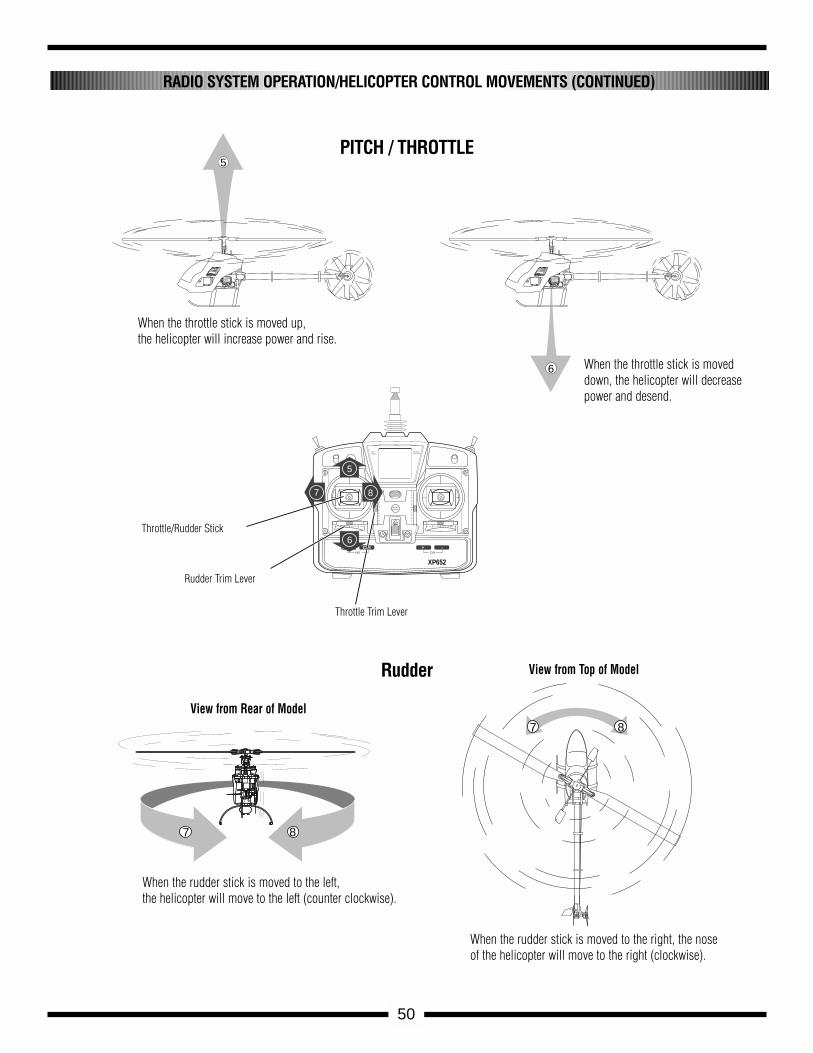
50
RADIO SYSTEM OPERATION/HELICOPTER CONTROL MOVEMENTS (CONTINUED)
FETHIGHT FREQUENCY
SPEED CONTROLLER
8.4V
NEA-300H
JRREMORECONTROL
MADE IN JAPAN
5
FETHIGHT FREQUENCY
SPEED CONTROLLER
8.4V
NEA-300H
JRREMORECONTROL
MADE IN JAPAN
6
MULTIDATADISPLAY
VOLTAGEINDICATOR
MODE C H
ON
ENT
+ -CLR
XP652
5
7 8
6
7 8
7 8
When the throttle stick is moved up, the helicopter will increase power and rise.
When the throttle stick is moveddown, the helicopter will decreasepower and desend.
PITCH / THROTTLE
Throttle/Rudder Stick
Throttle Trim Lever
Rudder Trim Lever
When the rudder stick is moved to the left, the helicopter will move to the left (counter clockwise).
When the rudder stick is moved to the right, the noseof the helicopter will move to the right (clockwise).
Rudder
View from Rear of Model
View from Top of Model
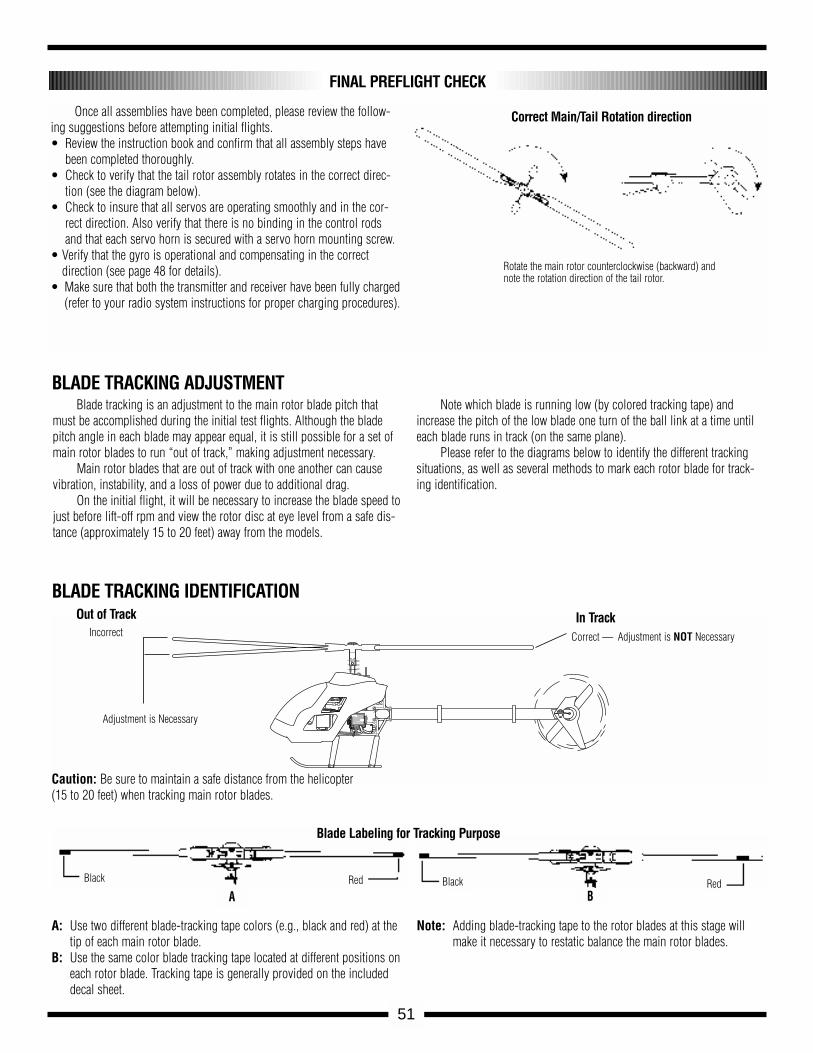
Once all assemblies have been completed, please review the follow-ing suggestions before attempting initial flights.• Review the instruction book and confirm that all assembly steps have
been completed thoroughly.• Check to verify that the tail rotor assembly rotates in the correct direc-
tion (see the diagram below).• Check to insure that all servos are operating smoothly and in the cor-
rect direction. Also verify that there is no binding in the control rodsand that each servo horn is secured with a servo horn mounting screw.
• Verify that the gyro is operational and compensating in the correct direction (see page 48 for details).
• Make sure that both the transmitter and receiver have been fully charged(refer to your radio system instructions for proper charging procedures).
FINAL PREFLIGHT CHECK
FETHIGHT FREQUENCY
SPEED CONTROLLER
8.4V
NEA-300H
JRREMORECONTROL
MADE IN JAPAN
BLADE TRACKING IDENTIFICATION
A: Use two different blade-tracking tape colors (e.g., black and red) at thetip of each main rotor blade.
B: Use the same color blade tracking tape located at different positions oneach rotor blade. Tracking tape is generally provided on the includeddecal sheet.
Note: Adding blade-tracking tape to the rotor blades at this stage willmake it necessary to restatic balance the main rotor blades.
Blade Labeling for Tracking Purpose
BLADE TRACKING ADJUSTMENTBlade tracking is an adjustment to the main rotor blade pitch that
must be accomplished during the initial test flights. Although the bladepitch angle in each blade may appear equal, it is still possible for a set ofmain rotor blades to run “out of track,” making adjustment necessary.
Main rotor blades that are out of track with one another can causevibration, instability, and a loss of power due to additional drag.
On the initial flight, it will be necessary to increase the blade speed tojust before lift-off rpm and view the rotor disc at eye level from a safe dis-tance (approximately 15 to 20 feet) away from the models.
Note which blade is running low (by colored tracking tape) andincrease the pitch of the low blade one turn of the ball link at a time untileach blade runs in track (on the same plane).
Please refer to the diagrams below to identify the different trackingsituations, as well as several methods to mark each rotor blade for track-ing identification.
Incorrect
Out of Track
Correct —
In Track
Caution: Be sure to maintain a safe distance from the helicopter(15 to 20 feet) when tracking main rotor blades.
Adjustment is Necessary
Adjustment is NOT Necessary
ARedBlack
BRedBlack
Rotate the main rotor counterclockwise (backward) andnote the rotation direction of the tail rotor.
51
Correct Main/Tail Rotation direction
52
GENERAL MAINTENANCE
TAIL ROTOR BELTPeriodically check the tension on the tail drive belt (as shown in Step 3-5,page 17) to insure that it has sufficient tension for proper engagement. It isespecially important to check this after initial test flights.
CHECK ALL NUTS AND BOLTSA helicopter is subject to vibration during flight. It is important to checkthat all screws, nuts and bolts are properly secured after each day of flying.It is also suggested that you perform a “quick” inspection between eachinitial test flight for approximately the first 6 to 10 flights.
CHECK BALL LINK WEARCheck to insure that all universal links fit freely but securely to the controlballs. If there is excessive play noted, replace the universal link in question.
BATTERY MAINTENANCECheck that your batteries are properly mounted and charged. The most fre-quent cause of crashes (aside from pilot error) is battery failure or discon-nection. Be certain that your batteries are fully charged prior to each flight.
CLEANING / INSPECTIONAt the end of each flight or flying session this is a good time to inspect allparts for tightness or fatigue. Remember, a clean, well-maintained helicop-ter will provide you with many hours of trouble-free flight.
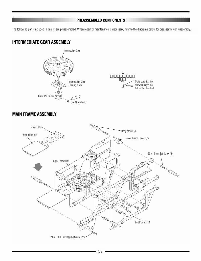
53
PREASSEMBLED COMPONENTS
The following parts included in this kit are preassembled. When repair or maintenance is necessary, refer to the diagrams below for disassembly or reassembly.
Intermediate Gear
Intermediate GearBearing block
Use Threadlock
Front Tail Pulley
Make sure that the screw engages the flat spot of the shaft.
Body Mount (4)
Frame Spacer (2)
26 x 15 mm Set Screw (4)
Left Frame Half
2.6 x 8 mm Self Tapping Screw (22)
Right Frame Half
Front Radio Bed
Motor Plate
INTERMEDIATE GEAR ASSEMBLY
MAIN FRAME ASSEMBLY
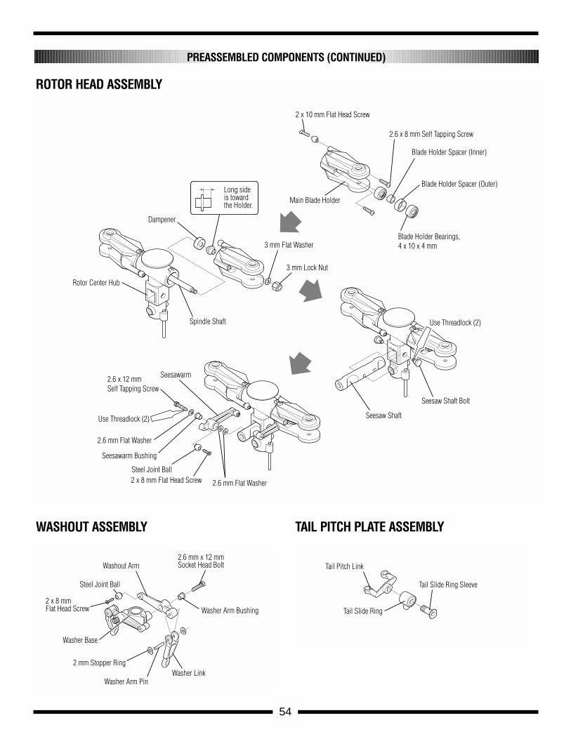
54
PREASSEMBLED COMPONENTS (CONTINUED)
2 x 10 mm Flat Head Screw
2.6 x 8 mm Self Tapping Screw
Blade Holder Spacer (Inner)
Blade Holder Spacer (Outer)
Blade Holder Bearings,4 x 10 x 4 mm
Main Blade HolderLong side is toward the Holder.
Dampener
3 mm Flat Washer
3 mm Lock Nut
Spindle Shaft
Rotor Center Hub
Seesawarm2.6 x 12 mm Self Tapping Screw
Use Threadlock (2)
2.6 mm Flat Washer
Seesawarm Bushing
Steel Joint Ball2 x 8 mm Flat Head Screw 2.6 mm Flat Washer
Seesaw Shaft Bolt
Use Threadlock (2)
Seesaw Shaft
ROTOR HEAD ASSEMBLY
WASHOUT ASSEMBLY TAIL PITCH PLATE ASSEMBLY
2.6 mm x 12 mm Socket Head BoltWashout Arm
Steel Joint Ball
2 x 8 mm Flat Head Screw
Washer Base
2 mm Stopper Ring
Washer Arm PinWasher Link
Washer Arm Bushing
Tail Slide Ring Sleeve
Tail Slide Ring
Tail Pitch Link
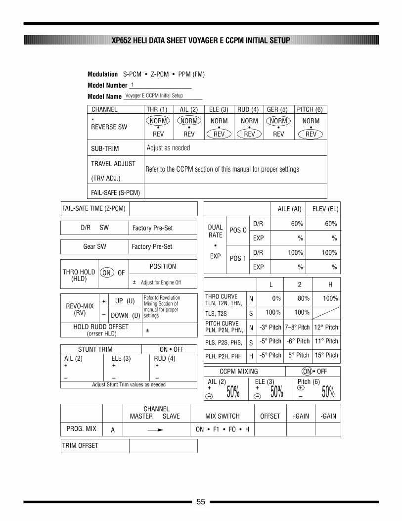
55
XP652 HELI DATA SHEET VOYAGER E CCPM INITIAL SETUP
Factory Pre-Set
Factory Pre-Set
D/R 60% 60%
EXP % %
D/R 100% 100%
EXP % %
TRIM OFFSET
CHANNEL THR (1) AIL (2) ELE (3) RUD (4) GER (5) PITCH (6)
NORM NORM NORM NORM NORM NORM• • • • • •
REV REV REV REV REV REV
SUB-TRIM
TRAVEL ADJUST
(TRV ADJ.)
FAIL-SAFE (S-PCM)
REVERSE SW*
FAIL-SAFE TIME (Z-PCM) AILE (AI) ELEV (EL)
POS O
POS 1
L 2 H
N
S
N
S
H
THRO CURVE TLN, T2N, THN,
TLS, T2S
PITCH CURVEPLN, P2N, PHN,
PLS, P2S, PHS,
PLH, P2H, PHH
0% 80% 100%
100% 100%
-3° Pitch 7–8° Pitch 12° Pitch
-5° Pitch -6° Pitch 11° Pitch
-5° Pitch 5° Pitch 15° Pitch
DUAL RATE
•
EXP
D/R SW
Gear SW
REVO-MIX(RV)
HOLD RUDD OFFSET(OFFSET HLD)
UP (U)
±
DOWN (D)
+
–
THRO HOLD(HLD)
ON OF
PROG. MIX A
CHANNELMASTER SLAVE MIX SWITCH OFFSET +GAIN -GAIN
ON • F1 • FO • H
POSITION
±
Modulation S-PCM • Z-PCM • PPM (FM)
Model Number ___________________
Model Name ________________________
AIL (2) ELE (3) Pitch (6)
CCPM MIXING ON • OFF
+– 50%50% 50%+
–+–
AIL (2) ELE (3) RUD (4)STUNT TRIM ON • OFF
+
–
+
–
+
–Adjust Stunt Trim values as needed
Voyager E CCPM Initial Setup
1
Adjust as needed
Adjust for Engine Off
Refer to RevolutionMixing Section ofmanual for propersettings
Refer to the CCPM section of this manual for proper settings
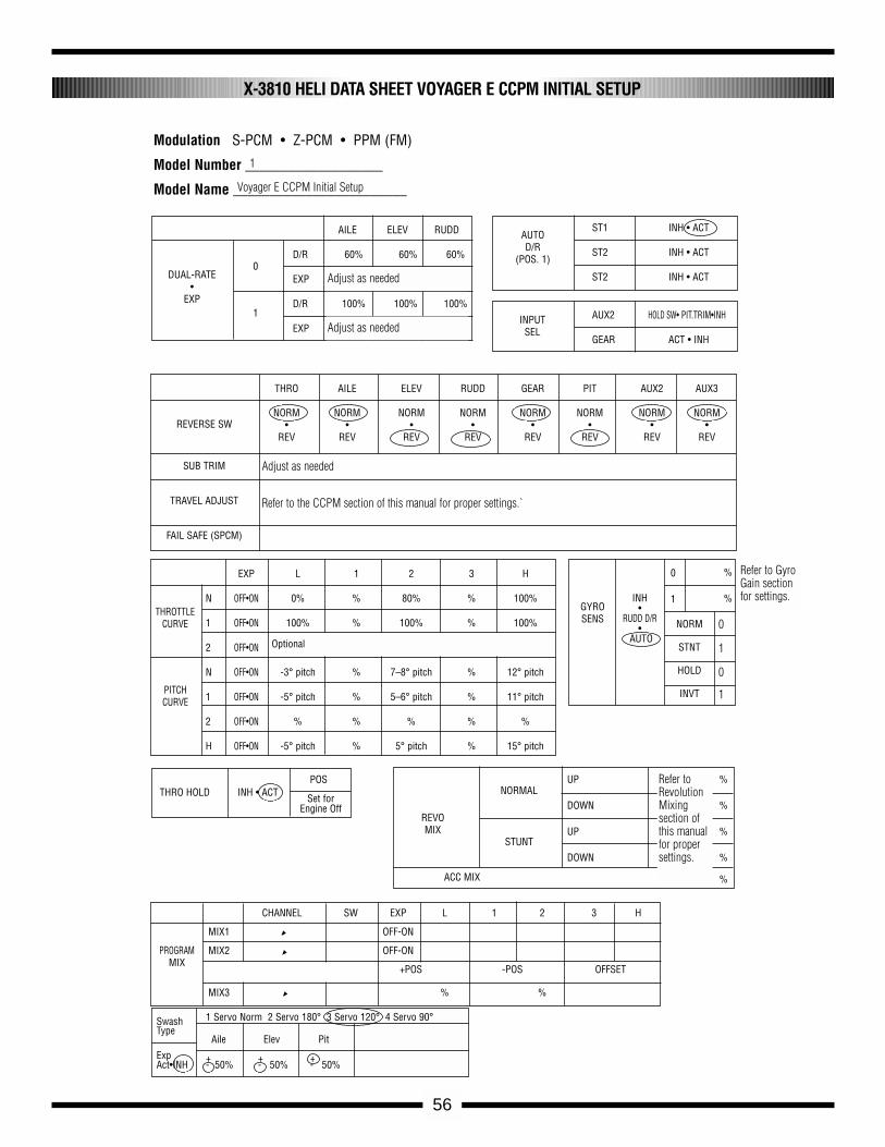
56
X-3810 HELI DATA SHEET VOYAGER E CCPM INITIAL SETUP
Modulation S-PCM • Z-PCM • PPM (FM)
Model Number ___________________
Model Name ________________________ Voyager E CCPM Initial Setup
1
EXP L 1 2 3 H
N OFF•ON 0% % 80% % 100%
1 OFF•ON 100% % 100% % 100%
2 OFF•ON
N OFF•ON -3° pitch % 7–8° pitch % 12° pitch
1 OFF•ON -5° pitch % 5–6° pitch % 11° pitch
2 OFF•ON % % % % %
H OFF•ON -5° pitch % 5° pitch % 15° pitch
1
AILE ELEV RUDD
D/R 60% 60% 60%
EXP
D/R 100% 100% 100%
EXP
0
0 %
%
Set for Engine Off
POS
REVOMIX
ACC MIX
NORMAL
NORM
STNT
HOLD
INVT
UP %
DOWN %
UP %
DOWN %
%
GYROSENS
INH•
RUDD D/R•
AUTO
STUNT
PROGRAMMIX
THROTTLECURVE
PITCHCURVE
THRO HOLD INH • ACT
CHANNEL SW EXP L 1 2 3 H
MIX1 OFF-ON
MIX2 OFF-ON
+POS -POS OFFSET
MIX3 % %
REVERSE SW
SUB TRIM
TRAVEL ADJUST
FAIL SAFE (SPCM)
THRO AILE ELEV RUDD GEAR PIT AUX2 AUX3
NORM NORM NORM NORM NORM NORM NORM NORM• • • • • • • •
REV REV REV REV REV REV REV REV
DUAL-RATE•
EXP
AUTOD/R
(POS. 1)
ST1 INH • ACT
ST2 INH • ACT
ST2 INH • ACT
AUX2 HOLD SW• PIT.TRIM•INH
GEAR ACT • INH
INPUTSEL
1
Adjust as needed
Adjust as needed
Adjust as needed
Refer to the CCPM section of this manual for proper settings.`
Optional
Refer to GyroGain sectionfor settings.
Refer toRevolutionMixing section ofthis manualfor propersettings.
0
1
0
1
Swash 1 Servo Norm 2 Servo 180° 3 Servo 120° 4 Servo 90°Type
Aile Elev Pit
Exp + + +Act•INH - 50% - 50% - 50%
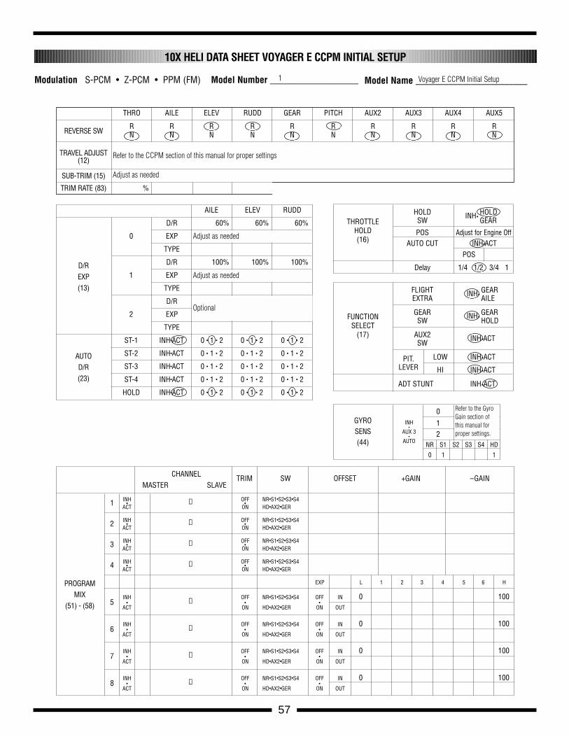
57
10X HELI DATA SHEET VOYAGER E CCPM INITIAL SETUP
THRO AILE ELEV RUDD GEAR PITCH AUX2 AUX3 AUX4 AUX5
R R R R R R R R R RN N N N N N N N N N
%
REVERSE SW
TRAVEL ADJUST(12)
SUB-TRIM (15)
TRIM RATE (83)
PROGRAMMIX
(51) - (58)
AILE ELEV RUDD
D/R 60% 60% 60%
0 EXP
TYPE
D/R 100% 100% 100%
1 EXP
TYPE
D/R % % %
2 EXP % % %
TYPE
ST-1 INH•ACT 0 • 1 • 2 0 • 1 • 2 0 • 1 • 2
ST-2 INH•ACT 0 • 1 • 2 0 • 1 • 2 0 • 1 • 2
ST-3 INH•ACT 0 • 1 • 2 0 • 1 • 2 0 • 1 • 2
ST-4 INH•ACT 0 • 1 • 2 0 • 1 • 2 0 • 1 • 2
HOLD INH•ACT 0 • 1 • 2 0 • 1 • 2 0 • 1 • 2
D/REXP(13)
AUTOD/R(23)
HOLD INH•HOLD
SW GEAR
POS Adjust for Engine OffAUTO CUT INH•ACT
POS
Delay 1/4 1/2 3/4 1
FLIGHT INH•GEAR
EXTRA AILE
GEAR INH•GEAR
SW HOLD
AUX2 INH•ACTSW
PIT. LOW INH•ACTLEVER HI INH•ACT
ADT STUNT INH•ACT
THROTTLEHOLD(16)
INH•
AUX 3•
AUTO
0
12
NR S1 S2 S3 S4 HD
0 1 1
GYROSENS(44)
FUNCTIONSELECT
(17)
CHANNEL TRIM SW OFFSET +GAIN –GAINMASTER SLAVE
INH OFF NR•S1•S2•S3•S41 • → •ACT ON HD•AX2•GER
INH OFF NR•S1•S2•S3•S42 • → •ACT ON HD•AX2•GER
INH OFF NR•S1•S2•S3•S43 • → •ACT ON HD•AX2•GER
INH OFF NR•S1•S2•S3•S44 • → •ACT ON HD•AX2•GER
EXP L 1 2 3 4 5 6 H
INH OFF NR•S1•S2•S3•S4 OFF IN 0 1005 • → • •
ACT ON HD•AX2•GER ON OUT
INH OFF NR•S1•S2•S3•S4 OFF IN 0 1006 • → • •
ACT ON HD•AX2•GER ON OUT
INH OFF NR•S1•S2•S3•S4 OFF IN 0 1007 • → • •
ACT ON HD•AX2•GER ON OUT
INH OFF NR•S1•S2•S3•S4 OFF IN 0 1008 • → • •
ACT ON HD•AX2•GER ON OUT
Refer to the CCPM section of this manual for proper settings
Adjust as needed
Adjust as needed
Adjust as needed
Optional
Refer to the GyroGain section ofthis manual forproper settings.
Modulation S-PCM • Z-PCM • PPM (FM) 1 Model Name ________________________ Voyager E CCPM Initial SetupModel Number ___________________
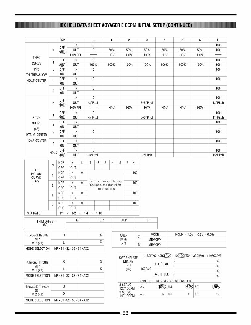
58
10X HELI DATA SHEET VOYAGER E CCPM INITIAL SETUP (CONTINUED)
TRIM OFFSET HV.T HV.P LO.P HI.P(82)
NNOR IN L 1 2 3 4 5 6 HORG OUT
1NOR IN 0 100ORG OUT
2NOR IN 0 100ORG OUT
3NOR IN 0 100ORG OUT
4NOR IN 0 100ORG OUT
MIX RATE 1/1 • 1/2 • 1/4 • 1/10
TAILROTORCURVE
(47)
ZMODE HOLD • 1.0s • 0.5s • 0.25s
MEMORYS MEMORY
FAIL-SAFE(77)
1 SERVO • 3SERVO - 120°CCPM • 3SERVO - 140°CCPM
ELE →AILD %
1SERVOU %
AIL →ELEL %R %
SWITCH NR • S1 • S2 • S3 • S4 • HD3 SERVO
AIL -50% ELE -50% PIT +50%120° CCPM3 SERVO
AIL % ELE % PIT %140° CCPM
SWASHPLATEMIXINGTYPE(65)
R %
L %
MODE SELECTION NR • S1 • S2 • S3 • S4 • AX2
Rudder→Throttle4→1
MIX (41)
R %
L %
MODE SELECTION NR • S1 • S2 • S3 • S4 • AX2
Aileron→Throttle2→1
MIX (41)
U
D
MODE SELECTION NR • S1 • S2 • S3 • S4 • AX2
Elevator→Throttle3→1
MIX (41)
EXP L 1 2 3 4 5 6 H
OFFIN 0 100
N • OUT 0 50% 50% 50% 50% 50% 50% 100ON
HOV.SEL —— HOV HOV HOV HOV HOV HOV ——
1OFF IN 0 100
•ON OUT 100% 100% 100% 100% 100% 100% 100% 100
2OFF IN 0 100
•ON OUT
3OFF IN 0 100
•ON OUT
4OFF IN 0 100
•ON OUT
OFFIN 0 100
N • OUT -3°Pitch 7–8°Pitch 12°PitchON
HOV.SEL —— HOV HOV HOV HOV HOV HOV ——
1OFF IN 0 100
•ON OUT -5°Pitch 5–6°Pitch 11°Pitch
2OFF IN 0 100
•ON OUT
3OFF IN 0 100
•ON OUT
4OFF IN 0 100
•ON OUT
HOLDOFF IN 0 100
•ON OUT -3°Pitch 5°Pitch 15°Pitch
THRO
CURVE
(18)
TH,TRIM=SLOW
HOV.T=CENTER
PITCH
CURVE
(68)
P,TRIM=CENTER
HOV.P=CENTER
Refer to Revolution MixingSection of this manual for
proper settings
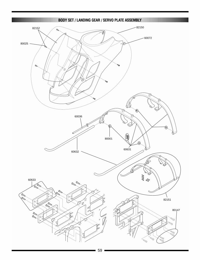
60036
60631
82151
80001
60632
60072
8215082152
80025
60633
80147
59
BODY SET / LANDING GEAR / SERVO PLATE ASSEMBLY
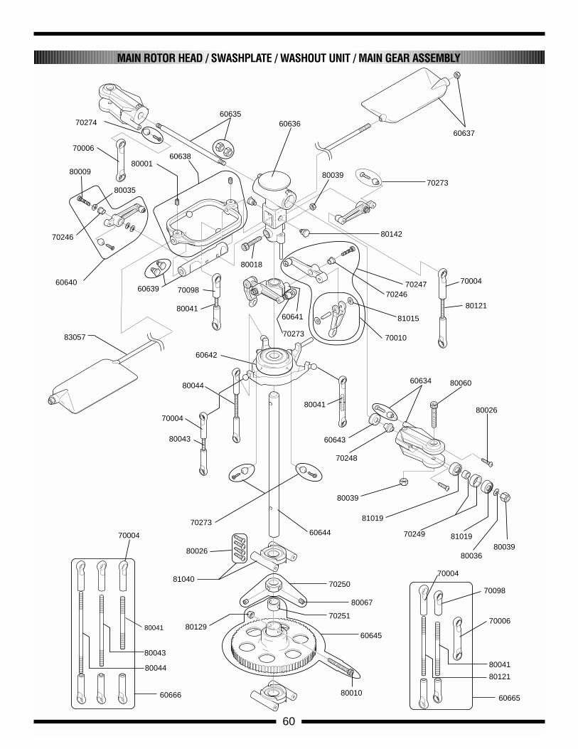
70246
80035
80009
6064060639
8000160638
6063560636
80039
60637
70273
80018
80142
70247 70004
80121
81015
70246
70010
60641
81019
80026
70248
60643
7027360644
81040
80026
60645
80010
80129
80041
80041
70006
70006
80121
70098
70098
70004
70004
70004
6066560666
80044
80043
70250
70251
70249 81019
80036
83057
60634
80039
80039
80060
80067
80041
60642
80044
80043
80041
70274
70273
60
MAIN ROTOR HEAD / SWASHPLATE / WASHOUT UNIT / MAIN GEAR ASSEMBLY
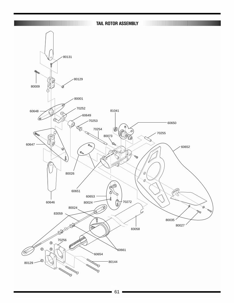
80009
60648
80129
80131
70252
80001
60649
70253
70254
80073
81041
70255
60650
60652
60651
80026
60646
83059
60661
80129
83058
80035
80027
60654
70256
80144
60647
60653
80024
80024
70272
TAIL ROTOR ASSEMBLY
61
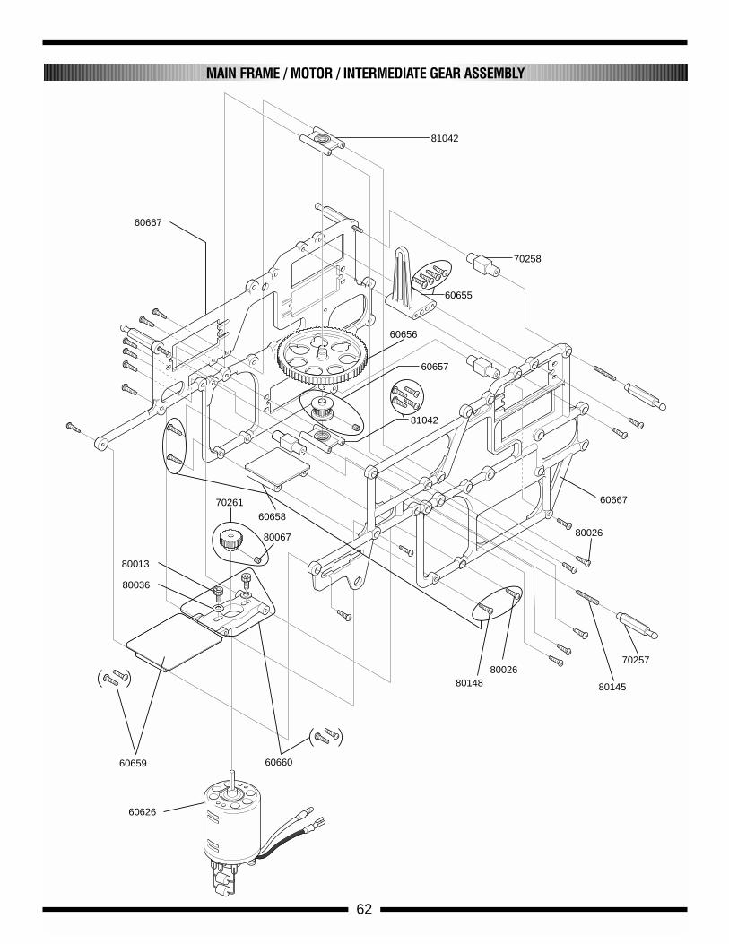
60667
60667
81042
60655
70258
60656
60657
81042
80145
80026
8014880026
60658
80067
70261
60660
60626
60659
80036
70257
80013
MAIN FRAME / MOTOR / INTERMEDIATE GEAR ASSEMBLY
62
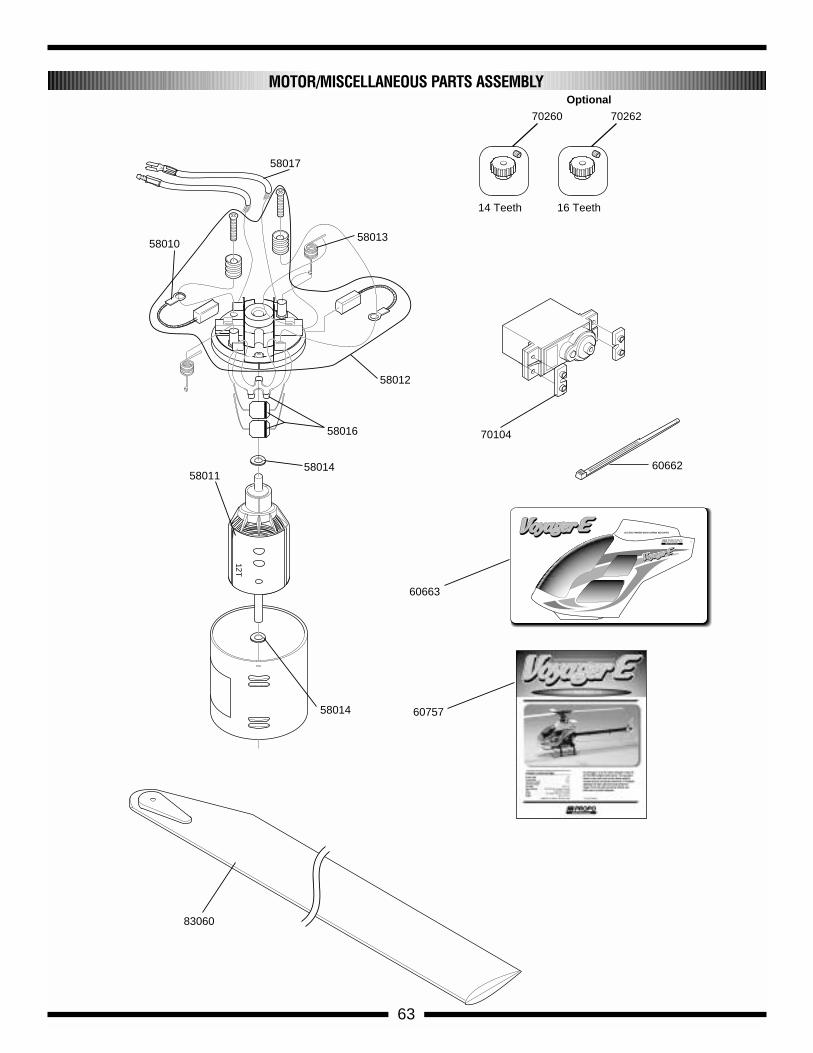
58017
5801058013
58016
58012
58014
5801458011
70260
14 Teeth
70262
16 Teeth
83060
70104
60663
60757
60662
OptionalMOTOR/MISCELLANEOUS PARTS ASSEMBLY
63
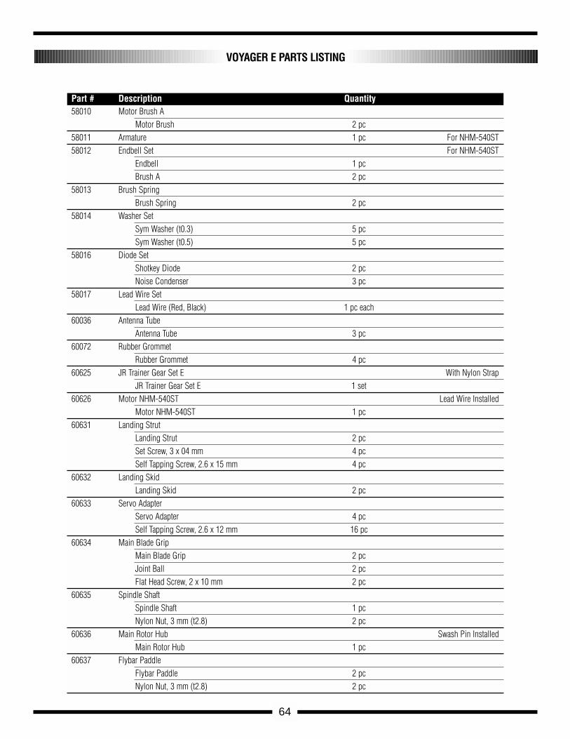
64
VOYAGER E PARTS LISTING
58010 Motor Brush AMotor Brush 2 pc
58011 Armature 1 pc For NHM-540ST58012 Endbell Set For NHM-540ST
Endbell 1 pcBrush A 2 pc
58013 Brush Spring Brush Spring 2 pc
58014 Washer Set Sym Washer (t0.3) 5 pcSym Washer (t0.5) 5 pc
58016 Diode Set Shotkey Diode 2 pcNoise Condenser 3 pc
58017 Lead Wire Set Lead Wire (Red, Black) 1 pc each
60036 Antenna TubeAntenna Tube 3 pc
60072 Rubber GrommetRubber Grommet 4 pc
60625 JR Trainer Gear Set E With Nylon StrapJR Trainer Gear Set E 1 set
60626 Motor NHM-540ST Lead Wire InstalledMotor NHM-540ST 1 pc
60631 Landing StrutLanding Strut 2 pcSet Screw, 3 x 04 mm 4 pcSelf Tapping Screw, 2.6 x 15 mm 4 pc
60632 Landing SkidLanding Skid 2 pc
60633 Servo AdapterServo Adapter 4 pcSelf Tapping Screw, 2.6 x 12 mm 16 pc
60634 Main Blade GripMain Blade Grip 2 pcJoint Ball 2 pcFlat Head Screw, 2 x 10 mm 2 pc
60635 Spindle ShaftSpindle Shaft 1 pcNylon Nut, 3 mm (t2.8) 2 pc
60636 Main Rotor Hub Swash Pin InstalledMain Rotor Hub 1 pc
60637 Flybar PaddleFlybar Paddle 2 pcNylon Nut, 3 mm (t2.8) 2 pc
Part # Description Quantity
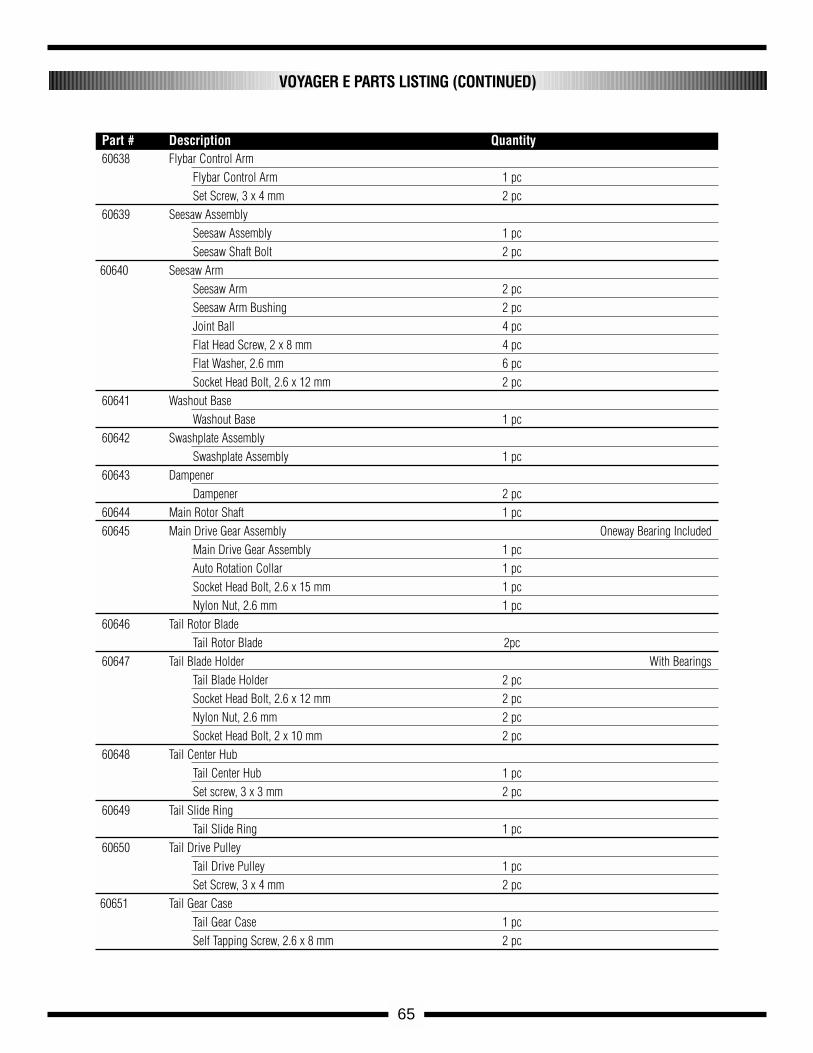
65
60638 Flybar Control ArmFlybar Control Arm 1 pcSet Screw, 3 x 4 mm 2 pc
60639 Seesaw AssemblySeesaw Assembly 1 pcSeesaw Shaft Bolt 2 pc
60640 Seesaw ArmSeesaw Arm 2 pcSeesaw Arm Bushing 2 pcJoint Ball 4 pcFlat Head Screw, 2 x 8 mm 4 pcFlat Washer, 2.6 mm 6 pcSocket Head Bolt, 2.6 x 12 mm 2 pc
60641 Washout BaseWashout Base 1 pc
60642 Swashplate AssemblySwashplate Assembly 1 pc
60643 DampenerDampener 2 pc
60644 Main Rotor Shaft 1 pc60645 Main Drive Gear Assembly Oneway Bearing Included
Main Drive Gear Assembly 1 pcAuto Rotation Collar 1 pcSocket Head Bolt, 2.6 x 15 mm 1 pcNylon Nut, 2.6 mm 1 pc
60646 Tail Rotor BladeTail Rotor Blade 2pc
60647 Tail Blade Holder With BearingsTail Blade Holder 2 pcSocket Head Bolt, 2.6 x 12 mm 2 pcNylon Nut, 2.6 mm 2 pcSocket Head Bolt, 2 x 10 mm 2 pc
60648 Tail Center HubTail Center Hub 1 pcSet screw, 3 x 3 mm 2 pc
60649 Tail Slide RingTail Slide Ring 1 pc
60650 Tail Drive PulleyTail Drive Pulley 1 pcSet Screw, 3 x 4 mm 2 pc
60651 Tail Gear CaseTail Gear Case 1 pcSelf Tapping Screw, 2.6 x 8 mm 2 pc
VOYAGER E PARTS LISTING (CONTINUED)
Part # Description Quantity

66
60652 Horizontal & Vertical Fin SetVertical Fin 1 pcHorizontal Fin 1 pc Self Tapping Screw, 2.6 x 12 mm 2 pcFlat Washer, 2.6mm 2 pc
60653 Tail Pitch Control LeverTail Pitch Control Lever 1 pc Tail Lever Spacer 1 pc Self Tapping Screw, 2 x 8 mm 1 pc Joint Ball 1 pc Flat Head Screw, 2 x 7 mm 1 pc
60654 Tail Drive Belt Tail Drive Belt 1 pc
60655 Anti-Rotation PlateAnti-Rotation Plate 1 pc Self Tapping Screw, 2.6 x 8 mm 4 pc
60656 Intermediate GearIntermediate Gear 1 pc
60657 Front Tail PulleyFront Tail Pulley 1 pc Set screw, 3 x 3 mm 1 pc
60658 Gyro MountGyro Mount 1 pc Self-Tapping Screw, 2.6 x 15mm 2 pcSelf-Tapping Screw, 2.6 x 8 mm 2 pc
60659 Front Radio BedFront Radio Bed 1 pc Self-Tapping Screw, 2.6 x 8 mm 2 pc
60660 Motor MountMotor Mount 1 pc Socket Head Bolt, 3 x 8 mm 2 pc Flat Washer, 3 mm 2 pcSelf-Tapping Screw, 2.6 x 8 mm 2 pc
60661 Tail Guide Clamp (2pcs)Tail Guide Clamp 2 pcTail Control Bushing 2 pcSelf-Tapping Screw, 2 x 8 mm 2pc
60662 Nylon StrapNylon Strap 10 pc
60663 Decal SetDecal A 1 pc
60757 Assembly Instruction ManualAssembly Instruction Manual 1 pc
VOYAGER E PARTS LISTING (CONTINUED)
Part # Description Quantity
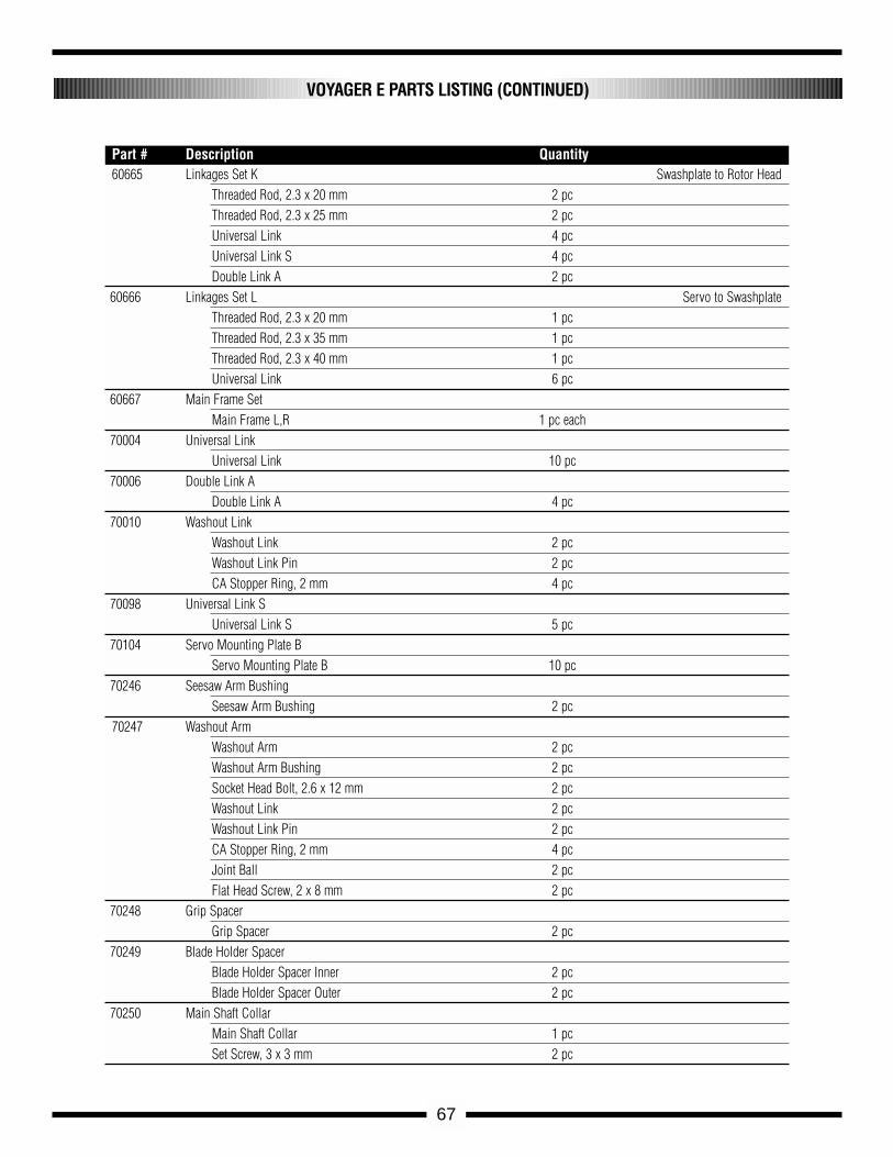
67
60665 Linkages Set K Swashplate to Rotor Head Threaded Rod, 2.3 x 20 mm 2 pcThreaded Rod, 2.3 x 25 mm 2 pcUniversal Link 4 pcUniversal Link S 4 pcDouble Link A 2 pc
60666 Linkages Set L Servo to SwashplateThreaded Rod, 2.3 x 20 mm 1 pc Threaded Rod, 2.3 x 35 mm 1 pc Threaded Rod, 2.3 x 40 mm 1 pc Universal Link 6 pc
60667 Main Frame SetMain Frame L,R 1 pc each
70004 Universal LinkUniversal Link 10 pc
70006 Double Link ADouble Link A 4 pc
70010 Washout LinkWashout Link 2 pcWashout Link Pin 2 pcCA Stopper Ring, 2 mm 4 pc
70098 Universal Link SUniversal Link S 5 pc
70104 Servo Mounting Plate BServo Mounting Plate B 10 pc
70246 Seesaw Arm BushingSeesaw Arm Bushing 2 pc
70247 Washout ArmWashout Arm 2 pcWashout Arm Bushing 2 pcSocket Head Bolt, 2.6 x 12 mm 2 pcWashout Link 2 pcWashout Link Pin 2 pcCA Stopper Ring, 2 mm 4 pcJoint Ball 2 pcFlat Head Screw, 2 x 8 mm 2 pc
70248 Grip SpacerGrip Spacer 2 pc
70249 Blade Holder SpacerBlade Holder Spacer Inner 2 pcBlade Holder Spacer Outer 2 pc
70250 Main Shaft CollarMain Shaft Collar 1 pcSet Screw, 3 x 3 mm 2 pc
VOYAGER E PARTS LISTING (CONTINUED)
Part # Description Quantity
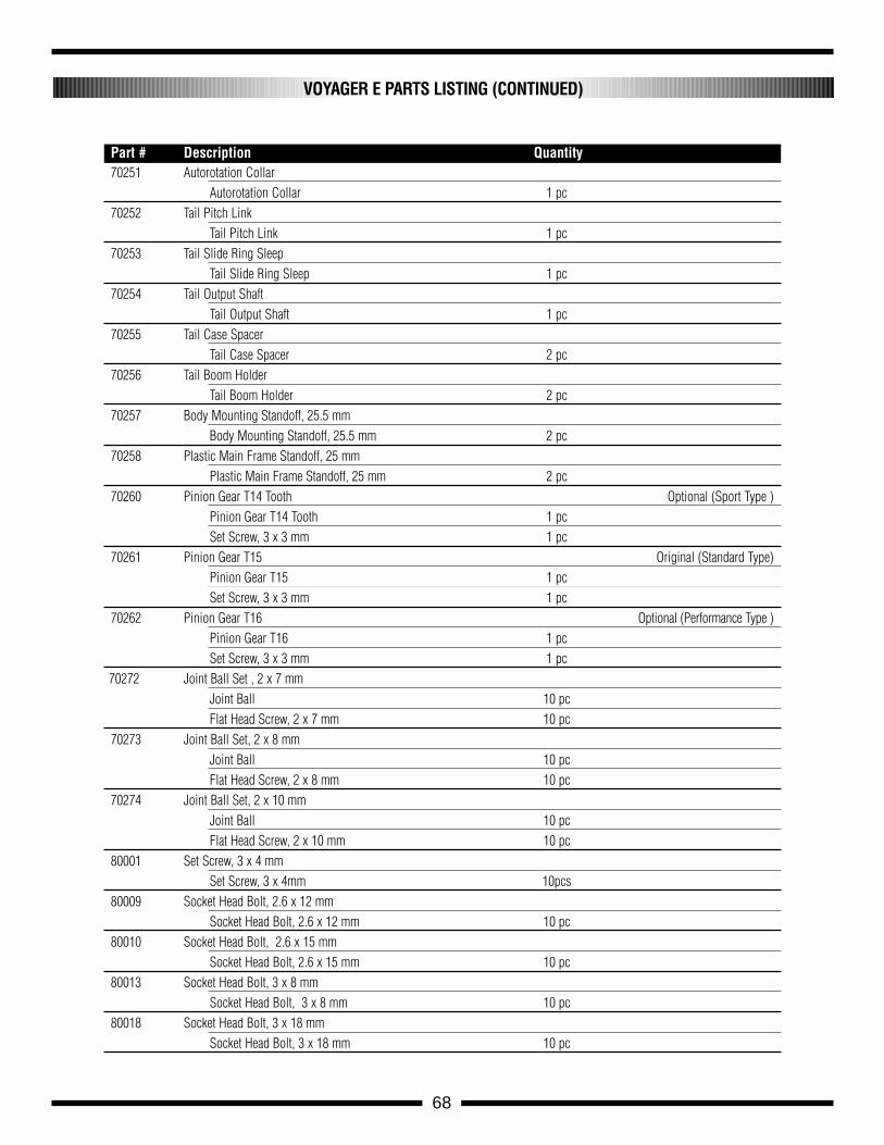
70251 Autorotation CollarAutorotation Collar 1 pc
70252 Tail Pitch LinkTail Pitch Link 1 pc
70253 Tail Slide Ring SleepTail Slide Ring Sleep 1 pc
70254 Tail Output ShaftTail Output Shaft 1 pc
70255 Tail Case SpacerTail Case Spacer 2 pc
70256 Tail Boom HolderTail Boom Holder 2 pc
70257 Body Mounting Standoff, 25.5 mmBody Mounting Standoff, 25.5 mm 2 pc
70258 Plastic Main Frame Standoff, 25 mmPlastic Main Frame Standoff, 25 mm 2 pc
70260 Pinion Gear T14 Tooth Optional (Sport Type )Pinion Gear T14 Tooth 1 pcSet Screw, 3 x 3 mm 1 pc
70261 Pinion Gear T15 Original (Standard Type)Pinion Gear T15 1 pcSet Screw, 3 x 3 mm 1 pc
70262 Pinion Gear T16 Optional (Performance Type )Pinion Gear T16 1 pcSet Screw, 3 x 3 mm 1 pc
70272 Joint Ball Set , 2 x 7 mmJoint Ball 10 pcFlat Head Screw, 2 x 7 mm 10 pc
70273 Joint Ball Set, 2 x 8 mmJoint Ball 10 pcFlat Head Screw, 2 x 8 mm 10 pc
70274 Joint Ball Set, 2 x 10 mmJoint Ball 10 pcFlat Head Screw, 2 x 10 mm 10 pc
80001 Set Screw, 3 x 4 mmSet Screw, 3 x 4mm 10pcs
80009 Socket Head Bolt, 2.6 x 12 mmSocket Head Bolt, 2.6 x 12 mm 10 pc
80010 Socket Head Bolt, 2.6 x 15 mmSocket Head Bolt, 2.6 x 15 mm 10 pc
80013 Socket Head Bolt, 3 x 8 mmSocket Head Bolt, 3 x 8 mm 10 pc
80018 Socket Head Bolt, 3 x 18 mmSocket Head Bolt, 3 x 18 mm 10 pc
68
VOYAGER E PARTS LISTING (CONTINUED)
Part # Description Quantity
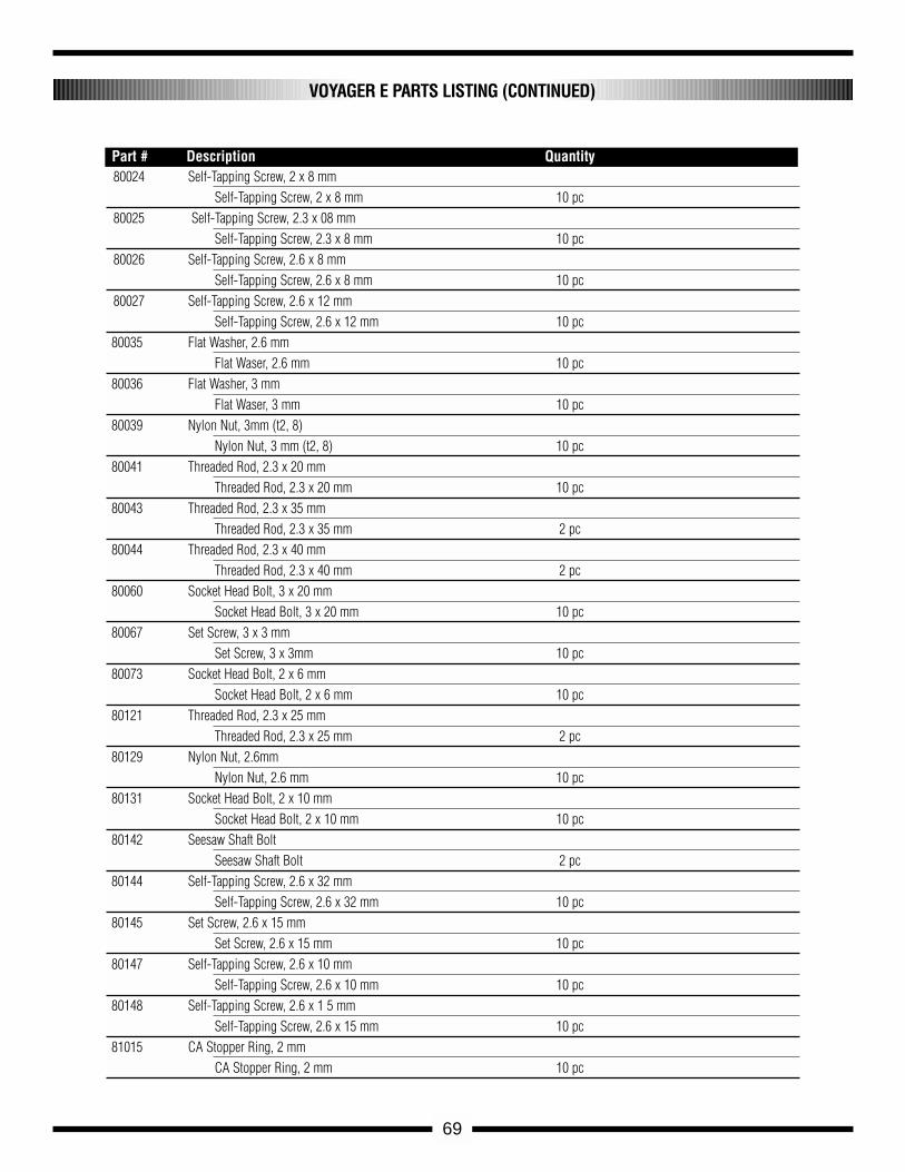
80024 Self-Tapping Screw, 2 x 8 mmSelf-Tapping Screw, 2 x 8 mm 10 pc
80025 Self-Tapping Screw, 2.3 x 08 mmSelf-Tapping Screw, 2.3 x 8 mm 10 pc
80026 Self-Tapping Screw, 2.6 x 8 mmSelf-Tapping Screw, 2.6 x 8 mm 10 pc
80027 Self-Tapping Screw, 2.6 x 12 mmSelf-Tapping Screw, 2.6 x 12 mm 10 pc
80035 Flat Washer, 2.6 mmFlat Waser, 2.6 mm 10 pc
80036 Flat Washer, 3 mmFlat Waser, 3 mm 10 pc
80039 Nylon Nut, 3mm (t2, 8)Nylon Nut, 3 mm (t2, 8) 10 pc
80041 Threaded Rod, 2.3 x 20 mmThreaded Rod, 2.3 x 20 mm 10 pc
80043 Threaded Rod, 2.3 x 35 mmThreaded Rod, 2.3 x 35 mm 2 pc
80044 Threaded Rod, 2.3 x 40 mmThreaded Rod, 2.3 x 40 mm 2 pc
80060 Socket Head Bolt, 3 x 20 mmSocket Head Bolt, 3 x 20 mm 10 pc
80067 Set Screw, 3 x 3 mmSet Screw, 3 x 3mm 10 pc
80073 Socket Head Bolt, 2 x 6 mmSocket Head Bolt, 2 x 6 mm 10 pc
80121 Threaded Rod, 2.3 x 25 mmThreaded Rod, 2.3 x 25 mm 2 pc
80129 Nylon Nut, 2.6mmNylon Nut, 2.6 mm 10 pc
80131 Socket Head Bolt, 2 x 10 mmSocket Head Bolt, 2 x 10 mm 10 pc
80142 Seesaw Shaft BoltSeesaw Shaft Bolt 2 pc
80144 Self-Tapping Screw, 2.6 x 32 mmSelf-Tapping Screw, 2.6 x 32 mm 10 pc
80145 Set Screw, 2.6 x 15 mmSet Screw, 2.6 x 15 mm 10 pc
80147 Self-Tapping Screw, 2.6 x 10 mmSelf-Tapping Screw, 2.6 x 10 mm 10 pc
80148 Self-Tapping Screw, 2.6 x 1 5 mmSelf-Tapping Screw, 2.6 x 15 mm 10 pc
81015 CA Stopper Ring, 2 mmCA Stopper Ring, 2 mm 10 pc
69
VOYAGER E PARTS LISTING (CONTINUED)
Part # Description Quantity
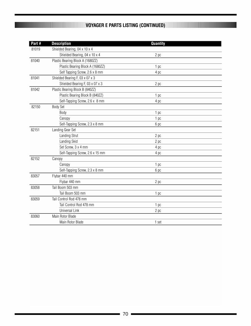
70
VOYAGER E PARTS LISTING (CONTINUED)
Part # Description Quantity81019 Shielded Bearing, 04 x 10 x 4
Shielded Bearing, 04 x 10 x 4 2 pc81040 Plastic Bearing Block A (1680ZZ)
Plastic Bearing Block A (1680ZZ) 1 pcSelf Tapping Screw, 2.6 x 8 mm 4 pc
81041 Shielded Bearing F, 03 x 07 x 3Shielded Bearing F, 03 x 07 x 3 2 pc
81042 Plastic Bearing Block B (840ZZ)Plastic Bearing Block B (840ZZ) 1 pcSelf-Tapping Screw, 2.6 x 8 mm 4 pc
82150 Body SetBody 1 pcCanopy 1 pcSelf-Tapping Screw, 2.3 x 8 mm 6 pc
82151 Landing Gear Set Landing Strut 2 pcLanding Skid 2 pcSet Screw, 3 x 4 mm 4 pcSelf-Tapping Screw, 2.6 x 15 mm 4 pc
82152 CanopyCanopy 1 pcSelf-Tapping Screw, 2.3 x 8 mm 6 pc
83057 Flybar 440 mmFlybar 440 mm 2 pc
83058 Tail Boom 503 mmTail Boom 503 mm 1 pc
83059 Tail Control Rod 478 mmTail Control Rod 478 mm 1 pcUniversal Link 2 pc
83060 Main Rotor BladeMain Rotor Blade 1 set

71
NOTES

Japan Remote Control Co., Ltd.Heli Division