assembly instructions sea fury - graupner fury_900_en.pdf · we reserve the right to introduce ......
TRANSCRIPT
GRAUPNER GmbH & Co. KG D-73230 KIRCHHEIM/TECK GERMA NY We reserve the right to introduce modifications. Not liable for printing errors! 11/2011 - 1 -
Re: Order No. 9351
ASSEMBLY INSTRUCTIONS
SEA FURY
RC semiscale model for 2 LiPo cells
Requires a HoTT radio control system with 6 functio ns

GRAUPNER GmbH & Co. KG D-73230 KIRCHHEIM/TECK GERMA NY We reserve the right to introduce modifications. Not liable for printing errors! 11/2011 - 2 -
Please be sure to observe the safety notes attached to these operating instructions. If the model is passed on to others, the complete operating instructions must also be passed on to and observed by them.
General The model SEA FURY is a particularly beautiful RC semiscale model, which, thanks to its compact dimensions, is easy to transport. However, the small dimensions should not mislead you into thinking that the assembly and operation of the model does not require sound model aircraft experience. The model is extensively pre-assembled. The assembly steps described in the following must be carried out with the greatest of care to ensure safe and successful use of the model. The all-up weight may not exceed 1000 g. RC accessories (not included) The accessories listed in the following are required for the assembly and operation of the model. MX-16 COMPUTER SYSTEM 2.4 GRAUPNER HoTT Order No. 33116 Transmitter charger cable Order No. 3022 Electric retractable undercarriage (mechanism) 2 units Order No. 193.3 Connecting cable for retractable undercarriage Order No. 3936.32 Brushless Motor COMPACT 345Z Order No. 7738 ELEKTRO PROP 10x5” Order No. 1326. 10x5 GRP Propeller Spacer Order No. 197.60 COMPACT CONTROL 45 Order No. 7224 LiPo 2/1600 7.4 V/1.6 Ah Order No. 7634.2 G 3.5 Charger Cable Order No. 2970.L Charger ULTRAMAT 16 S Order No. 6468 Servo DES 476 BB (6 required) Order No. 7915 Servo Extension Cable 100 mm (4 required) Order No. 3935.11 Servo Extension Cable 320 mm (2 required) Order No. 3935.32 Hook-and-Loop Cable Tie Order No. 1587 Required tools and adhesives (not included) Balsa Knife Order No. 980 Fast Setting Glue Order No. 5821 Activator for Fast Setting Glue Order No. 953.150 UHU ALL PURPOSE ADHESIVE�Power Order No. 1096 You will also need the following items: Philips screwdriver, open-end spanner SW 12, flat-nose pliers, wire cutter, drill Ø 1.6, Allen wrenches SW 1.5 and SW 2.5 mm, soldering gun and solder, hair dryer, sandpaper, geometric protractor, overhead marker, transparent tape, wood pulp paper, protective gloves, safety glasses. Assembly instructions Please read these building instructions completely before you start building, so that you have a clear idea of the sequence required. Before each stage, identify all the parts, tools and adhesives you will need, and have them ready. When working, always lay the parts on a clean, smooth surface, or a layer of foam material. Unless the instructions specifically state otherwise, use fast-setting glue with activator as adhesive. The best method is to apply glue to one face, then spray activator on the
GRAUPNER GmbH & Co. KG D-73230 KIRCHHEIM/TECK GERMA NY We reserve the right to introduce modifications. Not liable for printing errors! 11/2011 - 3 -
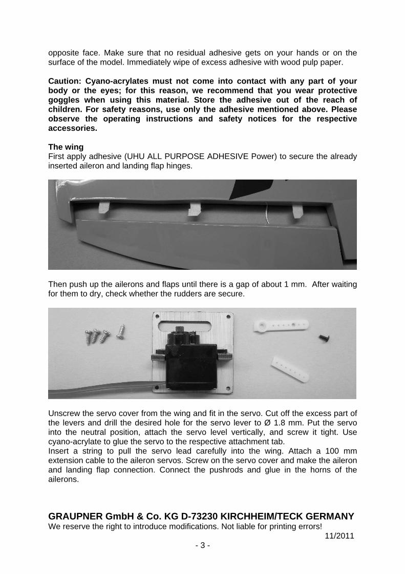
opposite face. Make sure that no residual adhesive gets on your hands or on the surface of the model. Immediately wipe of excess adhesive with wood pulp paper. Caution: Cyano-acrylates must not come into contact with any part of your body or the eyes; for this reason, we recommend tha t you wear protective goggles when using this material. Store the adhesiv e out of the reach of children. For safety reasons, use only the adhesive mentioned above. Please observe the operating instructions and safety notic es for the respective accessories. The wing First apply adhesive (UHU ALL PURPOSE ADHESIVE Power) to secure the already inserted aileron and landing flap hinges.
Then push up the ailerons and flaps until there is a gap of about 1 mm. After waiting for them to dry, check whether the rudders are secure.
Unscrew the servo cover from the wing and fit in the servo. Cut off the excess part of the levers and drill the desired hole for the servo lever to Ø 1.8 mm. Put the servo into the neutral position, attach the servo level vertically, and screw it tight. Use cyano-acrylate to glue the servo to the respective attachment tab. Insert a string to pull the servo lead carefully into the wing. Attach a 100 mm extension cable to the aileron servos. Screw on the servo cover and make the aileron and landing flap connection. Connect the pushrods and glue in the horns of the ailerons.

GRAUPNER GmbH & Co. KG D-73230 KIRCHHEIM/TECK GERMA NY We reserve the right to introduce modifications. Not liable for printing errors! 11/2011 - 4 -
The figure shows the completed aileron connection. Note that the length of the servo levers should be a minimum of 14 mm to keep the clevis from colliding with the wing.
The figure shows the completed landing flap connection. Note that the length of the servo levers should be a minimum of 12 mm to keep the clevis from colliding with the wing. Note: Arrange the spreading landing gear so that the flap deflection is about 12 mm with the servo in neutral position, as shown here. Set the full deflection to about 25 mm. It is best to operate the flaps on the transmitter with a 3-stage switch. The asymmetrical servo arrangement makes it possible later to control both servos without a mixer with a connector cable Order No. 3936.32 at one of the transmitter outputs.
The figure shows the servo lead exiting at the wing root. Later, use the CRP tube Ø 5x125 mm to push the halves of the wing onto the fuselage.

GRAUPNER GmbH & Co. KG D-73230 KIRCHHEIM/TECK GERMA NY We reserve the right to introduce modifications. Not liable for printing errors! 11/2011 - 5 -
Fuselage with tail group and cockpit canopy First place the motor spindle, motor mount, and locking ring onto the motor; these parts are included as accessories in the package for Order No. 7738.
The figure shows the individual parts for the motor spindle and motor mount; tighten all screws.
The figure shows the motor with attached motor mount and motor spindle. Separate the motor leads and remove about 5 mm of insulation. Apply solder to the ends of all leads and then solder on the G 3.5 connectors (included with Order No. 7738); insulate the connector shaft with the heat-shrink sleeves (included with Order No. 7738). Use a hair dryer to shrink the heat-shrink sleeve. Then do a test run of the motor. Viewed in flight direction, the motor should rotate to the right; if this is not the case, switch any two of the leads and re-insert.
GRAUPNER GmbH & Co. KG D-73230 KIRCHHEIM/TECK GERMA NY We reserve the right to introduce modifications. Not liable for printing errors! 11/2011 - 6 -
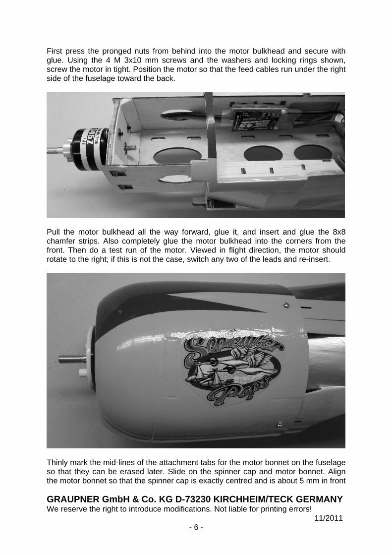
First press the pronged nuts from behind into the motor bulkhead and secure with glue. Using the 4 M 3x10 mm screws and the washers and locking rings shown, screw the motor in tight. Position the motor so that the feed cables run under the right side of the fuselage toward the back.
Pull the motor bulkhead all the way forward, glue it, and insert and glue the 8x8 chamfer strips. Also completely glue the motor bulkhead into the corners from the front. Then do a test run of the motor. Viewed in flight direction, the motor should rotate to the right; if this is not the case, switch any two of the leads and re-insert.
Thinly mark the mid-lines of the attachment tabs for the motor bonnet on the fuselage so that they can be erased later. Slide on the spinner cap and motor bonnet. Align the motor bonnet so that the spinner cap is exactly centred and is about 5 mm in front

GRAUPNER GmbH & Co. KG D-73230 KIRCHHEIM/TECK GERMA NY We reserve the right to introduce modifications. Not liable for printing errors! 11/2011 - 7 -
of the forward edge of the motor bonnet. Hold the motor bonnet in place with tape, and drill the Ø 1 mm attachment holes. Screw the motor bonnet on tight with four Ø 2.2x6 mm metal screws.
Place the GRP propeller spacer onto the propeller, enlarge the cut-outs in the spinner cap to fit the propeller, and separate the two short pins on the spinner back plate so that the spinner cap fits and can be pushed on without any stress. When everything fits, attach the spinner to the propeller. Tighten the propeller attachment nut.
Use UHU ALL PURPOSE ADHESIVE Power to glue in the rudder hinges of the tailplane and vertical stabilisers in accordance with the method already described; glue the aileron connectors in with fast-setting glue. Use a geometric protractor and overhead marker to exactly mark the midline of the tailplane, then on all the areas to be glued to the fuselage and on the vertical stabiliser, and also use the hot tip of a soldering gun to cut through the covering sheet, and pull it off. Slide the tailplane into the fuselage exactly centred and glue it. For the lowest rudder hinge of the rudder, cut a slit in the fuselage; then push on the vertical stabiliser as well. First try this procedure without any adhesive. Above all, make sure you do not use activator for the gluing process.

GRAUPNER GmbH & Co. KG D-73230 KIRCHHEIM/TECK GERMA NY We reserve the right to introduce modifications. Not liable for printing errors! 11/2011 - 8 -
The figure shows the rudder servo with the control already attached. Also glue in the rudder horn and drill a Ø 1.6 mm hole in the servo lever arm. Then place rubber grommets on the servo, insert the hollow rivets from below, and screw in the servo. All servo attachment elements are included with the respective servos.
The figure shows the elevator servo with the control already attached. Installation is done according to the same principle as already described. Attach a 320 mm servo extension cable to each aileron and elevator servo.
GRAUPNER GmbH & Co. KG D-73230 KIRCHHEIM/TECK GERMA NY We reserve the right to introduce modifications. Not liable for printing errors! 11/2011 - 9 -
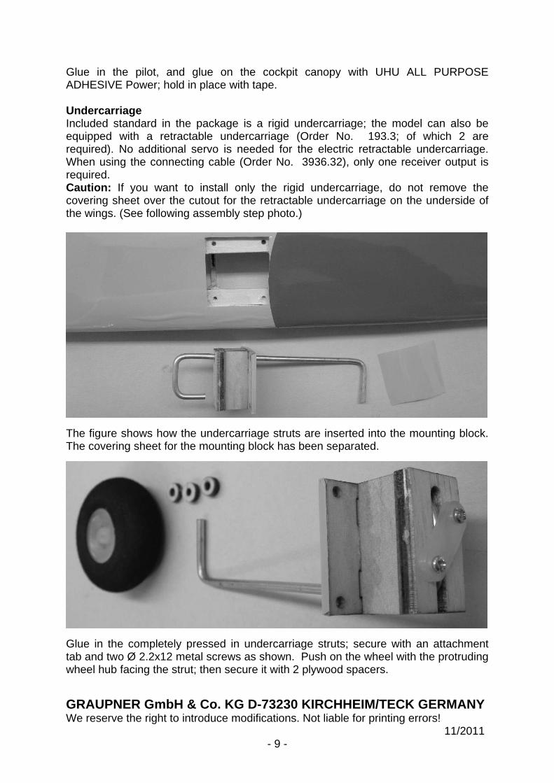
Glue in the pilot, and glue on the cockpit canopy with UHU ALL PURPOSE ADHESIVE Power; hold in place with tape. Undercarriage Included standard in the package is a rigid undercarriage; the model can also be equipped with a retractable undercarriage (Order No. 193.3; of which 2 are required). No additional servo is needed for the electric retractable undercarriage. When using the connecting cable (Order No. 3936.32), only one receiver output is required. Caution: If you want to install only the rigid undercarriage, do not remove the covering sheet over the cutout for the retractable undercarriage on the underside of the wings. (See following assembly step photo.)
The figure shows how the undercarriage struts are inserted into the mounting block. The covering sheet for the mounting block has been separated.
Glue in the completely pressed in undercarriage struts; secure with an attachment tab and two Ø 2.2x12 metal screws as shown. Push on the wheel with the protruding wheel hub facing the strut; then secure it with 2 plywood spacers.
GRAUPNER GmbH & Co. KG D-73230 KIRCHHEIM/TECK GERMA NY We reserve the right to introduce modifications. Not liable for printing errors! 11/2011 - 10 -
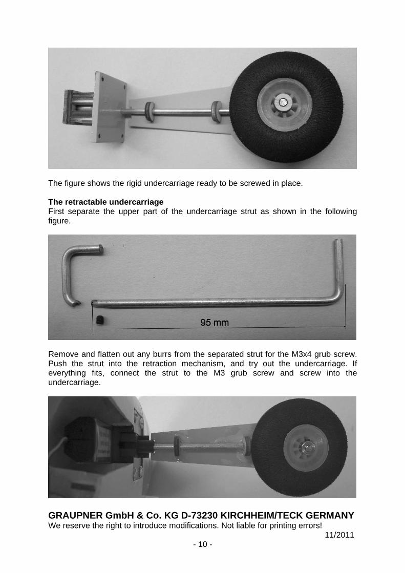
The figure shows the rigid undercarriage ready to be screwed in place. The retractable undercarriage First separate the upper part of the undercarriage strut as shown in the following figure.
Remove and flatten out any burrs from the separated strut for the M3x4 grub screw. Push the strut into the retraction mechanism, and try out the undercarriage. If everything fits, connect the strut to the M3 grub screw and screw into the undercarriage.

GRAUPNER GmbH & Co. KG D-73230 KIRCHHEIM/TECK GERMA NY We reserve the right to introduce modifications. Not liable for printing errors! 11/2011 - 11 -
The figures shows the retracted undercarriage. Deals Cut out the individual decals and name placards and apply them as shown in the illustrations on the kit box. Installing the receiver and LiPo battery The first step is to connect the servo leads to the receiver; we recommend the following sequence: speed controller to socket 1, left aileron servo to socket 2 (extension cable 100 mm), elevator servo to socket 3, rudder servo to socket 4, right aileron servo to socket 5 (extension cable 100 mm), left landing flap socket 6 (extension cable 100 mm). Right landing flap to socket 7 (extension cable 100 mm), retractable undercarriage to socket 8 (connecting cable); now do a test of all functions using the radio control transmitter. Caution: After closing the G3.5 connector, the motor can start; do not touch the propeller!

GRAUPNER GmbH & Co. KG D-73230 KIRCHHEIM/TECK GERMA NY We reserve the right to introduce modifications. Not liable for printing errors! 11/2011 - 12 -
The figure shows the LiPo battery held in place by hook-and-loop cable ties, the speed controller, and the GR-16 HoTT receiver. Push the servo power lines into the receiver before using two M4 plastic screws to mount the wing on the fuselage Rudder deflections The following rudder deflections are recommended, but can be changed as desired. Ailerons 15 mm in each direction, elevators 15 mm in each direction, rudder 30 mm. All measured at the inboard or bottom edge of the rudder. For airbrake deflections, see the section on "The wing." Balancing Check the balance with the model in ready-to-fly condition, meaning with the LiPo inserted. The centre of gravity is 55 mm from the leading edge of the wing. Adjust it by moving the LiPo battery as needed. Check the centre of gravity by simply supporting the model near the centre of gravity under the wing on two fingers. The model should balance level at the point indicated. Flying Fly the model for the first time with rudders in the neutral position on a day with little or no breeze. A smooth runway into the wind is ideal for a ground start. If no runway is available, the model can be started by means of a hand start into the wind. Use minimal aileron and elevator corrections to keep the model in a straight climb. The fine trim is done via the trim slider below or next to the joysticks. Always land the model flying directly into wind, with the motor idling but not switched off. Just before touch-down reduce air speed through careful use of up-elevator. Always land the model into the wind. Here at GRAUPNER Modellbau, we hope you will have many enjoyable flights with your new aircraft model, the SEA FURY

GRAUPNER GmbH & Co. KG D-73230 KIRCHHEIM/TECK GERMA NY We reserve the right to introduce modifications. Not liable for printing errors! 11/2011 - 13 -
Safety notes Valid third-party insurance must be obtained before you operate a ny model aircraft; this is now a legal requirement. Before you attempt to assemble and fly the model, it is esse ntial to carefully read all the assembly and operating instructions. You alone are responsible for t he safe operation of your RC model aircraft. Young persons should be permitted to build and ope rate this model only under the instruction and supervision of an adult who is aware of the hazards involved in this activity. In legal terms, our models are classed as aircraft and as suc h are subject to legal regulations and restrictions which must be observed. Our brochure “Modellflugrec ht, Paragrafen and mehr” (Model Aviation Law, Legal Requirements and more), Order No. 8034.02 contains a summary of all these rules, and your local model shop should also have a copy which you can read. In addition, you must also observe postal regulations for the ra dio control system. You will find more information on this subject in the operating instruct ions for your radio control system. Be sure to use only those parts included in the kit, together wi th other genuine Graupner accessories and replacement parts as recommended expressly by us. If you change a component of the propulsion system, you can no longer be sure that the s ystem will work reliably, and such changes also invalidate your guarantee. Take care to avoid short-circuits and reversed polarity. The high energy of the LiPo batteries involves a risk of fire a nd explosion. A radio-controlled model aircraft can only work properly and fulfi l your expectations if it is built with the greatest of care and in accordance with the assembly instructions. To avoid injuring people and damaging property, it is essential to be careful and though tful when operating your model. Nobody would climb into a full-size glider and attempt to fl y it without undergoing training beforehand. Successful model flying also requires training a nd practice. As manufacturers, however, we are not in a position to influen ce the way you build and operate your RC model aircraft. We therefore hereby expressly point out the hazards and reject any liability. We suggest that you ask an experienced model flyer for help, or j oin a model club or model flight training school. Your local model shop and the specialist mag azines are excellent sources of information. It is always best to join a club and fly at the approved model flying site. Adhesives contain materials which may be hazardous to health under certain circumstances. You should therefore read and observe the notes and warnings supplied by the manufacturers of these materials. The operator of the model must be in full possession of his or her bodily a nd mental faculties. As with car driving, operating a model aircraft under the influe nce of alcohol or drugs is not permissible under any circumstances.
If there are passers-by or spectators at your flying site, m ake sure that they are aware of the dangers inherent in your activity before you start the motor, and insist that they keep a safe distance away. Always keep a safe distance from people and objects when flying; never fly low over people’s heads, and never fly directly toward them! Models should only be flown in a temperature range of -5° to +35 ° C. Extreme temperatures can lead to changes in battery capacity and material characteris tics as well as weakened glued joints, et cetera. All model fliers should take care to ensure that the public safe ty, especially that of people and property, as well as orderly flying operations, are not endangered or disturbed.

GRAUPNER GmbH & Co. KG D-73230 KIRCHHEIM/TECK GERMA NY We reserve the right to introduce modifications. Not liable for printing errors! 11/2011 - 14 -
Never operate your model aircraft close to high-tension overhead cables, industrial sites, residential areas, public roads, squares, school playgrounds, public pa rks or sports grounds et cetera. Pre-flight check Check for correct functioning before every flight. To do so, switch o n the transmitter, followed by the receiving system. Extend the transmitter aerial, the n check that all the model’s control surfaces are at neutral, work properly, and deflect in the proper direction. Repeat the check with the motor running, while someone holds the model securely for you. The first time you control a model aircraft, it is best to ask an experienced person to help you with the pre-flight check and during the first few flights. Do not ignore warnings! They refer to materials and situations, wh ich, if ignored, can - in extreme cases - result in fatal injury or permanent damage. Propellers and other rotating parts that are powered by a motor pos e a constant risk of injury. Do not touch them with any part of your body! For example, a propeller spinning at high speed can easily cut your finger. Always keep well clear of the rotational plane of the prope ller! You never know when some part or even the entire propeller may come loose and fly off at high s peed, hitting you or anybody else in the vicinity. This could result in serious personal injur y. Make sure that no other object can come into contact with the rotating propeller. Make sure that no object is blocking the propeller. Every time you intend to operate your model, check carefully to e nsure that it and everything attached to it (such as the propeller, RC components, et ceter a) are securely attached and undamaged. If you find a fault, do not fly the model until you have corre cted it. Always make sure that your transmitter frequency is vacant. Do not switch on the transmitter until you have! Radio interference caused by unknown sources can occur at any time without warning. Your model will then be uncontrollable and completely unpredi ctable. Never leave your radio control system unattended, as another person might pick it up and try to use it. Do not switch on the electric motor unless you are sure that the re is nothing in the rotational plane of the propeller. Do not try to stop the rotating propel ler. Electric motors with the propeller attached should only be run when firmly mounted. You should always be aware of the model’s position and attitude throughout e ach flight, so that you can execute control and avoidance manoeuvres. If you detect a control problem or interference during a flight, immediately land the model for the s ake of safety. Models must always give way to full-size aircraft. Take-off and landing s trips should be free of people and other obstacles. To ensure proper operation of your RC system, make sure that the ba tteries are kept fully charged. Never use batteries which are hot, faulty or damaged. At all times heed the instructions provided by the battery manufacturer. Before each flight check that all functions on the model aircraf t are working correctly, and that the radio control system is in good order and operating at full range. Note that the motor control function on the transmitter must always be moved to the OFF position as the first stage in preparing for a flight. To keep the el ectric motor from starting unexpectedly, always switch the transmitter on first, and only then the receiving system. Likewise, always switch the receiving system off first and only then the transmitter. Check that the control surfaces follow the movement of the transm itter joysticks.
GRAUPNER GmbH & Co. KG D-73230 KIRCHHEIM/TECK GERMA NY We reserve the right to introduce modifications. Not liable for printing errors! 11/2011 - 15 -
After each session, remove the battery from the model, dischar ge it, and store it in a safe place, well out of the reach of children, at a temperature in t he range about +5°C to +25°C. These notes are intended only to make you aware of the many dangers and hazards that can arise if you work carelessly or irresponsibly. If you take r easonable care, model flying is a highly creative, instructive, and relaxing pastime. Manufacturer’s declaration: If material defects or manufacturing faults should arise in a product distributed by us in the Federal Republic of Germany and purchased by a consumer (§ 13 BGB ), we, Graupner GmbH & Co. KG, D-73230 Kirchheim/Teck, Germany, acknowledge the obl igation to correct those defects within the limitations described below. The consumer is not entitled to make claims under this manufactur er’s declaration if the failure in the usability of the product is due to natural wear, use under c ompetition conditions, incompetent or improper use (including incorrect installation), or ext ernal influences. This manufacturer’s declaration does not affect the consumer’s lega l or contractual rights regarding defects arising from the purchase contract between th e consumer and the vendor (dealer). Extent of the guarantee If a claim is made under guarantee, we undertake at our discre tion to repair or replace the defective goods. We will not consider further claims, especial ly for reimbursement of costs relating to the defect (such as installation / removal costs) a nd compensation for consequent damages unless they are allowed by statute. This does not af fect claims based on legal regulations, especially according to product liability law. Guarantee requirements The purchaser is required to make the guarantee claim in writing a nd must enclose original proof of purchase (such as invoice, receipt, delivery note) and thi s guarantee card. The defective goods must be sent to us at the purchaser's own cost, using the address stated above. The purchaser should state the material defect or manufacturing faul t or the symptoms of the fault in as accurate a manner as possible so that we can check whether our guarantee obligation is applicable. The goods are transported from the consumer to us and from us to the cons umer at the risk of the consumer. Duration of validity This declaration only applies to claims made to us during the claim period as stated in this declaration. The claim period is 24 months from the date of purc hase of the product by the consumer from a dealer in the Federal Republic of Germany (date of purchase). If a defect arises after the end of the claim period, or if the evidence or documents required according to this declaration in order to make the claim valid are not pre sented until after this period, then the consumer forfeits any rights or claims from this declar ation. Limitation by lapse of time If we do not acknowledge the validity of a claim based on thi s declaration within the claim period, all claims based on this declaration expire after six months from the time of claim, but not before the end of the claim period. Applicable law This declaration, and the claims, rights and obligations arising from it, are based exclusively on the applicable German Law, without the norms of international priv ate law, and excluding UN retail law.