assembly instructions veranda sunblind vz520€¦ · assembly instructions veranda sunblind vz520...
TRANSCRIPT

Assembly instructions
Veranda sunblindVZ520
art.nr. 29143

- 2 -V6-04-05
Assembly instructions Veranda sunblind VZ520
A. Introduction:
The Harol veranda awning is an outside sun protection to be fitted on top of the veranda. This sun protection blocks the sun rays and in doing so protects the veranda against overheating. Thanks to the special and manyfold fastening accessories, this sun protection can be fitted onto all existing veranda profiles.
With this manual we confine ourselves to the instructions regarding the perfect installation of our sun proctection. The contractor assumes full responsibility for the installation of the complete sun protec-tion and all possible components added by this very contractor. Contractor is also held accountable for the correct CE-labelling of the sun protection installed under his responsibility. This manual is meant to be used by professionals only. It is not to be used by DIY-enthusiasts or apprentice fitters.
B. General warnings !
For a safe fitting, use and maintenance of this sun protection a number of precautions have to be taken. For the safety of everyone concerned, please do take notice of the following general warnings !
! This manual is meant to be used by professionals only! It is not to be used bij DIY-enthusiasts or apprentice fitters.
! Before you start ,please do read these instructions thoroughly.! The tightening of springs creates important powers. Be very careful and make sure of a solid footing
whilst operating.! Provide sufficent light in the fitting area. Dispose of obtsacles and dirt. Make sure that, except for
the fitters, no other people are in the fitting area. Unauthorized people might be in the way or at risk themselves.
! Whilst operating the system, you must be able to overlook the complete area and the whole of the sun protection. There are a number of places where people might get injured. Especially watch the following parts where people might risk getting jammed : the extension pole, the intermediate rol-lers, the bench, the guide rails and the casing.
! Electrical connections have to be made in accordance with the existing local norms and require-ments.
Guarantee and conditions :- Harol has endeavered to design and assemble this sun protection in accordance with the ruling and
valid CE-norms. Nevertheless, feel free at any time to countercheck these interpretations with your local national institute of normation.
- From this manual no rights can be derived. Technical alterations are possible without prior notifica-tion.
- When dealing with larger projects, we do advise you to implement a full installation of 1 sun protec-tion before starting with the installation of the rest of the sun protections. This way, an oversight or a small mistake can be detected in its earliest and least expansive stadium.
- For our general conditions of sale: see pricelist.
Veranda sun-blinds have been designed as a sun protection and for that reason may not be used as an all-weather protection. In case of heavy rain or wind the sun-blind has to be closed immediately. Therefore we recommend to use the sun protection in combination wth an automated wind/sun – control.
- 3 -V6-04-05
Assembly instructions Veranda sunblind VZ520
Harol NV Industriepark 3 - 3290 Diest Belgium Tel. +32 (0)13 38 01 11 Fax. +32 (0)13 31 48 03 E-mail: [email protected]: www.harol.com
C. List of requirements:
- Ladder(s)- Footplanks- Wooden blocks 60x60x300 mm- Electric drill- Cross-head screwdriver- Fork or ring spanners 13- Tongs for clinch-nails- Metal drill- Ruler and pencil- Voltmeter or test lamp 220 V- Masonry drill 6 mm.- Clamps for electric wire- Test cable with switch- Socket wrench 4 mm.
D. Assembly instructions veranda sunblind VZ520
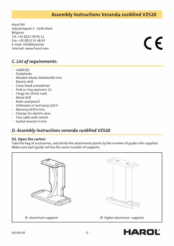
D1. Open the carton:Take the bag of accessories, and divide the attachment points by the number of guide rails supplied.Make sure each guide rail has the same number of supports.
A- aluminum supports B- higher aluminum supports
- 4 -V6-04-05
Assembly instructions Veranda sunblind VZ520
Distributing the attachment points
a- aluminum supports: Push the hexagonal screws in the lateral guide and fix the aluminum supports. The gaps bet-
ween the supports has to be equal.
b- higher aluminum supports: Same procedure as the regular aluminum supports.
Remark: In case of an intermediate roll, at the same time the screws are placed in the guide for the fixation of the support for the intermediate roll.
D2. Setting up the ladders and footplanks:Position the ladders and set up the footplanks on the veranda.
D3. Unpack the boxes:Take the boxes out of the packaging and lay them out in the right order on the roof of the veranda.
D4. Checking the measurements:Check the dimensions of the awning against the verandaprofiles. Small deviations in measurements will be catched up by the movable supports.
D5. Outlining the different positions:Using a completely prepared guide rail, mark on the roof where the base supports will be positioned. Take care: the distance between the top support and the top end should be ca. 280 mm. Drill holes, for the base pieces of the supports, in the veranda frame and fix them firmly.
D6. Positioning the wooden blocks:Take a few blocks (60x60x300 mm.) and slide them under the mounting brackets between the boxes and the verandaprofile.
D7. Removing the protective plastic foil:Open the boxes by removing the covers. Then remove the protective plastic foil from the boxes.
D8. Connecting the boxes:Take care that the spindles are matched to each other correctly.The slots for the fabrics must be in line with each other. (avoid getting dirty spots on the fabric).Insert the square connecting shaft one side halfway into the side-hole. Check that the blind slot mat-ches, then insert the other half in the other hole. Now press the two halves of the mounting bracket together and fix them by using the screws supplied.
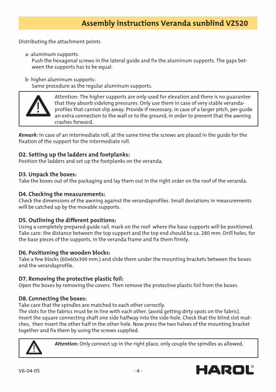
Attention: The higher supports are only used for elevation and there is no guarantee that they absorb sidelong pressures. Only use them in case of very stable veranda-profiles that cannot slip away. Provide if necessary, in case of a larger pitch, per guide an extra connection to the wall or to the ground, in order to prevent that the awning crashes forward.
Attention: Only connect up in the right place, only couple the spindles as allowed.

- 5 -V6-04-05
Assembly instructions Veranda sunblind VZ520
Attention: Only couple the spindles as allowed. Given that the power of the motor is selected according to the number of blinds to be operated, the number of blinds connected up must match the number allowed for the motor.For this reason, end brackets not supplied with a connector are covered by a self-adhesive patch.
D9. Positioning the awning:Slide the entire sun blind assembly over the wooden blocks upto the right position. (Which may be hard against the wall). Take care that the verandaprofiles are at right angles regarding to the wall. We are working with a squared-off system.
D10. Unwinding the cables:Unwind the cable so that there are no loops or kinks. Check that at least 2 or 3 turns of cable are left on the cable pulley. Mind that the cable unrolls along the bottom side.Connect the motor cable up provisionally using a test cable and let the endprofile run out for +/- 15cm

- 6 -V6-04-05
Assembly instructions Veranda sunblind VZ520
D11. Positioning the cables into the guide rails:Take a guide rail, and insert the cable across the entry pulley. Hold the rail pointing diagonally down-wards and push the cable through the rail. Make sure that the cable comes out again through the right hole. At the far end, feed the cable back round the pulley.
D12. Positioning the guides:Now lay the guide rails onto the glass roof, just in front of the pins of the mounting brackets.
D13. Positioning the cables into the endprofile:Insert the cable into the endprofile, aside via the small hole behind the pulley on the slider block.

- 7 -V6-04-05
Assembly instructions Veranda sunblind VZ520
D14. Positioning the cables:Position the endprofile in equal height with the guide rails, and insert the endprofile a short way into the rail. Position the guide rail in front of the pins on the mounting bracket. Make sure that the cable is feeding cleanly throughout. Then pull the cable at point E, and the guide rail slides on to the pin by itself.Do the same for all the guide rails.
D15. Fixing the sun blind in the supports:Position the sun blind in the supports, and screw the supports hand-tight by using the screws sup-plied. Remove the wooden blocks.
D16. Placement of the intermediate rolls:In case of using intermediate rolls, by extremely large extension, the brackets are placed just under-neath the guides. The intermediate rolls must be placed in line to each other and rather in the middle of the lateral guide.
D17. Tensioning the spring:Position the endprofile in the highest position and make 2 marks in the endprofile the distance apart R shown in the separate table.
The maximum distance depends on the spring supplied, the used fabric, the diameter of the roll for fabric and the extension of the blind.Make sure the marks are always at the same distance from the centre of the endprofile.
Attention: The awning will be put on tension now. Pleace work carefully and safe!
- 8 -V6-04-05
Assembly instructions Veranda sunblind VZ520
Feed the cable round the pulley (through the fork) and insert the cable through the hole in the right-angled bracket on the end of the endprofile. Feed the cable back through the second hole and tighten the cable clamps on the cable behind the right-angled bracket so that the axle of the pulley is against the marks in the endprofile. (See fig.)
Check carefully the feed of the cable over all the pulleys both on the front of the guide rail, as well as at the endprofile slider block and the cable feed pulley.Pay attention to the symmetry of the spring.
D18. Inserting the spring:The awning is still in its highest position. Check that the cable doesn’t cross over at the cable pulley, but running cleanly side by side. Thread the spring into the forks of the pulleys and insert the cable into the cable unit. Make a knot in each cable, behind the clamp unit. The sun blind is now under tension.
Remark concerning the motor:If the motor is a standard SLT type, then you can proceed with reading these instructions.If the motor is an Orea or an Altus RTS, please consult the enclosure of the concerned motor.

- 9 -V6-04-05
Assembly instructions Veranda sunblind VZ520
Table spring distance R (in mm)
Dis
tanc
e R
Extension
Distance R

- 10 -V6-04-05
Assembly instructions Veranda sunblind VZ520
D19. Running the motor to its stopping point:Let the motor run until it switches off.Check that the motor stops where it should, not touching the end pulley on the guide rail. The motor is not adjusted.Both buttons on the motor are completely pushed down ex-works (if not push them down both). The motor will not stop by itself.Let the blind run out until the chosen lower position is reached. Then turn the switch for the test cable to its neutral position.Next push the white or yellow button (depending on the built-in side), so that the button lifts up.The lowest position is now adjusted.
- 11 -V6-04-05
Assembly instructions Veranda sunblind VZ520
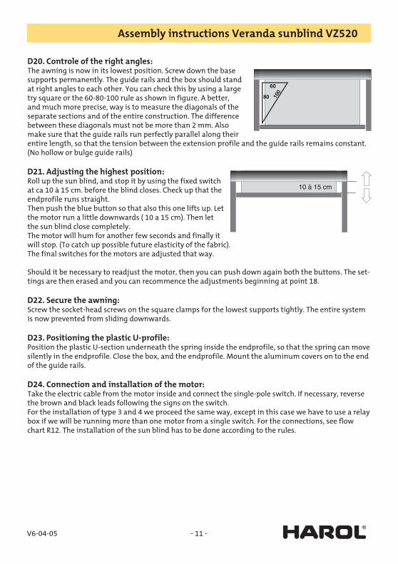
D20. Controle of the right angles:The awning is now in its lowest position. Screw down the base supports permanently. The guide rails and the box should stand at right angles to each other. You can check this by using a large try square or the 60-80-100 rule as shown in figure. A better, and much more precise, way is to measure the diagonals of the separate sections and of the entire construction. The difference between these diagonals must not be more than 2 mm. Also make sure that the guide rails run perfectly parallel along their entire length, so that the tension between the extension profile and the guide rails remains constant. (No hollow or bulge guide rails)
D21. Adjusting the highest position:Roll up the sun blind, and stop it by using the fixed switch at ca 10 à 15 cm. before the blind closes. Check up that the endprofile runs straight.Then push the blue button so that also this one lifts up. Let the motor run a little downwards ( 10 a 15 cm). Then let the sun blind close completely.The motor will hum for another few seconds and finally it will stop. (To catch up possible future elasticity of the fabric).The final switches for the motors are adjusted that way.
Should it be necessary to readjust the motor, then you can push down again both the buttons. The set-tings are then erased and you can recommence the adjustments beginning at point 18.
D22. Secure the awning:Screw the socket-head screws on the square clamps for the lowest supports tightly. The entire system is now prevented from sliding downwards.
D23. Positioning the plastic U-profile:Position the plastic U-section underneath the spring inside the endprofile, so that the spring can move silently in the endprofile. Close the box, and the endprofile. Mount the aluminum covers on to the end of the guide rails.
D24. Connection and installation of the motor:Take the electric cable from the motor inside and connect the single-pole switch. If necessary, reverse the brown and black leads following the signs on the switch.For the installation of type 3 and 4 we proceed the same way, except in this case we have to use a relay box if we will be running more than one motor from a single switch. For the connections, see flow chart R12. The installation of the sun blind has to be done according to the rules.

- 12 -V6-04-05
Assembly instructions Veranda sunblind VZ520
E. Electrical connections:
E1. Flow chart for a single-pole switch:There are 4 wires from the motor. Yellow-green (earth), blue (neutral), brown and black (raise and lower)From the fuse box, there are 3 wires. Yellow-green (earth), blue (neutral), and phase. Connect the wires as shown in the diagram. The phase wire from the fuse box should be connected to terminal L. If neces-sary, reverse the brown and black leads from the motor in the switch so that the arrows on the switch correspond to rolling up and unrolling the sun blind.The 2 earth wires are connected using separate clamps. Ditto for the 2 neutral wires.
yello
w /
gre
en
brow
n /
bla
ck
brow
n /
bla
ck
red
blu
e

- 13 -V6-04-05
Assembly instructions Veranda sunblind VZ520
E2. Why use a relay box RI2?Sun blinds consisting of 3 or 4 panels are always driven by 2 motors. These motors can be operated each using a separate switch. This allows the panels to be opened separately in pairs. However, if you want to operate the sun blind by using a single switch, it is necessary to use a relay box. If this is not done, the system will oscillate, and the high inductive and capacitative voltages created will perma-nently burn out the built-in switches in the motor housing. Therefore this good advice : always use the relay box and switches we supply for single operation of 2 or more motors. The same applies to a “wind/sun automat”.
yello
w /
gre
en
brown / black
red
blu
e
yello
w /
gre
en
blu
e

- 14 -V6-04-05
Assembly instructions Veranda sunblind VZ520
F. Fault-finding:
F1. Blind will not unroll or roll up:- The internal final switch points at zero in both directions. Push both adjusting buttons of the motor
and continue adjusting the final switch.- Wire making poor contact after extending motor cable. Check connections.- Motor has run hot. Leave ½ hour to cool.- Faulty adjustment of the limit switches.- No current supplied to switch. Check using voltmeter.- Motor wrongly connected. Check using connection chart.
F2. Motor hums:- Check whether everything can freely turn in both directions. Is anything catching ? (Cable ?)- Capacitor in motor has blown (as a result of faulty connection of the motor).- Motor is wrongly connected : check correct connection of motor cables to the switch using the chart
on p.12. A phase wire (brown or black) has been transposed with neutral (blue). The motor will turn in one direction, but it will hum in the other.
F3. Motor does not switch off in time:- Faulty adjustment of limit switches.
F4. Internal flap not straight:- The guide rails are parallel, but not square to the casing. Check by measuring diagonals.
F5. Internal flap slips out of the guides:- The guide rails are a little too far apart. Adjust them slightly further together.
F6. Internal flap is not straight against the box when rolled up:- See point 4 above.
F7. Fabric sticks during raising and lowering:- Internal flap not properly fitted in guide rail.- Steel cable not running properly over all pulleys.- Spring blocked.
F8. Fabric not taut at bottom:- The guide rails are not straight with respect to the box. (Veranda rails not straight with respect to wall or box).- Cable sticking somewhere.- Spring not under sufficient tension.- Faulty adjustment of limit switches.- Endprofile runs against the pulleys of the guide rails.
F9. Blinds are not even when unrolled:- Bad fitting of fabric rolls. Turn one of the tubes 1/4 of 1/2 turn.
- 15 -V6-04-05
Assembly instructions Veranda sunblind VZ520
F10. Blinds are not even when rolled up:- The two springs are not adjusted to proportional tension.- The spring for the panel which is rolled up the furthest must be adjusted a little tighter. (Or the
other spring a little looser).
F11. Direction of rotation of the motor does not match the arrows on the switch:- Reverse brown and black wires in the switch.
F12. Blinds roll back up without stopping: - Use a relay box ( RI2)
F13. On a type 3 or 4: One motor rolls up while the other rolls down:- Reverse the brown and black wires to one of the motors IN THE RELAY BOX.
F14. Automatic operation not working well:- See fitting instructions for wind/sun automatics.

- 16 -V6-04-05
Assembly instructions Veranda sunblind VZ520
G. Exception : method for coupling 2 guide rails:
In some cases we have to couple 2 guide rails (when 2 or more systems are mounted beside one another.This can be done in different ways.
G1. Mounting the base attachment point in the middle:The coupling plate is fixed directly underneath both guide rails. The standard attachment point is fixed on the coupling plate.
G2. Mounting the attachment point high profile in the middle:The upper part of the high profile attachment point is replaced by the coupling plate. The coupling plate is fixed underneath both guide rails.
- 17 -V6-04-05
Assembly instructions Veranda sunblind VZ520
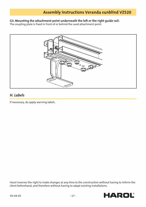
G3. Mounting the attachment point underneath the left or the right guide rail:The coupling plate is fixed in front of or behind the used attachment point.
H. Labels
If necessary, do apply warning labels.
Harol reserves the right to make changes at any time to the construction without having to inform the client beforehand, and therefore without having to adapt existing installations.